Embed Size (px)
Citation preview

Part number 550-100-090/0809
gas-fired water boiler — Boiler Manual
112
Replacement parts
Replacement parts must be purchased through a local Weil-McLain distributor. When ordering, specify boiler model and size and include description and part number of replacement part. Results from using modified or other manufactured parts will not be covered by warranty and may damage boiler or impair operation.
Weil-McLain part numbers are found in Weil-McLain Boilers and Controls Repair Parts Lists.
The boiler contains ceramic fiber materials. Use care when handling these materials per instructions on page 93 of this manual. Failure to comply could result in severe personal in-jury.
Reinstall boiler jacket front door after startup or servicing
Inspect boiler jacket front door gaskets and reinstall boiler jacket front door after start or servicing. The boiler front door must be securely fastened to the boiler to prevent boiler from drawing air from inside the boiler room. This is particularly important if the boiler is located in the same room as other appliances. Failure to keep the door securely fastened could result in severe personal injury or death.
Propane conversion kits and instructionsFigure 116
The conversion kits listed below are only for use with Ultra Series 3 boilers. For series 1 or series 2 boilers, refer to the boiler manual or contact Weil-McLain for the correct parts.
Natural to propane conversion — SERIES 3 BOILERS ONLY(not required for Ultra-399 — adjustment is made with throttle screw, not with orifice)
Sea level (to 5,500 feet altitude) High altitude (above 5,500 feet)
Model Kit part # Kit location Instructions Model Kit part # Kit location Instructions
Ultra-80 383-501-020SPECIAL ORDER
In kit only
Ultra-80LP 383-500-644SPECIAL ORDER
See page 44 or kit
Ultra-105540-100-001
Supplied with boilerSee page 44 Ultra-105 383-500-645
SPECIAL ORDER
See page 44 or kit
Ultra-155383-500-115
Supplied with boilerSee page 45 Ultra-155 383-500-646
SPECIAL ORDER
See page 45 or kit
Ultra-230383-500-120
Supplied with boilerSee page 45 Ultra-230 383-500-647
SPECIAL ORDER
See page 45 or kit
Ultra-299540-202-832
Supplied with boilerSee page 45 Ultra-299 383-500-394
SPECIAL ORDER
See page 45 or kit
Propane to natural conversion
Ultra-80 383-501-021SPECIAL ORDER
In kit only
Contact factory
Boilers marked with this symbol require special installation procedures Do not use the instructions in this manual — use only the instructions supplied in the conversion kit

Part number 550-100-090/0809 113
gas-fired water boiler — Boiler Manual
MA
INT
EN
AN
CE
& S
PE
CIF
ICA
TIO
NS
Miscellaneous parts and kitsFigure 117
Item Description Part Number
1
CHEMICALSAntifreeze, aluminum-safe, Sentinel X500 . . . . . . . . . . . . . . . . . . . . . . . . . . Corrosion inhibitor, Sentinel X100 . . . . . . . . . . . . . . . . . . . . . . . . . . . . . . Inhibitor quick-test kit . . . . . . . . . . . . . . . . . . . . . . . . . . . . . . . . . . . . Cleaner, Sentinel X400 . . . . . . . . . . . . . . . . . . . . . . . . . . . . . . . . . . . .
592-900-004592-900-002592-900-005592-900-003
BOILER ACCESSORIES AND CONTROLS
2Boiler circulator, without flanges Ultra-80/105 Taco Model 007 Ultra-155/230/299 Taco Model 0014 Ultra-399 Taco Model 2400-20
511-405-113511-405-133511-405-135
3
Circulator hardware kit – inlet (1 flange, 2 nuts, 2 screws, and 1 gasket) 1” 1¼” 1½”
381-354-525381-354-526381-354-531
4 Low water cut-off with test button, kit 511-100-005
5 Heat exchanger cleaning tool 591-706-200
6Annual maintenance kit (Igniter, igniter gasket, cover Ultra-80/105plate gasket, cover plate insulation, burner gasket, Ultra-155 – 399 flue sensor gasket and venturi gasket)
383-500-605383-500-620
7Pressure relief valve, ASME 30 PSI, 3/4” NPT male Ultra-80 – 299 Ultra-80 – 399
383-500-095511-546-921
8 Ultra boiler wall-mount kit 389-900-180
VENT / AIR TERMINATIONS
9 Vent/air termination wall penetrate cover plate (2 required for each boiler) 383-500-100
10Vent termination bird screen (2 required) 3” vent (Ultra-80/105/155) 4” vent (Ultra-230/299/399)
383-500-105383-500-110
11
Weil-McLain sidewall vent/air cap termination kit — Includes W-M sidewall vent/air termination cap, inside and outside cover plates, and mounting hardware; openings are sized for PVC pipe. (3” is shipped with Ultra-80 – 155; 4” is shipped with Ultra-230 – 399) 3” kit 4” kit
383-500-397383-500-398
12 Concentric vent kit (for sidewall or vertical termination) 3” PVC only 383-500-350
CONDENSATE HANDLING
13 Condensate neutralizer kit 383-500-631
Replacement parts (continued)
Go to www.weil-mclain.com to locate Weil-McLain distributors

Part number 550-100-090/0809
gas-fired water boiler — Boiler Manual
114
Replacement parts (continued)
Jacket partsFigure 118
Go to www.weil-mclain.com to locate Weil-McLain distributors
Item Description
Boiler models
Part number
1 Jacket front door All 383-500-1352 Boiler leg kit (4 required) All 383-500-0653 Knurled head screw for jacket front door
(2 required)All 383-500-320
4 Knurled head screw clip-on receptacle (not shown) (2 required)
All 383-500-180
5 Air adapter kit (Includes adapter, 3” gasket and mounting bracket) 3” 4”
80/105 155
230–399
383-500-655383-500-145383-500-150
Item Description
Boiler models
Part number
6 Flue outlet pipe adapter 3” 3” 4”
80/105 560-900-001155 383-500-656
230–399 383-500-6577 Top cover, front All 383-500-6078 Top cover, rear 80/230 383-500-608
299/399 383-500-6099 Door Gasket replacement kit (not shown) All 383-500-610
10 Handle (2 required) All 383-500-611

Part number 550-100-090/0809 115
gas-fired water boiler — Boiler Manual
MA
INT
EN
AN
CE
& S
PE
CIF
ICA
TIO
NS
Go to www.weil-mclain.com to locate Weil-McLain distributors
Replacement parts (continued)
ControlsFigure 119
Item Description
Part Number
1 Ultra U-Control module 383-500-658
2 Transformer, 120v/24v 383-500-628
3 Display board assembly (includes plastic and display screen) 383-500-659
4 On/off power switch 383-500-205
5 Pressure/temperature gauge assembly (Includes temperature and pressure sensor)
383-500-630
6 Flue temperature sensor replacement kit 383-500-600
7 System temperature sensors (2 required) 383-500-601
8 Outdoor temperature sensor 510-312-218
9 Display to U-Control wire harness (not shown) 383-500-633
10 Upper line voltage wire harness (male) (not shown) 383-500-634
11 Lower line voltage wire harness (female) (not shown) 383-500-635
12 Upper low voltage wire harness (male) (not shown) 383-500-636
13 Lower low voltage wire harness (female) (not shown) 383-500-637
14 120 volt, 3-wire receptacle (not shown) 383-500-638
15 Ultra U-Control module fuses (not shown) F1 - 3-amp, fast-blow ATO (5 fuses) F2 - 12-amp, slow-blow AG (5 fuses)
383-500-603383-500-604
16 Jumper for low voltage terminal blocks, (5 jumpers) (not shown)
383-500-641
17 Ultra U-Control terminal block kit, (includes 1 high voltage terminal block, 6 low voltage terminal blocks, and U-Control screwdriver) (not shown)
383-500-642
18 24-V LWCO kit with quick connect harness (not shown) 511-100-005

Part number 550-100-090/0809
gas-fired water boiler — Boiler Manual
116
Heat exchanger and piping — Ultra-80 and -105Figure 120
Item DescriptionBoiler
ModelsPart Number
1 Heat exchanger replacement kit - Heat exchanger, cover plate, burner, electrode, water sensors, compression fittings, condensate fitting, gaskets, and hardware
80NG80LP105
383-500-612383-500-613383-500-614
2 Cover plate replacement kit - Cover plate, cover plate gasket, burner gasket, and hardware
80/105 383-501-022
3 Cover plate gasket/insulation 80/105 591-200-000
4 Burner gasket 80/105 590-300-000
5 Cover plate studs, M6, 1 pitch All 560-340-598
6 Cover plate nuts, M6, 1 pitch All 561-928-449
7 Water compression fitting, 28 mm 80–230 383-500-260
8 Water compression fitting, 22 mm 80/105 564-100-002
9 Supply water pipe assembly - Pipe, temperature well, check valve, cap (assembled) & compression fitting
80/105 383-501-036
10 Supply water lower pipe clamp and hardware 80/105 383-500-615
11 1/2” NPT well for temperature gauge All 383-500-270
12 Pressure/temperature gauge check valve All 383-500-275
13 Return water pipe assembly - Pipe, drain valve, cap (assembled) & compression fitting
80/105 383-501-037
14 Boiler drain valve, 3/4” NPT All 511-246-392
15 Blower assembly kit - Blower, gasket, and hardware 80/105 383-501-027
16 Gas pipe 80/105 560-907-682
17 Flexible gas line section and shut-off valve 80/105 383-500-616
18 Gas Pipe lower pipe clamp and hardware 80/105 383-500-617
19 Gas valve/venturi kit - Gas valve, venturi, 90° elbow, gaskets, and hardware (assembled) (For LP boilers, make sure to reinstall the existing propane orifice)
80105
383-501-029383-501-030
20 Gasket cork, for in between gas valve venturi & burner inlet All 590-317-299
21 Air silencer kit - Air silencer and gasket 80/105 383-501-026
22 Air silencer adapter kit - Air silencer adapter and hardware 80/105 383-501-025
23 Condensate trap kit - Condensate trap, hose clamps, pvc fittings, and gasket 80/105 383-501-031
24 Return/supply sensor kit - (1) sensor All 383-500-602
25 Ignition electrode kit - Ignition electrode, suppressor, gasket, and hardware All 383-500-045
Ignition electrode gasket ONLY All 511-330-253
Igniter and gasket All 383-500-045
26 Ignition cable kit (not shown) - Ignition cable, suppressor, and wire tie All 383-500-619
27 Inspection glass kit - Bracket, glass, gasket and hardware All 383-500-020
28 Burner replacement kit - Burner, gaskets and hardware 80NG80LP105
383-501-032383-501-033383-501-034
29 Gasket rubber, blower 80/105 590-300-003
30 Condensate fitting 80/105 561-200-000
Replacement parts (continued)

Part number 550-100-090/0809 117
gas-fired water boiler — Boiler Manual
MA
INT
EN
AN
CE
& S
PE
CIF
ICA
TIO
NS
Heat exchanger and piping — Ultra-80 and -105Figure 121
Replacement parts (continued)
Go to www.weil-mclain.com to locate Weil-McLain distributors

Part number 550-100-090/0809
gas-fired water boiler — Boiler Manual
118
Go to www.weil-mclain.com to locate Weil-McLain distributors
Heat exchanger and piping Figure 122 Ultra-155 & -230
Replacement parts (continued)
Item Description
Boiler models
Part number
1 Heat exchanger replacement kit - Heat exchanger, cover plate, burner, electrode, water sensors, compression fittings, condensate fitting, gaskets, and hardware
155230
383-500-621383-500-622
2 Cover plate replacement kit - Cover plate, cover plate gasket, burner gasket, and hardware
155/230 383-500-395
3 Cover plate insulation 155/230 383-500-2504 Cover plate gasket 155/230 383-500-2555 Cover plate studs, M6, 1 pitch All 560-340-5986 Cover plate nuts, M6, 1 pitch All 561-928-4497 Water compression fitting, 28 mm 80–230 383-500-2608 Supply water pipe assembly - Pipe,
temperature well, check valve, cap (assembled) & compression fitting
155/230 383-500-265
9 Supply water lower pipe clamp and hardware 155/230 383-500-61510 1/2” NPT well for temperature gauge All 383-500-27011 Pressure/temperature gauge check valve All 383-500-27512 Return water bushing, 1 1/4” BSP x 1” BSP
(not use on Ultra-299)155/230 383-500-280
13 Return water pipe assembly - Pipe, drain valve, cap (assembled) & compression fitting
155/230 383-500-285
16 Boiler drain valve, 3/4” NPT All 511-246-39217 Blower assembly kit - Blower, gasket, and
hardware155230
383-500-035383-500-040
Item Description
Boiler models
Part number
18 Gas pipe 155/230 560-907-68319 Flexible gas line section and shut-off valve 155/230 383-500-62420 Gas pipe lower clamp and hardware 155/230 383-500-61721 Gas valve/venturi kit - Gas valve, venturi,
adapter block, O-ring and hardware (assembled) ke sure to reinstall the existing propane orifice)
155230
383-500-025383-500-030
22 Gasket cork, for in between gas valve venturi & burner inlet
All 590-317-299
23 Air silencer kit - Air silencer and gasket 155/230 383-500-29524 Condensate trap kit - Condensate trap, hose
clamps, pvc fittings, and gasket155230
383-501-031383-500-060
25 Ignition electrode kit - Ignition electrode, suppressor, gasket, and hardware
All 383-500-045
Ignition electrode gasket ONLY 511-330-253Ignition electrode and gasket 511-330-253
26 Ignition cable kit (not shown) - Ignition cable, suppressor, and wire tie
All 383-500-619
27 Inspection glass kit - Bracket, glass, gasket and hardware
All 383-500-020
28 Burner replacement kit - Burner, gaskets and hardware
155230
383-500-085383-500-090
29 Return/supply sensor kit - (1) sensor All 383-500-602

Part number 550-100-090/0809 119
gas-fired water boiler — Boiler Manual
MA
INT
EN
AN
CE
& S
PE
CIF
ICA
TIO
NS
Figure 123 Heat exchanger and piping Ultra-299 & -399
Replacement parts (continued)It
em DescriptionBoiler
modelsPart
number
1 Heat exchanger replacement kit - Heat exchanger, cover plate, burner, electrode, water sensors, compression fittings, condensate fitting, gaskets, and hardware
299/399 383-500-623
2 Cover plate replacement kit - Cover plate, cover plate gasket, burner gasket, and hardware
299/399 383-500-395
3 Cover plate insulation 299/399 383-500-2504 Cover plate gasket 299/399 383-500-2555 Cover plate studs, M6, 1 pitch All 560-340-5986 Cover plate nuts, M6, 1 pitch All 561-928-4498 Supply water pipe assembly - Pipe, temperature
well, check valve, cap (assembled) & compression fitting
299/399 383-500-380
10 1/2” NPT well for temperature gauge All 383-500-27011 Pressure/temperature gauge check valve All 383-500-27513 Return water pipe assembly - Pipe, drain valve,
cap (assembled) & compression fitting299/399 383-500-385
14 Supply/Return water piping square cut EPDM gasket (Ultra-299 only)
299/399 562-248-743
15 Fitting, double nipple for supply/return 299/399 561-326-82816 Boiler drain valve, 3/4” NPT All 511-246-39217 Blower assembly kit - Blower, gasket, and
hardware299399
383-500-360383-500-650
18 Gas pipe 299/399 560-907-67919 Flexible gas line section and shut-off valve 299
399560-900-016383-500-653
Item Description
Boiler models
Part number
20 Gas pipe lower clamp and hardware 299 383-500-62521 Gas valve/venturi kit - Gas valve, venturi,
adapter block, O-ring and hardware (assembled) (For 310LP boilers, make sure to reinstall the existing propane orifice)
299 383-500-390
Gas valve kit - Gas valve, venturi, adapter block, O-ring and hardware (assembled)
399 383-500-652
22 Gas valve outlet adapter/nipple kit 399 383-500-65123 Gasket cork, for in between gas valve venturi &
burner inletAll 590-317-310
24 Air silencer kit - Air silencer and gasket 299399
383-500-355383-500-654
25 Ignition electrode kit - Ignition electrode, suppressor, gasket, and hardware
All 383-500-045
Ignition electrode gasket ONLY 511-330-253Ignition electrode and gasket 511-330-253
26 Ignition cable kit (not shown) - Ignition cable, suppressor, and wire tie
All 383-500-619
27 Inspection glass kit - Bracket, glass, gasket and hardware
All 383-500-020
28 Burner replacement kit - Burner, gaskets and hardware
299 383-500-407
29 Return/supply sensor kit - (1) sensor All 383-500-60230 Condensate trap kit - Condensate trap, hose
clamps, pvc fittings, and gasket299 383-500-626
Part number 550-100-090/0809
gas-fired water boiler — Boiler Manual
120
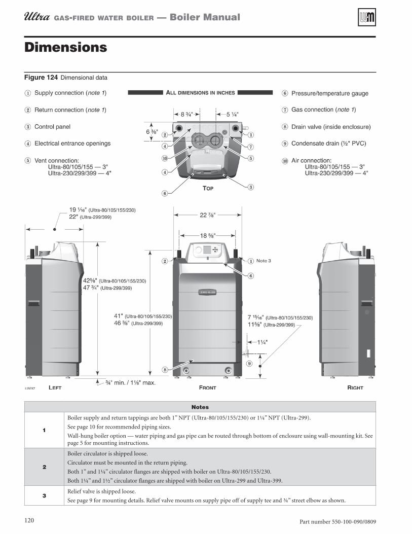
Figure 124 Dimensional data
Notes
1
Boiler supply and return tappings are both 1” NPT (Ultra-80/105/155/230) or 1¼” NPT (Ultra-299).
See page 10 for recommended piping sizes.
Wall-hung boiler option — water piping and gas pipe can be routed through bottom of enclosure using wall-mounting kit. See page 5 for mounting instructions.
2
Boiler circulator is shipped loose.
Circulator must be mounted in the return piping.
Both 1” and 1¼” circulator flanges are shipped with boiler on Ultra-80/105/155/230.
Both 1¼” and 1½” circulator flanges are shipped with boiler on Ultra-299 and Ultra-399.
3Relief valve is shipped loose.
See page 9 for mounting details. Relief valve mounts on supply pipe off of supply tee and ¾” street elbow as shown.
Dimensions
Part number 550-100-090/0809 121
gas-fired water boiler — Boiler Manual
MA
INT
EN
AN
CE
& S
PE
CIF
ICA
TIO
NS
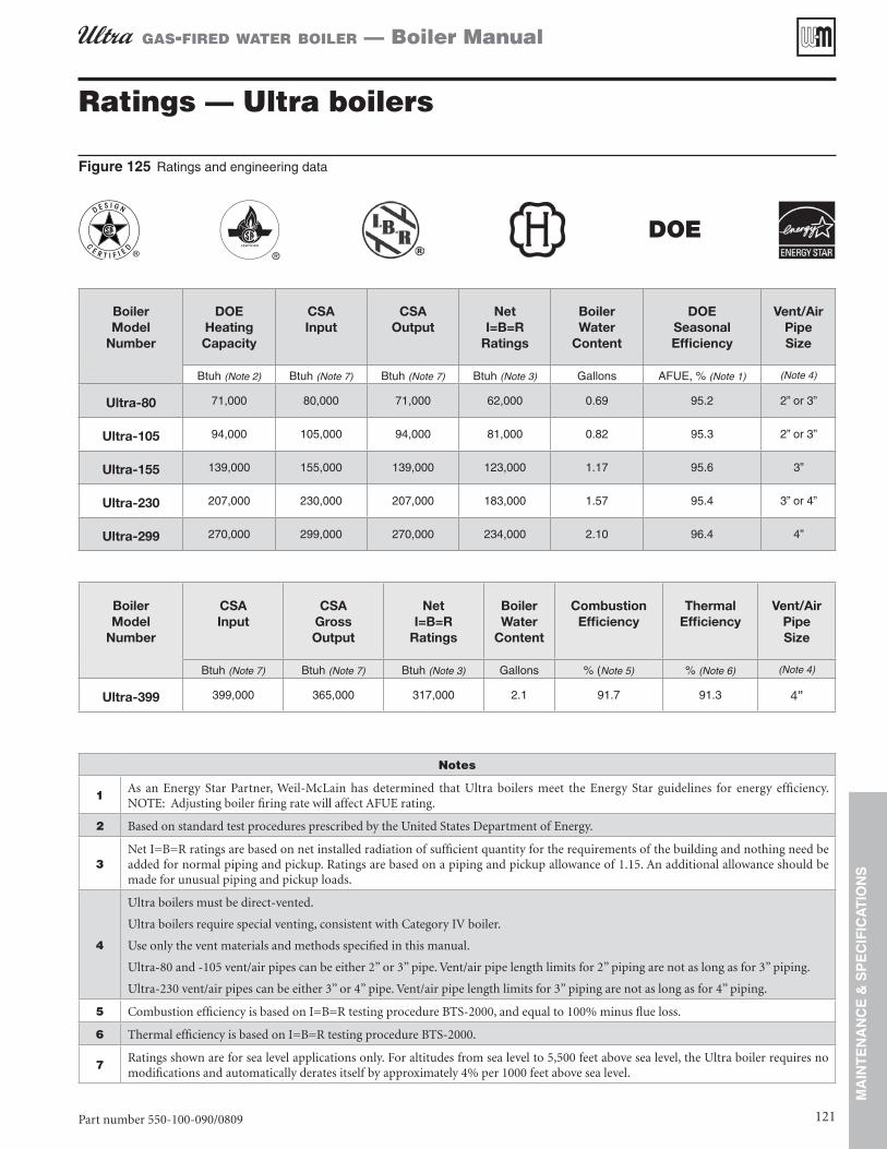
Ratings — Ultra boilers
Figure 125 Ratings and engineering data
DOE
Boiler Model
Number
DOE Heating Capacity
CSA Input
CSA Output
Net I=B=R
Ratings
Boiler Water
Content
DOE Seasonal Efficiency
Vent/Air PipeSize
Btuh (Note 2) Btuh (Note 7) Btuh (Note 7) Btuh (Note 3) Gallons AFUE, % (Note 1) (Note 4)
Ultra-80 71,000 80,000 71,000 62,000 0 69 95 2 2” or 3”
Ultra-105 94,000 105,000 94,000 81,000 0 82 95 3 2” or 3”
Ultra-155 139,000 155,000 139,000 123,000 1 17 95 6 3”
Ultra-230 207,000 230,000 207,000 183,000 1 57 95 4 3” or 4”
Ultra-299 270,000 299,000 270,000 234,000 2 10 96 4 4”
Boiler Model
Number
CSA Input
CSA Gross Output
Net I=B=R
Ratings
Boiler Water
Content
Combustion Efficiency
Thermal Efficiency
Vent/Air PipeSize
Btuh (Note 7) Btuh (Note 7) Btuh (Note 3) Gallons % (Note 5) % (Note 6) (Note 4)
Ultra-399 399,000 365,000 317,000 2 1 91 7 91 3 4”
Notes
1As an Energy Star Partner, Weil-McLain has determined that Ultra boilers meet the Energy Star guidelines for energy efficiency. NOTE: Adjusting boiler firing rate will affect AFUE rating.
2 Based on standard test procedures prescribed by the United States Department of Energy.
3Net I=B=R ratings are based on net installed radiation of sufficient quantity for the requirements of the building and nothing need be added for normal piping and pickup. Ratings are based on a piping and pickup allowance of 1.15. An additional allowance should be made for unusual piping and pickup loads.
4
Ultra boilers must be direct-vented.
Ultra boilers require special venting, consistent with Category IV boiler.
Use only the vent materials and methods specified in this manual.
Ultra-80 and -105 vent/air pipes can be either 2” or 3” pipe. Vent/air pipe length limits for 2” piping are not as long as for 3” piping.
Ultra-230 vent/air pipes can be either 3” or 4” pipe. Vent/air pipe length limits for 3” piping are not as long as for 4” piping.
5 Combustion efficiency is based on I=B=R testing procedure BTS-2000, and equal to 100% minus flue loss.
6 Thermal efficiency is based on I=B=R testing procedure BTS-2000.
7Ratings shown are for sea level applications only. For altitudes from sea level to 5,500 feet above sea level, the Ultra boiler requires no modifications and automatically derates itself by approximately 4% per 1000 feet above sea level.

Part number 550-100-090/0809
gas-fired water boiler — Boiler Manual
122
Ratings — multiple Ultra boilers
Figure 126 Ratings and engineering data (see Figure 128 for notes)
DOE
Boilers in system Model Ultra –
Total CSA input
DOE Heating capacity
Boiler H.P.
Net water
ratings
Manifolded combustion
air duct size
Foundation sizeSide-to-sidearrangement
(height 2” to 4”)
Back-to-back arrangement
(height 2” to 4”)Input, MBH
Output, MBH - MBH Square
inchesLength (inches)
Length (inches)
Length (inches)
Length (inches)
80 105 155 230 299 399 - Note 1 - Note 2 Figure 59, page 55 Note 3
2 160 142 4 2 123 80
56 23 27 48
2 210 188 5 6 163 105
2 310 278 8 3 242 155
2 460 414 12 4 360 230
2 598 540 16 1 468 299
2 798 730 21 8 634 385
3 240 213 6 4 185 120
85 23 56 48
3 315 282 8 4 245 157
3 465 417 12 5 363 232
3 690 621 18 6 540 345
3 897 810 24 2 702 449
3 1197 1095 32 7 951 578
4 320 284 8 5 247 160
114 24 56 49
4 420 376 11 2 327 210
4 620 556 16 6 483 310
4 920 828 24 7 720 460
4 1196 1080 32 3 936 598
4 1596 1460 43 6 1268 770
5 400 355 10 6 309 200
143 24 85 49
5 525 470 14 409 267
5 775 695 20 8 604 387
5 1150 1035 30 9 900 575
5 1495 1350 40 3 1170 748
5 1995 1825 54 5 1585 963
6 480 426 12 7 370 240
172 24 85 49
6 630 564 16 8 490 315
6 930 834 24 9 725 465
6 1380 1242 37 1 1080 690
6 1794 1620 48 4 1404 897
6 2394 2190 65 4 1902 1155
7 560 497 14 8 432 280
201 24 114 49
7 735 658 19 7 572 367
7 1085 973 29 1 846 542
7 1610 1449 43 3 1260 805
7 2093 1890 56 5 1638 1047
7 2793 2555 76 3 2219 1348
8 640 568 17 494 320
230 24 114 49
8 840 752 22 5 654 420
8 1240 1112 33 2 967 620
8 1840 1656 49 5 1440 920
8 2392 2160 64 5 1872 1196
8 3192 2920 87 2 2536 1539

Part number 550-100-090/0809 123
gas-fired water boiler — Boiler Manual
MA
INT
EN
AN
CE
& S
PE
CIF
ICA
TIO
NS
Ratings — multiple Ultra boilers (continued)
Figure 127 Engineering data (see Figure 128 for notes)
Boiler Model
Ultra –
Shipping weight
Operating weight
Water content
Water flow rate per boiler
Vent/air pipe size —
Provide a separate vent for each boiler
Electrical service required
Pounds per boiler
Pounds per boiler Gallons
per boilerGPM
@ 20°F riseGPM
@ 40°F rise
Amps per boiler
Note 4 Note 5 Note 6
80 199 139 0 7 7 1 3 6 2” or 3” 15 0
105 207 145 0 8 9 4 4 7 2” or 3” 15 0
155 234 181 1 2 13 9 7 0 3” 15 0
230 246 192 1 6 20 7 10 4 3” or 4” 15 0
299 297 229 2 1 27 9 14 0 4” 15 0
399 297 229 2 1 36 5 18 2 4” 15 0
Figure 128 Notes for Figure 126 and Figure 127-
1Based on standard test procedures outlined by DOE for individual boilers.
2Net I=B=R ratings are based on piping and pickup allowance of 1.15.
Consult Weil-McLain Technical Services for other allowances.
3
Foundation sizes in Figure 126 provide 6 inches between boilers and 2 inches from boiler to edge of foundation.
Smaller foundations are possible with reduced service clearances.
See page 54 for details.
For side-to-side installations, see • Figure 56, page 54.
For back-to-back installations, see • Figure 57, page 54.
4 Operating weight is the total weight of the boiler, including water.
5
Ultra-80 and -105 vent/air pipes can be either 2” or 3” pipe. Vent/air pipe length limits for 2” piping are not as long as for 3” piping.
Ultra-230 vent/air pipes can be either 3” or 4” pipe. Vent/air pipe length limits for 3” piping are not as long as for 4” piping.
All Ultra installations require a separate vent pipe and termination for each boiler. Vent piping cannot be manifolded. Install and terminate vents as described in vent/air installation instructions in this manual.
Combustion air piping can be individually piped or manifolded. See Figure 59, page 55, for manifolded air piping.
6 Total amp requirement includes up to three circulators, not exceeding 2.2 amps per circulator.

gas-fired water boiler — Boiler Manual
124
gas-fired water boiler — Boiler Manual
Boiler Model Series CP Number Date Installed
BTU Input ❏ ❏❏❏Installation instructions have been followed.
❏ ❏ ❏ ❏ ❏ ❏❏❏Check-out sequence has been performed.
❏ ❏ ❏ ❏ ❏ ❏❏❏Above information is certified to be correct.
❏ ❏ ❏ ❏ ❏ ❏❏❏Information received and left with owner/maintenance person.
Installer
(Company) (Address) (Phone) (Installer's Signature)
Installation and Service Certificate
START-UP DATABoiler Model CO2 High fire % CO2 Low fire %Fuel Natural ____ LP ____ CO High fire ppm CO Low fire ppmWas orifice changed? ______________________________________ Was gas valve throttle adjusted (Ultra-399) for propane? __________________Natural gas input rate measured _________________________ Btuh
U-CONTROL SET-UP DATABoiler Model WWSD Temp °F Add’l Heat Demand Type 1___ 2___ 3___ 4___High Altitude yes ____ no _____ Adjust Outdoor °F Add’l Heat Demand Time minutesManual Reset Temp °F
PRIORITY 1 Settings PRIORITY 2 Settings PRIORITY 3 Settings
System Type System Type System TypeMax Supply °F Max Supply °F Max Supply °FMin Supply °F Min Supply °F Min Supply °FMax OD Reset °F Max OD Reset °F Max OD Reset °FMin OD Reset °F Min OD Reset °F Min OD Reset °FModulate On Diff °F Modulate On Diff °F Modulate On Diff °FModulate Off Diff °F Modulate Off Diff °F Modulate Off Diff °FMax On Time minutes Max On Time minutes Max On Time —Min On Time — Min On Time minutes Min On Time minutesBoost Interval minutes Boost Interval minutes Boost Interval minutesPre-pump Time: seconds Pre-pump Time: seconds Pre-pump Time: secondsPost-pump Time: seconds Post-pump Time: seconds Post-pump Time: secondsCirculator 1 on-off Circulator 1 on-off Circulator 1 on-offCirculator 2 on-off Circulator 2 on-off Circulator 2 on-offCirculator 3 on-off Circulator 3 on-off Circulator 3 on-offMaximum Rate %Rate Maximum Rate %Rate Maximum Rate %RateMinimum Rate %Rate Minimum Rate %Rate Minimum Rate %Rate
Circulator Exercising Freeze Protection CirculatorsCirculator 1 on _______ off _______ Circulator 1 on _______ off _______ Circulator 2 on _______ off _______ Circulator 2 on _______ off _______ Circulator 3 on _______ off _______ Circulator 3 on _______ off _______