Embed Size (px)
Citation preview
Installation Sheets Manual 121Gas Combustion Combination Controls and Systems Section G
Technical Bulletin G670Issue Date 0300
© 2000 Johnson Controls, Inc. 1Part No. 24-8143-162, Rev. B www.johnsoncontrols.comCode No. LIT-121240
Figure 1: G670 Intermittent Pilot Ignition Control
The G670 is a Non-100% Lockout Intermittent Pilot Ignition (IPI) controlthat replaces the G67AG and G67BG ignition controls. The G670 is used toautomatically light a pilot burner and energize the main burner gas valve inresponse to a call for heat from the system thermostat. When the call for heatis satisfied, the thermostat opens and the G670 de-energizes the pilot andmain burner gas valves.
Following are the application requirements of the G670 control.
• The G670 can be used with equipment with a maximum firing rate of117 kW (400,000 Btu/hr). Any application greater than 117 kW(400,000 Btu/hr) must have written approval in advance from theHeating Products Engineering Department.
• All G670 applications must use a redundant gas valve system with themain valve seats in series.
G670 Intermittent Pilot Ignition Controls
Description
ApplicationRequirements
2 GG670 Intermittent Pilot Ignition Controls Technical Bulletin
Table 1: SpecificationsIgnition Type Indirect
Ignition Source High voltage spark, capacitive discharge
High Voltage CableLength
915 mm (36 in.) maximum
Flame Detection Means Flame rectification
Flame Detection Types Remote sensing
Minimum Flame Current 0.2 microampere
Flame Failure ResponseTime
0.8 second, maximum
Spark Gap 2.5 mm (0.1 in.) nominal
Ignition Trial Time Infinite
Power Requirements Control: 24 VAC, 50/60 Hz, nominalOperation Current: 0.15A nominal + valves
Contact Rating Main Valve: 2A continuous, 5A inrushPilot Valve: 2A continuous, 5A inrush
Ambient Operating andStorage Temperature
-40 to 66°C (-40 to 150°F)
Humidity 95% RH non-condensing
Types of Gas Natural(Liquefied Petroleum [LP], manufactured, mixed, orLP gas-air mixture may be used in a well vented oroutdoor application.)
Agency Listing CSA (AGA/CGA) Certificate Number 112520-0-19
Specification Standards ANSI Standard Z21.20CSA C22.2-No. 199
The performance specifications are nominal and conform to acceptable industrystandards. For application at conditions beyond these specifications, consult thelocal Johnson Controls office. Johnson Controls, Inc. shall not be liable fordamages resulting from misapplication or misuse of its products.
The following definitions describe operating conditions.
• Trial for Ignition--Period during which the pilot valve and spark areactivated attempting to ignite gas at the main burner. Thetrial-for-ignition period is infinite for the G670s and ends once thepilot flame is detected or the call for heat ends.
• Run--The main valve remains energized and the spark is turned offafter successful ignition.
• Flameout--Loss of proven flame. Should a flameout occur, the mainvalve closes and the spark recurs within 0.8 second.
OperatingModeDefinitions
GG670 Intermittent Pilot Ignition Controls Technical Bulletin 3
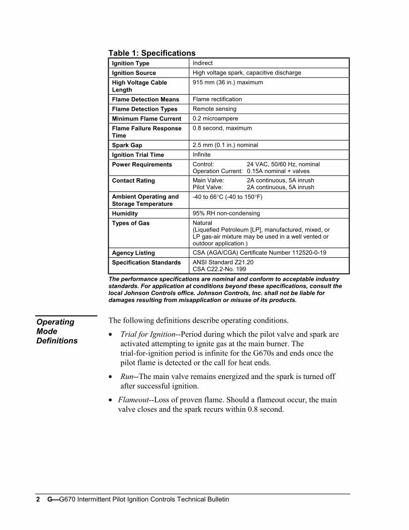
Figure 2 illustrates the sequence of operation for the G670 ignition control.
On a call for heat from the system thermostat, the G670 simultaneouslyopens the pilot valve and supplies a continuous spark to the pilot burner’selectrode. When the pilot burner gas ignites, the pilot flame sensor detectsthe pilot flame and signals the G670 to energize the main gas valve anddiscontinue the spark. The main gas valve will not be energized until theflame sensor detects the presence of the pilot flame.
If the pilot flame goes out (with the thermostat still calling for heat), theG670 will de-energize the main gas valve and provide a continuous sparkat the pilot burner’s electrode. When the pilot flame is re-ignited anddetected by the pilot flame sensor, the main gas valve is energized and thespark is shut off. The G670 de-energizes the pilot gas valve and mainburner gas valve when the thermostat stops calling for heat.
Start
Flameout?
No
No
Yes
No
Yes
Run
No
Yes
End
Yes
De-energize ControlPilot and Main Valves
ThermostatCalling for
Heat?
De-energizeMain Valve
EnergizeMain Valve
PilotFlame
Sensed?
Trial forIgnition
FlamePresent?
ThermostatCall for Heat
Figure 2: Sequence of Operation
Sequence ofOperation

4 GG670 Intermittent Pilot Ignition Controls Technical Bulletin
IMPORTANT: These instructions are intended as a guide for qualifiedpersonnel installing or servicing Johnson Controlsignition controls. Carefully follow all instructions inthis bulletin and all instructions on the appliance. Limitrepairs, adjustments, and servicing to the operationslisted in this bulletin or on the appliance.
! WARNING: Fire or Explosion Hazard. Avoid serious injury bycarefully following precautions in this bulletin and allinstructions on the appliance. Limit repairs,adjustments, and servicing to the operations listed inthis bulletin or on the appliance.
! WARNING: Fire or Explosion Hazard. If the control is installedin an area that is exposed to water (dripping, spraying,rain, etc.), it must be protected. If the control has beenexposed to water in any way, do not use it.
! WARNING: Shock Hazard. Avoid electrical shock and equipmentdamage. Disconnect electrical power and turn off thegas before wiring the control.
! CAUTION: Equipment Damage Hazard. Label all wires prior todisconnection when servicing controls. Wiring errorscan cause improper and dangerous operation. Verifyproper operation after servicing.
Perform the following procedure to install the G670 ignition control.
1. Shut off power to the appliance.
2. Turn off gas at the manual shutoff valve adjacent to the appliance.
3. Label each wire with the correct terminal designation prior todisconnection.
4. Disconnect the power supply (transformer) and the thermostat leadwire at the ignition control.
5. Disconnect the sensing probe lead from Terminal 4 on the ignitioncontrol.
6. Disconnect the high voltage cable from the spark transformer.
7. Disconnect the Pilot Valve 1 and Main Valve 3 leads from the ignitioncontrol.
8. Disconnect any wires connected to the ground terminals on the ignitioncontrol.
Installation
Mounting
GG670 Intermittent Pilot Ignition Controls Technical Bulletin 5
9. Remove the screws holding the ignition control assembly in place.
10. Remove the ignition control and discard.
11. Using the same holes as the old ignition, mount the new G670 controlon a grounded metal surface with metal screws or bolts through themounting holes provided on the enclosure.
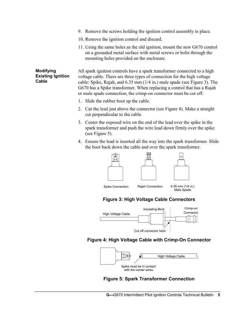
All spark ignition controls have a spark transformer connected to a highvoltage cable. There are three types of connection for the high voltagecable: Spike, Rajah, and 6.35 mm (1/4 in.) male spade (see Figure 3). TheG670 has a Spike transformer. When replacing a control that has a Rajahor male spade connection, the crimp-on connector must be cut off.
1. Slide the rubber boot up the cable.
2. Cut the lead just above the connector (see Figure 4). Make a straightcut perpendicular to the cable.
3. Center the exposed wire on the end of the lead over the spike in thespark transformer and push the wire lead down firmly over the spike(see Figure 5).
4. Ensure the lead is inserted all the way into the spark transformer. Slidethe boot back down the cable and over the spark transformer.
Spike Connection Rajah Connection 6.35 mm (1/4 in.)Male Spade
Figure 3: High Voltage Cable Connectors
High Voltage Cable
Insulating Boot Crimp-onConnector
Cut off connector here.
Figure 4: High Voltage Cable with Crimp-On Connector
High Voltage Cable
Spike must be in contact with the center wires.
Figure 5: Spark Transformer Connection
ModifyingExisting IgnitionCable
6 GG670 Intermittent Pilot Ignition Controls Technical Bulletin
! CAUTION: Equipment Damage Hazard. Connect the highvoltage cable to the spark transformer terminal andspark electrode (pilot burner assembly) beforeapplying power to the control. Ensure the ground wireis attached to the pilot burner and control groundterminal strip.
! CAUTION: Equipment Damage Hazard. Locate all limit andoperating controls in series with the thermostatterminal (THS 2) on the ignition control.
Check the voltage rating marked on the control and make sure it is suited tothe application. Use a National Electrical Code (NEC) Class 2 transformerto provide 24 VAC under maximum load, including valves. A transformerhaving excessive primary impedance due to poor coupling will affect theignition potential.
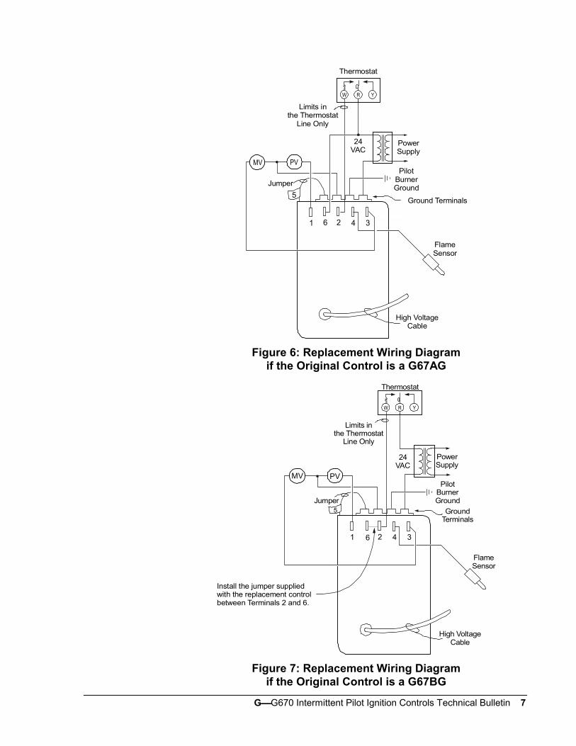
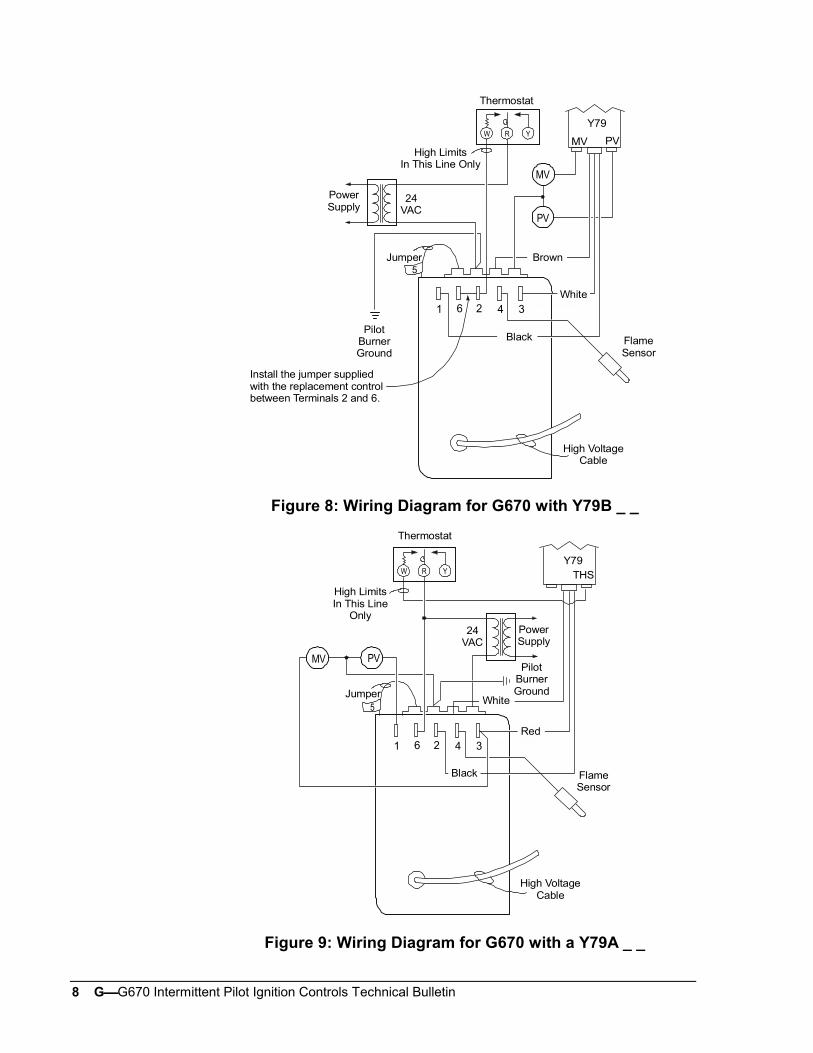
Refer to Figures 6 through 9 for wiring diagrams. All wiring should be inaccordance with the NEC and all other local codes and regulations. Thehigh voltage spark transformer cable must not be in continuous contactwith a metal surface. Use standoff insulators. Ensure that the flame sensorwire and the high voltage spark transformer cable are separated fromone another by a minimum distance of 6.35 mm (1/4 in.) and are notwrapped around any pipe, other wiring, or accessories.
Wiring
GG670 Intermittent Pilot Ignition Controls Technical Bulletin 7
0.21 in
RW Y
Thermostat
1 6 2 4 3
Jumper
Ground Terminals5
PVMV
Limits inthe Thermostat
Line Only
24VAC
PowerSupply
FlameSensor
High VoltageCable
PilotBurnerGround
Figure 6: Replacement Wiring Diagramif the Original Control is a G67AG
RW Y
Thermostat
1 2 4 3
Jumper5
6
MV PV
Limits inthe Thermostat
Line Only
24VAC
PowerSupply
PilotBurnerGround
GroundTerminals
FlameSensor
High VoltageCable
Install the jumper suppliedwith the replacement controlbetween Terminals 2 and 6.
Figure 7: Replacement Wiring Diagramif the Original Control is a G67BG
8 GG670 Intermittent Pilot Ignition Controls Technical Bulletin
RW Y
Thermostat
1 6 2 4 3
Jumper5
MV
PV
Y79
PVMV
High VoltageCable
FlameSensor
PilotBurnerGround
24VAC
PowerSupply
High LimitsIn This Line Only
Black
Brown
White
Install the jumper suppliedwith the replacement controlbetween Terminals 2 and 6.
Figure 8: Wiring Diagram for G670 with Y79B _ _
RW Y
Thermostat
1 6 2 4 3
Jumper
Y79THS
MV PV
5
FlameSensor
High VoltageCable
PilotBurnerGround
24VAC
High LimitsIn This Line
OnlyPowerSupply
White
Red
Black
Figure 9: Wiring Diagram for G670 with a Y79A _ _

GG670 Intermittent Pilot Ignition Controls Technical Bulletin 9
! WARNING: Fire or Explosion Hazard. Avoid personal injury orproperty damage by making sure the control functionsproperly and there are no gas leaks. Follow thischeckout and startup procedure before leaving theinstallation.
! WARNING: Fire or Explosion Hazard. Do not attempt to checkout this system by manually lighting the pilot. Thiscould energize the main valve.
Make sure all components are functioning properly by performing thefollowing shutoff test.
1. With the gas and thermostat off, turn on power to the appliance.
2. Turn on the thermostat to the highest setting and verify that the controlgoes through the operating sequence to a shutoff condition.
Note: The burner will not light because the gas is off.
3. Turn off the thermostat.
4. Turn on the gas and purge gas lines of all air.
5. Test for gas leaks on all pipe joints and connections upstream of thegas valve with a soap solution.
6. Turn on the thermostat to the highest setting and verify successfulignition and a normal run condition for at least three minutes. If theappliance fails to run, see the Service Checkout Procedures section.
7. Test for leaks on all pipe joints and connections downstream of the gasvalve with a soap solution.
8. Turn the thermostat down for at least 30 seconds and then back upagain. Verify successful ignition at least three times.
9. Return the thermostat to a normal temperature setting before leavingthe installation.
Checkout andStartupProcedure

10 GG670 Intermittent Pilot Ignition Controls Technical Bulletin
The thermostat anticipator setting is normally equal to the ignition systemcurrent draw, plus that of the pilot and main valve.
Due to variations in appliance wiring and valves, it is advisable to measurethe actual current draw of the heating system at the thermostat location.Measuring this current can be accomplished by opening the thermostatcontacts (lowering the set point) and installing an AC ammeter across theterminals, or by using a clamp-on ammeter with a 10-turn multiplierattached to the terminals (see Figure 10).
IMPORTANT: Measuring the current with an ammeter will energizethe system. Wait until the gas valve and inducerenergize before taking a current draw measurement.
Ten Turns
W R
W R
AC Ammeter Low Scale Setting
Clamp-on Ammeter(Divide reading by ten.)
ToHeatingSystem
ToHeatingSystem
Figure 10: Measuring the Thermostat Current
ThermostatHeatAnticipatorSettings
GG670 Intermittent Pilot Ignition Controls Technical Bulletin 11
If the system does not function properly, determine the cause using theprocedures in this section.
Before proceeding with troubleshooting the system, check the following:
• Are all mechanical and electrical connections tight?
• Is the system wired correctly?
• Is the gas inlet pressure per the manufacturer’s specifications?
• Is the system powered?
• Is the thermostat calling for heat?
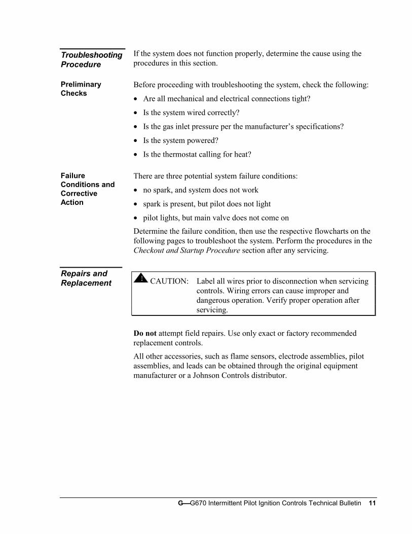
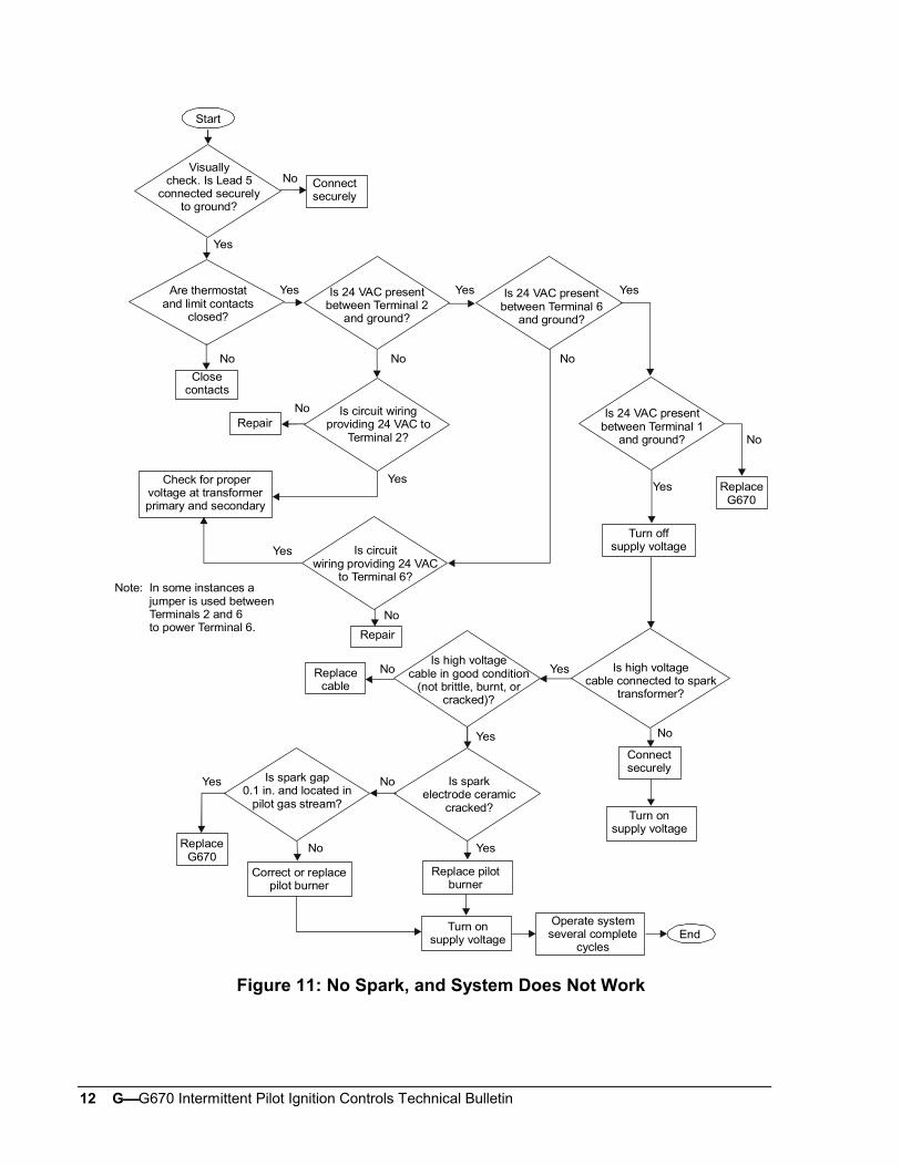
There are three potential system failure conditions:
• no spark, and system does not work
• spark is present, but pilot does not light
• pilot lights, but main valve does not come on
Determine the failure condition, then use the respective flowcharts on thefollowing pages to troubleshoot the system. Perform the procedures in theCheckout and Startup Procedure section after any servicing.
! CAUTION: Label all wires prior to disconnection when servicingcontrols. Wiring errors can cause improper anddangerous operation. Verify proper operation afterservicing.
Do not attempt field repairs. Use only exact or factory recommendedreplacement controls.
All other accessories, such as flame sensors, electrode assemblies, pilotassemblies, and leads can be obtained through the original equipmentmanufacturer or a Johnson Controls distributor.
TroubleshootingProcedure
PreliminaryChecks
FailureConditions andCorrectiveAction
Repairs andReplacement
12 GG670 Intermittent Pilot Ignition Controls Technical Bulletin
No
Yes
No
Yes
Yes
No
No
No
Yes Yes
No
No
Yes
Yes
No
Yes
NoYes
Yes
No
No
Yes
Repair
Start
Repair
End
ReplaceG670
Is 24 VAC presentbetween Terminal 6
and ground?
Is 24 VAC presentbetween Terminal 1
and ground?
Turn offsupply voltage
Visuallycheck. Is Lead 5
connected securelyto ground?
Connectsecurely
Is 24 VAC presentbetween Terminal 2
and ground?
Is circuit wiringproviding 24 VAC to
Terminal 2?
Are thermostatand limit contacts
closed?
Closecontacts
Check for propervoltage at transformerprimary and secondary
Is circuitwiring providing 24 VAC
to Terminal 6?
Replacecable
Is high voltagecable in good condition
(not brittle, burnt, orcracked)?
Turn onsupply voltage
Connectsecurely
Is spark gap0.1 in. and located in
pilot gas stream?
Is sparkelectrode ceramic
cracked?
Correct or replacepilot burner
Replace pilotburner
Turn onsupply voltage
Operate systemseveral complete
cycles
ReplaceG670
Is high voltagecable connected to spark
transformer?
In some instances ajumper is used betweenTerminals 2 and 6 to power Terminal 6.
Note:
Figure 11: No Spark, and System Does Not Work
GG670 Intermittent Pilot Ignition Controls Technical Bulletin 13
Yes
No
Yes
No
No
Yes
Yes
No
No
Yes
Start
Is gas at pilot?
End
Is pilot valve wiringsecurely connected to
Terminal 1 and ground?
Connectsecurely
Is 24 VAC presentbetween Terminal 1
and ground?
ReplaceG670
Make sure pilot line is notkinked or obstructed. Check
for clean orifice.
Is inlet gas pressureper manufacturer’s
specifications?
Replacepilot valveCorrect gas
pressure
Is pilot spark gap0.1 in. and located in
pilot gas stream?
Correct orreplace pilot
Check for drafts. Shieldas necessary and check
for clean orifice.
! WARNING: Explosion Hazard.Do not use a match to test for presence of gas.
Figure 12: Spark is Present, but Pilot Does Not Light

14 GG670 Intermittent Pilot Ignition Controls Technical Bulletin
Correct
End
Correct
No No
No
No
No
No No
No
No
No
Yes
Yes
Yes
Yes Yes
Yes
Yes
Yes
Yes
Yes
StartDoes spark stay on
for more than 30 secondsafter the pilot lights?
Is 24 VACbetween Terminal 3
and ground?
Is inlet gas pressureper manufacturer’s
specifications?
Correctgas pressure
ReplaceG670Make sure sensor cable
and high voltage cable areseparated and not wrapped
around any pipe or accessories.
Is sensor cablesecurely connectedto Terminal 4 and
flame sensor?
Connectsecurely
Is mainvalve wiring
securely connected toTerminal 3 and
ground?
Replacemain valve
Is sensorceramic cracked?
Is cablegrounded out?
Is sensor orsensor connector
shorted out to metalsurface?
Is therecontinuity and good
insulation in thesensor cable?
Replacecable
Disconnect main valvelead from Terminal 3
Disconnect sensorcable from Terminal 4
Replacesensor
Connect DC microammeterbetween sensor cable terminal andTerminal 4. Observe correct polarity.
See Figure 20.
ReplaceG670
Is DC current0.2 microamperes orgreater with pilot only
operation?
Check for:- proper gas pressure- clean pilot assembly- tight mechanical and electrical connections
If there is not improvement, change theflame sensor length or the orifice size andperform any necessary turn down tests.
Connectsecurely
Figure 13: Pilot Lights, but Main Burner Does Not Come On
GG670 Intermittent Pilot Ignition Controls Technical Bulletin 15
No
Yes
Yes
No
Yes
No
NoNo
YesTurn off supply voltage
No
No
Yes
Yes
Yes
Yes
Yes
NoYes
No
Start
No
Turn supply voltage on
EndOperate system several complete cycles
Is system wiringper manufacturer’s
instructions?
Correctwiring
Open thermostatcontacts for30 seconds
Close thermostatcontacts and wait 30%of the Y79 lockout time
Is aspark
present?
System wasin lockout
Determine reason for lockout.Conduct microamperage test as
outlined in Figure 16,starting at A .
Is 24 VAC presentbetween Terminal 1
and ground?
ReplaceG670
Check the high voltagecable. Is it securely
connected to the sparktransformer?
Connectsecurely
Turn supplyvoltage on
Is 24 VAC presenton secondary
of transformer?
Replace the transformer ifproper voltage is presenton primary of transformer.
Is highlimit
closed?
Resethigh limit
Replacecable
Is condition of highvoltage cable good(not brittle, burnt,
or cracked)?
Is sparkelectrode
ceramic cracked?
Is spark gap0.1 in. and
located in pilotgas stream?
ReplaceG670
Correct orreplace pilot
burner
Replacepilot burner
Is 24 VAC presentbetween Terminal 2
and ground?
Replace the Y79 withthe appropriate
G600 Ignition controls(contact Johnson Controls
Technical Support).
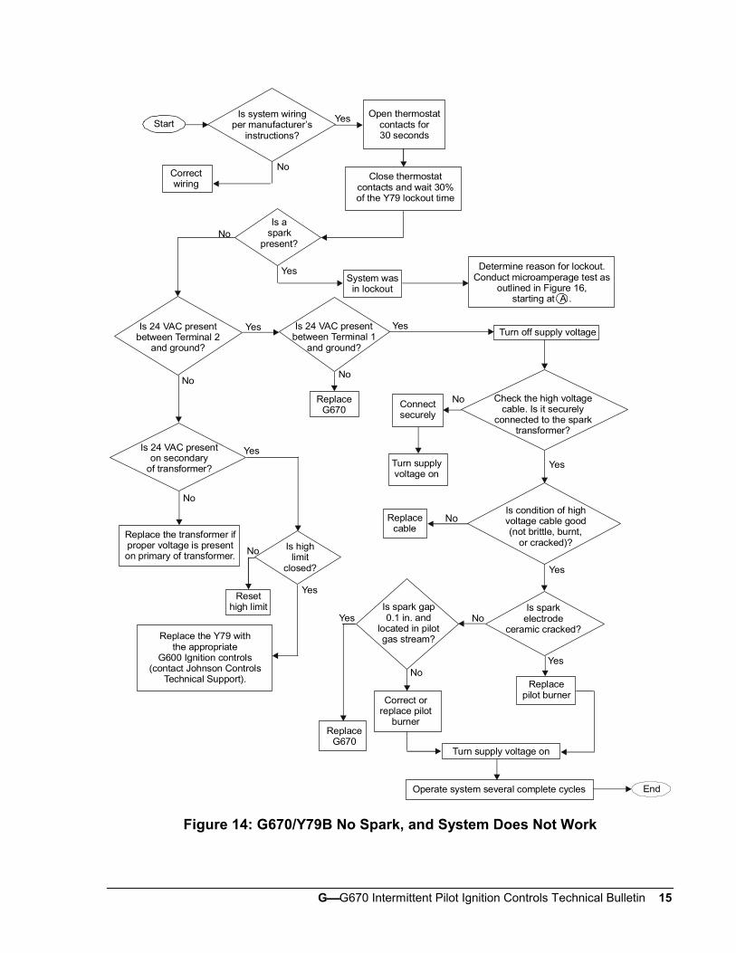
Figure 14: G670/Y79B No Spark, and System Does Not Work
16 GG670 Intermittent Pilot Ignition Controls Technical Bulletin
Yes
No
Connect securely
Yes
No
No
Yes
CorrectNo
Yes
Yes
No
Yes
No
Start
If OK, replace pilot valve.End
Are pilot valve andmain valve connections
secured to the proper Y79terminal and ground?
Open thermostat contactsfor 30 seconds
Close thermostatcontacts
Is 24 VAC presentbetween Terminal 1
and ground on the G670?Wait 30% of the Y79
lockout time.
Is 24 VAC presentbetween ground and pilot valve terminals
of Y79?
Is inletpressure per
manufacturer’sspecifications?
Is gasat pilot?
Make sure the pilot line is notkinked or obstructed. Check
for a clean orifice.
Is spark gap0.1 in. and located inthe pilot gas stream?
Correct or replacepilot burner
Check for drafts.Shield as necessary andcheck for clean orifice.
ReplaceG670
! WARNING: Explosion Hazard.Do not use a match to test for presence of gas.
Replace the Y79 withthe appropriate
G600 ignition control(contact Johnson Controls
Technical Support).
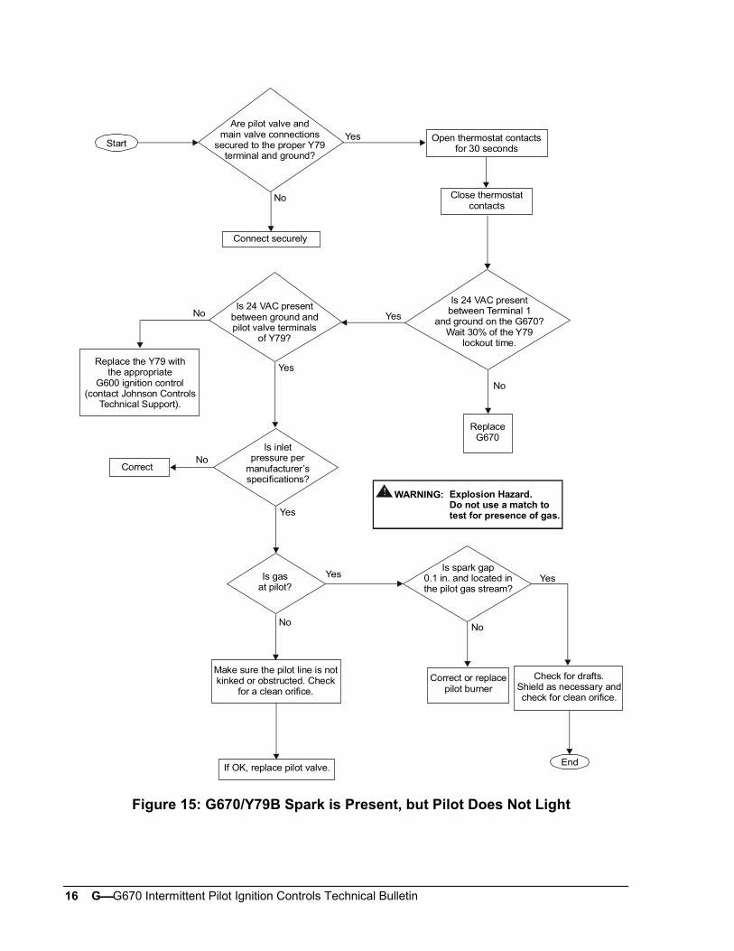
Figure 15: G670/Y79B Spark is Present, but Pilot Does Not Light

GG670 Intermittent Pilot Ignition Controls Technical Bulletin 17
Yes
No Yes No
Yes
No
No
Yes
No
Yes
No
Yes
Start
Yes
No
Yes
NoCorrect
No
Yes
Yes
No
End
A
No
Does spark stay onfor more than 30 seconds
after pilot lights?
Make sure sensor cableand high voltage cable areseparated and not wrapped
around any pipe or accessories.
Is 24 VACbetween Terminal 3
and ground?
ReplaceG670
Is 24 VAC present betweenmain valve terminal on the Y79
and ground terminal on the G670?
Is inlet gas pressureper manufacturer’s
specifications?
Correctgas pressure
Is sensor cablesecurely connectedto Terminal 4 and
flame sensor?
Connectsecurely
Is sensorceramic cracked?
Is main valve wiringsecurely connected tothe main valve terminalon the Y79 and ground?
Connectsecurely
Replacemain valve
Is sensor orsensor connector
shorted out to metalsurface?
Is therecontinuity and good
insulation in thesensor cable?
Replacecable
Is cablegrounded out?
Correct
Replacesensor
Disconnect main valvelead from Terminal 3
Disconnect sensorcable from Terminal 4
Connect DC microammeterbetween sensor cable terminal andTerminal 4. Observe correct polarity.
See Figure 20.
Is DC current0.2 microamperes orgreater with pilot only
operation?
ReplaceG670
Check for:- proper gas pressure- clean pilot assembly- tight mechanical and electrical connections
If there is no improvement, change the flamesensor length or the orifice size, then performany necessary turn down tests.
Replace the Y79 withthe appropriate
G600 ignition control (contact Johnson Controls
Technical Support).
Figure 16: G670/Y79B Pilot Lights, but Main Burner Does Not Come On
18 GG670 Intermittent Pilot Ignition Controls Technical Bulletin
No
Yes
Yes
No
Turn supply voltage on
Yes
No
No
No
YesTurn off supply voltage
No
No
Yes
Yes
No
Yes
Yes
No
No
Start
Yes
Operate system several complete cyclesEnd
Yes
Is system wiringper manufacturer’s
instructions?
Correctwiring
Open thermostatcontact for30 seconds
Close thermostatcontacts and wait 30%of the Y79 lockout time
Is aspark
present?
System wasin lockout
Determine the reason for lockout.Conduct microamperage test as
outlined in Figure 16, starting at A .
Is 24 VAC presentbetween Terminal 2
and ground?
Check the high voltagecable. Is it securely
connected to the sparktransformer?
Connectsecurely
Is 24 VACpresent between
Terminal 1and ground?
ReplaceG670Is 24 VAC present
on secondaryof transformer?
Replace transformer ifproper voltage is presenton primary of transformer
Is highlimit
closed?
Resethigh limit
Turn supplyvoltage on
Replacecable
Is condition of highvoltage cable good(not brittle, burnt,
or cracked)?
Is sparkelectrode ceramic
cracked?
Replacepilot burner
Is spark gap0.1 in. and
located in pilotgas stream?
ReplaceG670
Correct orreplace pilot
burner
Replace the Y79 withthe appropriate
G600 ignition control(contact Johnson Controls
Technical Support).
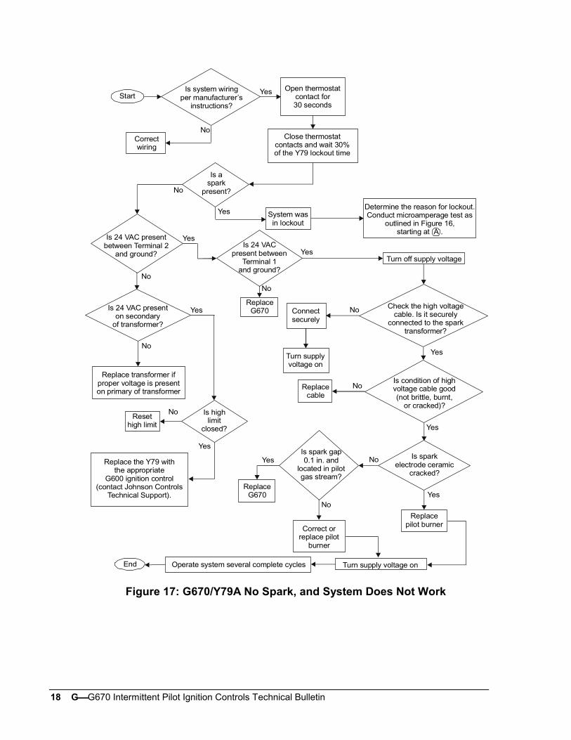
Figure 17: G670/Y79A No Spark, and System Does Not Work
GG670 Intermittent Pilot Ignition Controls Technical Bulletin 19
Yes
NoStart
No
Yes
Yes
No
No
Yes
End
Is pilot valve wiringsecurely connected to
Terminal 1 andground?
Connectsecurely
Make sure pilot line is notkinked or obstructed. Check
for clean orifice.
Replacepilot valve
Is gas at pilot?Is inlet gas pressureper manufacturer’s
specifications?
Correct gaspressure
Is pilot spark gap0.1 in. and located in
pilot gas stream?
Correct orreplace pilot
Check for drafts. Shieldas necessary and check
for clean orifice.
! WARNING: Explosion Hazard.Do not use a match to test for presence of gas.
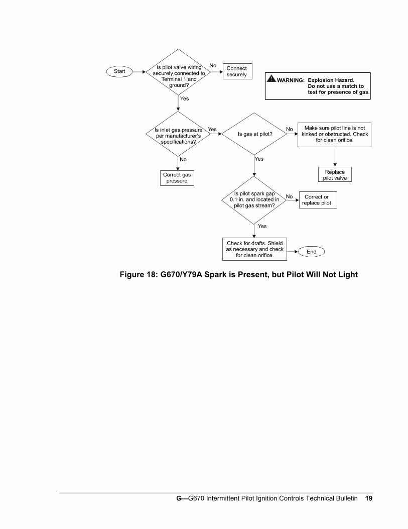
Figure 18: G670/Y79A Spark is Present, but Pilot Will Not Light
20 GG670 Intermittent Pilot Ignition Controls Technical Bulletin
Correct
End
Correct
No No
No
No
No
No No
No
No
No
Yes
Yes
Yes
Yes Yes
Yes
Yes
Yes
Yes
Yes
StartDoes spark stay on
for more than 30 secondsafter the pilot lights?
Is 24 VACbetween Terminal 3
and ground?
Is inlet gas pressureper manufacturer’s
specifications?
Correctgas pressure
ReplaceG670Make sure sensor cable
and high voltage cable areseparated and not wrapped
around any pipe or accessories.
Is sensor cablesecurely connectedto Terminal 4 and
flame sensor?
Connectsecurely
Is mainvalve wiring
securely connected toTerminal 3 and
ground?
Replacemain valve
Is sensorceramic cracked?
Is cablegrounded out?
Is sensor orsensor connector
shorted out to metalsurface?
Is therecontinuity and good
insulation in thesensor cable?
Replacecable
Disconnect main valvelead from Terminal 3
Disconnect sensorcable from Terminal 4
Replacesensor
Connect DC microammeterbetween sensor cable terminal andTerminal 4. Observe correct polarity.
See Figure 20.
ReplaceG670
Is DC current0.2 microamperes orgreater with pilot only
operation?
Check for:- proper gas pressure- clean pilot assembly- tight mechanical and electrical connections
If there is not improvement, change theflame sensor length or the orifice size andperform any necessary turn down tests.
Connectsecurely
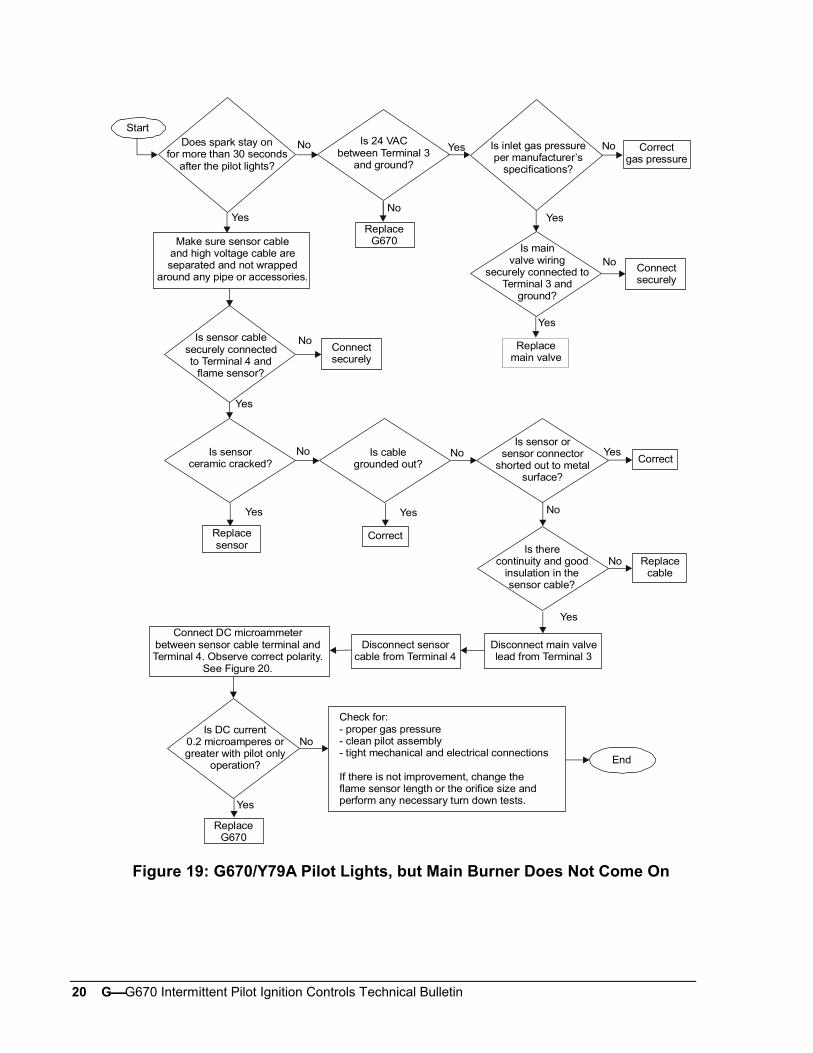
Figure 19: G670/Y79A Pilot Lights, but Main Burner Does Not Come On
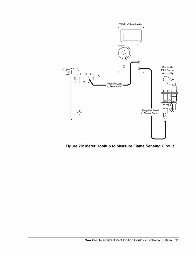
GG670 Intermittent Pilot Ignition Controls Technical Bulletin 21
1 6 2 4 3
Jumper
5
Positive Leadto Terminal 4
Negative Leadto Flame Sensor
ElectrodePilot BurnerAssembly
Y99AU-2 Multimeter
Figure 20: Meter Hookup to Measure Flame Sensing Circuit

22 GG670 Intermittent Pilot Ignition Controls Technical Bulletin
Notes

GG670 Intermittent Pilot Ignition Controls Technical Bulletin 23
Notes

24 GG670 Intermittent Pilot Ignition Controls Technical Bulletin
Notes
Controls Group www.johnsoncontrols.com507 E. Michigan Street FAN 121P.O. Box 423 Installation Sheets ManualMilwaukee, WI 53201 Printed in U.S.A.


![GAS-FIRED STEAM BOILERS · GAS-FIRED STEAM BOILERS INSTALLATION, OPERATION & MAINTENANCE MANUAL P/N# 240009572, Rev. B [07/2012] MODEL PEGDID Electronic Intermittent Ignition An ISO](https://img.pdfslide.net/doc/110x75/5d5f2dac88c993e3528b930c/gas-fired-steam-boilers-gas-fired-steam-boilers-installation-operation-maintenance.jpg)