Embed Size (px)
Citation preview

G6S User Manual V1.6
Copyright © 2013 Gosafe
G6S User Manual
2
ATTENTION!
⃞Do not disassemble the device. Do not touch before unplugging the power supply if the device is
damaged, the power supply cables are not isolated or the isolation is damaged.
⃞All wireless data transferring devices produce interference that may affect other devices which are
placed nearby.
⃞The device may be connected only by qualified individuals.
⃞The device must be firmly fastened in the predefined location.
⃞The device is susceptible to water and humidity.
INSTRUCTIONS OF SAFETY
⃞This chapter contains information on how to operate “G6S” safely.
⃞BY following these requirements and recommendations you will avoid dangerous situations. You must
read these instructions carefully and follow the strictly before operating the device!
⃞The device uses a 8V-32V DC power supply. The nominal voltage is 12V DC. It is advised to transport
the device in an impact-proof package.
⃞Before usage, the device should be placed so that its LED indicators are visible, which show what
status of operation the device is in.
⃞When connecting the connection cables to the vehicle, the appropriate jumpers of the power supply of
the vehicle should be disconnected.
⃞Before dismounting the device from the vehicle, the connection must be disconnected.
G6S User Manual
3
LEGAL NOTICE
Copyright © 2013 Gosafe
All rights reserved. Reproduction, transfer, distribution or storage of part or all of the contents in this
document in any form without the prior written permission of Gosafe is prohibited.
1-Wire is a registered trademark of Dallas Semiconductor.
Other products and company names mentioned herein may be trademarks or trade names of their
respective owners.
INTRODUCTION
The G6S Feature Rich Powerful GPS Tracker is the latest solution for track and trace applications and
extreme level fleet management.
G6S is designed for service providers, integrators, and enterprise customers to enhance mobile
resources and improve their dispatch system; the G6S is a dependable quad-band GSM/GPRS tracking
device, delivering the key features fulfilling the most demanding applications: fleet management,
insurance telemetric, dispatch, vehicle location and recovery, and more.
With accurate GPS location performance, a robust programmable rules engine, 2-axis accelerometer for
measuring driver behavior and vehicle impacts, geo-fencing, messaging and much more, the G6S is
designed for powerful solution deployment. The G6S also includes optional routing and optimization
with Garmin® FMI (Fleet Management Interface) - a key part of today’s fleet management.
The G6S is powered by over-the-air device management and maintenance system, (Programming,
Updates, and Logistics System). FOTA (Firmware update over the air), GSM Jamming detection and 156
hardware based geo-fences makes this the perfect choice for superior safety and security of your
vehicle.
G6S User Manual
4
ContentsATTENTION! ....................................................................... 2
INSTRUCTIONS OF SAFETY ................................................. 2
LEGAL NOTICE .................................................................... 3
INTRODUCTION .................................................................. 3
1. Packing List ..................................................................... 5
2. Specifications ................................................................. 6
3. Overview ........................................................................ 7
4. Installation ..................................................................... 9
5. I/O Connector .............................................................. 11
6. LED Indicator Behavior ................................................. 12
7. User Command ............................................................. 13
8. Message Explanation ................................................... 15
Appendix .......................................................................... 18
Optional accessory ....................................................... 18

G6S User Manual
5
1. Packing List
■Standard
The G6S box is packaged with all the components that is necessary for operation, it contains:
⃞G6S device x1
⃞2*8/2*5 PIN I/O connector cable x1
To connect with external
power supply and optional
accessory
To the back panel I/O
connector of device
NOTE: SIM card which for GSM/GPRS connectivity is not supplied in the package, please consult your
local SIM provider for further information.
■Optional accessory
Name Purpose
USB cable To configure device via configuration tool on computer
External GPS antenna It helps to fix GPS faster
Microphone It enables device for voice monitoring features
*Speaker It enables device for voice conversation
*iButton For driver ID verification via 1WIRE link
*DS18B20 Temperature sensor via 1WIRE link
Immobilizer It enables the device to kill/restore engine
Panic button Device reports or calls when this button being pressed
*DB9 cable Communicate with computer via RS232 serial link
*GARMIN cable Communicate with GARMIN PND
Magic tape It helps to attach device firmly
Fuse Protecting device from electrical surge
Backup battery Rechargeable, Li-Po 3.7V, 250mAh
NOTE: * indicates only for G6S
Please refer chapter Appendix for further details and installation guide for optional accessory
G6S User Manual
6
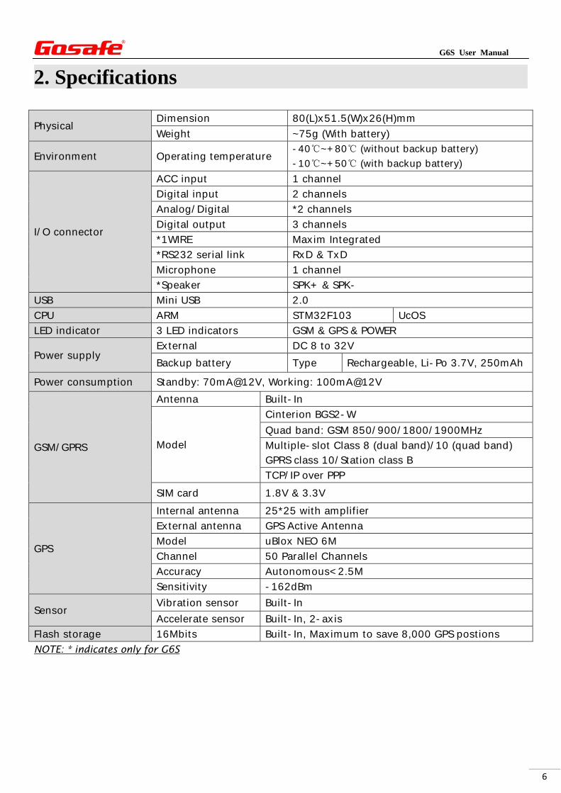
2. Specifications
Physical Dimension 80(L)x51.5(W)x26(H)mm
Weight ~75g (With battery)
Environment Operating temperature -40℃~+80℃ (without backup battery)
-10℃~+50℃ (with backup battery)
I/O connector
ACC input 1 channel
Digital input 2 channels
Analog/Digital *2 channels
Digital output 3 channels
*1WIRE Maxim Integrated
*RS232 serial link RxD & TxD
Microphone 1 channel
*Speaker SPK+ & SPK-
USB Mini USB 2.0
CPU ARM STM32F103 UcOS
LED indicator 3 LED indicators GSM & GPS & POWER
Power supply External DC 8 to 32V
Backup battery Type Rechargeable, Li-Po 3.7V, 250mAh
Power consumption Standby: 70mA@12V, Working: 100mA@12V
GSM/GPRS
Antenna Built-In
Model
Cinterion BGS2-W
Quad band: GSM 850/900/1800/1900MHz
Multiple-slot Class 8 (dual band)/10 (quad band) GPRS class 10/Station class B
TCP/IP over PPP
SIM card 1.8V & 3.3V
GPS
Internal antenna 25*25 with amplifier
External antenna GPS Active Antenna
Model uBlox NEO 6M
Channel 50 Parallel Channels
Accuracy Autonomous<2.5M
Sensitivity -162dBm
Sensor Vibration sensor Built-In
Accelerate sensor Built-In, 2-axis
Flash storage 16Mbits Built-In, Maximum to save 8,000 GPS postions
NOTE: * indicates only for G6S
G6S User Manual
7
3. Overview
3.1. Device Capabilities
FOTA, Firmware Upgrade Over The Air
Flexible Programming Rules
Garmin® FMI
1-Wire® Interface
GSM Jamming Detection
Quad Band GSM Modem
HDOP For Precise Location
Multiple Data Upload Modes
2-Axis Accelerometer Sensor
156 Hardware Based Geo-Fence/Point of interest
Over Speed Management
Multiple Inputs & Outputs
Configurable Inputs & Outputs
Internal Backup Battery
G6S User Manual
8
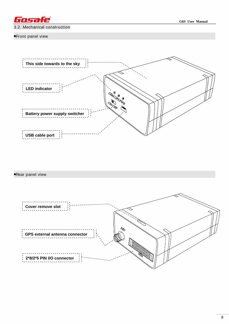
3.2. Mechanical construction
■Front panel view
■Rear panel view
Battery power supply switcher
USB cable port
2*8/2*5 PIN I/O connector
GPS external antenna connector
LED indicator
This side towards to the sky
Cover remove slot
G6S User Manual
9
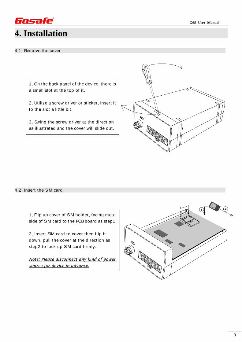
4. Installation
4.1. Remove the cover
4.2. Insert the SIM card
1, On the back panel of the device, there is
a small slot at the top of it.
2, Utilize a screw driver or sticker, insert it
to the slot a little bit.
3, Swing the screw driver at the direction
as illustrated and the cover will slide out.
1, Flip up cover of SIM holder, facing metal
side of SIM card to the PCB board as step1.
2, Insert SIM card to cover then flip it
down, pull the cover at the direction as
step2 to lock up SIM card firmly.
Note: Please disconnect any kind of power
source for device in advance.
G6S User Manual
10
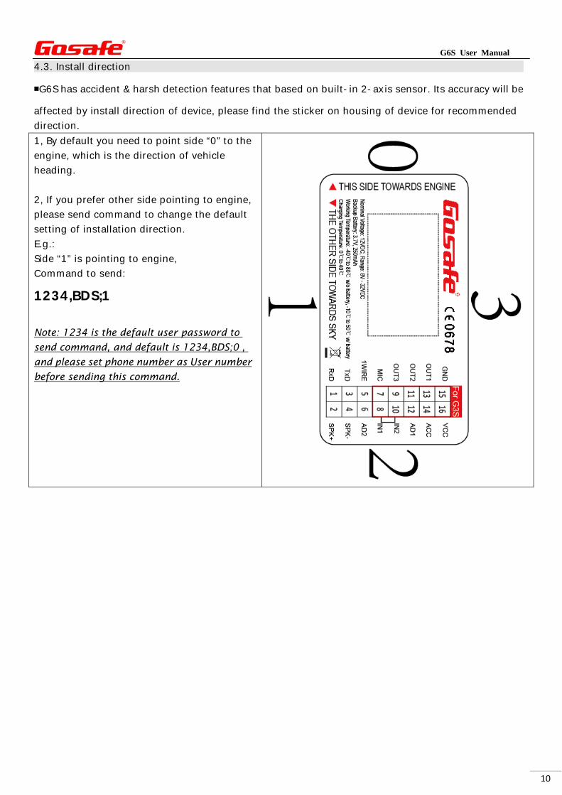
4.3. Install direction
■G6S has accident & harsh detection features that based on built-in 2-axis sensor. Its accuracy will be
affected by install direction of device, please find the sticker on housing of device for recommended
direction.
1, By default you need to point side “0” to the
engine, which is the direction of vehicle
heading.
2, If you prefer other side pointing to engine,
please send command to change the default
setting of installation direction.
E.g.:
Side “1” is pointing to engine,
Command to send:
1234,BDS;1 Note: 1234 is the default user password to
send command, and default is 1234,BDS;0 ,
and please set phone number as User number
before sending this command.
G6S User Manual
11
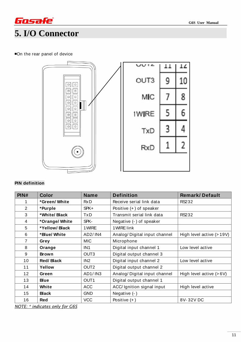
5. I/O Connector
■On the rear panel of device
PIN definition
NOTE: * indicates only for G6S
PIN# Color Name Definition Remark/Default 1 *Green/White RxD Receive serial link data RS232
2 *Purple SPK+ Positive (+) of speaker
3 *White/Black TxD Transmit serial link data RS232
4 *Orange/White SPK- Negative (-) of speaker
5 *Yellow/Black 1WIRE 1WIRE link
6 *Blue/White AD2/IN4 Analog/Digital input channel High level active (>19V)
7 Grey MIC Microphone
8 Orange IN1 Digital input channel 1 Low level active
9 Brown OUT3 Digital output channel 3
10 Red/Black IN2 Digital input channel 2 Low level active
11 Yellow OUT2 Digital output channel 2
12 Green AD1/IN3 Analog/Digital input channel High level active (>6V)
13 Blue OUT1 Digital output channel 1
14 White ACC ACC/Ignition signal input High level active
15 Black GND Negative (-)
16 Red VCC Positive (+) 8V-32V DC
G6S User Manual
12
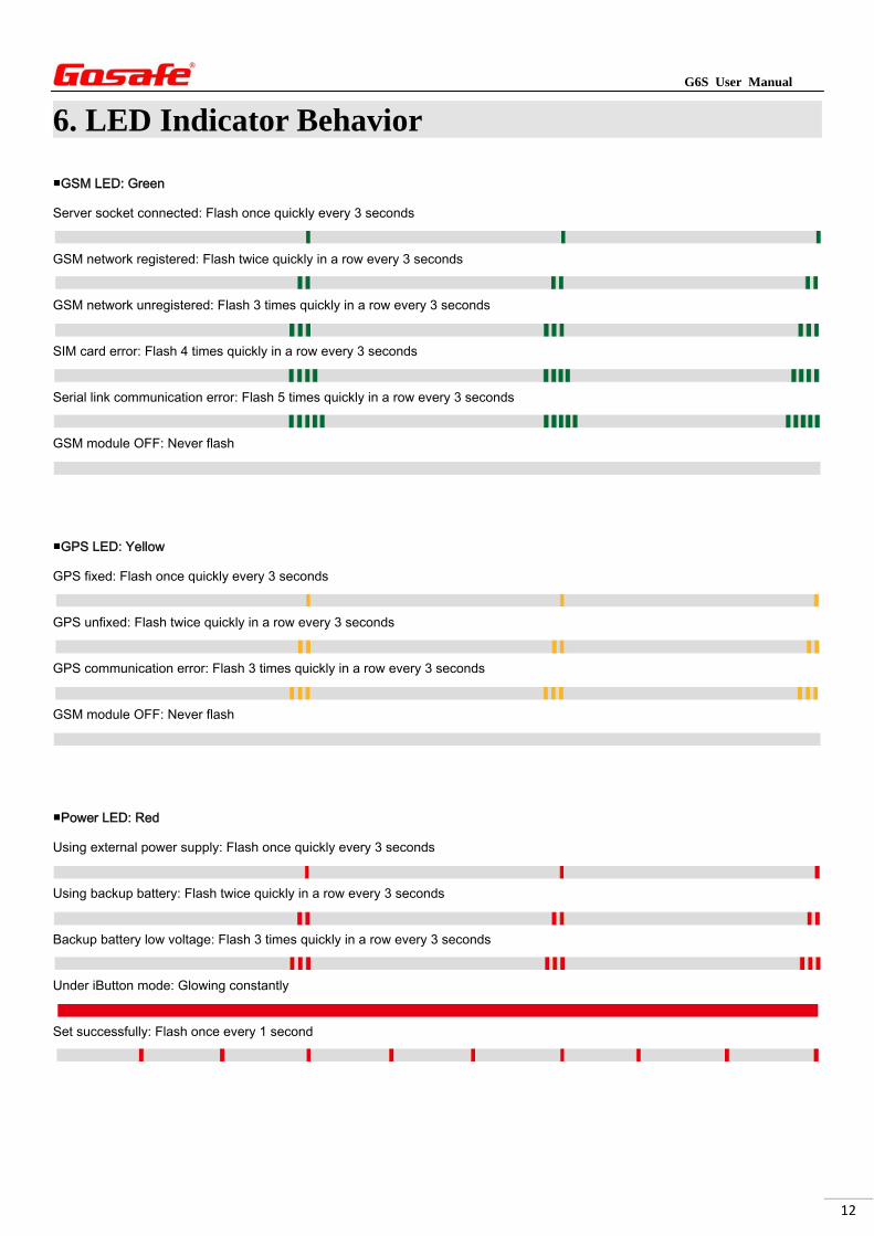
6. LED Indicator Behavior
■GSM LED: Green
Server socket connected: Flash once quickly every 3 seconds
GSM network registered: Flash twice quickly in a row every 3 seconds
GSM network unregistered: Flash 3 times quickly in a row every 3 seconds
SIM card error: Flash 4 times quickly in a row every 3 seconds
Serial link communication error: Flash 5 times quickly in a row every 3 seconds
GSM module OFF: Never flash
■GPS LED: Yellow
GPS fixed: Flash once quickly every 3 seconds
GPS unfixed: Flash twice quickly in a row every 3 seconds
GPS communication error: Flash 3 times quickly in a row every 3 seconds
GSM module OFF: Never flash
■Power LED: Red
Using external power supply: Flash once quickly every 3 seconds
Using backup battery: Flash twice quickly in a row every 3 seconds
Backup battery low voltage: Flash 3 times quickly in a row every 3 seconds
Under iButton mode: Glowing constantly
Set successfully: Flash once every 1 second
G6S User Manual
13
7. User Command
■Set User Phone Number
There are 2 users phone supported by G6S, they have the same authorization.
User1’s command words are UNO0, UPW0, USP0.
User2’s command words are UNO1, UPW1, USP1. Below will take user1 as example:
To set your cell phone number as User1 to control and receive messages from device, please send
UNO command to the device, e.g.:
1234,UNO0;+8613912345678 Or
1234,UNO0;13912345678 Explanations:
1234: Default password.
UNO0: Command control word for setting user number.
+8613912345678: Phone number with country code.
13912345678: Phone number without country code.
Device is supposed to reply a confirmation SMS to you, if the device does not accept the command,
it also reply a message with content: Command err.
■Modify User Password
Factory default password 1234 Changing the factory password at the first usage is highly suggested.
New password should be 4 digits that from number “0-9”.
To modify password, send UPW command from your USER phone number, e.g.:
1234,UPW0;5678 Explanations:
1234: Factory Password
UPW0: Command control word for setting new password
5678: New Password
■Set position report interval to user phone
Device is able to report its current position periodically according to the setting, default is every 30
minutes. To change it please send USP command, e.g.:
1234,USP0;0;30S;G;W
G6S User Manual
14
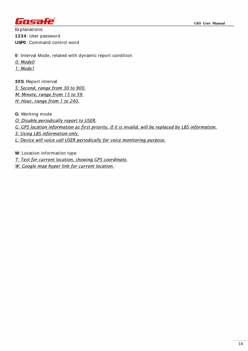
Explanations:
1234: User password
USP0: Command control word
0: Interval Mode, related with dynamic report condition
0: Mode0
1: Mode1
30S: Report interval
S: Second, range from 30 to 900.
M: Minute, range from 15 to 59.
H: Hour, range from 1 to 240.
G: Working mode
O: Disable periodically report to USER.
G: GPS location information as first priority, if it is invalid, will be replaced by LBS information.
S: Using LBS information only.
L: Device will voice call USER periodically for voice monitoring purpose.
W: Location information type
T: Text for current location, showing GPS coordinate.
W: Google map hyper link for current location.
G6S User Manual
15
8. Message Explanation
■Periodical SMS report
Below are the different kinds of message will be received by user periodically according to the setting of
command USP, example on G6S.
“W” mode
1. GPS is fixed
Content of message Explanation
G6S V1.00
LTM 2013-06-06 14:17:12
http://maps.google.com/maps?q...
GSM -52dBm
EXT_PWR=12.08V
BAT=3.86V
#30
Device name/Firmware version
Date/Time
Google map hyper link
GSM network signal strength
External power voltage
Built-in battery voltage
Consumed messages
There are 2 kinds of map hyper link available, static and dynamic, it depends on the setting of
command USP, e.g.:
Static link:
http://maps.google.com/staticmap?zoom=14&size=300x300&markers =%n(,%e&sensor=false Dynamic link:
URL0;http://maps.google.com/maps?q=%n(,%e&t=m&z=16
2. GPS is not fixed
Map hyper link will be LBS (URL1) instead of GPS (URL0)
Content of message Explanation
G6S V1.00
LTM 2013-06-06 14:17:12
http://maps.google.com/maps?q...
GSM -52dBm
EXT_PWR=12.08V
BAT=3.86V
#30
Device name/Firmware version
Date/Time
Google map hyper link
GSM network signal strength
External power voltage
Built-in battery voltage
Consumed messages
G6S User Manual
16
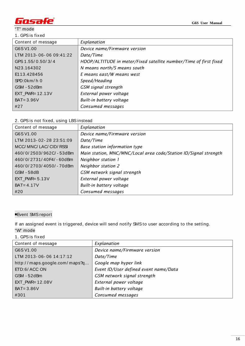
“T” mode
1. GPS is fixed
Content of message Explanation
G6S V1.00
LTM 2013-06-06 09:41:22
GPS 1.55/0.50/3/4
N23.164302
E113.428456
SPD:0km/h 0
GSM -52dBm
EXT_PWR=12.13V
BAT=3.96V
#27
Device name/Firmware version
Date/Time
HDOP/ALTITUDE in meter/Fixed satellite number/Time of first fixed
N means north/S means south
E means east/W means west
Speed/Heading
GSM signal strength
External power voltage
Built-in battery voltage
Consumed messages
2. GPS is not fixed, using LBS instead
Content of message Explanation
G6S V1.00
LTM 2013-02-28 23:51:09
MCC/MNC/LAC/CID/RSSI
460/0/2503/962C/-53dBm
460/0/2731/40F4/-60dBm
460/0/2703/4050/-70dBm
GSM -58dB
EXT_PWR=5.13V
BAT=4.17V
#20
Device name/Firmware version
Date/Time
Base station information type
Main station, MNC/MNC/Local area code/Station ID/Signal strength
Neighbor station 1
Neighbor station 2
GSM network signal strength
External power voltage
Built-in battery voltage
Consumed messages
■Event SMS report
If an assigned event is triggered, device will send notify SMS to user according to the setting.
“W” mode
1. GPS is fixed
Content of message Explanation
G6S V1.00
LTM 2013-06-06 14:17:12
http://maps.google.com/maps?q...
ETD:6/ACC ON
GSM -52dBm
EXT_PWR=12.08V
BAT=3.86V
#301
Device name/Firmware version
Date/Time
Google map hyper link
Event ID/User defined event name/Data
GSM network signal strength
External power voltage
Built-in battery voltage
Consumed messages
G6S User Manual
17
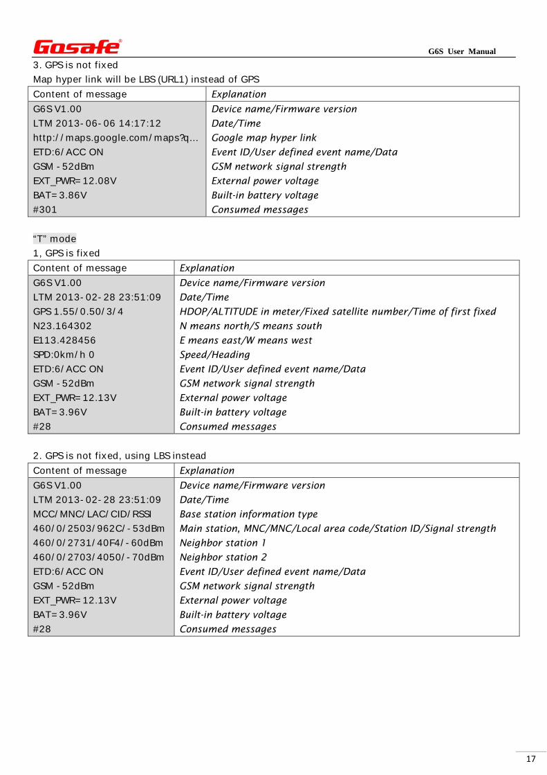
3. GPS is not fixed
Map hyper link will be LBS (URL1) instead of GPS
Content of message Explanation
G6S V1.00
LTM 2013-06-06 14:17:12
http://maps.google.com/maps?q...
ETD:6/ACC ON
GSM -52dBm
EXT_PWR=12.08V
BAT=3.86V
#301
Device name/Firmware version
Date/Time
Google map hyper link
Event ID/User defined event name/Data
GSM network signal strength
External power voltage
Built-in battery voltage
Consumed messages
“T” mode
1, GPS is fixed
Content of message Explanation
G6S V1.00
LTM 2013-02-28 23:51:09
GPS 1.55/0.50/3/4
N23.164302
E113.428456
SPD:0km/h 0
ETD:6/ACC ON
GSM -52dBm
EXT_PWR=12.13V
BAT=3.96V
#28
Device name/Firmware version
Date/Time
HDOP/ALTITUDE in meter/Fixed satellite number/Time of first fixed
N means north/S means south
E means east/W means west
Speed/Heading
Event ID/User defined event name/Data
GSM network signal strength
External power voltage
Built-in battery voltage
Consumed messages
2. GPS is not fixed, using LBS instead
Content of message Explanation
G6S V1.00
LTM 2013-02-28 23:51:09
MCC/MNC/LAC/CID/RSSI
460/0/2503/962C/-53dBm
460/0/2731/40F4/-60dBm
460/0/2703/4050/-70dBm
ETD:6/ACC ON
GSM -52dBm
EXT_PWR=12.13V
BAT=3.96V
#28
Device name/Firmware version
Date/Time
Base station information type
Main station, MNC/MNC/Local area code/Station ID/Signal strength
Neighbor station 1
Neighbor station 2
Event ID/User defined event name/Data
GSM network signal strength
External power voltage
Built-in battery voltage
Consumed messages
G6S User Manual
18
Appendix
Optionalaccessory
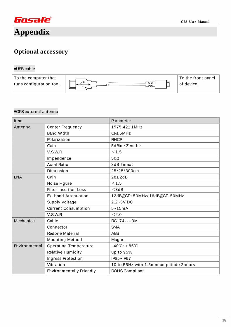
■USB cable
To the computer that
runs configuration tool
To the front panel
of device
■GPS external antenna
Item Parameter
Antenna Center Frequency 1575.42±1MHz
Band Width CF±5MHz
Polarization RHCP
Gain 5dBic(Zenith)
V.S.W.R <1.5
Impendence 50Ω
Axial Ratio 3dB(max)
Dimension 25*25*300cm
LNA Gain 28±2dB
Noise Figure <1.5
Filter Insertion Loss <3dB
Ex-band Attenuation 12dB@CF+50MHz/16dB@CF-50MHz
Supply Voltage 2.2~5V DC
Current Consumption 5~15mA
V.S.W.R <2.0
Mechanical Cable RG174---3M
Connector SMA
Redone Material ABS
Mounting Method Magnet
Environmental Operating Temperature -40℃~+85℃
Relative Humidity Up to 95%
Ingress Protection IP65~IP67
Vibration 10 to 55Hz with 1.5mm amplitude 2hours
Environmentally Friendly ROHS Compliant
G6S User Manual
19
Expose this terminal
under the sky
To the rear panel of device,
GPS antenna connector
■Microphone
Item Parameter
Length 3 meters
Material Al-Si
Output impedance 2.2Kohm
Sensitivity -30db to 60db
Frequency 50HZ to1600HZ
Channel Stereo
PIN15
PIN7
Black wire: To PIN15
Red wire: To PIN7
This accessory is necessary
for voice related
functionalities.
■Speaker
Item Parameter
Length 3 meters
Impedance 16ohm
Sensitivity 96db/W
Frequency 50HZ to1600HZ
Signal to noise ratio 75db
Power consumption 1W
PIN16
PIN15
PIN4
PIN2
Red: To PIN16
Black: To PIN15
White: To PIN4
Blue: To PIN2
This accessory is
necessary for voice
related functionalities.
G6S User Manual
20
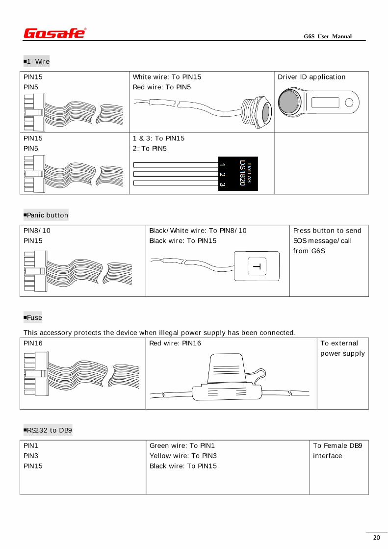
■1-Wire
PIN15
PIN5
White wire: To PIN15
Red wire: To PIN5
Driver ID application
PIN15
PIN5
1 & 3: To PIN15
2: To PIN5
■Panic button
PIN8/10
PIN15
Black/White wire: To PIN8/10
Black wire: To PIN15
Press button to send
SOS message/call
from G6S
■Fuse
This accessory protects the device when illegal power supply has been connected.
PIN16
Red wire: PIN16
To external
power supply
■RS232 to DB9
PIN1
PIN3
PIN15
Green wire: To PIN1
Yellow wire: To PIN3
Black wire: To PIN15
To Female DB9
interface
G6S User Manual
21
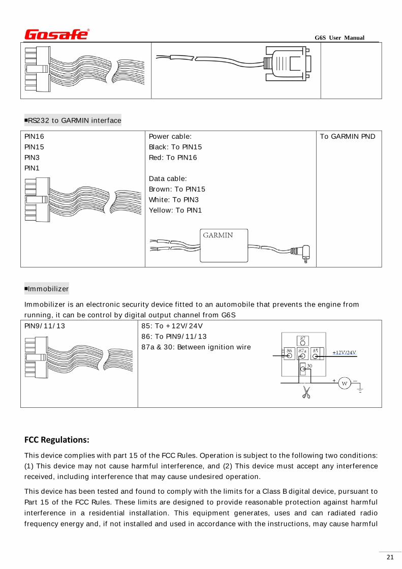
■RS232 to GARMIN interface
PIN16
PIN15
PIN3
PIN1
Power cable:
Black: To PIN15
Red: To PIN16
Data cable:
Brown: To PIN15
White: To PIN3
Yellow: To PIN1
To GARMIN PND
■Immobilizer
Immobilizer is an electronic security device fitted to an automobile that prevents the engine from
running, it can be control by digital output channel from G6S
PIN9/11/13
85: To +12V/24V
86: To PIN9/11/13
87a & 30: Between ignition wire
FCC Regulations:
This device complies with part 15 of the FCC Rules. Operation is subject to the following two conditions:
(1) This device may not cause harmful interference, and (2) This device must accept any interference
received, including interference that may cause undesired operation.
This device has been tested and found to comply with the limits for a Class B digital device, pursuant to
Part 15 of the FCC Rules. These limits are designed to provide reasonable protection against harmful
interference in a residential installation. This equipment generates, uses and can radiated radio
frequency energy and, if not installed and used in accordance with the instructions, may cause harmful
G6S User Manual
22
interference to radio communications. However, there is no guarantee that interference will not occur in
a particular installation If this equipment does cause harmful interference to radio or television
reception, which can be determined by turning the equipment off and on, the user is encouraged to try
to correct the interference by one or more of the following measures:
-Reorient or relocate the receiving antenna.
-Increase the separation between the equipment and receiver.
-Connect the equipment into an outlet on a circuit different from that to which the receiver is
connected.
-Consult the dealer or an experienced radio/TV technician for help.
Caution: Changes or modifications not expressly approved by the party responsible for compliance
could void the user‘s authority to operate the equipment.
RF Exposure Information
This device complies with FCC radiation exposure limits set forth for an uncontrolled environment. In
order to avoid the possibility of exceeding the FCC radio frequency exposure limits, human proximity to
the antenna shall not be less than 20cm (8 inches) during normal operation.