Embed Size (px)
Citation preview
1
G6S
G6SSurface-mounting Relay
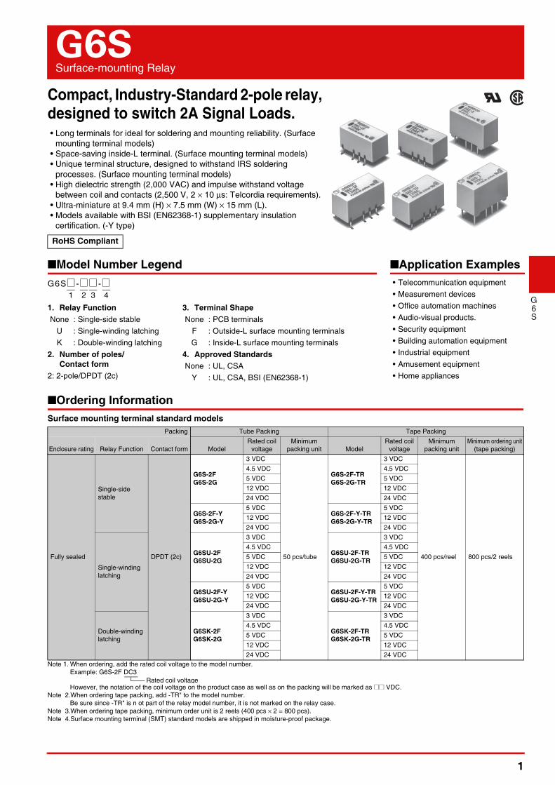
Compact, Industry-Standard 2-pole relay, designed to switch 2A Signal Loads.• Long terminals for ideal for soldering and mounting reliability. (Surface
mounting terminal models)• Space-saving inside-L terminal. (Surface mounting terminal models)• Unique terminal structure, designed to withstand IRS soldering
processes. (Surface mounting terminal models)• High dielectric strength (2,000 VAC) and impulse withstand voltage
between coil and contacts (2,500 V, 2 × 10 μs: Telcordia requirements).• Ultra-miniature at 9.4 mm (H) × 7.5 mm (W) × 15 mm (L).• Models available with BSI (EN62368-1) supplementary insulation
certification. (-Y type)
■Model Number Legend
■Ordering Information Surface mounting terminal standard models
Note 1. When ordering, add the rated coil voltage to the model number. Example: G6S-2F DC3
However, the notation of the coil voltage on the product case as well as on the packing will be marked as @@ VDC.Note 2.When ordering tape packing, add -TR" to the model number.
Be sure since -TR" is n ot part of the relay model number, it is not marked on the relay case.Note 3.When ordering tape packing, minimum order unit is 2 reels (400 pcs × 2 = 800 pcs).Note 4.Surface mounting terminal (SMT) standard models are shipped in moisture-proof package.
RoHS Compliant
Packing Tube Packing Tape Packing
Enclosure rating Relay Function Contact form ModelRated coil
voltageMinimum
packing unit ModelRated coil
voltageMinimum
packing unitMinimum ordering unit
(tape packing)
Fully sealed
Single-side stable
DPDT (2c)
G6S-2FG6S-2G
3 VDC
50 pcs/tube
G6S-2F-TRG6S-2G-TR
3 VDC
400 pcs/reel 800 pcs/2 reels
4.5 VDC 4.5 VDC5 VDC 5 VDC12 VDC 12 VDC24 VDC 24 VDC
G6S-2F-YG6S-2G-Y
5 VDCG6S-2F-Y-TRG6S-2G-Y-TR
5 VDC12 VDC 12 VDC24 VDC 24 VDC
Single-winding latching
G6SU-2FG6SU-2G
3 VDC
G6SU-2F-TRG6SU-2G-TR
3 VDC4.5 VDC 4.5 VDC5 VDC 5 VDC12 VDC 12 VDC24 VDC 24 VDC
G6SU-2F-YG6SU-2G-Y
5 VDCG6SU-2F-Y-TRG6SU-2G-Y-TR
5 VDC12 VDC 12 VDC24 VDC 24 VDC
Double-winding latching
G6SK-2FG6SK-2G
3 VDC
G6SK-2F-TRG6SK-2G-TR
3 VDC4.5 VDC 4.5 VDC5 VDC 5 VDC12 VDC 12 VDC24 VDC 24 VDC
1. Relay FunctionNone : Single-side stable
U : Single-winding latchingK : Double-winding latching
2. Number of poles/ Contact form
2: 2-pole/DPDT (2c)
G6S@ -@@ -@1 2 3 4
3. Terminal ShapeNone : PCB terminals
F : Outside-L surface mounting terminalsG : Inside-L surface mounting terminals
4. Approved StandardsNone : UL, CSA
Y : UL, CSA, BSI (EN62368-1)
■Application Examples• Telecommunication equipment• Measurement devices• Office automation machines• Audio-visual products.• Security equipment• Building automation equipment• Industrial equipment• Amusement equipment• Home appliances
Rated coil voltage
2
G6S Surface-mounting Relay
G6S
●PCB Terminal Standard Models
Note 1. When ordering, add the rated coil voltage to the model number.Example: G6S-2 DC3
However, the notation of the coil voltage on the product case as well as on the packing will be marked as @@ VDC.Note 2.PCB terminal standard types do not require moisture proof packaging and therefore shipped in non-moisture-proof package.
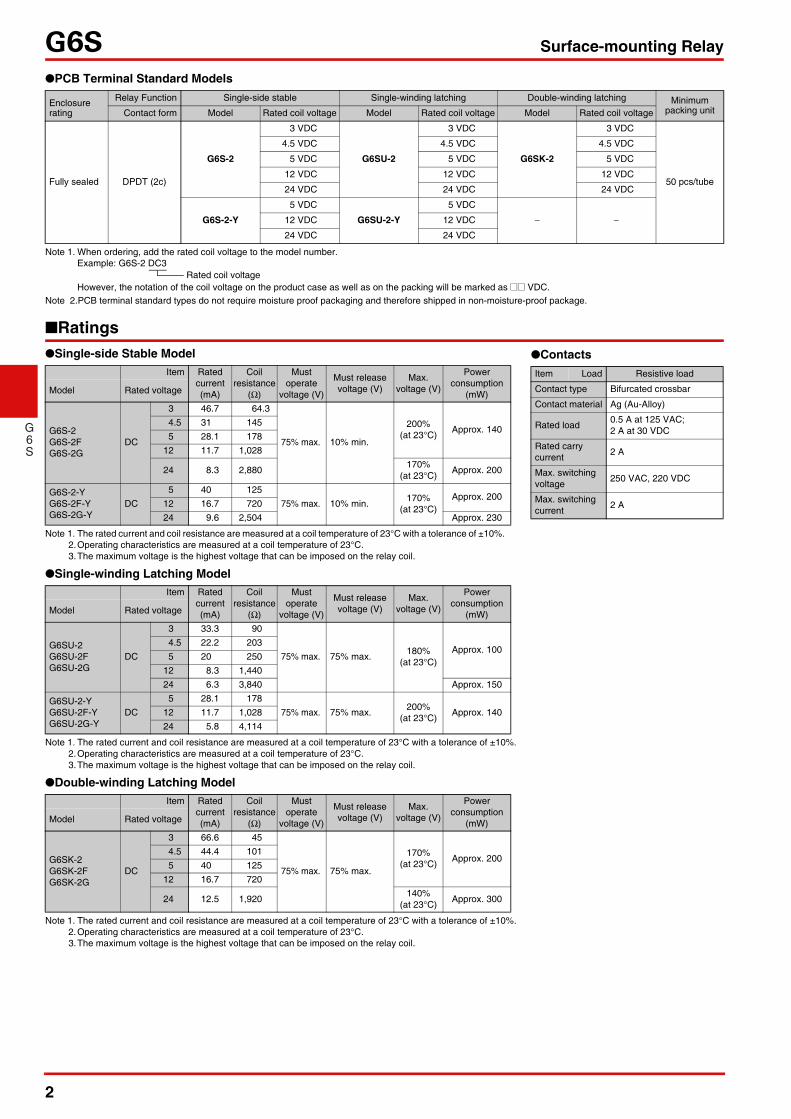
■Ratings●Single-side Stable Model
Note 1. The rated current and coil resistance are measured at a coil temperature of 23°C with a tolerance of ±10%. 2.Operating characteristics are measured at a coil temperature of 23°C. 3.The maximum voltage is the highest voltage that can be imposed on the relay coil.
●Single-winding Latching Model
Note 1. The rated current and coil resistance are measured at a coil temperature of 23°C with a tolerance of ±10%. 2.Operating characteristics are measured at a coil temperature of 23°C. 3.The maximum voltage is the highest voltage that can be imposed on the relay coil.
●Double-winding Latching Model
Note 1. The rated current and coil resistance are measured at a coil temperature of 23°C with a tolerance of ±10%. 2.Operating characteristics are measured at a coil temperature of 23°C. 3.The maximum voltage is the highest voltage that can be imposed on the relay coil.
Enclosure rating
Relay Function Single-side stable Single-winding latching Double-winding latching Minimum packing unitContact form Model Rated coil voltage Model Rated coil voltage Model Rated coil voltage
Fully sealed DPDT (2c)
G6S-2
3 VDC
G6SU-2
3 VDC
G6SK-2
3 VDC
50 pcs/tube
4.5 VDC 4.5 VDC 4.5 VDC
5 VDC 5 VDC 5 VDC
12 VDC 12 VDC 12 VDC
24 VDC 24 VDC 24 VDC
G6S-2-Y
5 VDC
G6SU-2-Y
5 VDC
− −12 VDC 12 VDC
24 VDC 24 VDC
Item Rated current (mA)
Coil resistance
(Ω)
Must operate
voltage (V)
Must release voltage (V)
Max. voltage (V)
Power consumption
(mW)Model Rated voltage
G6S-2G6S-2FG6S-2G
DC
3 46.7 64.3
75% max. 10% min.
200% (at 23°C) Approx. 140
4.5 31 1455 28.1 178
12 11.7 1,028
24 8.3 2,880 170% (at 23°C) Approx. 200
G6S-2-YG6S-2F-YG6S-2G-Y
DC5 40 125
75% max. 10% min. 170% (at 23°C)
Approx. 20012 16.7 72024 9.6 2,504 Approx. 230
Item Rated current (mA)
Coil resistance
(Ω)
Must operate
voltage (V)
Must release voltage (V)
Max. voltage (V)
Power consumption
(mW)Model Rated voltage
G6SU-2G6SU-2FG6SU-2G
DC
3 33.3 90
75% max. 75% max. 180% (at 23°C)
Approx. 1004.5 22.2 2035 20 250
12 8.3 1,44024 6.3 3,840 Approx. 150
G6SU-2-YG6SU-2F-YG6SU-2G-Y
DC5 28.1 178
75% max. 75% max. 200% (at 23°C) Approx. 14012 11.7 1,028
24 5.8 4,114
Item Rated current (mA)
Coil resistance
(Ω)
Must operate
voltage (V)
Must release voltage (V)
Max. voltage (V)
Power consumption
(mW)Model Rated voltage
G6SK-2G6SK-2FG6SK-2G
DC
3 66.6 45
75% max. 75% max.
170% (at 23°C) Approx. 200
4.5 44.4 1015 40 125
12 16.7 720
24 12.5 1,920 140% (at 23°C) Approx. 300
Rated coil voltage
●ContactsItem Load Resistive load
Contact type Bifurcated crossbar
Contact material Ag (Au-Alloy)
Rated load 0.5 A at 125 VAC; 2 A at 30 VDC
Rated carry current 2 A
Max. switching voltage 250 VAC, 220 VDC
Max. switching current 2 A
3
G6S Surface-mounting Relay
G6S
■Characteristics
Note: The above values are initial values.*1. The contact resistance was measured with 10 mA at 1 VDC with a voltage drop method.*2. The insulation resistance was measured with a 500 VDC megohmmeter applied to the same parts as those used for checking the dielectric strength (except
between the set and reset coil).*3. This value was measured at a switching frequency of 120 operations/min and the criterion of contact resistance is 50 Ω. This value may vary, depending on
switching frequency, operating conditions, expected reliability level of the relay, etc. It is always recommended to double-check relay suitability under actual load conditions.
■Engineering Data
Item Relay FunctionSingle-side Stable
G6S-2, G6S-2F, G6S-2G
Single-winding LatchingG6SU-2, G6SU-2F, G6SU-2G
Double-winding LatchingG6SK-2, G6SK-2F, G6SK-2G
Single-side StableG6S-2F-Y, G6S-2G-Y, G6S-2-Y
Single-winding LatchingG6SU-2-Y,
G6SU-2F-Y,G6SU-2G-Y
Contact resistance *1 75 mΩ max.Operate (set) time 4 ms max.Release (reset) time 4 ms max.Min. set/reset pulse width − 10 ms − 10 msInsulation resistance *2 1,000 MΩ min. (at 500 VDC)
Dielectric strength
Between coil and contacts 2,000 VAC, 50/60 Hz for 1 min 1,000 VAC, 50/60 Hz for 1 min 2,000 VAC, 50/60 Hz for 1 min
Between contacts of different polarity 1,500 VAC, 50/60 Hz for 1 minBetween contacts of the same polarity 1,000 VAC, 50/60 Hz for 1 min
Between set and reset coil − 500 VAC, 50/60 Hz for 1 min −
Insulation distance Between coil and contacts Clearance: 1 mm, Creepage: 1.5 mm Clearance: 2 mm, Creepage: 2 mm
Impulse withstand voltage
Between coil and contacts 2,500 V (2 × 10 μs); 1,500 V (10 × 160 μs) 1,500 V (10 × 160 μs)
2,500 V (2 × 10 μs); 1,500 V (10 × 160 μs)
Between contacts of different polarity 2,500 V (2 × 10 μs); 1,500 V (10 × 160 μs)Between contacts of the same polarity 1,500 V (10 × 160 μs)
Vibration resistance
Destruction 10 to 55 to 10 Hz, 2.5 mm single amplitude (5 mm double amplitude)Malfunction 10 to 55 to 10 Hz, 1.65 mm single amplitude (3.3 mm double amplitude)
Shock resistance
Destruction 1,000 m/s2
Malfunction 750 m/s2
DurabilityMechanical 100,000,000 operations min. (at 36,000 operations/hr)
Electrical 100,000 operations min. for AC (at 1,800 operations/h with rated load) 100,000 operations min. for DC (at 1,200 operations/h with rated load)
Failure rate (P level) (reference value) *3 10 μA at 10 m VDC
Ambient operating temperature -40°C to 85°C (with no icing or condensation), and -40°C to 70°C (with no icing or condensation) only for double-winding latching 24 VDC and -Y type 24 VDC
Ambient operating humidity 5% to 85%Weight Approx. 2 g
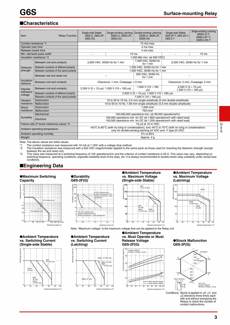
●Maximum Switching Capacity
●DurabilityG6S-2F(G)
●Ambient Temperature vs. Maximum Voltage(Single-side Stable)
●Ambient Temperature vs. Maximum Voltage(Latching)
Note: “Maximum voltage” is the maximum voltage that can be applied to the Relay coil.
●Ambient Temperature vs. Switching Current(Single-side Stable)
●Ambient Temperature vs. Switching Current(Latching)
●Ambient Temperature vs. Must Operate or Must Release VoltageG6S-2F(G)
●Shock MalfunctionG6S-2F(G)
Conditions: Shock is applied in ±X, ±Y, and ±Z directions three times each with and without energizing the Relays to check the number of contact malfunctions.
10 30 50 70 100 300 500 700 1,000
Switching voltage (V)
Sw
itchi
ng c
urre
nt (
A) 10
7
5
3
0.1
0.7
1
0.5
0.3DC resistive load
AC resistive load
500
300
100
50
30
10
5
3
10 0.5 1 1.5 2 2.5 3
Switching current (A)
125 VAC resistive loadAmbient temperature 23°CSwitching frequency: 1,800 operations/h
30 VDC resistive loadAmbient temperature 23°CSwitching frequency: 1,200 operations/h
Dur
abili
ty (
×10
4 op
erat
ions
)
G6S4.5 to 12 VDC
G6S-Y24 VDC
G6S24 VDCG6S-Y12 VDC max.
−40 −20 0 20 40 60 80 100
250
200
150
100
50
0
Ambient temperature (°C)
Max
imum
vol
tage
(%
) 250
200
150
100
50
0
G6SU
G6SK12 VDC max.
G6SK24 VDC
Max
imum
vol
tage
(%
)
−40 −20 0 20 40 60 80 100
250
200
150
100
50
0
Ambient temperature (°C)
G6S12 VDC max.
G6S24 VDCG6S-Y12 VDC max.
G6S-Y24 VDC
Sw
itchi
ng c
urre
nt (
A) 3
2
1
040 50 60 70 80 90 100
Ambient temperature (°C)
3
2
1
040 50 60 70 80 90 100
Ambient temperature (°C)
G6SK 24 VDC
G6SU 12 VDC max.
G6SU 24 VDCG6SK
12 VDC max.
Sw
itchi
ng c
urre
nt (
A) 100
80
60
40
20
0−60 −40 −20 0 20 40 60 80 100 120
Ambient temperature (°C)
Sample: G6S-2F Number of Relays: 10 pcs
max.
X
X
Must operate voltageMust release voltage
min.
min.
max.
On
the
basi
s of
rat
ed v
olta
ge (
%)
Z
Z'
Y
Y'
X
X'
200
400
600
800
1,000
1,000
1,0001,000
1,000
800
600
400
200
1,000
Shock direction
Unit: m/s2
Sample: G6S-2FNumber of Relays: 10 pcs
X X'
Energized
Z
Z'
Y
Y'
De- energized
4
G6S Surface-mounting Relay
G6S
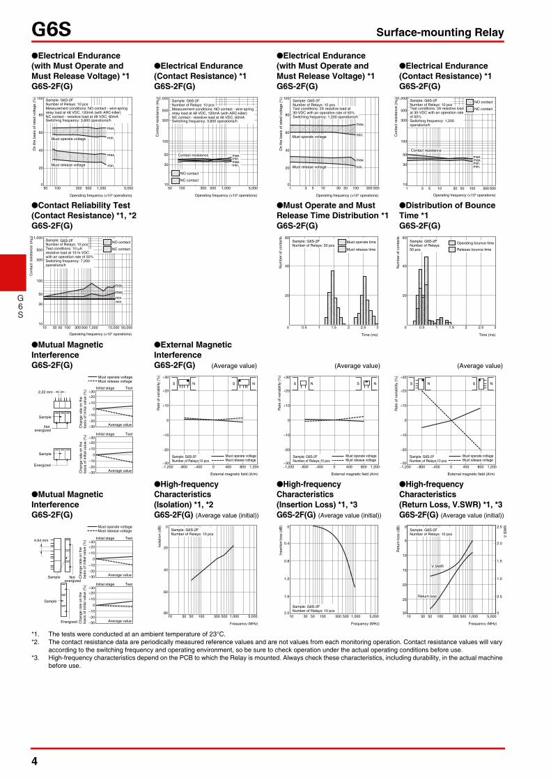
*1. The tests were conducted at an ambient temperature of 23°C.*2. The contact resistance data are periodically measured reference values and are not values from each monitoring operation. Contact resistance values will vary
according to the switching frequency and operating environment, so be sure to check operation under the actual operating conditions before use.*3. High-frequency characteristics depend on the PCB to which the Relay is mounted. Always check these characteristics, including durability, in the actual machine
before use.
●Electrical Endurance (with Must Operate and Must Release Voltage) *1G6S-2F(G)
●Electrical Endurance (Contact Resistance) *1G6S-2F(G)
●Electrical Endurance (with Must Operate and Must Release Voltage) *1G6S-2F(G)
●Electrical Endurance (Contact Resistance) *1G6S-2F(G)
●Contact Reliability Test (Contact Resistance) *1, *2G6S-2F(G)
●Must Operate and Must Release Time Distribution *1G6S-2F(G)
●Distribution of Bounce Time *1G6S-2F(G)
●Mutual Magnetic InterferenceG6S-2F(G)
●External Magnetic InterferenceG6S-2F(G) (Average value) (Average value) (Average value)
●Mutual Magnetic InterferenceG6S-2F(G)
●High-frequency Characteristics (Isolation) *1, *2G6S-2F(G) (Average value (initial))
●High-frequency Characteristics (Insertion Loss) *1, *3G6S-2F(G) (Average value (initial))
●High-frequency Characteristics (Return Loss, V.SWR) *1, *3G6S-2F(G) (Average value (initial))
100
80
60
40
20
0
Must operate voltage
Must release voltage
Sample: G6S-2FNumber of Relays: 10 pcsMeasurement conditions: NO contact - wire-spring relay load at 48 VDC, 120mA (with ARC-killer)NC contact - resistive load at 48 VDC, 60mASwitching frequency: 3,600 operations/h
min.
min.
max.
max.
50 100 300 500 1,000 5,000
Operating frequency (×103 operations)
On
the
basi
s of
rat
ed v
olta
ge (
%)
NO contact
NC contact
Contact resistance
Sample: G6S-2FNumber of Relays: 10 pcsMeasurement conditions: NO contact - wire-spring relay load at 48 VDC, 120mA (with ARC-killer)NC contact - resistive load at 48 VDC, 60mASwitching frequency: 3,600 operations/h
max.min.max.min.
1,000
500
300
100
50
30
1050 100 300 500 1,000 5,000
Operating frequency (×103 operations)
Con
tact
res
ista
nce
(mΩ
)
1 3 5 10 30 50 100 300 500
Operating frequency (×103 operations)
100
80
60
40
20
0
Must operate voltage
Must release voltage min.
Sample: G6S-2FNumber of Relays: 10 pcsTest conditions: 2A resistive load at 30-VDC with an operation rate of 50%Switching frequency: 1,200 operations/h
max.
min.
max.
On
the
basi
s of
rat
ed v
olta
ge (
%) 1,000
500
300
100
50
30
10
Operating frequency (×103 operations)
NO contact
NC contact
1 3 5 10 30 50 100 300 500
Contact resistance
Sample: G6S-2FNumber of Relays: 10 pcsTest conditions: 2A resistive load at 30-VDC with an operation rate of 50%Switching frequency: 1,200 operations/h
max.max.min.min.
Con
tact
res
ista
nce
(mΩ
)
NO contact
NC contact
1,000
500
300
100
50
30
1010 30 50 100 300 500 1,000 10,000 50,000
Sample: G6S-2FNumber of Relays: 10 pcsTest conditions: 10 μA resistive load at 10 m VDC with an operation rate of 50%Switching frequency: 7,200 operations/h
min.min.
max.
max.
Operating frequency (×103 operations)
Con
tact
res
ista
nce
(mΩ
)
0.5 1 1.5 2 2.5 3
60
40
20
0
Sample: G6S-2F Number of Relays: 50 pcs
Time (ms)
Num
ber
of c
onta
cts
Must operate time
Must release time
Num
ber
of c
onta
cts
0 0.5 1 1.5 2 2.5 3
60
40
20
Sample: G6S-2F Number of Relays: 50 pcs
Time (ms)
Operating bounce time
Release bounce time
+30+20
+10
0
−10
−20
−30 Average value
TestInitial stage
+30+20
+10
0
−10
−20
−30 Average value
TestInitial stage
Energized
Sample
2.22 mm
Sample
Not energized
Cha
nge
rate
on
the
basi
s of
initi
al v
alue
(%
)C
hang
e ra
te o
n th
eba
sis
of in
itial
val
ue (
%)
Must operate voltageMust release voltage
−1,200 −800 −400 0 400 800 1,200
+30
+20
+10
0
−10
−20
−30
External magnetic field (A/m)
Must operate voltageMust release voltage
Sample: G6S-2F Number of Relays:10 pcs
S NS N
Rat
e of
var
iabi
lity
(%)
−1,200 −800 −400 0 400 800 1,200
+30
+20
+10
0
−10
−20
−30
External magnetic field (A/m)
Must operate voltageMust release voltage
Sample: G6S-2F Number of Relays:10 pcs
S NS N
Rat
e of
var
iabi
lity
(%)
−1,200 −800 −400 0 400 800 1,200
Rat
e of
var
iabi
lity
(%) +30
+20
+10
0
−10
−20
−30
External magnetic field (A/m)
Must operate voltageMust release voltage
Sample: G6S-2F Number of Relays:10 pcs
S NS N
+30+20
+10
0
−10
−20
−30 Average value
TestInitial stage
+30+20
+10
0
−10
−20
−30 Average value
TestInitial stage
Sample
4.64 mm
Not energized
Energized
Sample
Must operate voltageMust release voltage
Cha
nge
rate
on
the
basi
s of
initi
al v
alue
(%
)C
hang
e ra
te o
n th
eba
sis
of in
itial
val
ue (
%)
Isol
atio
n (d
B)
10 30 50 100 300 500 1,000 5,000
Frequency (MHz)
Sample: G6S-2F Number of Relays: 10 pcs
0
20
40
60
80
0
0.4
0.8
1.2
1.6
2.010 30 50 100 300 500 1,000 5,000
Frequency (MHz)
Sample: G6S-2F Number of Relays: 10 pcs
Inse
rtio
n lo
ss (
dB)
10 30 50 100 300 500 1,000 5,000
Frequency (MHz)
Sample: G6S-2F Number of Relays: 10 pcs
Ret
urn
loss
(dB
) 2.5
2.0
1.5
1.0
0.5
0
0
5
10
15
20
25
30
Return loss
V.SWR
V.S
WR
5
G6S Surface-mounting Relay
G6S
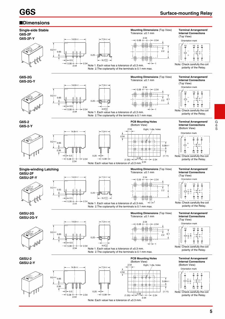
■Dimensions
5431
891012
9.2±0.2
14.8±0.2 7.3±0.2
0.65
0.5
5.08 2.542.54
Orientation mark
9.2+0.5 −0.3
0.25
5.082.54
2.54
2.2 8
1
Single-side StableG6S-2FG6S-2F-Y
Mounting Dimensions (Top View)Tolerance: ±0.1 mm
Terminal Arrangement/ Internal Connections (Top View)
Note 1. Each value has a tolerance of ±0.3 mm.Note 2.The coplanarity of the terminals is 0.1 mm max.
Note: Check carefully the coil polarity of the Relay.
5431
891012
Orientation mark
1
9.2±0.2
14.8±0.2 7.3±0.2
0.65
0.5
5.08 2.542.54
4.9+0.3 −0.5
0.25
5.082.54
2.54
2.2 6.1
G6S-2GG6S-2G-Y
Mounting Dimensions (Top View)Tolerance: ±0.1 mm
Terminal Arrangement/ Internal Connections (Top View)
Note 1. Each value has a tolerance of ±0.3 mm.Note 2.The coplanarity of the terminals is 0.1 mm max.
Note: Check carefully the coil polarity of the Relay.
891012
54312.54
2.54
2.54(1.05)2.54
5.08
5.08±0.1
(1.11)
Eight, 1-dia. holes
9.2±0.2
14.8±0.2 7.3±0.2
0.65
2.95
0.5
5.08 2.54
0.25
5.082.54
Orientation mark
G6S-2G6S-2-Y
PCB Mounting Holes (Bottom View)
Terminal Arrangement/ Internal Connections (Bottom View)
Note: Each value has a tolerance of ±0.3 mm.
Note: Check carefully the coil polarity of the Relay.
5431
891012
S R
Orientation mark
9.20.2
14.80.2 7.30.2
0.65
0.5
5.08 2.542.54
9.20.5 0.3
0.25
5.082.54
2.54
2.2 8
1
Single-winding LatchingG6SU-2FG6SU-2F-Y
Mounting Dimensions (Top View)Tolerance: ±0.1 mm
Terminal Arrangement/ Internal Connections (Top View)
Note 1. Each value has a tolerance of ±0.3 mm.Note 2.The coplanarity of the terminals is 0.1 mm max.
Note: Check carefully the coil polarity of the Relay.
5431
891012
S R
Orientation mark
9.2±0.2
14.8±0.2 7.3±0.2
0.65
0.5
5.08 2.542.54
4.9+0.3 −0.5
0.25
1
5.082.54
2.54
2.2 6.1
G6SU-2GG6SU-2G-Y
Mounting Dimensions (Top View)Tolerance: ±0.1 mm
Terminal Arrangement/ Internal Connections (Top View)
Note 1. Each value has a tolerance of ±0.3 mm.Note 2.The coplanarity of the terminals is 0.1 mm max.
Note: Check carefully the coil polarity of the Relay.
2.54
2.54
2.54(1.05)2.54
5.08
5.08±0.1
(1.11)
Eight, 1-dia. holes
891012
5431
S R
9.2±0.2
14.8±0.2 7.3±0.2
0.65
2.95
0.5
5.08 2.54
0.25
5.082.54
Orientation mark
G6SU-2G6SU-2-Y
PCB Mounting Holes (Bottom View)
Terminal Arrangement/ Internal Connections (Bottom View)
Note: Each value has a tolerance of ±0.3 mm.
Note: Check carefully the coil polarity of the Relay.
6
G6S Surface-mounting Relay
G6S
9.2±0.2
14.8±0.2 7.3±0.2
0.65
0.5
5.08 2.542.54 2.54
9.2+0.5 −0.3
0.25
5.082.54 2.54
2.54
2.2 8
1
5431
891012
6
7
S R
Orientation mark
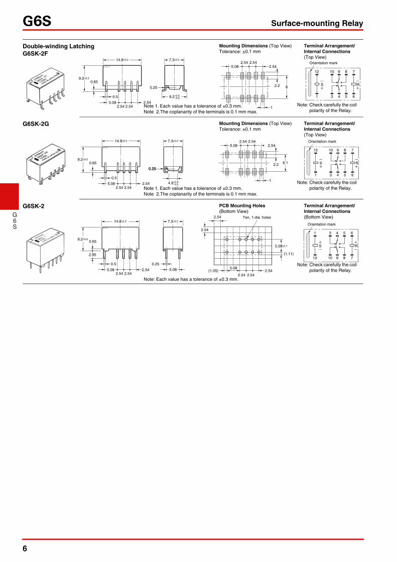
Double-winding LatchingG6SK-2F
Mounting Dimensions (Top View)Tolerance: ±0.1 mm
Terminal Arrangement/ Internal Connections (Top View)
Note 1. Each value has a tolerance of ±0.3 mm.Note 2.The coplanarity of the terminals is 0.1 mm max.
Note: Check carefully the coil polarity of the Relay.
9.2±0.2
14.8±0.2
0.65
0.5
5.08 2.542.54 2.54
0.25
2.54 2.54
1
7.3±0.2
4.9+0.3 −0.5
0.25
5.08 2.54
2.2 6.1
5431
891012
6
7
S R
Orientation mark
G6SK-2G Mounting Dimensions (Top View)Tolerance: ±0.1 mm
Terminal Arrangement/ Internal Connections (Top View)
Note 1. Each value has a tolerance of ±0.3 mm.Note 2.The coplanarity of the terminals is 0.1 mm max.
Note: Check carefully the coil polarity of the Relay.
891012
5431
7
6
S R
2.54
2.54
2.54(1.05)2.54 2.54
5.08
5.08±0.1
(1.11)
Ten, 1-dia. holes
9.2±0.2
14.8±0.2 7.3±0.2
0.65
2.95
0.5
5.08 2.54
0.25
5.082.54 2.54
Orientation mark
G6SK-2 PCB Mounting Holes (Bottom View)
Terminal Arrangement/ Internal Connections (Bottom View)
Note: Each value has a tolerance of ±0.3 mm.
Note: Check carefully the coil polarity of the Relay.
7
G6S Surface-mounting Relay
G6S
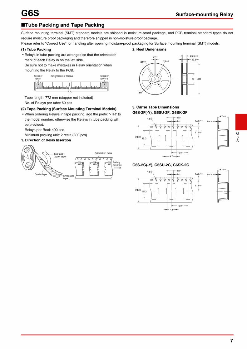
■Tube Packing and Tape PackingSurface mounting terminal (SMT) standard models are shipped in moisture-proof package, and PCB terminal standard types do notrequire moisture proof packaging and therefore shipped in non-moisture-proof package.Please refer to "Correct Use" for handling after opening moisture-proof packaging for Surface mounting terminal (SMT) models.
(1) Tube Packing• Relays in tube packing are arranged so that the orientation
mark of each Relay in on the left side. Be sure not to make mistakes in Relay orientation when mounting the Relay to the PCB.
Tube length: 772 mm (stopper not included)No. of Relays per tube: 50 pcs
(2) Tape Packing (Surface Mounting Terminal Models)• When ordering Relays in tape packing, add the prefix “-TR” to
the model number, otherwise the Relays in tube packing will be provided.Relays per Reel: 400 pcsMinimum packing unit: 2 reels (800 pcs)
1. Direction of Relay Insertion
2. Reel Dimensions
3. Carrie Tape Dimensions
Stopper(gray)
Orientation of Relays Stopper(green)
Top tape(cover tape)
Carrier tapeEmbossedtape
Orientation mark
Pullingdirection
2±0.3 25.5±0.5
29.5±1.0
21±0.5
R1
13±0.2
80 330
1.5+0.1−0
9.7
16±0.1
1.75±0.1
15.3
15.3
0.4±0.05
9.7±0.1
11.5±0.1
24±0.3
4±0.1
2±0.1
1.5+0.1−0
7.8
16±0.1
1.75±0.1 0.4±0.05
9.7±0.1
11.5±0.1
24±0.3
4±0.1
2±0.1
G6S-2F(-Y), G6SU-2F, G6SK-2F
G6S-2G(-Y), G6SU-2G, G6SK-2G
8
G6S Surface-mounting Relay
G6S
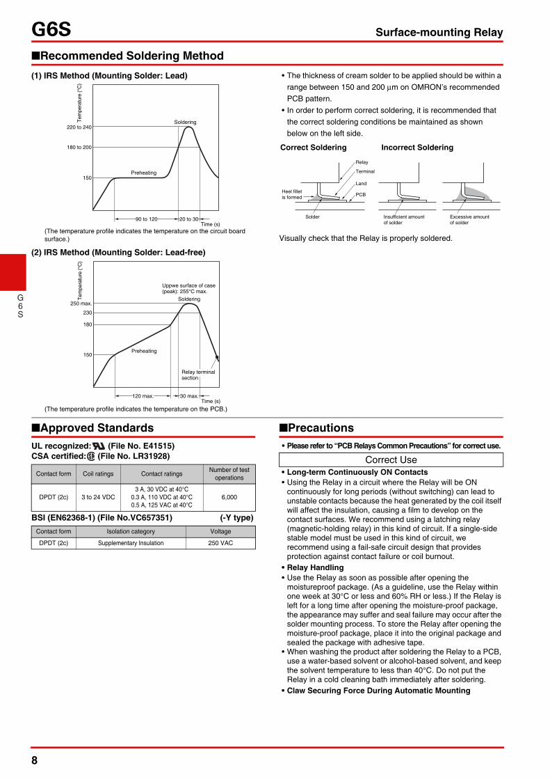
■Recommended Soldering Method(1) IRS Method (Mounting Solder: Lead)
(2) IRS Method (Mounting Solder: Lead-free)
• The thickness of cream solder to be applied should be within a range between 150 and 200 µm on OMRON’s recommended PCB pattern.
• In order to perform correct soldering, it is recommended that the correct soldering conditions be maintained as shown below on the left side.
Visually check that the Relay is properly soldered.
■Approved StandardsUL recognized: (File No. E41515)CSA certified: (File No. LR31928)
BSI (EN62368-1) (File No.VC657351) (-Y type)
■Precautions• Please refer to “PCB Relays Common Precautions” for correct use.
• Long-term Continuously ON Contacts• Using the Relay in a circuit where the Relay will be ON
continuously for long periods (without switching) can lead to unstable contacts because the heat generated by the coil itself will affect the insulation, causing a film to develop on the contact surfaces. We recommend using a latching relay (magnetic-holding relay) in this kind of circuit. If a single-side stable model must be used in this kind of circuit, we recommend using a fail-safe circuit design that provides protection against contact failure or coil burnout.
• Relay Handling• Use the Relay as soon as possible after opening the
moistureproof package. (As a guideline, use the Relay within one week at 30°C or less and 60% RH or less.) If the Relay is left for a long time after opening the moisture-proof package, the appearance may suffer and seal failure may occur after the solder mounting process. To store the Relay after opening the moisture-proof package, place it into the original package and sealed the package with adhesive tape.
• When washing the product after soldering the Relay to a PCB, use a water-based solvent or alcohol-based solvent, and keep the solvent temperature to less than 40°C. Do not put the Relay in a cold cleaning bath immediately after soldering.
• Claw Securing Force During Automatic Mounting
150
20 to 30
220 to 240
180 to 200
Soldering
Preheating
Time (s)90 to 120
Tem
pera
ture
(°C
)
(The temperature profile indicates the temperature on the circuit board surface.)
250 max.
230
180
150
Time (s)120 max. 30 max.
Relay terminalsection
Soldering
Preheating
Uppwe surface of case (peak): 255°C max.
Tem
pera
ture
(°C
)
(The temperature profile indicates the temperature on the PCB.)
Insufficient amount of solder
Excessive amount of solder
Heel fillet is formed
Solder
PCB
Land
Terminal
Relay
Correct Soldering Incorrect Soldering
Contact form Coil ratings Contact ratings Number of test operations
DPDT (2c) 3 to 24 VDC3 A, 30 VDC at 40°C
0.3 A, 110 VDC at 40°C0.5 A, 125 VAC at 40°C
6,000
Contact form Isolation category Voltage
DPDT (2c) Supplementary Insulation 250 VAC
Correct Use
9
G6S Surface-mounting Relay
G6S
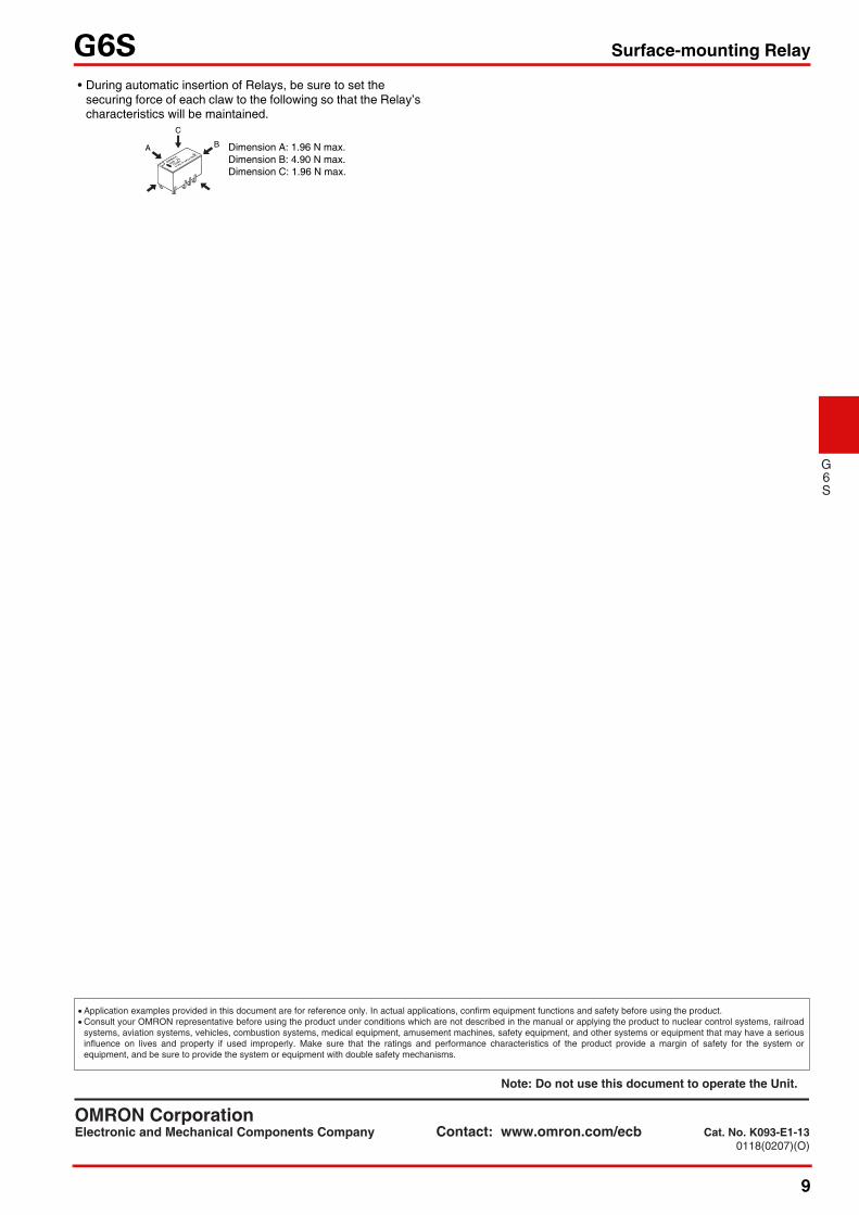
• During automatic insertion of Relays, be sure to set the securing force of each claw to the following so that the Relay’s characteristics will be maintained.
A
C
B Dimension A: 1.96 N max.Dimension B: 4.90 N max.Dimension C: 1.96 N max.
• Application examples provided in this document are for reference only. In actual applications, confirm equipment functions and safety before using the product. • Consult your OMRON representative before using the product under conditions which are not described in the manual or applying the product to nuclear control systems, railroad
systems, aviation systems, vehicles, combustion systems, medical equipment, amusement machines, safety equipment, and other systems or equipment that may have a serious influence on lives and property if used improperly. Make sure that the ratings and performance characteristics of the product provide a margin of safety for the system or equipment, and be sure to provide the system or equipment with double safety mechanisms.
OMRON CorporationElectronic and Mechanical Components Company Contact: www.omron.com/ecb Cat. No. K093-E1-13
0118(0207)(O)
Note: Do not use this document to operate the Unit.