Embed Size (px)
Citation preview

GAS COOLED REACTORS
(Session 6)
Chairpersons
D. Nicholls South Africa
M. Lecomte France


IAEA-SR-218/62
PRESENT STATUS AND PERSPECTIVE OF HTGR IN JAPAN
S. SHIOZAWA, Y. TACHIBANA, O. BABA, M. OGAWA Oarai Research Establishment, Japan Atomic Energy Research Institute, Japan
Abstract
The High Temperature Gas-cooled Reactor (HTGR) is particularly attractive due to its capability of producing high temperature helium gas and inherent safety characteristics. These interesting aspects make HTGR worthy of discussion on the future advanced reactors. The Japanese interest in the HTGR has resulted in the construction of the High Temperature Engineering Test Reactor (the HTTR) at the Japan Atomic Energy Research Institute (JAERI). The HTTR was successfully constructed and now under power-up test at JAERI. The purpose of the HTTR Project is to establish and upgrade HTGR technology and make an irradiation test for innovative basic research in the field of high temperature engineering. It is widely recognized in the nuclear community that the timely and successful operation of the HTTR and tests using the HTTR are major milestones in HTGR development, and in the development of high temperature nuclear process heat application. In addition to accumulation of the HTTR operation and performance data, extensive tests are planned in the HTTR, e.g., the tests for the development of advanced fuel and graphite materials as well as safety demonstration test to verify the inherent safety of HTGR. Furthermore, a process heat application system will be coupled to the HTTR in the future, where hydrogen will be produced directly from nuclear. The out-of-reactor loop facility is under construction to confirm the design of the heat application system and its performance prior to the HTTR coupling. In parallel to the HTTR Project, some Japanese industries are exploring the feasibility of HTGR commercialization. A further industrial effort is expected to follow for commercialization HTGR. This paper gives an overview of the HTTR Project and the future plans using the HTTR. In addition, an industrial view and activities for HTGR commercialization are briefly introduced.
1. INTRODUCTION [1],[2]
High Temperature Gas-cooled Reactor (HTGR), which is a graphite moderated, helium cooled reactor, is particularly attractive due to capability of producing high temperature helium gas and its inherent safety characteristics, as well as an option to efficiently burn weapons-grade plutonium for energy production. These interesting aspects make HTGR worthy of discussion on the future advanced reactors, along with advanced light water reactor (LWR). The HTGR is also expected to contribute to solving the currently increasing global environmental issue of CO2 emission, since it could be an alternative or supplemental to the fossil-fuel energy sources for process heat application. With this understanding, the perspective of HTGR as a possible future nuclear energy source was discussed in the review of “Long-term Program for Research, Development and Utilization of Nuclear Energy,” by the Atomic Energy Commission of Japan. The commission recommended that a feasibility study should be done first to decide the commercial development for the gas turbine power generation HTGR and the development study of high temperature heat application using HTGR should be continued to enhance the possible fields of application.
The development of HTGR began in 1950’s and the 20 MWt Dragon Reactor operated in the UK from 1964 through to 1977 within a framework of the OECD/NEA international collaboration as a productive research tool for the development of HTGR. Following the Dragon Reactor, the 15 MWe AVR and the 40 MWe Peach Bottom HTGR were constructed and successfully operated in Germany and USA, respectively. The commercialization efforts were continued thereafter, the FSV HTGR of 330 MWe in USA and the THTR of 300 MWe in Germany. Further continued interest in development of larger steam cycle HTGR plants included the German HTR-500, the Russian VG-400 and the US HTGR-SC, etc. However, these plants had not been realized mainly due to less economic competitiveness compared to
305307
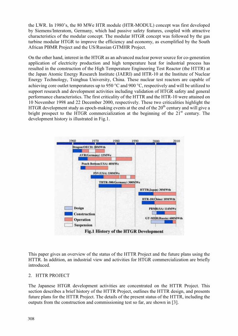
the LWR. In 1980’s, the 80 MWe HTR module (HTR-MODUL) concept was first developed by Siemens/Interatom, Germany, which had passive safety features, coupled with attractive characteristics of the modular concept. The modular HTGR concept was followed by the gas turbine modular HTGR to improve the efficiency and economy, as exemplified by the South African PBMR Project and the US/Russian GTMHR Project.
On the other hand, interest in the HTGR as an advanced nuclear power source for co-generation application of electricity production and high temperature heat for industrial process has resulted in the construction of the High Temperature Engineering Test Reactor (the HTTR) at the Japan Atomic Energy Research Institute (JAERI) and HTR-10 at the Institute of Nuclear Energy Technology, Tsinghua University, China. These nuclear test reactors are capable of achieving core outlet temperatures up to 950 °C and 900 °C, respectively and will be utilized to support research and development activities including validation of HTGR safety and general performance characteristics. The first criticality of the HTTR and the HTR-10 were attained on 10 November 1998 and 22 December 2000, respectively. These two criticalities highlight the HTGR development study as epoch-making events at the end of the 20th century and will give a bright prospect to the HTGR commercialization at the beginning of the 21st century. The development history is illustrated in Fig.1.
This paper gives an overview of the status of the HTTR Project and the future plans using the HTTR. In addition, an industrial view and activities for HTGR commercialization are briefly introduced.
2. HTTR PROJECT
The Japanese HTGR development activities are concentrated on the HTTR Project. This section describes a brief history of the HTTR Project, outlines the HTTR design, and presents future plans for the HTTR Project. The details of the present status of the HTTR, including the outputs from the construction and commissioning test so far, are shown in [3].
306308

FIG. 3. Bird’s eye view of HTTR facility.
307309
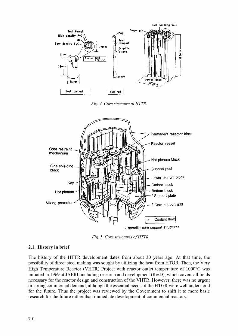
Fig. 4. Core structure of HTTR.
Fig. 5. Core structures of HTTR.
2.1. History in brief
The history of the HTTR development dates from about 30 years ago. At that time, the possibility of direct steel making was sought by utilizing the heat from HTGR. Then, the Very High Temperature Reactor (VHTR) Project with reactor outlet temperature of 1000°C was initiated in 1969 at JAERI, including research and development (R&D), which covers all fields necessary for the reactor design and construction of the VHTR. However, there was no urgent or strong commercial demand, although the essential needs of the HTGR were well understood for the future. Thus the project was reviewed by the Government to shift it to more basic research for the future rather than immediate development of commercial reactors.
308310
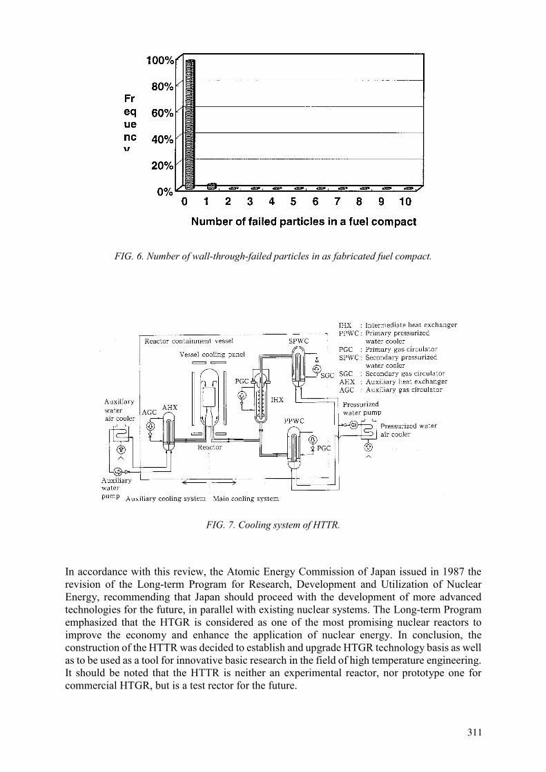
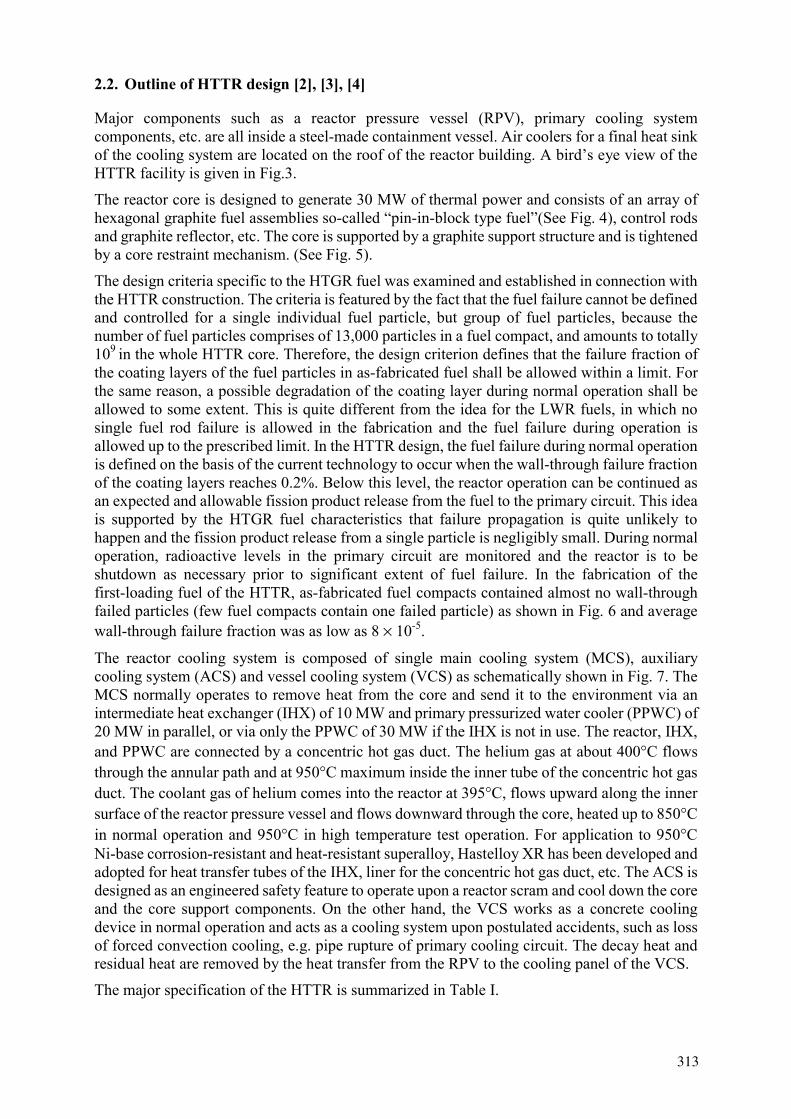
FIG. 6. Number of wall-through-failed particles in as fabricated fuel compact.
FIG. 7. Cooling system of HTTR.
In accordance with this review, the Atomic Energy Commission of Japan issued in 1987 the revision of the Long-term Program for Research, Development and Utilization of Nuclear Energy, recommending that Japan should proceed with the development of more advanced technologies for the future, in parallel with existing nuclear systems. The Long-term Program emphasized that the HTGR is considered as one of the most promising nuclear reactors to improve the economy and enhance the application of nuclear energy. In conclusion, the construction of the HTTR was decided to establish and upgrade HTGR technology basis as well as to be used as a tool for innovative basic research in the field of high temperature engineering. It should be noted that the HTTR is neither an experimental reactor, nor prototype one for commercial HTGR, but is a test rector for the future.
309311

TABLE I. MAJOR SPECIFICATION OF HTTR
Thermal power Outlet coolant temperature Inlet coolant temperature Fuel Fuel element type Direction of coolant flow Pressure vessel Number of cooling loop Heat removal Primary coolant pressure Containment type Plant lifetime
30MW 850°C/950°C395°CLow enriched UO2Prismatic block DownwardSteel 1IHX and PWC (parallel loaded) 4MPaSteel containment 20 years
TABLE II. DATA TO BE ACCUMULATED IN LONG TERM RATED POWER
OPERATION
According to the revised Long-term Program for Research, Development and Utilization of Nuclear Energy, the construction of the HTTR was initiated in 1991 and is now at the stage of the power-up test. The first criticality of the HTTR was attained on 10 November 1998, followed by power-up test and rated power operation. The full power operation at the high temperature of 950 °C will be attained in 2002 and extensive tests using the HTTR are planned thereafter. The development history of the HTTR is schematically illustrated in Fig.2.
-Fission product release in the primary circuit
-Fuel integrity
-Purification system performance
-Helium gas leakage from the primary circuit
identification of leakage place
-High temperature components performance
intermediate heat exchanger
pressurized water cooler
vessel cooling system
-Data specific to nuclear technology
operability and controllability
amount of radioactive waste
human engineering data for operators
310312
2.2. Outline of HTTR design [2], [3], [4]
Major components such as a reactor pressure vessel (RPV), primary cooling system components, etc. are all inside a steel-made containment vessel. Air coolers for a final heat sink of the cooling system are located on the roof of the reactor building. A bird’s eye view of the HTTR facility is given in Fig.3.
The reactor core is designed to generate 30 MW of thermal power and consists of an array of hexagonal graphite fuel assemblies so-called “pin-in-block type fuel”(See Fig. 4), control rods and graphite reflector, etc. The core is supported by a graphite support structure and is tightened by a core restraint mechanism. (See Fig. 5).
The design criteria specific to the HTGR fuel was examined and established in connection with the HTTR construction. The criteria is featured by the fact that the fuel failure cannot be defined and controlled for a single individual fuel particle, but group of fuel particles, because the number of fuel particles comprises of 13,000 particles in a fuel compact, and amounts to totally 109 in the whole HTTR core. Therefore, the design criterion defines that the failure fraction of the coating layers of the fuel particles in as-fabricated fuel shall be allowed within a limit. For the same reason, a possible degradation of the coating layer during normal operation shall be allowed to some extent. This is quite different from the idea for the LWR fuels, in which no single fuel rod failure is allowed in the fabrication and the fuel failure during operation is allowed up to the prescribed limit. In the HTTR design, the fuel failure during normal operation is defined on the basis of the current technology to occur when the wall-through failure fraction of the coating layers reaches 0.2%. Below this level, the reactor operation can be continued as an expected and allowable fission product release from the fuel to the primary circuit. This idea is supported by the HTGR fuel characteristics that failure propagation is quite unlikely to happen and the fission product release from a single particle is negligibly small. During normal operation, radioactive levels in the primary circuit are monitored and the reactor is to be shutdown as necessary prior to significant extent of fuel failure. In the fabrication of the first-loading fuel of the HTTR, as-fabricated fuel compacts contained almost no wall-through failed particles (few fuel compacts contain one failed particle) as shown in Fig. 6 and average wall-through failure fraction was as low as 8 × 10⁻⁵.
The reactor cooling system is composed of single main cooling system (MCS), auxiliary cooling system (ACS) and vessel cooling system (VCS) as schematically shown in Fig. 7. The MCS normally operates to remove heat from the core and send it to the environment via an intermediate heat exchanger (IHX) of 10 MW and primary pressurized water cooler (PPWC) of 20 MW in parallel, or via only the PPWC of 30 MW if the IHX is not in use. The reactor, IHX, and PPWC are connected by a concentric hot gas duct. The helium gas at about 400°C flows through the annular path and at 950°C maximum inside the inner tube of the concentric hot gas duct. The coolant gas of helium comes into the reactor at 395°C, flows upward along the inner surface of the reactor pressure vessel and flows downward through the core, heated up to 850°Cin normal operation and 950°C in high temperature test operation. For application to 950°CNi-base corrosion-resistant and heat-resistant superalloy, Hastelloy XR has been developed and adopted for heat transfer tubes of the IHX, liner for the concentric hot gas duct, etc. The ACS is designed as an engineered safety feature to operate upon a reactor scram and cool down the core and the core support components. On the other hand, the VCS works as a concrete cooling device in normal operation and acts as a cooling system upon postulated accidents, such as loss of forced convection cooling, e.g. pipe rupture of primary cooling circuit. The decay heat and residual heat are removed by the heat transfer from the RPV to the cooling panel of the VCS.
The major specification of the HTTR is summarized in Table I.
311313

Fig. 8 Transient response at control rod withdrawal from 50 % power operation.
Fig. 9 Transient response at no forced cooling systems functioned with failure of reactor shutdown.
2.3. Future plans for the HTTR
This section introduces the future plans to be done within a framework of the HTTR Project, including HTGR technology development and process heat application systems.
2.3.1 Establishment of HTGR Technologies
2.3.1.1 Accumulation of HTGR Operation Experience
The highest prioritized objective of the HTTR Project is to establish HTGR technologies, which is to be partially attained upon the completion of the HTTR construction and its commissioning. Here, the validation of the HTTR design will be confirmed regarding reactor power, temperature at various locations, flow rate and its local distribution …etc. The rest will be obtained through an operational experience of the HTTR. A long-term rated power operation at 850°C of reactor outlet temperature is scheduled after the commissioning test.
312314

Fig. 10 Flow diagram of HTTR hydrogen production system.
Year
Out-of-Pile TestDesign and Fabrication
Hydrogen Permeation TestMaterial Test
Detailed andSafety Design Fabrication Test
HTTR Hydrogen Production System
First Criticality
Design Study
OperationRise to Power Test
HTTROperation
Test
19961997 19981999 2000 20012002 2003 2004 2008 2009
IS Process
Laboratory-ScaleTest (H
2: L/h)
Laboratory-ScaleTest (H
2:50L/h)
Engineering andOut-of-Pile Tests
Steam Reforming System
HydrogenProductionSystem
Fig. 11 Development schedule of the hydrogen production systems at JAERI.
During the long-term rated power operation, basic data concerning HTTR performance is to be accumulated focusing on the fission product release in the primary circuit in relation to fuel integrity and function of the purification system, helium gas leakage from the primary circuit, as well as identification of leakage place if significant, general performance of the high temperature components such as the gas circulators, intermediate heat exchanger, pressurized water cooler and vessel cooling system. Data specific to nuclear technology will be also collected through the reactor operation concerning operability and controllability of the reactor, amount of radioactive waste, as well as human engineering data for operators. Data to be accumulated in long term rated power operation are given in Table II.
313315
The data obtained here are certain to be useful for the future HTGR development. The operational experience especially is to be utilized to improve the economy of HTGR, by simplifying safety-related equipment, rationalizing reactor operation and maintenance, increasing availability of reactor operation, minimizing amounts of radioactive waste, etc.
2.3.2 Upgrade of HTGR Technologies
2.3.2.1 Evaluation of Reactor Performance
Based on the HTTR operational and test data, the HTGR reactor performance is to be evaluated and analytical computer codes will be verified or modified for predicting realistic reactor performance under steady state and operational transient conditions. The evaluation is focused on:
1. Core physics in relation to thermal response and control system,
2. Thermal analysis for fuel, reactor internals and high temperature components,
3. Fuel performance on fission product release and degradation of the coating layers to contain the fission products,
4. Structural integrity of reactor internals and high temperature components,
5. Decay heat and residual heat removal characteristics, etc.
The fruits from the HTTR operational data and their evaluation are expected to be utilized for the commercial HTGR designs underway in South Africa, the Russian Federation, the United States of America and so on, as well as for the design of future Japanese advanced HTGR, which has been initiated at JAERI with industry support [5], [6].
Among those listed above, most important are fuel performance and decay heat removal characteristics, since those are key factors to assure the reactor safety. For the fuel performance, peak fuel temperature and its distribution, in the core, will be calculated and compared with the data to accurately predict the fuel temperatures. Also, the fission product release from the fuel into the primary circuit is measured to predict the failure fraction of the coating layers and fission product release. For decay heat removal characteristics, the cooling ability of the VCS is precisely evaluated in relation with the establishment of the passive cooling system.
2.3.2.2 Safety Demonstration Test
It is well known that the HTGR has inherent safety features, characterized by no risk of reactor core meltdown even in the case of no forced cooling systems functioned with failure of reactor shutdown. It is of great importance and one of the best ways for the wide public acceptance to demonstrate such inherent safety of the HTGR using an actual HTGR.
It is, therefore, planned to conduct a safety demonstration test under simulated accident conditions in the HTTR. The control rod withdrawal test and decrease in the primary coolant flow rate are carried out in the first stage of the safety demonstration test. Figure 8 [4] shows the analytical results during the control rod withdrawal from 50% power operation. As seen from the figure, the thermal power decreases and is kept at low constant value after the power excursion during which no significant fuel damage is likely. In the most extreme test to be planned in the final stage, all the forced cooling systems will be stopped under the rated power operation and the position of the control rods kept as it is. The analytical result of the reactor
314316

transients in this test is given in Fig.9. The decrease of the thermal power is due to strong negative feedback by the Doppler effect with increase of the fuel temperature. It is shown that the maximum fuel temperature does not exceed the limit of 1600°C.
It is hoped that the public can really understand the inherent safety features of the HTGR from these test results and come to show an interest in introducing HTGR in their neighborhood. .
2.3.2.3 Development of Key Components for Advanced HTGR
From a technical point of view, the most essential issue for the development of the future advanced HTGR is to develop fuel with high quality, since it is the most important parameter to determine the plant capability on reactor power and safety. For instance, high quality of fuel makes high power density of reactor core possible, consequently increasing reactor power in one unit and improving the economics of HTGR. As well, high quality fuel to retain fission product release, even at elevated temperatures, can assure higher degree of reactor safety against possible core heat up accidents. Furthermore, the high quality of fuel with less release of fission products results in the easy-maintenance and low cost for the waste management. An effort to develop such fuel with high quality as e.g. zirconium-carbide coated fuel and/or high temperature oxidation-resistant fuel will be taken through irradiation test using the HTTR together with related out-pile experiments. Beside fuel development, advanced graphite materials for control rod clad material and core support component are explored to be developed through the HTTR experiment.
2.3.2.4 Development of Process Heat Application System [7], [8]
To enhance the nuclear energy application to heat process industries, JAERI has continued extensive efforts for development of hydrogen production systems using the nuclear heat from HTGR. A hydrogen production system is being designed by means of a steam reforming process of natural gas using nuclear heat (10MW, 905°C) supplied by the HTTR. The flow diagram of the hydrogen system is shown in Fig. 10. The safety principle and criteria are also being investigated for the HTTR hydrogen production system. A construction of the facility for an out-of-pile test prior to the demonstration test with the HTTR is almost finished, followed by the test operation soon. The out-of-pile test facility simulates key components of the HTTR hydrogen production system on a scale of 1 to 30. The out-of-pile test on safety, controllability and performance of the hydrogen production system will be started in the last quarter of 2001 and continued for 4 years or longer. In parallel to this, a hydrogen permeation test and a corrosion test of a catalyst tube of a steam reformer are being carried out to obtain data necessary for the design of the system. The HTTR demonstration test is to be initiated hopefully in 2008.
In the hydrogen production system by steam reforming of natural gas mentioned above, the emission of CO2 is unavoidable, because natural gas of methane is used as feed gas. It is, therefore, generally understood that the final goal of the hydrogen production system using HTGR is to produce hydrogen from water without emission of CO2. For this purpose, the thermochemical Iodine-Sulfur (IS) process is under development in a small-scale laboratory experiment in parallel. In the experiment, a closed-cycle continuous operation in a steady state for 48 hours was successfully achieved at JAERI, and then the development activity will be shifted to engineering system development using a large-scale facility. The coupling to the HTTR will be possible in 2014 at the earliest.
Figure 1.. gives the total development schedule of the hydrogen production systems at JAERI.
315317
3. INDUSTRIAL VIEW AND ACTIVITIES FOR HTGR COMMERCIALIZATION
The Japanese HTGR development activities are concentrated on the HTTR Project. But, in parallel, some of Japanese industries try to explore the feasibility of the HTGR commercialization. Thus, an industrial effort is expected to follow for the commercialization of HTGR on the basis of the future accomplishment from the HTTR Project.
3.1. General View and Perspective by Industries
The HTGR concept and the essential needs of the HTGR are generally well accepted by Japanese nuclear industries of interest. For the electricity generation, they are interested in the South African PBMR Project and US/Russian GTMHR Project, and carefully watching the development movement of the Projects. Their interest is particularly on the high economy shown by the PBMR Project. In other words, they are not fully confident of such a low cost and high operational performance, such as efficiency and availability, because of the lack of experience. From a technical point of view, they are concerned about the feasibility of such big gas-turbine system with a capacity of several hundreds MWt. Thus industry appears hesitant to proceed with full commercial development by themselves due to such a big investment. They look forward to information from the HTTR experience as well as financial support by the government.
3.2. Industrial Activities
Under the circumstances mentioned above, some survey studies of the HTGR development have been done in some of nuclear vendors and non-government organizations, which consist of representatives of major nuclear industries including utilities, vendors and professional experts. Among them, the RAHP (Research Association of HTGR Plants) and the JAIF (Japan Atomic Industrial Forum) have made a continuous effort on the survey study of HTGR development. The RAHP has been a leading organization to review the HTGR technologies and to publicize full understanding of the HTGR to the public. They have summarized Japanese industrial interests or requirements for near-term future HTGR in Japan.
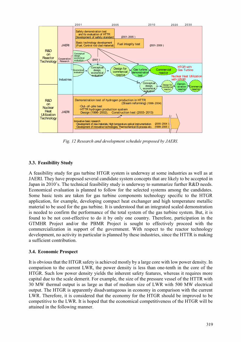
The JAIF has recently discussed the long-term and near-term prospect of the HTGR from a standpoint of industries including some utilities and summarized action plan to be done for the future. According to their report, the importance and necessity of the HTGR are well understood to solve global environmental issues and possible energy crisis that may happen not only in Japan but also in the world. However, it is pointed out in the meantime the urgent needs or requirements of the HTGR commercialization do not exist in Japan for electricity generation until at least 2010, if looking at the recent low economic growth rate in Japan. As for the process heat application, they consider the HTGR application quite far from commercialization, more in the stage of long-term research and development. Thus, it is concluded and recommended to the government that the government should proceed with the HTTR Project to provide basic technology information useful for the future commercialization of the HTGR in both area of electricity and process heat applications. In addition to this the report says that the government should perform a feasibility study on the commercialization for electricity application of HTGR. The research and development schedule proposed by JAERI is given in Fig. 12. In response to this recommendation, the Atomic Energy Commission of Japan recommended that first a feasibility study should be done to decide the commercial development of the gas turbine power generation HTGR, and the development study of high temperature heat application using HTGR should be continued to enhance the fields of application.
316318
Demon-strat ionreactor
Commercialreactor
Design forcommercial
reactor
Conceptualdesign,economicalevaluation
Fuel integrity testBasic technology development(Fuel, Control rod clad material)
Safety demonstration test and its evaluation of HTTRDevelopment of safety standard
Commercialreactor
Economicalevaluation
JAERI
200
200 - 2005
200 - 2009
Innovative basic researchDevelopment of new materials, High temperature optical instrumentation Development of innovative technologies, Thermochemical IS process etc.
Industries
R&Don
ReactorTechnology
R&Don
NuclearHeat
UtilizationTechnology
Gas turbinedemonstration
test
Demonstrat ion test of hydrogen product ion in HTTR (Steam reforming) ( 996- 2004) Out- of- pile test HTTR hydrogen product ion system Design ( 996- 2002), Construct ion test (2003- 20 3)
HTGR withGas Turbine
Nuclear Heat Utilizationwith HTGR
CooperationResearch
2000- 2004999- 2005
JAERI
Conceptualdesign,
economicalevaluation
Conceptualdesign,
economicalevaluation
Design forcommercial
reactor
Fig. 12 Research and development schedule proposed by JAERI.
3.3. Feasibility Study
A feasibility study for gas turbine HTGR system is underway at some industries as well as at JAERI. They have proposed several candidate system concepts that are likely to be accepted in Japan in 2010’s. The technical feasibility study is underway to summarize further R&D needs. Economical evaluation is planned to follow for the selected systems among the candidates. Some basic tests are taken for gas turbine components technology specific to the HTGR application, for example, developing compact heat exchanger and high temperature metallic material to be used for the gas turbine. It is understood that an integrated scaled demonstration is needed to confirm the performance of the total system of the gas turbine system. But, it is found to be not cost-effective to do it by only one country. Therefore, participation in the GTMHR Project and/or the PBMR Project is sought to effectively proceed with the commercialization in support of the government. With respect to the reactor technology development, no activity in particular is planned by these industries, since the HTTR is making a sufficient contribution.
3.4. Economic Prospect
It is obvious that the HTGR safety is achieved mostly by a large core with low power density. In comparison to the current LWR, the power density is less than one-tenth in the core of the HTGR. Such low power density yields the inherent safety features, whereas it requires more capital due to the scale demerit. For example, the size of the pressure vessel of the HTTR with 30 MW thermal output is as large as that of medium size of LWR with 500 MW electrical output. The HTGR is apparently disadvantageous in economy in comparison with the current LWR. Therefore, it is considered that the economy for the HTGR should be improved to be competitive to the LWR. It is hoped that the economical competitiveness of the HTGR will be attained in the following manner.
317319
The inherent safety features in the HTGR could make it possible that no or quite limited engineered safety features of reactor grade quality are needed, as exemplified by elimination of the containment vessel and emergency core cooling system. The only safety elements in the entire system are the fuel element and graphite core components which can be checked in running operation, while the safety of LWR with high power density is ensured by extensive, active and passive safeguards and the reactor grade quality of the components and materials. Sophistication and expensive reactor grade quality are particularly required for all components of LWR, but, in the case of HTGR, ultimately only for the fuel element and graphite core components. Thus, the HTGR would provide a new, qualitatively different safety, resulting in decreasing the cost competitive to the current LWR. The plant cost of a module type HTGR is evaluated positively in the long run to improve the economy, since it can be achieved for small units built in series in the vendor’s workshop and using normal mechanical engineering quality.
CONCLUDING REMARKS
The HTGR has salient features concerning the reactor safety as well as supply of high temperature heat. With this understanding the HTTR project is ongoing for HTGR development. Global interest in the HTTR project comes from not only nuclear people but also the public, since its successful achievement may enhance the possibility of solving the environmental issues of CO2 emission. as well as a possible energy crisis which might happen in the future. Further effort is to be continued at JAERI. Finally, it should be emphasized that support and understanding from people involved in the nuclear development are needed and wished for the success of the HTTR Project.
REFERENCES
[1] INTERNATIONAL ATOMIC ENERGY AGENCY, Current Status and Future Development of Modular High Temperature Gas Cooled Reactor Technology, IAEA TECDOC, May (2000).
[2] JAPAN ATOMIC ENERGY RESEARCH INSTITUTE, Present Status of HTGR Research & Development, JAERI, March (2000).
[3] FUJIKAWA, S., et al., Present Status of the HTTR and Topics from Operation, Proceedings of the Seminar on “HTGR Application and Development — Celebration for the HTR-10 criticality,” Beijing, China, March 19-21 (2001).
[4] SAITO, S., et al., Design of High Temperature Engineering Test Reactor (HTTR), JAERI-1332, JAERI (1994).
[5] MUTO, Y., et al, Present Activity of the Design and Experimental Works for HTGR-GT System in JAERI, Proceedings of the Helium Gas Reactor Workshop, EPRI, Palo Alto, California, U.S. 7-8 December (1999).
[6] YAN, X. L., et al., Design of Gas Turbine High Temperature Reactor – GTHTR 300, ibid. [7] INTERNATIONAL ATOMIC ENERGY AGENCY, Design and Evaluation of Heat
Utilization System for the High Temperature Engineering Test Reactor, IAEA TECDOC, December (2000).
[8] HIGASHI, S., et al., Present Status of Development Study on HTGR Heat Application Systems at JAERI, Proceedings of the Seminar on “HTGR Application and Development - Celebration for the HTR-10 criticality,” Beijing, China, March 19-21 (2001).
318320
IAEA-SR-218/19
PERSPECTIVE OF HTGR AND ITS COMMERCIAL DEVELOPMENT
H. SEKIMOTO Tokyo Institute of Technology (TIT), Japan
S. SHIOZAWA Japan Atomic Energy Research Institute (JAERI), Japan
Y. TSUCHIE The Japan Atomic Power Company (JAPC), Japan
H. HAYAKAWA Fuji Electric Company, Japan
M. SAIGO Japan Atomic Industrial Forum (JAIF), Japan
Abstract
Japan Atomic Industrial Forum (JAIF) has recently conducted a survey on “Future Perspective on Nuclear Heat Application,” focusing on HTGRs, such as small and modular HTGRs as seen in South African Pebble Bed Modular Reactor and US-Russian Gas Turbine Modular Helium Reactor Commercialization Programs now under way. The study investigated the issues to be solved for commercialization and their countermeasures were identified from viewpoints of technology, economy, regime, regulation and international cooperation. Development scenarios suitable for Japan were discussed for electricity generation systems, which can be commercialized in a relatively earlier stage, and for heat applications from a long-term point of view. An action plan on the role of the HTGR in the national nuclear energy policy was summarized as a proposal to the government.
1. INTRODUCTION
High Temperature Gas-cooled Reactor (HTGR), which is a graphite moderated, helium gas cooled reactor, is particularly attractive due to its inherent safety and its capability of producing high temperature energy.
Japan Atomic Industrial Forum (JAIF), by establishing a study group composed of scholars, researchers, experts from industries, has recently conducted a survey on “Future Perspective on Nuclear Heat Application,” focusing on HTGRs, such as small and modular HTGRs (MHTGRs) in particular, as seen in South African Pebble Bed Modular Reactor (PBMR) and US-Russian Gas Turbine Modular Helium Reactor (GT-MHR) Commercialization Programs now under way.
The summary of the study is as follows:
1. The HTGR development history and the present status were reviewed and the fundamental characteristics were re-examined to give a basis for the study. It was technically reconfirmed that such MHTGRs have excellent inherent safety characteristics and capability of producing high temperature energy, including electricity and heat,
2. Long term energy and environmental effects of HTGR introduction to Japan were assessed by using analytical models,
319321
3. The issues to be solved for commercialization and their countermeasures were identified from viewpoints of technology, economy, regime, regulation and international cooperation, etc.,
4. Development scenarios,
5. considered suitable for Japan were discussed for two cases, i.e. for electricity generation system which can be commercialized in a relatively earlier stage, and for heat application from long-term point of view, and,
6. An action plan, to give a clear position to the HTGR in the national nuclear energy policy, was summarized as a proposal to the government as seen in Section 5.
At present, the study group has started following investigations and actions as follows:
The actions of public understanding and promotion of HTGR development,
Preparatory work for the feasibility study ( FS ) on commercial HTGR in Japan,
The study on short term strategy for a feasibility of a cooperative development project of HTGRs in Asia,
The study on long term strategy for the development of the high temperature nuclear heat utilization and,
The study on HTGR fuel cycle.
2. HTGR DEVELOPMENT HISTORY AND CHARACTERISTICS
Development history
In 60’s and 70’s, considerable experiences were accumulated in developing towards relatively large sized (over 1000MWe) HTGR, as seen in German and US prototype HTGRs for electricity production by steam generator. Nevertheless, such commercial developments have been suspended or stopped mainly due to technical troubles in such prototype plant and Chernobyl accident. In ‘90s however, substantial developments have been made in conceptual and basic designs of small (100-300MWe) and modular HTGR (MHTGR) with gas-turbine system, as exemplified in the South African PBMR Project and US/Russian/France/Japan GT-MHR Project. In China the HTR-10 has been successfully constructed and succeeded in first criticality last December, and also ESKOM in South Africa deciding to proceed with the PBMR Program aiming at first criticality in 2005. The MHTGR is well understood to have inherent, passive safety features, coupled with attractive characteristics of the modular concept to improve economic competitiveness with the current fossil energy and LWR systems. On the other hand in Japan, Japan Atomic Energy Research Institute (JAERI) started to research and develop the first HTGR, i.e. High Temperature Engineering Test Reactor (HTTR) as Test Reactor from 1969. After that, HTTR was successfully constructed and now is under commissioning test for power up. In the HTTR Project, an extensive R&D is planned to establish and upgrade HTGR technologies including its heat application.
320322
Characteristics of MHTGR
It was technically reconfirmed in the present study that the MHTGR has an excellent inherent safety characteristics and capability of producing high temperature helium gas. Due to these basic characteristics in combination with the modular concept and gas turbine system, the economical improvement can be expected by e.g. elimination or simplification of safety systems including review of the safety grade, high thermal efficiency as well as wide temperature range of heat utilization, design standardization including small units prefabricated in series at factories, siting near energy consuming areas.
Hence, it was concluded that the MHTGR has the potential to enhance further utilization of nuclear energy. That is, the MHTGR has potential to provide new system concepts with high safety and economy suitable to various energy application fields and areas. For example, such new applications would become possible in the MHTGR, as electricity generation by gas turbine with high thermal efficiency, high temperature heat production and the electricity/heat co-generation fit for needs both developed and developing countries, etc.
3. LONG TERM ENERGY AND ENVIRONMENTAL EFFECTS OF HTGR INTRODUCTION
1. The worldwide primary energy demand/supply was investigated during the period of 1990 through 2100 based on the predictions of International Institute for Applied System Analysis (IIASA) reported in 1998. According to the present study, the annual increase rate of the primary energy demand is likely to be as high as 1.2 % in the world, resulting in the serious problem of fossil fuel exhaustion after 2050. It is, therefore, expected that the role of the nuclear energy will become more and more important due to reducing CO2emission.
2. The possible heat application systems given below were examined in the present study and the concepts of the individual systems were identified as well as the future tasks necessary for the commercial development, specific to respective systems.
a. Power generation (power generation with gas turbine, electricity-heat co-generation using steam turbine )
b. Secondary energy carrier production ( hydrogen, methanol, coal gasification and/or liquefaction )
c. Manufacturing ( production of reduced iron )
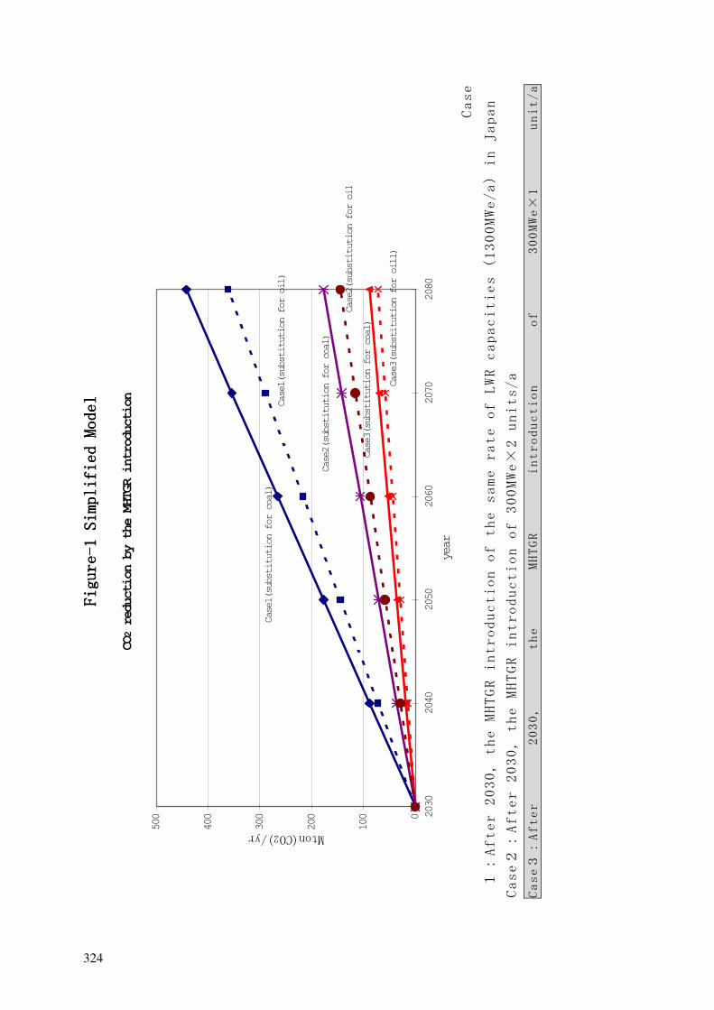
3. The effect of such MHTGR introduction was assessed by using the MARKAL Model(Optimization Analysis Model of Long Term Energy System), in addition to a simplified model. With an assumption that HTGR be initially built in 2030 and increasing the capacity at a rate of 300 MWe/a thereafter, a total amount of CO2 is estimated to be reduced at 60 --- 70 million ton/a as of 2070 as seen in Case 3 of Figure 1. Also the effective introduction of the MHTGR will result in the reduction of dependency on import of fossil energy resources.
As a conclusion, it was made clear that significant effect of the MHTGR introduction would be expected as one of the promising options for solving the global issues of the environment and energy shortage.
321323
Fig
ure
Fig
ure
Fig
ure
Fig
ure- ---1
Simpl
ifie
d Mo
del
1 Simpl
ifie
d Mo
del
1 Simpl
ifie
d Mo
del
1 Simpl
ifie
d Mo
del
CO2 r
eduction by the MHTGR introduction….
0
100
200
300
400
500 2030
2040
2050
2060
2070
2080
year
Mton(CO2)/yr
Case1(substitution for coal)
Case1(substitution for oil)
Case2(substitution for coal)
Case2(substitution for oi l
Case3(substitution for coal)
Case3(substitution for oill)
Case
After 2030, the MHTGR introduction of the same rate of LWR capacities (1300MWe/a) in Japan
Case
After 2030, the MHTGR introduction of 300MWe
2 units/a
Case
After
2030,
the
MHTGR
introduction
of
300MWe
1
unit/a
322324
4. ISSUES TO BE SOLVED FOR COMMERCIALIZATION AND THEIR COUNTERMEASURES
The issues to be solved for commercialization were identified, and the measures were studied from the viewpoint of technology, economic-sociology, development regime, regulation and international aspect. Major subjects to be solved in future were identified to be to decrease the uncertainty of the economic perspective, to make further technical development, to give solid measures for technological development and international co-operation,and to make the clear positioning of HTGR in the national nuclear policy.
5. DEVELOPMENT SCENARIOS AND ACTION PLANS
1. Development scenario
For the power generation system, which is considered to be commercialized in a relatively earlier stage, the FS should be made on the commercial MHTGR, assuming the first plant to be built in 2010’s in Japan. From a long-term point of view, the development study should be continuously performed on the heat application with a milestone of the first demonstration plant to be built in around 2030, followed by commercial plant in around 2050.
2. Action plans
Action plans were discussed on the basis of the above development scenario and summarized as a proposal to the government, as described below.
6. PROPOSALS
It was concluded in the present study that the MHTGR is one of the most promising solutions for global environmental issues as well as energy security. It is proposed, therefore, for the government to take the following actions to give a clear position to the MHTGR in the national nuclear energy development program.
1. At first, a FS should be made on commercialization of HTGR for power generation application. Then, an overall evaluation should be done to judge whether to commercially introduce HTGRs in Japan, including the following viewpoints;
a. Safety and economy
b. Fuel cycle
c. Plant siting near energy consuming areas
d. Contribution to stable energy supply and its diversity
e. Possible reduction of environmental impact
f. Nuclear non-proliferation
g. Activation of industries and national economy.
Following the overall evaluation, and after obtaining general consensus to proceed with the commercialization, new preparatory actions should be taken to initiate the commercial development under a new organizational framework. For such development,
323325

the information of the overseas HTGR development projects, which might be obtained through international cooperation, etc., should be positively and effectively utilized.
2. In parallel to the above actions, additional tests and R&D necessary for the commercialization should be conducted, in addition to the currently planned HTTR Programs. R&D on high temperature heat application, like hydrogen production, should be done, taking into account of overseas trends of needs from longer time point of view.
3. HTGR development and Asian co-operational programs, because of HTGR’s significant role in global environment and energy security, concrete measures should be proposed and agreed.
7. STATUS OF THE SUBSEQUENT STUDY
1. Actions of public understanding and promotion of HTGR development
The news related to HTGR is being distributed near quarterly to the industries, e.g. electric companies, nuclear plant makers, nuclear engineering companies, car and steel makers, etc.
2. Preparatory work for the FS on commercial HTGR in Japan
A draft HTGR commercialization plan was proposed by JEARI, and has been reviewed by the study group in JAIF.
JAERI and JAPC have been jointly conducting preliminary FS on commercial modular HTGR in Japan, including user’s needs, requirements, and comparative evaluation among PBMR, GT-MHR and Japanese original designs for about three years.
3. Study on short term strategy
Relating to the proposal (3) in the item 5 mentioned above, a preliminary study has been started on a cooperative development project of HTGRs in Asia.
The scheduled works are mainly composed of:
1. Significance of Introduction of Nuclear Energy in Asian Energy Market,
2. Specific Features of Asian Market and Suitability of HTGRs,
3. Users’ Requirements and Specifications of HTGRs for Asian countries,
4. Economical compatibility of HTGRs in Asia, and,
5. Development Program and Possible Cooperation.
Some countries such as China, Indonesia and Vietnam are indicating their basic interest in the preliminary study.
4. Study on long term strategy
Following the previous study, study on the significance of the system focusing on vehicles with fuel cell battery.
324326
The scheduled works are composed of:
a. Requirement for hydrogen production system using HTGR,
b. Surveying the present status of R&D concerning vehicles with fuel cell battery and hydrogen demand for their vehicles in the near future, and requirements for HTGR hydrogen production system.
c. Study of hydrogen production system using HTGR,
d. According to the above requirements, proposal of hydrogen production system with HTGR, giving an outline and main parameters for the system.
e. Cost and environmental evaluation, and,
f. Based on data obtained in the above items, cost evaluation of hydrogen production using the system and environmental effect.
g. Strategy of R&D.
h. Listing up of technical issues, planning of their R&D, and strategy to solve the issues, including organizations to implement the R&D.
5. Study of HTGR fuel cycle.
a. Review of technical and economical feasibility and related issues of HTGR fuel cycle, making full use of the past works by Research Association of HTGR Plant (RAHP) as follows;
• Combustion characteristic at the time of using U, Pu, Th, and MOX as HTGR fuel, and,
• Once through and reprocessing cycles.
b. A conceptual HTGR fuel cycle, considered suitable for Japan and Asia, is being proposed.
325327

IAEA-SR-218/22
CURRENT VIEWS ON COMMERCIALIZATION OF SMALL AND MODULAR HTGRs IN JAPAN
Y. TSUCHIE Research Association of HTGR Plant (RAHP), The Japan Atomic Power Co. (JAPC), Tokyo, Japan
S. AN Research Association of HTGR Plant (RAHP), University of Tokyo, Tokyo, Japan
T. HAYASHI Research Association of HTGR Plant (RAHP), Tokai University, Tokyo, Japan
Abstract
The Research Association of High Temperature Gas Cooled Reactor (HTGR) Plant (RAHP) is the sole industrial based research association on HTGR Plant in Japan, composed of academia, R&D organizations, industries such as all 11 electric power companies and manufactures of nuclear power plant, fuel and equipment. RAHP has long been researching the current status of HTGR R&D in the world, and studying the commercializing feasibility and scenarios for Japan, and carrying out international cooperation, such as exchange of information and views.
Members of the RAHP have been dispatched to the important international meetings on nuclear energy development, HTGR in particular, and there, updated status of HTGR R&D in Japan has been generally and periodically introduced, as seen in [1] and [2], for example.
Recently, on the other hand, “Small and Medium Reactors (SMRs)”, “Innovative Reactors”, “Next Generation Reactors (NGRs)”, are of increasing interest on a global scale, from view points of increasing demands of energy, food and water, in Asia especially, reduction of CO2 emission, enhanced safety and economic competitiveness, higher efficiency of energy use including electricity and heat uses, plant siting for dispersed or centralized demand, flexibility in energy supply program, and nuclear non-proliferation, etc..
As RAHP becomes increasingly confident, through such activities, which have been conducted for over 10 years, the subject of HTGRs, modernized small and modularized type of HTGRs in particular, are becoming of the most promising candidates among the SMRs or NGRs, as seen in [3].
In this paper, a briefing on RAHP's current views is given covering positioning, developing scenarios and strategies on HTGRs for Japan, including Asian aspects, which have been discussed and agreed among the participating members as the current one.
1. FUNDAMENTAL REQUIREMENTS
Fundamental requirements of Japanese industry, which were extracted, taking into account of (1) the current large scale LWRs, (2) HTGRs, which are under development in South Africa, USA-Russia, China, Japan, and (3) the other types of nuclear reactor, are as follows;
a. Its safety is required to be equal or better than those of the current LWRs, and the technology system to be demonstrated prior to its commercialization, where the related R&D should be done if necessary, and the economy to be competitive with other power sources.
326328

b. It should be of value for study on its commercialization, if it meets the requirements of the above mentioned SMRs or NGRs (Ref. User’s Requirements, Mar. 2000, RAHP [1]), and having attractive advantages such as high temperature heat utilization ability, etc.
c. Technologies, which have been accumulated through development of HTTR by JAERI, should be fully utilized.
2. CHARACTERISTICS AND SIGNIFICANCE OF HTGR COMMERCILALIZATION
2.1. Characteristics of HTGRs
a. Superior Safety; - Inherent safety can be firmly secured even without engineered safety systems such as Emergency Core Cooling System (ECCS), by restricting its power density, and such safe nuclear plant systems with relieved feeling to the public can be established and commercialized.
b. Superior potential of enhanced economy - Small (about 100-300 MWe) and simplified system due to the above inherent safety, and modularized plant concept, series production at factory and stepwise setting at plant site, etc. can be possible regarding the construction cost. Plant siting near demand areas is possible regarding the power generation and transmission line costs. Initial investment can be small, and flexible planning by stepwise increasing the number of modules according to its demand size and timing, becomes possible. Target costs should be less than about 1500$/KWe (FOAK) and 1200$/KWe (NOAK), and 4-6¢/KWh, in the case of introduction in Japan. (About 1000$/KWe and 2¢/KWh, in case of S. African Pebble Bed Modular Reactor (PBMR).(Ref.3.3.1)
c. Expandability of nuclear energy utilization - Highly efficient electricity generation combined with gas turbine system, rather than steam turbine, and a wide temperature range of heat uses are possible, because of high temperature energy supply ability.
d. Flexibility in fuel cycle - Various fuels (uranium and plutonium, and thorium as well) and forms (oxide, carbide, etc.) can be used, and no reprocessing (once-through) option is possible due to its ability of enhanced fuel burn-up. (Ref. 4.7)
2.2. Significance and Positioning
a. One of the small, medium and safe reactors, which are globally proposed as desirable.
b. Nuclear energy utilization is expandable in global scale (electricity use and a variety of heat uses in both developed and developing countries, plant siting near demand areas regardless of dispersed or centralized type, are possible), and cost competitiveness with current large scale LWRs is emerging.
c. It seems possible to become one of the effective power supply options, in light of reduction of environmental impact and energy security, on a global scale.
d. From these, it is necessary to firmly and clearly position such HTGRs in the national energy development program in Japan, from now on.
327329
2.3. View Points
a. Stable and sustainable energy supply and its diversification, enhanced safety and economy, reduction in global environmental impact, nuclear non-proliferation, measures for dispersed demand as well as centralized demand, plant siting near demand areas, electricity generation and heat use, international cooperation, industrial and economic activation, etc.
2.4. Public Acceptance (PA)
a. It is important to obtain public understanding and acceptance on wider uses of nuclear energy.
3. CLARIFICATION OF R&D TARGETS ON HTGR
3.1. Technical Problems and Prospects for Solving Them
3.1.1 Overseas Development Programs a. Development and demonstration of Power Conversion System (PCS), including helium
gas turbine, recuperator, magnetic bearing, etc., effective development by international cooperation is needed.
b. Fabrication and irradiation of fuel and graphite; Cooperation by Japan, having commercial level of technologies, is necessary.
3.2. Domestic Programs
a. Development of PCS (Ref. 3.1.1 above) b. Preparation of international safety criteria and its domestic application are needed.
c. Development of fuel cycle technology is needed, in case of reprocessing option.
3.3. Reliability Problems and Prospects for Solving Them
a. There should b a margin in plant operation.
b. Transients should be minimized in plant operation.
c. Human errors should also be minimized.
d. Targets should be more than 90% as plant availability, and less than 1 time/1.5-5y as plant outage frequency. (About 95% and 1 time/6y are proposed in case of PBMR)
3.4. Economic Problems and Prospects for Solving Them
3.4.1 Overseas programs (PBMR Project, etc.) (Ref.4.1)
a. Competitiveness with current LWRs, etc. can be expected by adoption of non-nuclear grade systems & facilities, small modular and series production systems, equipment procurement by international competitive bids, minimization of site work, siting near demand areas, etc.
b. Construction, operation and demonstration of the 1st module plant (combining roles of “Prototype Reactor”, “Demonstration Reactor” and “the 1st Commercial Reactor”, into a single reactor plant) will be very important for the economic outlook.
328330
3.4.2 Domestic Programs
a. It is important to execute a national based Feasibility Study (FS) and to evaluate.
b. Success of the above mentioned overseas 1st module plant programs is inevitable.
c. It will depend on the degree of adoption of non-nuclear grade facilities.
d. (Assuming introduction of PBMR to other countries, Japan for example, it was estimated to become 1.3-2.5 times of those in South Africa, depending on the degree of adoption of the non-nuclear grade and/or commodity prices in the subject countries [3].)
3.4.3 R&D Cost
a. Research & Development cost itself should be small.
b. International cooperation on technological basics and commons is needed for efficient development and cost saving.
3.5. Institutional Problems and Prospects for Solving Them
3.5.1 International Safety and Technological Criteria
a. Rational safety and technical criteria and licensing scheme should be established to make full use of the characteristics of HTGRs.
- It will be possible to establish safe and simple nuclear plant systems, making full use of the inherent safety characteristics of HTGRs and rational design considerations.
- Only the minimum necessary safety facilities should be facilitated. Reactor containment vessel free design, etc., which is possible in case of modernized small HTGRs, with suppressed power density, should be adopted. (Only coated particle fuel (CPF) is basically of “nuclear grade”, in case of PBMR.)
3.6. Safety Problems and Prospects for Solving Them
3.6.1 Inherent Safety
a. Full use of inherent safety characteristics of HTGRs; - Safety design will become possible, without relying on any active systems and/or operator’s manual operations.
- Evacuation of the public out of the plant site boundary is unnecessary due to the secured inherent safety, even assuming events of very low frequency ( 10-10)
- Fuel temperatures in reactor shall not reach failure or melting level even during severe accidents
- Containment vessel free design
- Since the fuel shall not fail nor melt, even at such accidents, additional fission product
- (FP) release will be of minimum level. Therefore such designs shall become possible.
3.6.2 3.5.2 Public Acceptance (PA)
a. It is important to obtain the public understanding and acceptance on the inherent safety of HTGRs.
329331

- The reactor plant “operation will cease passively”, ”cool down passively”, ”will not release FP” even in case of accidents
- Nuclear plant safety of relieved feeling or easily understandable to the public
- Adaptability to siting near demand areas, like highly populated cities.
4. HTGR DEVELOPMENT SCENARIOS (R&D PROGRAMS)
4.1. Development Status of Japan and Abroad
4.1.1 Development Policy
a. High Temperature Engineering Test Reactor (HTTR) Project (Japan): - JAERI has constructed the HTTR as a key facility for R&D of nuclear heat uses towards the future.
b. High Temperature Test Reactor (HTR-10) Project (China) : - It is aiming at establishment of multi-purpose, such as a system complementary with LWRs and nuclear heat utilization.
c. Gas Turbine Modular Helium Reactor (GT-MHR) Project (US-Russia): - It is aiming at burning of plutonium from dismantled atomic bombs, and electricity generation and heat use as well.
d. Pebble Bed Modular Reactor (PBMR) Project (South Africa): - It is aiming at small and safe nuclear electricity generation system capable to be added flexibly according to the electricity demand, and to make it grow as an export industry for the country.
4.1.2 Status of R&D
a. HTTR: Attained first criticality in 1998, and now under power-up testing since fall of 1999, and under R&D of basic technologies, including gas turbine and nuclear heat utilization technologies centering on hydrogen production.
b. If such HTGRs had attained economic viability, the electricity demands would appear at first.
c. Although the demands of nuclear heat uses, such as reforming of natural resources like coal, oil, and natural gas, and a wide range of heat uses, from high to low temperatures, are not so much expected in Japan for the time being, they can be expected in Asia and other areas in a longer term.
d. PBMR: Preliminary safety and environmental evaluations were executed in 1998 and 1999, respectively, and Basic Design Report and Preliminary Safety Analysis Report (PSAR, Rev.0) were already issued. And now, many European and US organizations, including nuclear plant makers, utilities, licensing authorities or groups are participating to the project either with funding or technologies, and the commercial operational start of the 1st module plant is expected in about 2005.
e. GT-MHR: It is under detailed design phase, and the R&D is being accelerated, by obtaining additional funding from US, Russia, Europe and Japan.
4.2. Electricity and Heat Uses
4.2.1 Priority
a. HTGRs might be used for electricity generation at first, and then or in parallel, be expanded to nuclear heat utilization by developing the demand itself, on longer time basis.
330332

4.3. R&D and Commercialization Scenarios
4.3.1 Fundamental Way of Thinking
a. HTGRs should be commercialized for electricity generation, and the economy and reliability be demonstrated at first on the one hand, and nuclear heat utilization technologies (hydrogen production, seawater desalination, etc.) should be developed in parallel and then commercialized, on the other hand.
4.3.2 Image of Short Term Program
a. Fundamental demonstrations in HTTR of JAERI, confirmation test on important elemental technologies, Feasibility Study (FS) on electricity generation by HTGRs, their overall evaluation, including commercial plant design, and then the commercialization.
4.3.3 Image of Long Term Program
a. Basic technological development on nuclear heat utilization, its demonstration tests, by connecting the facilities to HTTR, commercializing R&D on nuclear heat utilization system by JAERI in accordance with industrial needs and requirements, and then industrial based commercialization.
b. Proceed to substantial commercialization of HTGRs.
4.4. Way of Thinking on R&D to be done for the Time being
4.4.1 Fundamental Way of Thinking
a. Overall evaluation on the following and commercializing values;
- Execution of FS (including confirmation test of important elemental technologies) and evaluation of technological and economical feasibility
- Establishment of basic technologies, and demonstration of safety and reliability by HTTR.
4.4.2 Role Share between Government and Industry
a. Political and financial supports by the government, including through JAERI as a national research institute, and execution of FS with industrial participation.
b. Promotion of HTTR Project by JAERI, and joint evaluations by the government and the concerned industries.
4.5. International Cooperation
4.5.1 Relationship with Direction of Development by Japan
a. A quantity of time and money would be needed for independent development by a single country, and then, efficient R&D through international cooperation desirable.
b. Experiences of overseas projects will be of substantial influence to such Japanese programs.
331333
4.5.2 Role of Japan
a. Japan is to be expected to have a role of leadership and support of HTGR developments, backed up by the following:
- HTGR technologies, centered to HTTR (including basic developments for commercial plant and nuclear heat utilization technologies)
- Nuclear plant technologies accumulated in LWR’s experiences so far.
4.5.3 Practical Measures (for example) (Ref. 4.8)
a. Participation in overseas commercialization projects (PBMR, GT-MHR etc.)
b. Joint R&D or establishment of joint commercialization projects with oversea organizations
c. Establishment of international safety and technological criteria. (Ref. 3.4).
4.6. International Requirements and Needs including those of Asia
a. Most countries in Asia where energy demand is rapidly increasing, are wishing to introduce nuclear energy systems from now. Simpler and more economic nuclear plants are desirable.
b. Start HTGR development with “steam turbine” type of power plant, which is deemed to be easily realized by using existing technologies, as seen in the 1st phase of HTR-10 in China, seems to be one of the steadiest ways, rather than jumping to “gas turbine” power plant system, which is not yet technologically established.
c. If such HTGRs were developed, there are a lot of practical demands, such as electricity use, heat uses such as gasification or liquefaction of coal, reforming of heavy oil, separation of CO2 from natural gas, sea water desalination, regional heat supply, agricultural use, etc.
4.7. Fuel Cycle
4.7.1 Way of Thinking on Reprocessing or not
a. HTGR fuels are fundamentally suited for “once-through option” due to their high burn-up ability, chemical stability of fuel coating layers, etc., but the “reprocessing option” is also possible, although depends on the fuel and reactor core design.
b. Execution of reprocessing or not will be evaluated and decided, from the viewpoints of physical meaning of reprocessing (quantity of residual plutonium and/or uranium), economy, technological feasibility, waste disposal, nuclear non-proliferation, etc.
4.7.2 Way of Thinking on Waste Disposal
a. Spent fuels shall be stored for cooling for several decades, and then their reprocessing or direct disposal shall be totally evaluated and judged from viewpoint of technology, economy, environmental effect, and international scheme for spent fuel and/or radioactive waste disposal.
332334

4.8. Merit and Risk of Development
a. Development of HTGR plant will become a forrunner of nuclear plants of small & medium, and safe and multi-modular reactor systems, and can be greatly contributing to substantial expansion of nuclear energy demand and supply, and reduction in global environmental impact, but there will be the risks, on the other hand.
b. Helium gas turbine, for example, has a history of substantial development in Germany in 1970’s but has been interrupted due to the technological troubles experienced etc., and then plant scale demonstration tests are newly needed for the commercialization.
c. (Plant scale helium gas turbine system demonstrations are planned “in-situ” in the 1st module plant, in the case of the PBMR Project.)
d. Systematic program promotion and international cooperation, etc. are essential, from the viewpoint of risk reduction and development efficiency.
SUMMARY
Fundamental users requirements, characteristics and significance of HTGRs, and development and commercialization scenarios were discussed and sorted, mainly from a Japanese industrial point of view.
HTGR plants, of modernsmall, inherently safe, and multi-modular reactors in particular, are deemed to be one of the most promising SMRs, for Japan, Asia and the World.
REFERENCES
[1] TSUCHIE, Y., KATO, S., et al, "Status of HTGR R&D in Japan", IAEA IWGGCR, Jun.27-29
[2] (2000), Vienna [3] TSUCHIE, Y., TANIHIRA, M, et al, "HTGR Development Activities in Japan", IAEA
TCM on[4] Gas Turbine Power Conversion System for Modular HTGRs", Nov.14-16 (2000), Palo
Alto,[5] Calif. [6] TSUCHIE, Y., "Desirability of Small Reactors, HTGR in particular", GENES-3,
Dec.14-19[7] (1999), Tokyo
335

IAEA-SR-218/39
THE TECHNICAL DESIGN AND SAFETY FEATURES OF THE 10 MW HTGR TEST REACTOR
ZONGXIN WU, YULIANG SUNInstitute of Nuclear Energy Technology, Tsinghua University, Beijing, China
Abstract
The 10MW high temperature gas-cooled test reactor (HTR-10) located in Institute of Nuclear Energy Technology of Tsinghua University reached initial criticality on December 21, 2000.
HTGR is chosen as the advanced reactor to be developed because of its favorable safety features and its ability to provide highcoolant outlet temperature for efficient power generation and high quality process heat for industrial application. In this paper, the characteristics of technical design and safety features of HTR-10 are described. The fuel elements, engineering experiments, manufacturing of components and commissioning of HTR-10 are also discussed.
A 10MW Modular HTGR Test Reactor (HTR-10) was initiated within the China High Technology Programme in 1986. HTGR was chosen for its favorable safety features and its ability to provide high coolant outlet temperature for efficient power generation and high quality process heat for industrial application. The HTR-10 project is to be carried out in two phases. In the first phase, the reactor will be operated with a coolant outlet temperature of 700˚C. It will be coupled with a steam generator providing steam for a steam turbine cycle, which works on an electricity/heat cogeneration basis. In the second phase, it is planned to raise the reactor coolant outlet temperature to 900˚C . Helium turbine cycle is considered as the preferred option in the second phase. The construction of the first phase has been completed and initial criticality was reachedat the end of 2000. The basic design of the second phase has been initiated.
With the HTR-10 being built , it will enable the following aims to be met. • acquiring know-how in the design, construction and operation of HTGRs. • establishing an irradiation and experimental facility. • demonstrating the inherent safety features of modular HTGR. • testing electricity/heat co-generation and closed gas turbine cycle technology. • carrying out R&D work on high temperature process heat application.
1. TECHNICAL DESIGN OF THE HTR-10 TEST REACTOR
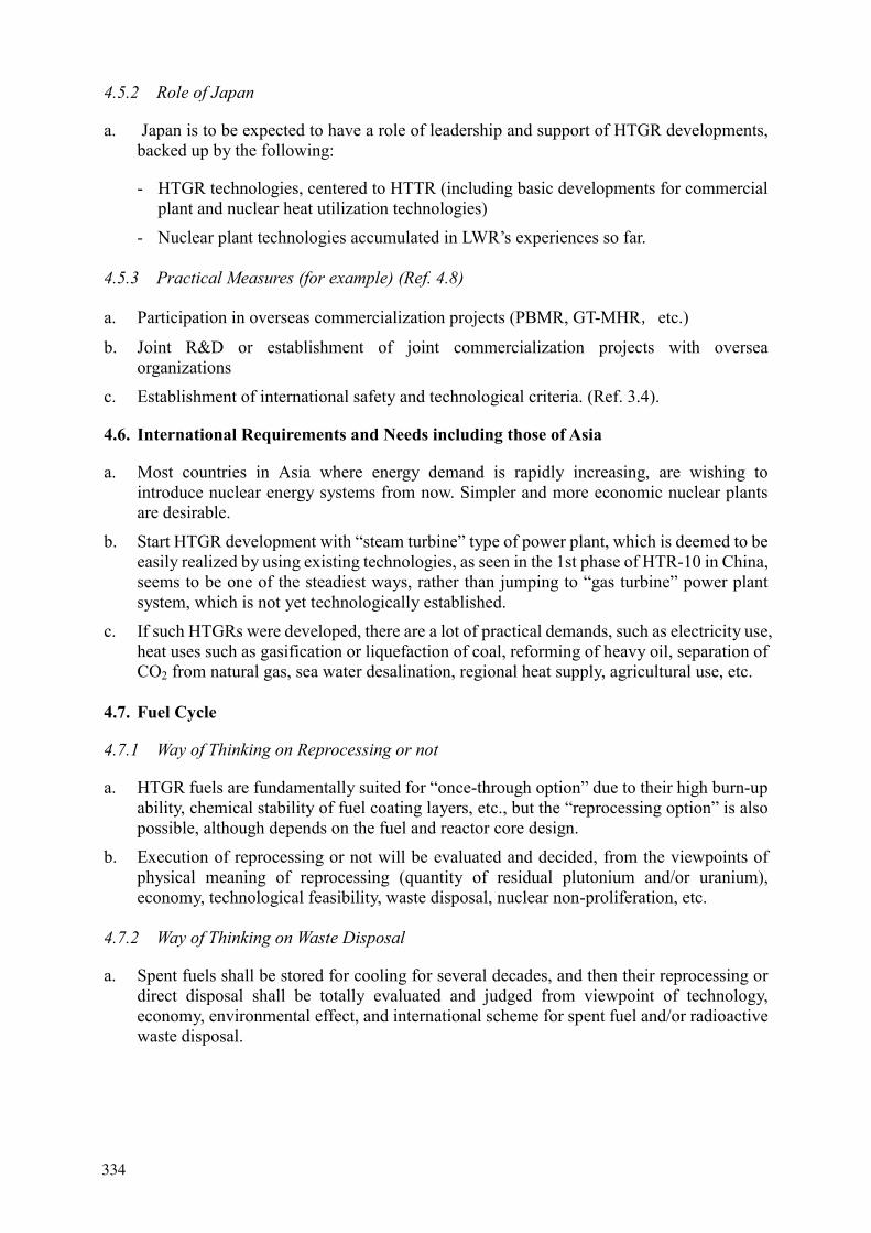
Technical design of the HTR-10 test reactor represents the features of modular HTGR design. The reactor core and steam generator are housed in two steel pressure vessels which are arranged in a “side-by-side” way (Fig.1). A connecting vessel in which the hot gas duct is situated connects the two vessels to each other . All these steel pressure vessels are in touch with the cold helium of about 250˚Ccoming out from the circulator, which sits over the steam generator tubes in the same vessel. The key design parameters are listed in Table 1.
Spherical fuel elements (6cm in diameter) with coated particles are used. The equilibrium reactor core contains about 27,000 fuel elements forming a pebble bed, which is 180 cm in diameter and 197 cm in average height. Graphite serves as the main material of core structures, which mainly consist of the top,
334336
bottom and side reflector. The ceramic core structures are housed in a metallic core vessel, which is supported on the steel pressure vessel. The side reflector is 100 cm thick. In the side reflector cold helium channels are designed in which helium flows upward after entering the reactor from between the connecting vessel and the hot gas duct. Helium flow reverses at the top of reactor core into the pebble bed, so that a downward flow pattern takes place in it. After being heated in the pebble bed, helium enters into hot gas chamber in the bottom reflector, and from there it flows with reactor outlet temperature through hot gas duct to the heat exchanging components.
FIG. 1. HTR-10 reactor and steam generator arrangement in the primary cavity
The steam generator comprises of a number of modular helical tubes, which are arranged in a circle between two insulation barrels inside the steam generator pressure vessel. The place inside the inner barrel is foreseen for an Intermediate Heat Exchanger (IHX) which is to be installed in the second phase of the project. The IHX will be large helical tube type with the primary helium flowing outside the tubes.
Decay heat removal is accomplished on a completely passive basis. In a loss of pressure accident, against which no core cooling is foreseen at all, decay power will dissipate through the core structures by means of heat conduction and radiation to the outside of the reactor pressure vessel, where a surface
Control rod drives Helium circulator Absorber balls Thermal shielding Top reflector Cold gas plenum Steam generator tubes IHX Reactor core Side reflector Core barrel Steam generator vessel Reactor vessel Bottom reflector
Hot gas duct
Connecting vessel
Hot gas plenum
Core support structures
Fuel discharge
335337

cooling system is designed on the wall of the concrete housing. This system works on the principle of natural circulation of water and it takes the decay heat via air coolers to the atmosphere. In fact, this surface cooling system is designed to protect the vessel and concrete structures more than the ceramic reactor core from being overheated by decay power.
TABLE I. KEY DESIGN PARAMETERS OF THE HTR-10 TEST REACTOR
Items First phase Second phase Thermal power MW 10 Average core power density MW/m3 2 Reactor core diameter cm 180 Average core height cm 197 Primary helium pressure MPa 3.0 Average helium temperature at reactor inlet/outlet
˚C 250/700 300/900
Helium mass flow rate at full power kg/s 4.3 3.2 Number of control rods in side reflector 10 Number of absorber ball units in side reflector 7 Nuclear fuel UO2Heavy metal loading per fuel element g 5 Enrichment of fresh fuel element % 17 Number of fuel elements in reactor core 27,000 Fuel loading mode Multi-pass
There are two reactor shutdown systems, one control rod system and one small absorber ball system. They are all designed in the side reflector. Both systems are able to bring the reactor to cold shutdown conditions. Since the reactor has strong negative temperature coefficients and decay, heat removal does not require any circulation of the helium coolant. Turning off the helium circulator can also shut down the reactor from power operating conditions.
Spherical fuel elements go through the reactor core in a “multi-pass” pattern. Fuel pebbles are continuously discharged via a pneumatic pulse single-exit gate (or better called “serializer”) which is placed inside the reactor pressure vessel. The burn-up of the discharged fuel elements is measured individually and those fuel elements which have not reached the limit value will be sent back pneumatically to the reactor core.
No pressure-containing and leak-tight containment is designed. The concrete compartments, which house the reactor vessel and the steam generator vessel as well as other parts of the primary pressure boundary and which are known as containment , together with the accident ventilation system, serve as the barrier to the radioactivity release into the environment.
2. FUEL ELEMENTS AND MANUFACTURE
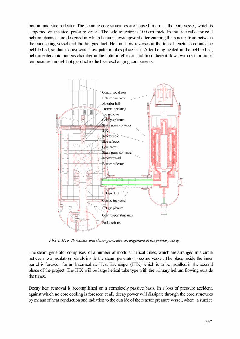
The spherical fuel elements with “TRISO” coated particles (fig. 2) are used in HTR-10. The UO2 fuel kernel of particle is coated by ceramic layers, namely the inner buffer layer with less dense pyro-carbon, the dense pyro-carbon, the SiC coating, and the outer layer of dense pyro-carbon. The coated particles are capable of retaining the noble gas fission products and solid fission products produced in UO2
kernel to prevent their release. The SiC coating serves as the crucial layer to stand against the pressure generated by gas fission products within a particle.
338
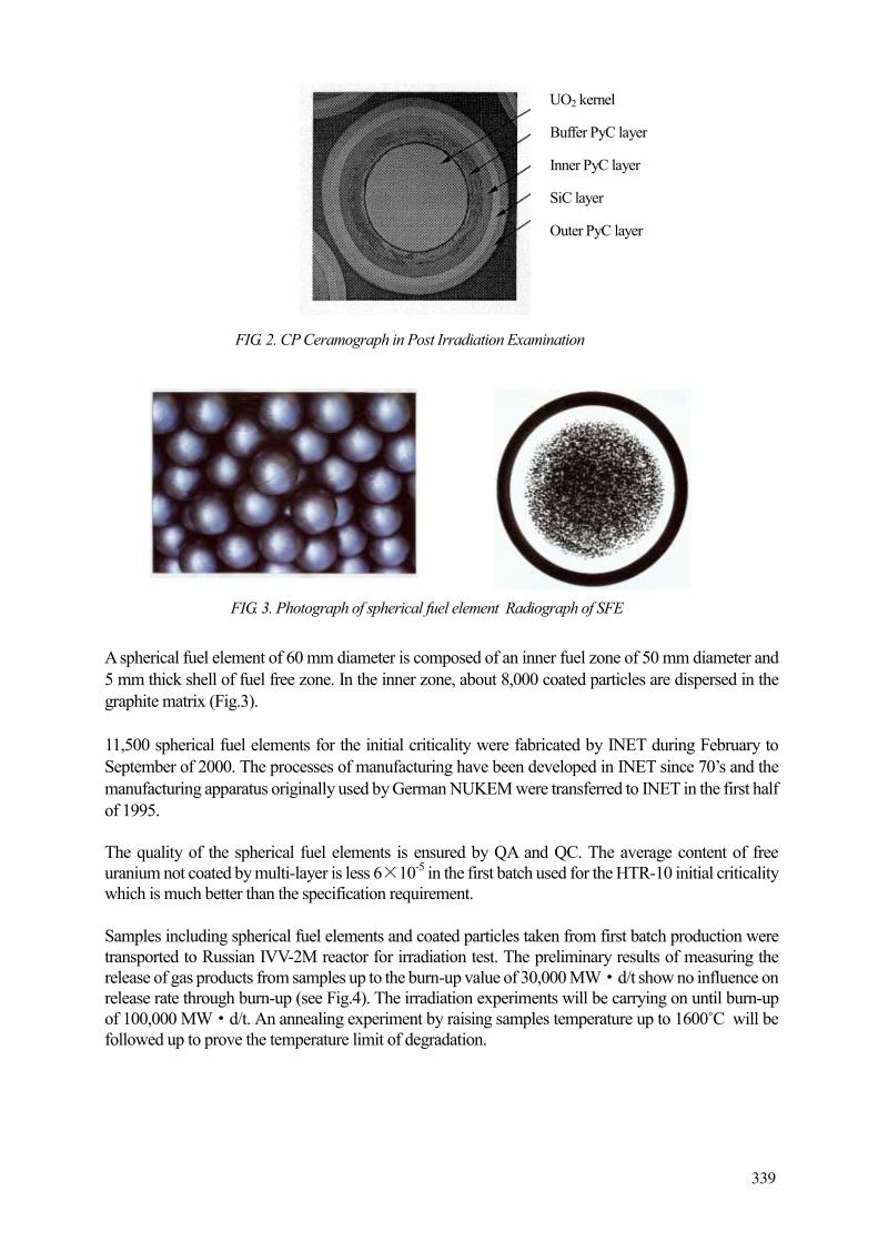
A spherical fuel element of 60 mm diameter is composed of an inner fuel zone of 50 mm diameter and 5 mm thick shell of fuel free zone. In the inner zone, about 8,000 coated particles are dispersed in the graphite matrix (Fig.3).
11,500 spherical fuel elements for the initial criticality were fabricated by INET during February to September of 2000. The processes of manufacturing have been developed in INET since 70’s and the manufacturing apparatus originally used by German NUKEM were transferred to INET in the first half of 1995.
The quality of the spherical fuel elements is ensured by QA and QC. The average content of free uranium not coated by multi-layer is less 6 10-5 in the first batch used for the HTR-10 initial criticality which is much better than the specification requirement.
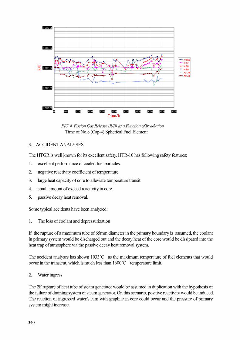
Samples including spherical fuel elements and coated particles taken from first batch production were transported to Russian IVV-2M reactor for irradiation test. The preliminary results of measuring the release of gas products from samples up to the burn-up value of 30,000 MW d/t show no influence on release rate through burn-up (see Fig.4). The irradiation experiments will be carrying on until burn-up of 100,000 MW d/t. An annealing experiment by raising samples temperature up to 1600˚C will be followed up to prove the temperature limit of degradation.
UO2 kernel
Buffer PyC layer
Inner PyC layer
SiC layer
Outer PyC layer
FIG. 2. CP Ceramograph in Post Irradiation Examination
FIG. 3. Photograph of spherical fuel element Radiograph of SFE
337339
3. ACCIDENT ANALYSES
The HTGR is well known for its excellent safety. HTR-10 has following safety features:
1. excellent performance of coaled fuel particles.
2. negative reactivity coefficient of temperature
3. large heat capacity of core to alleviate temperature transit
4. small amount of exceed reactivity in core
5. passive decay heat removal.
Some typical accidents have been analyzed:
1. The loss of coolant and depressurization
If the rupture of a maximum tube of 65mm diameter in the primary boundary is assumed, the coolant in primary system would be discharged out and the decay heat of the core would be dissipated into the heat trap of atmosphere via the passive decay heat removal system.
The accident analyses has shown 1033˚C as the maximum temperature of fuel elements that would occur in the transient, which is much less than 1600˚C temperature limit.
2. Water ingress
The 2F rupture of heat tube of steam generator would be assumed in duplication with the hypothesis of the failure of draining system of steam generator. On this scenario, positive reactivity would be induced. The reaction of ingressed water/steam with graphite in core could occur and the pressure of primary system might increase.
1. 00E- 09
1. 00E- 08
1. 00E- 07
1. 00E- 06
1. 00E- 05
0 500 1000 1500 2000 2500 3000 3500 4000 4500 5000
Time/hTime/hTime/hTime/h
R/B
R/B
R/B
R/B
Kr 85mKr 87Kr 88Kr 89Xe135Xe138
FIG. 4. Fission Gas Release (R/B) as a Function of Irradiation Time of No.8 (Cap.4) Spherical Fuel Element
338340
In consequence, the safety valve would open and the helium of primary coolant could be discharged out. The decay heat of core might be dissipated to the atmosphere via the passive heat removal system. The results of accident have indicated 1036˚C . The fuel maximum temperature in the accident is much lower than the temperature limit.
3. ATWS on mis-operation of a control rod
The accident would happen in following up drawing a control rod in mis-operation. It would be assumed the control rod would not fall down due to cramping and the reactor could not shut down. This accident is of Class IV accident. In the scenario, the pressure and temperature of reactor might be raised and the reactor could eventually be shut down by means of the negative reactivity of temperature. The decay heat of reactor would be transferred to the environment by the passive decay heat removal system.
The results of accident analysis have indicated that the maximum temperature of fuel would be below 1109˚C .
The conclusion could be drawn from the above analyses of three typical accidents:
In any severe accident conditions, the decay heat of HTR-10 could be transferred and dissipated into atmosphere via the passive decay heat removal system. The maximum temperature of fuel would not exceed beyond the temperature limit in the accident transients and the risk of core damage would be excluded.
4. ENGINEERING EXPERIMENTS
A programme of engineering experiments for the HTR-10 key technologies was conducted in INET. The main aims of these engineering experiments are to verify the designed characteristics and performance of the components and systems, to give feedback on design and to obtain operational experiences.
Various experimental facilities have been set up in INET. The key engineering experiments are as following:
• high temperature helium test loop and the relevant helium technology
• fuel handling system test
• control rod driving mechanism system
• small absorber ball simulating system
• hot gas duct test facility
• stability test of the stream generator
• helium flow temperature mixing
• pebble bed flow pattern.
The test components of the fuel handling system and the small absorber ball system, the prototype of the control rod driving apparatus and the test section of the hot gas duct are designed on a 1:1 scale.
339341
The tests have been performed at operation temperatures and under helium atmosphere conditions. Prior tests of the fuel handling system and the small absorber ball system under air condition at room temperature were carried out.
5. MANUFACTURING OF THE MAIN COMPONENTS
The main HTR-10 components, such as the reactor pressure vessel and its metallic internals, the steam generator vessel and its internals and the helium circulator are fabricated by domestic factories which have the ability and experience of manufacturing PWR’s components. The semi-finished graphite blocks of core internals and part of the safety grade helium valves are imported from foreign suppliers.
The reactor pressure vessel is a safety grade 1 component. It has an overall height of 11.4m, and a diameter of 4.2m. The total weight is 142t. It is fabricated by Shanghai Boiler Works. The metallic core internals, which consist of the metallic core vessel, top thermal shielding structure and the bottom support structures, manufactured by Shanghai Machine Works No.1. The semi-finished graphite blocks for the reflector are supplied by Toyo Tanso Co. Ltd., Japan. The final machining of the graphite blocks was done in the INET workshop. . The carbon bricks of the reflector are domestically fabricated.
The steam generator pressure vessel as part of the primary pressure boundary is also a safety grade 1 component. It has a height of 11.2 m; a diameter of 2.5 m and the total weight is 70 t. The once-through type steam generator consists of 30 small helical heating tubes. This component (vessel and internals) is fabricated by Shanghai Power Station Auxiliary Equipment Works.
The helium circulator is a vertical single-stage centrifugal one with the impeller at the end of the shaft. The circulator has the same axle with its driving motor and is fixed in the circulator pressure vessel, which is the top part of the steam generator vessel. The helium circulator is fabricated by the Shanghai Blower Works.
6. COMMISSIONING
The commissioning of HTR-10 started from April 2000 in the later stages of installation. 36 program tests were carried out in the pre-operation phase to obtain the initial parameter data of equipment and systems, examine the compatibility of operation between associated systems, and verify the function of systems and parameters of systems.
After one year, review on Final Safety Analysis Report as well as site inspection and assessment on the test results of pre-operation in commissioning, the National Nuclear Safety Administration issued the Loading Permit for HTR-10 on November 17 of 2000.
The initial criticality was carried out in the condition of room temperature and atmosphere and the loading was run by the pneumatic fuel handling system. Before the first loading, 7000 graphite balls have been bedded into the bottom graphite blocks in order to prevent crushing when balls are falling down during loading. The initial core is composed of 53% fuel balls and 47% graphite balls. In terms of neutron physical calculation the critical volume of initial core in the nominal operation condition should be as same as that of equilibrium core in which there are only fuel balls. The graphite balls would be gradually discharged in the transition from the initial core to the equilibrium core.
340342

The first loading started from November 21, 2000 and initial criticality reached on December 21, 2000. The critical numbers of fuel elements in the initial criticality is very near the estimated numbers of calculation with the difference less 1%.
The following up commissioning will be carried out in the next stage. That includes:
• The moisture retained in the graphite blocks should be removed by core heating. The heating cloud is provided by the power of the circulator in operation or an auxiliary boiler producing steam to heat helium of primary coolant via the stream generator.
• The primary system should be further evacuated to clear out remaining impurity gases. Filling helium into the primary system could be followed up.
• The criticality would be approached again after filling with helium coolant.
• The power output would be raised step by step. It is planned to connect HTR-10 to the power grid in around one year.
REFERENCE
[1] YULIANG SUN etc. The HTR-10 test reactor project and potential use of HTGR-10 for non-] electric application in China. ITEA-TECDOC-923, 1997.
341343
IAEA-SR-218/72
TECHNOLOGY DEVELOPMENT TO SUPPORT THE PROJECT OF GT-MHR MODULAR HELIUM-COOLED REACTOR WITH GAS TURBINE
A.I. KIRYUSHIN, N.G. KODOCHIGOV, A.V. VASYAEV, V.I. POLUNICHEV OKB Mechanical Engineering, Nizhny Novgorod, Russian Federation
Abstract
Modular high-temperature gas-cooled reactors (HTGR) possess all the features needed for the safe development of nuclear power, and also have good proliferation resistance properties. The international project of the GT-MHR modular helium reactor with gas turbine is suggested as one potential line of collaboration.
The conceptual Design of the GT-MHR NPP was developed with parity funding by Russian MINATOM and private funds from "General Atomics", Framatome, and "Fuji Electric" in 1997. The preliminary design of the GT-MHR NPP is currently being developed within the framework of the USA -Russian Federation scientific-technical cooperation for weapons-grade plutonium disposition.
HTGR reactor technologies (including the GT-MHR Project) have, after numerous discussions, been included in the Russian Federation's Nuclear Power Development Strategy. Stage-by-stage implementation of HTGR technology is planned, including application of the reactors for electricity generation in direct gas-turbine cycle with high efficiency and utilization of waste heat, and for generation of process heat. Effective generation of electricity in the GT-MHR plant is currently considered as the first stage of HTGR implementation in the power industry. Other applications (coal gasification, oil refinement, production of synthetic liquid fuel and hydrogen) need a non-traditional approach to safety validation and will be considered in later stages of HTGR implementation.
The GT-MHR reactor plant is based on a 600 MW high-temperature gas-cooled reactor with an annular-type active core assembled of prismatic fuel blocks. The innovative technologies of the GT-MHR Project define the main directions of related technology developments.
It is planned to construct a NPP based on the GT-MHR module and its associated fuel fabrication facilities on the Siberian Chemical Combine site. Such a co-location minimizes the risk associated with transport of fissile materials and potential subversive actions.
1. INTRODUCTION
The Long-term policy for nuclear power development in the Russian Federation is determined by “Development Strategy of Russian Nuclear Power in the First Half of the XXI-st Century” prepared by Minatom and approved approved by the Government of the Russian Federation/1/.
The basis of future nuclear power is the development of fast reactors and a closed fuel cycle. This strategy also presupposes the development of other technologies and first of all of a new generation light water reactors.
At the same time Minatom of Russia supports also the GT-MHR Project being developed according to the decision of the Joint Steering Committee (JSC) established in accordance with the Agreement between the Government of the United States of America and the Government of the Russian Federation on Scientific and Technical Cooperation in the Management of Plutonium That Has Been Withdrawn From Nuclear Military Programs dated July 24, 1998 Agreement. Minatom of Russia and the DOE of USA finance this Project on parity ratio and favor further expansion of international cooperation including the European Community and Japan.
342344

FIG. 1. GT-MHR Module.
Power conversion system
Reactor
345
The GT-MHR Project is included into the “Development Strategy of Russian Nuclear Power in the First Half of the XXI-st Century” providing for “ the participation in an international project on the development and construction of a nuclear power plant till year 2000 and “operation of GT-MHR prototype unit and production of fuel for it (within framework of International Project) till year 2030”.
The implementation of the technical concept of a modular helium reactor with gas turbine (GT-MHR, Fig. 1) is based on the use of the following advanced technologies:
- ceramic design of plutonium oxide fuel on the basis of micro- kernels with multi-layer coating which retains fission products at high temperatures (~1600 C);
- modern technologies on large gas turbines - electromagnetic bearings - high efficiency compact recuperators - heat resistance materials and large-size reactor vessels fabrication technology.
The indicated technologies constitute the innovational essence of the GT-MHR Project and determine the main trends of technology developments.
Construction of a nuclear power plant based on the GT-MHR reactor and of the facility for production of fuel is planned to commence on the Site of Siberian Chemical Combine (SCC). This decision lowers the risk associated with transportation of fission materials and possible diversions.
2. FUEL
The GT-MHR fuel design uses kernels of plutonium oxide with multi-layer coatings of carbon and silicon carbide dispersed in a graphite matrix having the form of cylindrical compact. The compacts are placed into channels of graphite blocks (Fig. 2) which are similar to FSV reactor fuel assemblies (USA)/2/.
The experiments with the irradiation of such fuel particles with plutonium oxide in Dragon and Peach Bottom reactors showed the possibility of the burnup reaching more than 700000 MW/day/3/.
One GT-MHR module of 600 MW thermal power burns about 250 kg of weapon-grade plutonium. Five GT-MHR reactors planned for construction can burn more than 50 tons of weapon-grade plutonium during their service life. Thirty four metric tons of weapon-grade plutonium can be disposed in 28 years since the moment of conversion of plutonium in GT-MHR fuel.
For obtaining a considerable amount of fission material (plutonium) in conditions of accepted GT-MHR fuel assemblies design it is necessary to reprocess several tons of graphite blocks together with fuel. This requires the creation of large-scale production with advanced technologies and can not be ignored in respect to impact on environment.
GT-MHR fuel discharged after a single-passage irradiation in the reactor core contains less than 30% of the initial Pu-139. Considering this aspect as well as that the plutonium of discharged fuel contains up to 30% of Pu-240, which is a strong absorber, it becomes clear that obtaining the fission materials of weapon-grade quality from the discharged fuel is fruitless. Thus, the GT-MHR concept meets the requirement of non-proliferation.
344346

FIG. 2. Fuel components with Plutonium charge.
FIG. 3. Arrangement plant for BIU boxes chain.
345347
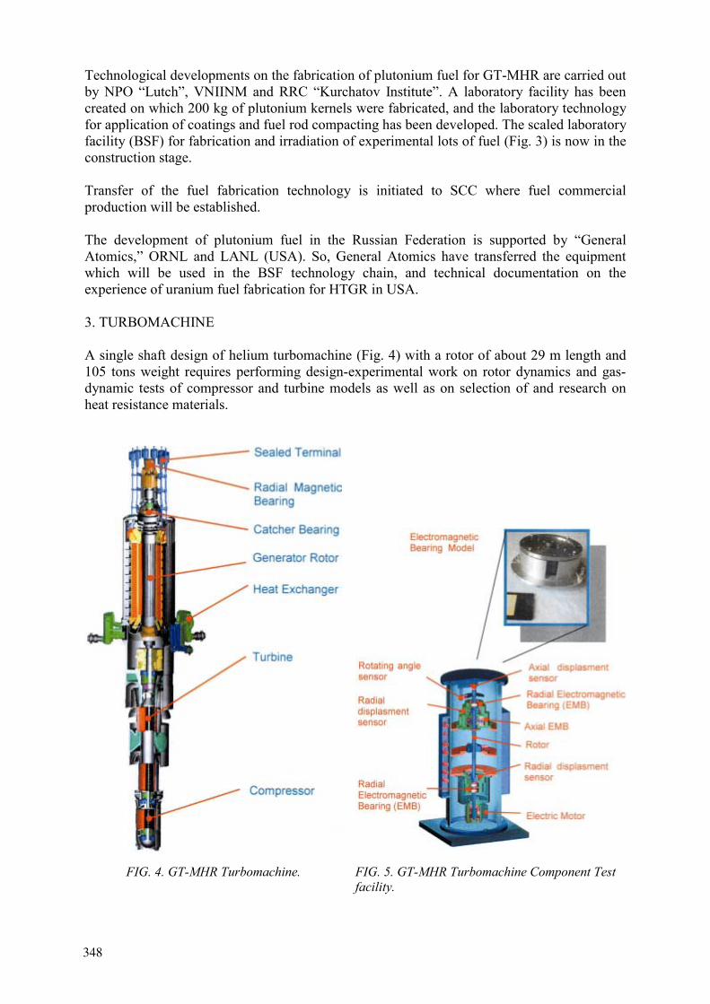
Technological developments on the fabrication of plutonium fuel for GT-MHR are carried out by NPO “Lutch”, VNIINM and RRC “Kurchatov Institute”. A laboratory facility has been created on which 200 kg of plutonium kernels were fabricated, and the laboratory technology for application of coatings and fuel rod compacting has been developed. The scaled laboratory facility (BSF) for fabrication and irradiation of experimental lots of fuel (Fig. 3) is now in the construction stage.
Transfer of the fuel fabrication technology is initiated to SCC where fuel commercial production will be established.
The development of plutonium fuel in the Russian Federation is supported by “General Atomics,” ORNL and LANL (USA). So, General Atomics have transferred the equipment which will be used in the BSF technology chain, and technical documentation on the experience of uranium fuel fabrication for HTGR in USA.
3. TURBOMACHINE
A single shaft design of helium turbomachine (Fig. 4) with a rotor of about 29 m length and 105 tons weight requires performing design-experimental work on rotor dynamics and gas-dynamic tests of compressor and turbine models as well as on selection of and research on heat resistance materials.
FIG. 4. GT-MHR Turbomachine. FIG. 5. GT-MHR Turbomachine Component Test facility.
346348

The turbocompressor design is developed by best specialists of the Russian Academy of Sciences and Russian Federation enterprises having experience and modern technologies in the field of compressors, gas turbines and structural materials development including aviation and rocket-space enterprises:
- Central Institute of Aviation Motorbuilding, Moscow;
- Kuznetsov Samara Scientific-Technical Complex, Samara;
- Keldysh Research Center, Moscow;
- Leningrad Metaalworks, St. Petersburg;
- Central Scientific-Research Institute of Structural Materials, “Prometey”, St.Petersburg;
- All-Russia Institute of Alloys, Moscow.
To investigate dynamics of a flexible rotor a mini-mockup (Fig. 5) was fabricated in the OKBM. The carrying-out the experiments on this equipment is planned at the end of 2000.
4. ELECTROMAGNETIC BEARINGS
SPE VNIIEM (Scientific-Production Enterprise “All-Russia Scientific-Research Institute of Electromechanics”), Moscow, is involved in solving tasks on electromagnetic suspension of the rotor. This enterprise is a leading Russian one providing gas-pumping stations and other apparatus with electromagnetic suspension systems. The possibility and conditions of participation of Federal Mogul Magnetic Bearings (USA) and S2M (France) in the Project is discussed.
The following is foreseen to validate the reliability and safety of the turbomachine operation entirely on electromagnetic suspension:
- tests of rotor model and of electromagnetic bearings provided with control system on mini-mockups;
- tests of scale mode of the rotor (1:10);
- tests of full-size electromagnetic bearings;
- tests of the entire set of electromagnetic bearings with control system.
5. RECUPERATOR
In the framework of the GT-MHR Conceptual Design a largely new compact design of high efficiency plate-type recuperator has been developed. To validate the recuperator design the experimental development of its component fabrication technology of the heat exchange surface with compactness of 1500 m2/m3 has been carried out and the full-size heat exchange element of the recuperator manufactured (Fig. 6).
The heat exchange element was subjected to comprehensive tests at working temperature in aerodynamic and helium rigs at the OKBM.
During the tests of the heat exchange element (Fig. 7) its aerodynamic and thermodynamic characteristics were validated, as well as recommendations worked out for its improvement that would allow its efficiency to be increased up to 95%.
349
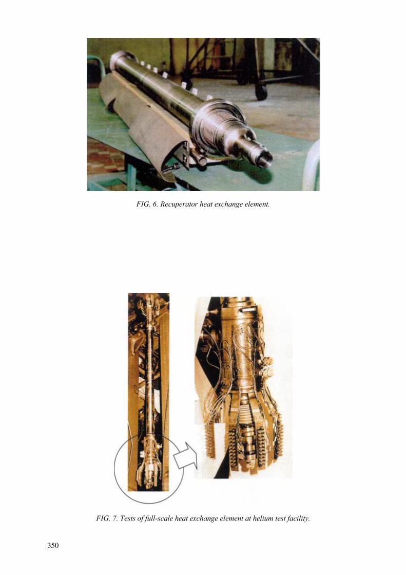
FIG. 6. Recuperator heat exchange element.
FIG. 7. Tests of full-scale heat exchange element at helium test facility.
348350

FIG. 8. 15MW Helium test facility for tests of Heat exchangers.
The design of a plate-type recuperator is being perfected using the results of investigation on the Preliminary Design stage.
To test large-scale models of heat exchange equipment OKBM has a 15 MW helium test facility with helium temperature of up to 965 oC (Fig. 8)
6. HEAT RESISTANCE MATERIALS AND TECHNOLOGIES OF VESSELS’ SYSTEM FABRICATION
One of the most complex elements of the GT-MHR vessel system is the reactor vessel operating at high temperatures (Fig. 9).
Heat resistant steel 10Cr9MoVNb (TU 108.11.733-83) was chosen as the main candidate for the reactor vessel material. For a complex of properties the steel meets the requirements for the material of GT-MHR vessels. A comprehensive data for this steel is available including data on irradiation, the experience of using it for steam superheating systems and for thermal stations pipelines.
To use this steel in the GT-MHR it is necessary to carry out a complex of certification tests according to the normative requirements of RF GAN for the application of 10Cr9MoVNb steel as a reactor vessel material.
Carrying out the initial experimental works is planned within framework of the ISTC Project.
351

FIG. 9. Reactor vessel of GT-MHR.
7. CONCLUSION
1. The fuel design ensures a high burnup of plutonium in the GT-MHR. The burnt-up fuel is unsuitable for obtaining weapon-grade quality fission material and meets the requirement of non-proliferation.
2. Technological developments for the validation of the GT-MHR Project technical decisions as well as using the experience and the technologies transferred from the USA lower the technical risk of the Project.
3. There are good prospects for expansion of the international technological basis of the GT-MHR Project through joining the European Community, Framatome (France), Fuji Electric (Japan) and others to the program.
REFERENCES
[1] Russia Minatom “ Development Strategy of Russian Nuclear Power in the First Half of XXI-st Century”. Main Statements. Moscow, 2000.
[2] GILBERT MELESE, Robert Katz, Thermal and Flow Design of Helium-Cooled Reactors, American Nuclear Society, La Grange Park, Illinois, USA.
[3] General Atomics. “The Modular HTGR for the Destruction of the Surplus Weapons-Grade Plutonium”. December 10, 1992.
350352
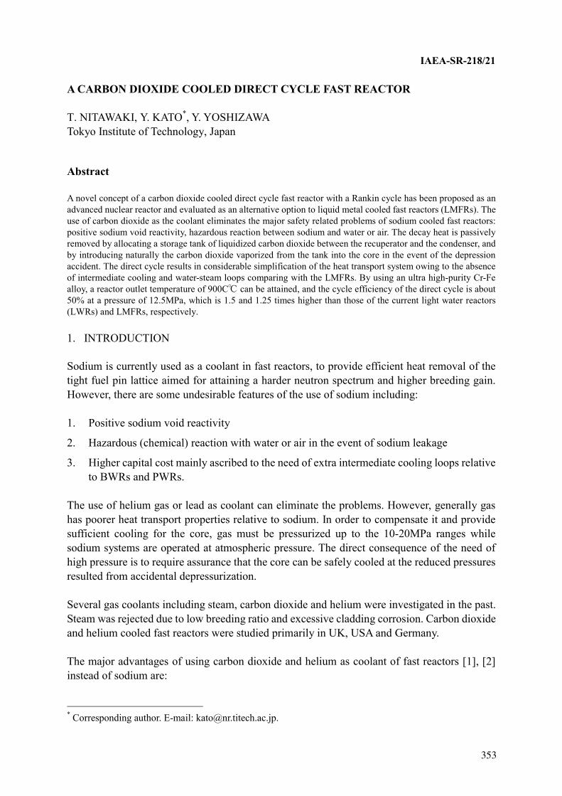
IAEA-SR-218/21
A CARBON DIOXIDE COOLED DIRECT CYCLE FAST REACTOR
T. NITAWAKI, Y. KATO*, Y. YOSHIZAWA Tokyo Institute of Technology, Japan
Abstract
A novel concept of a carbon dioxide cooled direct cycle fast reactor with a Rankin cycle has been proposed as an advanced nuclear reactor and evaluated as an alternative option to liquid metal cooled fast reactors (LMFRs). The use of carbon dioxide as the coolant eliminates the major safety related problems of sodium cooled fast reactors: positive sodium void reactivity, hazardous reaction between sodium and water or air. The decay heat is passively removed by allocating a storage tank of liquidized carbon dioxide between the recuperator and the condenser, and by introducing naturally the carbon dioxide vaporized from the tank into the core in the event of the depression accident. The direct cycle results in considerable simplification of the heat transport system owing to the absence of intermediate cooling and water-steam loops comparing with the LMFRs. By using an ultra high-purity Cr-Fe alloy, a reactor outlet temperature of 900C can be attained, and the cycle efficiency of the direct cycle is about 50% at a pressure of 12.5MPa, which is 1.5 and 1.25 times higher than those of the current light water reactors (LWRs) and LMFRs, respectively.
1. INTRODUCTION
Sodium is currently used as a coolant in fast reactors, to provide efficient heat removal of the tight fuel pin lattice aimed for attaining a harder neutron spectrum and higher breeding gain. However, there are some undesirable features of the use of sodium including:
1. Positive sodium void reactivity
2. Hazardous (chemical) reaction with water or air in the event of sodium leakage
3. Higher capital cost mainly ascribed to the need of extra intermediate cooling loops relative to BWRs and PWRs.
The use of helium gas or lead as coolant can eliminate the problems. However, generally gas has poorer heat transport properties relative to sodium. In order to compensate it and provide sufficient cooling for the core, gas must be pressurized up to the 10-20MPa ranges while sodium systems are operated at atmospheric pressure. The direct consequence of the need of high pressure is to require assurance that the core can be safely cooled at the reduced pressures resulted from accidental depressurization.
Several gas coolants including steam, carbon dioxide and helium were investigated in the past. Steam was rejected due to low breeding ratio and excessive cladding corrosion. Carbon dioxide and helium cooled fast reactors were studied primarily in UK, USA and Germany.
The major advantages of using carbon dioxide and helium as coolant of fast reactors [1], [2] instead of sodium are:
* Corresponding author. E-mail: [email protected].
351353
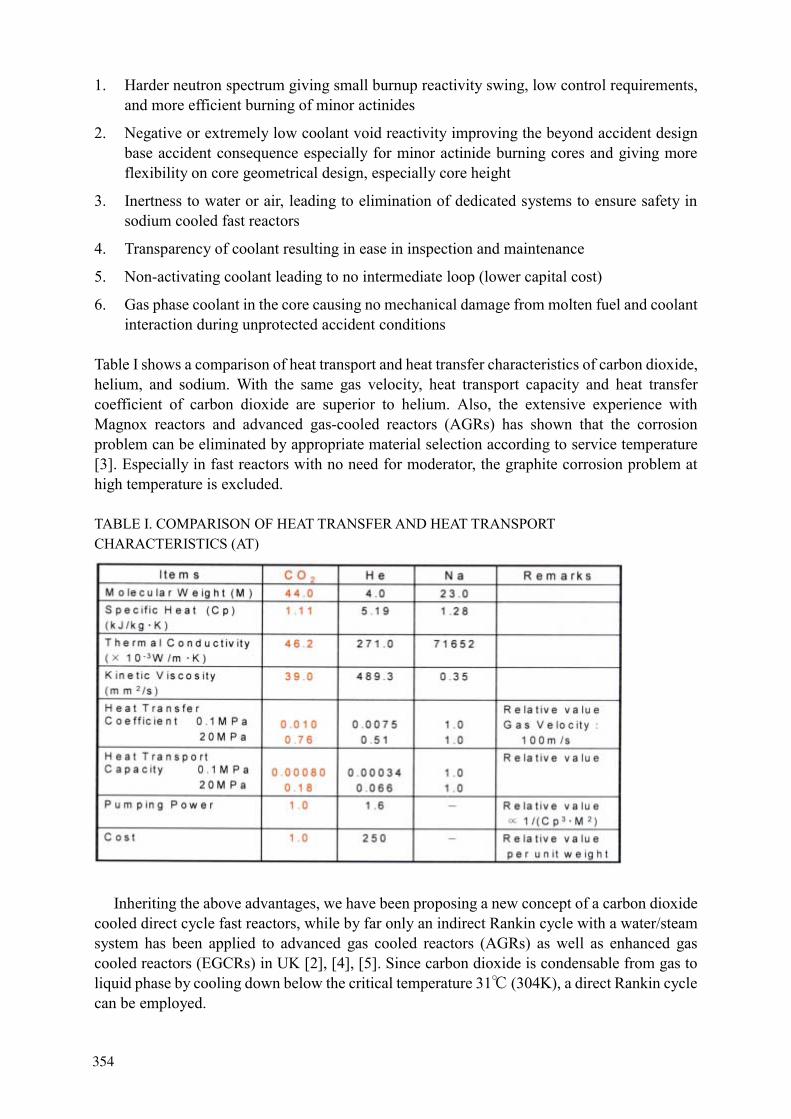
1. Harder neutron spectrum giving small burnup reactivity swing, low control requirements, and more efficient burning of minor actinides
2. Negative or extremely low coolant void reactivity improving the beyond accident design base accident consequence especially for minor actinide burning cores and giving more flexibility on core geometrical design, especially core height
3. Inertness to water or air, leading to elimination of dedicated systems to ensure safety in sodium cooled fast reactors
4. Transparency of coolant resulting in ease in inspection and maintenance
5. Non-activating coolant leading to no intermediate loop (lower capital cost)
6. Gas phase coolant in the core causing no mechanical damage from molten fuel and coolant interaction during unprotected accident conditions
Table I shows a comparison of heat transport and heat transfer characteristics of carbon dioxide, helium, and sodium. With the same gas velocity, heat transport capacity and heat transfer coefficient of carbon dioxide are superior to helium. Also, the extensive experience with Magnox reactors and advanced gas-cooled reactors (AGRs) has shown that the corrosion problem can be eliminated by appropriate material selection according to service temperature [3]. Especially in fast reactors with no need for moderator, the graphite corrosion problem at high temperature is excluded.
TABLE I. COMPARISON OF HEAT TRANSFER AND HEAT TRANSPORT CHARACTERISTICS (AT)
Inheriting the above advantages, we have been proposing a new concept of a carbon dioxide cooled direct cycle fast reactors, while by far only an indirect Rankin cycle with a water/steam system has been applied to advanced gas cooled reactors (AGRs) as well as enhanced gas cooled reactors (EGCRs) in UK [2], [4], [5]. Since carbon dioxide is condensable from gas to liquid phase by cooling down below the critical temperature 31 (304K), a direct Rankin cycle can be employed.
352354
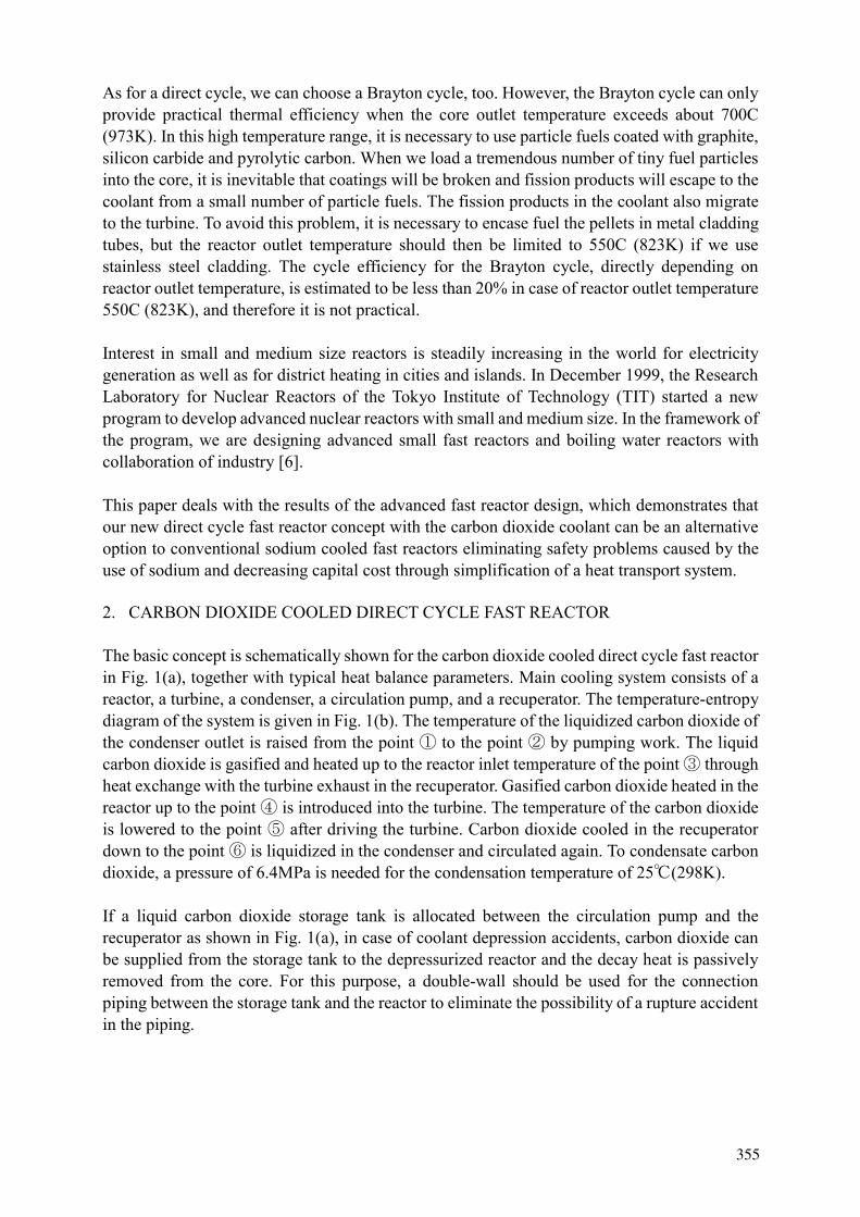
As for a direct cycle, we can choose a Brayton cycle, too. However, the Brayton cycle can only provide practical thermal efficiency when the core outlet temperature exceeds about 700C (973K). In this high temperature range, it is necessary to use particle fuels coated with graphite, silicon carbide and pyrolytic carbon. When we load a tremendous number of tiny fuel particles into the core, it is inevitable that coatings will be broken and fission products will escape to the coolant from a small number of particle fuels. The fission products in the coolant also migrate to the turbine. To avoid this problem, it is necessary to encase fuel the pellets in metal cladding tubes, but the reactor outlet temperature should then be limited to 550C (823K) if we use stainless steel cladding. The cycle efficiency for the Brayton cycle, directly depending on reactor outlet temperature, is estimated to be less than 20% in case of reactor outlet temperature 550C (823K), and therefore it is not practical.
Interest in small and medium size reactors is steadily increasing in the world for electricity generation as well as for district heating in cities and islands. In December 1999, the Research Laboratory for Nuclear Reactors of the Tokyo Institute of Technology (TIT) started a new program to develop advanced nuclear reactors with small and medium size. In the framework of the program, we are designing advanced small fast reactors and boiling water reactors with collaboration of industry [6].
This paper deals with the results of the advanced fast reactor design, which demonstrates that our new direct cycle fast reactor concept with the carbon dioxide coolant can be an alternative option to conventional sodium cooled fast reactors eliminating safety problems caused by the use of sodium and decreasing capital cost through simplification of a heat transport system.
2. CARBON DIOXIDE COOLED DIRECT CYCLE FAST REACTOR
The basic concept is schematically shown for the carbon dioxide cooled direct cycle fast reactor in Fig. 1(a), together with typical heat balance parameters. Main cooling system consists of a reactor, a turbine, a condenser, a circulation pump, and a recuperator. The temperature-entropy diagram of the system is given in Fig. 1(b). The temperature of the liquidized carbon dioxide of the condenser outlet is raised from the point to the point by pumping work. The liquid carbon dioxide is gasified and heated up to the reactor inlet temperature of the point through heat exchange with the turbine exhaust in the recuperator. Gasified carbon dioxide heated in the reactor up to the point is introduced into the turbine. The temperature of the carbon dioxide is lowered to the point after driving the turbine. Carbon dioxide cooled in the recuperator down to the point is liquidized in the condenser and circulated again. To condensate carbon dioxide, a pressure of 6.4MPa is needed for the condensation temperature of 25 (298K).
If a liquid carbon dioxide storage tank is allocated between the circulation pump and the recuperator as shown in Fig. 1(a), in case of coolant depression accidents, carbon dioxide can be supplied from the storage tank to the depressurized reactor and the decay heat is passively removed from the core. For this purpose, a double-wall should be used for the connection piping between the storage tank and the reactor to eliminate the possibility of a rupture accident in the piping.
353355

FIG. 1. Schematic diagram for carbon dioxide cooled direct cycle.
FIG. 2. Cycle efficiency curve for carbon dioxide cooled direct cycle.
354356

FIG. 3. Schematic diagram for partial condensation cycle.
FIG. 4. Cycle efficiency curve for partial condensation cycle.
355357
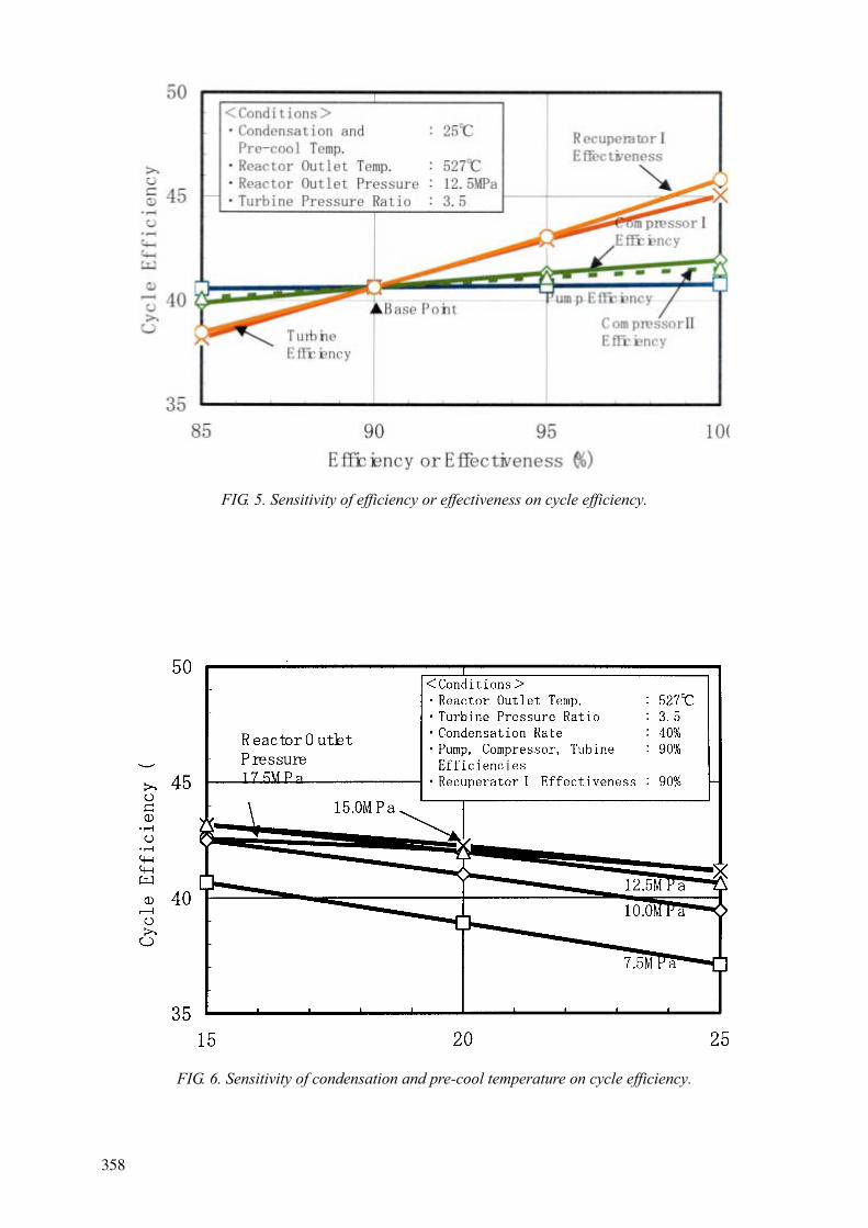
FIG. 5. Sensitivity of efficiency or effectiveness on cycle efficiency.
FIG. 6. Sensitivity of condensation and pre-cool temperature on cycle efficiency.
356358

Fig.2 shows cycle efficiency of the direct cycle with wide range of reactor outlet temperature under the conditions of the following plant efficiencies:
Pump efficiency = 95% Turbine efficiency =90%
Recuperator effectiveness* = 90% (* Means heat exchanger effectiveness, which is defined by the ratio of the effective recuperated heat to the ideal recuperative heat of turbine exhaust.)
The cycle efficiency in the case of pressure and temperature conditions shown in Fig.1 (a) is about 33%. It is nearly equal to those of LWRs, but it is lower than those of usual LMFRs (about 40%).
Cycle efficiency can be improved by increasing reactor outlet temperature and pressure as shown in Fig.2. Improvement of cycle efficiency can be also achieved by introduction of a pre-cooler and pre-compressor before the condenser, and by using a multi-recuperator with high effectiveness. Fig.3(a) shows a schematic diagram for this cycle with the pre-cooler, two compressors ( and ) and two recuperators ( and ). Gas cooled in the recuperator and recuperator is additionally cooled in the pre-cooler to the point . After that, the gas is compressed by compressor to the set pressure point , which depends on the condensation temperature. With sufficiently high effectiveness of the recuperator , the equilibrium of the temperature difference in the recuperator requires a by-pass of flow before condensation. The by-pass gas is compressed by the compressor to the point , and mixed with the outlet gas of the low temperature side from the recuperator at this point.
Fig.4 shows cycle efficiencies evaluated under the following conditions for the partial condensation cycle. In this evaluation, a turbine pressure ratio of 3.5 is commonly used to gain approximately maximum cycle efficiency for all of conditions. Then the condensation rate is set to the logarithmic mean temperature difference of 30C for the recuperator in each case.
Condensation and pre-cool temperatures= 25C
Turbine pressure ratio= 3.5
Pump, compressor, and turbine efficiency= 90%
Recuperator effectiveness= 90%
(The effectiveness of recuperator is determined by heat balance.)
Comparing the results in Fig.2 with those in Fig.4, it is seen that the cycle efficiency can be considerably improved over several percent by introducing the partial condensation cycle pre-cooler and compressor. It is mainly due to the reduction of reactor power causing a rise of the reactor inlet temperature by using the recuperator with sufficiently high effectiveness. In order to maximize the cycle efficiency without an excessive plant cost increase, optimization studies have been undertaken.
Recently, an ultra high-purity Cr-Fe alloy has been developed, whose tensile strength is four times higher at 1200C than that of Ni-based alloy [7],[8]. Besides, the absence of Ni makes it possible to reduce (n, ) and (n, p) reaction in the Cr-Fe alloy to one-fifth comparing with
357359

316 stainless steel, which contribute to swelling of stainless steels. Consequently, the irradiation limit in fast neutron flux is expected to be 2 or 3 times higher at least than that of Ni contained alloy.
By using this ultra high-purity Cr-Fe alloy as fuel cladding, the cycle efficiency is over 50% from Fig.4 when reactor outlet pressure is 12.5MPa and reactor outlet temperature is 900(cladding hot spot temperature =1200 ). The efficiency is 1.5 and 1.25 times higher than those of LWRs and LMFRs, respectively.
Fig.5 shows sensitivities of the pump efficiency, the compressor efficiencies, the turbine efficiency, and the recuperator effectiveness on the cycle efficiency for a partial condensation cycle. The cycle efficiency is not so sensitive to the pump efficiency. This result is ascribed to the fact that the pump work needed for the liquid coolant is significantly smaller than the turbine work in this cycle, while the compressor work needed for gaseous coolant is not so small in a simple Brayton cycle. The cycle efficiency is most sensitive to the effectiveness of the recuperator and turbine. The recuperator has also larger amount of heat exchange than the reactor power even in the simple cycle with lower cycle efficiency as shown in Fig.1 (a). It means that the recuperator is one of the most important equipment in this cycle, and it is necessary to develop a recuperator with higher effectiveness for improving cycle efficiency.
Fig.6 shows the sensitivity of the condensation and pre-cool temperature on the cycle efficiency when the reactor outlet temperature is 527 (800K). Naturally, the lower temperature can achieve a higher efficiency, however, the sensitivity becomes gradually saturated as the reactor outlet pressure increases. The relation of cycle efficiency with reactor outlet pressure is reversed at a high pressure of 15~17.5MPa. This is because that reactor power increase due to the decrease of reactor inlet temperature is larger than the effective work increase in the high-pressure region.
CONCLUSIONS
The proposed concept of the carbon dioxide direct cooled cycle fast reactor in this study has the following promising features, which are expected to be a potential alternative option to sodium cooled fast reactors:
1. Exclusion of safety problems specific to sodium cooled fast reactors 2. Effective burning of minor actinides 3. Passive decay heat removal 4. Simplification of plant systems and reduction of capital cost 5. Cycle efficiency 1.5 and 1.25 times higher than those of LWRs and LMFRs, respectively.
REFERENCES
[1] E. WALTAR AND A. B. REYNOLDS, Fast breeder reactors, pp.705-706, Pergamon Press (1981).
[2] P. GRATTON, The gas-cooled fast reactor in 1981, Nuclear Energy, Vol. 20, pp. 287-295 (1981).
358360
[3] G. B. GIBBS, L.A. POPPLE, Oxidation of structural steels in CO2 cooled reactors, Nuclear Energy, Vol.21, pp.51-55 (1982).
[4] T. A. LENNOX, D. M. BANKS, J. E. GILROY AND R. E. SUNDERLAND, Gas cooled fast reactors, Trans. ENC 98, Vol. IV, TAL/005392 (1998).
[5] T. J. ABRAM, D. P. EVERY, B. FARRAR, G. HULME, T. A. LENNOX AND R. E. SUNDERLAND, The enhanced gas cooled reactor (EGCR), Proc. 8th Int. Conf. on Nuclear Engineering, ICONE-8289 (2000).
[6] J.YAMASHITA, M.OHTSUKA, K. FUJIMURA AND Y.KATO, An innovative conceptual design of safe and simplified boiling water reactor (SSBWR), Proc. Intl. Seminar on Status and Prospects for Small and Medium Sized Reactors, IAEA-SR-218/23, (2001).
[7] GAKU KANOU, NOBUYUKI HARIMA, SEIICHI TAKAKI AND KENJI ABIKO, Mechanical properties of a high-purity 60 mass% Cr-Fe alloy, Materials Transactions, JIM,Vol.41, No.1, pp.197-202 (2000).
[8] KENJI ABIKO, Nikkei Science, No.10, pp.32-41 (2000)
359361


![Improving economics and safety of water cooled … Nuclear power plants (NPPs) with water cooled reactors [either light water reactors (LWRs) or heavy water reactors (HWRs)] constitute](https://img.pdfslide.net/doc/110x75/5b88e5437f8b9a46538ebfc1/improving-economics-and-safety-of-water-cooled-nuclear-power-plants-npps-with.jpg)