Embed Size (px)
DESCRIPTION
GAS DISTRIBUTION SYSTEM & FLOW STUDIES OF MM-NSW. T. Alexopoulos, S. Maltezos, S. Karentzos National Technical University of Athens. Outline -- Updates. Updated design and configuration of the gas distribution system Results from the simulation ( “ Pipe-Flow ” ) Gas Flow Studies. - PowerPoint PPT Presentation
Citation preview
11
25.03.2014 NSW/MM Layout & Design Working Group
GAS DISTRIBUTIONGAS DISTRIBUTION SYSTEM & FLOW STUDIES OF MM-NSW SYSTEM & FLOW STUDIES OF MM-NSW
T. Alexopoulos, S. Maltezos, S. Karentzos T. Alexopoulos, S. Maltezos, S. Karentzos
National Technical University of AthensNational Technical University of Athens
22
25.03.2014 NSW/MM Layout & Design Working Group
• Updated design and configuration of the gas distribution systemUpdated design and configuration of the gas distribution system
• Results from the simulation (“Pipe-Flow”)Results from the simulation (“Pipe-Flow”)
• Gas Flow StudiesGas Flow Studies
Outline -- UpdatesOutline -- Updates
33
25.03.2014 NSW/MM Layout & Design Working Group
What is available for the gas system?
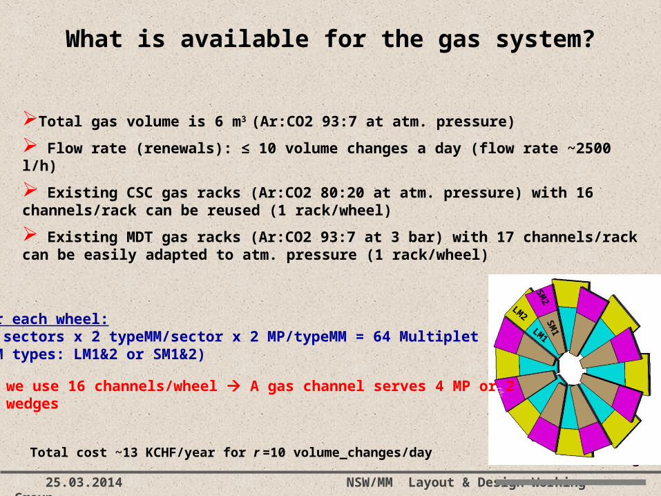
Total gas volume is 6 m3 (Ar:CO2 93:7 at atm. pressure)
Flow rate (renewals): ≤ 10 volume changes a day (flow rate ~2500 l/h)
Existing CSC gas racks (Ar:CO2 80:20 at atm. pressure) with 16 channels/rack can be reused (1 rack/wheel)
Existing MDT gas racks (Ar:CO2 93:7 at 3 bar) with 17 channels/rack can be easily adapted to atm. pressure (1 rack/wheel)
For each wheel:16 sectors x 2 typeMM/sector x 2 MP/typeMM = 64 Multiplet(MM types: LM1&2 or SM1&2)
we use 16 channels/wheel A gas channel serves 4 MP or 2 wedges
LM1
LM2
SM
2S
M1
Total cost ~13 KCHF/year for r =10 volume_changes/day
44
25.03.2014 NSW/MM Layout & Design Working Group
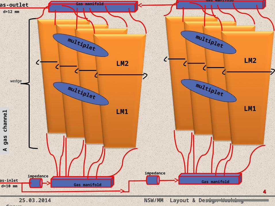
LM1
LM2
wedge
gas-inlet
gas-outlet
impedance
Gas manifold
multiplet
multiplet
LM1
LM2
impedance
Gas manifold
multiplet
multiplet
A g
as c
han
nel
Gas manifoldGas manifold
d=10 mm
d=12 mm
55
25.03.2014 NSW/MM Layout & Design Working Group
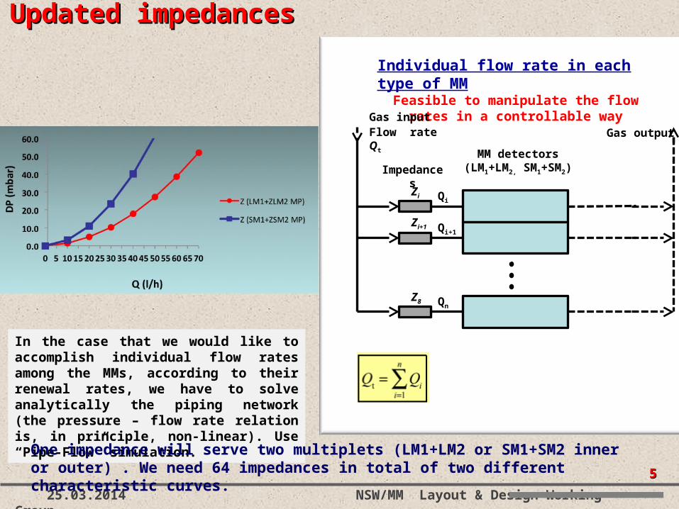
Individual flow rate in each type of MMFeasible to manipulate the flow rates in a
controllable way
Impedances
MM detectors(LM1+LM2, SM1+SM2)
Gas input
Gas outputFlow rate Qt
Qi+1
Qn
QiZi
Zi+1
Z8
Updated impedancesUpdated impedances
In the case that we would like to accomplish individual flow rates among the MMs, according to their renewal rates, we have to solve analytically the piping network (the pressure – flow rate relation is, in principle, non-linear). Use “Pipe-Flow” simulation.
One impedance will serve two multiplets (LM1+LM2 or SM1+SM2 inner or outer) . We need 64 impedances in total of two different characteristic curves.
66
25.03.2014 NSW/MM Layout & Design Working Group
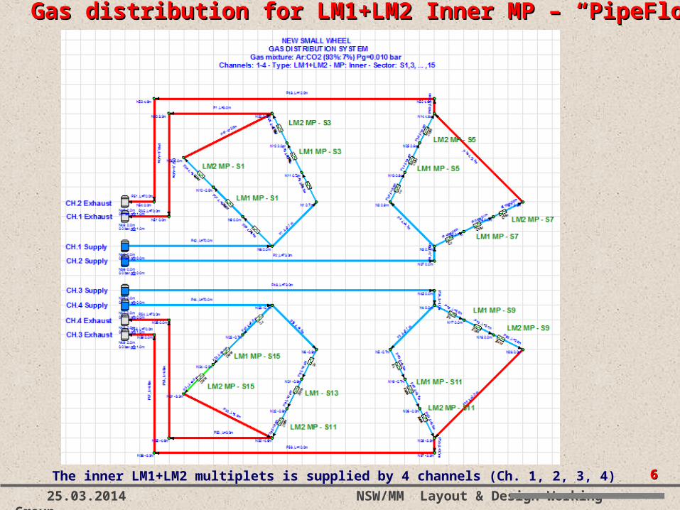
The inner LM1+LM2 multiplets is supplied by 4 channels (Ch. 1, 2, 3, 4)
Gas distribution for LM1+LM2 Inner MP Gas distribution for LM1+LM2 Inner MP –– “PipeFlow” “PipeFlow”
77
25.03.2014 NSW/MM Layout & Design Working Group
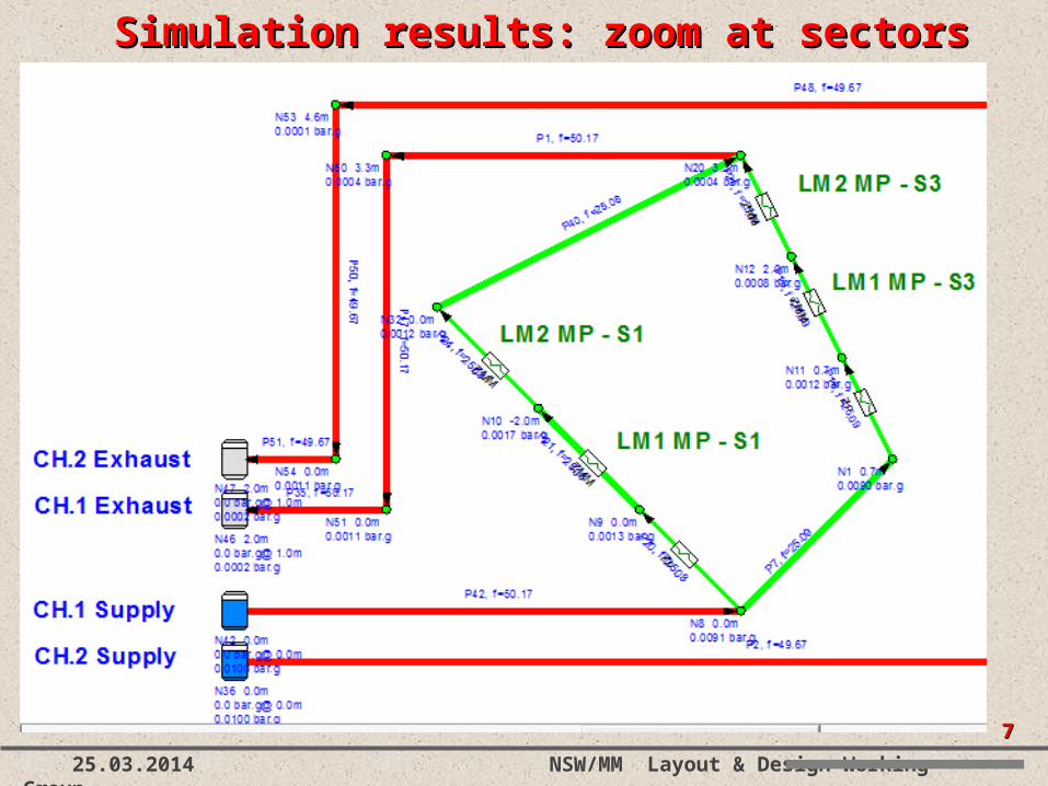
Simulation results: zoom at sectors 1 Simulation results: zoom at sectors 1 & 3& 3
88
25.03.2014 NSW/MM Layout & Design Working Group
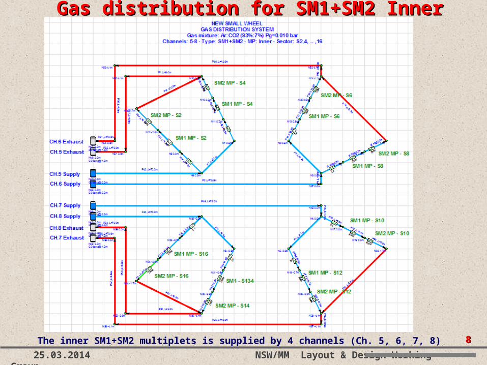
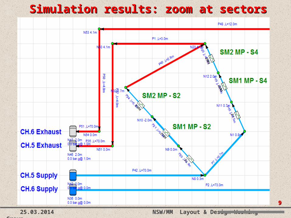
Gas distribution for SM1+SM2 Inner Gas distribution for SM1+SM2 Inner MP MP
The inner SM1+SM2 multiplets is supplied by 4 channels (Ch. 5, 6, 7, 8)
99
25.03.2014 NSW/MM Layout & Design Working Group
Simulation results: zoom at sectors 2 Simulation results: zoom at sectors 2 & 4& 4
1010
25.03.2014 NSW/MM Layout & Design Working Group
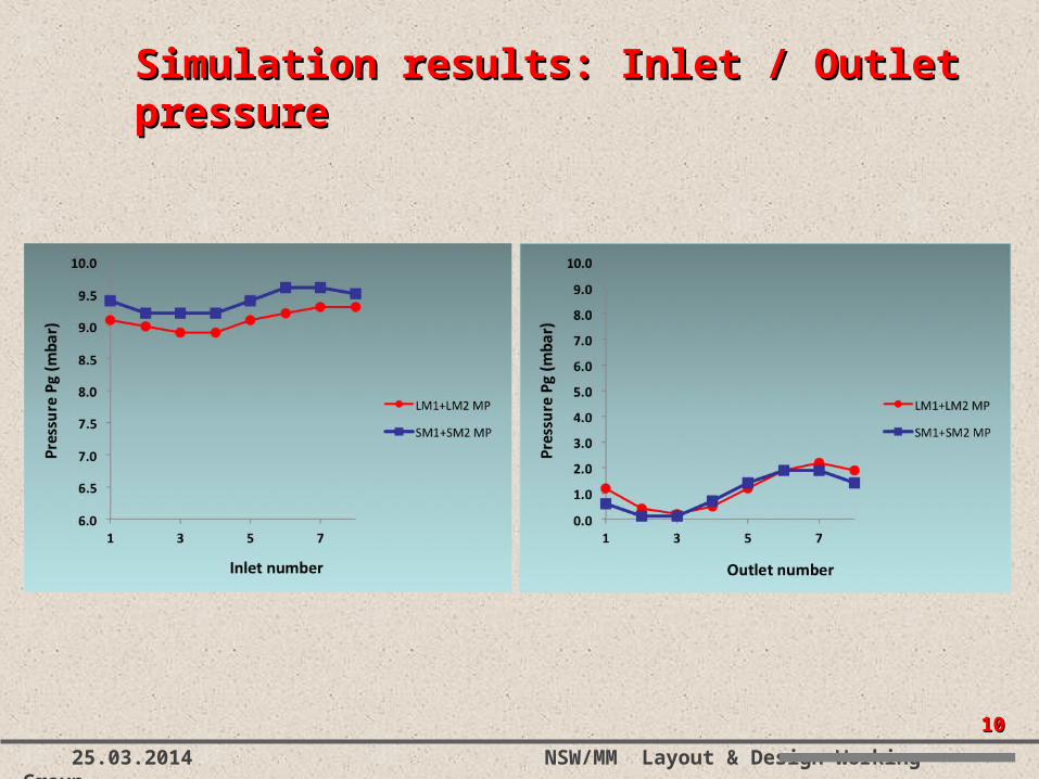
Simulation results: Inlet / Outlet Simulation results: Inlet / Outlet pressurepressure
1111
25.03.2014 NSW/MM Layout & Design Working Group
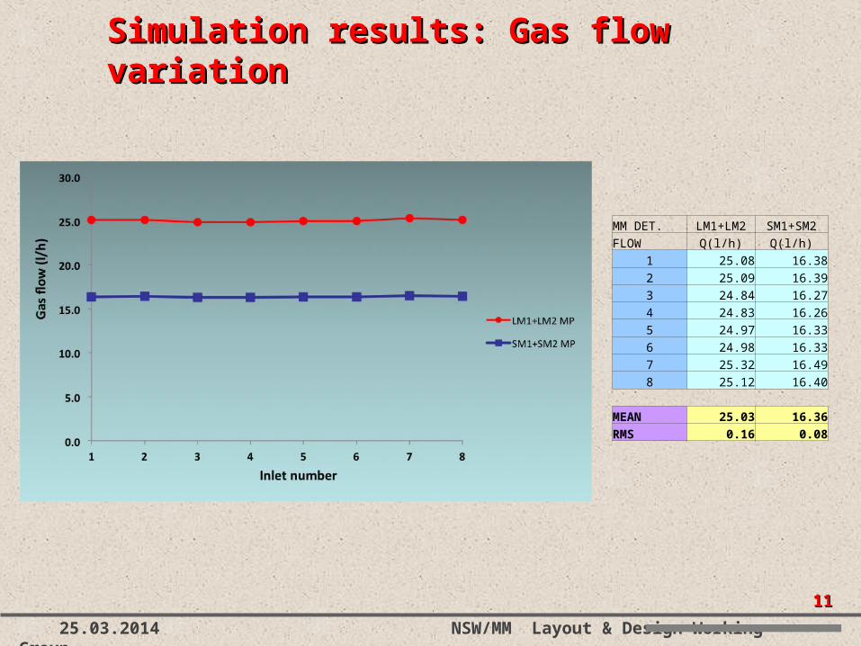
Simulation results: Gas flow variation Simulation results: Gas flow variation
MM DET. LM1+LM2 SM1+SM2
FLOW Q(l/h) Q(l/h)
1 25.08 16.38
2 25.09 16.39
3 24.84 16.27
4 24.83 16.26
5 24.97 16.33
6 24.98 16.33
7 25.32 16.49
8 25.12 16.40
MEAN 25.03 16.36
RMS 0.16 0.08
1212
25.03.2014 NSW/MM Layout & Design Working Group
0.5mm
2mm2mm
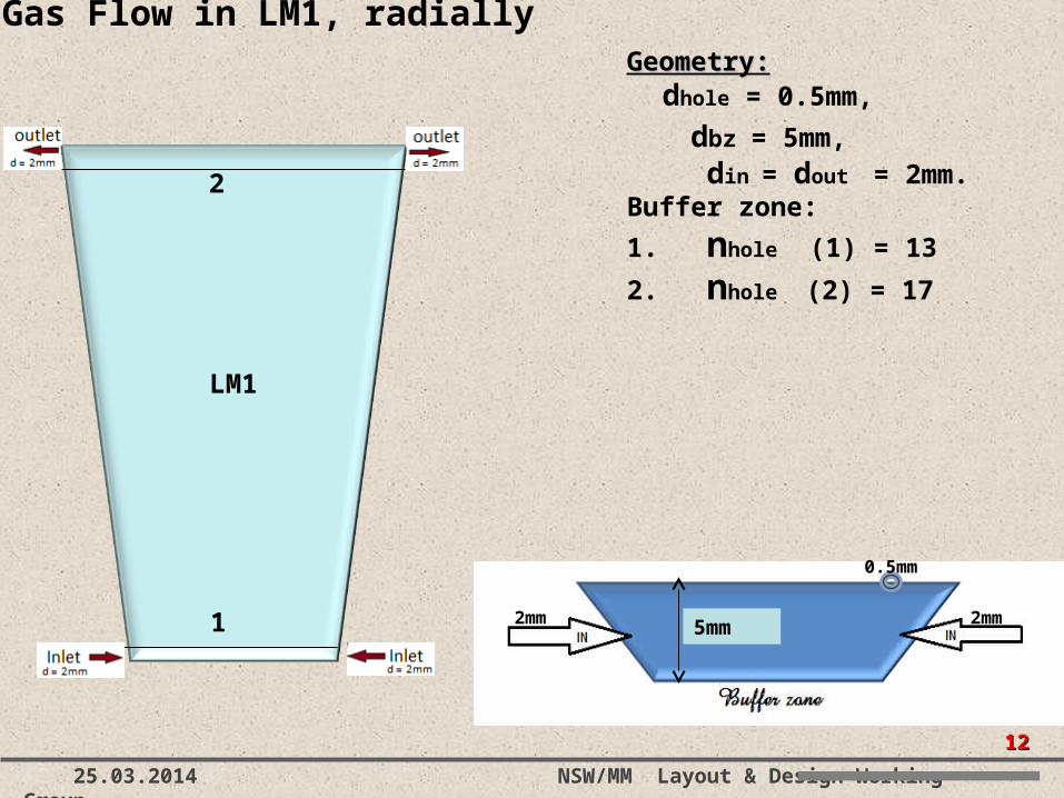
Gas Flow in LM1, radially Geometry:Geometry:
dhole = 0.5mm,
dbz = 5mm, din = dout = 2mm. Buffer zone:
1. nhole (1) = 13
2. nhole (2) = 17
5mm1
2
LM1
1313
25.03.2014 NSW/MM Layout & Design Working Group
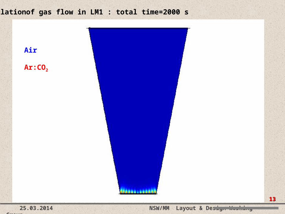
Simulationof gas flow in LM1 : total time=2000 s
Air
Ar:CO2
1414
25.03.2014 NSW/MM Layout & Design Working Group
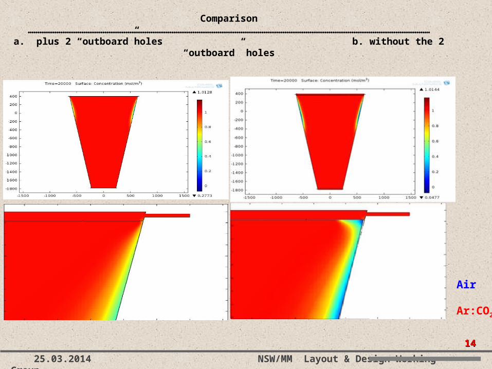
Comparison………………………………………………………………………………………………………………………
…………………………………………………………………a. plus 2 “outboard”holes b. without the 2 “outboard” holes
Air
Ar:CO2
1515
25.03.2014 NSW/MM Layout & Design Working Group
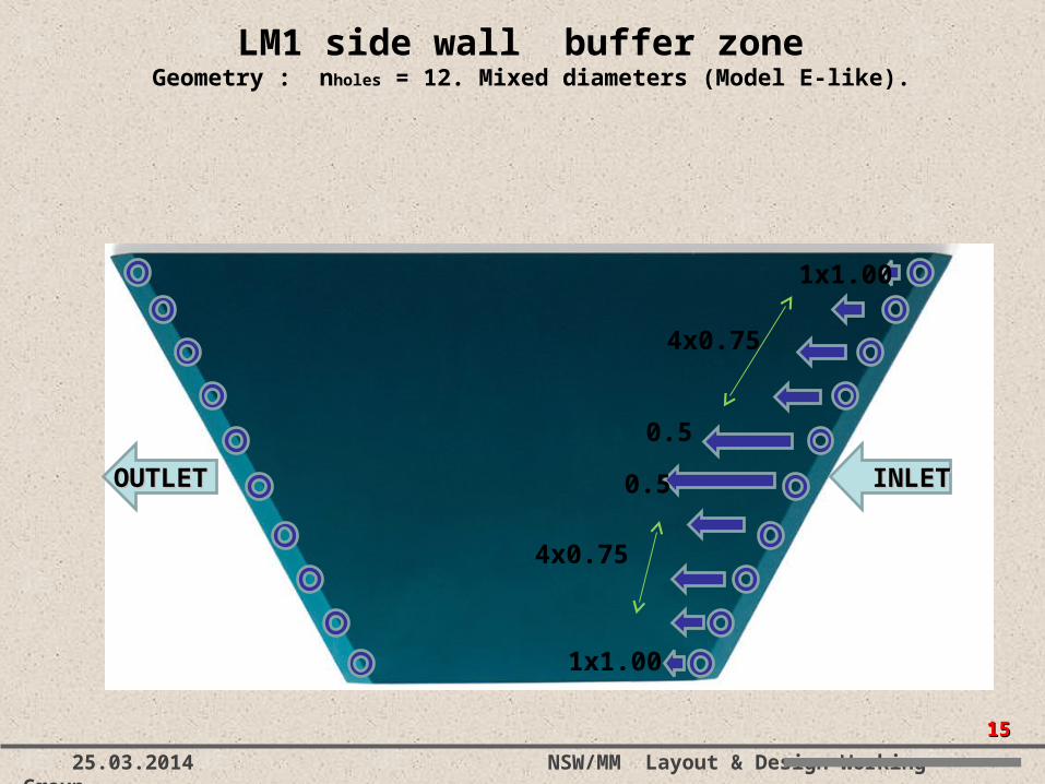
LM1 side”wall” buffer zone Geometry : nholes = 12. Mixed diameters (Model E-like).
OUTLEOUTLETT
INLETINLET
0.5
4x0.75
4x0.75
1x1.00
1x1.00
0.5
1616
25.03.2014 NSW/MM Layout & Design Working Group
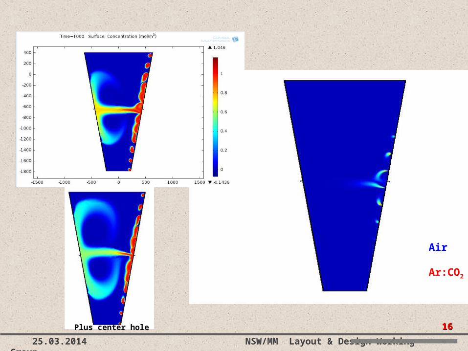
Plus center hole
Air
Ar:CO2
1717
25.03.2014 NSW/MM Layout & Design Working Group
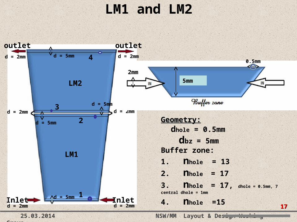
LM1 and LM2
outlet outlet
InletInlet
d = 2mmd = 2mm
d = 2mm d = 2mm
d = 2mmd = 2mm
d = 5mm
d = 5mm
d = 5mm
d = 5mm
5mm
2mm
0.5mm
Geometry:Geometry: dhole = 0.5mm
dbz = 5mmBuffer zone:
1. nhole = 13
2. nhole = 17
3. nhole = 17, dhole = 0.5mm, 7 central dhole = 1mm
4. nhole =151
2
3
4
LM2
LM1
1818
25.03.2014 NSW/MM Layout & Design Working Group
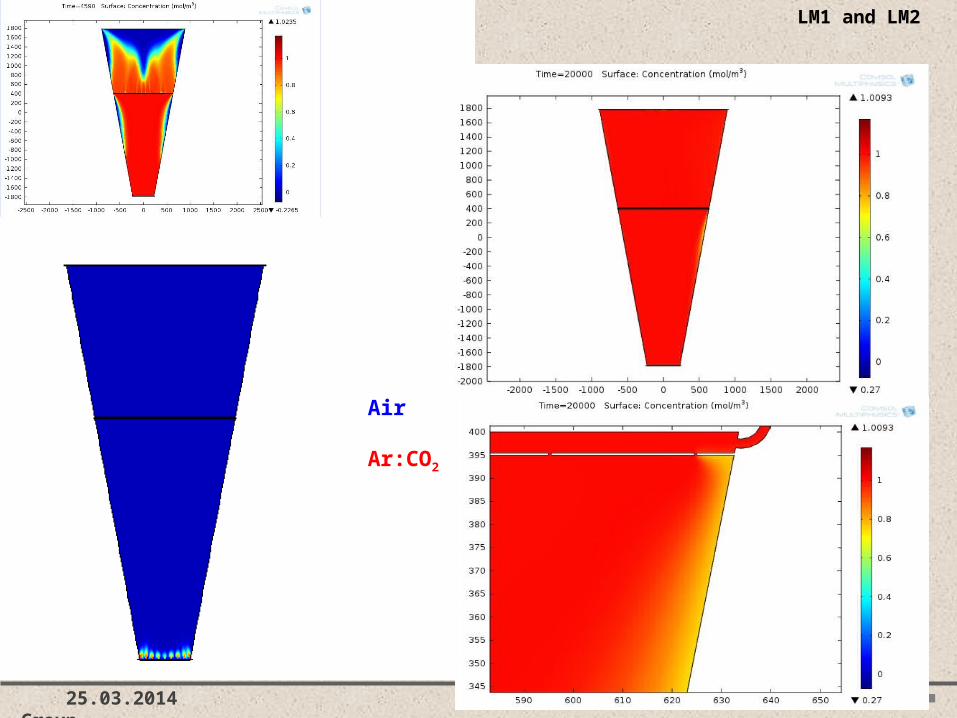
LM1 and LM2
Air
Ar:CO2
1919
25.03.2014 NSW/MM Layout & Design Working Group
• The configuration in which the gas goes through multi-planes instead of single planes-layer has been studied and simulated by using the “Pipe Flow”. We assumed 16 gas channels per Wheel.
• The functional curves of the impedances have been updated. In this configuration we need 32 impedances per Wheel.
• From the simulation “Pipe-Flow” conclude that the gas flow through the multi-planes seem adequate uniform.
• Individual plane-layer gas flow simulation has been performed to study the uniformity of the gas flow.
• More work on model of gas diffusion through mesh is in progress…
Summary & on going workSummary & on going work