Embed Size (px)
Citation preview

Seismic technology will be of key importance for evaluat-ing gas-hydrate resources, particularly across the Gulf ofMexico (GoM) where many seismic surveys have beenacquired and will continue to be acquired. To apply seismictechnology to gas-hydrate studies in the gulf in an optimalmanner, it is essential to understand the seismic target thathas to be analyzed.
What is gas hydrate? Gas hydrate is an ice-like crystallinematerial consisting of structured water molecules linked toform an assembly of cages (or clathrates). Each cage (clath-rate) can enclose and trap a gas molecule. The terms clathratehydrate and gas clathrate are accurate for describing this ice-like substance, but the term gas hydrate is more widely usedacross the oil and gas industry. Clathrates are observed togrow with water molecules arranged in one of three lattice-forming geometries known as structure I, structure II, andstructure H (Figure 1). The arrangement of water moleculesforming each structure creates specific cavity geometries, orindividual cages. These cage geometries are identified besideeach lattice configuration in Figure 1. Each hydrate struc-ture shown in this figure is described as a unit structure(Sloan, 2003), which is the smallest repeating structural ele-ment involved in hydrate growth. Each unit structure con-sists of a specific number of cavity types that are defined inthe diagrams.
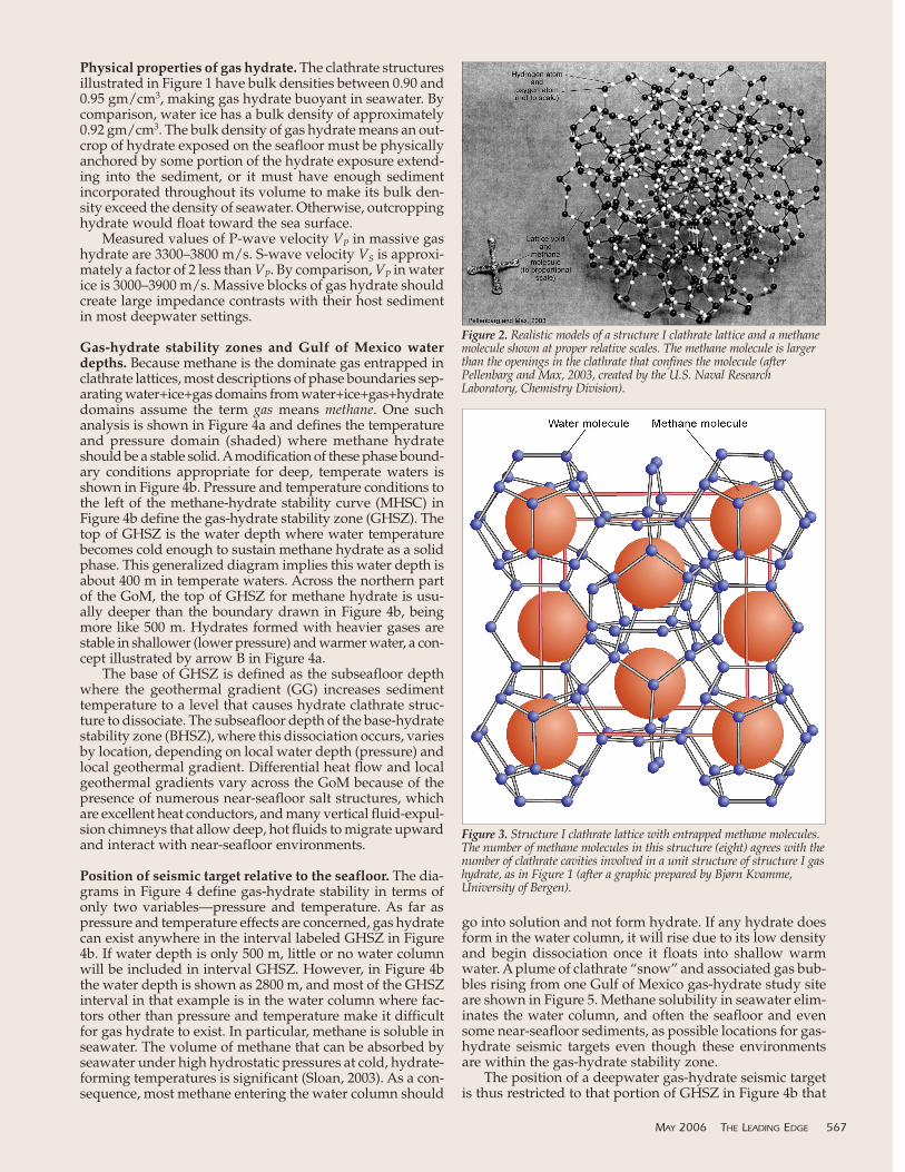
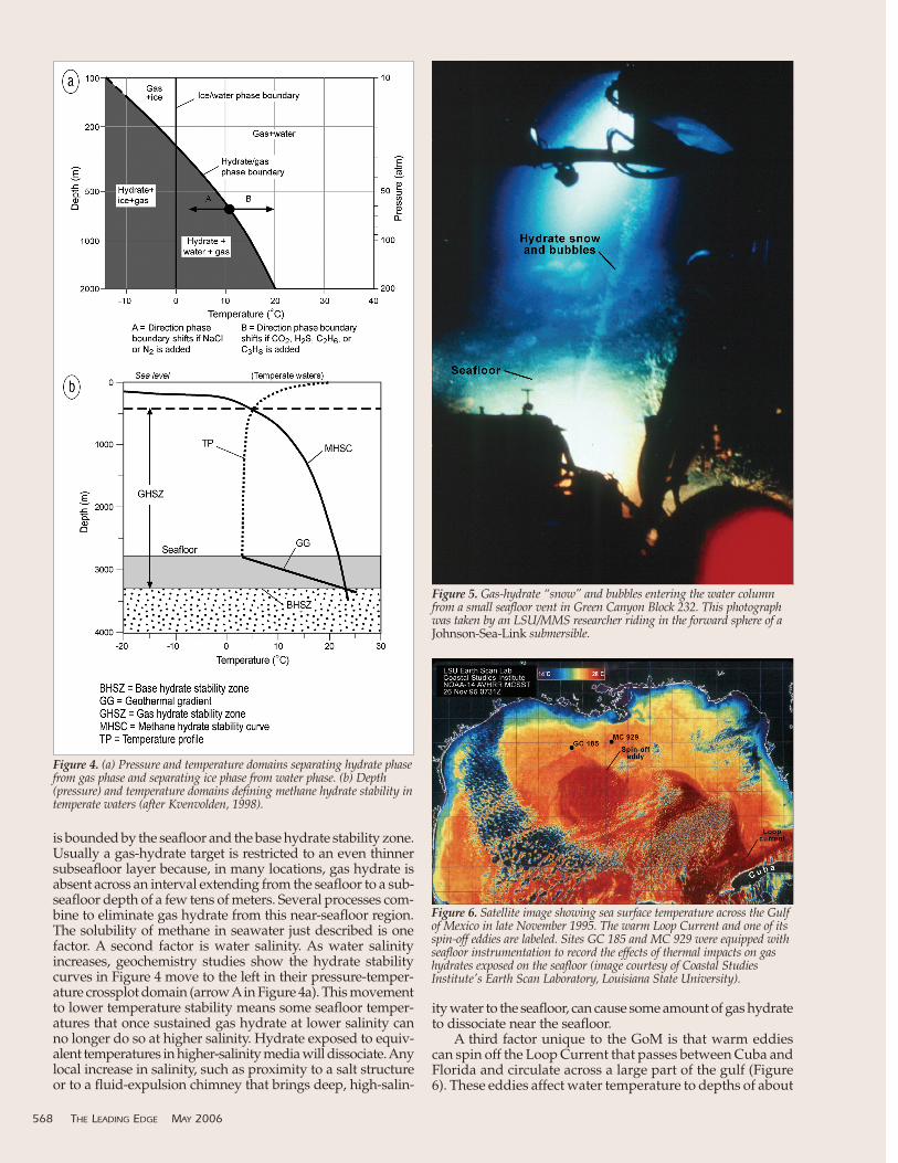
Clathrate cavities have radii that range from a little lessthan 4 angstroms to almost 6 angstroms (1 angstrom =10–8 cm). A variety of gas molecules can be trapped insidethese cages, with possibilities being methane (CH4), ethane(C2H6), propane (C3H8), butane (C4H10), nitrogen (N2), car-bon dioxide (CO2), and hydrogen sulfide (H2S). In Gulf ofMexico gas-hydrate systems, the most common entrappedgas appears to be methane. Models of a methane moleculeand a configuration of structure I clathrate lattices are shownside by side in Figure 2 at correct relative scales to show amethane molecule is slightly larger than the openings instructure I lattice faces. Once a methane molecule is encagedin one of the clathrates, it is trapped until the lattice struc-ture is destroyed. Figure 3 shows a structure I assembly ofclathrates entrapping several methane molecules.
Gas hydrate in the Gulf of Mexico: What and where is the seismic target?BOB A. HARDAGE, Bureau of Economic Geology, Austin, USAHARRY H. ROBERTS, Louisiana State University, Baton Rouge, USA
566 THE LEADING EDGE MAY 2006
Figure 1. Clathrate structures of gas hydrate. Structure I (top): Body-centered cubic structure of 512 cavities linked at their vertices. This unitvolume has eight cavities (eight possible gas molecules) and 46 watermolecules. The host molecule is smaller than propane. Structure II (cen-ter): Diamond lattice within a cubic framework with 512 cavities linked attheir faces. This unit volume has 24 cavities (24 possible gas molecules)and 136 water molecules. The host molecule is larger than ethane butsmaller than pentane. Structure H (bottom): Hexagonal structure withlayers of 512 cavities connecting layers of 51268 and 435663 cavities. Thisunit volume has six cavities (six possible gas molecules) and 34 watermolecules. The host molecule is a wide range of sizes. The cavity diagramsare views looking down on a cavity with solid lines showing face edges onthe top half of the cavity and dotted lines showing face edges on the bot-tom half. These hydrate diagrams depict unit volumes, the smallestrepeating structural elements of hydrate growth. The cluster of cavities inthe structure II diagram shows only 12 of the 24 cavities needed for astructure II unit volume. The cluster in the structure H diagram is largerthan a six-cavity structure H unit volume. The distributions of the col-ored cavities are suggestive, not precise (after Sloan, 1998).
Physical properties of gas hydrate. The clathrate structuresillustrated in Figure 1 have bulk densities between 0.90 and0.95 gm/cm3, making gas hydrate buoyant in seawater. Bycomparison, water ice has a bulk density of approximately0.92 gm/cm3. The bulk density of gas hydrate means an out-crop of hydrate exposed on the seafloor must be physicallyanchored by some portion of the hydrate exposure extend-ing into the sediment, or it must have enough sedimentincorporated throughout its volume to make its bulk den-sity exceed the density of seawater. Otherwise, outcroppinghydrate would float toward the sea surface.
Measured values of P-wave velocity VP in massive gashydrate are 3300–3800 m/s. S-wave velocity VS is approxi-mately a factor of 2 less than VP. By comparison, VP in waterice is 3000–3900 m/s. Massive blocks of gas hydrate shouldcreate large impedance contrasts with their host sedimentin most deepwater settings.
Gas-hydrate stability zones and Gulf of Mexico waterdepths. Because methane is the dominate gas entrapped inclathrate lattices, most descriptions of phase boundaries sep-arating water+ice+gas domains from water+ice+gas+hydratedomains assume the term gas means methane. One suchanalysis is shown in Figure 4a and defines the temperatureand pressure domain (shaded) where methane hydrateshould be a stable solid. Amodification of these phase bound-ary conditions appropriate for deep, temperate waters isshown in Figure 4b. Pressure and temperature conditions tothe left of the methane-hydrate stability curve (MHSC) inFigure 4b define the gas-hydrate stability zone (GHSZ). Thetop of GHSZ is the water depth where water temperaturebecomes cold enough to sustain methane hydrate as a solidphase. This generalized diagram implies this water depth isabout 400 m in temperate waters. Across the northern partof the GoM, the top of GHSZ for methane hydrate is usu-ally deeper than the boundary drawn in Figure 4b, beingmore like 500 m. Hydrates formed with heavier gases arestable in shallower (lower pressure) and warmer water, a con-cept illustrated by arrow B in Figure 4a.
The base of GHSZ is defined as the subseafloor depthwhere the geothermal gradient (GG) increases sedimenttemperature to a level that causes hydrate clathrate struc-ture to dissociate. The subseafloor depth of the base-hydratestability zone (BHSZ), where this dissociation occurs, variesby location, depending on local water depth (pressure) andlocal geothermal gradient. Differential heat flow and localgeothermal gradients vary across the GoM because of thepresence of numerous near-seafloor salt structures, whichare excellent heat conductors, and many vertical fluid-expul-sion chimneys that allow deep, hot fluids to migrate upwardand interact with near-seafloor environments.
Position of seismic target relative to the seafloor. The dia-grams in Figure 4 define gas-hydrate stability in terms ofonly two variables—pressure and temperature. As far aspressure and temperature effects are concerned, gas hydratecan exist anywhere in the interval labeled GHSZ in Figure4b. If water depth is only 500 m, little or no water columnwill be included in interval GHSZ. However, in Figure 4bthe water depth is shown as 2800 m, and most of the GHSZinterval in that example is in the water column where fac-tors other than pressure and temperature make it difficultfor gas hydrate to exist. In particular, methane is soluble inseawater. The volume of methane that can be absorbed byseawater under high hydrostatic pressures at cold, hydrate-forming temperatures is significant (Sloan, 2003). As a con-sequence, most methane entering the water column should
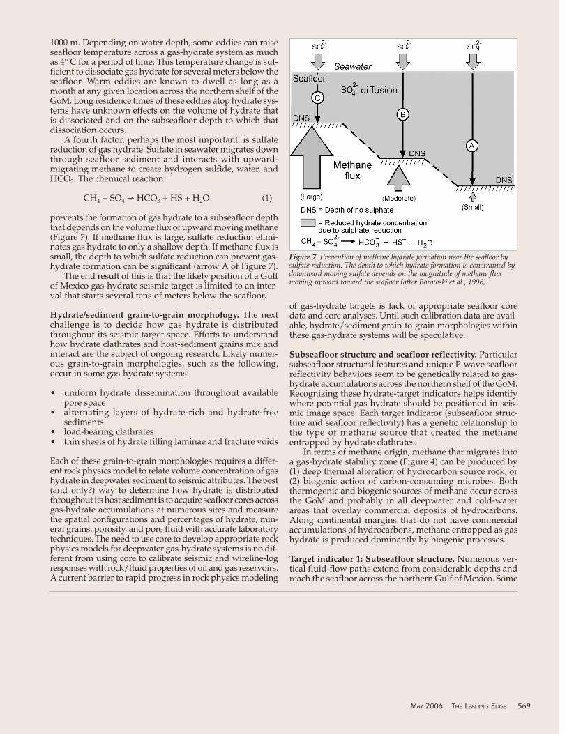
go into solution and not form hydrate. If any hydrate doesform in the water column, it will rise due to its low densityand begin dissociation once it floats into shallow warmwater. A plume of clathrate “snow” and associated gas bub-bles rising from one Gulf of Mexico gas-hydrate study siteare shown in Figure 5. Methane solubility in seawater elim-inates the water column, and often the seafloor and evensome near-seafloor sediments, as possible locations for gas-hydrate seismic targets even though these environmentsare within the gas-hydrate stability zone.
The position of a deepwater gas-hydrate seismic targetis thus restricted to that portion of GHSZ in Figure 4b that
MAY 2006 THE LEADING EDGE 567
Figure 2. Realistic models of a structure I clathrate lattice and a methanemolecule shown at proper relative scales. The methane molecule is largerthan the openings in the clathrate that confines the molecule (afterPellenbarg and Max, 2003, created by the U.S. Naval ResearchLaboratory, Chemistry Division).
Figure 3. Structure I clathrate lattice with entrapped methane molecules.The number of methane molecules in this structure (eight) agrees with thenumber of clathrate cavities involved in a unit structure of structure I gashydrate, as in Figure 1 (after a graphic prepared by Bjørn Kvamme,University of Bergen).
is bounded by the seafloor and the base hydrate stability zone.Usually a gas-hydrate target is restricted to an even thinnersubseafloor layer because, in many locations, gas hydrate isabsent across an interval extending from the seafloor to a sub-seafloor depth of a few tens of meters. Several processes com-bine to eliminate gas hydrate from this near-seafloor region.The solubility of methane in seawater just described is onefactor. A second factor is water salinity. As water salinityincreases, geochemistry studies show the hydrate stabilitycurves in Figure 4 move to the left in their pressure-temper-ature crossplot domain (arrow Ain Figure 4a). This movementto lower temperature stability means some seafloor temper-atures that once sustained gas hydrate at lower salinity canno longer do so at higher salinity. Hydrate exposed to equiv-alent temperatures in higher-salinity media will dissociate. Anylocal increase in salinity, such as proximity to a salt structureor to a fluid-expulsion chimney that brings deep, high-salin-
ity water to the seafloor, can cause some amount of gas hydrateto dissociate near the seafloor.
A third factor unique to the GoM is that warm eddiescan spin off the Loop Current that passes between Cuba andFlorida and circulate across a large part of the gulf (Figure6). These eddies affect water temperature to depths of about
568 THE LEADING EDGE MAY 2006
Figure 4. (a) Pressure and temperature domains separating hydrate phasefrom gas phase and separating ice phase from water phase. (b) Depth(pressure) and temperature domains defining methane hydrate stability intemperate waters (after Kvenvolden, 1998).
Figure 5. Gas-hydrate “snow” and bubbles entering the water columnfrom a small seafloor vent in Green Canyon Block 232. This photographwas taken by an LSU/MMS researcher riding in the forward sphere of aJohnson-Sea-Link submersible.
Figure 6. Satellite image showing sea surface temperature across the Gulfof Mexico in late November 1995. The warm Loop Current and one of itsspin-off eddies are labeled. Sites GC 185 and MC 929 were equipped withseafloor instrumentation to record the effects of thermal impacts on gashydrates exposed on the seafloor (image courtesy of Coastal StudiesInstitute's Earth Scan Laboratory, Louisiana State University).
1000 m. Depending on water depth, some eddies can raiseseafloor temperature across a gas-hydrate system as muchas 4° C for a period of time. This temperature change is suf-ficient to dissociate gas hydrate for several meters below theseafloor. Warm eddies are known to dwell as long as amonth at any given location across the northern shelf of theGoM. Long residence times of these eddies atop hydrate sys-tems have unknown effects on the volume of hydrate thatis dissociated and on the subseafloor depth to which thatdissociation occurs.
A fourth factor, perhaps the most important, is sulfatereduction of gas hydrate. Sulfate in seawater migrates downthrough seafloor sediment and interacts with upward-migrating methane to create hydrogen sulfide, water, andHCO3. The chemical reaction
CH4 + SO4 → HCO3 + HS + H2O (1)
prevents the formation of gas hydrate to a subseafloor depththat depends on the volume flux of upward moving methane(Figure 7). If methane flux is large, sulfate reduction elimi-nates gas hydrate to only a shallow depth. If methane flux issmall, the depth to which sulfate reduction can prevent gas-hydrate formation can be significant (arrow A of Figure 7).
The end result of this is that the likely position of a Gulfof Mexico gas-hydrate seismic target is limited to an inter-val that starts several tens of meters below the seafloor.
Hydrate/sediment grain-to-grain morphology. The nextchallenge is to decide how gas hydrate is distributedthroughout its seismic target space. Efforts to understandhow hydrate clathrates and host-sediment grains mix andinteract are the subject of ongoing research. Likely numer-ous grain-to-grain morphologies, such as the following,occur in some gas-hydrate systems:
• uniform hydrate dissemination throughout availablepore space
• alternating layers of hydrate-rich and hydrate-free sediments
• load-bearing clathrates• thin sheets of hydrate filling laminae and fracture voids
Each of these grain-to-grain morphologies requires a differ-ent rock physics model to relate volume concentration of gashydrate in deepwater sediment to seismic attributes. The best(and only?) way to determine how hydrate is distributedthroughout its host sediment is to acquire seafloor cores acrossgas-hydrate accumulations at numerous sites and measurethe spatial configurations and percentages of hydrate, min-eral grains, porosity, and pore fluid with accurate laboratorytechniques. The need to use core to develop appropriate rockphysics models for deepwater gas-hydrate systems is no dif-ferent from using core to calibrate seismic and wireline-logresponses with rock/fluid properties of oil and gas reservoirs.A current barrier to rapid progress in rock physics modeling
of gas-hydrate targets is lack of appropriate seafloor coredata and core analyses. Until such calibration data are avail-able, hydrate/sediment grain-to-grain morphologies withinthese gas-hydrate systems will be speculative.
Subseafloor structure and seafloor reflectivity. Particularsubseafloor structural features and unique P-wave seafloorreflectivity behaviors seem to be genetically related to gas-hydrate accumulations across the northern shelf of the GoM.Recognizing these hydrate-target indicators helps identifywhere potential gas hydrate should be positioned in seis-mic image space. Each target indicator (subseafloor struc-ture and seafloor reflectivity) has a genetic relationship tothe type of methane source that created the methaneentrapped by hydrate clathrates.
In terms of methane origin, methane that migrates intoa gas-hydrate stability zone (Figure 4) can be produced by(1) deep thermal alteration of hydrocarbon source rock, or(2) biogenic action of carbon-consuming microbes. Boththermogenic and biogenic sources of methane occur acrossthe GoM and probably in all deepwater and cold-waterareas that overlay commercial deposits of hydrocarbons.Along continental margins that do not have commercialaccumulations of hydrocarbons, methane entrapped as gashydrate is produced dominantly by biogenic processes.
Target indicator 1: Subseafloor structure. Numerous ver-tical fluid-flow paths extend from considerable depths andreach the seafloor across the northern Gulf of Mexico. Some
MAY 2006 THE LEADING EDGE 569
Figure 7. Prevention of methane hydrate formation near the seafloor bysulfate reduction. The depth to which hydrate formation is constrained bydownward moving sulfate depends on the magnitude of methane fluxmoving upward toward the seafloor (after Borowski et al., 1996).

of these vertical conduits are fault planes; some are fluid/gasexpulsion chimneys. Each type of fluid-flow feature allowsdeep thermogenic methane to migrate upward and enter thegas-hydrate stability zone where it becomes entrapped inhydrate cages. Many of these vertically oriented faults andgas chimneys are detectable with conventional towed-cablemarine seismic data. If such subseafloor structural featuresare observed in water depths that sustain gas hydrate, thereis a good possibility a gas-hydrate accumulation is geneti-cally related to the fault and/or chimney.
Target indicator 2: Seafloor reflectivity. Two types of Archaeamicrobes are abundant in seafloor sediment. One, identifiedas Archaea 1 in Figure 8, consumes carbon from the abun-dant carbon compounds existing in seafloor sediment and pro-duces methane. These microbes are the source of most of themethane entrapped in gas hydrate along continental marginswhere there is minimal thermal generation of deep gas. Theyare also responsible for a portion of the methane confined ingas hydrate across prolific gas-producing areas of the GoM.The second family of microbes, labeled Archaea 2, eats methaneand produces sulfides. The methane needed by Archaea 2 canbe provided by deep thermogenic methane sources or bymethane produced by Archaea 1.
Numerous seafloor organisms thrive on methane and sul-fide produced by Archaea 1 and 2, such as mussels, clams, tubeworms, and bacterial mats (Figure 8). Mussels consume
methane; clams consume hydrogensulfide. Another byproduct of micro-bial activity is Ca/Mg carbonate precipitated in surficial sediments.These carbonates form “hard-grounds” on the seafloor which causelarge increases in the seafloor reflec-tion coefficient. Thick layers of mus-sel shells stacked on methane-richsediment also produce large increasesin seafloor reflectivity; thus, robustincreases in seafloor reflection ampli-tudes, when observed at waterdepths appropriate for gas-hydratestability, are valuable indicators ofupwelling sulfide-producing meth-ane, which in turn, implies the pres-ence of subseafloor gas hydrate. TheMinerals Management Service andLouisiana State University have along-running program of mappingareas of high-amplitude seafloorreflections and conducting deep divesin each location. These dives defineseafloor conditions that create eachhigh-amplitude seismic response andconfirm the presence or absence ofgas hydrate across the reflectionanomalies. Their work is showing ahigh correlation between bright,deepwater seafloor reflectivity andpresence of gas hydrate.
What is the host medium for gashydrate? To produce methane fromgas hydrate as a commercial venture,gas hydrate needs to be embedded ina host medium that has high poros-ity for volumetric storage of methaneand high permeability for deliver-
ability requirements. A high-porosity, unconsolidated sandwould be an ideal host medium. So then, what type of sedi-ment does gas hydrate prefer as a host? This is a question thatis not yet satisfactorily answered; however, Rudy Rogers atMississippi State University has done some interesting exper-iments with Gulf sediments and microbial communities thatwarrant consideration. One of his experimental tests is shownin Figure 9.
In this experiment, three typical Gulf of Mexico seafloorsediments, sand, kaolinite/sand mix, and bentonite/sandmix, were placed in segregated compartments of a test cell.These sediments were then saturated with surfactin producedby Bacillus subtilis, a microbe common to gas-hydrate systemsacross the GoM. A blend of 90% methane, 6% ethane, and 4%propane was introduced into the sediment, and the test cellwas subjected to pressure and temperature typical of gas-hydrate stability zones in the GoM. The photo in Figure 9shows prolific and rapid growth of gas hydrate on bentonitesurfaces and minor growth on sand and kaolinite surfaces.The implication is surfactin produced by Bacillus subtilisencourages methane and structured water to preferentiallycongregate and nucleate at common sites on the surfaces ofbentonite grains, not on sand grains or kaolinite grains. Gashydrate in the GoM may thus be more prone to accumulatein fine-grained sediment than in coarse-grained sediment.Determining what type of sediment is the preferred hostmedium for gas hydrate in this area requires more research.
570 THE LEADING EDGE MAY 2006
Figure 9. Influence of GoM-based biosurfactants on gas-hydrate formation. In this laboratory test,surfactant produced by Bacillus subtilis, a microbe found in many of the area gas-hydrate systems,causes gas hydrate to preferentially form on bentonite grains rather than on sand or kaolinite grains(courtesy of Rudy Rogers, Swalm School of Chemical Engineering, Mississippi State University).
Figure 8. Symbionic communities associated with marine gas-hydrate systems. Archaea 1 eats carbonand produces methane. Some of this methane forms gas hydrate; some serves as the food source forArchaea 2. Archaea 2 eats methane and produces sulfide. Methane and sulfide support largechemosynthetic seafloor communities. Microbe-generated carbonate hardgrounds and thick layers ofmussel shells create local seafloor seismic bright spots, leading to the conclusion that bright seafloorreflectivity is indirect evidence of gas hydrate (after Kunzig, 2004).
Based on the evidence of tests such as those done by Rogers,some gas-hydrate researchers consider dirty sand an ideal hostmedium for gas hydrate. In dirty sand, bacterial surfactinencourages hydrate growth on the clay components, and thesand component provides the desired permeability.
Bottom-simulating reflections. Bottom-simulating reflec-tions (BSRs) are classic seismic identifiers of gas-hydrateaccumulations in marine environments. In many gas-hydratelocations, BSRs are bold, obvious events that are easily seenand interpreted in stacked/migrated seismic data. In con-trast, BSRs across GoM gas-hydrate systems are subtle, dis-continuous, and sometimes just not detectable. Investigatorsare now documenting more BSR events across the gulf thanwere previously known, but robust BSRs that extend forgreat distances, as occurs in some gas-hydrate provinces,are rare. Because of the less-dominant role of BSRs in thisarea, gas-hydrate target indicators previously mentioned(vertical conduits for fluid flow and bright seafloor reflec-tions at appropriate water depths) are presently the preferredseismic evidence for identifying prime locations for gashydrate in the GoM. No doubt BSRs will increase in impor-tance as hydrate target indicators as our knowledge ofhydrate systems increases and as the study areas expand.
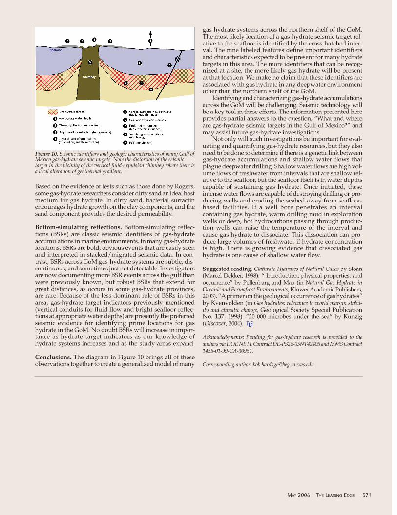
Conclusions. The diagram in Figure 10 brings all of theseobservations together to create a generalized model of many
gas-hydrate systems across the northern shelf of the GoM.The most likely location of a gas-hydrate seismic target rel-ative to the seafloor is identified by the cross-hatched inter-val. The nine labeled features define important identifiersand characteristics expected to be present for many hydratetargets in this area. The more identifiers that can be recog-nized at a site, the more likely gas hydrate will be presentat that location. We make no claim that these identifiers areassociated with gas hydrate in any deepwater environmentother than the northern shelf of the GoM.
Identifying and characterizing gas-hydrate accumulationsacross the GoM will be challenging. Seismic technology willbe a key tool in these efforts. The information presented hereprovides partial answers to the question, “What and whereare gas-hydrate seismic targets in the Gulf of Mexico?” andmay assist future gas-hydrate investigations.
Not only will such investigations be important for eval-uating and quantifying gas-hydrate resources, but they alsoneed to be done to determine if there is a genetic link betweengas-hydrate accumulations and shallow water flows thatplague deepwater drilling. Shallow water flows are high vol-ume flows of freshwater from intervals that are shallow rel-ative to the seafloor, but the seafloor itself is in water depthscapable of sustaining gas hydrate. Once initiated, theseintense water flows are capable of destroying drilling or pro-ducing wells and eroding the seabed away from seafloor-based facilities. If a well bore penetrates an intervalcontaining gas hydrate, warm drilling mud in explorationwells or deep, hot hydrocarbons passing through produc-tion wells can raise the temperature of the interval andcause gas hydrate to dissociate. This dissociation can pro-duce large volumes of freshwater if hydrate concentrationis high. There is growing evidence that dissociated gashydrate is one cause of shallow water flow.
Suggested reading. Clathrate Hydrates of Natural Gases by Sloan(Marcel Dekker, 1998). “ Introduction, physical properties, andoccurrence” by Pellenbarg and Max (in Natural Gas Hydrate inOceanic and Permafrost Environments, Kluwer Academic Publishers,2003). “Aprimer on the geological occurrence of gas hydrates”by Kvenvolden (in Gas hydrates: relevance to world margin stabil-ity and climatic change, Geological Society Special PublicationNo. 137, 1998). “20 000 microbes under the sea” by Kunzig(Discover, 2004). TLE
Acknowledgments: Funding for gas-hydrate research is provided to theauthors via DOE NETL Contract DE-PS26-05NT42405 and MMS Contract1435-01-99-CA-30951.
Corresponding author: [email protected]
MAY 2006 THE LEADING EDGE 571
Figure 10. Seismic identifiers and geologic characteristics of many Gulf ofMexico gas-hydrate seismic targets. Note the distortion of the seismictarget in the vicinity of the vertical fluid-expulsion chimney where there isa local alteration of geothermal gradient.


![BASIN-SCALE ASSESSMENT OFGAS HYDRATE DISSOCIATION IN ... › icgh7 › papers › icgh2011Final00759.pdf · of water clathrate crystals[1]. Natural gas hydrate deposits occur in geologic](https://img.pdfslide.net/doc/110x75/5f10cdf47e708231d44ae5ec/basin-scale-assessment-ofgas-hydrate-dissociation-in-a-icgh7-a-papers-a.jpg)