Embed Size (px)
Citation preview

Specification for
Polyethylene pipes and fittings for natural gas and suitable manufactured gas
Part 5: Electrofusion ancillary tooling
Gas Industry Standard
GIS/PL2-5:2018


GIS/PL2-5:2018
i
Contents
Page
Foreword iii Relationship with other publications iii Mandatory and non-mandatory requirements iii Disclaimer iii Brief history iv 1 Scope 1 2 Normative references 1 3 Terms, definitions and symbols 1 4 Construction 3 4.1 General 3 4.2 In-trench operation 3 5 Saddle fusion tools (for installing tapping tees and branch saddles) 5 5.1 General 5 5.2 Design of top loading saddle fusion tools 6 5.3 Tapping tee drive keys 8 6 Restraining clamps 9 6.1 General 9 6.2 Design 9 7 Re-rounding clamps 14 7.1 General 14 7.2 Design 14 8 Combined restraining and re-rounding clamps 14 8.1 Design 14 9 Coiled pipe jointing equipment (90 mm and above) 14 9.1 General 14 9.2 Design 15 10 Coiled pipe straightening equipment 15 10.1 General 15 10.2 Design 15 11 Large diameter coupler assembly equipment 15 11.1 General 15 11.2 Design 15 12 Pipe surface preparation tools 16 12.1 General 16 12.2 Design 16 13 Peelable skin removal tools 17 13.1 General 17 13.2 Design 17 14 Branch saddle drilling equipment 17 14.1 General 17 14.2 Standard drilling equipment (unpressurized main) 17 14.3 Under-pressure drilling equipment 18 15 Pipe cutting/trimming tools 18 15.1 General 18 15.2 Design 18 16 Type testing schedule 19 17 Batch release testing schedule 21 18 Marking 22 19 Packaging 22

GIS/PL2-5:2018
ii
Contents (continued)
Page
Annex A (normative) Restraining clamp rigidity test 23 Annex B (normative) Re-rounding test 25 Annex C (normative) Coiled pipe jointing equipment: alignment test 27 Annex D (normative) Coiled pipe straightening test 29 Annex E (normative) Air pressure test (under-pressure drilling equipment) 30 Bibliography 30 Figure 1 — Exclusion area for tapping tees 4 Figure 2 — Exclusion area for branch saddles 5 Figure 3 — Interface for tapping tees 7 Figure 4 — Interface adaptor for branch saddle tooling 8 Figure 5 — Restraining clamps for service pipes 10 Figure 6 —Restraining clamps for mains pipes and electrofusion fittings 11 Figure 7 — Restraining clamps for mains pipes and spigot end fittings 12 Figure 8 — Restraining clamps for electrofusion elbows 13 Figure A.1 — Preparation for the restraining clamp rigidity test with the beam on top or underneath pipe: procedure A 24 Figure C.1 — Clamping arrangement prior to application of jointing equipment 28 Table 1 — Rigidity test: maximum average change in height of the pipe ends 9 Table 2 — Ovality after re-rounding 14 Table 3 — Type testing schedule 20 Table 4 — Batch release testing schedule 21

GIS/PL2-5:2018
iii
Foreword
Gas Industry Standards (GIS) are revised, when necessary, by the issue of new editions. Users should ensure that they are in possession of the latest edition. Contractors and other users external to Gas Transporters should direct their requests for copies of a GIS to the department or group responsible for the initial issue of their contract documentation.
Comments and queries regarding the technical content of this document should be directed in the first instance to the contract department of the Gas Transporter responsible for the initial issue of their contract documentation.
This standard calls for the use of procedures that may be injurious to health if adequate precautions are not taken. It refers only to technical suitability and does not absolve the user from legal obligations relating to health and safety at any stage.
Compliance with this engineering document does not confer immunity from prosecution for breach of statutory or other legal obligations.
Relationship with other publications
GIS/PL2 Polyethylene pipes and fittings for natural gas and suitable manufactured gas consists of the following parts:
Part 1: General and polyethylene compounds for use in polyethylene pipes and fittings.
Part 2: Pipes for use at pressures up to 5.5 bar.
Part 3: Butt fusion machines and ancillary equipment.
Part 4: Fusion fittings with integral heating element(s).
Part 5: Electrofusion ancillary tooling.
Part 6: Spigot end fittings for electrofusion and/or butt fusion purposes.
Part 7: Squeeze-off tools and equipment.
Part 8: Pipes for use at pressures up to 7 bar.
Mandatory and non-mandatory requirements
For the purposes of a GIS the following auxiliary verbs have the meanings indicated:
can indicates a physical possibility;
may indicates an option that is not mandatory;
shall indicates a GIS requirement;
should indicates best practice and is the preferred option. If an alternative method is used then a suitable and sufficient risk assessment needs to be completed to show that the alternative method delivers the same, or better, level of protection.
Disclaimer
This engineering document is provided for use by Gas Transporters and such of their contractors as are obliged by the terms of their contracts to comply with this engineering document. Where this engineering document is used by any other party, it is the responsibility of that party to ensure that the engineering document is correctly applied.

GIS/PL2-5:2018
iv
Brief history
First issued as PS/PL/2: Part 5, Stage 3, Issue 3 Revision published as GBE/PL/2: Part 5 Editorial update to reflect demerger November 2000 Editorial update to reflect merger October 2002 Editorial update to comply with GRM Revision Edited by BSI in accordance with BS 0-3:1997 Reviewed on behalf of the Gas Distribution Networks' Technical Standard Forum by BSI Revision to increase the scope of diameter ranges covered to 800 mm
June 1986 December 1993 June 2001 November 2002 August 2004 December 2005 August 2006 September 2013 October 2018
© Energy Networks Association on behalf of Cadent Gas Limited, Northern Gas Networks, SGN and Wales & West Utilities Ltd.
This Gas Industry Standard is copyright and must not be reproduced in whole or in part by any means without the approval in writing of Energy Networks Association.

GIS/PL2-5:2018
1
1 Scope
This part of GIS/PL2-2 specifies requirements for tooling for the construction and maintenance of polyethylene systems equal to or less than 800 mm nominal size. The polyethylene systems consist of pipe conforming to GIS/PL2-2 and GIS/PL2-8, electrofusion fittings conforming to GIS/PL2-4, spigot end fittings conforming to GIS/PL2-6 and valves to GIS/V7-2.
2 Normative references
The following referenced documents are indispensable for the application of this document. For dated references, only the edition cited applies. For undated references, the latest edition of the referenced document (including any amendments) applies.
Formal standards
BS EN 60068-2-31, Environmental testing — Tests. Ec. Rough handling shocks, primarily for equipment-type specimens.
BS EN 60529, Specification for degrees of protection provided by enclosures (IP code).
Gas Industry Standards
GIS/PL2-1, Specification for polyethylene pipes and fittings for natural gas and suitable manufactured gas — Part 1 General and polyethylene compounds for use in polyethyene pipes and fittings.
GIS/PL2-2, Specification for polyethylene pipes and fittings for natural gas and suitable manufactured gas — Part 2: Pipes for use at pressures up to 5.5 bar.
GIS/PL2-4, Specification for polyethylene pipes and fittings for natural gas and suitable manufactured gas — Part 4: Fusion fittings with integral heating element(s).
GIS/PL2-6, Specification for polyethylene pipes and fittings for natural gas and suitable manufactured gas — Part 6: Spigot end fittings for electrofusion and/or butt fusion purposes.
GIS/PL2-8, Specification for polyethylene pipes and fittings for natural gas and suitable manufactured gas — Part 8: Pipes for use at pressures up to 7 bar.
GIS/V7-1, Specification for distribution valves — Part 1: Metal-bodied line valves for use at pressures up to 16 bar and construction valves for use at pressures up to 7 bar..
GIS/V7-2, Specification for distribution valves — Part 2: Plastics bodied valves of size up to and including 180 mm suitable for operation at pressures not exceeding 5.5 bar.
3 Terms, definitions and symbols
For the purposes of standard following terms, definitions and symbols apply.
3.1 nominal outside diameter, dn
specified outside diameter, in millimetres, assigned to a nominal size DN/OD
3.2 ovality (out-of-roundness) difference between the maximum and the minimum outside diameter in the same cross-section of a pipe or spigot, rounded off to the nearest 0.1 mm

GIS/PL2-5:2018
2
3.3 tolerance permitted variation of the specified value of a quantity, expressed as the difference between the permitted maximum and the permitted minimum value
3.4 standard dimension ratio (SDR) numerical designation of a pipe series, which is a convenient round number, approximately equal to the dimension ratio of the nominal outside diameter, dn, and the nominal wall thickness, en
3.5 peelable pipe PE100 core material over which is an outer layer (skin), which is removed locally with the aid of simple tools, prior to fusion jointing
NOTE The skin allows protection of the core pipe during installation, but does not contribute to the specified wall thickness or to the mechanical strength of the pipe. The skin should carry all marking and colour identification of the pipe.
3.6 core pipe polyethylene pipe without skin
NOTE The core pipe meets all the dimensional requirements of GIS/PL/2-2 with the exception of colour.
3.7 coiled pipe pipe coiled in a multilayer configuration with the layers strapped together to provide a stable and self-supporting unit
3.8 Symbols
dn nominal outside diameter

GIS/PL2-5:2018
3
4 Construction
4.1 General
4.1.1 All tooling shall be capable of correct operation at ambient temperatures between −5 °C and 30 °C, with pipes and fitting spigot outlets at extremes of diameter and ovality tolerances specified in GIS/PL2-1, GIS/PL2-4, GIS/PL2-6 and GIS/PL2-8 and GIS/V7-2.
4.1.2 All tools shall be capable of withstanding a single drop test, in accordance with Procedure 1 of BS EN 60068-2-32 from a height of 1 m without subsequent malfunction.
4.1.3 Equipment shall be suitably robust and reliable to withstand normal field usage without deterioration of performance. Compliance with this requirement shall be demonstrated by satisfactory completion of a field trial, which shall not exceed six weeks.
4.1.4 The supplier shall specify the hardness and composition of the material to be used for any cutting edges and shall demonstrate that it is suitable for the intended application. Compliance with this requirement shall be demonstrated by satisfactory completion of a field trial, which shall not exceed six weeks. The part shall not chip or fracture when subjected to an impact test as specified in 4.1.2.
4.1.5 All tools shall be capable of simple and easy operation.
4.1.6 Tools and equipment shall not cause damage or cause distortion to the pipes or fittings. Outside diameter/bore dimensions and ovalities shall conform to GIS/PL2-2, GIS/PL2-4, GIS/PL2-6 and GIS/PL2-8.
NOTE Tools should be constructed from corrosion-resistant materials, or be otherwise suitably protected. Particular consideration should be given to shafts and fastenings.
4.2 In-trench operation
All tools shall be capable of being installed and operated within trench conditions (other than for coiled pipe straightening equipment) by not more than two persons. Electrofusion tools shall conform to the exclusion areas and details shown in Figures 1 and 2.

GIS/PL2-5:2018
4
All dimensions in mm
Figure 1 — Exclusion area for tapping tees
150

GIS/PL2-5:2018
5
All dimensions in mm
Figure 2 — Exclusion area for branch saddles
5 Saddle fusion tools (for installing tapping tees and branch saddles)
5.1 General
Tapping tees and branch saddles having spigot outlets equal to or less than 63 mm shall be capable of either:
a) installation by a force of between 1 kN and 1.5 kN applied perpendicular to the pipe’s longitudinal axis and through the centre line of the fitting stack or branch saddle outlet;
b) installation by a temporary or permanent underclamp.

GIS/PL2-5:2018
6
5.2 Design of top loading saddle fusion tools
5.2.1 The saddle fusion tool shall be capable of installation and removal in a cross main trench at a depth of 800 mm from ground level to the crown of the main, and in a width of 300 mm (or three times main pipe diameter, whichever is the greater) for tapping tees and branch saddles equal to or less than 63 mm outlet, and with a clearance of 150 mm from the back of the pipe to the end of the trench, (see Figures 1 and 2).
NOTE Preferably the saddle fusion tool should not require significant excavation below the pipe.
5.2.2 The total weight of the saddle fusion tool shall be not greater than 10 kg. Larger saddle fusion tools shall use a modular design to limit individual weights to less than 10 kg.
5.2.3 The saddle fusion tool shall be so designed that, when used with either straight pipe or coiled pipe, the load on the fitting shall follow the centre line of the stack, down through the centre line of the pipe, and be not less than 95 % of the indicated value.
5.2.4 In operation, the saddle fusion tool geometry shall not encroach into the space defined in Figures 1 and 2 except for the specific adaptor parts associated with each manufacturer's fitting.
5.2.5 All tapping tees (both 63 mm and 32 mm outlets) shall have integral cutters with a 12 mm A/F hexagonal drive (female). The saddle fusion tool shall utilize this common design feature for location and force application, in accordance with Figure 3.
Provision shall be made for an adaptor for use on branch saddles (flanged and straight spigot outlets) to provide a suitable interface between the saddle fusion tool and the fitting, in accordance with Figure 4.
5.2.6 The saddle fusion tool shall be capable of both applying and reacting to forces equal to or less than 30 % overload between the mains pipe and the tapping tee.
5.2.7 A method of indicating that the correct load is achieved shall be permanently provided on the saddle fusion tool. The application of the correct load shall be easily detected by the operator. The indicator shall be set at 1.4 kN to 1.5 kN and shall not drop to less than 1.2 kN after a movement of 2 mm at the saddle interface. The indicator shall be capable of registering any overload. Once the indicator has been set, it shall not be adjustable without special tooling. The manufacturer shall recommend the frequency of recalibration.
5.2.8 Any screw action shall not apply a turning motion to the fitting.

GIS/PL2-5:2018
7
All dimensions in mm
Figure 3 — Interface for tapping tees
800

GIS/PL2-5:2018
8
All dimensions in mm
Figure 4 — Interface adaptor for branch saddle tooling
5.3 Tapping tee drive keys
5.3.1 Tapping tee drive keys shall be capable of one-person operation in trench conditions.
5.3.2 The tapping tee drive keys shall interface with the tapping tee 12 mm A/F hexagonal
drive (5.2.5) and shall be capable of transmitting a torque of 160 Nm.

GIS/PL2-5:2018
9
6 Restraining clamps
6.1 General
6.1.1 Restraining clamps shall be designed for attachment on either service or mains pipe systems incorporating electrofusion socket, saddle spigot outlet and spigot end fittings. They are designed for small diameter coiled service pipes (16 mm to 32 mm) and all sizes of straight pipes.
6.1.2 The restraining clamp design shall be suitable for use with one or more of the fitting arrangements shown in Figures 5 to 8 inclusive.
6.1.3 Restraining clamps are required for jointing fittings to in-line pipes and pipes at 45° and 90° to each other.
6.2 Design
6.2.1 The restraining clamp shall be designed to stop axial and rotational movement and aid alignment of adjoining pipes during the jointing/cooling process, but shall not preclude free movement of the electrofusion fitting.
6.2.2 The restraining clamps shall cater for reductions in pipe diameter either side of the electrofusion socket fitting, e.g. when fusing a reducer.
6.2.3 The rigidity of the pipe restraining clamps shall be demonstrated as part of the type testing schedule for restraining clamps of 90 mm and above, in accordance with Clause 16. The average of the change in height of the two pipe ends shall conform to Table 1. The test method shall be in accordance with Annex A.
Table 1 — Rigidity test: maximum average change in height of the pipe ends
Tooling for maximum pipe diameter
Maximum average pipe end change in height
mm mm
90 35
125 35
180 35
250 30
315 30
355 30
400 60
500 60
6.2.4 Restraining clamps shall be capable of being set up and removed in a trench.
NOTE Typical dimensions for joint pits are:
a) width: 200 mm + pipe diameter;
b) depth: 800 mm + pipe diameter.

GIS/PL2-5:2018
10
Figure 5 — Restraining clamps for service pipes

GIS/PL2-5:2018
11
Figure 6 —Restraining clamps for mains pipes and electrofusion fittings
GIS/PL2-5:2018
12
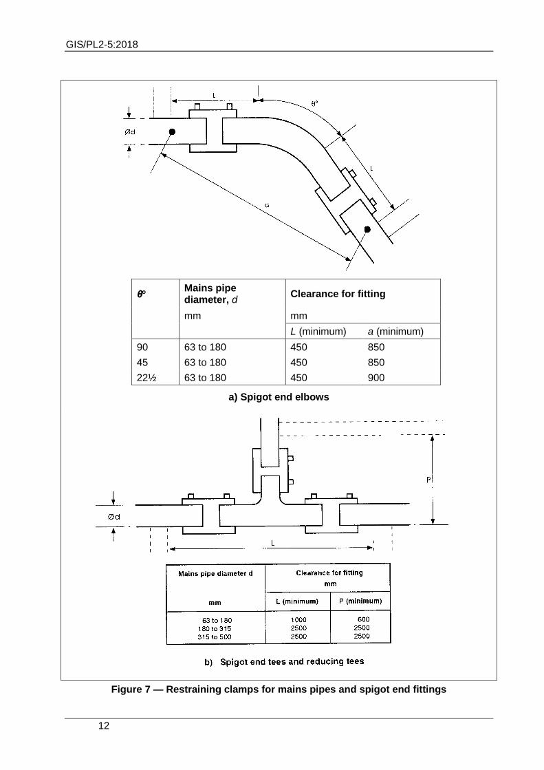
θ Mains pipe diameter, d
Clearance for fitting
mm mm
L (minimum) a (minimum)
90 63 to 180 450 850
45 63 to 180 450 850
22½ 63 to 180 450 900
a) Spigot end elbows
Figure 7 — Restraining clamps for mains pipes and spigot end fittings

GIS/PL2-5:2018
13
Figure 8 — Restraining clamps for electrofusion elbows

GIS/PL2-5:2018
14
7 Re-rounding clamps
7.1 General
7.1.1 A re-rounding clamp shall be designed for use on mains pipe supplied in straight lengths or from coils or drums.
7.1.2 Re-rounding clamps shall be suitable for use with pipes conforming to GIS/PL2-2 and GIS/PL2-8, to assist in the assembly of electrofusion fittings conforming to GIS/PL2-4.
7.2 Design
The re-rounding clamps shall have a re-rounding action on the polyethylene pipe such that ovality, when measured in accordance with Annex B, shall be in accordance with Table 2 over the applied size range of the re-rounding equipment. The type testing schedule shall be in accordance with Clause 16.
Table 2 — Ovality after re-rounding
Pipe nominal outside diameter, dn
Maximum ovality
mm mm
75 1
>75 to 180 0.05dn
>180 to 315 0.015dn
>315 to 800 0.02dn
8 Combined restraining and re-rounding clamps
8.1 Design
8.1.1 The combined restraining and re-rounding clamps shall be designed to assist in rerounding, restraining and aligning the coiled pipes in the range 63 mm – 800 mm inclusive whilst jointing electrofusion fittings.
8.1.2 The equipment shall be designed so that the two inner clamps nearest the electrofusion fitting shall be re-rounding clamps, the other outer pair shall be alignment clamps.
8.1.3 The inner re-rounding clamps shall conform to Clause 7 and the whole unit shall conform to Clause 6.
9 Coiled pipe jointing equipment (90 mm and above)
9.1 General
9.1.1 Coiled pipe jointing equipment shall be designed for use on mains pipe of 90 mm and above supplied from coils or drums.
9.1.2 The coiled pipe jointing equipment shall be suitable for use with pipes conforming to GIS/PL2-2 and -8 and electrofusion fittings conforming to GIS/PL2-4.
9.1.3 Coiled pipe jointing equipment shall be used to join two pipe coils together using electrofusion fittings.

GIS/PL2-5:2018
15
9.2 Design
9.2.1 The coiled pipe jointing equipment shall be designed to align coiled pipes and restrict axial and rotational movement, during the jointing/cooling process.
9.2.2 The coiled pipe jointing equipment shall have a re-rounding action on the polyethylene pipe such that ovality, when measured in accordance with Annex B, shall be in accordance with Table 2. The type testing schedule shall be in accordance with Clause 16.
9.2.3 The coiled pipe jointing equipment shall cater for reductions in pipe diameter either side of the electrofusion socket fitting, e.g. when fusing a reducer.
9.2.4 When the coiled pipe jointing equipment is tested in accordance with Annex C, it shall be possible to slide the electrofusion coupler by hand into a central position between the pipe ends and then be able to rotate the coupler by hand. The type testing schedule for coiled pipe jointing equipment shall be in accordance with Clause 16.
10 Coiled pipe straightening equipment
10.1 General
Coiled pipe straightening equipment shall be designed for use on coiled polyethylene pipe supplied from coils or drums and conforming to GIS/PL2-2 and GIS/PL2-8 .
10.2 Design
10.2.1 When the coiled pipe straightening equipment is tested in accordance with Annex D, the polyethylene pipe shall have a radius of curvature of not less than 10 m. The type testing schedule shall be in accordance with Clause 16.
10.2.2 Coiled pipe straightening equipment shall be suitable for use with coiled/drummed pipe in the range 63 mm to 180 mm inclusive nominal size.
NOTE Consideration should be given to combining sizes by the use of interchangeable inserts.
11 Large diameter coupler assembly equipment
11.1 General
Large diameter coupler assembly equipment shall be designed to aid the assembly of large diameter electrofusion couplers on to straight pipes, spigot ends of electrofusion fittings and fabricated fittings.
11.2 Design
11.2.1 The large diameter coupler assembly equipment shall be suitable for use with pipes and couplers in the following size ranges:
a) 355 mm to 400 mm inclusive;
b) 400 mm to 500 mm inclusive.
11.2.2 When the large diameter coupler assembly equipment is tested in accordance with Annex B the polyethylene pipe shall be re-rounded to within the ovality tolerances specified in Table 2 over a length of (⅔dn + 100 mm) from the clamp face to the pipe end. The type testing schedule shall be in accordance with Clause 16.

GIS/PL2-5:2018
16
11.2.3 The rigidity of the large diameter coupler assembly equipment shall be demonstrated as part of the type testing schedule, see Clause 16. The average of the change in height of the two pipe ends shall conform to Table 1. The test method shall be in accordance with Annex A.
11.2.4 The large diameter coupler assembly equipment shall cater for reductions in pipe diameter either side of the electrofusion socket fitting, e.g. when fusing a reducer.
11.2.5 The large diameter coupler assembly equipment shall be capable of applying assembly forces up to 50 kN. The equipment shall suffer no permanent deformation of critical operating members when subject to an overload assembly test force of 75 kN.
12 Pipe surface preparation tools
12.1 General
12.1.1 Pipe preparation shall provide a fusible surface on any polyethylene pipe material (new, weathered or previously installed).
NOTE The only reliable method so far identified is to remove not less than 0.05 mm from the existing surface of the pipe; this standard is based on this known effect.
12.1.2 The same, or a separate tool, is also required for saddle fusion to produce a similarly prepared area.
12.2 Design
12.2.1 The design of pipe surface preparation tools shall require only minimum maintenance of scraper/cutter blades and replacement shall be incapable of incorrect positioning.
12.2.2 Pipe surface preparation tools shall be capable of being set up and removed in a trench.
NOTE Typical dimensions for joint pits are:
a) width:200 mm + pipe diameter;
b) depth:800 mm + pipe diameter.
12.2.3 The pipe surface preparation tool shall be designed for use on pipes with an out-of-squareness of end of not greater than 5°.
12.2.4 The pipe surface shall be removed to a depth of between 0.05 mm and 0.1 mm for pipe diameters less than 63 mm and between 0.05 mm and 0.2 mm for pipe diameters equal to or greater than 63 mm.
12.2.5 For pipes 63 mm and smaller, the length of preparation of the pipe shall be not less than L1 + 10 mm. For larger diameters, the length of preparation of the pipe shall be not less than
L1 + 25 mm, where L1 is the penetration depth of the fitting, as specified in GIS/PL2-4, for the largest size of fitting for which the pipe surface preparation tool is designed.
12.2.6 The pipe surface preparation tool shall be designed so that it produces the correct preparation in a maximum of two passes around the circumference of the pipe.
12.2.7 The surface preparation of a single pipe end shall be achieved with only one setting and application of the pipe surface preparation tool.
12.2.8 The area of preparation of the pipe for saddle fusion shall be equal to area of the saddle base plus a minimum of 25 mm excess all round.

GIS/PL2-5:2018
17
12.2.9 The operation shall not leave any sharp discontinuities or notched corners.
12.2.10 The completed operation shall not leave unprepared patches.
13 Peelable skin removal tools
13.1 General
The peelable skin removal tool shall cut through the skin so that it can then be removed by hand without the use of additional tools. The peelable skin removal tool shall be capable of skin removal from the end of a straight or coiled pipe and/or from a position along a pipe length, so a saddle fusion joint can be made.
13.2 Design
13.2.1 The design of peelable skin removal tools shall require only minimum maintenance of cutter blades and replacement shall be incapable of incorrect positioning.
13.2.2 Pipe surface preparation tools shall be capable of being set up and removed in a trench.
NOTE Typical dimensions for joint pits are:
a) width: 200 mm + pipe diameter;
b) depth: 800 mm + pipe diameter.
13.2.3 The tool shall not damage the surface of the underlying PE100 core pipe.
14 Branch saddle drilling equipment
14.1 General
14.1.1 Branch saddle drilling equipment shall be designed to drill into the polyethylene pipe (63 mm and above) after fusing on a polyethylene branch saddle.
14.1.2 Branch saddle drilling equipment shall be designed for either:
a) drilling into an unpressurized main or;
b) drilling into a pressurized main (under-pressure drilling equipment)
14.2 Standard drilling equipment (unpressurized main)
14.2.1 The standard (i.e. not under-pressure) drilling equipment shall be suitable for use with electrofusion branch saddles to GIS/PL2-4.
14.2.2 The standard drilling equipment shall align the drill spindle, branch and clamping mechanism to prevent damage to the pipe and saddle fitting.
14.2.3 Setting of the drill spindle shall preclude over-penetration of the drill to the far pipe wall by a positive mechanical stop.
14.2.4 The standard drilling equipment shall produce a minimal amount of swarf and retain the pipe coupon.
14.2.5 The standard drilling equipment shall be clearly and permanently marked to indicate that it is not suitable for use on pressurized mains, see 18.2.

GIS/PL2-5:2018
18
14.3 Under-pressure drilling equipment
14.3.1 The under-pressure drilling equipment shall incorporate a pressure tapping point to allow the seals to be tested prior to drilling, and to monitor the system pressure during operation.
14.3.2 The under-pressure drilling equipment shall be suitable for use with branch saddles conforming to GIS/PL2-4, and metal valves conforming to GIS/V7-1.
14.3.3 When all under-pressure drilling equipment is tested in accordance with Annex E, there shall be no pressure decay or leakage.
14.3.4 The maximum rated working pressure shall be clearly and permanently marked on the under-pressure drilling equipment, see 18.1.
14.3.5 The under-pressure drilling equipment shall align the drill spindle, branch and clamping mechanism to prevent damage to the pipe and saddle fitting, and shall provide anchorage to restrain test pressures and drilling forces.
14.3.6 Setting of the drill spindle shall preclude over-penetration of the drill to the far pipe wall by a positive mechanical stop.
14.3.7 The under-pressure drilling equipment shall retain the swarf and coupon.
14.3.8 The drill spindle shall be retractable to allow flow-stopping prior to removing the under-pressure drilling equipment.
14.3.9 Powered under-pressure drilling equipment shall be pneumatically or hydraulically operated.
15 Pipe cutting/trimming tools
15.1 General
NOTE Joints made on polyethylene pipe are required to have a clean, square end to the pipe. Suitably prepared pipe ends are required in the middle of pipe lengths; alternatively an existing pipe end that is uneven may be trimmed.
The tool for pipe cutting and trimming operations shall be one unit.
15.2 Design
15.2.1 The design of pipe cutting/trimming tools shall require only minimum maintenance of cutter blades, and replacement shall be incapable of incorrect positioning.
15.2.2 Pipe cutting/trimming tools shall be capable of being set up and removed in a trench.
NOTE Typical dimensions for joint pits are:
a) width: 200 mm + pipe diameter;
b) depth: 800 mm + pipe diameter.
15.2.3 The pipe cutting/trimming tool shall be designed to cut the pipe end square, within 2°.
15.2.4 The cutting action shall be such that a cut can be made into the middle of a pipe and also within 6 mm of the end of a pipe.
15.2.5 The pipe cutting/trimming tool shall not damage or deform the pipe remote from the actual cutting action.

GIS/PL2-5:2018
19
15.2.6 Powered pipe cutting/trimming tools shall be pneumatically, hydraulically or electrically operated. Electrically operated or powered components of machines shall be suitable for use with a nominal 55 V-0-55 V ± 10 % ac power supply which incorporates current overload, earth leakage protection and mid-point earthing. Electrical equipment shall be protected to conform to degree of protection IP 44 of BS EN 60529.
16 Type testing schedule
Type tests shall be carried out in accordance with Table 3 on each design of tool or piece of equipment.
NOTE Users of this standard are advised to consider the desirability of third-party certification of product conformity with this standard or testing by an independent laboratory accredited to BS EN ISO/IEC 17025.

GIS/PL2-5:2018
20
Table 3 — Type testing schedule
Subject Property Clause Test method
General
(all tools and equipment)
Impact 4.1.2 Procedure 1, BS EN 60068-2-32
Reliability 4.1.3 Field trial
Ease of use 4.1.5 —
Saddle fusion tool Use with coiled pipe 5.2.3 —
Overload 5.2.6 —
Correct load indication 5.2.7 —
Restraining clamps Rigidity 6.2.3 Annex A
Re-rounding clamp Re-rounding 7.2 Annex B
Combined restraining and re-rounding clamp
Rigidity 8.1.3 Annex A
Re-rounding 8.1.3 Annex B
Coiled pipe jointing equipment Re-rounding 9.2.2 Annex B
Electrofusion coupler rotation 9.2.4 Annex C
Coiled pipe straightening equipment
Straightening 10.2.1 Annex D
Large diameter coupler assembly equipment
Re-rounding 11.2.2 Annex B
Rigidity 11.2.3 Annex A
Overload 11.2.5 —
Pipe surface preparation tool Ease of maintenance/cutter replacement
12.2.1 —
Out—of-squareness 12.2.3 —
Surface removal 12.2.4 —
Length of preparation 12.2.5 —
Peelable skin removal tools Operation 13.1 —
Ease of maintenance 13.2.1 —
Pipe surface damage 13.2.3 —
Branch saddle drilling equipment – standard
Alignment 14.2.2 —
Over penetration 14.2.3 —
Swarf retention 14.2.4 —
Marking 14.2.5 —
Branch saddle drilling equipment – under pressure
Pressure tapping point 14.3.1 —
Pressure test 14.3.3 Annex E
Marking 14.3.4 —
Alignment ans anchorage 14.3.5 —
Over penetration 14.3.6 —
Swarf retention 14.3.7 —
Pipe cutting/trimming tool Ease of maintenance 15.2.1 —
Angle of cut (squareness) 15.2.3 —
Operation 15.2.4 —
Pipe damage 15.2.5 —
Power requirements 15.2.6 —

GIS/PL2-5:2018
21
17 Batch release testing schedule
The contractor shall carry out batch release tests in accordance with Table 4.
Table 4 — Batch release testing schedule
Subject Property Clause Min. sampling frequency
Test method
Saddle fusion tool Correct load indication 5.2.7 Each fitting —
Restraining clamps Rigidity 6.2.3 Once per year Annex A
Re-rounding clamp Re-rounding 7.2 Once per year Annex B
Combined restraining and re-rounding clamp
Rigidity 8.1.3 Once per year Annex A
Re-rounding 8.1.3 Once per year Annex B
Coiled pipe jointing equipment
Re-rounding 9.2.2 Once per year Annex B
Electrofusion coupler rotation
9.2.4 Once per year Annex C
Coiled pipe straightening equipment
Straightening 10.2.1 Once per year Annex D
Large diameter coupler assembly equipment
Re-rounding 11.2.2 Once per year Annex B
Rigidity 11.2.3 Once per year Annex A
Overload 11.2.5 Once per year —
Pipe surface preparation tool
Surface removal 12.2.4 Once per year —
Peelable skin removal tools
Operation 13.1 Once per year —
Pipe surface damage 13.2.3 Once per year —
Branch saddle drilling equipment – standard
Alignment 14.2.2 Once per year —
Branch saddle drilling equipment – under pressure
Pressure test 14.3.3 Once per year —
Alignment and anchorage
14.3.5 Once per year —
Pipe cutting/trimming tool
Angle of cut (squareness)
15.2.3 Once per year —
Pipe damage 15.2.5 Once per year —

GIS/PL2-5:2018
22
18 Marking
18.1 Products conforming to GIS/PL2-5 shall be permanently marked. The marking shall be applied to all major structural components so as not to damage the fusion tools/ancillary equipment, and shall contain the following information:
a) the number and date of this standard, i.e. GIS/PL2-5:2018 1);
b) the name or trademark of the manufacturer or their appointed agent;
c) the manufacturer’s contact details;
d) model;
e) serial number (hydraulic equipment, saddle fusion tools and branch saddle drilling equipment);
f) equipment size range;
g) maximum rated working pressure for under-pressure drilling equipment (see 14.3.4);
h) weight of tooling or part of tooling, if modular, when 10 kg and above ;
i) where authorized, the product conformity mark of a third party certification body, e.g. BSI Kitemark.
NOTE Attention is drawn to the advantages of using third party certification of conformance to a standard.
18.2 The standard drilling equipment shall be clearly and permanently marked to indicate that it is not suitable for use on pressurized mains.
19 Packaging
Electrofusion ancillary tooling shall be suitably packaged so that it does not deteriorate during transit or storage. The package shall contain the operating, safety and maintenance instructions.
1) Marking GIS/PL2-5:2018 on or in relation to a product represents a manufacturer’s declaration of conformity, i.e. a claim by or on behalf of the manufacturer that the product meets the requirements of the standard. The accuracy of the claim is therefore solely the responsibility of the person making the claim. Such a declaration is not to be confused with third party certification of conformity, which may also be desirable.

GIS/PL2-5:2018
23
Annex A (normative) Restraining clamp rigidity test
A.1 Principle
The strength and rigidity of the restraining clamp equipment is determined by applying a bending load using the weight of two 1.75 m long polyethylene pipes protruding from the clamps. The deflection of the pipe ends is measured to assess the rigidity.
A.2 Apparatus
A.2.1 Restraining clamp equipment.
A.2.2 Two polyethylene pipes, each 1750 mm ± 10 mm long, straight and of the largest size and thickest wall for which the restraining clamp is designed. The polyethylene pipes shall conform to GIS/PL2-2 and the ends shall be cut square to within 1 % dn.
A.2.3 Electrofusion coupler, of the size appropriate for the polyethylene pipes.
A.2.4 Four pipe support rollers, of diameter 25 mm to 50 mm and adjustable height so that they can keep the restraining clamp and polyethylene pipe above the ground by a minimum of 200 mm.
A.2.5 Spirit level, to ensure the pipes are horizontal and are of a suitable length for the length of pipe.
A.2.6 Steel rule, to measure the height of the pipe ends.
A.2.7 Flat, horizontal ground, approximately 5 m long by 1 m wide on which to conduct the test.
A.3 Conditioning
Condition the polyethylene pipes and also the restraining clamp, if it contains plastics components, at 23 °C ± 3 °C for a minimum period of 8 h.
A.4 Procedure A: normal loading
Maintain the temperature during the test procedure at 23 °C ± 3 °C.
Measure the length of the electrofusion coupler to within 1 mm.
Position the clamps (inner clamp pair, if more than two) centrally along the main structural beam of the restraining clamp equipment and so that the spacing between the inner clamps is equal to the length of the electrofusion coupler plus 45 mm (sizes up to and including 315 mm) and 70 mm for larger sizes, in accordance with Figure A.1. The outer clamps, if available, shall be positioned as far apart as possible.
Assemble the pipes in the restraining clamps so that the pipe ends are spaced 25 mm ± 3 mm apart (sizes up to and including 315 mm) and 50 mm ± 3 mm for larger sizes, and each end protrudes an equal distance from the inner clamp.
Support the restraining clamp, a minimum of 200 mm above the ground, using two support rollers placed on the outside of and against the outer clamps.
As quickly as possible, horizontally support each polyethylene pipe on support rollers at a distance of 1.5 m from the centre of the restraining clamp equipment, in accordance with Figure A.1. Check pipe ends are aligned and the pipes are also horizontal, using a spirit level.
Measure the height of each pipe end from the ground or other suitable fixed reference point.
Remove the two pipe support rollers at 1.5 m.

GIS/PL2-5:2018
24
If the polyethylene pipes touch the ground, the test shall be repeated with the restraining clamp and pipes at a greater distance above the ground.
If the pipe ends touch each other, the test shall be repeated with the pipe ends spaced further apart until they do not touch during the test.
Within 5 min, re-measure height of each pipe end from the ground.
A.5 Procedure B: lateral loading
Repeat the Procedure A except that the restraining clamp is turned through 90°, i.e. the main beam is now on the side of the polyethylene pipe. Two new 1.75 m polyethylene pipes shall be used in the case of dispute but the original polyethylene pipes may be used, provided the pipes are turned through 180°, i.e. the top of each pipe becomes the bottom.
A.6 Expression of results
The following shall be recorded and reported for test procedures A and B:
a) height of each pipe end before and after the removal of the pipe support rollers;
b) calculation of the change in height for each pipe end;
c) average of the two changes in height.
A.7 Test report
The test report shall include the following information:
a) reference to this standard and test method, i.e. GIS/PL2-5:2018;
b) manufacturer and model of the restraining clamp;
c) pipe diameter and SDR;
d) the change in height for each pipe end;
e) average of the two changes in height;
f) any unusual factors which may have affected the results.
Gap between pipe ends:
25 mm (90 mm – 315 mm)
50 mm (355 mm – 630 mm)
1 500 mm
Main beam
on top or
underneath pipe
Length of electrofusion coupler +
45 mm (90 mm to 315 mm)
70 mm (355 mm to 630 mm)
Pipe supports rollers
Gap between pipe ends:
25 mm (90 mm – 315 mm)
50 mm (355 mm – 630 mm)
1 500 mm
Main beam
on top or
underneath pipe
Length of electrofusion coupler +
45 mm (90 mm to 315 mm)
70 mm (355 mm to 630 mm)
Pipe supports rollers
50 mm (355 mm – 800 mm)
70 mm (355 mm – 800 mm)
Figure A.1 — Preparation for the restraining clamp rigidity test with the beam on top or underneath pipe: procedure A

GIS/PL2-5:2018
25
Annex B (normative) Re-rounding test
B.1 Principle
The ability of the re-rounding clamp to re-round a polyethylene pipe, that protrudes a short distance beyond the clamp, so that the pipe end can now be easily inserted and centralized into an electrofusion coupler is determined.
B.2 Apparatus
B.2.1 Re-rounding clamp.
B.2.2 Polyethylene pipe, 0.5 m ± 0.1 m long, conforming to GIS/PL2-2.
B.2.3 Vernier calliper, accuracy 0.01 mm to measure the polyethylene pipe diameter.
B.3 Pipe samples
B.3.1 The pipe samples shall be the maximum diameter for which the equipment is suitable and shall include the following:
a) equal to or less than 75 mm: SDR11 only;
b) 90 mm to 315 mm inclusive: SDR17.6 and SDR11.
c) 355 mm to 800 mm inclusive: SDR17.6.
B.3.2 The pipe specimen shall be either from a coil or a straight length, and shall have an ovality of not less than the maximum allowable as specified in GIS/PL2-2. For pipe diameters equal to or less than 180 mm, the ovality shall be the maximum allowable specified for coiled pipe.
NOTE If necessary, the pipe may be conditioned to give the required ovality by over-squeezing in a press or a vice arrangement.
This required ovality shall extend over a distance of 2L1 from the pipe end, for pipe diameters equal to or less than 180 mm (where L1 equals the maximum penetration depth of socket as specified in GIS/PL2-4), and (⅔dn + 100 mm) for pipe diameters greater than 180 mm.
B.4 Procedure
B.4.1 Condition the pipe at a temperature of −5 °C ± 2 °C for not less than 4 h.
B.4.2 Check the ovality of the end of the pipe over a distance of 2L1 is still at least equal to the maximum allowable specified in GIS/PL2-2. Record the ovality.
B.4.3 Assemble the re-rounding clamp near the end of the pipe, so that a length, L1 protrudes.
B.4.4 Fully tighten the re-rounding clamp and immediately measure the maximum and minimum diameter of the protruding pipe at a distance of 0.1dn and 0.5dn from the clamp.
B.5 Expression of results
The following shall be recorded and reported:
a) ovality measurements of the re-rounded pipe at 0.1dn and 0.5dn, before applying the rerounding clamp;
b) ovality measurements of the re-rounded pipe at 0.1dn and 0.5dn, after applying the rerounding clamp.

GIS/PL2-5:2018
26
B.6 Test report
The test report shall include the following information:
a) reference to this standard and test method, i.e. GIS/PL2-5:2018;
b) manufacturer and model of the re-rounding clamp;
c) polyethylene pipe diameter and SDR;
d) ovality measurements of the re-rounded pipe at 0.1dn and 0.5dn before and after testing;
e) any unusual factors which may have affected the results.

GIS/PL2-5:2018
27
Annex C (normative) Coiled pipe jointing equipment: alignment test
C.1 Principle
The ability of the coiled pipe jointing equipment to restrain and align the ends of coiled pipes, such that when pipe and fittings are assembled it is possible to rotate the electrofusion fitting prior to fusion, is determined. Lack of centralization of the pipe in the electrofusion fitting will produce wide gaps between the bore of the coupler and the outside of the polyethylene pipe and will lead to poor fusion in the joint and consequential premature failure.
C.2 Apparatus
C.2.1 Coiled pipe jointing equipment.
C.2.2 Two SDR11 polyethylene coiled pipes, of the maximum size for which the equipment is suitable, each 6 m minimum long to GIS/PL2-8 (PE100) or, if not commercially available, the same pipe diameter and SDR to GIS/PL2-2 (PE80). One pipe length to be taken from the inner layer of the coil/drum, and the other from the outer layer of the coil/drum. Neither pipe shall be re-rounded or straightened.
C.2.3 Electrofusion coupler, conforming to GIS/PL2-4 for the appropriate pipe diameter.
C.3 Procedure
C.3.1 Condition the polyethylene pipes at a temperature of 23 °C ± 3 °C for not less than 8 h.
C.3.2 Each pipe specimen shall be not less than 6 m long: one to be from the inner layer of the coil/drum, and one from the outer layer. Neither pipe shall be re-rounded or straightened.
C.3.3 Support and clamp each pipe as shown in Figure C.1. The clamps shall be on a common centre line, 6.0 m ± 0.2 m apart, and shall allow the pipes to rotate and move longitudinally. Maintain the temperature at 23 °C ± 3 °C.
C.3.4 Slide the electrofusion coupler over the end of the pipe.
C.3.5 Apply and operate the coiled pipe jointing equipment to align the pipes and pull them together.
C.4 Expression of results
It shall be reported whether it was possible to slide the electrofusion coupler by hand into a central position between the pipe ends and then rotate the coupler by hand.
C.5 Test report
The test report shall include the following information:
a) reference to this standard and test method, i.e. GIS/PL2-5:2018;
b) manufacturer and model of the coiled pipe jointing equipment;
c) polyethylene pipe diameter, SDR and type (PE100 or PE80);
d) whether it was possible to slide the electrofusion coupler by hand into a central position between the pipe ends and then rotate the coupler by hand;
e) any unusual factors which may have affected the results.

GIS/PL2-5:2018
28
Figure C.1 — Clamping arrangement prior to application of jointing equipment

GIS/PL2-5:2018
29
Annex D (normative) Coiled pipe straightening test
D.1 Principle
The capability of coiled pipe straightening equipment to straighten pipe dispensed from coils or drums to a radius of curvature of not less than 10 m is determined.
D.2 Apparatus
D.2.1 Coil or drum, on which there is 10 m minimum of polyethylene pipe of the maximum size for which the coiled pipe straightening equipment is suitable. The coil or drum dimensions shall be in accordance with GIS/PL2-2.
D.2.2 Polyethylene pipe, which shall conform to GIS/PL2-8 (PE100) or, if not commercially available, the same pipe diameter and SDR to GIS/PL2-2 (PE80).
D.3 Procedure
D.3.1 Condition the pipe coil/drum at a temperature of −5 °C ± 2 °C for not less than 1 h.
D.3.2 Measure and mark 10 m from the pipe end, measured along the pipe.
D.3.3 Remove the conditioned pipe from its controlled temperature and, at ambient temperature, pass the full length of pipe on the coil/drum through the coiled pipe straightening equipment.
D.3.4 Ensure the radius of curvature of the final 10 m of pipe is greater than 10 m by determining that a straight line joining the two ends of the final 10 m of pipe is greater than 9.59 m, i.e. the radius of curvature is not less than 10 m.
D.4 Expression of results
The following shall be recorded and reported:
a) the length of a straight line joining the two ends of the final 10 m of pipe;
b) whether this length is greater than 9.59 m, i.e. the radius of curvature of the final 10 m of pipe is greater than 10 m.
D.5 Test report
The test report shall include the following information:
a) reference to this standard and test method, i.e. GIS/PL2-6:2013;
b) manufacturer and model of the coiled pipe straightening equipment;
c) polyethylene pipe diameter, SDR and type (PE100 or PE80);
d) length of a straight line joining the two ends of the final 10 m of pipe;
e) state if the pipe’s radius of curvature is greater than 10 m, i.e. the length of a straight line joining the two ends of the final 10 m of pipe is greater than 9.59 m;
f) any unusual factors which may have affected the results.

GIS/PL2-5:2018
30
Annex E (normative) Air pressure test (under-pressure drilling equipment)
E.1 Principle
The capability of the seals and housing of the under-pressure drilling equipment to withstand an air pressure leakage test of 1.5 times rated working pressure (or 350 mbar, whichever is the greater) is determined.
E.2 Apparatus
E.2.1 Spigot outlet or flanged outlet branch saddle, electrofusion jointed to a polyethylene pipe of appropriate size. The polyethylene pipe shall not be drilled through.
E.2.2 Metal valve, conforming to GIS/V7-1. In the case of a flanged branch saddle, appropriate gaskets shall also be provided.
E.3 Procedure
E.3.1 At ambient temperature, assemble the under-pressure drilling equipment to the branch saddle and GIS/V7-1 valve, if appropriate, in accordance with the manufacturer's instructions.
E.3.2 Connect a small three-way valve to the pressure tapping point on the equipment housing to enable connection of a suitable pressure source and pressure gauge. The valve shall allow the pressure within the equipment housing to be monitored, whether the pressure source is connected or isolated.
WARNING: Appropriate precautions associated with air pressure testing shall be observed.
E.3.3 Pressurize the equipment housing to 1.5 times the maximum rated working pressure (or 350 mbar, if greater), then isolate the pressure source.
E.3.4 Observe the pressure within the housing for 30 min, and check potential leak points such as seals with an approved leak detection solution.
E.4 Expression of results
Any pressure decay or leakage during the 30 min test time shall be recorded and reported.
E.5 Test report
The test report shall include the following information:
a) reference to this standard and test method, i.e. GIS/PL2-5:2018;
b) manufacturer and model of the under-pressure drilling equipment;
c) manufacturer, size and type of spigot outlet or flanged outlet branch saddle;
d) manufacturer, size and type of GIS/V7-1 valve used;
e) whether there was any pressure decay or leakage during the 30 min test time;
f) any unusual factors which may have affected the results.
Bibliography
BS EN ISO 17025:2005, General requirements for the competence of testing and calibration laboratories.