Embed Size (px)
Citation preview
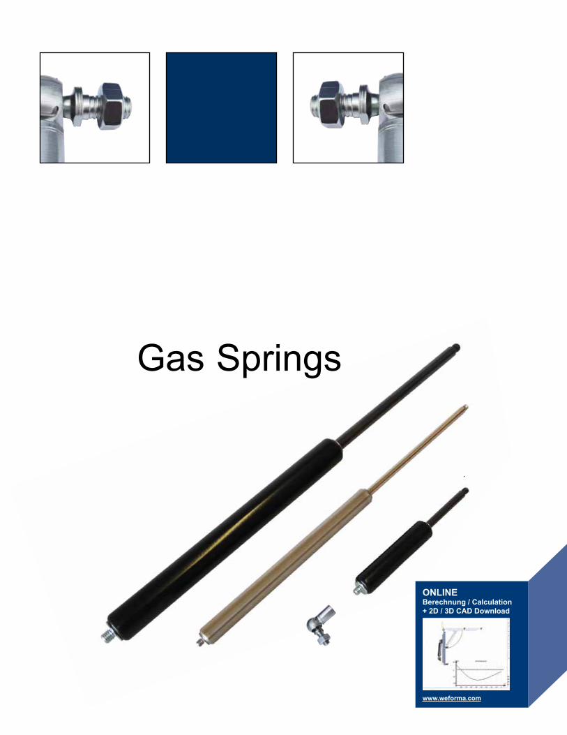
Gas Springs
ONLINEBerechnung / Calculation+ 2D / 3D CAD Download
www.weforma.com
192 Made in Germanywww.weforma.com
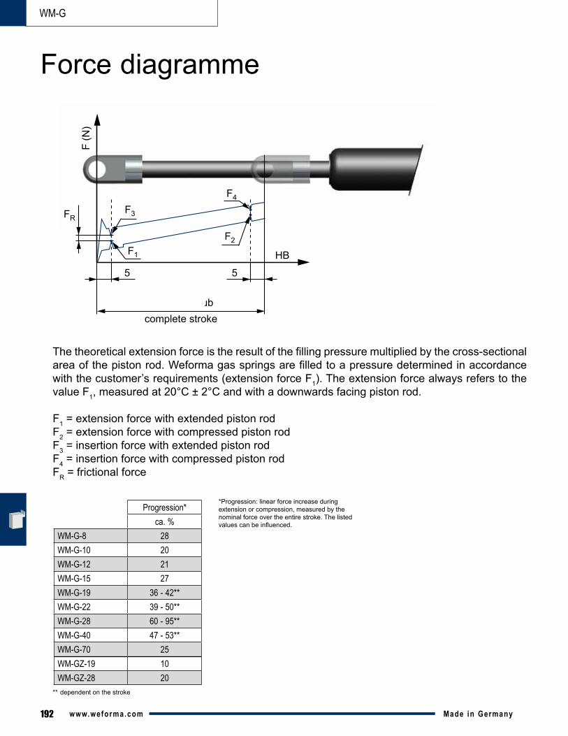
Thetheoreticalextensionforceistheresultofthefillingpressuremultipliedbythecross-sectionalareaofthepistonrod.Weformagasspringsarefilledtoapressuredeterminedinaccordancewith the customer’s requirements (extension force F1). The extension force always refers to the value F1, measured at 20°C ± 2°C and with a downwards facing piston rod.
F1 = extension force with extended piston rodF2 = extension force with compressed piston rodF3 = insertion force with extended piston rodF4 = insertion force with compressed piston rodFR = frictional force
5
FR
F (N
)
HB
gesamter Hubcomplete stroke
5
F3
F4
F2F1
Progression*ca. %
WM-G-8 28WM-G-10 20WM-G-12 21WM-G-15 27WM-G-19 36 - 42**WM-G-22 39 - 50**WM-G-28 60 - 95**WM-G-40 47 - 53**WM-G-70 25WM-GZ-19 10WM-GZ-28 20
*Progression: linear force increase during extension or compression, measured by the nominal force over the entire stroke. The listed valuescanbeinfluenced.
** dependent on the stroke
Force diagramme
WM-G
193Made in Germany www.weforma.com
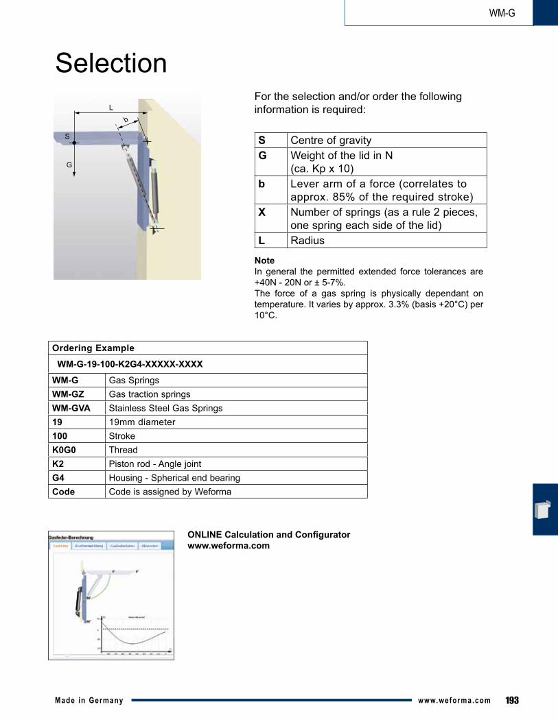
L
S
b
G
NoteIn general the permitted extended force tolerances are +40N - 20N or ± 5-7%. The force of a gas spring is physically dependant on temperature. It varies by approx. 3.3% (basis +20°C) per 10°C.
ONLINE Calculation and Configuratorwww.weforma.com
S Centre of gravityG Weight of the lid in N
(ca. Kp x 10)b Lever arm of a force (correlates to
approx. 85% of the required stroke)X Number of springs (as a rule 2 pieces,
one spring each side of the lid)L Radius
Ordering Example
WM-G-19-100-K2G4-XXXXX-XXXX
WM-G Gas SpringsWM-GZ Gas traction springsWM-GVA Stainless Steel Gas Springs19 19mm diameter100 StrokeK0G0 ThreadK2 Piston rod - Angle jointG4 Housing - Spherical end bearingCode Code is assigned by Weforma
WM-G
SelectionFor the selection and/or order the following information is required:
194 Made in Germanywww.weforma.com
WM-G
▪ High corrosion resistance · Housing: powder coated (WM-G 8: brass) · Piston rod: ceramic coated (WM-G 8 - 40) · Piston rod hard chrome-plated (WM-G 70)▪ Minimal friction coefficient to achieve the lowest extension forces▪ Integrated grease chamber and sliding bearing▪ Lower breakaway force▪ Installation position: any▪ Maintenance-free and ready for installation▪ Temperature: -20°C – +80°C, optional: -45°C – +200°C▪ Adjustable filling force (optional)▪ RoHS - conform Directive 2002/95/EC
Gas SpringsWM-G
FEATURES
195Made in Germany www.weforma.com
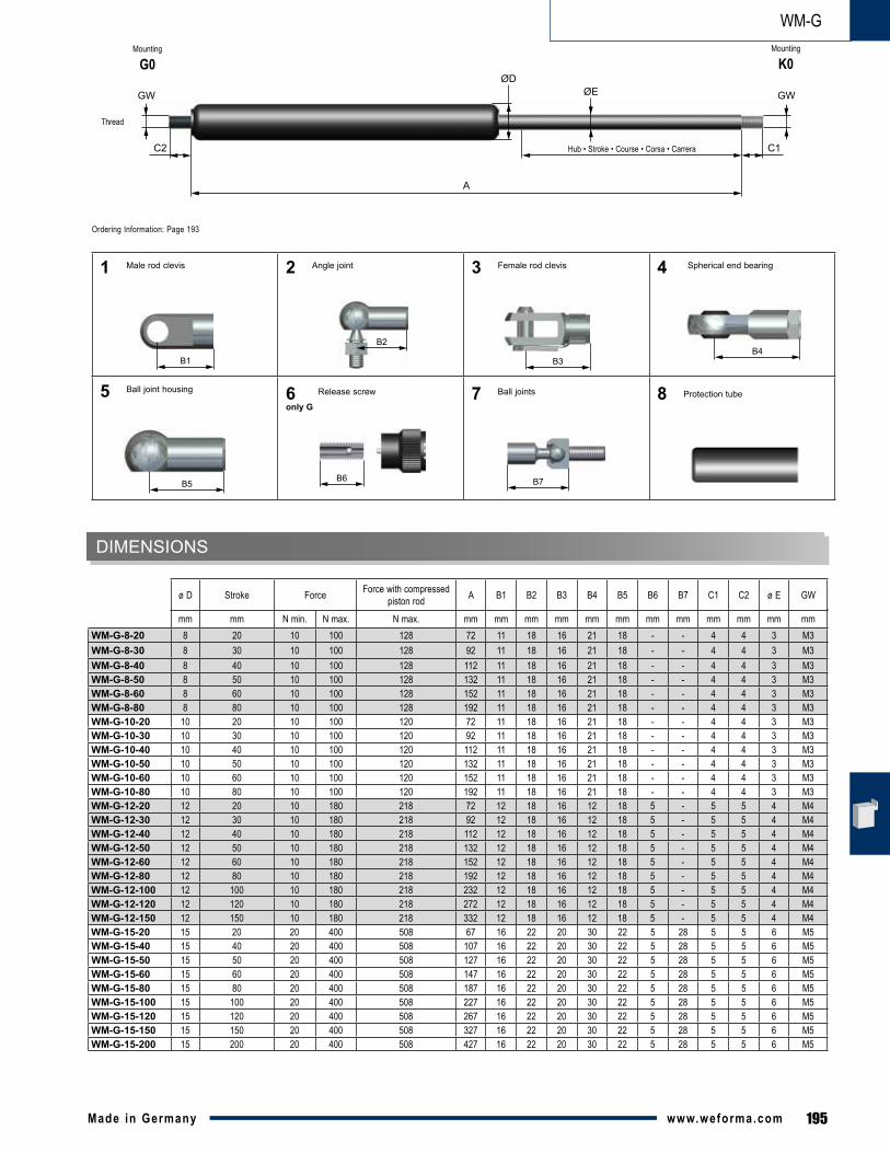
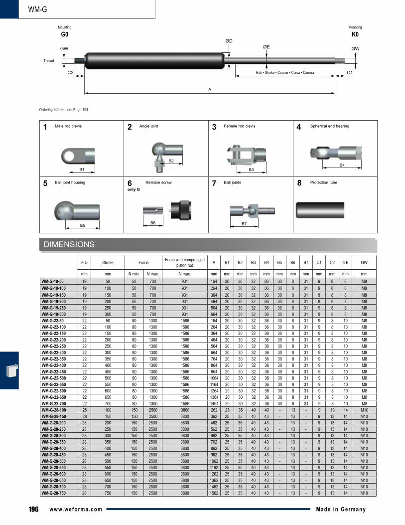
WM-GMounting
G0
mm mm N min. N max. N max. mm mm mm mm mm mm mm mm mm mm mm mmWM-G-8-20 8 20 10 100 128 72 11 18 16 21 18 - - 4 4 3 M3WM-G-8-30 8 30 10 100 128 92 11 18 16 21 18 - - 4 4 3 M3WM-G-8-40 8 40 10 100 128 112 11 18 16 21 18 - - 4 4 3 M3WM-G-8-50 8 50 10 100 128 132 11 18 16 21 18 - - 4 4 3 M3WM-G-8-60 8 60 10 100 128 152 11 18 16 21 18 - - 4 4 3 M3WM-G-8-80 8 80 10 100 128 192 11 18 16 21 18 - - 4 4 3 M3WM-G-10-20 10 20 10 100 120 72 11 18 16 21 18 - - 4 4 3 M3WM-G-10-30 10 30 10 100 120 92 11 18 16 21 18 - - 4 4 3 M3WM-G-10-40 10 40 10 100 120 112 11 18 16 21 18 - - 4 4 3 M3WM-G-10-50 10 50 10 100 120 132 11 18 16 21 18 - - 4 4 3 M3WM-G-10-60 10 60 10 100 120 152 11 18 16 21 18 - - 4 4 3 M3WM-G-10-80 10 80 10 100 120 192 11 18 16 21 18 - - 4 4 3 M3WM-G-12-20 12 20 10 180 218 72 12 18 16 12 18 5 - 5 5 4 M4WM-G-12-30 12 30 10 180 218 92 12 18 16 12 18 5 - 5 5 4 M4WM-G-12-40 12 40 10 180 218 112 12 18 16 12 18 5 - 5 5 4 M4WM-G-12-50 12 50 10 180 218 132 12 18 16 12 18 5 - 5 5 4 M4WM-G-12-60 12 60 10 180 218 152 12 18 16 12 18 5 - 5 5 4 M4WM-G-12-80 12 80 10 180 218 192 12 18 16 12 18 5 - 5 5 4 M4WM-G-12-100 12 100 10 180 218 232 12 18 16 12 18 5 - 5 5 4 M4WM-G-12-120 12 120 10 180 218 272 12 18 16 12 18 5 - 5 5 4 M4WM-G-12-150 12 150 10 180 218 332 12 18 16 12 18 5 - 5 5 4 M4WM-G-15-20 15 20 20 400 508 67 16 22 20 30 22 5 28 5 5 6 M5WM-G-15-40 15 40 20 400 508 107 16 22 20 30 22 5 28 5 5 6 M5WM-G-15-50 15 50 20 400 508 127 16 22 20 30 22 5 28 5 5 6 M5WM-G-15-60 15 60 20 400 508 147 16 22 20 30 22 5 28 5 5 6 M5WM-G-15-80 15 80 20 400 508 187 16 22 20 30 22 5 28 5 5 6 M5WM-G-15-100 15 100 20 400 508 227 16 22 20 30 22 5 28 5 5 6 M5WM-G-15-120 15 120 20 400 508 267 16 22 20 30 22 5 28 5 5 6 M5WM-G-15-150 15 150 20 400 508 327 16 22 20 30 22 5 28 5 5 6 M5WM-G-15-200 15 200 20 400 508 427 16 22 20 30 22 5 28 5 5 6 M5
Thread
Mounting
K0
ø D Stroke Force Force with compressed piston rod A B1 B2 B3 B4 B5 B6 B7 C1 C2 ø E GW
DIMENSIONS
B6
B3B1B4
B5
B2
1
5
2 3 4
A
ØE
C1
ØD
C2
GWGW
Hub • Stroke • Course • Corsa • Carrera
Spherical end bearingFemale rod clevisAngle joint
Release screw
Male rod clevis
Ball joint housing 8 Protection tube
Ordering Information: Page 193
6only G
B7
7 Ball joints
196 Made in Germanywww.weforma.com
WM-G
Mounting
G0Mounting
K0
mm mm N min. N max. N max. mm mm mm mm mm mm mm mm mm mm mm mmWM-G-19-50 19 50 50 700 931 164 20 30 32 36 30 8 31 9 8 8 M8WM-G-19-100 19 100 50 700 931 264 20 30 32 36 30 8 31 9 8 8 M8WM-G-19-150 19 150 50 700 931 364 20 30 32 36 30 8 31 9 8 8 M8WM-G-19-200 19 200 50 700 931 464 20 30 32 36 30 8 31 9 8 8 M8WM-G-19-250 19 250 50 700 931 564 20 30 32 36 30 8 31 9 8 8 M8WM-G-19-300 19 300 50 700 931 664 20 30 32 36 30 8 31 9 8 8 M8WM-G-22-50 22 50 80 1300 1586 164 20 30 32 36 30 8 31 9 8 10 M8WM-G-22-100 22 100 80 1300 1586 264 20 30 32 36 30 8 31 9 8 10 M8WM-G-22-150 22 150 80 1300 1586 364 20 30 32 36 30 8 31 9 8 10 M8WM-G-22-200 22 200 80 1300 1586 464 20 30 32 36 30 8 31 9 8 10 M8WM-G-22-250 22 250 80 1300 1586 564 20 30 32 36 30 8 31 9 8 10 M8WM-G-22-300 22 300 80 1300 1586 664 20 30 32 36 30 8 31 9 8 10 M8WM-G-22-350 22 350 80 1300 1586 764 20 30 32 36 30 8 31 9 8 10 M8WM-G-22-400 22 400 80 1300 1586 864 20 30 32 36 30 8 31 9 8 10 M8WM-G-22-450 22 450 80 1300 1586 964 20 30 32 36 30 8 31 9 8 10 M8WM-G-22-500 22 500 80 1300 1586 1064 20 30 32 36 30 8 31 9 8 10 M8WM-G-22-550 22 550 80 1300 1586 1164 20 30 32 36 30 8 31 9 8 10 M8WM-G-22-600 22 600 80 1300 1586 1264 20 30 32 36 30 8 31 9 8 10 M8WM-G-22-650 22 650 80 1300 1586 1364 20 30 32 36 30 8 31 9 8 10 M8WM-G-22-700 22 700 80 1300 1586 1464 20 30 32 36 30 8 31 9 8 10 M8WM-G-28-100 28 100 150 2500 3800 262 25 35 40 43 - 13 - 9 13 14 M10WM-G-28-150 28 150 150 2500 3800 362 25 35 40 43 - 13 - 9 13 14 M10WM-G-28-200 28 200 150 2500 3800 462 25 35 40 43 - 13 - 9 13 14 M10WM-G-28-250 28 250 150 2500 3800 562 25 35 40 43 - 13 - 9 13 14 M10WM-G-28-300 28 300 150 2500 3800 662 25 35 40 43 - 13 - 9 13 14 M10WM-G-28-350 28 350 150 2500 3800 762 25 35 40 43 - 13 - 9 13 14 M10WM-G-28-400 28 400 150 2500 3800 862 25 35 40 43 - 13 - 9 13 14 M10WM-G-28-450 28 450 150 2500 3800 962 25 35 40 43 - 13 - 9 13 14 M10WM-G-28-500 28 500 150 2500 3800 1062 25 35 40 43 - 13 - 9 13 14 M10WM-G-28-550 28 550 150 2500 3800 1162 25 35 40 43 - 13 - 9 13 14 M10WM-G-28-600 28 600 150 2500 3800 1262 25 35 40 43 - 13 - 9 13 14 M10WM-G-28-650 28 650 150 2500 3800 1362 25 35 40 43 - 13 - 9 13 14 M10WM-G-28-700 28 700 150 2500 3800 1462 25 35 40 43 - 13 - 9 13 14 M10WM-G-28-750 28 750 150 2500 3800 1562 25 35 40 43 - 13 - 9 13 14 M10
DIMENSIONS
ø D Stroke Force Force with compressed piston rod A B1 B2 B3 B4 B5 B6 B7 C1 C2 ø E GW
Thread
B6
B3B1B4
B7B5
B2
1
5
2 3
7
4
A
ØE
C1
ØD
C2
GWGW
Hub • Stroke • Course • Corsa • Carrera
Spherical end bearingFemale rod clevis
Protection tubeBall joints
Angle joint
Release screw
Male rod clevis
Ball joint housing
Ordering Information: Page 193
6only G
8
197Made in Germany www.weforma.com
WM-G
mm mm N min. N max. N max. mm mm mm mm mm mm mm mm mm mm mmWM-G-40-100 40 100 500 5000 7250 317 40 45 56 57 15 - 15 15 20 M14x1,5WM-G-40-150 40 150 500 5000 7250 417 40 45 56 57 15 - 15 15 20 M14x1,5WM-G-40-200 40 200 500 5000 7250 517 40 45 56 57 15 - 15 15 20 M14x1,5WM-G-40-300 40 300 500 5000 7250 717 40 45 56 57 15 - 15 15 20 M14x1,5WM-G-40-400 40 400 500 5000 7250 917 40 45 56 57 15 - 15 15 20 M14x1,5WM-G-40-500 40 500 500 5000 7250 1117 40 45 56 57 15 - 15 15 20 M14x1,5WM-G-40-600 40 600 500 5000 7250 1317 40 45 56 57 15 - 15 15 20 M14x1,5WM-G-40-800 40 800 500 5000 7250 1717 40 45 56 57 15 - 15 15 20 M14x1,5WM-G-40-1000 40 1000 500 5000 7250 2117 40 45 56 57 15 - 15 15 20 M14x1,5WM-G-70-100 70 100 2000 12000 16250 320 - - 100 94 - - 35 35 30 M24x2,0WM-G-70-200 70 200 2000 12000 16250 520 - - 100 94 - - 35 35 30 M24x2,0WM-G-70-300 70 300 2000 12000 16250 720 - - 100 94 - - 35 35 30 M24x2,0WM-G-70-400 70 400 2000 12000 16250 920 - - 100 94 - - 35 35 30 M24x2,0WM-G-70-500 70 500 2000 12000 16250 1120 - - 100 94 - - 35 35 30 M24x2,0WM-G-70-600 70 600 2000 12000 16250 1320 - - 100 94 - - 35 35 30 M24x2,0WM-G-70-700 70 700 2000 12000 16250 1520 - - 100 94 - - 35 35 30 M24x2,0WM-G-70-800 70 800 2000 12000 16250 1720 - - 100 94 - - 35 35 30 M24x2,0
DIMENSIONS
ø D Stroke Force Force with compressed piston rod A B1 B2 B3 B4 B6 B7 C1 C2 ø E GW
Thread
B6
B3B1B4
B7
B2
1 2
7
3
8
4
A
ØE
C1
ØD
C2
GWGW
Hub • Stroke • Course • Corsa • Carrera
Spherical end bearingFemale rod clevis
Protection tube
Angle joint
Ball joints
Male rod clevis
Release screw
Ordering Information: Page 193
6only G
Mounting
G0Mounting
K0
198 Made in Germanywww.weforma.com
WM-GZ
▪Highcorrosionresistance · Housing: powder coated · Piston rod: ceramic coated▪Minimalfrictioncoefficienttoachievethelowestextensionforces▪Integratedgreasechambersandslidingbearing▪Lowerbreakawayforce▪Installationposition:any▪Maintenancefree-andreadyforinstallation▪Temperature:-20°C – +80°C, optional: -45°C – +200°C▪Adjustable filling force (optional)▪RoHS-conformDirective2002/95/EC
Gas Traction SpringsWM-GZ
FEATURES
199Made in Germany www.weforma.com
WM-GZ
mm mm N min. N max. N max. mm mm mm mm mm mm mm mm mm mm mm mmWM-GZ-19-30 19 30 30 300 330 112 20 30 32 36 30 5 10 8 6 M8 M8WM-GZ-19-50 19 50 30 300 330 132 20 30 32 36 30 5 10 8 6 M8 M8WM-GZ-19-100 19 100 30 300 330 182 20 30 32 36 30 5 10 8 6 M8 M8WM-GZ-19-150 19 150 30 300 330 232 20 30 32 36 30 5 10 8 6 M8 M8WM-GZ-19-200 19 200 30 300 330 282 20 30 32 36 30 5 10 8 6 M8 M8WM-GZ-28-30 28 30 150 1200 1440 130 25 35 40 43 - 12 9 9 10 M10 M10WM-GZ-28-50 28 50 150 1200 1440 150 25 35 40 43 - 12 9 9 10 M10 M10WM-GZ-28-100 28 100 150 1200 1440 200 25 35 40 43 - 12 9 9 10 M10 M10WM-GZ-28-150 28 150 150 1200 1440 250 25 35 40 43 - 12 9 9 10 M10 M10WM-GZ-28-200 28 200 150 1200 1440 300 25 35 40 43 - 12 9 9 10 M10 M10WM-GZ-28-250 28 250 150 1200 1440 350 25 35 40 43 - 12 9 9 10 M10 M10WM-GZ-28-300 28 300 150 1200 1440 400 25 35 40 43 - 12 9 9 10 M10 M10WM-GZ-28-350 28 350 150 1200 1440 450 25 35 40 43 - 12 9 9 10 M10 M10WM-GZ-28-400 28 400 150 1200 1440 500 25 35 40 43 - 12 9 9 10 M10 M10WM-GZ-28-450 28 450 150 1200 1440 550 25 35 40 43 - 12 9 9 10 M10 M10WM-GZ-28-500 28 500 150 1200 1440 600 25 35 40 43 - 12 9 9 10 M10 M10WM-GZ-28-550 28 550 150 1200 1440 650 25 35 40 43 - 12 9 9 10 M10 M10WM-GZ-28-600 28 600 150 1200 1440 700 25 35 40 43 - 12 9 9 10 M10 M10WM-GZ-28-650 28 650 150 1200 1440 750 25 35 40 43 - 12 9 9 10 M10 M10
DIMENSIONS
ø D Stroke Force Force with extended piston rod A B1 B2 B3 B4 B5 B6 C1 C2 ø E GW1 GW2
Thread
B6
B3B1B4
B5
B2
1
5
2
6only G
3 4
A
ØE
C1
ØD
C2
GW1GW2
Hub • Stroke • Course • Corsa • Carrera
Spherical end bearingFemale rod clevis
Protection tube
Angle joint
Release screw
Male rod clevis
Ball joint housing
Ordering Information: Page 193
Mounting
G0 Mounting
K0
8
200 Made in Germanywww.weforma.com
Zubehör
M3
M4
1-M3
1-M4
2-M3
2-M4
3-M3
3-M4
4-M3
4-M4
5-M3
5-M4
max. 370 N
max. 370 N
max. 370 N
max. 370 N
max. 370 N
max. 370 N
max. 370 N
max. 370 N
max. 370 N
max. 370 N
M3
ø4,1
5
11
3
M4
ø4,1
6
12
3
M3
6
18
M310
,29
M4
6
18
M4
10,2
9
M3
ø4
8 4
8
5 16
M4
ø4
8 4
8
5 16
M3
1021
6
ø3ø5
M4
512
7
ø4ø7,8
M3
618
ø8
M4
618
ø8
Spherical end bearing
Spherical end bearing
Female rod clevis
Female rod clevis
Angle joint
Angle joint
Male rod clevis
Male rod clevis
Ball joint housing
Ball joint housing Release screw6-M4
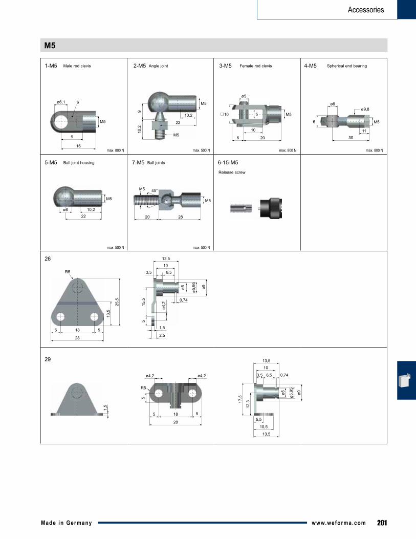
201Made in Germany www.weforma.com
Accessories
M5
1-M5
5-M5 7-M5
2-M5 3-M5 4-M5
R5
5
5 55,5
10,5
13,5
12,317
,5
0,746,53,5
18
28
1,5
ø4,2ø4,2
ø5
ø5,9
5
ø9
10
13,5
ø4,2
ø5
5
6,5
0,74
1,5
2,5
13,5
103,5
15,5
R5
185
28
5
13,5
25,5
ø5,9
5
ø9
26
29
max. 800 N max. 500 N
max. 500 N
max. 800 N max. 800 N
max. 500 N
M5
ø6,1
9
16
6 M5
10,2
22
M510
,29
M5
ø5
10 5
10
6 20
M5
1130
6
ø6ø9,8
M5
10,222
ø8
Spherical end bearingFemale rod clevisAngle jointMale rod clevis
Ball joint housing Ball joints
M5
M5 45°
2820
Release screw
6-15-M5
202 Made in Germanywww.weforma.com
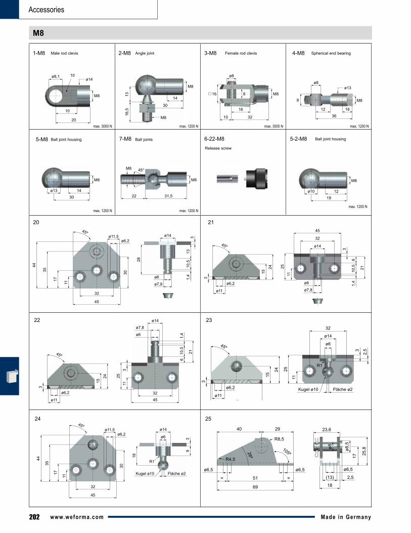
Accessories
M8
1-M8 2-M8 3-M8 4-M8
5-M8
21
22 23
24 25
7-M8
20
11
30
ø6,2ø11,5
17
45º
35
44
32
45
ø14
ø6
313
10,5
1,4
28
ø7,8
45º
15
24
ø14
32
ø6,2
ø11
3
3
610
,5 21
1,4
45
ø611
ø7,8
25
45º
15
24
ø14
ø6,2
ø11
3
610
,5
21
1,4
4532
ø6
11
ø7,8
253
ø6,5
R8,5
26º
105ºR4,5
51 ==
69
ø6,5 ø6,5
ø8 ø8,5
17 25,8
(13) 2,5
18
23,640 29
45º
15
24
ø14
ø6
ø6,2
ø11
3
3
2,5
32
Fläche ø2Kugel ø10
45
11
25
R1
11
30
ø6,2ø11,5
17
45º
35
44
32
45
ø14
ø6
R1
39
18
Fläche ø2Kugel ø10
max. 3000 N max. 1200 N max. 3000 N max. 1200 N
max. 1200 N max. 1200 N
M8
ø8,1
10
20
10ø14
M8
14
30
M8
16,5
13 M8
ø8
16 8
16
10 32
M8
161236
8
ø8ø13
M8
1430
ø13
M8
M8 45°
31,522
Spherical end bearingFemale rod clevisAngle jointMale rod clevis
Ball joint housing Ball joints 5-2-M8
max. 1200 N
M8
1219
ø10
Ball joint housing
Release screw
6-22-M8
203Made in Germany www.weforma.com
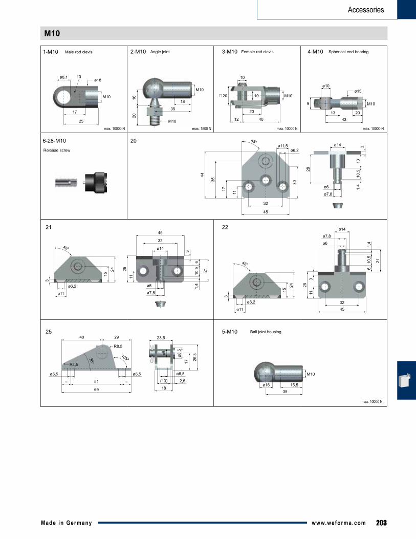
Accessories
M10
M10
ø8,1
17
25
10ø18
1-M10
20
21 22
2-M10 3-M10 4-M10
11
30
ø6,2ø11,5
17
45º
35
4432
45
ø14
ø6
313
10,5
1,4
28
ø7,8
45º
15
24
ø14
32
ø6,2
ø11
3
3
610
,5 21
1,4
45
ø6
11
ø7,8
25
45º
15
24
ø14
ø6,2
ø11
3
610
,5
21
1,4
4532
ø6
11
ø7,8
253
ø6,5
R8,5
26º
105ºR4,5
51 ==
69
ø6,5 ø6,5
ø8 ø8,5
17 25,8
(13) 2,5
18
23,640 29
M10
18
35
M10
2016
M10
10
20 10
20
12 40
M10
201343
9
ø10ø15
25
max. 10000 N max. 1800 N max. 10000 N max. 10000 N
max. 10000 N
5-M10
M10
15,535
ø16
Spherical end bearingFemale rod clevisAngle jointMale rod clevis
Ball joint housing
Release screw
6-28-M10
204 Made in Germanywww.weforma.com
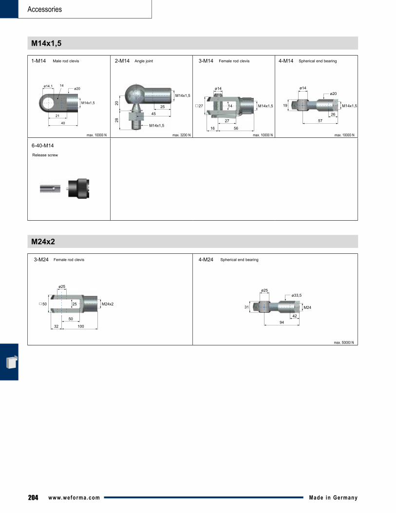
Accessories
M14x1,5
M24x2
M24x2
ø25
50 25
50
32 100
M24
4294
31
ø25ø33,5
1-M14
3-M24 4-M24
2-M14 3-M14 4-M14
M14x1,5
ø14,1
21
40
14ø20
M14x1,5
25
45
M14x1,5
2820 M14x1,5
ø14
27 14
27
16 56
M14x1,5
2657
19
ø14ø20
max. 10000 N max. 3200 N max. 10000 N max. 10000 N
max. 50000 N
Spherical end bearing
Spherical end bearing
Female rod clevis
Female rod clevis
Angle jointMale rod clevis
Release screw
6-40-M14
205Made in Germany www.weforma.com
Accessories
Accessories
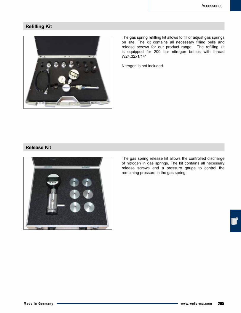
Refilling Kit
Release Kit
Thegasspringrefillingkitallowstofilloradjustgasspringson site. The kit contains all necessary filling bells and release screws for our product range. The refilling kitis equipped for 200 bar nitrogen bottles with thread W24,32x1/14"
Nitrogen is not included.
The gas spring release kit allows the controlled discharge of nitrogen in gas springs. The kit contains all necessary release screws and a pressure gauge to control the remaining pressure in the gas spring.
206 Made in Germanywww.weforma.com
WM-GB
FEATURES
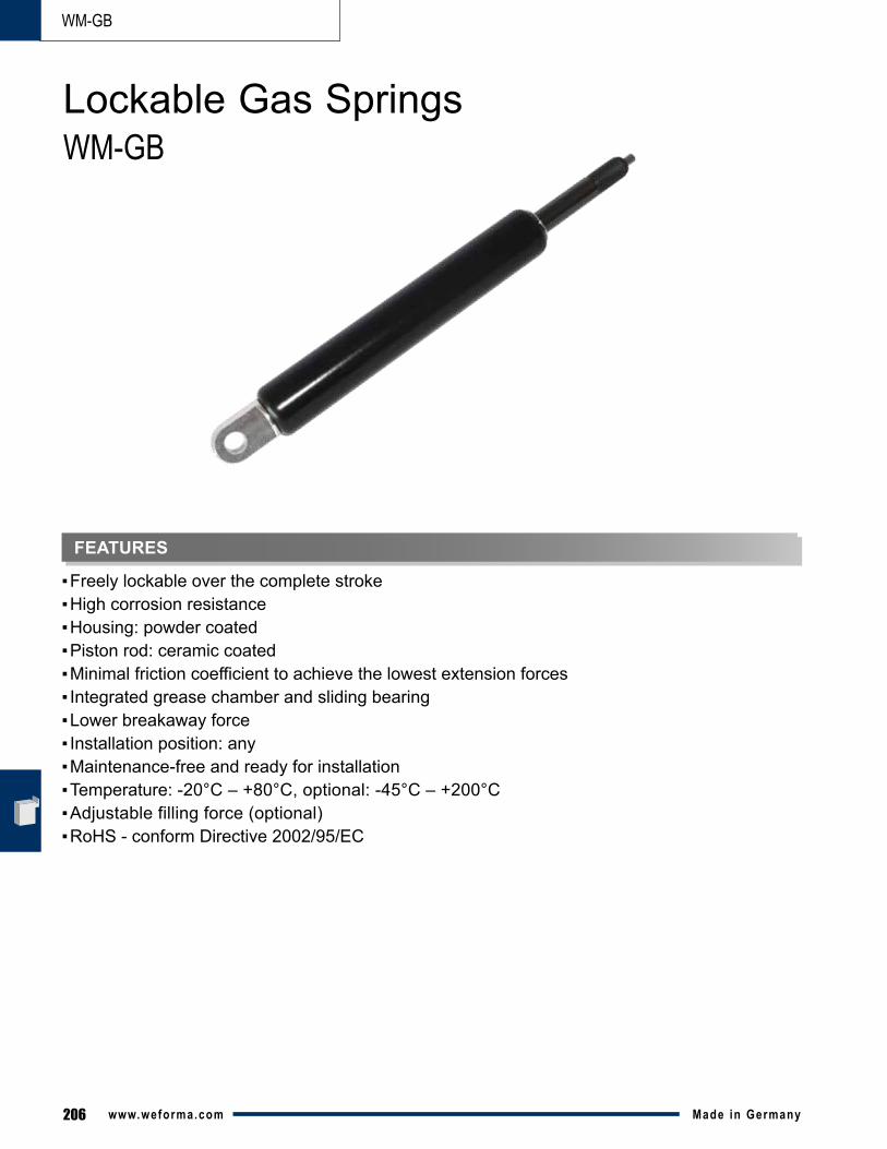
▪Freelylockableoverthecompletestroke▪Highcorrosionresistance▪Housing:powdercoated▪Pistonrod:ceramiccoated▪Minimalfrictioncoefficienttoachievethelowestextensionforces▪Integratedgreasechamberandslidingbearing▪Lowerbreakawayforce▪Installationposition:any▪Maintenance-freeandreadyforinstallation▪Temperature:-20°C – +80°C, optional: -45°C – +200°C▪Adjustable filling force (optional)▪RoHS-conformDirective2002/95/EC
Lockable Gas SpringsWM-GB
207Made in Germany www.weforma.com
WM-GB
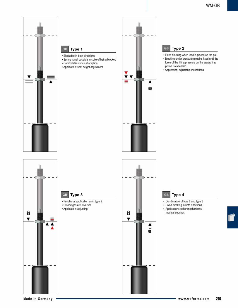
GB Type 1▪ Blockable in both directions ▪ Spring travel possible in spite of being blocked ▪ Comfortable shock absorption ▪ Application: seat height adjustment
GB Type 3▪ Functional application as in type 2▪ Oil and gas are reversed▪ Application: adjusting
GB Type 2▪ Fixed blocking when load is placed on the pull▪ Blocking under pressure remains fixed until the force of the filling pressure on the separating piston is exceeded.▪ Application: adjustable inclinations
GB Type 4▪ Combination of type 2 and type 3▪ Fixed blocking in both directions ▪ Application: rocker mechanisms, medical couches
208 Made in Germanywww.weforma.com
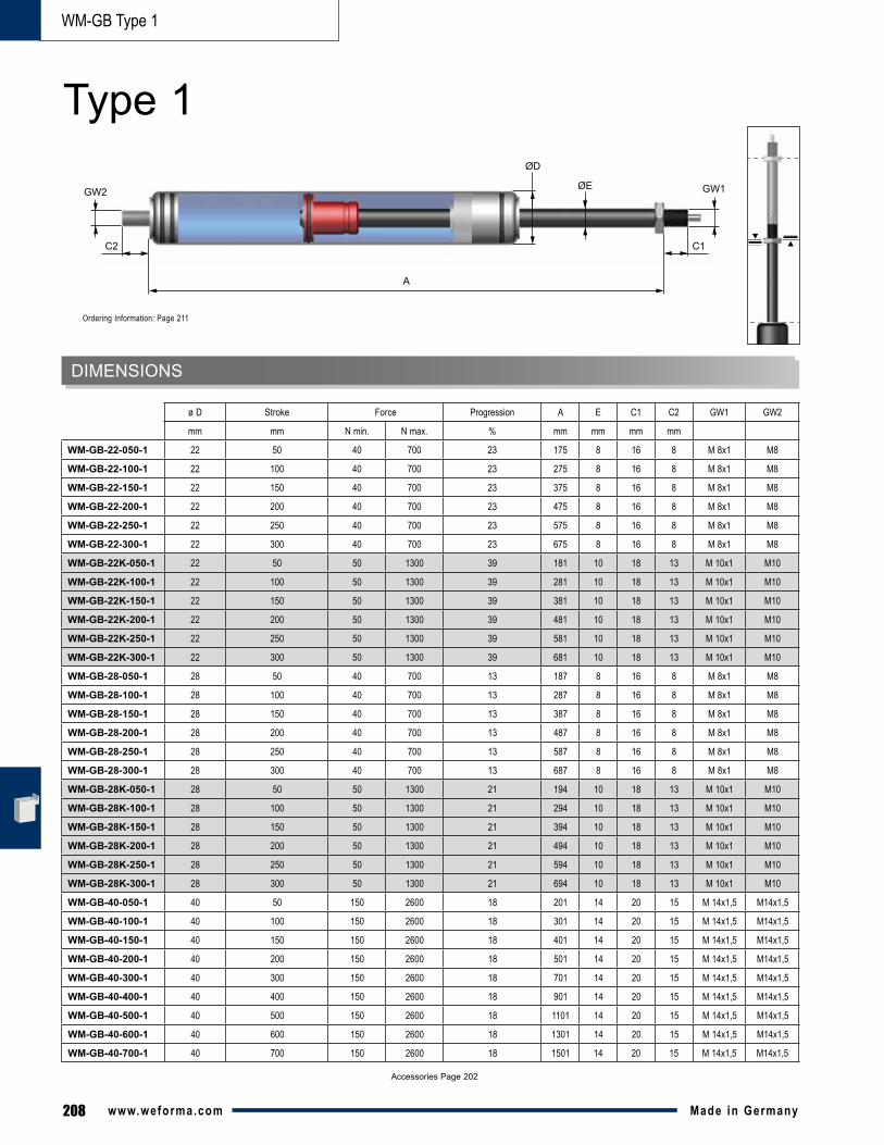
WM-GB Type 1
Accessories Page 202
mm mm N min. N max. % mm mm mm mm
WM-GB-22-050-1 22 50 40 700 23 175 8 16 8 M 8x1 M8
WM-GB-22-100-1 22 100 40 700 23 275 8 16 8 M 8x1 M8
WM-GB-22-150-1 22 150 40 700 23 375 8 16 8 M 8x1 M8
WM-GB-22-200-1 22 200 40 700 23 475 8 16 8 M 8x1 M8
WM-GB-22-250-1 22 250 40 700 23 575 8 16 8 M 8x1 M8
WM-GB-22-300-1 22 300 40 700 23 675 8 16 8 M 8x1 M8
WM-GB-22K-050-1 22 50 50 1300 39 181 10 18 13 M 10x1 M10
WM-GB-22K-100-1 22 100 50 1300 39 281 10 18 13 M 10x1 M10
WM-GB-22K-150-1 22 150 50 1300 39 381 10 18 13 M 10x1 M10
WM-GB-22K-200-1 22 200 50 1300 39 481 10 18 13 M 10x1 M10
WM-GB-22K-250-1 22 250 50 1300 39 581 10 18 13 M 10x1 M10
WM-GB-22K-300-1 22 300 50 1300 39 681 10 18 13 M 10x1 M10
WM-GB-28-050-1 28 50 40 700 13 187 8 16 8 M 8x1 M8
WM-GB-28-100-1 28 100 40 700 13 287 8 16 8 M 8x1 M8
WM-GB-28-150-1 28 150 40 700 13 387 8 16 8 M 8x1 M8
WM-GB-28-200-1 28 200 40 700 13 487 8 16 8 M 8x1 M8
WM-GB-28-250-1 28 250 40 700 13 587 8 16 8 M 8x1 M8
WM-GB-28-300-1 28 300 40 700 13 687 8 16 8 M 8x1 M8
WM-GB-28K-050-1 28 50 50 1300 21 194 10 18 13 M 10x1 M10
WM-GB-28K-100-1 28 100 50 1300 21 294 10 18 13 M 10x1 M10
WM-GB-28K-150-1 28 150 50 1300 21 394 10 18 13 M 10x1 M10
WM-GB-28K-200-1 28 200 50 1300 21 494 10 18 13 M 10x1 M10
WM-GB-28K-250-1 28 250 50 1300 21 594 10 18 13 M 10x1 M10
WM-GB-28K-300-1 28 300 50 1300 21 694 10 18 13 M 10x1 M10
WM-GB-40-050-1 40 50 150 2600 18 201 14 20 15 M 14x1,5 M14x1,5
WM-GB-40-100-1 40 100 150 2600 18 301 14 20 15 M 14x1,5 M14x1,5
WM-GB-40-150-1 40 150 150 2600 18 401 14 20 15 M 14x1,5 M14x1,5
WM-GB-40-200-1 40 200 150 2600 18 501 14 20 15 M 14x1,5 M14x1,5
WM-GB-40-300-1 40 300 150 2600 18 701 14 20 15 M 14x1,5 M14x1,5
WM-GB-40-400-1 40 400 150 2600 18 901 14 20 15 M 14x1,5 M14x1,5
WM-GB-40-500-1 40 500 150 2600 18 1101 14 20 15 M 14x1,5 M14x1,5
WM-GB-40-600-1 40 600 150 2600 18 1301 14 20 15 M 14x1,5 M14x1,5
WM-GB-40-700-1 40 700 150 2600 18 1501 14 20 15 M 14x1,5 M14x1,5
ø D Stroke Force Progression A E C1 C2 GW1 GW2
DIMENSIONS
A
ØE
ØD
C1
GW1
C2
GW2
Type 1
Ordering Information: Page 211
209Made in Germany www.weforma.com
WM-GB Type 2
*Data are approximate - depending on the extension force "F1" Accessories Page 202
mm mm N min. N max. mm mm mm mm mm mm N max N maxWM-GB-22-050-2 22 50 40 700 194 187 178 8 16 8 M 8x1 M 8 3920 -
WM-GB-22-100-2 22 100 40 700 320 305 287 8 16 8 M 8x1 M 8 3920 -
WM-GB-22-150-2 22 150 40 700 446 424 397 8 16 8 M 8x1 M 8 3920 -
WM-GB-22-200-2 22 200 40 700 572 542 506 8 16 8 M 8x1 M 8 3920 -
WM-GB-22-250-2 22 250 40 700 698 661 616 8 16 8 M 8x1 M 8 3920 -
WM-GB-22-300-2 22 300 40 700 824 779 725 8 16 8 M 8x1 M 8 3920 -
WM-GB-22K-050-2 22 50 40 1300 214 202 188 10 18 13 M 10x1 M 10 3920 7000
WM-GB-22K-100-2 22 100 40 1300 354 331 303 10 18 13 M 10x1 M 10 3920 7000
WM-GB-22K-150-2 22 150 40 1300 495 460 418 10 18 13 M 10x1 M 10 3920 7000
WM-GB-22K-200-2 22 200 40 1300 635 589 533 10 18 13 M 10x1 M 10 3920 7000
WM-GB-22K-250-2 22 250 40 1300 776 718 648 10 18 13 M 10x1 M 10 3920 7000
WM-GB-22K-300-2 22 300 40 1300 916 847 763 10 18 13 M 10x1 M 10 3920 7000
WM-GB-28-050-2 28 50 50 700 189 184 179 8 16 8 M 8x1 M 8 7000 -
WM-GB-28-100-2 28 100 50 700 305 296 285 8 16 8 M 8x1 M 8 7000 -
WM-GB-28-150-2 28 150 50 700 422 408 392 8 16 8 M 8x1 M 8 7000 -
WM-GB-28-200-2 28 200 50 700 538 520 498 8 16 8 M 8x1 M 8 7000 -
WM-GB-28-250-2 28 250 50 700 655 632 605 8 16 8 M 8x1 M 8 7000 -
WM-GB-28-300-2 28 300 50 700 771 744 711 8 16 8 M 8x1 M 8 7000 -
WM-GB-28K-050-2 28 50 50 1300 203 195 187 10 18 13 M 10x1 M 10 10000 10000
WM-GB-28K-100-2 28 100 50 1300 329 313 296 10 18 13 M 10x1 M 10 10000 10000
WM-GB-28K-150-2 28 150 50 1300 455 431 406 10 18 13 M 10x1 M 10 10000 10000
WM-GB-28K-200-2 28 200 50 1300 581 549 515 10 18 13 M 10x1 M 10 10000 10000
WM-GB-28K-250-2 28 250 50 1300 707 667 625 10 18 13 M 10x1 M 10 10000 10000
WM-GB-28K-300-2 28 300 50 1300 833 744 734 10 18 13 M 10x1 M 10 10000 10000
WM-GB-40-100-2 40 100 150 2600 342 330 314 14 20 15 M 14x1,5 M 14x1,5 10000 10000
WM-GB-40-150-2 40 150 150 2600 464 446 422 14 20 15 M 14x1,5 M 14x1,5 10000 10000
WM-GB-40-200-2 40 200 150 2600 585 561 529 14 20 15 M 14x1,5 M 14x1,5 10000 10000
WM-GB-40-300-2 40 300 150 2600 828 792 744 14 20 15 M 14x1,5 M 14x1,5 10000 10000
WM-GB-40-400-2 40 400 150 2600 1071 1023 959 14 20 15 M 14x1,5 M 14x1,5 10000 10000
WM-GB-40-500-2 40 500 150 2600 1314 1254 1174 14 20 15 M 14x1,5 M 14x1,5 10000 10000
WM-GB-40-600-2 40 600 150 2600 1557 1485 1389 14 20 15 M 14x1,5 M 14x1,5 10000 10000
WM-GB-40-700-2 40 700 150 2600 1800 1716 1604 14 20 15 M 14x1,5 M 14x1,5 10000 10000
ø D Stroke ForceA1
Progression 35%
A2Progression
50%
A3Progression
100%E C1 C2 GW1 GW2 Locking force
push*Locking force
pull
DIMENSIONS
A1 / A2 / A3
ØE
ØD
C1
GW
C2
GW2
Type 2
Ordering Information: Page 211
210 Made in Germanywww.weforma.com
WM-GB Type 3
*Data are approximate - depending on the extension force "F1" Accessories Page 202
mm mm N min. N max. mm mm mm mm mm mm N max N maxWM-GB-22-050-3 22 50 40 700 216 206 196 8 16 8 M 8x1 M8 7000 -
WM-GB-22-100-3 22 100 40 700 357 338 317 8 16 8 M 8x1 M8 7000 -
WM-GB-22-150-3 22 150 40 700 499 470 439 8 16 8 M 8x1 M8 7000 -
WM-GB-22-200-3 22 200 40 700 640 602 560 8 16 8 M 8x1 M8 7000 -
WM-GB-22K-050-3 22 50 50 1300 254 239 219 10 18 13 M 10x1 M10 7000 3380
WM-GB-22K-100-3 22 100 50 1300 427 396 357 10 18 13 M 10x1 M10 7000 3380
WM-GB-22K-150-3 22 150 50 1300 600 554 495 10 18 13 M 10x1 M10 7000 3380
WM-GB-22K-200-3 22 200 50 1300 773 711 633 10 18 13 M 10x1 M10 7000 3380
WM-GB-22K-250-3 22 250 50 1300 946 869 771 10 18 13 M 10x1 M10 7000 3380
WM-GB-22K-300-3 22 300 50 1300 1119 1026 909 10 18 13 M 10x1 M10 7000 3380
WM-GB-28-050-3 28 50 50 700 202 196 191 8 16 8 M 8x1 M8 7000 7000
WM-GB-28-100-3 28 100 50 700 326 313 303 8 16 8 M 8x1 M8 7000 7000
WM-GB-28-150-3 28 150 50 700 450 431 416 8 16 8 M 8x1 M8 7000 7000
WM-GB-28-200-3 28 200 50 700 574 548 528 8 16 8 M 8x1 M8 7000 7000
WM-GB-28-250-3 28 250 50 700 698 666 641 8 16 8 M 8x1 M8 7000 7000
WM-GB-28-300-3 28 300 50 700 822 783 753 8 16 8 M 8x1 M8 7000 7000
WM-GB-28K-050-3 28 50 50 1300 226 217 206 10 18 13 M 10x1 M10 10000 7000
WM-GB-28K-100-3 28 100 50 1300 366 348 327 10 18 13 M 10x1 M10 10000 7000
WM-GB-28K-150-3 28 150 50 1300 507 480 448 10 18 13 M 10x1 M10 10000 7000
WM-GB-28K-200-3 28 200 50 1300 647 611 569 10 18 13 M 10x1 M10 10000 7000
WM-GB-28K-250-3 28 250 50 1300 788 743 690 10 18 13 M 10x1 M10 10000 7000
WM-GB-28K-300-3 28 300 50 1300 828 874 811 10 18 13 M 10x1 M10 10000 7000
WM-GB-40-050-3 40 50 150 2600 227 220 211 14 20 15 M 14x1,5 M 14x1,5 10000 10000
WM-GB-40-100-3 40 100 150 2600 361 346 328 14 20 15 M 14x1,5 M 14x1,5 10000 10000
WM-GB-40-150-3 40 150 150 2600 495 473 446 14 20 15 M 14x1,5 M 14x1,5 10000 10000
WM-GB-40-200-3 40 200 150 2600 629 599 563 14 20 15 M 14x1,5 M 14x1,5 10000 10000
WM-GB-40-300-3 40 300 150 2600 897 852 798 14 20 15 M 14x1,5 M 14x1,5 10000 10000
WM-GB-40-400-3 40 400 150 2600 1165 1105 1033 14 20 15 M 14x1,5 M 14x1,5 10000 10000
WM-GB-40-500-3 40 500 150 2600 1433 1356 1268 14 20 15 M 14x1,5 M 14x1,5 10000 10000
WM-GB-40-600-3 40 600 150 2600 1701 1611 1503 14 20 15 M 14x1,5 M 14x1,5 10000 10000
ø D Stroke ForceA1 -
Progression 35%
A2 - Progression
50%
A3 - Progression
100%E C1 C2 GW1 GW2 Locking
force push*Locking
force pull*
DIMENSIONS
A1 / A2 / A3
ØE
ØD
C1
GW1
C2
GW2
Type 3
Ordering Information: Page 211! without valve
211Made in Germany www.weforma.com
WM-GB Type 4
Ordering Example
WM-GB-22-100-2-K0G1-XXXXX-XXXX
WM-GB Lockable Gas Springs
22 22 mm diameter
100 Stroke
-2 Type
K0G1 Piston rod - only threadHousing - Male rod clevis
Code Code is assigned by Weforma
Accessories Page 202
mm mm N min. N max. mm mm mm mm N max N maxWM-GB-22K-050-4 22 50 50 1300 233 10 18 13 M 10x1 M10 7000 7000
WM-GB-22K-100-4 22 100 50 1300 383 10 18 13 M 10x1 M10 7000 7000
WM-GB-22K-150-4 22 150 50 1300 533 10 18 13 M 10x1 M10 7000 7000
WM-GB-22K-200-4 22 200 50 1300 683 10 18 13 M 10x1 M10 7000 7000
WM-GB-22K-250-4 22 250 50 1300 833 10 18 13 M 10x1 M10 7000 7000
WM-GB-28K-50-4 28 50 50 1300 237 10 18 13 M 10x1 M10 10000 10000
WM-GB-28K-100-4 28 100 50 1300 387 10 18 13 M 10x1 M10 10000 10000
WM-GB-28K-150-4 28 150 50 1300 537 10 18 13 M 10x1 M10 10000 10000
WM-GB-28K-200-4 28 200 50 1300 687 10 18 13 M 10x1 M10 10000 10000
WM-GB-28K-250-4 28 250 50 1300 837 10 18 13 M 10x1 M10 10000 10000
WM-GB-40-050-4 40 50 150 2600 239 14 20 15 M 14x1,5 M 14x1,5 12000 12000
WM-GB-40-100-4 40 100 150 2600 389 14 20 15 M 14x1,5 M 14x1,5 12000 12000
WM-GB-40-150-4 40 150 150 2600 539 14 20 15 M 14x1,5 M 14x1,5 12000 12000
WM-GB-40-200-4 40 200 150 2600 689 14 20 15 M 14x1,5 M 14x1,5 12000 12000
WM-GB-40-250-4 40 250g 150 2600 989 14 20 15 M 14x1,5 M 14x1,5 12000 12000
ø D Stroke Force A E C1 C2 GW1 GW2 Locking force push*
Locking force pull*
DIMENSIONS
ØE
ØD
C1
GW1
A
C2
GW2
Type 4
Ordering Information: Page 211
212 Made in Germanywww.weforma.com
WM-GB
Release Systems
BOWDEN WIRE RELEASE SYSTEM
Release head (Standard, Zinc die cast)
Useourgasspringconfiguratorwww.weforma.com (Button: Calculation)
Release head (Horizontal, Zinc die cast)A
AK7 AK8
BO-1000
Bowden wireB
T1Push button plastic with spring
T2Push button plasticwithout spring
T3
Push button alu with spring
T4
Push button alu without spring
T5
Push button with long bushing, aluminium,without spring
C
213Made in Germany www.weforma.com
WM-GB
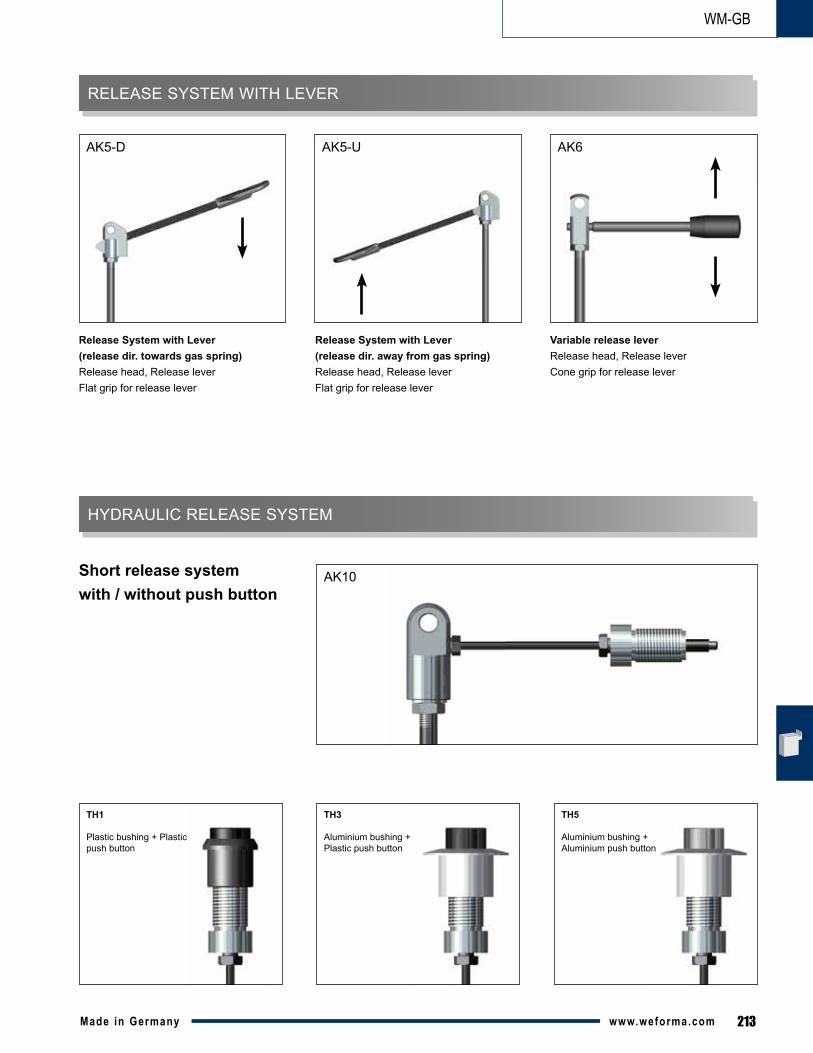
RELEASE SYSTEM WITH LEVER
HYDRAULIC RELEASE SYSTEM
Release System with Lever (release dir. towards gas spring)Release head, Release leverFlat grip for release lever
Release System with Lever (release dir. away from gas spring)Release head, Release leverFlat grip for release lever
Variable release leverRelease head, Release leverCone grip for release lever
Short release system with / without push button
AK5-D AK5-U AK6
AK10
TH1
Plastic bushing + Plastic push button
TH3
Aluminium bushing + Plastic push button
TH5
Aluminium bushing + Aluminium push button
214 Made in Germanywww.weforma.com
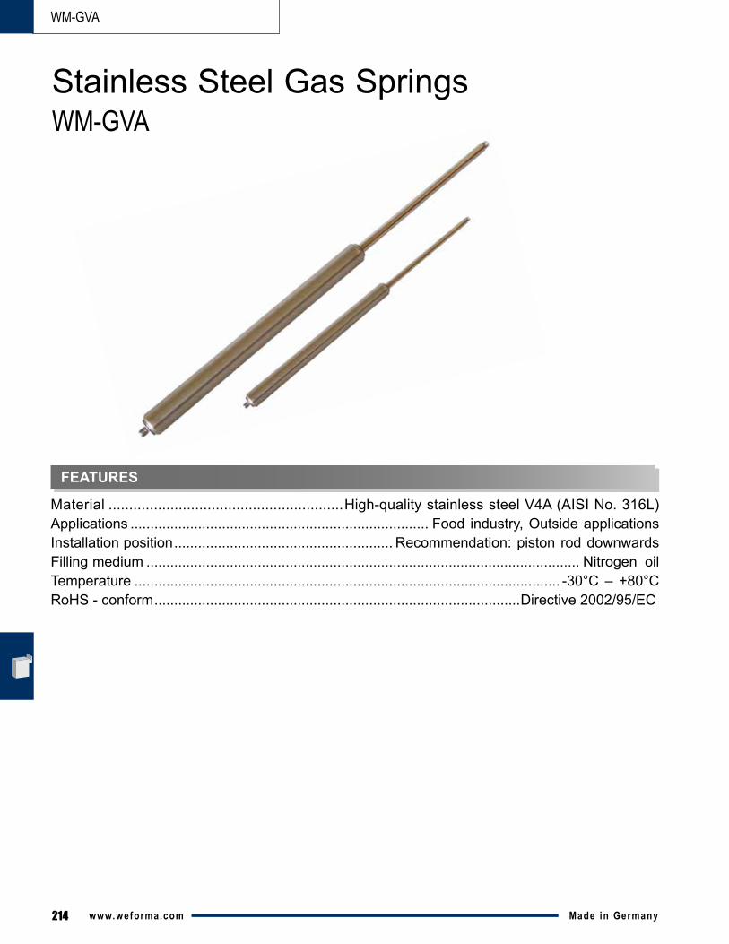
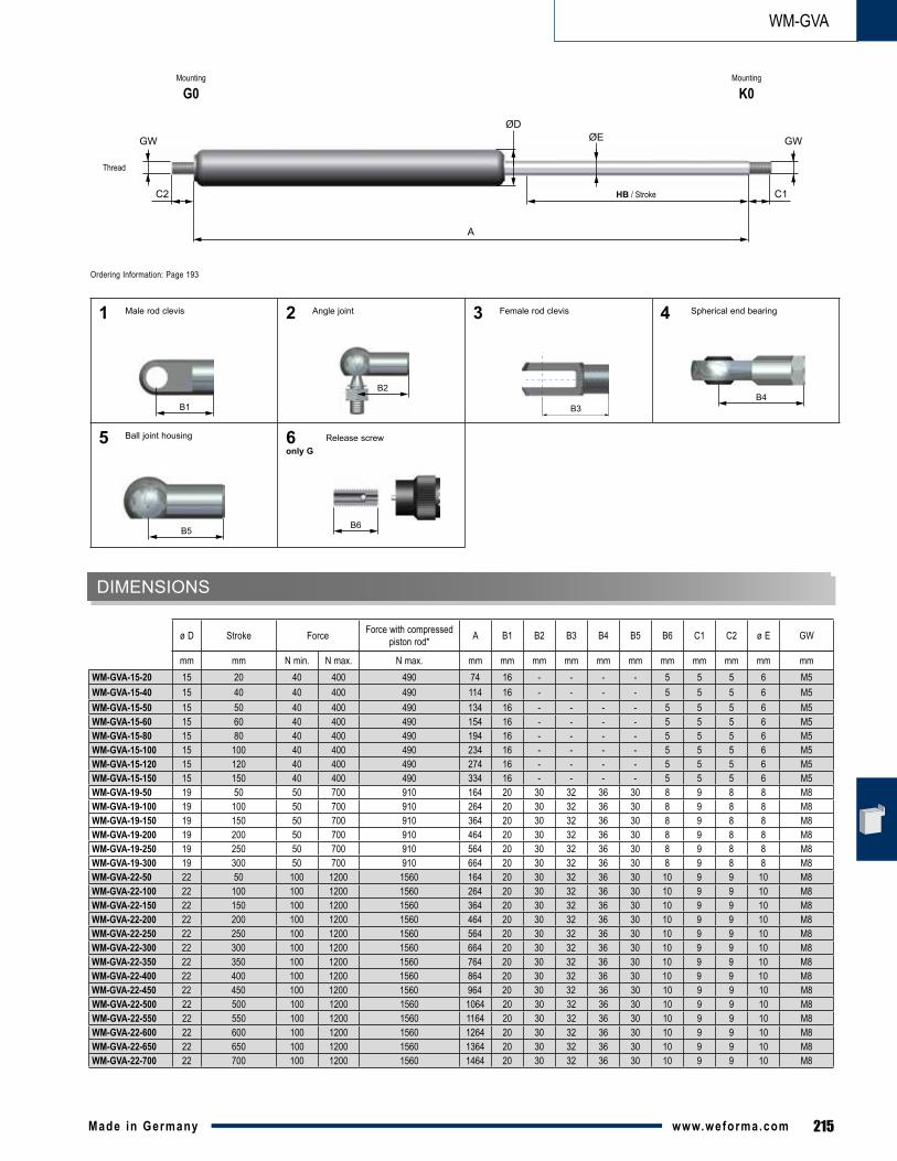
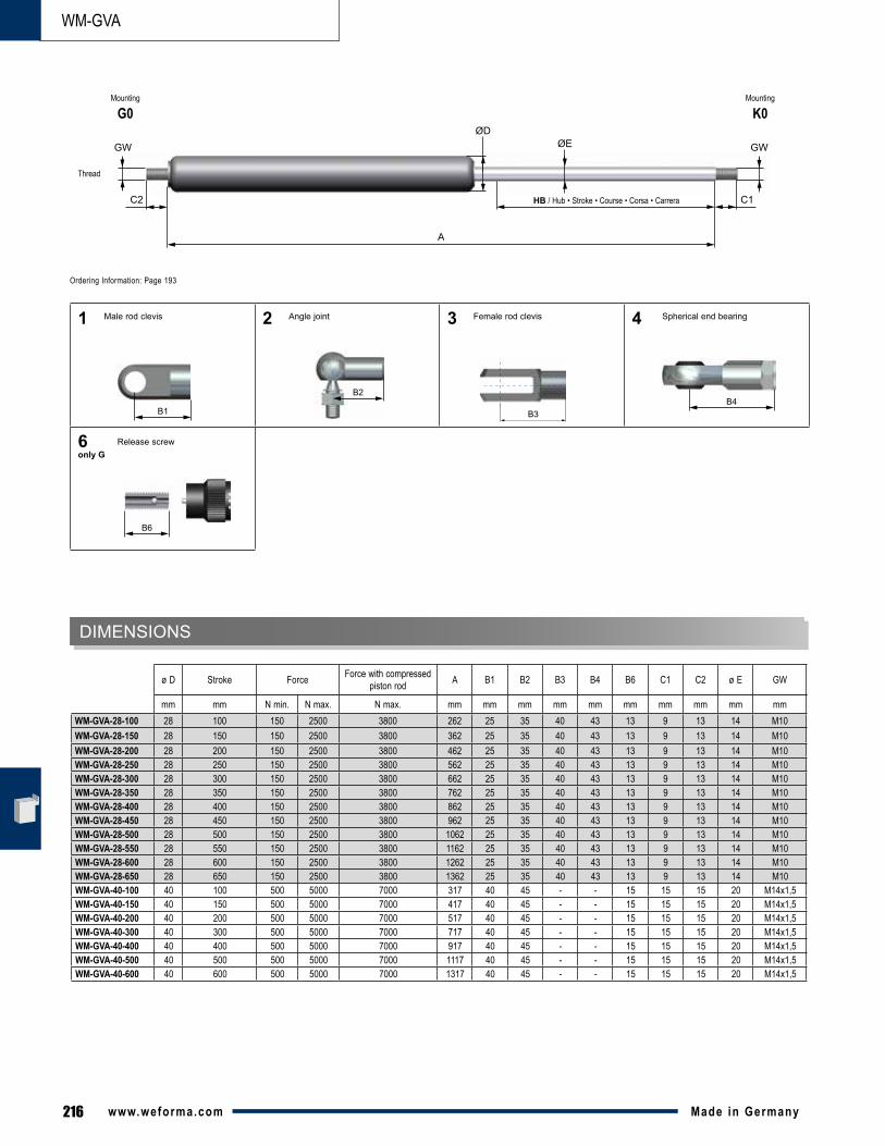
WM-GVA
Material .........................................................High-quality stainless steel V4A (AISI No. 316L)Applications ........................................................................... Food industry, Outside applicationsInstallation position ....................................................... Recommendation: piston rod downwardsFilling medium ............................................................................................................. Nitrogen oilTemperature ........................................................................................................... -30°C – +80°CRoHS - conform ............................................................................................Directive 2002/95/EC
Stainless Steel Gas SpringsWM-GVA
FEATURES
215Made in Germany www.weforma.com
WM-GVA
mm mm N min. N max. N max. mm mm mm mm mm mm mm mm mm mm mmWM-GVA-15-20 15 20 40 400 490 74 16 - - - - 5 5 5 6 M5WM-GVA-15-40 15 40 40 400 490 114 16 - - - - 5 5 5 6 M5WM-GVA-15-50 15 50 40 400 490 134 16 - - - - 5 5 5 6 M5WM-GVA-15-60 15 60 40 400 490 154 16 - - - - 5 5 5 6 M5WM-GVA-15-80 15 80 40 400 490 194 16 - - - - 5 5 5 6 M5WM-GVA-15-100 15 100 40 400 490 234 16 - - - - 5 5 5 6 M5WM-GVA-15-120 15 120 40 400 490 274 16 - - - - 5 5 5 6 M5WM-GVA-15-150 15 150 40 400 490 334 16 - - - - 5 5 5 6 M5WM-GVA-19-50 19 50 50 700 910 164 20 30 32 36 30 8 9 8 8 M8WM-GVA-19-100 19 100 50 700 910 264 20 30 32 36 30 8 9 8 8 M8WM-GVA-19-150 19 150 50 700 910 364 20 30 32 36 30 8 9 8 8 M8WM-GVA-19-200 19 200 50 700 910 464 20 30 32 36 30 8 9 8 8 M8WM-GVA-19-250 19 250 50 700 910 564 20 30 32 36 30 8 9 8 8 M8WM-GVA-19-300 19 300 50 700 910 664 20 30 32 36 30 8 9 8 8 M8WM-GVA-22-50 22 50 100 1200 1560 164 20 30 32 36 30 10 9 9 10 M8WM-GVA-22-100 22 100 100 1200 1560 264 20 30 32 36 30 10 9 9 10 M8WM-GVA-22-150 22 150 100 1200 1560 364 20 30 32 36 30 10 9 9 10 M8WM-GVA-22-200 22 200 100 1200 1560 464 20 30 32 36 30 10 9 9 10 M8WM-GVA-22-250 22 250 100 1200 1560 564 20 30 32 36 30 10 9 9 10 M8WM-GVA-22-300 22 300 100 1200 1560 664 20 30 32 36 30 10 9 9 10 M8WM-GVA-22-350 22 350 100 1200 1560 764 20 30 32 36 30 10 9 9 10 M8WM-GVA-22-400 22 400 100 1200 1560 864 20 30 32 36 30 10 9 9 10 M8WM-GVA-22-450 22 450 100 1200 1560 964 20 30 32 36 30 10 9 9 10 M8WM-GVA-22-500 22 500 100 1200 1560 1064 20 30 32 36 30 10 9 9 10 M8WM-GVA-22-550 22 550 100 1200 1560 1164 20 30 32 36 30 10 9 9 10 M8WM-GVA-22-600 22 600 100 1200 1560 1264 20 30 32 36 30 10 9 9 10 M8WM-GVA-22-650 22 650 100 1200 1560 1364 20 30 32 36 30 10 9 9 10 M8WM-GVA-22-700 22 700 100 1200 1560 1464 20 30 32 36 30 10 9 9 10 M8
DIMENSIONS
ø D Stroke Force Force with compressed piston rod* A B1 B2 B3 B4 B5 B6 C1 C2 ø E GW
Thread
B6
B1B4
B5
B2
1
5
2
6only G
3 4
A
ØE
C1
ØD
C2
GWGW
HB / Stroke
Spherical end bearingFemale rod clevisAngle joint
Release screw
Male rod clevis
Ball joint housing
Ordering Information: Page 193
Mounting
G0Mounting
K0
B3
216 Made in Germanywww.weforma.com
WM-GVA
mm mm N min. N max. N max. mm mm mm mm mm mm mm mm mm mmWM-GVA-28-100 28 100 150 2500 3800 262 25 35 40 43 13 9 13 14 M10WM-GVA-28-150 28 150 150 2500 3800 362 25 35 40 43 13 9 13 14 M10WM-GVA-28-200 28 200 150 2500 3800 462 25 35 40 43 13 9 13 14 M10WM-GVA-28-250 28 250 150 2500 3800 562 25 35 40 43 13 9 13 14 M10WM-GVA-28-300 28 300 150 2500 3800 662 25 35 40 43 13 9 13 14 M10WM-GVA-28-350 28 350 150 2500 3800 762 25 35 40 43 13 9 13 14 M10WM-GVA-28-400 28 400 150 2500 3800 862 25 35 40 43 13 9 13 14 M10WM-GVA-28-450 28 450 150 2500 3800 962 25 35 40 43 13 9 13 14 M10WM-GVA-28-500 28 500 150 2500 3800 1062 25 35 40 43 13 9 13 14 M10WM-GVA-28-550 28 550 150 2500 3800 1162 25 35 40 43 13 9 13 14 M10WM-GVA-28-600 28 600 150 2500 3800 1262 25 35 40 43 13 9 13 14 M10WM-GVA-28-650 28 650 150 2500 3800 1362 25 35 40 43 13 9 13 14 M10WM-GVA-40-100 40 100 500 5000 7000 317 40 45 - - 15 15 15 20 M14x1,5WM-GVA-40-150 40 150 500 5000 7000 417 40 45 - - 15 15 15 20 M14x1,5WM-GVA-40-200 40 200 500 5000 7000 517 40 45 - - 15 15 15 20 M14x1,5WM-GVA-40-300 40 300 500 5000 7000 717 40 45 - - 15 15 15 20 M14x1,5WM-GVA-40-400 40 400 500 5000 7000 917 40 45 - - 15 15 15 20 M14x1,5WM-GVA-40-500 40 500 500 5000 7000 1117 40 45 - - 15 15 15 20 M14x1,5WM-GVA-40-600 40 600 500 5000 7000 1317 40 45 - - 15 15 15 20 M14x1,5
DIMENSIONS
ø D Stroke Force Force with compressed piston rod A B1 B2 B3 B4 B6 C1 C2 ø E GW
Thread
B3B1B4
B2
1 2 3 4
A
ØE
C1
ØD
C2
GWGW
HB / Hub • Stroke • Course • Corsa • Carrera
Spherical end bearingFemale rod clevisAngle joint
B6
6only G
Release screw
Male rod clevis
Ordering Information: Page 193
Mounting
G0Mounting
K0
217Made in Germany www.weforma.com
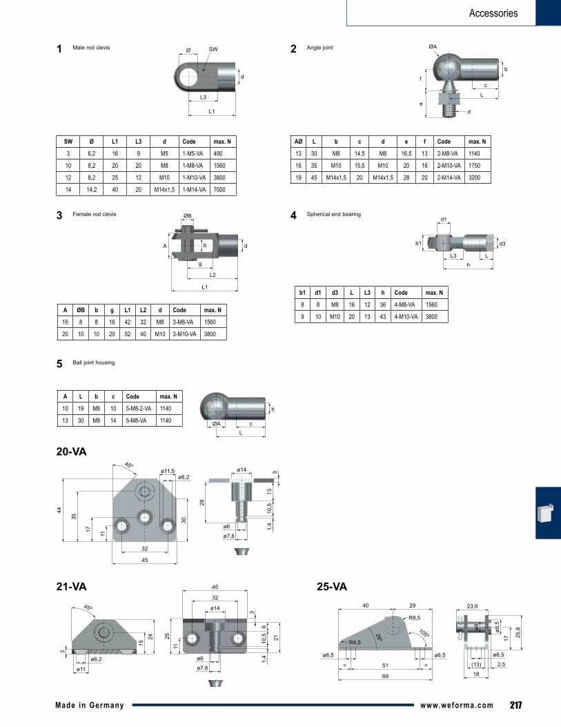
Accessories
d
Ø
L3
L1
SW
b
c
L
d
ØA
e
f
ØB
A b
g
L1
L2
d d3
LL3h
b1
d1
b
cL
ØA
11
30
ø6,2ø11,5
17
45º
35
44
32
45
ø14
ø6
313
10,5
1,4
28
ø7,8
45º
15
24
ø14
32
ø6,2
ø11
3
3
610
,5 21
1,4
45
ø6
11
ø7,8
25
ø6,5
R8,5
26º
105ºR4,5
51 ==
69
ø6,5 ø6,5
ø8 ø8,5
17 25,8
(13) 2,5
18
23,640 29
SW Ø L1 L3 d Code max. N
3 6,2 16 9 M5 1-M5-VA 490
10 8,2 20 20 M8 1-M8-VA 1560
12 8,2 25 12 M10 1-M10-VA 3800
14 14,2 40 20 M14x1,5 1-M14-VA 7000
A ØB b g L1 L2 d Code max. N
16 8 8 16 42 32 M8 3-M8-VA 1560
20 10 10 20 52 40 M10 3-M10-VA 3800
b1 d1 d3 L L3 h Code max. N
8 8 M8 16 12 36 4-M8-VA 1560
9 10 M10 20 13 43 4-M10-VA 3800
A L b c Code max. N
10 19 M8 10 5-M8-2-VA 1140
13 30 M8 14 5-M8-VA 1140
AØ L b c d e f Code max. N
13 30 M8 14,5 M8 16,5 13 2-M8-VA 1140
16 35 M10 15,5 M10 20 16 2-M10-VA 1750
19 45 M14x1,5 20 M14x1,5 28 20 2-M14-VA 3200
1 2 Angle jointMale rod clevis
3 Female rod clevis 4 Spherical end bearing
5 Ball joint housing
20-VA
21-VA 25-VA