Embed Size (px)
DESCRIPTION
Gas Dynamic for control of quadcopter
Citation preview
BULLETIN OF THE POLISH ACADEMY OF SCIENCESTECHNICAL SCIENCES, Vol. 60, No. 4, 2012DOI: 10.2478/v10175-012-0096-4
VARIA
Guidance impulse algorithms for air bomb control
R. GŁĘBOCKI∗
Faculty of Power and Aeronautical Engineering, Warsaw University of Technology, 24 Nowowiejska St., 00-665 Warszawa, Poland
Abstract. In this paper, some results of research concerning the development of guidance of bombs were presented. The paper presentsconceptions of an impulse (gasodynamic) control system, the measurement unit based on IMU/GPS signals and control algorithms basedon predicted trajectories. The presented results of simulation research are based on the numerical model of the bomb and real signals frommeasurement devices.
Key words: control, flying objects, control algorithms, air bombs, automatic flight control systems.
1. Introduction
The papers focuses on the problem of guiding small flightobjects like bombs. The author described a new method of animpulse (gasodynamic) control of these objects. The contem-porary development of air-launched weapons is mostly orient-ed on the design of precision guided munitions. The percent-age of guided weapons in all instruments of war used fromair is greater in each subsequent military conflict.
Over the last ten years the development of controlledbombs has been closely connected with Global PositioningSystem and Inertial Navigation System. Especially since GPShas reached full availability, many navigation systems of guid-ed missiles and bombs base on INS/GPS. Joint Direct AttackMonition is a well-known example [1]. There are also otherconstructions like AASM carried out by SAGEM and SPICEcarried out by RAFAEL. All these bombs are aerodynamicallycontrolled [2].
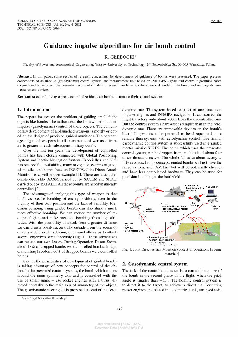
The advantage of applying this type of weapon is thatit allows precise bombing of enemy positions, even in thevicinity of their own position and the lack of visibility. Pre-cision bombing using guided bombs can also share a muchmore effective bombing. We can reduce the number of re-quired flights, and make precision bombing from high alti-tudes. With the possibility of attack from a greater distancewe can drop a bomb successfully outside from the scope ofdirect air defence. In addition, one round allows us to attackseveral objectives simultaneously (Fig. 1). These advantagescan reduce our own losses. During Operation Desert Stormabout 18% of dropped bombs were controlled bombs. In Op-eration Iraq Freedom, 66% of dropped bombs were controlledbombs.
One of the possibilities of development of guided bombsis taking advantage of new concepts for control of the ob-ject. In the presented control systems, the bomb which rotatesaround the main symmetry axis and is controlled with theuse of small single – use rocket engines with a thrust di-rected normally to the main axis of symmetry of the object.The gasodynamic steering kit is proposed instead of the aero-
dynamic one. The system based on a set of one time usedimpulse engines and INS/GPS navigation. It can correct theflight trajectory only about 700m from the uncontrolled one.But the control system’s hardware is simpler than in the aero-dynamic one. There are immovable devices on the bomb’sboard. It gives them the potential to be cheaper and morereliable than systems with aerodynamic control. The similargasodynamic control system is successfully used in a guidedmortar missile STRIX. The bomb which uses the presentedcontrol system, can be dropped from an altitude of about fourto ten thousand meters. The whole fall takes about twenty tofifty seconds. In this concept, guided bombs will not have therange as long as JDAM has, but will be potentially cheaperand have less complicated hardware. They can be used forprecision bombing at the battlefield.
Fig. 1. Joint Direct Attack Monition concept of operations [Boeingmaterials]
2. Gasodynamic control system
The task of the control engines set is to correct the course ofthe bomb in the second phase of the flight, when the pitchangle is smaller than −45. The homing control system isto direct it to the target, to achieve a direct hit. Correctingrocket engines are located in a cylindrical unit, arranged radi-
∗e-mail: [email protected]
825
Unauthenticated | 89.67.242.59Download Date | 5/19/13 8:57 PM
R. Głębocki
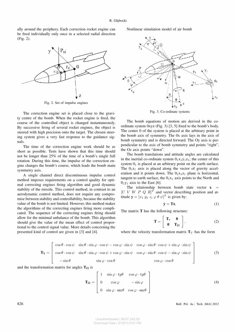
ally around the periphery. Each correction rocket engine canbe fired individually only once in a selected radial direction(Fig. 2).
Fig. 2. Set of impulse engines
The correction engine set is placed close to the gravi-ty centre of the bomb. When the rocket engine is fired, thecourse of the controlled object is changed instantaneously.By successive firing of several rocket engines, the object issteered with high precision onto the target. The chosen steer-ing system gives a very fast response to the guidance sig-nals.
The time of the correction engine work should be asshort as possible. Tests have shown that this time shouldnot be longer than 25% of the time of a bomb’s single fullrotation. During this time, the impulse of the correction en-gine changes the bomb’s course, which leads the bomb mainsymmetry axis.
A single channel direct discontinuous impulse controlmethod imposes requirements on a control quality for opti-mal correcting engines firing algorithm and good dynamicstability of the missile. This control method, in contrast to anaerodynamic control method, does not require any compro-mise between stability and controllability, because the stabilityvalue of the bomb is not limited. However, this method makesthe algorithms of the correcting engines firing more compli-cated. The sequence of the correcting engines firing shouldallow for the minimal unbalance of the bomb. This algorithmshould give the value of the mean effect of control propor-tional to the control signal value. More details concerning thepresented kind of control are given in [3] and [4].
Nonlinear simulation model of air bomb
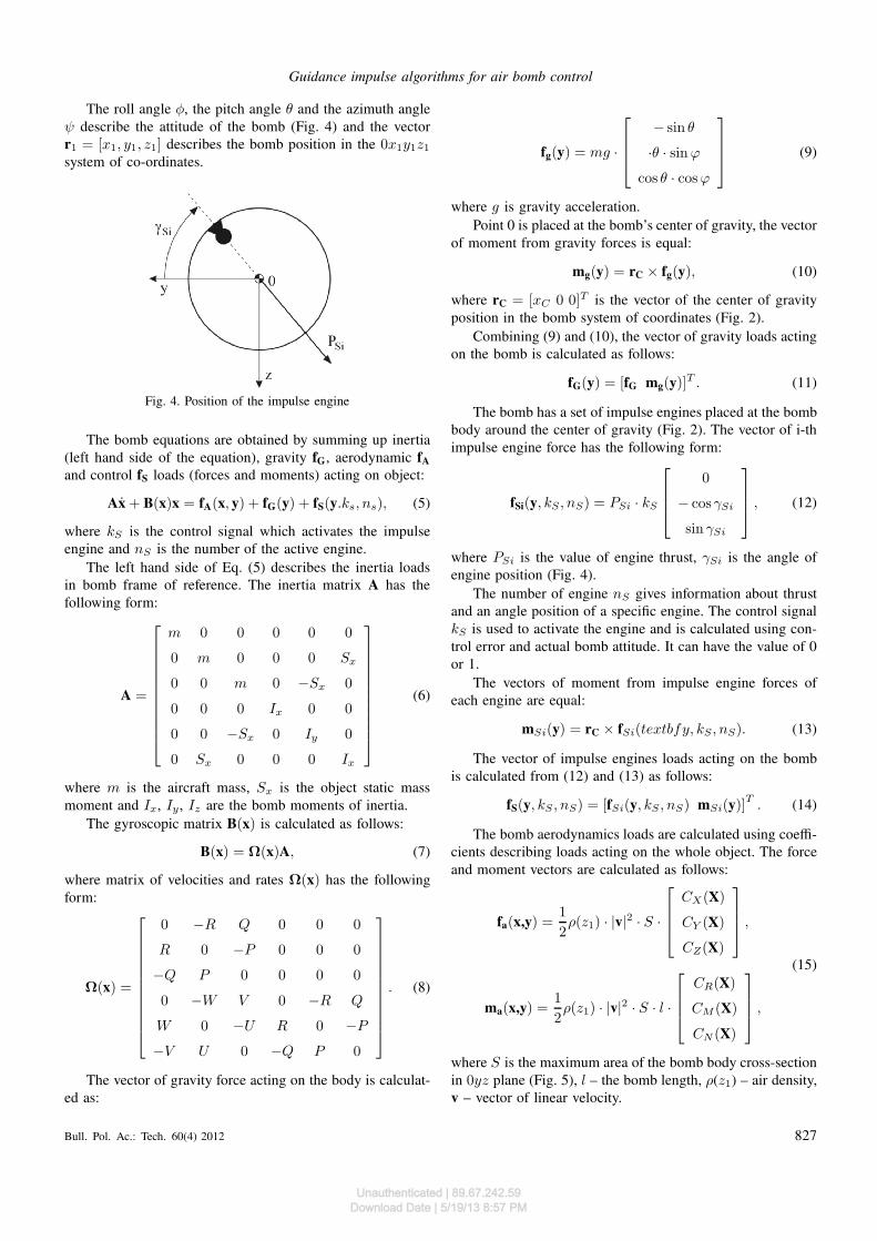
Fig. 3. Co-ordinate systems
The bomb equations of motion are derived in the co-ordinate system 0xyz (Fig. 3) [3, 5] fixed to the bomb’s body.The center 0 of the system is placed at the arbitrary point inthe bomb axis of symmetry. The 0x axis lays in the axis ofbomb symmetry and is directed forward. The Oy axis is per-pendicular to the axis of bomb symmetry and points “right”,the Oz axis points “down”.
The bomb translations and attitude angles are calculatedin the inertial co-ordinate system 01x1y1z1; the center of thissystem 01 is placed at an arbitrary point on the earth surface.The 01z1 axis is placed along the vector of gravity accel-eration and it points down. The 01x1z1 plane is horizontal,tangent to earth surface, the 01x1 axis points to the North and01y1 axis to the East [6].
The relationship between bomb state vector x =[U V W P Q R]T and vector describing position and at-titude y = [x1 y1 zi ϕ θ ψ]T is given by:
y = Tx. (1)
The matrix T has the following structure:
T =
[
Tv 0
0 TΩ
]
, (2)
where the velocity transformation matrix TV has the form
TV =
cos θ · cosψ sin θ · sinϕ · cosψ − cosϕ · sinψ cosϕ · sin θ · cosψ + sinϕ · sinψ
cos θ · cosψ sin θ · sinϕ · cosψ + cosϕ · sinψ cosϕ · sin θ · cosψ − sinϕ · sinψ
− sin θ sinϕ · cos θ cosϕ · cos θ
(3)
and the transformation matrix for angles TΩ is
TΩ =
1 sinϕ · tgθ cosϕ · tgθ
0 cosϕ − sinϕ
0 sinϕ · secθ cosϕ · secθ
(4)
826 Bull. Pol. Ac.: Tech. 60(4) 2012
Unauthenticated | 89.67.242.59Download Date | 5/19/13 8:57 PM
Guidance impulse algorithms for air bomb control
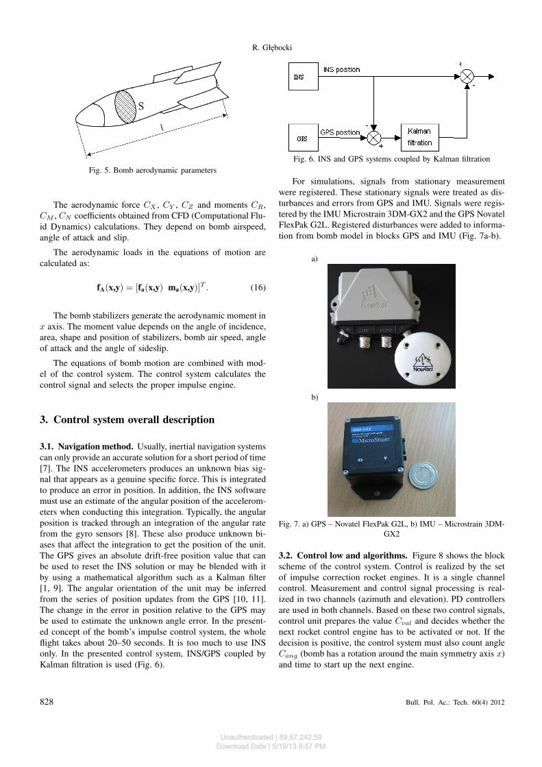
The roll angle φ, the pitch angle θ and the azimuth angleψ describe the attitude of the bomb (Fig. 4) and the vectorr1 = [x1, y1, z1] describes the bomb position in the 0x1y1z1system of co-ordinates.
Fig. 4. Position of the impulse engine
The bomb equations are obtained by summing up inertia(left hand side of the equation), gravity fG, aerodynamic fA
and control fS loads (forces and moments) acting on object:
Ax + B(x)x = fA(x, y) + fG(y) + fS(y.ks, ns), (5)
where kS is the control signal which activates the impulseengine and nS is the number of the active engine.
The left hand side of Eq. (5) describes the inertia loadsin bomb frame of reference. The inertia matrix A has thefollowing form:
A =
m 0 0 0 0 0
0 m 0 0 0 Sx
0 0 m 0 −Sx 0
0 0 0 Ix 0 0
0 0 −Sx 0 Iy 0
0 Sx 0 0 0 Ix
(6)
where m is the aircraft mass, Sx is the object static massmoment and Ix, Iy , Iz are the bomb moments of inertia.
The gyroscopic matrix B(x) is calculated as follows:
B(x) = Ω(x)A, (7)
where matrix of velocities and rates Ω(x) has the followingform:
Ω(x) =
0 −R Q 0 0 0
R 0 −P 0 0 0
−Q P 0 0 0 0
0 −W V 0 −R Q
W 0 −U R 0 −P
−V U 0 −Q P 0
. (8)
The vector of gravity force acting on the body is calculat-ed as:
fg(y) = mg ·
− sin θ
·θ · sinϕ
cos θ · cosϕ
(9)
where g is gravity acceleration.Point 0 is placed at the bomb’s center of gravity, the vector
of moment from gravity forces is equal:
mg(y) = rC × fg(y), (10)
where rC = [xC 0 0]T is the vector of the center of gravityposition in the bomb system of coordinates (Fig. 2).
Combining (9) and (10), the vector of gravity loads actingon the bomb is calculated as follows:
fG(y) = [fG mg(y)]T . (11)
The bomb has a set of impulse engines placed at the bombbody around the center of gravity (Fig. 2). The vector of i-thimpulse engine force has the following form:
fSi(y, kS , nS) = PSi · kS
0
− cosγSi
sinγSi
, (12)
where PSi is the value of engine thrust, γSi is the angle ofengine position (Fig. 4).
The number of engine nS gives information about thrustand an angle position of a specific engine. The control signalkS is used to activate the engine and is calculated using con-trol error and actual bomb attitude. It can have the value of 0or 1.
The vectors of moment from impulse engine forces ofeach engine are equal:
mSi(y) = rC × fSi(textbfy, kS , nS). (13)
The vector of impulse engines loads acting on the bombis calculated from (12) and (13) as follows:
fS(y, kS , nS) = [fSi(y, kS , nS) mSi(y)]T. (14)
The bomb aerodynamics loads are calculated using coeffi-cients describing loads acting on the whole object. The forceand moment vectors are calculated as follows:
fa(x,y) =1
2ρ(z1) · |v|
2 · S ·
CX(X)
CY (X)
CZ(X)
,
ma(x,y) =1
2ρ(z1) · |v|
2 · S · l ·
CR(X)
CM (X)
CN (X)
,
(15)
where S is the maximum area of the bomb body cross-sectionin 0yz plane (Fig. 5), l – the bomb length, ρ(z1) – air density,v – vector of linear velocity.
Bull. Pol. Ac.: Tech. 60(4) 2012 827
Unauthenticated | 89.67.242.59Download Date | 5/19/13 8:57 PM
R. Głębocki
Fig. 5. Bomb aerodynamic parameters
The aerodynamic force CX , CY , CZ and moments CR,CM , CN coefficients obtained from CFD (Computational Flu-id Dynamics) calculations. They depend on bomb airspeed,angle of attack and slip.
The aerodynamic loads in the equations of motion arecalculated as:
fA(x,y) = [fa(x,y) ma(x,y)]T . (16)
The bomb stabilizers generate the aerodynamic moment inx axis. The moment value depends on the angle of incidence,area, shape and position of stabilizers, bomb air speed, angleof attack and the angle of sideslip.
The equations of bomb motion are combined with mod-el of the control system. The control system calculates thecontrol signal and selects the proper impulse engine.
3. Control system overall description
3.1. Navigation method. Usually, inertial navigation systemscan only provide an accurate solution for a short period of time[7]. The INS accelerometers produces an unknown bias sig-nal that appears as a genuine specific force. This is integratedto produce an error in position. In addition, the INS softwaremust use an estimate of the angular position of the accelerom-eters when conducting this integration. Typically, the angularposition is tracked through an integration of the angular ratefrom the gyro sensors [8]. These also produce unknown bi-ases that affect the integration to get the position of the unit.The GPS gives an absolute drift-free position value that canbe used to reset the INS solution or may be blended with itby using a mathematical algorithm such as a Kalman filter[1, 9]. The angular orientation of the unit may be inferredfrom the series of position updates from the GPS [10, 11].The change in the error in position relative to the GPS maybe used to estimate the unknown angle error. In the present-ed concept of the bomb’s impulse control system, the wholeflight takes about 20–50 seconds. It is too much to use INSonly. In the presented control system, INS/GPS coupled byKalman filtration is used (Fig. 6).
Fig. 6. INS and GPS systems coupled by Kalman filtration
For simulations, signals from stationary measurementwere registered. These stationary signals were treated as dis-turbances and errors from GPS and IMU. Signals were regis-tered by the IMU Microstrain 3DM-GX2 and the GPS NovatelFlexPak G2L. Registered disturbances were added to informa-tion from bomb model in blocks GPS and IMU (Fig. 7a-b).
a)
b)
Fig. 7. a) GPS – Novatel FlexPak G2L, b) IMU – Microstrain 3DM-GX2
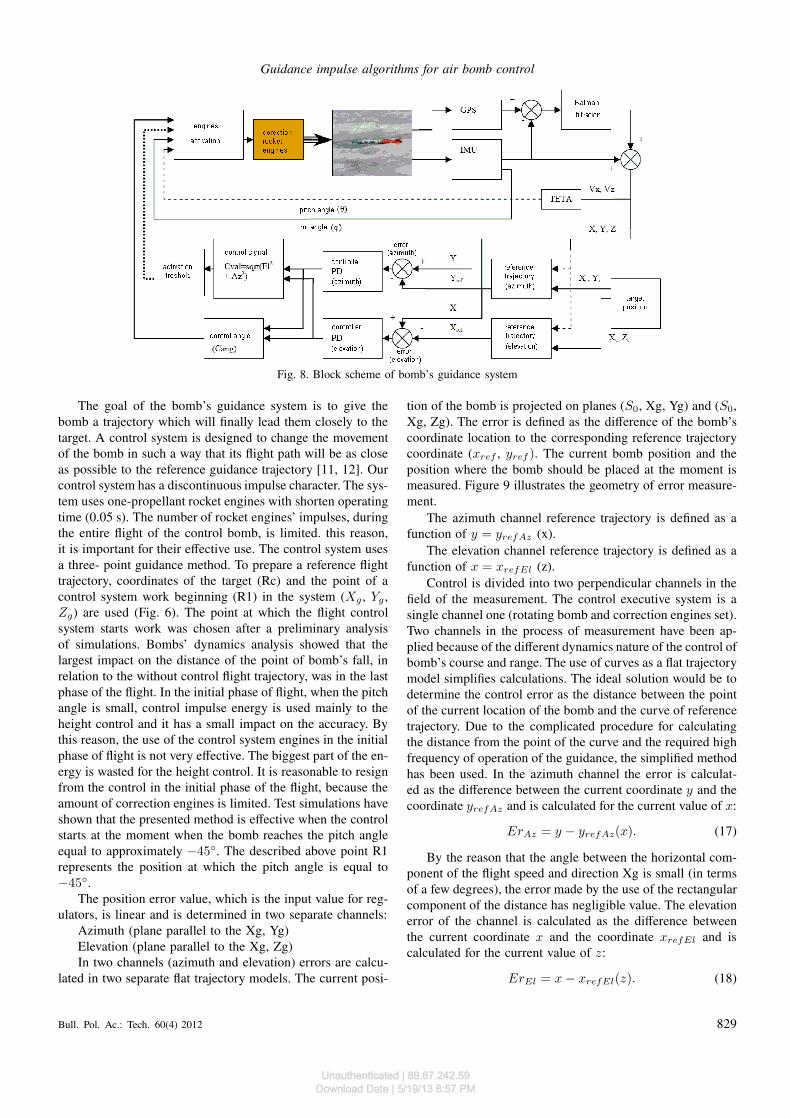
3.2. Control low and algorithms. Figure 8 shows the blockscheme of the control system. Control is realized by the setof impulse correction rocket engines. It is a single channelcontrol. Measurement and control signal processing is real-ized in two channels (azimuth and elevation). PD controllersare used in both channels. Based on these two control signals,control unit prepares the value Cval and decides whether thenext rocket control engine has to be activated or not. If thedecision is positive, the control system must also count angleCang (bomb has a rotation around the main symmetry axis x)and time to start up the next engine.
828 Bull. Pol. Ac.: Tech. 60(4) 2012
Unauthenticated | 89.67.242.59Download Date | 5/19/13 8:57 PM
Guidance impulse algorithms for air bomb control
Fig. 8. Block scheme of bomb’s guidance system
The goal of the bomb’s guidance system is to give thebomb a trajectory which will finally lead them closely to thetarget. A control system is designed to change the movementof the bomb in such a way that its flight path will be as closeas possible to the reference guidance trajectory [11, 12]. Ourcontrol system has a discontinuous impulse character. The sys-tem uses one-propellant rocket engines with shorten operatingtime (0.05 s). The number of rocket engines’ impulses, duringthe entire flight of the control bomb, is limited. this reason,it is important for their effective use. The control system usesa three- point guidance method. To prepare a reference flighttrajectory, coordinates of the target (Rc) and the point of acontrol system work beginning (R1) in the system (Xg , Yg ,Zg) are used (Fig. 6). The point at which the flight controlsystem starts work was chosen after a preliminary analysisof simulations. Bombs’ dynamics analysis showed that thelargest impact on the distance of the point of bomb’s fall, inrelation to the without control flight trajectory, was in the lastphase of the flight. In the initial phase of flight, when the pitchangle is small, control impulse energy is used mainly to theheight control and it has a small impact on the accuracy. Bythis reason, the use of the control system engines in the initialphase of flight is not very effective. The biggest part of the en-ergy is wasted for the height control. It is reasonable to resignfrom the control in the initial phase of the flight, because theamount of correction engines is limited. Test simulations haveshown that the presented method is effective when the controlstarts at the moment when the bomb reaches the pitch angleequal to approximately −45. The described above point R1represents the position at which the pitch angle is equal to−45.
The position error value, which is the input value for reg-ulators, is linear and is determined in two separate channels:
Azimuth (plane parallel to the Xg, Yg)Elevation (plane parallel to the Xg, Zg)In two channels (azimuth and elevation) errors are calcu-
lated in two separate flat trajectory models. The current posi-
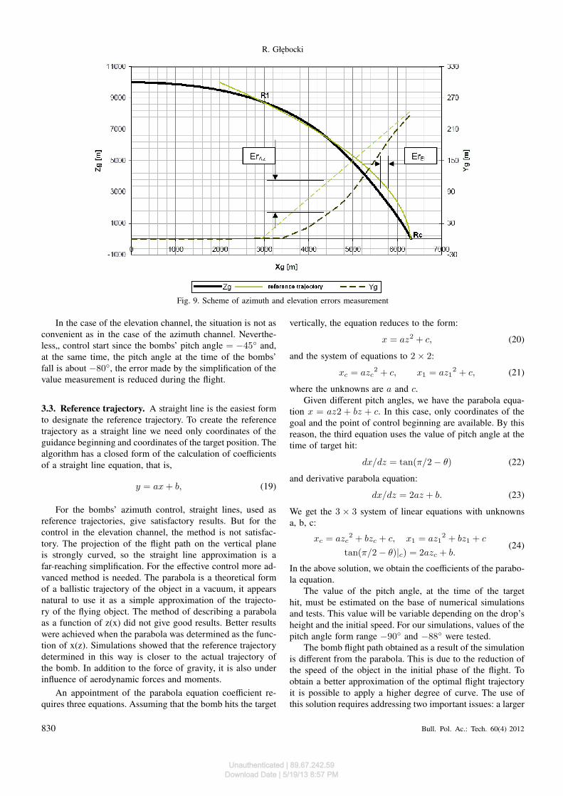
tion of the bomb is projected on planes (S0, Xg, Yg) and (S0,Xg, Zg). The error is defined as the difference of the bomb’scoordinate location to the corresponding reference trajectorycoordinate (xref , yref ). The current bomb position and theposition where the bomb should be placed at the moment ismeasured. Figure 9 illustrates the geometry of error measure-ment.
The azimuth channel reference trajectory is defined as afunction of y = yrefAz (x).
The elevation channel reference trajectory is defined as afunction of x = xrefEl (z).
Control is divided into two perpendicular channels in thefield of the measurement. The control executive system is asingle channel one (rotating bomb and correction engines set).Two channels in the process of measurement have been ap-plied because of the different dynamics nature of the control ofbomb’s course and range. The use of curves as a flat trajectorymodel simplifies calculations. The ideal solution would be todetermine the control error as the distance between the pointof the current location of the bomb and the curve of referencetrajectory. Due to the complicated procedure for calculatingthe distance from the point of the curve and the required highfrequency of operation of the guidance, the simplified methodhas been used. In the azimuth channel the error is calculat-ed as the difference between the current coordinate y and thecoordinate yrefAz and is calculated for the current value of x:
ErAz = y − yrefAz(x). (17)
By the reason that the angle between the horizontal com-ponent of the flight speed and direction Xg is small (in termsof a few degrees), the error made by the use of the rectangularcomponent of the distance has negligible value. The elevationerror of the channel is calculated as the difference betweenthe current coordinate x and the coordinate xrefEl and iscalculated for the current value of z:
ErEl = x− xrefEl(z). (18)
Bull. Pol. Ac.: Tech. 60(4) 2012 829
Unauthenticated | 89.67.242.59Download Date | 5/19/13 8:57 PM
R. Głębocki
Fig. 9. Scheme of azimuth and elevation errors measurement
In the case of the elevation channel, the situation is not asconvenient as in the case of the azimuth channel. Neverthe-less„ control start since the bombs’ pitch angle = −45 and,at the same time, the pitch angle at the time of the bombs’fall is about −80, the error made by the simplification of thevalue measurement is reduced during the flight.
3.3. Reference trajectory. A straight line is the easiest formto designate the reference trajectory. To create the referencetrajectory as a straight line we need only coordinates of theguidance beginning and coordinates of the target position. Thealgorithm has a closed form of the calculation of coefficientsof a straight line equation, that is,
y = ax+ b, (19)
For the bombs’ azimuth control, straight lines, used asreference trajectories, give satisfactory results. But for thecontrol in the elevation channel, the method is not satisfac-tory. The projection of the flight path on the vertical planeis strongly curved, so the straight line approximation is afar-reaching simplification. For the effective control more ad-vanced method is needed. The parabola is a theoretical formof a ballistic trajectory of the object in a vacuum, it appearsnatural to use it as a simple approximation of the trajecto-ry of the flying object. The method of describing a parabolaas a function of z(x) did not give good results. Better resultswere achieved when the parabola was determined as the func-tion of x(z). Simulations showed that the reference trajectorydetermined in this way is closer to the actual trajectory ofthe bomb. In addition to the force of gravity, it is also underinfluence of aerodynamic forces and moments.
An appointment of the parabola equation coefficient re-quires three equations. Assuming that the bomb hits the target
vertically, the equation reduces to the form:
x = az2 + c, (20)
and the system of equations to 2 × 2:
xc = azc2 + c, x1 = az1
2 + c, (21)
where the unknowns are a and c.Given different pitch angles, we have the parabola equa-
tion x = az2 + bz + c. In this case, only coordinates of thegoal and the point of control beginning are available. By thisreason, the third equation uses the value of pitch angle at thetime of target hit:
dx/dz = tan(π/2 − θ) (22)
and derivative parabola equation:
dx/dz = 2az + b. (23)
We get the 3 × 3 system of linear equations with unknownsa, b, c:
xc = azc2 + bzc + c, x1 = az1
2 + bz1 + c
tan(π/2 − θ)|c) = 2azc + b.(24)
In the above solution, we obtain the coefficients of the parabo-la equation.
The value of the pitch angle, at the time of the targethit, must be estimated on the base of numerical simulationsand tests. This value will be variable depending on the drop’sheight and the initial speed. For our simulations, values of thepitch angle form range −90 and −88 were tested.
The bomb flight path obtained as a result of the simulationis different from the parabola. This is due to the reduction ofthe speed of the object in the initial phase of the flight. Toobtain a better approximation of the optimal flight trajectoryit is possible to apply a higher degree of curve. The use ofthis solution requires addressing two important issues: a larger
830 Bull. Pol. Ac.: Tech. 60(4) 2012
Unauthenticated | 89.67.242.59Download Date | 5/19/13 8:57 PM
Guidance impulse algorithms for air bomb control
number of coefficients to a higher degree of curve. It wouldbe necessary to estimate the coordinates of several points onthe intermediate bomb’s flight trajectory, a larger dimensionof the system of equations lead to need bigger processorscapacities. In the presented work, the following reference tra-jectories were used: the parabolic one for the elevation controland the straight line for the azimuth.
4. Results
Simulation tests showed interesting results and possibilitiesof the described control method and algorithms. The papershows only two cases (Figs. 10–13) but to count CEP (Circu-lar Error Probable) value, we made ten simulations for each
case with targets in ten different positions. Targets were se-lected randomly in the range of 400 m from the uncontrolledbomb drop point.
In the presented cases, CEP counted for bombs with ide-al navigation was about 21 meters. CEP counted for bombsguided with errors from INS/GPS system was about 25 me-ters. It shows that, at this level of accuracy, the system is quiterobust to navigation errors during the flight. We the observethat final results of control processes for the ideal and realnavigation are similar but the control system needs to usemore correction engines impulses for guidance process. Theaverage is 11 correction impulses for system with the idealnavigation and 14 impulses for system with navigation witherrors from INS/GPS.
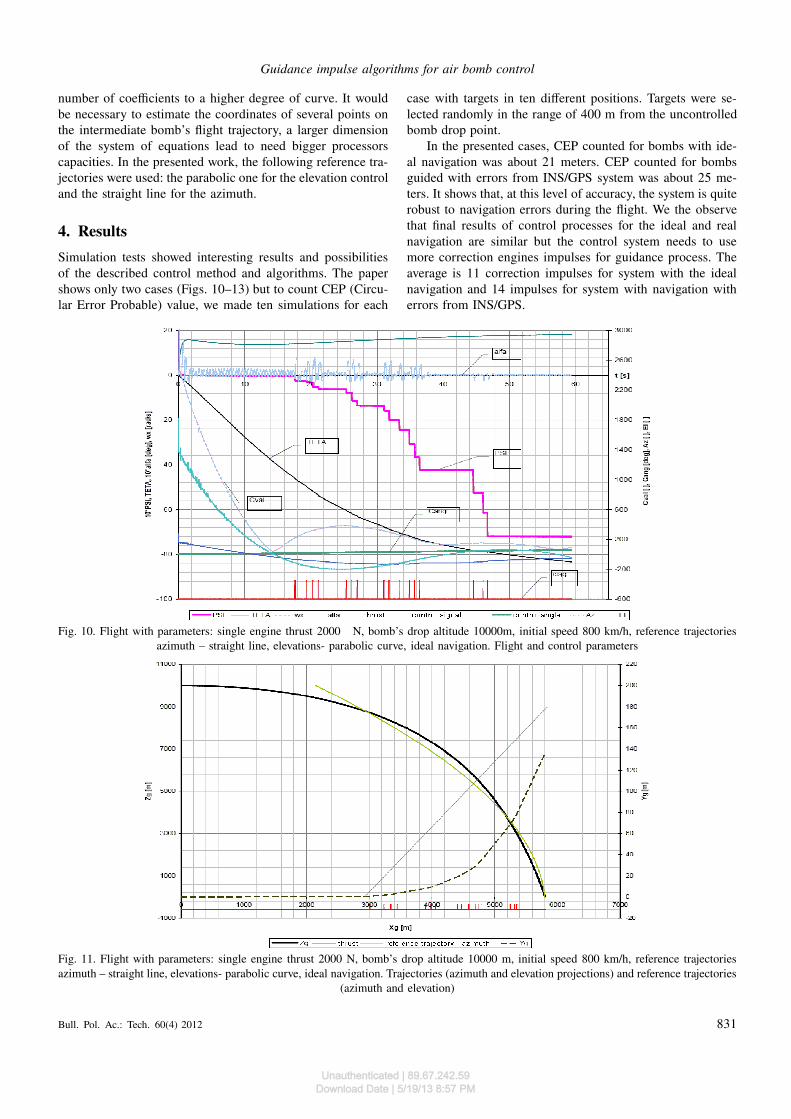
Fig. 10. Flight with parameters: single engine thrust 2000 N, bomb’s drop altitude 10000m, initial speed 800 km/h, reference trajectoriesazimuth – straight line, elevations- parabolic curve, ideal navigation. Flight and control parameters
Fig. 11. Flight with parameters: single engine thrust 2000 N, bomb’s drop altitude 10000 m, initial speed 800 km/h, reference trajectoriesazimuth – straight line, elevations- parabolic curve, ideal navigation. Trajectories (azimuth and elevation projections) and reference trajectories
(azimuth and elevation)
Bull. Pol. Ac.: Tech. 60(4) 2012 831
Unauthenticated | 89.67.242.59Download Date | 5/19/13 8:57 PM
R. Głębocki
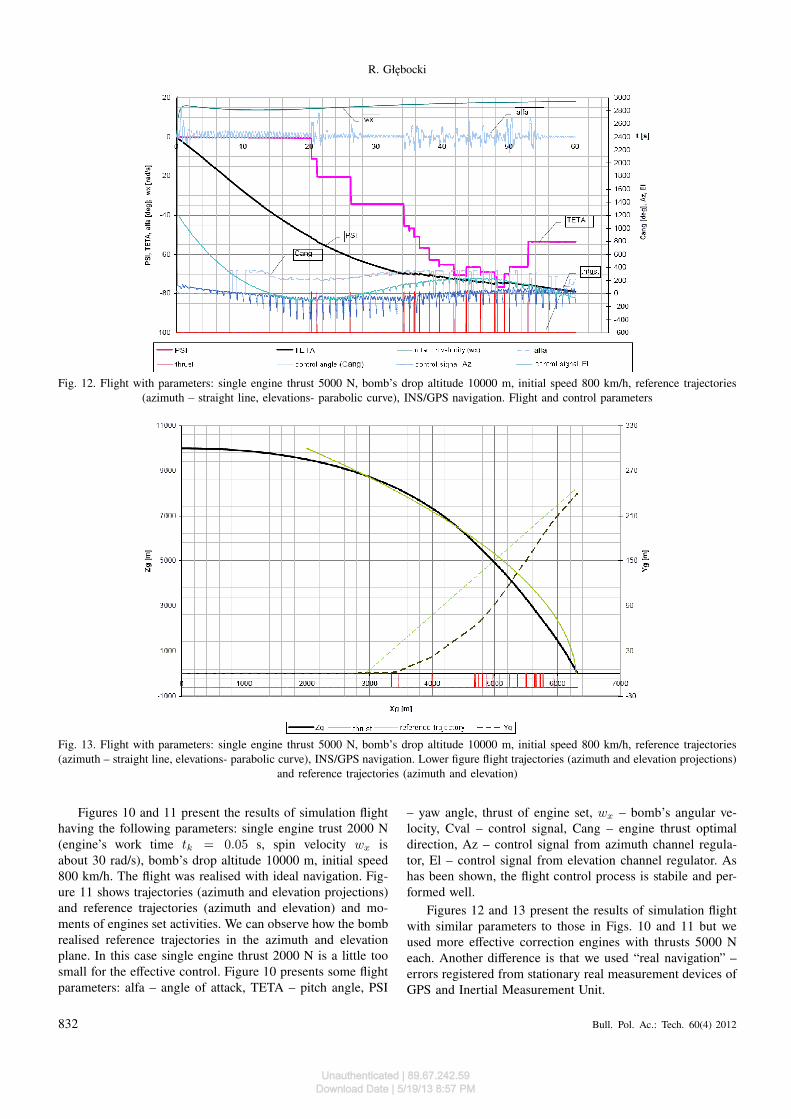
Fig. 12. Flight with parameters: single engine thrust 5000 N, bomb’s drop altitude 10000 m, initial speed 800 km/h, reference trajectories(azimuth – straight line, elevations- parabolic curve), INS/GPS navigation. Flight and control parameters
Fig. 13. Flight with parameters: single engine thrust 5000 N, bomb’s drop altitude 10000 m, initial speed 800 km/h, reference trajectories(azimuth – straight line, elevations- parabolic curve), INS/GPS navigation. Lower figure flight trajectories (azimuth and elevation projections)
and reference trajectories (azimuth and elevation)
Figures 10 and 11 present the results of simulation flighthaving the following parameters: single engine trust 2000 N(engine’s work time tk = 0.05 s, spin velocity wx isabout 30 rad/s), bomb’s drop altitude 10000 m, initial speed800 km/h. The flight was realised with ideal navigation. Fig-ure 11 shows trajectories (azimuth and elevation projections)and reference trajectories (azimuth and elevation) and mo-ments of engines set activities. We can observe how the bombrealised reference trajectories in the azimuth and elevationplane. In this case single engine thrust 2000 N is a little toosmall for the effective control. Figure 10 presents some flightparameters: alfa – angle of attack, TETA – pitch angle, PSI
– yaw angle, thrust of engine set, wx – bomb’s angular ve-locity, Cval – control signal, Cang – engine thrust optimaldirection, Az – control signal from azimuth channel regula-tor, El – control signal from elevation channel regulator. Ashas been shown, the flight control process is stabile and per-formed well.
Figures 12 and 13 present the results of simulation flightwith similar parameters to those in Figs. 10 and 11 but weused more effective correction engines with thrusts 5000 Neach. Another difference is that we used “real navigation” –errors registered from stationary real measurement devices ofGPS and Inertial Measurement Unit.
832 Bull. Pol. Ac.: Tech. 60(4) 2012
Unauthenticated | 89.67.242.59Download Date | 5/19/13 8:57 PM
Guidance impulse algorithms for air bomb control
As has been demonstrated,5kN engines realised the flighttrajectory better in both control channels (azimuth and eleva-tions). We do not observe any control system negative reac-tions for errors from GPS and IMU.
5. Summary
Series of simulations done to assess the performance of thedesigned system showed that it is possible to apply the investi-gated control system for the bomb. With the launch conditionchosen: altitude 10 000 m speed 800 km/h, the achieved ac-curacy (CEP) was about 25 m. Numerical experiments haveshown large possibilities of the objects’ control by the influ-ence on the motion of their gravity centre. It is possible touse the set of impulse correction rockets to control fallingobjects such as bombs. The amount of 20 correction enginesis enough to control the bomb. To control a 100 kg bomb,5kN thrust of correction engines is needed.
There is a problem with a guidance algorithm for an im-pulse control. Traditional methods are insufficient. The limitedamount of the control impulse and better effectiveness withattack from steep trajectory make the guidance with straightline trajectory useless. This problem is particularly apparentin the longitudinal control channel of an air bomb. The numer-ical experiments and simulations showed that the possibilityof using a parabola trajectory is good enough for the guid-ance process. There are positive results of using these meth-ods. A parabola is mathematically a non-complicated curve;therefore, it is easy to calculate on board during the guidanceprocess of an air bomb.
To make simulation more realistic there were added er-ror values from the real measurement elements. Experimentsshowed that during the work with real signals the method stillworks correctly.
REFERENCES
[1] H. Klotz and C. Derbak, GPS- aided Navigation and Unaided
Navigation on the Joint Direct Attack Munitions, IEEE, Lon-don, 1998.
[2] R. Kostrow, M. Makuszewski, and M. Studencki, Rockets and
Rocket Artillery of the Army, Bellona, Warszawa, 2001, (inPolish).
[3] R. Glebocki and R. Vogt, “Guidance system of smart mortarmissile”, The Archive Mechanical Engineering LIV (1), 47–63(2007).
[4] R. Głębocki and M. Żugaj, “Gasodynamic control system forINS guided bomb”, 47
th AIAA Aerospace Sciences Meeting
and Exhibit 1, CD-ROM (2009).[5] Z. Dziopa, I. Krzysztofik, and Z. Koruba “An analysis of the
dynamics of a launcher-missile system on a moveable base”,Bull. Pol. Ac.: Tech. 58, 645–650 (2010).
[6] J. Gacek, External Ballistics, WAT Publishing House, Warsza-wa, 1999, (in Polish).
[7] Z. Koruba and J. Osiecki, Construction, Dynamics and Navi-
gation of Selected Precise Destruction Weapons, Kielce Uni-versity of Technology Publishing House, Kielce, 2006.
[8] Z. Koruba, I. Krzysztofik, and Z. Dziopa “An analysis of thegyroscope dynamics of an anti-aircraft missile launched froma mobile platform”, Bull. Pol. Ac.: Tech. 58, 651–656 (2010).
[9] R. Głębocki, R. Vogt, and M. Żugaj, “Smart mortar missileattitude detection based on the algorithm that takes advantageof the artificial neural networks”, AIAA Guidance Navigation
and Control Conference and Exhibit 1, CD-ROM (2006).[10] W.H. Chen, “Nonlinear disturbance observer-enhanced dynam-
ic inversion control of missiles”, J. Guidance, Control, and
Dynamics 26, 161–166 (2003).[11] P.A. Iglesian and T.J. Urban, “Loop shaping design for missile
autopilot”, J. Guidance, Control, and Dynamics 23, 516–525(2000).
[12] T. Kaczorek, “Stability of continuous-discrete linear systemsdescribed by the general model”, Bull. Pol. Ac.: Tech. 59, 189–193 (2011).
Bull. Pol. Ac.: Tech. 60(4) 2012 833
Unauthenticated | 89.67.242.59Download Date | 5/19/13 8:57 PM