Embed Size (px)
Citation preview
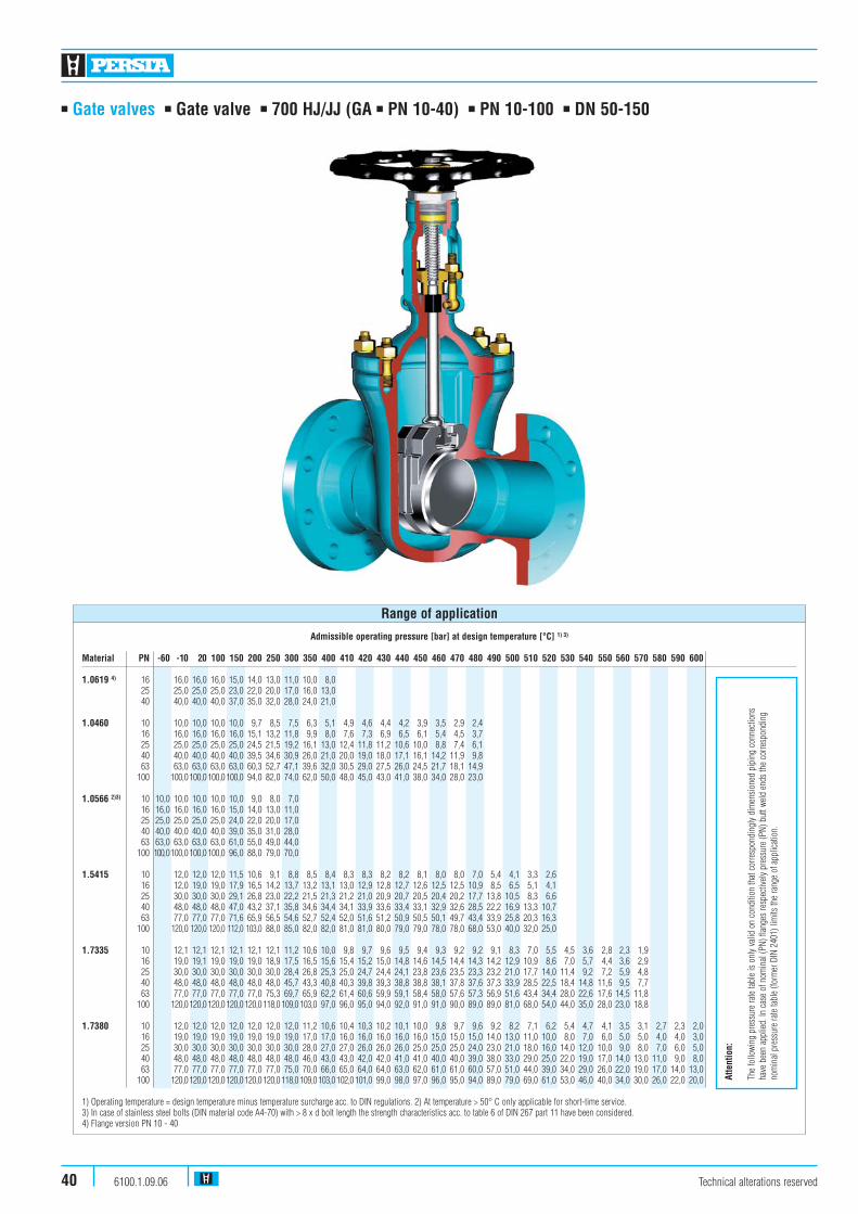
■ Gate valves ■ Gate valve ■ 700 HJ/JJ (GA ■ PN 10-40) ■ PN 10-100 ■ DN 50-150
Technical alterations reserved6100.1.09.0640
Admissible operating pressure [bar] at design temperature [°C] 1) 3)
Material PN -60 -10 20 100 150 200 250 300 350 400 410 420 430 440 450 460 470 480 490 500 510 520 530 540 550 560 570 580 590 600
1.0619 4) 16 16,0 16,0 16,0 15,0 14,0 13,0 11,0 10,0 8,025 25,0 25,0 25,0 23,0 22,0 20,0 17,0 16,0 13,040 40,0 40,0 40,0 37,0 35,0 32,0 28,0 24,0 21,0
1.0460 10 10,0 10,0 10,0 10,0 9,7 8,5 7,5 6,3 5,1 4,9 4,6 4,4 4,2 3,9 3,5 2,9 2,416 16,0 16,0 16,0 16,0 15,1 13,2 11,8 9,9 8,0 7,6 7,3 6,9 6,5 6,1 5,4 4,5 3,725 25,0 25,0 25,0 25,0 24,5 21,5 19,2 16,1 13,0 12,4 11,8 11,2 10,6 10,0 8,8 7,4 6,140 40,0 40,0 40,0 40,0 39,5 34,6 30,9 26,0 21,0 20,0 19,0 18,0 17,1 16,1 14,2 11,9 9,863 63,0 63,0 63,0 63,0 60,3 52,7 47,1 39,6 32,0 30,5 29,0 27,5 26,0 24,5 21,7 18,1 14,9
100 100,0100,0100,0100,0 94,0 82,0 74,0 62,0 50,0 48,0 45,0 43,0 41,0 38,0 34,0 28,0 23,0
1.0566 2)3) 10 10,0 10,0 10,0 10,0 10,0 9,0 8,0 7,016 16,0 16,0 16,0 16,0 15,0 14,0 13,0 11,025 25,0 25,0 25,0 25,0 24,0 22,0 20,0 17,040 40,0 40,0 40,0 40,0 39,0 35,0 31,0 28,063 63,0 63,0 63,0 63,0 61,0 55,0 49,0 44,0
100 100,0100,0100,0100,0 96,0 88,0 79,0 70,0
1.5415 10 12,0 12,0 12,0 11,5 10,6 9,1 8,8 8,5 8,4 8,3 8,3 8,2 8,2 8,1 8,0 8,0 7,0 5,4 4,1 3,3 2,616 12,0 19,0 19,0 17,9 16,5 14,2 13,7 13,2 13,1 13,0 12,9 12,8 12,7 12,6 12,5 12,5 10,9 8,5 6,5 5,1 4,125 30,0 30,0 30,0 29,1 26,8 23,0 22,2 21,5 21,3 21,2 21,0 20,9 20,7 20,5 20,4 20,2 17,7 13,8 10,5 8,3 6,640 48,0 48,0 48,0 47,0 43,2 37,1 35,8 34,6 34,4 34,1 33,9 33,6 33,4 33,1 32,9 32,6 28,5 22,2 16,9 13,3 10,763 77,0 77,0 77,0 71,6 65,9 56,5 54,6 52,7 52,4 52,0 51,6 51,2 50,9 50,5 50,1 49,7 43,4 33,9 25,8 20,3 16,3
100 120,0 120,0 120,0 112,0 103,0 88,0 85,0 82,0 82,0 81,0 81,0 80,0 79,0 79,0 78,0 78,0 68,0 53,0 40,0 32,0 25,0
1.7335 10 12,1 12,1 12,1 12,1 12,1 12,1 11,2 10,6 10,0 9,8 9,7 9,6 9,5 9,4 9,3 9,2 9,2 9,1 8,3 7,0 5,5 4,5 3,6 2,8 2,3 1,916 19,0 19,1 19,0 19,0 19,0 18,9 17,5 16,5 15,6 15,4 15,2 15,0 14,8 14,6 14,5 14,4 14,3 14,2 12,9 10,9 8,6 7,0 5,7 4,4 3,6 2,925 30,0 30,0 30,0 30,0 30,0 30,0 28,4 26,8 25,3 25,0 24,7 24,4 24,1 23,8 23,6 23,5 23,3 23,2 21,0 17,7 14,0 11,4 9,2 7,2 5,9 4,840 48,0 48,0 48,0 48,0 48,0 48,0 45,7 43,3 40,8 40,3 39,8 39,3 38,8 38,8 38,1 37,8 37,6 37,3 33,9 28,5 22,5 18,4 14,8 11,6 9,5 7,763 77,0 77,0 77,0 77,0 77,0 75,3 69,7 65,9 62,2 61,4 60,6 59,9 59,1 58,4 58,0 57,6 57,3 56,9 51,6 43,4 34,4 28,0 22,6 17,6 14,5 11,8
100 120,0120,0120,0120,0120,0118,0109,0103,0 97,0 96,0 95,0 94,0 92,0 91,0 91,0 90,0 89,0 89,0 81,0 68,0 54,0 44,0 35,0 28,0 23,0 18,8
1.7380 10 12,0 12,0 12,0 12,0 12,0 12,0 12,0 11,2 10,6 10,4 10,3 10,2 10,1 10,0 9,8 9,7 9,6 9,2 8,2 7,1 6,2 5,4 4,7 4,1 3,5 3,1 2,7 2,3 2,016 19,0 19,0 19,0 19,0 19,0 19,0 19,0 17,0 17,0 16,0 16,0 16,0 16,0 16,0 15,0 15,0 15,0 14,0 13,0 11,0 10,0 8,0 7,0 6,0 5,0 5,0 4,0 4,0 3,025 30,0 30,0 30,0 30,0 30,0 30,0 30,0 28,0 27,0 27,0 26,0 26,0 26,0 25,0 25,0 25,0 24,0 23,0 21,0 18,0 16,0 14,0 12,0 10,0 9,0 8,0 7,0 6,0 5,040 48,0 48,0 48,0 48,0 48,0 48,0 48,0 46,0 43,0 43,0 42,0 42,0 41,0 41,0 40,0 40,0 39,0 38,0 33,0 29,0 25,0 22,0 19,0 17,0 14,0 13,0 11,0 9,0 8,063 77,0 77,0 77,0 77,0 77,0 77,0 75,0 70,0 66,0 65,0 64,0 64,0 63,0 62,0 61,0 61,0 60,0 57,0 51,0 44,0 39,0 34,0 29,0 26,0 22,0 19,0 17,0 14,0 13,0
100 120,0120,0120,0120,0120,0120,0118,0109,0103,0102,0101,0 99,0 98,0 97,0 96,0 95,0 94,0 89,0 79,0 69,0 61,0 53,0 46,0 40,0 34,0 30,0 26,0 22,0 20,0
1) Operating temperature = design temperature minus temperature surcharge acc. to DIN regulations. 2) At temperature > 50° C only applicable for short-time service.3) In case of stainless steel bolts (DIN material code A4-70) with > 8 x d bolt length the strength characteristics acc. to table 6 of DIN 267 part 11 have been considered.4) Flange version PN 10 - 40
Range of application
Atte
ntio
n:
The
follo
wing
pre
ssur
e ra
te tab
le is
only
valid
on
cond
ition
that
corre
spon
ding
ly di
men
sione
d pi
ping
con
necti
ons
have
bee
n ap
plied
. In
case
of n
omin
al (P
N) fl
ange
s re
spec
tively
pre
ssur
e (P
N) b
utt w
eld e
nds
the
corre
spon
ding
nom
inal
pres
sure
rate
table
(form
er D
IN 2
401)
lim
its th
e ra
nge
of a
pplic
ation
.

■ Gate valves ■ Gate valve ■ 700 HJ/JJ (GA ■ PN 10-40) ■ PN 10-100 ■ DN 50-150
Design Highlights
■ The main valve body is one-piece die-forged incorporating the bonnet flange and the guide for the shut-off device
■ Bolted bonnet with reduced shaft bolts
■ Polished stem shaft with a surface roughness of max. 2 μm
■ Hard faced seats (valve body and shut-off device). Hardness app. 35-37 HRC
Benefits
■ Die-forged parts, compared with cast steel parts are generally free from porosity and shrink holes. The special of the valve body minimizes the existance of welding seams
■ To improve the stress capability when temperature and pressure fluctuate
■ Minimum wear to the gland packing compared with ground stem surfaces
■ Extremely resistant to wear
Standard features
■ Die-forged body and bonnet■ Split wedge = Type 700 JJ■ Flexible wedge = Type 700 HJ■ Full bore, exception DN 65/50 and DN 125/100■ Outside screw and yoke■ Yoke sleeve
Option Standard features GA
■ Split wedge / Flexible wedge■ Inside screw■ Non-rising turning stem
Pressure and temperature ratings
■ Pressure rating up to 100 bar■ Acc. to PERSTA PD 10 up to 120 bar■ Temperature rating up to +600° C
Materials
■ 1.0460■ 1.0619 only flange version PN 10 - 40■ 1.0566■ 1.5415■ 1.7335■ 1.7380
Further materials on request
Fields of application
Chemical industries, power plants, ship building andother
Technical alterations reserved 6100.1.09.06 41

■ Gate valves ■ Gate valve ■ 700 HJ/JJ (GA ■ PN 10-40) ■ PN 10-100 ■ DN 50-150
Technical alterations reserved6100.1.09.0642
611
613
600
605
510
530
511
590
464
461
440
420
451
200
190
170
160
400
360
363
100
700 GA
Stro
ke
361

700 GADN H1
50 28065/50 28080 345100 405125/100 405150 525
■ Gate valves ■ Gate valve ■ 700 HJ/JJ (GA ■ PN 10-40) ■ PN 10-100 ■ DN 50-150
Pos. Component 1.0619 (11) 1.0460 (21) 1.0566 (25) 1.5415 (42) 1.7335 (44) 1.7380 (45)PN 10-40
100 Body 1.0619 1) 1.0460 1) 1.0566 1) 1.5415 2) 1.7335 2) 1.7380 2)
160 �Gasket Graphite 4) Graphite 4) Graphite 4) Graphite 4) Graphite 4) Graphite 4)
170 Stud 1.7709 1.7709 A4-70 1.7709 1.7709 1.7709190 Hexagonal nut 1.7258 1.7258 A4-70 1.7258 1.7258 1.7258200 Bonnet 1.0460 1.0460 1.0566 1.5415 1.7335 1.7380360/361 �Disc 1.0460 3) 1.0460 3) 1.0566 3) 1.5415 2) 1.7335 2) 1.7380 2)
363 Pressure piece 1.4021 1.4021 1.4021 1.4021 1.4021 1.4021400 �Stem 1.4021 1.4021 1.4571 1.4122 1.4122 1.4122420 �Packing Graphite Graphite Graphite Graphite Graphite Graphite440 Gland flange 1.0460 1.0460 1.4571 1.0460 1.0460 1.0460451 Grooved pin St St 1.4571 St St St461 Eye bolt 1.1181 1.1181 A4-50 1.1181 1.1181 1.1181464 Hexagonal nut 1.1181 1.1181 A4-70 1.1181 1.1181 1.1181510 �Yoke sleeve 1.0718 1.0718 1.0718 1.0718 1.0718 1.0718511 �Roller bearing WLSt WLSt WLSt WLSt WLSt WLSt530 Yoke nut 1.0718 1.0718 1.0718 1.0718 1.0718 1.0718590 Grease nipple 5.8 5.8 5.8 5.8 5.8 5.8600 Handwheel 0.7040 0.7040 0.7040 0.7040 0.7040 0.7040605 Key 1.0060 1.0060 1.0060 1.0060 1.0060 1.0060611 Hexagonal pipe nut St St St St St St613 Screw pin 45H 45H 45H 45H 45H 45H
�Spare parts
1) Welded on with Cr172) Welded on with Stellite3) Welded on with 18/84) DN 150 grooved with graphite layer Attention: Ki-Gate-Valve 700 GA only in material 1.0460
Materials
700 GA Flange Flange BWDN PN 10-25 PN 40 PN 10-40
50 19,0 19,0 15,065/50 21,0 21,0 28,080 35,0 35,0 28,0100 50,0 54,0 43,0125/100 53,0 59,0 45,0150 92,0 98,0 80,0
Flange Flange Flange Flange Flange Flange BW BW KvsPN 10-25 PN 40 PN 10-25 PN 40 PN 63 PN 100 PN10-40 PN63-100 (m3/h)
DN GS-C25N GS-C25N
50 21,5 21,5 19,0 19,0 23,5 26,5 15,0 15,5 258,065/50 24,0 24,0 21,0 21,0 26,0 30,5 15,5 16,0 258,080 40,0 40,0 35,0 35,0 40,5 45,0 28,0 31,0 628,0100 57,0 61,5 50,0 54,0 63,0 71,0 43,0 47,0 991,0125/100 61,5 67,0 53,5 59,0 74,0 89,0 45,0 49,0 991,0150 114,0 120,0 92,0 98,0 138,0 155,0 80,0 100,0 2323,0
Weights/kg and Kvs-values
PN PN PN PN PN PN 10-25 40-100 10-40 63-100 10-40 63-100
DN L L H H Stroke D D
50 250 250 337 337 63 180 18065/50 270 290 337 337 63 180 18080 280 310 410 410 90 225 225100 300 350 455 505 110 280 360125/100 325 400 455 505 110 280 360150 350 450 655 685 165 360 450
Dimensions/mm
Technical alterations reserved 6100.1.09.06 43

■ Gate valves ■ Gate valve ■ 700 HJ/JJ (GA) ■ PN 10-40 ■ DN 200-250
Technical alterations reserved6100.1.09.0644
Admissible operating pressure [bar] at design temperature [°C] 1)
Material PN -60 -10 20 100 150 200 250 300 350 400 450
10-16 16 16 16 15 14 13 11 10 8 61.0460 25 25 25 25 24 22 20 17 16 13 10
40 40 40 40 38 35 32 28 24 21 10
10-16 16 16 16 16 15 14 13 111.0566 2) 25 25 25 25 25 24 22 20 17
40 40 40 40 40 38 35 32 28
1) Operating temperature = design temperature minus temperature surcharge acc. to DIN regulations.2) At temperature > 50° C only applicable for short-time service.
Range of application

■ Gate valves ■ Gate valve ■ 700 HJ/JJ (GA) ■ PN 10-40 ■ DN 200-250
Design Highlights
■ Die-forged body and bonnet
■ Hard faced seats (valve body and shut-off device). Hardness app. 35-37 HRC
■ Non-rising stem with polished stem shaft and a surfaceroughness of max. 2 μm
■ Bolted bonnet with reduced shaft bolts
Standard features
■ Die-forged body and bonnet■ Split wedge = Type 700 JJ■ Flexible wedge = Type 700 HJ■ Full bore■ Outside screw and yoke■ Yoke sleeve
Optional standard features GA
■ Split wedge / Flexible wedge■ Inside screw■ Non-rising turning stem
Pressure and temperature ratings
■ Pressure rating up to 40 bar■ Temperature rating up to +450° C
Benefits
■ Free from porosity and shrink holes
■ Extremely resistant to wear
■ Minimum wear to the gland packing compared with ground stem surfaces
■ To improve the stress capability when temperature and pressure fluctuate
Materials
■ 1.0460■ 1.0566
Further materials on request
Fields of application
Chemical industries, power plants, ship building andother
Technical alterations reserved 6100.1.09.06 45

611613600605530590510464461440451420201
180160190400362360100
532
700 JJ 700 HJ
511
361
350
■ Gate valves ■ Gate valve ■ 700 HJ/JJ (GA) ■ PN 10-40 ■ DN 200-250
Technical alterations reserved6100.1.09.0646
Stro
ke

■ Gate valves ■ Gate valve ■ 700 HJ/JJ (GA) ■ PN 10-40 ■ DN 200-250
Pos. Component 1.0460 (21) 1.0566 (25)
100 Body 1.0460 3) 1.0566 3)
160 �Gasket Grooved with Grooved withgraphite layer graphite layer
180 Stud 1.1181 A4-70190 Hexagonal nut 1.1181 A4-70201 Bonnet 1.0460 1.0566350 �Wedge 1.0460 4) 1.0566 4)
360/361 �Disc 1.8507 4) 1.0566 4)
362 �Ball WLSt WLSt400 �Stem 1.4021 5) 1.4571420 �Packing Graphite Graphite440 �Gland flange 1.0460 1.4571451 Grooved pin St 1.4571461 Eye bolt 1.1181 A4-50464 Hexagonal nut 1.1181 A4-70510 Yoke sleeve 1.0718 1.0718511 �Needle bearing WLSt � DN 250 WLSt � DN 250530 �Yoke nut 1.0718 1.0718532 Screw pin 45H 45H590 �Grease nipple 5.8 5.8600 Handwheel 0.7040 0.7040605 Key 1.0060 1.0060611 Hexagonal pipe nut St St613 Screw pin 45H 45H
�Spare parts
3) Welded on with 18/8 (40)4) Welded on with Cr175) PN 40 DN 250 = 1.4122
Further materials on request.
Attention: Ki-Gate-Valve 700 GA only in material 1.0460.
Materials
Flange Flange BW BW KvsDN PN 10-25 PN 40 PN 10-25 PN 40 (m3/h)
200 151,5 185 140 140 4000250 285,0 325 245 280 6247
700 GADN
200 138,5 170 125 125 4000250 263,0 303 223 258 6247
Weights/kg and Kvs-values
PN PN PN PN10-25 40 10-25 40
DN L L H Stroke D D
200 400 550 810 220 360 450250 450 650 975 285 450 450
700 GADN H1
200 590250 725
Maße/mm
Technical alterations reserved 6100.1.09.06 47
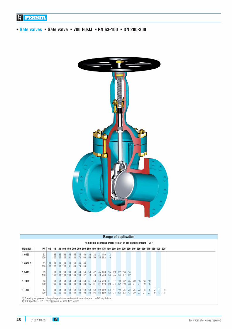
■ Gate valves ■ Gate valve ■ 700 HJ/JJ ■ PN 63-100 ■ DN 200-300
Technical alterations reserved6100.1.09.0648
Admissible operating pressure [bar] at design temperature [°C] 1)
Material PN -60 -10 20 100 150 200 250 300 350 400 450 475 480 500 510 520 530 540 550 560 570 580 590 600
1.0460 63 63 63 63 58 50 45 40 36 32 21 14,0 12100 100 100 100 91 80 70 60 56 50 34 21,8 19
1.0566 2) 63 63 63 63 63 58 50 45 40100 100 100 100 100 91 80 70 60
1.5415 63 63 63 63 63 63 63 56 50 47 45 37,0 35 29 22 16 14100 100 100 100 100 100 100 87 78 74 70 57,0 54 45 34 27 22
1.7335 63 63 63 63 63 63 63 63 61 58 56 53,0 51 47 40 32 25 20 16 13 10100 100 100 100 100 100 100 100 95 91 87 82,0 80 74 62 49 38 31 24 19 16
1.7380 63 63 63 63 63 63 63 63 62 62 60 55,0 53 47 40 35 28 25 22 18 15 12 11 9100 100 100 100 100 100 100 100 98 96 94 85,0 82 74 62 53 43 39 33 27 23 19 17 15
1) Operating temperature = design temperature minus temperature surcharge acc. to DIN regulations.2) At temperature > 50° C only applicable for short-time service.
Range of application

■ Gate valves ■ Gate valve ■ 700 HJ/JJ ■ PN 63-100 ■ DN 200-300
Standard features
■ Die-forged body and bonnet■ Split wedge = Type 700 JJ■ Flexible wedge = Type 700 HJ■ > DN 350 = Type 400 JJ (without picture)■ Full bore■ Outside screw and yoke■ Yoke sleeve
Pressure and temperature ratings
■ Pressure rating up to 100 bar■ Temperature rating up to +600° C
Materials
■ 1.0460■ 1.0566■ 1.5415■ 1.7335■ 1.7380
Further materials on request
Design Highlights
■ Die-forged body and bonnet
■ Hard faced seats (valve body and shut-off device)
■ Non-rising stem with polished stem shaft and a surface roughness of max. 2 μm
■ Bolted bonnet with reduced shaft bolts
Benefits
■ Free from porosity and shrink holes
■ Extremely resistant to wear
■ Minimum wear to the gland packing compared with ground stem surfaces
■ To improve the stress capability when temperature and pressure fluctuate
Fields of application
Chemical industries, power plants, ship building andother
Technical alterations reserved 6100.1.09.06 49
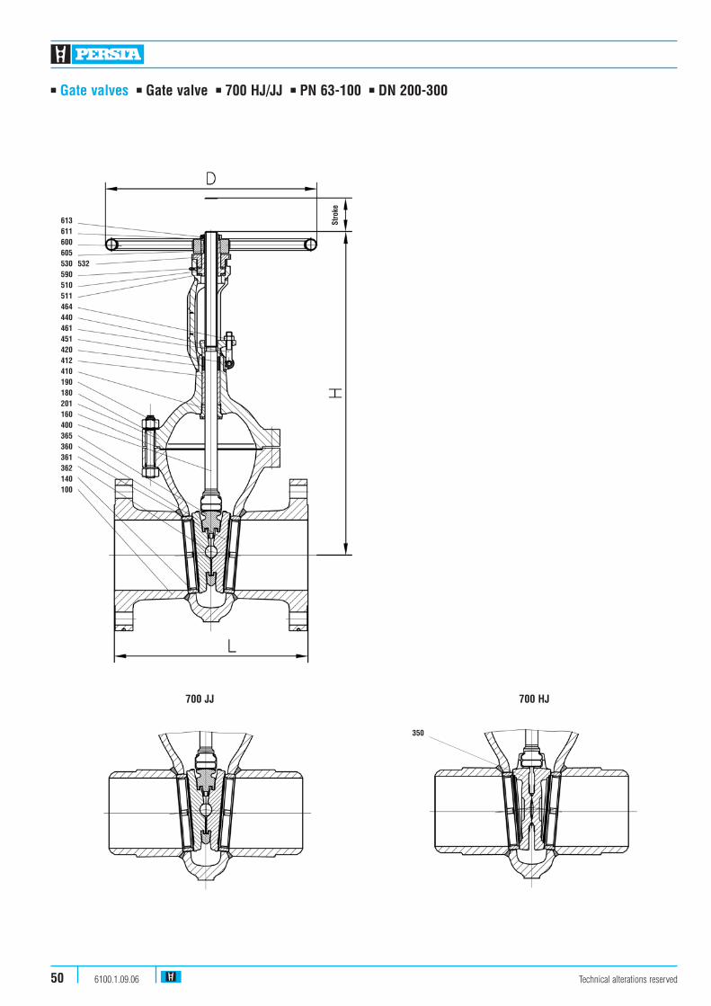
■ Gate valves ■ Gate valve ■ 700 HJ/JJ ■ PN 63-100 ■ DN 200-300
Technical alterations reserved6100.1.09.0650
613611600605530590510511464440461451420412410190180201160400365360361362140100
532
Stro
ke
700 JJ 700 HJ
350

■ Gate valves ■ Gate valve ■ 700 HJ/JJ ■ PN 63-100 ■ DN 200-300
Pos. Component 1.0460 (21) 1.0566 (25) 1.5415 (42) 1.7335 (44) 1.7380 (45)
100 Body 1.0460 1.0566 1.5415 1.7335 1.7380140 Seat ring 1.0460 3) 1.0566 3) 1.5415 3) 1.7335 5) 1.7380 5)
160 �Gasket Grooved with Grooved with Grooved with Grooved with Grooved withgraphite layer graphite layer graphite layer graphite layer graphite layer
180 Stud 1.7709 A4-701 7) 1.7709 1.7709 1.7709190 Hexagonal nut 1.7258 A4-70 1.7258 1.7258 1.7258201 Bonnet 1.0460 1.0566 1.5415 1.7335 1.7380350 �Wedge 1.0460 4) 1.0566 4) 1.5415 1.7335 5) 1.7380 5)
360/361 �Disc 1.8507 8) 1.0566 4) 1.5415 1.8507 1)5) 1.8507 5)
362 �Ball WLSt 2) WLS t2) WLSt 2) WLSt 2) WLSt 2)
365 �Double disc guide 1.0460 1.0566 1.5415 1.7335 1.7380400 �Stem 1.4021 1.4571 1.4122 1.4122 1.4122410 Back seat bushing 1.4006 1.4006 1.4006 1.4006 1.4006412 Basic ring 1.0718 1.0718 1.0718 1.0718 1.0718420 �Packing Graphite Graphite Graphite Graphite Graphite440 Gland flange 1.0460 1.4571 1.0460 1.0460 1.0460451 Grooved pin St 12) 1.4571 St 12) St 12) St 12)
461 Eye bolt 1.1181 11) A4-50 1.1181 11) 1.1181 11) 1.1181 11)
464 Hexagonal nut 1.1181 16) A4-70 1.1181 16) 1.1181 16) 1.1181 16)
510 �Yoke sleeve 1.0718 14) 1.0718 1.0718 14) 1.0718 14) 1.0718 14)
511 �Roller bearing WLSt 13) WLSt 13) WLSt 13) WLSt 13) WLSt 13)
530 Yoke nut 1.0718 1.0718 1.0718 1.0718 1.0718531 Screwing 1.7335 � DN 250 1.7335 � DN 250 1.7335 � DN 250 1.7335 � DN 250 1.7335 � DN 250532 Screw pin 45H 45H 45H 45H 45H590 Grease nipple 5.8 5.8 5.8 5.8 5.8600 Handwheel St St St St St605 Key 1.0060 1.0060 1.0060 1.0060 1.0060611 Handwheel nut St St St St St613 Screw pin 45H 45H 45H 45H 45H
�Spare parts
1) � DN 250 = 1.7380 welded on with Stellite2) � DN 250 = Pressure ring 1.41223) Welded on with 18/8 (40)4) Welded on with Cr175) Welded on with Stellite8) � DN 250 = 1.0460 welded on with Cr1711) � DN 250 = 1.770912) � DN 250 = 1.725813) � DN 250 = Thrust ball bearing14) � DN 250 = 2.055016) � DN 250 = 1.725817) � DN 300 = 1.5680
Materials
Flange Flange BWPN PN PN Kvs
DN 63 100 63-100 (m3/h)
200 270 285 215 4000250 480 538 430 6247300 690 750 560 8997
Weights/kg and Kvs-values
Flange BW PN 63-100 PN 63-100
DN L L H Stroke D
200 550 550 920 210 600250 650 650 1110 265 720300 750 750 1310 313 900
Dimensions/mm
Technical alterations reserved 6100.1.09.06 51