Embed Size (px)
Citation preview
Gateway KNX-DALI
GW610X00
Programming manual
GW610X00 - Gateway KNX-DALI Programming manual v2.1.3
www.besknx.com 2
Index 1 GENERAL DESCRIPTION ........................................................................................................................................... 3
2 TECHNICAL INFORMATION ...................................................................................................................................... 4
3 PROGRAMMING ...................................................................................................................................................... 5
3.1 APPLICATION PROGRAM INFORMATION ........................................................................................................................... 5
3.2 INDIVIDUAL ADDRESS ASSIGNMENT ................................................................................................................................ 5
3.3 COMMUNICATION OBJECTS TABLE .................................................................................................................................. 6
3.4 COMMUNICATION OBJECTS DESCRIPTION ........................................................................................................................ 7
3.5 PARAMETERS ............................................................................................................................................................. 8
3.5.1 General .............................................................................................................................................................. 9
3.5.2 Channel 1/2/3 ................................................................................................................................................. 11
3.5.3 Scenes .............................................................................................................................................................. 12
3.6 INPUTS ................................................................................................................................................................... 14
3.6.1 Connection ...................................................................................................................................................... 14
3.6.2 Working mode ................................................................................................................................................. 14
4 INSTALLATION ....................................................................................................................................................... 15
GW610X00 - Gateway KNX-DALI Programming manual v2.1.3
www.besknx.com 3
1 General description
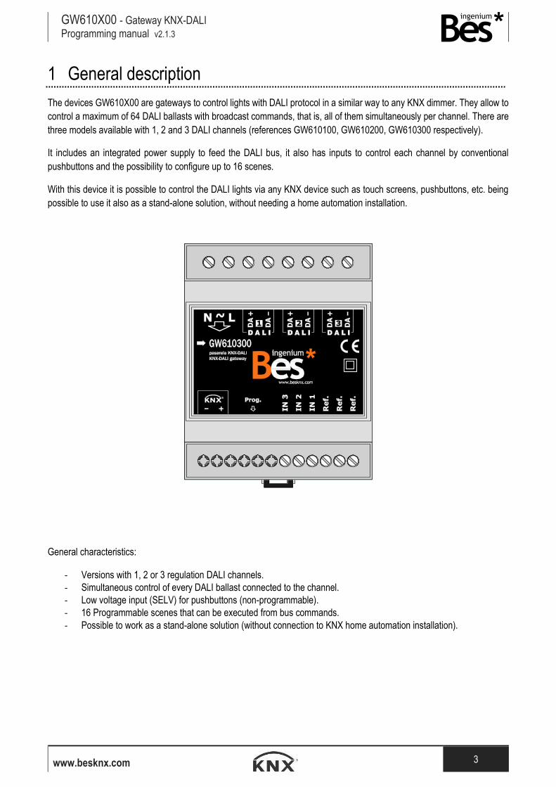
The devices GW610X00 are gateways to control lights with DALI protocol in a similar way to any KNX dimmer. They allow to
control a maximum of 64 DALI ballasts with broadcast commands, that is, all of them simultaneously per channel. There are
three models available with 1, 2 and 3 DALI channels (references GW610100, GW610200, GW610300 respectively).
It includes an integrated power supply to feed the DALI bus, it also has inputs to control each channel by conventional
pushbuttons and the possibility to configure up to 16 scenes.
With this device it is possible to control the DALI lights via any KNX device such as touch screens, pushbuttons, etc. being
possible to use it also as a stand-alone solution, without needing a home automation installation.
General characteristics:
- Versions with 1, 2 or 3 regulation DALI channels.
- Simultaneous control of every DALI ballast connected to the channel.
- Low voltage input (SELV) for pushbuttons (non-programmable).
- 16 Programmable scenes that can be executed from bus commands.
- Possible to work as a stand-alone solution (without connection to KNX home automation installation).
GW610X00 - Gateway KNX-DALI Programming manual v2.1.3
www.besknx.com 4
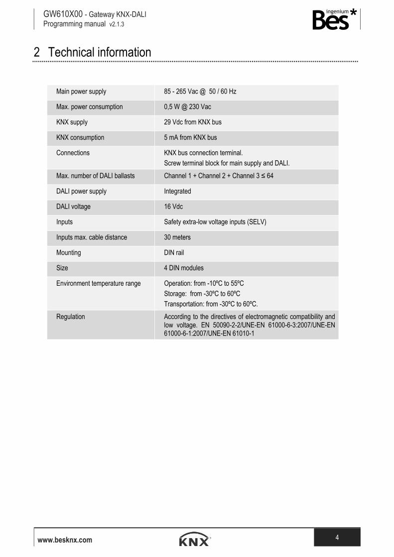
2 Technical information
Main power supply 85 - 265 Vac @ 50 / 60 Hz
Max. power consumption 0,5 W @ 230 Vac
KNX supply 29 Vdc from KNX bus
KNX consumption 5 mA from KNX bus
Connections KNX bus connection terminal.
Screw terminal block for main supply and DALI.
Max. number of DALI ballasts Channel 1 + Channel 2 + Channel 3 ≤ 64
DALI power supply Integrated
DALI voltage 16 Vdc
Inputs Safety extra-low voltage inputs (SELV)
Inputs max. cable distance 30 meters
Mounting DIN rail
Size 4 DIN modules
Environment temperature range Operation: from -10ºC to 55ºC
Storage: from -30ºC to 60ºC
Transportation: from -30ºC to 60ºC.
Regulation According to the directives of electromagnetic compatibility and low voltage. EN 50090-2-2/UNE-EN 61000-6-3:2007/UNE-EN 61000-6-1:2007/UNE-EN 61010-1
GW610X00 - Gateway KNX-DALI Programming manual v2.1.3
www.besknx.com 5
3 Programming
3.1 Application program information
Catalogue: Ingenium / Dimmers (manufacturer / program name).
Plug-in version: v2.1.3
Maximum number of communication objects: 24.
Maximum number of assignments: 25.
ETS minimum required version: 4.1.8 (build 3614)
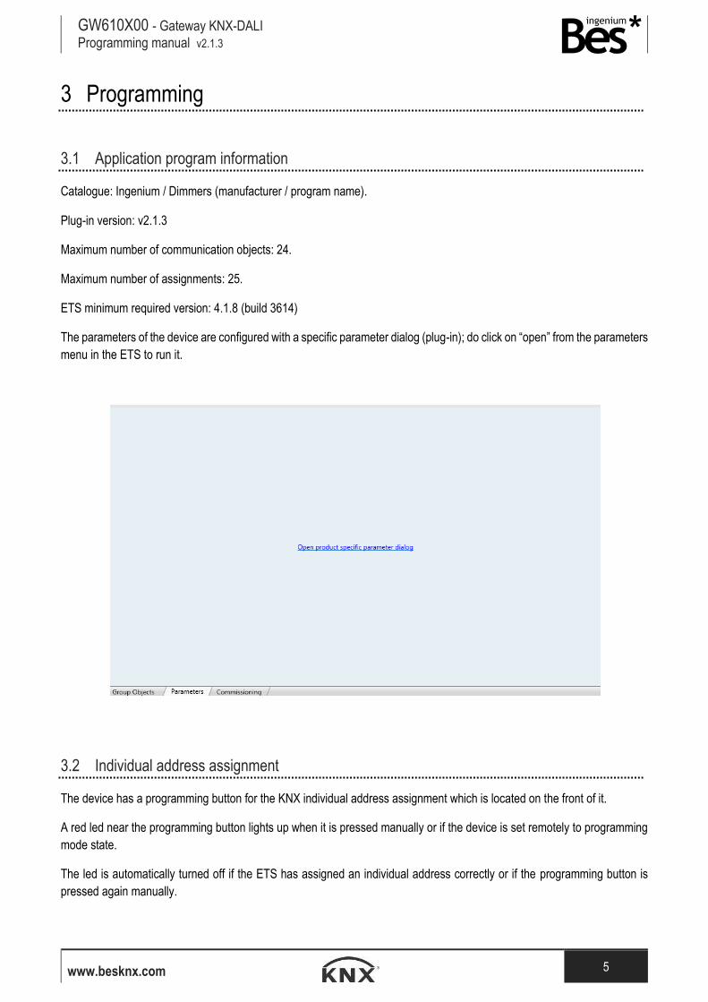
The parameters of the device are configured with a specific parameter dialog (plug-in); do click on “open” from the parameters
menu in the ETS to run it.
3.2 Individual address assignment
The device has a programming button for the KNX individual address assignment which is located on the front of it.
A red led near the programming button lights up when it is pressed manually or if the device is set remotely to programming
mode state.
The led is automatically turned off if the ETS has assigned an individual address correctly or if the programming button is
pressed again manually.
GW610X00 - Gateway KNX-DALI Programming manual v2.1.3
www.besknx.com 6
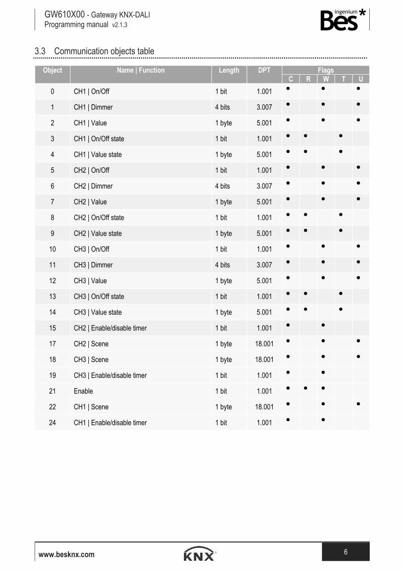
3.3 Communication objects table
Object
Name | Function
Length
DPT
Flags
C R W T U
0 CH1 | On/Off 1 bit 1.001 ● ● ●
1 CH1 | Dimmer 4 bits 3.007 ● ● ●
2 CH1 | Value 1 byte 5.001 ● ● ●
3 CH1 | On/Off state 1 bit 1.001 ● ● ●
4 CH1 | Value state 1 byte 5.001 ● ● ●
5 CH2 | On/Off 1 bit 1.001 ● ● ●
6 CH2 | Dimmer 4 bits 3.007 ● ● ●
7 CH2 | Value 1 byte 5.001 ● ● ●
8 CH2 | On/Off state 1 bit 1.001 ● ● ●
9 CH2 | Value state 1 byte 5.001 ● ● ●
10 CH3 | On/Off 1 bit 1.001 ● ● ●
11 CH3 | Dimmer 4 bits 3.007 ● ● ●
12 CH3 | Value 1 byte 5.001 ● ● ●
13 CH3 | On/Off state 1 bit 1.001 ● ● ●
14 CH3 | Value state 1 byte 5.001 ● ● ●
15 CH2 | Enable/disable timer 1 bit 1.001 ● ●
17 CH2 | Scene 1 byte 18.001 ● ● ●
18 CH3 | Scene 1 byte 18.001 ● ● ●
19 CH3 | Enable/disable timer 1 bit 1.001 ● ●
21 Enable 1 bit 1.001 ● ● ●
22 CH1 | Scene 1 byte 18.001 ● ● ●
24 CH1 | Enable/disable timer 1 bit 1.001 ● ●
GW610X00 - Gateway KNX-DALI Programming manual v2.1.3
www.besknx.com 7
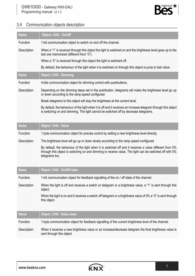
3.4 Communication objects description
Name Object: CHX - On/Off
Function 1-bit communication object to switch on and off the channel.
Description When a “1” is received through this object the light is switched on and the brightness level goes up to the last one memorized (different from “0”).
When a “0” is received through this object the light is switched off.
By default, the behaviour of the light when it is switched on through this object is jump to last value.
Name Object: CHX - Dimming
Function 4-bits communication object for dimming control with pushbuttons.
Description Depending on the dimming steps set in the pushbutton, telegrams will make the brightness level go up or down according to the ramp speed configured.
Break telegrams to this object will stop the brightness at the current level.
By default, the behaviour of the light when it is off and it receives an increase telegram through this object is switching on and dimming. The light cannot be switched off by decrease telegrams.
Name Object: CHX - Value
Function 1.byte communication object for precise control by setting a new brightness level directly.
Description The brightness level will go up or down slowly according to the ramp speed configured.
By default, the behaviour of the light when it is switched off and it receives a value different from 0% through this object is switching on and dimming to receive value. The light can be switched off with 0% telegrams too.
Name Object: CHX - On/Off state
Function 1-bit communication object for feedback signalling of the on / off state of the channel.
Description When the light is off and receives a switch on telegram or a brightness value, a “1” is sent through this object.
When the light is on and it receives a switch off telegram or a brightness value of 0% a “0” is sent through this object.
Name Object: CHX - Value state
Function 1-byte communication object for feedback signalling of the current brightness level of the channel.
Description When it receives a new brightness value or an increase/decrease telegram the final brightness value is sent through this object.
GW610X00 - Gateway KNX-DALI Programming manual v2.1.3
www.besknx.com 8
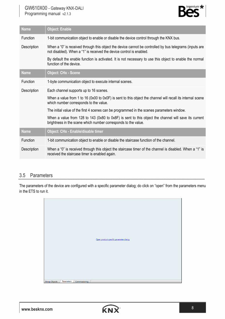
Name Object: Enable
Function 1-bit communication object to enable or disable the device control through the KNX bus.
Description When a “0” is received through this object the device cannot be controlled by bus telegrams (inputs are not disabled). When a “1” is received the device control is enabled.
By default the enable function is activated. It is not necessary to use this object to enable the normal function of the device.
Name Object: CHx - Scene
Function 1-byte communication object to execute internal scenes.
Description Each channel supports up to 16 scenes.
When a value from 1 to 16 (0x00 to 0x0F) is sent to this object the channel will recall its internal scene which number corresponds to the value.
The initial value of the first 4 scenes can be programmed in the scenes parameters window.
When a value from 128 to 143 (0x80 to 0x8F) is sent to this object the channel will save its current brightness in the scene which number corresponds to the value.
Name Object: CHx - Enable/disable timer
Function 1-bit communication object to enable or disable the staircase function of the channel.
Description When a “0” is received through this object the staircase timer of the channel is disabled. When a “1” is received the staircase timer is enabled again.
3.5 Parameters
The parameters of the device are configured with a specific parameter dialog; do click on “open” from the parameters menu
in the ETS to run it.
GW610X00 - Gateway KNX-DALI Programming manual v2.1.3
www.besknx.com 9
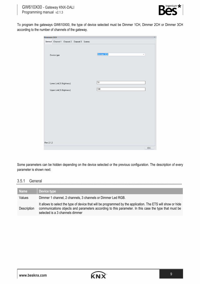
To program the gateways GW610X00, the type of device selected must be Dimmer 1CH, Dimmer 2CH or Dimmer 3CH
according to the number of channels of the gateway.
Some parameters can be hidden depending on the device selected or the previous configuration. The description of every
parameter is shown next:
3.5.1 General
Name Device type
Values Dimmer 1 channel, 2 channels, 3 channels or Dimmer Led RGB.
Description It allows to select the type of device that will be programmed by the application. The ETS will show or hide communications objects and parameters according to this parameter. In this case the type that must be selected is a 3 channels dimmer
GW610X00 - Gateway KNX-DALI Programming manual v2.1.3
www.besknx.com 10
Name Lower limit (% Brightness)
Values From 0 to 100
Description
It is the minimum regulation value (hardware limitation) in percentage % that any channel of the dimmer can reach.
The brightness level of the dimmer will stop at the lower limit when receiving decrements by precise control telegrams (by objects 2,7 and 12) or dimming telegrams (by objects 1,6,11) and it can only be switched off with a “0” through the on/off or value objects (objects 0,5,10 and 2,7,12).
This parameter is only a hardware limitation. The user can dim any value from 0 to 100% but the real brightness value is internally adjusted according to the lower and upper limitation span.
Name Upper limit (% Brightness)
Values From 0 to 100
Description
It is the maximum regulation value (hardware limitation) in percentage % that any channel of the dimmer can reach.
The brightness level of the dimmer will stop at the upper limit when receiving increments by precise control telegrams (by objects 2, 7 and 12) or dimming telegrams (by objects 1, 6, 11).
This parameter is only a hardware limitation. The user can dim any value from 0 to 100% but the real brightness value is internally adjusted according to the lower and upper limitation span.
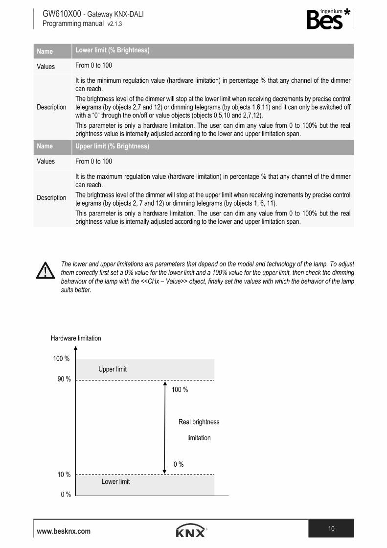
The lower and upper limitations are parameters that depend on the model and technology of the lamp. To adjust
them correctly first set a 0% value for the lower limit and a 100% value for the upper limit, then check the dimming
behaviour of the lamp with the <<CHx – Value>> object, finally set the values with which the behavior of the lamp
suits better.
Hardware limitation
Real brightness
limitation
100 %
0 %
90 %
10 % Lower limit
100 %
0 %
Upper limit
GW610X00 - Gateway KNX-DALI Programming manual v2.1.3
www.besknx.com 11
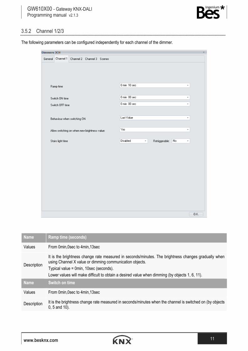
3.5.2 Channel 1/2/3
The following parameters can be configured independently for each channel of the dimmer.
Name Ramp time (seconds)
Values From 0min,0sec to 4min,13sec
Description
It is the brightness change rate measured in seconds/minutes. The brightness changes gradually when using Channel X value or dimming communication objects.
Typical value = 0min, 10sec (seconds).
Lower values will make difficult to obtain a desired value when dimming (by objects 1, 6, 11).
Name Switch on time
Values From 0min,0sec to 4min,13sec
Description It is the brightness change rate measured in seconds/minutes when the channel is switched on (by objects 0, 5 and 10).
GW610X00 - Gateway KNX-DALI Programming manual v2.1.3
www.besknx.com 12
Name Switch off time
Values From 0min,0sec to 4min,13sec
Description It is the brightness change rate measured in seconds/minutes when the channel is switched off (by objects 0, 5 and 10).
Name Behaviour when switching on
Values Last value or fixed value from 0,78% to 98,82%
Description It is the brightness level of the channel when it is switched on (by objects 0, 5 and 10).
The channel can be configured to dimm up to the last value (different from “0”) memorized or dimm to a selected fixed value.
Name Allow switching on with new brightness value
Values Yes/no
Description
By default, this parameter is set to yes, and the behaviour of the light when it is switched off and it receives a brightness value different from 0% (by objects 2,7 and 12) is switching on and dimming to received value.
If this parameter is set to No, the channel must be switched on first and then it will respond to new brightness values.
Name Stairs light time
Values Disabled or fixed value from 5 seconds to 790 minutes
Description
A stairscase lighting function can be configured for each channel with this parameter.
If enabled, the channel will be switched off automatically after the time configured. During the staircase function, take into account the following behaviour:
-The countdown can be retriggerable or not (see next parameter).
-The channel can always be switched off manually.
It is possible to enable/disable the staircase light timer by sending values 1 and 0 to the corresponding channel communication object (objects 15, 19 and 24).
Name Retriggerable
Values Yes/no
Description Defines if the stairscase countdown of the channel can be retriggered or not. If set to yes, it can be retriggered with on, dimming or brightness value telegrams.
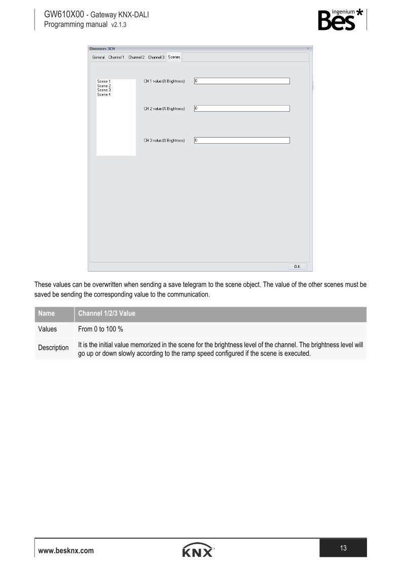
3.5.3 Scenes
The device supports up to 16 scenes per channel that can be saved or executed from bus commands with the corresponding
communication objects (number 17, 18 and 22). The initial values of the first 4 scenes can be configured in the following
parameters tab:
GW610X00 - Gateway KNX-DALI Programming manual v2.1.3
www.besknx.com 13
These values can be overwritten when sending a save telegram to the scene object. The value of the other scenes must be
saved be sending the corresponding value to the communication.
Name Channel 1/2/3 Value
Values From 0 to 100 %
Description It is the initial value memorized in the scene for the brightness level of the channel. The brightness level will go up or down slowly according to the ramp speed configured if the scene is executed.
GW610X00 - Gateway KNX-DALI Programming manual v2.1.3
www.besknx.com 14
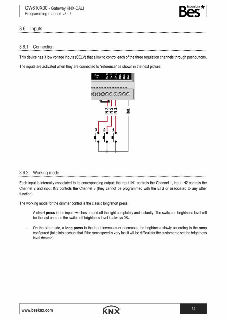
3.6 Inputs
3.6.1 Connection
This device has 3 low voltage inputs (SELV) that allow to control each of the three regulation channels through pushbuttons.
The inputs are activated when they are connected to “reference” as shown in the next picture:
3.6.2 Working mode
Each input is internally associated to its corresponding output: the input IN1 controls the Channel 1, input IN2 controls the
Channel 2 and input IN3 controls the Channel 3 (they cannot be programmed with the ETS or associated to any other
function).
The working mode for the dimmer control is the classic long/short press:
- A short press in the input switches on and off the light completely and instantly. The switch on brightness level will
be the last one and the switch off brightness level is always 0%.
- On the other side, a long press in the input increases or decreases the brightness slowly according to the ramp
configured (take into account that if the ramp speed is very fast it will be difficult for the customer to set the brightness
level desired).
GW610X00 - Gateway KNX-DALI Programming manual v2.1.3
www.besknx.com 15
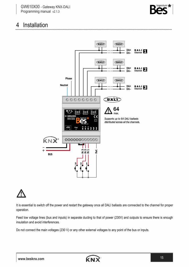
4 Installation
-
It is essential to switch off the power and restart the gateway once all DALI ballasts are connected to the channel for proper
operation.
Feed low voltage lines (bus and inputs) in separate ducting to that of power (230V) and outputs to ensure there is enough
insulation and avoid interferences.
Do not connect the main voltages (230 V) or any other external voltages to any point of the bus or inputs.

Liability limitation: The present document is subject to changes or excepted errors. The contents are
continuously checked to be according to the hardware and software but deviations cannot be completely
excluded. Consequently any liability for this is not accepted. Please inform us of any suggestion. Every
correction will be incorporated in new versions of this manual.
Manual version: v1.1
Ingenium, Ingeniería y Domótica S.L.
Parque Tecnológico de Asturias, Parcela 50
33428 Llanera, Asturias, España
T (+34) 985 757 195
www.besknx.com
www.ingeniumsl.com


![KNX-DALI TAUSTOJAknx.fi/doc/2016_lokakuu_julkaisut/KNX-DALI-TAUSTOJA.pdfDALI (Digital Addressable Lighting Interface) ... DALI-standardinsa NEMA 243-2004. [38] DALI-järjestelmää](https://img.pdfslide.net/doc/110x75/5b0c7f7e7f8b9a2c3b8bb990/knx-dali-digital-addressable-lighting-interface-dali-standardinsa-nema-243-2004.jpg)


![KNX-DALI TAUSTOJA - Talotekniikkatate.blogs.tamk.fi/files/2016/12/KNX-DALI-TAUSTOJA.pdfDALI (Digital Addressable Lighting Interface) ... DALI-standardinsa NEMA 243-2004. [38] DALI-järjestelmää](https://img.pdfslide.net/doc/110x75/5b0c7f7e7f8b9a2c3b8bb9ea/knx-dali-taustoja-digital-addressable-lighting-interface-dali-standardinsa.jpg)