Embed Size (px)
Citation preview

GFK-2223
GE Fanuc Manuals
rx7i-plc
New In Stock!
PACSystems RX7i Installation Manual
http://www.pdfsupply.com/automation/ge-fanuc-manuals/rx7i-plc/GFK-2223
www.pdfsupply.com
1-919-535-3180
Email: [email protected]
GE Fanuc Automation Programmable Control Products
PACSystems™ RX7i Installation Manual, GFK-2223G
September 2006

GFL-002
Warnings, Cautions, and Notes as Used in this Publication
Warning
Warning notices are used in this publication to emphasize that hazardous voltages, currents, temperatures, or other conditions that could cause personal injury exist in this equipment or may be associated with its use.
In situations where inattention could cause either personal injury or damage to equipment, a Warning notice is used.
Caution
Caution notices are used where equipment might be damaged if care is not taken.
Note: Notes merely call attention to information that is especially significant to understanding and operating the equipment.
This document is based on information available at the time of its publication. While efforts have been made to be accurate, the information contained herein does not purport to cover all details or variations in hardware or software, nor to provide for every possible contingency in connection with installation, operation, or maintenance. Features may be described herein which are not present in all hardware and software systems. GE Fanuc Automation assumes no obligation of notice to holders of this document with respect to changes subsequently made.
GE Fanuc Automation makes no representation or warranty, expressed, implied, or statutory with respect to, and assumes no responsibility for the accuracy, completeness, sufficiency, or usefulness of the information contained herein. No warranties of merchantability or fitness for purpose shall apply.
The following are trademarks of GE Fanuc Automation, Inc.
Alarm Master Genius ProLoop Series Six CIMPLICITY Helpmate PROMACRO Series Three CIMPLICITY 90–ADS Logicmaster PowerMotion VersaMax CIMSTAR Modelmaster PowerTRAC VersaPoint Field Control Motion Mate Series 90 VersaPro GEnet PACSystems Series Five VuMaster Proficy Series One Workmaster
©Copyright 2003—2006 GE Fanuc Automation North America, Inc.
All Rights Reserved
Contents
GFK-2223G iii
Introduction....................................................................................................................1-1 Getting Started.................................................................................................................. 1-1
Guide to the RX7i Document Set............................................................................. 1-1 The PACSystems RX7i Control System........................................................................... 1-3
Hardware Description ...................................................................................................2-1
RX7i CPUs........................................................................................................................ 2-2 Serial Ports............................................................................................................... 2-2 Ethernet Ports .......................................................................................................... 2-3 MAC Address ........................................................................................................... 2-3 LEDs......................................................................................................................... 2-3 CPU Specifications .................................................................................................. 2-3
RX7i Racks ....................................................................................................................... 2-4 Specifications — Standard 17-Slot Racks ............................................................... 2-5 Specifications — 17-Slot Rack with Rear I/O Access.............................................. 2-6 Specifications — 9-Slot Racks................................................................................. 2-7
Power Supplies ................................................................................................................. 2-8 Overview .................................................................................................................. 2-8 Power Supply Operation .......................................................................................... 2-8 VMEbus Power Monitor Interface Timing .............................................................. 2-10 IC698PSA100 Specifications ................................................................................. 2-11 IC698PSA350 Specifications ................................................................................. 2-12 IC698PSD300 Specifications................................................................................. 2-14
Fan Assemblies .............................................................................................................. 2-15 Modules Supported by RX7i ........................................................................................... 2-16 Series 90-70 Expansion Racks....................................................................................... 2-20
Sharing a Power Supply with a Second Expansion Rack...................................... 2-21
Installation Instructions ................................................................................................3-1
Pre-Installation Check....................................................................................................... 3-2 System Layout Guidelines ................................................................................................ 3-3 Enclosures ........................................................................................................................ 3-4 System Wiring................................................................................................................... 3-5
General Wiring Information ...................................................................................... 3-5 Color Coding Wires .................................................................................................. 3-5 Wire Routing ............................................................................................................ 3-6
System Grounding ............................................................................................................ 3-7 Ground Conductors.................................................................................................. 3-7 Equipment Grounding .............................................................................................. 3-8
System Installation............................................................................................................ 3-9 RX7i Rack ................................................................................................................ 3-9 Fan Assembly ........................................................................................................ 3-16 RX7i Power Supply ................................................................................................ 3-21
Contents
iv PACSystems™ RX7i Installation Manual–September 2006 GFK-2223G
CPU........................................................................................................................ 3-23 Ethernet Interface Module...................................................................................... 3-27 I/O, Communications and Intelligent Option Modules............................................ 3-28
Power Supply Load Requirements ..............................................................................4-1
Power Supply Load Capacity............................................................................................ 4-1 Module Load Requirements.............................................................................................. 4-2
Cabling Information.......................................................................................................5-1
Ethernet Ports ................................................................................................................... 5-1 Serial Ports ....................................................................................................................... 5-2
Port 1 Pin Assignments............................................................................................ 5-2 Port 2 Pin Assignments............................................................................................ 5-2 Serial Cable Lengths and Shielding......................................................................... 5-3
Product Certifications and Installation Guidelines for Conformance ..................... A-1
RX7i Agency Approvals .................................................................................................... A-2 UL Class 1 Division 2 Hazardous Location Requirements............................................... A-3 ATEX Class 1 Zone 2 Hazardous Location Requirements .............................................. A-3 Standards Overview ......................................................................................................... A-4
Environmental Specifications................................................................................... A-4 Additional RX7i Specifications ................................................................................. A-5
Government Regulations .................................................................................................. A-6 I ......................................................................................................................................... A-7 Shielded Cable Alternative to Conduit .............................................................................. A-8
Communication Cables ............................................................................................ A-8 I/O Cables ................................................................................................................ A-8 Analog/High Speed Cables...................................................................................... A-8 Power Input to Enclosure (for Series 90-70 Power Supplies).................................. A-9 Shield Termination ................................................................................................... A-9 Specialty Shielded Cable Vendors.........................................................................A-10
Safety-Related Guidelines for Installation in the European Union .................................A-11
Calculating Heat Dissipation ....................................................................................... B-1
Information Required ........................................................................................................ B-1 Heat Dissipation Calculations ........................................................................................... B-2
Module Heat Dissipation .......................................................................................... B-2 Power Supply Heat Dissipation................................................................................ B-2 Heat Dissipation for Discrete Output Modules ......................................................... B-3 Heat Dissipation for Discrete Input Modules............................................................ B-4 Total Heat Dissipation .............................................................................................. B-5
Index
GFK-2223G Index Index-3
expansion racks, 2-20 installation guidelines for conformance, A-7
Shared power supply, 2-21 Shielding
serial cable, 5-3 Single-width modules
installing, 3-29 supported, 2-16
Specialty shielded cable vendors, A-10 Specifications
17-slot racks, 2-5 17-slot racks with rear I/O access, 2-6 9-slot racks, 2-7 CPUs, 2-3 environmental, A-4 fan assemblies, 2-15 general RX7il, A-5 PSA100 power supplies, 2-11 PSA350 power supplies, 2-12 PSD300 power supplies, 2-14
System grounding, 3-7
T Technical support, 3-2 Terminal boards
detachable, 3-30, 3-31 I/O, 3-30, 3-31
V VME modules, 2-18
W Wiring
Color coding, 3-5 Routing wires, 3-6
GFK-2223G 1-1
Introduction
Getting Started Read this chapter first to learn about the basics of the PACSystems RX7i control system hardware. To locate detailed information, check the “Guide to the RX7i Document Set” below.
Guide to the RX7i Document Set Chapter 2 provides descriptions and general specifications of the RX7i hardware.
Chapter 3 provides installation instructions for RX7i racks and modules.
Chapter 4 provides power supply load requirements.
Chapter 5 provides cabling information.
Appendix A contains installation instructions and specifications related to product certification.
RX7i Manuals
PACSystems RX7i CPU Reference Manual, GFK-2222
PACSystems RX7i Installation Manual, GFK-2223
TCP/IP Ethernet Communications for the PACSystems RX7i, GFK-2224
Station Manager for the PACSystems RX7i, GFK-2225
PACSystems RX7i User's Guide to Integration of VME Modules, GFK-2235
C Toolkit for PACSystems, GFK-2259
Genius® Bus Controller User’s Manual, GFK-2017
PACSystems RX7i Memory Xchange Modules User’s Manual, GFK-2300 PACSystems Hot Standby Redundancy Manual, GFK-2308
Proficy® Machine Edition Logic Developer-PLC Getting Started, GFK-1918
Serial Communications for Series 90™ User’s Manual, GFK-0582
Programmable Coprocessor Module and Support Software, GFK-0255
1 Chapter

1-2 PACSystems™ RX7i Installation Manual – September 2006 GFK-2223G
1
Series 90-70 and Genius Manuals
Series 90-70 Programmable Controller Installation Manual, GFK-0262
Series 90-70 CPU Instruction Set Reference Manual, GFK-0265
Series 90-70 Programmable Controller Datasheets Manual, GFK-0600
Series 90 PLC Serial Communications Driver User's Manual, GFK-0582
TCP/IP Ethernet Communications for the Series 90 PLC, GFK-1541
Series 90-70 PLC User's Guide to Integration of 3rd Party VME Modules, GFK-0448
MMS-Ethernet Communications for the Series 90-70 PLC User’s Manual, GFK-0686
Digital Input IC697VDD100 Module User’s Guide, GFK-2062
Relay Output, 64 Point IC697VDR151 Module User’s Guide, GFK-2063
Digital Output, 64 Point IC697VDQ120 Module User’s Guide, GFK-2066
Analog Input, 64 Channel, 16bit IC697VAL264 Module User’s Guide, GFK-2056
Analog Input, Isolated, 16bit, 16 Channel IC697VAL132 Module User’s Guide, GFK-2060
Eight Channel RTD/Strain Gauge IC697VRD008 Module User’s Guide, GFK-2098
Analog Output, 32 Channel, 12bit IC697VAL301 Module User’s Guide, GFK-2058
Series 90-70 Genius I/O System User’s Manual, GEK-90486-1
Series 90-70 Genius I/O Analog and Discrete Blocks User’s Manual, GEK-90486-2
Series 90-70 DLAN/DLAN+ Interface Module, GFK-0729
Programmable Coprocessor Module and Support Software, GFK-0255
Installation Requirements for Conformance to Standards, GFK-1179
GFK-2223G Chapter 1 Introduction 1-3
1
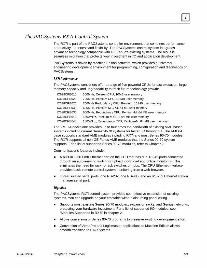
The PACSystems RX7i Control System The RX7i is part of the PACSystems controller environment that combines performance, productivity, openness and flexibility. The PACSystems control system integrates advanced technology compatible with GE Fanuc’s existing systems. The result is seamless migration that protects your investment in I/O and application development.
PACSystems is driven by Machine Edition software, which provides a universal engineering development environment for programming, configuration and diagnostics of PACSystems.
RX7i Performance
The PACSystems controllers offer a range of five powerful CPUs for fast execution, large memory capacity and upgradeability to track future technology growth:
IC698CPE010 300MHz, Celeron CPU, 10MB user memory IC698CPE020 700MHz, Pentium CPU, 10 MB user memory IC698CRE020 700MHz Redundancy CPU, Pentium, 10 MB user memory IC698CPE030 600MHz, Pentium-M CPU, 64 MB user memory IC698CRE030 600MHz, Redundancy CPU, Pentium-M, 64 MB user memory IC698CPE040 1800MHz, Pentium-M CPU, 64 MB user memory IC698CRE040 1800MHz, Redundancy CPU, Pentium-M, 64 MB user memory
The VME64 backplane provides up to four times the bandwidth of existing VME based systems including current Series 90-70 systems for faster I/O throughput. The VME64 base supports standard VME modules including RX7i and most Series 90-70 modules. The RX7i supports all non-GE Fanuc VME modules that the Series 90-70 system supports. For a list of supported Series 90-70 modules, refer to Chapter 2.
Communications features include:
A built-in 10/100mb Ethernet port on the CPU that has dual RJ-45 ports connected through an auto-sensing switch for upload, download and online monitoring. This eliminates the need for rack-to-rack switches or hubs. The CPU Ethernet Interface provides basic remote control system monitoring from a web browser.
Three isolated serial ports: one RS-232, one RS-485, and an RS-232 Ethernet station manager serial port.
Migration
The PACSystems RX7i control system provides cost-effective expansion of existing systems. You can upgrade on your timetable without disturbing panel wiring.
Supports most existing Series 90-70 modules, expansion racks, and Genius networks, protecting your hardware investment. For a list of supported I/O modules, see “Modules Supported in RX7i” in chapter 2.
Allows conversion of Series 90-70 programs to preserve existing development effort.
Conversion of VersaPro and Logicmaster applications to Machine Edition allows smooth transition to PACSystems.
1-4 PACSystems™ RX7i Installation Manual – September 2006 GFK-2223G
1
RX7i Rack System
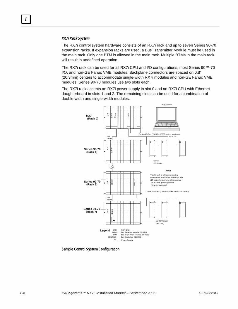
The RX7i control system hardware consists of an RX7i rack and up to seven Series 90-70 expansion racks. If expansion racks are used, a Bus Transmitter Module must be used in the main rack. Only one BTM is allowed in the main rack. Multiple BTMs in the main rack will result in undefined operation.
The RX7i rack can be used for all RX7i CPU and I/O configurations, most Series 90™-70 I/O, and non-GE Fanuc VME modules. Backplane connectors are spaced on 0.8" (20.3mm) centers to accommodate single-width RX7i modules and non-GE Fanuc VME modules. Series 90-70 modules use two slots each.
The RX7i rack accepts an RX7i power supply in slot 0 and an RX7i CPU with Ethernet daughterboard in slots 1 and 2. The remaining slots can be used for a combination of double-width and single-width modules.
GeniusI/O Blocks
Programmer
PS
CPU
BTM
GBC
BRM
Genius I/O Bus (7500 feet/2285 meters maximum)
BRM
GBC
BRM
onemeter
onemeter
Genius I/O bus (7500 feet/2285 meters maximum)
PS
I/O Terminator (last rack)
Total length of all interconnecting cables from BTM to last BRM is 50 feet (15 meters) maximum. All racks must be at same ground potential (8 racks maximum).
Note
Legend CPU - RX7i CPUBRM - Bus Receiver Module, BEM711BTM - Bus Transmitter Module, BEM713
GBC/NBC - Bus Controller, BEM731PS - Power Supply
PS
PS
RX7i (Rack 0)
Series 90-70(Rack 1)
Series 90-70(Rack 6)
Series 90-70(Rack 7)
Sample Control System Configuration
GFK-2223G 2-1
Hardware Description
An RX7i control system hardware consists of an RX7i rack and up to seven Series 90-70 expansion racks.
This chapter provides details on the following components of an RX7i control system:
■ RX7i CPUs
■ RX7i Racks
■ Power Supplies
■ Fan Assemblies
■ Modules Supported in RX7i
■ Series 90-70 Expansion Racks
2 Chapter
2-2 PACSystems™ RX7i Installation Manual - September 2006 GFK-2223G
2
RX7i CPUs The RX7i CPUs are programmed and configured by the programming software to perform real time control of machines, processes, and material handling systems. The CPU communicates with I/O and smart option modules over a rack-mounted backplane using the VME64 Standard format. It communicates with the programmer and/or HMI devices via the embedded Ethernet ports or via the serial ports 1 and 2 using GE Fanuc SNP-X, Serial I/O, or Modbus RTU slave protocols.
IC698CPE010: 300MHz Celeron CPU, 10MB user memory IC698CPE020: 700MHz Pentium CPU, 10MB user memory IC698CRE020: 700MHz Pentium CPU, 10 MB user memory with redundancy IC698CPE030: 600MHz Pentium-M CPU, 64 MB user memory IC698CRE030: 600MHz Pentium-M CPU, 64 MB user memory with redundancy IC698CPE040: 1800MHz Pentium-M CPU, 64 MB user memory IC698CRE040: 1800MHz Pentium-M CPU, 64 MB user memory with redundancy
This section provides information on CPU port pinouts and other physical features. For additional details on CPU features and operation, refer to the PACSystems RX7i CPU Reference Manual, GFK-2222.
Serial Ports The CPU has three independent, on-board serial ports, accessed by connectors on the front of the module. Two of these ports are used for firmware upgrades and as serial interface to external devices. The third on-board serial port is used for station management of the Ethernet interface. All serial ports are isolated. For pinout information, refer to chapter 5.
Port 1 Port 1 is RS-232 compatible and optocoupler isolated. It has a 9-pin, female, D-sub connector with a standard pin out. This is a DCE (data communications equipment) port that allows a simple straight-through cable to connect with a standard AT-style RS-232 port.
The Port 1 indicator provides the status of serial port activity.
Port 2 Port 2 is an RS-485 compatible and optocoupler isolated DCE port. It has a 15-pin, female D-sub connector. This port requires an externally powered converter and does not support the RS-485 to RS-232 adapter IC690ACC901.
This port requires a shielded cable.
The Port 2 indicator provides the status of serial port activity without having a terminal connected.
GFK-2223G Chapter 2 Hardware Description 2-3
2
Station Mgr Port The Ethernet Station Manager port is RS-232 compatible, and isolated. Port 3 has a 9-pin, female, D-connector. This is a DCE port that allows a simple straight-through cable to connect with a standard AT-style RS-232 port. This port contains full use of the standard RS-232 signals for future use with point-to-point protocol (PPP).
Ethernet Ports There are two shielded RJ-45 Ethernet ports on the embedded Ethernet Interface. Either or both of these ports may be attached to other Ethernet devices. Each port automatically senses the data rate (10 Mbps or 100 Mbps), duplex (half duplex or full duplex), and cabling arrangement (straight through or crossover) of the attached link. The use of shielded Ethernet cables is optional.
Caution The two ports on the Ethernet Interface must not be connected, directly or indirectly to the same device. The hub or switch connections in an Ethernet network must form a tree, otherwise duplication of packets may result.
MAC Address The MAC Address label indicates the globally unique Media Access Control (MAC) address used by the CPU Ethernet interface. The MAC Address label is located on the rear inside wall of the battery compartment.
LEDs The CPU and the embedded Ethernet interface LEDs indicate the status of various functions. For details of CPU LED operation, refer to the PACSystems RX7i CPU Reference Manual, GFK-2222. For details of Ethernet LED operation, refer to the TCP/IP Ethernet Communications for the PACSystems RX7i User’s Manual, GFK-2224.
CPU Specifications For CPU performance specifications, refer to chapter 2 of the PACSystems CPU Reference Manual, GFK-2222.
For environmental specifications, see “RX7i General Specifications” in appendix A.
2-4 PACSystems™ RX7i Installation Manual - September 2006 GFK-2223G
2
RX7i Racks IC698CHS017: Rear (wall) mount, 17 slots
IC698CHS217: Rear (wall) mount, 17 slots with rear I/O access
IC698CHS117: Front mount, 17 slots
IC698CHS009: Rear (wall) mount, 9 slots
IC698CHS109: Front mount, 9 slots
The RX7i rack can be used for all RX7i CPU and I/O configurations, including Series 90-70 I/O, and VME modules. The RX7i rack accommodates two module types:
■ RX7i and Series 90-70 modules, which use a detachable field wiring terminal board. Each I/O module accepts up to forty AWG #14 (2.10 mm2) wires. The wire bundle is routed out the bottom of the terminal board cavity where a cleat is provided for a tie wrap to secure the bundle to the terminal board housing. With the IC698CHS217, the VME64 J2 connector user -defined I/O pins are accessible through a rear 96-pin DIN connector. I/O wiring may be connected to these rear access connectors. If the optional rear cover is used, I/O wiring is routed out the bottom of the cover.
■ VME modules, which have varying methods of connecting to field devices.
Backplane connectors are spaced on 0.8" (20.3mm) centers to accommodate single width and double width RX7i and non-GE Fanuc VME modules.
The RX7i rack:
■ Accepts RX7i modules, VME modules, and some Series 90-70 modules. For a list of supported modules, refer to page 2-16.
■ Provides slot sensing for Series 90-70 rack-type I/O modules. No jumpers or DIP switches on the I/O modules are required for addressing of these modules.
■ Provides J2 backplane connectors to allow high-speed VME transfers of up to 64 data bits per cycle.
■ Accepts plug-in RX7i AC power supplies.
■ Supports an optional cooling fan assembly (required for IC698CPE020/CRE020/CPE040/CRE040, IC698PSA350, IC698PSD300, or any of the single-width IC697Vxx modules).
■ Provides a 6-pin RJ-11 connector for connecting an I2C serial cable.
■ The IC698CHS217 rack provides rear access to the VME64 J2 backplane connectors.
The rack accepts a power supply in slot 0 and a CPU with Ethernet daughterboard in slots 1 and 2. The remaining slots can be used for one of the following I/O combinations. 17-slot racks (IC698CHS017, IC698CHS217 and IC698CHS117)
Fifteen single-width modules (with no double-width modules installed) Seven double-width modules A combination of double-width and single-width modules.
9-slot racks (IC698CHS009 and IC698CHS109)
Seven single-width modules (with no double-width modules installed) Four double-width modules A combination of double-width and single-width modules.
The power supply capacity may limit the number of modules in a rack. Power requirement information is provided in chapter 4.
GFK-2223G Chapter 2 Hardware Description 2-5
2
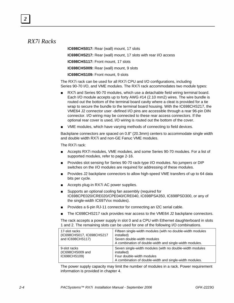
Specifications — Standard 17-Slot Racks
Part numbers Rear mount IC698CHS017 Front mount IC698CHS117
Slots Slots 1 through 17 are 0.8" (20.3mm) wide. (The CPU is installed in slot 1.) Slot 0 (power supply slot) is 2.4" (61.0mm) wide
Maximum current (from RX7i power supplies) 100 watt supply: +5V +12V -12V 350 watt supply: +5V +12V -12V
20 amps (100W maximum total power allocation) 2 amps 1 amp 60 amps (350W maximum total power allocation) 12 amps 4 amps
Dimensions Height Width Depth 11.15" 19.00" 7.5" 283mm 483mm 190mm (Note that all Series 90-70 modules extend 1.7" (43 mm) beyond front of rack.)
VME System supports VME standard 64 Fan kits (optional, required for IC698CPE020/CRE020/CPE040/CRE040, IC698PSA350, IC698PSD300, and single-width IC697Vxx modules)
IC697ACC721, IC697ACC724, IC697ACC744 See page 2-15 for details.
Note: For environmental specifications, see “RX7i General Specifications” in appendix A.
2-6 PACSystems™ RX7i Installation Manual - September 2006 GFK-2223G
2
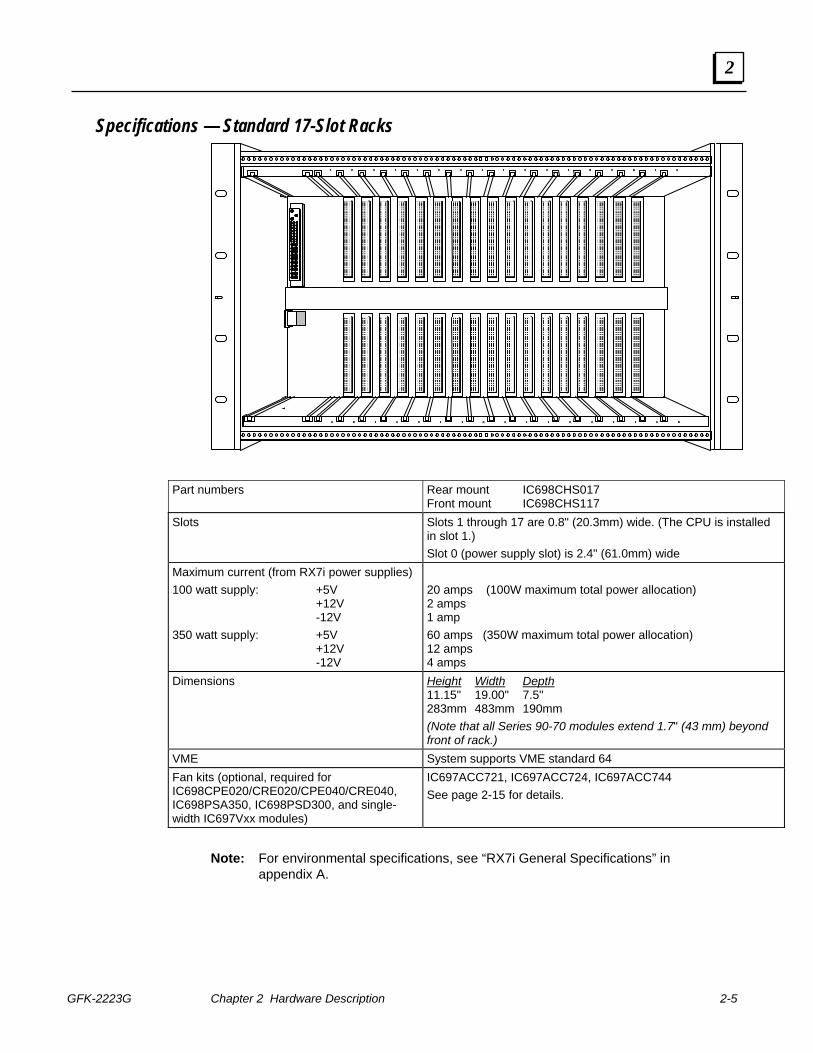
Specifications — 17-Slot Rack with Rear I/O Access
Part number Rear mount IC698CHS217 (rear I/O access) Slots Slots 1 through 17 are 0.8" (20.3mm) wide. (The
CPU is installed in slot 1.) Slot 0 (power supply slot) is 2.4" (61.0mm) wide.
Maximum current (from RX7i power supplies) 100 watt supply: +5V +12V -12V 350 watt supply: +5V +12V -12V
20 amps (100W maximum total power allocation)2 amps 1 amp 60 amps (350W maximum total power allocation)12 amps 4 amps
Dimensions (IC698CHS217) Without rear cover With rear cover
Height Width Depth 11.15" 19.00" 8.875" 283mm 483mm 225mm Height Width Depth 11.15" 19.00" 8.97" 283mm 483mm 228mm
VME System supports VME standard 64 Fan kits (optional, required for IC698CPE020/CRE020/CPE040/CRE040, IC698PSA350, IC698PSD300, and single-width IC697Vxx modules)
IC697ACC721, IC697ACC724, IC697ACC744 See page 2-15 for details.
Note: For environmental specifications, see “RX7i General Specifications” in appendix A.
GFK-2223G Chapter 2 Hardware Description 2-7
2
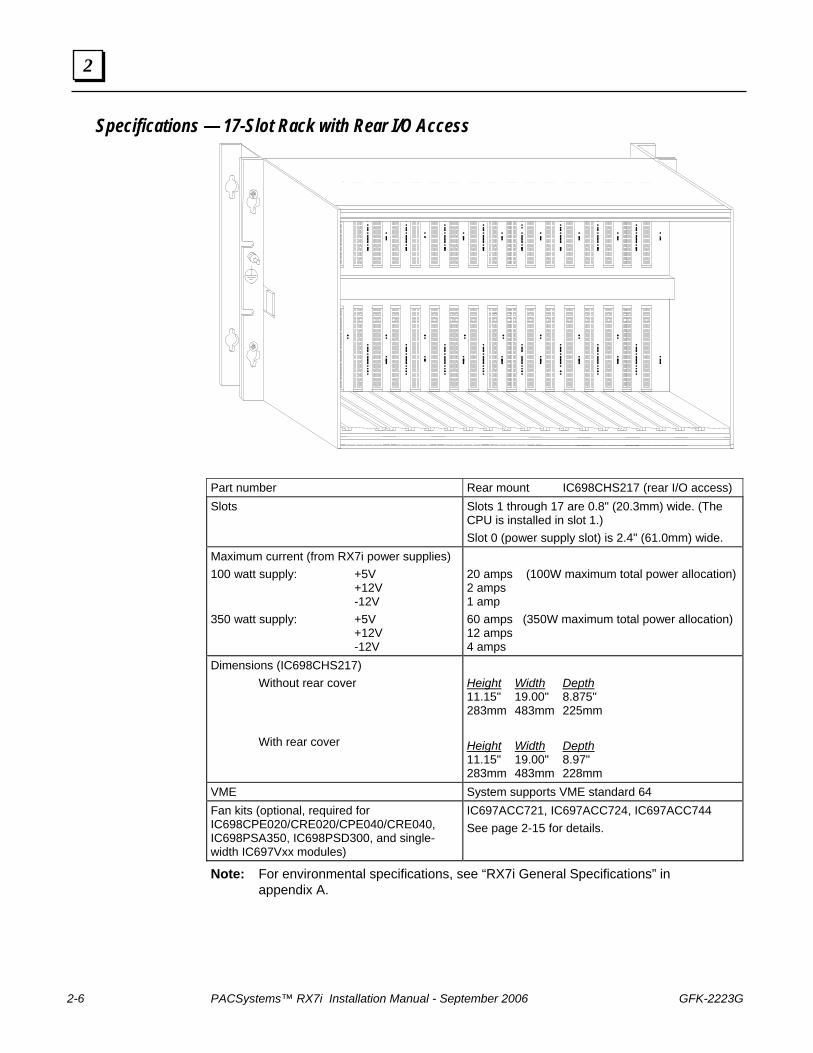
Specifications — 9-Slot Racks
Part numbers Rear mount IC698CHS009 Front mount IC698CHS109
Slots Slots 1 through 8 are 0.8" (20.3mm) wide. (The CPU is installed in slot 1.) Slot 9 is 1.6” wide. If a single width module is installed in slot 9, it is recommended that a single-width filler faceplate be used to close the extra width opening. Slot 0 (power supply slot) is 2.4" (61.0mm) wide.
Maximum current (from RX7i power supplies) 100 watt supply: +5V +12V -12V 350 watt supply: +5V +12V -12V
20 amps (100W maximum total power allocation) 2 amps 1 amp 60 amps (350W maximum total power allocation) 12 amps 4 amps
Dimensions Height Width Depth 11.15" 12.60" 7.5" 283mm 320mm 190mm (Note that all Series 90-70 modules extend 1.7" (43 mm) beyond front of rack.)
VME System supports VME standard 64 Fan kits (optional, required for IC698CPE020/CRE020/CPE040/CRE040, IC698PSA350, IC698PSD300, or any of the single-width IC697Vxx modules)
IC697ACC621, IC697ACC624, IC697ACC644 See page 2-15 for details.
Note: For environmental specifications, see “RX7i General Specifications” in appendix A.
2-8 PACSystems™ RX7i Installation Manual - September 2006 GFK-2223G
2
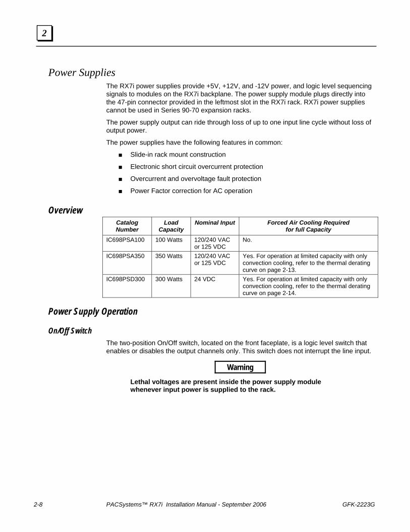
Power Supplies The RX7i power supplies provide +5V, +12V, and -12V power, and logic level sequencing signals to modules on the RX7i backplane. The power supply module plugs directly into the 47-pin connector provided in the leftmost slot in the RX7i rack. RX7i power supplies cannot be used in Series 90-70 expansion racks.
The power supply output can ride through loss of up to one input line cycle without loss of output power.
The power supplies have the following features in common:
■ Slide-in rack mount construction
■ Electronic short circuit overcurrent protection
■ Overcurrent and overvoltage fault protection
■ Power Factor correction for AC operation
Overview Catalog Number
Load Capacity
Nominal Input Forced Air Cooling Required for full Capacity
IC698PSA100 100 Watts 120/240 VAC or 125 VDC
No.
IC698PSA350 350 Watts 120/240 VAC or 125 VDC
Yes. For operation at limited capacity with only convection cooling, refer to the thermal derating curve on page 2-13.
IC698PSD300 300 Watts 24 VDC Yes. For operation at limited capacity with only convection cooling, refer to the thermal derating curve on page 2-14.
Power Supply Operation
On/Off Switch The two-position On/Off switch, located on the front faceplate, is a logic level switch that enables or disables the output channels only. This switch does not interrupt the line input.
Warning Lethal voltages are present inside the power supply module whenever input power is supplied to the rack.
GFK-2223G Chapter 2 Hardware Description 2-9
2
Indicators The following LED indicators are provided on the power supply front panel.
LED Name Color Function FIELD OK green Turns ON when AC power is applied within its
specification range. OUTPUT OK green Turns ON when all three DC outputs channels are
operating within their specifications. Turns OFF if any of the three DC output channels has failed.
OVER TEMP (IC698PSA350 and IC698PSD300 only)
red Turns On if the critical power supply temperature is exceeded or if the airflow sensor detects cessation of air flow.
Overvoltage Protection Any output channel that exceeds the nominal output voltage by 15% or more will cause all outputs to latch off. The ON/OFF control switch or the user input power must be recycled to reset the power supply.
AC power supplies have replaceable fuses the hot and neutral AC inputs. DC power supplies have replaceable fuses on the positive and negative DC inputs. Make sure that power to the rack is turned off before replacing fuses.
Overcurrent/Short Circuit Protection All outputs are protected against overcurrent and short circuit with automatic recovery upon removal of fault.
An electronic current limit is provided on each of the three outputs. An overload on any output will cause the voltage to collapse and may cause the other output voltages to collapse.
Normal operation will resume after removal of the overload. Some component cooling time may be required before normal operation resumes.
Over Temperature Protection All RX7i power supplies have internal temperature sensing that shuts down the output channels if overheated. Recovery is automatic when the internal temperature returns to the specified operating range. The IC698PSA350 and IC698PSD300 power supplies have an OVER TEMP indicator that comes on when the output channels become overheated.
2-10 PACSystems™ RX7i Installation Manual - September 2006 GFK-2223G
2
Air Flow Protection The IC698PSA100 power supply can operate at full capacity from 0 to 60ºC with only convection cooling.
The IC698PSA350 and IC698PSD300 power supplies are capable of operating at full capacity from 0 to 60ºC with 70 CFM forced-air cooling provided by a fan tray mounted below the system chassis. These power supplies can operate at a limited capacity with only convection cooling. For details, see the temperature derating curves provided with the power supply specifications.
An airflow sensor is provided in the IC698PSA350 and IC698PSD300 power supplies to detect a fan failure or air blockage. If the power supply senses a cessation of airflow, it responds by latching off all outputs and turning on the overtemperature LED indicator. A power cycle is required to recover from this latched condition.
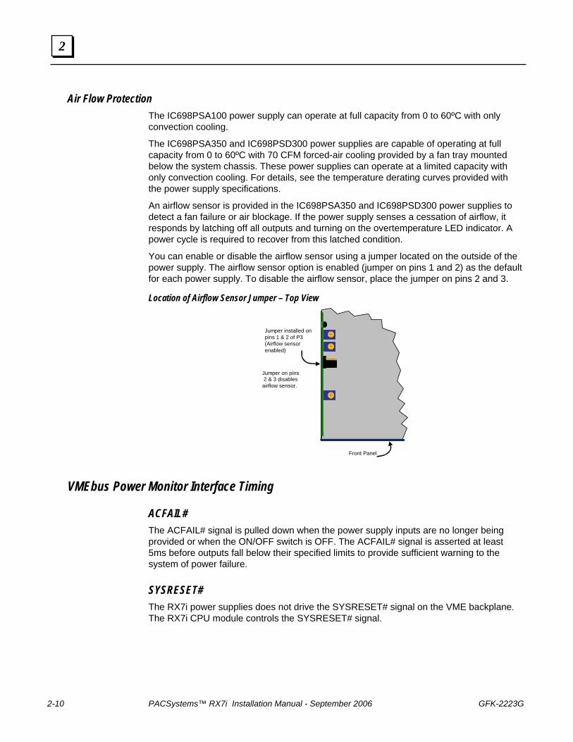
You can enable or disable the airflow sensor using a jumper located on the outside of the power supply. The airflow sensor option is enabled (jumper on pins 1 and 2) as the default for each power supply. To disable the airflow sensor, place the jumper on pins 2 and 3.
Location of Airflow Sensor Jumper – Top View
Front Panel
Jumper installed on pins 1 & 2 of P3(Airflow sensor enabled)
Jumper on pins 2 & 3 disables
airflow sensor.
VMEbus Power Monitor Interface Timing
ACFAIL# The ACFAIL# signal is pulled down when the power supply inputs are no longer being provided or when the ON/OFF switch is OFF. The ACFAIL# signal is asserted at least 5ms before outputs fall below their specified limits to provide sufficient warning to the system of power failure.
SYSRESET# The RX7i power supplies does not drive the SYSRESET# signal on the VME backplane. The RX7i CPU module controls the SYSRESET# signal.
GFK-2223G Chapter 2 Hardware Description 2-11
2
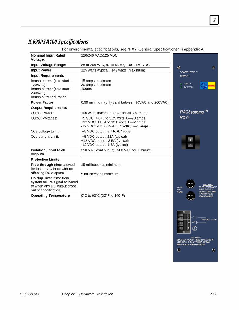
IC698PSA100 Specifications For environmental specifications, see “RX7i General Specifications” in appendix A.
Nominal Input Rated Voltage:
120/240 VAC/125 VDC
Input Voltage Range: 85 to 264 VAC, 47 to 63 Hz, 100—150 VDC Input Power 125 watts (typical), 142 watts (maximum) Input Requirements Inrush current (cold start - 120VAC) Inrush current (cold start - 230VAC) Inrush current duration
15 amps maximum 30 amps maximum 100ms
Power Factor 0.99 minimum (only valid between 90VAC and 260VAC) Output Requirements Output Power: Output Voltages: Overvoltage Limit: Overcurrent Limit:
100 watts maximum (total for all 3 outputs) +5 VDC: 4.875 to 5.25 volts, 0—20 amps +12 VDC: 11.64 to 12.6 volts, 0—2 amps -12 VDC: -12.60 to -11.64 volts, 0—1 amps +5 VDC output: 5.7 to 6.7 volts +5 VDC output: 21A (typical) +12 VDC output: 3.5A (typical) -12 VDC output: 1.6A (typical)
Isolation, input to all outputs
250 VAC continuous; 1500 VAC for 1 minute
Protective Limits Ride-through (time allowed for loss of AC input without affecting DC outputs) Holdup Time (time from system failure signal activated to when any DC output drops out of specification)
15 milliseconds minimum 5 milliseconds minimum
Operating Temperature 0°C to 60°C (32°F to 140°F)
2-12 PACSystems™ RX7i Installation Manual - September 2006 GFK-2223G
2
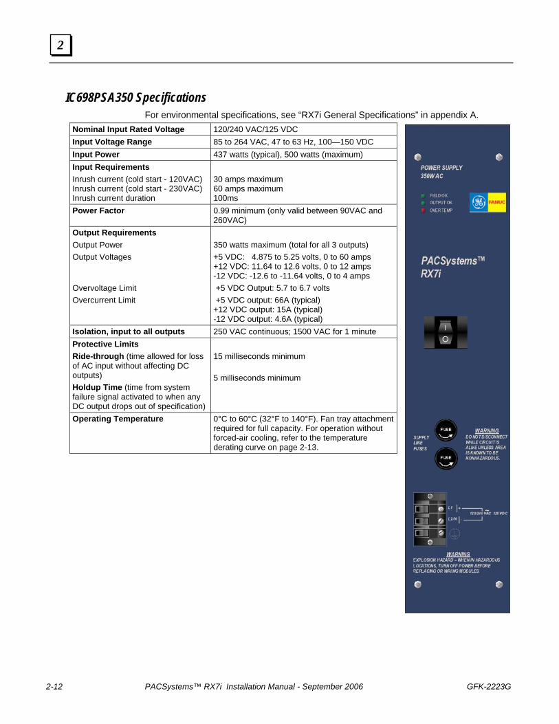
IC698PSA350 Specifications For environmental specifications, see “RX7i General Specifications” in appendix A.
Nominal Input Rated Voltage 120/240 VAC/125 VDC Input Voltage Range 85 to 264 VAC, 47 to 63 Hz, 100—150 VDC Input Power 437 watts (typical), 500 watts (maximum) Input Requirements Inrush current (cold start - 120VAC) Inrush current (cold start - 230VAC) Inrush current duration
30 amps maximum 60 amps maximum 100ms
Power Factor 0.99 minimum (only valid between 90VAC and 260VAC)
Output Requirements Output Power Output Voltages Overvoltage Limit Overcurrent Limit
350 watts maximum (total for all 3 outputs) +5 VDC: 4.875 to 5.25 volts, 0 to 60 amps +12 VDC: 11.64 to 12.6 volts, 0 to 12 amps -12 VDC: -12.6 to -11.64 volts, 0 to 4 amps +5 VDC Output: 5.7 to 6.7 volts +5 VDC output: 66A (typical) +12 VDC output: 15A (typical) -12 VDC output: 4.6A (typical)
Isolation, input to all outputs 250 VAC continuous; 1500 VAC for 1 minute Protective Limits Ride-through (time allowed for loss of AC input without affecting DC outputs) Holdup Time (time from system failure signal activated to when any DC output drops out of specification)
15 milliseconds minimum 5 milliseconds minimum
Operating Temperature 0°C to 60°C (32°F to 140°F). Fan tray attachment required for full capacity. For operation without forced-air cooling, refer to the temperature derating curve on page 2-13.
GFK-2223G Chapter 2 Hardware Description 2-13
2
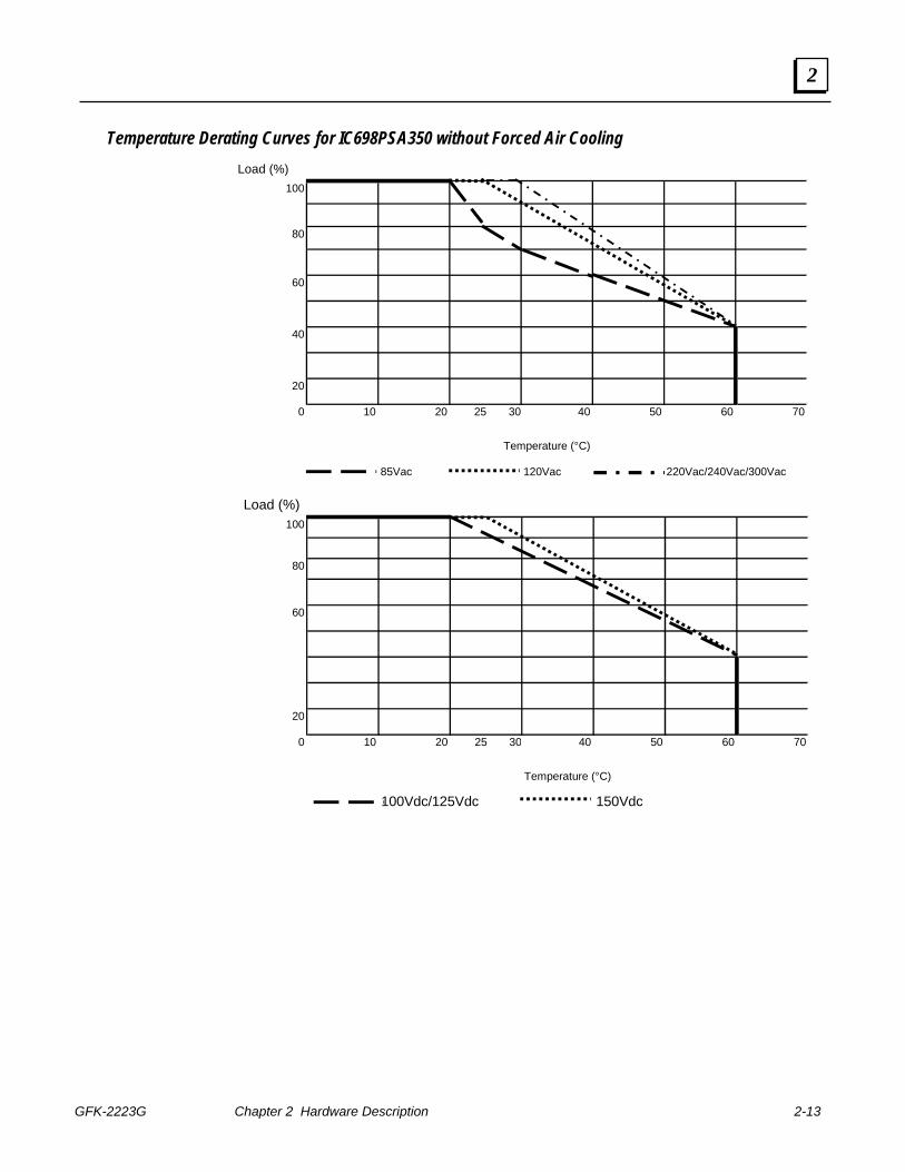
Temperature Derating Curves for IC698PSA350 without Forced Air Cooling Load (%)
100
80
60
40
20
0 10 20 25 30 40 50 60 70
Temperature (°C)
85Vac 120Vac 220Vac/240Vac/300Vac
Load (%)100
80
60
20
0 10 20 25 30 40 50 60 70
Temperature (°C)
100Vdc/125Vdc 150Vdc
2-14 PACSystems™ RX7i Installation Manual - September 2006 GFK-2223G
2
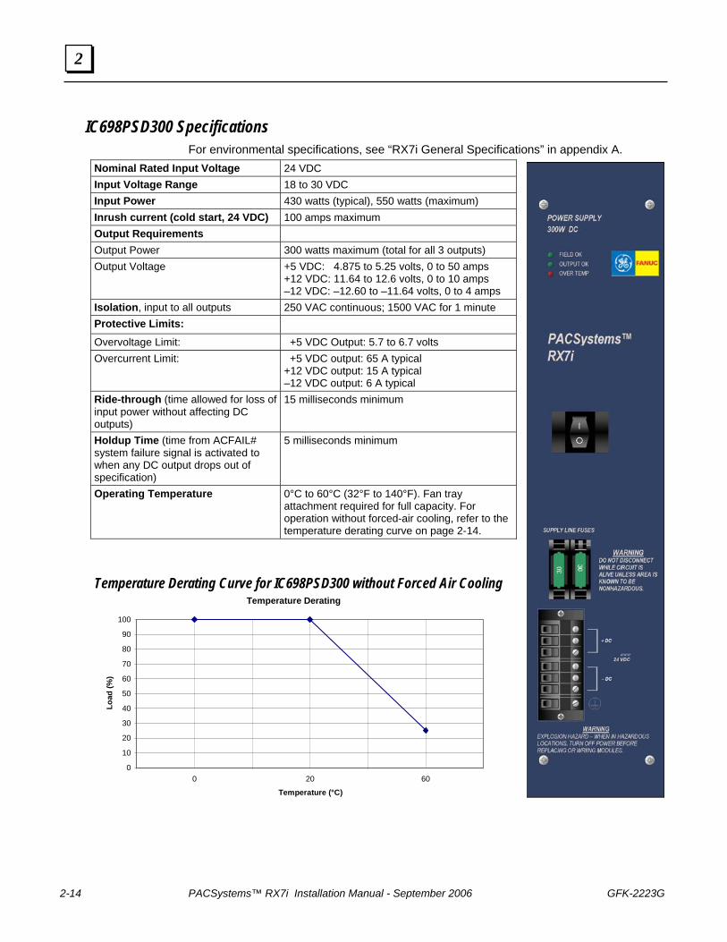
IC698PSD300 Specifications For environmental specifications, see “RX7i General Specifications” in appendix A.
Nominal Rated Input Voltage 24 VDC Input Voltage Range 18 to 30 VDC Input Power 430 watts (typical), 550 watts (maximum) Inrush current (cold start, 24 VDC) 100 amps maximum Output Requirements Output Power 300 watts maximum (total for all 3 outputs) Output Voltage +5 VDC: 4.875 to 5.25 volts, 0 to 50 amps
+12 VDC: 11.64 to 12.6 volts, 0 to 10 amps –12 VDC: –12.60 to –11.64 volts, 0 to 4 amps
Isolation, input to all outputs 250 VAC continuous; 1500 VAC for 1 minute Protective Limits: Overvoltage Limit: +5 VDC Output: 5.7 to 6.7 volts Overcurrent Limit: +5 VDC output: 65 A typical
+12 VDC output: 15 A typical –12 VDC output: 6 A typical
Ride-through (time allowed for loss of input power without affecting DC outputs)
15 milliseconds minimum
Holdup Time (time from ACFAIL# system failure signal is activated to when any DC output drops out of specification)
5 milliseconds minimum
Operating Temperature 0°C to 60°C (32°F to 140°F). Fan tray attachment required for full capacity. For operation without forced-air cooling, refer to the temperature derating curve on page 2-14.
Temperature Derating Curve for IC698PSD300 without Forced Air Cooling Temperature Derating
0 10 20 30 40 50 60 70 80 90
100
0 20 60
Temperature (°C)
Load
(%)
GFK-2223G Chapter 2 Hardware Description 2-15
2
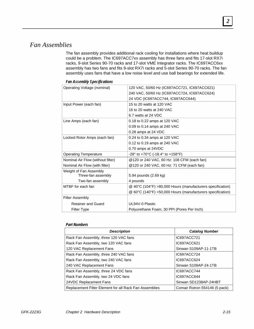
Fan Assemblies The fan assembly provides additional rack cooling for installations where heat buildup could be a problem. The IC697ACC7xx assembly has three fans and fits 17-slot RX7i racks, 9-slot Series 90-70 racks and 17-slot VME Integrator racks. The IC697ACC6xx assembly has two fans and fits 9-slot RX7i racks and 5-slot Series 90-70 racks. The fan assembly uses fans that have a low noise level and use ball bearings for extended life.
Fan Assembly Specifications Operating Voltage (nominal) 120 VAC, 50/60 Hz (IC697ACC721, IC697ACC621) 240 VAC, 50/60 Hz (IC697ACC724, IC697ACC624) 24 VDC (IC697ACC744, IC697ACC644) Input Power (each fan) 15 to 20 watts at 120 VAC 16 to 20 watts at 240 VAC 6.7 watts at 24 VDC Line Amps (each fan) 0.18 to 0.22 amps at 120 VAC 0.09 to 0.14 amps at 240 VAC 0.28 amps at 24 VDC Locked Rotor Amps (each fan) 0.24 to 0.34 amps at 120 VAC 0.12 to 0.19 amps at 240 VAC 0.70 amps at 24VDC Operating Temperature -28° to +70°C (-18.4° to +158°F) Nominal Air Flow (without filter) @120 or 240 VAC, 60 Hz: 108 CFM (each fan) Nominal Air Flow (with filter) @120 or 240 VAC, 60 Hz: 71 CFM (each fan) Weight of Fan Assembly Three-fan assembly Two-fan assembly
5.94 pounds (2.69 kg) 4 pounds
MTBF for each fan @ 40°C (104°F) >80,000 Hours (manufacturers specification) @ 60°C (140°F) >50,000 Hours (manufacturers specification) Filter Assembly Retainer and Guard UL94V-0 Plastic Filter Type Polyurethane Foam, 30 PPI (Pores Per Inch)
Part Numbers Description Catalog Number
Rack Fan Assembly, three 120 VAC fans IC697ACC721 Rack Fan Assembly, two 120 VAC fans IC697ACC621 120 VAC Replacement Fans Sinwan S109AP-11-1TB Rack Fan Assembly, three 240 VAC fans IC697ACC724 Rack Fan Assembly, two 240 VAC fans IC697ACC624 240 VAC Replacement Fans Sinwan S109AP-24-1TB Rack Fan Assembly, three 24 VDC fans IC697ACC744 Rack Fan Assembly, two 24 VDC fans IC697ACC644 24VDC Replacement Fans Sinwan SD1238AP-24HBT Replacement Filter Element for all Rack Fan Assemblies Comair Rotron 554146 (5 pack)
2-16 PACSystems™ RX7i Installation Manual - September 2006 GFK-2223G
2
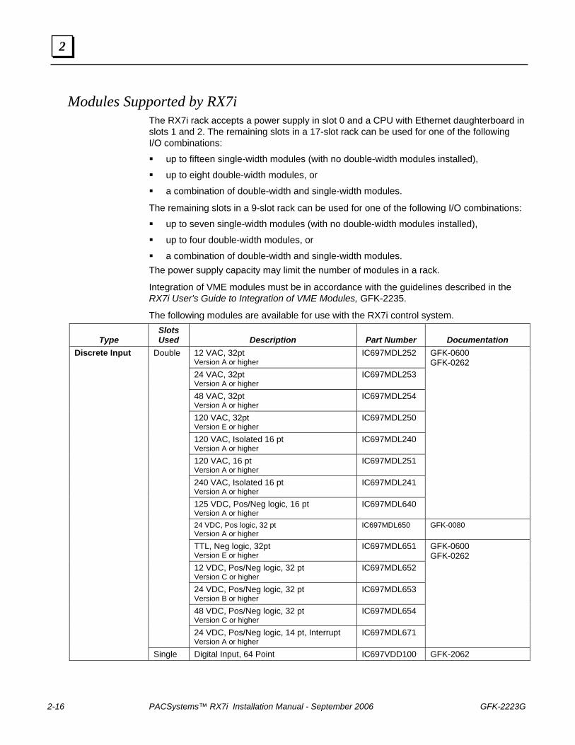
Modules Supported by RX7i The RX7i rack accepts a power supply in slot 0 and a CPU with Ethernet daughterboard in slots 1 and 2. The remaining slots in a 17-slot rack can be used for one of the following I/O combinations:
up to fifteen single-width modules (with no double-width modules installed),
up to eight double-width modules, or
a combination of double-width and single-width modules.
The remaining slots in a 9-slot rack can be used for one of the following I/O combinations:
up to seven single-width modules (with no double-width modules installed),
up to four double-width modules, or
a combination of double-width and single-width modules. The power supply capacity may limit the number of modules in a rack.
Integration of VME modules must be in accordance with the guidelines described in the RX7i User's Guide to Integration of VME Modules, GFK-2235.
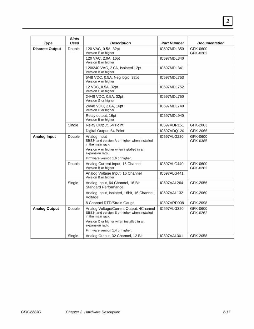
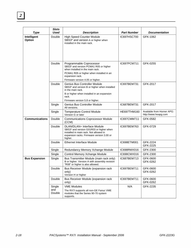
The following modules are available for use with the RX7i control system.
Type Slots Used
Description
Part Number
Documentation
12 VAC, 32pt Version A or higher
IC697MDL252
24 VAC, 32pt Version A or higher
IC697MDL253
48 VAC, 32pt Version A or higher
IC697MDL254
120 VAC, 32pt Version E or higher
IC697MDL250
120 VAC, Isolated 16 pt Version A or higher
IC697MDL240
120 VAC, 16 pt Version A or higher
IC697MDL251
240 VAC, Isolated 16 pt Version A or higher
IC697MDL241
125 VDC, Pos/Neg logic, 16 pt Version A or higher
IC697MDL640
GFK-0600 GFK-0262
24 VDC, Pos logic, 32 pt Version A or higher
IC697MDL650 GFK-0080
TTL, Neg logic, 32pt Version E or higher
IC697MDL651
12 VDC, Pos/Neg logic, 32 pt Version C or higher
IC697MDL652
24 VDC, Pos/Neg logic, 32 pt Version B or higher
IC697MDL653
48 VDC, Pos/Neg logic, 32 pt Version C or higher
IC697MDL654
Double
24 VDC, Pos/Neg logic, 14 pt, Interrupt Version A or higher
IC697MDL671
GFK-0600 GFK-0262
Discrete Input
Single Digital Input, 64 Point IC697VDD100 GFK-2062
GFK-2223G Chapter 2 Hardware Description 2-17
2
Type
Slots Used
Description
Part Number
Documentation
120 VAC, 0.5A, 32pt Version E or higher
IC697MDL350
120 VAC, 2.0A, 16pt Version E or higher
IC697MDL340
120/240 VAC, 2.0A, Isolated 12pt Version B or higher
IC697MDL341
5/48 VDC, 0.5A, Neg logic, 32pt Version A or higher
IC697MDL753
12 VDC, 0.5A, 32pt Version E or higher
IC697MDL752
24/48 VDC, 0.5A, 32pt Version G or higher
IC697MDL750
24/48 VDC, 2.0A, 16pt Version D or higher
IC697MDL740
Double
Relay output, 16pt Version B or higher
IC697MDL940
GFK-0600 GFK-0262
Relay Output, 64 Point IC697VDR151 GFK-2063
Discrete Output
Single Digital Output, 64 Point IC697VDQ120 GFK-2066
Double Analog Input SBS3* and version A or higher when installed in the main rack. Version A or higher when installed in an expansion rack. Firmware version 1.6 or higher.
IC697ALG230 GFK-0600 GFK-0385
Analog Current Input, 16 Channel Version B or higher
IC697ALG440 Double
Analog Voltage Input, 16 Channel Version B or higher
IC697ALG441
GFK-0600 GFK-0262
Analog Input, 64 Channel, 16 Bit Standard Performance
IC697VAL264 GFK-2056
Analog Input, Isolated, 16bit, 16 Channel, Voltage
IC697VAL132 GFK-2060
Analog Input
Single
8 Channel RTD/Strain Gauge IC697VRD008 GFK-2098 Double Analog Voltage/Current Output, 4Channel
SBS3* and version E or higher when installed in the main rack. Version C or higher when installed in an expansion rack. Firmware version 1.4 or higher.
IC697ALG320 GFK-0600 GFK-0262
Analog Output
Single Analog Output, 32 Channel, 12 Bit IC697VAL301 GFK-2058
2-18 PACSystems™ RX7i Installation Manual - September 2006 GFK-2223G
2
Type
Slots Used
Description
Part Number
Documentation
Double High Speed Counter Module SBS3* and version A or higher when installed in the main rack.
IC697HSC700 GFK-1062
Double Programmable Coprocessor SBS3* and version PCMA1 R05 or higher when installed in the main rack. PCMA1 R05 or higher when installed in an expansion rack. Firmware version 4.05 or higher.
IC697PCM711 GFK-0255
Double Genius Bus Controller Module SBS3* and version B or higher when installed in the main rack. B or higher when installed in an expansion rack. Firmware version 5.8 or higher.
IC697BEM731 GFK-2017
Single Genius Bus Controller Module All versions.
IC687BEM731 GFK-2017
Intelligent Option
Single Temperature Control Module Version G or later
HE697THM160 Available from Horner APG: http://www.heapg.com
Double Communications Coprocessor Module (CCM)
IC697CMM711 GFK-0582
Double DLAN/DLAN+ Interface Module SBS3* and version G01R03 or higher when installed in main rack. Not allowed in expansion racks. Firmware version 3.00 or higher.
IC697BEM763 GFK-0729
Double Ethernet Interface Module IC698ETM001 GFK-2224 GFK-2225
Single Redundancy Memory Xchange Module IC698RMX016 GFK-2300
Communications
Single Control Memory Xchange Module IC698CMX016 GFK-2300 Single Bus Transmitter Module (main rack only)
B or higher. Version A with assembly revision "R08" or higher is also allowed.
IC687BEM713 GFK-0600 GFK-0262
Double Bus Receiver Module (expansion rack only) Version H or higher
IC697BEM711 GFK-0600 GFK-0262
Double Bus Receiver Module (expansion rack only)
IC697BEM711 GFK-0600 GFK-0262
Bus Expansion
Single and Double
VME Modules The RX7i supports all non-GE Fanuc VME modules that the Series 90-70 system supports.
N/A GFK-2235
GFK-2223G Chapter 2 Hardware Description 2-19
2
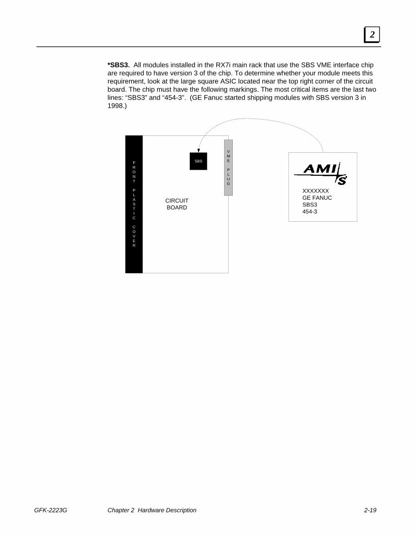
*SBS3. All modules installed in the RX7i main rack that use the SBS VME interface chip are required to have version 3 of the chip. To determine whether your module meets this requirement, look at the large square ASIC located near the top right corner of the circuit board. The chip must have the following markings. The most critical items are the last two lines: “SBS3” and “454-3”. (GE Fanuc started shipping modules with SBS version 3 in 1998.)
CIRCUITBOARD
VME
PLUG
SBSFRONT
PLASTIC
COVER
XXXXXXXGE FANUCSBS3454-3
2-20 PACSystems™ RX7i Installation Manual - September 2006 GFK-2223G
2
Series 90-70 Expansion Racks The RX7i control system supports up to seven expansion racks. The following Series 90-70 racks can be used as expansion racks.
IC697CHS750 – Five slot, rear (panel) mount
IC697CHS782 – VME Integrator rear (panel) mount
IC697CHS783 – VME Integrator front (rack) mount
IC697CHS790 – Nine slot rear (panel) mount
IC697CHS791 – Nine slot front (rack) mount
When used as expansion racks in an RX7i rack system, these Series 90-70 racks support the same Series 90-70 modules and Genius devices that RX7i main racks support. For details, see the list of modules on page 2-16.
RX7i main racks (page 2-4) cannot be used as expansion racks.
Note: Due to Series 90-70 hardware limitations, expansion racks on an RX7i rack system do not support RX7i power supplies, or the RX7i Ethernet module.
The following single width I/O modules are fully integrated when installed in the main rack. When installed in an expansion rack the module must be configured as a generic VME module.
IC697VDD100, Digital Input, 64 Point IC697VDR151, Relay Output, 64 Point IC697VDQ120, Digital Output, 64 Point IC697VAL264, Analog Input, 64 Channel, 16bit Standard Performance IC697VAL132, Analog Input, Isolated, 16bit, 16 Channel, Voltage IC697VRD008, 8 Channel RTD/Strain Gauge IC697VAL301, Analog Output, 32 Channel, 12bit
For expansion rack specifications, refer to the Series 90-70 Programmable Controller Datasheets Manual, GFK-0600. For installation instructions, refer to the Series 90-70 Programmable Controller Installation Manual, GFK-0262.
The Bus Transmitter Module BTM allows expansion from the CPU rack to a maximum of seven Series 90-70 PLC expansion racks with up to 50 feet (15 meters) total of interconnecting cable. The BTM has two connectors however the RX7i only supports the one used for a daisy-chained arrangement through Bus Receiver Modules to expansion racks.
A Bus Receiver Module (BRM) must be used in slot 1 of every Series 90-70 expansion rack. The BRM has two connectors: one for attachment to the upstream or CPU rack, and the other for a daisy-chained arrangement to additional expansion racks.
An expansion rack containing a High Speed Counter module (IC697HSC700) requires Bus Receiver Module (IC697BEM711) version 13 or later.
Warning Do not attempt to disconnect or connect an expansion rack cable while the system is under power. This could cause unexpected system operation or damage to equipment.
GFK-2223G Chapter 2 Hardware Description 2-21
2
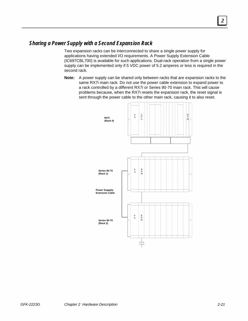
Sharing a Power Supply with a Second Expansion Rack Two expansion racks can be interconnected to share a single power supply for applications having extended I/O requirements. A Power Supply Extension Cable (IC697CBL700) is available for such applications. Dual-rack operation from a single power supply can be implemented only if 5 VDC power of 5.2 amperes or less is required in the second rack.
Note: A power supply can be shared only between racks that are expansion racks to the same RX7i main rack. Do not use the power cable extension to expand power to a rack controlled by a different RX7i or Series 90-70 main rack. This will cause problems because, when the RX7i resets the expansion rack, the reset signal is sent through the power cable to the other main rack, causing it to also reset.
RX7i(Rack 0)
PS
CPU
B T M
PS
BRM
PS
BRM
Series 90-70(Rack 1)
Series 90-70(Rack 2)
Power SuppplyExtension Cable
GFK-2223G 3-1
Installation Instructions
This chapter describes the procedures for installing an RX7i control system and preparing the system for use. Included are instructions for unpacking, inspecting, installing the rack in a rack or panel, installing modules, and connecting cables. ■ Pre-Installation Check ■ System Layout Guidelines ■ Enclosures ■ System Wiring ■ System Grounding ■ System Installation
- RX7i Rack
- Fan Assembly
- Power Supply
- CPU
- Ethernet Interface Module
- I/O, Communications, and Intelligent Option Modules
Notes:
■ RX7i racks are considered open equipment and therefore must be installed in a protective enclosure rated IP54 or greater.
■ For installations in the European Union, an RX7i rack system with Series 90-70 products requires a metal enclosure and conduit. Requirements for installing Series 90-70 products in an RX7i rack are described in Appendix A.
■ RX7i systems that include one or more Memory Xchange modules (IC698RMX016 and IC698CMX016) must be installed in a metal enclosure or equivalent to meet radiated emission standards. Requirements for installing Memory Xchange modules in an RX7i rack are described in Appendix A.
■ For expansion rack installation instructions, refer to the Series 90-70 Programmable Controller Installation Manual, GFK-0262.
Warning
Do not attempt to disconnect or connect an expansion rack cable while the system is under power. This could cause unexpected system operation or damage to equipment.
3 Chapter

3-2 PACSystems™ RX7i Installation Manual - September 2006 GFK-2223G
3
Pre-Installation Check Upon receiving your RX7i system, carefully inspect all shipping containers for damage during shipping. If any part of the system is damaged, notify the carrier immediately. The damaged shipping container should be saved as evidence for inspection by the carrier. As the consignee, it is your responsibility to register a claim with the carrier for damage incurred during shipment. However, GE Fanuc will fully cooperate with you, should such action be necessary.
After unpacking the RX7i rack and other equipment, record all serial numbers. Serial numbers are required if you should need to contact Customer Care during the warranty period of the equipment. All shipping containers and all packing material should be saved should it be necessary to transport or ship any part of the system.
Verify that all components of the system have been received and that they agree with your order. If the system received does not agree with your order, contact Customer Care. If you need technical help, technical support can be reached as described below.
Technical Support for Control System Components Described in this Manual
If you purchased this product through a GE Fanuc Authorized Channel Partner, please contact them directly. Otherwise, contact GE Fanuc Customer Care at:
Customer Care Hotline Toll free: 800-GE FANUC (800-433-2682) International Americas direct dial: 780-401-7700 Other International contact info: www.gefanuc.com Technical Support Email: [email protected] Customer Care Email: [email protected] Web Support www.gefanuc.com
GFK-2223G Chapter 3 Installation Instructions 3-3
3
System Layout Guidelines A good layout helps minimize the chance of electrical shock to personnel working on the system. It lets maintenance technicians easily access the unit to make measurements, load software, check indicator lights, remove and replace modules, etc. It also makes it easier to trace wiring and locate components while troubleshooting. In addition, proper system layout promotes good heat dissipation and helps eliminate electrical noise from the system. Excess heat and noise are two major causes of electronic component failure.
Locate RX7i equipment away from other components that generate a lot of heat, such as transformers, power supplies, or power resistors.
Locate RX7i equipment away from components that generate electrical noise such as relays and contacts.
Locate RX7i equipment away from high-voltage components and wiring, such as circuit breakers and fusible disconnects, transformers, motor wiring, etc.
Locate equipment at a convenient level that allows technicians reasonable access for maintaining the system.
Route sensitive input wires away from electrically noisy wires such as discrete output and AC wiring. Grouping I/O modules to separate output modules from sensitive input modules can facilitate this.
Allow a 6" minimum clearance on all four sides of each RX7i rack for ventilation/cooling.
If your installation includes a fan assembly, a minimum clearance of 23cm (9 inches) between RX7i racks is recommended so that an individual fan can be removed and replaced.
Use shielded cable connections with the shield grounded at one end (at source) for all analog modules, including RTD and Thermocouple modules.
3-4 PACSystems™ RX7i Installation Manual - September 2006 GFK-2223G
3
Enclosures The RX7i system and its components are considered open equipment (having live electrical parts that may be accessible to users) and must be installed in a protective enclosure or incorporated into other assemblies manufactured to provide safety. As a minimum, the enclosure or assemblies shall provide a degree of protection against solid objects 12mm and larger (e.g. fingers). This equates to a NEMA/UL Type 1 enclosure or an IP20 rating (IEC60529).
When an RX7i system is installed in an area designated as Class 1 Zone 2 in Europe, compliance with the ATEX Directive requires an enclosure with a higher degree of protection. Refer to “ATEX Class 1 Zone 2 Hazardous Location Requirements” located in Appendix A for specifications.
The enclosure must be able to adequately dissipate the heat generated by all of the components mounted inside so that no components overheat. Heat dissipation is also a factor in determining the need for enclosure cooling options such as fans and air conditioning. A minimum space of at least 152.4smm (6 inches) is required on all sides of the RX7i rack for cooling. Additional space may be required, depending on the amount of heat generated by the equipment during operation. Appendix B explains how to calculate heat dissipation for RX7i modules and field devices in an enclosure.
GFK-2223G Chapter 3 Installation Instructions 3-5
3
System Wiring
General Wiring Information To avoid possible misrouting of wiring to I/O modules, the following is recommended:
• Label all wires to and from I/O devices. Record circuit identification numbers or other pertinent data on the inserts that go in the module’s faceplate door.
• Wires should be dressed so that each field I/O connector is fixed relative to its respective module.
Warning
In addition to the information provided here, always follow all wiring and safety codes that apply to your area or your type of equipment. For example, in the United States, most areas have adopted the National Electrical Code standard and specify that all wiring conform to its requirements. In other countries, different codes will apply. For maximum safety to personnel and property you must follow these codes. Failure to do so can lead to personal injury or death, property damage or destruction, or both.
Color Coding Wires These color codes are commonly used in industrial equipment manufactured in the United States. Where they differ from codes that apply to your area or your type of equipment, follow your applicable codes instead. Besides satisfying code requirements, wire color coding makes testing and troubleshooting safer, faster, and easier.
■ Green or green with stripe- Ground
■ Black - Primary AC
■ Red - Secondary AC
■ Blue - DC
■ White - Common or neutral
■ Yellow - Secondary power source not controlled by the main disconnect. Alerts maintenance personnel that there may be power present (from an external source) even if the equipment is disconnected from its main power source.
3-6 PACSystems™ RX7i Installation Manual - September 2006 GFK-2223G
3
Wire Routing To reduce noise-coupling among PLC wires, electrically-noisy wiring such as AC power wiring and discrete output module wiring should be separated from low-level signal wiring such as DC and analog input module wiring or communications cables. Where practical, group separately the following types of wiring:
■ AC power wiring. This includes the AC input to the PLC power supply, as well as other AC devices in the control cabinet.
■ Analog Input or Output Module wiring. This should be shielded to further reduce noise coupling.
■ Discrete Output Module wiring. These often switch inductive loads that produce noise spikes when switched off.
■ DC Input Module wiring. Although suppressed internally, these low-level inputs should be further protected against noise coupling by observing these wiring practices.
■ Communications Cables. Wiring such as Genius bus or serial cables should be kept away from noise-producing wiring.
Where AC or output wiring bundles must pass near noise-sensitive signal wiring bundles, avoid running them beside each other. If they have to cross, route them a right angle to minimize coupling between them.
Grouping Modules to Keep Wires Segregated
If practical, grouping similar modules together in the racks can help keep wiring segregated. For example, one rack could contain only AC modules, and another only DC modules, with further grouping by input and output types.
GFK-2223G Chapter 3 Installation Instructions 3-7
3
System Grounding All components of a control system and the devices it is controlling must be properly grounded. This is particularly important for the reasons listed below.
■ A low resistance path from all parts of a system to earth minimizes exposure to shock in the event of short circuits or equipment malfunction.
■ A low inductance path from all parts of a system to earth minimizes emissions and increases immunity to electrical interferences. A braided ground strap with a maximum 10:1 length-to-width ratio is recommended for these purposes.
■ The RX7i system requires proper grounding for correct operation.
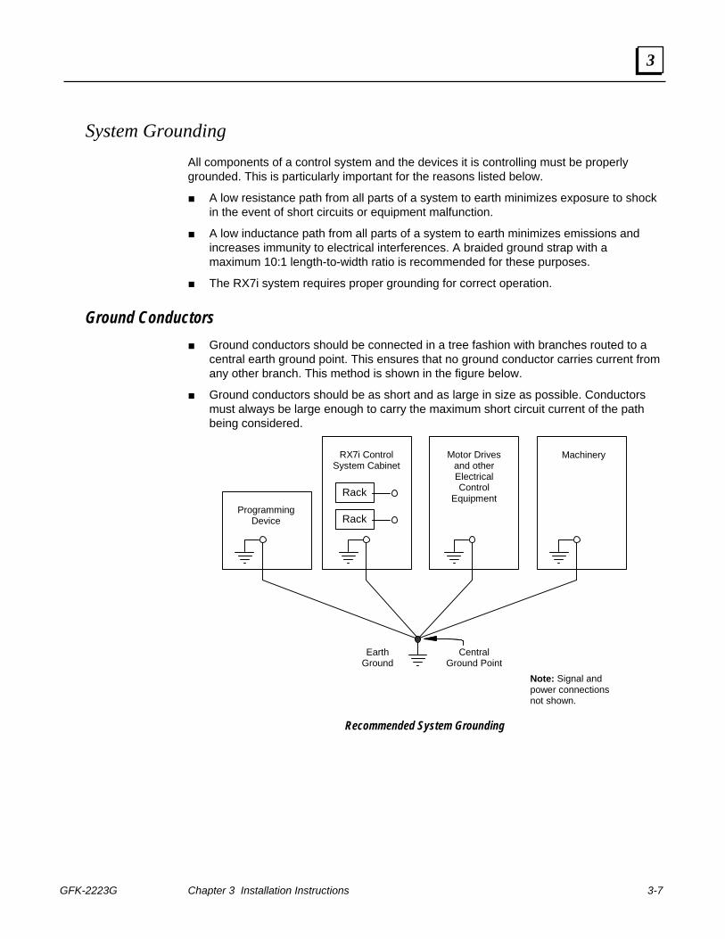
Ground Conductors ■ Ground conductors should be connected in a tree fashion with branches routed to a
central earth ground point. This ensures that no ground conductor carries current from any other branch. This method is shown in the figure below.
■ Ground conductors should be as short and as large in size as possible. Conductors must always be large enough to carry the maximum short circuit current of the path being considered.
ProgrammingDevice
RX7i ControlSystem Cabinet
Motor Drivesand otherElectricalControl
Equipment
Machinery
Rack
Rack
EarthGround
CentralGround Point
Note: Signal andpower connectionsnot shown.
Recommended System Grounding
3-8 PACSystems™ RX7i Installation Manual - September 2006 GFK-2223G
3
Equipment Grounding Equipment grounding recommendations and procedures are listed below. These grounding procedures must be properly followed for safe operation of your RX7i control system.
Safety and Reference Ground ■ The ground stud on the side of the rack must be connected to earth ground using
minimum AWG #12 (3.3 mm2) wire, with the shortest possible length, and a ring terminal. Use of a nut and star washer for each wire on the GND stud is recommended to ensure adequate grounding. Refer to applicable electrical safety codes.
Warning
If the ground stud on the rack is not connected, the rack is not grounded. The rack must be grounded to minimize electrical shock hazard, which may result in severe personal injury or fatality and to maintain certification to standards.
■ To assure adequate module to rack grounding, all RX7i modules must have their faceplate screws tightened to ensure a good electrical connection to the rack.
■ All racks that are grouped together in an RX7i control system must have a common ground connection. This is especially important for racks that are not mounted in the same control cabinet.
Shield Ground The top and bottom rails of the rack are used for module shield grounding.
RX7i modules must have their faceplate screws tightened to ensure shield grounding. The CPU and Ethernet Interface modules’ serial port shields are tied directly to the rack ground. To prevent DC loop currents caused by different ground potentials, the shield may require external capacitive coupling between the cable shield and the rack ground at one end of the cable.
The RX7i Ethernet network ports are tied directly to rack (or frame) ground. When using shielded Ethernet cables, one end of the cable needs to be capacitively coupled to its shield or local ground to prevent DC ground current loops from running through the cable shield between grounds at different potentials.
Some Series 90-70 modules have a ground clip that contacts the conductive bottom rail when the module is fully inserted. Shield connections in the user connector are routed to this ground clip through conductors on the module.
GFK-2223G Chapter 3 Installation Instructions 3-9
3
System Installation
RX7i Rack
Warning
RX7i racks are considered open equipment, and therefore must be installed in a protective enclosure with a rating of IP54 or greater.
Mounting requirements (front or rear mount) must be determined according to the application. Mounting flanges are an integral part of rack side panels.
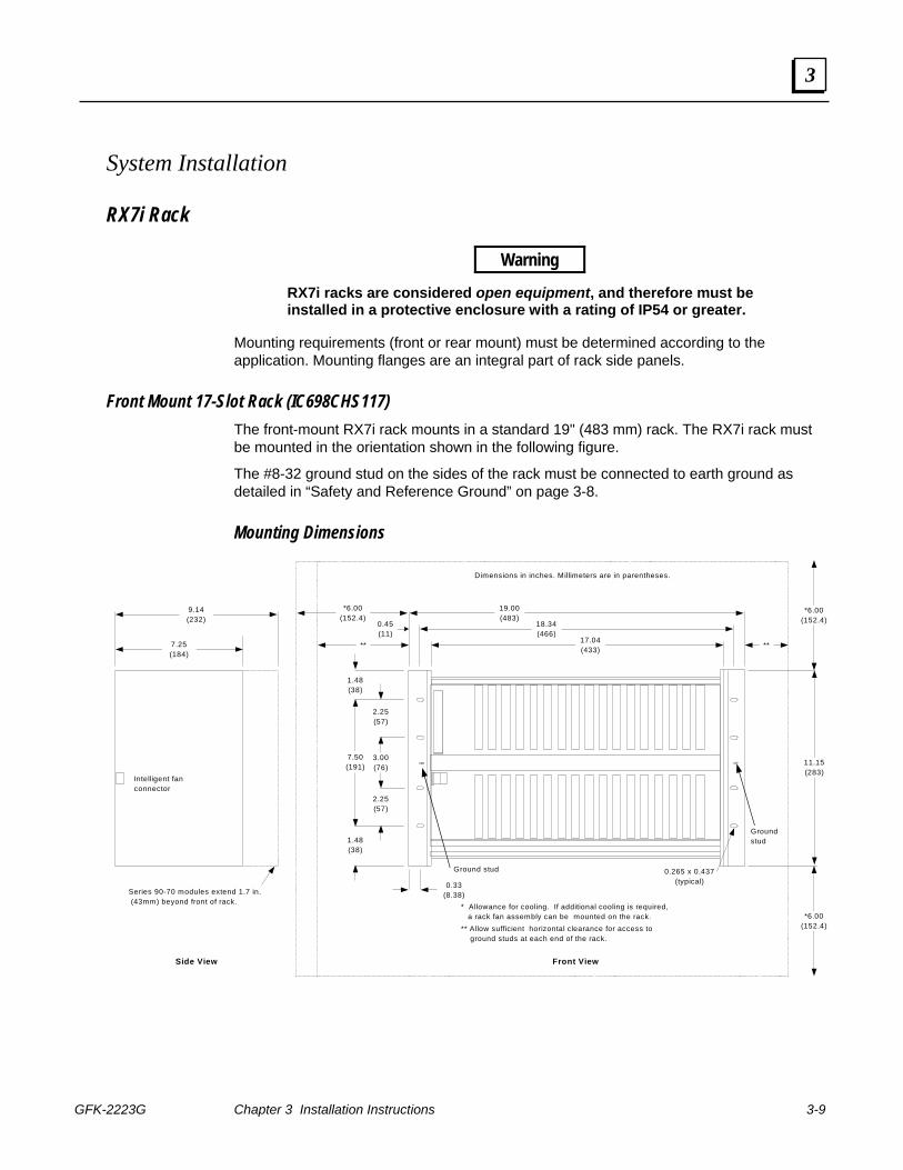
Front Mount 17-Slot Rack (IC698CHS117) The front-mount RX7i rack mounts in a standard 19" (483 mm) rack. The RX7i rack must be mounted in the orientation shown in the following figure.
The #8-32 ground stud on the sides of the rack must be connected to earth ground as detailed in “Safety and Reference Ground” on page 3-8.
Mounting Dimensions
19.00(483)
0.45(11)
18.34(466)
17.04(433)
1.48(38)
1.48(38)
0.33(8.38)
7.50(191)
2.25(57)
3.00(76)
2.25(57)
0.265 x 0.437(typical)
Dimensions in inches. Millimeters are in parentheses.
* Allowance for cooling. If additional cooling is required, a rack fan assembly can be mounted on the rack.** Allow sufficient horizontal clearance for access to ground studs at each end of the rack.
** **
*6.00(152.4)
11.15(283)
*6.00(152.4)
*6.00(152.4)
Front View
Series 90-70 modules extend 1.7 in. (43mm) beyond front of rack.
Intelligent fanconnector
9.14(232)
7.25(184)
Side View
Ground stud
Groundstud
3-10 PACSystems™ RX7i Installation Manual - September 2006 GFK-2223G
3
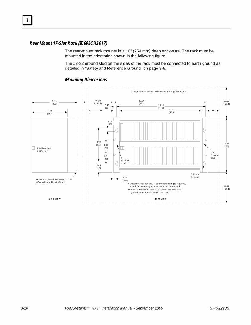
Rear Mount 17-Slot Rack (IC698CHS017) The rear-mount rack mounts in a 10" (254 mm) deep enclosure. The rack must be mounted in the orientation shown in the following figure.
The #8-32 ground stud on the sides of the rack must be connected to earth ground as detailed in “Safety and Reference Ground” on page 3-8.
Mounting Dimensions
19.00(483)
0.45(11)
18.11(460)
17.04(433)
2.24(57)
0.34(8.64)
6.75(172) 3.00
(76)
1.5(38)
0.25 dia(typical)
Dimensions in inches. Millimeters are in parentheses.
* Allowance for cooling. If additional cooling is required, a rack fan assembly can be mounted on the rack.** Allow sufficient horizontal clearance for access to ground studs at each end of the rack.
** **
*6.00(152.4)
11.15(283)
*6.00(152.4)
*6.00(152.4)
Front View
Series 90-70 modules extend 1.7 in.(43mm) beyond front of rack.
Intelligent fanconnector
9.14(232)
7.25(184)
Side View
Groundstud
Groundstud
0.75(19)
GFK-2223G Chapter 3 Installation Instructions 3-11
3
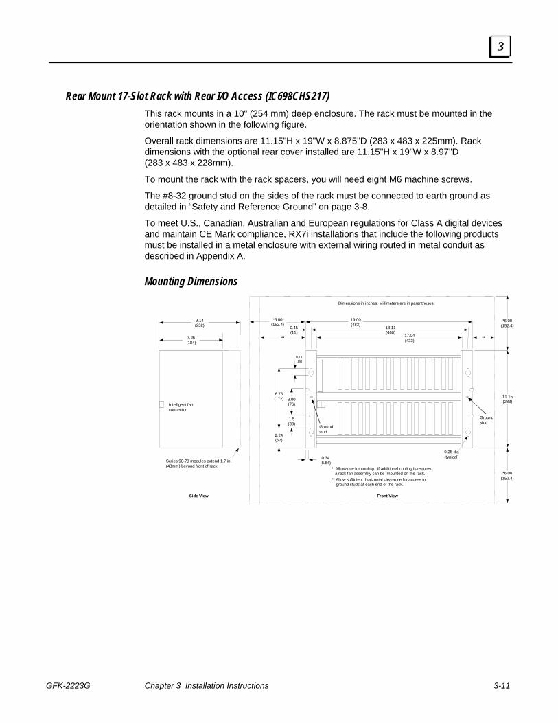
Rear Mount 17-Slot Rack with Rear I/O Access (IC698CHS217) This rack mounts in a 10" (254 mm) deep enclosure. The rack must be mounted in the orientation shown in the following figure.
Overall rack dimensions are 11.15"H x 19"W x 8.875"D (283 x 483 x 225mm). Rack dimensions with the optional rear cover installed are 11.15"H x 19"W x 8.97"D (283 x 483 x 228mm).
To mount the rack with the rack spacers, you will need eight M6 machine screws.
The #8-32 ground stud on the sides of the rack must be connected to earth ground as detailed in “Safety and Reference Ground” on page 3-8.
To meet U.S., Canadian, Australian and European regulations for Class A digital devices and maintain CE Mark compliance, RX7i installations that include the following products must be installed in a metal enclosure with external wiring routed in metal conduit as described in Appendix A.
Mounting Dimensions
19.00(483)
0.45(11)
18.11 (460)
17.04 (433)
2.24(57)
0.34(8.64)
6.75(172) 3.00
(76)
1.5(38)
0.25 dia(typical)
Dimensions in inches. Millimeters are in parentheses.
* Allowance for cooling. If additional cooling is required, a rack fan assembly can be mounted on the rack. ** Allow sufficient horizontal clearance for access to ground studs at each end of the rack.
** **
*6.00(152.4)
11.15(283)
*6.00(152.4)
*6.00(152.4)
Front View
Series 90-70 modules extend 1.7 in.(43mm) beyond front of rack.
Intelligent fan connector
9.14 (232)
7.25 (184)
Side View
Groundstud
Groundstud
0.75(19)
3-12 PACSystems™ RX7i Installation Manual - September 2006 GFK-2223G
3
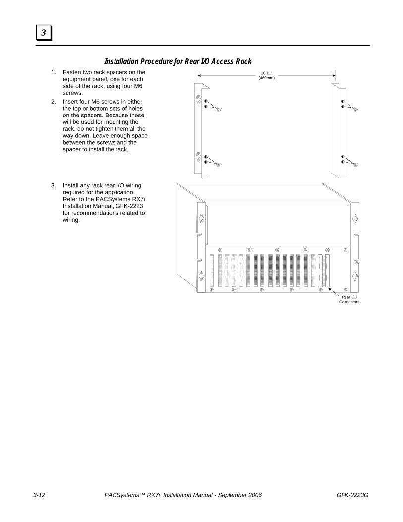
Installation Procedure for Rear I/O Access Rack 1. Fasten two rack spacers on the
equipment panel, one for each side of the rack, using four M6 screws.
2. Insert four M6 screws in either the top or bottom sets of holes on the spacers. Because these will be used for mounting the rack, do not tighten them all the way down. Leave enough space between the screws and the spacer to install the rack.
18.11"(460mm)
3. Install any rack rear I/O wiring
required for the application. Refer to the PACSystems RX7i Installation Manual, GFK-2223 for recommendations related to wiring.
Rear I/OConnectors
GFK-2223G Chapter 3 Installation Instructions 3-13
3
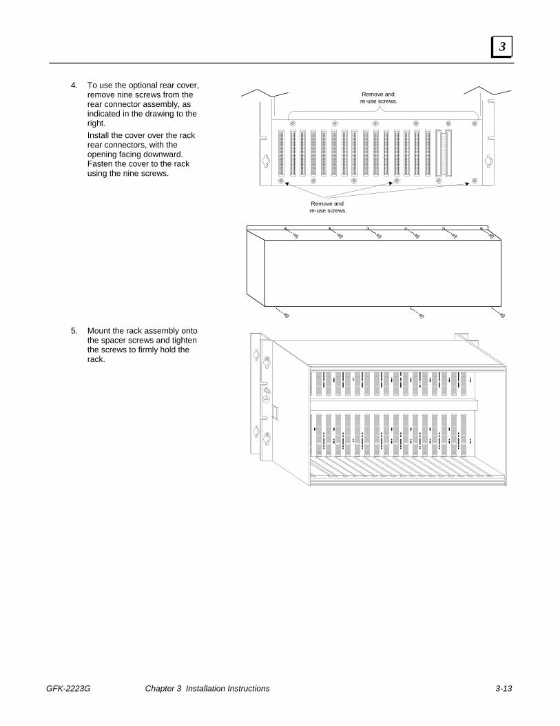
4. To use the optional rear cover, remove nine screws from the rear connector assembly, as indicated in the drawing to the right. Install the cover over the rack rear connectors, with the opening facing downward. Fasten the cover to the rack using the nine screws.
Remove and re-use screws.
Remove and re-use screws.
5. Mount the rack assembly onto
the spacer screws and tighten the screws to firmly hold the rack.
3-14 PACSystems™ RX7i Installation Manual - September 2006 GFK-2223G
3
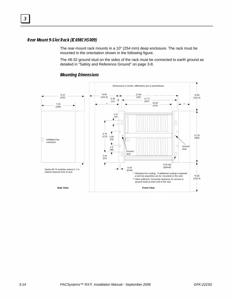
Rear Mount 9-Slot Rack (IC698CHS009)
The rear-mount rack mounts in a 10" (254 mm) deep enclosure. The rack must be mounted in the orientation shown in the following figure.
The #8-32 ground stud on the sides of the rack must be connected to earth ground as detailed in “Safety and Reference Ground” on page 3-8.
Mounting Dimensions
12.60(320
0.45(11)
11.71(297)
10.64(270)
2.24(57)
0.34(8.64)
6.75(172) 3.00
(76)
1.5(38)
0.25 dia(typical)
Dimensions in inches. Millimeters are in parentheses.
* Allowance for cooling. If additional cooling is required, a rack fan assembly can be mounted on the rack.** Allow sufficient horizontal clearance for access to ground studs at each end of the rack.
** **
*6.00(152.4)
11.15(283)
*6.00(152.4)
*6.00(152.4)
Front View
Series 90-70 modules extend 1.7 in.(43mm) beyond front of rack.
Intelligent fanconnector
9.14(232)
7.25(184)
Side View
Groundstud
Groundstud
0.75(19)
GFK-2223G Chapter 3 Installation Instructions 3-15
3
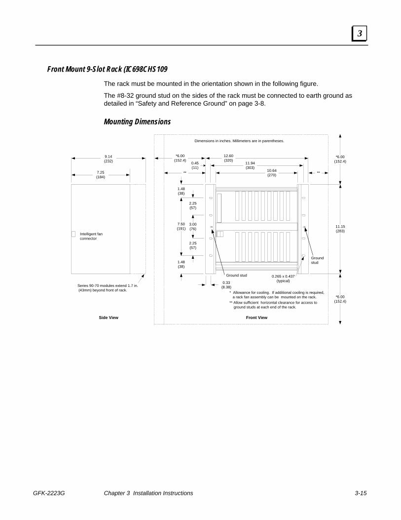
Front Mount 9-Slot Rack (IC698CHS109
The rack must be mounted in the orientation shown in the following figure.
The #8-32 ground stud on the sides of the rack must be connected to earth ground as detailed in “Safety and Reference Ground” on page 3-8.
Mounting Dimensions
12.60(320)
0.45(11)
11.94(303)
10.64(270)
1.48(38)
1.48(38)
0.33(8.38)
7.50(191)
2.25(57)
3.00(76)
2.25(57)
0.265 x 0.437(typical)
Dimensions in inches. Millimeters are in parentheses.
* Allowance for cooling. If additional cooling is required, a rack fan assembly can be mounted on the rack.** Allow sufficient horizontal clearance for access to ground studs at each end of the rack.
** **
*6.00(152.4)
11.15(283)
*6.00(152.4)
*6.00(152.4)
Front View
Series 90-70 modules extend 1.7 in. (43mm) beyond front of rack.
Intelligent fanconnector
9.14(232)
7.25(184)
Side View
Ground stud
Groundstud
3-16 PACSystems™ RX7i Installation Manual - September 2006 GFK-2223G
3
Fan Assembly Note: It is recommended that the fans be wired to the same source of power as the
CPU. This ensures that the fans are running when the CPU is active.
Note: You will need to install the fan assembly on the rack before installing the rack into an enclosure or equipment rack. A minimum of 23cm (9 inches) between racks is required to remove and replace an individual fan from the fan assembly.
The following fan kits are available:
For 9-Slot Racks Rack Fan Assembly, 120 VAC IC697ACC621Rack Fan Assembly, 240 VAC IC697ACC624Rack Fan Assembly, 24 VDC IC697ACC644
For 17-Slot Racks Rack Fan Assembly, 120 VAC IC697ACC721Rack Fan Assembly, 240 VAC IC697ACC724 Rack Fan Assembly, 24 VDC IC697ACC744
Replacement Fans and Filter Elements 120 VAC Replacement Fans Sinwan S109AP-11-1TB 240 VAC Replacement Fans Sinwan S109AP-22-1TB 24 VDC Replacement Fans Sinwan SD1238AP-24HBT Replacement Filter Element for all Rack Fan Assemblies Comair Rotron 554146 (5 pack)
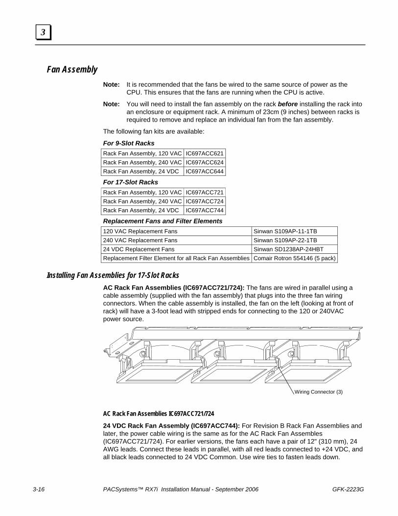
Installing Fan Assemblies for 17-Slot Racks AC Rack Fan Assemblies (IC697ACC721/724): The fans are wired in parallel using a cable assembly (supplied with the fan assembly) that plugs into the three fan wiring connectors. When the cable assembly is installed, the fan on the left (looking at front of rack) will have a 3-foot lead with stripped ends for connecting to the 120 or 240VAC power source.
Wiring Connector (3)
AC Rack Fan Assemblies IC697ACC721/724
24 VDC Rack Fan Assembly (IC697ACC744): For Revision B Rack Fan Assemblies and later, the power cable wiring is the same as for the AC Rack Fan Assembles (IC697ACC721/724). For earlier versions, the fans each have a pair of 12" (310 mm), 24 AWG leads. Connect these leads in parallel, with all red leads connected to +24 VDC, and all black leads connected to 24 VDC Common. Use wire ties to fasten leads down.
GFK-2223G Chapter 3 Installation Instructions 3-17
3
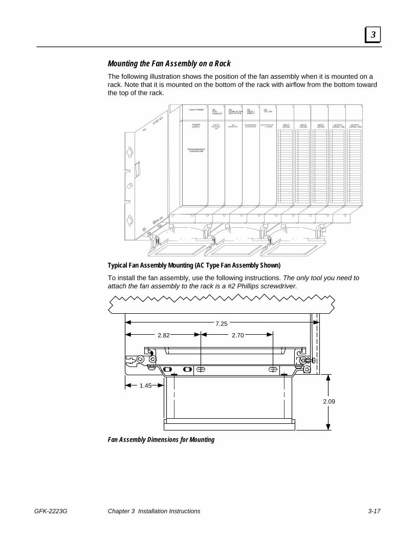
Mounting the Fan Assembly on a Rack The following illustration shows the position of the fan assembly when it is mounted on a rack. Note that it is mounted on the bottom of the rack with airflow from the bottom toward the top of the rack.
TPK.A.429794-17-89
PROGRAMMABLE BUS CONTROLLER INPUT120VAC
OK OK OK
POWER
LOGIC POWER
SUPPLY
CONTROLLERPROGRAMMABLE
PROCESSORUNIT
CENTRALTRANSMITTER
BUSCOPROCESOOR 1 CHANNEL
INPUT120VAC
INPUT120VAC
OUTPUT120VAC, 05A
OUTPUT120VAC, 05A
ENABLEDRUNOK
BUS ACTIVEPGMR ACTIVE
USER 2USER 1 CH 1 OK
Typical Fan Assembly Mounting (AC Type Fan Assembly Shown)
To install the fan assembly, use the following instructions. The only tool you need to attach the fan assembly to the rack is a #2 Phillips screwdriver.
2.82 2.70
1.45
2.09
7.25
Fan Assembly Dimensions for Mounting
3-18 PACSystems™ RX7i Installation Manual - September 2006 GFK-2223G
3
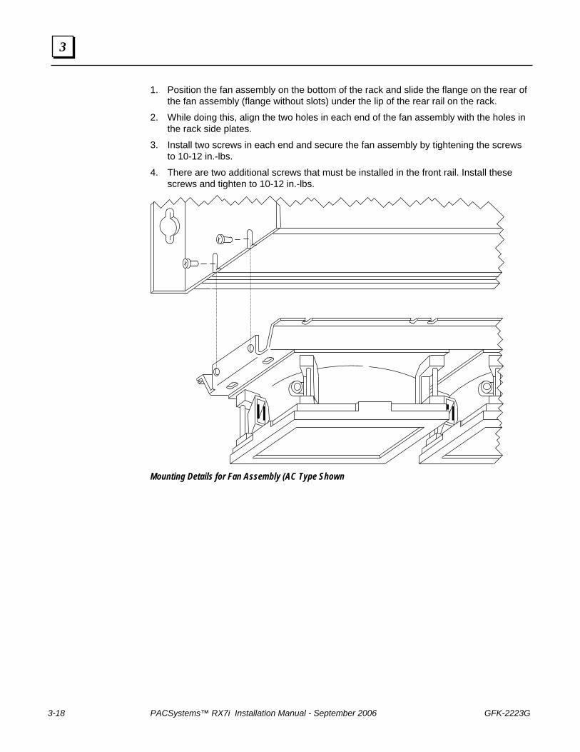
1. Position the fan assembly on the bottom of the rack and slide the flange on the rear of the fan assembly (flange without slots) under the lip of the rear rail on the rack.
2. While doing this, align the two holes in each end of the fan assembly with the holes in the rack side plates.
3. Install two screws in each end and secure the fan assembly by tightening the screws to 10-12 in.-lbs.
4. There are two additional screws that must be installed in the front rail. Install these screws and tighten to 10-12 in.-lbs.
Mounting Details for Fan Assembly (AC Type Shown
GFK-2223G Chapter 3 Installation Instructions 3-19
3
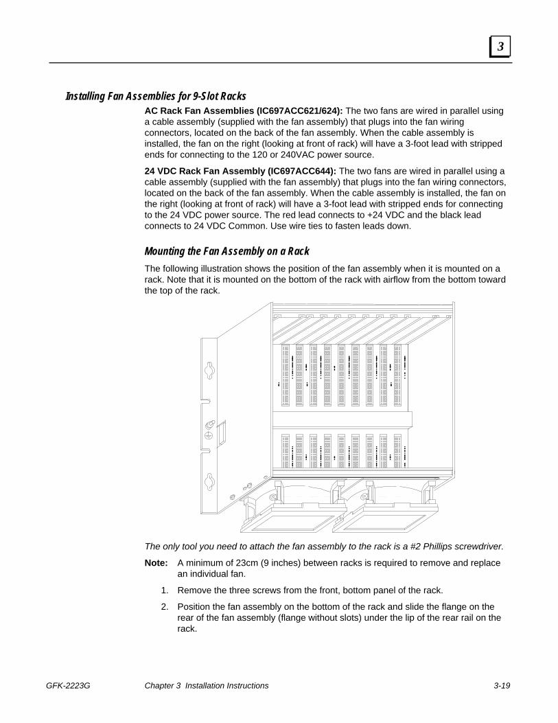
Installing Fan Assemblies for 9-Slot Racks AC Rack Fan Assemblies (IC697ACC621/624): The two fans are wired in parallel using a cable assembly (supplied with the fan assembly) that plugs into the fan wiring connectors, located on the back of the fan assembly. When the cable assembly is installed, the fan on the right (looking at front of rack) will have a 3-foot lead with stripped ends for connecting to the 120 or 240VAC power source.
24 VDC Rack Fan Assembly (IC697ACC644): The two fans are wired in parallel using a cable assembly (supplied with the fan assembly) that plugs into the fan wiring connectors, located on the back of the fan assembly. When the cable assembly is installed, the fan on the right (looking at front of rack) will have a 3-foot lead with stripped ends for connecting to the 24 VDC power source. The red lead connects to +24 VDC and the black lead connects to 24 VDC Common. Use wire ties to fasten leads down.
Mounting the Fan Assembly on a Rack The following illustration shows the position of the fan assembly when it is mounted on a rack. Note that it is mounted on the bottom of the rack with airflow from the bottom toward the top of the rack.
The only tool you need to attach the fan assembly to the rack is a #2 Phillips screwdriver.
Note: A minimum of 23cm (9 inches) between racks is required to remove and replace an individual fan.
1. Remove the three screws from the front, bottom panel of the rack.
2. Position the fan assembly on the bottom of the rack and slide the flange on the rear of the fan assembly (flange without slots) under the lip of the rear rail on the rack.
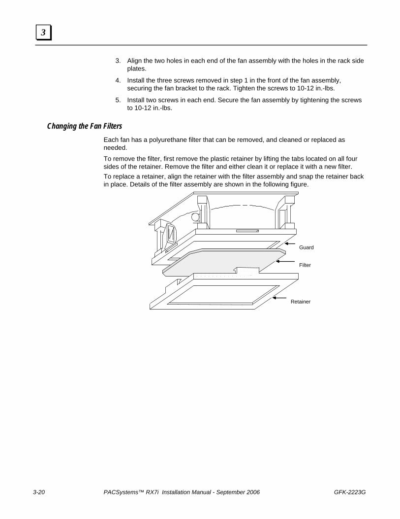
3-20 PACSystems™ RX7i Installation Manual - September 2006 GFK-2223G
3
3. Align the two holes in each end of the fan assembly with the holes in the rack side plates.
4. Install the three screws removed in step 1 in the front of the fan assembly, securing the fan bracket to the rack. Tighten the screws to 10-12 in.-lbs.
5. Install two screws in each end. Secure the fan assembly by tightening the screws to 10-12 in.-lbs.
Changing the Fan Filters Each fan has a polyurethane filter that can be removed, and cleaned or replaced as needed.
To remove the filter, first remove the plastic retainer by lifting the tabs located on all four sides of the retainer. Remove the filter and either clean it or replace it with a new filter. To replace a retainer, align the retainer with the filter assembly and snap the retainer back in place. Details of the filter assembly are shown in the following figure.
Guard
Filter
Retainer
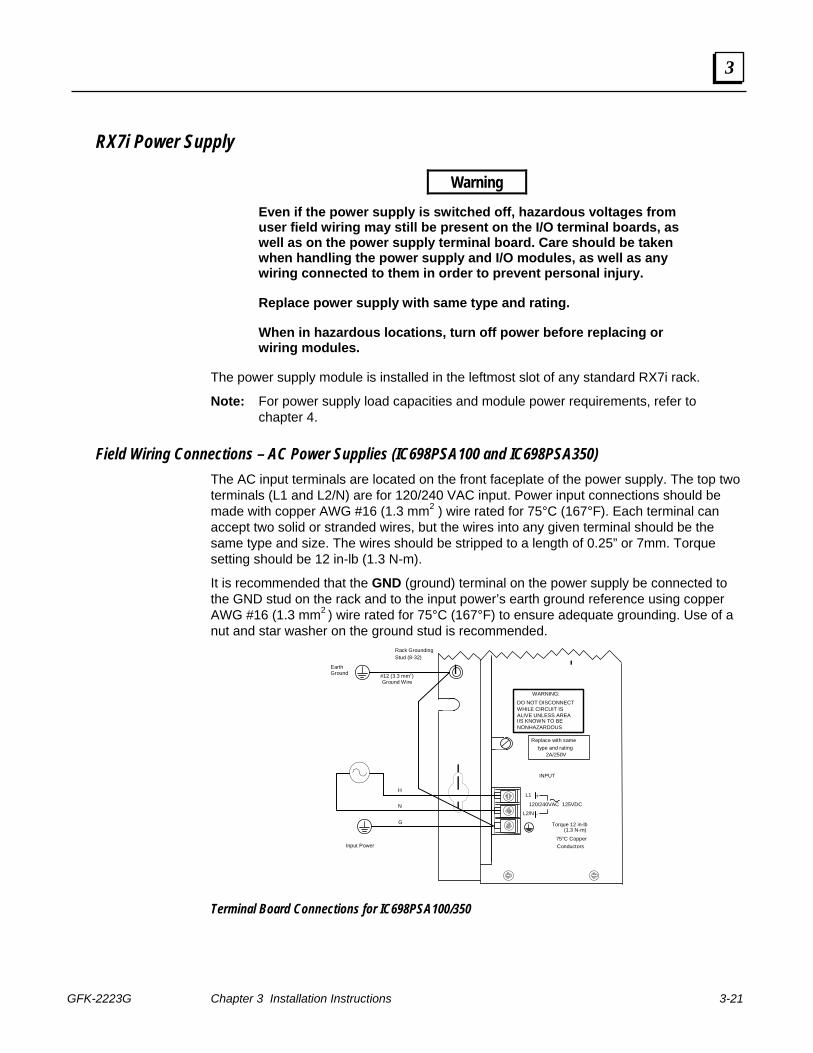
GFK-2223G Chapter 3 Installation Instructions 3-21
3
RX7i Power Supply
Warning
Even if the power supply is switched off, hazardous voltages from user field wiring may still be present on the I/O terminal boards, as well as on the power supply terminal board. Care should be taken when handling the power supply and I/O modules, as well as any wiring connected to them in order to prevent personal injury.
Replace power supply with same type and rating.
When in hazardous locations, turn off power before replacing or wiring modules.
The power supply module is installed in the leftmost slot of any standard RX7i rack.
Note: For power supply load capacities and module power requirements, refer to chapter 4.
Field Wiring Connections – AC Power Supplies (IC698PSA100 and IC698PSA350) The AC input terminals are located on the front faceplate of the power supply. The top two terminals (L1 and L2/N) are for 120/240 VAC input. Power input connections should be made with copper AWG #16 (1.3 mm2 ) wire rated for 75°C (167°F). Each terminal can accept two solid or stranded wires, but the wires into any given terminal should be the same type and size. The wires should be stripped to a length of 0.25” or 7mm. Torque setting should be 12 in-lb (1.3 N-m).
It is recommended that the GND (ground) terminal on the power supply be connected to the GND stud on the rack and to the input power’s earth ground reference using copper AWG #16 (1.3 mm2 ) wire rated for 75°C (167°F) to ensure adequate grounding. Use of a nut and star washer on the ground stud is recommended.
Rack GroundingStud (8-32)
#12 (3.3 mm2) Ground Wire
INPUT
75°C Copper
Torque 12 in-lb (1.3 N-m)
Conductors
Replace with same type and rating
2A/250V
L1
120/240VAC 125VDC
Earth Ground
IIS KNOWN TO BE
WHILE CIRCUIT IS
WARNING:
DO NOT DISCONNECT ALIVE UNLESS AREA NONHAZARDOUS
H
N
G
L2/N
Input Power
+
-
Terminal Board Connections for IC698PSA100/350
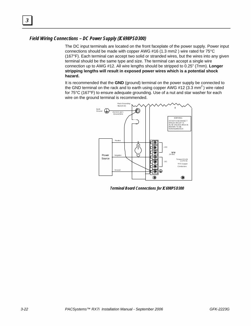
3-22 PACSystems™ RX7i Installation Manual - September 2006 GFK-2223G
3
Field Wiring Connections – DC Power Supply (IC698PSD300) The DC input terminals are located on the front faceplate of the power supply. Power input connections should be made with copper AWG #16 (1.3 mm2 ) wire rated for 75°C (167°F). Each terminal can accept two solid or stranded wires, but the wires into any given terminal should be the same type and size. The terminal can accept a single wire connection up to AWG #12. All wire lengths should be stripped to 0.25” (7mm). Longer stripping lengths will result in exposed power wires which is a potential shock hazard. It is recommended that the GND (ground) terminal on the power supply be connected to the GND terminal on the rack and to earth using copper AWG #12 (3.3 mm2 ) wire rated for 75°C (167°F) to ensure adequate grounding. Use of a nut and star washer for each wire on the ground terminal is recommended.
Rack GroundingStud (8-32)
#12 (3.3 mm2) Ground Wire
+ DC
Torque 12 in-lb
75°C Copper
(1.3 N-m)
Conductors
Earth Ground
IKNOWN TO BE WHILE C IRCUIT IS
WARNING: DO NOT D ISCONNEC T ALIVE UNLESS AREA IS NONHAZARDOUS
Positive
Negative
Ground
PowerSource
- DC
24 VDC
Terminal Board Connections for IC698PSD300
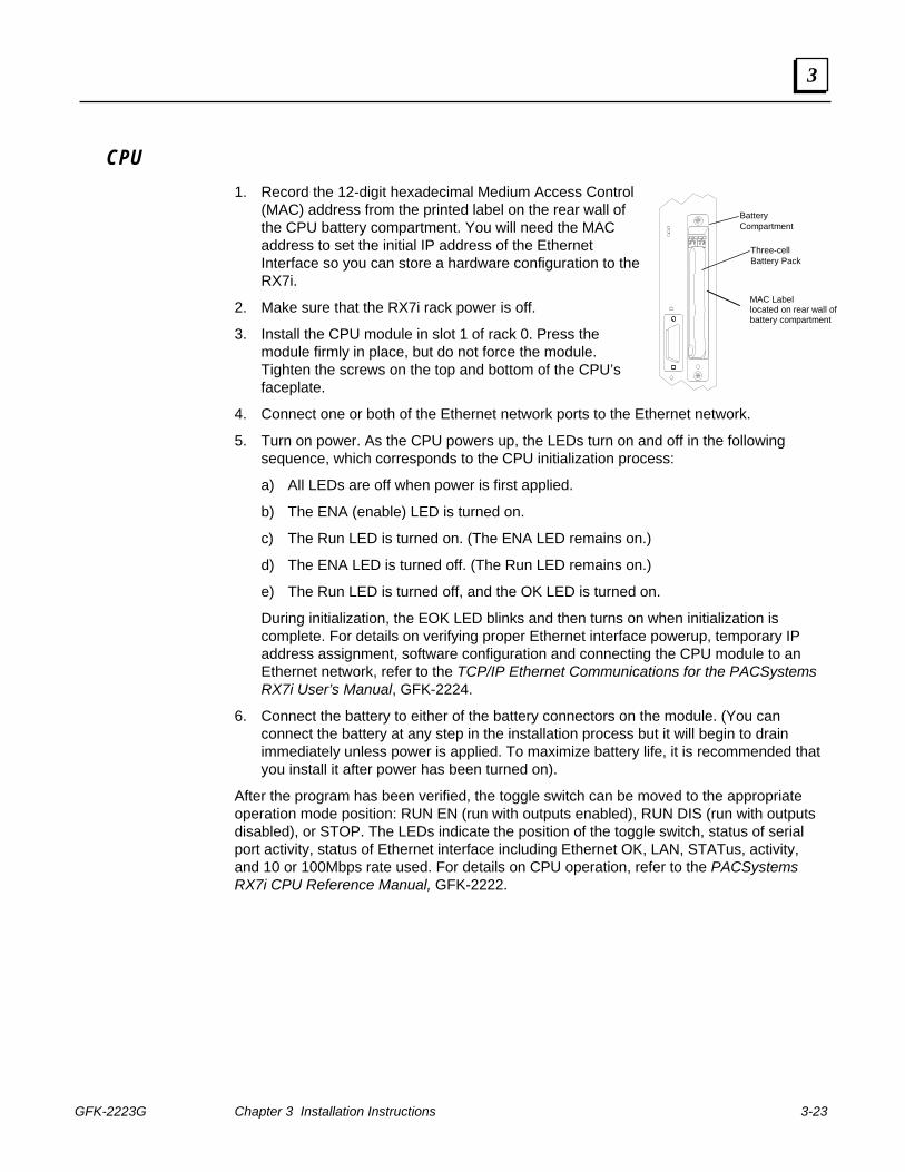
GFK-2223G Chapter 3 Installation Instructions 3-23
3
BatteryCompartment
Three-cellBattery Pack
MAC Labellocated on rear wall ofbattery compartment
CPU 1. Record the 12-digit hexadecimal Medium Access Control
(MAC) address from the printed label on the rear wall of the CPU battery compartment. You will need the MAC address to set the initial IP address of the Ethernet Interface so you can store a hardware configuration to the RX7i.
2. Make sure that the RX7i rack power is off.
3. Install the CPU module in slot 1 of rack 0. Press the module firmly in place, but do not force the module. Tighten the screws on the top and bottom of the CPU’s faceplate.
4. Connect one or both of the Ethernet network ports to the Ethernet network.
5. Turn on power. As the CPU powers up, the LEDs turn on and off in the following sequence, which corresponds to the CPU initialization process:
a) All LEDs are off when power is first applied.
b) The ENA (enable) LED is turned on.
c) The Run LED is turned on. (The ENA LED remains on.)
d) The ENA LED is turned off. (The Run LED remains on.)
e) The Run LED is turned off, and the OK LED is turned on.
During initialization, the EOK LED blinks and then turns on when initialization is complete. For details on verifying proper Ethernet interface powerup, temporary IP address assignment, software configuration and connecting the CPU module to an Ethernet network, refer to the TCP/IP Ethernet Communications for the PACSystems RX7i User’s Manual, GFK-2224.
6. Connect the battery to either of the battery connectors on the module. (You can connect the battery at any step in the installation process but it will begin to drain immediately unless power is applied. To maximize battery life, it is recommended that you install it after power has been turned on).
After the program has been verified, the toggle switch can be moved to the appropriate operation mode position: RUN EN (run with outputs enabled), RUN DIS (run with outputs disabled), or STOP. The LEDs indicate the position of the toggle switch, status of serial port activity, status of Ethernet interface including Ethernet OK, LAN, STATus, activity, and 10 or 100Mbps rate used. For details on CPU operation, refer to the PACSystems RX7i CPU Reference Manual, GFK-2222.
3-24 PACSystems™ RX7i Installation Manual - September 2006 GFK-2223G
3
Replacing the CPU Battery Pack – CPE030/CRE030 and CPE040/CRE040 Models Note: The IC698ACC701 RX7i Replacement Battery is not compatible with the
these CPU modules.
The CPE030/CRE030 and CPE040/CRE040 CPUs use the Auxiliary Battery Module, IC693ACC302, to maintain program and data memory in RAM and operate the calendar clock when power is removed.
To avoid loss of RAM contents, routine maintenance procedures should include scheduled replacement of the battery module. For information on estimating battery life, refer to the PACSystems CPU Reference Manual, GFK-2222.
For additional information about the Auxiliary Battery Module, refer to the module datasheet, GFK-2124.
Note: The battery can be replaced with power applied to the rack and the CPU in RUN or STOP mode.
1. Open the battery compartment door. 2. Connect the replacement battery module to the battery terminals that are not being
used. 4. Disconnect the old battery from its terminal and remove the battery cable from the slot
in the battery compartment door. Discard the old battery module. 5. Route the cable of the replacement battery module through the slot in the bottom of
the battery compartment door. Close the battery compartment door.
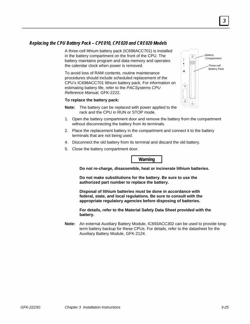
GFK-2223G Chapter 3 Installation Instructions 3-25
3
BatteryCompartment
Three-cellBattery Pack
Replacing the CPU Battery Pack – CPE010, CPE020 and CRE020 Models A three-cell lithium battery pack (IC698ACC701) is installed in the battery compartment on the front of the CPU. The battery maintains program and data memory and operates the calendar clock when power is removed.
To avoid loss of RAM contents, routine maintenance procedures should include scheduled replacement of the CPU’s IC698ACC701 lithium battery pack. For information on estimating battery life, refer to the PACSystems CPU Reference Manual, GFK-2222.
To replace the battery pack:
Note: The battery can be replaced with power applied to the rack and the CPU in RUN or STOP mode.
1. Open the battery compartment door and remove the battery from the compartment without disconnecting the battery from its terminals.
2. Place the replacement battery in the compartment and connect it to the battery terminals that are not being used.
4. Disconnect the old battery from its terminal and discard the old battery. 5. Close the battery compartment door.
Warning
Do not re-charge, disassemble, heat or incinerate lithium batteries.
Do not make substitutions for the battery. Be sure to use the authorized part number to replace the battery.
Disposal of lithium batteries must be done in accordance with federal, state, and local regulations. Be sure to consult with the appropriate regulatory agencies before disposing of batteries.
For details, refer to the Material Safety Data Sheet provided with the battery.
Note: An external Auxiliary Battery Module, IC693ACC302 can be used to provide long-term battery backup for these CPUs. For details, refer to the datasheet for the Auxiliary Battery Module, GFK-2124.
3-26 PACSystems™ RX7i Installation Manual - September 2006 GFK-2223G
3
Removing a CPU from the Rack The instructions listed below should be followed when removing a CPU from its slot in a rack.
Warning
Do not insert or remove a module when power is applied to the rack. This could cause the system to stop, damage the module, or cause personal injury to you. Use care when inserting or removing a module so that the printed circuit board and/or its components are not damaged.
1. Be sure the RX7i rack power is OFF.
2. Unscrew the top and bottom mounting screws to release the board from the chassis. The screws should stay mounted in the faceplate but allow the faceplate to be separated from the chassis rails.
3. Grasp the board firmly at the top and bottom of the faceplate with your thumbs on the front of the cover and your fingers on the back of the cover.
4. Pull the board firmly to remove it from the backplane connector.
5. Slide the board along the card guide and remove it from the rack.
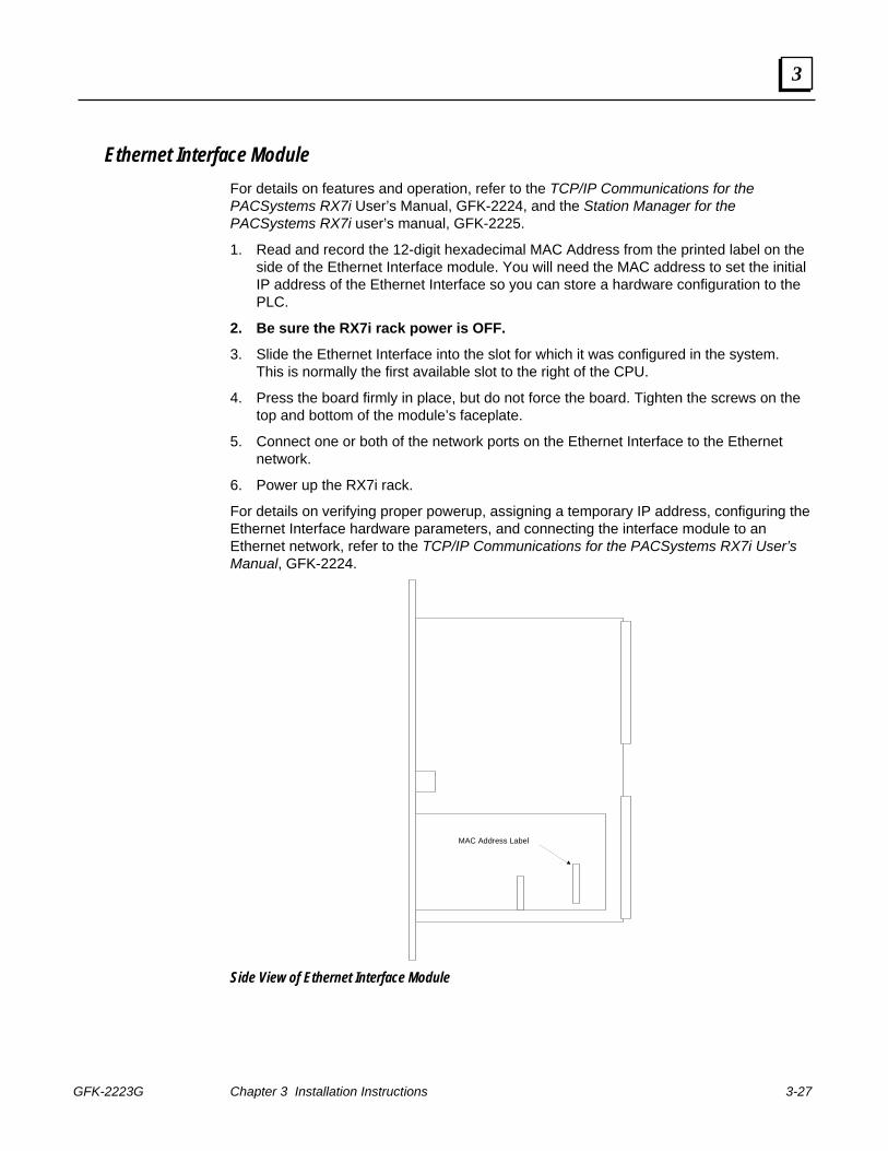
GFK-2223G Chapter 3 Installation Instructions 3-27
3
Ethernet Interface Module For details on features and operation, refer to the TCP/IP Communications for the PACSystems RX7i User’s Manual, GFK-2224, and the Station Manager for the PACSystems RX7i user’s manual, GFK-2225.
1. Read and record the 12-digit hexadecimal MAC Address from the printed label on the side of the Ethernet Interface module. You will need the MAC address to set the initial IP address of the Ethernet Interface so you can store a hardware configuration to the PLC.
2. Be sure the RX7i rack power is OFF.
3. Slide the Ethernet Interface into the slot for which it was configured in the system. This is normally the first available slot to the right of the CPU.
4. Press the board firmly in place, but do not force the board. Tighten the screws on the top and bottom of the module’s faceplate.
5. Connect one or both of the network ports on the Ethernet Interface to the Ethernet network.
6. Power up the RX7i rack.
For details on verifying proper powerup, assigning a temporary IP address, configuring the Ethernet Interface hardware parameters, and connecting the interface module to an Ethernet network, refer to the TCP/IP Communications for the PACSystems RX7i User’s Manual, GFK-2224.
MAC Address Label
Side View of Ethernet Interface Module
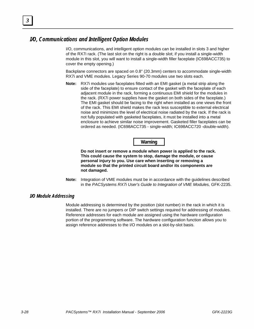
3-28 PACSystems™ RX7i Installation Manual - September 2006 GFK-2223G
3
I/O, Communications and Intelligent Option Modules I/O, communications, and intelligent option modules can be installed in slots 3 and higher of the RX7i rack. (The last slot on the right is a double slot; if you install a single-width module in this slot, you will want to install a single-width filler faceplate (IC698ACC735) to cover the empty opening.)
Backplane connectors are spaced on 0.8" (20.3mm) centers to accommodate single-width RX7i and VME modules. Legacy Series 90-70 modules use two slots each.
Note: RX7i modules use faceplates fitted with an EMI gasket (a metal strip along the side of the faceplate) to ensure contact of the gasket with the faceplate of each adjacent module in the rack, forming a continuous EMI shield for the modules in the rack. (RX7i power supplies have the gasket on both sides of the faceplate.) The EMI gasket should be facing to the right when installed as one views the front of the rack. This EMI shield makes the rack less susceptible to external electrical noise and minimizes the level of electrical noise radiated by the rack. If the rack is not fully populated with gasketed faceplates, it must be installed into a metal enclosure to achieve similar noise improvement. Gasketed filler faceplates can be ordered as needed. (IC698ACC735 - single-width; IC698ACC720 -double-width).
Warning
Do not insert or remove a module when power is applied to the rack. This could cause the system to stop, damage the module, or cause personal injury to you. Use care when inserting or removing a module so that the printed circuit board and/or its components are not damaged.
Note: Integration of VME modules must be in accordance with the guidelines described in the PACSystems RX7i User's Guide to Integration of VME Modules, GFK-2235.
I/O Module Addressing Module addressing is determined by the position (slot number) in the rack in which it is installed. There are no jumpers or DIP switch settings required for addressing of modules. Reference addresses for each module are assigned using the hardware configuration portion of the programming software. The hardware configuration function allows you to assign reference addresses to the I/O modules on a slot-by-slot basis.
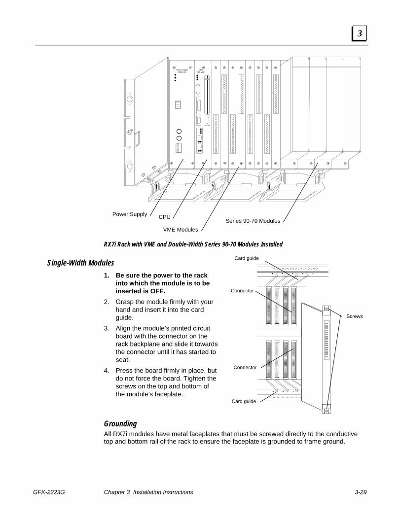
GFK-2223G Chapter 3 Installation Instructions 3-29
3
Power Supply350W AC
CPU750 MHz
Power Supply CPU
VME ModulesSeries 90-70 Modules
RX7i Rack with VME and Double-Width Series 90-70 Modules Installed
Single-Width Modules 1. Be sure the power to the rack
into which the module is to be inserted is OFF.
2. Grasp the module firmly with your hand and insert it into the card guide.
3. Align the module’s printed circuit board with the connector on the rack backplane and slide it towards the connector until it has started to seat.
4. Press the board firmly in place, but do not force the board. Tighten the screws on the top and bottom of the module’s faceplate.
Grounding All RX7i modules have metal faceplates that must be screwed directly to the conductive top and bottom rail of the rack to ensure the faceplate is grounded to frame ground.
Card guide
Connector
Connector
Card guide
Screws
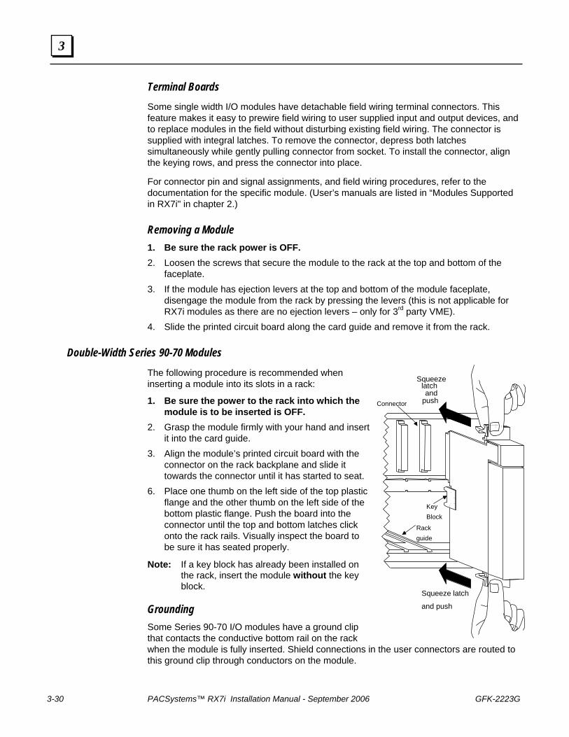
3-30 PACSystems™ RX7i Installation Manual - September 2006 GFK-2223G
3
KeyBlock
Connector
Rackguide
Squeeze latch
and push
Squeezelatchand
push
Terminal Boards Some single width I/O modules have detachable field wiring terminal connectors. This feature makes it easy to prewire field wiring to user supplied input and output devices, and to replace modules in the field without disturbing existing field wiring. The connector is supplied with integral latches. To remove the connector, depress both latches simultaneously while gently pulling connector from socket. To install the connector, align the keying rows, and press the connector into place.
For connector pin and signal assignments, and field wiring procedures, refer to the documentation for the specific module. (User’s manuals are listed in “Modules Supported in RX7i" in chapter 2.)
Removing a Module 1. Be sure the rack power is OFF. 2. Loosen the screws that secure the module to the rack at the top and bottom of the
faceplate. 3. If the module has ejection levers at the top and bottom of the module faceplate,
disengage the module from the rack by pressing the levers (this is not applicable for RX7i modules as there are no ejection levers – only for 3rd party VME).
4. Slide the printed circuit board along the card guide and remove it from the rack.
Double-Width Series 90-70 Modules The following procedure is recommended when inserting a module into its slots in a rack:
1. Be sure the power to the rack into which the module is to be inserted is OFF.
2. Grasp the module firmly with your hand and insert it into the card guide.
3. Align the module’s printed circuit board with the connector on the rack backplane and slide it towards the connector until it has started to seat.
6. Place one thumb on the left side of the top plastic flange and the other thumb on the left side of the bottom plastic flange. Push the board into the connector until the top and bottom latches click onto the rack rails. Visually inspect the board to be sure it has seated properly.
Note: If a key block has already been installed on the rack, insert the module without the key block.
Grounding Some Series 90-70 I/O modules have a ground clip that contacts the conductive bottom rail on the rack when the module is fully inserted. Shield connections in the user connectors are routed to this ground clip through conductors on the module.
GFK-2223G Chapter 3 Installation Instructions 3-31
3
Universal Terminal Boards Series 90-70 I/O modules have detachable field wiring terminal boards. This convenient feature makes it easy to prewire field wiring to the user supplied input and output devices, and to replace modules in the field without disturbing existing field wiring. The I/O connector terminals accept up to one AWG #14 (2.1 mm2 ) wire or two AWG #16 (1.3 mm2) wires. Wires are routed out of the bottom of the terminal board cavity. A terminal board strap attached to the bottom front of each I/O terminal board is used to securely fasten the terminal board to the rack. For field wiring procedures, refer to GFK-0262.
Mechanical Keying Some double-width Series 90-70 I/O modules are mechanically interlocked by means of a key block to prevent the accidental interchange of one module type for another. For example, a DC Output module cannot be inserted into a slot where the terminal board has been wired for an AC Input module. A unique key is provided with each module. When a module is initially installed in a rack, the key block automatically latches onto the center rail on the backplane, where it remains when a module is removed. Only the correct module type can be inserted into that slot.
Installing Insulating Strips for Series 90-70 Modules An insulator strip is required on certain Series 90-70 modules that are installed to the immediate right of an RX7i module. The insulator strip prevents module from short-circuiting to the metal faceplates of an adjacent VME module.
Note: Current versions of these modules are shipped with the insulators installed. The strip is visible on the back of the printed wiring assembly.
High Voltage Series 90-70 Modules
Insulating strips should be installed on the following modules: Versions earlier than IC697MDL240 D IC697MDL241 D IC697MDL250 G IC697MDL251 E IC697MDL640 E IC697MDL340 G IC697MDL341 E IC697MDL350 F
The RX7i rack is shipped with an Insulator Kit that includes enough parts to update three Series 90-70 I/O modules.
The plastic insulating strip is installed on the back of the printed wiring assembly, along the edge of the I/O connector to prevent the possibility of high voltage I/O cards short-circuiting to the metal faceplates of VME cards. (Follow the installation instructions included with the kit). Use part number 44A752213-G01 to order additional kits as needed.
3-32 PACSystems™ RX7i Installation Manual - September 2006 GFK-2223G
3
Bus Controller and Bus Expansion Modules
Insulating strips should be installed on the following modules to prevent the possibility of the module short-circuiting to the metal faceplate of the adjacent VME board.
IC697BEM731 Genius Bus Controller IC697BEM713 Bus Transmitter Module IC697BEM711 Bus Receiver Module
The plastic insulating strip is installed on the backside of the printed wiring assembly, along the edge of the I/O connector.
To order insulating strip kits for IC697BEMxxx modules that do not have them, use part number 44A751635-G01. (Follow the installation instructions included with the kit).
Removing a Double Width Series 90-70 Module 1. Ensure that the rack is powered down. 2. Grasp the module firmly at the top and bottom of the board cover with your thumbs on
the front of the cover and your fingers on the plastic clips on the back of the cover. 3. Squeeze the rack clips on the back of the cover with your fingers to disengage the
clips from the rack rail and pull the board firmly to remove it from the backplane connector.
4. Slide the printed circuit board along the card guide and remove it from the rack.
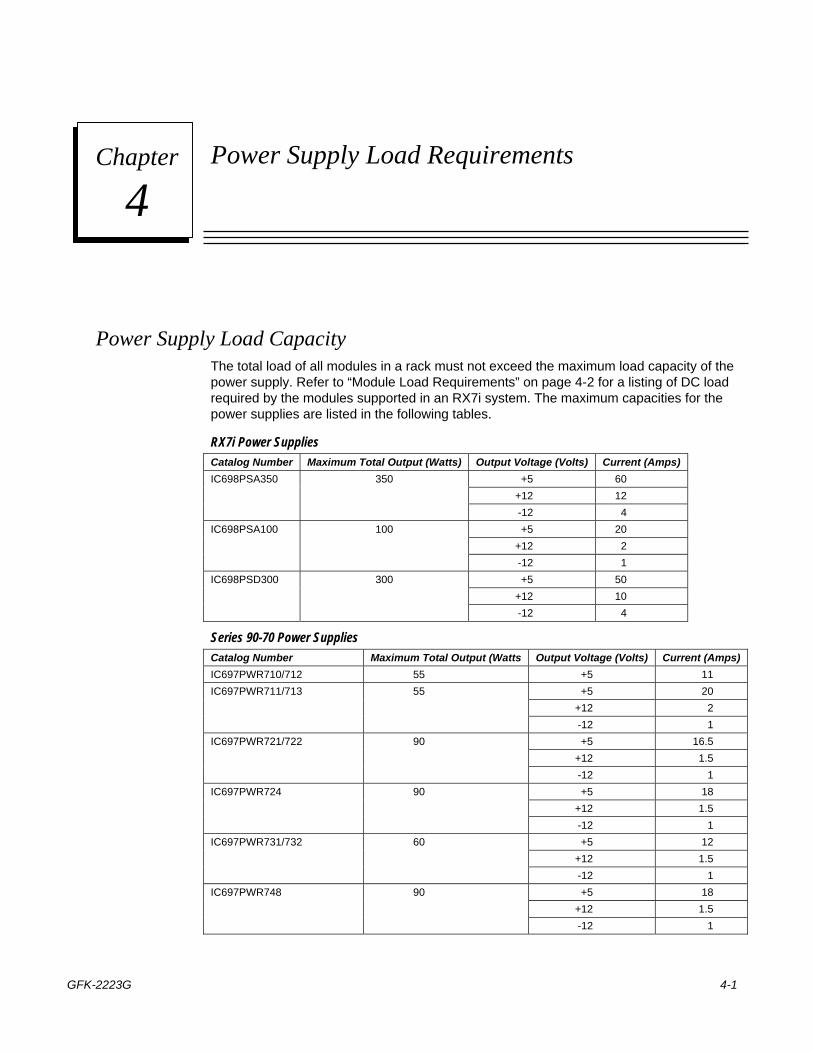
GFK-2223G 4-1
Power Supply Load Requirements
Power Supply Load Capacity The total load of all modules in a rack must not exceed the maximum load capacity of the power supply. Refer to “Module Load Requirements” on page 4-2 for a listing of DC load required by the modules supported in an RX7i system. The maximum capacities for the power supplies are listed in the following tables.
RX7i Power Supplies Catalog Number Maximum Total Output (Watts) Output Voltage (Volts) Current (Amps)
+5 60 +12 12
IC698PSA350 350
-12 4 +5 20
+12 2 IC698PSA100 100
-12 1 +5 50
+12 10 IC698PSD300 300
-12 4
Series 90-70 Power Supplies Catalog Number Maximum Total Output (Watts Output Voltage (Volts) Current (Amps) IC697PWR710/712 55 +5 11
+5 20 +12 2
IC697PWR711/713 55
-12 1 +5 16.5
+12 1.5 IC697PWR721/722 90
-12 1 +5 18
+12 1.5 IC697PWR724 90
-12 1 +5 12
+12 1.5 IC697PWR731/732 60
-12 1 +5 18
+12 1.5 IC697PWR748 90
-12 1
4 Chapter
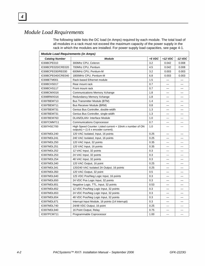
4-2 PACSystems™ RX7i Installation Manual – September 2006 GFK-2223G
4
Module Load Requirements The following table lists the DC load (in Amps) required by each module. The total load of all modules in a rack must not exceed the maximum capacity of the power supply in the rack in which the modules are installed. For power supply load capacities, see page 4-1.
Module Load Requirements (in Amps) Catalog Number Module +5 VDC +12 VDC -12 VDC
IC698CPE010 300Mhz CPU, Celeron 3.2 0.042 0.008 IC698CPE020/CRE020 700Mhz CPU, Pentium 4.5 0.042 0.008 IC698CPE030/RE030 600MHz CPU, Pentium-M 3.2 0.003 0.003 IC698CPE040/CRE040 1800MHz CPU, Pentium-M 6.8 0.003 0.003 IC698ETM001 Rack-based Ethernet module 1.5 — — IC698CHS017 Rear mount rack 0.7 — — IC698CHS117 Front mount rack 0.7 — — IC698CMX016 Communications Memory Xchange 1.8 — — IC698RMX016 Redundancy Memory Xchange 1.8 — — IC697BEM713 Bus Transmitter Module (BTM) 1.4 — — IC697BEM711 Bus Receiver Module (BRM) 0.8 — — IC697BEM731 Genius Bus Controller, double-width 1.3 — — IC687BEM731 Genius Bus Controller, single-width 1.3 — — IC697BEM763 DLAN/DLAN+ Interface Module 1.0 — — IC697CMM711 Communications Coprocessor 0.7 — — IC697HSC700 High Speed Counter: Listed current + 10mA x number of ON
outputs) + (1.6 x encoder current). 1.0 — —
IC697MDL240 120 VAC Isolated, Input, 16 points 0.25 — — IC697MDL241 240 VAC Isolated, Input, 16 points 0.25 — — IC697MDL250 120 VAC Input, 32 points 0.35 — — IC697MDL251 120 VAC Input, 16 points 0.35 — — IC697MDL252 12 VAC Input, 32 points 0.3 — — IC697MDL253 24 VAC Input, 32 points 0.3 — — IC697MDL254 48 VAC Input, 32 points 0.3 — — IC697MDL340 120 VAC Output, 16 point 0.25 — — IC697MDL341 120/240 VAC Isolated 2A Output, 16 points 0.25 — — IC697MDL350 120 VAC Output, 32 point 0.5 — — IC697MDL640 125 VDC Pos/Neg Logic Input, 16 points 0.3 — — IC697MDL650 24 VDC Pos Logic Input, 32 points 0.3 — — IC697MDL651 Negative Logic, TTL, Input, 32 points 0.53 — — IC697MDL652 12 VDC Pos/Neg Logic Input, 32 points 0.3 — — IC697MDL653 24 VDC Pos/Neg Logic Input, 32 points 0.3 — — IC697MDL654 48 VDC Pos/Neg Logic Input, 32 points 0.3 — — IC697MDL671 Interrupt Input Module, 16 points (14 Interrupt) 0.3 — — IC697MDL740 24/48 VDC Output, 16 point 0.25 — — IC697MDL940 16 Point Output, Relay 0.75 — — IC697PCM711 Programmable Coprocessor 1.00 — —
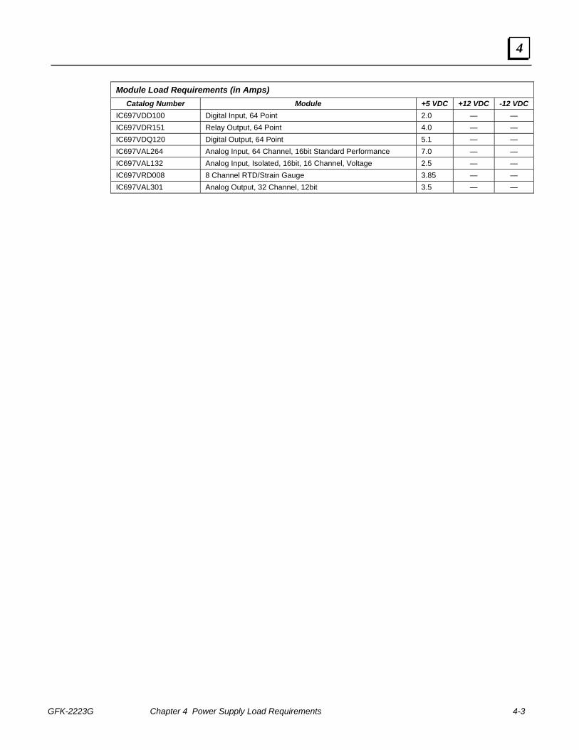
GFK-2223G Chapter 4 Power Supply Load Requirements 4-3
4
Module Load Requirements (in Amps) Catalog Number Module +5 VDC +12 VDC -12 VDC
IC697VDD100 Digital Input, 64 Point 2.0 — — IC697VDR151 Relay Output, 64 Point 4.0 — — IC697VDQ120 Digital Output, 64 Point 5.1 — — IC697VAL264 Analog Input, 64 Channel, 16bit Standard Performance 7.0 — — IC697VAL132 Analog Input, Isolated, 16bit, 16 Channel, Voltage 2.5 — — IC697VRD008 8 Channel RTD/Strain Gauge 3.85 — — IC697VAL301 Analog Output, 32 Channel, 12bit 3.5 — —
GFK-2223G 5-1
Cabling Information
This chapter presents pin assignment information for the Ethernet and serial ports provided in the RX7i system.
Ethernet Ports There are two RJ-45 Ethernet ports on the Ethernet Interface. Either or both of these ports may be attached to other Ethernet devices. Each port automatically senses the data rate (10Mbps or 100Mbps), duplex (half duplex or full duplex), and cabling arrangement (straight through or crossover) of the attached link.
Caution
The two ports on the Ethernet Interface must not be connected, directly or indirectly to the same device. The hub or switch connections in an Ethernet network must form a tree, otherwise duplication of packets may result.
10Base-T/100Base-Tx Port Pin Assignments Pin Number Signal Description
1* TD+ Transmit Data + 2 TD- Transmit Data - 3 RD+ Receive Data + 4 NC No connection 5 NC No connection 6 RD- Receive Data - 7 NC No connection 8 NC No connection
* Pin 1 is at the bottom of the connector as viewed from the front of the module.
5 Chapter
5-2 PACSystems™ RX7i Installation Manual – September 2006 GFK-2223G
5
Serial Ports
Port 1 Pin Assignments CPU Port 1 is RS-232 compatible and optocoupler isolated. It has a 9-pin, female, D-sub connector with a standard pin out. This is a DCE (data communications equipment) port that allows a simple straight-through cable to connect to a standard AT-style RS-232 port.
Port 1 RS-232 Signals Pin Number Signal Name Description
1* NC No Connection 2 TXD Transmit Data 3 RXD Receive Data 4 DSR Data Set Ready 5 0V Signal Ground 6 DTR Data Terminal Ready 7 CTS Clear To Send 8 RTS Request to Send 9 NC No Connection
* Pin 1 is at the bottom right of the connector as viewed from the front of the module.
Port 2 Pin Assignments CPU Port 2 is an RS-485 compatible and optocoupler isolated DCE port. Port 2 has a 15-pin, female D-sub connector. This port requires an externally powered converter and does not support the RS-485 to RS-232 adapter (IC690ACC901).
Port 2 RS-485 Signals Pin No. Signal Name Description
1* Shield Cable Shield 2 NC No Connection 3 NC No Connection 4 NC No Connection 5 NC No Connection 6 RTS(A) Differential Request to Send 7 0V Signal Ground 8 CTS(B‘) Differential Clear To Send 9 RT** Resistor Termination 10 RD(A‘)** Differential Receive Data 11 RD(B‘) Differential Receive Data 12 SD(A) Differential Send Data 13 SD(B) Differential Send Data 14 RTS(B) Differential Request To Send 15 CTS(A’) Differential Clear To Send
* Pin 1 is at the bottom right of the connector as viewed from the front of the module. ** Termination resistance for the RD A’ signal should be connected on units at the end of the line.
To make this termination, connect a jumper between pins 9 and 10 inside the 15-pin D-shell.
GFK-2223F Chapter 5 Cabling Information 5-3
5
Station Manager Port Pin Assignments The Station Manager ports on both the CPU and Ethernet modules are RS-232 compatible, and isolated. The Station Manager port has a 9-pin, female, D-connector. This is a DCE port that allows a simple straight-through cable to connect with a standard AT-style RS-232 port. This port contains full use of the standard RS-232 signals for future use with point-to-point protocol (PPP).
Station Manager RS-232 Signals Pin Number Signal Name Description
1* DCD Data Carrier Detect 2 TXD Transmit Data 3 RXD Receive Data 4 DSR Data Set Ready 5 0V Signal Ground 6 DTR Data Terminal Ready 7 CTS Clear To Send 8 RTS Request to Send 9 RI Ring Indicator
* Pin 1 is at the bottom right of the connector as viewed from the front of the module.
Serial Cable Lengths and Shielding The connection from a CPU serial port to the serial port on a computer or other serial device requires a serial cable. This connection can be made with the IC200CBL001 cable kit or you may build cables to fit the needs of your particular application.
Maximum cable lengths (the total number of feet from the CPU to the last device attached to the serial cable) are:
Port 1 (RS-232) = 15 meters (50 ft.) – shielded cable optional
Port 2 (RS-485) = 1200 meters (4000 ft.) – shielded cable required
Port 3 (RS-232) = 15 meters (50 ft.) – shielded cable optional
GFK-2223G A-1
Product Certifications and Installation Guidelines for Conformance
This appendix describes the compliance markings and standards to which the RX7i products have been certified. It also provides installation requirements for conformance to standards and additional safety guidelines for installing in the European Union.
RX7i Agency Approvals
UL Class 1 Division 2 Hazardous Location Requirements
ATEX Class 1 Zone 2 Hazardous Location Requirements
Standards Overview
Government Regulations
Installation Guidelines for Conformance to Standards
Shielded Cable Alternative to Conduit
Safety-Related Guidelines for Installation in the European Union
A Appendix
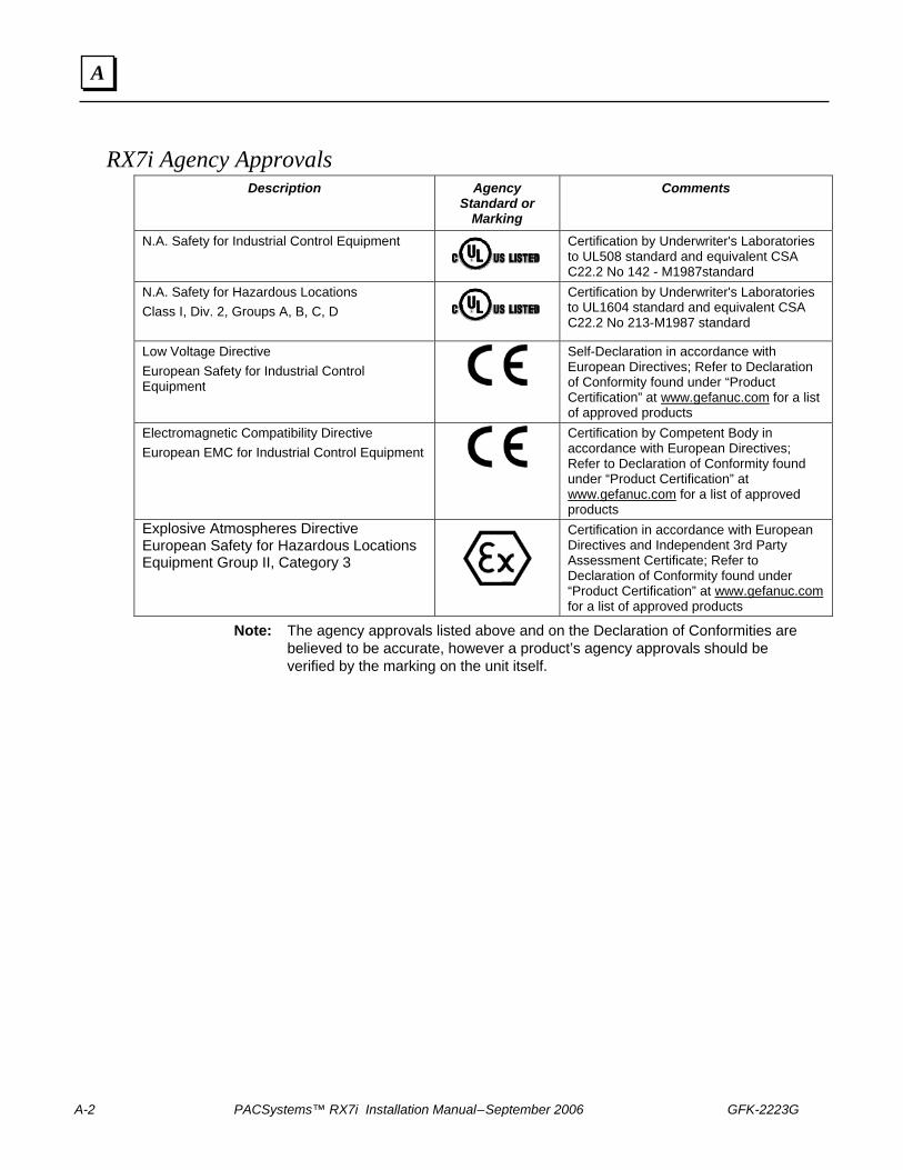
A-2 PACSystems™ RX7i Installation Manual – September 2006 GFK-2223G
A
RX7i Agency Approvals Description
Agency Standard or
Marking
Comments
N.A. Safety for Industrial Control Equipment
Certification by Underwriter's Laboratories to UL508 standard and equivalent CSA C22.2 No 142 - M1987standard
N.A. Safety for Hazardous Locations Class I, Div. 2, Groups A, B, C, D
Certification by Underwriter's Laboratories to UL1604 standard and equivalent CSA C22.2 No 213-M1987 standard
Low Voltage Directive European Safety for Industrial Control Equipment
Self-Declaration in accordance with European Directives; Refer to Declaration of Conformity found under “Product Certification” at www.gefanuc.com for a list of approved products
Electromagnetic Compatibility Directive European EMC for Industrial Control Equipment
Certification by Competent Body in accordance with European Directives; Refer to Declaration of Conformity found under “Product Certification” at www.gefanuc.com for a list of approved products
Explosive Atmospheres Directive European Safety for Hazardous Locations Equipment Group II, Category 3
Certification in accordance with European Directives and Independent 3rd Party Assessment Certificate; Refer to Declaration of Conformity found under “Product Certification” at www.gefanuc.com for a list of approved products
Note: The agency approvals listed above and on the Declaration of Conformities are believed to be accurate, however a product’s agency approvals should be verified by the marking on the unit itself.
GFK-2223G Appendix A Product Certifications and Installation Guidelines for Conformance A-3
A
UL Class 1 Division 2 Hazardous Location Requirements The following information is for products bearing the UL marking for Hazardous Locations.
WARNING - EXPLOSION HAZARD - SUBSTITUTION OF COMPONENTS MAY IMPAIR SUITABILITY FOR CLASS I, DIVISION 2.
WARNING - EXPLOSION HAZARD - WHEN IN HAZARDOUS LOCATIONS, TURN OFF POWER BEFORE REPLACING OR WIRING MODULES.
WARNING - EXPLOSION HAZARD - DO NOT CONNECT OR DISCONNECT EQUIPMENT UNLESS POWER HAS BEEN SWITCHED OFF OR THE AREA IS KNOWN TO BE NONHAZARDOUS.
EQUIPMENT LABELED WITH REFERENCE TO CLASS I, GROUPS A, B, C, & D, DIV. 2 HAZARDOUS LOCATIONS IS SUITABLE FOR USE IN CLASS I, DIVISION 2, GROUPS A, B, C, D OR NON-HAZARDOUS LOCATIONS ONLY.
Power input connections should be made with copper AWG No. 16 (1.33 mm2) through AWG No. 12 (3.31 mm2) wire rated for 75°C (167°F). Each terminal can accept solid or stranded wires, but the wires into any given terminal should be the same type and size.
The tightening torque range for the control terminals is 12 in.-lb. Use only wire rated for 75°C. Observe any additional ratings that are provided with the modules.
ATEX Class 1 Zone 2 Hazardous Location Requirements In order to maintain compliance with the ATEX Directive, an RX7i system located in a Class 1 Zone 2 area (Category 3) must be installed within a protective enclosure meeting the criteria detailed below:
• IP54 or greater
• Mechanical strength to withstand an impact energy of 3.5 Joules
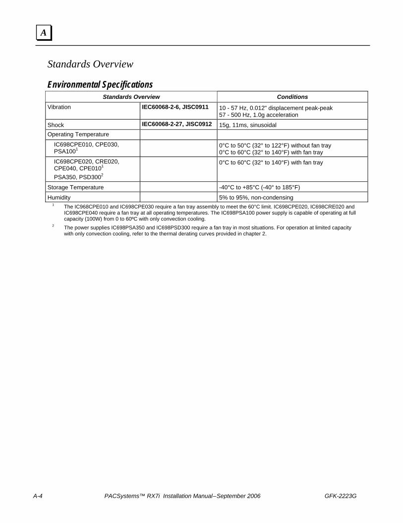
A-4 PACSystems™ RX7i Installation Manual – September 2006 GFK-2223G
A
Standards Overview
Environmental Specifications Standards Overview Conditions
Vibration IEC60068-2-6, JISC0911 10 - 57 Hz, 0.012" displacement peak-peak 57 - 500 Hz, 1.0g acceleration
Shock IEC60068-2-27, JISC0912 15g, 11ms, sinusoidal Operating Temperature
IC698CPE010, CPE030, PSA1001
0°C to 50°C (32° to 122°F) without fan tray
0°C to 60°C (32° to 140°F) with fan tray IC698CPE020, CRE020, CPE040, CPE0101 PSA350, PSD3002
0°C to 60°C (32° to 140°F) with fan tray
Storage Temperature -40°C to +85°C (-40° to 185°F)
Humidity 5% to 95%, non-condensing 1 The IC968CPE010 and IC698CPE030 require a fan tray assembly to meet the 60°C limit. IC698CPE020, IC698CRE020 and
IC698CPE040 require a fan tray at all operating temperatures. The IC698PSA100 power supply is capable of operating at full capacity (100W) from 0 to 60ºC with only convection cooling.
2 The power supplies IC698PSA350 and IC698PSD300 require a fan tray in most situations. For operation at limited capacity with only convection cooling, refer to the thermal derating curves provided in chapter 2.
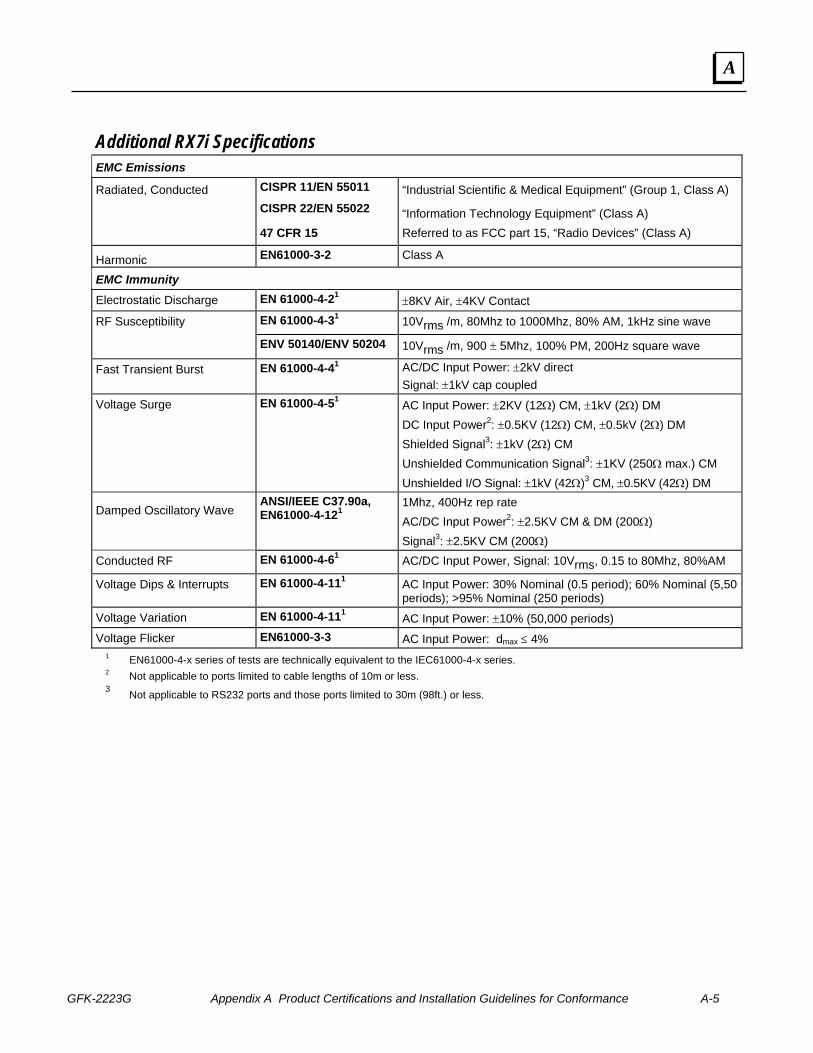
GFK-2223G Appendix A Product Certifications and Installation Guidelines for Conformance A-5
A
Additional RX7i Specifications EMC Emissions
Radiated, Conducted CISPR 11/EN 55011 “Industrial Scientific & Medical Equipment” (Group 1, Class A)
CISPR 22/EN 55022 “Information Technology Equipment” (Class A)
47 CFR 15 Referred to as FCC part 15, “Radio Devices” (Class A)
Harmonic EN61000-3-2 Class A
EMC Immunity Electrostatic Discharge EN 61000-4-21 ±8KV Air, ±4KV Contact
RF Susceptibility EN 61000-4-31 10Vrms /m, 80Mhz to 1000Mhz, 80% AM, 1kHz sine wave
ENV 50140/ENV 50204 10Vrms /m, 900 ± 5Mhz, 100% PM, 200Hz square wave
Fast Transient Burst EN 61000-4-41 AC/DC Input Power: ±2kV direct Signal: ±1kV cap coupled
Voltage Surge EN 61000-4-51 AC Input Power: ±2KV (12Ω) CM, ±1kV (2Ω) DM DC Input Power2: ±0.5KV (12Ω) CM, ±0.5kV (2Ω) DM Shielded Signal3: ±1kV (2Ω) CM Unshielded Communication Signal3: ±1KV (250Ω max.) CM Unshielded I/O Signal: ±1kV (42Ω)3 CM, ±0.5KV (42Ω) DM
Damped Oscillatory Wave ANSI/IEEE C37.90a, EN61000-4-121
1Mhz, 400Hz rep rate AC/DC Input Power2: ±2.5KV CM & DM (200Ω) Signal3: ±2.5KV CM (200Ω)
Conducted RF EN 61000-4-61 AC/DC Input Power, Signal: 10Vrms, 0.15 to 80Mhz, 80%AM
Voltage Dips & Interrupts EN 61000-4-111 AC Input Power: 30% Nominal (0.5 period); 60% Nominal (5,50 periods); >95% Nominal (250 periods)
Voltage Variation EN 61000-4-111 AC Input Power: ±10% (50,000 periods) Voltage Flicker EN61000-3-3 AC Input Power: dmax ≤ 4%
1 EN61000-4-x series of tests are technically equivalent to the IEC61000-4-x series. 2 Not applicable to ports limited to cable lengths of 10m or less. 3 Not applicable to RS232 ports and those ports limited to 30m (98ft.) or less.
A-6 PACSystems™ RX7i Installation Manual – September 2006 GFK-2223G
A
Government Regulations U.S., Canadian, Australian, and European regulations are intended to prevent equipment from interfering with approved transmissions or with the operation of other equipment through the AC power source.
The PACSystems RX7i family of products has been tested and found to meet or exceed the requirements of U.S. (47 CFR 15), Canadian (ICES-003), Australian (AS/NZS 3548), and European (EN55022) regulations for Class A digital devices when installed in accordance with the guidelines noted in this manual. These various regulations share commonality in content and test levels with that of CISPR 22 and based on this commonality testing to the each individual standard was deemed inappropriate.
The FCC requires the following note to be published according to FCC guidelines:
Note: This equipment has been tested and found to comply with the limits for a Class A digital device, pursuant to Part 15 of the FCC Rules. These limits are designed to provide reasonable protection against harmful interference when the equipment is operated in a commercial environment. This equipment generates, uses, and can radiate radio frequency energy and, if not installed and used in accordance with the instruction manual, may cause harmful interference to radio communications. Operation of this equipment in a residential area is likely to cause harmful interference in which case user will be required to correct the interference at his own expense.
Industry Canada requires the following note to be published:
Note: This Class A digital apparatus complies with Canadian ICES-003.
GFK-2223G Appendix A Product Certifications and Installation Guidelines for Conformance A-7
A
Installation Guidelines for Conformance to Standards To meet U.S., Canadian, Australian and European regulations for Class A digital devices and maintain CE Mark compliance, RX7i installations that include the following products must be installed in a metal enclosure with external wiring routed in metal conduit as described in this appendix:
■ All Series 90-70 modules (For a list of supported Series 90-70 modules, see “Modules Supported in RX7i" in chapter 2.)
■ All Series 90-70 expansion racks
■ RX7i Memory Xchange modules (IC698RMX016, IC698CMX016)
■ RX7i Rear Mount Rack with Rear I/O Access (IC698CHS217)
Requirements for Installation in a Metal Enclosure ■ Racks must be mounted in a metal enclosure with a metal-on-metal connection
around the door or the equivalent. All surfaces of the enclosure must be adequately grounded to adjacent surfaces to provide electrical conductivity.
■ Wiring external to the enclosure must be routed in metal conduit or the equivalent. Using shielded cables and power line filtering, as detailed in “Shielded Cable Alternative to Conduit,” is equivalent to using metal conduit.
■ The conduit must be mounted to the enclosure using standard procedures and hardware to ensure electrical conductivity between the enclosure and conduit. The termination for the shielded cable alternative to conduit is detailed in “Shielded Cable Alternative to Conduit.”
A-8 PACSystems™ RX7i Installation Manual – September 2006 GFK-2223G
A
Shielded Cable Alternative to Conduit This section describes the installation requirements for using shielded cable as an alternative to metal conduit for meeting radiated emissions requirements (EN 55022, 47CFR15, etc.). The following practices could be used in place of conduit for systems or cables that require conduit or the equivalent.
Communication Cables All communication lines should be double-shielded. The outside braided shield (85% coverage) must be terminated at the entrance to the enclosure and not continue within the enclosure. The inside shield should be left intact since it shields the communication line from noise within the enclosure and is terminated to the connector shell. The RX7i communication port connector shells are directly tied to frame ground. To prevent ground loop currents, one cable end of the inside shield should be capacitively coupled to its shell. The outside shield is classified as an RF shield and should be insulated from the inside shield. An alternative to double-shielded cable for Genius bus communications is Eupen* CMS cable, equivalent Genius cables with an RF-absorptive material outer coating. The shield should be terminated per standard Genius wiring guidelines. *Telephone: 32 87 55 47 71 (Europe), 908-919-1100 (U.S.A.)
I/O Cables
All I/O lines leaving the enclosure must have at least 85% braided shield coverage terminated at the entrance to the enclosure. This 85% RF shield should not continue into the enclosure. Eighty-five percent braided shield is a standard cable available with various wire sizes and quantities from many cable manufacturers.
Analog/High Speed Cables
Analog or high-speed lines, which require shielded cable for immunity, should be double-shielded. The outside braided shield should be terminated at the entrance to the enclosure and not continue within the enclosure. The inside shield should be terminated per standard installation instructions. The outside shield is classified as an RF shield and should be insulated from the inside shield.
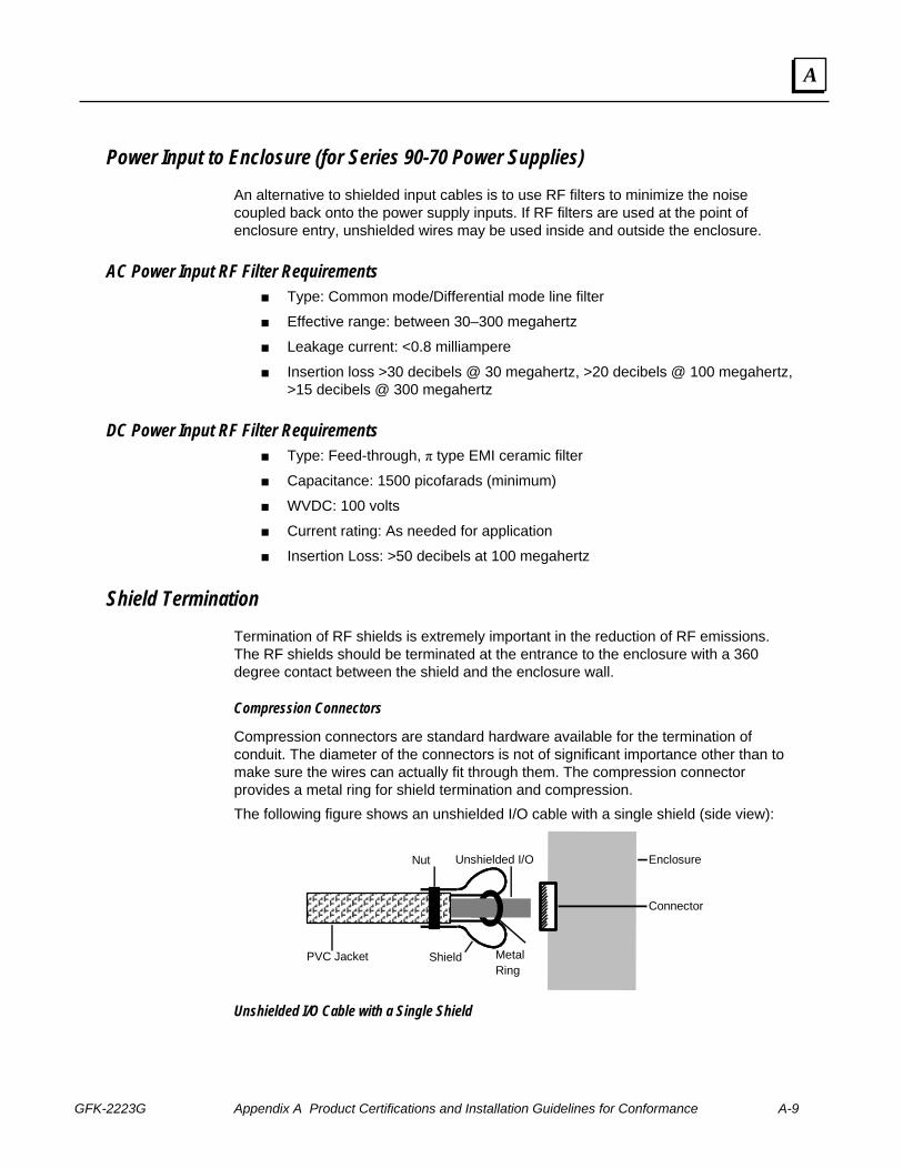
GFK-2223G Appendix A Product Certifications and Installation Guidelines for Conformance A-9
A
Power Input to Enclosure (for Series 90-70 Power Supplies) An alternative to shielded input cables is to use RF filters to minimize the noise coupled back onto the power supply inputs. If RF filters are used at the point of enclosure entry, unshielded wires may be used inside and outside the enclosure.
AC Power Input RF Filter Requirements ■ Type: Common mode/Differential mode line filter
■ Effective range: between 30–300 megahertz
■ Leakage current: <0.8 milliampere
■ Insertion loss >30 decibels @ 30 megahertz, >20 decibels @ 100 megahertz, >15 decibels @ 300 megahertz
DC Power Input RF Filter Requirements ■ Type: Feed-through, π type EMI ceramic filter
■ Capacitance: 1500 picofarads (minimum)
■ WVDC: 100 volts
■ Current rating: As needed for application
■ Insertion Loss: >50 decibels at 100 megahertz
Shield Termination Termination of RF shields is extremely important in the reduction of RF emissions. The RF shields should be terminated at the entrance to the enclosure with a 360 degree contact between the shield and the enclosure wall.
Compression Connectors
Compression connectors are standard hardware available for the termination of conduit. The diameter of the connectors is not of significant importance other than to make sure the wires can actually fit through them. The compression connector provides a metal ring for shield termination and compression. The following figure shows an unshielded I/O cable with a single shield (side view):
PVC Jacket
Nut Unshielded I/O
Metal Ring
Shield
Enclosure
Connector
Unshielded I/O Cable with a Single Shield
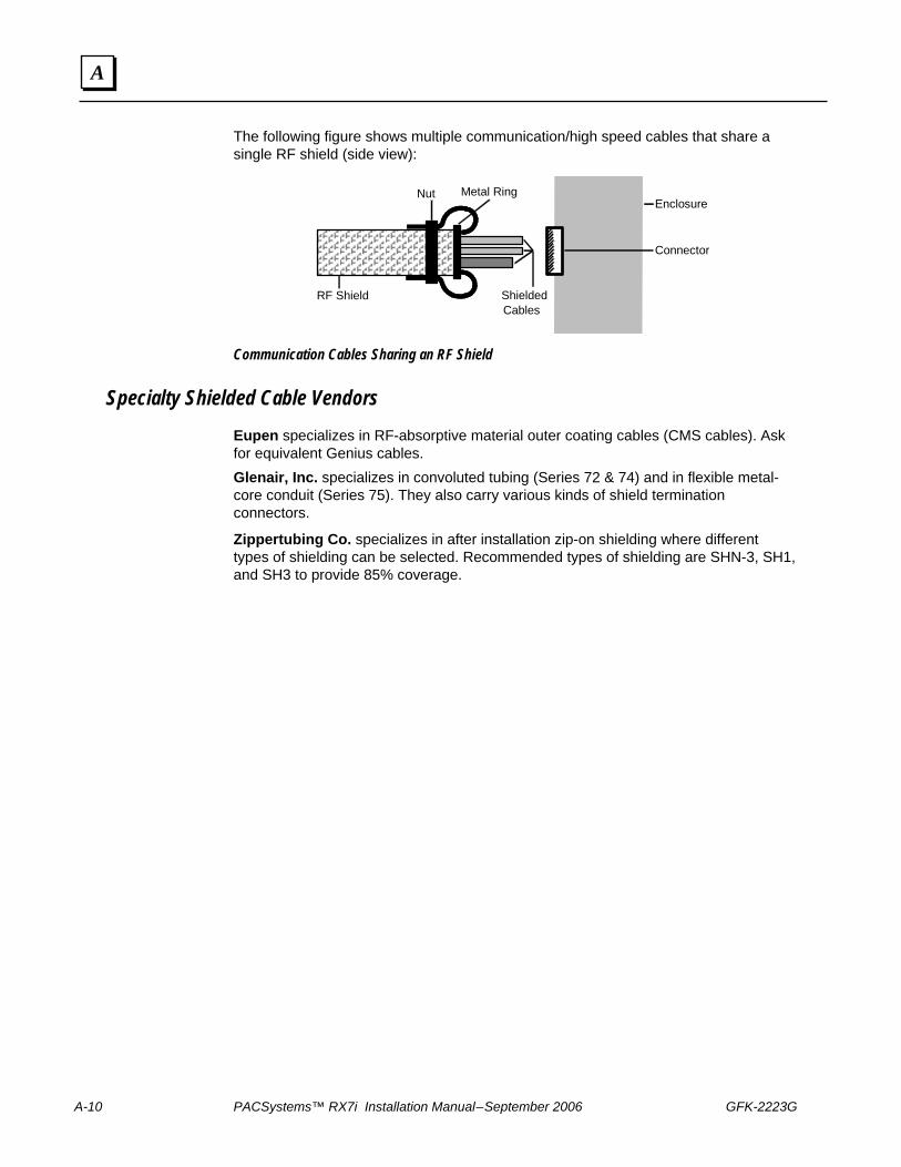
A-10 PACSystems™ RX7i Installation Manual – September 2006 GFK-2223G
A
The following figure shows multiple communication/high speed cables that share a single RF shield (side view):
RF Shield
Nut Enclosure
Connector
ShieldedCables
Metal Ring
Communication Cables Sharing an RF Shield
Specialty Shielded Cable Vendors Eupen specializes in RF-absorptive material outer coating cables (CMS cables). Ask for equivalent Genius cables. Glenair, Inc. specializes in convoluted tubing (Series 72 & 74) and in flexible metal-core conduit (Series 75). They also carry various kinds of shield termination connectors.
Zippertubing Co. specializes in after installation zip-on shielding where different types of shielding can be selected. Recommended types of shielding are SHN-3, SH1, and SH3 to provide 85% coverage.

GFK-2223G Appendix A Product Certifications and Installation Guidelines for Conformance A-11
A
Safety-Related Guidelines for Installation in the European Union This section provides safety-related guidelines specifically for control system products to be installed in the European Union. It is assumed that personnel who install, operate, and maintain automation systems that include GE Fanuc products are trained and qualified to perform those functions 1. General:
GE Fanuc product manuals provide information required for the intended use of GE Fanuc products. The product manuals are written for technically qualified personnel such as engineers, programmers, or maintenance specialists who have been specifically trained and are experienced in the field of automation control. Such personnel must possess the knowledge to correctly interpret and apply the safety guidelines provided in GE Fanuc product manuals. Should you require further information or face special problems that are not covered in sufficient detail in the product manuals, please contact your local GE Fanuc sales or service office or GE Fanuc authorized distributor.
2. Qualified Personnel: Only qualified personnel should be allowed to specify, apply, install, operate, maintain, or perform any other function related to the products described in the product manuals. Examples of such qualified persons are defined as follows:
System application and design engineers who are familiar with the safety concepts of automation equipment.
Installation, startup, and service personnel who are trained to install and maintain such automation equipment.
Operating personnel trained to operate automation equipment and trained on the specific safety issues and requirements of the particular equipment.
3. Proper Usage: The equipment/system or the system components may be used only as described in the product manuals. GE Fanuc control system products have been developed, manufactured, tested, and the documentation compiled in keeping with the relevant safety standards. Handling instructions and safety guidelines described for planning, installation, proper operation and maintenance must be followed to ensure safe application and use of the products.
4. Guidelines for the Application Planning and Installation of the Product: RX7i control system products generally form part of larger systems or installations. These guidelines are intended to help integrate GE Fanuc RX7i control system products into systems and installations without constituting a source of danger. The following precautions must be followed:
Compliance with EN292-1 and EN292-2 (Safety of Machinery) as well as EN60204/IEC204 (Electrical Equipment of Industrial Machines) must be observed during the design phase.
Opening the housing or the protective cover exposes certain parts of this equipment/system that could have a dangerously high voltage level.
A-12 PACSystems™ RX7i Installation Manual – September 2006 GFK-2223G
A
Only qualified personnel should be allowed access to this equipment/system. These persons must be knowledgeable of potential sources of danger and maintenance measures as described in the product manuals.
Personnel must strictly adhere to applicable safety and accident prevention rules and regulations.
A suitable isolating switch or fuses must be provided in the building wiring system. The equipment must be connected to a protective ground (PE) conductor.
For equipment or systems with a fixed connecting cable but no isolating switch that disconnects all poles, a power socket with the grounding pin must be installed.
Before switching on the equipment, make sure that the voltage range setting on the equipment corresponds to the local power system voltage.
In the case of equipment operating on 24 VDC, make sure that proper electrical isolation is provided between the main supply and the 24 VDC supply. Use only power supplies that meet EN60204 (IEC204) requirements.
The RX7i control system AC power supply must be supplied through an IEC-rated isolation transformer.
Power supply to the RX7i control system must be controlled not to exceed overvoltage category II per EN60204-1 (IEC204).
Do not exceed the input specifications of the power supply. Otherwise, functional failures or dangerous conditions can occur in the electronic modules/equipment.
Emergency shutoff devices in accordance with EN60204/IEC204 must be effective in all operating modes of the automation equipment. Resetting the emergency off device must not result in any uncontrolled or undefined restart of the equipment.
Automation equipment and its operating elements must be installed in such a manner as to prevent unintentional operation.
Suitable measurements must be taken to ensure that operating sequences interrupted by a voltage dip or power supply failure resume proper operation when the power supply is restored. Care must be taken to ensure that dangerous operating conditions do not occur even momentarily. If necessary, the equipment must be forced into the “emergency off” state.
Negative Logic Input and Output Modules cannot be used. (Exception: With safety agency approval, such as TÜV on GMR Systems, these devices may be used in safety system “H” configurations).
Cable shielding and grounding are the responsibility of the machine builder. GE Fanuc’s installation instructions and guidelines must be followed.
Install the power supply and signal cables in such a manner as to prevent inductive and capacitive interference voltages from affecting automation functions.
When interfacing the inputs and outputs of the automation equipment, measures must be taken to prevent an undefined state from being assumed in the case of a wire break in the signal lines.
GFK-2223G B-1
Calculating Heat Dissipation
This appendix explains how to find the total heat dissipation of PACSystems RX7i equipment.
PACSystems RX7i equipment must be mounted in a protective enclosure. The enclosure must be able to properly dissipate the heat produced by all the devices mounted inside. This includes the modules, discrete output devices, and discrete input devices. Each device manufacturer publishes these values. If an exact value is not available for a device, you can make a close estimate by obtaining the value for a similar device.
Information Required In addition to the information in this manual, you will need the Series 90-70 Data
Sheet Manual (GFK-0600) or individual module data sheets.
You will need operating current values for the discrete output devices connected to the PLC’s discrete output modules. These include control relays, motor starters, solenoids, pilot lights, etc. Each device manufacturer publishes these values. If an exact value is not available for a device, you can make a close estimate by obtaining the value for a similar device from a catalog. These values are also needed for selecting Output modules during the design process in order to ensure that the modules’ maximum ratings are not exceeded.
B Appendix
B-2 PACSystems™ RX7i Installation Manual – September 2006 GFK-2223G
B
Heat Dissipation Calculations
Module Heat Dissipation For each module except power supplies (discussed separately), use the following procedure. Assume that all input power to these modules is dissipated as heat.
1. Look up the module in the Module Load Requirements table (chapter 4) and obtain the current values for each of the three power supply voltages listed. All modules use the 5VDC supply, and a relatively few modules also use one or both of the two 24VDC supplies.
2. For each voltage used by the module, calculate the power dissipation by multiplying the current value (in Amps) times the voltage:
Power (in Watts) = Current (in Amps) x Voltage (in Volts).
3. For modules using more than one voltage, add the calculated power values to arrive at the total for the module.
Example 1
The Module Load Requirements table shows that the IC698CPE020 module draws:
4.5 Amps from the +5VDC supply 22.5 Watts
0.042 Amps from the +12VDC supply 0.504 Watts
0.008 Amps from the -12VDC supply 0.096 Watts
Total 23.1 Watts
Example 2
The Module Load Requirements table shows that the IC698ETM001 module draws:
1.5 Amps from the +5VDC supply 7.5 Watts
Power Supply Heat Dissipation In general, power supplies are 66% efficient. The power supply dissipates approximately 1 Watt of power in the form of heat for every 2 Watts of power it delivers to the PLC.
After finding the total power requirement for all of the modules in the rack served by a power supply above, divide the total by 2 to find the power supply dissipation value. Do not use the rating of the power supply (such as 350 Watts) for this calculation because the application may not use the full capacity of the power supply.
Since each rack has its own power supply, each rack should be calculated on an individual basis.
GFK-2223G Appendix B Calculating Heat Dissipation B-3
B
Heat Dissipation for Discrete Output Modules In addition to the module power calculations, discrete solid-state output modules require a calculation for their output circuits, which are powered from another supply. (This calculation is not required for Relay Output modules.) To calculate output circuit power dissipation:
1. In the Series 90-70 Data Sheet Manual, GFK-0600 (or individual module data sheet), find the value for the Output Voltage Drop for your particular module listed in the module Specifications table.
2. Using the manufacturer’s documentation or other reference information, find the required current value for each device (such as a relay, pilot light, solenoid, etc.) connected to an output point on the module. Estimate the device’s percent of on-time based on its intended use in the application.
3. Multiply the Output Voltage Drop times the current value times the estimated percent of on-time to arrive at average power dissipation for that output.
4. Repeat these steps for all outputs on the module, and then for all discrete output modules in the rack.
Example:
The Data Sheet for the IC697MDL340 16-Point Discrete 120 VAC Output Module lists the following information:
Output Voltage Drop: 3 Volts maximum
Use that value for all of the calculations for this module.
In this example, two of the Output module’s output points drive solenoids that control the advance and retract travel of a hydraulic cylinder. The solenoid manufacturer’s data sheet shows that each solenoid draws 1.0 Amp. The cylinder advances and retracts once every 60 seconds that the machine is cycling. It takes 6 seconds to advance and 6 seconds to retract.
Since the cylinder takes equal time to advance and retract, both solenoids are on for equal lengths of time: 6 seconds out of every 60 seconds, which is 10% of the time. Since both solenoids have equal current draws and on-times, a single calculation can be applied to both outputs.
Use the formula Average Power Dissipation = Voltage Drop x Current Draw (in Amps) x Percent (expressed as a decimal) of on-time:
3.0 x 1.0 x 0.10 = 0.3 Watts per solenoid
Then multiply this result by 2 since there are two identical solenoids:
0.3 Watts x 2 Solenoids = 0.60 Watts total for the two solenoids
Also in this example, the other 14 output points on this 16-point module operate pilot lights on an operator’s panel. Each pilot light requires 0.05 Amps of current. Seven of the pilot lights are on 100% of the time and seven are on an estimated 40%.
B-4 PACSystems™ RX7i Installation Manual – September 2006 GFK-2223G
B
For the seven lights that are on 100% of the time:
3.0 x .05 x 1.00 = 0.15 Watts per light
Then multiply this value by 7:
0.15 Watts x 7 lights = 1.05 Watts total dissipation for the first 7 lights
For the seven lights that are on 40% of the time:
3.0 x .05 x 0.40 = 0.06 Watts per light
Then multiply this value by 7:
0.06 Watts x 7 lights = 0.42 Watts total dissipation for the other 7 lights
Adding up the individual calculations:
0.60 + 1.05 + 0.42 = 2.07 Watts for the module’s total output calculation
Heat Dissipation for Discrete Input Modules In addition to the module power calculations described above, a discrete input module requires another calculation for its input circuits, because the power dissipated by the input circuits comes from a separate power source. This calculation assumes that all input circuit power delivered to these modules is dissipated as heat. The procedure is:
In the Series 90-70 Data Sheet Manual, GFK-0600 (or individual module data sheet), find the value for the Input Current for your particular module listed in the module Specifications table.
Multiply the input voltage times the current value times the estimated percent of on-time to arrive at average power dissipation for that input.
Repeat these steps for all inputs on the module, and then for all discrete input modules in the rack.
Example
The Specifications table for the IC697MDL240 16-Point Discrete 120 VAC Input Module in the module’s Data Sheet gives the following information:
Input Current: 10 mA (typical) at rated voltage)
Use this value for all of the input calculations for this module.
In this example, eight of the Input Module’s points are used for switches that, for normal operation, stay on (closed) 100% of the time. These include the Emergency Stop, Over Temperature, Lube Pressure OK, and similar switches.
Use the formula Average Power Dissipation = Input Voltage x Input Current (in Amps) x Percent (expressed as a decimal) of on-time:
120 x .010 x 1.0 = 1.2 Watts per input
Then multiply this result by 8:
1.2 Watts x 8 inputs = 9.6 Watts total for the 8 inputs
Also in this example, two input points on this 16-point module are for the Control On and Pump Start pushbuttons. Under normal conditions, these pushbuttons are only pressed once per day for about one second - just long enough to start up the control
GFK-2223G Appendix B Calculating Heat Dissipation B-5
B
and pump. Therefore, their effect on the power calculation is negligible and you can assume a power dissipation of zero for them:
0.0 Watts total for 2 inputs
For the remaining six inputs of this sixteen point module, it is estimated that they will be on for an average of 20% of the time. So the following calculation is made for these six inputs:
Using the formula of Average Power Dissipation = Input Voltage x Input Current (in Amps) x Percent (expressed as a decimal) of on-time:
120 x 0.010 x 0.20 = 0.24 Watts per input
Then multiply this result by 6:
0.24 Watts x 6 inputs = 1.44 Watts total for the 6 inputs
Finally, adding up the individual calculations:
9.6 + 0.0 + 1.44 = 11.04 Watts for the module’s total input calculation
Total Heat Dissipation Once the individual power dissipations have been calculated, add them all to obtain total heat dissipation. Note that the rack, analog input modules, and analog output modules have been ignored in this procedure because their power dissipation values are negligible when compared with the total. Also, since each rack has its own power supply, each rack should be calculated on an individual basis.
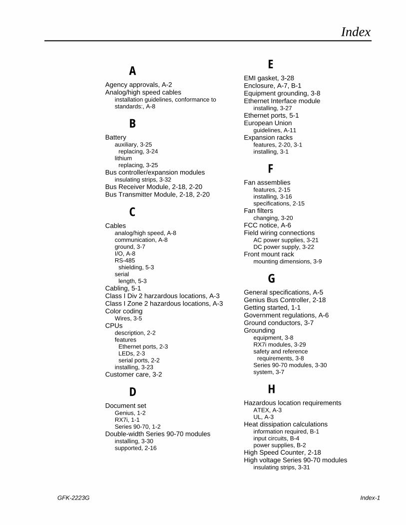
Index
GFK-2223G Index-1
A Agency approvals, A-2 Analog/high speed cables
installation guidelines, conformance to standards:, A-8
B Battery
auxiliary, 3-25 replacing, 3-24
lithium replacing, 3-25
Bus controller/expansion modules insulating strips, 3-32
Bus Receiver Module, 2-18, 2-20 Bus Transmitter Module, 2-18, 2-20
C Cables
analog/high speed, A-8 communication, A-8 ground, 3-7 I/O, A-8 RS-485
shielding, 5-3 serial
length, 5-3 Cabling, 5-1 Class I Div 2 harzardous locations, A-3 Class I Zone 2 hazardous locations, A-3 Color coding
Wires, 3-5 CPUs
description, 2-2 features
Ethernet ports, 2-3 LEDs, 2-3 serial ports, 2-2
installing, 3-23 Customer care, 3-2
D Document set
Genius, 1-2 RX7i, 1-1 Series 90-70, 1-2
Double-width Series 90-70 modules installing, 3-30 supported, 2-16
E EMI gasket, 3-28 Enclosure, A-7, B-1 Equipment grounding, 3-8 Ethernet Interface module
installing, 3-27 Ethernet ports, 5-1 European Union
guidelines, A-11 Expansion racks
features, 2-20, 3-1 installing, 3-1
F Fan assemblies
features, 2-15 installing, 3-16 specifications, 2-15
Fan filters changing, 3-20
FCC notice, A-6 Field wiring connections
AC power supplies, 3-21 DC power supply, 3-22
Front mount rack mounting dimensions, 3-9
G General specifications, A-5 Genius Bus Controller, 2-18 Getting started, 1-1 Government regulations, A-6 Ground conductors, 3-7 Grounding
equipment, 3-8 RX7i modules, 3-29 safety and reference
requirements, 3-8 Series 90-70 modules, 3-30 system, 3-7
H Hazardous location requirements
ATEX, A-3 UL, A-3
Heat dissipation calculations information required, B-1 input circuits, B-4 power supplies, B-2
High Speed Counter, 2-18 High voltage Series 90-70 modules
insulating strips, 3-31
Index
Index-2 PACSystems™ RX7i Installation Manual–September 2006 GFK-2223G
I I/O cables, A-8 I/O modules
addressing, 3-28 installing, 3-28 Series 90-70
keying, 3-31 supported, 2-16 terminal boards, 3-30 universal terminal boards, 3-31
Installation guidelines, conformance to standards
application planning and installation, A-11 communication cables, A-8 European Union, A-11 general, A-11 power input to enclosure, A-9 Proper usage, A-11 Qualified personnel, A-11 RX7i Memory Xchange modules, A-7 shield termination, A-9
Insulating strips high voltage Series 90-70 modules, 3-31 Series 90-70 bus controller/expansion modules, 3-32
K Keying, Series 90-70 I/O modules, 3-31
L Layout, PLC system
guidelines, 3-3 Load requirements
modules, 4-2
M MAC address
embedded Ethernet Interface, 2-3, 3-23 ETM001, 3-27
Metal enclosure, 3-1, A-7 Modules
double width removing, 3-32 replacement, 3-32
load requirements, 4-2 single width
removing, 3-30 replacement, 3-30
VME, 2-18 Modules supported in RX7i, 2-16 Mounting dimensions
front mount rack, 3-9 rear mount rack, 3-10, 3-11
N Noise protection, 3-28
P Part numbers
standard fan assemblies, 2-15 Pin assignments, 5-1 Ports
Ethernet, 5-1 CPU, 2-3
serial, 5-2 CPU, 2-2
Power supplies features, 2-8 installing, 3-21 sharing, 2-21
Power supply load capacity RX7i, 4-1 Series 90-70, 4-1
Pre-installation check, 3-2
R Racks, RX7i
features, 2-4 installing, 3-9
Racks, Series 90-70 features, 2-20 installing, 3-1
Rear mount rack mounting dimensions, 3-10, 3-11
Recommended system grounding, 3-7 Regulations, A-6 Related documents
Genius, 1-2 RX7i, 1-1 Series 90-70, 1-2
Removable terminal boards, 3-30, 3-31 RFI standards, A-6 RX7i
control system overview, 1-3 document set, 1-1 environmental specifications, A-4 general specifications, A-5 modules supported, 2-16 racks, installing, 3-9
RX7i Memory Xchange modules installation guidelines for conformance, A-7
S Safety and reference ground
requirements, 3-8 Serial ports, 5-2 Series 90-70