Embed Size (px)
Citation preview
ÎÎ
GE Fanuc Automation
Programmable Control Products
GE FanucMicr o PLCUser’s Guide
GFK-0803B April 1994
FANUC Replacements
GFL–002
Warnings, Cautions, and Notesas Used in this Publication
Warning
Warning notices are used in this publication to emphasize that hazardous voltages,currents, temperatures, or other conditions that could cause personal injury exist in thisequipment or may be associated with its use.
In situations where inattention could cause either personal injury or damage toequipment, a Warning notice is used.
Caution
Caution notices are used where equipment might be damaged if care is not taken.
Note
Notes merely call attention to information that is especially significant to understandingand operating the equipment.
This document is based on information available at the time of its publication. Whileefforts have been made to be accurate, the information contained herein does notpurport to cover all details or variations in hardware or software, nor to provide forevery possible contingency in connection with installation, operation, or maintenance.Features may be described herein which are not present in all hardware and softwaresystems. GE Fanuc Automation assumes no obligation of notice to holders of thisdocument with respect to changes subsequently made.
GE Fanuc Automation makes no representation or warranty, expressed, implied, orstatutory with respect to, and assumes no responsibility for the accuracy, completeness,sufficiency, or usefulness of the information contained herein. No warranties ofmerchantability or fitness for purpose shall apply.
The following are trademarks of GE Fanuc Automation North America, Inc.
Alarm Master CIMSTAR Helpmate PROMACRO Series SixCIMPLICITY Field Control GEnet Logicmaster Series OneSeries 90 CIMPLICITY 90–ADS Genius Modelmaster Series ThreeVuMaster CIMPLICITY PowerTRAC Genius PowerTRAC ProLoop Series FiveWorkmaster
Copyright 1994 GE Fanuc Automation North America, Inc.All Rights Reserved
iii GFK-0803B
Preface
This book describes the GE Fanuc Micro PLC. It contains product specifications,installation instructions, and general information needed to set up and use a Micro PLC.
Content of this ManualChapter 1. Introduction: begins with a discussion of PLC basics. Chapter 1 alsodescribes the Micro PLC and its programming devices, and provides an overview ofthe programming features of the Micro PLC.
Chapter 2. The Micro PLC: describes the available types of Micro PLC units, and listsproduct specifications.
Chapter 3. Installation: explains how to situate and install the Micro PLC, and howto connect I/O devices to the Micro PLC.
Chapter 4. The Hand-held Programmer: describes the Hand-held Programmer andexplains how to use it for monitoring and changing data, transferring programs, andchanging the operating mode of the Micro PLC.
Chapter 5. The Operator Interface Unit: describes the OIU and explains how to useand program it.
Chapter 7. The Programming Software: explains how to install the programmingsoftware. Chapter 6 also describes how to use the software for monitoring and changingdata, transferring programs, and changing the operating mode of the Micro PLC.
Appendix A. Cable Pin Assignments: shows pinouts for the cables used with aMicro PLC.
Appendix B. Using a Modem: describes modem setup and cabling.
Appendix C. Using EPROMs or Battery-backed RAM: describes the charging anddischarging characteristics of the program storage memory unit provided with someprevious versions of the Micro PLC CPU. Appendix C also describes the EPROMProgrammer, which can be used with optional EPROMS for program storage andtransfer.
Appendix D. Related Products: introduces some products, made by othercompanies, that can be used to enhance a Micro PLC application.
Related PublicationsGE Fanuc Micro PLC Programming Manual (GFK-0804): this book is thereference guide to programming the Micro PLC. Instructions are given forprogramming with the programming software or with a Hand-held Programmer.
GE Fanuc Micro PLC Self-Teach Manual (GFK–0811): a quick-start guide tounderstanding and using the Micro PLC.
FANUC Replacements
Contents
iv GFK–0803BMicro Programmable Controller User’s Guide – April 1994
Technical AssistanceAt GE Fanuc, we strive to produce quality documentation. If you should have a probleminstalling or programming your GE Fanuc Micro PLC, and the information you need isnot in this book or the Micro PLC Programmer’s Guide, you can call GE Fanuc FieldService at 1-800-828-5747.
Jeanne L. GrimsbySenior Technical Writer
Note
This equipment has been tested and found to comply with the limits for aClass A digital device, pursuant to part 15 of the FCC rules. These limits aredesigned to provide reasonable protection against harmful interference whenthe equipment is operated in a commercial environment. This equipmentgenerates, uses, and can radiate radio frequency energy and, if not installedand used in accordance with the instruction manual, may cause harmfulinterference to radio communications. Operation of this equipment in aresidential area is likely to cause harmful interference in which case the userwill be required to correct the interference at his own expense.
Contents
vGFK-0803B Micro PLC User’s Guide - April 1994
Chapter 1 Introduction 1-1 . . . . . . . . . . . . . . . . . . . . . . . . . . . . . . . . . . . . . . . . . . . . . . .
PLC Basics 1-2 . . . . . . . . . . . . . . . . . . . . . . . . . . . . . . . . . . . . . . . . . . . . . . . . . . . . .
PLC Operation 1-3 . . . . . . . . . . . . . . . . . . . . . . . . . . . . . . . . . . . . . . . . . . . . . . . . .
The GE Fanuc Micro PLC 1-6 . . . . . . . . . . . . . . . . . . . . . . . . . . . . . . . . . . . . . . . .
Overview 1-7 . . . . . . . . . . . . . . . . . . . . . . . . . . . . . . . . . . . . . . . . . . . . . . . . . . . . .
Micro PLC CPU and Expander Unit 1-8 . . . . . . . . . . . . . . . . . . . . . . . . . . . . . . .
Programming and Monitoring Devices 1-9 . . . . . . . . . . . . . . . . . . . . . . . . . . . .
Programming for the Micro PLC 1-11 . . . . . . . . . . . . . . . . . . . . . . . . . . . . . . . . . .
Monitoring the System 1-13 . . . . . . . . . . . . . . . . . . . . . . . . . . . . . . . . . . . . . . . . . .
Ordering Information 1-14 . . . . . . . . . . . . . . . . . . . . . . . . . . . . . . . . . . . . . . . . . . .
Product Compatibility 1-15 . . . . . . . . . . . . . . . . . . . . . . . . . . . . . . . . . . . . . . . . . . .
Related Products 1-16 . . . . . . . . . . . . . . . . . . . . . . . . . . . . . . . . . . . . . . . . . . . . . . .
Chapter 2 The Micro PLC 2-1 . . . . . . . . . . . . . . . . . . . . . . . . . . . . . . . . . . . . . . . . . . . .
CPU Units 2-2 . . . . . . . . . . . . . . . . . . . . . . . . . . . . . . . . . . . . . . . . . . . . . . . . . . . . .
Expander Units 2-3 . . . . . . . . . . . . . . . . . . . . . . . . . . . . . . . . . . . . . . . . . . . . . . . .
General Specifications 2-4 . . . . . . . . . . . . . . . . . . . . . . . . . . . . . . . . . . . . . . . . . . .
Descriptions of CPU Units 2-7 . . . . . . . . . . . . . . . . . . . . . . . . . . . . . . . . . . . . . . .
Descriptions of Expander Units 2-13 . . . . . . . . . . . . . . . . . . . . . . . . . . . . . . . . . .
Chapter 3 Installation 3-1 . . . . . . . . . . . . . . . . . . . . . . . . . . . . . . . . . . . . . . . . . . . . . . . .
Choosing a Location for the Micro PLC 3-2 . . . . . . . . . . . . . . . . . . . . . . . . . . .
Mounting a Unit 3-3 . . . . . . . . . . . . . . . . . . . . . . . . . . . . . . . . . . . . . . . . . . . . . . .
Connecting an Expander Unit 3-6 . . . . . . . . . . . . . . . . . . . . . . . . . . . . . . . . . . . .
Connecting AC or DC Power to a Unit 3-7 . . . . . . . . . . . . . . . . . . . . . . . . . . . . .
I/O Wiring for 14-Point CPU or Expansion Units 3-9 . . . . . . . . . . . . . . . . . . . .
I/O Wiring for 16-Point DC/DC CPU Units 3-10 . . . . . . . . . . . . . . . . . . . . . . . . .
I/O Wiring for 28-Point CPU or Expansion Units 3-11 . . . . . . . . . . . . . . . . . . . .
I/O Wiring for Units with AC Inputs and AC Outputs 3-13 . . . . . . . . . . . . . . . .
I/O Wiring for an Analog Expander Unit 3-14 . . . . . . . . . . . . . . . . . . . . . . . . . .
Selecting Operation with a 14 or 28 Point CPU 3-16 . . . . . . . . . . . . . . . . . . . . . .
Selecting the Operating Mode 3-17 . . . . . . . . . . . . . . . . . . . . . . . . . . . . . . . . . . . .
Chapter 4 The Hand-held Programmer 4-1 . . . . . . . . . . . . . . . . . . . . . . . . . . . . . . . . .
FANUC Replacements
Contents
viGFK-0803B Micro PLC User’s Guide - April 1994
Parts of the Hand-held Programmer 4-2 . . . . . . . . . . . . . . . . . . . . . . . . . . . . . .
Dimensions 4-2 . . . . . . . . . . . . . . . . . . . . . . . . . . . . . . . . . . . . . . . . . . . . . . . . . . . .
Hand-held Programmer Specifications 4-3 . . . . . . . . . . . . . . . . . . . . . . . . . . . .
Getting the HHP Ready to Use 4-4 . . . . . . . . . . . . . . . . . . . . . . . . . . . . . . . . . . .
Operating Power Supply 4-5 . . . . . . . . . . . . . . . . . . . . . . . . . . . . . . . . . . . . . . . .
Keypad Functions 4-6 . . . . . . . . . . . . . . . . . . . . . . . . . . . . . . . . . . . . . . . . . . . . . .
Powerup Displays 4-8 . . . . . . . . . . . . . . . . . . . . . . . . . . . . . . . . . . . . . . . . . . . . . .
Using the Online Functions of the HHP 4-9 . . . . . . . . . . . . . . . . . . . . . . . . . . .
Chapter 5 The Operator Interface Unit 5-1 . . . . . . . . . . . . . . . . . . . . . . . . . . . . . . . . .
Parts of the Operator Interface Unit 5-2 . . . . . . . . . . . . . . . . . . . . . . . . . . . . . . .
Dimensions 5-2 . . . . . . . . . . . . . . . . . . . . . . . . . . . . . . . . . . . . . . . . . . . . . . . . . . . .
Operator Interface Unit Specifications 5-3 . . . . . . . . . . . . . . . . . . . . . . . . . . . . .
Getting the OIU Ready to Use 5-4 . . . . . . . . . . . . . . . . . . . . . . . . . . . . . . . . . . . .
Operating Power Supply 5-5 . . . . . . . . . . . . . . . . . . . . . . . . . . . . . . . . . . . . . . . .
Keypad Functions 5-6 . . . . . . . . . . . . . . . . . . . . . . . . . . . . . . . . . . . . . . . . . . . . . .
Powerup Displays 5-7 . . . . . . . . . . . . . . . . . . . . . . . . . . . . . . . . . . . . . . . . . . . . . .
Changing the Operating Mode of the PLC 5-7 . . . . . . . . . . . . . . . . . . . . . . . . .
Program Listing 5-7 . . . . . . . . . . . . . . . . . . . . . . . . . . . . . . . . . . . . . . . . . . . . . . . .
Program Transfer 5-8 . . . . . . . . . . . . . . . . . . . . . . . . . . . . . . . . . . . . . . . . . . . . . . .
Program Searching 5-9 . . . . . . . . . . . . . . . . . . . . . . . . . . . . . . . . . . . . . . . . . . . . .
Monitoring and Changing Program Data 5-10 . . . . . . . . . . . . . . . . . . . . . . . . . .
Setting the Operation Keys 5-12 . . . . . . . . . . . . . . . . . . . . . . . . . . . . . . . . . . . . . .
Using the Operation Keys 5-14 . . . . . . . . . . . . . . . . . . . . . . . . . . . . . . . . . . . . . . .
Chapter 6 The Programming Software 6-1 . . . . . . . . . . . . . . . . . . . . . . . . . . . . . . . . .
Serial Port Setup 6-2 . . . . . . . . . . . . . . . . . . . . . . . . . . . . . . . . . . . . . . . . . . . . . . . .
Programming Software Files 6-2 . . . . . . . . . . . . . . . . . . . . . . . . . . . . . . . . . . . . .
The Programming Software Main Menu 6-9 . . . . . . . . . . . . . . . . . . . . . . . . . . .
Configuring the Programmer 6-13 . . . . . . . . . . . . . . . . . . . . . . . . . . . . . . . . . . . .
Using the File-Handling Functions 6-14 . . . . . . . . . . . . . . . . . . . . . . . . . . . . . . . .
Using the Online Functions of the Programming Software 6-20 . . . . . . . . . . .
Using the Offline (Programming) Functions 6-37 . . . . . . . . . . . . . . . . . . . . . . . .
Printing an Application Program 6-38 . . . . . . . . . . . . . . . . . . . . . . . . . . . . . . . . .
Contents
viiGFK-0803B Micro PLC User’s Guide - April 1994
Exiting the Programming Software 6-41 . . . . . . . . . . . . . . . . . . . . . . . . . . . . . . . .
Appendix A Cable Pin Assignments A-1 . . . . . . . . . . . . . . . . . . . . . . . . . . . . . . . . . . . . .
Nine-pin computer port to Micro PLC CableHand-held Programmer to Micro PLC Cable A-2 . . . . . . . . . . . . . . . . .
Hand-held Programmer to EPROM Writer CableComputer to EPROM Writer Cable A-2 . . . . . . . . . . . . . . . . . . . . . . . . .
Appendix B Using a Modem B–1 . . . . . . . . . . . . . . . . . . . . . . . . . . . . . . . . . . . . . . . . . . . .
Appendix C Using EPROMs or Battery-backed RAM C-1 . . . . . . . . . . . . . . . . . . . . . .
Program Storage in the Micro PLC C-2 . . . . . . . . . . . . . . . . . . . . . . . . . . . . . . . .
Memory Charging/Discharging Characteristics of Older CPUs C-3 . . . . . . . .
Installing an EPROM or Battery-Backed RAM C-5 . . . . . . . . . . . . . . . . . . . . . .
The EPROM Programmer C-7 . . . . . . . . . . . . . . . . . . . . . . . . . . . . . . . . . . . . . . .
Dimensions C-7 . . . . . . . . . . . . . . . . . . . . . . . . . . . . . . . . . . . . . . . . . . . . . . . . . . . .
Transferring a Program to the EPROM Programmer C-11 . . . . . . . . . . . . . . . . .
Writing the Program to EPROM C-15 . . . . . . . . . . . . . . . . . . . . . . . . . . . . . . . . . .
Transferring a Program from the EPROM Programmer C-17 . . . . . . . . . . . . . .
Appendix D Related Products D-1 . . . . . . . . . . . . . . . . . . . . . . . . . . . . . . . . . . . . . . . . . . .
Data Access Unit D-2 . . . . . . . . . . . . . . . . . . . . . . . . . . . . . . . . . . . . . . . . . . . . . . .
Multidrop Hardware Network for the Micro PLC D-4 . . . . . . . . . . . . . . . . . . .
FANUC Replacements
1 section level 1 1figure bi level 1 table_big level 1
restart lowapp ARestart oddapp: ARestarts for autonumbers that do not restart ineach chapter. figure bi level 1, reset table_big level 1, reset chap_big level 1, reset1Lowapp Alwbox restart evenap:A1app_big level 1, resetA figure_ap level 1, resettable_ap level 1, reset figure level 1, reset table level 1, reset these restartsoddbox reset: 1evenbox reset: 1must be in the header frame of chapter 1. a:ebx, l 1resetA a:obx:l 1, resetA a:bigbx level 1 resetA a:ftr level 1 resetA c:ebx, l 1 reset1c:obx:l 1, reset1 c:bigbx level 1 reset1 c:ftr level 1 reset1 Reminders forautonumbers that need to be restarted manually (first instance will always be 4)let_in level 1: A. B. C. letter level 1:A.B.C. num level 1: 1. 2. 3. num_in level 1: 1. 2.3. rom_in level 1: I. II. III. roman level 1: I. II. III. steps level 1: 1. 2. 3.
1-1GFK-0803B
Chapter 1 Introduction
This chapter explains PLC basics, and introduces the GE Fanuc Micro PLCprogrammable controller.
PLC Basics
Parts of a PLC
PLC Operation
PLC Inputs and Outputs
PLC Memory
The GE Fanuc Micro PLC
Micro PLC CPU and Expander Unit
The CPU Unit
Expander Units
Programming and Monitoring Devices
Connections between Devices
Program Storage in the Micro PLC
Programming for the Micro PLC
Program Format
Programming Information
Monitoring the System
Ordering Information
Product Compatibility
Related Products
1
1-2 Micro PLC User’s Guide – April 1994 GFK-0803B
PLC Basics
FGOUTPUT
INPUT
1 2 3 4 5 6 7 8 COM
1 2 3 4 5 6COM
L2
L1
AC110–220V
1 2 3 4 5 6 7 8
1 2 3 4 5 6 OK RUN
PGM
RUN
COM
VPP
PWR
GE FanucMICRO
PROGRAMMABLE
CONTROLLER
46001
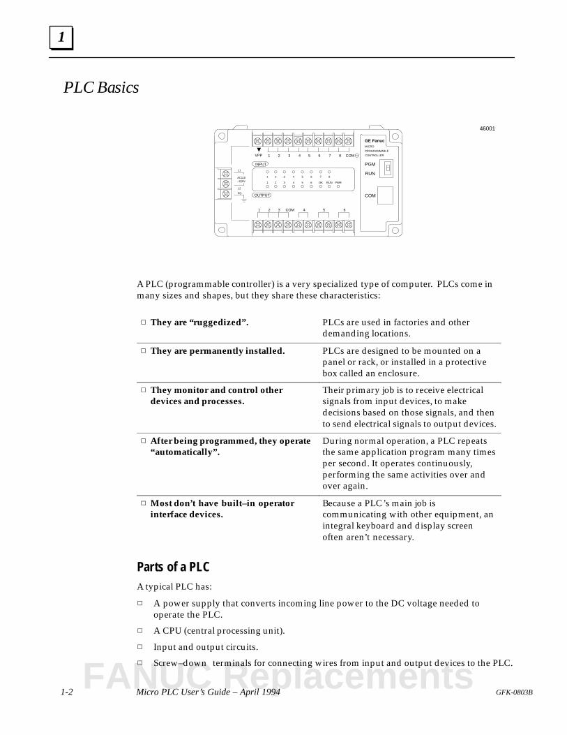
A PLC (programmable controller) is a very specialized type of computer. PLCs come inmany sizes and shapes, but they share these characteristics:
They are “ruggedized”. PLCs are used in factories and otherdemanding locations.
They are permanently installed. PLCs are designed to be mounted on apanel or rack, or installed in a protectivebox called an enclosure.
They monitor and control otherdevices and processes.
Their primary job is to receive electricalsignals from input devices, to makedecisions based on those signals, and thento send electrical signals to output devices.
After being programmed, they operate“automatically”.
During normal operation, a PLC repeatsthe same application program many timesper second. It operates continuously,performing the same activities over andover again.
Most don’t have built–in operatorinterface devices.
Because a PLC’s main job iscommunicating with other equipment, anintegral keyboard and display screenoften aren’t necessary.
Parts of a PLCA typical PLC has:
A power supply that converts incoming line power to the DC voltage needed tooperate the PLC.
A CPU (central processing unit).
Input and output circuits.
Screw–down terminals for connecting wires from input and output devices to the PLC.
FANUC Replacements
1
1-3GFK-0803B Chapter 1 Introduction
PLC Operation
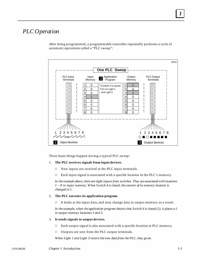
After being programmed, a programmable controller repeatedly performs a cycle ofautomatic operations called a “PLC sweep”:
12345678
ApplicationProgram
InputMemory
OutputMemory
PLC InputTerminals
PLC OutputTerminals
!!!!!!!!
!!!!!!!!
12345678
1 2 3 4 5 6 7 8 1 2 3 4 5 6 7 8
If switch 4 is closedTurn on Light 1 and Light 3
00010000
10100000
Input devices Output devices
One PLC Sweep
1
2
3
46002
Three basic things happen during a typical PLC sweep:
1. The PLC receives signals from input devices.
New inputs are received at the PLC input terminals.
Each input signal is associated with a specific location in the PLC’s memory.
In the example above, there are eight inputs from switches. They are associated with locations1 – 8 in input memory. When Switch 4 is closed, the content of its memory location ischanged to 1.
2. The PLC executes its application program.
It looks at the input data, and may change data in output memory as a result.
In the example, when the application program detects that Switch 4 is closed (1), it places a 1in output memory locations 1 and 3.
3. It sends signals to output devices.
Each output signal is also associated with a specific location in PLC memory.
Outputs are sent from the PLC output terminals.
When Light 1 and Light 3 receive the new data from the PLC, they go on.
1
1-4 Micro PLC User’s Guide – April 1994 GFK-0803B
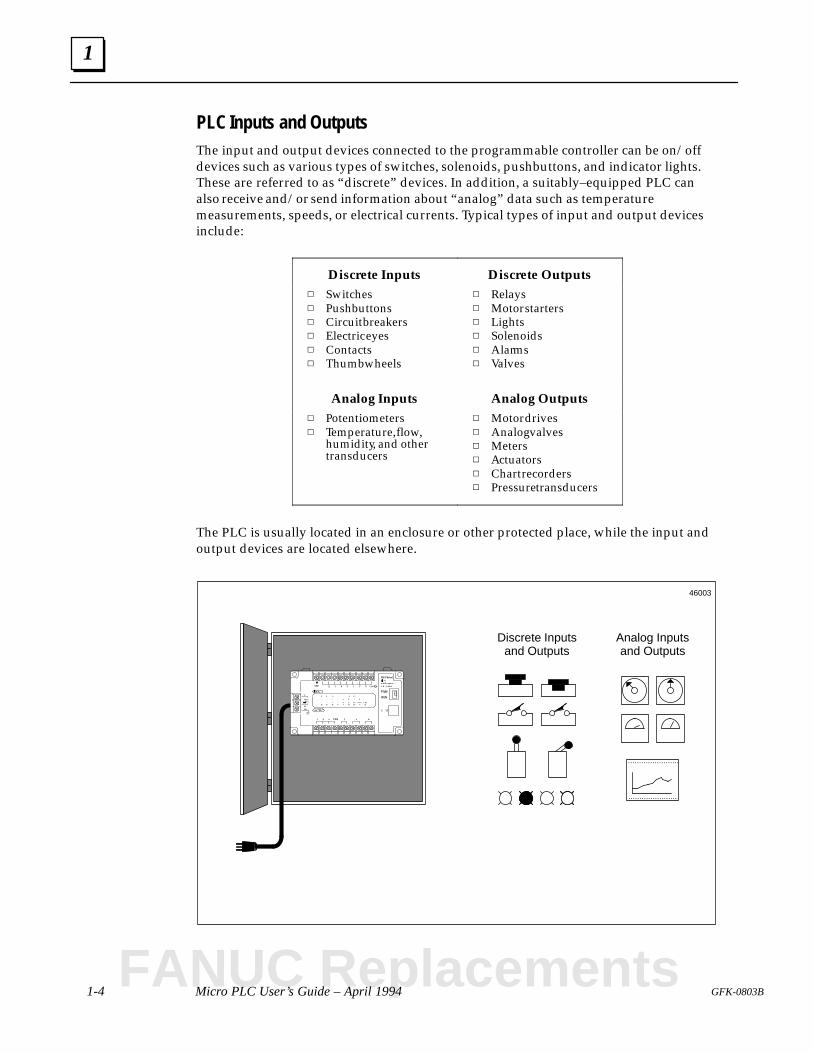
PLC Inputs and OutputsThe input and output devices connected to the programmable controller can be on/offdevices such as various types of switches, solenoids, pushbuttons, and indicator lights.These are referred to as “discrete” devices. In addition, a suitably–equipped PLC canalso receive and/or send information about “analog” data such as temperaturemeasurements, speeds, or electrical currents. Typical types of input and output devicesinclude:
Discrete Inputs Discrete Outputs Switches Pushbuttons Circuit breakers Electric eyes Contacts Thumbwheels
Relays Motor starters Lights Solenoids Alarms Valves
Analog Inputs Analog Outputs Potentiometers Temperature, flow,
humidity, and othertransducers
Motor drives Analog valves Meters Actuators Chart recorders Pressure transducers
The PLC is usually located in an enclosure or other protected place, while the input andoutput devices are located elsewhere.
Discrete Inputsand Outputs
Analog Inputsand Outputs
......................
.......................
46003
FANUC Replacements
1
1-5GFK-0803B Chapter 1 Introduction
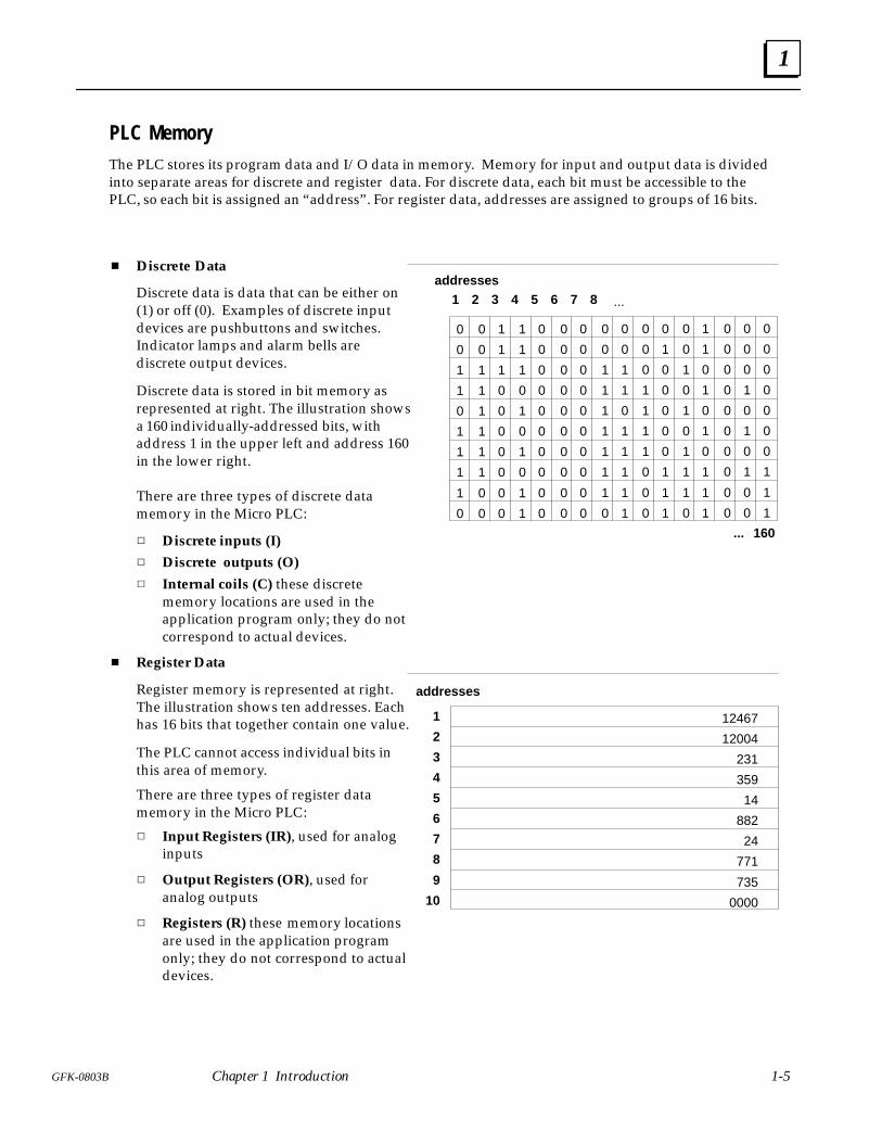
PLC MemoryThe PLC stores its program data and I/O data in memory. Memory for input and output data is dividedinto separate areas for discrete and register data. For discrete data, each bit must be accessible to thePLC, so each bit is assigned an “address”. For register data, addresses are assigned to groups of 16 bits.
0
0
1
1
0
1
1
1
1
0
0
0
1
1
1
1
1
1
0
0
1
1
1
0
0
0
0
0
0
0
1
1
1
0
1
0
1
0
1
1
0
0
0
0
0
0
0
0
0
0
0
0
0
0
0
0
0
0
0
0
0
0
0
0
0
0
0
0
0
0
0
0
1
1
1
1
1
1
1
0
0
0
1
1
0
1
1
1
1
1
0
0
0
1
1
1
1
0
0
0
0
1
0
0
0
0
0
1
1
1
0
0
1
0
1
0
1
1
1
0
1
1
0
1
0
1
0
1
1
1
0
0
0
0
0
0
0
0
0
0
0
0
0
1
0
1
0
1
0
0
0
0
0
0
0
0
0
1
1
1
1 2 3 4 5 6 7 8 ...
... 160
Discrete Data
Discrete data is data that can be either on(1) or off (0). Examples of discrete inputdevices are pushbuttons and switches.Indicator lamps and alarm bells arediscrete output devices.
Discrete data is stored in bit memory asrepresented at right. The illustration showsa 160 individually-addressed bits, withaddress 1 in the upper left and address 160in the lower right.
There are three types of discrete datamemory in the Micro PLC:
Discrete inputs (I)
Discrete outputs (O)
Internal coils (C) these discretememory locations are used in theapplication program only; they do notcorrespond to actual devices.
Register Data
Register memory is represented at right.The illustration shows ten addresses. Eachhas 16 bits that together contain one value.
The PLC cannot access individual bits inthis area of memory.
There are three types of register datamemory in the Micro PLC:
Input Registers (IR), used for analoginputs
Output Registers (OR), used foranalog outputs
Registers (R) these memory locationsare used in the application programonly; they do not correspond to actualdevices.
12467
12004
231
359
14
882
24
771
735
0000
1
2
3
4
5
6
7
8
9
10
addresses
addresses
1
1-6 Micro PLC User’s Guide – April 1994 GFK-0803B
The GE Fanuc Micro PLC
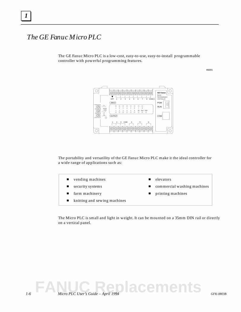
The GE Fanuc Micro PLC is a low-cost, easy-to-use, easy-to-install programmablecontroller with powerful programming features.
FGOUTPUT
INPUT
1 2 3 4 5 6 7 8 COM
1 2 3 4 5 6COM
L2
L1
AC110–220V
1 2 3 4 5 6 7 8
1 2 3 4 5 6 OK RUN
PGM
RUN
COM
VPP
PWR
GE FanucMICRO
PROGRAMMABLE
CONTROLLER
46001
The portability and versatility of the GE Fanuc Micro PLC make it the ideal controller fora wide range of applications such as:
vending machines
security systems
farm machinery
knitting and sewing machines
elevators
commercial washing machines
printing machines
The Micro PLC is small and light in weight. It can be mounted on a 35mm DIN rail or directlyon a vertical panel.
FANUC Replacements
Hand-held Programmer
EPROM Programmer
Programming Software on a Personal Computer
OperatorInterface Unit
OR OR OR
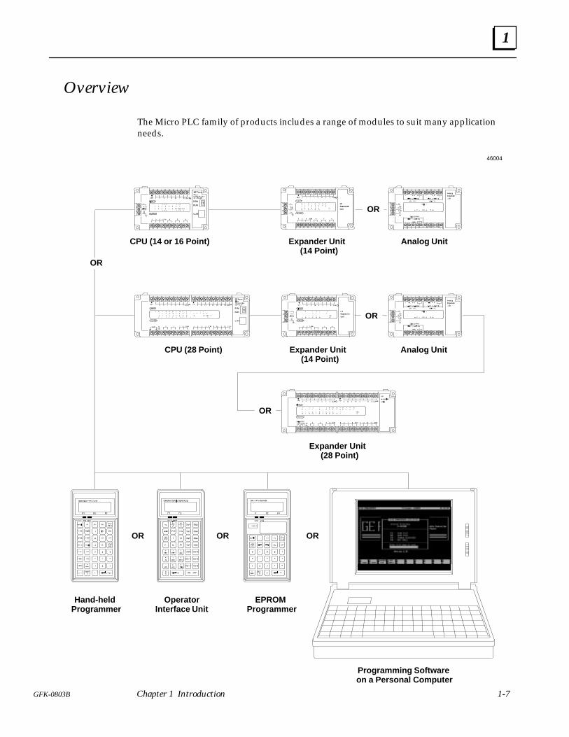
CPU (14 or 16 Point) Expander Unit (14 Point)
Analog Unit
Analog UnitCPU (28 Point) Expander Unit (14 Point)
OR
OR
OR
46004
OR
Expander Unit (28 Point)
1
1-7GFK-0803B Chapter 1 Introduction
Overview
The Micro PLC family of products includes a range of modules to suit many applicationneeds.
1
1-8 Micro PLC User’s Guide – April 1994 GFK-0803B
Micro PLC CPU and Expander Unit
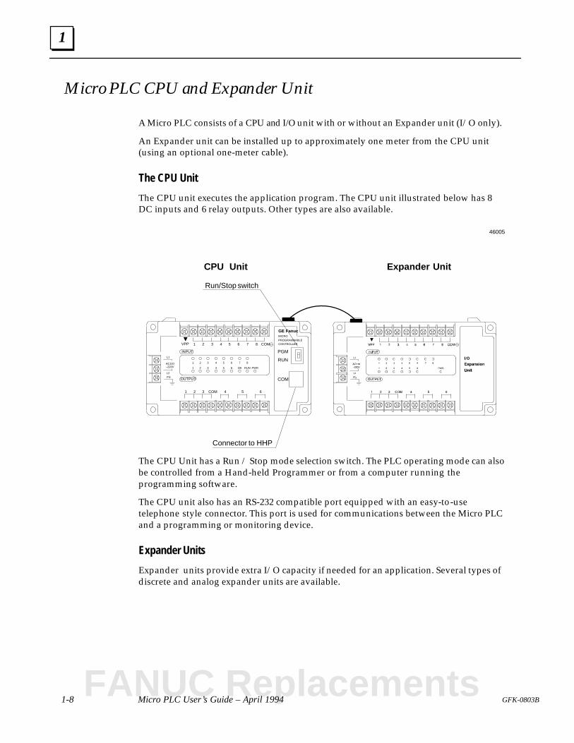
A Micro PLC consists of a CPU and I/O unit with or without an Expander unit (I/O only).
An Expander unit can be installed up to approximately one meter from the CPU unit(using an optional one-meter cable).
The CPU Unit
The CPU unit executes the application program. The CPU unit illustrated below has 8DC inputs and 6 relay outputs. Other types are also available.
Connector to HHP
FG OUTPUT
INPUT
1 2 3 4 5 6 7 8 COM
1 2 3 4 5 6COM
L2
L1
AC110–220V
1 2 3 4 5 6 7 8
1 2 3 4 5 6 OK RUN
PGM
RUN
COM
VPP
PWR
GE FanucMICROPROGRAMMABLECONTROLLER
Run/Stop switch
CPU Unit Expander Unit
46005
The CPU Unit has a Run / Stop mode selection switch. The PLC operating mode can alsobe controlled from a Hand-held Programmer or from a computer running theprogramming software.
The CPU unit also has an RS-232 compatible port equipped with an easy-to-usetelephone style connector. This port is used for communications between the Micro PLCand a programming or monitoring device.
Expander Units
Expander units provide extra I/O capacity if needed for an application. Several types ofdiscrete and analog expander units are available.
FANUC Replacements
Hand-held Programmer
EPROM Programmer
Computer with Programming Software
OperatorInterface Unit
46006
1
1-9GFK-0803B Chapter 1 Introduction
Programming and Monitoring Devices
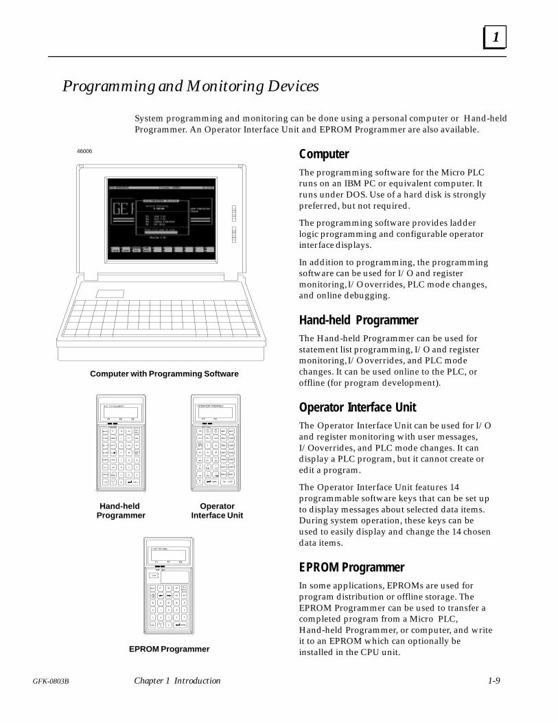
System programming and monitoring can be done using a personal computer or Hand-heldProgrammer. An Operator Interface Unit and EPROM Programmer are also available.
ComputerThe programming software for the Micro PLCruns on an IBM PC or equivalent computer. Itruns under DOS. Use of a hard disk is stronglypreferred, but not required.
The programming software provides ladderlogic programming and configurable operatorinterface displays.
In addition to programming, the programmingsoftware can be used for I/O and registermonitoring, I/O overrides, PLC mode changes,and online debugging.
Hand-held ProgrammerThe Hand-held Programmer can be used forstatement list programming, I/O and registermonitoring, I/O overrides, and PLC modechanges. It can be used online to the PLC, oroffline (for program development).
Operator Interface UnitThe Operator Interface Unit can be used for I/Oand register monitoring with user messages,I/O overrides, and PLC mode changes. It candisplay a PLC program, but it cannot create oredit a program.
The Operator Interface Unit features 14programmable software keys that can be set upto display messages about selected data items.During system operation, these keys can beused to easily display and change the 14 chosendata items.
EPROM ProgrammerIn some applications, EPROMs are used forprogram distribution or offline storage. TheEPROM Programmer can be used to transfer acompleted program from a Micro PLC,Hand-held Programmer, or computer, and writeit to an EPROM which can optionally beinstalled in the CPU unit.
1
1-10 Micro PLC User’s Guide – April 1994 GFK-0803B
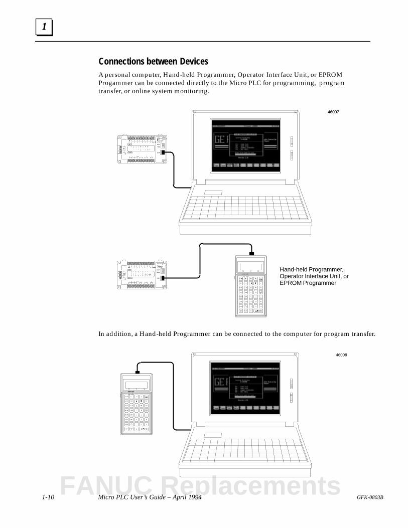
Connections between DevicesA personal computer, Hand-held Programmer, Operator Interface Unit, or EPROMProgammer can be connected directly to the Micro PLC for programming, programtransfer, or online system monitoring.
Hand-held Programmer,Operator Interface Unit, orEPROM Programmer
4600746007
In addition, a Hand-held Programmer can be connected to the computer for program transfer.
46008
FANUC Replacements
1
1-11GFK-0803B Chapter 1 Introduction
Programming for the Micro PLC
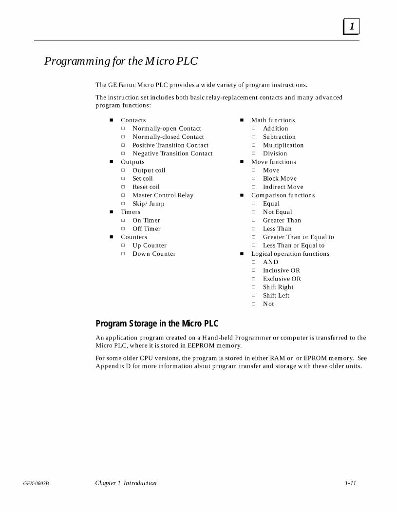
The GE Fanuc Micro PLC provides a wide variety of program instructions.
The instruction set includes both basic relay-replacement contacts and many advancedprogram functions:
Contacts Normally-open Contact Normally-closed Contact Positive Transition Contact Negative Transition Contact
Outputs Output coil Set coil Reset coil Master Control Relay Skip/Jump
Timers On Timer Off Timer
Counters Up Counter Down Counter
Math functions Addition Subtraction Multiplication Division
Move functions Move Block Move Indirect Move
Comparison functions Equal Not Equal Greater Than Less Than Greater Than or Equal to Less Than or Equal to
Logical operation functions AND Inclusive OR Exclusive OR Shift Right Shift Left Not
Program Storage in the Micro PLCAn application program created on a Hand-held Programmer or computer is transferred to theMicro PLC, where it is stored in EEPROM memory.
For some older CPU versions, the program is stored in either RAM or or EPROM memory. SeeAppendix D for more information about program transfer and storage with these older units.
1
1-12 Micro PLC User’s Guide – April 1994 GFK-0803B
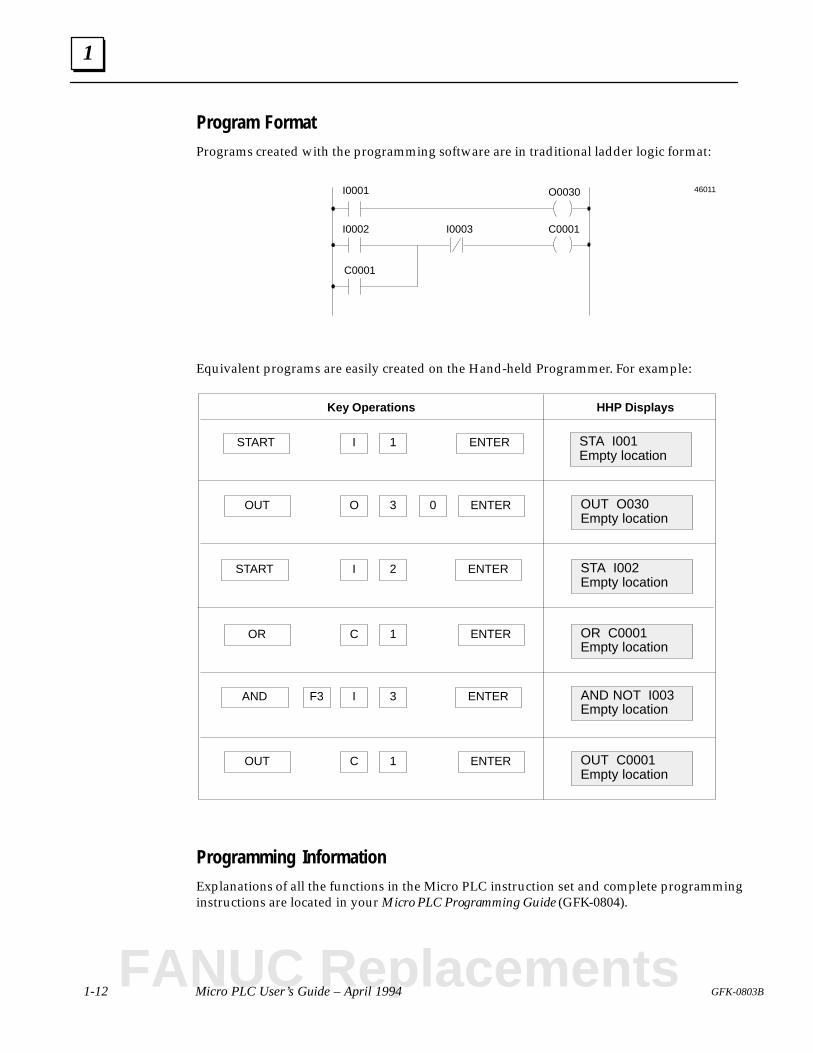
Program FormatPrograms created with the programming software are in traditional ladder logic format:
I0001
I0002
C0001
I0003 C0001
O0030 46011
Equivalent programs are easily created on the Hand-held Programmer. For example:
ISTART STA I001Empty location
ENTER1
Key Operations HHP Displays
OOUT OUT O030Empty location
ENTER3 0
ISTART STA I002Empty location
ENTER2
COR OR C0001Empty location
ENTER1
F3AND AND NOT I003Empty location
ENTERI 3
COUT OUT C0001Empty location
ENTER1
Programming InformationExplanations of all the functions in the Micro PLC instruction set and complete programminginstructions are located in your Micro PLC Programming Guide (GFK-0804).
FANUC Replacements
1
1-13GFK-0803B Chapter 1 Introduction
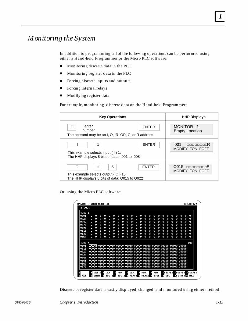
Monitoring the System
In addition to programming, all of the following operations can be performed usingeither a Hand-held Programmer or the Micro PLC software:
Monitoring discrete data in the PLC
Monitoring register data in the PLC
Forcing discrete inputs and outputs
Forcing internal relays
Modifying register data
For example, monitoring discrete data on the Hand-held Programmer:
MONITOR I1Empty Location
ENTERI/O
Key Operations HHP Displays
enternumber
The operand may be an I, O, IR, OR, C, or R address.
I ENTER
This example selects input ( I ) 1.The HHP displays 8 bits of data: I001 to I008
O O015 RMODIFY FON FOFF
ENTER1 5
1
This example selects output ( O ) 15.The HHP displays 8 bits of data: O015 to O022
I001 RMODIFY FON FOFF
Or using the Micro PLC software:
Discrete or register data is easily displayed, changed, and monitored using either method.
1
1-14 Micro PLC User’s Guide – April 1994 GFK-0803B
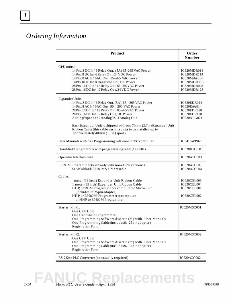
Ordering Information
Product OrderNumber
CPU units:14 Pts, 8 DC In/6 Relay Out, (5A) 85–265 VAC Power14 Pts, 8 DC In/6 Relay Out, 24 VDC Power14 Pts, 8 AC In/6 AC Out, 85–265 VAC Power16 Pts, 8 DC In/8 Transistor Out, DC Power28 Pts, 16 DC In/12 Relay Out, 85-265 VAC Power28 Pts, 16 DC In/12 Relay Out, 24 VDC Power
IC620MDR014IC620MDR114IC620MAA014IC620MDD116IC620MDR028IC620MDR128
Expander Units:14 Pts, 8 DC In/6 Relay Out, (5A), 85 – 265 VAC Power14 Pts, 8 AC In/6 AC Out, 90 – 260 VAC Power28 Pts, 16 DC In/12 Relay Out, 85-265 VAC Power28 Pts, 16 DC In/12 Relay Out, DC PowerAnalog Expander, 2 Analog In/1 Analog Out
Each Expander Unit is shipped with one 70mm (2.7in) Expander UnitRibbon Cable (this cable permits units to be installed up to approximately 40 mm (1.6 in) apart).
IC620EDR014IC620EAA014IC620EDR028IC620EDR128IC620ALG021
User Manuals with free Programming Software for PC computer. IC641SWP020
Hand-held Programmer with programming cable (CBL001) IC620HHP001
Operator Interface Unit IC620ACC003
EPROM Programmer (used only with some CPU versions)Set of 4 blank EPROMS, UV erasable
IC620ACC001IC620ACC004
Cables: meter (19 inch) Expander Unit Ribbon Cable1 meter (39 inch) Expander Unit Ribbon CableHHP, EPROM Programmer or computer to Micro PLC
(includes 9 / 25 pin adapter)HHP or EPROM Programmer to computer,
or HHP to EPROM Programmer
IC620CBL003IC620CBL004IC620CBL001
IC620CBL002
Starter kit #1:One CPU UnitOne Hand-held ProgrammerOne Programming Software diskette (3”) with User ManualsOne Programming Cable (includes 9 / 25 pin adapter)Registration Form
IC620MSC001
Starter kit #2:One CPU UnitOne Programming Software diskette (3”) with User ManualsOne Programming Cable (includes 9 / 25 pin adapter)Registration Form
IC620MSC002
RS-232 to PLC Converter (not usually required) IC620ACC002
FANUC Replacements
1
1-15GFK-0803B Chapter 1 Introduction
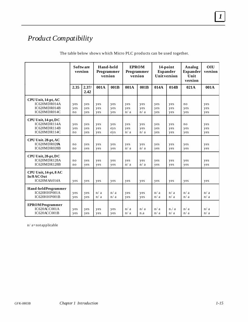
Product Compatibility
The table below shows which Micro PLC products can be used together.
Softwareversion
Hand-heldProgrammer
version
EPROMProgrammer
version
14-pointExpander
Unit version
AnalogExpander
Unitversion
OIUversion
2.35 2.37/2.42
001A 001B 001A 001B 014A 014B 021A 001A
CPU Unit, 14-pt, ACIC620MDR014AIC620MDR014BIC620MDR014C
yesyesno
yesyesyes
yesyesyes
yesyesyes
yesyesn/a
yesyesn/a
yesyesyes
yesyesyes
noyesyes
yesyesyes
CPU Unit, 14-pt, DCIC620MDR114AIC620MDR114BIC620MDR114C
yesyesno
yesyesyes
yesyesyes
yeseyseys
yesyesn/a
yesyesn/a
yesyesyes
yesyesyes
noyesyes
yesyesyes
CPU Unit. 28-pt, ACIC620MDR028AIC620MDR028B
nono
yesyes
yesyes
yesyes
yesn/a
yesn/a
yesyes
yesyes
yesyes
yesyes
CPU Unit, 28-pt, DCIC620MDR128AIC620MDR128B
nono
yesyes
yesyes
yesyes
yesn/a
yesn/a
yesyes
yesyes
yesyes
yesyes
CPU Unit, 14-pt, 8 ACIn/8 AC Out
IC620MAA014A yes yes yes yes yes yes yes yes yes yes
Hand-held ProgrammerIC620HHP001AIC620HHP001B
yesyes
yesyes
n/an/a
n/an/a
yesyes
yesyes
n/an/a
n/an/a
n/an/a
n/an/a
EPROM ProgrammerIC620ACC001AIC620ACC001B
yesyes
yesyes
yesyes
yesyes
n/an/a
n/an.a
n/an/a
n./an/a
n/an/a
n/an/a
n/a= not applicable
1
1-16 Micro PLC User’s Guide – April 1994 GFK-0803B
Related Products
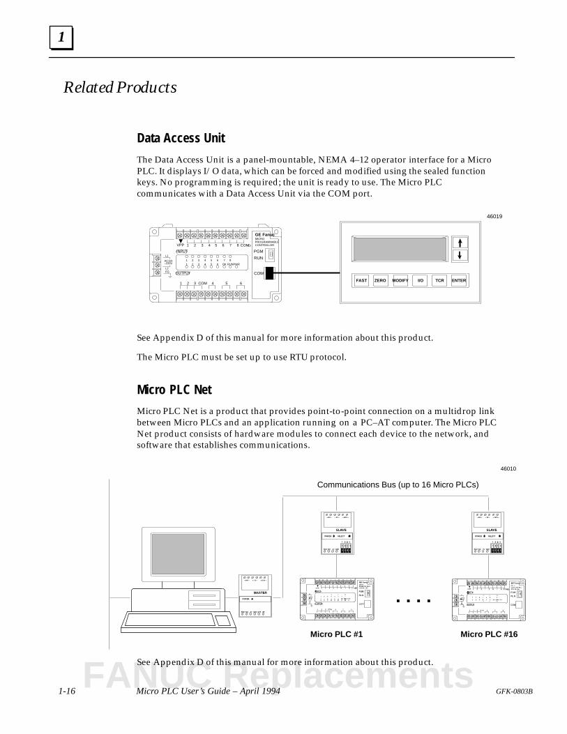
Data Access Unit
The Data Access Unit is a panel-mountable, NEMA 4–12 operator interface for a MicroPLC. It displays I/O data, which can be forced and modified using the sealed functionkeys. No programming is required; the unit is ready to use. The Micro PLCcommunicates with a Data Access Unit via the COM port.
FAST ZERO MODIFY I/O TCR ENTER
FG OUTPUT
INPUT
1 2 3 4 5 6 7 8 COM
1 2 3 4 5 6COM
L2
L1
AC110–220V
1 2 3 4 5 6 7 81 2 3 4 5 6 OK RUN
PGM
RUN
COM
VPP
PWR
GE FanucMICROPROGRAMMABLECONTROLLER
46019
See Appendix D of this manual for more information about this product.
The Micro PLC must be set up to use RTU protocol.
Micro PLC Net
Micro PLC Net is a product that provides point-to-point connection on a multidrop linkbetween Micro PLCs and an application running on a PC–AT computer. The Micro PLCNet product consists of hardware modules to connect each device to the network, andsoftware that establishes communications.
Micro PLC #1
46010
Communications Bus (up to 16 Micro PLCs)
Micro PLC #16
. . . .
See Appendix D of this manual for more information about this product.
FANUC Replacements
1
1-17GFK-0803B Chapter 1 Introduction
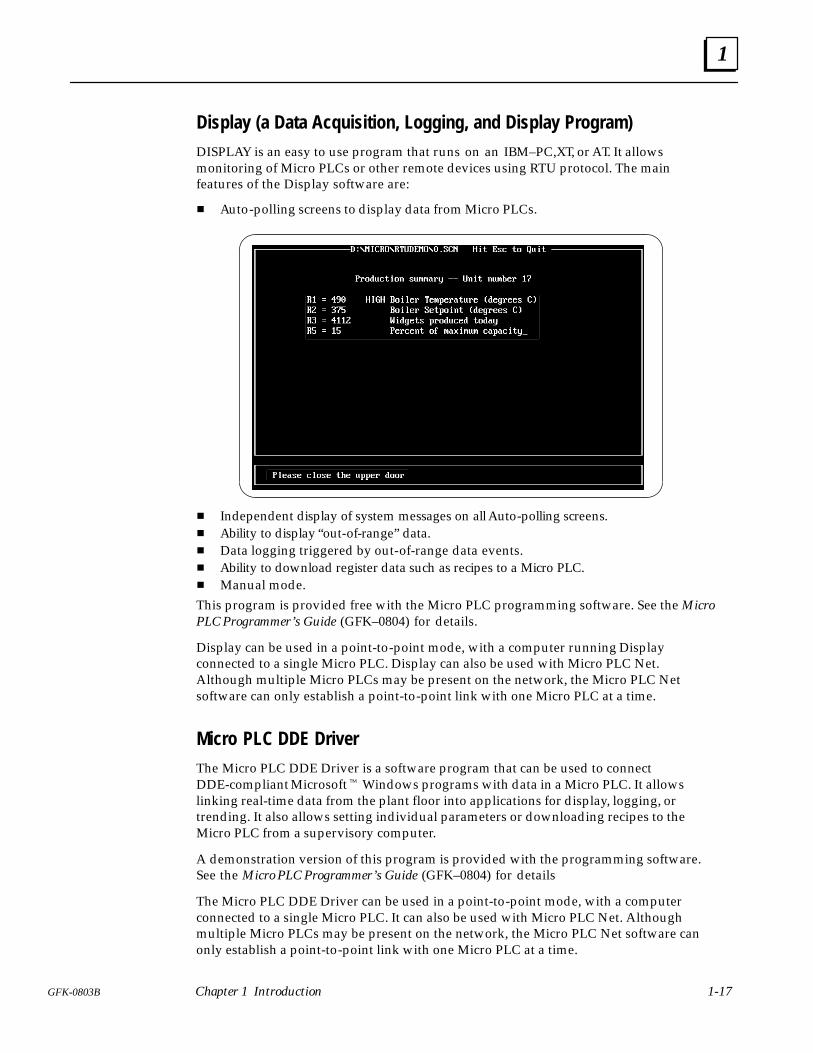
Display (a Data Acquisition, Logging, and Display Program)DISPLAY is an easy to use program that runs on an IBM–PC,XT, or AT. It allowsmonitoring of Micro PLCs or other remote devices using RTU protocol. The mainfeatures of the Display software are:
Auto-polling screens to display data from Micro PLCs.
Independent display of system messages on all Auto-polling screens. Ability to display “out-of-range” data. Data logging triggered by out-of-range data events. Ability to download register data such as recipes to a Micro PLC. Manual mode.This program is provided free with the Micro PLC programming software. See the MicroPLC Programmer’s Guide (GFK–0804) for details.
Display can be used in a point-to-point mode, with a computer running Displayconnected to a single Micro PLC. Display can also be used with Micro PLC Net.Although multiple Micro PLCs may be present on the network, the Micro PLC Netsoftware can only establish a point-to-point link with one Micro PLC at a time.
Micro PLC DDE DriverThe Micro PLC DDE Driver is a software program that can be used to connectDDE-compliant Microsoft Windows programs with data in a Micro PLC. It allowslinking real-time data from the plant floor into applications for display, logging, ortrending. It also allows setting individual parameters or downloading recipes to theMicro PLC from a supervisory computer.
A demonstration version of this program is provided with the programming software.See the Micro PLC Programmer’s Guide (GFK–0804) for details
The Micro PLC DDE Driver can be used in a point-to-point mode, with a computerconnected to a single Micro PLC. It can also be used with Micro PLC Net. Althoughmultiple Micro PLCs may be present on the network, the Micro PLC Net software canonly establish a point-to-point link with one Micro PLC at a time.
2 section level 1 1figure bi level 1 table_big level 1
2-1GFK-0803B
Chapter 2 The Micro PLC
This chapter describes the GE Fanuc Micro PLC CPU and Expander Units.
CPU Units
Expander Units
General Specifications
Electrical Specifications
Function Specifications
Relay Output Specifications
Relay Ratings and Lifetimes
Input Specifications
Memory Map
Descriptions of CPU Units
14 Point CPU Unit with DC Inputs/Relay Outputs, AC Power
14 Point CPU Unit with DC Inputs/Relay Outputs, DC Power
14 Point CPU Unit with AC Inputs/AC Outputs, AC Power
16 Point CPU Unit with DC Inputs/Transistor Outputs, DC Power
28 Point CPU Unit with DC Inputs/Relay Outputs, DC Power
28 Point CPU Unit with DC Inputs/Relay Outputs, AC Power
Descriptions of Expander Units
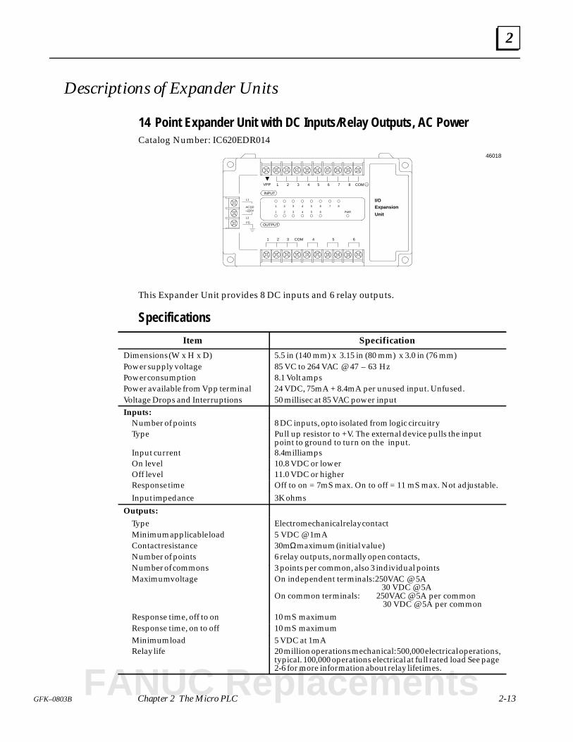
14 Point Expander Unit with DC Inputs/Relay Outputs, AC Power
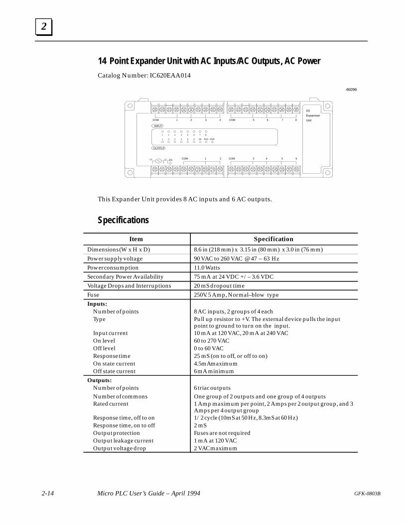
14 Point Expander Unit with AC Inputs/AC Outputs, AC Power
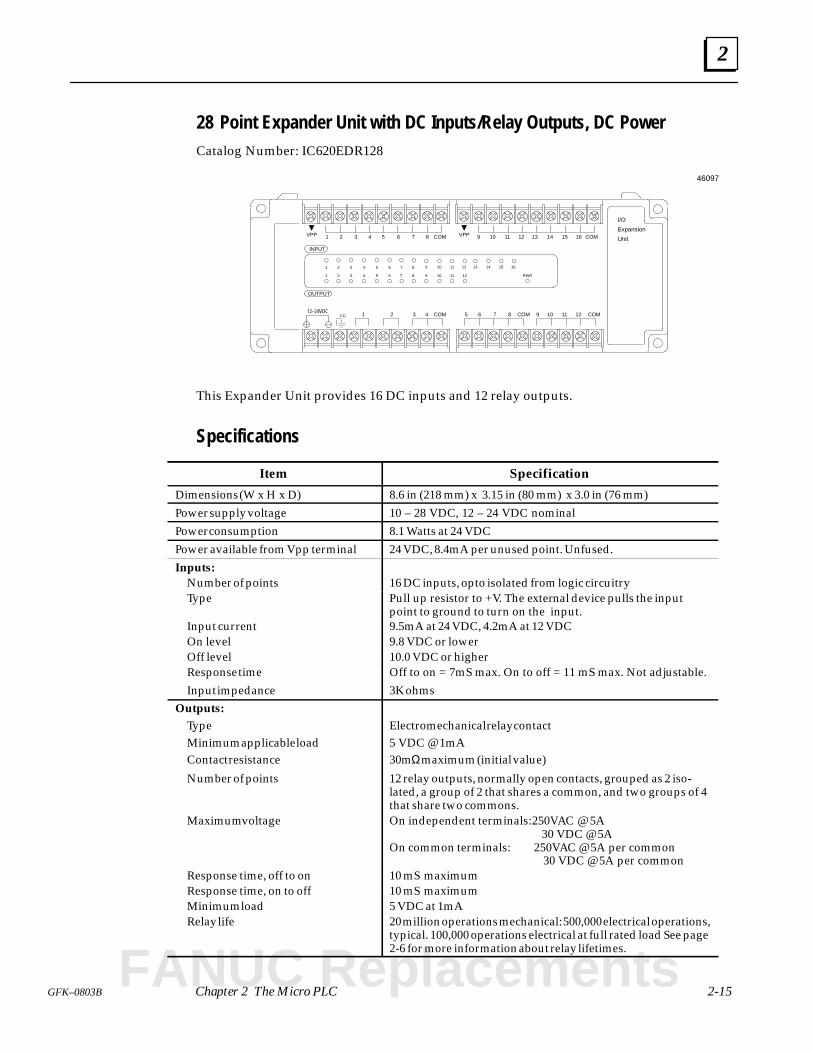
28 Point Expander Unit with DC Inputs/Relay Outputs, DC Power
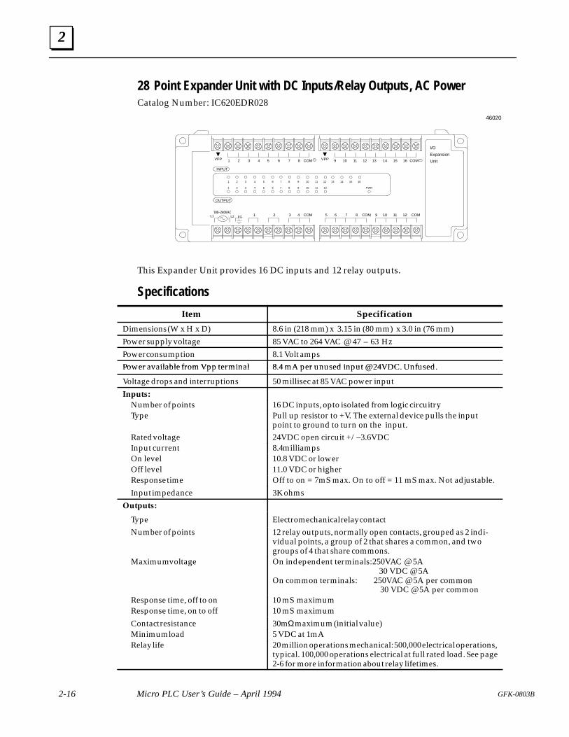
28 Point Expander Unit with DC Inputs/Relay Outputs, AC Power
Analog Expander Unit
FANUC Replacements
2
2-2 Micro PLC User’s Guide – April 1994 GFK-0803B
CPU Units
The CPU unit executes the application program. It has an easily-accessible RS– 232compatible communications port and mode-selection switch. CPU units are available for ACor DC power. The following types of Micro PLC CPU Units are available:
14 Point CPU Unit with DC Inputs/Relay Outputs, AC Power. See page 2-7.
14 Point CPU Unit with DC Inputs/Relay Outputs, DC Power. See page 2-8.
14 Point CPU Unit with AC Inputs/AC Outputs, AC Power. See page 2-9.
16 Point CPU Unit with DC Inputs/Transistor Outputs, DC Power. See page 2-10.
28 Point CPU Unit with DC Inputs/Relay Outputs, DC Power. See page 2-11.
28 Point CPU Unit with DC Inputs/Relay Outputs, AC Power. See page 2-12.
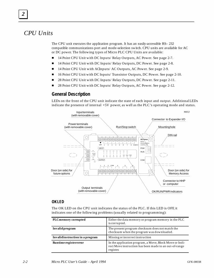
General DescriptionLEDs on the front of the CPU unit indicate the state of each input and output. Additional LEDsindicate the presence of internal +5V power, as well as the PLC’s operating mode and status.
Connector to Expander I/O
Mounting hole
DIN rail
Connector to HHPor computer
OK/RUN/PWR indicatorsOutput terminals
(with removable cover)
Power terminals(with removable cover)
Input terminals(with removable cover)
Run/Stop switch
FGOUTPUT
INPUT
1 2 3 4 5 6 7 8 COM
1 2 3 4 5 6COM
L2
L1
AC110–220V
1 2 3 4 5 6 7 8
1 2 3 4 5 6 OK RUN
PGM
RUN
COM
VPP
PWR
GE FanucMICRO
PROGRAMMABLE
CONTROLLER
Door (on side) forfuture options
Door (on side) forMemory Access
46012
OK LEDThe OK LED on the CPU unit indicates the status of the PLC. If this LED is OFF, itindicates one of the following problems (usually related to programming):
PLC memory corrupted Either the data memory or program memory in the PLCis corrupted.
Invalid program The present program checksum does not match thechecksum when the program was downloaded.
Invalid instruction in a program Missing or incorrect instruction
Runtime register error In the application program, a Move, Block Move or Indi-rect Move instruction has been made to an out-of-rangeregister.
2
2-3GFK–0803B Chapter 2 The Micro PLC
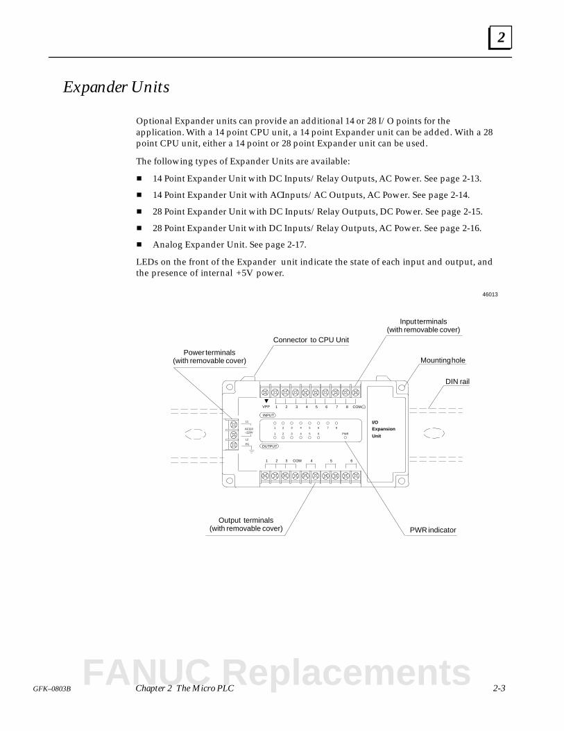
Expander Units
Optional Expander units can provide an additional 14 or 28 I/O points for theapplication. With a 14 point CPU unit, a 14 point Expander unit can be added. With a 28point CPU unit, either a 14 point or 28 point Expander unit can be used.
The following types of Expander Units are available:
14 Point Expander Unit with DC Inputs/Relay Outputs, AC Power. See page 2-13.
14 Point Expander Unit with AC Inputs/AC Outputs, AC Power. See page 2-14.
28 Point Expander Unit with DC Inputs/Relay Outputs, DC Power. See page 2-15.
28 Point Expander Unit with DC Inputs/Relay Outputs, AC Power. See page 2-16.
Analog Expander Unit. See page 2-17.
LEDs on the front of the Expander unit indicate the state of each input and output, andthe presence of internal +5V power.
Connector to CPU Unit
Mounting hole
DIN rail
PWR indicatorOutput terminals
(with removable cover)
Power terminals(with removable cover)
Input terminals(with removable cover)
FGOUTPUT
INPUT
1 2 3 4 5 6 7 8 COM
1 2 3 4 5 6COM
L2
L1
AC110–220V
1 2 3 4 5 6 7 8
1 2 3 4 5 6
VPP
PWR
Expansion
Unit
I/O
46013
FANUC Replacements
2
2-4 Micro PLC User’s Guide – April 1994 GFK-0803B
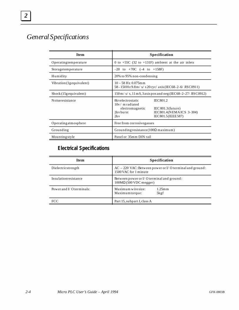
General Specifications
Item Specification
Operating temperature 0 to +55C (32 to +131F) ambient at the air inlets
Storage temperature –20 to +70C (–4 to +158F)
Humidity 20% to 95% non-condensing
Vibration (1g equivalent) 10 – 58 Hz 0.075mm58 – 150 Hz 9.8 m/s/s 20 cyc/axis (IEC68–2–6/JIS C0911)
Shock (15g equivalent) 150 m/s/s, 11 mS, 3 axis pos and neg (IEC68–2–27/JIS C0912)
Noise resistance 8kv electrostatic IEC801.210v / m radiated electromagnetic IEC 801.3 (future)2kv burst IEC801.4 (NEMA ICS 3–304)2kv IEC801.5 (IEEE 587)
Operating atmosphere Free from corrosive gasses
Grounding Grounding resistance (100Ω maximum)
Mounting style Panel or 35mm DIN rail
Electrical Specifications
Item Specification
Dielectric strength AC – 220 VAC: Between power or I/O terminal and ground:1500 VAC for 1 minute
Insulation resistance Between power or I/O terminal and ground: 100MΩ (500 VDC megger)
Power and I/O terminals: Maximum wire size: 1.25mmMaximum torque: 5kgf
Power and I/O terminals: Maximum wire size: 1.25mmMaximum torque: 5kgf
FCC Part 15, subpart J, class A
2
2-5GFK–0803B Chapter 2 The Micro PLC
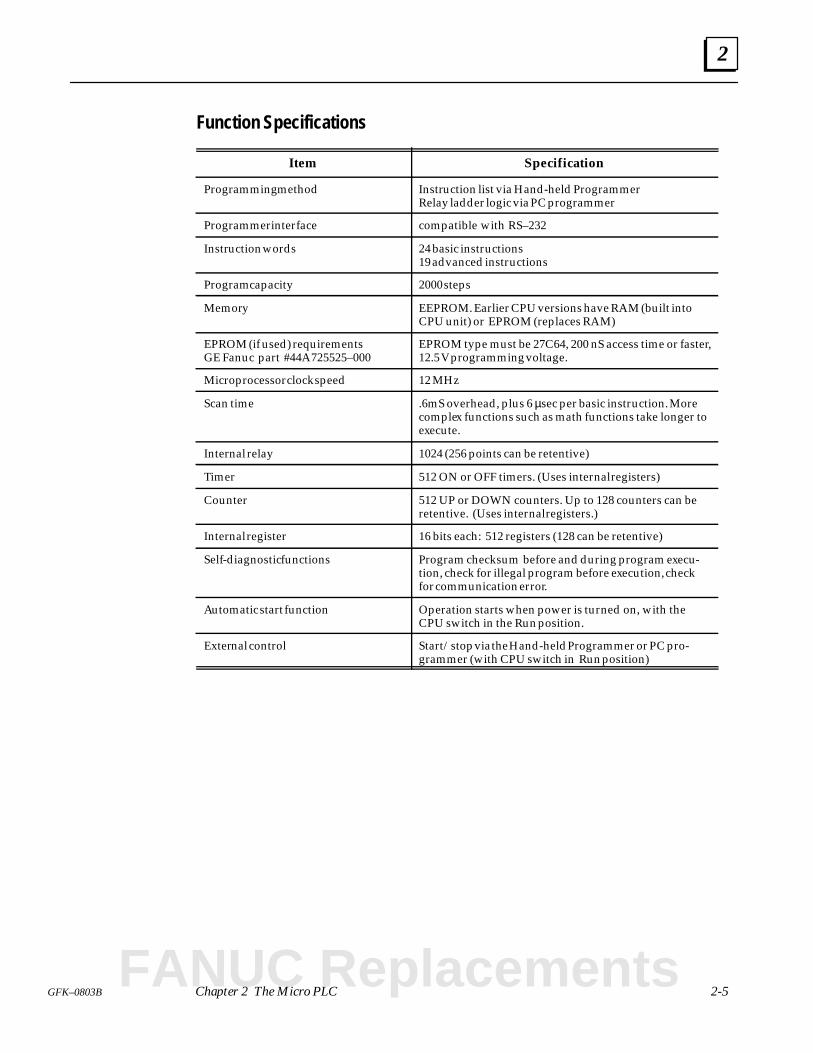
Function Specifications
Item Specification
Programming method Instruction list via Hand-held ProgrammerRelay ladder logic via PC programmer
Programmer interface compatible with RS–232
Instruction words 24 basic instructions19 advanced instructions
Program capacity 2000 steps
Memory EEPROM. Earlier CPU versions have RAM (built intoCPU unit) or EPROM (replaces RAM)
EPROM (if used) requirementsGE Fanuc part #44A725525–000
EPROM type must be 27C64, 200 nS access time or faster,12.5 V programming voltage.
Microprocessor clock speed 12 MHz
Scan time .6mS overhead, plus 6 µsec per basic instruction. Morecomplex functions such as math functions take longer toexecute.
Internal relay 1024 (256 points can be retentive)
Timer 512 ON or OFF timers. (Uses internal registers)
Counter 512 UP or DOWN counters. Up to 128 counters can beretentive. (Uses internal registers.)
Internal register 16 bits each: 512 registers (128 can be retentive)
Self-diagnostic functions Program checksum before and during program execu-tion, check for illegal program before execution, checkfor communication error.
Automatic start function Operation starts when power is turned on, with theCPU switch in the Run position.
External control Start/stop via the Hand-held Programmer or PC pro-grammer (with CPU switch in Run position)
FANUC Replacements
2
2-6 Micro PLC User’s Guide – April 1994 GFK-0803B
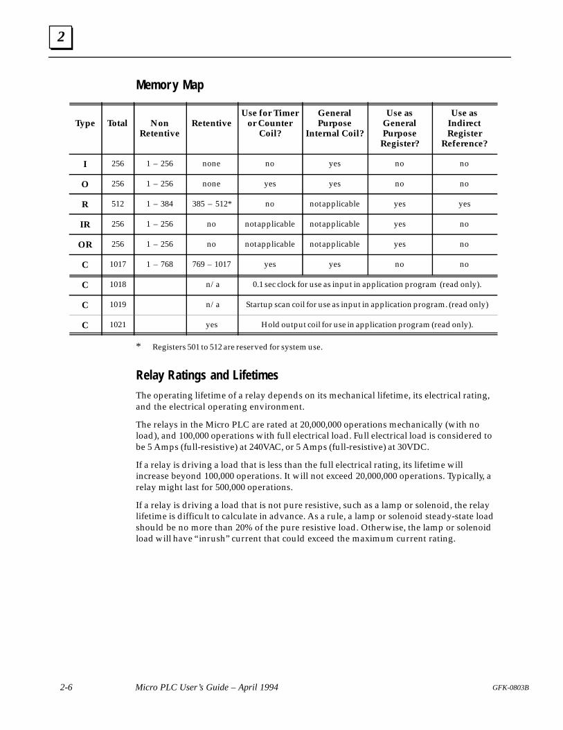
Memor y Map
Type Total NonRetentive
RetentiveUse for Timer
or CounterCoil?
GeneralPurpose
Internal Coil?
Use asGeneralPurpose
Register?
Use asIndirectRegister
Reference?
I 256 1 – 256 none no yes no no
O 256 1 – 256 none yes yes no no
R 512 1 – 384 385 – 512* no not applicable yes yes
IR 256 1 – 256 no not applicable not applicable yes no
OR 256 1 – 256 no not applicable not applicable yes no
C 1017 1 – 768 769 – 1017 yes yes no no
C 1018 n/a 0.1 sec clock for use as input in application program (read only).
C 1019 n/a Startup scan coil for use as input in application program. (read only)
C 1021 yes Hold output coil for use in application program (read only).
* Registers 501 to 512 are reserved for system use.
Relay Ratings and Lifetimes
The operating lifetime of a relay depends on its mechanical lifetime, its electrical rating,and the electrical operating environment.
The relays in the Micro PLC are rated at 20,000,000 operations mechanically (with noload), and 100,000 operations with full electrical load. Full electrical load is considered tobe 5 Amps (full-resistive) at 240VAC, or 5 Amps (full-resistive) at 30VDC.
If a relay is driving a load that is less than the full electrical rating, its lifetime willincrease beyond 100,000 operations. It will not exceed 20,000,000 operations. Typically, arelay might last for 500,000 operations.
If a relay is driving a load that is not pure resistive, such as a lamp or solenoid, the relaylifetime is difficult to calculate in advance. As a rule, a lamp or solenoid steady-state loadshould be no more than 20% of the pure resistive load. Otherwise, the lamp or solenoidload will have “inrush” current that could exceed the maximum current rating.
2
2-7GFK–0803B Chapter 2 The Micro PLC
Descriptions of CPU Units
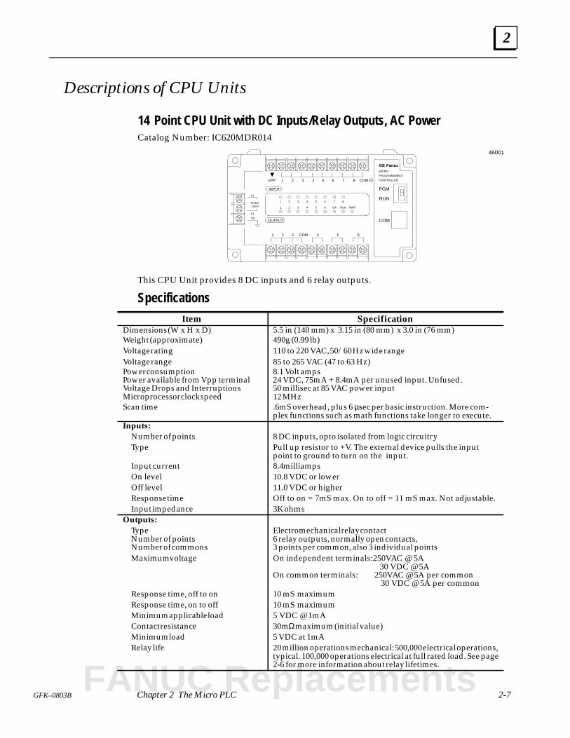
14 Point CPU Unit with DC Inputs/Relay Outputs, AC Power
Catalog Number: IC620MDR014
FGOUTPUT
INPUT
1 2 3 4 5 6 7 8 COM
1 2 3 4 5 6COM
L2
L1
AC110–220V
1 2 3 4 5 6 7 8
1 2 3 4 5 6 OK RUN
PGM
RUN
COM
VPP
PWR
GE FanucMICRO
PROGRAMMABLE
CONTROLLER
46001
This CPU Unit provides 8 DC inputs and 6 relay outputs.
Specifications
Item SpecificationDimensions (W x H x D)Weight (approximate)Voltage ratingVoltage rangePower consumptionPower available from Vpp terminalVoltage Drops and InterruptionsMicroprocessor clock speed
5.5 in (140 mm) x 3.15 in (80 mm) x 3.0 in (76 mm)490g (0.99 lb)110 to 220 VAC, 50/60 Hz wide range85 to 265 VAC (47 to 63 Hz)8.1 Volt amps24 VDC, 75mA + 8.4mA per unused input. Unfused.50 millisec at 85 VAC power input12 MHz
Scan time .6mS overhead, plus 6 µsec per basic instruction. More com-plex functions such as math functions take longer to execute.
Inputs:Number of points 8 DC inputs, opto isolated from logic circuitryType Pull up resistor to +V. The external device pulls the input
point to ground to turn on the input.Input current 8.4 milliampsOn level 10.8 VDC or lowerOff level 11.0 VDC or higherResponse time Off to on = 7mS max. On to off = 11 mS max. Not adjustable.Input impedance 3K ohms
Outputs:TypeNumber of pointsNumber of commons
Electromechanical relay contact6 relay outputs, normally open contacts,3 points per common, also 3 individual points
Maximum voltage On independent terminals: 250VAC @ 5A 30 VDC @ 5AOn common terminals: 250VAC @ 5A per common 30 VDC @ 5A per common
Response time, off to on 10 mS maximumResponse time, on to off 10 mS maximumMinimum applicable load 5 VDC @ 1mAContact resistance 30mΩ maximum (initial value)Minimum load 5 VDC at 1mARelay life 20 million operations mechanical: 500,000 electrical operations,
typical. 100,000 operations electrical at full rated load. See page2-6 for more information about relay lifetimes.
FANUC Replacements
2
2-8 Micro PLC User’s Guide – April 1994 GFK-0803B
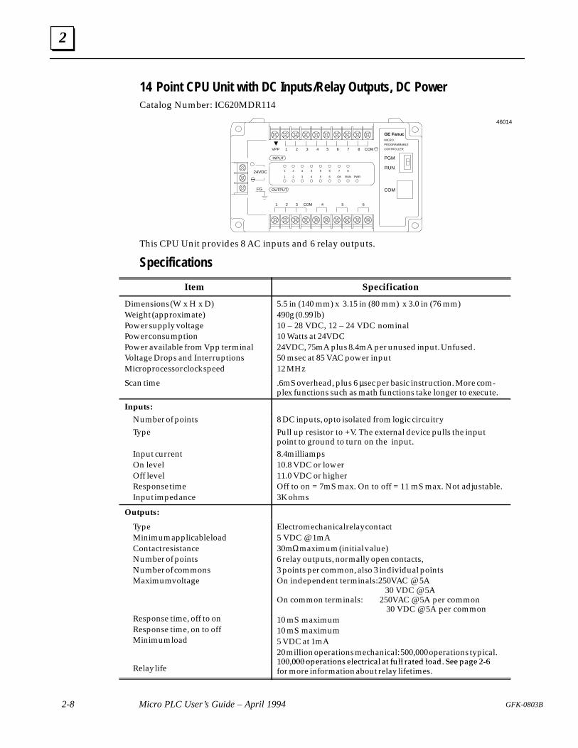
14 Point CPU Unit with DC Inputs/Relay Outputs, DC Power
Catalog Number: IC620MDR114
OUTPUT
INPUT
1 2 3 4 5 6 7 8 COM
1 2 3 4 5 6COM
1 2 3 4 5 6 7 8
1 2 3 4 5 6 OK RUN
PGM
RUN
COM
VPP
PWR
GE FanucMICRO
PROGRAMMABLE
CONTROLLER
FG
24VDC
–
46014
This CPU Unit provides 8 AC inputs and 6 relay outputs.
Specifications
Item Specification
Dimensions (W x H x D)Weight (approximate)Power supply voltagePower consumptionPower available from Vpp terminalVoltage Drops and InterruptionsMicroprocessor clock speed
5.5 in (140 mm) x 3.15 in (80 mm) x 3.0 in (76 mm)490g (0.99 lb)10 – 28 VDC, 12 – 24 VDC nominal10 Watts at 24VDC24VDC, 75mA plus 8.4mA per unused input. Unfused.50 msec at 85 VAC power input12 MHz
Scan time .6mS overhead, plus 6 µsec per basic instruction. More com-plex functions such as math functions take longer to execute.
Inputs:
Number of points 8 DC inputs, opto isolated from logic circuitryType Pull up resistor to +V. The external device pulls the input
point to ground to turn on the input.Input currentOn levelOff levelResponse timeInput impedance
8.4 milliamps10.8 VDC or lower11.0 VDC or higherOff to on = 7mS max. On to off = 11 mS max. Not adjustable.3K ohms
Outputs:
TypeMinimum applicable loadContact resistanceNumber of pointsNumber of commons
Electromechanical relay contact5 VDC @ 1mA30mΩ maximum (initial value)6 relay outputs, normally open contacts,3 points per common, also 3 individual pointsNumber of commons
Maximum voltage
Response time, off to on
3 points per common, also 3 individual pointsOn independent terminals: 250VAC @ 5A 30 VDC @ 5AOn common terminals: 250VAC @ 5A per common 30 VDC @ 5A per common10 mS maximumResponse time, off to on
Response time, on to offMinimum load
30 VDC @ 5A per common10 mS maximum10 mS maximum5 VDC at 1mA20 million operations mechanical: 500,000 operations typical.100,000 operations electrical at full rated load. See page 2-6
Relay life100,000 operations electrical at full rated load. See page 2-6for more information about relay lifetimes.
2
2-9GFK–0803B Chapter 2 The Micro PLC
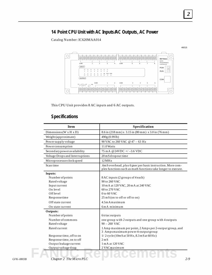
14 Point CPU Unit with AC Inputs/AC Outputs, AC Power
Catalog Number: IC620MAA014
FG
OUTPUT
INPUT
1 2 3 4 5 6 7 8COM
1 2 3 4 5 6 7 8
1 2 3 4 5 6
COM
L1 L25 63 4COM1 2COM
PGM
RUN
COM
GE FanucMICRO
PROGRAMMABLE
CONTROLLER
46015
OK RUN PWR
This CPU Unit provides 8 AC inputs and 6 AC outputs.
Specifications
Item Specification
Dimensions (W x H x D) 8.6 in (218 mm) x 3.15 in (80 mm) x 3.0 in (76 mm)
Weight (approximate) 490g (0.99 lb)
Power supply voltage 90 VAC to 260 VAC @ 47 – 63 Hz
Power consumption 11.0 Watts
Secondary power availability 75 mA @ 24VDC +/–3.6 VDC
Voltage Drops and Interruptions 20 mS dropout time
Microprocessor clock speed 12 MHz
Scan time .6mS overhead, plus 6 µsec per basic instruction. More com-plex functions such as math functions take longer to execute.
Inputs:Number of points 8 AC inputs (2 groups of 4 each)Rated voltage 90 to 260 VACInput current 10 mA at 120 VAC, 20 mA at 240 VACOn level 60 to 270 VACOff level 0 to 60 VACResponse time 25 mS (on to off or off to on)
Off state currentOn state current
4.5 mA maximum6 mA minimum
Outputs:Number of pointsNumber of commons
6 triac outputsone group with 2 outputs and one group with 4 outputs
Rated voltageRated current
90 – 260 VAC1 Amp maximum per point, 2 Amps per 2-output group, and3 Amps maximum power 4-output group
Response time, off to on 1/2 cycle (10mS at 50 Hz, 8.3 mS at 60 Hz)Response time, on to off 2 mSOutput leakage current 1 mA at 120 VACOutput voltage drop 2 VAC maximum
FANUC Replacements
2
2-10 Micro PLC User’s Guide – April 1994 GFK-0803B
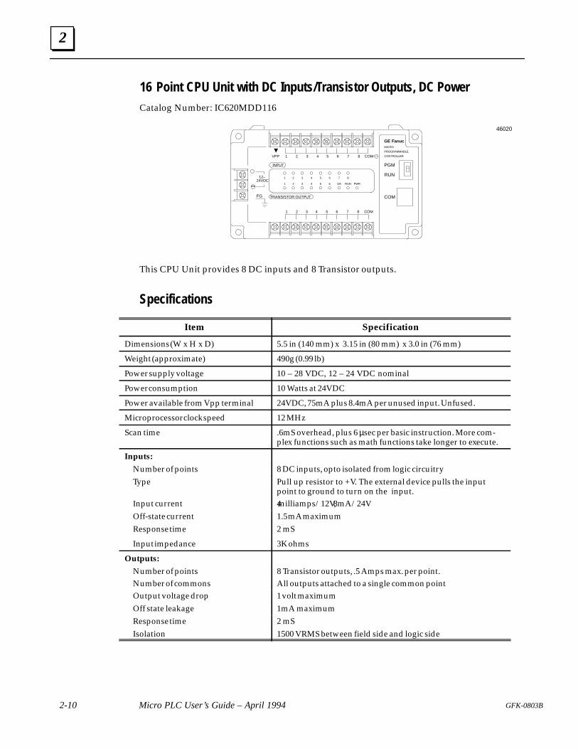
16 Point CPU Unit with DC Inputs/Transistor Outputs, DC Power
Catalog Number: IC620MDD116
TRANSISTOR OUTPUT
INPUT
1 2 3 4 5 6 7 8 COM
1 2 3 4 5 6 COM
1 2 3 4 5 6 7 8
1 2 3 4 5 6 OK RUN
PGM
RUN
COM
VPP
PWR
GE FanucMICRO
PROGRAMMABLE
CONTROLLER
FG
12–
–
46020
24VDC
7 8
This CPU Unit provides 8 DC inputs and 8 Transistor outputs.
Specifications
Item Specification
Dimensions (W x H x D) 5.5 in (140 mm) x 3.15 in (80 mm) x 3.0 in (76 mm)
Weight (approximate) 490g (0.99 lb)
Power supply voltage 10 – 28 VDC, 12 – 24 VDC nominal
Power consumption 10 Watts at 24VDC
Power available from Vpp terminal 24VDC, 75mA plus 8.4mA per unused input. Unfused.
Microprocessor clock speed 12 MHz
Scan time .6mS overhead, plus 6 µsec per basic instruction. More com-plex functions such as math functions take longer to execute.
Inputs:
Number of points 8 DC inputs, opto isolated from logic circuitryType Pull up resistor to +V. The external device pulls the input
point to ground to turn on the input.Input current 4 milliamps/12V, 8mA/24VOff-state current 1.5 mA maximumResponse time 2 mS
Input impedance 3K ohms
Outputs:
Number of pointsNumber of commons
8 Transistor outputs, .5 Amps max. per point.All outputs attached to a single common point
Output voltage drop 1 volt maximumOff state leakage 1mA maximumResponse time 2 mSIsolation 1500 VRMS between field side and logic side
2
2-11GFK–0803B Chapter 2 The Micro PLC
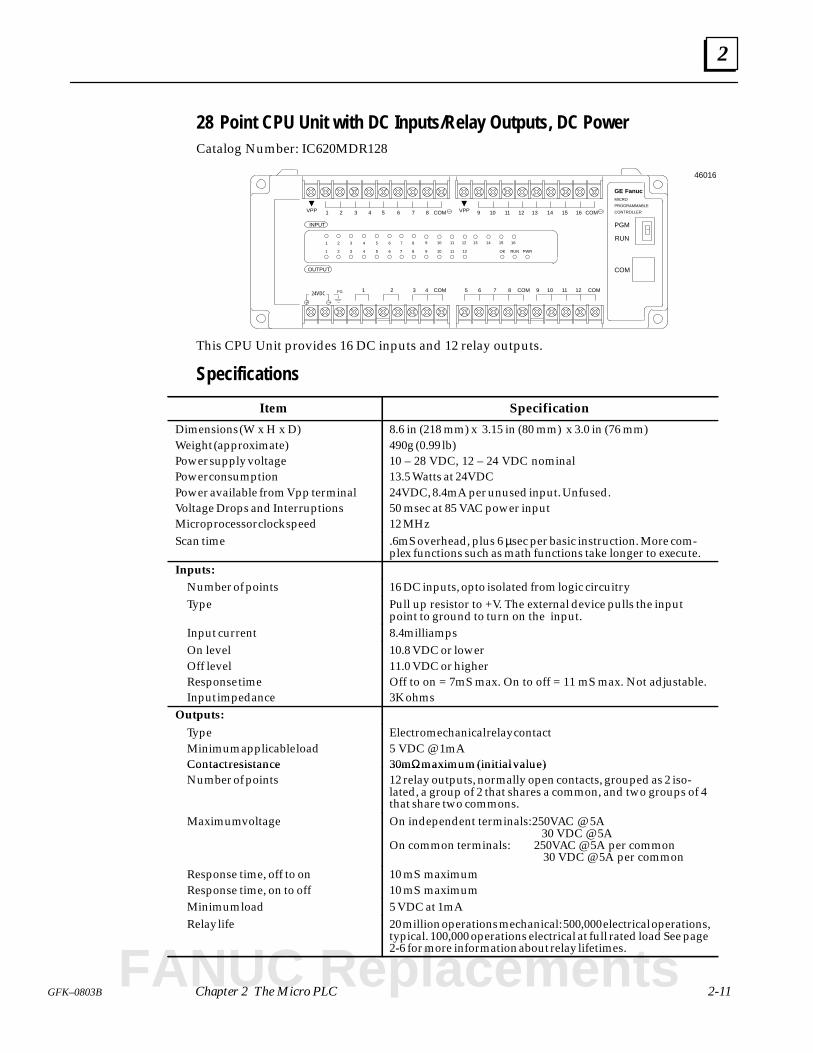
28 Point CPU Unit with DC Inputs/Relay Outputs, DC Power
Catalog Number: IC620MDR128
FG
OUTPUT
INPUT
1 2 3 4 5 6 7 8 COM
10 11 121 2 6 COM
1 2 3 4 5 6 7 8
1 2 3 4 5 6 OK RUN
PGM
RUN
COM
VPP
PWR
GE FanucMICRO
PROGRAMMABLE
CONTROLLERVPP
9 10 11 12 13 14 15 16 COM
93 4 5 7 COM24VDC
COM 8
7 8 9 10 11 12
9 10 11 12
13 14 15 16
46016
This CPU Unit provides 16 DC inputs and 12 relay outputs.
Specifications
Item Specification
Dimensions (W x H x D)Weight (approximate)Power supply voltagePower consumptionPower available from Vpp terminalVoltage Drops and InterruptionsMicroprocessor clock speed
8.6 in (218 mm) x 3.15 in (80 mm) x 3.0 in (76 mm)490g (0.99 lb)10 – 28 VDC, 12 – 24 VDC nominal13.5 Watts at 24VDC24VDC, 8.4mA per unused input. Unfused.50 msec at 85 VAC power input12 MHz
Scan time .6mS overhead, plus 6 µsec per basic instruction. More com-plex functions such as math functions take longer to execute.
Inputs:Number of points 16 DC inputs, opto isolated from logic circuitryType Pull up resistor to +V. The external device pulls the input
point to ground to turn on the input.Input current 8.4 milliampsOn levelOff levelResponse timeInput impedance
10.8 VDC or lower11.0 VDC or higherOff to on = 7mS max. On to off = 11 mS max. Not adjustable.3K ohms
Outputs:
TypeMinimum applicable loadContact resistance
Electromechanical relay contact5 VDC @ 1mA30mΩ maximum (initial value)Contact resistance
Number of points30mΩ maximum (initial value)12 relay outputs, normally open contacts, grouped as 2 iso-lated, a group of 2 that shares a common, and two groups of 4that share two commons.
Maximum voltage On independent terminals: 250VAC @ 5A 30 VDC @ 5AOn common terminals: 250VAC @ 5A per common 30 VDC @ 5A per common
Response time, off to onResponse time, on to off
10 mS maximum10 mS maximum
Minimum load 5 VDC at 1mARelay life 20 million operations mechanical: 500,000 electrical operations,
typical. 100,000 operations electrical at full rated load See page2-6 for more information about relay lifetimes.
FANUC Replacements
2
2-12 Micro PLC User’s Guide – April 1994 GFK-0803B
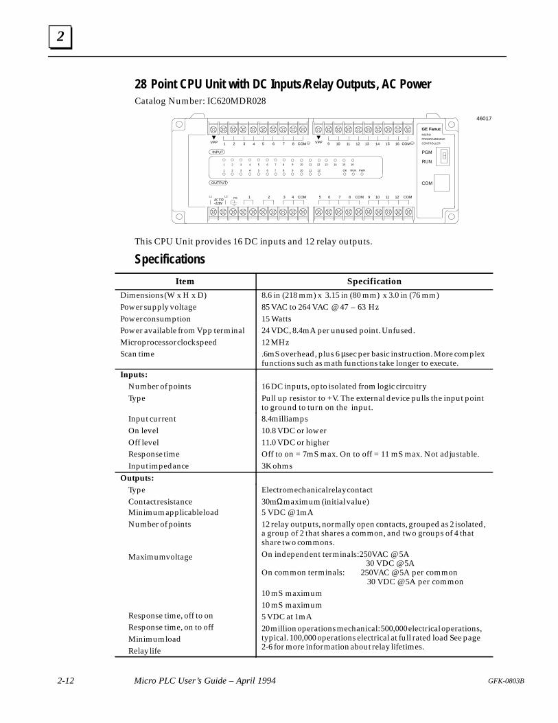
28 Point CPU Unit with DC Inputs/Relay Outputs, AC Power
Catalog Number: IC620MDR028
FG
OUTPUT
INPUT
1 2 3 4 5 6 7 8 COM
10 11 121 2 6 COM
1 2 3 4 5 6 7 8
1 2 3 4 5 6 OK RUN
PGM
RUN
COM
VPP
PWR
GE FanucMICRO
PROGRAMMABLE
CONTROLLERVPP
9 10 11 12 13 14 15 16 COM
93 4 5 7 COMAC110
COM 8
7 8 9 10 11 12
9 10 11 12
13 14 15 16
–220V
L1 L2
46017
This CPU Unit provides 16 DC inputs and 12 relay outputs.
Specifications
Item Specification
Dimensions (W x H x D)Power supply voltagePower consumptionPower available from Vpp terminalMicroprocessor clock speedScan time
8.6 in (218 mm) x 3.15 in (80 mm) x 3.0 in (76 mm)85 VAC to 264 VAC @ 47 – 63 Hz15 Watts24 VDC, 8.4mA per unused point. Unfused.12 MHz.6mS overhead, plus 6 µsec per basic instruction. More complexfunctions such as math functions take longer to execute.
Inputs:Number of points 16 DC inputs, opto isolated from logic circuitryType Pull up resistor to +V. The external device pulls the input point
to ground to turn on the input.Input currentOn levelOff levelResponse timeInput impedance
8.4 milliamps10.8 VDC or lower11.0 VDC or higherOff to on = 7mS max. On to off = 11 mS max. Not adjustable.3K ohms
Outputs:TypeContact resistanceMinimum applicable loadNumber of points
Maximum voltage
Response time, off to onResponse time, on to offMinimum loadRelay life
Electromechanical relay contact30mΩ maximum (initial value)5 VDC @ 1mA12 relay outputs, normally open contacts, grouped as 2 isolated,a group of 2 that shares a common, and two groups of 4 thatshare two commons.On independent terminals: 250VAC @ 5A 30 VDC @ 5AOn common terminals: 250VAC @ 5A per common 30 VDC @ 5A per common10 mS maximum10 mS maximum5 VDC at 1mA20 million operations mechanical: 500,000 electrical operations,typical. 100,000 operations electrical at full rated load See page2-6 for more information about relay lifetimes.
2
2-13GFK–0803B Chapter 2 The Micro PLC
Descriptions of Expander Units
14 Point Expander Unit with DC Inputs/Relay Outputs, AC Power
Catalog Number: IC620EDR014
FGOUTPUT
INPUT
1 2 3 4 5 6 7 8 COM
1 2 3 4 5 6COM
L2
L1
AC110–220V
1 2 3 4 5 6 7 8
1 2 3 4 5 6
VPP
PWR
Expansion
Unit
I/O
46018
This Expander Unit provides 8 DC inputs and 6 relay outputs.
Specifications
Item Specification
Dimensions (W x H x D)Power supply voltagePower consumptionPower available from Vpp terminalVoltage Drops and Interruptions
5.5 in (140 mm) x 3.15 in (80 mm) x 3.0 in (76 mm)85 VC to 264 VAC @ 47 – 63 Hz8.1 Volt amps24 VDC, 75mA + 8.4mA per unused input. Unfused.50 millisec at 85 VAC power input
Inputs:Number of points 8 DC inputs, opto isolated from logic circuitryType Pull up resistor to +V. The external device pulls the input
point to ground to turn on the input.Input current 8.4 milliampsOn level 10.8 VDC or lowerOff level 11.0 VDC or higherResponse time Off to on = 7mS max. On to off = 11 mS max. Not adjustable.
Input impedance 3K ohms
Outputs:
TypeMinimum applicable loadContact resistanceNumber of pointsNumber of commons
Electromechanical relay contact5 VDC @ 1mA30mΩ maximum (initial value)6 relay outputs, normally open contacts,3 points per common, also 3 individual pointsNumber of commons
Maximum voltage3 points per common, also 3 individual pointsOn independent terminals: 250VAC @ 5A 30 VDC @ 5AOn common terminals: 250VAC @ 5A per common 30 VDC @ 5A per common
Response time, off to onResponse time, on to off
10 mS maximum10 mS maximum
Response time, off to onResponse time, on to off
10 mS maximum10 mS maximum
Minimum load 5 VDC at 1mARelay life 20 million operations mechanical: 500,000 electrical operations,
typical. 100,000 operations electrical at full rated load See page2-6 for more information about relay lifetimes.
FANUC Replacements
2
2-14 Micro PLC User’s Guide – April 1994 GFK-0803B
14 Point Expander Unit with AC Inputs/AC Outputs, AC Power
Catalog Number: IC620EAA014
FG
OUTPUT
INPUT
1 2 3 4 5 6 7 8COM
1 2 6
1 2 3 4 5 6 7 8
1 2 3 4 5 6
PWR
I/O
Expansion
UnitCOM
3 4 5COMCOM
L1 L2
46096
RUNOK
This Expander Unit provides 8 AC inputs and 6 AC outputs.
Specifications
Item Specification
Dimensions (W x H x D) 8.6 in (218 mm) x 3.15 in (80 mm) x 3.0 in (76 mm)
Power supply voltage 90 VAC to 260 VAC @ 47 – 63 Hz
Power consumption 11.0 Watts
Secondary Power Availability 75 mA at 24 VDC +/– 3.6 VDC
Voltage Drops and Interruptions 20 mS dropout time
Fuse 250V. 5 Amp, Normal–blow type
Inputs:Number of points 8 AC inputs, 2 groups of 4 eachType Pull up resistor to +V. The external device pulls the input
point to ground to turn on the input.Input current 10 mA at 120 VAC, 20 mA at 240 VACOn level 60 to 270 VACOff level 0 to 60 VACResponse time 25 mS (on to off, or off to on)On state current 4.5mA maximumOff state current 6 mA minimum
Outputs:Number of pointsNumber of commons
6 triac outputsOne group of 2 outputs and one group of 4 outputs
Rated current 1 Amp maximum per point, 2 Amps per 2 output group, and 3Amps per 4 output group
Response time, off to on 1/2 cycle (10mS at 50 Hz, 8.3mS at 60 Hz)Response time, on to off 2 mSOutput protection Fuses are not requiredOutput leakage current 1 mA at 120 VACOutput voltage drop 2 VAC maximum
2
2-15GFK–0803B Chapter 2 The Micro PLC
28 Point Expander Unit with DC Inputs/Relay Outputs, DC Power
Catalog Number: IC620EDR128
FG
OUTPUT
INPUT
1 2 3 4 5 6 7 8 COM
10 11 121 2 6 COM
1 2 3 4 5 6 7 8
1 2 3 4 5 6
VPP
PWR
VPP
9 10 11 12 13 14 15 16 COM
93 4 5 7 COM12–24VDC
COM 8
7 8 9 10 11 12
9 10 11 12
13 14 15 16
46097
I/O
Expansion
Unit
This Expander Unit provides 16 DC inputs and 12 relay outputs.
Specifications
Item Specification
Dimensions (W x H x D) 8.6 in (218 mm) x 3.15 in (80 mm) x 3.0 in (76 mm)
Power supply voltage 10 – 28 VDC, 12 – 24 VDC nominal
Power consumption 8.1 Watts at 24 VDC
Power available from Vpp terminal 24 VDC, 8.4mA per unused point. Unfused.
Inputs:Number of points 16 DC inputs, opto isolated from logic circuitryType Pull up resistor to +V. The external device pulls the input
point to ground to turn on the input.Input current 9.5mA at 24 VDC, 4.2mA at 12 VDCOn level 9.8 VDC or lowerOff level 10.0 VDC or higherResponse time Off to on = 7mS max. On to off = 11 mS max. Not adjustable.
Input impedance 3K ohmsOutputs:
TypeMinimum applicable load
Electromechanical relay contact5 VDC @ 1mA
TypeMinimum applicable loadContact resistance
Electromechanical relay contact5 VDC @ 1mA30mΩ maximum (initial value)
Number of points 12 relay outputs, normally open contacts, grouped as 2 iso-lated, a group of 2 that shares a common, and two groups of 4that share two commons.
Maximum voltage On independent terminals: 250VAC @ 5A 30 VDC @ 5AOn common terminals: 250VAC @ 5A per common 30 VDC @ 5A per common
Response time, off to on 10 mS maximumResponse time, on to off 10 mS maximumMinimum load 5 VDC at 1mARelay life 20 million operations mechanical: 500,000 electrical operations,
typical. 100,000 operations electrical at full rated load See page2-6 for more information about relay lifetimes.
FANUC Replacements
2
2-16 Micro PLC User’s Guide – April 1994 GFK-0803B
28 Point Expander Unit with DC Inputs/Relay Outputs, AC Power
Catalog Number: IC620EDR028
FG
OUTPUT
INPUT
1 2 3 4 5 6 7 8 COM
10 11 121 2 6 COM
1 2 3 4 5 6 7 8
1 2 3 4 5 6
VPP
PWR
I/O
Expansion
UnitVPP
9 10 11 12 13 14 15 16 COM
93 4 5 7 COM100–240VAC
COM 8
7 8 9 10 11 12
9 10 11 12
13 14 15 16
L1 L2
46020
This Expander Unit provides 16 DC inputs and 12 relay outputs.
Specifications
Item Specification
Dimensions (W x H x D) 8.6 in (218 mm) x 3.15 in (80 mm) x 3.0 in (76 mm)
Power supply voltage 85 VAC to 264 VAC @ 47 – 63 Hz
Power consumption 8.1 Volt ampsPower available from Vpp terminal 8.4 mA per unused input @ 24VDC. Unfused.Power available from Vpp terminal 8.4 mA per unused input @ 24VDC. Unfused.
Voltage drops and interruptions 50 millisec at 85 VAC power input
Inputs:Number of points 16 DC inputs, opto isolated from logic circuitryType Pull up resistor to +V. The external device pulls the input
point to ground to turn on the input.Rated voltage 24VDC open circuit +/–3.6VDCInput current 8.4 milliampsOn level 10.8 VDC or lowerOff level 11.0 VDC or higherResponse time Off to on = 7mS max. On to off = 11 mS max. Not adjustable.
Input impedance 3K ohms
Outputs:
Type Electromechanical relay contactNumber of points 12 relay outputs, normally open contacts, grouped as 2 indi-
vidual points, a group of 2 that shares a common, and twogroups of 4 that share commons.
Maximum voltage On independent terminals: 250VAC @ 5A 30 VDC @ 5AOn common terminals: 250VAC @ 5A per common 30 VDC @ 5A per common
Response time, off to on 10 mS maximumResponse time, on to off 10 mS maximum
Contact resistance 30mΩ maximum (initial value)Minimum load 5 VDC at 1mARelay life 20 million operations mechanical: 500,000 electrical operations,
typical. 100,000 operations electrical at full rated load. See page2-6 for more information about relay lifetimes.
2
2-17GFK–0803B Chapter 2 The Micro PLC
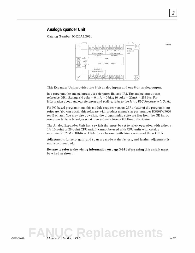
Analog Expander Unit Catalog Number: IC620ALG021
FGL2/N
L1
100-240VAC
PWR
AnalogExpanderUnit
GAIN
SPANZERO
Ch.1 INPUT
SHDJ
+ –
0-10V (J=0-20mA)J
–
Ch.2 INPUT
SHD+
0-10V (J=0-20mA)
Ch.1 OUTPUT
SHDJ
+ –
0-20mA (J=0-10V)
46019
This Expander Unit provides two 8-bit analog inputs and one 8-bit analog output.
In a program, the analog inputs use references IR1 and IR2. The analog output usesreference OR1. Scaling is 0 volts = 0 mA = 0 bits; 10 volts = 20mA = 255 bits. Forinformation about analog references and scaling, refer to the Micro PLC Programmer’s Guide.
For PC-based programming, this module requires version 2.37 or later of the programmingsoftware. You can obtain this software with product manuals as part number IC620SWP020rev B or later. You may also download the programming software files from the GE Fanuccomputer bulletin board, or obtain the software from a GE Fanuc distributor.
The Analog Expander Unit has a switch that must be set to select operation with either a14/16-point or 28-point CPU unit. It cannot be used with CPU units with catalognumbers IC620MRD014A or 114A. It can be used with later versions of those CPUs.
Adjustments for zero, gain, and span are made at the factory, and further adjustment isnot recommended.
Be sure to refer to the wiring information on page 3-14 before using this unit. It mustbe wired as shown.
FANUC Replacements
2
2-18 Micro PLC User’s Guide – April 1994 GFK-0803B
Specifications
Item Specification
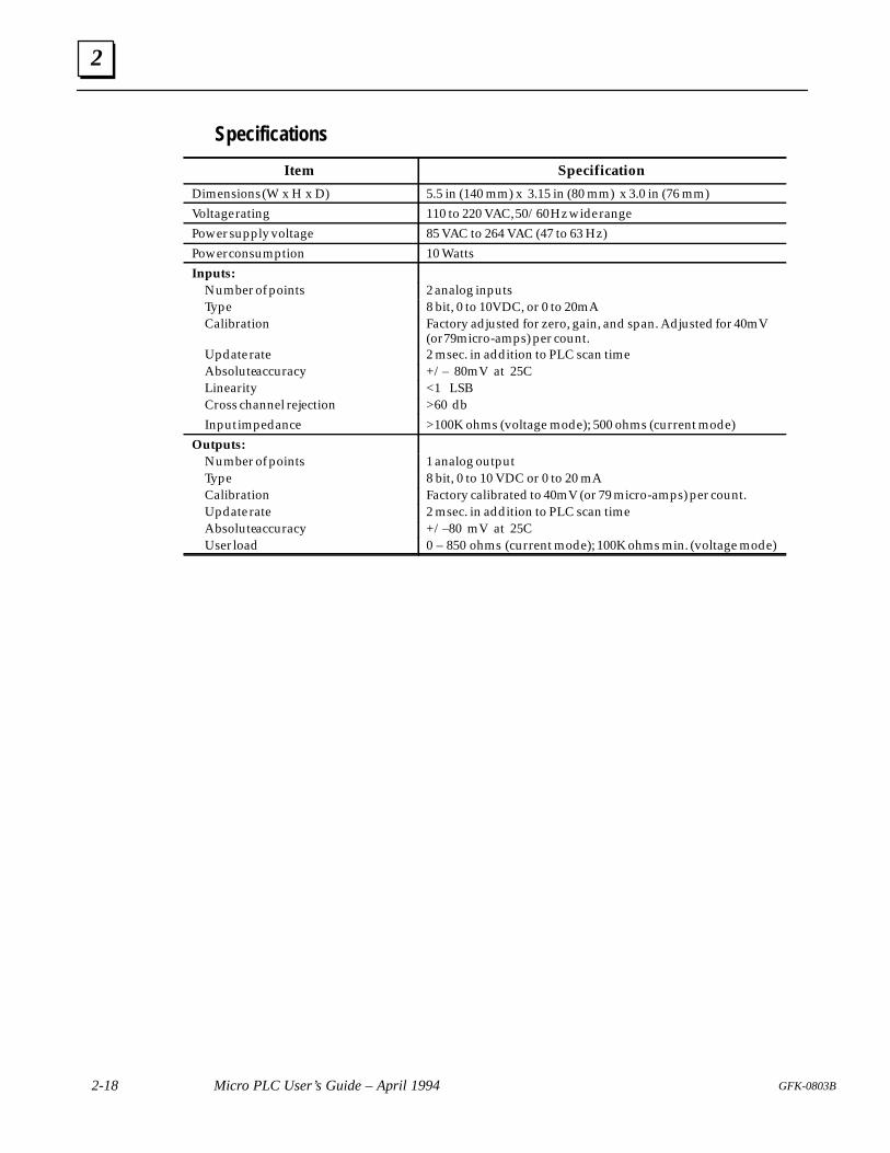
Dimensions (W x H x D) 5.5 in (140 mm) x 3.15 in (80 mm) x 3.0 in (76 mm)
Voltage rating 110 to 220 VAC, 50/60 Hz wide range
Power supply voltage 85 VAC to 264 VAC (47 to 63 Hz)
Power consumption 10 Watts
Inputs:Number of points 2 analog inputsType 8 bit, 0 to 10VDC, or 0 to 20mACalibration Factory adjusted for zero, gain, and span. Adjusted for 40mV
(or 79micro-amps) per count.Update rate 2 msec. in addition to PLC scan timeAbsolute accuracy +/– 80mV at 25CLinearity <1 LSBCross channel rejection >60 db
Input impedance >100K ohms (voltage mode); 500 ohms (current mode)
Outputs:Number of points 1 analog outputType 8 bit, 0 to 10 VDC or 0 to 20 mACalibration Factory calibrated to 40mV (or 79 micro-amps) per count.Update rate 2 msec. in addition to PLC scan timeAbsolute accuracy +/–80 mV at 25CUser load 0 – 850 ohms (current mode); 100K ohms min. (voltage mode)
3 section level 1 1figure bi level 1 table_big level 1
3-1GFK-0803B
Chapter 3 Installation
This chapter explains how to situate, mount, and wire the GE Fanuc Micro PLC.
Choosing a Location for the Micro PLC
Environmental Requirements
Other Considerations
Mounting a Unit
Connecting an Expander Unit
Connecting AC or DC Power to a Unit
AC Power Connections
DC Power Connections
Grounding
I/O Wiring for 14-Point CPU or Expansion Units
I/O Wiring for 16-Point CPU Units
I/O Wiring for 28-Point CPU or Expansion Units
I/O Wiring for Units with AC Inputs and AC Outputs
I/O Wiring for an Analog Expander Unit
Selecting Operation with a 14 or 28 Point CPU
Selecting the Operating Mode
Controlling the Operating Mode from the CPU Unit
Changing the Operating Mode from the Programmer
FANUC Replacements
3
3-2 Micro PLC User’s Guide – April 1994 GFK-0803B
Choosing a Location for the Micro PLC
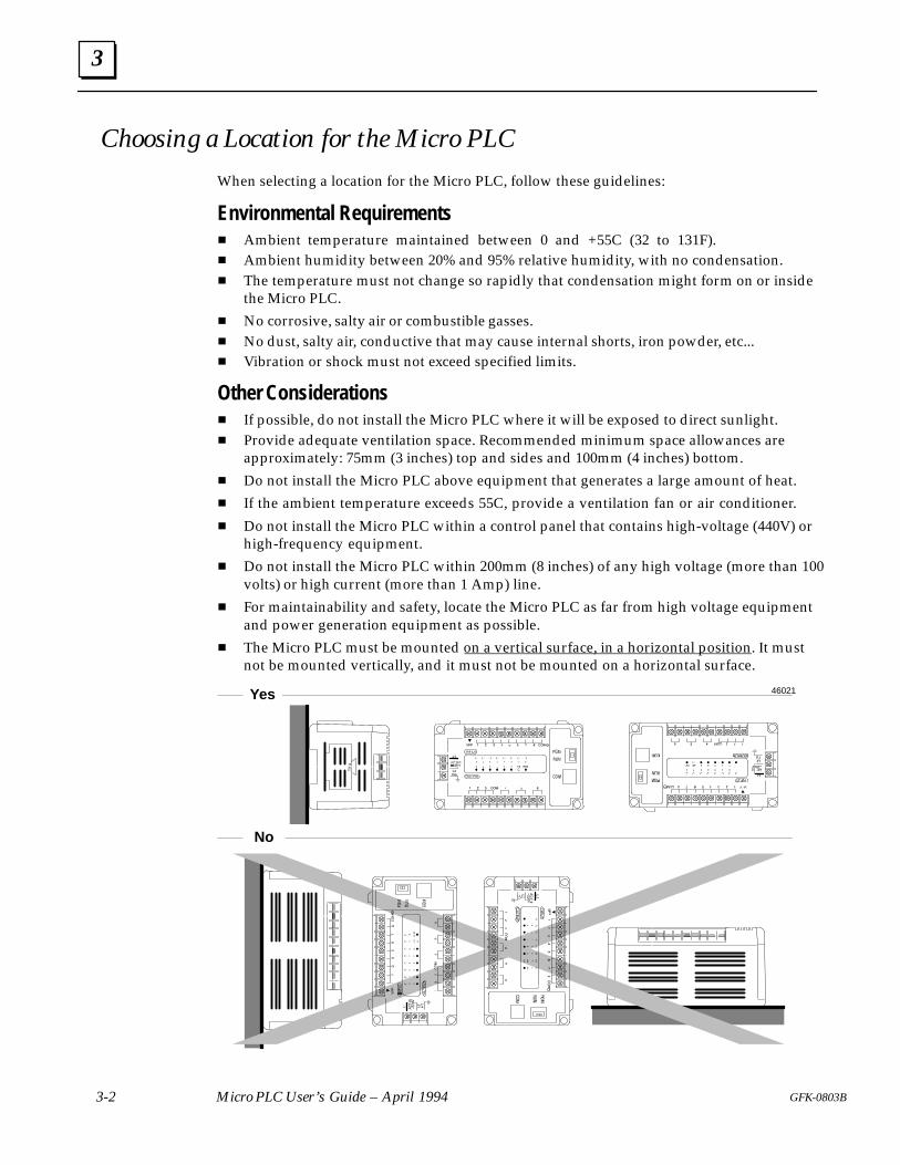
When selecting a location for the Micro PLC, follow these guidelines:
Environmental Requirements Ambient temperature maintained between 0 and +55C (32 to 131F). Ambient humidity between 20% and 95% relative humidity, with no condensation. The temperature must not change so rapidly that condensation might form on or inside
the Micro PLC.
No corrosive, salty air or combustible gasses. No dust, salty air, conductive that may cause internal shorts, iron powder, etc... Vibration or shock must not exceed specified limits.
Other Considerations If possible, do not install the Micro PLC where it will be exposed to direct sunlight. Provide adequate ventilation space. Recommended minimum space allowances are
approximately: 75mm (3 inches) top and sides and 100mm (4 inches) bottom.
Do not install the Micro PLC above equipment that generates a large amount of heat.
If the ambient temperature exceeds 55C, provide a ventilation fan or air conditioner.
Do not install the Micro PLC within a control panel that contains high-voltage (440V) orhigh-frequency equipment.
Do not install the Micro PLC within 200mm (8 inches) of any high voltage (more than 100volts) or high current (more than 1 Amp) line.
For maintainability and safety, locate the Micro PLC as far from high voltage equipmentand power generation equipment as possible.
The Micro PLC must be mounted on a vertical surface, in a horizontal position. It mustnot be mounted vertically, and it must not be mounted on a horizontal surface.
Yes
No
46021
3
3-3GFK-0803B Chapter 3 Installation
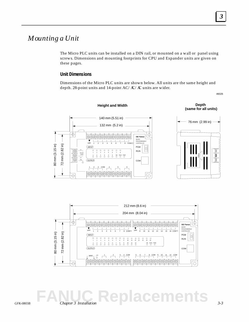
Mounting a Unit
The Micro PLC units can be installed on a DIN rail, or mounted on a wall or panel usingscrews. Dimensions and mounting footprints for CPU and Expander units are given onthese pages.
Unit Dimensions
Dimensions of the Micro PLC units are shown below. All units are the same height anddepth. 28-point units and 14-point AC/AC/AC units are wider.
PU
LL
76 mm (2.99 in)132 mm (5.2 in)
140 mm (5.51 in)
80 m
m (3
.15
in)
72 m
m (2
.82
in)
Height and Width Depth (same for all units)
FGOUTPUT
INPUT
1 2 3 4 5 6 7 8 COM
1 2 3 4 5 6COM
L2
L1
AC110–220V
1 2 3 4 5 6 7 8
1 2 3 4 5 6 OK RUN
PGM
RUN
COM
VPP
PWR
GE FanucMICRO
PROGRAMMABLE
CONTROLLER
FG
OUTPUT
INPUT
1 2 3 4 5 6 7 8 COM
10 11 121 2 6 COM
1 2 3 4 5 6 7 8
1 2 3 4 5 6 OK RUN
PGM
RUN
COM
VPP
PWR
GE FanucMICRO
PROGRAMMABLE
CONTROLLERVPP
9 10 11 12 13 14 15 16 COM
93 4 5 7 COM24VDC COM 8
7 8 9 10 11 12
9 10 11 12
13 14 15 16
204 mm (8.04 in)
212 mm (8.6 in)
80 m
m (3
.15
in)
72 m
m (2
.82
in)
46026
FANUC Replacements
up
Mou
ntin
g Te
mpl
ate
for
14–p
oint
and
anal
og u
nits Mou
ntin
g Te
mpl
ate
for
28–p
oint
uni
tsan
d 14
–poi
nt A
C/A
C/A
C u
nits
up
46027
3
3-4 Micro PLC User’s Guide – April 1994 GFK-0803B
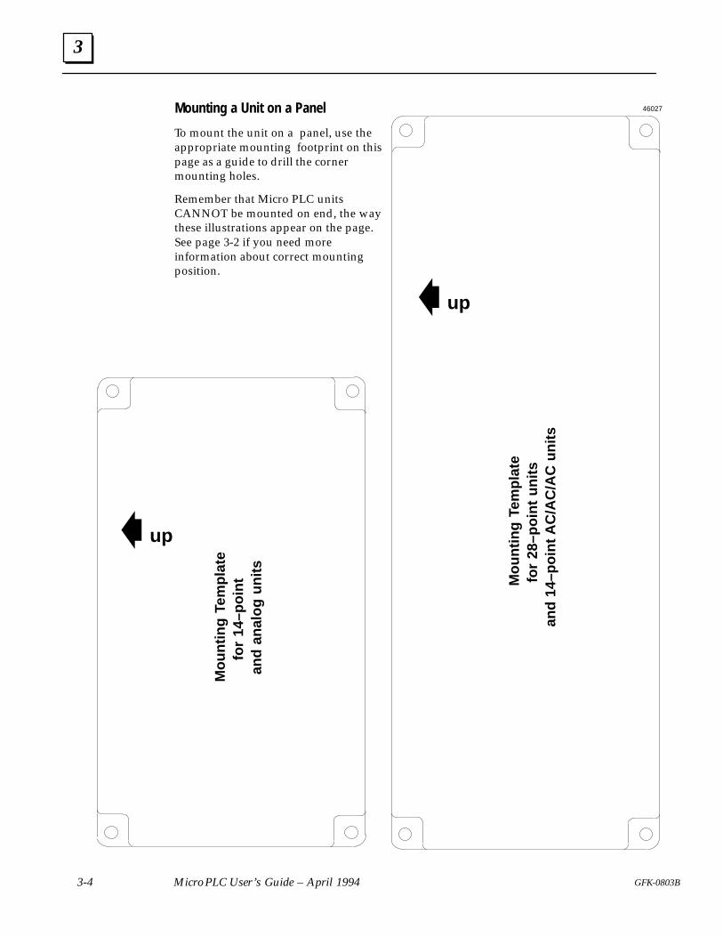
Mounting a Unit on a Panel
To mount the unit on a panel, use theappropriate mounting footprint on thispage as a guide to drill the cornermounting holes.
Remember that Micro PLC unitsCANNOT be mounted on end, the waythese illustrations appear on the page.See page 3-2 if you need moreinformation about correct mountingposition.
3
3-5GFK-0803B Chapter 3 Installation
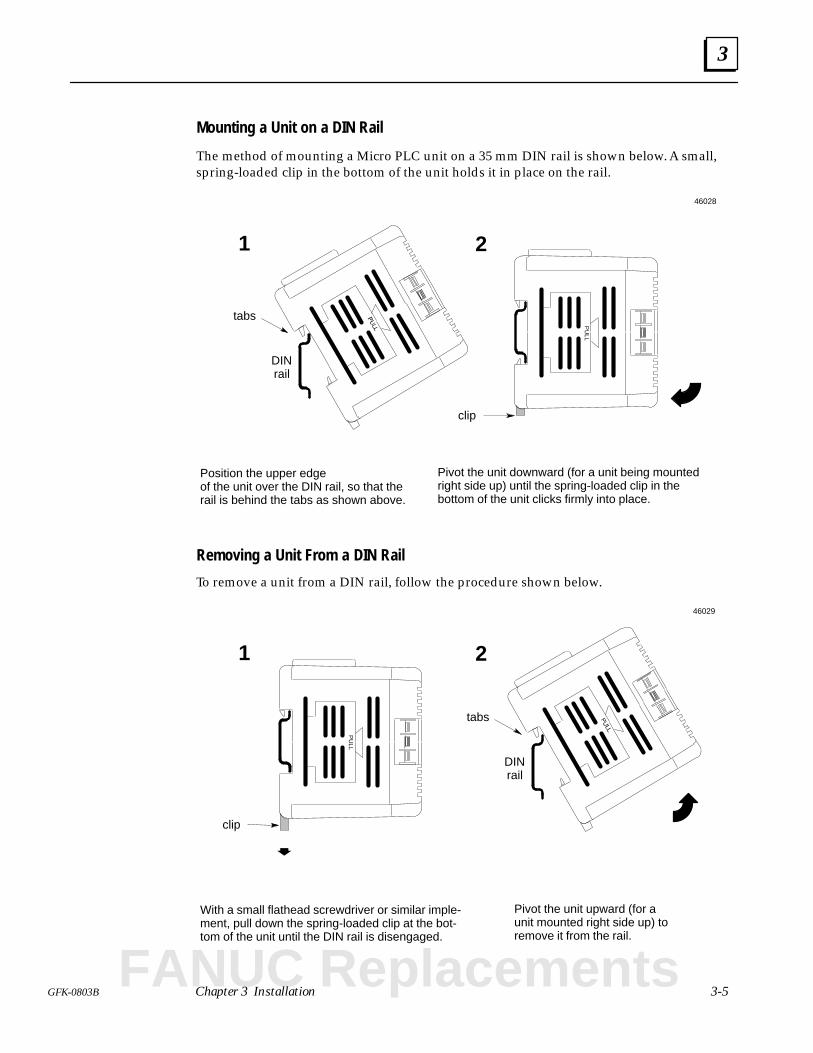
Mounting a Unit on a DIN Rail
The method of mounting a Micro PLC unit on a 35 mm DIN rail is shown below. A small,spring-loaded clip in the bottom of the unit holds it in place on the rail.
DINrail
clip
Position the upper edge of the unit over the DIN rail, so that therail is behind the tabs as shown above.
Pivot the unit downward (for a unit being mountedright side up) until the spring-loaded clip in thebottom of the unit clicks firmly into place.
tabs
1 2P
ULL
46028
Removing a Unit From a DIN Rail
To remove a unit from a DIN rail, follow the procedure shown below.
clip
With a small flathead screwdriver or similar imple-ment, pull down the spring-loaded clip at the bot-tom of the unit until the DIN rail is disengaged.
Pivot the unit upward (for aunit mounted right side up) toremove it from the rail.
1 2
PU
LL
DINrail
tabs
46029
FANUC Replacements
3
3-6 Micro PLC User’s Guide – April 1994 GFK-0803B
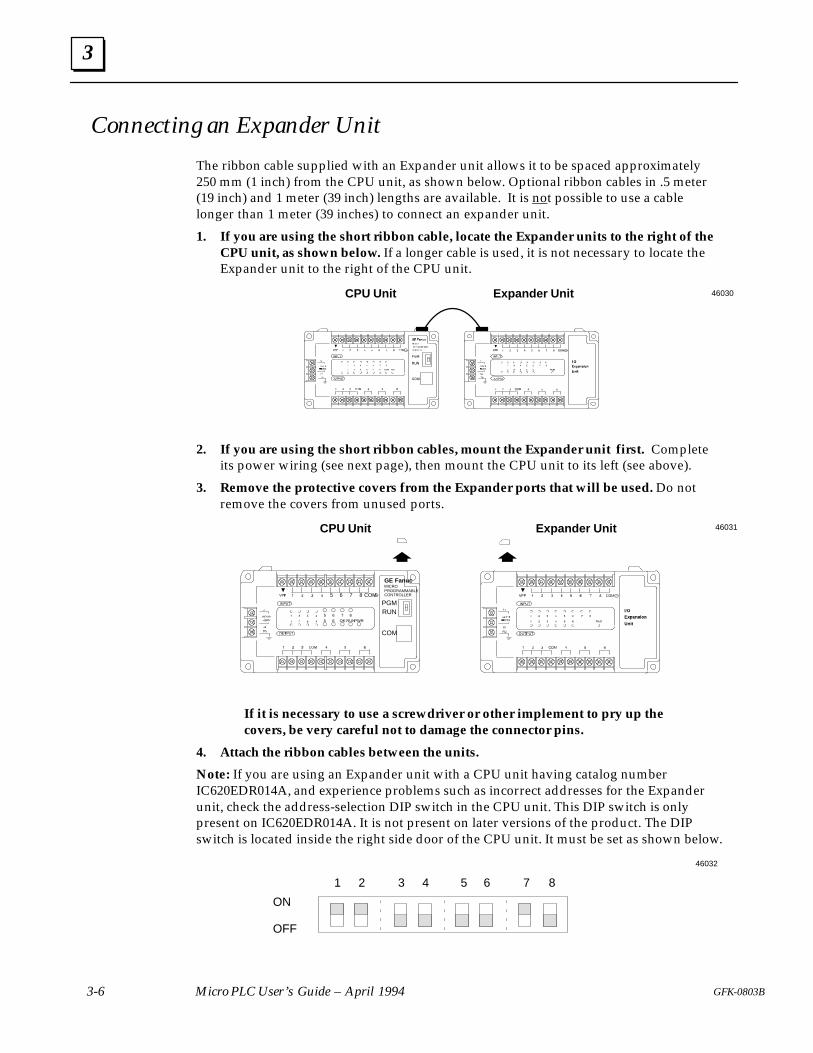
Connecting an Expander Unit
The ribbon cable supplied with an Expander unit allows it to be spaced approximately250 mm (1 inch) from the CPU unit, as shown below. Optional ribbon cables in .5 meter(19 inch) and 1 meter (39 inch) lengths are available. It is not possible to use a cablelonger than 1 meter (39 inches) to connect an expander unit.
1. If you are using the short ribbon cable, locate the Expander units to the right of theCPU unit, as shown below. If a longer cable is used, it is not necessary to locate theExpander unit to the right of the CPU unit.
CPU Unit Expander Unit 46030
2. If you are using the short ribbon cables, mount the Expander unit first. Completeits power wiring (see next page), then mount the CPU unit to its left (see above).
3. Remove the protective covers from the Expander ports that will be used. Do notremove the covers from unused ports.
CPU Unit Expander Unit
5 6 7 8 COM
5 6 7 85 6 OK RUN
PGMRUN
COM
PWR
GE FanucMICROPROGRAMMABLECONTROLLER
46031
If it is necessary to use a screwdriver or other implement to pry up thecovers, be very careful not to damage the connector pins.
4. Attach the ribbon cables between the units.
Note: If you are using an Expander unit with a CPU unit having catalog numberIC620EDR014A, and experience problems such as incorrect addresses for the Expanderunit, check the address-selection DIP switch in the CPU unit. This DIP switch is onlypresent on IC620EDR014A. It is not present on later versions of the product. The DIPswitch is located inside the right side door of the CPU unit. It must be set as shown below.
ON
OFF
1 2 3 4 5 6 7 8
46032
3
3-7GFK-0803B Chapter 3 Installation
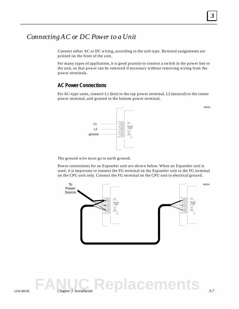
Connecting AC or DC Power to a Unit
Connect either AC or DC wiring, according to the unit type. Terminal assignments areprinted on the front of the unit.
For many types of application, it is good practice to connect a switch in the power line tothe unit, so that power can be removed if necessary without removing wiring from thepower terminals.
AC Power ConnectionsFor AC-type units, connect L1 (hot) to the top power terminal, L2 (neutral) to the centerpower terminal, and ground to the bottom power terminal.
FGL2
L1
AC110–220V
L1
L2
ground
46033
The ground wire must go to earth ground.
Power connections for an Expander unit are shown below. When an Expander unit isused, it is important to connect the FG terminal on the Expander unit to the FG terminalon the CPU unit only. Connect the FG terminal on the CPU unit to electrical ground.
FGL2
L1
AC110–220V
FGL2
L1
AC110–220V
ToPowerSource
46034
FANUC Replacements
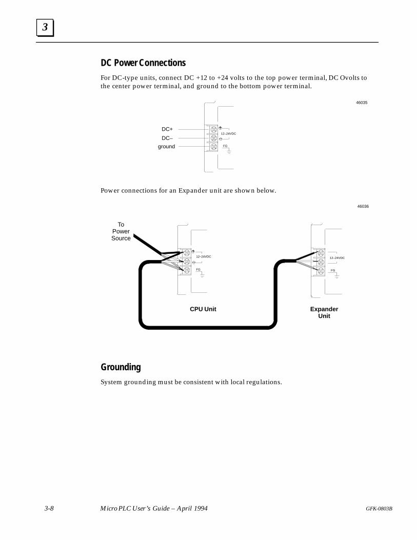
3
3-8 Micro PLC User’s Guide – April 1994 GFK-0803B
DC Power ConnectionsFor DC-type units, connect DC +12 to +24 volts to the top power terminal, DC O volts tothe center power terminal, and ground to the bottom power terminal.
FG
12–24VDCDC+
DC–
ground
+
–
46035
Power connections for an Expander unit are shown below.
FGFG
+
–
CPU Unit ExpanderUnit
46036
12–24VDC 12–24VDC
ToPowerSource
GroundingSystem grounding must be consistent with local regulations.

3
3-9GFK-0803B Chapter 3 Installation
I/O Wiring for 14-Point CPU or Expansion Units
The diagrams below show I/O wiring for 14-point units with DC inputs and relay outputs.
External load power
External load power
External load power
External load power
VPP: power supplyto low-current sensor (<75mA + 8.4 mAper unused point). Not fused
1 2 3 4 5 6
46037
Optional connection for someproximity switches or othersensitive switching devices.
Make this connection betweenCOM and FG if the input turnson at the wrong time whenused with high-sensitivityproximity switches.
Note: For relays, solenoids, and other inductive loads, install an appropriate suppressiondevice (such as an RC network) at the coil.
LED
2.2K1.2K
+.24V
or
Typical DC Input CircuitPLC Field Wiring
LED
LampR
+ V
or
+12
User-suppliedAC or DC
Typical Relay Output Circuit
PLC Field Wiring
The Micro PLC does not have internal fusing for outputs.If necessary, external fusing can be added. Be sure thetype and size of fuse is appropriate for the load.
46038
FANUC Replacements
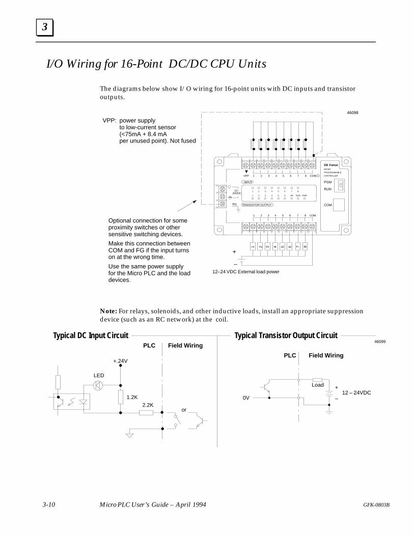
3
3-10 Micro PLC User’s Guide – April 1994 GFK-0803B
I/O Wiring for 16-Point DC/DC CPU Units
The diagrams below show I/O wiring for 16-point units with DC inputs and transistoroutputs.
12–24 VDC External load power
VPP: power supplyto low-current sensor (<75mA + 8.4 mAper unused point). Not fused
1 2 3 4 5 6
46098
Optional connection for someproximity switches or othersensitive switching devices.
Make this connection betweenCOM and FG if the input turnson at the wrong time.
Use the same power supplyfor the Micro PLC and the loaddevices.
TRANSISTOR OUTPUT
INPUT
1 2 3 4 5 6 7 8 COM
1 2 3 4 5 6 COM
1 2 3 4 5 6 7 8
1 2 3 4 5 6 OK RUN
PGM
RUN
COM
VPP
PWR
GE FanucMICRO
PROGRAMMABLE
CONTROLLER
FG
12–
–24VDC
7 8
7 8
+
–
Note: For relays, solenoids, and other inductive loads, install an appropriate suppressiondevice (such as an RC network) at the coil.
LED
2.2K1.2K
+.24V
or
Typical DC Input CircuitPLC Field Wiring
Typical Transistor Output Circuit
PLC Field Wiring
46099
Load +
–12 – 24VDC
0V
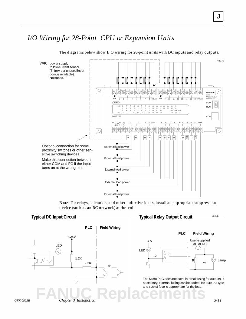
3
3-11GFK-0803B Chapter 3 Installation
I/O Wiring for 28-Point CPU or Expansion Units
The diagrams below show I/O wiring for 28-point units with DC inputs and relay outputs.
External load power
External load power
External load power
External load power
VPP: power supplyto low-current sensor (8.4mA per unused input point is available).Not fused.
FG
OUTPUT
INPUT
1 2 3 4 5 6 7 8 COM
10 11 121 2 6 COM
1 2 3 4 5 6 7 8
1 2 3 4 5 6 OK RUN
PGM
RUN
COM
VPP
PWR
GE FanucMICRO
PROGRAMMABLE
CONTROLLERVPP
9 10 11 12 13 14 15 16 COM
93 4 5 7 COMAC110
COM 8
7 8 9 10 11 12
9 10 11 12
13 14 15 16
–220V
L1 L2
1 2 3 4 5 6 7 8 9 10 11 12External load power
46039
Optional connection for someproximity switches or other sen-sitive switching devices.
Make this connection betweeneither COM and FG if the inputturns on at the wrong time.
Note: For relays, solenoids, and other inductive loads, install an appropriate suppressiondevice (such as an RC network) at the coil.
LED
2.2K1.2K
+.24V
or
Typical DC Input Circuit
PLC Field Wiring
LED
LampR
+ V
or
+12
User-suppliedAC or DC
Typical Relay Output Circuit
PLC Field Wiring
The Micro PLC does not have internal fusing for outputs. Ifnecessary, external fusing can be added. Be sure the typeand size of fuse is appropriate for the load.
46040
FANUC Replacements
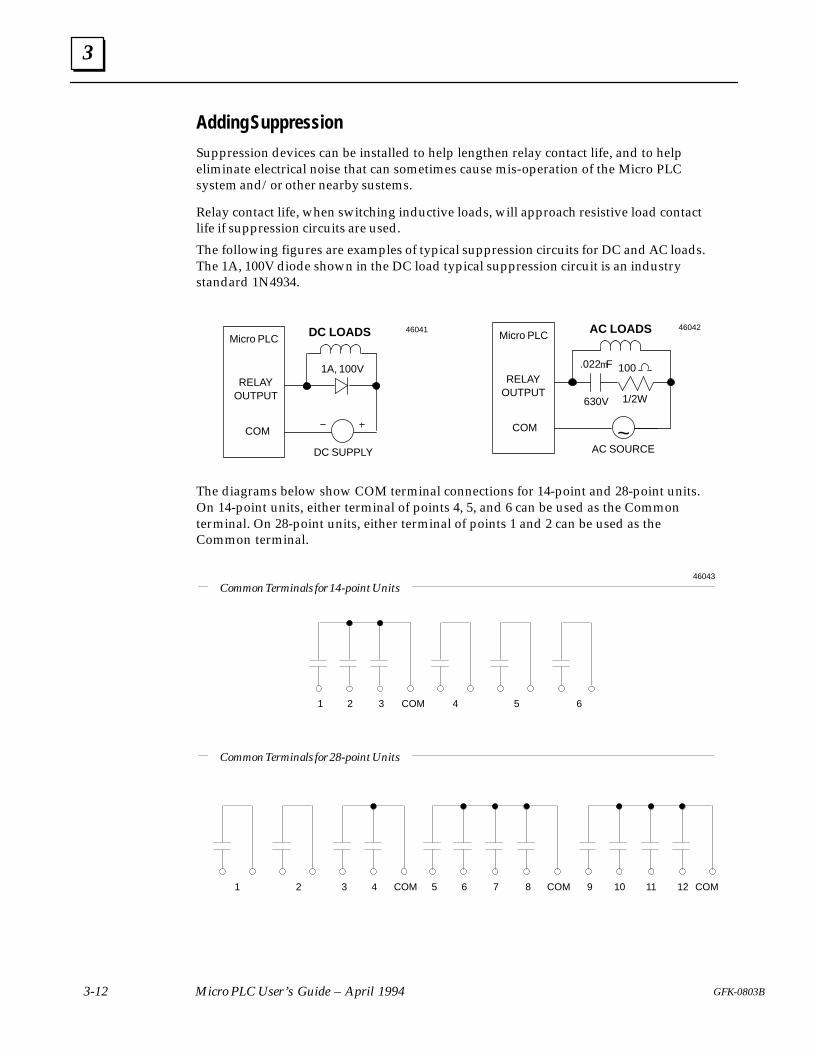
3
3-12 Micro PLC User’s Guide – April 1994 GFK-0803B
Adding Suppression
Suppression devices can be installed to help lengthen relay contact life, and to helpeliminate electrical noise that can sometimes cause mis-operation of the Micro PLCsystem and/or other nearby sustems.
Relay contact life, when switching inductive loads, will approach resistive load contactlife if suppression circuits are used.
The following figures are examples of typical suppression circuits for DC and AC loads.The 1A, 100V diode shown in the DC load typical suppression circuit is an industrystandard 1N4934.
DC LOADSMicro PLC
COM
DC SUPPLY
1A, 100VRELAY
OUTPUT
46041
The diagrams below show COM terminal connections for 14-point and 28-point units.On 14-point units, either terminal of points 4, 5, and 6 can be used as the Commonterminal. On 28-point units, either terminal of points 1 and 2 can be used as theCommon terminal.
1 2 3 4 5 6COM
Common Terminals for 14-point Units
Common Terminals for 28-point Units
1 2 3 4 5 6 8 COM 9 10 12 COMCOM 7 11
46043
Micro PLC
AC SOURCE
100.022mF
COM
630V 1/2WÎ
AC LOADS
RELAYOUTPUT
~
46042
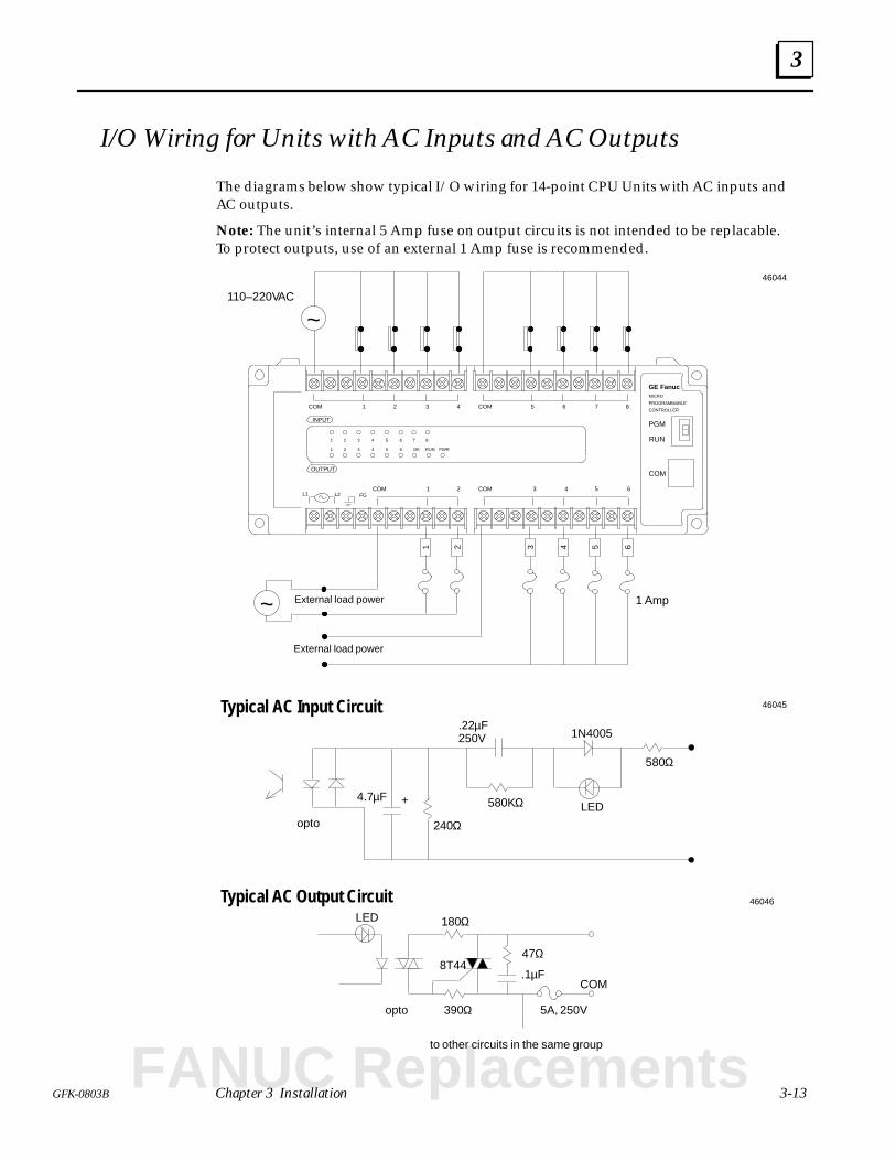
3
3-13GFK-0803B Chapter 3 Installation
I/O Wiring for Units with AC Inputs and AC Outputs
The diagrams below show typical I/O wiring for 14-point CPU Units with AC inputs andAC outputs.
Note: The unit’s internal 5 Amp fuse on output circuits is not intended to be replacable.To protect outputs, use of an external 1 Amp fuse is recommended.
External load power
External load power
1 2 3 4 5
FG
OUTPUT
INPUT
1 2 3 4 5 6 7 8COM
1 2 3 4 5 6 7 8
1 2 3 4 5 6
COM
L1 L25 63 4COM1 2COM
PGM
RUN
COM
GE FanucMICRO
PROGRAMMABLE
CONTROLLER
6
110–220VAC
~
~
46044
1 Amp
OK RUN PWR
LED580KΩ
240Ω
.22µF250V
Typical AC Input Circuit
4.7µF +
1N4005
580Ω
opto
46045
LED
8T44
COM
to other circuits in the same group
Typical AC Output Circuit180Ω
390Ω
47Ω
.1µF
5A, 250Vopto
46046
FANUC Replacements
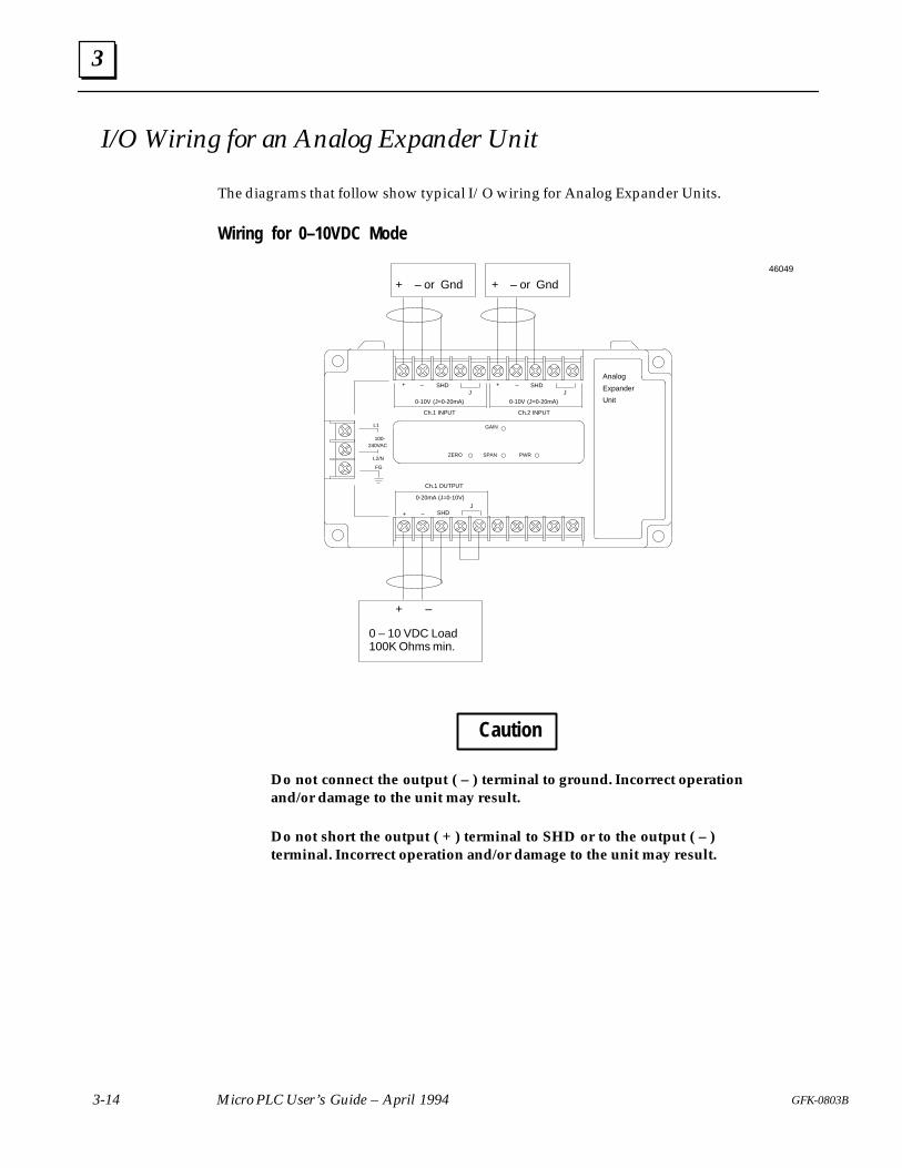
3
3-14 Micro PLC User’s Guide – April 1994 GFK-0803B
I/O Wiring for an Analog Expander Unit
The diagrams that follow show typical I/O wiring for Analog Expander Units.
Wiring for 0–10VDC Mode
FG
L2/N
L1
100-240VAC
PWR
Analog
Expander
Unit
GAIN
SPANZERO
Ch.1 INPUT
SHDJ
+ –
0-10V (J=0-20mA)
J–
Ch.2 INPUT
SHD+
0-10V (J=0-20mA)
Ch.1 OUTPUT
SHDJ
+ –
0-20mA (J=0-10V)
+ – or Gnd + – or Gnd
+ –
0 – 10 VDC Load100K Ohms min.
46049
Caution
Do not connect the output ( – ) terminal to ground. Incorrect operationand/or damage to the unit may result.
Do not short the output ( + ) terminal to SHD or to the output ( – )terminal. Incorrect operation and/or damage to the unit may result.
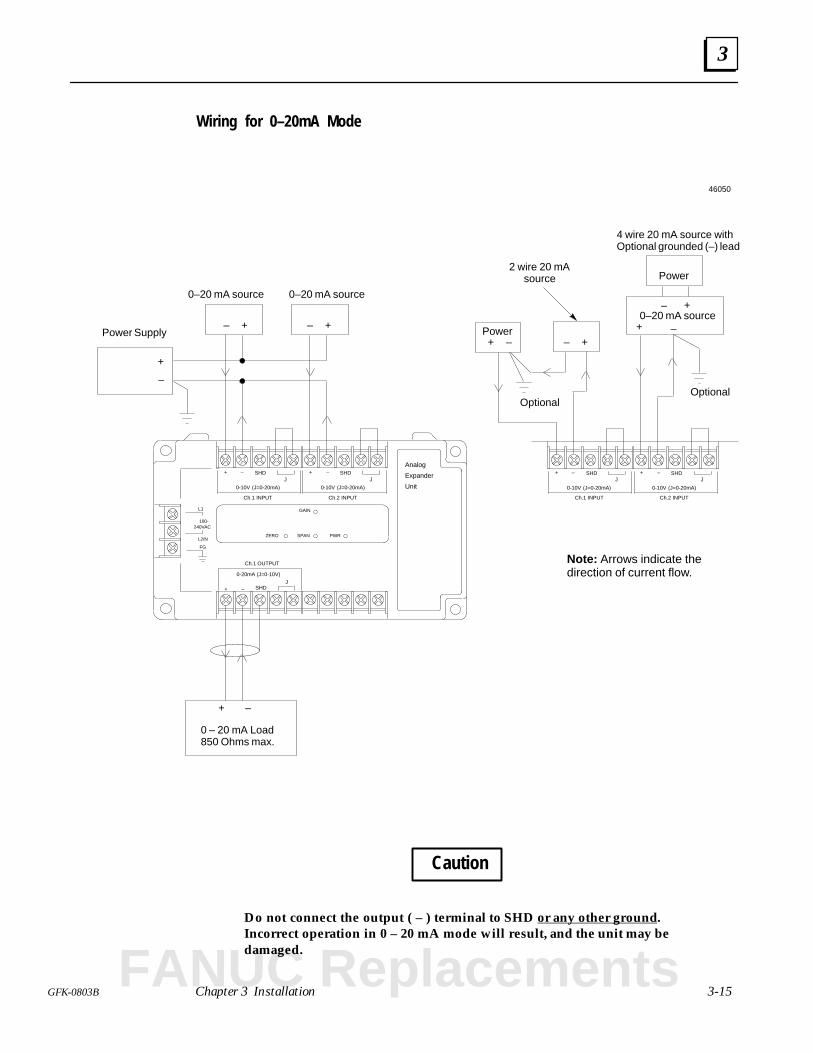
3
3-15GFK-0803B Chapter 3 Installation
Wiring for 0–20mA Mode
FG
L2/N
L1
100-240VAC
PWR
Analog
Expander
Unit
GAIN
SPANZERO
Ch.1 INPUT
SHDJ
+ –
0-10V (J=0-20mA)
J–
Ch.2 INPUT
SHD+
0-10V (J=0-20mA)
Ch.1 OUTPUT
SHDJ
+ –
0-20mA (J=0-10V)
+–
+ –
0 – 20 mA Load850 Ohms max.
+–
0–20 mA source 0–20 mA source
+
–
+–
Power
0–20 mA source
Ch.1 INPUT
SHDJ
+ –
0-10V (J=0-20mA)
J–
Ch.2 INPUT
SHD+
0-10V (J=0-20mA)
Power Supply
Optional
4 wire 20 mA source withOptional grounded (–) lead
Power+ –
+ –
+–
2 wire 20 mAsource
Optional
Note: Arrows indicate thedirection of current flow.
46050
Caution
Do not connect the output ( – ) terminal to SHD or any other ground.Incorrect operation in 0 – 20 mA mode will result, and the unit may bedamaged.
FANUC Replacements
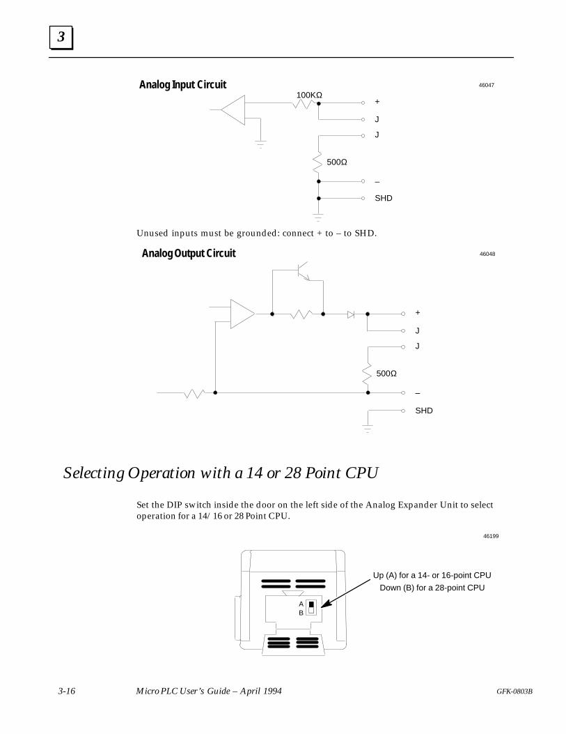
3
3-16 Micro PLC User’s Guide – April 1994 GFK-0803B
500Ω
Analog Input Circuit100KΩ
+
J
J
–
SHD
46047
Unused inputs must be grounded: connect + to – to SHD.
Analog Output Circuit
500Ω
+
J
J
–
SHD
46048
Selecting Operation with a 14 or 28 Point CPU
Set the DIP switch inside the door on the left side of the Analog Expander Unit to selectoperation for a 14/16 or 28 Point CPU.
46199
Up (A) for a 14- or 16-point CPU
Down (B) for a 28-point CPU
AB
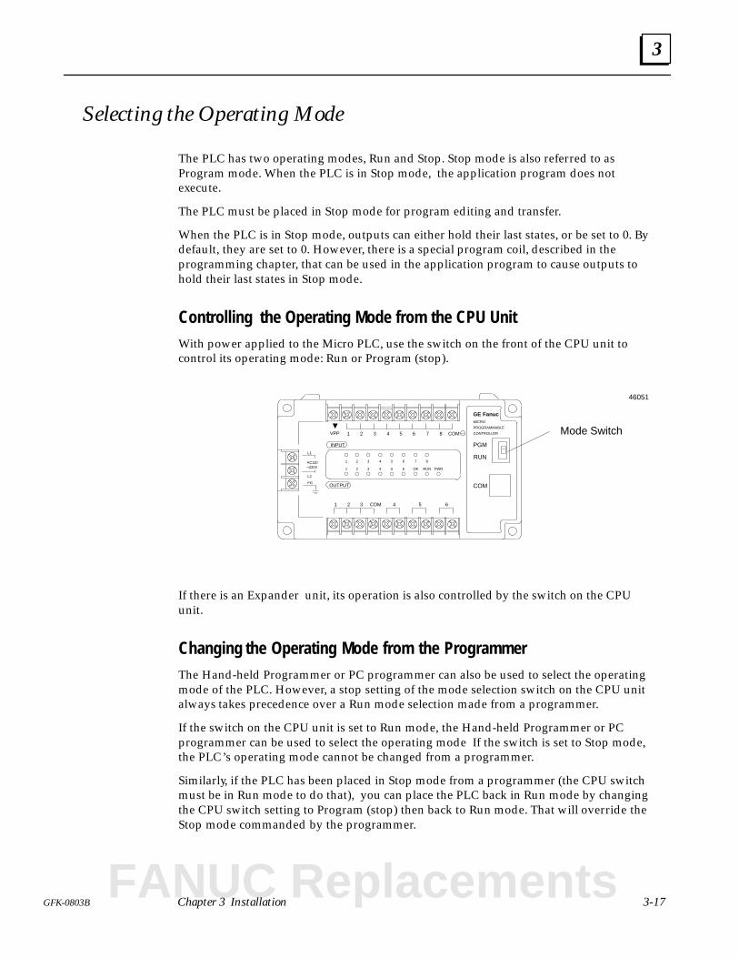
3
3-17GFK-0803B Chapter 3 Installation
Selecting the Operating Mode
The PLC has two operating modes, Run and Stop. Stop mode is also referred to asProgram mode. When the PLC is in Stop mode, the application program does notexecute.
The PLC must be placed in Stop mode for program editing and transfer.
When the PLC is in Stop mode, outputs can either hold their last states, or be set to 0. Bydefault, they are set to 0. However, there is a special program coil, described in theprogramming chapter, that can be used in the application program to cause outputs tohold their last states in Stop mode.
Controlling the Operating Mode from the CPU UnitWith power applied to the Micro PLC, use the switch on the front of the CPU unit tocontrol its operating mode: Run or Program (stop).
FGOUTPUT
INPUT
1 2 3 4 5 6 7 8 COM
1 2 3 4 5 6COM
L2
L1
AC110–220V
1 2 3 4 5 6 7 8
1 2 3 4 5 6 OK RUN
PGM
RUN
COM
VPP
PWR
GE FanucMICRO
PROGRAMMABLE
CONTROLLER Mode Switch
46051
If there is an Expander unit, its operation is also controlled by the switch on the CPUunit.
Changing the Operating Mode from the ProgrammerThe Hand-held Programmer or PC programmer can also be used to select the operatingmode of the PLC. However, a stop setting of the mode selection switch on the CPU unitalways takes precedence over a Run mode selection made from a programmer.
If the switch on the CPU unit is set to Run mode, the Hand-held Programmer or PCprogrammer can be used to select the operating mode If the switch is set to Stop mode,the PLC’s operating mode cannot be changed from a programmer.
Similarly, if the PLC has been placed in Stop mode from a programmer (the CPU switchmust be in Run mode to do that), you can place the PLC back in Run mode by changingthe CPU switch setting to Program (stop) then back to Run mode. That will override theStop mode commanded by the programmer.
FANUC Replacements

4 section level 1 1figure bi level 1 table_big level 1
4-1GFK-0803B
Chapter 4 The Hand-held Programmer
This chapter describes the Hand-held Programmer.
Parts of the Hand-held Programmer
Hand-held Programmer Specifications
Getting the HHP Ready to Use
Operating Power Supply
Online Mode
Offline Mode
Internal Battery Backup Operation
Keypad Functions
Powerup Displays
Using the Online Functions of the HHP
Transferring a Program
Monitoring Program Data
Forcing I/O Bits
Modifying Word (Register) Data
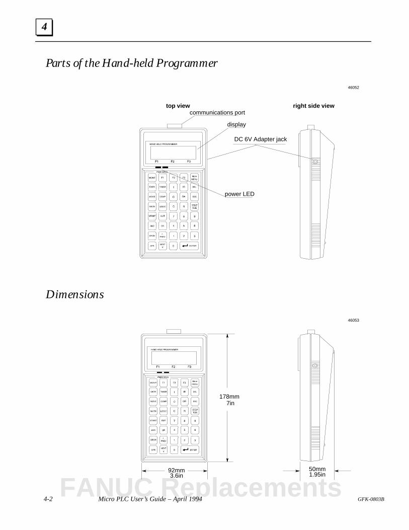
4
4-2 Micro PLC User’s Guide – April 1994 GFK-0803B
Parts of the Hand-held Programmer
top view right side viewcommunications port
DC 6V Adapter jack
power LED
display
46052
Dimensions
178mm7in
92mm3.6in
50mm1.95in
46053
FANUC Replacements

4
4-3GFK–0803B Chapter 4 The Hand-held Programmer
Hand-held Programmer Specifications
Item Specification
Processor Intel 8031AH
Memory RAM CMOS 16K words
Mode Online/offline programming
Interface RS–232C compatible 9-pin serial communications
Input voltage From PLC, or from 6VDC, 400mA adapter
Power Consumption 1 Watt (200mA) @ 5VDC, +.23V
Dimensions 178mm H x 92mm W x 50mm D7” H x 3.6” W x 1.95” D
Weight 320g (0.7 lb)
Display LCD with back-lighting2 lines, 16 characters per line
Keypad 39-key soft-touch membrane contact keypad withbeep
LEDs Power and error LED indications
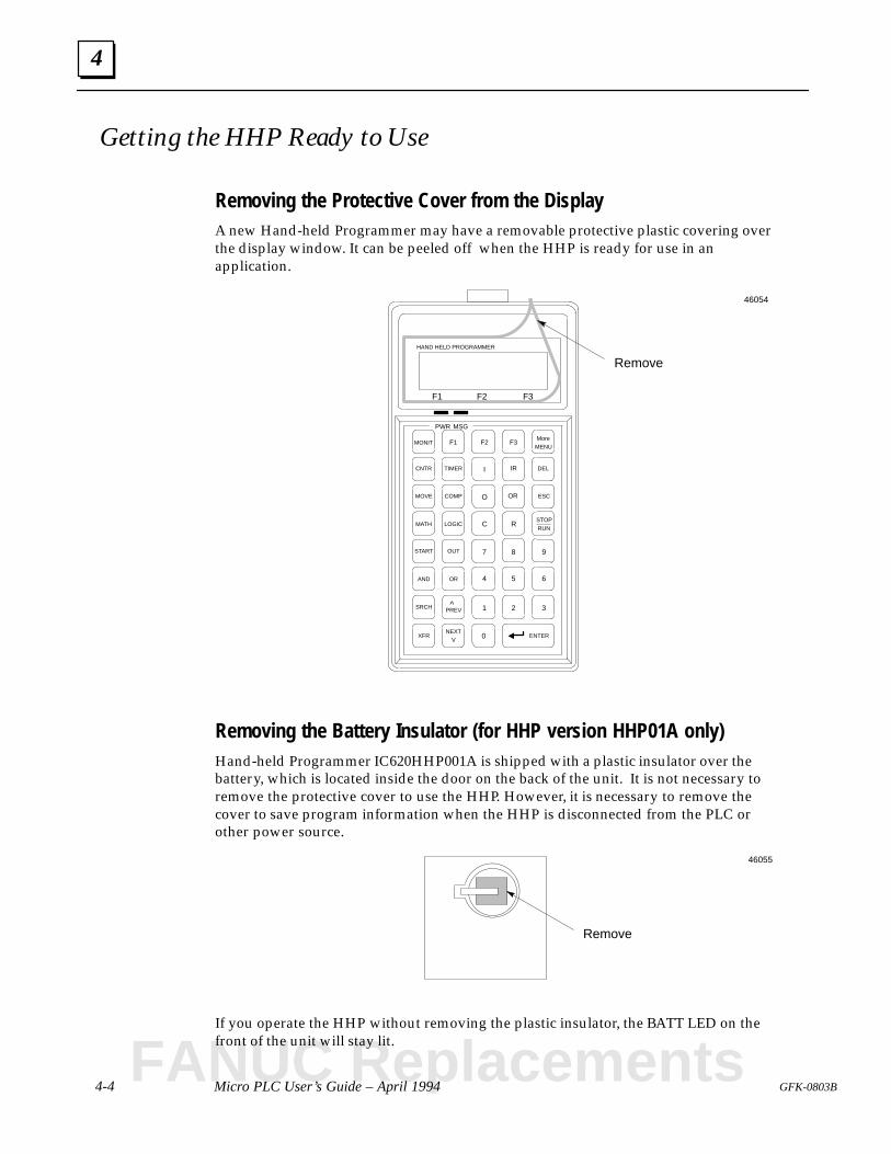
4
4-4 Micro PLC User’s Guide – April 1994 GFK-0803B
Getting the HHP Ready to Use
Removing the Protective Cover from the DisplayA new Hand-held Programmer may have a removable protective plastic covering overthe display window. It can be peeled off when the HHP is ready for use in anapplication.
NEXT
STOP
More
^
XFR
SRCH
AND
1 2 3
0
OR 4 5 6
9
R
87
C
O OR ESC
DEL
F3
IRI
F2F1
TIMER
COMP
LOGIC
OUTSTART
MATH
MOVE
CNTR
MONIT
ENTER
MENU
RUN
PREV
V
F1 F2 F3
PWR MSG
HAND HELD PROGRAMMER
Remove
46054
Removing the Battery Insulator (for HHP version HHP01A only)Hand-held Programmer IC620HHP001A is shipped with a plastic insulator over thebattery, which is located inside the door on the back of the unit. It is not necessary toremove the protective cover to use the HHP. However, it is necessary to remove thecover to save program information when the HHP is disconnected from the PLC orother power source.
Remove
46055
If you operate the HHP without removing the plastic insulator, the BATT LED on thefront of the unit will stay lit.
FANUC Replacements
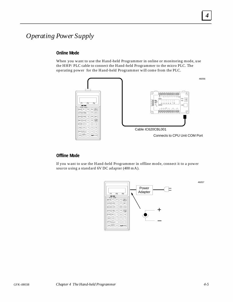
4
4-5GFK–0803B Chapter 4 The Hand-held Programmer
Operating Power Supply
Online Mode
When you want to use the Hand-held Programmer in online or monitoring mode, usethe HHP/PLC cable to connect the Hand-held Programmer to the micro PLC. Theoperating power for the Hand-held Programmer will come from the PLC.
Cable IC620CBL001
Connects to CPU Unit COM Port
46056
Offline Mode
If you want to use the Hand-held Programmer in offline mode, connect it to a powersource using a standard 6V DC adapter (400 mA).
PowerAdapter
–
+
46057
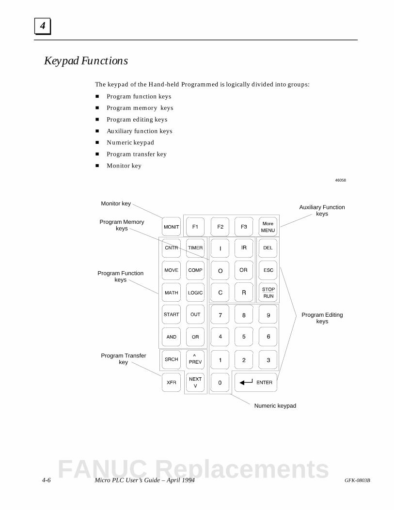
4
4-6 Micro PLC User’s Guide – April 1994 GFK-0803B
Keypad Functions
The keypad of the Hand-held Programmed is logically divided into groups:
Program function keys
Program memory keys
Program editing keys
Auxiliary function keys
Numeric keypad
Program transfer key
Monitor key
Program Functionkeys
Program Memorykeys
Program Editingkeys
Auxiliary Functionkeys
Numeric keypad
Program Transferkey
Monitor key
46058
FANUC Replacements
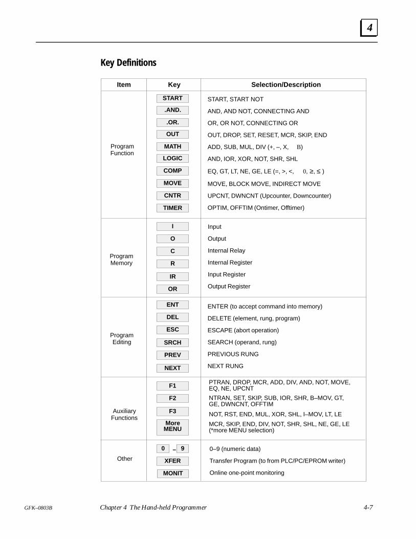
4
4-7GFK–0803B Chapter 4 The Hand-held Programmer
Key Definitions
Item Key Selection/Description
.AND.
.OR.
OUT
MATH
LOGIC
COMP
MOVE
CNTR
TIMER
ProgramFunction
ProgramMemory
START, START NOT
AND, AND NOT, CONNECTING AND
OR, OR NOT, CONNECTING OR
OUT, DROP, SET, RESET, MCR, SKIP, END
ADD, SUB, MUL, DIV (+, –, X, B)
AND, IOR, XOR, NOT, SHR, SHL
EQ, GT, LT, NE, GE, LE (=, >, <, 0, ≥, ≤ )
MOVE, BLOCK MOVE, INDIRECT MOVE
UPCNT, DWNCNT (Upcounter, Downcounter)
OPTIM, OFFTIM (Ontimer, Offtimer)
I
O
C
R
IR
OR
Input
Output
Internal Relay
Internal Register
Input Register
Output Register
ProgramEditing
ENT
DEL
ESC
SRCH
PREV
NEXT
ENTER (to accept command into memory)
DELETE (element, rung, program)
ESCAPE (abort operation)
SEARCH (operand, rung)
PREVIOUS RUNG
NEXT RUNG
AuxiliaryFunctions
F1
F2
F3
More
PTRAN, DROP, MCR, ADD, DIV, AND, NOT, MOVE,EQ, NE, UPCNT
MCR, SKIP, END, DIV, NOT, SHR, SHL, NE, GE, LE(*more MENU selection)
NTRAN, SET, SKIP, SUB, IOR, SHR, B–MOV, GT,GE, DWNCNT, OFFTIM
NOT, RST, END, MUL, XOR, SHL, I–MOV, LT, LE
MENU
START
Other
0
XFER
MONIT
9– 0–9 (numeric data)
Transfer Program (to from PLC/PC/EPROM writer)
Online one-point monitoring
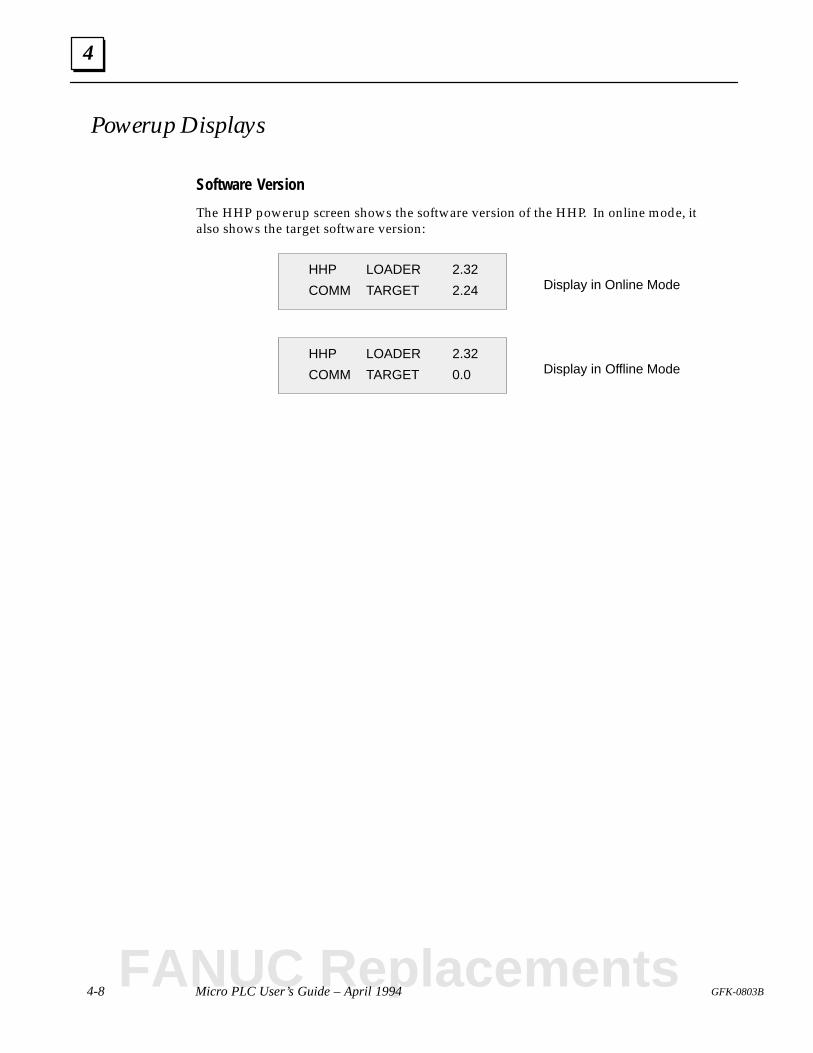
4
4-8 Micro PLC User’s Guide – April 1994 GFK-0803B
Powerup Displays
Software Version
The HHP powerup screen shows the software version of the HHP. In online mode, italso shows the target software version:
HHP LOADER 2.32
COMM TARGET 0.0
HHP LOADER 2.32
COMM TARGET 2.24
Display in Offline Mode
Display in Online Mode
FANUC Replacements
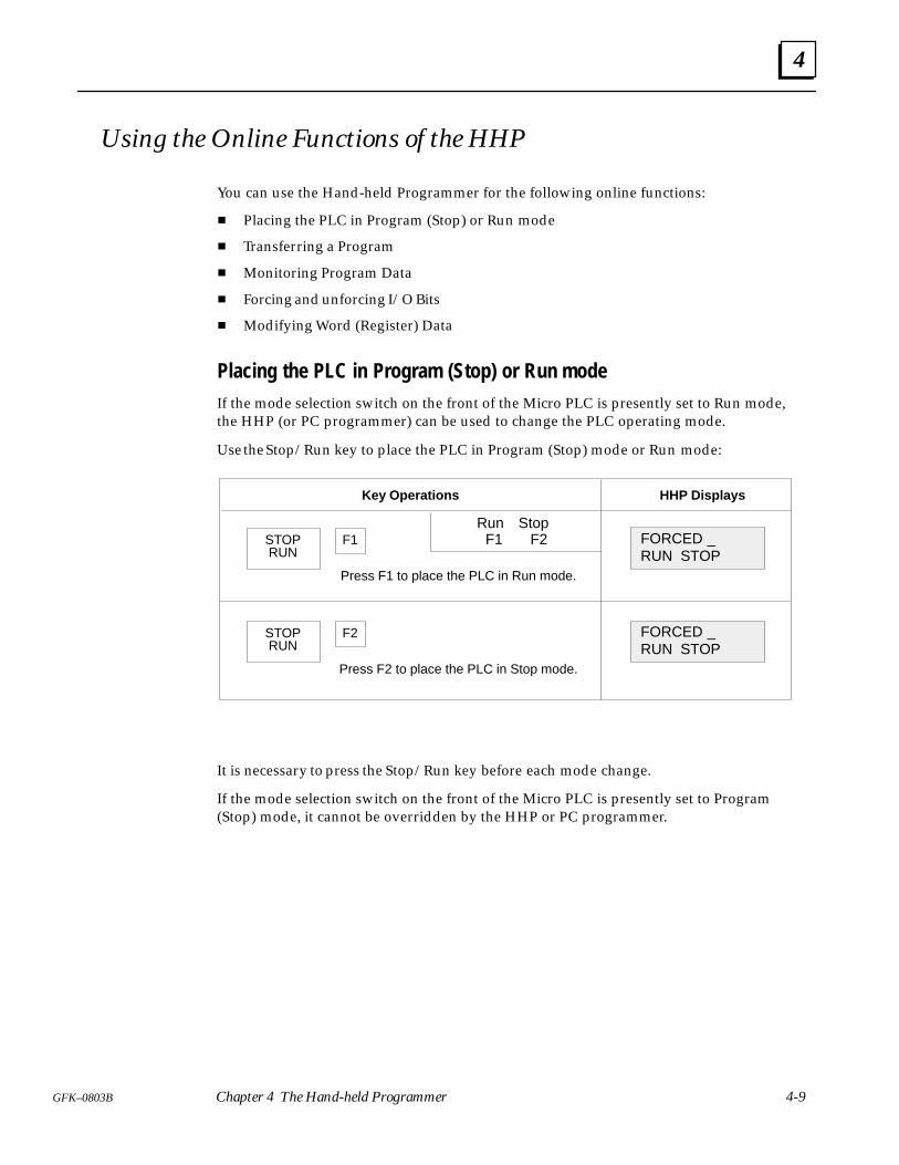
4
4-9GFK–0803B Chapter 4 The Hand-held Programmer
Using the Online Functions of the HHP
You can use the Hand-held Programmer for the following online functions:
Placing the PLC in Program (Stop) or Run mode
Transferring a Program
Monitoring Program Data
Forcing and unforcing I/O Bits
Modifying Word (Register) Data
Placing the PLC in Program (Stop) or Run modeIf the mode selection switch on the front of the Micro PLC is presently set to Run mode,the HHP (or PC programmer) can be used to change the PLC operating mode.
Use the Stop/Run key to place the PLC in Program (Stop) mode or Run mode:
Key Operations HHP Displays
STOP FORCED _RUN STOP
F1
Press F1 to place the PLC in Run mode.
Run Stop F1 F2
RUN
STOP FORCED _RUN STOP
F2
Press F2 to place the PLC in Stop mode.
RUN
It is necessary to press the Stop/Run key before each mode change.
If the mode selection switch on the front of the Micro PLC is presently set to Program(Stop) mode, it cannot be overridden by the HHP or PC programmer.
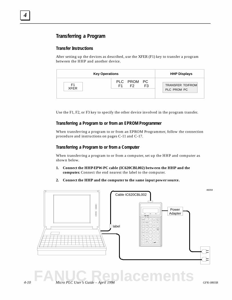
4
4-10 Micro PLC User’s Guide – April 1994 GFK-0803B
Transferring a Program
Transfer Instructions
After setting up the devices as described, use the XFER (F1) key to transfer a programbetween the HHP and another device.
Key Operations HHP Displays
F1 TRANSFER TO/FROM
PLC PROM PC
PLC PROM PC F1 F2 F3
XFER
Use the F1, F2, or F3 key to specify the other device involved in the program transfer.
Transferring a Program to or from an EPROM Programmer
When transferring a program to or from an EPROM Programmer, follow the connectionprocedure and instructions on pages C-11 and C-17.
Transferring a Program to or from a Computer
When transferring a program to or from a computer, set up the HHP and computer asshown below.
1. Connect the HHP-EPW-PC cable (IC620CBL002) between the HHP and thecomputer. Connect the end nearest the label to the computer.
2. Connect the HHP and the computer to the same input power source.
Cable IC620CBL002
PowerAdapter
label
46059
FANUC Replacements
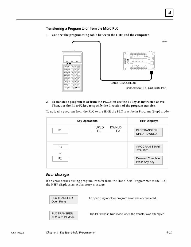
4
4-11GFK–0803B Chapter 4 The Hand-held Programmer
Transferring a Program to or from the Micro PLC
1. Connect the programming cable between the HHP and the computer.
Cable IC620CBL001
Connects to CPU Unit COM Port
46056
2. To transfer a program to or from the PLC, first use the F1 key as instructed above.Then, use the F1 or F2 key to specify the direction of the program transfer.
To upload a program from the PLC to the HHP, the PLC must be in Program (Stop) mode.
Key Operations HHP Displays
F1 PLC TRANSFERUPLD DWNLD
UPLD DWNLD F1 F2
F1 PROGRAM STARTSTA I001
or
F2 Dwnload CompletePress Any Key
Error Messages
If an error occurs during program transfer from the Hand-held Programmer to the PLC,the HHP displays an explanatory message:
PLC TRANSFEROpen Rung
PLC TRANSFERPLC in RUN Mode
An open rung or other program error was encountered.
The PLC was in Run mode when the transfer was attempted.
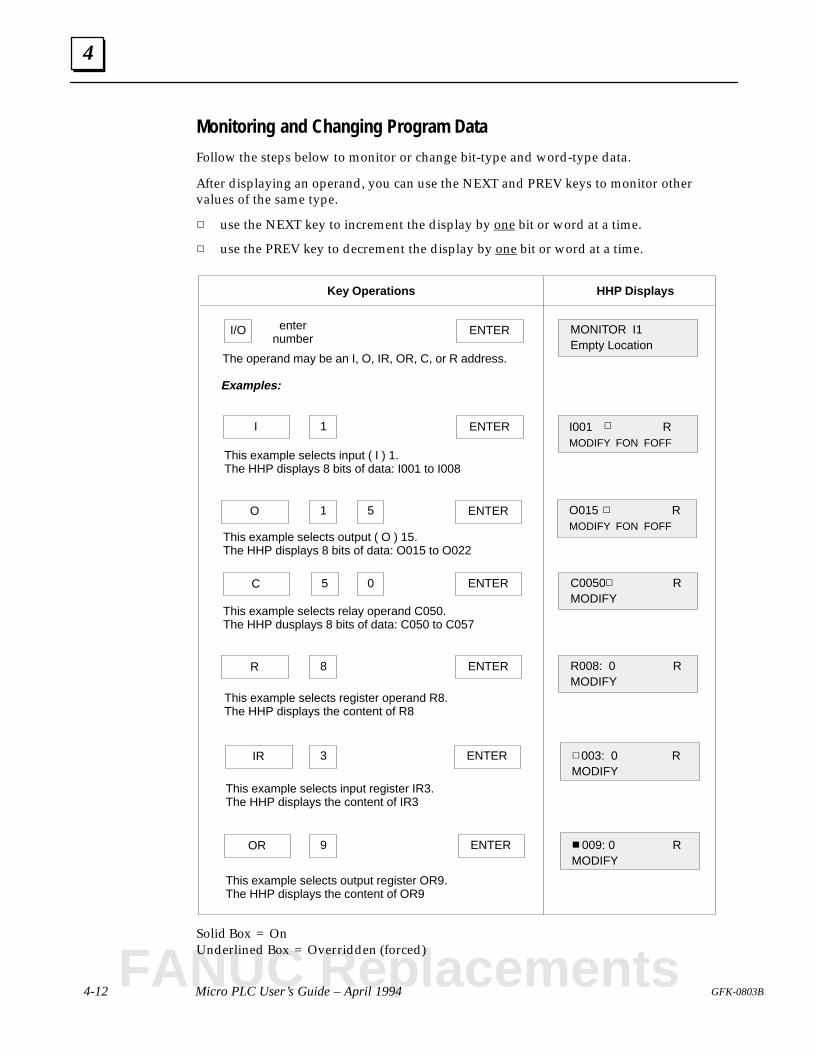
4
4-12 Micro PLC User’s Guide – April 1994 GFK-0803B
Monitoring and Changing Program Data
Follow the steps below to monitor or change bit-type and word-type data.
After displaying an operand, you can use the NEXT and PREV keys to monitor othervalues of the same type.
use the NEXT key to increment the display by one bit or word at a time.
use the PREV key to decrement the display by one bit or word at a time.
MONITOR I1Empty Location
ENTERI/O
Key Operations HHP Displays
enternumber
The operand may be an I, O, IR, OR, C, or R address.
I ENTER
This example selects input ( I ) 1.The HHP displays 8 bits of data: I001 to I008
O O015 RMODIFY FON FOFF
ENTER1 5
C C0050 RMODIFY
0
R R008: 0 RMODIFY
ENTER
IR 003: 0 RMODIFY
3
OR 009: 0 RMODIFY
ENTER
1
5
8
9
This example selects output ( O ) 15.The HHP displays 8 bits of data: O015 to O022
This example selects relay operand C050.The HHP dusplays 8 bits of data: C050 to C057
This example selects register operand R8.The HHP displays the content of R8
ENTER
This example selects input register IR3.The HHP displays the content of IR3
This example selects output register OR9.The HHP displays the content of OR9
I001 RMODIFY FON FOFF
ENTER
Examples:
Solid Box = OnUnderlined Box = Overridden (forced)
FANUC Replacements
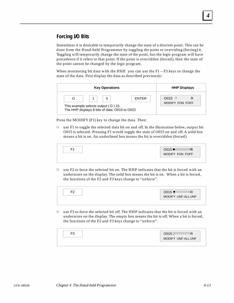
4
4-13GFK–0803B Chapter 4 The Hand-held Programmer
Forcing I/O Bits
Sometimes it is desirable to temporarily change the state of a discrete point. This can bedone from the Hand-held Programmer by toggling the point or overriding (forcing) it.Toggling will temporarily change the state of the point, but the logic program will haveprecedence if it refers to that point. If the point is overridden (forced), then the state ofthe point cannot be changed by the logic program.
When monitoring bit data with the HHP, you can use the F1 – F3 keys to change thestate of the data. First display the data as described previously:
Key Operations HHP Displays
O O015 RMODIFY FON FOFF
ENTER1 5
This example selects output ( O ) 15.The HHP displays 8 bits of data: O015 to O022
Press the MODIFY (F1) key to change the data. Then:
use F1 to toggle the selected data bit on and off. In the illustration below, output bitO015 is selected. Pressing F1 would toggle the state of O015 on and off. A solid boxmeans a bit is on. An underlined box means the bit is overridden (forced).
F1 O015 RMODIFY FON FOFF
use F2 to force the selected bit on. The HHP indicates that the bit is forced with anunderscore on the display. The solid box means the bit is on. When a bit is forced,the functions of the F2 and F3 keys change to “unforce”.
F2 O015 R
MODIFY UNF-ALL UNF
use F3 to force the selected bit off. The HHP indicates that the bit is forced with anunderscore on the display. The empty box means the bit is off. When a bit is forced,the functions of the F2 and F3 keys change to “unforce”.
F3 O015 R
MODIFY UNF-ALL UNF
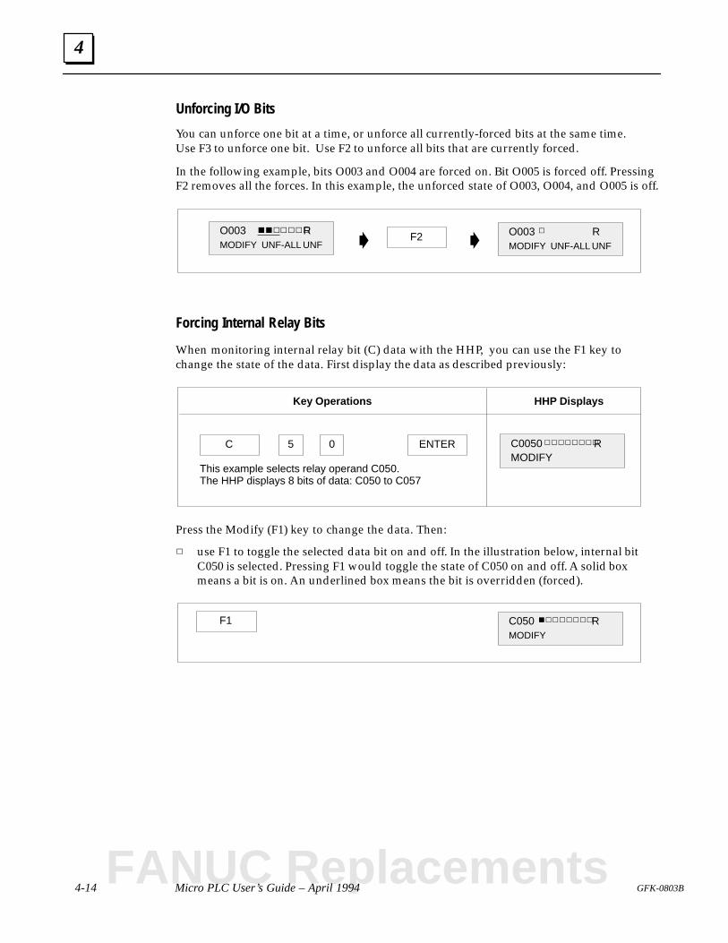
4
4-14 Micro PLC User’s Guide – April 1994 GFK-0803B
Unforcing I/O Bits
You can unforce one bit at a time, or unforce all currently-forced bits at the same time.Use F3 to unforce one bit. Use F2 to unforce all bits that are currently forced.
In the following example, bits O003 and O004 are forced on. Bit O005 is forced off. PressingF2 removes all the forces. In this example, the unforced state of O003, O004, and O005 is off.
F2 O003 RMODIFY UNF-ALL UNF
O003 RMODIFY UNF-ALL UNF
Forcing Internal Relay Bits
When monitoring internal relay bit (C) data with the HHP, you can use the F1 key tochange the state of the data. First display the data as described previously:
Key Operations HHP Displays
C C0050 RMODIFY
05
This example selects relay operand C050.The HHP displays 8 bits of data: C050 to C057
ENTER
Press the Modify (F1) key to change the data. Then:
use F1 to toggle the selected data bit on and off. In the illustration below, internal bitC050 is selected. Pressing F1 would toggle the state of C050 on and off. A solid boxmeans a bit is on. An underlined box means the bit is overridden (forced).
F1 C050 RMODIFY
FANUC Replacements
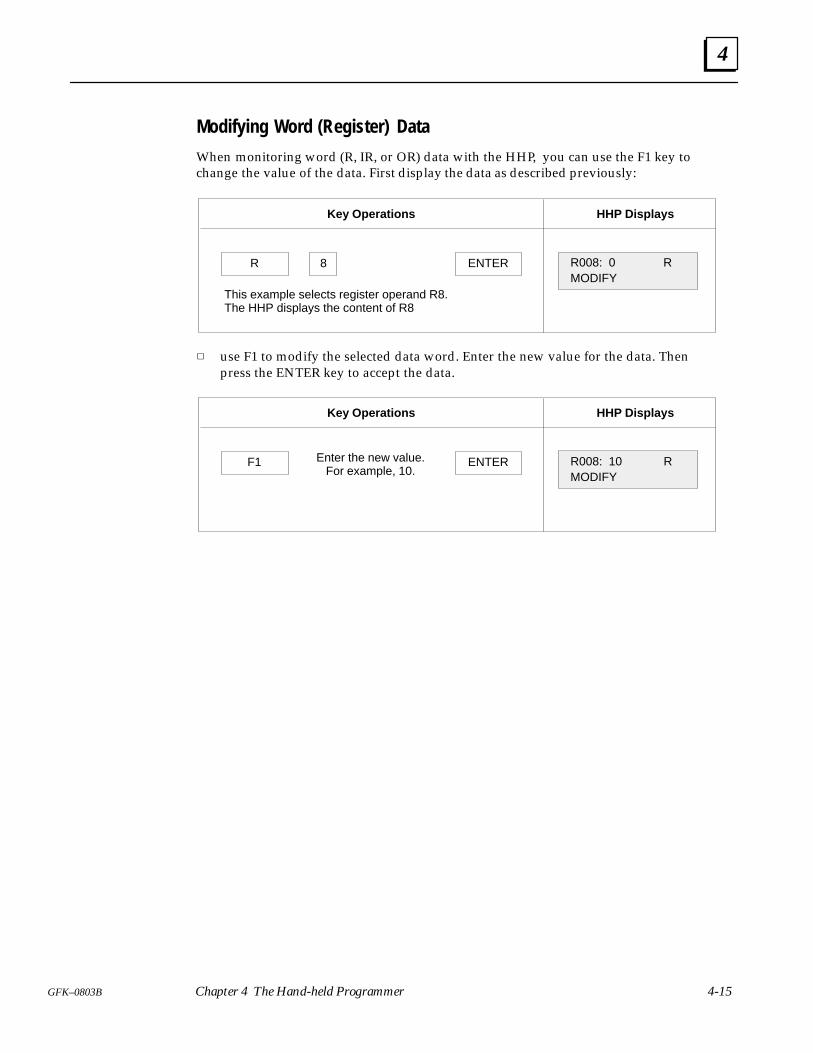
4
4-15GFK–0803B Chapter 4 The Hand-held Programmer
Modifying Word (Register) Data
When monitoring word (R, IR, or OR) data with the HHP, you can use the F1 key tochange the value of the data. First display the data as described previously:
Key Operations HHP Displays
R R008: 0 RMODIFY
ENTER8
This example selects register operand R8.The HHP displays the content of R8
use F1 to modify the selected data word. Enter the new value for the data. Thenpress the ENTER key to accept the data.
Key Operations HHP Displays
F1 R008: 10 RMODIFY
ENTEREnter the new value.For example, 10.
5 section level 1 1figure bi level 1 table_big level 1
5-1GFK-0803B
Chapter 5 The Operator Interface Unit
This chapter describes the Operator Interface Unit.
Parts of the Operator Interface Unit
Dimensions
Operator Interface Unit Specifications
Getting the OIU Ready to Use
Operating Power Supply
Keypad Functions
Powerup Displays
Changing the Operating Mode of the PLC
Program Listing
Program Transfer
Program Searching
Monitoring and Changing Program Data
Setting the Operation Keys
Using the Operation Keys
Changing Data that is Associated with Operation Keys
The Operator Interface Unit (OIU) performs many of the same functions as a Hand-heldProgrammer. It can be used to monitor program data and I/O status and to change theoperating mode of the PLC. It can display an application program, but it cannot be usedto create or edit a program.
In addition to its basic features, the OIU has fourteen configurable software keys. Thesekeys are easily set to display operator messages for up to 14 discrete and/or register dataitems. In addition, the OIU can be used to quickly change the state or value of any of the14 data items that have been assigned to software keys.
FANUC Replacements
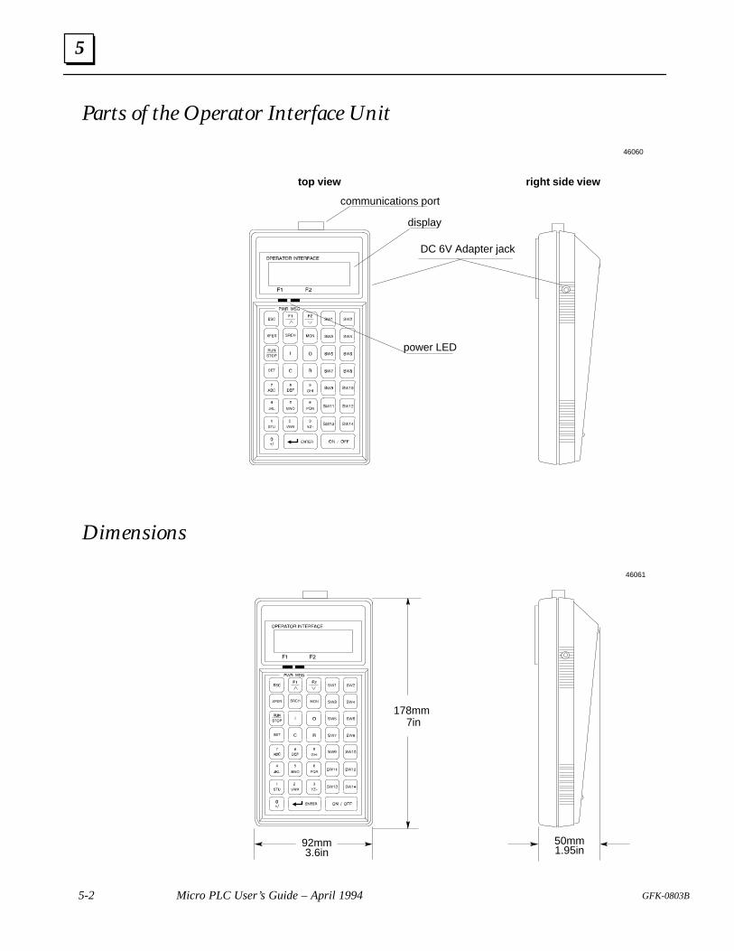
5
5-2 Micro PLC User’s Guide – April 1994 GFK-0803B
Parts of the Operator Interface Unit
top view right side view
communications port
DC 6V Adapter jack
power LED
display
46060
Dimensions
178mm7in
92mm3.6in
50mm1.95in
46061
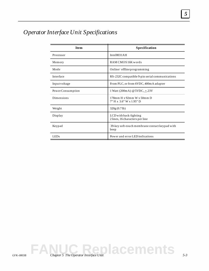
5
5-3GFK–0803B Chapter 5 The Operator Interface Unit
Operator Interface Unit Specifications
Item Specification
Processor Intel 8031AH
Memory RAM CMOS 16K words
Mode Online/offline programming
Interface RS–232C compatible 9-pin serial communications
Input voltage From PLC, or from 6VDC, 400mA adapter
Power Consumption 1 Watt (200mA) @ 5VDC, +.23V
Dimensions 178mm H x 92mm W x 50mm D7” H x 3.6” W x 1.95” D
Weight 320g (0.7 lb)
Display LCD with back-lighting2 lines, 16 characters per line
Keypad 39-key soft-touch membrane contact keypad withbeep
LEDs Power and error LED indications
FANUC Replacements
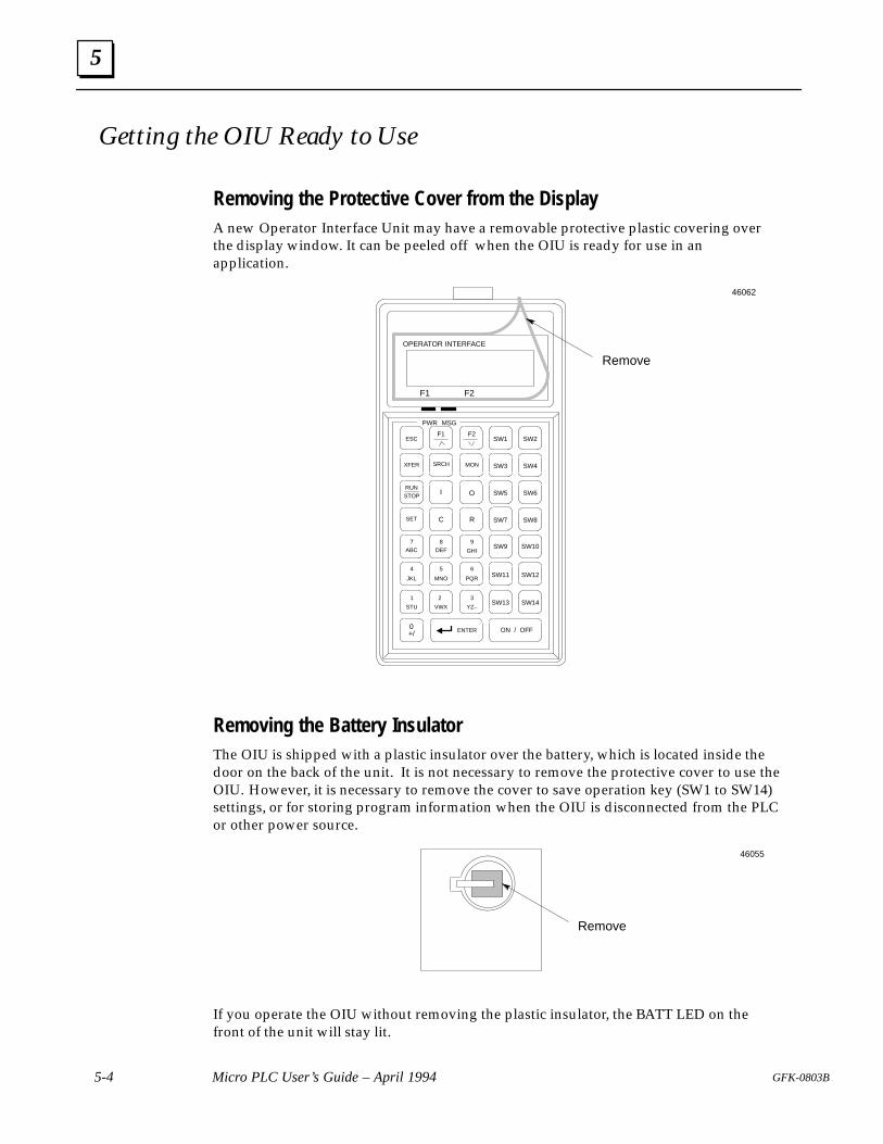
5
5-4 Micro PLC User’s Guide – April 1994 GFK-0803B
Getting the OIU Ready to Use
Removing the Protective Cover from the DisplayA new Operator Interface Unit may have a removable protective plastic covering overthe display window. It can be peeled off when the OIU is ready for use in anapplication.
MON
STOP
2
XFER SRCH
4
0
R
9
C
O
ESC SW1
I
F2F1
SET
ON / OFF
RUN
VWX
F1 F2
PWR MSG
OPERATOR INTERFACE
GHI
SW2
SW3 SW4
SW5 SW6
SW7 SW8
SW9
SW11
SW13
SW10
SW12
SW14
ENTER
7ABC
JKL
1
STU
+/
3
YZ–
6
PQR
5
MNO
8DEF
Remove
46062
Removing the Battery InsulatorThe OIU is shipped with a plastic insulator over the battery, which is located inside thedoor on the back of the unit. It is not necessary to remove the protective cover to use theOIU. However, it is necessary to remove the cover to save operation key (SW1 to SW14)settings, or for storing program information when the OIU is disconnected from the PLCor other power source.
Remove
46055
If you operate the OIU without removing the plastic insulator, the BATT LED on thefront of the unit will stay lit.
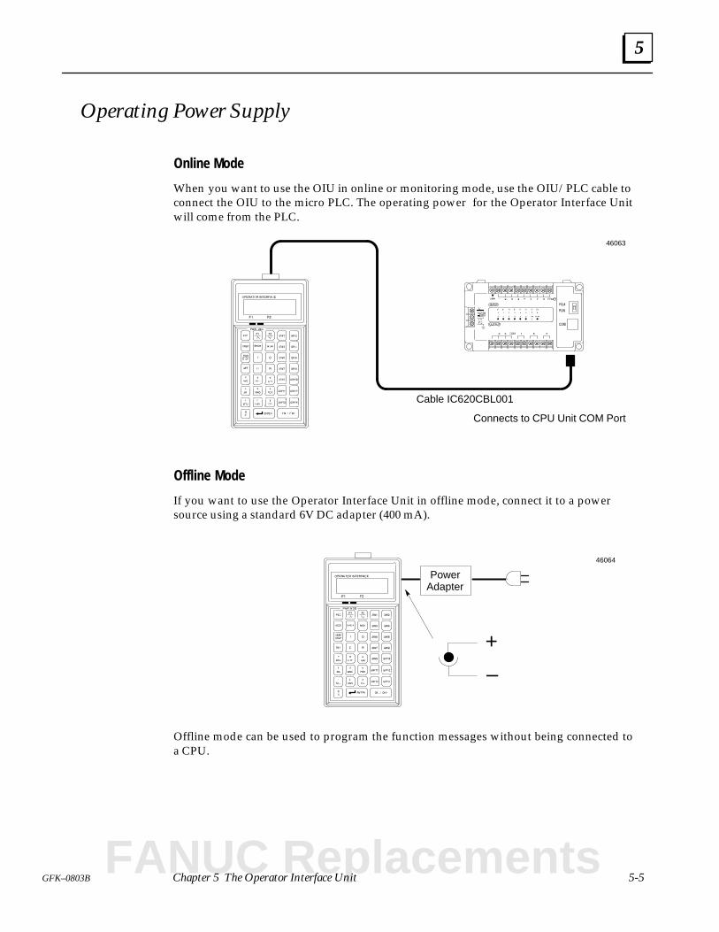
5
5-5GFK–0803B Chapter 5 The Operator Interface Unit
Operating Power Supply
Online Mode
When you want to use the OIU in online or monitoring mode, use the OIU/PLC cable toconnect the OIU to the micro PLC. The operating power for the Operator Interface Unitwill come from the PLC.
Cable IC620CBL001
Connects to CPU Unit COM Port
46063
Offline Mode
If you want to use the Operator Interface Unit in offline mode, connect it to a powersource using a standard 6V DC adapter (400 mA).
PowerAdapter
–
+
46064
Offline mode can be used to program the function messages without being connected toa CPU.
FANUC Replacements
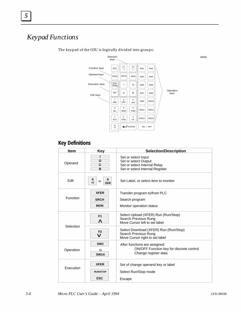
5
5-6 Micro PLC User’s Guide – April 1994 GFK-0803B
Keypad Functions
The keypad of the OIU is logically divided into groups:
Edit keys
Operationkeys
Function keys
Selectionkeys
MON
STOP
2
XFER SRCH
4
0
R
9
C
O
ESC SW1
I
F2F1
SET
ON / OFF
RUN
VWX
GHI
SW2
SW3 SW4
SW5 SW6
SW7 SW8
SW9
SW11
SW13
SW10
SW12
SW14
ENTER
7ABC
JKL
1STU
+/
3YZ–
6
PQR
5
MNO
8DEF
Operand keys
Execution keys
46065
Key DefinitionsItem Key Selection/Description
Operand
IOCR
Set or select InputSet or select OutputSet or select Internal RelaySet or select Internal Register
Set Label, or select item to monitor
F1
^
XFER
MON
Edit
Function SRCH
Transfer program to/from PLC
Search program
Monitor operation status
to
Select Upload (XFER) Run (Run/Stop)Search Previous RungMove Cursor left to set label
F2^ Select Download (XFER) Run (Run/Stop)Search Previous RungMove Cursor right to set label
Selection
0+/
9GHI
After functions are assigned:ON/OFF Function key for discrete controlChange register data
Operation to
XFER
ESC
ExecutionRUN/STOP
Set of change operand key or label
Select Run/Stop mode
Escape
SW14
SW1
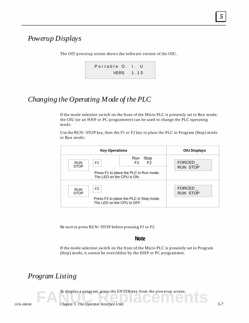
5
5-7GFK–0803B Chapter 5 The Operator Interface Unit
Powerup Displays
The OIT powerup screen shows the software version of the OIU.
P o r t a b l e O . I . U
VERS 1 . 1 5
Changing the Operating Mode of the PLC
If the mode selection switch on the front of the Micro PLC is presently set to Run mode,the OIU (or an HHP or PC programmer) can be used to change the PLC operatingmode.
Use the RUN/STOP key, then the F1 or F2 key to place the PLC in Program (Stop) modeor Run mode:
Key Operations OIU Displays
RUN FORCED _RUN STOP
F1
Press F1 to place the PLC in Run mode.The LED on the CPU is ON.
Run Stop F1 F2
STOP
FORCED _RUN STOP
F2
Press F2 to place the PLC in Stop mode.The LED on the CPU is OFF.
RUNSTOP
Be sure to press RUN/STOP before pressing F1 or F2.
Note
If the mode selection switch on the front of the Micro PLC is presently set to Program(Stop) mode, it cannot be overridden by the HHP or PC programmer.
Program Listing
To display a program, press the ENTER key from the powerup screen.
FANUC Replacements
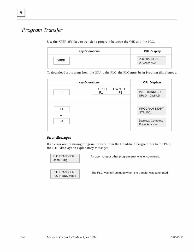
5
5-8 Micro PLC User’s Guide – April 1994 GFK-0803B
Program Transfer
Use the XFER (F1) key to transfer a program between the OIU and the PLC.
Key Operations OIU Display
PLC TRANSFER
UPLD DWNLDXFER
To download a program from the OIU to the PLC, the PLC must be in Program (Stop) mode.
Key Operations OIU Displays
F1 PLC TRANSFERUPLD DWNLD
UPLD DWNLD F1 F2
F1 PROGRAM STARTSTA I001
or
F2 Dwnload CompletePress Any Key
Error Messages
If an error occurs during program transfer from the Hand-held Programmer to the PLC,the HHP displays an explanatory message:
PLC TRANSFEROpen Rung
PLC TRANSFERPLC in RUN Mode
An open rung or other program error was encountered.
The PLC was in Run mode when the transfer was attempted.
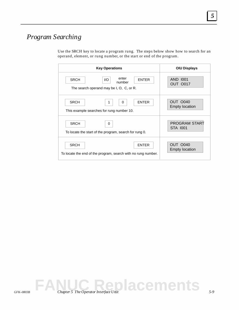
5
5-9GFK–0803B Chapter 5 The Operator Interface Unit
Program Searching
Use the SRCH key to locate a program rung. The steps below show how to search for anoperand, element, or rung number, or the start or end of the program.
SRCH AND I001OUT O017
ENTERI/O
Key Operations OIU Displays
enternumber
The search operand may be I, O, C, or R.
SRCH OUT O040Empty location
ENTER1
This example searches for rung number 10.
0
SRCH PROGRAM STARTSTA I001
To locate the start of the program, search for rung 0.
0
SRCH OUT O040Empty location
To locate the end of the program, search with no rung number.
ENTER
FANUC Replacements
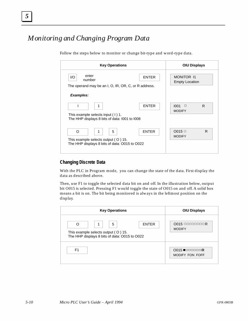
5
5-10 Micro PLC User’s Guide – April 1994 GFK-0803B
Monitoring and Changing Program Data
Follow the steps below to monitor or change bit-type and word-type data.
MONITOR I1Empty Location
ENTERI/O
Key Operations OIU Displays
enternumber
The operand may be an I, O, IR, OR, C, or R address.
I ENTER
This example selects input ( I ) 1.The HHP displays 8 bits of data: I001 to I008
O O015 RMODIFY
ENTER1 5
1
This example selects output ( O ) 15.The HHP displays 8 bits of data: O015 to O022
I001 RMODIFY
Examples:
Changing Discrete Data
With the PLC in Program mode, you can change the state of the data. First display thedata as described above.
Then, use F1 to toggle the selected data bit on and off. In the illustration below, outputbit O015 is selected. Pressing F1 would toggle the state of O015 on and off. A solid boxmeans a bit is on. The bit being monitored is always in the leftmost position on thedisplay.
F1 O015 RMODIFY FON FOFF
O O015 RMODIFY
ENTER1 5
This example selects output ( O ) 15.The HHP displays 8 bits of data: O015 to O022
Key Operations OIU Displays
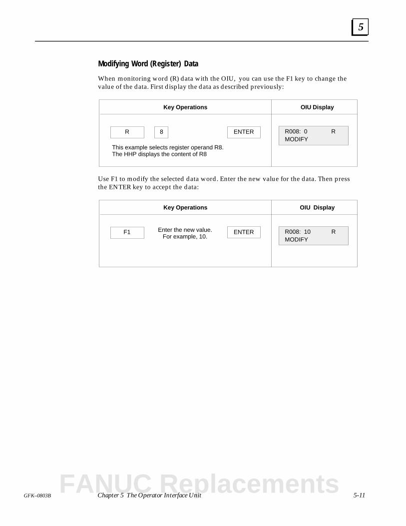
5
5-11GFK–0803B Chapter 5 The Operator Interface Unit
Modifying Word (Register) Data
When monitoring word (R) data with the OIU, you can use the F1 key to change thevalue of the data. First display the data as described previously:
Key Operations OIU Display
R R008: 0 RMODIFY
ENTER8
This example selects register operand R8.The HHP displays the content of R8
Use F1 to modify the selected data word. Enter the new value for the data. Then pressthe ENTER key to accept the data:
Key Operations OIU Display
F1 R008: 10 RMODIFY
ENTEREnter the new value.For example, 10.
FANUC Replacements
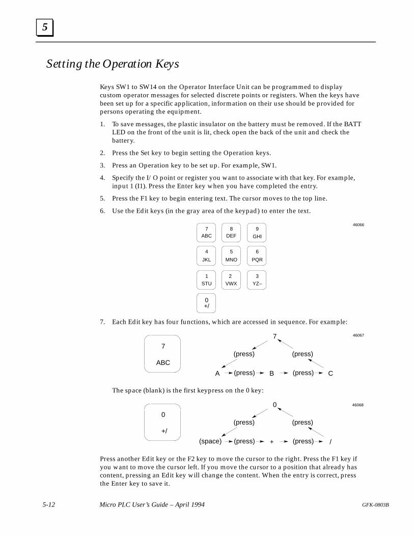
5
5-12 Micro PLC User’s Guide – April 1994 GFK-0803B
Setting the Operation Keys
Keys SW1 to SW14 on the Operator Interface Unit can be programmed to displaycustom operator messages for selected discrete points or registers. When the keys havebeen set up for a specific application, information on their use should be provided forpersons operating the equipment.
1. To save messages, the plastic insulator on the battery must be removed. If the BATTLED on the front of the unit is lit, check open the back of the unit and check thebattery.
2. Press the Set key to begin setting the Operation keys.
3. Press an Operation key to be set up. For example, SW1.
4. Specify the I/O point or register you want to associate with that key. For example,input 1 (I1). Press the Enter key when you have completed the entry.
5. Press the F1 key to begin entering text. The cursor moves to the top line.
6. Use the Edit keys (in the gray area of the keypad) to enter the text.
2
4
0
9
VWX
GHI
7ABC
JKL
1
STU
+/
3
YZ–
6
PQR
5
MNO
8DEF
46066
7. Each Edit key has four functions, which are accessed in sequence. For example:
7
ABC
A (press) B (press) C
7
(press)(press)
46067
The space (blank) is the first keypress on the 0 key:
0
+/
(space) (press) + (press) /
0
(press)(press)
46068
Press another Edit key or the F2 key to move the cursor to the right. Press the F1 key ifyou want to move the cursor left. If you move the cursor to a position that already hascontent, pressing an Edit key will change the content. When the entry is correct, pressthe Enter key to save it.
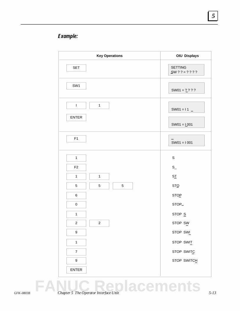
5
5-13GFK–0803B Chapter 5 The Operator Interface Unit
Example:
Key Operations OIU Displays
SET SETTINGSW ? ? = ? ? ? ?
SW1SW01 = ? ? ? ?
ISW01 = I 1
1
ENTER
SW01 = I 001
F1SW01 = I 001
1
1 1
F2
S
S_
ST
5 5 5 STO
6 STOP
0 STOP
1 STOP S
2 2 STOP SW
9 STOP SWI
1 STOP SWIT
7 STOP SWITC
9 STOP SWITCH
ENTER
FANUC Replacements
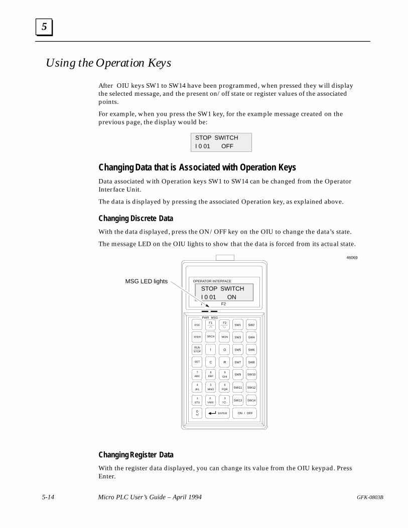
5
5-14 Micro PLC User’s Guide – April 1994 GFK-0803B
Using the Operation Keys
After OIU keys SW1 to SW14 have been programmed, when pressed they will displaythe selected message, and the present on/off state or register values of the associatedpoints.
For example, when you press the SW1 key, for the example message created on theprevious page, the display would be:
I 0 01 OFFSTOP SWITCH
Changing Data that is Associated with Operation KeysData associated with Operation keys SW1 to SW14 can be changed from the OperatorInterface Unit.
The data is displayed by pressing the associated Operation key, as explained above.
Changing Discrete Data
With the data displayed, press the ON/OFF key on the OIU to change the data’s state.
The message LED on the OIU lights to show that the data is forced from its actual state.
I 0 01 ONSTOP SWITCH
MSG LED lights
46069
MON
STOP
2
XFER SRCH
4
0
R
9
C
O
ESC SW1
I
F2F1
SET
ON / OFF
RUN
VWX
F1 F2
PWR MSG
OPERATOR INTERFACE
GHI
SW2
SW3 SW4
SW5 SW6
SW7 SW8
SW9
SW11
SW13
SW10
SW12
SW14
ENTER
7ABC
JKL
1
STU
+/
3
YZ–
6
PQR
5
MNO
8DEF
Changing Register Data
With the register data displayed, you can change its value from the OIU keypad. PressEnter.
6 section level 1 1figure bi level 1 table_big level 1
6-1GFK-0803B
Chapter 6 The Programming Software
This chapter explains the basics of using the Micro PLC programming software. For detailedprogramming information, refer to the Micro PLC Programmer’s Guide (GFK–0804).
Files Provided on the Diskette
Setup Instructions
Hardware Setup
Installing the Programming Software
Automatic Installation on a Hard Disk
The Programming Software Main Menu
Software Functions
Configuring the Programmer
Setup Parameters
Using the File-Handling Functions
Loading a Program File
Saving a Program File
Changing to Another Directory
Accessing the DOS Utilities
Clearing a Program from Memory
Using the Online Functions of the Programming Software
Connecting the Computer to a Micro PLC
Map of the Online Functions
Placing the PLC in Stop or Run Mode
Transferring a Program
Monitoring an Application Program
Monitoring and Changing Program Data
Using the Offline (Programming) Functions
Programming Operations
Printing an Application Program
Exiting the Programming Software
FANUC Replacements
6
6-2 Micro PLC User’s Guide – April 1994 GFK-0803B
Serial Port Setup
The serial port in the programming computer must be set up for RS-232.
The programming software can use COM1, COM2, COM3, or COM4 as thecommunications port. Be sure your computer has a serial port available.
Programming Software Files
The programming software is available with product manuals as part numberIC620SWP020.
It can also be obtained from a GE Fanuc distributor, or downloaded from the GE Fanuccomputer bulletin board (see below).
Installing the Programming Software from the Bulletin Board
If you want to download the latest version of the programming software from the GEFanuc bulletin board, follow the steps below. (Files from the bulletin board need to be“unzipped” before you can use them).
1. You will probably want to create a new subdirectory on your hard disk. For example:
C:> MC MICRO242C:> CD MICRO242C:\MICRO242>
2. Download the file VER242.ZIP from the bulletin board to the C:\MICRO242>directory.
3. Use PKUNZIP with the –d switch to unzip the files:
C:\MICRO242> PKUNZIP –d MICRO242
4. This creates a subdirectory structure and copies all the files to the appropriatesubdirectory under the \MICRO242 directory.
5. Use an editor (such as DOS EDIT) to append the statement C:\MICRO242 to theend of your PATH statement. For example:
PATH=C:\;C:\DOS;C:\MICRO242;
The text files listed below provide on-line information about the software. (Nearly all ofthe same information is included in these manuals).
README.1ST contains the most recent notes and comments.STARTUP.TXT summarizes startup steps.DDE.TXT describes the demo Windows DDE communications driver.CHANGES.TXTlists all PLC and software changes that have been made.COMM.TXT describes C files that can be used for communications.DISPLAY.TXT describes the Display software program.README.TXT describes the RTU communications files.
6
6-3GFK-0803B Chapter 6 The Programming Software
Installing the Programming Software from DisketteThe programming software can be installed on the hard disk of an IBM PC-compatiblecomputer, or run directly from diskette. Before using the programming software, makea backup diskette.
Software installation on a hard disk can be done either automatically or manually. Bothmethods are explained below.
Automatic Installation
Automatic installation will create the following directory structure on your hard disk (forexample, C:>):
C:>\MICRO
MICRO.EXEMICRO.CFGREADME.1STetc\COMM
communications driver and sample files\DDE
To use this method, you must have an AUTOEXEC.BAT file (most computers areshipped with a default AUTOEXEC.BAT file). In addition, you will need about 1megabyte of available space on the hard disk for all the files listed above. (Afterinstallation, you may prefer to delete the documentation, communications drivers andproduct demonstration files).
FANUC Replacements
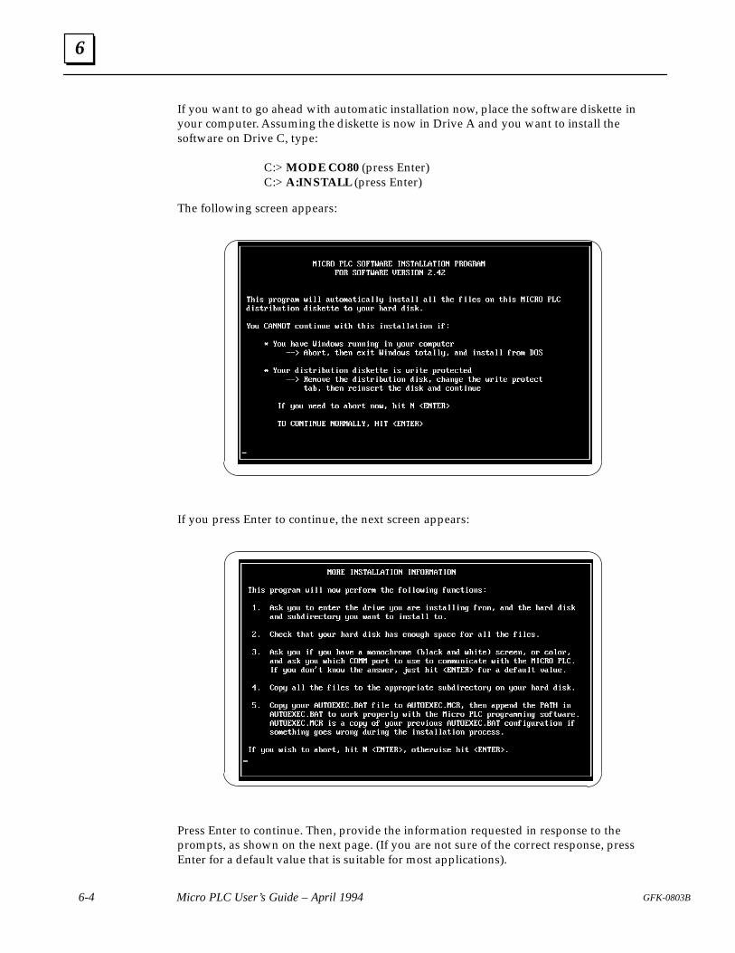
6
6-4 Micro PLC User’s Guide – April 1994 GFK-0803B
If you want to go ahead with automatic installation now, place the software diskette inyour computer. Assuming the diskette is now in Drive A and you want to install thesoftware on Drive C, type:
C:> MODE CO80 (press Enter) C:> A:INSTALL (press Enter)
The following screen appears:
If you press Enter to continue, the next screen appears:
Press Enter to continue. Then, provide the information requested in response to theprompts, as shown on the next page. (If you are not sure of the correct response, pressEnter for a default value that is suitable for most applications).
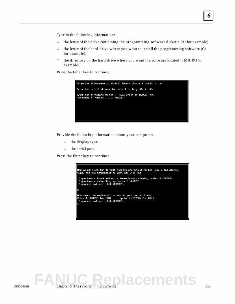
6
6-5GFK-0803B Chapter 6 The Programming Software
Type in the following information:
the letter of the drive containing the programming software diskette (A: for example).
the letter of the hard drive where you want to install the programming software (C:for example).
the directory on the hard drive where you want the software located (\MICRO forexample).
Press the Enter key to continue.
Provide the following information about your computer:
the display type.
the serial port.
Press the Enter key to continue.
FANUC Replacements
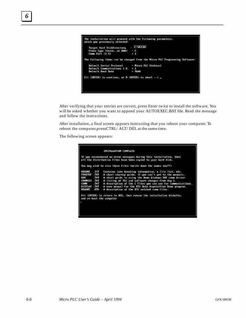
6
6-6 Micro PLC User’s Guide – April 1994 GFK-0803B
After verifying that your entries are correct, press Enter twice to install the software. Youwill be asked whether you want to append your AUTOEXEC.BAT file. Read the messageand follow the instructions
After installation, a final screen appears instructing that you reboot your computer. Toreboot the computer, press CTRL/ALT/DEL at the same time.
The following screen appears:
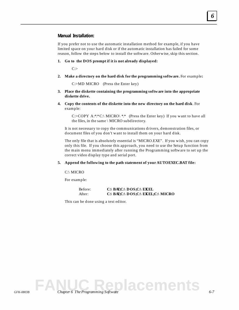
6
6-7GFK-0803B Chapter 6 The Programming Software
Manual Installation:
If you prefer not to use the automatic installation method for example, if you havelimited space on your hard disk or if the automatic installation has failed for somereason, follow the steps below to install the software. Otherwise, skip this section.
1. Go to the DOS prompt if it is not already displayed:
C:>
2. Make a directory on the hard disk for the programming software. For example:
C:>MD MICRO (Press the Enter key)
3. Place the diskette containing the programming software into the appropriatediskette drive.
4. Copy the contents of the diskette into the new directory on the hard disk. Forexample:
C:>COPY A:*.* C:\MICRO\*.* (Press the Enter key) If you want to have allthe files, in the same \MICRO subdirectory.
It is not necessary to copy the communications drivers, demonstration files, ordocument files of you don’t want to install them on your hard disk.
The only file that is absolutely essential is “MICRO.EXE”. If you wish, you can copyonly this file. If you choose this approach, you need to use the Setup function fromthe main menu immediately after running the Programming software to set up thecorrect video display type and serial port.
5. Append the following to the path statement of your AUTOEXEC.BAT file:
C:\MICRO
For example:
Before: C:\BAT;C:\DOS;C:\EXCELAfter: C:\BAT;C:\DOS;C:\EXCEL;C:\MICRO
This can be done using a text editor.
FANUC Replacements
6
6-8 Micro PLC User’s Guide – April 1994 GFK-0803B
Running the Programming Software from a Hard Disk1. Go to the directory where you placed the MICRO.EXE file. For example:
C:>CD MICRO (Press the Enter key)
2. To run the programming software, type:
C:\MICRO>MICRO (Press the Enter key)
Using the Programming Software Directly from a Diskette(Operation from a hard disk is preferred, if one is available.)
1. Go to the DOS prompt if it is not already displayed:
A:>
2. Place the diskette containing the programming software into the appropriatediskette drive (for example, drive A). To run the programming software, type:
A:> MICRO (Press the Enter key)
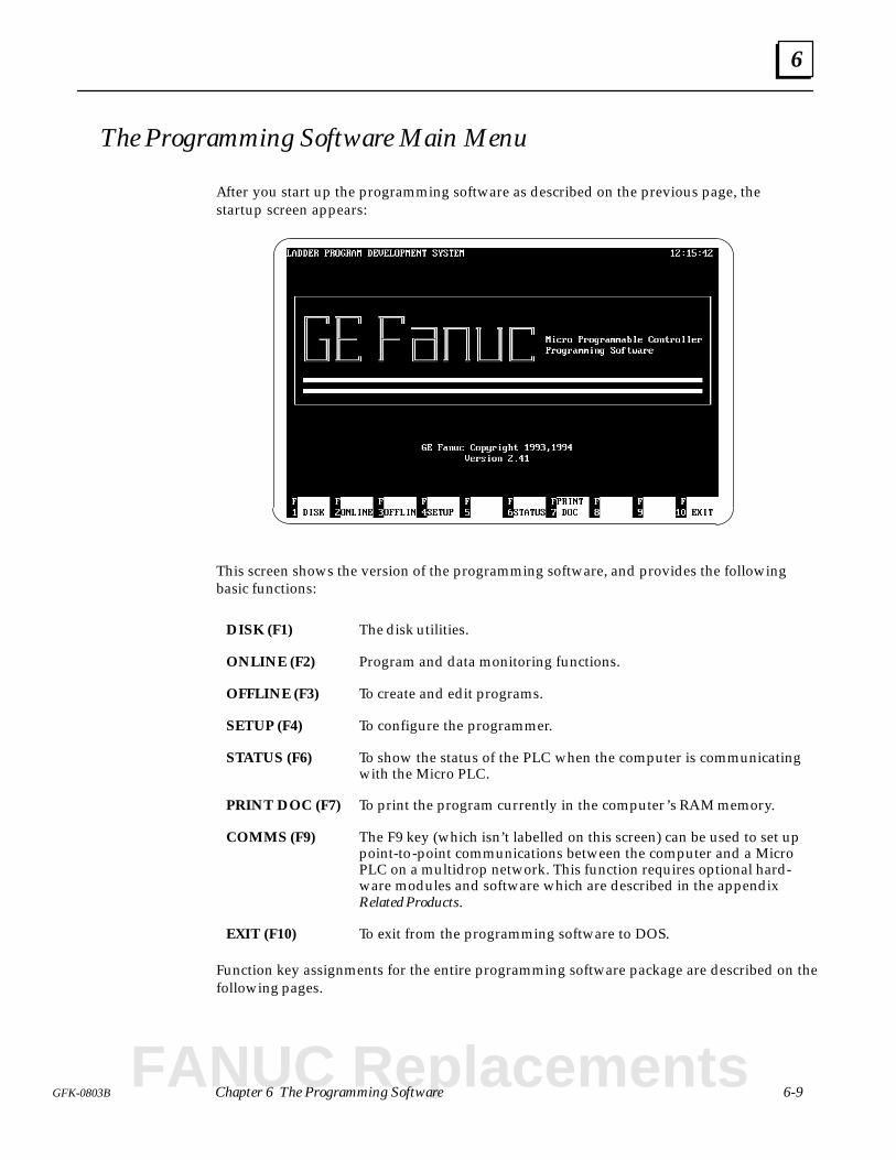
6
6-9GFK-0803B Chapter 6 The Programming Software
The Programming Software Main Menu
After you start up the programming software as described on the previous page, thestartup screen appears:
This screen shows the version of the programming software, and provides the followingbasic functions:
DISK (F1) The disk utilities.
ONLINE (F2) Program and data monitoring functions.
OFFLINE (F3) To create and edit programs.
SETUP (F4) To configure the programmer.
STATUS (F6) To show the status of the PLC when the computer is communicatingwith the Micro PLC.
PRINT DOC (F7) To print the program currently in the computer’s RAM memory.
COMMS (F9) The F9 key (which isn’t labelled on this screen) can be used to set uppoint-to-point communications between the computer and a MicroPLC on a multidrop network. This function requires optional hard-ware modules and software which are described in the appendixRelated Products.
EXIT (F10) To exit from the programming software to DOS.
Function key assignments for the entire programming software package are described on thefollowing pages.
FANUC Replacements
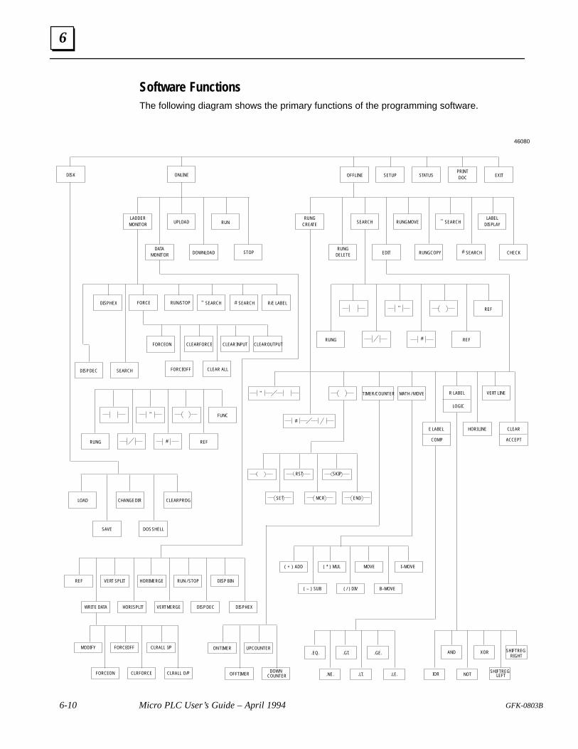
6
6-10 Micro PLC User’s Guide – April 1994 GFK-0803B
Software FunctionsThe following diagram shows the primary functions of the programming software.
EXITPRINTDOCONLINE STATUSSETUPOFFLINEDISK
LADDERMONITOR RUN
RUNGCREATE
LABELDISPLAYUPLOAD RUNG MOVE SEARCH
DATAMONITOR STOP
RUNGDELETEDOWNLOAD EDIT RUNG COPY SEARCH CHECK
DISP DEC SEARCH
RUNG
REF
REF
"
"
#
#
RUNG
FUNC
REF
"
#
LOAD
SAVE
CHANGE DIR
DOS SHELL
REF
WRITE DATA
VERT SPLIT HORI MERGE
VERT MERGE
RUN / STOP
MODIFY
FORCE ON
FORCE OFF
CLR FORCE
CLRALL I/P
CLRALL O/P
ON TIMER
OFF TIMER
UP COUNTER
DOWN COUNTER
.EQ.
.NE.
.GT.
SHIFT REGLEFT
.GE.
.LE.
AND XOR
NOT
SHIFT REGRIGHT
IOR.LT.
VERT LINE
HORI LINE CLEAR
R LABEL
E LABEL
MOVE
( / ) DIV B–MOVE
( * ) MUL
( – ) SUB
I–MOVE( + ) ADD
MATH / MOVETIMER/COUNTER"
#
RST SKIP
SET MCR END
SEARCH
CLEAR PROG
HORI SPLIT
DISP BIN
DISP HEXDISP DEC
ACCEPTCOMP
LOGIC
46080
SEARCH R/E LABELSEARCH" #DISP HEX FORCE RUN/STOP
FORCE ON CLEAR FORCE
FORCE OFF CLEAR ALL
CLEAR INPUT CLEAR OUTPUT
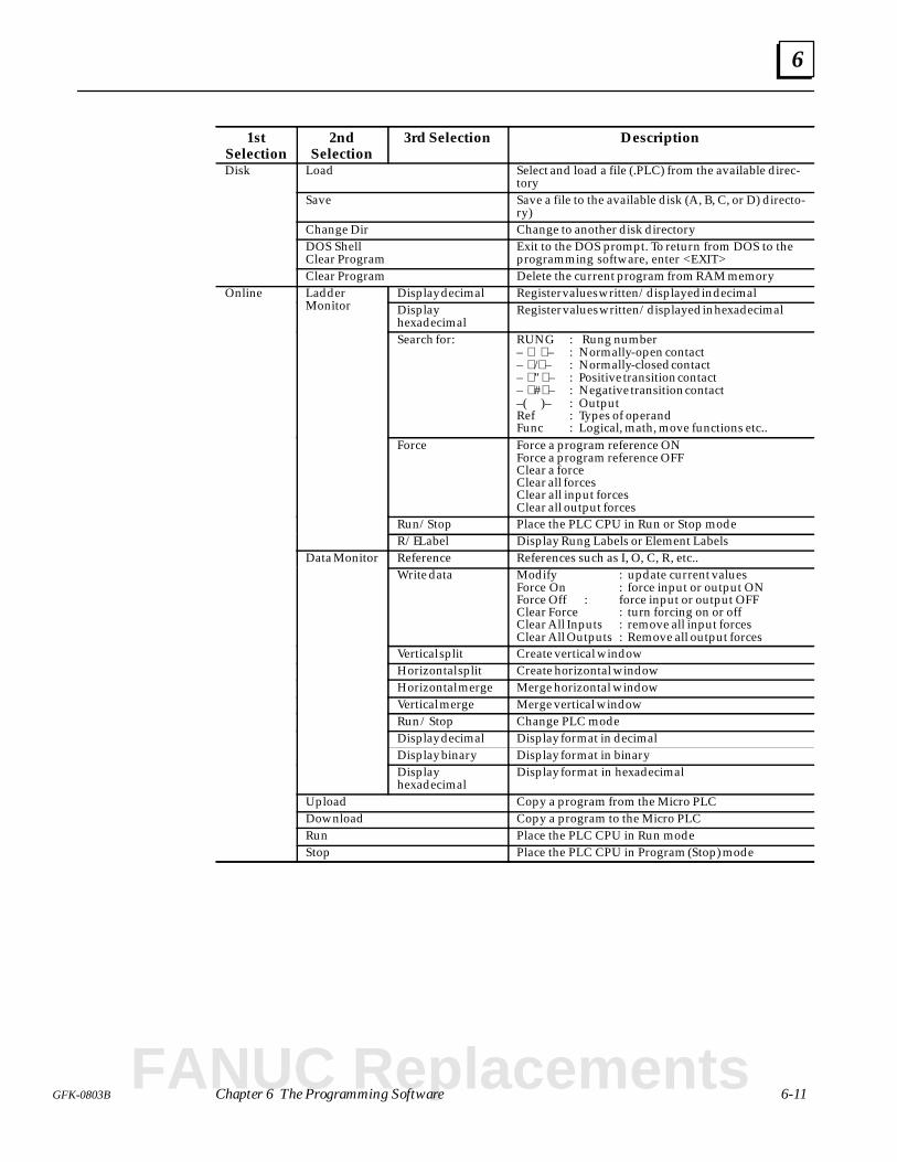
6
6-11GFK-0803B Chapter 6 The Programming Software
1stSelection
2ndSelection
3rd Selection Description
Disk Load Select and load a file (.PLC) from the available direc-tory
Save Save a file to the available disk (A, B, C, or D) directo-ry)
Change Dir Change to another disk directoryDOS ShellClear Program
Exit to the DOS prompt. To return from DOS to theprogramming software, enter <EXIT>
Clear Program Delete the current program from RAM memoryOnline Ladder
MonitorDisplay decimal Register values written/displayed in decimalOnline Ladder
Monitor Displayhexadecimal
Register values written/displayed in hexadecimal
Search for: RUNG : Rung number– – : Normally-open contact– / – : Normally-closed contact– " – : Positive transition contact– # – : Negative transition contact–( )– : OutputRef : Types of operandFunc : Logical, math, move functions etc..
Force Force a program reference ONForce a program reference OFFClear a forceClear all forcesClear all input forcesClear all output forces
Run/Stop Place the PLC CPU in Run or Stop modeR/E Label Display Rung Labels or Element Labels
Data Monitor Reference References such as I, O, C, R, etc..Data MonitorWrite data Modify : update current values
Force On : force input or output ONForce Off : force input or output OFFClear Force : turn forcing on or offClear All Inputs : remove all input forcesClear All Outputs : Remove all output forces
Vertical split Create vertical windowHorizontal split Create horizontal windowHorizontal merge Merge horizontal windowVertical merge Merge vertical windowRun / Stop Change PLC modeDisplay decimal Display format in decimalDisplay binary Display format in binaryDisplayhexadecimal
Display format in hexadecimal
Upload Copy a program from the Micro PLCDownload Copy a program to the Micro PLCRun Place the PLC CPU in Run modeStop Place the PLC CPU in Program (Stop) mode
FANUC Replacements
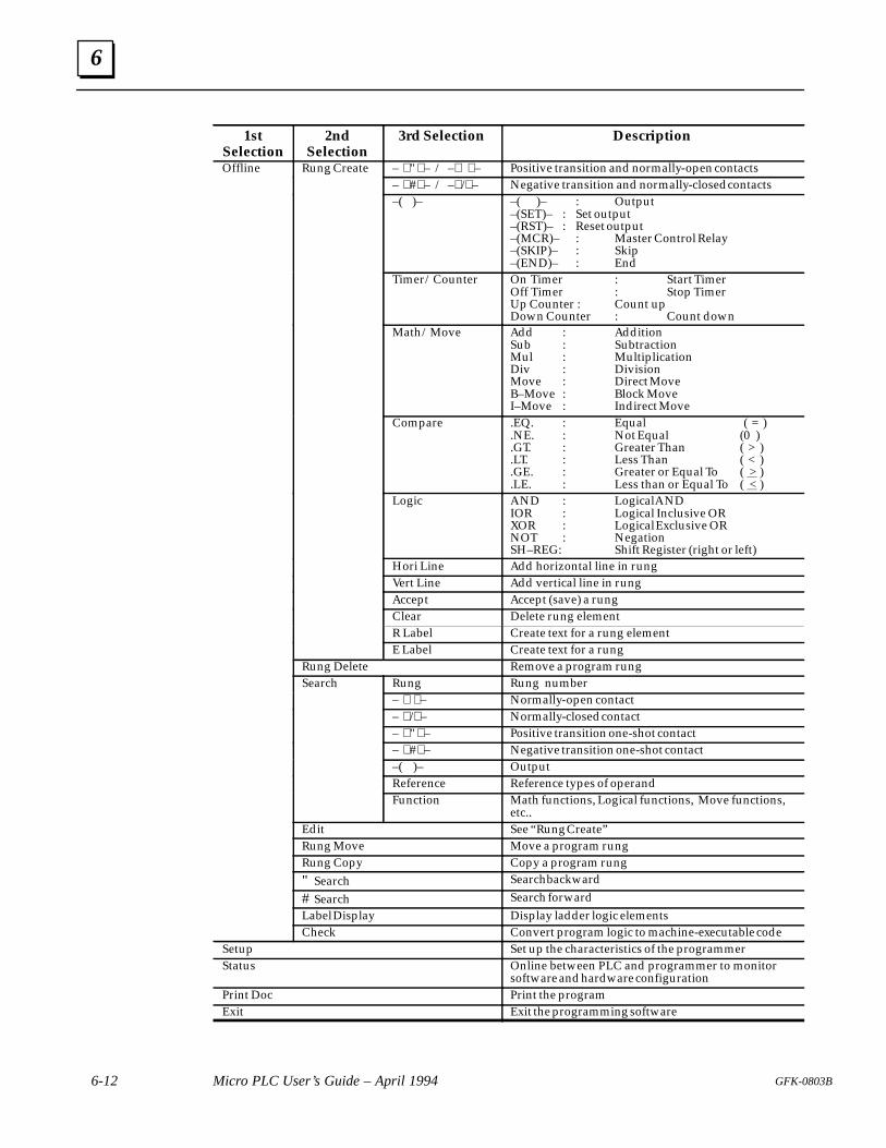
6
6-12 Micro PLC User’s Guide – April 1994 GFK-0803B
1stSelection
Description3rd Selection2ndSelection
Offline Rung Create – " – / – – Positive transition and normally-open contactsOffline Rung Create– # – / – / – Negative transition and normally-closed contacts–( )– –( )– : Output
–(SET)– : Set output–(RST)– : Reset output–(MCR)– : Master Control Relay–(SKIP)– : Skip–(END)– : End
Timer / Counter On Timer : Start TimerOff Timer : Stop TimerUp Counter : Count upDown Counter : Count down
Math / Move Add : AdditionSub : SubtractionMul : MultiplicationDiv : DivisionMove : Direct MoveB–Move : Block MoveI–Move : Indirect Move
Compare .EQ. : Equal ( = ).NE. : Not Equal (0 ).GT. : Greater Than ( > ).LT. : Less Than ( < ).GE. : Greater or Equal To ( > ).LE. : Less than or Equal To ( < )
Logic AND : Logical ANDIOR : Logical Inclusive ORXOR : Logical Exclusive ORNOT : NegationSH–REG: Shift Register (right or left)
Hori Line Add horizontal line in rungVert Line Add vertical line in rungAccept Accept (save) a rungClear Delete rung elementR Label Create text for a rung elementE Label Create text for a rung
Rung Delete Remove a program rungSearch Rung Rung numberSearch
– – Normally-open contact– / – Normally-closed contact– " – Positive transition one-shot contact– # – Negative transition one-shot contact–( )– OutputReference Reference types of operandFunction Math functions, Logical functions, Move functions,
etc..Edit See “Rung Create”Rung Move Move a program rungRung Copy Copy a program rung" Search Search backward
# Search Search forwardLabel Display Display ladder logic elementsCheck Convert program logic to machine-executable code
Setup Set up the characteristics of the programmerStatus Online between PLC and programmer to monitor
software and hardware configurationPrint Doc Print the programExit Exit the programming software

6
6-13GFK-0803B Chapter 6 The Programming Software
Configuring the Programmer
To change the programmer screen color, clock display, or communications port, selectSetup (F4) from the Main menu.
The Configuration Parameters window appears:
Use the arrow keys to select an item, and to display the choices. To quit the window, usethe ESC key.
Setup Parameters
Comm. Protocol Specify whether your computer will communicate using Micro PLCprotocol or RTU protocol. Most applications use Micro PLC protocol.
Comm Port Specify whether your computer will communicate with the MicroPLC through its COM1, COM2, COM3, or COM4 port.
Comm Baud Rate Select the baud rate that will be used for communications: 9600,4800, 2400, 1200, 600, or 300 baud. 9600 is the usual selection.
Station Number Specify the station number if the system uses RTU protocol. Typein the station number from 1 to 247.
Clock Specify whether to display a real-time clock while programming.
Select Color Select either color or black and white.
Beep Sound Specify whether to use the programmer’s audible beep if an erroris encountered.
Configuration If you want to save the configuration from this screen, select Save.In addition to the selections made in this window, the Screen for-mat set up for online monitoring, including multiple windowsand data types, is also saved. If you don’t save the configuration,your changes will be lost when you exit.
If you want to reset to the setup of a previously-saved configura-tion, MOVE to the SUBDIRECTORY where the configuration wassaved and select Restore.
FANUC Replacements
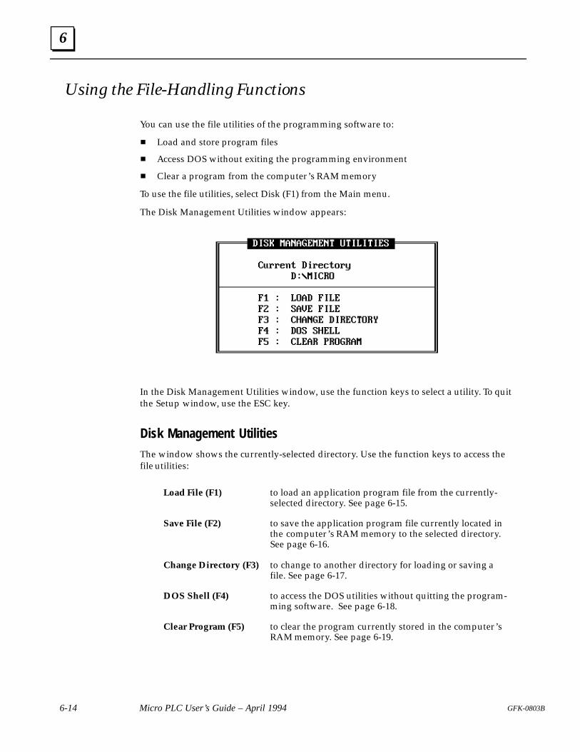
6
6-14 Micro PLC User’s Guide – April 1994 GFK-0803B
Using the File-Handling Functions
You can use the file utilities of the programming software to:
Load and store program files
Access DOS without exiting the programming environment
Clear a program from the computer’s RAM memory
To use the file utilities, select Disk (F1) from the Main menu.
The Disk Management Utilities window appears:
In the Disk Management Utilities window, use the function keys to select a utility. To quitthe Setup window, use the ESC key.
Disk Management UtilitiesThe window shows the currently-selected directory. Use the function keys to access thefile utilities:
Load File (F1) to load an application program file from the currently-selected directory. See page 6-15.
Save File (F2) to save the application program file currently located inthe computer’s RAM memory to the selected directory.See page 6-16.
Change Directory (F3) to change to another directory for loading or saving afile. See page 6-17.
DOS Shell (F4) to access the DOS utilities without quitting the program-ming software. See page 6-18.
Clear Program (F5) to clear the program currently stored in the computer’sRAM memory. See page 6-19.
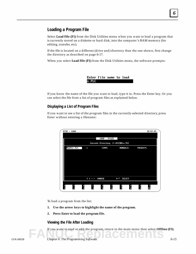
6
6-15GFK-0803B Chapter 6 The Programming Software
Loading a Program FileSelect Load File (F1) from the Disk Utilities menu when you want to load a program thatis currently stored on a diskette or hard disk, into the computer’s RAM memory (forediting, transfer, etc).
If the file is located on a different (drive and) directory than the one shown, first changethe directory as described on page 6-17.
When you select Load File (F1) from the Disk Utilities menu, the software prompts:
If you know the name of the file you want to load, type it in. Press the Enter key. Or youcan select the file from a list of program files as explained below.
Displaying a List of Program Files
If you want to see a list of the program files in the currently-selected directory, pressEnter without entering a filename:
To load a program from the list:
1. Use the arrow keys to highlight the name of the program.
2. Press Enter to load the program file.
Viewing the File After Loading
If you want to read or edit the program, return to the main menu then select Offline (F3).
FANUC Replacements
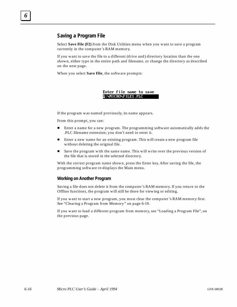
6
6-16 Micro PLC User’s Guide – April 1994 GFK-0803B
Saving a Program FileSelect Save File (F2) from the Disk Utilities menu when you want to save a programcurrently in the computer’s RAM memory.
If you want to save the file to a different (drive and) directory location than the oneshown, either type in the entire path and filename, or change the directory as describedon the next page.
When you select Save File, the software prompts:
If the program was named previously, its name appears.
From this prompt, you can:
Enter a name for a new program. The programming software automatically adds the.PLC filename extension; you don’t need to enter it.
Enter a new name for an existing program. This will create a new program filewithout deleting the original file.
Save the program with the same name. This will write over the previous version ofthe file that is stored in the selected directory.
With the correct program name shown, press the Enter key. After saving the file, theprogramming software re-displays the Main menu.
Working on Another Program
Saving a file does not delete it from the computer’s RAM memory. If you return to theOffline functions, the program will still be there for viewing or editing.
If you want to start a new program, you must clear the computer’s RAM memory first.See “Clearing a Program from Memory” on page 6-19.
If you want to load a different program from memory, see “Loading a Program File”, onthe previous page.
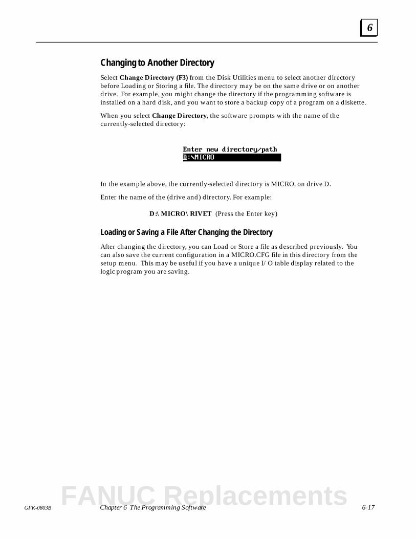
6
6-17GFK-0803B Chapter 6 The Programming Software
Changing to Another DirectorySelect Change Directory (F3) from the Disk Utilities menu to select another directorybefore Loading or Storing a file. The directory may be on the same drive or on anotherdrive. For example, you might change the directory if the programming software isinstalled on a hard disk, and you want to store a backup copy of a program on a diskette.
When you select Change Directory, the software prompts with the name of thecurrently-selected directory:
In the example above, the currently-selected directory is MICRO, on drive D.
Enter the name of the (drive and) directory. For example:
D:\MICRO\RIVET (Press the Enter key)
Loading or Saving a File After Changing the Directory
After changing the directory, you can Load or Store a file as described previously. Youcan also save the current configuration in a MICRO.CFG file in this directory from thesetup menu. This may be useful if you have a unique I/O table display related to thelogic program you are saving.
FANUC Replacements
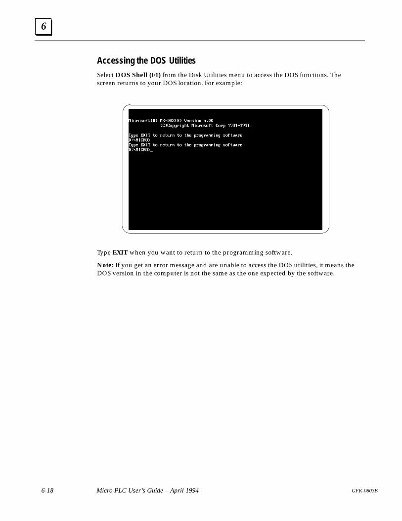
6
6-18 Micro PLC User’s Guide – April 1994 GFK-0803B
Accessing the DOS UtilitiesSelect DOS Shell (F1) from the Disk Utilities menu to access the DOS functions. Thescreen returns to your DOS location. For example:
Type EXIT when you want to return to the programming software.
Note: If you get an error message and are unable to access the DOS utilities, it means theDOS version in the computer is not the same as the one expected by the software.
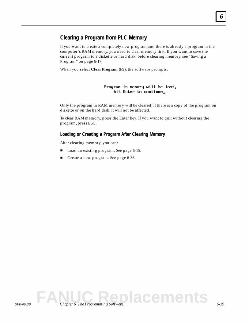
6
6-19GFK-0803B Chapter 6 The Programming Software
Clearing a Program from PLC MemoryIf you want to create a completely new program and there is already a program in thecomputer ’s RAM memory, you need to clear memory first. If you want to save thecurrent program to a diskette or hard disk before clearing memory, see “Saving aProgram” on page 6-17.
When you select Clear Program (F5), the software prompts:
Only the program in RAM memory will be cleared; if there is a copy of the program ondiskette or on the hard disk, it will not be affected.
To clear RAM memory, press the Enter key. If you want to quit without clearing theprogram, press ESC.
Loading or Creating a Program After Clearing Memory
After clearing memory, you can:
Load an existing program. See page 6-15.
Create a new program. See page 6-36.
FANUC Replacements
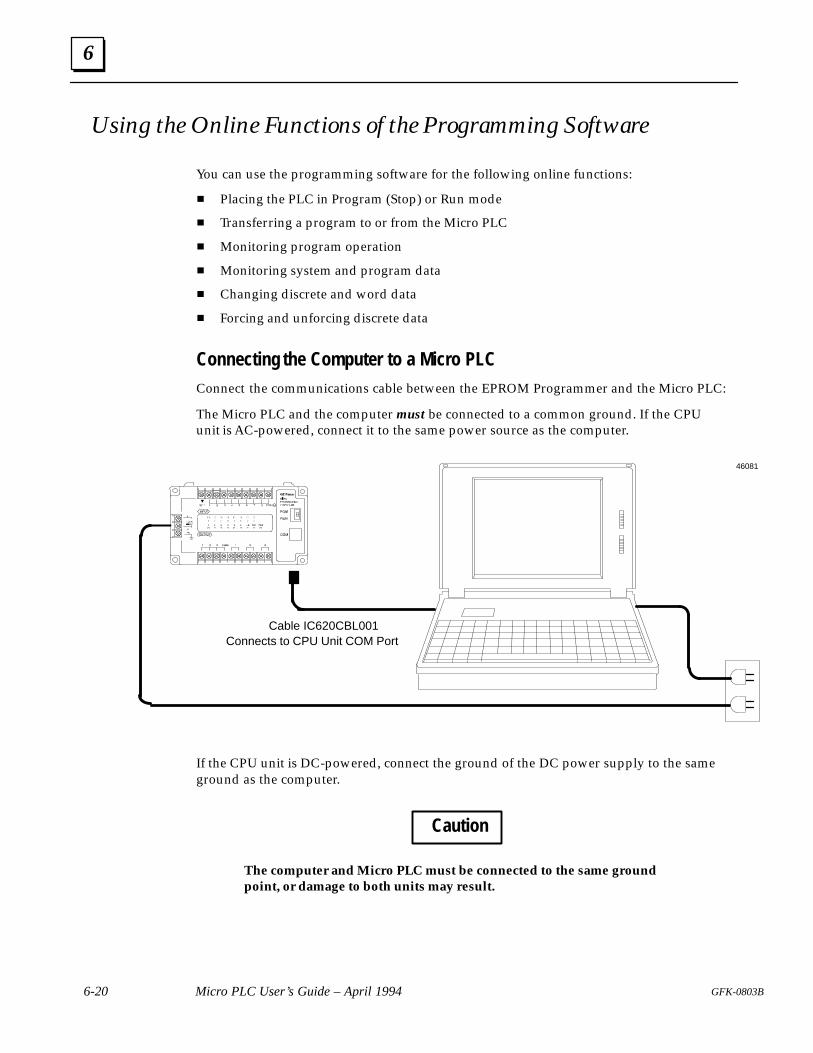
6
6-20 Micro PLC User’s Guide – April 1994 GFK-0803B
Using the Online Functions of the Programming Software
You can use the programming software for the following online functions:
Placing the PLC in Program (Stop) or Run mode
Transferring a program to or from the Micro PLC
Monitoring program operation
Monitoring system and program data
Changing discrete and word data
Forcing and unforcing discrete data
Connecting the Computer to a Micro PLCConnect the communications cable between the EPROM Programmer and the Micro PLC:
The Micro PLC and the computer must be connected to a common ground. If the CPUunit is AC-powered, connect it to the same power source as the computer.
Cable IC620CBL001Connects to CPU Unit COM Port
46081
If the CPU unit is DC-powered, connect the ground of the DC power supply to the sameground as the computer.
Caution
The computer and Micro PLC must be connected to the same groundpoint, or damage to both units may result.
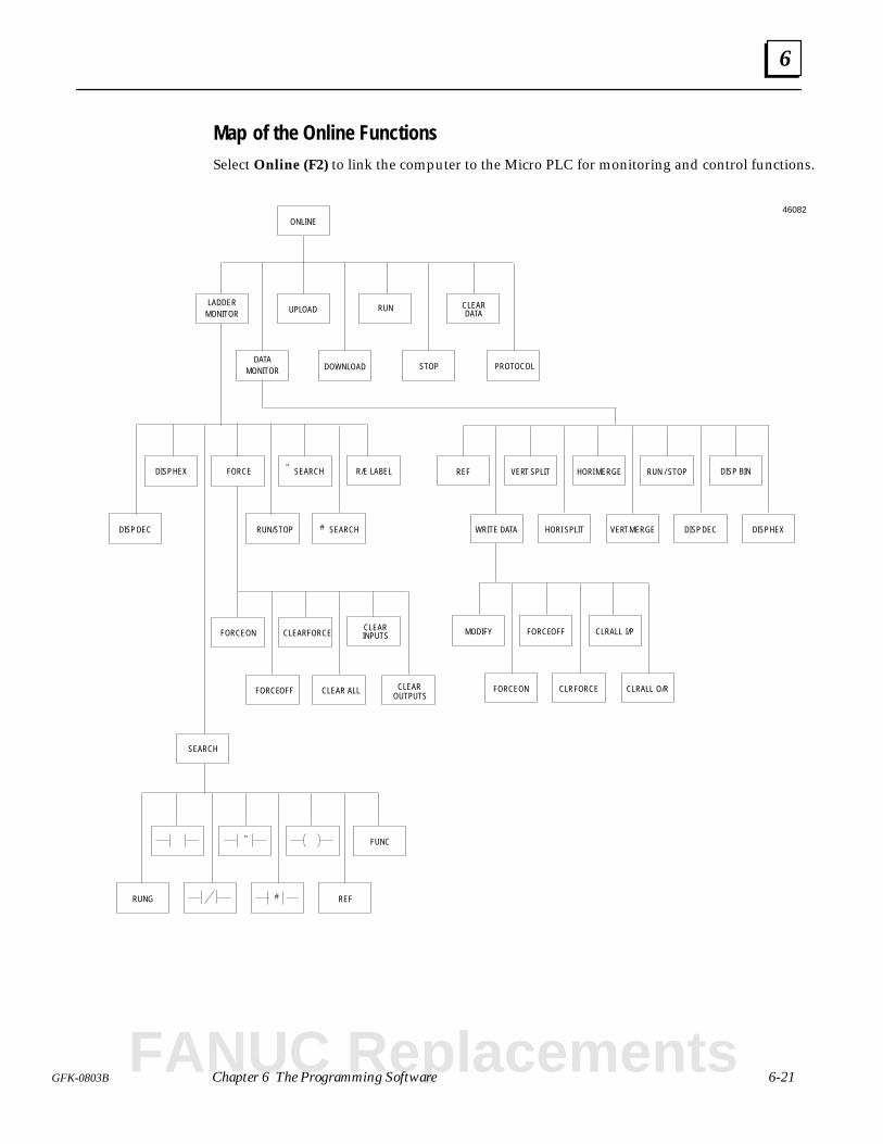
6
6-21GFK-0803B Chapter 6 The Programming Software
Map of the Online FunctionsSelect Online (F2) to link the computer to the Micro PLC for monitoring and control functions.
DISP HEX FORCE
DISP DEC
SEARCH
RUN/STOP SEARCH
R/E LABELSEARCH"
#
ONLINE
LADDERMONITOR
RUNUPLOAD
DATAMONITOR STOPDOWNLOAD
RUNG
FUNC
REF
"
#
REF
WRITE DATA
VERT SPLIT
HORI SPLIT
HORI MERGE
VERT MERGE
RUN / STOP
DISP DEC
DISP BIN
MODIFY
FORCE ON
FORCE OFF
CLR FORCE
CLRALL I/P
CLRALL O/R
DISP HEX
46082
FORCE ON CLEAR FORCE
FORCE OFF CLEAR ALL CLEAR
CLEAR
R/E LABEL
OUTPUTS
INPUTS
CLEARDATA
PROTOCOL
FANUC Replacements
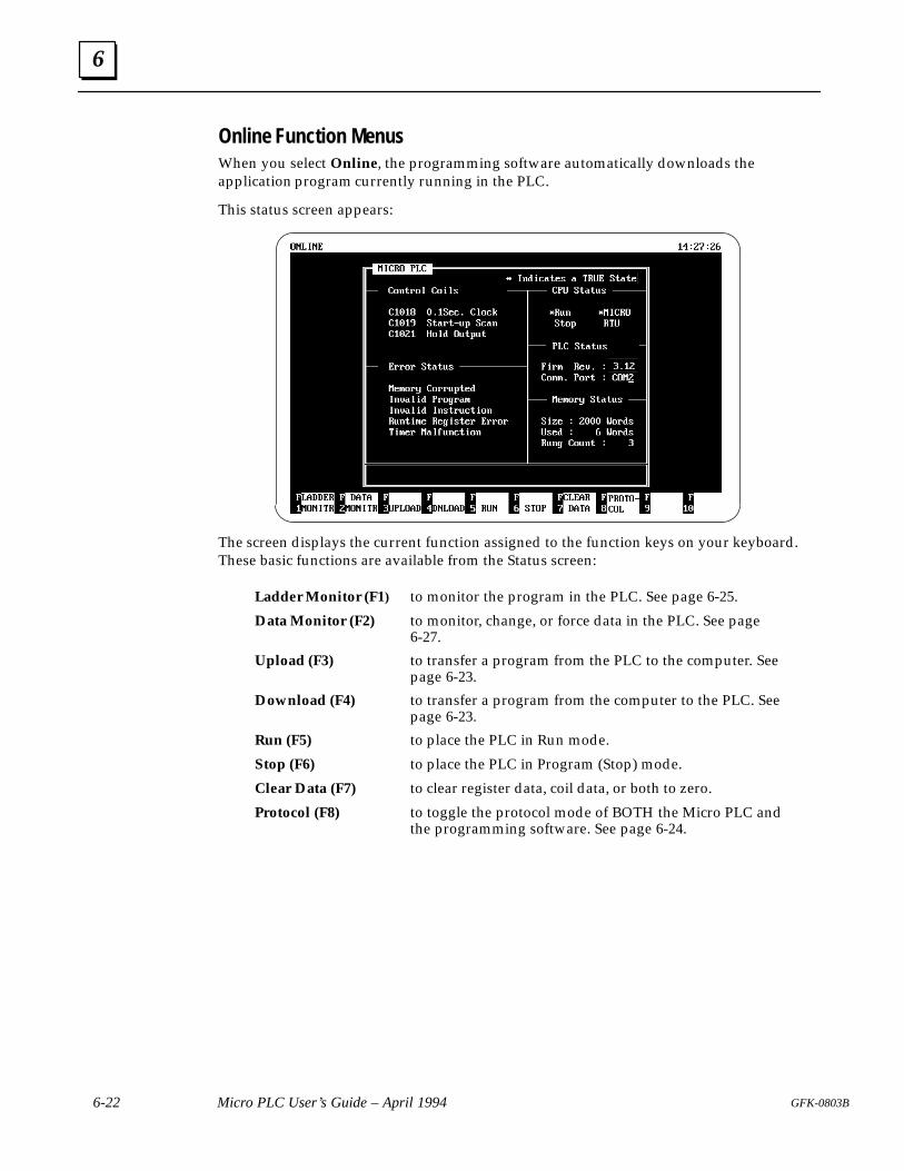
6
6-22 Micro PLC User’s Guide – April 1994 GFK-0803B
Online Function Menus
When you select Online, the programming software automatically downloads theapplication program currently running in the PLC.
This status screen appears:
The screen displays the current function assigned to the function keys on your keyboard.These basic functions are available from the Status screen:
Ladder Monitor (F1) to monitor the program in the PLC. See page 6-25.
Data Monitor (F2) to monitor, change, or force data in the PLC. See page6-27.
Upload (F3) to transfer a program from the PLC to the computer. Seepage 6-23.
Download (F4) to transfer a program from the computer to the PLC. Seepage 6-23.
Run (F5) to place the PLC in Run mode.
Stop (F6) to place the PLC in Program (Stop) mode.
Clear Data (F7) to clear register data, coil data, or both to zero.
Protocol (F8) to toggle the protocol mode of BOTH the Micro PLC andthe programming software. See page 6-24.
6
6-23GFK-0803B Chapter 6 The Programming Software
Placing the PLC in Program (Stop) or Run ModeWith the mode selection switch on the front of the Micro PLC set to Run mode, theprogramming software (or a Hand-held Programmer) can be used to change the PLCoperating mode. (The operating mode of the PLC can also be changed while monitoringprogram data, as described on page 6-27.)
Note: If the switch on the front of the Micro PLC is presently set to Program (Stop) mode, itcannot be overridden by the programming software or a Hand-held Programmer. To changethe PLC operating mode, select Online (F2), then Run (F5) or Stop (F6).
For software version 2.37 and later, a blinking character appears in the upper rightcorner of the screen when the PLC is in Run mode. If the character is not there, the PLCis in Stop mode. (In software version 2.35, this character indicated “online” mode).
Transferring a ProgramUse the Online functions to transfer a program between the computer and anotherdevice.
For information about transferring a program to or from a Hand-held Programmer,see page 4-11.
For information about transferring a program to or from an EPROM Programmer,see pages C-15 and C-17.
Copying a Program to the Computer from a Micro PLC
A program can be transferred from a Micro PLC when the Micro PLC is in either Stopmode or Run mode.
To transfer a program, select Upload (F3) from the Online status screen.
If there is presently a program in the computer’s RAM memory, the software prompts:
Program in PC will be lost. Continue (Y/N)?
When a transfer has been completed, the software displays:Program has been uploaded from PLC
Copying a Program to the Micro PLC from a Computer
To transfer a program to a Micro PLC from the computer, the Micro PLC must be in Stopmode (see page 6-28 for instructions). If you try to upload a program while the PLC is inRun mode, an error message will appear.
To transfer a program, select Download (F4) from the Online status screen.
If there is presently a program in the PLC, the software prompts:
Program in PLC will be lost. Continue (Y/N)?
When a transfer has been completed, the software displays:Program has been downloaded to PLC
FANUC Replacements
6
6-24 Micro PLC User’s Guide – April 1994 GFK-0803B
Clearing Coils and Retentive RegistersTo clear coils or retentive registers, select Clear Data (F7) from the Online Status screen.Then:
Select Clear Reg (F2) to clear all retentive registers to zero. This function does notclear non-retentive registers. Non-retentive registers are cleared on every powercycle and on every transition from Stop mode to Run mode.
Select Clear Coil (F3) to clear all coils.
Select Clear All (F1) to clear both coils and retentive registers.
Changing the Communications Protocol The Micro PLC can communicate using either its own Micro PLC protocol, or RTUprotocol. Micro PLC protocol is used for programming. In addition, most applicationsuse Micro PLC protocol.
The programming software provides two tools for changing protocol if necessary:
From the Main menu, you can select Setup. From the Setup screen, you can changethe protocol mode of the programming software (only). This does not change theprotocol mode of the Micro PLC.
From the Online screen, you can select Protocol (F8), as shown on page 6-22. Thistoggles the protocol of BOTH the software and the Micro PLC. This step is necessaryto actually begin communicating using RTU protocol.
The method to use depends on the type of activity you are working on.
When developing and debugging a program, always use Micro PLC protocol. Micro PLCprotocol is used for most applications.
On the Setup screen, select Micro.On the Online screen, select Micro.
If the application will use RTU protocol, it is necessary to switch to RTU beforecommunicating with the RTU device.
1. When the Micro is ready to begin operating in the application, go to the Onlinescreen and use the F8 key to change to RTU protocol.
2. Connect the Micro PLC to the RTU master device.
3. If program changes are needed:
A. Connect the Micro PLC to a computer running the programming software.
B. Go to the Setup screen and select RTU protocol.
C. Go to the Online screen and select Micro protocol.
D. Develop and debug your program changes.
E. After changing the program, go back to the Online screen and again selectRTU protocol.
F. Disconnect the computer and reconnect the RTU master device.
NoteThe protocol selections on the Setup screen and Online screen mustmatch for communications to begin. Selections that do not match willcause a Communications Error message.
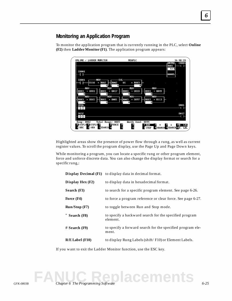
6
6-25GFK-0803B Chapter 6 The Programming Software
Monitoring an Application Program
To monitor the application program that is currently running in the PLC, select Online(F2) then Ladder Monitor (F1). The application program appears:
Highlighted areas show the presence of power flow through a rung, as well as currentregister values. To scroll the program display, use the Page Up and Page Down keys.
While monitoring a program, you can locate a specific rung or other program element,force and unforce discrete data. You can also change the display format or search for aspecific rung,:
Display Decimal (F1) to display data in decimal format.
Display Hex (F2) to display data in hexadecimal format.
Search (F3) to search for a specific program element. See page 6-26.
Force (F4) to force a program reference or clear force. See page 6-27.
Run/Stop (F7) to toggle between Run and Stop mode.
" Search (F8) to specify a backward search for the specified programelement.
# Search (F9) to specify a forward search for the specified program ele-ment.
R/E Label (F10) to display Rung Labels (shift/F10) or Element Labels.
If you want to exit the Ladder Monitor function, use the ESC key.
FANUC Replacements
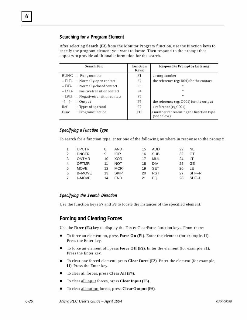
6
6-26 Micro PLC User’s Guide – April 1994 GFK-0803B
Searching for a Program Element
After selecting Search (F3) from the Monitor Program function, use the function keys tospecify the program element you want to locate. Then respond to the prompt thatappears to provide additional information for the search.
Search For: FunctionKeys:
Respond to Prompt by Entering:
RUNG : Rung number– – : Normally-open contact– / – : Normally-closed contact– " – : Positive transition contact– # – : Negative transition contact–( )– : OutputRef : Types of operandFunc : Program function
F1F2F3F4F5F6F7F10
a rung numberthe reference (eg: I001) for the contact
”””
the reference (eg: O001) for the outputa reference (eg: I001)
a number representing the function type(see below)
Specif ying a Function Type
To search for a function type, enter one of the following numbers in response to the prompt:
1 UPCTR2 DNCTR3 ONTMR4 OFTMR5 MOVE6 B–MOVE7 I–MOVE
8 AND9 IOR10 XOR11 NOT12 MCR13 SKIP14 END
15 ADD16 SUB17 MUL18 DIV19 SET20 RST21 EQ
22 NE32 GT24 LT25 GE26 LE27 SHF–R28 SHF–L
Specif ying the Search Direction
Use the function keys F7 and F8 to locate the instances of the specified element.
Forcing and Clearing Forces
Use the Force (F4) key to display the Force/Clear Force function keys. From there:
To force an element on, press Force On (F1). Enter the element (for example, i1).Press the Enter key.
To force an element off, press Force Off (F2). Enter the element (for example, i1).Press the Enter key.
To clear one forced element, press Clear Force (F3). Enter the element (for example,i1). Press the Enter key.
To clear all forces, press Clear All (F4).
To clear all input forces, press Clear Input (F5).
To clear all output forces, press Clear Output (F6).
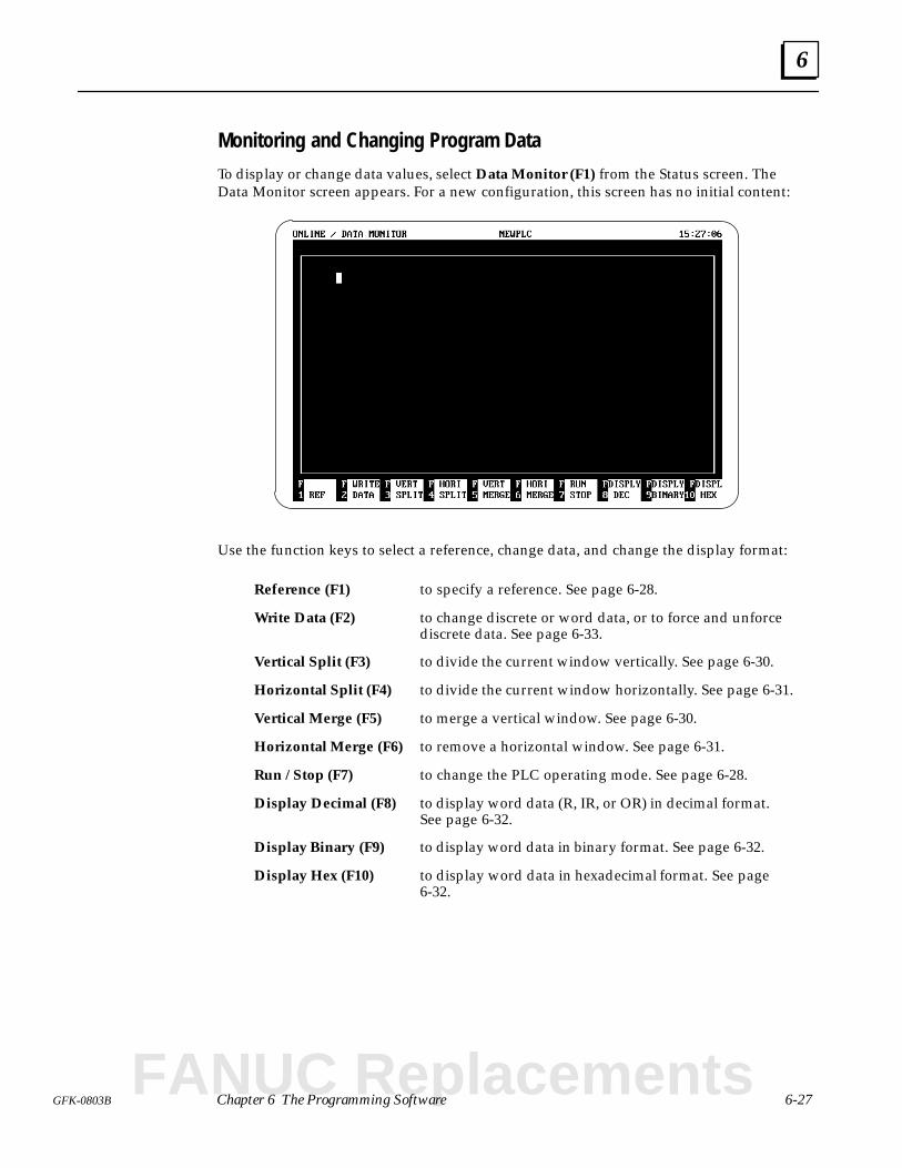
6
6-27GFK-0803B Chapter 6 The Programming Software
Monitoring and Changing Program Data
To display or change data values, select Data Monitor (F1) from the Status screen. TheData Monitor screen appears. For a new configuration, this screen has no initial content:
Use the function keys to select a reference, change data, and change the display format:
Reference (F1) to specify a reference. See page 6-28.
Write Data (F2) to change discrete or word data, or to force and unforcediscrete data. See page 6-33.
Vertical Split (F3) to divide the current window vertically. See page 6-30.
Horizontal Split (F4) to divide the current window horizontally. See page 6-31.
Vertical Merge (F5) to merge a vertical window. See page 6-30.
Horizontal Merge (F6) to remove a horizontal window. See page 6-31.
Run / Stop (F7) to change the PLC operating mode. See page 6-28.
Display Decimal (F8) to display word data (R, IR, or OR) in decimal format.See page 6-32.
Display Binary (F9) to display word data in binary format. See page 6-32.
Display Hex (F10) to display word data in hexadecimal format. See page6-32.
FANUC Replacements
6
6-28 Micro PLC User’s Guide – April 1994 GFK-0803B
Selecting a Reference Type
To display a data table, specify a reference to be monitored.
1. Select Reference (F1) from the Data Monitor screen.
2. Enter a reference type (I, O, C, R, IR, or OR).
3. Enter a numerical address.
For example:
Type O
0001
4. Press the Enter key. The selected data table appears:
Displaying a Different Data Table
To display a different data table, repeat the steps above.
Placing the PLC in Stop or Run Mode
With the mode selection switch on the front of the Micro PLC set to Run mode, theprogramming software (or a Hand-held Programmer) can be used to change the PLCoperating mode.
Note: If the mode selection switch on the front of the Micro PLC is presently set to Stopmode, it cannot be overridden by the programming software or a Hand-held Programmer.
To change the PLC operating mode while monitoring program data, select Run / Stop (F7).
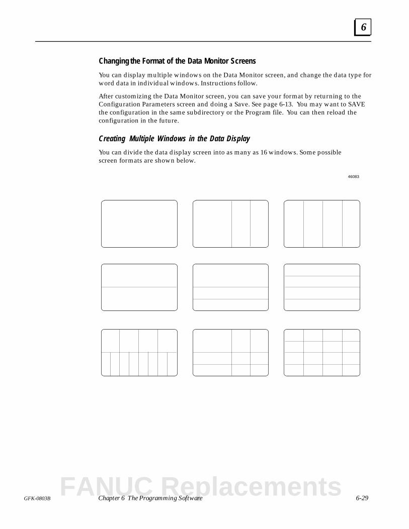
6
6-29GFK-0803B Chapter 6 The Programming Software
Changing the Format of the Data Monitor Screens
You can display multiple windows on the Data Monitor screen, and change the data type forword data in individual windows. Instructions follow.
After customizing the Data Monitor screen, you can save your format by returning to theConfiguration Parameters screen and doing a Save. See page 6-13. You may want to SAVEthe configuration in the same subdirectory or the Program file. You can then reload theconfiguration in the future.
Creating Multiple Windows in the Data Display
You can divide the data display screen into as many as 16 windows. Some possiblescreen formats are shown below.
46083
FANUC Replacements
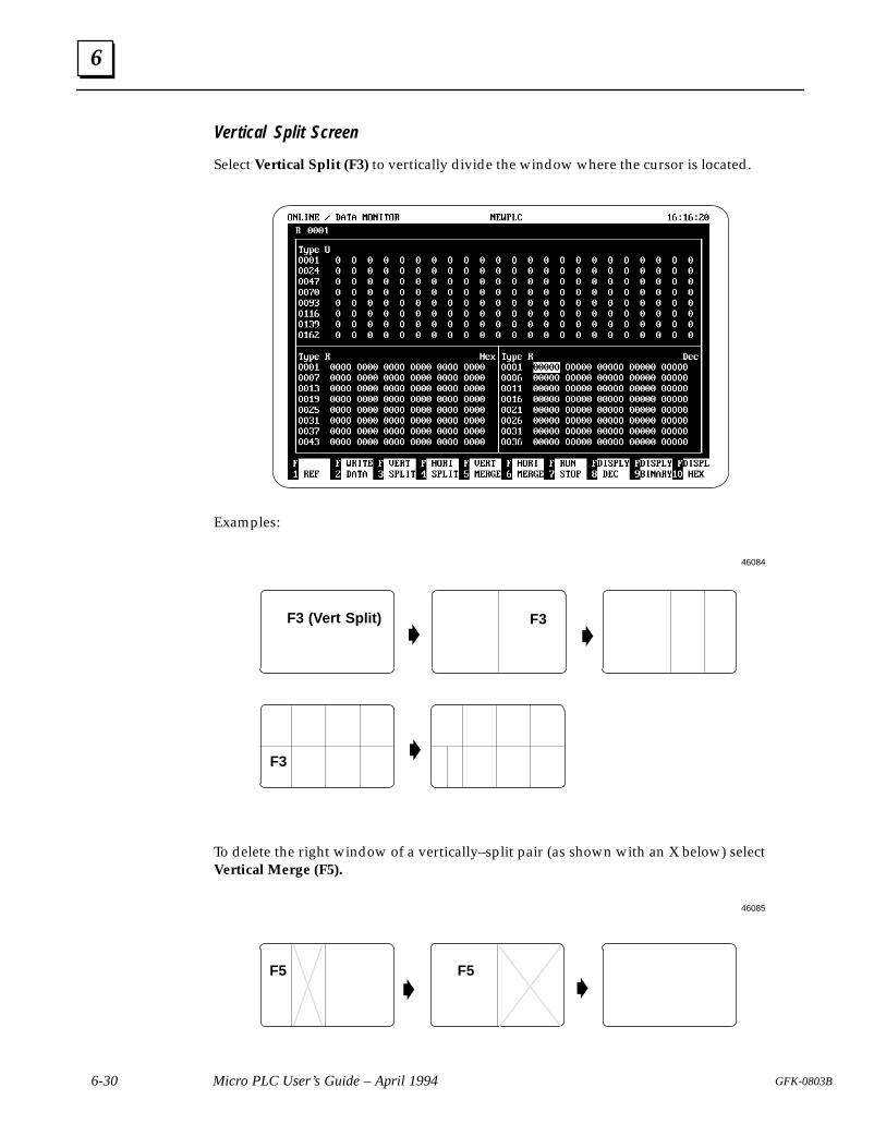
6
6-30 Micro PLC User’s Guide – April 1994 GFK-0803B
Vertical Split Screen
Select Vertical Split (F3) to vertically divide the window where the cursor is located.
Examples:
F3 (Vert Split) F3
F3
46084
To delete the right window of a vertically–split pair (as shown with an X below) select Vertical Merge (F5).
F5
F5
46085
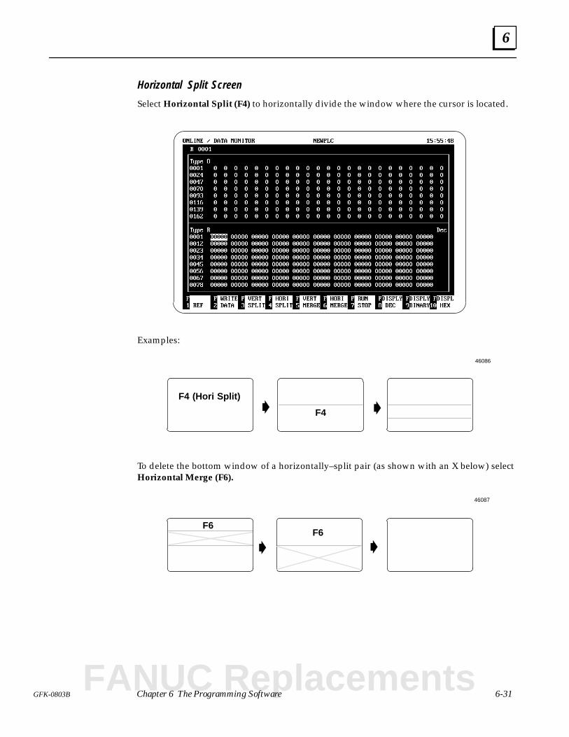
6
6-31GFK-0803B Chapter 6 The Programming Software
Horizontal Split Screen
Select Horizontal Split (F4) to horizontally divide the window where the cursor is located.
Examples:
F4 (Hori Split)
F4
46086
To delete the bottom window of a horizontally–split pair (as shown with an X below) selectHorizontal Merge (F6).
F6F6
46087
FANUC Replacements
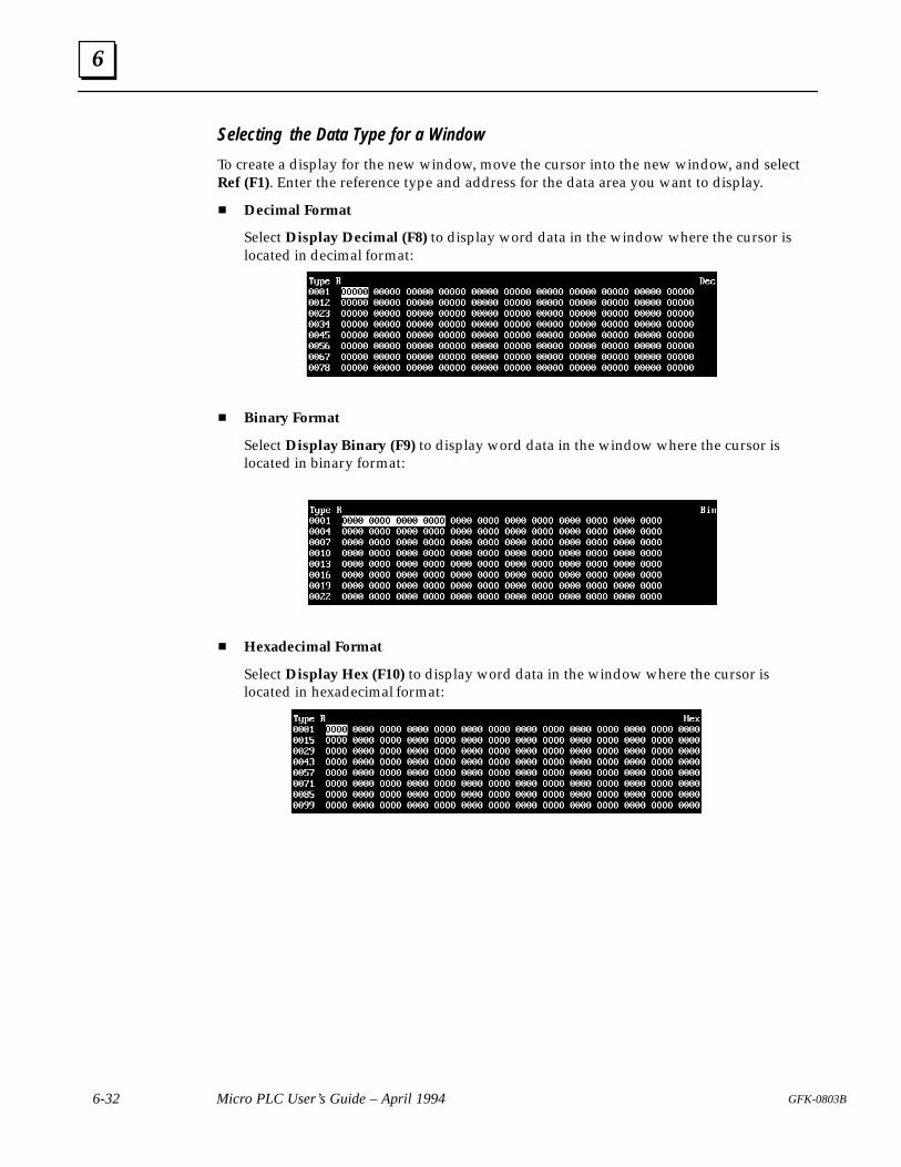
6
6-32 Micro PLC User’s Guide – April 1994 GFK-0803B
Selecting the Data Type for a Window
To create a display for the new window, move the cursor into the new window, and selectRef (F1). Enter the reference type and address for the data area you want to display.
Decimal Format
Select Display Decimal (F8) to display word data in the window where the cursor islocated in decimal format:
Binary Format
Select Display Binary (F9) to display word data in the window where the cursor islocated in binary format:
Hexadecimal Format
Select Display Hex (F10) to display word data in the window where the cursor islocated in hexadecimal format:
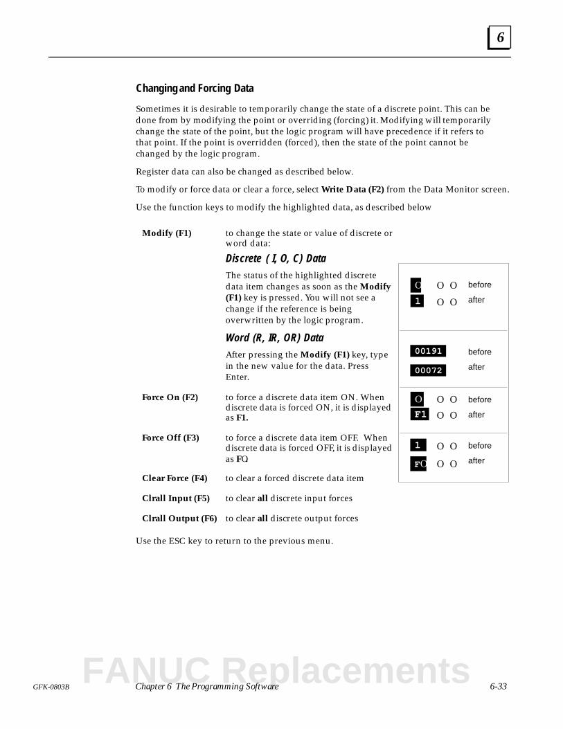
6
6-33GFK-0803B Chapter 6 The Programming Software
Changing and Forcing Data
Sometimes it is desirable to temporarily change the state of a discrete point. This can bedone from by modifying the point or overriding (forcing) it. Modifying will temporarilychange the state of the point, but the logic program will have precedence if it refers tothat point. If the point is overridden (forced), then the state of the point cannot bechanged by the logic program.
Register data can also be changed as described below.
To modify or force data or clear a force, select Write Data (F2) from the Data Monitor screen.
Use the function keys to modify the highlighted data, as described below
Modify (F1) to change the state or value of discrete orword data:
Discrete ( I, O, C) DataThe status of the highlighted discretedata item changes as soon as the Modify(F1) key is pressed. You will not see achange if the reference is beingoverwritten by the logic program.
Word (R, IR, OR) DataAfter pressing the Modify (F1) key, typein the new value for the data. PressEnter.
Force On (F2) to force a discrete data item ON. Whendiscrete data is forced ON, it is displayedas F1.
Force Off (F3) to force a discrete data item OFF. Whendiscrete data is forced OFF, it is displayedas FO.
Clear Force (F4) to clear a forced discrete data item
Clrall Input (F5) to clear all discrete input forces
Clrall Output (F6) to clear all discrete output forces
Use the ESC key to return to the previous menu.
O OO
1
00191
00072
O OO
F1
O OFO
1
before
after
before
after
before
after
before
after
O O
O O
O O
FANUC Replacements
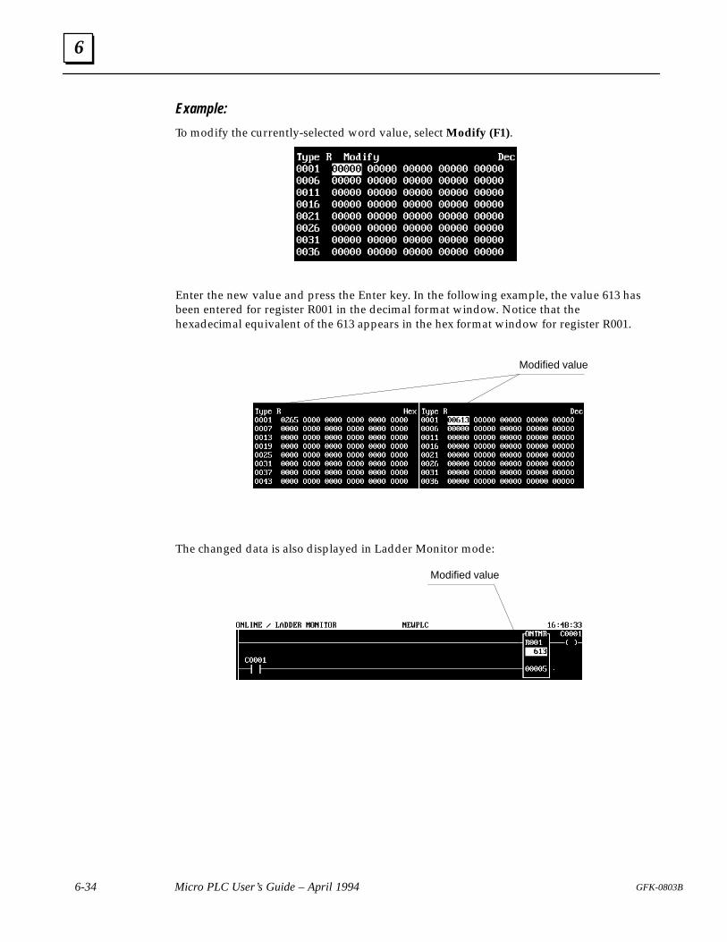
6
6-34 Micro PLC User’s Guide – April 1994 GFK-0803B
Example:
To modify the currently-selected word value, select Modify (F1).
Enter the new value and press the Enter key. In the following example, the value 613 hasbeen entered for register R001 in the decimal format window. Notice that thehexadecimal equivalent of the 613 appears in the hex format window for register R001.
Modified value
The changed data is also displayed in Ladder Monitor mode:
Modified value
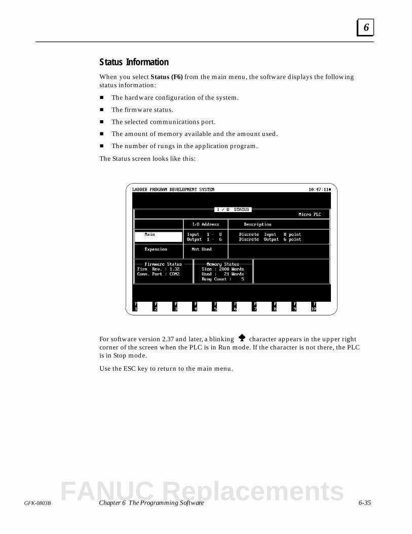
6
6-35GFK-0803B Chapter 6 The Programming Software
Status InformationWhen you select Status (F6) from the main menu, the software displays the followingstatus information:
The hardware configuration of the system.
The firmware status.
The selected communications port.
The amount of memory available and the amount used.
The number of rungs in the application program.
The Status screen looks like this:
For software version 2.37 and later, a blinking character appears in the upper rightcorner of the screen when the PLC is in Run mode. If the character is not there, the PLCis in Stop mode.
Use the ESC key to return to the main menu.
FANUC Replacements
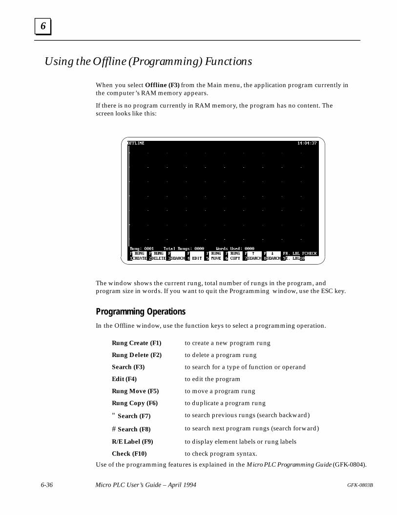
6
6-36 Micro PLC User’s Guide – April 1994 GFK-0803B
Using the Offline (Programming) Functions
When you select Offline (F3) from the Main menu, the application program currently inthe computer’s RAM memory appears.
If there is no program currently in RAM memory, the program has no content. Thescreen looks like this:
The window shows the current rung, total number of rungs in the program, andprogram size in words. If you want to quit the Programming window, use the ESC key.
Programming OperationsIn the Offline window, use the function keys to select a programming operation.
Rung Create (F1) to create a new program rung
Rung Delete (F2) to delete a program rung
Search (F3) to search for a type of function or operand
Edit (F4) to edit the program
Rung Move (F5) to move a program rung
Rung Copy (F6) to duplicate a program rung
" Search (F7) to search previous rungs (search backward)
# Search (F8) to search next program rungs (search forward)
R/E Label (F9) to display element labels or rung labels
Check (F10) to check program syntax.
Use of the programming features is explained in the Micro PLC Programming Guide (GFK-0804).
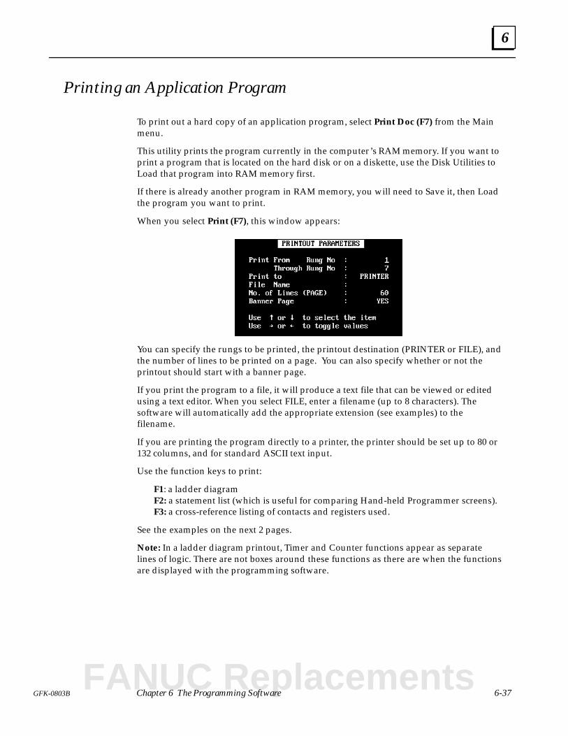
6
6-37GFK-0803B Chapter 6 The Programming Software
Printing an Application Program
To print out a hard copy of an application program, select Print Doc (F7) from the Mainmenu.
This utility prints the program currently in the computer’s RAM memory. If you want toprint a program that is located on the hard disk or on a diskette, use the Disk Utilities toLoad that program into RAM memory first.
If there is already another program in RAM memory, you will need to Save it, then Loadthe program you want to print.
When you select Print (F7), this window appears:
You can specify the rungs to be printed, the printout destination (PRINTER or FILE), andthe number of lines to be printed on a page. You can also specify whether or not theprintout should start with a banner page.
If you print the program to a file, it will produce a text file that can be viewed or editedusing a text editor. When you select FILE, enter a filename (up to 8 characters). Thesoftware will automatically add the appropriate extension (see examples) to thefilename.
If you are printing the program directly to a printer, the printer should be set up to 80 or132 columns, and for standard ASCII text input.
Use the function keys to print:
F1: a ladder diagramF2: a statement list (which is useful for comparing Hand-held Programmer screens).F3: a cross-reference listing of contacts and registers used.
See the examples on the next 2 pages.
Note: In a ladder diagram printout, Timer and Counter functions appear as separatelines of logic. There are not boxes around these functions as there are when the functionsare displayed with the programming software.
FANUC Replacements
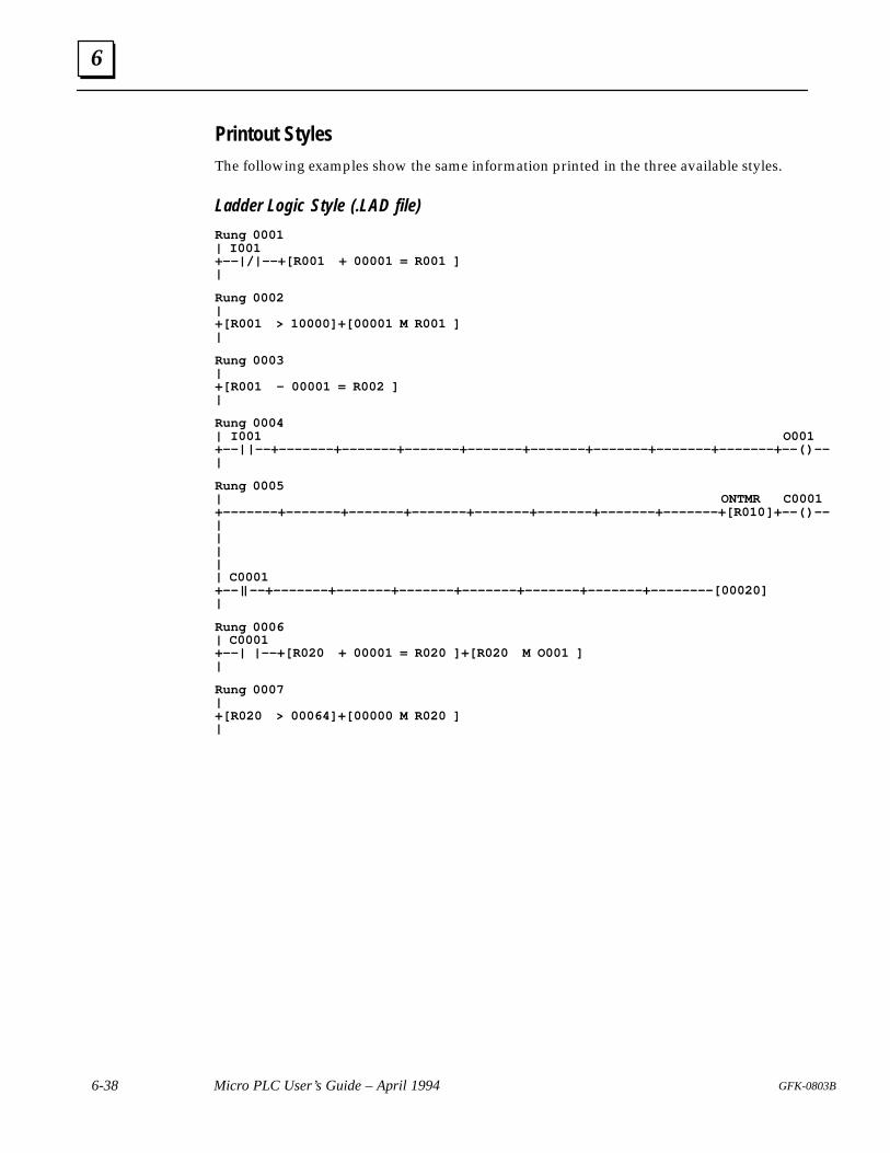
6
6-38 Micro PLC User’s Guide – April 1994 GFK-0803B
Printout StylesThe following examples show the same information printed in the three available styles.
Ladder Logic Style (.LAD file)
Rung 0001| I001+––|/|––+[R001 + 00001 = R001 ]|
Rung 0002|+[R001 > 10000]+[00001 M R001 ]|
Rung 0003|+[R001 – 00001 = R002 ]|
Rung 0004| I001 O001+––| |––+–––––––+–––––––+–––––––+–––––––+–––––––+–––––––+–––––––+–––––––+––( )––|
Rung 0005| ONTMR C0001+–––––––+–––––––+–––––––+–––––––+–––––––+–––––––+–––––––+–––––––+[R010 ]+––( )––||||| C0001+––| |––+–––––––+–––––––+–––––––+–––––––+–––––––+–––––––+––––––––[00020]|
Rung 0006| C0001+––| |––+[R020 + 00001 = R020 ]+[R020 M O001 ]|
Rung 0007|+[R020 > 00064]+[00000 M R020 ]|
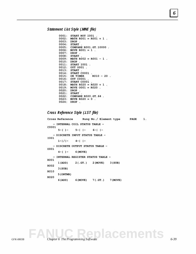
6
6-39GFK-0803B Chapter 6 The Programming Software
Statement List Style (.MNE file)
0001: START NOT I001 .0002: MATH R001 = R001 + 1 .0003: DROP .0004: START .0005: COMPARE R001.GT.10000 .0006: MOVE R001 = 1 .0007: DROP .0008: START .0009: MATH R002 = R001 – 1 .0010: DROP .0011: START I001 .0012: OUT O001 .0013: START .0014: START C0001 .0015: ON TIMER R010 – 20 .0016: OUT C0001 .0017: START C0001 .0018: MATH R020 = R020 + 1 .0019: MOVE O001 = R020 .0020: DROP .0021: START .0022: COMPARE R020.GT.64 .0023: MOVE R020 = 0 .0024: DROP .
Cross Reference Style (.LST file)
Cross Reference Rung No./ Element type PAGE 1.
– INTERNAL COIL STATUS TABLE –C0001
5–( )– 5–| |– 6–| |–
– DISCRETE INPUT STATUS TABLE –I001
1–|/|– 4–| |–
– DISCRETE OUTPUT STATUS TABLE –O001
4–( )– 6(MOVE)
– INTERNAL REGISTER STATUS TABLE –R001
1(ADD) 2(.GT.) 2(MOVE) 3(SUB)R002
3(SUB)R010
5(ONTMR)R020
6(ADD) 6(MOVE) 7(.GT.) 7(MOVE)
FANUC Replacements
6
6-40 Micro PLC User’s Guide – April 1994 GFK-0803B
Exiting the Programming Software
If you want to terminate the programming software, select Exit (F10) from the Mainmenu. This will return you to DOS. The program currently in RAM memory will becleared. If there is a program in RAM memory that you want to keep, be sure to Save itbefore exiting the programming software.
(If you only want to exit to DOS temporarily, select Disk Utilities (F1) then DOS Shell(F4) instead). If you exit temporarily, the programming software and the program inRAM memory are not cleared.
A
A-1GFK-0803B
Appendix A Cable Pin Assignments
This appendix shows cable pin assignments for:
Computer or HHP to Micro PLC Cable
Computer or Hand-held Programmer to EPROM Writer Cable
Cable Length
The maximum recommended cable length is approximately 2 meters (6 feet).
FANUC Replacements
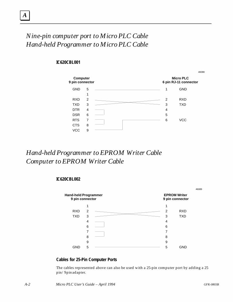
A
A-2 Micro PLC User’s Guide – April 1994 GFK-0803B
Nine-pin computer port to Micro PLC CableHand-held Programmer to Micro PLC Cable
IC620CBL001
Computer9 pin connector
Micro PLC6 pin RJ-11 connector
GND
RXD
TXD
DTR
DSR
RTS
CTS
VCC
5
1
2
3
4
6
7
8
9
1 GND
2 RXD
3 TXD
4
5
6 VCC
46088
Hand-held Programmer to EPROM Writer CableComputer to EPROM Writer Cable
IC620CBL002
Hand-held Programmer9 pin connector
EPROM Writer 9 pin connector
RXD
TXD
GND
1
2
3
4
6
7
8
9
5
1
2 RXD
3 TXD
4
6
7
8
9
5 GND
46089
Cables for 25-Pin Computer Ports
The cables represented above can also be used with a 25-pin computer port by adding a 25pin/9 pin adapter.
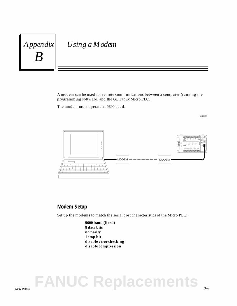
Bsection level 1 1figure_ap level 1 table_ap level 1
B–1GFK-0803B
Appendix B Using a Modem
A modem can be used for remote communications between a computer (running theprogramming software) and the GE Fanuc Micro PLC.
The modem must operate at 9600 baud.
MODEM MODEM
46090
Modem SetupSet up the modems to match the serial port characteristics of the Micro PLC:
9600 baud (fixed)8 data bitsno parity1 stop bitdisable error checkingdisable compression
FANUC Replacements
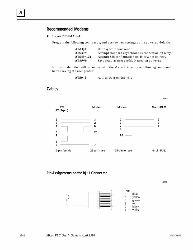
B
B–2 Micro PLC User’s Guide – Aptil 1994 GFK-0803B
Recommended Modems
Hayes OPTIMA 144
Program the following commands, and use the new settings as the powerup defaults.
AT&Q0 Use asynchronous modeATS36=1 Attempt standard asynchronous connection on retryATS48=128 Attempt S36 configuration on 1st try, not on retryAT&W0 Save setup as user profile 0, used on powerup
For the modem that will be connected to the Micro PLC, add the following commandbefore saving the user profile:
ATS0=2 Auto answer on 2nd ring
Cables
PCAT (9-pin)
Micro PLCModemModem
234
67
85
326
20
7
2376
20
231
9-pin female 25-pin male 25-pin female 6–pin RJ11
46091
Pin Assignments on the RJ11 Connector
Pins654321
blueyellowgreenredblackwhite
46092
Csection level 1 1figure_ap level 1 table_ap level 1
C-1GFK-0803B
Appendix C Using EPROMs or Battery-backed RAM
This appendix describes the EPROM Programmer that may be used with some versionsof the Micro PLC CPU.
Program Storage in the Micro PLC
Battery-backed RAM
Memory Charging/Discharging Characteristics of Older CPUs
Charging Characteristics
Discharging Characteristics
Installing an EPROM or Battery-Backed RAM
Charging the CPU Unit’s Program Backup Memory
The EPROM Programmer
Dimensions
EPROM Programmer Specifications
Keypad Functions
EPROM Programmer Menus
Transferring a Program TO the EPROM Programmer
Transferring a Program FROM a Micro PLC
Transferring a Program FROM a Hand-held Programmer
Transferring a Program FROM a Computer
Transferring a Program FROM the EPROM Programmer
Transferring a Program TO a Hand-held Programmer
Transferring a Program TO a Computer
FANUC Replacements
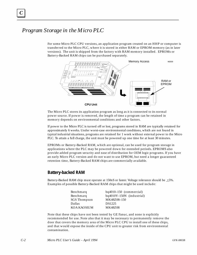
C
C-2 Micro PLC User’s Guide – April 1994 GFK-0803B
Program Storage in the Micro PLC
For some Micro PLC CPU versions, an application program created on an HHP or computer istransferred to the Micro PLC, where it is stored in either RAM or EPROM memory (as in laterversions). The unit is shipped from the factory with RAM memory installed. EPROMs orBattery-Backed RAM chips can be purchased separately.
Memory Access
RAM orEPROM
CPU Unit
46009
The Micro PLC stores its application program as long as it is connected to its normalpower source. If power is removed, the length of time a program can be retained inmemory depends on environmental conditions and other factors.
If power to the Micro PLC is turned off or lost, programs stored in RAM are typically retained forapproximately 6 weeks. Under worst-case environmental conditions, which are not found intypical industrial situations, programs are retained for 1 week without external power to the MicroPLC. To attain a full charge, the unit must be powered up one time for at least 30 minutes.
EPROMs or Battery-Backed RAM, which are optional, can be used for program storage inapplications where the PLC may be powered down for extended periods. EPROMS alsoprovide added program security and ease of distribution for OEM logic programs. If you havean early Micro PLC version and do not want to use EPROM, but need a longer guaranteedretention time, Battery-Backed RAM chips are commercially available.
Battery-backed RAM
Battery-Backed RAM chip must operate at 150nS or faster. Voltage tolerance should be +5%.Examples of possible Battery-Backed RAM chips that might be used include:
Benchmarq bq4010–150 (commercial)Benchmarq bq4010Y–150N (industrial)SGS Thompson MK48Z08–150Dallas DS1225KOA KAOSIUM MK48Z08
Note that these chips have not been tested by GE Fanuc, and none is explicitlyrecommended for use. Note also that it may be necessary to permanently remove thedoor that covers the memory area of the Micro PLC CPU to install one of these chips,and that would expose the inside of the CPU unit to greater risk from environmentalcontamination.
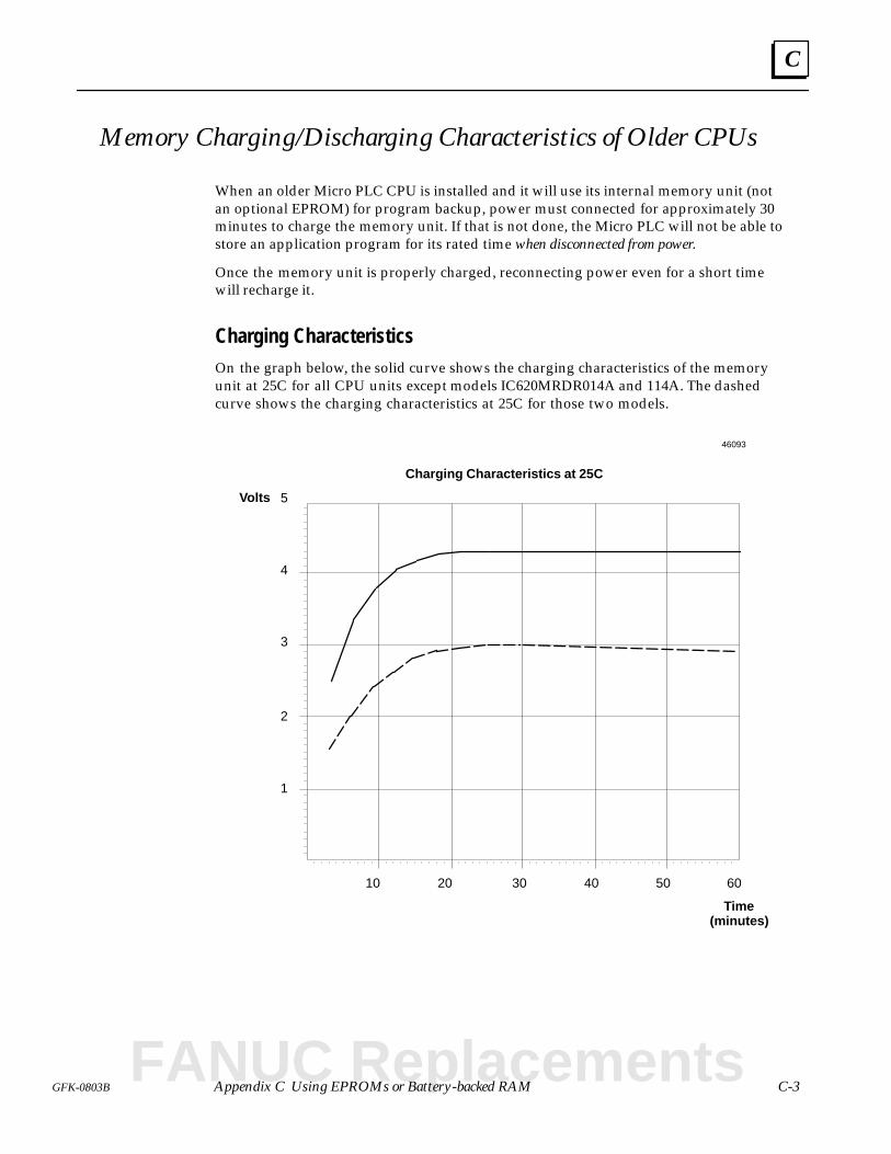
C
C-3GFK-0803B Appendix C Using EPROMs or Battery-backed RAM
Memory Charging/Discharging Characteristics of Older CPUs
When an older Micro PLC CPU is installed and it will use its internal memory unit (notan optional EPROM) for program backup, power must connected for approximately 30minutes to charge the memory unit. If that is not done, the Micro PLC will not be able tostore an application program for its rated time when disconnected from power.
Once the memory unit is properly charged, reconnecting power even for a short timewill recharge it.
Charging CharacteristicsOn the graph below, the solid curve shows the charging characteristics of the memoryunit at 25C for all CPU units except models IC620MRDR014A and 114A. The dashedcurve shows the charging characteristics at 25C for those two models.
10 20 30 40 50 60
1
2
3
4
5
Time(minutes)
Volts
Charging Characteristics at 25C
46093
FANUC Replacements
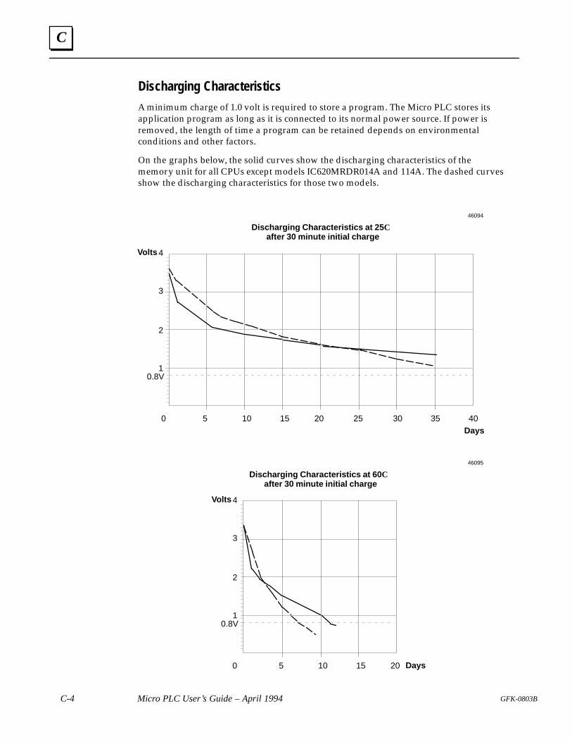
C
C-4 Micro PLC User’s Guide – April 1994 GFK-0803B
Discharging Characteristics
A minimum charge of 1.0 volt is required to store a program. The Micro PLC stores itsapplication program as long as it is connected to its normal power source. If power isremoved, the length of time a program can be retained depends on environmentalconditions and other factors.
On the graphs below, the solid curves show the discharging characteristics of thememory unit for all CPUs except models IC620MRDR014A and 114A. The dashed curvesshow the discharging characteristics for those two models.
0 5 10 15 20
1
2
3
4
Days
Volts
Discharging Characteristics at 25 Cafter 30 minute initial charge
25 30 35 40
0.8V
46094
0 5 10 15 20
1
2
3
4
Days
Volts
Discharging Characteristics at 60 Cafter 30 minute initial charge
0.8V
46095
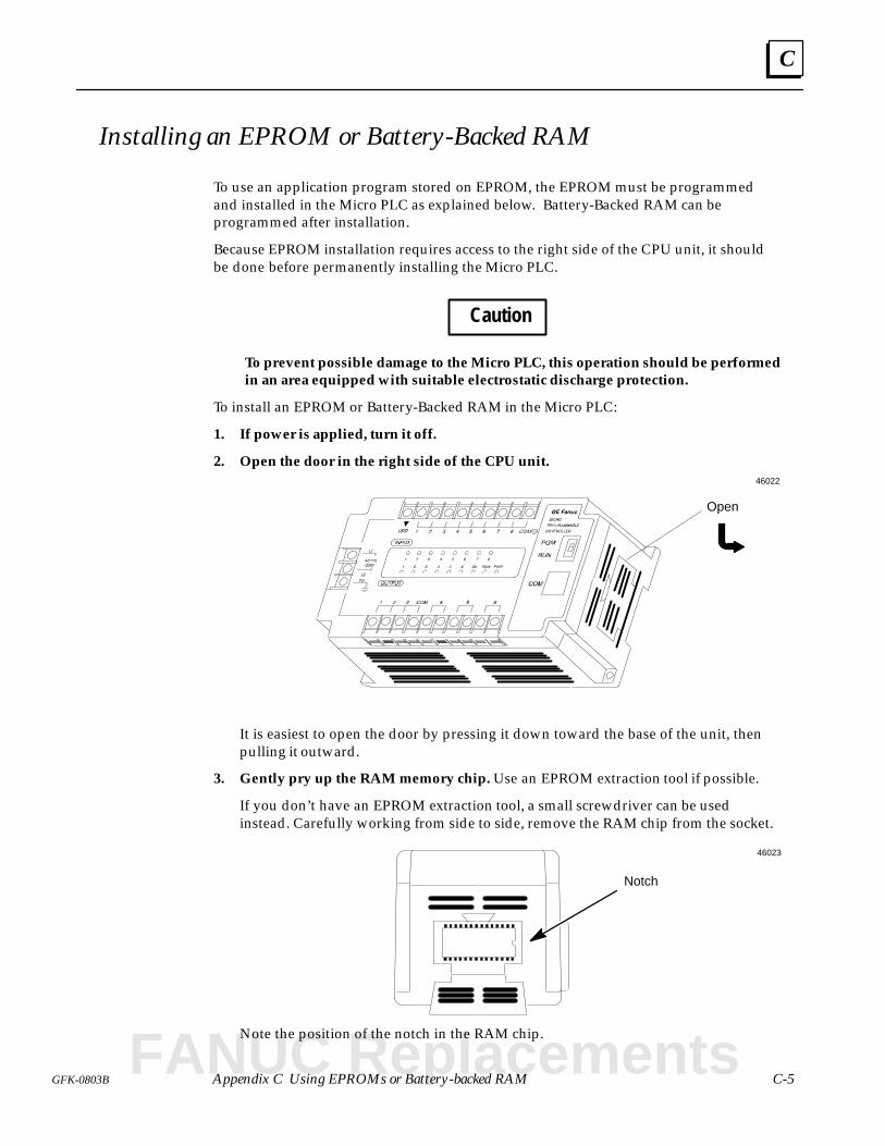
C
C-5GFK-0803B Appendix C Using EPROMs or Battery-backed RAM
Installing an EPROM or Battery-Backed RAM
To use an application program stored on EPROM, the EPROM must be programmedand installed in the Micro PLC as explained below. Battery-Backed RAM can beprogrammed after installation.
Because EPROM installation requires access to the right side of the CPU unit, it shouldbe done before permanently installing the Micro PLC.
Caution
To prevent possible damage to the Micro PLC, this operation should be performedin an area equipped with suitable electrostatic discharge protection.
To install an EPROM or Battery-Backed RAM in the Micro PLC:
1. If power is applied, turn it off.
2. Open the door in the right side of the CPU unit.
Open
46022
It is easiest to open the door by pressing it down toward the base of the unit, thenpulling it outward.
3. Gently pry up the RAM memory chip. Use an EPROM extraction tool if possible.
If you don’t have an EPROM extraction tool, a small screwdriver can be usedinstead. Carefully working from side to side, remove the RAM chip from the socket.
Notch
46023
Note the position of the notch in the RAM chip.
FANUC Replacements
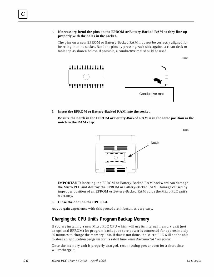
C
C-6 Micro PLC User’s Guide – April 1994 GFK-0803B
4. If necessary, bend the pins on the EPROM or Battery-Backed RAM so they line upproperly with the holes in the socket.
The pins on a new EPROM or Battery-Backed RAM may not be correctly aligned forinserting into the socket. Bend the pins by pressing each side against a clean desk ortable top as shown below. If possible, a conductive mat should be used.
Conductive mat
46024
5. Insert the EPROM or Battery-Backed RAM into the socket.
Be sure the notch in the EPROM or Battery-Backed RAM is in the same position as thenotch in the RAM chip:
Notch
46025
IMPORTANT: Inserting the EPROM or Battery-Backed RAM backward can damagethe Micro PLC and destroy the EPROM or Battery-Backed RAM. Damage caused byimproper position of an EPROM or Battery-Backed RAM voids the Micro PLC unit’swarranty.
6. Close the door on the CPU unit.
As you gain experience with this procedure, it becomes very easy.
Charging the CPU Unit’s Program Backup MemoryIf you are installing a new Micro PLC CPU which will use its internal memory unit (notan optional EPROM) for program backup, be sure power is connected for approximately30 minutes to charge the memory unit. If that is not done, the Micro PLC will not be ableto store an application program for its rated time when disconnected from power.
Once the memory unit is properly charged, reconnecting power even for a short timewill recharge it.
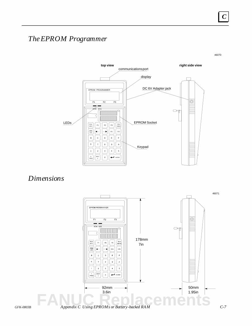
C
C-7GFK-0803B Appendix C Using EPROMs or Battery-backed RAM
The EPROM Programmer
top view right side viewcommunications port
DC 6V Adapter jack
LEDs
display
^
More
NEXT
REM
1 2 3
0
4 5
6 9
D
87
C E
ESCDEL
F3
F
F2F1
ENTER
MENU
LOC
PREV V
F1 F2 F3
ROM MSG
EPROM PROGRAMMER
B
A
More
INFO
EPROM Socket
Keypad
46070
Dimensions
178mm7in
92mm3.6in
50mm1.95in
46071
FANUC Replacements
C
C-8 Micro PLC User’s Guide – April 1994 GFK-0803B
EPROM Programmer Specifications
Item Specification
Processor Intel 8031AH
Memory 27C64, 8K bytes
Program memory CMOS RAM, 32K bytes
Interface type RS–232C compatible 9-pin serial communications
System interfaces Hand-held Programmer, PC, Micro PLC
Baud rate 9600 BPS
Data format 8 bits, no parity, 1 stop bit
Input voltage from PLC, or from 6VDC, 400mA adapter
Power Consumption 1.5 Watt (250mA) @ 5VDC + .23V
Programming voltage Vpp: 12V +0.3V
Dimensions 178mm H x 92mm W x 50mm D7” H x 3.6” W x 1.95” D
Weight 320g (0.7 lb)
Operating humidity 5% to 95% relative humidity (no condensation)
Operating temperature 0 to 55C
Storage temperature –20 to +70C
Display Backlit LCD 2 lines, 16 characters per line
Keypad 20-key soft-touch membrane contact keypad
LEDs ROM and error LED indications
Software VersionThe HHP powerup screen shows the software version of the HHP. For example:
EPROM PROGRAMMER
VERS 2.23
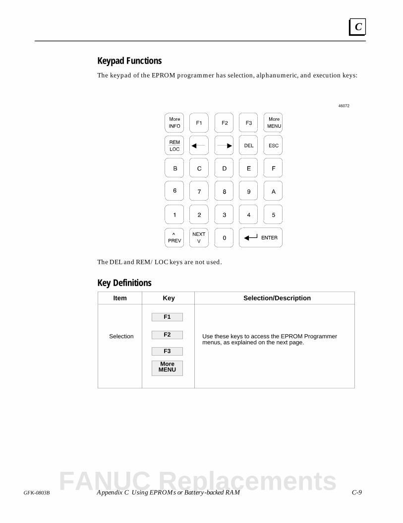
C
C-9GFK-0803B Appendix C Using EPROMs or Battery-backed RAM
Keypad FunctionsThe keypad of the EPROM programmer has selection, alphanumeric, and execution keys:
46072
The DEL and REM/LOC keys are not used.
Key Definitions
Item Key Selection/Description
Selection
F1
F2
F3
More
Use these keys to access the EPROM Programmermenus, as explained on the next page.
MENU
FANUC Replacements
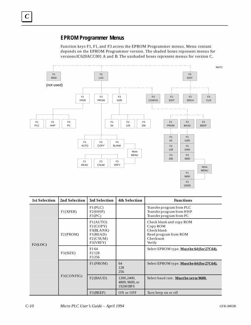
C
C-10 Micro PLC User’s Guide – April 1994 GFK-0803B
EPROM Programmer Menus
Function keys F1, F1, and F3 access the EPROM Programmer menus. Menu contantdepends on the EPROM Programmer version. The shaded boxes represent menus forversions IC620ACC001 A and B. The unshaded boxes represent menus for version C.
F3EDIT
F2LOC
F1REM
F3CONFIG
F2PROM
F1XFER
F3PC
F2HHP
F1PLC
F3BLANK
F2COPY
F1AUTO
F3VRFY
F2CSUM
F1READ
F3BEEP
F2BAUD
F1PROM
F22400
F11200
F164
F19600
F34800
F3256
F2128
F219200
F3CLR
F2SRCH
F1EDIT
(not used)
46073
F3SIZE
MoreMENU
F164
F2128
F3256
MoreMENU
1st Selection 2nd Selection 3rd Selection 4th Selection Functions
F1 (XFER)F1 (PLC)F2 (HHP)F3 (PC)
Transfer program from PLCTransfer program from HHPTransfer program from PC
F2 (LOC)
F2 (PROM)
F1 (AUTO)F2 (COPY)F3 (BLANK)F1 (READ)F2 (CSUM)F3 (VRFY)
Check blank and copy ROMCopy ROMCheck blankRead program from ROMChecksumVerifyF2 (LOC)
F3 (SIZE)F1 64F2 128F3 256
Select EPROM type. Must be 64 (for 27C64).
F3 (CONFIG)
F1 (PROM) 64128256
Select EPROM type. Must be 64 (for 27C64).
F3 (CONFIG) F2 (BAUD) 1200, 2400,4800, 9600, or19200 BPS
Select baud rate. Must be set to 9600.
F3 (BEEP) ON or OFF Turn beep on or off
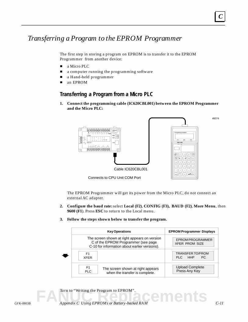
C
C-11GFK-0803B Appendix C Using EPROMs or Battery-backed RAM
Transferring a Program to the EPROM Programmer
The first step in storing a program on EPROM is to transfer it to the EPROMProgrammer from another device:
a Micro PLC a computer running the programming software a Hand-held programmer an EPROM
Transferring a Program from a Micro PLC
1. Connect the programming cable (IC620CBL001) between the EPROM Programmerand the Micro PLC:
Cable IC620CBL001
Connects to CPU Unit COM Port
46074
The EPROM Programmer will get its power from the Micro PLC, do not connect anexternal AC adapter.
2. Configure the baud rate: select Local (F2), CONFIG (F3), BAUD (F2), More Menu, then9600 (F1). Press ESC to return to the Local menu.
3. Follow the steps shown below to transfer the program.
Key Operations EPROM Programmer Displays
XFER PROM SIZEEPROM PROGRAMMER
F1XFER PLC HHP PC
TRANSFER TO/FROM
F1PLC Press Any Key
Upload CompleteThe screen shown at right appearswhen the transfer is complete.
The screen shown at right appears on versionC of the EPROM Programmer (see page
C-10 for information about earlier versions).
Turn to “Writing the Program to EPROM”.
FANUC Replacements
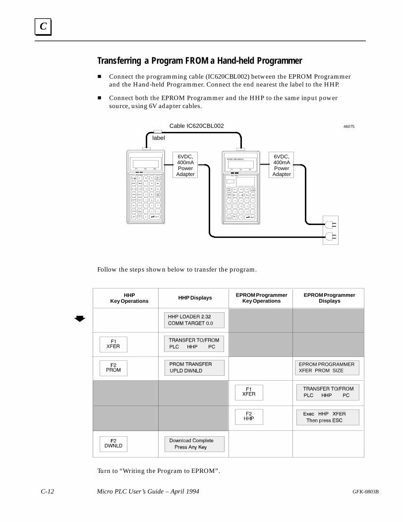
C
C-12 Micro PLC User’s Guide – April 1994 GFK-0803B
Transferring a Program FROM a Hand-held Programmer
Connect the programming cable (IC620CBL002) between the EPROM Programmerand the Hand-held Programmer. Connect the end nearest the label to the HHP.
Connect both the EPROM Programmer and the HHP to the same input powersource, using 6V adapter cables.
Cable IC620CBL002
label
6VDC,400mAPower
Adapter
6VDC,400mAPower
Adapter
46075
Follow the steps shown below to transfer the program.
HHPKey Operations
HHP Displays EPROM ProgrammerDisplays
EPROM ProgrammerKey Operations
XFER PROM SIZEEPROM PROGRAMMER
Turn to “Writing the Program to EPROM”.
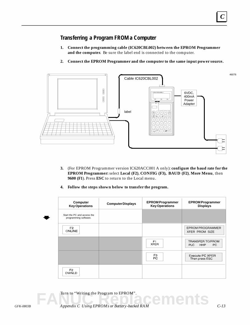
C
C-13GFK-0803B Appendix C Using EPROMs or Battery-backed RAM
Transferring a Program FROM a Computer
1. Connect the programming cable (IC620CBL002) between the EPROM Programmerand the computer. Be sure the label end is connected to the computer.
2. Connect the EPROM Programmer and the computer to the same input power source.
Cable IC620CBL002
6VDC,400mAPower
Adapter
label
46076
3. (For EPROM Programmer version IC620ACC001 A only): configure the baud rate for theEPROM Programmer: select Local (F2), CONFIG (F3), BAUD (F2), More Menu, then9600 (F1). Press ESC to return to the Local menu.
4. Follow the steps shown below to transfer the program.
ComputerKey Operations
Computer Displays EPROM ProgrammerDisplays
EPROM ProgrammerKey Operations
Start the PC and access theprogramming software.
XFER PROM SIZEEPROM PROGRAMMER
Turn to “Writing the Program to EPROM”.
FANUC Replacements
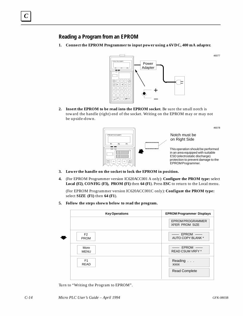
C
C-14 Micro PLC User’s Guide – April 1994 GFK-0803B
Reading a Program from an EPROM1. Connect the EPROM Programmer to input power using a 6VDC, 400 mA adapter.
PowerAdapter
–+
46077
2. Insert the EPROM to be read into the EPROM socket. Be sure the small notch istoward the handle (right) end of the socket. Writing on the EPROM may or may notbe upside-down.
Notch must be on Right Side
This operation should be performedin an area equipped with suitableESD (electrostatic discharge)protection to prevent damage to theEPROM Programmer.
46078
3. Lower the handle on the socket to lock the EPROM in position.
4. (For EPROM Programmer version IC620ACC001 A only): Configure the PROM type: selectLocal (F2), CONFIG (F3), PROM (F1) then 64 (F1). Press ESC to return to the Local menu.
(For EPROM Programmer version IC620ACC001C only): Configure the PROM type:select SIZE (F1) then 64 (F1).
5. Follow the steps shown below to read the program.
Key Operations EPROM Programmer Displays
XFER PROM SIZEEPROM PROGRAMMER
F2PROM
MoreMENU
–––– EPROM ––––
AUTO COPY BLANK *–––– EPROM ––––
Read Complete
READ CSUM VRFY *
F1READ xxxx
Reading . . .
Turn to “Writing the Program to EPROM”.
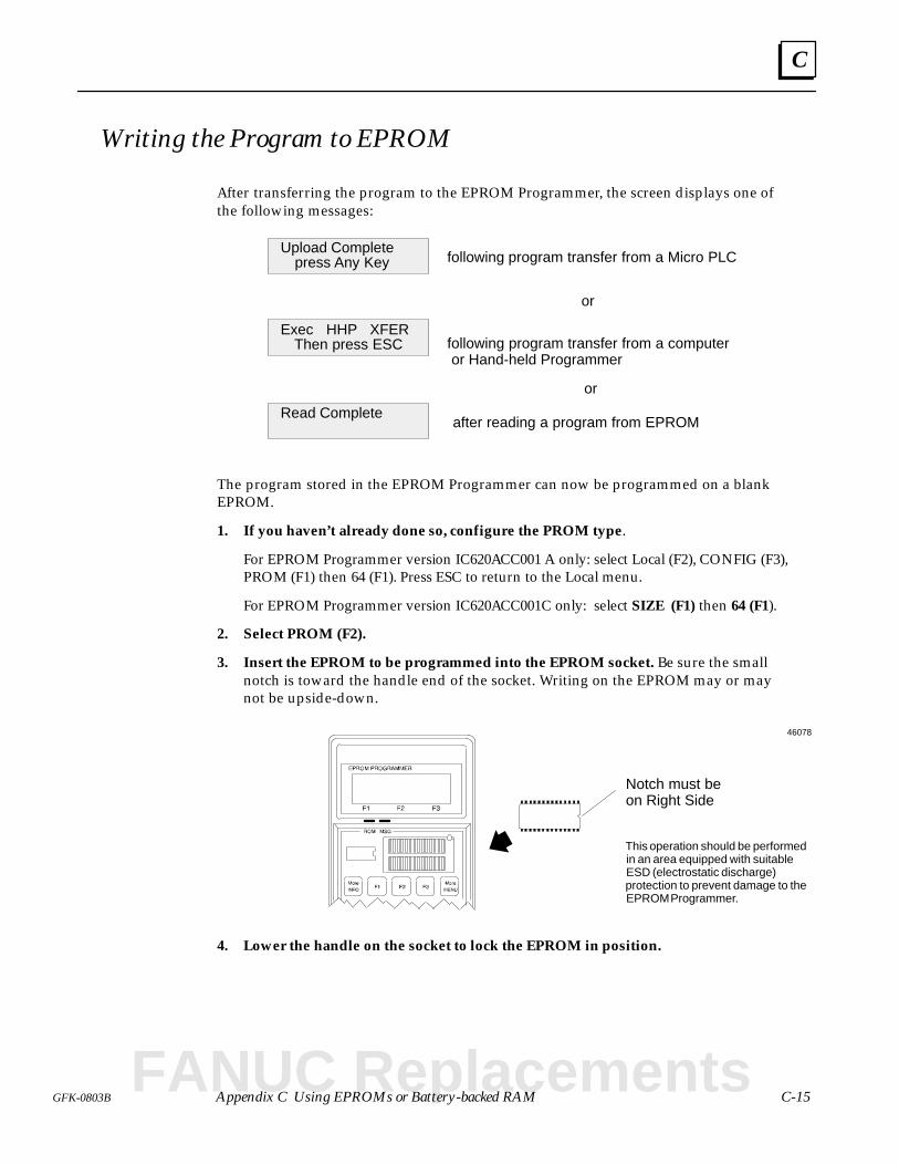
C
C-15GFK-0803B Appendix C Using EPROMs or Battery-backed RAM
Writing the Program to EPROM
After transferring the program to the EPROM Programmer, the screen displays one ofthe following messages:
Read Complete
Then press ESCExec HHP XFER
press Any KeyUpload Complete
following program transfer from a Micro PLC
or
following program transfer from a computeror Hand-held Programmer
or
after reading a program from EPROM
The program stored in the EPROM Programmer can now be programmed on a blankEPROM.
1. If you haven’t already done so, configure the PROM type.
For EPROM Programmer version IC620ACC001 A only: select Local (F2), CONFIG (F3),PROM (F1) then 64 (F1). Press ESC to return to the Local menu.
For EPROM Programmer version IC620ACC001C only: select SIZE (F1) then 64 (F1).
2. Select PROM (F2).
3. Insert the EPROM to be programmed into the EPROM socket. Be sure the smallnotch is toward the handle end of the socket. Writing on the EPROM may or maynot be upside-down.
Notch must be on Right Side
This operation should be performedin an area equipped with suitableESD (electrostatic discharge)protection to prevent damage to theEPROM Programmer.
46078
4. Lower the handle on the socket to lock the EPROM in position.
FANUC Replacements
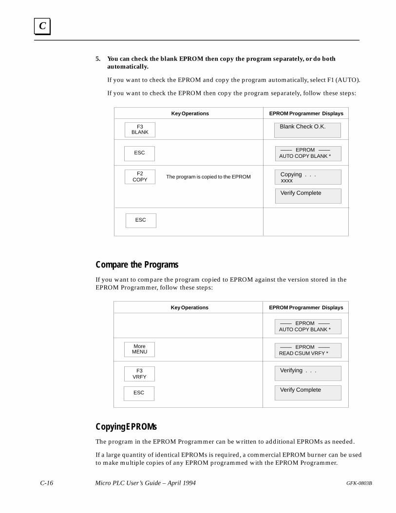
C
C-16 Micro PLC User’s Guide – April 1994 GFK-0803B
5. You can check the blank EPROM then copy the program separately, or do bothautomatically.
If you want to check the EPROM and copy the program automatically, select F1 (AUTO).
If you want to check the EPROM then copy the program separately, follow these steps:
Key Operations EPROM Programmer Displays
F3BLANK
ESC –––– EPROM ––––
Blank Check O.K.
Verify Complete
AUTO COPY BLANK *
F2COPY xxxx
Copying . . .The program is copied to the EPROM
ESC
Compare the Programs
If you want to compare the program copied to EPROM against the version stored in theEPROM Programmer, follow these steps:
Key Operations EPROM Programmer Displays
MoreMENU
ESC
–––– EPROM ––––
Verify Complete
AUTO COPY BLANK *
F3VRFY
Verifying . . .
–––– EPROM ––––READ CSUM VRFY *
Copying EPROMs
The program in the EPROM Programmer can be written to additional EPROMs as needed.
If a large quantity of identical EPROMs is required, a commercial EPROM burner can be usedto make multiple copies of any EPROM programmed with the EPROM Programmer.
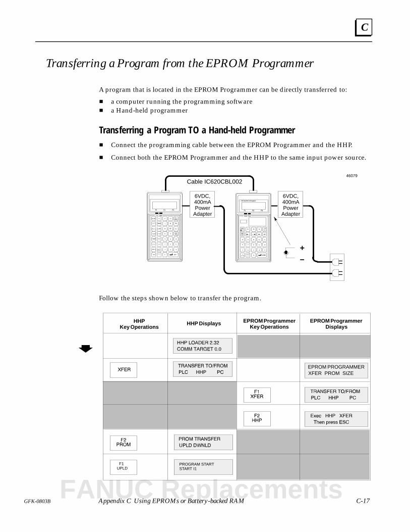
C
C-17GFK-0803B Appendix C Using EPROMs or Battery-backed RAM
Transferring a Program from the EPROM Programmer
A program that is located in the EPROM Programmer can be directly transferred to:
a computer running the programming software a Hand-held programmer
Transferring a Program TO a Hand-held Programmer Connect the programming cable between the EPROM Programmer and the HHP.
Connect both the EPROM Programmer and the HHP to the same input power source.
Cable IC620CBL002
–+
6VDC,400mAPower
Adapter
6VDC,400mAPower
Adapter
46079
Follow the steps shown below to transfer the program.
HHPKey Operations
HHP Displays EPROM ProgrammerDisplays
EPROM ProgrammerKey Operations
F1UPLD
PROGRAM STARTSTART I1
XFER PROM SIZEEPROM PROGRAMMER
FANUC Replacements
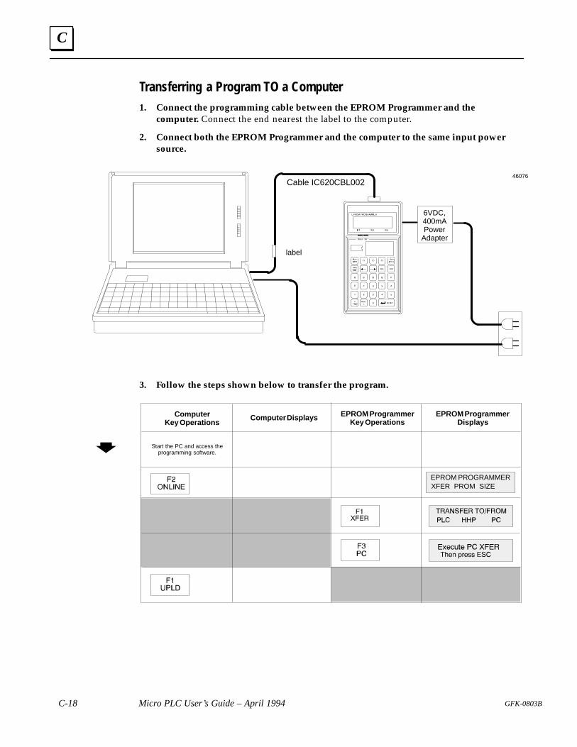
C
C-18 Micro PLC User’s Guide – April 1994 GFK-0803B
Transferring a Program TO a Computer1. Connect the programming cable between the EPROM Programmer and the
computer. Connect the end nearest the label to the computer.
2. Connect both the EPROM Programmer and the computer to the same input powersource.
Cable IC620CBL002
label
6VDC,400mAPower
Adapter
46076
3. Follow the steps shown below to transfer the program.
ComputerKey Operations
Computer Displays EPROM ProgrammerDisplays
EPROM ProgrammerKey Operations
Start the PC and access theprogramming software.
XFER PROM SIZEEPROM PROGRAMMER
Dsection level 1 1figure_ap level 1 table_ap level 1
D-1GFK-0803
Appendix D Related Products
This appendix introduces some products, made by other companies, that can be used toenhance a Micro PLC application.
Data Access Unit
Multidrop Hardware Network for the Micro PLC
FANUC Replacements
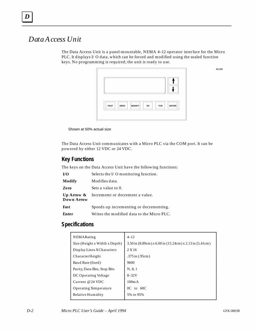
D
D-2 Micro PLC User’s Guide – April 1994 GFK-0803B
Data Access Unit
The Data Access Unit is a panel-mountable, NEMA 4–12 operator interface for the MicroPLC. It displays I/O data, which can be forced and modified using the sealed functionkeys. No programming is required; the unit is ready to use.
FAST ZERO MODIFY I/O TCR ENTER
Shown at 50% actual size
46198
The Data Access Unit communicates with a Micro PLC via the COM port. It can bepowered by either 12 VDC or 24 VDC.
Key FunctionsThe keys on the Data Access Unit have the following functions:
Selects the I/O monitoring function.
Modifies data.
Sets a value to 0.
Incrememt or decrement a value.
Speeds up incrementing or decrementing.
Writes the modified data to the Micro PLC.
Specifications
NEMA Rating 4–12
Size (Height x Width x Depth) 3.50 in (8.89cm) x 6.00 in (15.24cm) x 2.13 in (5.41cm)
Display Lines X Characters 2 X 16
Character Height .375 in (.95cm)
Baud Rate (fixed) 9600
Parity, Data Bits, Stop Bits N, 8, 1
DC Operating Voltage 8–32V
Current @ 24 VDC 100mA
Operating Temperature 0C to 60C
Relative Humidity 5% to 95%
I/O
Modify
Zero
Up Arrow &Down Arrow
Fast
Enter
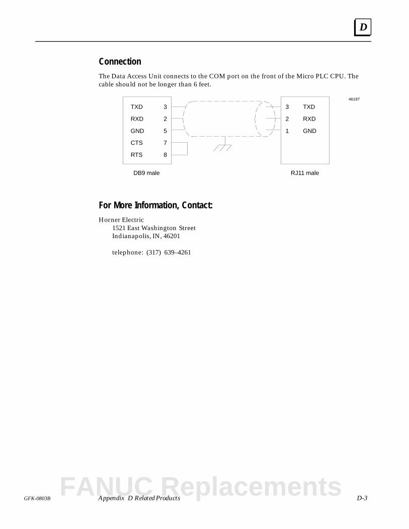
D
D-3GFK-0803B Appendix D Related Products
ConnectionThe Data Access Unit connects to the COM port on the front of the Micro PLC CPU. Thecable should not be longer than 6 feet.
3
2
5
7
8
TXD
RXD
GND
CTS
RTS
DB9 male
3
2
1
TXD
RXD
GND
RJ11 male
46197
For More Information, Contact:Horner Electric 1521 East Washington Street
Indianapolis, IN, 46201
telephone: (317) 639–4261
FANUC Replacements
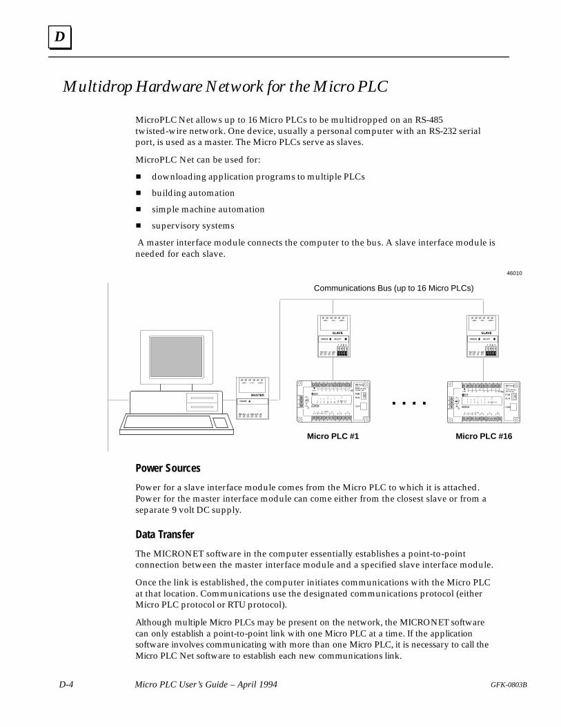
D
D-4 Micro PLC User’s Guide – April 1994 GFK-0803B
Multidrop Hardware Network for the Micro PLC
MicroPLC Net allows up to 16 Micro PLCs to be multidropped on an RS-485twisted-wire network. One device, usually a personal computer with an RS-232 serialport, is used as a master. The Micro PLCs serve as slaves.
MicroPLC Net can be used for:
downloading application programs to multiple PLCs
building automation
simple machine automation
supervisory systems
A master interface module connects the computer to the bus. A slave interface module isneeded for each slave.
Micro PLC #1
46010
Communications Bus (up to 16 Micro PLCs)
Micro PLC #16
. . . .
Power Sources
Power for a slave interface module comes from the Micro PLC to which it is attached.Power for the master interface module can come either from the closest slave or from aseparate 9 volt DC supply.
Data Transfer
The MICRONET software in the computer essentially establishes a point-to-pointconnection between the master interface module and a specified slave interface module.
Once the link is established, the computer initiates communications with the Micro PLCat that location. Communications use the designated communications protocol (eitherMicro PLC protocol or RTU protocol).
Although multiple Micro PLCs may be present on the network, the MICRONET softwarecan only establish a point-to-point link with one Micro PLC at a time. If the applicationsoftware involves communicating with more than one Micro PLC, it is necessary to call theMicro PLC Net software to establish each new communications link.
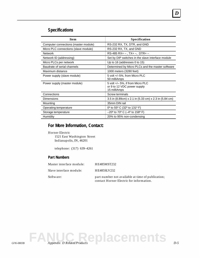
D
D-5GFK-0803B Appendix D Related Products
Specifications
Item Specification
Computer connections (master module) RS-232 RX, TX, DTR, and GND
Micro PLC connections (slave module) RS-232 RX, TX, and GND
Network RS-485 RX+ – , TX+ –, DTR+ –
Network ID (addressing) Set by DIP switches in the slave interface module
Micro PLCs per network Up to 16 (addresses 0 to 15)
Baudrate of serial channels Determined by Micro PLCs and the master software
Maximum distance 1000 meters (3280 feet)
Power supply (slave module) 5 volt +/–5%, from Micro PLC50 milliAmps
Power supply (master module) 5 volt +/– 5%, if from Micro PLCor 9 to 12 VDC power supply15 milliAmps
Connections Screw terminals
Dimensions 3.5 in (8.89cm) x 2.1 in (5.33 cm) x 2.3 in (5.84 cm)
Mounting 35mm DIN rail
Operating temperature 0º to 55º C (32º to 131º F)
Storage temperature –20º to 70º C (–4º to 158º F)
Humidity 20% to 95% non-condensing
For More Information, Contact:Horner Electric 1521 East Washington Street
Indianapolis, IN, 46201
telephone: (317) 639–4261
Part Numbers
Master interface module: HE485MST232
Slave interface module: HE485SLV232
Software: part number not available at time of publication; contact Horner Electric for information.
FANUC Replacements
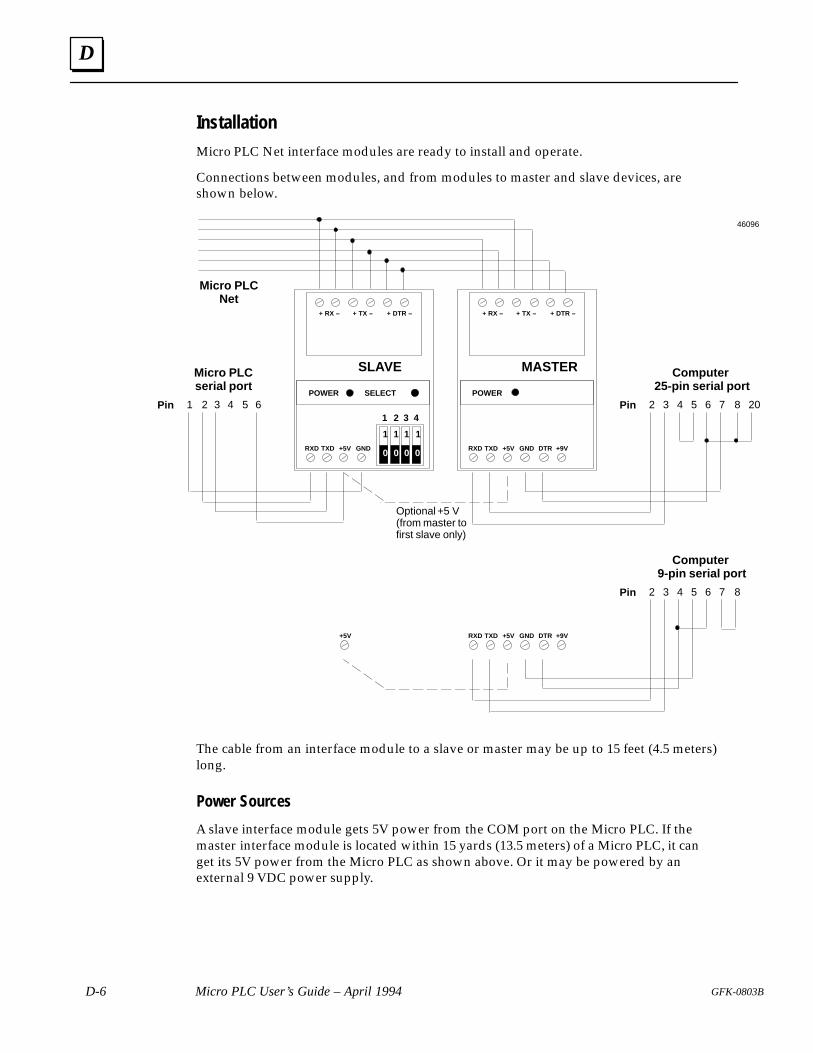
D
D-6 Micro PLC User’s Guide – April 1994 GFK-0803B
InstallationMicro PLC Net interface modules are ready to install and operate.
Connections between modules, and from modules to master and slave devices, areshown below.
1 1 1 1
00 0 0
1 2 3 4
POWER SELECT
SLAVE
RXD TXD +5V GND
+ RX – + TX – + DTR –
POWER
MASTER
RXD TXD +5V GND
+ RX – + TX – + DTR –
DTR +9V
Micro PLCserial port
1 2 3 4 5 6Pin
Computer 25-pin serial port
72 3 4 5 6Pin 8 20
Micro PLCNet
Optional +5 V(from master tofirst slave only)
RXD TXD +5V GND DTR +9V
Computer 9-pin serial port
72 3 4 5 6Pin 8
+5V
46096
The cable from an interface module to a slave or master may be up to 15 feet (4.5 meters)long.
Power Sources
A slave interface module gets 5V power from the COM port on the Micro PLC. If themaster interface module is located within 15 yards (13.5 meters) of a Micro PLC, it canget its 5V power from the Micro PLC as shown above. Or it may be powered by anexternal 9 VDC power supply.
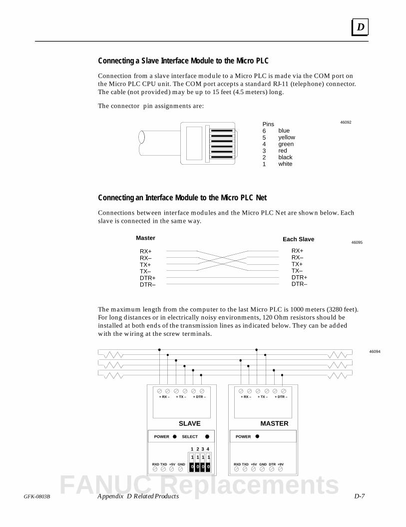
D
D-7GFK-0803B Appendix D Related Products
Connecting a Slave Interface Module to the Micro PLC
Connection from a slave interface module to a Micro PLC is made via the COM port onthe Micro PLC CPU unit. The COM port accepts a standard RJ-11 (telephone) connector.The cable (not provided) may be up to 15 feet (4.5 meters) long.
The connector pin assignments are:
Pins654321
blueyellowgreenredblackwhite
46092
Connecting an Interface Module to the Micro PLC Net
Connections between interface modules and the Micro PLC Net are shown below. Eachslave is connected in the same way.
Each SlaveMaster
RX+RX–TX+TX–DTR+DTR–
RX+RX–TX+TX–DTR+DTR–
46095
The maximum length from the computer to the last Micro PLC is 1000 meters (3280 feet).For long distances or in electrically noisy environments, 120 Ohm resistors should beinstalled at both ends of the transmission lines as indicated below. They can be addedwith the wiring at the screw terminals.
1 1 1 1
00 0 0
1 2 3 4
POWER SELECT
SLAVE
RXD TXD +5V GND
+ RX – + TX – + DTR –
POWER
MASTER
RXD TXD +5V GND
+ RX – + TX – + DTR –
DTR +9V
46094
FANUC Replacements
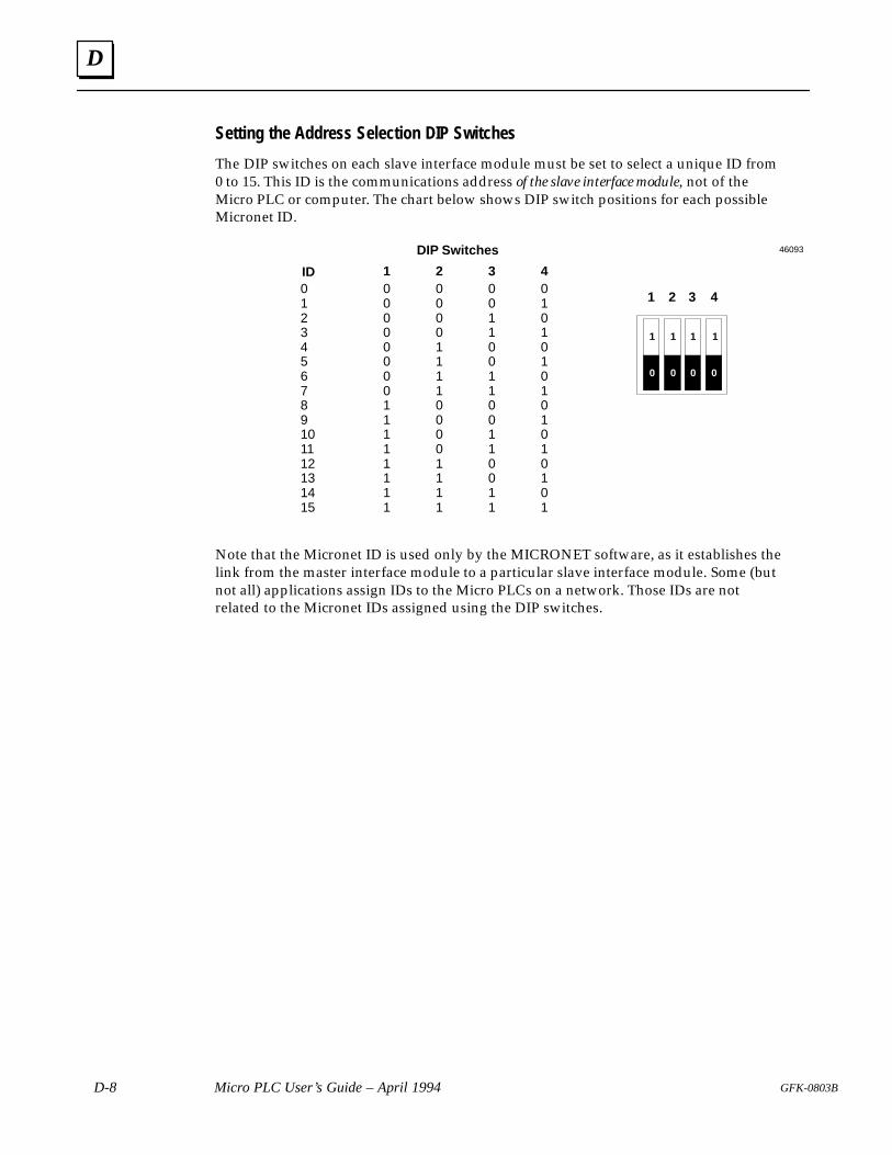
D
D-8 Micro PLC User’s Guide – April 1994 GFK-0803B
Setting the Address Selection DIP Switches
The DIP switches on each slave interface module must be set to select a unique ID from0 to 15. This ID is the communications address of the slave interface module, not of theMicro PLC or computer. The chart below shows DIP switch positions for each possibleMicronet ID.
ID
DIP Switches
1 2 3 40123456789101112131415
0 0 0 00 0 0 10 0 1 00 0 1 10 1 0 00 1 0 10 1 1 00 1 1 11 0 0 01 0 0 11 0 1 01 0 1 11 1 0 01 1 0 11 1 1 01 1 1 1
1 1 1 1
00 0 0
1 2 3 4
46093
Note that the Micronet ID is used only by the MICRONET software, as it establishes thelink from the master interface module to a particular slave interface module. Some (butnot all) applications assign IDs to the Micro PLCs on a network. Those IDs are notrelated to the Micronet IDs assigned using the DIP switches.
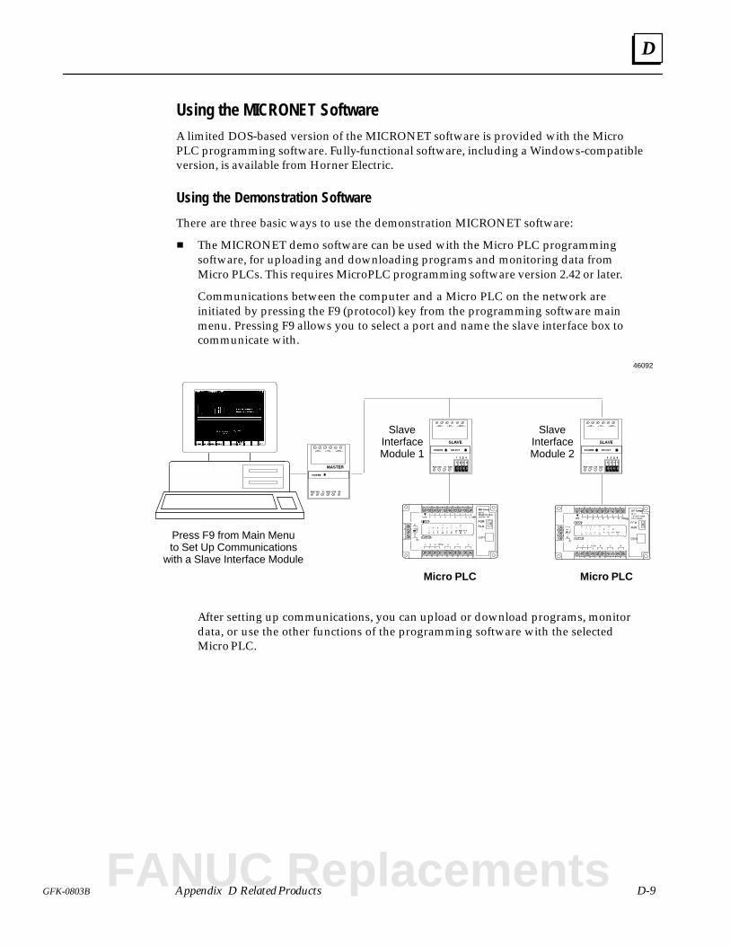
D
D-9GFK-0803B Appendix D Related Products
Using the MICRONET SoftwareA limited DOS-based version of the MICRONET software is provided with the MicroPLC programming software. Fully-functional software, including a Windows-compatibleversion, is available from Horner Electric.
Using the Demonstration Software
There are three basic ways to use the demonstration MICRONET software:
The MICRONET demo software can be used with the Micro PLC programmingsoftware, for uploading and downloading programs and monitoring data fromMicro PLCs. This requires MicroPLC programming software version 2.42 or later.
Communications between the computer and a Micro PLC on the network areinitiated by pressing the F9 (protocol) key from the programming software mainmenu. Pressing F9 allows you to select a port and name the slave interface box tocommunicate with.
Micro PLC
46092
Micro PLC
SlaveInterfaceModule 1
SlaveInterfaceModule 2
Press F9 from Main Menuto Set Up Communications
with a Slave Interface Module
After setting up communications, you can upload or download programs, monitordata, or use the other functions of the programming software with the selectedMicro PLC.
FANUC Replacements
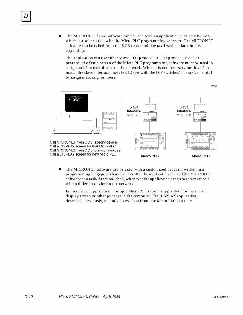
D
D-10 Micro PLC User’s Guide – April 1994 GFK-0803B
The MICRONET demo software can be used with an application such as DISPLAY,which is also included with the Micro PLC programming software. The MICRONETsoftware can be called from the DOS command line (as described later in thisappendix).
The application can use either Micro PLC protocol or RTU protocol. For RTUprotocol, the Setup screen of the Micro PLC programming software must be used toassign an ID to each device on the network. While it is not necessary for this ID tomatch the slave interface module’s ID (set with the DIP switches), it may be helpfulto assign matching numbers.
Micro PLC
46091
Micro PLC
SlaveInterfaceModule 1
SlaveInterfaceModule 2
Call MICRONET from DOS, specify device.Call a DISPLAY screen for that Micro PLC.Call MICRONET from DOS to switch devices.Call a DISPLAY screen for new Micro PLC.
The MICRONET software can be used with a customized program written in aprogramming langage such as C or BASIC. The application can call the MICRONETsoftware as a task/function/shell, whenever the application needs to communicatewith a different device on the network.
In this type of application, multiple Micro PLCs could supply data for the samedisplay screen or other purpose in the computer. The DISPLAY application,described previously, can only access data from one Micro PLC at a time.
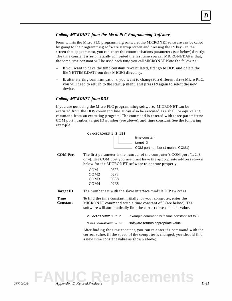
D
D-11GFK-0803B Appendix D Related Products
Calling MICRONET from the Micro PLC Programming Software
From within the Micro PLC programming software, the MICRONET software can be calledby going to the programming software startup screen and pressing the F9 key. On thescreen that appears next, you can enter the communications parameters (see below) directly.The time constant is automatically computed the first time you call MICRONET. After that,the same time constant will be used each time you call MICRONET. Note the following:
– If you want to have the time constant re-calculated, first go to DOS and delete thefile NETTIME.DAT from the \MICRO directory.
– If, after starting communications, you want to change to a different slave Micro PLC,you will need to return to the startup menu and press F9 again to select the newdevice.
Calling MICRONET from DOS
If you are not using the Micro PLC programming software, MICRONET can beexecuted from the DOS command line. It can also be executed as a shell (or equivalent)command from an executing program. The command is entered with three parameters:COM port number, target ID number (see above), and time constant. See the followingexample.
C:>MICRONET 1 3 158time constant
target ID
COM port number (1 means COM1)
The first parameter is the number of the computer’s COM port (1, 2, 3,or 4). The COM port you use must have the appropriate address shownbelow for the MICRONET software to operate properly.
COM1 03F8COM2 02F8COM3 03E8COM4 02E8
The number set with the slave interface module DIP switches.
To find the time constant initially for your computer, enter theMICRONET command with a time constant of 0 (see below). Thesoftware will automatically find the correct time constant value.
C:>MICRONET 1 3 0
Time constant = 203
example command with time constant set to 0
software returns appropriate value
After finding the time constant, you can re-enter the command with thecorrect value. (If the speed of the computer is changed, you should finda new time constant value as shown above).
COM Port
Target ID
TimeConstant
FANUC Replacements
Index
Index-1GFK-0803
AAnalog devices, 1-4
Analog Expander Unitdescription and specifications, 2-17 I/O wiring, 3-14 , 3-15 , 3-16
BBattery–back ed RAM, C-2
Baud rate, B–1
CCable length, A-1
Cablescatalog numbers, 1-14 computer or HHP to Micro PLC, A-2 HHP or computer to EPROM writer,
A-2
Charging characteristics of RAM, C-3
Charging RAM Memory, 3-7
Clock speed, 2-5
Coils, clearing, 6-25
Communications, Micronet, D-4
Communications port, setting up, 6-13
Communications protocol, 6-25
Computerclear program from memory, 6-19 connect to EPROM Programmer, C-13 connect to HHP, 4-10 connect to Micro PLC, 6-20
Connecting I/O devices, 3-9 , 3-10
Counters, number, 2-5
CPU Unit, 1-8 , 2-2 14 Point, with AC Inputs/AC Outputs,
AC Power, 2-9 14 Point, with DC Inputs/Relay Out-
puts, AC Power, 2-7 14 Point, with DC Inputs/Relay Out-
puts, DC Power, 2-8 , 2-10 28 Point, with DC Inputs/Relay Out-
puts, AC Power, 2-12 , 2-15 28 Point, with DC Inputs/Relay Out-
puts, DC Power, 2-11
DData Access Unit, D-2
Data logging, 1-17
Data Monitor screen, 6-30
Data monitoringwith a Hand-held Programmer, 4-12 with an Operator Interface Unit, 5-10 with the programming software, 6-28 ,
6-34
DC power, 2-2 , 2-3
DimensionsEPROM programmer, C-7 Hand–held programmer, 4-2 , 5-2 PLC, 3-3
DIN rail mounting, 3-5
DIP switches, on Micronet module, D-8
Directory, change, 6-17
Discharging characteristics of RAM, C-4
Discrete data, modify from HHP, 4-14
Discrete data, in PLC memory, 1-5
Discrete devices, 1-4
Display, optional software, 1-17
Display, optional unit, D-2
DOSaccess from programming software,
6-18 exiting to, 6-41
EElectrostatic discharge, C-5 , C-15
Enclosure for PLC, 1-4
EPROMcopying, C-16 insert in EPROM Programmer, C-15 installing in Micro PLC, C-5 read program from, C-14 specifications, 2-5 using to store programs, 1-11 , C-2 write program to, C-15
EPROM Programmercatalog number, 1-14 connect to HHP, C-12 connect to Micro PLC, C-11 controls and indicators, C-7
Index
Index-2 GFK-0803
description, 1-9 dimensions, C-7 keypad, C-9 menus, C-10 software version, C-8 specifications, C-8 using in Micro PLC system, 1-11 , C-2
Expander Unit, 1-8 , 2-3 14 Point, with DC Inputs/Relay Out-
puts, AC Power, 2-13 , 2-14 28 Point with DC Inputs/Relay Outputs,
AC Power, 2-16 Analog, 2-17 connecting, 3-6
FFCC specification, 2-4
Field Service assistance, iv
File-handling functions, 6-14
Footprint, 3-4
Forcing I/O bits from HHP, 4-13
Forcing I/O in program, 6-27
Forcing internal relays from the HHP, 4-14
GGrounding, 3-8
HHand–held Programmer
catalog number, 1-14 connect to computer, 4-10 connect to EPROM Programmer, C-12 connect to Micro PLC, 4-11 controls and indicators, 4-2 data monitoring in online mode, 4-12 dimensions, 4-2 , 5-2 forcing I/O bits, 4-13 forcing internal relays, 4-14 key definitions, 4-7 keypad, 4-6 modifying register data, 4-15 online functions, 4-9 power supply, 4-5
powerup displays, 4-8 software version, 4-8 specifications, 4-3 transferring a program, 4-10
II/O points, number, 2-2 , 2-3
Input circuit, typical, 3-9 , 3-10 , 3-11 , 3-13
Inputsnumber, 2-2 , 2-3 signals to PLC, 1-3 typical devices, 1-4
Installation, software, 6-3
Insulation resistance, 2-4
LLEDS on CPU unit, 2-2
LEDS on Expander unit, 2-3
Load, minimum, 2-7 , 2-8 , 2-11 , 2-12 , 2-13, 2-15 , 2-16
Location requirements, 3-2
MMemory
charging characteristics, C-3 discharging characteristics, C-4 discrete and register, 1-5 initial charging time required, C-6 RAM or EPROM in Micro PLC, 2-5 types and amounts in the Micro PLC,
2-6
Memory addresses, 2-6
Micro PLC, typical applications, 1-6
Micronet software, D-9
Modem, using, B–1
Modifying register data from the HHP,4-15
Modifying register data from the OIU,5-11
Monitoring functions, overview, 1-13
Mounting position, 3-2
Multidrop network, D-4
FANUC Replacements
Index
Index-3GFK-0803
NNetwork for Micro PLCs, D-4
OOIU. See Operator Interface Unit
OK LED, 2-2
Online functions, 6-20 of programming software, 6-21
Operator Interface Unitcontrols and indicators, 5-2 data monitoring, 5-10 key definitions, 5-6 keypad, 5-6 modifying register data, 5-11 online functions, 5-7 power supply, 5-5 powerup displays, 5-7 setting the operation keys, 5-12 , 5-14 software version, 5-7 specifications, 5-3 transferring a program, 5-8
Ordering information, 1-14
Output circuit, typical, 3-9 , 3-10 , 3-11 ,3-13
Outputscontact resistance, 2-7 , 2-8 , 2-11 , 2-12 ,
2-13 , 2-15 , 2-16 electrical life, 2-7 , 2-8 , 2-11 , 2-12 , 2-13 ,
2-15 , 2-16 from PLC, 1-3 mechanical life, 2-6 number, 2-2 , 2-3 , 2-7 , 2-8 , 2-11 , 2-12 ,
2-13 , 2-15 , 2-16 response time, 2-7 , 2-8 , 2-11 , 2-12 , 2-13
, 2-15 , 2-16 typical devices, 1-4
Override I/O, 6-27
PPanel mounting, 3-3
PLC basics, 1-2
PLC memory types, 1-5
PLC mode, 3-17 selecting with HHM, 4-9
selecting with OIT, 5-7 selecting with programming software,
6-22 , 6-29 selecting with switch on CPU unit, 1-8
PLC operation, 1-3
PLC, parts of, 1-2
Port setup, 6-2 , 6-13
Power connectionsAC, 3-7 DC, 3-8
Power LED, 2-2 , 2-3
Printing a program, 6-38
Programcapacity, 2-5 clear from computer, 6-19 execution in PLC, 1-3 execution time, 2-5 format, overview, 1-12 load from computer to Micro PLC, 6-15 load into computer, 6-15 memory, 2-5 retention time, 1-11 , C-2 save on disk, 6-16 storage, 2-5 transfer
between computer and EPROM Pro-grammer, 4-10
between Micro PLC and Hand–heldProgrammer, 4-11
to computer from EPROM Program-mer, C-18
to computer from Micro PLC, 6-24 to EPROM Programmer from com-
puter, C-13 to EPROM Programmer from HHP,
C-12 to EPROM Programmer from Micro
PLC, C-11 to HHP from EPROM Programmer,
C-17 to the Micro PLC from a computer,
6-24 with the programming software, 6-24
Program monitoring, 6-26
Program storage, offline, C-2
Program transferwith a Hand-held Programmer, 4-10 with an Operator Interface Unit, 5-8
Programmers for the Micro PLC, 1-9
Programming, Instruction set, 1-11
Index
Index-4 GFK-0803
Programming functions, 6-37
Programming softwaredata monitoring in online mode, 6-28 ,
6-34 installation, 6-3 , 6-7 main menu functions, 6-9 online functions, 6-20 program monitoring in online mode,
6-26 running, 6-8 transferring a program, 6-24
RReading a Program from EPROM, C-14
Registersdata stored in, 1-5 modify data from HHP, 4-15 modify data from OIU, 5-11 number, 2-5 retentive, clearing, 6-25
Relay outputs, 2-6 , 2-7 , 2-8 , 2-11 , 2-12 ,2-13 , 2-15 , 2-16
Retentive references, 2-6
Run/Stop mode, 3-17
Run/Stop switch, 1-8
Rung, search with OIU, 5-9
SScan time, 2-5
Search, with OIU, 5-9
Search for a program element, 6-27
Softwarefiles provided on diskette, 6-2 installation, 6-3 , 6-7
main menu functions, 6-9 map of, 6-10 running, 6-8
SpecificationsCPU Units, 2-7 , 2-8 , 2-9 , 2-10 , 2-11 ,
2-12 , 2-15 EPROM Programmer, C-8 Expander Units, 2-13 , 2-14 , 2-16 , 2-17 functional, 2-5 general, 2-4 Hand–held Programmer, 4-3 Operator Interface Unit, 5-3
Split screen data display, 6-31
Status, display, 6-22 , 6-36
Stop/Run mode, 3-17 selecting with HHP, 4-9 selecting with OIT, 5-7 selecting with programming software,
6-22 , 6-29
Suppression, 3-12
TTechnical assistance, iv
Terminal specifications, 2-4
Time constant, D-9
Timers, number, 2-5
WWiring
for AC devices, 3-13 for analog devices, 3-14 , 3-15 , 3-16 for DC devices, 3-9 , 3-10 , 3-11 power, 3-7
Writing a program to EPROM, C-15
FANUC Replacements