Embed Size (px)
Citation preview
CA08102001E For more
Co
-1
NEMA Contactors & Starters 33
January 2003Vol. 2, Ref. No. [0019]ntents
33
0330
000
NE
MA
Co
nta
cto
rs &
Sta
rte
rs
Description PageIT. Electro-Mechanical . . . . . . . . . . . . . . . . . . . . . . . . . . . . . . . . . . . . . . . . . . . 33-2
Contactors — Full Voltage, Non-reversing and Reversing . . . . . . . . . . . . 33-4
Starters — Full Voltage, Non-reversing and Reversing. . . . . . . . . . . . . . . 33-7
IT. Electro-Mechanical — Enclosed . . . . . . . . . . . . . . . . . . . . . . . . . . . . . . . . . 33-34
Contactors. . . . . . . . . . . . . . . . . . . . . . . . . . . . . . . . . . . . . . . . . . . . . . . . . . . 33-35
Starters — Non-combination . . . . . . . . . . . . . . . . . . . . . . . . . . . . . . . . . . . 33-37
Starters — Combination . . . . . . . . . . . . . . . . . . . . . . . . . . . . . . . . . . . . . . . 33-39
Freedom . . . . . . . . . . . . . . . . . . . . . . . . . . . . . . . . . . . . . . . . . . . . . . . . . . . . . . 33-45
Contactors — Non-reversing and Reversing . . . . . . . . . . . . . . . . . . . . . . . 33-47
Starters — 3-Phase Non-reversing and Reversing, Full Voltage . . . . . . . 33-50
Starters — 3-Phase Multispeed . . . . . . . . . . . . . . . . . . . . . . . . . . . . . . . . . . 33-53
Starters — Single-Phase Non-reversing, Full Voltage. . . . . . . . . . . . . . . . 33-54
Relays — Thermal Overload . . . . . . . . . . . . . . . . . . . . . . . . . . . . . . . . . . . . 33-76
Relays — Current Sensing Protective . . . . . . . . . . . . . . . . . . . . . . . . . . . . 33-82
Freedom, 3-Phase Magnetic — Enclosed . . . . . . . . . . . . . . . . . . . . . . . . . . . . 33-84
Starters — Non-combination . . . . . . . . . . . . . . . . . . . . . . . . . . . . . . . . . . . 33-86
Starters — Combination . . . . . . . . . . . . . . . . . . . . . . . . . . . . . . . . . . . . . . . 33-92
Advantage . . . . . . . . . . . . . . . . . . . . . . . . . . . . . . . . . . . . . . . . . . . . . . . . . . . . . 33-147
Contactors — Non-reversing and Reversing . . . . . . . . . . . . . . . . . . . . . . . 33-148
Starters — Non-reversing and Reversing . . . . . . . . . . . . . . . . . . . . . . . . . 33-149
Starters — Non-reversing, Two-Speed. . . . . . . . . . . . . . . . . . . . . . . . . . . . 33-151
Advantage Control Modules . . . . . . . . . . . . . . . . . . . . . . . . . . . . . . . . . . . . 33-161
PowerNet Communication Devices . . . . . . . . . . . . . . . . . . . . . . . . . . . . . . 33-171
Advantage, 3-Phase Magnetic — Enclosed . . . . . . . . . . . . . . . . . . . . . . . . . . 33-174
Starters — Non-combination . . . . . . . . . . . . . . . . . . . . . . . . . . . . . . . . . . . 33-176
Starters — Combination . . . . . . . . . . . . . . . . . . . . . . . . . . . . . . . . . . . . . . . 33-182
A200 . . . . . . . . . . . . . . . . . . . . . . . . . . . . . . . . . . . . . . . . . . . . . . . . . . . . . . . . . . 33-194
Contactors — Non-reversing and Reversing . . . . . . . . . . . . . . . . . . . . . . . 33-194
Starters — Non-reversing and Reversing . . . . . . . . . . . . . . . . . . . . . . . . . 33-200
Starters — Two-Speed . . . . . . . . . . . . . . . . . . . . . . . . . . . . . . . . . . . . . . . . . 33-207
Relays — Thermal and Fast Trip . . . . . . . . . . . . . . . . . . . . . . . . . . . . . . . . 33-220
Citation — Renewal Parts . . . . . . . . . . . . . . . . . . . . . . . . . . . . . . . . . . . . . . . . 33-229
Type N — Renewal Parts . . . . . . . . . . . . . . . . . . . . . . . . . . . . . . . . . . . . . . . . . 33-232
Solenoids — Alternating Current . . . . . . . . . . . . . . . . . . . . . . . . . . . . . . . . . . 33-233
Shoe Brakes — AC and DC Magnetic . . . . . . . . . . . . . . . . . . . . . . . . . . . . . . . 33-235
Pump Panels with 3R Enclosure . . . . . . . . . . . . . . . . . . . . . . . . . . . . . . . . . . . 33-239
Motor Control Technical Data . . . . . . . . . . . . . . . . . . . . . . . . . . . . . . . . . . . . . 33-249
NEMA Contactors and Starters
information visit: www.cutler-hammer.eaton.com
0330000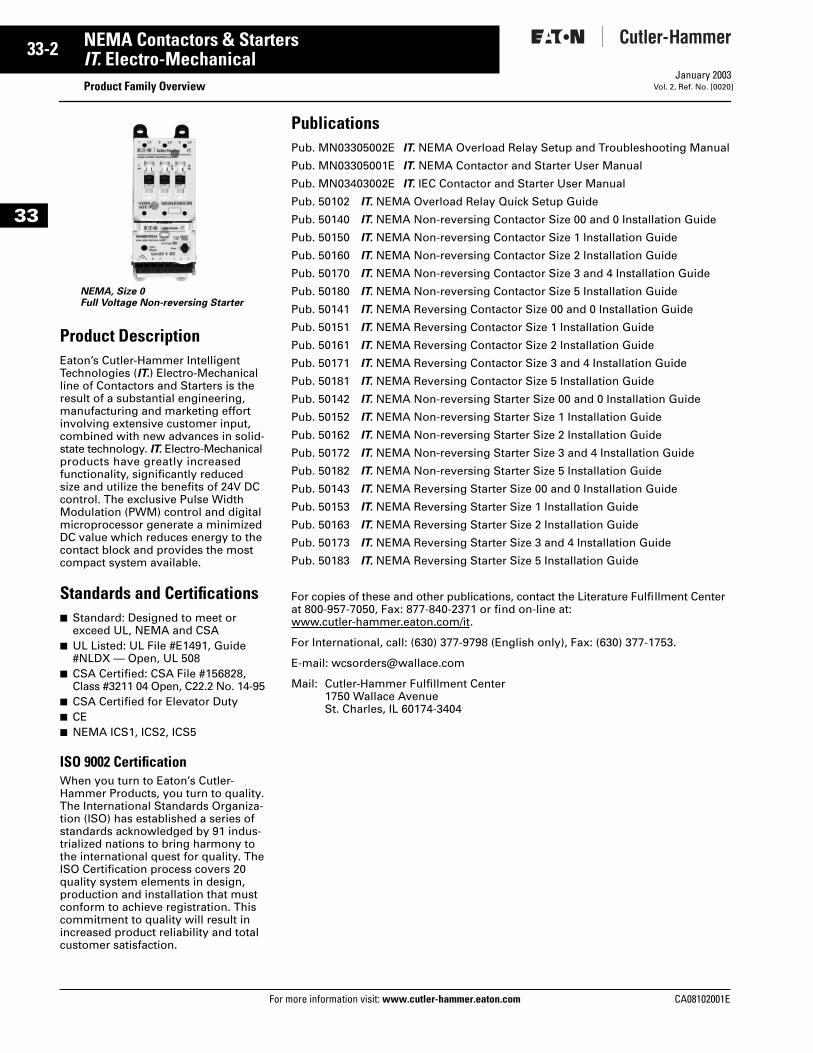
33-2
33
NEMA Contactors & StartersIT. Electro-Mechanical
Product Family OverviewFor more information visit: www.cutler-hammer.eaton.com
January 2003Vol. 2, Ref. No. [0020]
Product DescriptionEaton’s Cutler-Hammer Intelligent Technologies (IT.) Electro-Mechanical line of Contactors and Starters is the result of a substantial engineering, manufacturing and marketing effort involving extensive customer input, combined with new advances in solid-state technology. IT. Electro-Mechanical products have greatly increased functionality, significantly reduced size and utilize the benefits of 24V DC control. The exclusive Pulse Width Modulation (PWM) control and digital microprocessor generate a minimized DC value which reduces energy to the contact block and provides the most compact system available.
Standards and Certifications■ Standard: Designed to meet or
exceed UL, NEMA and CSA■ UL Listed: UL File #E1491, Guide
#NLDX — Open, UL 508■ CSA Certified: CSA File #156828,
Class #3211 04 Open, C22.2 No. 14-95■ CSA Certified for Elevator Duty■ CE■ NEMA ICS1, ICS2, ICS5
ISO 9002 CertificationWhen you turn to Eaton’s Cutler-Hammer Products, you turn to quality. The International Standards Organiza-tion (ISO) has established a series of standards acknowledged by 91 indus-trialized nations to bring harmony to the international quest for quality. The ISO Certification process covers 20 quality system elements in design, production and installation that must conform to achieve registration. This commitment to quality will result in increased product reliability and total customer satisfaction.
NEMA, Size 0Full Voltage Non-reversing Starter
PublicationsPub. MN03305002E IT. NEMA Overload Relay Setup and Troubleshooting Manual
Pub. MN03305001E IT. NEMA Contactor and Starter User Manual
Pub. MN03403002E IT. IEC Contactor and Starter User Manual
Pub. 50102 IT. NEMA Overload Relay Quick Setup Guide
Pub. 50140 IT. NEMA Non-reversing Contactor Size 00 and 0 Installation Guide
Pub. 50150 IT. NEMA Non-reversing Contactor Size 1 Installation Guide
Pub. 50160 IT. NEMA Non-reversing Contactor Size 2 Installation Guide
Pub. 50170 IT. NEMA Non-reversing Contactor Size 3 and 4 Installation Guide
Pub. 50180 IT. NEMA Non-reversing Contactor Size 5 Installation Guide
Pub. 50141 IT. NEMA Reversing Contactor Size 00 and 0 Installation Guide
Pub. 50151 IT. NEMA Reversing Contactor Size 1 Installation Guide
Pub. 50161 IT. NEMA Reversing Contactor Size 2 Installation Guide
Pub. 50171 IT. NEMA Reversing Contactor Size 3 and 4 Installation Guide
Pub. 50181 IT. NEMA Reversing Contactor Size 5 Installation Guide
Pub. 50142 IT. NEMA Non-reversing Starter Size 00 and 0 Installation Guide
Pub. 50152 IT. NEMA Non-reversing Starter Size 1 Installation Guide
Pub. 50162 IT. NEMA Non-reversing Starter Size 2 Installation Guide
Pub. 50172 IT. NEMA Non-reversing Starter Size 3 and 4 Installation Guide
Pub. 50182 IT. NEMA Non-reversing Starter Size 5 Installation Guide
Pub. 50143 IT. NEMA Reversing Starter Size 00 and 0 Installation Guide
Pub. 50153 IT. NEMA Reversing Starter Size 1 Installation Guide
Pub. 50163 IT. NEMA Reversing Starter Size 2 Installation Guide
Pub. 50173 IT. NEMA Reversing Starter Size 3 and 4 Installation Guide
Pub. 50183 IT. NEMA Reversing Starter Size 5 Installation Guide
For copies of these and other publications, contact the Literature Fulfillment Center at 800-957-7050, Fax: 877-840-2371 or find on-line at:www.cutler-hammer.eaton.com/it.
For International, call: (630) 377-9798 (English only), Fax: (630) 377-1753.
E-mail: [email protected]
Mail: Cutler-Hammer Fulfillment Center1750 Wallace AvenueSt. Charles, IL 60174-3404
CA08102001E
CA08102001E For more
-3
33NEMA Contactors & StartersIT. Electro-Mechanical
Catalog Number SelectionJanuary 2003Vol. 2, Ref. No. [0021]
33
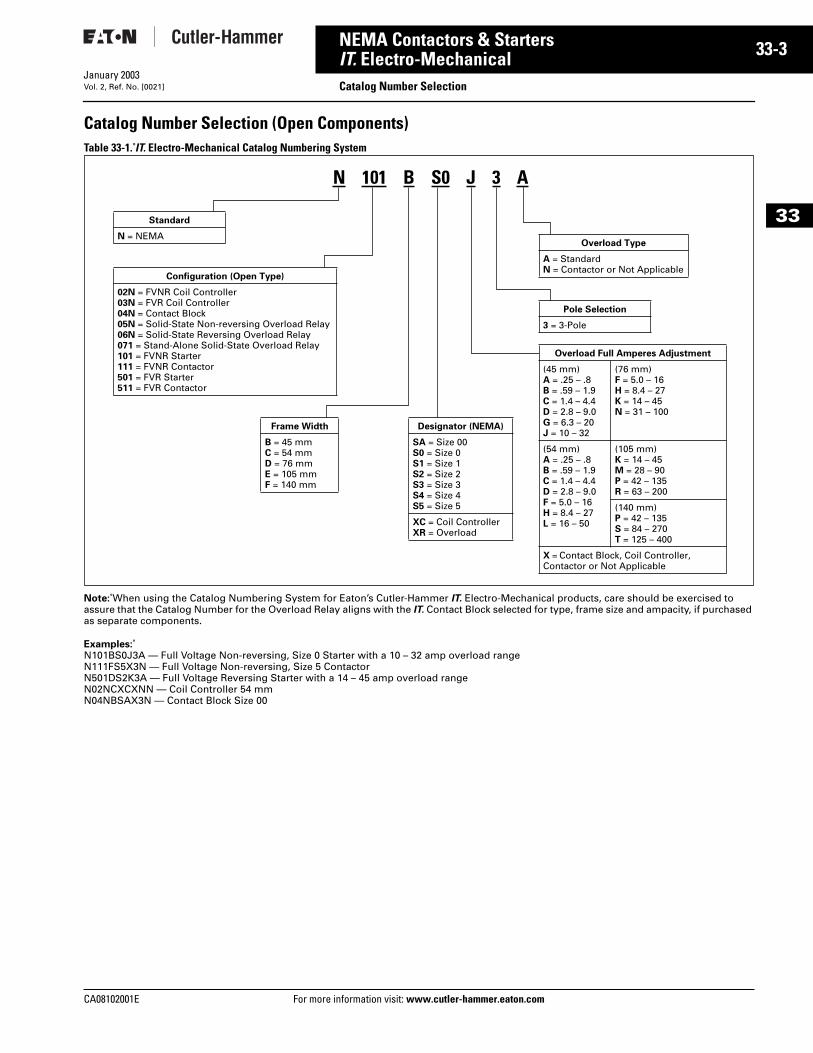
Catalog Number Selection (Open Components)Table 33-1. IT. Electro-Mechanical Catalog Numbering System
Note: When using the Catalog Numbering System for Eaton’s Cutler-Hammer IT. Electro-Mechanical products, care should be exercised to assure that the Catalog Number for the Overload Relay aligns with the IT. Contact Block selected for type, frame size and ampacity, if purchased as separate components.
Examples: N101BS0J3A — Full Voltage Non-reversing, Size 0 Starter with a 10 – 32 amp overload rangeN111FS5X3N — Full Voltage Non-reversing, Size 5 ContactorN501DS2K3A — Full Voltage Reversing Starter with a 14 – 45 amp overload rangeN02NCXCXNN — Coil Controller 54 mmN04NBSAX3N — Contact Block Size 00
Designator (NEMA)
SA = Size 00S0 = Size 0S1 = Size 1S2 = Size 2S3 = Size 3S4 = Size 4S5 = Size 5
XC = Coil ControllerXR = Overload
Overload Type
A = StandardN = Contactor or Not Applicable
Standard
N = NEMA
Configuration (Open Type)
02N = FVNR Coil Controller03N = FVR Coil Controller04N = Contact Block05N = Solid-State Non-reversing Overload Relay06N = Solid-State Reversing Overload Relay071 = Stand-Alone Solid-State Overload Relay101 = FVNR Starter111 = FVNR Contactor501 = FVR Starter511 = FVR Contactor
Frame Width
B = 45 mm C = 54 mm D = 76 mm E = 105 mmF = 140 mm
Overload Full Amperes Adjustment
(45 mm)A = .25 – .8B = .59 – 1.9C = 1.4 – 4.4D = 2.8 – 9.0G = 6.3 – 20J = 10 – 32
(76 mm)F = 5.0 – 16H = 8.4 – 27K = 14 – 45N = 31 – 100
(54 mm)A = .25 – .8B = .59 – 1.9C = 1.4 – 4.4D = 2.8 – 9.0F = 5.0 – 16H = 8.4 – 27L = 16 – 50
(105 mm)K = 14 – 45M = 28 – 90P = 42 – 135R = 63 – 200
(140 mm)P = 42 – 135S = 84 – 270T = 125 – 400
X = Contact Block, Coil Controller, Contactor or Not Applicable
Pole Selection
3 = 3-Pole
N 101 B S0 J 3 A
information visit: www.cutler-hammer.eaton.com
33-4
33
NEMA Contactors & StartersIT. Electro-Mechanical
Contactors — Full Voltage, Non-reversing and ReversingFor more information visit: www.cutler-hammer.eaton.com
January 2003Vol. 2, Ref. No. [0022]
ContentsDescription Page
Product Family Overview
Product Description. . . . . . . 33-2
Standards andCertifications . . . . . . . . . . . 33-2
Catalog NumberSelection . . . . . . . . . . . . . . 33-3
Contactors — Non-reversingand Reversing
Product Description. . . . . . . 33-4
Features . . . . . . . . . . . . . . . . 33-4
Product Selection . . . . . . . . 33-5
Technical Data. . . . . . . . . . . . . . 33-10
Accessories . . . . . . . . . . . . . . . . 33-13
Auxiliary Contacts . . . . . . . . 33-15
Renewal Parts . . . . . . . . . . . . . . 33-25
Dimensions . . . . . . . . . . . . . . . . 33-27
Product DescriptionThe Cutler-Hammer Intelligent Tech-nologies (IT.) Electro-Mechanical Con-tactor by Eaton Corporation consists of an IT. Electro-Mechanical Contact Block and IT. Electro-Mechanical Coil Controller as a Full Voltage Non-reversing (FVNR) or Full Voltage Reversing (FVR) device. Size 00 to Size 4 Contact Blocks combined with Coil Controllers (factory or field assembled) are stand-alone Contactors. Only the Size 5 Contactors have internal factory assembled coil controllers.
Features■ Size 00 – 5, 9 – 270A, 2 – 200 hp,
460V■ 24V DC Coil Control — safe, reliable
global standard■ Compact DC coil control — Size 00,
45 mm wide, 9A, 2 hp, 460V■ Frame width (mm): 45, 54, 76, 105,
140■ No laminations, shading coils or
magnet noise■ -40 to 149°F (-40 to 65°C)
operating temperature■ No seal in auxiliary contacts
required — control wiring is not needed between the contactor and overload relay
■ Conformal coated PWM (coil con-troller) board for environmental toughness
■ Unique Pulse Width Modulated coil utilizes minimum energy
■ Microprocessor-based control■ Easily accessible mounting feet for
panel mounting■ Highest immunity to ESD, harmonics
— minimal Total Harmonic Distortion
■ Built-in logic to provide either 2- or 3-wire control, eliminating the need to provide and wire auxiliary con-tacts to seal in and interlock the con-tactor coils
■ Easy field assembly of control wiring — plug and unplug lockable control connector
■ Optional mounting plates for Size 00 – 5.
■ Common accessories■ Long-life silver nickel and silver tin
oxide contacts provide excellent conductivity and superior resistance to welding and arc erosion
■ Environmentally friendly materials■ Low wattage coils and minimal heat
dissipation■ Front mounted Auxiliary Contacts:
1NO, 1NC, 2NO, 2NC, 1NO/1NC and logic level
■ 2- or 3-wire control
Reversing Contactors■ Includes Reversing Power Wiring■ Mounting plates for Size 00 – 2■ Exclusive internal electronic inter-
lock for reversing■ Field installed Reversing Kits■ Unique coil controller/overload
energizes both forward and reverse contactors — one control point for wiring
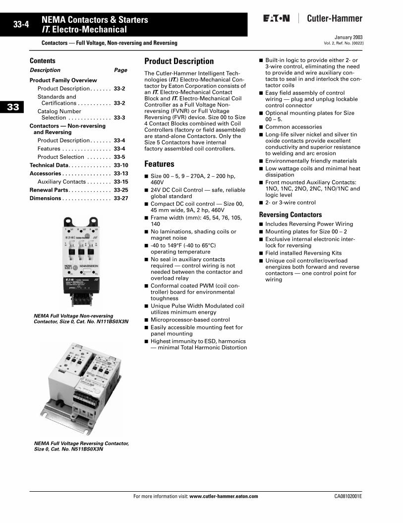
NEMA Full Voltage Reversing Contactor, Size 0, Cat. No. N511BS0X3N
NEMA Full Voltage Non-reversing Contactor, Size 0, Cat. No. N111BS0X3N
CA08102001E
CA08102001E For more
-5
33NEMA Contactors & StartersIT. Electro-Mechanical Contactors — Full Voltage, Non-reversing and ReversingJanuary 2003Vol. 2, Ref. No. [0023]
33
Product Selection
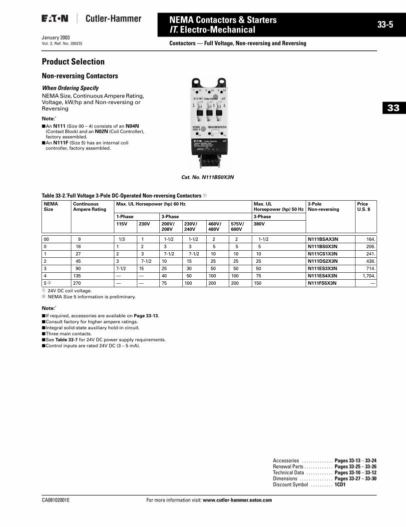
Non-reversing Contactors
When Ordering SpecifyNEMA Size, Continuous Ampere Rating, Voltage, kW/hp and Non-reversing or Reversing
Note:
■ An N111 (Size 00 – 4) consists of an N04N (Contact Block) and an N02N (Coil Controller), factory assembled.
■ An N111F (Size 5) has an internal coil controller, factory assembled.
Table 33-2. Full Voltage 3-Pole DC-Operated Non-reversing Contactors 1
1 24V DC coil voltage. 2 NEMA Size 5 information is preliminary.
Note:
■ If required, accessories are available on Page 33-13.■ Consult factory for higher ampere ratings.■ Integral solid-state auxiliary hold-in circuit.■ Three main contacts.■ See Table 33-7 for 24V DC power supply requirements.■ Control inputs are rated 24V DC (3 – 5 mA).
Cat. No. N111BS0X3N
NEMASize
Continuous Ampere Rating
Max. UL Horsepower (hp) 60 Hz Max. UL Horsepower (hp) 50 Hz
3-Pole Non-reversing
Price U.S. $
1-Phase 3-Phase 3-Phase
115V 230V 200V/208V
230V/240V
460V/480V
575V/600V
380V
00 9 1/3 1 1-1/2 1-1/2 2 2 1-1/2 N111BSAX3N 164.
0 18 1 2 3 3 5 5 5 N111BS0X3N 206.
1 27 2 3 7-1/2 7-1/2 10 10 10 N111CS1X3N 241.
2 45 3 7-1/2 10 15 25 25 25 N111DS2X3N 438.
3 90 7-1/2 15 25 30 50 50 50 N111ES3X3N 714.
4 135 — — 40 50 100 100 75 N111ES4X3N 1,704.
5 2 270 — — 75 100 200 200 150 N111FS5X3N —
Accessories . . . . . . . . . . . . . . Pages 33-13 – 33-24Renewal Parts . . . . . . . . . . . . . Pages 33-25 – 33-26Technical Data . . . . . . . . . . . . Pages 33-10 – 33-12Dimensions . . . . . . . . . . . . . . . Pages 33-27 – 33-30Discount Symbol . . . . . . . . . . 1CD1
information visit: www.cutler-hammer.eaton.com
33-6
33
NEMA Contactors & StartersIT. Electro-Mechanical
Contactors — Full Voltage, Non-reversing and ReversingFor more information visit: www.cutler-hammer.eaton.com
January 2003Vol. 2, Ref. No. [0024]
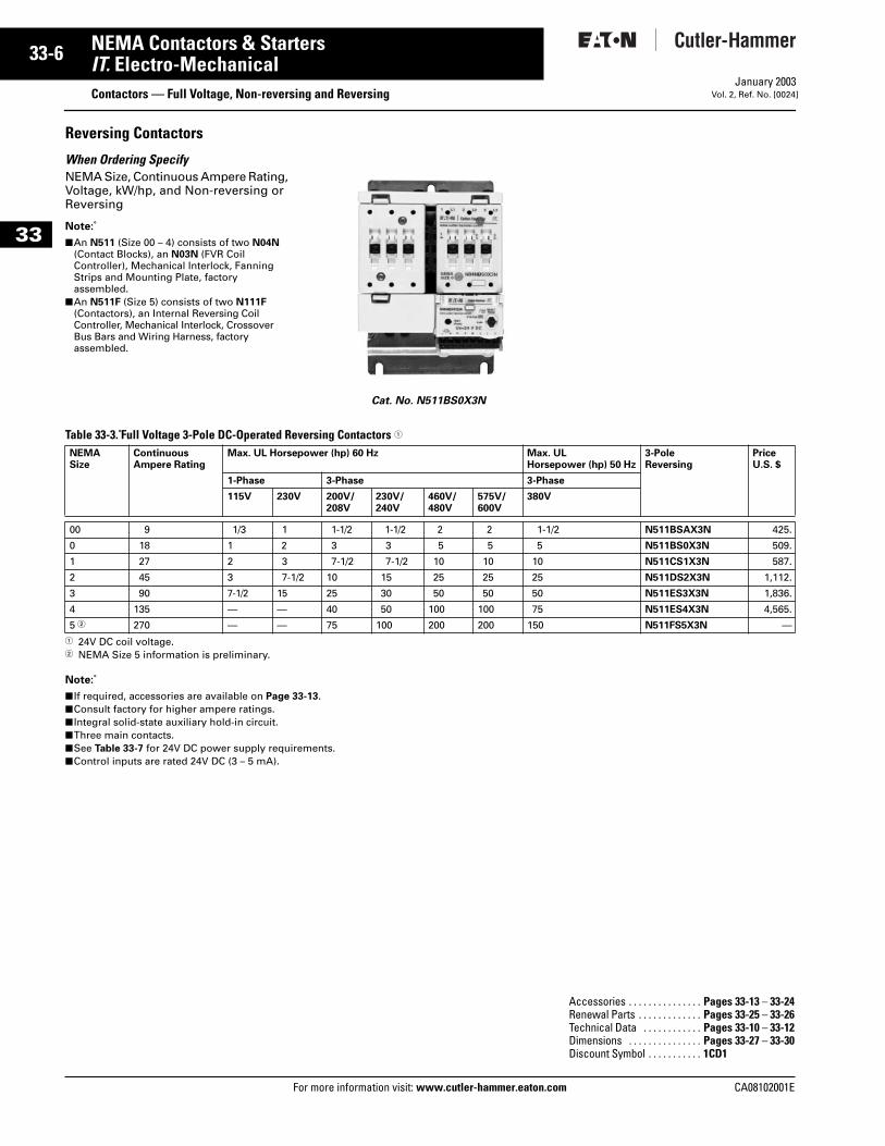
Reversing Contactors
When Ordering SpecifyNEMA Size, Continuous Ampere Rating, Voltage, kW/hp, and Non-reversing or Reversing
Note:
■ An N511 (Size 00 – 4) consists of two N04N (Contact Blocks), an N03N (FVR Coil Controller), Mechanical Interlock, Fanning Strips and Mounting Plate, factory assembled.
■ An N511F (Size 5) consists of two N111F (Contactors), an Internal Reversing Coil Controller, Mechanical Interlock, Crossover Bus Bars and Wiring Harness, factory assembled.
Table 33-3. Full Voltage 3-Pole DC-Operated Reversing Contactors 1
1 24V DC coil voltage. 2 NEMA Size 5 information is preliminary.
Note:
■ If required, accessories are available on Page 33-13.■ Consult factory for higher ampere ratings.■ Integral solid-state auxiliary hold-in circuit.■ Three main contacts.■ See Table 33-7 for 24V DC power supply requirements.■ Control inputs are rated 24V DC (3 – 5 mA).
Cat. No. N511BS0X3N
NEMASize
Continuous Ampere Rating
Max. UL Horsepower (hp) 60 Hz Max. UL Horsepower (hp) 50 Hz
3-Pole Reversing
Price U.S. $
1-Phase 3-Phase 3-Phase
115V 230V 200V/208V
230V/240V
460V/480V
575V/600V
380V
00 9 1/3 1 1-1/2 1-1/2 2 2 1-1/2 N511BSAX3N 425.
0 18 1 2 3 3 5 5 5 N511BS0X3N 509.
1 27 2 3 7-1/2 7-1/2 10 10 10 N511CS1X3N 587.
2 45 3 7-1/2 10 15 25 25 25 N511DS2X3N 1,112.
3 90 7-1/2 15 25 30 50 50 50 N511ES3X3N 1,836.
4 135 — — 40 50 100 100 75 N511ES4X3N 4,565.
5 2 270 — — 75 100 200 200 150 N511FS5X3N —
Accessories . . . . . . . . . . . . . . . Pages 33-13 – 33-24Renewal Parts . . . . . . . . . . . . . Pages 33-25 – 33-26Technical Data . . . . . . . . . . . . Pages 33-10 – 33-12Dimensions . . . . . . . . . . . . . . . Pages 33-27 – 33-30Discount Symbol . . . . . . . . . . . 1CD1
CA08102001E
CA08102001E For more
-7
33NEMA Contactors & StartersIT. Electro-Mechanical Starters — Full Voltage, Non-reversing and ReversingJanuary 2003Vol. 2, Ref. No. [0025]
33
ContentsDescription Page
Product Family Overview
Product Description . . . . . . 33-2
Standards andCertifications . . . . . . . . . . 33-2
Catalog NumberSelection . . . . . . . . . . . . . 33-3
Starters — Non-reversingand Reversing
Product Description . . . . . . 33-7
Features . . . . . . . . . . . . . . . 33-7
Product Selection. . . . . . . . 33-8
Technical Data . . . . . . . . . . . . . 33-10
Accessories . . . . . . . . . . . . . . . 33-13
Auxiliary Contacts . . . . . . . 33-15
Renewal Parts . . . . . . . . . . . . . 33-25
Dimensions . . . . . . . . . . . . . . . 33-31
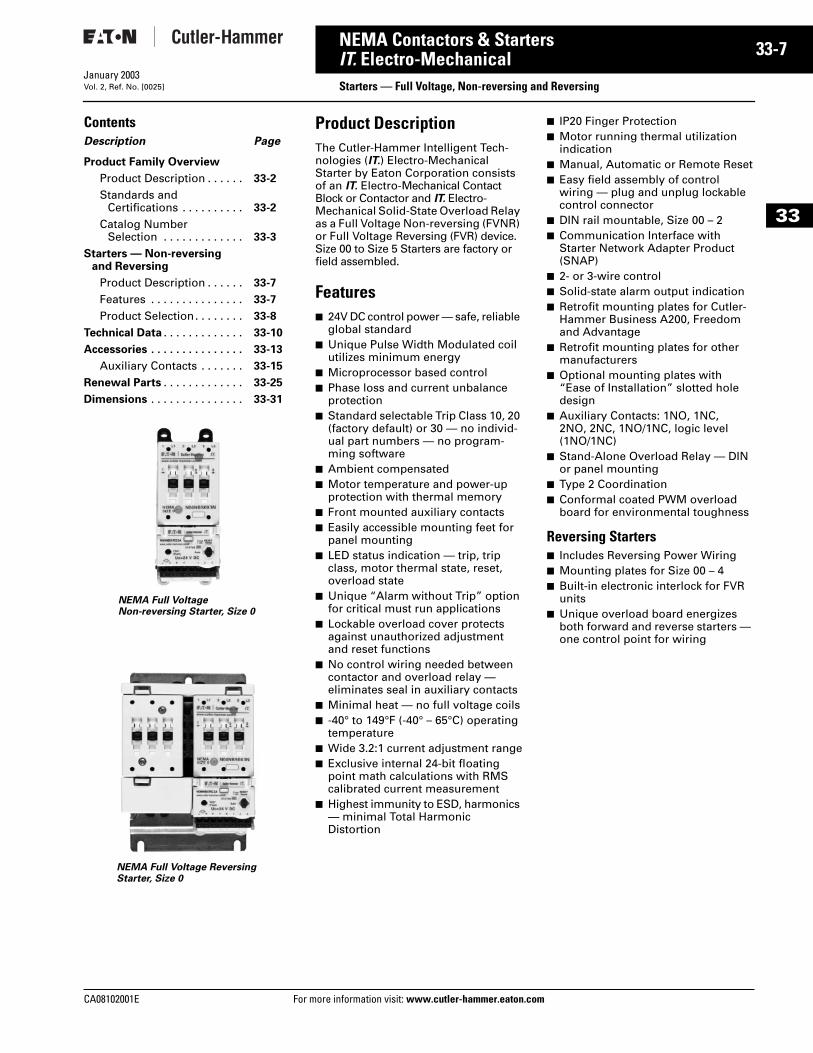
Product DescriptionThe Cutler-Hammer Intelligent Tech-nologies (IT.) Electro-Mechanical Starter by Eaton Corporation consists of an IT. Electro-Mechanical Contact Block or Contactor and IT. Electro-Mechanical Solid-State Overload Relay as a Full Voltage Non-reversing (FVNR) or Full Voltage Reversing (FVR) device. Size 00 to Size 5 Starters are factory or field assembled.
Features■ 24V DC control power — safe, reliable
global standard■ Unique Pulse Width Modulated coil
utilizes minimum energy■ Microprocessor based control■ Phase loss and current unbalance
protection■ Standard selectable Trip Class 10, 20
(factory default) or 30 — no individ-ual part numbers — no program-ming software
■ Ambient compensated■ Motor temperature and power-up
protection with thermal memory■ Front mounted auxiliary contacts■ Easily accessible mounting feet for
panel mounting■ LED status indication — trip, trip
class, motor thermal state, reset, overload state
■ Unique “Alarm without Trip” option for critical must run applications
■ Lockable overload cover protects against unauthorized adjustment and reset functions
■ No control wiring needed between contactor and overload relay — eliminates seal in auxiliary contacts
■ Minimal heat — no full voltage coils■ -40° to 149°F (-40° – 65°C) operating
temperature■ Wide 3.2:1 current adjustment range■ Exclusive internal 24-bit floating
point math calculations with RMS calibrated current measurement
■ Highest immunity to ESD, harmonics — minimal Total Harmonic Distortion
■ IP20 Finger Protection■ Motor running thermal utilization
indication■ Manual, Automatic or Remote Reset■ Easy field assembly of control
wiring — plug and unplug lockable control connector
■ DIN rail mountable, Size 00 – 2■ Communication Interface with
Starter Network Adapter Product (SNAP)
■ 2- or 3-wire control■ Solid-state alarm output indication■ Retrofit mounting plates for Cutler-
Hammer Business A200, Freedom and Advantage
■ Retrofit mounting plates for other manufacturers
■ Optional mounting plates with “Ease of Installation” slotted hole design
■ Auxiliary Contacts: 1NO, 1NC, 2NO, 2NC, 1NO/1NC, logic level (1NO/1NC)
■ Stand-Alone Overload Relay — DIN or panel mounting
■ Type 2 Coordination■ Conformal coated PWM overload
board for environmental toughness
Reversing Starters■ Includes Reversing Power Wiring■ Mounting plates for Size 00 – 4■ Built-in electronic interlock for FVR
units■ Unique overload board energizes
both forward and reverse starters — one control point for wiring
NEMA Full Voltage Non-reversing Starter, Size 0
NEMA Full Voltage Reversing Starter, Size 0
information visit: www.cutler-hammer.eaton.com
33-8
33
NEMA Contactors & StartersIT. Electro-Mechanical
Starters — Full Voltage, Non-reversing and ReversingFor more information visit: www.cutler-hammer.eaton.com
January 2003Vol. 2, Ref. No. [0026]
Product Selection
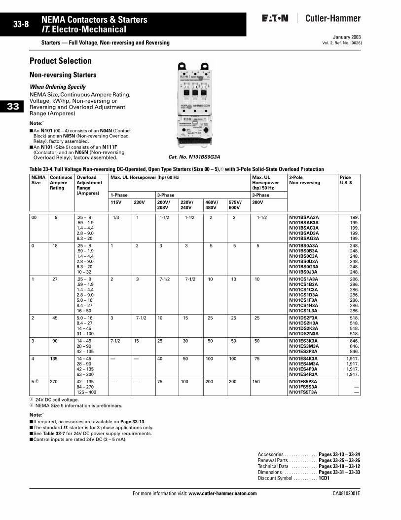
Non-reversing Starters
When Ordering SpecifyNEMA Size, Continuous Ampere Rating, Voltage, kW/hp, Non-reversing or Reversing and Overload Adjustment Range (Amperes)
Note:
■ An N101 (00 – 4) consists of an N04N (Contact Block) and an N05N (Non-reversing Overload Relay), factory assembled.
■ An N101 (Size 5) consists of an N111F (Contactor) and an N05N (Non-reversing Overload Relay), factory assembled.
Table 33-4. Full Voltage Non-reversing DC-Operated, Open Type Starters (Size 00 – 5),1 with 3-Pole Solid-State Overload Protection
1 24V DC coil voltage. 2 NEMA Size 5 information is preliminary.
Note:
■ If required, accessories are available on Page 33-13.■ The standard IT. starter is for 3-phase applications only.■ See Table 33-7 for 24V DC power supply requirements.■ Control inputs are rated 24V DC (3 – 5 mA).
Cat. No. N101BS0G3A
NEMASize
ContinuosAmpereRating
OverloadAdjustmentRange(Amperes)
Max. UL Horsepower (hp) 60 Hz Max. UL Horsepower(hp) 50 Hz
3-Pole Non-reversing
PriceU.S. $
1-Phase 3-Phase 3-Phase
115V 230V 200V/208V
230V/240V
460V/480V
575V/600V
380V
00 9 .25 – .8.59 – 1.91.4 – 4.42.8 – 9.06.3 – 20
1/3 1 1-1/2 1-1/2 2 2 1-1/2 N101BSAA3AN101BSAB3AN101BSAC3AN101BSAD3AN101BSAG3A
199.199.199.199.199.
0 18 .25 – .8.59 – 1.91.4 – 4.42.8 – 9.06.3 – 2010 – 32
1 2 3 3 5 5 5 N101BS0A3AN101BS0B3AN101BS0C3AN101BS0D3AN101BS0G3AN101BS0J3A
248.248.248.248.248.248.
1 27 .25 – .8.59 – 1.91.4 – 4.42.8 – 9.05.0 – 168.4 – 2716 – 50
2 3 7-1/2 7-1/2 10 10 10 N101CS1A3AN101CS1B3AN101CS1C3AN101CS1D3AN101CS1F3AN101CS1H3AN101CS1L3A
286.286.286.286.286.286.286.
2 45 5.0 – 168.4 – 2714 – 4531 – 100
3 7-1/2 10 15 25 25 25 N101DS2F3AN101DS2H3AN101DS2K3AN101DS2N3A
518.518.518.518.
3 90 14 – 4528 – 9042 – 135
7-1/2 15 25 30 50 50 50 N101ES3K3AN101ES3M3AN101ES3P3A
846.846.846.
4 135 14 – 4528 – 9042 – 13563 – 200
— — 40 50 100 100 75 N101ES4K3AN101ES4M3AN101ES4P3AN101ES4R3A
1,917.1,917.1,917.1,917.
5 2 270 42 – 13584 – 270125 – 400
— — 75 100 200 200 150 N101FS5P3AN101FS5S3AN101FS5T3A
———
Accessories . . . . . . . . . . . . . . . Pages 33-13 – 33-24Renewal Parts . . . . . . . . . . . . . Pages 33-25 – 33-26Technical Data . . . . . . . . . . . . Pages 33-10 – 33-12Dimensions . . . . . . . . . . . . . . . Pages 33-31 – 33-33Discount Symbol . . . . . . . . . . . 1CD1
CA08102001E
CA08102001E For more
-9
33NEMA Contactors & StartersIT. Electro-Mechanical Starters — Full Voltage, Non-reversing and ReversingJanuary 2003Vol. 2, Ref. No. [0027]
33
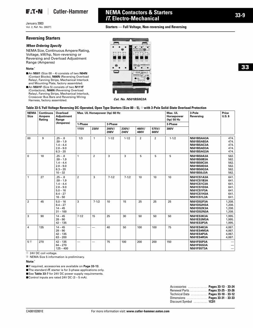
Reversing Starters
When Ordering SpecifyNEMA Size, Continuous Ampere Rating, Voltage, kW/hp, Non-reversing or Reversing and Overload Adjustment Range (Amperes)
Note:
■ An N501 (Size 00 – 4) consists of two N04N (Contact Blocks), N06N (Reversing Overload Relay), Fanning Strips, Mechanical Interlock and Mounting Plate, factory assembled.
■ An N501F (Size 5) consists of two N111F (Contactors), N06N (Reversing Overload Relay), Fanning Strips, Mechanical Interlock, Crossover Bus Bars and Reversing Wiring Harness, factory assembled.
Table 33-5. Full Voltage Reversing DC-Operated, Open Type Starters (Size 00 – 5), 1 with 3-Pole Solid-State Overload Protection
1 24V DC coil voltage.2 NEMA Size 5 information is preliminary.
Note:
■ If required, accessories are available on Page 33-13.■ The standard IT. starter is for 3-phase applications only.■ See Table 33-7 for 24V DC power supply requirements.■ Control inputs are rated 24V DC (3 – 5 mA).
Cat. No. N501BS0G3A
NEMASize
ContinuosAmpereRating
OverloadAdjustmentRange(Amperes)
Max. UL Horsepower (hp) 60 Hz Max. UL Horsepower (hp) 50 Hz
3-Pole Reversing
PriceU.S. $
1-Phase 3-Phase 3-Phase
115V 230V 200V/208V
230V/240V
460V/480V
575V/600V
380V
00 9 .25 – .8.59 – 1.91.4 – 4.42.8 – 9.06.3 – 20
1/3 1 1-1/2 1-1/2 2 2 1-1/2 N501BSAA3AN501BSAB3AN501BSAC3AN501BSAD3AN501BSAG3A
474.474.474.474.474.
0 18 .25 – .8.59 – 1.91.4 – 4.42.8 – 9.06.3 – 2010 – 32
1 2 3 3 5 5 5 N501BS0A3AN501BS0B3AN501BS0C3AN501BS0D3AN501BS0G3AN501BS0J3A
562.562.562.562.562.562.
1 27 .25 – .8.59 – 1.91.4 – 4.42.8 – 9.05.0 – 168.4 – 2716 – 50
2 3 7-1/2 7-1/2 10 10 10 N501CS1A3AN501CS1B3AN501CS1C3AN501CS1D3AN501CS1F3AN501CS1H3AN501CS1L3A
641.641.641.641.641.641.641.
2 45 5.0 – 168.4 – 2714 – 4531 – 100
3 7-1/2 10 15 25 25 25 N501DS2F3AN501DS2H3AN501DS2K3AN501DS2N3A
1,208.1,208.1,208.1,208.
3 90 14 – 4528 – 9042 – 135
7-1/2 15 25 30 50 50 50 N501ES3K3AN501ES3M3AN501ES3P3A
1,995.1,995.1,995.
4 135 14 – 4528 – 9042 – 13563 – 200
— — 40 50 100 100 75 N501ES4K3AN501ES4M3AN501ES4P3AN501ES4R3A
4,867.4,867.4,867.4,867.
5 2 270 42 – 13584 – 270125 – 400
— — 75 100 200 200 150 N501FS5P3AN501FS5S3AN501FS5T3A
———
Accessories . . . . . . . . . . . . . . Pages 33-13 – 33-24Renewal Parts . . . . . . . . . . . . . Pages 33-25 – 33-26Technical Data . . . . . . . . . . . . Pages 33-10 – 33-12Dimensions . . . . . . . . . . . . . . . Pages 33-31 – 33-33Discount Symbol . . . . . . . . . . 1CD1
information visit: www.cutler-hammer.eaton.com
33-10
33
NEMA Contactors & StartersIT. Electro-Mechanical
Technical Data and SpecificationsFor more information visit: www.cutler-hammer.eaton.com
January 2003Vol. 2, Ref. No. [0028]
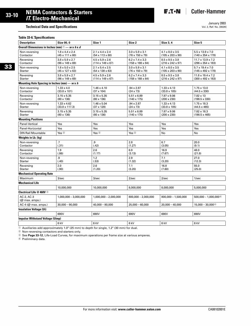
Table 33-6. Specifications
1 Auxiliaries add approximately 1.0" (25 mm) to depth for single, 1.2" (30 mm) for dual. 2 Non-reversing contactors and starters only.3 See Page 33-12, Life-Load Curves, for maximum operations per frame size at various amperes.4 Preliminary data.
Description Size 00, 0 Size 1 Size 2 Size 3, 4 Size 5
Overall Dimensions in Inches (mm) 1 — w x h x dNon-reversing Contactor
1.8 x 4.4 x 2.4(45 x 111 x 60)
2.1 x 4.4 x 2.4(54 x 113 x 60)
3.0 x 5.9 x 3.1(76 x 150 x 79)
4.1 x 8.0 x 3.5(105 x 203 x 90)
5.5 x 13.9 x 7.0(140 x 354 x 178)
Reversing Contactor
3.8 x 5.9 x 2.7(96 x 149 x 69)
4.5 x 5.9 x 2.6(114 x 149 x 67)
6.2 x 7.4 x 3.3(158 x 188 x 84)
8.5 x 9.5 x 3.8(216 x 242 x 97)
11.7 x 13.9 x 7.2(296 x 354 x 183)
Non-reversing Starter
1.8 x 5.0 x 2.5(45 x 127 x 63)
2.1 x 5.4 x 2.5(54 x 138 x 63)
3.0 x 5.9 x 3.1(76 x 150 x 79)
4.1 x 8.0 x 3.5(105 x 203 x 90)
5.7 x 19.4 x 7.0(145 x 492 x 178)
Reversing Starter
3.8 x 5.9 x 2.7(96 x 149 x 69)
4.5 x 5.9 x 2.6(114 x 149 x 67)
6.2 x 7.4 x 3.3(158 x 188 x 84)
8.5 x 9.5 x 3.8(216 x 242 x 97)
11.8 x 19.4 x 7.2(300 x 492 x 183)
Mounting Hole Spacing in Inches (mm) — w x h Non-reversing Contactor
1.33 x 4.0 (33.8 x 101)
1.46 x 4.10(37 x 104)
.94 x 2.87 (24 x 73)
1.33 x 4.13 (33.8 x 10⁵)
1.75 x 13.0(44.5 x 330)
Reversing Contactor
3.15 x 5.35(80 x 136)
3.15 x 5.35 (80 x 136)
5.51 x 6.89 (140 x 175)
7.87 x 9.06 (200 x 230)
7.82 x 13(198.5 x 330)
Non-reversing Starter
1.33 x 4.62 (33.8 x 117.3)
1.46 x 5.04 (37 x 128)
.94 x 2.87 (24 x 73)
1.33 x 4.13 (33.8 x 10⁵)
1.75 x 18.3(44.5 x 465)
Reversing Starter
3.15 x 5.35 (80 x 136)
3.15 x 5.35 (80 x 136)
5.51 x 6.89 (140 x 175)
7.87 x 9.06 (200 x 230)
7.82 x 18.3(198.5 x 465)
Mounting PositionsPanel-Vertical Yes Yes Yes Yes Yes
Panel-Horizontal Yes Yes Yes Yes Yes
DIN Rail Mountable Yes 2 Yes 2 Yes 2 No No
Weights in Lb. (kg)Non-reversing Contactor
.7(.31)
.9(.42)
2.8(1.27)
6.7(3.05)
20.0 (9.1)
Reversing Contactor
1.9(.86)
2.6(1.17)
6.9(3.13)
16.9(7.67)
48.0 (21.8)
Non-reversing Starter
.9(.40)
1.2(.53)
2.9(1.32)
7.1(3.20)
27.0 (12.3)
Reversing Starter
2.0(.90)
2.6(1.20)
7.1(3.20)
16.8(7.60)
55.0(25.0)
Mechanical Operating RateMaximum 3/sec 3/sec 2/sec 2/sec 1/sec
Mechanical Life10,000,000 10,000,000 8,000,000 8,000,000 5,000,000
Electrical Life @ 460V 3 AC-2, AC-3 (@ max. amps.)
1,000,000 – 3,000,000 1,000,000 – 2,000,000 800,000 – 2,000,000 800,000 – 1,500,000 500,000 – 1,000,0004
AC-4 (@ max. amps.) 30,000 – 90,000 40,000 – 80,000 25,000 – 60,000 20,000 – 40,000 15,000 – 30,0004
Insulation Voltage (Ui)690V 690V 690V 690V 690V
Impulse Withstand Voltage (Uimp)6 kV 6 kV 6 kV 6 kV 6 kV
CA08102001E
CA08102001E For more
11
33-NEMA Contactors & StartersIT. Electro-Mechanical Technical Data and SpecificationsJanuary 2003Vol. 2, Ref. No. [0029]
33
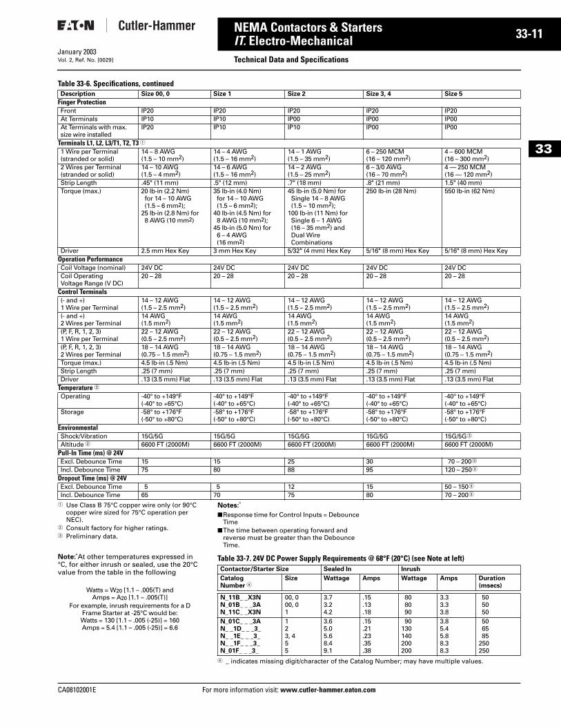
Table 33-6. Specifications, continued
1 Use Class B 75°C copper wire only (or 90°C copper wire sized for 75°C operation per NEC).
2 Consult factory for higher ratings.3 Preliminary data.
Note: At other temperatures expressed in °C, for either inrush or sealed, use the 20°Cvalue from the table in the following
Description Size 00, 0
Finger ProtectionFront IP20At Terminals IP10At Terminals with max. size wire installed
IP20
Terminals L1, L2, L3/T1, T2, T3 11 Wire per Terminal(stranded or solid)
14 – 8 AWG(1.5 – 10 mm2)
2 Wires per Terminal(stranded or solid)
14 – 10 AWG(1.5 – 4 mm2)
Strip Length .45" (11 mm)Torque (max.) 20 lb-in (2.2 Nm)
for 14 – 10 AWG(1.5 – 6 mm2);
25 lb-in (2.8 Nm) for8 AWG (10 mm2)
Driver 2.5 mm Hex KeyOperation PerformanceCoil Voltage (nominal) 24V DCCoil Operating Voltage Range (V DC)
20 – 28
Control Terminals(- and +)1 Wire per Terminal
14 – 12 AWG(1.5 – 2.5 mm2)
(- and +)2 Wires per Terminal
14 AWG(1.5 mm2)
(P, F, R, 1, 2, 3)1 Wire per Terminal
22 – 12 AWG(0.5 – 2.5 mm2)
(P, F, R, 1, 2, 3)2 Wires per Terminal
18 – 14 AWG(0.75 – 1.5 mm2)
Torque (max.) 4.5 lb-in (.5 Nm)Strip Length .25 (7 mm)Driver .13 (3.5 mm) Flat
Temperature 2Operating -40° to +149°F
(-40° to +65°C)Storage -58° to +176°F
(-50° to +80°C)EnvironmentalShock/Vibration 15G/5GAltitude 2 6600 FT (2000M)
Pull-In Time (ms) @ 24VExcl. Debounce Time 15Incl. Debounce Time 75
Dropout Time (ms) @ 24VExcl. Debounce Time 5Incl. Debounce Time 65
Watts = W20 [1.1 – .005(T) and Amps = A20 [1.1 – .005(T)]
For example, inrush requirements for a D Frame Starter at -25°C would be:Watts = 130 [1.1 – .005 (-25)] = 160Amps = 5.4 [1.1 – .005 (-25)] = 6.6
Size 1 Size 2 Size 3, 4 Size 5
IP20 IP20 IP20 IP20IP10 IP00 IP00 IP00IP10 IP10 IP00 IP00
14 – 4 AWG(1.5 – 16 mm2)
14 – 1 AWG(1.5 – 35 mm2)
6 – 250 MCM(16 – 120 mm2)
4 – 600 MCM(16 – 300 mm2)
14 – 6 AWG(1.5 – 16 mm2)
14 – 2 AWG(1.5 – 25 mm2)
6 – 3/0 AWG(16 – 70 mm2)
4 — 250 MCM(16 — 120 mm2)
.5" (12 mm) .7" (18 mm) .8" (21 mm) 1.5" (40 mm)35 lb-in (4.0 Nm)for 14 – 10 AWG(1.5 – 6 mm2);
40 lb-in (4.5 Nm) for 8 AWG (10 mm2);
45 lb-in (5.0 Nm) for 6 – 4 AWG (16 mm2)
45 lb-in (5.0 Nm) for Single 14 – 8 AWG (1.5 – 10 mm2);
100 lb-in (11 Nm) for Single 6 – 1 AWG (16 – 35 mm2) andDual Wire Combinations
250 lb-in (28 Nm) 550 lb-in (62 Nm)
3 mm Hex Key 5/32" (4 mm) Hex Key 5/16" (8 mm) Hex Key 5/16" (8 mm) Hex Key
24V DC 24V DC 24V DC 24V DC20 – 28 20 – 28 20 – 28 20 – 28
14 – 12 AWG(1.5 – 2.5 mm2)
14 – 12 AWG(1.5 – 2.5 mm2)
14 – 12 AWG(1.5 – 2.5 mm2)
14 – 12 AWG(1.5 – 2.5 mm2)
14 AWG(1.5 mm2)
14 AWG(1.5 mm2)
14 AWG(1.5 mm2)
14 AWG(1.5 mm2)
22 – 12 AWG(0.5 – 2.5 mm2)
22 – 12 AWG(0.5 – 2.5 mm2)
22 – 12 AWG(0.5 – 2.5 mm2)
22 – 12 AWG(0.5 – 2.5 mm2)
18 – 14 AWG(0.75 – 1.5 mm2)
18 – 14 AWG(0.75 – 1.5 mm2)
18 – 14 AWG(0.75 – 1.5 mm2)
18 – 14 AWG(0.75 – 1.5 mm2)
4.5 lb-in (.5 Nm) 4.5 lb-in (.5 Nm) 4.5 lb-in (.5 Nm) 4.5 lb-in (.5 Nm).25 (7 mm) .25 (7 mm) .25 (7 mm) .25 (7 mm).13 (3.5 mm) Flat .13 (3.5 mm) Flat .13 (3.5 mm) Flat .13 (3.5 mm) Flat
-40° to +149°F(-40° to +65°C)
-40° to +149°F(-40° to +65°C)
-40° to +149°F(-40° to +65°C)
-40° to +149°F(-40° to +65°C)
-58° to +176°F(-50° to +80°C)
-58° to +176°F(-50° to +80°C)
-58° to +176°F(-50° to +80°C)
-58° to +176°F(-50° to +80°C)
15G/5G 15G/5G 15G/5G 15G/5G3
6600 FT (2000M) 6600 FT (2000M) 6600 FT (2000M) 6600 FT (2000M)
15 25 30 70 – 2003
80 88 95 120 – 2503
5 12 15 50 – 1503
70 75 80 70 – 2003
Notes:
■ Response time for Control Inputs = Debounce Time
■ The time between operating forward and reverse must be greater than the Debounce Time.
Table 33-7. 24V DC Power Supply Requirements @ 68°F (20°C) (see Note at left)
4 _ indicates missing digit/character of the Catalog Number; may have multiple values.
Contactor/Starter Size Sealed In Inrush
CatalogNumber 4
Size Wattage Amps Wattage Amps Duration(msecs)
N_11B_ _X3NN_01B_ _ _3AN_11C_ _X3N
00, 000, 01
3.73.24.2
.15
.13
.18
808090
3.33.33.8
505050
N_01C_ _ _3AN_ _1D_ _ _3_N_ _1E_ _ _3_N_ _1F_ _ _3_N_01F_ _ _3_
123, 455
3.65.05.68.49.1
.15
.21
.23
.35
.38
90130140200200
3.85.45.88.38.3
506585
250250
information visit: www.cutler-hammer.eaton.com
33-12
33
NEMA Contactors & StartersIT. Electro-Mechanical
Technical Data and SpecificationsFor more information visit: www.cutler-hammer.eaton.com
January 2003Vol. 2, Ref. No. [0030]
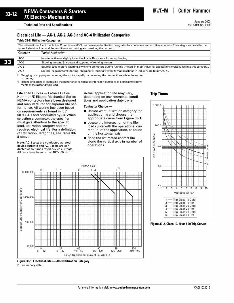
Electrical Life — AC-1, AC-2, AC-3 and AC-4 Utilization CategoriesTable 33-8. Utilization Categories
1 Plugging is stopping or reversing the motor rapidly by reversing the connections while the motor is running.
2 Inching or jogging is energizing the motor once or repeatedly for short durations to obtain small move-ments of the motor driven load.
Life Load Curves — Eaton’s Cutler-Hammer IT. Electro-Mechanical Series NEMA contactors have been designed and manufactured for superior life per-formance. All testing has been based on requirements as found in IEC 60947-4-1 and conducted by us. When selecting a contactor, the specifier must give attention to the specific load, utilization category and the required electrical life. For a definition of Utilization Categories, see Table 33-8 above.
Note: AC-3 tests are conducted at rated device currents and AC-4 tests are con-ducted at six-times rated device currents. All tests have been run at 460V, 60 Hz.
Actual application life may vary, depending on environmental condi-tions and application duty cycle.
Contactor Choice —■ Decide what utilization category the
application is and choose the appropriate curve from Figure 33-1.
■ Locate the intersection of the life-load curve with the operational cur-rent (le) of the application, as found on the horizontal axis.
■ Read the estimated contact life along the vertical axis in number of operations.
Figure 33-1. Electrical Life — AC-3 Utilization Category3 Preliminary data.
The International Electrotechnical Commission (IEC) has developed utilization categories for contactors antype of electrical load and the conditions for making and breaking the current.
Category Typical Application
AC-1 Non-inductive or slightly inductive loads: Resistance furnaces, heating.
AC-2 Slip-ring motors: Starting and stopping of running motors
AC-3 Squirrel cage motors: Starting, switching off motors during running (motors in most ind
AC-4 Squirrel cage motors: Starting, plugging 1, inching 2 (very few applications in industry
1
00 0 1 2 3 4 5
6 129
1827
32 40 50 6590100 125
135200 250
270400
Rated Operational Current (Ie) AC-3 [A]
NEMA Size
10,000,000
1,000,000
100,000
10,000
Con
tact
Life
(Num
ber
of O
pera
tions
)
45
3
d auxiliary contacts. The categories describe the
ustrial applications typically fall into this category).
are totally AC-4).
Trip Times
Figure 33-2. Class 10, 20 and 30 Trip Curves
1000.0
100.0
10.0
1.0
0.11 2 3 4 5 6 7 8 9
2
416
35
10
Trip
Tim
e (S
eco
nd
s)
Trip Class 10 ColdTrip Class 10 HotTrip Class 20 ColdTrip Class 20 HotTrip Class 30 ColdTrip Class 30 Hot
123456
Multiples of FLA
CA08102001E
CA08102001E For more
13
33-NEMA Contactors & StartersIT. Electro-Mechanical AccessoriesJanuary 2003Vol. 2, Ref. No. [0031]
33
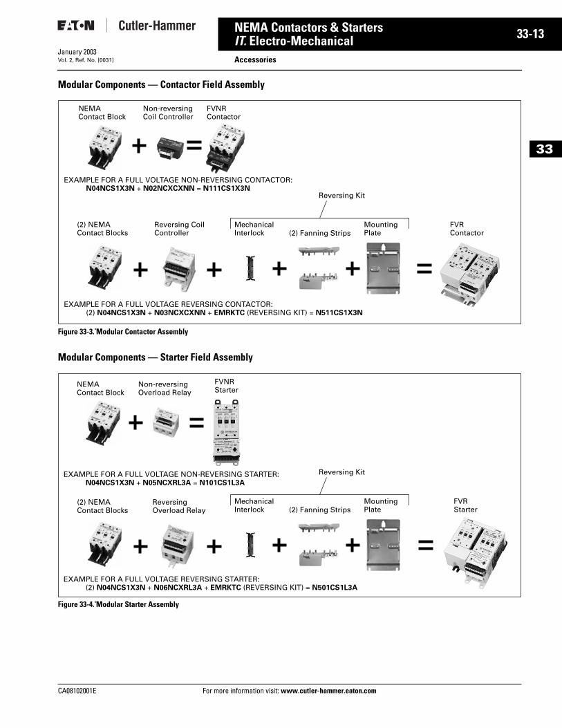
Modular Components — Contactor Field Assembly
Figure 33-3. Modular Contactor Assembly
Modular Components — Starter Field Assembly
Figure 33-4. Modular Starter Assembly
NEMA Contact Block
Non-reversingCoil Controller
FVNRContactor
EXAMPLE FOR A FULL VOLTAGE REVERSING CONTACTOR:(2) N04NCS1X3N + N03NCXCXNN + EMRKTC (REVERSING KIT) = N511CS1X3N
FVRContactor
Reversing Coil Controller
Mechanical Interlock (2) Fanning Strips
(2) NEMAContact Blocks
Mounting Plate
EXAMPLE FOR A FULL VOLTAGE NON-REVERSING CONTACTOR:N04NCS1X3N + N02NCXCXNN = N111CS1X3N
Reversing Kit
Non-reversing Overload Relay
FVNRStarter
FVRStarter
Reversing Overload Relay
EXAMPLE FOR A FULL VOLTAGE NON-REVERSING STARTER:N04NCS1X3N + N05NCXRL3A = N101CS1L3A
EXAMPLE FOR A FULL VOLTAGE REVERSING STARTER:(2) N04NCS1X3N + N06NCXRL3A + EMRKTC (REVERSING KIT) = N501CS1L3A
NEMA Contact Block
Mechanical Interlock (2) Fanning Strips
(2) NEMAContact Blocks
Mounting Plate
Reversing Kit
information visit: www.cutler-hammer.eaton.com
33-14
33
NEMA Contactors & StartersIT. Electro-Mechanical
AccessoriesFor more information visit: www.cutler-hammer.eaton.com
January 2003Vol. 2, Ref. No. [0032]
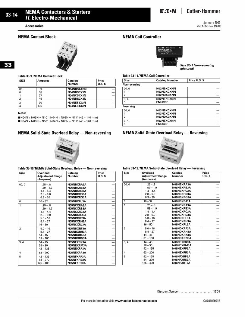
NEMA Contact Block
Table 33-9. NEMA Contact Block
Note:
■ N04N + N05N = N101; N04N + N02N = N111 (45 – 140 mm)■ N04N + N06N = N501; N04N + N03N = N511 (45 – 140 mm)
NEMA Solid-State Overload Relay — Non-reversing
Table 33-10. NEMA Solid-State Overload Relay — Non-reversing
NEMA Coil Controller
Table 33-11. NEMA Coil Controller
NEMA Solid-State Overload Relay — Reversing
Table 33-12. NEMA Solid-State Overload Relay — Reversing
SIZE Amperes CatalogNumber
PriceU.S. $
00012
9182745
N04NBSAX3NN04NBS0X3NN04NCS1X3NN04NDS2X3N
————
34
90135
N04NES3X3NN04NES4X3N
——
Size Overload Adjustment Range (Amperes)
CatalogNumber
PriceU.S. $
00, 0 .25 – .8.59 – 1.9
1.4 – 4.42.8 – 9.06.3 – 20
N05NBXRA3AN05NBXRB3AN05NBXRC3AN05NBXRD3AN05NBXRG3A
—————
0 10 – 32 N05NBXRJ3A —1 .25 – .8
.59 – 1.91.4 – 4.42.8 – 9.05.0 – 168.4 – 27
16 – 50
N05NCXRA3AN05NCXRB3AN05NCXRC3AN05NCXRD3AN05NCXRF3AN05NCXRH3AN05NCXRL3A
———————
2 5.0 – 168.4 – 27
14 – 4531 – 100
N05NDXRF3AN05NDXRH3AN05NDXRK3AN05NDXRN3A
————
3, 4 14 – 4528 – 9042 – 135
N05NEXRK3AN05NEXRM3AN05NEXRP3A
———
4 63 – 200 N05NEXRR3A —5 42 – 135
84 – 270125 – 400
N05NFXRP3AN05NFXRS3AN05NFXRT3A
———
Size Catalog Number Price U.S. $
Non-reversing00, 012
N02NBXCXNNN02NCXCXNNN02NDXCXNN
———
3, 45
N02NEXCXNNEMUCCF
——
Reversing00, 012
N03NBXCXNNN03NCXCXNNN03NDXCXNN
———
3, 45
N03NEXCXNNEMUCCF
——
Size Overload Adjustment Range (Amperes)
CatalogNumber
PriceU.S. $
00, 0 .25 – .8.59 – 1.9
1.4 – 4.42.8 – 9.06.3 – 20
N06NBXRA3AN06NBXRB3AN06NBXRC3AN06NBXRD3AN06NBXRG3A
—————
0 10 – 32 N06NBXRJ3A —1 .25 – .8
.59 – 1.91.4 – 4.42.8 – 9.05.0 – 168.4 – 27
16 – 50
N06NCXRA3AN06NCXRB3AN06NCXRC3AN06NCXRD3AN06NCXRF3AN06NCXRH3AN06NCXRL3A
———————
2 5.0 – 168.4 – 27
14 – 4531 – 100
N06NDXRF3AN06NDXRH3AN06NDXRK3AN06NDXRN3A
————
3, 4 14 – 4528 – 9042 – 135
N06NEXRK3AN06NEXRM3AN06NEXRP3A
———
4 63 – 200 N06NEXRR3A —5 42 – 135
84 – 270125 – 400
N06NFXRP3AN06NFXRS3AN06NFXRT3A
———
Discount Symbol . . . . . . . . . . . . . . . . . . . . . . . . 1CD1
Size 00-1 Non-reversing(pictured)
CA08102001E
CA08102001E For more
15
33-NEMA Contactors & StartersIT. Electro-Mechanical AccessoriesJanuary 2003Vol. 2, Ref. No. [0033]
33
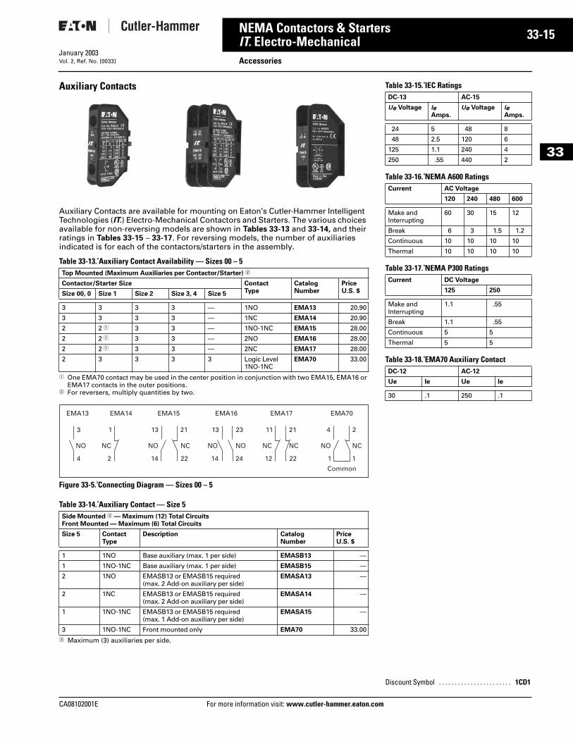
Auxiliary Contacts
Auxiliary Contacts are available for mounting on Eaton’s Cutler-Hammer Intelligent Technologies (IT.) Electro-Mechanical Contactors and Starters. The various choices available for non-reversing models are shown in Tables 33-13 and 33-14, and their ratings in Tables 33-15 – 33-17. For reversing models, the number of auxiliaries indicated is for each of the contactors/starters in the assembly.
Table 33-13. Auxiliary Contact Availability — Sizes 00 – 5
1 One EMA70 contact may be used in the center position in conjunction with two EMA15, EMA16 or EMA17 contacts in the outer positions.
2 For reversers, multiply quantities by two.
Figure 33-5. Connecting Diagram — Sizes 00 – 5
Table 33-14. Auxiliary Contact — Size 5
3 Maximum (3) auxiliaries per side.
Top Mounted (Maximum Auxiliaries per Contactor/Starter) 2
Contactor/Starter Size ContactType
Catalog Number
PriceU.S. $Size 00, 0 Size 1 Size 2 Size 3, 4 Size 5
3 3 3 3 — 1NO EMA13 20.90
3 3 3 3 — 1NC EMA14 20.90
2 2 1 3 3 — 1NO-1NC EMA15 28.00
2 2 1 3 3 — 2NO EMA16 28.00
2 2 1 3 3 — 2NC EMA17 28.00
2 3 3 3 3 Logic Level1NO-1NC
EMA70 33.00
Side Mounted 3 — Maximum (12) Total CircuitsFront Mounted — Maximum (6) Total Circuits
Size 5 ContactType
Description Catalog Number
PriceU.S. $
1 1NO Base auxiliary (max. 1 per side) EMASB13 —
1 1NO-1NC Base auxiliary (max. 1 per side) EMASB15 —
2 1NO EMASB13 or EMASB15 required (max. 2 Add-on auxiliary per side)
EMASA13 —
2 1NC EMASB13 or EMASB15 required (max. 2 Add-on auxiliary per side)
EMASA14 —
1 1NO-1NC EMASB13 or EMASB15 required (max. 1 Add-on auxiliary per side)
EMASA15 —
3 1NO-1NC Front mounted only EMA70 33.00
1
NC
2
EMA14
4
NO
1
23 21
NC
22
EMA70
13
NO
14
11
NC
12
13
NO
14
EMA15 EMA16 EMA17
3
EMA13
NO
4
2
NC
1
21
NC
22
NO
24
Common
information visit: www.cutler-hammer.eaton.co
Table 33-15. IEC Ratings
Table 33-16. NEMA A600 Ratings
Table 33-17. NEMA P300 Ratings
Table 33-18. EMA70 Auxiliary Contact
DC-13 AC-15
Ue Voltage le Amps.
Ue Voltage le Amps.
24 5 48 8
48 2.5 120 6
125 1.1 240 4
250 .55 440 2
Current AC Voltage
120 240 480 600
Make and Interrupting
60 30 15 12
Break 6 3 1.5 1.2
Continuous 10 10 10 10
Thermal 10 10 10 10
Current DC Voltage
125 250
Make and Interrupting
1.1 .55
Break 1.1 .55
Continuous 5 5
Thermal 5 5
DC-12 AC-12
Ue Ie Ue Ie
30 .1 250 .1
Discount Symbol . . . . . . . . . . . . . . . . . . . . . . . 1CD1
m
33-16
33
NEMA Contactors & StartersIT. Electro-Mechanical
AccessoriesFor more information visit: www.cutler-hammer.eaton.com
January 2003Vol. 2, Ref. No. [0034]
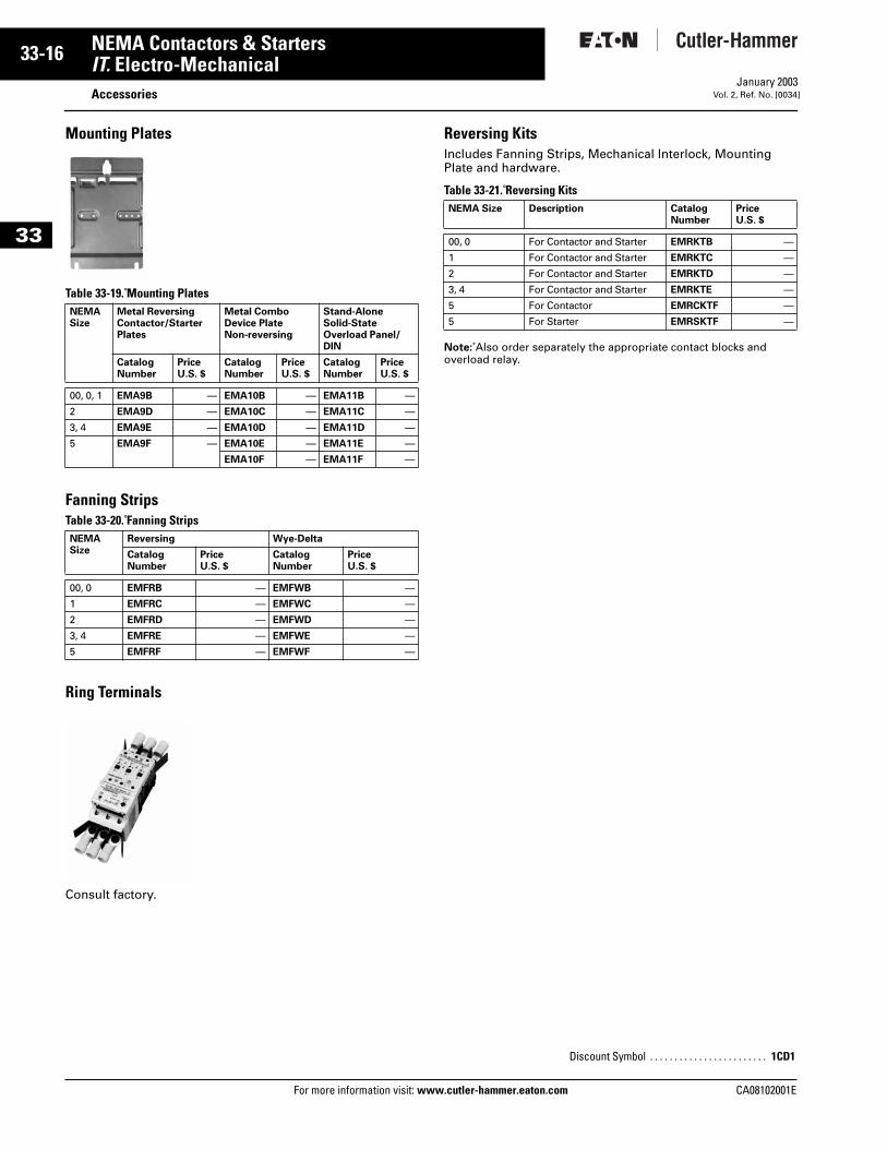
Mounting Plates
Table 33-19. Mounting Plates
Fanning StripsTable 33-20. Fanning Strips
Ring Terminals
Consult factory.
Reversing KitsIncludes Fanning Strips, Mechanical Interlock, Mounting Plate and hardware.
Table 33-21. Reversing Kits
Note: Also order separately the appropriate contact blocks and overload relay.
NEMASize
Metal ReversingContactor/StarterPlates
Metal ComboDevice PlateNon-reversing
Stand-AloneSolid-StateOverload Panel/DIN
CatalogNumber
PriceU.S. $
CatalogNumber
PriceU.S. $
CatalogNumber
PriceU.S. $
00, 0, 1 EMA9B — EMA10B — EMA11B —
2 EMA9D — EMA10C — EMA11C —
3, 4 EMA9E — EMA10D — EMA11D —
5 EMA9F — EMA10E — EMA11E —
EMA10F — EMA11F —
NEMASize
Reversing Wye-Delta
CatalogNumber
PriceU.S. $
CatalogNumber
PriceU.S. $
00, 0 EMFRB — EMFWB —
1 EMFRC — EMFWC —
2 EMFRD — EMFWD —
3, 4 EMFRE — EMFWE —
5 EMFRF — EMFWF —
NEMA Size Description CatalogNumber
PriceU.S. $
00, 0 For Contactor and Starter EMRKTB —
1 For Contactor and Starter EMRKTC —
2 For Contactor and Starter EMRKTD —
3, 4 For Contactor and Starter EMRKTE —
5 For Contactor EMRCKTF —
5 For Starter EMRSKTF —
Discount Symbol . . . . . . . . . . . . . . . . . . . . . . . . 1CD1
CA08102001E
CA08102001E For more
17
33-NEMA Contactors & StartersIT. Electro-Mechanical Accessories — DSNAPJanuary 2003Vol. 2, Ref. No. [0035]
33
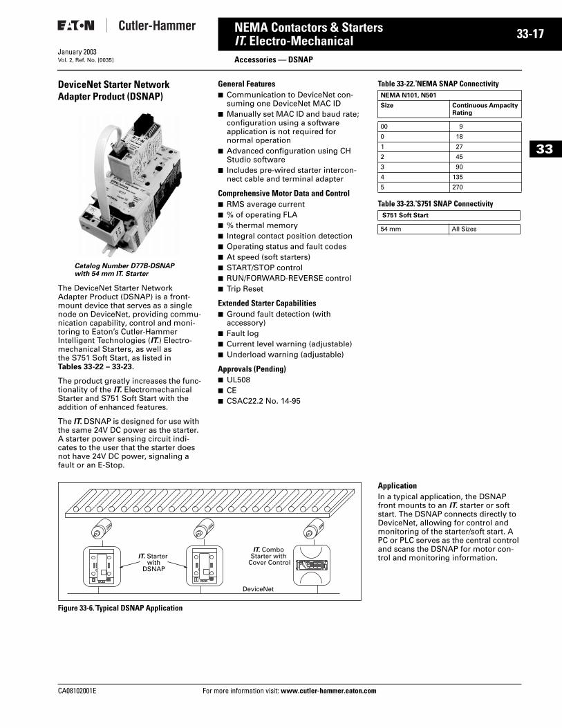
DeviceNet Starter Network Adapter Product (DSNAP)
The DeviceNet Starter Network Adapter Product (DSNAP) is a front-mount device that serves as a single node on DeviceNet, providing commu-nication capability, control and moni-toring to Eaton’s Cutler-Hammer Intelligent Technologies (IT.) Electro-mechanical Starters, as well as the S751 Soft Start, as listed in Tables 33-22 – 33-23.
The product greatly increases the func-tionality of the IT. Electromechanical Starter and S751 Soft Start with the addition of enhanced features.
The IT. DSNAP is designed for use with the same 24V DC power as the starter. A starter power sensing circuit indi-cates to the user that the starter does not have 24V DC power, signaling a fault or an E-Stop.
General Features■ Communication to DeviceNet con-
suming one DeviceNet MAC ID■ Manually set MAC ID and baud rate;
configuration using a software application is not required for normal operation
■ Advanced configuration using CH Studio software
■ Includes pre-wired starter intercon-nect cable and terminal adapter
Comprehensive Motor Data and Control■ RMS average current■ % of operating FLA■ % thermal memory■ Integral contact position detection■ Operating status and fault codes■ At speed (soft starters)■ START/STOP control■ RUN/FORWARD-REVERSE control■ Trip Reset
Extended Starter Capabilities■ Ground fault detection (with
accessory)■ Fault log■ Current level warning (adjustable)■ Underload warning (adjustable)
Approvals (Pending)■ UL508■ CE■ CSAC22.2 No. 14-95
Figure 33-6. Typical DSNAP Application
Catalog Number D77B-DSNAPwith 54 mm IT. Starter
IT. Starter with
DSNAP
IT. Combo Starter with
Cover Control
DeviceNet
information visit: www.cutler-hammer.eaton.co
Table 33-22. NEMA SNAP Connectivity
Table 33-23. S751 SNAP Connectivity
ApplicationIn a typical application, the DSNAP front mounts to an IT. starter or soft start. The DSNAP connects directly to DeviceNet, allowing for control and monitoring of the starter/soft start. A PC or PLC serves as the central control and scans the DSNAP for motor con-trol and monitoring information.
NEMA N101, N501
Size Continuous Ampacity Rating
00 9
0 18
1 27
2 45
3 90
4 135
5 270
S751 Soft Start
54 mm All Sizes
m
33-18
33
NEMA Contactors & StartersIT. Electro-Mechanical
Accessories — DSNAPFor more information visit: www.cutler-hammer.eaton.com
January 2003Vol. 2, Ref. No. [0036]
Table 33-24. DeviceNet Specifications
Table 33-25. DSNAP Specifications
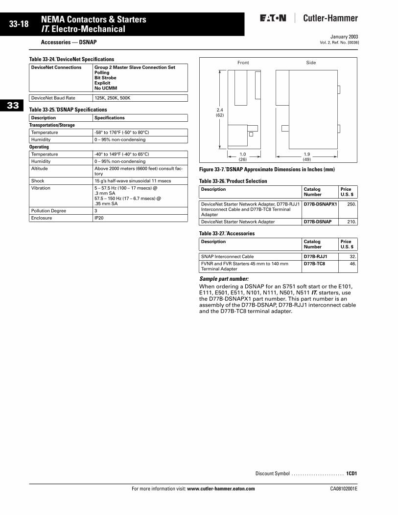
Figure 33-7. DSNAP Approximate Dimensions in Inches (mm)
Table 33-26. Product Selection
Table 33-27. Accessories
Sample part number:When ordering a DSNAP for an S751 soft start or the E101, E111, E501, E511, N101, N111, N501, N511 IT. starters, use the D77B-DSNAPX1 part number. This part number is an assembly of the D77B-DSNAP, D77B-RJJ1 interconnect cable and the D77B-TC8 terminal adapter.
DeviceNet Connections Group 2 Master Slave Connection SetPollingBit StrobeExplicitNo UCMM
DeviceNet Baud Rate 125K, 250K, 500K
Description Specifications
Transportation/StorageTemperature -58° to 176°F (-50° to 80°C)
Humidity 0 – 95% non-condensing
OperatingTemperature -40° to 149°F (-40° to 65°C)
Humidity 0 – 95% non-condensing
Altitude Above 2000 meters (6600 feet) consult fac-tory
Shock 15 g’s half-wave sinusoidal 11 msecs
Vibration 5 – 57.5 Hz (100 – 17 msecs) @ .3 mm SA57.5 – 150 Hz (17 – 6.7 msecs) @ .35 mm SA
Pollution Degree 3
Enclosure IP20
Description CatalogNumber
PriceU.S. $
DeviceNet Starter Network Adapter, D77B-RJJ1Interconnect Cable and D77B-TC8 Terminal Adapter
D77B-DSNAPX1 250.
DeviceNet Starter Network Adapter D77B-DSNAP 210.
Description CatalogNumber
PriceU.S. $
SNAP Interconnect Cable D77B-RJJ1 32.
FVNR and FVR Starters 45 mm to 140 mm Terminal Adapter
D77B-TC8 46.
Discount Symbol . . . . . . . . . . . . . . . . . . . . . . . . 1CD1
2.4(62)
1.0(26)
1.9(49)
Front Side
CA08102001E
CA08102001E For more
19
33-NEMA Contactors & StartersIT. Electro-Mechanical Accessories — QSNAPJanuary 2003Vol. 2, Ref. No. [0037]
33
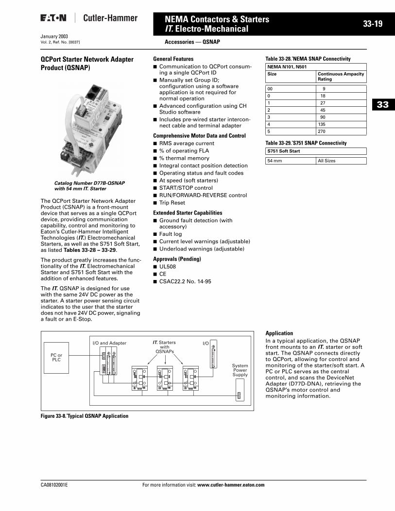
QCPort Starter Network Adapter Product (QSNAP)
The QCPort Starter Network Adapter Product (CSNAP) is a front-mount device that serves as a single QCPort device, providing communication capability, control and monitoring to Eaton’s Cutler-Hammer Intelligent Technologies (IT.) Electromechanical Starters, as well as the S751 Soft Start, as listed Tables 33-28 – 33-29.
The product greatly increases the func-tionality of the IT. Electromechanical Starter and S751 Soft Start with the addition of enhanced features.
The IT. QSNAP is designed for use with the same 24V DC power as the starter. A starter power sensing circuit indicates to the user that the starter does not have 24V DC power, signaling a fault or an E-Stop.
General Features■ Communication to QCPort consum-
ing a single QCPort ID■ Manually set Group ID;
configuration using a software application is not required for normal operation
■ Advanced configuration using CH Studio software
■ Includes pre-wired starter intercon-nect cable and terminal adapter
Comprehensive Motor Data and Control■ RMS average current■ % of operating FLA■ % thermal memory■ Integral contact position detection■ Operating status and fault codes■ At speed (soft starters)■ START/STOP control■ RUN/FORWARD-REVERSE control■ Trip Reset
Extended Starter Capabilities■ Ground fault detection (with
accessory)■ Fault log■ Current level warnings (adjustable)■ Underload warnings (adjustable)
Approvals (Pending)■ UL508■ CE■ CSAC22.2 No. 14-95
Figure 33-8. Typical QSNAP Application
Catalog Number D77B-QSNAPwith 54 mm IT. Starter
information visit: www.cutler-hammer.eaton.co
Table 33-28. NEMA SNAP Connectivity
Table 33-29. S751 SNAP Connectivity
ApplicationIn a typical application, the QSNAP front mounts to an IT. starter or soft start. The QSNAP connects directly to QCPort, allowing for control and monitoring of the starter/soft start. A PC or PLC serves as the central control, and scans the DeviceNet Adapter (D77D-DNA), retrieving the QSNAP’s motor control and monitoring information.
NEMA N101, N501
Size Continuous Ampacity Rating
00 9
0 18
1 27
2 45
3 90
4 135
5 270
S751 Soft Start
54 mm All Sizes
m
33-20
33
NEMA Contactors & StartersIT. Electro-Mechanical
Accessories — QSNAPFor more information visit: www.cutler-hammer.eaton.com
January 2003Vol. 2, Ref. No. [0038]
Table 33-30. QSNAP Specifications
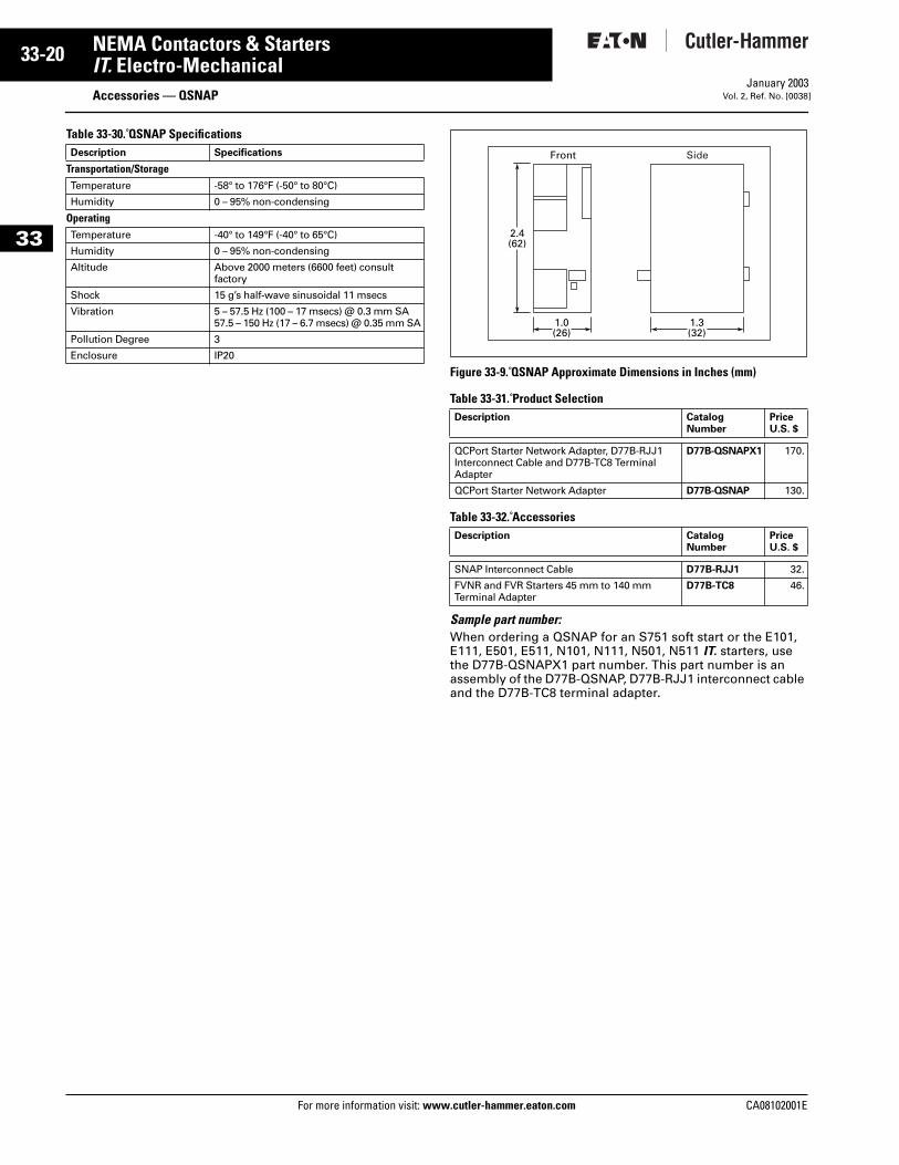
Figure 33-9. QSNAP Approximate Dimensions in Inches (mm)
Table 33-31. Product Selection
Table 33-32. Accessories
Sample part number:When ordering a QSNAP for an S751 soft start or the E101, E111, E501, E511, N101, N111, N501, N511 IT. starters, use the D77B-QSNAPX1 part number. This part number is an assembly of the D77B-QSNAP, D77B-RJJ1 interconnect cable and the D77B-TC8 terminal adapter.
Description Specifications
Transportation/StorageTemperature -58° to 176°F (-50° to 80°C)
Humidity 0 – 95% non-condensing
OperatingTemperature -40° to 149°F (-40° to 65°C)
Humidity 0 – 95% non-condensing
Altitude Above 2000 meters (6600 feet) consult factory
Shock 15 g’s half-wave sinusoidal 11 msecs
Vibration 5 – 57.5 Hz (100 – 17 msecs) @ 0.3 mm SA57.5 – 150 Hz (17 – 6.7 msecs) @ 0.35 mm SA
Pollution Degree 3
Enclosure IP20
Description CatalogNumber
PriceU.S. $
QCPort Starter Network Adapter, D77B-RJJ1 Interconnect Cable and D77B-TC8 Terminal Adapter
D77B-QSNAPX1 170.
QCPort Starter Network Adapter D77B-QSNAP 130.
Description CatalogNumber
PriceU.S. $
SNAP Interconnect Cable D77B-RJJ1 32.
FVNR and FVR Starters 45 mm to 140 mm Terminal Adapter
D77B-TC8 46.
2.4(62)
Front
1.0(26)
1.3(32)
Side
CA08102001E
CA08102001E For more
21
33-NEMA Contactors & StartersIT. Electro-Mechanical Accessories — Cover ControlJanuary 2003Vol. 2, Ref. No. [0039]
33
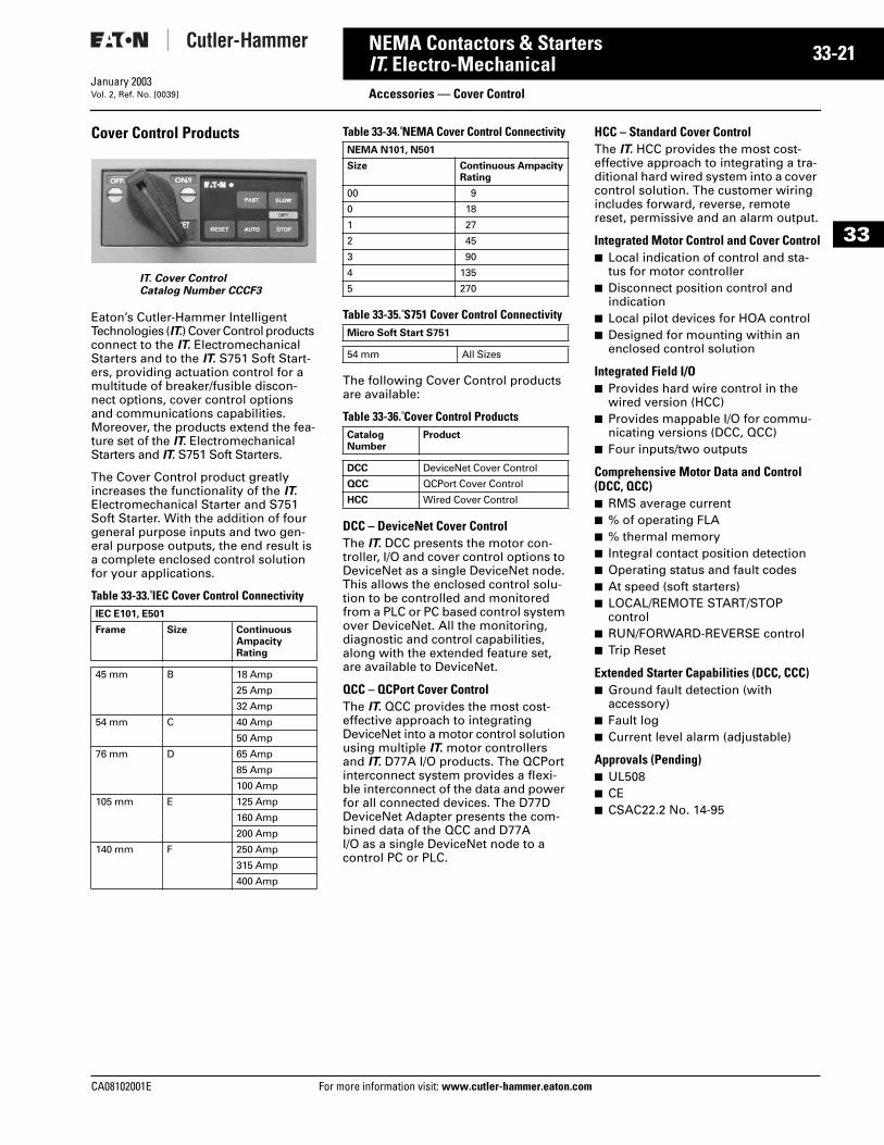
Cover Control Products
Eaton’s Cutler-Hammer Intelligent Technologies (IT.) Cover Control products connect to the IT. Electromechanical Starters and to the IT. S751 Soft Start-ers, providing actuation control for a multitude of breaker/fusible discon-nect options, cover control options and communications capabilities. Moreover, the products extend the fea-ture set of the IT. Electromechanical Starters and IT. S751 Soft Starters.
The Cover Control product greatly increases the functionality of the IT. Electromechanical Starter and S751 Soft Starter. With the addition of four general purpose inputs and two gen-eral purpose outputs, the end result is a complete enclosed control solution for your applications.
Table 33-33. IEC Cover Control Connectivity
Table 33-34. NEMA Cover Control Connectivity
Table 33-35. S751 Cover Control Connectivity
The following Cover Control products are available:
Table 33-36. Cover Control Products
DCC – DeviceNet Cover ControlThe IT. DCC presents the motor con-troller, I/O and cover control options to DeviceNet as a single DeviceNet node. This allows the enclosed control solu-tion to be controlled and monitored from a PLC or PC based control system over DeviceNet. All the monitoring, diagnostic and control capabilities, along with the extended feature set, are available to DeviceNet.
QCC – QCPort Cover ControlThe IT. QCC provides the most cost-effective approach to integrating DeviceNet into a motor control solution using multiple IT. motor controllers and IT. D77A I/O products. The QCPort interconnect system provides a flexi-ble interconnect of the data and power for all connected devices. The D77D DeviceNet Adapter presents the com-bined data of the QCC and D77A I/O as a single DeviceNet node to a control PC or PLC.
HCC – Standard Cover ControlThe IT. HCC provides the most cost-effective approach to integrating a tra-ditional hard wired system into a cover control solution. The customer wiring includes forward, reverse, remote reset, permissive and an alarm output.
Integrated Motor Control and Cover Control■ Local indication of control and sta-
tus for motor controller■ Disconnect position control and
indication■ Local pilot devices for HOA control■ Designed for mounting within an
enclosed control solution
Integrated Field I/O■ Provides hard wire control in the
wired version (HCC)■ Provides mappable I/O for commu-
nicating versions (DCC, QCC)■ Four inputs/two outputs
Comprehensive Motor Data and Control (DCC, QCC)■ RMS average current■ % of operating FLA■ % thermal memory■ Integral contact position detection■ Operating status and fault codes■ At speed (soft starters)■ LOCAL/REMOTE START/STOP
control■ RUN/FORWARD-REVERSE control■ Trip Reset
Extended Starter Capabilities (DCC, CCC)■ Ground fault detection (with
accessory)■ Fault log■ Current level alarm (adjustable)
Approvals (Pending)■ UL508■ CE■ CSAC22.2 No. 14-95
IEC E101, E501
Frame Size Continuous Ampacity Rating
45 mm B 18 Amp
25 Amp
32 Amp
54 mm C 40 Amp
50 Amp
76 mm D 65 Amp
85 Amp
100 Amp
105 mm E 125 Amp
160 Amp
200 Amp
140 mm F 250 Amp
315 Amp
400 Amp
IT. Cover ControlCatalog Number CCCF3
NEMA N101, N501
Size Continuous Ampacity Rating
00 9
0 18
1 27
2 45
3 90
4 135
5 270
Micro Soft Start S751
54 mm All Sizes
Catalog Number
Product
DCC DeviceNet Cover Control
QCC QCPort Cover Control
HCC Wired Cover Control
information visit: www.cutler-hammer.eaton.com
33-22
33
NEMA Contactors & StartersIT. Electro-Mechanical
Accessories — Cover ControlFor more information visit: www.cutler-hammer.eaton.com
January 2003Vol. 2, Ref. No. [0040]
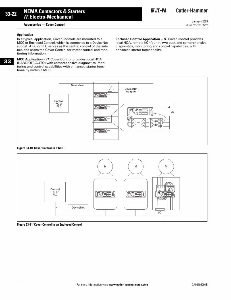
ApplicationIn a typical application, Cover Controls are mounted to a MCC or Enclosed Control, which is connected to a DeviceNet subnet. A PC or PLC serves as the central control of the sub-net, and scans the Cover Control for motor control and mon-itoring information.
MCC Application – IT. Cover Control provides local HOA (HAND/OFF/AUTO) with comprehensive diagnostics, moni-toring and control capabilities with enhanced starter func-tionality within a MCC.
Enclosed Control Application – IT. Cover Control provides local HOA, remote I/O (four in, two out), and comprehensive diagnostics, monitoring and control capabilities, with enhanced starter functionality.
Figure 33-10. Cover Control in a MCC
Figure 33-11. Cover Control in an Enclosed Control
ControlPC orPLC
DeviceNetDeviceNetAdapter
I/O
ControlPC orPLC
DeviceNet
M
I/O
M M
CA08102001E
CA08102001E For more
23
33-NEMA Contactors & StartersIT. Electro-Mechanical Accessories — Cover ControlJanuary 2003Vol. 2, Ref. No. [0041]
33
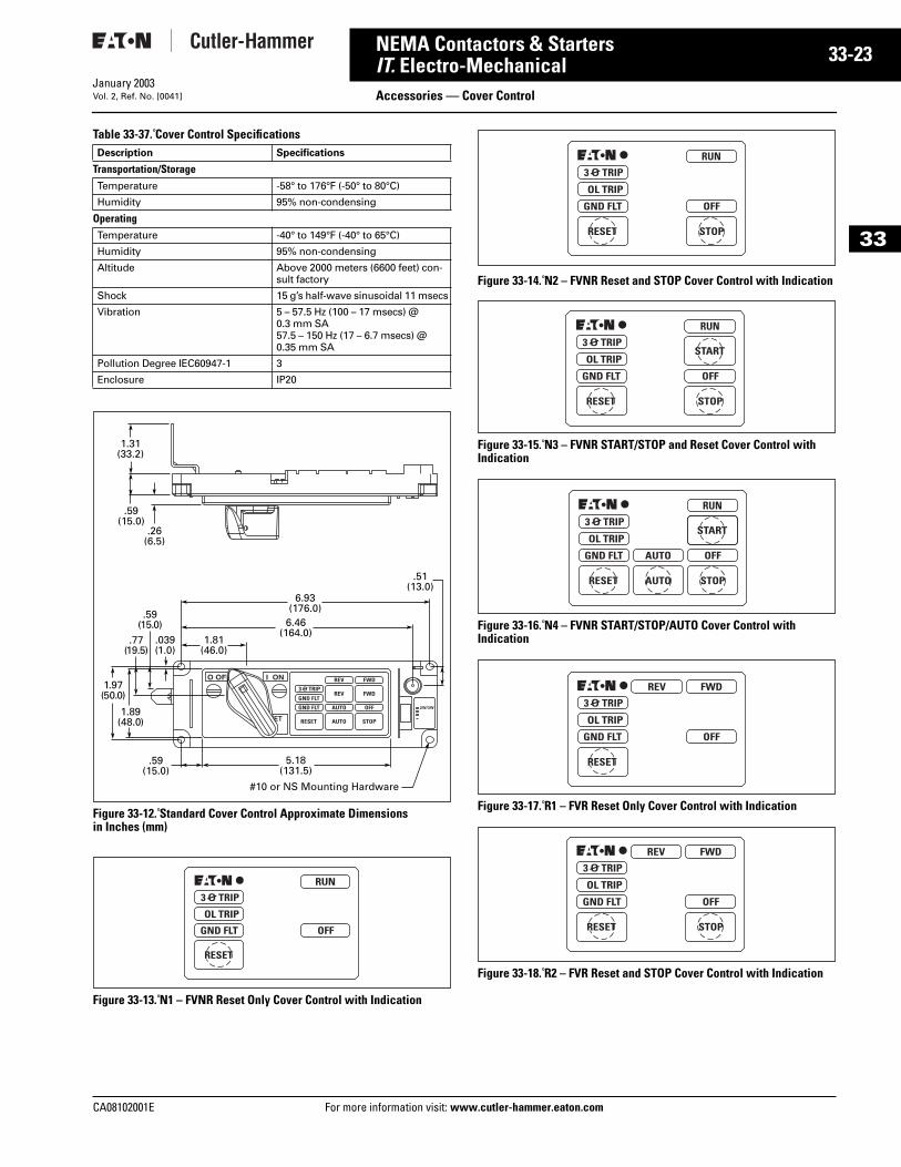
Table 33-37. Cover Control Specifications
Figure 33-12. Standard Cover Control Approximate Dimensions in Inches (mm)
Figure 33-13. N1 – FVNR Reset Only Cover Control with Indication
Figure 33-14. N2 – FVNR Reset and STOP Cover Control with Indication
Figure 33-15. N3 – FVNR START/STOP and Reset Cover Control with Indication
Figure 33-16. N4 – FVNR START/STOP/AUTO Cover Control with Indication
Figure 33-17. R1 – FVR Reset Only Cover Control with Indication
Figure 33-18. R2 – FVR Reset and STOP Cover Control with Indication
Description Specifications
Transportation/StorageTemperature -58° to 176°F (-50° to 80°C)
Humidity 95% non-condensing
OperatingTemperature -40° to 149°F (-40° to 65°C)
Humidity 95% non-condensing
Altitude Above 2000 meters (6600 feet) con-sult factory
Shock 15 g’s half-wave sinusoidal 11 msecs
Vibration 5 – 57.5 Hz (100 – 17 msecs) @ 0.3 mm SA57.5 – 150 Hz (17 – 6.7 msecs) @ 0.35 mm SA
Pollution Degree IEC60947-1 3
Enclosure IP20
.59(15.0)
1.31(33.2)
.26(6.5)
.77(19.5)
.59(15.0)
.039(1.0)
1.89(48.0)
.59(15.0)
1.97(50.0)
1.81(46.0)
6.46(164.0)
6.93(176.0)
.51(13.0)
5.18(131.5)
#10 or NS Mounting Hardware
information visit: www.cutler-hammer.eaton.com
33-24
33
NEMA Contactors & StartersIT. Electro-Mechanical
Accessories — Cover ControlFor more information visit: www.cutler-hammer.eaton.com
January 2003Vol. 2, Ref. No. [0042]
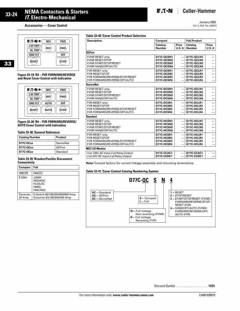
Figure 33-19. R3 – FVR FORWARD/REVERSE and Reset Cover Control with Indication
Figure 33-20. R4 – FVR FORWARD/REVERSE/AUTO Cover Control with Indication
Table 33-38. General Reference
Table 33-39. Breaker/Fusible Disconnect Connectivity
Catalog Number Product
D77C-DCxx DeviceNet
D77C-QCxx QCPort
D77C-HCxx Standard
Compact Full
HMCPE HMCPJ
E125H J250HHKD/KDCHLD/LDCHMDLHNK/NDC
Socemec32 Amp
K Switch 60/100/200/600/800 AmpSocomec 63/160/200/400 Amp
Table 33-40. Cover Control Product Selection
Note: Consult factory for correct linkage assembly and mounting dimensions.
Table 33-41. Cover Control Catalog Numbering System
Description Compact Full Product
CatalogNumber
PriceU.S. $
CatalogNumber
PriceU.S. $
QCPort FVNR RESET onlyFVNR RESET/STOPFVNR START/STOP/RESETFVNR HAND/OFF/AUTO
D77C-QCSN1D77C-QCSN2D77C-QCSN3D77C-QCSN4
————
D77C-QCLN1D77C-QCLN2D77C-QCLN3D77C-QCLN4
————
FVR RESET onlyFVR RESET/STOPFVR FORWARD/REVERSE/STOP/RESETFVR FORWARD/REVERSE/OFF/AUTO
D77C-QCSR1D77C-QCSR2D77C-QCSR3D77C-QCSR4
————
D77C-QCLR1D77C-QCLR2D77C-QCLR3D77C-QCLR4
————
DeviceNet FVNR RESET onlyFVNR RESET/STOPFVNR START/STOP/RESETFVNR HAND/OFF/AUTO
D77C-DCSN1D77C-DCSN2D77C-DCSN3D77C-DCSN4
————
D77C-DCLN1D77C-DCLN2D77C-DCLN3D77C-DCLN4
————
FVR RESET onlyFVR RESET/STOPFVR FORWARD/REVERSE/STOP/RESETFVR FORWARD/REVERSE/OFF/AUTO
D77C-DCSR1D77C-DCSR2D77C-DCSR3D77C-DCSR4
————
D77C-DCLR1D77C-DCLR2D77C-DCLR3D77C-DCLR4
————
Standard FVNR RESET onlyFVNR RESET/STOPFVNR START/STOP/RESETFVNR HAND/OFF/AUTO
D77C-HCSN1D77C-HCSN2D77C-HCSN3D77C-HCSN4
————
D77C-HCLN1D77C-HCLN2D77C-HCLN3D77C-HCLN4
————
FVR RESET onlyFVR RESET/STOPFVR FORWARD/REVERSE/STOP/RESETFVR FORWARD/REVERSE/OFF/AUTO
D77C-HCSR1D77C-HCSR2D77C-HCSR3D77C-HCSR4
————
D77C-HCLR1D77C-HCLR2D77C-HCLR3D77C-HCLR4
————
MCC I/O Module4 pt 120V AC Input 2 pt Relay Output4 pt 24V DC Input 2 pt Relay Output
D77C-CCAC1D77C-CCDC1
——
D77C-CCAC1D77C-CCDC1
——
1 = RESET2 = STOP/RESET3 = START/STOP/RESET (FVNR);
FORWARD/REVERSE/STOP/RESET (FVR)
4 = HAND/OFF/AUTO (FVNR);FORWARD/REVERSE/OFF/AUTO (FVR)
S = CompactL = Full
D77C-QC S N 4
HC = StandardQC = QCPortDC = DeviceNet
N = Full Voltage Non-reversing (FVNR)
R = Full Voltage Reversing (FVR)
Discount Symbol . . . . . . . . . . . . . . . . . . . . . . . . 1CD1
CA08102001E
CA08102001E For more
25
33-NEMA Contactors & StartersIT. Electro-Mechanical Renewal PartsJanuary 2003Vol. 2, Ref. No. [0043]
33
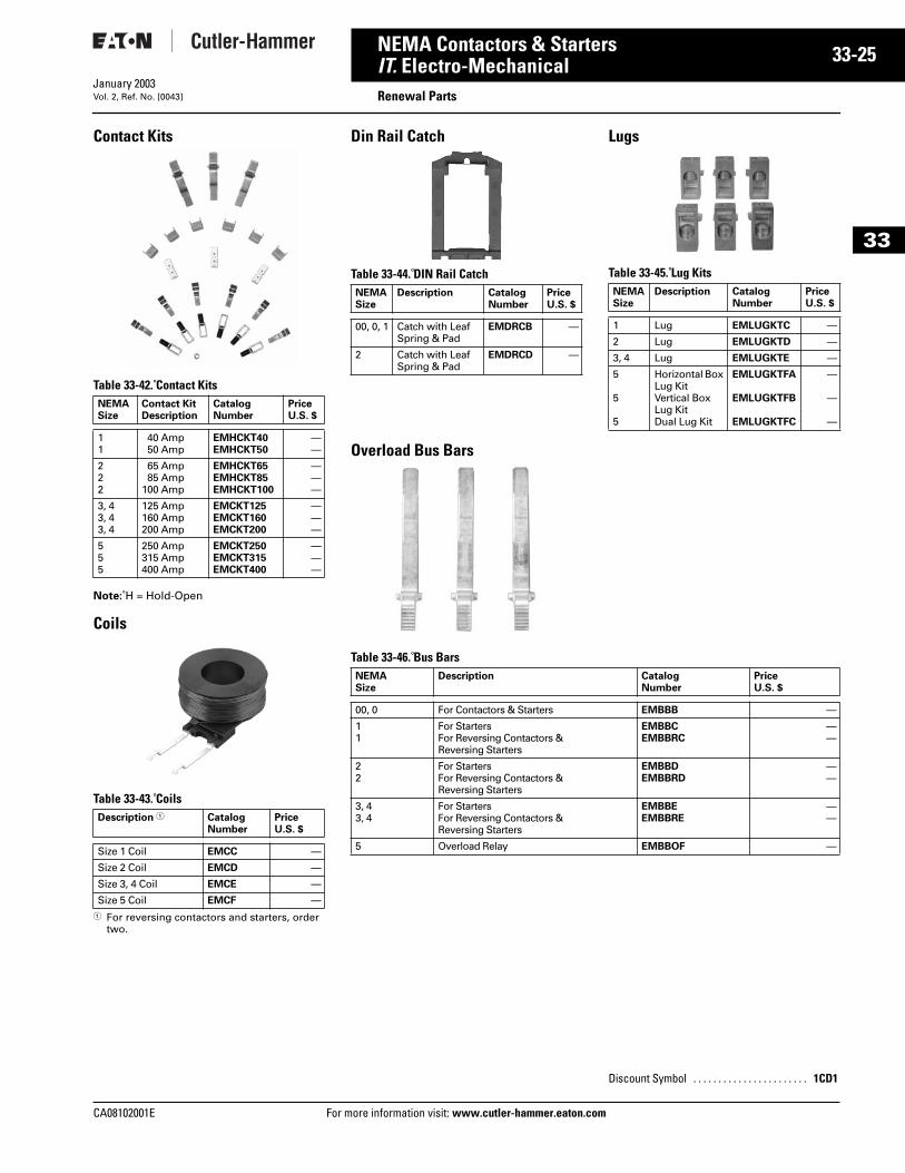
Contact Kits
Table 33-42. Contact Kits
Note: H = Hold-Open
Coils
Table 33-43. Coils
1 For reversing contactors and starters, order two.
NEMASize
Contact Kit Description
CatalogNumber
PriceU.S. $
11
40 Amp50 Amp
EMHCKT40EMHCKT50
——
222
65 Amp85 Amp
100 Amp
EMHCKT65EMHCKT85EMHCKT100
———
3, 43, 43, 4
125 Amp160 Amp200 Amp
EMCKT125EMCKT160EMCKT200
———
555
250 Amp315 Amp400 Amp
EMCKT250EMCKT315EMCKT400
———
Description 1 CatalogNumber
PriceU.S. $
Size 1 Coil EMCC —
Size 2 Coil EMCD —
Size 3, 4 Coil EMCE —
Size 5 Coil EMCF —
Din Rail Catch
Table 33-44. DIN Rail Catch
Lugs
Table 33-45. Lug Kits
Overload Bus Bars
Table 33-46. Bus Bars
NEMASize
Description CatalogNumber
PriceU.S. $
00, 0, 1 Catch with LeafSpring & Pad
EMDRCB —
2 Catch with LeafSpring & Pad
EMDRCD —
NEMASize
Description Catalog Number
PriceU.S. $
1 Lug EMLUGKTC —
2 Lug EMLUGKTD —
3, 4 Lug EMLUGKTE —
5
5
5
Horizontal Box Lug KitVertical Box Lug KitDual Lug Kit
EMLUGKTFA
EMLUGKTFB
EMLUGKTFC
—
—
—
NEMASize
Description CatalogNumber
PriceU.S. $
00, 0 For Contactors & Starters EMBBB —
11
For StartersFor Reversing Contactors & Reversing Starters
EMBBCEMBBRC
——
22
For StartersFor Reversing Contactors & Reversing Starters
EMBBDEMBBRD
——
3, 43, 4
For StartersFor Reversing Contactors & Reversing Starters
EMBBEEMBBRE
——
5 Overload Relay EMBBOF —
Discount Symbol . . . . . . . . . . . . . . . . . . . . . . . 1CD1
information visit: www.cutler-hammer.eaton.com
33-26
33
NEMA Contactors & StartersIT. Electro-Mechanical
Renewal PartsFor more information visit: www.cutler-hammer.eaton.com
January 2003Vol. 2, Ref. No. [0044]
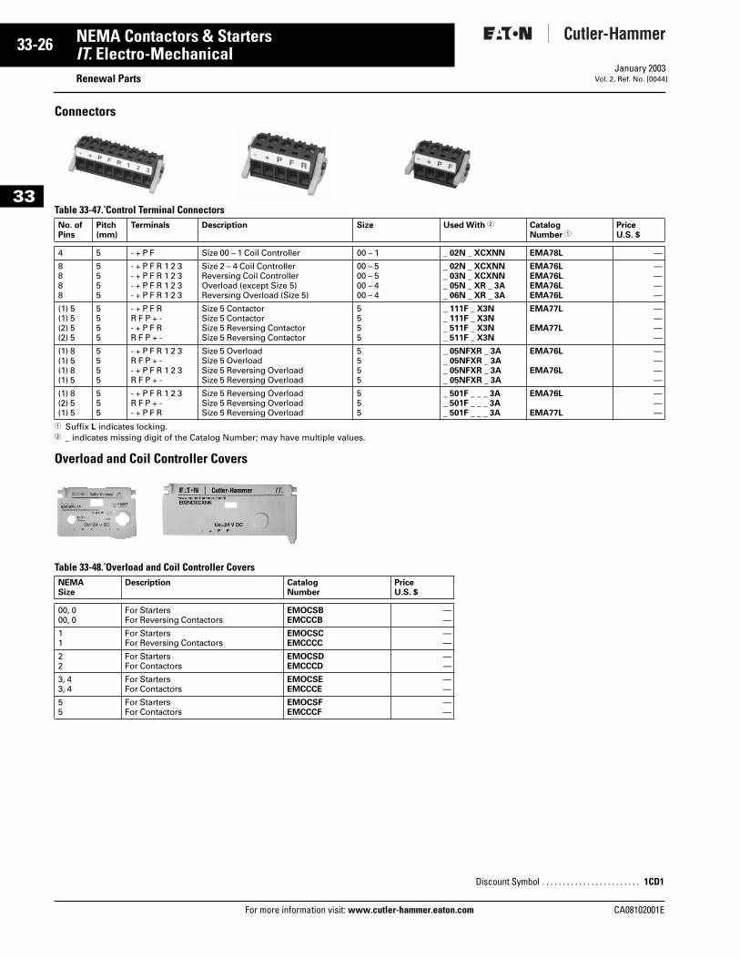
Connectors
Table 33-47. Control Terminal Connectors
1 Suffix L indicates locking.2 _ indicates missing digit of the Catalog Number; may have multiple values.
Overload and Coil Controller Covers
Table 33-48. Overload and Coil Controller Covers
No. of Pins
Pitch(mm)
Terminals Description Size Used With 2 CatalogNumber 1
PriceU.S. $
4 5 - + P F Size 00 – 1 Coil Controller 00 – 1 _ 02N _ XCXNN EMA78L —
8888
5555
- + P F R 1 2 3- + P F R 1 2 3- + P F R 1 2 3- + P F R 1 2 3
Size 2 – 4 Coil ControllerReversing Coil ControllerOverload (except Size 5)Reversing Overload (Size 5)
00 – 500 – 500 – 400 – 4
_ 02N _ XCXNN_ 03N _ XCXNN_ 05N _ XR _ 3A_ 06N _ XR _ 3A
EMA76LEMA76LEMA76LEMA76L
————
(1) 5(1) 5(2) 5(2) 5
5555
- + P F RR F P + -- + P F RR F P + -
Size 5 ContactorSize 5 ContactorSize 5 Reversing ContactorSize 5 Reversing Contactor
5555
_ 111F _ X3N_ 111F _ X3N_ 511F _ X3N_ 511F _ X3N
EMA77L
EMA77L
————
(1) 8(1) 5(1) 8(1) 5
5555
- + P F R 1 2 3R F P + -- + P F R 1 2 3R F P + -
Size 5 OverloadSize 5 OverloadSize 5 Reversing OverloadSize 5 Reversing Overload
5555
_ 05NFXR _ 3A_ 05NFXR _ 3A_ 05NFXR _ 3A_ 05NFXR _ 3A
EMA76L
EMA76L
————
(1) 8(2) 5(1) 5
555
- + P F R 1 2 3R F P + -- + P F R
Size 5 Reversing OverloadSize 5 Reversing OverloadSize 5 Reversing Overload
555
_ 501F _ _ _ 3A_ 501F _ _ _ 3A_ 501F _ _ _ 3A
EMA76L
EMA77L
———
NEMASize
Description CatalogNumber
PriceU.S. $
00, 000, 0
For StartersFor Reversing Contactors
EMOCSBEMCCCB
——
11
For StartersFor Reversing Contactors
EMOCSCEMCCCC
——
22
For StartersFor Contactors
EMOCSDEMCCCD
——
3, 43, 4
For StartersFor Contactors
EMOCSEEMCCCE
——
55
For StartersFor Contactors
EMOCSFEMCCCF
——
Discount Symbol . . . . . . . . . . . . . . . . . . . . . . . . 1CD1
CA08102001E
CA08102001E For more
27
33-NEMA Contactors & StartersIT. Electro-Mechanical DimensionsJanuary 2003Vol. 2, Ref. No. [0045]
33
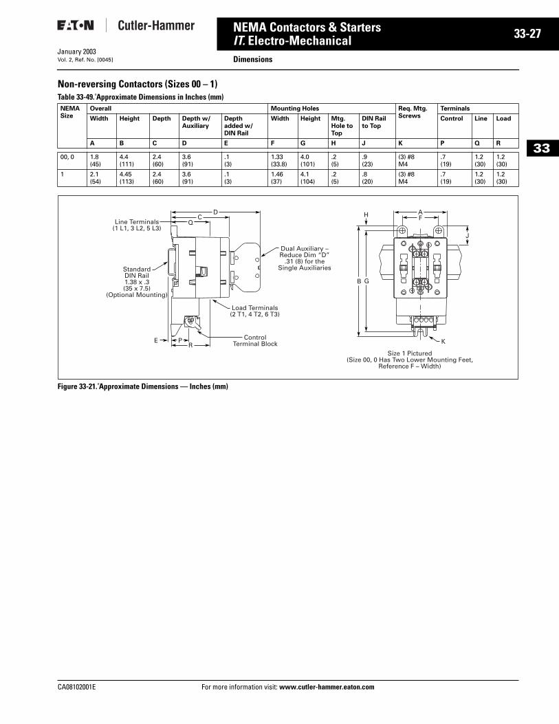
Non-reversing Contactors (Sizes 00 – 1)Table 33-49. Approximate Dimensions in Inches (mm)
Figure 33-21. Approximate Dimensions — Inches (mm)
NEMASize
Overall Mounting Holes Req. Mtg.Screws
Terminals
Width Height Depth Depth w/Auxiliary
Depthadded w/ DIN Rail
Width Height Mtg. Hole to Top
DIN Railto Top
Control Line Load
A B C D E F G H J K P Q R
00, 0 1.8(45)
4.4(111)
2.4(60)
3.6(91)
.1(3)
1.33(33.8)
4.0(101)
.2(5)
.9(23)
(3) #8M4
.7(19)
1.2(30)
1.2(30)
1 2.1(54)
4.45(113)
2.4(60)
3.6(91)
.1(3)
1.46(37)
4.1(104)
.2(5)
.8(20)
(3) #8M4
.7(19)
1.2(30)
1.2(30)
RP Control
Terminal BlockE
Load Terminals(2 T1, 4 T2, 6 T3)
Dual Auxiliary –Reduce Dim “D”
.31 (8) for theSingle Auxiliaries
K
QC FH
G
J
B
AD
Line Terminals(1 L1, 3 L2, 5 L3)
StandardDIN Rail1.38 x .3(35 x 7.5)
(Optional Mounting)
Size 1 Pictured(Size 00, 0 Has Two Lower Mounting Feet,
Reference F – Width)
information visit: www.cutler-hammer.eaton.com
33-28
33
NEMA Contactors & StartersIT. Electro-Mechanical
DimensionsFor more information visit: www.cutler-hammer.eaton.com
January 2003Vol. 2, Ref. No. [0046]
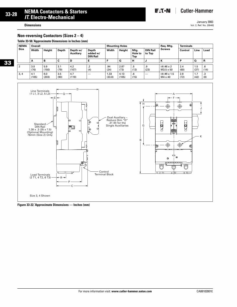
Non-reversing Contactors (Sizes 2 – 4) Table 33-50. Approximate Dimensions in Inches (mm)
Figure 33-22. Approximate Dimensions — Inches (mm)
NEMASize
Overall Mounting Holes Req. Mtg.Screws
Terminals
Width Height Depth Depth w/Auxiliary
Depthadded w/ DIN Rail
Width Height Mtg. Hole to Top
DIN Railto Top
Control Line Load
A B C D E F G H J K P Q R
2 3.0(76)
5.9(150)
3.1(79)
4.2(107)
.2(4)
.94(24)
2.87(73)
.5(13)
.9(23)
(4) #6 x 2M3.5 x 50
2.4(60)
1.5(37)
.6(14)
3, 4 4.1(105)
8.0(203)
3.5(90)
4.7(119)
— 1.33(33.8)
4.13(105)
.6(15)
— (4) #8 x 1.5M4 x 40
2.8(72)
1.7(42)
.3(8)
H
G
K
J
B
ControlTerminal Block
R
P
Load Terminals(2 T1, 4 T2, 6 T3)
Size 3, 4 Shown
Dual Auxiliary –Reduce Dim “D”
.31 (8) for theSingle Auxiliaries
QE
AF
DLine Terminals
(1 L1, 3 L2, 5 L3)
StandardDIN Rail
1.38 x .3 (35 x 7.5)(Optional Mounting)76mm (Size 2) Only
C
2 T1 T24 T36
CA08102001E
CA08102001E For more
29
33-NEMA Contactors & StartersIT. Electro-Mechanical DimensionsJanuary 2003Vol. 2, Ref. No. [0047]
33
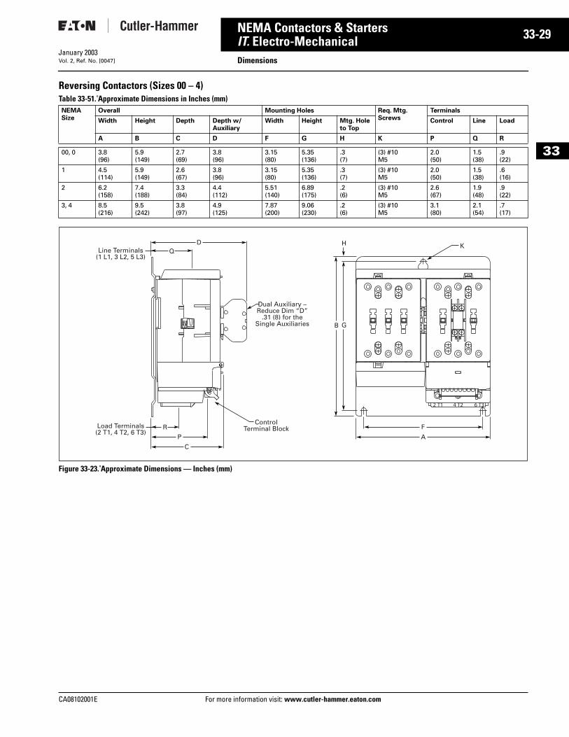
Reversing Contactors (Sizes 00 – 4) Table 33-51. Approximate Dimensions in Inches (mm)
Figure 33-23. Approximate Dimensions — Inches (mm)
NEMASize
Overall Mounting Holes Req. Mtg.Screws
Terminals
Width Height Depth Depth w/Auxiliary
Width Height Mtg. Hole to Top
Control Line Load
A B C D F G H K P Q R
00, 0 3.8(96)
5.9(149)
2.7(69)
3.8(96)
3.15(80)
5.35(136)
.3(7)
(3) #10M5
2.0(50)
1.5(38)
.9(22)
1 4.5(114)
5.9(149)
2.6(67)
3.8(96)
3.15(80)
5.35(136)
.3(7)
(3) #10M5
2.0(50)
1.5(38)
.6(16)
2 6.2(158)
7.4(188)
3.3(84)
4.4(112)
5.51(140)
6.89(175)
.2(6)
(3) #10M5
2.6(67)
1.9(48)
.9(22)
3, 4 8.5(216)
9.5(242)
3.8(97)
4.9(125)
7.87(200)
9.06(230)
.2(6)
(3) #10M5
3.1(80)
2.1(54)
.7(17)
ControlTerminal Block
Dual Auxiliary –Reduce Dim “D”
.31 (8) for theSingle Auxiliaries
K
P
FR
A
C
H
GB
QD
Line Terminals(1 L1, 3 L2, 5 L3)
Load Terminals(2 T1, 4 T2, 6 T3)
information visit: www.cutler-hammer.eaton.com
33-30
33
NEMA Contactors & StartersIT. Electro-Mechanical
DimensionsFor more information visit: www.cutler-hammer.eaton.com
January 2003Vol. 2, Ref. No. [0048]
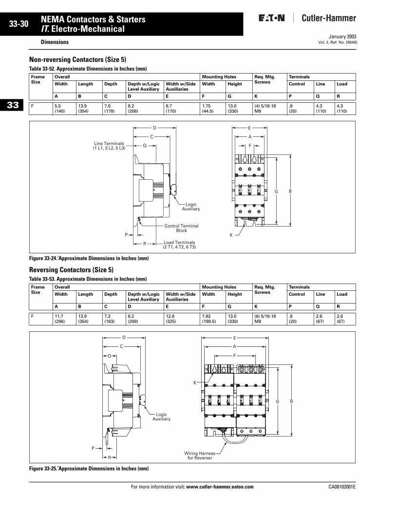
Non-reversing Contactors (Size 5)Table 33-52. Approximate Dimensions in Inches (mm)
Figure 33-24. Approximate Dimensions in Inches (mm)
Reversing Contactors (Size 5)Table 33-53. Approximate Dimensions in Inches (mm)
Figure 33-25. Approximate Dimensions in Inches (mm)
FrameSize
Overall Mounting Holes Req. Mtg.Screws
Terminals
Width Length Depth Depth w/Logic Level Auxiliary
Width w/Side Auxiliaries
Width Height Control Line Load
A B C D E F G K P Q R
F 5.5(140)
13.9(354)
7.0(178)
8.2(208)
6.7(170)
1.75(44.5)
13.0(330)
(4) 5/16-18M8
.8(20)
4.3(110)
4.3(110)
FrameSize
Overall Mounting Holes Req. Mtg.Screws
Terminals
Width Length Depth Depth w/Logic Level Auxiliary
Width w/Side Auxiliaries
Width Height Control Line Load
A B C D E F G K P Q R
F 11.7(296)
13.9(354)
7.2(183)
8.2(208)
12.8(325)
7.82(198.5)
13.0(330)
(6) 5/16-18M8
.8(20)
2.6(67)
2.6(67)
Load Terminals (2 T1, 4 T2, 6 T3)
Line Terminals (1 L1, 3 L2, 5 L3)
Logic Auxiliary
Control Terminal Block
D
C
E
Q
P
R
F
A
K
G B
Q
D
C
R
P
K
E
A
F
Wiring Harnessfor Reverser
G B
Logic Auxiliary
CA08102001E
CA08102001E For more
31
33-NEMA Contactors & StartersIT. Electro-Mechanical DimensionsJanuary 2003Vol. 2, Ref. No. [0049]
33
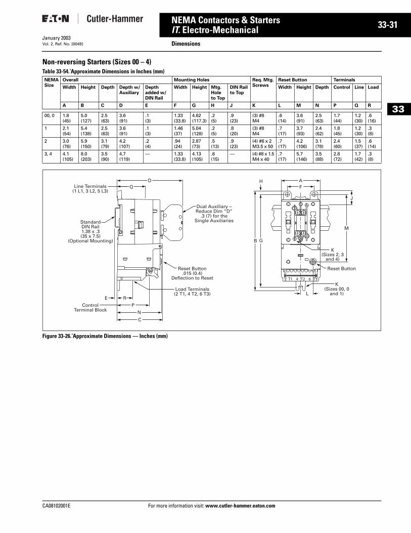
Non-reversing Starters (Sizes 00 – 4) Table 33-54. Approximate Dimensions in Inches (mm)
Figure 33-26. Approximate Dimensions — Inches (mm)
NEMASize
Overall Mounting Holes Req. Mtg.Screws
Reset Button Terminals
Width Height Depth Depth w/Auxiliary
Depthadded w/ DIN Rail
Width Height Mtg. Hole to Top
DIN Railto Top
Width Height Depth Control Line Load
A B C D E F G H J K L M N P Q R
00, 0 1.8(45)
5.0(127)
2.5(63)
3.6(91)
.1(3)
1.33(33.8)
4.62(117.3)
.2(5)
.9(23)
(3) #8M4
.6(14)
3.6(91)
2.5(63)
1.7(44)
1.2(30)
.6(16)
1 2.1(54)
5.4(138)
2.5(63)
3.6(91)
.1(3)
1.46(37)
5.04(128)
.2(5)
.8(20)
(3) #8M4
.7(17)
3.7(93)
2.4(62)
1.8(45)
1.2(30)
.3(8)
2 3.0(76)
5.9(150)
3.1(79)
4.2(107)
.2(4)
.94(24)
2.87(73)
.5(13)
.9(23)
(4) #6 x 2M3.5 x 50
.7(17)
4.2(106)
3.1(78)
2.4(60)
1.5(37)
.6(14)
3, 4 4.1(105)
8.0(203)
3.5(90)
4.7(119)
— 1.33(33.8)
4.13(105)
.6(15)
— (4) #8 x 1.5M4 x 40
.7(17)
5.7(146)
3.5(88)
2.8(72)
1.7(42)
.3(8)
ControlTerminal Block
P
REL
Reset Button.015 (0.4)
Deflection to Reset
Load Terminals(2 T1, 4 T2, 6 T3)
Dual Auxiliary –Reduce Dim “D”
.3 (7) for theSingle Auxiliaries
Reset Button
K(Sizes 00, 0
and 1)
K(Sizes 2, 3
and 4)
Q
N
C
H
G
J
M
B
FAD
Line Terminals(1 L1, 3 L2, 5 L3)
StandardDIN Rail1.38 x .3(35 x 7.5)
(Optional Mounting)
information visit: www.cutler-hammer.eaton.com
33-32
33
NEMA Contactors & StartersIT. Electro-Mechanical
DimensionsFor more information visit: www.cutler-hammer.eaton.com
January 2003Vol. 2, Ref. No. [0050]
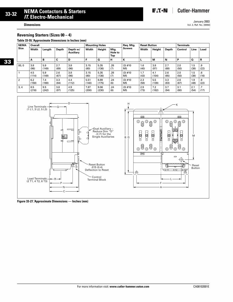
Reversing Starters (Sizes 00 – 4)Table 33-55. Approximate Dimensions in Inches (mm)
Figure 33-27. Approximate Dimensions — Inches (mm)
NEMASize
Overall Mounting Holes Req. Mtg.Screws
Reset Button Terminals
Width Length Depth Depth w/Auxiliary
Width Height Mtg. Hole to Top
Width Height Depth Control Line Load
A B C D F G H K L M N P Q R
00, 0 3.8(96)
5.9(149)
2.7(69)
3.8(96)
3.15(80)
5.35(136)
.28(7)
(3) #10M5
1.6(40)
3.8(97)
2.7(68)
2.0(50)
1.5(38)
.9(22)
1 4.5(114)
5.9(149)
2.6(67)
3.8(96)
3.15(80)
5.35(136)
.28(7)
(3) #10M5
1.7(43)
4.1(104)
2.6(65)
2.0(50)
1.5(38)
.6(16)
2 6.2(158)
7.4(188)
3.3(84)
4.4(112)
5.51(140)
6.89(175)
.24(6)
(3) #10M5
2.3(58)
5.5(139)
3.3(83)
2.6(67)
1.9(48)
.9(22)
3, 4 8.5(216)
9.5(242)
3.8(97)
4.9(125)
7.87(200)
9.06(230)
.24(6)
(3) #10M5
2.9(73)
7.2(182)
3.7(94)
3.1(80)
2.1(54)
.7(17)
ControlTerminal Block
Reset Button.015 (0.4)
Deflection to Reset
ResetButton
Dual Auxiliary –Reduce Dim “D”
.3 (7) for theSingle Auxiliaries
K
P F
R L
N A
C
H
G MB
QD
Line Terminals(1 L1, 3 L2, 5 L3)
Load Terminals(2 T1, 4 T2, 6 T3)
CA08102001E
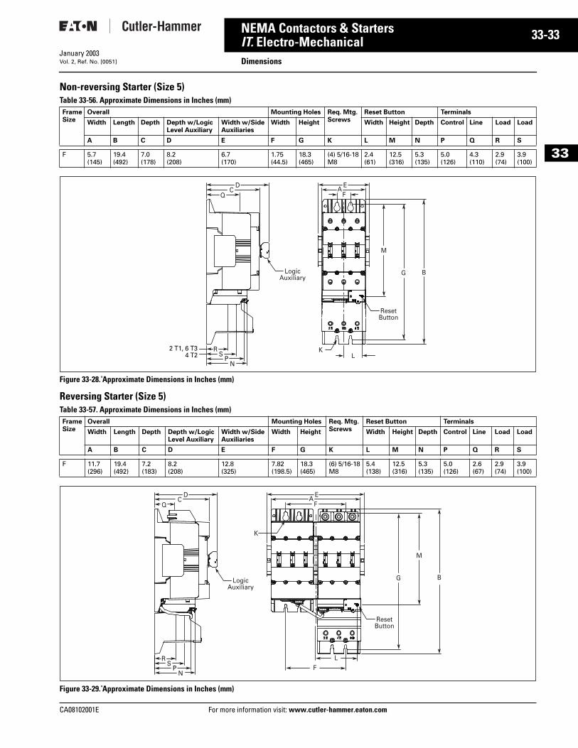
CA08102001E For more
33
33-NEMA Contactors & StartersIT. Electro-Mechanical DimensionsJanuary 2003Vol. 2, Ref. No. [0051]
33
Non-reversing Starter (Size 5)Table 33-56. Approximate Dimensions in Inches (mm)
Figure 33-28. Approximate Dimensions in Inches (mm)
Reversing Starter (Size 5)Table 33-57. Approximate Dimensions in Inches (mm)
Figure 33-29. Approximate Dimensions in Inches (mm)
FrameSize
Overall Mounting Holes Req. Mtg.Screws
Reset Button Terminals
Width Length Depth Depth w/LogicLevel Auxiliary
Width w/SideAuxiliaries
Width Height Width Height Depth Control Line Load Load
A B C D E F G K L M N P Q R S
F 5.7(145)
19.4(492)
7.0(178)
8.2(208)
6.7(170)
1.75(44.5)
18.3(465)
(4) 5/16-18M8
2.4(61)
12.5(316)
5.3(135)
5.0(126)
4.3(110)
2.9(74)
3.9(100)
FrameSize
Overall Mounting Holes Req. Mtg.Screws
Reset Button Terminals
Width Length Depth Depth w/LogicLevel Auxiliary
Width w/SideAuxiliaries
Width Height Width Height Depth Control Line Load Load
A B C D E F G K L M N P Q R S
F 11.7(296)
19.4(492)
7.2(183)
8.2(208)
12.8(325)
7.82(198.5)
18.3(465)
(6) 5/16-18M8
5.4(138)
12.5(316)
5.3(135)
5.0(126)
2.6(67)
2.9(74)
3.9(100)
2 T1, 6 T34 T2
KL
M
G B
FE
A
Reset Button
RS
DC
Q
PN
Logic Auxiliary
FL
K
Reset Button
M
G B
RS
P
FE
AD
CQ
Logic Auxiliary
N
information visit: www.cutler-hammer.eaton.com
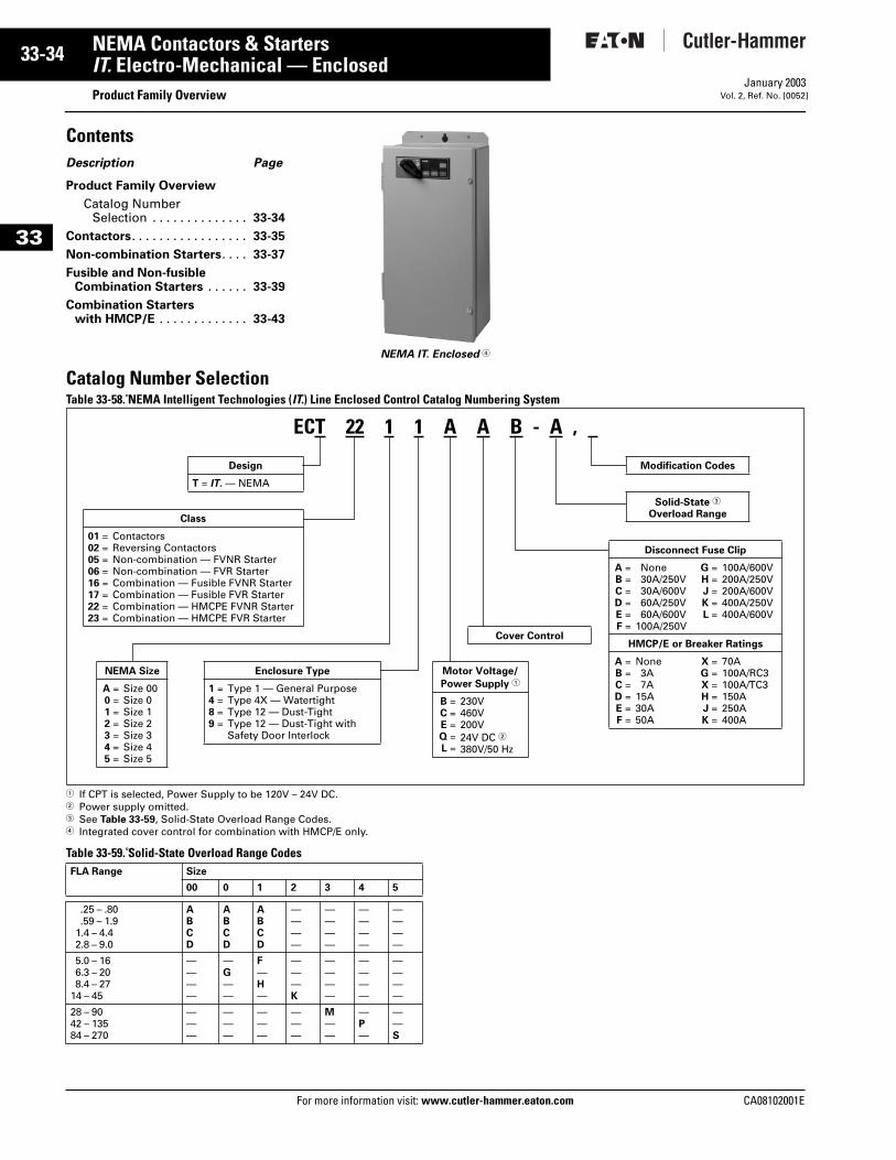
33-34
33
NEMA Contactors & StartersIT. Electro-Mechanical — Enclosed
Product Family OverviewFor more information visit: www.cutler-hammer.eaton.com
January 2003Vol. 2, Ref. No. [0052]
ContentsDescription Page
Product Family Overview
Catalog Number Selection . . . . . . . . . . . . . . 33-34
Contactors. . . . . . . . . . . . . . . . . 33-35
Non-combination Starters. . . . 33-37
Fusible and Non-fusible Combination Starters . . . . . . 33-39
Combination Starters with HMCP/E . . . . . . . . . . . . . 33-43
Catalog Number SelectionTable 33-58. NEMA Intelligent Technologies (IT.) Line Enclosed Control Catalog Numbering System
1 If CPT is selected, Power Supply to be 120V – 24V DC.2 Power supply omitted.3 See Table 33-59, Solid-State Overload Range Codes.4 Integrated cover control for combination with HMCP/E only.
Table 33-59. Solid-State Overload Range Codes
NEMA IT. Enclosed 4
FLA Range Size
00 0 1 2 3 4 5
.25 – .80
.59 – 1.91.4 – 4.42.8 – 9.0
ABCD
ABCD
ABCD
————
————
————
————
5.0 – 166.3 – 208.4 – 27
14 – 45
————
—G——
F—H—
———K
————
————
————
28 – 9042 – 13584 – 270
———
———
———
———
M——
—P—
——S
ECT 22 1 1 A A B - A ,
Design
T = IT. — NEMA
Class
01 =02 =05 =06 =16 =17 =22 =23 =
ContactorsReversing ContactorsNon-combination — FVNR StarterNon-combination — FVR StarterCombination — Fusible FVNR StarterCombination — Fusible FVR StarterCombination — HMCPE FVNR StarterCombination — HMCPE FVR Starter
NEMA Size
A =0 =1 =2 =3 =4 =5 =
Size 00Size 0Size 1Size 2Size 3Size 4Size 5
Enclosure Type
1 =4 =8 =9 =
Type 1 — General PurposeType 4X — WatertightType 12 — Dust-TightType 12 — Dust-Tight with Safety Door Interlock
Motor Voltage/
Power Supply 1
B =C =E =Q =L =
230V460V200V24V DC 2380V/50 Hz
Disconnect Fuse Clip
A =B =C =D =E =F =
None30A/250V30A/600V60A/250V60A/600V
100A/250V
G =H =J =K =L =
100A/600V200A/250V200A/600V400A/250V400A/600V
HMCP/E or Breaker Ratings
A =B =C =D =E =F =
None3A7A
15A30A50A
X =G =X =H =J =K =
70A100A/RC3100A/TC3150A250A400A
Cover Control
Modification Codes
Solid-State 3
Overload Range
CA08102001E
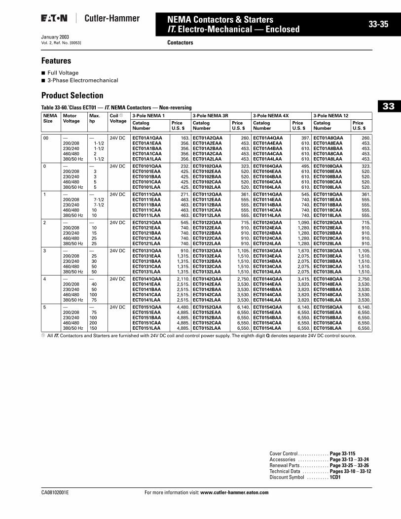
CA08102001E For more
35
33-NEMA Contactors & StartersIT. Electro-Mechanical — Enclosed ContactorsJanuary 2003Vol. 2, Ref. No. [0053]
33
Features■ Full Voltage■ 3-Phase Electromechanical
Product SelectionTable 33-60. Class ECT01 — IT. NEMA Contactors — Non-reversing
1 All IT. Contactors and Starters are furnished with 24V DC coil and control power supply. The eighth digit Q denotes separate 24V DC control source.
NEMASize
MotorVoltage
Max.hp
Coil 1
Voltage3-Pole NEMA 1 3-Pole NEMA 3R 3-Pole NEMA 4X 3-Pole NEMA 12
CatalogNumber
PriceU.S. $
CatalogNumber
Price U.S. $
CatalogNumber
PriceU.S. $
CatalogNumber
Price U.S. $
00 —200/208230/240460/480380/50 Hz
—1-1/21-1/221-1/2
24V DC ECT01A1QAAECT01A1EAAECT01A1BAAECT01A1CAAECT01A1LAA
163.356.356.356.356.
ECT01A2QAAECT01A2EAAECT01A2BAAECT01A2CAAECT01A2LAA
260.453.453.453.453.
ECT01A4QAAECT01A4EAAECT01A4BAAECT01A4CAAECT01A4LAA
397.610.610.610.610.
ECT01A8QAAECT01A8EAAECT01A8BAAECT01A8CAAECT01A8LAA
260.453.453.453.453.
0 —200/208230/240460/480380/50 Hz
—3 3 55
24V DC ECT0101QAAECT0101EAAECT0101BAAECT0101CAAECT0101LAA
232.425.425.425.425.
ECT0102QAAECT0102EAAECT0102BAAECT0102CAAECT0102LAA
323.520.520.520.520.
ECT0104QAAECT0104EAAECT0104BAAECT0104CAAECT0104LAA
495.610.610.610.610.
ECT0108QAAECT0108EAAECT0108BAAECT0108CAAECT0108LAA
323.520.520.520.520.
1 —200/208230/240460/480380/50 Hz
—7-1/27-1/2
1010
24V DC ECT0111QAAECT0111EAAECT0111BAAECT0111CAAECT0111LAA
271.463.463.463.463.
ECT0112QAAECT0112EAAECT0112BAAECT0112CAAECT0112LAA
361.555.555.555.555.
ECT0114QAAECT0114EAAECT0114BAAECT0114CAAECT0114LAA
545.740.740.740.740.
ECT0118QAAECT0118EAAECT0118BAAECT0118CAAECT0118LAA
361.555.555.555.555.
2 —200/208230/240460/480380/50 Hz
—10 15 2525
24V DC ECT0121QAAECT0121EAAECT0121BAAECT0121CAAECT0121LAA
545.740.740.740.740.
ECT0122QAAECT0122EAAECT0122BAAECT0122CAAECT0122LAA
715.910.910.910.910.
ECT0124QAAECT0124EAAECT0124BAAECT0124CAAECT0124LAA
1,090.1,280.1,280.1,280.1,280.
ECT0128QAAECT0128EAAECT0128BAAECT0128CAAECT0128LAA
715.910.910.910.910.
3 —200/208230/240460/480380/50 Hz
—25 30 5050
24V DC ECT0131QAAECT0131EAAECT0131BAAECT0131CAAECT0131LAA
910.1,315.1,315.1,315.1,315.
ECT0132QAAECT0132EAAECT0132BAAECT0132CAAECT0132LAA
1,105.1,510.1,510.1,510.1,510.
ECT0134QAAECT0134EAAECT0134BAAECT0134CAAECT0134LAA
1,670.2,075.2,075.2,075.2,075.
ECT0138QAAECT0138EAAECT0138BAAECT0138CAAECT0138LAA
1,105.1,510.1,510.1,510.1,510.
4 —200/208230/240460/480380/50 Hz
—40 50
10075
24V DC ECT0141QAAECT0141EAAECT0141BAAECT0141CAAECT0141LAA
2,110.2,515.2,515.2,515.2,515.
ECT0142QAAECT0142EAAECT0142BAAECT0142CAAECT0142LAA
2,750.3,530.3,530.3,530.3,530.
ECT0144QAAECT0144EAAECT0144BAAECT0144CAAECT0144LAA
3,415.3,820.3,820.3,820.3,820.
ECT0148QAAECT0148EAAECT0148BAAECT0148CAAECT0148LAA
2,750.3,530.3,530.3,530.3,530.
5 —200/208230/240460/480380/50 Hz
—75
100 200150
24V DC ECT0151QAAECT0151EAAECT0151BAAECT0151CAAECT0151LAA
4,480.4,885.4,885.4,885.4,885.
ECT0152QAAECT0152EAAECT0152BAAECT0152CAAECT0152LAA
6,140.6,550.6,550.6,550.6,550.
ECT0154QAAECT0154EAAECT0154BAAECT0154CAAECT0154LAA
6,140.6,550.6,550.6,550.6,550.
ECT0158QAAECT0158EAAECT0158BAAECT0158CAAECT0158LAA
6,140.6,550.6,550.6,550.6,550.
Cover Control . . . . . . . . . . . . . . Page 33-115Accessories . . . . . . . . . . . . . . Page 33-13 – 33-24Renewal Parts . . . . . . . . . . . . . Page 33-25 – 33-26Technical Data . . . . . . . . . . . . Pages 33-10 – 33-12Discount Symbol . . . . . . . . . . 1CD1
information visit: www.cutler-hammer.eaton.com
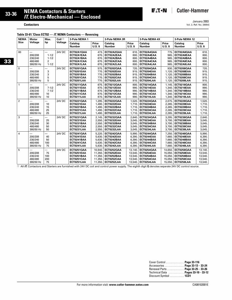
33-36
33
NEMA Contactors & StartersIT. Electro-Mechanical — Enclosed
ContactorsFor more information visit: www.cutler-hammer.eaton.com
January 2003Vol. 2, Ref. No. [0054]
Table 33-61. Class ECT02 — IT. NEMA Contactors — Reversing
1 All IT. Contactors and Starters are furnished with 24V DC coil and control power supply. The eighth digit Q denotes separate 24V DC control source.
NEMASize
MotorVoltage
Max.hp
Coil 1
Voltage3-Pole NEMA 1 3-Pole NEMA 3R 3-Pole NEMA 4X 3-Pole NEMA 12
CatalogNumber
Price U.S. $
CatalogNumber
PriceU.S. $
CatalogNumber
PriceU.S. $
CatalogNumber
PriceU.S. $
00 —200/208230/240460/480380/50 Hz
—1-1/21-1/221-1/2
24V DC ECT02A1QAAECT02A1EAAECT02A1BAAECT02A1CAAECT02A1LAA
473.670.670.670.670.
ECT02A2QAAECT02A2EAAECT02A2BAAECT02A2CAAECT02A2LAA
610.800.800.800.800.
ECT02A4QAAECT02A4EAAECT02A4BAAECT02A4CAAECT02A4LAA
775.965.965.965.965.
ECT02A8QAAECT02A8EAAECT02A8BAAECT02A8CAAECT02A8LAA
610.800.800.800.800.
0 —200/208230/240460/480380/50 Hz
—3 3 55
24V DC ECT0201QAAECT0201EAAECT0201BAAECT0201CAAECT0201LAA
575.770.770.770.770.
ECT0202QAAECT0202EAAECT0202BAAECT0202CAAECT0202LAA
720.915.915.915.915.
ECT0204QAAECT0204EAAECT0204BAAECT0204CAAECT0204LAA
930.1,120.1,120.1,120.1,120.
ECT0208QAAECT0208EAAECT0208BAAECT0208CAAECT0208LAA
720.915.915.915.915.
1 —200/208230/240460/480380/50 Hz
—7-1/27-1/2
1010
24V DC ECT0211QAAECT0211EAAECT0211BAAECT0211CAAECT0211LAA
675.870.870.870.870.
ECT0212QAAECT0212EAAECT0212BAAECT0212CAAECT0212LAA
800.990.990.990.990.
ECT0214QAAECT0214EAAECT0214BAAECT0214CAAECT0214LAA
1,145.1,340.1,340.1,340.1,340.
ECT0218QAAECT0218EAAECT0218BAAECT0218CAAECT0218LAA
800.990.990.990.990.
2 —200/208230/240460/480380/50 Hz
—10 15 2525
24V DC ECT0221QAAECT0221EAAECT0221BAAECT0221CAAECT0221LAA
1,295.1,490.1,490.1,490.1,490.
ECT0222QAAECT0222EAAECT0222BAAECT0222CAAECT0222LAA
1,520.1,710.1,710.1,710.1,710.
ECT0224QAAECT0224EAAECT0224BAAECT0224CAAECT0224LAA
2,075.2,265.2,265.2,265.2,265.
ECT0228QAAECT0228EAAECT0228BAAECT0228CAAECT0228LAA
1,520.1,710.1,710.1,710.1,710.
3 —200/208230/240460/480380/50 Hz
—25 30 5050
24V DC ECT0231QAAECT0231EAAECT0231BAAECT0231CAAECT0231LAA
2,145.2,550.2,550.2,550.2,550.
ECT0232QAAECT0232EAAECT0232BAAECT0232CAAECT0232LAA
2,640.3,045.3,045.3,045.3,045.
ECT0234QAAECT0234EAAECT0234BAAECT0234CAAECT0234LAA
3,295.3,700.3,700.3,700.3,700.
ECT0238QAAECT0238EAAECT0238BAAECT0238CAAECT0238LAA
2,640.3,045.3,045.3,045.3,045.
4 —200/208230/240460/480380/50 Hz
—4050
10075
24V DC ECT0241QAAECT0241EAAECT0241BAAECT0241CAAECT0241LAA
5,220.5,630.5,630.5,630.5,630.
ECT0242QAAECT0242EAAECT0242BAAECT0242CAAECT0242LAA
5,990.6,390.6,390.6,390.6,390.
ECT0244QAAECT0244EAAECT0244BAAECT0244CAAECT0244LAA
7,250.7,660.7,660.7,660.7,660.
ECT0248QAAECT0248EAAECT0248BAAECT0248CAAECT0248LAA
5,990.6,390.6,390.6,390.6,390.
5 —200/208230/240460/480380/50 Hz
—75
10020075
24V DC ECT0251QAAECT0251EAAECT0251BAAECT0251CAAECT0251LAA
10,940.11,350.11,350.11,350.11,350.
ECT0252QAAECT0252EAAECT0252BAAECT0252CAAECT0252LAA
13,140.13,540.13,540.13,540.13,540.
ECT0254QAAECT0254EAAECT0254BAAECT0254CAAECT0254LAA
14,650.15,050.15,050.15,050.15,050.
ECT0258QAAECT0258EAAECT0258BAAECT0258CAAECT0258LAA
13,140.13,540.13,540.13,540.13,540.
Cover Control . . . . . . . . . . . . . . Page 33-116Accessories . . . . . . . . . . . . . . . Page 33-13 – 33-24Renewal Parts . . . . . . . . . . . . . Page 33-25 – 33-26Technical Data . . . . . . . . . . . . Pages 33-10 – 33-12Discount Symbol . . . . . . . . . . . 1CD1
CA08102001E
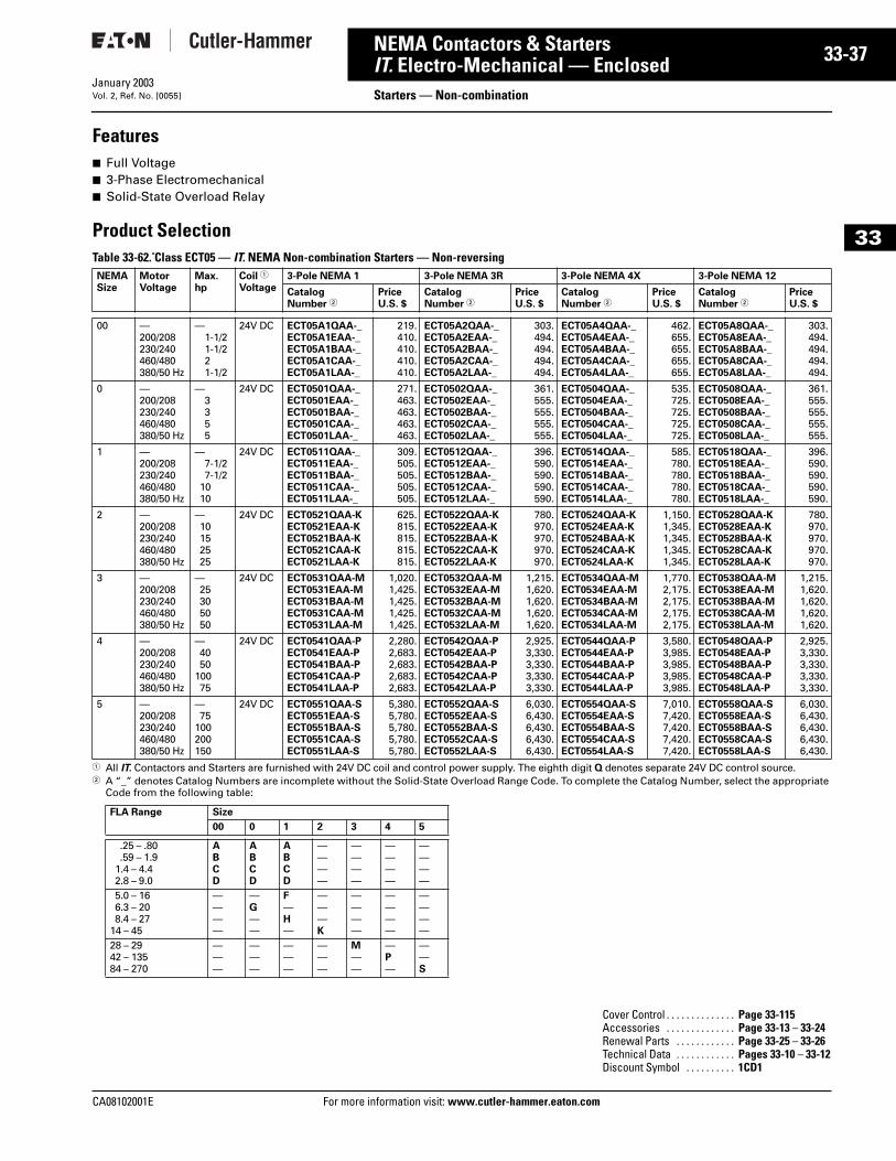
CA08102001E For more
37
33-NEMA Contactors & StartersIT. Electro-Mechanical — Enclosed Starters — Non-combinationJanuary 2003Vol. 2, Ref. No. [0055]
33
Features■ Full Voltage■ 3-Phase Electromechanical■ Solid-State Overload Relay
Product SelectionTable 33-62. Class ECT05 — IT. NEMA Non-combination Starters — Non-reversing
1 All IT. Contactors and Starters are furnished with 24V DC coil and control power supply. The eighth digit Q denotes separate 24V DC control source.2 A “_” denotes Catalog Numbers are incomplete without the Solid-State Overload Range Code. To complete the Catalog Number, select the appropriate
Code from the following table:
NEMASize
MotorVoltage
Max.hp
Coil 1
Voltage3-Pole NEMA 1 3-Pole NEMA 3R 3-Pole NEMA 4X 3-Pole NEMA 12
Catalog Number 2
PriceU.S. $
Catalog Number 2
PriceU.S. $
Catalog Number 2
PriceU.S. $
Catalog Number 2
PriceU.S. $
00 —200/208230/240460/480380/50 Hz
—1-1/21-1/221-1/2
24V DC ECT05A1QAA-_ECT05A1EAA-_ECT05A1BAA-_ECT05A1CAA-_ECT05A1LAA-_
219.410.410.410.410.
ECT05A2QAA-_ECT05A2EAA-_ECT05A2BAA-_ECT05A2CAA-_ECT05A2LAA-_
303.494.494.494.494.
ECT05A4QAA-_ECT05A4EAA-_ECT05A4BAA-_ECT05A4CAA-_ECT05A4LAA-_
462.655.655.655.655.
ECT05A8QAA-_ECT05A8EAA-_ECT05A8BAA-_ECT05A8CAA-_ECT05A8LAA-_
303.494.494.494.494.
0 —200/208230/240460/480380/50 Hz
—3355
24V DC ECT0501QAA-_ECT0501EAA-_ECT0501BAA-_ECT0501CAA-_ECT0501LAA-_
271.463.463.463.463.
ECT0502QAA-_ECT0502EAA-_ECT0502BAA-_ECT0502CAA-_ECT0502LAA-_
361.555.555.555.555.
ECT0504QAA-_ECT0504EAA-_ECT0504BAA-_ECT0504CAA-_ECT0504LAA-_
535.725.725.725.725.
ECT0508QAA-_ECT0508EAA-_ECT0508BAA-_ECT0508CAA-_ECT0508LAA-_
361.555.555.555.555.
1 —200/208230/240460/480380/50 Hz
—7-1/27-1/2
1010
24V DC ECT0511QAA-_ECT0511EAA-_ECT0511BAA-_ECT0511CAA-_ECT0511LAA-_
309.505.505.505.505.
ECT0512QAA-_ECT0512EAA-_ECT0512BAA-_ECT0512CAA-_ECT0512LAA-_
396.590.590.590.590.
ECT0514QAA-_ECT0514EAA-_ECT0514BAA-_ECT0514CAA-_ECT0514LAA-_
585.780.780.780.780.
ECT0518QAA-_ECT0518EAA-_ECT0518BAA-_ECT0518CAA-_ECT0518LAA-_
396.590.590.590.590.
2 —200/208230/240460/480380/50 Hz
—10152525
24V DC ECT0521QAA-KECT0521EAA-KECT0521BAA-KECT0521CAA-KECT0521LAA-K
625.815.815.815.815.
ECT0522QAA-KECT0522EAA-KECT0522BAA-KECT0522CAA-KECT0522LAA-K
780.970.970.970.970.
ECT0524QAA-KECT0524EAA-KECT0524BAA-KECT0524CAA-KECT0524LAA-K
1,150.1,345.1,345.1,345.1,345.
ECT0528QAA-KECT0528EAA-KECT0528BAA-KECT0528CAA-KECT0528LAA-K
780.970.970.970.970.
3 —200/208230/240460/480380/50 Hz
—25305050
24V DC ECT0531QAA-MECT0531EAA-MECT0531BAA-MECT0531CAA-MECT0531LAA-M
1,020.1,425.1,425.1,425.1,425.
ECT0532QAA-MECT0532EAA-MECT0532BAA-MECT0532CAA-MECT0532LAA-M
1,215.1,620.1,620.1,620.1,620.
ECT0534QAA-MECT0534EAA-MECT0534BAA-MECT0534CAA-MECT0534LAA-M
1,770.2,175.2,175.2,175.2,175.
ECT0538QAA-MECT0538EAA-MECT0538BAA-MECT0538CAA-MECT0538LAA-M
1,215.1,620.1,620.1,620.1,620.
4 —200/208230/240460/480380/50 Hz
—4050
10075
24V DC ECT0541QAA-PECT0541EAA-PECT0541BAA-PECT0541CAA-PECT0541LAA-P
2,280.2,683.2,683.2,683.2,683.
ECT0542QAA-PECT0542EAA-PECT0542BAA-PECT0542CAA-PECT0542LAA-P
2,925.3,330.3,330.3,330.3,330.
ECT0544QAA-PECT0544EAA-PECT0544BAA-PECT0544CAA-PECT0544LAA-P
3,580.3,985.3,985.3,985.3,985.
ECT0548QAA-PECT0548EAA-PECT0548BAA-PECT0548CAA-PECT0548LAA-P
2,925.3,330.3,330.3,330.3,330.
5 —200/208230/240460/480380/50 Hz
—75
100200150
24V DC ECT0551QAA-SECT0551EAA-SECT0551BAA-SECT0551CAA-SECT0551LAA-S
5,380.5,780.5,780.5,780.5,780.
ECT0552QAA-SECT0552EAA-SECT0552BAA-SECT0552CAA-SECT0552LAA-S
6,030.6,430.6,430.6,430.6,430.
ECT0554QAA-SECT0554EAA-SECT0554BAA-SECT0554CAA-SECT0554LAA-S
7,010.7,420.7,420.7,420.7,420.
ECT0558QAA-SECT0558EAA-SECT0558BAA-SECT0558CAA-SECT0558LAA-S
6,030.6,430.6,430.6,430.6,430.
FLA Range Size
00 0 1 2 3 4 5
.25 – .80
.59 – 1.91.4 – 4.42.8 – 9.0
ABCD
ABCD
ABCD
————
————
————
————
5.0 – 166.3 – 208.4 – 27
14 – 45
————
—G——
F—H—
———K
————
————
————
28 – 2942 – 13584 – 270
———
———
———
———
M——
—P—
——S
Cover Control . . . . . . . . . . . . . . Page 33-115Accessories . . . . . . . . . . . . . . Page 33-13 – 33-24Renewal Parts . . . . . . . . . . . . Page 33-25 – 33-26Technical Data . . . . . . . . . . . . Pages 33-10 – 33-12Discount Symbol . . . . . . . . . . 1CD1
information visit: www.cutler-hammer.eaton.com
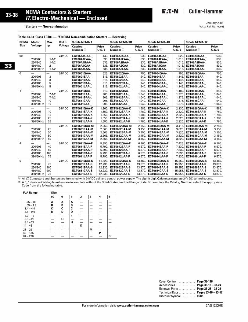
33-38
33
NEMA Contactors & StartersIT. Electro-Mechanical — Enclosed
Starters — Non-combinationFor more information visit: www.cutler-hammer.eaton.com
January 2003Vol. 2, Ref. No. [0056]
Table 33-63. Class ECT06 — IT. NEMA Non-combination Starters — Reversing
1 All IT. Contactors and Starters are furnished with 24V DC coil and control power supply. The eighth digit Q denotes separate 24V DC control source.2 A “_” denotes Catalog Numbers are incomplete without the Solid-State Overload Range Code. To complete the Catalog Number, select the appropriate
Code from the following table:
NEMASize
MotorVoltage
Max.hp
Coil 1
Voltage3-Pole NEMA 1 3-Pole NEMA 3R 3-Pole NEMA 4X 3-Pole NEMA 12
Catalog Number 2
PriceU.S. $
Catalog Number 2
PriceU.S. $
Catalog Number 2
PriceU.S. $
Catalog Number 2
PriceU.S. $
00 —200/208230/240460/480380/50 Hz
—1-1/21-1/221-1/2
24V DC ECT06A1QAA-_ECT06A1EAA-_ECT06A1BAA-_ECT06A1CAA-_ECT06A1LAA-_
443.635.635.635.635.
ECT06A2QAA-_ECT06A2EAA-_ECT06A2BAA-_ECT06A2CAA-_ECT06A2LAA-_
635.830.830.830.830.
ECT06A4QAA-_ECT06A4EAA-_ECT06A4BAA-_ECT06A4CAA-_ECT06A4LAA-_
820.1,015.1,015.1,015.1,015.
ECT06A8QAA-_ECT06A8EAA-_ECT06A8BAA-_ECT06A8CAA-_ECT06A8LAA-_
635.830.830.830.830.
0 —200/208230/240460/480380/50 Hz
—3 3 55
24V DC ECT0601QAA-_ECT0601EAA-_ECT0601BAA-_ECT0601CAA-_ECT0601LAA-_
625.815.815.815.815.
ECT0602QAA-_ECT0602EAA-_ECT0602BAA-_ECT0602CAA-_ECT0602LAA-_
750.940.940.940.940.
ECT0604QAA-_ECT0604EAA-_ECT0604BAA-_ECT0604CAA-_ECT0604LAA-_
955.1,145.1,145.1,145.1,145.
ECT0608QAA-_ECT0608EAA-_ECT0608BAA-_ECT0608CAA-_ECT0608LAA-_
750.940.940.940.940.
1 —200/208230/240460/480380/50 Hz
—7-1/27-1/2
1010
24V DC ECT0611QAA-_ECT0611EAA-_ECT0611BAA-_ECT0611CAA-_ECT0611LAA-_
710.905.905.905.905.
ECT0612QAA-_ECT0612EAA-_ECT0612BAA-_ECT0612CAA-_ECT0612LAA-_
845.1,040.1,040.1,040.1,040.
ECT0614QAA-_ECT0614EAA-_ECT0614BAA-_ECT0614CAA-_ECT0614LAA-_
1,180.1,375.1,375.1,375.1,375.
ECT0618QAA-_ECT0618EAA-_ECT0618BAA-_ECT0618CAA-_ECT0618LAA-_
845.1,040.1,040.1,040.1,040.
2 —200/208230/240460/480380/50 Hz
—10152525
24V DC ECT0621QAA-KECT0621EAA-KECT0621BAA-KECT0621CAA-KECT0621LAA-K
1,360.1,550.1,550.1,550.1,550.
ECT0622QAA-KECT0622EAA-KECT0622BAA-KECT0622CAA-KECT0622LAA-K
1,585.1,780.1,780.1,780.1,780.
ECT0624QAA-KECT0624EAA-KECT0624BAA-KECT0624CAA-KECT0624LAA-K
2,130.2,320.2,320.2,320.2,320.
ECT0628QAA-KECT0628EAA-KECT0628BAA-KECT0628CAA-KECT0628LAA-K
1,585.1,780.1,780.1,780.1,780.
3 —200/208230/240460/480380/50 Hz
—25305050
24V DC ECT0631QAA-MECT0631EAA-MECT0631BAA-MECT0631CAA-MECT0631LAA-M
2,260.2,665.2,665.2,665.2,665.
ECT0632QAA-MECT0632EAA-MECT0632BAA-MECT0632CAA-MECT0632LAA-M
2,750.3,150.3,150.3,150.3,150.
ECT0634QAA-MECT0634EAA-MECT0634BAA-MECT0634CAA-MECT0634LAA-M
3,415.3,820.3,820.3,820.3,820.
ECT0638QAA-MECT0638EAA-MECT0638BAA-MECT0638CAA-MECT0638LAA-M
2,750.3,150.3,150.3,150.3,150.
4 —200/208230/240460/480380/50 Hz
—4050
10075
24V DC ECT0641QAA-PECT0641EAA-PECT0641BAA-PECT0641CAA-PECT0641LAA-P
5,390.5,790.5,790.5,790.5,790.
ECT0642QAA-PECT0642EAA-PECT0642BAA-PECT0642CAA-PECT0642LAA-P
6,160.6,570.6,570.6,570.6,570.
ECT0644QAA-PECT0644EAA-PECT0644BAA-PECT0644CAA-PECT0644LAA-P
7,425.7,830.7,830.7,830.7,830.
ECT0648QAA-PECT0648EAA-PECT0648BAA-PECT0648CAA-PECT0648LAA-P
6,160.6,570.6,570.6,570.6,570.
5 —200/208230/240460/480380/50 Hz
—75
10020075
24V DC ECT0651QAA-SECT0651EAA-SECT0651BAA-SECT0651CAA-SECT0651LAA-S
11,820.12,230.12,230.12,230.12,230.
ECT0652QAA-SECT0652EAA-SECT0652BAA-SECT0652CAA-SECT0652LAA-S
13,460.13,870.13,870.13,870.13,870.
ECT0654QAA-SECT0654EAA-SECT0654BAA-SECT0654CAA-SECT0654LAA-S
15,550.15,955.15,955.15,955.15,955.
ECT0658QAA-SECT0658EAA-SECT0658BAA-SECT0658CAA-SECT0658LAA-S
13,460.13,870.13,870.13,870.13,870.
FLA Range Size
00 0 1 2 3 4 5
.25 – .80
.59 – 1.91.4 – 4.42.8 – 9.0
ABCD
ABCD
ABCD
————
————
————
————
5.0 – 166.3 – 208.4 – 27
14 – 45
————
—G——
F—H—
———K
————
————
————
28 – 2942 – 13584 – 270
———
———
———
———
M——
—P—
——S
Cover Control . . . . . . . . . . . . . Page 33-116Accessories . . . . . . . . . . . . . . Page 33-13 – 33-24Renewal Parts . . . . . . . . . . . . Page 33-25 – 33-26Technical Data . . . . . . . . . . . . Pages 33-10 – 33-12Discount Symbol . . . . . . . . . . 1CD1
CA08102001E
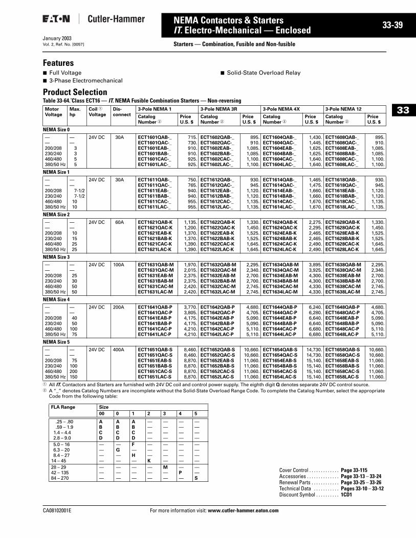
CA08102001E For more
39
33-NEMA Contactors & StartersIT. Electro-Mechanical — Enclosed Starters — Combination, Fusible and Non-fusibleJanuary 2003Vol. 2, Ref. No. [0057]
33
Features■ Full Voltage■ 3-Phase Electromechanical
■ Solid-State Overload Relay
Product SelectionTable 33-64. Class ECT16 — IT. NEMA Fusible Combination Starters — Non-reversing
1 All IT. Contactors and Starters are furnished with 24V DC coil and control power supply. The eighth digit Q denotes separate 24V DC control source.2 A “_” denotes Catalog Numbers are incomplete without the Solid-State Overload Range Code. To complete the Catalog Number, select the appropriate
Code from the following table:
MotorVoltage
Max.hp
Coil 1
VoltageDis-connect
3-Pole NEMA 1 3-Pole NEMA 3R 3-Pole NEMA 4X 3-Pole NEMA 12
CatalogNumber 2
Price U.S. $
Catalog Number 2
Price U.S. $
Catalog Number 2
Price U.S. $
Catalog Number 2
Price U.S. $
NEMA Size 0——200/208230/240460/480380/50 Hz
——
33 55
24V DC 30A ECT1601QAB-_ECT1601QAC-_ECT1601EAB-_ECT1601BAB-_ECT1601CAC-_ECT1601LAC-_
715.730.910.910.925.925.
ECT1602QAB-_ECT1602QAC-_ECT1602EAB-_ECT1602BAB-_ECT1602CAC-_ECT1602LAC-_
895.910.
1,085.1,085.1,100.1,100.
ECT1604QAB-_ECT1604QAC-_ECT1604EAB-_ECT1604BAB-_ECT1604CAC-_ECT1604LAC-_
1,430.1,445.1,625.1,625.1,640.1,640.
ECT1608QAB-_ECT1608QAC-_ECT1608EAB-_ECT1608BAB-_ECT1608CAC-_ECT1608LAC-_
895.910.
1,085.1,085.1,100.1,100.
NEMA Size 1——200/208230/240460/480380/50 Hz
——
7-1/27-1/2
1010
24V DC 30A ECT1611QAB-_ECT1611QAC-_ECT1611EAB-_ECT1611BAB-_ECT1611CAC-_ECT1611LAC-_
750.765.940.940.955.955.
ECT1612QAB-_ECT1612QAC-_ECT1612EAB-_ECT1612BAB-_ECT1612CAC-_ECT1612LAC-_
930.945.
1,120.1,120.1,135.1,135.
ECT1614QAB-_ECT1614QAC-_ECT1614EAB-_ECT1614BAB-_ECT1614CAC-_ECT1614LAC-_
1,465.1,475.1,660.1,660.1,670.1,670.
ECT1618QAB-_ECT1618QAC-_ECT1618EAB-_ECT1618BAB-_ECT1618CAC-_ECT1618LAC-_
930.945.
1,120.1,120.1,135.1,135.
NEMA Size 2——200/208230/240460/480380/50 Hz
——10152525
24V DC 60A ECT1621QAB-KECT1621QAC-KECT1621EAB-KECT1621BAB-KECT1621CAC-KECT1621LAC-K
1,135.1,200.1,370.1,370.1,390.1,390.
ECT1622QAB-KECT1622QAC-KECT1622EAB-KECT1622BAB-KECT1622CAC-KECT1622LAC-K
1,330.1,450.1,525.1,525.1,645.1,645.
ECT1624QAB-KECT1624QAC-KECT1624EAB-KECT1624BAB-KECT1624CAC-KECT1624LAC-K
2,275.2,295.2,465.2,465.2,490.2,490.
ECT1628QAB-KECT1628QAC-KECT1628EAB-KECT1628BAB-KECT1628CAC-KECT1628LAC-K
1,330.1,450.1,525.1,525.1,645.1,645.
NEMA Size 3——200/208230/240460/480380/50 Hz
——2530 5050
24V DC 100A ECT1631QAB-MECT1631QAC-MECT1631EAB-MECT1631BAB-MECT1631CAC-MECT1631LAC-M
1,970.2,015.2,375.2,375.2,420.2,420.
ECT1632QAB-MECT1632QAC-MECT1632EAB-MECT1632BAB-MECT1632CAC-MECT1632LAC-M
2,295.2,340.2,700.2,700.2,745.2,745.
ECT1634QAB-MECT1634QAC-MECT1634EAB-MECT1634BAB-MECT1634CAC-MECT1634LAC-M
3,895.3,925.4,300.4,300.4,330.4,330.
ECT1638QAB-MECT1638QAC-MECT1638EAB-MECT1638BAB-MECT1638CAC-MECT1638LAC-M
2,295.2,340.2,700.2,700.2,745.2,745.
NEMA Size 4——200/208230/240460/480380/50 Hz
——40 50
10075
24V DC 200A ECT1641QAB-PECT1641QAC-PECT1641EAB-PECT1641BAB-PECT1641CAC-PECT1641LAC-P
3,770.3,805.4,175.4,175.4,210.4,210.
ECT1642QAB-PECT1642QAC-PECT1642EAB-PECT1642BAB-PECT1642CAC-PECT1642LAC-P
4,680.4,705.5,090.5,090.5,110.5,110.
ECT1644QAB-PECT1644QAC-PECT1644EAB-PECT1644BAB-PECT1644CAC-PECT1644LAC-P
6,240.6,280.6,640.6,640.6,680.6,680.
ECT1648QAB-PECT1648QAC-PECT1648EAB-PECT1648BAB-PECT1648CAC-PECT1648LAC-P
4,680.4,705.5,090.5,090.5,110.5,110.
NEMA Size 5——200/208230/240460/480380/50 Hz
——75
100200150
24V DC 400A ECT1651QAB-SECT1651QAC-SECT1651EAB-SECT1651BAB-SECT1651CAC-SECT1651LAC-S
8,460.8,460.8,870.8,870.8,870.8,870.
ECT1652QAB-SECT1652QAC-SECT1652EAB-SECT1652BAB-SECT1652CAC-SECT1652LAC-S
10,660.10,660.11,060.11,060.11,060.11,060.
ECT1654QAB-SECT1654QAC-SECT1654EAB-SECT1654BAB-SECT1654CAC-SECT1654LAC-S
14,730.14,730.15,140.15,140.15,140.15,140.
ECT1658QAB-SECT1658QAC-SECT1658EAB-SECT1658BAB-SECT1658CAC-SECT1658LAC-S
10,660.10,660.11,060.11,060.11,060.11,060.
FLA Range Size
00 0 1 2 3 4 5
.25 – .80
.59 – 1.91.4 – 4.42.8 – 9.0
ABCD
ABCD
ABCD
————
————
————
————
5.0 – 166.3 – 208.4 – 27
14 – 45
————
—G——
F—H—
———K
————
————
————
28 – 2942 – 13584 – 270
———
———
———
———
M——
—P—
——S
Cover Control . . . . . . . . . . . . . Page 33-115Accessories . . . . . . . . . . . . . . Page 33-13 – 33-24Renewal Parts . . . . . . . . . . . . Page 33-25 – 33-26Technical Data . . . . . . . . . . . Pages 33-10 – 33-12Discount Symbol . . . . . . . . . . 1CD1
information visit: www.cutler-hammer.eaton.com

33-40
33
NEMA Contactors & StartersIT. Electro-Mechanical — Enclosed
Starters — Combination, Fusible and Non-fusibleFor more information visit: www.cutler-hammer.eaton.com
January 2003Vol. 2, Ref. No. [0058]
Table 33-65. Class ECT16-NF — IT. NEMA Non-fusible Combination Starters — Non-reversing
1 All IT. Contactors and Starters are furnished with 24V DC coil and control power supply. The eighth digit Q denotes separate 24V DC control source.2 A “_” denotes Catalog Numbers are incomplete without the Solid-State Overload Range Code. To complete the Catalog Number, select the appropriate
Code from the following table:
MotorVoltage
Max.hp
Coil 1
VoltageDis-connect
3-Pole NEMA 1 3-Pole NEMA 3R 3-Pole NEMA 4X 3-Pole NEMA 12
Catalog Number 2
Price U.S. $
Catalog Number 2
Price U.S. $
Catalog Number 2
Price U.S. $
Catalog Number 2
Price U.S. $
NEMA Size 0—200/208230/240460/480380/50 Hz
—3355
24V DC 30A ECT1601QAA-_ECT1601EAA-_ECT1601BAB-_ECT1601CAA-_ECT1601LAA-_
670.856.856.856.856.
ECT1602QAA-_ECT1602EAA-_ECT1602BAB-_ECT1602CAA-_ECT1602LAA-_
840.1,026.1,026.1,026.1,026.
ECT1604QAA-_ECT1604EAA-_ECT1604BAB-_ECT1604CAA-_ECT1604LAA-_
1,365.1,551.1,551.1,551.1,551.
ECT1608QAA-_ECT1608EAA-_ECT1608BAB-_ECT1608CAA-_ECT1608LAA-_
840.1,026.1,026.1,026.1,026.
NEMA Size 1—200/208230/240460/480380/50 Hz
—7-1/27-1/2
1010
24V DC 30A ECT1611QAA-_ECT1611EAA-_ECT1611BAA-_ECT1611CAA-_ECT1611LAA-_
705.891.891.891.891.
ECT1612QAA-_ECT1612EAA-_ECT1612BAA-_ECT1612CAA-_ECT1612LAA-_
875.1,061.1,061.1,061.1,061.
ECT1614QAA-_ECT1614EAA-_ECT1614BAA-_ECT1614CAA-_ECT1614LAA-_
1,395.1,581.1,581.1,581.1,581.
ECT1618QAA-_ECT1618EAA-_ECT1618BAA-_ECT1618CAA-_ECT1618LAA-_
875.1,061.1,061.1,061.1,061.
NEMA Size 2—200/208230/240460/480380/50 Hz
—10152525
24V DC 60A ECT1621QAA-KECT1621EAA-KECT1621BAA-KECT1621CAA-KECT1621LAA-K
1,105.1,291.1,291.1,291.1,291.
ECT1622QAA-KECT1622EAA-KECT1622BAA-KECT1622CAA-KECT1622LAA-K
1,350.1,536.1,536.1,536.1,536.
ECT1624QAA-KECT1624EAA-KECT1624BAA-KECT1624CAA-KECT1624LAA-K
2,170.2,356.2,356.2,356.2,356.
ECT1628QAA-KECT1628EAA-KECT1628BAA-KECT1628CAA-KECT1628LAA-K
1,350.1,536.1,536.1,536.1,536.
NEMA Size 3—200/208230/240460/480380/50 Hz
—25305050
24V DC 100A ECT1631QAA-MECT1631EAA-MECT1631BAB-MECT1631CAA-MECT1631LAA-M
1,830.2,221.2,221.2,221.2,221.
ECT1632QAA-MECT1632EAA-MECT1632BAB-MECT1632CAA-MECT1632LAA-M
2,150.2,541.2,541.2,541.2,541.
ECT1634QAA-MECT1634EAA-MECT1634BAB-MECT1634CAA-MECT1634LAA-M
3,690.4,081.4,081.4,081.4,081.
ECT1638QAA-MECT1638EAA-MECT1638BAB-MECT1638CAA-MECT1638LAA-M
2,150.2,541.2,541.2,541.2,541.
NEMA Size 4—200/208230/240460/480380/50 Hz
—4050
10075
24V DC 200A ECT1641QAA-PECT1641EAA-PECT1641BAA-PECT1641CAA-PECT1641LAA-P
3,520.3,911.3,911.3,911.3,911.
ECT1642QAA-PECT1642EAA-PECT1642BAA-PECT1642CAA-PECT1642LAA-P
4,395.4,786.4,786.4,786.4,786.
ECT1644QAA-PECT1644EAA-PECT1644BAA-PECT1644CAA-PECT1644LAA-P
5,900.6,291.6,291.6,291.6,291.
ECT1648QAA-PECT1648EAA-PECT1648BAA-PECT1648CAA-PECT1648LAA-P
4,395.4,786.4,786.4,786.4,786.
NEMA Size 5—200/208230/240460/480380/50 Hz
—75
100200150
24V DC 400A ECT1651QAA-SECT1651EAA-SECT1651BAA-SECT1651CAA-SECT1651LAA-S
7,900.8,291.8,291.8,291.8,291.
ECT1652QAA-SECT1652EAA-SECT1652BAA-SECT1652CAA-SECT1652LAA-S
10,030.10,421.10,421.10,421.10,421.
ECT1654QAA-SECT1654EAA-SECT1654BAA-SECT1654CAA-SECT1654LAA-S
13,960.14,351.14,351.14,351.14,351.
ECT1658QAA-SECT1658EAA-SECT1658BAA-SECT1658CAA-SECT1658LAA-S
10,030.10,421.10,421.10,421.10,421.
FLA Range Size
00 0 1 2 3 4 5
.25 – .80
.59 – 1.91.4 – 4.42.8 – 9.0
ABCD
ABCD
ABCD
————
————
————
————
5.0 – 166.3 – 208.4 – 27
14 – 45
————
—G——
F—H—
———K
————
————
————
28 – 2942 – 13584 – 270
———
———
———
———
M——
—P—
——S
Cover Control . . . . . . . . . . . . . . Page 33-115Accessories . . . . . . . . . . . . . . . Page 33-13 – 33-24Renewal Parts . . . . . . . . . . . . . Page 33-25 – 33-26Technical Data . . . . . . . . . . . . . Pages 33-10 – 33-12Discount Symbol . . . . . . . . . . . 1CD1
CA08102001E
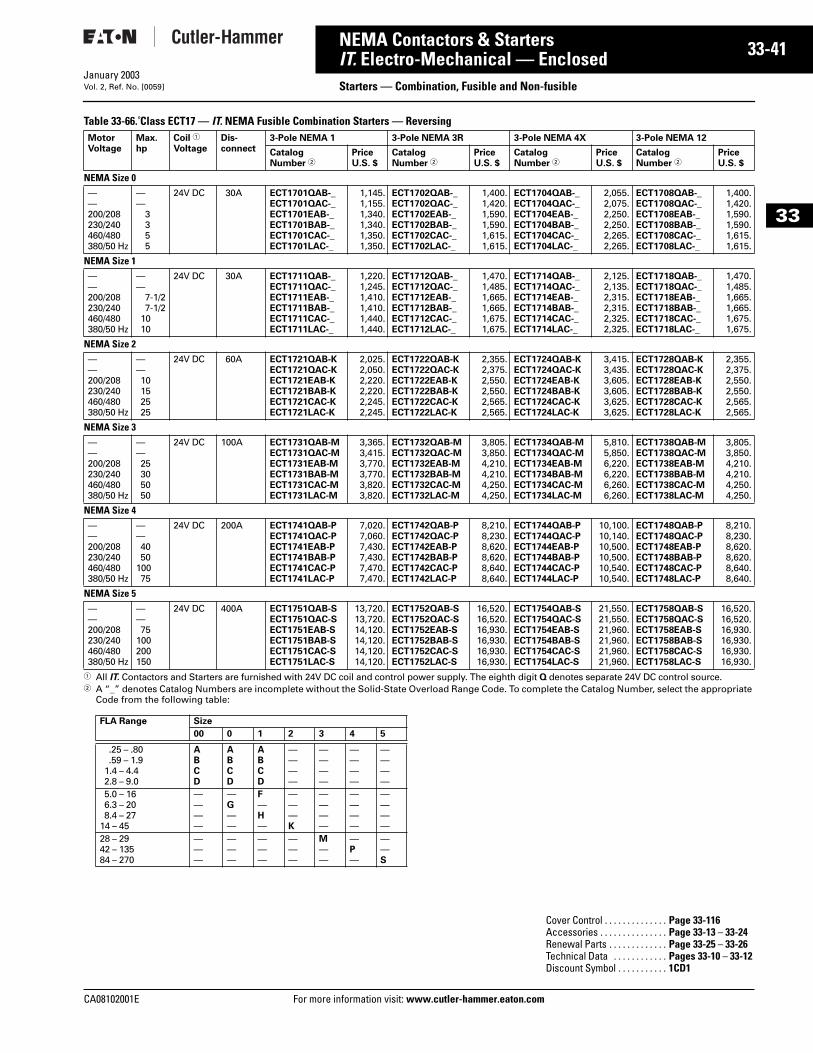
CA08102001E For more
41
33-NEMA Contactors & StartersIT. Electro-Mechanical — Enclosed Starters — Combination, Fusible and Non-fusibleJanuary 2003Vol. 2, Ref. No. [0059]
33
Table 33-66. Class ECT17 — IT. NEMA Fusible Combination Starters — Reversing
1 All IT. Contactors and Starters are furnished with 24V DC coil and control power supply. The eighth digit Q denotes separate 24V DC control source.2 A “_” denotes Catalog Numbers are incomplete without the Solid-State Overload Range Code. To complete the Catalog Number, select the appropriate
Code from the following table:
MotorVoltage
Max.hp
Coil 1
VoltageDis-connect
3-Pole NEMA 1 3-Pole NEMA 3R 3-Pole NEMA 4X 3-Pole NEMA 12
Catalog Number 2
Price U.S. $
Catalog Number 2
Price U.S. $
Catalog Number 2
Price U.S. $
Catalog Number 2
Price U.S. $
NEMA Size 0——200/208230/240460/480380/50 Hz
——
3 3 55
24V DC 30A ECT1701QAB-_ECT1701QAC-_ECT1701EAB-_ECT1701BAB-_ECT1701CAC-_ECT1701LAC-_
1,145.1,155.1,340.1,340.1,350.1,350.
ECT1702QAB-_ECT1702QAC-_ECT1702EAB-_ECT1702BAB-_ECT1702CAC-_ECT1702LAC-_
1,400.1,420.1,590.1,590.1,615.1,615.
ECT1704QAB-_ECT1704QAC-_ECT1704EAB-_ECT1704BAB-_ECT1704CAC-_ECT1704LAC-_
2,055.2,075.2,250.2,250.2,265.2,265.
ECT1708QAB-_ECT1708QAC-_ECT1708EAB-_ECT1708BAB-_ECT1708CAC-_ECT1708LAC-_
1,400.1,420.1,590.1,590.1,615.1,615.
NEMA Size 1——200/208230/240460/480380/50 Hz
——
7-1/27-1/2
1010
24V DC 30A ECT1711QAB-_ECT1711QAC-_ECT1711EAB-_ECT1711BAB-_ECT1711CAC-_ECT1711LAC-_
1,220.1,245.1,410.1,410.1,440.1,440.
ECT1712QAB-_ECT1712QAC-_ECT1712EAB-_ECT1712BAB-_ECT1712CAC-_ECT1712LAC-_
1,470.1,485.1,665.1,665.1,675.1,675.
ECT1714QAB-_ECT1714QAC-_ECT1714EAB-_ECT1714BAB-_ECT1714CAC-_ECT1714LAC-_
2,125.2,135.2,315.2,315.2,325.2,325.
ECT1718QAB-_ECT1718QAC-_ECT1718EAB-_ECT1718BAB-_ECT1718CAC-_ECT1718LAC-_
1,470.1,485.1,665.1,665.1,675.1,675.
NEMA Size 2——200/208230/240460/480380/50 Hz
——10152525
24V DC 60A ECT1721QAB-KECT1721QAC-KECT1721EAB-KECT1721BAB-KECT1721CAC-KECT1721LAC-K
2,025.2,050.2,220.2,220.2,245.2,245.
ECT1722QAB-KECT1722QAC-KECT1722EAB-KECT1722BAB-KECT1722CAC-KECT1722LAC-K
2,355.2,375.2,550.2,550.2,565.2,565.
ECT1724QAB-KECT1724QAC-KECT1724EAB-KECT1724BAB-KECT1724CAC-KECT1724LAC-K
3,415.3,435.3,605.3,605.3,625.3,625.
ECT1728QAB-KECT1728QAC-KECT1728EAB-KECT1728BAB-KECT1728CAC-KECT1728LAC-K
2,355.2,375.2,550.2,550.2,565.2,565.
NEMA Size 3——200/208230/240460/480380/50 Hz
——25 305050
24V DC 100A ECT1731QAB-MECT1731QAC-MECT1731EAB-MECT1731BAB-MECT1731CAC-MECT1731LAC-M
3,365.3,415.3,770.3,770.3,820.3,820.
ECT1732QAB-MECT1732QAC-MECT1732EAB-MECT1732BAB-MECT1732CAC-MECT1732LAC-M
3,805.3,850.4,210.4,210.4,250.4,250.
ECT1734QAB-MECT1734QAC-MECT1734EAB-MECT1734BAB-MECT1734CAC-MECT1734LAC-M
5,810.5,850.6,220.6,220.6,260.6,260.
ECT1738QAB-MECT1738QAC-MECT1738EAB-MECT1738BAB-MECT1738CAC-MECT1738LAC-M
3,805.3,850.4,210.4,210.4,250.4,250.
NEMA Size 4——200/208230/240460/480380/50 Hz
——4050
10075
24V DC 200A ECT1741QAB-PECT1741QAC-PECT1741EAB-PECT1741BAB-PECT1741CAC-PECT1741LAC-P
7,020.7,060.7,430.7,430.7,470.7,470.
ECT1742QAB-PECT1742QAC-PECT1742EAB-PECT1742BAB-PECT1742CAC-PECT1742LAC-P
8,210.8,230.8,620.8,620.8,640.8,640.
ECT1744QAB-PECT1744QAC-PECT1744EAB-PECT1744BAB-PECT1744CAC-PECT1744LAC-P
10,100.10,140.10,500.10,500.10,540.10,540.
ECT1748QAB-PECT1748QAC-PECT1748EAB-PECT1748BAB-PECT1748CAC-PECT1748LAC-P
8,210.8,230.8,620.8,620.8,640.8,640.
NEMA Size 5——200/208230/240460/480380/50 Hz
——75
100200150
24V DC 400A ECT1751QAB-SECT1751QAC-SECT1751EAB-SECT1751BAB-SECT1751CAC-SECT1751LAC-S
13,720.13,720.14,120.14,120.14,120.14,120.
ECT1752QAB-SECT1752QAC-SECT1752EAB-SECT1752BAB-SECT1752CAC-SECT1752LAC-S
16,520.16,520.16,930.16,930.16,930.16,930.
ECT1754QAB-SECT1754QAC-SECT1754EAB-SECT1754BAB-SECT1754CAC-SECT1754LAC-S
21,550.21,550.21,960.21,960.21,960.21,960.
ECT1758QAB-SECT1758QAC-SECT1758EAB-SECT1758BAB-SECT1758CAC-SECT1758LAC-S
16,520.16,520.16,930.16,930.16,930.16,930.
FLA Range Size
00 0 1 2 3 4 5
.25 – .80
.59 – 1.91.4 – 4.42.8 – 9.0
ABCD
ABCD
ABCD
————
————
————
————
5.0 – 166.3 – 208.4 – 27
14 – 45
————
—G——
F—H—
———K
————
————
————
28 – 2942 – 13584 – 270
———
———
———
———
M——
—P—
——S
Cover Control . . . . . . . . . . . . . . Page 33-116Accessories . . . . . . . . . . . . . . . Page 33-13 – 33-24Renewal Parts . . . . . . . . . . . . . Page 33-25 – 33-26Technical Data . . . . . . . . . . . . Pages 33-10 – 33-12Discount Symbol . . . . . . . . . . . 1CD1
information visit: www.cutler-hammer.eaton.com
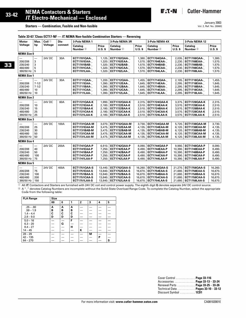
33-42
33
NEMA Contactors & StartersIT. Electro-Mechanical — Enclosed
Starters — Combination, Fusible and Non-fusibleFor more information visit: www.cutler-hammer.eaton.com
January 2003Vol. 2, Ref. No. [0060]
Table 33-67. Class ECT17-NF — IT. NEMA Non-fusible Combination Starters — Reversing
1 All IT. Contactors and Starters are furnished with 24V DC coil and control power supply. The eighth digit Q denotes separate 24V DC control source.2 A “_” denotes Catalog Numbers are incomplete without the Solid-State Overload Range Code. To complete the Catalog Number, select the appropriate
Code from the following table:
MotorVoltage
Max.hp
Coil 1
VoltageDis-connect
3-Pole NEMA 1 3-Pole NEMA 3R 3-Pole NEMA 4X 3-Pole NEMA 12
Catalog Number 2
Price U.S. $
Catalog Number 2
Price U.S. $
Catalog Number 2
Price U.S. $
Catalog Number 2
Price U.S. $
NEMA Size 0—200/208230/240460/480380/50 Hz
—3355
24V DC 30A ECT1701QAA-_ECT1701EAA-_ECT1701BAB-_ECT1701CAA-_ECT1701LAA-_
1,125.1,320.1,320.1,320.1,320.
ECT1702QAA-_ECT1702EAA-_ECT1702BAB-_ECT1702CAA-_ECT1702LAA-_
1,380.1,570.1,570.1,570.1,570.
ECT1704QAA-_ECT1704EAA-_ECT1704BAB-_ECT1704CAA-_ECT1704LAA-_
2,035.2,230.2,230.2,230.2,230.
ECT1708QAA-_ECT1708EAA-_ECT1708BAB-_ECT1708CAA-_ECT1708LAA-_
1,380.1,570.1,570.1,570.1,570.
NEMA Size 1—200/208230/240460/480380/50 Hz
—7-1/27-1/21010
24V DC 30A ECT1711QAA-_ECT1711EAA-_ECT1711BAA-_ECT1711CAA-_ECT1711LAA-_
1,200.1,390.1,390.1,390.1,390.
ECT1712QAA-_ECT1712EAA-_ECT1712BAA-_ECT1712CAA-_ECT1712LAA-_
1,455.1,645.1,645.1,645.1,645.
ECT1714QAA-_ECT1714EAA-_ECT1714BAA-_ECT1714CAA-_ECT1714LAA-_
2,105.2,295.2,295.2,295.2,295.
ECT1718QAA-_ECT1718EAA-_ECT1718BAA-_ECT1718CAA-_ECT1718LAA-_
1,455.1,645.1,645.1,645.1,645.
NEMA Size 2—200/208230/240460/480380/50 Hz
—10152525
24V DC 60A ECT1721QAA-KECT1721EAA-KECT1721BAA-KECT1721CAA-KECT1721LAA-K
1,990.2,180.2,180.2,180.2,180.
ECT1722QAA-KECT1722EAA-KECT1722BAA-KECT1722CAA-KECT1722LAA-K
2,315.2,510.2,510.2,510.2,510.
ECT1724QAA-KECT1724EAA-KECT1724BAA-KECT1724CAA-KECT1724LAA-K
3,375.3,570.3,570.3,570.3,570.
ECT1728QAA-KECT1728EAA-KECT1728BAA-KECT1728CAA-KECT1728LAA-K
2,315.2,510.2,510.2,510.2,510.
NEMA Size 3—200/208230/240460/480380/50 Hz
—25305050
24V DC 100A ECT1731QAA-MECT1731EAA-MECT1731BAB-MECT1731CAA-MECT1731LAA-M
3,070.3,475.3,475.3,475.3,475.
ECT1732QAA-MECT1732EAA-MECT1732BAB-MECT1732CAA-MECT1732LAA-M
3,730.4,135.4,135.4,135.4,135.
ECT1734QAA-MECT1734EAA-MECT1734BAB-MECT1734CAA-MECT1734LAA-M
5,720.6,120.6,120.6,120.6,120.
ECT1738QAA-MECT1738EAA-MECT1738BAB-MECT1738CAA-MECT1738LAA-M
3,730.4,135.4,135.4,135.4,135.
NEMA Size 4—200/208230/240460/480380/50 Hz
—405010075
24V DC 200A ECT1741QAA-PECT1741EAA-PECT1741BAA-PECT1741CAA-PECT1741LAA-P
6,910.7,250.7,250.7,250.7,250.
ECT1742QAA-PECT1742EAA-PECT1742BAA-PECT1742CAA-PECT1742LAA-P
8,090.8,490.8,490.8,490.8,490.
ECT1744QAA-PECT1744EAA-PECT1744BAA-PECT1744CAA-PECT1744LAA-P
9,980.10,390.10,390.10,390.10,390.
ECT1748QAA-PECT1748EAA-PECT1748BAA-PECT1748CAA-PECT1748LAA-P
8,090.8,490.8,490.8,490.8,490.
NEMA Size 5—200/208230/240460/480380/50 Hz
—75100200150
24V DC 400A ECT1751QAA-SECT1751EAA-SECT1751BAA-SECT1751CAA-SECT1751LAA-S
13,440.13,840.13,840.13,840.13,840.
ECT1752QAA-SECT1752EAA-SECT1752BAA-SECT1752CAA-SECT1752LAA-S
16,260.16,670.16,670.16,670.16,670.
ECT1754QAA-SECT1754EAA-SECT1754BAA-SECT1754CAA-SECT1754LAA-S
21,270.21,680.21,680.21,680.21,680.
ECT1758QAA-SECT1758EAA-SECT1758BAA-SECT1758CAA-SECT1758LAA-S
16,260.16,670.16,670.16,670.16,670.
FLA Range Size
00 0 1 2 3 4 5
.25 – .80
.59 – 1.91.4 – 4.42.8 – 9.0
ABCD
ABCD
ABCD
————
————
————
————
5.0 – 166.3 – 208.4 – 27
14 – 45
————
—G——
F—H—
———K
————
————
————
28 – 2942 – 13584 – 270
———
———
———
———
M——
—P—
——S
Cover Control . . . . . . . . . . . . . . Page 33-116Accessories . . . . . . . . . . . . . . . Page 33-13 – 33-24Renewal Parts . . . . . . . . . . . . . Page 33-25 – 33-26Technical Data . . . . . . . . . . . . . Pages 33-10 – 33-12Discount Symbol . . . . . . . . . . . 1CD1
CA08102001E

CA08102001E For more
43
33-NEMA Contactors & StartersIT. Electro-Mechanical — Enclosed Starters — Combination with HMCP or HMCPEJanuary 2003Vol. 2, Ref. No. [0061]
33
Features■ Full Voltage■ 3-Phase Electromechanical
■ Solid-State Overload Relay■ Integrated Cover Control (NEMA 1/12)
Product SelectionTable 33-68. Class ECT22 — IT. NEMA Combination Starters with HMCP/E — Non-reversing
1 All IT. Contactors and Starters are furnished with 24V DC coil and control power supply. The eighth digit Q denotes separate 24V DC control source.2 A “_” denotes Catalog Numbers are incomplete without the Solid-State Overload Range Code. To complete the Catalog Number, select the appropriate
Code from the following table:
MotorVoltage
Max. hp
MagnetCoilVoltage1
CircuitBreakerType
3-Pole NEMA 1General Purpose
3-Pole NEMA 3RRainproof
3-Pole NEMA 4XWatertight
3-Pole NEMA 12Dust-Tight
CatalogNumber 2
PriceU.S. $
CatalogNumber 2
PriceU.S. $
CatalogNumber 2
PriceU.S. $
CatalogNumber 2
PriceU.S. $
NEMA Size 0200 1
324V DC HMCPE 7A
HMCPE 15AECT2201EAC-_ECT2201EAD-_
1,145.1,145.
ECT2202EAC-_ECT2202EAD-_
1,330.1,330.
ECT2204EAC-_ECT2204EAD-_
1,870.1,870.
ECT2208EAC-_ECT2208EAD-_
1,330.1,330.
230 13
24V DC HMCPE 7AHMCPE 15A
ECT2201BAC-_ECT2201BAD-_
1,145.1,145.
ECT2202BAC-_ECT2202BAD-_
1,330.1,330.
ECT2204BAC-_ECT2204BAD-_
1,870.1,870.
ECT2208BAC-_ECT2208BAD-_
1,330.1,330.
460 135
24V DC HMCPE 3AHMCPE 7AHMCPE 15A
ECT2201CAB-_ECT2201CAC-_ECT2201CAD-_
1,145.1,145.1,145.
ECT2202CAB-_ECT2202CAC-_ECT2202CAD-_
1,330.1,330.1,330.
ECT2204CAB-_ECT2204CAC-_ECT2204CAD-_
1,870.1,870.1,870.
ECT2208CAB-_ECT2208CAC-_ECT2208CAD-_
1,330.1,330.1,330.
NEMA Size 1200 1
357-1/2
24V DC HMCPE 7AHMCPE 15AHMCPE 30AHMCPE 50A
ECT2211EAC-_ECT2211EAD-_ECT2211EAE-_ECT2211EAF-_
1,190.1,190.1,190.1,190.
ECT2212EAC-_ECT2212EAD-_ECT2212EAE-_ECT2212EAF-_
1,370.1,370.1,370.1,370.
ECT2214EAC-_ECT2214EAD-_ECT2214EAE-_ECT2214EAF-_
1,910.1,910.1,910.1,910.
ECT2218EAC-_ECT2218EAD-_ECT2218EAE-_ECT2218EAF-_
1,370.1,370.1,370.1,370.
230 1357-1/2
24V DC HMCPE 7AHMCPE 15AHMCPE 30AHMCPE 50A
ECT2211BAC-_ECT2211BAD-_ECT2211BAE-_ECT2211BAF-_
1,190.1,190.1,190.1,190.
ECT2212BAC-_ECT2212BAD-_ECT2212BAE-_ECT2212BAF-_
1,370.1,370.1,370.1,370.
ECT2214BAC-_ECT2214BAD-_ECT2214BAE-_ECT2214BAF-_
1,910.1,910.1,910.1,910.
ECT2218BAC-_ECT2218BAD-_ECT2218BAE-_ECT2218BAF-_
1,370.1,370.1,370.1,370.
460 135
10
24V DC HMCPE 3AHMCPE 7AHMCPE 15AHMCPE 30A
ECT2211CAB-_ECT2211CAC-_ECT2211CAD-_ECT2211CAE-_
1,190.1,190.1,190.1,190.
ECT2212CAB-_ECT2212CAC-_ECT2212CAD-_ECT2212CAE-_
1,370.1,370.1,370.1,370.
ECT2214CAB-_ECT2214CAC-_ECT2214CAD-_ECT2214CAE-_
1,910.1,910.1,910.1,910.
ECT2218CAB-_ECT2218CAC-_ECT2218CAD-_ECT2218CAE-_
1,370.1,370.1,370.1,370.
NEMA Size 2200 10 24V DC HMCPE 50A ECT2221EAF-K 1,610. ECT2222EAF-K 1,855. ECT2224EAF-K 2,705. ECT2228EAF-K 1,855.230 10
1524V DC HMCPE 50A
HMCPE 70AECT2221BAF-KECT2221BAW-K
1,610.1,610.
ECT2222BAF-KECT2222BAW-K
1,855.1,855.
ECT2224BAF-KECT2224BAW-K
2,705.2,705.
ECT2228BAF-KECT2228BAW-K
1,855.1,855.
460 25 24V DC HMCPE 50A ECT2221CAF-K 1,610. ECT2222CAF-K 1,855. ECT2224CAF-K 2,705. ECT2228CAF-K 1,855.NEMA Size 3200 20
2524V DC HMCPE 100A
HMCPE 100AECT2231EAG-MECT2231EAX-M
2,445.2,445.
ECT2232EAG-MECT2232EAX-M
2,770.2,770.
ECT2234EAG-MECT2234EAX-M
4,360.4,360.
ECT2238EAG-MECT2238EAX-M
2,770.2,770.
230 2530
24V DC HMCPE 100AHMCPE 100A
ECT2231BAG-MECT2231BAX-M
2,445.2,445.
ECT2232BAG-MECT2232BAX-M
2,770.2,770.
ECT2234BAG-MECT2234BAX-M
4,360.4,360.
ECT2238BAG-MECT2238BAX-M
2,770.2,770.
460 50 24V DC HMCPE 100A ECT2231CAG-M 2,445. ECT2232CAG-M 2,770. ECT2234CAG-M 4,360. ECT2238CAG-M 2,770.NEMA Size 4200 40 24V DC HMCP 150A ECT2241EAH-P 4,865. ECT2242EAH-P 5,770. ECT2244EAH-P 7,330. ECT2248EAH-P 5,770.230 50 24V DC HMCP 150A ECT2241BAH-P 4,865. ECT2242BAH-P 5,770. ECT2244BAH-P 7,330. ECT2248BAH-P 5,770.460 100 24V DC HMCP 150A ECT2241CAH-P 4,865. ECT2242CAH-P 5,770. ECT2244CAH-P 7,330. ECT2248CAH-P 5,770.
NEMA Size 5200 50
7524V DC HMCP 250A
HMCP 400AECT2251EAJ-SECT2251EAK-S
10,740.10,740.
ECT2252EAJ-SECT2252EAK-S
12,380.12,380.
ECT2254EAJ-SECT2254EAK-S
17,000.17,000.
ECT2258EAJ-SECT2258EAK-S
12,380.12,380.
230 60100
24V DC HMCP 250AHMCP 400A
ECT2251BAJ-SECT2251BAK-S
10,740.10,740.
ECT2252BAJ-SECT2252BAK-S
12,380.12,380.
ECT2254BAJ-SECT2254BAK-S
17,000.17,000.
ECT2258BAJ-SECT2258BAK-S
12,380.12,380.
460 125200
24V DC HMCP 250AHMCP 400A
ECT2251CAJ-SECT2251CAK-S
10,740.10,740.
ECT2252CAJ-SECT2252CAK-S
12,380.12,380.
ECT2254CAJ-SECT2254CAK-S
17,000.17,000.
ECT2258CAJ-SECT2258CAK-S
12,380.12,380.
FLA Range Size
00 0 1 2 3 4 5
.25 – .80
.59 – 1.91.4 – 4.42.8 – 9.0
ABCD
ABCD
ABCD
————
————
————
————
5.0 – 166.3 – 208.4 – 27
14 – 45
————
—G——
F—H—
———K
————
————
————
FLA Range Size
00 0 1 2 3 4 5
28 – 2942 – 13584 – 270
———
———
———
———
M——
—P—
——S
Cover Control . . . . . . . . . . . . . . Page 33-115Accessories . . . . . . . . . . . . . . . Page 33-13 – 33-24Renewal Parts . . . . . . . . . . . . . Page 33-25 – 33-26Technical Data . . . . . . . . . . . . Pages 33-10 – 33-12Discount Symbol . . . . . . . . . . . 1CD1
information visit: www.cutler-hammer.eaton.com
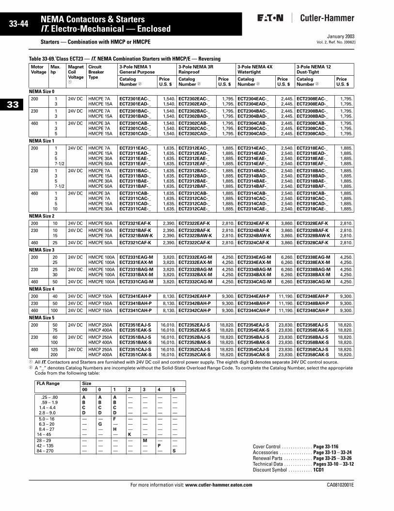
33-44
33
NEMA Contactors & StartersIT. Electro-Mechanical — Enclosed
Starters — Combination with HMCP or HMCPEFor more information visit: www.cutler-hammer.eaton.com
January 2003Vol. 2, Ref. No. [0062]
Table 33-69. Class ECT23 — IT. NEMA Combination Starters with HMCP/E — Reversing
1 All IT. Contactors and Starters are furnished with 24V DC coil and control power supply. The eighth digit Q denotes separate 24V DC control source. 2 A “_” denotes Catalog Numbers are incomplete without the Solid-State Overload Range Code. To complete the Catalog Number, select the appropriate
Code from the following table:
MotorVoltage
Max. hp
MagnetCoilVoltage1
CircuitBreakerType
3-Pole NEMA 1 General Purpose
3-Pole NEMA 3R Rainproof
3-Pole NEMA 4X Watertight
3-Pole NEMA 12 Dust-Tight
CatalogNumber 2
PriceU.S. $
CatalogNumber 2
PriceU.S. $
CatalogNumber 2
PriceU.S. $
CatalogNumber 2
PriceU.S. $
NEMA Size 0200 1
324V DC HMCPE 7A
HMCPE 15AECT2301EAC-_ECT2301EAD-_
1,540.1,540.
ECT2302EAC-_ECT2302EAD-_
1,795.1,795.
ECT2304EAC-_ECT2304EAD-_
2,445.2,445.
ECT2308EAC-_ECT2308EAD-_
1,795.1,795.
230 13
24V DC HMCPE 7AHMCPE 15A
ECT2301BAC-_ECT2301BAD-_
1,540.1,540.
ECT2302BAC-_ECT2302BAD-_
1,795.1,795.
ECT2304BAC-_ECT2304BAD-_
2,445.2,445.
ECT2308BAC-_ECT2308BAD-_
1,795.1,795.
460 135
24V DC HMCPE 3AHMCPE 7AHMCPE 15A
ECT2301CAB-_ECT2301CAC-_ECT2301CAD-_
1,540.1,540.1,540.
ECT2302CAB-_ECT2302CAC-_ECT2302CAD-_
1,795.1,795.1,795.
ECT2304CAB-_ECT2304CAC-_ECT2304CAD-_
2,445.2,445.2,445.
ECT2308CAB-_ECT2308CAC-_ECT2308CAD-_
1,795.1,795.1,795.
NEMA Size 1200 1
357-1/2
24V DC HMCPE 7AHMCPE 15AHMCPE 30AHMCPE 50A
ECT2311EAC-_ECT2311EAD-_ECT2311EAE-_ECT2311EAF-_
1,635.1,635.1,635.1,635.
ECT2312EAC-_ECT2312EAD-_ECT2312EAE-_ECT2312EAF-_
1,885.1,885.1,885.1,885.
ECT2314EAC-_ECT2314EAD-_ECT2314EAE-_ECT2314EAF-_
2,540.2,540.2,540.2,540.
ECT2318EAC-_ECT2318EAD-_ECT2318EAE-_ECT2318EAF-_
1,885.1,885.1,885.1,885.
230 1357-1/2
24V DC HMCPE 7AHMCPE 15AHMCPE 30AHMCPE 50A
ECT2311BAC-_ECT2311BAD-_ECT2311BAE-_ECT2311BAF-_
1,635.1,635.1,635.1,635.
ECT2312BAC-_ECT2312BAD-_ECT2312BAE-_ECT2312BAF-_
1,885.1,885.1,885.1,885.
ECT2314BAC-_ECT2314BAD-_ECT2314BAE-_ECT2314BAF-_
2,540.2,540.2,540.2,540.
ECT2318BAC-_ECT2318BAD-_ECT2318BAE-_ECT2318BAF-_
1,885.1,885.1,885.1,885.
460 135
10
24V DC HMCPE 3AHMCPE 7AHMCPE 15AHMCPE 30A
ECT2311CAB-_ECT2311CAC-_ECT2311CAD-_ECT2311CAE-_
1,635.1,635.1,635.1,635.
ECT2312CAB-_ECT2312CAC-_ECT2312CAD-_ECT2312CAE-_
1,885.1,885.1,885.1,885.
ECT2314CAB-_ECT2314CAC-_ECT2314CAD-_ECT2314CAE-_
2,540.2,540.2,540.2,540.
ECT2318CAB-_ECT2318CAC-_ECT2318CAD-_ECT2318CAE-_
1,885.1,885.1,885.1,885.
NEMA Size 2200 10 24V DC HMCPE 50A ECT2321EAF-K 2,390. ECT2322EAF-K 2,810. ECT2324EAF-K 3,860. ECT2328EAF-K 2,810.
230 1015
24V DC HMCPE 50AHMCPE 70A
ECT2321BAF-KECT2321BAW-K
2,390.2,390.
ECT2322BAF-KECT2322BAW-K
2,810.2,810.
ECT2324BAF-KECT2324BAW-K
3,860.3,860.
ECT2328BAF-KECT2328BAW-K
2,810.2,810.
460 25 24V DC HMCPE 50A ECT2321CAF-K 2,390. ECT2322CAF-K 2,810. ECT2324CAF-K 3,860. ECT2328CAF-K 2,810.
NEMA Size 3200 20
2524V DC HMCPE 100A
HMCPE 100AECT2331EAG-MECT2331EAX-M
3,820.3,820.
ECT2332EAG-MECT2332EAX-M
4,250.4,250.
ECT2334EAG-MECT2334EAX-M
6,260.6,260.
ECT2338EAG-MECT2338EAX-M
4,250.4,250.
230 2530
24V DC HMCPE 100AHMCPE 100A
ECT2331BAG-MECT2331BAX-M
3,820.3,820.
ECT2332BAG-MECT2332BAX-M
4,250.4,250.
ECT2334BAG-MECT2334BAX-M
6,260.6,260.
ECT2338BAG-MECT2338BAX-M
4,250.4,250.
460 50 24V DC HMCPE 100A ECT2331CAG-M 3,820. ECT2332CAG-M 4,250. ECT2334CAG-M 6,260. ECT2338CAG-M 4,250.
NEMA Size 4200 40 24V DC HMCP 150A ECT2341EAH-P 8,130. ECT2342EAH-P 9,300. ECT2344EAH-P 11,190. ECT2348EAH-P 9,300.
230 50 24V DC HMCP 150A ECT2341BAH-P 8,130. ECT2342BAH-P 9,300. ECT2344BAH-P 11,190. ECT2348BAH-P 9,300.
460 100 24V DC HMCP 150A ECT2341CAH-P 8,130. ECT2342CAH-P 9,300. ECT2344CAH-P 11,190. ECT2348CAH-P 9,300.
NEMA Size 5200 50
7524V DC HMCP 250A
HMCP 400AECT2351EAJ-SECT2351EAK-S
16,010.16,010.
ECT2352EAJ-SECT2352EAK-S
18,820.18,820.
ECT2354EAJ-SECT2354EAK-S
23,830.23,830.
ECT2358EAJ-SECT2358EAK-S
18,820.18,820.
230 60100
24V DC HMCP 250AHMCP 400A
ECT2351BAJ-SECT2351BAK-S
16,010.16,010.
ECT2352BAJ-SECT2352BAK-S
18,820.18,820.
ECT2354BAJ-SECT2354BAK-S
23,830.23,830.
ECT2358BAJ-SECT2358BAK-S
18,820.18,820.
460 125200
24V DC HMCP 250AHMCP 400A
ECT2351CAJ-SECT2351CAK-S
16,010.16,010.
ECT2352CAJ-SECT2352CAK-S
18,820.18,820.
ECT2354CAJ-SECT2354CAK-S
23,830.23,830.
ECT2358CAJ-SECT2358CAK-S
18,820.18,820.
FLA Range Size
00 0 1 2 3 4 5
.25 – .80
.59 – 1.91.4 – 4.42.8 – 9.0
ABCD
ABCD
ABCD
————
————
————
————
5.0 – 166.3 – 208.4 – 27
14 – 45
————
—G——
F—H—
———K
————
————
————
28 – 2942 – 13584 – 270
———
———
———
———
M——
—P—
——S
Cover Control . . . . . . . . . . . . . . Page 33-116Accessories . . . . . . . . . . . . . . . Page 33-13 – 33-24Renewal Parts . . . . . . . . . . . . . Page 33-25 – 33-26Technical Data . . . . . . . . . . . . . Pages 33-10 – 33-12Discount Symbol . . . . . . . . . . . 1CD1
CA08102001E
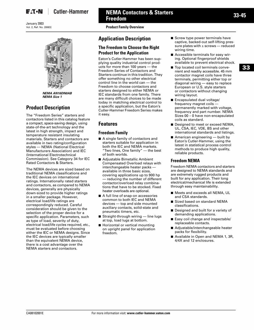
CA08102001E For more
45
33-NEMA Contactors & StartersFreedom
Product Family OverviewJanuary 2003Vol. 2, Ref. No. [0063]
33
Product DescriptionThe “Freedom Series” starters and contactors listed in this catalog feature a compact, space-saving design, using state-of-the-art technology and the latest in high strength, impact and temperature resistant insulating materials. Starters and contactors are available in two rating/configuration styles — NEMA (National Electrical Manufacturers Association) and IEC (International Electrotechnical Commission). See Category 34 for IEC Rated Contactors & Starters.
The NEMA devices are sized based on traditional NEMA classifications and the IEC devices on international ratings. Internationally rated starters and contactors, as compared to NEMA devices, generally are physically down-sized to provide higher ratings in a smaller package. However, electrical load/life ratings are correspondingly reduced. Careful consideration should be given to the selection of the proper device for a specific application. Parameters, such as type of load, severity of duty, electrical load/life cycles required, etc., must be evaluated before choosing either the IEC or NEMA designs. Since the IEC devices are typically smaller than the equivalent NEMA device, there is a cost advantage over the NEMA starters and contactors.
Application Description
The Freedom to Choose the Right Product for the ApplicationEaton’s Cutler-Hammer has been sup-plying quality industrial control prod-ucts for more than 100 years — the Freedom Series of Contactors and Starters continue in this tradition. They offer something no other electrical control line in the world can — the Freedom to choose contactors and starters designed to either NEMA or IEC standards from one family. There are many difficult choices to be made today in matching electrical control to a specific application, but the Eaton’s Cutler-Hammer Freedom Series makes it easy.
Features
Freedom Family■ A single family of contactors and
starters suitable for application in both the IEC and NEMA markets. “Two lines, One family” — the best of both worlds.
■ Adjustable Bimetallic Ambient Compensated Overload relays with interchangeable heater packs — available in three basic sizes, covering applications up to 900 hp — reducing the number of different contactor/overload relay combina-tions that have to be stocked. Fixed heater overloads are optional.
■ A full line of snap-on accessories common to both IEC and NEMA devices — top and side mounted auxiliary contacts, solid-state and pneumatic timers, etc.
■ Straight-through wiring — line lugs at top, load lugs at bottom.
■ Horizontal or vertical mounting on upright panel for application freedom.
■ Screw type power terminals have captive, backed-out self-lifting pres-sure plates with ± screws — reduced wiring time.
■ Accessible terminals for easy wir-ing. Optional fingerproof shields available to prevent electrical shock.
■ Top located coil terminals conve-nient and readily accessible. 45 mm contactor magnet coils have three terminals, permitting either top or diagonal wiring — easy to replace European or U.S. style starters or contactors without changing wiring layout.
■ Encapsulated dual voltage/frequency magnet coils — permanently marked with voltage, frequency and part number. NEMA Sizes 00 – 0 have non-encapsulated coils as standard.
■ Designed to meet or exceed NEMA, UL, CSA, IEC, VDE, BS and other international standards and listings.
■ American engineering — built by Eaton’s Cutler-Hammer, using the latest in statistical process control methods to produce high quality, reliable products.
Freedom NEMAFreedom NEMA contactors and starters are designed to NEMA standards and are extremely rugged products and built for any application. Their long electrical/mechanical life is extended through easy maintainability.
■ Meets and exceeds all NEMA, UL and CSA standards.
■ Sized based on standard NEMA classifications.
■ Designed and built for a variety of demanding applications.
■ Easy coil change and inspectable/replaceable contacts.
■ Adjustable/interchangeable heater packs for flexibility.
■ Available in Open and NEMA 1, 3R, 4/4X and 12 enclosures.
NEMA AN16DN0ABNEMA Size 1
information visit: www.cutler-hammer.eaton.com
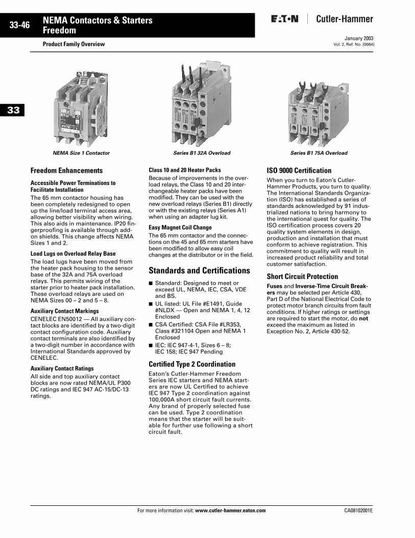
33-46
33
NEMA Contactors & StartersFreedom
Product Family OverviewFor more information visit: www.cutler-hammer.eaton.com
January 2003Vol. 2, Ref. No. [0064]
Freedom Enhancements
Accessible Power Terminations to Facilitate InstallationThe 65 mm contactor housing has been completely redesigned to open up the line/load terminal access area, allowing better visibility when wiring. This also aids in maintenance. IP20 fin-gerproofing is available through add-on shields. This change affects NEMA Sizes 1 and 2.
Load Lugs on Overload Relay BaseThe load lugs have been moved from the heater pack housing to the sensor base of the 32A and 75A overload relays. This permits wiring of the starter prior to heater pack installation. These overload relays are used on NEMA Sizes 00 – 2 and 5 – 8.
Auxiliary Contact MarkingsCENELEC EN50012 — All auxiliary con-tact blocks are identified by a two-digit contact configuration code. Auxiliary contact terminals are also identified by a two-digit number in accordance with International Standards approved by CENELEC.
Auxiliary Contact RatingsAll side and top auxiliary contact blocks are now rated NEMA/UL P300 DC ratings and IEC 947 AC-15/DC-13 ratings.
Class 10 and 20 Heater PacksBecause of improvements in the over-load relays, the Class 10 and 20 inter-changeable heater packs have been modified. They can be used with the new overload relays (Series B1) directly or with the existing relays (Series A1) when using an adapter lug kit.
Easy Magnet Coil ChangeThe 65 mm contactor and the connec-tions on the 45 and 65 mm starters have been modified to allow easy coil changes at the distributor or in the field.
Standards and Certifications■ Standard: Designed to meet or
exceed UL, NEMA, IEC, CSA, VDE and BS.
■ UL listed: UL File #E1491, Guide #NLDX — Open and NEMA 1, 4, 12 Enclosed
■ CSA Certified: CSA File #LR353, Class #321104 Open and NEMA 1 Enclosed
■ IEC: IEC 947-4-1, Sizes 6 – 8; IEC 158; IEC 947 Pending
Certified Type 2 CoordinationEaton’s Cutler-Hammer Freedom Series IEC starters and NEMA start-ers are now UL Certified to achieve IEC 947 Type 2 coordination against 100,000A short circuit fault currents. Any brand of properly selected fuse can be used. Type 2 coordination means that the starter will be suit-able for further use following a short circuit fault.
ISO 9000 CertificationWhen you turn to Eaton’s Cutler-Hammer Products, you turn to quality. The International Standards Organiza-tion (ISO) has established a series of standards acknowledged by 91 indus-trialized nations to bring harmony to the international quest for quality. The ISO certification process covers 20 quality system elements in design, production and installation that must conform to achieve registration. This commitment to quality will result in increased product reliability and total customer satisfaction.
Short Circuit ProtectionFuses and Inverse-Time Circuit Break-ers may be selected per Article 430, Part D of the National Electrical Code to protect motor branch circuits from fault conditions. If higher ratings or settings are required to start the motor, do not exceed the maximum as listed in Exception No. 2, Article 430-52.
NEMA Size 1 Contactor Series B1 32A Overload Series B1 75A Overload
CA08102001E
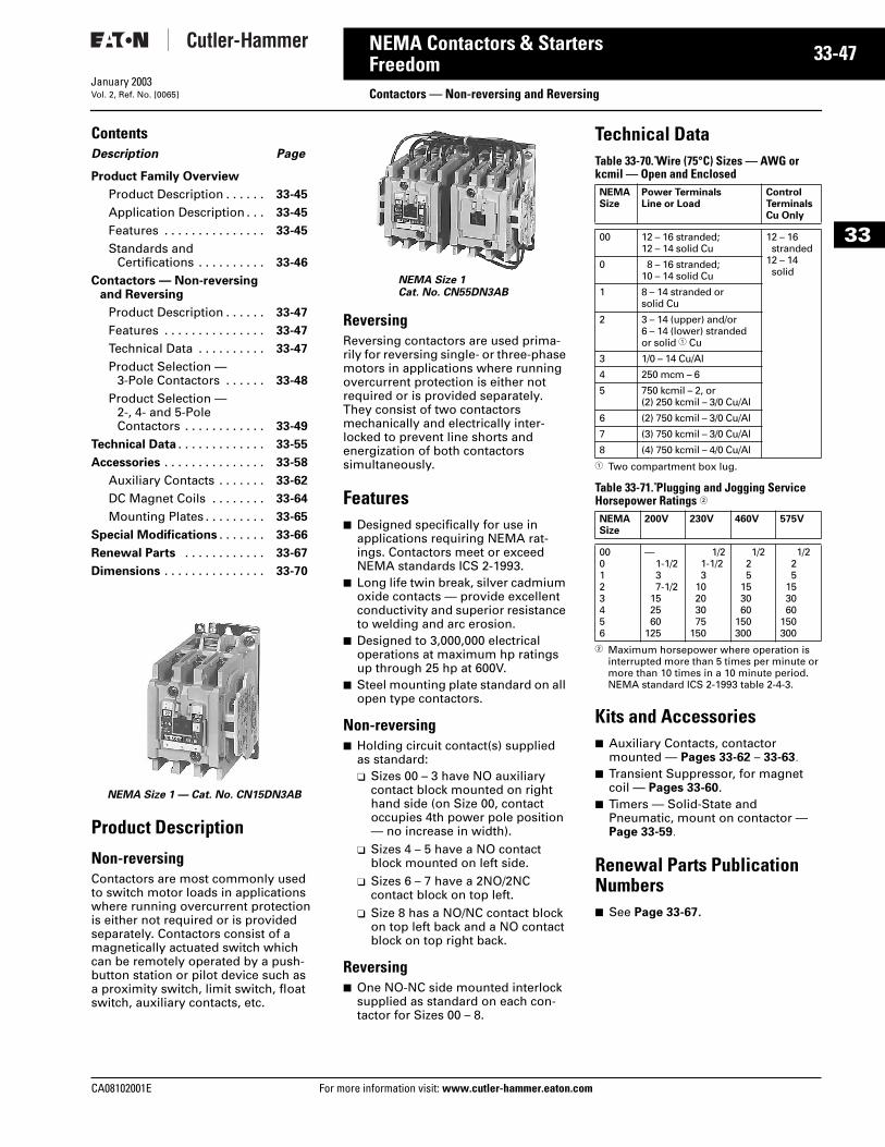
CA08102001E For more
47
33-NEMA Contactors & StartersFreedom
Contactors — Non-reversing and ReversingJanuary 2003Vol. 2, Ref. No. [0065]
33
ContentsDescription Page
Product Family Overview
Product Description . . . . . . 33-45
Application Description . . . 33-45
Features . . . . . . . . . . . . . . . 33-45
Standards and Certifications . . . . . . . . . . 33-46
Contactors — Non-reversing and Reversing
Product Description . . . . . . 33-47
Features . . . . . . . . . . . . . . . 33-47
Technical Data . . . . . . . . . . 33-47
Product Selection — 3-Pole Contactors . . . . . . 33-48
Product Selection — 2-, 4- and 5-Pole Contactors . . . . . . . . . . . . 33-49
Technical Data . . . . . . . . . . . . . 33-55
Accessories . . . . . . . . . . . . . . . 33-58
Auxiliary Contacts . . . . . . . 33-62
DC Magnet Coils . . . . . . . . 33-64
Mounting Plates . . . . . . . . . 33-65
Special Modifications . . . . . . . 33-66
Renewal Parts . . . . . . . . . . . . 33-67
Dimensions . . . . . . . . . . . . . . . 33-70
Product Description
Non-reversing Contactors are most commonly used to switch motor loads in applications where running overcurrent protection is either not required or is provided separately. Contactors consist of a magnetically actuated switch which can be remotely operated by a push-button station or pilot device such as a proximity switch, limit switch, float switch, auxiliary contacts, etc.
Reversing Reversing contactors are used prima-rily for reversing single- or three-phase motors in applications where running overcurrent protection is either not required or is provided separately. They consist of two contactors mechanically and electrically inter-locked to prevent line shorts and energization of both contactors simultaneously.
Features■ Designed specifically for use in
applications requiring NEMA rat-ings. Contactors meet or exceed NEMA standards ICS 2-1993.
■ Long life twin break, silver cadmium oxide contacts — provide excellent conductivity and superior resistance to welding and arc erosion.
■ Designed to 3,000,000 electrical operations at maximum hp ratings up through 25 hp at 600V.
■ Steel mounting plate standard on all open type contactors.
Non-reversing■ Holding circuit contact(s) supplied
as standard:❑ Sizes 00 – 3 have NO auxiliary
contact block mounted on right hand side (on Size 00, contact occupies 4th power pole position — no increase in width).
❑ Sizes 4 – 5 have a NO contact block mounted on left side.
❑ Sizes 6 – 7 have a 2NO/2NC contact block on top left.
❑ Size 8 has a NO/NC contact block on top left back and a NO contact block on top right back.
Reversing ■ One NO-NC side mounted interlock
supplied as standard on each con-tactor for Sizes 00 – 8.
Technical DataTable 33-70. Wire (75°C) Sizes — AWG or kcmil — Open and Enclosed
1 Two compartment box lug.
Table 33-71. Plugging and Jogging Service Horsepower Ratings 2
2 Maximum horsepower where operation is interrupted more than 5 times per minute or more than 10 times in a 10 minute period. NEMA standard ICS 2-1993 table 2-4-3.
Kits and Accessories■ Auxiliary Contacts, contactor
mounted — Pages 33-62 – 33-63. ■ Transient Suppressor, for magnet
coil — Pages 33-60. ■ Timers — Solid-State and
Pneumatic, mount on contactor — Page 33-59.
Renewal Parts Publication Numbers■ See Page 33-67.
NEMA Size 1 — Cat. No. CN15DN3AB
NEMA Size 1Cat. No. CN55DN3AB
NEMASize
Power TerminalsLine or Load
ControlTerminalsCu Only
00 12 – 16 stranded; 12 – 14 solid Cu
12 – 16stranded
12 – 14solid
0 8 – 16 stranded; 10 – 14 solid Cu
1 8 – 14 stranded or solid Cu
2 3 – 14 (upper) and/or 6 – 14 (lower) stranded or solid 1 Cu
3 1/0 – 14 Cu/Al
4 250 mcm – 6
5 750 kcmil – 2, or (2) 250 kcmil – 3/0 Cu/Al
6 (2) 750 kcmil – 3/0 Cu/Al
7 (3) 750 kcmil – 3/0 Cu/Al
8 (4) 750 kcmil – 4/0 Cu/Al
NEMASize
200V 230V 460V 575V
000123456
—1-1/237-1/2
152560
125
1/21-1/23
10203075
150
1/225
153060
150300
1/225
153060
150300
information visit: www.cutler-hammer.eaton.com
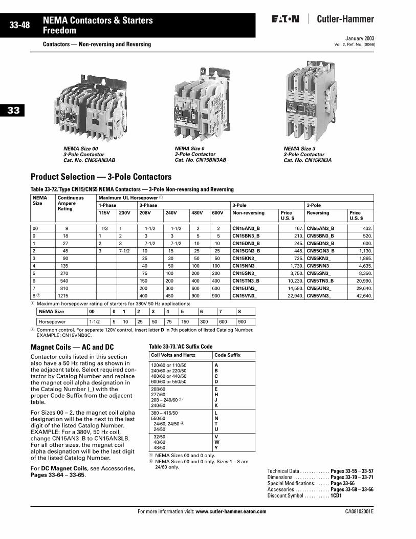
33-48
33
NEMA Contactors & StartersFreedom
Contactors — Non-reversing and ReversingFor more information visit: www.cutler-hammer.eaton.com
January 2003Vol. 2, Ref. No. [0066]
Product Selection — 3-Pole Contactors Table 33-72. Type CN15/CN55 NEMA Contactors — 3-Pole Non-reversing and Reversing
1 Maximum horsepower rating of starters for 380V 50 Hz applications:
2 Common control. For separate 120V control, insert letter D in 7th position of listed Catalog Number. EXAMPLE: CN15VND3C.
Magnet Coils — AC and DCContactor coils listed in this section also have a 50 Hz rating as shown in the adjacent table. Select required con-tactor by Catalog Number and replace the magnet coil alpha designation in the Catalog Number (_) with the proper Code Suffix from the adjacent table.
For Sizes 00 – 2, the magnet coil alpha designation will be the next to the last digit of the listed Catalog Number. EXAMPLE: For a 380V, 50 Hz coil, change CN15AN3_B to CN15AN3LB. For all other sizes, the magnet coil alpha designation will be the last digit of the listed Catalog Number.
For DC Magnet Coils, see Accessories, Pages 33-64 – 33-65.
Table 33-73. AC Suffix Code
3 NEMA Sizes 00 and 0 only.4 NEMA Sizes 00 and 0 only. Sizes 1 – 8 are
24/60 only.
NEMASize
ContinuousAmpereRating
Maximum UL Horsepower 1
1-Phase 3-Phase 3-Pole 3-Pole
115V 230V 208V 240V 480V 600V Non-reversing PriceU.S. $
Reversing PriceU.S. $
00 9 1/3 1 1-1/2 1-1/2 2 2 CN15AN3_B 167. CN55AN3_B 432.
0 18 1 2 3 3 5 5 CN15BN3_B 210. CN55BN3_B 520.
1 27 2 3 7-1/2 7-1/2 10 10 CN15DN3_B 245. CN55DN3_B 600.
2 45 3 7-1/2 10 15 25 25 CN15GN3_B 445. CN55GN3_B 1,130.
3 90 25 30 50 50 CN15KN3_ 725. CN55KN3_ 1,865.
4 135 40 50 100 100 CN15NN3_ 1,730. CN55NN3_ 4,635.
5 270 75 100 200 200 CN15SN3_ 3,750. CN55SN3_ 8,350.
6 540 150 200 400 400 CN15TN3_B 10,230. CN55TN3_B 20,990.
7 810 200 300 600 600 CN15UN3_ 14,580. CN55UN3_ 29,640.
8 2 1215 400 450 900 900 CN15VN3_ 22,940. CN55VN3_ 42,640.
NEMA Size 00 0 1 2 3 4 5 6 7 8
Horsepower 1-1/2 5 10 25 50 75 150 300 600 900
NEMA Size 003-Pole ContactorCat. No. CN55AN3AB
NEMA Size 0
3-Pole ContactorCat. No. CN15BN3AB
NEMA Size 33-Pole ContactorCat. No. CN15KN3A
Coil Volts and Hertz Code Suffix
120/60 or 110/50240/60 or 220/50480/60 or 440/50600/60 or 550/50
ABCD
208/60277/60208 – 240/60 3240/50
EHJK
380 – 415/50550/5024/60, 24/50 424/50
LNTU
32/5048/6048/50
VWY
Technical Data . . . . . . . . . . . . . Pages 33-55 – 33-57Dimensions . . . . . . . . . . . . . . . Pages 33-70 – 33-71Special Modifications. . . . . . . Page 33-66Accessories . . . . . . . . . . . . . . . Pages 33-58 – 33-66Discount Symbol . . . . . . . . . . . 1CD1
CA08102001E
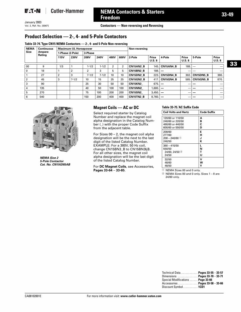
CA08102001E For more
49
33-NEMA Contactors & StartersFreedom Contactors — Non-reversing and ReversingJanuary 2003Vol. 2, Ref. No. [0067]
33
Product Selection — 2-, 4- and 5-Pole Contactors Table 33-74. Type CN15 NEMA Contactors — 2-, 4- and 5-Pole Non-reversing
NEMA Size 25-Pole ContactorCat. No. CN15GN5AB
Magnet Coils — AC or DCSelect required starter by Catalog Number and replace the magnet coil alpha designation in the Catalog Num-ber (_) with the proper Code Suffix from the adjacent table.
For Sizes 00 – 2, the magnet coil alpha designation will be the next to the last digit of the listed Catalog Number. EXAMPLE: For a 380V, 50 Hz coil, change CN15BN3_B to CN15BN3LB. For all other sizes, the magnet coil alpha designation will be the last digit of the listed Catalog Number.
For DC Magnet Coils, see Accessories, Pages 33-64 – 33-65.
Table 33-75. AC Suffix Code
1 NEMA Sizes 00 and 0 only.2 NEMA Sizes 00 and 0 only. Sizes 1 – 8 are
24/60 only.
NEMASize
ContinuousAmpereRating
Maximum UL Horsepower Non-reversing
1-Phase (2-Pole) 3-Phase
115V 230V 208V 240V 480V 600V 2-Pole PriceU.S. $
4-Pole PriceU.S. $
5-Pole PriceU.S. $
00 9 1/3 1 1-1/2 1-1/2 2 2 CN15AN2_B 145. CN15AN4_B 188. — —
0 18 1 2 2 3 5 5 CN15BN2_B 188. — — — —
1 27 2 3 7-1/2 7-1/2 10 10 CN15DN2_B 223. CN15DN4_B 302. CN15DN5_B 380.
2 45 3 7-1/2 10 15 25 25 CN15GN2_B 417. CN15GN4_B 585. CN15GN5_B 870.
3 90 25 30 50 50 CN15KN2_ 675. — — — —
4 135 40 50 100 100 CN15NN2_ 1,600. — — — —
5 270 75 100 200 200 CN15SN2_ 3,450. — — — —
6 540 150 200 400 400 CN15TN2_B 8,760. — — — —
Coil Volts and Hertz Code Suffix
120/60 or 110/50240/60 or 220/50480/60 or 440/50600/60 or 550/50
ABCD
208/60277/60208 – 240/60 1240/50
EHJK
380 – 415/50550/5024/60, 24/50 224/50
LNTU
32/5048/6048/50
VWY
Technical Data. . . . . . . . . . . . . Pages 33-55 – 33-57Dimensions . . . . . . . . . . . . . . . Pages 33-70 – 33-71Special Modifications . . . . . . Page 33-66Accessories . . . . . . . . . . . . . . . Pages 33-58 – 33-66Discount Symbol . . . . . . . . . . . 1CD1
information visit: www.cutler-hammer.eaton.com
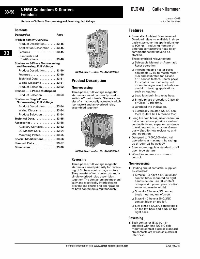
33-50
33
NEMA Contactors & StartersFreedom
Starters — 3-Phase Non-reversing and Reversing, Full VoltageFor more information visit: www.cutler-hammer.eaton.com
January 2003Vol. 2, Ref. No. [0068]
ContentsDescription Page
Product Family Overview
Product Description. . . . . . . 33-45
Application Description. . . . 33-45
Features . . . . . . . . . . . . . . . . 33-45
Standards and Certifications . . . . . . . . . . . 33-46
Starters — 3-Phase Non-reversing and Reversing, Full Voltage
Product Description. . . . . . . 33-50
Features . . . . . . . . . . . . . . . . 33-50
Technical Data . . . . . . . . . . . 33-51
Wiring Diagrams . . . . . . . . . 33-51
Product Selection . . . . . . . . 33-52
Starters — 3-Phase Multispeed
Product Selection . . . . . . . . 33-53
Starters — Single-PhaseNon-reversing, Full Voltage
Product Description. . . . . . . 33-54
Wiring Diagrams . . . . . . . . . 33-54
Product Selection . . . . . . . . 33-54
Technical Data. . . . . . . . . . . . . . 33-55
Accessories . . . . . . . . . . . . . . . . 33-58
Auxiliary Contacts . . . . . . . . 33-62
DC Magnet Coils . . . . . . . . . 33-64
Mounting Plates. . . . . . . . . . 33-65
Special Modifications. . . . . . . . 33-66
Renewal Parts . . . . . . . . . . . . . 33-67
Dimensions . . . . . . . . . . . . . . . . 33-70
Product Description
Non-reversingThree-phase, full voltage magnetic starters are most commonly used to switch AC motor loads. Starters con-sist of a magnetically actuated switch (contactor) and an overload relay assembled together.
Reversing Three-phase, full voltage magnetic starters are used primarily for revers-ing of 3-phase squirrel cage motors. They consist of two contactors and a single overload relay assembled together. The contactors are mechani-cally and electrically interlocked to prevent line shorts and energization of both contactors simultaneously.
Features■ Bimetallic Ambient Compensated
Overload relays — available in three basic sizes covering applications up to 900 hp — reducing number of different contactor/overload relay combinations that have to be stocked.These overload relays feature:❑ Selectable Manual or Automatic
Reset operation.❑ Interchangeable heater packs
adjustable ±24% to match motor FLA and calibrated for 1.0 and 1.15 service factors. Heater packs for smaller overload relay will mount in larger overload relay — useful in derating applications such as jogging.
❑ Load lugs built into relay base.❑ Single-phase protection, Class 20
or Class 10 trip time.❑ Overload trip indication.❑ Electrically isolated NO-NC con-
tacts (pull RESET button to test).■ Long life twin break, silver cadmium
oxide contacts — provide excellent conductivity and superior resistance to welding and arc erosion. Gener-ously sized for low resistance and cool operation.
■ Designed to 3,000,000 electrical operations at maximum hp ratings up through 25 hp at 600V.
■ Steel mounting plate standard on all open type starters.
■ Wired for separate or common control.
Non-reversing■ Holding circuit contact(s) supplied
as standard:❑ Sizes 00 – 3 have a NO auxiliary
contact block mounted on right-hand side (on Size 00, contact occupies 4th power pole position — no increase in width).
❑ Sizes 4 – 5 have a NO contact block mounted on left side.
❑ Sizes 6 – 7 have a 2NO/2NC contact block on top left.
❑ Size 8 has a NO/NC contact block on top left back and a NO on top right back.
Reversing■ Each contactor (Size 00 – 8)
supplied with one NO-NC side mounted contact block as standard. NC contacts are wired as electrical interlocks.
NEMA Size 1 — Cat. No. AN16DN0AB
NEMA Size 1 — Cat. No. AN56DN0AB
CA08102001E
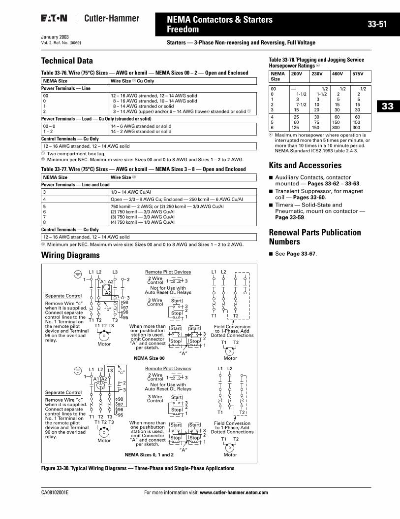
CA08102001E For more
51
33-NEMA Contactors & StartersFreedom Starters — 3-Phase Non-reversing and Reversing, Full VoltageJanuary 2003Vol. 2, Ref. No. [0069]
33
Technical DataTable 33-76. Wire (75°C) Sizes — AWG or kcmil — NEMA Sizes 00 – 2 — Open and Enclosed
1 Two compartment box lug.2 Minimum per NEC. Maximum wire size: Sizes 00 and 0 to 8 AWG and Sizes 1 – 2 to 2 AWG.
Table 33-77. Wire (75°C) Sizes — AWG or kcmil — NEMA Sizes 3 – 8 — Open and Enclosed
3 Minimum per NEC. Maximum wire size: Sizes 00 and 0 to 8 AWG and Sizes 1 – 2 to 2 AWG.
Wiring Diagrams
Figure 33-30. Typical Wiring Diagrams — Three-Phase and Single-Phase Applications
NEMA Size Wire Size 2 Cu Only
Power Terminals — Line00012
12 – 16 AWG stranded, 12 – 14 AWG solid8 – 16 AWG stranded, 10 – 14 AWG solid8 – 14 AWG stranded or solid3 – 14 AWG (upper) and/or 6 – 14 AWG (lower) stranded or solid 1
Power Terminals — Load — Cu Only (stranded or solid)00 – 01 – 2
14 – 6 AWG stranded or solid14 – 2 AWG stranded or solid
Control Terminals — Cu Only12 – 16 AWG stranded, 12 – 14 AWG solid
NEMA Size Wire Size 3
Power Terminals — Line and Load3 1/0 – 14 AWG Cu/Al
4 Open — 3/0 – 8 AWG Cu; Enclosed — 250 kcmil — 6 AWG Cu/Al
5678
750 kcmil — 2 AWG; or (2) 250 kcmil — 3/0 AWG Cu/Al(2) 750 kcmil — 3/0 AWG Cu/Al(3) 750 kcmil — 3/0 AWG Cu/Al(4) 750 kcmil — 1/0 AWG Cu/Al
Control Terminals — Cu Only12 – 16 AWG stranded, 12 – 14 AWG solid
Not for Use withAuto Reset OL Relays
Separate Control
Remove Wire “c”when it is supplied.Connect separatecontrol lines to theNo. 1 Terminal onthe remote pilotdevice and Terminal96 on the overloadrelay.
“c”
“A”
When more thanone pushbuttonstation is used,omit Connector
“A” and connectper sketch.
Field Conversionto 1-Phase, Add
Dotted Connections
Remote Pilot Devices
NEMA Size 00
2 WireControl
L1 L2 L3
T1 T2 T3T1 T2 T3
1 A1 A2
A2
2
398979695
1 3
3
32
1
2
L1
T1 T2
T1 T2
L2
1
Start
Start Start
Stop
Stop Stop
3 WireControl
Motor
Motor
Not for Use withAuto Reset OL Relays
Separate Control
Remove Wire “c”when it is supplied.Connect separatecontrol lines to theNo. 1 Terminal onthe remote pilotdevice and Terminal96 on the overloadrelay.
“A”
When more thanone pushbuttonstation is used,omit Connector
“A” and connectper sketch.
Field Conversionto 1-Phase, Add
Dotted Connections
Remote Pilot Devices
NEMA Sizes 0, 1 and 2
2 WireControl
T1 T2 T3
“c”L1 L2 L3
T1 T2 T3
1 A1 A22
3
98979695
1 3
3
32
1
2
L1
T1 T2
T1 T2
L2
1
Start
Start Start
Stop
Stop Stop
3 WireControl
Motor
Motor
information visit: www.cutler-hammer.eaton.co
Table 33-78. Plugging and Jogging ServiceHorsepower Ratings 4
4 Maximum horsepower where operation is interrupted more than 5 times per minute, or more than 10 times in a 10 minute period. NEMA Standard ICS2-1993 table 2-4-3.
Kits and Accessories■ Auxiliary Contacts, contactor
mounted — Pages 33-62 – 33-63. ■ Transient Suppressor, for magnet
coil — Pages 33-60. ■ Timers — Solid-State and
Pneumatic, mount on contactor — Page 33-59.
Renewal Parts Publication Numbers■ See Page 33-67.
NEMASize
200V 230V 460V 575V
000123
—1-1/237-1/2
15
1/21-1/23
1020
1/225
1530
1/225
1530
456
2560
125
3075
150
60150300
60150300
m
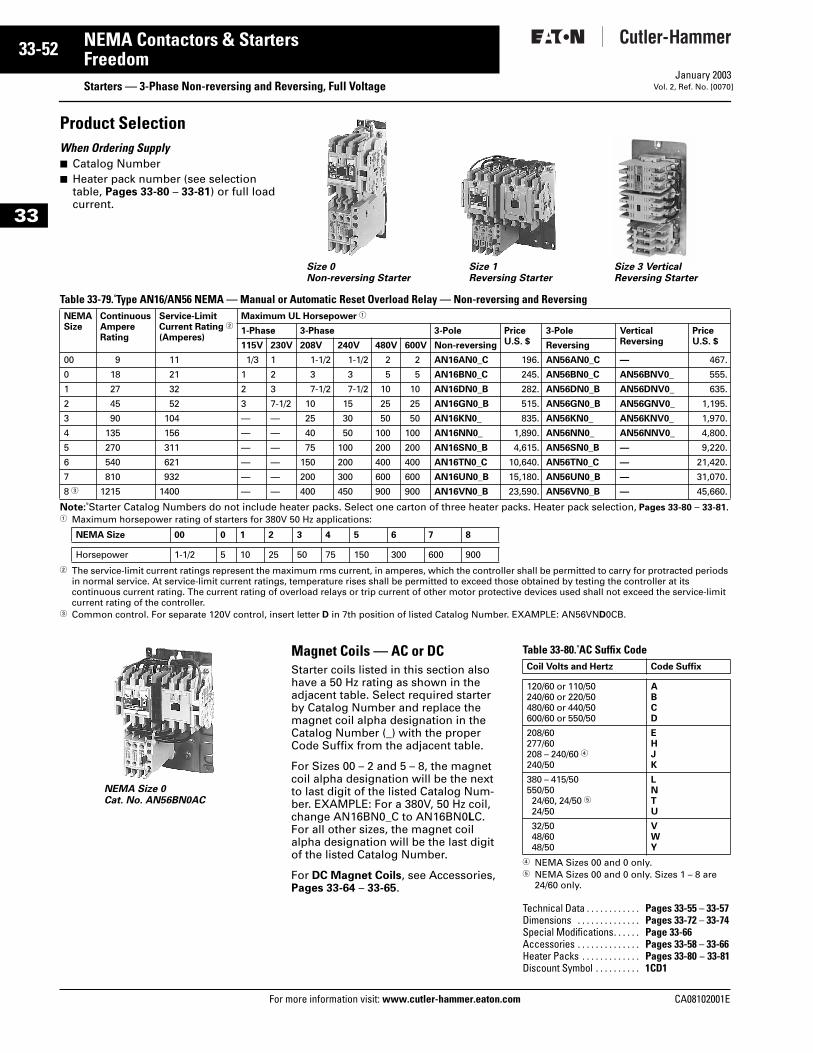
33-52
33
NEMA Contactors & StartersFreedom
Starters — 3-Phase Non-reversing and Reversing, Full VoltageFor more information visit: www.cutler-hammer.eaton.com
January 2003Vol. 2, Ref. No. [0070]
Product Selection When Ordering Supply■ Catalog Number■ Heater pack number (see selection
table, Pages 33-80 – 33-81) or full load current.
Table 33-79. Type AN16/AN56 NEMA — Manual or Automatic Reset Overload Relay — Non-reversing and Reversing
Note: Starter Catalog Numbers do not include heater packs. Select one carton of three heater packs. Heater pack selection, Pages 33-80 – 33-81.1 Maximum horsepower rating of starters for 380V 50 Hz applications:
2 The service-limit current ratings represent the maximum rms current, in amperes, which the controller shall be permitted to carry for protracted periods in normal service. At service-limit current ratings, temperature rises shall be permitted to exceed those obtained by testing the controller at its continuous current rating. The current rating of overload relays or trip current of other motor protective devices used shall not exceed the service-limit current rating of the controller.
3 Common control. For separate 120V control, insert letter D in 7th position of listed Catalog Number. EXAMPLE: AN56VND0CB.
Magnet Coils — AC or DCStarter coils listed in this section also have a 50 Hz rating as shown in the adjacent table. Select required starter by Catalog Number and replace the magnet coil alpha designation in the Catalog Number (_) with the proper Code Suffix from the adjacent table.
For Sizes 00 – 2 and 5 – 8, the magnet coil alpha designation will be the next to last digit of the listed Catalog Num-ber. EXAMPLE: For a 380V, 50 Hz coil, change AN16BN0_C to AN16BN0LC. For all other sizes, the magnet coil alpha designation will be the last digit of the listed Catalog Number.
For DC Magnet Coils, see Accessories, Pages 33-64 – 33-65.
Table 33-80. AC Suffix Code
4 NEMA Sizes 00 and 0 only.5 NEMA Sizes 00 and 0 only. Sizes 1 – 8 are
24/60 only.
NEMASize
ContinuousAmpereRating
Service-LimitCurrent Rating 2
(Amperes)
Maximum UL Horsepower 1
1-Phase 3-Phase 3-Pole PriceU.S. $
3-Pole VerticalReversing
PriceU.S. $115V 230V 208V 240V 480V 600V Non-reversing Reversing
00 9 11 1/3 1 1-1/2 1-1/2 2 2 AN16AN0_C 196. AN56AN0_C — 467.
0 18 21 1 2 3 3 5 5 AN16BN0_C 245. AN56BN0_C AN56BNV0_ 555.
1 27 32 2 3 7-1/2 7-1/2 10 10 AN16DN0_B 282. AN56DN0_B AN56DNV0_ 635.
2 45 52 3 7-1/2 10 15 25 25 AN16GN0_B 515. AN56GN0_B AN56GNV0_ 1,195.
3 90 104 — — 25 30 50 50 AN16KN0_ 835. AN56KN0_ AN56KNV0_ 1,970.
4 135 156 — — 40 50 100 100 AN16NN0_ 1,890. AN56NN0_ AN56NNV0_ 4,800.
5 270 311 — — 75 100 200 200 AN16SN0_B 4,615. AN56SN0_B — 9,220.
6 540 621 — — 150 200 400 400 AN16TN0_C 10,640. AN56TN0_C — 21,420.
7 810 932 — — 200 300 600 600 AN16UN0_B 15,180. AN56UN0_B — 31,070.
8 3 1215 1400 — — 400 450 900 900 AN16VN0_B 23,590. AN56VN0_B — 45,660.
NEMA Size 00 0 1 2 3 4 5 6 7 8
Horsepower 1-1/2 5 10 25 50 75 150 300 600 900
Size 0Non-reversing Starter
Size 1Reversing Starter
Size 3 Vertical Reversing Starter
NEMA Size 0 Cat. No. AN56BN0AC
Coil Volts and Hertz Code Suffix
120/60 or 110/50240/60 or 220/50480/60 or 440/50600/60 or 550/50
ABCD
208/60277/60208 – 240/60 4240/50
EHJK
380 – 415/50550/5024/60, 24/50 524/50
LNTU
32/5048/6048/50
VWY
Technical Data . . . . . . . . . . . . Pages 33-55 – 33-57Dimensions . . . . . . . . . . . . . . Pages 33-72 – 33-74Special Modifications. . . . . . Page 33-66Accessories . . . . . . . . . . . . . . Pages 33-58 – 33-66Heater Packs . . . . . . . . . . . . . Pages 33-80 – 33-81Discount Symbol . . . . . . . . . . 1CD1
CA08102001E
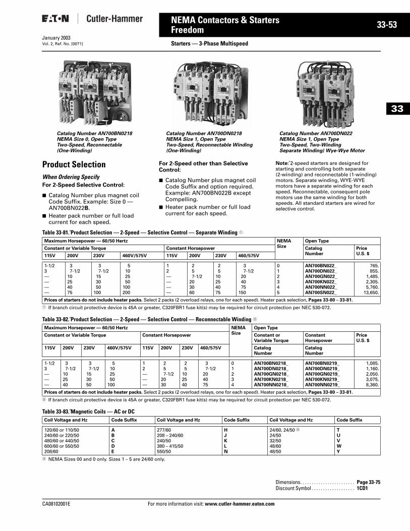
CA08102001E For more
53
33-NEMA Contactors & StartersFreedom Starters — 3-Phase MultispeedJanuary 2003Vol. 2, Ref. No. [0071]
33
Product SelectionWhen Ordering SpecifyFor 2-Speed Selective Control:
■ Catalog Number plus magnet coil Code Suffix. Example: Size 0 — AN700BN022B.
■ Heater pack number or full load current for each speed.
For 2-Speed other than Selective Control:
■ Catalog Number plus magnet coil Code Suffix and option required. Example: AN700BN022B except Compelling.
■ Heater pack number or full load current for each speed.
Note: 2-speed starters are designed for starting and controlling both separate (2-winding) and reconnectable (1-winding) motors. Separate winding, WYE-WYE motors have a separate winding for each speed. Reconnectable, consequent pole motors use the same winding for both speeds. All standard starters are wired for selective control.
Table 33-81. Product Selection — 2-Speed — Selective Control — Separate Winding 1
1 If branch circuit protective device is 45A or greater, C320FBR1 fuse kit(s) may be required for circuit protection per NEC 530-072.
Table 33-82. Product Selection — 2-Speed — Selective Control — Reconnectable Winding 2
2 If branch circuit protective device is 45A or greater, C320FBR1 fuse kit(s) may be required for circuit protection per NEC 530-072.
Table 33-83. Magnetic Coils — AC or DC
3 NEMA Sizes 00 and 0 only. Sizes 1 – 5 are 24/60 only.
Catalog Number AN700DN0218NEMA Size 1, Open TypeTwo-Speed, Reconnectable Winding(One-Winding)
Catalog Number AN700DN022NEMA Size 1, Open TypeTwo-Speed, Two-WindingSeparate Winding) Wye-Wye Motor
Catalog Number AN700BN0218NEMA Size 0, Open TypeTwo-Speed, Reconnectable(One-Winding)
Maximum Horsepower — 60/50 Hertz NEMASize
Open Type
Constant or Variable Torque Constant Horsepower CatalogNumber
PriceU.S. $115V 200V 230V 460V/575V 115V 200V 230V 460/575V
1-1/23————
37-1/2
10254075
37-1/2
153050
100
5102550
100200
12————
257-1/2
203060
25
10254075
37-1/2
204075
150
012345
AN700BN022_AN700DN022_AN700GN022_AN700KN022_AN700NN022_AN700SN022_
765.855.
1,485.2,305.5,760.
13,650.
Prices of starters do not include heater packs. Select 2 packs (2 overload relays, one for each speed). Heater pack selection, Pages 33-80 – 33-81.
Maximum Horsepower — 60/50 Hertz NEMASize
Open Type
Constant or Variable Torque Constant Horsepower Constant orVariable Torque
ConstantHorsepower
PriceU.S. $
115V 200V 230V 460V/575V 115V 200V 230V 460/575V CatalogNumber
CatalogNumber
1-1/23———
37-1/2
102540
37-1/2
153050
5102550
100
12———
257-1/2
2030
25
102540
37-1/2
204075
01234
AN700BN0218_AN700DN0218_AN700GN0218_AN700KN0218_AN700NN0218_
AN700BN0219_AN700DN0219_AN700GN0219_AN700KN0219_AN700NN0219_
1,085.1,160.2,050.3,075.8,360.
Prices of starters do not include heater packs. Select 2 packs (2 overload relays, one for each speed). Heater pack selection, Pages 33-80 – 33-81.
Coil Voltage and Hz Code Suffix Coil Voltage and Hz Code Suffix Coil Voltage and Hz Code Suffix
120/60 or 110/50240/60 or 220/50480/60 or 440/50600/60 or 550/50208/60
ABCDE
277/60208 – 240/60240/50380 – 415/50550/50
HJKLN
24/60, 24/50 324/5032/5048/6048/50
TUVWY
Dimensions. . . . . . . . . . . . . . . . . . . . . . . . Page 33-75Discount Symbol . . . . . . . . . . . . . . . . . . . 1CD1
information visit: www.cutler-hammer.eaton.com
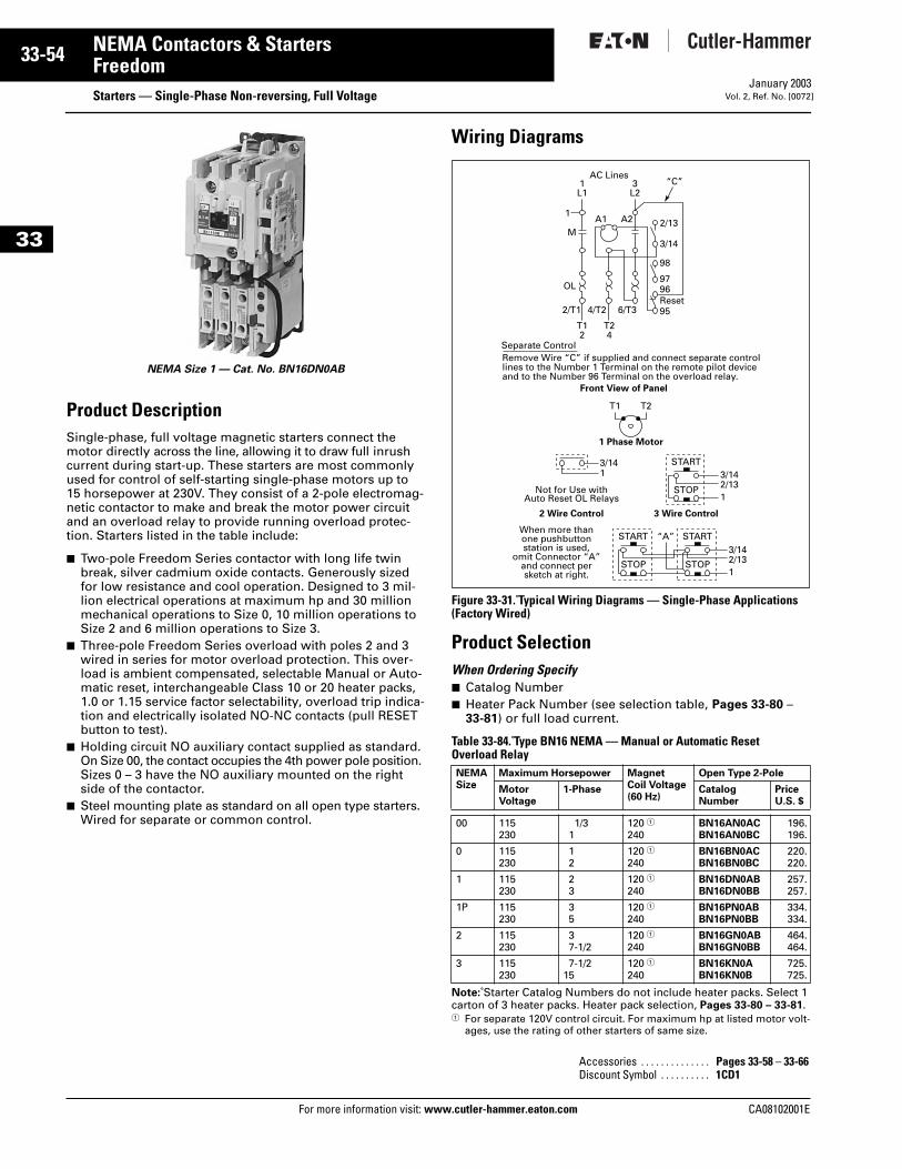
33-54
33
NEMA Contactors & StartersFreedom
Starters — Single-Phase Non-reversing, Full VoltageFor more information visit: www.cutler-hammer.eaton.com
January 2003Vol. 2, Ref. No. [0072]
Product DescriptionSingle-phase, full voltage magnetic starters connect the motor directly across the line, allowing it to draw full inrush current during start-up. These starters are most commonly used for control of self-starting single-phase motors up to 15 horsepower at 230V. They consist of a 2-pole electromag-netic contactor to make and break the motor power circuit and an overload relay to provide running overload protec-tion. Starters listed in the table include:
■ Two-pole Freedom Series contactor with long life twin break, silver cadmium oxide contacts. Generously sized for low resistance and cool operation. Designed to 3 mil-lion electrical operations at maximum hp and 30 million mechanical operations to Size 0, 10 million operations to Size 2 and 6 million operations to Size 3.
■ Three-pole Freedom Series overload with poles 2 and 3 wired in series for motor overload protection. This over-load is ambient compensated, selectable Manual or Auto-matic reset, interchangeable Class 10 or 20 heater packs, 1.0 or 1.15 service factor selectability, overload trip indica-tion and electrically isolated NO-NC contacts (pull RESET button to test).
■ Holding circuit NO auxiliary contact supplied as standard. On Size 00, the contact occupies the 4th power pole position. Sizes 0 – 3 have the NO auxiliary mounted on the right side of the contactor.
■ Steel mounting plate as standard on all open type starters. Wired for separate or common control.
Wiring Diagrams
Figure 33-31. Typical Wiring Diagrams — Single-Phase Applications(Factory Wired)
Product SelectionWhen Ordering Specify ■ Catalog Number■ Heater Pack Number (see selection table, Pages 33-80 –
33-81) or full load current.
Table 33-84. Type BN16 NEMA — Manual or Automatic Reset Overload Relay
Note: Starter Catalog Numbers do not include heater packs. Select 1 carton of 3 heater packs. Heater pack selection, Pages 33-80 – 33-81.1 For separate 120V control circuit. For maximum hp at listed motor volt-
ages, use the rating of other starters of same size.
NEMA Size 1 — Cat. No. BN16DN0AB
NEMASize
Maximum Horsepower MagnetCoil Voltage(60 Hz)
Open Type 2-Pole
MotorVoltage
1-Phase CatalogNumber
PriceU.S. $
00 115230
1/31
120 1240
BN16AN0ACBN16AN0BC
196.196.
0 115230
12
120 1240
BN16BN0ACBN16BN0BC
220.220.
1 115230
23
120 1240
BN16DN0ABBN16DN0BB
257.257.
1P 115230
35
120 1240
BN16PN0ABBN16PN0BB
334.334.
2 115230
37-1/2
120 1240
BN16GN0ABBN16GN0BB
464.464.
3 115230
7-1/215
120 1240
BN16KN0ABN16KN0B
725.725.
Accessories . . . . . . . . . . . . . . Pages 33-58 – 33-66Discount Symbol . . . . . . . . . . 1CD1
Front View of Panel
1 Phase Motor
When more thanone pushbuttonstation is used,
omit Connector “A”and connect persketch at right.
2 Wire Control
Not for Use withAuto Reset OL Relays
3 Wire Control
START
STOP
AC Lines1L1
1
M
OL
A1 A2 2/13
3/14
98
9796
952/T1 4/T2 6/T3Reset
3L2
T12
T24
T1 T2
“C”
3/14
Separate ControlRemove Wire “C” if supplied and connect separate controllines to the Number 1 Terminal on the remote pilot deviceand to the Number 96 Terminal on the overload relay.
1 3/142/131
START “A”
STOP
START
STOP
3/142/131
CA08102001E
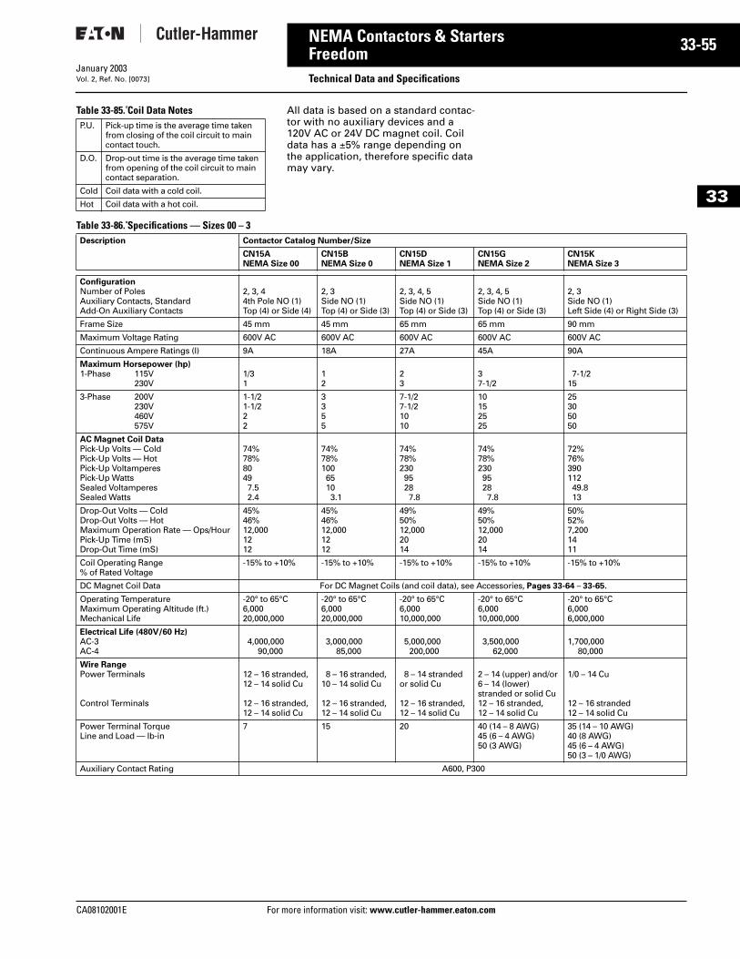
CA08102001E For more
55
33-NEMA Contactors & StartersFreedom Technical Data and SpecificationsJanuary 2003Vol. 2, Ref. No. [0073]
33
Table 33-85. Coil Data Notes All data is based on a standard contac-tor with no auxiliary devices and a 120V AC or 24V DC magnet coil. Coil data has a ±5% range depending on the application, therefore specific data may vary.
Table 33-86. Specifications — Sizes 00 – 3
P.U. Pick-up time is the average time taken from closing of the coil circuit to main contact touch.
D.O. Drop-out time is the average time taken from opening of the coil circuit to main contact separation.
Cold Coil data with a cold coil.
Hot Coil data with a hot coil.
Description Contactor Catalog Number/Size
CN15ANEMA Size 00
CN15BNEMA Size 0
CN15DNEMA Size 1
CN15GNEMA Size 2
CN15KNEMA Size 3
ConfigurationNumber of PolesAuxiliary Contacts, StandardAdd-On Auxiliary Contacts
2, 3, 44th Pole NO (1)Top (4) or Side (4)
2, 3Side NO (1)Top (4) or Side (3)
2, 3, 4, 5Side NO (1)Top (4) or Side (3)
2, 3, 4, 5Side NO (1)Top (4) or Side (3)
2, 3Side NO (1)Left Side (4) or Right Side (3)
Frame Size 45 mm 45 mm 65 mm 65 mm 90 mm
Maximum Voltage Rating 600V AC 600V AC 600V AC 600V AC 600V AC
Continuous Ampere Ratings (I) 9A 18A 27A 45A 90A
Maximum Horsepower (hp)1-Phase 115V
230V1/31
12
23
37-1/2
7-1/215
3-Phase 200V230V460V575V
1-1/21-1/222
3355
7-1/27-1/21010
10152525
25305050
AC Magnet Coil DataPick-Up Volts — ColdPick-Up Volts — HotPick-Up VoltamperesPick-Up WattsSealed VoltamperesSealed Watts
74%78%80497.52.4
74%78%10065103.1
74%78%23095287.8
74%78%23095287.8
72%76%39011249.813
Drop-Out Volts — ColdDrop-Out Volts — HotMaximum Operation Rate — Ops/HourPick-Up Time (mS)Drop-Out Time (mS)
45%46%12,0001212
45%46%12,0001212
49%50%12,0002014
49%50%12,0002014
50%52%7,2001411
Coil Operating Range % of Rated Voltage
-15% to +10% -15% to +10% -15% to +10% -15% to +10% -15% to +10%
DC Magnet Coil Data For DC Magnet Coils (and coil data), see Accessories, Pages 33-64 – 33-65.
Operating TemperatureMaximum Operating Altitude (ft.)Mechanical Life
-20° to 65°C6,00020,000,000
-20° to 65°C6,00020,000,000
-20° to 65°C6,00010,000,000
-20° to 65°C6,00010,000,000
-20° to 65°C6,0006,000,000
Electrical Life (480V/60 Hz)AC-3AC-4
4,000,00090,000
3,000,00085,000
5,000,000200,000
3,500,00062,000
1,700,00080,000
Wire RangePower Terminals
Control Terminals
12 – 16 stranded,12 – 14 solid Cu
12 – 16 stranded,12 – 14 solid Cu
8 – 16 stranded,10 – 14 solid Cu
12 – 16 stranded,12 – 14 solid Cu
8 – 14 stranded or solid Cu
12 – 16 stranded,12 – 14 solid Cu
2 – 14 (upper) and/or6 – 14 (lower)stranded or solid Cu12 – 16 stranded,12 – 14 solid Cu
1/0 – 14 Cu
12 – 16 stranded12 – 14 solid Cu
Power Terminal TorqueLine and Load — lb-in
7 15 20 40 (14 – 8 AWG)45 (6 – 4 AWG)50 (3 AWG)
35 (14 – 10 AWG)40 (8 AWG)45 (6 – 4 AWG)50 (3 – 1/0 AWG)
Auxiliary Contact Rating A600, P300
information visit: www.cutler-hammer.eaton.com
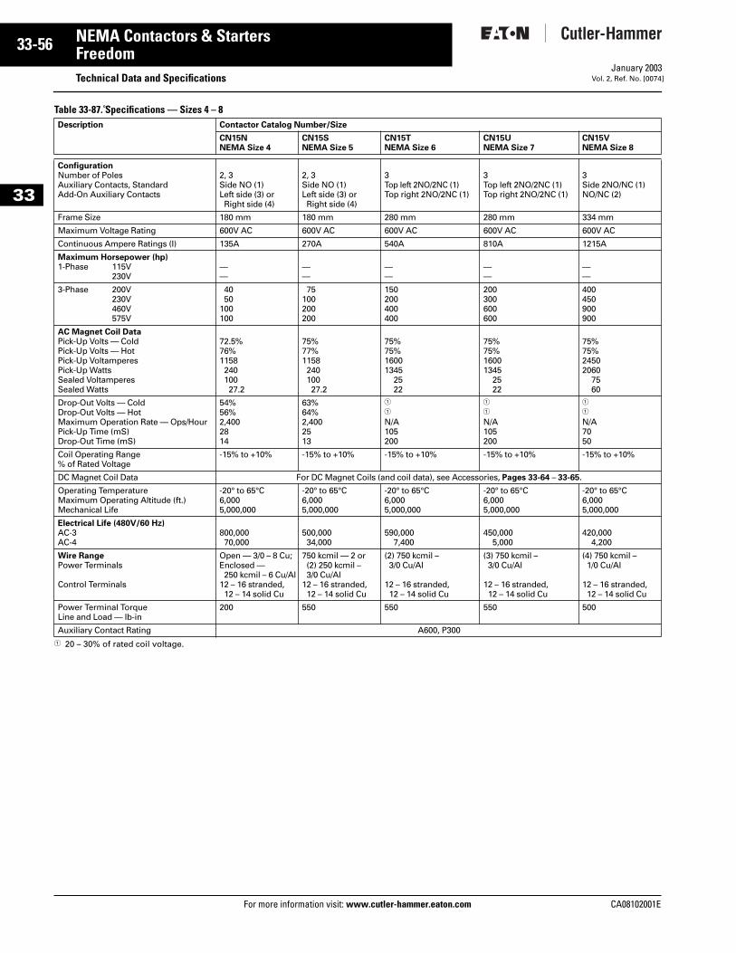
33-56
33
NEMA Contactors & StartersFreedom
Technical Data and SpecificationsFor more information visit: www.cutler-hammer.eaton.com
January 2003Vol. 2, Ref. No. [0074]
Table 33-87. Specifications — Sizes 4 – 8
1 20 – 30% of rated coil voltage.
Description Contactor Catalog Number/Size
CN15NNEMA Size 4
CN15SNEMA Size 5
CN15TNEMA Size 6
CN15UNEMA Size 7
CN15VNEMA Size 8
ConfigurationNumber of PolesAuxiliary Contacts, StandardAdd-On Auxiliary Contacts
2, 3Side NO (1)Left side (3) or Right side (4)
2, 3Side NO (1)Left side (3) or Right side (4)
3Top left 2NO/2NC (1)Top right 2NO/2NC (1)
3Top left 2NO/2NC (1)Top right 2NO/2NC (1)
3Side 2NO/NC (1)NO/NC (2)
Frame Size 180 mm 180 mm 280 mm 280 mm 334 mm
Maximum Voltage Rating 600V AC 600V AC 600V AC 600V AC 600V AC
Continuous Ampere Ratings (I) 135A 270A 540A 810A 1215A
Maximum Horsepower (hp)1-Phase 115V
230V——
——
——
——
——
3-Phase 200V230V460V575V
4050
100100
75100200200
150200400400
200300600600
400450900900
AC Magnet Coil DataPick-Up Volts — ColdPick-Up Volts — HotPick-Up VoltamperesPick-Up WattsSealed VoltamperesSealed Watts
72.5%76%115824010027.2
75%77%115824010027.2
75%75%16001345
2522
75%75%16001345
2522
75%75%24502060
7560
Drop-Out Volts — ColdDrop-Out Volts — HotMaximum Operation Rate — Ops/HourPick-Up Time (mS)Drop-Out Time (mS)
54%56%2,4002814
63%64%2,4002513
1
1
N/A105200
1
1
N/A105200
1
1
N/A7050
Coil Operating Range % of Rated Voltage
-15% to +10% -15% to +10% -15% to +10% -15% to +10% -15% to +10%
DC Magnet Coil Data For DC Magnet Coils (and coil data), see Accessories, Pages 33-64 – 33-65.
Operating TemperatureMaximum Operating Altitude (ft.)Mechanical Life
-20° to 65°C6,0005,000,000
-20° to 65°C6,0005,000,000
-20° to 65°C6,0005,000,000
-20° to 65°C6,0005,000,000
-20° to 65°C6,0005,000,000
Electrical Life (480V/60 Hz)AC-3AC-4
800,00070,000
500,00034,000
590,0007,400
450,0005,000
420,0004,200
Wire RangePower Terminals
Control Terminals
Open — 3/0 – 8 Cu;Enclosed — 250 kcmil – 6 Cu/Al
12 – 16 stranded,12 – 14 solid Cu
750 kcmil — 2 or (2) 250 kcmil – 3/0 Cu/Al
12 – 16 stranded,12 – 14 solid Cu
(2) 750 kcmil – 3/0 Cu/Al
12 – 16 stranded,12 – 14 solid Cu
(3) 750 kcmil – 3/0 Cu/Al
12 – 16 stranded,12 – 14 solid Cu
(4) 750 kcmil – 1/0 Cu/Al
12 – 16 stranded,12 – 14 solid Cu
Power Terminal TorqueLine and Load — lb-in
200 550 550 550 500
Auxiliary Contact Rating A600, P300
CA08102001E
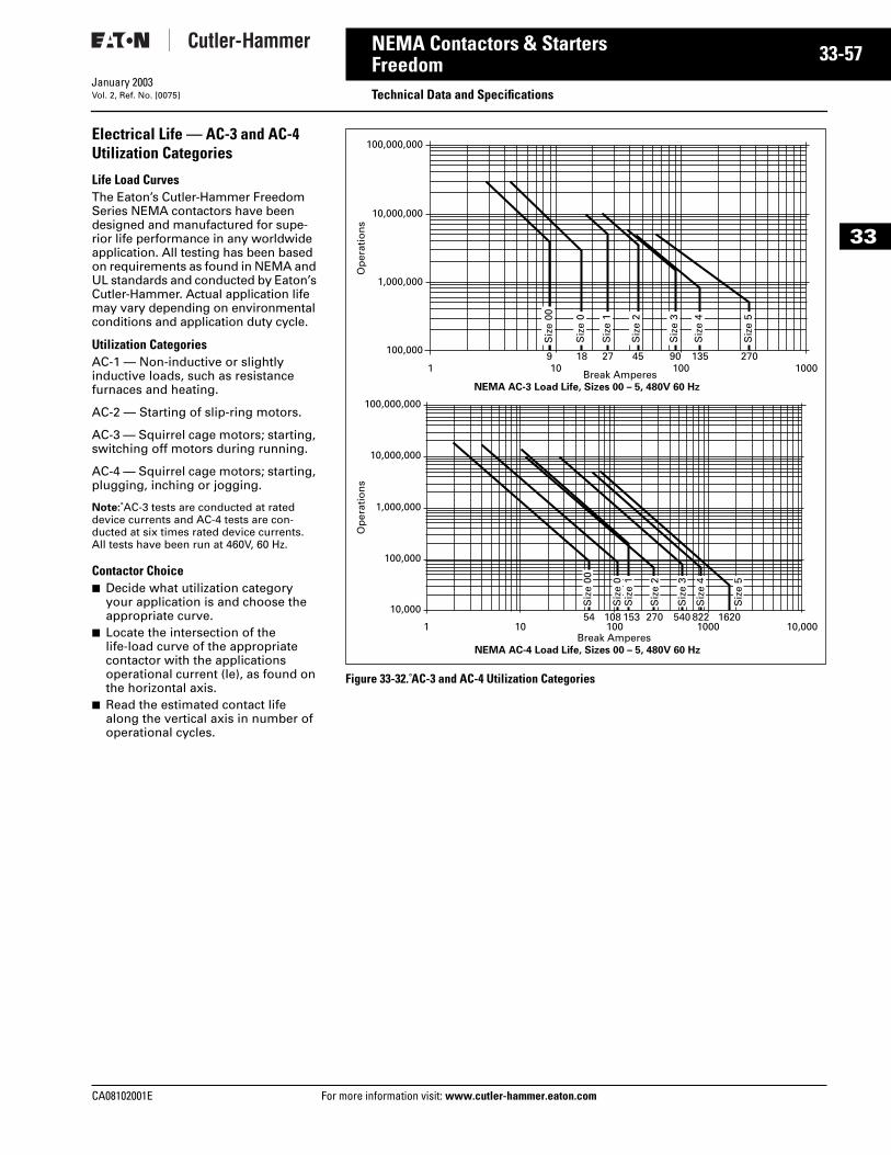
CA08102001E For more
57
33-NEMA Contactors & StartersFreedom Technical Data and SpecificationsJanuary 2003Vol. 2, Ref. No. [0075]
33
Electrical Life — AC-3 and AC-4 Utilization Categories
Life Load CurvesThe Eaton’s Cutler-Hammer Freedom Series NEMA contactors have been designed and manufactured for supe-rior life performance in any worldwide application. All testing has been based on requirements as found in NEMA and UL standards and conducted by Eaton’s Cutler-Hammer. Actual application life may vary depending on environmental conditions and application duty cycle.
Utilization CategoriesAC-1 — Non-inductive or slightly inductive loads, such as resistance furnaces and heating.
AC-2 — Starting of slip-ring motors.
AC-3 — Squirrel cage motors; starting, switching off motors during running.
AC-4 — Squirrel cage motors; starting, plugging, inching or jogging.
Note: AC-3 tests are conducted at rated device currents and AC-4 tests are con-ducted at six times rated device currents. All tests have been run at 460V, 60 Hz.
Contactor Choice■ Decide what utilization category
your application is and choose the appropriate curve.
■ Locate the intersection of the life-load curve of the appropriate contactor with the applications operational current (Ie), as found on the horizontal axis.
■ Read the estimated contact life along the vertical axis in number of operational cycles.
Figure 33-32. AC-3 and AC-4 Utilization Categories
NEMA AC-3 Load Life, Sizes 00 – 5, 480V 60 Hz
100,000,000
10,000,000
1,000,000
100,0009
1 10Break Amperes
100 100018 27 45 90 135 270
Siz
e 00
Siz
e 0
Siz
e 1
Siz
e 2
Siz
e 3
Siz
e 4
Siz
e 5
Op
erat
ion
sO
per
atio
ns
NEMA AC-4 Load Life, Sizes 00 – 5, 480V 60 Hz
100,000,000
Siz
e 00
Siz
e 0
Siz
e 1
Siz
e 2
Siz
e 3
Siz
e 4
Siz
e 5
10,000,000
1,000,000
100,000
10,00010854
1 10Break Amperes
100 1000 10,000153 270 540 822 1620
information visit: www.cutler-hammer.eaton.com
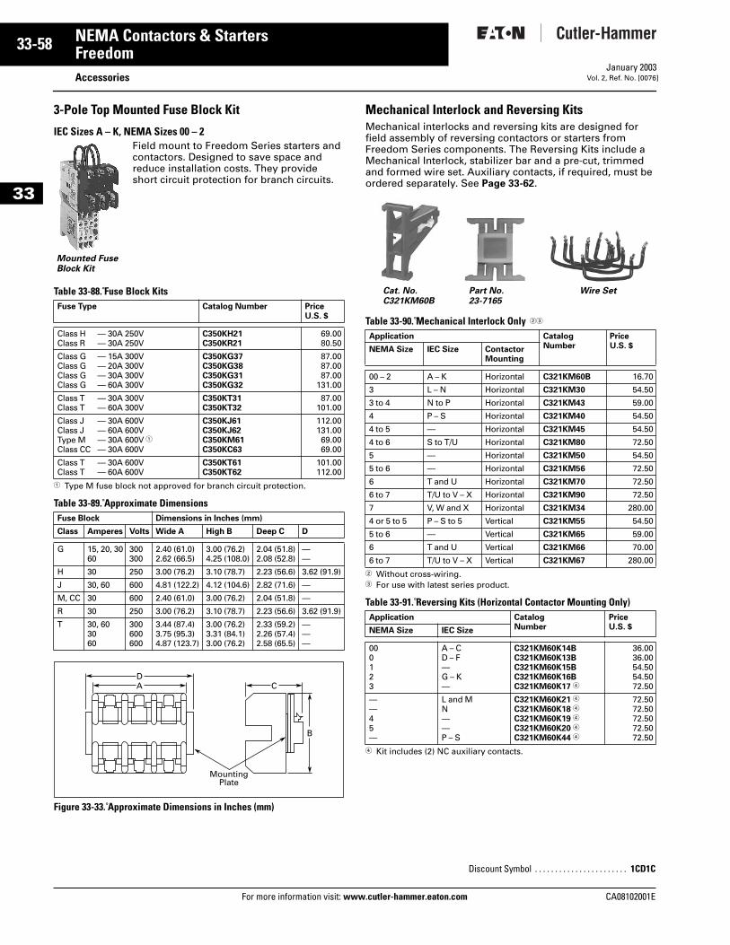
33-58
33
NEMA Contactors & StartersFreedom
AccessoriesFor more information visit: www.cutler-hammer.eaton.com
January 2003Vol. 2, Ref. No. [0076]
3-Pole Top Mounted Fuse Block Kit
IEC Sizes A – K, NEMA Sizes 00 – 2Field mount to Freedom Series starters and contactors. Designed to save space and reduce installation costs. They provide short circuit protection for branch circuits.
Table 33-88. Fuse Block Kits
1 Type M fuse block not approved for branch circuit protection.
Table 33-89. Approximate Dimensions
Figure 33-33. Approximate Dimensions in Inches (mm)
Mechanical Interlock and Reversing KitsMechanical interlocks and reversing kits are designed for field assembly of reversing contactors or starters from Freedom Series components. The Reversing Kits include a Mechanical Interlock, stabilizer bar and a pre-cut, trimmed and formed wire set. Auxiliary contacts, if required, must be ordered separately. See Page 33-62.
Table 33-90. Mechanical Interlock Only 23
2 Without cross-wiring.3 For use with latest series product.
Table 33-91. Reversing Kits (Horizontal Contactor Mounting Only)
4 Kit includes (2) NC auxiliary contacts.
Fuse Type Catalog Number PriceU.S. $
Class H — 30A 250VClass R — 30A 250V
C350KH21C350KR21
69.0080.50
Class G — 15A 300VClass G — 20A 300VClass G — 30A 300VClass G — 60A 300V
C350KG37C350KG38C350KG31C350KG32
87.0087.0087.00
131.00
Class T — 30A 300VClass T — 60A 300V
C350KT31C350KT32
87.00101.00
Class J — 30A 600VClass J — 60A 600VType M — 30A 600V 1Class CC — 30A 600V
C350KJ61C350KJ62C350KM61C350KC63
112.00131.0069.0069.00
Class T — 30A 600VClass T — 60A 600V
C350KT61C350KT62
101.00112.00
Fuse Block Dimensions in Inches (mm)
Class Amperes Volts Wide A High B Deep C D
G 15, 20, 3060
300300
2.40 (61.0)2.62 (66.5)
3.00 (76.2)4.25 (108.0)
2.04 (51.8)2.08 (52.8)
——
H 30 250 3.00 (76.2) 3.10 (78.7) 2.23 (56.6) 3.62 (91.9)
J 30, 60 600 4.81 (122.2) 4.12 (104.6) 2.82 (71.6) —
M, CC 30 600 2.40 (61.0) 3.00 (76.2) 2.04 (51.8) —
R 30 250 3.00 (76.2) 3.10 (78.7) 2.23 (56.6) 3.62 (91.9)
T 30, 603060
300600600
3.44 (87.4)3.75 (95.3)4.87 (123.7)
3.00 (76.2)3.31 (84.1)3.00 (76.2)
2.33 (59.2)2.26 (57.4)2.58 (65.5)
———
Mounted Fuse Block Kit
A C
MountingPlate
D
B
Application CatalogNumber
PriceU.S. $NEMA Size IEC Size Contactor
Mounting
00 – 2 A – K Horizontal C321KM60B 16.70
3 L – N Horizontal C321KM30 54.50
3 to 4 N to P Horizontal C321KM43 59.00
4 P – S Horizontal C321KM40 54.50
4 to 5 — Horizontal C321KM45 54.50
4 to 6 S to T/U Horizontal C321KM80 72.50
5 — Horizontal C321KM50 54.50
5 to 6 — Horizontal C321KM56 72.50
6 T and U Horizontal C321KM70 72.50
6 to 7 T/U to V – X Horizontal C321KM90 72.50
7 V, W and X Horizontal C321KM34 280.00
4 or 5 to 5 P – S to 5 Vertical C321KM55 54.50
5 to 6 — Vertical C321KM65 59.00
6 T and U Vertical C321KM66 70.00
6 to 7 T/U to V – X Vertical C321KM67 280.00
Application CatalogNumber
PriceU.S. $NEMA Size IEC Size
000123
A – CD – F—G – K—
C321KM60K14BC321KM60K13BC321KM60K15BC321KM60K16BC321KM60K17 4
36.0036.0054.5054.5072.50
——45—
L and MN——P – S
C321KM60K21 4
C321KM60K18 4
C321KM60K19 4
C321KM60K20 4
C321KM60K44 4
72.5072.5072.5072.5072.50
Discount Symbol . . . . . . . . . . . . . . . . . . . . . . . 1CD1C
Cat. No.C321KM60B
Part No.23-7165
Wire Set
CA08102001E
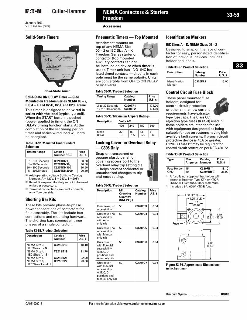
CA08102001E For more
59
33-NEMA Contactors & StartersFreedom AccessoriesJanuary 2003Vol. 2, Ref. No. [0077]
33
Solid-State Timers
Solid-State Timer
Solid-State ON DELAY Timer — Side Mounted on Freedom Series NEMA 00 – 2, IEC A – K and C25D, C25E and C25F FrameThis timer is designed to be wired in series with the load (typically a coil). When the START button is pushed (power applied to timer), the ON DELAY timing function starts. At the completion of the set timing period, timer and series wired load will both be energized.
Table 33-92. Mounted Timer Product Selection
1 Add operating voltage Suffix to Catalog Number. A = 120V, B = 240V, E = 208V
2 Rated .5 ampere pilot duty — not to be used on larger contactors.
3 Terminal connections are quick connects only. Two per side.
Shorting Bar KitsThese kits provide phase-to-phase power connections of contactors for field assembly. The kits include bus connections and mounting hardware. The shorting bars connect all three phases of a single contactor.
Table 33-93. Product Selection
Pneumatic Timers — Top MountedAttachment mounts on top of any NEMA Size 00 – 2 or IEC Size A – K Freedom Series starter or contactor (top mounted auxiliary contacts can not be installed on device when timer is used). Timer unit has 1NO-1NC iso-lated timed contacts — circuits in each pole must be the same polarity. Units are convertible from OFF to ON DELAY or vice-versa.
Table 33-94. Product Selection
Table 33-95. Maximum Ampere Ratings
Locking Cover for Overload Relay — C306 OnlySnap-on transparent or opaque plastic panel for covering access port to the overload relay trip setting dial — helps prevent accidental or unauthorized changes to trip and reset setting.
Table 33-96. Product Selection
Identification Markers
IEC Sizes A – K, NEMA Sizes 00 – 2Designed to snap on the face of con-tactor for easy, personalized identifica-tion of individual devices. Includes holder and labels.
Table 33-97. Product Selection
Control Circuit Fuse BlockThese panel mounted fuse holders, designed for control circuit protection or other similar low current requirements, have extractor type fuse caps. The Class CC rejection type fuses (KTK-R) used in these holders are intended for use with equipment designated as being suitable for use on systems having high available fault currents. If branch circuit protective device is 45A or greater, C320FBR fuse kit may be required for control circuit protection per NEC 430-72.
Table 33-98. Product Selection
1 A fuse is not supplied, but holder will accept a Bussman Type KTK or KTK-R (13/32" x 1-1/2") fuse, 600V maximum.
2 Includes a 5A, 600V KTK-R fuse.
Figure 33-34. Approximate Dimensionsin Inches (mm)
Timing Range CatalogNumber 123
PriceU.S. $
.1 – 1.0 Seconds1 – 30 Seconds
30 – 300 Seconds5 – 30 Minutes
C320TDN1_C320TDN30_C320TDN300_C320TDN3000_
90.5090.5090.5090.50
Description CatalogNumber
PriceU.S. $
NEMA Size 3, IEC Sizes L – N
NEMA Size 4, IEC Sizes A – S
NEMA Size 5NEMA Size 6, IEC Sizes T and U
C321SB18
C321SB19
C321SB21C321SB22
18.10
21.70
22.9023.30
Timing Range CatalogNumber
PriceU.S. $
.1 to 30 Seconds10 to 180 Seconds
C320TP1C320TP2
174.00174.00
Description Volts AC
120 240 480 600
MakeBreak
303
151.5
7.5.75
6.6
Description Min.OrderingQuantity(Std. Pkg.)
CatalogNumber
PriceU.S. $
Clear cover, noaccessibility
50 C320PC3 0.94
Gray cover, noaccessibility,with Autoonly nib
50 C320PC4 0.94
Gray cover, noaccessibility,with Manualonly nib
50 C320PC5 0.94
Gray coverwith FLA dialaccessibility,A, B, C, Dpositions andAuto only nib
50 C320PC6 0.94
Gray coverwith FLA dialaccessibility,A, B, C, Dpositions andManual only nib
50 C320PC7 0.94
Description CatalogNumber
PriceU.S. $
Identification Marker
C320DL2 13.00
Type Max.Amperes
CatalogNumber
PriceU.S. $
Fuse HolderOnly
1530
C320FB 1
C320FBR 218.1036.00
Discount Symbol . . . . . . . . . . . . . . . . . . . . . . . 1CD1C
.97(24.6)
1.25 (31.8)1.88 (47.8)
1.19(30.2)
.88(22.4)
2.06(52.3)
Fuse
information visit: www.cutler-hammer.eaton.com
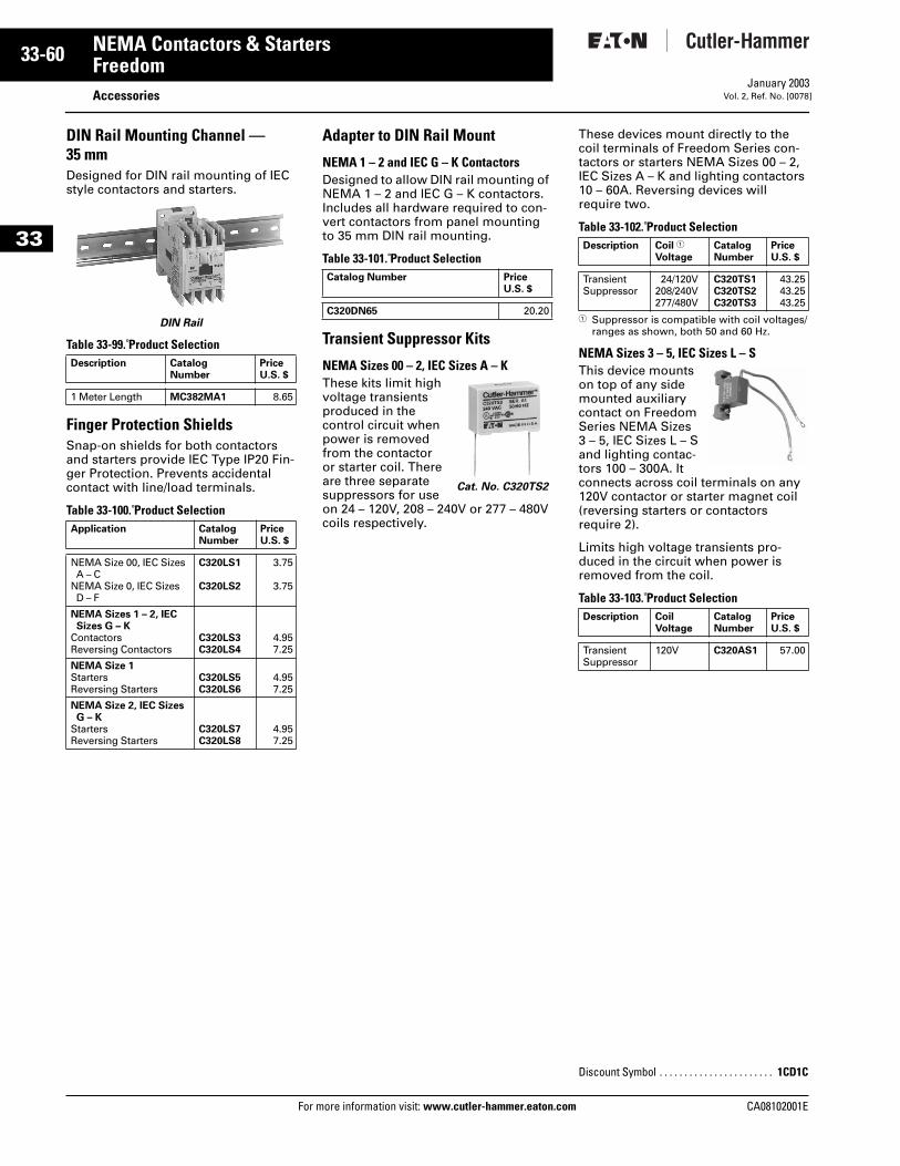
33-60
33
NEMA Contactors & StartersFreedom
AccessoriesFor more information visit: www.cutler-hammer.eaton.com
January 2003Vol. 2, Ref. No. [0078]
DIN Rail Mounting Channel — 35 mmDesigned for DIN rail mounting of IEC style contactors and starters.
DIN Rail
Table 33-99. Product Selection
Finger Protection ShieldsSnap-on shields for both contactors and starters provide IEC Type IP20 Fin-ger Protection. Prevents accidental contact with line/load terminals.
Table 33-100. Product Selection
Adapter to DIN Rail Mount
NEMA 1 – 2 and IEC G – K ContactorsDesigned to allow DIN rail mounting of NEMA 1 – 2 and IEC G – K contactors. Includes all hardware required to con-vert contactors from panel mounting to 35 mm DIN rail mounting.
Table 33-101. Product Selection
Transient Suppressor Kits
NEMA Sizes 00 – 2, IEC Sizes A – KThese kits limit high voltage transients produced in the control circuit when power is removed from the contactor or starter coil. There are three separate suppressors for use on 24 – 120V, 208 – 240V or 277 – 480V coils respectively.
These devices mount directly to the coil terminals of Freedom Series con-tactors or starters NEMA Sizes 00 – 2, IEC Sizes A – K and lighting contactors 10 – 60A. Reversing devices will require two.
Table 33-102. Product Selection
1 Suppressor is compatible with coil voltages/ranges as shown, both 50 and 60 Hz.
NEMA Sizes 3 – 5, IEC Sizes L – SThis device mounts on top of any side mounted auxiliary contact on Freedom Series NEMA Sizes 3 – 5, IEC Sizes L – S and lighting contac-tors 100 – 300A. It connects across coil terminals on any 120V contactor or starter magnet coil (reversing starters or contactors require 2).
Limits high voltage transients pro-duced in the circuit when power is removed from the coil.
Table 33-103. Product Selection
Description CatalogNumber
PriceU.S. $
1 Meter Length MC382MA1 8.65
Application CatalogNumber
PriceU.S. $
NEMA Size 00, IEC SizesA – C
NEMA Size 0, IEC SizesD – F
C320LS1
C320LS2
3.75
3.75
NEMA Sizes 1 – 2, IEC Sizes G – K
ContactorsReversing Contactors
C320LS3C320LS4
4.957.25
NEMA Size 1StartersReversing Starters
C320LS5C320LS6
4.957.25
NEMA Size 2, IEC SizesG – K
StartersReversing Starters
C320LS7C320LS8
4.957.25
Catalog Number PriceU.S. $
C320DN65 20.20
Cat. No. C320TS2
Description Coil 1
VoltageCatalogNumber
PriceU.S. $
TransientSuppressor
24/120V208/240V277/480V
C320TS1C320TS2C320TS3
43.2543.2543.25
Description CoilVoltage
CatalogNumber
PriceU.S. $
TransientSuppressor
120V C320AS1 57.00
Discount Symbol . . . . . . . . . . . . . . . . . . . . . . . 1CD1C
CA08102001E
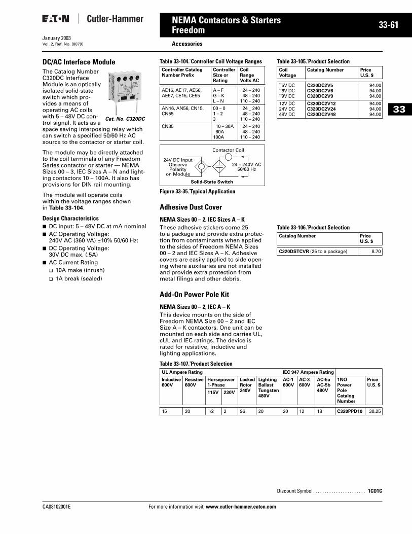
CA08102001E For more
61
33-NEMA Contactors & StartersFreedom AccessoriesJanuary 2003Vol. 2, Ref. No. [0079]
33
DC/AC Interface ModuleThe Catalog Number C320DC Interface Module is an optically isolated solid-state switch which pro-vides a means of operating AC coils with 5 – 48V DC con-trol signal. It acts as a space saving interposing relay which can switch a specified 50/60 Hz AC source to the contactor or starter coil.
The module may be directly attached to the coil terminals of any Freedom Series contactor or starter — NEMA Sizes 00 – 3, IEC Sizes A – N and light-ing contactors 10 – 100A. It also has provisions for DIN rail mounting.
The module will operate coils within the voltage ranges shown in Table 33-104.
Design Characteristics■ DC Input: 5 – 48V DC at mA nominal■ AC Operating Voltage:
240V AC (360 VA) ±10% 50/60 Hz; ■ DC Operating Voltage:
30V DC max. (.5A)■ AC Current Rating
❑ 10A make (inrush)❑ 1A break (sealed)
Cat. No. C320DC
Table 33-104. Controller Coil Voltage Ranges
Figure 33-35. Typical Application
Table 33-105. Product Selection
Adhesive Dust Cover
NEMA Sizes 00 – 2, IEC Sizes A – KThese adhesive stickers come 25 to a package and provide extra protec-tion from contaminants when applied to the sides of Freedom NEMA Sizes 00 – 2 and IEC Sizes A – K. Adhesive covers are easily applied to side open-ing where auxiliaries are not installed and provide extra protection from metal filings and other debris.
Table 33-106. Product Selection
Add-On Power Pole Kit
NEMA Sizes 00 – 2, IEC A – KThis device mounts on the side of Freedom NEMA Size 00 – 2 and IEC Size A – K contactors. One unit can be mounted on each side and carries UL, cUL and IEC ratings. The device is rated for resistive, inductive and lighting applications.
Table 33-107. Product Selection
Controller CatalogNumber Prefix
ControllerSize or Rating
Coil RangeVolts AC
AE16, AE17, AE56, AE57, CE15, CE55
A – FG – KL – N
24 – 24048 – 240
110 – 240
AN16, AN56, CN15, CN55
00 – 01 – 23
24 _ 24048 – 240
110 – 240
CN35 10 – 30A60A
100A
24 – 24048 – 240
110 – 240
24V DC InputObservePolarity
on Module
24 – 240V AC50/60 Hz
Contactor Coil
Solid-State Switch
Coil Voltage
Catalog Number PriceU.S. $
5V DC 6V DC 9V DC
C320DC2V5C320DC2V6C320DC2V9
94.0094.0094.00
12V DC24V DC48V DC
C320DC2V12C320DC2V24C320DC2V48
94.0094.0094.00
Catalog Number PriceU.S. $
C320DSTCVR (25 to a package) 8.70
UL Ampere Rating IEC 947 Ampere Rating
Inductive600V
Resistive600V
Horsepower 1-Phase
LockedRotor 240V
LightingBallastTungsten480V
AC-1600V
AC-3 600V
AC-5aAC-5b480V
1NOPowerPoleCatalogNumber
PriceU.S. $
115V 230V
15 20 1/2 2 96 20 20 12 18 C320PPD10 30.25
Discount Symbol . . . . . . . . . . . . . . . . . . . . . . . 1CD1C
information visit: www.cutler-hammer.eaton.com
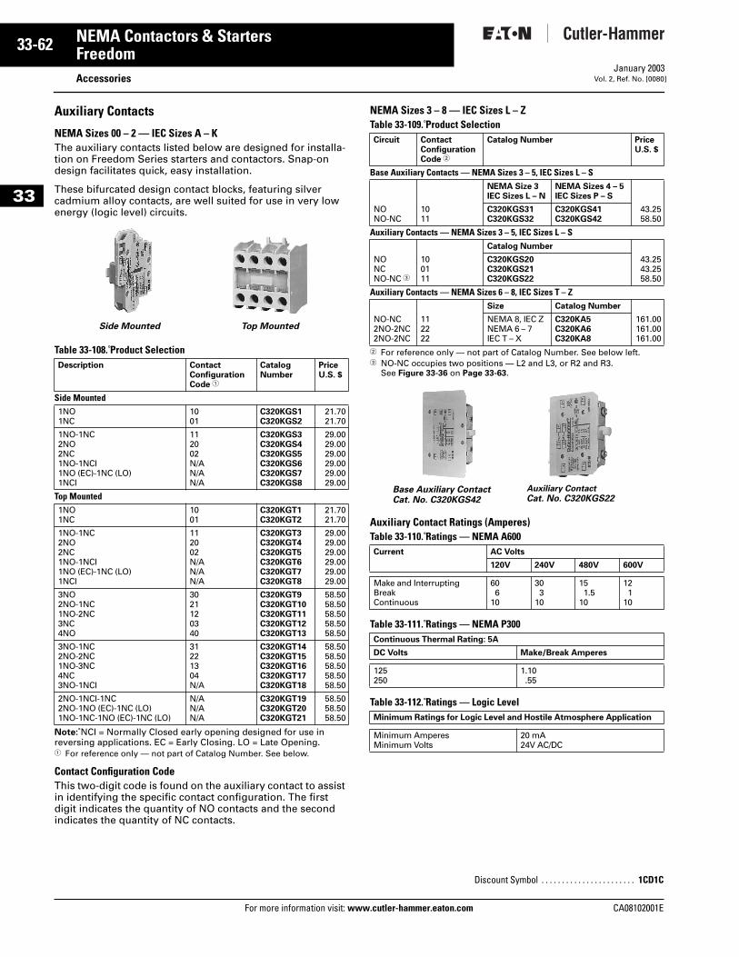
33-62
33
NEMA Contactors & StartersFreedom
AccessoriesFor more information visit: www.cutler-hammer.eaton.com
January 2003Vol. 2, Ref. No. [0080]
Auxiliary Contacts
NEMA Sizes 00 – 2 — IEC Sizes A – KThe auxiliary contacts listed below are designed for installa-tion on Freedom Series starters and contactors. Snap-on design facilitates quick, easy installation.
These bifurcated design contact blocks, featuring silver cadmium alloy contacts, are well suited for use in very low energy (logic level) circuits.
Table 33-108. Product Selection
Note: NCI = Normally Closed early opening designed for use in reversing applications. EC = Early Closing. LO = Late Opening.1 For reference only — not part of Catalog Number. See below.
Contact Configuration CodeThis two-digit code is found on the auxiliary contact to assist in identifying the specific contact configuration. The first digit indicates the quantity of NO contacts and the second indicates the quantity of NC contacts.
NEMA Sizes 3 – 8 — IEC Sizes L – ZTable 33-109. Product Selection
2 For reference only — not part of Catalog Number. See below left.3 NO-NC occupies two positions — L2 and L3, or R2 and R3.
See Figure 33-36 on Page 33-63.
Auxiliary Contact Ratings (Amperes) Table 33-110. Ratings — NEMA A600
Table 33-111. Ratings — NEMA P300
Table 33-112. Ratings — Logic Level
Description ContactConfiguration Code 1
CatalogNumber
PriceU.S. $
Side Mounted1NO1NC
1001
C320KGS1C320KGS2
21.7021.70
1NO-1NC2NO2NC1NO-1NCI1NO (EC)-1NC (LO)1NCI
112002N/AN/AN/A
C320KGS3C320KGS4C320KGS5C320KGS6C320KGS7C320KGS8
29.0029.0029.0029.0029.0029.00
Top Mounted1NO1NC
1001
C320KGT1C320KGT2
21.7021.70
1NO-1NC2NO2NC1NO-1NCI1NO (EC)-1NC (LO)1NCI
112002N/AN/AN/A
C320KGT3C320KGT4C320KGT5C320KGT6C320KGT7C320KGT8
29.0029.0029.0029.0029.0029.00
3NO2NO-1NC1NO-2NC3NC4NO
3021120340
C320KGT9C320KGT10C320KGT11C320KGT12C320KGT13
58.5058.5058.5058.5058.50
3NO-1NC2NO-2NC1NO-3NC4NC3NO-1NCI
31221304N/A
C320KGT14C320KGT15C320KGT16C320KGT17C320KGT18
58.5058.5058.5058.5058.50
2NO-1NCI-1NC2NO-1NO (EC)-1NC (LO)1NO-1NC-1NO (EC)-1NC (LO)
N/AN/AN/A
C320KGT19C320KGT20C320KGT21
58.5058.5058.50
Side Mounted Top Mounted
Circuit ContactConfigurationCode 2
Catalog Number PriceU.S. $
Base Auxiliary Contacts — NEMA Sizes 3 – 5, IEC Sizes L – SNEMA Size 3IEC Sizes L – N
NEMA Sizes 4 – 5IEC Sizes P – S
NONO-NC
1011
C320KGS31C320KGS32
C320KGS41C320KGS42
43.2558.50
Auxiliary Contacts — NEMA Sizes 3 – 5, IEC Sizes L – SCatalog Number
NONCNO-NC 3
100111
C320KGS20C320KGS21C320KGS22
43.2543.2558.50
Auxiliary Contacts — NEMA Sizes 6 – 8, IEC Sizes T – ZSize Catalog Number
NO-NC2NO-2NC2NO-2NC
112222
NEMA 8, IEC ZNEMA 6 – 7IEC T – X
C320KA5C320KA6C320KA8
161.00161.00161.00
Current AC Volts
120V 240V 480V 600V
Make and InterruptingBreakContinuous
606
10
303
10
151.5
10
121
10
Continuous Thermal Rating: 5A
DC Volts Make/Break Amperes
125250
1.10.55
Minimum Ratings for Logic Level and Hostile Atmosphere Application
Minimum AmperesMinimum Volts
20 mA24V AC/DC
Discount Symbol . . . . . . . . . . . . . . . . . . . . . . . 1CD1C
Base Auxiliary Contact Cat. No. C320KGS42
Auxiliary Contact
Cat. No. C320KGS22
CA08102001E
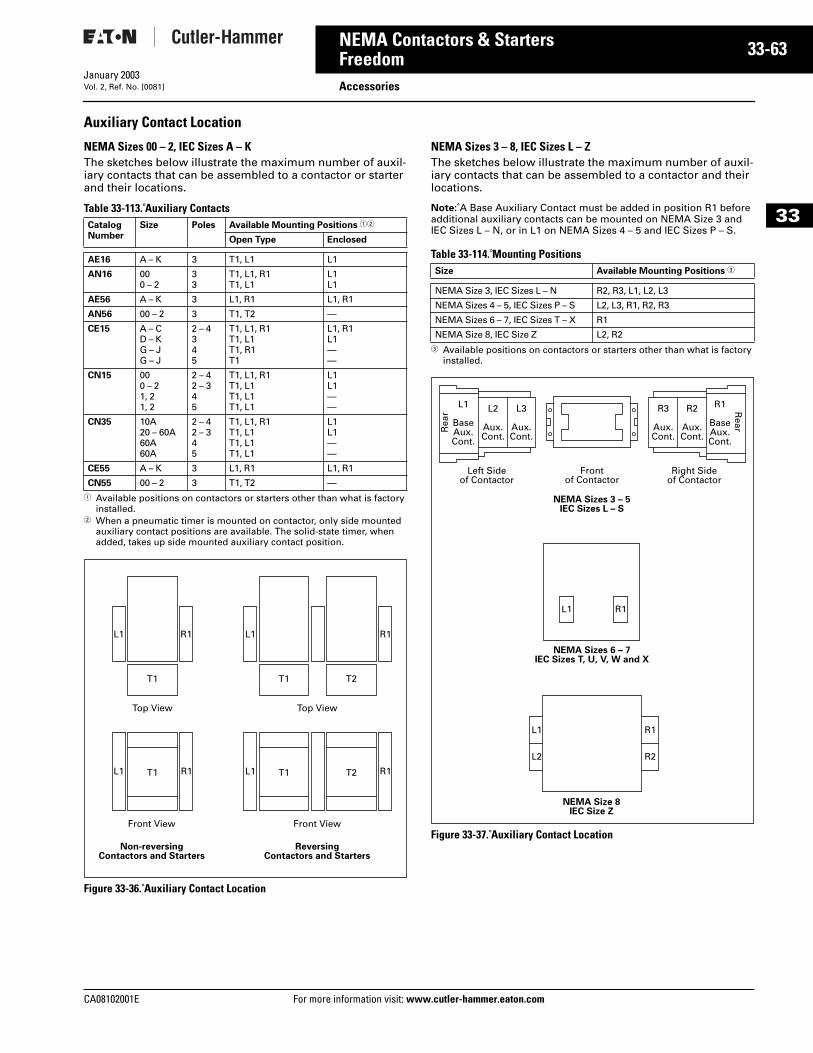
CA08102001E For more
63
33-NEMA Contactors & StartersFreedom AccessoriesJanuary 2003Vol. 2, Ref. No. [0081]
33
Auxiliary Contact Location
NEMA Sizes 00 – 2, IEC Sizes A – KThe sketches below illustrate the maximum number of auxil-iary contacts that can be assembled to a contactor or starter and their locations.
Table 33-113. Auxiliary Contacts
1 Available positions on contactors or starters other than what is factory installed.
2 When a pneumatic timer is mounted on contactor, only side mounted auxiliary contact positions are available. The solid-state timer, when added, takes up side mounted auxiliary contact position.
Figure 33-36. Auxiliary Contact Location
NEMA Sizes 3 – 8, IEC Sizes L – ZThe sketches below illustrate the maximum number of auxil-iary contacts that can be assembled to a contactor and their locations.
Note: A Base Auxiliary Contact must be added in position R1 before additional auxiliary contacts can be mounted on NEMA Size 3 and IEC Sizes L – N, or in L1 on NEMA Sizes 4 – 5 and IEC Sizes P – S.
Table 33-114. Mounting Positions
3 Available positions on contactors or starters other than what is factory installed.
Figure 33-37. Auxiliary Contact Location
CatalogNumber
Size Poles Available Mounting Positions 12
Open Type Enclosed
AE16 A – K 3 T1, L1 L1
AN16 000 – 2
33
T1, L1, R1T1, L1
L1L1
AE56 A – K 3 L1, R1 L1, R1
AN56 00 – 2 3 T1, T2 —
CE15 A – CD – KG – JG – J
2 – 4345
T1, L1, R1T1, L1T1, R1T1
L1, R1L1——
CN15 000 – 21, 21, 2
2 – 42 – 345
T1, L1, R1T1, L1T1, L1T1, L1
L1L1——
CN35 10A20 – 60A60A60A
2 – 42 – 345
T1, L1, R1T1, L1T1, L1T1, L1
L1L1——
CE55 A – K 3 L1, R1 L1, R1
CN55 00 – 2 3 T1, T2 —
L1
T1 T2
R1
L1 T1 T2 R1
L1
T1
Top View
Front View
L1 T1 R1
Front View
ReversingContactors and Starters
Non-reversingContactors and Starters
Top View
R1
Size Available Mounting Positions 3
NEMA Size 3, IEC Sizes L – N R2, R3, L1, L2, L3
NEMA Sizes 4 – 5, IEC Sizes P – S L2, L3, R1, R2, R3
NEMA Sizes 6 – 7, IEC Sizes T – X R1
NEMA Size 8, IEC Size Z L2, R2
NEMA Sizes 6 – 7IEC Sizes T, U, V, W and X
NEMA Sizes 3 – 5IEC Sizes L – S
NEMA Size 8IEC Size Z
L1 R1
L1
Frontof Contactor
Left Sideof Contactor
L2
Aux.Cont.
L3
Aux.Cont.
R2
Aux.Cont.
R3
Aux.Cont.
L1
BaseAux.Cont.
R1
BaseAux.Cont.
Rea
r Rear
Right Sideof Contactor
R1
L2 R2
information visit: www.cutler-hammer.eaton.com
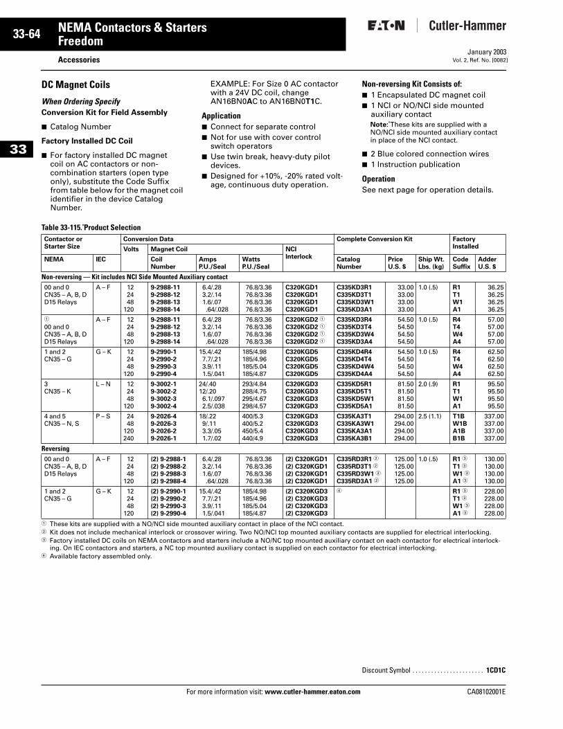
33-64
33
NEMA Contactors & StartersFreedom
AccessoriesFor more information visit: www.cutler-hammer.eaton.com
January 2003Vol. 2, Ref. No. [0082]
DC Magnet Coils
When Ordering SpecifyConversion Kit for Field Assembly
■ Catalog Number
Factory Installed DC Coil
■ For factory installed DC magnet coil on AC contactors or non-combination starters (open type only), substitute the Code Suffix from table below for the magnet coil identifier in the device Catalog Number.
EXAMPLE: For Size 0 AC contactor with a 24V DC coil, change AN16BN0AC to AN16BN0T1C.
Application■ Connect for separate control■ Not for use with cover control
switch operators■ Use twin break, heavy-duty pilot
devices.■ Designed for +10%, -20% rated volt-
age, continuous duty operation.
Non-reversing Kit Consists of:■ 1 Encapsulated DC magnet coil■ 1 NCI or NO/NCI side mounted
auxiliary contactNote: These kits are supplied with a NO/NCI side mounted auxiliary contact in place of the NCI contact.
■ 2 Blue colored connection wires■ 1 Instruction publication
OperationSee next page for operation details.
Table 33-115. Product Selection
1 These kits are supplied with a NO/NCI side mounted auxiliary contact in place of the NCI contact.2 Kit does not include mechanical interlock or crossover wiring. Two NO/NCI top mounted auxiliary contacts are supplied for electrical interlocking.3 Factory installed DC coils on NEMA contactors and starters include a NO/NC top mounted auxiliary contact on each contactor for electrical interlock-
ing. On IEC contactors and starters, a NC top mounted auxiliary contact is supplied on each contactor for electrical interlocking.4 Available factory assembled only.
Contactor orStarter Size
Conversion Data Complete Conversion Kit FactoryInstalledVolts Magnet Coil NCI
InterlockNEMA IEC CoilNumber
AmpsP.U./Seal
WattsP.U./Seal
CatalogNumber
PriceU.S. $
Ship Wt.Lbs. (kg)
CodeSuffix
AdderU.S. $
Non-reversing — Kit includes NCI Side Mounted Auxiliary contact00 and 0CN35 – A, B, DD15 Relays
A – F 122448
120
9-2988-119-2988-129-2988-139-2988-14
6.4/.283.2/.141.6/.07.64/.028
76.8/3.3676.8/3.3676.8/3.3676.8/3.36
C320KGD1C320KGD1C320KGD1C320KGD1
C335KD3R1C335KD3T1C335KD3W1C335KD3A1
33.0033.0033.0033.00
1.0 (.5) R1T1W1A1
36.2536.2536.2536.25
1
00 and 0CN35 – A, B, DD15 Relays
A – F 122448
120
9-2988-119-2988-129-2988-139-2988-14
6.4/.283.2/.141.6/.07.64/.028
76.8/3.3676.8/3.3676.8/3.3676.8/3.36
C320KGD2 1
C320KGD2 1
C320KGD2 1
C320KGD2 1
C335KD3R4C335KD3T4C335KD3W4C335KD3A4
54.5054.5054.5054.50
1.0 (.5) R4T4W4A4
57.0057.0057.0057.00
1 and 2CN35 – G
G – K 122448
120
9-2990-19-2990-29-2990-39-2990-4
15.4/.427.7/.213.9/.111.5/.041
185/4.98185/4.96185/5.04185/4.87
C320KGD5C320KGD5C320KGD5C320KGD5
C335KD4R4C335KD4T4C335KD4W4C335KD4A4
54.5054.5054.5054.50
1.0 (.5) R4T4W4A4
62.5062.5062.5062.50
3CN35 – K
L – N 122448
120
9-3002-19-3002-29-3002-39-3002-4
24/.4012/.206.1/.0972.5/.038
293/4.84288/4.75295/4.67298/4.57
C320KGD3C320KGD3C320KGD3C320KGD3
C335KD5R1C335KD5T1C335KD5W1C335KD5A1
81.5081.5081.5081.50
2.0 (.9) R1T1W1A1
95.5095.5095.5095.50
4 and 5CN35 – N, S
P – S 2448
120240
9-2026-49-2026-39-2026-29-2026-1
18/.229/.113.3/.051.7/.02
400/5.3400/5.2450/5.4440/4.9
C320KGD3C320KGD3C320KGD3C320KGD3
C335KA3T1C335KA3W1C335KA3A1C335KA3B1
294.00294.00294.00294.00
2.5 (1.1) T1BW1BA1BB1B
337.00337.00337.00337.00
Reversing00 and 0CN35 – A, B, DD15 Relays
A – F 122448
120
(2) 9-2988-1(2) 9-2988-2(2) 9-2988-3(2) 9-2988-4
6.4/.283.2/.141.6/.07.64/.028
76.8/3.3676.8/3.3676.8/3.3676.8/3.36
(2) C320KGD1(2) C320KGD1(2) C320KGD1(2) C320KGD1
C335RD3R1 2
C335RD3T1 2
C335RD3W1 2
C335RD3A1 2
125.00125.00125.00125.00
1.0 (.5) R1 3
T1 3
W1 3
A1 3
130.00130.00130.00130.00
1 and 2CN35 – G
G – K 122448
120
(2) 9-2990-1(2) 9-2990-2(2) 9-2990-3(2) 9-2990-4
15.4/.427.7/.213.9/.111.5/.041
185/4.98185/4.96185/5.04185/4.87
(2) C320KGD3(2) C320KGD3(2) C320KGD3(2) C320KGD3
4 R1 3
T1 3
W1 3
A1 3
228.00228.00228.00228.00
Discount Symbol . . . . . . . . . . . . . . . . . . . . . . . 1CD1C
CA08102001E
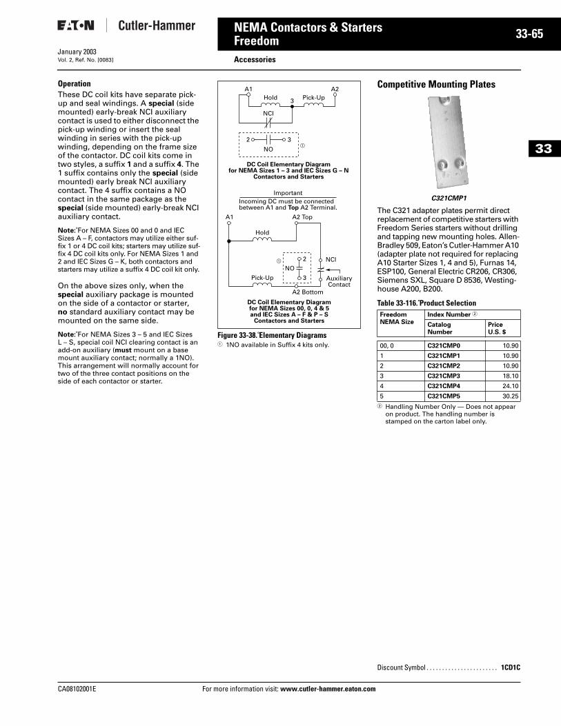
CA08102001E For more
65
33-NEMA Contactors & StartersFreedom AccessoriesJanuary 2003Vol. 2, Ref. No. [0083]
33
Operation These DC coil kits have separate pick-up and seal windings. A special (side mounted) early-break NCI auxiliary contact is used to either disconnect the pick-up winding or insert the seal winding in series with the pick-up winding, depending on the frame size of the contactor. DC coil kits come in two styles, a suffix 1 and a suffix 4. The 1 suffix contains only the special (side mounted) early break NCI auxiliary contact. The 4 suffix contains a NO contact in the same package as the special (side mounted) early-break NCI auxiliary contact.
Note: For NEMA Sizes 00 and 0 and IEC Sizes A – F, contactors may utilize either suf-fix 1 or 4 DC coil kits; starters may utilize suf-fix 4 DC coil kits only. For NEMA Sizes 1 and 2 and IEC Sizes G – K, both contactors and starters may utilize a suffix 4 DC coil kit only.
On the above sizes only, when the special auxiliary package is mounted on the side of a contactor or starter, no standard auxiliary contact may be mounted on the same side.
Note: For NEMA Sizes 3 – 5 and IEC Sizes L – S, special coil NCI clearing contact is an add-on auxiliary (must mount on a base mount auxiliary contact; normally a 1NO). This arrangement will normally account for two of the three contact positions on the side of each contactor or starter.
Figure 33-38. Elementary Diagrams1 1NO available in Suffix 4 kits only.
Competitive Mounting Plates
The C321 adapter plates permit direct replacement of competitive starters with Freedom Series starters without drilling and tapping new mounting holes. Allen-Bradley 509, Eaton’s Cutler-Hammer A10 (adapter plate not required for replacing A10 Starter Sizes 1, 4 and 5), Furnas 14, ESP100, General Electric CR206, CR306,Siemens SXL, Square D 8536, Westing-house A200, B200.
Table 33-116. Product Selection
2 Handling Number Only — Does not appear on product. The handling number is stamped on the carton label only.
AuxiliaryContact
ImportantIncoming DC must be connectedbetween A1 and Top A2 Terminal.
A1 A2
A1 A2 Top
A2 Bottom
3
NCI
NOa
a
3
2
3
NCINO
2
Hold Pick-Up
Hold
Pick-Up
DC Coil Elementary Diagramfor NEMA Sizes 1 – 3 and IEC Sizes G – N
Contactors and Starters
DC Coil Elementary Diagramfor NEMA Sizes 00, 0, 4 & 5and IEC Sizes A – F & P – S
Contactors and StartersFreedomNEMA Size
Index Number 2
CatalogNumber
PriceU.S. $
00, 0 C321CMP0 10.90
1 C321CMP1 10.90
2 C321CMP2 10.90
3 C321CMP3 18.10
4 C321CMP4 24.10
5 C321CMP5 30.25
Discount Symbol . . . . . . . . . . . . . . . . . . . . . . . 1CD1C
C321CMP1
information visit: www.cutler-hammer.eaton.com
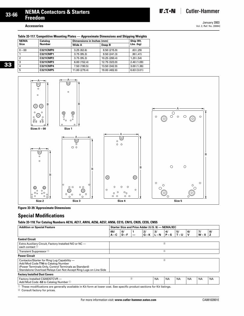
33-66
33
NEMA Contactors & StartersFreedom
AccessoriesFor more information visit: www.cutler-hammer.eaton.com
January 2003Vol. 2, Ref. No. [0084]
Table 33-117. Competitive Mounting Plates — Approximate Dimensions and Shipping Weights
Figure 33-39. Approximate Dimensions
Special ModificationsTable 33-118. For Catalog Numbers AE16, AE17, AN16, AE56, AE57, AN56, CE15, CN15, CN35, CE55, CN55
1 These modifications are generally available in Kit form at lower cost. See specific product sections for Kit listings.2 Consult factory for prices.
NEMASize
CatalogNumber
Dimensions in Inches (mm) Ship Wt. Lbs. (kg)Wide A Deep B
0 – 00 C321CMP0 3.25 (82.6) 8.50 (215.9) .63 (.29)1 C321CMP1 3.75 (95.3) 9.50 (241.3) .90 (.41)2 C321CMP2 3.75 (95.3) 10.25 (260.4) 1.20 (.54)3 C321CMP3 6.00 (152.4) 12.75 (323.9) 2.40 (1.09)4 C321CMP4 7.50 (190.5) 13.50 (342.9) 3.00 (1.36)5 C321CMP5 11.00 (279.4) 19.00 (482.6) 6.63 (3.01)
Addition or Special Feature Starter Size and Price Adder (U.S. $) — NEMA/IEC
00/A – C
0/D – F
1—
2/G – K
3/L – N
4/P – S
5/T – U
6/V
7/W – X
8/Z
Control CircuitExtra Auxiliary Circuit, Factory Installed NO or NC — each contact 1
2
Transient Suppressor 1 2
Power CircuitContactor/Starter for Ring Lug Capability — Add Mod Code T16 to Catalog Number(Power Terminals Only, Control Terminals as Standard)Standalone Overload Relays Can Not Accept Ring Lugs on Line Side
2
Factory Installed Dust CoversFactory Installed C320DSTCVR — Add Mod Code -53 to Catalog Number 1
2 NA NA NA NA NA NA
A
B
A
B
A
Size 2
Size 1Sizes 0 – 00
B
A
A
Size 5
B
Size 4
B
A
Size 3
B
CA08102001E
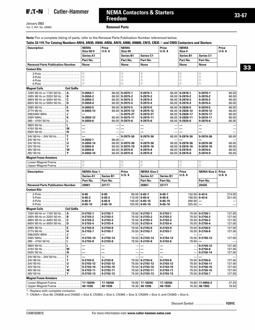
CA08102001E For more
67
33-NEMA Contactors & StartersFreedom Renewal PartsJanuary 2003Vol. 2, Ref. No. [0085]
33
Note: For a complete listing of parts, refer to the Renewal Parts Publication Number referenced below.
Table 33-119. For Catalog Numbers AN16, AN30, AN40, AN56, AN70, AN80, AN800, CN15, CN35 2 and CN55 Contactors and Starters
1 Replace with complete contactor. 2 CN35A = Size 00, CN35B and CN35D = Size 0, CN35G = Size 2, CN35K = Size 3, CN35N = Size 4, and CN35S = Size 5.
Description NEMA Size 00-0
PriceU.S. $
NEMA Size 00
PriceU.S. $
NEMASize 0
PriceU.S. $
Series A1 Series B1 Series C1 Series B1 Series C1
Part No. Part No. Part No. Part No. Part No.
Renewal Parts Publication Number None None None None None
Contact Kits2-Pole . . . . . . . . . . . . . . . . . . . . . . . .3-Pole . . . . . . . . . . . . . . . . . . . . . . . .4-Pole . . . . . . . . . . . . . . . . . . . . . . . .5-Pole . . . . . . . . . . . . . . . . . . . . . . . .
1
1
1
1
1
1
1
1
1
1
1
1
1
1
1
1
1
1
1
1
Magnet Coils Coil Suffix120V 60 Hz or 110V 50 Hz . .240V 60 Hz or 220V 50 Hz . .480V 60 Hz or 440V 50 Hz . .600V 60 Hz or 550V 50 Hz . .
ABCD
9-2650-19-2650-29-2650-39-2650-4
66.0066.0066.0066.00
9-2875-19-2875-29-2875-39-2875-4
9-2875-19-2875-29-2875-39-2875-4
66.0066.0066.0066.00
9-2876-19-2876-29-2876-39-2876-4
9-2876-19-2876-29-2876-39-2876-4
66.0066.0066.0066.00
208V 60 Hz . . . . . . . . . . . . . .277V 60 Hz . . . . . . . . . . . . . .208/240V 60Hz . . . . . . . . . .240V 50Hz. . . . . . . . . . . . . . .380 – 415V 50 Hz . . . . . . . . .
EHJKL
9-2650-59-2650-13— 9-2650-129-2650-6
66.0066.00
—66.0066.00
9-2875-59-2875-129-2875-379-2875-119-2875-6
9-2875-59-2875-129-2875-379-2875-119-2875-6
66.0066.0066.0066.0066.00
9-2826-5 9-2826-12 9-2826-17 9-2826-11 9-2826-6
9-2876-5 9-2876-12 9-2876-17 9-2876-11 9-2876-6
66.0066.0066.0066.0066.00
380V 50 Hz . . . . . . . . . . . . . .415V 50 Hz . . . . . . . . . . . . . .550V 50 Hz . . . . . . . . . . . . . .
LMN
— — —
———
— — —
— — —
———
— — —
— — —
———
24V 60 Hz – 24V 50 Hz . . . . .24V 60 Hz . . . . . . . . . . . . . . .24V 50 Hz . . . . . . . . . . . . . . .32V 50 Hz . . . . . . . . . . . . . . .48V 60 Hz . . . . . . . . . . . . . . .48V 50 Hz . . . . . . . . . . . . . . .
TTUVWY
— 9-2650-79-2650-149-2650-99-2650-89-2650-10
—66.0066.0066.0066.0066.00
9-2875-36— 9-2875-369-2875-169-2875-89-2875-9
9-2875-36— 9-2875-369-2875-169-2875-89-2875-9
66.00—
66.0066.0066.0066.00
9-2876-36— 9-2876-369-2876-169-2876-89-2876-9
9-2876-36— 9-2876-369-2876-169-2876-89-2876-9
66.00—
66.0066.0066.0066.00
Magnet Frame Armature Lower Magnet Frame . . . . . . . . . . . . . .Upper Magnet Frame . . . . . . . . . . . . . .
1
1
1
1
1
1
1
1
1
1
Description NEMA Size 1 PriceU.S. $
NEMA Size 2 PriceU.S. $
NEMA Size 3 PriceU.S. $Series A1 Series B1 Series A1 Series B1
Part No. Part No. Part No. Part No. Part No.
Renewal Parts Publication Number 20861 22177 20861 22177 20426
Contact Kits2-Pole . . . . . . . . . . . . . . . . . . . . . . . .3-Pole . . . . . . . . . . . . . . . . . . . . . . . .4-Pole . . . . . . . . . . . . . . . . . . . . . . . .5-Pole . . . . . . . . . . . . . . . . . . . . . . . .
6-656-65-26-65-96-65-10
6-656-65-26-65-96-65-10
69.00110.00145.00183.00
6-65-76-65-86-65-156-65-16
6-65-76-65-86-65-156-65-16
132.00196.00260.00325.00
6-43-56-43-6——
214.00321.00
——
Magnet Coils Coil Suffix120V 60 Hz or 110V 50 Hz . .240V 60 Hz or 220V 50 Hz . .480V 60 Hz or 440V 50 Hz . .600V 60 Hz or 550V 50 Hz . .
ABCD
9-2703-19-2703-29-2703-39-2703-4
9-2703-19-2703-29-2703-39-2703-4
78.5078.5078.5078.50
9-2703-19-2703-29-2703-39-2703-4
9-2703-19-2703-29-2703-39-2703-4
78.5078.5078.5078.50
9-2756-19-2756-29-2756-39-2756-4
127.00127.00127.00127.00
208V 60 Hz . . . . . . . . . . . . . .277V 60 Hz . . . . . . . . . . . . . .208/240V 60Hz . . . . . . . . . .240V 50Hz. . . . . . . . . . . . . . .380 – 415V 50 Hz . . . . . . . . .
EHJKL
9-2703-99-2703-7—9-2703-149-2703-8
9-2703-99-2703-7—9-2703-149-2703-8
78.5078.50
—78.5078.50
9-2703-99-2703-7—9-2703-149-2703-8
9-2703-99-2703-7—9-2703-149-2703-8
78.5078.50
—78.5078.50
9-2756-59-2756-9—9-2756-13—
127.00127.00
—127.00
—
380V 50 Hz . . . . . . . . . . . . . .415V 50 Hz . . . . . . . . . . . . . .550V 50 Hz . . . . . . . . . . . . . .
LMN
— — —
— — —
———
— — —
— — —
———
9-2756-129-2756-89-2756-14
127.00127.00127.00
24V 60 Hz – 24V 50 Hz . . . . .24V 60 Hz . . . . . . . . . . . . . . .24V 50 Hz . . . . . . . . . . . . . . .32V 50 Hz . . . . . . . . . . . . . . .48V 60 Hz . . . . . . . . . . . . . . .48V 50 Hz . . . . . . . . . . . . . . .
TTUVWY
—9-2703-69-2703-129-2703-109-2703-119-2703-13
—9-2703-69-2703-129-2703-109-2703-119-2703-13
—78.5078.5078.5078.5078.50
—9-2703-69-2703-129-2703-109-2703-119-2703-13
—9-2703-69-2703-129-2703-109-2703-119-2703-13
—78.5078.5078.5078.5078.50
— 9-2756-69-2756-119-2756-109-2756-159-2756-7
—127.00127.00127.00127.00127.00
Magnet Frame Armature Lower Magnet Frame . . . . . . . . . . . . . .Upper Magnet Frame . . . . . . . . . . . . . .
17-1820048-1936
17-1820048-1936
19.8018.30
17-1820048-1936
17-1820048-1936
19.8018.30
17-8955-248-1902
47.2519.50
Discount Symbol . . . . . . . . . . . . . . . . . . . . . 1CD1C
information visit: www.cutler-hammer.eaton.com
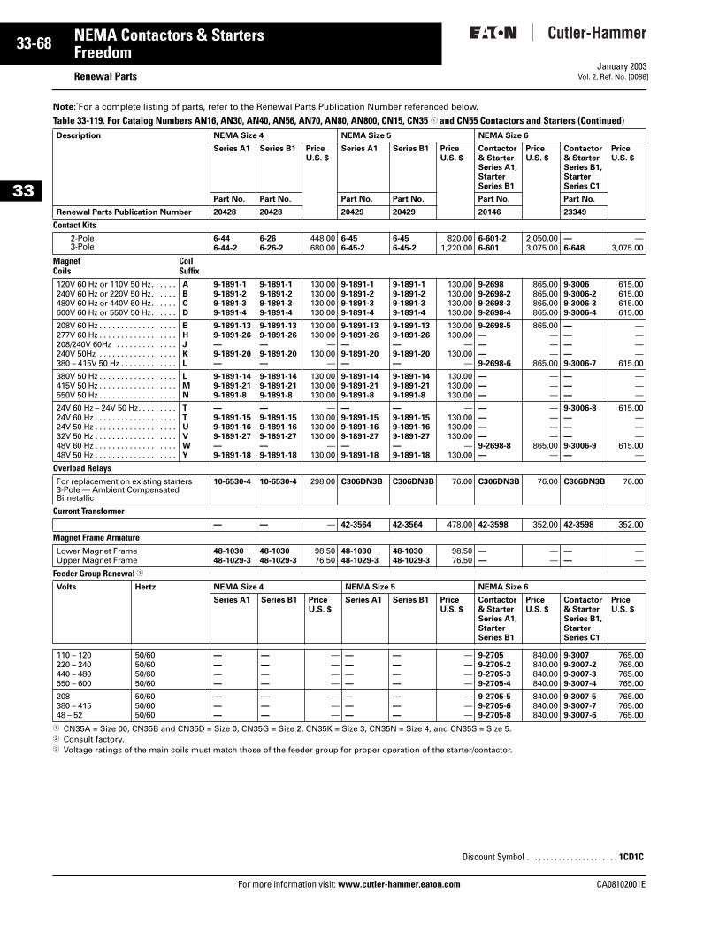
33-68
33
NEMA Contactors & StartersFreedom
Renewal PartsFor more information visit: www.cutler-hammer.eaton.com
January 2003Vol. 2, Ref. No. [0086]
Note: For a complete listing of parts, refer to the Renewal Parts Publication Number referenced below.
Table 33-119. For Catalog Numbers AN16, AN30, AN40, AN56, AN70, AN80, AN800, CN15, CN35 1 and CN55 Contactors and Starters (Continued)
1 CN35A = Size 00, CN35B and CN35D = Size 0, CN35G = Size 2, CN35K = Size 3, CN35N = Size 4, and CN35S = Size 5.2 Consult factory. 3 Voltage ratings of the main coils must match those of the feeder group for proper operation of the starter/contactor.
Description NEMA Size 4 NEMA Size 5 NEMA Size 6
Series A1 Series B1 PriceU.S. $
Series A1 Series B1 PriceU.S. $
Contactor & Starter Series A1, StarterSeries B1
PriceU.S. $
Contactor & Starter Series B1, StarterSeries C1
PriceU.S. $
Part No. Part No. Part No. Part No. Part No. Part No.
Renewal Parts Publication Number 20428 20428 20429 20429 20146 23349
Contact Kits2-Pole 3-Pole
6-44 6-44-2
6-266-26-2
448.00680.00
6-456-45-2
6-456-45-2
820.001,220.00
6-601-26-601
2,050.003,075.00
—6-648
—3,075.00
MagnetCoils
CoilSuffix
120V 60 Hz or 110V 50 Hz. . . . . .240V 60 Hz or 220V 50 Hz. . . . . .480V 60 Hz or 440V 50 Hz. . . . . .600V 60 Hz or 550V 50 Hz. . . . . .
ABCD
9-1891-19-1891-29-1891-39-1891-4
9-1891-19-1891-29-1891-39-1891-4
130.00130.00130.00130.00
9-1891-19-1891-29-1891-39-1891-4
9-1891-19-1891-29-1891-39-1891-4
130.00130.00130.00130.00
9-26989-2698-29-2698-39-2698-4
865.00865.00865.00865.00
9-30069-3006-29-3006-39-3006-4
615.00615.00615.00615.00
208V 60 Hz . . . . . . . . . . . . . . . . . .277V 60 Hz . . . . . . . . . . . . . . . . . .208/240V 60Hz . . . . . . . . . . . . . .240V 50Hz . . . . . . . . . . . . . . . . . .380 – 415V 50 Hz . . . . . . . . . . . . .
EHJKL
9-1891-139-1891-26—9-1891-20—
9-1891-139-1891-26—9-1891-20—
130.00130.00
—130.00
—
9-1891-139-1891-26—9-1891-20—
9-1891-139-1891-26—9-1891-20—
130.00130.00
—130.00
—
9-2698-5———9-2698-6
865.00———
865.00
————9-3006-7
————
615.00
380V 50 Hz . . . . . . . . . . . . . . . . . .415V 50 Hz . . . . . . . . . . . . . . . . . .550V 50 Hz . . . . . . . . . . . . . . . . . .
LMN
9-1891-149-1891-219-1891-8
9-1891-149-1891-219-1891-8
130.00130.00130.00
9-1891-149-1891-219-1891-8
9-1891-149-1891-219-1891-8
130.00130.00130.00
———
———
———
———
24V 60 Hz – 24V 50 Hz. . . . . . . . .24V 60 Hz . . . . . . . . . . . . . . . . . . .24V 50 Hz . . . . . . . . . . . . . . . . . . .32V 50 Hz . . . . . . . . . . . . . . . . . . .48V 60 Hz . . . . . . . . . . . . . . . . . . .48V 50 Hz . . . . . . . . . . . . . . . . . . .
TTUVWY
—9-1891-159-1891-169-1891-27—9-1891-18
—9-1891-159-1891-169-1891-27—9-1891-18
—130.00130.00130.00
—130.00
—9-1891-159-1891-169-1891-27—9-1891-18
—9-1891-159-1891-169-1891-27—9-1891-18
—130.00130.00130.00
—130.00
————9-2698-8—
————
865.00—
9-3006-8———9-3006-9—
615.00———
615.00—
Overload Relays For replacement on existing starters 3-Pole — Ambient Compensated Bimetallic
10-6530-4 10-6530-4 298.00 C306DN3B C306DN3B 76.00 C306DN3B 76.00 C306DN3B 76.00
Current Transformer— — — 42-3564 42-3564 478.00 42-3598 352.00 42-3598 352.00
Magnet Frame Armature Lower Magnet FrameUpper Magnet Frame
48-103048-1029-3
48-103048-1029-3
98.5076.50
48-103048-1029-3
48-103048-1029-3
98.5076.50
——
——
——
——
Feeder Group Renewal 3
Volts Hertz NEMA Size 4 NEMA Size 5 NEMA Size 6
Series A1 Series B1 PriceU.S. $
Series A1 Series B1 PriceU.S. $
Contactor & Starter Series A1, Starter Series B1
PriceU.S. $
Contactor & Starter Series B1, Starter Series C1
PriceU.S. $
110 – 120220 – 240440 – 480550 – 600
50/6050/6050/6050/60
————
————
————
————
————
————
9-27059-2705-29-2705-39-2705-4
840.00840.00840.00840.00
9-30079-3007-29-3007-39-3007-4
765.00765.00765.00765.00
208380 – 41548 – 52
50/6050/6050/60
———
———
———
———
———
———
9-2705-59-2705-69-2705-8
840.00840.00840.00
9-3007-59-3007-79-3007-6
765.00765.00765.00
Discount Symbol . . . . . . . . . . . . . . . . . . . . . . . 1CD1C
CA08102001E
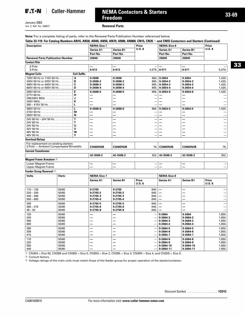
CA08102001E For more
69
33-NEMA Contactors & StartersFreedom Renewal PartsJanuary 2003Vol. 2, Ref. No. [0087]
33
Note: For a complete listing of parts, refer to the Renewal Parts Publication Number referenced below.
Table 33-119. For Catalog Numbers AN16, AN30, AN40, AN56, AN70, AN80, AN800, CN15, CN35 1 and CN55 Contactors and Starters (Continued)
1 CN35A = Size 00, CN35B and CN35D = Size 0, CN35G = Size 2, CN35K = Size 3, CN35N = Size 4, and CN35S = Size 5.2 Consult factory. 3 Voltage ratings of the main coils must match those of the feeder group for proper operation of the starter/contactor.
Description NEMA Size 7 PriceU.S. $
NEMA Size 8 PriceU.S. $Series A1 Series B1 Series A1 Series B1
Part No. Part No. Part No. Part No.
Renewal Parts Publication Number 20848 20848 20849 20849
Contact Kits2-Pole 3-Pole
—6-613
—6-613
—4,575.
—6-571
—6-571
—5,070.
Magnet Coils Coil Suffix120V 60 Hz or 110V 50 Hz . . . . . . . . .240V 60 Hz or 220V 50 Hz . . . . . . . . .480V 60 Hz or 440V 50 Hz . . . . . . . . .600V 60 Hz or 550V 50 Hz . . . . . . . . .
ABCD
9-26989-2698-29-2698-39-2698-4
9-26989-2698-29-2698-39-2698-4
865.865.865.865.
9-26549-2654-29-2654-39-2654-4
9-26549-2654-29-2654-39-2654-4
1,425.1,425.1,425.1,425.
208V 60 Hz . . . . . . . . . . . . . . . . . . . . .277V 60 Hz . . . . . . . . . . . . . . . . . . . . .208/240V 60Hz . . . . . . . . . . . . . . . . .240V 50Hz. . . . . . . . . . . . . . . . . . . . . .380 – 415V 50 Hz . . . . . . . . . . . . . . . .
EHJKL
9-2698-5————
9-2698-5————
865.————
9-2654-6————
9-2654-6————
1,425.————
380V 50 Hz . . . . . . . . . . . . . . . . . . . . .415V 50 Hz . . . . . . . . . . . . . . . . . . . . .550V 50 Hz . . . . . . . . . . . . . . . . . . . . .
LMN
9-2698-6——
9-2698-6——
865.——
9-2654-5——
9-2654-5——
1,425.——
24V 60 Hz – 24V 50 Hz . . . . . . . . . . . .24V 60 Hz . . . . . . . . . . . . . . . . . . . . . .24V 50 Hz . . . . . . . . . . . . . . . . . . . . . .32V 50 Hz . . . . . . . . . . . . . . . . . . . . . .48V 60 Hz . . . . . . . . . . . . . . . . . . . . . .48V 50 Hz . . . . . . . . . . . . . . . . . . . . . .
TTUVWY
——————
——————
——————
——————
——————
——————
Overload Relays For replacement on existing starters 3-Pole — Ambient Compensated Bimetallic C306DN3B C306DN3B 76. C306DN3B C306DN3B 76.
Current Transformer42-3598-2 42-3598-2 352. 42-3598-3 42-3598-3 352.
Magnet Frame Armature 2
Lower Magnet Frame Upper Magnet Frame
——
——
——
——
——
——
Feeder Group Renewal 3
Volts Hertz NEMA Size 7 NEMA Size 8
Series A1 Series B1 PriceU.S. $
Series A1 Series B1 PriceU.S. $
110 – 120220 – 240440 – 480550 – 600
50/6050/6050/6050/60
9-27059-2705-29-2705-39-2705-4
9-27059-2705-29-2705-39-2705-4
840.840.840.840.
————
————
————
208380 – 41548 – 52
50/6050/6050/60
9-2705-59-2705-69-2705-8
9-2705-59-2705-69-2705-8
840.840.840.
———
———
———
120240480600
50/6050/6050/6050/60
————
————
————
9-26649-2664-29-2664-39-2664-4
9-26649-2664-29-2664-39-2664-4
1,850.1,850.1,850.1,850.
380208415
50/6050/6050/60
———
———
———
9-2664-59-2664-69-2664-7
9-2664-59-2664-69-2664-7
1,850.1,850.1,850.
110220550440
50/6050/6050/6050/60
————
————
————
9-2664-89-2664-99-2664-109-2664-11
9-2664-89-2664-99-2664-109-2664-11
1,850.1,850.1,850.1,850.
Discount Symbol . . . . . . . . . . . . . . . . . . . . . . 1CD1C
information visit: www.cutler-hammer.eaton.com
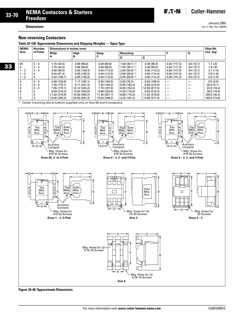
33-70
33
NEMA Contactors & StartersFreedom
DimensionsFor more information visit: www.cutler-hammer.eaton.com
January 2003Vol. 2, Ref. No. [0088]
Non-reversing ContactorsTable 33-120. Approximate Dimensions and Shipping Weights — Open Type
1 Center mounting slot at bottom supplied only on Size 00 and 0 contactors.
Figure 33-40. Approximate Dimensions
NEMASize
Numberof Poles
Dimensions in Inches (mm) Ship Wt.Lbs. (kg)Wide
AHighB
DeepC
Mounting F G
D E
0001 – 21 – 21 – 2
2 – 42 – 32 – 345
1.75 (44.5)1.75 (44.5)2.56 (65.0)3.44 (87.4)4.32 (109.7)
3.88 (98.6)3.88 (98.6)5.05 (128.3)5.05 (128.3)5.05 (128.3)
3.49 (88.6)3.49 (88.6)4.44 (112.8)4.44 (112.8)4.44 (112.8)
1.50 (38.1) 11.50 (38.1) 12.00 (50.8) 12.00 (50.8) 12.00 (50.8) 1
3.38 (85.9)3.38 (85.9)4.50 (114.3)4.50 (114.3)4.50 (114.3)
4.62 (117.3)4.62 (117.3)5.80 (147.3)5.80 (147.3)5.80 (147.3)
.54 (13.7)
.54 (13.7)
.54 (13.7)
.54 (13.7)
.54 (13.7)
1.7 (.8)1.8 (.8)3.1 (1.4)3.6 (1.6)4.0 (1.8)
345678
2 – 32 – 32 – 3333
4.08 (103.6)7.05 (179.1)7.05 (179.1)8.63 (219.2)
11.02 (279.9)13.00 (330.2)
7.17 (182.1)9.11 (231.4)
13.12 (333.2)13.54 (343.9)19.30 (490.2)24.50 (622.3)
5.94 (150.9)7.25 (184.2)7.78 (197.6)8.88 (225.6)
11.46 (291.1)13.63 (346.2)
3.00 (76.2)6.00 (152.4)6.00 (152.4)4.33 (110.0)6.89 (175.0)4.22 (107.2)
6.63 (168.4)8.50 (215.9)
12.50 (317.5)8.63 (219.2)
11.02 (279.9)14.86 (377.4)
——————
——————
8.5 (3.9)20.0 (9.1)23.0 (10.4)35.0 (15.9)
100.0 (45.4)160.0 (72.6)
Mtg. Holes for#10-32 Screws
AUX
AUX
A GG FC
D
TopMtd.Aux.
AuxiliaryContacts
TopMtd.Aux.
SideMtd.Aux.E B
Mtg. Holes for#10-32 Screws
AUX
AUX
A GG FC
D
TopMtd.Aux.
AuxiliaryContacts
TopMtd.Aux.
SideMtd.Aux.E B
Mtg. Holes for#10-32 Screws
AUX
AUX
A GG FC
D
TopMtd.Aux.
AuxiliaryContacts
TopMtd.Aux.
SideMtd.Aux.E B
Sizes 00, 2- to 4-Pole
Mtg. Holes for#10-32 Screws
AUX
AUX
A GG FC
D
TopMtd.Aux.
AuxiliaryContacts
TopMtd.Aux.
SideMtd.Aux.
SideMtd.Aux.
E B
Sizes 1 – 2, 5-Pole
Mtg. Holes for (3)1/4-20 Screws
A C A C
D
BE
Size 3
Mtg. Holes for(3) Screws
D
BE
Sizes 4 – 5
Sizes 0 – 2, 2- and 3-Pole Sizes 0 – 2, 2- and 3-Pole
C
Mtg. Slots for (2)5/16-18 Screws
Mtg. Holes for (2)5/16-18 Screws
D
A
BE
Size 6
CA08102001E
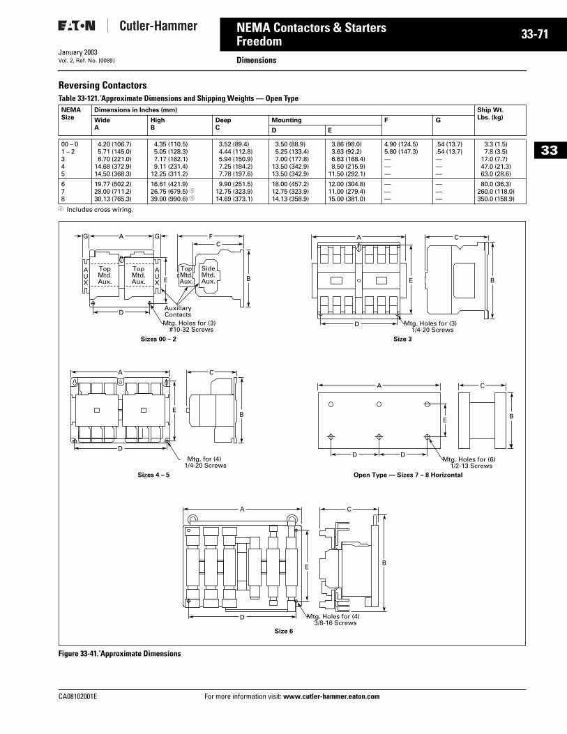
CA08102001E For more
71
33-NEMA Contactors & StartersFreedom DimensionsJanuary 2003Vol. 2, Ref. No. [0089]
33
Reversing ContactorsTable 33-121. Approximate Dimensions and Shipping Weights — Open Type
1 Includes cross wiring.
Figure 33-41. Approximate Dimensions
NEMASize
Dimensions in Inches (mm) Ship Wt.Lbs. (kg)Wide
AHighB
DeepC
Mounting F G
D E
00 – 01 – 2345
4.20 (106.7)5.71 (145.0)8.70 (221.0)
14.68 (372.9)14.50 (368.3)
4.35 (110.5)5.05 (128.3)7.17 (182.1)9.11 (231.4)
12.25 (311.2)
3.52 (89.4)4.44 (112.8)5.94 (150.9)7.25 (184.2)7.78 (197.6)
3.50 (88.9)5.25 (133.4)7.00 (177.8)
13.50 (342.9)13.50 (342.9)
3.86 (98.0)3.63 (92.2)6.63 (168.4)8.50 (215.9)
11.50 (292.1)
4.90 (124.5)5.80 (147.3)———
.54 (13.7)
.54 (13.7)———
3.3 (1.5)7.8 (3.5)
17.0 (7.7)47.0 (21.3)63.0 (28.6)
678
19.77 (502.2)28.00 (711.2)30.13 (765.3)
16.61 (421.9)26.75 (679.5) 139.00 (990.6) 1
9.90 (251.5)12.75 (323.9)14.69 (373.1)
18.00 (457.2)12.75 (323.9)14.13 (358.9)
12.00 (304.8)11.00 (279.4)15.00 (381.0)
———
———
80.0 (36.3)260.0 (118.0)350.0 (158.9)
Mtg. Holes for (3)#10-32 Screws
AUX
AUX
A GG FC
D
TopMtd.Aux.
TopMtd.Aux.
AuxiliaryContacts
TopMtd.Aux.
SideMtd.Aux.E B
Sizes 00 – 2 Size 3
Mtg. for (4)1/4-20 Screws
A C
D
EB
CA
Sizes 4 – 5
Mtg. Holes for (3)1/4-20 Screws
CA
D
E B
Mtg. Holes for (6)1/2-13 Screws
D D
EB
Open Type — Sizes 7 – 8 Horizontal
Mtg. Holes for (4)3/8-16 Screws
D
A C
EB
Size 6
information visit: www.cutler-hammer.eaton.com
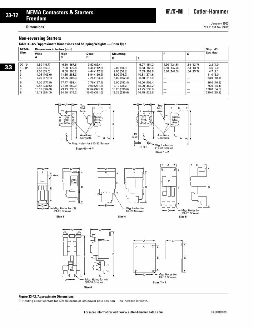
33-72
33
NEMA Contactors & StartersFreedom
DimensionsFor more information visit: www.cutler-hammer.eaton.com
January 2003Vol. 2, Ref. No. [0090]
Non-reversing StartersTable 33-122. Approximate Dimensions and Shipping Weights — Open Type
Figure 33-42. Approximate Dimensions1 Holding circuit contact for Size 00 occupies 4th power pole position — no increase in width.
NEMASize
Dimensions in Inches (mm) Ship. Wt.Lbs. (kg)Wide
AHighB
DeepC
Mounting F G
D E
00 – 01 – 1P234
1.80 (45.7)2.56 (65.0)2.56 (65.0)4.08 (103.6)7.05 (179.1)
6.60 (167.6)7.08 (179.8)8.08 (205.2)
11.35 (288.3)12.06 (306.3)
3.52 (89.4)4.44 (112.8)4.44 (112.8)5.94 (150.9)7.25 (184.2)
—2.00 (50.8)2.00 (50.8)3.00 (76.2)6.00 (152.4)
6.07 (154.2)6.63 (168.4)7.63 (193.8)
10.81 (274.6)8.50 (215.9)
4.90 (124.5)5.80 (147.3)5.80 (147.3)——
.54 (13.7)
.54 (13.7)
.54 (13.7)——
2.2 (1.0)4.5 (2.0)4.7 (2.1)
11.0 (5.0)23.0 (10.4)
5678
7.00 (177.8)9.47 (240.5)
15.13 (384.3)15.13 (384.3)
17.77 (451.4)21.69 (550.9)29.13 (739.9)34.50 (876.3)
7.76 (197.1)9.90 (251.5)
12.64 (321.1)15.00 (381.0)
6.00 (152.4)3.10 (78.7)
13.25 (336.6)13.25 (336.6)
16.00 (406.4)18.00 (457.2)21.25 (539.8)16.75 (425.5)
————
————
36.0 (16.3)75.0 (34.1)
120.0 (54.5)210.0 (95.3)
SideMtd.Aux.
D
AUX
Aux.Cont.
Aux.
AUX
A GGC
F
TopMtd.Aux.
AuxiliaryContacts
Mtg. Holes for #10-32 Screws
TopMtd.Aux.
E
CL CL
B
C A CG
E B
Sizes 00 – 0 aMtg. Holes for#10-32 Screws
Sizes 1 – 2
DA Mtg. Holes for (3)
1/4-20 Screws
Size 3
EB
A C
B
DMtg. Holes for1/4-20 Screws
Size 4
E
D Mtg. Holes for1/4-20 Screws
Size 5
A C
BE
D Mtg. Holes for1/2-13 Screws
Sizes 7 – 8
Size 6
A C
BE
D Mtg. Holes for (4)3/8-16 Screws
SideMtd.Aux.
AUX
AUX
A GG FC
TopMtd.Aux.
AuxiliaryContacts
TopMtd.Aux.
E
.13(3.3)
B
CA08102001E
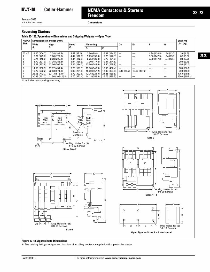
CA08102001E For more
73
33-NEMA Contactors & StartersFreedom DimensionsJanuary 2003Vol. 2, Ref. No. [0091]
33
Reversing StartersTable 33-123. Approximate Dimensions and Shipping Weights — Open Type
1 Includes cross wiring overhang.
Figure 33-43. Approximate Dimensions2 See catalog listings for type and location of auxiliary contacts supplied with a particular starter.
NEMASize
Dimensions in Inches (mm) Ship.Wt.Lbs. (kg)Wide
AHighB
DeepC
Mounting D1 E1 F G
D E
00 – 01 234
4.20 (106.7)5.71 (145.0)5.71 (145.0)8.70 (221.0)
14.68 (372.9)
7.38 (187.5)7.08 (179.8)8.08 (205.2)
11.35 (288.3)12.06 (306.3)
3.52 (89.4)4.44 (112.8)4.44 (112.8)5.94 (150.9)7.25 (184.2)
3.50 (88.9)5.25 (133.4)5.25 (133.4)7.00 (177.8)
13.50 (342.9)
6.87 (174.5)5.75 (146.1)6.75 (171.5)
10.81 (274.6)8.50 (215.9)
—————
—————
4.90 (124.5)5.80 (147.3)5.80 (147.3)——
.54 (13.7)
.54 (13.7)
.54 (13.7)——
3.6 (1.6)8.3 (3.8)8.5 (3.9)
20.0 (9.1)49.0 (22.2)
5678
14.50 (368.3)19.77 (502.2)28.06 (712.7)30.38 (771.7)
17.77 (451.4)22.63 (574.8)32.13 (816.1) 141.50 (1054.1) 1
7.76 (197.1)9.90 (251.5)
12.70 (322.6)14.70 (373.4)
13.50 (342.9)18.00 (457.2)12.75 (323.9)14.13 (358.9)
16.00 (406.4)12.00 (304.8)21.25 (539.8)16.75 (425.5)
—3.10 (78.7)——
—18.00 (457.2)——
————
————
68.0 (30.9)90.0 (40.9)
175.0 (79.5)430.0 (195.2)
SideMtd.Aux.
AUX
AUX
A
D.13(3.3)
GG FC
TopMtd.Aux.
TopMtd.Aux.
AuxiliaryContacts
b
Mtg. Holes for (3)#10-32 Screws
TopMtd.Aux.
EB
Sizes 00 – 2
A
D1
CD
Mtg. Holes for (6)3/8-16 Screws
E
E1 B
Size 6
D Mtg. Holes for (3)1/4-20 Screws
E
CA
B
Size 3
D Mtg. Holes for (4)1/4-20 Screws
E
CA
B
Sizes 4 – 5
DD Mtg. Holes for (6)1/2-13 Screws
E
A C
B
Open Type — Sizes 7 – 8 Horizontal
CL
CL
information visit: www.cutler-hammer.eaton.com
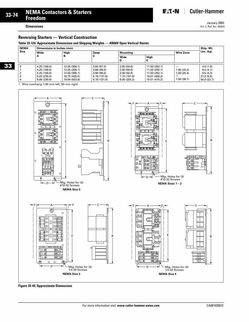
33-74
33
NEMA Contactors & StartersFreedom
DimensionsFor more information visit: www.cutler-hammer.eaton.com
January 2003Vol. 2, Ref. No. [0092]
Reversing Starters — Vertical ConstructionTable 33-124. Approximate Dimensions and Shipping Weights — AN56V Open Vertical Starter
1 Wire overhang 1.00 mm left, 50 mm right.
Figure 33-44. Approximate Dimensions
NEMASize
Dimensions in Inches (mm) Ship. Wt.Lbs. (kg)Wide
AHighB
DeepC
Mounting Wire Zone
WideD
HighE
01234
4.25 (108.0)4.25 (108.0)4.25 (108.0)9.25 (235.0)9.08 (230.6)
12.05 (306.1)12.05 (306.1)12.05 (306.1)16.75 (425.5)19.84 (503.9)
3.84 (97.5)3.86 (98.0)3.86 (98.0)5.18 (131.6)5.18 (131.6)
2.00 (50.8)2.00 (50.8)2.00 (50.8)7.15 (181.6)8.00 (203.2)
11.50 (292.1)11.50 (292.1)11.50 (292.1)16.07 (408.2)18.51 (470.2)
—1.00 (25.4)1.00 (25.4)1
1.50 (38.1)
4.0 (1.8)9.0 (4.1)9.5 (4.3)
21.0 (9.5)50.0 (22.7)
Mtg. Holes for (3)#10-32 Screws
NEMA Size 0
D
E
A
B
C
Mtg. Holes for (3)#10-32 Screws
NEMA Sizes 1 – 2
D
E
A CFF
B
Mtg. Holes for (3)1/4-20 Screws
NEMA Size 3
D
E
A CFF
B
Mtg. Holes for (4)1/4-20 Screws
NEMA Size 4
D
E
A CFF
B
CA08102001E
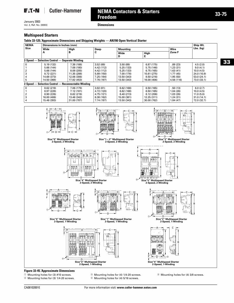
CA08102001E For more
75
33-NEMA Contactors & StartersFreedom DimensionsJanuary 2003Vol. 2, Ref. No. [0093]
33
Multispeed StartersTable 33-125. Approximate Dimensions and Shipping Weights — AN700 Open Vertical Starter
Figure 33-45. Approximate Dimensions 1 Mounting holes for (3) #10 screws.2 Mounting holes for (3) 1/4-20 screws.
3 Mounting holes for (4) 1/4-20 screws.4 Mounting holes for (4) 5/16 screws.
5 Mounting holes for (4) 3/8 screws.
NEMASize
Dimensions in Inches (mm) Ship Wt.Lbs. (kg)Wide
AHighB
DeepC
Mounting WireZone FWide
DHighE
2-Speed — Selective Control — Separate Winding 012345
5.19 (132)5.66 (144)5.66 (144)8.72 (221)
14.68 (373)14.50 (368)
7.38 (188)7.08 (180)8.08 (205)
11.35 (288)12.06 (306)17.82 (453)
3.52 (89)4.42 (112)4.42 (112)5.89 (150)7.25 (184)7.76 (197)
3.50 (89)5.25 (133)5.25 (133)7.00 (178)
13.50 (343)13.50 (343)
6.87 (175)5.75 (146)6.75 (165)
10.81 (275)8.50 (216)
16.00 (406)
.89 (23)1.23 (31)1.63 (41)1.77 (45)1.95 (50)4.56 (116)
4.5 (2.0)9.0 (4.1)
10.0 (4.5)24.0 (10.9)53.0 (24.1)73.0 (33.1)
2-Speed — Selective Control — Reconnectable Winding01234
8.62 (219)8.97 (228)8.90 (226)
16.00 (406)15.46 (393)
7.06 (179)7.12 (181)8.62 (219)
13.46 (342)31.00 (787)
3.82 (81)4.72 (120)4.75 (121)6.38 (162)7.74 (197)
6.62 (168)6.62 (168)8.40 (213)
15.00 (381)13.50 (343)
6.50 (165)6.50 (165)8.12 (206)
12.25 (311)30.00 (762)
.50 (13)1.04 (26)1.03 (26)1.24 (31)1.84 (47)
6.0 (2.7)10.0 (4.5)11.0 (5.0)31.0 (14.1)72.0 (32.7)
aa
b
E B
A
D C
F
EB
A
D
CF
E B
A
D
CF
Size“3” Multispeed Starter2-Speed, 2-Winding
Size“1 – 2” Multispeed Starter2-Speed, 2-Winding
Size“0” Multispeed Starter2-Speed, 2-Winding
EB
A
D
CF
E B
AF
D C
c
Size“4” Multispeed Starter2-Speed, 2-Winding
cSize“5” Multispeed Starter
2-Speed, 2-Winding
E B
A
D
CF
E B
A
D
C
F ed
Size“4” Multispeed Starter2-Speed, 1-Winding
Size“3” Multispeed Starter2-Speed, 1-Winding
E B
A
D C
F
E B
A
D
CF
E B
A
D
CF
a
a
a
Size“2” Multispeed Starter2-Speed, 1-Winding
Size“1” Multispeed Starter2-Speed, 1-Winding
Size“0” Multispeed Starter2-Speed, 1-Winding
information visit: www.cutler-hammer.eaton.com
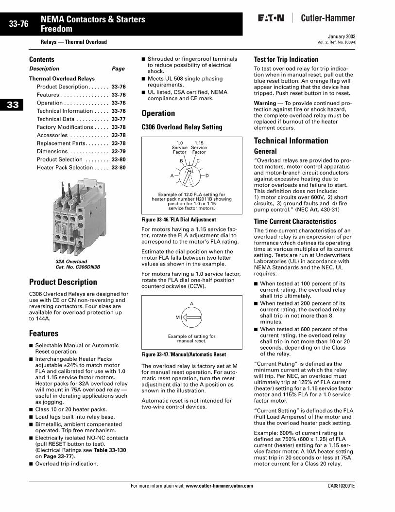
33-76
33
NEMA Contactors & StartersFreedom
Relays — Thermal OverloadFor more information visit: www.cutler-hammer.eaton.com
January 2003Vol. 2, Ref. No. [0094]
ContentsDescription Page
Thermal Overload Relays
Product Description. . . . . . . 33-76
Features . . . . . . . . . . . . . . . . 33-76
Operation . . . . . . . . . . . . . . . 33-76
Technical Information . . . . . 33-76
Technical Data . . . . . . . . . . . 33-77
Factory Modifications . . . . . 33-78
Accessories . . . . . . . . . . . . . 33-78
Replacement Parts. . . . . . . . 33-78
Dimensions . . . . . . . . . . . . . 33-79
Product Selection . . . . . . . . 33-80
Heater Pack Selection . . . . . 33-80
Product DescriptionC306 Overload Relays are designed for use with CE or CN non-reversing and reversing contactors. Four sizes are available for overload protection up to 144A.
Features■ Selectable Manual or Automatic
Reset operation.■ Interchangeable Heater Packs
adjustable ±24% to match motor FLA and calibrated for use with 1.0 and 1.15 service factor motors. Heater packs for 32A overload relay will mount in 75A overload relay — useful in derating applications such as jogging.
■ Class 10 or 20 heater packs.■ Load lugs built into relay base.■ Bimetallic, ambient compensated
operated. Trip free mechanism.■ Electrically isolated NO-NC contacts
(pull RESET button to test).(Electrical Ratings see Table 33-130 on Page 33-77).
■ Overload trip indication.
■ Shrouded or fingerproof terminals to reduce possibility of electrical shock.
■ Meets UL 508 single-phasing requirements.
■ UL listed, CSA certified, NEMA compliance and CE mark.
Operation
C306 Overload Relay Setting
Figure 33-46. FLA Dial Adjustment
For motors having a 1.15 service fac-tor, rotate the FLA adjustment dial to correspond to the motor’s FLA rating.
Estimate the dial position when the motor FLA falls between two letter values as shown in the example.
For motors having a 1.0 service factor, rotate the FLA dial one-half position counterclockwise (CCW).
Figure 33-47. Manual/Automatic Reset
The overload relay is factory set at M for manual reset operation. For auto-matic reset operation, turn the reset adjustment dial to the A position as shown in the illustration.
Automatic reset is not intended for two-wire control devices.
Test for Trip IndicationTo test overload relay for trip indica-tion when in manual reset, pull out the blue reset button. An orange flag will appear indicating that the device has tripped. Push reset button in to reset.
Warning — To provide continued pro-tection against fire or shock hazard, the complete overload relay must be replaced if burnout of the heater element occurs.
Technical InformationGeneral“Overload relays are provided to pro-tect motors, motor control apparatus and motor-branch circuit conductors against excessive heating due to motor overloads and failure to start. This definition does not include:1) motor circuits over 600V, 2) short circuits, 3) ground faults and 4) fire pump control.” (NEC Art. 430-31)
Time Current CharacteristicsThe time-current characteristics of an overload relay is an expression of per-formance which defines its operating time at various multiples of its current setting. Tests are run at Underwriters Laboratories (UL) in accordance with NEMA Standards and the NEC. UL requires:
■ When tested at 100 percent of its current rating, the overload relay shall trip ultimately.
■ When tested at 200 percent of its current rating, the overload relay shall trip in not more than 8 minutes.
■ When tested at 600 percent of the current rating, the overload relay shall trip in not more than 10 or 20 seconds, depending on the Class of the relay.
“Current Rating” is defined as the minimum current at which the relay will trip. Per NEC, an overload must ultimately trip at 125% of FLA current (heater) setting for a 1.15 service factor motor and 115% FLA for a 1.0 service factor motor.
“Current Setting” is defined as the FLA (Full Load Amperes) of the motor and thus the overload heater pack setting.
Example: 600% of current rating is defined as 750% (600 x 1.25) of FLA current (heater) setting for a 1.15 ser-vice factor motor. A 10A heater setting must trip in 20 seconds or less at 75A motor current for a Class 20 relay.
32A OverloadCat. No. C306DN3B
1.0ServiceFactor
1.15ServiceFactor
A
B C
D
Example of 12.0 FLA setting forheater pack number H2011B showing
position for 1.0 or 1.15service factor motors.
A
M
Example of setting formanual reset.
CA08102001E
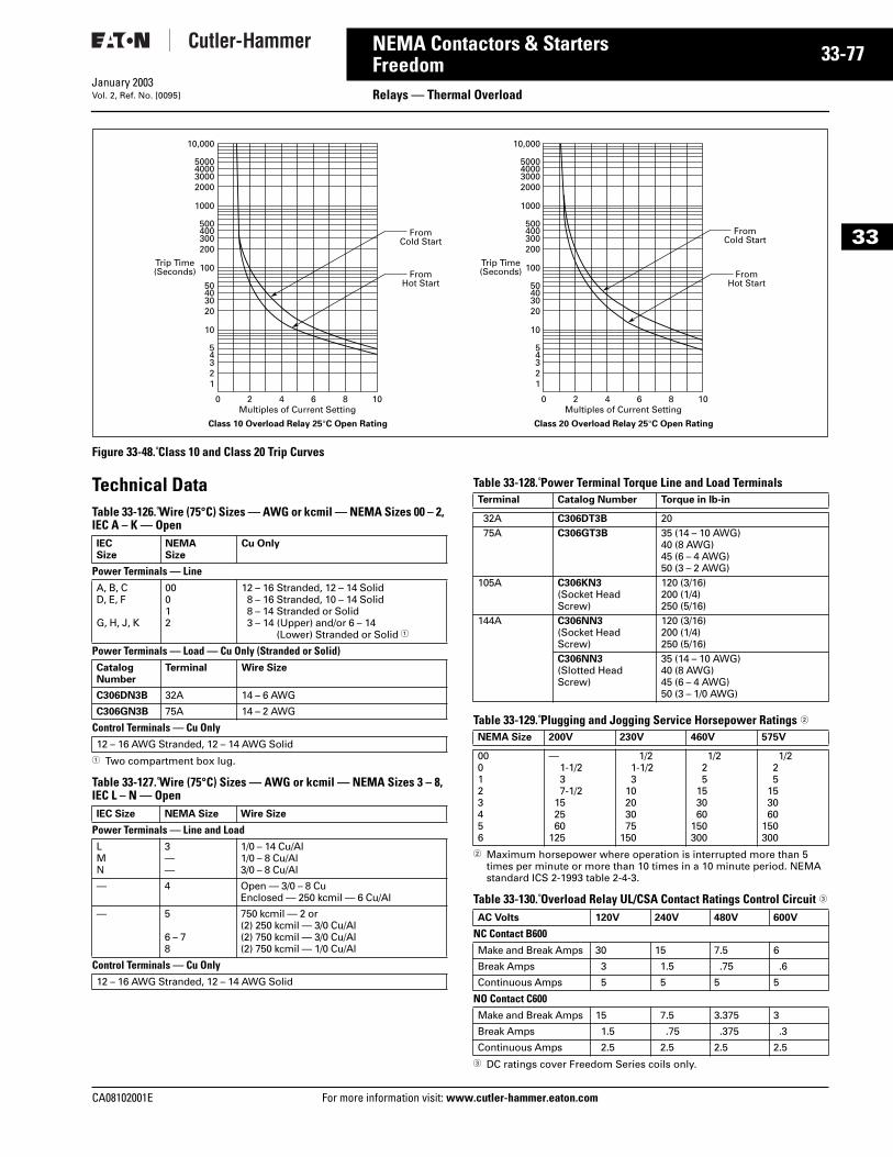
CA08102001E For more
77
33-NEMA Contactors & StartersFreedom Relays — Thermal OverloadJanuary 2003Vol. 2, Ref. No. [0095]
33
Figure 33-48. Class 10 and Class 20 Trip Curves
Technical DataTable 33-126. Wire (75°C) Sizes — AWG or kcmil — NEMA Sizes 00 – 2, IEC A – K — Open
1 Two compartment box lug.
Table 33-127. Wire (75°C) Sizes — AWG or kcmil — NEMA Sizes 3 – 8, IEC L – N — Open
Table 33-128. Power Terminal Torque Line and Load Terminals
Table 33-129. Plugging and Jogging Service Horsepower Ratings 2
2 Maximum horsepower where operation is interrupted more than 5 times per minute or more than 10 times in a 10 minute period. NEMA standard ICS 2-1993 table 2-4-3.
Table 33-130. Overload Relay UL/CSA Contact Ratings Control Circuit 3
3 DC ratings cover Freedom Series coils only.
0
12345
10
20304050
100
200300400500
1000
2000300040005000
10,000
2 4 6 8 10
FromHot Start
FromCold Start
Multiples of Current Setting
Trip Time(Seconds)
Class 10 Overload Relay 25°C Open Rating
0
12345
10
20304050
100
200300400500
1000
2000300040005000
10,000
2 4 6 8 10
FromHot Start
FromCold Start
Multiples of Current Setting
Trip Time(Seconds)
Class 20 Overload Relay 25°C Open Rating
IECSize
NEMASize
Cu Only
Power Terminals — LineA, B, CD, E, F
G, H, J, K
00012
12 – 16 Stranded, 12 – 14 Solid8 – 16 Stranded, 10 – 14 Solid8 – 14 Stranded or Solid3 – 14 (Upper) and/or 6 – 14
(Lower) Stranded or Solid 1
Power Terminals — Load — Cu Only (Stranded or Solid)CatalogNumber
Terminal Wire Size
C306DN3B 32A 14 – 6 AWG
C306GN3B 75A 14 – 2 AWG
Control Terminals — Cu Only12 – 16 AWG Stranded, 12 – 14 AWG Solid
IEC Size NEMA Size Wire Size
Power Terminals — Line and LoadLMN
3——
1/0 – 14 Cu/Al1/0 – 8 Cu/Al3/0 – 8 Cu/Al
— 4 Open — 3/0 – 8 CuEnclosed — 250 kcmil — 6 Cu/Al
— 5
6 – 78
750 kcmil — 2 or(2) 250 kcmil — 3/0 Cu/Al(2) 750 kcmil — 3/0 Cu/Al(2) 750 kcmil — 1/0 Cu/Al
Control Terminals — Cu Only12 – 16 AWG Stranded, 12 – 14 AWG Solid
Terminal Catalog Number Torque in lb-in
32A C306DT3B 2075A C306GT3B 35 (14 – 10 AWG)
40 (8 AWG)45 (6 – 4 AWG)50 (3 – 2 AWG)
105A C306KN3(Socket Head Screw)
120 (3/16)200 (1/4)250 (5/16)
144A C306NN3(Socket Head Screw)
120 (3/16)200 (1/4)250 (5/16)
C306NN3(Slotted Head Screw)
35 (14 – 10 AWG)40 (8 AWG)45 (6 – 4 AWG)50 (3 – 1/0 AWG)
NEMA Size 200V 230V 460V 575V
000123456
—1-1/237-1/2
152560
125
1/21-1/23
10203075
150
1/225
153060
150300
1/225
153060
150300
AC Volts 120V 240V 480V 600V
NC Contact B600Make and Break Amps 30 15 7.5 6
Break Amps 3 1.5 .75 .6
Continuous Amps 5 5 5 5
NO Contact C600Make and Break Amps 15 7.5 3.375 3
Break Amps 1.5 .75 .375 .3
Continuous Amps 2.5 2.5 2.5 2.5
information visit: www.cutler-hammer.eaton.com
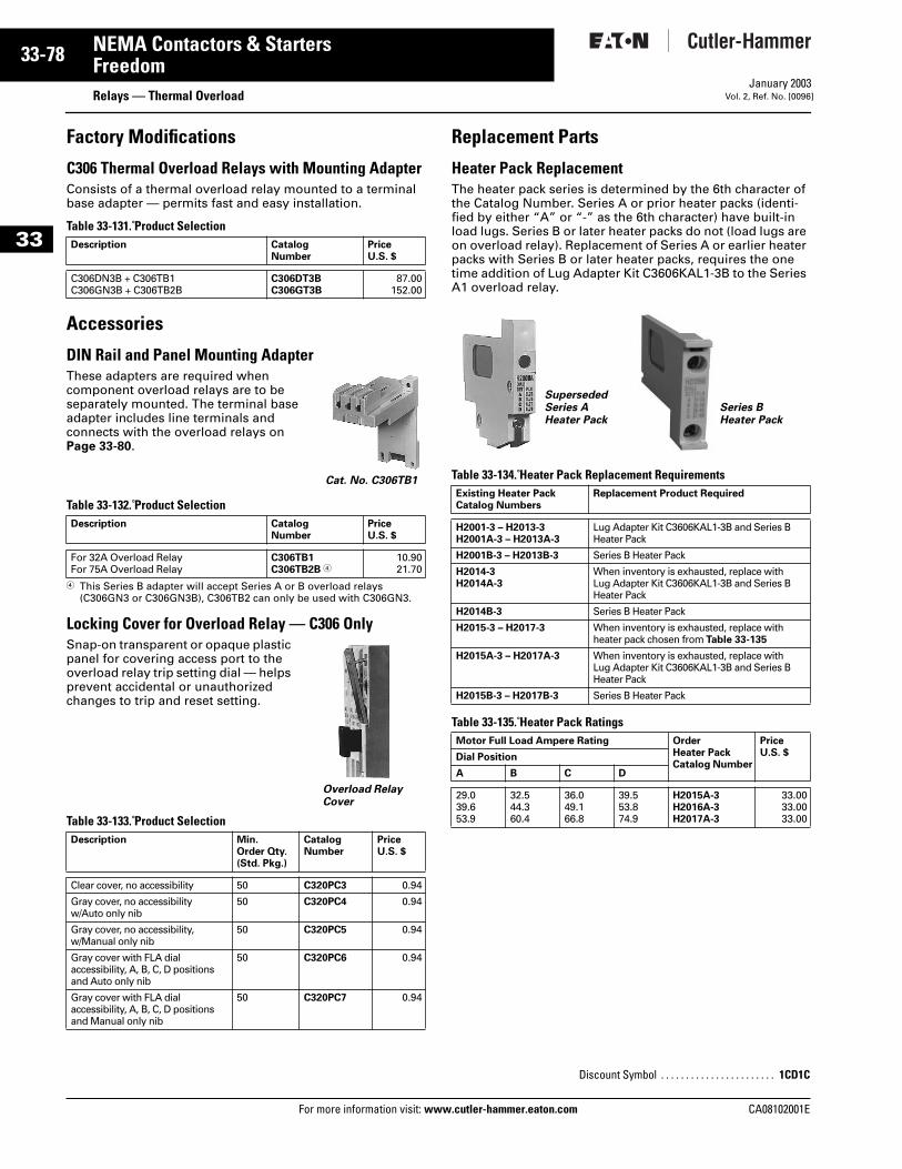
33-78
33
NEMA Contactors & StartersFreedom
Relays — Thermal OverloadFor more information visit: www.cutler-hammer.eaton.com
January 2003Vol. 2, Ref. No. [0096]
Factory Modifications
C306 Thermal Overload Relays with Mounting AdapterConsists of a thermal overload relay mounted to a terminal base adapter — permits fast and easy installation.
Table 33-131. Product Selection
Accessories
DIN Rail and Panel Mounting AdapterThese adapters are required when component overload relays are to be separately mounted. The terminal base adapter includes line terminals and connects with the overload relays onPage 33-80.
Table 33-132. Product Selection
4 This Series B adapter will accept Series A or B overload relays (C306GN3 or C306GN3B), C306TB2 can only be used with C306GN3.
Locking Cover for Overload Relay — C306 OnlySnap-on transparent or opaque plastic panel for covering access port to the overload relay trip setting dial — helps prevent accidental or unauthorized changes to trip and reset setting.
Table 33-133. Product Selection
Replacement Parts
Heater Pack Replacement The heater pack series is determined by the 6th character of the Catalog Number. Series A or prior heater packs (identi-fied by either “A” or “-” as the 6th character) have built-in load lugs. Series B or later heater packs do not (load lugs are on overload relay). Replacement of Series A or earlier heater packs with Series B or later heater packs, requires the one time addition of Lug Adapter Kit C3606KAL1-3B to the Series A1 overload relay.
Table 33-134. Heater Pack Replacement Requirements
Table 33-135. Heater Pack Ratings
Description CatalogNumber
PriceU.S. $
C306DN3B + C306TB1C306GN3B + C306TB2B
C306DT3BC306GT3B
87.00152.00
Description CatalogNumber
PriceU.S. $
For 32A Overload RelayFor 75A Overload Relay
C306TB1C306TB2B 4
10.9021.70
Description Min.Order Qty.(Std. Pkg.)
CatalogNumber
PriceU.S. $
Clear cover, no accessibility 50 C320PC3 0.94
Gray cover, no accessibility w/Auto only nib
50 C320PC4 0.94
Gray cover, no accessibility, w/Manual only nib
50 C320PC5 0.94
Gray cover with FLA dial accessibility, A, B, C, D positions and Auto only nib
50 C320PC6 0.94
Gray cover with FLA dial accessibility, A, B, C, D positions and Manual only nib
50 C320PC7 0.94
Cat. No. C306TB1
Overload Relay Cover
Existing Heater PackCatalog Numbers
Replacement Product Required
H2001-3 – H2013-3H2001A-3 – H2013A-3
Lug Adapter Kit C3606KAL1-3B and Series B Heater Pack
H2001B-3 – H2013B-3 Series B Heater Pack
H2014-3H2014A-3
When inventory is exhausted, replace with Lug Adapter Kit C3606KAL1-3B and Series B Heater Pack
H2014B-3 Series B Heater Pack
H2015-3 – H2017-3 When inventory is exhausted, replace with heater pack chosen from Table 33-135
H2015A-3 – H2017A-3 When inventory is exhausted, replace with Lug Adapter Kit C3606KAL1-3B and Series B Heater Pack
H2015B-3 – H2017B-3 Series B Heater Pack
Motor Full Load Ampere Rating Order Heater PackCatalog Number
PriceU.S. $Dial Position
A B C D
29.039.653.9
32.544.360.4
36.049.166.8
39.553.874.9
H2015A-3H2016A-3H2017A-3
33.0033.0033.00
Discount Symbol . . . . . . . . . . . . . . . . . . . . . . . 1CD1C
SupersededSeries AHeater Pack
Series BHeater Pack
CA08102001E
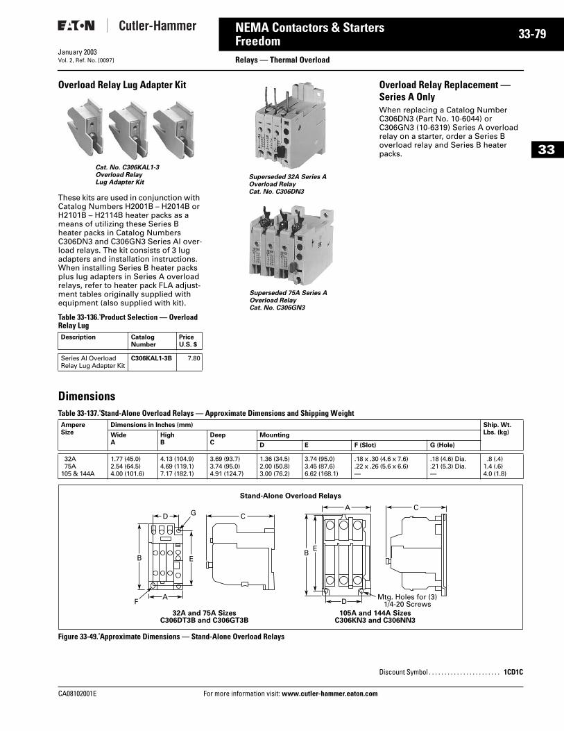
CA08102001E For more
79
33-NEMA Contactors & StartersFreedom Relays — Thermal OverloadJanuary 2003Vol. 2, Ref. No. [0097]
33
Overload Relay Lug Adapter Kit
These kits are used in conjunction with Catalog Numbers H2001B – H2014B or H2101B – H2114B heater packs as a means of utilizing these Series B heater packs in Catalog Numbers C306DN3 and C306GN3 Series Al over-load relays. The kit consists of 3 lug adapters and installation instructions. When installing Series B heater packs plus lug adapters in Series A overload relays, refer to heater pack FLA adjust-ment tables originally supplied with equipment (also supplied with kit).
Table 33-136. Product Selection — Overload Relay Lug
Overload Relay Replacement — Series A OnlyWhen replacing a Catalog Number C306DN3 (Part No. 10-6044) or C306GN3 (10-6319) Series A overload relay on a starter, order a Series B overload relay and Series B heater packs.
DimensionsTable 33-137. Stand-Alone Overload Relays — Approximate Dimensions and Shipping Weight
Figure 33-49. Approximate Dimensions — Stand-Alone Overload Relays
Description Catalog Number
PriceU.S. $
Series Al OverloadRelay Lug Adapter Kit
C306KAL1-3B 7.80
Cat. No. C306KAL1-3Overload RelayLug Adapter Kit
Superseded 32A Series A Overload RelayCat. No. C306DN3
Superseded 75A Series AOverload RelayCat. No. C306GN3
AmpereSize
Dimensions in Inches (mm) Ship. Wt.Lbs. (kg)Wide
AHighB
DeepC
Mounting
D E F (Slot) G (Hole)
32A75A
105 & 144A
1.77 (45.0)2.54 (64.5)4.00 (101.6)
4.13 (104.9)4.69 (119.1)7.17 (182.1)
3.69 (93.7)3.74 (95.0)4.91 (124.7)
1.36 (34.5)2.00 (50.8)3.00 (76.2)
3.74 (95.0)3.45 (87.6)6.62 (168.1)
.18 x .30 (4.6 x 7.6)
.22 x .26 (5.6 x 6.6)—
.18 (4.6) Dia.
.21 (5.3) Dia.—
.8 (.4)1.4 (.6)4.0 (1.8)
Stand-Alone Overload Relays
DA C
C
EBE
B
ADF
32A and 75A SizesC306DT3B and C306GT3B
105A and 144A SizesC306KN3 and C306NN3
G
Mtg. Holes for (3)1/4-20 Screws
Discount Symbol . . . . . . . . . . . . . . . . . . . . . . . 1CD1C
information visit: www.cutler-hammer.eaton.com
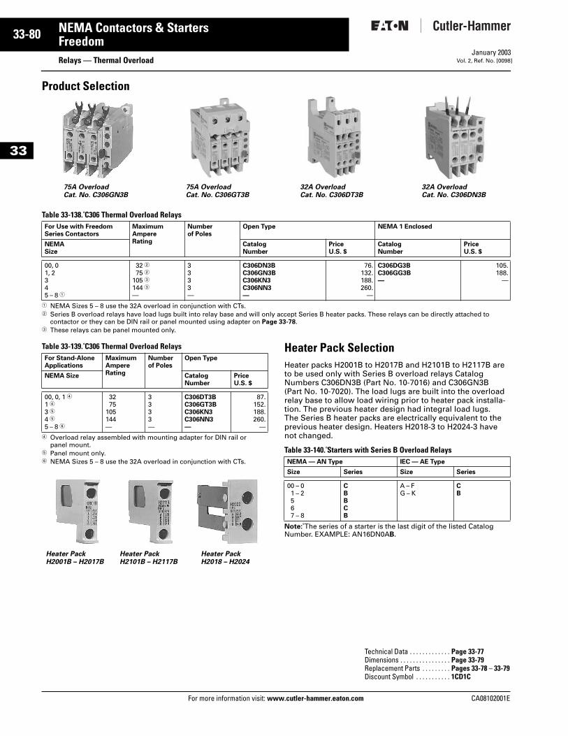
33-80
33
NEMA Contactors & StartersFreedom
Relays — Thermal OverloadFor more information visit: www.cutler-hammer.eaton.com
January 2003Vol. 2, Ref. No. [0098]
Product Selection
Table 33-138. C306 Thermal Overload Relays
1 NEMA Sizes 5 – 8 use the 32A overload in conjunction with CTs. 2 Series B overload relays have load lugs built into relay base and will only accept Series B heater packs. These relays can be directly attached to
contactor or they can be DIN rail or panel mounted using adapter on Page 33-78.3 These relays can be panel mounted only.
Table 33-139. C306 Thermal Overload Relays
4 Overload relay assembled with mounting adapter for DIN rail or panel mount.
5 Panel mount only.6 NEMA Sizes 5 – 8 use the 32A overload in conjunction with CTs.
Heater Pack SelectionHeater packs H2001B to H2017B and H2101B to H2117B are to be used only with Series B overload relays Catalog Numbers C306DN3B (Part No. 10-7016) and C306GN3B (Part No. 10-7020). The load lugs are built into the overload relay base to allow load wiring prior to heater pack installa-tion. The previous heater design had integral load lugs. The Series B heater packs are electrically equivalent to the previous heater design. Heaters H2018-3 to H2024-3 have not changed.
Table 33-140. Starters with Series B Overload Relays
Note: The series of a starter is the last digit of the listed Catalog Number. EXAMPLE: AN16DN0AB.
For Use with Freedom Series Contactors
MaximumAmpereRating
Numberof Poles
Open Type NEMA 1 Enclosed
NEMASize
CatalogNumber
PriceU.S. $
CatalogNumber
PriceU.S. $
00, 01, 2345 – 8 1
32 275 2
105 3144 3—
3333—
C306DN3BC306GN3BC306KN3C306NN3—
76.132.188.260.
—
C306DG3BC306GG3B—
105.188.
—
75A OverloadCat. No. C306GN3B
75A OverloadCat. No. C306GT3B
32A OverloadCat. No. C306DT3B
32A OverloadCat. No. C306DN3B
For Stand-Alone Applications
Maximum Ampere Rating
Number of Poles
Open Type
NEMA Size CatalogNumber
PriceU.S. $
00, 0, 1 41 43 54 55 – 8 6
3275
105144—
3333—
C306DT3BC306GT3BC306KN3C306NN3—
87.152.188.260.
—
Heater PackH2001B – H2017B
Heater PackH2101B – H2117B
Heater PackH2018 – H2024
NEMA — AN Type IEC — AE Type
Size Series Size Series
00 – 01 – 2567 – 8
CBBCB
A – FG – K
CB
Technical Data . . . . . . . . . . . . . Page 33-77Dimensions . . . . . . . . . . . . . . . . Page 33-79Replacement Parts . . . . . . . . . Pages 33-78 – 33-79Discount Symbol . . . . . . . . . . . 1CD1C
CA08102001E
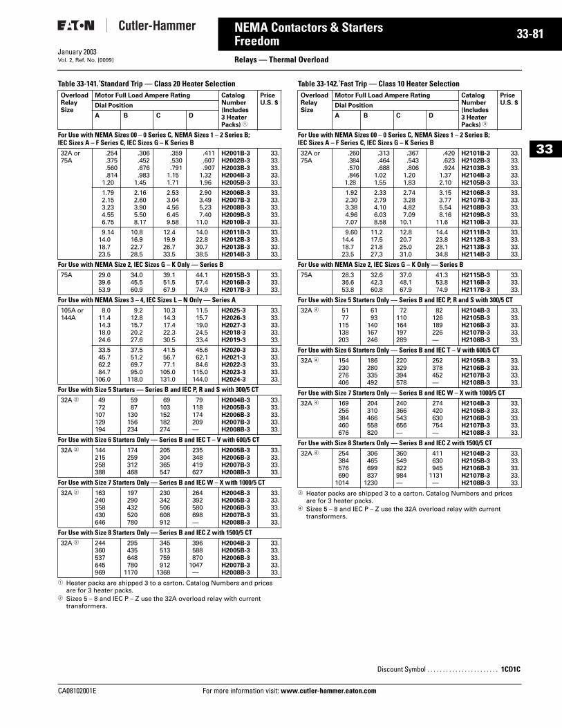
CA08102001E For more
81
33-NEMA Contactors & StartersFreedom Relays — Thermal OverloadJanuary 2003Vol. 2, Ref. No. [0099]
33
Table 33-141. Standard Trip — Class 20 Heater Selection
1 Heater packs are shipped 3 to a carton. Catalog Numbers and prices are for 3 heater packs.
2 Sizes 5 – 8 and IEC P – Z use the 32A overload relay with current transformers.
Table 33-142. Fast Trip — Class 10 Heater Selection
3 Heater packs are shipped 3 to a carton. Catalog Numbers and prices are for 3 heater packs.
4 Sizes 5 – 8 and IEC P – Z use the 32A overload relay with current transformers.
OverloadRelaySize
Motor Full Load Ampere Rating Catalog Number (Includes 3 Heater Packs) 1
Price U.S. $Dial Position
A B C D
For Use with NEMA Sizes 00 – 0 Series C, NEMA Sizes 1 – 2 Series B;IEC Sizes A – F Series C, IEC Sizes G – K Series B32A or75A
.254
.375
.560
.8141.20
.306
.452
.676
.9831.45
.359
.530
.7911.151.71
.411
.607
.9071.321.96
H2001B-3H2002B-3H2003B-3H2004B-3H2005B-3
33.33.33.33.33.
1.792.153.234.556.75
2.162.603.905.508.17
2.533.044.566.459.58
2.903.495.237.40
11.0
H2006B-3H2007B-3H2008B-3H2009B-3H2010B-3
33.33.33.33.33.
9.1414.018.723.5
10.816.922.728.5
12.419.926.733.5
14.022.830.738.5
H2011B-3H2012B-3H2013B-3H2014B-3
33.33.33.33.
For Use with NEMA Size 2, IEC Sizes G – K Only — Series B75A 29.0
39.653.9
34.045.560.9
39.151.567.9
44.157.474.9
H2015B-3H2016B-3H2017B-3
33.33.33.
For Use with NEMA Sizes 3 – 4, IEC Sizes L – N Only — Series A105A or144A
8.011.414.318.024.6
9.212.815.720.227.6
10.314.317.422.330.5
11.515.719.024.533.4
H2025-3H2026-3H2027-3H2018-3H2019-3
33.33.33.33.33.
33.545.762.284.7
106.0
37.551.269.795.0
118.0
41.556.777.1
105.0131.0
45.662.184.6
115.0144.0
H2020-3H2021-3H2022-3H2023-3H2024-3
33.33.33.33.33.
For Use with Size 5 Starters — Series B and IEC P, R and S with 300/5 CT32A 2 49
72107129194
5987
130156234
69103152182274
79118174209—
H2004B-3H2005B-3H2006B-3H2007B-3H2008B-3
33.33.33.33.33.
For Use with Size 6 Starters Only — Series B and IEC T – V with 600/5 CT32A 2 144
215258388
174259312468
205304365547
235348419627
H2005B-3H2006B-3H2007B-3H2008B-3
33.33.33.33.
For Use with Size 7 Starters Only — Series B and IEC W – X with 1000/5 CT32A 2 163
240358430646
197290432520780
230342506608912
264392580698—
H2004B-3H2005B-3H2006B-3H2007B-3H2008B-3
33.33.33.33.33.
For Use with Size 8 Starters Only — Series B and IEC Z with 1500/5 CT32A 2 244
360537645969
295435648780
1170
345513759912
1368
396588870
1047—
H2004B-3H2005B-3H2006B-3H2007B-3H2008B-3
33.33.33.33.33.
OverloadRelaySize
Motor Full Load Ampere Rating Catalog Number (Includes 3 Heater Packs) 3
Price U.S. $Dial Position
A B C D
For Use with NEMA Sizes 00 – 0 Series C, NEMA Sizes 1 – 2 Series B;IEC Sizes A – F Series C, IEC Sizes G – K Series B32A or75A
.260
.384
.570
.8461.28
.313
.464
.6881.021.55
.367
.543
.8061.201.83
.420
.623
.9241.372.10
H2101B-3H2102B-3H2103B-3H2104B-3H2105B-3
33.33.33.33.33.
1.922.303.384.967.07
2.332.794.106.038.58
2.743.284.827.09
10.1
3.153.775.548.16
11.6
H2106B-3H2107B-3H2108B-3H2109B-3H2110B-3
33.33.33.33.33.
9.6014.418.723.5
11.217.521.827.3
12.820.725.031.0
14.423.828.134.8
H2111B-3H2112B-3H2113B-3H2114B-3
33.33.33.33.
For Use with NEMA Size 2, IEC Sizes G – K Only — Series B75A 28.3
36.653.8
32.642.360.8
37.048.167.9
41.353.874.9
H2115B-3H2116B-3H2117B-3
33.33.33.
For Use with Size 5 Starters Only — Series B and IEC P, R and S with 300/5 CT32A 4 51
77115138203
6193
140167246
72110164197289
82126189226—
H2104B-3H2105B-3H2106B-3H2107B-3H2108B-3
33.33.33.33.33.
For Use with Size 6 Starters Only — Series B and IEC T – V with 600/5 CT32A 4 154
230276406
186280335492
220329394578
252378452—
H2105B-3H2106B-3H2107B-3H2108B-3
33.33.33.33.
For Use with Size 7 Starters Only — Series B and IEC W – X with 1000/5 CT32A 4 169
256384460676
204310466558820
240366543656—
274420630754—
H2104B-3H2105B-3H2106B-3H2107B-3H2108B-3
33.33.33.33.33.
For Use with Size 8 Starters Only — Series B and IEC Z with 1500/5 CT32A 4 254
384576690
1014
306465699837
1230
360549822984—
411630945
1131—
H2104B-3H2105B-3H2106B-3H2107B-3H2108B-3
33.33.33.33.33.
Discount Symbol . . . . . . . . . . . . . . . . . . . . . . . 1CD1C
information visit: www.cutler-hammer.eaton.com
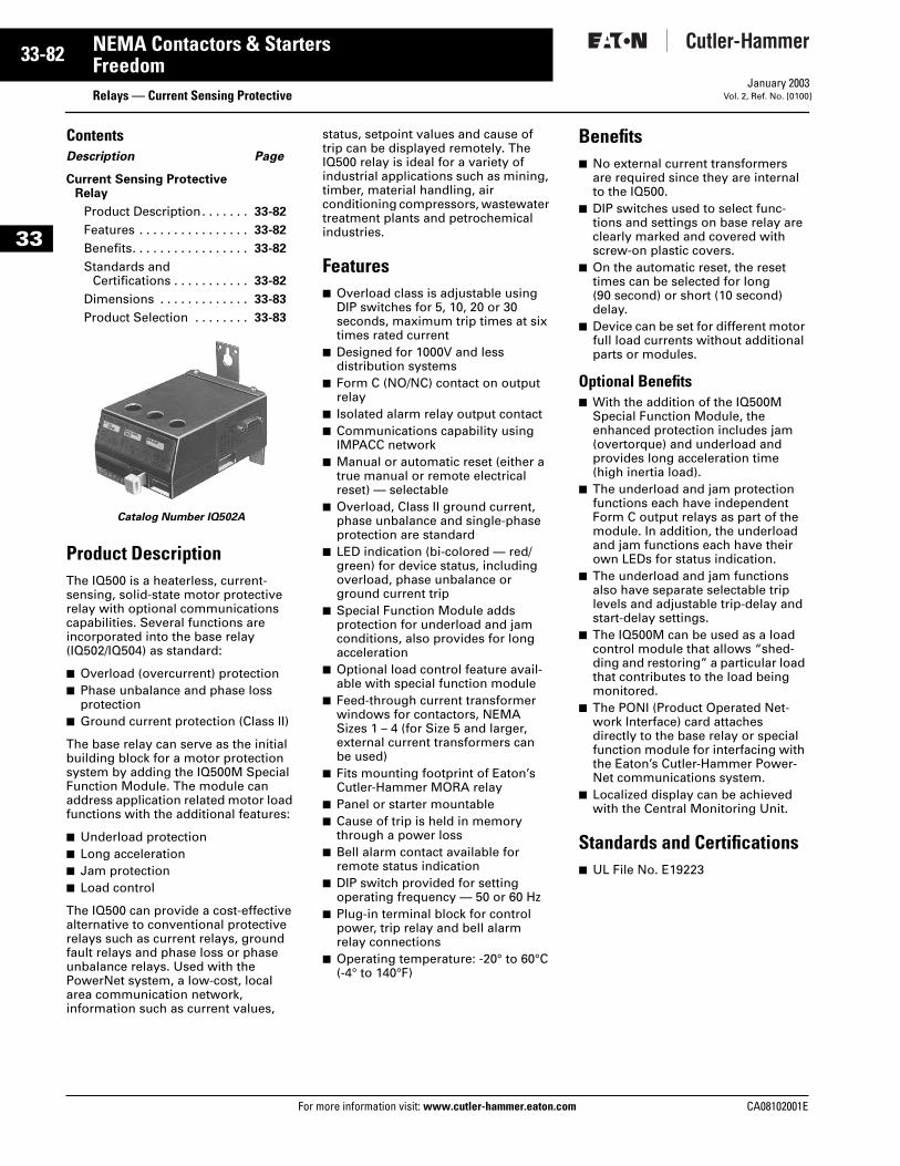
33-82
33
NEMA Contactors & StartersFreedom
Relays — Current Sensing ProtectiveFor more information visit: www.cutler-hammer.eaton.com
January 2003Vol. 2, Ref. No. [0100]
ContentsDescription Page
Current Sensing ProtectiveRelay
Product Description. . . . . . . 33-82
Features . . . . . . . . . . . . . . . . 33-82
Benefits. . . . . . . . . . . . . . . . . 33-82
Standards and Certifications . . . . . . . . . . . 33-82
Dimensions . . . . . . . . . . . . . 33-83
Product Selection . . . . . . . . 33-83
Product DescriptionThe IQ500 is a heaterless, current-sensing, solid-state motor protective relay with optional communications capabilities. Several functions are incorporated into the base relay (IQ502/IQ504) as standard:
■ Overload (overcurrent) protection■ Phase unbalance and phase loss
protection■ Ground current protection (Class II)
The base relay can serve as the initial building block for a motor protection system by adding the IQ500M Special Function Module. The module can address application related motor load functions with the additional features:
■ Underload protection■ Long acceleration■ Jam protection■ Load control
The IQ500 can provide a cost-effective alternative to conventional protective relays such as current relays, ground fault relays and phase loss or phase unbalance relays. Used with the PowerNet system, a low-cost, local area communication network, information such as current values,
status, setpoint values and cause of trip can be displayed remotely. The IQ500 relay is ideal for a variety of industrial applications such as mining, timber, material handling, air conditioning compressors, wastewater treatment plants and petrochemical industries.
Features■ Overload class is adjustable using
DIP switches for 5, 10, 20 or 30 seconds, maximum trip times at six times rated current
■ Designed for 1000V and less distribution systems
■ Form C (NO/NC) contact on output relay
■ Isolated alarm relay output contact■ Communications capability using
IMPACC network■ Manual or automatic reset (either a
true manual or remote electrical reset) — selectable
■ Overload, Class II ground current, phase unbalance and single-phase protection are standard
■ LED indication (bi-colored — red/green) for device status, including overload, phase unbalance or ground current trip
■ Special Function Module adds protection for underload and jam conditions, also provides for long acceleration
■ Optional load control feature avail-able with special function module
■ Feed-through current transformer windows for contactors, NEMA Sizes 1 – 4 (for Size 5 and larger, external current transformers can be used)
■ Fits mounting footprint of Eaton’s Cutler-Hammer MORA relay
■ Panel or starter mountable■ Cause of trip is held in memory
through a power loss■ Bell alarm contact available for
remote status indication■ DIP switch provided for setting
operating frequency — 50 or 60 Hz■ Plug-in terminal block for control
power, trip relay and bell alarm relay connections
■ Operating temperature: -20° to 60°C (-4° to 140°F)
Benefits■ No external current transformers
are required since they are internal to the IQ500.
■ DIP switches used to select func-tions and settings on base relay are clearly marked and covered with screw-on plastic covers.
■ On the automatic reset, the reset times can be selected for long (90 second) or short (10 second) delay.
■ Device can be set for different motor full load currents without additional parts or modules.
Optional Benefits■ With the addition of the IQ500M
Special Function Module, the enhanced protection includes jam (overtorque) and underload and provides long acceleration time (high inertia load).
■ The underload and jam protection functions each have independent Form C output relays as part of the module. In addition, the underload and jam functions each have their own LEDs for status indication.
■ The underload and jam functions also have separate selectable trip levels and adjustable trip-delay and start-delay settings.
■ The IQ500M can be used as a load control module that allows “shed-ding and restoring” a particular load that contributes to the load being monitored.
■ The PONI (Product Operated Net-work Interface) card attaches directly to the base relay or special function module for interfacing with the Eaton’s Cutler-Hammer Power-Net communications system.
■ Localized display can be achieved with the Central Monitoring Unit.
Standards and Certifications■ UL File No. E19223
Catalog Number IQ502A
CA08102001E
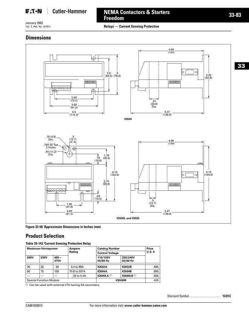
CA08102001E For more
83
33-NEMA Contactors & StartersFreedom Relays — Current Sensing ProtectiveJanuary 2003Vol. 2, Ref. No. [0101]
33
Dimensions
Figure 33-50. Approximate Dimensions in Inches (mm)
Product SelectionTable 33-143. Current Sensing Protective Relay
1 Can be used with external CTs having 5A secondary.
Maximum Horsepower AmpereRating
Catalog Number PriceU.S. $Control Voltage
200V 230V 460 – 475V
110/120V50/60 Hz
220/240V50/60 Hz
20 25 50 3.4 to 66A IQ502A IQ502B 695.
60 75 150 10.8 to 207A IQ504A IQ504B 695.
— — — .32 to 5.4A IQ500LA 1 IQ500LB 1 695.
Special Function Module IQ500M 420.
2.5(63.5)
2.88(73.2)
3(76.2) 3.25
(82.6)
3.59(91.2)
4.5(114.3)
4.88(124)
.81(20.6)Dia.
5.47(138.9)
IQ504
.53(13.5)
1.88(47.8)
2.75(69.9)
.78(19.8)
1.19(30.2)
4.13(104.9)
4.13(104.9)
3.59(91.2)
4.88(124)
.5(12.7)
.44 (11.2)Dia.
.164-32 Tap2 Holes
.19 (4.8)Dia.
.5(12.7)Dia.
5.47(138.9)
IQ500L and IQ502
Discount Symbol . . . . . . . . . . . . . . . . . . . . . . . 1CD1C
information visit: www.cutler-hammer.eaton.com
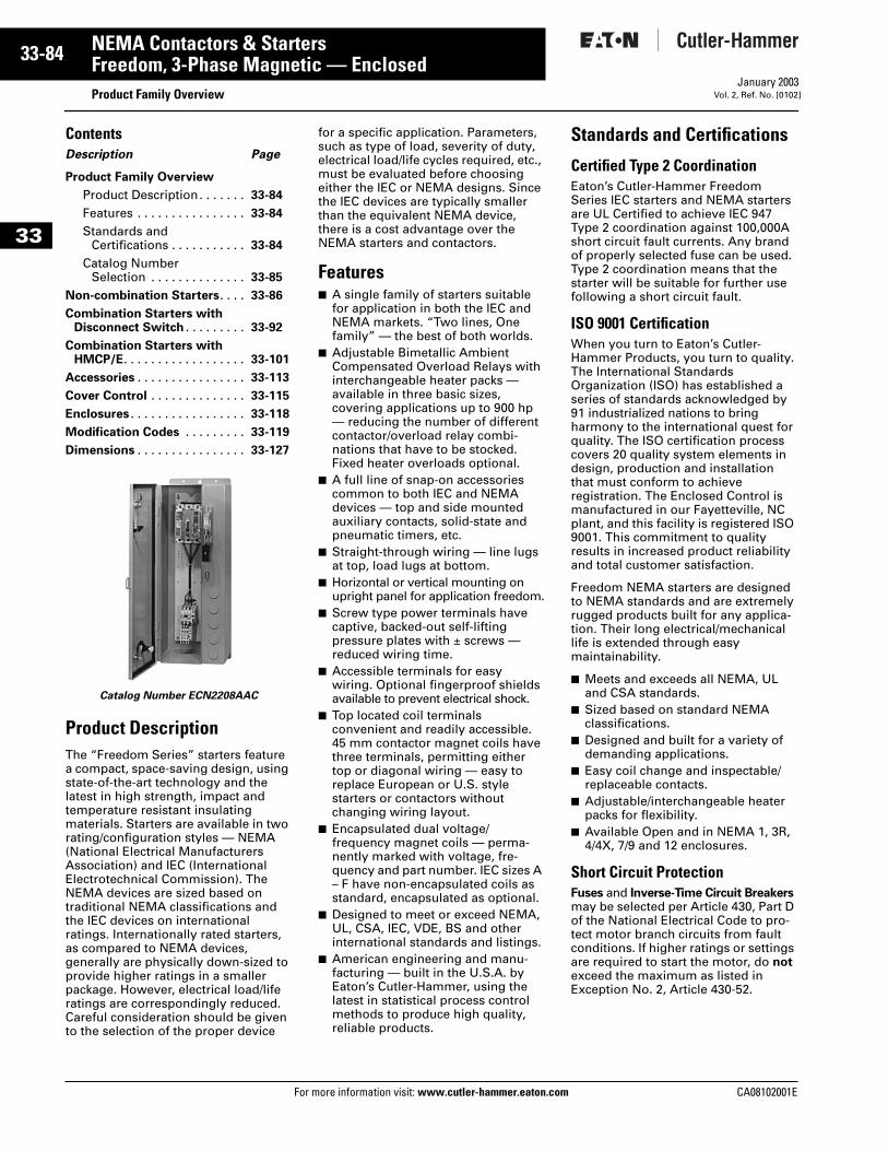
33-84
33
NEMA Contactors & StartersFreedom, 3-Phase Magnetic — Enclosed
Product Family OverviewFor more information visit: www.cutler-hammer.eaton.com
January 2003Vol. 2, Ref. No. [0102]
ContentsDescription Page
Product Family Overview
Product Description. . . . . . . 33-84
Features . . . . . . . . . . . . . . . . 33-84
Standards and Certifications . . . . . . . . . . . 33-84
Catalog NumberSelection . . . . . . . . . . . . . . 33-85
Non-combination Starters. . . . 33-86
Combination Starters withDisconnect Switch . . . . . . . . . 33-92
Combination Starters withHMCP/E. . . . . . . . . . . . . . . . . . 33-101
Accessories . . . . . . . . . . . . . . . . 33-113
Cover Control . . . . . . . . . . . . . . 33-115
Enclosures . . . . . . . . . . . . . . . . . 33-118
Modification Codes . . . . . . . . . 33-119
Dimensions . . . . . . . . . . . . . . . . 33-127
Catalog Number ECN2208AAC
Product Description The “Freedom Series” starters feature a compact, space-saving design, using state-of-the-art technology and the latest in high strength, impact and temperature resistant insulating materials. Starters are available in two rating/configuration styles — NEMA (National Electrical Manufacturers Association) and IEC (International Electrotechnical Commission). The NEMA devices are sized based on traditional NEMA classifications and the IEC devices on international ratings. Internationally rated starters, as compared to NEMA devices, generally are physically down-sized to provide higher ratings in a smaller package. However, electrical load/life ratings are correspondingly reduced. Careful consideration should be given to the selection of the proper device
for a specific application. Parameters, such as type of load, severity of duty, electrical load/life cycles required, etc., must be evaluated before choosing either the IEC or NEMA designs. Since the IEC devices are typically smaller than the equivalent NEMA device, there is a cost advantage over the NEMA starters and contactors.
Features■ A single family of starters suitable
for application in both the IEC and NEMA markets. “Two lines, One family” — the best of both worlds.
■ Adjustable Bimetallic Ambient Compensated Overload Relays with interchangeable heater packs — available in three basic sizes, covering applications up to 900 hp — reducing the number of different contactor/overload relay combi-nations that have to be stocked. Fixed heater overloads optional.
■ A full line of snap-on accessories common to both IEC and NEMA devices — top and side mounted auxiliary contacts, solid-state and pneumatic timers, etc.
■ Straight-through wiring — line lugs at top, load lugs at bottom.
■ Horizontal or vertical mounting on upright panel for application freedom.
■ Screw type power terminals have captive, backed-out self-lifting pressure plates with ± screws — reduced wiring time.
■ Accessible terminals for easy wiring. Optional fingerproof shields available to prevent electrical shock.
■ Top located coil terminals convenient and readily accessible. 45 mm contactor magnet coils have three terminals, permitting either top or diagonal wiring — easy to replace European or U.S. style starters or contactors without changing wiring layout.
■ Encapsulated dual voltage/frequency magnet coils — perma-nently marked with voltage, fre-quency and part number. IEC sizes A – F have non-encapsulated coils as standard, encapsulated as optional.
■ Designed to meet or exceed NEMA, UL, CSA, IEC, VDE, BS and other international standards and listings.
■ American engineering and manu-facturing — built in the U.S.A. by Eaton’s Cutler-Hammer, using the latest in statistical process control methods to produce high quality, reliable products.
Standards and Certifications
Certified Type 2 CoordinationEaton’s Cutler-Hammer Freedom Series IEC starters and NEMA starters are UL Certified to achieve IEC 947 Type 2 coordination against 100,000A short circuit fault currents. Any brand of properly selected fuse can be used. Type 2 coordination means that the starter will be suitable for further use following a short circuit fault.
ISO 9001 CertificationWhen you turn to Eaton’s Cutler-Hammer Products, you turn to quality. The International Standards Organization (ISO) has established a series of standards acknowledged by 91 industrialized nations to bring harmony to the international quest for quality. The ISO certification process covers 20 quality system elements in design, production and installation that must conform to achieve registration. The Enclosed Control is manufactured in our Fayetteville, NC plant, and this facility is registered ISO 9001. This commitment to quality results in increased product reliability and total customer satisfaction.
Freedom NEMA starters are designed to NEMA standards and are extremely rugged products built for any applica-tion. Their long electrical/mechanical life is extended through easy maintainability.
■ Meets and exceeds all NEMA, UL and CSA standards.
■ Sized based on standard NEMA classifications.
■ Designed and built for a variety of demanding applications.
■ Easy coil change and inspectable/replaceable contacts.
■ Adjustable/interchangeable heater packs for flexibility.
■ Available Open and in NEMA 1, 3R, 4/4X, 7/9 and 12 enclosures.
Short Circuit ProtectionFuses and Inverse-Time Circuit Breakers may be selected per Article 430, Part D of the National Electrical Code to pro-tect motor branch circuits from fault conditions. If higher ratings or settings are required to start the motor, do not exceed the maximum as listed in Exception No. 2, Article 430-52.
CA08102001E
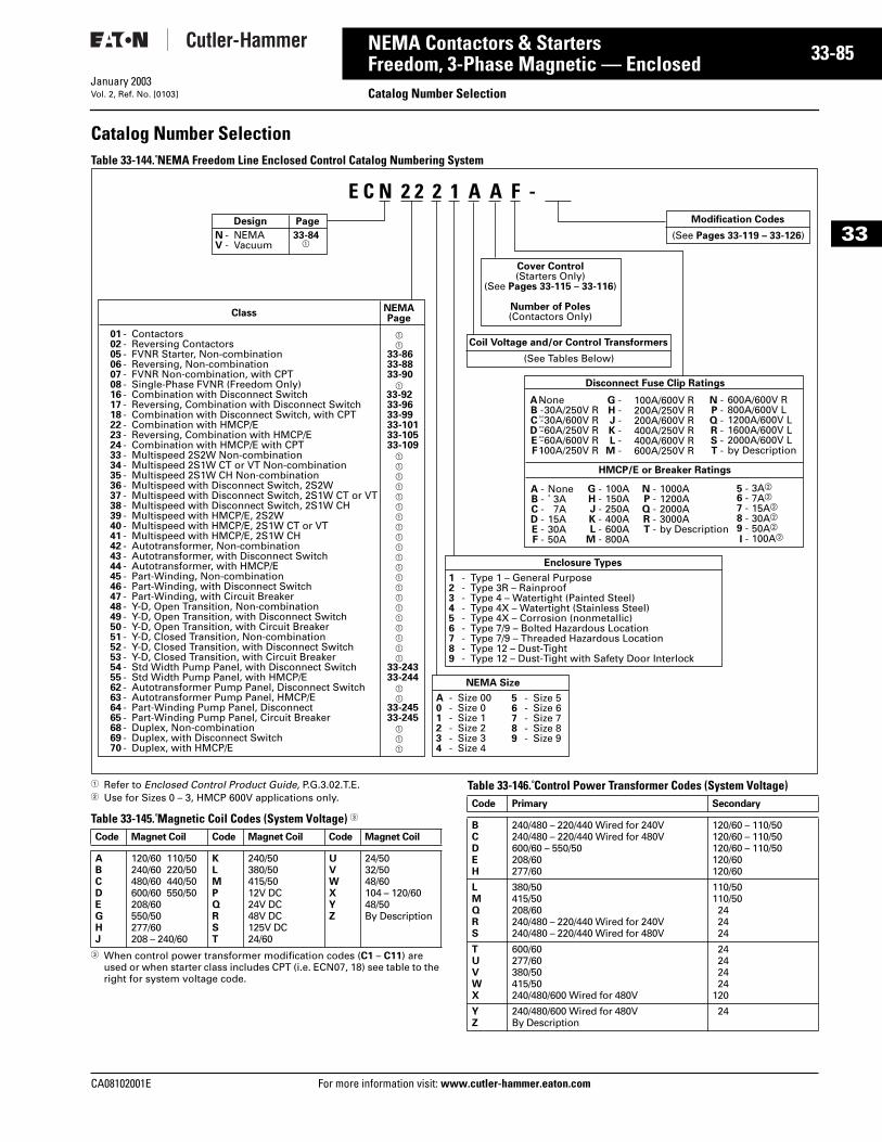
CA08102001E For more
85
33-NEMA Contactors & StartersFreedom, 3-Phase Magnetic — Enclosed
Catalog Number SelectionJanuary 2003Vol. 2, Ref. No. [0103]
33
Catalog Number SelectionTable 33-144. NEMA Freedom Line Enclosed Control Catalog Numbering System
1 Refer to Enclosed Control Product Guide, P.G.3.02.T.E.2 Use for Sizes 0 – 3, HMCP 600V applications only.
Table 33-145. Magnetic Coil Codes (System Voltage) 3
3 When control power transformer modification codes (C1 – C11) are used or when starter class includes CPT (i.e. ECN07, 18) see table to the right for system voltage code.
Table 33-146. Control Power Transformer Codes (System Voltage)
Design
ClassNEMAPage
Page
01 - Contactors a 02 - Reversing Contactors a05 - FVNR Starter, Non-combination 33-8606 - Reversing, Non-combination 33-8807 - FVNR Non-combination, with CPT 33-9008 - Single-Phase FVNR (Freedom Only) a16 - Combination with Disconnect Switch 33-9217 - Reversing, Combination with Disconnect Switch 33-9618 - Combination with Disconnect Switch, with CPT 33-9922 - Combination with HMCP/E 33-10123 - Reversing, Combination with HMCP/E 33-10524 - Combination with HMCP/E with CPT 33-10933 - Multispeed 2S2W Non-combination a34 - Multispeed 2S1W CT or VT Non-combination a35 - Multispeed 2S1W CH Non-combination a36 - Multispeed with Disconnect Switch, 2S2W a37 - Multispeed with Disconnect Switch, 2S1W CT or VT a38 - Multispeed with Disconnect Switch, 2S1W CH a39 - Multispeed with HMCP/E, 2S2W a40 - Multispeed with HMCP/E, 2S1W CT or VT a41 - Multispeed with HMCP/E, 2S1W CH a42 - Autotransformer, Non-combination a43 - Autotransformer, with Disconnect Switch a44 - Autotransformer, with HMCP/E a45 - Part-Winding, Non-combination a46 - Part-Winding, with Disconnect Switch a47 - Part-Winding, with Circuit Breaker a48 - Y-D, Open Transition, Non-combination a49 - Y-D, Open Transition, with Disconnect Switch a50 - Y-D, Open Transition, with Circuit Breaker a51 - Y-D, Closed Transition, Non-combination a52 - Y-D, Closed Transition, with Disconnect Switch a53 - Y-D, Closed Transition, with Circuit Breaker a54 - Std Width Pump Panel, with Disconnect Switch 33-24355 - Std Width Pump Panel, with HMCP/E 33-24462 - Autotransformer Pump Panel, Disconnect Switch a63 - Autotransformer Pump Panel, HMCP/E a64 - Part-Winding Pump Panel, Disconnect 33-24565 - Part-Winding Pump Panel, Circuit Breaker 33-24568 - Duplex, Non-combination a69 - Duplex, with Disconnect Switch a70 - Duplex, with HMCP/E a
Enclosure Types
1 - Type 1 – General Purpose2 - Type 3R – Rainproof3 - Type 4 – Watertight (Painted Steel)4 - Type 4X – Watertight (Stainless Steel)5 - Type 4X – Corrosion (nonmetallic)6 - Type 7/9 – Bolted Hazardous Location7 - Type 7/9 – Threaded Hazardous Location8 - Type 12 – Dust-Tight9 - Type 12 – Dust-Tight with Safety Door Interlock
Disconnect Fuse Clip Ratings
None 30A/250V R 30A/600V R 60A/250V R 60A/600V R100A/250V R
A -B -C -D -E -F -
G -H -J -K -L -
M -
100A/600V R200A/250V R200A/600V R400A/250V R400A/600V R600A/250V R
HMCP/E or Breaker Ratings
None 3A 7A15A30A50A
A -B -C -D -E -F -
G -H -J -K -L -
M -
100A150A 250A 400A600A800A
N - NEMAV - Vacuum
33-84 a
NEMA Size
A - Size 000 - Size 01 - Size 12 - Size 23 - Size 34 - Size 4
5 - Size 56 - Size 67 - Size 78 - Size 89 - Size 9
Cover Control(Starters Only)
(See Pages 33-115 – 33-116)
Number of Poles(Contactors Only)
Coil Voltage and/or Control Transformers
(See Tables Below)
N -P -Q -R -S -T -
600A/600V R800A/600V L1200A/600V L1600A/600V L2000A/600V Lby Description
N -P -Q -R -T -
1000A1200A 2000A 3000Aby Description
5 -6 -7 -8 -9 -I -
3Ab
7Ab 15Ab 30Ab
50Ab
100Ab
E C N 2 2 2 1 A A F - Modification Codes
(See Pages 33-119 – 33-126)
Code Magnet Coil Code Magnet Coil Code Magnet Coil
ABCDEGHJ
120/60 110/50240/60 220/50480/60 440/50600/60 550/50208/60550/50277/60208 – 240/60
KLMPQRST
240/50380/50415/5012V DC24V DC48V DC125V DC24/60
UVWXYZ
24/5032/5048/60104 – 120/6048/50By Description
Code Primary Secondary
BCDEH
240/480 – 220/440 Wired for 240V240/480 – 220/440 Wired for 480V600/60 – 550/50208/60277/60
120/60 – 110/50120/60 – 110/50120/60 – 110/50120/60120/60
LMQRS
380/50415/50208/60240/480 – 220/440 Wired for 240V240/480 – 220/440 Wired for 480V
110/50110/50242424
TUVWX
600/60277/60380/50415/50240/480/600 Wired for 480V
24242424
120
YZ
240/480/600 Wired for 480VBy Description
24
information visit: www.cutler-hammer.eaton.com
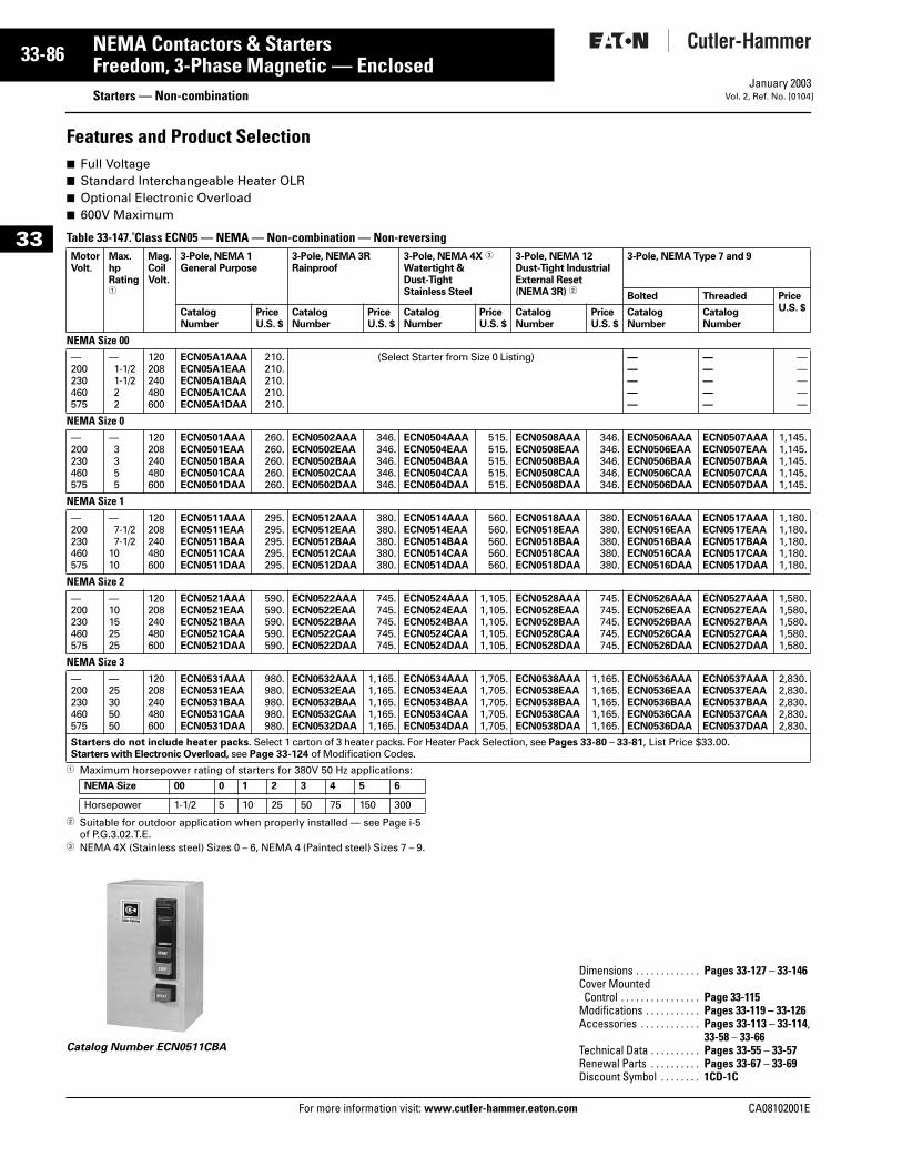
33-86
33
NEMA Contactors & StartersFreedom, 3-Phase Magnetic — Enclosed
Starters — Non-combinationFor more information visit: www.cutler-hammer.eaton.com
January 2003Vol. 2, Ref. No. [0104]
Features and Product Selection■ Full Voltage■ Standard Interchangeable Heater OLR■ Optional Electronic Overload■ 600V Maximum
Table 33-147. Class ECN05 — NEMA — Non-combination — Non-reversing
1 Maximum horsepower rating of starters for 380V 50 Hz applications:
2 Suitable for outdoor application when properly installed — see Page i-5 of P.G.3.02.T.E.
3 NEMA 4X (Stainless steel) Sizes 0 – 6, NEMA 4 (Painted steel) Sizes 7 – 9.
Catalog Number ECN0511CBA
MotorVolt.
Max.hpRating1
Mag.CoilVolt.
3-Pole, NEMA 1General Purpose
3-Pole, NEMA 3RRainproof
3-Pole, NEMA 4X 3
Watertight &Dust-TightStainless Steel
3-Pole, NEMA 12Dust-Tight IndustrialExternal Reset(NEMA 3R) 2
3-Pole, NEMA Type 7 and 9
Bolted Threaded PriceU.S. $Catalog
NumberPriceU.S. $
CatalogNumber
PriceU.S. $
CatalogNumber
PriceU.S. $
CatalogNumber
PriceU.S. $
CatalogNumber
CatalogNumber
NEMA Size 00—200230460575
—1-1/21-1/222
120208240480600
ECN05A1AAAECN05A1EAAECN05A1BAAECN05A1CAAECN05A1DAA
210.210.210.210.210.
(Select Starter from Size 0 Listing) —————
—————
—————
NEMA Size 0—200230460575
—3355
120208240480600
ECN0501AAAECN0501EAAECN0501BAAECN0501CAAECN0501DAA
260.260.260.260.260.
ECN0502AAAECN0502EAAECN0502BAAECN0502CAAECN0502DAA
346.346.346.346.346.
ECN0504AAAECN0504EAAECN0504BAAECN0504CAAECN0504DAA
515.515.515.515.515.
ECN0508AAAECN0508EAAECN0508BAAECN0508CAAECN0508DAA
346.346.346.346.346.
ECN0506AAAECN0506EAAECN0506BAAECN0506CAAECN0506DAA
ECN0507AAAECN0507EAAECN0507BAAECN0507CAAECN0507DAA
1,145.1,145.1,145.1,145.1,145.
NEMA Size 1—200230460575
—7-1/27-1/2
1010
120208240480600
ECN0511AAAECN0511EAAECN0511BAAECN0511CAAECN0511DAA
295.295.295.295.295.
ECN0512AAAECN0512EAAECN0512BAAECN0512CAAECN0512DAA
380.380.380.380.380.
ECN0514AAAECN0514EAAECN0514BAAECN0514CAAECN0514DAA
560.560.560.560.560.
ECN0518AAAECN0518EAAECN0518BAAECN0518CAAECN0518DAA
380.380.380.380.380.
ECN0516AAAECN0516EAAECN0516BAAECN0516CAAECN0516DAA
ECN0517AAAECN0517EAAECN0517BAAECN0517CAAECN0517DAA
1,180.1,180.1,180.1,180.1,180.
NEMA Size 2—200230460575
—10152525
120208240480600
ECN0521AAAECN0521EAAECN0521BAAECN0521CAAECN0521DAA
590.590.590.590.590.
ECN0522AAAECN0522EAAECN0522BAAECN0522CAAECN0522DAA
745.745.745.745.745.
ECN0524AAAECN0524EAAECN0524BAAECN0524CAAECN0524DAA
1,105.1,105.1,105.1,105.1,105.
ECN0528AAAECN0528EAAECN0528BAAECN0528CAAECN0528DAA
745.745.745.745.745.
ECN0526AAAECN0526EAAECN0526BAAECN0526CAAECN0526DAA
ECN0527AAAECN0527EAAECN0527BAAECN0527CAAECN0527DAA
1,580.1,580.1,580.1,580.1,580.
NEMA Size 3—200230460575
—25305050
120208240480600
ECN0531AAAECN0531EAAECN0531BAAECN0531CAAECN0531DAA
980.980.980.980.980.
ECN0532AAAECN0532EAAECN0532BAAECN0532CAAECN0532DAA
1,165.1,165.1,165.1,165.1,165.
ECN0534AAAECN0534EAAECN0534BAAECN0534CAAECN0534DAA
1,705.1,705.1,705.1,705.1,705.
ECN0538AAAECN0538EAAECN0538BAAECN0538CAAECN0538DAA
1,165.1,165.1,165.1,165.1,165.
ECN0536AAAECN0536EAAECN0536BAAECN0536CAAECN0536DAA
ECN0537AAAECN0537EAAECN0537BAAECN0537CAAECN0537DAA
2,830.2,830.2,830.2,830.2,830.
Starters do not include heater packs. Select 1 carton of 3 heater packs. For Heater Pack Selection, see Pages 33-80 – 33-81, List Price $33.00.Starters with Electronic Overload, see Page 33-124 of Modification Codes.
NEMA Size 00 0 1 2 3 4 5 6
Horsepower 1-1/2 5 10 25 50 75 150 300
Dimensions . . . . . . . . . . . . . Pages 33-127 – 33-146Cover MountedControl . . . . . . . . . . . . . . . . Page 33-115
Modifications . . . . . . . . . . . Pages 33-119 – 33-126Accessories . . . . . . . . . . . . Pages 33-113 – 33-114,
33-58 – 33-66Technical Data . . . . . . . . . . Pages 33-55 – 33-57Renewal Parts . . . . . . . . . . Pages 33-67 – 33-69Discount Symbol . . . . . . . . 1CD-1C
CA08102001E
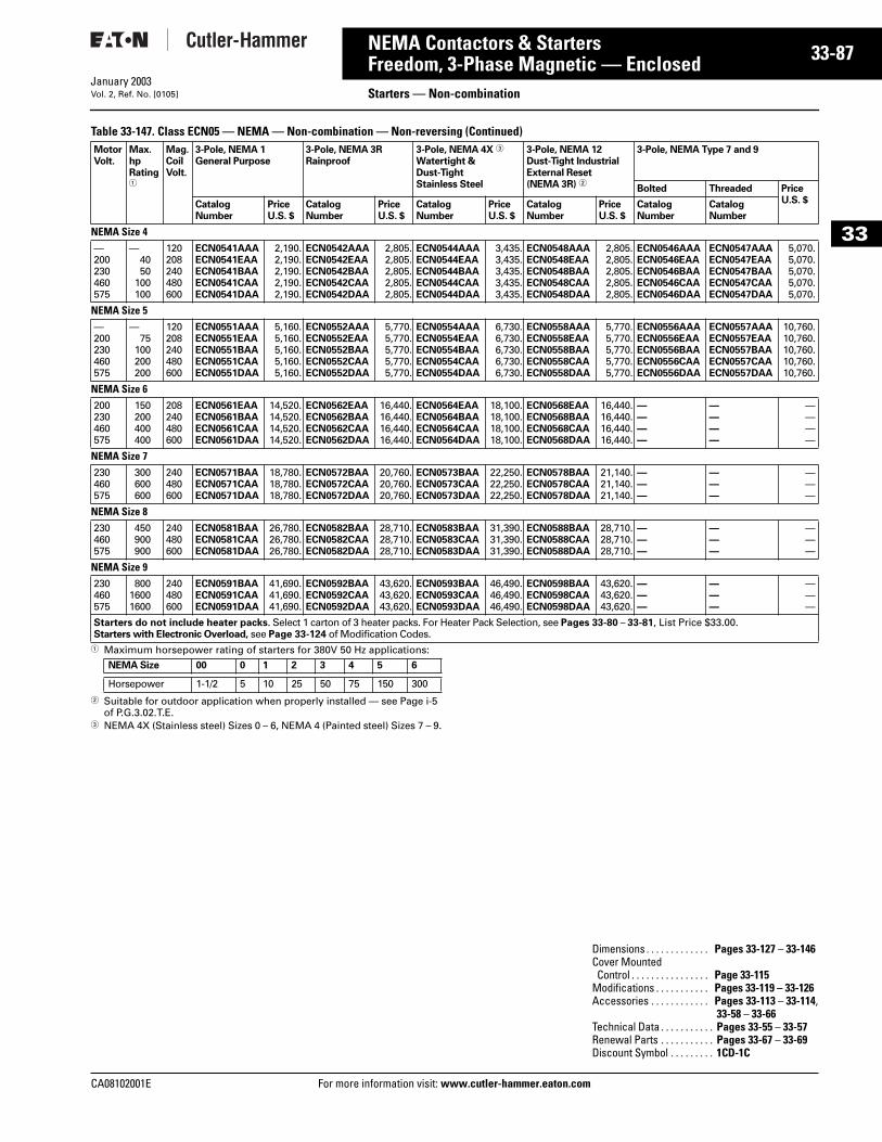
CA08102001E For more
87
33-NEMA Contactors & StartersFreedom, 3-Phase Magnetic — Enclosed
Starters — Non-combinationJanuary 2003Vol. 2, Ref. No. [0105]
33
Table 33-147. Class ECN05 — NEMA — Non-combination — Non-reversing (Continued)
1 Maximum horsepower rating of starters for 380V 50 Hz applications:
2 Suitable for outdoor application when properly installed — see Page i-5 of P.G.3.02.T.E.
3 NEMA 4X (Stainless steel) Sizes 0 – 6, NEMA 4 (Painted steel) Sizes 7 – 9.
MotorVolt.
Max.hpRating1
Mag.CoilVolt.
3-Pole, NEMA 1General Purpose
3-Pole, NEMA 3RRainproof
3-Pole, NEMA 4X 3
Watertight &Dust-TightStainless Steel
3-Pole, NEMA 12Dust-Tight IndustrialExternal Reset(NEMA 3R) 2
3-Pole, NEMA Type 7 and 9
Bolted Threaded PriceU.S. $Catalog
NumberPriceU.S. $
CatalogNumber
PriceU.S. $
CatalogNumber
PriceU.S. $
CatalogNumber
PriceU.S. $
CatalogNumber
CatalogNumber
NEMA Size 4—200230460575
—4050
100100
120208240480600
ECN0541AAAECN0541EAAECN0541BAAECN0541CAAECN0541DAA
2,190.2,190.2,190.2,190.2,190.
ECN0542AAAECN0542EAAECN0542BAAECN0542CAAECN0542DAA
2,805.2,805.2,805.2,805.2,805.
ECN0544AAAECN0544EAAECN0544BAAECN0544CAAECN0544DAA
3,435.3,435.3,435.3,435.3,435.
ECN0548AAAECN0548EAAECN0548BAAECN0548CAAECN0548DAA
2,805.2,805.2,805.2,805.2,805.
ECN0546AAAECN0546EAAECN0546BAAECN0546CAAECN0546DAA
ECN0547AAAECN0547EAAECN0547BAAECN0547CAAECN0547DAA
5,070.5,070.5,070.5,070.5,070.
NEMA Size 5—200230460575
—75
100200200
120208240480600
ECN0551AAAECN0551EAAECN0551BAAECN0551CAAECN0551DAA
5,160.5,160.5,160.5,160.5,160.
ECN0552AAAECN0552EAAECN0552BAAECN0552CAAECN0552DAA
5,770.5,770.5,770.5,770.5,770.
ECN0554AAAECN0554EAAECN0554BAAECN0554CAAECN0554DAA
6,730.6,730.6,730.6,730.6,730.
ECN0558AAAECN0558EAAECN0558BAAECN0558CAAECN0558DAA
5,770.5,770.5,770.5,770.5,770.
ECN0556AAAECN0556EAAECN0556BAAECN0556CAAECN0556DAA
ECN0557AAAECN0557EAAECN0557BAAECN0557CAAECN0557DAA
10,760.10,760.10,760.10,760.10,760.
NEMA Size 6200230460575
150200400400
208240480600
ECN0561EAAECN0561BAAECN0561CAAECN0561DAA
14,520.14,520.14,520.14,520.
ECN0562EAAECN0562BAAECN0562CAAECN0562DAA
16,440.16,440.16,440.16,440.
ECN0564EAAECN0564BAAECN0564CAAECN0564DAA
18,100.18,100.18,100.18,100.
ECN0568EAAECN0568BAAECN0568CAAECN0568DAA
16,440.16,440.16,440.16,440.
————
————
————
NEMA Size 7230460575
300600600
240480600
ECN0571BAAECN0571CAAECN0571DAA
18,780.18,780.18,780.
ECN0572BAAECN0572CAAECN0572DAA
20,760.20,760.20,760.
ECN0573BAAECN0573CAAECN0573DAA
22,250.22,250.22,250.
ECN0578BAAECN0578CAAECN0578DAA
21,140.21,140.21,140.
———
———
———
NEMA Size 8230460575
450900900
240480600
ECN0581BAAECN0581CAAECN0581DAA
26,780.26,780.26,780.
ECN0582BAAECN0582CAAECN0582DAA
28,710.28,710.28,710.
ECN0583BAAECN0583CAAECN0583DAA
31,390.31,390.31,390.
ECN0588BAAECN0588CAAECN0588DAA
28,710.28,710.28,710.
———
———
———
NEMA Size 9230460575
80016001600
240480600
ECN0591BAAECN0591CAAECN0591DAA
41,690.41,690.41,690.
ECN0592BAAECN0592CAAECN0592DAA
43,620.43,620.43,620.
ECN0593BAAECN0593CAAECN0593DAA
46,490.46,490.46,490.
ECN0598BAAECN0598CAAECN0598DAA
43,620.43,620.43,620.
———
———
———
Starters do not include heater packs. Select 1 carton of 3 heater packs. For Heater Pack Selection, see Pages 33-80 – 33-81, List Price $33.00.Starters with Electronic Overload, see Page 33-124 of Modification Codes.
NEMA Size 00 0 1 2 3 4 5 6
Horsepower 1-1/2 5 10 25 50 75 150 300
Dimensions . . . . . . . . . . . . . Pages 33-127 – 33-146Cover MountedControl . . . . . . . . . . . . . . . . Page 33-115
Modifications . . . . . . . . . . . Pages 33-119 – 33-126Accessories . . . . . . . . . . . . Pages 33-113 – 33-114,
33-58 – 33-66Technical Data . . . . . . . . . . . Pages 33-55 – 33-57Renewal Parts . . . . . . . . . . . Pages 33-67 – 33-69Discount Symbol . . . . . . . . . 1CD-1C
information visit: www.cutler-hammer.eaton.com
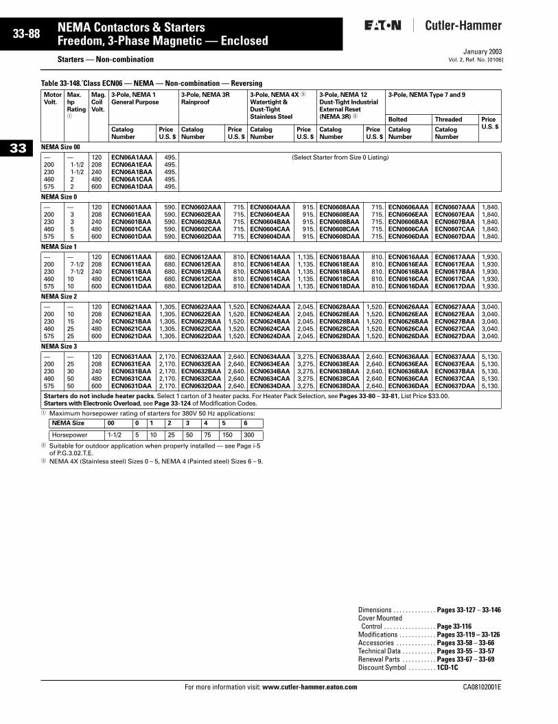
33-88
33
NEMA Contactors & StartersFreedom, 3-Phase Magnetic — Enclosed
Starters — Non-combinationFor more information visit: www.cutler-hammer.eaton.com
January 2003Vol. 2, Ref. No. [0106]
Table 33-148. Class ECN06 — NEMA — Non-combination — Reversing
1 Maximum horsepower rating of starters for 380V 50 Hz applications:
2 Suitable for outdoor application when properly installed — see Page i-5 of P.G.3.02.T.E.
3 NEMA 4X (Stainless steel) Sizes 0 – 5, NEMA 4 (Painted steel) Sizes 6 – 9.
MotorVolt.
Max.hpRating1
Mag.CoilVolt.
3-Pole, NEMA 1General Purpose
3-Pole, NEMA 3RRainproof
3-Pole, NEMA 4X 3
Watertight &Dust-TightStainless Steel
3-Pole, NEMA 12Dust-Tight IndustrialExternal Reset(NEMA 3R) 2
3-Pole, NEMA Type 7 and 9
Bolted Threaded PriceU.S. $Catalog
NumberPriceU.S. $
CatalogNumber
PriceU.S. $
CatalogNumber
PriceU.S. $
CatalogNumber
PriceU.S. $
CatalogNumber
CatalogNumber
NEMA Size 00—200230460575
—1-1/21-1/222
120208240480600
ECN06A1AAAECN06A1EAAECN06A1BAAECN06A1CAAECN06A1DAA
495.495.495.495.495.
(Select Starter from Size 0 Listing)
NEMA Size 0—200230460575
—3355
120208240480600
ECN0601AAAECN0601EAAECN0601BAAECN0601CAAECN0601DAA
590.590.590.590.590.
ECN0602AAAECN0602EAAECN0602BAAECN0602CAAECN0602DAA
715.715.715.715.715.
ECN0604AAAECN0604EAAECN0604BAAECN0604CAAECN0604DAA
915.915.915.915.915.
ECN0608AAAECN0608EAAECN0608BAAECN0608CAAECN0608DAA
715.715.715.715.715.
ECN0606AAAECN0606EAAECN0606BAAECN0606CAAECN0606DAA
ECN0607AAAECN0607EAAECN0607BAAECN0607CAAECN0607DAA
1,840.1,840.1,840.1,840.1,840.
NEMA Size 1—200230460575
—7-1/27-1/2
1010
120208240480600
ECN0611AAAECN0611EAAECN0611BAAECN0611CAAECN0611DAA
680.680.680.680.680.
ECN0612AAAECN0612EAAECN0612BAAECN0612CAAECN0612DAA
810.810.810.810.810.
ECN0614AAAECN0614EAAECN0614BAAECN0614CAAECN0614DAA
1,135.1,135.1,135.1,135.1,135.
ECN0618AAAECN0618EAAECN0618BAAECN0618CAAECN0618DAA
810.810.810.810.810.
ECN0616AAAECN0616EAAECN0616BAAECN0616CAAECN0616DAA
ECN0617AAAECN0617EAAECN0617BAAECN0617CAAECN0617DAA
1,930.1,930.1,930.1,930.1,930.
NEMA Size 2—200230460575
—10152525
120208240480600
ECN0621AAAECN0621EAAECN0621BAAECN0621CAAECN0621DAA
1,305.1,305.1,305.1,305.1,305.
ECN0622AAAECN0622EAAECN0622BAAECN0622CAAECN0622DAA
1,520.1,520.1,520.1,520.1,520.
ECN0624AAAECN0624EAAECN0624BAAECN0624CAAECN0624DAA
2,045.2,045.2,045.2,045.2,045.
ECN0628AAAECN0628EAAECN0628BAAECN0628CAAECN0628DAA
1,520.1,520.1,520.1,520.1,520.
ECN0626AAAECN0626EAAECN0626BAAECN0626CAAECN0626DAA
ECN0627AAAECN0627EAAECN0627BAAECN0627CAAECN0627DAA
3,040.3,040.3,040.3,040.3,040.
NEMA Size 3—200230460575
—25305050
120208240480600
ECN0631AAAECN0631EAAECN0631BAAECN0631CAAECN0631DAA
2,170.2,170.2,170.2,170.2,170.
ECN0632AAAECN0632EAAECN0632BAAECN0632CAAECN0632DAA
2,640.2,640.2,640.2,640.2,640.
ECN0634AAAECN0634EAAECN0634BAAECN0634CAAECN0634DAA
3,275.3,275.3,275.3,275.3,275.
ECN0638AAAECN0638EAAECN0638BAAECN0638CAAECN0638DAA
2,640.2,640.2,640.2,640.2,640.
ECN0636AAAECN0636EAAECN0636BAAECN0636CAAECN0636DAA
ECN0637AAAECN0637EAAECN0637BAAECN0637CAAECN0637DAA
5,130.5,130.5,130.5,130.5,130.
Starters do not include heater packs. Select 1 carton of 3 heater packs. For Heater Pack Selection, see Pages 33-80 – 33-81, List Price $33.00.Starters with Electronic Overload, see Page 33-124 of Modification Codes.
NEMA Size 00 0 1 2 3 4 5 6
Horsepower 1-1/2 5 10 25 50 75 150 300
Dimensions . . . . . . . . . . . . . . Pages 33-127 – 33-146Cover MountedControl . . . . . . . . . . . . . . . . . Page 33-116
Modifications . . . . . . . . . . . . Pages 33-119 – 33-126Accessories . . . . . . . . . . . . . Pages 33-58 – 33-66Technical Data . . . . . . . . . . . Pages 33-55 – 33-57Renewal Parts . . . . . . . . . . . Pages 33-67 – 33-69Discount Symbol . . . . . . . . . 1CD-1C
CA08102001E
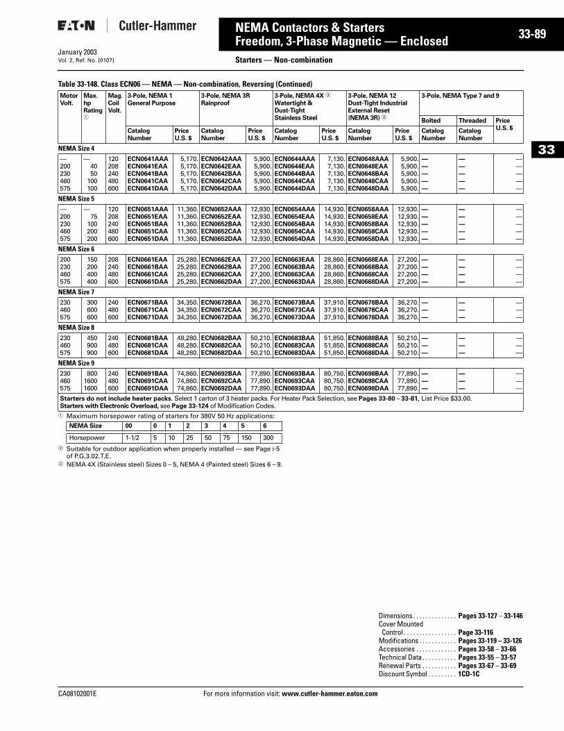
CA08102001E For more
89
33-NEMA Contactors & StartersFreedom, 3-Phase Magnetic — Enclosed Starters — Non-combinationJanuary 2003Vol. 2, Ref. No. [0107]
33
Table 33-148. Class ECN06 — NEMA — Non-combination, Reversing (Continued)
1 Maximum horsepower rating of starters for 380V 50 Hz applications:
2 Suitable for outdoor application when properly installed — see Page i-5 of P.G.3.02.T.E.
3 NEMA 4X (Stainless steel) Sizes 0 – 5, NEMA 4 (Painted steel) Sizes 6 – 9.
MotorVolt.
Max.hpRating1
Mag.CoilVolt.
3-Pole, NEMA 1General Purpose
3-Pole, NEMA 3RRainproof
3-Pole, NEMA 4X 3
Watertight & Dust-TightStainless Steel
3-Pole, NEMA 12Dust-Tight IndustrialExternal Reset(NEMA 3R) 2
3-Pole, NEMA Type 7 and 9
Bolted Threaded PriceU.S. $Catalog
NumberPriceU.S. $
CatalogNumber
PriceU.S. $
CatalogNumber
PriceU.S. $
CatalogNumber
PriceU.S. $
CatalogNumber
CatalogNumber
NEMA Size 4—200230460575
—4050
100100
120208240480600
ECN0641AAAECN0641EAAECN0641BAAECN0641CAAECN0641DAA
5,170.5,170.5,170.5,170.5,170.
ECN0642AAAECN0642EAAECN0642BAAECN0642CAAECN0642DAA
5,900.5,900.5,900.5,900.5,900.
ECN0644AAAECN0644EAAECN0644BAAECN0644CAAECN0644DAA
7,130.7,130.7,130.7,130.7,130.
ECN0648AAAECN0648EAAECN0648BAAECN0648CAAECN0648DAA
5,900.5,900.5,900.5,900.5,900.
—————
—————
—————
NEMA Size 5—200230460575
—75
100200200
120208240480600
ECN0651AAAECN0651EAAECN0651BAAECN0651CAAECN0651DAA
11,360.11,360.11,360.11,360.11,360.
ECN0652AAAECN0652EAAECN0652BAAECN0652CAAECN0652DAA
12,930.12,930.12,930.12,930.12,930.
ECN0654AAAECN0654EAAECN0654BAAECN0654CAAECN0654DAA
14,930.14,930.14,930.14,930.14,930.
ECN0658AAAECN0658EAAECN0658BAAECN0658CAAECN0658DAA
12,930.12,930.12,930.12,930.12,930.
—————
—————
—————
NEMA Size 6200230460575
150200400400
208240480600
ECN0661EAAECN0661BAAECN0661CAAECN0661DAA
25,280.25,280.25,280.25,280.
ECN0662EAAECN0662BAAECN0662CAAECN0662DAA
27,200.27,200.27,200.27,200.
ECN0663EAAECN0663BAAECN0663CAAECN0663DAA
28,860.28,860.28,860.28,860.
ECN0668EAAECN0668BAAECN0668CAAECN0668DAA
27,200.27,200.27,200.27,200.
————
————
————
NEMA Size 7230460575
300600600
240480600
ECN0671BAAECN0671CAAECN0671DAA
34,350.34,350.34,350.
ECN0672BAAECN0672CAAECN0672DAA
36,270.36,270.36,270.
ECN0673BAAECN0673CAAECN0673DAA
37,910.37,910.37,910.
ECN0678BAAECN0678CAAECN0678DAA
36,270.36,270.36,270.
———
———
———
NEMA Size 8230460575
450900900
240480600
ECN0681BAAECN0681CAAECN0681DAA
48,280.48,280.48,280.
ECN0682BAAECN0682CAAECN0682DAA
50,210.50,210.50,210.
ECN0683BAAECN0683CAAECN0683DAA
51,850.51,850.51,850.
ECN0688BAAECN0688CAAECN0688DAA
50,210.50,210.50,210.
———
———
———
NEMA Size 9230460575
80016001600
240480600
ECN0691BAAECN0691CAAECN0691DAA
74,860.74,860.74,860.
ECN0692BAAECN0692CAAECN0692DAA
77,890.77,890.77,890.
ECN0693BAAECN0693CAAECN0693DAA
80,750.80,750.80,750.
ECN0698BAAECN0698CAAECN0698DAA
77,890.77,890.77,890.
———
———
———
Starters do not include heater packs. Select 1 carton of 3 heater packs. For Heater Pack Selection, see Pages 33-80 – 33-81, List Price $33.00.Starters with Electronic Overload, see Page 33-124 of Modification Codes.
NEMA Size 00 0 1 2 3 4 5 6
Horsepower 1-1/2 5 10 25 50 75 150 300
Dimensions . . . . . . . . . . . . . . Pages 33-127 – 33-146Cover MountedControl . . . . . . . . . . . . . . . . . Page 33-116
Modifications . . . . . . . . . . . . Pages 33-119 – 33-126Accessories . . . . . . . . . . . . . Pages 33-58 – 33-66Technical Data . . . . . . . . . . . Pages 33-55 – 33-57Renewal Parts . . . . . . . . . . . Pages 33-67 – 33-69Discount Symbol . . . . . . . . . 1CD-1C
information visit: www.cutler-hammer.eaton.com
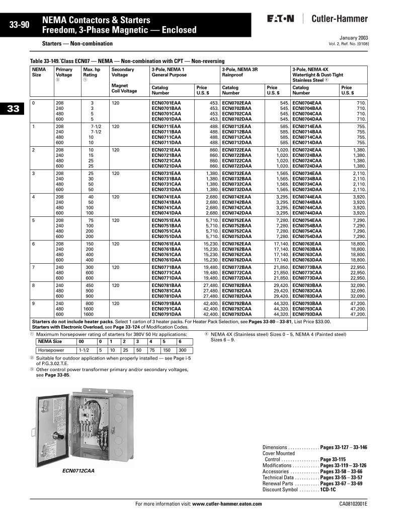
33-90
33
NEMA Contactors & StartersFreedom, 3-Phase Magnetic — Enclosed
Starters — Non-combinationFor more information visit: www.cutler-hammer.eaton.com
January 2003Vol. 2, Ref. No. [0108]
Table 33-149. Class ECN07 — NEMA — Non-combination with CPT — Non-reversing
1 Maximum horsepower rating of starters for 380V 50 Hz applications:
2 Suitable for outdoor application when properly installed — see Page i-5 of P.G.3.02.T.E.
3 Other control power transformer primary and/or secondary voltages, see Page 33-85.
ECN0712CAA
4 NEMA 4X (Stainless steel) Sizes 0 – 5, NEMA 4 (Painted steel)Sizes 6 – 9.
NEMASize
PrimaryVoltage3
Max. hpRating1
SecondaryVoltage
MagnetCoil Voltage
3-Pole, NEMA 1General Purpose
3-Pole, NEMA 3RRainproof
3-Pole, NEMA 4X Watertight & Dust-TightStainless Steel 4
CatalogNumber
PriceU.S. $
CatalogNumber
PriceU.S. $
CatalogNumber
PriceU.S. $
0 208240480600
3355
120 ECN0701EAAECN0701BAAECN0701CAAECN0701DAA
453.453.453.453.
ECN0702EAAECN0702BAAECN0702CAAECN0702DAA
545.545.545.545.
ECN0704EAAECN0704BAAECN0704CAAECN0704DAA
710.710.710.710.
1 208240480600
7-1/27-1/2
1010
120 ECN0711EAAECN0711BAAECN0711CAAECN0711DAA
488.488.488.488.
ECN0712EAAECN0712BAAECN0712CAAECN0712DAA
585.585.585.585.
ECN0714EAAECN0714BAAECN0714CAAECN0714DAA
755.755.755.755.
2 208240480600
10152525
120 ECN0721EAAECN0721BAAECN0721CAAECN0721DAA
860.860.860.860.
ECN0722EAAECN0722BAAECN0722CAAECN0722DAA
1,020.1,020.1,020.1,020.
ECN0724EAAECN0724BAAECN0724CAAECN0724DAA
1,380.1,380.1,380.1,380.
3 208240480600
25305050
120 ECN0731EAAECN0731BAAECN0731CAAECN0731DAA
1,380.1,380.1,380.1,380.
ECN0732EAAECN0732BAAECN0732CAAECN0732DAA
1,565.1,565.1,565.1,565.
ECN0734EAAECN0734BAAECN0734CAAECN0734DAA
2,110.2,110.2,110.2,110.
4 208240480600
4050
100100
120 ECN0741EAAECN0741BAAECN0741CAAECN0741DAA
2,680.2,680.2,680.2,680.
ECN0742EAAECN0742BAAECN0742CAAECN0742DAA
3,295.3,295.3,295.3,295.
ECN0744EAAECN0744BAAECN0744CAAECN0744DAA
3,920.3,920.3,920.3,920.
5 208240480600
75100200200
120 ECN0751EAAECN0751BAAECN0751CAAECN0751DAA
5,710.5,710.5,710.5,710.
ECN0752EAAECN0752BAAECN0752CAAECN0752DAA
7,280.7,280.7,280.7,280.
ECN0754EAAECN0754BAAECN0754CAAECN0754DAA
7,290.7,290.7,290.7,290.
6 208240480600
150200400400
120 ECN0761EAAECN0761BAAECN0761CAAECN0761DAA
15,230.15,230.15,230.15,230.
ECN0762EAAECN0762BAAECN0762CAAECN0762DAA
17,140.17,140.17,140.17,140.
ECN0763EAAECN0763BAAECN0763CAAECN0763DAA
18,800.18,800.18,800.18,800.
7 240480600
300600600
120 ECN0771BAAECN0771CAAECN0771DAA
19,480.19,480.19,480.
ECN0772BAAECN0772CAAECN0772DAA
21,850.21,850.21,850.
ECN0773BAAECN0773CAAECN0773DAA
22,950.22,950.22,950.
8 240480600
450900900
120 ECN0781BAAECN0781CAAECN0781DAA
27,480.27,480.27,480.
ECN0782BAAECN0782CAAECN0782DAA
29,420.29,420.29,420.
ECN0783BAAECN0783CAAECN0783DAA
32,090.32,090.32,090.
9 240480600
80016001600
120 ECN0791BAAECN0791CAAECN0791DAA
42,400.42,400.42,400.
ECN0792BAAECN0792CAAECN0792DAA
44,320.44,320.44,320.
ECN0793BAAECN0793CAAECN0793DAA
47,200.47,200.47,200.
Starters do not include heater packs. Select 1 carton of 3 heater packs. For Heater Pack Selection, see Pages 33-80 – 33-81, List Price $33.00.Starters with Electronic Overload, see Page 33-124 of Modification Codes.
NEMA Size 00 0 1 2 3 4 5 6
Horsepower 1-1/2 5 10 25 50 75 150 300
Dimensions . . . . . . . . . . . . . . Pages 33-127 – 33-146Cover MountedControl . . . . . . . . . . . . . . . . . Page 33-115
Modifications . . . . . . . . . . . . Pages 33-119 – 33-126Accessories . . . . . . . . . . . . . Pages 33-58 – 33-66Technical Data . . . . . . . . . . . Pages 33-55 – 33-57Renewal Parts . . . . . . . . . . . Pages 33-67 – 33-69Discount Symbol . . . . . . . . . 1CD-1C
CA08102001E
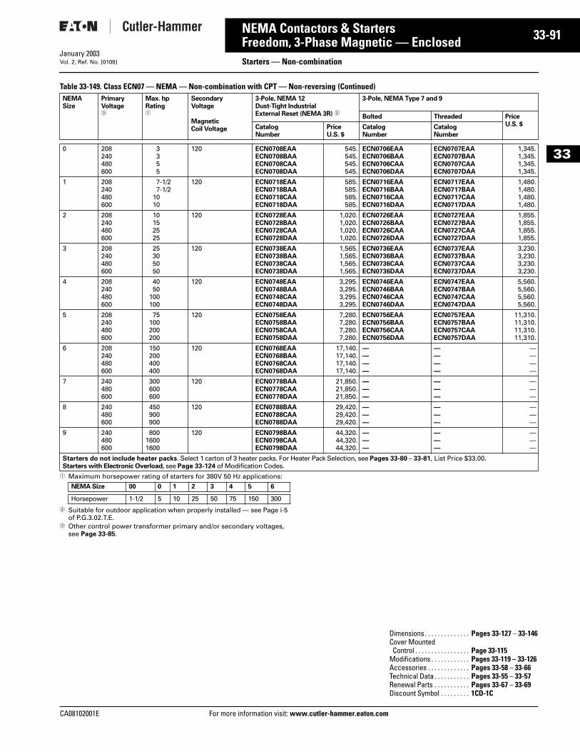
CA08102001E For more
91
33-NEMA Contactors & StartersFreedom, 3-Phase Magnetic — Enclosed Starters — Non-combinationJanuary 2003Vol. 2, Ref. No. [0109]
33
Table 33-149. Class ECN07 — NEMA — Non-combination with CPT — Non-reversing (Continued)
1 Maximum horsepower rating of starters for 380V 50 Hz applications:
2 Suitable for outdoor application when properly installed — see Page i-5 of P.G.3.02.T.E.
3 Other control power transformer primary and/or secondary voltages, see Page 33-85.
NEMASize
PrimaryVoltage3
Max. hpRating1
SecondaryVoltage
MagneticCoil Voltage
3-Pole, NEMA 12Dust-Tight IndustrialExternal Reset (NEMA 3R) 2
3-Pole, NEMA Type 7 and 9
Bolted Threaded PriceU.S. $Catalog
NumberPriceU.S. $
CatalogNumber
CatalogNumber
0 208240480600
3355
120 ECN0708EAAECN0708BAAECN0708CAAECN0708DAA
545.545.545.545.
ECN0706EAAECN0706BAAECN0706CAAECN0706DAA
ECN0707EAAECN0707BAAECN0707CAAECN0707DAA
1,345.1,345.1,345.1,345.
1 208240480600
7-1/27-1/2
1010
120 ECN0718EAAECN0718BAAECN0718CAAECN0718DAA
585.585.585.585.
ECN0716EAAECN0716BAAECN0716CAAECN0716DAA
ECN0717EAAECN0717BAAECN0717CAAECN0717DAA
1,480.1,480.1,480.1,480.
2 208240480600
10152525
120 ECN0728EAAECN0728BAAECN0728CAAECN0728DAA
1,020.1,020.1,020.1,020.
ECN0726EAAECN0726BAAECN0726CAAECN0726DAA
ECN0727EAAECN0727BAAECN0727CAAECN0727DAA
1,855.1,855.1,855.1,855.
3 208240480600
25305050
120 ECN0738EAAECN0738BAAECN0738CAAECN0738DAA
1,565.1,565.1,565.1,565.
ECN0736EAAECN0736BAAECN0736CAAECN0736DAA
ECN0737EAAECN0737BAAECN0737CAAECN0737DAA
3,230.3,230.3,230.3,230.
4 208240480600
4050
100100
120 ECN0748EAAECN0748BAAECN0748CAAECN0748DAA
3,295.3,295.3,295.3,295.
ECN0746EAAECN0746BAAECN0746CAAECN0746DAA
ECN0747EAAECN0747BAAECN0747CAAECN0747DAA
5,560.5,560.5,560.5,560.
5 208240480600
75100200200
120 ECN0758EAAECN0758BAAECN0758CAAECN0758DAA
7,280.7,280.7,280.7,280.
ECN0756EAAECN0756BAAECN0756CAAECN0756DAA
ECN0757EAAECN0757BAAECN0757CAAECN0757DAA
11,310.11,310.11,310.11,310.
6 208240480600
150200400400
120 ECN0768EAAECN0768BAAECN0768CAAECN0768DAA
17,140.17,140.17,140.17,140.
————
————
————
7 240480600
300600600
120 ECN0778BAAECN0778CAAECN0778DAA
21,850.21,850.21,850.
———
———
———
8 240480600
450900900
120 ECN0788BAAECN0788CAAECN0788DAA
29,420.29,420.29,420.
———
———
———
9 240480600
80016001600
120 ECN0798BAAECN0798CAAECN0798DAA
44,320.44,320.44,320.
———
———
———
Starters do not include heater packs. Select 1 carton of 3 heater packs. For Heater Pack Selection, see Pages 33-80 – 33-81, List Price $33.00.Starters with Electronic Overload, see Page 33-124 of Modification Codes.
NEMA Size 00 0 1 2 3 4 5 6
Horsepower 1-1/2 5 10 25 50 75 150 300
Dimensions . . . . . . . . . . . . . . Pages 33-127 – 33-146Cover MountedControl . . . . . . . . . . . . . . . . . Page 33-115
Modifications . . . . . . . . . . . . Pages 33-119 – 33-126Accessories . . . . . . . . . . . . . Pages 33-58 – 33-66Technical Data . . . . . . . . . . . Pages 33-55 – 33-57Renewal Parts . . . . . . . . . . . Pages 33-67 – 33-69Discount Symbol . . . . . . . . . 1CD-1C
information visit: www.cutler-hammer.eaton.com
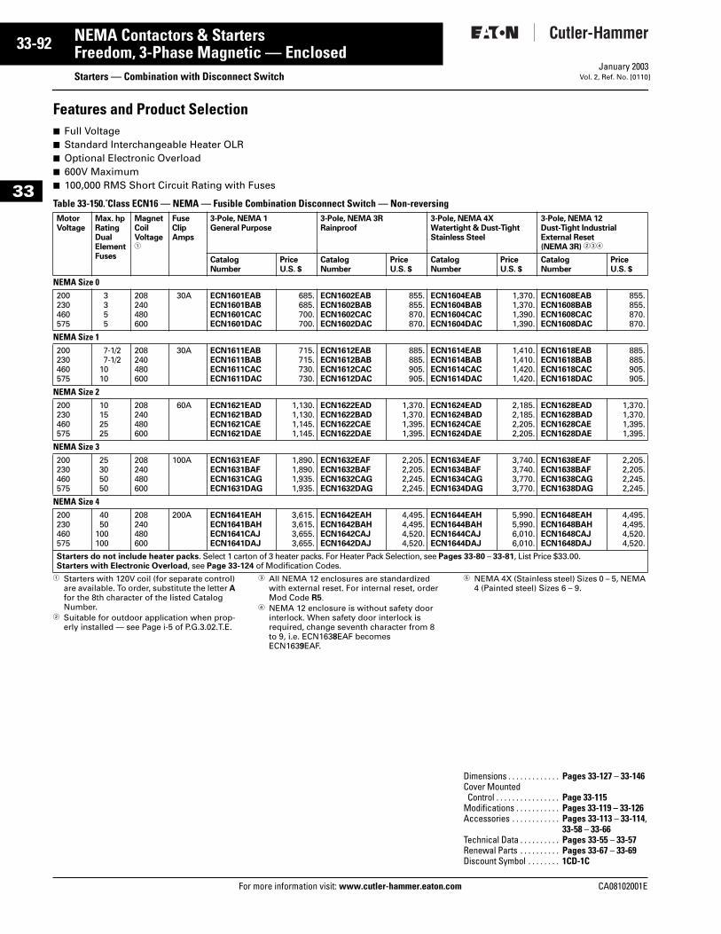
33-92
33
NEMA Contactors & StartersFreedom, 3-Phase Magnetic — Enclosed
Starters — Combination with Disconnect SwitchFor more information visit: www.cutler-hammer.eaton.com
January 2003Vol. 2, Ref. No. [0110]
Features and Product Selection■ Full Voltage■ Standard Interchangeable Heater OLR■ Optional Electronic Overload■ 600V Maximum■ 100,000 RMS Short Circuit Rating with Fuses
Table 33-150. Class ECN16 — NEMA — Fusible Combination Disconnect Switch — Non-reversing
1 Starters with 120V coil (for separate control) are available. To order, substitute the letter A for the 8th character of the listed Catalog Number.
2 Suitable for outdoor application when prop-erly installed — see Page i-5 of P.G.3.02.T.E.
3 All NEMA 12 enclosures are standardized with external reset. For internal reset, order Mod Code R5.
4 NEMA 12 enclosure is without safety door interlock. When safety door interlock is required, change seventh character from 8 to 9, i.e. ECN1638EAF becomes ECN1639EAF.
5 NEMA 4X (Stainless steel) Sizes 0 – 5, NEMA 4 (Painted steel) Sizes 6 – 9.
MotorVoltage
Max. hpRatingDual Element Fuses
MagnetCoilVoltage1
FuseClipAmps
3-Pole, NEMA 1General Purpose
3-Pole, NEMA 3RRainproof
3-Pole, NEMA 4XWatertight & Dust-TightStainless Steel
3-Pole, NEMA 12Dust-Tight IndustrialExternal Reset(NEMA 3R) 234
CatalogNumber
PriceU.S. $
CatalogNumber
PriceU.S. $
CatalogNumber
PriceU.S. $
CatalogNumber
PriceU.S. $
NEMA Size 0200230460575
3355
208240480600
30A ECN1601EABECN1601BABECN1601CACECN1601DAC
685.685.700.700.
ECN1602EABECN1602BABECN1602CACECN1602DAC
855.855.870.870.
ECN1604EABECN1604BABECN1604CACECN1604DAC
1,370.1,370.1,390.1,390.
ECN1608EABECN1608BABECN1608CACECN1608DAC
855.855.870.870.
NEMA Size 1200230460575
7-1/27-1/2
1010
208240480600
30A ECN1611EABECN1611BABECN1611CACECN1611DAC
715.715.730.730.
ECN1612EABECN1612BABECN1612CACECN1612DAC
885.885.905.905.
ECN1614EABECN1614BABECN1614CACECN1614DAC
1,410.1,410.1,420.1,420.
ECN1618EABECN1618BABECN1618CACECN1618DAC
885.885.905.905.
NEMA Size 2200230460575
10152525
208240480600
60A ECN1621EADECN1621BADECN1621CAEECN1621DAE
1,130.1,130.1,145.1,145.
ECN1622EADECN1622BADECN1622CAEECN1622DAE
1,370.1,370.1,395.1,395.
ECN1624EADECN1624BADECN1624CAEECN1624DAE
2,185.2,185.2,205.2,205.
ECN1628EADECN1628BADECN1628CAEECN1628DAE
1,370.1,370.1,395.1,395.
NEMA Size 3200230460575
25305050
208240480600
100A ECN1631EAFECN1631BAFECN1631CAGECN1631DAG
1,890.1,890.1,935.1,935.
ECN1632EAFECN1632BAFECN1632CAGECN1632DAG
2,205.2,205.2,245.2,245.
ECN1634EAFECN1634BAFECN1634CAGECN1634DAG
3,740.3,740.3,770.3,770.
ECN1638EAFECN1638BAFECN1638CAGECN1638DAG
2,205.2,205.2,245.2,245.
NEMA Size 4200230460575
4050
100100
208240480600
200A ECN1641EAHECN1641BAHECN1641CAJECN1641DAJ
3,615.3,615.3,655.3,655.
ECN1642EAHECN1642BAHECN1642CAJECN1642DAJ
4,495.4,495.4,520.4,520.
ECN1644EAHECN1644BAHECN1644CAJECN1644DAJ
5,990.5,990.6,010.6,010.
ECN1648EAHECN1648BAHECN1648CAJECN1648DAJ
4,495.4,495.4,520.4,520.
Starters do not include heater packs. Select 1 carton of 3 heater packs. For Heater Pack Selection, see Pages 33-80 – 33-81, List Price $33.00.Starters with Electronic Overload, see Page 33-124 of Modification Codes.
Dimensions . . . . . . . . . . . . . Pages 33-127 – 33-146Cover MountedControl . . . . . . . . . . . . . . . . Page 33-115
Modifications . . . . . . . . . . . Pages 33-119 – 33-126Accessories . . . . . . . . . . . . Pages 33-113 – 33-114,
33-58 – 33-66Technical Data . . . . . . . . . . Pages 33-55 – 33-57Renewal Parts . . . . . . . . . . Pages 33-67 – 33-69Discount Symbol . . . . . . . . 1CD-1C
CA08102001E
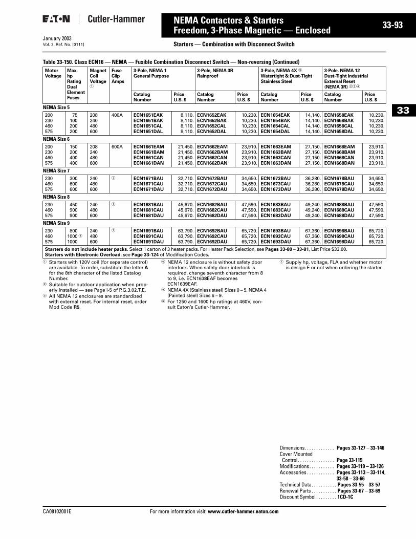
CA08102001E For more
93
33-NEMA Contactors & StartersFreedom, 3-Phase Magnetic — Enclosed Starters — Combination with Disconnect SwitchJanuary 2003Vol. 2, Ref. No. [0111]
33
Table 33-150. Class ECN16 — NEMA — Fusible Combination Disconnect Switch — Non-reversing (Continued)
1 Starters with 120V coil (for separate control) are available. To order, substitute the letter A for the 8th character of the listed Catalog Number.
2 Suitable for outdoor application when prop-erly installed — see Page i-5 of P.G.3.02.T.E.
3 All NEMA 12 enclosures are standardized with external reset. For internal reset, order Mod Code R5.
4 NEMA 12 enclosure is without safety door interlock. When safety door interlock is required, change seventh character from 8 to 9, i.e. ECN1638EAF becomes ECN1639EAF.
5 NEMA 4X (Stainless steel) Sizes 0 – 5, NEMA 4 (Painted steel) Sizes 6 – 9.
6 For 1250 and 1600 hp ratings at 460V, con-sult Eaton’s Cutler-Hammer.
7 Supply hp, voltage, FLA and whether motor is design E or not when ordering the starter.
MotorVoltage
Max.hpRating Dual Element Fuses
MagnetCoilVoltage1
FuseClipAmps
3-Pole, NEMA 1General Purpose
3-Pole, NEMA 3RRainproof
3-Pole, NEMA 4X 5
Watertight & Dust-TightStainless Steel
3-Pole, NEMA 12Dust-Tight IndustrialExternal Reset(NEMA 3R) 234
CatalogNumber
PriceU.S. $
CatalogNumber
PriceU.S. $
CatalogNumber
PriceU.S. $
CatalogNumber
PriceU.S. $
NEMA Size 5200230460575
75100200200
208240480600
400A ECN1651EAKECN1651BAKECN1651CALECN1651DAL
8,110.8,110.8,110.8,110.
ECN1652EAKECN1652BAKECN1652CALECN1652DAL
10,230.10,230.10,230.10,230.
ECN1654EAKECN1654BAKECN1654CALECN1654DAL
14,140.14,140.14,140.14,140.
ECN1658EAKECN1658BAKECN1658CALECN1658DAL
10,230.10,230.10,230.10,230.
NEMA Size 6200230460575
150200400400
208240480600
600A ECN1661EAMECN1661BAMECN1661CANECN1661DAN
21,450.21,450.21,450.21,450.
ECN1662EAMECN1662BAMECN1662CANECN1662DAN
23,910.23,910.23,910.23,910.
ECN1663EAMECN1663BAMECN1663CANECN1663DAN
27,150.27,150.27,150.27,150.
ECN1668EAMECN1668BAMECN1668CANECN1668DAN
23,910.23,910.23,910.23,910.
NEMA Size 7230460575
300600600
240480600
7 ECN1671BAUECN1671CAUECN1671DAU
32,710.32,710.32,710.
ECN1672BAUECN1672CAUECN1672DAU
34,650.34,650.34,650.
ECN1673BAUECN1673CAUECN1673DAU
36,280.36,280.36,280.
ECN1678BAUECN1678CAUECN1678DAU
34,650.34,650.34,650.
NEMA Size 8230460575
450900900
240480600
7 ECN1681BAUECN1681CAUECN1681DAU
45,670.45,670.45,670.
ECN1682BAUECN1682CAUECN1682DAU
47,590.47,590.47,590.
ECN1683BAUECN1683CAUECN1683DAU
49,240.49,240.49,240.
ECN1688BAUECN1688CAUECN1688DAU
47,590.47,590.47,590.
NEMA Size 9230460575
8001000 61000
240480600
7 ECN1691BAUECN1691CAUECN1691DAU
63,790.63,790.63,790.
ECN1692BAUECN1692CAUECN1692DAU
65,720.65,720.65,720.
ECN1693BAUECN1693CAUECN1693DAU
67,360.67,360.67,360.
ECN1698BAUECN1698CAUECN1698DAU
65,720.65,720.65,720.
Starters do not include heater packs. Select 1 carton of 3 heater packs. For Heater Pack Selection, see Pages 33-80 – 33-81, List Price $33.00.Starters with Electronic Overload, see Page 33-124 of Modification Codes.
Dimensions. . . . . . . . . . . . . Pages 33-127 – 33-146Cover MountedControl . . . . . . . . . . . . . . . . Page 33-115
Modifications. . . . . . . . . . . Pages 33-119 – 33-126Accessories . . . . . . . . . . . . Pages 33-113 – 33-114,
33-58 – 33-66Technical Data. . . . . . . . . . . Pages 33-55 – 33-57Renewal Parts . . . . . . . . . . . Pages 33-67 – 33-69Discount Symbol . . . . . . . . . 1CD-1C
information visit: www.cutler-hammer.eaton.com
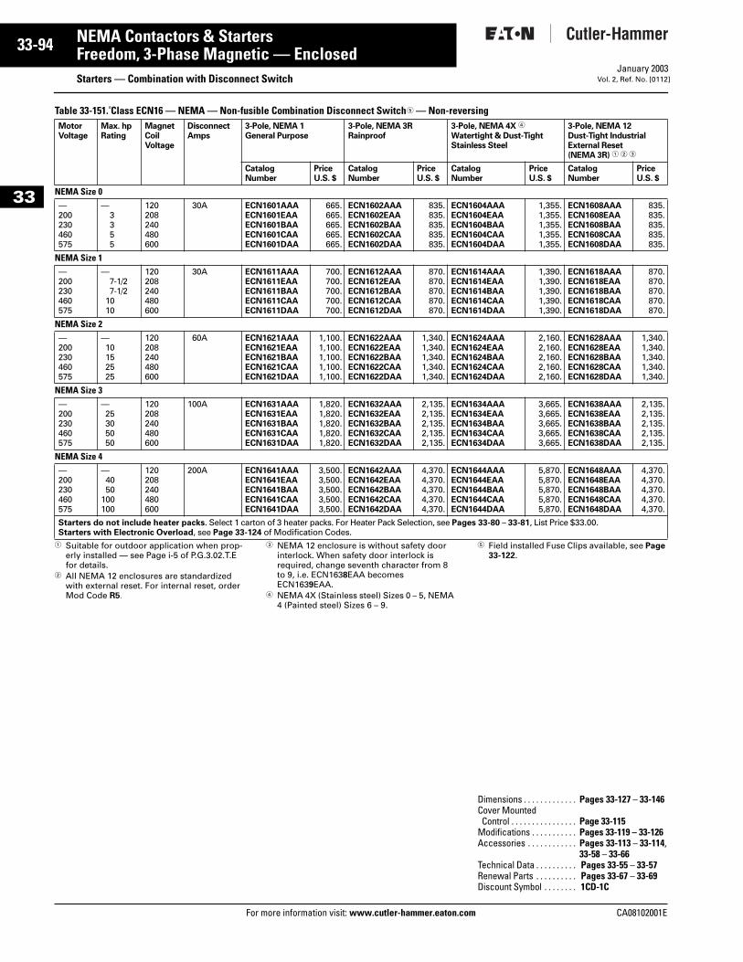
33-94
33
NEMA Contactors & StartersFreedom, 3-Phase Magnetic — Enclosed
Starters — Combination with Disconnect SwitchFor more information visit: www.cutler-hammer.eaton.com
January 2003Vol. 2, Ref. No. [0112]
Table 33-151. Class ECN16 — NEMA — Non-fusible Combination Disconnect Switch5 — Non-reversing
1 Suitable for outdoor application when prop-erly installed — see Page i-5 of P.G.3.02.T.E for details.
2 All NEMA 12 enclosures are standardized with external reset. For internal reset, order Mod Code R5.
3 NEMA 12 enclosure is without safety door interlock. When safety door interlock is required, change seventh character from 8 to 9, i.e. ECN1638EAA becomes ECN1639EAA.
4 NEMA 4X (Stainless steel) Sizes 0 – 5, NEMA 4 (Painted steel) Sizes 6 – 9.
5 Field installed Fuse Clips available, see Page 33-122.
MotorVoltage
Max. hpRating
MagnetCoilVoltage
DisconnectAmps
3-Pole, NEMA 1General Purpose
3-Pole, NEMA 3RRainproof
3-Pole, NEMA 4X 4
Watertight & Dust-TightStainless Steel
3-Pole, NEMA 12Dust-Tight IndustrialExternal Reset(NEMA 3R) 1 2 3
CatalogNumber
PriceU.S. $
CatalogNumber
PriceU.S. $
CatalogNumber
PriceU.S. $
CatalogNumber
PriceU.S. $
NEMA Size 0—200230460575
—3355
120208240480600
30A ECN1601AAAECN1601EAAECN1601BAAECN1601CAAECN1601DAA
665.665.665.665.665.
ECN1602AAAECN1602EAAECN1602BAAECN1602CAAECN1602DAA
835.835.835.835.835.
ECN1604AAAECN1604EAAECN1604BAAECN1604CAAECN1604DAA
1,355.1,355.1,355.1,355.1,355.
ECN1608AAAECN1608EAAECN1608BAAECN1608CAAECN1608DAA
835.835.835.835.835.
NEMA Size 1—200230460575
—7-1/27-1/2
1010
120208240480600
30A ECN1611AAAECN1611EAAECN1611BAAECN1611CAAECN1611DAA
700.700.700.700.700.
ECN1612AAAECN1612EAAECN1612BAAECN1612CAAECN1612DAA
870.870.870.870.870.
ECN1614AAAECN1614EAAECN1614BAAECN1614CAAECN1614DAA
1,390.1,390.1,390.1,390.1,390.
ECN1618AAAECN1618EAAECN1618BAAECN1618CAAECN1618DAA
870.870.870.870.870.
NEMA Size 2—200230460575
—10152525
120208240480600
60A ECN1621AAAECN1621EAAECN1621BAAECN1621CAAECN1621DAA
1,100.1,100.1,100.1,100.1,100.
ECN1622AAAECN1622EAAECN1622BAAECN1622CAAECN1622DAA
1,340.1,340.1,340.1,340.1,340.
ECN1624AAAECN1624EAAECN1624BAAECN1624CAAECN1624DAA
2,160.2,160.2,160.2,160.2,160.
ECN1628AAAECN1628EAAECN1628BAAECN1628CAAECN1628DAA
1,340.1,340.1,340.1,340.1,340.
NEMA Size 3—200230460575
—25305050
120208240480600
100A ECN1631AAAECN1631EAAECN1631BAAECN1631CAAECN1631DAA
1,820.1,820.1,820.1,820.1,820.
ECN1632AAAECN1632EAAECN1632BAAECN1632CAAECN1632DAA
2,135.2,135.2,135.2,135.2,135.
ECN1634AAAECN1634EAAECN1634BAAECN1634CAAECN1634DAA
3,665.3,665.3,665.3,665.3,665.
ECN1638AAAECN1638EAAECN1638BAAECN1638CAAECN1638DAA
2,135.2,135.2,135.2,135.2,135.
NEMA Size 4—200230460575
—4050
100100
120208240480600
200A ECN1641AAAECN1641EAAECN1641BAAECN1641CAAECN1641DAA
3,500.3,500.3,500.3,500.3,500.
ECN1642AAAECN1642EAAECN1642BAAECN1642CAAECN1642DAA
4,370.4,370.4,370.4,370.4,370.
ECN1644AAAECN1644EAAECN1644BAAECN1644CAAECN1644DAA
5,870.5,870.5,870.5,870.5,870.
ECN1648AAAECN1648EAAECN1648BAAECN1648CAAECN1648DAA
4,370.4,370.4,370.4,370.4,370.
Starters do not include heater packs. Select 1 carton of 3 heater packs. For Heater Pack Selection, see Pages 33-80 – 33-81, List Price $33.00.Starters with Electronic Overload, see Page 33-124 of Modification Codes.
Dimensions . . . . . . . . . . . . . Pages 33-127 – 33-146Cover MountedControl . . . . . . . . . . . . . . . . Page 33-115
Modifications . . . . . . . . . . . Pages 33-119 – 33-126Accessories . . . . . . . . . . . . Pages 33-113 – 33-114,
33-58 – 33-66Technical Data . . . . . . . . . . Pages 33-55 – 33-57Renewal Parts . . . . . . . . . . Pages 33-67 – 33-69Discount Symbol . . . . . . . . 1CD-1C
CA08102001E
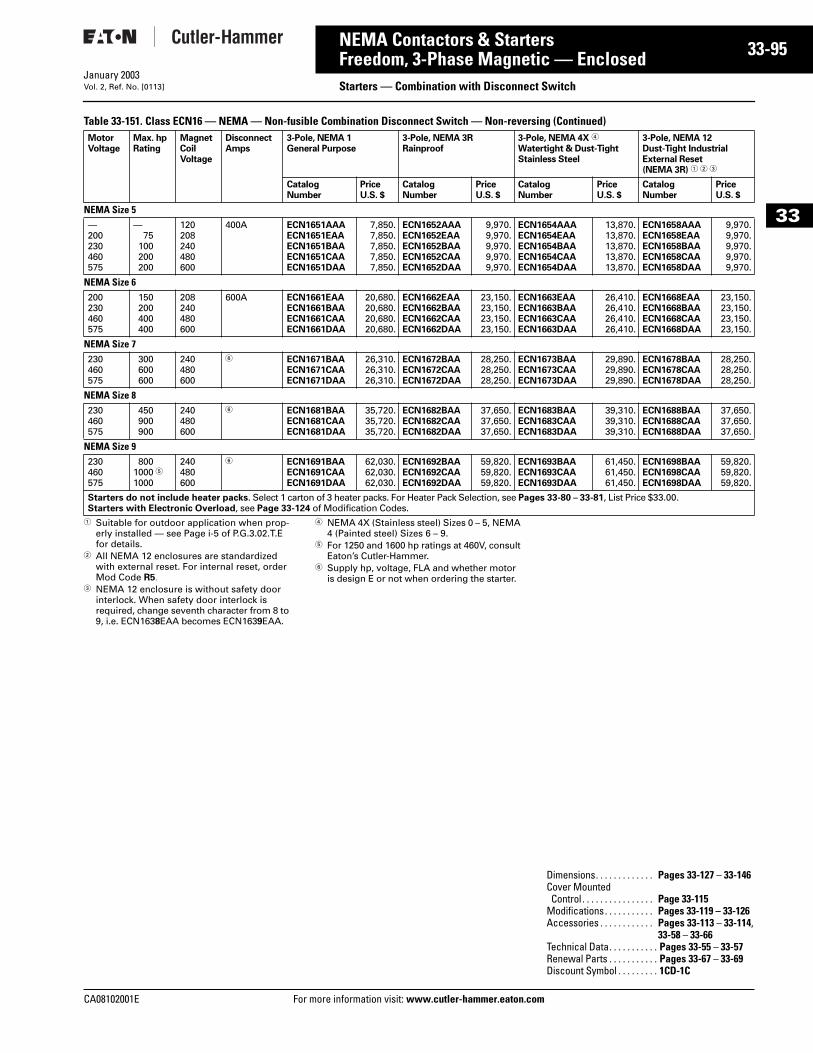
CA08102001E For more
95
33-NEMA Contactors & StartersFreedom, 3-Phase Magnetic — Enclosed Starters — Combination with Disconnect SwitchJanuary 2003Vol. 2, Ref. No. [0113]
33
Table 33-151. Class ECN16 — NEMA — Non-fusible Combination Disconnect Switch — Non-reversing (Continued)
1 Suitable for outdoor application when prop-erly installed — see Page i-5 of P.G.3.02.T.E for details.
2 All NEMA 12 enclosures are standardized with external reset. For internal reset, order Mod Code R5.
3 NEMA 12 enclosure is without safety door interlock. When safety door interlock is required, change seventh character from 8 to 9, i.e. ECN1638EAA becomes ECN1639EAA.
4 NEMA 4X (Stainless steel) Sizes 0 – 5, NEMA 4 (Painted steel) Sizes 6 – 9.
5 For 1250 and 1600 hp ratings at 460V, consult Eaton’s Cutler-Hammer.
6 Supply hp, voltage, FLA and whether motor is design E or not when ordering the starter.
MotorVoltage
Max. hpRating
MagnetCoilVoltage
DisconnectAmps
3-Pole, NEMA 1General Purpose
3-Pole, NEMA 3RRainproof
3-Pole, NEMA 4X 4
Watertight & Dust-TightStainless Steel
3-Pole, NEMA 12Dust-Tight IndustrialExternal Reset(NEMA 3R) 1 2 3
CatalogNumber
PriceU.S. $
CatalogNumber
PriceU.S. $
CatalogNumber
PriceU.S. $
CatalogNumber
PriceU.S. $
NEMA Size 5—200230460575
—75
100200200
120208240480600
400A ECN1651AAAECN1651EAAECN1651BAAECN1651CAAECN1651DAA
7,850.7,850.7,850.7,850.7,850.
ECN1652AAAECN1652EAAECN1652BAAECN1652CAAECN1652DAA
9,970.9,970.9,970.9,970.9,970.
ECN1654AAAECN1654EAAECN1654BAAECN1654CAAECN1654DAA
13,870.13,870.13,870.13,870.13,870.
ECN1658AAAECN1658EAAECN1658BAAECN1658CAAECN1658DAA
9,970.9,970.9,970.9,970.9,970.
NEMA Size 6200230460575
150200400400
208240480600
600A ECN1661EAAECN1661BAAECN1661CAAECN1661DAA
20,680.20,680.20,680.20,680.
ECN1662EAAECN1662BAAECN1662CAAECN1662DAA
23,150.23,150.23,150.23,150.
ECN1663EAAECN1663BAAECN1663CAAECN1663DAA
26,410.26,410.26,410.26,410.
ECN1668EAAECN1668BAAECN1668CAAECN1668DAA
23,150.23,150.23,150.23,150.
NEMA Size 7230460575
300600600
240480600
6 ECN1671BAAECN1671CAAECN1671DAA
26,310.26,310.26,310.
ECN1672BAAECN1672CAAECN1672DAA
28,250.28,250.28,250.
ECN1673BAAECN1673CAAECN1673DAA
29,890.29,890.29,890.
ECN1678BAAECN1678CAAECN1678DAA
28,250.28,250.28,250.
NEMA Size 8230460575
450900900
240480600
6 ECN1681BAAECN1681CAAECN1681DAA
35,720.35,720.35,720.
ECN1682BAAECN1682CAAECN1682DAA
37,650.37,650.37,650.
ECN1683BAAECN1683CAAECN1683DAA
39,310.39,310.39,310.
ECN1688BAAECN1688CAAECN1688DAA
37,650.37,650.37,650.
NEMA Size 9230460575
8001000 51000
240480600
6 ECN1691BAAECN1691CAAECN1691DAA
62,030.62,030.62,030.
ECN1692BAAECN1692CAAECN1692DAA
59,820.59,820.59,820.
ECN1693BAAECN1693CAAECN1693DAA
61,450.61,450.61,450.
ECN1698BAAECN1698CAAECN1698DAA
59,820.59,820.59,820.
Starters do not include heater packs. Select 1 carton of 3 heater packs. For Heater Pack Selection, see Pages 33-80 – 33-81, List Price $33.00.Starters with Electronic Overload, see Page 33-124 of Modification Codes.
Dimensions. . . . . . . . . . . . . Pages 33-127 – 33-146Cover MountedControl . . . . . . . . . . . . . . . . Page 33-115
Modifications. . . . . . . . . . . Pages 33-119 – 33-126Accessories . . . . . . . . . . . . Pages 33-113 – 33-114,
33-58 – 33-66Technical Data. . . . . . . . . . . Pages 33-55 – 33-57Renewal Parts . . . . . . . . . . . Pages 33-67 – 33-69Discount Symbol . . . . . . . . . 1CD-1C
information visit: www.cutler-hammer.eaton.com
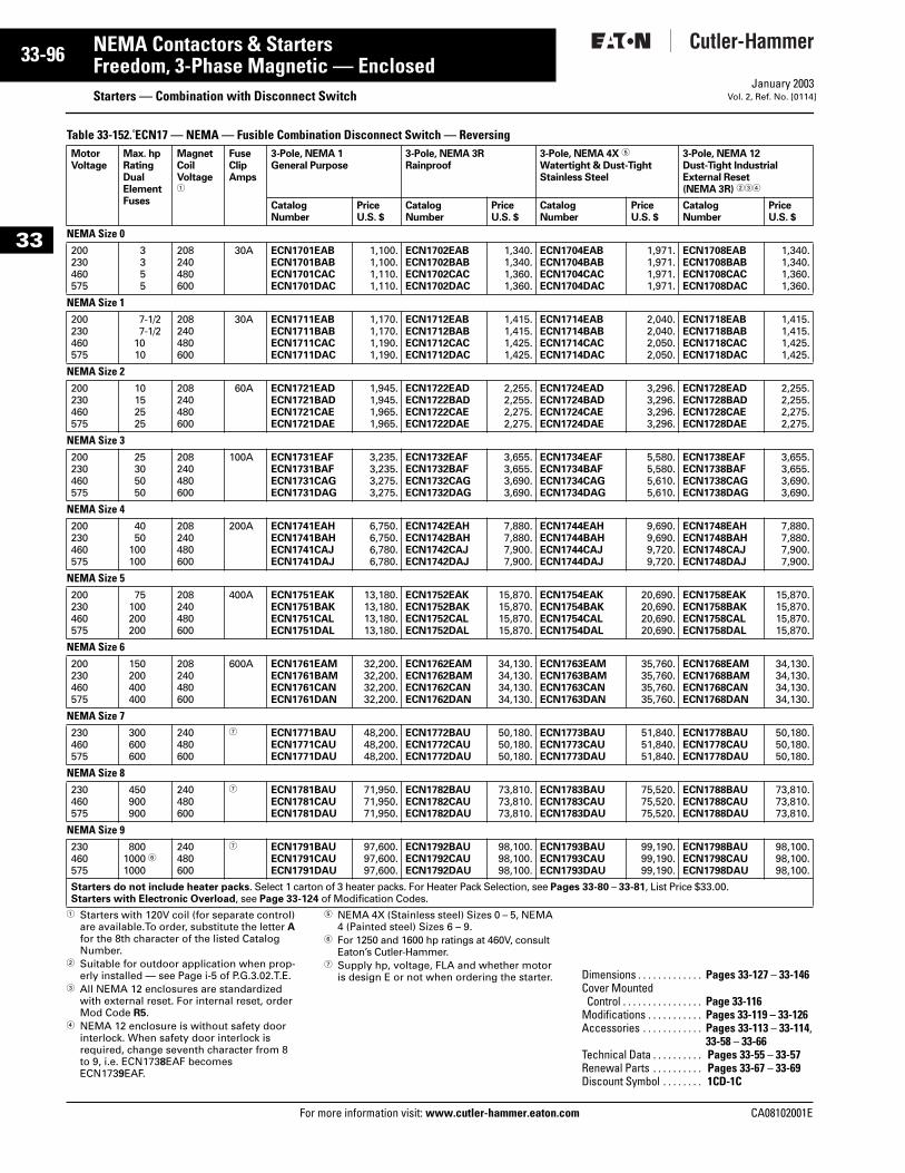
33-96
33
NEMA Contactors & StartersFreedom, 3-Phase Magnetic — Enclosed
Starters — Combination with Disconnect SwitchFor more information visit: www.cutler-hammer.eaton.com
January 2003Vol. 2, Ref. No. [0114]
Table 33-152. ECN17 — NEMA — Fusible Combination Disconnect Switch — Reversing
1 Starters with 120V coil (for separate control) are available.To order, substitute the letter A for the 8th character of the listed Catalog Number.
2 Suitable for outdoor application when prop-erly installed — see Page i-5 of P.G.3.02.T.E.
3 All NEMA 12 enclosures are standardized with external reset. For internal reset, order Mod Code R5.
4 NEMA 12 enclosure is without safety door interlock. When safety door interlock is required, change seventh character from 8 to 9, i.e. ECN1738EAF becomes ECN1739EAF.
5 NEMA 4X (Stainless steel) Sizes 0 – 5, NEMA 4 (Painted steel) Sizes 6 – 9.
6 For 1250 and 1600 hp ratings at 460V, consult Eaton’s Cutler-Hammer.
7 Supply hp, voltage, FLA and whether motor is design E or not when ordering the starter.
MotorVoltage
Max. hpRatingDualElementFuses
MagnetCoilVoltage1
FuseClipAmps
3-Pole, NEMA 1General Purpose
3-Pole, NEMA 3RRainproof
3-Pole, NEMA 4X 5
Watertight & Dust-TightStainless Steel
3-Pole, NEMA 12Dust-Tight IndustrialExternal Reset(NEMA 3R) 234
CatalogNumber
PriceU.S. $
CatalogNumber
PriceU.S. $
CatalogNumber
PriceU.S. $
CatalogNumber
PriceU.S. $
NEMA Size 0200230460575
3355
208240480600
30A ECN1701EABECN1701BABECN1701CACECN1701DAC
1,100.1,100.1,110.1,110.
ECN1702EABECN1702BABECN1702CACECN1702DAC
1,340.1,340.1,360.1,360.
ECN1704EABECN1704BABECN1704CACECN1704DAC
1,971.1,971.1,971.1,971.
ECN1708EABECN1708BABECN1708CACECN1708DAC
1,340.1,340.1,360.1,360.
NEMA Size 1200230460575
7-1/27-1/2
1010
208240480600
30A ECN1711EABECN1711BABECN1711CACECN1711DAC
1,170.1,170.1,190.1,190.
ECN1712EABECN1712BABECN1712CACECN1712DAC
1,415.1,415.1,425.1,425.
ECN1714EABECN1714BABECN1714CACECN1714DAC
2,040.2,040.2,050.2,050.
ECN1718EABECN1718BABECN1718CACECN1718DAC
1,415.1,415.1,425.1,425.
NEMA Size 2200230460575
10152525
208240480600
60A ECN1721EADECN1721BADECN1721CAEECN1721DAE
1,945.1,945.1,965.1,965.
ECN1722EADECN1722BADECN1722CAEECN1722DAE
2,255.2,255.2,275.2,275.
ECN1724EADECN1724BADECN1724CAEECN1724DAE
3,296.3,296.3,296.3,296.
ECN1728EADECN1728BADECN1728CAEECN1728DAE
2,255.2,255.2,275.2,275.
NEMA Size 3200230460575
25305050
208240480600
100A ECN1731EAFECN1731BAFECN1731CAGECN1731DAG
3,235.3,235.3,275.3,275.
ECN1732EAFECN1732BAFECN1732CAGECN1732DAG
3,655.3,655.3,690.3,690.
ECN1734EAFECN1734BAFECN1734CAGECN1734DAG
5,580.5,580.5,610.5,610.
ECN1738EAFECN1738BAFECN1738CAGECN1738DAG
3,655.3,655.3,690.3,690.
NEMA Size 4200230460575
4050
100100
208240480600
200A ECN1741EAHECN1741BAHECN1741CAJECN1741DAJ
6,750.6,750.6,780.6,780.
ECN1742EAHECN1742BAHECN1742CAJECN1742DAJ
7,880.7,880.7,900.7,900.
ECN1744EAHECN1744BAHECN1744CAJECN1744DAJ
9,690.9,690.9,720.9,720.
ECN1748EAHECN1748BAHECN1748CAJECN1748DAJ
7,880.7,880.7,900.7,900.
NEMA Size 5200230460575
75100200200
208240480600
400A ECN1751EAKECN1751BAKECN1751CALECN1751DAL
13,180.13,180.13,180.13,180.
ECN1752EAKECN1752BAKECN1752CALECN1752DAL
15,870.15,870.15,870.15,870.
ECN1754EAKECN1754BAKECN1754CALECN1754DAL
20,690.20,690.20,690.20,690.
ECN1758EAKECN1758BAKECN1758CALECN1758DAL
15,870.15,870.15,870.15,870.
NEMA Size 6200230460575
150200400400
208240480600
600A ECN1761EAMECN1761BAMECN1761CANECN1761DAN
32,200.32,200.32,200.32,200.
ECN1762EAMECN1762BAMECN1762CANECN1762DAN
34,130.34,130.34,130.34,130.
ECN1763EAMECN1763BAMECN1763CANECN1763DAN
35,760.35,760.35,760.35,760.
ECN1768EAMECN1768BAMECN1768CANECN1768DAN
34,130.34,130.34,130.34,130.
NEMA Size 7230460575
300600600
240480600
7 ECN1771BAUECN1771CAUECN1771DAU
48,200.48,200.48,200.
ECN1772BAUECN1772CAUECN1772DAU
50,180.50,180.50,180.
ECN1773BAUECN1773CAUECN1773DAU
51,840.51,840.51,840.
ECN1778BAUECN1778CAUECN1778DAU
50,180.50,180.50,180.
NEMA Size 8230460575
450900900
240480600
7 ECN1781BAUECN1781CAUECN1781DAU
71,950.71,950.71,950.
ECN1782BAUECN1782CAUECN1782DAU
73,810.73,810.73,810.
ECN1783BAUECN1783CAUECN1783DAU
75,520.75,520.75,520.
ECN1788BAUECN1788CAUECN1788DAU
73,810.73,810.73,810.
NEMA Size 9230460575
8001000 61000
240480600
7 ECN1791BAUECN1791CAUECN1791DAU
97,600.97,600.97,600.
ECN1792BAUECN1792CAUECN1792DAU
98,100.98,100.98,100.
ECN1793BAUECN1793CAUECN1793DAU
99,190.99,190.99,190.
ECN1798BAUECN1798CAUECN1798DAU
98,100.98,100.98,100.
Starters do not include heater packs. Select 1 carton of 3 heater packs. For Heater Pack Selection, see Pages 33-80 – 33-81, List Price $33.00.Starters with Electronic Overload, see Page 33-124 of Modification Codes.
Dimensions . . . . . . . . . . . . . Pages 33-127 – 33-146Cover MountedControl . . . . . . . . . . . . . . . . Page 33-116
Modifications . . . . . . . . . . . Pages 33-119 – 33-126Accessories . . . . . . . . . . . . Pages 33-113 – 33-114,
33-58 – 33-66Technical Data . . . . . . . . . . Pages 33-55 – 33-57Renewal Parts . . . . . . . . . . Pages 33-67 – 33-69Discount Symbol . . . . . . . . 1CD-1C
CA08102001E
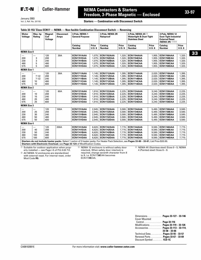
CA08102001E For more
97
33-NEMA Contactors & StartersFreedom, 3-Phase Magnetic — Enclosed Starters — Combination with Disconnect SwitchJanuary 2003Vol. 2, Ref. No. [0115]
33
Table 33-153. Class ECN17 — NEMA — Non-fusible Combination Disconnect Switch — Reversing
1 Suitable for outdoor application when prop-erly installed — see Page i-5 of P.G.3.02.T.E.
2 All NEMA 12 enclosures are standardized with external reset. For internal reset, order Mod Code R5.
3 NEMA 12 enclosure is without safety door interlock. When safety door interlock is required, change seventh character from 8 to 9, i.e. ECN1738EAA becomes ECN1739EAA.
4 NEMA 4X (Stainless steel) Sizes 0 – 5, NEMA 4 (Painted steel) Sizes 6 – 9.
MotorVoltage
Max. hpRating
MagnetCoilVoltage
DisconnectAmps
3-Pole, NEMA 1General Purpose
3-Pole, NEMA 3RRainproof
3-Pole, NEMA 4X 4
Watertight & Dust-TightStainless Steel
3-Pole, NEMA 12Dust-Tight IndustrialExternal Reset(NEMA 3R) 123
CatalogNumber
PriceU.S. $
CatalogNumber
PriceU.S. $
CatalogNumber
PriceU.S. $
CatalogNumber
PriceU.S. $
NEMA Size 0—200230460575
—3355
120208240480600
30A ECN1701AAAECN1701EAAECN1701BAAECN1701CAAECN1701DAA
1,075.1,075.1,075.1,075.1,075.
ECN1702AAAECN1702EAAECN1702BAAECN1702CAAECN1702DAA
1,320.1,320.1,320.1,320.1,320.
ECN1704AAAECN1704EAAECN1704BAAECN1704CAAECN1704DAA
1,955.1,955.1,955.1,955.1,955.
ECN1708AAAECN1708EAAECN1708BAAECN1708CAAECN1708DAA
1,320.1,320.1,320.1,320.1,320.
NEMA Size 1—200230460575
—7-1/27-1/2
1010
120208240480600
30A ECN1711AAAECN1711EAAECN1711BAAECN1711CAAECN1711DAA
1,145.1,145.1,145.1,145.1,145.
ECN1712AAAECN1712EAAECN1712BAAECN1712CAAECN1712DAA
1,395.1,395.1,395.1,395.1,395.
ECN1714AAAECN1714EAAECN1714BAAECN1714CAAECN1714DAA
2,020.2,020.2,020.2,020.2,020.
ECN1718AAAECN1718EAAECN1718BAAECN1718CAAECN1718DAA
1,395.1,395.1,395.1,395.1,395.
NEMA Size 2—200230460575
—10152525
120208240480600
60A ECN1721AAAECN1721EAAECN1721BAAECN1721CAAECN1721DAA
1,910.1,910.1,910.1,910.1,910.
ECN1722AAAECN1722EAAECN1722BAAECN1722CAAECN1722DAA
2,225.2,225.2,225.2,225.2,225.
ECN1724AAAECN1724EAAECN1724BAAECN1724CAAECN1724DAA
3,240.3,240.3,240.3,240.3,240.
ECN1728AAAECN1728EAAECN1728BAAECN1728CAAECN1728DAA
2,225.2,225.2,225.2,225.2,225.
NEMA Size 3—200230460575
—25305050
120208240480600
100A ECN1731AAAECN1731EAAECN1731BAAECN1731CAAECN1731DAA
2,945.2,945.2,945.2,945.2,945.
ECN1732AAAECN1732EAAECN1732BAAECN1732CAAECN1732DAA
3,580.3,580.3,580.3,580.3,580.
ECN1734AAAECN1734EAAECN1734BAAECN1734CAAECN1734DAA
5,490.5,490.5,490.5,490.5,490.
ECN1738AAAECN1738EAAECN1738BAAECN1738CAAECN1738DAA
3,580.3,580.3,580.3,580.3,580.
NEMA Size 4—200230460575
—4050
100100
120208240480600
200A ECN1741AAAECN1741EAAECN1741BAAECN1741CAAECN1741DAA
6,620.6,620.6,620.6,620.6,620.
ECN1742AAAECN1742EAAECN1742BAAECN1742CAAECN1742DAA
7,770.7,770.7,770.7,770.7,770.
ECN1744AAAECN1744EAAECN1744BAAECN1744CAAECN1744DAA
9,590.9,590.9,590.9,590.9,590.
ECN1748AAAECN1748EAAECN1748BAAECN1748CAAECN1748DAA
7,770.7,770.7,770.7,770.7,770.
Starters do not include heater packs. Select 1 carton of 3 heater packs. For Heater Pack Selection, see Pages 33-80 – 33-81, List Price $33.00.Starters with Electronic Overload, see Page 33-124 of Modification Codes.
Dimensions. . . . . . . . . . . . . Pages 33-127 – 33-146Cover MountedControl . . . . . . . . . . . . . . . . Page 33-116
Modifications. . . . . . . . . . . Pages 33-119 – 33-126Accessories . . . . . . . . . . . . Pages 33-113 – 33-114,
33-58 – 33-66Technical Data. . . . . . . . . . . Pages 33-55 – 33-57Renewal Parts . . . . . . . . . . . Pages 33-67 – 33-69Discount Symbol . . . . . . . . . 1CD-1C
information visit: www.cutler-hammer.eaton.com
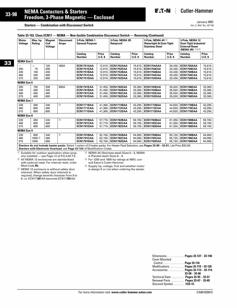
33-98
33
NEMA Contactors & StartersFreedom, 3-Phase Magnetic — Enclosed
Starters — Combination with Disconnect SwitchFor more information visit: www.cutler-hammer.eaton.com
January 2003Vol. 2, Ref. No. [0116]
Table 33-153. Class ECN17 — NEMA — Non-fusible Combination Disconnect Switch — Reversing (Continued)
1 Suitable for outdoor application when prop-erly installed — see Page i-5 of P.G.3.02.T.E.
2 All NEMA 12 enclosures are standardized with external reset. For internal reset, order Mod Code R5.
3 NEMA 12 enclosure is without safety door interlock. When safety door interlock is required, change seventh character from 8 to 9, i.e. ECN1738EAA becomes ECN1739EAA.
4 NEMA 4X (Stainless steel) Sizes 0 – 5, NEMA 4 (Painted steel) Sizes 6 – 9.
5 For 1250 and 1600 hp ratings at 460V, con-sult Eaton’s Cutler-Hammer.
6 Supply hp, voltage, FLA and whether motor is design E or not when ordering the starter.
MotorVoltage
Max. hpRating
MagnetCoilVoltage
DisconnectAmps
3-Pole, NEMA 1General Purpose
3-Pole, NEMA 3RRainproof
3-Pole, NEMA 4X 4
Watertight & Dust-TightStainless Steel
3-Pole, NEMA 12Dust-Tight IndustrialExternal Reset(NEMA 3R) 123
CatalogNumber
PriceU.S. $
CatalogNumber
PriceU.S. $
CatalogNumber
PriceU.S. $
CatalogNumber
PriceU.S. $
NEMA Size 5—200230460575
—75
100200200
120208240480600
400A ECN1751AAAECN1751EAAECN1751BAAECN1751CAAECN1751DAA
12,910.12,910.12,910.12,910.12,910.
ECN1752AAAECN1752EAAECN1752BAAECN1752CAAECN1752DAA
15,610.15,610.15,610.15,610.15,610.
ECN1754AAAECN1754EAAECN1754BAAECN1754CAAECN1754DAA
20,430.20,430.20,430.20,430.20,430.
ECN1758AAAECN1758EAAECN1758BAAECN1758CAAECN1758DAA
15,610.15,610.15,610.15,610.15,610.
NEMA Size 6200230460575
150200400400
208240480600
600A ECN1761EAAECN1761BAAECN1761CAAECN1761DAA
31,450.31,450.31,450.31,450.
ECN1762EAAECN1762BAAECN1762CAAECN1762DAA
33,380.33,380.33,380.33,380.
ECN1763EAAECN1763BAAECN1763CAAECN1763DAA
35,020.35,020.35,020.35,020.
ECN1768EAAECN1768BAAECN1768CAAECN1768DAA
33,380.33,380.33,380.33,380.
NEMA Size 7230460575
300600600
240480600
6 ECN1771BAAECN1771CAAECN1771DAA
41,360.41,360.41,360.
ECN1772BAAECN1772CAAECN1772DAA
43,290.43,290.43,290.
ECN1773BAAECN1773CAAECN1773DAA
44,920.44,920.44,920.
ECN1778BAAECN1778CAAECN1778DAA
43,290.43,290.43,290.
NEMA Size 8230460575
450900900
240480600
6 ECN1781BAAECN1781CAAECN1781DAA
57,770.57,770.57,770.
ECN1782BAAECN1782CAAECN1782DAA
59,700.59,700.59,700.
ECN1783BAAECN1783CAAECN1783DAA
61,350.61,350.61,350.
ECN1788BAAECN1788CAAECN1788DAA
59,700.59,700.59,700.
NEMA Size 9230460575
8001000 51000
240480600
6 ECN1791BAAECN1791CAAECN1791DAA
92,150.92,150.92,150.
ECN1792BAAECN1792CAAECN1792DAA
94,080.94,080.94,080.
ECN1793BAAECN1793CAAECN1793DAA
95,720.95,720.95,720.
ECN1798BAAECN1798CAAECN1798DAA
94,080.94,080.94,080.
Starters do not include heater packs. Select 1 carton of 3 heater packs. For Heater Pack Selection, see Pages 33-80 – 33-81, List Price $33.00.Starters with Electronic Overload, see Page 33-124 of Modification Codes.
Dimensions . . . . . . . . . . . . . Pages 33-127 – 33-146Cover MountedControl . . . . . . . . . . . . . . . . Page 33-116
Modifications . . . . . . . . . . . Pages 33-119 – 33-126Accessories . . . . . . . . . . . . Pages 33-113 – 33-114,
33-58 – 33-66Technical Data . . . . . . . . . . Pages 33-55 – 33-57Renewal Parts . . . . . . . . . . Pages 33-67 – 33-69Discount Symbol . . . . . . . . 1CD-1C
CA08102001E
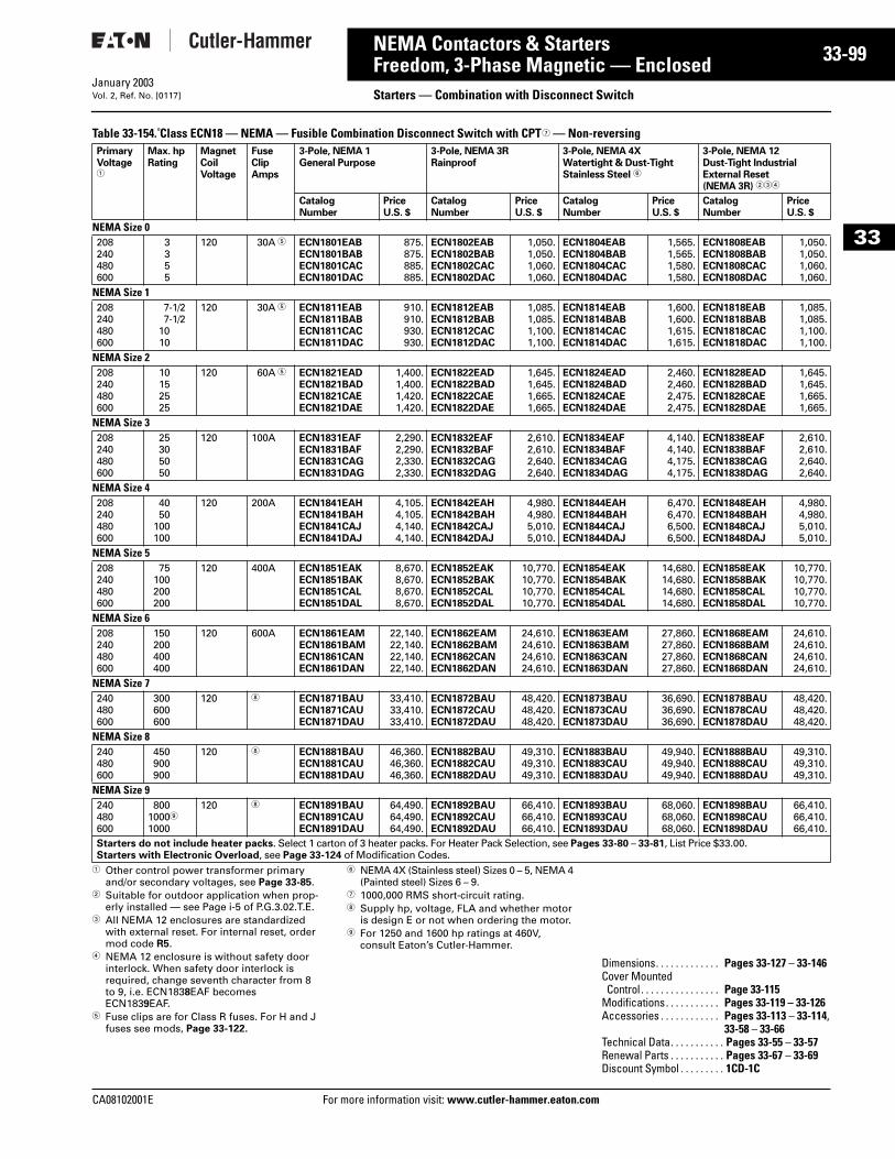
CA08102001E For more
99
33-NEMA Contactors & StartersFreedom, 3-Phase Magnetic — Enclosed Starters — Combination with Disconnect SwitchJanuary 2003Vol. 2, Ref. No. [0117]
33
Table 33-154. Class ECN18 — NEMA — Fusible Combination Disconnect Switch with CPT7 — Non-reversing
1 Other control power transformer primary and/or secondary voltages, see Page 33-85.
2 Suitable for outdoor application when prop-erly installed — see Page i-5 of P.G.3.02.T.E.
3 All NEMA 12 enclosures are standardized with external reset. For internal reset, order mod code R5.
4 NEMA 12 enclosure is without safety door interlock. When safety door interlock is required, change seventh character from 8 to 9, i.e. ECN1838EAF becomes ECN1839EAF.
5 Fuse clips are for Class R fuses. For H and J fuses see mods, Page 33-122.
6 NEMA 4X (Stainless steel) Sizes 0 – 5, NEMA 4 (Painted steel) Sizes 6 – 9.
7 1000,000 RMS short-circuit rating.8 Supply hp, voltage, FLA and whether motor
is design E or not when ordering the motor.9 For 1250 and 1600 hp ratings at 460V,
consult Eaton’s Cutler-Hammer.
PrimaryVoltage1
Max. hpRating
MagnetCoilVoltage
FuseClipAmps
3-Pole, NEMA 1General Purpose
3-Pole, NEMA 3RRainproof
3-Pole, NEMA 4X Watertight & Dust-TightStainless Steel 6
3-Pole, NEMA 12Dust-Tight IndustrialExternal Reset(NEMA 3R) 234
CatalogNumber
PriceU.S. $
CatalogNumber
PriceU.S. $
CatalogNumber
PriceU.S. $
CatalogNumber
PriceU.S. $
NEMA Size 0208240480600
3355
120 30A 5 ECN1801EABECN1801BABECN1801CACECN1801DAC
875.875.885.885.
ECN1802EABECN1802BABECN1802CACECN1802DAC
1,050.1,050.1,060.1,060.
ECN1804EABECN1804BABECN1804CACECN1804DAC
1,565.1,565.1,580.1,580.
ECN1808EABECN1808BABECN1808CACECN1808DAC
1,050.1,050.1,060.1,060.
NEMA Size 1208240480600
7-1/27-1/2
1010
120 30A 5 ECN1811EABECN1811BABECN1811CACECN1811DAC
910.910.930.930.
ECN1812EABECN1812BABECN1812CACECN1812DAC
1,085.1,085.1,100.1,100.
ECN1814EABECN1814BABECN1814CACECN1814DAC
1,600.1,600.1,615.1,615.
ECN1818EABECN1818BABECN1818CACECN1818DAC
1,085.1,085.1,100.1,100.
NEMA Size 2208240480600
10152525
120 60A 5 ECN1821EADECN1821BADECN1821CAEECN1821DAE
1,400.1,400.1,420.1,420.
ECN1822EADECN1822BADECN1822CAEECN1822DAE
1,645.1,645.1,665.1,665.
ECN1824EADECN1824BADECN1824CAEECN1824DAE
2,460.2,460.2,475.2,475.
ECN1828EADECN1828BADECN1828CAEECN1828DAE
1,645.1,645.1,665.1,665.
NEMA Size 3208240480600
25305050
120 100A ECN1831EAFECN1831BAFECN1831CAGECN1831DAG
2,290.2,290.2,330.2,330.
ECN1832EAFECN1832BAFECN1832CAGECN1832DAG
2,610.2,610.2,640.2,640.
ECN1834EAFECN1834BAFECN1834CAGECN1834DAG
4,140.4,140.4,175.4,175.
ECN1838EAFECN1838BAFECN1838CAGECN1838DAG
2,610.2,610.2,640.2,640.
NEMA Size 4208240480600
4050
100100
120 200A ECN1841EAHECN1841BAHECN1841CAJECN1841DAJ
4,105.4,105.4,140.4,140.
ECN1842EAHECN1842BAHECN1842CAJECN1842DAJ
4,980.4,980.5,010.5,010.
ECN1844EAHECN1844BAHECN1844CAJECN1844DAJ
6,470.6,470.6,500.6,500.
ECN1848EAHECN1848BAHECN1848CAJECN1848DAJ
4,980.4,980.5,010.5,010.
NEMA Size 5 208240480600
75100200200
120 400A ECN1851EAKECN1851BAKECN1851CALECN1851DAL
8,670.8,670.8,670.8,670.
ECN1852EAKECN1852BAKECN1852CALECN1852DAL
10,770.10,770.10,770.10,770.
ECN1854EAKECN1854BAKECN1854CALECN1854DAL
14,680.14,680.14,680.14,680.
ECN1858EAKECN1858BAKECN1858CALECN1858DAL
10,770.10,770.10,770.10,770.
NEMA Size 6208240480600
150200400400
120 600A ECN1861EAMECN1861BAMECN1861CANECN1861DAN
22,140.22,140.22,140.22,140.
ECN1862EAMECN1862BAMECN1862CANECN1862DAN
24,610.24,610.24,610.24,610.
ECN1863EAMECN1863BAMECN1863CANECN1863DAN
27,860.27,860.27,860.27,860.
ECN1868EAMECN1868BAMECN1868CANECN1868DAN
24,610.24,610.24,610.24,610.
NEMA Size 7240480600
300600600
120 8 ECN1871BAUECN1871CAUECN1871DAU
33,410.33,410.33,410.
ECN1872BAUECN1872CAUECN1872DAU
48,420.48,420.48,420.
ECN1873BAUECN1873CAUECN1873DAU
36,690.36,690.36,690.
ECN1878BAUECN1878CAUECN1878DAU
48,420.48,420.48,420.
NEMA Size 8240480600
450900900
120 8 ECN1881BAUECN1881CAUECN1881DAU
46,360.46,360.46,360.
ECN1882BAUECN1882CAUECN1882DAU
49,310.49,310.49,310.
ECN1883BAUECN1883CAUECN1883DAU
49,940.49,940.49,940.
ECN1888BAUECN1888CAUECN1888DAU
49,310.49,310.49,310.
NEMA Size 9240480600
80010009
1000
120 8 ECN1891BAUECN1891CAUECN1891DAU
64,490.64,490.64,490.
ECN1892BAUECN1892CAUECN1892DAU
66,410.66,410.66,410.
ECN1893BAUECN1893CAUECN1893DAU
68,060.68,060.68,060.
ECN1898BAUECN1898CAUECN1898DAU
66,410.66,410.66,410.
Starters do not include heater packs. Select 1 carton of 3 heater packs. For Heater Pack Selection, see Pages 33-80 – 33-81, List Price $33.00.Starters with Electronic Overload, see Page 33-124 of Modification Codes.
Dimensions. . . . . . . . . . . . . Pages 33-127 – 33-146Cover MountedControl . . . . . . . . . . . . . . . . Page 33-115
Modifications. . . . . . . . . . . Pages 33-119 – 33-126Accessories . . . . . . . . . . . . Pages 33-113 – 33-114,
33-58 – 33-66Technical Data. . . . . . . . . . . Pages 33-55 – 33-57Renewal Parts . . . . . . . . . . . Pages 33-67 – 33-69Discount Symbol . . . . . . . . . 1CD-1C
information visit: www.cutler-hammer.eaton.com
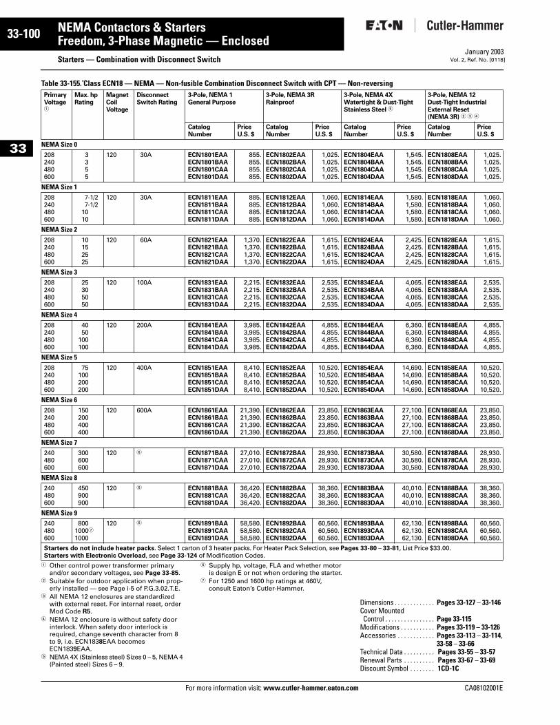
33-100
33
NEMA Contactors & StartersFreedom, 3-Phase Magnetic — Enclosed
Starters — Combination with Disconnect SwitchFor more information visit: www.cutler-hammer.eaton.com
January 2003Vol. 2, Ref. No. [0118]
Table 33-155. Class ECN18 — NEMA — Non-fusible Combination Disconnect Switch with CPT — Non-reversing
1 Other control power transformer primary and/or secondary voltages, see Page 33-85.
2 Suitable for outdoor application when prop-erly installed — see Page i-5 of P.G.3.02.T.E.
3 All NEMA 12 enclosures are standardized with external reset. For internal reset, order Mod Code R5.
4 NEMA 12 enclosure is without safety door interlock. When safety door interlock is required, change seventh character from 8 to 9, i.e. ECN1838EAA becomes ECN1839EAA.
5 NEMA 4X (Stainless steel) Sizes 0 – 5, NEMA 4 (Painted steel) Sizes 6 – 9.
6 Supply hp, voltage, FLA and whether motor is design E or not when ordering the starter.
7 For 1250 and 1600 hp ratings at 460V, consult Eaton’s Cutler-Hammer.
PrimaryVoltage1
Max. hpRating
MagnetCoilVoltage
DisconnectSwitch Rating
3-Pole, NEMA 1General Purpose
3-Pole, NEMA 3RRainproof
3-Pole, NEMA 4X Watertight & Dust-TightStainless Steel 5
3-Pole, NEMA 12Dust-Tight IndustrialExternal Reset(NEMA 3R) 2 3 4
CatalogNumber
PriceU.S. $
CatalogNumber
PriceU.S. $
CatalogNumber
PriceU.S. $
CatalogNumber
PriceU.S. $
NEMA Size 0208240480600
3355
120 30A ECN1801EAAECN1801BAAECN1801CAAECN1801DAA
855.855.855.855.
ECN1802EAAECN1802BAAECN1802CAAECN1802DAA
1,025.1,025.1,025.1,025.
ECN1804EAAECN1804BAAECN1804CAAECN1804DAA
1,545.1,545.1,545.1,545.
ECN1808EAAECN1808BAAECN1808CAAECN1808DAA
1,025.1,025.1,025.1,025.
NEMA Size 1208240480600
7-1/27-1/2
1010
120 30A ECN1811EAAECN1811BAAECN1811CAAECN1811DAA
885.885.885.885.
ECN1812EAAECN1812BAAECN1812CAAECN1812DAA
1,060.1,060.1,060.1,060.
ECN1814EAAECN1814BAAECN1814CAAECN1814DAA
1,580.1,580.1,580.1,580.
ECN1818EAAECN1818BAAECN1818CAAECN1818DAA
1,060.1,060.1,060.1,060.
NEMA Size 2208240480600
10152525
120 60A ECN1821EAAECN1821BAAECN1821CAAECN1821DAA
1,370.1,370.1,370.1,370.
ECN1822EAAECN1822BAAECN1822CAAECN1822DAA
1,615.1,615.1,615.1,615.
ECN1824EAAECN1824BAAECN1824CAAECN1824DAA
2,425.2,425.2,425.2,425.
ECN1828EAAECN1828BAAECN1828CAAECN1828DAA
1,615.1,615.1,615.1,615.
NEMA Size 3208240480600
25305050
120 100A ECN1831EAAECN1831BAAECN1831CAAECN1831DAA
2,215.2,215.2,215.2,215.
ECN1832EAAECN1832BAAECN1832CAAECN1832DAA
2,535.2,535.2,535.2,535.
ECN1834EAAECN1834BAAECN1834CAAECN1834DAA
4,065.4,065.4,065.4,065.
ECN1838EAAECN1838BAAECN1838CAAECN1838DAA
2,535.2,535.2,535.2,535.
NEMA Size 4208240480600
4050
100100
120 200A ECN1841EAAECN1841BAAECN1841CAAECN1841DAA
3,985.3,985.3,985.3,985.
ECN1842EAAECN1842BAAECN1842CAAECN1842DAA
4,855.4,855.4,855.4,855.
ECN1844EAAECN1844BAAECN1844CAAECN1844DAA
6,360.6,360.6,360.6,360.
ECN1848EAAECN1848BAAECN1848CAAECN1848DAA
4,855.4,855.4,855.4,855.
NEMA Size 5208240480600
75100200200
120 400A ECN1851EAAECN1851BAAECN1851CAAECN1851DAA
8,410.8,410.8,410.8,410.
ECN1852EAAECN1852BAAECN1852CAAECN1852DAA
10,520.10,520.10,520.10,520.
ECN1854EAAECN1854BAAECN1854CAAECN1854DAA
14,690.14,690.14,690.14,690.
ECN1858EAAECN1858BAAECN1858CAAECN1858DAA
10,520.10,520.10,520.10,520.
NEMA Size 6208240480600
150200400400
120 600A ECN1861EAAECN1861BAAECN1861CAAECN1861DAA
21,390.21,390.21,390.21,390.
ECN1862EAAECN1862BAAECN1862CAAECN1862DAA
23,850.23,850.23,850.23,850.
ECN1863EAAECN1863BAAECN1863CAAECN1863DAA
27,100.27,100.27,100.27,100.
ECN1868EAAECN1868BAAECN1868CAAECN1868DAA
23,850.23,850.23,850.23,850.
NEMA Size 7240480600
300600600
120 6 ECN1871BAAECN1871CAAECN1871DAA
27,010.27,010.27,010.
ECN1872BAAECN1872CAAECN1872DAA
28,930.28,930.28,930.
ECN1873BAAECN1873CAAECN1873DAA
30,580.30,580.30,580.
ECN1878BAAECN1878CAAECN1878DAA
28,930.28,930.28,930.
NEMA Size 8240480600
450900900
120 6 ECN1881BAAECN1881CAAECN1881DAA
36,420.36,420.36,420.
ECN1882BAAECN1882CAAECN1882DAA
38,360.38,360.38,360.
ECN1883BAAECN1883CAAECN1883DAA
40,010.40,010.40,010.
ECN1888BAAECN1888CAAECN1888DAA
38,360.38,360.38,360.
NEMA Size 9240480600
80010007
1000
120 6 ECN1891BAAECN1891CAAECN1891DAA
58,580.58,580.58,580.
ECN1892BAAECN1892CAAECN1892DAA
60,560.60,560.60,560.
ECN1893BAAECN1893CAAECN1893DAA
62,130.62,130.62,130.
ECN1898BAAECN1898CAAECN1898DAA
60,560.60,560.60,560.
Starters do not include heater packs. Select 1 carton of 3 heater packs. For Heater Pack Selection, see Pages 33-80 – 33-81, List Price $33.00.Starters with Electronic Overload, see Page 33-124 of Modification Codes.
Dimensions . . . . . . . . . . . . . Pages 33-127 – 33-146Cover MountedControl . . . . . . . . . . . . . . . . Page 33-115
Modifications . . . . . . . . . . . Pages 33-119 – 33-126Accessories . . . . . . . . . . . . Pages 33-113 – 33-114,
33-58 – 33-66Technical Data . . . . . . . . . . Pages 33-55 – 33-57Renewal Parts . . . . . . . . . . Pages 33-67 – 33-69Discount Symbol . . . . . . . . 1CD-1C
CA08102001E
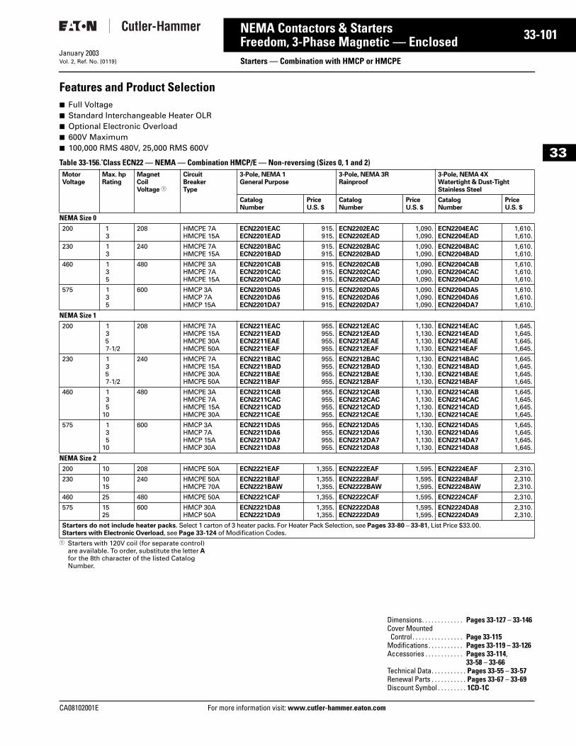
CA08102001E For more
01
33-1NEMA Contactors & StartersFreedom, 3-Phase Magnetic — Enclosed Starters — Combination with HMCP or HMCPEJanuary 2003Vol. 2, Ref. No. [0119]
33
Features and Product Selection■ Full Voltage■ Standard Interchangeable Heater OLR■ Optional Electronic Overload■ 600V Maximum■ 100,000 RMS 480V, 25,000 RMS 600V
Table 33-156. Class ECN22 — NEMA — Combination HMCP/E — Non-reversing (Sizes 0, 1 and 2)
1 Starters with 120V coil (for separate control) are available. To order, substitute the letter A for the 8th character of the listed Catalog Number.
MotorVoltage
Max. hpRating
MagnetCoilVoltage 1
CircuitBreakerType
3-Pole, NEMA 1General Purpose
3-Pole, NEMA 3RRainproof
3-Pole, NEMA 4X Watertight & Dust-Tight Stainless Steel
CatalogNumber
PriceU.S. $
CatalogNumber
PriceU.S. $
CatalogNumber
PriceU.S. $
NEMA Size 0200 1
3208 HMCPE 7A
HMCPE 15AECN2201EACECN2201EAD
915.915.
ECN2202EACECN2202EAD
1,090.1,090.
ECN2204EACECN2204EAD
1,610.1,610.
230 13
240 HMCPE 7AHMCPE 15A
ECN2201BACECN2201BAD
915.915.
ECN2202BACECN2202BAD
1,090.1,090.
ECN2204BACECN2204BAD
1,610.1,610.
460 135
480 HMCPE 3AHMCPE 7AHMCPE 15A
ECN2201CABECN2201CACECN2201CAD
915.915.915.
ECN2202CABECN2202CACECN2202CAD
1,090.1,090.1,090.
ECN2204CABECN2204CACECN2204CAD
1,610.1,610.1,610.
575 135
600 HMCP 3AHMCP 7AHMCP 15A
ECN2201DA5ECN2201DA6ECN2201DA7
915.915.915.
ECN2202DA5ECN2202DA6ECN2202DA7
1,090.1,090.1,090.
ECN2204DA5ECN2204DA6ECN2204DA7
1,610.1,610.1,610.
NEMA Size 1200 1
357-1/2
208 HMCPE 7AHMCPE 15AHMCPE 30AHMCPE 50A
ECN2211EACECN2211EADECN2211EAEECN2211EAF
955.955.955.955.
ECN2212EACECN2212EADECN2212EAEECN2212EAF
1,130.1,130.1,130.1,130.
ECN2214EACECN2214EADECN2214EAEECN2214EAF
1,645.1,645.1,645.1,645.
230 1357-1/2
240 HMCPE 7AHMCPE 15AHMCPE 30AHMCPE 50A
ECN2211BACECN2211BADECN2211BAEECN2211BAF
955.955.955.955.
ECN2212BACECN2212BADECN2212BAEECN2212BAF
1,130.1,130.1,130.1,130.
ECN2214BACECN2214BADECN2214BAEECN2214BAF
1,645.1,645.1,645.1,645.
460 135
10
480 HMCPE 3AHMCPE 7AHMCPE 15AHMCPE 30A
ECN2211CABECN2211CACECN2211CADECN2211CAE
955.955.955.955.
ECN2212CABECN2212CACECN2212CADECN2212CAE
1,130.1,130.1,130.1,130.
ECN2214CABECN2214CACECN2214CADECN2214CAE
1,645.1,645.1,645.1,645.
575 135
10
600 HMCP 3AHMCP 7AHMCP 15AHMCP 30A
ECN2211DA5ECN2211DA6ECN2211DA7ECN2211DA8
955.955.955.955.
ECN2212DA5ECN2212DA6ECN2212DA7ECN2212DA8
1,130.1,130.1,130.1,130.
ECN2214DA5ECN2214DA6ECN2214DA7ECN2214DA8
1,645.1,645.1,645.1,645.
NEMA Size 2200 10 208 HMCPE 50A ECN2221EAF 1,355. ECN2222EAF 1,595. ECN2224EAF 2,310.
230 1015
240 HMCPE 50AHMCPE 70A
ECN2221BAFECN2221BAW
1,355.1,355.
ECN2222BAFECN2222BAW
1,595.1,595.
ECN2224BAFECN2224BAW
2,310.2,310.
460 25 480 HMCPE 50A ECN2221CAF 1,355. ECN2222CAF 1,595. ECN2224CAF 2,310.
575 1525
600 HMCP 30AHMCP 50A
ECN2221DA8ECN2221DA9
1,355.1,355.
ECN2222DA8ECN2222DA9
1,595.1,595.
ECN2224DA8ECN2224DA9
2,310.2,310.
Starters do not include heater packs. Select 1 carton of 3 heater packs. For Heater Pack Selection, see Pages 33-80 – 33-81, List Price $33.00.Starters with Electronic Overload, see Page 33-124 of Modification Codes.
Dimensions. . . . . . . . . . . . . Pages 33-127 – 33-146Cover MountedControl . . . . . . . . . . . . . . . . Page 33-115
Modifications. . . . . . . . . . . Pages 33-119 – 33-126Accessories . . . . . . . . . . . . Pages 33-114,
33-58 – 33-66Technical Data. . . . . . . . . . . Pages 33-55 – 33-57Renewal Parts . . . . . . . . . . . Pages 33-67 – 33-69Discount Symbol . . . . . . . . . 1CD-1C
information visit: www.cutler-hammer.eaton.com
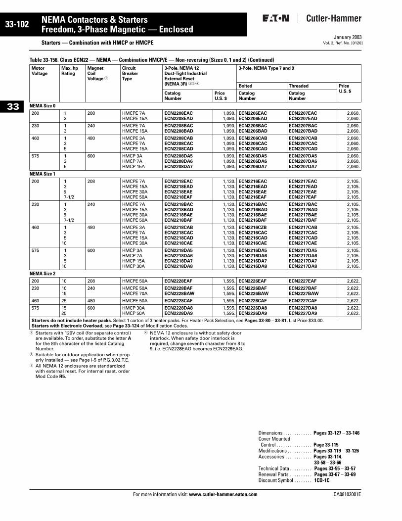
33-102
33
NEMA Contactors & StartersFreedom, 3-Phase Magnetic — Enclosed
Starters — Combination with HMCP or HMCPEFor more information visit: www.cutler-hammer.eaton.com
January 2003Vol. 2, Ref. No. [0120]
Table 33-156. Class ECN22 — NEMA — Combination HMCP/E — Non-reversing (Sizes 0, 1 and 2) (Continued)
1 Starters with 120V coil (for separate control) are available. To order, substitute the letter A for the 8th character of the listed Catalog Number.
2 Suitable for outdoor application when prop-erly installed — see Page i-5 of P.G.3.02.T.E.
3 All NEMA 12 enclosures are standardized with external reset. For internal reset, order Mod Code R5.
4 NEMA 12 enclosure is without safety door interlock. When safety door interlock is required, change seventh character from 8 to 9, i.e. ECN2228EAG becomes ECN2229EAG.
MotorVoltage
Max. hpRating
MagnetCoilVoltage 1
CircuitBreakerType
3-Pole, NEMA 12Dust-Tight IndustrialExternal Reset(NEMA 3R) 234
3-Pole, NEMA Type 7 and 9
Bolted Threaded PriceU.S. $Catalog
NumberPriceU.S. $
CatalogNumber
CatalogNumber
NEMA Size 0200 1
3208 HMCPE 7A
HMCPE 15AECN2208EACECN2208EAD
1,090.1,090.
ECN2206EACECN2206EAD
ECN2207EACECN2207EAD
2,060.2,060.
230 13
240 HMCPE 7AHMCPE 15A
ECN2208BACECN2208BAD
1,090.1,090.
ECN2206BACECN2206BAD
ECN2207BACECN2207BAD
2,060.2,060.
460 135
480 HMCPE 3AHMCPE 7AHMCPE 15A
ECN2208CABECN2208CACECN2208CAD
1,090.1,090.1,090.
ECN2206CABECN2206CACECN2206CAD
ECN2207CABECN2207CACECN2207CAD
2,060.2,060.2,060.
575 135
600 HMCP 3AHMCP 7AHMCP 15A
ECN2208DA5ECN2208DA6ECN2208DA7
1,090.1,090.1,090.
ECN2206DA5ECN2206DA6ECN2206DA7
ECN2207DA5ECN2207DA6ECN2207DA7
2,060.2,060.2,060.
NEMA Size 1200 1
357-1/2
208 HMCPE 7AHMCPE 15AHMCPE 30AHMCPE 50A
ECN2218EACECN2218EADECN2218EAEECN2218EAF
1,130.1,130.1,130.1,130.
ECN2216EACECN2216EADECN2216EAEECN2216EAF
ECN2217EACECN2217EADECN2217EAEECN2217EAF
2,105.2,105.2,105.2,105.
230 1357-1/2
240 HMCPE 7AHMCPE 15AHMCPE 30AHMCPE 50A
ECN2218BACECN2218BADECN2218BAEECN2218BAF
1,130.1,130.1,130.1,130.
ECN2216BACECN2216BADECN2216BAEECN2216BAF
ECN2217BACECN2217BADECN2217BAEECN2217BAF
2,105.2,105.2,105.2,105.
460 135
10
480 HMCPE 3AHMCPE 7AHMCPE 15AHMCPE 30A
ECN2218CABECN2218CACECN2218CADECN2218CAE
1,130.1,130.1,130.1,130.
ECN2216CZBECN2216CACECN2216CADECN2216CAE
ECN2217CABECN2217CACECN2217CADECN2217CAE
2,105.2,105.2,105.2,105.
575 135
10
600 HMCP 3AHMCP 7AHMCP 15AHMCP 30A
ECN2218DA5ECN2218DA6ECN2218DA7ECN2218DA8
1,130.1,130.1,130.1,130.
ECN2216DA5ECN2216DA6ECN2216DA7ECN2216DA8
ECN2217DA5ECN2217DA6ECN2217DA7ECN2217DA8
2,105.2,105.2,105.2,105.
NEMA Size 2200 10 208 HMCPE 50A ECN2228EAF 1,595. ECN2226EAF ECN2227EAF 2,622.
230 1015
240 HMCPE 50AHMCPE 70A
ECN2228BAFECN2228BAW
1,595.1,595.
ECN2226BAFECN2226BAW
ECN2227BAFECN2227BAW
2,622.2,622.
460 25 480 HMCPE 50A ECN2228CAF 1,595. ECN2226CAF ECN2227CAF 2,622.
575 1525
600 HMCP 30AHMCP 50A
ECN2228DA8ECN2228DA9
1,595.1,595.
ECN2226DA8ECN2226DA9
ECN2227DA8ECN2227DA9
2,622.2,622.
Starters do not include heater packs. Select 1 carton of 3 heater packs. For Heater Pack Selection, see Pages 33-80 – 33-81, List Price $33.00.Starters with Electronic Overload, see Page 33-124 of Modification Codes.
Dimensions . . . . . . . . . . . . . Pages 33-127 – 33-146Cover MountedControl . . . . . . . . . . . . . . . . Page 33-115
Modifications . . . . . . . . . . . Pages 33-119 – 33-126Accessories . . . . . . . . . . . . Pages 33-114,
33-58 – 33-66Technical Data . . . . . . . . . . Pages 33-55 – 33-57Renewal Parts . . . . . . . . . . Pages 33-67 – 33-69Discount Symbol . . . . . . . . 1CD-1C
CA08102001E
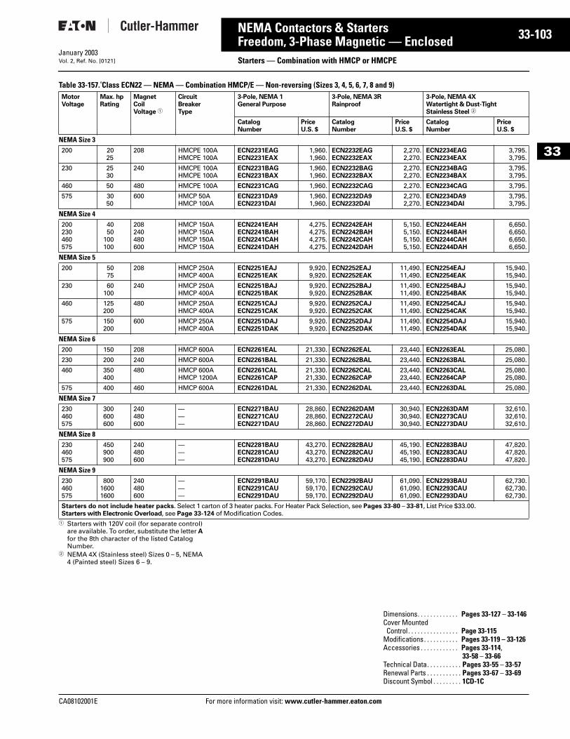
CA08102001E For more
03
33-1NEMA Contactors & StartersFreedom, 3-Phase Magnetic — Enclosed Starters — Combination with HMCP or HMCPEJanuary 2003Vol. 2, Ref. No. [0121]
33
Table 33-157. Class ECN22 — NEMA — Combination HMCP/E — Non-reversing (Sizes 3, 4, 5, 6, 7, 8 and 9)
1 Starters with 120V coil (for separate control) are available. To order, substitute the letter A for the 8th character of the listed Catalog Number.
2 NEMA 4X (Stainless steel) Sizes 0 – 5, NEMA 4 (Painted steel) Sizes 6 – 9.
MotorVoltage
Max. hpRating
MagnetCoilVoltage 1
CircuitBreakerType
3-Pole, NEMA 1General Purpose
3-Pole, NEMA 3RRainproof
3-Pole, NEMA 4X Watertight & Dust-TightStainless Steel 2
CatalogNumber
PriceU.S. $
CatalogNumber
PriceU.S. $
CatalogNumber
PriceU.S. $
NEMA Size 3200 20
25208 HMCPE 100A
HMCPE 100AECN2231EAGECN2231EAX
1,960.1,960.
ECN2232EAGECN2232EAX
2,270.2,270.
ECN2234EAGECN2234EAX
3,795.3,795.
230 2530
240 HMCPE 100AHMCPE 100A
ECN2231BAGECN2231BAX
1,960.1,960.
ECN2232BAGECN2232BAX
2,270.2,270.
ECN2234BAGECN2234BAX
3,795.3,795.
460 50 480 HMCPE 100A ECN2231CAG 1,960. ECN2232CAG 2,270. ECN2234CAG 3,795.
575 3050
600 HMCP 50AHMCP 100A
ECN2231DA9ECN2231DAI
1,960.1,960.
ECN2232DA9ECN2232DAI
2,270.2,270.
ECN2234DA9ECN2234DAI
3,795.3,795.
NEMA Size 4200230460575
4050
100100
208240480600
HMCP 150AHMCP 150AHMCP 150AHMCP 150A
ECN2241EAHECN2241BAHECN2241CAHECN2241DAH
4,275.4,275.4,275.4,275.
ECN2242EAHECN2242BAHECN2242CAHECN2242DAH
5,150.5,150.5,150.5,150.
ECN2244EAHECN2244BAHECN2244CAHECN2244DAH
6,650.6,650.6,650.6,650.
NEMA Size 5200 50
75208 HMCP 250A
HMCP 400AECN2251EAJECN2251EAK
9,920.9,920.
ECN2252EAJECN2252EAK
11,490.11,490.
ECN2254EAJECN2254EAK
15,940.15,940.
230 60100
240 HMCP 250AHMCP 400A
ECN2251BAJECN2251BAK
9,920.9,920.
ECN2252BAJECN2252BAK
11,490.11,490.
ECN2254BAJECN2254BAK
15,940.15,940.
460 125200
480 HMCP 250AHMCP 400A
ECN2251CAJECN2251CAK
9,920.9,920.
ECN2252CAJECN2252CAK
11,490.11,490.
ECN2254CAJECN2254CAK
15,940.15,940.
575 150200
600 HMCP 250AHMCP 400A
ECN2251DAJECN2251DAK
9,920.9,920.
ECN2252DAJECN2252DAK
11,490.11,490.
ECN2254DAJECN2254DAK
15,940.15,940.
NEMA Size 6200 150 208 HMCP 600A ECN2261EAL 21,330. ECN2262EAL 23,440. ECN2263EAL 25,080.
230 200 240 HMCP 600A ECN2261BAL 21,330. ECN2262BAL 23,440. ECN2263BAL 25,080.
460 350400
480 HMCP 600AHMCP 1200A
ECN2261CALECN2261CAP
21,330.21,330.
ECN2262CALECN2262CAP
23,440.23,440.
ECN2263CALECN2264CAP
25,080.25,080.
575 400 460 HMCP 600A ECN2261DAL 21,330. ECN2262DAL 23,440. ECN2263DAL 25,080.
NEMA Size 7230460575
300600600
240480600
———
ECN2271BAUECN2271CAUECN2271DAU
28,860.28,860.28,860.
ECN2262DAMECN2272CAUECN2272DAU
30,940.30,940.30,940.
ECN2263DAMECN2273CAUECN2273DAU
32,610.32,610.32,610.
NEMA Size 8230460575
450900900
240480600
———
ECN2281BAUECN2281CAUECN2281DAU
43,270.43,270.43,270.
ECN2282BAUECN2282CAUECN2282DAU
45,190.45,190.45,190.
ECN2283BAUECN2283CAUECN2283DAU
47,820.47,820.47,820.
NEMA Size 9230460575
80016001600
240480600
———
ECN2291BAUECN2291CAUECN2291DAU
59,170.59,170.59,170.
ECN2292BAUECN2292CAUECN2292DAU
61,090.61,090.61,090.
ECN2293BAUECN2293CAUECN2293DAU
62,730.62,730.62,730.
Starters do not include heater packs. Select 1 carton of 3 heater packs. For Heater Pack Selection, see Pages 33-80 – 33-81, List Price $33.00.Starters with Electronic Overload, see Page 33-124 of Modification Codes.
Dimensions. . . . . . . . . . . . . Pages 33-127 – 33-146Cover MountedControl . . . . . . . . . . . . . . . . Page 33-115
Modifications. . . . . . . . . . . Pages 33-119 – 33-126Accessories . . . . . . . . . . . . Pages 33-114,
33-58 – 33-66Technical Data. . . . . . . . . . . Pages 33-55 – 33-57Renewal Parts . . . . . . . . . . . Pages 33-67 – 33-69Discount Symbol . . . . . . . . . 1CD-1C
information visit: www.cutler-hammer.eaton.com
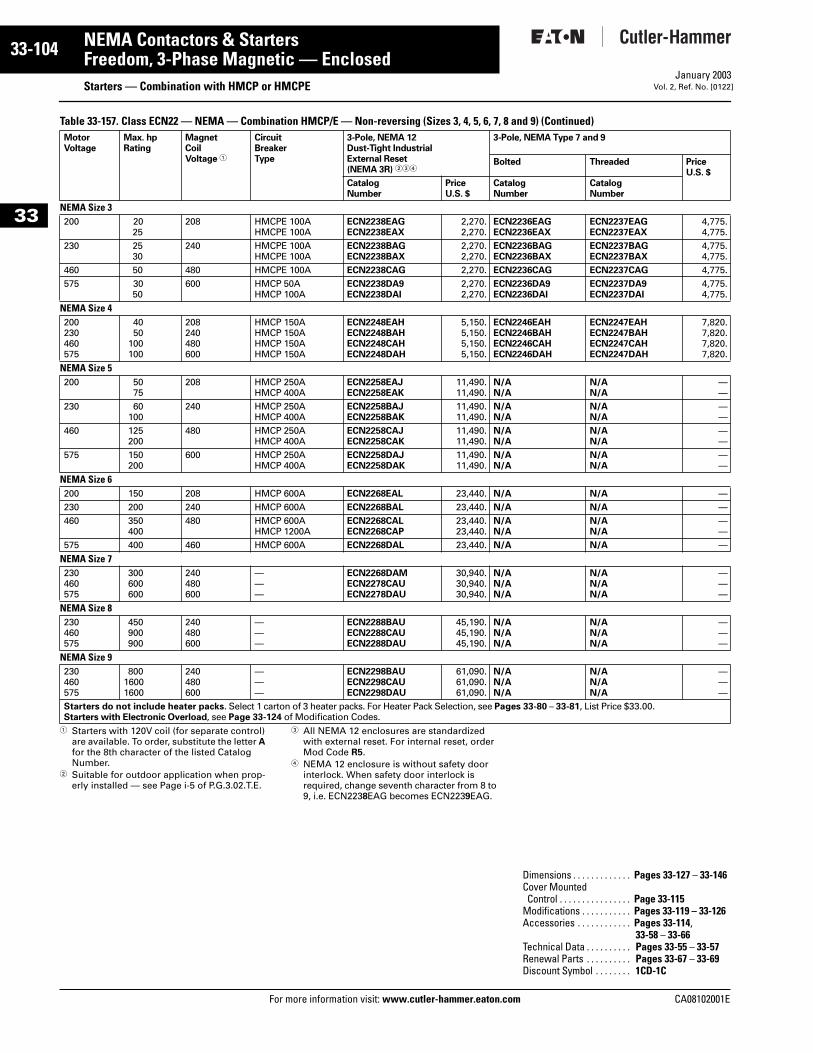
33-104
33
NEMA Contactors & StartersFreedom, 3-Phase Magnetic — Enclosed
Starters — Combination with HMCP or HMCPEFor more information visit: www.cutler-hammer.eaton.com
January 2003Vol. 2, Ref. No. [0122]
Table 33-157. Class ECN22 — NEMA — Combination HMCP/E — Non-reversing (Sizes 3, 4, 5, 6, 7, 8 and 9) (Continued)
1 Starters with 120V coil (for separate control) are available. To order, substitute the letter A for the 8th character of the listed Catalog Number.
2 Suitable for outdoor application when prop-erly installed — see Page i-5 of P.G.3.02.T.E.
3 All NEMA 12 enclosures are standardized with external reset. For internal reset, order Mod Code R5.
4 NEMA 12 enclosure is without safety door interlock. When safety door interlock is required, change seventh character from 8 to 9, i.e. ECN2238EAG becomes ECN2239EAG.
MotorVoltage
Max. hpRating
MagnetCoilVoltage 1
CircuitBreakerType
3-Pole, NEMA 12Dust-Tight IndustrialExternal Reset(NEMA 3R) 234
3-Pole, NEMA Type 7 and 9
Bolted Threaded PriceU.S. $
CatalogNumber
PriceU.S. $
CatalogNumber
CatalogNumber
NEMA Size 3200 20
25208 HMCPE 100A
HMCPE 100AECN2238EAGECN2238EAX
2,270.2,270.
ECN2236EAGECN2236EAX
ECN2237EAGECN2237EAX
4,775.4,775.
230 2530
240 HMCPE 100AHMCPE 100A
ECN2238BAGECN2238BAX
2,270.2,270.
ECN2236BAGECN2236BAX
ECN2237BAGECN2237BAX
4,775.4,775.
460 50 480 HMCPE 100A ECN2238CAG 2,270. ECN2236CAG ECN2237CAG 4,775.575 30
50600 HMCP 50A
HMCP 100AECN2238DA9ECN2238DAI
2,270.2,270.
ECN2236DA9ECN2236DAI
ECN2237DA9ECN2237DAI
4,775.4,775.
NEMA Size 4200230460575
4050
100100
208240480600
HMCP 150AHMCP 150AHMCP 150AHMCP 150A
ECN2248EAHECN2248BAHECN2248CAHECN2248DAH
5,150.5,150.5,150.5,150.
ECN2246EAHECN2246BAHECN2246CAHECN2246DAH
ECN2247EAHECN2247BAHECN2247CAHECN2247DAH
7,820.7,820.7,820.7,820.
NEMA Size 5200 50
75208 HMCP 250A
HMCP 400AECN2258EAJECN2258EAK
11,490.11,490.
N/AN/A
N/AN/A
——
230 60100
240 HMCP 250AHMCP 400A
ECN2258BAJECN2258BAK
11,490.11,490.
N/AN/A
N/AN/A
——
460 125200
480 HMCP 250AHMCP 400A
ECN2258CAJECN2258CAK
11,490.11,490.
N/AN/A
N/AN/A
——
575 150200
600 HMCP 250AHMCP 400A
ECN2258DAJECN2258DAK
11,490.11,490.
N/AN/A
N/AN/A
——
NEMA Size 6200 150 208 HMCP 600A ECN2268EAL 23,440. N/A N/A —230 200 240 HMCP 600A ECN2268BAL 23,440. N/A N/A —460 350
400480 HMCP 600A
HMCP 1200AECN2268CALECN2268CAP
23,440.23,440.
N/AN/A
N/AN/A
——
575 400 460 HMCP 600A ECN2268DAL 23,440. N/A N/A —
NEMA Size 7230460575
300600600
240480600
———
ECN2268DAMECN2278CAUECN2278DAU
30,940.30,940.30,940.
N/AN/AN/A
N/AN/AN/A
———
NEMA Size 8230460575
450900900
240480600
———
ECN2288BAUECN2288CAUECN2288DAU
45,190.45,190.45,190.
N/AN/AN/A
N/AN/AN/A
———
NEMA Size 9230460575
80016001600
240480600
———
ECN2298BAUECN2298CAUECN2298DAU
61,090.61,090.61,090.
N/AN/AN/A
N/AN/AN/A
———
Starters do not include heater packs. Select 1 carton of 3 heater packs. For Heater Pack Selection, see Pages 33-80 – 33-81, List Price $33.00.Starters with Electronic Overload, see Page 33-124 of Modification Codes.
Dimensions . . . . . . . . . . . . . Pages 33-127 – 33-146Cover MountedControl . . . . . . . . . . . . . . . . Page 33-115
Modifications . . . . . . . . . . . Pages 33-119 – 33-126Accessories . . . . . . . . . . . . Pages 33-114,
33-58 – 33-66Technical Data . . . . . . . . . . Pages 33-55 – 33-57Renewal Parts . . . . . . . . . . Pages 33-67 – 33-69Discount Symbol . . . . . . . . 1CD-1C
CA08102001E
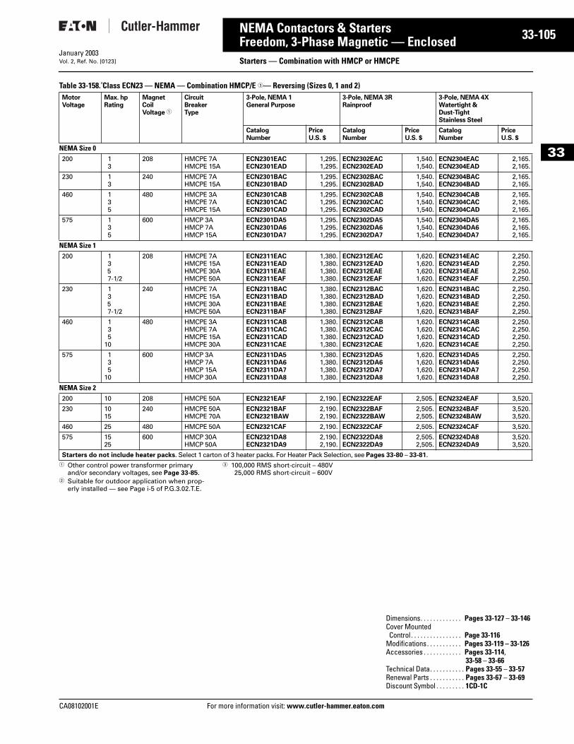
CA08102001E For more
05
33-1NEMA Contactors & StartersFreedom, 3-Phase Magnetic — Enclosed Starters — Combination with HMCP or HMCPEJanuary 2003Vol. 2, Ref. No. [0123]
33
Table 33-158. Class ECN23 — NEMA — Combination HMCP/E 3— Reversing (Sizes 0, 1 and 2)
1 Other control power transformer primary and/or secondary voltages, see Page 33-85.
2 Suitable for outdoor application when prop-erly installed — see Page i-5 of P.G.3.02.T.E.
3 100,000 RMS short-circuit – 480V25,000 RMS short-circuit – 600V
MotorVoltage
Max. hpRating
MagnetCoilVoltage 1
CircuitBreakerType
3-Pole, NEMA 1General Purpose
3-Pole, NEMA 3RRainproof
3-Pole, NEMA 4X Watertight &Dust-TightStainless Steel
CatalogNumber
PriceU.S. $
CatalogNumber
PriceU.S. $
CatalogNumber
PriceU.S. $
NEMA Size 0200 1
3208 HMCPE 7A
HMCPE 15AECN2301EACECN2301EAD
1,295.1,295.
ECN2302EACECN2302EAD
1,540.1,540.
ECN2304EACECN2304EAD
2,165.2,165.
230 13
240 HMCPE 7AHMCPE 15A
ECN2301BACECN2301BAD
1,295.1,295.
ECN2302BACECN2302BAD
1,540.1,540.
ECN2304BACECN2304BAD
2,165.2,165.
460 135
480 HMCPE 3AHMCPE 7AHMCPE 15A
ECN2301CABECN2301CACECN2301CAD
1,295.1,295.1,295.
ECN2302CABECN2302CACECN2302CAD
1,540.1,540.1,540.
ECN2304CABECN2304CACECN2304CAD
2,165.2,165.2,165.
575 135
600 HMCP 3AHMCP 7AHMCP 15A
ECN2301DA5ECN2301DA6ECN2301DA7
1,295.1,295.1,295.
ECN2302DA5ECN2302DA6ECN2302DA7
1,540.1,540.1,540.
ECN2304DA5ECN2304DA6ECN2304DA7
2,165.2,165.2,165.
NEMA Size 1200 1
357-1/2
208 HMCPE 7AHMCPE 15AHMCPE 30AHMCPE 50A
ECN2311EACECN2311EADECN2311EAEECN2311EAF
1,380.1,380.1,380.1,380.
ECN2312EACECN2312EADECN2312EAEECN2312EAF
1,620.1,620.1,620.1,620.
ECN2314EACECN2314EADECN2314EAEECN2314EAF
2,250.2,250.2,250.2,250.
230 1357-1/2
240 HMCPE 7AHMCPE 15AHMCPE 30AHMCPE 50A
ECN2311BACECN2311BADECN2311BAEECN2311BAF
1,380.1,380.1,380.1,380.
ECN2312BACECN2312BADECN2312BAEECN2312BAF
1,620.1,620.1,620.1,620.
ECN2314BACECN2314BADECN2314BAEECN2314BAF
2,250.2,250.2,250.2,250.
460 135
10
480 HMCPE 3AHMCPE 7AHMCPE 15AHMCPE 30A
ECN2311CABECN2311CACECN2311CADECN2311CAE
1,380.1,380.1,380.1,380.
ECN2312CABECN2312CACECN2312CADECN2312CAE
1,620.1,620.1,620.1,620.
ECN2314CABECN2314CACECN2314CADECN2314CAE
2,250.2,250.2,250.2,250.
575 135
10
600 HMCP 3AHMCP 7AHMCP 15AHMCP 30A
ECN2311DA5ECN2311DA6ECN2311DA7ECN2311DA8
1,380.1,380.1,380.1,380.
ECN2312DA5ECN2312DA6ECN2312DA7ECN2312DA8
1,620.1,620.1,620.1,620.
ECN2314DA5ECN2314DA6ECN2314DA7ECN2314DA8
2,250.2,250.2,250.2,250.
NEMA Size 2200 10 208 HMCPE 50A ECN2321EAF 2,190. ECN2322EAF 2,505. ECN2324EAF 3,520.
230 1015
240 HMCPE 50AHMCPE 70A
ECN2321BAFECN2321BAW
2,190.2,190.
ECN2322BAFECN2322BAW
2,505.2,505.
ECN2324BAFECN2324BAW
3,520.3,520.
460 25 480 HMCPE 50A ECN2321CAF 2,190. ECN2322CAF 2,505. ECN2324CAF 3,520.
575 1525
600 HMCP 30AHMCP 50A
ECN2321DA8ECN2321DA9
2,190.2,190.
ECN2322DA8ECN2322DA9
2,505.2,505.
ECN2324DA8ECN2324DA9
3,520.3,520.
Starters do not include heater packs. Select 1 carton of 3 heater packs. For Heater Pack Selection, see Pages 33-80 – 33-81.
Dimensions. . . . . . . . . . . . . Pages 33-127 – 33-146Cover MountedControl . . . . . . . . . . . . . . . . Page 33-116
Modifications. . . . . . . . . . . Pages 33-119 – 33-126Accessories . . . . . . . . . . . . Pages 33-114,
33-58 – 33-66Technical Data. . . . . . . . . . . Pages 33-55 – 33-57Renewal Parts . . . . . . . . . . . Pages 33-67 – 33-69Discount Symbol . . . . . . . . . 1CD-1C
information visit: www.cutler-hammer.eaton.com

33-106
33
NEMA Contactors & StartersFreedom, 3-Phase Magnetic — Enclosed
Starters — Combination with HMCP or HMCPEFor more information visit: www.cutler-hammer.eaton.com
January 2003Vol. 2, Ref. No. [0124]
Table 33-158. Class ECN23 — NEMA — Combination HMCP/E 3— Reversing (Sizes 0, 1 and 2) (Continued)
1 Other control power transformer primary and/or secondary voltages, see Page 33-85.
2 Suitable for outdoor application when prop-erly installed — see Page i-5 of P.G.3.02.T.E.
3 All NEMA 12 enclosures are standardized with external reset. For internal reset, order Mod Code R5.
4 NEMA 12 enclosure is without safety door interlock. When safety door interlock is required, change seventh character from 8 to 9, i.e. ECN2328EAG becomes ECN2329EAG.
5 100,000 RMS short-circuit – 480V25,000 RMS short-circuit – 600V
MotorVoltage
Max. hpRating
MagnetCoilVoltage 1
CircuitBreakerType
3-Pole, NEMA 12Dust-Tight IndustrialExternal Reset(NEMA 3R) 234
3-Pole NEMA Type 7 and 9
Bolted Threaded PriceU.S. $Catalog
NumberPriceU.S. $
CatalogNumber
CatalogNumber
NEMA Size 0200 1
3208 HMCPE 7A
HMCPE 15AECN2308EACECN2308EAD
1,540.1,540.
ECN2306EACECN2306EAD
ECN2307EACECN2307EAD
2,575.2,575.
230 13
240 HMCPE 7AHMCPE 15A
ECN2308BACECN2308BAD
1,540.1,540.
ECN2306BACECN2306BAD
ECN2307BACECN2307BAD
2,575.2,575.
460 135
480 HMCPE 3AHMCPE 7AHMCPE 15A
ECN2308CABECN2308CACECN2308CAD
1,540.1,540.1,540.
ECN2306CABECN2306CACECN2306CAD
ECN2307CABECN2307CACECN2307CAD
2,575.2,575.2,575.
575 135
600 HMCP 3AHMCP 7AHMCP 15A
ECN2308DA5ECN2308DA6ECN2308DA7
1,540.1,540.1,540.
ECN2306DA5ECN2306DA6ECN2306DA7
ECN2307DA5ECN2307DA6ECN2307DA7
2,575.2,575.2,575.
NEMA Size 1200 1
357-1/2
208 HMCPE 7AHMCPE 15AHMCPE 30AHMCPE 50A
ECN2318EACECN2318EADECN2318EAEECN2318EAF
1,620.1,620.1,620.1,620.
ECN2316EACECN2316EADECN2316EAEECN2316EAF
ECN2317EACECN2317EADECN2317EAEECN2317EAF
2,645.2,645.2,645.2,645.
230 1357-1/2
240 HMCPE 7AHMCPE 15AHMCPE 30AHMCPE 50A
ECN2318BACECN2318BADECN2318BAEECN2318BAF
1,620.1,620.1,620.1,620.
ECN2316BACECN2316BADECN2316BAEECN2316BAF
ECN2317BACECN2317BADECN2317BAEECN2317BAF
2,645.2,645.2,645.2,645.
460 135
10
480 HMCPE 3AHMCPE 7AHMCPE 15AHMCPE 30A
ECN2318CABECN2318CACECN2318CADECN2318CAE
1,620.1,620.1,620.1,620.
ECN2316CABECN2316CACECN2316CADECN2316CAE
ECN2317CABECN2317CACECN2317CADECN2317CAE
2,645.2,645.2,645.2,645.
575 135
10
600 HMCP 3AHMCP 7AHMCP 15AHMCP 30A
ECN2318DA5ECN2318DA6ECN2318DA7ECN2318DA8
1,620.1,620.1,620.1,620.
ECN2316DA5ECN2316DA6ECN2316DA7ECN2316DA8
ECN2317DA5ECN2317DA6ECN2317DA7ECN2317DA8
2,645.2,645.2,645.2,645.
NEMA Size 2200 10 208 HMCPE 50A ECN2328EAF 2,505. ECN2326EAF ECN2327EAF 3,925.
230 1015
240 HMCPE 50AHMCPE 70A
ECN2328BAFECN2328BAW
2,505.2,505.
ECN2326BAFECN2326BAW
ECN2327BAFECN2327BAW
3,925.3,925.
460 25 480 HMCPE 50A ECN2328CAF 2,505. ECN2326CAF ECN2327CAF 3,925.
575 1525
600 HMCP 30AHMCP 50A
ECN2328DA8ECN2328DA9
2,505.2,505.
ECN2326DA8ECN2326DA9
ECN2327DA8ECN2327DA9
3,925.3,925.
Starters do not include heater packs. Select 1 carton of 3 heater packs. For Heater Pack Selection, see Pages 33-80 – 33-81.
Dimensions . . . . . . . . . . . . . Pages 33-127 – 33-146Cover MountedControl . . . . . . . . . . . . . . . . Page 33-116
Modifications . . . . . . . . . . . Pages 33-119 – 33-126Accessories . . . . . . . . . . . . Pages 33-114,
33-58 – 33-66Technical Data . . . . . . . . . . Pages 33-55 – 33-57Renewal Parts . . . . . . . . . . Pages 33-67 – 33-69Discount Symbol . . . . . . . . 1CD-1C
CA08102001E
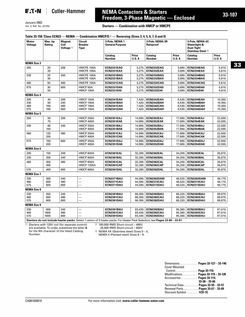
CA08102001E For more
07
33-1NEMA Contactors & StartersFreedom, 3-Phase Magnetic — Enclosed Starters — Combination with HMCP or HMCPEJanuary 2003Vol. 2, Ref. No. [0125]
33
Table 33-159. Class ECN23 — NEMA — Combination HMCP/E2 — Reversing (Sizes 3, 4, 5, 6, 7, 8 and 9)
1 Starters with 120V coil (for separate control) are available. To order, substitute the letter A for the 8th character of the listed Catalog Number.
2 100,000 RMS Short-circuit – 480V25,000 RMS Short-circuit – 600V
3 NEMA 4X (Stainless steel) Sizes 0 – 5, NEMA 4 (Painted steel) Sizes 6 – 9.
MotorVoltage
Max. hpRating
MagnetCoilVoltage 1
CircuitBreakerType
3-Pole, NEMA 1General Purpose
3-Pole, NEMA 3RRainproof
3-Pole, NEMA 4X Watertight &Dust-TightStainless Steel 3
CatalogNumber
PriceU.S. $
CatalogNumber
PriceU.S. $
CatalogNumber
PriceU.S. $
NEMA Size 3200 20
25208 HMCPE 100A
HMCPE 100AECN2331EAGECN2331EAX
3,275.3,275.
ECN2332EAGECN2332EAX
3,690.3,690.
ECN2334EAGECN2334EAX
5,610.5,610.
230 2530
240 HMCPE 100AHMCPE 100A
ECN2331BAGECN2331BAX
3,275.3,275.
ECN2332BAGECN2332BAX
3,690.3,690.
ECN2334BAGECN2334BAX
5,610.5,610.
460 50 480 HMCPE 100A ECN2331CAG 3,275. ECN2332CAG 3,690. ECN2334CAG 5,610.
575 3050
600 HMCP 50AHMCP 100A
ECN2331DA9ECN2331DAI
3,275.3,275.
ECN2332DA9ECN2332DAI
3,690.3,690.
ECN2334DA9ECN2334DAI
5,610.5,610.
NEMA Size 4200230460575
4050
100100
208240480600
HMCP 150AHMCP 150AHMCP 150AHMCP 150A
ECN2341EAHECN2341BAHECN2341CAHECN2341DAH
7,420.7,420.7,420.7,420.
ECN2342EAHECN2342BAHECN2342CAHECN2342DAH
8,530.8,530.8,530.8,530.
ECN2344EAHECN2344BAHECN2344CAHECN2344DAH
10,350.10,350.10,350.10,350.
NEMA Size 5200 50
75208 HMCP 250A
HMCP 400AECN2351EAJECN2351EAK
14,980.14,980.
ECN2352EAJECN2352EAK
17,680.17,680.
ECN2354EAJECN2354EAK
22,500.22,500.
230 60100
240 HMCP 250AHMCP 400A
ECN2351BAJECN2351BAK
14,980.14,980.
ECN2352BAJECN2352BAK
17,680.17,680.
ECN2354BAJECN2354BAK
22,500.22,500.
460 125200
480 HMCP 250AHMCP 400A
ECN2351CAJECN2351CAK
14,980.14,980.
ECN2352CAJECN2352CAK
17,680.17,680.
ECN2354CAJECN2354CAK
22,500.22,500.
575 150200
600 HMCP 250AHMCP 400A
ECN2351DAJECN2351DAK
14,980.14,980.
ECN2352DAJECN2352DAK
17,680.17,680.
ECN2354DAJECN2354DAK
22,500.22,500.
NEMA Size 6200 150 208 HMCP 600A ECN2361EAL 32,280. ECN2362EAL 34,200. ECN2363EAL 35,870.
230 200 240 HMCP 600A ECN2361BAL 32,280. ECN2362BAL 34,200. ECN2363BAL 35,870.
460 350400
480 HMCP 600AHMCP 1200A
ECN2361CALECN2361CAP
32,280.32,280.
ECN2362CALECN2362CAP
34,200.34,200.
ECN2363CALECN2364CAP
35,870.35,870.
575 400 600 HMCP 600A ECN2361DAL 32,280. ECN2362DAL 34,200. ECN2363DAL 35,870.
NEMA Size 7230460575
300600600
240480600
———
ECN2371BAUECN2371CAUECN2371DAU
44,590.44,590.44,590.
ECN2362DAMECN2372CAUECN2372DAU
46,520.46,520.46,520.
ECN2363DAMECN2373CAUECN2373DAU
48,170.48,170.48,170.
NEMA Size 8230460575
450900900
240480600
———
ECN2381BAUECN2381CAUECN2381DAU
66,300.66,300.66,300.
ECN2382BAUECN2382CAUECN2382DAU
68,220.68,220.68,220.
ECN2383BAUECN2383CAUECN2383DAU
69,870.69,870.69,870.
NEMA Size 9230460575
80016001600
240480600
———
ECN2391BAUECN2391CAUECN2391DAU
93,430.93,430.93,430.
ECN2392BAUECN2392CAUECN2392DAU
95,360.95,360.95,360.
ECN2393BAUECN2393CAUECN2393DAU
97,010.97,010.97,010.
Starters do not include heater packs. Select 1 carton of 3 heater packs. For Heater Pack Selection, see Pages 33-80 – 33-81.
Dimensions. . . . . . . . . . . . . Pages 33-127 – 33-146Cover MountedControl . . . . . . . . . . . . . . . . Page 33-116
Modifications. . . . . . . . . . . Pages 33-119 – 33-126Accessories . . . . . . . . . . . . Pages 33-114,
33-58 – 33-66Technical Data. . . . . . . . . . . Pages 33-55 – 33-57Renewal Parts . . . . . . . . . . . Pages 33-67 – 33-69Discount Symbol . . . . . . . . . 1CD-1C
information visit: www.cutler-hammer.eaton.com
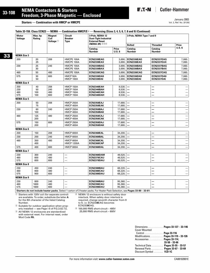
33-108
33
NEMA Contactors & StartersFreedom, 3-Phase Magnetic — Enclosed
Starters — Combination with HMCP or HMCPEFor more information visit: www.cutler-hammer.eaton.com
January 2003Vol. 2, Ref. No. [0126]
Table 33-159. Class ECN23 — NEMA — Combination HMCP/E5 — Reversing (Sizes 3, 4, 5, 6, 7, 8 and 9) (Continued)
1 Starters with 120V coil (for separate control) are available. To order, substitute the letter A for the 8th character of the listed Catalog Number.
2 Suitable for outdoor application when prop-erly installed — see Page i-5 of P.G.3.02.T.E.
3 All NEMA 12 enclosures are standardized with external reset. For internal reset, order Mod Code R5.
4 NEMA 12 enclosure is without safety door interlock. When safety door interlock is required, change seventh character from 8 to 9, i.e. ECN2338EAG becomes ECN2339EAG.
5 100,000 RMS short-circuit – 480V25,000 RMS short-circuit – 600V
MotorVoltage
Max. hpRating
MagnetCoilVoltage 1
CircuitBreakerType
3-Pole, NEMA 12Dust-Tight IndustrialExternal Reset(NEMA 3R) 234
3-Pole, NEMA Type 7 and 9
Bolted Threaded PriceU.S. $Catalog
NumberPriceU.S. $
CatalogNumber
CatalogNumber
NEMA Size 3200 20
25208 HMCPE 100A
HMCPE 100AECN2338EAGECN2338EAX
3,690.3,690.
ECN2336EAGECN2336EAX
ECN2337EAGECN2337EAX
7,060.7,060.
230 2530
240 HMCPE 100AHMCPE 100A
ECN2338BAGECN2338BAX
3,690.3,690.
ECN2336BAGECN2336BAX
ECN2337BAGECN2337BAX
7,060.7,060.
460 50 480 HMCPE 100A ECN2338CAG 3,690. ECN2336CAG ECN2337CAG 7,060.
575 3050
600 HMCP 50AHMCP 100A
ECN2338DA9ECN2338DAI
3,690.3,690.
ECN2336DA9ECN2336DAI
ECN2337DA9ECN2337DAI
7,060.7,060.
NEMA Size 4200230460575
4050
100100
208240480600
HMCP 150AHMCP 150AHMCP 150AHMCP 150A
ECN2348EAHECN2348BAHECN2348CAHECN2348DAH
8,530.8,530.8,530.8,530.
————
————
————
NEMA Size 5200 50
75208 HMCP 250A
HMCP 400AECN2358EAJECN2358EAK
17,680.17,680.
——
——
——
230 60100
240 HMCP 250AHMCP 400A
ECN2358BAJECN2358BAK
17,680.17,680.
——
——
——
460 125200
480 HMCP 250AHMCP 400A
ECN2358CAJECN2358CAK
17,680.17,680.
——
——
——
575 150200
600 HMCP 250AHMCP 400A
ECN2358DAJECN2358DAK
17,680.17,680.
——
——
——
NEMA Size 6200 150 208 HMCP 600A ECN2368EAL 34,200. — — —
230 200 240 HMCP 600A ECN2368BAL 34,200. — — —
460 350400
480 HMCP 600AHMCP 1200A
ECN2368CALECN2368CAP
34,200.34,200.
——
——
——
575 400 600 HMCP 600A ECN2368DAL 34,200. — — —
NEMA Size 7230460575
300600600
240480600
———
ECN2368DAMECN2378CAUECN2378DAU
46,520.46,520.46,520.
———
———
———
NEMA Size 8230460575
450900900
240480600
———
ECN2388BAUECN2388CAUECN2388DAU
68,220.68,220.68,220.
———
———
———
NEMA Size 9230460575
80016001600
240480600
———
ECN2398BAUECN2398CAUECN2398DAU
95,360.95,360.95,360.
———
———
———
Starters do not include heater packs. Select 1 carton of 3 heater packs. For Heater Pack Selection, see Pages 33-80 – 33-81.
Dimensions . . . . . . . . . . . . . Pages 33-127 – 33-146Cover MountedControl . . . . . . . . . . . . . . . . Page 33-116
Modifications . . . . . . . . . . . Pages 33-119 – 33-126Accessories . . . . . . . . . . . . Pages 33-114,
33-58 – 33-66Technical Data . . . . . . . . . . Pages 33-55 – 33-57Renewal Parts . . . . . . . . . . Pages 33-67 – 33-69Discount Symbol . . . . . . . . 1CD-1C
CA08102001E
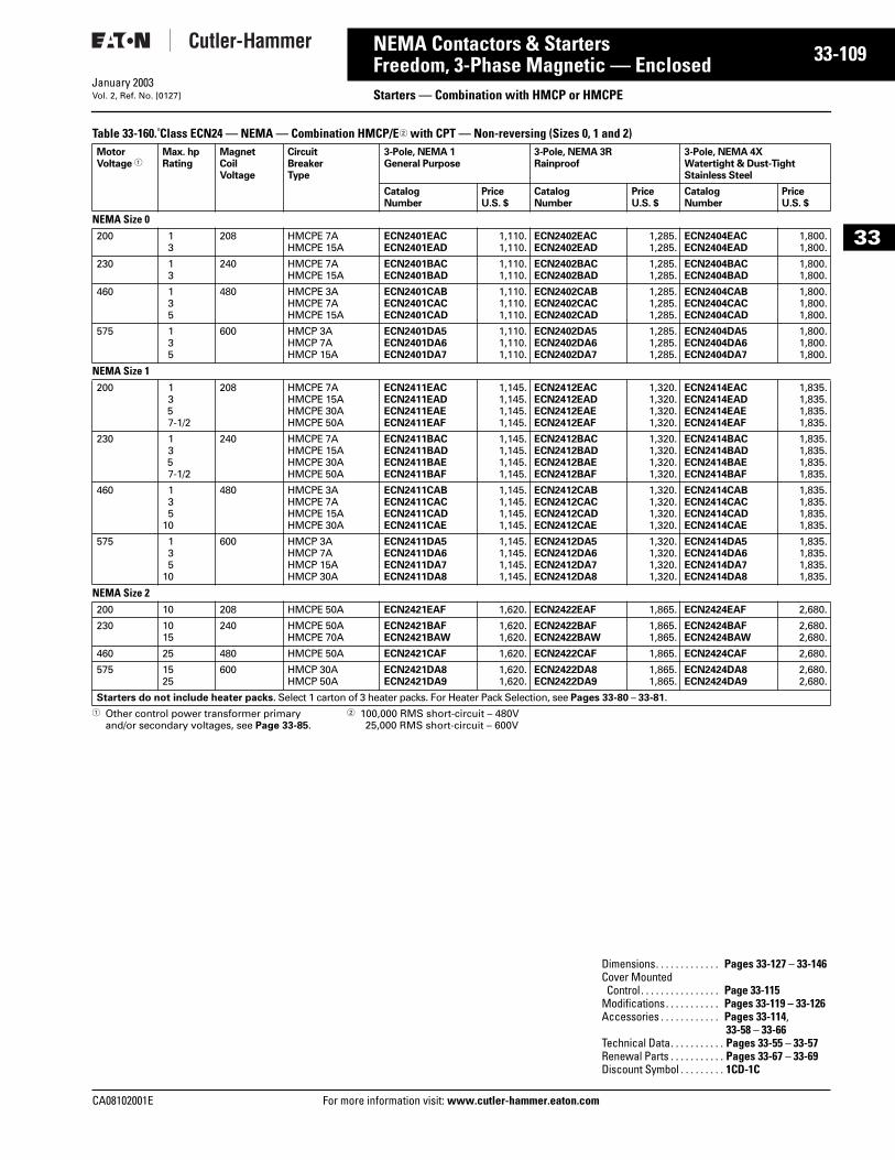
CA08102001E For more
09
33-1NEMA Contactors & StartersFreedom, 3-Phase Magnetic — Enclosed Starters — Combination with HMCP or HMCPEJanuary 2003Vol. 2, Ref. No. [0127]
33
Table 33-160. Class ECN24 — NEMA — Combination HMCP/E2 with CPT — Non-reversing (Sizes 0, 1 and 2)
1 Other control power transformer primary and/or secondary voltages, see Page 33-85.
2 100,000 RMS short-circuit – 480V25,000 RMS short-circuit – 600V
MotorVoltage 1
Max. hpRating
MagnetCoilVoltage
CircuitBreakerType
3-Pole, NEMA 1General Purpose
3-Pole, NEMA 3RRainproof
3-Pole, NEMA 4X Watertight & Dust-TightStainless Steel
CatalogNumber
PriceU.S. $
CatalogNumber
PriceU.S. $
CatalogNumber
PriceU.S. $
NEMA Size 0200 1
3208 HMCPE 7A
HMCPE 15AECN2401EACECN2401EAD
1,110.1,110.
ECN2402EACECN2402EAD
1,285.1,285.
ECN2404EACECN2404EAD
1,800.1,800.
230 13
240 HMCPE 7AHMCPE 15A
ECN2401BACECN2401BAD
1,110.1,110.
ECN2402BACECN2402BAD
1,285.1,285.
ECN2404BACECN2404BAD
1,800.1,800.
460 135
480 HMCPE 3AHMCPE 7AHMCPE 15A
ECN2401CABECN2401CACECN2401CAD
1,110.1,110.1,110.
ECN2402CABECN2402CACECN2402CAD
1,285.1,285.1,285.
ECN2404CABECN2404CACECN2404CAD
1,800.1,800.1,800.
575 135
600 HMCP 3AHMCP 7AHMCP 15A
ECN2401DA5ECN2401DA6ECN2401DA7
1,110.1,110.1,110.
ECN2402DA5ECN2402DA6ECN2402DA7
1,285.1,285.1,285.
ECN2404DA5ECN2404DA6ECN2404DA7
1,800.1,800.1,800.
NEMA Size 1200 1
357-1/2
208 HMCPE 7AHMCPE 15AHMCPE 30AHMCPE 50A
ECN2411EACECN2411EADECN2411EAEECN2411EAF
1,145.1,145.1,145.1,145.
ECN2412EACECN2412EADECN2412EAEECN2412EAF
1,320.1,320.1,320.1,320.
ECN2414EACECN2414EADECN2414EAEECN2414EAF
1,835.1,835.1,835.1,835.
230 1357-1/2
240 HMCPE 7AHMCPE 15AHMCPE 30AHMCPE 50A
ECN2411BACECN2411BADECN2411BAEECN2411BAF
1,145.1,145.1,145.1,145.
ECN2412BACECN2412BADECN2412BAEECN2412BAF
1,320.1,320.1,320.1,320.
ECN2414BACECN2414BADECN2414BAEECN2414BAF
1,835.1,835.1,835.1,835.
460 135
10
480 HMCPE 3AHMCPE 7AHMCPE 15AHMCPE 30A
ECN2411CABECN2411CACECN2411CADECN2411CAE
1,145.1,145.1,145.1,145.
ECN2412CABECN2412CACECN2412CADECN2412CAE
1,320.1,320.1,320.1,320.
ECN2414CABECN2414CACECN2414CADECN2414CAE
1,835.1,835.1,835.1,835.
575 135
10
600 HMCP 3AHMCP 7AHMCP 15AHMCP 30A
ECN2411DA5ECN2411DA6ECN2411DA7ECN2411DA8
1,145.1,145.1,145.1,145.
ECN2412DA5ECN2412DA6ECN2412DA7ECN2412DA8
1,320.1,320.1,320.1,320.
ECN2414DA5ECN2414DA6ECN2414DA7ECN2414DA8
1,835.1,835.1,835.1,835.
NEMA Size 2200 10 208 HMCPE 50A ECN2421EAF 1,620. ECN2422EAF 1,865. ECN2424EAF 2,680.
230 1015
240 HMCPE 50AHMCPE 70A
ECN2421BAFECN2421BAW
1,620.1,620.
ECN2422BAFECN2422BAW
1,865.1,865.
ECN2424BAFECN2424BAW
2,680.2,680.
460 25 480 HMCPE 50A ECN2421CAF 1,620. ECN2422CAF 1,865. ECN2424CAF 2,680.
575 1525
600 HMCP 30AHMCP 50A
ECN2421DA8ECN2421DA9
1,620.1,620.
ECN2422DA8ECN2422DA9
1,865.1,865.
ECN2424DA8ECN2424DA9
2,680.2,680.
Starters do not include heater packs. Select 1 carton of 3 heater packs. For Heater Pack Selection, see Pages 33-80 – 33-81.
Dimensions. . . . . . . . . . . . . Pages 33-127 – 33-146Cover MountedControl . . . . . . . . . . . . . . . . Page 33-115
Modifications. . . . . . . . . . . Pages 33-119 – 33-126Accessories . . . . . . . . . . . . Pages 33-114,
33-58 – 33-66Technical Data. . . . . . . . . . . Pages 33-55 – 33-57Renewal Parts . . . . . . . . . . . Pages 33-67 – 33-69Discount Symbol . . . . . . . . . 1CD-1C
information visit: www.cutler-hammer.eaton.com
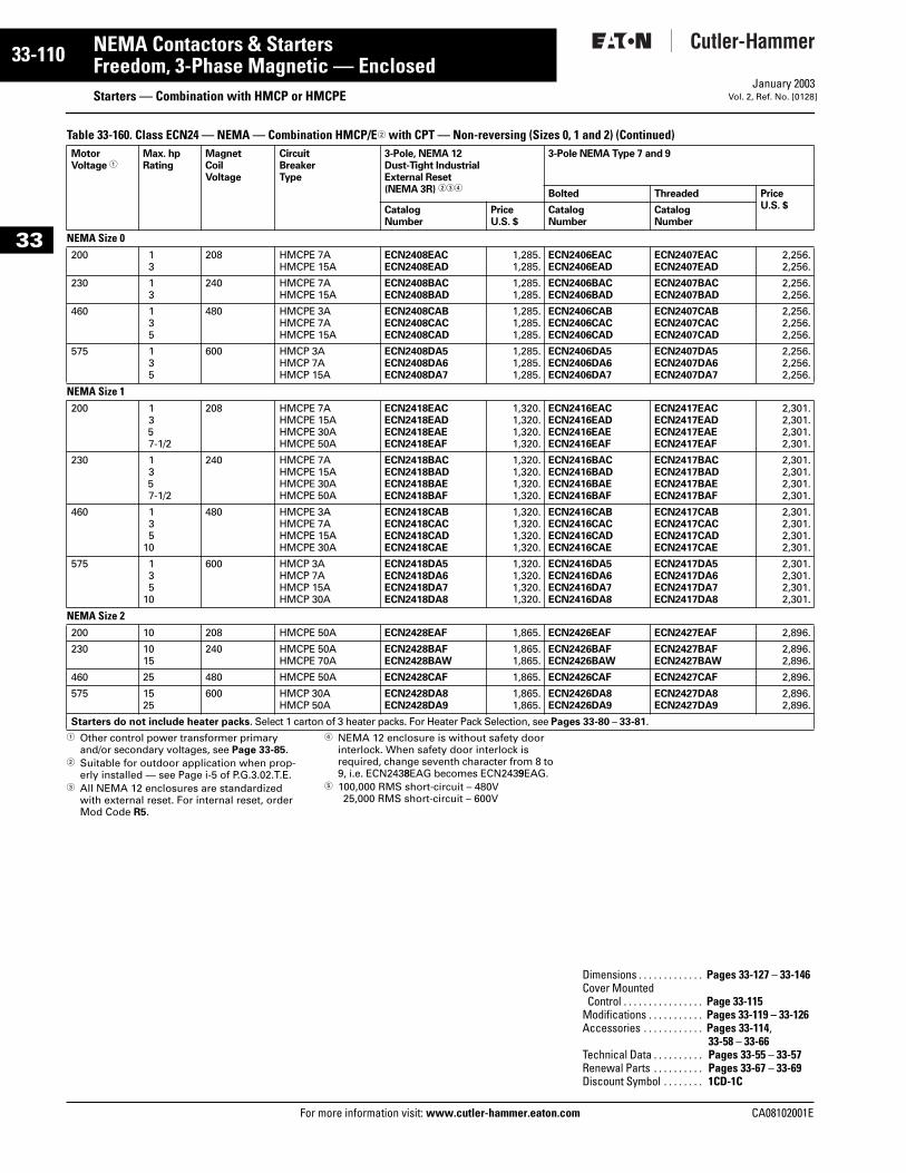
33-110
33
NEMA Contactors & StartersFreedom, 3-Phase Magnetic — Enclosed
Starters — Combination with HMCP or HMCPEFor more information visit: www.cutler-hammer.eaton.com
January 2003Vol. 2, Ref. No. [0128]
Table 33-160. Class ECN24 — NEMA — Combination HMCP/E2 with CPT — Non-reversing (Sizes 0, 1 and 2) (Continued)
1 Other control power transformer primary and/or secondary voltages, see Page 33-85.
2 Suitable for outdoor application when prop-erly installed — see Page i-5 of P.G.3.02.T.E.
3 All NEMA 12 enclosures are standardized with external reset. For internal reset, order Mod Code R5.
4 NEMA 12 enclosure is without safety door interlock. When safety door interlock is required, change seventh character from 8 to 9, i.e. ECN2438EAG becomes ECN2439EAG.
5 100,000 RMS short-circuit – 480V25,000 RMS short-circuit – 600V
MotorVoltage 1
Max. hpRating
MagnetCoilVoltage
CircuitBreakerType
3-Pole, NEMA 12Dust-Tight IndustrialExternal Reset(NEMA 3R) 234
3-Pole NEMA Type 7 and 9
Bolted Threaded PriceU.S. $Catalog
NumberPriceU.S. $
CatalogNumber
CatalogNumber
NEMA Size 0200 1
3208 HMCPE 7A
HMCPE 15AECN2408EACECN2408EAD
1,285.1,285.
ECN2406EACECN2406EAD
ECN2407EACECN2407EAD
2,256.2,256.
230 13
240 HMCPE 7AHMCPE 15A
ECN2408BACECN2408BAD
1,285.1,285.
ECN2406BACECN2406BAD
ECN2407BACECN2407BAD
2,256.2,256.
460 135
480 HMCPE 3AHMCPE 7AHMCPE 15A
ECN2408CABECN2408CACECN2408CAD
1,285.1,285.1,285.
ECN2406CABECN2406CACECN2406CAD
ECN2407CABECN2407CACECN2407CAD
2,256.2,256.2,256.
575 135
600 HMCP 3AHMCP 7AHMCP 15A
ECN2408DA5ECN2408DA6ECN2408DA7
1,285.1,285.1,285.
ECN2406DA5ECN2406DA6ECN2406DA7
ECN2407DA5ECN2407DA6ECN2407DA7
2,256.2,256.2,256.
NEMA Size 1200 1
357-1/2
208 HMCPE 7AHMCPE 15AHMCPE 30AHMCPE 50A
ECN2418EACECN2418EADECN2418EAEECN2418EAF
1,320.1,320.1,320.1,320.
ECN2416EACECN2416EADECN2416EAEECN2416EAF
ECN2417EACECN2417EADECN2417EAEECN2417EAF
2,301.2,301.2,301.2,301.
230 1357-1/2
240 HMCPE 7AHMCPE 15AHMCPE 30AHMCPE 50A
ECN2418BACECN2418BADECN2418BAEECN2418BAF
1,320.1,320.1,320.1,320.
ECN2416BACECN2416BADECN2416BAEECN2416BAF
ECN2417BACECN2417BADECN2417BAEECN2417BAF
2,301.2,301.2,301.2,301.
460 135
10
480 HMCPE 3AHMCPE 7AHMCPE 15AHMCPE 30A
ECN2418CABECN2418CACECN2418CADECN2418CAE
1,320.1,320.1,320.1,320.
ECN2416CABECN2416CACECN2416CADECN2416CAE
ECN2417CABECN2417CACECN2417CADECN2417CAE
2,301.2,301.2,301.2,301.
575 135
10
600 HMCP 3AHMCP 7AHMCP 15AHMCP 30A
ECN2418DA5ECN2418DA6ECN2418DA7ECN2418DA8
1,320.1,320.1,320.1,320.
ECN2416DA5ECN2416DA6ECN2416DA7ECN2416DA8
ECN2417DA5ECN2417DA6ECN2417DA7ECN2417DA8
2,301.2,301.2,301.2,301.
NEMA Size 2200 10 208 HMCPE 50A ECN2428EAF 1,865. ECN2426EAF ECN2427EAF 2,896.
230 1015
240 HMCPE 50AHMCPE 70A
ECN2428BAFECN2428BAW
1,865.1,865.
ECN2426BAFECN2426BAW
ECN2427BAFECN2427BAW
2,896.2,896.
460 25 480 HMCPE 50A ECN2428CAF 1,865. ECN2426CAF ECN2427CAF 2,896.
575 1525
600 HMCP 30AHMCP 50A
ECN2428DA8ECN2428DA9
1,865.1,865.
ECN2426DA8ECN2426DA9
ECN2427DA8ECN2427DA9
2,896.2,896.
Starters do not include heater packs. Select 1 carton of 3 heater packs. For Heater Pack Selection, see Pages 33-80 – 33-81.
Dimensions . . . . . . . . . . . . . Pages 33-127 – 33-146Cover MountedControl . . . . . . . . . . . . . . . . Page 33-115
Modifications . . . . . . . . . . . Pages 33-119 – 33-126Accessories . . . . . . . . . . . . Pages 33-114,
33-58 – 33-66Technical Data . . . . . . . . . . Pages 33-55 – 33-57Renewal Parts . . . . . . . . . . Pages 33-67 – 33-69Discount Symbol . . . . . . . . 1CD-1C
CA08102001E
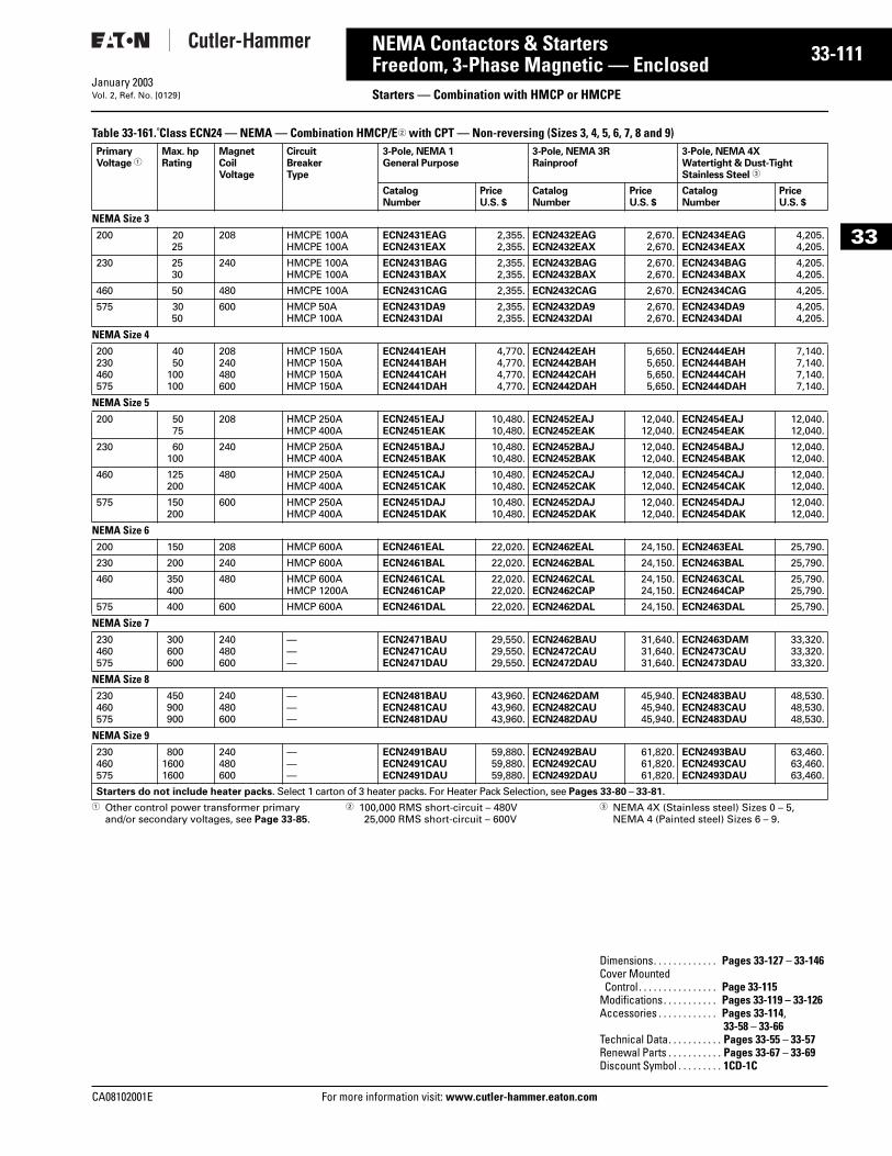
CA08102001E For more
11
33-1NEMA Contactors & StartersFreedom, 3-Phase Magnetic — Enclosed Starters — Combination with HMCP or HMCPEJanuary 2003Vol. 2, Ref. No. [0129]
33
Table 33-161. Class ECN24 — NEMA — Combination HMCP/E2 with CPT — Non-reversing (Sizes 3, 4, 5, 6, 7, 8 and 9)
1 Other control power transformer primary and/or secondary voltages, see Page 33-85.
2 100,000 RMS short-circuit – 480V25,000 RMS short-circuit – 600V
3 NEMA 4X (Stainless steel) Sizes 0 – 5, NEMA 4 (Painted steel) Sizes 6 – 9.
PrimaryVoltage 1
Max. hpRating
MagnetCoilVoltage
CircuitBreakerType
3-Pole, NEMA 1General Purpose
3-Pole, NEMA 3RRainproof
3-Pole, NEMA 4X Watertight & Dust-TightStainless Steel 3
CatalogNumber
PriceU.S. $
CatalogNumber
PriceU.S. $
CatalogNumber
PriceU.S. $
NEMA Size 3200 20
25208 HMCPE 100A
HMCPE 100AECN2431EAGECN2431EAX
2,355.2,355.
ECN2432EAGECN2432EAX
2,670.2,670.
ECN2434EAGECN2434EAX
4,205.4,205.
230 2530
240 HMCPE 100AHMCPE 100A
ECN2431BAGECN2431BAX
2,355.2,355.
ECN2432BAGECN2432BAX
2,670.2,670.
ECN2434BAGECN2434BAX
4,205.4,205.
460 50 480 HMCPE 100A ECN2431CAG 2,355. ECN2432CAG 2,670. ECN2434CAG 4,205.
575 3050
600 HMCP 50AHMCP 100A
ECN2431DA9ECN2431DAI
2,355.2,355.
ECN2432DA9ECN2432DAI
2,670.2,670.
ECN2434DA9ECN2434DAI
4,205.4,205.
NEMA Size 4200230460575
4050
100100
208240480600
HMCP 150AHMCP 150AHMCP 150AHMCP 150A
ECN2441EAHECN2441BAHECN2441CAHECN2441DAH
4,770.4,770.4,770.4,770.
ECN2442EAHECN2442BAHECN2442CAHECN2442DAH
5,650.5,650.5,650.5,650.
ECN2444EAHECN2444BAHECN2444CAHECN2444DAH
7,140.7,140.7,140.7,140.
NEMA Size 5200 50
75208 HMCP 250A
HMCP 400AECN2451EAJECN2451EAK
10,480.10,480.
ECN2452EAJECN2452EAK
12,040.12,040.
ECN2454EAJECN2454EAK
12,040.12,040.
230 60100
240 HMCP 250AHMCP 400A
ECN2451BAJECN2451BAK
10,480.10,480.
ECN2452BAJECN2452BAK
12,040.12,040.
ECN2454BAJECN2454BAK
12,040.12,040.
460 125200
480 HMCP 250AHMCP 400A
ECN2451CAJECN2451CAK
10,480.10,480.
ECN2452CAJECN2452CAK
12,040.12,040.
ECN2454CAJECN2454CAK
12,040.12,040.
575 150200
600 HMCP 250AHMCP 400A
ECN2451DAJECN2451DAK
10,480.10,480.
ECN2452DAJECN2452DAK
12,040.12,040.
ECN2454DAJECN2454DAK
12,040.12,040.
NEMA Size 6200 150 208 HMCP 600A ECN2461EAL 22,020. ECN2462EAL 24,150. ECN2463EAL 25,790.
230 200 240 HMCP 600A ECN2461BAL 22,020. ECN2462BAL 24,150. ECN2463BAL 25,790.
460 350400
480 HMCP 600AHMCP 1200A
ECN2461CALECN2461CAP
22,020.22,020.
ECN2462CALECN2462CAP
24,150.24,150.
ECN2463CALECN2464CAP
25,790.25,790.
575 400 600 HMCP 600A ECN2461DAL 22,020. ECN2462DAL 24,150. ECN2463DAL 25,790.
NEMA Size 7230460575
300600600
240480600
———
ECN2471BAUECN2471CAUECN2471DAU
29,550.29,550.29,550.
ECN2462BAUECN2472CAUECN2472DAU
31,640.31,640.31,640.
ECN2463DAMECN2473CAUECN2473DAU
33,320.33,320.33,320.
NEMA Size 8230460575
450900900
240480600
———
ECN2481BAUECN2481CAUECN2481DAU
43,960.43,960.43,960.
ECN2462DAMECN2482CAUECN2482DAU
45,940.45,940.45,940.
ECN2483BAUECN2483CAUECN2483DAU
48,530.48,530.48,530.
NEMA Size 9230460575
80016001600
240480600
———
ECN2491BAUECN2491CAUECN2491DAU
59,880.59,880.59,880.
ECN2492BAUECN2492CAUECN2492DAU
61,820.61,820.61,820.
ECN2493BAUECN2493CAUECN2493DAU
63,460.63,460.63,460.
Starters do not include heater packs. Select 1 carton of 3 heater packs. For Heater Pack Selection, see Pages 33-80 – 33-81.
Dimensions. . . . . . . . . . . . . Pages 33-127 – 33-146Cover MountedControl . . . . . . . . . . . . . . . . Page 33-115
Modifications. . . . . . . . . . . Pages 33-119 – 33-126Accessories . . . . . . . . . . . . Pages 33-114,
33-58 – 33-66Technical Data. . . . . . . . . . . Pages 33-55 – 33-57Renewal Parts . . . . . . . . . . . Pages 33-67 – 33-69Discount Symbol . . . . . . . . . 1CD-1C
information visit: www.cutler-hammer.eaton.com
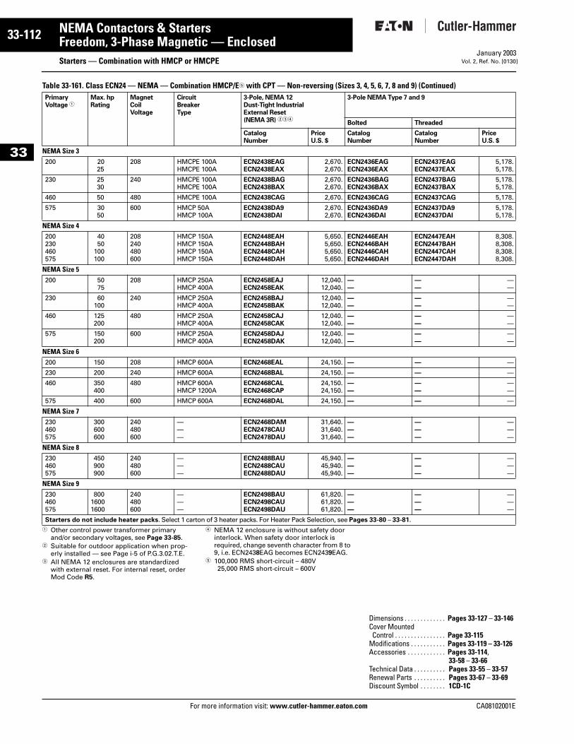
33-112
33
NEMA Contactors & StartersFreedom, 3-Phase Magnetic — Enclosed
Starters — Combination with HMCP or HMCPEFor more information visit: www.cutler-hammer.eaton.com
January 2003Vol. 2, Ref. No. [0130]
Table 33-161. Class ECN24 — NEMA — Combination HMCP/E5 with CPT — Non-reversing (Sizes 3, 4, 5, 6, 7, 8 and 9) (Continued)
1 Other control power transformer primary and/or secondary voltages, see Page 33-85.
2 Suitable for outdoor application when prop-erly installed — see Page i-5 of P.G.3.02.T.E.
3 All NEMA 12 enclosures are standardized with external reset. For internal reset, order Mod Code R5.
4 NEMA 12 enclosure is without safety door interlock. When safety door interlock is required, change seventh character from 8 to 9, i.e. ECN2438EAG becomes ECN2439EAG.
5 100,000 RMS short-circuit – 480V25,000 RMS short-circuit – 600V
PrimaryVoltage 1
Max. hpRating
MagnetCoilVoltage
CircuitBreakerType
3-Pole, NEMA 12Dust-Tight IndustrialExternal Reset(NEMA 3R) 234
3-Pole NEMA Type 7 and 9
Bolted Threaded
CatalogNumber
PriceU.S. $
CatalogNumber
CatalogNumber
PriceU.S. $
NEMA Size 3200 20
25208 HMCPE 100A
HMCPE 100AECN2438EAGECN2438EAX
2,670.2,670.
ECN2436EAGECN2436EAX
ECN2437EAGECN2437EAX
5,178.5,178.
230 2530
240 HMCPE 100AHMCPE 100A
ECN2438BAGECN2438BAX
2,670.2,670.
ECN2436BAGECN2436BAX
ECN2437BAGECN2437BAX
5,178.5,178.
460 50 480 HMCPE 100A ECN2438CAG 2,670. ECN2436CAG ECN2437CAG 5,178.
575 3050
600 HMCP 50AHMCP 100A
ECN2438DA9ECN2438DAI
2,670.2,670.
ECN2436DA9ECN2436DAI
ECN2437DA9ECN2437DAI
5,178.5,178.
NEMA Size 4200230460575
4050
100100
208240480600
HMCP 150AHMCP 150AHMCP 150AHMCP 150A
ECN2448EAHECN2448BAHECN2448CAHECN2448DAH
5,650.5,650.5,650.5,650.
ECN2446EAHECN2446BAHECN2446CAHECN2446DAH
ECN2447EAHECN2447BAHECN2447CAHECN2447DAH
8,308.8,308.8,308.8,308.
NEMA Size 5200 50
75208 HMCP 250A
HMCP 400AECN2458EAJECN2458EAK
12,040.12,040.
——
——
——
230 60100
240 HMCP 250AHMCP 400A
ECN2458BAJECN2458BAK
12,040.12,040.
——
——
——
460 125200
480 HMCP 250AHMCP 400A
ECN2458CAJECN2458CAK
12,040.12,040.
——
——
——
575 150200
600 HMCP 250AHMCP 400A
ECN2458DAJECN2458DAK
12,040.12,040.
——
——
——
NEMA Size 6200 150 208 HMCP 600A ECN2468EAL 24,150. — — —
230 200 240 HMCP 600A ECN2468BAL 24,150. — — —
460 350400
480 HMCP 600AHMCP 1200A
ECN2468CALECN2468CAP
24,150.24,150.
——
——
——
575 400 600 HMCP 600A ECN2468DAL 24,150. — — —
NEMA Size 7230460575
300600600
240480600
———
ECN2468DAMECN2478CAUECN2478DAU
31,640.31,640.31,640.
———
———
———
NEMA Size 8230460575
450900900
240480600
———
ECN2488BAUECN2488CAUECN2488DAU
45,940.45,940.45,940.
———
———
———
NEMA Size 9230460575
80016001600
240480600
———
ECN2498BAUECN2498CAUECN2498DAU
61,820.61,820.61,820.
———
———
———
Starters do not include heater packs. Select 1 carton of 3 heater packs. For Heater Pack Selection, see Pages 33-80 – 33-81.
Dimensions . . . . . . . . . . . . . Pages 33-127 – 33-146Cover MountedControl . . . . . . . . . . . . . . . . Page 33-115
Modifications . . . . . . . . . . . Pages 33-119 – 33-126Accessories . . . . . . . . . . . . Pages 33-114,
33-58 – 33-66Technical Data . . . . . . . . . . Pages 33-55 – 33-57Renewal Parts . . . . . . . . . . Pages 33-67 – 33-69Discount Symbol . . . . . . . . 1CD-1C
CA08102001E
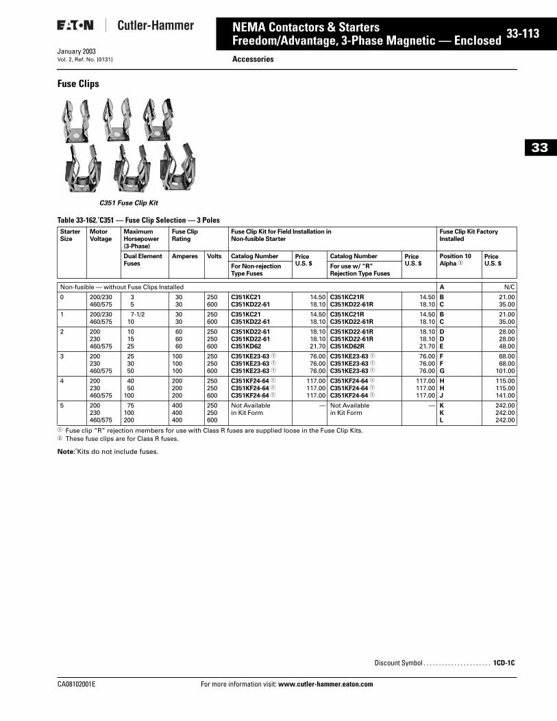
CA08102001E For more
13
33-1NEMA Contactors & StartersFreedom/Advantage, 3-Phase Magnetic — Enclosed AccessoriesJanuary 2003Vol. 2, Ref. No. [0131]
33
Fuse Clips
Table 33-162. C351 — Fuse Clip Selection — 3 Poles
1 Fuse clip “R” rejection members for use with Class R fuses are supplied loose in the Fuse Clip Kits.2 These fuse clips are for Class R fuses.
Note: Kits do not include fuses.
C351 Fuse Clip Kit
StarterSize
MotorVoltage
MaximumHorsepower(3-Phase)
Fuse ClipRating
Fuse Clip Kit for Field Installation inNon-fusible Starter
Fuse Clip Kit FactoryInstalled
Dual ElementFuses
Amperes Volts Catalog Number PriceU.S. $
Catalog Number PriceU.S. $
Position 10Alpha 2
PriceU.S. $For Non-rejection
Type FusesFor use w/ “R”Rejection Type Fuses
Non-fusible — without Fuse Clips Installed A N/C
0 200/230460/575
35
3030
250600
C351KC21C351KD22-61
14.5018.10
C351KC21RC351KD22-61R
14.5018.10
BC
21.0035.00
1 200/230460/575
7-1/210
3030
250600
C351KC21C351KD22-61
14.5018.10
C351KC21RC351KD22-61R
14.5018.10
BC
21.0035.00
2 200230460/575
101525
606060
250250600
C351KD22-61C351KD22-61C351KD62
18.1018.1021.70
C351KD22-61RC351KD22-61RC351KD62R
18.1018.1021.70
DDE
28.0028.0048.00
3 200230460/575
253050
100100100
250250600
C351KE23-63 1
C351KE23-63 1
C351KE23-63 1
76.0076.0076.00
C351KE23-63 1
C351KE23-63 1
C351KE23-63 1
76.0076.0076.00
FFG
68.0068.00
101.00
4 200230460/575
4050
100
200200200
250250600
C351KF24-64 1
C351KF24-64 1
C351KF24-64 1
117.00117.00117.00
C351KF24-64 1
C351KF24-64 1
C351KF24-64 1
117.00117.00117.00
HHJ
115.00115.00141.00
5 200230460/575
75100200
400400400
250250600
Not Availablein Kit Form
— Not Availablein Kit Form
— KKL
242.00242.00242.00
Discount Symbol . . . . . . . . . . . . . . . . . . . . . . 1CD-1C
information visit: www.cutler-hammer.eaton.com
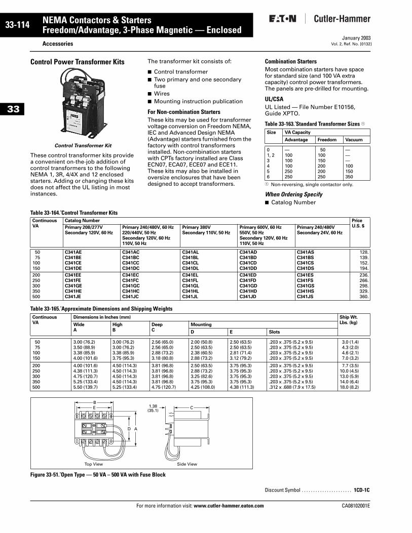
33-114
33
NEMA Contactors & StartersFreedom/Advantage, 3-Phase Magnetic — Enclosed
AccessoriesFor more information visit: www.cutler-hammer.eaton.com
January 2003Vol. 2, Ref. No. [0132]
Control Power Transformer Kits
These control transformer kits provide a convenient on-the-job addition of control transformers to the following NEMA 1, 3R, 4/4X and 12 enclosed starters. Adding or changing these kits does not affect the UL listing in most instances.
The transformer kit consists of:
■ Control transformer■ Two primary and one secondary
fuse■ Wires■ Mounting instruction publication
For Non-combination StartersThese kits may be used for transformer voltage conversion on Freedom NEMA, IEC and Advanced Design NEMA (Advantage) starters furnished from the factory with control transformers installed. Non-combination starters with CPTs factory installed are Class ECN07, ECA07, ECE07 and ECE11. These kits may also be installed in oversize enclosures that have been designed to accept transformers.
Combination StartersMost combination starters have space for standard size (and 100 VA extra capacity) control power transformers. The panels are pre-drilled for mounting.
UL/CSAUL Listed — File Number E10156, Guide XPTO.
Table 33-163. Standard Transformer Sizes 1
1 Non-reversing, single contactor only.
When Ordering Specify■ Catalog Number
Table 33-164. Control Transformer Kits
Table 33-165. Approximate Dimensions and Shipping Weights
Figure 33-51. Open Type — 50 VA – 500 VA with Fuse Block
Control Transformer Kit
Size VA Capacity
Advantage Freedom Vacuum
01, 23456
—100100100250250
50100150200200250
———100150350
ContinuousVA
Catalog Number PriceU.S. $Primary 208/277V
Secondary 120V, 60 HzPrimary 240/480V, 60 Hz220/440V, 50 HzSecondary 120V, 60 Hz110V, 50 Hz
Primary 380VSecondary 110V, 50 Hz
Primary 600V, 60 Hz550V, 50 HzSecondary 120V, 60 Hz110V, 50 Hz
Primary 240/480VSecondary 24V, 60 Hz
5075
100150
C341AEC341BEC341CEC341DE
C341ACC341BCC341CCC341DC
C341ALC341BLC341CLC341DL
C341ADC341BDC341CDC341DD
C341ASC341BSC341CSC341DS
128.139.152.194.
200250300350500
C341EEC341FEC341GEC341HEC341JE
C341ECC341FCC341GCC341HCC341JC
C341ELC341FLC341GLC341HLC341JL
C341EDC341FDC341GDC341HDC341JD
C341ESC341FSC341GSC341HSC341JS
236.266.298.329.360.
ContinuousVA
Dimensions in Inches (mm) Ship Wt.Lbs. (kg)Wide
AHighB
DeepC
Mounting
D E Slots
5075
100150
3.00 (76.2)3.50 (88.9)3.38 (85.9)4.00 (101.6)
3.00 (76.2)3.00 (76.2)3.38 (85.9)3.75 (95.3)
2.56 (65.0)2.56 (65.0)2.88 (73.2)3.18 (80.8)
2.00 (50.8)2.50 (63.5)2.38 (60.5)2.88 (73.2)
2.50 (63.5)2.50 (63.5)2.81 (71.4)3.12 (79.2)
.203 x .375 (5.2 x 9.5)
.203 x .375 (5.2 x 9.5)
.203 x .375 (5.2 x 9.5)
.203 x .375 (5.2 x 9.5)
3.0 (1.4) 4.3 (2.0) 4.6 (2.1) 7.0 (3.2)
200250300350500
4.00 (101.6)4.38 (111.3)4.75 (120.7)5.25 (133.4)5.50 (139.7)
4.50 (114.3)4.50 (114.3)4.50 (114.3)4.50 (114.3)5.25 (133.4)
3.81 (96.8)3.81 (96.8)3.81 (96.8)3.81 (96.8)4.75 (120.7)
2.50 (63.5)2.88 (73.2)3.25 (82.6)3.75 (95.3)4.25 (108.0)
3.75 (95.3)3.75 (95.3)3.75 (95.3)3.75 (95.3)4.38 (111.3)
.203 x .375 (5.2 x 9.5)
.203 x .375 (5.2 x 9.5)
.203 x .375 (5.2 x 9.5)
.203 x .375 (5.2 x 9.5)
.312 x .688 (7.9 x 17.5)
7.7 (3.5)10.0 (4.5)13.0 (5.9)14.0 (6.4)18.0 (8.2)
Top View Side View
1.38(35.1)
D A
E CB
Discount Symbol . . . . . . . . . . . . . . . . . . . . . . 1CD-1C
CA08102001E
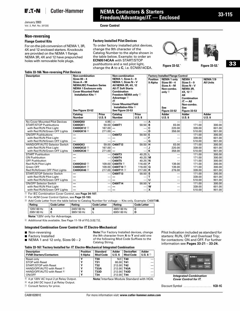
CA08102001E For more
15
33-1NEMA Contactors & StartersFreedom/Advantage/IT. — Enclosed Cover ControlJanuary 2003Vol. 2, Ref. No. [0133]
33
Non-reversingFlange Control KitsFor on-the-job conversion of NEMA 1, 3R, 4X and 12 enclosed starters. Knockouts are provided on the NEMA 1 flange. NEMA 3R, 4X and 12 have prepunched holes with removable hole plugs.
Factory Installed Pilot DevicesTo order factory installed pilot devices, change the 9th character of the Catalog Number to the alpha shown in the table below. Example: to order an ECN0514CAA with START/STOP pushbuttons and a red pilot light, change the A to a C, i.e. ECN0514CCA.
Table 33-166. Non-reversing Pilot Devices
1 For IEC Combination Cover Control, see Page 34-107.2 For ACM Cover Control Option, see Page 33-193.3 Add Code Letter from the table below to Catalog Number for voltage — Kits only. Example: C400T9B.
Note: 120V only for Advantage.4 Additional Kits available. See Page 11-19 of P.G.3.02.T.E.
Integrated Combination Cover Control for IT. Electro-Mechanical■ Non-reversing■ Factory Installed■ NEMA 1 and 12 only, Sizes 00 – 2
Note: For Factory Installed devices, change the 9th character from A to Y and add one of the following Mod Code Suffixes to the Catalog String.
Pilot Indication included as standard for starters: RUN, OFF and Overload Trip; for contactors: ON and OFF. For further information see Pages 33-21 – 33-24.
Table 33-167. Factory Installed for IT. Electro-Mechanical Integrated Combination
5 4 pt 120V AC Input 2 pt Relay Output.6 4 pt 24V DC Input 2 pt Relay Output.7 Consult factory for price.
Note: Interface Module Standard with HOA.
Figure 33-52. Figure 33-53.
Description Non-combinationSizes 00 – 4Sizes A – MNEMA/IEC Freedom SeriesNEMA 1 Enclosure onlyCover Mounted FieldInstallation Kits 4
See Figure 33-52
Non-combinationNEMA 1, Sizes 5 – 9NEMA 1, Sizes N – VAll NEMA 3R, 4X, 12All IT. Soft StartsCombinationFreedom NEMA only 1
Advantage 2
IT. Cover Mounted FieldInstallation Kits 4
See Figure 33-53
Factory Installed Flange Control
Position9 Alpha
NEMA 1 onlySizes 00 – 4Sizes A – MNon-combo.only 3
SeeFigure 33-52
NEMA 1Sizes 5 – 9Sizes N – VNEMA 3R,4X, 12 2
All Combination IT. — All Non-combo.SeeFigure 33-53
NEMA 7/9 All Units
CatalogNumber
PriceU.S. $
CatalogNumber
PriceU.S. $
AdderU.S. $
AdderU.S. $
AdderU.S. $
No Cover Mounted Pilot DevicesSTART/STOP Pushbuttonswith Red RUN Pilot Lightwith Red RUN/Green OFF Lights
C400GK0C400GK1C400GK12 3
C400GK16 3
4.9559.00
167.00271.00
—C400T1——
—58.50
——
ABCD
—83.00
220.00358.00
—171.00339.00510.00
—300.00601.00901.00
ON/OFF Pushbuttonswith Red RUN Pilot Lightwith Red RUN/Green OFF Lights
———
———
C400T2——
58.50——
EFG
———
171.00339.00510.00
300.00601.00901.00
HAND/OFF/AUTO Selector Switchwith Red RUN Pilot Lightwith Red RUN/Green OFF Lights
C400GK3C400GK32 3
C400GK36 3
59.00167.00271.00
C400T12——
58.50——
HJK
83.00220.00358.00
171.00339.00510.00
300.00601.00901.00
START PushbuttonON PushbuttonOFF PushbuttonRed RUN Pilot LightGreen OFFRed RUN/Green OFF Pilot Lights
———C400GK42 3
C400GK41 3
C400GK46 3
———
109.00109.00217.00
C400T3C400T4C400T5C400T9 3
C400T10 3
C400T11 3
40.2540.2540.25
116.00116.00217.00
LMNPQR
———
139.00139.00276.00
171.00171.00171.00171.00171.00339.00
300.00300.00300.00300.00300.00601.00
START/STOP Selector Switchwith Red RUN Pilot Lightwith Red RUN/Green OFF Lights
———
———
C400T13——
58.50——
STU
———
171.00339.00510.00
300.00601.00901.00
ON/OFF Selector Switchwith Red RUN Pilot Lightwith Red RUN/Green OFF Lights
———
———
C400T14——
58.50——
VWX
———
171.00339.00510.00
300.00601.00901.00
Rating Code Letter Rating Code Letter Rating Code Letter
120V 60 Hz208V 60 Hz
AE
240V 60 Hz380V 50 Hz
BL
480V 60 Hz600V 60 Hz
CD
DescriptionFVNR Starters/Contactors
Position9 Alpha
StandardMod Code
AdderU.S. $
DeviceNetMod Code
AdderU.S. $ 7
Reset onlySTOP with ResetSTART/STOP with ResetHAND/OFF/AUTO with Reset 5HAND/OFF/AUTO with Reset 6ON/OFF
YYYYYY
T30T31T32T33AT33DT34
N/C80.00
212.00212.00212.00212.00
T40T41T42T43AT43DT44
—————— Integrated Combination
Cover Control for IT.
Discount Symbol . . . . . . . . . . . . . . . . . . . . . 1CD-1C
information visit: www.cutler-hammer.eaton.com
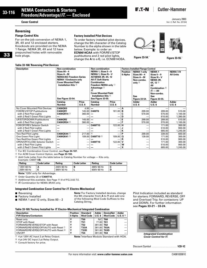
33-116
33
NEMA Contactors & StartersFreedom/Advantage/IT. — Enclosed
Cover ControlFor more information visit: www.cutler-hammer.eaton.com
January 2003Vol. 2, Ref. No. [0134]
ReversingFlange Control KitsFor on-the-job conversion of NEMA 1, 3R, 4X and 12 enclosed starters. Knockouts are provided on the NEMA 1 flange. NEMA 3R, 4X and 12 have prepunched holes with removable hole plugs.
Factory Installed Pilot DevicesTo order factory installed pilot devices, change the 9th character of the Catalog Number to the alpha shown in the table below. Example: to order an ECN0614CAA with FOR/REV/STOP pushbuttons and 2 red pilot lights, change the A to a C, i.e. ECN0614CCA.
Table 33-168. Reversing Pilot Devices
1 For IEC Combination Cover Control, see Page 34-107.2 For ACM Cover Control Option, see Page 33-193.3 Add Code Letter from the table below to Catalog Number for voltage — Kits only.
Example: C400T10B.
Note: 120V only for Advantage.4 Order Quantity (2) of C400T10.5 Additional Kits available. See Page 11-9 of P.G.3.02.T.E. 6 IT. Combination for NEMA 3R/4X only.
Integrated Combination Cover Control for IT. Electro-Mechanical■ Reversing■ Factory Installed■ NEMA 1 and 12 only, Sizes 00 – 2
Note: For Factory Installed devices, change the 9th character from A to Y and add one of the following Mod Code Suffixes to the Catalog String.
Pilot Indication included as standard for starters: FORWARD, REVERSE, OFF and Overload Trip; for contactors: UP and DOWN. For further information see Pages 33-21 – 33-24.
Table 33-169. Factory Installed for IT. Electro-Mechanical Integrated Combination
7 4 pt 120V AC Input 2 pt Relay Output.8 4 pt 24V DC Input 2 pt Relay Output.9 Consult factory for price.
Note: Interface Module Standard with HOA.
Figure 33-54. Figure 33-55.
Description Non-combinationSizes 00 – 4Sizes A – MNEMA/IEC Freedom SeriesNEMA 1 Enclosure onlyCover Mounted FieldInstallation Kits 5
See Figure 33-54.
Non-combinationNEMA 1, Sizes 5 – 9NEMA 1, Sizes N – VAll NEMA 3R, 4X, 12All IT. Soft StartsCombinationFreedom NEMA only 1
Advantage 2
IT. Cover Mounted FieldInstallation Kits 5
See Figure 33-55.
Factory Installed Flange Control
Position9 Alpha
NEMA 1 onlySizes 00 – 4Sizes A – MNon-combo.only 3
See Figure 33-54.
NEMA 1Sizes 5 – 9Sizes N – VNEMA 3R,4X, 12 2
AllCombination 6
IT. — All Non-combo.See Figure 33-55.
NEMA 7/9All Units
CatalogNumber
PriceU.S. $
CatalogNumber
PriceU.S. $
AdderU.S. $
AdderU.S. $
AdderU.S. $
No Cover Mounted Pilot DevicesFOR/REV/STOP Pushbuttonswith 2 Red Pilot Lightswith 2 Red/1 Green Pilot Lights
C400GK0C400GR1C400GR14 3
—
4.95145.00360.00
—
—C400T6——
—181.00
——
ABCD
—289.00570.00
—
—289.00570.00810.00
—510.00
1,100.001,390.00
UP/STOP/DOWN Pushbuttonswith 2 Red Pilot Lights
C400GR2C400GR24 3
145.00360.00
——
——
EF
289.00570.00
289.00570.00
510.001,100.00
FOR/OFF/REV Selector Switchwith 2 Red Pilot Lightswith 2 Red/1 Green Pilot Lights
———
———
C400T15——
122.00——
HJK
———
171.00510.00685.00
300.00900.00
1,245.00Two Red Pilot LightsOne Green Pilot LightTwo Red/One Green Pilot LightsOPEN/OFF/CLOSE Selector Switchwith 2 Red Pilot Lightswith 2 Red/1 Green Pilot Lights
C400GK44 3
C400GK41 3
————
217.00109.00
————
4
C400T10 3
—C400T16——
—109.00
—122.00
——
PQRVWX
289.00139.00
————
339.00171.00510.00171.00510.00685.00
600.00300.00900.00300.00900.00
1,245.00
Rating Code Letter Rating Code Letter Rating Code Letter
120V 60 Hz208V 60 Hz
AE
240V 60 Hz380V 50 Hz
BL
480V 60 Hz600V 60 Hz
CD
DescriptionFVR Starters/Contactors
Position9 Alpha
StandardMod Code
AdderU.S. $
DeviceNetMod Code
AdderU.S. $ 9
Reset onlySTOP with ResetFORWARD/REVERSE/STOP with ResetFORWARD/REVERSE/OFF/AUTO with Reset 7FORWARD/REVERSE/OFF/AUTO with Reset 8ON/OFF
YYYYYY
T50T51T52T33AT33DT54
N/C77.00
381.00381.00381.00381.00
T60T61T62T63AT63DT64
—————— Integrated Combination
Cover Control for IT.
Discount Symbol . . . . . . . . . . . . . . . . . . . . . . 1CD-1C
CA08102001E
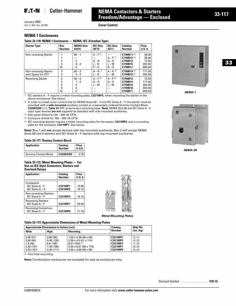
CA08102001E For more
17
33-1NEMA Contactors & StartersFreedom/Advantage — Enclosed Cover ControlJanuary 2003Vol. 2, Ref. No. [0135]
33
NEMA 1 EnclosuresTable 33-170. NEMA 1 Enclosures — NEMA, IEC (Freedom Type)
1 IEC starters A – F require a metal mounting plate, C321MP3, when mounting the starter in the above enclosures. See below.
2 In order to install cover control kits for NEMA Sizes 00 – 2 and IEC Sizes A – F, the starter must be provided with a side mounted auxiliary contact or a separately ordered Dummy Contact Block, C320KGSD from Table 33-171, to serve as a mounting base. Note: NEMA Size 00 and IEC Sizes A – C open type devices are not supplied as standard with side mounted auxiliaries.
3 Sub panel drilled for 50 – 200 VA CPTs.4 Enclosure drilled for 150 – 300 VA CPTs.5 IEC reversing starters require a metal mounting plate for the starter, C321MP3, and a mounting
plate for the contactor, C321MP1. See below.
Note: Box 1 will not accept devices with top mounted auxiliaries. Box 2 will accept NEMA Sizes 00 and 0 starters and IEC Sizes A – F starters with top mounted auxiliaries.
Table 33-171. Dummy Contact Block
Table 33-172. Metal Mounting Plates — For Use on IEC Style Contactors, Starters and Overload Relays
Table 33-173. Approximate Dimensions of Metal Mounting Plates
6 Two-hole mounting.
Note: Combination enclosures not available for sale as enclosures only.
Starter Type BoxNumber
NEMA SizeAN16
IEC SizeAE16
IEC SizeAE17
CatalogNumber
PriceU.S. $
Non-reversing Starter 1124
10
00 – 1—23 – 45
A – F 1—G – KL – NP – S
—A – F 1G – KL – MN – S
C799B11 2
C799B12 2
C799B13C799B15C799B17
36.0036.0072.50
302.00600.00
Non-reversing Starterwith Space for CPT
34
00 – 23 – 4
A – K 1L – N
A – K 1L – M
C799B14 3
C799B15 4117.00302.00
Reversing Starter 2349
10
00 – 01 – 2345
A – F 5G – KL – M——
A – F 5G – KL – M——
C799B13C799B14C799B15C799B16C799B17
72.50117.00302.00555.00600.00
Application CatalogNumber
PriceU.S.$
Dummy Contact Block C320KGSD 3.75
Application CatalogNumber
PriceU.S. $
ContactorsIEC Sizes A – F IEC Sizes G – K
C321MP1C321MP2
10.9018.10
Non-reversing StartersIEC Sizes A – F C321MP3 18.10
Reversing StartersIEC Sizes A – F C321MP7 29.00
Reversing ContactorsIEC Sizes A – F C321MP8 21.70
Approximate Dimensions in Inches (mm) CatalogNumber
Ship Wt.Lbs. (kg)Wide High Mounting
2.00 (51)2.56 (65)1.8 (46)4.20 (107)4.20 (107)
3.88 (99)5.05 (128)6.6 (168)7.38 (188)4.35 (111)
1.50 x 3.38 (38 x 86)2.00 x 4.5 (51 x 114)6.07 (154) 63.50 x 6.87 (89 x 175)3.50 x 3.86 (89 x 98)
C321MP1C321MP2C321MP3C321MP7C321MP8
.2 (.1)
.4 (.2)
.7 (.3)
.8 (.4)
.5 (.2)
Metal Mounting Plates
information visit: www.cutler-hammer.eaton.co
Discount Symbol . . . . . . . . . . . . . . . . . . . . . . 1CD-1C
NEMA 1
NEMA 3R
m
33-118
33
NEMA Contactors & StartersFreedom/Advantage — Enclosed
EnclosuresFor more information visit: www.cutler-hammer.eaton.com
January 2003Vol. 2, Ref. No. [0136]
NEMA 3R, 4X and 12 EnclosuresTable 33-174. NEMA 3R, 4X and 12 Enclosures — NEMA, IEC (Freedom Type)
1 IEC starters A – F require a metal mounting plate, C321MP3, when mounting the starter in the above enclosures. See Page 33-117.2 IEC reversing starters A – F require a metal mounting plate for the starter, C321MP3, and a mounting plate for the contactor, C321MP1.
See Page 33-117.3 Blank cover provided.
Table 33-175. NEMA 3R, 4X and 12 Enclosures — NEMA (Advantage Type) — with Hole Plugs
Table 33-176. NEMA 3R, 4X and 12 Enclosures — NEMA (Advantage Type) —with Cutout for 1 ACM and Hole Plugs 4
4 All boxes have 1 ACM cutout. In addition, Box 5 has one 30 mm round hole, Boxes 6 and 7 have two; Boxes 8, 9 and 10 have three holes plugged.
Starter Type BoxNumber
NEMA SizeAN16
IEC SizeAE16
IEC SizeAE17
NEMA 3R NEMA 12 NEMA 4X
CatalogNumber
PriceU.S. $
CatalogNumber
PriceU.S. $
CatalogNumber
PriceU.S. $
Non-reversing Starter 566888
10
00 – 12
—3
—45
A – F 1G – K—L – N——P – S
A – F 1—G – K—L – M—N – S
C799B21C799B24C799B25C799B210C799B212C799B211C799B218
188.245.245.346.346.930.
1,355.
C799B81C799B84C799B85C799B810C799B812C799B811C799B818
188.245.245.346.346.930.
1,355.
C799B41C799B43C799B44C799B47C799B49C799B48C799B413
360.615.615.900.900.
1,580.2,135.
Non-reversing Starterwith Space for CPT
66888
10
00 – 2—3
—45
A – K 1—L – N——P – S
—A – K 1—L – M—N – S
C799B24C799B25C799B210C799B212C799B211C799B218
245.245.346.346.930.
1,355.
C799B84C799B85C799B810C799B812C799B811C799B818
245.245.346.346.930.
1,355.
C799B43C799B44C799B47C799B49C799B48C799B413
615.615.900.900.
1,580.2,135.
Reversing Starter 66889
10
00 – 2—3
—45
A – K 2—L – M———
—A – K 2—L—M
C799B24C799B25C799B210C799B212C799B215C799B218
245.245.346.346.
1,355.1,355.
C799B84C799B85C799B810C799B812C799B815C799B818
245.245.346.346.
1,355.1,355.
C799B43C799B44C799B47C799B49C799B411C799B413
615.615.900.900.
2,135.2,135.
Multispeed 7 3 0 – 2 — — C799B223 295. C799B823 295. C799B417 755.
Starter Type BoxNumber
Size NEMA 3R NEMA 12 NEMA 4X
CatalogNumber
PriceU.S. $
CatalogNumber
PriceU.S. $
CatalogNumber
PriceU.S. $
Non-reversing Starter 5 1 – 2 C799B22 245. C799B82 245. C799B42 360.
Non-reversing Starterwith Space for CPTand Reversing
6 1 – 2 C799B26 245. C799B86 245. C799B45 360.
Non-reversing Starter,Non-reversing Starterwith Space for CPT,and Reversing
8
910
3
45
C799B213
C799B216C799B219
346.
930.1,355.
C799B813
C799B816C799B819
346.
930.930.
C799B410
C799B412C799B414
900.
1,580.2,135.
Starter Type BoxNumber
Size NEMA 3R NEMA 12
CatalogNumber
PriceU.S. $
CatalogNumber
PriceU.S. $
Non-reversing Starter 5 1 – 2 C799B23 245. C799B83 245.
Non-reversing Starterwith Space for CPTand Reversing
6 1 – 2 C799B27 245. C799B87 245.
Non-reversing Starter,Non-reversing Starterwith Space for CPT,and Reversing
8
910
3
45
C799B214
C799B217C799B220
346.
930.1,355.
C799B814
C799B817C799B820
346.
930.1,365.
Discount Symbol . . . . . . . . . . . . . . . . . . . . . . 1CD-1C
CA08102001E
CA08102001E For more
19
33-1NEMA Contactors & StartersFreedom/Advantage/IT./AF91 — Enclosed Modification CodesJanuary 2003Vol. 2, Ref. No. [0137]
33
Modification Codes Table 33-177. A — Ammeters, Auxiliary Contacts, Accelerating Relays,ACM Cover Control Modifications
Table 33-177. A — Ammeters, Auxiliary Contacts, Accelerating Relays,ACM Cover Control Modifications (Continued)
1 Oversize enclosure will be provided for IT. Starters.2 Consult factory for price.3 Top mounted auxiliary contacts cannot be added to contactors in Box 1
(NEMA 1).4 Not available for IT. Starters.5 NEMA 1/12 only.
Modification CatalogNumberSuffix
Description AdderU.S. $
Ammeter 1 A1 Panel Type Wired to Current Transformer in Line 1, NEMA 1, 12
1,015.
Panel Type Wired to Current Transformer in Line 1,NEMA 3R, 4X
1,640.
A2 Panel Type, Selector Switch and 3 Current Transformers Wired to Ammeter via Switch, NEMA 1, 12
2,655.
Panel Type, Selector Switch and 3 Current Transformers Wired to Ammeter via Switch, NEMA 3R, 4X
3,340.
A3 Miniature (Single-Phase), NEMA 1, 12
725.
A4 Miniature with Selector Switch, NEMA 1, 12
1,160.
A5 Switchboard (Single-Phase), NEMA 1, 12
1,425.
Switchboard (Single-Phase), NEMA 3R, 4X
1,955.
A6 Switchboard with Selector Switch.NEMA 1, 12
1,885.
Switchboard with Selector Switch.NEMA 3R, 4X
2,415.
A7 3-Panel Type (Single-Phase),NEMA 1, 12
3,010.
3-Panel Type (Single-Phase),NEMA 3R, 4X
3,465.
A10 3 Miniature (Single-Phase), NEMA 1, 3R, 4X, 12
2,160.
A11 3 Switchboard Type (Single-Phase).NEMA 1, 12
4,225.
3 Switchboard Type (Single-Phase).NEMA 3R, 4X
4,840.
A12 Ammeter Order by Description,NEMA 1, 3R, 4X, 12
2
Top Mounted AuxiliaryContacts 3 4(Unwired)
NEMA Sizes 00 – 2 only(Unwired)
IEC SizesA – K Only(Unwired)Freedom Series
A13 1NO 81.
A14 1NC 81.
A15 1NO-1NC 161.
A16 2NO 161.
A17 2NC 161.
A18 2NO-1NC 239.
A19 1NO-2NC 239.
A20 3NO 239.
A21 3NC 239.
A22 3NO-1NC 317.
A23 2NO-2NC 317.
A24 1NO-3NC 317.
A25 4NO 317.
A26 4NC 317.
Modification CatalogNumberSuffix
Description AdderU.S. $
Side MountedAuxiliaryContactsFreedom Series(Advantage —use Mod CodesA36 – A40)
A27 1NO 81.
A28 1NC 81.
A29 1NO-1NC 161.
A30 2NO 161.
A31 2NC 161.
A32 2NO-1NC 239.
A33 1NO-2NC 239.
A34 3NO 239.
A35 3NC 239.
A36 3NO-1NC 317.
A37 2NO-2NC 317.
A38 1NO-3NC 317.
A39 4NO 317.
A40 4NC 317.
Auxiliary Contacts 4
A42 Contacts Mounted on Operating Mechanism of Disconnect Switch, 1NO-1NC
109.
A43 Contacts Mounted on Operating Mechanism of Disconnect Switch, 2NO-2NC
161.
A44 With Auxiliary Contact Omitted —
A45 With 1 Set of Auxiliary Contacts (1NO-1NC) Plus 2 Tie Points, Unwired per Contactor (Advantage)
161.
Accelerating Relay
A46 For 2-Speed 1,110.
A47 2NO/2NC 24V DC Auxiliary Relay —IT. Only
387.
AdvantageControlModule 5
(ACM)
A49 Full Voltage Status Only with RESET 300.
A50 Full Voltage START/STOP 372.
A51 Full Voltage START/STOP/HOA 423.
A52 Full Voltage ON/OFF/AUTO 358.
A53 Reversing Status Only with RESET 397.
A54 Reversing FORWARD/REVERSE/STOP 493.
A55 Reversing FORWARD/REVERSE/STOP/HOA
550.
A56 2-Speed Status Only with RESET 397.
A57 2-Speed FAST/SLOW/STOP 493.
A58 2-Speed FAST/SLOW/STOP/HOA 550.
A59 Reduced Voltage Status Only with RESET
352.
A60 Reduced Voltage START/STOP 394.
A61 Reduced Voltage START/STOP/HOA 466.
A62 Reduced Voltage ON/OFF/AUTO 402.
A63 Metering Module 505.
A64 ACM — Order by Description 2
Discount Symbol . . . . . . . . . . . . . . . . . . . . . . . 1CD-1C
information visit: www.cutler-hammer.eaton.com
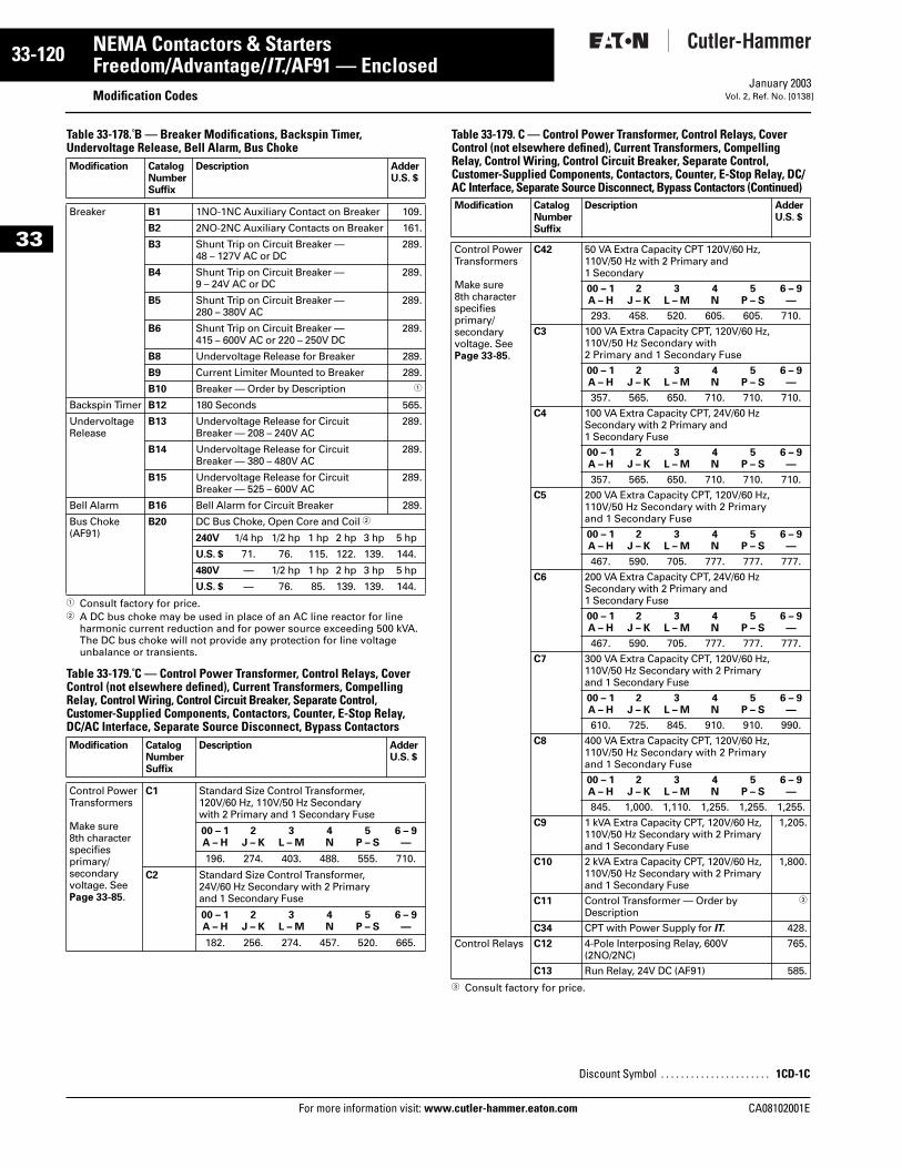
33-120
33
NEMA Contactors & StartersFreedom/Advantage/IT./AF91 — Enclosed
Modification CodesFor more information visit: www.cutler-hammer.eaton.com
January 2003Vol. 2, Ref. No. [0138]
Table 33-178. B — Breaker Modifications, Backspin Timer,Undervoltage Release, Bell Alarm, Bus Choke
1 Consult factory for price. 2 A DC bus choke may be used in place of an AC line reactor for line
harmonic current reduction and for power source exceeding 500 kVA. The DC bus choke will not provide any protection for line voltage unbalance or transients.
Table 33-179. C — Control Power Transformer, Control Relays, Cover Control (not elsewhere defined), Current Transformers, Compelling Relay, Control Wiring, Control Circuit Breaker, Separate Control, Customer-Supplied Components, Contactors, Counter, E-Stop Relay, DC/AC Interface, Separate Source Disconnect, Bypass Contactors
Table 33-179. C — Control Power Transformer, Control Relays, Cover Control (not elsewhere defined), Current Transformers, Compelling Relay, Control Wiring, Control Circuit Breaker, Separate Control, Customer-Supplied Components, Contactors, Counter, E-Stop Relay, DC/AC Interface, Separate Source Disconnect, Bypass Contactors (Continued)
3 Consult factory for price.
Modification CatalogNumberSuffix
Description AdderU.S. $
Breaker B1 1NO-1NC Auxiliary Contact on Breaker 109.
B2 2NO-2NC Auxiliary Contacts on Breaker 161.
B3 Shunt Trip on Circuit Breaker —48 – 127V AC or DC
289.
B4 Shunt Trip on Circuit Breaker —9 – 24V AC or DC
289.
B5 Shunt Trip on Circuit Breaker —280 – 380V AC
289.
B6 Shunt Trip on Circuit Breaker —415 – 600V AC or 220 – 250V DC
289.
B8 Undervoltage Release for Breaker 289.
B9 Current Limiter Mounted to Breaker 289.
B10 Breaker — Order by Description 1
Backspin Timer B12 180 Seconds 565.
UndervoltageRelease
B13 Undervoltage Release for Circuit Breaker — 208 – 240V AC
289.
B14 Undervoltage Release for Circuit Breaker — 380 – 480V AC
289.
B15 Undervoltage Release for Circuit Breaker — 525 – 600V AC
289.
Bell Alarm B16 Bell Alarm for Circuit Breaker 289.
Bus Choke(AF91)
B20 DC Bus Choke, Open Core and Coil 2
240V 1/4 hp 1/2 hp 1 hp 2 hp 3 hp 5 hp
U.S. $ 71. 76. 115. 122. 139. 144.
480V — 1/2 hp 1 hp 2 hp 3 hp 5 hp
U.S. $ — 76. 85. 139. 139. 144.
Modification CatalogNumberSuffix
Description AdderU.S. $
Control PowerTransformers
Make sure 8th characterspecifies primary/secondaryvoltage. SeePage 33-85.
C1 Standard Size Control Transformer,120V/60 Hz, 110V/50 Hz Secondary with 2 Primary and 1 Secondary Fuse
00 – 1A – H
2J – K
3L – M
4N
5P – S
6 – 9—
196. 274. 403. 488. 555. 710.
C2 Standard Size Control Transformer,24V/60 Hz Secondary with 2 Primaryand 1 Secondary Fuse
00 – 1A – H
2J – K
3L – M
4N
5P – S
6 – 9—
182. 256. 274. 457. 520. 665.
Modification CatalogNumberSuffix
Description AdderU.S. $
Control PowerTransformers
Make sure 8th characterspecifies primary/secondaryvoltage. SeePage 33-85.
C42 50 VA Extra Capacity CPT 120V/60 Hz, 110V/50 Hz with 2 Primary and1 Secondary
00 – 1A – H
2J – K
3L – M
4N
5P – S
6 – 9—
293. 458. 520. 605. 605. 710.
C3 100 VA Extra Capacity CPT, 120V/60 Hz, 110V/50 Hz Secondary with 2 Primary and 1 Secondary Fuse
00 – 1A – H
2J – K
3L – M
4N
5P – S
6 – 9—
357. 565. 650. 710. 710. 710.
C4 100 VA Extra Capacity CPT, 24V/60 Hz Secondary with 2 Primary and 1 Secondary Fuse
00 – 1A – H
2J – K
3L – M
4N
5P – S
6 – 9—
357. 565. 650. 710. 710. 710.
C5 200 VA Extra Capacity CPT, 120V/60 Hz, 110V/50 Hz Secondary with 2 Primary and 1 Secondary Fuse
00 – 1A – H
2J – K
3L – M
4N
5P – S
6 – 9—
467. 590. 705. 777. 777. 777.
C6 200 VA Extra Capacity CPT, 24V/60 Hz Secondary with 2 Primary and 1 Secondary Fuse
00 – 1A – H
2J – K
3L – M
4N
5P – S
6 – 9—
467. 590. 705. 777. 777. 777.
C7 300 VA Extra Capacity CPT, 120V/60 Hz, 110V/50 Hz Secondary with 2 Primary and 1 Secondary Fuse
00 – 1A – H
2J – K
3L – M
4N
5P – S
6 – 9—
610. 725. 845. 910. 910. 990.
C8 400 VA Extra Capacity CPT, 120V/60 Hz, 110V/50 Hz Secondary with 2 Primary and 1 Secondary Fuse
00 – 1A – H
2J – K
3L – M
4N
5P – S
6 – 9—
845. 1,000. 1,110. 1,255. 1,255. 1,255.
C9 1 kVA Extra Capacity CPT, 120V/60 Hz, 110V/50 Hz Secondary with 2 Primary and 1 Secondary Fuse
1,205.
C10 2 kVA Extra Capacity CPT, 120V/60 Hz, 110V/50 Hz Secondary with 2 Primary and 1 Secondary Fuse
1,800.
C11 Control Transformer — Order by Description
3
C34 CPT with Power Supply for IT. 428.
Control Relays C12 4-Pole Interposing Relay, 600V (2NO/2NC)
765.
C13 Run Relay, 24V DC (AF91) 585.
Discount Symbol . . . . . . . . . . . . . . . . . . . . . . 1CD-1C
CA08102001E
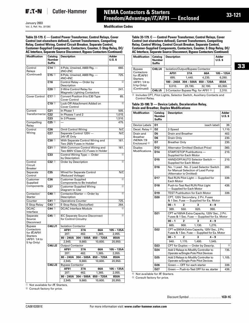
CA08102001E For more
21
33-1NEMA Contactors & StartersFreedom/Advantage/IT./AF91 — Enclosed Modification CodesJanuary 2003Vol. 2, Ref. No. [0139]
33
Table 33-179. C — Control Power Transformer, Control Relays, Cover Control (not elsewhere defined), Current Transformers, Compelling Relay, Control Wiring, Control Circuit Breaker, Separate Control, Customer-Supplied Components, Contactors, Counter, E-Stop Relay, DC/AC Interface, Separate Source Disconnect, Bypass Contactors (Continued)
1 Not available for IT. Starters.2 Consult factory for price.
Table 33-179. C — Control Power Transformer, Control Relays, Cover Control (not elsewhere defined), Current Transformers, Compelling Relay, Control Wiring, Control Circuit Breaker, Separate Control, Customer-Supplied Components, Contactors, Counter, E-Stop Relay, DC/AC Interface, Separate Source Disconnect, Bypass Contactors (Continued)
3 Includes CPT, Pilot Lights, Selector Switch, Auxiliary Contacts and Control Relay.
Table 33-180. D — Device Labels, Deceleration Relay, Drain and Breather, Duplex Modifications
4 Not available for IT. Starters.5 Consult factory for price.
Modification CatalogNumberSuffix
Description AdderU.S. $
Control Relays(Continued)
C14 1 4-Pole, Unwired, A600 Rtg. — 2NO-2NC
660.
C15 1 8-Pole, Unwired, A600 Rtg. — 4NO-4NC
725.
C16 Control Relay — Order by Description
2
C20 1 2-Wire Control Relay for Magnetic Lighting Contactors
241.
Cover Control C17 1 Convert Position 9 to E30 Type Cover Control
65.
C19 1 Lock-Off Attachment Added on Cover Control
2
Current Transformer(s)
C21 In Phase 1 505.C22 In Phases 1 and 2 1,015.C23 In 3 Phases 1,510.
CompellingRelay
C25 1 — 475.
ControlWiring
C26 Omit Control Wiring N/CC27 Separate Control 120V —
24V IT. OnlyN/C
C30 1 With Separate Control Wiring and Two 250V Fuses in Holder
161.
C31 1 With Common Control Wiring andTwo 600V (Class CC) Fuses in Holder
161.
C33 Control Wiring Type — Order by Description
2
Control CircuitBreaker
C32 1 Order by Description 2
SeparateControl
C35 Wired for Separate Control (Reduced Voltage)
N/C
CustomerSuppliedComponents
C36 Customer Supplied Components to Be Installed
2
C37 Customer Supplied Wiring Diagram to Use
2
Contactor/Starter
C40 1 Contactor/Starter — Order by Description
2
Counter C41 1 Operations Counter 725.E-Stop Relay C43 1 E-Stop Relay (DeviceNet) 264.DC/AC Interface
C44 1 DC/AC Interface Module 2
SeparateSource Disconnect
C45 1 IEC Separate Source Disconnect for Control Circuitry
2
Bypass Contactorsfor IT./AF91Starters (AF91: 1/4 to 5 hp Only)
C46/J1 Isolation ContactorAF91 37A 66A 105 – 135A
207. 462. 1,365. 2,055.80 – 240A 304 – 500A 650 – 720A 850A
2,945. 9,660. 10,600. 20,950.C46/J2 Output Contactor
AF91 37A 66A 105 – 135A
207. 462. 1,365. 2,055.80 – 240A 304 – 500A 650 – 720A 850A
2,945. 9,660. 10,600. 20,950.C46/J3 Bypass Contactor
AF91 37A 66A 105 – 135A
207. 462. 1,365. 2,055.80 – 240A 304 – 500A 650 – 720A 850A
2,945. 9,660. 10,600. 20,950.
Modification CatalogNumberSuffix
Description AdderU.S. $
Bypass Contactorsfor IT./AF91Starters (AF91: 1/4 to 5 hp Only) (Continued)
C46/J4 Isolation/Output/Bypass Contactor
AF91 37A 66A 105 – 135A
695. 1,440. 4,235. 6,280.
180 – 240A 304 – 500A 650 – 720A 850A
9,010. 29,190. 32,190. 63,350.
C46/J5 3-Contactor Bypass Pkg. for AF91 3 2,310.
Modification CatalogNumberSuffix
Description AdderU.S. $
Device Labels D1 (each label) 39.
Decel. Relay 4 D2 2-Speed 1,110.
Drain andBreather(NEMA 7/9 Enclosure) 4
D5 Drain and Breather 402.
D6 Drain Only 230.
D7 Breather Only 230.
DuplexModifications
D12 Alternator Omitted (Deduct Price) -360.
D14 START/STOP Pushbuttons — Supplied for Each Motor
210.
D15 HAND/OFF/AUTO Selector Switch — Supplied for Each Motor
210.
D16 No. 1 Lead - No. 2 Lead Selector Switchfor Manual Selection of Lead Pump (Alternator is Omitted)
260.
D17 Red RUN Pilot Light — Supplied for Each Motor
339.
D18 Push-to-Test Red RUN Pilot LIght — Supplied for Each Motor
438.
D19 TEST Pushbutton for Each Motor 339.
D20 CPT, 120V Secondary, 2 Pri. Fuses & 1 Sec. Fuse — Supplied for Ea. Motor
00 – 1 2 3 4 – 9
389. 550. 820. 990.
D21 CPT w/100VA Extra Capacity, 120V Sec., 2 Pri. Fuses & 1 Sec. Fuse — Supplied for Ea. Motor
00 – 1 2 3 4 – 9
665. 900. 1,130. 1,270.
D22 CPT w/200VA Extra Capacity, 120V Sec., 2 Pri. Fuses & 1 Sec. Fuse — Supplied for Ea. Motor
00 – 1 2 3 4 – 9
940. 1,170. 1,400. 1,545.
D23 CPT for Duplex — Order by Descrip. 5
D24 Add 2 Relays to Modify Controller to Operate w/Single-Pole Pilot Devices
735.
D25 Add 3 Relays to Modify Controller to Operate w/Single-Pole Pilot Devices
1,105.
D26 Green — OFF for each starter 339.
D27 Green — Push-to-Test OFF for ea. starter 438.
Discount Symbol . . . . . . . . . . . . . . . . . . . . . . . 1CD-1C
information visit: www.cutler-hammer.eaton.com
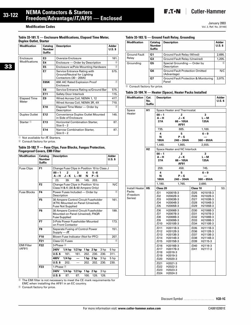
33-122
33
NEMA Contactors & StartersFreedom/Advantage/IT./AF91 — Enclosed
Modification CodesFor more information visit: www.cutler-hammer.eaton.com
January 2003Vol. 2, Ref. No. [0140]
Table 33-181. E — Enclosure Modifications, Elapsed Time Meter, Duplex Outlet, Starter
1 Not available for IT. Starters.2 Consult factory for price.
Table 33-182. F — Fuse Clips, Fuse Blocks, Fungus Protection, Fingerproof Covers, EMI Filter
3 The EMI filter is not necessary to meet the CE mark requirements for EMC when installing the AF91 in an EC country.
4 Consult factory for price.
Table 33-183. G — Ground Fault Relay, Grounding
5 Consult factory for price.
Table 33-184. H — Heater (Space), Heater Packs Installed
Modification CatalogNumberSuffix
Description AdderU.S. $
EnclosureModifications
E3 Oversize Enclosure 181.
E4 Enclosure — Order by Description 2
E5 Enclosure w/Pole Mounting Hardware 2
E7 Service Entrance Rating with Ground/Neutral for Lighting Contactors (30 – 200A)
575.
E65K 65K AIC Rated Explosion Proof Enclosure
2
E8 Service Entrance Rating w/Ground Bar 575.
E11 Safety Door Interlock 115.
Elapsed Time Meter
E9 Wired Across Coil, NEMA 1, 12 417.
Wired Across Coil, NEMA 3R, 4X 710.
E10 Elapsed Time Meter — Order by Description
2
Duplex Outlet E12 Convenience Duplex Outlet Mounted in Side of Enclosure
145.
Starter 1 E13 Horizontal Combination Starter, Size 0 – 2
87.
E14 Narrow Combination Starter,Size 0 – 2
87.
Modification CatalogNumberSuffix
Description AdderU.S. $
Fuse Clips F1 Change Fuse Clips in Position 10 to Class J
00 – 1A – H
2J – K
3L – M
4N
5 –6P – S
23. 39. 88. 145. 203.
F2 Change Fuse Clips in Position 10 toClass H & K (30 & 60 Ampere Only)
N/C
Fuse Blocks F4 Power Fuses Included — Order byDescription
4
F5 30 Ampere Control Circuit Fuseholder(KTK) Mounted on Panel (Unwired),Fuse Not Supplied
161.
F6 30 Ampere Control Circuit FuseholderMounted on Panel (Unwired), FNQRFuse Supplied
199.
F7 3-Pole Power Fuseholder Mountedon Front Contactor
173.
F8 Separate Fusing of Control PowerSupply — IT.
151.
F10 Blown Fuse Indicator (Not for PFC) 207.
F21 Class CC Fuses 4
EMI Filter(AF91)
F22 3-Phase 3
240V 1/4 hp 1/2 hp 1 hp 2 hp 3 hp 5 hp
U.S. $ 161. 161. 202. 230. 230. 311.
480V 1/4 hp — 1 hp 2 hp 3 hp 5 hp
U.S. $ 202. — 202. 202. 230. 230.
F23 1-Phase 3
240V 1/4 hp 1/2 hp 1 hp 2 hp 3 hp
U.S. $ 87. 87. 100. 128. 128.
Modification CatalogNumberSuffix
Description AdderU.S. $
Ground Fault Relay
G1 Ground Fault Relay (Wired) 2,695.
G3 Ground Fault Relay (Unwired) 1,205.
Grounding G5 Special Grounding — Order by Description
5
G6 Ground Fault Protection Omitted (Advantage)
N/C
G7 Ground Fault Protection & Monitoring Panel
3,975.
Modification Cat.No.Suffix
Description AdderU.S. $
SpaceHeater
H1 Space Heater and Thermostat
00 – 1A – H37A
2J – K
66 – 105AAF91
3L – M135A
735. 885. 1,100.
4N
180A
5P – S
240 – 304A
6 – 9—
360 – 850A
1,440. 1,865. 2,555.
H2 Space Heater and NC Interlock
00 – 1A – H37A
2J – K
66 – 105AAF91
3L – M135A
259. 458. 745.
4N
180A
5P – S
240 – 304A
6 – 9—
360 – 850A
1,180. 1,765. 2,680.
Install HeaterPacks (FreedomSeries)
H5 Class 20 Class 10 53.
/D1 H2001B-3/D2 H2002B-3/D3 H2003B-3/D4 H2004B-3/D5 H2005B-3
/D25 H2101B-3/D26 H2102B-3/D27 H2103B-3/D28 H2104B-3/D29 H2105B-3
/D6 H2006B-3/D7 H2007B-3/D8 H2008B-3/D9 H2009B-3/D10 H2010B-3
/D30 H2106B-3/D31 H2107B-3/D32 H2108B-3/D33 H2109B-3/D34 H2110B-3
/D11 H2011B-3/D12 H2012B-3/D13 H2013B-3/D14 H2014B-3/D15 H2015B-3
/D35 H2111B-3/D36 H2112B-3/D37 H2113B-3/D38 H2114B-3/D39 H2115-3
/D16 H2016B-3/D17 H2017B-3/D18 H2018-3/D19 H2019-3/D20 H2020-3
/D40 H2116-3/D41 H2117-3
/D21 H2021-3/D22 H2022-3/D23 H2023-3/D24 H2024-3
Discount Symbol . . . . . . . . . . . . . . . . . . . . . . 1CD-1C
CA08102001E
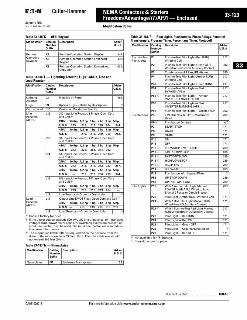
CA08102001E For more
23
33-1NEMA Contactors & StartersFreedom/Advantage/IT./AF91 — Enclosed Modification CodesJanuary 2003Vol. 2, Ref. No. [0141]
33
Table 33-185. K — AF91 Keypad
Table 33-186. L — Lightning Arrestor, Lugs, Labels, Line and Load Reactor
1 Consult factory for price.2 If the power source exceeds 500 kVA, 3% line unbalance, or if transient
voltages from power factor capacitor switching events are present, an input line reactor must be used. The input line reactor will also reduce line current harmonics.
3 The output line DV/DT filter is required when the distance from the drive to the motor exceeds 33 feet (10m). The total cable run should not exceed 165 feet (50m).
Table 33-187. N — Nameplates
Table 33-188. P — Pilot Lights, Pushbuttons, Phase Relays, Potential Transformers, Program Timer, Percentage Timer, Photocell
4 Not available for IT. Starters.5 Consult factory for price.
Modification CatalogNumberSuffix
Description AdderU.S. $
Remote OperatingKeypads
K1 Remote Operating Station Display 144.
K2 Remote Operating Station EnhancedKeypad
499.
K3 Remote Operating Station Keypad andCopy Unit
1,030.
Modification CatalogNumberSuffix
Description AdderU.S. $
Lighting Arrestor
L3 Installed on Panel 289.
Lugs L9 Special Lugs — Order by Description 1
Carton Label L10 Customer Marking — Specify 1
LineReactors(AF91)
L12 3% Input Line Reactor, 3-Phase, Open Core and Coil 2
240V 1/4 hp 1/2 hp 1 hp 2 hp 3 hp 5 hp
U.S. $ 213. 213. 213. 225. 264. 344.
480V 1/4 hp 1/2 hp 1 hp 2 hp 3 hp 5 hp
U.S. $ — 219. 219. 219. 219. 253.
L13 3% Input Line Reactor, 1-Phase, Open Core and Coil 2
480V 1/4 hp 1/2 hp 1 hp 2 hp 3 hp 5 hp
U.S. $ 213. 225. 264. 344. 362. —
L14 5% Input Line Reactor, 3-Phase, Open Core and Coil 2
240V 1/4 hp 1/2 hp 1 hp 2 hp 3 hp 5 hp
U.S. $ 213. 213. 219. 253. 282. 357.
480V 1/4 hp 1/2 hp 1 hp 2 hp 3 hp 5 hp
U.S. $ — 213. 213. 230. 230. 344.
L15 5% Input Line Reactor, 1-Phase, Open Core and Coil 2
480V 1/4 hp 1/2 hp 1 hp 2 hp 3 hp 5 hp
U.S. $ 213. 213. 213. 213. 264. —
L16 Line Reactor — Order by Description 1
LoadReactors(AF91)
L17 Output Line DV/DT Filter, Open Core and Coil 3
480V 1/4 hp 1/2 hp 1 hp 2 hp 3 hp 5 hp
U.S. $ — 219. 219. 219. 219. 253.
L18 Load Reactor — Order by Description 1
Modification CatalogNumberSuffix
Description AdderU.S. $
Nameplates N1 Enclosure Nameplates 23.
Modification CatalogNumberSuffix
Description AdderU.S. $
Push-to-TestPilot Lights
P1 Push-to-Test Pilot Light (Red RUN)Wired to Coil
217.
P2 Push-to-Test Pilot Light (Green OFF)Wired in Series with Auxiliary Contact
302.
P3 Combination of P1 and P2 Above 520.
P4 Push-to-Test Pilot Light (Amber RUN)Wired to Coil
217.
P49 Push-to-Test Pilot Light (Green RUN) 217.
P54 4 Push-to-Test Pilot Light — RedBYPASS (AF91)
217.
P55 4 Push-to-Test Pilot Light — AmberINVERTER ENABLE (AF91)
217.
P56 4 Push-to-Test Pilot Light — RedINVERTER RUNNING (AF91)
217.
P57 Push-to-Test Pilot Light — Green STOP 302.
Pushbuttons P5 EMERGENCY STOP — MushroomHead
289.
P6 4 Pushbutton Omitted N/C
P7 START/STOP 171.
P8 ON/OFF 171.
P9 START 171.
P10 ON 171.
P11 OFF 171.
P12 4 FORWARD/REVERSE/STOP 289.
P13 4 FAST/SLOW/STOP 289.
P14 4 FAST/OFF/SLOW 289.
P15 4 HIGH/LOW/STOP 289.
P16 4 HIGH/LOW 289.
P17 4 SLOW/FAST 289.
P18 4 Pushbutton with Legend Plate 5
P52 UP/STOP/DOWN 289.
P53 OPEN/STOP/CLOSE 289.
Pilot Lights P19 With 1 Amber Pilot Light MarkedPOWER AVAILABLE Wired to LoadSide of 2 Fuses or Circuit Breaker
283.
P20 Pilot Light (Amber RUN) Wired to Coil 171.
P21 4 With 1 Red Pilot Light Marked RUNWired thru NO Auxiliary Contact
171.
P22 4 With 1 Push-to-Test Red Light MarkedRUN Wired thru NO Auxiliary Contact
217.
P23 Pilot Light — Red RUN 171.
P24 Pilot Light — Red ON 171.
P25 Pilot Light — Green OFF 171.
P26 Pilot Light — Order by Description 5
P29 Pilot Light — Red STOP 171.
Discount Symbol . . . . . . . . . . . . . . . . . . . . . . 1CD-1C
information visit: www.cutler-hammer.eaton.com
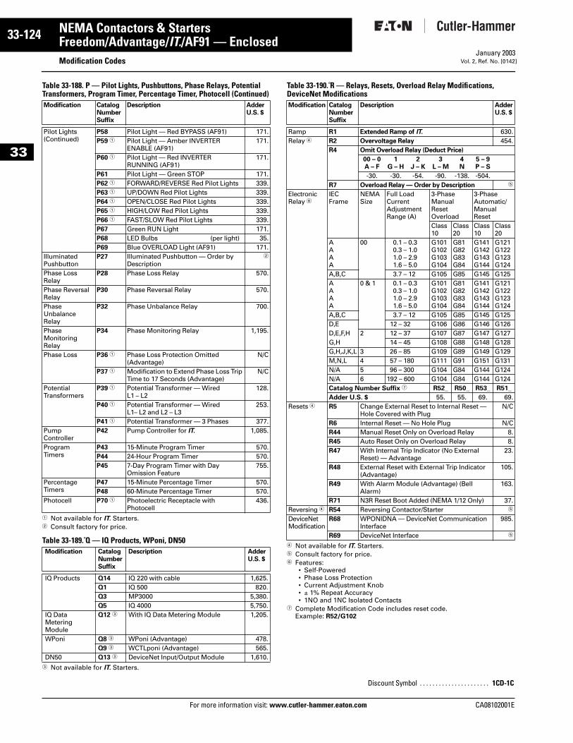
33-124
33
NEMA Contactors & StartersFreedom/Advantage/IT./AF91 — Enclosed
Modification CodesFor more information visit: www.cutler-hammer.eaton.com
January 2003Vol. 2, Ref. No. [0142]
Table 33-188. P — Pilot Lights, Pushbuttons, Phase Relays, Potential Transformers, Program Timer, Percentage Timer, Photocell (Continued)
1 Not available for IT. Starters.2 Consult factory for price.
Table 33-189. Q — IQ Products, WPoni, DN50
3 Not available for IT. Starters.
Table 33-190. R — Relays, Resets, Overload Relay Modifications, DeviceNet Modifications
4 Not available for IT. Starters.5 Consult factory for price.6 Features:
• Self-Powered• Phase Loss Protection• Current Adjustment Knob• ± 1% Repeat Accuracy• 1NO and 1NC Isolated Contacts
7 Complete Modification Code includes reset code. Example: R52/G102
Modification CatalogNumberSuffix
Description AdderU.S. $
Pilot Lights(Continued)
P58 Pilot Light — Red BYPASS (AF91) 171.P59 1 Pilot Light — Amber INVERTER
ENABLE (AF91)171.
P60 1 Pilot Light — Red INVERTER RUNNING (AF91)
171.
P61 Pilot Light — Green STOP 171.P62 1 FORWARD/REVERSE Red Pilot Lights 339.P63 1 UP/DOWN Red Pilot Lights 339.P64 1 OPEN/CLOSE Red Pilot Lights 339.P65 1 HIGH/LOW Red Pilot Lights 339.P66 1 FAST/SLOW Red Pilot Lights 339.P67 Green RUN Light 171.P68 LED Bulbs (per light) 35.P69 Blue OVERLOAD Light (AF91) 171.
Illuminated Pushbutton
P27 Illuminated Pushbutton — Order by Description
2
Phase Loss Relay
P28 Phase Loss Relay 570.
Phase Reversal Relay
P30 Phase Reversal Relay 570.
Phase UnbalanceRelay
P32 Phase Unbalance Relay 700.
Phase MonitoringRelay
P34 Phase Monitoring Relay 1,195.
Phase Loss P36 1 Phase Loss Protection Omitted (Advantage)
N/C
P37 1 Modification to Extend Phase Loss Trip Time to 17 Seconds (Advantage)
N/C
PotentialTransformers
P39 1 Potential Transformer — Wired L1 – L2
128.
P40 1 Potential Transformer — Wired L1– L2 and L2 – L3
253.
P41 1 Potential Transformer — 3 Phases 377.PumpController
P42 Pump Controller for IT. 1,085.
ProgramTimers
P43 15-Minute Program Timer 570.P44 24-Hour Program Timer 570.P45 7-Day Program Timer with Day
Omission Feature755.
PercentageTimers
P47 15-Minute Percentage Timer 570.P48 60-Minute Percentage Timer 570.
Photocell P70 1 Photoelectric Receptacle withPhotocell
436.
Modification CatalogNumberSuffix
Description AdderU.S. $
IQ Products Q14 IQ 220 with cable 1,625.Q1 IQ 500 820.Q3 MP3000 5,380.Q5 IQ 4000 5,750.
IQ Data MeteringModule
Q12 3 With IQ Data Metering Module 1,205.
WPoni Q8 3 WPoni (Advantage) 478.Q9 3 WCTLponi (Advantage) 565.
DN50 Q13 3 DeviceNet Input/Output Module 1,610.
Modification CatalogNumberSuffix
Description AdderU.S. $
Ramp R1 Extended Ramp of IT. 630.Relay 4 R2 Overvoltage Relay 454.
R4 Omit Overload Relay (Deduct Price)
00 – 0A – F
1G – H
2J – K
3L – M
4N
5 – 9P – S
-30. -30. -54. -90. -138. -504.R7 Overload Relay — Order by Description 5
Electronic Relay 6
IEC Frame
NEMA Size
Full Load Current Adjustment Range (A)
3-Phase Manual Reset Overload
3-Phase Automatic/Manual Reset
Class10
Class20
Class10
Class20
AAAA
00 0.1 – 0.30.3 – 1.01.0 – 2.91.6 – 5.0
G101G102G103G104
G81G82G83G84
G141G142G143G144
G121G122G123G124
A,B,C 3.7 – 12 G105 G85 G145 G125AAAA
0 & 1 0.1 – 0.30.3 – 1.01.0 – 2.91.6 – 5.0
G101G102G103G104
G81G82G83G84
G141G142G143G144
G121G122G123G124
A,B,C 3.7 – 12 G105 G85 G145 G125D,E 12 – 32 G106 G86 G146 G126D,E,F,H 2 12 – 37 G107 G87 G147 G127G,H 14 – 45 G108 G88 G148 G128G,H,J,K,L 3 26 – 85 G109 G89 G149 G129M,N,L 4 57 – 180 G111 G91 G151 G131N/A 5 96 – 300 G104 G84 G144 G124N/A 6 192 – 600 G104 G84 G144 G124Catalog Number Suffix 7 R52_ R50_ R53_ R51_
Adder U.S. $ 55. 55. 69. 69.Resets 4 R5 Change External Reset to Internal Reset —
Hole Covered with PlugN/C
R6 Internal Reset — No Hole Plug N/CR44 Manual Reset Only on Overload Relay 8.R45 Auto Reset Only on Overload Relay 8.R47 With Internal Trip Indicator (No External
Reset) — Advantage23.
R48 External Reset with External Trip Indicator (Advantage)
105.
R49 With Alarm Module (Advantage) (Bell Alarm)
163.
R71 N3R Reset Boot Added (NEMA 1/12 Only) 37.Reversing 4 R54 Reversing Contactor/Starter 5
DeviceNet Modification
R68 WPONIDNA — DeviceNet Communication Interface
985.
R69 DeviceNet Interface 5
Discount Symbol . . . . . . . . . . . . . . . . . . . . . . 1CD-1C
CA08102001E
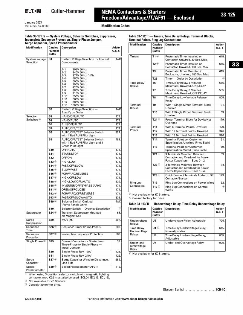
CA08102001E For more
25
33-1NEMA Contactors & StartersFreedom/Advantage/IT./AF91 — Enclosed Modification CodesJanuary 2003Vol. 2, Ref. No. [0143]
33
Table 33-191. S — System Voltage, Selector Switches, Suppressor, Incomplete Sequence Protection, Single-Phase Jumper, Surge Capacitor, Speed Potentiometer
1 When using 3-position selector switch with magnetic lighting contactor, mod C20 must also be used (ECL04, ECL13, ECL15).
2 Not available for IT. Starters.3 Consult factory for price.
Table 33-192. T — Timers, Time Delay Relays, Terminal Blocks, Terminal Points, Ring Lug Connections
4 Not available for IT. Starters.5 Consult factory for price.
Table 33-193. U — Undervoltage Relay, Time Delay Undervoltage Relay
6 Not available for IT. Starters.
Modification CatalogNumberSuffix
Description AdderU.S. $
System Voltage Selection
S1 System Voltage Selection for Internal Components
N/C
/H1 208V 60 Hz/H2 240V 60 Hz/H3 277V 60 Hz, 1-Ph/H4 480V 60 Hz/H5 600V 60 Hz/H6 796V 60 Hz/H7 220V 50 Hz/H8 380V 50 Hz/H9 415V 50 Hz/H10 550V 50 Hz/H11 660V 50 Hz/H12 380V 60 Hz/H13 1500V 60 Hz
S2 System Voltage Selection — Specify on Order
N/C
Selector Switches 1
S3 HAND/OFF/AUTO 171.S4 HAND/AUTO 171.S6 RUN/OFF/AUTO 171.S7 AUTO/OFF/TEST 171.S8 AUTO/OFF/TEST Selector Switch
with 1 Red RUN Pilot Light327.
S9 AUTO/OFF/TEST Selector Switch with 1 Red RUN Pilot Light and 1 Green Pilot Light
489.
S10 OFF/AUTO 171.S11 START/STOP 171.S12 OFF/ON 171.S13 2 HIGH/LOW 171.S14 2 FAST/OFF/SLOW 171.S15 2 SLOW/FAST 171.S16 2 FORWARD/REVERSE 171.S17 2 HIGH/OFF/LOW 171.S18 2 HIGH/LOW/OFF/AUTO 339.S38 2 INVERTER/OFF/BYPASS (AF91) 171.S41 2 OPEN/OFF/CLOSE 171.S42 2 FORWARD/OFF/REVERSE 171.S43 2 FAST/OFF/SLOW/AUTO 339.S19 2 Selector Switch Omitted
(Pump Panels Only) N/C
S40 Selector Switch — Order by Description 3
Suppressor S24 2 Transient Suppressor Mountedon Magnet Coil
68.
SurgeSuppression
S20 MOV (IT.) 297.
Sequence Timer
S26 2 Sequence Timer (Pump Panels) 600.
Sequence Protection
S27 2 Incomplete Sequence Protection 860.
Single Phase 2 S29 Convert Contactor or Starter from Three-Phase to Single-Phase — Install Jumper
33.
S30 Single-Phase Rev. 120V 125.S31 Single-Phase Rev. 240V 125.
SurgeCapacitor
S37 2 Surge Capacitor Wired to Disconnect Line Side
289.
Speed Potentiometer
S39 2 Speed Potentiometer (AF91) 419.
Modification CatalogNumberSuffix
Description AdderU.S. $
Timers T1 4 Pneumatic Timer Installed on Contactor, Unwired, 30 Sec. Max.
615.
T2 4 Pneumatic Timer Installed onContactor, Unwired, 180 Sec. Max.
615.
T3 Pneumatic Timer Mounted in Enclosure, Unwired, 180 Sec. Max.
615.
T25 Timer — Order by Description 5
Time DelayRelays
T6 Time Delay Relay, 3 Minutes Maximum, Unwired, ON DELAY
585.
T7 Time Delay Relay, 3 MinutesMaximum, Unwired, OFF DELAY
585.
T8 Time Delay Low Voltage ReleaseRelay
805.
TerminalBlocks
T9 With 1 Single Circuit Terminal Block,Unwired
31.
T10 With 2 Single Circuit Terminal Block,Unwired
59.
T24 4 Power Terminal Block for DeviceNet Overload
179.
TerminalPoints
T11 With 6 Terminal Points, Unwired 179.
T12 With 12 Terminal Points, Unwired 346.
T13 With 18 Terminal Points, Unwired 520.
T14 Terminal Point per CustomerSpecification, Unwired (Price Each)
31.
T15 Terminal Point per CustomerSpecification, Wired (Price Each)
59.
T21 4 3 Terminals Mounted Between Contactor and Overload for Power Factor Capacitors — Sizes 0 – 2
39.
T22 4 3 Terminals Mounted BetweenContactor and Overload for PowerFactor Capacitors — Sizes 3 – 4
74.
T23 4 Quick-Connect Terminals Added to DP Contactor/Starter
179.
Ring LugConnectors
T16 Ring Lug Connections on Power Wires 92.
T17 4 Ring Lug Connections on Control Wires
5
Modification CatalogNumberSuffix
Description AdderU.S. $
Undervoltage Relays
U2 Undervoltage Relay, Adjustable 725.
Time Delay Undervoltage Relays
U4 6 Time Delay Undervoltage Relay, Non-adjustable
615.
U5 Time Delay Undervoltage Relay,Adjustable
805.
Under- and Overvoltage Relay
U7 Under- and Overvoltage Relay 905.
Discount Symbol . . . . . . . . . . . . . . . . . . . . . . . 1CD-1C
information visit: www.cutler-hammer.eaton.com
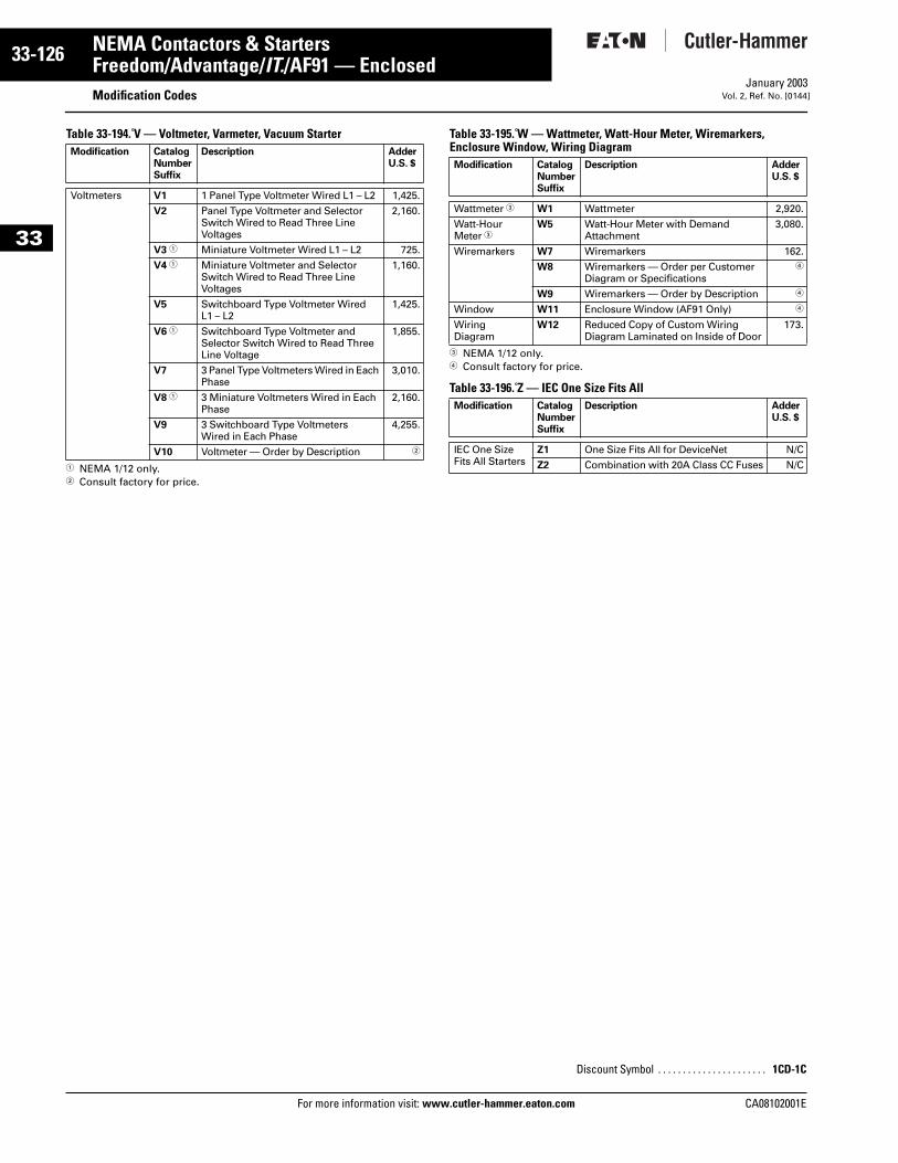
33-126
33
NEMA Contactors & StartersFreedom/Advantage/IT./AF91 — Enclosed
Modification CodesFor more information visit: www.cutler-hammer.eaton.com
January 2003Vol. 2, Ref. No. [0144]
Table 33-194. V — Voltmeter, Varmeter, Vacuum Starter
1 NEMA 1/12 only.2 Consult factory for price.
Table 33-195. W — Wattmeter, Watt-Hour Meter, Wiremarkers, Enclosure Window, Wiring Diagram
3 NEMA 1/12 only.4 Consult factory for price.
Table 33-196. Z — IEC One Size Fits All
Modification CatalogNumberSuffix
Description AdderU.S. $
Voltmeters V1 1 Panel Type Voltmeter Wired L1 – L2 1,425.
V2 Panel Type Voltmeter and SelectorSwitch Wired to Read Three LineVoltages
2,160.
V3 1 Miniature Voltmeter Wired L1 – L2 725.
V4 1 Miniature Voltmeter and Selector Switch Wired to Read Three LineVoltages
1,160.
V5 Switchboard Type Voltmeter WiredL1 – L2
1,425.
V6 1 Switchboard Type Voltmeter and Selector Switch Wired to Read Three Line Voltage
1,855.
V7 3 Panel Type Voltmeters Wired in Each Phase
3,010.
V8 1 3 Miniature Voltmeters Wired in Each Phase
2,160.
V9 3 Switchboard Type VoltmetersWired in Each Phase
4,255.
V10 Voltmeter — Order by Description 2
Modification CatalogNumberSuffix
Description AdderU.S. $
Wattmeter 3 W1 Wattmeter 2,920.
Watt-Hour Meter 3
W5 Watt-Hour Meter with Demand Attachment
3,080.
Wiremarkers W7 Wiremarkers 162.
W8 Wiremarkers — Order per Customer Diagram or Specifications
4
W9 Wiremarkers — Order by Description 4
Window W11 Enclosure Window (AF91 Only) 4
Wiring Diagram
W12 Reduced Copy of Custom Wiring Diagram Laminated on Inside of Door
173.
Modification CatalogNumberSuffix
Description AdderU.S. $
IEC One Size Fits All Starters
Z1 One Size Fits All for DeviceNet N/C
Z2 Combination with 20A Class CC Fuses N/C
Discount Symbol . . . . . . . . . . . . . . . . . . . . . . 1CD-1C
CA08102001E
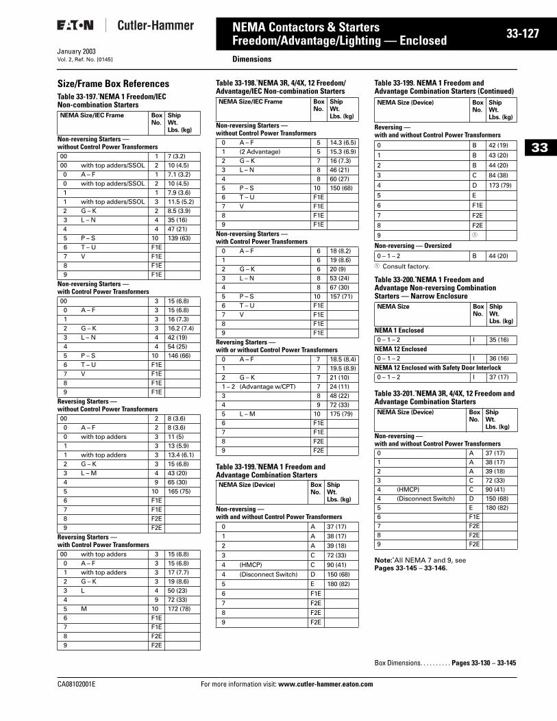
CA08102001E For more
27
33-1NEMA Contactors & StartersFreedom/Advantage/Lighting — Enclosed DimensionsJanuary 2003Vol. 2, Ref. No. [0145]
33
Size/Frame Box ReferencesTable 33-197. NEMA 1 Freedom/IEC Non-combination Starters
Table 33-198. NEMA 3R, 4/4X, 12 Freedom/Advantage/IEC Non-combination Starters
Table 33-199. NEMA 1 Freedom and Advantage Combination Starters
Table 33-199. NEMA 1 Freedom and Advantage Combination Starters (Continued)
1 Consult factory.
Table 33-200. NEMA 1 Freedom and Advantage Non-reversing Combination Starters — Narrow Enclosure
Table 33-201. NEMA 3R, 4/4X, 12 Freedom and Advantage Combination Starters
Note: All NEMA 7 and 9, seePages 33-145 – 33-146.
NEMA Size/IEC Frame BoxNo.
ShipWt.Lbs. (kg)
Non-reversing Starters — without Control Power Transformers00 1 7 (3.2)00 with top adders/SSOL 2 10 (4.5)0 A – F 1 7.1 (3.2)0 with top adders/SSOL 2 10 (4.5)1 1 7.9 (3.6)1 with top adders/SSOL 3 11.5 (5.2)2 G – K 2 8.5 (3.9)3 L – N 4 35 (16)4 4 47 (21)5 P – S 10 139 (63)6 T – U F1E7 V F1E8 F1E9 F1E
Non-reversing Starters — with Control Power Transformers00 3 15 (6.8)0 A – F 3 15 (6.8)1 3 16 (7.3)2 G – K 3 16.2 (7.4)3 L – N 4 42 (19)4 4 54 (25)5 P – S 10 146 (66)6 T – U F1E7 V F1E8 F1E9 F1E
Reversing Starters — without Control Power Transformers00 2 8 (3.6)0 A – F 2 8 (3.6)0 with top adders 3 11 (5)1 3 13 (5.9)1 with top adders 3 13.4 (6.1)2 G – K 3 15 (6.8)3 L – M 4 43 (20)4 9 65 (30)5 10 165 (75)6 F1E7 F1E8 F2E9 F2E
Reversing Starters — with Control Power Transformers00 with top adders 3 15 (6.8)0 A – F 3 15 (6.8)1 with top adders 3 17 (7.7)2 G – K 3 19 (8.6)3 L 4 50 (23)4 9 72 (33)5 M 10 172 (78)6 F1E7 F1E8 F2E9 F2E
NEMA Size/IEC Frame BoxNo.
ShipWt.Lbs. (kg)
Non-reversing Starters — without Control Power Transformers
0 A – F 5 14.3 (6.5)1 (2 Advantage) 5 15.3 (6.9)2 G – K 7 16 (7.3)3 L – N 8 46 (21)4 8 60 (27)5 P – S 10 150 (68)6 T – U F1E7 V F1E8 F1E9 F1E
Non-reversing Starters — with Control Power Transformers
0 A – F 6 18 (8.2)1 6 19 (8.6)2 G – K 6 20 (9)3 L – N 8 53 (24)4 8 67 (30)5 P – S 10 157 (71)6 T – U F1E7 V F1E8 F1E9 F1E
Reversing Starters — with or without Control Power Transformers
0 A – F 7 18.5 (8.4)1 7 19.5 (8.9)2 G – K 7 21 (10)1 – 2 (Advantage w/CPT) 7 24 (11)3 8 48 (22)4 9 72 (33)5 L – M 10 175 (79)6 F1E7 F1E8 F2E9 F2E
NEMA Size (Device) BoxNo.
ShipWt.Lbs. (kg)
Non-reversing —with and without Control Power Transformers
0 A 37 (17)
1 A 38 (17)
2 A 39 (18)
3 C 72 (33)
4 (HMCP) C 90 (41)
4 (Disconnect Switch) D 150 (68)
5 E 180 (82)
6 F1E
7 F2E
8 F2E
9 F2E
NEMA Size (Device) BoxNo.
ShipWt.Lbs. (kg)
Reversing —with and without Control Power Transformers0 B 42 (19)
1 B 43 (20)
2 B 44 (20)
3 C 84 (38)
4 D 173 (79)
5 E
6 F1E
7 F2E
8 F2E
9 1
Non-reversing — Oversized0 – 1 – 2 B 44 (20)
NEMA Size BoxNo.
ShipWt.Lbs. (kg)
NEMA 1 Enclosed0 – 1 – 2 I 35 (16)
NEMA 12 Enclosed0 – 1 – 2 I 36 (16)
NEMA 12 Enclosed with Safety Door Interlock 0 – 1 – 2 I 37 (17)
NEMA Size (Device) BoxNo.
ShipWt.Lbs. (kg)
Non-reversing — with and without Control Power Transformers0 A 37 (17)1 A 38 (17)2 A 39 (18)3 C 72 (33)4 (HMCP) C 90 (41)4 (Disconnect Switch) D 150 (68)5 E 180 (82)6 F1E7 F2E8 F2E9 F2E
Box Dimensions. . . . . . . . . . Pages 33-130 – 33-145
information visit: www.cutler-hammer.eaton.com
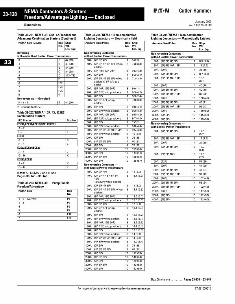
33-128
33
NEMA Contactors & StartersFreedom/Advantage/Lighting — Enclosed
DimensionsFor more information visit: www.cutler-hammer.eaton.com
January 2003Vol. 2, Ref. No. [0146]
Table 33-201. NEMA 3R, 4/4X, 12 Freedom and Advantage Combination Starters (Continued)
1 Consult factory.
Table 33-202. NEMA 1, 3R, 4X, 12 IEC Combination Starters
Note: All NEMA 7 and 9, seePages 33-145 – 33-146.
Table 33-203. NEMA 3R — Pump Panels Freedom/Advantage
Table 33-204. NEMA 1 Non-combination Lighting Contactors — Electrically Held
Table 33-205. NEMA 1 Non-combination Lighting Contactors — Magnetically Latched
NEMA Size (Device) BoxNo.
ShipWt.Lbs. (kg)
Reversing — with and without Control Power Transformers0 B 42 (19)1 B 43 (20)2 B 44 (20)3 C 84 (38)4 D 173 (79)5 E6 F1E7 F2E8 F2E9 1
Non-reversing — Oversized0 – 1 – 2 B 44 (20)
IEC Frame Box No.
ECE16/ECE17/ECE18/ECE19/ECE21A – E JF – H L
ECE20A – E KF – H L
ECE22/ECE24/ECE25A – F JG – H K
ECE23/ECE26A – F KG – H L
NEMA Size Box No.
1 – 2 Narrow P11 – 3 P34 P55 P76 F1E7 F2E
Ampere Size (Poles) BoxNo.
ShipWt.Lbs. (kg)
Non-reversing Contactors — without Control Power Transformers
10A (2P, 3P, 4P) 1 5 (2.3)10A (2P, 3P, 4P, 5P, 6P) w/top
adders2 7.3 (3.3)
10A (9P, 10P, 12P, 20P) 3 9.5 (4.3)20A (2P, 3P) 1 5.2 (2.4)20A (2P, 3P, 4P, 5P, 6P) w/top
adders & 6P w/o top adder
2 7.3 (3.3)
20A (9P, 10P, 12P, 20P) 3 9 (4.1)20A (9P, 12P) w/top adders 3 9.3 (4.2)30A (2P, 3P) 1 5.3 (2.4)30A (2P, 3P, 4P) w/top
adders2 7.3 (3.3)
30A (5P, 6P) 3 9.0 (4.1)30A (5P, 6P) w/top adders 3 9.2 (4.2)30A (9P, 10P, 12P, 20P) 3 9.5 (4.3)30A (9P, 12P) w/top adders 3 9.7 (4.4)60A (2P, 3P) 1 7 (3.2)60A (2P, 3P) w/top adders 3 9.8 (4.4)60A (4P, 5P, 6P, 9P, 10P, 12P) 3 9.5 (4.3)60A (4P, 5P) w/top adders 3 10 (4.5)
100A (2P, 3P) 4 35 (16)100A (4P, 5P, 6P, 9P) 4 60 (27)200A (2P, 3P) 4 70 (32)200A (4P, 5P, 6P) 10 133 (60)300A (2P, 3P) 10 113 (51)300A (4P, 5P, 6P) 10 136 (62)400A (2P, 3P) 10 125 (57)
Non-reversing Contactors — with Control Power Transformers
10A (2P, 3P, 4P) 2 11 (5.0)10A (2P, 3P, 4P, 5P, 6P, 9P,
10P,12P, 20P) w/top adders
3 13.1 (5.9)
20A (2P, 3P, 4P, 6P) 2 11 (5.0)20A (2P, 3P, 4P, 5P, 6P) w/top
adders3 13.1 (5.9)
20A (9P, 10P, 12P, 20P) 3 13.5 (6.1)20A (9P, 12P) w/top adders 3 13.5 (6.1)30A (2P, 3P, 4P) 2 12 (5.4)30A (2P, 3P, 4P) w/top
adders3 13.1 (5.9)
30A (5P, 6P) 2 12.5 (5.7)30A (5P, 6P) w/top adders 3 13.5 (6.1)30A (9P, 10P, 12P, 20P) 3 13.9 (6.3)30A (9P, 12P) w/top adders 3 14.1 (6.4)60A (2P, 3P) 2 12.8 (5.8)60A (2P, 3P) w/top adders 3 14 (6.4)60A (4P, 5P, 6P, 9P, 10P, 12P) 3 14 (6.4)60A (4P, 5P) w/top adders 3 14.2 (6.4)
100A (2P, 3P) 4 39 (18)100A (4P, 5P, 6P, 9P) 4 67 (30)200A (2P, 3P) 10 117 (53)200A (4P, 5P, 6P) 10 140 (64)300A (2P, 3P) 10 120 (54)300A (4P, 5P, 6P) 10 143 (65)400A (2P, 3P) 10 132 (60)
Ampere Size (Poles) BoxNo.
ShipWt.Lbs. (kg)
Non-reversing Contactors— without Control Power Transformers
30A (2P, 3P, 4P, 5P) 2 8.5 (3.9)
30A (6P, 8P, 10P, 12P) 3 13 (5.9)
30A (20P) 4 35 (16)
60A (2P, 3P, 4P, 5P) 2 8.7 (3.9)
60A (6P, 8P, 10P, 12P) 3 13.5 (6.1)
60A (20P) 4 40 (18)
100A (2P, 3P, 4P, 5P) 4 40 (18)
100A (6P, 8P, 10P, 12P) 9 85 (39)
100A (20P) 10 100 (45)
200A (2P, 3P, 4P, 5P) 4 46 (21)
200A (6P, 8P, 10P, 12P) 9 95 (43)
200A (20P) 10 110 (50)
300A (2P, 3P) 10 115 (52)
400A (2P, 3P) 10 125 (57)
Non-reversing Contactors — with Control Power Transformers
30A (2P, 3P, 4P, 5P) 2 12.5 (5.7)
30A (6P, 8P, 10P, 12P) 3 17 (7.7)
30A (20P) 4 39 (18)
60A (2P, 3P, 4P, 5P) 2 12.7 (5.8)
60A (6P, 8P, 10P) 3 17.5 (7.9)
60A (12P) 9 87 (39)
60A (20P) 4 44 (20)
100A (2P, 3P, 4P, 5P) 4 47 (21)
100A (6P, 8P, 10P, 12P) 9 92 (42)
100A (20P) 10 107 (49)
200A (2P, 3P, 4P, 5P) 4 53 (24)
200A (6P, 8P, 10P, 12P) 9 102 (46)
200A (20P) 10 117 (53)
300A (2P, 3P) 10 122 (55)
400A (2P, 3P) 10 132 (60)
Box Dimensions . . . . . . . . . Pages 33-130 – 33-145
CA08102001E
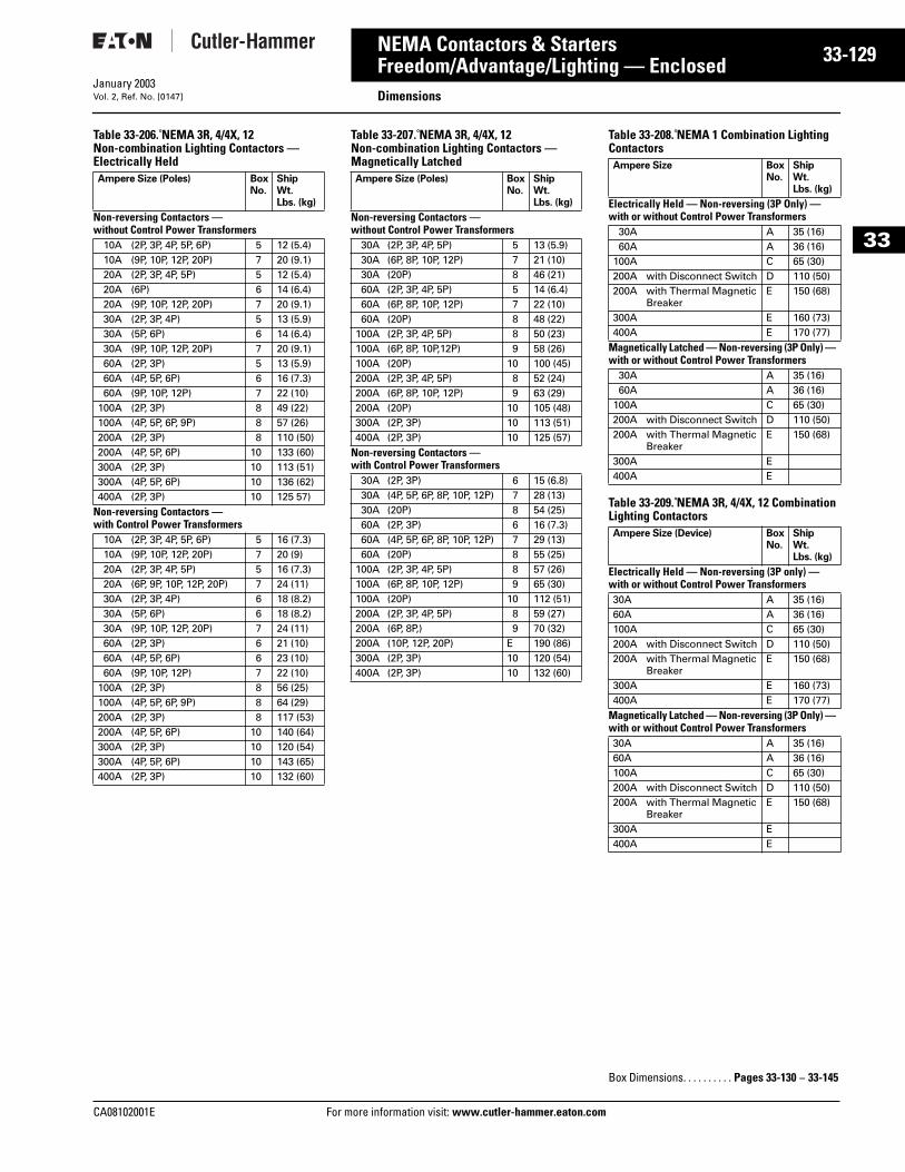
CA08102001E For more
29
33-1NEMA Contactors & StartersFreedom/Advantage/Lighting — Enclosed DimensionsJanuary 2003Vol. 2, Ref. No. [0147]
33
Table 33-206. NEMA 3R, 4/4X, 12 Non-combination Lighting Contactors — Electrically Held
Table 33-207. NEMA 3R, 4/4X, 12 Non-combination Lighting Contactors — Magnetically Latched
Table 33-208. NEMA 1 Combination Lighting Contactors
Table 33-209. NEMA 3R, 4/4X, 12 Combination Lighting Contactors
Ampere Size (Poles) BoxNo.
ShipWt.Lbs. (kg)
Non-reversing Contactors — without Control Power Transformers
10A (2P, 3P, 4P, 5P, 6P) 5 12 (5.4)10A (9P, 10P, 12P, 20P) 7 20 (9.1)20A (2P, 3P, 4P, 5P) 5 12 (5.4)20A (6P) 6 14 (6.4)20A (9P, 10P, 12P, 20P) 7 20 (9.1)30A (2P, 3P, 4P) 5 13 (5.9)30A (5P, 6P) 6 14 (6.4)30A (9P, 10P, 12P, 20P) 7 20 (9.1)60A (2P, 3P) 5 13 (5.9)60A (4P, 5P, 6P) 6 16 (7.3)60A (9P, 10P, 12P) 7 22 (10)
100A (2P, 3P) 8 49 (22)100A (4P, 5P, 6P, 9P) 8 57 (26)200A (2P, 3P) 8 110 (50)200A (4P, 5P, 6P) 10 133 (60)300A (2P, 3P) 10 113 (51)300A (4P, 5P, 6P) 10 136 (62)400A (2P, 3P) 10 125 57)
Non-reversing Contactors — with Control Power Transformers
10A (2P, 3P, 4P, 5P, 6P) 5 16 (7.3)10A (9P, 10P, 12P, 20P) 7 20 (9)20A (2P, 3P, 4P, 5P) 5 16 (7.3)20A (6P, 9P, 10P, 12P, 20P) 7 24 (11)30A (2P, 3P, 4P) 6 18 (8.2)30A (5P, 6P) 6 18 (8.2)30A (9P, 10P, 12P, 20P) 7 24 (11)60A (2P, 3P) 6 21 (10)60A (4P, 5P, 6P) 6 23 (10)60A (9P, 10P, 12P) 7 22 (10)
100A (2P, 3P) 8 56 (25)100A (4P, 5P, 6P, 9P) 8 64 (29)200A (2P, 3P) 8 117 (53)200A (4P, 5P, 6P) 10 140 (64)300A (2P, 3P) 10 120 (54)300A (4P, 5P, 6P) 10 143 (65)400A (2P, 3P) 10 132 (60)
Ampere Size (Poles) BoxNo.
ShipWt.Lbs. (kg)
Non-reversing Contactors — without Control Power Transformers
30A (2P, 3P, 4P, 5P) 5 13 (5.9)30A (6P, 8P, 10P, 12P) 7 21 (10)30A (20P) 8 46 (21)60A (2P, 3P, 4P, 5P) 5 14 (6.4)60A (6P, 8P, 10P, 12P) 7 22 (10)60A (20P) 8 48 (22)
100A (2P, 3P, 4P, 5P) 8 50 (23)100A (6P, 8P, 10P,12P) 9 58 (26)100A (20P) 10 100 (45)200A (2P, 3P, 4P, 5P) 8 52 (24)200A (6P, 8P, 10P, 12P) 9 63 (29)200A (20P) 10 105 (48)300A (2P, 3P) 10 113 (51)400A (2P, 3P) 10 125 (57)
Non-reversing Contactors — with Control Power Transformers
30A (2P, 3P) 6 15 (6.8)30A (4P, 5P, 6P, 8P, 10P, 12P) 7 28 (13)30A (20P) 8 54 (25)60A (2P, 3P) 6 16 (7.3)60A (4P, 5P, 6P, 8P, 10P, 12P) 7 29 (13)60A (20P) 8 55 (25)
100A (2P, 3P, 4P, 5P) 8 57 (26)100A (6P, 8P, 10P, 12P) 9 65 (30)100A (20P) 10 112 (51)200A (2P, 3P, 4P, 5P) 8 59 (27)200A (6P, 8P,) 9 70 (32)200A (10P, 12P, 20P) E 190 (86)300A (2P, 3P) 10 120 (54)400A (2P, 3P) 10 132 (60)
Ampere Size BoxNo.
ShipWt.Lbs. (kg)
Electrically Held — Non-reversing (3P Only) — with or without Control Power Transformers
30A A 35 (16)60A A 36 (16)
100A C 65 (30)200A with Disconnect Switch D 110 (50)200A with Thermal Magnetic
BreakerE 150 (68)
300A E 160 (73)400A E 170 (77)
Magnetically Latched — Non-reversing (3P Only) — with or without Control Power Transformers
30A A 35 (16)60A A 36 (16)
100A C 65 (30)200A with Disconnect Switch D 110 (50)200A with Thermal Magnetic
BreakerE 150 (68)
300A E400A E
Ampere Size (Device) BoxNo.
ShipWt.Lbs. (kg)
Electrically Held — Non-reversing (3P only) — with or without Control Power Transformers30A A 35 (16)60A A 36 (16)100A C 65 (30)200A with Disconnect Switch D 110 (50)200A with Thermal Magnetic
BreakerE 150 (68)
300A E 160 (73)400A E 170 (77)
Magnetically Latched — Non-reversing (3P Only) — with or without Control Power Transformers30A A 35 (16)60A A 36 (16)100A C 65 (30)200A with Disconnect Switch D 110 (50)200A with Thermal Magnetic
BreakerE 150 (68)
300A E400A E
Box Dimensions. . . . . . . . . . Pages 33-130 – 33-145
information visit: www.cutler-hammer.eaton.com
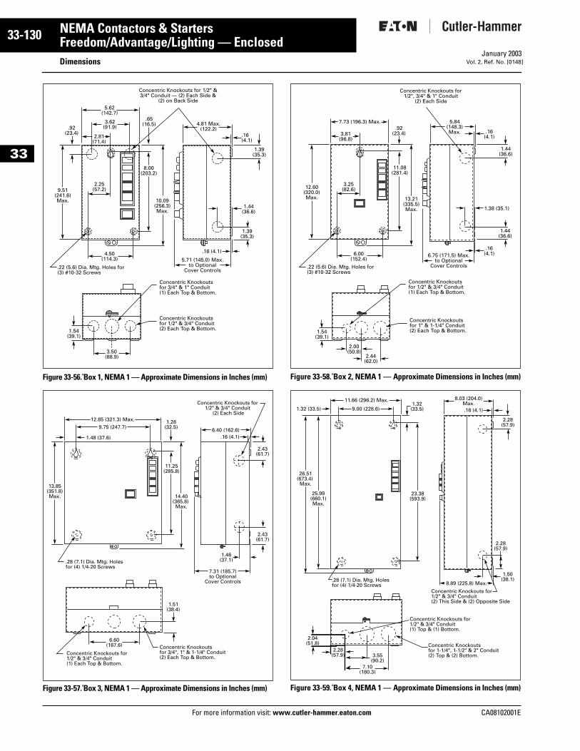
33-130
33
NEMA Contactors & StartersFreedom/Advantage/Lighting — Enclosed
DimensionsFor more information visit: www.cutler-hammer.eaton.com
January 2003Vol. 2, Ref. No. [0148]
Figure 33-56. Box 1, NEMA 1 — Approximate Dimensions in Inches (mm)
Figure 33-57. Box 3, NEMA 1 — Approximate Dimensions in Inches (mm)
Figure 33-58. Box 2, NEMA 1 — Approximate Dimensions in Inches (mm)
Figure 33-59. Box 4, NEMA 1 — Approximate Dimensions in Inches (mm)
5.62(142.7)
3.62(91.9)
2.81(71.4)
.92(23.4)
.65(16.5)
8.00(203.2)
10.09(256.3) Max.
9.51(241.6)Max.
2.25(57.2)
1.44(36.6)
1.39(35.3)
4.50(114.3)
3.50(88.9)
1.54(39.1)
.22 (5.6) Dia. Mtg. Holes for(3) #10-32 Screws
4.81 Max.(122.2)
5.71 (145.0) Max.to Optional
Cover Controls
Concentric Knockoutsfor 3/4" & 1" Conduit(1) Each Top & Bottom.
Concentric Knockouts for 1/2" & 3/4" Conduit — (2) Each Side &
(2) on Back Side
Concentric Knockoutsfor 1/2" & 3/4" Conduit(2) Each Top & Bottom.
.16(4.1)
.16 (4.1)
1.39(35.3)
12.65 (321.3) Max.
9.75 (247.7)
1.48 (37.6)
1.28(32.5)
.16 (4.1)
11.25(285.8)
14.40(365.8) Max.
13.85(351.8)Max.
2.43(61.7)
1.46(37.1)
2.43(61.7)
6.60(167.6)
1.51(38.4)
.28 (7.1) Dia. Mtg. Holes for (4) 1/4-20 Screws
6.40 (162.6)
7.31 (185.7)to Optional
Cover Controls
Concentric Knockouts for1/2" & 3/4" Conduit(1) Each Top & Bottom.
Concentric Knockouts for 1/2" & 3/4" Conduit
(2) Each Side
Concentric Knockoutsfor 3/4", 1" & 1-1/4" Conduit(2) Each Top & Bottom.
7.73 (196.3) Max.
3.81(96.8)
.16(4.1)
.16(4.1)
11.08(281.4)
13.21(335.5) Max.
12.60(320.0)Max.
3.25(82.6)
1.38 (35.1)
1.44(36.6)
1.44(36.6)
6.00(152.4)
2.00(50.8)
2.44(62.0)
1.54(39.1)
.22 (5.6) Dia. Mtg. Holes for(3) #10-32 Screws
5.84(148.3)Max.
6.75 (171.5) Max.to Optional
Cover Controls
Concentric Knockoutsfor 1/2" & 3/4" Conduit(1) Each Top & Bottom.
Concentric Knockouts for 1/2", 3/4" & 1" Conduit
(2) Each Side
Concentric Knockoutsfor 1" & 1-1/4" Conduit(2) Each Top & Bottom.
.92(23.4)
11.66 (296.2) Max.
9.00 (228.6)1.32 (33.5)1.32
(33.5)
23.38(593.9)
26.51(673.4) Max.
25.99(660.1)Max.
.28 (7.1) Dia. Mtg. Holes for (4) 1/4-20 Screws
.16 (4.1)
2.28(57.9)
1.50(38.1)
2.28(57.9)
8.03 (204.0)Max.
8.89 (225.8) Max.
Concentric Knockouts for 1/2" & 3/4" Conduit (2) This Side & (2) Opposite Side
2.04(51.8)
2.28(57.9)
7.10(180.3)
3.55(90.2)
Concentric Knockouts for1/2" & 3/4" Conduit(1) Top & (1) Bottom.
Concentric Knockoutsfor 1-1/4", 1-1/2" & 2" Conduit(2) Top & (2) Bottom.
CA08102001E
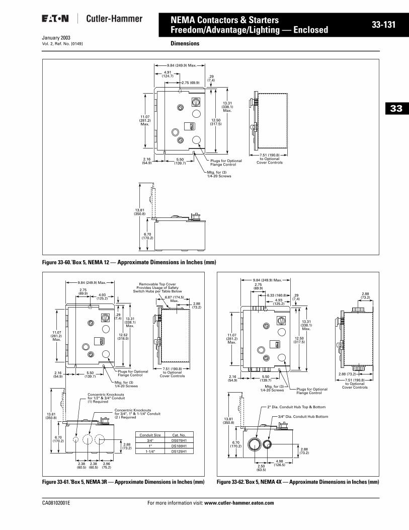
CA08102001E For more
31
33-1NEMA Contactors & StartersFreedom/Advantage/Lighting — Enclosed DimensionsJanuary 2003Vol. 2, Ref. No. [0149]
33
Figure 33-60. Box 5, NEMA 12 — Approximate Dimensions in Inches (mm)
Figure 33-61. Box 5, NEMA 3R — Approximate Dimensions in Inches (mm) Figure 33-62. Box 5, NEMA 4X — Approximate Dimensions in Inches (mm)
9.84 (249.9) Max.
11.07(281.2) Max.
13.31(338.1)Max.
12.50(317.5)
2.75 (69.9)
.29(7.4)
4.91(124.7)
5.50(139.7)
2.16(54.9) Plugs for Optional
Flange Control
7.51 (190.8)to Optional
Cover Controls
Mtg. for (3)1/4-20 Screws
6.70(170.2)
13.81(350.8)
9.84 (249.9) Max.
11.07(281.2) Max.
13.31(338.1)Max.
12.52(318.0)
2.75(69.9) 4.93
(125.2) 6.87 (174.5)Max.
2.88(73.2)
2.38(60.5)
5.50(139.7)
2.16(54.9)
Plugs for OptionalFlange Control
7.51 (190.8)to Optional
Cover Controls
Removable Top CoverProvides Usage of Safety
Switch Hubs per Table Below
Mtg. for (3)1/4-20 Screws
2.38(60.5)
2.96(75.2)
2.88(73.2)
6.70(170.2)
13.81(350.8)
Concentric Knockoutsfor 1/2" & 3/4" Conduit(1) Required
Concentric Knockoutsfor 3/4", 1" & 1-1/4" Conduit(2 ) Required
.29(7.4)
Conduit Size Cat. No.
3/4" DS075H1
1" DS100H1
1-1/4" DS125H1
2.88 (73.2)
9.84 (249.9) Max.
11.07(281.2)Max.
13.31(338.1)Max.
12.50(317.5)
2.75(69.9)
.29(7.4)4.93
(125.2)
6.33 (160.8)
5.50(139.7)
2.16(54.9)
4.98(126.5)2.50
(63.5)
Plugs for OptionalFlange Control
7.51 (190.8)to Optional
Cover ControlsMtg. for (3)1/4-20 Screws
6.70(170.2)
2" Dia. Conduit Hub Top & Bottom
3/4" Dia. Conduit Hub Bottom
2.88(73.2)
13.81(350.8)
2.88(73.2)
information visit: www.cutler-hammer.eaton.com
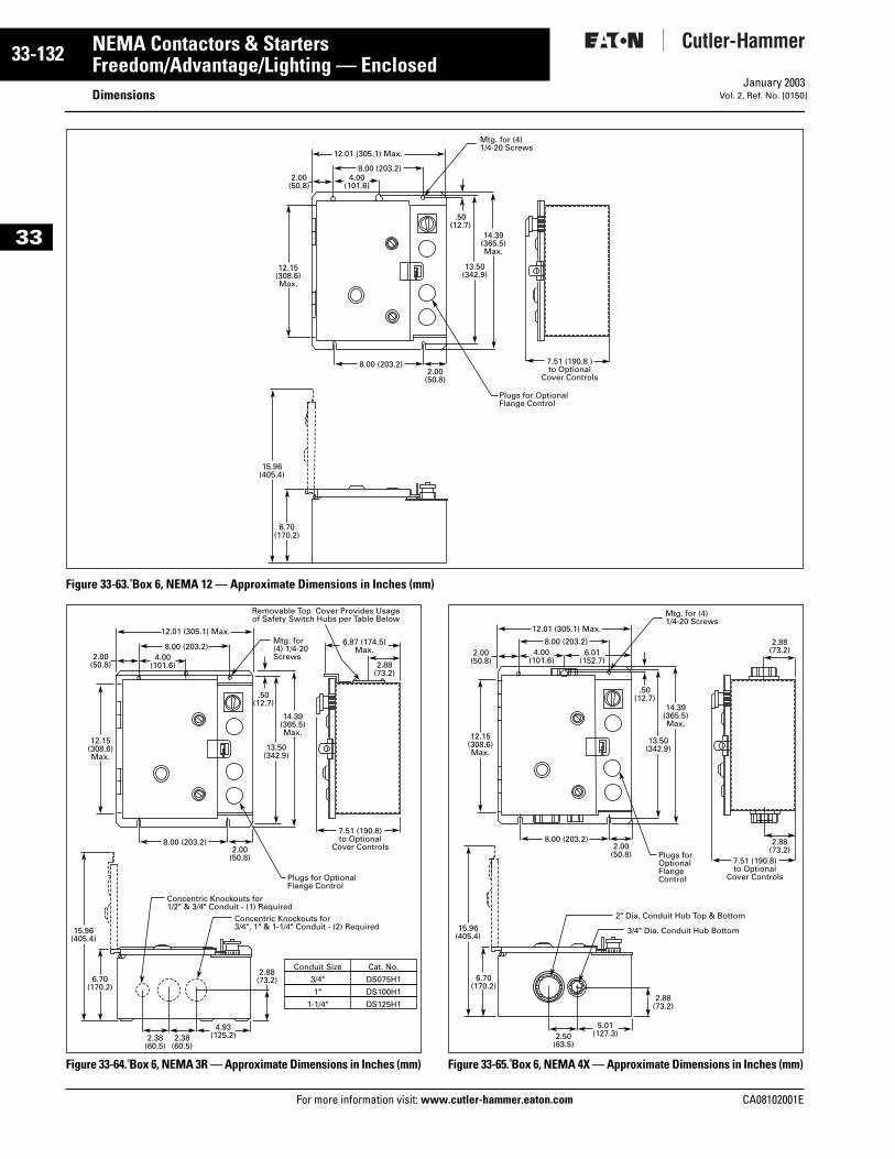
33-132
33
NEMA Contactors & StartersFreedom/Advantage/Lighting — Enclosed
DimensionsFor more information visit: www.cutler-hammer.eaton.com
January 2003Vol. 2, Ref. No. [0150]
Figure 33-63. Box 6, NEMA 12 — Approximate Dimensions in Inches (mm)
Figure 33-64. Box 6, NEMA 3R — Approximate Dimensions in Inches (mm) Figure 33-65. Box 6, NEMA 4X — Approximate Dimensions in Inches (mm)
12.01 (305.1) Max.
Mtg. for (4)1/4-20 Screws
4.00(101.6)
2.00(50.8)
2.00(50.8)
8.00 (203.2)
8.00 (203.2)
12.15(308.6)Max.
14.39(365.5)Max.
.50(12.7)
13.50(342.9)
Plugs for Optional Flange Control
6.70(170.2)
15.96(405.4)
7.51 (190.8 )to Optional
Cover Controls
12.01 (305.1) Max.Mtg. for(4) 1/4-20Screws
Removable Top Cover Provides Usageof Safety Switch Hubs per Table Below
4.00(101.6)
2.00(50.8)
2.00(50.8)
8.00 (203.2)
8.00 (203.2)
12.15(308.6)Max.
14.39(365.5)Max.
.50(12.7)
2.88(73.2)
6.87 (174.5)Max.
13.50(342.9)
2.38(60.5)
2.38(60.5)
4.93(125.2)
2.88(73.2)6.70
(170.2)
15.96(405.4)
Concentric Knockouts for1/2" & 3/4" Conduit - (1) Required
Concentric Knockouts for 3/4", 1" & 1-1/4" Conduit - (2) Required
Conduit Size Cat. No.
3/4" DS075H1
1" DS100H1
1-1/4" DS125H1
Plugs for OptionalFlange Control
7.51 (190.8)to Optional
Cover Controls
5.01(127.3)
2.88(73.2)
6.70(170.2)
15.96(405.4)
2" Dia. Conduit Hub Top & Bottom
12.01 (305.1) Max.
Mtg. for (4)1/4-20 Screws
4.00(101.6)
2.00(50.8)
2.00(50.8)
8.00 (203.2)
8.00 (203.2)
14.39(365.5)Max.
12.15(308.6)Max.
.50(12.7)
13.50(342.9)
2.50(63.5)
3/4" Dia. Conduit Hub Bottom
2.88(73.2)
2.88(73.2)
7.51 (190.8)to Optional
Cover Controls
6.01(152.7)
Plugs forOptional FlangeControl
CA08102001E
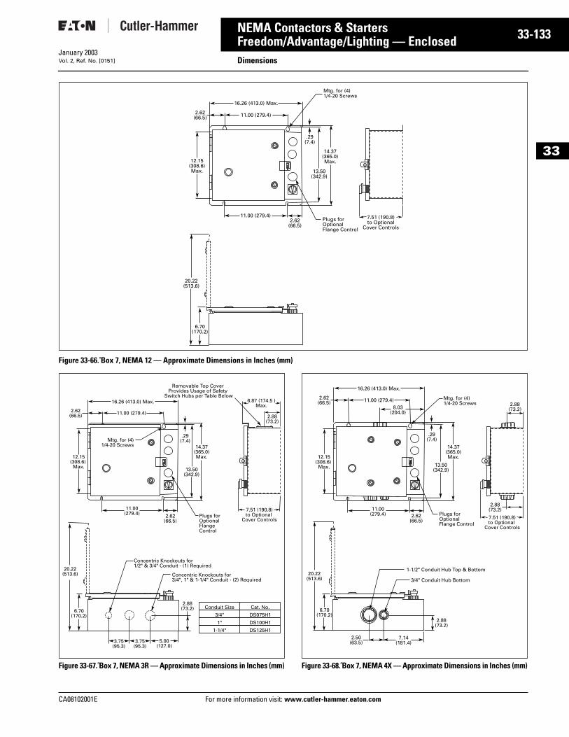
CA08102001E For more
33
33-1NEMA Contactors & StartersFreedom/Advantage/Lighting — Enclosed DimensionsJanuary 2003Vol. 2, Ref. No. [0151]
33
Figure 33-66. Box 7, NEMA 12 — Approximate Dimensions in Inches (mm)
Figure 33-67. Box 7, NEMA 3R — Approximate Dimensions in Inches (mm) Figure 33-68. Box 7, NEMA 4X — Approximate Dimensions in Inches (mm)
6.70(170.2)
20.22(513.6)
7.51 (190.8)to Optional
Cover Controls
Mtg. for (4)1/4-20 Screws
11.00 (279.4)2.62(66.5)
2.62(66.5)
11.00 (279.4)
12.15(308.6) Max.
14.37(365.0)Max.
13.50(342.9)
.29(7.4)
16.26 (413.0) Max.
Plugs forOptionalFlange Control
Mtg. for (4)1/4-20 Screws
Removable Top Cover Provides Usage of Safety
Switch Hubs per Table Below
11.00 (279.4)2.62(66.5)
2.62(66.5)
11.00(279.4)
12.15(308.6)
Max.
14.37(365.0)Max.
2.88(73.2)
6.87 (174.5 )Max.
13.50(342.9)
3.75(95.3)
3.75(95.3)
5.00(127.0)
2.88(73.2)6.70
(170.2)
Concentric Knockouts for1/2" & 3/4" Conduit - (1) Required
Concentric Knockouts for3/4", 1" & 1-1/4" Conduit - (2) Required
.29(7.4)
16.26 (413.0) Max.
Plugs forOptionalFlangeControl
20.22(513.6)
7.51 (190.8)to Optional
Cover Controls
Conduit Size Cat. No.
3/4" DS075H1
1" DS100H1
1-1/4" DS125H1
Mtg. for (4)1/4-20 Screws
11.00 (279.4)2.62(66.5)
2.62(66.5)
11.00(279.4)
12.15(308.6)
Max.
14.37(365.0)Max.
13.50(342.9)
8.03(204.0)
.29(7.4)
16.26 (413.0) Max.
Plugs forOptionalFlange Control
1-1/2" Conduit Hub Top & Bottom
3/4" Conduit Hub Bottom
2.88(73.2)
7.51 (190.8)to Optional
Cover Controls
2.88(73.2)
2.50(63.5)
7.14(181.4)
2.88(73.2)
6.70(170.2)
20.22(513.6)
information visit: www.cutler-hammer.eaton.com
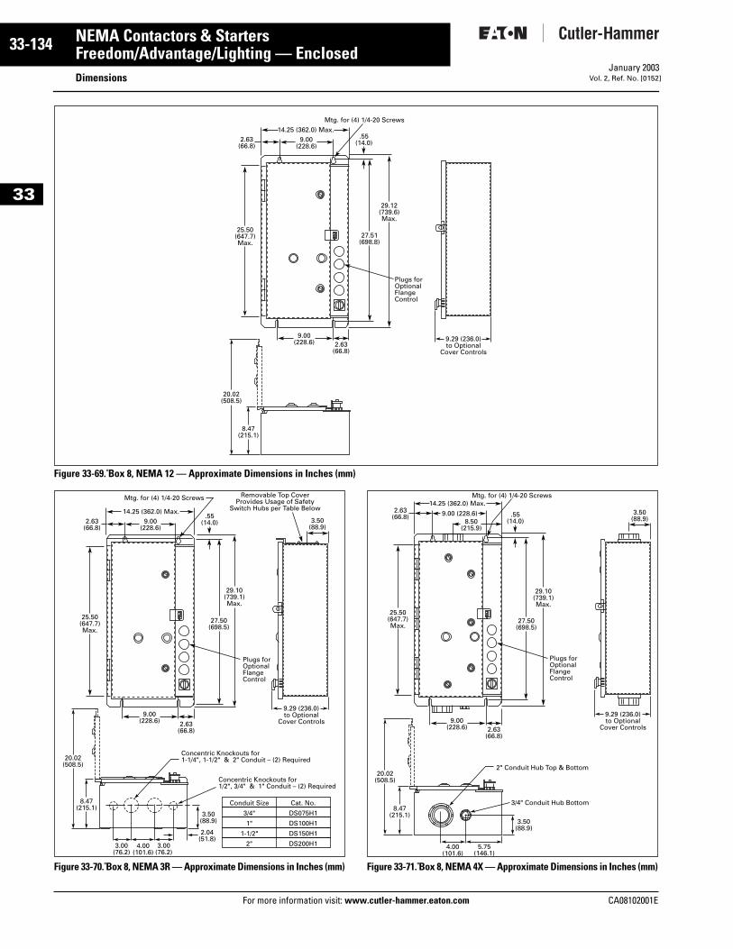
33-134
33
NEMA Contactors & StartersFreedom/Advantage/Lighting — Enclosed
DimensionsFor more information visit: www.cutler-hammer.eaton.com
January 2003Vol. 2, Ref. No. [0152]
Figure 33-69. Box 8, NEMA 12 — Approximate Dimensions in Inches (mm)
Figure 33-70. Box 8, NEMA 3R — Approximate Dimensions in Inches (mm) Figure 33-71. Box 8, NEMA 4X — Approximate Dimensions in Inches (mm)
14.25 (362.0) Max.Mtg. for (4) 1/4-20 Screws
2.63(66.8)
2.63(66.8)
9.00(228.6)
9.00(228.6)
25.50(647.7)Max.
29.12(739.6)Max.
.55(14.0)
27.51(698.8)
9.29 (236.0)to Optional
Cover Controls
Plugs for OptionalFlange Control
8.47(215.1)
20.02(508.5)
14.25 (362.0) Max.
Mtg. for (4) 1/4-20 Screws Removable Top CoverProvides Usage of Safety
Switch Hubs per Table Below
2.63(66.8)
9.00(228.6)
2.63(66.8)
9.00(228.6)
25.50(647.7)Max.
29.10(739.1)Max.
.55(14.0) 3.50
(88.9)
27.50(698.5)
Plugs for OptionalFlange Control
3.00(76.2)
3.00(76.2)
4.00(101.6)
3.50(88.9)
2.04(51.8)
8.47(215.1)
20.02(508.5)
Concentric Knockouts for1-1/4", 1-1/2" & 2" Conduit – (2) Required
Concentric Knockouts for1/2", 3/4" & 1" Conduit – (2) Required
9.29 (236.0)to Optional
Cover Controls
Conduit Size Cat. No.
3/4" DS075H1
1" DS100H1
1-1/2" DS150H1
2" DS200H1
14.25 (362.0) Max.Mtg. for (4) 1/4-20 Screws
2.63(66.8)
2.63(66.8)
9.00 (228.6)
9.00(228.6)
25.50(647.7)Max.
29.10(739.1)Max.
.55(14.0)
3.50(88.9)
27.50(698.5)
9.29 (236.0)to Optional
Cover Controls
Plugs for OptionalFlange Control
5.75(146.1)
4.00(101.6)
3.50(88.9)
8.47(215.1)
20.02(508.5)
2" Conduit Hub Top & Bottom
3/4" Conduit Hub Bottom
8.50(215.9)
CA08102001E
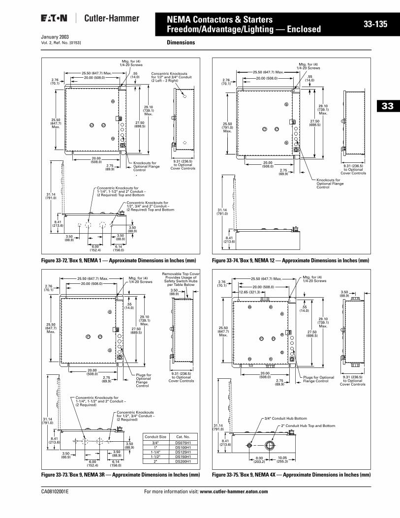
CA08102001E For more
35
33-1NEMA Contactors & StartersFreedom/Advantage/Lighting — Enclosed DimensionsJanuary 2003Vol. 2, Ref. No. [0153]
33
Figure 33-72. Box 9, NEMA 1 — Approximate Dimensions in Inches (mm)
Figure 33-73. Box 9, NEMA 3R — Approximate Dimensions in Inches (mm)
Figure 33-74. Box 9, NEMA 12 — Approximate Dimensions in Inches (mm)
Figure 33-75. Box 9, NEMA 4X — Approximate Dimensions in Inches (mm)
8.41(213.6)
31.14(791.0)
25.50 (647.7) Max.
Mtg. for (4) 1/4-20 Screws
20.00 (508.0)
25.50(647.7) Max.
29.10(739.1)Max.
.55(14.0)
27.50(698.5)
2.76(70.1)
Knockouts for Optional Flange Control
2.75(69.9)
20.00(508.0)
Concentric Knockouts for 1/2" and 3/4" Conduit(2 Left – 2 Right)
6.14(156.0)
6.00(152.4)
3.50(88.9)
3.50(88.9)
3.50(88.9)
Concentric Knockouts for1-1/4", 1-1/2" and 2" Conduit –(2 Required) Top and Bottom
Concentric Knockouts for1/2", 3/4" and 2" Conduit –(2 Required) Top and Bottom
9.31 (236.5)to Optional
Cover Controls
8.41(213.6)
31.14(791.0)
25.50 (647.7) Max. Mtg. for (4) 1/4-20 Screws
2.76(70.1)
25.50(647.7)Max.
29.10(739.1)Max.
.55(14.0)
27.50(689.5)
3.50(88.9)
3.50(88.9)3.50
(88.9)6.14
(156.0)6.00
(152.4)
Concentric Knockouts for1-1/4", 1-1/2" and 2" Conduit –(2 Required)
Concentric Knockouts for 1/2", 3/4" Conduit –(2 Required)
9.31 (236.5)to Optional
Cover Controls
20.00 (508.0)
Plugs forOptionalFlangeControl
20.00(508.0)
2.75(69.9)
Removable Top CoverProvides Usage of
Safety Switch Hubsper Table Below
3.50(88.9)
Conduit Size
3/4"1"
1-1/4"1-1/2"
2"
Cat. No.
DS075H1DS100H1DS125H1DS150H1DS200H1
8.41(213.6)
31.14(791.0)
29.10(739.1)Max.
27.50(698.5)
25.50 (647.7) Max.
Mtg. for (4) 1/4-20 Screws
20.00 (508.0)
25.50(791.0) Max.
.55(14.0)2.76
(70.1)
Knockouts for Optional Flange Control
20.00(508.0)
2.75(69.9)
9.31 (236.5)to Optional
Cover Controls
8.41(213.6)
31.14(791.0)
25.50(647.7)Max.
29.10(739.1)Max.
27.50(698.5)
3.50(88.9)
10.05(255.3)
8.00(203.2)
3/4" Conduit Hub Bottom
2" Conduit Hub Top and Bottom
25.50 (647.7) Max. Mtg. for (4) 1/4-20 Screws
20.00 (508.0)
.55(14.0)
2.76(70.1)
Plugs for OptionalFlange Control
20.00(508.0)
2.75(69.9)
12.65 (321.3)
9.31 (236.5)to Optional
Cover Controls
information visit: www.cutler-hammer.eaton.com
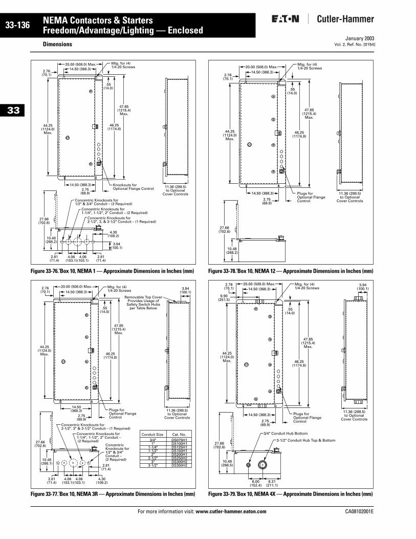
33-136
33
NEMA Contactors & StartersFreedom/Advantage/Lighting — Enclosed
DimensionsFor more information visit: www.cutler-hammer.eaton.com
January 2003Vol. 2, Ref. No. [0154]
Figure 33-76. Box 10, NEMA 1 — Approximate Dimensions in Inches (mm)
Figure 33-77. Box 10, NEMA 3R — Approximate Dimensions in Inches (mm)
Figure 33-78. Box 10, NEMA 12 — Approximate Dimensions in Inches (mm)
Figure 33-79. Box 10, NEMA 4X — Approximate Dimensions in Inches (mm)
10.48(266.2)
27.66(702.6)
Mtg. for (4) 1/4-20 Screws
44.25(1124.0)
Max.
47.85(1215.4)
Max.
.55(14.0)
46.25(1174.8)
11.36 (288.5)to Optional
Cover Controls
2.76(70.1)
20.00 (508.0) Max.14.50 (368.3)
14.50 (368.3)2.75
(69.9)
Knockouts for Optional Flange Control
2.81(71.4)
2.81(71.4)
3.94(100.1)
4.06(103.1)
4.06(103.1)
4.30(109.2)
Concentric Knockouts for1/2" & 3/4" Conduit – (2 Required)
Concentric Knockouts for1-1/4", 1-1/2", 2" Conduit – (2 Required)
Concentric Knockouts for2-1/2", 3, & 3-1/2" Conduit – (1 Required)
10.48(266.1)
27.66(702.6)
44.25(1124.0)
Max.
47.85(1215.4)
Max.
46.25(1174.8)
11.36 (288.5)to Optional
Cover Controls
Mtg. for (4) 1/4-20 Screws
.55(14.0)
20.00 (508.0) Max.14.50 (368.3)
14.50(368.3)
2.75(69.9)
Plugs for Optional Flange Control
2.76(70.1)
3.94(100.1)
Removable Top Cover Provides Usage of
Safety Switch Hubsper Table Below
Conduit Size Cat. No.3/4"1"
1-1/4"1-1/2"
2"2-1/2"
3"3-1/2"
DS075H1DS100H1DS125H1DS150H1DS200H1DS250H2DS300H2DS350H2
Concentric Knockouts for2-1/2". 3" & 3-1/2" Conduit – (1 Required)
Concentric Knockouts for1-1/4", 1-1/2", 2" Conduit – (2 Required)
Concentric Knockouts for1/2" & 3/4" Conduit – (2 Required)
4.06(103.1)
4.06(103.1)
4.30(109.2)
2.81(71.4)
2.81(71.4)
20.00 (508.0) Max.
10.48(266.2)
27.66(702.6)
47.85(1215.4)
Max.
.55(14.0)
46.25(1174.8)
11.36 (288.5)to Optional
Cover Controls
44.25(1124.0)
Max.
14.50 (368.3)
Mtg. for (4) 1/4-20 Screws
14.50 (368.3)
2.75(69.9)
Plugs for Optional Flange Control
2.76(70.1)
47.85(1215.4)
Max.
46.25(1174.8)
10.48(266.5)
27.66(702.6)
44.25(1124.0)
Max.
Mtg. for (4) 1/4-20 Screws
.55(14.0)
20.00 (508.0) Max.2.76(70.1)
14.50 (368.3)
2.75(69.9)
Plugs for Optional Flange Control
6.00(152.4)
11.36 (288.5)to Optional
Cover Controls
3.94(100.1)
8.31(211.1)
3/4" Conduit Hub Bottom
3-1/2" Conduit Hub Top & Bottom
14.50 (368.3)
9.90(251.5)
CA08102001E
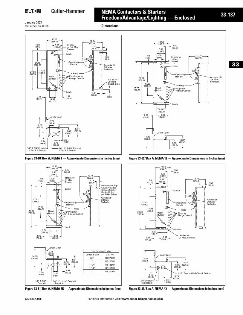
CA08102001E For more
37
33-1NEMA Contactors & StartersFreedom/Advantage/Lighting — Enclosed DimensionsJanuary 2003Vol. 2, Ref. No. [0155]
33
Figure 33-80. Box A, NEMA 1 — Approximate Dimensions in Inches (mm)
Figure 33-81. Box A, NEMA 3R — Approximate Dimensions in Inches (mm)
Figure 33-82. Box A, NEMA 12 — Approximate Dimensions in Inches (mm)
Figure 33-83. Box A, NEMA 4X — Approximate Dimensions in Inches (mm)
10.50(266.7)
6.65(168.9)
27.06(687.3)
24.49(622.0)
1.28(32.5)
17.30(439.4)
ResetButton
Latch
Knockouts forFlange Control
Hasp
OperatingHandle
Latch
3 Holes for 1/4 Mtg.Screws
12.74(323.6)
4.38(111.3)
4.39(111.5)
1.31(33.3)
1.31(33.3)
1.31(33.3)
1.31(33.3)
Accepts (3)3/8 Max.Padlocks
1/2" & 3/4"Conduit2 Each Side
14.25(362.0)
8.87(225.3)
Door Open
6.66(169.2)
2.18(55.4)
2.24(56.9) 2.75
(69.9)
2.75(69.9)
3/4", 1", 1-1/4" Conduit2 Top & 2 Bottom
1/2" & 3/4" Conduit 1 Top & 1 Bottom
2.91(73.9)
14.25(362.0) 8.87
(225.3)
Door Open
6.66(169.2)
28.98(736.1)
27.92(709.2)
.50(12.7)
17.30(439.7)
10.50(266.7) 2.50
(63.5)5.50(139.7)
2.75(69.9)
ResetButton
Latch
Plugs forFlange Control
Hasp
OperatingHandle
Latch
3 Holes for1/4 Mtg. Screws
12.74(323.6)
2.16(54.9)
Accepts (3)3/8 Max. Padlocks
Removeable TopCover ProvidesUsage of SafetySwitch Hubsper Table Below
Top Entrance Hubs
2.95(74.9)
2.24(56.9)
2.75(69.9)
2.75(69.9)
3/4", 1", 1-1/4" Conduit2 Required
1/2" & 3/4" Conduit
2.91(73.9)
5.50(139.7)
8.00(203.2)
Conduit Size Cat. No.
3/4" DS075H1
1" DS100H1
1-1/2" DS150H1
1-1/4" DS125H1
2" DS200H1
14.25(362.0) 8.87
(225.3)
Door Open
6.66(169.2)
28.98(736.1)
27.92(709.2)
.50(12.7)
17.30(439.4)
ResetButton
Latch
Plugs forFlange Control
Hasp
OperatingHandle
Latch
5.50(139.7)
8.00(203.2)
10.50(266.7)
2.50(63.5)
5.50(139.7)
2.75(69.9) 3 Holes for
1/4 Mtg. Screws
12.74(323.6)
Accepts (3)3/8 Max.Padlocks
2.95(74.9)
14.25(362.0)
2.56(65.0)
8.87(225.3)
Door Open
6.66(169.2)
12.74(323.6)
2.56(65.0)
Accepts (3)3/8 Max. Padlocks
10.50(266.7)
2.50(63.5)5.50
(139.7)
2.75(69.9)
ResetButton
Latch
3 Holes for1/4 Mtg. Screws
Plugs forFlange Control
Hasp
OperatingHandle
Latch
5.50(139.7)
8.00(203.2)
28.98(736.1)
27.92(709.2)
.50(12.7)
17.30(439.4)
2.95(74.9)
3/4" ConduitHub Bottom
3.41(86.6)
5.25(133.4)
1-1/2" Conduit Hub Top & Bottom
information visit: www.cutler-hammer.eaton.com
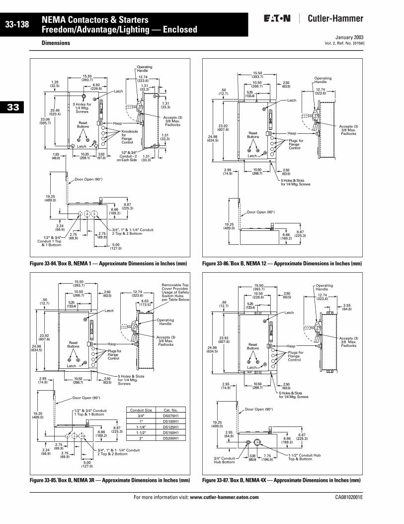
33-138
33
NEMA Contactors & StartersFreedom/Advantage/Lighting — Enclosed
DimensionsFor more information visit: www.cutler-hammer.eaton.com
January 2003Vol. 2, Ref. No. [0156]
Figure 33-84. Box B, NEMA 1 — Approximate Dimensions in Inches (mm)
Figure 33-85. Box B, NEMA 3R — Approximate Dimensions in Inches (mm)
Figure 33-86. Box B, NEMA 12 — Approximate Dimensions in Inches (mm)
Figure 33-87. Box B, NEMA 4X — Approximate Dimensions in Inches (mm)
19.25(489.0)
8.87(225.3)
Door Open (90°)
6.66(169.2)
23.06(585.7)
20.49(520.4)
1.28(32.5)
15.50(393.7)
8.92(226.6)
Latch
Knockouts forFlange Control
Hasp
Latch
3.82(97.0)
10.20(259.1)
1.93(49.0)
2.24(56.9)
2.75(69.9)
2.75(69.9)
5.00(127.0)
3/4", 1" & 1-1/4" Conduit2 Top & 2 Bottom
1/2" & 3/4"Conduit 1 Top
& 1 Bottom
12.74(323.6)
Accepts (3)3/8 Max.Padlocks
1.31(33.3)
1.31(33.3)
1.31(33.3)
1.31(33.3)
OperatingHandle
1/2" & 3/4"Conduit – 2
on Each Side
ResetButtons
3 Holes for1/4 Mtg.Screws
Door Open (90°)
1/2" & 3/4" Conduit1 Top & 1 Bottom
Plugs forFlange Control
Hasp
Latch
Latch
5 Holes & Slotsfor 1/4 Mtg.Screws
2.75(69.9)2.24
(56.9) 2.75(69.9)
5.00(127.0)
3/4", 1" & 1- 1/4" Conduit2 Top & 2 Bottom
6.83(173.5)
Removable TopCover ProvidesUsage of SafetySwitch Hubsper Table Below
Accepts (3)3/8 Max.Padlocks
Operating Handle
Conduit Size Cat. No.
3/4" DS075H1
1" DS100H1
1-1/2" DS150H1
1-1/4" DS125H1
2" DS200H1
24.98(634.5)
23.92(607.6)
.50(12.7) 5.25
(133.4)
2.50(63.5)
2.50(63.5)
10.50(266.7)
2.95(74.9)
19.25(489.0)
8.87(225.3)6.66
(169.2)
15.50(393.7)
10.50(266.7)
12.74(323.6)
ResetButtons
Door Open (90°)
Latch
Accepts (3)3/8 Max.Padlocks
OperatingHandle
24.98(634.5)
23.92(607.6)
.50(12.7) 5.25
(133.4)
Plugs forFlange Control
5 Holes & Slotsfor 1/4 Mtg. Screws
Hasp
Latch
2.50(63.5)
2.50(63.5)
10.50(266.7)
2.95(74.9)
19.25(489.0)
8.87(225.3)6.66
(169.2)
15.50(393.7)
10.50(266.7)
12.74(323.6)
ResetButtons
Door Open (90°)
Latch
OperatingHandle
Accepts (3)3/8 Max.Padlocks
2.55(64.8)
Latch
Plugs forFlange Control
Hasp
2.55(64.8)
3.38(85.9)
7.75(196.9)
1-1/2" Conduit HubTop & Bottom3/4" Conduit
Hub Bottom
24.98(634.5)
23.92(607.6)
.50(12.7) 5.25
(133.4)
2.50(63.5)
2.50(63.5)
10.50(226.6)
2.95(74.9)
19.25(489.0)
8.87(225.3)6.66
(169.2)
15.50(393.7)
10.50(266.7)
12.74(323.6)
5 Holes & Slotsfor 1/4 Mtg. Screws
ResetButtons
CA08102001E
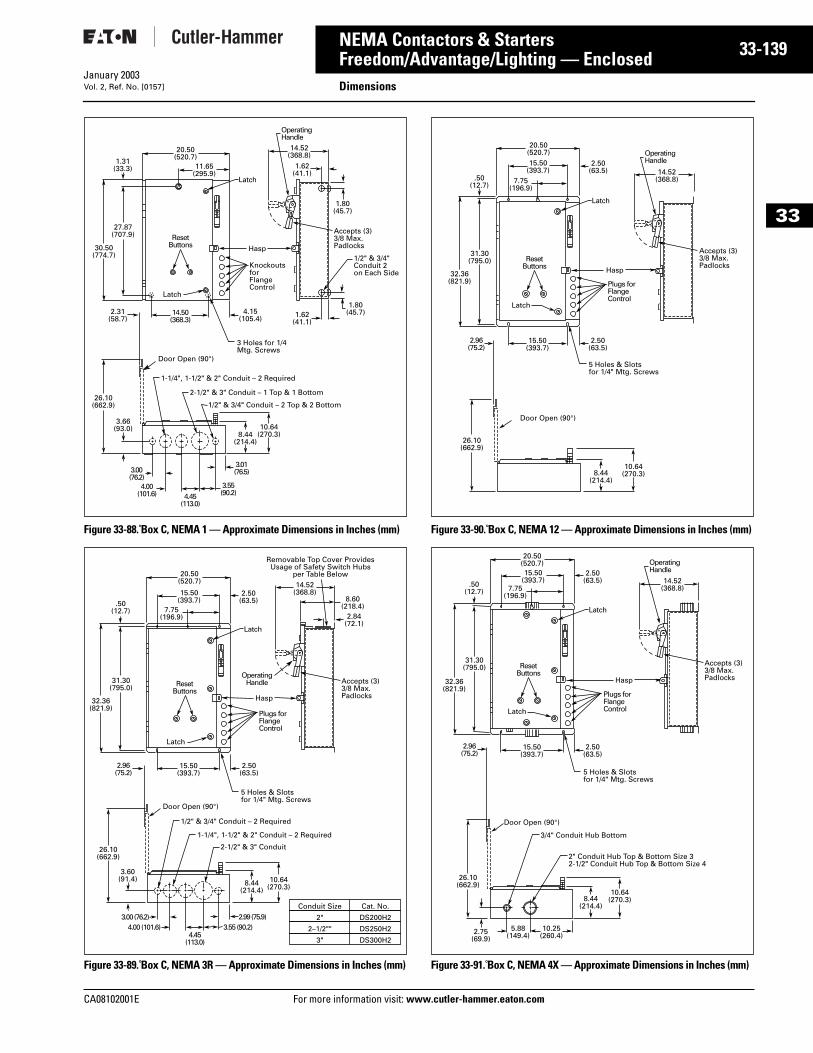
CA08102001E For more
39
33-1NEMA Contactors & StartersFreedom/Advantage/Lighting — Enclosed DimensionsJanuary 2003Vol. 2, Ref. No. [0157]
33
Figure 33-88. Box C, NEMA 1 — Approximate Dimensions in Inches (mm)
Figure 33-89. Box C, NEMA 3R — Approximate Dimensions in Inches (mm)
Figure 33-90. Box C, NEMA 12 — Approximate Dimensions in Inches (mm)
Figure 33-91. Box C, NEMA 4X — Approximate Dimensions in Inches (mm)
26.10(662.9)
10.64(270.3)8.44
(214.4)
27.87(707.9)
1.31(33.3)
20.50(520.7)
11.65(295.9)
Latch
30.50(774.7)
Latch
Hasp
KnockoutsforFlange Control
14.50(368.3)
4.15(105.4)
Door Open (90°)
1/2" & 3/4" Conduit 2 on Each Side
Accepts (3)3/8 Max.Padlocks
OperatingHandle
14.52(368.8)
1.62(41.1)
1.62(41.1)
1.80(45.7)
1.80(45.7)2.31
(58.7)
3.66(93.0)
3.00(76.2)
4.00(101.6) 4.45
(113.0)
3.55(90.2)
3.01(76.5)
1/2" & 3/4" Conduit – 2 Top & 2 Bottom
3 Holes for 1/4Mtg. Screws
1-1/4", 1-1/2" & 2" Conduit – 2 Required
2-1/2" & 3" Conduit – 1 Top & 1 Bottom
ResetButtons
Door Open (90°)
Latch
OperatingHandle
Latch
Hasp
Plugs forFlange Control
Accepts (3)3/8 Max.Padlocks
8.60(218.4)
2.84(72.1)
3.60(91.4)
5 Holes & Slotsfor 1/4" Mtg. Screws
1/2" & 3/4" Conduit – 2 Required
1-1/4", 1-1/2" & 2" Conduit – 2 Required
2-1/2" & 3" Conduit
7.75(196.9)
15.50(393.7)
15.50(393.7)
31.30(795.0)
.50(12.7)
32.36(821.9)
2.96(75.2)
2.50(63.5)
2.50(63.5)
26.10(662.9)
10.64(270.3)8.44
(214.4)
20.50(520.7) 14.52
(368.8)
3.00 (76.2)4.00 (101.6)
4.45(113.0)
3.55 (90.2)2.99 (75.9)
Conduit Size Cat. No.
2" DS200H2
2–1/2"" DS250H2
3" DS300H2
Removable Top Cover ProvidesUsage of Safety Switch Hubs
per Table Below
ResetButtons
Door Open (90°)
Latch
OperatingHandle
7.75(196.9)
Latch
15.50(393.7)
15.50(393.7)
31.30(795.0)
.50(12.7)
32.36(821.9)
Hasp
Plugs forFlange Control
2.96(75.2)
2.50(63.5)
2.50(63.5)
Accepts (3)3/8 Max.Padlocks
5 Holes & Slotsfor 1/4" Mtg. Screws
26.10(662.9)
10.64(270.3)8.44
(214.4)
20.50(520.7)
14.52(368.8)
ResetButtons
Door Open (90°)
2.75(69.9)
Latch
OperatingHandle
Latch
Hasp
Plugs forFlange Control
10.25(260.4)
5.88(149.4)
Accepts (3)3/8 Max.Padlocks
5 Holes & Slotsfor 1/4" Mtg. Screws
2" Conduit Hub Top & Bottom Size 32-1/2" Conduit Hub Top & Bottom Size 4
3/4" Conduit Hub Bottom
7.75(196.9)
15.50(393.7)
15.50(393.7)
31.30(795.0)
.50(12.7)
32.36(821.9)
2.96(75.2)
2.50(63.5)
2.50(63.5)
26.10(662.9)
10.64(270.3)8.44
(214.4)
20.50(520.7)
14.52(368.8)
ResetButtons
information visit: www.cutler-hammer.eaton.com
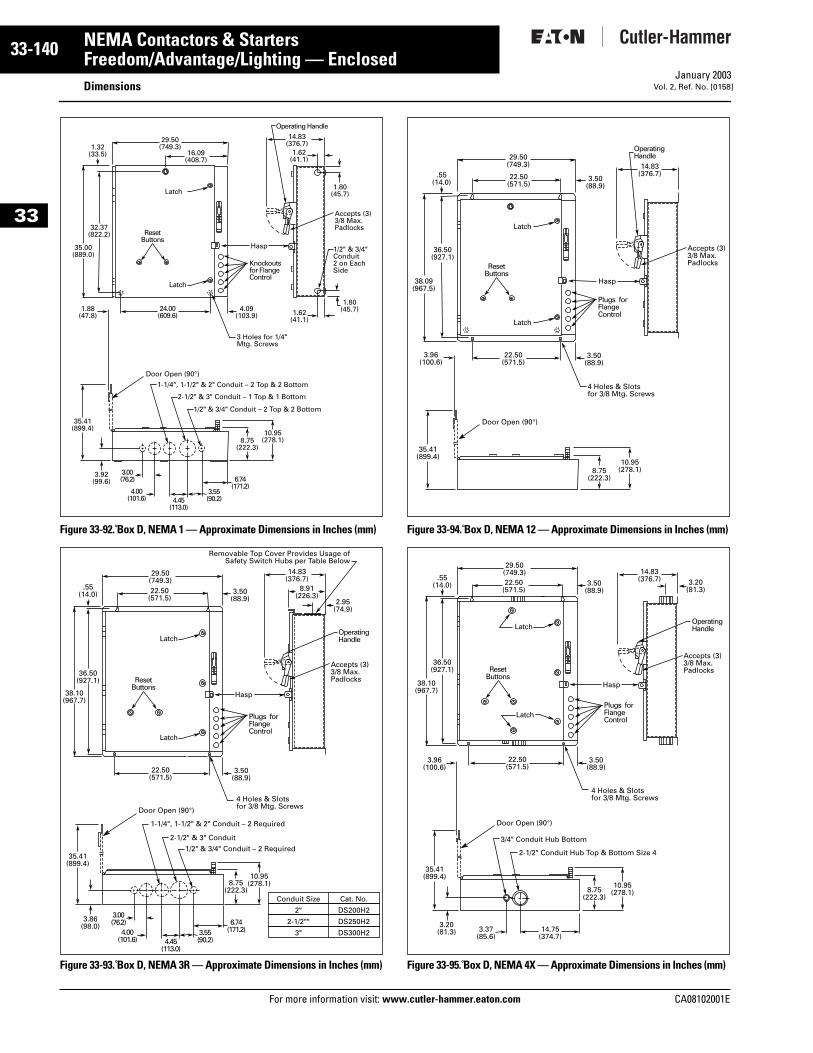
33-140
33
NEMA Contactors & StartersFreedom/Advantage/Lighting — Enclosed
DimensionsFor more information visit: www.cutler-hammer.eaton.com
January 2003Vol. 2, Ref. No. [0158]
Figure 33-92. Box D, NEMA 1 — Approximate Dimensions in Inches (mm)
Figure 33-93. Box D, NEMA 3R — Approximate Dimensions in Inches (mm)
Figure 33-94. Box D, NEMA 12 — Approximate Dimensions in Inches (mm)
Figure 33-95. Box D, NEMA 4X — Approximate Dimensions in Inches (mm)
35.41(899.4)
10.95(278.1)8.75
(222.3)
32.37(822.2)
1.32(33.5)
29.50(749.3)
16.09(408.7)
Latch
35.00(889.0)
Latch
Hasp
Knockouts for Flange Control
24.00(609.6)
4.09(103.9)
Door Open (90°)
1/2" & 3/4" Conduit2 on EachSide
Accepts (3)3/8 Max.Padlocks
Operating Handle14.83
(376.7)1.62
(41.1)
1.62(41.1)
1.80(45.7)
1.80(45.7)1.88
(47.8)
3.92(99.6)
3.00(76.2)
4.00(101.6) 4.45
(113.0)
3.55(90.2)
6.74(171.2)
1/2" & 3/4" Conduit – 2 Top & 2 Bottom
1-1/4", 1-1/2" & 2" Conduit – 2 Top & 2 Bottom
2-1/2" & 3" Conduit – 1 Top & 1 Bottom
3 Holes for 1/4"Mtg. Screws
ResetButtons
.55(14.0)
Latch
Latch
Hasp
Plugs forFlange Control
Door Open (90°)
Accepts (3)3/8 Max.Padlocks
OperatingHandle
2.95(74.9)
8.91(226.3)
3.86(98.0)
1/2" & 3/4" Conduit – 2 Required
1-1/4", 1-1/2" & 2" Conduit – 2 Required
2-1/2" & 3" Conduit
4 Holes & Slotsfor 3/8 Mtg. Screws
Removable Top Cover Provides Usage ofSafety Switch Hubs per Table Below
Conduit Size Cat. No.
2" DS200H2
2-1/2"" DS250H2
3" DS300H2
3.00(76.2)
4.00(101.6) 4.45
(113.0)
3.55(90.2)
6.74(171.2)
22.50(571.5)
3.50(88.9)
22.50(571.5)
3.50(88.9)
36.50(927.1)
38.10(967.7)
35.41(899.4)
10.95(278.1)8.75
(222.3)
29.50(749.3)
14.83(376.7)
ResetButtons
22.50(571.5)
3.50(88.9)
22.50(571.5)
3.50(88.9)
36.50(927.1)
.55(14.0)
38.09(967.5)
Latch
Latch
Hasp
Plugs forFlange Control
Door Open (90°)
Accepts (3)3/8 Max.Padlocks
OperatingHandle
3.96(100.6)
35.41(899.4)
10.95(278.1)8.75
(222.3)
29.50(749.3) 14.83
(376.7)
ResetButtons
4 Holes & Slotsfor 3/8 Mtg. Screws
14.75(374.7)
3.37(85.6)
Latch
Latch
Hasp
Plugs forFlange Control
Accepts (3)3/8 Max.Padlocks
OperatingHandle
3.20(81.3)
3.96(100.6)
3.20(81.3)
Door Open (90°)
3/4" Conduit Hub Bottom
2-1/2" Conduit Hub Top & Bottom Size 4
4 Holes & Slotsfor 3/8 Mtg. Screws
.55(14.0) 22.50
(571.5)3.50
(88.9)
22.50(571.5)
3.50(88.9)
36.50(927.1)
38.10(967.7)
35.41(899.4)
10.95(278.1)8.75
(222.3)
29.50(749.3) 14.83
(376.7)
ResetButtons
CA08102001E
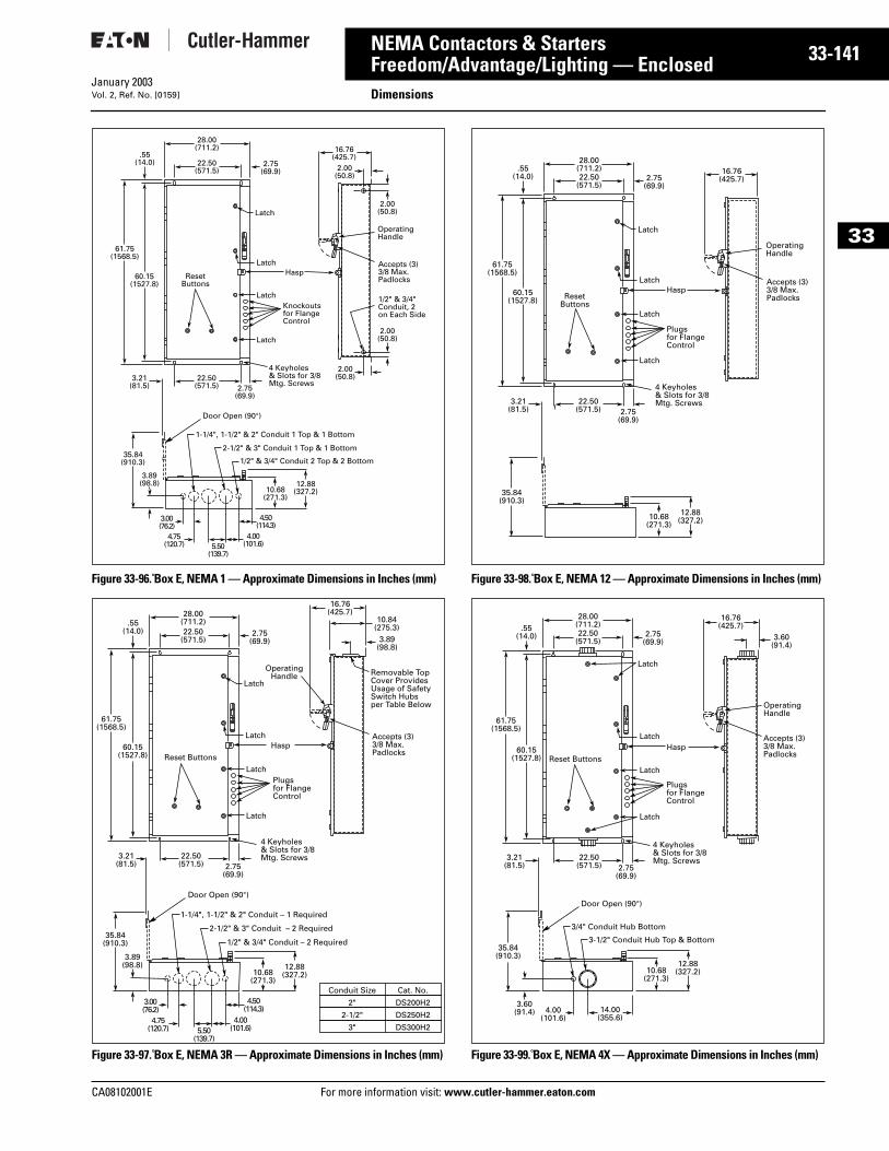
CA08102001E For more
41
33-1NEMA Contactors & StartersFreedom/Advantage/Lighting — Enclosed DimensionsJanuary 2003Vol. 2, Ref. No. [0159]
33
Figure 33-96. Box E, NEMA 1 — Approximate Dimensions in Inches (mm)
Figure 33-97. Box E, NEMA 3R — Approximate Dimensions in Inches (mm)
Figure 33-98. Box E, NEMA 12 — Approximate Dimensions in Inches (mm)
Figure 33-99. Box E, NEMA 4X — Approximate Dimensions in Inches (mm)
61.75(1568.5)
28.00(711.2) 16.76
(425.7)2.00
(50.8)
2.00(50.8)
2.00(50.8)
2.00(50.8)
22.50(571.5)
2.75(69.9)
Latch
LatchHasp
Latch
OperatingHandle
Accepts (3)3/8 Max.Padlocks
1/2" & 3/4"Conduit, 2on Each Side
Latch
Knockouts for Flange Control
ResetButtons
60.15(1527.8)
.55(14.0)
22.50(571.5) 2.75
(69.9)
3.21(81.5)
4 Keyholes & Slots for 3/8 Mtg. Screws
35.84(910.3)
12.88(327.2)10.68
(271.3)
Door Open (90°)
3.89(98.8)
1/2" & 3/4" Conduit 2 Top & 2 Bottom
1-1/4", 1-1/2" & 2" Conduit 1 Top & 1 Bottom
2-1/2" & 3" Conduit 1 Top & 1 Bottom
3.00(76.2)
4.75(120.7) 5.50
(139.7)
4.00(101.6)
4.50(114.3)
Latch
LatchHasp
OperatingHandle
Latch
Accepts (3)3/8 Max.Padlocks
Latch
Plugs for Flange Control
Reset Buttons
4 Keyholes & Slots for 3/8 Mtg. Screws
10.84(275.3)
3.89(98.8)
Door Open (90°)
1/2" & 3/4" Conduit – 2 Required
1-1/4", 1-1/2" & 2" Conduit – 1 Required
2-1/2" & 3" Conduit – 2 Required
Removable TopCover ProvidesUsage of SafetySwitch Hubsper Table Below
Conduit Size Cat. No.
2" DS200H2
2-1/2" DS250H2
3" DS300H2
35.84(910.3)
3.89(98.8)
3.00(76.2)
4.75(120.7) 5.50
(139.7)
4.00(101.6)
4.50(114.3)
61.75(1568.5)
28.00(711.2)
16.76(425.7)
22.50(571.5)
2.75(69.9)
60.15(1527.8)
.55(14.0)
22.50(571.5) 2.75
(69.9)
3.21(81.5)
12.88(327.2)10.68
(271.3)
Latch
LatchHasp
Latch
OperatingHandle
Accepts (3)3/8 Max.Padlocks
Latch
Plugs for Flange Control
ResetButtons
4 Keyholes & Slots for 3/8 Mtg. Screws
61.75(1568.5)
28.00(711.2) 16.76
(425.7)22.50(571.5)
2.75(69.9)
60.15(1527.8)
.55(14.0)
22.50(571.5) 2.75
(69.9)
3.21(81.5)
35.84(910.3)
12.88(327.2)10.68
(271.3)
Latch
LatchHasp
Latch
OperatingHandle
Accepts (3)3/8 Max.Padlocks
Latch
Plugs for Flange Control
Reset Buttons
4 Keyholes & Slots for 3/8 Mtg. Screws
14.00(355.6)
4.00(101.6)
35.84(910.3)
3.60(91.4)
Door Open (90°)
3.60(91.4)
3/4" Conduit Hub Bottom
3-1/2" Conduit Hub Top & Bottom
61.75(1568.5)
28.00(711.2)
16.76(425.7)
22.50(571.5)
2.75(69.9)
60.15(1527.8)
.55(14.0)
22.50(571.5) 2.75
(69.9)
3.21(81.5)
12.88(327.2)10.68
(271.3)
information visit: www.cutler-hammer.eaton.com
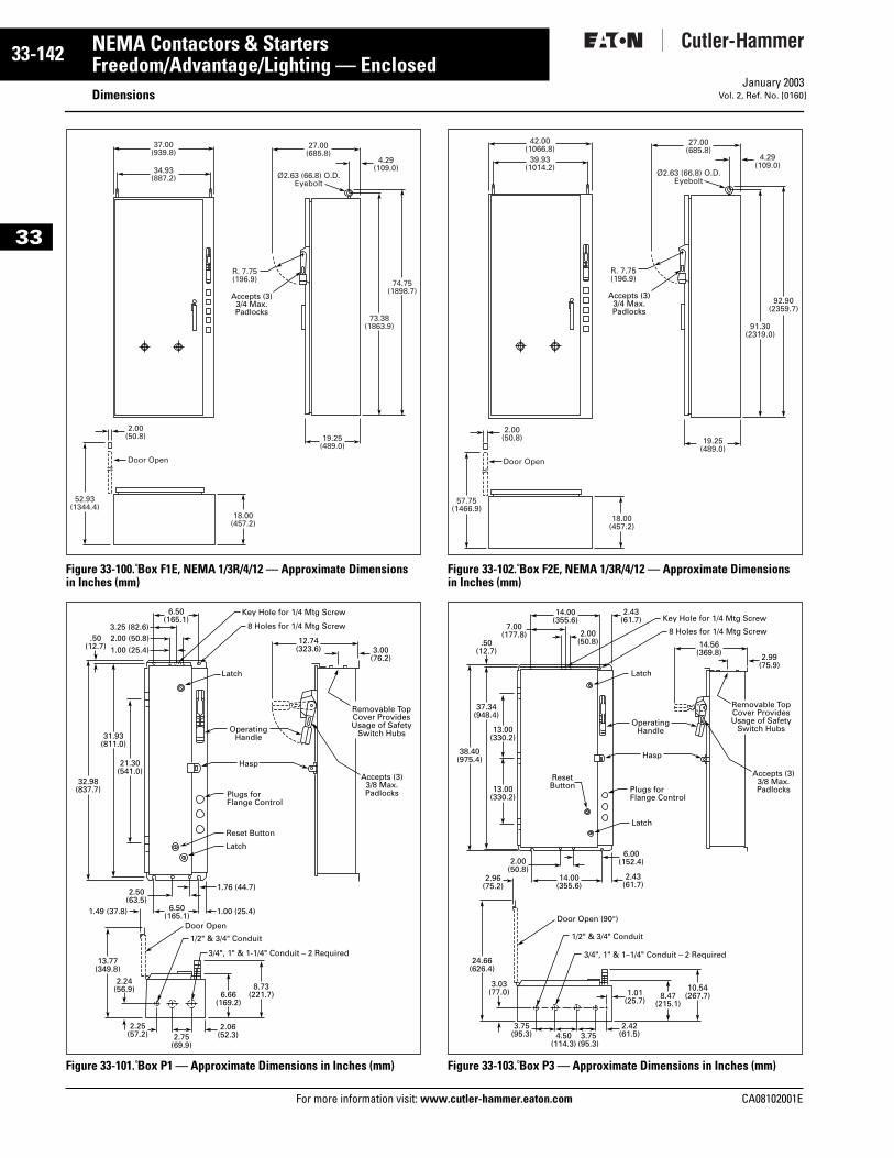
33-142
33
NEMA Contactors & StartersFreedom/Advantage/Lighting — Enclosed
DimensionsFor more information visit: www.cutler-hammer.eaton.com
January 2003Vol. 2, Ref. No. [0160]
Figure 33-100. Box F1E, NEMA 1/3R/4/12 — Approximate Dimensions in Inches (mm)
Figure 33-101. Box P1 — Approximate Dimensions in Inches (mm)
Figure 33-102. Box F2E, NEMA 1/3R/4/12 — Approximate Dimensions in Inches (mm)
Figure 33-103. Box P3 — Approximate Dimensions in Inches (mm)
37.00(939.8)
27.00(685.8)
34.93(887.2)
2.00(50.8) 19.25
(489.0)
Door Open
4.29(109.0)
Ø2.63 (66.8) O.D.Eyebolt
R. 7.75(196.9)
52.93(1344.4)
18.00(457.2)
74.75(1898.7)
73.38(1863.9)
Accepts (3)3/4 Max.Padlocks
6.50(165.1)
3.25 (82.6)2.00 (50.8)1.00 (25.4)
12.74(323.6) 3.00
(76.2)
6.50(165.1) 1.00 (25.4)1.49 (37.8)
2.50(63.5)
1.76 (44.7)
2.25(57.2)
2.06(52.3)2.75
(69.9)
32.98(837.7)
6.66(169.2)
8.73(221.7)
21.30(541.0)
13.77(349.8)
2.24(56.9)
31.93(811.0)
.50(12.7)
Latch
Latch
Plugs forFlange Control
Reset Button
Key Hole for 1/4 Mtg Screw
8 Holes for 1/4 Mtg Screw
Hasp
OperatingHandle
3/4", 1" & 1-1/4" Conduit – 2 Required
Door Open
1/2" & 3/4" Conduit
Accepts (3)3/8 Max.Padlocks
Removable TopCover ProvidesUsage of Safety
Switch Hubs
42.00(1066.8)
39.93(1014.2)
57.75(1466.9)
92.90(2359.7)
91.30(2319.0)
Accepts (3)3/4 Max.Padlocks
27.00(685.8)
2.00(50.8) 19.25
(489.0)
4.29(109.0)
Ø2.63 (66.8) O.D.Eyebolt
R. 7.75(196.9)
18.00(457.2)
Door Open
14.00(355.6)
2.43(61.7)
7.00(177.8) 2.00
(50.8)
2.96(75.2)
14.00(355.6)
2.43(61.7)
2.00(50.8)
6.00(152.4)
3.75(95.3)
2.42(61.5)
1.01(25.7)
3.75(95.3)
4.50(114.3)
8.47(215.1)
10.54(267.7)
24.66(626.4)
3.03(77.0)
38.40(975.4)
13.00(330.2)
13.00(330.2)
37.34(948.4)
.50(12.7)
3/4", 1" & 1–1/4" Conduit – 2 Required
Door Open (90°)
1/2" & 3/4" Conduit
14.56(369.8) 2.99
(75.9)Latch
Latch
Plugs forFlange Control
ResetButton
Key Hole for 1/4 Mtg Screw
8 Holes for 1/4 Mtg Screw
Hasp
OperatingHandle
Accepts (3)3/8 Max.Padlocks
Removable TopCover ProvidesUsage of Safety
Switch Hubs
CA08102001E
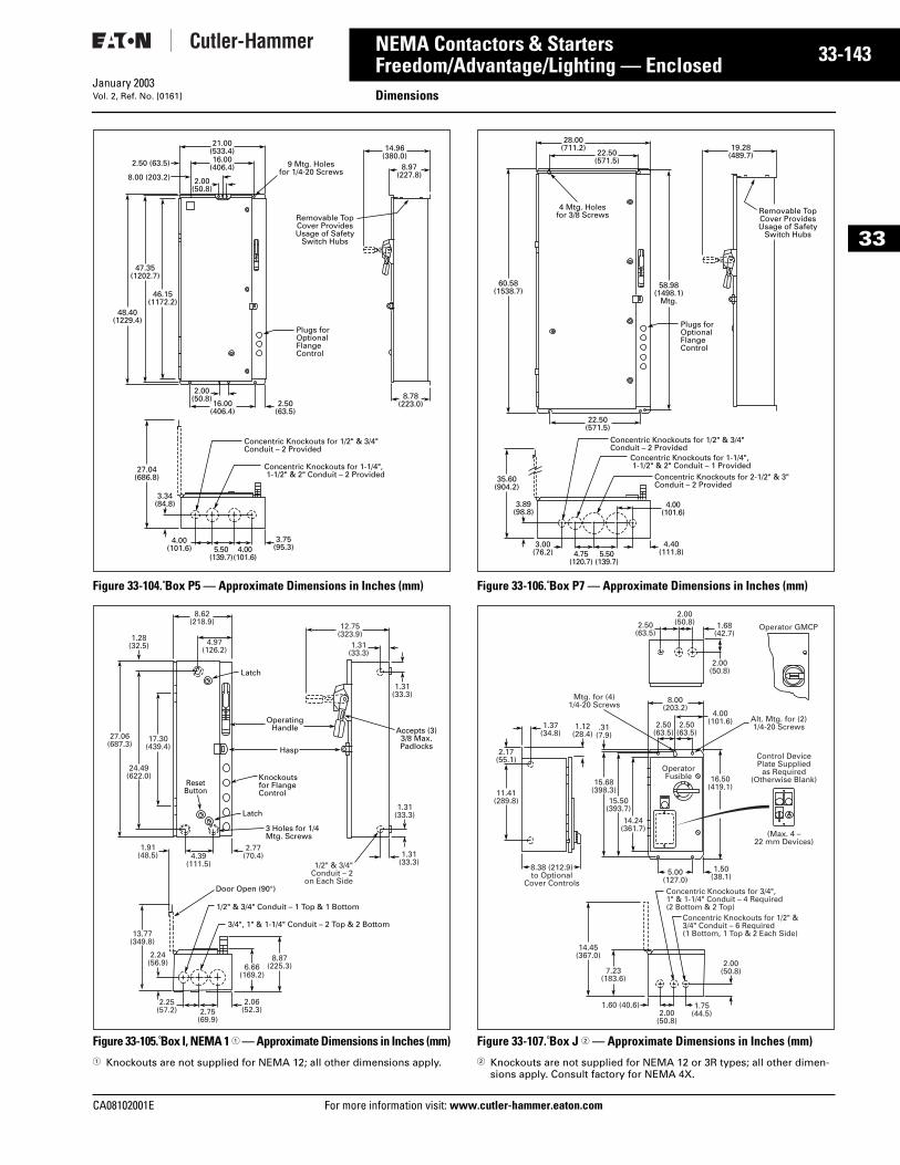
CA08102001E For more
43
33-1NEMA Contactors & StartersFreedom/Advantage/Lighting — Enclosed DimensionsJanuary 2003Vol. 2, Ref. No. [0161]
33
Figure 33-104. Box P5 — Approximate Dimensions in Inches (mm)
Figure 33-105. Box I, NEMA 1 1 — Approximate Dimensions in Inches (mm)1 Knockouts are not supplied for NEMA 12; all other dimensions apply.
Figure 33-106. Box P7 — Approximate Dimensions in Inches (mm)
Figure 33-107. Box J 2 — Approximate Dimensions in Inches (mm)2 Knockouts are not supplied for NEMA 12 or 3R types; all other dimen-
sions apply. Consult factory for NEMA 4X.
21.00(533.4)16.00
(406.4)
2.00(50.8)
8.00 (203.2)
2.50 (63.5)
14.96(380.0)
8.97(227.8)
8.78(223.0)
48.40(1229.4)
46.15(1172.2)
27.04(686.8)
47.35(1202.7)
Concentric Knockouts for 1/2" & 3/4"Conduit – 2 Provided
Concentric Knockouts for 1-1/4", 1-1/2" & 2" Conduit – 2 Provided
16.00(406.4)
2.50(63.5)
2.00(50.8)
5.50(139.7)
4.00(101.6)
4.00(101.6)
3.75(95.3)
Plugs forOptionalFlangeControl
Removable TopCover ProvidesUsage of Safety
Switch Hubs
3.34(84.8)
9 Mtg. Holesfor 1/4-20 Screws
13.77(349.8)
2.24(56.9)
4.39(111.5)
1.91(48.5)
2.77(70.4)
2.06(52.3)2.75
(69.9)
2.25(57.2)
6.66(169.2)
8.87(225.3)
3/4", 1" & 1-1/4" Conduit – 2 Top & 2 Bottom
Door Open (90°)
1/2" & 3/4" Conduit – 1 Top & 1 Bottom
24.49(622.0)
17.30(439.4)
27.06(687.3)
8.62(218.9)
4.97(126.2)
1.28(32.5)
OperatingHandle
Hasp
Latch
Latch
3 Holes for 1/4Mtg. Screws
ResetButton
Knockoutsfor FlangeControl
12.75(323.9)
1.31(33.3)
1.31(33.3)
1.31(33.3)
1.31(33.3)
1/2" & 3/4"Conduit – 2
on Each Side
Accepts (3)3/8 Max.Padlocks
4.00(101.6)
4.40(111.8)
3.00(76.2)
3.89(98.8)
Concentric Knockouts for 1/2" & 3/4"Conduit – 2 Provided
Concentric Knockouts for 1-1/4", 1-1/2" & 2" Conduit – 1 Provided
Concentric Knockouts for 2-1/2" & 3"Conduit – 2 Provided
28.00(711.2)
22.50(571.5)
19.28(489.7)
22.50(571.5)
60.58(1538.7)
58.98(1498.1)
Mtg.
35.60(904.2)
Plugs forOptionalFlangeControl
Removable TopCover ProvidesUsage of Safety
Switch Hubs
5.50(139.7)
4.75(120.7)
4 Mtg. Holesfor 3/8 Screws
8.00(203.2)
2.50(63.5)
1.68(42.7)
Operator GMCP
OperatorFusible
2.00(50.8)
(Max. 4 –22 mm Devices)
Control DevicePlate Supplied
as Required(Otherwise Blank)
4.00(101.6)2.50
(63.5)2.50
(63.5)
Mtg. for (4)1/4-20 Screws
Alt. Mtg. for (2)1/4-20 Screws
5.00(127.0)
8.38 (212.9)to Optional
Cover Controls
1.50(38.1)
1.75(44.5)2.00
(50.8)
1.60 (40.6)
16.50(419.1)
1.37(34.8)
2.00(50.8)
15.68(398.3)
.31(7.9)
15.50(393.7)
14.24(361.7)
11.41(289.8)
2.17(55.1)
14.45(367.0)
7.23(183.6)
2.00(50.8)
Concentric Knockouts for 3/4",1" & 1-1/4" Conduit – 4 Required(2 Bottom & 2 Top)
Concentric Knockouts for 1/2" &3/4" Conduit – 6 Required(1 Bottom, 1 Top & 2 Each Side)
1.12(28.4)
information visit: www.cutler-hammer.eaton.com
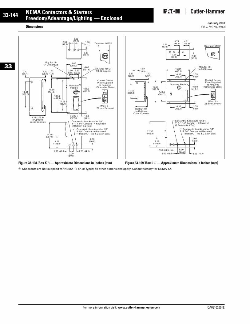
33-144
33
NEMA Contactors & StartersFreedom/Advantage/Lighting — Enclosed
DimensionsFor more information visit: www.cutler-hammer.eaton.com
January 2003Vol. 2, Ref. No. [0162]
Figure 33-108. Box K 1 — Approximate Dimensions in Inches (mm) Figure 33-109. Box L 1 — Approximate Dimensions in Inches (mm)1 Knockouts are not supplied for NEMA 12 or 3R types; all other dimensions apply. Consult factory for NEMA 4X.
(Max. 6 –22 mm Devices)
Control DevicePlate Supplied
as Required(Otherwise Blank)
5.00(127.0)
1.50(38.1)
19.50(495.3)
18.68(474.5)
18.50(469.9)
17.18(436.4)
8.38 (212.9)to Optional
Cover Controls
14.41(366.0)
1.75 (44.5)2.00
(50.8)
1.60 (40.6)
14.45(367.0)
7.23(183.6)
2.00(50.8)
Concentric Knockouts for 3/4",1" & 1-1/4" Conduit – 4 Required(2 Bottom & 2 Top)
Concentric Knockouts for 1/2"& 3/4" Conduit – 6 Required(1 Bottom, 1 Top & 2 Each Side)
8.00(203.2)
2.50(63.5)
1.68(42.7)
2.00(50.8)
4.00(101.6)2.50
(63.5)2.50
(63.5)
2.00(50.8)
.31(7.9)
2.17(55.1)
1.12(28.4)
Mtg. for (3)1/4-20 Screws
Alt. Mtg. for (2)1/4-20 Screws
OperatorFusible
Operator GMCP
2.00(50.8)
16.50(419.1)
Operator Fusible
Operator GMCP
15.68(398.3)
14.24(361.7)
11.41(289.8)
2.17(55.1)
1.12(28.4)
2.50(63.5)
4.31(109.5)
15.87(403.1)10.37
(263.4)
22.32(566.9)
7.23(183.6)
2.00(50.8)
5.00(127.0)
2.50 (63.5)
2.50 (63.5) 3.06 (77.7)
2.75(69.9)
10.37(263.4)
2.75(69.9)
1.37(34.8)
3.75(95.3)2.50
(63.5)
(Max. 6 –22 mm Devices)
Control DevicePlate Supplied
as Required(Otherwise Blank)
8.38 (212.9)to Optional
Cover Controls
Concentric Knockouts for 3/4",1" & 1-1/4" Conduit – 6 Required(3 Bottom & 3 Top)
Concentric Knockouts for 1/2"& 3/4" Conduit – 6 Required(1 Bottom, 1 Top & 2 Each Side)
Mtg. for (4)1/4-20 Screws
CA08102001E
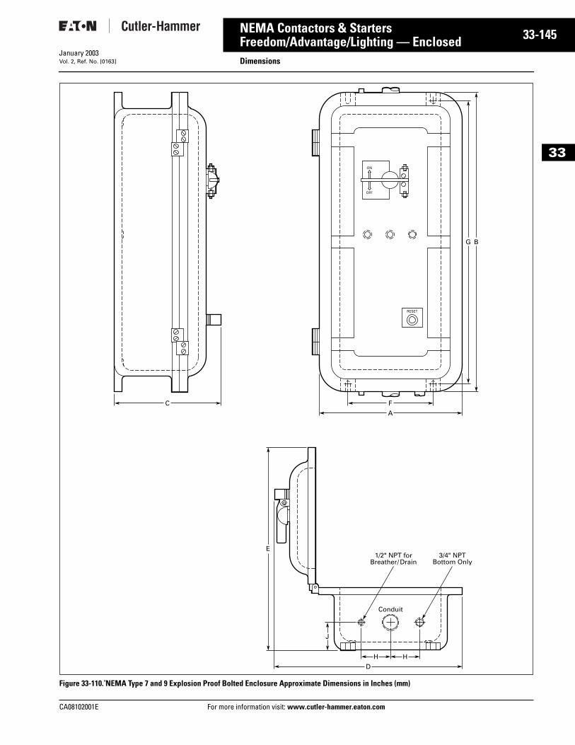
CA08102001E For more
45
33-1NEMA Contactors & StartersFreedom/Advantage/Lighting — Enclosed DimensionsJanuary 2003Vol. 2, Ref. No. [0163]
33
Figure 33-110. NEMA Type 7 and 9 Explosion Proof Bolted Enclosure Approximate Dimensions in Inches (mm)
RESET
ON
OFF
C
E
F
A
H H
D
G
1/2" NPT forBreather/ Drain
3/4" NPTBottom Only
Conduit
J
B
information visit: www.cutler-hammer.eaton.com
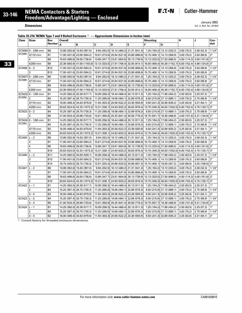
33-146
33
NEMA Contactors & StartersFreedom/Advantage/Lighting — Enclosed
DimensionsFor more information visit: www.cutler-hammer.eaton.com
January 2003Vol. 2, Ref. No. [0164]
Table 33-210. NEMA Type 7 and 9 Bolted Enclosure 1 — Approximate Dimensions in Inches (mm)
1 Consult factory for threaded enclosure dimensions.
Class Sizes BoxNumber
Overall Mounting H J Con-duitA B C D E F G
ECN05/ECS90
0 – 2/65 mm B6 13.88 (352.6) 15.63 (397.0) 9.94 (252.5) 18.12 (460.2) 21.31 (541.3) 7.25 (184.2) 13.12 (333.2) 3.00 (76.2) 2.06 (52.3) 1-1/4"
3/110 mm B7 17.00 (431.8) 23.00 (584.2) 10.81 (274.6) 20.94 (531.9) 23.88 (606.6) 15.75 (400.1) 14.13 (358.9) 3.00 (76.2) 3.50 (88.9) 2"
4 B8 19.63 (498.6) 29.00 (736.6) 13.69 (347.7) 23.81 (604.8) 29.13 (739.9) 13.13 (333.5) 27.50 (698.5) 4.50 (114.3) 4.00 (101.6) 2"
5/200 mm B9 23.38 (593.9) 47.00 (1193.8) 13.13 (333.5) 27.81 (706.4) 32.05 (814.1) 16.00 (406.4) 45.38 (1152.7) 6.00 (152.4) 4.88 (124.0) 3"
ECN06 0 – 2 B12 17.00 (431.8) 23.00 (584.2) 10.81 (274.6) 20.94 (531.9) 23.88 (606.6) 15.75 (400.1) 14.13 (358.9) 3.00 (76.2) 3.50 (88.9) 1-1/4"
3 B13 17.00 (431.8) 23.00 (584.2) 10.81 (274.6) 20.94 (531.9) 23.88 (606.6) 15.75 (400.1) 14.13 (358.9) 3.00 (76.2) 3.50 (88.9) 2"
ECN07/ECS90
0 – 2/65 mm B6 13.88 (352.6) 15.63 (397.0) 9.94 (252.5) 18.12 (460.2) 21.31 (541.3) 7.25 (184.2) 13.12 (333.2) 3.00 (76.2) 2.06 (52.3) 1-1/4"
3/110 mm B7 17.00 (431.8) 23.00 (584.2) 10.81 (274.6) 20.94 (531.9) 23.88 (606.6) 15.75 (400.1) 14.13 (358.9) 3.00 (76.2) 3.50 (88.9) 2"
4 B8 19.63 (498.6) 29.00 (736.6) 13.69 (347.7) 23.81 (604.8) 29.13 (739.9) 13.13 (333.5) 27.50 (698.5) 4.50 (114.3) 4.00 (101.6) 2"
5/200 mm B9 23.38 (593.9) 47.00 (1193.8) 13.13 (333.5) 27.81 (706.4) 32.05 (814.1) 16.00 (406.4) 45.38 (1152.7) 6.00 (152.4) 4.88 (124.0) 3"
ECN22/ECS92
0 – 1/65 mm B1 14.25 (362.0) 20.38 (517.7) 10.09 (256.3) 18.44 (468.4) 20.13 (511.3) 7.25 (184.2) 17.88 (454.2) 2.50 (63.5) 2.25 (57.2) 1"
2 B4 15.25 (387.4) 28.75 (730.3) 11.25 (285.8) 19.06 (484.1) 22.69 (576.3) 8.50 (215.9) 27.13 (689.1) 3.00 (76.2) 2.75 (69.9) 1-1/4"
3/110 mm B2 16.00 (406.4) 34.63 (879.6) 11.94 (303.3) 20.56 (522.2) 23.38 (593.9) 9.50 (241.3) 32.88 (835.2) 3.25 (82.6) 3.31 (84.1) 2"
4/200 mm B3 20.63 (524.0) 42.25 (1073.2) 13.31 (338.1) 24.93 (633.2) 26.63 (676.4) 13.75 (349.3) 40.63 (1032.0) 6.00 (152.4) 4.75 (120.7) 3"
ECN23 0 – 2 B4 15.25 (387.4) 28.75 (730.3) 11.25 (285.8) 19.06 (484.1) 22.69 (576.3) 8.50 (215.9) 27.13 (689.1) 3.00 (76.2) 2.75 (69.9) 1-1/4"
3 B5 21.00 (533.4) 28.88 (733.6) 13.81 (350.8) 25.25 (641.4) 30.56 (776.2) 19.75 (501.7) 18.38 (466.9) 4.00 (101.6) 5.31 (134.9) 2"
ECN24/ECS92
0 – 1/65 mm B1 14.25 (362.0) 20.38 (517.7) 10.09 (256.3) 18.44 (468.4) 20.13 (511.3) 7.25 (184.2) 17.88 (454.2) 2.50 (63.5) 2.25 (57.2) 1"
2 B4 15.25 (387.4) 28.75 (730.3) 11.25 (285.8) 19.06 (484.1) 22.69 (576.3) 8.50 (215.9) 27.13 (689.1) 3.00 (76.2) 2.75 (69.9) 1-1/4"
3/110 mm B2 16.00 (406.4) 34.63 (879.6) 11.94 (303.3) 20.56 (522.2) 23.38 (593.9) 9.50 (241.3) 32.88 (835.2) 3.25 (82.6) 3.31 (84.1) 2"
4/200 mm B3 20.63 (524.0) 42.25 (1073.2) 13.31 (338.1) 24.93 (633.2) 26.63 (676.4) 13.75 (349.3) 40.63 (1032.0) 6.00 (152.4) 4.75 (120.7) 3"
ECA05 L – 2 B6 13.88 (352.6) 15.63 (397.0) 9.94 (252.5) 18.12 (460.2) 21.31 (541.3) 7.25 (184.2) 13.12 (333.2) 3.00 (76.2) 2.06 (52.3) 1-1/4"
3 B7 17.00 (431.8) 23.00 (584.2) 10.81 (274.6) 20.94 (531.9) 23.88 (606.6) 15.75 (400.1) 14.13 (358.9) 3.00 (76.2) 3.50 (88.9) 2"
4 B8 19.63 (498.6) 29.00 (736.6) 13.69 (347.7) 23.81 (604.8) 29.13 (739.9) 13.13 (333.5) 27.50 (698.5) 4.50 (114.3) 4.00 (101.6) 2"
5 B10 20.63 (524.0) 42.25 (1073.2) 13.31 (338.1) 24.93 (633.2) 26.63 (676.4) 13.75 (349.3) 40.63 (1032.0) 6.00 (152.4) 4.75 (120.7) 3"
ECA06 L – 2 B11 14.25 (362.0) 20.83 (529.1) 10.09 (256.3) 18.44 (468.4) 20.13 (511.3) 7.25 (184.2) 17.88 (454.2) 2.50 (63.5) 2.25 (57.2) 1-1/4"
3 B13 17.00 (431.8) 23.00 (584.2) 10.81 (274.6) 20.94 (531.9) 23.88 (606.6) 15.75 (400.1) 14.13 (358.9) 3.00 (76.2) 3.50 (88.9) 2"
4 B14 16.75 (425.5) 28.75 (730.3) 12.81 (325.4) 20.69 (525.5) 25.88 (657.4) 15.75 (400.1) 18.00 (457.2) 3.50 (88.9) 4.25 (108.0) 2"
ECA07 L – 2 B6 13.88 (352.6) 15.63 (397.0) 9.94 (252.5) 18.12 (460.2) 21.31 (541.3) 7.25 (184.2) 13.12 (333.2) 3.00 (76.2) 2.06 (52.3) 1-1/4"
3 B7 17.00 (431.8) 23.00 (584.2) 10.81 (274.6) 20.94 (531.9) 23.88 (606.6) 15.75 (400.1) 14.13 (358.9) 3.00 (76.2) 3.50 (88.9) 2"
4 B8 19.63 (498.6) 29.00 (736.6) 13.69 (347.7) 23.81 (604.8) 29.13 (739.9) 13.13 (333.5) 27.50 (698.5) 4.50 (114.3) 4.00 (101.6) 2"
5 B10 20.63 (524.0) 42.25 (1073.2) 13.31 (338.1) 24.93 (633.2) 26.63 (676.4) 13.75 (349.3) 40.63 (1032.0) 6.00 (152.4) 4.75 (120.7) 3"
ECA22 L – 1 B1 14.25 (362.0) 20.38 (517.7) 10.09 (256.3) 18.44 (468.4) 20.13 (511.3) 7.25 (184.2) 17.88 (454.2) 2.50 (63.5) 2.25 (57.2) 1"
2 B4 15.25 (387.4) 28.75 (730.3) 11.25 (285.8) 19.06 (484.1) 22.69 (576.3) 8.50 (215.9) 27.13 (689.1) 3.00 (76.2) 2.75 (69.9) 1-1/4"
3 – 4 B2 16.00 (406.4) 34.63 (879.6) 11.94 (303.3) 20.56 (522.2) 23.38 (593.9) 9.50 (241.3) 32.88 (835.2) 3.25 (82.6) 3.31 (84.1) 2"
ECA23 L – 2 B4 15.25 (387.4) 28.75 (730.3) 11.25 (285.8) 19.06 (484.1) 22.69 (576.3) 8.50 (215.9) 27.13 (689.1) 3.00 (76.2) 2.75 (69.9) 1-1/4"
3 – 4 B5 21.00 (533.4) 28.88 (733.6) 13.81 (350.8) 25.25 (641.4) 30.56 (776.2) 19.75 (501.7) 18.38 (466.9) 4.00 (101.6) 5.31 (134.9) 2"
ECA24 L – 1 B1 14.25 (362.0) 20.38 (517.7) 10.09 (256.3) 18.44 (468.4) 20.13 (511.3) 7.25 (184.2) 17.88 (454.2) 2.50 (63.5) 2.25 (57.2) 1"
2 B4 15.25 (387.4) 28.75 (730.3) 11.25 (285.8) 19.06 (484.1) 22.69 (576.3) 8.50 (215.9) 27.13 (689.1) 3.00 (76.2) 2.75 (69.9) 1-1/4"
3 – 4 B2 16.00 (406.4) 34.63 (879.6) 11.94 (303.3) 20.56 (522.2) 23.38 (593.9) 9.50 (241.3) 32.88 (835.2) 3.25 (82.6) 3.31 (84.1) 2"
CA08102001E
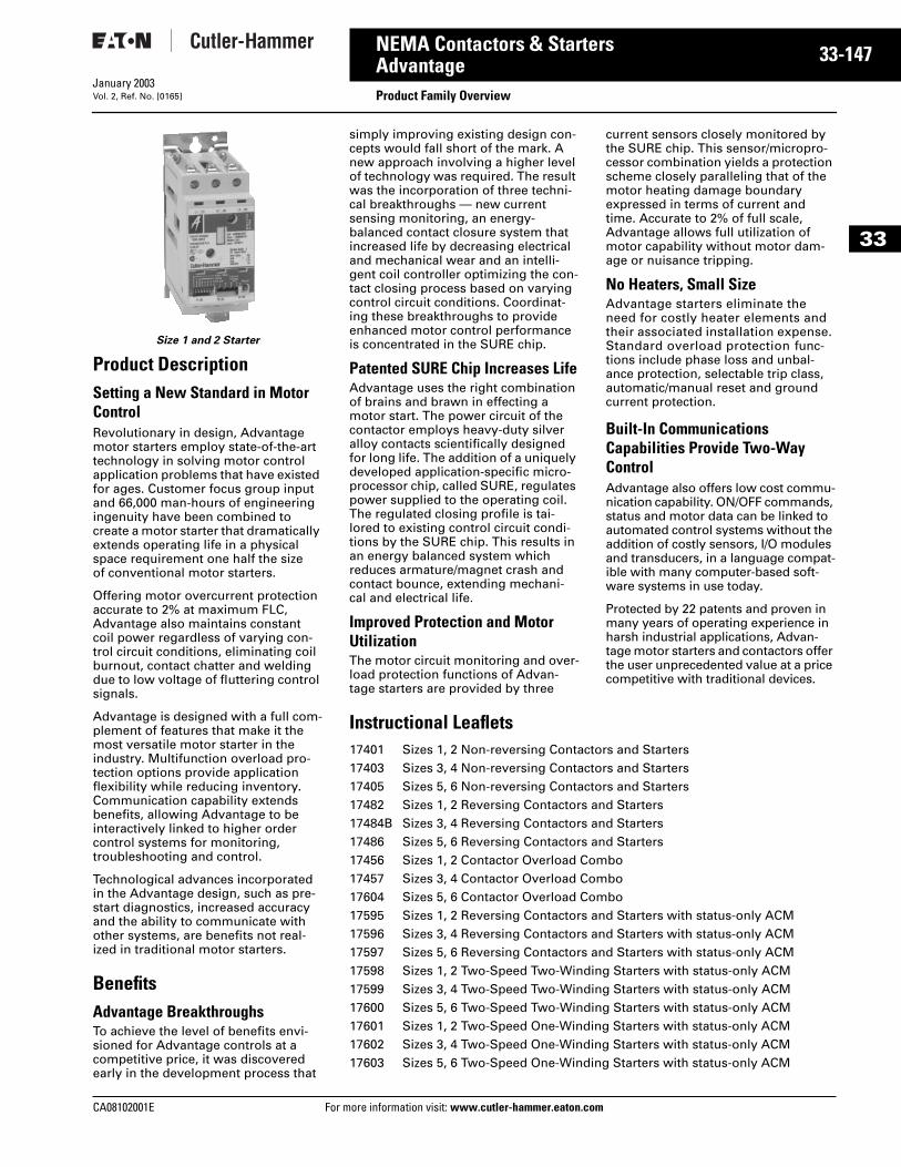
CA08102001E For more
47
33-1NEMA Contactors & StartersAdvantage
Product Family OverviewJanuary 2003Vol. 2, Ref. No. [0165]
33
Size 1 and 2 Starter
Product DescriptionSetting a New Standard in Motor ControlRevolutionary in design, Advantage motor starters employ state-of-the-art technology in solving motor control application problems that have existed for ages. Customer focus group input and 66,000 man-hours of engineering ingenuity have been combined to create a motor starter that dramatically extends operating life in a physical space requirement one half the size of conventional motor starters.
Offering motor overcurrent protection accurate to 2% at maximum FLC, Advantage also maintains constant coil power regardless of varying con-trol circuit conditions, eliminating coil burnout, contact chatter and welding due to low voltage of fluttering control signals.
Advantage is designed with a full com-plement of features that make it the most versatile motor starter in the industry. Multifunction overload pro-tection options provide application flexibility while reducing inventory. Communication capability extends benefits, allowing Advantage to be interactively linked to higher order control systems for monitoring, troubleshooting and control.
Technological advances incorporated in the Advantage design, such as pre-start diagnostics, increased accuracy and the ability to communicate with other systems, are benefits not real-ized in traditional motor starters.
BenefitsAdvantage BreakthroughsTo achieve the level of benefits envi-sioned for Advantage controls at a competitive price, it was discovered early in the development process that
simply improving existing design con-cepts would fall short of the mark. A new approach involving a higher level of technology was required. The result was the incorporation of three techni-cal breakthroughs — new current sensing monitoring, an energy-balanced contact closure system that increased life by decreasing electrical and mechanical wear and an intelli-gent coil controller optimizing the con-tact closing process based on varying control circuit conditions. Coordinat-ing these breakthroughs to provide enhanced motor control performance is concentrated in the SURE chip.
Patented SURE Chip Increases LifeAdvantage uses the right combination of brains and brawn in effecting a motor start. The power circuit of the contactor employs heavy-duty silver alloy contacts scientifically designed for long life. The addition of a uniquely developed application-specific micro-processor chip, called SURE, regulates power supplied to the operating coil. The regulated closing profile is tai-lored to existing control circuit condi-tions by the SURE chip. This results in an energy balanced system which reduces armature/magnet crash and contact bounce, extending mechani-cal and electrical life.
Improved Protection and Motor UtilizationThe motor circuit monitoring and over-load protection functions of Advan-tage starters are provided by three
current sensors closely monitored by the SURE chip. This sensor/micropro-cessor combination yields a protection scheme closely paralleling that of the motor heating damage boundary expressed in terms of current and time. Accurate to 2% of full scale, Advantage allows full utilization of motor capability without motor dam-age or nuisance tripping.
No Heaters, Small SizeAdvantage starters eliminate the need for costly heater elements and their associated installation expense. Standard overload protection func-tions include phase loss and unbal-ance protection, selectable trip class, automatic/manual reset and ground current protection.
Built-In Communications Capabilities Provide Two-Way ControlAdvantage also offers low cost commu-nication capability. ON/OFF commands, status and motor data can be linked to automated control systems without the addition of costly sensors, I/O modules and transducers, in a language compat-ible with many computer-based soft-ware systems in use today.
Protected by 22 patents and proven in many years of operating experience in harsh industrial applications, Advan-tage motor starters and contactors offer the user unprecedented value at a price competitive with traditional devices.
Instructional Leaflets17401 Sizes 1, 2 Non-reversing Contactors and Starters17403 Sizes 3, 4 Non-reversing Contactors and Starters17405 Sizes 5, 6 Non-reversing Contactors and Starters17482 Sizes 1, 2 Reversing Contactors and Starters17484B Sizes 3, 4 Reversing Contactors and Starters17486 Sizes 5, 6 Reversing Contactors and Starters17456 Sizes 1, 2 Contactor Overload Combo17457 Sizes 3, 4 Contactor Overload Combo17604 Sizes 5, 6 Contactor Overload Combo17595 Sizes 1, 2 Reversing Contactors and Starters with status-only ACM17596 Sizes 3, 4 Reversing Contactors and Starters with status-only ACM17597 Sizes 5, 6 Reversing Contactors and Starters with status-only ACM17598 Sizes 1, 2 Two-Speed Two-Winding Starters with status-only ACM17599 Sizes 3, 4 Two-Speed Two-Winding Starters with status-only ACM17600 Sizes 5, 6 Two-Speed Two-Winding Starters with status-only ACM17601 Sizes 1, 2 Two-Speed One-Winding Starters with status-only ACM17602 Sizes 3, 4 Two-Speed One-Winding Starters with status-only ACM17603 Sizes 5, 6 Two-Speed One-Winding Starters with status-only ACM
information visit: www.cutler-hammer.eaton.com
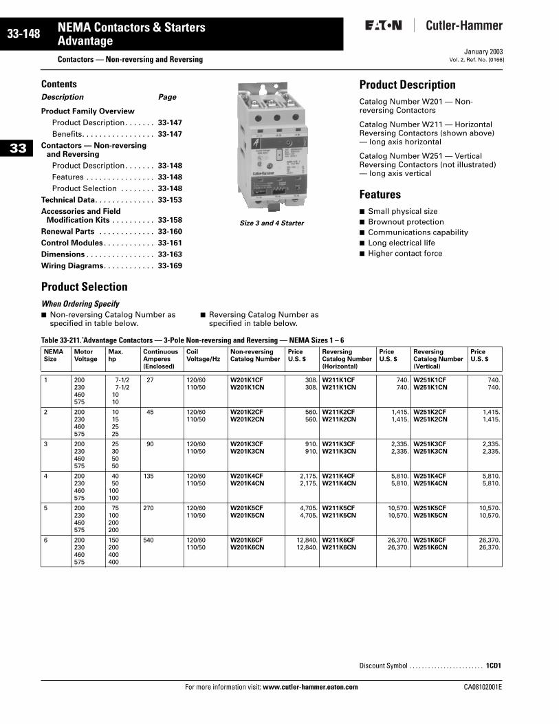
33-148
33
NEMA Contactors & StartersAdvantage
Contactors — Non-reversing and ReversingFor more information visit: www.cutler-hammer.eaton.com
January 2003Vol. 2, Ref. No. [0166]
ContentsDescription Page
Product Family Overview
Product Description. . . . . . . 33-147
Benefits. . . . . . . . . . . . . . . . . 33-147
Contactors — Non-reversing and Reversing
Product Description. . . . . . . 33-148
Features . . . . . . . . . . . . . . . . 33-148
Product Selection . . . . . . . . 33-148
Technical Data. . . . . . . . . . . . . . 33-153
Accessories and FieldModification Kits . . . . . . . . . . 33-158
Renewal Parts . . . . . . . . . . . . . 33-160
Control Modules . . . . . . . . . . . . 33-161
Dimensions . . . . . . . . . . . . . . . . 33-163
Wiring Diagrams. . . . . . . . . . . . 33-169
Size 3 and 4 Starter
Product DescriptionCatalog Number W201 — Non-reversing Contactors
Catalog Number W211 — Horizontal Reversing Contactors (shown above) — long axis horizontal
Catalog Number W251 — Vertical Reversing Contactors (not illustrated) — long axis vertical
Features■ Small physical size■ Brownout protection■ Communications capability■ Long electrical life■ Higher contact force
Product Selection When Ordering Specify ■ Non-reversing Catalog Number as
specified in table below.■ Reversing Catalog Number as
specified in table below.
Table 33-211. Advantage Contactors — 3-Pole Non-reversing and Reversing — NEMA Sizes 1 – 6 NEMASize
MotorVoltage
Max.hp
ContinuousAmperes(Enclosed)
Coil Voltage/Hz
Non-reversingCatalog Number
PriceU.S. $
ReversingCatalog Number(Horizontal)
PriceU.S. $
ReversingCatalog Number(Vertical)
PriceU.S. $
1 200230460575
7-1/27-1/2
1010
27 120/60110/50
W201K1CFW201K1CN
308.308.
W211K1CFW211K1CN
740.740.
W251K1CFW251K1CN
740.740.
2 200230460575
10152525
45 120/60110/50
W201K2CFW201K2CN
560.560.
W211K2CFW211K2CN
1,415.1,415.
W251K2CFW251K2CN
1,415.1,415.
3 200230460575
25305050
90 120/60110/50
W201K3CFW201K3CN
910.910.
W211K3CFW211K3CN
2,335.2,335.
W251K3CFW251K3CN
2,335.2,335.
4 200230460575
4050
100100
135 120/60110/50
W201K4CFW201K4CN
2,175.2,175.
W211K4CFW211K4CN
5,810.5,810.
W251K4CFW251K4CN
5,810.5,810.
5 200230460575
75100200200
270 120/60110/50
W201K5CFW201K5CN
4,705.4,705.
W211K5CFW211K5CN
10,570.10,570.
W251K5CFW251K5CN
10,570.10,570.
6 200230460575
150200400400
540 120/60110/50
W201K6CFW201K6CN
12,840.12,840.
W211K6CFW211K6CN
26,370.26,370.
W251K6CFW251K6CN
26,370.26,370.
Discount Symbol . . . . . . . . . . . . . . . . . . . . . . . . 1CD1
CA08102001E
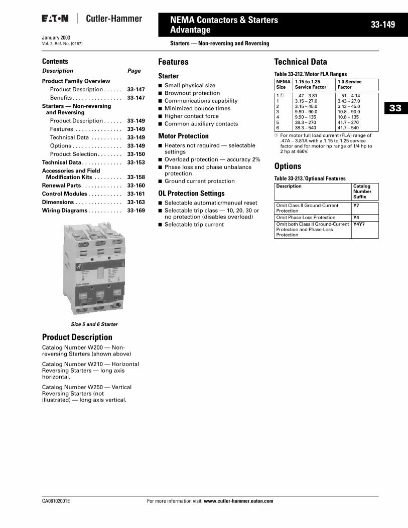
CA08102001E For more
49
33-1NEMA Contactors & StartersAdvantage
Starters — Non-reversing and ReversingJanuary 2003Vol. 2, Ref. No. [0167]
33
ContentsDescription Page
Product Family Overview
Product Description . . . . . . 33-147
Benefits . . . . . . . . . . . . . . . . 33-147
Starters — Non-reversing and Reversing
Product Description . . . . . . 33-149
Features . . . . . . . . . . . . . . . 33-149
Technical Data . . . . . . . . . . 33-149
Options . . . . . . . . . . . . . . . . 33-149
Product Selection. . . . . . . . 33-150
Technical Data . . . . . . . . . . . . . 33-153
Accessories and FieldModification Kits . . . . . . . . . 33-158
Renewal Parts . . . . . . . . . . . . 33-160
Control Modules . . . . . . . . . . . 33-161
Dimensions . . . . . . . . . . . . . . . 33-163
Wiring Diagrams . . . . . . . . . . . 33-169
Size 5 and 6 Starter
Product DescriptionCatalog Number W200 — Non-reversing Starters (shown above)
Catalog Number W210 — Horizontal Reversing Starters — long axis horizontal.
Catalog Number W250 — Vertical Reversing Starters (not illustrated) — long axis vertical.
Features
Starter■ Small physical size■ Brownout protection■ Communications capability■ Minimized bounce times■ Higher contact force■ Common auxiliary contacts
Motor Protection■ Heaters not required — selectable
settings■ Overload protection — accuracy 2%■ Phase loss and phase unbalance
protection■ Ground current protection
OL Protection Settings■ Selectable automatic/manual reset■ Selectable trip class — 10, 20, 30 or
no protection (disables overload)■ Selectable trip current
Technical DataTable 33-212. Motor FLA Ranges
1 For motor full load current (FLA) range of .47A – 3.81A with a 1.15 to 1.25 service factor and for motor hp range of 1/4 hp to 2 hp at 460V.
OptionsTable 33-213. Optional Features
NEMASize
1.15 to 1.25Service Factor
1.0 Service Factor
1 1123456
.47 – 3.813.15 – 27.03.15 – 45.09.90 – 90.09.90 – 13538.3 – 27038.3 – 540
.51 – 4.143.43 – 27.03.43 – 45.010.8 – 90.010.8 – 13541.7 – 27041.7 – 540
Description CatalogNumberSuffix
Omit Class II Ground-Current Protection
Y7
Omit Phase-Loss Protection Y4
Omit both Class II Ground-Current Protection and Phase-Loss Protection
Y4Y7
information visit: www.cutler-hammer.eaton.com
33-150
33
NEMA Contactors & StartersAdvantage
Starters — Non-reversing and ReversingFor more information visit: www.cutler-hammer.eaton.com
January 2003Vol. 2, Ref. No. [0168]
Product SelectionWhen Ordering Specify ■ Non-reversing Catalog Number as
specified in table below.■ Reversing Catalog Number as
specified in table below.
Table 33-214. Advantage Starters — 3-Pole Non-reversing and Reversing — Wired for Separate Control — Heaters Not Required — NEMA Sizes 1 – 6
1 For motor full load current (FLA) range of .47A – 3.81A with a 1.15 to 1.25 service factor and for motor hp range of 1/4 hp to 2 hp at 460V.
NEMASize
MotorVoltage
Max.hp
ContinuousAmperes(Enclosed)
Coil Voltage/Hz
Non-reversingCatalog Number
PriceU.S. $
ReversingCatalog Number(Horizontal)
PriceU.S. $
ReversingCatalog Number(Vertical)
PriceU.S. $
1 1 200230460575
1122
27 120/60110/50
W200MLCFCW200MLCNC
395.395.
W210MLCFCW210MLCNC
835.835.
W250MLCFCW250MLCNC
835.835.
1 200230460575
7-1/27-1/2
1010
27 120/60110/50
W200M1CFCW200M1CNC
395.395.
W210M1CFCW210M1CNC
835.835.
W250M1CFCW250M1CNC
835.835.
2 200230460575
10152525
45 120/60110/50
W200M2CFCW200M2CNC
685.685.
W210M2CFCW210M2CNC
1,540.1,540.
W250M2CFCW250M2CNC
1,540.1,540.
3 200230460575
25305050
90 120/60110/50
W200M3CFCW200M3CNC
1,090.1,090.
W210M3CFCW210M3CNC
2,510.2,510.
W250M3CFCW250M3CNC
2,510.2,510.
4 200230460575
4050
100100
135 120/60110/50
W200M4CFCW200M4CNC
2,415.2,415.
W210M4CFCW210M4CNC
6,050.6,050.
W250M4CFCW250M4CNC
6,050.6,050.
5 200230460575
75100200200
270 120/60110/50
W200M5CFCW200M5CNC
5,290.5,820.
W210M5CFCW210M5CNC
11,700.11,700.
W250M5CFCW250M5CNC
11,700.11,700.
6 200230460575
150200400400
540 120/60110/50
W200M6CFCW200M6CNC
12,510.13,760.
W210M6CFCW210M6CNC
27,270.27,270.
W250M6CFCW250M6CNC
27,270.27,270.
Discount Symbol . . . . . . . . . . . . . . . . . . . . . . . . 1CD1
CA08102001E
CA08102001E For more
51
33-1NEMA Contactors & StartersAdvantage
Starters — Non-reversing, Two-SpeedJanuary 2003Vol. 2, Ref. No. [0169]
33
ContentsDescription Page
Product Family Overview
Product Description . . . . . . 33-147
Benefits . . . . . . . . . . . . . . . . 33-147
Starters — Non-reversingTwo-Speed
Product Selection. . . . . . . . 33-151
Technical Data . . . . . . . . . . . . . 33-153
Accessories and FieldModification Kits . . . . . . . . . 33-158
Renewal Parts . . . . . . . . . . . . 33-160
Control Modules . . . . . . . . . . . 33-161
Dimensions . . . . . . . . . . . . . . . 33-163
Wiring Diagrams . . . . . . . . . . . 33-169
Product SelectionWhen Ordering Specify■ Catalog Number as shown in table
below.
Table 33-215. Two-Speed Advantage Starters — Wired for Separate Control — Heaters Not Required — NEMA Sizes 1 – 6
1 For motor full load current (FLA) range of .47A – 3.81A with a 1.15 to 1.25 service factor and for motor hp range of 1/4 hp to 2 hp at 460V.
NEMA Size
MotorVoltage
Max. Horsepower ContinuousAmperes(Enclosed)
CoilVoltage/Hz
Open Type (Horizontal)
Constantor VariableTorque
Constanthp
CatalogNumber
PriceU.S. $
For Separate (2) Winding Type Motors — Wye Wye1 1 200
230460575
1122
1122
27 120/60110/50
W960MLCFCM3W960MLCNCM3
1,170.1,170.
1 200230460575
7-1/27-1/2
1010
557-1/27-1/2
27 120/60110/50
W960M1CFCM3W960M1CNCM3
1,170.1,170.
2 200230460575
10152525
7-1/2102020
45 120/60110/50
W960M2CFCM3W960M2CNCM3
1,980.1,980.
3 200230460575
25305050
20254040
90 120/60110/50
W960M3CFCM3W960M3CNCM3
3,025.3,025.
4 200230460575
4050
100100
30407575
135 120/60110/50
W960M4CFCM3W960M4CNCM3
7,460.7,460.
5 200230460575
75100200200
6075
150150
270 120/60110/50
W960M5CFCM3W960M5CNCM3
17,500.17,500.
6 200230460575
150200400400
100150300300
540 120/60110/50
W960M6CFCM3W960M6CNCM3
32,790.32,790.
Discount Symbol . . . . . . . . . . . . . . . . . . . . . . . . . 1CD1
information visit: www.cutler-hammer.eaton.com
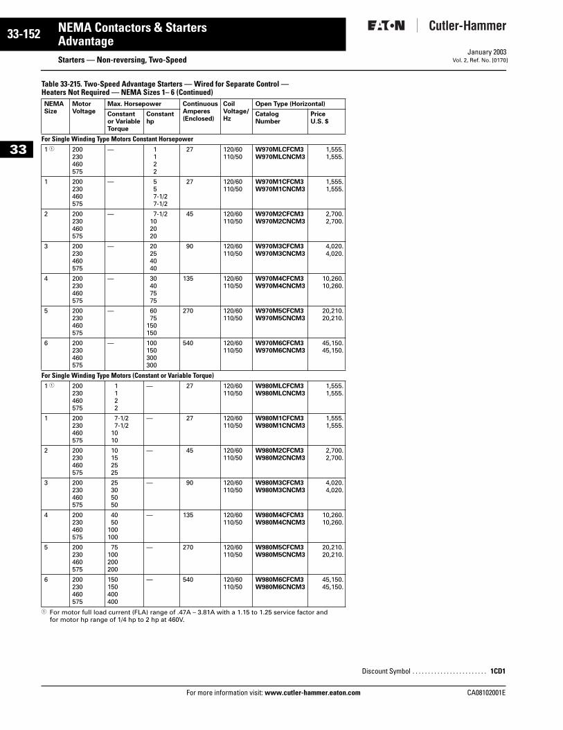
33-152
33
NEMA Contactors & StartersAdvantage
Starters — Non-reversing, Two-SpeedFor more information visit: www.cutler-hammer.eaton.com
January 2003Vol. 2, Ref. No. [0170]
Table 33-215. Two-Speed Advantage Starters — Wired for Separate Control — Heaters Not Required — NEMA Sizes 1– 6 (Continued)
1 For motor full load current (FLA) range of .47A – 3.81A with a 1.15 to 1.25 service factor and for motor hp range of 1/4 hp to 2 hp at 460V.
NEMA Size
MotorVoltage
Max. Horsepower ContinuousAmperes(Enclosed)
CoilVoltage/Hz
Open Type (Horizontal)
Constantor VariableTorque
Constanthp
CatalogNumber
PriceU.S. $
For Single Winding Type Motors Constant Horsepower 1 1 200
230460575
— 1122
27 120/60110/50
W970MLCFCM3W970MLCNCM3
1,555.1,555.
1 200230460575
— 557-1/27-1/2
27 120/60110/50
W970M1CFCM3W970M1CNCM3
1,555.1,555.
2 200230460575
— 7-1/2102020
45 120/60110/50
W970M2CFCM3W970M2CNCM3
2,700.2,700.
3 200230460575
— 20254040
90 120/60110/50
W970M3CFCM3W970M3CNCM3
4,020.4,020.
4 200230460575
— 30407575
135 120/60110/50
W970M4CFCM3W970M4CNCM3
10,260.10,260.
5 200230460575
— 6075
150150
270 120/60110/50
W970M5CFCM3W970M5CNCM3
20,210.20,210.
6 200230460575
— 100150300300
540 120/60110/50
W970M6CFCM3W970M6CNCM3
45,150.45,150.
For Single Winding Type Motors (Constant or Variable Torque)1 1 200
230460575
1122
— 27 120/60110/50
W980MLCFCM3W980MLCNCM3
1,555.1,555.
1 200230460575
7-1/27-1/2
1010
— 27 120/60110/50
W980M1CFCM3W980M1CNCM3
1,555.1,555.
2 200230460575
10152525
— 45 120/60110/50
W980M2CFCM3W980M2CNCM3
2,700.2,700.
3 200230460575
25305050
— 90 120/60110/50
W980M3CFCM3W980M3CNCM3
4,020.4,020.
4 200230460575
4050
100100
— 135 120/60110/50
W980M4CFCM3W980M4CNCM3
10,260.10,260.
5 200230460575
75100200200
— 270 120/60110/50
W980M5CFCM3W980M5CNCM3
20,210.20,210.
6 200230460575
150150400400
— 540 120/60110/50
W980M6CFCM3W980M6CNCM3
45,150.45,150.
Discount Symbol . . . . . . . . . . . . . . . . . . . . . . . . 1CD1
CA08102001E
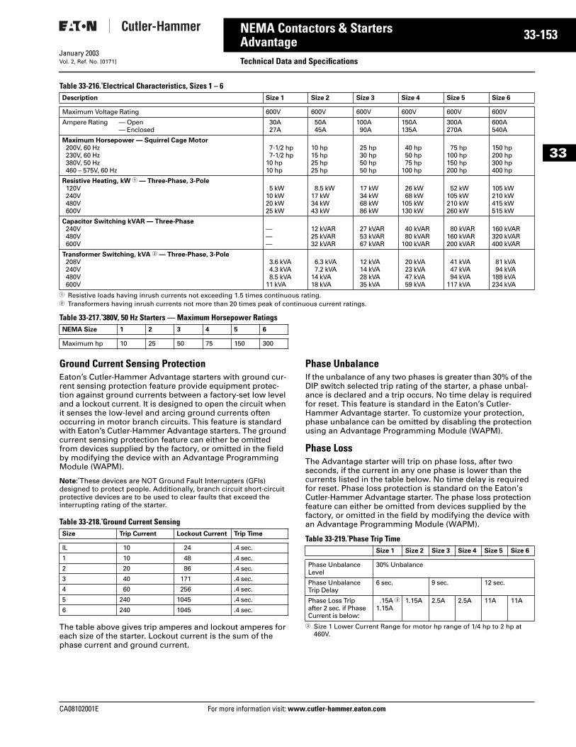
CA08102001E For more
53
33-1NEMA Contactors & StartersAdvantage Technical Data and SpecificationsJanuary 2003Vol. 2, Ref. No. [0171]
33
Table 33-216. Electrical Characteristics, Sizes 1 – 6
1 Resistive loads having inrush currents not exceeding 1.5 times continuous rating.2 Transformers having inrush currents not more than 20 times peak of continuous current ratings.
Table 33-217. 380V, 50 Hz Starters — Maximum Horsepower Ratings
Ground Current Sensing ProtectionEaton’s Cutler-Hammer Advantage starters with ground cur-rent sensing protection feature provide equipment protec-tion against ground currents between a factory-set low level and a lockout current. It is designed to open the circuit when it senses the low-level and arcing ground currents often occurring in motor branch circuits. This feature is standard with Eaton’s Cutler-Hammer Advantage starters. The ground current sensing protection feature can either be omitted from devices supplied by the factory, or omitted in the field by modifying the device with an Advantage Programming Module (WAPM).
Note: These devices are NOT Ground Fault Interrupters (GFIs) designed to protect people. Additionally, branch circuit short-circuit protective devices are to be used to clear faults that exceed the interrupting rating of the starter.
Table 33-218. Ground Current Sensing
The table above gives trip amperes and lockout amperes for each size of the starter. Lockout current is the sum of the phase current and ground current.
Phase UnbalanceIf the unbalance of any two phases is greater than 30% of the DIP switch selected trip rating of the starter, a phase unbal-ance is declared and a trip occurs. No time delay is required for reset. This feature is standard in the Eaton’s Cutler-Hammer Advantage starter. To customize your protection, phase unbalance can be omitted by disabling the protection using an Advantage Programming Module (WAPM).
Phase LossThe Advantage starter will trip on phase loss, after two seconds, if the current in any one phase is lower than the currents listed in the table below. No time delay is required for reset. Phase loss protection is standard on the Eaton’s Cutler-Hammer Advantage starter. The phase loss protection feature can either be omitted from devices supplied by the factory, or omitted in the field by modifying the device with an Advantage Programming Module (WAPM).
Table 33-219. Phase Trip Time
3 Size 1 Lower Current Range for motor hp range of 1/4 hp to 2 hp at 460V.
Description Size 1 Size 2 Size 3 Size 4 Size 5 Size 6
Maximum Voltage Rating 600V 600V 600V 600V 600V 600V
Ampere Rating — Open— Enclosed
30A27A
50A45A
100A90A
150A135A
300A270A
600A540A
Maximum Horsepower — Squirrel Cage Motor200V, 60 Hz230V, 60 Hz380V, 50 Hz460 – 575V, 60 Hz
7-1/2 hp7-1/2 hp
10 hp10 hp
10 hp15 hp25 hp25 hp
25 hp30 hp50 hp50 hp
40 hp50 hp75 hp
100 hp
75 hp100 hp150 hp200 hp
150 hp200 hp300 hp400 hp
Resistive Heating, kW 1 — Three-Phase, 3-Pole120V240V480V600V
5 kW10 kW20 kW25 kW
8.5 kW17 kW34 kW43 kW
17 kW34 kW68 kW86 kW
26 kW68 kW
105 kW130 kW
52 kW105 kW210 kW260 kW
105 kW210 kW415 kW515 kW
Capacitor Switching kVAR — Three-Phase240V480V600V
———
12 kVAR25 kVAR32 kVAR
27 kVAR53 kVAR67 kVAR
40 kVAR80 kVAR
100 kVAR
80 kVAR160 kVAR200 kVAR
160 kVAR320 kVAR400 kVAR
Transformer Switching, kVA 2 — Three-Phase, 3-Pole208V240V480V600V
3.6 kVA4.3 kVA8.5 kVA
11 kVA
6.3 kVA7.2 kVA
14 kVA18 kVA
12 kVA14 kVA28 kVA35 kVA
20 kVA23 kVA47 kVA59 kVA
41 kVA47 kVA94 kVA
117 kVA
81 kVA94 kVA
188 kVA234 kVA
NEMA Size 1 2 3 4 5 6
Maximum hp 10 25 50 75 150 300
Size Trip Current Lockout Current Trip Time
IL 10 24 .4 sec.
1 10 48 .4 sec.
2 20 86 .4 sec.
3 40 171 .4 sec.
4 60 256 .4 sec.
5 240 1045 .4 sec.
6 240 1045 .4 sec.
Size 1 Size 2 Size 3 Size 4 Size 5 Size 6
Phase Unbalance Level
30% Unbalance
Phase Unbalance Trip Delay
6 sec. 9 sec. 12 sec.
Phase Loss Trip after 2 sec. if Phase Current is below:
.15A 31.15A
1.15A 2.5A 2.5A 11A 11A
information visit: www.cutler-hammer.eaton.com
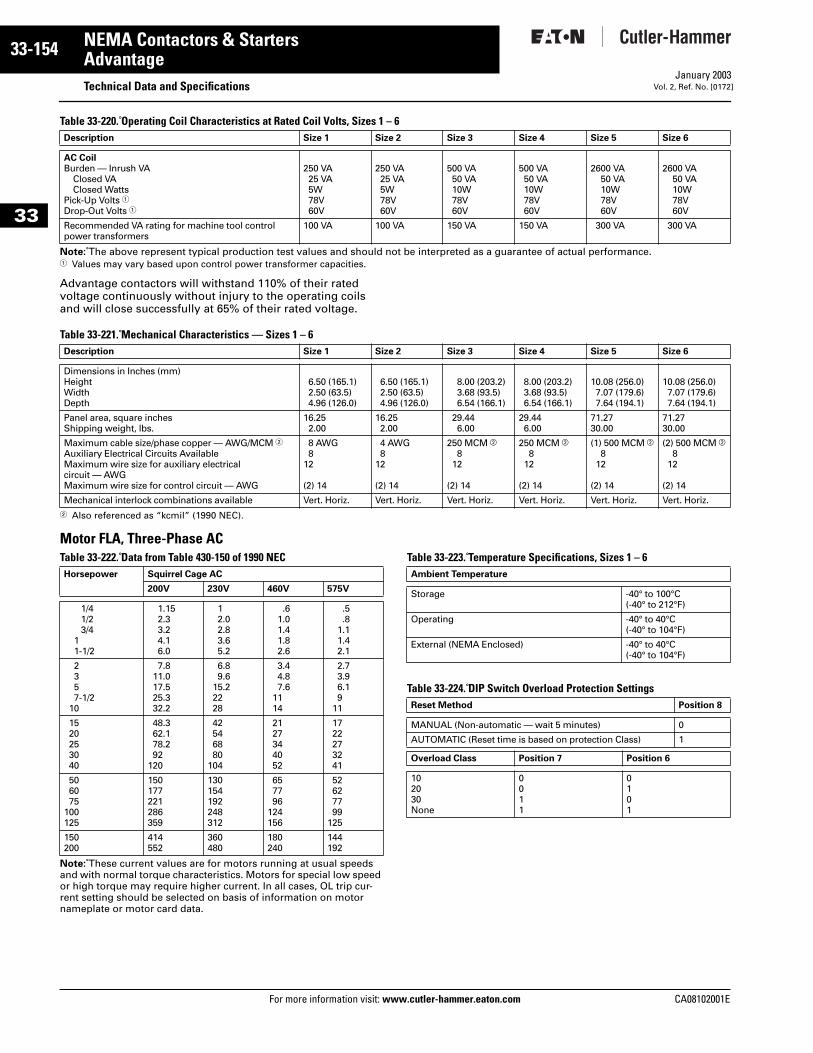
33-154
33
NEMA Contactors & StartersAdvantage
Technical Data and SpecificationsFor more information visit: www.cutler-hammer.eaton.com
January 2003Vol. 2, Ref. No. [0172]
Table 33-220. Operating Coil Characteristics at Rated Coil Volts, Sizes 1 – 6
Note: The above represent typical production test values and should not be interpreted as a guarantee of actual performance.1 Values may vary based upon control power transformer capacities.
Advantage contactors will withstand 110% of their rated voltage continuously without injury to the operating coils and will close successfully at 65% of their rated voltage.
Table 33-221. Mechanical Characteristics — Sizes 1 – 6
2 Also referenced as “kcmil” (1990 NEC).
Motor FLA, Three-Phase ACTable 33-222. Data from Table 430-150 of 1990 NEC
Note: These current values are for motors running at usual speeds and with normal torque characteristics. Motors for special low speed or high torque may require higher current. In all cases, OL trip cur-rent setting should be selected on basis of information on motor nameplate or motor card data.
Table 33-223. Temperature Specifications, Sizes 1 – 6
Table 33-224. DIP Switch Overload Protection Settings
Description Size 1 Size 2 Size 3 Size 4 Size 5 Size 6
AC CoilBurden — Inrush VA
Closed VAClosed Watts
Pick-Up Volts 1Drop-Out Volts 1
250 VA25 VA5W78V60V
250 VA25 VA5W78V60V
500 VA50 VA10W78V60V
500 VA50 VA10W78V60V
2600 VA50 VA10W78V60V
2600 VA50 VA10W78V60V
Recommended VA rating for machine tool control power transformers
100 VA 100 VA 150 VA 150 VA 300 VA 300 VA
Description Size 1 Size 2 Size 3 Size 4 Size 5 Size 6
Dimensions in Inches (mm)HeightWidthDepth
6.50 (165.1)2.50 (63.5)4.96 (126.0)
6.50 (165.1)2.50 (63.5)4.96 (126.0)
8.00 (203.2)3.68 (93.5)6.54 (166.1)
8.00 (203.2)3.68 (93.5)6.54 (166.1)
10.08 (256.0)7.07 (179.6)7.64 (194.1)
10.08 (256.0)7.07 (179.6)7.64 (194.1)
Panel area, square inchesShipping weight, lbs.
16.252.00
16.252.00
29.446.00
29.446.00
71.2730.00
71.2730.00
Maximum cable size/phase copper — AWG/MCM 2Auxiliary Electrical Circuits AvailableMaximum wire size for auxiliary electrical circuit — AWGMaximum wire size for control circuit — AWG
8 AWG8
12
(2) 14
4 AWG8
12
(2) 14
250 MCM b8
12
(2) 14
250 MCM b8
12
(2) 14
(1) 500 MCM b8
12
(2) 14
(2) 500 MCM b8
12
(2) 14
Mechanical interlock combinations available Vert. Horiz. Vert. Horiz. Vert. Horiz. Vert. Horiz. Vert. Horiz. Vert. Horiz.
Horsepower Squirrel Cage AC
200V 230V 460V 575V
1/41/23/4
11-1/2
1.152.33.24.16.0
12.02.83.65.2
.61.01.41.82.6
.5
.81.11.42.1
2357-1/2
10
7.811.017.525.332.2
6.89.6
15.22228
3.44.87.6
1114
2.73.96.19
11
1520253040
48.362.178.292
120
42546880
104
2127344052
1722273241
506075
100125
150177221286359
130154192248312
657796
124156
52627799
125
150200
414552
360480
180240
144192
Ambient Temperature
Storage -40° to 100°C(-40° to 212°F)
Operating -40° to 40°C(-40° to 104°F)
External (NEMA Enclosed) -40° to 40°C(-40° to 104°F)
Reset Method Position 8
MANUAL (Non-automatic — wait 5 minutes) 0
AUTOMATIC (Reset time is based on protection Class) 1
Overload Class Position 7 Position 6
102030None
0011
0101
CA08102001E
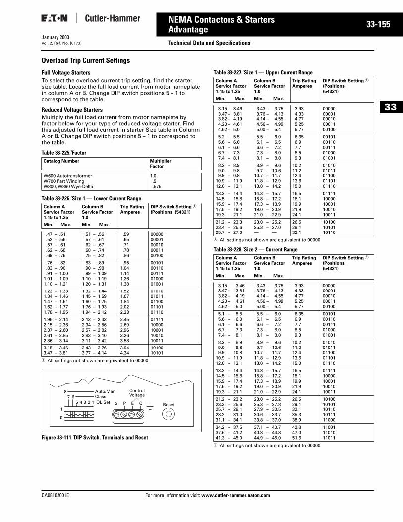
CA08102001E For more
55
33-1NEMA Contactors & StartersAdvantage Technical Data and SpecificationsJanuary 2003Vol. 2, Ref. No. [0173]
33
Overload Trip Current Settings
Full Voltage StartersTo select the overload current trip setting, find the starter size table. Locate the full load current from motor nameplate in column A or B. Change DIP switch positions 5 – 1 to correspond to the table.
Reduced Voltage StartersMultiply the full load current from motor nameplate by factor below for your type of reduced voltage starter. Find this adjusted full load current in starter Size table in Column A or B. Change DIP switch positions 5 – 1 to correspond to the table.
Table 33-225. Factor
Table 33-226. Size 1 — Lower Current Range
1 All settings not shown are equivalent to 00000.
Figure 33-111. DIP Switch, Terminals and Reset
Table 33-227. Size 1 — Upper Current Range
2 All settings not shown are equivalent to 00000.
Table 33-228. Size 2 — Current Range
3 All settings not shown are equivalent to 00000.
Catalog Number MultiplierFactor
W600 AutotransformerW700 Part WindingW800, W890 Wye-Delta
1.0.5.575
Column AService Factor1.15 to 1.25
Column BService Factor1.0
Trip RatingAmperes
DIP Switch Setting 1
(Positions) (54321)
Min. Max. Min. Max.
.47 –
.52 –
.57 –
.62 –
.69 –
.51
.56
.61
.68
.75
.51 –
.57 –
.62 –
.68 –
.75 –
.56
.61
.67
.74
.82
.59
.65
.71
.78
.86
0000000001000100001100100
.76 –
.83 –
.91 –1.01 –1.10 –
.82
.901.001.091.21
.83 –
.90 –
.99 –1.10 –1.20 –
.89
.981.091.191.31
.951.041.141.261.38
0010100110001110100001001
1.22 –1.34 –1.47 –1.62 –1.78 –
1.331.461.611.771.95
1.32 –1.45 –1.60 –1.76 –1.94 –
1.441.591.751.932.12
1.521.671.842.022.23
0101001011011000110101110
1.96 –2.15 –2.37 –2.61 –2.86 –
2.142.362.602.853.14
2.13 –2.34 –2.57 –2.83 –3.11 –
2.332.562.823.103.42
2.452.692.963.263.58
0111110000100011001010011
3.15 –3.47 –
3.463.81
3.43 –3.77 –
3.764.14
3.944.34
1010010101
1
1234567
8
0
Auto/ManClassOL Set 3 P E C
ControlVoltage
Reset
Column AService Factor1.15 to 1.25
Column BService Factor1.0
Trip RatingAmperes
DIP Switch Setting 2
(Positions) (54321)
Min. Max. Min. Max.
3.15 –3.47 –3.82 –4.20 –4.62 –
3.463.814.194.615.0
3.43 –3.76 –4.14 –4.56 –5.00 –
3.754.134.554.995.4
3.934.334.775.255.77
0000000001000100001100100
5.2 –5.6 –6.1 –6.7 –7.4 –
5.56.06.67.38.1
5.5 –6.1 –6.6 –7.3 –8.1 –
6.06.57.28.08.8
6.356.97.78.59.3
0010100110001110100001001
8.2 –9.0 –9.9 –
10.9 –12.0 –
8.99.80.811.913.1
8.9 –9.7 –
10.7 –11.8 –13.0 –
9.610.611.712.914.2
10.211.212.413.615.0
0101001011011000110101110
13.2 –14.5 –15.9 –17.5 –19.3 –
14.415.817.419.221.1
14.3 –15.8 –17.3 –19.0 –21.0 –
15.717.218.920.922.9
16.518.119.921.924.1
0111110000100011001010011
21.2 –23.4 –25.7 –
23.325.627.0
23.0 –25.3 –—
25.227.0—
26.529.132.1
101001010110110
Column AService Factor1.15 to 1.25
Column BService Factor1.0
Trip RatingAmperes
DIP Switch Setting 3
(Positions) (54321)
Min. Max. Min. Max.
3.15 –3.47 –3.82 –4.20 –4.62 –
3.463.814.194.615.0
3.43 –3.76 –4.14 –4.56 –5.00 –
3.754.134.554.995.4
3.934.334.775.255.77
0000000001000100001100100
5.1 –5.6 –6.1 –6.7 –7.4 –
5.56.06.67.38.1
5.5 –6.1 –6.6 –7.3 –8.1 –
6.06.57.28.08.8
6.356.97.78.59.3
0010100110001110100001001
8.2 –9.0 –9.9 –
10.9 –12.0 –
8.99.8
10.811.913.1
8.9 –9.7 –
10.7 –11.8 –13.0 –
9.610.611.712.914.2
10.211.212.413.615.0
0101001011011000110101110
13.2 –14.5 –15.9 –17.5 –19.3 –
14.415.817.419.221.1
14.3 –15.8 –17.3 –19.0 –21.0 –
15.717.218.920.922.9
16.518.119.921.924.1
0111110000100011001010011
21.2 –23.3 –25.7 –28.2 –31.1 –
23.225.628.131.034.1
23.0 –25.3 –27.9 –30.6 –33.8 –
25.227.830.533.737.0
26.529.132.135.338.9
1010010101101101011111000
34.2 –37.6 –41.3 –
37.541.245.0
37.1 –40.8 –44.9 –
40.744.845.0
42.847.051.6
110011101011011
information visit: www.cutler-hammer.eaton.com
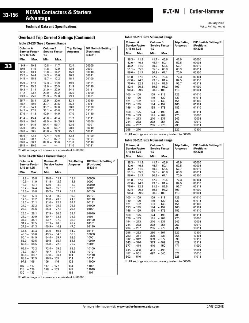
33-156
33
NEMA Contactors & StartersAdvantage
Technical Data and SpecificationsFor more information visit: www.cutler-hammer.eaton.com
January 2003Vol. 2, Ref. No. [0174]
Overload Trip Current Settings (Continued)Table 33-229. Size 3 Current Range
1 All settings not shown are equivalent to 00000.
Table 33-230. Size 4 Current Range
2 All settings not shown are equivalent to 00000.
Table 33-231. Size 5 Current Range
3 All settings not shown are equivalent to 00000.
Table 33-232. Size 6 Current Range
4 All settings not shown are equivalent to 00000.
Column AService Factor1.15 to 1.25
Column BService Factor1.0
Trip RatingAmperes
DIP Switch Setting 1
(Positions) (54321)
Min. Max. Min. Max.
9.9 –10.9 –12.0 –13.2 –14.5 –
10.811.913.114.415.8
10.8 –11.8 –13.0 –14.3 –15.7 –
11.712.914.215.617.2
12.413.615.016.518.1
0000000001000100001100100
15.9 –17.5 –19.3 –21.2 –23.3 –
17.319.221.123.225.6
17.3 –19.0 –21.0 –23.0 –25.3 –
18.920.922.925.227.8
19.921.924.126.529.1
0010100110001110100001001
25.7 –28.2 –31.0 –34.2 –37.6 –
28.130.934.137.541.3
27.9 –30.7 –33.7 –37.1 –40.9 –
30.633.637.040.844.9
32.135.338.842.747.0
0101001011011000110101110
41.4 –45.5 –50.1 –55.0 –60.6 –
45.450.054.960.566.5
45.0 –49.5 –54.4 –59.8 –65.8 –
49.454.359.765.772.3
51.756.962.668.875.7
0111110000100011001010011
66.6 –73.3 –80.8 –88.8 –
73.280.788.790.0
72.4 –79.7 –87.8 –—
79.687.790.0—
83.391.6
101.0111.0
10100101011011010111
Column AService Factor1.15 to 1.25
Column BService Factor1.0
Trip RatingAmperes
DIP Switch Setting 2
(Positions) (54321)
Min. Max. Min. Max.
9.9 –10.9 –12.0 –13.2 –14.5 –
10.811.913.114.415.8
10.8 –11.8 –13.0 –14.3 –15.7 –
11.712.914.215.617.2
12.413.615.016.518.1
0000000001000100001100100
15.9 –17.5 –19.3 –21.2 –23.3 –
17.419.221.123.225.6
17.3 –19.0 –21.0 –23.0 –25.3 –
18.920.922.925.227.8
19.921.924.126.529.1
0010100110001110100001001
25.7 –28.2 –31.0 –34.2 –37.6 –
28.130.934.137.541.3
27.9 –30.7 –33.7 –37.1 –40.9 –
30.633.637.040.844.9
32.135.338.842.747.0
0101001011011000110101110
41.4 –45.5 –50.1 –55.0 –60.6 –
45.450.054.960.566.5
45.0 –49.5 –54.4 –59.8 –65.8 –
49.454.359.765.772.3
51.756.962.668.875.7
0111110000100011001010011
66.6 –73.3 –80.8 –88.8 –97.6 –
73.280.788.797.5
106
72.4 –79.7 –87.8 –96.5 –
106 –
79.687.796.4
105116
83.391.6
101111122
1010010101101101011111000
107 –118 –130 –
117129133
117 –128 –—
127133—
134147162
110011101011011
Column AService Factor1.15 to 1.25
Column BService Factor1.0
Trip RatingAmperes
DIP Switch Setting 3
(Positions) (54321)
Min. Max. Min. Max.
38.3 –42.0 –46.2 –51.1 –56.0 –
41.946.151.055.961.7
41.7 –45.7 –50.2 –55.6 –60.9 –
45.650.155.560.867.1
47.952.557.763.970.0
0000000001000100001100100
61.8 –67.6 –75.0 –82.4 –90.4 –
67.574.982.390.399.9
67.2 –73.5 –81.5 –89.6 –98.3 –
73.481.489.598.2
108
77.384.593.7
103113
0010100110001110100001001
100 –110 –121 –133 –146 –
109120132145159
109 –119 –131 –144 –158 –
118130143157173
125137151166182
0101001011011000110101110
160 –176 –194 –214 –234 –
175193213233257
174 –191 –210 –232 –255 –
190209231254270
200220242267293
0111110000100011001010011
258 – 270 — — 322 10100
Column AService Factor1.15 to 1.25
Column BService Factor1.0
Trip RatingAmperes
DIP Switch Setting 4
(Positions) (54321)
Min. Max. Min. Max.
38.3 –42.0 –46.2 –51.1 –56.0 –
41.946.151.055.961.7
41.7 –45.7 –50.2 –55.6 –60.9 –
45.650.155.560.867.1
47.952.557.763.970.0
0000000001000100001100100
61.8 –67.6 –75.0 –82.4 –90.4 –
67.574.982.390.399.9
67.2 –73.5 –81.5 –89.6 –98.3 –
73.481.489.598.2
108
77.384.593.7
103113
0010100110001110100001001
100 –110 –121 –133 –146 –
109120132145159
109 –119 –131 –144 –158 –
118130143157173
125137151166182
0101001011011000110101110
160 –176 –194 –214 –234 –
175193213233257
174 –191 –210 –232 –255 –
190209231254279
200220242267293
0111110000100011001010011
258 –283 –312 –343 –377 –
282311342376414
280 –308 –339 –373 –410 –
307338372409450
322354390429471
1010010101101101011111000
415 –457 –502 –
456501540
451 –497 –—
496540—
519571628
110011101011011
CA08102001E
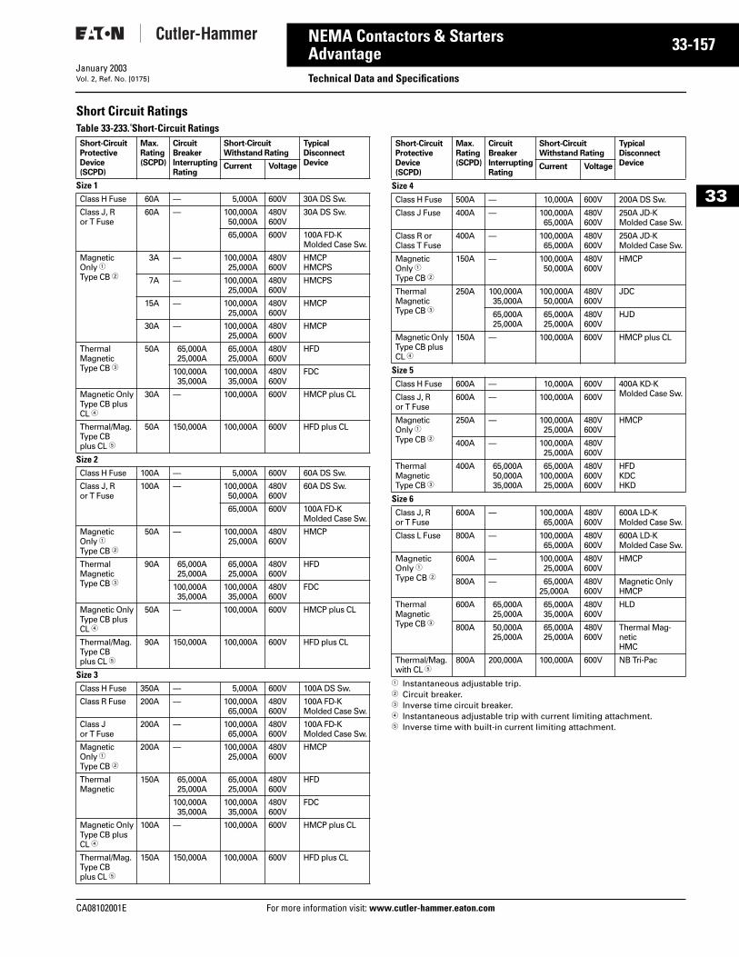
CA08102001E For more
57
33-1NEMA Contactors & StartersAdvantage Technical Data and SpecificationsJanuary 2003Vol. 2, Ref. No. [0175]
33
Short Circuit RatingsTable 33-233. Short-Circuit Ratings
1 Instantaneous adjustable trip.2 Circuit breaker.3 Inverse time circuit breaker.4 Instantaneous adjustable trip with current limiting attachment.5 Inverse time with built-in current limiting attachment.
Short-CircuitProtectiveDevice(SCPD)
Max.Rating(SCPD)
CircuitBreakerInterruptingRating
Short-CircuitWithstand Rating
TypicalDisconnectDeviceCurrent Voltage
Size 1Class H Fuse 60A — 5,000A 600V 30A DS Sw.
Class J, Ror T Fuse
60A — 100,000A50,000A
480V600V
30A DS Sw.
65,000A 600V 100A FD-KMolded Case Sw.
MagneticOnly 1Type CB 2
3A — 100,000A25,000A
480V600V
HMCPHMCPS
7A — 100,000A25,000A
480V600V
HMCPS
15A — 100,000A25,000A
480V600V
HMCP
30A — 100,000A25,000A
480V600V
HMCP
ThermalMagneticType CB 3
50A 65,000A25,000A
65,000A25,000A
480V600V
HFD
100,000A35,000A
100,000A35,000A
480V600V
FDC
Magnetic OnlyType CB plusCL 4
30A — 100,000A 600V HMCP plus CL
Thermal/Mag.Type CBplus CL 5
50A 150,000A 100,000A 600V HFD plus CL
Size 2Class H Fuse 100A — 5,000A 600V 60A DS Sw.
Class J, Ror T Fuse
100A — 100,000A50,000A
480V600V
60A DS Sw.
65,000A 600V 100A FD-KMolded Case Sw.
MagneticOnly 1Type CB 2
50A — 100,000A25,000A
480V600V
HMCP
ThermalMagneticType CB 3
90A 65,000A25,000A
65,000A25,000A
480V600V
HFD
100,000A35,000A
100,000A35,000A
480V600V
FDC
Magnetic OnlyType CB plusCL 4
50A — 100,000A 600V HMCP plus CL
Thermal/Mag.Type CBplus CL 5
90A 150,000A 100,000A 600V HFD plus CL
Size 3Class H Fuse 350A — 5,000A 600V 100A DS Sw.
Class R Fuse 200A — 100,000A65,000A
480V600V
100A FD-K Molded Case Sw.
Class J or T Fuse
200A — 100,000A65,000A
480V600V
100A FD-KMolded Case Sw.
MagneticOnly 1Type CB 2
200A — 100,000A25,000A
480V600V
HMCP
ThermalMagnetic
150A 65,000A25,000A
65,000A25,000A
480V600V
HFD
100,000A35,000A
100,000A35,000A
480V600V
FDC
Magnetic OnlyType CB plusCL 4
100A — 100,000A 600V HMCP plus CL
Thermal/Mag.Type CBplus CL 5
150A 150,000A 100,000A 600V HFD plus CL
Short-CircuitProtectiveDevice(SCPD)
Max.Rating(SCPD)
CircuitBreakerInterruptingRating
Short-CircuitWithstand Rating
TypicalDisconnectDeviceCurrent Voltage
Size 4Class H Fuse 500A — 10,000A 600V 200A DS Sw.
Class J Fuse 400A — 100,000A65,000A
480V600V
250A JD-K Molded Case Sw.
Class R or Class T Fuse
400A — 100,000A65,000A
480V600V
250A JD-K Molded Case Sw.
MagneticOnly 1Type CB 2
150A — 100,000A50,000A
480V600V
HMCP
ThermalMagneticType CB 3
250A 100,000A35,000A
100,000A50,000A
480V600V
JDC
65,000A25,000A
65,000A25,000A
480V600V
HJD
Magnetic Only Type CB plus CL 4
150A — 100,000A 600V HMCP plus CL
Size 5Class H Fuse 600A — 10,000A 600V 400A KD-K
Molded Case Sw.Class J, Ror T Fuse
600A — 100,000A 600V
MagneticOnly 1Type CB 2
250A — 100,000A25,000A
480V600V
HMCP
400A — 100,000A25,000A
480V600V
ThermalMagneticType CB 3
400A 65,000A50,000A35,000A
65,000A100,000A25,000A
480V600V600V
HFDKDCHKD
Size 6Class J, Ror T Fuse
600A — 100,000A65,000A
480V600V
600A LD-K Molded Case Sw.
Class L Fuse 800A — 100,000A65,000A
480V600V
600A LD-K Molded Case Sw.
MagneticOnly 1Type CB 2
600A — 100,000A25,000A
480V600V
HMCP
800A — 65,000A25,000A
480V600V
Magnetic OnlyHMCP
ThermalMagneticType CB 3
600A 65,000A25,000A
65,000A35,000A
480V600V
HLD
800A 50,000A25,000A
65,000A25,000A
480V600V
Thermal Mag-neticHMC
Thermal/Mag.with CL 5
800A 200,000A 100,000A 600V NB Tri-Pac
information visit: www.cutler-hammer.eaton.com
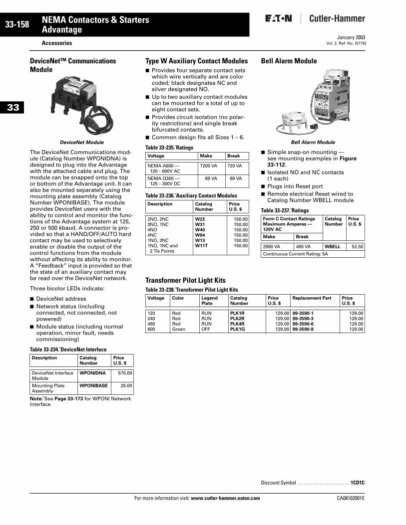
33-158
33
NEMA Contactors & StartersAdvantage
AccessoriesFor more information visit: www.cutler-hammer.eaton.com
January 2003Vol. 2, Ref. No. [0176]
DeviceNet™ Communications Module
DeviceNet Module
The DeviceNet Communications mod-ule (Catalog Number WPONIDNA) is designed to plug into the Advantage with the attached cable and plug. The module can be snapped onto the top or bottom of the Advantage unit. It can also be mounted separately using the mounting plate assembly (Catalog Number WPONIBASE). The module provides DeviceNet users with the ability to control and monitor the func-tions of the Advantage system at 125, 250 or 500 kbaud. A connector is pro-vided so that a HAND/OFF/AUTO hard contact may be used to selectively enable or disable the output of the control functions from the module without affecting its ability to monitor. A “Feedback” input is provided so that the state of an auxiliary contact may be read over the DeviceNet network.
Three bicolor LEDs indicate:
■ DeviceNet address■ Network status (including
connected, not connected, not powered)
■ Module status (including normal operation, minor fault, needs commissioning)
Table 33-234. DeviceNet Interface
Note: See Page 33-173 for WPONI Network Interface.
Description CatalogNumber
PriceU.S. $
DeviceNet InterfaceModule
WPONIDNA 570.00
Mounting Plate Assembly
WPONIBASE 26.00
Type W Auxiliary Contact Modules■ Provides four separate contact sets
which wire vertically and are color coded; black designates NC and silver designated NO.
■ Up to two auxiliary contact modules can be mounted for a total of up to eight contact sets.
■ Provides circuit isolation (no polar-ity restrictions) and single break bifurcated contacts.
■ Common design fits all Sizes 1 – 6.
Table 33-235. Ratings
Table 33-236. Auxiliary Contact Modules
Bell Alarm Module
Bell Alarm Module
■ Simple snap-on mounting —see mounting examples in Figure 33-112.
■ Isolated NO and NC contacts (1 each)
■ Plugs into Reset port■ Remote electrical Reset wired to
Catalog Number WBELL module
Table 33-237. Ratings
Transformer Pilot Light KitsTable 33-238. Transformer Pilot Light Kits
Voltage Make Break
NEMA A600 — 120 – 600V AC
7200 VA 720 VA
NEMA Q300 — 125 – 300V DC
69 VA 69 VA
Description CatalogNumber
PriceU.S. $
2NO, 2NC3NO, 1NC4NO4NC1NO, 3NC1NO, 1NC and 2 Tie Points
W22W31W40W04W13W11T
150.00150.00150.00150.00150.00150.00
Form C Contact RatingsMaximum Amperes — 120V AC
CatalogNumber
PriceU.S. $
Make Break
2880 VA 480 VA WBELL 52.50
Continuous Current Rating: 5A
Voltage Color LegendPlate
CatalogNumber
PriceU.S. $
Replacement Part PriceU.S. $
120240480600
RedRedRedGreen
RUNRUNRUNOFF
PLK1RPLK2RPLK4RPLK1G
129.00129.00129.00129.00
99-3590-199-3590-399-3590-699-3590-8
129.00129.00129.00129.00
Discount Symbol . . . . . . . . . . . . . . . . . . . . . . . 1CD1C
CA08102001E
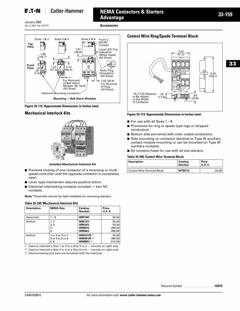
CA08102001E For more
59
33-1NEMA Contactors & StartersAdvantage AccessoriesJanuary 2003Vol. 2, Ref. No. [0177]
33
Figure 33-112. Approximate Dimensions in Inches (mm)
Mechanical Interlock Kits
Installed Mechanical Interlock Kit
■ Prevents closing of one contactor of a reversing or multi-speed controller until the opposite contactor is completely open.
■ Lever type mechanism assures positive action.■ Electrical interlocking contacts included — two NC
contacts.
Note: These kits cannot be field installed on reversing starters.
Table 33-239. Mechanical Interlock Kits
1 Used to interlock a Size 1 or 2 to a Size 3 or 4 — mounts on right only.2 Used to interlock a Size 3 or 4 to a Size 5 or 6 — mounts on right only.3 Interconnecting bus bars are furnished with the interlock.
Control Wire Ring/Spade Terminal Block
Figure 33-113. Approximate Dimensions in Inches (mm)
■ For use with all Sizes 1 – 6.■ Provisions for ring or spade type lugs or stripped
conductors.■ Bottom side pre-wired with color coded conductors.■ Side mounting on contactor identical to Type W auxiliary
contact module mounting or can be mounted on Type W auxiliary contacts.
■ Kit contains fuses for use with all size starters.
Table 33-240. Control Wire Terminal Block
Orientation NEMA Size Catalog Number
PriceU.S. $
Horizontal 1 – 6 WM16H 55.50
Vertical 1, 23, 456
WM12VWM34VWM55VWM66V
55.5093.50
498.00498.00
Vertical 1 or 2 to 3 or 43 or 4 to 5 or 65, 6
WM23VR 1
WM45VR 2
WMBBV 3
93.50498.00910.00
Sizes 1 & 2 Sizes 3 & 4 Sizes 5 & 6
1.68(42.7)
1.47(37.3)
2.14(54.4)
1.61(40.9)
.29(7.4)
1.02 (25.9)For Removalof Plug(All Sizes)
For Removalof Bell AlarmModule .55 (14.0)(All Sizes)
Optional Mounting Locations
Local LED TripIndication(When Used)(All Sizes)
From CNO/NCContact
Note: PlugOrientation(All Sizes)
TopView
FrontView
Mounting — Bell Alarm Modules
Description CatalogNumber
PriceU.S. $
Control Wire Terminal Block WTBF16 93.50
Discount Symbol . . . . . . . . . . . . . . . . . . . . . . . . 1CD1C
2.25(57.2)
.70(17.8) .93
(23.6)
4.20(106.7)
.70 (17.8) Distanceto Be Addedto the Widthof Contactor
information visit: www.cutler-hammer.eaton.com
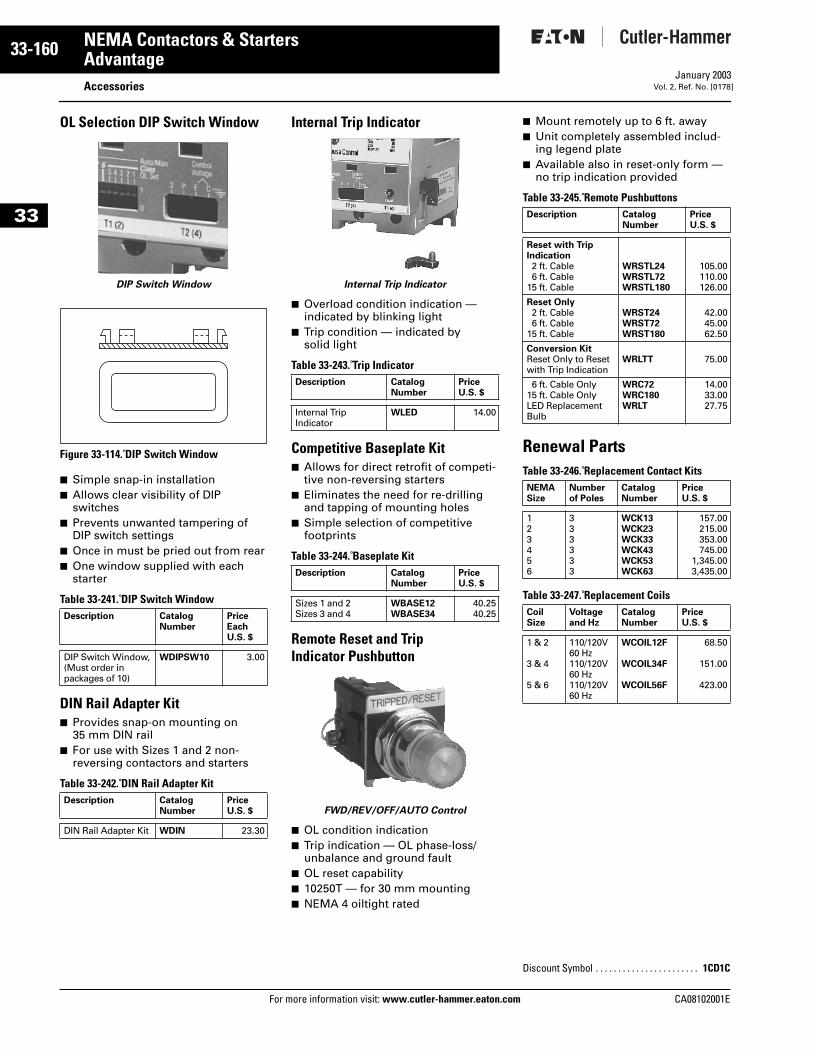
33-160
33
NEMA Contactors & StartersAdvantage
AccessoriesFor more information visit: www.cutler-hammer.eaton.com
January 2003Vol. 2, Ref. No. [0178]
OL Selection DIP Switch Window
DIP Switch Window
Figure 33-114. DIP Switch Window
■ Simple snap-in installation■ Allows clear visibility of DIP
switches■ Prevents unwanted tampering of
DIP switch settings■ Once in must be pried out from rear■ One window supplied with each
starter
Table 33-241. DIP Switch Window
DIN Rail Adapter Kit■ Provides snap-on mounting on
35 mm DIN rail■ For use with Sizes 1 and 2 non-
reversing contactors and starters
Table 33-242. DIN Rail Adapter Kit
Internal Trip Indicator
Internal Trip Indicator
■ Overload condition indication — indicated by blinking light
■ Trip condition — indicated by solid light
Table 33-243. Trip Indicator
Competitive Baseplate Kit■ Allows for direct retrofit of competi-
tive non-reversing starters■ Eliminates the need for re-drilling
and tapping of mounting holes■ Simple selection of competitive
footprints
Table 33-244. Baseplate Kit
Remote Reset and Trip Indicator Pushbutton
FWD/REV/OFF/AUTO Control
■ OL condition indication■ Trip indication — OL phase-loss/
unbalance and ground fault■ OL reset capability■ 10250T — for 30 mm mounting■ NEMA 4 oiltight rated
■ Mount remotely up to 6 ft. away■ Unit completely assembled includ-
ing legend plate■ Available also in reset-only form —
no trip indication provided
Table 33-245. Remote Pushbuttons
Renewal PartsTable 33-246. Replacement Contact Kits
Table 33-247. Replacement Coils
Description CatalogNumber
Price EachU.S. $
DIP Switch Window, (Must order in packages of 10)
WDIPSW10 3.00
Description CatalogNumber
PriceU.S. $
DIN Rail Adapter Kit WDIN 23.30
Description CatalogNumber
PriceU.S. $
Internal TripIndicator
WLED 14.00
Description CatalogNumber
PriceU.S. $
Sizes 1 and 2Sizes 3 and 4
WBASE12WBASE34
40.2540.25
Description CatalogNumber
PriceU.S. $
Reset with Trip Indication2 ft. Cable6 ft. Cable
15 ft. Cable
WRSTL24WRSTL72WRSTL180
105.00110.00126.00
Reset Only2 ft. Cable6 ft. Cable
15 ft. Cable
WRST24WRST72WRST180
42.0045.0062.50
Conversion KitReset Only to Reset with Trip Indication
WRLTT 75.00
6 ft. Cable Only15 ft. Cable OnlyLED Replacement Bulb
WRC72WRC180WRLT
14.0033.0027.75
NEMASize
Numberof Poles
CatalogNumber
Price U.S. $
123456
333333
WCK13WCK23WCK33WCK43WCK53WCK63
157.00215.00353.00745.00
1,345.003,435.00
CoilSize
Voltage and Hz
CatalogNumber
Price U.S. $
1 & 2
3 & 4
5 & 6
110/120V 60 Hz110/120V 60 Hz110/120V 60 Hz
WCOIL12F
WCOIL34F
WCOIL56F
68.50
151.00
423.00
Discount Symbol . . . . . . . . . . . . . . . . . . . . . . . 1CD1C
CA08102001E
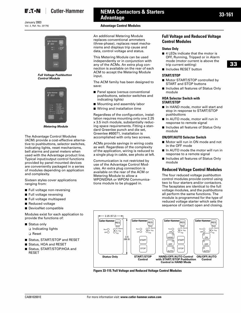
CA08102001E For more
61
33-1NEMA Contactors & StartersAdvantage Advantage Control ModulesJanuary 2003Vol. 2, Ref. No. [0179]
33
The Advantage Control Modules (ACM) provide a cost-effective alterna-tive to pushbuttons, selector switches, indicating lights, reset mechanisms, bell alarms and panel meters when used with the Advantage product line. Typical input/output control functions provided by panel mounted devices are conveniently packaged in a series of modules depending on application and complexity.
Sixteen styles cover applications ranging from:
■ Full voltage non-reversing■ Full voltage reversing■ Full voltage multispeed■ Reduced voltage■ DeviceNet compatible
Modules exist for each application to provide the functions of:
■ Status only❑ Indicating lights❑ Reset
■ Status, START/STOP and RESET■ Status, HOA and RESET■ Status, START/STOP/HOA and
RESET
Full Voltage PushbuttonControl Module
Metering Module
An additional Metering Module replaces conventional ammeters (three-phase), replaces reset mecha-nisms and displays trip cause and data, control voltage and status.
This Metering Module can be used independently or in conjunction with any of the ACMs. An extra plug con-nection is available on the rear of each ACM to accept the Metering Module input.
The ACM family has been designed to save:
■ Panel space (versus conventional pushbuttons, selector switches and indicating lights)
■ Mounting and assembly labor■ Wiring and installation time
Regardless of the configuration, instal-lation requires mounting only one 2.25 x 3.5 inch module, substantially reduc-ing space requirements. Fitting a stan-dard Greenlee punch and die set, Greenlee #60071, installation is accomplished with only two screws.
ACMs provide savings in wiring costs as well. Regardless of the complexity of the application, wiring is reduced to a single plug-in cable, see photo at left.
Communication is not restricted by use of the Advantage Control Mod-ules. An extra plug connection is available on the rear of the ACM or Metering Module to allow a WPONIDNA or WPONI Communica-tions module to be plugged in.
Full Voltage and Reduced Voltage Control Modules
Status Only■ 4 LEDs indicate that the motor is
OFF, Running, Tripped or in Alarm mode (motor current is above the trip current setting)
■ Includes RESET button
START/STOP■ Motor START/STOP controlled by
START and STOP buttons■ Includes all features of Status Only
module
HOA Selector Switch with START/STOP■ In HAND mode, motor will start and
stop in response to START/STOP pushbuttons
■ In AUTO mode, motor will run in response to remote signal
■ Includes all features of Status Only module
ON/OFF/AUTO Selector Switch■ Motor will run in ON mode and not
in the OFF mode■ In AUTO mode the motor will run in
response to a remote signal■ Includes all features of Status Only
module
Reduced Voltage Control ModulesThe four reduced voltage pushbutton control modules provide control using two to four starters and/or contactors. The faceplates are identical to the full voltage modules, and the pushbuttons all perform the same functions. The module is programmed for the type of reduced voltage starter which sets the sequence of contact open and closing.
Figure 33-115. Full Voltage and Reduced Voltage Control Modules
OL Alarm
TripOL Trip
OL Alarm
TripOL Trip
OL Alarm
TripOL Trip
RES
Reset
Run
Off
OL Alarm
TripOL Trip
RESReset
RESReset
RESReset
Run
Off
Run
HANDSTART
STOP
START
STOP
OFF
AUTO
ON
OFF
AUTO
Off
Run
Off
Status Only START/STOPControl
HAND/OFF/AUTO Controlwith START/STOP Pushbutton
Control in HAND Mode
ON/OFF/AUTOControl
3.5(88.9)
2.25 (57.2)
information visit: www.cutler-hammer.eaton.com
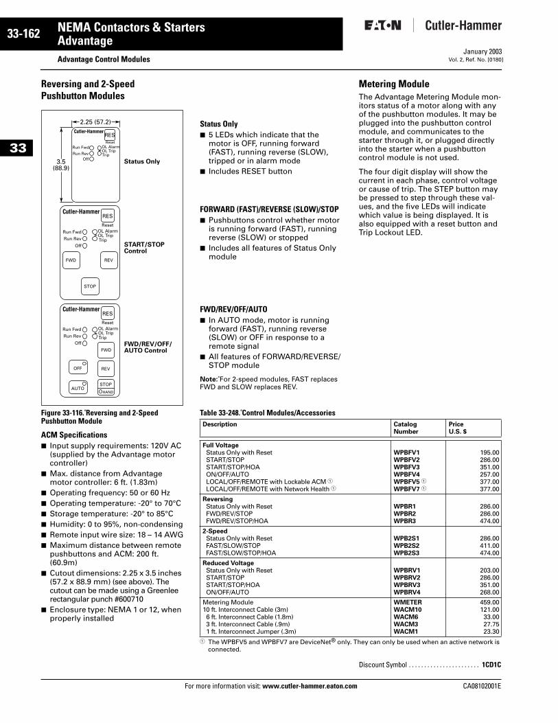
33-162
33
NEMA Contactors & StartersAdvantage
Advantage Control ModulesFor more information visit: www.cutler-hammer.eaton.com
January 2003Vol. 2, Ref. No. [0180]
Reversing and 2-Speed Pushbutton Modules
Figure 33-116. Reversing and 2-Speed Pushbutton Module
ACM Specifications■ Input supply requirements: 120V AC
(supplied by the Advantage motor controller)
■ Max. distance from Advantage motor controller: 6 ft. (1.83m)
■ Operating frequency: 50 or 60 Hz■ Operating temperature: -20° to 70°C■ Storage temperature: -20° to 85°C■ Humidity: 0 to 95%, non-condensing■ Remote input wire size: 18 – 14 AWG■ Maximum distance between remote
pushbuttons and ACM: 200 ft. (60.9m)
■ Cutout dimensions: 2.25 x 3.5 inches (57.2 x 88.9 mm) (see above). The cutout can be made using a Greenlee rectangular punch #600710
■ Enclosure type: NEMA 1 or 12, when properly installed
RESReset
Run Fwd
Run RevOff
OL Alarm
TripOL Trip
Status Only
RES
Reset
REVFWD
STOP
Run Fwd
Run Rev
Off
OL Alarm
TripOL Trip
START/STOPControl
RES
Reset
REV
AUTO
OFF
STOP
HAND
FWD
Run Fwd
Run Rev
Off
OL Alarm
TripOL Trip
FWD/REV/OFF/AUTO Control
3.5(88.9)
2.25 (57.2)
Status Only■ 5 LEDs which indicate that themotor is OFF, running forward (FAST), running reverse (SLOW), tripped or in alarm mode
■ Includes RESET button
FORWARD (FAST)/REVERSE (SLOW)/STOP■ Pushbuttons control whether motor
is running forward (FAST), running reverse (SLOW) or stopped
■ Includes all features of Status Only module
FWD/REV/OFF/AUTO■ In AUTO mode, motor is running
forward (FAST), running reverse (SLOW) or OFF in response to a remote signal
■ All features of FORWARD/REVERSE/STOP module
Note: For 2-speed modules, FAST replaces FWD and SLOW replaces REV.
Metering ModuleThe Advantage Metering Module mon-itors status of a motor along with any of the pushbutton modules. It may be plugged into the pushbutton control module, and communicates to the starter through it, or plugged directly into the starter when a pushbutton control module is not used.
The four digit display will show the current in each phase, control voltage or cause of trip. The STEP button may be pressed to step through these val-ues, and the five LEDs will indicate which value is being displayed. It is also equipped with a reset button and Trip Lockout LED.
Table 33-248. Control Modules/Accessories
1 The WPBFV5 and WPBFV7 are DeviceNet® only. They can only be used when an active network is connected.
Description CatalogNumber
PriceU.S. $
Full VoltageStatus Only with ResetSTART/STOPSTART/STOP/HOAON/OFF/AUTOLOCAL/OFF/REMOTE with Lockable ACM 1LOCAL/OFF/REMOTE with Network Health 1
WPBFV1WPBFV2WPBFV3WPBFV4WPBFV5 1
WPBFV7 1
195.00286.00351.00257.00377.00377.00
ReversingStatus Only with ResetFWD/REV/STOPFWD/REV/STOP/HOA
WPBR1WPBR2WPBR3
286.00286.00474.00
2-SpeedStatus Only with ResetFAST/SLOW/STOPFAST/SLOW/STOP/HOA
WPB2S1WPB2S2WPB2S3
286.00411.00474.00
Reduced VoltageStatus Only with ResetSTART/STOPSTART/STOP/HOAON/OFF/AUTO
WPBRV1WPBRV2WPBRV3WPBRV4
203.00286.00351.00268.00
Metering Module10 ft. Interconnect Cable (3m)6 ft. Interconnect Cable (1.8m)3 ft. Interconnect Cable (.9m)1 ft. Interconnect Jumper (.3m)
WMETERWACM10WACM6WACM3WACM1
459.00121.0033.0027.7523.30
Discount Symbol . . . . . . . . . . . . . . . . . . . . . . . 1CD1C
CA08102001E
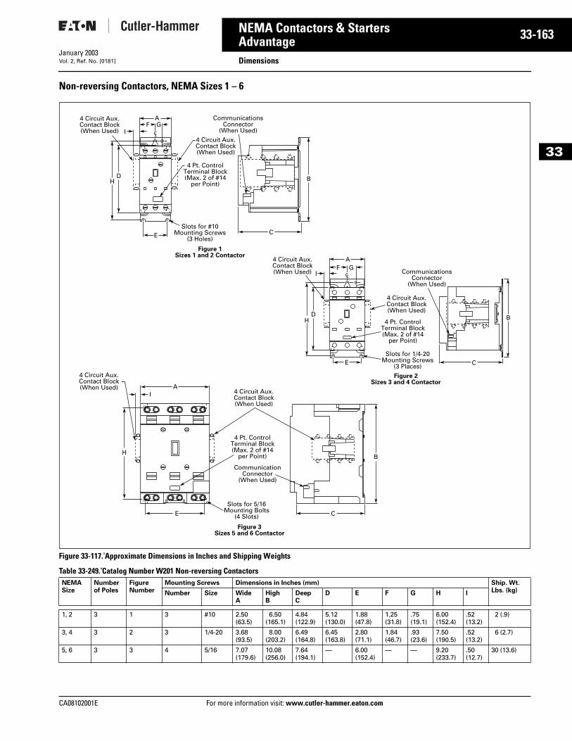
CA08102001E For more
63
33-1NEMA Contactors & StartersAdvantage DimensionsJanuary 2003Vol. 2, Ref. No. [0181]
33
Non-reversing Contactors, NEMA Sizes 1 – 6
Figure 33-117. Approximate Dimensions in Inches and Shipping Weights
Table 33-249. Catalog Number W201 Non-reversing Contactors NEMA Size
Numberof Poles
FigureNumber
Mounting Screws Dimensions in Inches (mm) Ship. Wt. Lbs. (kg)Number Size Wide
AHighB
DeepC
D E F G H I
1, 2 3 1 3 #10 2.50(63.5)
6.50(165.1)
4.84(122.9)
5.12(130.0)
1.88 (47.8)
1.25(31.8)
.75(19.1)
6.00(152.4)
.52(13.2)
2 (.9)
3, 4 3 2 3 1/4-20 3.68(93.5)
8.00(203.2)
6.49(164.8)
6.45(163.8)
2.80(71.1)
1.84(46.7)
.93(23.6)
7.50(190.5)
.52(13.2)
6 (2.7)
5, 6 3 3 4 5/16 7.07(179.6)
10.08(256.0)
7.64(194.1)
— 6.00(152.4)
— — 9.20(233.7)
.50(12.7)
30 (13.6)
AF G
I
H
E
BD
CSlots for #10
Mounting Screws(3 Holes)
CommunicationsConnector
(When Used)
4 Pt. Control Terminal Block(Max. 2 of #14
per Point)
4 Circuit Aux.Contact Block(When Used)
4 Circuit Aux.Contact Block(When Used)
CL
AI
H
E
B
C
Slots for 5/16Mounting Bolts
(4 Slots)
CommunicationConnector
(When Used)
4 Pt. Control Terminal Block(Max. 2 of #14
per Point)
4 Circuit Aux.Contact Block(When Used)
4 Circuit Aux.Contact Block(When Used)
Figure 3Sizes 5 and 6 Contactor
AF G
I
H
E
BD
CSlots for 1/4-20
Mounting Screws(3 Places)
CommunicationsConnector
(When Used)
4 Pt. Control Terminal Block(Max. 2 of #14
per Point)
4 Circuit Aux.Contact Block(When Used)
4 Circuit Aux.Contact Block(When Used)
CL
Figure 2Sizes 3 and 4 Contactor
Figure 1Sizes 1 and 2 Contactor
information visit: www.cutler-hammer.eaton.com
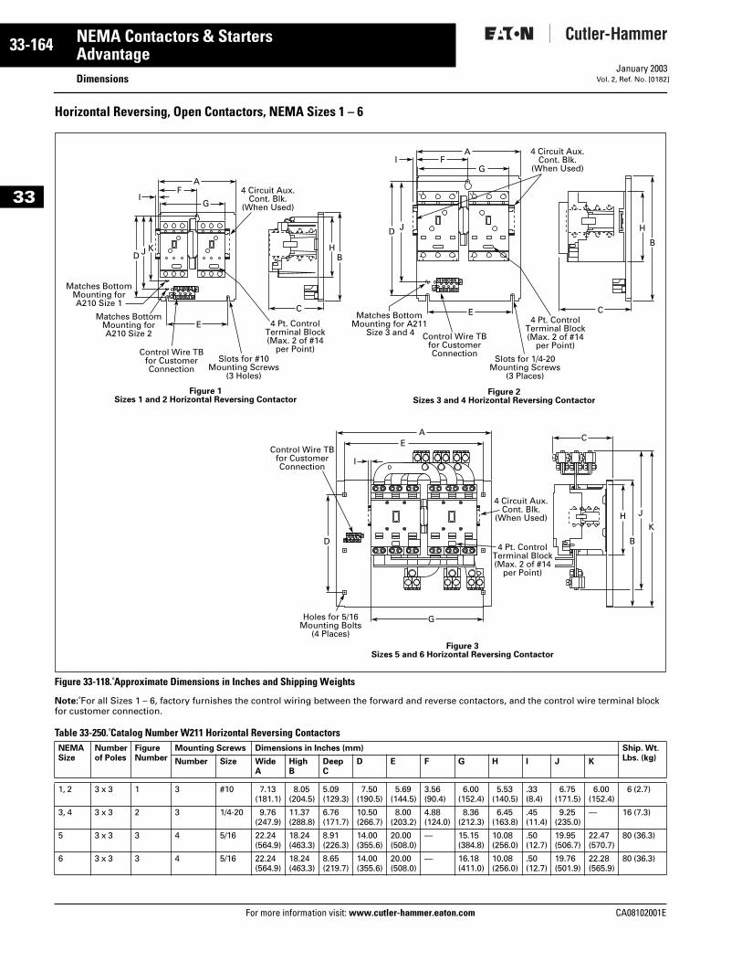
33-164
33
NEMA Contactors & StartersAdvantage
DimensionsFor more information visit: www.cutler-hammer.eaton.com
January 2003Vol. 2, Ref. No. [0182]
Horizontal Reversing, Open Contactors, NEMA Sizes 1 – 6
Figure 33-118. Approximate Dimensions in Inches and Shipping Weights
Note: For all Sizes 1 – 6, factory furnishes the control wiring between the forward and reverse contactors, and the control wire terminal block for customer connection.
Table 33-250. Catalog Number W211 Horizontal Reversing Contactors NEMA Size
Numberof Poles
FigureNumber
Mounting Screws Dimensions in Inches (mm) Ship. Wt. Lbs. (kg)Number Size Wide
AHighB
DeepC
D E F G H I J K
1, 2 3 x 3 1 3 #10 7.13(181.1)
8.05(204.5)
5.09(129.3)
7.50(190.5)
5.69(144.5)
3.56(90.4)
6.00(152.4)
5.53(140.5)
.33(8.4)
6.75(171.5)
6.00(152.4)
6 (2.7)
3, 4 3 x 3 2 3 1/4-20 9.76(247.9)
11.37(288.8)
6.76(171.7)
10.50(266.7)
8.00(203.2)
4.88(124.0)
8.36(212.3)
6.45(163.8)
.45(11.4)
9.25(235.0)
— 16 (7.3)
5 3 x 3 3 4 5/16 22.24(564.9)
18.24(463.3)
8.91(226.3)
14.00(355.6)
20.00(508.0)
— 15.15(384.8)
10.08(256.0)
.50(12.7)
19.95(506.7)
22.47(570.7)
80 (36.3)
6 3 x 3 3 4 5/16 22.24(564.9)
18.24(463.3)
8.65(219.7)
14.00(355.6)
20.00(508.0)
— 16.18(411.0)
10.08(256.0)
.50(12.7)
19.76(501.9)
22.28(565.9)
80 (36.3)
AF
D J K
IG
E
C
BH
4 Circuit Aux.Cont. Blk.
(When Used)
Control Wire TBfor CustomerConnection
Matches BottomMounting forA210 Size 2
Matches BottomMounting forA210 Size 1
Slots for #10Mounting Screws
(3 Holes)
4 Pt. Control Terminal Block(Max. 2 of #14
per Point)
AF
D J
IG
E C
B
H
4 Circuit Aux.Cont. Blk.
(When Used)
Control Wire TBfor CustomerConnection
Matches BottomMounting for A211
Size 3 and 4
Slots for 1/4-20Mounting Screws
(3 Places)
4 Pt. Control Terminal Block(Max. 2 of #14
per Point)
Figure 1Sizes 1 and 2 Horizontal Reversing Contactor
Figure 2Sizes 3 and 4 Horizontal Reversing Contactor
AE
C
I
D
G
B
HK
J4 Circuit Aux.
Cont. Blk.(When Used)
Control Wire TBfor CustomerConnection
Holes for 5/16Mounting Bolts
(4 Places)
4 Pt. Control Terminal Block(Max. 2 of #14
per Point)
Figure 3Sizes 5 and 6 Horizontal Reversing Contactor
CA08102001E
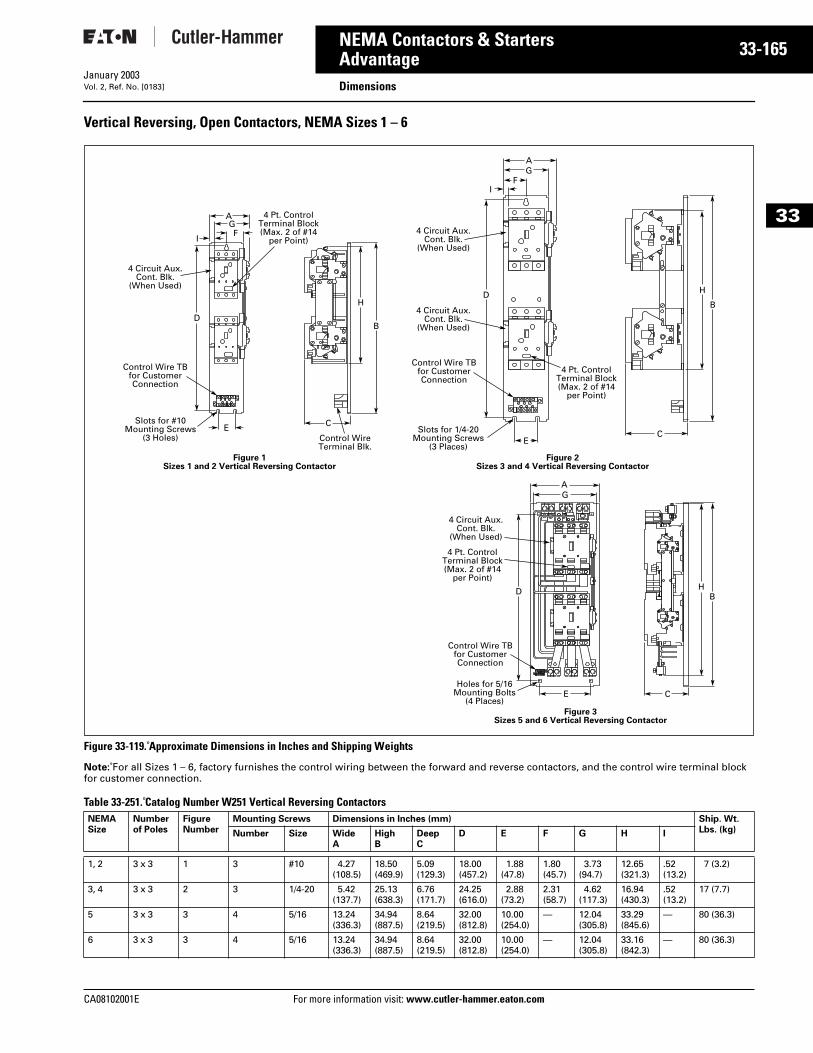
CA08102001E For more
65
33-1NEMA Contactors & StartersAdvantage DimensionsJanuary 2003Vol. 2, Ref. No. [0183]
33
Vertical Reversing, Open Contactors, NEMA Sizes 1 – 6
Figure 33-119. Approximate Dimensions in Inches and Shipping Weights
Note: For all Sizes 1 – 6, factory furnishes the control wiring between the forward and reverse contactors, and the control wire terminal block for customer connection.
Table 33-251. Catalog Number W251 Vertical Reversing Contactors NEMA Size
Numberof Poles
FigureNumber
Mounting Screws Dimensions in Inches (mm) Ship. Wt. Lbs. (kg)Number Size Wide
AHighB
DeepC
D E F G H I
1, 2 3 x 3 1 3 #10 4.27(108.5)
18.50(469.9)
5.09(129.3)
18.00(457.2)
1.88(47.8)
1.80(45.7)
3.73(94.7)
12.65(321.3)
.52(13.2)
7 (3.2)
3, 4 3 x 3 2 3 1/4-20 5.42(137.7)
25.13(638.3)
6.76(171.7)
24.25(616.0)
2.88(73.2)
2.31(58.7)
4.62(117.3)
16.94(430.3)
.52(13.2)
17 (7.7)
5 3 x 3 3 4 5/16 13.24(336.3)
34.94(887.5)
8.64(219.5)
32.00(812.8)
10.00(254.0)
— 12.04(305.8)
33.29(845.6)
— 80 (36.3)
6 3 x 3 3 4 5/16 13.24(336.3)
34.94(887.5)
8.64(219.5)
32.00(812.8)
10.00(254.0)
— 12.04(305.8)
33.16(842.3)
— 80 (36.3)
AGF
I
D
E C
B
H
4 Circuit Aux.Cont. Blk.
(When Used)
Control Wire TBfor CustomerConnection
Slots for #10Mounting Screws
(3 Holes) Control WireTerminal Blk.
4 Pt. Control Terminal Block(Max. 2 of #14
per Point)
AG
FI
D
EC
B
H
4 Circuit Aux.Cont. Blk.
(When Used)
4 Circuit Aux.Cont. Blk.
(When Used)
Control Wire TBfor CustomerConnection
Slots for 1/4-20Mounting Screws
(3 Places)
4 Pt. Control Terminal Block(Max. 2 of #14
per Point)
Figure 2Sizes 3 and 4 Vertical Reversing Contactor
Figure 1Sizes 1 and 2 Vertical Reversing Contactor
AG
D
CE
BH
4 Circuit Aux.Cont. Blk.
(When Used)
Control Wire TBfor CustomerConnection
Holes for 5/16Mounting Bolts
(4 Places)
4 Pt. Control Terminal Block(Max. 2 of #14
per Point)
Figure 3Sizes 5 and 6 Vertical Reversing Contactor
information visit: www.cutler-hammer.eaton.com
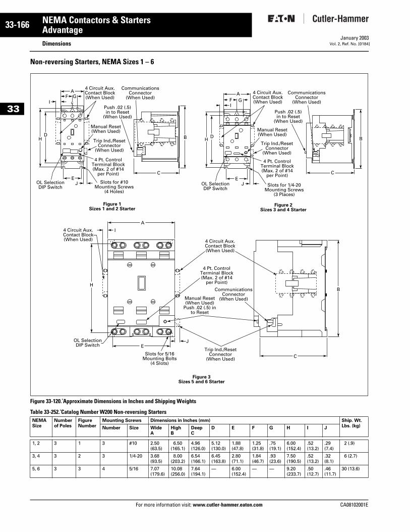
33-166
33
NEMA Contactors & StartersAdvantage
DimensionsFor more information visit: www.cutler-hammer.eaton.com
January 2003Vol. 2, Ref. No. [0184]
Non-reversing Starters, NEMA Sizes 1 – 6
Figure 33-120. Approximate Dimensions in Inches and Shipping Weights
Table 33-252. Catalog Number W200 Non-reversing Starters NEMA Size
Numberof Poles
FigureNumber
Mounting Screws Dimensions in Inches (mm) Ship. Wt. Lbs. (kg)Number Size Wide
AHighB
DeepC
D E F G H I J
1, 2 3 1 3 #10 2.50(63.5)
6.50(165.1)
4.96(126.0)
5.12(130.0)
1.88(47.8)
1.25(31.8)
.75(19.1)
6.00(152.4)
.52(13.2)
.29(7.4)
2 (.9)
3, 4 3 2 3 1/4-20 3.68(93.5)
8.00(203.2)
6.54(166.1)
6.45(163.8)
2.80(71.1)
1.84(46.7)
.93(23.6)
7.50(190.5)
.52(13.2)
.32(8.1)
6 (2.7)
5, 6 3 3 4 5/16 7.07(179.6)
10.08(256.0)
7.64(194.1)
— 6.00(152.4)
— — 9.20(233.7)
.50(12.7)
.46(11.7)
30 (13.6)
AF G
I
H
JE
BD
C
OL SelectionDIP Switch
Slots for #10Mounting Screws
(4 Holes)
Trip Ind./ResetConnector
(When Used)
Manual Reset(When Used)
CommunicationsConnector
(When Used)
4 Pt. Control Terminal Block(Max. 2 of #14
per Point)
4 Circuit Aux.Contact Block(When Used)
Push .02 (.5)in to Reset
(When Used)
CL
A
I
H
EJ
B
C
OL SelectionDIP Switch
Slots for 5/16Mounting Bolts
(4 Slots)
Trip Ind./ResetConnector
(When Used)
Manual Reset(When Used)
Push .02 (.5) into Reset
CommunicationsConnector
(When Used)
4 Pt. Control Terminal Block(Max. 2 of #14
per Point)
4 Circuit Aux.Contact Block(When Used)
4 Circuit Aux.Contact Block(When Used)
AF GI
H
JE
BD
C
OL SelectionDIP Switch
Figure 2Sizes 3 and 4 Starter
Figure 3Sizes 5 and 6 Starter
Figure 1Sizes 1 and 2 Starter
Slots for 1/4-20Mounting Screws
(3 Places)
Trip Ind./ResetConnector
(When Used)
Manual Reset(When Used)
CommunicationsConnector
(When Used)
4 Pt. Control Terminal Block(Max. 2 of #14
per Point)
4 Circuit Aux.Contact Block(When Used)
Push .02 (.5)in to Reset
(When Used)
CA08102001E
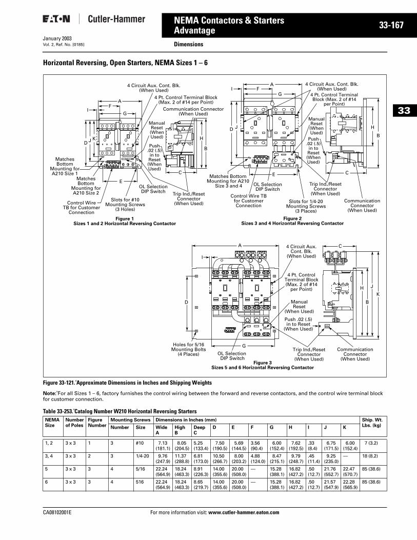
CA08102001E For more
67
33-1NEMA Contactors & StartersAdvantage DimensionsJanuary 2003Vol. 2, Ref. No. [0185]
33
Horizontal Reversing, Open Starters, NEMA Sizes 1 – 6
Figure 33-121. Approximate Dimensions in Inches and Shipping Weights
Note: For all Sizes 1 – 6, factory furnishes the control wiring between the forward and reverse contactors, and the control wire terminal block for customer connection.
Table 33-253. Catalog Number W210 Horizontal Reversing Starters NEMA Size
Numberof Poles
FigureNumber
Mounting Screws Dimensions in Inches (mm) Ship. Wt. Lbs. (kg)Number Size Wide
AHighB
DeepC
D E F G H I J K
1, 2 3 x 3 1 3 #10 7.13(181.1)
8.05(204.5)
5.25(133.4)
7.50(190.5)
5.69(144.5)
3.56(90.4)
6.00(152.4)
7.62(192.5)
.33(8.4)
6.75(171.5)
6.00(152.4)
7 (3.2)
3, 4 3 x 3 2 3 1/4-20 9.76(247.9)
11.37(288.8)
6.81(173.0)
10.50(266.7)
8.00(203.2)
4.88(124.0)
8.47(215.1)
9.79(248.7)
.45(11.4)
9.25(235.0)
— 18 (8.2)
5 3 x 3 3 4 5/16 22.24(564.9)
18.24(463.3)
8.91(226.3)
14.00(355.6)
20.00(508.0)
— 15.28 (388.1)
16.82(427.2)
.50(12.7)
21.76(552.7)
22.47(570.7)
85 (38.6)
6 3 x 3 3 4 516 22.24(564.9)
18.24(463.3)
8.65(219.7)
14.00(355.6)
20.00(508.0)
— 15.28(388.1)
16.82(427.2)
.50(12.7)
21.57(547.9)
22.28(565.9)
85 (38.6)
AF
D J K
IG
E
C
B
H
4 Circuit Aux. Cont. Blk.(When Used)
Control WireTB for Customer
Connection
MatchesBottom
Mounting forA210 Size 2
MatchesBottom
Mounting forA210 Size 1
Slots for #10Mounting Screws
(3 Holes)
4 Pt. Control Terminal Block(Max. 2 of #14 per Point)
AF
D J
IG
E C
B
H
4 Circuit Aux. Cont. Blk.(When Used)
Control Wire TBfor CustomerConnection
Matches BottomMounting for A210
Size 3 and 4
Slots for 1/4-20Mounting Screws
(3 Places)
4 Pt. Control TerminalBlock (Max. 2 of #14
per Point)
Figure 1Sizes 1 and 2 Horizontal Reversing Contactor
Figure 2Sizes 3 and 4 Horizontal Reversing Contactor
OL SelectionDIP Switch
OL SelectionDIP Switch
Trip Ind./ResetConnector
(When Used)
Communication Connector(When Used)
CommunicationConnector
(When Used)
ManualReset(WhenUsed)
Trip Ind./ResetConnector
(When Used)
ManualReset(WhenUsed)
Push.02 (.5)in toReset(WhenUsed)
Push.02 (.5)in toReset(WhenUsed)
A C
I
D
G
B
HK
J
4 Circuit Aux.Cont. Blk.
(When Used)
Holes for 5/16Mounting Bolts
(4 Places) OL Selection DIP Switch
4 Pt. Control Terminal Block(Max. 2 of #14
per Point)
ManualReset
(When Used)
Figure 3Sizes 5 and 6 Horizontal Reversing Contactor
Trip Ind./ResetConnector
(When Used)
Push .02 (.5)in to Reset
(When Used)
CommunicationConnector
(When Used)
information visit: www.cutler-hammer.eaton.com
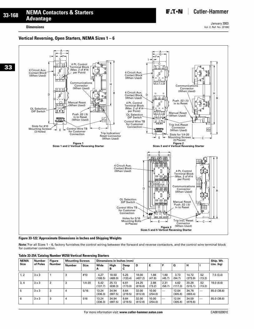
33-168
33
NEMA Contactors & StartersAdvantage
DimensionsFor more information visit: www.cutler-hammer.eaton.com
January 2003Vol. 2, Ref. No. [0186]
Vertical Reversing, Open Starters, NEMA Sizes 1 – 6
Figure 33-122. Approximate Dimensions in Inches and Shipping Weights
Note: For all Sizes 1 – 6, factory furnishes the control wiring between the forward and reverse contactors, and the control wire terminal block for customer connection.
Table 33-254. Catalog Number W250 Vertical Reversing Starters NEMA Size
Numberof Poles
FigureNumber
Mounting Screws Dimensions in Inches (mm) Ship. Wt. Lbs. (kg)Number Size Wide
AHighB
DeepC
D E F G H I
1, 2 3 x 3 1 3 #10 4.27(108.5)
18.50(469.9)
5.25(133.4)
18.00(457.2)
1.88(47.8)
1.80(45.7)
3.73(94.7)
14.72(373.9)
.52(13.2)
7.5 (3.4)
3, 4 3 x 3 2 3 1/4-20 5.42(137.7)
25.13(638.3)
6.81(173.0)
24.25(616.0)
2.88(73.2)
2.31(58.7)
4.62(117.3)
20.28(515.1)
.52(13.2)
19.0 (8.6)
5 3 x 3 3 4 5/16 13.24(336.3)
34.94(887.5)
8.64(219.5)
32.00(812.8)
10.00(254.0)
— 12.04(305.8)
34.78(883.4)
— 85.0 (38.6)
6 3 x 3 3 4 516 13.24(336.3)
34.94(887.5)
8.64(219.5)
32.00(812.8)
10.00(254.0)
— 12.04(305.8)
34.59(878.6)
— 85.0 (38.6)
AG
FI
D
EC
B
H
4 Circuit Aux.Contact Block(When Used)
OL SelectionDIP Switch
Control Wire TBfor CustomerConnection
Push .02 (.5)in to Reset
(When Used)
Slots for #10Mounting Screws
(3 Holes)
4 Pt. Control Terminal Block(Max. 2 of #14
per Point)
Manual Reset(When Used)
CommunicationsConnector
(When Used)
Trip Indication/Reset Connector
(When Used)
CL
AG
FI
D
E C
B
H
4 Circuit Aux.Contact Block(When Used)
4 Circuit Aux.Contact Block(When Used)
Control Wire TBfor CustomerConnection
Slots for 1/4-20Mounting Screws
(3 Places)
4 Pt. Control Terminal Block(Max. 2 of #14
per Point)Manual Reset(When Used)
Trip Ind./ResetConnector
(When Used)
OL SelectionDIP Switch
CommunicationsConnector
(When Used)
Push .02 (.5)in to Reset
Figure 2Sizes 3 and 4 Vertical Reversing Starter
Figure 1Sizes 1 and 2 Vertical Reversing Starter
AG
D
E
BH
4 Circuit Aux.Contact Block(When Used)
Control Wire TBfor CustomerConnection
Holes for 5/16Mounting Bolts
(4 Places)
4 Pt. Control Terminal Block(Max. 2 of #14
per Point)
OL Selection DIP Switch Manual Reset
Push .02 (.5)in to Reset
Trip Ind./ ResetConnector
(When Used)
CommunicationsConnector
(When Used)
C
Figure 3Sizes 5 and 6 Vertical Reversing Starter
CA08102001E
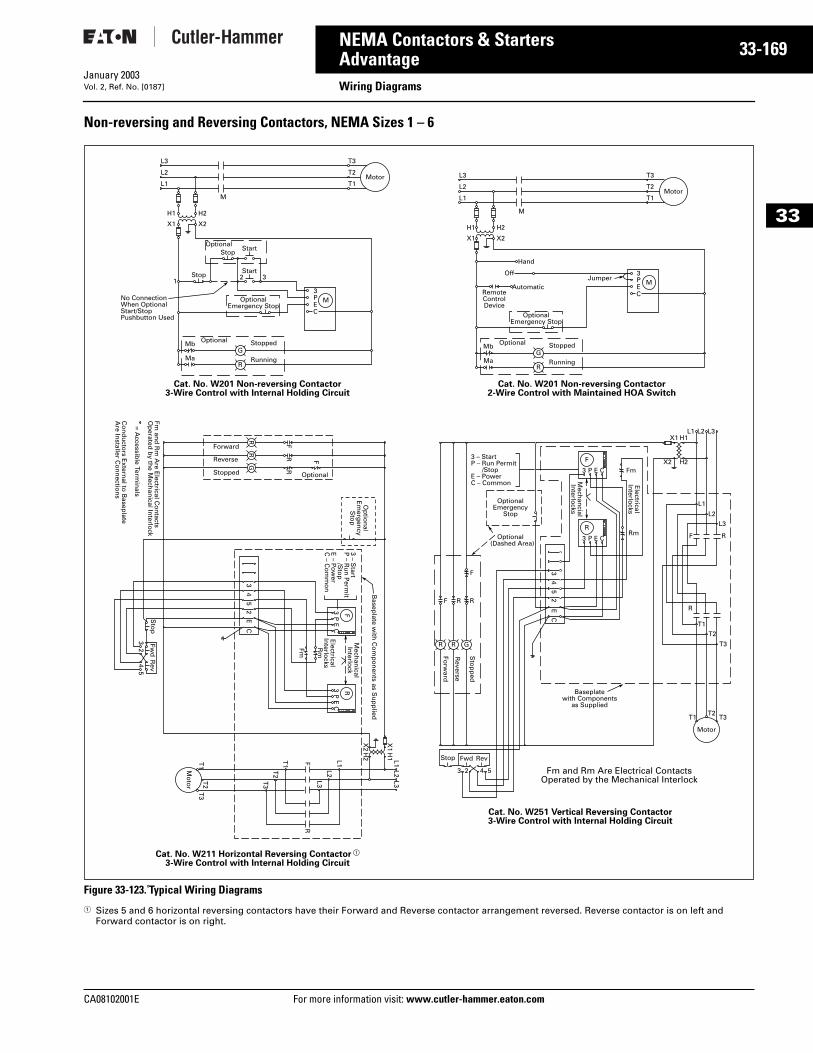
CA08102001E For more
69
33-1NEMA Contactors & StartersAdvantage Wiring DiagramsJanuary 2003Vol. 2, Ref. No. [0187]
33
Non-reversing and Reversing Contactors, NEMA Sizes 1 – 6
Figure 33-123. Typical Wiring Diagrams
1 Sizes 5 and 6 horizontal reversing contactors have their Forward and Reverse contactor arrangement reversed. Reverse contactor is on left and Forward contactor is on right.
L3
L2
L1
T3
T2
T1
H1
X1
132
3M
GMa
Mb
R
PEC
StartStop
StartOptional
Stop
OptionalEmergency Stop
H2
M
Motor
X2
Stopped
No ConnectionWhen OptionalStart/StopPushbutton Used
Optional
Running
Cat. No. W201 Non-reversing Contactor3-Wire Control with Internal Holding Circuit
L3
L2
L1
T3
T2
T1
H1
X1
3M
GMa
Mb
R
PEC
Automatic
H2
M
Motor
X2
StoppedOptional
Running
OptionalEmergency Stop
RemoteControlDevice
JumperOff
Hand
Cat. No. W201 Non-reversing Contactor2-Wire Control with Maintained HOA Switch
Cat. No. W211 Horizontal Reversing Contactor a
3-Wire Control with Internal Holding Circuit
Cat. No. W251 Vertical Reversing Contactor3-Wire Control with Internal Holding Circuit
Fm and Rm Are Electrical ContactsOperated by the Mechanical Interlock
T1
T3
T2
Mo
tor
T2
T3
T1
Sto
pFw
dR
ev
32
54
Stop Fwd Rev
3 2 54
F
F
FR
R
RR
G
F
3P
EC
3P
EC
R
R
L1 L1X
1H
1
X2
H2
L2 L2
L3 L3
Mech
anical
Interlo
ck
Basep
late with
Co
mp
on
ents as S
up
plied
Electrical
Interlo
cksR
m
Fm
3 – Start
P – R
un
Perm
it /S
top
E – P
ow
erC
– Co
mm
on
Op
tion
alE
merg
ency
Sto
p
43
CE
52
43
CE
52
Optional
Forward
Reverse
Stopped
Fm an
d R
m A
re Electrical C
on
tactsO
perated
by th
e Mech
anical In
terlock
= Accessib
le Termin
als
Co
nd
ucto
rs Extern
al to B
aseplate
Are In
staller Co
nn
ection
s
Fm
Rm
Mech
ancial
Interlo
cks
Electrical
Interlo
cks
R
3 P E C
F
Sto
pp
ed
Reverse
Forw
ard
3 P E C
R
F
RRF
T1 T3T2
Motor
T2
T3
T1
R
F R
L1
L1X1 H1
X2 H2
L2
L2
L3
L3
3 – StartP – Run Permit /StopE – PowerC – Common
OptionalEmergency
Stop
Optional (Dashed Area)
R G
Baseplatewith Components
as Supplied
information visit: www.cutler-hammer.eaton.com
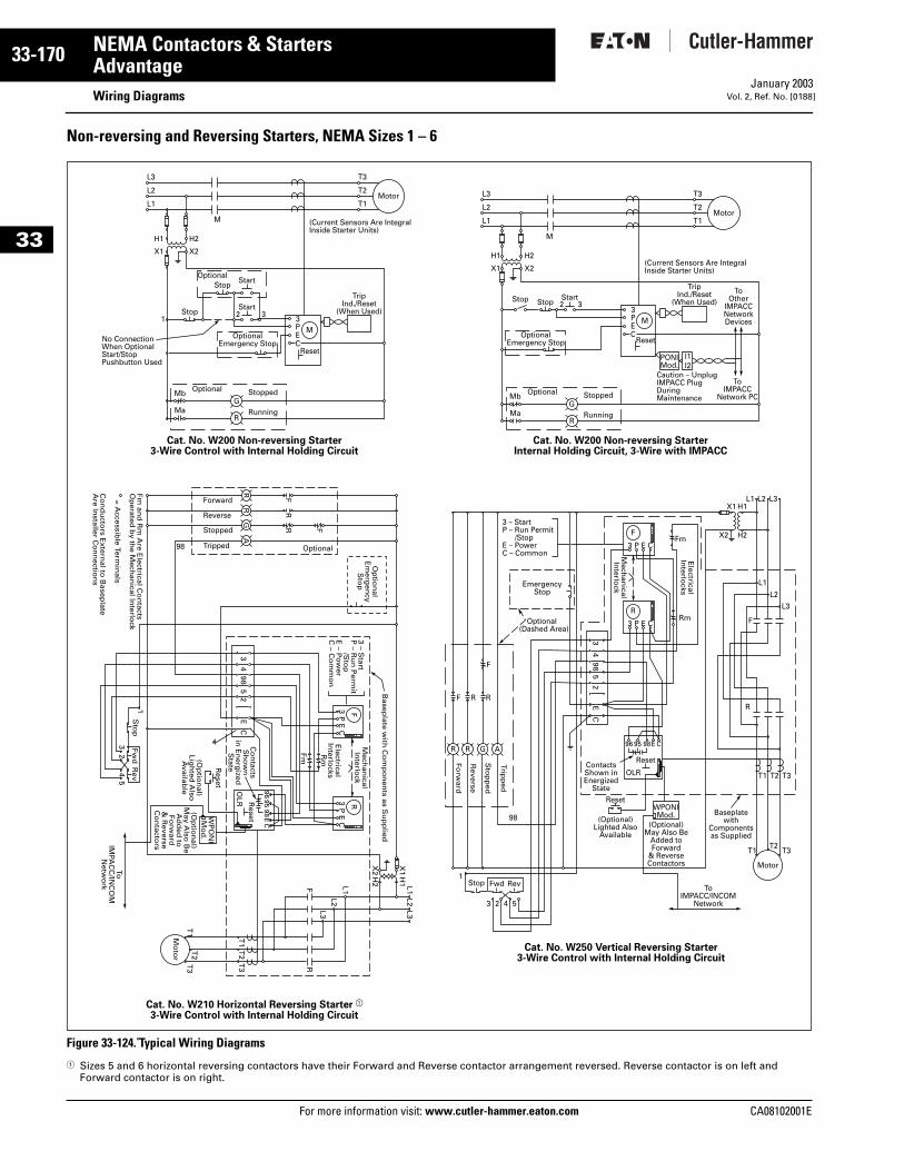
33-170
33
NEMA Contactors & StartersAdvantage
Wiring DiagramsFor more information visit: www.cutler-hammer.eaton.com
January 2003Vol. 2, Ref. No. [0188]
Non-reversing and Reversing Starters, NEMA Sizes 1 – 6
Figure 33-124. Typical Wiring Diagrams
1 Sizes 5 and 6 horizontal reversing contactors have their Forward and Reverse contactor arrangement reversed. Reverse contactor is on left and Forward contactor is on right.
L3
L2
L1
T3
T2
T1
H1
X1
132
3M
GMa
Mb
R
Reset
TripInd./Reset
(When Used)
PEC
StartStop
StartOptional
Stop
OptionalEmergency Stop
H2
M
Motor
X2
(Current Sensors Are IntegralInside Starter Units)
Stopped
No ConnectionWhen OptionalStart/StopPushbutton Used
Optional
Running
Start2 3StopStop
Cat. No. W200 Non-reversing Starter3-Wire Control with Internal Holding Circuit
L3
L2
L1
T3
T2
T1
H1
X1
3M
PONIMod.
GMa
Mb
R
Reset
TripInd./Reset
(When Used)To
OtherIMPACCNetworkDevices
ToIMPACC
Network PC
PEC
H2
M
Motor
X2(Current Sensors Are IntegralInside Starter Units)
Caution – UnplugIMPACC PlugDuringMaintenanceStoppedOptional
Running
I1I2
OptionalEmergency Stop
Cat. No. W200 Non-reversing StarterInternal Holding Circuit, 3-Wire with IMPACC
Cat. No. W210 Horizontal Reversing Starter a
3-Wire Control with Internal Holding Circuit
Cat. No. W250 Vertical Reversing Starter3-Wire Control with Internal Holding Circuit
T1
T3
T2
Mo
tor
T2
T3
T1
Sto
p
Reset
Reset
Fwd
Rev
ToIM
PAC
C/IN
CO
MN
etwo
rk
3
1
24
5
Stop Fwd Rev
3 2 4 5
(Op
tion
al)Lig
hted
Also
Availab
le(O
ptio
nal)
May A
lso B
eA
dd
ed to
Forw
ard&
Reverse
Co
ntacto
rs
WP
ON
IM
od
.
F
F
FR
R
RR
GA
F
3P
EC
3P
EC
R
R
L1 L1X
1H
1
X2
H2
L2 L2
L3 L3
Mech
anical
Interlo
ck
Basep
late with
Co
mp
on
ents as S
up
plied
Electrical
Interlo
cksR
m
Fm
Mech
anical
Interlo
ck
Electrical
Interlo
cks
3 – Start
P – R
un
Perm
it /S
top
E – P
ow
erC
– Co
mm
on
Op
tion
alE
merg
ency
Sto
p
9695
98
984
35
CE
2
984
3C
E5
2
EC
OLR
Optional98
Forward
Reverse
Stopped
Tripped
Fm an
d R
m A
re Electrical C
on
tactsO
perated
by th
e Mech
anical In
terlock
= A
ccessible Term
inals
Co
nd
ucto
rs Extern
al to B
aseplate
Are In
staller Co
nn
ection
s
Co
ntacts
Sh
ow
nin
En
ergized
State
Reset
98
1
Reset
ToIMPACC/INCOM
Network
(Optional)Lighted Also
Available(Optional)
May Also BeAdded toForward
& ReverseContactors
WPONIMod.
96 95 98E C
OLRContactsShown inEnergized
State
R
3 PFm
EmergencyStop
Rm
E C
F
3 P E C
R
T1 T3T2
Motor
T2 T3T1
R
F
L1
L1X1 H1
X2 H2
L2
L2
L3
L3
3 – StartP – Run Permit /StopE – PowerC – Common
G A
Baseplatewith
Componentsas Supplied
Tripp
ed
Sto
pp
ed
Forw
ard
F
R
R
Reverse
RF
Optional (Dashed Area)
CA08102001E
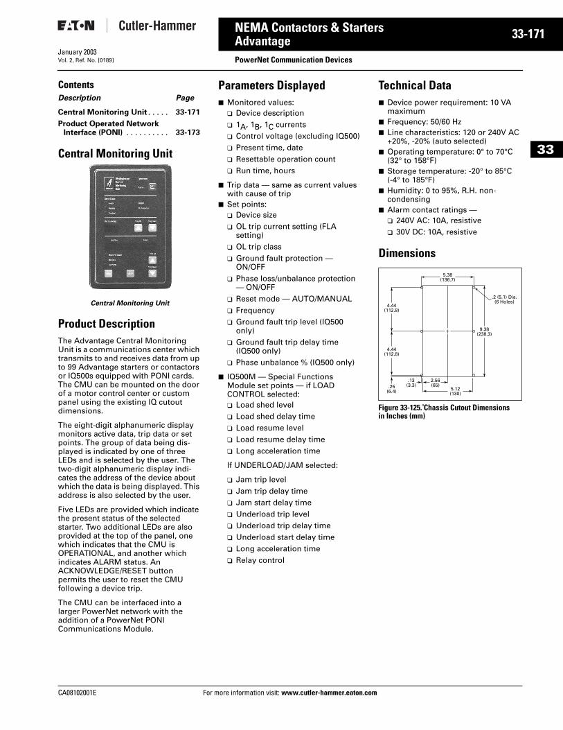
CA08102001E For more
71
33-1NEMA Contactors & StartersAdvantage PowerNet Communication DevicesJanuary 2003Vol. 2, Ref. No. [0189]
33
ContentsDescription Page
Central Monitoring Unit . . . . . 33-171
Product Operated NetworkInterface (PONI) . . . . . . . . . . 33-173
Central Monitoring Unit
Central Monitoring Unit
Product DescriptionThe Advantage Central Monitoring Unit is a communications center which transmits to and receives data from up to 99 Advantage starters or contactors or IQ500s equipped with PONI cards. The CMU can be mounted on the door of a motor control center or custom panel using the existing IQ cutout dimensions.
The eight-digit alphanumeric display monitors active data, trip data or set points. The group of data being dis-played is indicated by one of three LEDs and is selected by the user. The two-digit alphanumeric display indi-cates the address of the device about which the data is being displayed. This address is also selected by the user.
Five LEDs are provided which indicate the present status of the selected starter. Two additional LEDs are also provided at the top of the panel, one which indicates that the CMU is OPERATIONAL, and another which indicates ALARM status. An ACKNOWLEDGE/RESET button permits the user to reset the CMUfollowing a device trip.
The CMU can be interfaced into a larger PowerNet network with the addition of a PowerNet PONI Communications Module.
Parameters Displayed■ Monitored values:
❑ Device description❑ 1A, 1B, 1C currents❑ Control voltage (excluding IQ500)❑ Present time, date❑ Resettable operation count❑ Run time, hours
■ Trip data — same as current values with cause of trip
■ Set points:❑ Device size❑ OL trip current setting (FLA
setting)❑ OL trip class❑ Ground fault protection —
ON/OFF❑ Phase loss/unbalance protection
— ON/OFF❑ Reset mode — AUTO/MANUAL❑ Frequency❑ Ground fault trip level (IQ500
only)❑ Ground fault trip delay time
(IQ500 only)❑ Phase unbalance % (IQ500 only)
■ IQ500M — Special Functions Module set points — if LOAD CONTROL selected:❑ Load shed level❑ Load shed delay time❑ Load resume level❑ Load resume delay time❑ Long acceleration time
If UNDERLOAD/JAM selected:
❑ Jam trip level❑ Jam trip delay time❑ Jam start delay time❑ Underload trip level❑ Underload trip delay time❑ Underload start delay time❑ Long acceleration time❑ Relay control
Technical Data■ Device power requirement: 10 VA
maximum■ Frequency: 50/60 Hz■ Line characteristics: 120 or 240V AC
+20%, -20% (auto selected)■ Operating temperature: 0° to 70°C
(32° to 158°F)■ Storage temperature: -20° to 85°C
(-4° to 185°F)■ Humidity: 0 to 95%, R.H. non-
condensing■ Alarm contact ratings —
❑ 240V AC: 10A, resistive❑ 30V DC: 10A, resistive
Dimensions
Figure 33-125. Chassis Cutout Dimensionsin Inches (mm)
9.38(238.3)
4.44(112.8)
4.44(112.8)
.25(6.4)
2.56(65)
.13(3.3)
5.12(130)
5.38(136.7)
.2 (5.1) Dia.(6 Holes)
information visit: www.cutler-hammer.eaton.com
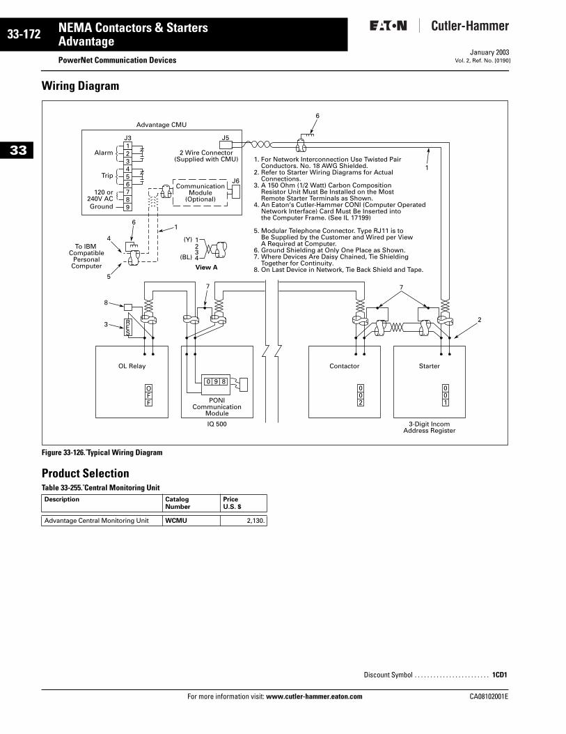
33-172
33
NEMA Contactors & StartersAdvantage
PowerNet Communication DevicesFor more information visit: www.cutler-hammer.eaton.com
January 2003Vol. 2, Ref. No. [0190]
Wiring Diagram
Figure 33-126. Typical Wiring Diagram
Product SelectionTable 33-255. Central Monitoring Unit Description Catalog
NumberPriceU.S. $
Advantage Central Monitoring Unit WCMU 2,130.
1. For Network Interconnection Use Twisted Pair Conductors. No. 18 AWG Shielded.2. Refer to Starter Wiring Diagrams for Actual Connections.3. A 150 Ohm (1/2 Watt) Carbon Composition Resistor Unit Must Be Installed on the Most Remote Starter Terminals as Shown.4. An Eaton‘s Cutler-Hammer CONI (Computer Operated Network Interface) Card Must Be Inserted into the Computer Frame. (See IL 17199)
5. Modular Telephone Connector. Type RJ11 is to Be Supplied by the Customer and Wired per View A Required at Computer.6. Ground Shielding at Only One Place as Shown.7. Where Devices Are Daisy Chained, Tie Shielding Together for Continuity.8. On Last Device in Network, Tie Back Shield and Tape.
Advantage CMU
Alarm
Trip
Ground
120 or240V AC
J5
J6
2 Wire Connector(Supplied with CMU)
CommunicationModule
(Optional)
To IBM Compatible
PersonalComputer
1J3
1
1
23
3
4
12
2
34
5
4
6
5
6
6
7
7 7
8
8
9
(Y)
(BL)
View A
OL Relay
PONICommunication
Module
IQ 500 3-Digit IncomAddress Register
Contactor Starter
RES
OFF
0 9 8002
001
Discount Symbol . . . . . . . . . . . . . . . . . . . . . . . . 1CD1
CA08102001E
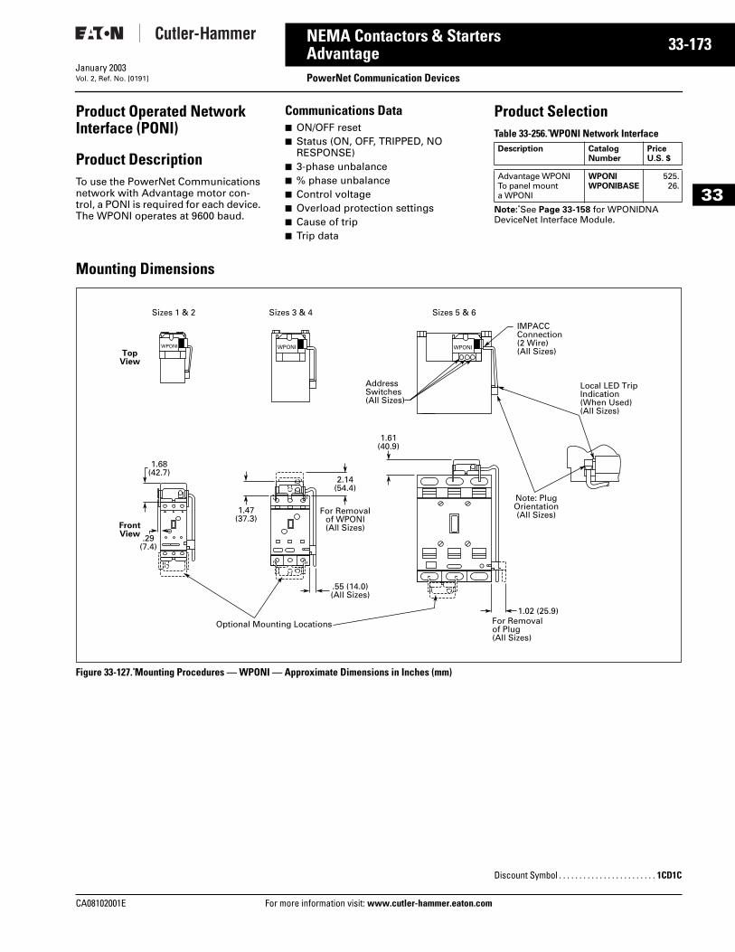
CA08102001E For more
73
33-1NEMA Contactors & StartersAdvantage PowerNet Communication DevicesJanuary 2003Vol. 2, Ref. No. [0191]
33
Product Operated Network Interface (PONI)
Product DescriptionTo use the PowerNet Communications network with Advantage motor con-trol, a PONI is required for each device. The WPONI operates at 9600 baud.
Communications Data■ ON/OFF reset■ Status (ON, OFF, TRIPPED, NO
RESPONSE)■ 3-phase unbalance■ % phase unbalance■ Control voltage■ Overload protection settings■ Cause of trip■ Trip data
Product SelectionTable 33-256. WPONI Network Interface
Note: See Page 33-158 for WPONIDNA DeviceNet Interface Module.
Mounting Dimensions
Figure 33-127. Mounting Procedures — WPONI — Approximate Dimensions in Inches (mm)
Description Catalog Number
PriceU.S. $
Advantage WPONITo panel mount a WPONI
WPONIWPONIBASE
525.26.
Sizes 1 & 2 Sizes 3 & 4 Sizes 5 & 6
1.68(42.7)
1.47(37.3)
2.14(54.4)
1.61(40.9)
.29(7.4)
1.02 (25.9)For Removalof Plug(All Sizes)
For Removalof WPONI(All Sizes)
.55 (14.0)(All Sizes)
Optional Mounting Locations
Local LED TripIndication(When Used)(All Sizes)
IMPACCConnection(2 Wire)(All Sizes)
Note: PlugOrientation(All Sizes)
TopView
FrontView
AddressSwitches(All Sizes)
WPONIWPONIWPONI
Discount Symbol . . . . . . . . . . . . . . . . . . . . . . . . 1CD1C
information visit: www.cutler-hammer.eaton.com
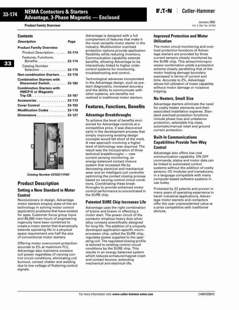
33-174
33
NEMA Contactors & StartersAdvantage, 3-Phase Magnetic — Enclosed
Product Family OverviewFor more information visit: www.cutler-hammer.eaton.com
January 2003Vol. 2, Ref. No. [0192]
ContentsDescription Page
Product Family Overview
Product Description. . . . . . . 33-174
Features, Functions, Benefits . . . . . . . . . . . . . . . 33-174
Catalog Number Selection . . . . . . . . . . . . . . 33-175
Non-combination Starters. . . . 33-176
Combination Starters withDisconnect Switch . . . . . . . . . 33-182
Combination Starters withHMCP/E or Magnetic Trip CB. . . . . . . . . . . . . . . . . . . 33-187
Accessories . . . . . . . . . . . . . . . . 33-113
Cover Control . . . . . . . . . . . . . . 33-193
Modification Codes . . . . . . . . . 33-119
Dimensions . . . . . . . . . . . . . . . . 33-127
Catalog Number ECH2211FAD
Product DescriptionSetting a New Standard in Motor ControlRevolutionary in design, Advantage motor starters employ state-of-the-art technology in solving motor control application problems that have existed for ages. Customer focus group input and 66,000 man-hours of engineering ingenuity have been combined tocreate a motor starter that dramatically extends operating life in a physical space requirement one half the size of conventional motor starters.
Offering motor overcurrent protection accurate to 2% at maximum FLC, Advantage also maintains constant coil power regardless of varying con-trol circuit conditions, eliminating coil burnout, contact chatter and welding due to low voltage of fluttering control signals.
Advantage is designed with a full complement of features that make it the most versatile motor starter in the industry. Multifunction overload protection options provide application flexibility while reducing inventory. Communication capability extends benefits, allowing Advantage to be interactively linked to higher order control systems for monitoring, troubleshooting and control.
Technological advances incorporated in the Advantage design, such as pre-start diagnostics, increased accuracy and the ability to communicate with other systems, are benefits not realized in traditional motor starters.
Features, Functions, Benefits
Advantage BreakthroughsTo achieve the level of benefits envi-sioned for Advantage controls at a competitive price, it was discovered early in the development process that simply improving existing design concepts would fall short of the mark. A new approach involving a higher level of technology was required. The result was the incorporation of three technical breakthroughs — new current sensing monitoring, an energy-balanced contact closure system that increased life by decreasing electrical and mechanical wear and an intelligent coil controller optimizing the contact closing process based on varying control circuit condi-tions. Coordinating these break-throughs to provide enhanced motor control performance is concentrated in the SURE chip.
Patented SURE Chip Increases LifeAdvantage uses the right combination of brains and brawn in effecting a motor start. The power circuit of the contactor employs heavy-duty silver alloy contacts scientifically designed for long life. The addition of a uniquely developed application-specific micro-processor chip, called the SURE chip, regulates power supplied to the oper-ating coil. The regulated closing profile is tailored to existing control circuit conditions by the SURE chip. This results in an energy balanced system which reduces armature/magnet crash and contact bounce, extending mechanical and electrical life.
Improved Protection and Motor UtilizationThe motor circuit monitoring and over-load protection functions of Advan-tage starters are provided by three current sensors closely monitored by the SURE chip. This sensor/micropro-cessor combination yields a protection scheme closely paralleling that of the motor heating damage boundary expressed in terms of current and time. Accurate to 2%, Advantage allows full utilization of motor capability without motor damage or nuisance tripping.
No Heaters, Small SizeAdvantage starters eliminate the need for costly heater elements and their associated installation expense. Stan-dard overload protection functions include phase loss and unbalance protection, selectable trip class, automatic/manual reset and ground current protection.
Built-In Communications Capabilities Provide Two-Way ControlAdvantage also offers low cost communication capability. ON-OFF commands, status and motor data can be linked to automated control systems without the addition of costly sensors, I/O modules and transducers, in a language compatible with many computer-based software systems in use today.
Protected by 22 patents and proven in many years of operating experience in harsh industrial applications, Advan-tage motor starters and contactors offer the user unprecedented value at a price competitive with traditional devices.
CA08102001E
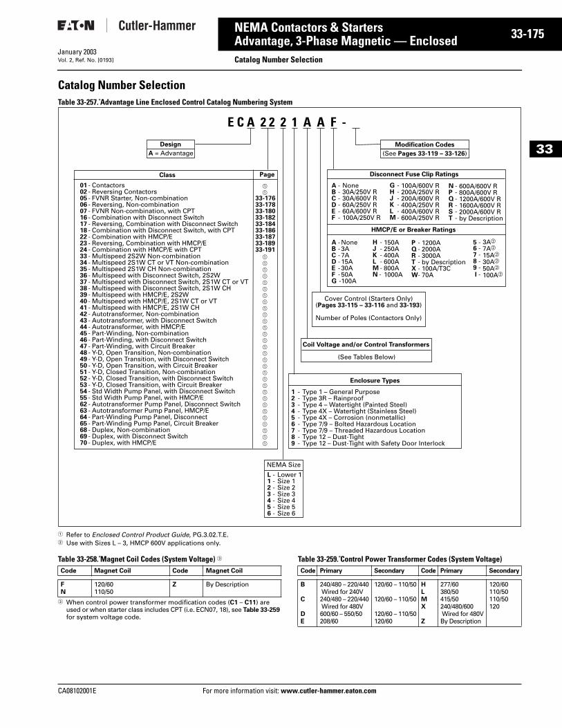
CA08102001E For more
75
33-1NEMA Contactors & StartersAdvantage, 3-Phase Magnetic — Enclosed
Catalog Number SelectionJanuary 2003Vol. 2, Ref. No. [0193]
33
Catalog Number Selection Table 33-257. Advantage Line Enclosed Control Catalog Numbering System
1 Refer to Enclosed Control Product Guide, PG.3.02.T.E.2 Use with Sizes L – 3, HMCP 600V applications only.
Table 33-258. Magnet Coil Codes (System Voltage) 3
3 When control power transformer modification codes (C1 – C11) are used or when starter class includes CPT (i.e. ECN07, 18), see Table 33-259 for system voltage code.
Table 33-259. Control Power Transformer Codes (System Voltage)
Design
Class
01 - Contactors 02 - Reversing Contactors05 - FVNR Starter, Non-combination06 - Reversing, Non-combination07 - FVNR Non-combination, with CPT16 - Combination with Disconnect Switch17 - Reversing, Combination with Disconnect Switch18 - Combination with Disconnect Switch, with CPT22 - Combination with HMCP/E23 - Reversing, Combination with HMCP/E24 - Combination with HMCP/E with CPT33 - Multispeed 2S2W Non-combination 34 - Multispeed 2S1W CT or VT Non-combination35 - Multispeed 2S1W CH Non-combination36 - Multispeed with Disconnect Switch, 2S2W37 - Multispeed with Disconnect Switch, 2S1W CT or VT38 - Multispeed with Disconnect Switch, 2S1W CH39 - Multispeed with HMCP/E, 2S2W 40 - Multispeed with HMCP/E, 2S1W CT or VT41 - Multispeed with HMCP/E, 2S1W CH42 - Autotransformer, Non-combination43 - Autotransformer, with Disconnect Switch44 - Autotransformer, with HMCP/E45 - Part-Winding, Non-combination46 - Part-Winding, with Disconnect Switch47 - Part-Winding, with Circuit Breaker48 - Y-D, Open Transition, Non-combination49 - Y-D, Open Transition, with Disconnect Switch50 - Y-D, Open Transition, with Circuit Breaker51 - Y-D, Closed Transition, Non-combination52 - Y-D, Closed Transition, with Disconnect Switch53 - Y-D, Closed Transition, with Circuit Breaker54 - Std Width Pump Panel, with Disconnect Switch55 - Std Width Pump Panel, with HMCP/E62 - Autotransformer Pump Panel, Disconnect Switch63 - Autotransformer Pump Panel, HMCP/E64 - Part-Winding Pump Panel, Disconnect65 - Part-Winding Pump Panel, Circuit Breaker68 - Duplex, Non-combination69 - Duplex, with Disconnect Switch70 - Duplex, with HMCP/E
a
a
33-17633-17833-18033-18233-18433-18633-18733-18933-191 a
a
a
a
a
a
a
a
a
a
a
a
a
a
a
a
a
a
a
a
a
a
a
a
a
a
a
a
a
a
Enclosure Types
1 - Type 1 – General Purpose2 - Type 3R – Rainproof3 - Type 4 – Watertight (Painted Steel)4 - Type 4X – Watertight (Stainless Steel)5 - Type 4X – Corrosion (nonmetallic)6 - Type 7/9 – Bolted Hazardous Location7 - Type 7/9 – Threaded Hazardous Location8 - Type 12 – Dust-Tight9 - Type 12 – Dust-Tight with Safety Door Interlock
Disconnect Fuse Clip Ratings
None30A/250V R30A/600V R60A/250V R60A/600V R100A/250V R
A -B -C -D -E -F -
G -H -J -K -L -M -
100A/600V R200A/250V R200A/600V R400A/250V R400A/600V R600A/250V R
HMCP/E or Breaker Ratings
None3A7A15A30A50A100A
150A 250A 400A600A800A1000A
A = Advantage
NEMA Size
L - Lower 1 1 - Size 12 - Size 23 - Size 34 - Size 45 - Size 56 - Size 6
Page
Cover Control (Starters Only)(Pages 33-115 – 33-116 and 33-193)
Number of Poles (Contactors Only)
Modification Codes
(See Pages 33-119 – 33-126)
Coil Voltage and/or Control Transformers
(See Tables Below)
N -P -Q -R -S -T -
A -B -C -D -E -F -G -
H -J -K -L -M -N -
P -Q -R -T -X -W-
600A/600V R800A/600V R1200A/600V R1600A/600V R2000A/600V Rby Description
1200A 2000A 3000Aby Description100A/T3C70A
5 -6 -7 -8 -9 -I -
3Ab
7Ab 15Ab 30Ab
50Ab
100Ab
E C A 2 2 2 1 A A F -
Code Magnet Coil Code Magnet Coil
FN
120/60110/50
Z By Description
Code Primary Secondary Code Primary Secondary
B
C
DE
240/480 – 220/440 Wired for 240V240/480 – 220/440 Wired for 480V600/60 – 550/50208/60
120/60 – 110/50
120/60 – 110/50
120/60 – 110/50120/60
HLMX
Z
277/60380/50415/50240/480/600 Wired for 480VBy Description
120/60110/50110/50120
information visit: www.cutler-hammer.eaton.com
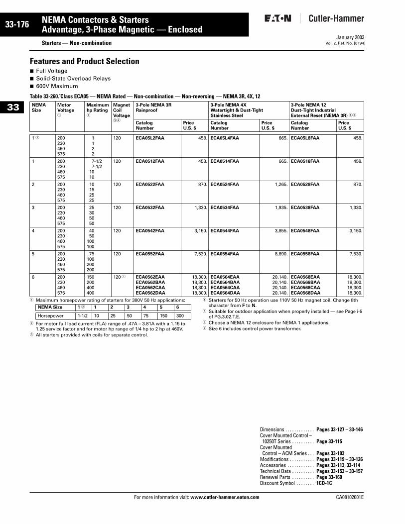
33-176
33
NEMA Contactors & StartersAdvantage, 3-Phase Magnetic — Enclosed
Starters — Non-combinationFor more information visit: www.cutler-hammer.eaton.com
January 2003Vol. 2, Ref. No. [0194]
Features and Product Selection■ Full Voltage■ Solid-State Overload Relays■ 600V Maximum
Table 33-260. Class ECA05 — NEMA Rated — Non-combination — Non-reversing — NEMA 3R, 4X, 12
1 Maximum horsepower rating of starters for 380V 50 Hz applications:
2 For motor full load current (FLA) range of .47A – 3.81A with a 1.15 to 1.25 service factor and for motor hp range of 1/4 hp to 2 hp at 460V.
3 All starters provided with coils for separate control.
4 Starters for 50 Hz operation use 110V 50 Hz magnet coil. Change 8th character from F to N.
5 Suitable for outdoor application when properly installed — see Page i-5 of PG.3.02.T.E.
6 Choose a NEMA 12 enclosure for NEMA 1 applications.7 Size 6 includes control power transformer.
NEMASize
MotorVoltage1
Maximumhp Rating1
MagnetCoilVoltage34
3-Pole NEMA 3RRainproof
3-Pole NEMA 4XWatertight & Dust-TightStainless Steel
3-Pole NEMA 12Dust-Tight IndustrialExternal Reset (NEMA 3R) 56
CatalogNumber
PriceU.S. $
CatalogNumber
PriceU.S. $
CatalogNumber
PriceU.S. $
1 2 200230460575
1122
120 ECA05L2FAA 458. ECA05L4FAA 665. ECA05L8FAA 458.
1 200230460575
7-1/27-1/2
1010
120 ECA0512FAA 458. ECA0514FAA 665. ECA0518FAA 458.
2 200230460575
10152525
120 ECA0522FAA 870. ECA0524FAA 1,265. ECA0528FAA 870.
3 200230460575
25305050
120 ECA0532FAA 1,330. ECA0534FAA 1,935. ECA0538FAA 1,330.
4 200230460575
4050
100100
120 ECA0542FAA 3,150. ECA0544FAA 3,855. ECA0548FAA 3,150.
5 200230460575
75100200200
120 ECA0552FAA 7,530. ECA0554FAA 8,890. ECA0558FAA 7,530.
6 200230460575
150200400400
120 7 ECA0562EAAECA0562BAAECA0562CAAECA0562DAA
18,300.18,300.18,300.18,300.
ECA0564EAAECA0564BAAECA0564CAAECA0564DAA
20,140.20,140.20,140.20,140.
ECA0568EAAECA0568BAAECA0568CAAECA0568DAA
18,300.18,300.18,300.18,300.
NEMA Size 1 2 1 2 3 4 5 6
Horsepower 1-1/2 10 25 50 75 150 300
Dimensions . . . . . . . . . . . . . Pages 33-127 – 33-146Cover Mounted Control – 10250T Series . . . . . . . . . . Page 33-115
Cover Mounted Control – ACM Series . . . Pages 33-193
Modifications . . . . . . . . . . . Pages 33-119 – 33-126Accessories . . . . . . . . . . . . Pages 33-113, 33-114Technical Data . . . . . . . . . . Pages 33-153 – 33-157Renewal Parts . . . . . . . . . . Page 33-160Discount Symbol . . . . . . . . 1CD-1C
CA08102001E
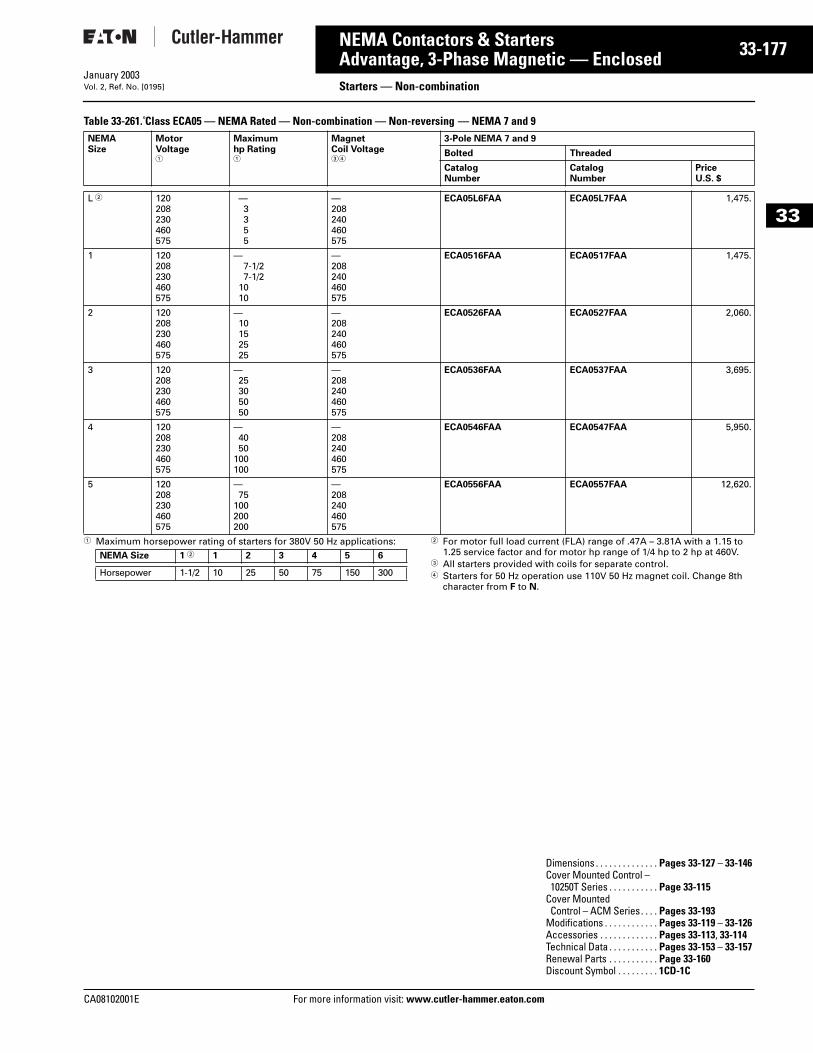
CA08102001E For more
77
33-1NEMA Contactors & StartersAdvantage, 3-Phase Magnetic — Enclosed
Starters — Non-combinationJanuary 2003Vol. 2, Ref. No. [0195]
33
Table 33-261. Class ECA05 — NEMA Rated — Non-combination — Non-reversing — NEMA 7 and 9
1 Maximum horsepower rating of starters for 380V 50 Hz applications: 2 For motor full load current (FLA) range of .47A – 3.81A with a 1.15 to 1.25 service factor and for motor hp range of 1/4 hp to 2 hp at 460V.
3 All starters provided with coils for separate control.4 Starters for 50 Hz operation use 110V 50 Hz magnet coil. Change 8th
character from F to N.
NEMASize
MotorVoltage1
Maximumhp Rating1
MagnetCoil Voltage34
3-Pole NEMA 7 and 9
Bolted Threaded
CatalogNumber
CatalogNumber
PriceU.S. $
L 2 120208230460575
—3355
—208240460575
ECA05L6FAA ECA05L7FAA 1,475.
1 120208230460575
—7-1/27-1/2
1010
—208240460575
ECA0516FAA ECA0517FAA 1,475.
2 120208230460575
—10152525
—208240460575
ECA0526FAA ECA0527FAA 2,060.
3 120208230460575
—25305050
—208240460575
ECA0536FAA ECA0537FAA 3,695.
4 120208230460575
—4050
100100
—208240460575
ECA0546FAA ECA0547FAA 5,950.
5 120208230460575
—75
100200200
—208240460575
ECA0556FAA ECA0557FAA 12,620.
NEMA Size 1 2 1 2 3 4 5 6
Horsepower 1-1/2 10 25 50 75 150 300
Dimensions . . . . . . . . . . . . . . Pages 33-127 – 33-146Cover Mounted Control – 10250T Series . . . . . . . . . . . Page 33-115
Cover Mounted Control – ACM Series. . . . Pages 33-193
Modifications . . . . . . . . . . . . Pages 33-119 – 33-126Accessories . . . . . . . . . . . . . Pages 33-113, 33-114Technical Data . . . . . . . . . . . Pages 33-153 – 33-157Renewal Parts . . . . . . . . . . . Page 33-160Discount Symbol . . . . . . . . . 1CD-1C
information visit: www.cutler-hammer.eaton.com
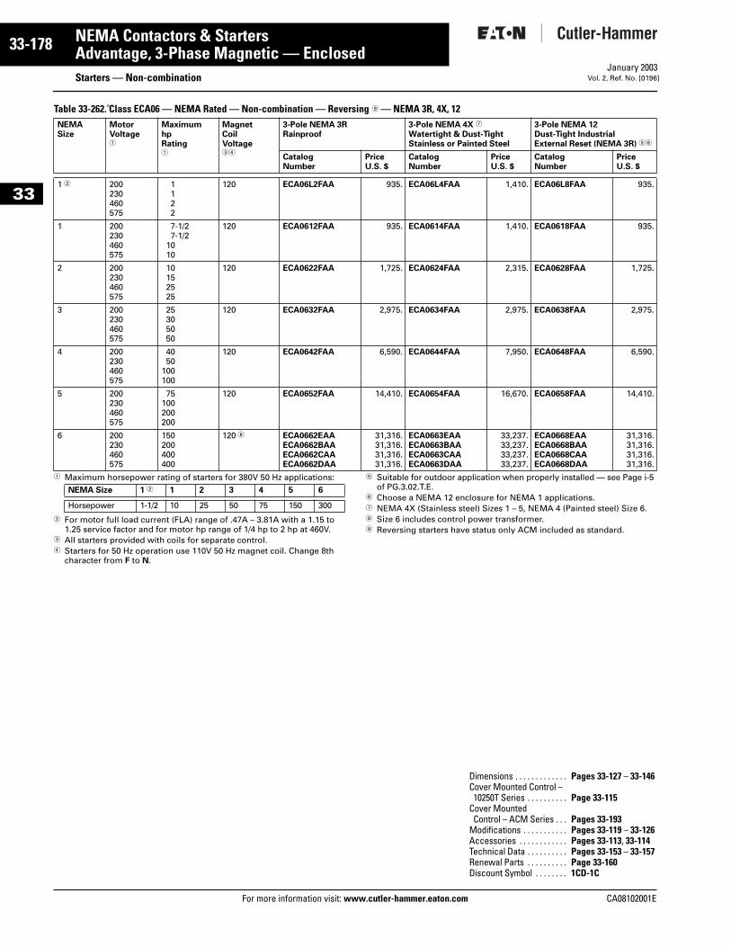
33-178
33
NEMA Contactors & StartersAdvantage, 3-Phase Magnetic — Enclosed
Starters — Non-combinationFor more information visit: www.cutler-hammer.eaton.com
January 2003Vol. 2, Ref. No. [0196]
Table 33-262. Class ECA06 — NEMA Rated — Non-combination — Reversing 9 — NEMA 3R, 4X, 12
1 Maximum horsepower rating of starters for 380V 50 Hz applications:
2 For motor full load current (FLA) range of .47A – 3.81A with a 1.15 to 1.25 service factor and for motor hp range of 1/4 hp to 2 hp at 460V.
3 All starters provided with coils for separate control.4 Starters for 50 Hz operation use 110V 50 Hz magnet coil. Change 8th
character from F to N.
5 Suitable for outdoor application when properly installed — see Page i-5 of PG.3.02.T.E.
6 Choose a NEMA 12 enclosure for NEMA 1 applications.7 NEMA 4X (Stainless steel) Sizes 1 – 5, NEMA 4 (Painted steel) Size 6.8 Size 6 includes control power transformer.9 Reversing starters have status only ACM included as standard.
NEMASize
MotorVoltage1
MaximumhpRating1
MagnetCoilVoltage34
3-Pole NEMA 3RRainproof
3-Pole NEMA 4X 7
Watertight & Dust-TightStainless or Painted Steel
3-Pole NEMA 12Dust-Tight IndustrialExternal Reset (NEMA 3R) 56
CatalogNumber
PriceU.S. $
CatalogNumber
PriceU.S. $
CatalogNumber
PriceU.S. $
1 2 200230460575
1122
120 ECA06L2FAA 935. ECA06L4FAA 1,410. ECA06L8FAA 935.
1 200230460575
7-1/27-1/2
1010
120 ECA0612FAA 935. ECA0614FAA 1,410. ECA0618FAA 935.
2 200230460575
10152525
120 ECA0622FAA 1,725. ECA0624FAA 2,315. ECA0628FAA 1,725.
3 200230460575
25305050
120 ECA0632FAA 2,975. ECA0634FAA 2,975. ECA0638FAA 2,975.
4 200230460575
4050
100100
120 ECA0642FAA 6,590. ECA0644FAA 7,950. ECA0648FAA 6,590.
5 200230460575
75100200200
120 ECA0652FAA 14,410. ECA0654FAA 16,670. ECA0658FAA 14,410.
6 200230460575
150200400400
120 8 ECA0662EAAECA0662BAAECA0662CAAECA0662DAA
31,316.31,316.31,316.31,316.
ECA0663EAAECA0663BAAECA0663CAAECA0663DAA
33,237.33,237.33,237.33,237.
ECA0668EAAECA0668BAAECA0668CAAECA0668DAA
31,316.31,316.31,316.31,316.
NEMA Size 1 2 1 2 3 4 5 6
Horsepower 1-1/2 10 25 50 75 150 300
Dimensions . . . . . . . . . . . . . Pages 33-127 – 33-146Cover Mounted Control – 10250T Series . . . . . . . . . . Page 33-115
Cover Mounted Control – ACM Series . . . Pages 33-193
Modifications . . . . . . . . . . . Pages 33-119 – 33-126Accessories . . . . . . . . . . . . Pages 33-113, 33-114Technical Data . . . . . . . . . . Pages 33-153 – 33-157Renewal Parts . . . . . . . . . . Page 33-160Discount Symbol . . . . . . . . 1CD-1C
CA08102001E
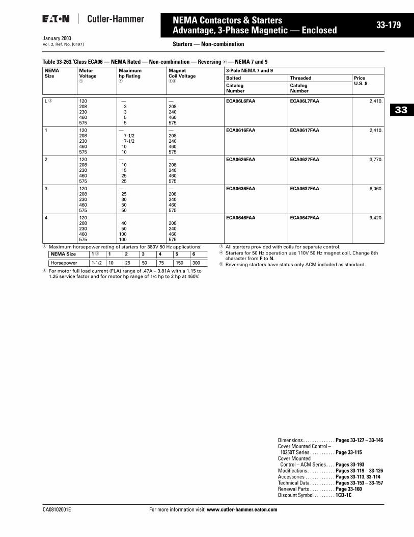
CA08102001E For more
79
33-1NEMA Contactors & StartersAdvantage, 3-Phase Magnetic — Enclosed Starters — Non-combinationJanuary 2003Vol. 2, Ref. No. [0197]
33
Table 33-263. Class ECA06 — NEMA Rated — Non-combination — Reversing 5 — NEMA 7 and 9
1 Maximum horsepower rating of starters for 380V 50 Hz applications:
2 For motor full load current (FLA) range of .47A – 3.81A with a 1.15 to 1.25 service factor and for motor hp range of 1/4 hp to 2 hp at 460V.
3 All starters provided with coils for separate control.4 Starters for 50 Hz operation use 110V 50 Hz magnet coil. Change 8th
character from F to N.5 Reversing starters have status only ACM included as standard.
NEMASize
MotorVoltage1
Maximumhp Rating1
MagnetCoil Voltage34
3-Pole NEMA 7 and 9
Bolted Threaded PriceU.S. $Catalog
NumberCatalogNumber
L 2 120208230460575
—3355
—208240460575
ECA06L6FAA ECA06L7FAA 2,410.
1 120208230460575
—7-1/27-1/2
1010
—208240460575
ECA0616FAA ECA0617FAA 2,410.
2 120208230460575
—10152525
—208240460575
ECA0626FAA ECA0627FAA 3,770.
3 120208230460575
—25305050
—208240460575
ECA0636FAA ECA0637FAA 6,060.
4 120208230460575
—4050
100100
—208240460575
ECA0646FAA ECA0647FAA 9,420.
NEMA Size 1 2 1 2 3 4 5 6
Horsepower 1-1/2 10 25 50 75 150 300
Dimensions . . . . . . . . . . . . . . Pages 33-127 – 33-146Cover Mounted Control – 10250T Series . . . . . . . . . . . Page 33-115
Cover Mounted Control – ACM Series. . . . Pages 33-193
Modifications . . . . . . . . . . . . Pages 33-119 – 33-126Accessories . . . . . . . . . . . . . Pages 33-113, 33-114Technical Data . . . . . . . . . . . Pages 33-153 – 33-157Renewal Parts . . . . . . . . . . . Page 33-160Discount Symbol . . . . . . . . . 1CD-1C
information visit: www.cutler-hammer.eaton.com
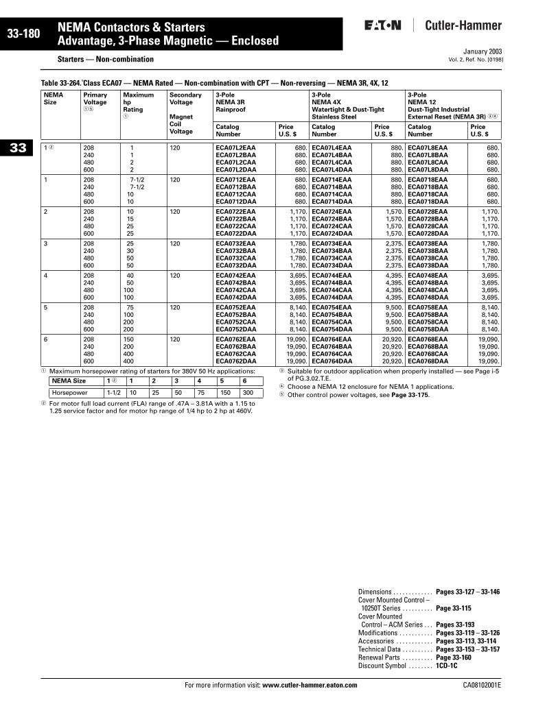
33-180
33
NEMA Contactors & StartersAdvantage, 3-Phase Magnetic — Enclosed
Starters — Non-combinationFor more information visit: www.cutler-hammer.eaton.com
January 2003Vol. 2, Ref. No. [0198]
Table 33-264. Class ECA07 — NEMA Rated — Non-combination with CPT — Non-reversing — NEMA 3R, 4X, 12
1 Maximum horsepower rating of starters for 380V 50 Hz applications:
2 For motor full load current (FLA) range of .47A – 3.81A with a 1.15 to 1.25 service factor and for motor hp range of 1/4 hp to 2 hp at 460V.
3 Suitable for outdoor application when properly installed — see Page i-5 of PG.3.02.T.E.
4 Choose a NEMA 12 enclosure for NEMA 1 applications.5 Other control power voltages, see Page 33-175.
NEMASize
PrimaryVoltage15
MaximumhpRating1
SecondaryVoltage
MagnetCoilVoltage
3-PoleNEMA 3RRainproof
3-PoleNEMA 4XWatertight & Dust-TightStainless Steel
3-PoleNEMA 12Dust-Tight IndustrialExternal Reset (NEMA 3R) 34
CatalogNumber
PriceU.S. $
CatalogNumber
PriceU.S. $
CatalogNumber
PriceU.S. $
1 2 208240480600
1122
120 ECA07L2EAAECA07L2BAAECA07L2CAAECA07L2DAA
680.680.680.680.
ECA07L4EAAECA07L4BAAECA07L4CAAECA07L4DAA
880.880.880.880.
ECA07L8EAAECA07L8BAAECA07L8CAAECA07L8DAA
680.680.680.680.
1 208240480600
7-1/27-1/2
1010
120 ECA0712EAAECA0712BAAECA0712CAAECA0712DAA
680.680.680.680.
ECA0714EAAECA0714BAAECA0714CAAECA0714DAA
880.880.880.880.
ECA0718EAAECA0718BAAECA0718CAAECA0718DAA
680.680.680.680.
2 208240480600
10152525
120 ECA0722EAAECA0722BAAECA0722CAAECA0722DAA
1,170.1,170.1,170.1,170.
ECA0724EAAECA0724BAAECA0724CAAECA0724DAA
1,570.1,570.1,570.1,570.
ECA0728EAAECA0728BAAECA0728CAAECA0728DAA
1,170.1,170.1,170.1,170.
3 208240480600
25305050
120 ECA0732EAAECA0732BAAECA0732CAAECA0732DAA
1,780.1,780.1,780.1,780.
ECA0734EAAECA0734BAAECA0734CAAECA0734DAA
2,375.2,375.2,375.2,375.
ECA0738EAAECA0738BAAECA0738CAAECA0738DAA
1,780.1,780.1,780.1,780.
4 208240480600
4050
100100
120 ECA0742EAAECA0742BAAECA0742CAAECA0742DAA
3,695.3,695.3,695.3,695.
ECA0744EAAECA0744BAAECA0744CAAECA0744DAA
4,395.4,395.4,395.4,395.
ECA0748EAAECA0748BAAECA0748CAAECA0748DAA
3,695.3,695.3,695.3,695.
5 208240480600
75100200200
120 ECA0752EAAECA0752BAAECA0752CAAECA0752DAA
8,140.8,140.8,140.8,140.
ECA0754EAAECA0754BAAECA0754CAAECA0754DAA
9,500.9,500.9,500.9,500.
ECA0758EAAECA0758BAAECA0758CAAECA0758DAA
8,140.8,140.8,140.8,140.
6 208240480600
150200400400
120 ECA0762EAAECA0762BAAECA0762CAAECA0762DAA
19,090.19,090.19,090.19,090.
ECA0764EAAECA0764BAAECA0764CAAECA0764DAA
20,920.20,920.20,920.20,920.
ECA0768EAAECA0768BAAECA0768CAAECA0768DAA
19,090.19,090.19,090.19,090.
NEMA Size 1 2 1 2 3 4 5 6
Horsepower 1-1/2 10 25 50 75 150 300
Dimensions . . . . . . . . . . . . . Pages 33-127 – 33-146Cover Mounted Control – 10250T Series . . . . . . . . . . Page 33-115
Cover Mounted Control – ACM Series . . . Pages 33-193
Modifications . . . . . . . . . . . Pages 33-119 – 33-126Accessories . . . . . . . . . . . . Pages 33-113, 33-114Technical Data . . . . . . . . . . Pages 33-153 – 33-157Renewal Parts . . . . . . . . . . Page 33-160Discount Symbol . . . . . . . . 1CD-1C
CA08102001E
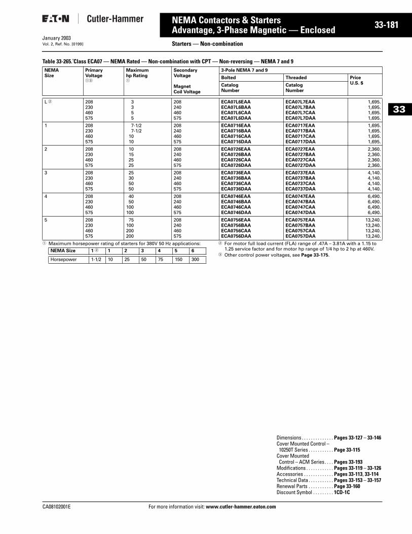
CA08102001E For more
81
33-1NEMA Contactors & StartersAdvantage, 3-Phase Magnetic — Enclosed Starters — Non-combinationJanuary 2003Vol. 2, Ref. No. [0199]
33
Table 33-265. Class ECA07 — NEMA Rated — Non-combination with CPT — Non-reversing — NEMA 7 and 9
1 Maximum horsepower rating of starters for 380V 50 Hz applications: 2 For motor full load current (FLA) range of .47A – 3.81A with a 1.15 to 1.25 service factor and for motor hp range of 1/4 hp to 2 hp at 460V.
3 Other control power voltages, see Page 33-175.
NEMASize
PrimaryVoltage13
Maximumhp Rating1
SecondaryVoltage
MagnetCoil Voltage
3-Pole NEMA 7 and 9
Bolted Threaded PriceU.S. $Catalog
NumberCatalogNumber
L 2 208230460575
3355
208240460575
ECA07L6EAAECA07L6BAAECA07L6CAAECA07L6DAA
ECA07L7EAAECA07L7BAAECA07L7CAAECA07L7DAA
1,695.1,695.1,695.1,695.
1 208230460575
7-1/27-1/2
1010
208240460575
ECA0716EAAECA0716BAAECA0716CAAECA0716DAA
ECA0717EAAECA0717BAAECA0717CAAECA0717DAA
1,695.1,695.1,695.1,695.
2 208230460575
10152525
208240460575
ECA0726EAAECA0726BAAECA0726CAAECA0726DAA
ECA0727EAAECA0727BAAECA0727CAAECA0727DAA
2,360.2,360.2,360.2,360.
3 208230460575
25305050
208240460575
ECA0736EAAECA0736BAAECA0736CAAECA0736DAA
ECA0737EAAECA0737BAAECA0737CAAECA0737DAA
4,140.4,140.4,140.4,140.
4 208230460575
4050
100100
208240460575
ECA0746EAAECA0746BAAECA0746CAAECA0746DAA
ECA0747EAAECA0747BAAECA0747CAAECA0747DAA
6,490.6,490.6,490.6,490.
5 208230460575
75100200200
208240460575
ECA0756EAAECA0756BAAECA0756CAAECA0756DAA
ECA0757EAAECA0757BAAECA0757CAAECA0757DAA
13,240.13,240.13,240.13,240.
NEMA Size 1 2 1 2 3 4 5 6
Horsepower 1-1/2 10 25 50 75 150 300
Dimensions . . . . . . . . . . . . . . Pages 33-127 – 33-146Cover Mounted Control – 10250T Series . . . . . . . . . . . Page 33-115
Cover Mounted Control – ACM Series. . . . Pages 33-193
Modifications . . . . . . . . . . . . Pages 33-119 – 33-126Accessories . . . . . . . . . . . . . Pages 33-113, 33-114Technical Data . . . . . . . . . . . Pages 33-153 – 33-157Renewal Parts . . . . . . . . . . . Page 33-160Discount Symbol . . . . . . . . . 1CD-1C
information visit: www.cutler-hammer.eaton.com
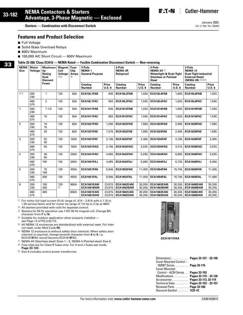
33-182
33
NEMA Contactors & StartersAdvantage, 3-Phase Magnetic — Enclosed
Starters — Combination with Disconnect SwitchFor more information visit: www.cutler-hammer.eaton.com
January 2003Vol. 2, Ref. No. [0200]
Features and Product Selection■ Full Voltage■ Solid-State Overload Relays■ 600V Maximum■ 100,000 AIC Short Circuit — 600V Maximum
Table 33-266. Class ECA16 — NEMA Rated — Fusible Combination Disconnect Switch — Non-reversing
1 For motor full load current (FLA) range of .47A – 3.81A with a 1.15 to 1.25 service factor and for motor hp range of 1/4 hp to 2 hp at 460V.
2 All starters provided with coils for separate control.3 Starters for 50 Hz operation use 110V 50 Hz magnet coil. Change 8th
character from F to N.4 Suitable for outdoor application when properly installed —
see Page i-5 of PG.3.02.T.E.5 All NEMA 12 enclosures are standardized with external reset. For inter-
nal reset, order Mod Code R5.6 NEMA 12 enclosure is without safety door interlock. When safety door
interlock is required, change seventh character from 8 to 9, i.e. ECA1618FAC would become ECA1619FAC.
7 NEMA 4X (Stainless steel) Sizes 1 – 5, NEMA 4 (Painted steel) Size 6.8 Fuse clips are for Class R fuses only. For H and J fuses see mods,
Page 33-122.9 Size 6 includes control power transformer.
ECA1611FAA
NEMASize
MotorVoltage
MaximumhpRatingDualElementFuses
MagnetCoilVoltage23
FuseClipAmps.8
3-PoleNEMA 1General Purpose
3-PoleNEMA 3RRainproof
3-PoleNEMA 4X 7
Watertight & Dust-TightStainless or Painted Steel
3-PoleNEMA 12Dust-Tight IndustrialExternal Reset (NEMA 3R) 456
CatalogNumber
PriceU.S. $
CatalogNumber
PriceU.S. $
CatalogNumber
PriceU.S. $
CatalogNumber
PriceU.S. $
1 1 200230
1 120 30A ECA16L1FAB 830. ECA16L2FAB 1,020. ECA16L4FAB 1,600. ECA16L8FAB 1,020.
460575
2 120 30A ECA16L1FAC 850. ECA16L2FAC 1,045. ECA16L4FAC 1,620. ECA16L8FAC 1,045.
1 200230
7-1/2 120 30A ECA1611FAB 830. ECA1612FAB 1,020. ECA1614FAB 1,600. ECA1618FAB 1,020.
460575
10 120 30A ECA1611FAC 850. ECA1612FAC 1,045. ECA1614FAC 1,620. ECA1618FAC 1,045.
2 200230
1015
120 60A ECA1621FAD 1,290. ECA1622FAD 1,560. ECA1624FAD 2,465. ECA1628FAD 1,560.
460575
25 120 60A ECA1621FAE 1,315. ECA1622FAE 1,585. ECA1624FAE 2,485. ECA1628FAE 1,585.
3 200230
2530
120 100A ECA1631FAF 2,140. ECA1632FAF 2,485. ECA1634FAF 4,185. ECA1638FAF 2,485.
460575
50 120 100A ECA1631FAG 2,180. ECA1632FAG 2,525. ECA1634FAG 4,215. ECA1638FAG 2,525.
4 200230
4050
120 200A ECA1641FAH 4,060. ECA1642FAH 5,030. ECA1644FAH 6,690. ECA1648FAH 5,030.
460575
100 120 200A ECA1641FAJ 4,095. ECA1642FAJ 5,060. ECA1644FAJ 6,720. ECA1648FAJ 5,060.
5 200230
75100
120 400A ECA1651FAK 9,040. ECA1652FAK 11,400. ECA1654FAK 15,740. ECA1658FAK 11,400.
460575
200 120 400A ECA1651FAL 9,040. ECA1652FAL 11,400. ECA1654FAL 15,740. ECA1658FAL 11,400.
6 200230
150200
1209
600A ECA1661EAMECA1661BAM
23,870.23,870.
ECA1662EAMECA1662BAM
30,200.30,200.
ECA1663EAMECA1663BAM
30,200.30,200.
ECA1668EAMECA1668BAM
30,200.30,200.
460575
400 600A ECA1661CANECA1661DAN
23,870.23,870.
ECA1662CANECA1662DAN
30,200.30,200.
ECA1663CANECA1663DAN
30,200.30,200.
ECA1668CANECA1668DAN
30,200.30,200.
Dimensions . . . . . . . . . . . . . Pages 33-127 – 33-146Cover Mounted Control – 10250T Series . . . . . . . . . . Page 33-115
Cover Mounted Control – ACM Series . . . Pages 33-193
Modifications . . . . . . . . . . . Pages 33-119 – 33-126Accessories . . . . . . . . . . . . Pages 33-113, 33-114Technical Data . . . . . . . . . . Pages 33-153 – 33-157Renewal Parts . . . . . . . . . . Page 33-160Discount Symbol . . . . . . . . 1CD-1C
CA08102001E
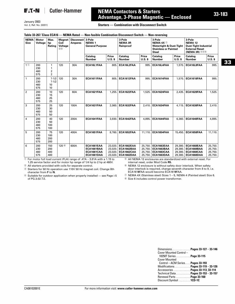
CA08102001E For more
83
33-1NEMA Contactors & StartersAdvantage, 3-Phase Magnetic — Enclosed Starters — Combination with Disconnect SwitchJanuary 2003Vol. 2, Ref. No. [0201]
33
Table 33-267. Class ECA16 — NEMA Rated — Non-fusible Combination Disconnect Switch — Non-reversing
1 For motor full load current (FLA) range of .47A – 3.81A with a 1.15 to 1.25 service factor and for motor hp range of 1/4 hp to 2 hp at 460V.
2 All starters provided with coils for separate control.3 Starters for 50 Hz operation use 110V 50 Hz magnet coil. Change 8th
character from F to N.4 Suitable for outdoor application when properly installed — see Page i-5
of PG.3.02.T.E.
5 All NEMA 12 enclosures are standardized with external reset. For internal reset, order Mod Code R5.
6 NEMA 12 enclosure is without safety door interlock. When safety door interlock is required, change seventh character from 8 to 9, i.e. ECA1618FAA would become ECA1619FAA.
7 NEMA 4X (Stainless steel) Sizes 1 – 5, NEMA 4 (Painted steel) Size 6.8 Size 6 includes control power transformer.
NEMASize
MotorVoltage
Max.hpRating
MagnetCoilVoltage23
DisconnectAmperes
3-PoleNEMA 1General Purpose
3-PoleNEMA 3RRainproof
3-PoleNEMA 4X 7
Watertight & Dust-TightStainless or Painted Steel
3-PoleNEMA 12Dust-Tight IndustrialExternal Reset (NEMA 3R) 456
CatalogNumber
PriceU.S. $
CatalogNumber
PriceU.S. $
CatalogNumber
PriceU.S. $
CatalogNumber
PriceU.S. $
1 1 200230460575
1122
120 30A ECA16L1FAA 805. ECA16L2FAA 995. ECA16L4FAA 1,570. ECA16L8FAA 995.
1 200230460575
7-1/27-1/2
1010
120 30A ECA1611FAA 805. ECA1612FAA 995. ECA1614FAA 1,570. ECA1618FAA 995.
2 200230460575
10152525
120 60A ECA1621FAA 1,255. ECA1622FAA 1,525. ECA1624FAA 2,435. ECA1628FAA 1,525.
3 200230460575
25305050
120 100A ECA1631FAA 2,060. ECA1632FAA 2,410. ECA1634FAA 4,115. ECA1638FAA 2,410.
4 200230460575
4050
100100
120 200A ECA1641FAA 3,930. ECA1642FAA 4,895. ECA1644FAA 6,360. ECA1648FAA 4,895.
5 200230460575
75100200200
120 400A ECA1651FAA 8,760. ECA1652FAA 11,110. ECA1654FAA 15,450. ECA1658FAA 11,110.
6 200230460575
150200400400
120 8 600A ECA1661EAAECA1661BAAECA1661CAAECA1661DAA
23,020.23,020.23,020.23,020.
ECA1662EAAECA1662BAAECA1662CAAECA1662DAA
25,750.25,750.25,750.25,750.
ECA1663EAAECA1663BAAECA1663CAAECA1663DAA
29,380.29,380.29,380.29,380.
ECA1668EAAECA1668BAAECA1668CAAECA1668DAA
25,750.25,750.25,750.25,750.
Dimensions . . . . . . . . . . . . . . Pages 33-127 – 33-146Cover Mounted Control – 10250T Series . . . . . . . . . . . Page 33-115
Cover Mounted Control – ACM Series. . . . Pages 33-193
Modifications . . . . . . . . . . . . Pages 33-119 – 33-126Accessories . . . . . . . . . . . . . Pages 33-113, 33-114Technical Data . . . . . . . . . . . Pages 33-153 – 33-157Renewal Parts . . . . . . . . . . . Page 33-160Discount Symbol . . . . . . . . . 1CD-1C
information visit: www.cutler-hammer.eaton.com
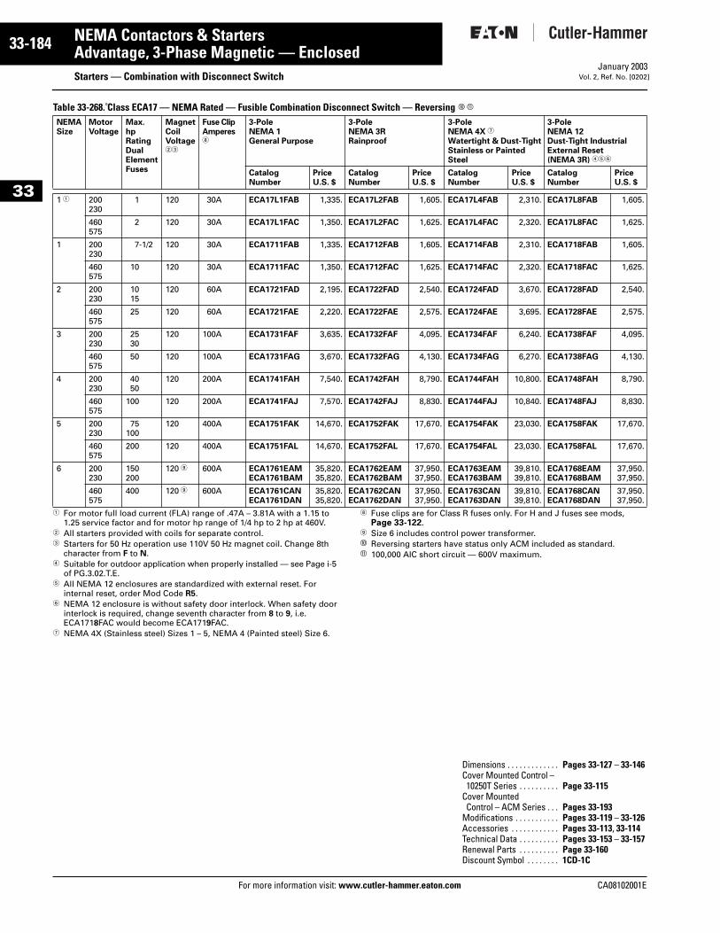
33-184
33
NEMA Contactors & StartersAdvantage, 3-Phase Magnetic — Enclosed
Starters — Combination with Disconnect SwitchFor more information visit: www.cutler-hammer.eaton.com
January 2003Vol. 2, Ref. No. [0202]
Table 33-268. Class ECA17 — NEMA Rated — Fusible Combination Disconnect Switch — Reversing j k
1 For motor full load current (FLA) range of .47A – 3.81A with a 1.15 to 1.25 service factor and for motor hp range of 1/4 hp to 2 hp at 460V.
2 All starters provided with coils for separate control.3 Starters for 50 Hz operation use 110V 50 Hz magnet coil. Change 8th
character from F to N.4 Suitable for outdoor application when properly installed — see Page i-5
of PG.3.02.T.E.5 All NEMA 12 enclosures are standardized with external reset. For
internal reset, order Mod Code R5.6 NEMA 12 enclosure is without safety door interlock. When safety door
interlock is required, change seventh character from 8 to 9, i.e. ECA1718FAC would become ECA1719FAC.
7 NEMA 4X (Stainless steel) Sizes 1 – 5, NEMA 4 (Painted steel) Size 6.
8 Fuse clips are for Class R fuses only. For H and J fuses see mods, Page 33-122.
9 Size 6 includes control power transformer.j Reversing starters have status only ACM included as standard. k 100,000 AIC short circuit — 600V maximum.
NEMASize
MotorVoltage
Max.hpRatingDual Element Fuses
MagnetCoilVoltage23
Fuse ClipAmperes8
3-PoleNEMA 1General Purpose
3-PoleNEMA 3RRainproof
3-PoleNEMA 4X 7
Watertight & Dust-TightStainless or Painted Steel
3-PoleNEMA 12Dust-Tight IndustrialExternal Reset (NEMA 3R) 456
CatalogNumber
PriceU.S. $
CatalogNumber
PriceU.S. $
CatalogNumber
PriceU.S. $
CatalogNumber
PriceU.S. $
1 1 200230
1 120 30A ECA17L1FAB 1,335. ECA17L2FAB 1,605. ECA17L4FAB 2,310. ECA17L8FAB 1,605.
460575
2 120 30A ECA17L1FAC 1,350. ECA17L2FAC 1,625. ECA17L4FAC 2,320. ECA17L8FAC 1,625.
1 200230
7-1/2 120 30A ECA1711FAB 1,335. ECA1712FAB 1,605. ECA1714FAB 2,310. ECA1718FAB 1,605.
460575
10 120 30A ECA1711FAC 1,350. ECA1712FAC 1,625. ECA1714FAC 2,320. ECA1718FAC 1,625.
2 200230
1015
120 60A ECA1721FAD 2,195. ECA1722FAD 2,540. ECA1724FAD 3,670. ECA1728FAD 2,540.
460575
25 120 60A ECA1721FAE 2,220. ECA1722FAE 2,575. ECA1724FAE 3,695. ECA1728FAE 2,575.
3 200230
2530
120 100A ECA1731FAF 3,635. ECA1732FAF 4,095. ECA1734FAF 6,240. ECA1738FAF 4,095.
460575
50 120 100A ECA1731FAG 3,670. ECA1732FAG 4,130. ECA1734FAG 6,270. ECA1738FAG 4,130.
4 200230
4050
120 200A ECA1741FAH 7,540. ECA1742FAH 8,790. ECA1744FAH 10,800. ECA1748FAH 8,790.
460575
100 120 200A ECA1741FAJ 7,570. ECA1742FAJ 8,830. ECA1744FAJ 10,840. ECA1748FAJ 8,830.
5 200230
75100
120 400A ECA1751FAK 14,670. ECA1752FAK 17,670. ECA1754FAK 23,030. ECA1758FAK 17,670.
460575
200 120 400A ECA1751FAL 14,670. ECA1752FAL 17,670. ECA1754FAL 23,030. ECA1758FAL 17,670.
6 200230
150200
120 9 600A ECA1761EAMECA1761BAM
35,820.35,820.
ECA1762EAMECA1762BAM
37,950.37,950.
ECA1763EAMECA1763BAM
39,810.39,810.
ECA1768EAMECA1768BAM
37,950.37,950.
460575
400 120 9 600A ECA1761CANECA1761DAN
35,820.35,820.
ECA1762CANECA1762DAN
37,950.37,950.
ECA1763CANECA1763DAN
39,810.39,810.
ECA1768CANECA1768DAN
37,950.37,950.
Dimensions . . . . . . . . . . . . . Pages 33-127 – 33-146Cover Mounted Control – 10250T Series . . . . . . . . . . Page 33-115
Cover Mounted Control – ACM Series . . . Pages 33-193
Modifications . . . . . . . . . . . Pages 33-119 – 33-126Accessories . . . . . . . . . . . . Pages 33-113, 33-114Technical Data . . . . . . . . . . Pages 33-153 – 33-157Renewal Parts . . . . . . . . . . Page 33-160Discount Symbol . . . . . . . . 1CD-1C
CA08102001E

CA08102001E For more
85
33-1NEMA Contactors & StartersAdvantage, 3-Phase Magnetic — Enclosed Starters — Combination with Disconnect SwitchJanuary 2003Vol. 2, Ref. No. [0203]
33
Table 33-269. Class ECA17 — NEMA Rated — Non-fusible Combination Disconnect Switch — Reversing 9
1 For motor full load current (FLA) range of .47A – 3.81A with a 1.15 to 1.25 service factor and for motor hp range of 1/4 hp to 2 hp at 460V.
2 All starters provided with coils for separate control.3 Starters for 50 Hz operation use 110V 50 Hz magnet coil. Change 8th
character from F to N.4 Suitable for outdoor application when properly installed — see Page i-5
of PG.3.02.T.E.5 All NEMA 12 enclosures are standardized with external reset. For
internal reset, order Mod Code R5.
6 NEMA 12 enclosure is without safety door interlock. When safety door interlock is required, change seventh character from 8 to 9, i.e. ECA1718FAA would become ECA1719FAA.
7 NEMA 4X (Stainless steel) Sizes 1 – 5, NEMA 4 (Painted steel) Size 6.8 Size 6 includes control power transformer.9 Reversing starters have status only ACM included as standard.
NEMASize
MotorVoltage
Max.hpRating
MagnetCoilVoltage23
DisconnectAmperes
3-PoleNEMA 1General Purpose
3-PoleNEMA 3RRainproof
3-PoleNEMA 4X 7
Watertight & Dust-TightStainless or Painted Steel
3-PoleNEMA 12Dust-Tight IndustrialExternal Reset (NEMA 3R) 456
CatalogNumber
PriceU.S. $
CatalogNumber
PriceU.S. $
CatalogNumber
PriceU.S. $
CatalogNumber
PriceU.S. $
1 1 200230460575
1122
120 30A ECA17L1FAA 1,315. ECA17L2FAA 1,585. ECA17L4FAA 2,280. ECA17L8FAA 1,585.
1 200230460575
7-1/27-1/2
1010
120 30A ECA1711FAA 1,315. ECA1712FAA 1,585. ECA1714FAA 2,280. ECA1718FAA 1,585.
2 200230460575
10152525
120 60A ECA1721FAA 2,165. ECA1722FAA 2,510. ECA1724FAA 3,640. ECA1728FAA 2,510.
3 200230460575
25305050
120 100A ECA1731FAA 3,550. ECA1732FAA 4,010. ECA1734FAA 6,150. ECA1738FAA 4,010.
4 200230460575
4050
100100
120 200A ECA1741FAA 7,390. ECA1742FAA 8,650. ECA1744FAA 10,680. ECA1748FAA 8,650.
5 200230460575
75100200200
120 400A ECA1751FAA 14,883. ECA1752FAA 17,390. ECA1754FAA 22,730. ECA1758FAA 17,390.
6 200230460575
150200400400
120 8 600A ECA1761EAAECA1761BAAECA1761CAAECA1761DAA
32,475.32,475.32,475.32,475.
ECA1762EAAECA1762BAAECA1762CAAECA1762DAA
34,980.34,980.34,980.34,980.
ECA1763EAAECA1763BAAECA1763CAAECA1763DAA
38,960.38,960.38,960.38,960.
ECA1768EAAECA1768BAAECA1768CAAECA1768DAA
34,980.34,980.34,980.34,980.
Dimensions . . . . . . . . . . . . . . Pages 33-127 – 33-146Cover Mounted Control – 10250T Series . . . . . . . . . . . Page 33-115
Cover Mounted Control – ACM Series. . . . Pages 33-193
Modifications . . . . . . . . . . . . Pages 33-119 – 33-126Accessories . . . . . . . . . . . . . Pages 33-113, 33-114Technical Data . . . . . . . . . . . Pages 33-153 – 33-157Renewal Parts . . . . . . . . . . . Page 33-160Discount Symbol . . . . . . . . . 1CD-1C
information visit: www.cutler-hammer.eaton.com
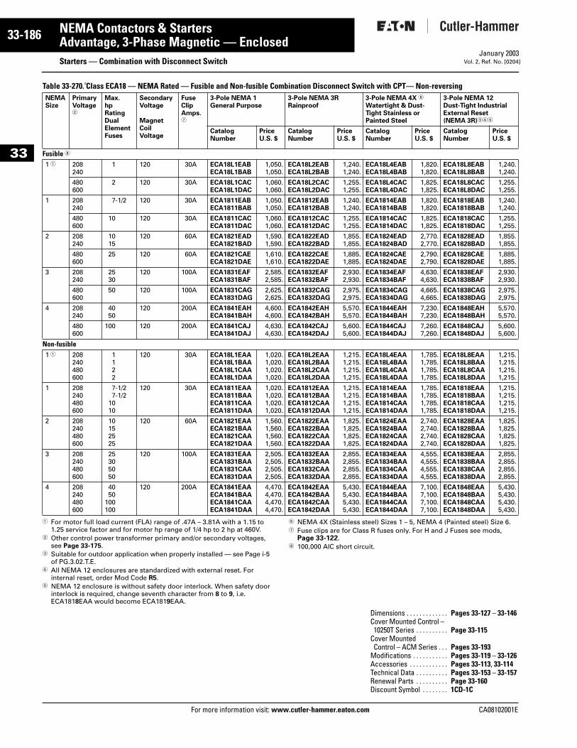
33-186
33
NEMA Contactors & StartersAdvantage, 3-Phase Magnetic — Enclosed
Starters — Combination with Disconnect SwitchFor more information visit: www.cutler-hammer.eaton.com
January 2003Vol. 2, Ref. No. [0204]
Table 33-270. Class ECA18 — NEMA Rated — Fusible and Non-fusible Combination Disconnect Switch with CPT— Non-reversing
1 For motor full load current (FLA) range of .47A – 3.81A with a 1.15 to 1.25 service factor and for motor hp range of 1/4 hp to 2 hp at 460V.
2 Other control power transformer primary and/or secondary voltages, see Page 33-175.
3 Suitable for outdoor application when properly installed — see Page i-5 of PG.3.02.T.E.
4 All NEMA 12 enclosures are standardized with external reset. For internal reset, order Mod Code R5.
5 NEMA 12 enclosure is without safety door interlock. When safety door interlock is required, change seventh character from 8 to 9, i.e. ECA1818EAA would become ECA1819EAA.
6 NEMA 4X (Stainless steel) Sizes 1 – 5, NEMA 4 (Painted steel) Size 6. 7 Fuse clips are for Class R fuses only. For H and J Fuses see mods,
Page 33-122.8 100,000 AIC short circuit.
NEMASize
PrimaryVoltage2
Max.hpRatingDualElementFuses
SecondaryVoltage
MagnetCoilVoltage
FuseClipAmps.7
3-Pole NEMA 1General Purpose
3-Pole NEMA 3RRainproof
3-Pole NEMA 4X 6
Watertight & Dust-Tight Stainless or Painted Steel
3-Pole NEMA 12Dust-Tight IndustrialExternal Reset (NEMA 3R)345
CatalogNumber
PriceU.S. $
CatalogNumber
PriceU.S. $
CatalogNumber
PriceU.S. $
CatalogNumber
PriceU.S. $
Fusible 8
1 1 208240
1 120 30A ECA18L1EABECA18L1BAB
1,050.1,050.
ECA18L2EABECA18L2BAB
1,240.1,240.
ECA18L4EABECA18L4BAB
1,820.1,820.
ECA18L8EABECA18L8BAB
1,240.1,240.
480600
2 120 30A ECA18L1CACECA18L1DAC
1,060.1,060.
ECA18L2CACECA18L2DAC
1,255.1,255.
ECA18L4CACECA18L4DAC
1,825.1,825.
ECA18L8CACECA18L8DAC
1,255.1,255.
1 208240
7-1/2 120 30A ECA1811EABECA1811BAB
1,050.1,050.
ECA1812EABECA1812BAB
1,240.1,240.
ECA1814EABECA1814BAB
1,820.1,820.
ECA1818EABECA1818BAB
1,240.1,240.
480600
10 120 30A ECA1811CACECA1811DAC
1,060.1,060.
ECA1812CACECA1812DAC
1,255.1,255.
ECA1814CACECA1814DAC
1,825.1,825.
ECA1818CACECA1818DAC
1,255.1,255.
2 208240
1015
120 60A ECA1821EADECA1821BAD
1,590.1,590.
ECA1822EADECA1822BAD
1,855.1,855.
ECA1824EADECA1824BAD
2,770.2,770.
ECA1828EADECA1828BAD
1,855.1,855.
480600
25 120 60A ECA1821CAEECA1821DAE
1,610.1,610.
ECA1822CAEECA1822DAE
1,885.1,885.
ECA1824CAEECA1824DAE
2,790.2,790.
ECA1828CAEECA1828DAE
1,885.1,885.
3 208240
2530
120 100A ECA1831EAFECA1831BAF
2,585.2,585.
ECA1832EAFECA1832BAF
2,930.2,930.
ECA1834EAFECA1834BAF
4,630.4,630.
ECA1838EAFECA1838BAF
2,930.2,930.
480600
50 120 100A ECA1831CAGECA1831DAG
2,625.2,625.
ECA1832CAGECA1832DAG
2,975.2,975.
ECA1834CAGECA1834DAG
4,665.4,665.
ECA1838CAGECA1838DAG
2,975.2,975.
4 208240
4050
120 200A ECA1841EAHECA1841BAH
4,600.4,600.
ECA1842EAHECA1842BAH
5,570.5,570.
ECA1844EAHECA1844BAH
7,230.7,230.
ECA1848EAHECA1848BAH
5,570.5,570.
480600
100 120 200A ECA1841CAJECA1841DAJ
4,630.4,630.
ECA1842CAJECA1842DAJ
5,600.5,600.
ECA1844CAJECA1844DAJ
7,260.7,260.
ECA1848CAJECA1848DAJ
5,600.5,600.
Non-fusible1 1 208
240480600
1122
120 30A ECA18L1EAAECA18L1BAAECA18L1CAAECA18L1DAA
1,020.1,020.1,020.1,020.
ECA18L2EAAECA18L2BAAECA18L2CAAECA18L2DAA
1,215.1,215.1,215.1,215.
ECA18L4EAAECA18L4BAAECA18L4CAAECA18L4DAA
1,785.1,785.1,785.1,785.
ECA18L8EAAECA18L8BAAECA18L8CAAECA18L8DAA
1,215.1,215.1,215.1,215.
1 208240480600
7-1/27-1/2
1010
120 30A ECA1811EAAECA1811BAAECA1811CAAECA1811DAA
1,020.1,020.1,020.1,020.
ECA1812EAAECA1812BAAECA1812CAAECA1812DAA
1,215.1,215.1,215.1,215.
ECA1814EAAECA1814BAAECA1814CAAECA1814DAA
1,785.1,785.1,785.1,785.
ECA1818EAAECA1818BAAECA1818CAAECA1818DAA
1,215.1,215.1,215.1,215.
2 208240480600
10152525
120 60A ECA1821EAAECA1821BAAECA1821CAAECA1821DAA
1,560.1,560.1,560.1,560.
ECA1822EAAECA1822BAAECA1822CAAECA1822DAA
1,825.1,825.1,825.1,825.
ECA1824EAAECA1824BAAECA1824CAAECA1824DAA
2,740.2,740.2,740.2,740.
ECA1828EAAECA1828BAAECA1828CAAECA1828DAA
1,825.1,825.1,825.1,825.
3 208240480600
25305050
120 100A ECA1831EAAECA1831BAAECA1831CAAECA1831DAA
2,505.2,505.2,505.2,505.
ECA1832EAAECA1832BAAECA1832CAAECA1832DAA
2,855.2,855.2,855.2,855.
ECA1834EAAECA1834BAAECA1834CAAECA1834DAA
4,555.4,555.4,555.4,555.
ECA1838EAAECA1838BAAECA1838CAAECA1838DAA
2,855.2,855.2,855.2,855.
4 208240480600
4050
100100
120 200A ECA1841EAAECA1841BAAECA1841CAAECA1841DAA
4,470.4,470.4,470.4,470.
ECA1842EAAECA1842BAAECA1842CAAECA1842DAA
5,430.5,430.5,430.5,430.
ECA1844EAAECA1844BAAECA1844CAAECA1844DAA
7,100.7,100.7,100.7,100.
ECA1848EAAECA1848BAAECA1848CAAECA1848DAA
5,430.5,430.5,430.5,430.
Dimensions . . . . . . . . . . . . . Pages 33-127 – 33-146Cover Mounted Control – 10250T Series . . . . . . . . . . Page 33-115
Cover Mounted Control – ACM Series . . . Pages 33-193
Modifications . . . . . . . . . . . Pages 33-119 – 33-126Accessories . . . . . . . . . . . . Pages 33-113, 33-114Technical Data . . . . . . . . . . Pages 33-153 – 33-157Renewal Parts . . . . . . . . . . Page 33-160Discount Symbol . . . . . . . . 1CD-1C
CA08102001E
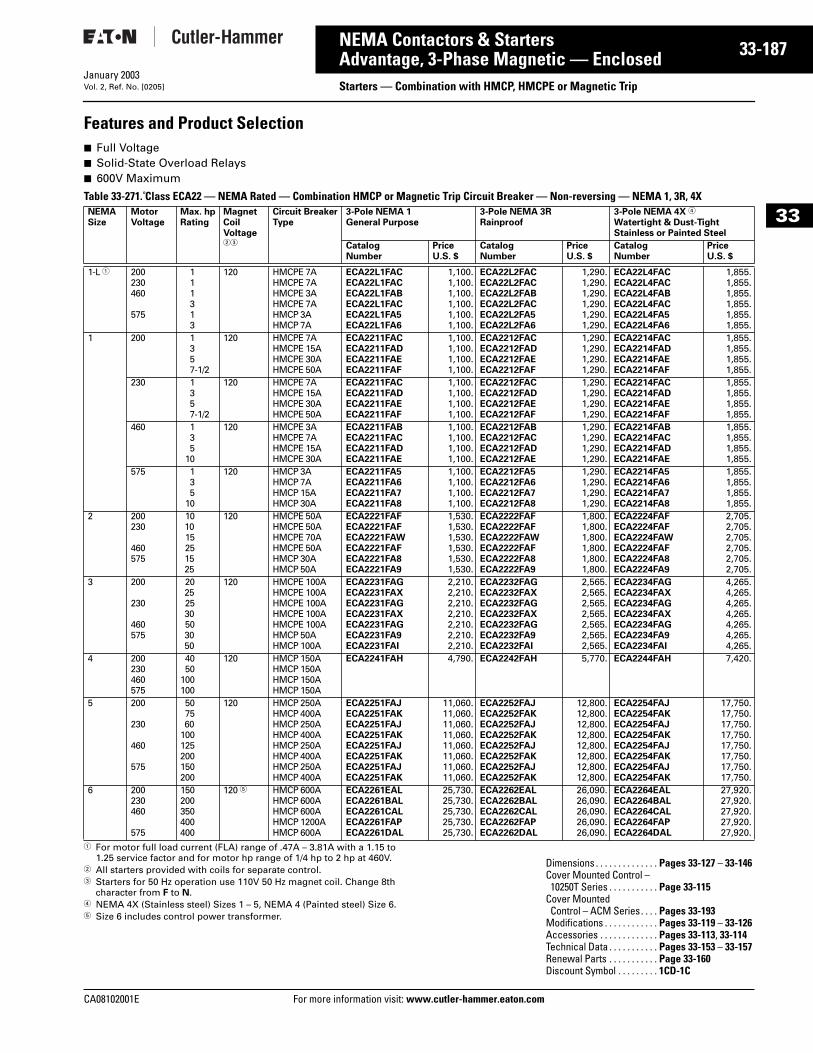
CA08102001E For more
87
33-1NEMA Contactors & StartersAdvantage, 3-Phase Magnetic — Enclosed Starters — Combination with HMCP, HMCPE or Magnetic TripJanuary 2003Vol. 2, Ref. No. [0205]
33
Features and Product Selection■ Full Voltage■ Solid-State Overload Relays■ 600V Maximum
Table 33-271. Class ECA22 — NEMA Rated — Combination HMCP or Magnetic Trip Circuit Breaker — Non-reversing — NEMA 1, 3R, 4X
1 For motor full load current (FLA) range of .47A – 3.81A with a 1.15 to 1.25 service factor and for motor hp range of 1/4 hp to 2 hp at 460V.
2 All starters provided with coils for separate control.3 Starters for 50 Hz operation use 110V 50 Hz magnet coil. Change 8th
character from F to N.4 NEMA 4X (Stainless steel) Sizes 1 – 5, NEMA 4 (Painted steel) Size 6.5 Size 6 includes control power transformer.
NEMASize
MotorVoltage
Max. hpRating
MagnetCoilVoltage23
Circuit BreakerType
3-Pole NEMA 1General Purpose
3-Pole NEMA 3RRainproof
3-Pole NEMA 4X 4
Watertight & Dust-TightStainless or Painted Steel
CatalogNumber
PriceU.S. $
CatalogNumber
PriceU.S. $
CatalogNumber
PriceU.S. $
1-L 1 200230460
575
111313
120 HMCPE 7AHMCPE 7AHMCPE 3AHMCPE 7AHMCP 3AHMCP 7A
ECA22L1FACECA22L1FACECA22L1FABECA22L1FACECA22L1FA5ECA22L1FA6
1,100.1,100.1,100.1,100.1,100.1,100.
ECA22L2FACECA22L2FACECA22L2FABECA22L2FACECA22L2FA5ECA22L2FA6
1,290.1,290.1,290.1,290.1,290.1,290.
ECA22L4FACECA22L4FACECA22L4FABECA22L4FACECA22L4FA5ECA22L4FA6
1,855.1,855.1,855.1,855.1,855.1,855.
1 200 1357-1/2
120 HMCPE 7AHMCPE 15AHMCPE 30AHMCPE 50A
ECA2211FACECA2211FADECA2211FAEECA2211FAF
1,100.1,100.1,100.1,100.
ECA2212FACECA2212FADECA2212FAEECA2212FAF
1,290.1,290.1,290.1,290.
ECA2214FACECA2214FADECA2214FAEECA2214FAF
1,855.1,855.1,855.1,855.
230 1357-1/2
120 HMCPE 7AHMCPE 15AHMCPE 30AHMCPE 50A
ECA2211FACECA2211FADECA2211FAEECA2211FAF
1,100.1,100.1,100.1,100.
ECA2212FACECA2212FADECA2212FAEECA2212FAF
1,290.1,290.1,290.1,290.
ECA2214FACECA2214FADECA2214FAEECA2214FAF
1,855.1,855.1,855.1,855.
460 135
10
120 HMCPE 3AHMCPE 7AHMCPE 15AHMCPE 30A
ECA2211FABECA2211FACECA2211FADECA2211FAE
1,100.1,100.1,100.1,100.
ECA2212FABECA2212FACECA2212FADECA2212FAE
1,290.1,290.1,290.1,290.
ECA2214FABECA2214FACECA2214FADECA2214FAE
1,855.1,855.1,855.1,855.
575 135
10
120 HMCP 3AHMCP 7AHMCP 15AHMCP 30A
ECA2211FA5ECA2211FA6ECA2211FA7ECA2211FA8
1,100.1,100.1,100.1,100.
ECA2212FA5ECA2212FA6ECA2212FA7ECA2212FA8
1,290.1,290.1,290.1,290.
ECA2214FA5ECA2214FA6ECA2214FA7ECA2214FA8
1,855.1,855.1,855.1,855.
2 200230
460575
101015251525
120 HMCPE 50AHMCPE 50AHMCPE 70AHMCPE 50AHMCP 30AHMCP 50A
ECA2221FAFECA2221FAFECA2221FAWECA2221FAFECA2221FA8ECA2221FA9
1,530.1,530.1,530.1,530.1,530.1,530.
ECA2222FAFECA2222FAFECA2222FAWECA2222FAFECA2222FA8ECA2222FA9
1,800.1,800.1,800.1,800.1,800.1,800.
ECA2224FAFECA2224FAFECA2224FAWECA2224FAFECA2224FA8ECA2224FA9
2,705.2,705.2,705.2,705.2,705.2,705.
3 200
230
460575
20252530503050
120 HMCPE 100AHMCPE 100AHMCPE 100AHMCPE 100AHMCPE 100AHMCP 50AHMCP 100A
ECA2231FAGECA2231FAXECA2231FAGECA2231FAXECA2231FAGECA2231FA9ECA2231FAI
2,210.2,210.2,210.2,210.2,210.2,210.2,210.
ECA2232FAGECA2232FAXECA2232FAGECA2232FAXECA2232FAGECA2232FA9ECA2232FAI
2,565.2,565.2,565.2,565.2,565.2,565.2,565.
ECA2234FAGECA2234FAXECA2234FAGECA2234FAXECA2234FAGECA2234FA9ECA2234FAI
4,265.4,265.4,265.4,265.4,265.4,265.4,265.
4 200230460575
4050
100100
120 HMCP 150AHMCP 150AHMCP 150AHMCP 150A
ECA2241FAH 4,790. ECA2242FAH 5,770. ECA2244FAH 7,420.
5 200
230
460
575
507560
100125200150200
120 HMCP 250AHMCP 400AHMCP 250AHMCP 400AHMCP 250AHMCP 400AHMCP 250AHMCP 400A
ECA2251FAJECA2251FAKECA2251FAJECA2251FAKECA2251FAJECA2251FAKECA2251FAJECA2251FAK
11,060.11,060.11,060.11,060.11,060.11,060.11,060.11,060.
ECA2252FAJECA2252FAKECA2252FAJECA2252FAKECA2252FAJECA2252FAKECA2252FAJECA2252FAK
12,800.12,800.12,800.12,800.12,800.12,800.12,800.12,800.
ECA2254FAJECA2254FAKECA2254FAJECA2254FAKECA2254FAJECA2254FAKECA2254FAJECA2254FAK
17,750.17,750.17,750.17,750.17,750.17,750.17,750.17,750.
6 200230460
575
150200350400400
120 5 HMCP 600AHMCP 600AHMCP 600AHMCP 1200AHMCP 600A
ECA2261EALECA2261BALECA2261CALECA2261FAPECA2261DAL
25,730.25,730.25,730.25,730.25,730.
ECA2262EALECA2262BALECA2262CALECA2262FAPECA2262DAL
26,090.26,090.26,090.26,090.26,090.
ECA2264EALECA2264BALECA2264CALECA2264FAPECA2264DAL
27,920.27,920.27,920.27,920.27,920.
Dimensions . . . . . . . . . . . . . . Pages 33-127 – 33-146Cover Mounted Control – 10250T Series . . . . . . . . . . . Page 33-115
Cover Mounted Control – ACM Series. . . . Pages 33-193
Modifications . . . . . . . . . . . . Pages 33-119 – 33-126Accessories . . . . . . . . . . . . . Pages 33-113, 33-114Technical Data . . . . . . . . . . . Pages 33-153 – 33-157Renewal Parts . . . . . . . . . . . Page 33-160Discount Symbol . . . . . . . . . 1CD-1C
information visit: www.cutler-hammer.eaton.com

33-188
33
NEMA Contactors & StartersAdvantage, 3-Phase Magnetic — Enclosed
Starters — Combination with HMCP, HMCPE or Magnetic TripFor more information visit: www.cutler-hammer.eaton.com
January 2003Vol. 2, Ref. No. [0206]
Table 33-272. Class ECA22 — NEMA Rated — Combination HMCP or Magnetic Trip Circuit Breaker — Non-reversing — NEMA 12, 7, 9
1 For motor full load current (FLA) range of .47A – 3.81A with a 1.15 to 1.25 service factor and for motor hp range of 1/4 hp to 2 hp at 460V.
2 All starters provided with coils for separate control.3 Starters for 50 Hz operation use 110V 50 Hz magnet coil. Change 8th
character from F to N.4 Suitable for outdoor application when properly installed — see Page i-5
of PG.3.02.T.E.5 All NEMA 12 enclosures are standardized with external reset. For
internal reset, order Mod Code R5.6 NEMA 12 enclosure is without safety door interlock. When safety door
interlock is required, change seventh character from 8 to 9, i.e. ECA2218FAC would become ECA2219FAC.
7 Size 6 includes control power transformer.
NEMASize
MotorVoltage
Max. hpRating
MagnetCoilVoltage23
Circuit BreakerType
3-Pole NEMA 12Dust-Tight IndustrialExternal Reset (NEMA 3R) 456
3-Pole NEMA Type 7 and 9Explosion Proof
Bolted Threaded PriceU.S. $Catalog
NumberPriceU.S. $
CatalogNumber
CatalogNumber
1-L 1 200230460
575
111313
120 HMCPE 7AHMCPE 7AHMCPE 3AHMCPE 7AHMCP 3AHMCP 7A
ECA22L8FACECA22L8FACECA22L8FABECA22L8FACECA22L8FA5ECA22L8FA6
1,290.1,290.1,290.1,290.1,290.1,290.
ECA22L6FACECA22L6FACECA22L6FABECA22L6FACECA22L6FA5ECA22L6FA6
ECA22L7FACECA22L7FACECA22L7FABECA22L7FACECA22L7FA5ECA22L7FA6
2,465.2,465.2,465.2,465.2,465.2,465.
1 200 1357-1/2
120 HMCPE 7AHMCPE 15AHMCPE 30AHMCPE 50A
ECA2218FACECA2218FADECA2218FAEECA2218FAF
1,290.1,290.1,290.1,290.
ECA2216FACECA2216FADECA2216FAEECA2216FAF
ECA2217FACECA2217FADECA2217FAEECA2217FAF
2,465.2,465.2,465.2,465.
230 1357-1/2
120 HMCPE 7AHMCPE 15AHMCPE 30AHMCPE 50A
ECA2218FACECA2218FADECA2218FAEECA2218FAF
1,290.1,290.1,290.1,290.
ECA2216FACECA2216FADECA2216FAEECA2216FAF
ECA2217FACECA2217FADECA2217FAEECA2217FAF
2,465.2,465.2,465.2,465.
460 135
10
120 HMCPE 3AHMCPE 7AHMCPE 15AHMCPE 30A
ECA2218FABECA2218FACECA2218FADECA2218FAE
1,290.1,290.1,290.1,290.
ECA2216FABECA2216FACECA2216FADECA2216FAE
ECA2217FABECA2217FACECA2217FADECA2217FAE
2,465.2,465.2,465.2,465.
575 135
10
120 HMCP 3AHMCP 7AHMCP 15AHMCP 30A
ECA2218FA5ECA2218FA6ECA2218FA7ECA2218FA8
1,290.1,290.1,290.1,290.
ECA2216FA5ECA2216FA6ECA2216FA7ECA2216FA8
ECA2217FA5ECA2217FA6ECA2217FA7ECA2217FA8
2,465.2,465.2,465.2,465.
2 200230
460575
101015251525
120 HMCPE 50AHMCPE 50AHMCPE 70AHMCPE 50AHMCP 30AHMCP 50A
ECA2228FAFECA2228FAFECA2228FAWECA2228FAFECA2228FA8ECA2228FA9
1,810.1,810.1,810.1,810.1,810.1,810.
ECA2226FAFECA2226FAFECA2226FAWECA2226FAFECA2226FA8ECA2226FA9
ECA2227FAFECA2227FAFECA2227FAWECA2227FAFECA2227FA8ECA2227FA9
3,270.3,270.3,270.3,270.3,270.3,270.
3 200
230
460575
20252530503050
120 HMCPE 100AHMCPE 100AHMCPE 100AHMCPE 100AHMCPE 100AHMCP 50AHMCP 100A
ECA2238FAGECA2238FAXECA2238FAGECA2238FAXECA2238FAGECA2238FA9ECA2238FAI
2,565.2,565.2,565.2,565.2,565.2,565.2,565.
ECA2236FAGECA2236FAXECA2236FAGECA2236FAXECA2236FAGECA2236FA9ECA2236FAI
ECA2237FAGECA2237FAXECA2237FAGECA2237FAXECA2237FAGECA2237FA9ECA2237FAI
6,030.6,030.6,030.6,030.6,030.6,030.6,030.
4 200230460575
4050
100100
120 HMCP 150AHMCP 150AHMCP 150AHMCP 150A
ECA2248FAH 5,770. ECA2246FAH ECA2247FAH 7,850.
5 200
230
460
575
507560
100125200150200
120 HMCP 250AHMCP 400AHMCP 250AHMCP 400AHMCP 250AHMCP 400AHMCP 250AHMCP 400A
ECA2258FAJECA2258FAKECA2258FAJECA2258FAKECA2258FAJECA2258FAKECA2258FAJECA2258FAK
12,800.12,800.12,800.12,800.12,800.12,800.12,800.12,800.
N/A N/A —
6 200230460
575
150200350400400
120 7 HMCP 600AHMCP 600AHMCP 600AHMCP 1200AHMCP 600A
ECA2268EALECA2268BALECA2268CALECA2268FAPECA2268DAL
26,090.26,090.26,090.26,090.26,090.
N/A N/A —
Dimensions . . . . . . . . . . . . . Pages 33-127 – 33-146Cover Mounted Control – 10250T Series . . . . . . . . . . Page 33-115
Cover Mounted Control – ACM Series . . . Pages 33-193
Modifications . . . . . . . . . . . Pages 33-119 – 33-126Accessories . . . . . . . . . . . . Pages 33-113, 33-114Technical Data . . . . . . . . . . Pages 33-153 – 33-157Renewal Parts . . . . . . . . . . Page 33-160Discount Symbol . . . . . . . . 1CD-1C
CA08102001E
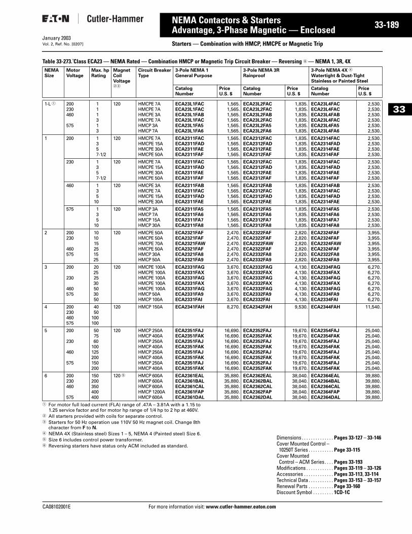
CA08102001E For more
89
33-1NEMA Contactors & StartersAdvantage, 3-Phase Magnetic — Enclosed Starters — Combination with HMCP, HMCPE or Magnetic TripJanuary 2003Vol. 2, Ref. No. [0207]
33
Table 33-273. Class ECA23 — NEMA Rated — Combination HMCP or Magnetic Trip Circuit Breaker — Reversing 6 — NEMA 1, 3R, 4X
1 For motor full load current (FLA) range of .47A – 3.81A with a 1.15 to 1.25 service factor and for motor hp range of 1/4 hp to 2 hp at 460V.
2 All starters provided with coils for separate control.3 Starters for 50 Hz operation use 110V 50 Hz magnet coil. Change 8th
character from F to N.4 NEMA 4X (Stainless steel) Sizes 1 – 5, NEMA 4 (Painted steel) Size 6.5 Size 6 includes control power transformer. 6 Reversing starters have status only ACM included as standard.
NEMASize
MotorVoltage
Max. hpRating
MagnetCoilVoltage23
Circuit BreakerType
3-Pole NEMA 1General Purpose
3-Pole NEMA 3RRainproof
3-Pole NEMA 4X 4
Watertight & Dust-TightStainless or Painted Steel
CatalogNumber
PriceU.S. $
CatalogNumber
PriceU.S. $
CatalogNumber
PriceU.S. $
1-L 1 200230460
575
111313
120 HMCPE 7AHMCPE 7AHMCPE 3AHMCPE 7AHMCP 3AHMCP 7A
ECA23L1FACECA23L1FACECA23L1FABECA23L1FACECA23L1FA5ECA23L1FA6
1,565.1,565.1,565.1,565.1,565.1,565.
ECA23L2FACECA23L2FACECA23L2FABECA23L2FACECA23L2FA5ECA23L2FA6
1,835.1,835.1,835.1,835.1,835.1,835.
ECA23L4FACECA23L4FACECA23L4FABECA23L4FACECA23L4FA5ECA23L4FA6
2,530.2,530.2,530.2,530.2,530.2,530.
1 200 1357-1/2
120 HMCPE 7AHMCPE 15AHMCPE 30AHMCPE 50A
ECA2311FACECA2311FADECA2311FAEECA2311FAF
1,565.1,565.1,565.1,565.
ECA2312FACECA2312FADECA2312FAEECA2312FAF
1,835.1,835.1,835.1,835.
ECA2314FACECA2314FADECA2314FAEECA2314FAF
2,530.2,530.2,530.2,530.
230 1357-1/2
120 HMCPE 7AHMCPE 15AHMCPE 30AHMCPE 50A
ECA2311FACECA2311FADECA2311FAEECA2311FAF
1,565.1,565.1,565.1,565.
ECA2312FACECA2312FADECA2312FAEECA2312FAF
1,835.1,835.1,835.1,835.
ECA2314FACECA2314FADECA2314FAEECA2314FAF
2,530.2,530.2,530.2,530.
460 135
10
120 HMCPE 3AHMCPE 7AHMCPE 15AHMCPE 30A
ECA2311FABECA2311FACECA2311FADECA2311FAE
1,565.1,565.1,565.1,565.
ECA2312FABECA2312FACECA2312FADECA2312FAE
1,835.1,835.1,835.1,835.
ECA2314FABECA2314FACECA2314FADECA2314FAE
2,530.2,530.2,530.2,530.
575 135
10
120 HMCP 3AHMCP 7AHMCP 15AHMCP 30A
ECA2311FA5ECA2311FA6ECA2311FA7ECA2311FA8
1,565.1,565.1,565.1,565.
ECA2312FA5ECA2312FA6ECA2312FA7ECA2312FA8
1,835.1,835.1,835.1,835.
ECA2314FA5ECA2314FA6ECA2314FA7ECA2314FA8
2,530.2,530.2,530.2,530.
2 200230
460575
101015251525
120 HMCPE 50AHMCPE 50AHMCPE 70AHMCPE 50AHMCP 30AHMCP 50A
ECA2321FAFECA2321FAFECA2321FAWECA2321FAFECA2321FA8ECA2321FA9
2,470.2,470.2,470.2,470.2,470.2,470.
ECA2322FAFECA2322FAFECA2322FAWECA2322FAFECA2332FA8ECA2332FA9
2,820.2,820.2,820.2,820.2,820.2,820.
ECA2324FAFECA2324FAFECA2324FAWECA2324FAFECA2322FA8ECA2324FA9
3,955.3,955.3,955.3,955.3,955.3,955.
3 200
230
460575
20252530503050
120 HMCPE 100AHMCPE 100AHMCPE 100AHMCPE 100AHMCPE 100AHMCP 50AHMCP 100A
ECA2331FAGECA2331FAXECA2331FAGECA2331FAXECA2331FAGECA2331FA9ECA2331FAI
3,670.3,670.3,670.3,670.3,670.3,670.3,670.
ECA2332FAGECA2332FAXECA2332FAGECA2332FAXECA2332FAGECA2332FA9ECA2332FAI
4,130.4,130.4,130.4,130.4,130.4,130.4,130.
ECA2334FAGECA2334FAXECA2334FAGECA2334FAXECA2334FAGECA2334FA9ECA2334FAI
6,270.6,270.6,270.6,270.6,270.6,270.6,270.
4 200230460575
4050
100100
120 HMCP 150A ECA2341FAH 8,270. ECA2342FAH 9,530. ECA2344FAH 11,540.
5 200
230
460
575
507560
100125200150200
120 HMCP 250AHMCP 400AHMCP 250AHMCP 400AHMCP 250AHMCP 400AHMCP 250AHMCP 400A
ECA2351FAJECA2351FAKECA2351FAJECA2351FAKECA2351FAJECA2351FAKECA2351FAJECA2351FAK
16,690.16,690.16,690.16,690.16,690.16,690.16,690.16,690.
ECA2352FAJECA2352FAKECA2352FAJECA2352FAKECA2352FAJECA2352FAKECA2352FAJECA2352FAK
19,670.19,670.19,670.19,670.19,670.19,670.19,670.19,670.
ECA2354FAJECA2354FAKECA2354FAJECA2354FAKECA2354FAJECA2354FAKECA2354FAJECA2354FAK
25,040.25,040.25,040.25,040.25,040.25,040.25,040.25,040.
6 200230460
575
150200350400400
120 5 HMCP 600AHMCP 600AHMCP 600AHMCP 1200AHMCP 600A
ECA2361EALECA2361BALECA2361CALECA2361FAPECA2361DAL
35,880.35,880.35,880.35,880.35,880.
ECA2362EALECA2362BALECA2362CALECA2362FAPECA2362DAL
38,040.38,040.38,040.38,040.38,040.
ECA2364EALECA2364BALECA2364CALECA2364FAPECA2364DAL
39,880.39,880.39,880.39,880.39,880.
Dimensions . . . . . . . . . . . . . . Pages 33-127 – 33-146Cover Mounted Control – 10250T Series . . . . . . . . . . . Page 33-115
Cover Mounted Control – ACM Series. . . . Pages 33-193
Modifications . . . . . . . . . . . . Pages 33-119 – 33-126Accessories . . . . . . . . . . . . . Pages 33-113, 33-114Technical Data . . . . . . . . . . . Pages 33-153 – 33-157Renewal Parts . . . . . . . . . . . Page 33-160Discount Symbol . . . . . . . . . 1CD-1C
information visit: www.cutler-hammer.eaton.com
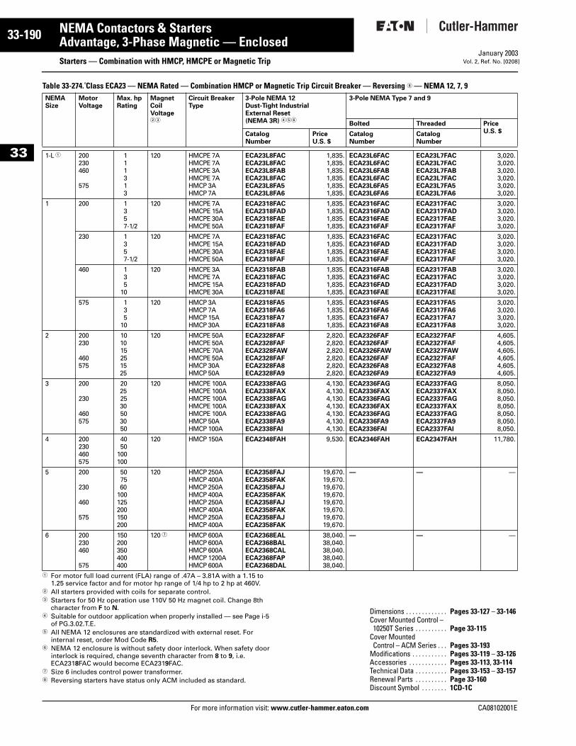
33-190
33
NEMA Contactors & StartersAdvantage, 3-Phase Magnetic — Enclosed
Starters — Combination with HMCP, HMCPE or Magnetic TripFor more information visit: www.cutler-hammer.eaton.com
January 2003Vol. 2, Ref. No. [0208]
Table 33-274. Class ECA23 — NEMA Rated — Combination HMCP or Magnetic Trip Circuit Breaker — Reversing 8 — NEMA 12, 7, 9
1 For motor full load current (FLA) range of .47A – 3.81A with a 1.15 to 1.25 service factor and for motor hp range of 1/4 hp to 2 hp at 460V.
2 All starters provided with coils for separate control.3 Starters for 50 Hz operation use 110V 50 Hz magnet coil. Change 8th
character from F to N.4 Suitable for outdoor application when properly installed — see Page i-5
of PG.3.02.T.E.5 All NEMA 12 enclosures are standardized with external reset. For
internal reset, order Mod Code R5.6 NEMA 12 enclosure is without safety door interlock. When safety door
interlock is required, change seventh character from 8 to 9, i.e. ECA2318FAC would become ECA2319FAC.
7 Size 6 includes control power transformer.8 Reversing starters have status only ACM included as standard.
NEMASize
MotorVoltage
Max. hpRating
MagnetCoilVoltage23
Circuit BreakerType
3-Pole NEMA 12Dust-Tight IndustrialExternal Reset (NEMA 3R) 456
3-Pole NEMA Type 7 and 9
Bolted Threaded PriceU.S. $Catalog
NumberPriceU.S. $
CatalogNumber
CatalogNumber
1-L 1 200230460
575
111313
120 HMCPE 7AHMCPE 7AHMCPE 3AHMCPE 7AHMCP 3AHMCP 7A
ECA23L8FACECA23L8FACECA23L8FABECA23L8FACECA23L8FA5ECA23L8FA6
1,835.1,835.1,835.1,835.1,835.1,835.
ECA23L6FACECA23L6FACECA23L6FABECA23L6FACECA23L6FA5ECA23L6FA6
ECA23L7FACECA23L7FACECA23L7FABECA23L7FACECA23L7FA5ECA23L7FA6
3,020.3,020.3,020.3,020.3,020.3,020.
1 200 1357-1/2
120 HMCPE 7AHMCPE 15AHMCPE 30AHMCPE 50A
ECA2318FACECA2318FADECA2318FAEECA2318FAF
1,835.1,835.1,835.1,835.
ECA2316FACECA2316FADECA2316FAEECA2316FAF
ECA2317FACECA2317FADECA2317FAEECA2317FAF
3,020.3,020.3,020.3,020.
230 1357-1/2
120 HMCPE 7AHMCPE 15AHMCPE 30AHMCPE 50A
ECA2318FACECA2318FADECA2318FAEECA2318FAF
1,835.1,835.1,835.1,835.
ECA2316FACECA2316FADECA2316FAEECA2316FAF
ECA2317FACECA2317FADECA2317FAEECA2317FAF
3,020.3,020.3,020.3,020.
460 135
10
120 HMCPE 3AHMCPE 7AHMCPE 15AHMCPE 30A
ECA2318FABECA2318FACECA2318FADECA2318FAE
1,835.1,835.1,835.1,835.
ECA2316FABECA2316FACECA2316FADECA2316FAE
ECA2317FABECA2317FACECA2317FADECA2317FAE
3,020.3,020.3,020.3,020.
575 135
10
120 HMCP 3AHMCP 7AHMCP 15AHMCP 30A
ECA2318FA5ECA2318FA6ECA2318FA7ECA2318FA8
1,835.1,835.1,835.1,835.
ECA2316FA5ECA2316FA6ECA2316FA7ECA2316FA8
ECA2317FA5ECA2317FA6ECA2317FA7ECA2317FA8
3,020.3,020.3,020.3,020.
2 200230
460575
101015251525
120 HMCPE 50AHMCPE 50AHMCPE 70AHMCPE 50AHMCP 30AHMCP 50A
ECA2328FAFECA2328FAFECA2328FAWECA2328FAFECA2328FA8ECA2328FA9
2,820.2,820.2,820.2,820.2,820.2,820.
ECA2326FAFECA2326FAFECA2326FAWECA2326FAFECA2326FA8ECA2326FA9
ECA2327FAFECA2327FAFECA2327FAWECA2327FAFECA2327FA8ECA2327FA9
4,605.4,605.4,605.4,605.4,605.4,605.
3 200
230
460575
20252530503050
120 HMCPE 100AHMCPE 100AHMCPE 100AHMCPE 100AHMCPE 100AHMCP 50AHMCP 100A
ECA2338FAGECA2338FAXECA2338FAGECA2338FAXECA2338FAGECA2338FA9ECA2338FAI
4,130.4,130.4,130.4,130.4,130.4,130.4,130.
ECA2336FAGECA2336FAXECA2336FAGECA2336FAXECA2336FAGECA2336FA9ECA2336FAI
ECA2337FAGECA2337FAXECA2337FAGECA2337FAXECA2337FAGECA2337FA9ECA2337FAI
8,050.8,050.8,050.8,050.8,050.8,050.8,050.
4 200230460575
4050
100100
120 HMCP 150A ECA2348FAH 9,530. ECA2346FAH ECA2347FAH 11,780.
5 200
230
460
575
507560
100125200150200
120 HMCP 250AHMCP 400AHMCP 250AHMCP 400AHMCP 250AHMCP 400AHMCP 250AHMCP 400A
ECA2358FAJECA2358FAKECA2358FAJECA2358FAKECA2358FAJECA2358FAKECA2358FAJECA2358FAK
19,670.19,670.19,670.19,670.19,670.19,670.19,670.19,670.
— — —
6 200230460
575
150200350400400
120 7 HMCP 600AHMCP 600AHMCP 600AHMCP 1200AHMCP 600A
ECA2368EALECA2368BALECA2368CALECA2368FAPECA2368DAL
38,040.38,040.38,040.38,040.38,040.
— — —
Dimensions . . . . . . . . . . . . . Pages 33-127 – 33-146Cover Mounted Control – 10250T Series . . . . . . . . . . Page 33-115
Cover Mounted Control – ACM Series . . . Pages 33-193
Modifications . . . . . . . . . . . Pages 33-119 – 33-126Accessories . . . . . . . . . . . . Pages 33-113, 33-114Technical Data . . . . . . . . . . Pages 33-153 – 33-157Renewal Parts . . . . . . . . . . Page 33-160Discount Symbol . . . . . . . . 1CD-1C
CA08102001E
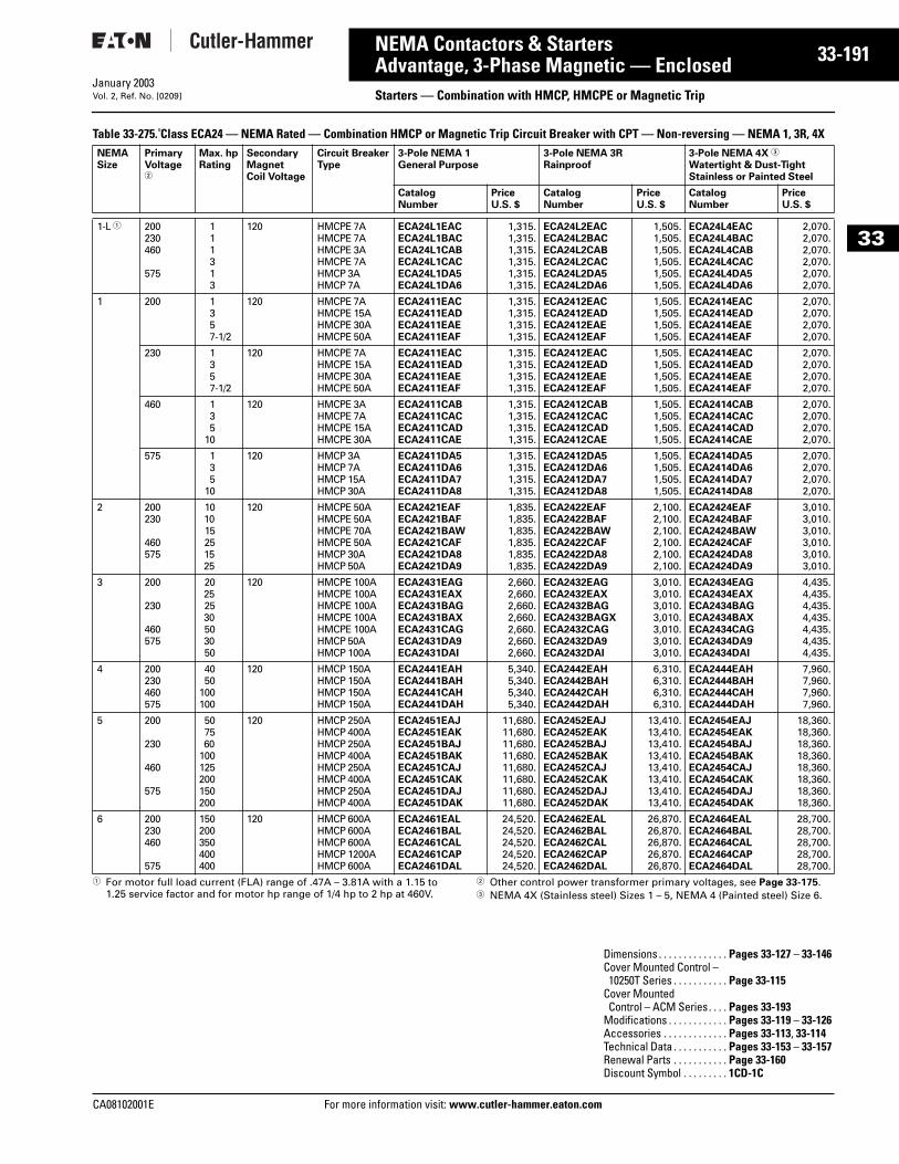
CA08102001E For more
91
33-1NEMA Contactors & StartersAdvantage, 3-Phase Magnetic — Enclosed Starters — Combination with HMCP, HMCPE or Magnetic TripJanuary 2003Vol. 2, Ref. No. [0209]
33
Table 33-275. Class ECA24 — NEMA Rated — Combination HMCP or Magnetic Trip Circuit Breaker with CPT — Non-reversing — NEMA 1, 3R, 4X
1 For motor full load current (FLA) range of .47A – 3.81A with a 1.15 to 1.25 service factor and for motor hp range of 1/4 hp to 2 hp at 460V.
2 Other control power transformer primary voltages, see Page 33-175.3 NEMA 4X (Stainless steel) Sizes 1 – 5, NEMA 4 (Painted steel) Size 6.
NEMASize
PrimaryVoltage2
Max. hpRating
Secondary MagnetCoil Voltage
Circuit BreakerType
3-Pole NEMA 1General Purpose
3-Pole NEMA 3RRainproof
3-Pole NEMA 4X 3
Watertight & Dust-TightStainless or Painted Steel
CatalogNumber
PriceU.S. $
CatalogNumber
PriceU.S. $
CatalogNumber
PriceU.S. $
1-L 1 200230460
575
111313
120 HMCPE 7AHMCPE 7AHMCPE 3AHMCPE 7AHMCP 3AHMCP 7A
ECA24L1EACECA24L1BACECA24L1CABECA24L1CACECA24L1DA5ECA24L1DA6
1,315.1,315.1,315.1,315.1,315.1,315.
ECA24L2EACECA24L2BACECA24L2CABECA24L2CACECA24L2DA5ECA24L2DA6
1,505.1,505.1,505.1,505.1,505.1,505.
ECA24L4EACECA24L4BACECA24L4CABECA24L4CACECA24L4DA5ECA24L4DA6
2,070.2,070.2,070.2,070.2,070.2,070.
1 200 1357-1/2
120 HMCPE 7AHMCPE 15AHMCPE 30AHMCPE 50A
ECA2411EACECA2411EADECA2411EAEECA2411EAF
1,315.1,315.1,315.1,315.
ECA2412EACECA2412EADECA2412EAEECA2412EAF
1,505.1,505.1,505.1,505.
ECA2414EACECA2414EADECA2414EAEECA2414EAF
2,070.2,070.2,070.2,070.
230 1357-1/2
120 HMCPE 7AHMCPE 15AHMCPE 30AHMCPE 50A
ECA2411EACECA2411EADECA2411EAEECA2411EAF
1,315.1,315.1,315.1,315.
ECA2412EACECA2412EADECA2412EAEECA2412EAF
1,505.1,505.1,505.1,505.
ECA2414EACECA2414EADECA2414EAEECA2414EAF
2,070.2,070.2,070.2,070.
460 135
10
120 HMCPE 3AHMCPE 7AHMCPE 15AHMCPE 30A
ECA2411CABECA2411CACECA2411CADECA2411CAE
1,315.1,315.1,315.1,315.
ECA2412CABECA2412CACECA2412CADECA2412CAE
1,505.1,505.1,505.1,505.
ECA2414CABECA2414CACECA2414CADECA2414CAE
2,070.2,070.2,070.2,070.
575 135
10
120 HMCP 3AHMCP 7AHMCP 15AHMCP 30A
ECA2411DA5ECA2411DA6ECA2411DA7ECA2411DA8
1,315.1,315.1,315.1,315.
ECA2412DA5ECA2412DA6ECA2412DA7ECA2412DA8
1,505.1,505.1,505.1,505.
ECA2414DA5ECA2414DA6ECA2414DA7ECA2414DA8
2,070.2,070.2,070.2,070.
2 200230
460575
101015251525
120 HMCPE 50AHMCPE 50AHMCPE 70AHMCPE 50AHMCP 30AHMCP 50A
ECA2421EAFECA2421BAFECA2421BAWECA2421CAFECA2421DA8ECA2421DA9
1,835.1,835.1,835.1,835.1,835.1,835.
ECA2422EAFECA2422BAFECA2422BAWECA2422CAFECA2422DA8ECA2422DA9
2,100.2,100.2,100.2,100.2,100.2,100.
ECA2424EAFECA2424BAFECA2424BAWECA2424CAFECA2424DA8ECA2424DA9
3,010.3,010.3,010.3,010.3,010.3,010.
3 200
230
460575
20252530503050
120 HMCPE 100AHMCPE 100AHMCPE 100AHMCPE 100AHMCPE 100AHMCP 50AHMCP 100A
ECA2431EAGECA2431EAXECA2431BAGECA2431BAXECA2431CAGECA2431DA9ECA2431DAI
2,660.2,660.2,660.2,660.2,660.2,660.2,660.
ECA2432EAGECA2432EAXECA2432BAGECA2432BAGXECA2432CAGECA2432DA9ECA2432DAI
3,010.3,010.3,010.3,010.3,010.3,010.3,010.
ECA2434EAGECA2434EAXECA2434BAGECA2434BAXECA2434CAGECA2434DA9ECA2434DAI
4,435.4,435.4,435.4,435.4,435.4,435.4,435.
4 200230460575
4050
100100
120 HMCP 150AHMCP 150AHMCP 150AHMCP 150A
ECA2441EAHECA2441BAHECA2441CAHECA2441DAH
5,340.5,340.5,340.5,340.
ECA2442EAHECA2442BAHECA2442CAHECA2442DAH
6,310.6,310.6,310.6,310.
ECA2444EAHECA2444BAHECA2444CAHECA2444DAH
7,960.7,960.7,960.7,960.
5 200
230
460
575
507560
100125200150200
120 HMCP 250AHMCP 400AHMCP 250AHMCP 400AHMCP 250AHMCP 400AHMCP 250AHMCP 400A
ECA2451EAJECA2451EAKECA2451BAJECA2451BAKECA2451CAJECA2451CAKECA2451DAJECA2451DAK
11,680.11,680.11,680.11,680.11,680.11,680.11,680.11,680.
ECA2452EAJECA2452EAKECA2452BAJECA2452BAKECA2452CAJECA2452CAKECA2452DAJECA2452DAK
13,410.13,410.13,410.13,410.13,410.13,410.13,410.13,410.
ECA2454EAJECA2454EAKECA2454BAJECA2454BAKECA2454CAJECA2454CAKECA2454DAJECA2454DAK
18,360.18,360.18,360.18,360.18,360.18,360.18,360.18,360.
6 200230460
575
150200350400400
120 HMCP 600AHMCP 600AHMCP 600AHMCP 1200AHMCP 600A
ECA2461EALECA2461BALECA2461CALECA2461CAPECA2461DAL
24,520.24,520.24,520.24,520.24,520.
ECA2462EALECA2462BALECA2462CALECA2462CAPECA2462DAL
26,870.26,870.26,870.26,870.26,870.
ECA2464EALECA2464BALECA2464CALECA2464CAPECA2464DAL
28,700.28,700.28,700.28,700.28,700.
Dimensions . . . . . . . . . . . . . . Pages 33-127 – 33-146Cover Mounted Control – 10250T Series . . . . . . . . . . . Page 33-115
Cover Mounted Control – ACM Series. . . . Pages 33-193
Modifications . . . . . . . . . . . . Pages 33-119 – 33-126Accessories . . . . . . . . . . . . . Pages 33-113, 33-114Technical Data . . . . . . . . . . . Pages 33-153 – 33-157Renewal Parts . . . . . . . . . . . Page 33-160Discount Symbol . . . . . . . . . 1CD-1C
information visit: www.cutler-hammer.eaton.com
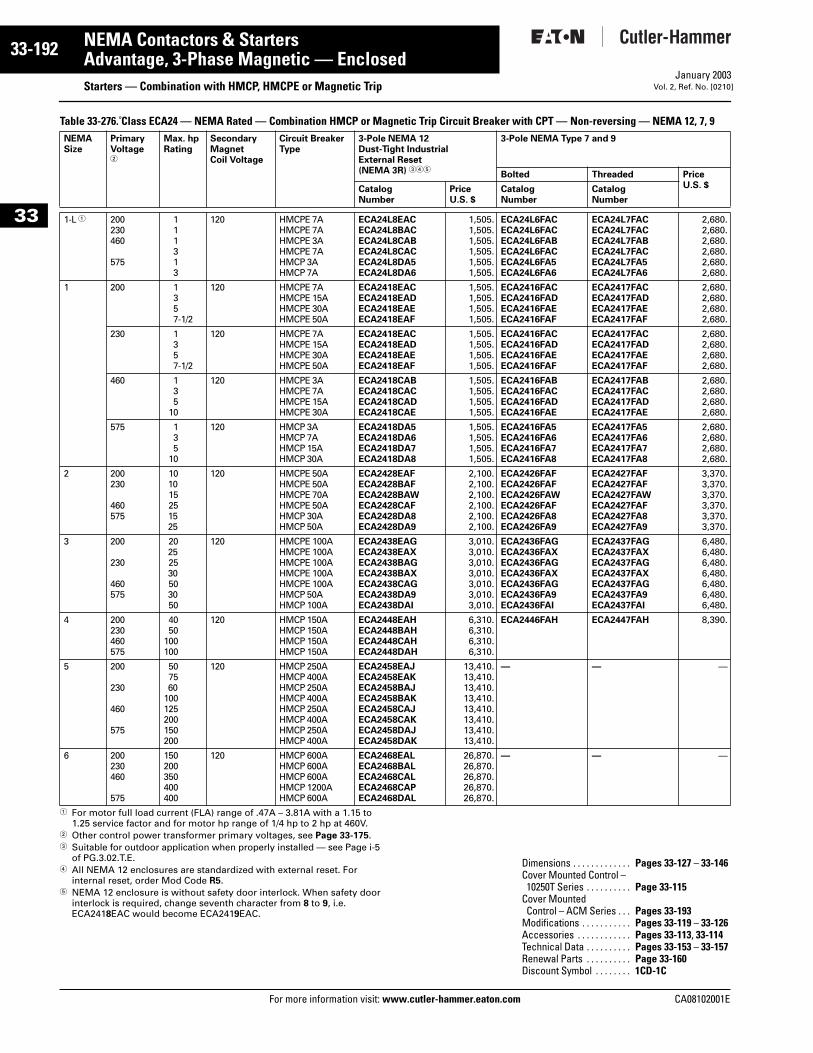
33-192
33
NEMA Contactors & StartersAdvantage, 3-Phase Magnetic — Enclosed
Starters — Combination with HMCP, HMCPE or Magnetic TripFor more information visit: www.cutler-hammer.eaton.com
January 2003Vol. 2, Ref. No. [0210]
Table 33-276. Class ECA24 — NEMA Rated — Combination HMCP or Magnetic Trip Circuit Breaker with CPT — Non-reversing — NEMA 12, 7, 9
1 For motor full load current (FLA) range of .47A – 3.81A with a 1.15 to 1.25 service factor and for motor hp range of 1/4 hp to 2 hp at 460V.
2 Other control power transformer primary voltages, see Page 33-175.3 Suitable for outdoor application when properly installed — see Page i-5
of PG.3.02.T.E.4 All NEMA 12 enclosures are standardized with external reset. For
internal reset, order Mod Code R5.5 NEMA 12 enclosure is without safety door interlock. When safety door
interlock is required, change seventh character from 8 to 9, i.e. ECA2418EAC would become ECA2419EAC.
NEMASize
PrimaryVoltage2
Max. hpRating
Secondary MagnetCoil Voltage
Circuit BreakerType
3-Pole NEMA 12Dust-Tight IndustrialExternal Reset (NEMA 3R) 345
3-Pole NEMA Type 7 and 9
Bolted Threaded PriceU.S. $Catalog
NumberPriceU.S. $
CatalogNumber
CatalogNumber
1-L 1 200230460
575
111313
120 HMCPE 7AHMCPE 7AHMCPE 3AHMCPE 7AHMCP 3AHMCP 7A
ECA24L8EACECA24L8BACECA24L8CABECA24L8CACECA24L8DA5ECA24L8DA6
1,505.1,505.1,505.1,505.1,505.1,505.
ECA24L6FACECA24L6FACECA24L6FABECA24L6FACECA24L6FA5ECA24L6FA6
ECA24L7FACECA24L7FACECA24L7FABECA24L7FACECA24L7FA5ECA24L7FA6
2,680.2,680.2,680.2,680.2,680.2,680.
1 200 1357-1/2
120 HMCPE 7AHMCPE 15AHMCPE 30AHMCPE 50A
ECA2418EACECA2418EADECA2418EAEECA2418EAF
1,505.1,505.1,505.1,505.
ECA2416FACECA2416FADECA2416FAEECA2416FAF
ECA2417FACECA2417FADECA2417FAEECA2417FAF
2,680.2,680.2,680.2,680.
230 1357-1/2
120 HMCPE 7AHMCPE 15AHMCPE 30AHMCPE 50A
ECA2418EACECA2418EADECA2418EAEECA2418EAF
1,505.1,505.1,505.1,505.
ECA2416FACECA2416FADECA2416FAEECA2416FAF
ECA2417FACECA2417FADECA2417FAEECA2417FAF
2,680.2,680.2,680.2,680.
460 135
10
120 HMCPE 3AHMCPE 7AHMCPE 15AHMCPE 30A
ECA2418CABECA2418CACECA2418CADECA2418CAE
1,505.1,505.1,505.1,505.
ECA2416FABECA2416FACECA2416FADECA2416FAE
ECA2417FABECA2417FACECA2417FADECA2417FAE
2,680.2,680.2,680.2,680.
575 135
10
120 HMCP 3AHMCP 7AHMCP 15AHMCP 30A
ECA2418DA5ECA2418DA6ECA2418DA7ECA2418DA8
1,505.1,505.1,505.1,505.
ECA2416FA5ECA2416FA6ECA2416FA7ECA2416FA8
ECA2417FA5ECA2417FA6ECA2417FA7ECA2417FA8
2,680.2,680.2,680.2,680.
2 200230
460575
101015251525
120 HMCPE 50AHMCPE 50AHMCPE 70AHMCPE 50AHMCP 30AHMCP 50A
ECA2428EAFECA2428BAFECA2428BAWECA2428CAFECA2428DA8ECA2428DA9
2,100.2,100.2,100.2,100.2,100.2,100.
ECA2426FAFECA2426FAFECA2426FAWECA2426FAFECA2426FA8ECA2426FA9
ECA2427FAFECA2427FAFECA2427FAWECA2427FAFECA2427FA8ECA2427FA9
3,370.3,370.3,370.3,370.3,370.3,370.
3 200
230
460575
20252530503050
120 HMCPE 100AHMCPE 100AHMCPE 100AHMCPE 100AHMCPE 100AHMCP 50AHMCP 100A
ECA2438EAGECA2438EAXECA2438BAGECA2438BAXECA2438CAGECA2438DA9ECA2438DAI
3,010.3,010.3,010.3,010.3,010.3,010.3,010.
ECA2436FAGECA2436FAXECA2436FAGECA2436FAXECA2436FAGECA2436FA9ECA2436FAI
ECA2437FAGECA2437FAXECA2437FAGECA2437FAXECA2437FAGECA2437FA9ECA2437FAI
6,480.6,480.6,480.6,480.6,480.6,480.6,480.
4 200230460575
4050
100100
120 HMCP 150AHMCP 150AHMCP 150AHMCP 150A
ECA2448EAHECA2448BAHECA2448CAHECA2448DAH
6,310.6,310.6,310.6,310.
ECA2446FAH ECA2447FAH 8,390.
5 200
230
460
575
507560
100125200150200
120 HMCP 250AHMCP 400AHMCP 250AHMCP 400AHMCP 250AHMCP 400AHMCP 250AHMCP 400A
ECA2458EAJECA2458EAKECA2458BAJECA2458BAKECA2458CAJECA2458CAKECA2458DAJECA2458DAK
13,410.13,410.13,410.13,410.13,410.13,410.13,410.13,410.
— — —
6 200230460
575
150200350400400
120 HMCP 600AHMCP 600AHMCP 600AHMCP 1200AHMCP 600A
ECA2468EALECA2468BALECA2468CALECA2468CAPECA2468DAL
26,870.26,870.26,870.26,870.26,870.
— — —
Dimensions . . . . . . . . . . . . . Pages 33-127 – 33-146Cover Mounted Control – 10250T Series . . . . . . . . . . Page 33-115
Cover Mounted Control – ACM Series . . . Pages 33-193
Modifications . . . . . . . . . . . Pages 33-119 – 33-126Accessories . . . . . . . . . . . . Pages 33-113, 33-114Technical Data . . . . . . . . . . Pages 33-153 – 33-157Renewal Parts . . . . . . . . . . Page 33-160Discount Symbol . . . . . . . . 1CD-1C
CA08102001E
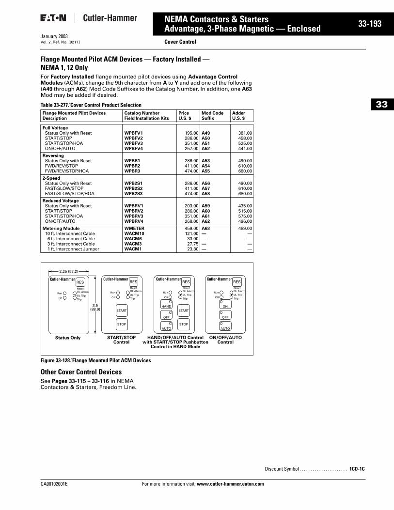
CA08102001E For more
93
33-1NEMA Contactors & StartersAdvantage, 3-Phase Magnetic — Enclosed Cover ControlJanuary 2003Vol. 2, Ref. No. [0211]
33
Flange Mounted Pilot ACM Devices — Factory Installed — NEMA 1, 12 OnlyFor Factory Installed flange mounted pilot devices using Advantage Control Modules (ACMs), change the 9th character from A to Y and add one of the following (A49 through A62) Mod Code Suffixes to the Catalog Number. In addition, one A63 Mod may be added if desired.
Table 33-277. Cover Control Product Selection
Figure 33-128. Flange Mounted Pilot ACM Devices
Other Cover Control DevicesSee Pages 33-115 – 33-116 in NEMA Contactors & Starters, Freedom Line.
Flange Mounted Pilot DevicesDescription
Catalog NumberField Installation Kits
PriceU.S. $
Mod CodeSuffix
AdderU.S. $
Full VoltageStatus Only with ResetSTART/STOPSTART/STOP/HOAON/OFF/AUTO
WPBFV1WPBFV2WPBFV3WPBFV4
195.00286.00351.00257.00
A49A50A51A52
381.00458.00525.00441.00
ReversingStatus Only with ResetFWD/REV/STOPFWD/REV/STOP/HOA
WPBR1WPBR2WPBR3
286.00411.00474.00
A53A54A55
490.00610.00680.00
2-SpeedStatus Only with ResetFAST/SLOW/STOPFAST/SLOW/STOP/HOA
WPB2S1WPB2S2WPB2S3
286.00411.00474.00
A56A57A58
490.00610.00680.00
Reduced VoltageStatus Only with ResetSTART/STOPSTART/STOP/HOAON/OFF/AUTO
WPBRV1WPBRV2WPBRV3WPBRV4
203.00286.00351.00268.00
A59A60A61A62
435.00515.00575.00496.00
Metering Module10 ft. Interconnect Cable6 ft. Interconnect Cable3 ft. Interconnect Cable1 ft. Interconnect Jumper
WMETERWACM10WACM6WACM3WACM1
459.00121.0033.0027.7523.30
A63————
489.00————
OL Alarm
TripOL Trip
OL Alarm
TripOL Trip
OL Alarm
TripOL Trip
RES
Reset
Run
Off
OL Alarm
TripOL Trip
RESReset
RESReset
RESReset
Run
Off
Run
HANDSTART
STOP
START
STOP
OFF
AUTO
ON
OFF
AUTO
Off
Run
Off
Status Only START/STOPControl
HAND/OFF/AUTO Controlwith START/STOP Pushbutton
Control in HAND Mode
ON/OFF/AUTOControl
3.5(88.9)
2.25 (57.2)
information visit: www.cutler-hammer.eaton.co
Discount Symbol . . . . . . . . . . . . . . . . . . . . . . 1CD-1C
m
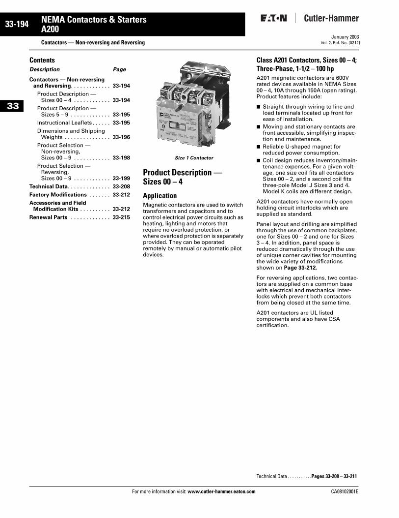
33-194
33
NEMA Contactors & StartersA200
Contactors — Non-reversing and ReversingFor more information visit: www.cutler-hammer.eaton.com
January 2003Vol. 2, Ref. No. [0212]
ContentsDescription Page
Contactors — Non-reversingand Reversing. . . . . . . . . . . . . 33-194
Product Description — Sizes 00 – 4 . . . . . . . . . . . . 33-194
Product Description — Sizes 5 – 9 . . . . . . . . . . . . . 33-195
Instructional Leaflets . . . . . . 33-195
Dimensions and Shipping Weights . . . . . . . . . . . . . . . 33-196
Product Selection — Non-reversing, Sizes 00 – 9 . . . . . . . . . . . . 33-198
Product Selection — Reversing, Sizes 00 – 9 . . . . . . . . . . . . 33-199
Technical Data. . . . . . . . . . . . . . 33-208
Factory Modifications . . . . . . . 33-212
Accessories and Field Modification Kits . . . . . . . . . . 33-212
Renewal Parts . . . . . . . . . . . . . 33-215
Size 1 Contactor
Product Description — Sizes 00 – 4
ApplicationMagnetic contactors are used to switch transformers and capacitors and to control electrical power circuits such as heating, lighting and motors that require no overload protection, or where overload protection is separately provided. They can be operated remotely by manual or automatic pilot devices.
Class A201 Contactors, Sizes 00 – 4; Three-Phase, 1-1/2 – 100 hpA201 magnetic contactors are 600V rated devices available in NEMA Sizes 00 – 4, 10A through 150A (open rating). Product features include:
■ Straight-through wiring to line and load terminals located up front for ease of installation.
■ Moving and stationary contacts are front accessible, simplifying inspec-tion and maintenance.
■ Reliable U-shaped magnet for reduced power consumption.
■ Coil design reduces inventory/main-tenance expenses. For a given volt-age, one size coil fits all contactors Sizes 00 – 2, and a second coil fits three-pole Model J Sizes 3 and 4. Model K coils are different design.
A201 contactors have normally open holding circuit interlocks which are supplied as standard.
Panel layout and drilling are simplified through the use of common backplates, one for Sizes 00 – 2 and one for Sizes 3 – 4. In addition, panel space is reduced dramatically through the use of unique corner cavities for mounting the wide variety of modifications shown on Page 33-212.
For reversing applications, two contac-tors are supplied on a common base with electrical and mechanical inter-locks which prevent both contactors from being closed at the same time.
A201 contactors are UL listed components and also have CSA certification.
Technical Data . . . . . . . . . . .Pages 33-208 – 33-211
CA08102001E
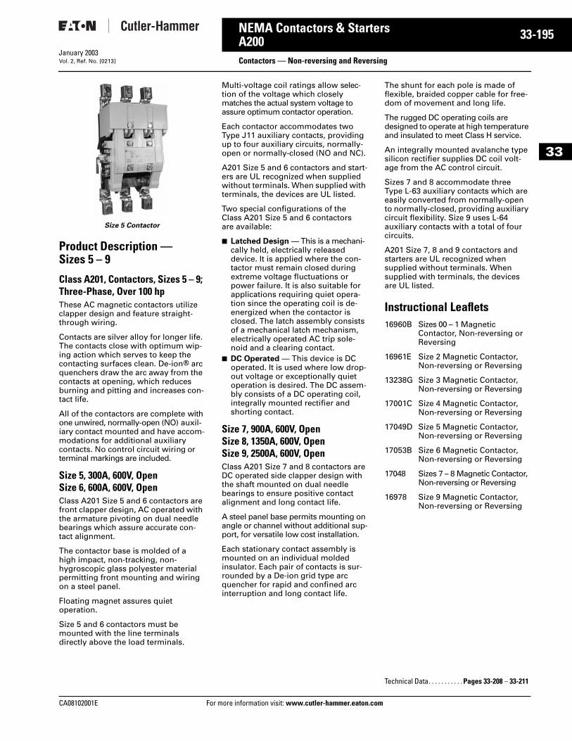
CA08102001E For more
95
33-1NEMA Contactors & StartersA200
Contactors — Non-reversing and ReversingJanuary 2003Vol. 2, Ref. No. [0213]
33
Size 5 Contactor
Product Description — Sizes 5 – 9
Class A201, Contactors, Sizes 5 – 9; Three-Phase, Over 100 hpThese AC magnetic contactors utilize clapper design and feature straight-through wiring.
Contacts are silver alloy for longer life. The contacts close with optimum wip-ing action which serves to keep the contacting surfaces clean. De-ion® arc quenchers draw the arc away from the contacts at opening, which reduces burning and pitting and increases con-tact life.
All of the contactors are complete with one unwired, normally-open (NO) auxil-iary contact mounted and have accom-modations for additional auxiliary contacts. No control circuit wiring or terminal markings are included.
Size 5, 300A, 600V, OpenSize 6, 600A, 600V, OpenClass A201 Size 5 and 6 contactors are front clapper design, AC operated with the armature pivoting on dual needle bearings which assure accurate con-tact alignment.
The contactor base is molded of a high impact, non-tracking, non-hygroscopic glass polyester material permitting front mounting and wiring on a steel panel.
Floating magnet assures quiet operation.
Size 5 and 6 contactors must be mounted with the line terminals directly above the load terminals.
Multi-voltage coil ratings allow selec-tion of the voltage which closely matches the actual system voltage to assure optimum contactor operation.
Each contactor accommodates two Type J11 auxiliary contacts, providing up to four auxiliary circuits, normally-open or normally-closed (NO and NC).
A201 Size 5 and 6 contactors and start-ers are UL recognized when supplied without terminals. When supplied with terminals, the devices are UL listed.
Two special configurations of the Class A201 Size 5 and 6 contactors are available:
■ Latched Design — This is a mechani-cally held, electrically released device. It is applied where the con-tactor must remain closed during extreme voltage fluctuations or power failure. It is also suitable for applications requiring quiet opera-tion since the operating coil is de-energized when the contactor is closed. The latch assembly consists of a mechanical latch mechanism, electrically operated AC trip sole-noid and a clearing contact.
■ DC Operated — This device is DC operated. It is used where low drop-out voltage or exceptionally quiet operation is desired. The DC assem-bly consists of a DC operating coil, integrally mounted rectifier and shorting contact.
Size 7, 900A, 600V, OpenSize 8, 1350A, 600V, OpenSize 9, 2500A, 600V, OpenClass A201 Size 7 and 8 contactors are DC operated side clapper design with the shaft mounted on dual needle bearings to ensure positive contact alignment and long contact life.
A steel panel base permits mounting on angle or channel without additional sup-port, for versatile low cost installation.
Each stationary contact assembly is mounted on an individual molded insulator. Each pair of contacts is sur-rounded by a De-ion grid type arc quencher for rapid and confined arc interruption and long contact life.
The shunt for each pole is made of flexible, braided copper cable for free-dom of movement and long life.
The rugged DC operating coils are designed to operate at high temperature and insulated to meet Class H service.
An integrally mounted avalanche type silicon rectifier supplies DC coil volt-age from the AC control circuit.
Sizes 7 and 8 accommodate three Type L-63 auxiliary contacts which are easily converted from normally-open to normally-closed, providing auxiliary circuit flexibility. Size 9 uses L-64 auxiliary contacts with a total of four circuits.
A201 Size 7, 8 and 9 contactors and starters are UL recognized when supplied without terminals. When supplied with terminals, the devices are UL listed.
Instructional Leaflets16960B Sizes 00 – 1 Magnetic
Contactor, Non-reversing or Reversing
16961E Size 2 Magnetic Contactor, Non-reversing or Reversing
13238G Size 3 Magnetic Contactor, Non-reversing or Reversing
17001C Size 4 Magnetic Contactor, Non-reversing or Reversing
17049D Size 5 Magnetic Contactor, Non-reversing or Reversing
17053B Size 6 Magnetic Contactor, Non-reversing or Reversing
17048 Sizes 7 – 8 Magnetic Contactor, Non-reversing or Reversing
16978 Size 9 Magnetic Contactor, Non-reversing or Reversing
Technical Data. . . . . . . . . . . Pages 33-208 – 33-211
information visit: www.cutler-hammer.eaton.com
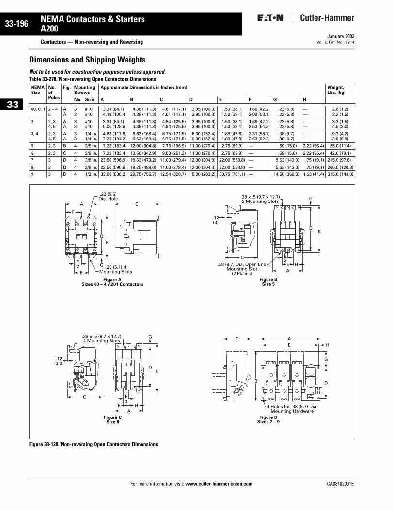
33-196
33
NEMA Contactors & StartersA200
Contactors — Non-reversing and ReversingFor more information visit: www.cutler-hammer.eaton.com
January 2003Vol. 2, Ref. No. [0214]
Dimensions and Shipping WeightsNot to be used for construction purposes unless approved. Table 33-278. Non-reversing Open Contactors Dimensions
Figure 33-129. Non-reversing Open Contactors Dimensions
NEMASize
No.ofPoles
Fig. MountingScrews
Approximate Dimensions in Inches (mm) Weight,Lbs. (kg)
No. Size A B C D E F G H
00, 0, 1 2 – 45
AA
33
#10#10
3.31 (84.1)4.19 (106.4)
4.38 (111.3)4.38 (111.3)
4.61 (117.1)4.61 (117.1)
3.95 (100.3)3.95 (100.3)
1.50 (38.1)1.50 (38.1)
1.66 (42.2)2.09 (53.1)
.23 (5.8)
.23 (5.8)——
2.6 (1.2)3.2 (1.5)
2 2, 34, 5
AA
33
#10#10
3.31 (84.1)5.06 (128.5)
4.38 (111.3)4.38 (111.3)
4.94 (125.5)4.94 (125.5)
3.95 (100.3)3.95 (100.3)
1.50 (38.1)1.50 (38.1)
1.66 (42.2)2.53 (64.3)
.23 (5.8)
.23 (5.8)——
3.3 (1.5)4.5 (2.0)
3, 4 2, 34, 5
AA
33
1/4 in.1/4 in.
4.63 (117.6)7.25 (184.2)
6.63 (168.4)6.63 (168.4)
6.75 (171.5)6.75 (171.5)
6.00 (152.4)6.00 (152.4)
1.88 (47.8)1.88 (47.8)
2.31 (58.7)3.63 (92.2)
.38 (9.7)
.38 (9.7)——
9.3 (4.2)13.0 (5.9)
5 2, 3 B 4 3/8 in. 7.22 (183.4) 12.00 (304.8) 7.75 (196.9) 11.00 (279.4) 2.75 (69.9) — .59 (15.0) 2.22 (56.4) 25.0 (11.4)
6 2, 3 C 4 3/8 in. 7.22 (183.4) 13.50 (342.9) 9.50 (251.3) 11.00 (279.4) 2.75 (69.9) — .59 (15.0) 2.22 (56.4) 42.0 (19.1)
7 3 D 4 3/8 in. 23.50 (596.9) 18.63 (473.2) 11.00 (279.4) 12.00 (304.8) 22.00 (558.8) — 5.63 (143.0) .75 (19.1) 215.0 (97.6)
8 3 D 4 3/8 in. 23.50 (596.9) 19.25 (489.0) 11.00 (279.4) 12.00 (304.8) 22.00 (558.8) — 5.63 (143.0) .75 (19.1) 265.0 (120.3)
9 3 D 4 1/2 in. 33.00 (838.2) 29.75 (755.7) 12.94 (328.7) 8.00 (203.2) 30.75 (781.1) — 14.50 (368.3) 1.63 (41.4) 315.0 (143.0)
A C
E.20 (5.1) 4
Mounting Slots
.22 (5.6)Dia. Hole
E2 G
DB
Figure ASizes 00 – 4 A201 Contactors
F
C
.12(3.0)
.38 x .5 (9.7 x 12.7)2 Mounting Slots
Figure CSize 6
EA
H
BD
G
E2
C
.12(3)
.38 x .5 (9.7 x 12.7)2 Mounting Slots
A
Figure BSize 5
E H
BD
G
E2
.38 (9.7) Dia. Open EndMounting Slot
(2 Places)
C AE H
DB
Figure DSizes 7 – 9
G
4 Holes for .38 (9.7) Dia.Mounting Hardware
CA08102001E
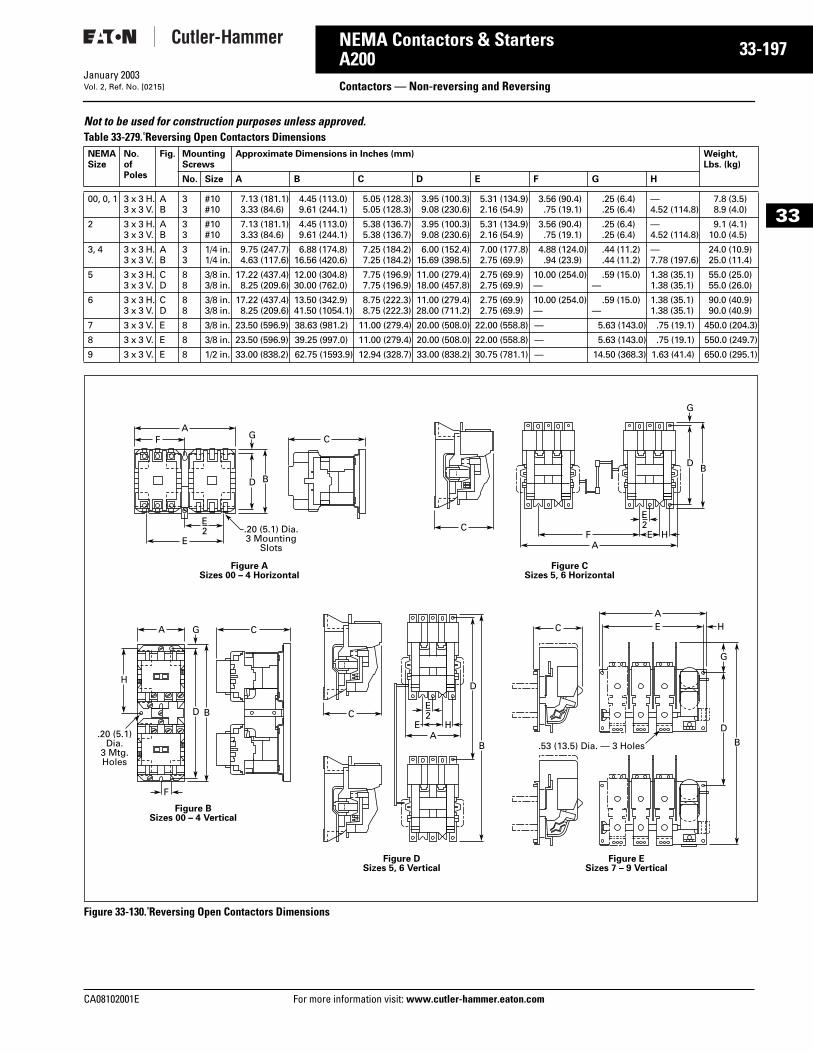
CA08102001E For more
97
33-1NEMA Contactors & StartersA200
Contactors — Non-reversing and ReversingJanuary 2003Vol. 2, Ref. No. [0215]
33
Not to be used for construction purposes unless approved. Table 33-279. Reversing Open Contactors Dimensions
Figure 33-130. Reversing Open Contactors Dimensions
NEMASize
No.ofPoles
Fig. MountingScrews
Approximate Dimensions in Inches (mm) Weight,Lbs. (kg)
No. Size A B C D E F G H
00, 0, 1 3 x 3 H.3 x 3 V.
AB
33
#10#10
7.13 (181.1)3.33 (84.6)
4.45 (113.0)9.61 (244.1)
5.05 (128.3)5.05 (128.3)
3.95 (100.3)9.08 (230.6)
5.31 (134.9)2.16 (54.9)
3.56 (90.4).75 (19.1)
.25 (6.4)
.25 (6.4)—4.52 (114.8)
7.8 (3.5)8.9 (4.0)
2 3 x 3 H.3 x 3 V.
AB
33
#10#10
7.13 (181.1)3.33 (84.6)
4.45 (113.0)9.61 (244.1)
5.38 (136.7)5.38 (136.7)
3.95 (100.3)9.08 (230.6)
5.31 (134.9)2.16 (54.9)
3.56 (90.4).75 (19.1)
.25 (6.4)
.25 (6.4)—4.52 (114.8)
9.1 (4.1)10.0 (4.5)
3, 4 3 x 3 H.3 x 3 V.
AB
33
1/4 in.1/4 in.
9.75 (247.7)4.63 (117.6)
6.88 (174.8)16.56 (420.6)
7.25 (184.2)7.25 (184.2)
6.00 (152.4)15.69 (398.5)
7.00 (177.8)2.75 (69.9)
4.88 (124.0).94 (23.9)
.44 (11.2)
.44 (11.2)—7.78 (197.6)
24.0 (10.9)25.0 (11.4)
5 3 x 3 H.3 x 3 V.
CD
88
3/8 in.3/8 in.
17.22 (437.4)8.25 (209.6)
12.00 (304.8)30.00 (762.0)
7.75 (196.9)7.75 (196.9)
11.00 (279.4)18.00 (457.8)
2.75 (69.9)2.75 (69.9)
10.00 (254.0)—
.59 (15.0)—
1.38 (35.1)1.38 (35.1)
55.0 (25.0)55.0 (26.0)
6 3 x 3 H.3 x 3 V.
CD
88
3/8 in.3/8 in.
17.22 (437.4)8.25 (209.6)
13.50 (342.9)41.50 (1054.1)
8.75 (222.3)8.75 (222.3)
11.00 (279.4)28.00 (711.2)
2.75 (69.9)2.75 (69.9)
10.00 (254.0)—
.59 (15.0)—
1.38 (35.1)1.38 (35.1)
90.0 (40.9)90.0 (40.9)
7 3 x 3 V. E 8 3/8 in. 23.50 (596.9) 38.63 (981.2) 11.00 (279.4) 20.00 (508.0) 22.00 (558.8) — 5.63 (143.0) .75 (19.1) 450.0 (204.3)
8 3 x 3 V. E 8 3/8 in. 23.50 (596.9) 39.25 (997.0) 11.00 (279.4) 20.00 (508.0) 22.00 (558.8) — 5.63 (143.0) .75 (19.1) 550.0 (249.7)
9 3 x 3 V. E 8 1/2 in. 33.00 (838.2) 62.75 (1593.9) 12.94 (328.7) 33.00 (838.2) 30.75 (781.1) — 14.50 (368.3) 1.63 (41.4) 650.0 (295.1)
E
Figure ASizes 00 – 4 Horizontal
Figure CSizes 5, 6 Horizontal
CF E H
A
CA
F
A
F
Figure B Sizes 00 – 4 Vertical
Figure DSizes 5, 6 Vertical
Figure ESizes 7 – 9 Vertical
C
C
BD
G
BD
B
DH
G
BD
G
E2
E2.20 (5.1) Dia.
3 MountingSlots
.20 (5.1)Dia.
3 Mtg.Holes
AE H
E2
C
AE H
D
G
B.53 (13.5) Dia. — 3 Holes
information visit: www.cutler-hammer.eaton.com
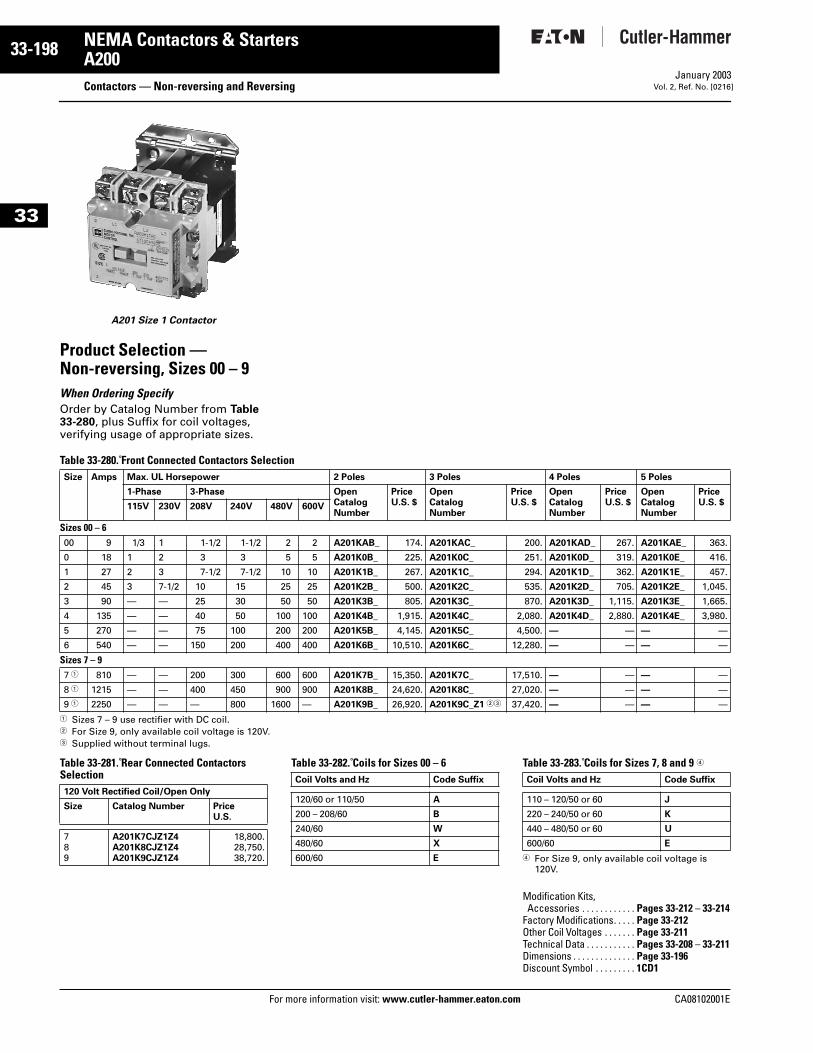
33-198
33
NEMA Contactors & StartersA200
Contactors — Non-reversing and ReversingFor more information visit: www.cutler-hammer.eaton.com
January 2003Vol. 2, Ref. No. [0216]
A201 Size 1 Contactor
Product Selection — Non-reversing, Sizes 00 – 9When Ordering Specify Order by Catalog Number from Table 33-280, plus Suffix for coil voltages, verifying usage of appropriate sizes.
Table 33-280. Front Connected Contactors Selection
1 Sizes 7 – 9 use rectifier with DC coil.2 For Size 9, only available coil voltage is 120V.3 Supplied without terminal lugs.
Table 33-281. Rear Connected Contactors Selection
Table 33-282. Coils for Sizes 00 – 6 Table 33-283. Coils for Sizes 7, 8 and 9 4
4 For Size 9, only available coil voltage is 120V.
Size Amps Max. UL Horsepower 2 Poles 3 Poles 4 Poles 5 Poles
1-Phase 3-Phase OpenCatalogNumber
PriceU.S. $
OpenCatalogNumber
PriceU.S. $
OpenCatalogNumber
PriceU.S. $
OpenCatalogNumber
PriceU.S. $115V 230V 208V 240V 480V 600V
Sizes 00 – 600 9 1/3 1 1-1/2 1-1/2 2 2 A201KAB_ 174. A201KAC_ 200. A201KAD_ 267. A201KAE_ 363.
0 18 1 2 3 3 5 5 A201K0B_ 225. A201K0C_ 251. A201K0D_ 319. A201K0E_ 416.
1 27 2 3 7-1/2 7-1/2 10 10 A201K1B_ 267. A201K1C_ 294. A201K1D_ 362. A201K1E_ 457.
2 45 3 7-1/2 10 15 25 25 A201K2B_ 500. A201K2C_ 535. A201K2D_ 705. A201K2E_ 1,045.
3 90 — — 25 30 50 50 A201K3B_ 805. A201K3C_ 870. A201K3D_ 1,115. A201K3E_ 1,665.
4 135 — — 40 50 100 100 A201K4B_ 1,915. A201K4C_ 2,080. A201K4D_ 2,880. A201K4E_ 3,980.
5 270 — — 75 100 200 200 A201K5B_ 4,145. A201K5C_ 4,500. — — — —
6 540 — — 150 200 400 400 A201K6B_ 10,510. A201K6C_ 12,280. — — — —
Sizes 7 – 97 1 810 — — 200 300 600 600 A201K7B_ 15,350. A201K7C_ 17,510. — — — —
8 1 1215 — — 400 450 900 900 A201K8B_ 24,620. A201K8C_ 27,020. — — — —
9 1 2250 — — — 800 1600 — A201K9B_ 26,920. A201K9C_Z1 23 37,420. — — — —
120 Volt Rectified Coil/Open Only
Size Catalog Number PriceU.S.
789
A201K7CJZ1Z4A201K8CJZ1Z4A201K9CJZ1Z4
18,800.28,750.38,720.
Coil Volts and Hz Code Suffix
120/60 or 110/50 A
200 – 208/60 B
240/60 W
480/60 X
600/60 E
Coil Volts and Hz Code Suffix
110 – 120/50 or 60 J
220 – 240/50 or 60 K
440 – 480/50 or 60 U
600/60 E
Modification Kits, Accessories . . . . . . . . . . . . Pages 33-212 – 33-214
Factory Modifications. . . . . Page 33-212Other Coil Voltages . . . . . . . Page 33-211Technical Data . . . . . . . . . . . Pages 33-208 – 33-211Dimensions . . . . . . . . . . . . . . Page 33-196Discount Symbol . . . . . . . . . 1CD1
CA08102001E
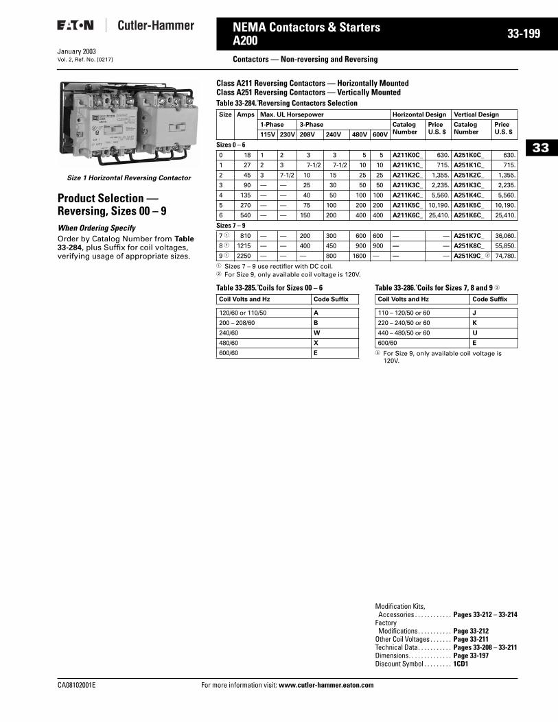
CA08102001E For more
99
33-1NEMA Contactors & StartersA200
Contactors — Non-reversing and ReversingJanuary 2003Vol. 2, Ref. No. [0217]
33
Size 1 Horizontal Reversing Contactor
Product Selection — Reversing, Sizes 00 – 9When Ordering Specify Order by Catalog Number from Table 33-284, plus Suffix for coil voltages, verifying usage of appropriate sizes.
Class A211 Reversing Contactors — Horizontally MountedClass A251 Reversing Contactors — Vertically Mounted Table 33-284. Reversing Contactors Selection
1 Sizes 7 – 9 use rectifier with DC coil.2 For Size 9, only available coil voltage is 120V.
Table 33-285. Coils for Sizes 00 – 6 Table 33-286. Coils for Sizes 7, 8 and 9 3
3 For Size 9, only available coil voltage is 120V.
Size Amps Max. UL Horsepower Horizontal Design Vertical Design
1-Phase 3-Phase CatalogNumber
PriceU.S. $
CatalogNumber
PriceU.S. $115V 230V 208V 240V 480V 600V
Sizes 0 – 60 18 1 2 3 3 5 5 A211K0C_ 630. A251K0C_ 630.
1 27 2 3 7-1/2 7-1/2 10 10 A211K1C_ 715. A251K1C_ 715.
2 45 3 7-1/2 10 15 25 25 A211K2C_ 1,355. A251K2C_ 1,355.
3 90 — — 25 30 50 50 A211K3C_ 2,235. A251K3C_ 2,235.
4 135 — — 40 50 100 100 A211K4C_ 5,560. A251K4C_ 5,560.
5 270 — — 75 100 200 200 A211K5C_ 10,190. A251K5C_ 10,190.
6 540 — — 150 200 400 400 A211K6C_ 25,410. A251K6C_ 25,410.
Sizes 7 – 97 1 810 — — 200 300 600 600 — — A251K7C_ 36,060.
8 1 1215 — — 400 450 900 900 — — A251K8C_ 55,850.
9 1 2250 — — — 800 1600 — — — A251K9C_ 2 74,780.
Coil Volts and Hz Code Suffix
120/60 or 110/50 A
200 – 208/60 B
240/60 W
480/60 X
600/60 E
Coil Volts and Hz Code Suffix
110 – 120/50 or 60 J
220 – 240/50 or 60 K
440 – 480/50 or 60 U
600/60 E
Modification Kits, Accessories . . . . . . . . . . . . Pages 33-212 – 33-214
Factory Modifications. . . . . . . . . . . Page 33-212
Other Coil Voltages . . . . . . . Page 33-211Technical Data. . . . . . . . . . . Pages 33-208 – 33-211Dimensions. . . . . . . . . . . . . . Page 33-197Discount Symbol . . . . . . . . . 1CD1
information visit: www.cutler-hammer.eaton.com
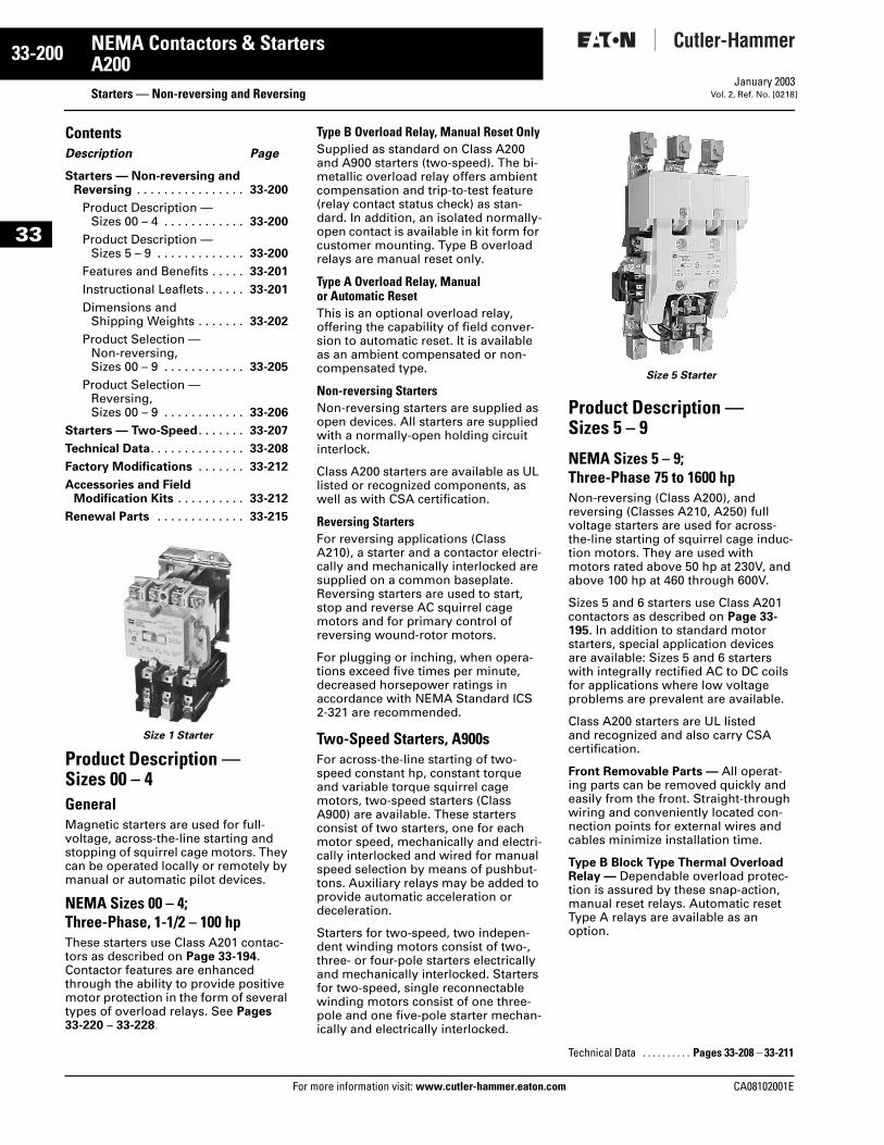
33-200
33
NEMA Contactors & StartersA200
Starters — Non-reversing and ReversingFor more information visit: www.cutler-hammer.eaton.com
January 2003Vol. 2, Ref. No. [0218]
ContentsDescription Page
Starters — Non-reversing and Reversing . . . . . . . . . . . . . . . . 33-200
Product Description — Sizes 00 – 4 . . . . . . . . . . . . 33-200
Product Description — Sizes 5 – 9 . . . . . . . . . . . . . 33-200
Features and Benefits . . . . . 33-201
Instructional Leaflets . . . . . . 33-201
Dimensions and Shipping Weights . . . . . . . 33-202
Product Selection —Non-reversing, Sizes 00 – 9 . . . . . . . . . . . . 33-205
Product Selection —Reversing,Sizes 00 – 9 . . . . . . . . . . . . 33-206
Starters — Two-Speed . . . . . . . 33-207
Technical Data. . . . . . . . . . . . . . 33-208
Factory Modifications . . . . . . . 33-212
Accessories and Field Modification Kits . . . . . . . . . . 33-212
Renewal Parts . . . . . . . . . . . . . 33-215
Size 1 Starter
Product Description — Sizes 00 – 4 GeneralMagnetic starters are used for full-voltage, across-the-line starting and stopping of squirrel cage motors. They can be operated locally or remotely by manual or automatic pilot devices.
NEMA Sizes 00 – 4; Three-Phase, 1-1/2 – 100 hpThese starters use Class A201 contac-tors as described on Page 33-194. Contactor features are enhanced through the ability to provide positive motor protection in the form of several types of overload relays. See Pages 33-220 – 33-228.
Type B Overload Relay, Manual Reset OnlySupplied as standard on Class A200 and A900 starters (two-speed). The bi-metallic overload relay offers ambient compensation and trip-to-test feature (relay contact status check) as stan-dard. In addition, an isolated normally-open contact is available in kit form for customer mounting. Type B overload relays are manual reset only.
Type A Overload Relay, Manual or Automatic ResetThis is an optional overload relay, offering the capability of field conver-sion to automatic reset. It is available as an ambient compensated or non-compensated type.
Non-reversing StartersNon-reversing starters are supplied as open devices. All starters are supplied with a normally-open holding circuit interlock.
Class A200 starters are available as UL listed or recognized components, as well as with CSA certification.
Reversing StartersFor reversing applications (Class A210), a starter and a contactor electri-cally and mechanically interlocked are supplied on a common baseplate. Reversing starters are used to start, stop and reverse AC squirrel cage motors and for primary control of reversing wound-rotor motors.
For plugging or inching, when opera-tions exceed five times per minute, decreased horsepower ratings in accordance with NEMA Standard ICS 2-321 are recommended.
Two-Speed Starters, A900sFor across-the-line starting of two-speed constant hp, constant torque and variable torque squirrel cage motors, two-speed starters (Class A900) are available. These starters consist of two starters, one for each motor speed, mechanically and electri-cally interlocked and wired for manual speed selection by means of pushbut-tons. Auxiliary relays may be added to provide automatic acceleration or deceleration.
Starters for two-speed, two indepen-dent winding motors consist of two-, three- or four-pole starters electrically and mechanically interlocked. Starters for two-speed, single reconnectable winding motors consist of one three-pole and one five-pole starter mechan-ically and electrically interlocked.
Size 5 Starter
Product Description — Sizes 5 – 9
NEMA Sizes 5 – 9; Three-Phase 75 to 1600 hpNon-reversing (Class A200), and reversing (Classes A210, A250) full voltage starters are used for across-the-line starting of squirrel cage induc-tion motors. They are used with motors rated above 50 hp at 230V, and above 100 hp at 460 through 600V.
Sizes 5 and 6 starters use Class A201 contactors as described on Page 33-195. In addition to standard motor starters, special application devices are available: Sizes 5 and 6 starters with integrally rectified AC to DC coils for applications where low voltage problems are prevalent are available.
Class A200 starters are UL listed and recognized and also carry CSA certification.
Front Removable Parts — All operat-ing parts can be removed quickly and easily from the front. Straight-through wiring and conveniently located con-nection points for external wires and cables minimize installation time.
Type B Block Type Thermal Overload Relay — Dependable overload protec-tion is assured by these snap-action, manual reset relays. Automatic reset Type A relays are available as an option.
Technical Data . . . . . . . . . . Pages 33-208 – 33-211
CA08102001E
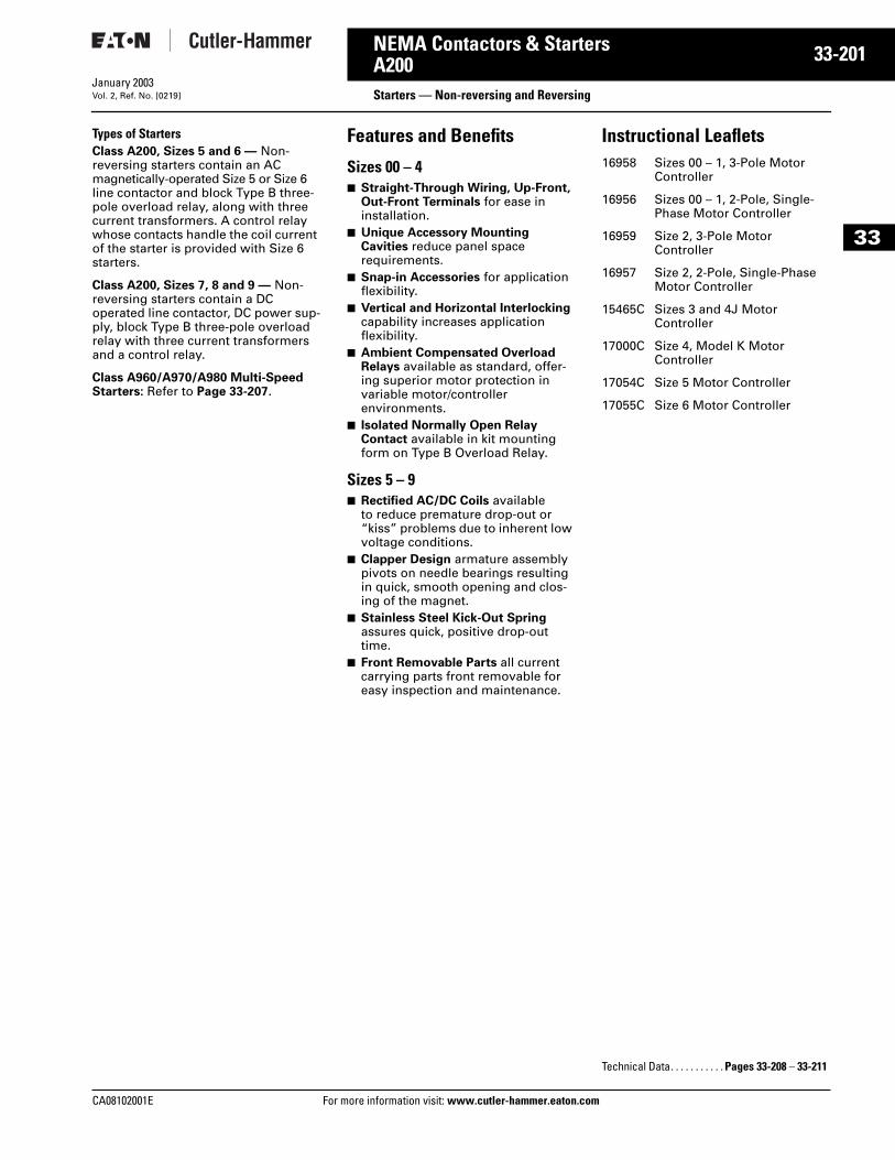
CA08102001E For more
01
33-2NEMA Contactors & StartersA200 Starters — Non-reversing and ReversingJanuary 2003Vol. 2, Ref. No. [0219]
33
Types of StartersClass A200, Sizes 5 and 6 — Non-reversing starters contain an AC magnetically-operated Size 5 or Size 6 line contactor and block Type B three-pole overload relay, along with three current transformers. A control relay whose contacts handle the coil current of the starter is provided with Size 6 starters.
Class A200, Sizes 7, 8 and 9 — Non-reversing starters contain a DC operated line contactor, DC power sup-ply, block Type B three-pole overload relay with three current transformers and a control relay.
Class A960/A970/A980 Multi-Speed Starters: Refer to Page 33-207.
Features and Benefits
Sizes 00 – 4■ Straight-Through Wiring, Up-Front,
Out-Front Terminals for ease in installation.
■ Unique Accessory Mounting Cavities reduce panel space requirements.
■ Snap-in Accessories for application flexibility.
■ Vertical and Horizontal Interlocking capability increases application flexibility.
■ Ambient Compensated Overload Relays available as standard, offer-ing superior motor protection in variable motor/controller environments.
■ Isolated Normally Open Relay Contact available in kit mounting form on Type B Overload Relay.
Sizes 5 – 9■ Rectified AC/DC Coils available
to reduce premature drop-out or “kiss” problems due to inherent low voltage conditions.
■ Clapper Design armature assembly pivots on needle bearings resulting in quick, smooth opening and clos-ing of the magnet.
■ Stainless Steel Kick-Out Spring assures quick, positive drop-out time.
■ Front Removable Parts all current carrying parts front removable for easy inspection and maintenance.
Instructional Leaflets16958 Sizes 00 – 1, 3-Pole Motor
Controller
16956 Sizes 00 – 1, 2-Pole, Single-Phase Motor Controller
16959 Size 2, 3-Pole Motor Controller
16957 Size 2, 2-Pole, Single-Phase Motor Controller
15465C Sizes 3 and 4J Motor Controller
17000C Size 4, Model K Motor Controller
17054C Size 5 Motor Controller
17055C Size 6 Motor Controller
Technical Data. . . . . . . . . . . Pages 33-208 – 33-211
information visit: www.cutler-hammer.eaton.com
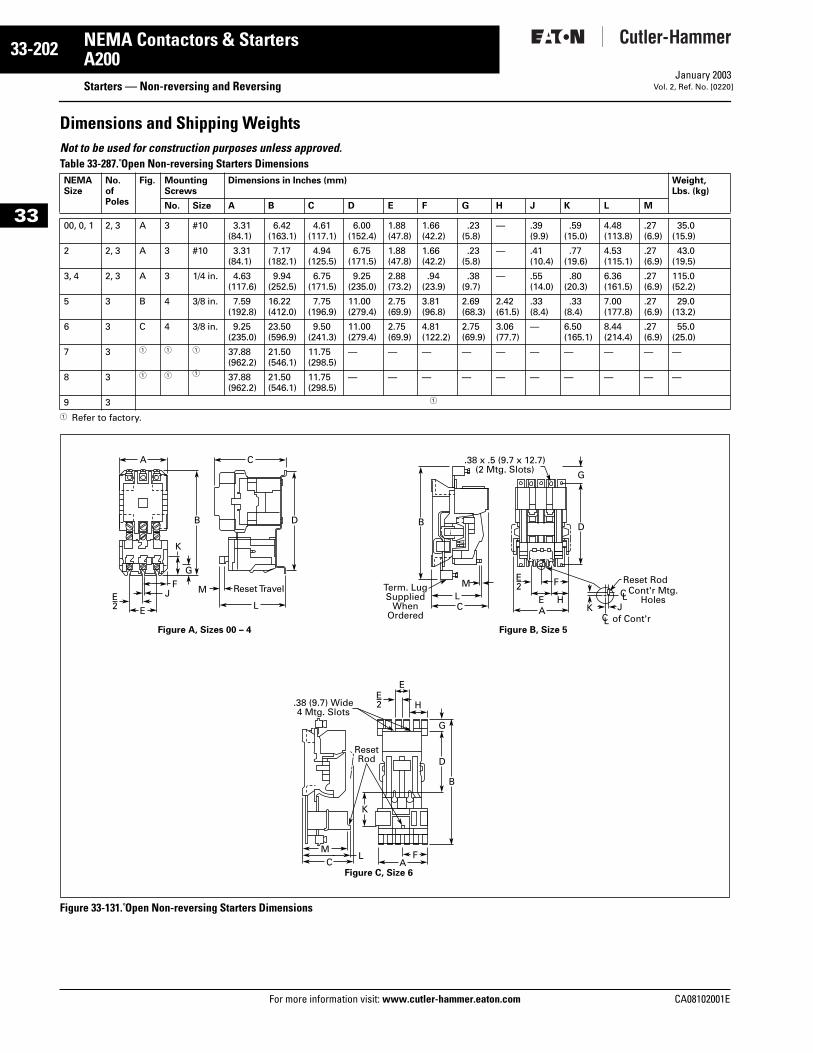
33-202
33
NEMA Contactors & StartersA200
Starters — Non-reversing and ReversingFor more information visit: www.cutler-hammer.eaton.com
January 2003Vol. 2, Ref. No. [0220]
Dimensions and Shipping WeightsNot to be used for construction purposes unless approved. Table 33-287. Open Non-reversing Starters Dimensions
1 Refer to factory.
Figure 33-131. Open Non-reversing Starters Dimensions
NEMASize
No. ofPoles
Fig. MountingScrews
Dimensions in Inches (mm) Weight,Lbs. (kg)
No. Size A B C D E F G H J K L M
00, 0, 1 2, 3 A 3 #10 3.31(84.1)
6.42(163.1)
4.61 (117.1)
6.00(152.4)
1.88(47.8)
1.66 (42.2)
.23(5.8)
— .39(9.9)
.59(15.0)
4.48(113.8)
.27(6.9)
35.0 (15.9)
2 2, 3 A 3 #10 3.31 (84.1)
7.17(182.1)
4.94(125.5)
6.75(171.5)
1.88(47.8)
1.66(42.2)
.23 (5.8)
— .41(10.4)
.77(19.6)
4.53(115.1)
.27(6.9)
43.0 (19.5)
3, 4 2, 3 A 3 1/4 in. 4.63 (117.6)
9.94(252.5)
6.75(171.5)
9.25(235.0)
2.88(73.2)
.94(23.9)
.38 (9.7)
— .55(14.0)
.80(20.3)
6.36(161.5)
.27(6.9)
115.0 (52.2)
5 3 B 4 3/8 in. 7.59 (192.8)
16.22 (412.0)
7.75(196.9)
11.00(279.4)
2.75(69.9)
3.81(96.8)
2.69(68.3)
2.42(61.5)
.33(8.4)
.33(8.4)
7.00(177.8)
.27(6.9)
29.0(13.2)
6 3 C 4 3/8 in. 9.25 (235.0)
23.50(596.9)
9.50(241.3)
11.00(279.4)
2.75(69.9)
4.81(122.2)
2.75(69.9)
3.06(77.7)
— 6.50(165.1)
8.44(214.4)
.27(6.9)
55.0(25.0)
7 3 1 1 1 37.88 (962.2)
21.50(546.1)
11.75(298.5)
— — — — — — — — — —
8 3 1 1 1 37.88(962.2)
21.50(546.1)
11.75(298.5)
— — — — — — — — — —
9 3 1
E L C A
C AF
H
E
M
ResetRod
L
LM F
HEK J
Reset Rod
Figure A, Sizes 00 – 4 Figure B, Size 5
Figure C, Size 6
Reset TravelMJF
CA
B B
K
B
DD
D
G
G
K
G
E2
E2
E2
C L
C L
of Cont'r
Cont'r Mtg.Holes
.38 (9.7) Wide4 Mtg. Slots
.38 x .5 (9.7 x 12.7)(2 Mtg. Slots)
Term. LugSupplied
WhenOrdered
CA08102001E
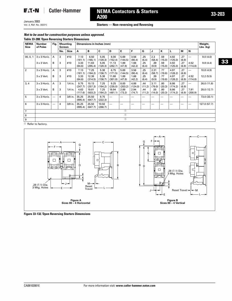
CA08102001E For more
03
33-2NEMA Contactors & StartersA200 Starters — Non-reversing and ReversingJanuary 2003Vol. 2, Ref. No. [0221]
33
Not to be used for construction purposes unless approved. Table 33-288. Open Reversing Starters Dimensions
1 Refer to factory.
Figure 33-132. Open Reversing Starters Dimensions
NEMASize
Numberof Poles
Fig. MountingScrews
Dimensions in Inches (mm) Weight,Lbs. (kg)
No. Size A B C D E F G J K L M N
00, 0, 1 3 x 3 Horiz.
3 x 3 Vert.
A
B
3
3
#10
#10
7.13(181.1)3.33
(84.6)
6.50(165.1)11.63(295.4)
5.05(128.3)5.05
(128.3)
6.00(152.4)11.13(282.7)
5.69(144.5)1.88(47.8)
3.56(90.4)1.66(42.2)
.25(6.4).25(6.4)
2.3(58.4).39
(9.9)
.59(15.0).59(15.0)
4.92(125.0)4.92(125.0)
.27(6.9).27(6.9)
—
4.52(114.8)
9.0 (4.0)
9.8 (4.4)
2 3 x 3 Horiz.
3 x 3 Vert.
A
B
3
3
#10
#10
7.13(181.1)3.33
(84.6)
7.25(184.2)12.38(314.5)
5.38(136.7)5.38
(136.7)
6.75(171.5)11.88(301.8)
5.69(144.5)1.88(47.8)
3.56(90.4)1.66(42.2)
.25(6.4).25(6.4)
2.31(58.7).39
(9.9)
.77(19.6).77(19.6)
4.97(126.2)4.97(126.2)
.27(6.9).27(6.9)
—
4.52(114.8)
10.8 (4.9)
12.2 (5.5)
3, 4 3 x 3 Horiz.
3 x 3 Vert.
A
B
3
3
1/4 in.
1/4 in.
9.75(247.7)4.63
(117.6)
10.13(257.3)19.81(503.2)
7.25(184.2)7.25
(184.2)
9.25(235.0)18.94(481.1)
8.00(203.2)2.88(73.2)
4.88(124.0)2.94(74.7)
.44(11.2).44(11.2)
3.11(79.0).55
(14.0)
.80(20.3).80(20.3)
6.86(174.2)6.86(174.2)
.27(6.9).27(6.9)
—
7.91(200.9)
26.0 (11.8)
28.0 (12.7)
5 3 x 3 Horiz. — 4 3/8 in. 35.25(895.4)
25.50(647.7)
8.75(222.3)
— — — — — — — — — 73.0 (33.1)
6 3 x 3 Horiz. — 4 3/8 in. 35.25(895.4)
25.50(647.7)
10.50(266.7)
— — — — — — — — — 127.0 (57.7)
7 1
8 1
9 1
E
Figure ASizes 00 – 4 Horizontal
Figure BSizes 00 – 4 Vertical
.28 (7.1) Dia.3 Mtg. Holes L
L
J
E
J
MResetTravel M
A C
F
A C
F
B D
N
G
BD
K
G
K
.28 (7.1) Dia.3 Mtg. Holes
Reset Travel
information visit: www.cutler-hammer.eaton.com
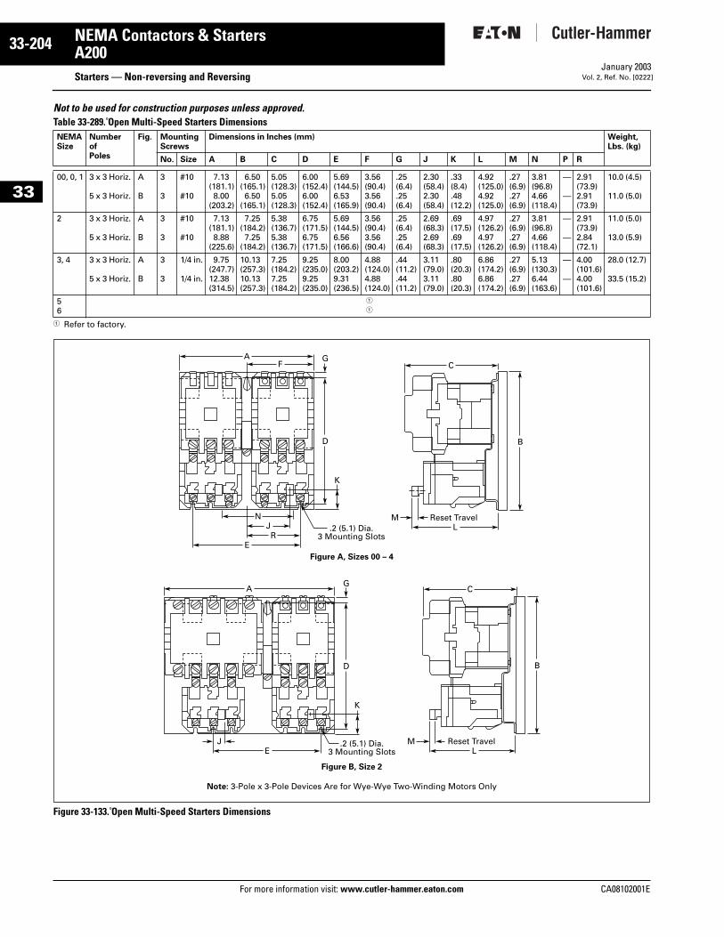
33-204
33
NEMA Contactors & StartersA200
Starters — Non-reversing and ReversingFor more information visit: www.cutler-hammer.eaton.com
January 2003Vol. 2, Ref. No. [0222]
Not to be used for construction purposes unless approved. Table 33-289. Open Multi-Speed Starters Dimensions
1 Refer to factory.
Figure 33-133. Open Multi-Speed Starters Dimensions
NEMASize
NumberofPoles
Fig. MountingScrews
Dimensions in Inches (mm) Weight,Lbs. (kg)
No. Size A B C D E F G J K L M N P R
00, 0, 1 3 x 3 Horiz.
5 x 3 Horiz.
A
B
3
3
#10
#10
7.13(181.1)8.00
(203.2)
6.50(165.1)6.50
(165.1)
5.05(128.3)5.05(128.3)
6.00(152.4)6.00(152.4)
5.69(144.5)6.53(165.9)
3.56(90.4)3.56(90.4)
.25(6.4).25(6.4)
2.30(58.4)2.30(58.4)
.33(8.4).48(12.2)
4.92(125.0)4.92(125.0)
.27(6.9).27(6.9)
3.81(96.8)4.66(118.4)
—
—
2.91(73.9)2.91(73.9)
10.0 (4.5)
11.0 (5.0)
2 3 x 3 Horiz.
5 x 3 Horiz.
A
B
3
3
#10
#10
7.13(181.1)8.88
(225.6)
7.25(184.2)7.25
(184.2)
5.38(136.7)5.38(136.7)
6.75(171.5)6.75(171.5)
5.69(144.5)6.56(166.6)
3.56(90.4)3.56(90.4)
.25(6.4).25(6.4)
2.69(68.3)2.69(68.3)
.69(17.5).69(17.5)
4.97(126.2)4.97(126.2)
.27(6.9).27(6.9)
3.81(96.8)4.66(118.4)
—
—
2.91(73.9)2.84(72.1)
11.0 (5.0)
13.0 (5.9)
3, 4 3 x 3 Horiz.
5 x 3 Horiz.
A
B
3
3
1/4 in.
1/4 in.
9.75(247.7)12.38(314.5)
10.13(257.3)10.13(257.3)
7.25(184.2)7.25(184.2)
9.25(235.0)9.25(235.0)
8.00(203.2)9.31(236.5)
4.88(124.0)4.88(124.0)
.44(11.2).44(11.2)
3.11(79.0)3.11(79.0)
.80(20.3).80(20.3)
6.86(174.2)6.86(174.2)
.27(6.9).27(6.9)
5.13(130.3)6.44(163.6)
—
—
4.00(101.6)4.00(101.6)
28.0 (12.7)
33.5 (15.2)
56
1
1
A
D
G
B
K
F C
J .2 (5.1) Dia.3 Mounting Slots
Figure A, Sizes 00 – 4
RE
NL
Reset TravelM
A
D
G
B
K
C
.2 (5.1) Dia.3 Mounting Slots
Figure B, Size 2
EJ
LReset TravelM
Note: 3-Pole x 3-Pole Devices Are for Wye-Wye Two-Winding Motors Only
CA08102001E
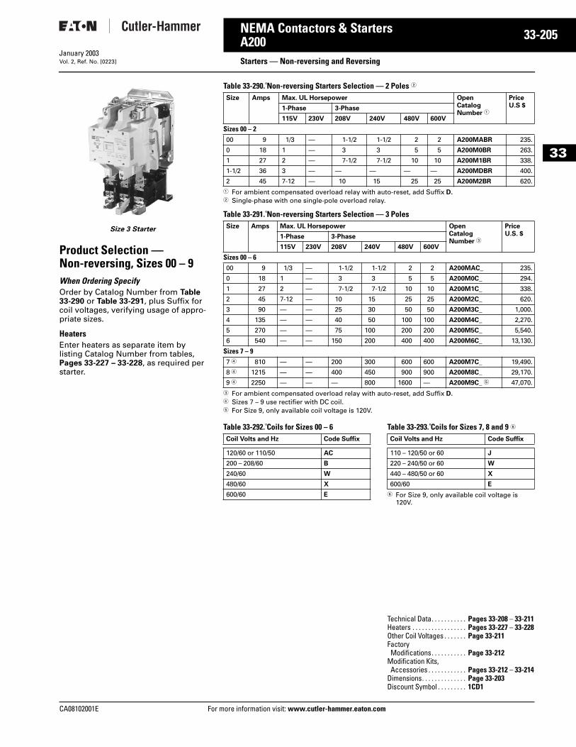
CA08102001E For more
05
33-2NEMA Contactors & StartersA200 Starters — Non-reversing and ReversingJanuary 2003Vol. 2, Ref. No. [0223]
33
Size 3 Starter
Product Selection —Non-reversing, Sizes 00 – 9When Ordering SpecifyOrder by Catalog Number from Table 33-290 or Table 33-291, plus Suffix for coil voltages, verifying usage of appro-priate sizes.
Heaters Enter heaters as separate item by listing Catalog Number from tables, Pages 33-227 – 33-228, as required per starter.
Table 33-290. Non-reversing Starters Selection — 2 Poles 2
1 For ambient compensated overload relay with auto-reset, add Suffix D.2 Single-phase with one single-pole overload relay.
Table 33-291. Non-reversing Starters Selection — 3 Poles
3 For ambient compensated overload relay with auto-reset, add Suffix D.4 Sizes 7 – 9 use rectifier with DC coil.5 For Size 9, only available coil voltage is 120V.
Table 33-292. Coils for Sizes 00 – 6 Table 33-293. Coils for Sizes 7, 8 and 9 6
6 For Size 9, only available coil voltage is 120V.
Size Amps Max. UL Horsepower OpenCatalogNumber 1
PriceU.S $1-Phase 3-Phase
115V 230V 208V 240V 480V 600V
Sizes 00 – 200 9 1/3 — 1-1/2 1-1/2 2 2 A200MABR 235.
0 18 1 — 3 3 5 5 A200M0BR 263.
1 27 2 — 7-1/2 7-1/2 10 10 A200M1BR 338.
1-1/2 36 3 — — — — — A200MDBR 400.
2 45 7-12 — 10 15 25 25 A200M2BR 620.
Size Amps Max. UL Horsepower OpenCatalogNumber 3
PriceU.S. $1-Phase 3-Phase
115V 230V 208V 240V 480V 600V
Sizes 00 – 600 9 1/3 — 1-1/2 1-1/2 2 2 A200MAC_ 235.
0 18 1 — 3 3 5 5 A200M0C_ 294.
1 27 2 — 7-1/2 7-1/2 10 10 A200M1C_ 338.
2 45 7-12 — 10 15 25 25 A200M2C_ 620.
3 90 — — 25 30 50 50 A200M3C_ 1,000.
4 135 — — 40 50 100 100 A200M4C_ 2,270.
5 270 — — 75 100 200 200 A200M5C_ 5,540.
6 540 — — 150 200 400 400 A200M6C_ 13,130.
Sizes 7 – 97 4 810 — — 200 300 600 600 A200M7C_ 19,490.
8 4 1215 — — 400 450 900 900 A200M8C_ 29,170.
9 4 2250 — — — 800 1600 — A200M9C_ 5 47,070.
Coil Volts and Hz Code Suffix
120/60 or 110/50 AC
200 – 208/60 B
240/60 W
480/60 X
600/60 E
Coil Volts and Hz Code Suffix
110 – 120/50 or 60 J
220 – 240/50 or 60 W
440 – 480/50 or 60 X
600/60 E
Technical Data. . . . . . . . . . . Pages 33-208 – 33-211Heaters . . . . . . . . . . . . . . . . . Pages 33-227 – 33-228Other Coil Voltages . . . . . . . Page 33-211Factory Modifications. . . . . . . . . . . Page 33-212
Modification Kits, Accessories . . . . . . . . . . . . Pages 33-212 – 33-214
Dimensions. . . . . . . . . . . . . . Page 33-203Discount Symbol . . . . . . . . . 1CD1
information visit: www.cutler-hammer.eaton.com
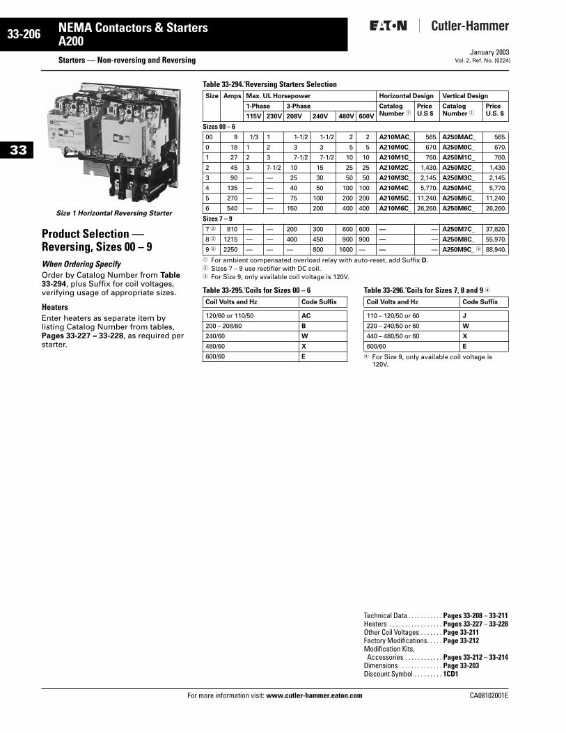
33-206
33
NEMA Contactors & StartersA200
Starters — Non-reversing and ReversingFor more information visit: www.cutler-hammer.eaton.com
January 2003Vol. 2, Ref. No. [0224]
Size 1 Horizontal Reversing Starter
Product Selection —Reversing, Sizes 00 – 9When Ordering SpecifyOrder by Catalog Number from Table 33-294, plus Suffix for coil voltages, verifying usage of appropriate sizes.
Heaters Enter heaters as separate item by listing Catalog Number from tables, Pages 33-227 – 33-228, as required per starter.
Table 33-294. Reversing Starters Selection
1 For ambient compensated overload relay with auto-reset, add Suffix D.2 Sizes 7 – 9 use rectifier with DC coil.3 For Size 9, only available coil voltage is 120V.
Table 33-295. Coils for Sizes 00 – 6 Table 33-296. Coils for Sizes 7, 8 and 9 4
4 For Size 9, only available coil voltage is 120V.
Size Amps Max. UL Horsepower Horizontal Design Vertical Design
1-Phase 3-Phase CatalogNumber 1
PriceU.S $
CatalogNumber 1
PriceU.S. $115V 230V 208V 240V 480V 600V
Sizes 00 – 600 9 1/3 1 1-1/2 1-1/2 2 2 A210MAC_ 565. A250MAC_ 565.
0 18 1 2 3 3 5 5 A210M0C_ 670. A250M0C_ 670.
1 27 2 3 7-1/2 7-1/2 10 10 A210M1C_ 760. A250M1C_ 760.
2 45 3 7-1/2 10 15 25 25 A210M2C_ 1,430. A250M2C_ 1,430.
3 90 — — 25 30 50 50 A210M3C_ 2,145. A250M3C_ 2,145.
4 135 — — 40 50 100 100 A210M4C_ 5,770. A250M4C_ 5,770.
5 270 — — 75 100 200 200 A210M5C_ 11,240. A250M5C_ 11,240.
6 540 — — 150 200 400 400 A210M6C_ 26,260. A250M6C_ 26,260.
Sizes 7 – 97 2 810 — — 200 300 600 600 — — A250M7C_ 37,820.
8 2 1215 — — 400 450 900 900 — — A250M8C_ 55,970.
9 2 2250 — — — 800 1600 — — — A250M9C_ 3 88,940.
Coil Volts and Hz Code Suffix
120/60 or 110/50 AC
200 – 208/60 B
240/60 W
480/60 X
600/60 E
Coil Volts and Hz Code Suffix
110 – 120/50 or 60 J
220 – 240/50 or 60 W
440 – 480/50 or 60 X
600/60 E
Technical Data . . . . . . . . . . . Pages 33-208 – 33-211Heaters . . . . . . . . . . . . . . . . . Pages 33-227 – 33-228Other Coil Voltages . . . . . . . Page 33-211Factory Modifications. . . . . Page 33-212Modification Kits, Accessories . . . . . . . . . . . . Pages 33-212 – 33-214
Dimensions . . . . . . . . . . . . . . Page 33-203Discount Symbol . . . . . . . . . 1CD1
CA08102001E
CA08102001E For more
07
33-2NEMA Contactors & StartersA200 Starters — Two-SpeedJanuary 2003Vol. 2, Ref. No. [0225]
33
Product SelectionFor Separate Two-Winding Motors
HeatersEnter heaters as separate item by listing Catalog Number from table, Pages 33-227 – 33-228, as required per starter.
Table 33-297. Three-Phase, Non-reversing, Reversing 60 Hz Starters — Heater Selection
1 For ambient compensated overload relay with auto-reset, add Suffix D.
For Single-Winding MotorsTable 33-298. Product Selection — Sizes 0 – 6
2 For ambient compensated overload relay with auto-reset, add Suffix D.
NEMA Amps Constant Horsepower Constant or Variable Torque 3 Poles
208V 240V 480V 600V 208V 240V 480V 600V OpenCatalogNumber 1
PriceU.S. $
Sizes 0 – 60 18 3 3 5 5 2 2 3 3 A960M0C_ 920.
1 27 7-1/2 7-1/2 10 10 5 5 7-1/2 7-1/2 A960M1C_ 1,025.
2 45 10 15 25 25 7-1/2 10 20 20 A960M2C_ 1,780.
3 90 25 30 50 50 20 25 40 40 A960M3C_ 2,765.
4 135 40 50 100 100 30 40 75 75 A960M4C_ 6,900.
5 270 75 100 200 200 60 75 150 150 A960M5C_ 16,410.
6 540 150 200 400 400 100 150 300 300 A960M6C_ 28,440.
NEMA Amps 208V 240V 480V 600V 3-Poles
OpenCatalogNumber 2
PriceU.S. $
Constant Horsepower 0 18 3 3 5 5 A970M0C_ 1,300.
1 27 7-1/2 7-1/2 10 10 A970M1C_ 1,390.
2 45 10 15 25 25 A970M2C_ 2,450.
3 90 25 30 50 50 A970M3C_ 3,685.
4 135 40 50 100 100 A970M4C_ 9,530.
5 270 75 100 200 200 A970M5C_ 18,960.
6 540 150 200 400 400 A970M6C_ 42,380.
Constant or Variable Torque0 18 2 2 3 3 A980M0C_ 1,300.
1 27 5 5 7-1/2 7-1/2 A980M1C_ 1,390.
2 45 7-1/2 10 20 20 A980M2C_ 2,450.
3 90 20 25 40 40 A980M3C_ 3,685.
4 135 30 40 75 75 A980M4C_ 9,530.
5 270 60 75 150 150 A980M5C_ 18,960.
6 540 100 150 300 300 A980M6C_ 42,380.
information visit: www.cutler-hammer.eaton.co
Table 33-299. Coils for Sizes 0 – 6
Table 33-300. Coils for Sizes 0 – 6
Coil Volts and Hz Coil Suffix
120/60 or 110/50 AC
200 – 208/60 B
240/60 W
480/60 X
600/60 E
Coil Volts and Hz Coil Suffix
120/60 or 110/50 AC
200 – 208/60 B
240/60 W
480/60 X
600/60 E
Technical Data. . . . . . . . . . . Pages 33-208 – 33-211Heaters . . . . . . . . . . . . . . . . . Pages 33-227 – 33-228Other Coil Voltages . . . . . . . Page 33-211Factory Modifications . . . . Page 33-212Modification Kits, Accessories . . . . . . . . . . . . Pages 33-212 – 33-214
Dimensions. . . . . . . . . . . . . . Page 33-203Discount Symbol . . . . . . . . . 1CD1
m
33-208
33
NEMA Contactors & StartersA200
Technical Data and SpecificationsFor more information visit: www.cutler-hammer.eaton.com
January 2003Vol. 2, Ref. No. [0226]
Electrical CharacteristicsTable 33-301. Electrical Characteristics — Sizes 00 – 4
1 Resistive loads having inrush currents not exceeding 1.5 times continuous rating.
2 These ratings are for transformers having inrush currents not more than 20 times peak of continuous current ratings. For inrush currents greater than 20 times, refer to factory.
Table 33-302. Electrical Characteristics — Sizes 5 – 9
3 For ratings refer to factory.4 Resistive loads having inrush currents not exceeding 1.5 times
continuous rating.5 These ratings are for transformers having inrush currents not more
than 20 times peak of continuous current ratings. For inrush currents greater than 20 times, refer to factory.
Size 00 Size 0 Size 1 Size 2 Size 3 Size 4
Max. VoltageRating
600V 600V 600V 600V 600V 600V
Ampere Rating(Open)(Enclosed)
10A9A
20A18A
30A27A
50A45A
100A90A
150A135A
Squirrel Cage MotorMaximumHorsepower At:200V/60 Hz230V/ 60 Hz380V/50 Hz460V – 575V/60 Hz
1-1/2 hp1-1/2 hp1-1/2 hp2 hp
3 hp3 hp5 hp5 hp
7-1/2 hp7-1/2 hp
10 hp10 hp
10 hp15 hp25 hp25 hp
25 hp30 hp50 hp50 hp
40 hp50 hp75 hp
100 hp
Resistive Heating kW 1
Single-Phase, 2-Pole
120V240V480V600V
Three-Phase, 3-Pole
120V240V480V600V
————
————
————
————
3 kW6 kW
12 kW15 kW
5 kW10 kW20 kW25 kW
5 kW10 kW20 kW25 kW
8.5 kW17 kW34 kW43 kW
10 kW20 kW40 kW50 kW
17 kW34 kW68 kW86 kW
15 kW30 kW60 kW75 kW
26 kW68 kW
105 kW130 kW
Capacitor Switching kVAR, Three-Phase240V480V600V
———
———
———
12 kVAR25 kVAR31 kVAR
27 kVAR53 kVAR67 kVAR
40 kVAR80 kVAR
100 kVAR
Transformer Switching kVA 2
Single-Phase, 2-Pole
120V240V480V600V
Three-Phase, 3-Pole
120V240V480V600V
————
————
.6 kVA1.2 kVA2.4 kVA3 kVA
1.8 kVA2.1 kVA4.2 kVA5.2 kVA
1.2 kVA2.4 kVA4.9 kVA6.2 kVA
3.6 kVA4.3 kVA8.5 kVA
11 kVA
2.1 kVA4.1 kVA8.3 kVA
10 kVA
6.3 kVA7.2 kVA
14 kVA18 kVA
4.1 kVA8.1 kVA
16 kVA20 kVA
12 kVA14 kVA28 kVA35 kVA
6.8 kVA14 kVA27 kVA34 kVA
20 kVA23 kVA47 kVA59 kVA
Size 5 Size 6 Size 7 Size 8 Size 9
Max. VoltageRating
600V 600V 600V 600V 600V
Ampere Rating(Open)(Enclosed)
300A270A
600A540A
900A810A
1350A1215A
2500A2250A
Squirrel Cage MotorMaximum Horsepower At:200V/60 Hz230V/60 Hz380V/50 Hz460V – 575V/60 Hz
75 hp100 hp150 hp200 hp
150 hp200 hp300 hp400 hp
—300 hp—600 hp
—450 hp—900 hp
—800 hp
—1600 hp
Resistive Heating kW 4
Single-Phase, 2-Pole
120V240V480V600V
Three-Phase, 3-Pole
120V240V480V600V
30 kW60 kW
120 kW150 kW
52 kW105 kW210 kW260 kW
60 kW120 kW240 kW300 kW
105 kW210 kW415 kW515 kW
90 kW180 kW360 kW450 kW
155 kW315 kW625 kW775 kW
3
3
3
3
3
3
3
3
3
3
3
3
3
3
3
3
Capacitor Switching kVAR, Three-Phase240V480V600V
80 kVAR160 kVAR200 kVAR
160 kVAR320 kVAR400 kVAR
240 kVAR480 kVAR600 kVAR
360 kVAR720 kVAR900 kVAR
665 kVAR1325 kVAR1670 kVAR
Transformer Switching kVA 5
Single-Phase, 2-Pole
120V240V480V600V
Three-Phase, 3-Pole
120V240V480V600V
14 kVA27 kVA54 kVA68 kVA
41 kVA47 kVA94 kVA
117 kVA
27 kVA54 kVA
108 kVA135 kVA
81 kVA94 kVA
188 kVA234 kVA
41 kVA81 kVA
162 kVA203 kVA
122 kVA140 kVA280 kVA351 kVA
61 kVA122 kVA244 kVA304 kVA
182 kVA210 kVA420 kVA526 kVA
112 kVA225 kVA450 kVA562 kVA
337 kVA342 kVA783 kVA975 kVA
CA08102001E
CA08102001E For more
09
33-2NEMA Contactors & StartersA200 Technical Data and SpecificationsJanuary 2003Vol. 2, Ref. No. [0227]
33
DC Power Pole RatingsThe following represent typical pro-duction test values and should not be interpreted as a guarantee of actual performance.
Table 33-303. DC Operated 120 and 240V Coils
1 Non-inductive load.
380V, 50 Hz Starter Maximum Horsepower RatingsTable 33-304. 380V, 50 Hz Starters — Maximum Horsepower Ratings
Operating Coil Characteristics at Rated Coil Volts, Sizes 00 – 9The following represent typical production test values and should not be interpreted as a guarantee of actual performance.Table 33-305. Operating Coil Characteristics
2 AC coil data pertains to Model K, DC coil data pertains to Model J.3 DC Operated only. 4 Percent of rated coil voltage.5 Lower figure when coil is cold. Higher figure when coil is hot.6 Drop-out time to clear arc. Time varies with type of load and contact wear.7 At 60 Hz base.8 To contact touch.
ContactorSize
DC ContactAmp Rating 2 Poles in Series 1
120V 240V
01234
—20457590
—10304070
NEMA Size 00 0 1 2 3 4 5 6 7 8
MaximumHorsepower
1-1/2 5 10 25 50 75 150 300 450 700
Sizes 00, 0, 1 Size 2 Size 3 Size 4 2 Size 5 Size 6 Size 7 Size 8 Size 9
AC CoilBurden (Open VA)
(Closed VA)(Closed Watts)
Pick-Up Volts 4Drop-Out Volts 4Pick-Up Time Hz 78
Drop-Out Time Hz 7
160 VA25 VA7.8 W85%40 – 60%1 – 1-1/23/4 – 1
160 VA25 VA7.8 W85%40 – 60%1-1/2 – 23/4 – 1
625 VA50 VA18 W85%40 – 60%2 – 2-1/23/4 – 1
700 VA64 VA21 W85%40 – 60%1 – 1-1/23/4 – 1
1700 VA180 VA32 W78%65 to 75%1.5.75
2900 VA220 VA42 W70%60 to 70%4.0.75
3
3
—————
3
3
—————
3
3
—————
DC CoilBurden (Open VA)
(Closed VA)(Closed Watts)
Pick-Up Volts 4Drop-Out Volts 4Pick-Up Time Hz 8Drop-Out Time Hz 7
17 VA17 VA18 W80%5 – 10%——
17 VA17 VA18 W80%5 – 10%25 – 75 mS16 – 25 mS
35 VA35 VA35 W80%5 – 10%25 – 75 mS16 – 25 mS
35 VA35 VA35 W80%5 – 10%25 – 75 mS16 – 25 mS
600 VA22 VA20 W64%18%2.7 Hz 79.3 Hz 7
2120 VA21 VA20 W73%13%3 Hz 717.5 Hz 7
400 VA400 VA400 W45% – 65% 530% – 45% 521 – 41 Hz 57
7 – 12 Hz 67
400 VA400 VA400 W45% – 65% 530% – 45% 517 – 29 Hz 57
7 – 12 Hz 67
2100 VA350 VA350 W50% – 65% 540% – 50% 516 – 18 57
18 – 20 Hz 57
information visit: www.cutler-hammer.eaton.com
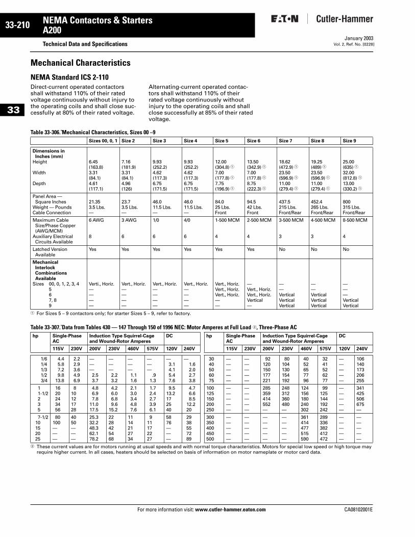
33-210
33
NEMA Contactors & StartersA200
Technical Data and SpecificationsFor more information visit: www.cutler-hammer.eaton.com
January 2003Vol. 2, Ref. No. [0228]
Mechanical Characteristics
NEMA Standard ICS 2-110Direct-current operated contactors shall withstand 110% of their rated voltage continuously without injury to the operating coils and shall close suc-cessfully at 80% of their rated voltage.
Alternating-current operated contac-tors shall withstand 110% of their rated voltage continuously without injury to the operating coils and shall close successfully at 85% of their rated voltage.
Table 33-306. Mechanical Characteristics, Sizes 00 –9
1 For Sizes 5 – 9 contactors only; for starter Sizes 5 – 9, refer to factory.
Table 33-307. Data from Tables 430 — 147 Through 150 of 1996 NEC: Motor Amperes at Full Load 2, Three-Phase AC
2 These current values are for motors running at usual speeds and with normal torque characteristics. Motors for special low speed or high torque may require higher current. In all cases, heaters should be selected on basis of information on motor nameplate or motor card data.
Sizes 00, 0, 1 Size 2 Size 3 Size 4 Size 5 Size 6 Size 7 Size 8 Size 9
Dimensions in Inches (mm)
Height
Width
Depth
6.45(163.8)3.31(84.1)4.61(117.1)
7.16(181.9)3.31(84.1)4.96(126)
9.93(252.2)4.62(117.3)6.75(171.5)
9.93(252.2)4.62(117.3)6.75(171.5)
12.00(304.8) 17.00(177.8) 17.75(196.9) 1
13.50(342.9) 17.00(177.8) 18.75(222.3) 1
18.62(472.9) 123.50(596.9) 111.00(279.4) 1
19.25(489) 123.50(596.9) 111.00(279.4) 1
25.00(635) 132.00(812.8) 113.00(330.2) 1
Panel Area — Square Inches
Weight — PoundsCable Connection
21.353.5 Lbs.—
23.73.5 Lbs.—
46.011.5 Lbs.—
46.011.5 Lbs.—
84.025 Lbs.Front
94.542 Lbs.Front
437.5215 Lbs.Front/Rear
452.4265 Lbs.Front/Rear
800315 Lbs.Front/Rear
Maximum CableSize/Phase Copper (AWG/MCM)
Auxiliary Electrical Circuits Available
6 AWG
8
3 AWG
6
1/0
6
4/0
6
1-500 MCM
4
2-500 MCM
4
3-500 MCM
3
4-500 MCM
3
8-500 MCM
4
Latched VersionAvailable
Yes Yes Yes Yes Yes Yes No No No
Mechanical Interlock CombinationsAvailable
Sizes 00, 0, 1, 2, 3, 4567, 89
Verti., Horiz.————
Vert., Horiz.————
Vert., Horiz.————
Vert., Horiz.————
Vert., Horiz.Vert., Horiz.Vert., Horiz.——
—Vert., Horiz.Vert., Horiz.Vertical—
——VerticalVerticalVertical
——VerticalVerticalVertical
———VerticalVertical
hp Single-PhaseAC
Induction Type Squirrel-Cageand Wound-Rotor Amperes
DC hp Single-PhaseAC
Induction Type Squirrel-Cageand Wound-Rotor Amperes
DC
115V 230V 200V 230V 460V 575V 120V 240V 115V 230V 200V 230V 460V 575V 120V 240V
1/61/41/31/23/4
4.45.87.29.8
13.8
2.22.93.64.96.9
———2.53.7
———2.23.2
———1.11.6
———
.91.3
—3.14.15.47.6
—1.62.02.73.8
3040506075
—————
—————
92120150177221
80104130154192
4052657796
3241526277
—————
106140173206255
11-1/2235
1620243456
810121728
4.86.97.8
11.017.5
4.26.06.89.6
15.2
2.13.03.44.87.6
1.72.42.73.96.1
9.513.2172540
4.76.68.5
12.220
100125150200250
—————
—————
285359414552—
248312360480—
124156180240302
99125144192242
—————
341425506675—
7-1/210152025
80100———
4050———
25.332.248.362.178.2
2228425468
1114212734
911172227
5876———
2938557289
300350400450500
—————
—————
—————
—————
361414477515590
289336382412472
—————
—————
CA08102001E
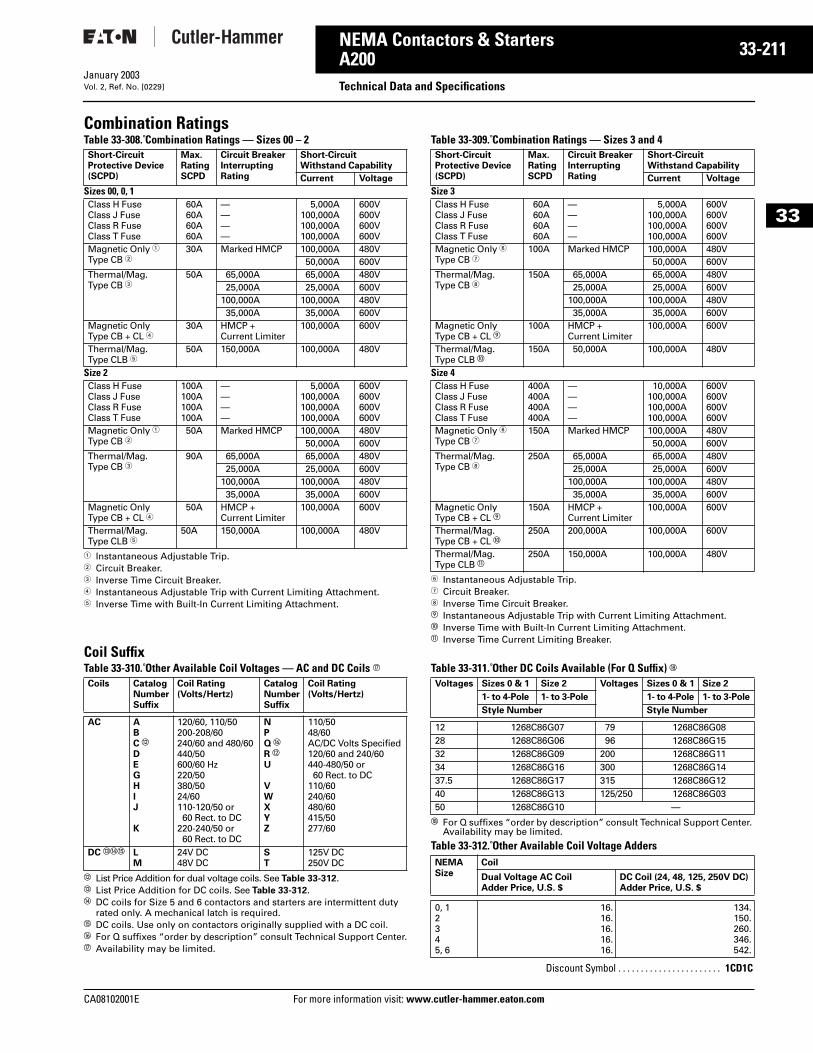
CA08102001E For more
11
33-2NEMA Contactors & StartersA200 Technical Data and SpecificationsJanuary 2003Vol. 2, Ref. No. [0229]
33
Combination RatingsTable 33-308. Combination Ratings — Sizes 00 – 2
1 Instantaneous Adjustable Trip.2 Circuit Breaker.3 Inverse Time Circuit Breaker.4 Instantaneous Adjustable Trip with Current Limiting Attachment.5 Inverse Time with Built-In Current Limiting Attachment.
Table 33-309. Combination Ratings — Sizes 3 and 4
6 Instantaneous Adjustable Trip.7 Circuit Breaker.8 Inverse Time Circuit Breaker.i Instantaneous Adjustable Trip with Current Limiting Attachment.j Inverse Time with Built-In Current Limiting Attachment.k Inverse Time Current Limiting Breaker.
Coil SuffixTable 33-310. Other Available Coil Voltages — AC and DC Coils q
l List Price Addition for dual voltage coils. See Table 33-312.m List Price Addition for DC coils. See Table 33-312.n DC coils for Size 5 and 6 contactors and starters are intermittent duty
rated only. A mechanical latch is required.o DC coils. Use only on contactors originally supplied with a DC coil.p For Q suffixes “order by description” consult Technical Support Center.q Availability may be limited.
Table 33-311. Other DC Coils Available (For Q Suffix) r
r For Q suffixes “order by description” consult Technical Support Center. Availability may be limited.
Table 33-312. Other Available Coil Voltage Adders
Short-CircuitProtective Device(SCPD)
Max.RatingSCPD
Circuit BreakerInterrupting Rating
Short-Circuit Withstand Capability
Current Voltage
Sizes 00, 0, 1Class H FuseClass J FuseClass R FuseClass T Fuse
60A60A60A60A
————
5,000A100,000A100,000A100,000A
600V600V600V600V
Magnetic Only 1Type CB 2
30A Marked HMCP 100,000A 480V50,000A 600V
Thermal/Mag.Type CB 3
50A 65,000A 65,000A 480V25,000A 25,000A 600V
100,000A 100,000A 480V35,000A 35,000A 600V
Magnetic OnlyType CB + CL 4
30A HMCP + Current Limiter
100,000A 600V
Thermal/Mag.Type CLB 5
50A 150,000A 100,000A 480V
Size 2Class H FuseClass J FuseClass R FuseClass T Fuse
100A100A100A100A
————
5,000A100,000A100,000A100,000A
600V600V600V600V
Magnetic Only 1Type CB 2
50A Marked HMCP 100,000A 480V50,000A 600V
Thermal/Mag.Type CB 3
90A 65,000A 65,000A 480V25,000A 25,000A 600V
100,000A 100,000A 480V35,000A 35,000A 600V
Magnetic OnlyType CB + CL 4
50A HMCP + Current Limiter
100,000A 600V
Thermal/Mag.Type CLB 5
50A 150,000A 100,000A 480V
Short-CircuitProtective Device(SCPD)
Max.RatingSCPD
Circuit BreakerInterrupting Rating
Short-Circuit Withstand Capability
Current Voltage
Size 3 Class H FuseClass J FuseClass R FuseClass T Fuse
60A60A60A60A
————
5,000A100,000A100,000A100,000A
600V600V600V600V
Magnetic Only 6Type CB 7
100A Marked HMCP 100,000A 480V50,000A 600V
Thermal/Mag.Type CB 8
150A 65,000A 65,000A 480V25,000A 25,000A 600V
100,000A 100,000A 480V35,000A 35,000A 600V
Magnetic OnlyType CB + CL i
100A HMCP + Current Limiter
100,000A 600V
Thermal/Mag.Type CLB j
150A 50,000A 100,000A 480V
Size 4Class H FuseClass J FuseClass R FuseClass T Fuse
400A400A400A400A
————
10,000A100,000A100,000A100,000A
600V600V600V600V
Magnetic Only 6Type CB 7
150A Marked HMCP 100,000A 480V50,000A 600V
Thermal/Mag.Type CB 8
250A 65,000A 65,000A 480V25,000A 25,000A 600V
100,000A 100,000A 480V35,000A 35,000A 600V
Magnetic OnlyType CB + CL i
150A HMCP + Current Limiter
100,000A 600V
Thermal/Mag.Type CB + CL j
250A 200,000A 100,000A 600V
Thermal/Mag.Type CLB k
250A 150,000A 100,000A 480V
Coils CatalogNumberSuffix
Coil Rating (Volts/Hertz)
CatalogNumberSuffix
Coil Rating (Volts/Hertz)
AC ABC lDEGHIJ
K
120/60, 110/50200-208/60240/60 and 480/60440/50600/60 Hz220/50380/5024/60110-120/50 or 60 Rect. to DC
220-240/50 or 60 Rect. to DC
NPQ pR lU
VWXYZ
110/5048/60AC/DC Volts Specified120/60 and 240/60440-480/50 or60 Rect. to DC
110/60240/60480/60415/50277/60
DC mno LM
24V DC48V DC
ST
125V DC250V DC
Voltages Sizes 0 & 1 Size 2 Voltages Sizes 0 & 1 Size 2
1- to 4-Pole 1- to 3-Pole 1- to 4-Pole 1- to 3-Pole
Style Number Style Number
12 1268C86G07 79 1268C86G0828 1268C86G06 96 1268C86G1532 1268C86G09 200 1268C86G1134 1268C86G16 300 1268C86G1437.5 1268C86G17 315 1268C86G1240 1268C86G13 125/250 1268C86G0350 1268C86G10 —
Discount Symbol . . . . . . . . . . . . . . . . . . . . . . . 1CD1C
NEMASize
Coil
Dual Voltage AC CoilAdder Price, U.S. $
DC Coil (24, 48, 125, 250V DC)Adder Price, U.S. $
0, 12345, 6
16.16.16.16.16.
134.150.260.346.542.
information visit: www.cutler-hammer.eaton.com
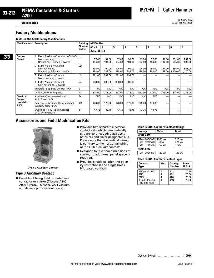
33-212
33
NEMA Contactors & StartersA200
AccessoriesFor more information visit: www.cutler-hammer.eaton.com
January 2003Vol. 2, Ref. No. [0230]
Factory ModificationsTable 33-313. A200 Factory Modifications
Accessories and Field Modification Kits
Type J Auxiliary Contact
Type J Auxiliary Contact■ Capable of being field mounted in a
contactor or starter (Classes A200, A900 Sizes 00 – 6, V200, V201 vacuum and definite purpose controllers).
■ Provides two separate electrical contact sets which wire vertically and are color coded; black desig-nates NC and silver designates NO. Please note that the vertical wiring is contrary to the horizontal wiring of the L-56 auxiliary contacts.
■ Designed to fit within dimensions of starter; no additional panel space is required.
■ Provides circuit isolation (no polar-ity restrictions) and single break bifurcated contacts.
Table 33-314. Auxiliary Contact Ratings
Table 33-315. Auxiliary Contact Types
Modifications Description CatalogNumberSuffix
NEMA Size
00 – 1 2 3 4 5 6 7 8 9
Adder U.S. $
Control Circuit
1 Extra Auxiliary Contact (1NO-1NC) Non-reversing, Reversing, 2-Speed Unwired
J197.00
194.0097.00
194.0097.00
194.0097.00
194.0097.00
194.0097.00
194.0097.00
194.00291.00585.00
291.00585.00
2 Extra Auxiliary Contact Non-reversing, Reversing, 2-Speed Unwired
J2194.00388.00
194.00388.00
194.00388.00
194.00388.00
194.00388.00
194.00388.00
194.00388.00
585.001,170.00
585.001,170.00
3 Extra Auxiliary Contact Non-reversing, Unwired
J3 291.00 291.00 291.00 291.00 — — — — —
4 Extra Auxiliary Contact Non-reversing, Unwired
J4 388.00 388.00 388.00 388.00 — — — — —
Wired for Separate Control (NC) C N/C N/C N/C N/C N/C N/C N/C N/C N/C
Omit Control Wiring (NC) X 213.00 213.00 213.00 213.00 213.00 213.00 213.00 213.00 213.00
Overload Relays (Substitu-tions)
Ambient Compensated with Auto Reset (NC)
D N/C N/C N/C N/C N/C N/C — — —
Fast Trip — Ambient Compensated (Specify Motor FLA)
D7 176.00 176.00 176.00 176.00 176.00 176.00 — — —
Overload Relay Alarm Contact (NO) per overload
E 43.75 43.75 43.75 43.75 43.75 43.75 — — —
Voltage Make Break
NEMA A600120 – 600V AC72 – 120V AC28 – 72V AC
7200 VA60A60 VA
720 VA720 VA10A
NEMA R30028 – 300V DC 28 VA 28 VA
Contact Type
Max. Catalog Number
PriceU.S. $
1NO and 1NC2NC2NO1 Coil Clearing NC and 1NO
4444
J11J02J20J1C
70.5070.5070.5070.50
Discount Symbol . . . . . . . . . . . . . . . . . . . . . . . 1CD1C
CA08102001E
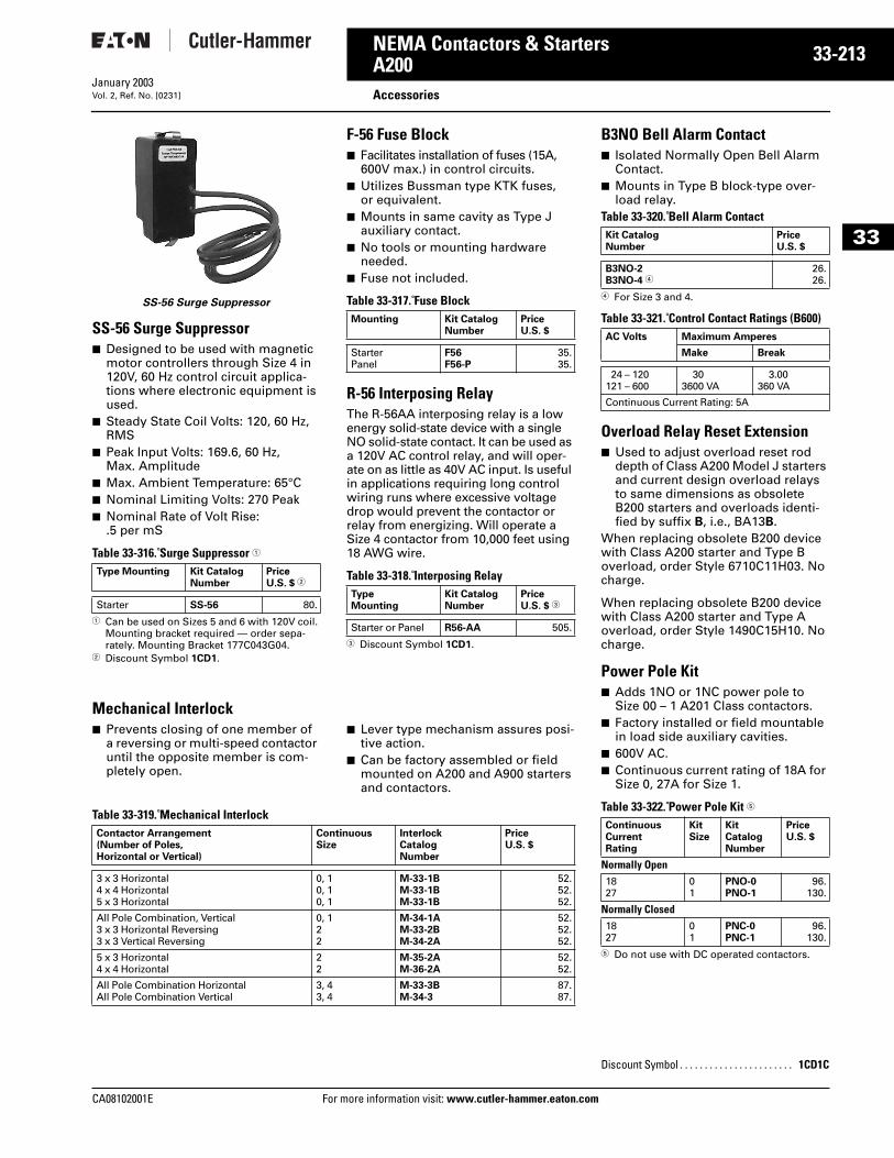
CA08102001E For more
13
33-2NEMA Contactors & StartersA200 AccessoriesJanuary 2003Vol. 2, Ref. No. [0231]
33
SS-56 Surge Suppressor
SS-56 Surge Suppressor■ Designed to be used with magnetic
motor controllers through Size 4 in 120V, 60 Hz control circuit applica-tions where electronic equipment is used.
■ Steady State Coil Volts: 120, 60 Hz, RMS
■ Peak Input Volts: 169.6, 60 Hz, Max. Amplitude
■ Max. Ambient Temperature: 65°C■ Nominal Limiting Volts: 270 Peak■ Nominal Rate of Volt Rise:
.5 per mS
Table 33-316. Surge Suppressor 1
1 Can be used on Sizes 5 and 6 with 120V coil. Mounting bracket required — order sepa-rately. Mounting Bracket 177C043G04.
2 Discount Symbol 1CD1.
F-56 Fuse Block■ Facilitates installation of fuses (15A,
600V max.) in control circuits.■ Utilizes Bussman type KTK fuses,
or equivalent.■ Mounts in same cavity as Type J
auxiliary contact.■ No tools or mounting hardware
needed.■ Fuse not included.
Table 33-317. Fuse Block
R-56 Interposing RelayThe R-56AA interposing relay is a low energy solid-state device with a single NO solid-state contact. It can be used as a 120V AC control relay, and will oper-ate on as little as 40V AC input. Is useful in applications requiring long control wiring runs where excessive voltage drop would prevent the contactor or relay from energizing. Will operate a Size 4 contactor from 10,000 feet using 18 AWG wire.
Table 33-318. Interposing Relay
3 Discount Symbol 1CD1.
Mechanical Interlock■ Prevents closing of one member of
a reversing or multi-speed contactor until the opposite member is com-pletely open.
■ Lever type mechanism assures posi-tive action.
■ Can be factory assembled or field mounted on A200 and A900 starters and contactors.
Table 33-319. Mechanical Interlock
Type Mounting Kit Catalog Number
PriceU.S. $ 2
Starter SS-56 80.
Mounting Kit CatalogNumber
PriceU.S. $
StarterPanel
F56F56-P
35.35.
Type Mounting
Kit Catalog Number
PriceU.S. $ 3
Starter or Panel R56-AA 505.
Contactor Arrangement (Number of Poles, Horizontal or Vertical)
ContinuousSize
Interlock CatalogNumber
PriceU.S. $
3 x 3 Horizontal4 x 4 Horizontal5 x 3 Horizontal
0, 10, 10, 1
M-33-1BM-33-1BM-33-1B
52.52.52.
All Pole Combination, Vertical3 x 3 Horizontal Reversing3 x 3 Vertical Reversing
0, 122
M-34-1AM-33-2BM-34-2A
52.52.52.
5 x 3 Horizontal4 x 4 Horizontal
22
M-35-2AM-36-2A
52.52.
All Pole Combination HorizontalAll Pole Combination Vertical
3, 43, 4
M-33-3BM-34-3
87.87.
information visit: www.cutler-hammer.eaton.co
B3NO Bell Alarm Contact■ Isolated Normally Open Bell Alarm
Contact.■ Mounts in Type B block-type over-
load relay.Table 33-320. Bell Alarm Contact
4 For Size 3 and 4.
Table 33-321. Control Contact Ratings (B600)
Overload Relay Reset Extension■ Used to adjust overload reset rod
depth of Class A200 Model J starters and current design overload relays to same dimensions as obsolete B200 starters and overloads identi-fied by suffix B, i.e., BA13B.
When replacing obsolete B200 device with Class A200 starter and Type B overload, order Style 6710C11H03. No charge.
When replacing obsolete B200 device with Class A200 starter and Type A overload, order Style 1490C15H10. No charge.
Power Pole Kit■ Adds 1NO or 1NC power pole to
Size 00 – 1 A201 Class contactors.■ Factory installed or field mountable
in load side auxiliary cavities.■ 600V AC.■ Continuous current rating of 18A for
Size 0, 27A for Size 1.
Table 33-322. Power Pole Kit 5
5 Do not use with DC operated contactors.
Kit Catalog Number
PriceU.S. $
B3NO-2B3NO-4 4
26.26.
AC Volts Maximum Amperes
Make Break
24 – 120121 – 600
303600 VA
3.00360 VA
Continuous Current Rating: 5A
ContinuousCurrentRating
Kit Size
Kit CatalogNumber
PriceU.S. $
Normally Open1827
01
PNO-0PNO-1
96.130.
Normally Closed1827
01
PNC-0PNC-1
96.130.
Discount Symbol . . . . . . . . . . . . . . . . . . . . . . . 1CD1C
m
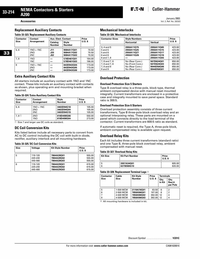
33-214
33
NEMA Contactors & StartersA200
AccessoriesFor more information visit: www.cutler-hammer.eaton.com
January 2003Vol. 2, Ref. No. [0232]
Replacement Auxiliary ContactsTable 33-323. Replacement Auxiliary Contacts
Extra Auxiliary Contact KitsAll starters include an auxiliary contact with 1NO and 1NC contact. These kits include an auxiliary contact with contacts as shown, plus operating arm and mounting bracket when required.
Table 33-324. Extra Auxiliary Contact Kits
1 Size 7 and larger use DC coils as standard.
DC Coil Conversion KitsKits listed below include all necessary parts to convert from AC to DC control including the DC coil with built-in diode, rectifier, auxiliary interlock and all mounting hardware.
Table 33-325. DC Coil Conversion Kits
Mechanical InterlocksTable 33-326. Mechanical Interlocks
Overload Protection
Overload Protection Size 5 StartersType B overload relay is a three-pole, block type, thermal ambient compensated device with manual reset mounted integrally. Current transformers are enclosed in a protective case and integrally mounted to save panel space. Standard ratio is 300:5.
Overload Protection Size 6 StartersOverload protection assembly consists of three current transformers, Type B three-pole block overload relay and an optional interposing relay. These parts are mounted on a panel which connects directly to the load terminal of the contactor. Current transformers are 600:5 ratio as standard.
If automatic reset is required, the Type A, three-pole block, ambient compensated relay is available upon request.
Overload Relay KitsEach kit includes three current transformers (standard ratio) and one Type B, three-pole block overload relay, ambient compensated with manual reset.
Table 33-327. Overload Relay Kits
Table 33-328. Replacement Terminal Lugs 2
2 All mounting hardware is included in kit.
Contactor Size
ContactArrangement
Aux. Elect. Contact PriceU.S. $Catalog
NumberStyle Number
5, 6 1NO + 1NC2NO2NC
J11J20J02
9084A17G019084A17G029084A17G03
70.5070.5070.50
7, 8 1NO1NC
——
578D461G01578D461G03
184.00196.00
9 1NO + 1NC2NO2NC
———
843D943G04843D943G05843D943G06
173.00173.00173.00
Contactor Size
ContactArrangement
Style Number
PriceU.S. $
5, 6 1NO + 1NC2NO2NC
3463D94G183463D94G043463D94G19
105.00105.00105.00
7, 8 1 2NO1NO
818D498G06818D498G04
550.00273.00
Size Voltage Kit Style Number PriceU.S. $
5 110-120220-240440-480
7864A28G017864A28G027864A28G03
555.00555.00555.00
6 110-120220-240440-480
7864A29G017864A29G027864A29G03
615.00615.00615.00
Contactor Sizes Style Numbers PriceU.S. $Horizontal Vertical
3, 4 and 55 and 55 and 66 and 66 and 7, 8
2050A11G752050A11G252050A11G272050A11G26—
2050A11G652050A11G152050A11G172050A11G162050A11G55
423.00423.00423.00423.00423.00
7, 8 and 7, 87, 8 and 7, 87, 8 and 99 and 9
No (Rear Conn.)No (Front Conn.)No (Rear Conn.)No (Rear Conn.)
567D624G01567D624G039944D56G069944D56G01
650.00650.00650.00650.00
Kit Size Kit Part Number PriceU.S. $
56
2057A34G016379D80G10
605.00820.00
ContactorSize
CableSize
Kit Style Number
PriceU.S. $
Terminals
Qty. in Kit
Qty.Req’d.per Pole
5678
1-500 MCM2-500 MCM4-500 MCM4-500 MCM
2119A76G017858A96G017858A96G027858A96G03
83.50197.00392.00392.00
66
1212
2244
Discount Symbol . . . . . . . . . . . . . . . . . . . . . . . 1CD1C
CA08102001E
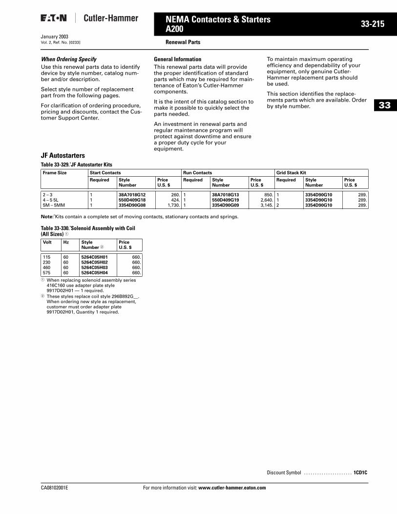
CA08102001E For more
15
33-2NEMA Contactors & StartersA200 Renewal PartsJanuary 2003Vol. 2, Ref. No. [0233]
33
When Ordering SpecifyUse this renewal parts data to identify device by style number, catalog num-ber and/or description.
Select style number of replacement part from the following pages.
For clarification of ordering procedure, pricing and discounts, contact the Cus-tomer Support Center.
General InformationThis renewal parts data will provide the proper identification of standard parts which may be required for main-tenance of Eaton’s Cutler-Hammer components.
It is the intent of this catalog section to make it possible to quickly select the parts needed.
An investment in renewal parts and regular maintenance program will protect against downtime and ensure a proper duty cycle for your equipment.
To maintain maximum operating efficiency and dependability of your equipment, only genuine Cutler-Hammer replacement parts should be used.
This section identifies the replace-ments parts which are available. Order by style number.
JF AutostartersTable 33-329. JF Autostarter Kits
Note: Kits contain a complete set of moving contacts, stationary contacts and springs.
Table 33-330. Solenoid Assembly with Coil (All Sizes) 1
1 When replacing solenoid assembly series 416C160 use adapter plate style 9917D02H01 — 1 required.
2 These styles replace coil style 296B892G__. When ordering new style as replacement, customer must order adapter plate 9917D02H01, Quantity 1 required.
Frame Size Start Contacts Run Contacts Grid Stack Kit
Required Style Number
Price U.S. $
Required Style Number
Price U.S. $
Required Style Number
Price U.S. $
2 – 34 – 5 5L5M – 5MM
111
38A7018G12550D409G183354D90G08
260.424.
1,730.
111
38A7018G13550D409G193354D90G09
850.2,640.3,145.
112
3354D90G103354D90G103354D90G10
289.289.289.
Volt Hz Style Number 2
Price U.S. $
115230460575
60606060
5264C05H015264C05H025264C05H035264C05H04
660.660.660.660.
Discount Symbol . . . . . . . . . . . . . . . . . . . . . . 1CD1C
information visit: www.cutler-hammer.eaton.com
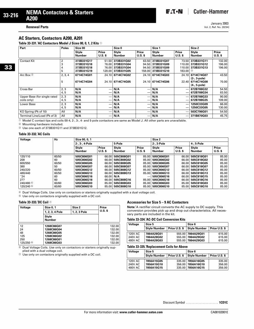
33-216
33
NEMA Contactors & StartersA200
Renewal PartsFor more information visit: www.cutler-hammer.eaton.com
January 2003Vol. 2, Ref. No. [0234]
AC Starters, Contactors A200, A201Table 33-331. AC Contactors Model J Sizes 00, 0, 1, 2 Kits 1
1 Model C contact tips and coils 00-4, 2-, 3-, 4- and 5-pole contactors are same as Model J. All other parts are unavailable.2 Mounting hardware included.3 Use one each of 373B331G11 and 373B331G12.
Table 33-332. AC Coils
4 Dual Voltage Coils. Use only on contactors or starters originally supplied with a dual voltage coil. 5 Use only on contactors originally supplied with a DC coil.
Table 33-333. DC Coil 7
6 Dual Voltage Coils. Use only on contactors or starters originally sup-plied with a dual voltage coil.
7 Use only on contactors originally supplied with a DC coil.
Accessories for Size 5 – 9 AC Contactors Note: A rectifier circuit converts the AC supply to DC supply. This conversion provides pick up and drop out characteristics. All neces-sary parts are included in the kit.
Table 33-334. AC-DC Coil Conversion Kits
Table 33-335. Replacement Coils for Above
Part Poles Size 00 Size 0 Size 1 Size 2
Style Number
PriceU.S. $
Style Number
PriceU.S. $
Style Number
PriceU.S. $
Style Number
PriceU.S. $
Contact Kit 2345
373B331G17373B331G18373B331G18373B331G19
51.5076.0076.00
128.00
373B331G02373B331G04373B331G04373B331G05
63.5094.5094.50
158.00
373B331G07373B331G09373B331G09373B331G10
73.50110.00110.00183.00
373B331G11373B331G12373B331G133
132.00196.00196.00
Arc Box 2 2, 3, 4
5
6714C74G01
6714C74G04
24.10
24.10
6714C74G02
6714C74G05
24.10
24.10
6714C74G03
6714C74G06
24.10
22.40
6714C74G07 (2-, 3-pole)6714C74G08 (4-, 5-pole)
43.50
70.00
Cross Bar 2, 34, 5
N/AN/A
——
N/AN/A
——
N/AN/A
——
672B788G32672B788G34
54.5083.50
Upper Base (for single rated coils only)
2, 34, 5
N/AN/A
——
N/AN/A
——
N/AN/A
——
672B788G33672B788G35
90.00109.00
Lower Base 2, 34, 5
N/AN/A
——
N/AN/A
——
N/AN/A
——
1250C33G091250C33G05
66.00130.00
KO Spring (Pk of 10) All N/A — N/A — N/A — 503C796G01 54.50Terminal Line/Load (Pk of 3) All N/A — N/A — N/A — 371B870G03 45.75
Voltage Hz Size 00, 0, 1 Size 2
2-, 3-, 4-Pole 5-Pole 2-, 3-Pole 4-, 5-Pole
Style Number
PriceU.S. $
Style Number
PriceU.S. $
Style Number
PriceU.S. $
Style Number
PriceU.S. $
120/110208600/550380240/220480/440 24277240/480 4120/240 5
60/506060/505060/5060/50606060/6060/60
505C806G01505C806G02505C806G05505C806G07505C806G12505C806G13505C806G16505C806G18505C806G03505C806G10
66.0066.0066.0066.0066.0066.0066.0066.0085.0085.00
505C808G01505C808G02505C808G05505C808G07505C808G12505C808G13N/A505C808G16505C808G03505C808G10
85.0085.0085.0085.0085.0085.00
—85.0085.0085.00
505C806G01505C806G02505C806G05505C806G07505C806G12505C806G13505C806G16505C806G18505C806G03505C806G10
66.0066.0066.0066.0066.0066.0066.0066.0085.0085.00
505C818G01505C818G02505C818G05505C818G07505C818G12505C818G13505C818G15505C818G16505C818G03505C818G10
85.0085.0085.0085.0085.0085.0085.0085.0085.0085.00
Voltage Size 0, 1 Size 2 PriceU.S. $1, 2, 3, 4 Pole 1, 2, 3 Pole
Style Number
122448125250125/250 6
1268C86G071268C86G041268C86G051268C86G021268C86G011268C86G03
132.00132.00132.00132.00132.00132.00
Voltage Size 5 Size 6
Style Number Price U.S. $ Style Number Price U.S. $
120V AC240V AC480V AC
7864A28G017864A28G027864A28G03
555.00555.00555.00
7864A29G017864A29G027864A29G03
615.00615.00615.00
Voltage Size 5 Size 6
Style Number Price U.S. $ Style Number Price U.S. $
120V AC240V AC480V AC
7856A15G057856A15G107856A15G15
335.00356.00335.00
7856A16G057856A16G107856A16G15
335.00356.00356.00
Discount Symbol . . . . . . . . . . . . . . . . . . . . . . . 1CD1C
CA08102001E
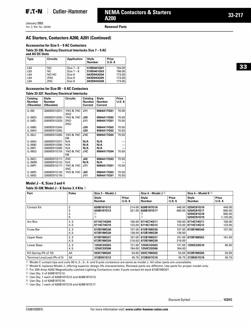
CA08102001E For more
17
33-2NEMA Contactors & StartersA200 Renewal PartsJanuary 2003Vol. 2, Ref. No. [0235]
33
AC Starters, Contactors A200, A201 (Continued)
Accessories for Size 5 – 9 AC Contactors Table 33-336. Auxiliary Electrical Interlocks Size 7 – 9 AC and All DC Units
Accessories for Size 00 – 6 AC ContactorsTable 33-337. Auxiliary Electrical Interlocks
Model J – K, Sizes 3 and 4 Table 33-338. Model J – K Series 3, 4 Kits 1
1 Model C contact tips and coils 00-4, 2-, 3-, 4- and 5-pole contactors are same as model J. All other parts are unavailable.2 Model K replaces Model J, offering superior design life characteristics. Renewal parts are different. Use parts for proper model only. 3 For 200 Amp A202 Magnetically Latched Lighting Contactors order 3-pole contact kit style 672B788G07.4 Use Qty. 2 of 626B187G12. 5 Use Qty. 1 each of 626B187G12 and 626B187G13.6 Use Qty. 2 of 626B187G16.7 Use Qty. 1 each of 626B187G16 and 626B187G17.
Type Circuits Application Style Number
PriceU.S. $
L63L63L64L64L64
NONCNO-NC2NO2NC
Size 7 – 8Size 7 – 8Size 9Size 9Size 9
578D461G01578D461G03843D943G04843D943G05843D943G06
184.00196.00173.00173.00173.00
CatalogNumber(Obsolete)
StyleNumber(Obsolete)
Circuits CatalogNumberCurrent
StyleNumberCurrent
PriceU.S. $
(L-56)
(L-56D)(L-56E)
(L-56B)(L-56H)
(2609D01G01)
(2609D01G02)(2609D01G03)
(2609D01G04)(2609D01G05)
1NO & 1NC2NO1NO & 1NC2NO2NO
J11
J20J11
J20J20
9084A17G01
9084A17G029084A17G01
9084A17G029084A17G02
70.50
70.5070.50
70.5070.50
(L-56J)
(L-56A)(L-56B)(L-56F)(L-56G)
(2609D01G06)
(2609D01G07)(2609D01G08)(2609D01G09)(2609D01G10)
1NO & 1NC DBN/AN/AN/A1NO & 1NC DB
J1C
N/AN/AN/AJ1C
9084A17G04
N/AN/AN/A9084A17G04
70.50
———
70.50
(L-56C)(L-56M)(L-56P)
(L-56R)(L-56S)
(2609D01G11)(2609D01G12)(2609D01G17)
(2609D01G18)(2609D01G19)
2NCN/A1NO & 1NC2NC1NO & 1NC
J02N/AJ11
J02J11
9084A17G03N/A9084A17G01
9084A17G039084A17G01
70.50—
70.50
70.5070.50
Part Poles Size 3 – Model J Size 4 – Model J 3 Size 4 – Model K 2
Style Number
PriceU.S. $
Style Number
PriceU.S. $
Style Number
PriceU.S. $
Contact Kit 2345
626B187G12626B187G134
5
214.00321.00
626B187G16626B187G176
7
448.00680.00
5250C81G165250C81G175250C81G185250C81G19
448.00680.00900.00
1,125.00
Arc Box 2, 34, 5
6714C74G096714C74G10
100.00123.00
6714C74G116714C74G12
100.00123.00
6714C74G116714C74G12
100.00123.00
Cross Bar 2, 34, 5
672B788G36672B788G38
107.00138.00
672B788G36672B788G38
107.00138.00
672B788G40 107.00
Upper Base 2, 34, 5
672B788G37672B788G39
161.00218.00
672B788G37672B788G39
161.00218.00
672B788G52 161.00
Lower Base 2, 34, 5
1250C33G031250C33G06
121.00164.00
1250C33G031250C33G06
121.00164.00
1250C33G10 85.00
KO Spring (Pk of 10) All 503C796G02 54.50 503C796G02 54.50 672B788G50 54.50
Terminal Line/Load (Pk of 3) All 372B357G12 45.75 372B357G18 45.75 372B357G18 45.75
Discount Symbol . . . . . . . . . . . . . . . . . . . . . . . 1CD1C
information visit: www.cutler-hammer.eaton.com
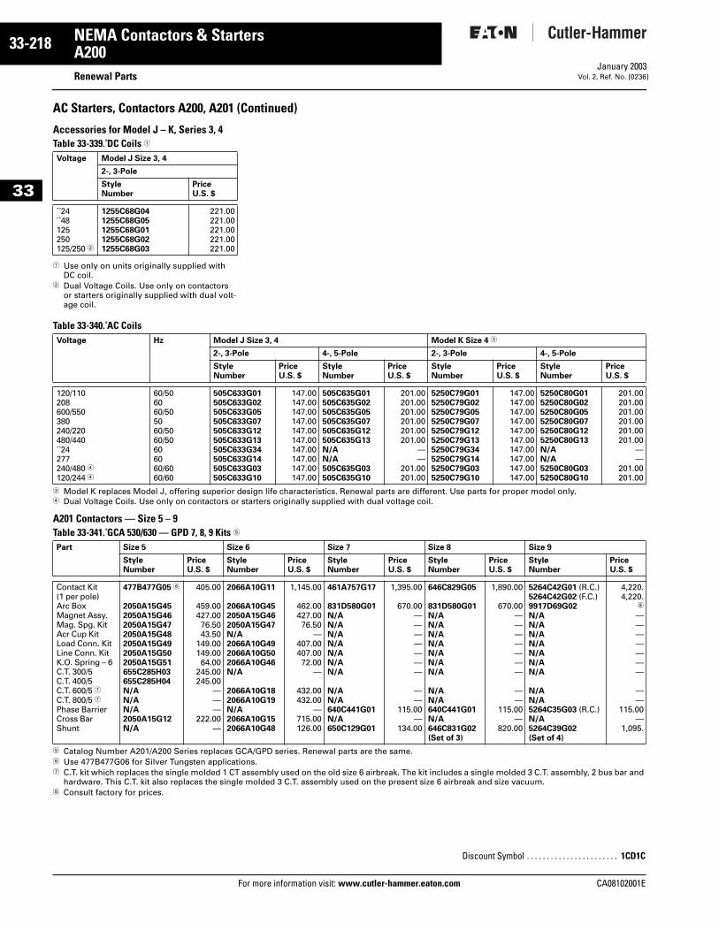
33-218
33
NEMA Contactors & StartersA200
Renewal PartsFor more information visit: www.cutler-hammer.eaton.com
January 2003Vol. 2, Ref. No. [0236]
AC Starters, Contactors A200, A201 (Continued)
Accessories for Model J – K, Series 3, 4 Table 33-339. DC Coils 1
1 Use only on units originally supplied with DC coil.
2 Dual Voltage Coils. Use only on contactors or starters originally supplied with dual volt-age coil.
Table 33-340. AC Coils
3 Model K replaces Model J, offering superior design life characteristics. Renewal parts are different. Use parts for proper model only.4 Dual Voltage Coils. Use only on contactors or starters originally supplied with dual voltage coil.
A201 Contactors — Size 5 – 9 Table 33-341. GCA 530/630 — GPD 7, 8, 9 Kits 5
5 Catalog Number A201/A200 Series replaces GCA/GPD series. Renewal parts are the same. 6 Use 477B477G06 for Silver Tungsten applications.7 C.T. kit which replaces the single molded 1 CT assembly used on the old size 6 airbreak. The kit includes a single molded 3 C.T. assembly, 2 bus bar and
hardware. This C.T. kit also replaces the single molded 3 C.T. assembly used on the present size 6 airbreak and size vacuum.8 Consult factory for prices.
Voltage Model J Size 3, 4
2-, 3-Pole
Style Number
Price U.S. $
24 48125250125/250 2
1255C68G041255C68G051255C68G011255C68G021255C68G03
221.00221.00221.00221.00221.00
Voltage Hz Model J Size 3, 4 Model K Size 4 3
2-, 3-Pole 4-, 5-Pole 2-, 3-Pole 4-, 5-Pole
Style Number
PriceU.S. $
Style Number
PriceU.S. $
Style Number
PriceU.S. $
Style Number
PriceU.S. $
120/110208600/550380240/220480/440 24277240/480 4120/244 4
60/506060/505060/5060/50606060/6060/60
505C633G01505C633G02505C633G05505C633G07505C633G12505C633G13505C633G34505C633G14505C633G03505C633G10
147.00147.00147.00147.00147.00147.00147.00147.00147.00147.00
505C635G01505C635G02505C635G05505C635G07505C635G12505C635G13N/AN/A505C635G03505C635G10
201.00201.00201.00201.00201.00201.00
——
201.00201.00
5250C79G015250C79G025250C79G055250C79G075250C79G125250C79G135250C79G345250C79G145250C79G035250C79G10
147.00147.00147.00147.00147.00147.00147.00147.00147.00147.00
5250C80G015250C80G025250C80G055250C80G075250C80G125250C80G13N/AN/A5250C80G035250C80G10
201.00201.00201.00201.00201.00201.00
——
201.00201.00
Part Size 5 Size 6 Size 7 Size 8 Size 9
Style Number
PriceU.S. $
Style Number
PriceU.S. $
Style Number
PriceU.S. $
Style Number
PriceU.S. $
Style Number
PriceU.S. $
Contact Kit(1 per pole)Arc BoxMagnet Assy.Mag. Spg. KitAcr Cup KitLoad Conn. KitLine Conn. KitK.O. Spring – 6C.T. 300/5C.T. 400/5C.T. 600/5 7C.T. 800/5 7Phase BarrierCross BarShunt
477B477G05 6
2050A15G452050A15G462050A15G472050A15G482050A15G492050A15G502050A15G51655C285H03655C285H04N/AN/AN/A2050A15G12N/A
405.00
459.00427.0076.5043.50
149.00149.0064.00
245.00245.00
———
222.00—
2066A10G11
2066A10G452050A15G462050A15G47N/A2066A10G492066A10G502066A10G46N/A
2066A10G182066A10G19N/A2066A10G152066A10G48
1,145.00
462.00427.0076.50
—407.00407.0072.00
—
432.00432.00
—715.00126.00
461A757G17
831D580G01N/AN/AN/AN/AN/AN/AN/A
N/AN/A640C441G01N/A650C129G01
1,395.00
670.00———————
——
115.00—
134.00
646C829G05
831D580G01N/AN/AN/AN/AN/AN/AN/A
N/AN/A640C441G01N/A646C831G02(Set of 3)
1,890.00
670.00———————
——
115.00—
820.00
5264C42G01 (R.C.)5264C42G02 (F.C.)9917D69G02N/AN/AN/AN/AN/AN/AN/A
N/AN/A5264C35G03 (R.C.)N/A5264C39G02 (Set of 4)
4,220.4,220.
8
———————
——
115.00—
1,095.
Discount Symbol . . . . . . . . . . . . . . . . . . . . . . . 1CD1C
CA08102001E
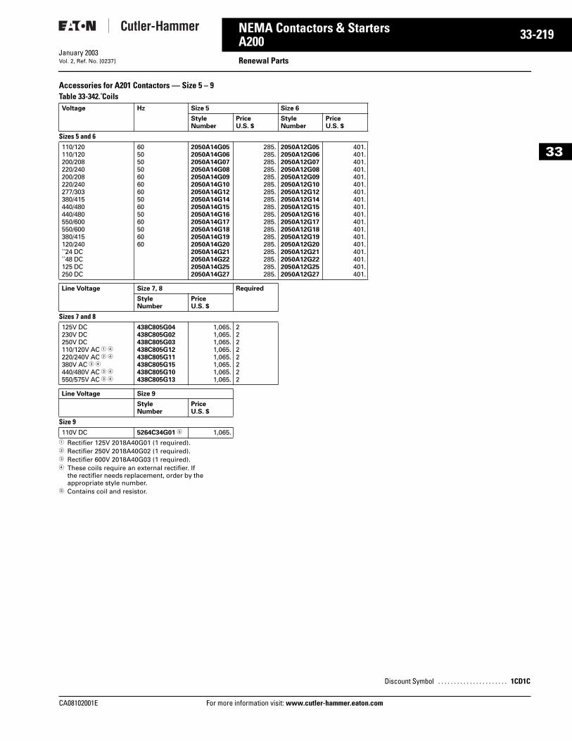
CA08102001E For more
19
33-2NEMA Contactors & StartersA200 Renewal PartsJanuary 2003Vol. 2, Ref. No. [0237]
33
Accessories for A201 Contactors — Size 5 – 9Table 33-342. Coils
1 Rectifier 125V 2018A40G01 (1 required).2 Rectifier 250V 2018A40G02 (1 required).3 Rectifier 600V 2018A40G03 (1 required).4 These coils require an external rectifier. If
the rectifier needs replacement, order by the appropriate style number.
5 Contains coil and resistor.
Voltage Hz Size 5 Size 6
Style Number
PriceU.S. $
Style Number
PriceU.S. $
Sizes 5 and 6110/120110/120200/208220/240200/208220/240277/303380/415440/480440/480550/600550/600380/415120/240 24 DC 48 DC125 DC250 DC
6050505060606050605060506060
2050A14G052050A14G062050A14G072050A14G082050A14G092050A14G102050A14G122050A14G142050A14G152050A14G162050A14G172050A14G182050A14G192050A14G202050A14G212050A14G222050A14G252050A14G27
285.285.285.285.285.285.285.285.285.285.285.285.285.285.285.285.285.285.
2050A12G052050A12G062050A12G072050A12G082050A12G092050A12G102050A12G122050A12G142050A12G152050A12G162050A12G172050A12G182050A12G192050A12G202050A12G212050A12G222050A12G252050A12G27
401.401.401.401.401.401.401.401.401.401.401.401.401.401.401.401.401.401.
Line Voltage Size 7, 8 Required
Style Number
Price U.S. $
Sizes 7 and 8125V DC230V DC250V DC110/120V AC 1 4220/240V AC 2 4380V AC 3 4440/480V AC 3 4550/575V AC 3 4
438C805G04438C805G02438C805G03438C805G12438C805G11438C805G15438C805G10438C805G13
1,065.1,065.1,065.1,065.1,065.1,065.1,065.1,065.
22222222
Line Voltage Size 9
Style Number
Price U.S. $
Size 9110V DC 5264C34G01 5 1,065.
information visit: www.cutler-hammer.eaton.co
Discount Symbol . . . . . . . . . . . . . . . . . . . . . . 1CD1C
m
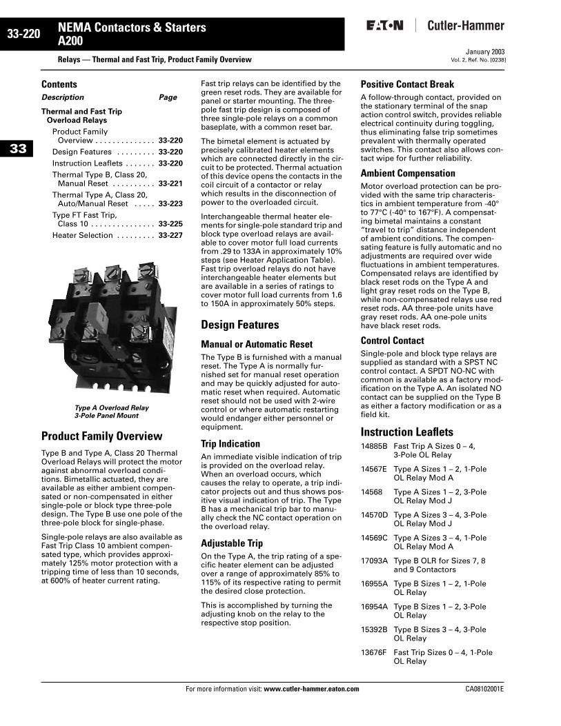
33-220
33
NEMA Contactors & StartersA200
Relays — Thermal and Fast Trip, Product Family OverviewFor more information visit: www.cutler-hammer.eaton.com
January 2003Vol. 2, Ref. No. [0238]
ContentsDescription Page
Thermal and Fast Trip Overload Relays
Product FamilyOverview . . . . . . . . . . . . . . 33-220
Design Features . . . . . . . . . 33-220
Instruction Leaflets . . . . . . . 33-220
Thermal Type B, Class 20, Manual Reset . . . . . . . . . . 33-221
Thermal Type A, Class 20, Auto/Manual Reset . . . . . 33-223
Type FT Fast Trip, Class 10 . . . . . . . . . . . . . . . 33-225
Heater Selection . . . . . . . . . 33-227
Type A Overload Relay3-Pole Panel Mount
Product Family OverviewType B and Type A, Class 20 Thermal Overload Relays will protect the motor against abnormal overload condi-tions. Bimetallic actuated, they are available as either ambient compen-sated or non-compensated in either single-pole or block type three-pole design. The Type B use one pole of the three-pole block for single-phase.
Single-pole relays are also available as Fast Trip Class 10 ambient compen-sated type, which provides approxi-mately 125% motor protection with a tripping time of less than 10 seconds, at 600% of heater current rating.
Fast trip relays can be identified by the green reset rods. They are available for panel or starter mounting. The three-pole fast trip design is composed of three single-pole relays on a common baseplate, with a common reset bar.
The bimetal element is actuated by precisely calibrated heater elements which are connected directly in the cir-cuit to be protected. Thermal actuation of this device opens the contacts in the coil circuit of a contactor or relay which results in the disconnection of power to the overloaded circuit.
Interchangeable thermal heater ele-ments for single-pole standard trip and block type overload relays are avail-able to cover motor full load currents from .29 to 133A in approximately 10% steps (see Heater Application Table). Fast trip overload relays do not have interchangeable heater elements but are available in a series of ratings to cover motor full load currents from 1.6 to 150A in approximately 50% steps.
Design Features
Manual or Automatic ResetThe Type B is furnished with a manual reset. The Type A is normally fur-nished set for manual reset operation and may be quickly adjusted for auto-matic reset when required. Automatic reset should not be used with 2-wire control or where automatic restarting would endanger either personnel or equipment.
Trip IndicationAn immediate visible indication of trip is provided on the overload relay. When an overload occurs, which causes the relay to operate, a trip indi-cator projects out and thus shows pos-itive visual indication of trip. The Type B has a mechanical trip bar to manu-ally check the NC contact operation on the overload relay.
Adjustable TripOn the Type A, the trip rating of a spe-cific heater element can be adjusted over a range of approximately 85% to 115% of its respective rating to permit the desired close protection.
This is accomplished by turning the adjusting knob on the relay to the respective stop position.
Positive Contact BreakA follow-through contact, provided on the stationary terminal of the snap action control switch, provides reliable electrical continuity during toggling, thus eliminating false trip sometimes prevalent with thermally operated switches. This contact also allows con-tact wipe for further reliability.
Ambient CompensationMotor overload protection can be pro-vided with the same trip characteris-tics in ambient temperature from -40° to 77°C (-40° to 167°F). A compensat-ing bimetal maintains a constant “travel to trip” distance independent of ambient conditions. The compen-sating feature is fully automatic and no adjustments are required over wide fluctuations in ambient temperatures. Compensated relays are identified by black reset rods on the Type A and light gray reset rods on the Type B, while non-compensated relays use red reset rods. AA three-pole units have gray reset rods. AA one-pole units have black reset rods.
Control ContactSingle-pole and block type relays are supplied as standard with a SPST NC control contact. A SPDT NO-NC with common is available as a factory mod-ification on the Type A. An isolated NO contact can be supplied on the Type B as either a factory modification or as a field kit.
Instruction Leaflets14885B Fast Trip A Sizes 0 – 4,
3-Pole OL Relay
14567E Type A Sizes 1 – 2, 1-Pole OL Relay Mod A
14568 Type A Sizes 1 – 2, 3-Pole OL Relay Mod J
14570D Type A Sizes 3 – 4, 3-Pole OL Relay Mod J
14569C Type A Sizes 3 – 4, 1-Pole OL Relay Mod A
17093A Type B OLR for Sizes 7, 8 and 9 Contactors
16955A Type B Sizes 1 – 2, 1-Pole OL Relay
16954A Type B Sizes 1 – 2, 3-Pole OL Relay
15392B Type B Sizes 3 – 4, 3-Pole OL Relay
13676F Fast Trip Sizes 0 – 4, 1-Pole OL Relay
CA08102001E
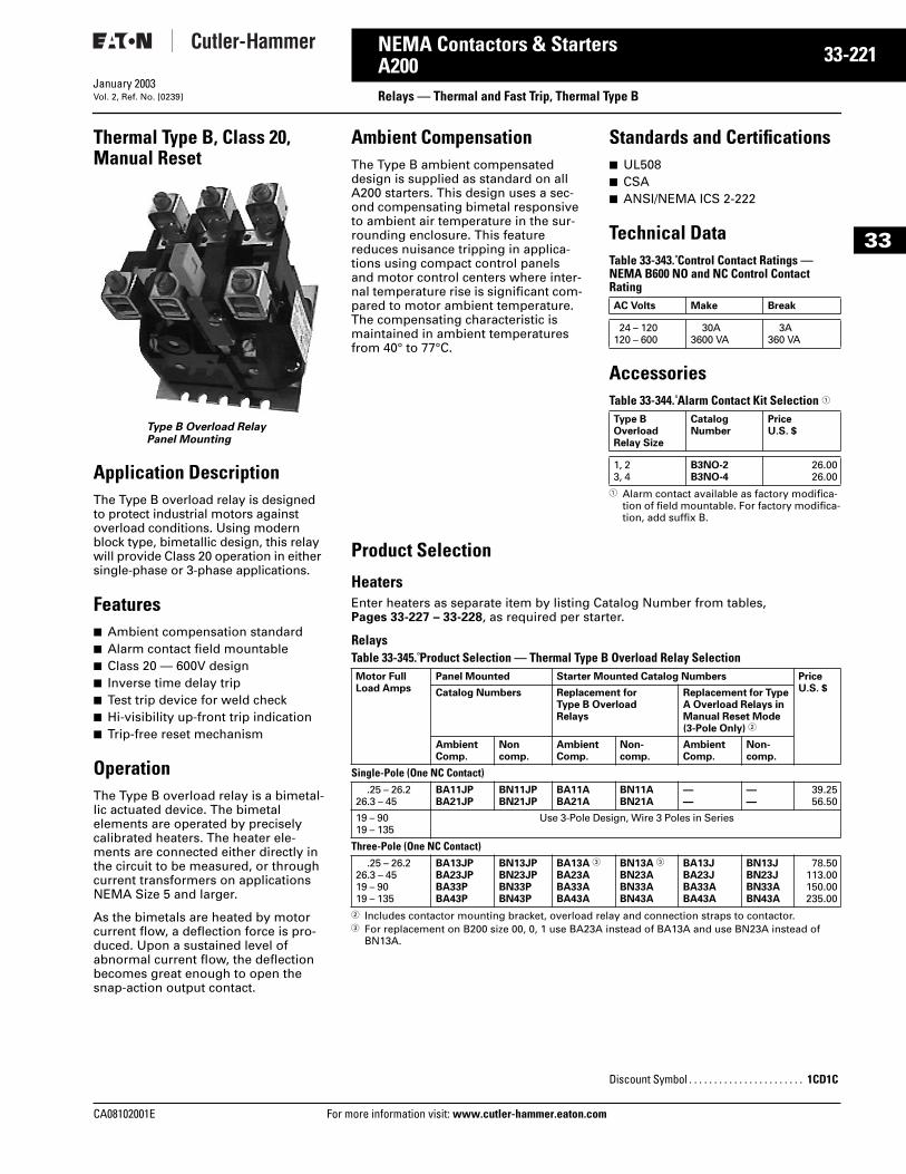
CA08102001E For more
21
33-2NEMA Contactors & StartersA200 Relays — Thermal and Fast Trip, Thermal Type BJanuary 2003Vol. 2, Ref. No. [0239]
33
Thermal Type B, Class 20, Manual Reset
Type B Overload RelayPanel Mounting
Application DescriptionThe Type B overload relay is designed to protect industrial motors against overload conditions. Using modern block type, bimetallic design, this relay will provide Class 20 operation in either single-phase or 3-phase applications.
Features■ Ambient compensation standard■ Alarm contact field mountable■ Class 20 — 600V design■ Inverse time delay trip■ Test trip device for weld check■ Hi-visibility up-front trip indication■ Trip-free reset mechanism
OperationThe Type B overload relay is a bimetal-lic actuated device. The bimetal elements are operated by precisely calibrated heaters. The heater ele-ments are connected either directly in the circuit to be measured, or through current transformers on applications NEMA Size 5 and larger.
As the bimetals are heated by motor current flow, a deflection force is pro-duced. Upon a sustained level of abnormal current flow, the deflection becomes great enough to open the snap-action output contact.
Ambient CompensationThe Type B ambient compensated design is supplied as standard on all A200 starters. This design uses a sec-ond compensating bimetal responsive to ambient air temperature in the sur-rounding enclosure. This feature reduces nuisance tripping in applica-tions using compact control panels and motor control centers where inter-nal temperature rise is significant com-pared to motor ambient temperature. The compensating characteristic is maintained in ambient temperatures from 40° to 77°C.
Standards and Certifications■ UL508■ CSA■ ANSI/NEMA ICS 2-222
Technical DataTable 33-343. Control Contact Ratings — NEMA B600 NO and NC Control Contact Rating
AccessoriesTable 33-344. Alarm Contact Kit Selection 1
1 Alarm contact available as factory modifica-tion of field mountable. For factory modifica-tion, add suffix B.
Product Selection
Heaters Enter heaters as separate item by listing Catalog Number from tables, Pages 33-227 – 33-228, as required per starter.
Relays Table 33-345. Product Selection — Thermal Type B Overload Relay Selection
2 Includes contactor mounting bracket, overload relay and connection straps to contactor.3 For replacement on B200 size 00, 0, 1 use BA23A instead of BA13A and use BN23A instead of
BN13A.
AC Volts Make Break
24 – 120120 – 600
30A3600 VA
3A360 VA
Type B OverloadRelay Size
Catalog Number
PriceU.S. $
1, 23, 4
B3NO-2B3NO-4
26.0026.00
Motor FullLoad Amps
Panel Mounted Starter Mounted Catalog Numbers PriceU.S. $Catalog Numbers Replacement for
Type B OverloadRelays
Replacement for Type A Overload Relays in Manual Reset Mode(3-Pole Only) 2
AmbientComp.
Noncomp.
AmbientComp.
Non-comp.
AmbientComp.
Non-comp.
Single-Pole (One NC Contact).25 – 26.2
26.3 – 45BA11JPBA21JP
BN11JPBN21JP
BA11ABA21A
BN11ABN21A
——
——
39.2556.50
19 – 9019 – 135
Use 3-Pole Design, Wire 3 Poles in Series
Three-Pole (One NC Contact).25 – 26.2
26.3 – 4519 – 9019 – 135
BA13JPBA23JPBA33PBA43P
BN13JPBN23JPBN33PBN43P
BA13A 3
BA23ABA33ABA43A
BN13A 3
BN23ABN33ABN43A
BA13JBA23JBA33ABA43A
BN13JBN23JBN33ABN43A
78.50113.00150.00235.00
Discount Symbol . . . . . . . . . . . . . . . . . . . . . . . 1CD1C
information visit: www.cutler-hammer.eaton.com
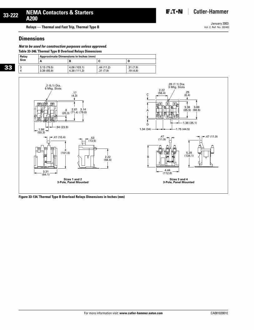
33-222
33
NEMA Contactors & StartersA200
Relays — Thermal and Fast Trip, Thermal Type BFor more information visit: www.cutler-hammer.eaton.com
January 2003Vol. 2, Ref. No. [0240]
DimensionsNot to be used for construction purposes unless approved. Table 33-346. Thermal Type B Overload Relays Dimensions
Figure 33-134. Thermal Type B Overload Relays Dimensions in Inches (mm)
RelaySize
Approximate Dimensions in Inches (mm)
A B C D
34
3.13 (79.5)3.38 (85.9)
4.06 (103.1)4.38 (111.3)
.44 (11.2)
.31 (7.9).31 (7.9).19 (4.8)
C
D
A
.94 (23.9)1.98
(50.3)
.8(20.3)
3.14(79.8)
2.81(71.4)
.17(4.3)
1.38 (35.1)
1.75 (44.5)
.41 (10.4) .47 (11.9).47(11.9).53
(13.5)
4(101.6)
Sizes 1 and 23-Pole, Panel Mounted
Sizes 3 and 43-Pole, Panel Mounted
3.31(84.1)
4.44(112.8)
5.28(134.1)
3.88(98.6)
3.38(85.9)
2.22(56.4)
1.34 (34)
B
.25(6.4)
2.22(56.4)
.2 (5.1) Dia.6 Mtg. Slots
.28 (7.1) Dia.3 Mtg. Slots
CA08102001E
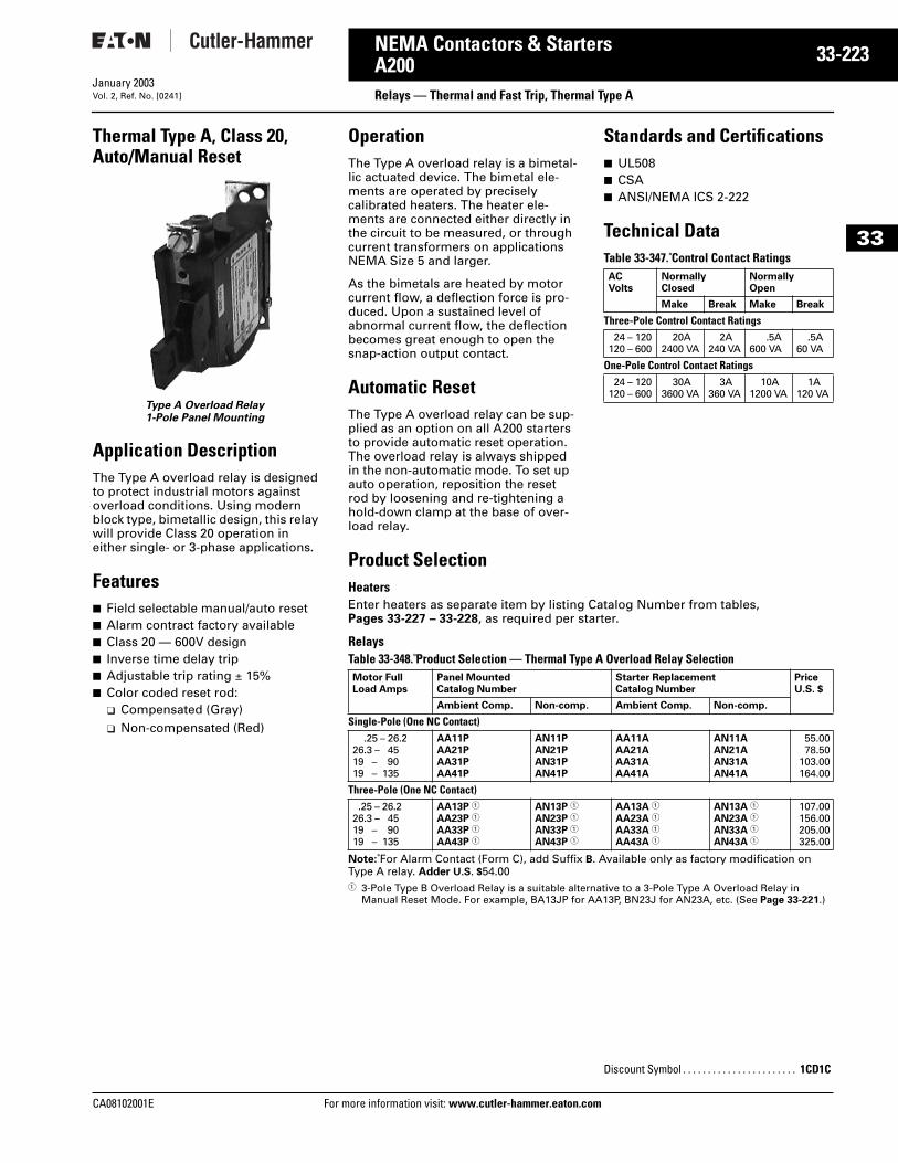
CA08102001E For more
23
33-2NEMA Contactors & StartersA200 Relays — Thermal and Fast Trip, Thermal Type AJanuary 2003Vol. 2, Ref. No. [0241]
33
Thermal Type A, Class 20, Auto/Manual Reset
Type A Overload Relay1-Pole Panel Mounting
Application DescriptionThe Type A overload relay is designed to protect industrial motors against overload conditions. Using modern block type, bimetallic design, this relay will provide Class 20 operation in either single- or 3-phase applications.
Features■ Field selectable manual/auto reset■ Alarm contract factory available■ Class 20 — 600V design■ Inverse time delay trip■ Adjustable trip rating ± 15%■ Color coded reset rod:
❑ Compensated (Gray)❑ Non-compensated (Red)
OperationThe Type A overload relay is a bimetal-lic actuated device. The bimetal ele-ments are operated by precisely calibrated heaters. The heater ele-ments are connected either directly in the circuit to be measured, or through current transformers on applications NEMA Size 5 and larger.
As the bimetals are heated by motor current flow, a deflection force is pro-duced. Upon a sustained level of abnormal current flow, the deflection becomes great enough to open the snap-action output contact.
Automatic ResetThe Type A overload relay can be sup-plied as an option on all A200 starters to provide automatic reset operation. The overload relay is always shipped in the non-automatic mode. To set up auto operation, reposition the reset rod by loosening and re-tightening a hold-down clamp at the base of over-load relay.
Standards and Certifications■ UL508■ CSA■ ANSI/NEMA ICS 2-222
Technical DataTable 33-347. Control Contact Ratings
Product SelectionHeaters Enter heaters as separate item by listing Catalog Number from tables,Pages 33-227 – 33-228, as required per starter.
Relays Table 33-348. Product Selection — Thermal Type A Overload Relay Selection
Note: For Alarm Contact (Form C), add Suffix B. Available only as factory modification on Type A relay. Adder U.S. $54.001 3-Pole Type B Overload Relay is a suitable alternative to a 3-Pole Type A Overload Relay in
Manual Reset Mode. For example, BA13JP for AA13P, BN23J for AN23A, etc. (See Page 33-221.)
ACVolts
NormallyClosed
NormallyOpen
Make Break Make Break
Three-Pole Control Contact Ratings24 – 120
120 – 60020A
2400 VA2A
240 VA.5A
600 VA.5A
60 VA
One-Pole Control Contact Ratings24 – 120
120 – 60030A
3600 VA3A
360 VA10A
1200 VA1A
120 VA
Motor Full Load Amps
Panel Mounted Catalog Number
Starter Replacement Catalog Number
PriceU.S. $
Ambient Comp. Non-comp. Ambient Comp. Non-comp.
Single-Pole (One NC Contact).25 – 26.2
26.3 – 4519 – 9019 – 135
AA11PAA21PAA31PAA41P
AN11PAN21PAN31PAN41P
AA11AAA21AAA31AAA41A
AN11AAN21AAN31AAN41A
55.0078.50
103.00164.00
Three-Pole (One NC Contact).25 – 26.2
26.3 – 4519 – 9019 – 135
AA13P 1
AA23P 1
AA33P 1
AA43P 1
AN13P 1
AN23P 1
AN33P 1
AN43P 1
AA13A 1
AA23A 1
AA33A 1
AA43A 1
AN13A 1
AN23A 1
AN33A 1
AN43A 1
107.00156.00205.00325.00
Discount Symbol . . . . . . . . . . . . . . . . . . . . . . . 1CD1C
information visit: www.cutler-hammer.eaton.com
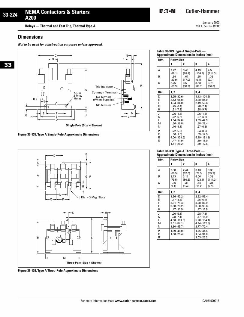
33-224
33
NEMA Contactors & StartersA200
Relays — Thermal and Fast Trip, Thermal Type AFor more information visit: www.cutler-hammer.eaton.com
January 2003Vol. 2, Ref. No. [0242]
DimensionsNot to be used for construction purposes unless approved.
Figure 33-135. Type A Single-Pole Approximate Dimensions
Figure 33-136. Type A Three-Pole Approximate Dimensions
CQ P
N
F
TB
MSE LHD
A
JG
RTrip Indicator
Common Terminal
No Terminal(When Supplied)
NC Terminal
K Dia.2 Mtg.Holes
Single-Pole (Size 4 Shown)
D
N
Q P
K
J Dia. – 3 Mtg. Slots
Three-Pole (Size 4 Shown)
H
M
FGA
C
B L
E
R
Table 33-349. Type A Single-Pole —Approximate Dimensions in Inches (mm)
Table 33-350. Type A Three-Pole —Approximate Dimensions in Inches (mm)
Dim. Relay Size
1 2 3 4
A
B
C
2.72(69.1).94
(23.9)2.75(69.9)
3.48(88.4).67
(17.0)3.5(88.9)
4.19(106.4).25
(6.4)3.53(89.7)
4.5(114.3).38
(9.7)3.78(96.0)
Dim. 1, 2 3, 4
DEFGH
3.25 (82.6)2.63 (66.8)1.34 (34.0).25 (6.4).31 (7.9)
4.13 (104.9)3.38 (85.9)2.19 (55.6).28 (7.1).38 (9.7)
JKLMN
.06 (1.5)
.22 (5.6)1.34 (34.0).66 (16.8).16 (4.1)
.06 (1.5)
.27 (6.8)1.69 (42.9).88 (22.4).27 (6.8)
PQRST
.22 (5.6)
.06 (1.5)4.00 (101.6).47 (11.9)
1.11 (28.2)
.34 (8.6)
.69 (17.5)5.19 (131.8).59 (15.0).69 (17.5)
Dim. Relay Size
1 2 3 4
A
B
C
2.38(60.5)3.13(79.5).36
(9.1)
2.44(62.0)3.17(80.5).33
(8.4)
3.13(79.5)4.06(103.1).44
(11.2)
3.38(85.9)4.38(111.3).31
(7.9)
Dim. 1, 2 3, 4
DEFGH
1.66 (42.2).17 (4.3)
2.81 (71.4)3.08 (78.2).47 (11.9)
2.22 (56.4).25 (6.4)
3.38 (85.9)3.88 (98.6).47 (11.9)
JKLMN
.20 (5.1)
.28 (7.1)4.00 (101.6)3.31 (84.1)1.80 (45.7)
.28 (7.1)
.47 (11.9)5.28 (134.1)4.44 (112.8)2.77 (70.4)
PQR
1.89 (48.0)1.00 (25.4)
1.75 (44.5)1.34 (34.0)1.03 (26.2)
CA08102001E
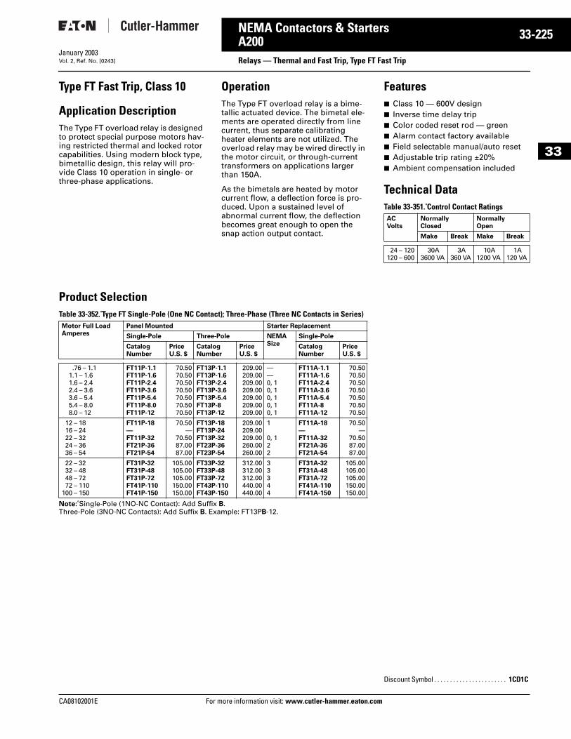
CA08102001E For more
25
33-2NEMA Contactors & StartersA200 Relays — Thermal and Fast Trip, Type FT Fast TripJanuary 2003Vol. 2, Ref. No. [0243]
33
Type FT Fast Trip, Class 10
Application DescriptionThe Type FT overload relay is designed to protect special purpose motors hav-ing restricted thermal and locked rotor capabilities. Using modern block type, bimetallic design, this relay will pro-vide Class 10 operation in single- or three-phase applications.
OperationThe Type FT overload relay is a bime-tallic actuated device. The bimetal ele-ments are operated directly from line current, thus separate calibrating heater elements are not utilized. The overload relay may be wired directly in the motor circuit, or through-current transformers on applications larger than 150A.
As the bimetals are heated by motor current flow, a deflection force is pro-duced. Upon a sustained level of abnormal current flow, the deflection becomes great enough to open the snap action output contact.
Features■ Class 10 — 600V design■ Inverse time delay trip■ Color coded reset rod — green■ Alarm contact factory available■ Field selectable manual/auto reset■ Adjustable trip rating ±20%■ Ambient compensation included
Technical DataTable 33-351. Control Contact Ratings
Product Selection Table 33-352. Type FT Single-Pole (One NC Contact); Three-Phase (Three NC Contacts in Series)
Note: Single-Pole (1NO-NC Contact): Add Suffix B. Three-Pole (3NO-NC Contacts): Add Suffix B. Example: FT13PB-12.
ACVolts
NormallyClosed
NormallyOpen
Make Break Make Break
24 – 120120 – 600
30A3600 VA
3A360 VA
10A1200 VA
1A120 VA
Motor Full Load Amperes
Panel Mounted Starter Replacement
Single-Pole Three-Pole NEMA Size
Single-Pole
CatalogNumber
PriceU.S. $
CatalogNumber
PriceU.S. $
CatalogNumber
PriceU.S. $
.76 – 1.11.1 – 1.61.6 – 2.42.4 – 3.63.6 – 5.45.4 – 8.08.0 – 12
FT11P-1.1FT11P-1.6FT11P-2.4FT11P-3.6FT11P-5.4FT11P-8.0FT11P-12
70.5070.5070.5070.5070.5070.5070.50
FT13P-1.1FT13P-1.6FT13P-2.4FT13P-3.6FT13P-5.4FT13P-8FT13P-12
209.00209.00209.00209.00209.00209.00209.00
——0, 10, 10, 10, 10, 1
FT11A-1.1FT11A-1.6FT11A-2.4FT11A-3.6FT11A-5.4FT11A-8FT11A-12
70.5070.5070.5070.5070.5070.5070.50
12 – 1816 – 2422 – 3224 – 3636 – 54
FT11P-18—FT11P-32FT21P-36FT21P-54
70.50—
70.5087.0087.00
FT13P-18FT13P-24FT13P-32FT23P-36FT23P-54
209.00209.00209.00260.00260.00
1
0, 122
FT11A-18—FT11A-32FT21A-36FT21A-54
70.50—
70.5087.0087.00
22 – 3232 – 4848 – 7272 – 110
100 – 150
FT31P-32FT31P-48FT31P-72FT41P-110FT41P-150
105.00105.00105.00150.00150.00
FT33P-32FT33P-48FT33P-72FT43P-110FT43P-150
312.00312.00312.00440.00440.00
33344
FT31A-32FT31A-48FT31A-72FT41A-110FT41A-150
105.00105.00105.00150.00150.00
Discount Symbol . . . . . . . . . . . . . . . . . . . . . . . 1CD1C
information visit: www.cutler-hammer.eaton.com
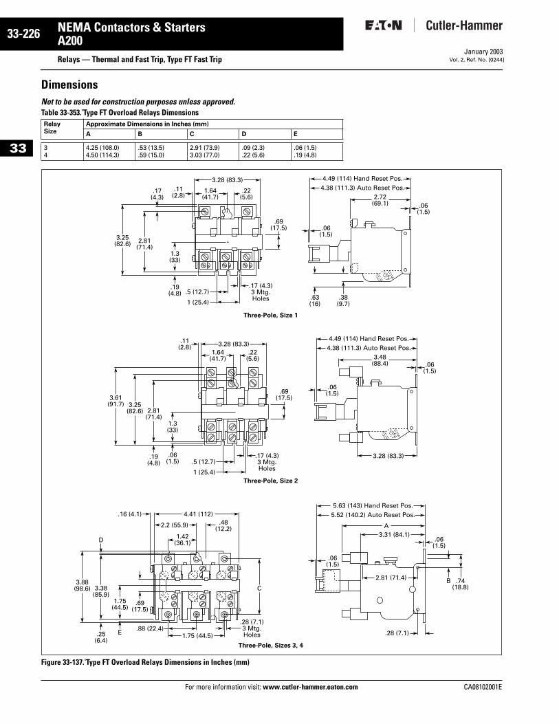
33-226
33
NEMA Contactors & StartersA200
Relays — Thermal and Fast Trip, Type FT Fast TripFor more information visit: www.cutler-hammer.eaton.com
January 2003Vol. 2, Ref. No. [0244]
DimensionsNot to be used for construction purposes unless approved. Table 33-353. Type FT Overload Relays Dimensions
Figure 33-137. Type FT Overload Relays Dimensions in Inches (mm)
RelaySize
Approximate Dimensions in Inches (mm)
A B C D E
34
4.25 (108.0)4.50 (114.3)
.53 (13.5)
.59 (15.0)2.91 (73.9)3.03 (77.0)
.09 (2.3)
.22 (5.6).06 (1.5).19 (4.8)
4.49 (114) Hand Reset Pos.4.38 (111.3) Auto Reset Pos.
1 (25.4)
.5 (12.7)
2.72(69.1)
1.64(41.7)
2.81(71.4)
3.28 (83.3)
3.25(82.6)
.17 (4.3)3 Mtg.Holes
1.3(33)
.19(4.8)
.19(4.8)
.25(6.4)
.69(17.5)
.63(16)
Three-Pole, Size 1
.38(9.7)
.17(4.3)
.11(2.8)
.22(5.6)
.06(1.5)
.06(1.5)
4.49 (114) Hand Reset Pos.4.38 (111.3) Auto Reset Pos.
1 (25.4)
.5 (12.7)
3.48(88.4)
1.64(41.7)
2.81(71.4)
3.28 (83.3)
3.28 (83.3)
3.25(82.6)
3.61(91.7)
.17 (4.3)3 Mtg.Holes
1.3(33)
.06(1.5)
.69(17.5)
Three-Pole, Size 2
.11(2.8)
.22(5.6)
3.38(85.9)
D
3.88(98.6)
1.75(44.5)
C
E
.69(17.5)
.06(1.5)
.06(1.5)
5.63 (143) Hand Reset Pos.5.52 (140.2) Auto Reset Pos.
3.31 (84.1)A
.28 (7.1)
Three-Pole, Sizes 3, 4
2.81 (71.4)
.06(1.5)
.74(18.8)
B
.06(1.5)
1.75 (44.5)
4.41 (112)
2.2 (55.9) .48(12.2)
1.42(36.1)
.16 (4.1)
.88 (22.4).28 (7.1)3 Mtg.Holes
CA08102001E
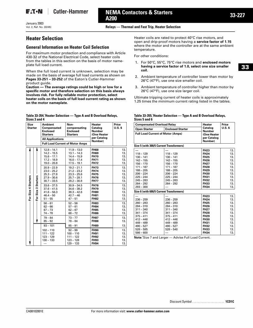
CA08102001E For more
27
33-2NEMA Contactors & StartersA200 Relays — Thermal and Fast Trip, Heater SelectionJanuary 2003Vol. 2, Ref. No. [0245]
33
Heater Selection
General Information on Heater Coil SelectionFor maximum motor protection and compliance with Article 430-32 of the National Electrical Code, select heater coils from the tables in this section on the basis of motor name-plate full load current.
When the full load current is unknown, selection may be made on the basis of average full load currents as shown on Pages 33-251 – 33-252 of the Eaton’s Cutler-Hammer product guide. Caution — The average ratings could be high or low for a specific motor and therefore selection on this basis always involves risk. For fully reliable motor protection, select heater coils on the basis of full load current rating as shown on the motor nameplate.
Heater coils are rated to protect 40°C rise motors, and open and drip-proof motors having a service factor of 1.15 where the motor and the controller are at the same ambient temperature.
For other conditions:
1. For 50°C, 55°C, 75°C rise motors and enclosed motors having a service factor of 1.0, select one size smaller coil.
2. Ambient temperature of controller lower than motor by 26°C (47°F), use one size smaller coil.
3. Ambient temperature of controller higher than motor by 26°C (47°F), use one size larger coil.
Ultimate tripping current of heater coils is approximately 1.25 times the minimum current rating listed in the tables.
Table 33-354. Heater Selection — Type A and B Overload Relays, Sizes 3 and 4
Table 33-355. Heater Selection — Type A and B Overload Relays, Sizes 5 and 6
Note: Size 7 and Larger — Advise Full Load Current.
SizeStarter
Ambient CompensatedEnclosed Starters
Non-compensating Enclosed Starters
HeaterCatalogNumber(One Heater per Catalog Number)
PriceU.S. $
All Applications
Full Load Current of Motor Amps
12.8 – 14.114.2 – 15.515.6 – 17.117.2 – 18.919.0 – 20.8
11.9 – 13.013.1 – 14.314.4 – 15.916.0 – 17.417.5 – 19.1
FH68FH69FH70FH71FH72
13.13.13.13.13.
20.9 – 22.923.0 – 25.225.3 – 27.827.9 – 30.630.7 – 33.5
19.2 – 21.121.2 – 23.223.3 – 25.625.7 – 28.128.2 – 30.8
FH73FH74FH75FH76FH77
13.13.13.13.13.
33.6 – 37.537.6 – 41.541.6 – 56.346.4 – 5051 – 55
30.9 – 34.534.6 – 38.238.3 – 42.642.7 – 4647 – 51
FH78FH79FH80FH81FH82
13.13.13.13.13.
56 – 6162 – 6667 – 7374 – 78
52 – 5657 – 6162 – 6768 – 72
FH83FH84FH85FH86
13.13.13.13.
79 – 8485 – 92
73 – 7778 – 84
FH87FH88
13.13.
93 – 101 85 – 91 FH89 13.
102 – 110111 – 122123 – 129130 – 133—
92 – 99100 – 110111 – 122123 – 128129 – 133
FH90FH91FH92FH93FH94
13.13.13.13.13.
Fo
r S
ize 4
Sta
rters
Fo
r S
ize 3
Sta
rters
Compensated Overload Relay HeaterCatalogNumber(One Heater per Catalog Number)
PriceU.S. $Open Starter Enclosed Starter
Full Load Current of Motor (Amps)
Size 5 (with 300/5 Current Transformers)—118 – 129130 – 141142 – 155156 – 170171 – 187188 – 205206 – 224225 – 244245 – 263264 – 292293 – 300
—118 – 129130 – 141142 – 155156 – 170171 – 187188 – 205206 – 224225 – 244245 – 263264 – 292—
FH23FH24FH25FH26FH27FH28FH29FH30FH31FH32FH33FH34
13.13.13.13.13.13.13.13.13.13.13.13.
Size 6 (with 600/5 Current Transformers)—236 – 259260 – 283284 – 310311 – 340341 – 374375 – 411412 – 448449 – 489490 – 527528 – 585586 – 600
—236 – 259260 – 283284 – 310311 – 340341 – 374375 – 411412 – 448449 – 489490 – 527528 – 540—
FH23FH24FH25FH26FH27FH28FH29FH30FH31FH32FH33FH34
13.13.13.13.13.13.13.13.13.13.13.13.
Discount Symbol . . . . . . . . . . . . . . . . . . . . . . . 1CD1C
information visit: www.cutler-hammer.eaton.com
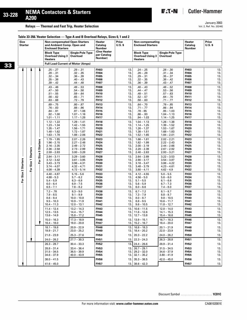
33-228
33
NEMA Contactors & StartersA200
Relays — Thermal and Fast Trip, Heater SelectionFor more information visit: www.cutler-hammer.eaton.com
January 2003Vol. 2, Ref. No. [0246]
Table 33-356. Heater Selection — Type A and B Overload Relays, Sizes 0, 1 and 2 SizeStarter
Non-compensated Open Starters and Ambient Comp. Open and Enclosed Starters
Heater Catalog Number(One Heater per Catalog Number)
PriceU.S. $
Non-compensating Enclosed Starters
Heater Catalog Number
PriceU.S. $
Block Type Overload Using 3 Heaters
Single-Pole Type Overload
Block Type Overload Using 3 Heaters
Single-Pole Type Overload
Full Load Current of Motor (Amps)
.25 – .27
.28 – .31
.32 – .34
.35 – .38
.39 – .42
.29 – .31
.32 – .35
.36 – .39
.40 – .43
.44 – .48
FH03FH04FH05FH06FH07
13.13.13.13.13.
.24 – .25
.26 – .28
.29 – .31
.32 – .35
.36 – .39
.28 – .30
.31 – .34
.35 – .37
.38 – .42
.43 – .47
FH03FH04FH05FH06FH07
13.13.13.13.13.
.43 – .46
.47 – .50
.51 – .55
.56 – .62
.63 – .68
.49 – .53
.54 – .58
.59 – .64
.65 – .71
.72 – .79
FH08FH09FH10FH11FH12
13.13.13.13.13.
.40 – .43
.44 – .47
.48 – .51
.52 – .57
.58 – .63
.48 – .52
.53 – .56
.57 – .63
.64 – .70
.71 – .77
FH08FH09FH10FH11FH12
13.13.13.13.13.
.69 – .75
.76 – .83
.84 – .91
.92 – 1.001.01 – 1.11
.80 – .87
.88 – .96
.97 – 1.061.07 – 1.161.17 – 1.28
FH13FH14FH15FH16FH17
13.13.13.13.13.
.64 – .70
.71 – .77
.78 – 85
.86 – .93
.94 – 1.03
.78 – .85
.86 – .94
.95 – 1.031.04 – 1.131.14 – 1.25
FH13FH14FH15FH16FH17
13.13.13.13.13.
1.12 – 1.221.23 – 1.341.35 – 1.471.48 – 1.621.63 – 1.78
1.29 – 1.411.42 – 1.551.56 – 1.711.72 – 1.871.88 – 2.06
FH18FH19FH20FH21FH22
13.13.13.13.13.
1.04 – 1.131.14 – 1.251.26 – 1.371.38 – 1.511.52 – 1.65
1.26 – 1.381.39 – 1.521.53 – 1.671.68 – 1.831.84 – 2.01
FH18FH19FH20FH21FH22
13.13.13.13.13.
1.79 – 1.951.96 – 2.152.16 – 2.352.36 – 2.582.59 – 2.83
2.07 – 2.262.27 – 2.482.49 – 2.722.73 – 2.993.00 – 3.28
FH23FH24FH25FH26FH27
13.13.13.13.13.
1.66 – 1.811.82 – 1.992.00 – 2.192.20 – 2.392.40 – 2.63
2.02 – 2.212.22 – 2.432.44 – 2.662.67 – 2.922.93 – 3.21
FH23FH24FH25FH26FH27
13.13.13.13.13.
2.84 – 3.113.12 – 3.423.43 – 3.733.74 – 4.074.08 – 4.39
3.29 – 3.603.61 – 3.953.96 – 4.314.32 – 4.714.72 – 5.14
FH28FH29FH30FH31FH32
13.13.13.13.13.
2.64 – 2.892.90 – 3.173.18 – 3.473.48 – 3.793.80 – 4.11
3.22 – 3.533.54 – 3.873.88 – 4.224.23 – 4.614.62 – 4.9
FH28FH29FH30FH31FH32
13.13.13.13.13.
4.40 – 4.874.88 – 5.35.4 – 5.96.0 – 6.46.5 – 7.1
5.15 – 5.65.7 – 6.26.3 – 6.86.9 – 7.57.6 – 8.2
FH33FH34FH35FH36FH37
13.13.13.13.13.
4.12 – 4.554.56 – 5.05.1 – 5.55.6 – 5.96.0 – 6.6
5.0 – 5.55.6 – 6.06.1 – 6.66.7 – 7.37.4 – 8.0
FH33FH34FH35FH36FH37
13.13.13.13.13.
7.2 – .787.9 – 8.58.6 – 9.49.5 – 10.3
10.4 – 11.3
8.3 – 9.09.1 – 9.9
10.0 – 10.810.9 – 11.912.0 – 13.1
FH38FH39FH40FH41FH42
13.13.13.13.13.
6.7 – 7.27.3 – 7.98.0 – 8.78.8 – 9.59.6 – 10.5
8.1 – 8.78.8 – 9.79.8 – 10.5
10.6 – 11.711.8 – 12.7
FH38FH39FH40FH41FH42
13.13.13.13.13.
11.4 – 12.412.5 – 13.513.6 – 14.9
13.2 – 14.314.4 – 15.715.8 – 17.2
FH43FH44FH45
13.13.13.
10.6 – 11.511.6 – 12.612.7 – 13.8
12.8 – 14.014.1 – 15.315.4 – 16.6
FH43FH44FH45
13.13.13.
15.0 – 16.316.4 – 18.0
17.3 – 18.919.0 – 20.8
FH46FH47
13.13.
13.9 – 15.115.2 – 16.7
16.7 – 18.318.4 – 20.0
FH46FH47
13.13.
18.1 – 19.819.9 – 21.7
20.9 – 22.923.0 – 25.2
FH48FH49
13.13.
16.8 – 18.318.4 – 20.2
20.1 – 21.922.0 – 23.9
FH48FH49
13.13.
21.8 – 23.9 25.3 – 27.6 FH50 13. 20.3 – 22.2 24.0 – 26.2 FH50 13.
24.0 – 26.2 27.7 – 30.3 FH51 13. 22.3 – 24.3 26.3 – 28.8 FH51 13.
26.3 – 28.7 30.4 – 33.3 FH52 13. 24.4 – 26.6 28.9 – 31.4 FH52 13.
28.8 – 31.431.5 – 34.534.6 – 37.9
33.4 – 36.436.5 – 39.940.0 – 43.9
FH53FH54FH55
13.13.13.
26.7 – 29.129.2 – 32.032.1 – 35.2
31.5 – 34.534.6 – 37.93.80 – 41.9
FH53FH54FH55
13.13.13.
38.0 – 41.5 FH56 13. 35.3 – 38.5 42.0 – 45.0 FH56 13.
41.6 – 45.0 FH57 13. 38.6 – 42.3 FH57 13.
Fo
r S
ize 2
Sta
rters
Fo
r S
ize 1
Sta
rters
Fo
r S
ize 0
Sta
rters
Discount Symbol . . . . . . . . . . . . . . . . . . . . . . . 1CD1C
CA08102001E
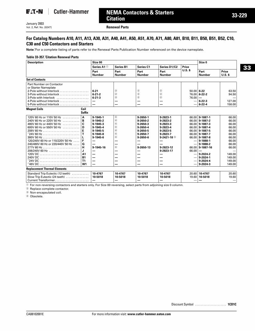
CA08102001E For more
29
33-2NEMA Contactors & StartersCitation Renewal PartsJanuary 2003Vol. 2, Ref. No. [0247]
33
For Catalog Numbers A10, A11, A13, A30, A31, A40, A41, A50, A51, A70, A71, A80, A81, B10, B11, B50, B51, B52, C10, C30 and C50 Contactors and StartersNote: For a complete listing of parts refer to the Renewal Parts Publication Number referenced on the device nameplate.
Table 33-357. Citation Renewal Parts
1 For non-reversing contactors and starters only. For Size 00 reversing, select parts from adjoining size 0 column.2 Replace complete contactor. 3 Non-encapsulated coil.4 Obsolete.
Description Size 00 Size 0
Series A1 1 Series B1 Series C1 Series D1/C2 Price U.S. $Part
NumberPart Number
Part Number
Part Number
Part Number
Price U.S. $
Set of Contacts Part Number on Contactor or Starter Nameplate 2-Pole without Interlock . . . . . . . . . . . . . . . . . . . 3-Pole without Interlock . . . . . . . . . . . . . . . . . . . 3-Pole with Interlock . . . . . . . . . . . . . . . . . . . . . 4-Pole without Interlock . . . . . . . . . . . . . . . . . . . 5-Pole without Interlock . . . . . . . . . . . . . . . . . . .
6-21 6-21-26-21-3——
2
2
2
——
2
2
2
——
2
2
2
——
50.0076.0076.00
——
6-226-22-2—6-22-36-22-4
63.5094.50
—127.00158.00
Magnet Coils Coil Suffix
120V 60 Hz or 110V 50 Hz . . . . . . . . . . .240V 60 Hz or 220V 50 Hz . . . . . . . . . . .480V 60 Hz or 440V 50 Hz . . . . . . . . . . .600V 60 Hz or 550V 50 Hz . . . . . . . . . . .208V 60 Hz . . . . . . . . . . . . . . . . . . . . . . . . 24V 60 Hz . . . . . . . . . . . . . . . . . . . . . . . .380V 50 Hz . . . . . . . . . . . . . . . . . . . . . . . .120/240V 60 Hz or 110/220V 50 Hz . . . .240/480V 60 Hz or 220/440V 50 Hz . . . .277V 60 Hz . . . . . . . . . . . . . . . . . . . . . . . .208/240V 60 Hz . . . . . . . . . . . . . . . . . . . .120V DC . . . . . . . . . . . . . . . . . . . . . . . . . .240V DC . . . . . . . . . . . . . . . . . . . . . . . . . . 24V DC . . . . . . . . . . . . . . . . . . . . . . . . . . 48V DC . . . . . . . . . . . . . . . . . . . . . . . . . .
ABCDETLFGHJA1B1T1W1
9-1945-19-1945-29-1945-39-1945-49-1945-59-1945-89-1945-6——9-1945-16—————
4
4
4
4
4
4
4
——4
—————
9-2650-19-2650-29-2650-39-2650-49-2650-59-2650-79-2650-6——9-2650-13—————
9-2823-19-2823-29-2823-39-2823-49-2823-59-2823-79-2421-18 3
——9-2823-129-2823-17————
66.0066.0066.0066.0066.0066.0066.00
——
66.0066.00
————
9-1887-19-1887-29-1887-39-1887-49-1887-59-1887-79-1887-89-1888-19-1888-29-1887-16—9-2024-29-2024-19-2024-49-2024-3
66.0066.0066.0066.0066.0066.0066.0066.0066.0066.00
—149.00149.00149.00149.00
Replacement Thermal Elements Standard Trip Eutectic (12 teeth) . . . . . . . . . . . Slow Trip Eutectic (24 teeth) . . . . . . . . . . . . . . . Current Transformer . . . . . . . . . . . . . . . . . . . . . .
10-476710-5018—
10-476710-5018—
10-476710-5018—
10-476710-5018—
20.6019.60
—
10-476710-5018—
20.6019.60
—
Discount Symbol . . . . . . . . . . . . . . . . . . . . . . 1CD1C
information visit: www.cutler-hammer.eaton.com
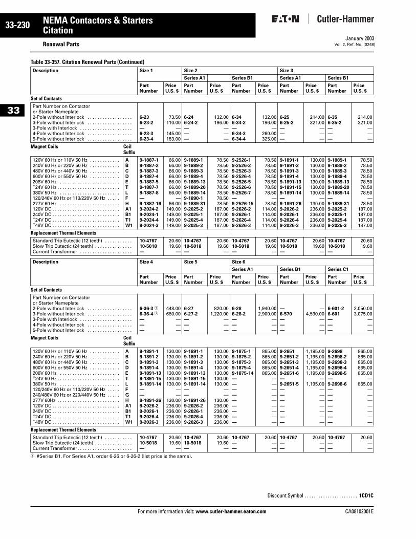
33-230
33
NEMA Contactors & StartersCitation
Renewal PartsFor more information visit: www.cutler-hammer.eaton.com
January 2003Vol. 2, Ref. No. [0248]
Table 33-357. Citation Renewal Parts (Continued)
1 #Series B1. For Series A1, order 6-26 or 6-26-2 (list price is the same).
Description Size 1 Size 2 Size 3
Series A1 Series B1 Series A1 Series B1
Part Number
Price U.S. $
Part Number
Price U.S. $
Part Number
Price U.S. $
Part Number
Price U.S. $
Part Number
Price U.S. $
Set of Contacts Part Number on Contactor or Starter Nameplate 2-Pole without Interlock . . . . . . . . . . . . . . . . . . 3-Pole without Interlock . . . . . . . . . . . . . . . . . . 3-Pole with Interlock . . . . . . . . . . . . . . . . . . . . . 4-Pole without Interlock . . . . . . . . . . . . . . . . . . 5-Pole without Interlock . . . . . . . . . . . . . . . . . .
6-236-23-2—6-23-36-23-4
73.50110.00
—145.00183.00
6-246-24-2———
132.00196.00
———
6-346-34-2—6-34-36-34-4
132.00196.00
—260.00325.00
6-256-25-2———
214.00321.00
———
6-356-35-2———
214.00321.00
———
Magnet Coils Coil Suffix
120V 60 Hz or 110V 50 Hz . . . . . . . . . . . .240V 60 Hz or 220V 50 Hz . . . . . . . . . . . .480V 60 Hz or 440V 50 Hz . . . . . . . . . . . .600V 60 Hz or 550V 50 Hz . . . . . . . . . . . .208V 60 Hz . . . . . . . . . . . . . . . . . . . . . . . . 24V 60 Hz . . . . . . . . . . . . . . . . . . . . . . . . .380V 50 Hz . . . . . . . . . . . . . . . . . . . . . . . .120/240V 60 Hz or 110/220V 50 Hz . . . . .277V 60 Hz . . . . . . . . . . . . . . . . . . . . . . . .120V DC . . . . . . . . . . . . . . . . . . . . . . . . . . .240V DC . . . . . . . . . . . . . . . . . . . . . . . . . . . 24V DC . . . . . . . . . . . . . . . . . . . . . . . . . . . 48V DC . . . . . . . . . . . . . . . . . . . . . . . . . . .
ABCDETLFHA1B1T1W1
9-1887-19-1887-29-1887-39-1887-49-1887-59-1887-79-1887-8—9-1887-169-2024-29-2024-19-2024-49-2024-3
66.0066.0066.0066.0066.0066.0066.00
—66.00
149.00149.00149.00149.00
9-1889-19-1889-29-1889-39-1889-49-1889-139-1889-209-1889-149-1890-19-1889-319-2025-29-2025-19-2025-49-2025-3
78.5078.5078.5078.5078.5078.5078.5078.5078.50
187.00187.00187.00187.00
9-2526-19-2526-29-2526-39-2526-49-2526-59-2526-69-2526-7—9-2526-159-2626-29-2626-19-2626-49-2626-3
78.5078.5078.5078.5078.5078.5078.50
—78.50
114.00114.00114.00114.00
9-1891-19-1891-29-1891-39-1891-49-1891-139-1891-159-1891-14—9-1891-269-2026-29-2026-19-2026-49-2026-3
130.00130.00130.00130.00130.00130.00130.00
—130.00236.00236.00236.00236.00
9-1889-19-1889-29-1889-39-1889-49-1889-139-1889-209-1889-14—9-1889-319-2025-29-2025-19-2025-49-2025-3
78.5078.5078.5078.5078.5078.5078.50
—78.50
187.00187.00187.00187.00
Replacement Thermal Elements Standard Trip Eutectic (12 teeth) . . . . . . . . . . . Slow Trip Eutectic (24 teeth) . . . . . . . . . . . . . . . Current Transformer . . . . . . . . . . . . . . . . . . . . .
10-476710-5018—
20.6019.60
—
10-476710-5018—
20.6019.60
—
10-476710-5018—
20.6019.60
—
10-476710-5018—
20.6019.60
—
10-476710-5018—
20.6019.60
—
Description Size 4 Size 5 Size 6
Series A1 Series B1 Series C1
Part Number
Price U.S. $
Part Number
Price U.S. $
Part Number
Price U.S. $
Part Number
Price U.S. $
Part Number
Price U.S. $
Set of Contacts Part Number on Contactor or Starter Nameplate 2-Pole without Interlock . . . . . . . . . . . . . . . . . . 3-Pole without Interlock . . . . . . . . . . . . . . . . . . 3-Pole with Interlock . . . . . . . . . . . . . . . . . . . . . 4-Pole without Interlock . . . . . . . . . . . . . . . . . . 5-Pole without Interlock . . . . . . . . . . . . . . . . . .
6-36-3 1
6-36-4 1
———
448.00680.00
———
6-276-27-2———
820.001,220.00
———
6-286-28-2———
1,940.002,900.00
———
—6-570———
—4,590.00
———
6-601-26-601———
2,050.003,075.00
———
Magnet Coils Coil Suffix
120V 60 Hz or 110V 50 Hz . . . . . . . . . . . .240V 60 Hz or 220V 50 Hz . . . . . . . . . . . .480V 60 Hz or 440V 50 Hz . . . . . . . . . . . .600V 60 Hz or 550V 50 Hz . . . . . . . . . . . .208V 60 Hz . . . . . . . . . . . . . . . . . . . . . . . . 24V 60 Hz . . . . . . . . . . . . . . . . . . . . . . . . .380V 50 Hz . . . . . . . . . . . . . . . . . . . . . . . .120/240V 60 Hz or 110/220V 50 Hz . . . . .240/480V 60 Hz or 220/440V 50 Hz . . . . .277V 60Hz . . . . . . . . . . . . . . . . . . . . . . . . .120V DC . . . . . . . . . . . . . . . . . . . . . . . . . . .240V DC . . . . . . . . . . . . . . . . . . . . . . . . . . . 24V DC . . . . . . . . . . . . . . . . . . . . . . . . . . . 48V DC . . . . . . . . . . . . . . . . . . . . . . . . . . .
ABCDETLFGHA1B1T1W1
9-1891-19-1891-29-1891-39-1891-49-1891-139-1891-159-1891-14——9-1891-269-2026-29-2026-19-2026-49-2026-3
130.00130.00130.00130.00130.00130.00130.00
——
130.00236.00236.00236.00236.00
9-1891-19-1891-29-1891-39-1891-49-1891-139-1891-159-1891-14——9-1891-269-2026-29-2026-19-2026-49-2026-3
130.00130.00130.00130.00130.00130.00130.00
——
130.00236.00236.00236.00236.00
9-1875-19-1875-29-1875-39-1875-49-1875-14—————————
865.00865.00865.00865.00865.00
—————————
9-26519-2651-29-2651-39-2651-49-2651-6—9-2651-5———————
1,195.001,195.001,195.001,195.001,195.00
—1,195.00
———————
9-26989-2698-29-2698-39-2698-49-2698-5—9-2698-6———————
865.00865.00865.00865.00865.00
—865.00
———————
Replacement Thermal Elements Standard Trip Eutectic (12 teeth) . . . . . . . . . . . Slow Trip Eutectic (24 teeth) . . . . . . . . . . . . . . . Current Transformer. . . . . . . . . . . . . . . . . . . . . .
10-476710-5018—
20.6019.60
—
10-476710-5018—
20.6019.60
—
10-4767——
20.60——
10-4767——
20.60——
10-4767——
20.60——
Discount Symbol . . . . . . . . . . . . . . . . . . . . . . . 1CD1C
CA08102001E
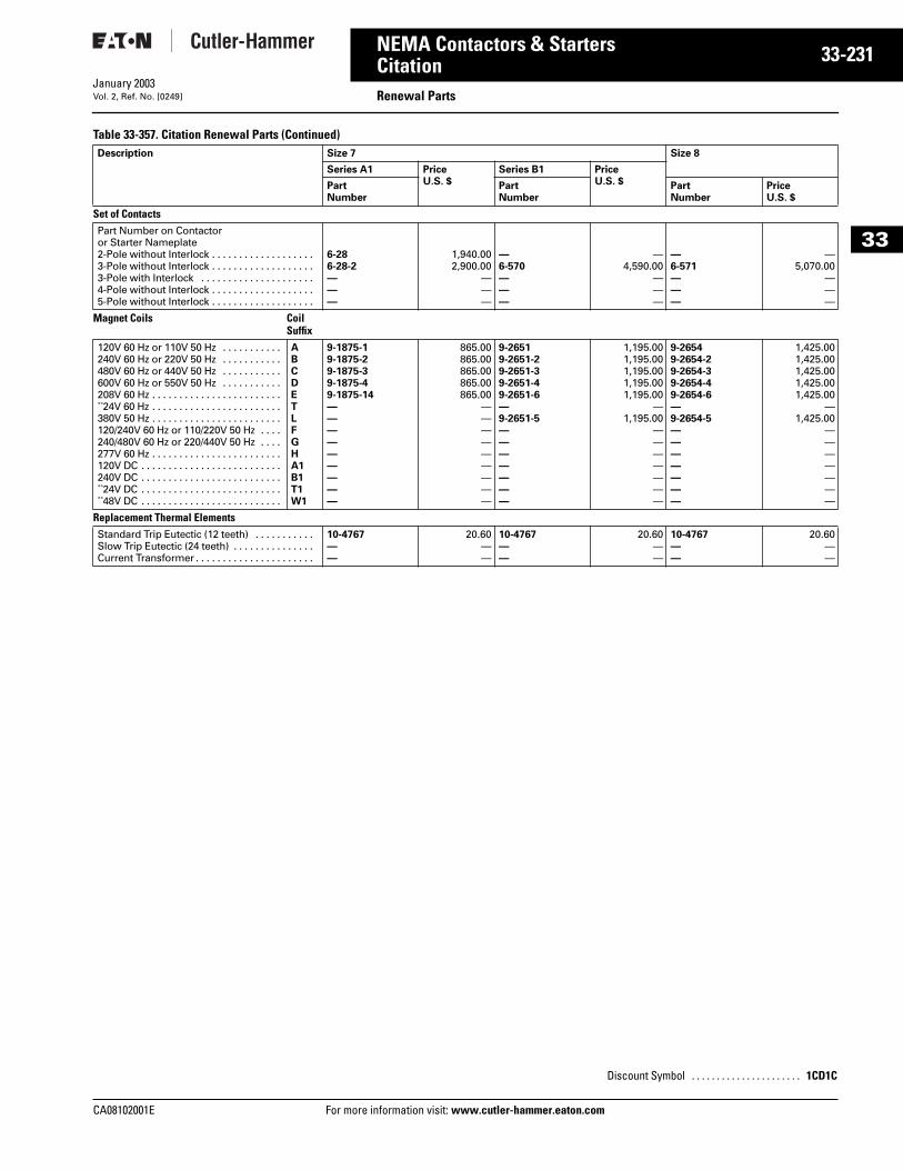
CA08102001E For more
31
33-2NEMA Contactors & StartersCitation Renewal PartsJanuary 2003Vol. 2, Ref. No. [0249]
33
Table 33-357. Citation Renewal Parts (Continued)Description Size 7 Size 8
Series A1 Price U.S. $
Series B1 Price U.S. $Part
NumberPart Number
Part Number
Price U.S. $
Set of Contacts Part Number on Contactor or Starter Nameplate 2-Pole without Interlock . . . . . . . . . . . . . . . . . . . 3-Pole without Interlock . . . . . . . . . . . . . . . . . . . 3-Pole with Interlock . . . . . . . . . . . . . . . . . . . . . 4-Pole without Interlock . . . . . . . . . . . . . . . . . . . 5-Pole without Interlock . . . . . . . . . . . . . . . . . . .
6-286-28-2———
1,940.002,900.00
———
—6-570———
—4,590.00
———
—6-571———
—5,070.00
———
Magnet Coils Coil Suffix
120V 60 Hz or 110V 50 Hz . . . . . . . . . . .240V 60 Hz or 220V 50 Hz . . . . . . . . . . .480V 60 Hz or 440V 50 Hz . . . . . . . . . . .600V 60 Hz or 550V 50 Hz . . . . . . . . . . .208V 60 Hz . . . . . . . . . . . . . . . . . . . . . . . . 24V 60 Hz . . . . . . . . . . . . . . . . . . . . . . . .380V 50 Hz . . . . . . . . . . . . . . . . . . . . . . . .120/240V 60 Hz or 110/220V 50 Hz . . . .240/480V 60 Hz or 220/440V 50 Hz . . . .277V 60 Hz . . . . . . . . . . . . . . . . . . . . . . . .120V DC . . . . . . . . . . . . . . . . . . . . . . . . . .240V DC . . . . . . . . . . . . . . . . . . . . . . . . . . 24V DC . . . . . . . . . . . . . . . . . . . . . . . . . . 48V DC . . . . . . . . . . . . . . . . . . . . . . . . . .
ABCDETLFGHA1B1T1W1
9-1875-19-1875-29-1875-39-1875-49-1875-14—————————
865.00865.00865.00865.00865.00
—————————
9-26519-2651-29-2651-39-2651-49-2651-6—9-2651-5———————
1,195.001,195.001,195.001,195.001,195.00
—1,195.00
———————
9-26549-2654-29-2654-39-2654-49-2654-6—9-2654-5———————
1,425.001,425.001,425.001,425.001,425.00
—1,425.00
———————
Replacement Thermal Elements Standard Trip Eutectic (12 teeth) . . . . . . . . . . . Slow Trip Eutectic (24 teeth) . . . . . . . . . . . . . . . Current Transformer . . . . . . . . . . . . . . . . . . . . . .
10-4767——
20.60——
10-4767——
20.60——
10-4767——
20.60——
Discount Symbol . . . . . . . . . . . . . . . . . . . . . . 1CD1C
information visit: www.cutler-hammer.eaton.com
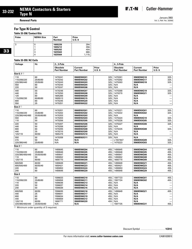
33-232
33
NEMA Contactors & StartersType N
Renewal PartsFor more information visit: www.cutler-hammer.eaton.com
January 2003Vol. 2, Ref. No. [0250]
For Type N ControlTable 33-358. Contact Kits
Table 33-359. AC Coils
1 Minimum order quantity of 3 required.
Poles NEMA Size Part Number
Price U.S. $
3 0123 4
16052261605212160520216255631625564
294.356.404.660.
1,115.
Voltage Hz 2-, 3-Pole 4-, 5-Pole
Obsolete Part Number
CurrentPart Number
PriceU.S. $
Obsolete Part Number
CurrentPart Number
PriceU.S. $
Size 0, 1 1
110110/208/220220/380/440550220
6025/60/6025/50/606050
14702411470242147024314702441470247
9969D90G019969D90G029969D90G039969D90G049969D90G06
325.325.325.325.325.
147026114702621470263N/AN/A
9969D90G169969D90G179969D90G18N/AN/A
325.325.325.
——
440440120115/208/230600550
50256060/60/606025
147024814702501605268160551314702451470251
9969D90G079969D90G089969D90G099969D90G159969D90G209969D90G22
325.325.325.325.325.325.
14702681470270N/AN/AN/AN/A
9969D90G199969D90G21N/AN/AN/AN/A
325.325.
————
Size 2 1
110110/208/220220/380/440/480550110
6025/60/6025/50/60/606050
14702011470202147020314702041470206
9969D92G019969D92G029969D92G039969D92G049969D92G05
325.325.325.325.325.
14702211470222N/A14702241470226
9969D93G019969D93G02N/A9969D93G109969D93G05
325.325.
—325.325.
220440600440120/110
5050602560/50
14702071470208147020514702101605478
9969D92G069969D92G079969D92G089969D92G099969D92G10
325.325.325.325.325.
1470227N/A1470225N/AN/A
9969D93G06N/A9969D93G08N/AN/A
325.—
325.——
550415220/380/440
505025/60/60
1470209N/AN/A
9969D92G11N/AN/A
325.——
N/AL15576471470223
N/A9969D93G099969D93G03
—325.325.
Size 3 1
110110/208/220220/380/400/440110120/110
6025/60/6025/50/50/605060/50
14906451490646149064714906521600770
9969D96G049969D96G059969D96G069969D96G089969D96G09
455.455.455.455.455.
14906451490646149064714906521600770
9969D96G049969D96G059969D96G069969D96G089969D96G09
455.455.455.455.455.
600/500600/500/400220240
60/5060/50/405060
1490649165942114906531490648
9969D96G219969D96G239969D93G249969D96G29
455.455.455.455.
1490649165942114906531490648
9969D96G219969D96G239969D93G249969D96G29
455.455.455.455.
Size 4110110/208/220110220240
6025/60/60505050
15966331490658159663615966371596639
9969D96G109969D96G119969D96G139969D96G149969D96G15
455.455.455.455.455.
15977231597724N/AN/AN/A
9969D96G019969D96G02N/AN/AN/A
455.455.
———
600/500440600440120/110220/380/400/440
60/5025606060/5025/50/50/60
15966351596641159663414906591600771N/A
9969D96G169969D96G179969D96G199969D96G129969D96G20N/A
455.455.455.455.455.
—
1490649N/AN/AN/AN/A1597725
9969D96G21N/AN/AN/AN/A9969D96G31
455.————
455.
Discount Symbol . . . . . . . . . . . . . . . . . . . . . . . 1CD1C
CA08102001E
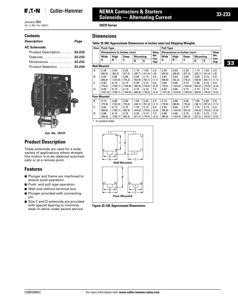
CA08102001E For more
33
33-2NEMA Contactors & StartersSolenoids — Alternating Current 10370 SeriesJanuary 2003Vol. 2, Ref. No. [0251]
33
ContentsDescription Page
AC Solenoids
Product Description . . . . . 33-233
Features . . . . . . . . . . . . . . . 33-233
Dimensions . . . . . . . . . . . . 33-233
Product Selection . . . . . . . 33-234
Cat. No. 10370
Product DescriptionThese solenoids are used for a wide variety of applications where straight line motion is to be obtained automati-cally or at a remote point.
Features■ Plunger and frame are machined to
ensure quiet operation■ Push- and pull-type operation■ With and without terminal box■ Plunger provided with connecting
pin■ Size C and D solenoids are provided
with special bearing to minimize wear in clevis under severe service
DimensionsTable 33-360. Approximate Dimensions in Inches (mm) and Shipping Weights
1 In sealed state.
Figure 33-138. Approximate Dimensions
Size Push Type Pull Type
Dimensions in Inches (mm) Ship.Wt.Lbs.(kg)
Dimensions in Inches (mm) Ship.Wt.Lbs.(kg)
WideA
HighB 1
DeepC
Mounting WideA
HighB 1
DeepC
Mounting
D E D E
Wall MountedA
B
C
D
2.38(60.5)2.63(66.8)3.00(76.2)4.00(101.6)
3.63(92.2)4.88(124.0)6.13(155.7)6.13(155.7)
2.25(57.2)3.00(76.2)4.13(104.9)4.13(104.9)
1.13(28.7)2.00(50.8)2.38(60.5)2.75(69.9)
1.63(41.4)2.13(54.1)3.13(79.5)3.13(79.5)
2.0(.9)2.5(1.1)5.0(2.3)7.0(3.2)
2.38(60.5)2.63(66.8)3.00(76.2)4.00(101.6)
2.63(66.8)3.63(92.2)4.88(124.0)4.88(124.0)
2.25(57.2)3.00(76.2)4.13(104.9)4.13(104.9)
1.13(28.7)2.00(50.8)2.38(60.5)2.75(69.9)
1.63(41.4)2.13(54.1)3.13(79.5)3.13(79.5)
2.0(.9)2.5(1.1)5.0(2.3)7.0(3.2)
Floor MountedB
C
D
3.13(79.5)3.50(88.9)3.88(98.6)
4.88(124.0)6.13(155.7)6.13(155.7)
3.00(76.2)3.75(95.3)3.75(95.3)
1.50(38.1)1.75(44.5)2.25(57.2)
2.25(57.2)3.13(79.5)3.13(79.5)
2.5(1.1)5.0(2.3)7.0(3.2)
3.13(79.5)3.50(88.9)3.88(98.6)
3.88(98.6)4.88(124.0)4.88(124.0)
3.00(76.2)3.75(95.3)3.75(95.3)
1.50(38.1)1.75(44.5)2.25(57.2)
2.25(57.2)3.13(79.5)3.13(79.5)
2.5(1.1)5.0(2.3)7.0(3.2)
DA
B
DA
EC
C
E
B
Wall Mounted
Floor Mounted
information visit: www.cutler-hammer.eaton.com
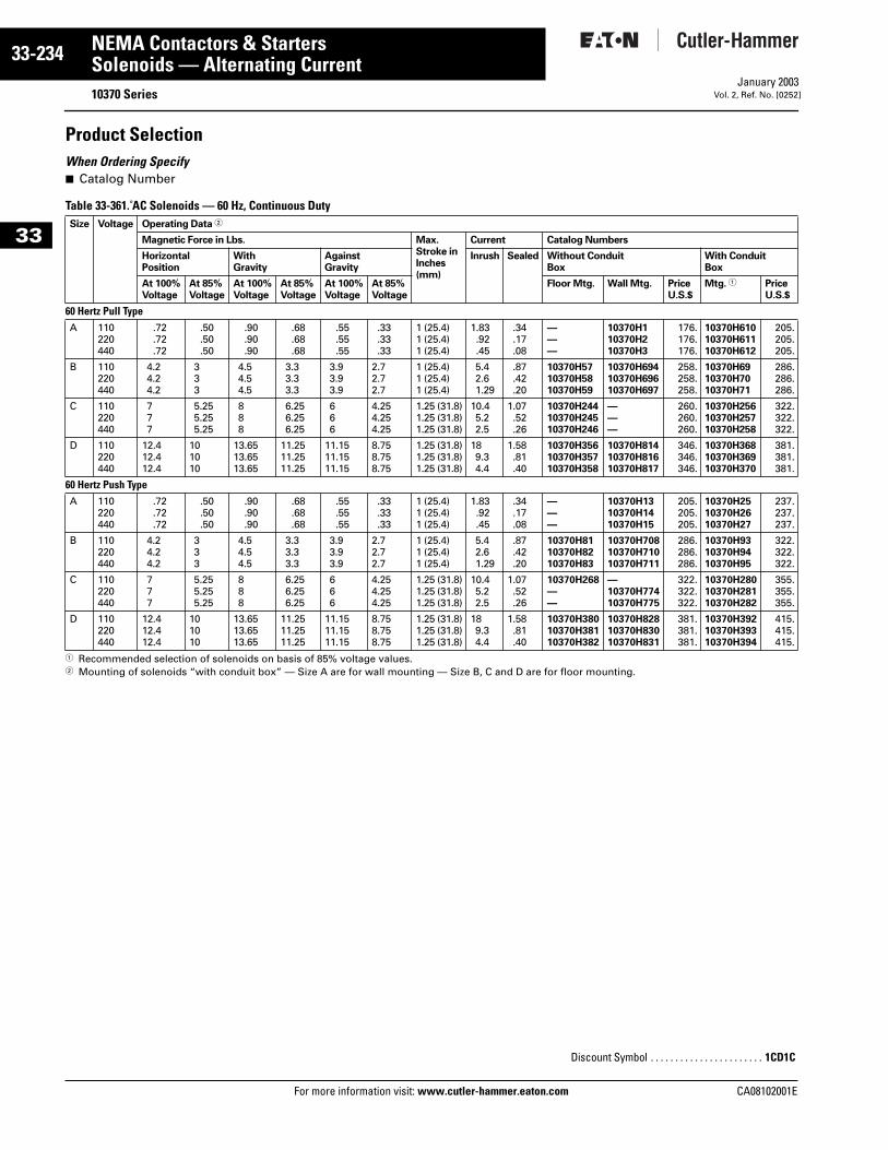
33-234
33
NEMA Contactors & StartersSolenoids — Alternating Current
10370 SeriesFor more information visit: www.cutler-hammer.eaton.com
January 2003Vol. 2, Ref. No. [0252]
Product SelectionWhen Ordering Specify■ Catalog Number
Table 33-361. AC Solenoids — 60 Hz, Continuous Duty
1 Recommended selection of solenoids on basis of 85% voltage values.2 Mounting of solenoids “with conduit box” — Size A are for wall mounting — Size B, C and D are for floor mounting.
Size Voltage Operating Data 2
Magnetic Force in Lbs. Max.Stroke inInches(mm)
Current Catalog Numbers
HorizontalPosition
With Gravity
AgainstGravity
Inrush Sealed Without Conduit Box
With Conduit Box
At 100%Voltage
At 85%Voltage
At 100%Voltage
At 85%Voltage
At 100%Voltage
At 85%Voltage
Floor Mtg. Wall Mtg. PriceU.S.$
Mtg. 1 PriceU.S.$
60 Hertz Pull TypeA 110
220440
.72
.72
.72
.50
.50
.50
.90
.90
.90
.68
.68
.68
.55
.55
.55
.33
.33
.33
1 (25.4)1 (25.4)1 (25.4)
1.83.92.45
.34
.17
.08
———
10370H110370H210370H3
176.176.176.
10370H61010370H61110370H612
205.205.205.
B 110220440
4.24.24.2
333
4.54.54.5
3.33.33.3
3.93.93.9
2.72.72.7
1 (25.4)1 (25.4)1 (25.4)
5.42.61.29
.87
.42
.20
10370H5710370H5810370H59
10370H69410370H69610370H697
258.258.258.
10370H6910370H7010370H71
286.286.286.
C 110220440
777
5.255.255.25
888
6.256.256.25
666
4.254.254.25
1.25 (31.8)1.25 (31.8)1.25 (31.8)
10.45.22.5
1.07.52.26
10370H24410370H24510370H246
———
260.260.260.
10370H25610370H25710370H258
322.322.322.
D 110220440
12.412.412.4
101010
13.6513.6513.65
11.2511.2511.25
11.1511.1511.15
8.758.758.75
1.25 (31.8)1.25 (31.8)1.25 (31.8)
189.34.4
1.58.81.40
10370H35610370H35710370H358
10370H81410370H81610370H817
346.346.346.
10370H36810370H36910370H370
381.381.381.
60 Hertz Push TypeA 110
220440
.72
.72
.72
.50
.50
.50
.90
.90
.90
.68
.68
.68
.55
.55
.55
.33
.33
.33
1 (25.4)1 (25.4)1 (25.4)
1.83.92.45
.34
.17
.08
———
10370H1310370H1410370H15
205.205.205.
10370H2510370H2610370H27
237.237.237.
B 110220440
4.24.24.2
333
4.54.54.5
3.33.33.3
3.93.93.9
2.72.72.7
1 (25.4)1 (25.4)1 (25.4)
5.42.61.29
.87
.42
.20
10370H8110370H8210370H83
10370H70810370H71010370H711
286.286.286.
10370H9310370H9410370H95
322.322.322.
C 110220440
777
5.255.255.25
888
6.256.256.25
666
4.254.254.25
1.25 (31.8)1.25 (31.8)1.25 (31.8)
10.45.22.5
1.07.52.26
10370H268——
—10370H77410370H775
322.322.322.
10370H28010370H28110370H282
355.355.355.
D 110220440
12.412.412.4
101010
13.6513.6513.65
11.2511.2511.25
11.1511.1511.15
8.758.758.75
1.25 (31.8)1.25 (31.8)1.25 (31.8)
189.34.4
1.58.81.40
10370H38010370H38110370H382
10370H82810370H83010370H831
381.381.381.
10370H39210370H39310370H394
415.415.415.
Discount Symbol . . . . . . . . . . . . . . . . . . . . . . . 1CD1C
CA08102001E
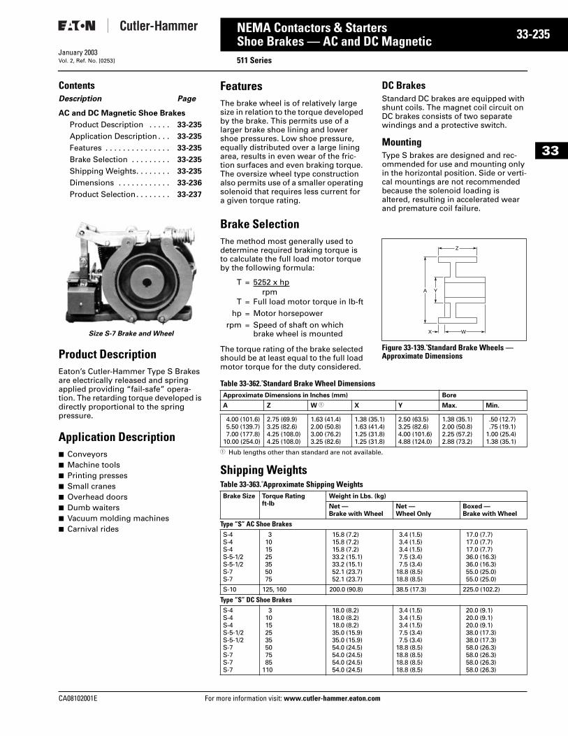
CA08102001E For more
35
33-2NEMA Contactors & StartersShoe Brakes — AC and DC Magnetic 511 SeriesJanuary 2003Vol. 2, Ref. No. [0253]
33
ContentsDescription Page
AC and DC Magnetic Shoe Brakes
Product Description . . . . . 33-235
Application Description . . . 33-235
Features . . . . . . . . . . . . . . . 33-235
Brake Selection . . . . . . . . . 33-235
Shipping Weights. . . . . . . . 33-235
Dimensions . . . . . . . . . . . . 33-236
Product Selection. . . . . . . . 33-237
Size S-7 Brake and Wheel
Product DescriptionEaton’s Cutler-Hammer Type S Brakes are electrically released and spring applied providing “fail-safe” opera-tion. The retarding torque developed is directly proportional to the spring pressure.
Application Description■ Conveyors■ Machine tools■ Printing presses■ Small cranes■ Overhead doors■ Dumb waiters■ Vacuum molding machines■ Carnival rides
FeaturesThe brake wheel is of relatively large size in relation to the torque developed by the brake. This permits use of a larger brake shoe lining and lower shoe pressures. Low shoe pressure, equally distributed over a large lining area, results in even wear of the fric-tion surfaces and even braking torque. The oversize wheel type construction also permits use of a smaller operating solenoid that requires less current for a given torque rating.
DC BrakesStandard DC brakes are equipped with shunt coils. The magnet coil circuit on DC brakes consists of two separate windings and a protective switch.
MountingType S brakes are designed and rec-ommended for use and mounting only in the horizontal position. Side or verti-cal mountings are not recommended because the solenoid loading is altered, resulting in accelerated wear and premature coil failure.
Brake SelectionThe method most generally used to determine required braking torque is to calculate the full load motor torque by the following formula:
The torque rating of the brake selected should be at least equal to the full load motor torque for the duty considered.
Figure 33-139. Standard Brake Wheels — Approximate Dimensions
Table 33-362. Standard Brake Wheel Dimensions
1 Hub lengths other than standard are not available.
Shipping WeightsTable 33-363. Approximate Shipping Weights
T = 5252 x hprpm
T = Full load motor torque in lb-fthp = Motor horsepower
rpm = Speed of shaft on which brake wheel is mounted W
Z
X
A Y
Approximate Dimensions in Inches (mm) Bore
A Z W 1 X Y Max. Min.
4.00 (101.6)5.50 (139.7)7.00 (177.8)
10.00 (254.0)
2.75 (69.9)3.25 (82.6)4.25 (108.0)4.25 (108.0)
1.63 (41.4)2.00 (50.8)3.00 (76.2)3.25 (82.6)
1.38 (35.1)1.63 (41.4)1.25 (31.8)1.25 (31.8)
2.50 (63.5)3.25 (82.6)4.00 (101.6)4.88 (124.0)
1.38 (35.1)2.00 (50.8)2.25 (57.2)2.88 (73.2)
.50 (12.7)
.75 (19.1)1.00 (25.4)1.38 (35.1)
Brake Size Torque Ratingft-lb
Weight in Lbs. (kg)
Net —Brake with Wheel
Net —Wheel Only
Boxed —Brake with Wheel
Type “S” AC Shoe BrakesS-4S-4S-4S-5-1/2S-5-1/2S-7S-7
3101525355075
15.8 (7.2)15.8 (7.2)15.8 (7.2)33.2 (15.1)33.2 (15.1)52.1 (23.7)52.1 (23.7)
3.4 (1.5)3.4 (1.5)3.4 (1.5)7.5 (3.4)7.5 (3.4)
18.8 (8.5)18.8 (8.5)
17.0 (7.7)17.0 (7.7)17.0 (7.7)36.0 (16.3)36.0 (16.3)55.0 (25.0)55.0 (25.0)
S-10 125, 160 200.0 (90.8) 38.5 (17.3) 225.0 (102.2)
Type “S” DC Shoe BrakesS-4S-4S-4S-5-1/2S-5-1/2S-7S-7S-7S-7
310152535507585
110
18.0 (8.2)18.0 (8.2)18.0 (8.2)35.0 (15.9)35.0 (15.9)54.0 (24.5)54.0 (24.5)54.0 (24.5)54.0 (24.5)
3.4 (1.5)3.4 (1.5)3.4 (1.5)7.5 (3.4)7.5 (3.4)
18.8 (8.5)18.8 (8.5)18.8 (8.5)18.8 (8.5)
20.0 (9.1)20.0 (9.1)20.0 (9.1)38.0 (17.3)38.0 (17.3)58.0 (26.3)58.0 (26.3)58.0 (26.3)58.0 (26.3)
information visit: www.cutler-hammer.eaton.com
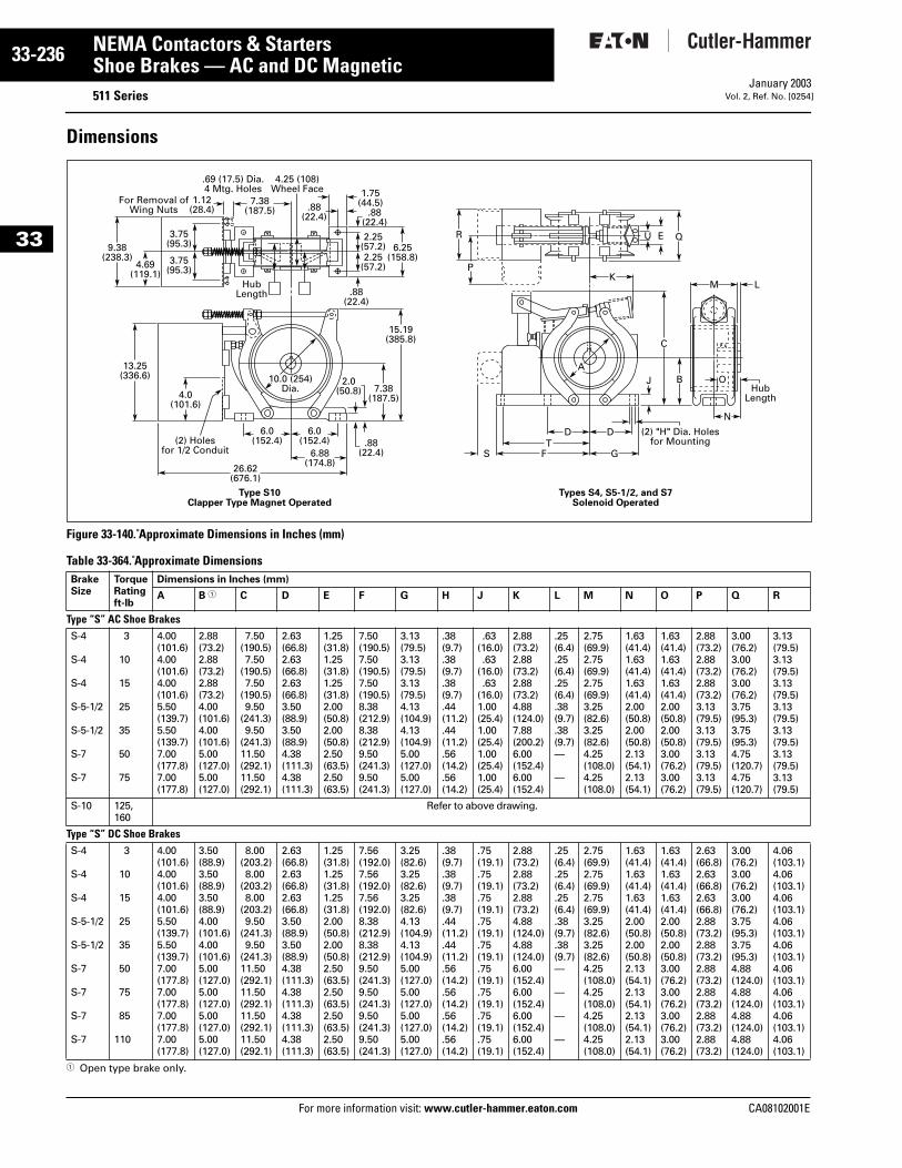
33-236
33
NEMA Contactors & StartersShoe Brakes — AC and DC Magnetic
511 SeriesFor more information visit: www.cutler-hammer.eaton.com
January 2003Vol. 2, Ref. No. [0254]
Dimensions
Figure 33-140. Approximate Dimensions in Inches (mm)
Table 33-364. Approximate Dimensions
1 Open type brake only.
BrakeSize
TorqueRatingft-lb
Dimensions in Inches (mm)
A B 1 C D E F G H J K L M N O P Q R
Type “S” AC Shoe BrakesS-4
S-4
S-4
S-5-1/2
S-5-1/2
S-7
S-7
3
10
15
25
35
50
75
4.00(101.6)4.00(101.6)4.00(101.6)5.50(139.7)5.50(139.7)7.00(177.8)7.00(177.8)
2.88(73.2)2.88(73.2)2.88(73.2)4.00(101.6)4.00(101.6)5.00(127.0)5.00(127.0)
7.50(190.5)7.50
(190.5)7.50
(190.5)9.50
(241.3)9.50
(241.3)11.50(292.1)11.50(292.1)
2.63(66.8)2.63(66.8)2.63(66.8)3.50(88.9)3.50(88.9)4.38(111.3)4.38(111.3)
1.25(31.8)1.25(31.8)1.25(31.8)2.00(50.8)2.00(50.8)2.50(63.5)2.50(63.5)
7.50(190.5)7.50(190.5)7.50(190.5)8.38(212.9)8.38(212.9)9.50(241.3)9.50(241.3)
3.13(79.5)3.13(79.5)3.13(79.5)4.13(104.9)4.13(104.9)5.00(127.0)5.00(127.0)
.38(9.7).38(9.7).38(9.7).44(11.2).44(11.2).56(14.2).56(14.2)
.63(16.0).63
(16.0).63
(16.0)1.00(25.4)1.00(25.4)1.00(25.4)1.00(25.4)
2.88(73.2)2.88(73.2)2.88(73.2)4.88(124.0)7.88(200.2)6.00(152.4)6.00(152.4)
.25(6.4).25(6.4).25(6.4).38(9.7).38(9.7)—
—
2.75(69.9)2.75(69.9)2.75(69.9)3.25(82.6)3.25(82.6)4.25(108.0)4.25(108.0)
1.63(41.4)1.63(41.4)1.63(41.4)2.00(50.8)2.00(50.8)2.13(54.1)2.13(54.1)
1.63(41.4)1.63(41.4)1.63(41.4)2.00(50.8)2.00(50.8)3.00(76.2)3.00(76.2)
2.88(73.2)2.88(73.2)2.88(73.2)3.13(79.5)3.13(79.5)3.13(79.5)3.13(79.5)
3.00(76.2)3.00(76.2)3.00(76.2)3.75(95.3)3.75(95.3)4.75(120.7)4.75(120.7)
3.13(79.5)3.13(79.5)3.13(79.5)3.13(79.5)3.13(79.5)3.13(79.5)3.13(79.5)
S-10 125,160
Refer to above drawing.
Type “S” DC Shoe BrakesS-4
S-4
S-4
S-5-1/2
S-5-1/2
S-7
S-7
S-7
S-7
3
10
15
25
35
50
75
85
110
4.00(101.6)4.00(101.6)4.00(101.6)5.50(139.7)5.50(139.7)7.00(177.8)7.00(177.8)7.00(177.8)7.00(177.8)
3.50(88.9)3.50(88.9)3.50(88.9)4.00(101.6)4.00(101.6)5.00(127.0)5.00(127.0)5.00(127.0)5.00(127.0)
8.00(203.2)8.00
(203.2)8.00
(203.2)9.50
(241.3)9.50
(241.3)11.50(292.1)11.50(292.1)11.50(292.1)11.50(292.1)
2.63(66.8)2.63(66.8)2.63(66.8)3.50(88.9)3.50(88.9)4.38(111.3)4.38(111.3)4.38(111.3)4.38(111.3)
1.25(31.8)1.25(31.8)1.25(31.8)2.00(50.8)2.00(50.8)2.50(63.5)2.50(63.5)2.50(63.5)2.50(63.5)
7.56(192.0)7.56(192.0)7.56(192.0)8.38(212.9)8.38(212.9)9.50(241.3)9.50(241.3)9.50(241.3)9.50(241.3)
3.25(82.6)3.25(82.6)3.25(82.6)4.13(104.9)4.13(104.9)5.00(127.0)5.00(127.0)5.00(127.0)5.00(127.0)
.38(9.7).38(9.7).38(9.7).44(11.2).44(11.2).56(14.2).56(14.2).56(14.2).56(14.2)
.75(19.1).75(19.1).75(19.1).75(19.1).75(19.1).75(19.1).75(19.1).75(19.1).75(19.1)
2.88(73.2)2.88(73.2)2.88(73.2)4.88(124.0)4.88(124.0)6.00(152.4)6.00(152.4)6.00(152.4)6.00(152.4)
.25(6.4).25(6.4).25(6.4).38(9.7).38(9.7)—
—
—
—
2.75(69.9)2.75(69.9)2.75(69.9)3.25(82.6)3.25(82.6)4.25(108.0)4.25(108.0)4.25(108.0)4.25(108.0)
1.63(41.4)1.63(41.4)1.63(41.4)2.00(50.8)2.00(50.8)2.13(54.1)2.13(54.1)2.13(54.1)2.13(54.1)
1.63(41.4)1.63(41.4)1.63(41.4)2.00(50.8)2.00(50.8)3.00(76.2)3.00(76.2)3.00(76.2)3.00(76.2)
2.63(66.8)2.63(66.8)2.63(66.8)2.88(73.2)2.88(73.2)2.88(73.2)2.88(73.2)2.88(73.2)2.88(73.2)
3.00(76.2)3.00(76.2)3.00(76.2)3.75(95.3)3.75(95.3)4.88(124.0)4.88(124.0)4.88(124.0)4.88(124.0)
4.06(103.1)4.06(103.1)4.06(103.1)4.06(103.1)4.06(103.1)4.06(103.1)4.06(103.1)4.06(103.1)4.06(103.1)
26.62(676.1)
(2) Holesfor 1/2 Conduit
13.25(336.6)
4.0(101.6)
3.75(95.3)
3.75(95.3)
4.69(119.1)
HubLength
9.38(238.3)
6.25(158.8)
15.19(385.8)
10.0 (254)Dia. 7.38
(187.5)
2.0(50.8)
.88(22.4)
6.0(152.4)
7.38(187.5)
1.12(28.4)
1.75(44.5)
2.25(57.2)2.25
(57.2)
6.0(152.4)
6.88(174.8)
FT
D D
K
N
M L
(2) "H" Dia. Holesfor Mounting
HubLength
C
B O
QR
P
J
EU
GS
For Removal ofWing Nuts .88
(22.4) .88(22.4)
.88(22.4)
4.25 (108)Wheel Face
.69 (17.5) Dia.4 Mtg. Holes
Types S4, S5-1/2, and S7Solenoid Operated
Type S10Clapper Type Magnet Operated
A
CA08102001E
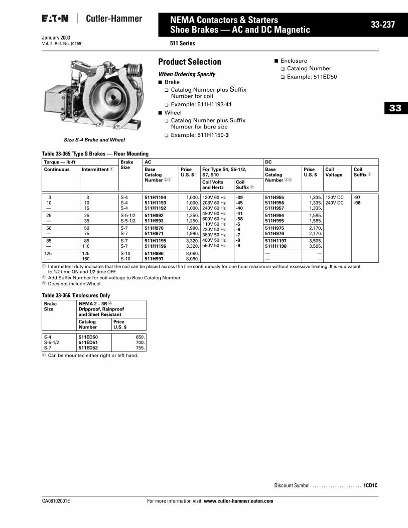
CA08102001E For more
37
33-2NEMA Contactors & StartersShoe Brakes — AC and DC Magnetic 511 SeriesJanuary 2003Vol. 2, Ref. No. [0255]
33
Size S-4 Brake and Wheel
Product SelectionWhen Ordering Specify■ Brake
❑ Catalog Number plus Suffix Number for coil
❑ Example: 511H1193-41
■ Wheel❑ Catalog Number plus Suffix
Number for bore size❑ Example: 511H1150-3
■ Enclosure❑ Catalog Number❑ Example: 511ED50
Table 33-365. Type S Brakes — Floor Mounting
1 Intermittent duty indicates that the coil can be placed across the line continuously for one hour maximum without excessive heating. It is equivalent to 1/2 time ON and 1/2 time OFF.
2 Add Suffix Number for coil voltage to Base Catalog Number.3 Does not include Wheel.
Table 33-366. Enclosures Only
4 Can be mounted either right or left hand.
Torque — lb-ft BrakeSize
AC DC
Continuous Intermittent 1 BaseCatalogNumber 23
PriceU.S. $
For Type S4, S5-1/2, S7, S10
BaseCatalogNumber 23
PriceU.S. $
CoilVoltage
Coil Suffix 2
Coil Voltsand Hertz
CoilSuffix 2
310—
31015
S-4S-4S-4
511H1194511H1193511H1192
1,000.1,000.1,000.
120V 60 Hz208V 60 Hz240V 60 Hz480V 60 Hz600V 60 Hz110V 50 Hz220V 50 Hz380V 50 Hz400V 50 Hz550V 50 Hz
-39-45-40-41-58-5-6-7-8-9
511H955511H956511H957
1,335.1,335.1,335.
120V DC240V DC
-97-98
25—
2535
S-5-1/2S-5-1/2
511H992511H993
1,250.1,250.
511H994511H995
1,585.1,585.
50—
5075
S-7S-7
511H970511H971
1,990.1,990.
511H975511H976
2,170.2,170.
85—
85110
S-7S-7
511H1195511H1196
3,320.3,320.
511H1197511H1198
3,505.3,505.
125—
125160
S-10S-10
511H996511H997
8,060.8,060.
——
——
BrakeSize
NEMA 2 – 3R 4
Dripproof, Rainproof and Sleet Resistant
CatalogNumber
PriceU.S. $
S-4S-5-1/2S-7
511ED50511ED51511ED52
650.700.755.
Discount Symbol . . . . . . . . . . . . . . . . . . . . . . . 1CD1C
information visit: www.cutler-hammer.eaton.com
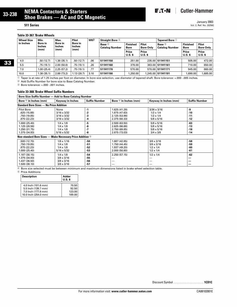
33-238
33
NEMA Contactors & StartersShoe Brakes — AC and DC Magnetic
511 SeriesFor more information visit: www.cutler-hammer.eaton.com
January 2003Vol. 2, Ref. No. [0256]
Table 33-367. Brake Wheels
1 Taper is at rate of 1.25 inches per foot on diameter. In bore size selection, use diameter of tapered shaft. Bore tolerance: +.000 -.005 inches.2 Add Suffix Number for bore size to Base Catalog Number.3 Bore tolerance: +.000 -.001 inches.
Table 33-368. Brake Wheel Suffix Numbers
4 Bore size selected must be between minimum and maximum dimensions listed in brake wheel selection table.5 Price Additions
Wheel Sizein Inches
Min.Bore inInches (mm)
Max.Bore in Inches (mm)
PilotBore inInches (mm)
WK2 Straight Bore 3 Tapered Bore 1
Base 2
Catalog NumberFinishedBore
PilotBore Only
Base 2
Catalog NumberFinishedBore
PilotBore Only
PriceU.S. $
PriceU.S. $
PriceU.S. $
PriceU.S. $
4.0 .50 (12.7) 1.38 (35.1) .50 (12.7) .06 511H1150 251.00 235.00 511H1151 505.00 472.00
5.5 .75 (19.1) 2.00 (50.8) .75 (19.1) .26 511H1160 378.00 383.00 511H1161 710.00 650.00
7.0 1.00 (25.4) 2.25 (57.2) .75 (19.1) .77 511H1170 570.00 570.00 511H1171 945.00 860.00
10.0 1.38 (35.1) 2.88 (73.2) 1.13 (28.7) 3.10 511H1190 1,250.00 1,245.00 511H1191 1,690.00 1,685.00
Bore Size Suffix Number — Add to Base Catalog Number
Bore 4 in Inches (mm) Keyway in Inches Suffix Number Bore 4 in Inches (mm) Keyway in Inches (mm) Suffix Number
Standard Bore Sizes — No Price Addition Pilot Bore.625 (15.88).750 (19.05).875 (22.23)
None3/16 x 3/323/16 x 3/323/16 x 3/32
-1-2-3-4
1.625 (41.28)1.875 (47.63)2.125 (53.98)2.375 (60.33)
3/38 x 3/16 1/2 x 1/4 1/2 x 1/4 5/8 x 5/16
-9-10-11-12
1.000 (25.40)1.125 (28.58)1.250 (31.75)1.375 (34.93)
1/4 x 1/81/4 x 1/81/4 x 1/8
5/16 x 5/32
-5-6-7-8
2.500 (63.50)2.625 (66.68)2.750 (69.85)2.875 (73.03)
5/8 x 5/16 5/8 x 5/16 5/8 x 5/16 3/4 x 3/8
-63-13-18-14
Non-standard Bore Sizes — Make Necessary Price Addition 5
.500 (12.70)
.750 (19.05)
.875 (22.23)1.000 (25.40)
1/8 x 1/161/4 x 1/81/4 x 1/8
5/16 x 5/32
-50-51-52-53
1.687 (42.85)1.750 (44.45)1.937 (49.20)2.000 (50.80)
3/8 x 3/16 3/8 x 3/16 1/2 x 1/4 1/2 x 1/4
-58-59-60-61
1.187 (30.15)1.375 (34.93)1.437 (36.50)1.500 (38.10)
1/4 x 1/83/8 x 3/163/8 x 3/163/8 x 3/16
-54-55-56-57
2.250 (57.15)———
1/2 x 1/4 — ——
-62———
Description AdderU.S. $
4.0 Inch (101.6 mm)5.5 Inch (139.7 mm)7.0 Inch (177.8 mm)
10.0 Inch (254.0 mm)
70.5092.50
123.00189.00
Discount Symbol . . . . . . . . . . . . . . . . . . . . . . . 1CD1C
CA08102001E
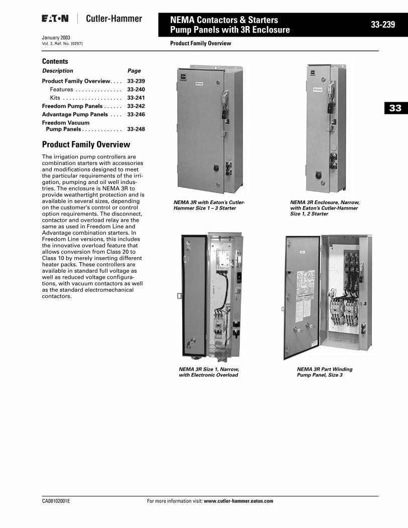
CA08102001E For more
39
33-2NEMA Contactors & StartersPump Panels with 3R Enclosure Product Family OverviewJanuary 2003Vol. 2, Ref. No. [0257]
33
ContentsDescription Page
Product Family Overview. . . . 33-239
Features . . . . . . . . . . . . . . . 33-240
Kits . . . . . . . . . . . . . . . . . . . 33-241
Freedom Pump Panels . . . . . . 33-242
Advantage Pump Panels . . . . 33-246
Freedom Vacuum Pump Panels . . . . . . . . . . . . . 33-248
Product Family OverviewThe irrigation pump controllers are combination starters with accessories and modifications designed to meet the particular requirements of the irri-gation, pumping and oil well indus-tries. The enclosure is NEMA 3R to provide weathertight protection and is available in several sizes, depending on the customer’s control or control option requirements. The disconnect, contactor and overload relay are the same as used in Freedom Line and Advantage combination starters. In Freedom Line versions, this includes the innovative overload feature that allows conversion from Class 20 to Class 10 by merely inserting different heater packs. These controllers are available in standard full voltage as well as reduced voltage configura-tions, with vacuum contactors as well as the standard electromechanical contactors.
NEMA 3R with Eaton’s Cutler-Hammer Size 1 – 3 Starter
NEMA 3R Size 1, Narrow,with Electronic Overload
NEMA 3R Enclosure, Narrow, with Eaton’s Cutler-Hammer Size 1, 2 Starter
NEMA 3R Part WindingPump Panel, Size 3
information visit: www.cutler-hammer.eaton.com
33-240
33
NEMA Contactors & StartersPump Panels with 3R Enclosure
Product Family OverviewFor more information visit: www.cutler-hammer.eaton.com
January 2003Vol. 2, Ref. No. [0258]
FeaturesThe Freedom Series and Advantage starters are available in either fusible or circuit breaker types utilizing NEMA 3R Rainproof and Sleet Resistant enclosures. Convenient straight-through wiring with top line connec-tions and bottom load connections features easily accessible pressure connections for line, load and control. Starter and disconnect are factory wired. Freedom overload relays with trip indication feature bimetallic type operation with ambient compensation and a choice of either manual or automatic reset.
■ Motor Circuit Switch — Long life, heavy-duty, quick acting, double break action. Positive ON and posi-tive OFF available in either fusible or non-fusible versions. Fuse clip kits are available for field installation and can be converted in the field for maximum job flexibility.
■ Motor Circuit Protector — Similar to a magnetic trip only circuit breaker. Features an adjustable magnetic trip characteristic for accurate, depend-able fault protection and simulta-neous trip of all poles to prevent single phasing.
■ HAND/OFF/AUTO Selector Switch and START Pushbutton — 10250T heavy-duty units mounted on the flange of the enclosure for outside accessibility.
■ RESET Button — Accessible from front of enclosure (booted for envi-ronmental protection) for operation of overload relay reset function.
■ Enclosure — NEMA 3R Rainproof and Sleet Resistant construction with stainless steel door latches and special corrosion resistant paint. Enclosure features include ground-ing lugs, padlocking feature on door latch, drip hood over door and pro-visions for top mounting conduit hubs. Most enclosures include gen-erous panel space for mounting optional control and accessories.
■ Mounting — Pole mounting feet with keyhole slots for easy mount-ing are standard on enclosures for Sizes 1 – 5 (removable for Sizes 1 – 5 standard width flange type enclosures). Brackets can be formed to the contour of the pole after mounting.
■ Padlocking — Provision on door latch for locking door closed, as well as provision for padlocking discon-nect switch in OFF position. With a simple modification, disconnect can also be padlocked in ON position.
■ UL Listed — Underwriters Laborato-ries Inc. listed under File E1491, guide NLDX, includes the “Suitable for Use as Service Equipment” label.
Interrupting Ratings■ Fusible — Sizes 1 – 5 suitable for use
on a circuit capable of delivering not more than 100,000 rms symmetrical amperes. 600V maximum where a Class R fuse clip kit is properly installed and Class R fuses are used. If Class R fuses are not used, the switch should not be installed on circuits capable of delivering more than 10,000 rms symmetrical amperes. Size 6 is limited to 18,000 and Size 7 is limited to 30,000 rms symmetrical amperes.
■ Circuit Breaker HMCPE — Sizes 1 – 3 controllers are suitable for use on circuits capable of delivering not more than 100,000 rms symmetrical amperes at 480V maximum; for 600V applications, see below.
■ Circuit Breaker HMCP — Sizes 4 and 5 controllers are suitable for use on circuits capable of delivering not more than 100,000 rms symmetrical amperes at 480V maximum; Sizes 1 and 2 are suitable for use on circuits capable of delivering not more than 25,000 rms symmetrical amperes at 600V maximum; and Sizes 3 and 4 are suitable for use on circuits capa-ble of delivering not more than 50,000 rms symmetrical amperes at 600V maximum. Size 5 is suitable for use on circuits capable of deliv-ering not more than 35,000 rms symmetrical amperes at 600V maxi-mum. Size 6 is limited to 18,000 and Size 7 is limited to 30,000 rms sym-metrical amperes.
Optional Features■ Backspin Timer — .2 seconds to 3
minutes. Prevents restart until motor and pump have stopped.
■ Program Timer — 24 hour, 7 day with day omission.
■ Control Transformer — Available as standard, either as a field kit or factory installed. Includes 2 primary and 1 secondary fuses.
■ Electrical Interlocks — Side mounted in NO, NC and NO-NC. Maximum of 2 contacts on either side of starter through Size 2, maxi-mum of 3 per side Sizes 3 – 5.
■ Control Circuit Fuse Kit — 30A, 600V rating.
■ Lightning Arrestor — Offers protec-tion to control from lightning induced surges.
■ “R” Fuse Clip Kits — 30 – 200A, 250V and 600V ratings.
■ Disconnect Control Circuit Interlock — To disconnect separate control circuits.
■ Enclosure Conduit Hubs — Hole provided in enclosure top covered with hole closer. Will accept 3/4", 1-1/4", 1-1/2", 2", 2-1/2" and 3" conduit sizes.
■ Pad Mounting Feet — For standard width enclosures Sizes 1 – 5.
■ Electronic Overload
CA08102001E
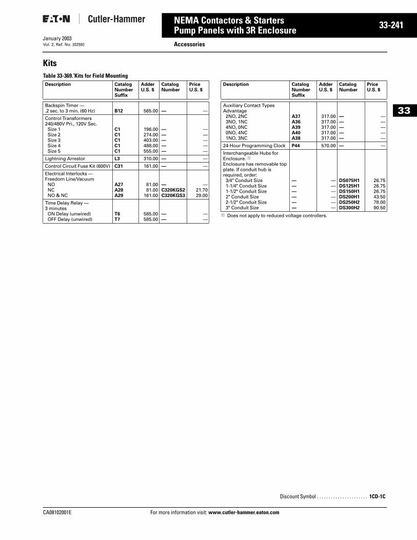
CA08102001E For more
41
33-2NEMA Contactors & StartersPump Panels with 3R Enclosure AccessoriesJanuary 2003Vol. 2, Ref. No. [0259]
33
KitsTable 33-369. Kits for Field Mounting
1 Does not apply to reduced voltage controllers.
Description CatalogNumberSuffix
Adder U.S. $
CatalogNumber
PriceU.S. $
Backspin Timer — .2 sec. to 3 min. (60 Hz) B12 565.00 — —
Control Transformers240/480V Pri., 120V Sec.Size 1Size 2Size 3Size 4Size 5
C1C1C1C1C1
196.00274.00403.00488.00555.00
—————
—————
Lightning Arrestor L3 310.00 — —
Control Circuit Fuse Kit (600V) C31 161.00 — —
Electrical Interlocks — Freedom Line/VacuumNONCNO & NC
A27A28A29
81.0081.00
161.00
—C320KGS2C320KGS3
—21.7029.00
Time Delay Relay —3 minutesON Delay (unwired)OFF Delay (unwired)
T6T7
585.00585.00
——
——
Description CatalogNumberSuffix
Adder U.S. $
CatalogNumber
PriceU.S. $
Auxiliary Contact Types Advantage2NO, 2NC3NO, 1NC4NO, 0NC0NO, 4NC1NO, 3NC
A37A36A39A40A38
317.00317.00317.00317.00317.00
—————
—————
24-Hour Programming Clock P44 570.00 — —
Interchangeable Hubs for Enclosure. 1Enclosure has removable top plate. If conduit hub is required, order:3/4" Conduit Size1-1/4" Conduit Size1-1/2" Conduit Size2" Conduit Size2-1/2" Conduit Size3" Conduit Size
——————
——————
DS075H1DS125H1DS150H1DS200H1DS250H2DS300H2
26.7526.7526.7543.5078.0090.50
Discount Symbol . . . . . . . . . . . . . . . . . . . . . . 1CD-1C
information visit: www.cutler-hammer.eaton.com
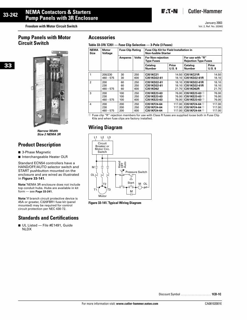
33-242
33
NEMA Contactors & StartersPump Panels with 3R Enclosure
Freedom with Motor Circuit SwitchFor more information visit: www.cutler-hammer.eaton.com
January 2003Vol. 2, Ref. No. [0260]
Pump Panels with Motor Circuit Switch
Product Description■ 3-Phase Magnetic■ Interchangeable Heater OLR
Standard ECN54 controllers have a HAND/OFF/AUTO selector switch and START pushbutton mounted on the enclosure and are wired as illustrated in Figure 33-141.
Note: NEMA 3R enclosure does not include top conduit hubs. Hubs are available in kit form — see Page 33-241.
Note: If branch circuit protective device is 45A or greater, C320FBR1 fuse kit (panel mounted) may be required for control circuit protection per NEC 430-72.
Standards and Certifications■ UL Listed — File #E1491, Guide
NLDX
Narrow WidthSize 2 NEMA 3R
AccessoriesTable 33-370. C351 — Fuse Clip Selection — 3-Pole (3 Fuses)
1 Fuse clip “R” rejection members for use with Class R fuses are supplied loose both in Fuse Clip Kits and when fuse clips are factory installed.
Wiring Diagram
Figure 33-141. Typical Wiring Diagram
NEMASize
MotorVoltage
Fuse Clip Rating Fuse Clip Kit for Field Installation inNon-fusible Starter
Amperes Volts For Non-rejection Type Fuses
For use with “R”Rejection Type Fuses
CatalogNumber
PriceU.S. $
CatalogNumber
PriceU.S. $
1 200/230460 – 575
3030
250600
C351KC21C351KD22-61
14.5018.10
C351KC21RC351KD22-61R
14.5018.10
2 200230460 – 575
606060
250250600
C351KD22-61C351KD22-61C351KD62
18.1018.1021.70
C351KD22-61RC351KD22-61RC351KD62R
18.1018.1021.70
3 200230460 – 575
100100100
250250600
C351KE23-63C351KE23-63C351KE23-63
76.0076.0076.00
C351KE23-63 1
C351KE23-63 1
C351KE23-63 1
76.0076.0076.00
4 200230460 – 575
200200200
250250600
C351KF24-64C351KF24-64C351KF24-64
117.00117.00117.00
C351KF24-64 1
C351KF24-64 1
C351KF24-64 1
117.00117.00117.00
OL
M
CircuitBreaker orMotor Circ.
Switch
Motor
L2 L3L1
T1
T2
T3M
Start M
Pressure Switch
Han
dO
FFA
uto
OL
Discount Symbol . . . . . . . . . . . . . . . . . . . . . . 1CD-1C
CA08102001E
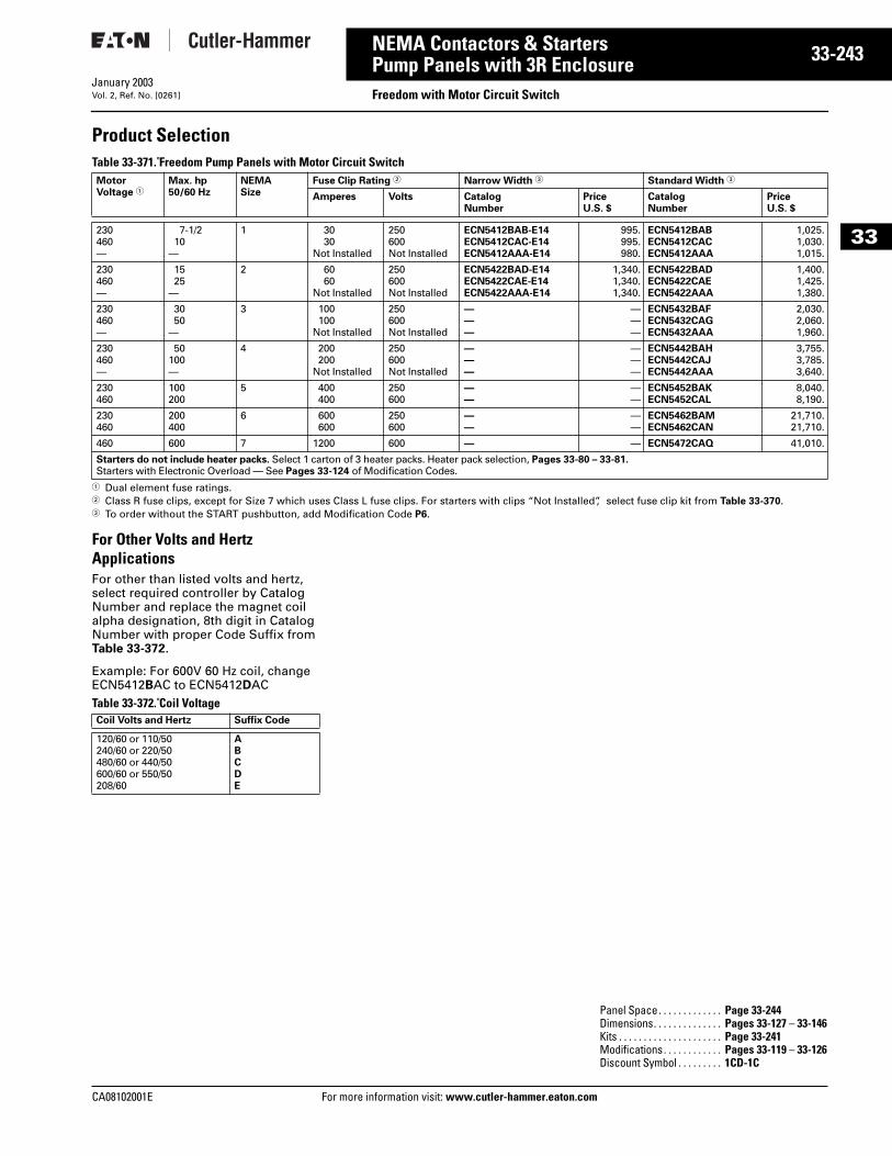
CA08102001E For more
43
33-2NEMA Contactors & StartersPump Panels with 3R Enclosure Freedom with Motor Circuit SwitchJanuary 2003Vol. 2, Ref. No. [0261]
33
Product SelectionTable 33-371. Freedom Pump Panels with Motor Circuit Switch
1 Dual element fuse ratings.2 Class R fuse clips, except for Size 7 which uses Class L fuse clips. For starters with clips “Not Installed”, select fuse clip kit from Table 33-370. 3 To order without the START pushbutton, add Modification Code P6.
For Other Volts and Hertz ApplicationsFor other than listed volts and hertz, select required controller by Catalog Number and replace the magnet coil alpha designation, 8th digit in Catalog Number with proper Code Suffix from Table 33-372.
Example: For 600V 60 Hz coil, change ECN5412BAC to ECN5412DACTable 33-372. Coil Voltage
MotorVoltage 1
Max. hp50/60 Hz
NEMASize
Fuse Clip Rating 2 Narrow Width 3 Standard Width 3
Amperes Volts CatalogNumber
PriceU.S. $
CatalogNumber
PriceU.S. $
230460—
7-1/210
—
1 3030
Not Installed
250600Not Installed
ECN5412BAB-E14ECN5412CAC-E14ECN5412AAA-E14
995.995.980.
ECN5412BABECN5412CACECN5412AAA
1,025.1,030.1,015.
230460—
1525
—
2 6060
Not Installed
250600Not Installed
ECN5422BAD-E14ECN5422CAE-E14ECN5422AAA-E14
1,340.1,340.1,340.
ECN5422BADECN5422CAEECN5422AAA
1,400.1,425.1,380.
230460—
3050
—
3 100100
Not Installed
250600Not Installed
———
———
ECN5432BAFECN5432CAGECN5432AAA
2,030.2,060.1,960.
230460—
50100—
4 200200
Not Installed
250600Not Installed
———
———
ECN5442BAHECN5442CAJECN5442AAA
3,755.3,785.3,640.
230460
100200
5 400400
250600
——
——
ECN5452BAKECN5452CAL
8,040.8,190.
230460
200400
6 600600
250600
——
——
ECN5462BAMECN5462CAN
21,710.21,710.
460 600 7 1200 600 — — ECN5472CAQ 41,010.
Starters do not include heater packs. Select 1 carton of 3 heater packs. Heater pack selection, Pages 33-80 – 33-81.Starters with Electronic Overload — See Pages 33-124 of Modification Codes.
Coil Volts and Hertz Suffix Code
120/60 or 110/50240/60 or 220/50480/60 or 440/50600/60 or 550/50208/60
ABCDE
Panel Space. . . . . . . . . . . . . Page 33-244Dimensions. . . . . . . . . . . . . . Pages 33-127 – 33-146Kits . . . . . . . . . . . . . . . . . . . . . Page 33-241Modifications. . . . . . . . . . . . Pages 33-119 – 33-126Discount Symbol . . . . . . . . . 1CD-1C
information visit: www.cutler-hammer.eaton.com
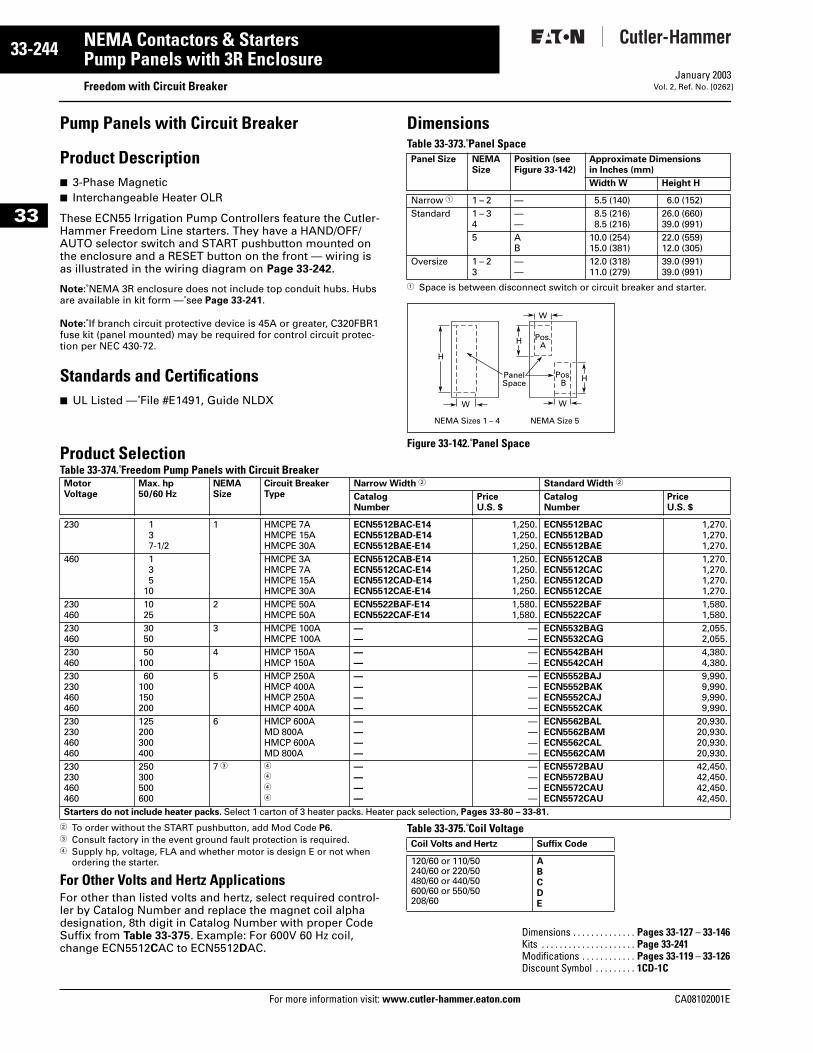
33-244
33
NEMA Contactors & StartersPump Panels with 3R Enclosure
Freedom with Circuit BreakerFor more information visit: www.cutler-hammer.eaton.com
January 2003Vol. 2, Ref. No. [0262]
Pump Panels with Circuit Breaker
Product Description■ 3-Phase Magnetic■ Interchangeable Heater OLR
These ECN55 Irrigation Pump Controllers feature the Cutler-Hammer Freedom Line starters. They have a HAND/OFF/AUTO selector switch and START pushbutton mounted on the enclosure and a RESET button on the front — wiring is as illustrated in the wiring diagram on Page 33-242.
Note: NEMA 3R enclosure does not include top conduit hubs. Hubs are available in kit form — see Page 33-241.
Note: If branch circuit protective device is 45A or greater, C320FBR1 fuse kit (panel mounted) may be required for control circuit protec-tion per NEC 430-72.
Standards and Certifications■ UL Listed — File #E1491, Guide NLDX
DimensionsTable 33-373. Panel Space
1 Space is between disconnect switch or circuit breaker and starter.
Figure 33-142. Panel SpaceProduct SelectionTable 33-374. Freedom Pump Panels with Circuit Breaker
2 To order without the START pushbutton, add Mod Code P6.3 Consult factory in the event ground fault protection is required.4 Supply hp, voltage, FLA and whether motor is design E or not when
ordering the starter.
For Other Volts and Hertz ApplicationsFor other than listed volts and hertz, select required control-ler by Catalog Number and replace the magnet coil alpha designation, 8th digit in Catalog Number with proper Code Suffix from Table 33-375. Example: For 600V 60 Hz coil, change ECN5512CAC to ECN5512DAC.
Table 33-375. Coil Voltage
Panel Size NEMASize
Position (seeFigure 33-142)
Approximate Dimensions in Inches (mm)
Width W Height H
Narrow 1 1 – 2 — 5.5 (140) 6.0 (152)Standard 1 – 3
4——
8.5 (216)8.5 (216)
26.0 (660)39.0 (991)
5 AB
10.0 (254)15.0 (381)
22.0 (559)12.0 (305)
Oversize 1 – 23
——
12.0 (318)11.0 (279)
39.0 (991)39.0 (991)
H
W
W
PanelSpace
Pos.A
Pos.B
H
H
W
NEMA Sizes 1 – 4 NEMA Size 5
MotorVoltage
Max. hp50/60 Hz
NEMASize
Circuit Breaker Type
Narrow Width 2 Standard Width 2
CatalogNumber
PriceU.S. $
CatalogNumber
PriceU.S. $
230 137-1/2
1 HMCPE 7AHMCPE 15AHMCPE 30A
ECN5512BAC-E14ECN5512BAD-E14ECN5512BAE-E14
1,250.1,250.1,250.
ECN5512BACECN5512BADECN5512BAE
1,270.1,270.1,270.
460 135
10
HMCPE 3AHMCPE 7AHMCPE 15AHMCPE 30A
ECN5512CAB-E14ECN5512CAC-E14ECN5512CAD-E14ECN5512CAE-E14
1,250.1,250.1,250.1,250.
ECN5512CABECN5512CACECN5512CADECN5512CAE
1,270.1,270.1,270.1,270.
230460
1025
2 HMCPE 50AHMCPE 50A
ECN5522BAF-E14ECN5522CAF-E14
1,580.1,580.
ECN5522BAFECN5522CAF
1,580.1,580.
230460
3050
3 HMCPE 100AHMCPE 100A
——
——
ECN5532BAGECN5532CAG
2,055.2,055.
230460
50100
4 HMCP 150AHMCP 150A
——
——
ECN5542BAHECN5542CAH
4,380.4,380.
230230460460
60100150200
5 HMCP 250AHMCP 400AHMCP 250AHMCP 400A
————
————
ECN5552BAJECN5552BAKECN5552CAJECN5552CAK
9,990.9,990.9,990.9,990.
230230460460
125200300400
6 HMCP 600AMD 800AHMCP 600AMD 800A
————
————
ECN5562BALECN5562BAMECN5562CALECN5562CAM
20,930.20,930.20,930.20,930.
230230460460
250300500600
7 3 4
4
4
4
————
————
ECN5572BAUECN5572BAUECN5572CAUECN5572CAU
42,450.42,450.42,450.42,450.
Starters do not include heater packs. Select 1 carton of 3 heater packs. Heater pack selection, Pages 33-80 – 33-81.
Coil Volts and Hertz Suffix Code
120/60 or 110/50240/60 or 220/50480/60 or 440/50600/60 or 550/50208/60
ABCDE
Dimensions . . . . . . . . . . . . . . Pages 33-127 – 33-146Kits . . . . . . . . . . . . . . . . . . . . . Page 33-241Modifications . . . . . . . . . . . . Pages 33-119 – 33-126Discount Symbol . . . . . . . . . 1CD-1C
CA08102001E
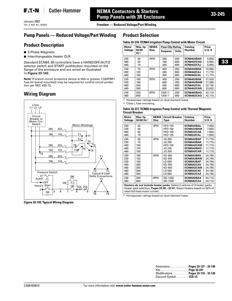
CA08102001E For more
45
33-2NEMA Contactors & StartersPump Panels with 3R Enclosure Freedom — Reduced Voltage/Part WindingJanuary 2003Vol. 2, Ref. No. [0263]
33
Pump Panels — Reduced Voltage/Part Winding
Product Description■ 3-Phase Magnetic■ Interchangeable Heater OLR
Standard ECN64, 65 controllers have a HAND/OFF/AUTO selector switch and START pushbutton mounted on the flange of the enclosure and are wired as illustrated in Figure 33-143.
Note: If branch circuit protective device is 45A or greater, C320FBR1 fuse kit (panel mounted) may be required for control circuit protec-tion per NEC 430-72.
Wiring Diagram
Figure 33-143. Typical Wiring Diagram
Product SelectionTable 33-376. ECN64 Irrigation Pump Control with Motor Circuit
1 Horsepower ratings based on dual element fuses.2 Class L fuse mounting.
Table 33-377. ECN65 Irrigation Pump Control with Thermal Magnetic Circuit Breaker
3 Horsepower ratings based on dual element fuses.
CircuitBreaker orMotor Circ.
Switch
T1
Typical 6 LeadDelta Connections
T3 T2
T7
T9 T8
OFFAuto
Hand Start
1M2
L1 L2 L3Lines
2MMotor Windings
2M
2M
1M
1M
1M
2OL
2OL
2OL
1OL T1
T4
T9
T3
T7
T5
T6T2
T81OL10
1OL
2OL1OL
3 6 7 8
1M1M
2M
T.C.
9
4Pressure Switch
MotorVoltage
Max. hp50/60 Hz1
NEMASize
Fuse Clip Rating CatalogNumber
PriceU.S. $Amperes Volts
230460460
505075
3PW 200100200
250600600
ECN6432BAHECN6432CAGECN6432CAJ
5,850.5,850.5,850.
230460460
75125150
4PW 400200400
250600600
ECN6442BAKECN6442CAJECN6442CAL
10,980.11,770.11,770.
230230460460
100150200350
5PW 400600400600
250250600600
ECN6452BAKECN6452BAMECN6452CALECN6452CAN
21,020.21,360.22,730.23,002.
230460
300600
6PW 1200 21200 2
250600
ECN6462BAQECN6462CAQ
42,110.42,110.
MotorVoltage
Max. hp50/60 Hz3
NEMASize
Circuit Breaker Type
CatalogNumber
PriceU.S. $
230230460460
40505075
3PW HFD 125HFD 150HFD 100HFD 125
ECN6532BALECN6532BAMECN6532CAKECN6532CAL
7,650.7,650.7,650.7,650.
230230460460460
6075
100125150
4PW JD 200JD 250HFD 150JD 225JD 250
ECN6542BAPECN6542BARECN6542CAMECN6542BAQECN6542CAR
11,770.11,770.11,770.11,770.11,770.
230230230460460460460
100125150200250300350
5PW KD 350KD 400LD 500KD 350KD 400LD 500LD 600
ECN6552BAVECN6552BAWECN6552BAYECN6552CAVECN6552CAWECN6552CAYECN6552CAZ
24,790.24,790.24,790.24,790.24,790.24,790.24,790.
230460
350600
6PW ND 1200ND 1200
ECN6562BA4ECN6562CA4
44,710.44,710.
Starters do not include heater packs. Select 2 cartons of 3 heater packs. Heater pack selection, Pages 33-80 – 33-81. Select heaters based on 50% of rated full-load motor current.
Dimensions . . . . . . . . . . . . . . Pages 33-127 – 33-146Kits . . . . . . . . . . . . . . . . . . . . . Page 33-241Modifications . . . . . . . . . . . . Pages 33-119 – 33-126Discount Symbol . . . . . . . . . 1CD-1C
information visit: www.cutler-hammer.eaton.com
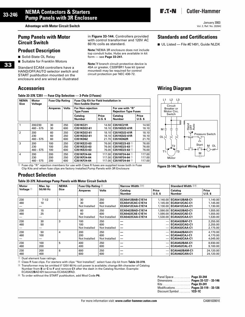
33-246
33
NEMA Contactors & StartersPump Panels with 3R Enclosure
Advantage with Motor Circuit SwitchFor more information visit: www.cutler-hammer.eaton.com
January 2003Vol. 2, Ref. No. [0264]
Pump Panels with Motor Circuit Switch
Product Description■ Solid-State OL Relay■ Suitable for Franklin Motors
Standard ECA54 controllers have a HAND/OFF/AUTO selector switch and START pushbutton mounted on the enclosure and are wired as illustrated
in Figure 33-144. Controllers provided with control transformer and 120V AC 60 Hz coils as standard.
Note: NEMA 3R enclosure does not include top conduit hubs. Hubs are available in kit form — see Page 33-241.
Note: If branch circuit protective device is 45A or greater, C320FBR1 fuse kit (panel mounted) may be required for control circuit protection per NEC 430-72.
AccessoriesTable 33-378. C351 — Fuse Clip Selection — 3-Pole (3 Fuses)
1 Fuse clip “R” rejection members for use with Class R fuses are supplied loose both in Fuse Clip Kits and when fuse clips are factory installed.Pump Panels with 3R Enclosure
Product SelectionTable 33-379. Advantage Pump Panels with Motor Circuit Switch
1 Dual element fuse ratings.2 Class R fuse clips. For starters with clips “Not Installed”, select fuse clip kit from Table 33-378. 3 Transformer may be omitted if 120V 60 Hz coil power is available; change 8th character of Catalog
Number from B or C to F and remove C1 after the dash in the Catalog Number. Example: ECA5422BAD-C1 becomes ECA5422FAD.
4 To order without the START pushbutton, add Mod Code P6.
NEMASize
MotorVoltage
Fuse Clip Rating Fuse Clip Kit for Field Installation inNon-fusible Starter
Amperes Volts For Non-rejection Type Fuses
For use with “R”Rejection Type Fuses
CatalogNumber
PriceU.S. $
CatalogNumber
PriceU.S. $
1 200/230460 – 575
3030
250600
C351KC21C351KD22-61
14.5018.10
C351KC21RC351KD22-61R
14.5018.10
2 200230460 – 575
606060
250250600
C351KD22-61C351KD22-61C351KD62
18.1018.1021.70
C351KD22-61RC351KD22-61RC351KD62R
18.1018.1021.70
3 200230460 – 575
100100100
250250600
C351KE23-63C351KE23-63C351KE23-63
76.0076.0076.00
C351KE23-63 1
C351KE23-63 1
C351KE23-63 1
76.0076.0076.00
4 200230460 – 575
200200200
250250600
C351KF24-64C351KF24-64C351KF24-64
117.00117.00117.00
C351KF24-64 1
C351KF24-64 1
C351KF24-64 1
117.00117.00117.00
MotorVoltage 1
Max. hp50/60 Hz
NEMASize
Fuse Clip Rating 2 Narrow Width 34
Amperes Volts CatalogNumber
PU
230460—
7-1/210
—
1 3030
Not Installed
250600Not Installed
ECA5412BAB-C1E14ECA5412CAC-C1E14ECA5412CAA-C1E14
230460—
1525
—
2 6060
Not Installed
250600Not Installed
ECA5422BAD-C1E14ECA5422CAE-C1E14ECA5422CAA-C1E14
230460—
3050
—
3 100100Not Installed
250600Not Installed
———
230460—
50100—
4 200200Not Installed
250600Not Installed
———
230460
100200
5 400400
250600
——
230460
200400
6 600600
250600
——
Standard Width 34
rice.S. $
CatalogNumber
PriceU.S. $
1,140.001,145.001,130.00
ECA5412BAB-C1ECA5412CAC-C1ECA5412CAA-C1
1,140.001,145.001,130.00
1,590.001,590.001,530.00
ECA5422BAD-C1ECA5422CAE-C1ECA5422CAA-C1
1,555.001,555.001,530.00
———
ECA5432BAF-C1ECA5432CAG-C1ECA5432CAA-C1
2,255.002,255.002,175.00
———
ECA5442BAH-C1ECA5442CAJ-C1ECA5442CAA-C1
4,170.004,170.004,045.00
——
ECA5452BAK-C1ECA5452CAL-C1
8,930.009,100.00
——
ECA5462BAM-C1ECA5462CAN-C1
24,120.0024,120.00
Standards and Certifications■ UL Listed — File #E1491, Guide NLDX
Wiring Diagram
Figure 33-144. Typical Wiring Diagram
Panel Space . . . . . . . . . . . . Page 33-244Dimensions . . . . . . . . . . . . . Pages 33-127 – 33-146Kits . . . . . . . . . . . . . . . . . . . . Page 33-241Modifications . . . . . . . . . . . Pages 33-119 – 33-126Discount Symbol . . . . . . . . 1CD-1C
OL
M
CircuitBreaker orMotor Circ.
Switch
Motor
L2 L3L1
T1
T2
T3M
Start M
Pressure Switch
Han
dO
FFA
uto
OL
CA08102001E
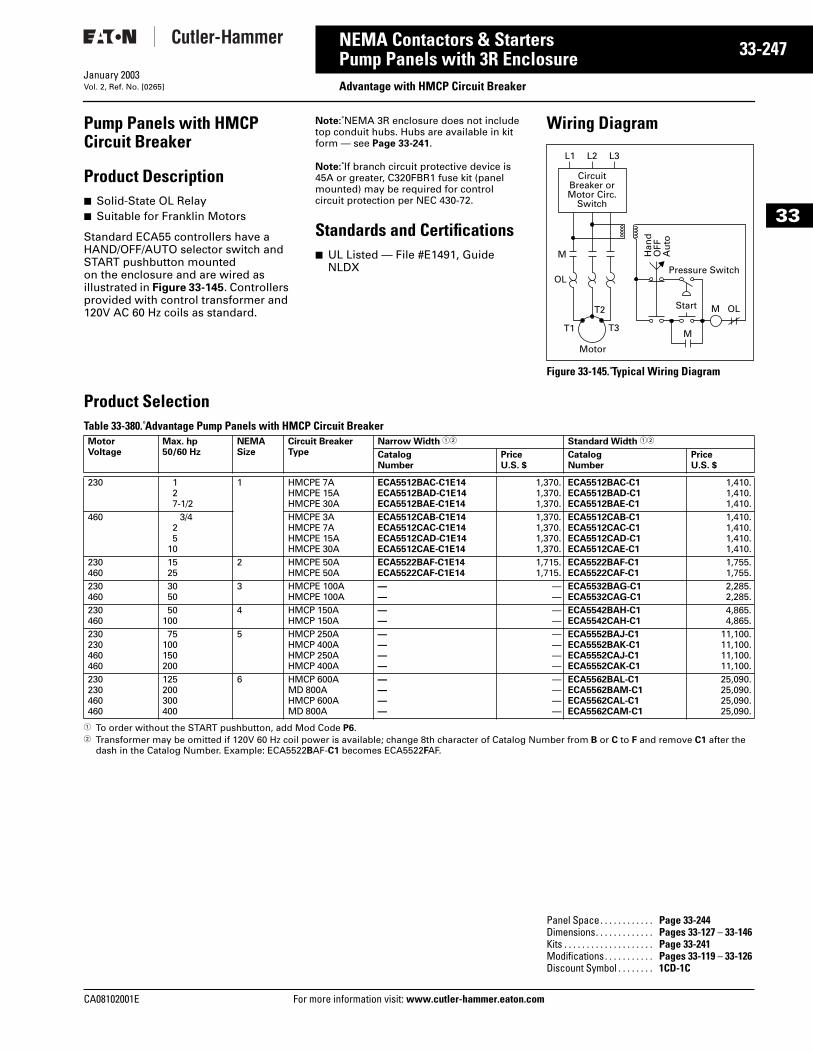
CA08102001E For more
47
33-2NEMA Contactors & StartersPump Panels with 3R Enclosure Advantage with HMCP Circuit BreakerJanuary 2003Vol. 2, Ref. No. [0265]
33
Pump Panels with HMCP Circuit Breaker
Product Description■ Solid-State OL Relay■ Suitable for Franklin Motors
Standard ECA55 controllers have a HAND/OFF/AUTO selector switch and START pushbutton mounted on the enclosure and are wired as illustrated in Figure 33-145. Controllers provided with control transformer and 120V AC 60 Hz coils as standard.
Note: NEMA 3R enclosure does not include top conduit hubs. Hubs are available in kit form — see Page 33-241.
Note: If branch circuit protective device is 45A or greater, C320FBR1 fuse kit (panel mounted) may be required for control circuit protection per NEC 430-72.
Standards and Certifications■ UL Listed — File #E1491, Guide
NLDX
Wiring Diagram
Figure 33-145. Typical Wiring Diagram
Product Selection Table 33-380. Advantage Pump Panels with HMCP Circuit Breaker
1 To order without the START pushbutton, add Mod Code P6.2 Transformer may be omitted if 120V 60 Hz coil power is available; change 8th character of Catalog Number from B or C to F and remove C1 after the
dash in the Catalog Number. Example: ECA5522BAF-C1 becomes ECA5522FAF.
OL
M
CircuitBreaker orMotor Circ.
Switch
Motor
L2 L3L1
T1
T2
T3M
Start M
Pressure Switch
Han
dO
FFA
uto
OL
MotorVoltage
Max. hp50/60 Hz
NEMASize
Circuit Breaker Type
Narrow Width 12 Standard Width 12
CatalogNumber
PriceU.S. $
CatalogNumber
PriceU.S. $
230 127-1/2
1 HMCPE 7AHMCPE 15AHMCPE 30A
ECA5512BAC-C1E14ECA5512BAD-C1E14ECA5512BAE-C1E14
1,370.1,370.1,370.
ECA5512BAC-C1ECA5512BAD-C1ECA5512BAE-C1
1,410.1,410.1,410.
460 3/425
10
HMCPE 3AHMCPE 7AHMCPE 15AHMCPE 30A
ECA5512CAB-C1E14ECA5512CAC-C1E14ECA5512CAD-C1E14ECA5512CAE-C1E14
1,370.1,370.1,370.1,370.
ECA5512CAB-C1ECA5512CAC-C1ECA5512CAD-C1ECA5512CAE-C1
1,410.1,410.1,410.1,410.
230460
1525
2 HMCPE 50AHMCPE 50A
ECA5522BAF-C1E14ECA5522CAF-C1E14
1,715.1,715.
ECA5522BAF-C1ECA5522CAF-C1
1,755.1,755.
230460
3050
3 HMCPE 100AHMCPE 100A
——
——
ECA5532BAG-C1ECA5532CAG-C1
2,285.2,285.
230460
50100
4 HMCP 150AHMCP 150A
——
——
ECA5542BAH-C1ECA5542CAH-C1
4,865.4,865.
230230460460
75100150200
5 HMCP 250AHMCP 400AHMCP 250AHMCP 400A
————
————
ECA5552BAJ-C1ECA5552BAK-C1ECA5552CAJ-C1ECA5552CAK-C1
11,100.11,100.11,100.11,100.
230230460460
125200300400
6 HMCP 600AMD 800AHMCP 600AMD 800A
————
————
ECA5562BAL-C1ECA5562BAM-C1ECA5562CAL-C1ECA5562CAM-C1
25,090.25,090.25,090.25,090.
Panel Space. . . . . . . . . . . . Page 33-244Dimensions. . . . . . . . . . . . . Pages 33-127 – 33-146Kits . . . . . . . . . . . . . . . . . . . . Page 33-241Modifications. . . . . . . . . . . Pages 33-119 – 33-126Discount Symbol . . . . . . . . 1CD-1C
information visit: www.cutler-hammer.eaton.com
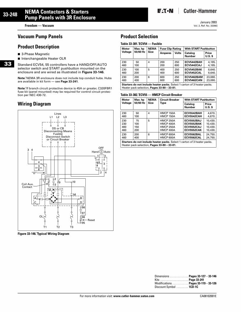
33-248
33
NEMA Contactors & StartersPump Panels with 3R Enclosure
Freedom — VacuumFor more information visit: www.cutler-hammer.eaton.com
January 2003Vol. 2, Ref. No. [0266]
Vacuum Pump Panels
Product Description■ 3-Phase Magnetic■ Interchangeable Heater OLR
Standard ECV54, 55 controllers have a HAND/OFF/AUTO selector switch and START pushbutton mounted on the enclosure and are wired as illustrated in Figure 33-146.
Note: NEMA 3R enclosure does not include top conduit hubs. Hubs are available in kit form — see Page 33-241.
Note: If branch circuit protective device is 45A or greater, C320FBR1 fuse kit (panel mounted) may be required for control circuit protec-tion per NEC 430-72.
Wiring Diagram
Figure 33-146. Typical Wiring Diagram
Product SelectionTable 33-381. ECV54 — Fusible
Table 33-382. ECV55 — HMCP Circuit Breaker
DS or CBDisconnecting Means
FusibleDisconnect Switchor Circuit Breaker
OFFHand Auto
1 1
3
2
2
3
A
C
T1
OL
”D”
Coil Aux. Contact
T2 T3
BM
D
98
9796
Reset95
9 10
4
3 4
36
4
A
L1 L2 L3Lines
1
+
–
M
MotorVoltage
Max. hp50/60 Hz
NEMASize
Fuse Clip Rating With START Pushbutton
CatalogNumber
PriceU.S. $
Amperes Volts
230460
50100
4 200200
250600
ECV5442BAHECV5442CAJ
4,185.4,185.
230460
100200
5 400400
250600
ECV5452BAKECV5452CAL
8,640.8,640.
230460
200400
6 600600
250600
ECV5462BAMECV5462CAN
23,080.23,080.
Starters do not include heater packs. Select 1 carton of 3 heater packs. Heater pack selection, Pages 33-80 – 33-81.
MotorVoltage
Max. hp50/60 Hz
NEMASize
Circuit Breaker Type
With START Pushbutton
CatalogNumber
PriceU.S. $
230460
50100
4 HMCP 150AHMCP 150A
ECV5542BAHECV5542CAH
4,670.4,670.
230230460460
75100150200
5 HMCP 250AHMCP 400AHMCP 250AHMCP 400A
ECV5552BAJECV5552BAKECV5552CAJECV5552CAK
10,430.10,430.10,430.10,430.
230460
200400
6 HMCP 600AHMCP 600A
ECV5562BALECV5562CAL
24,750.24,750.
Starters do not include heater packs. Select 1 carton of 3 heater packs. Heater pack selection, Pages 33-80 – 33-81.
Dimensions . . . . . . . . . . . . . . Pages 33-127 – 33-146Kits . . . . . . . . . . . . . . . . . . . . . Page 33-241Modifications . . . . . . . . . . . . Pages 33-119 – 33-126Discount Symbol . . . . . . . . . 1CD-1C
CA08102001E
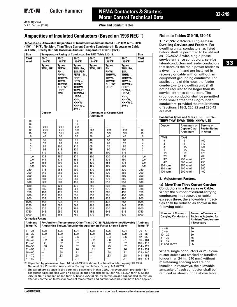
CA08102001E For more
49
33-2NEMA Contactors & StartersMotor Control Technical Data Wire and Conduit TablesJanuary 2003Vol. 2, Ref. No. [0267]
33
Ampacities of Insulated Conductors (Based on 1996 NEC 1)Table 310-16. Allowable Ampacities of Insulated Conductors Rated 0 – 2000V, 60° – 90°C (140° – 194°F), Not More Than Three Current-Carrying Conductors in Raceway or Cable or Earth (Directly Buried), Based on Ambient Temperature of 30°C (86°F)
1 Reprinted by permission from NFPA 70-1996. National Electrical Code®, Copyright© 1996. National Fire Protection Association, Batterymarch Park, Quincy, MA 02269.
† Unless otherwise specifically permitted elsewhere in this Code, the overcurrent protection for conductor types marked with an obelisk (†) shall not exceed 15A for No. 14, 20A for No. 12 and 30A for No. 10 copper; or 15A for No. 12 and 25A for No. 10 aluminum and copper-clad aluminum after any correction factors for ambient temperature and number of conductors have been applied.
Size Temperature Rating of Conductor. See NEC Table 310-13. Size
AWGkcmil
60°C(140°F)
75°C(167°F)
90°C(194°F)
60°C(140°F)
75°C(167°F)
90°C(194°F)
AWGkcmil
TypesTW†, UF†
Types FEPW†, RH†, RHW†, THHW†, THW†, THWN†, XHHW†, USE†, ZW†
TypesTBS, SA, SIS, FEP†, FEPB†, MI, RHH†, RHW-2, THHN†, THHW†, THW-2†, THWN-2†, USE-2, XHH, XHHW†, XHHW-2, ZW-2
TypesTW†, UF†
Types RH†, RHW†, THHW†, THW†, THWN†, XHHW†, USE†
TypesTBS, SA, SIS, THHN†, THHW†, THW-2, THWN-2, RHH†, RHW-2, USE-2, XHH, XHHW, XHHW-2, ZW-2
Copper Aluminum or Copper-Clad Aluminum
18161412108
——20✝25✝3040
——20✝25✝35✝50
141825†30†40†55
———20†2530
———20†30†40
———25†35†45
———
12108
64321
55708595
110
6585
100115130
7595
110130150
4055657585
50657590
100
607585
100115
64321
1/02/03/04/0
125145165195
150175200230
170195225260
100115130150
120135155180
135150175205
1/02/03/04/0
250300350400500
215240260280320
255285310335380
290320350380430
170190210225260
205230250270310
230255280305350
250300350400500
600700750800900
355385400410435
420460475490520
475520535555585
285310320330355
340375385395425
385420435450480
600700750800900
10001250150017502000
455495520545560
545590625650665
615665705735750
375405435455470
445485520545560
500545585615630
10001250150017502000
Correction FactorsAmbientTemp. °C
For Ambient Temperatures Other Than 30°C (86°F), Multiply the Allowable Ampacities Shown Above by the Appropriate Factor Shown Below
Ambient Temp. °F
21 – 2526 – 3031 – 3536 – 4041 – 4546 – 5051 – 5556 – 6061 – 7071 – 80
1.081.00.91.82.71.58.41
———
1.051.00.94.88.82.75.67.58.33
—
1.041.00.96.91.87.82.76.71.58.41
1.081.00.91.82.71.58.41
———
1.051.00.94.88.82.75.67.58.33
—
1.041.00.96.91.87.82.76.71.58.41
70 – 7778 – 8687 – 9596 – 104
105 – 113114 – 122123 – 131132 – 140141 – 158159 – 176
information visit: www.cutler-hammer.eaton.co
Notes to Tables 310-16, 310-181. 120/240V, 3-Wire, Single-Phase Dwelling Services and Feeders. For dwelling units, conductors, as listed below, shall be permitted to be utilized as 120/240V, 3-wire, single-phase service-entrance conductors, service lateral conductors and feeder conductors that serve as the main power feeder to a dwelling unit and are installed in raceway or cable with or without an equipment grounding conductor. For applications of this note, the feeder conductors to a dwelling unit shall not be required to be larger than its service-entrance conductors. The grounded conductor shall be permitted to be smaller than the ungrounded conductors, provided the requirements of Sections 215-2, 220-22 and 230-42 are met.
Conductor Types and Sizes RH-RHH-RHW-THHW-THW-THWN-THHN-XHHW-USE
8. Adjustment Factors.
(a) More Than Three Current-Carrying Conductors in a Raceway or Cable. Where the number of current-carrying conductors in a raceway or cable exceeds three, the allowable ampaci-ties shall be reduced as shown in the following table:
Where single conductors or multicon-ductor cables are stacked or bundled longer than 24 in. (610 mm) without maintaining spacing and are not installed in raceways, the allowable ampacity of each conductor shall be reduced as shown in the above table.
Copper Aluminum or Copper-Clad Aluminum
Service or Feeder Rating in Amps
AWG43211/02/03/04/0
250 kcmil350 kcmil400 kcmil
AWG211/02/03/04/0
250 kcmil300 kcmil350 kcmil500 kcmil600 kcmil
100110125150175200225250300350400
Number of Current-Carrying Conductors
Percent of Values in Tables as Adjusted for Ambient Temperature if Necessary
4 – 67 – 9
10 – 2021 – 3031 – 4041 and above
807050454035
m
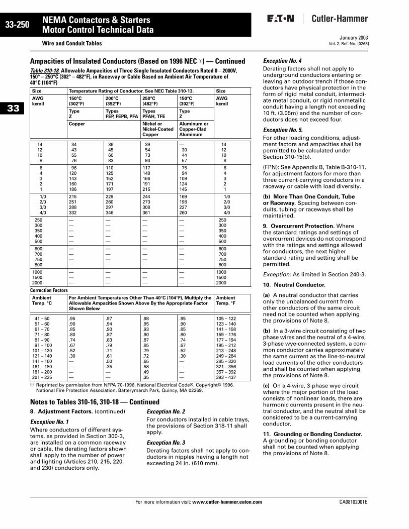
33-250
33
NEMA Contactors & StartersMotor Control Technical Data
Wire and Conduit TablesFor more information visit: www.cutler-hammer.eaton.com
January 2003Vol. 2, Ref. No. [0268]
Ampacities of Insulated Conductors (Based on 1996 NEC 1) — ContinuedTable 310-18. Allowable Ampacities of Three Single Insulated Conductors Rated 0 – 2000V, 150° – 250°C (302° – 482°F), in Raceway or Cable Based on Ambient Air Temperature of 40°C (104°F)
1 Reprinted by permission from NFPA 70-1996. National Electrical Code®, Copyright© 1996. National Fire Protection Association, Batterymarch Park, Quincy, MA 02269.
Notes to Tables 310-16, 310-18 — Continued8. Adjustment Factors. (continued)
Exception No. 1Where conductors of different sys-tems, as provided in Section 300-3, are installed on a common raceway or cable, the derating factors shown shall apply to the number of power and lighting (Articles 210, 215, 220 and 230) conductors only.
Exception No. 2For conductors installed in cable trays, the provisions of Section 318-11 shall apply.
Exception No. 3Derating factors shall not apply to con-ductors in nipples having a length not exceeding 24 in. (610 mm).
Size Temperature Rating of Conductor. See NEC Table 310-13. Size
AWGkcmil
150°C(302°F)
200°C(392°F)
250°C(482°F)
150°C(302°F)
AWGkcmil
Type Z
Types FEP, FEPB, PFA
Types PFAH, TFE
Type Z
Copper Nickel or Nickel-Coated Copper
Aluminum or Copper-Clad Aluminum
1412108
34435576
36456083
39547393
—304457
1412108
64321
96120143160186
110125152171197
117148166191215
7594
109124145
64321
1/02/03/04/0
215251288332
229260297346
244273308361
169198227260
1/02/03/04/0
250300350400500
—————
—————
—————
—————
250300350400500
600700750800
————
————
————
————
600700750800
100015002000
———
———
———
———
100015002000
Correction FactorsAmbientTemp. °C
For Ambient Temperatures Other Than 40°C (104°F), Multiply the Allowable Ampacities Shown Above By the Appropriate Factor Shown Below
AmbientTemp. °F
41 – 5051 – 6061 – 7071 – 8081 – 9091 – 100
101 – 120121 – 140141 – 160161 – 180181 – 200201 – 225
.95
.90
.85
.80
.74
.67
.52
.30————
.97
.94
.90
.87
.83
.79
.71
.61
.50
.35——
.98
.95
.93
.90
.87
.85
.79
.72
.65
.58
.49
.35
.95
.90
.85
.80
.74
.67
.52
.30————
105 – 122123 – 140141 – 158159 – 176177 – 194195 – 212213 – 248249 – 284285 – 320321 – 356357 – 392393 – 437
Exception No. 4Derating factors shall not apply to underground conductors entering or leaving an outdoor trench if those con-ductors have physical protection in the form of rigid metal conduit, intermedi-ate metal conduit, or rigid nonmetallic conduit having a length not exceeding 10 ft. (3.05m) and the number of con-ductors does not exceed four.
Exception No. 5.For other loading conditions, adjust-ment factors and ampacities shall be permitted to be calculated under Section 310-15(b).
(FPN): See Appendix B, Table B-310-11, for adjustment factors for more than three current-carrying conductors in a raceway or cable with load diversity.
(b) More Than One Conduit, Tube or Raceway. Spacing between con-duits, tubing or raceways shall be maintained.
9. Overcurrent Protection. Where the standard ratings and settings of overcurrent devices do not correspond with the ratings and settings allowed for conductors, the next higher standard rating and setting shall be permitted.
Exception: As limited in Section 240-3.
10. Neutral Conductor.
(a) A neutral conductor that carries only the unbalanced current from other conductors of the same circuit need not be counted when applying the provisions of Note 8.
(b) In a 3-wire circuit consisting of two phase wires and the neutral of a 4-wire, 3-phase wye-connected system, a com-mon conductor carries approximately the same current as the line-to-neutral load currents of the other conductors and shall be counted when applying the provisions of Note 8.
(c) On a 4-wire, 3-phase wye circuit where the major portion of the load consists of nonlinear loads, there are harmonic currents present in the neu-tral conductor, and the neutral shall be considered to be a current-carrying conductor.
11. Grounding or Bonding Conductor. A grounding or bonding conductor shall not be counted when applying the provisions of Note 8.
CA08102001E
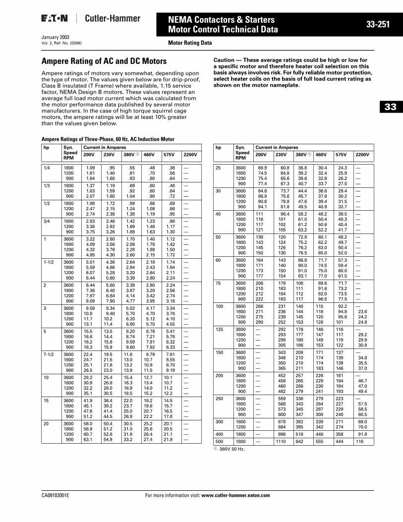
CA08102001E For more
51
33-2NEMA Contactors & StartersMotor Control Technical Data Motor Rating DataJanuary 2003Vol. 2, Ref. No. [0269]
33
Ampere Rating of AC and DC MotorsAmpere ratings of motors vary somewhat, depending upon the type of motor. The values given below are for drip-proof, Class B insulated (T Frame) where available, 1.15 service factor, NEMA Design B motors. These values represent an average full load motor current which was calculated from the motor performance data published by several motor manufacturers. In the case of high torque squirrel cage motors, the ampere ratings will be at least 10% greater than the values given below.
Caution — These average ratings could be high or low for a specific motor and therefore heater coil selection on this basis always involves risk. For fully reliable motor protection, select heater coils on the basis of full load current rating as shown on the motor nameplate.
Ampere Ratings of Three-Phase, 60 Hz, AC Induction Motor
1 380V 50 Hz.
hp Syn.SpeedRPM
Current in Amperes
200V 230V 380V 1 460V 575V 2200V
1/4 18001200900
1.091.611.84
.951.401.60
.55
.81
.93
.48
.70
.80
.38
.56
.64
———
1/3 18001200900
1.371.832.07
1.191.591.80
.69
.921.04
.60
.80
.90
.48
.64
.72
———
1/2 18001200900
1.982.472.74
1.722.152.38
.991.241.38
.861.081.19
.69
.86
.95
———
3/4 18001200900
2.833.363.75
2.462.923.26
1.421.691.88
1.231.461.63
.981.171.30
———
1 360018001200900
3.224.094.324.95
2.803.563.764.30
1.702.062.282.60
1.401.781.882.15
1.121.421.501.72
————
1-1/2 360018001200900
5.015.596.076.44
4.364.865.285.60
2.642.943.203.39
2.182.432.642.80
1.741.942.112.24
————
2 360018001200900
6.447.367.879.09
5.606.406.847.90
3.393.874.144.77
2.803.203.423.95
2.242.562.743.16
————
3 360018001200900
9.5910.811.713.1
8.349.40
10.211.4
5.025.706.206.90
4.174.705.125.70
3.343.764.104.55
————
5 360018001200900
15.516.618.218.3
13.514.415.815.9
8.208.749.599.60
6.767.217.917.92
5.415.786.326.33
————
7-1/2 360018001200900
22.424.725.126.5
19.521.521.823.0
11.813.013.213.9
9.7910.710.911.5
7.818.558.709.19
————
10 360018001200900
29.230.832.235.1
25.426.828.030.5
15.416.316.918.5
12.713.414.015.2
10.110.711.212.2
————
15 360018001200900
41.945.147.651.2
36.439.241.444.5
22.023.725.026.9
18.219.620.722.2
14.515.716.517.8
————
20 360018001200900
58.058.960.763.1
50.451.252.854.9
30.531.031.933.2
25.225.626.427.4
20.120.521.121.9
————
hp Syn.SpeedRPM
Current in Amperes
200V 230V 380V 1 460V 575V 2200V
25 360018001200900
69.974.575.477.4
60.864.865.667.3
36.839.239.640.7
30.432.432.833.7
24.325.926.227.0
————
30 360018001200900
84.886.990.694.1
73.775.678.881.8
44.445.747.649.5
36.837.839.440.9
29.430.231.532.7
————
40 360018001200900
111116117121
96.4101102105
58.261.061.263.2
48.250.450.652.2
38.540.340.441.7
————
50 360018001200900
138143145150
120124126130
72.975.276.278.5
60.162.263.065.0
48.249.750.452.0
————
60 360018001200900
164171173177
143140150154
86.890.091.093.1
71.774.575.077.0
57.359.460.061.5
————
75 360018001200900
206210212222
179183184193
108111112117
89.691.692.096.5
71.773.273.577.5
————
100 360018001200900
266271275290
231236239252
140144145153
115118120126
92.294.895.6
101
—23.624.224.8
125 360018001200900
————
292293298305
176177180186
146147149153
116117119122
—29.229.930.9
150 360018001200900
————
343348350365
208210210211
171174174183
137139139146
—34.835.537.0
200 360018001200900
————
452458460482
257265266279
226229230241
181184184193
—46.747.049.4
250 360018001200900
————
559568573600
338343345347
279284287300
223227229240
—57.558.560.5
300 18001200
——
678684
392395
339342
271274
69.070.0
400 1800 — 896 518 448 358 91.8
500 1800 — 1110 642 555 444 116
information visit: www.cutler-hammer.eaton.com
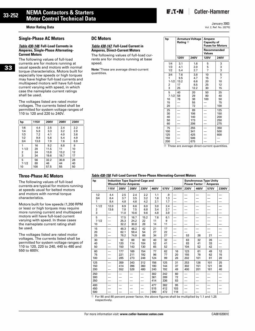
33-252
33
NEMA Contactors & StartersMotor Control Technical Data
Motor Rating DataFor more information visit: www.cutler-hammer.eaton.com
January 2003Vol. 2, Ref. No. [0270]
Single-Phase AC Motors
Table 430-148. Full-Load Currents in Amperes, Single-Phase Alternating-Current MotorsThe following values of full-load currents are for motors running at usual speeds and motors with normal torque characteristics. Motors built for especially low speeds or high torques may have higher full-load currents and multispeed motors will have full-load current varying with speed, in which case the nameplate current ratings shall be used.
The voltages listed are rated motor voltages. The currents listed shall be permitted for system voltage ranges of 110 to 120 and 220 to 240V.
Three-Phase AC MotorsThe following values of full-load currents are typical for motors running at speeds usual for belted motors and motors with normal torque characteristics.
Motors built for low speeds (1,200 RPM or less) or high torques may require more running current and multispeed motors will have full-load current varying with speed. In these cases the nameplate current rating shall be used.
The voltages listed are rated motor voltages. The currents listed shall be permitted for system voltage ranges of 110 to 120, 220 to 240, 440 to 480 and 550 to 600V.
hp 115V 200V 208V 230V
1/61/41/31/23/4
4.45.87.29.8
13.8
2.53.34.15.67.9
2.43.24.05.47.6
2.22.93.64.96.9
11-1/223
16202434
9.211.513.819.6
8.81113.218.7
8101217
57-1/2
10
5680
100
32.24657.5
30.84455
284050
DC Motors
Table 430-147. Full-Load Current in Amperes, Direct-Current MotorsThe following values of full-load cur-rents are for motors running at base speed.
Note: These are average direct-current quantities.
2 These are average direct-current quantities.
Table 430-150. Full-Load Current Three-Phase Alternating-Current Motors
1 For 90 and 80 percent power factor, the above figures shall be multiplied by 1.1 and 1.25 respectively.
hp Armature Voltage Rating 2
Ampere Capacity of Fuses for Motors
RecommendedValues
120V 240V 120V 240V
1/41/31/2
3.14.15.4
1.62.02.7
557
333
3/411-1/223
7.69.5
13.21725
3.84.76.68.5
12.2
1015202530
57
101215
57-1/2
101520
405876——
2029385572
5080
100——
25405075
100
2530405060
—————
89106140173206
—————
125150200250275
75100125150200
—————
255341425506675
—————
350500600——
hp Induction Type Squirrel-Cage and Wound-Rotor Amperes
Synchronous Type Unity Power Factor 1 Amperes
115V 200V 208V 230V 460V 575V 2300V 230V 460V 575V 2300V
1/23/41
4.46.48.4
2.53.74.8
2.43.54.6
2.23.24.2
1.11.62.1
.91.31.7
———
———
———
———
———
1-1/223
12.013.6—
6.97.8
11.0
6.67.5
10.6
6.06.89.6
3.03.44.8
2.42.73.9
———
———
———
———
———
57-1/2
10
———
17.525.332.2
16.724.230.8
15.22228
7.61114
6.19
11
———
———
———
———
———
152025
———
48.362.178.2
46.259.474.8
425468
212734
172227
———
——53
——26
——21
———
304050
———
92120150
88114143
80104130
405265
324152
———
6383
104
324152
263342
———
6075
100
———
177221285
169211273
154192248
7796
124
627799
162026
123155202
6178
101
496281
121520
125150200
———
359414552
343396528
312360480
156180240
125144192
313749
253302400
126151201
101121161
253040
250300350
———
———
———
———
302361414
242289336
607283
———
———
———
———
400450500
———
———
———
———
477515590
382412472
95103118
———
———
———
———
CA08102001E


![Mengenal Sistem Pengendali Kontaktor [Compatibility Mode]](https://img.pdfslide.net/doc/110x75/577c83b91a28abe054b5f595/mengenal-sistem-pengendali-kontaktor-compatibility-mode.jpg)