Embed Size (px)
Citation preview
GE Oil & Gas Drilling & Production
DOCUMENT
VGS 5.418.2
REVISION 13
Engineering Standards & Specifications
DATE
27 April 2015
PAGE
1 of 12
TITLE: Single Seam SAWL Pipe for Marine Drilling Risers Per API 16F With Mandatory Approved Vendor List
PREPARED BY
David Hodgson
REVIEWED BY
David Salgado
APPROVED BY
Jerry Maldonado
GE CONFIDENTIAL
This document is classified under the GE document classification and security policy as “GE Confidential”. Access is granted to GE employees with a need to know. Access granted to external parties subject to implementation of a non-disclosure agreement and a business need to know. Refer to policy ENGWW19.03 for authorization levels required for communication of technical documents to customers or customer representatives.
NOTICE: THIS SPECIFICATION CONTAINS A MANDATORY APPROVED VENDOR LIST 1. SCOPE
1.1. This specification defines the minimum requirements for Single Seam Submerged Arc Welded (SAW) Marine Drilling Riser (MDR) pipe. This pipe is intended to be subsequently fabricated per VGS 4.3.66.
1.2. A primary objective of this specification is to define the chemical and mechanical properties for the pipe that will be supplied. The mechanical properties shall be demonstrated by testing specimens removed from a length of the pipe as required by this specification. It is the vendor’s responsibility to select the proper processing parameters so as to ensure full compliance with all the requirements within.
1.3. Section 17 of this VGS defines the supplemental specification numbers and in turn references the appropriate sections of this specification that apply for each supplement.
1.4. The weldability and response to post-weld heat treatment (PWHT) of this pipe shall be determined via the Heat Weldability Qualification / Pre-Qualification criteria and tests referenced in section 2 of this VGS.
1.5. The vendor is responsible for compliance with all requirements of this specification and shall contact GE Oil and Gas for any written clarifications of any interpretations the vendor may require. Any deviations from this specification must be approved by the cognizant GE Oil and Gas Materials and Processes Engineering (MPE) Department in writing.
1.6. This VGS has been written to comply with the following referenced specification editions: API 16F, ABS Guide for the Classification of Drilling Systems requirements for impact toughness, and DNV-OS-E101 requirements for impact toughness. When revisions to the referenced specifications mandate a change to the requirements of this VGS, it shall be revised accordingly.
1.7. Record of Revision: Section 17 of this specification lists the changes made at this revision.
1.8. APPLICABLE DOCUMENTS
API 5L Specification for Line Pipe ASTM A370 Standard Test Methods and Definitions for Mechanical Testing of
Steel Products ASTM E18 Standard Test Methods for Rockwell Hardness of Metallic
Materials ASTM E140 Standard Hardness Conversion Tables for Metals Relationship
among Brinell Hardness, Vickers Hardness, Rockwell Hardness, Superficial Hardness, Knoop Hardness, Scleroscope Hardness,
STATE: CREATE REVIEWED BY: N/A REVIEWED ON: VIEWED: 2015/05/07 08:43:40
REVISION PENDING: NO APPROVED BY: N/A APPROVED ON: DOCUMENT: VGS5.418.2 | 13
PROE NAME: PROE REV: PROE MODEL VERSION:
DOC NOT RELEASED.Security Level: CONFIDENTIAL
GE Oil & Gas
Drilling & Production
DOCUMENT VGS 5.518.2
GE CONFIDENTIAL
DATE/REV. 27 April 2015 Revision 13
PAGE
2 of 12
and Leeb Hardness ASTM E384 Standard Test Method for Knoop and Vickers Hardness of
Materials ASTM E1823 Standard Terminology Relating to Fatigue and Fracture Testing VGS4.3.66 Marine Drilling Riser Joint – Main Tube Fabrication Specification VGS20.2.2.2 Technical Qualification Procedures for Welded Pipe for Marine
Drilling Riser VGS8.7.1 Standard Procedure for Hardness Testing
2. APPROVED VENDORS AND VENDOR QUALIFICATION REQUIREMENTS
2.1. Only the approved vendors and manufacturing process plans listed below are acceptable for use with this specification.
2.2. Approved Pipe Manufacturers and MPP numbers:
Manufacturer Grade MPP
Qualified Carbon Equivalent
Qualification Test Report
2.2.1. 2.2.2. 2.2.3.
2.3. For vendor approval to this specification, the vendor shall meet requirements of VGS 20.2.2.2,
"Technical Qualification Procedure for Welded Pipe for Marine Drilling Riser”. If the vendor is approved, the vendor will be added to the specification by the revision process.
2.4. The qualified vendor shall be limited to the following based on the results of the qualification testing.
2.4.1. Manufacturing process plan and revision
2.4.2. Pipe grade
2.4.3. Pipe delivery condition (Q or M)
2.4.4. Qualified carbon equivalent range (Pcm +/- 0.02 or CE +/- 0.03)
2.4.5. Plate material manufacturer and location of plate manufacture
2.5. When a change to the MPP is required, the latest revision shall be submitted to GE Oil & Gas MPE department for determination applicability of past qualification test results to revised manufacturing process. 3. GENERAL REQUIREMENTS AND ORDER INFORMATION
3.1. The pipe, as supplied by the pipe manufacturer, shall meet the requirements of API 5L PSL2 (latest edition), with additions and modifications as defined in this specification.
3.2. The following information is to be supplied by GE Oil and Gas on the purchase order:
3.2.1. Quantity (e.g. total mass or total length of pipe)
3.2.2. Outside diameter and wall thickness (see API 5L)
3.2.3. Length and type of length (random or approximate) (see API 5L)
STATE: CREATE REVIEWED BY: N/A REVIEWED ON: VIEWED: 2015/05/07 08:43:40
REVISION PENDING: NO APPROVED BY: N/A APPROVED ON: DOCUMENT: VGS5.418.2 | 13
PROE NAME: PROE REV: PROE MODEL VERSION:
DOC NOT RELEASED.Security Level: CONFIDENTIAL
GE Oil & Gas
Drilling & Production
DOCUMENT VGS 5.518.2
GE CONFIDENTIAL
DATE/REV. 27 April 2015 Revision 13
PAGE
3 of 12
3.3. Where a conflict exists between the base specification and a specified supplement, the supplemental requirements shall govern. Where a conflict exists between this specification and API 5L, the requirements of this specification shall govern. 4. CHEMICAL COMPOSITION
4.1. The chemical composition shall be tested in accordance with API 5L on a per heat (ladle) basis and shall conform to the composition for the applicable mill source in the qualified MPP. The results of the chemical analysis shall be reported on the Certified Test Report.
4.2. Carbon equivalent restrictions are placed on the raw material to help assure that purchased pipe material will be weldable and will meet the required mechanical properties after post-weld heat treatment. The carbon equivalent as determined from the heat analysis or product analysis shall be reported on the Certified Test Report.
4.2.1. For pipe with a product analysis carbon mass fraction greater than 0.12%, the carbon equivalent (CE) based on the formula below shall be 0.55 or less, and shall be defined for the purposes of this specification as follows, with all values in wt. %:
CE = C + Mn/6 + (Cu + Ni)/15 + (Cr + Mo + V + Nb + Ti)/5
4.2.2. For pipe with a product analysis carbon mass fraction less than or equal to 0.12%, the carbon equivalent (CE) based on the CE(Pcm) formula below shall be 0.25 or less, and shall be defined for the purposes of this specification as follows, with all values in wt. %:
CE(Pcm) = C + Si/30 + Mn/20 + Cu/20 + Ni/60 + Cr/20 + Mo/15 + V/10 + 5B
4.3. A change to the chemical composition limits in the Manufacturing Process Plan may require requalification. Any proposed changes to the chemical composition shall be submitted to GE Oil & Gas MPE Department for review. 5. MELTING PRACTICE
5.1. The steel shall be melted by basic oxygen (BOF) or basic electric furnaces (EF). Steel melted in acid furnaces shall not be permitted for the manufacturing of this material. Material processed by vacuum induction melting (VIM) or which receives additional processing by vacuum degassing (VD), argon-oxygen decarburization (AOD), vacuum oxygen decarburization (VOD), electroslag remelting (ESR) or vacuum arc remelting (VAR) shall also be acceptable. The steel shall be fully killed and melted to a fine grain practice. 6. MANUFACTURING PRACTICES
6.1. The plate shall be manufactured by the Thermo-Mechanical Controlled Processing (TMCP) or quench and tempered process followed by single seam longitudinal DSAW. GMAW tack welding is acceptable.
6.2. Pipe forming may be conducted using the UO, JCO or rolled and welded processes.
6.3. Internal or external cold sizing and cold expansion/compression is permissible in accordance with API 5L. However, the sizing ratio for cold expansion and cold sizing shall not exceed 1.5%
6.4. No girth welds are permitted. All weld repairs within the weld seam shall be in accordance with API 5Lrequirements.
STATE: CREATE REVIEWED BY: N/A REVIEWED ON: VIEWED: 2015/05/07 08:43:40
REVISION PENDING: NO APPROVED BY: N/A APPROVED ON: DOCUMENT: VGS5.418.2 | 13
PROE NAME: PROE REV: PROE MODEL VERSION:
DOC NOT RELEASED.Security Level: CONFIDENTIAL
GE Oil & Gas
Drilling & Production
DOCUMENT VGS 5.518.2
GE CONFIDENTIAL
DATE/REV. 27 April 2015 Revision 13
PAGE
4 of 12
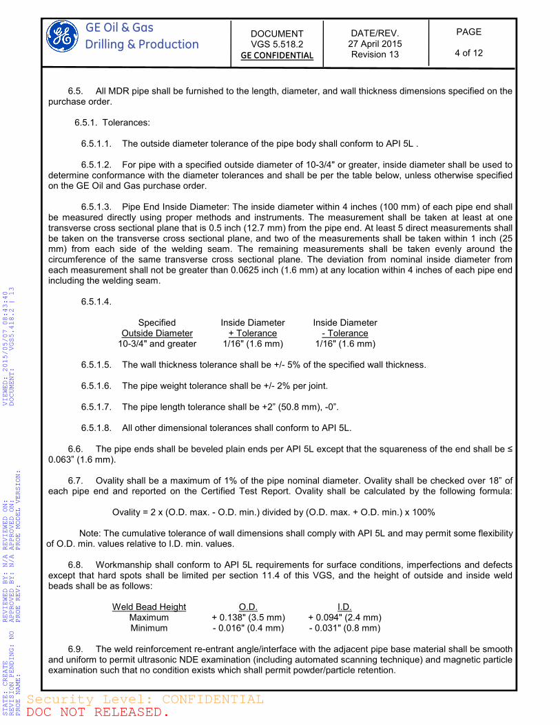
6.5. All MDR pipe shall be furnished to the length, diameter, and wall thickness dimensions specified on the purchase order.
6.5.1. Tolerances: 6.5.1.1. The outside diameter tolerance of the pipe body shall conform to API 5L .
6.5.1.2. For pipe with a specified outside diameter of 10-3/4" or greater, inside diameter shall be used to
determine conformance with the diameter tolerances and shall be per the table below, unless otherwise specified on the GE Oil and Gas purchase order.
6.5.1.3. Pipe End Inside Diameter: The inside diameter within 4 inches (100 mm) of each pipe end shall be measured directly using proper methods and instruments. The measurement shall be taken at least at one transverse cross sectional plane that is 0.5 inch (12.7 mm) from the pipe end. At least 5 direct measurements shall be taken on the transverse cross sectional plane, and two of the measurements shall be taken within 1 inch (25 mm) from each side of the welding seam. The remaining measurements shall be taken evenly around the circumference of the same transverse cross sectional plane. The deviation from nominal inside diameter from each measurement shall not be greater than 0.0625 inch (1.6 mm) at any location within 4 inches of each pipe end including the welding seam.
6.5.1.4.
Specified Outside Diameter
Inside Diameter + Tolerance
Inside Diameter - Tolerance
10-3/4" and greater 1/16" (1.6 mm) 1/16" (1.6 mm)
6.5.1.5. The wall thickness tolerance shall be +/- 5% of the specified wall thickness.
6.5.1.6. The pipe weight tolerance shall be +/- 2% per joint. 6.5.1.7. The pipe length tolerance shall be +2” (50.8 mm), -0”. 6.5.1.8. All other dimensional tolerances shall conform to API 5L.
6.6. The pipe ends shall be beveled plain ends per API 5L except that the squareness of the end shall be ≤
0.063” (1.6 mm).
6.7. Ovality shall be a maximum of 1% of the pipe nominal diameter. Ovality shall be checked over 18” of each pipe end and reported on the Certified Test Report. Ovality shall be calculated by the following formula: Ovality = 2 x (O.D. max. - O.D. min.) divided by (O.D. max. + O.D. min.) x 100% Note: The cumulative tolerance of wall dimensions shall comply with API 5L and may permit some flexibility of O.D. min. values relative to I.D. min. values.
6.8. Workmanship shall conform to API 5L requirements for surface conditions, imperfections and defects except that hard spots shall be limited per section 11.4 of this VGS, and the height of outside and inside weld beads shall be as follows:
Weld Bead Height O.D. I.D. Maximum + 0.138" (3.5 mm) + 0.094" (2.4 mm) Minimum - 0.016" (0.4 mm) - 0.031" (0.8 mm)
6.9. The weld reinforcement re-entrant angle/interface with the adjacent pipe base material shall be smooth
and uniform to permit ultrasonic NDE examination (including automated scanning technique) and magnetic particle examination such that no condition exists which shall permit powder/particle retention.
STATE: CREATE REVIEWED BY: N/A REVIEWED ON: VIEWED: 2015/05/07 08:43:40
REVISION PENDING: NO APPROVED BY: N/A APPROVED ON: DOCUMENT: VGS5.418.2 | 13
PROE NAME: PROE REV: PROE MODEL VERSION:
DOC NOT RELEASED.Security Level: CONFIDENTIAL
GE Oil & Gas
Drilling & Production
DOCUMENT VGS 5.518.2
GE CONFIDENTIAL
DATE/REV. 27 April 2015 Revision 13
PAGE
5 of 12
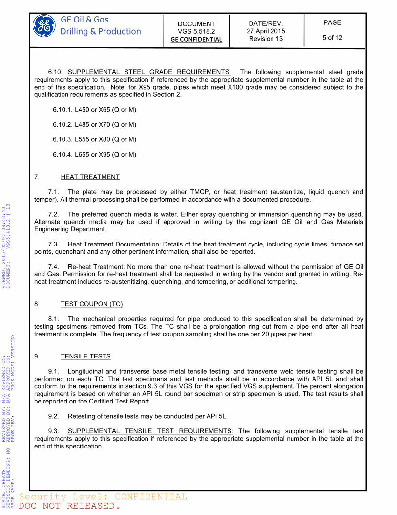
6.10. SUPPLEMENTAL STEEL GRADE REQUIREMENTS: The following supplemental steel grade
requirements apply to this specification if referenced by the appropriate supplemental number in the table at the end of this specification. Note: for X95 grade, pipes which meet X100 grade may be considered subject to the qualification requirements as specified in Section 2.
6.10.1. L450 or X65 (Q or M)
6.10.2. L485 or X70 (Q or M)
6.10.3. L555 or X80 (Q or M)
6.10.4. L655 or X95 (Q or M) 7. HEAT TREATMENT
7.1. The plate may be processed by either TMCP, or heat treatment (austenitize, liquid quench and temper). All thermal processing shall be performed in accordance with a documented procedure.
7.2. The preferred quench media is water. Either spray quenching or immersion quenching may be used. Alternate quench media may be used if approved in writing by the cognizant GE Oil and Gas Materials Engineering Department.
7.3. Heat Treatment Documentation: Details of the heat treatment cycle, including cycle times, furnace set points, quenchant and any other pertinent information, shall also be reported.
7.4. Re-heat Treatment: No more than one re-heat treatment is allowed without the permission of GE Oil and Gas. Permission for re-heat treatment shall be requested in writing by the vendor and granted in writing. Re-heat treatment includes re-austenitizing, quenching, and tempering, or additional tempering. 8. TEST COUPON (TC)
8.1. The mechanical properties required for pipe produced to this specification shall be determined by testing specimens removed from TCs. The TC shall be a prolongation ring cut from a pipe end after all heat treatment is complete. The frequency of test coupon sampling shall be one per 20 pipes per heat. 9. TENSILE TESTS
9.1. Longitudinal and transverse base metal tensile testing, and transverse weld tensile testing shall be performed on each TC. The test specimens and test methods shall be in accordance with API 5L and shall conform to the requirements in section 9.3 of this VGS for the specified VGS supplement. The percent elongation requirement is based on whether an API 5L round bar specimen or strip specimen is used. The test results shall be reported on the Certified Test Report.
9.2. Retesting of tensile tests may be conducted per API 5L.
9.3. SUPPLEMENTAL TENSILE TEST REQUIREMENTS: The following supplemental tensile test requirements apply to this specification if referenced by the appropriate supplemental number in the table at the end of this specification.
STATE: CREATE REVIEWED BY: N/A REVIEWED ON: VIEWED: 2015/05/07 08:43:40
REVISION PENDING: NO APPROVED BY: N/A APPROVED ON: DOCUMENT: VGS5.418.2 | 13
PROE NAME: PROE REV: PROE MODEL VERSION:
DOC NOT RELEASED.Security Level: CONFIDENTIAL
GE Oil & Gas
Drilling & Production
DOCUMENT VGS 5.518.2
GE CONFIDENTIAL
DATE/REV. 27 April 2015 Revision 13
PAGE
6 of 12
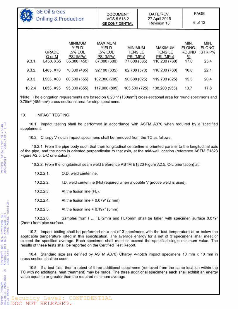
GRADE Q or M
MINIMUM YIELD
.5% EUL PSI (MPa)
MAXIMUM YIELD
.5% EUL PSI (MPa)
MINIMUM TENSILE PSI (MPa)
MAXIMUM TENSILE PSI (MPa)
MIN. ELONG. ROUND
%
MIN. ELONG. STRIP%
9.3.1. L450, X65 65,300 (450) 87,000 (600) 77,600 (535) 110,200 (760) 17.8 23.4
9.3.2. L485, X70 70,300 (485) 92,100 (635) 82,700 (570) 110,200 (760) 16.8 22.1
9.3.3. L555, X80 80,500 (555) 102,300 (705) 90,600 (625) 119,700 (825) 15.5 20.4
10.2.4 L655, X95 95,000 (655) 117,000 (805) 105,500 (725) 138,200 (955) 13.7 17.8 *Note: The elongation requirements are based on 0.20in² (130mm²) cross-sectional area for round specimens and 0.75in² (485mm²) cross-sectional area for strip specimens. 10. IMPACT TESTING
10.1. Impact testing shall be performed in accordance with ASTM A370 when required by a specified supplement.
10.2. Charpy V-notch impact specimens shall be removed from the TC as follows:
10.2.1. From the pipe body such that their longitudinal centerline is oriented parallel to the longitudinal axis of the pipe, and the notch is oriented perpendicular to that axis, at the mid-wall location (reference ASTM E1823 Figure A2.5, L-C orientation).
10.2.2. From the longitudinal seam weld (reference ASTM E1823 Figure A2.5, C-L orientation) at:
10.2.2.1. O.D. weld centerline.
10.2.2.2. I.D. weld centerline (Not required when a double V groove weld is used).
10.2.2.3. At the fusion line (FL).
10.2.2.4. At the fusion line + 0.079" (2 mm)
10.2.2.5. At the fusion line + 0.197” (5mm)
10.2.2.6. Samples from FL, FL+2mm and FL+5mm shall be taken with specimen surface 0.079” (2mm) from pipe surface.
10.3. Impact testing shall be performed on a set of 3 specimens with the test temperature at or below the applicable temperature listed in this specification. The average energy for a set of 3 specimens shall meet or exceed the specified average. Each specimen shall meet or exceed the specified single minimum value. The results of these tests shall be reported on the Certified Test Report.
10.4. Standard size (as defined by ASTM A370) Charpy V-notch impact specimens 10 mm x 10 mm in cross-section shall be used.
10.5. If a test fails, then a retest of three additional specimens (removed from the same location within the TC with no additional heat treatment) may be made. The three additional specimens each shall exhibit an energy value equal to or greater than the required minimum average.
STATE: CREATE REVIEWED BY: N/A REVIEWED ON: VIEWED: 2015/05/07 08:43:40
REVISION PENDING: NO APPROVED BY: N/A APPROVED ON: DOCUMENT: VGS5.418.2 | 13
PROE NAME: PROE REV: PROE MODEL VERSION:
DOC NOT RELEASED.Security Level: CONFIDENTIAL
GE Oil & Gas
Drilling & Production
DOCUMENT VGS 5.518.2
GE CONFIDENTIAL
DATE/REV. 27 April 2015 Revision 13
PAGE
7 of 12
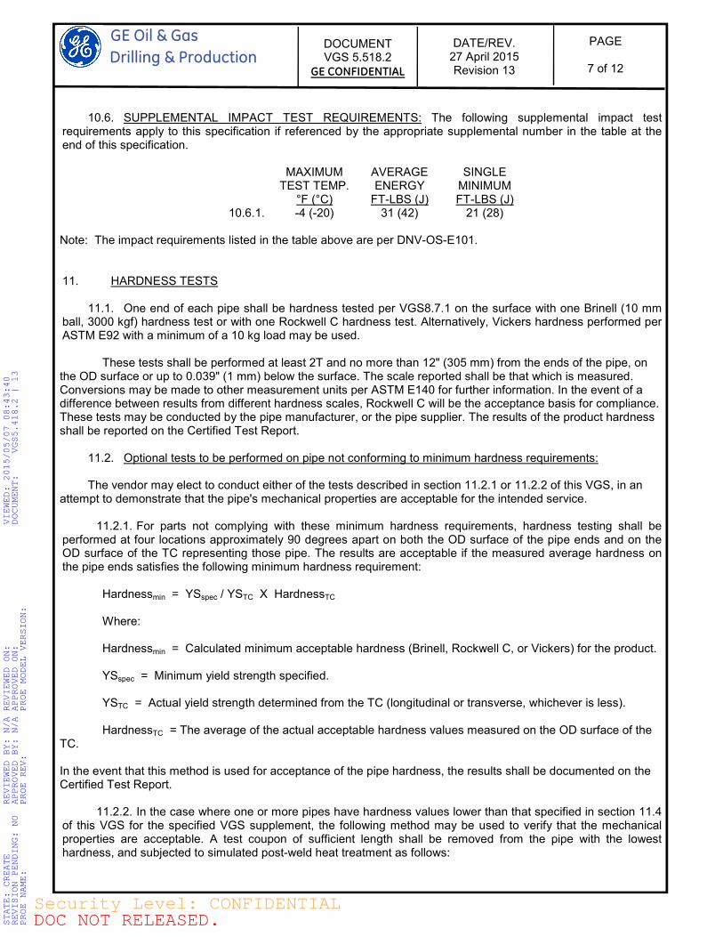
10.6. SUPPLEMENTAL IMPACT TEST REQUIREMENTS: The following supplemental impact test requirements apply to this specification if referenced by the appropriate supplemental number in the table at the end of this specification.
MAXIMUM TEST TEMP.
°F (°C)
AVERAGE ENERGY
FT-LBS (J)
SINGLE MINIMUM FT-LBS (J)
10.6.1. -4 (-20) 31 (42) 21 (28) Note: The impact requirements listed in the table above are per DNV-OS-E101. 11. HARDNESS TESTS
11.1. One end of each pipe shall be hardness tested per VGS8.7.1 on the surface with one Brinell (10 mm ball, 3000 kgf) hardness test or with one Rockwell C hardness test. Alternatively, Vickers hardness performed per ASTM E92 with a minimum of a 10 kg load may be used. These tests shall be performed at least 2T and no more than 12" (305 mm) from the ends of the pipe, on the OD surface or up to 0.039" (1 mm) below the surface. The scale reported shall be that which is measured. Conversions may be made to other measurement units per ASTM E140 for further information. In the event of a difference between results from different hardness scales, Rockwell C will be the acceptance basis for compliance. These tests may be conducted by the pipe manufacturer, or the pipe supplier. The results of the product hardness shall be reported on the Certified Test Report.
11.2. Optional tests to be performed on pipe not conforming to minimum hardness requirements:
The vendor may elect to conduct either of the tests described in section 11.2.1 or 11.2.2 of this VGS, in an attempt to demonstrate that the pipe's mechanical properties are acceptable for the intended service.
11.2.1. For parts not complying with these minimum hardness requirements, hardness testing shall be performed at four locations approximately 90 degrees apart on both the OD surface of the pipe ends and on the OD surface of the TC representing those pipe. The results are acceptable if the measured average hardness on the pipe ends satisfies the following minimum hardness requirement: Hardnessmin = YSspec / YSTC X HardnessTC Where: Hardnessmin = Calculated minimum acceptable hardness (Brinell, Rockwell C, or Vickers) for the product. YSspec = Minimum yield strength specified. YSTC = Actual yield strength determined from the TC (longitudinal or transverse, whichever is less). HardnessTC = The average of the actual acceptable hardness values measured on the OD surface of the TC. In the event that this method is used for acceptance of the pipe hardness, the results shall be documented on the Certified Test Report.
11.2.2. In the case where one or more pipes have hardness values lower than that specified in section 11.4 of this VGS for the specified VGS supplement, the following method may be used to verify that the mechanical properties are acceptable. A test coupon of sufficient length shall be removed from the pipe with the lowest hardness, and subjected to simulated post-weld heat treatment as follows:
STATE: CREATE REVIEWED BY: N/A REVIEWED ON: VIEWED: 2015/05/07 08:43:40
REVISION PENDING: NO APPROVED BY: N/A APPROVED ON: DOCUMENT: VGS5.418.2 | 13
PROE NAME: PROE REV: PROE MODEL VERSION:
DOC NOT RELEASED.Security Level: CONFIDENTIAL
GE Oil & Gas
Drilling & Production
DOCUMENT VGS 5.518.2
GE CONFIDENTIAL
DATE/REV. 27 April 2015 Revision 13
PAGE
8 of 12
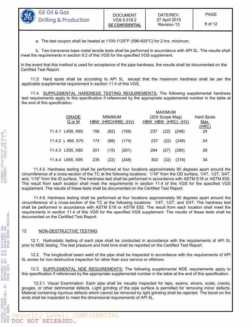
a. The test coupon shall be heated at 1105-1125°F (596-605°C) for 2 hrs. minimum. b. Two transverse base metal tensile tests shall be performed in accordance with API 5L. The results shall meet the requirements in section 9.2 of this VGS for the specified VGS supplement. In the event that this method is used for acceptance of the pipe hardness, the results shall be documented on the Certified Test Report.
11.3. Hard spots shall be according to API 5L except that the maximum hardness shall be per the applicable supplemental requirement in section 11.4 of this VGS.
11.4. SUPPLEMENTAL HARDNESS TESTING REQUIREMENTS: The following supplemental hardness test requirements apply to this specification if referenced by the appropriate supplemental number in the table at the end of this specification.
GRADE Q or M
MINIMUM
HBW (HRC/HRB) (HV)
MAXIMUM (20X Scope Mag)
HBW HBW (HRC) (HV)
Hard Spots
Max. (HRC)
11.4.1. L450, X65 156 (82) (156) 237 (22) (248) 24
11.4.2. L 485, X70 174 (88) (174) 237 (22) (248) 24
11.4.3. L555, X80 201 (15) (201) 264 (27) (280) 29
11.4.4. L655, X95 235 (22) (248) 302 (32) (319) 34
11.4.5. Hardness testing shall be performed at four locations approximately 90 degrees apart around the circumference of a cross-section of the TC at the following locations: 1/16" from the OD surface, 1/4T, 1/2T, 3/4T, and, 1/16" from the ID surface. The hardness test shall be performed in accordance with ASTM E18 or ASTM E92. The result from each location shall meet the requirements in section 11.4 of this VGS for the specified VGS supplement. The results of these tests shall be documented on the Certified Test Report.
11.4.6. Hardness testing shall be performed at four locations approximately 90 degrees apart around the circumference of a cross-section of the TC at the following locations: 1/4T, 1/2T, and 3/4T. The hardness test shall be performed in accordance with ASTM E18 or ASTM E92. The result from each location shall meet the requirements in section 11.4 of this VGS for the specified VGS supplement. The results of these tests shall be documented on the Certified Test Report. 12. NON-DESTRUCTIVE TESTING
12.1. Hydrostatic testing of each pipe shall be conducted in accordance with the requirements of API 5L prior to NDE testing. The test pressure and hold time shall be reported on the Certified Test Report.
12.2. The longitudinal seam weld of the pipe shall be inspected in accordance with the requirements of API 5L annex for non-destructive inspection for other than sour service or offshore.
12.3. SUPPLEMENTAL NDE REQUIREMENTS: The following supplemental NDE requirements apply to this specification if referenced by the appropriate supplemental number in the table at the end of this specification.
12.3.1. Visual Examination: Each pipe shall be visually inspected for laps, seams, slivers, scale, cracks, gouges, or other detrimental defects. Light grinding of the pipe surface is permitted for removing minor defects. Material containing injurious defects which cannot be removed by light grinding shall be rejected. The bevel on the ends shall be inspected to meet the dimensional requirements of API 5L.
STATE: CREATE REVIEWED BY: N/A REVIEWED ON: VIEWED: 2015/05/07 08:43:40
REVISION PENDING: NO APPROVED BY: N/A APPROVED ON: DOCUMENT: VGS5.418.2 | 13
PROE NAME: PROE REV: PROE MODEL VERSION:
DOC NOT RELEASED.Security Level: CONFIDENTIAL
GE Oil & Gas
Drilling & Production
DOCUMENT VGS 5.518.2
GE CONFIDENTIAL
DATE/REV. 27 April 2015 Revision 13
PAGE
9 of 12
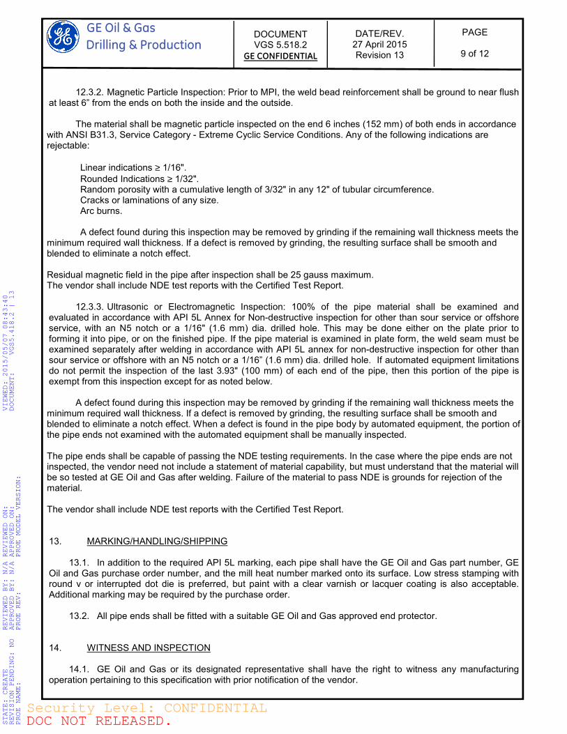
12.3.2. Magnetic Particle Inspection: Prior to MPI, the weld bead reinforcement shall be ground to near flush at least 6” from the ends on both the inside and the outside.
The material shall be magnetic particle inspected on the end 6 inches (152 mm) of both ends in accordance with ANSI B31.3, Service Category - Extreme Cyclic Service Conditions. Any of the following indications are rejectable:
Linear indications ≥ 1/16".
Rounded Indications ≥ 1/32". Random porosity with a cumulative length of 3/32" in any 12" of tubular circumference. Cracks or laminations of any size. Arc burns.
A defect found during this inspection may be removed by grinding if the remaining wall thickness meets the minimum required wall thickness. If a defect is removed by grinding, the resulting surface shall be smooth and blended to eliminate a notch effect. Residual magnetic field in the pipe after inspection shall be 25 gauss maximum. The vendor shall include NDE test reports with the Certified Test Report.
12.3.3. Ultrasonic or Electromagnetic Inspection: 100% of the pipe material shall be examined and evaluated in accordance with API 5L Annex for Non-destructive inspection for other than sour service or offshore service, with an N5 notch or a 1/16" (1.6 mm) dia. drilled hole. This may be done either on the plate prior to forming it into pipe, or on the finished pipe. If the pipe material is examined in plate form, the weld seam must be examined separately after welding in accordance with API 5L annex for non-destructive inspection for other than sour service or offshore with an N5 notch or a 1/16” (1.6 mm) dia. drilled hole. If automated equipment limitations do not permit the inspection of the last 3.93" (100 mm) of each end of the pipe, then this portion of the pipe is exempt from this inspection except for as noted below.
A defect found during this inspection may be removed by grinding if the remaining wall thickness meets the minimum required wall thickness. If a defect is removed by grinding, the resulting surface shall be smooth and blended to eliminate a notch effect. When a defect is found in the pipe body by automated equipment, the portion of the pipe ends not examined with the automated equipment shall be manually inspected. The pipe ends shall be capable of passing the NDE testing requirements. In the case where the pipe ends are not inspected, the vendor need not include a statement of material capability, but must understand that the material will be so tested at GE Oil and Gas after welding. Failure of the material to pass NDE is grounds for rejection of the material. The vendor shall include NDE test reports with the Certified Test Report. 13. MARKING/HANDLING/SHIPPING
13.1. In addition to the required API 5L marking, each pipe shall have the GE Oil and Gas part number, GE Oil and Gas purchase order number, and the mill heat number marked onto its surface. Low stress stamping with round v or interrupted dot die is preferred, but paint with a clear varnish or lacquer coating is also acceptable. Additional marking may be required by the purchase order.
13.2. All pipe ends shall be fitted with a suitable GE Oil and Gas approved end protector. 14. WITNESS AND INSPECTION
14.1. GE Oil and Gas or its designated representative shall have the right to witness any manufacturing operation pertaining to this specification with prior notification of the vendor.
STATE: CREATE REVIEWED BY: N/A REVIEWED ON: VIEWED: 2015/05/07 08:43:40
REVISION PENDING: NO APPROVED BY: N/A APPROVED ON: DOCUMENT: VGS5.418.2 | 13
PROE NAME: PROE REV: PROE MODEL VERSION:
DOC NOT RELEASED.Security Level: CONFIDENTIAL
GE Oil & Gas
Drilling & Production
DOCUMENT VGS 5.518.2
GE CONFIDENTIAL
DATE/REV. 27 April 2015 Revision 13
PAGE
10 of 12
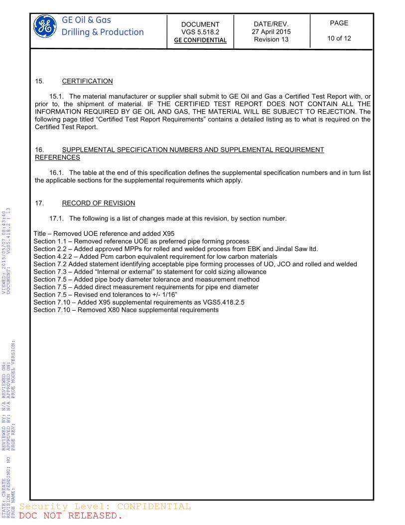
15. CERTIFICATION
15.1. The material manufacturer or supplier shall submit to GE Oil and Gas a Certified Test Report with, or prior to, the shipment of material. IF THE CERTIFIED TEST REPORT DOES NOT CONTAIN ALL THE INFORMATION REQUIRED BY GE OIL AND GAS, THE MATERIAL WILL BE SUBJECT TO REJECTION. The following page titled “Certified Test Report Requirements” contains a detailed listing as to what is required on the Certified Test Report. 16. SUPPLEMENTAL SPECIFICATION NUMBERS AND SUPPLEMENTAL REQUIREMENT REFERENCES
16.1. The table at the end of this specification defines the supplemental specification numbers and in turn list the applicable sections for the supplemental requirements which apply. 17. RECORD OF REVISION
17.1. The following is a list of changes made at this revision, by section number. Title – Removed UOE reference and added X95 Section 1.1 – Removed reference UOE as preferred pipe forming process Section 2.2 – Added approved MPPs for rolled and welded process from EBK and Jindal Saw ltd. Section 4.2.2 – Added Pcm carbon equivalent requirement for low carbon materials Section 7.2 Added statement identifying acceptable pipe forming processes of UO, JCO and rolled and welded Section 7.3 – Added “Internal or external” to statement for cold sizing allowance Section 7.5 – Added pipe body diameter tolerance and measurement method Section 7.5 – Added direct measurement requirements for pipe end diameter Section 7.5 – Revised end tolerances to +/- 1/16” Section 7.10 – Added X95 supplemental requirements as VGS5.418.2.5 Section 7.10 – Removed X80 Nace supplemental requirements
STATE: CREATE REVIEWED BY: N/A REVIEWED ON: VIEWED: 2015/05/07 08:43:40
REVISION PENDING: NO APPROVED BY: N/A APPROVED ON: DOCUMENT: VGS5.418.2 | 13
PROE NAME: PROE REV: PROE MODEL VERSION:
DOC NOT RELEASED.Security Level: CONFIDENTIAL
GE Oil & Gas
Drilling & Production
DOCUMENT VGS 5.518.2
GE CONFIDENTIAL
DATE/REV. 27 April 2015 Revision 13
PAGE
11 of 12
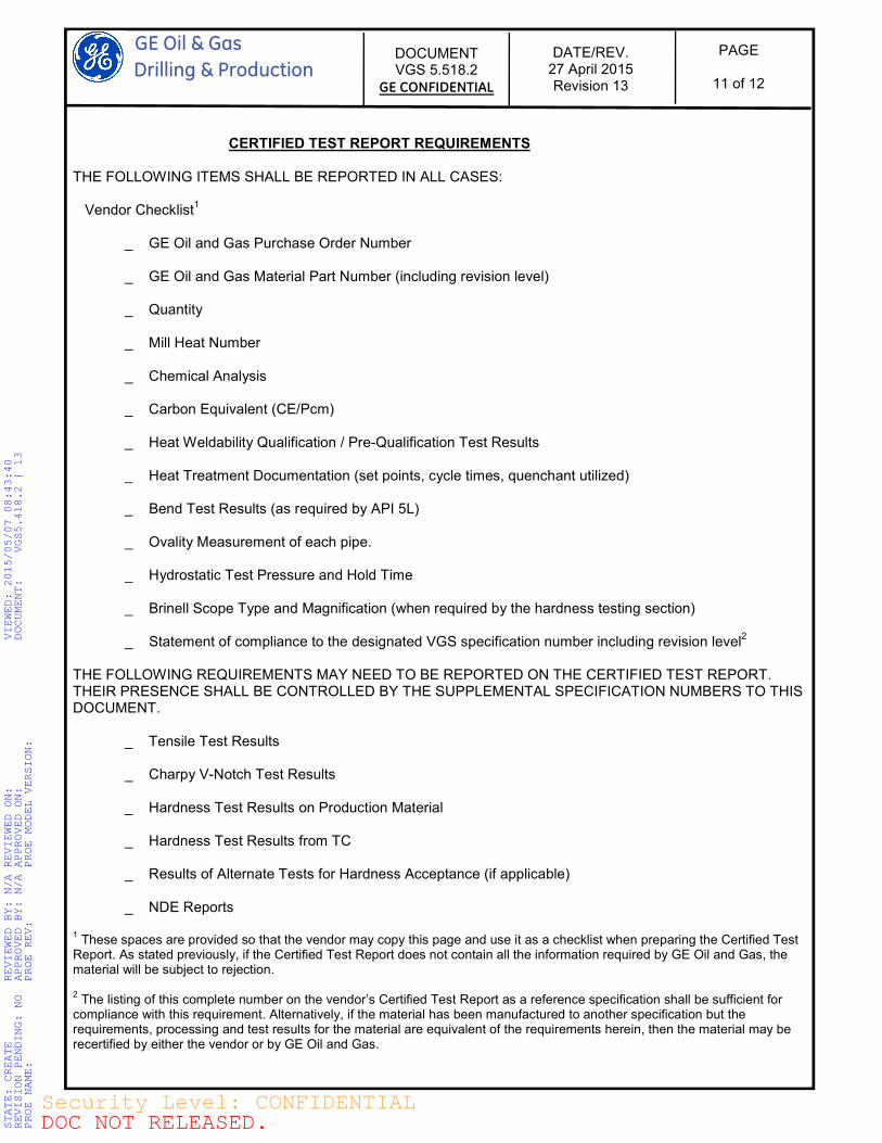
CERTIFIED TEST REPORT REQUIREMENTS THE FOLLOWING ITEMS SHALL BE REPORTED IN ALL CASES: Vendor Checklist
1
_ GE Oil and Gas Purchase Order Number _ GE Oil and Gas Material Part Number (including revision level) _ Quantity _ Mill Heat Number _ Chemical Analysis _ Carbon Equivalent (CE/Pcm) _ Heat Weldability Qualification / Pre-Qualification Test Results _ Heat Treatment Documentation (set points, cycle times, quenchant utilized) _ Bend Test Results (as required by API 5L) _ Ovality Measurement of each pipe. _ Hydrostatic Test Pressure and Hold Time _ Brinell Scope Type and Magnification (when required by the hardness testing section) _ Statement of compliance to the designated VGS specification number including revision level
2
THE FOLLOWING REQUIREMENTS MAY NEED TO BE REPORTED ON THE CERTIFIED TEST REPORT. THEIR PRESENCE SHALL BE CONTROLLED BY THE SUPPLEMENTAL SPECIFICATION NUMBERS TO THIS DOCUMENT. _ Tensile Test Results _ Charpy V-Notch Test Results _ Hardness Test Results on Production Material _ Hardness Test Results from TC _ Results of Alternate Tests for Hardness Acceptance (if applicable) _ NDE Reports 1 These spaces are provided so that the vendor may copy this page and use it as a checklist when preparing the Certified Test
Report. As stated previously, if the Certified Test Report does not contain all the information required by GE Oil and Gas, the material will be subject to rejection. 2 The listing of this complete number on the vendor’s Certified Test Report as a reference specification shall be sufficient for
compliance with this requirement. Alternatively, if the material has been manufactured to another specification but the requirements, processing and test results for the material are equivalent of the requirements herein, then the material may be recertified by either the vendor or by GE Oil and Gas.
STATE: CREATE REVIEWED BY: N/A REVIEWED ON: VIEWED: 2015/05/07 08:43:40
REVISION PENDING: NO APPROVED BY: N/A APPROVED ON: DOCUMENT: VGS5.418.2 | 13
PROE NAME: PROE REV: PROE MODEL VERSION:
DOC NOT RELEASED.Security Level: CONFIDENTIAL
GE Oil & Gas Drilling & Production
PAGE
12 of 12
DOCUMENT VGS 5.518.2
GE CONFIDENTIAL
DATE/REV. 6 April 2015 Revision 13
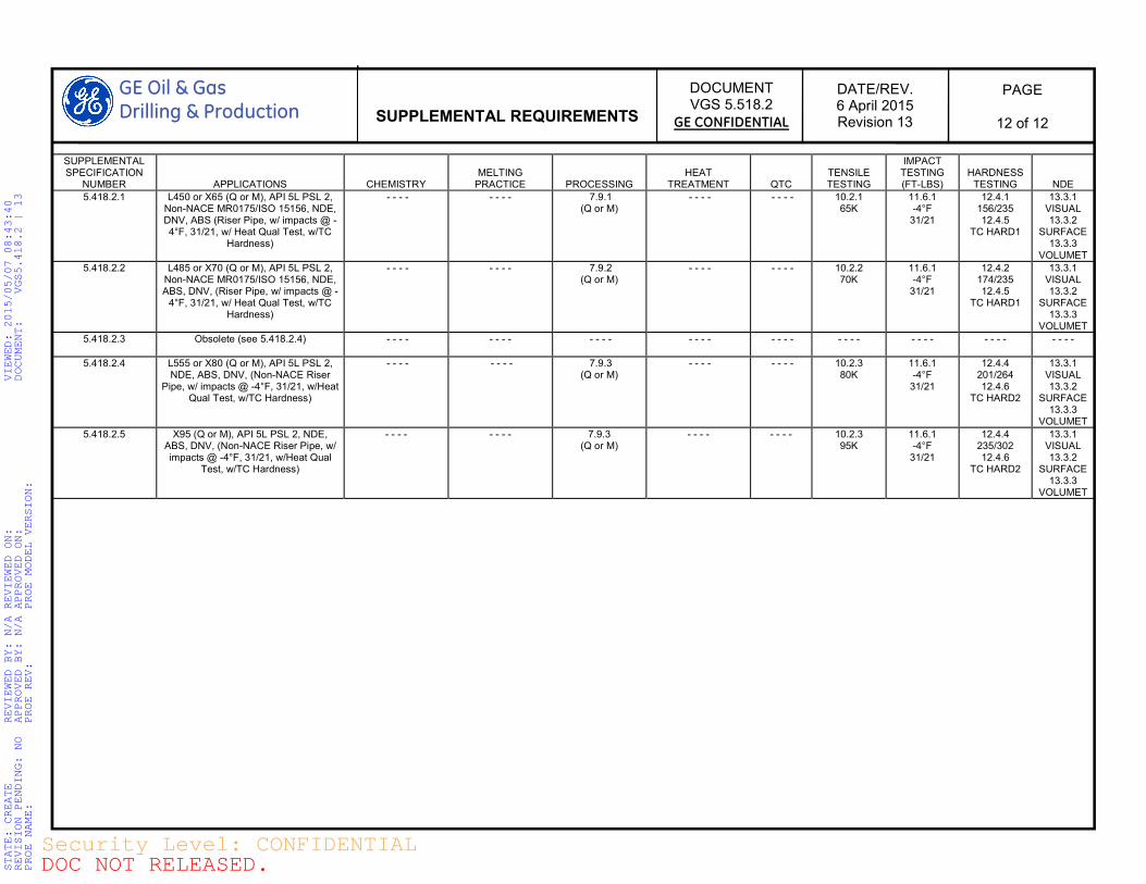
SUPPLEMENTAL REQUIREMENTS
SUPPLEMENTAL SPECIFICATION
NUMBER
APPLICATIONS
CHEMISTRY
MELTING
PRACTICE
PROCESSING
HEAT
TREATMENT
QTC
TENSILE TESTING
IMPACT TESTING (FT-LBS)
HARDNESS
TESTING
NDE
5.418.2.1 L450 or X65 (Q or M), API 5L PSL 2, Non-NACE MR0175/ISO 15156, NDE, DNV, ABS (Riser Pipe, w/ impacts @ -4°F, 31/21, w/ Heat Qual Test, w/TC
Hardness)
- - - -
- - - - 7.9.1 (Q or M)
- - - -
- - - -
10.2.1 65K
11.6.1 -4°F
31/21
12.4.1 156/235 12.4.5
TC HARD1
13.3.1 VISUAL 13.3.2
SURFACE 13.3.3
VOLUMET
5.418.2.2 L485 or X70 (Q or M), API 5L PSL 2, Non-NACE MR0175/ISO 15156, NDE, ABS, DNV, (Riser Pipe, w/ impacts @ -
4°F, 31/21, w/ Heat Qual Test, w/TC Hardness)
- - - -
- - - - 7.9.2 (Q or M)
- - - -
- - - -
10.2.2 70K
11.6.1 -4°F
31/21
12.4.2 174/235 12.4.5
TC HARD1
13.3.1 VISUAL 13.3.2
SURFACE 13.3.3
VOLUMET
5.418.2.3 Obsolete (see 5.418.2.4) - - - -
- - - - - - - -
- - - -
- - - -
- - - - - - - - - - - - - - - -
5.418.2.4 L555 or X80 (Q or M), API 5L PSL 2, NDE, ABS, DNV, (Non-NACE Riser
Pipe, w/ impacts @ -4°F, 31/21, w/Heat Qual Test, w/TC Hardness)
- - - -
- - - - 7.9.3 (Q or M)
- - - -
- - - -
10.2.3 80K
11.6.1 -4°F
31/21
12.4.4 201/264 12.4.6
TC HARD2
13.3.1 VISUAL 13.3.2
SURFACE 13.3.3
VOLUMET
5.418.2.5 X95 (Q or M), API 5L PSL 2, NDE, ABS, DNV, (Non-NACE Riser Pipe, w/ impacts @ -4°F, 31/21, w/Heat Qual
Test, w/TC Hardness)
- - - - - - - - 7.9.3 (Q or M)
- - - - - - - - 10.2.3 95K
11.6.1 -4°F
31/21
12.4.4 235/302 12.4.6
TC HARD2
13.3.1 VISUAL 13.3.2
SURFACE 13.3.3
VOLUMET
STATE: CREATE REVIEWED BY: N/A REVIEWED ON: VIEWED: 2015/05/07 08:43:40
REVISION PENDING: NO APPROVED BY: N/A APPROVED ON: DOCUMENT: VGS5.418.2 | 13
PROE NAME: PROE REV: PROE MODEL VERSION:
DOC NOT RELEASED.Security Level: CONFIDENTIAL