Embed Size (px)
Citation preview
gears where teeth have been cut beforeheat treatment, but through-hardenedgears are also ground for higher ac-curacies. In the case of fine pitch gears,many times teeth are ground in at finishedblank without any previous teeth cuttingoperation.
Gear Grinding PreparationFollowing are some of the items which
should be considered carefully indetail forsuccessful gear grinding.
Preparation of the Gear Blank. Thecommon statement, "A good gear blank is
Gear Grinding fundamentalsYogi Sharma, P.E.,
Philadelphia Cear CorporationKin,g of Prussia, PA
AUTHOR:
yocm SHAruv1A is employed in gearmanufartun·ng.and design at Philadelphia GearCorp. He holds an M.S. degree ill mechanicalengineering from Villanova University and onein industria/engil1eering from Penn State. Mr.Sharma is a .licensed mechanical engineer in thestate of Pennsylvania ,and a senior member ofSME
IntroducdonThis article deals with certain items to
be taken i.ntooonsideration for gear grind-ing, common problems that arise in gear
26 Gear Techno'iogy
grinding and their solutions. The discus-sion will be limited to jobbing or low-batch production environments, whereexperimental setup and testing is notpossible for economic and other reasons,
Gear grindi.ng is basically performedeither to finish hardened gears or toenhance the accuracy of gears or both.The accuracy from gear grinding includesdesired lead and profile modifications,lower spacing and runouterrors, and highsurface finish. Most of the time, geargrinding is associated with case-hardened
Fig. 1- Double hel ical pinion shaftshowing groovefor grinding wheel clearance.
a must fo.r a good gear," is very true Ior asuccessful. gear grinding operation. Asgear grinding is quite often the last opera-tion in gear manufacturing, any com-promise in gear blank design, processing,or manufacturing can cause unnecessarydelays, poor quality, or rejected parts.
The following items should be con-sidered for gear blank preparation.
Grinding Wheel Runout Clearance atTooth Grinding. Gear blanks with eon-straints on one or both ends must bechecked for proper grinding wheel
clearance. These include double helicalgears, pinion shafts with teeth running outin diameters higher than root diameter,etc.
The grind.ing wheel runout clearance isa function of many factors, such as grind-ing wheel diameter, helix angle, DPN,etc., but the grinding wheel diameter is themost influential item. One of the simplesolution approaches is to providedesigners a 'chart for runout clearancebased on DPN, helix, and grinding wheeldiameters onavailable machines, along
with a machine capacity chart. This willallow designers to have a preliminarydesign with a reasonable accuracy, whichmust be verified by an appropriate personin manufacturing, Runout clearancevalues can also be included in gear designprograms and provided to the designerwith gear data. In cases of crlticalappli-cation. runout clearancecan befine tunedwith dummy blanks on grindingmachines ..
fig. 1 shows a double helical pinion;Fig. 2 shows a pinion shaft with runout
fig. 2 =Double helical pinion shaft showing runout(or grinding wheel clearance.
Sepfember IOctober 1989 27
CIRCLE A-li90N REAIDERREPLY CARD
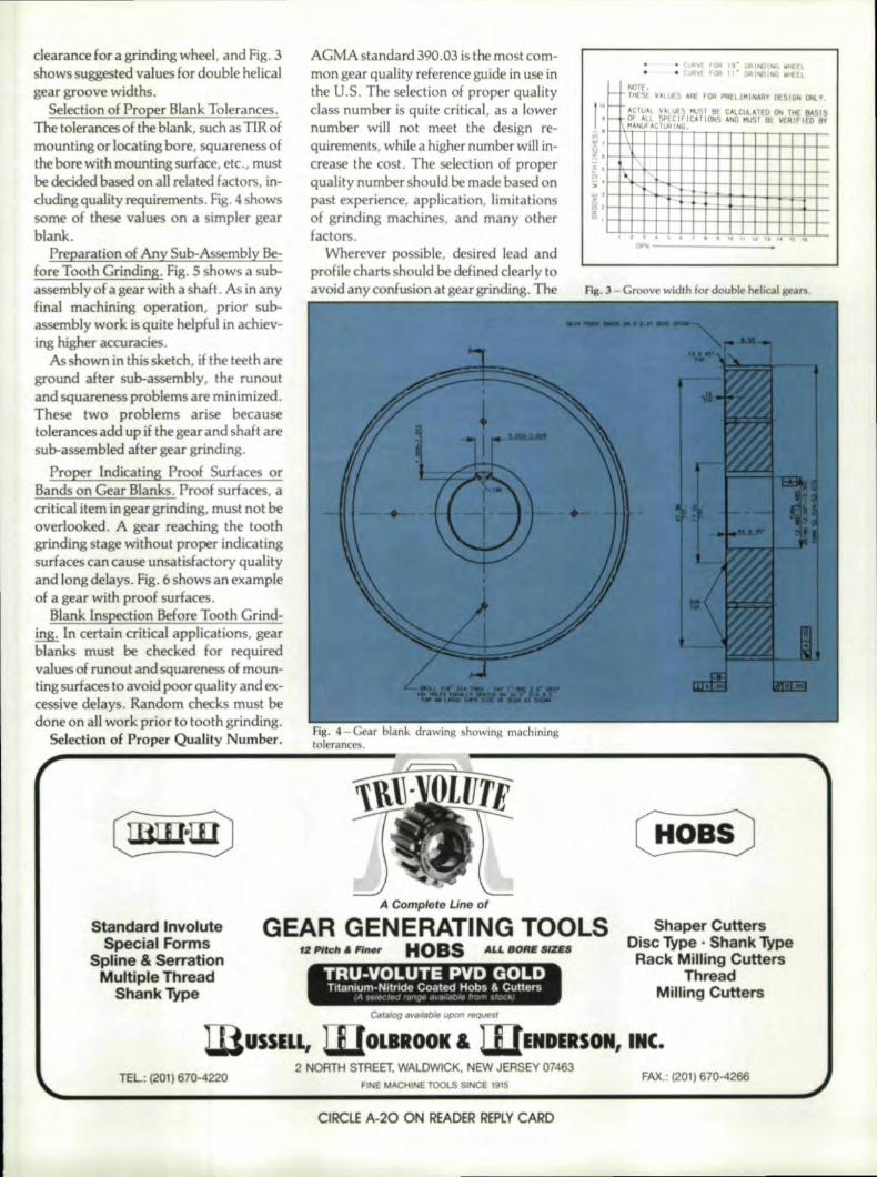
clearance for a grinding wheel, and Fig, 3shows suggested vaJues for double helicalgear groove widths.,
S lection ,ofProper Blank Tolerances.The tolerances of the blank, such as TIR ofmounting or locating bore, squareness oftheborewithmountingswface, etc., mustbe decided based onall related factors, in-cluding quality requirements. Fig. 4 showssome of these values on a simpler gearblank ..
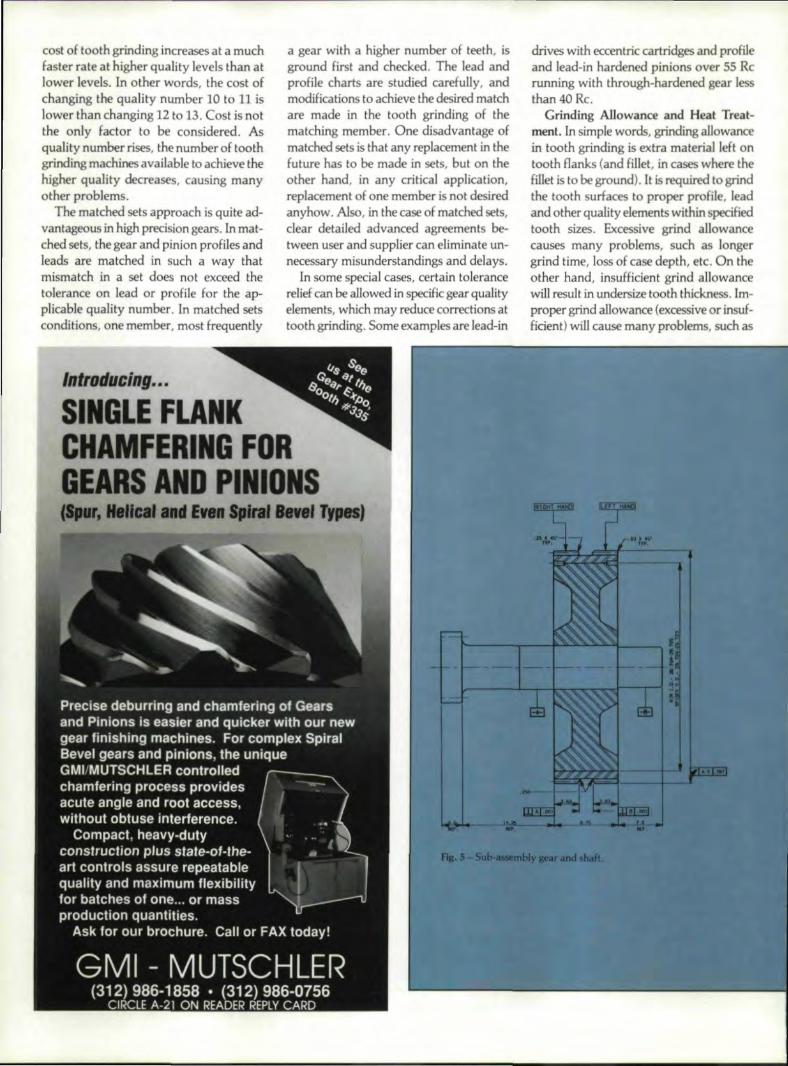
Pfreparation of Any Sub-Assembly Be-roJ'1@ ':ooth Grinding,. Fig,S shows a sub-assembly ,of 3. gea.r with a shaft . As in anyfinal machining operation, prior sub-assembly work is quite helpful in achiev-ing higher accuracies.
As shown in 'this sketch, if the teeth areground after sub-assembly, the runoutand squareness problems, are minimized,These two problems arise becausetolerances add up if the gear and shaft aresub-assembled after gear grinding.
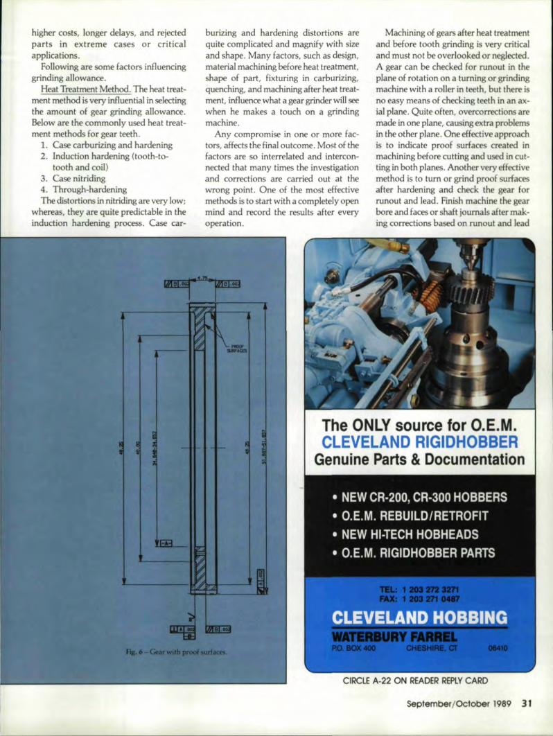
PliOper [ndicating Proot Surfaces orBands on Gear Blanks,. Proof surfaces, acritical item mgear grinding, must not beoverlooked. A gear reaching the' toothgrinding stage without proper indicatingsurfaces can cause unsatisfactory qualityand long delays. Fig. 6 shows an. exampleof a gear with proof surfaces.
Blank Inspection Before Tooth Grind-ing. In certain critlcalapplicatiens, gearblanks must be checked for requiredvalues of runout and squareness of moun-Ilingsurfaces 'to avoid poor quality and ex-cessive delays. Random checks mast bedone on aU work prior to tooth grinding.
Sel etion of Proper Quality Number.
Standard InvoluteSpecial Forms,
Splinel ,& SeflrstionMultipl'e' Thf'ieadl
ShankTYrpe
AGMA standard 390.03 is the most com-mon gear quality reference guide in use inthe U.S. Th selection of proper qualityclass number is quite critical. as a lowernumber will not meet the d sign re-quirements, while a higher number will in-crease the cost. The selection of properquality number should be made based onpast experience, application, limitationsof grinding machines, and many otherfactors.
Wherever possible, desired lead andprchlecharts should be defined dearly toavoid any conhrsionat gear grinding. The
• CUfh( ,tOR 19* GRINOlhG II• Cl.OIv£ FIlA ,,' GRIMlII<t H
NOIE.r THE!.! ~AL1.JE5 ARE fOR PIlfllMI .... RT DESIGN QIl.~.- ACTUAL YALt.{SHUST liE CALCU.ATEO ON THE B'SIS.- :~~c;r:i~~~CAlIOI<S /.NO MT BE VERIFIED By•, ..i
·•· ",,,
, , . . • • , , ., . . '.Fig. 3-Graove width for double helical gears.
A Complete Line of
GIEAIR 'GENE,RATIN,GI TOOLS12Mdt. n_ IHOBS, .Au. 80ASZES
-- ----
TRU'~VOLU'TE PVD GO'LDTltanium-Nllrlde Coated Mobs'" Cutters
4 -,t- f' ',<: '.I' lr- .Ioa dt)Jif ~r 1'r " {"
ShapeII' CuH.ersDisc Ty,pe • Shan'k T~pe
Rack. Milling Cutters,Thread
Millingl'CutteJS,CIIralOg available upon requesr
US,SW,W:O=-=ROOK &l'EL: {201) 670-4220
CIRCLE A-:20 ONI READ8R REPLY CA:RD
IENDERSONI,IINC.2 NORTH SmEET. WALDWICK, INEWJERSEY 07463
FINE MACHINE TOOlS SI CE 1915FAX.: (201) 670-4266
cost of tooth grinding increases at a muchfaster rate at.higher quality levels than atlower levels. in other words, the cost ofchanging the quality number 10 to 11 islower than changing 12 to D, Cost is notthe only factor to be considered, Asquality number rises, the number of toothgrinding machines available 110 achieve thehigher quality decreases, causing manyother problems.
The matched sets approach is quite ad-vantageous in high precision gears. Inmat-ched sets, the gear and pinion profiles andleads are matched in such a way thatmismatchina set does not exceed thetolerance on lead or profile for the ap-plicable quality number. In matched setsconditions, one member. most frequently
a gear with a higher number of teeth, isground first and checked. The lead andprofile charts are studiedcarefuUy, andmodifications to achieve the desired matchMe made in the tooth grinding of thematching member. One disadvantage ofmatched sets is that any replacement in thefuture has to be made in sets, but on theother hand, in any critical application,replacement of one member is not desiredanyhow. Also, in the case of matched sets,dear detailed advanced agreementsbe-tween user and supplier can eliminate un-necessary misunderstandings and delays,
In some special cases, certain tolerancerelief can be allowed inspecific gear qualityelements, which mayreduce corrections attooth grinding. Some examples are lead-in
drives with eccentric cartridges and profileand lead-in hardened pinions over 55 Rcrunning with through-hardened gearlessthan 40 Rc.
Grinding .A1lowanoe and Heat Treat-ment. In. simple words, grinding allowancein tooth grinding is extra material I.eft ontooth flanks (and fillet. i.ncases where thefillet is to be ground). lit is required to grindthe tooth surfaces to proper profile. leadand other quality elements within. specifiedtooth sizes. Exoessive grind allowancecauses many problems, such as longergrind time, loss of case depth, etc. Onthother hand, insufficient grind allowancewill result in undersize tooth thickness. Im-proper grind allowance (excessive or insuf-ficient) will cause many problems, such as
IntrDducing ....
SINGLE FLANKCHAMFERING FORGEARS AND PINIONS
II Mal &II ........ , TnIIIJ
higher costs, longer delays, and rejectedparts in extreme cases or criticalapplications.
Following are some factors influencinggrinding allowance.
Heat Treatment Method. The heat treat-ment method is very iIlfIuential in selectingtheamount of gear grinding allowance.Below are the commonly used heat treat-ment methods for gear teeth.
1. Case carburizing and hardening2. Induction hardening (tooth-to-
tooth and coil)3. Case nitriding4. Through-hardeningThe distortions innitriding are very low;
whereas, they are quite predictable in theinduction hardening process. Case car-
burizing and hardening distortions arequite complicated and magnify with sizeand shape. Many factors, such as design,material machining before heat treatment,shape of part, fix turing in carburizing,quenching, and machining after heat treat-ment,influence what a gear grinder will seewhen he makes a touch on a grindingmachine ..
Any compromise in one or more fac-tors, affects the final outcome. Most of thefactors are so interrelated and intercon-nected that many times the investigationand corrections are carried out at thewrong point, One Df the most effectivemethods is to start with a completely openmind and record the results after everyoperation.
Machining of gears after heat treatmen]and before tooth grinding is very criticaland must not be overlooked or neglected.A gear can be checked :for runout in theplane of rotation on a turning or grindingmachine with a roller in teeth, hut there isno. easy means of checking teeth in an ax-ial plane, Quite often, overcorrections aremade in one plane, causLngextra problemsin the other plane. One effective approachis to indicate proof surfaces created inmachining before cutting and used in cut-ting in both planes. Another very eHectivemethod is to tumor grind proof surfacesafter hardening and check the gear forrunout and lead. finish machine the gearbore and faces or shaft journals after mak-ing corrections based on runout and lead
The, ,ONILY source, for O',.E.M.CLEVELAND RIGIIDHOBBER
Genuine Parts & Docu!menlaUon
CIROLE A-22: ONI READER REALY CARD
September/October 1'989 31'
THE WORLD IS GRINDINGA PATH mWMW:NILES
GGEAR
RS
SEE THE WMW:I :ZST.2 16301IG:EA'RIIGRfNrn;!R-._AT BOOTH 143
WMW.:NILIESZSTZ O8IEG-CNC
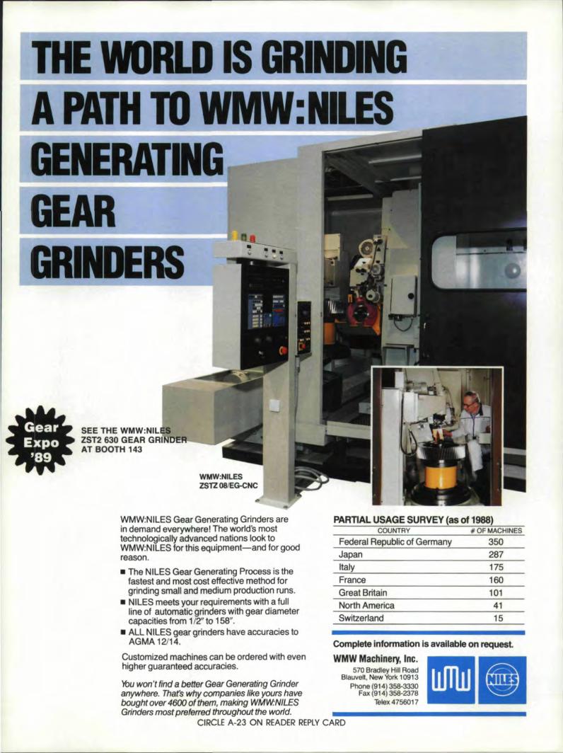
WMW:NILES Gear Generating Grinders are'in demand everywhere,! The world's mosttechnologically advanced nations look toWMW:NILES for this equipment-and for goodreason.• The NILES Gear Generating Prooess is the
fastest and most cost ,eHective metihod forgrinding small and medium production runs.
• NILES meets your requirements with a fullline of automaticgrind'ers with gear diametercapacities from liZ' to 158".
• , ALL NilLES gear grinders have accuracies toAGMA 12114.
Customized machines can be ordered with evenhigher guaranteed accuracies.
PARTIAL USAGE SURViEY (as ,011988)1COUNTRY II OF MACHINES
Federal Republic of Germany 350Japan 267Iitaly 175FranceGreat Britain 101North America 41Switzerland 115
Complete information lisavailable on request,WMW Machinery, Inc .
Youwon't .find 8'better Gear Generating Grinderanywhere. Thafs why companies like yours .havebought over 4600 of them, making 'WMW:NlLESGrinde.rs most preferred throughout the world.
CIRCLE A-23 ON! READER REPlY CARD
570 Bradley Hill Road8lauvelt, New York 109'13
Phone (914) 358·~0Fax (914) 358·2378
Telex 4756017 •
charts, relative to proof surfaces createdafter hardening and used for setting on gearchecking machines. The above method iseffective, but needs two extra operationsand a longer cyde ..Also it is Lneffect:ivewhen a gear has irregular distortions, suchas taper along length or oval shape ofdiameter.
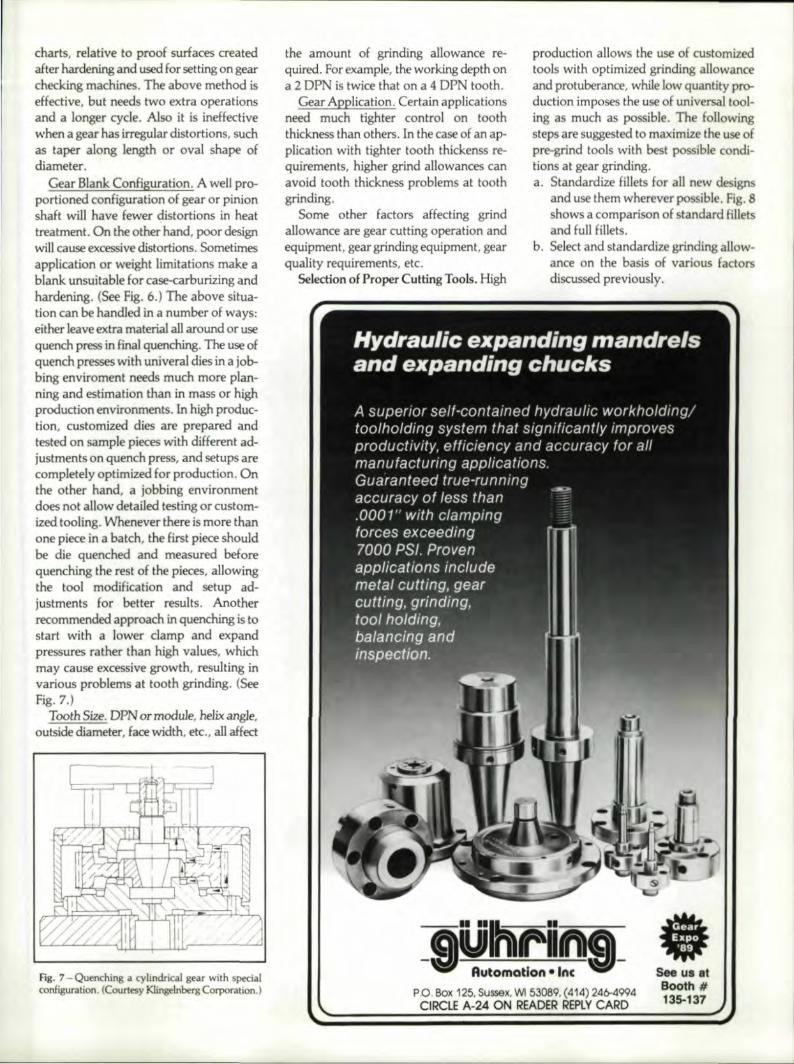
Gear Blank Configuration. A well pro-portioned configuration oJ gear or pinionshalt will have fewer distortions in heattreatment . On the other hand, poor designwill cause excessive distortions. Sometimesapplication or weight limitations make ablank unsuitable for case-carburizing andhardening. (See fig. 6.) The above situa-tion can be handled in a number of ways:either leave extramateria1 all around or usequench press in final! quenching. The use ofquench presses with univeral dies in a job-bing enviroment needs much marie plan-ningand estimation than in mass or highproduction environments. In high produc-tion, customized dies are prepared andtested on sample pieces with dilierentad-justments on quench press, and setups arecompletely optimized for production. Onthe other hand, a jobbing environmentdoes not allow detailed testing or custom-ized tooling. VVhenever there is more thanone piece in a.batch, the first piece shouldbe die quenched and measured beforequenching the rest of the pieces, allowingthe 'tool modificat:ionand setup ad-justments for better results, Anotherrecommended approach in quenching is tostart with a lower damp and expandpressures rather than. high values, whichmay Cause excessive growth, resulting invarious problems at tooth grinding. (SeeFig. 7.)
Tooth Size. DPN or module, helix angle,outsidediameter, face width, etc.. all affect
Fig.. '1- Quenching a cylindrical gearwith specialconfiguration. (Courtesy Klingilnberg Corporation. I
the amount of grinding allowance r'f-quired. For example, the working depth ona 2 DPN is twice that on a 4: DPN tooth ..
Gear ApplicaHon. Certain applicationsneed much tighter control. on tooththickness than others ..In the case of an ap-plication with tighter tooth thickenss re-quirernents, higher grind allowances canavoid tooth thickness problems at toothgrinding.
Some other factors affecting grindallowance are gear cutting operation andequipment, gear grinding equipment, gearquality requirements, etc.
Selection of Proper Cutting Tools. High
production allows the use of customizedtools with optimized grinding allowanceand protuberance. while low quantity PI'O-duction imposes the use of universal tool-ing as much as possible. The foUowingsteps are suggested to maximize Itheuse ofpre-grind tools with best possible condi-tions at gea.r grinding.a. Standardize fillets for aU new designs
and use them wherever possible. Fig. 8shows a comparison of standard filletsand full fillets.
b. Select and standardize grinding allow-anee on the basis of various factorsdiscussed previously.
8, -,
S us at:Booth #135-137p,o, Box 125. Sussex, WI 53089. (414) 246-4994
CIRCLE .A-24 ON READER' REPLYCARD
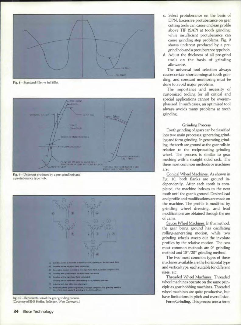
Fig..8 - Standard fillet vs full fillet.
Fig. 9 - Undercut produces by a pre-grind hob anda protuberance type hob,
IIJ ~_ .. _. __ t .- ..... ---"' __ of" __ ~
101 -.....---.. -....--_ .... --A - .......-- .......11) ., .......
.-.- ---,---ft ........- ~III .--. _ __ IIoft,~- ..--- _--
Fig. 10 - Representation of the gear grinding process.(Courtesy of BHS Hofler. Ettlingen. West Germany.)
34 'Gear Technology
c. Select protuberance on the basis ofDPN. Excessive protuberance on gearcutting tools can cause unclean profileabove TrF (SAP) at tooth grinding,while insufficient protuberance cancause grinding step problems. Fig. 9shows undercut produced by a pre-grind hob and a protuberance type hob.
d. Adjust the thickness ofaH pre-grindtools on the basis of grindingallowance.
The universal tool selection alwayscauses certain shortcomings at tooth grin-ding, and constant monitoring must bedone to avoid major problems.
The importance and necessity ofcustomized tooling for all critical andspecial applications cannot be overem-phasized.In such cases, an optimized toolalways avoids many problems at toothgrinding.
Grindin,g ProcessTooth grinding of gears can be classified
into two main processes: generating grind-ing and form grinding. Ingenerating grind-ing, the teeth are ground as the gear mils inrelation to the reciprocating grindingwheel. The process is similar to gearmeshing with a straight sided rack. Thethree most common methods or machinesare:
Conical Wheel Machines ..As shown inFig. 10, both flanks an! ground in-dependently, After each tooth is com-pleted, the machine indexes to the nexttooth until the gear is ground, Desired leadand profile and modifications are made onthe machine. The profile is modified bygrinding wheel dressing, and leadmodifications are obtained through the useof cams,
Saucer V'lheel Machines. In this method,the gear being ground has oscillatingrolling-generating motion, while twogrinding wheels sweep out the involuteprofiles by the relative motion, The twomost common methods are 0° grindingmethod and 15° 120° grinding method.
The two most common types of thesemachines available are the horizontal typeand vertical type, each suitable for differentsizes, etc.
Threaded Wheel Machines. Threadedwheel machines operate on the same prin-ciple as gear hobbing machines. Threadedwheel machines are quite productive, buthave limitations in pitch and overall size.
Form Crinding ..This process uses a form
grinding wheel to grind both flanks, whilethe work piece is maintained in a fixedradial position. Form grinding is quiteuseful in many applications, and both ex-ternal and internal gears can be ground bythis method.
Grinding WJ1eeJ Selection. Selection ofthe grinding wheel is quite important ingear grinding. Following are some of thevariables to consider when choosing agrindlng wheel. (Fig. 11).
Abrasiv,es ..The four main abrasives inuse are
a. Aluminum oxide (AL203
b. Silicon carbide (SC)c. Cubic Boron Nitride (CBN)d. Diamond
The use of "cubic boron nitride" is increas-ing every day. It is stili mainly limited toform grinding in gears but much researchinto its use in grinding is being done. Dia-mond is rarely used in gear grinding.
The other variables in grinding wheelselection are gri,t size, grade or hardness,and structure, A properly selected wheelshould maintain its form for a reasonableperiod and produce the required surfacefinish without burning the tooth surface.Gri.t that is too hard and fine will maintainits edge and give good surface finish, butmaterial. removal is slow and chance ofburning is too high. On the other hand,soft and coarse grit win remove metal fastwithout burning, but the edge wear will behigh. The consumption of the soft wheel isalso high.
One simple rule of selecting grade orhardness is "the harder the material, thesofter the grind wheel and vice versa". Toget satisfying results from grinding wheels,the following are suggested.a. Monitor the performance of the grind-
ing wheel constantly,b. Maintain good records.c. Work with a limited number of
suppliers.d. Sel.ectthe grinding wheel based on heat
treatment, pitch, surface finish,andother factors.
e. Continue some kind of program toupgrade the grinding wheels .. Besidesgrinding whee.1s, tit dressers and dress-ing equipment must be maintainedproperly.
Coolant for Wet 'Grinding. The impor-tance of the proper selection of coolant inwet gear grinding must not beunderestimated. The use of coolant reducesthe grinding wheel loading, lowers(continued on page 37)
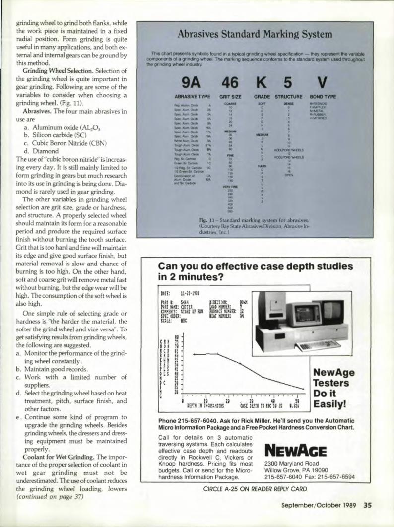
Abrasives Standard Marking System
ThIS chart presents symbols found In a typical gnnclmg wheel speclficabon - they repreII80t the vanabIecomponents of a grinding wheel The markmg sequence conforms 10 the standard system used throughoutthe grinding wheellncluslry.
9A 46 K 5 VABRASIVE TYPE GRIT SIZE GRADE STRUCTURE BOHDTYPE
Rov "'""'" 0....CO&ME ~ - B-OQINOIO
'0 C 0 ,~u ..s.-::~Oll'" 2A 11 0 MI\I(TAI.Sc-:. ~ 010. JI\ ,. E R...-R
Sooc: A,b,i'" OIJlllo 51! 18 F vlllt •• o~AlumO:a:.m .... 2!l G
1< "SiPK. Alum. 0101 ..500<:_0. ... "" -- 1sc-.;: jIJum 0•.- ..... XI -- 8
:J!i J •__ 0.... ... ... • 10_"'""'0 .... 274 !>oI L 11T__ O-
RA eo ... ~_B.II
touaI' "'"'" 0.<10 Til ~ 12.. 0 KCICILJ'OAE WtEEUIAog so eo.- c 10 p lJo.->&< c.n.o. rc 110 '.'~PIou $I c..- )C 90 - to
111> 0,~_s.oc.OG '20 18
ComI>nohon .. CIt 1:C
_N.Alum Dull 1M 180.... 51 IA<bodo u-- v~ w
2«l2lIQ:l2Oooc.!OO!Ill
fig. 11 - Standard marking system for abrasives.(Courtesy Bay State Abrasives Division, Abrasive In-dustries. lnc.)
Can you do effective case dieiPthstudiesiin 2 minutes?
tAtE: n-n-mB! 'ARr t 5414.m 10:: CUTTER
I 'CCII!IL'lTS: mu. P EIlH,I me ODD:. scm: m
ell00.1
I
HR.UDUHi
,$ t tI rL S
OLS"HI
"C
New.Age'TestersDo iilt
I Easiily!~--------------------------------------Phone, 215-657-6D40 •.As'k for R'ick lMiller.He'll send you tile AlIt.omaticlIMicro,lnformaUon IPac~kageand a Free P·ocket IHardness Conversion Chart.
Call for details on sauromauctraversing; systems. Each calculateseffective case depth and readoutsdirectly in Rockwell C, Vickers orKnoop hardness. Pricing fits mostbudgets. Call or send lor the Micro-hardness Information Pack.age.
!EWAGE2300 Maryland FloadWillow Grove, PA 19090215-657-6040 Fax: 215-657-6594
C/RCtE A-25 ON RLADER REptY CARD
September/October 1989 .3:.5
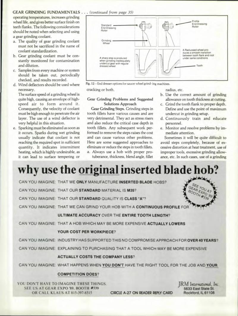
GEAR GRINDING tUNDAMENTAl.S .... (continued from page 35)operating temperatures, maeasesgrinding :r---....-.;--:;......::;......--=====;-;::===:::::;-----------,wheel life. and gives better swface finish onteeth flanks. The following considerationsshould be noted when selecting and usinga gear grinding coolant.a. The quality of gear grinding coolant
must not be sacrificed in the name ofcoolant standardization.
b. Gear gTinding coolant must be con-stantly monitored for contaminationand dilution.
c. Samples from every machine or systemshould be taken out. periodicallychecked, and results recorded.
d. Wind deflectors should be used wherenecessary.The surface speed of a grinding wheel isquite high, causing an envelope of high-speed air to form around it.Consequently, the velocity of coolantmust be high enough to penetrate the airlayer. The use ofa wind deflector isvery helpful in this situation.
e. Sparking must be eliminated as soon asit occurs, Sparks during wet grindingusually indicate that coolant is not:reaching the required spot in sufficientquantity. It indicates intermittentheating. which is highly undesirable. asit can lead to surface tempering or
Standard _---_End'DresSlngRailer
A sllarp Slep IS producedwhen gnodl ng ,"adequatelyund rcul gear w,ln regula,dressed wheel
A R,dlUssed wheel pro-ducn a srnoem IranSll\Onbel_n looth flank and rootunder same condlhons
cracking or both.
Fig. 12 - End dresser options for saucer wheel grind- ing machines,
Gear Grinding Pwblemsand Sgggest dSclutlons ApPl'oath
Gear Grinding Steps. Grinding steps intooth fillets have various causes and arevery detrimental. They act as stress risersand also reduce the critical case depth intooth fillets. Any subsequent work per-formed to remove the steps raises the costand can cause various other problems.Here ace some suggested approaches toeliminate orreduoe the steps in tooth fillets.a. Always use at hob with proper pro-
tuberance, thickness, blend angle, fillet
radius. etc.b, Use the correct amount of grinding
allowance on tooth thickness at cutting.c. Grind the tooth flank to proper depth.
Define and use the point of maximumundercut in grinding setup.
d. Continuously train and educatepersonnel.
e. Monitor and resolve problems by im-mediate attention.
Sometimes it will be quite difficult toavoid steps completely, because of ex-cessive distortion at heat 'treatment use ofimproper tools. excessive grinding allow-ance. etc. In such cases. use of a grinding
CAN YOU IMAGINE: THAT WE ONLY MANUFACTURE INISERTEID BLADE HOBS?
CAN YOU IMAG,IINE: THAT OUR STAND'ARD MATERIIAL IS M35,?
CAN YOU IMAGINE: THAT OUR STAND'ARD QUALITY IS CLASS "A"?
CAN YOU IMAGINE: THAT WE CAN GRIND YOUR: HOB WITH A CONTIINUOUS PROFILE FOFf
ULTIMATE ACCURACY OVER THE ENTIRE TOOTH LENGT.H?
CAN YOU IMAGINE: THAT A HOB WHICH MAY BE MOIRE iEXPENSIVE ACTUALLY LO'WERS,
YOUR, COST PER WORKPIECE?
CAN YOU IMAGINE: INDUSTRY HAS SUPPORTIED' THIIS NO COMPROMIS,E APPROACH FOR OVIER,40 YIEARS?
CAN YOU IMAGINE: IEXPLAINING TO PURCHASING THAT A TOOL WHICH MAY BE MORE EXPENSIVE
ACTUALLY COS,TS TIHE COMPANY LESS?
CAN YOU IMAGINE: WHAT !HAPPENS WHEN YOU IDON'T !HAVE THE RI(3HT TOOL FOR THE JOB AND YOUR
COMPETIITION DOES?
voi: [)O~T HAVE TO IMAO! E THSE THI:-.:iGS.S: E SAT G R EXPO '89. BOOTH *339
OR CALL KL SAT ,1,S-397-RSIS CtIRCLE A-27 ON IREADERIREPLYCARD
JRM IntmtatlOnal, Inc.5633 East State StRockford, IlL'61108
wheel with tip radius can avoid sharp cor-ners in grinding steps. The amount ofradius can be selected on the basis of DPN,grinding machine, and all other factors.The same approach can be used in conicalwheel machines. (See Fig. 12.)
GeM Grinding Cracks. Gear grindingcracks or grinding checks usually indicatetha.t there is process control problem, eitherin heat treatment or in gear grinding orboth.
Heat Treatment. The correct amount ofcase carbon content is very critical, as aninsuffident amount can cause low hardnessproblems; whereas, excessive case carboncontent can cause the presence of retainedaustenite. The grinding process generatespressure and heat, which causes transfor-mation. Retained austenite transformationat grinding isconsidered a source of surfacetempering or cracks or both.
free carbides or carbide networks in casestructures is another side ·effectof excessivecase carbon content ..Excessive hardness ofthe material (fr~ carbides) can causelocalized overheating. Overheating duringthe grinding operation results in surfacetempering 'or cracks or both.
Heat treatment operations usually resultin some film on the surface of heat treatedparts. This scale must be removed beforegrinding, as it tends to. load the grindingwheel. Surface oxidation in heat treatmentprcduces a thin layer of decarburized andsoft material on teeth flanks. This materialleads up the grinding wheel, causingoverheating, leading to. surface temperingor cracks or beth.
Excessive distortions in an irregular pat-tern make it difficult for machine operatorsto locate the highest point on the gear toothsurface. If the grinding cut is not started atthis point, excessive amounts of materialwill be removed during the cut from highpoints. Excessive cuts will generateoverheating and can lead to. cracking orsurface tempering or both. This problemcan be handled easily by the machlneoperator on a machine with threadedwheels and continuous indexing.
Gear Grinding. The variables in geargri-"ding operations are the gear grindingmachine, Ithegrinding wheel, the grindingcoolant in the case of wet grinding, andgrinding machine setup.
Any problem. with one or morevariables can lead to. various problems, in-dudingcracks on teeth. As discussedbefore, overheating or eecessive heating at
38 Gear lechnology
any point in the grinding operation canlead to surface tempering or grindingcracks or both. This overheating can becaused by a combination of factors, such asmalfunction of the gear grinding machine,use of an improper grinding wheel, un-suitable coolant or improper positioning ofcoolant nozzle, and an excessiveamount ofcut or material removal.
Gear Grinding Cost In a jobbing or lowbatch production, gear grinding cost is animportant matter. The estimation is nor-mally based on many factors in grinding,such as number of teeth, DPN,. helix angle,face, material, grinding allowance. quality,method, machine, etc., and the final.number is corrected on the basis of past ex-perience. Somehow, the estimation usuallyfalls short of actual time. In the currentcompetitive world, the gear grinding costhas to. be maintained at a reasonable level.Below are some suggested approaches.a. Setup preparation cannot be overem-
phasized in a low production atmo-sphere. It is a good practice to havemore than one item ready for thegrin-ding machine. Incase something goeswrong at the last minute with the firstitem on line, the next on line can bestarted without excessive idle time.
b. Heat treatment distortions or metallur-gical characteristics and inadequatemanufacturing process control. willdeliver gears with high inaccuracies to.gear grinding, which will increase grind-ing time. Therefore, a good control. atheal treatment and manufacturing pro-cess will not only cut grinding times, butwill also reduce scrappage and enhancequality ..
c. A good preventative maintenance ofgear grinding machines will keep down-time minimum.
d. Training and education of personnel isquite critical and must not beoverlooked ..
e. Useaf skiving hobs can be very helpfulin many ways, such as removing mostof the distortions and delivering a gearto grmding with limited grindallowance, reducing grinding time,removing any heat treatment scale ordecarburized and soft layers of materialfrom teeth flanks, reducing the possibil-ity of the surface tempering or grindingcracks or beth.
MiscellaneousStress Relieving After Tooth Grinding.
A stress relieving operation after tooth
grinding is highly desirable in allcritical ap-plications. This stress relieving minimizesthe possibility of latent grinding cracks. la-tent grinding cracks are the cracks thatdevelop in the storageor early period ofuse. The typical stress .relieving for case-carburized and hardened parts is around32-00 F for four hours, which can be furtherrefined for every application. This stressrelieving must be carried out as soon aspossible after tooth gr:i~ding, as anyex-cessively delayed stress relieving may beteo late.
GrindLng Allowance at Tooth CutHng.As discussed earlier, excessive grindingaJlowallcecauses many problems. Toavoid excessive material left at teeth cut-ting, all cutting personnel should betrained, parts must be checked, and sizesrecorded after teeth cutting. In cases whereQ.c. personnel are not available, thesesteps can be 'taken by shop supervisors.
Use of <II Quench Press. The use of aquench press with proper setup can keepdistortions well in control. Many com-plicated parts can be pre-machined to suitquench press use.
Prequenching and Tempering. Pre-quenching and tempering of rough-tumedgear blanks can be advantageous instabilizing and estimating growth of a gearin final heat treatment.
Checking. All ground parts must bechecked for cracks after grinding. It is alsovery important to do frequent ma.gnaf1uxinspection during the grinding operation,particularly in case of a large batch or biggears, to catch. any problem at an. earlystage.
Handling of GeMS With GrLndingCracks, Any part with sever grindingcracks or surface tempering cannot besalvaged. The suggested approach for partswith minor problems include: stress relief,regrinding to remove cracks, magnafluxinspection for cracks, checking final toothsizes, and reporting all Hndings to. theengineering department for disposition.Gears With. Close Tooth Thickness Toler-ances. Many applications need dose toothtolerances. A practical approach is to keepan approved master in the same environ-ment as gears being ground and comparesizes. For the most part, the first piece of ahatch can be used as a master after com-plete inspection.Acknowledgement: Reprinted courtesy of the Societyof Manufacturing Etrgin2ers, from its Gear Process.ingand Mtlnufactun'rrg Clink. NOI}. 1,3, 1988. lrrdit:ma-polis. IN.