Embed Size (px)
Citation preview
Gear MotorsGroup 1, 2 and 3
Technical Information
2 520L0568 • Rev. B • 10/2005
© 2005, Sauer-Danfoss. All rights reserved. Printed in Europe.
Sauer-Danfoss accepts no responsibility for possible errors in catalogs, brochures and other printed material. Sauer -Danfoss reserves the right to alter its products without prior notice. This also applies to products already ordered provided that such alterations can be made without affecting agreed specifications. All trademarks in this material are properties of their respective owners. Sauer-Danfoss and the Sauer-Danfoss logotype are trademarks of the Sauer-Danfoss Group.
Front cover illustrations: F005 216, F005 219, F005 018, F005 214, F005 221, F005 220, F005 030 and P005 256.
OVERVIEW The Sauer-Danfoss Gear Motors is a range of peak performance fixed displacement hydraulic motors available in three different frame sizes: Group 1, Group 2 and Group 3, all as uni- and bi-directional version.
Constructed of a high strength extruded aluminum body with aluminum rear cover and aluminum front flange, all motors are balanced for exceptional efficiency and designed to ensure an excellent starting torque and, in the bi-directional version, to guarantee the ability to work with high back pressure and extremely low system pressure.
The flexibility of the range in each frame size combined with the high efficiency and low starting torque makes the Sauer-Danfoss Gear Motors ideal for a wide range of applications sectors including on- and off-highway hydraulic fan drive systems, turf care, road bildge, fork lifts and municipal.
All the uni-directional motors have the same construction of the correspondent pump as well but, with inlet and outlet positioned at the opposite side for the same rotation.
Some representatives of Gear Motors: SKM1 SC06 SNM3.L SC07
Gear motors` attributes:• Three groups of frame sizes (Group 1, 2 and 3) • Displacements from 2.6 to 90 cm3/rev [from 0.158 to 3.425 in3/rev]• Available in uni- and bi-directional version for all the frame sizes, displacements and
configurations• Rated pressure up to 250 bar [3625 psi] for all the frame sizes in the uni- and
bi-directional version• Back pressure capability up to 250 bar [3625 psi] for all the frame sizes in the
bi-directional version• Speeds up to 4000 min-1 (rpm) for Group 1 and 2, and up to 2500 min-1 (rpm) for
Group 3• SAE, ISO and DIN mounting flanges and shafts • Available with integrated relief valve in the Group 2 frame size and integrated
anti-cavitation valve in Group 2 and Group 3 frame sizes.
General Information
FEATURES AND BENEFITS
F005 219
F005 216
SNM2 CI96 SNU2 CI06
F005 220
F005 221
Gear Motors • Group 1, 2 and 3Technical Information
3520L0568 • Rev. B • 10/2005
Contents
GENERAL INFORMATION
SYSTEM REQUIREMENTS
GROUP 1 GENERAL INFORMATION
MODEL CODE DESCRIPTION
MOTOR PERFORMANCE
PRODUCT OPTIONS
DIMENSIONS
Overview ........................................................................................................................................................... 2Features and benefits ................................................................................................................................... 2Motor displacements .................................................................................................................................... 6Determination of nominal motor sizes .................................................................................................. 7
Based on SI units ....................................................................................................................................... 7Based on US units ..................................................................................................................................... 7
Pressure .............................................................................................................................................................. 8Speed .................................................................................................................................................................. 8Hydraulic fluids ............................................................................................................................................... 9Temperature and viscosity .......................................................................................................................... 9Filtration ..........................................................................................................................................................10
Filters ...........................................................................................................................................................10Selecting a filter .......................................................................................................................................10
Reservoir ..........................................................................................................................................................10Line sizing .......................................................................................................................................................11Motor shaft connection .............................................................................................................................11Motor shaft load data form .......................................................................................................................12Motor life .........................................................................................................................................................13
Motor design ..................................................................................................................................................14SKM1 ............................................................................................................................................................14SKU1 ...........................................................................................................................................................14SNU1 ............................................................................................................................................................14
Technical data ................................................................................................................................................15
Model code .....................................................................................................................................................16
Motor performance graphs ......................................................................................................................18
Shaft, flange, and port configurations ..................................................................................................20Shaft options ..................................................................................................................................................21Mounting flanges .........................................................................................................................................21
Shaft availability and torque capability ..........................................................................................21Port configurations ......................................................................................................................................22
Standard port configurations .............................................................................................................22Nonstandard port configurations .....................................................................................................22
SKM1 ports .....................................................................................................................................................23SNU1, SKU1 Ports ..........................................................................................................................................24
SKM1, SKU1, SNU1 – CO01 and SC01 .....................................................................................................25SKM1, SKU1 – CO02 and CI02 ...................................................................................................................26SKM1, SKU1 – CI06 and SC06 ....................................................................................................................27
Gear Motors • Group 1, 2 and 3Technical Information
4 520L0568 • Rev. B • 10/2005
Contents
GROUP 2 GENERAL INFORMATION
MODEL CODE DESCRIPTION
MOTOR PERFORMANCE
PRODUCT OPTIONS
DIMENSIONS
Motor design ..................................................................................................................................................28SNM2 ...........................................................................................................................................................28SNU2 ............................................................................................................................................................28SKU2 ............................................................................................................................................................28
Technical data ................................................................................................................................................29
Model code .....................................................................................................................................................30
Motor performance graphs ......................................................................................................................32
Shaft, flange, and port configurations ..................................................................................................34Shaft options ..................................................................................................................................................35
Shaft availability and torque capability ..........................................................................................35Mounting flanges .........................................................................................................................................36Port configurations ......................................................................................................................................37
Standard port configurations .............................................................................................................37Nonstandard port configurations .....................................................................................................37
SNM2, SNM2G. and SNM2J. ports ..........................................................................................................38SNU2, SKU2 ports .........................................................................................................................................39Integral relief valve SNM2I. ......................................................................................................................40
SNM2I. .......................................................................................................................................................40Variant codes for ordering integral relief valve ............................................................................41
Integral relief valve and Anti-cavitation check valve – SNM2J. ..................................................42SNM2J. .......................................................................................................................................................42
Outrigger bearing assembly – SNM2 ....................................................................................................42Available configurations .......................................................................................................................42Dimensions ...............................................................................................................................................44
SNM2, SNU2 – SC01, CI01 and CO01 ......................................................................................................46SNM2, SNU2 – SC02 and CO02 ................................................................................................................47SNM2, SNU2 – FR03 .....................................................................................................................................48SNM2, SNU2 – SC04/05 and CO04/05 ...................................................................................................49SNM2, SNU2 – SC06 and CI06 ..................................................................................................................50
Gear Motors • Group 1, 2 and 3Technical Information
5520L0568 • Rev. B • 10/2005
Contents
GROUP 3 GENERAL INFORMATION
MODEL CODE DESCRIPTION
MOTOR PERFORMANCE
PRODUCT OPTIONS
DIMENSIONS
Motor design ..................................................................................................................................................52SNM3 ...........................................................................................................................................................52SNU3 ............................................................................................................................................................52
Technical data ................................................................................................................................................53
Model code .....................................................................................................................................................54
Motor performance graphs ......................................................................................................................56
Shaft, flange, and port configurations ..................................................................................................59Shaft options ..................................................................................................................................................60
Shaft availability and torque capability ..........................................................................................60Mounting flanges .........................................................................................................................................60SNM3, SNM3G. ports ...................................................................................................................................61SNU3 ports ......................................................................................................................................................62
SNM3, SNU3 – CI01, SC01 and CO01 ......................................................................................................65SNM3, SNU3 – CI02, SC02 and CO02 ......................................................................................................66SNM3, SNU3 – CI03, SC03 and CO03 ......................................................................................................67SNM3, SNU3 – CO06 ....................................................................................................................................68SNM3, SNU3 – CO07, SC07 and CI07 ......................................................................................................69
Gear Motors • Group 1, 2 and 3Technical Information
6 520L0568 • Rev. B • 10/2005
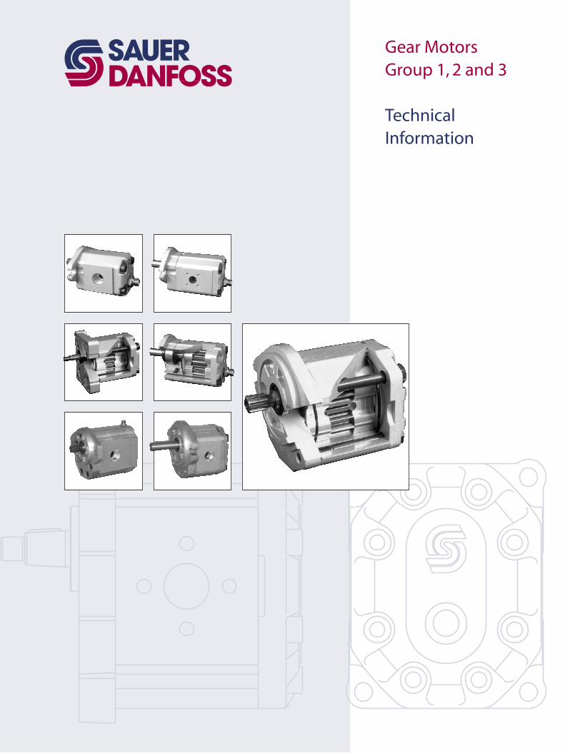
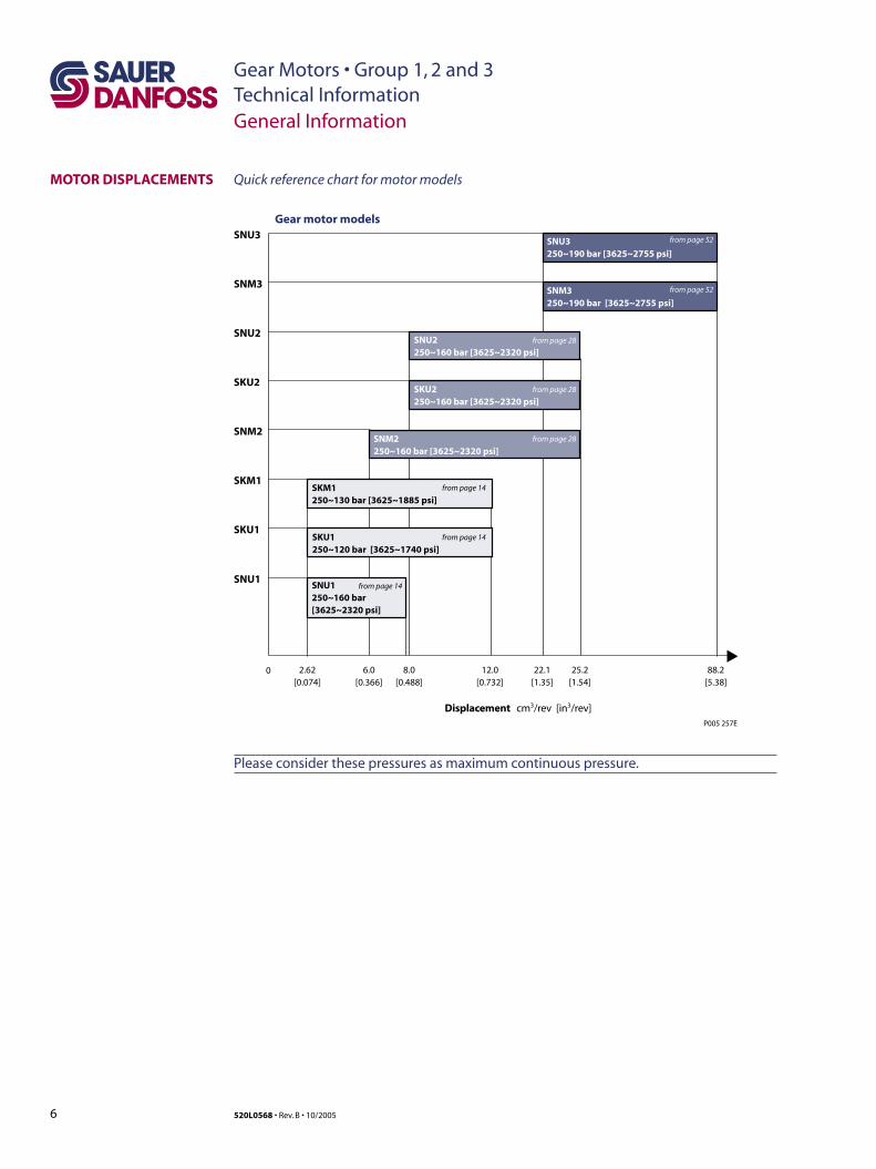
MOTOR DISPLACEMENTS Quick reference chart for motor models
SKU1 250~120 bar [3625~1740 psi]
SNM2 250~160 bar [3625~2320 psi]
SKM1 250~130 bar [3625~1885 psi]
SKU1
SNM2
SKU2
SNU2
SNM3
SNU3
SKM1
SNU3 250~190 bar [3625~2755 psi]
SNM3 250~190 bar [3625~2755 psi]
SKU2 250~160 bar [3625~2320 psi]
SNU2 250~160 bar [3625~2320 psi]
Gear motor models
0
P005 257E
2.62[0.074]
6.0[0.366]
8.0[0.488]
12.0[0.732]
22.1[1.35]
25.2[1.54]
88.2[5.38]
Displacement cm3/rev [in3/rev]
SNU1 250~160 bar [3625~2320 psi]
SNU1
from page 14
from page 28
from page 28
from page 28
from page 52
from page 52
from page 14
from page 14
Please consider these pressures as maximum continuous pressure.
General Information
Gear Motors • Group 1, 2 and 3Technical Information
7520L0568 • Rev. B • 10/2005
General Information
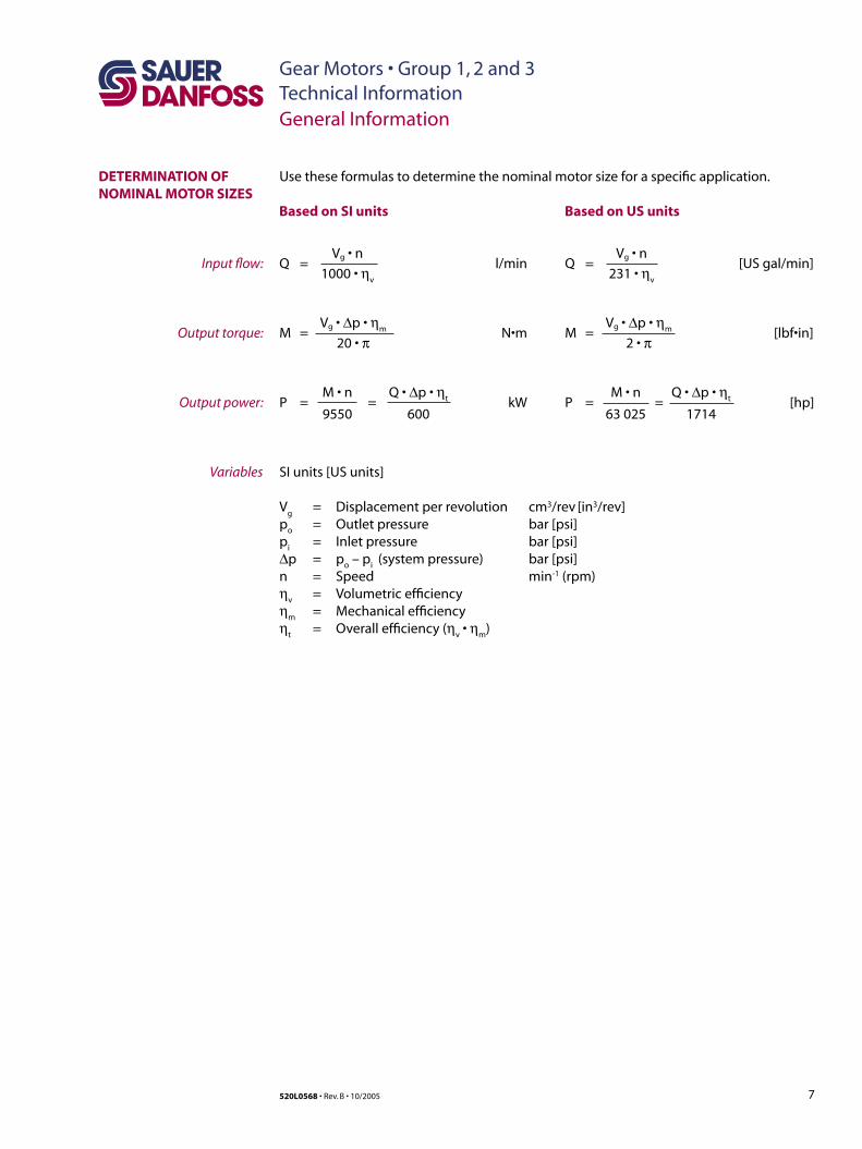
Use these formulas to determine the nominal motor size for a specific application.DETERMINATION OF NOMINAL MOTOR SIZES
Based on SI units Based on US units
Vg • n Q = l/min 1000 • ηv
Vg • ∆p • ηmM = N•m 20 • π
M • n Q • ∆p • ηtP = = kW 9550 600
SI units [US units]
Vg = Displacement per revolution cm3/rev [in3/rev]
po = Outlet pressure bar [psi]pi = Inlet pressure bar [psi]∆p = po – pi (system pressure) bar [psi]n = Speed min-1 (rpm)ηv = Volumetric efficiencyηm = Mechanical efficiencyηt = Overall efficiency (ηv • ηm)
Vg • nQ = [US gal/min] 231 • ηv
Vg • ∆p • ηmM = [lbf•in] 2 • π
M • n Q • ∆p • ηtP = = [hp] 63 025 1714
Input flow:
Output torque:
Output power:
Variables
Gear Motors • Group 1, 2 and 3Technical Information
8 520L0568 • Rev. B • 10/2005
PRESSURE
SPEED
System Requirements
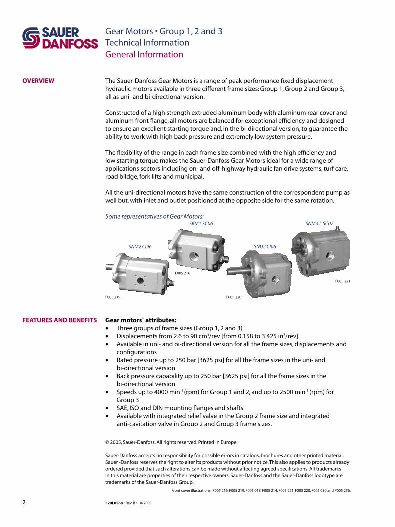
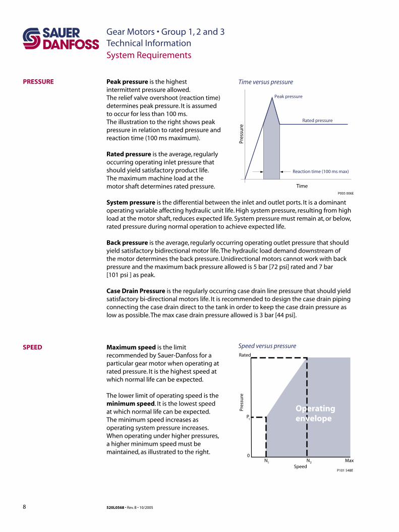
Peak pressure is the highest intermittent pressure allowed. The relief valve overshoot (reaction time) determines peak pressure. It is assumed to occur for less than 100 ms. The illustration to the right shows peak pressure in relation to rated pressure and reaction time (100 ms maximum).
Rated pressure is the average, regularly occurring operating inlet pressure that should yield satisfactory product life. The maximum machine load at the motor shaft determines rated pressure.
Maximum speed is the limit recommended by Sauer-Danfoss for a particular gear motor when operating at rated pressure. It is the highest speed at which normal life can be expected.
The lower limit of operating speed is the minimum speed. It is the lowest speed at which normal life can be expected. The minimum speed increases as operating system pressure increases. When operating under higher pressures, a higher minimum speed must be maintained, as illustrated to the right.
Rated
P1
Pres
sure
0N MaxN2
P101 548ESpeed
Operatingenvelope
1
Peak pressure
Rated pressure
Reaction time (100 ms max)
TimeP005 006E
Pres
sure
Time versus pressure
Speed versus pressure
System pressure is the differential between the inlet and outlet ports. It is a dominant operating variable affecting hydraulic unit life. High system pressure, resulting from high load at the motor shaft, reduces expected life. System pressure must remain at, or below, rated pressure during normal operation to achieve expected life.
Back pressure is the average, regularly occurring operating outlet pressure that should yield satisfactory bidirectional motor life. The hydraulic load demand downstream of the motor determines the back pressure. Unidirectional motors cannot work with back pressure and the maximum back pressure allowed is 5 bar [72 psi] rated and 7 bar [101 psi ] as peak.
Case Drain Pressure is the regularly occurring case drain line pressure that should yield satisfactory bi-directional motors life. It is recommended to design the case drain piping connecting the case drain direct to the tank in order to keep the case drain pressure as low as possible. The max case drain pressure allowed is 3 bar [44 psi].
Gear Motors • Group 1, 2 and 3Technical Information
9520L0568 • Rev. B • 10/2005
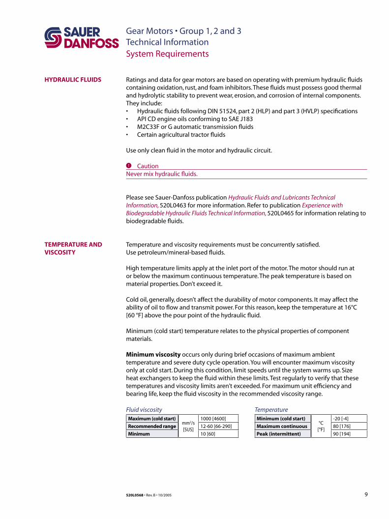
Temperature and viscosity requirements must be concurrently satisfied. Use petroleum/mineral-based fluids.
High temperature limits apply at the inlet port of the motor. The motor should run at or below the maximum continuous temperature. The peak temperature is based on material properties. Don’t exceed it.
Cold oil, generally, doesn’t affect the durability of motor components. It may affect the ability of oil to flow and transmit power. For this reason, keep the temperature at 16°C [60 °F] above the pour point of the hydraulic fluid.
Minimum (cold start) temperature relates to the physical properties of component materials.
Minimum viscosity occurs only during brief occasions of maximum ambient temperature and severe duty cycle operation. You will encounter maximum viscosity only at cold start. During this condition, limit speeds until the system warms up. Size heat exchangers to keep the fluid within these limits. Test regularly to verify that these temperatures and viscosity limits aren’t exceeded. For maximum unit efficiency and bearing life, keep the fluid viscosity in the recommended viscosity range.
System Requirements
HYDRAULIC FLUIDS
TEMPERATURE AND VISCOSITY
TemperatureMinimum (cold start)
°C[°F]
-20 [-4]
Maximum continuous 80 [176]
Peak (intermittent) 90 [194]
Fluid viscosityMaximum (cold start)
mm2/s[SUS]
1000 [4600]
Recommended range 12-60 [66-290]
Minimum 10 [60]
Ratings and data for gear motors are based on operating with premium hydraulic fluids containing oxidation, rust, and foam inhibitors. These fluids must possess good thermal and hydrolytic stability to prevent wear, erosion, and corrosion of internal components. They include:• Hydraulic fluids following DIN 51524, part 2 (HLP) and part 3 (HVLP) specifications• API CD engine oils conforming to SAE J183• M2C33F or G automatic transmission fluids• Certain agricultural tractor fluids
Use only clean fluid in the motor and hydraulic circuit.
C CautionNever mix hydraulic fluids.
Please see Sauer-Danfoss publication Hydraulic Fluids and Lubricants Technical Information, 520L0463 for more information. Refer to publication Experience with Biodegradable Hydraulic Fluids Technical Information, 520L0465 for information relating to biodegradable fluids.
Gear Motors • Group 1, 2 and 3Technical Information
10 520L0568 • Rev. B • 10/2005
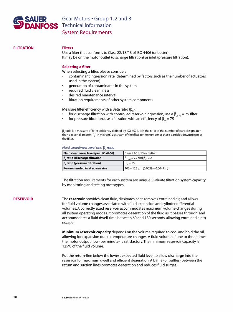
FiltersUse a filter that conforms to Class 22/18/13 of ISO 4406 (or better). It may be on the motor outlet (discharge filtration) or inlet (pressure filtration).
Selecting a filterWhen selecting a filter, please consider:• contaminant ingression rate (determined by factors such as the number of actuators
used in the system)• generation of contaminants in the system• required fluid cleanliness• desired maintenance interval• filtration requirements of other system components
Measure filter efficiency with a Beta ratio (βX):
• for discharge filtration with controlled reservoir ingression, use a β35-45
= 75 filter• for pressure filtration, use a filtration with an efficiency of β
10 = 75
βx ratio is a measure of filter efficiency defined by ISO 4572. It is the ratio of the number of particles greater
than a given diameter ( “X“ in microns) upstream of the filter to the number of these particles downstream of
the filter.
Fluid cleanliness level and βx ratio
Fluid cleanliness level (per ISO 4406) Class 22/18/13 or better
βx ratio (discharge filtration) β
35-45 = 75 and β
10 = 2
βx ratio (pressure filtration) β
10 = 75
Recommended inlet screen size 100 – 125 µm [0.0039 – 0.0049 in]
The filtration requirements for each system are unique. Evaluate filtration system capacity by monitoring and testing prototypes.
The reservoir provides clean fluid, dissipates heat, removes entrained air, and allows for fluid volume changes associated with fluid expansion and cylinder differential volumes. A correctly sized reservoir accommodates maximum volume changes during all system operating modes. It promotes deaeration of the fluid as it passes through, and accommodates a fluid dwell-time between 60 and 180 seconds, allowing entrained air to escape.
Minimum reservoir capacity depends on the volume required to cool and hold the oil, allowing for expansion due to temperature changes. A fluid volume of one to three times the motor output flow (per minute) is satisfactory. The minimum reservoir capacity is 125% of the fluid volume.
Put the return-line below the lowest expected fluid level to allow discharge into the reservoir for maximum dwell and efficient deaeration. A baffle (or baffles) between the return and suction lines promotes deaeration and reduces fluid surges.
RESERVOIR
FILTRATION
System Requirements
Gear Motors • Group 1, 2 and 3Technical Information
11520L0568 • Rev. B • 10/2005
System Requirements
LINE SIZING
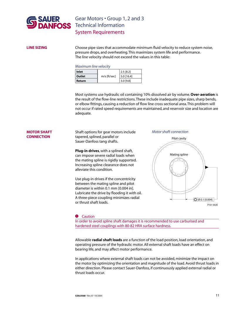
MOTOR SHAFT CONNECTION Pilot cavity
Ø 0.1 [0.004]
P101 002E
Mating spline
Shaft options for gear motors include tapered, splined, parallel or Sauer-Danfoss tang shafts.
Plug-in drives, with a splined shaft, can impose severe radial loads when the mating spline is rigidly supported. Increasing spline clearance does not alleviate this condition.
Use plug-in drives if the concentricity between the mating spline and pilot diameter is within 0.1 mm [0.004 in]. Lubricate the drive by flooding it with oil. A three-piece coupling minimizes radial or thrust shaft loads.
Choose pipe sizes that accommodate minimum fluid velocity to reduce system noise, pressure drops, and overheating. This maximizes system life and performance. The line velocity should not exceed the values in this table:
Maximum line velocityInlet
m/s [ft/sec]
2.5 [8.2]
Outlet 5.0 [16.4]
Return 3.0 [9.8]
Most systems use hydraulic oil containing 10% dissolved air by volume. Over-aeration is the result of the flow-line restrictions. These include inadequate pipe sizes, sharp bends, or elbow fittings, causing a reduction of flow line cross sectional area. This problem will not occur if rated speed requirements are maintained, and reservoir size and location are adequate.
C CautionIn order to avoid spline shaft damages it is recommended to use carburised and hardened steel couplings with 80-82 HRA surface hardness.
Allowable radial shaft loads are a function of the load position, load orientation, and operating pressure of the hydraulic motor. All external shaft loads have an effect on bearing life, and may affect motor performance.
In applications where external shaft loads can not be avoided, minimize the impact on the motor by optimizing the orientation and magnitude of the load. Avoid thrust loads in either direction. Please contact Sauer-Danfoss, if continuously applied external radial or thrust loads occur.
Motor shaft connection
Gear Motors • Group 1, 2 and 3Technical Information
12 520L0568 • Rev. B • 10/2005
Application dataItem Value Based on SI or US units
Motor displacement ❑ cm3/rev ❑ in3/rev
Rated system pressure❑ bar ❑ psi
Peak pressure
Motor shaft rotation ❑ left ❑ right
Motor minimum speedmin-1 (rpm)
Motor maximum speed
Radial load RL ❑ N ❑ lbf
Angular orientation of radial load to inlet port α degree
Axial load AL ❑ N ❑ lbf
Distance from flange to radial load a ❑ mm ❑ in
System Requirements
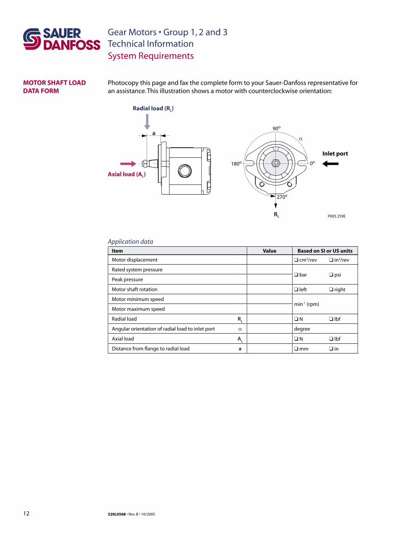
Photocopy this page and fax the complete form to your Sauer-Danfoss representative for an assistance. This illustration shows a motor with counterclockwise orientation:
MOTOR SHAFT LOAD DATA FORM
P005 259E
a90o
α
0o
270o
180o
Inlet port
Axial load (AL)
Radial load (RL)
RL
Gear Motors • Group 1, 2 and 3Technical Information
13520L0568 • Rev. B • 10/2005
System Requirements
Motor life is a function of speed, system pressure, and other system parameters (such as fluid quality and cleanliness).
All Sauer-Danfoss gear motors use hydrodynamic journal bearings that have an oil film maintained between the gear/shaft and bearing surfaces at all times. If the oil film is sufficiently sustained through proper system maintenance and operating within recommended limits, long life can be expected.
B10
life expectancy number is generally associated with rolling element bearings. It does not exist for hydrodynamic bearings.
High pressure impacts motor life. When submitting an application for review, provide machine duty cycle data that includes percentages of time at various loads and speeds. We strongly recommend a prototype testing program to verify operating parameters and their impact on life expectancy before finalizing any system design.
MOTOR LIFE
Gear Motors • Group 1, 2 and 3Technical Information
14
Gear Motors • Group 3Technical Information
520L0568 • Rev. B • 10/2005
General Information
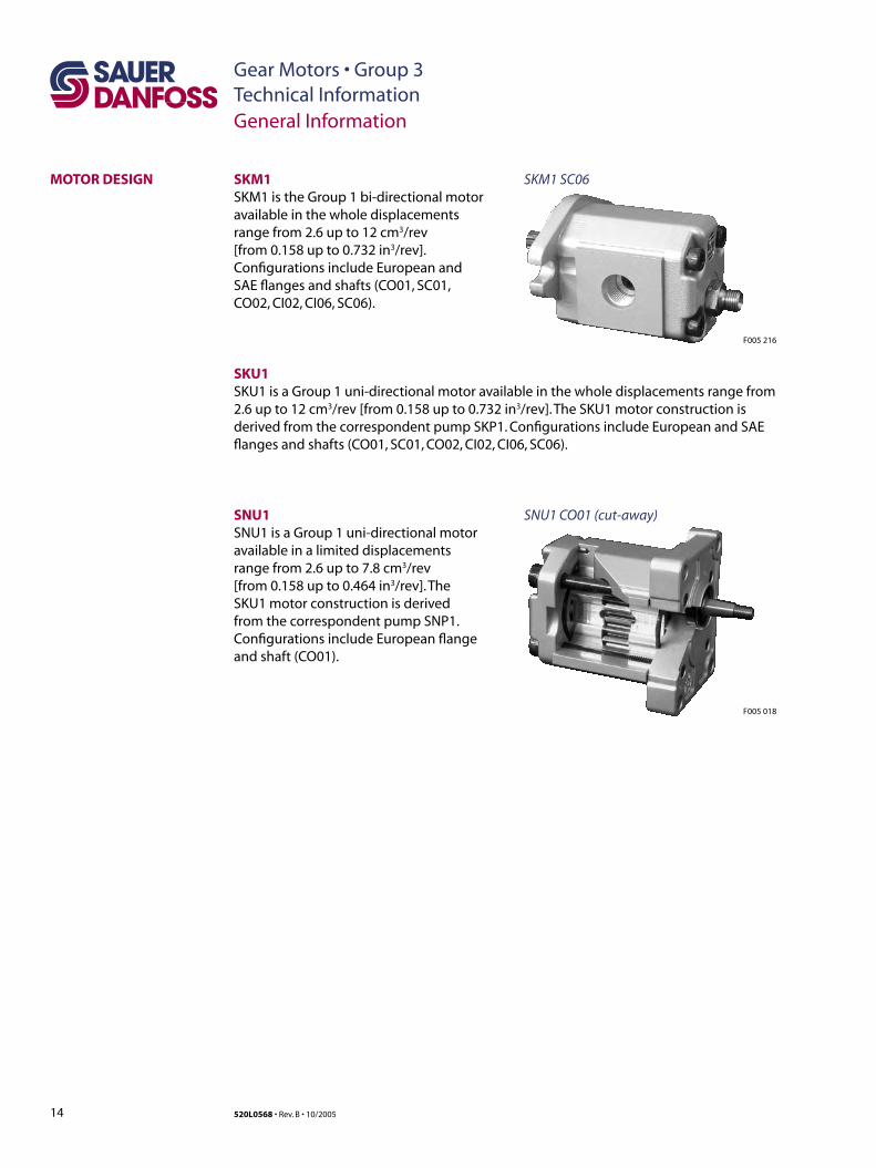
SNU1 CO01 (cut-away)
MOTOR DESIGN
F005 018
SKM1SKM1 is the Group 1 bi-directional motor available in the whole displacements range from 2.6 up to 12 cm3/rev [from 0.158 up to 0.732 in3/rev]. Configurations include European and SAE flanges and shafts (CO01, SC01, CO02, CI02, CI06, SC06).
SKM1 SC06
SKU1 SKU1 is a Group 1 uni-directional motor available in the whole displacements range from 2.6 up to 12 cm3/rev [from 0.158 up to 0.732 in3/rev]. The SKU1 motor construction is derived from the correspondent pump SKP1. Configurations include European and SAE flanges and shafts (CO01, SC01, CO02, CI02, CI06, SC06).
SNU1SNU1 is a Group 1 uni-directional motor available in a limited displacements range from 2.6 up to 7.8 cm3/rev [from 0.158 up to 0.464 in3/rev]. The SKU1 motor construction is derived from the correspondent pump SNP1. Configurations include European flange and shaft (CO01).
F005 216
15
Gear Motors • Group 3Technical Information
520L0568 • Rev. B • 10/2005
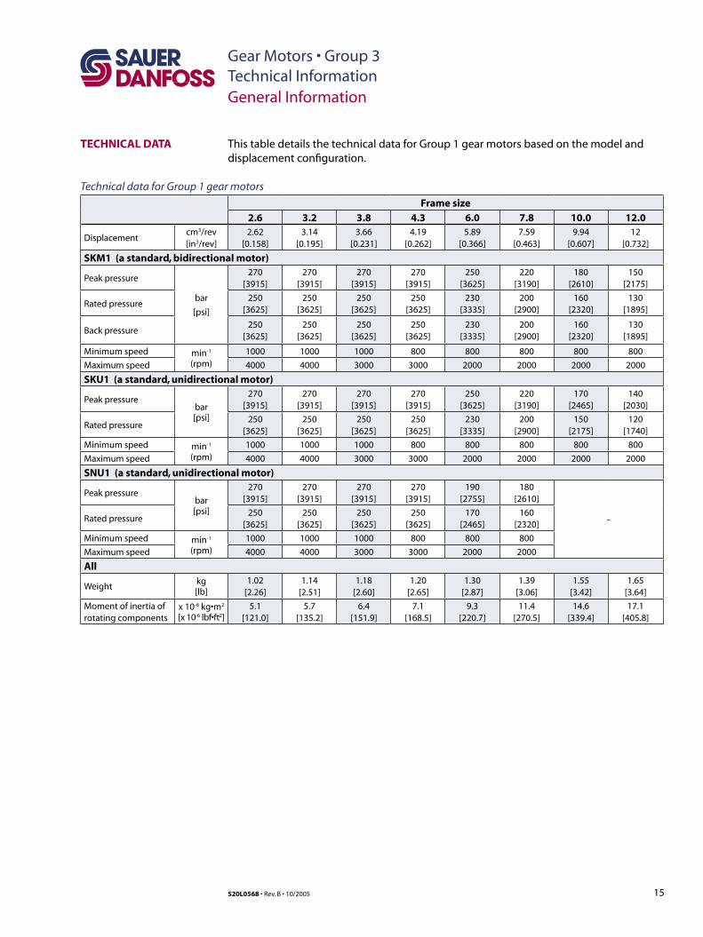
TECHNICAL DATA
Technical data for Group 1 gear motors
Frame size
2.6 3.2 3.8 4.3 6.0 7.8 10.0 12.0
Displacementcm3/rev[in3/rev]
2.62[0.158]
3.14[0.195]
3.66[0.231]
4.19[0.262]
5.89[0.366]
7.59[0.463]
9.94[0.607]
12[0.732]
SKM1 (a standard, bidirectional motor)
Peak pressure
bar
[psi]
270[3915]
270[3915]
270[3915]
270[3915]
250[3625]
220[3190]
180[2610]
150[2175]
Rated pressure250
[3625]250
[3625]250
[3625]250
[3625]230
[3335]200
[2900]160
[2320]130
[1895]
Back pressure250
[3625]250
[3625]250
[3625]250
[3625]230
[3335]200
[2900]160
[2320]130
[1895]
Minimum speed min-1
(rpm)1000 1000 1000 800 800 800 800 800
Maximum speed 4000 4000 3000 3000 2000 2000 2000 2000
SKU1 (a standard, unidirectional motor)
Peak pressurebar[psi]
270[3915]
270[3915]
270[3915]
270[3915]
250[3625]
220[3190]
170[2465]
140[2030]
Rated pressure250
[3625]250
[3625]250
[3625]250
[3625]230
[3335]200
[2900]150
[2175]120
[1740]
Minimum speed min-1
(rpm)1000 1000 1000 800 800 800 800 800
Maximum speed 4000 4000 3000 3000 2000 2000 2000 2000
SNU1 (a standard, unidirectional motor)
Peak pressurebar[psi]
270[3915]
270[3915]
270[3915]
270[3915]
190[2755]
180[2610]
-Rated pressure250
[3625]250
[3625]250
[3625]250
[3625]170
[2465]160
[2320]
Minimum speed min-1
(rpm)1000 1000 1000 800 800 800
Maximum speed 4000 4000 3000 3000 2000 2000
All
Weightkg[lb]
1.02[2.26]
1.14[2.51]
1.18[2.60]
1.20[2.65]
1.30[2.87]
1.39[3.06]
1.55[3.42]
1.65[3.64]
Moment of inertia ofrotating components
x 10-6 kg•m2
[x 10-6 lbf•ft2]5.1
[121.0]5.7
[135.2]6.4
[151.9]7.1
[168.5]9.3
[220.7]11.4
[270.5]14.6
[339.4]17.1
[405.8]
General Information
This table details the technical data for Group 1 gear motors based on the model and displacement configuration.
16
Gear Motors • Group 3Technical Information
520L0568 • Rev. B • 10/2005
Model Code Description
MODEL CODE A B C D
/
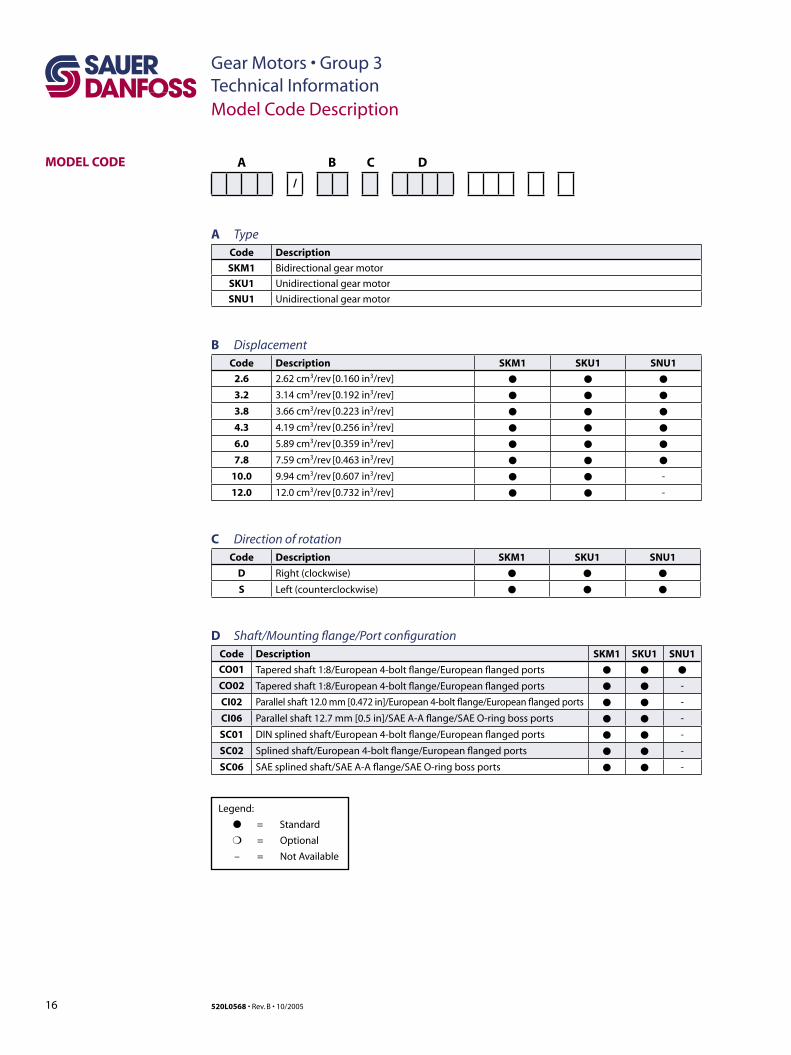
A TypeCode Description
SKM1 Bidirectional gear motor
SKU1 Unidirectional gear motor
SNU1 Unidirectional gear motor
B DisplacementCode Description SKM1 SKU1 SNU1
2.6 2.62 cm3/rev [0.160 in3/rev] ● ● ●
3.2 3.14 cm3/rev [0.192 in3/rev] ● ● ●
3.8 3.66 cm3/rev [0.223 in3/rev] ● ● ●
4.3 4.19 cm3/rev [0.256 in3/rev] ● ● ●
6.0 5.89 cm3/rev [0.359 in3/rev] ● ● ●
7.8 7.59 cm3/rev [0.463 in3/rev] ● ● ●
10.0 9.94 cm3/rev [0.607 in3/rev] ● ● -
12.0 12.0 cm3/rev [0.732 in3/rev] ● ● -
C Direction of rotationCode Description SKM1 SKU1 SNU1
D Right (clockwise) ● ● ●
S Left (counterclockwise) ● ● ●
D Shaft/Mounting flange/Port configurationCode Description SKM1 SKU1 SNU1
CO01 Tapered shaft 1:8/European 4-bolt flange/European flanged ports ● ● ●
CO02 Tapered shaft 1:8/European 4-bolt flange/European flanged ports ● ● -
CI02 Parallel shaft 12.0 mm [0.472 in]/European 4-bolt flange/European flanged ports ● ● -
CI06 Parallel shaft 12.7 mm [0.5 in]/SAE A-A flange/SAE O-ring boss ports ● ● -
SC01 DIN splined shaft/European 4-bolt flange/European flanged ports ● ● -
SC02 Splined shaft/European 4-bolt flange/European flanged ports ● ● -
SC06 SAE splined shaft/SAE A-A flange/SAE O-ring boss ports ● ● -
Legend:
● = Standard
❍ = Optional
– = Not Available
17
Gear Motors • Group 3Technical Information
520L0568 • Rev. B • 10/2005
Model Code Description
MODEL CODE (continued) E F G
/
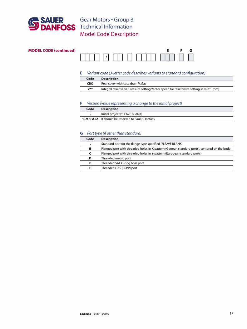
E Variant code (3-letter code describes variants to standard configuration)Code Description
CBO Rear cover with case drain 1/4 Gas
V** Integral relief valve/Pressure setting/Motor speed for relief valve setting in min-1 (rpm)
F Version (value representing a change to the initial project)Code Description
. Initial project [*LEAVE BLANK]
1÷9 or A÷Z It should be reserved to Sauer-Danfoss
G Port type (if other than standard)Code Description
. Standard port for the flange type specified [*LEAVE BLANK]
B Flanged port with threaded holes in X pattern (German standard ports), centered on the body
C Flanged port with threaded holes in + pattern (European standard ports)
D Threaded metric port
E Threaded SAE O-ring boss port
F Threaded GAS (BSPP) port
18
Gear Motors • Group 3Technical Information
520L0568 • Rev. B • 10/2005
Speed min -1 (rpm)
Flow
l
/min
[U
S g
al/m
in]
Ou
tpu
t To
rqu
e N
•m [
lbf•
in]
2000 25001000 1500 3000
SKM1/2.6
11 [2.9]
10 [2.6]
9 [2.4]
8 [2.1]
7 [1.9]
6 [1.6]
5 [1.3]
4 [1.1]
3 [0.8]
2 [0.5]
11 [2.9]
10 [2.6]
9 [2.4]
8 [2.1]
7 [1.9]
6 [1.6]
5 [1.3]
4 [1.1]
3 [0.8]
2 [0.5]
11 [97.4]
10 [88.5]
9 [79.7]
8 [70.8]
7 [62.0]
6 [53.1]
5 [44.3]
4 [35.4]
3 [26.6]
2 [17.7]
Speed min -1 (rpm)
Flow
l
/min
[U
S g
al/m
in]
2000 25001000 1500 3000
SKM1/3.2
210 bar [3046 psi]
210 bar [3046 psi]
250 bar [3626 psi]
250 bar [3626 psi]
150 bar [2176 psi]
150 bar [2176 psi]
100 bar [1450 psi]100 bar [1450 psi]
250 bar [
3626 psi]
100 bar [
1450 psi]
250 bar [3626 psi]
100 bar [1450 psi]
Speed min -1 (rpm)
Flow
l
/min
[U
S g
al/m
in]
2000 25001000 1500 3000
SKM1/4.3
210 bar [3046 psi]
250 bar [3626 psi]
150 bar [2176 psi]
100 bar [1450 psi]
250 bar [
3626 psi]
100 bar [
1450 psi]
13 [3.4]
12 [3.2]
11 [2.9]
10 [2.6]
9 [2.4]
8 [2.1]
7 [1.9]
6 [1.6]
5 [1.3]
4 [1.1]
16 [4.2]
15 [4.0]
14 [3.7]
13 [3.4]
12 [3.2]
11 [2.9]
10 [2.6]
9 [2.4]
8 [2.1]
7 [1.9]
6 [1.6]
5 [1.3]
4 [1.1]
Speed min -1 (rpm)
Flow
l
/min
[U
S g
al/m
in]
2000 25001000 1500 3000
SKM1/3.8
210 bar [3046 psi]
250 bar [3626 psi]
150 bar [2176 psi]
100 bar [1450 psi]
250 bar
[3626 p
si]
100 bar
[1450 p
si]
P005 266E
Ou
tpu
t To
rqu
e N
•m [
lbf•
in]
11 [97.4]
10 [88.5]
9 [79.7]
8 [70.8]
7 [62.0]
6 [53.1]
5 [44.3]
4 [35.4]
3 [26.6]
2 [17.7]
Ou
tpu
t To
rqu
e N
•m [
lbf•
in]
13 [115.1]
12 [106.2]
11 [97.4]
10 [88.5]
9 [79.7]
8 [70.8]
7 [62.0]
6 [53.1]
5 [44.3]
4 [35.4]
16 [141.6]
15 [132.8]
14 [123.9]
13 [115.1]
12 [106.2]
11 [97.4]
10 [88.5]
9 [79.7]
8 [70.8]
7 [62.0]
6 [53.1]
5 [44.3]
4 [35.4]
Ou
tpu
t To
rqu
e N
•m [
lbf•
in]
Motor Performance
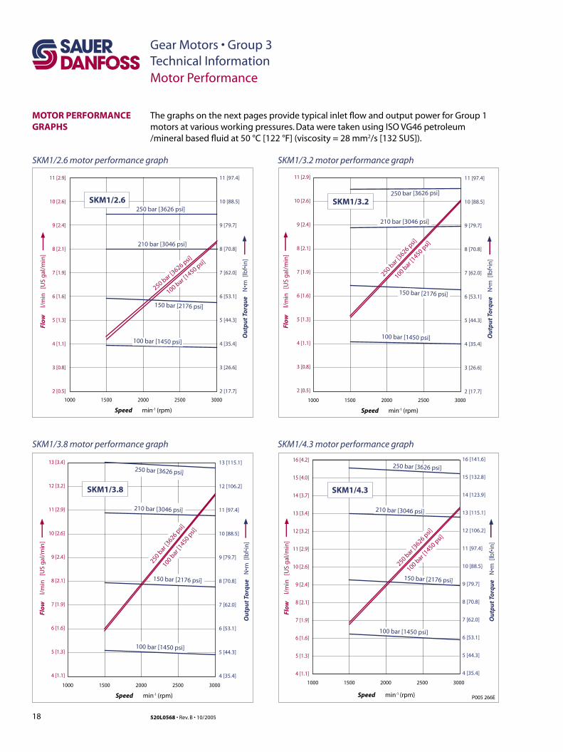
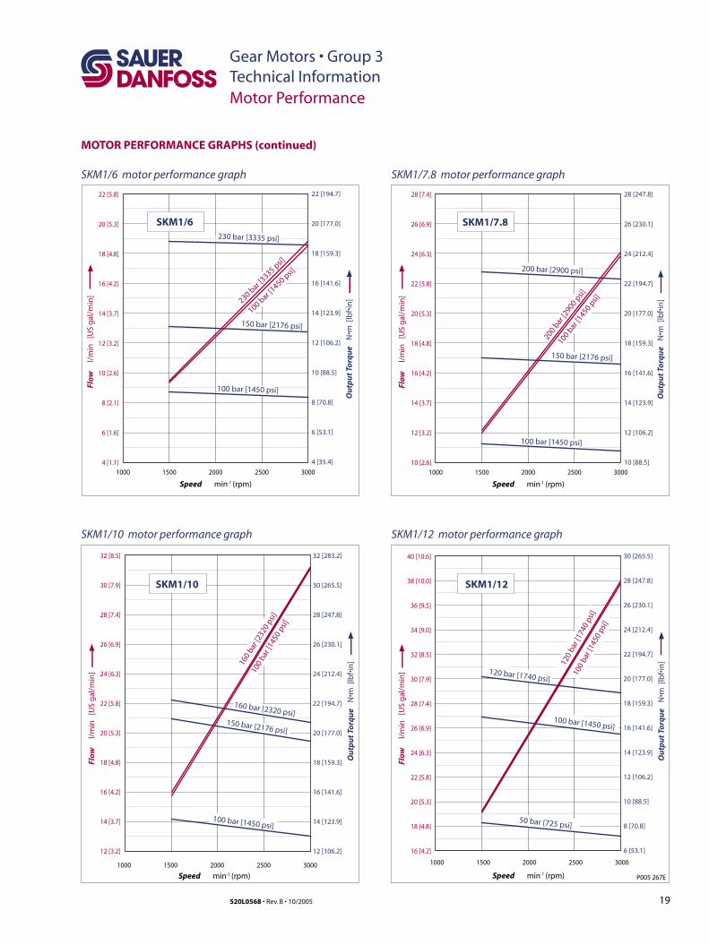
The graphs on the next pages provide typical inlet flow and output power for Group 1 motors at various working pressures. Data were taken using ISO VG46 petroleum /mineral based fluid at 50 °C [122 °F] (viscosity = 28 mm2/s [132 SUS]).
MOTOR PERFORMANCE GRAPHS
SKM1/2.6 motor performance graph SKM1/3.2 motor performance graph
SKM1/3.8 motor performance graph SKM1/4.3 motor performance graph
19
Gear Motors • Group 3Technical Information
520L0568 • Rev. B • 10/2005
Motor Performance
MOTOR PERFORMANCE GRAPHS (continued)
P005 267E
32 [8.5]
30 [7.9]
28 [7.4]
26 [6.9]
24 [6.3]
22 [5.8]
20 [5.3]
18 [4.8]
16 [4.2]
14 [3.7]
12 [3.2]
Speed min -1 (rpm)
Flow
l
/min
[U
S g
al/m
in]
2000 25001000 1500 3000
SKM1/10
100 bar [1450 psi]
160
bar [
2320
psi]
150 bar [2176 psi]
160 bar [2320 psi]
40 [10.6]
38 [10.0]
36 [9.5]
34 [9.0]
32 [8.5]
30 [7.9]
28 [7.4]
26 [6.9]
24 [6.3]
22 [5.8]
20 [5.3]
18 [4.8]
16 [4.2]
Speed min -1 (rpm)
Flow
l
/min
[U
S g
al/m
in]
2000 25001000 1500 3000
50 bar [725 psi]
120
bar [
1740
psi
]
100 bar [1450 psi]
120 bar [1740 psi]
100
bar [
1450
psi
]
Speed min -1 (rpm)
Flow
l
/min
[U
S g
al/m
in]
2000 25001000 1500 3000
SKM1/6
22 [5.8]
20 [5.3]
18 [4.8]
16 [4.2]
14 [3.7]
12 [3.2]
10 [2.6]
8 [2.1]
6 [1.6]
4 [1.1]
230 bar [3335 psi]
150 bar [2176 psi]
100 bar [1450 psi]
230 bar [
3335 psi]
100 bar [
1450 psi]
Speed min -1 (rpm)
Flow
l
/min
[U
S g
al/m
in]
2000 25001000 1500 3000
SKM1/7.8
28 [7.4]
26 [6.9]
24 [6.3]
22 [5.8]
20 [5.3]
18 [4.8]
16 [4.2]
14 [3.7]
12 [3.2]
10 [2.6]
200 bar [2900 psi]
150 bar [2176 psi]
100 bar [1450 psi]
200
bar [2
900
psi]
100 bar
[1450 p
si]
100
bar [
1450
psi]
SKM1/12
Ou
tpu
t To
rqu
e N
•m [
lbf•
in]
22 [194.7]
20 [177.0]
18 [159.3]
16 [141.6]
14 [123.9]
12 [106.2]
10 [88.5]
8 [70.8]
6 [53.1]
4 [35.4]
Ou
tpu
t To
rqu
e N
•m [
lbf•
in]
28 [247.8]
26 [230.1]
24 [212.4]
22 [194.7]
20 [177.0]
18 [159.3]
16 [141.6]
14 [123.9]
12 [106.2]
10 [88.5]
Ou
tpu
t To
rqu
e N
•m [
lbf•
in]
32 [283.2]
30 [265.5]
28 [247.8]
26 [230.1]
24 [212.4]
22 [194.7]
20 [177.0]
18 [159.3]
16 [141.6]
14 [123.9]
12 [106.2]
Ou
tpu
t To
rqu
e N
•m [
lbf•
in]
30 [265.5]
28 [247.8]
26 [230.1]
24 [212.4]
22 [194.7]
20 [177.0]
18 [159.3]
16 [141.6]
14 [123.9]
12 [106.2]
10 [88.5]
8 [70.8]
6 [53.1]
SKM1/6 motor performance graph
SKM1/12 motor performance graphSKM1/10 motor performance graph
SKM1/7.8 motor performance graph
20
Gear Motors • Group 3Technical Information
520L0568 • Rev. B • 10/2005
Product Options
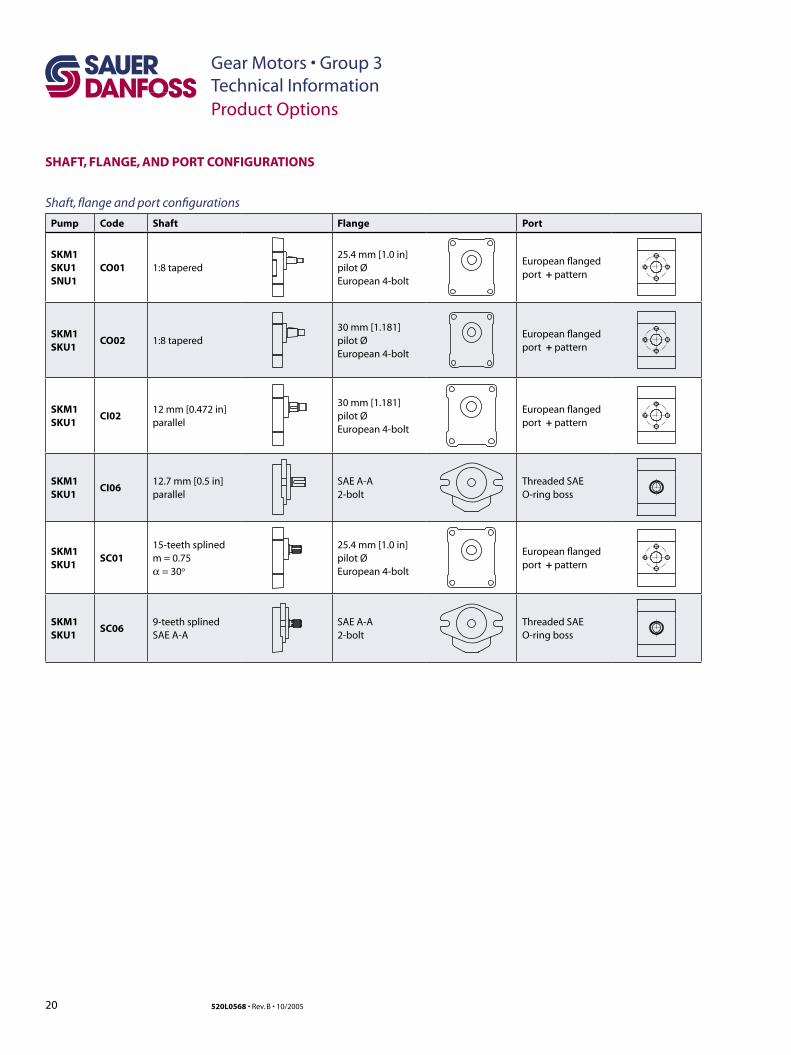
SHAFT, FLANGE, AND PORT CONFIGURATIONS
Pump Code Shaft Flange Port
SKM1SKU1SNU1
CO01 1:8 tapered25.4 mm [1.0 in] pilot Ø European 4-bolt
European flanged port + pattern
SKM1SKU1
CO02 1:8 tapered30 mm [1.181] pilot Ø European 4-bolt
European flanged port + pattern
SKM1SKU1
CI0212 mm [0.472 in] parallel
30 mm [1.181] pilot Ø European 4-bolt
European flanged port + pattern
SKM1SKU1
CI0612.7 mm [0.5 in] parallel
SAE A-A 2-bolt
Threaded SAEO-ring boss
SKM1SKU1
SC0115-teeth splined m = 0.75α = 30o
25.4 mm [1.0 in] pilot Ø European 4-bolt
European flanged port + pattern
SKM1SKU1
SC069-teeth splined SAE A-A
SAE A-A 2-bolt
Threaded SAEO-ring boss
Shaft, flange and port configurations
21
Gear Motors • Group 3Technical Information
520L0568 • Rev. B • 10/2005
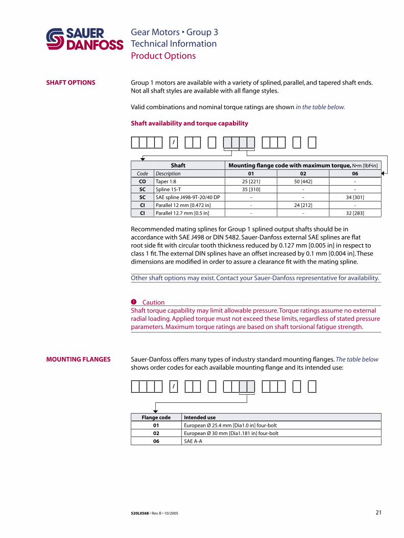
SHAFT OPTIONS
Product Options
MOUNTING FLANGES
Group 1 motors are available with a variety of splined, parallel, and tapered shaft ends. Not all shaft styles are available with all flange styles.
Valid combinations and nominal torque ratings are shown in the table below.
Shaft availability and torque capability
/
Shaft Mounting flange code with maximum torque, N•m [lbf•in]
Code Description 01 02 06
CO Taper 1:8 25 [221] 50 [442] -
SC Spline 15-T 35 [310] - -
SC SAE spline J498-9T-20/40 DP - - 34 [301]
CI Parallel 12 mm [0.472 in] - 24 [212] -
CI Parallel 12.7 mm [0.5 in] - - 32 [283]
Recommended mating splines for Group 1 splined output shafts should be in accordance with SAE J498 or DIN 5482. Sauer-Danfoss external SAE splines are flat root side fit with circular tooth thickness reduced by 0.127 mm [0.005 in] in respect to class 1 fit. The external DIN splines have an offset increased by 0.1 mm [0.004 in]. These dimensions are modified in order to assure a clearance fit with the mating spline.
Other shaft options may exist. Contact your Sauer-Danfoss representative for availability.
C CautionShaft torque capability may limit allowable pressure. Torque ratings assume no external radial loading. Applied torque must not exceed these limits, regardless of stated pressure parameters. Maximum torque ratings are based on shaft torsional fatigue strength.
Sauer-Danfoss offers many types of industry standard mounting flanges. The table below shows order codes for each available mounting flange and its intended use:
/
Flange code Intended use
01 European Ø 25.4 mm [Dia1.0 in] four-bolt
02 European Ø 30 mm [Dia1.181 in] four-bolt
06 SAE A-A
22
Gear Motors • Group 3Technical Information
520L0568 • Rev. B • 10/2005
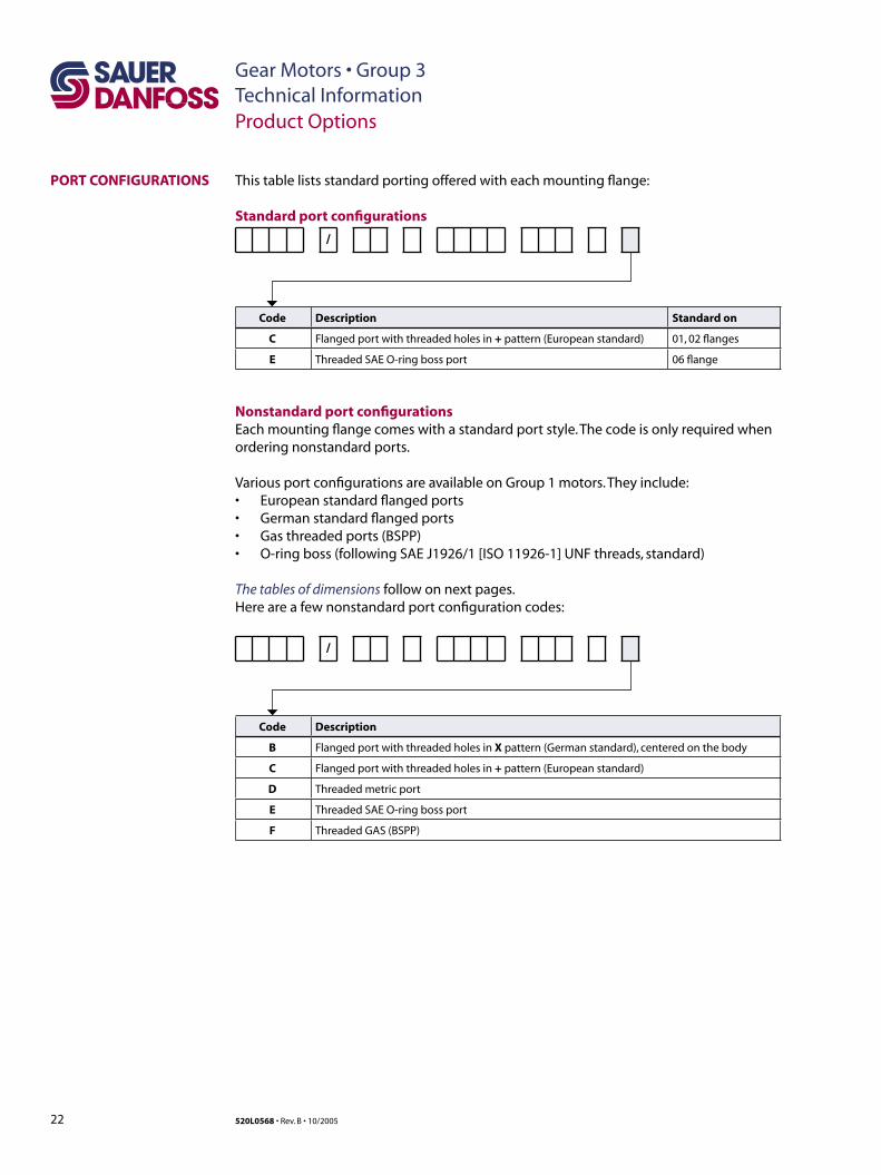
This table lists standard porting offered with each mounting flange:
Standard port configurations
/
Code Description Standard on
C Flanged port with threaded holes in + pattern (European standard) 01, 02 flanges
E Threaded SAE O-ring boss port 06 flange
Nonstandard port configurationsEach mounting flange comes with a standard port style. The code is only required when ordering nonstandard ports.
Various port configurations are available on Group 1 motors. They include:• European standard flanged ports• German standard flanged ports• Gas threaded ports (BSPP)• O-ring boss (following SAE J1926/1 [ISO 11926-1] UNF threads, standard)
The tables of dimensions follow on next pages. Here are a few nonstandard port configuration codes:
/
Code Description
B Flanged port with threaded holes in X pattern (German standard), centered on the body
C Flanged port with threaded holes in + pattern (European standard)
D Threaded metric port
E Threaded SAE O-ring boss port
F Threaded GAS (BSPP)
PORT CONFIGURATIONS
Product Options
23
Gear Motors • Group 3Technical Information
520L0568 • Rev. B • 10/2005
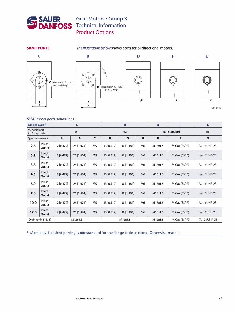
SKM1 PORTS
SKM1 motor ports dimensions
Model code* C B D F E
Standard portfor flange code
01 02 nonstandard 06
Type (displacement) B A C F G H E E D
2.6Inlet/Outlet
12 [0.472] 26 [1.024] M5 13 [0.512] 30 [1.181] M6 M18x1.5 3/8 Gas (BSPP) 3/4 -16UNF-2B
3.2Inlet/Outlet
12 [0.472] 26 [1.024] M5 13 [0.512] 30 [1.181] M6 M18x1.5 3/8 Gas (BSPP) 3/4 -16UNF-2B
3.8Inlet/Outlet
12 [0.472] 26 [1.024] M5 13 [0.512] 30 [1.181] M6 M18x1.5 3/8 Gas (BSPP) 3/4 -16UNF-2B
4.3Inlet/Outlet
12 [0.472] 26 [1.024] M5 13 [0.512] 30 [1.181] M6 M18x1.5 3/8 Gas (BSPP) 3/4 -16UNF-2B
6.0Inlet/Outlet
12 [0.472] 26 [1.024] M5 13 [0.512] 30 [1.181] M6 M18x1.5 3/8 Gas (BSPP) 3/4 -16UNF-2B
7.8Inlet/Outlet
12 [0.472] 26 [1.024] M5 13 [0.512] 30 [1.181] M6 M18x1.5 3/8 Gas (BSPP) 3/4 -16UNF-2B
10.0Inlet/Outlet
12 [0.472] 26 [1.024] M5 13 [0.512] 30 [1.181] M6 M18x1.5 3/8 Gas (BSPP) 3/4 -16UNF-2B
12.0Inlet/Outlet
12 [0.472] 26 [1.024] M5 13 [0.512] 30 [1.181] M6 M18x1.5 3/8 Gas (BSPP) 3/4 -16UNF-2B
Drain (only SKM1) M12x1.5 M12x1.5 M12x1.5 1/8 Gas (BSPP) 7/16 -20UNF-2B
The illustration below shows ports for bi-directional motors.
B
C B D F E
C
A
(4 holes min. full thd.10 [0.394] deep)
F
H
E
G
45o
(4 holes min. full thd.10 [0.394] deep)
E D
P005 049E
Product Options
* Mark only if desired porting is nonstandard for the flange code selected. Otherwise, mark ‘.‘
24
Gear Motors • Group 3Technical Information
520L0568 • Rev. B • 10/2005
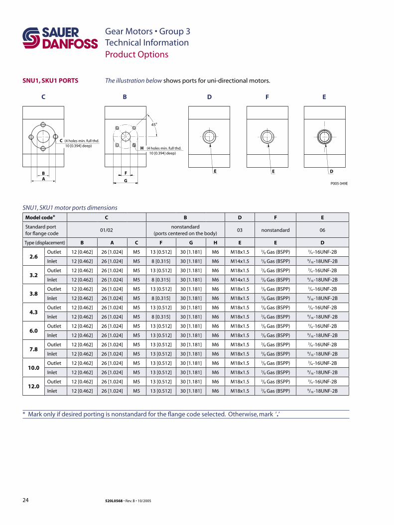
* Mark only if desired porting is nonstandard for the flange code selected. Otherwise, mark ‘.’
SNU1, SKU1 PORTS
Product Options
B
C B D F E
C
A
(4 holes min. full thd.10 [0.394] deep)
F
H
E
G
45o
(4 holes min. full thd.10 [0.394] deep)
E D
P005 049E
SNU1, SKU1 motor ports dimensions
Model code* C B D F E
Standard portfor flange code
01/02nonstandard
(ports centered on the body)03 nonstandard 06
Type (displacement) B A C F G H E E D
2.6Outlet 12 [0.462] 26 [1.024] M5 13 [0.512] 30 [1.181] M6 M18x1.5 3/8 Gas (BSPP) 3/4 -16UNF-2B
Inlet 12 [0.462] 26 [1.024] M5 8 [0.315] 30 [1.181] M6 M14x1.5 3/8 Gas (BSPP) 9/16 -18UNF-2B
3.2Outlet 12 [0.462] 26 [1.024] M5 13 [0.512] 30 [1.181] M6 M18x1.5 3/8 Gas (BSPP) 3/4 -16UNF-2B
Inlet 12 [0.462] 26 [1.024] M5 8 [0.315] 30 [1.181] M6 M14x1.5 3/8 Gas (BSPP) 9/16 -18UNF-2B
3.8Outlet 12 [0.462] 26 [1.024] M5 13 [0.512] 30 [1.181] M6 M18x1.5 3/8 Gas (BSPP) 3/4 -16UNF-2B
Inlet 12 [0.462] 26 [1.024] M5 8 [0.315] 30 [1.181] M6 M18x1.5 3/8 Gas (BSPP) 9/16 -18UNF-2B
4.3Outlet 12 [0.462] 26 [1.024] M5 13 [0.512] 30 [1.181] M6 M18x1.5 3/8 Gas (BSPP) 3/4 -16UNF-2B
Inlet 12 [0.462] 26 [1.024] M5 8 [0.315] 30 [1.181] M6 M18x1.5 3/8 Gas (BSPP) 9/16 -18UNF-2B
6.0Outlet 12 [0.462] 26 [1.024] M5 13 [0.512] 30 [1.181] M6 M18x1.5 3/8 Gas (BSPP) 3/4 -16UNF-2B
Inlet 12 [0.462] 26 [1.024] M5 13 [0.512] 30 [1.181] M6 M18x1.5 3/8 Gas (BSPP) 9/16 -18UNF-2B
7.8Outlet 12 [0.462] 26 [1.024] M5 13 [0.512] 30 [1.181] M6 M18x1.5 3/8 Gas (BSPP) 3/4 -16UNF-2B
Inlet 12 [0.462] 26 [1.024] M5 13 [0.512] 30 [1.181] M6 M18x1.5 3/8 Gas (BSPP) 9/16 -18UNF-2B
10.0Outlet 12 [0.462] 26 [1.024] M5 13 [0.512] 30 [1.181] M6 M18x1.5 3/8 Gas (BSPP) 3/4 -16UNF-2B
Inlet 12 [0.462] 26 [1.024] M5 13 [0.512] 30 [1.181] M6 M18x1.5 3/8 Gas (BSPP) 9/16 -18UNF-2B
12.0Outlet 12 [0.462] 26 [1.024] M5 13 [0.512] 30 [1.181] M6 M18x1.5 3/8 Gas (BSPP) 3/4 -16UNF-2B
Inlet 12 [0.462] 26 [1.024] M5 13 [0.512] 30 [1.181] M6 M18x1.5 3/8 Gas (BSPP) 9/16 -18UNF-2B
The illustration below shows ports for uni-directional motors.
25
Gear Motors • Group 3Technical Information
520L0568 • Rev. B • 10/2005
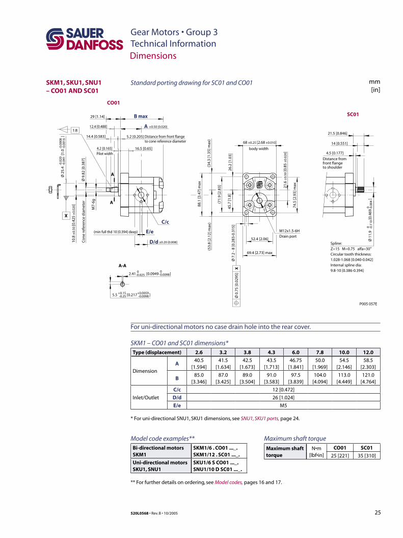
SKM1, SKU1, SNU1 – CO01 AND SC01
Dimensions
SKM1 – CO01 and SC01 dimensions*Type (displacement) 2.6 3.2 3.8 4.3 6.0 7.8 10.0 12.0
Dimension
A40.5
[1.594]41.5
[1.634]42.5
[1.673]43.5
[1.713]46.75
[1.841]50.0
[1.969]54.5
[2.146]58.5
[2.303]
B85.0
[3.346]87.0
[3.425]89.0
[3.504]91.0
[3.583]97.5
[3.839]104.0
[4.094]113.0
[4.449]121.0
[4.764]
Inlet/Outlet
C/c 12 [0.472]
D/d 26 [1.024]
E/e M5
* For uni-directional SNU1, SKU1 dimensions, see SNU1, SKU1 ports, page 24.
CO01
SC01
1:8
Co
ne
refe
ren
ce d
iam
eter
to cone reference diameterDistance from front flange
29 [1.14]
M7-
6g
14.4 [0.583] 5.2 [0.205]
12.4 [0.488]
X
Pilot width
-0.0
41-0
.020
16.5 [0.65]4.2 [0.165]
XØ
0.7
5 [0
.029
5]
body width
69.4 [2.73] max
52.4 [2.06]
88.1
[3.4
7] m
ax
74.5
[2.9
3] m
ax
(53.
8 [2
.12]
max
)(3
4.3
[1.3
5] m
ax)
(71.
9 [2
.83]
26.2
[1.0
3]45
.7 [1
.8]
68 ±0.25 [2.68 ±0.010]
21.6
±0.
50 [0
.85
±0.
020 ]
5.5 [0.217 ]+0.15-0.25
+0.0059-0.0098
-0.00982.41 [0.0949 ] 0-0.025
0
D/d
E/e
C/c
Spline:Z=15 M=0.75 alfa=30°Circular tooth thickness: 1.028-1.068 [0.040-0.042] Internal spline dia: 9.8-10 [0.386-0.394]
to shoulderfront flangeDistance from
4.5 [0.177]
14 [0.551]
21.5 [0.846]
(min full thd 10 [0.394] deep)
±0.50 [0.020]
±0.20 [0.008]
P005 057E
B max
A
A
A
A-A
Ø 2
5.4
[1.0
]
Ø 9
.82
[0.3
87]
10.8
±0.
50 [0
.425
±0.
020]
Ø 1
1.9
[0.4
69
]
Ø 7
.2 -
8 [0
.283
-0.3
15]
0 -0.1
100 -0
.004
-0.0
016
-0.0
008
M12x1.5-6HDrain port
mm[in]
Standard porting drawing for SC01 and CO01
Model code examples**Bi-directional motorsSKM1
SKM1/6 . CO01 ..._.SKM1/12 . SC01 ..._.
Uni-directional motorsSKU1, SNU1
SKU1/6 S CO01 ..._.SNU1/10 D SC01 ..._.
** For further details on ordering, see Model codes, pages 16 and 17.
Maximum shaft torque
Maximum shaft torque
N•m [lbf•in]
CO01 SC01
25 [221] 35 [310]
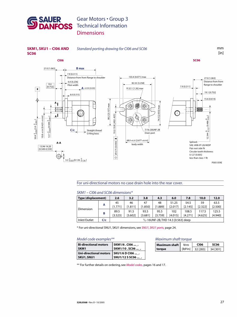
For uni-directional motors no case drain hole into the rear cover.
26
Gear Motors • Group 3Technical Information
520L0568 • Rev. B • 10/2005
mm[in]
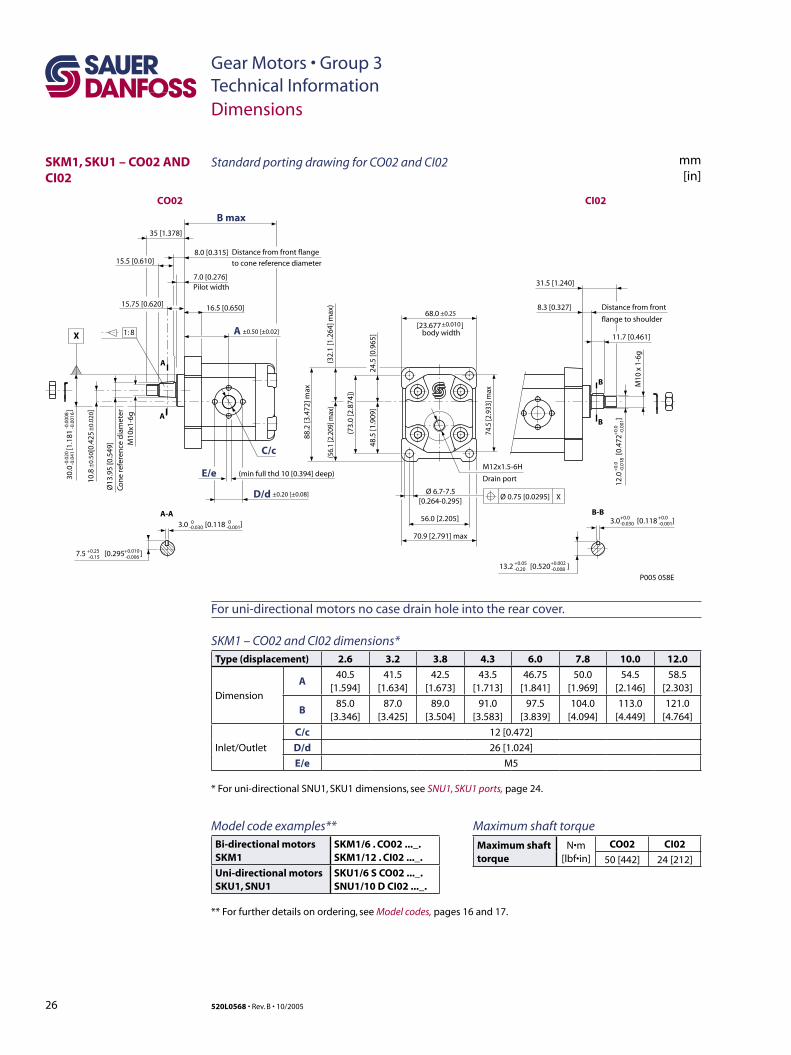
SKM1, SKU1 – CO02 AND CI02
Dimensions
For uni-directional motors no case drain hole into the rear cover.
SKM1 – CO02 and CI02 dimensions*Type (displacement) 2.6 3.2 3.8 4.3 6.0 7.8 10.0 12.0
Dimension
A40.5
[1.594]41.5
[1.634]42.5
[1.673]43.5
[1.713]46.75
[1.841]50.0
[1.969]54.5
[2.146]58.5
[2.303]
B85.0
[3.346]87.0
[3.425]89.0
[3.504]91.0
[3.583]97.5
[3.839]104.0
[4.094]113.0
[4.449]121.0
[4.764]
Inlet/Outlet
C/c 12 [0.472]
D/d 26 [1.024]
E/e M5
* For uni-directional SNU1, SKU1 dimensions, see SNU1, SKU1 ports, page 24.
12.0
[0
.472
]
+0.
0
+0.
0-0
.018
-0
.001
M10
x 1
-6g
11.7 [0.461]
8.3 [0.327] Distance from front
flange to shoulder
31.5 [1.240]
3.0 [0.118 ]+0.0 +0.0-0.030 -0.001
13.2 [0.520 ]+0.05 +0.002-0.20 -0.008
88.2
[3.4
72] m
ax
7.5 [0.295 ]+0.25 +0.010-0.15 -0.006
3.0 [0.118 ]0 0-0.030 -0.001
C/c
D/d
E/e
A
A
A
A-A
16.5 [0.650]
7.0 [0.276]Pilot width
8.0 [0.315] Distance from front flange
to cone reference diameter
B max
M10
x1-6
g
Ø13
.95
[0.5
49]
Con
e re
fere
nce
dia
met
er
10.8
[0
.425
30.0
[1
.181
]
-0.0
20
-
0.00
08-0
.041
-0.
0016
68.0
[23.677 ]body width
74.5
[2.9
33] m
ax
56.0 [2.205]
70.9 [2.791] max
24.5
[0.9
65]
48.5
[1.9
09]
(73.
0 [2
.874
])
(32.
1 [1
.264
] max
)(5
6.1
[2.2
09] m
ax)
Ø 6.7-7.5[0.264-0.295]
1: 8
35 [1.378]
15.75 [0.620]
15.5 [0.610]
P005 058E
±0.25
±0.20 [±0.08]
±0.
50
±0.
020]
±0.50 [±0.02]±0.010
CO02 CI02
(min full thd 10 [0.394] deep)
XØ 0.75 [0.0295]
M12x1.5-6H
Drain port
B
B
B-B
X
Standard porting drawing for CO02 and CI02
Maximum shaft torque
Maximum shaft torque
N•m [lbf•in]
CO02 CI02
50 [442] 24 [212]
Model code examples**Bi-directional motorsSKM1
SKM1/6 . CO02 ..._.SKM1/12 . CI02 ..._.
Uni-directional motorsSKU1, SNU1
SKU1/6 S CO02 ..._.SNU1/10 D CI02 ..._.
** For further details on ordering, see Model codes, pages 16 and 17.
27
Gear Motors • Group 3Technical Information
520L0568 • Rev. B • 10/2005
SKM1, SKU1 – CI06 AND SC06
Dimensions
For uni-directional motors no case drain hole into the rear cover.
SKM1 – CI06 and SC06 dimensions*Type (displacement) 2.6 3.2 3.8 4.3 6.0 7.8 10.0 12.0
Dimension
A45
[1.771]46
[1.811]47
[1.850]48
[1.889]51.25
[2.017]54.5
[2.145]59
[2.322]63.5
[2.500]
B89.5
[3.523]91.5
[3.602]93.5
[3.681]95.5
[3.759]102
[4.015]108.5
[4.271]117.5
[4.625]125.5
[4.940]
Inlet/Outlet C/c 3/4 -16UNF-2B, THD 14.3 [0.563] deep
* For uni-directional SNU1, SKU1 dimensions, see SNU1, SKU1 ports, page 24.
12.3
44
[0
.486
]
0
0 0
0 -0.0
5
Splined: SAE J498-9T-20/40DPFlat root side fitCircular tooth thickness:0.127 [0.005]less than class 1 fit
15.6 [0.614]
19.1 [0.752]
7.9 [0.311]
27.0 [1.063]
74.5
[2.9
33] m
ax
body width
R 32.1 [1.26] max
82.55 [3.258]
103.4 [4.071] max
80.2
[3.1
57] m
ax
X10
.2-1
0.8
[.402
-.425
]Ø
0.7
5 [0
.030
]
3.2 [0.126 ]-0.025 -0.126
13.94-14.20[0.549-0.559]
Straight thread O-Ring boss
8.0 [0.315]
6.0 [0.236]
Pilot width
7.9 [0.311]
Distance from front flange to shoulder
Distance from front flange to shoulder19.1
[0.752]
27.0 [1.063]
12.7
[
0.50
0
]-0
.025
-0
.001
10.8
±0.
50 [0
.425
±0.
020]
68.0 ±0.25 [2.677 ±0.010]
50.8
[
2.0
]
00
-0.0
50
-0.0
02
P005 059E
CI06 SC06
C/c
±0.50 [0.020]
B max
A
A
A
A-A
-0.1
27
00
7/16-20UNF-2BDrain port
X
mm[in]
Standard porting drawing for CI06 and SC06
Maximum shaft torque
Maximum shaft torque
N•m [lbf•in]
CI06 SC06
32 [283] 34 [301]
Model code examples**Bi-directional motorsSKM1
SKM1/6 . CI06 ..._.SKM1/10 . SC06 ..._.
Uni-directional motorsSKU1, SNU1
SKU1/6 D CI06 ..._.SNU1/12 S SC06 ..._.
** For further details on ordering, see Model codes, pages 16 and 17.
28 520L0568 • Rev. B • 10/2005
Gear Motors • Group 2Technical InformationGeneral Information
F005 214
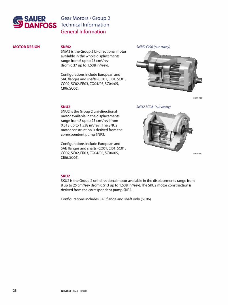
SNM2 CI96 (cut-away)MOTOR DESIGN SNM2SNM2 is the Group 2 bi-directional motor available in the whole displacements range from 6 up to 25 cm3/rev [from 0.37 up to 1.538 in3/rev].
Configurations include European and SAE flanges and shafts (CO01, CI01, SC01, CO02, SC02, FR03, CO04/05, SC04/05, CI06, SC06).
SNU2SNU2 is the Group 2 uni-directional motor available in the displacements range from 8 up to 25 cm3/rev [from 0.513 up to 1.538 in3/rev]. The SNU2 motor construction is derived from the correspondent pump SNP2.
Configurations include European and SAE flanges and shafts (CO01, CI01, SC01, CO02, SC02, FR03, CO04/05, SC04/05, CI06, SC06).
SNU2 SC06 (cut away)
F005 030
SKU2SKU2 is the Group 2 uni-directional motor available in the displacements range from 8 up to 25 cm3/rev [from 0.513 up to 1.538 in3/rev]. The SKU2 motor construction is derived from the correspondent pump SKP2.
Configurations includes SAE flange and shaft only (SC06).
29520L0568 • Rev. B • 10/2005
Gear Motors • Group 2Technical Information
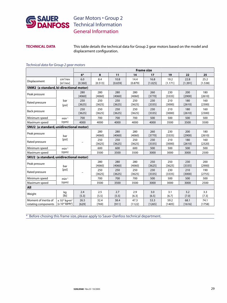
TECHNICAL DATA
General Information
This table details the technical data for Group 2 gear motors based on the model and displacement configuration.
Technical data for Group 2 gear motors
Frame size6* 8 11 14 17 19 22 25
Displacementcm3/rev[in3/rev]
6.0[0.360]
8.4[0.513]
10.8[0.659]
14.4[0.879]
16.8[1.025]
19.2[1.171]
22.8[1.391]
25.2[1.538]
SNM2 (a standard, bi-directional motor)
Peak pressure
bar
[psi]
280[4060]
280[4060]
280[4060]
280[4060]
260[3770]
230[3335]
200[2900]
180[2610]
Rated pressure250
[3625]250
[3625]250
[3625]250
[3625]230
[3335]210
[3000]180
[2610]160
[2300]
Back pressure250
[3625]250
[3625]250
[3625]250
[3625]230
[3335]210
[3000]180
[2610]160
[2300]
Minimum speed min-1
(rpm)700 700 700 700 500 500 500 500
Maximum speed 4000 4000 4000 4000 4000 3500 3500 3500
SNU2 (a standard, unidirectional motor)
Peak pressurebar[psi]
–
280[4060]
280[4060]
280[4060]
260[3770]
230[3335]
200[2900]
180[2610]
Rated pressure250
[3625]250
[3625]250
[3625]230
[3335]210
[3000]180
[2610]160
[2320]
Minimum speed min-1
(rpm)600 600 600 500 500 500 500
Maximum speed 3500 3500 3500 3000 3000 3000 2500
SKU2 (a standard, unidirectional motor)
Peak pressurebar[psi]
–
280[4060]
280[4060]
280[4060]
250[3625]
250[3625]
230[3335]
200[2900]
Rated pressure250
[3625]250
[3625]250
[3625]230
[3335]230
[3335]210
[3000]190
[2755]
Minimum speed min-1
(rpm)700 700 700 500 500 500 500
Maximum speed 3500 3500 3500 3000 3000 3000 2500
All
Weightkg[lb]
2.4[5.3]
2.5[5.5]
2.7[5.5]
2.9[6.3]
3.0[6.5]
3.1[6.7]
3.2[7.0]
3.3[7.3]
Moment of inertia ofrotating components
x 10-6 kg•m2
[x 10-6 lbf•ft2]26.5[629]
32.4[769]
38.4[911]
47.3[1122]
53.3[1265]
59.2[1405]
68.1[1616]
74.1[1758]
* Before chosing this frame size, please apply to Sauer-Danfoss technical department.
30 520L0568 • Rev. B • 10/2005
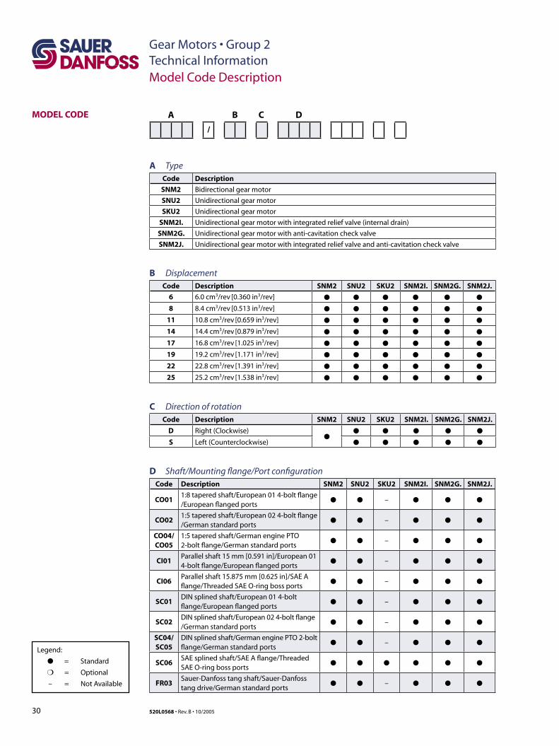
Gear Motors • Group 2Technical InformationModel Code Description
MODEL CODE A B C D
/
A TypeCode Description
SNM2 Bidirectional gear motor
SNU2 Unidirectional gear motor
SKU2 Unidirectional gear motor
SNM2I. Unidirectional gear motor with integrated relief valve (internal drain)
SNM2G. Unidirectional gear motor with anti-cavitation check valve
SNM2J. Unidirectional gear motor with integrated relief valve and anti-cavitation check valve
B DisplacementCode Description SNM2 SNU2 SKU2 SNM2I. SNM2G. SNM2J.
6 6.0 cm3/rev [0.360 in3/rev] ● ● ● ● ● ●
8 8.4 cm3/rev [0.513 in3/rev] ● ● ● ● ● ●
11 10.8 cm3/rev [0.659 in3/rev] ● ● ● ● ● ●
14 14.4 cm3/rev [0.879 in3/rev] ● ● ● ● ● ●
17 16.8 cm3/rev [1.025 in3/rev] ● ● ● ● ● ●
19 19.2 cm3/rev [1.171 in3/rev] ● ● ● ● ● ●
22 22.8 cm3/rev [1.391 in3/rev] ● ● ● ● ● ●
25 25.2 cm3/rev [1.538 in3/rev] ● ● ● ● ● ●
C Direction of rotationCode Description SNM2 SNU2 SKU2 SNM2I. SNM2G. SNM2J.
D Right (Clockwise)●
● ● ● ● ●
S Left (Counterclockwise) ● ● ● ● ●
D Shaft/Mounting flange/Port configurationCode Description SNM2 SNU2 SKU2 SNM2I. SNM2G. SNM2J.
CO011:8 tapered shaft/European 01 4-bolt flange /European flanged ports
● ● – ● ● ●
CO021:5 tapered shaft/European 02 4-bolt flange /German standard ports
● ● – ● ● ●
CO04/CO05
1:5 tapered shaft/German engine PTO 2-bolt flange/German standard ports
● ● – ● ● ●
CI01Parallel shaft 15 mm [0.591 in]/European 01 4-bolt flange/European flanged ports
● ● – ● ● ●
CI06Parallel shaft 15.875 mm [0.625 in]/SAE A flange/Threaded SAE O-ring boss ports
● ● – ● ● ●
SC01DIN splined shaft/European 01 4-bolt flange/European flanged ports
● ● – ● ● ●
SC02DIN splined shaft/European 02 4-bolt flange /German standard ports
● ● – ● ● ●
SC04/SC05
DIN splined shaft/German engine PTO 2-bolt flange/German standard ports
● ● – ● ● ●
SC06SAE splined shaft/SAE A flange/Threaded SAE O-ring boss ports
● ● ● ● ● ●
FR03Sauer-Danfoss tang shaft/Sauer-Danfoss tang drive/German standard ports
● ● – ● ● ●
Legend:
● = Standard
❍ = Optional
– = Not Available
31520L0568 • Rev. B • 10/2005
Gear Motors • Group 2Technical InformationModel Code Description
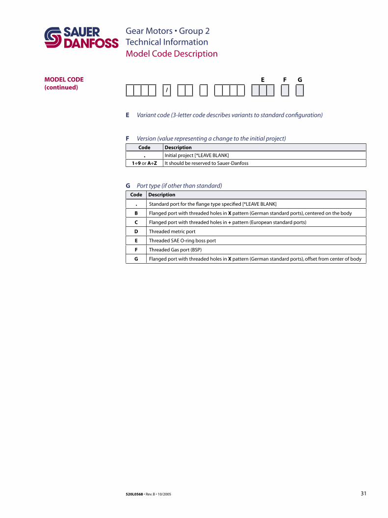
MODEL CODE (continued)
E F G
/
E Variant code (3-letter code describes variants to standard configuration)
F Version (value representing a change to the initial project)Code Description
. Initial project [*LEAVE BLANK]
1÷9 or A÷Z It should be reserved to Sauer-Danfoss
G Port type (if other than standard)Code Description
. Standard port for the flange type specified [*LEAVE BLANK]
B Flanged port with threaded holes in X pattern (German standard ports), centered on the body
C Flanged port with threaded holes in + pattern (European standard ports)
D Threaded metric port
E Threaded SAE O-ring boss port
F Threaded Gas port (BSP)
G Flanged port with threaded holes in X pattern (German standard ports), offset from center of body
32 520L0568 • Rev. B • 10/2005
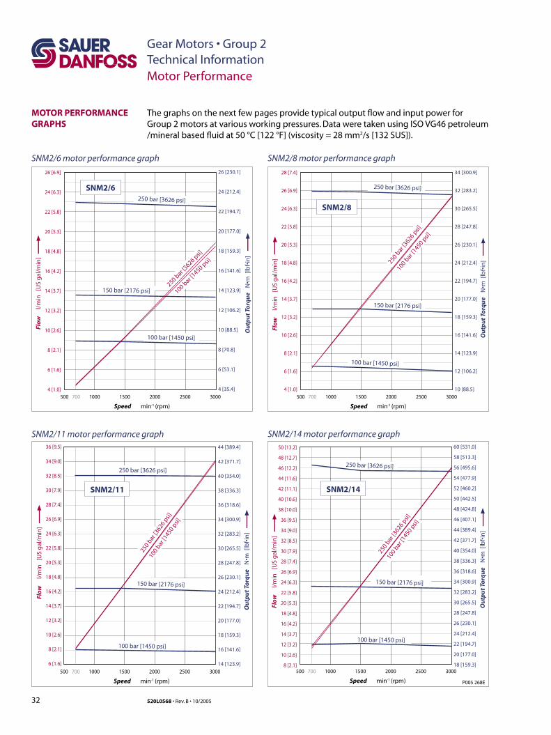
Gear Motors • Group 2Technical InformationMotor Performance
The graphs on the next few pages provide typical output flow and input power for Group 2 motors at various working pressures. Data were taken using ISO VG46 petroleum /mineral based fluid at 50 °C [122 °F] (viscosity = 28 mm2/s [132 SUS]).
MOTOR PERFORMANCE GRAPHS
SNM2/6 motor performance graph SNM2/8 motor performance graph
26 [6.9]
24 [6.3]
22 [5.8]
20 [5.3]
18 [4.8]
16 [4.2]
14 [3.7]
12 [3.2]
10 [2.6]
8 [2.1]
6 [1.6]
4 [1.0]
500 700
50 [13.2]
48 [12.7]
46 [12.2]
44 [11.6]
42 [11.1]
40 [10.6]
38 [10.0]
36 [9.5]
34 [9.0]
32 [8.5]
30 [7.9]
28 [7.4]
26 [6.9]
24 [6.3]
22 [5.8]
20 [5.3]
18 [4.8]
16 [4.2]
14 [3.7]
12 [3.2]
10 [2.6]
8 [2.1]
Speed min -1 (rpm)
Flow
l
/min
[U
S g
al/m
in]
2000 25001000 1500 3000
SNM2/14
100
bar [1
450
psi]
250 bar [3626 psi]
150 bar [2176 psi]
100 bar [1450 psi]
250
bar [3
626
psi]
500 700
36 [9.5]
34 [9.0]
32 [8.5]
30 [7.9]
28 [7.4]
26 [6.9]
24 [6.3]
22 [5.8]
20 [5.3]
18 [4.8]
16 [4.2]
14 [3.7]
12 [3.2]
10 [2.6]
8 [2.1]
6 [1.6]
Speed min -1 (rpm)
Flow
l
/min
[U
S g
al/m
in]
2000 25001000 1500 3000
SNM2/11
100
bar [1
450
psi]
250 bar [3626 psi]
150 bar [2176 psi]
100 bar [1450 psi]
250
bar [3
626
psi]
500 700
Speed min -1 (rpm)
Flow
l
/min
[U
S g
al/m
in]
2000 25001000 1500 3000
28 [7.4]
26 [6.9]
24 [6.3]
22 [5.8]
20 [5.3]
18 [4.8]
16 [4.2]
14 [3.7]
12 [3.2]
10 [2.6]
8 [2.1]
6 [1.6]
4 [1.0]
SNM2/6250 bar [3626 psi]
100 bar [
1450 psi]
250 bar [
3626 psi]
150 bar [2176 psi]
100 bar [1450 psi]
500 700
Speed min -1 (rpm)
Flow
l
/min
[U
S g
al/m
in]
2000 25001000 1500 3000
SNM2/8
250 bar [3626 psi]
100 bar
[1450 p
si]
250 bar
[3626 p
si]
150 bar [2176 psi]
100 bar [1450 psi]
P005 268E
34 [300.9]
32 [283.2]
30 [265.5]
28 [247.8]
26 [230.1]
24 [212.4]
22 [194.7]
20 [177.0]
18 [159.3]
16 [141.6]
14 [123.9]
12 [106.2]
10 [88.5]
44 [389.4]
42 [371.7]
40 [354.0]
38 [336.3]
36 [318.6]
34 [300.9]
32 [283.2]
30 [265.5]
28 [247.8]
26 [230.1]
24 [212.4]
22 [194.7]
20 [177.0]
18 [159.3]
16 [141.6]
14 [123.9]
60 [531.0]
58 [513.3]
56 [495.6]
54 [477.9]
52 [460.2]
50 [442.5]
48 [424.8]
46 [407.1]
44 [389.4]
42 [371.7]
40 [354.0]
38 [336.3]
36 [318.6]
34 [300.9]
32 [283.2]
30 [265.5]
28 [247.8]
26 [230.1]
24 [212.4]
22 [194.7]
20 [177.0]
18 [159.3]
Ou
tpu
t To
rqu
e N
•m [
lbf•
in]
26 [230.1]
24 [212.4]
22 [194.7]
20 [177.0]
18 [159.3]
16 [141.6]
14 [123.9]
12 [106.2]
10 [88.5]
8 [70.8]
6 [53.1]
4 [35.4]
Ou
tpu
t To
rqu
e N
•m [
lbf•
in]
Ou
tpu
t To
rqu
e N
•m [
lbf•
in]
Ou
tpu
t To
rqu
e N
•m [
lbf•
in]
SNM2/11 motor performance graph SNM2/14 motor performance graph
33520L0568 • Rev. B • 10/2005
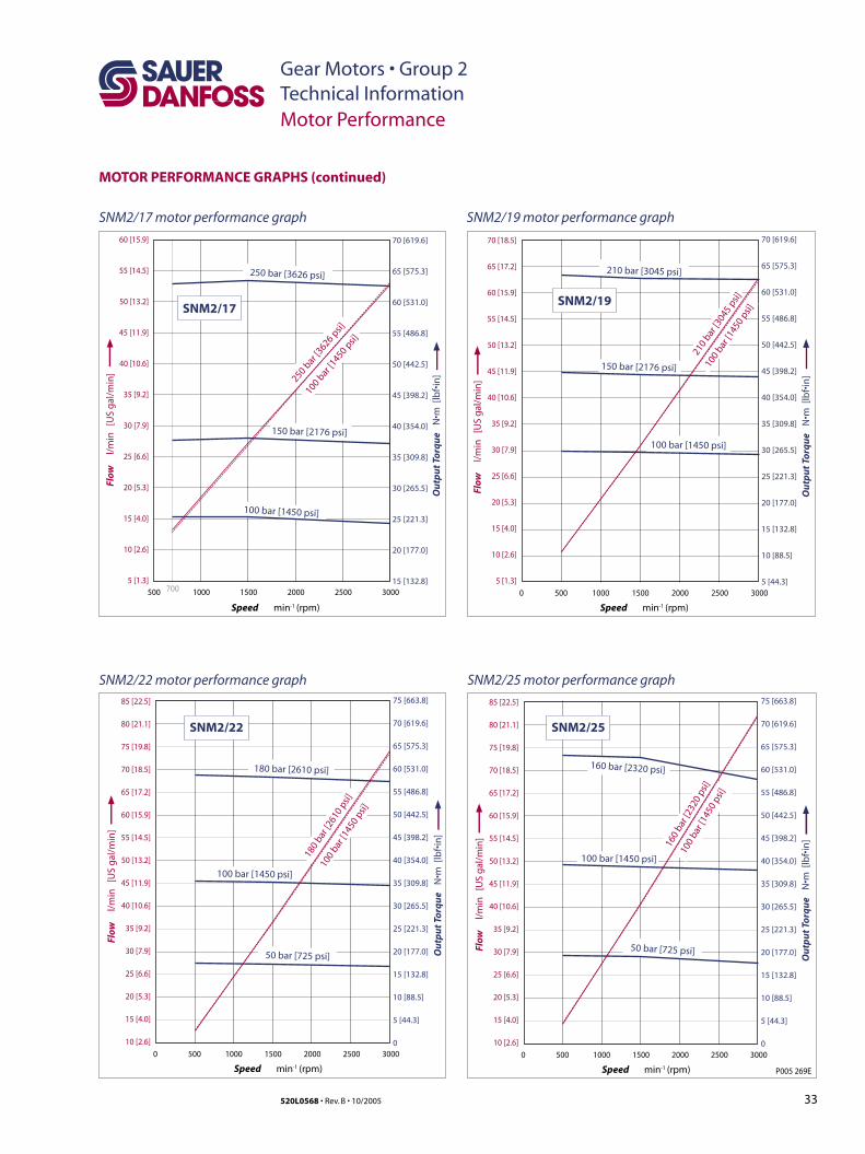
Gear Motors • Group 2Technical InformationMotor Performance
MOTOR PERFORMANCE GRAPHS (continued)
SNM2/17 motor performance graph
P005 269E
85 [22.5]
80 [21.1]
75 [19.8]
70 [18.5]
65 [17.2]
60 [15.9]
55 [14.5]
50 [13.2]
45 [11.9]
40 [10.6]
35 [9.2]
30 [7.9]
25 [6.6]
20 [5.3]
15 [4.0]
10 [2.6]
Speed min -1 (rpm)
Flow
l
/min
[U
S g
al/m
in]
2000 25005000 1000 1500 3000
SNM2/25
160 bar [2320 psi]
50 bar [725 psi]
100 bar [1450 psi]
100
bar [
1450
psi]
160
bar [
2320
psi]
85 [22.5]
80 [21.1]
75 [19.8]
70 [18.5]
65 [17.2]
60 [15.9]
55 [14.5]
50 [13.2]
45 [11.9]
40 [10.6]
35 [9.2]
30 [7.9]
25 [6.6]
20 [5.3]
15 [4.0]
10 [2.6]
Speed min -1 (rpm)
Flow
l
/min
[U
S g
al/m
in]
2000 25005000 1000 1500 3000
SNM2/22
180 bar [2610 psi]
50 bar [725 psi]
100 bar [1450 psi]
100
bar [1
450
psi]
180
bar [2
610
psi]
60 [15.9]
55 [14.5]
50 [13.2]
45 [11.9]
40 [10.6]
35 [9.2]
30 [7.9]
25 [6.6]
20 [5.3]
15 [4.0]
10 [2.6]
5 [1.3]
Speed min -1 (rpm)
Flow
l
/min
[U
S g
al/m
in]
2000 2500500 700 1000 1500 3000
SNM2/17
100 bar [1450 psi]
250 bar [3626 psi]
100 bar
[1450 p
si]
250 bar
[3626 p
si]
70 [18.5]
65 [17.2]
60 [15.9]
55 [14.5]
50 [13.2]
45 [11.9]
40 [10.6]
35 [9.2]
30 [7.9]
25 [6.6]
20 [5.3]
15 [4.0]
10 [2.6]
5 [1.3]
Speed min -1 (rpm)
Flow
l
/min
[U
S g
al/m
in]
2000 25005000 1000 1500 3000
SNM2/19
100 bar [1450 psi]
150 bar [2176 psi]
210 bar [3045 psi]
100
bar [1
450
psi]
210
bar [3
045
psi]
150 bar [2176 psi]
70 [619.6]
65 [575.3]
60 [531.0]
55 [486.8]
50 [442.5]
45 [398.2]
40 [354.0]
35 [309.8]
30 [265.5]
25 [221.3]
20 [177.0]
15 [132.8]
75 [663.8]
70 [619.6]
65 [575.3]
60 [531.0]
55 [486.8]
50 [442.5]
45 [398.2]
40 [354.0]
35 [309.8]
30 [265.5]
25 [221.3]
20 [177.0]
15 [132.8]
10 [88.5]
5 [44.3]
0
70 [619.6]
65 [575.3]
60 [531.0]
55 [486.8]
50 [442.5]
45 [398.2]
40 [354.0]
35 [309.8]
30 [265.5]
25 [221.3]
20 [177.0]
15 [132.8]
10 [88.5]
5 [44.3]
Ou
tpu
t To
rqu
e N
•m [
lbf•
in]
75 [663.8]
70 [619.6]
65 [575.3]
60 [531.0]
55 [486.8]
50 [442.5]
45 [398.2]
40 [354.0]
35 [309.8]
30 [265.5]
25 [221.3]
20 [177.0]
15 [132.8]
10 [88.5]
5 [44.3]
0
Ou
tpu
t To
rqu
e N
•m [
lbf•
in]
Ou
tpu
t To
rqu
e N
•m [
lbf•
in]
Ou
tpu
t To
rqu
e N
•m [
lbf•
in]
SNM2/25 motor performance graphSNM2/22 motor performance graph
SNM2/19 motor performance graph
34 520L0568 • Rev. B • 10/2005
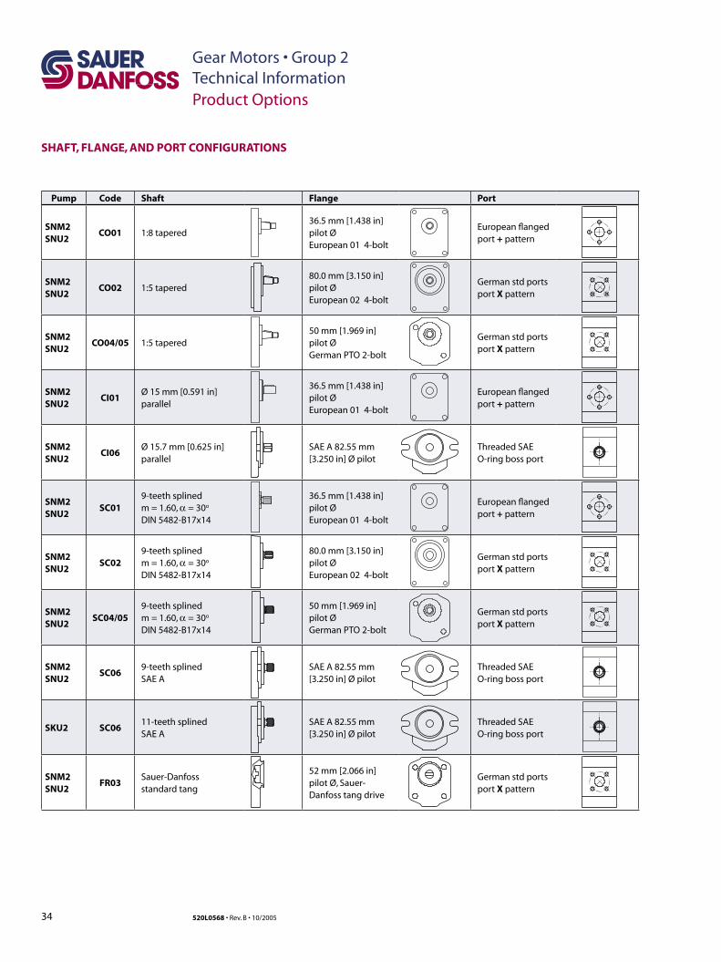
Gear Motors • Group 2Technical InformationProduct Options
SHAFT, FLANGE, AND PORT CONFIGURATIONS
Pump Code Shaft Flange Port
SNM2SNU2
CO01 1:8 tapered36.5 mm [1.438 in] pilot Ø European 01 4-bolt
European flanged port + pattern
SNM2SNU2
CO02 1:5 tapered80.0 mm [3.150 in] pilot Ø European 02 4-bolt
German std portsport X pattern
SNM2SNU2
CO04/05 1:5 tapered50 mm [1.969 in] pilot Ø German PTO 2-bolt
German std portsport X pattern
SNM2SNU2
CI01Ø 15 mm [0.591 in]parallel
36.5 mm [1.438 in] pilot Ø European 01 4-bolt
European flanged port + pattern
SNM2SNU2
CI06Ø 15.7 mm [0.625 in]parallel
SAE A 82.55 mm [3.250 in] Ø pilot
Threaded SAE O-ring boss port
SNM2SNU2
SC019-teeth splinedm = 1.60, α = 30o
DIN 5482-B17x14
36.5 mm [1.438 in] pilot Ø European 01 4-bolt
European flanged port + pattern
SNM2SNU2
SC029-teeth splinedm = 1.60, α = 30o
DIN 5482-B17x14
80.0 mm [3.150 in] pilot Ø European 02 4-bolt
German std portsport X pattern
SNM2SNU2
SC04/059-teeth splinedm = 1.60, α = 30o
DIN 5482-B17x14
50 mm [1.969 in] pilot Ø German PTO 2-bolt
German std portsport X pattern
SNM2SNU2
SC069-teeth splinedSAE A
SAE A 82.55 mm [3.250 in] Ø pilot
Threaded SAE O-ring boss port
SKU2 SC0611-teeth splinedSAE A
SAE A 82.55 mm [3.250 in] Ø pilot
Threaded SAE O-ring boss port
SNM2SNU2
FR03Sauer-Danfoss standard tang
52 mm [2.066 in] pilot Ø, Sauer-Danfoss tang drive
German std portsport X pattern
35520L0568 • Rev. B • 10/2005
Gear Motors • Group 2Technical InformationProduct Options
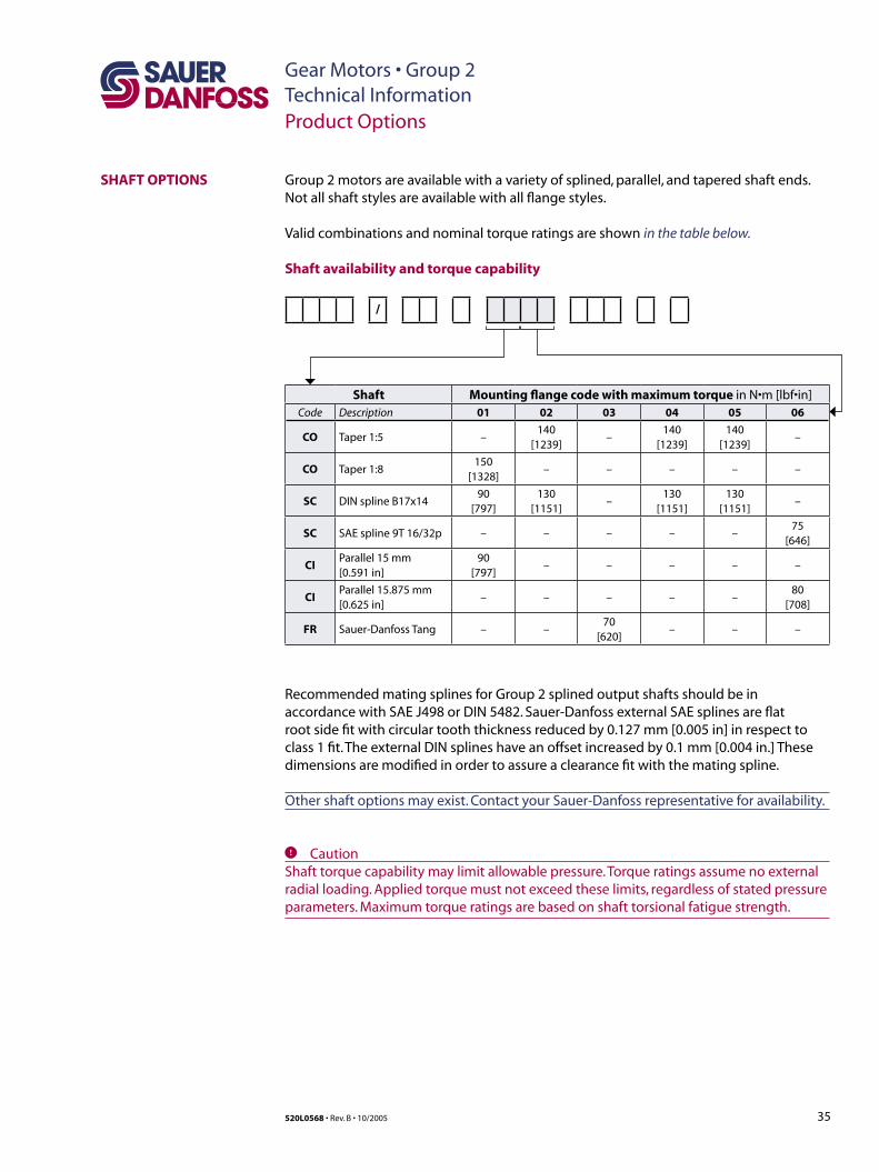
SHAFT OPTIONS
Shaft availability and torque capability
/
Group 2 motors are available with a variety of splined, parallel, and tapered shaft ends. Not all shaft styles are available with all flange styles.
Valid combinations and nominal torque ratings are shown in the table below.
Shaft Mounting flange code with maximum torque in N•m [lbf•in]Code Description 01 02 03 04 05 06
CO Taper 1:5 –140
[1239]–
140 [1239]
140 [1239]
–
CO Taper 1:8150
[1328]– – – – –
SC DIN spline B17x1490
[797]130
[1151]–
130[1151]
130 [1151]
–
SC SAE spline 9T 16/32p – – – – –75
[646]
CIParallel 15 mm [0.591 in]
90 [797]
– – – – –
CIParallel 15.875 mm [0.625 in]
– – – – –80
[708]
FR Sauer-Danfoss Tang – –70
[620]– – –
Recommended mating splines for Group 2 splined output shafts should be in accordance with SAE J498 or DIN 5482. Sauer-Danfoss external SAE splines are flat root side fit with circular tooth thickness reduced by 0.127 mm [0.005 in] in respect to class 1 fit. The external DIN splines have an offset increased by 0.1 mm [0.004 in.] These dimensions are modified in order to assure a clearance fit with the mating spline.
Other shaft options may exist. Contact your Sauer-Danfoss representative for availability.
C CautionShaft torque capability may limit allowable pressure. Torque ratings assume no external radial loading. Applied torque must not exceed these limits, regardless of stated pressure parameters. Maximum torque ratings are based on shaft torsional fatigue strength.
36 520L0568 • Rev. B • 10/2005
Gear Motors • Group 2Technical Information
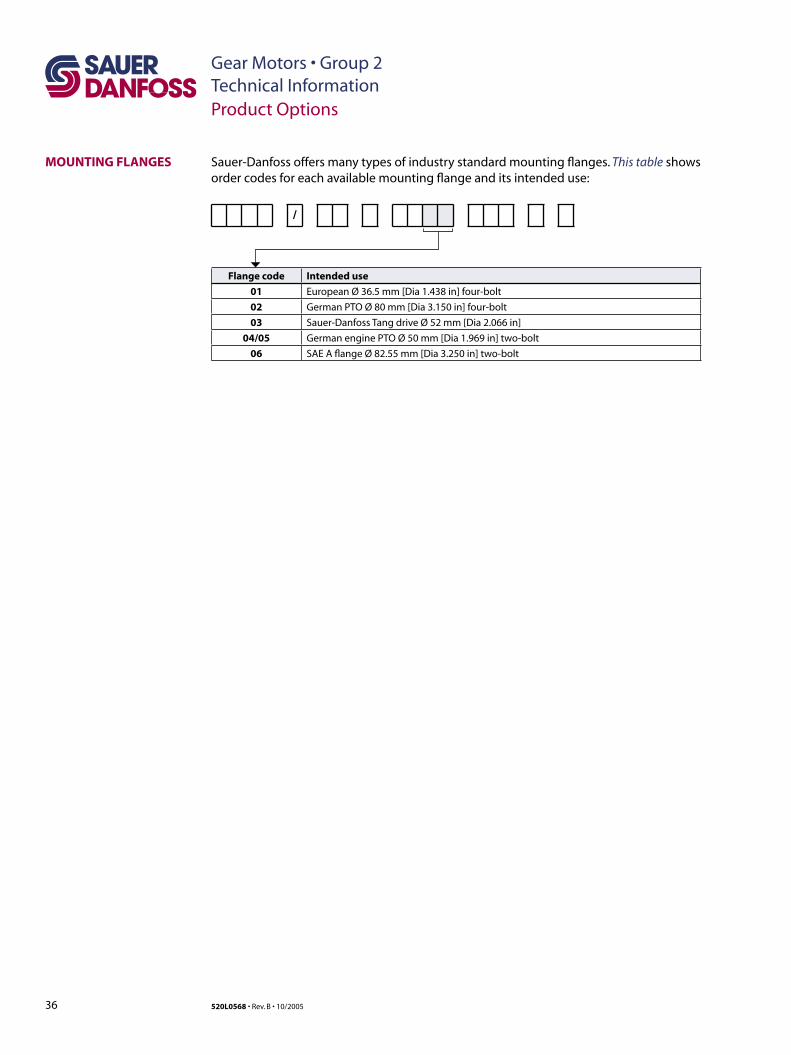
Sauer-Danfoss offers many types of industry standard mounting flanges. This table shows order codes for each available mounting flange and its intended use:
/
Flange code Intended use
01 European Ø 36.5 mm [Dia 1.438 in] four-bolt
02 German PTO Ø 80 mm [Dia 3.150 in] four-bolt
03 Sauer-Danfoss Tang drive Ø 52 mm [Dia 2.066 in]
04/05 German engine PTO Ø 50 mm [Dia 1.969 in] two-bolt
06 SAE A flange Ø 82.55 mm [Dia 3.250 in] two-bolt
MOUNTING FLANGES
Product Options
37520L0568 • Rev. B • 10/2005
Gear Motors • Group 2Technical Information
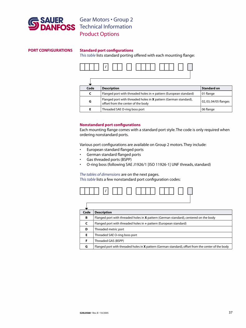
Standard port configurationsThis table lists standard porting offered with each mounting flange:
/
Code Description Standard on
C Flanged port with threaded holes in + pattern (European standard) 01 flange
GFlanged port with threaded holes in X pattern (German standard), offset from the center of the body
02, 03, 04/05 flanges
E Threaded SAE O-ring boss port 06 flange
Nonstandard port configurationsEach mounting flange comes with a standard port style. The code is only required when ordering nonstandard ports.
Various port configurations are available on Group 2 motors. They include:• European standard flanged ports• German standard flanged ports• Gas threaded ports (BSPP)• O-ring boss (following SAE J1926/1 [ISO 11926-1] UNF threads, standard)
The tables of dimensions are on the next pages. This table lists a few nonstandard port configuration codes:
/
Code Description
B Flanged port with threaded holes in X pattern (German standard), centered on the body
C Flanged port with threaded holes in + pattern (European standard)
D Threaded metric port
E Threaded SAE O-ring boss port
F Threaded GAS (BSPP)
G Flanged port with threaded holes in X pattern (German standard), offset from the center of the body
PORT CONFIGURATIONS
Product Options
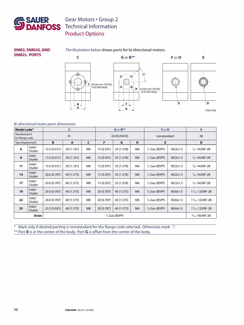
38 520L0568 • Rev. B • 10/2005
Gear Motors • Group 2Technical Information
SNM2, SNM2G. AND SNM2J. PORTS
B
C G or B** F or D E
C
A
(4 holes min. full thd.10 [0.394] deep)
F
H
G
45o
(4 holes min. full thd.10 [0.394] deep)
E D
P005 050E
Bi-directional motor ports dimensionsModel code* C G or B** F or D EStandard portfor flange code
01 02/03/04/05 nonstandard 06
Type (displacement) B A C F G H E D
6Inlet/Outlet
13.5 [0.531] 30 [1.181] M6 15 [0.591] 35 [1.378] M6 1/2 Gas (BSPP) M22x1.5 7/8 -14UNF-2B
8Inlet/Outlet
13.5 [0.531] 30 [1.181] M6 15 [0.591] 35 [1.378] M6 1/2 Gas (BSPP) M22x1.5 7/8 -14UNF-2B
11Inlet/Outlet
13.5 [0.531] 30 [1.181] M6 15 [0.591] 35 [1.378] M6 1/2 Gas (BSPP) M22x1.5 7/8 -14UNF-2B
14Inlet/Outlet
20.0 [0.787] 40 [1.575] M8 15 [0.591] 35 [1.378] M6 1/2 Gas (BSPP) M22x1.5 7/8 -14UNF-2B
17Inlet/Outlet
20.0 [0.787] 40 [1.575] M8 15 [0.591] 35 [1.378] M6 1/2 Gas (BSPP) M22x1.5 7/8 -14UNF-2B
19Inlet/Outlet
20.0 [0.787] 40 [1.575] M8 20 [0.787] 40 [1.575] M6 3/4 Gas (BSPP) M26x1.5 11/16 -12UNF-2B
22Inlet/Outlet
20.0 [0.787] 40 [1.575] M8 20 [0.787] 40 [1.575] M6 3/4 Gas (BSPP) M26x1.5 11/16 -12UNF-2B
25Inlet/Outlet
23.5 [0.925] 40 [1.575] M8 20 [0.787] 40 [1.575] M6 3/4 Gas (BSPP) M26x1.5 11/16 -12UNF-2B
Drain 1/4 Gas (BSPP) 9/16 -18UNF-2B
Product Options
The illustration below shows ports for bi-directional motors.
* Mark only if desired porting is nonstandard for the flange code selected. Otherwise, mark ‘.’ ** Port B is in the center of the body. Port G is offset from the center of the body.
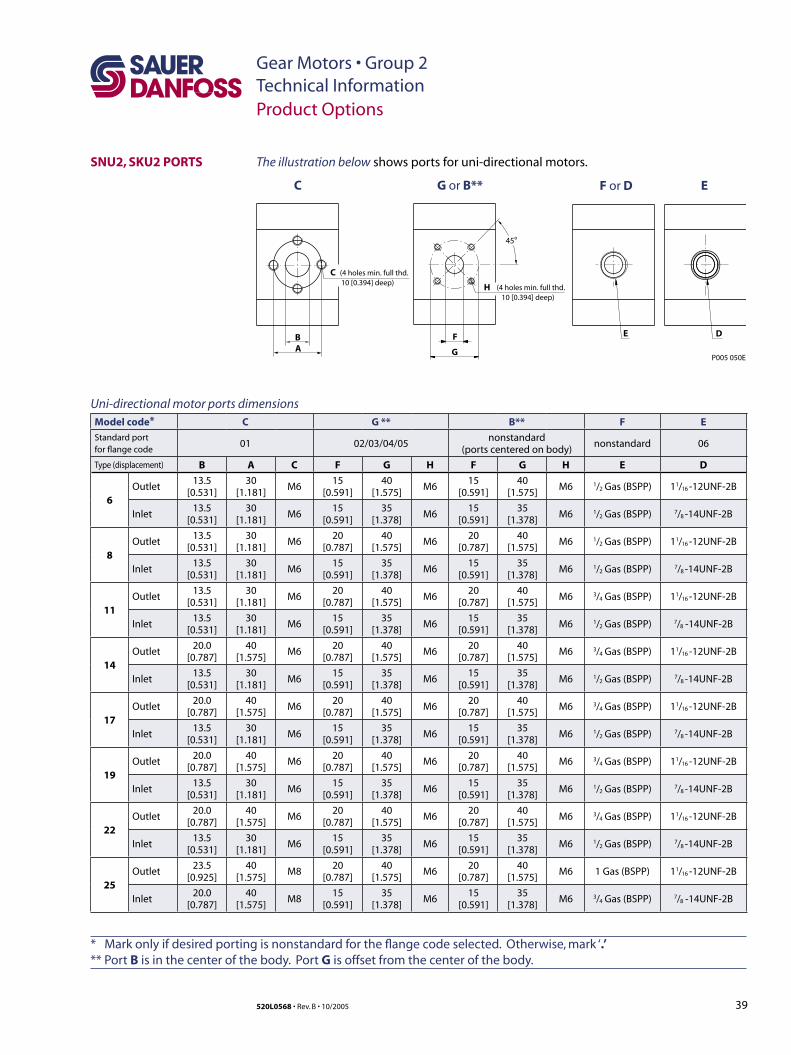
39520L0568 • Rev. B • 10/2005
Gear Motors • Group 2Technical Information
SNU2, SKU2 PORTS
Uni-directional motor ports dimensionsModel code* C G ** B** F E
Standard portfor flange code
01 02/03/04/05nonstandard
(ports centered on body)nonstandard 06
Type (displacement) B A C F G H F G H E D
6Outlet
13.5 [0.531]
30 [1.181]
M615
[0.591]40
[1.575]M6
15 [0.591]
40 [1.575]
M6 1/2 Gas (BSPP) 11/16 -12UNF-2B
Inlet13.5
[0.531]30
[1.181]M6
15 [0.591]
35 [1.378]
M615
[0.591]35
[1.378]M6 1/2 Gas (BSPP) 7/8 -14UNF-2B
8Outlet
13.5 [0.531]
30 [1.181]
M620
[0.787]40
[1.575]M6
20 [0.787]
40 [1.575]
M6 1/2 Gas (BSPP) 11/16 -12UNF-2B
Inlet13.5
[0.531]30
[1.181]M6
15 [0.591]
35 [1.378]
M615
[0.591]35
[1.378]M6 1/2 Gas (BSPP) 7/8 -14UNF-2B
11Outlet
13.5 [0.531]
30 [1.181]
M620
[0.787]40
[1.575]M6
20 [0.787]
40 [1.575]
M6 3/4 Gas (BSPP) 11/16 -12UNF-2B
Inlet13.5
[0.531]30
[1.181]M6
15 [0.591]
35 [1.378]
M615
[0.591]35
[1.378]M6 1/2 Gas (BSPP) 7/8 -14UNF-2B
14Outlet
20.0 [0.787]
40 [1.575]
M620
[0.787]40
[1.575]M6
20 [0.787]
40 [1.575]
M6 3/4 Gas (BSPP) 11/16 -12UNF-2B
Inlet13.5
[0.531]30
[1.181]M6
15 [0.591]
35 [1.378]
M615
[0.591]35
[1.378]M6 1/2 Gas (BSPP) 7/8 -14UNF-2B
17Outlet
20.0 [0.787]
40 [1.575]
M620
[0.787]40
[1.575]M6
20 [0.787]
40 [1.575]
M6 3/4 Gas (BSPP) 11/16 -12UNF-2B
Inlet13.5
[0.531]30
[1.181]M6
15 [0.591]
35 [1.378]
M615
[0.591]35
[1.378]M6 1/2 Gas (BSPP) 7/8 -14UNF-2B
19Outlet
20.0 [0.787]
40 [1.575]
M620
[0.787]40
[1.575]M6
20 [0.787]
40 [1.575]
M6 3/4 Gas (BSPP) 11/16 -12UNF-2B
Inlet13.5
[0.531]30
[1.181]M6
15 [0.591]
35 [1.378]
M615
[0.591]35
[1.378]M6 1/2 Gas (BSPP) 7/8 -14UNF-2B
22Outlet
20.0 [0.787]
40 [1.575]
M620
[0.787]40
[1.575]M6
20 [0.787]
40 [1.575]
M6 3/4 Gas (BSPP) 11/16 -12UNF-2B
Inlet13.5
[0.531]30
[1.181]M6
15 [0.591]
35 [1.378]
M615
[0.591]35
[1.378]M6 1/2 Gas (BSPP) 7/8 -14UNF-2B
25Outlet
23.5 [0.925]
40 [1.575]
M820
[0.787]40
[1.575]M6
20 [0.787]
40 [1.575]
M6 1 Gas (BSPP) 11/16 -12UNF-2B
Inlet20.0
[0.787]40
[1.575]M8
15 [0.591]
35 [1.378]
M615
[0.591]35
[1.378]M6 3/4 Gas (BSPP) 7/8 -14UNF-2B
The illustration below shows ports for uni-directional motors.
Product Options
* Mark only if desired porting is nonstandard for the flange code selected. Otherwise, mark ‘.’ ** Port B is in the center of the body. Port G is offset from the center of the body.
B
C G or B** F or D E
C
A
(4 holes min. full thd.10 [0.394] deep)
F
H
G
45o
(4 holes min. full thd.10 [0.394] deep)
E D
P005 050E
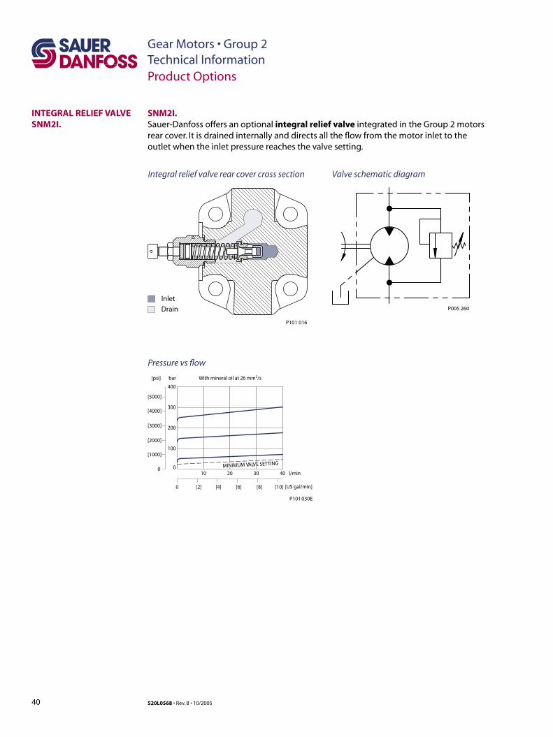
40 520L0568 • Rev. B • 10/2005
Gear Motors • Group 2Technical Information
SNM2I.Sauer-Danfoss offers an optional integral relief valve integrated in the Group 2 motors rear cover. It is drained internally and directs all the flow from the motor inlet to the outlet when the inlet pressure reaches the valve setting.
Product Options
INTEGRAL RELIEF VALVE SNM2I.
Inlet
Drain
P101 016
Valve schematic diagramIntegral relief valve rear cover cross section
Pressure vs flow
P005 260
bar
0
[1000]
[2000]
[3000]
[4000]
[5000]
[psi]
l/min
0 [US gal/min]
0
100
200
300
400
With mineral oil at 26 mm2/s
P101 030E
10 3020 40
[10][2] [4] [6] [8]
MINIMUM VALVE SETTING
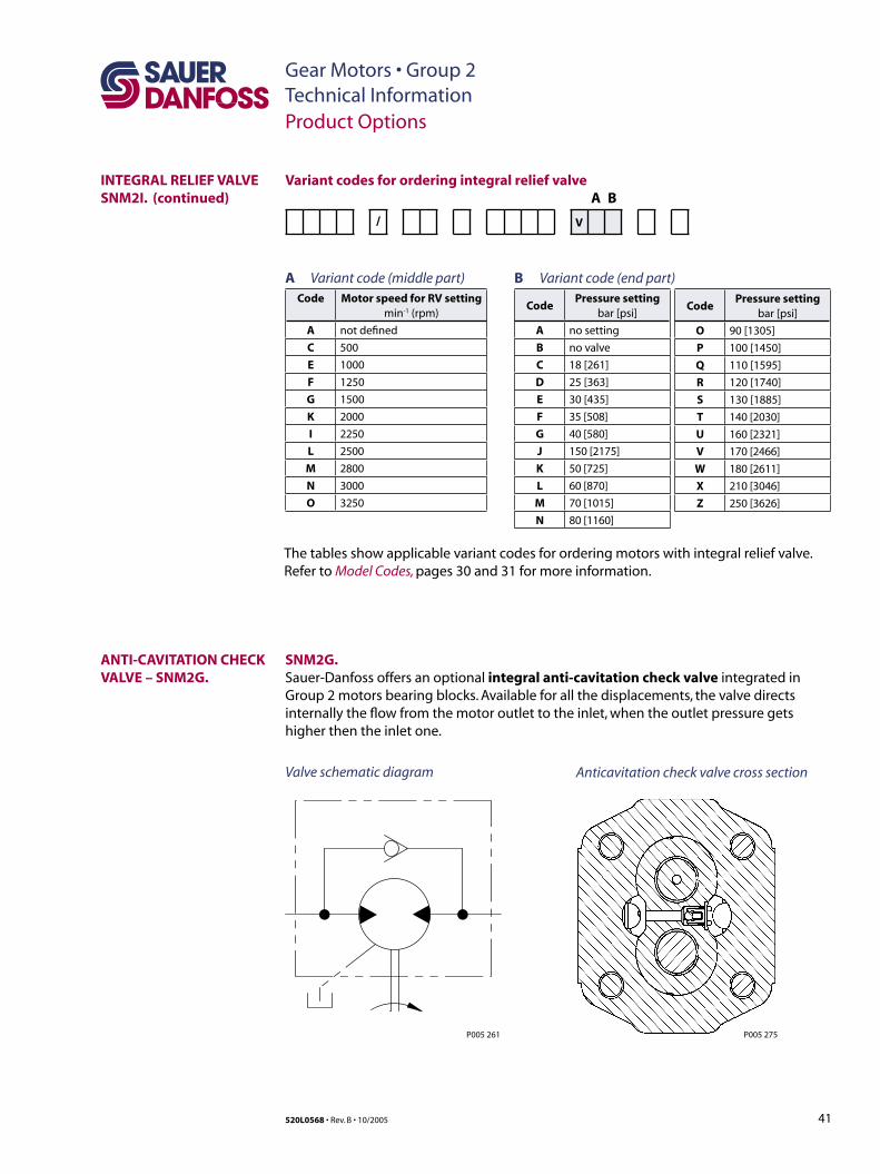
41520L0568 • Rev. B • 10/2005
Gear Motors • Group 2Technical Information
Variant codes for ordering integral relief valve A B
/ V
A Variant code (middle part)Code Motor speed for RV setting
min-1 (rpm)
A not defined
C 500
E 1000
F 1250
G 1500
K 2000
I 2250
L 2500
M 2800
N 3000
O 3250
B Variant code (end part)
CodePressure setting
bar [psi]
A no setting
B no valve
C 18 [261]
D 25 [363]
E 30 [435]
F 35 [508]
G 40 [580]
J 150 [2175]
K 50 [725]
L 60 [870]
M 70 [1015]
N 80 [1160]
CodePressure setting
bar [psi]
O 90 [1305]
P 100 [1450]
Q 110 [1595]
R 120 [1740]
S 130 [1885]
T 140 [2030]
U 160 [2321]
V 170 [2466]
W 180 [2611]
X 210 [3046]
Z 250 [3626]
The tables show applicable variant codes for ordering motors with integral relief valve. Refer to Model Codes, pages 30 and 31 for more information.
Product Options
INTEGRAL RELIEF VALVE SNM2I. (continued)
ANTI-CAVITATION CHECK VALVE – SNM2G.
SNM2G. Sauer-Danfoss offers an optional integral anti-cavitation check valve integrated in Group 2 motors bearing blocks. Available for all the displacements, the valve directs internally the flow from the motor outlet to the inlet, when the outlet pressure gets higher then the inlet one.
Valve schematic diagram Anticavitation check valve cross section
P005 275P005 261
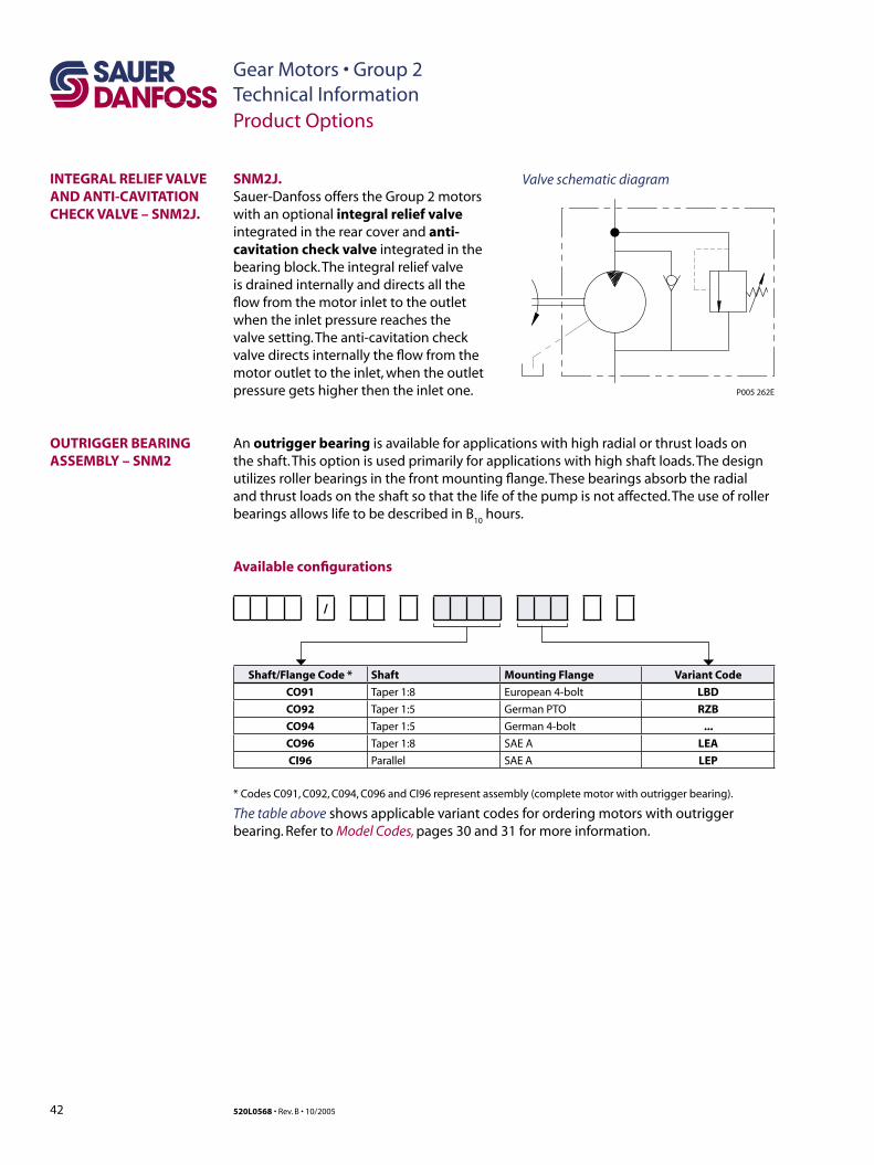
42 520L0568 • Rev. B • 10/2005
Gear Motors • Group 2Technical Information
SNM2J.Sauer-Danfoss offers the Group 2 motors with an optional integral relief valve integrated in the rear cover and anti-cavitation check valve integrated in the bearing block. The integral relief valve is drained internally and directs all the flow from the motor inlet to the outlet when the inlet pressure reaches the valve setting. The anti-cavitation check valve directs internally the flow from the motor outlet to the inlet, when the outlet pressure gets higher then the inlet one.
Product Options
INTEGRAL RELIEF VALVE AND ANTI-CAVITATION CHECK VALVE – SNM2J.
An outrigger bearing is available for applications with high radial or thrust loads on the shaft. This option is used primarily for applications with high shaft loads. The design utilizes roller bearings in the front mounting flange. These bearings absorb the radial and thrust loads on the shaft so that the life of the pump is not affected. The use of roller bearings allows life to be described in B
10 hours.
OUTRIGGER BEARING ASSEMBLY – SNM2
Valve schematic diagram
Available configurations
/
Shaft/Flange Code * Shaft Mounting Flange Variant Code
CO91 Taper 1:8 European 4-bolt LBD
CO92 Taper 1:5 German PTO RZB
CO94 Taper 1:5 German 4-bolt ...
CO96 Taper 1:8 SAE A LEA
CI96 Parallel SAE A LEP
* Codes C091, C092, C094, C096 and CI96 represent assembly (complete motor with outrigger bearing).
The table above shows applicable variant codes for ordering motors with outrigger bearing. Refer to Model Codes, pages 30 and 31 for more information.
P005 262E
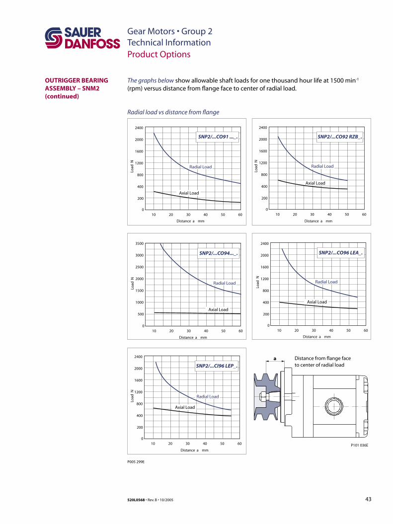
43520L0568 • Rev. B • 10/2005
Gear Motors • Group 2Technical InformationProduct Options
P101 036E
Distance from flange faceto center of radial load
a
0
500
1000
1500
2000
2500
3000
3500
10 20 30 40 50 60
Load
N
SNP2/...CO94..._.
Radial Load
Axial Load
0
400
200
800
1200
1600
2000
2400
10 20 30 40 50 60
Load
N
SNP2/...CI96 LEP_.
Radial Load
Axial Load
0
400
200
800
1200
1600
2000
2400
10 20 30 40 50 60
Distance a mm Distance a mm
Distance a mm
Distance a mm
Distance a mm
Load
N
SNP2/...CO91 ..._.
Radial Load
Axial Load
0
400
200
800
1200
1600
2000
2400
10 20 30 40 50 60
Load
N
Radial Load
Axial Load
SNP2/...CO92 RZB_.
0
400
200
800
1200
1600
2000
2400
10 20 30 40 50 60
Load
NSNP2/...CO96 LEA_.
Radial Load
Axial Load
P005 299E
The graphs below show allowable shaft loads for one thousand hour life at 1500 min-1 (rpm) versus distance from flange face to center of radial load.
Radial load vs distance from flange
OUTRIGGER BEARING ASSEMBLY – SNM2(continued)
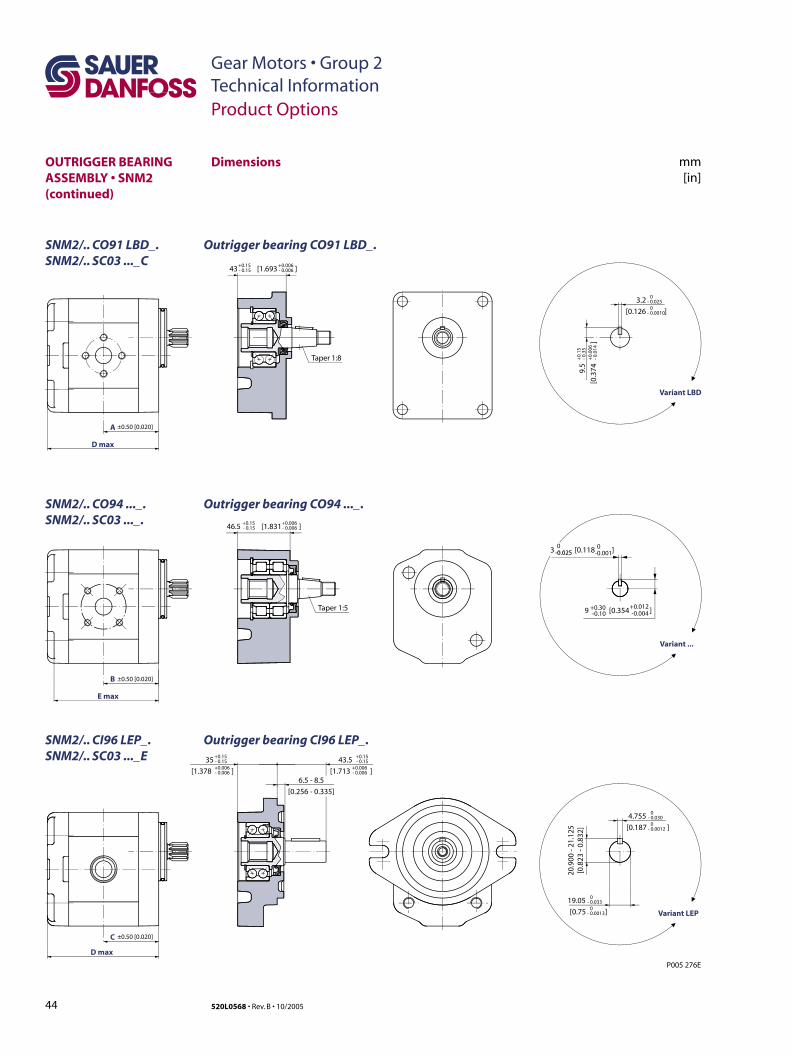
44 520L0568 • Rev. B • 10/2005
Gear Motors • Group 2Technical InformationProduct Options
OUTRIGGER BEARING ASSEMBLY • SNM2 (continued)
6.5 - 8.5
[0.256 - 0.335]
43
Taper 1:8
]- 0.15+0.006- 0.006
+0.15
46.5 [1.831 ]- 0.15+0.006- 0.006
+0.15
35
[1.378 ]- 0.15+0.006- 0.006
+0.15 43.5
[1.713 ]- 0.15
+0.006- 0.006
+0.15
20.9
00 -
21.1
25[0
.823
- 0.
832]
4.755
[0.187 ]- 0.030
0- 0.0012
0
19.05
[0.75 ]- 0.033
- 0.0013
0
Variant LEP
3.2
[0.126 ]- 0.025
0- 0.0010
0
9.5
[0.3
74]
- 0.3
5+
0.00
6- 0
.014
+0.
15
Variant LBD
A ±0.50 [0.020]
B ±0.50 [0.020]
C ±0.50 [0.020]
D max
P005 276E
[1.693
0
E max
D max
Variant ...
Taper 1:5
3 [0.118 ]
+0.30-0.109 [0.354 ]
+0.012-0.004
00250.0 -0.025
0-0.001
Dimensions
SNM2/.. CO91 LBD_. Outrigger bearing CO91 LBD_.SNM2/.. SC03 ..._C
SNM2/.. CO94 ..._. Outrigger bearing CO94 ..._.SNM2/.. SC03 ..._.
SNM2/.. CI96 LEP_. Outrigger bearing CI96 LEP_.SNM2/.. SC03 ..._E
mm[in]
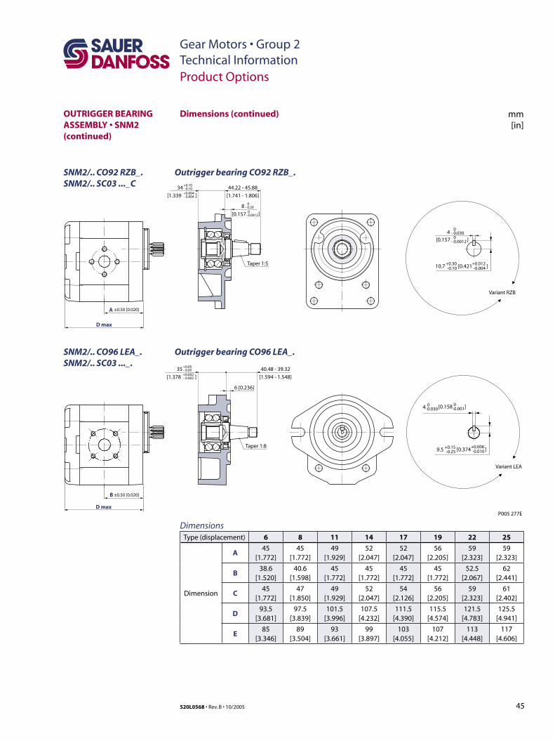
45520L0568 • Rev. B • 10/2005
Gear Motors • Group 2Technical Information
DimensionsType (displacement) 6 8 11 14 17 19 22 25
Dimension
A45
[1.772]45
[1.772]49
[1.929]52
[2.047]52
[2.047]56
[2.205]59
[2.323]59
[2.323]
B38.6
[1.520]40.6
[1.598]45
[1.772]45
[1.772]45
[1.772]45
[1.772]52.5
[2.067]62
[2.441]
C45
[1.772]47
[1.850]49
[1.929]52
[2.047]54
[2.126]56
[2.205]59
[2.323]61
[2.402]
D93.5
[3.681]97.5
[3.839]101.5
[3.996]107.5
[4.232]111.5
[4.390]115.5
[4.574]121.5
[4.783]125.5
[4.941]
E85
[3.346]89
[3.504]93
[3.661]99
[3.897]103
[4.055]107
[4.212]113
[4.448]117
[4.606]
6 [0.236]
Variant RZB
Variant LEA
- 0.030 0
4
- 0.0012 0[0.157 ]
44.22 - 45.88
[1.741 - 1.806]
35
[1.378 ]- 0.05+0.002- 0.002
+0.05
34
[1.339 ]- 0.10+0.004- 0.004
+0.10
- 0.20 08
- 0.0012 0[0.157 ]
40.48 - 39.32
[1.594 - 1.548]
P005 277E
A ±0.50 [0.020]
B ±0.50 [0.020]
D max
D max
Taper 1:5
Taper 1:8
4 0-0.030
0-0.001[0.158 ]
[0.374 ]9.5 +0.15-0.25
+0.006 -0.010
[0.421 ]10.7 +0.30-0.10
+0.012 -0.004
SNM2/.. CO92 RZB_. Outrigger bearing CO92 RZB_.SNM2/.. SC03 ..._C
Product Options
OUTRIGGER BEARING ASSEMBLY • SNM2 (continued)
SNM2/.. CO96 LEA_. Outrigger bearing CO96 LEA_.SNM2/.. SC03 ..._.
mm[in]
Dimensions (continued)
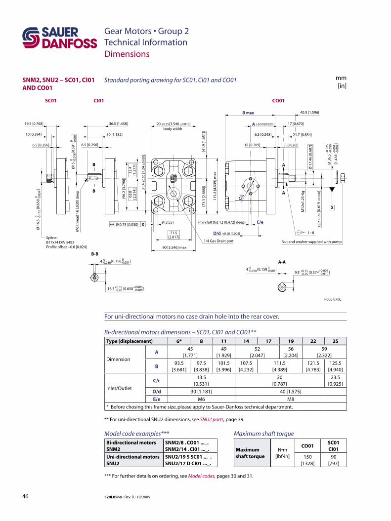
46 520L0568 • Rev. B • 10/2005
Gear Motors • Group 2Technical Information
SNM2, SNU2 – SC01, CI01 AND CO01
Dimensions
[1.4
38
]
-0.0
25-0
.050
-0.0
01-0
.002
9 [3.55]
Nut and washer supplied with pump
[0.6
19
]A
A
[0.650 ]
(min full thd 12 [0.472] deep)
1 : 8
A-A
M12
x1.2
5-6g
E/e
40.5 [1.596]
6.3 [0.248] 21.7 [0.854]
17 [0.670]
18 [0.709] 5 [0.020]
C/c
M6
thre
ad 1
6 [.6
30] d
eep
B-B
B
B
6.5 [0.256]
30 [1.182]
36.5 [1.438]
Spline:B17x14 DIN 5482Profile offset +0.6 [0.024]
6.5 [0.256]
10 [0.394]
19.5 [0.768]body width
(96.
2 [3
.790
])
115.
2 [4
.539
] max
90 [3.546] max
D/d ±0.20 [0.008]
(41.
9 [1
.651
])
71.5[2.817]
63.8
[2.5
14]
32.4
[1.2
77]
(73.
3 [2
.888
])
90 ±0.25[3.546 ±0.010]
15.7
±0.
50±
0.02
0
Ø 1
6.5
[
0.65
0
]0 -0
.110
0 -0.0
04
Ø 3
6.5
Ø 1
7.46
[0.6
87]
16.5+0.10-0.20
+0.004 -0.008
[0.374 ]9.5 +0.15-0.25
+0.006 -0.010
Ø15
[
0.59
1
]0 -0
.018
0 -0.0
01
4 0-0.030
0-0.001[0.158 ]
4 0-0.030
0-0.001[0.158 ]
X
Ø 0.75 [0.030] X
CO01
±0.50 [0.020]
P005 070E
B max
A
CI01SC01
1/4 Gas Drain port
31.4
±0.
50 [1
.24
±0.
020]
Standard porting drawing for SC01, CI01 and CO01 mm[in]
For uni-directional motors no case drain hole into the rear cover.
Bi-directional motors dimensions – SC01, CI01 and CO01**Type (displacement) 6* 8 11 14 17 19 22 25
Dimension
A45
[1.771]49
[1.929]52
[2.047]56
[2.204]59
[2.322]
B93.5
[3.681]97.5
[3.838]101.5
[3.996]107.5
[4.232]111.5
[4.389]121.5
[4.783]125.5
[4.940]
Inlet/Outlet
C/c13.5
[0.531]20
[0.787]23.5
[0.925]
D/d 30 [1.181] 40 [1.575]
E/e M6 M8
* Before chosing this frame size, please apply to Sauer-Danfoss technical department.
** For uni-directional SNU2 dimensions, see SNU2 ports, page 39.
Maximum shaft torque
Maximum shaft torque
N•m [lbf•in]
CO01SC01CI01
150 [1328]
90 [797]
Model code examples***Bi-directional motorsSNM2
SNM2/8 . CO01 ..._.SNM2/14 . CI01 ..._.
Uni-directional motorsSNU2
SNU2/19 S SC01 ..._.SNU2/17 D CI01 ..._.
*** For further details on ordering, see Model codes, pages 30 and 31.
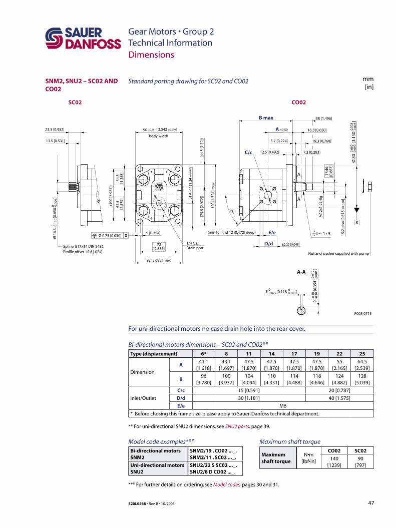
47520L0568 • Rev. B • 10/2005
Gear Motors • Group 2Technical Information
SNM2, SNU2 – SC02 AND CO02
Dimensions
3 [0.118 ]
Ø 8
0
[3.1
50
]
9 [0.354]
Ø 1
6.5
[
0.65
0
]
Spline: B17x14 DIN 5482Profile offset +0.6 [.024]
13.5 [0.531]
23.5 [0.952]
1 : 5
A
A-A
A
M12
x1.2
5-6g
16.5 [0.650]
E/e
17.4
6[0
.687
]
38 [1.496]B max
12.5 [0.492] 7.2 [0.283]
5.7 [0.224] 19.3 [0.760]
C/c
45˚
body width
(100
[3.9
37])
D/d ±0.20 [0.008]
A ±0.50
72[2.835]
120
[4.7
24] m
ax
92 [3.622] max
(44.
5 [1
.72]
)
65.5
[2.5
79]
34.5
[1.3
58]
(75.
5 [2
.972
])
90 ±0.25 ±0.0103.543[ ]
0 -0.1
100 -0
.004
-0.0
60-0
.090
-0.0
02-0
.003
0-0.025
0-0.001
9
[0.3
54
]
+0.
30-0
.10
+0.
012
-0.0
04
15.7
±0.
50 [0
.618
±0.
020]
Ø 0.75 [0.030] X
X
(min full thd 12 [0.472] deep)
Nut and washer supplied with pump
SC02 CO02
1/4 GasDrain port
31.4
[1.
24
]±
0.5
±0.
0197
P005 071E
Standard porting drawing for SC02 and CO02 mm[in]
For uni-directional motors no case drain hole into the rear cover.
Bi-directional motors dimensions – SC02 and CO02**Type (displacement) 6* 8 11 14 17 19 22 25
Dimension
A41.1
[1.618]43.1
[1.697]47.5
[1.870]47.5
[1.870]47.5
[1.870]47.5
[1.870]55
[2.165]64.5
[2.539]
B96
[3.780]100
[3.937]104
[4.094]110
[4.331]114
[4.488]118
[4.646]124
[4.882]128
[5.039]
Inlet/Outlet
C/c 15 [0.591] 20 [0.787]
D/d 30 [1.181] 40 [1.575]
E/e M6
* Before chosing this frame size, please apply to Sauer-Danfoss technical department.
** For uni-directional SNU2 dimensions, see SNU2 ports, page 39.
Maximum shaft torque
Maximum shaft torque
N•m [lbf•in]
CO02 SC02
140 [1239]
90 [797]
Model code examples***Bi-directional motorsSNM2
SNM2/19 . CO02 ..._.SNM2/11 . SC02 ..._.
Uni-directional motorsSNU2
SNU2/22 S SC02 ..._.SNU2/8 D CO02 ..._.
*** For further details on ordering, see Model codes, pages 30 and 31.
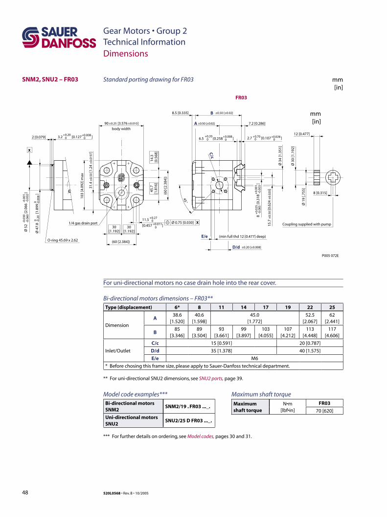
48 520L0568 • Rev. B • 10/2005
Gear Motors • Group 2Technical Information
SNM2, SNU2 – FR03
Dimensions
3.2 [0.127 ]+0.20
0+0.008
02 [0.079]
(min full thd 12 [0.477] deep)E/e
Ø 3
4 [1
.351
]
7.2 [0.286]
Ø 1
9 [.7
55]
Ø 3
0 [1
.192
]
12 [0.477]
C/c
45˚
X
O-ring 45.69 x 2.62
body width
(60
[2.3
84])
D/d ±0.20 [±0.008]
B8.5 [0.335] ±0.50 [±0.02]
A
(60 [2.384])
103
[4.0
92] m
ax
30[1.192]
45.7
[1.8
16]
14.3
[0.5
68]
30[1.192]Ø
52
[2.0
66
]
-0.0
30-0
.060
-0.0
01-0
.002
8
[0
.318
]+
0.02
5-0
.083
+0.
001
-0.0
03
11.5
[0.457 ]
+0.270+0.011
0
2.7 [0.107 ]+0.700
+0.02806.5 [0.258 ]
+0.200
+0.0080
Ø 4
7.8
[1
.899
]
0 -0.2
00 -0
.008
15.7
±0.
50 [0
.624
±0.
020 ]
90 [3.576 ]±0.25 ±0.010
Ø 0.75 [0.030] X
8 [0.315]
Coupling supplied with pump
±0.50 [±0.02]
1/4 gas drain port
31.4
±0.
50 [1
.24
±0.
0197
]
P005 072E
FR03
mm[in]
Standard porting drawing for FR03 mm[in]
For uni-directional motors no case drain hole into the rear cover.
Bi-directional motors dimensions – FR03**Type (displacement) 6* 8 11 14 17 19 22 25
Dimension
A38.6
[1.520]40.6
[1.598]45.0
[1.772]52.5
[2.067]62
[2.441]
B85
[3.346]89
[3.504]93
[3.661]99
[3.897]103
[4.055]107
[4.212]113
[4.448]117
[4.606]
Inlet/Outlet
C/c 15 [0.591] 20 [0.787]
D/d 35 [1.378] 40 [1.575]
E/e M6
* Before chosing this frame size, please apply to Sauer-Danfoss technical department.
** For uni-directional SNU2 dimensions, see SNU2 ports, page 39.
Maximum shaft torque
Maximum shaft torque
N•m [lbf•in]
FR03
70 [620]
Model code examples***Bi-directional motors SNM2
SNM2/19 . FR03 ..._.
Uni-directional motors SNU2
SNU2/25 D FR03 ..._.
*** For further details on ordering, see Model codes, pages 30 and 31.
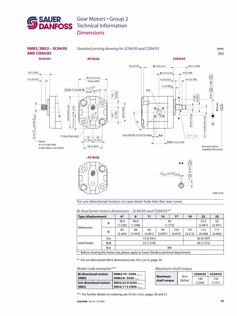
49520L0568 • Rev. B • 10/2005
Gear Motors • Group 2Technical Information
SNM2, SNU2 – SC04/05 AND CO04/05
Dimensions
3 [0.118 ]
11.5
[0.453 ]
Ø 1
6.5
[0
.650
]
±0.
50±
0.02
A
B8.5 [0.335]
±0.50 [±0.02]
±0.50 [±0.02]
+0.270+0.011
0
Spline: B17x14 DIN 5482Profile offset +0.6 [0.024]
13.5 [0.531]
26 [1.024]
A-A
A
A
1 : 5
X
(min full thd 12 [0.472] deep)
M12
x1.2
5-6g
17.4
6[0
.687
]
19 [0.748]
E/e
C/c
7.2 [0.283]
40.5 [1.594]
8.2 [0.323] 19.3 [0.760]
45°
body width
(60
[2.3
62])
D/d ±0.20 [±0.008]
90 ±0.25 [0.010]
(60 [2.362])
103
[4.0
55] m
ax
45.7
[1.7
99]
14.3
[0.5
63]
30[1.181]
30[1.181]
Ø0.75 [0.030] X
0 -0.1
100 -0
.004
-0.0
25-0
.050
Ø 5
0
[1
.969
]-0
.001
-0.0
02
+0.
30-0
.10
9
[0.
354
]
+0.
012
-0.0
04
0-0.025
0-0.001
Nut and washer supplied with pump
P005 073E
SC04/05 ..04 Body
..05 Body
CO04/05
15.7
[
0.61
8
]
1/4 Gas Drain port
31.4
±0.
50 [
1.24
±0.
02]
Standard porting drawing for SC04/05 and CO04/05 mm[in]
For uni-directional motors no case drain hole into the rear cover.
Bi-directional motors dimensions – SC04/05 and CO04/05**Type (displacement) 6* 8 11 14 17 19 22 25
Dimension
A38.6
[1.520]40.6
[1.598]45
[1.772]52.5
[2.067]62
[2.441]
B85
[3.364]89
[3.503]93
[3.661]99
[3.897]103
[4.055]107
[4.212]113
[4.448]117
[4.606]
Inlet/Outlet
C/c 15 [0.591] 20 [0.787]
D/d 35 [1.378] 40 [1.575]
E/e M6
* Before chosing this frame size, please apply to Sauer-Danfoss technical department.
** For uni-directional SNU2 dimensions, see SNU2 ports, page 39.
Maximum shaft torque
Maximum shaft torque
N•m [lbf•in]
CO04/05 SC04/05
140 [1239]
130 [1151]
Model code examples***Bi-directional motorsSNM2
SNM2/19 . CO04 ..._.SNM2/8 . SC05 ..._.
Uni-directional motorsSNU2
SNU2/22 D SC04 ..._.SNU2/11 S CO05 ..._.
*** For further details on ordering, see Model codes, pages 30 and 31.
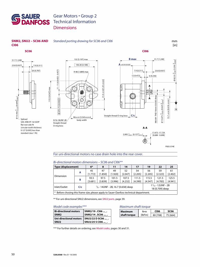
50 520L0568 • Rev. B • 10/2005
Gear Motors • Group 2Technical Information
SNM2, SNU2 – SC06 AND CI06
A
A
A-A
7.9 [0.311] 23.8 [0.937]
B max 31.7 [1.248]
C/c
17.475 -17.729[0.688 - 0.698]
12 [0.472] 6 [0.236]
body width
11 -
11.6
[0.4
33 -
0.45
7]
A ±0.50 [0.020]
132 [5.197] max
106.38 [4.188]
115.
5 [4
.547
] max
R 48 [1.889] max
3.995 [0.157 ]0-0.025
0-0.010
90±0.25 [3.543±0.010]
Ø 0
.75
[0.0
30] X
X
P005 074E
SC06
SplinedSAE J498-9T-16/32DPflat root side fit(circular tooth thickness0.127 [0.005] less thanstandard class 1 fit)
CI06
20 [0.787]
31.7 [1.248]
23.8 [0.937] 7.9 [0.311]
Ø 1
5.45
6
[0.6
09
]0 -0
.127
0 -0.0
05
9/16-18UNF-2BStraight thread O-ring boss
Straight thread O-ring boss
31.4
±0.
50[1
.24
±0.
020 ]
M6-
6H- T
HD
16m
m [0
.630
] dee
p
Ø 8
2.55
[3
.250
]
00 -0
.020
Ø 1
5.87
5
[0.
625
]
0 -0.0
250 -0
.010
15.7
±0.
50 [0
.618
±0.
020
]
-0.5
0
Dimensions
Standard porting drawing for SC06 and CI06 mm[in]
For uni-directional motors no case drain hole into the rear cover.
Bi-directional motors dimensions – SC06 and CI06**Type (displacement) 6* 8 11 14 17 19 22 25
Dimension
A45
[1.772]47
[1.850]49
[1.920]52
[2.047]54
[2.205]56
[2.205]59
[2.323]61
[2.402]
B93.5
[3.681]97.5
[3.839]101.5
[3.996]107.5
[4.232]111.5
[4.390]115.5
[4.547]121.5
[4.783]125.5
[4.941]
Inlet/Outlet C/c 7/8 - 14UNF - 2B, 16.7 [0.658] deep11/16 - 12UNF - 2B 18 [0.709] deep
* Before chosing this frame size, please apply to Sauer-Danfoss technical department.
** For uni-directional SNU2 dimensions, see SNU2 ports, page 39.
Maximum shaft torque
Maximum shaft torque
N•m [lbf•in]
CI06 SC06
80 [708] 75 [664]
Model code examples***Bi-directional motorsSNM2
SNM2/19 . CI06 ..._.SNM2/14 . SC06 ..._.
Uni-directional motorsSNU2
SNU2/22 D SC06 ..._.SNU2/25 S CI06 ..._.
*** For further details on ordering, see Model codes, pages 30 and 31.

51520L0568 • Rev. B • 10/2005
Gear Motors • Group 2Technical InformationNotes
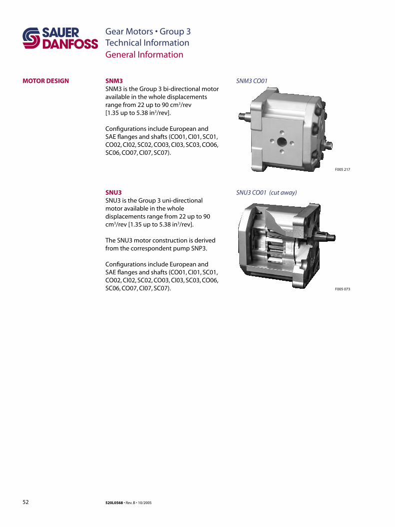
52 520L0568 • Rev. B • 10/2005
Gear Motors • Group 3Technical InformationGeneral Information
MOTOR DESIGN
F005 217
SNM3 CO01SNM3SNM3 is the Group 3 bi-directional motor available in the whole displacements range from 22 up to 90 cm3/rev [1.35 up to 5.38 in3/rev].
Configurations include European and SAE flanges and shafts (CO01, CI01, SC01, CO02, CI02, SC02, CO03, CI03, SC03, CO06, SC06, CO07, CI07, SC07).
SNU3SNU3 is the Group 3 uni-directional motor available in the whole displacements range from 22 up to 90 cm3/rev [1.35 up to 5.38 in3/rev].
The SNU3 motor construction is derived from the correspondent pump SNP3.
Configurations include European and SAE flanges and shafts (CO01, CI01, SC01, CO02, CI02, SC02, CO03, CI03, SC03, CO06, SC06, CO07, CI07, SC07). F005 073
SNU3 CO01 (cut away)
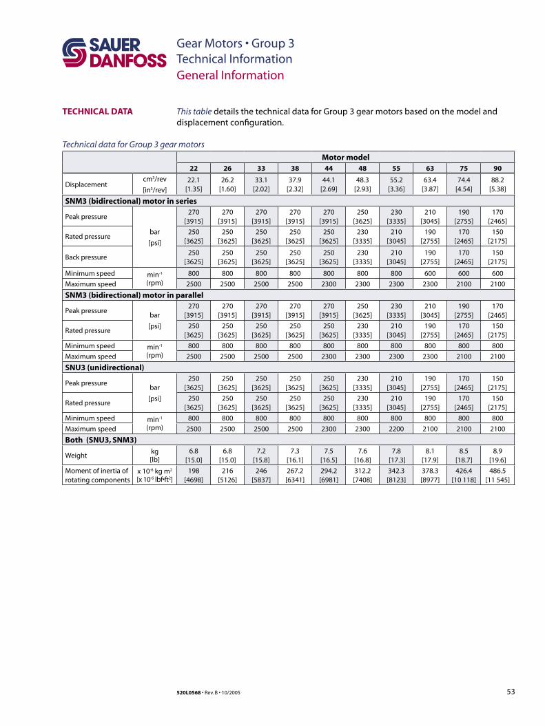
53520L0568 • Rev. B • 10/2005
Gear Motors • Group 3Technical Information
TECHNICAL DATA
General Information
This table details the technical data for Group 3 gear motors based on the model and displacement configuration.
Technical data for Group 3 gear motors
Motor model22 26 33 38 44 48 55 63 75 90
Displacementcm3/rev
[in3/rev]
22.1[1.35]
26.2[1.60]
33.1[2.02]
37.9[2.32]
44.1[2.69]
48.3[2.93]
55.2[3.36]
63.4[3.87]
74.4[4.54]
88.2[5.38]
SNM3 (bidirectional) motor in series
Peak pressure
bar
[psi]
270[3915]
270[3915]
270[3915]
270[3915]
270[3915]
250[3625]
230[3335]
210[3045]
190[2755]
170[2465]
Rated pressure250
[3625]250
[3625]250
[3625]250
[3625]250
[3625]230
[3335]210
[3045]190
[2755]170
[2465]150
[2175]
Back pressure250
[3625]250
[3625]250
[3625]250
[3625]250
[3625]230
[3335]210
[3045]190
[2755]170
[2465]150
[2175]
Minimum speed min-1
(rpm)800 800 800 800 800 800 800 600 600 600
Maximum speed 2500 2500 2500 2500 2300 2300 2300 2300 2100 2100
SNM3 (bidirectional) motor in parallel
Peak pressurebar
[psi]
270[3915]
270[3915]
270[3915]
270[3915]
270[3915]
250[3625]
230[3335]
210[3045]
190[2755]
170[2465]
Rated pressure250
[3625]250
[3625]250
[3625]250
[3625]250
[3625]230
[3335]210
[3045]190
[2755]170
[2465]150
[2175]
Minimum speed min-1
(rpm)800 800 800 800 800 800 800 800 800 800
Maximum speed 2500 2500 2500 2500 2300 2300 2300 2300 2100 2100
SNU3 (unidirectional)
Peak pressurebar
[psi]
250[3625]
250[3625]
250[3625]
250[3625]
250[3625]
230[3335]
210[3045]
190[2755]
170[2465]
150[2175]
Rated pressure250
[3625]250
[3625]250
[3625]250
[3625]250
[3625]230
[3335]210
[3045]190
[2755]170
[2465]150
[2175]
Minimum speed min-1
(rpm)800 800 800 800 800 800 800 800 800 800
Maximum speed 2500 2500 2500 2500 2300 2300 2200 2100 2100 2100
Both (SNU3, SNM3)
Weightkg[lb]
6.8 [15.0]
6.8 [15.0]
7.2 [15.8]
7.3 [16.1]
7.5[16.5]
7.6[16.8]
7.8 [17.3]
8.1 [17.9]
8.5[18.7]
8.9[19.6]
Moment of inertia ofrotating components
x 10-6 kg m2
[x 10-6 lbf•ft2]198
[4698]216
[5126]246
[5837]267.2[6341]
294.2[6981]
312.2[7408]
342.3[8123]
378.3[8977]
426.4[10 118]
486.5[11 545]
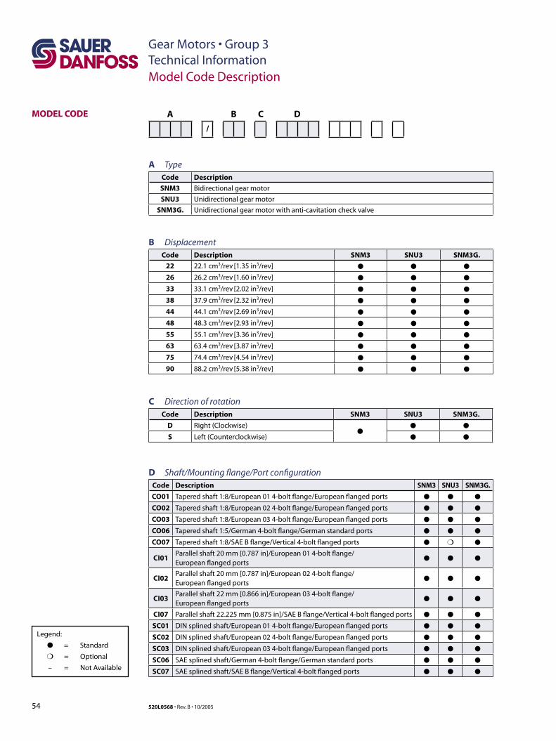
54 520L0568 • Rev. B • 10/2005
Gear Motors • Group 3Technical InformationModel Code Description
MODEL CODE A B C D
/
A TypeCode Description
SNM3 Bidirectional gear motor
SNU3 Unidirectional gear motor
SNM3G. Unidirectional gear motor with anti-cavitation check valve
B DisplacementCode Description SNM3 SNU3 SNM3G.
22 22.1 cm3/rev [1.35 in3/rev] ● ● ●
26 26.2 cm3/rev [1.60 in3/rev] ● ● ●
33 33.1 cm3/rev [2.02 in3/rev] ● ● ●
38 37.9 cm3/rev [2.32 in3/rev] ● ● ●
44 44.1 cm3/rev [2.69 in3/rev] ● ● ●
48 48.3 cm3/rev [2.93 in3/rev] ● ● ●
55 55.1 cm3/rev [3.36 in3/rev] ● ● ●
63 63.4 cm3/rev [3.87 in3/rev] ● ● ●
75 74.4 cm3/rev [4.54 in3/rev] ● ● ●
90 88.2 cm3/rev [5.38 in3/rev] ● ● ●
C Direction of rotationCode Description SNM3 SNU3 SNM3G.
D Right (Clockwise)●
● ●
S Left (Counterclockwise) ● ●
D Shaft/Mounting flange/Port configurationCode Description SNM3 SNU3 SNM3G.
CO01 Tapered shaft 1:8/European 01 4-bolt flange/European flanged ports ● ● ●
CO02 Tapered shaft 1:8/European 02 4-bolt flange/European flanged ports ● ● ●
CO03 Tapered shaft 1:8/European 03 4-bolt flange/European flanged ports ● ● ●
CO06 Tapered shaft 1:5/German 4-bolt flange/German standard ports ● ● ●
CO07 Tapered shaft 1:8/SAE B flange/Vertical 4-bolt flanged ports ● ❍ ●
CI01Parallel shaft 20 mm [0.787 in]/European 01 4-bolt flange/European flanged ports
● ● ●
CI02Parallel shaft 20 mm [0.787 in]/European 02 4-bolt flange/European flanged ports
● ● ●
CI03Parallel shaft 22 mm [0.866 in]/European 03 4-bolt flange/European flanged ports
● ● ●
CI07 Parallel shaft 22.225 mm [0.875 in]/SAE B flange/Vertical 4-bolt flanged ports ● ● ●
SC01 DIN splined shaft/European 01 4-bolt flange/European flanged ports ● ● ●
SC02 DIN splined shaft/European 02 4-bolt flange/European flanged ports ● ● ●
SC03 DIN splined shaft/European 03 4-bolt flange/European flanged ports ● ● ●
SC06 SAE splined shaft/German 4-bolt flange/German standard ports ● ● ●
SC07 SAE splined shaft/SAE B flange/Vertical 4-bolt flanged ports ● ● ●
Legend:
● = Standard
❍ = Optional
– = Not Available
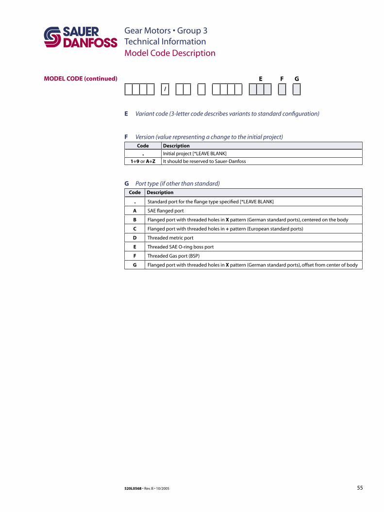
55520L0568 • Rev. B • 10/2005
Gear Motors • Group 3Technical InformationModel Code Description
MODEL CODE (continued) E F G
/
E Variant code (3-letter code describes variants to standard configuration)
F Version (value representing a change to the initial project)Code Description
. Initial project [*LEAVE BLANK]
1÷9 or A÷Z It should be reserved to Sauer-Danfoss
G Port type (if other than standard)Code Description
. Standard port for the flange type specified [*LEAVE BLANK]
A SAE flanged port
B Flanged port with threaded holes in X pattern (German standard ports), centered on the body
C Flanged port with threaded holes in + pattern (European standard ports)
D Threaded metric port
E Threaded SAE O-ring boss port
F Threaded Gas port (BSP)
G Flanged port with threaded holes in X pattern (German standard ports), offset from center of body
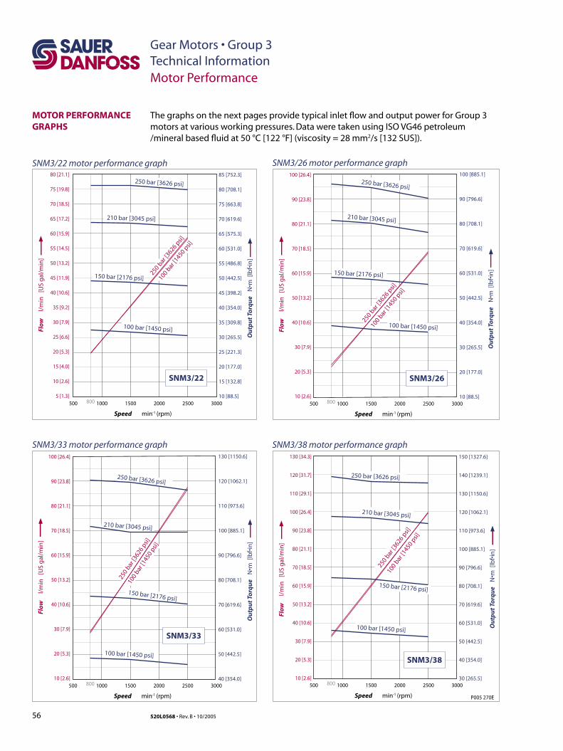
56 520L0568 • Rev. B • 10/2005
Gear Motors • Group 3Technical InformationMotor Performance
The graphs on the next pages provide typical inlet flow and output power for Group 3 motors at various working pressures. Data were taken using ISO VG46 petroleum /mineral based fluid at 50 °C [122 °F] (viscosity = 28 mm2/s [132 SUS]).
MOTOR PERFORMANCE GRAPHS
SNM3/22 motor performance graph SNM3/26 motor performance graph
SNM3/33 motor performance graph SNM3/38 motor performance graph
P005 270E
800
80 [21.1]
75 [19.8]
70 [18.5]
65 [17.2]
60 [15.9]
55 [14.5]
50 [13.2]
45 [11.9]
40 [10.6]
35 [9.2]
30 [7.9]
25 [6.6]
20 [5.3]
15 [4.0]
10 [2.6]
5 [1.3]
Speed min -1 (rpm)
Flow
l
/min
[U
S g
al/m
in]
2000 2500500 1000 1500 3000
SNM3/22
100 bar
[1450 p
si]
210 bar [3045 psi]
250 bar [3626 psi]
250 bar
[3626 p
si]
100 bar [1450 psi]
150 bar [2176 psi]
800
100 [26.4]
90 [23.8]
80 [21.1]
70 [18.5]
60 [15.9]
50 [13.2]
40 [10.6]
30 [7.9]
20 [5.3]
10 [2.6]
Speed min -1 (rpm)
Flow
l
/min
[U
S g
al/m
in]
2000 2500500 1000 1500 3000
SNM3/26100 b
ar [1
450 psi]
250 bar [3626 psi]
250 bar
[3626 p
si]
100 bar [1450 psi]
150 bar [2176 psi]
210 bar [3045 psi]
800
100 [26.4]
90 [23.8]
80 [21.1]
70 [18.5]
60 [15.9]
50 [13.2]
40 [10.6]
30 [7.9]
20 [5.3]
10 [2.6]
130 [34.3]
120 [31.7]
110 [29.1]
100 [26.4]
90 [23.8]
80 [21.1]
70 [18.5]
60 [15.9]
50 [13.2]
40 [10.6]
30 [7.9]
20 [5.3]
10 [2.6]
Speed min -1 (rpm)
Flow
l
/min
[U
S g
al/m
in]
2000 2500500 1000 1500 3000
SNM3/33
100
bar [1
450
psi]
250 bar [3626 psi]
250
bar [3
626
psi]
100 bar [1450 psi]
150 bar [2176 psi]
210 bar [3045 psi]
800
Speed min -1 (rpm)
Flow
l
/min
[U
S g
al/m
in]
2000 2500500 1000 1500 3000
SNM3/38
100
bar [1
450
psi]
250 bar [3626 psi]
250
bar [3
626
psi]
100 bar [1450 psi]
150 bar [2176 psi]
210 bar [3045 psi]
Ou
tpu
t To
rqu
e N
•m [
lbf•
in]
Ou
tpu
t To
rqu
e N
•m [
lbf•
in]
Ou
tpu
t To
rqu
e N
•m [
lbf•
in]
Ou
tpu
t To
rqu
e N
•m [
lbf•
in]
85 [752.3]
80 [708.1]
75 [663.8]
70 [619.6]
65 [575.3]
60 [531.0]
55 [486.8]
50 [442.5]
45 [398.2]
40 [354.0]
35 [309.8]
30 [265.5]
25 [221.3]
20 [177.0]
15 [132.8]
10 [88.5]
100 [885.1]
90 [796.6]
80 [708.1]
70 [619.6]
60 [531.0]
50 [442.5]
40 [354.0]
30 [265.5]
20 [177.0]
10 [88.5]
130 [1150.6]
120 [1062.1]
110 [973.6]
100 [885.1]
90 [796.6]
80 [708.1]
70 [619.6]
60 [531.0]
50 [442.5]
40 [354.0]
150 [1327.6]
140 [1239.1]
130 [1150.6]
120 [1062.1]
110 [973.6]
100 [885.1]
90 [796.6]
80 [708.1]
70 [619.6]
60 [531.0]
50 [442.5]
40 [354.0]
30 [265.5]
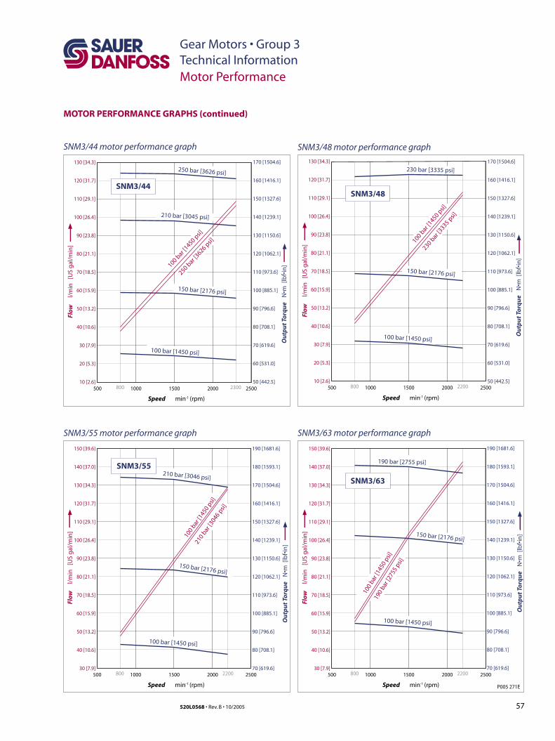
57520L0568 • Rev. B • 10/2005
Gear Motors • Group 3Technical Information
P005 271E
130 [34.3]
120 [31.7]
110 [29.1]
100 [26.4]
90 [23.8]
80 [21.1]
70 [18.5]
60 [15.9]
50 [13.2]
40 [10.6]
30 [7.9]
20 [5.3]
10 [2.6]800 2300
Speed min -1 (rpm)
Flow
l
/min
[U
S g
al/m
in]
2000 2500500 1000 1500
100 bar [
1450 psi]
250 bar [3626 psi]250 b
ar [3626 p
si]
100 bar [1450 psi]
150 bar [2176 psi]
210 bar [3045 psi]
SNM3/44
130 [34.3]
120 [31.7]
110 [29.1]
100 [26.4]
90 [23.8]
80 [21.1]
70 [18.5]
60 [15.9]
50 [13.2]
40 [10.6]
30 [7.9]
20 [5.3]
10 [2.6]800 2200
Speed min -1 (rpm)
Flow
l
/min
[U
S g
al/m
in]
2000 2500500 1000 1500
100 bar
[1450 p
si]
230 bar [3335 psi]
230 bar
[3335 p
si]
100 bar [1450 psi]
150 bar [2176 psi]
SNM3/48
150 [39.6]
140 [37.0]
130 [34.3]
120 [31.7]
110 [29.1]
100 [26.4]
90 [23.8]
80 [21.1]
70 [18.5]
60 [15.9]
50 [13.2]
40 [10.6]
30 [7.9]800 2200
Speed min -1 (rpm)
Flow
l
/min
[U
S g
al/m
in]
2000 2500500 1000 1500
100
bar [
1450
psi]
190 bar [2755 psi]
190
bar [
2755
psi]
100 bar [1450 psi]
150 bar [2176 psi]
SNM3/63
150 [39.6]
140 [37.0]
130 [34.3]
120 [31.7]
110 [29.1]
100 [26.4]
90 [23.8]
80 [21.1]
70 [18.5]
60 [15.9]
50 [13.2]
40 [10.6]
30 [7.9]800 2200
Speed min -1 (rpm)
Flow
l
/min
[U
S g
al/m
in]
2000 2500500 1000 1500
100
bar [1
450
psi]
210 bar [3046 psi]
210
bar [3
046
psi]
100 bar [1450 psi]
150 bar [2176 psi]
SNM3/55
Ou
tpu
t To
rqu
e N
•m [
lbf•
in]
Ou
tpu
t To
rqu
e N
•m [
lbf•
in]
Ou
tpu
t To
rqu
e N
•m [
lbf•
in]
Ou
tpu
t To
rqu
e N
•m [
lbf•
in]
170 [1504.6]
160 [1416.1]
150 [1327.6]
140 [1239.1]
130 [1150.6]
120 [1062.1]
110 [973.6]
100 [885.1]
90 [796.6]
80 [708.1]
70 [619.6]
60 [531.0]
50 [442.5]
170 [1504.6]
160 [1416.1]
150 [1327.6]
140 [1239.1]
130 [1150.6]
120 [1062.1]
110 [973.6]
100 [885.1]
90 [796.6]
80 [708.1]
70 [619.6]
60 [531.0]
50 [442.5]
190 [1681.6]
180 [1593.1]
170 [1504.6]
160 [1416.1]
150 [1327.6]
140 [1239.1]
130 [1150.6]
120 [1062.1]
110 [973.6]
100 [885.1]
90 [796.6]
80 [708.1]
70 [619.6]
190 [1681.6]
180 [1593.1]
170 [1504.6]
160 [1416.1]
150 [1327.6]
140 [1239.1]
130 [1150.6]
120 [1062.1]
110 [973.6]
100 [885.1]
90 [796.6]
80 [708.1]
70 [619.6]
Motor Performance
MOTOR PERFORMANCE GRAPHS (continued)
SNM3/44 motor performance graph SNM3/48 motor performance graph
SNM3/55 motor performance graph SNM3/63 motor performance graph
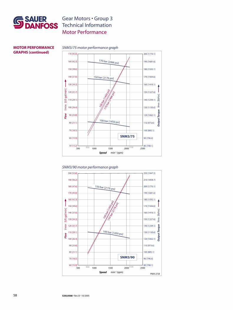
58 520L0568 • Rev. B • 10/2005
Gear Motors • Group 3Technical Information
P005 272E
170 [45.0]
160 [42.3]
150 [39.6]
140 [37.0]
130 [34.3]
120 [31.7]
110 [29.1]
100 [26.4]
90 [23.8]
80 [21.1]
70 [18.5]
60 [15.9]
50 [13.2]800 2100
Speed min -1 (rpm)
Flow
l
/min
[U
S g
al/m
in]
2000 2500500 1000 1500
100
bar [
1450
psi
]
170 bar [2466 psi]
170
bar [
2466
psi
]
100 bar [1450 psi]
150 bar [2176 psi]
SNM3/75
200 [52.8]
190 [50.2]
180 [47.6]
170 [45.0]
160 [42.3]
150 [39.6]
140 [37.0]
130 [34.3]
120 [31.7]
110 [29.1]
100 [26.4]
90 [23.8]
80 [21.1]
70 [18.5]
60 [15.9]800 2100
Speed min -1 (rpm)
Flow
l
/min
[U
S g
al/m
in]
2000 2500500 1000 1500
100
bar [
1450
psi
]
150
bar [
2176
psi
]
100 bar [1450 psi]
150 bar [2176 psi]
SNM3/90
200 [1770.1]
190 [1681.6]
180 [1593.1]
170 [1504.6]
160 [1416.1]
150 [1327.6]
140 [1239.1]
130 [1150.6]
120 [1062.1]
110 [973.6]
100 [885.1]
90 [796.6]
80 [708.1]
220 [1947.2]
210 [1858.7]
200 [1770.1]
190 [1681.6]
180 [1593.1]
170 [1504.6]
160 [1416.1]
150 [1327.6]
140 [1239.1]
130 [1150.6]
120 [1062.1]
110 [973.6]
100 [885.1]
90 [796.6]
80 [708.1]
Ou
tpu
t To
rqu
e N
•m [
lbf•
in]
Ou
tpu
t To
rqu
e N
•m [
lbf•
in]
Motor Performance
MOTOR PERFORMANCE GRAPHS (continued)
SNM3/75 motor performance graph
SNM3/90 motor performance graph
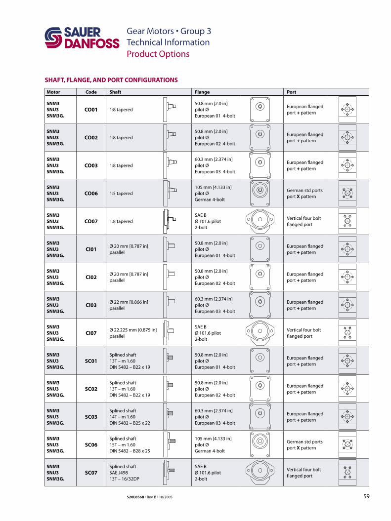
59520L0568 • Rev. B • 10/2005
Gear Motors • Group 3Technical InformationProduct Options
SHAFT, FLANGE, AND PORT CONFIGURATIONS
Motor Code Shaft Flange Port
SNM3SNU3SNM3G.
CO01 1:8 tapered50.8 mm [2.0 in] pilot Ø European 01 4-bolt
European flanged port + pattern
SNM3SNU3SNM3G.
CO02 1:8 tapered50.8 mm [2.0 in] pilot Ø European 02 4-bolt
European flanged port + pattern
SNM3SNU3SNM3G.
CO03 1:8 tapered60.3 mm [2.374 in] pilot Ø European 03 4-bolt
European flanged port + pattern
SNM3SNU3SNM3G.
CO06 1:5 tapered105 mm [4.133 in] pilot Ø German 4-bolt
German std portsport X pattern
SNM3SNU3SNM3G.
CO07 1:8 taperedSAE BØ 101.6 pilot2-bolt
Vertical four boltflanged port
SNM3SNU3SNM3G.
CI01Ø 20 mm [0.787 in]parallel
50.8 mm [2.0 in] pilot Ø European 01 4-bolt
European flanged port + pattern
SNM3SNU3SNM3G.
CI02Ø 20 mm [0.787 in]parallel
50.8 mm [2.0 in] pilot Ø European 02 4-bolt
European flanged port + pattern
SNM3SNU3SNM3G.
CI03Ø 22 mm [0.866 in]parallel
60.3 mm [2.374 in] pilot Ø European 03 4-bolt
European flanged port + pattern
SNM3SNU3SNM3G.
CI07Ø 22.225 mm [0.875 in]parallel
SAE BØ 101.6 pilot2-bolt
Vertical four boltflanged port
SNM3SNU3SNM3G.
SC01Splined shaft13T – m 1.60DIN 5482 – B22 x 19
50.8 mm [2.0 in] pilot Ø European 01 4-bolt
European flanged port + pattern
SNM3SNU3SNM3G.
SC02Splined shaft 13T – m 1.60DIN 5482 – B22 x 19
50.8 mm [2.0 in] pilot Ø European 02 4-bolt
European flanged port + pattern
SNM3SNU3SNM3G.
SC03Splined shaft14T – m 1.60DIN 5482 – B25 x 22
60.3 mm [2.374 in] pilot Ø European 03 4-bolt
European flanged port + pattern
SNM3SNU3SNM3G.
SC06Splined shaft15T – m 1.60DIN 5482 – B28 x 25
105 mm [4.133 in] pilot Ø German 4-bolt
German std portsport X pattern
SNM3SNU3SNM3G.
SC07Splined shaftSAE J49813T – 16/32DP
SAE BØ 101.6 pilot2-bolt
Vertical four boltflanged port
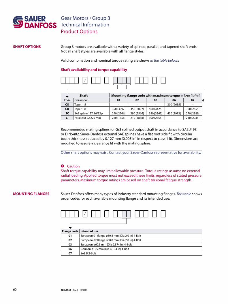
60 520L0568 • Rev. B • 10/2005
Gear Motors • Group 3Technical Information
SHAFT OPTIONS
Product Options
MOUNTING FLANGES
Shaft availability and torque capability
/
Shaft Mounting flange code with maximum torque in N•m [lbf•in]Code Description 01 02 03 06 07
CO Taper 1:5 - - - 300 [2655] -
CO Taper 1:8 350 [3097] 350 [3097] 500 [4425] - 300 [2655]
SC SAE spline 13T 16/32p 290 [2566] 290 [2566] 380 [3363] 450 [3982] 270 [2389]
CI Parallel ø 22.225 mm 210 [1858] 210 [1858] 300 [2655] - 230 [2035]
Recommended mating splines for Gr3 splined output shaft in accordance to SAE J498 or DIN5482. Sauer-Danfoss external SAE splines have a flat root side fit with circular tooth thickness reduced by 0.127 mm [0.005 in] in respect to class 1 fit. Dimensions are modified to assure a clearance fit with the mating spline.
Other shaft options may exist. Contact your Sauer-Danfoss representative for availability.
C CautionShaft torque capability may limit allowable pressure. Torque ratings assume no external radial loading. Applied torque must not exceed these limits, regardless of stated pressure parameters. Maximum torque ratings are based on shaft torsional fatigue strength.
Sauer-Danfoss offers many types of industry standard mounting flanges. This table shows order codes for each available mounting flange and its intended use:
/
Flange code Intended use
01 European 01 flange ø50.8 mm [Dia 2.0 in] 4-Bolt
02 European 02 flange ø50.8 mm [Dia 2.0 in] 4-Bolt
03 European ø60.3 mm [Dia 2.374 in] 4-Bolt
06 German ø105 mm [Dia 4.134 in] 4-Bolt
07 SAE B 2-Bolt
Group 3 motors are available with a variety of splined, parallel, and tapered shaft ends. Not all shaft styles are available with all flange styles.
Valid combination and nominal torque rating are shows in the table below::
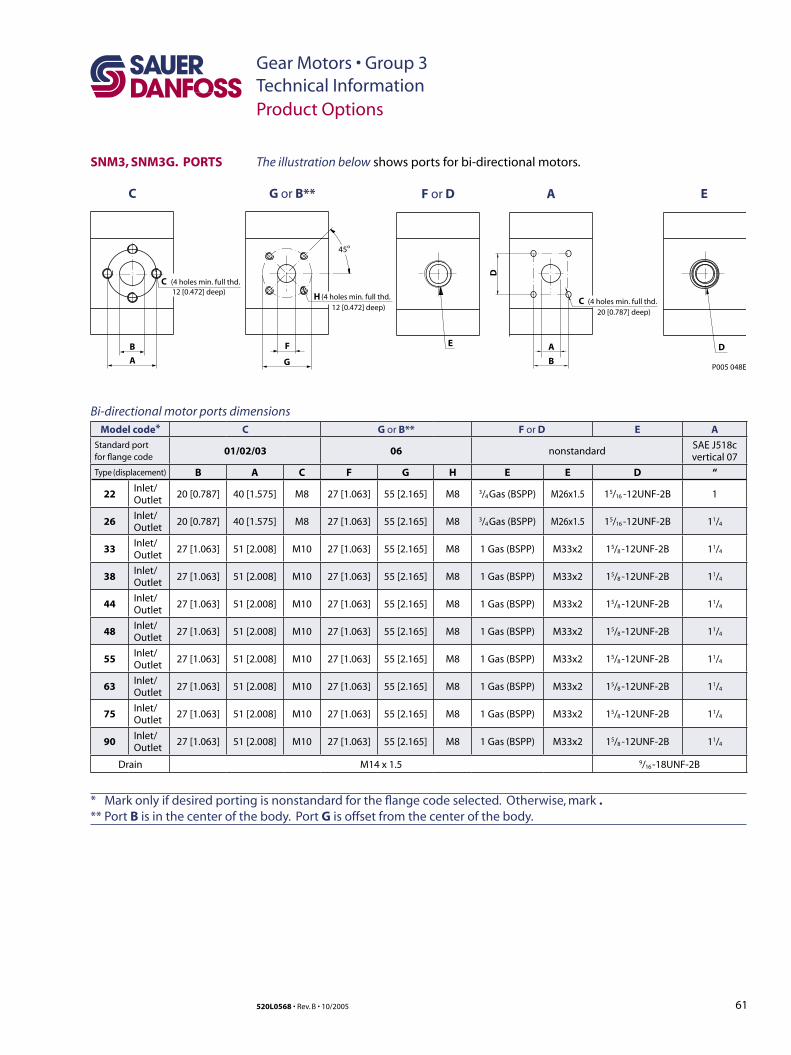
61520L0568 • Rev. B • 10/2005
Gear Motors • Group 3Technical Information
SNM3, SNM3G. PORTS
Bi-directional motor ports dimensionsModel code* C G or B** F or D E A
Standard portfor flange code
01/02/03 06 nonstandardSAE J518cvertical 07
Type (displacement) B A C F G H E E D “
22Inlet/Outlet
20 [0.787] 40 [1.575] M8 27 [1.063] 55 [2.165] M8 3/4 Gas (BSPP) M26x1.5 15/16 -12UNF-2B 1
26Inlet/Outlet
20 [0.787] 40 [1.575] M8 27 [1.063] 55 [2.165] M8 3/4 Gas (BSPP) M26x1.5 15/16 -12UNF-2B 11/4
33Inlet/Outlet
27 [1.063] 51 [2.008] M10 27 [1.063] 55 [2.165] M8 1 Gas (BSPP) M33x2 15/8 -12UNF-2B 11/4
38Inlet/Outlet
27 [1.063] 51 [2.008] M10 27 [1.063] 55 [2.165] M8 1 Gas (BSPP) M33x2 15/8 -12UNF-2B 11/4
44Inlet/Outlet
27 [1.063] 51 [2.008] M10 27 [1.063] 55 [2.165] M8 1 Gas (BSPP) M33x2 15/8 -12UNF-2B 11/4
48Inlet/Outlet
27 [1.063] 51 [2.008] M10 27 [1.063] 55 [2.165] M8 1 Gas (BSPP) M33x2 15/8 -12UNF-2B 11/4
55Inlet/Outlet
27 [1.063] 51 [2.008] M10 27 [1.063] 55 [2.165] M8 1 Gas (BSPP) M33x2 15/8 -12UNF-2B 11/4
63Inlet/Outlet
27 [1.063] 51 [2.008] M10 27 [1.063] 55 [2.165] M8 1 Gas (BSPP) M33x2 15/8 -12UNF-2B 11/4
75Inlet/Outlet
27 [1.063] 51 [2.008] M10 27 [1.063] 55 [2.165] M8 1 Gas (BSPP) M33x2 15/8 -12UNF-2B 11/4
90Inlet/Outlet
27 [1.063] 51 [2.008] M10 27 [1.063] 55 [2.165] M8 1 Gas (BSPP) M33x2 15/8 -12UNF-2B 11/4
Drain M14 x 1.5 9/16 -18UNF-2B
* Mark only if desired porting is nonstandard for the flange code selected. Otherwise, mark . ** Port B is in the center of the body. Port G is offset from the center of the body.
Product Options
The illustration below shows ports for bi-directional motors.
B
C G or B** F or D E
C
A
(4 holes min. full thd.12 [0.472] deep)
F
H
G
45o
(4 holes min. full thd.12 [0.472] deep)
P005 048E
E D
A
A
C (4 holes min. full thd. 20 [0.787] deep)
B
D
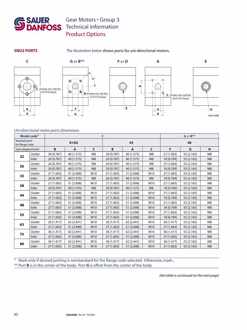
62 520L0568 • Rev. B • 10/2005
Gear Motors • Group 3Technical Information
B
C G or B** F or D E
C
A
(4 holes min. full thd.12 [0.472] deep)
F
H
G
45o
(4 holes min. full thd.12 [0.472] deep)
P005 048E
E D
A
A
C (4 holes min. full thd. 20 [0.787] deep)
B
D
(the table is continued on the next page)
Uni-directional motor ports dimensionsModel code* C G or B**
Standard portfor flange code
01/02 03 06
Type (displacement) B A C B A C F G H
22Outlet 20 [0.787] 40 [1.575] M8 20 [0.787] 40 [1.575] M8 27 [1.063] 55 [2.165] M8
Inlet 20 [0.787] 40 [1.575] M8 20 [0.787] 40 [1.575] M8 18 [0.709] 55 [2.165] M8
26Outlet 20 [0.787] 40 [1.575] M8 20 [0.787] 40 [1.575] M8 27 [1.063] 55 [2.165] M8
Inlet 20 [0.787] 40 [1.575] M8 20 [0.787] 40 [1.575] M8 18 [0.709] 55 [2.165] M8
33Outlet 27 [1.063] 51 [2.008] M10 27 [1.063] 51 [2.008] M10 27 [1.063] 55 [2.165] M8
Inlet 20 [0.787] 40 [1.575] M8 20 [0.787] 40 [1.575] M8 18 [0.709] 55 [2.165] M8
38Outlet 27 [1.063] 51 [2.008] M10 27 [1.063] 51 [2.008] M10 27 [1.063] 55 [2.165] M8
Inlet 20 [0.787] 40 [1.575] M8 20 [0.787] 40 [1.575] M8 18 [0.709] 55 [2.165] M8
44Outlet 27 [1.063] 51 [2.008] M10 27 [1.063] 51 [2.008] M10 27 [1.063] 55 [2.165] M8
Inlet 27 [1.063] 51 [2.008] M10 27 [1.063] 51 [2.008] M10 18 [0.709] 55 [2.165] M8
48Outlet 27 [1.063] 51 [2.008] M10 27 [1.063] 51 [2.008] M10 27 [1.063] 55 [2.165] M8
Inlet 27 [1.063] 51 [2.008] M10 27 [1.063] 51 [2.008] M10 18 [0.709] 55 [2.165] M8
55Outlet 27 [1.063] 51 [2.008] M10 27 [1.063] 51 [2.008] M10 27 [1.063] 55 [2.165] M8
Inlet 27 [1.063] 51 [2.008] M10 27 [1.063] 51 [2.008] M10 18 [0.709] 55 [2.165] M8
63Outlet 36 [1.417] 62 [2.441] M10 36 [1.417] 62 [2.441] M10 36 [1.417] 55 [2.165] M8
Inlet 27 [1.063] 51 [2.008] M10 27 [1.063] 51 [2.008] M10 27 [1.063] 55 [2.165] M8
75Outlet 36 [1.417] 62 [2.441] M10 36 [1.417] 62 [2.441] M10 36 [1.417] 55 [2.165] M8
Inlet 27 [1.063] 51 [2.008] M10 27 [1.063] 51 [2.008] M10 27 [1.063] 55 [2.165] M8
90Outlet 36 [1.417] 62 [2.441] M10 36 [1.417] 62 [2.441] M10 36 [1.417] 55 [2.165] M8
Inlet 27 [1.063] 51 [2.008] M10 27 [1.063] 51 [2.008] M10 27 [1.063] 55 [2.165] M8
* Mark only if desired porting is nonstandard for the flange code selected. Otherwise, mark . ** Port B is in the center of the body. Port G is offset from the center of the body.
SNU3 PORTS
Product Options
The illustration below shows ports for uni-directional motors.
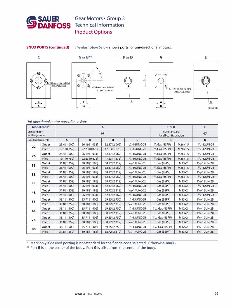
63520L0568 • Rev. B • 10/2005
Gear Motors • Group 3Technical Information
Uni-directional motor ports dimensionsModel code* A F or D E
Standard portfor flange code
07nonstandard
for all configuration07
Type (displacement) A B D C E D
22Outlet 25.4 [1.000] 26.19 [1.031] 52.37 [2.062] 3/8 -16UNC-2B 3/4 Gas (BSPP) M26x1.5 15/16 -12UN-2B
Inlet 19.1 [0.752] 22.23 [0.875] 47.63 [1.875] 3/8 -16UNC-2B 3/4 Gas (BSPP) M26x1.5 11/16 -12UN-2B
26Outlet 25.4 [1.000] 26.19 [1.031] 52.37 [2.062] 3/8 -16UNC-2B 3/4 Gas (BSPP) M26x1.5 15/16 -12UN-2B
Inlet 19.1 [0.752] 22.23 [0.875] 47.63 [1.875] 3/8 -16UNC-2B 3/4 Gas (BSPP) M26x1.5 11/16 -12UN-2B
33Outlet 31.8 [1.252] 30.18 [1.188] 58.72 [2.312] 7/16 -14UNC-2B 1 Gas (BSPP) M33x2 15/8 -12UN-2B
Inlet 25.4 [1.000] 26.19 [1.031] 52.37 [2.062] 3/8 -16UNC-2B 3/4 Gas (BSPP) M26x1.5 15/16 -12UN-2B
38Outlet 31.8 [1.252] 30.18 [1.188] 58.72 [2.312] 7/16 -14UNC-2B 1 Gas (BSPP) M33x2 15/8 -12UN-2B
Inlet 25.4 [1.000] 26.19 [1.031] 52.37 [2.062] 3/8 -16UNC-2B 3/4 Gas (BSPP) M26x1.5 15/16 -12UN-2B
44Outlet 31.8 [1.252] 30.18 [1.188] 58.72 [2.312] 7/16 -14UNC-2B 1 Gas (BSPP) M33x2 15/8 -12UN-2B
Inlet 25.4 [1.000] 26.19 [1.031] 52.37 [2.062] 3/8 -16UNC-2B 1 Gas (BSPP) M33x2 15/16 -12UN-2B
48Outlet 31.8 [1.252] 30.18 [1.188] 58.72 [2.312] 7/16 -14UNC-2B 1 Gas (BSPP) M33x2 15/8 -12UN-2B
Inlet 25.4 [1.000] 26.19 [1.031] 52.37 [2.062] 3/8 -16UNC-2B 1 Gas (BSPP) M33x2 15/16 -12UN-2B
55Outlet 38.1 [1.500] 35.71 [1.406] 69.85 [2.750] 1/2 -13UNC-2B 1 Gas (BSPP) M33x2 17/8 -12UN-2B
Inlet 31.8 [1.252] 30.18 [1.188] 58.72 [2.312] 7/16 -14UNC-2B 1 Gas (BSPP) M33x2 15/8 -12UN-2B
63Outlet 38.1 [1.500] 35.71 [1.406] 69.85 [2.750] 1/2 -13UNC-2B 11/4 Gas (BSPP) M42x2 17/8 -12UN-2B
Inlet 31.8 [1.252] 30.18 [1.188] 58.72 [2.312] 7/16 -14UNC-2B 1 Gas (BSPP) M33x2 15/8 -12UN-2B
75Outlet 38.1 [1.500] 35.71 [1.406] 69.85 [2.750] 1/2 -13UNC-2B 11/4 Gas (BSPP) M42x2 17/8 -12UN-2B
Inlet 31.8 [1.252] 30.18 [1.188] 58.72 [2.312] 7/16 -14UNC-2B 1 Gas (BSPP) M33x2 15/8 -12UN-2B
90Outlet 38.1 [1.500] 35.71 [1.406] 69.85 [2.750] 1/2 -13UNC-2B 11/4 Gas (BSPP) M42x2 17/8 -12UN-2B
Inlet 31.8 [1.252] 30.18 [1.188] 58.72 [2.312] 7/16 -14UNC-2B 1 Gas (BSPP) M33x2 15/8 -12UN-2B
* Mark only if desired porting is nonstandard for the flange code selected. Otherwise, mark . ** Port B is in the center of the body. Port G is offset from the center of the body.
B
C G or B** F or D E
C
A
(4 holes min. full thd.12 [0.472] deep)
F
H
G
45o
(4 holes min. full thd.12 [0.472] deep)
P005 048E
E D
A
A
C (4 holes min. full thd. 20 [0.787] deep)
B
D
SNU3 PORTS (continued) The illustration below shows ports for uni-directional motors.
Product Options
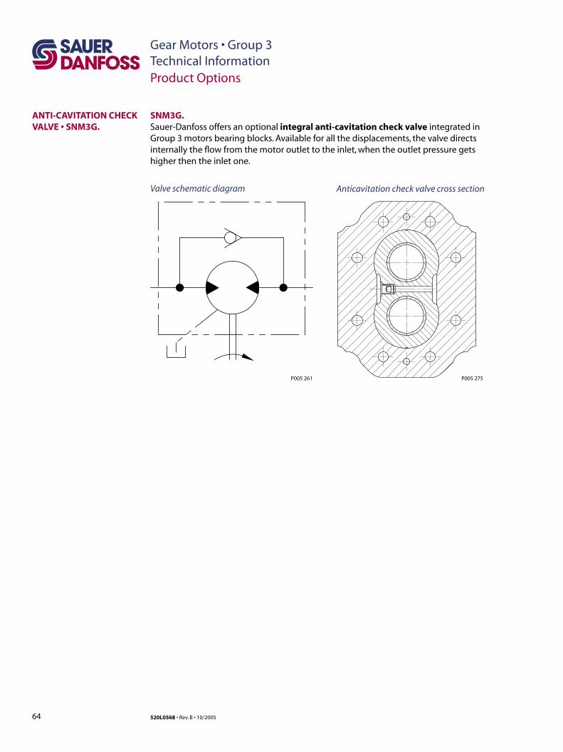
64 520L0568 • Rev. B • 10/2005
Gear Motors • Group 3Technical InformationProduct Options
ANTI-CAVITATION CHECK VALVE • SNM3G.
SNM3G. Sauer-Danfoss offers an optional integral anti-cavitation check valve integrated in Group 3 motors bearing blocks. Available for all the displacements, the valve directs internally the flow from the motor outlet to the inlet, when the outlet pressure gets higher then the inlet one.
Valve schematic diagram Anticavitation check valve cross section
P005 275P005 261
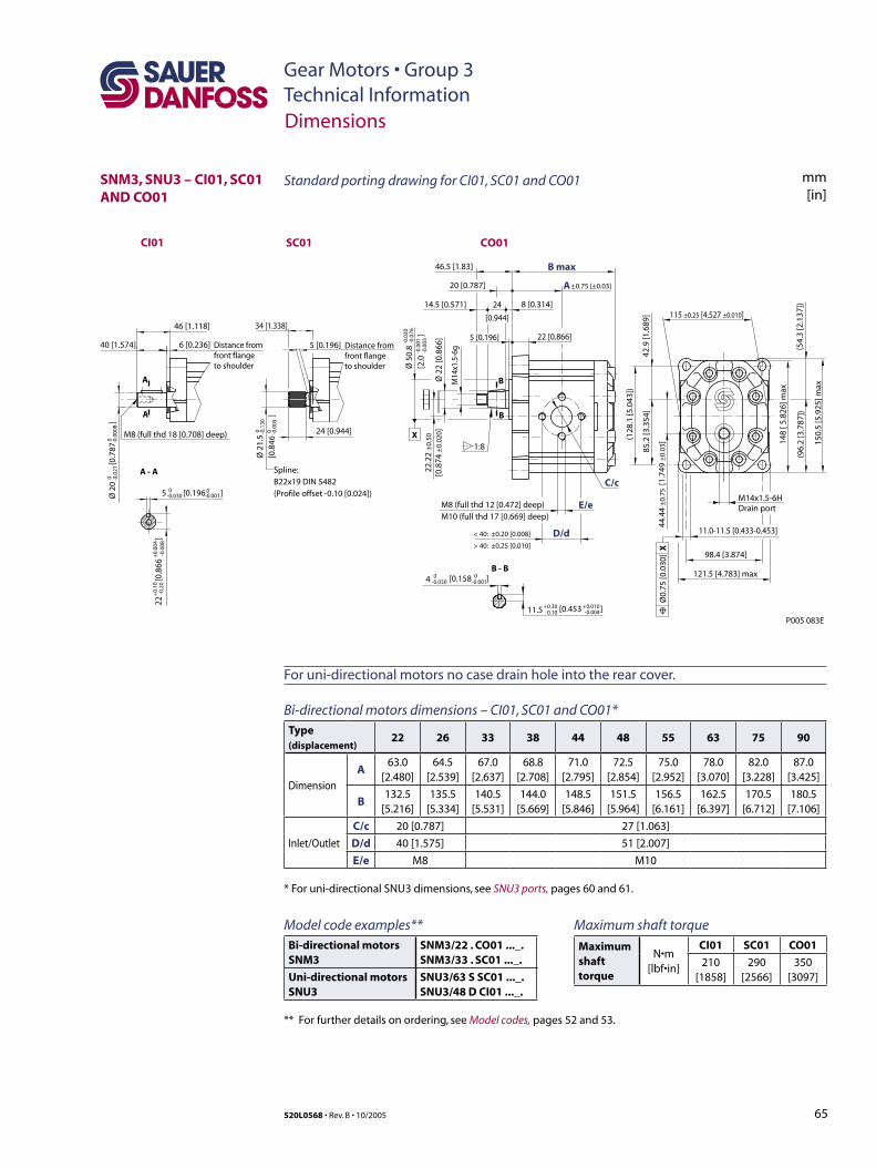
65520L0568 • Rev. B • 10/2005
Gear Motors • Group 3Technical Information
Model code examples**Bi-directional motorsSNM3
SNM3/22 . CO01 ..._.SNM3/33 . SC01 ..._.
Uni-directional motorsSNU3
SNU3/63 S SC01 ..._.SNU3/48 D CI01 ..._.
** For further details on ordering, see Model codes, pages 52 and 53.
Dimensions
SNM3, SNU3 – CI01, SC01 AND CO01
46.5 [1.83]
34 [1.338]46 [1.118]
6 [0.236]40 [1.574]
24 [0.944]
5 [0.196]
20 [0.787]
24
[0.944]
14.5 [0.571] 8 [0.314]
22 [0.866]5 [0.196]
±0.75 [±0.03]
121.5 [4.783] max
P005 083E
98.4 [3.874]
115 ±0.25 [4.527 ±0.010]
Ø 5
0.8
[2.0
]
-0.0
30-0
.076
-0.0
01-0
.003
Ø 2
0
[
0.78
7
]0 -0
.021
0 -0.0
008
Ø 2
2 [0
.866
]
M8 (full thd 12 [0.472] deep)M10 (full thd 17 [0.669] deep)
E/e
C/c
B max
D/d
A
< 40: ±0.20 [0.008]
> 40: ±0.25 [0.010]
85.2
[3.3
54]
42.9
[1.6
89]
(128
.1 [5
.043
])
(54.
3 [2
.137
])
148
[ 5.8
26] m
ax
(96.
2 [3
.787
])
150.
5 [5
.925
] maxM
14x1
.5-6
g
22.2
2 ±
0.50
[0.8
74 ±
0.02
0 ]
44.4
4 ±
0.75
[1.
749
±0.
03]
1:8
B - B
A - A
B
B
A
A
11.0-11.5 [0.433-0.453]
Spline:B22x19 DIN 5482(Profile offset -0.10 [0.024])
Ø0.
75 [0
.030
] X
Distance from front flange to shoulder
Distance from front flange to shoulder
5 [0.196 ]0-0.030
0-0.001
-0.0
0822
[0.
866
]
+0.
10-0
.20
+0.
004
Ø 2
1.5
[0.8
46
]
0 -0.1
300 -0
.005
M8 (full thd 18 [0.708] deep)
[0.453 ]+0.30 +0.010-0.10 -0.004
4 0 0-0.030 [0.158 ]-0.001
11.5
X
M14x1.5-6HDrain port
CO01SC01CI01
Standard porting drawing for CI01, SC01 and CO01 mm[in]
For uni-directional motors no case drain hole into the rear cover.
Bi-directional motors dimensions – CI01, SC01 and CO01*Type (displacement)
22 26 33 38 44 48 55 63 75 90
Dimension
A63.0
[2.480]64.5
[2.539]67.0
[2.637]68.8
[2.708]71.0
[2.795]72.5
[2.854]75.0
[2.952]78.0
[3.070]82.0
[3.228]87.0
[3.425]
B132.5
[5.216]135.5
[5.334]140.5
[5.531]144.0
[5.669]148.5
[5.846]151.5
[5.964]156.5
[6.161]162.5
[6.397]170.5
[6.712]180.5
[7.106]
Inlet/Outlet
C/c 20 [0.787] 27 [1.063]
D/d 40 [1.575] 51 [2.007]
E/e M8 M10
* For uni-directional SNU3 dimensions, see SNU3 ports, pages 60 and 61.
Maximum shaft torque
Maximum shaft torque
N•m [lbf•in]
CI01 SC01 CO01
210 [1858]
290 [2566]
350 [3097]
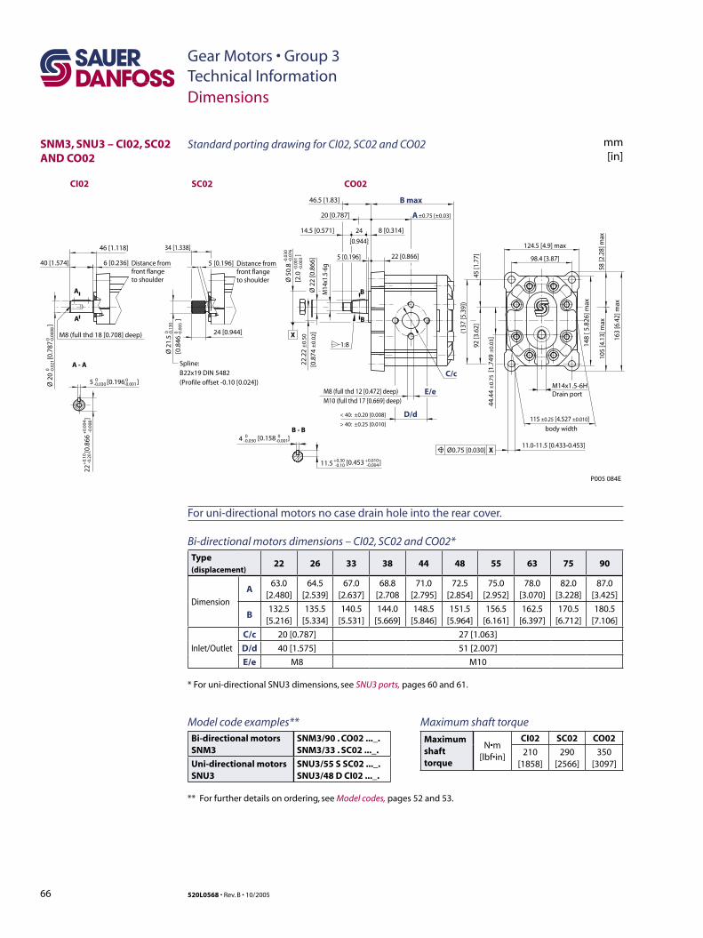
66 520L0568 • Rev. B • 10/2005
Gear Motors • Group 3Technical InformationDimensions
SNM3, SNU3 – CI02, SC02 AND CO02
46.5 [1.83]
34 [1.338]46 [1.118]
6 [0.236]40 [1.574]
24 [0.944]
5 [0.196]
20 [0.787]
24
[0.944]
14.5 [0.571] 8 [0.314]
22 [0.866]5 [0.196]
±0.75 [±0.03]
P005 084E
115 ±0.25 [4.527 ±0.010]
Ø 5
0.8
[2.0
]
-0.0
30-0
.076
-0.0
01-0
.003
Ø 2
0
[
0.78
7
]0 -0
.021
0 -0.0
008
Ø 2
2 [0
.866
]
M8 (full thd 12 [0.472] deep)M10 (full thd 17 [0.669] deep)
E/e
C/c
B max
D/d
A
< 40: ±0.20 [0.008]
> 40: ±0.25 [0.010]
148
[ 5.8
26] m
ax
M14
x1.5
-6g
22.2
2 ±
0.50
[0.8
74 ±
0.02
]
1:8
B - B
A - A
B
B
A
A
11.0-11.5 [0.433-0.453]
Spline:B22x19 DIN 5482(Profile offset -0.10 [0.024])
Ø0.75 [0.030] X
Distance from front flange to shoulder
Distance from front flange to shoulder
5 [0.196 ]0-0.030
0-0.001
-0.0
0822
[0.
866
]
+0.
10-0
.20
+0.
004
Ø 2
1.5
[0.8
46
]
0 -0.1
300 -0
.005
M8 (full thd 18 [0.708] deep)
[0.453 ]+0.30 +0.010-0.10 -0.004
4 0 0-0.030 [0.158 ]-0.001
11.5
X
body width
124.5 [4.9] max
98.4 [3.87]
58 [2
.28]
max
105
[4.1
3] m
ax
163
[6.4
2] m
ax
(137
[5.3
9])
92 [3
.62]
45 [1
.77]
44.4
4 ±
0.75
[1.
749
±0.
03]
M14x1.5-6HDrain port
CO02SC02CI02
mm[in]
Standard porting drawing for CI02, SC02 and CO02
For uni-directional motors no case drain hole into the rear cover.
Bi-directional motors dimensions – CI02, SC02 and CO02*Type (displacement)
22 26 33 38 44 48 55 63 75 90
Dimension
A63.0
[2.480]64.5
[2.539]67.0
[2.637]68.8
[2.70871.0
[2.795]72.5
[2.854]75.0
[2.952]78.0
[3.070]82.0
[3.228]87.0
[3.425]
B132.5
[5.216]135.5
[5.334]140.5
[5.531]144.0
[5.669]148.5
[5.846]151.5
[5.964]156.5
[6.161]162.5
[6.397]170.5
[6.712]180.5
[7.106]
Inlet/Outlet
C/c 20 [0.787] 27 [1.063]
D/d 40 [1.575] 51 [2.007]
E/e M8 M10
* For uni-directional SNU3 dimensions, see SNU3 ports, pages 60 and 61.
Model code examples**Bi-directional motorsSNM3
SNM3/90 . CO02 ..._.SNM3/33 . SC02 ..._.
Uni-directional motorsSNU3
SNU3/55 S SC02 ..._.SNU3/48 D CI02 ..._.
** For further details on ordering, see Model codes, pages 52 and 53.
Maximum shaft torque
Maximum shaft torque
N•m [lbf•in]
CI02 SC02 CO02
210 [1858]
290 [2566]
350 [3097]
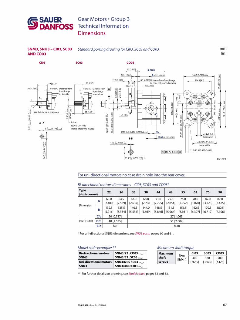
67520L0568 • Rev. B • 10/2005
Gear Motors • Group 3Technical Information
X
P005 085E
body width
Distance from front flange to cone reference diameter
-0.0
30-0
.076
-0.0
12-0
.003
A
D/d ±0.25 [±0.010]
B max
22.2
2 ±0
.50
[0.8
75 ±
0.02
0]
Ø60
.3
[2.3
74
]
115 ±0.25[4.527 ±0.010]
E/e
C/c
Ø 2
5 [0
.984
]
M16
x1.5
-6g
22 [0.866]
60 [2.362]
146.5 [5.768] max
114.3 [4.5]
9 [0.354]50 [1.968]
59 [2.323] 50 1.97]
28.5 [1.122]
28[1.102]
14.5 [0.571]17.5 [0.689]
1:8
M10 (full thd 17 [0.669] deep)
34 [1.351]
±0.75 [±0.030]
8 [0.315]8 [0.315]
B-B
B
B 148
[ 5.8
26] m
ax
(149
.5 [
5.88
5])
100
[ 3.9
37]
49.5
[ 1
.949
]
116
[4.5
66] m
ax65
.5 [2
.578
] max
181.
5 [ 7
.145
] max
4.79 [0.189 ]0-0.30
0-0.012
-0.01013.5 [0.532 ] +0.15-0.25
+0.006
Ø 2
2
[
0.86
6
]0 -0
.021
0 -0.0
008
A - A
A
A
Spline:B22x19 DIN 5482(Profile offset: 0.45 [0.018])
Distance from front flange to shoulder
Distance from front flange to shoulder
5 [0.196 ]0-0.030
0-0.001
-0.0
0824
[0.
945
]
+0.
10-0
.20
+0.
004
Ø 2
4.5
[0.9
65
]
0 -0.1
300 -0
.005
M8 (full thd 18 [0.708] deep)
11.0-11.5 [0.433-0.453]Ø0.75 [0.030] X
44.4
4 ±
0.75
[1.
749
±0.
03]
M14x1.5-6HDrain port
CO03SC03CI03
Dimensions
SNM3, SNU3 – CI03, SC03 AND CO03
Model code examples**Bi-directional motorsSNM3
SNM3/22 . CO03 ..._.SNM3/33 . SC03 ..._.
Uni-directional motorsSNU3
SNU3/63 S SC03 ..._.SNU3/48 D CI03 ..._.
** For further details on ordering, see Model codes, pages 52 and 53.
Standard porting drawing for CI03, SC03 and CO03 mm[in]
For uni-directional motors no case drain hole into the rear cover.
Bi-directional motors dimensions – CI03, SC03 and CO03*Type (displacement)
22 26 33 38 44 48 55 63 75 90
Dimension
A63.0
[2.480]64.5
[2.539]67.0
[2.637]68.8
[2.70871.0
[2.795]72.5
[2.854]75.0
[2.952]78.0
[3.070]82.0
[3.228]87.0
[3.425]
B132.5
[5.216]135.5
[5.334]140.5
[5.531]144.0
[5.669]148.5
[5.846]151.5
[5.964]156.5
[6.161]162.5
[6.397]170.5
[6.712]180.5
[7.106]
Inlet/Outlet
C/c 20 [0.787] 27 [1.063]
D/d 40 [1.575] 51 [2.007]
E/e M8 M10
* For uni-directional SNU3 dimensions, see SNU3 ports, pages 60 and 61.
Maximum shaft torque
Maximum shaft torque
N•m [lbf•in]
CI03 SC03 CO03
300 [2655]
380 [3363]
500 [4425]
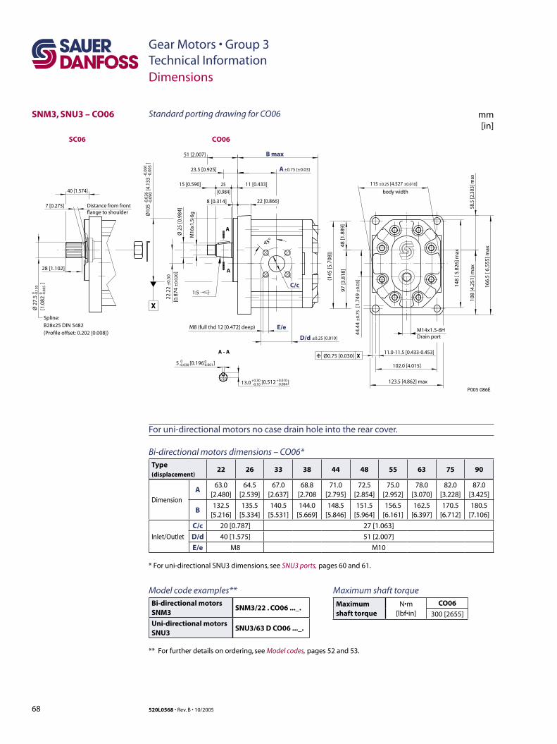
68 520L0568 • Rev. B • 10/2005
Gear Motors • Group 3Technical Information
SNM3, SNU3 – CO06
P005 086E
11.0-11.5 [0.433-0.453]Ø0.75 [0.030] X
40 [1.574]
1:5
45o
28 [1.102]
8 [0.314] 22 [0.866]
25 [0.984]
51 [2.007]
23.5 [0.925]
15 [0.590] 11 [0.433]
7 [0.275]
±0.75 [±0.03]
M8 (full thd 12 [0.472] deep) E/e
C/c
B max
D/d
A
A - A
A
A
Spline:B28x25 DIN 5482(Profile offset: 0.202 [0.008])
Distance from front flange to shoulder
5 [0.196 ]0-0.030
0-0.001
Ø 2
7.5
[1.0
82
]
0 -0.1
300 -0
.005
[0.512 ]+0.30 +0.010-0.10 -0.00413.0 123.5 [4.862] max
102.0 [4.015]
115 ±0.25 [4.527 ±0.010]
±0.25 [0.010]
22.2
2 ±
0.50
[0.8
74 ±
0.02
0]
X
body width
-0.0
36-0
.090
-0.0
01-0
.003
Ø10
5
[4.
133
]
Ø 2
5 [0
.984
]
M16
x1.5
-6g
108
[4.2
51] m
ax58
.5 [2
.303
] max
148
[ 5.8
26] m
ax
166.
5 [ 6
.555
] max
(145
[5.7
08])
97 [3
.818
]48
[1.8
89]
44.4
4 ±
0.75
[1.
749
±0.
03]
M14x1.5-6HDrain port
CO06SC06
Dimensions
Model code examples**Bi-directional motorsSNM3
SNM3/22 . CO06 ..._.
Uni-directional motorsSNU3
SNU3/63 D CO06 ..._.
** For further details on ordering, see Model codes, pages 52 and 53.
Standard porting drawing for CO06 mm[in]
For uni-directional motors no case drain hole into the rear cover.
Bi-directional motors dimensions – CO06*Type (displacement)
22 26 33 38 44 48 55 63 75 90
Dimension
A63.0
[2.480]64.5
[2.539]67.0
[2.637]68.8
[2.70871.0
[2.795]72.5
[2.854]75.0
[2.952]78.0
[3.070]82.0
[3.228]87.0
[3.425]
B132.5
[5.216]135.5
[5.334]140.5
[5.531]144.0
[5.669]148.5
[5.846]151.5
[5.964]156.5
[6.161]162.5
[6.397]170.5
[6.712]180.5
[7.106]
Inlet/Outlet
C/c 20 [0.787] 27 [1.063]
D/d 40 [1.575] 51 [2.007]
E/e M8 M10
* For uni-directional SNU3 dimensions, see SNU3 ports, pages 60 and 61.
Maximum shaft torque
Maximum shaft torque
N•m [lbf•in]
CO06
300 [2655]
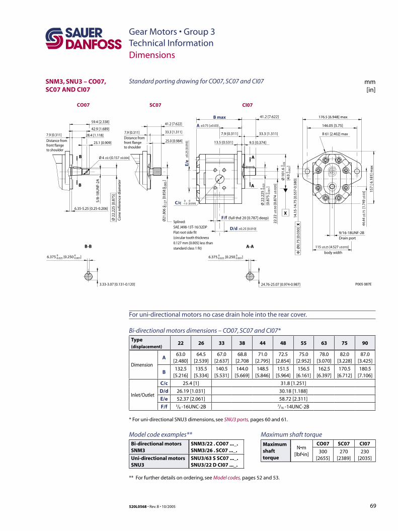
69520L0568 • Rev. B • 10/2005
Gear Motors • Group 3Technical Information
SNM3, SNU3 – CO07, SC07 AND CI07
±0.75 [±0.03]
(full thd 20 [0.787] deep)F/f
B max
D/d
A
6.375 [0.250 ]0-0.025
0 0-1.5 [0.059]
0-0.001
115 ±0.25 [4.527 ±0.010]
±0.25 [0.010]
C/c
E/e
±0.
25 [0
.010
]
22.2
2 ±
0.50
[0.8
74 ±
0.02
0 ]
body width
0 -0.1
270 -0
.005
Ø21
.806
[0.8
58
]
176.5 [6.948] max
R 61 [2.402] max
146.05 [5.75]
41.2 [7.622]
41.2 [7.622]
33.3 [1.311]33.3 [1.311]
25.0 [0.984]
7.9 [0.311]7.9 [0.311]7.9 [0.311]
13.5 [0.531] 9.5 [0.374]
157
[ 6.1
81] m
ax
14.1
5-14
.75
[0.5
57-0
.580
]
6.35-5.25 [0.25-0.206]
24.76-25.07 [0.974-0.987]
Ø0.
75 [0
.030
] X
Ø 2
2.22
5[0
.875
]
0 -0.0
250 -0
.001
Ø 1
01.6
[4.0
]0 -0
.05
0 -0.0
02
X
A
A
B
B
A-A
6.375 [0.250 ]0-0.025
0-0.001
3.33-3.07 [0.131-0.120]
B-B
Splined:SAE J498-13T-16/32DPFlat root side fit(circular tooth thickness0.127 mm [0.005] less thanstandard class 1 fit)
P005 087E
9/16-18UNF-2BDrain port
5/8-
18U
NF-
2A
28.4 [1.118]
59.4 [2.338]
42.9 [1.689]
23.1 [0.909]
Ø 2
2.22
5 [0
.875
]
Co
ne
refe
ren
ce d
iam
eter
Distance from front flange to shoulder
Distance from front flange to shoulder
Ø 4 ±0.1[0.157 ±0.004]
44.4
4 ±0
.75
[1.7
49 ±
0.03
]
CI07SC07CO07
Dimensions
Model code examples**Bi-directional motorsSNM3
SNM3/22 . CO07 ..._.SNM3/26 . SC07 ..._.
Uni-directional motorsSNU3
SNU3/63 S SC07 ..._.SNU3/22 D CI07 ..._.
** For further details on ordering, see Model codes, pages 52 and 53.
Standard porting drawing for CO07, SC07 and CI07 mm[in]
For uni-directional motors no case drain hole into the rear cover.
Bi-directional motors dimensions – CO07, SC07 and CI07*Type (displacement)
22 26 33 38 44 48 55 63 75 90
Dimension
A63.0
[2.480]64.5
[2.539]67.0
[2.637]68.8
[2.70871.0
[2.795]72.5
[2.854]75.0
[2.952]78.0
[3.070]82.0
[3.228]87.0
[3.425]
B132.5
[5.216]135.5
[5.334]140.5
[5.531]144.0
[5.669]148.5
[5.846]151.5
[5.964]156.5
[6.161]162.5
[6.397]170.5
[6.712]180.5
[7.106]
Inlet/Outlet
C/c 25.4 [1] 31.8 [1.251]
D/d 26.19 [1.031] 30.18 [1.188]
E/e 52.37 [2.061] 58.72 [2.311]
F/f 3/8 -16UNC-2B 7/16 -14UNC-2B
* For uni-directional SNU3 dimensions, see SNU3 ports, pages 60 and 61.
Maximum shaft torque
Maximum shaft torque
N•m [lbf•in]
CO07 SC07 CI07
300 [2655]
270 [2389]
230 [2035]

70 520L0568 • Rev. B • 10/2005
Notes
Gear Motors • Group 1, 2 and 3Technical Information

71520L0568 • Rev. B • 10/2005
Notes
Gear Motors • Group 1, 2 and 3Technical Information
Sauer-Danfoss Hydraulic Power Systems– Market Leaders Worldwide
Sauer-Danfoss is a comprehensive supplier providing complete systems to the global mobile market.
Sauer-Danfoss serves markets such as agriculture, construction, road building, material handling, municipal, forestry, turf care, and many others.
We offer our customers optimum solutions for their needs and develop new products and systems in close cooperation and partnership with them.
Sauer-Danfoss specializes in integrating a full range of system components to provide vehicle designers with the most advanced total system design.
Sauer-Danfoss provides comprehensive worldwide service for its products through an extensive network of Authorized Service Centers strategically located in all parts of the world.
Sauer-Danfoss (US) Company2800 East 13th StreetAmes, IA 50010, USAPhone: +1 515 239-6000, Fax: +1 515 239 6618
Sauer-Danfoss (Neumünster) GmbH & Co. OHGPostfach 2460, D-24531 NeumünsterKrokamp 35, D-24539 Neumünster, GermanyPhone +49 4321 871-0, Fax: +49 4321 871 122
Sauer-Danfoss (Nordborg) ApSDK-6430 Nordborg, DenmarkPhone: +45 7488 4444, Fax: +45 7488 4400
www.sauer-danfoss.com
OUR PRODUCTS
Hydrostatic transmissions
Hydraulic power steering
Electric power steering
Electrohydraulic power steering
Closed and open circuit axial piston motors and motors
Gear motors and motors
Bent axis motors
Orbital motors
Transit mixer drives
Planetary compact gears
Proportional valves
Directional spool valves
Cartridge valves
Hydraulic integrated circuits
Hydrostatic transaxles
Integrated systems
Fan drive systems
Electrohydraulic controls
Digital electronics and software
Electric motors and inverters
Joysticks and control handles
Displays
Sensors
520L0568 • Rev. B • 10/2005