Embed Size (px)
Citation preview
Gecko-Inspired Climbing Behaviors on Vertical and Overhanging SurfacesDaniel Santos, Barrett Heyneman, Sangbae Kim, Noe Esparza, and Mark R. Cutkosky
Center for Design ResearchStanford University
Stanford, CA 94305-2232, USAcontact: [email protected]
Abstract— The adhesive and frictional properties of dryadhesive materials can be described by a three-dimensionallimit surface in the space of normal and tangential con-tact forces at the feet. We present the empirically derivedlimit surface for directional adhesive pads and illustrate itsapplication to controlling the forces at the feet of a robotclimbing on arbitrary slopes, including overhanging surfaces.For the directional adhesive patches that we have developed,the limit surface is convex, which permits efficient computationof the desired internal and external forces among the feet tomaximize a safety margin with respect to disturbance forceson the robot. The limit surface also intersects the origin inforce space, which enables efficient climbing without wastingenergy in attaching and detaching the feet. These insights areapplied to an experimental climbing platform demonstrating theproper use of directional adhesion and mimicking the climbingbehavior seen in geckos.
I. INTRODUCTION
As progress continues in legged robotics, research hasbegun to focus on developing robust climbers. Various robotshave been developed that climb flat vertical surfaces usingsuction [16], [17], [21], magnets [6], [23], and arrays of smallspines [1], [20] to attach their feet to the surface. Morerecently, robots have been developed that utilize adhesivematerials for climbing smooth surfaces such as glass [7],[15], [18].
Researchers have also begun to examine the adhesivestructures of the gecko lizard in detail, inspired by thegecko’s remarkable speed and ability to climb a wide varietyof surfaces. The gecko employs a sophisticated hierarchicaladhesive system consisting of lamellae, setae, and spatulae[4], [5] that conform intimately to both smooth and roughsurfaces, allowing van der Waals forces to provide sufficientadhesion for climbing. In addition, the adhesive structuresare angled and curved, which gives gecko adhesion theimportant property of directionality [2]. When the adhesivestructures are pulled tangentially to the climbing surfacein one direction, the amount of adhesion at the contactlinearly increases with the amount of shear; when shearforces are applied in the opposite direction, only frictionis observed. The directional property of gecko adhesionhas been described by an empirical model termed frictionaladhesion [3].
In previous work, the authors reported on a synthetic ad-hesive material that mimics the directional property of geckoadhesion [19] and on the design and operation of a legged
front feet
rear feet
(reversed)mg
20°
Fig. 1. StickyBot (∼450g) shown clinging to an overhanging (20◦ beyondvertical) surface, with rear feet reversed and with∼6N internal force appliedbetween front and rear feet in the fore-aft direction (3N on both left andand right sides). (Weight hanging from suction cup in foreground showsgravity direction.)
robot that utilizes this material to climb smooth verticalsurfaces [15]. In the present paper, we extend this workto develop a three-dimensional limit surface that describescombinations of normal, tangential and lateral forces that adirectional adhesive contact can sustain without failing dueto slippage or detachment. The 3D force limit surfaces forindividual contact patches are then combined, using convexaddition, to obtain an overall limit surface for an entirefoot. We use the limit surfaces as constraints in a forceanalysis to prescribe optimal foot orientations and internalforces to apply at the feet of a climbing robot, to maximizeits ability to resist arbitrary disturbance forces on slopedand overhanging surfaces. We demonstrate the applicationof this analysis to StickyBot (Fig. 1) allowing it to clingto overhanging surfaces. We conclude with a discussion offuture extensions of the work.
Tangential
Tangential
Normal
NormalLateral
Lateral
FN
FT
FL
T1
T4
O
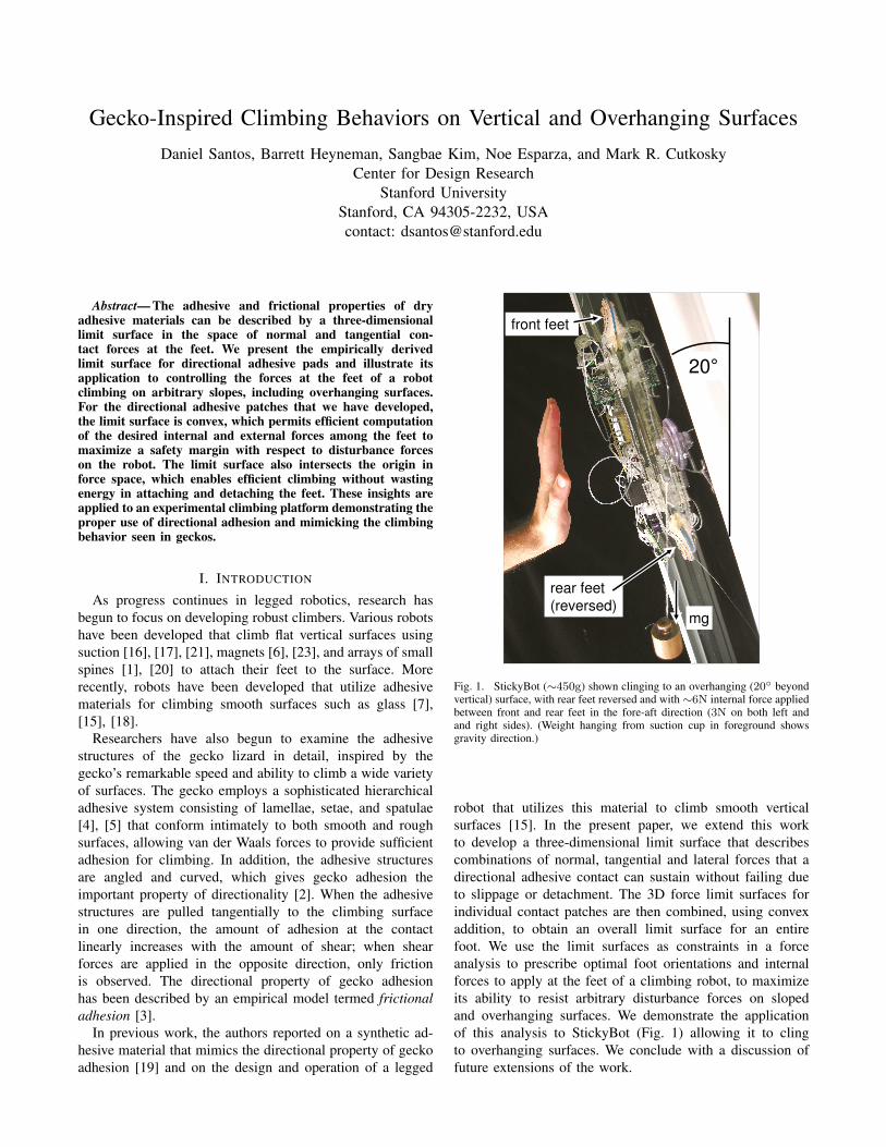
Fig. 2. A StickyBot foot has four toes, each of which has a 4cm2 patch of asynthetic adhesive termed Directional Polymer Stalks (DPS). The preferredloading direction for each patch is along the tangential axis. The tangential,lateral and normal axes form a right-handed coordinate system for eachpatch, as shown. The four patches combine to produce a resultant lateral,tangential and normal force for the entire foot.
II. THREE DIMENSIONAL ADHESION LIMIT SURFACE
Figure 2 shows one foot of StickyBot with four toes,each of which is equipped with a synthetic adhesive patchtermed Directional Polymer Stalks (DPS) [19]. Because ofthe angled nature of the stalks in the DPS patches, theyexhibit directional adhesion similar to that observed in thegecko [3], [19].
To obtain a more complete, three-dimensional charac-terization of the friction and adhesion, new experimentswere performed that included the effects of loading in allthree directions: normal, tangential and lateral (see Fig. 2).A 3-axis linear stage was used to apply motions to DPSpatches, bringing them into and out of contact with a glasssubstrate. The motion stage (Velmex, MAXY4009W2-S4and MA2506B-S2.5) has a positioning resolution of ±10µmin the lateral and tangential directions and ±1µm in thenormal direction. The flat glass substrate is mounted on a 6-axis force/torque sensor (ATI Industrial Automation, GammaTransducer SI-32-2.5), which is in turn mounted on a manual2-axis tilt stage (Newport, 30 Series Tilt Platform) used foraligning the sample to the substrate.
Experiments consisted of first preloading patches along anapproach trajectory to a desired depth in the normal direction.The patches were then pulled away from the substrate and thepull-off and/or sliding forces were measured in the lateral,tangential, and normal directions. Both the preload trajectoryangle and the preload depth were varied in order to determinetheir effect on normal pull-off forces.
For the initial tests, pull-off vectors were constrained tothe tangential-normal plane (Fig. 2) and speed was heldconstant at 1mm/s. A preload approach angle of 45◦ wasempirically found to produce the largest pull-off forcesfor any given preload. Pull-off forces quickly drop as theapproach becomes shallower (more dragging) or steeper
0 1 2 3 40
1
2
3
4
Preload Force (N)
Pu
llo
ff F
orc
e (
N)
400µµµµm
500µµµµm
600µµµµm
700µµµµm
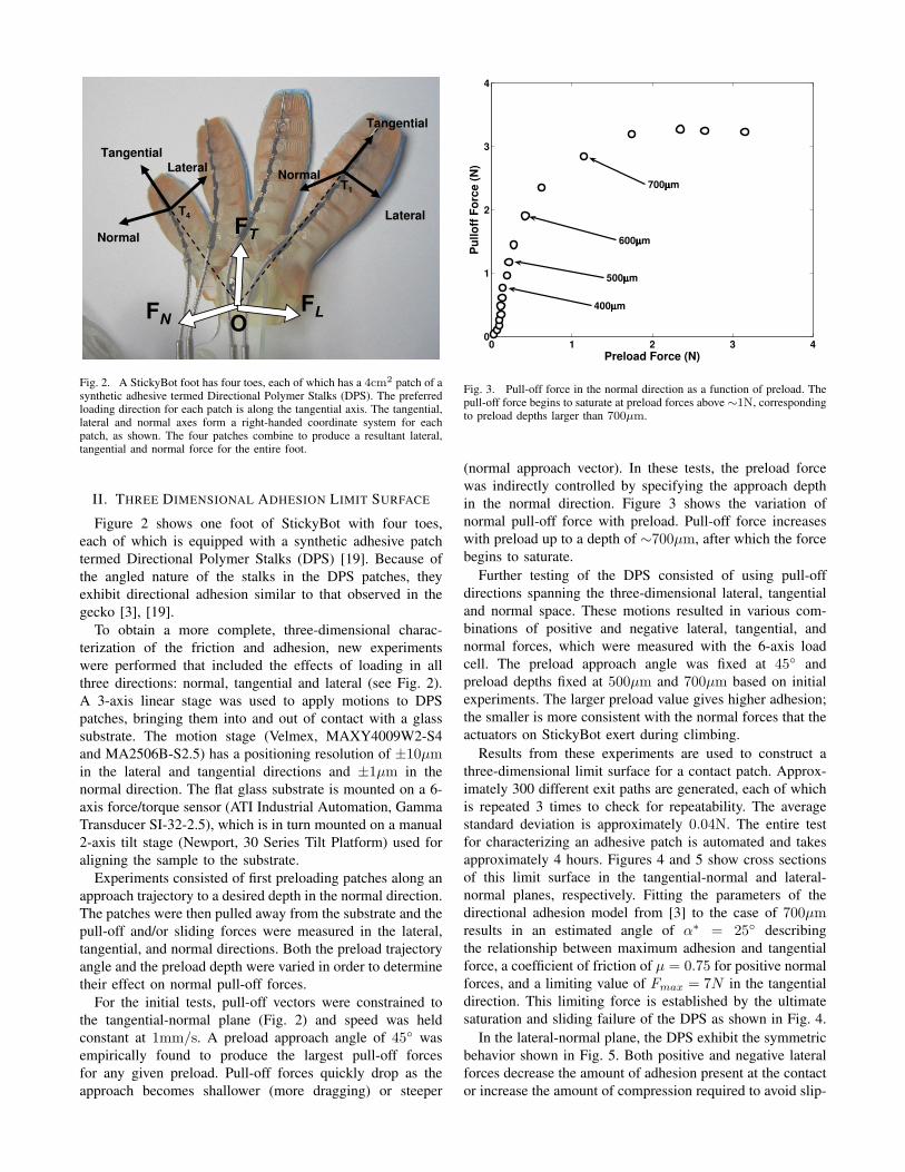
Fig. 3. Pull-off force in the normal direction as a function of preload. Thepull-off force begins to saturate at preload forces above ∼1N, correspondingto preload depths larger than 700µm.
(normal approach vector). In these tests, the preload forcewas indirectly controlled by specifying the approach depthin the normal direction. Figure 3 shows the variation ofnormal pull-off force with preload. Pull-off force increaseswith preload up to a depth of ∼700µm, after which the forcebegins to saturate.
Further testing of the DPS consisted of using pull-offdirections spanning the three-dimensional lateral, tangentialand normal space. These motions resulted in various com-binations of positive and negative lateral, tangential, andnormal forces, which were measured with the 6-axis loadcell. The preload approach angle was fixed at 45◦ andpreload depths fixed at 500µm and 700µm based on initialexperiments. The larger preload value gives higher adhesion;the smaller is more consistent with the normal forces that theactuators on StickyBot exert during climbing.
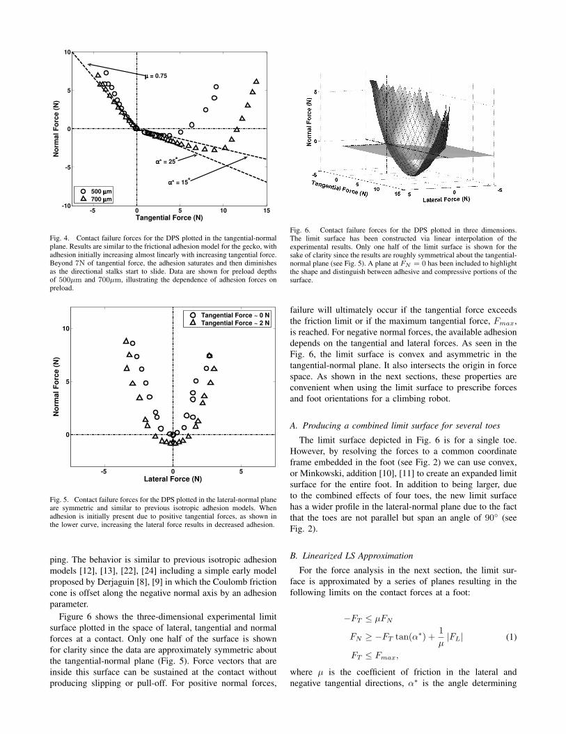
Results from these experiments are used to construct athree-dimensional limit surface for a contact patch. Approx-imately 300 different exit paths are generated, each of whichis repeated 3 times to check for repeatability. The averagestandard deviation is approximately 0.04N. The entire testfor characterizing an adhesive patch is automated and takesapproximately 4 hours. Figures 4 and 5 show cross sectionsof this limit surface in the tangential-normal and lateral-normal planes, respectively. Fitting the parameters of thedirectional adhesion model from [3] to the case of 700µmresults in an estimated angle of α∗ = 25◦ describingthe relationship between maximum adhesion and tangentialforce, a coefficient of friction of µ = 0.75 for positive normalforces, and a limiting value of Fmax = 7N in the tangentialdirection. This limiting force is established by the ultimatesaturation and sliding failure of the DPS as shown in Fig. 4.
In the lateral-normal plane, the DPS exhibit the symmetricbehavior shown in Fig. 5. Both positive and negative lateralforces decrease the amount of adhesion present at the contactor increase the amount of compression required to avoid slip-
-5 0 5 10 15-10
-5
0
5
10
Tangential Force (N)
No
rma
l F
orc
e (
N)
500 µµµµm
700 µµµµm
αααα* = 25°°°°
αααα* = 15°°°°
µµµµ = 0.75
Fig. 4. Contact failure forces for the DPS plotted in the tangential-normalplane. Results are similar to the frictional adhesion model for the gecko, withadhesion initially increasing almost linearly with increasing tangential force.Beyond 7N of tangential force, the adhesion saturates and then diminishesas the directional stalks start to slide. Data are shown for preload depthsof 500µm and 700µm, illustrating the dependence of adhesion forces onpreload.
-5 0 5
0
5
10
Lateral Force (N)
No
rma
l F
orc
e (
N)
Tangential Force ~ 0 N
Tangential Force ~ 2 N
Fig. 5. Contact failure forces for the DPS plotted in the lateral-normal planeare symmetric and similar to previous isotropic adhesion models. Whenadhesion is initially present due to positive tangential forces, as shown inthe lower curve, increasing the lateral force results in decreased adhesion.
ping. The behavior is similar to previous isotropic adhesionmodels [12], [13], [22], [24] including a simple early modelproposed by Derjaguin [8], [9] in which the Coulomb frictioncone is offset along the negative normal axis by an adhesionparameter.
Figure 6 shows the three-dimensional experimental limitsurface plotted in the space of lateral, tangential and normalforces at a contact. Only one half of the surface is shownfor clarity since the data are approximately symmetric aboutthe tangential-normal plane (Fig. 5). Force vectors that areinside this surface can be sustained at the contact withoutproducing slipping or pull-off. For positive normal forces,
Fig. 6. Contact failure forces for the DPS plotted in three dimensions.The limit surface has been constructed via linear interpolation of theexperimental results. Only one half of the limit surface is shown for thesake of clarity since the results are roughly symmetrical about the tangential-normal plane (see Fig. 5). A plane at FN = 0 has been included to highlightthe shape and distinguish between adhesive and compressive portions of thesurface.
failure will ultimately occur if the tangential force exceedsthe friction limit or if the maximum tangential force, Fmax,is reached. For negative normal forces, the available adhesiondepends on the tangential and lateral forces. As seen in theFig. 6, the limit surface is convex and asymmetric in thetangential-normal plane. It also intersects the origin in forcespace. As shown in the next sections, these properties areconvenient when using the limit surface to prescribe forcesand foot orientations for a climbing robot.
A. Producing a combined limit surface for several toes
The limit surface depicted in Fig. 6 is for a single toe.However, by resolving the forces to a common coordinateframe embedded in the foot (see Fig. 2) we can use convex,or Minkowski, addition [10], [11] to create an expanded limitsurface for the entire foot. In addition to being larger, dueto the combined effects of four toes, the new limit surfacehas a wider profile in the lateral-normal plane due to the factthat the toes are not parallel but span an angle of 90◦ (seeFig. 2).
B. Linearized LS Approximation
For the force analysis in the next section, the limit sur-face is approximated by a series of planes resulting in thefollowing limits on the contact forces at a foot:
−FT ≤ µFN
FN ≥ −FT tan(α∗) +1µ|FL|
FT ≤ Fmax,
(1)
where µ is the coefficient of friction in the lateral andnegative tangential directions, α∗ is the angle determining
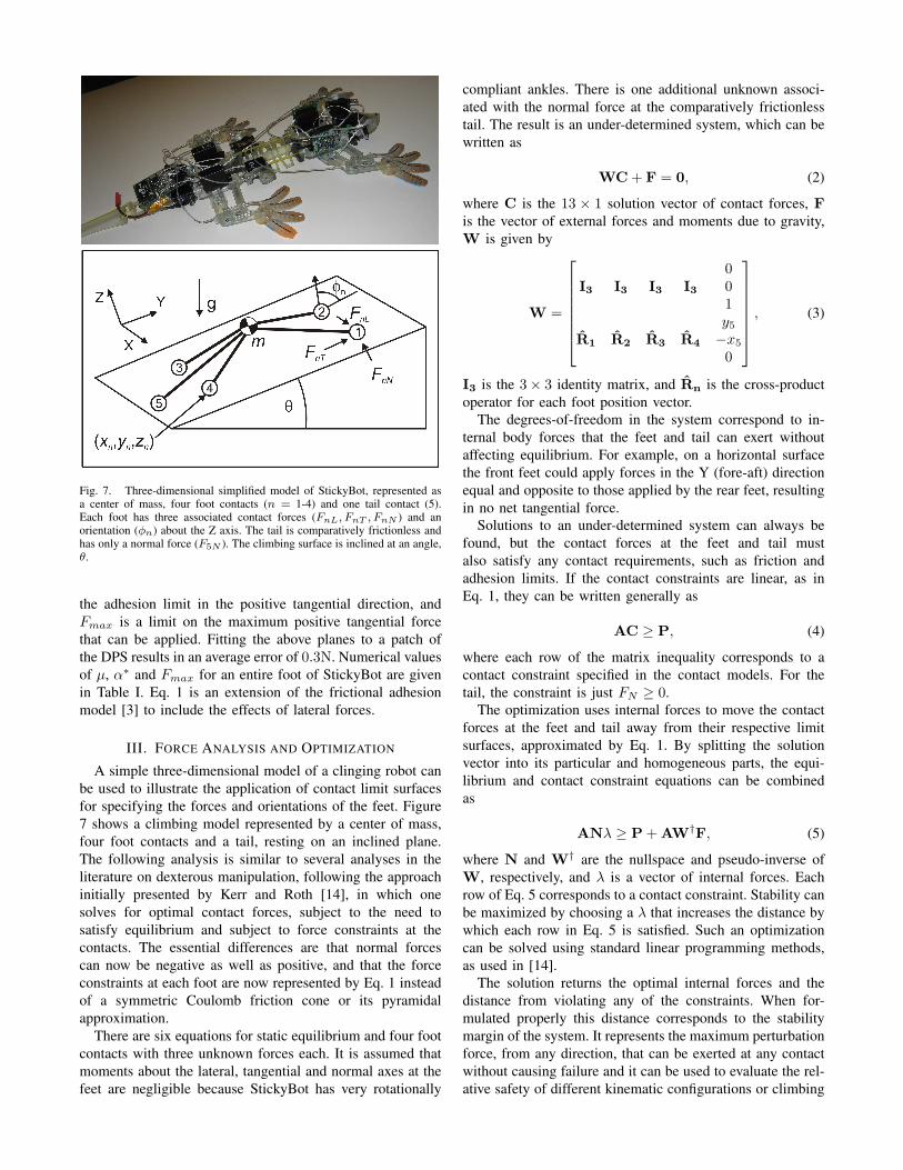
Fig. 7. Three-dimensional simplified model of StickyBot, represented asa center of mass, four foot contacts (n = 1-4) and one tail contact (5).Each foot has three associated contact forces (FnL, FnT , FnN ) and anorientation (φn) about the Z axis. The tail is comparatively frictionless andhas only a normal force (F5N ). The climbing surface is inclined at an angle,θ.
the adhesion limit in the positive tangential direction, andFmax is a limit on the maximum positive tangential forcethat can be applied. Fitting the above planes to a patch ofthe DPS results in an average error of 0.3N. Numerical valuesof µ, α∗ and Fmax for an entire foot of StickyBot are givenin Table I. Eq. 1 is an extension of the frictional adhesionmodel [3] to include the effects of lateral forces.
III. FORCE ANALYSIS AND OPTIMIZATION
A simple three-dimensional model of a clinging robot canbe used to illustrate the application of contact limit surfacesfor specifying the forces and orientations of the feet. Figure7 shows a climbing model represented by a center of mass,four foot contacts and a tail, resting on an inclined plane.The following analysis is similar to several analyses in theliterature on dexterous manipulation, following the approachinitially presented by Kerr and Roth [14], in which onesolves for optimal contact forces, subject to the need tosatisfy equilibrium and subject to force constraints at thecontacts. The essential differences are that normal forcescan now be negative as well as positive, and that the forceconstraints at each foot are now represented by Eq. 1 insteadof a symmetric Coulomb friction cone or its pyramidalapproximation.
There are six equations for static equilibrium and four footcontacts with three unknown forces each. It is assumed thatmoments about the lateral, tangential and normal axes at thefeet are negligible because StickyBot has very rotationally
compliant ankles. There is one additional unknown associ-ated with the normal force at the comparatively frictionlesstail. The result is an under-determined system, which can bewritten as
WC + F = 0, (2)
where C is the 13 × 1 solution vector of contact forces, Fis the vector of external forces and moments due to gravity,W is given by
W =
I3 I3 I3 I3
001
R̂1 R̂2 R̂3 R̂4
y5
−x5
0
, (3)
I3 is the 3× 3 identity matrix, and R̂n is the cross-productoperator for each foot position vector.
The degrees-of-freedom in the system correspond to in-ternal body forces that the feet and tail can exert withoutaffecting equilibrium. For example, on a horizontal surfacethe front feet could apply forces in the Y (fore-aft) directionequal and opposite to those applied by the rear feet, resultingin no net tangential force.
Solutions to an under-determined system can always befound, but the contact forces at the feet and tail mustalso satisfy any contact requirements, such as friction andadhesion limits. If the contact constraints are linear, as inEq. 1, they can be written generally as
AC ≥ P, (4)
where each row of the matrix inequality corresponds to acontact constraint specified in the contact models. For thetail, the constraint is just FN ≥ 0.
The optimization uses internal forces to move the contactforces at the feet and tail away from their respective limitsurfaces, approximated by Eq. 1. By splitting the solutionvector into its particular and homogeneous parts, the equi-librium and contact constraint equations can be combinedas
ANλ ≥ P + AW†F, (5)
where N and W† are the nullspace and pseudo-inverse ofW, respectively, and λ is a vector of internal forces. Eachrow of Eq. 5 corresponds to a contact constraint. Stability canbe maximized by choosing a λ that increases the distance bywhich each row in Eq. 5 is satisfied. Such an optimizationcan be solved using standard linear programming methods,as used in [14].
The solution returns the optimal internal forces and thedistance from violating any of the constraints. When for-mulated properly this distance corresponds to the stabilitymargin of the system. It represents the maximum perturbationforce, from any direction, that can be exerted at any contactwithout causing failure and it can be used to evaluate the rel-ative safety of different kinematic configurations or climbing
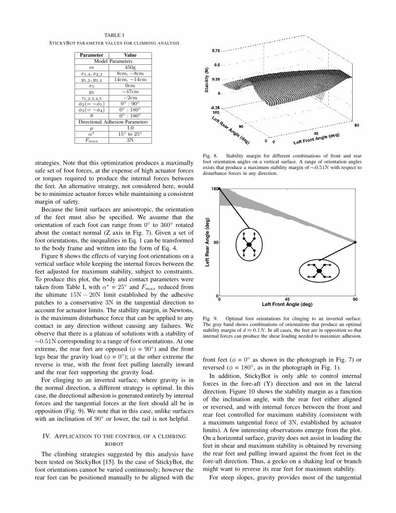
TABLE ISTICKYBOT PARAMETER VALUES FOR CLIMBING ANALYSIS
Parameter ValueModel Parameters
m 450gx1,4, x2,3 8cm, −8cmy1,2, y3,4 14cm, −14cm
x5 0cmy5 −47cm
z1,2,3,4,5 −2cmφ2(= −φ1) 0◦ : 90◦
φ3(= −φ4) 0◦ : 180◦
θ 0◦ : 180◦
Directional Adhesion Parametersµ 1.0α∗ 15◦ to 25◦
Fmax 3N
strategies. Note that this optimization produces a maximallysafe set of foot forces, at the expense of high actuator forcesor torques required to produce the internal forces betweenthe feet. An alternative strategy, not considered here, wouldbe to minimize actuator forces while maintaining a consistentmargin of safety.
Because the limit surfaces are anisotropic, the orientationof the feet must also be specified. We assume that theorientation of each foot can range from 0◦ to 360◦ rotatedabout the contact normal (Z axis in Fig. 7). Given a set offoot orientations, the inequalities in Eq. 1 can be transformedto the body frame and written into the form of Eq. 4.
Figure 8 shows the effects of varying foot orientations on avertical surface while keeping the internal forces between thefeet adjusted for maximum stability, subject to constraints.To produce this plot, the body and contact parameters weretaken from Table I, with α∗ = 25◦ and Fmax reduced fromthe ultimate 15N− 20N limit established by the adhesivepatches to a conservative 3N in the tangential direction toaccount for actuator limits. The stability margin, in Newtons,is the maximum disturbance force that can be applied to anycontact in any direction without causing any failures. Weobserve that there is a plateau of solutions with a stability of∼0.51N corresponding to a range of foot orientations. At oneextreme, the rear feet are opposed (φ = 90◦) and the frontlegs bear the gravity load (φ = 0◦); at the other extreme thereverse is true, with the front feet pulling laterally inwardand the rear feet supporting the gravity load.
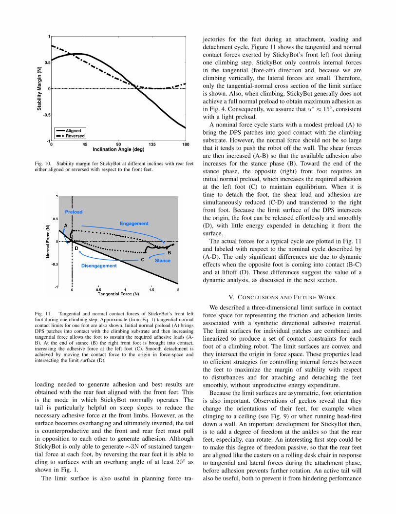
For clinging to an inverted surface, where gravity is inthe normal direction, a different strategy is optimal. In thiscase, the directional adhesion is generated entirely by internalforces and the tangential forces at the feet should all be inopposition (Fig. 9). We note that in this case, unlike surfaceswith an inclination of 90◦ or lower, the tail is not helpful.
IV. APPLICATION TO THE CONTROL OF A CLIMBINGROBOT
The climbing strategies suggested by this analysis havebeen tested on StickyBot [15]. In the case of StickyBot, thefoot orientations cannot be varied continuously; however therear feet can be positioned manually to be aligned with the
Fig. 8. Stability margin for different combinations of front and rearfoot orientation angles on a vertical surface. A range of orientation anglesexists that produce a maximum stability margin of ∼0.51N with respect todisturbance forces in any direction.
0 45 900
90
180
Left Front Angle (deg)
Le
ft R
ea
r A
ng
le (
de
g)
Fig. 9. Optimal foot orientations for clinging to an inverted surface.The gray band shows combinations of orientations that produce an optimalstability margin of d ≈ 0.1N . In all cases, the feet are in opposition so thatinternal forces can produce the shear loading needed to maximize adhesion.
front feet (φ = 0◦ as shown in the photograph in Fig. 7) orreversed (φ = 180◦, as in the photograph in Fig. 1).
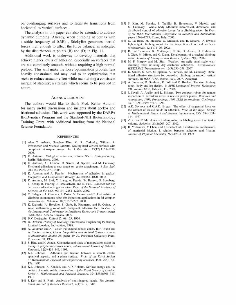
In addition, StickyBot is only able to control internalforces in the fore-aft (Y) direction and not in the lateraldirection. Figure 10 shows the stability margin as a functionof the inclination angle, with the rear feet either alignedor reversed, and with internal forces between the front andrear feet controlled for maximum stability (consistent witha maximum tangential force of 3N, established by actuatorlimits). A few interesting observations emerge from the plot.On a horizontal surface, gravity does not assist in loading thefeet in shear and maximum stability is obtained by reversingthe rear feet and pulling inward against the front feet in thefore-aft direction. Thus, a gecko on a shaking leaf or branchmight want to reverse its rear feet for maximum stability.
For steep slopes, gravity provides most of the tangential
0 45 90 135 180-1
-0.5
0
0.5
1
Inclination Angle (deg)
Sta
bil
ity
Ma
rgin
(N
)
Aligned
Reversed
Fig. 10. Stability margin for StickyBot at different inclines with rear feeteither aligned or reversed with respect to the front feet.
Engagement
StanceDisengagement
Preload
Fig. 11. Tangential and normal contact forces of StickyBot’s front leftfoot during one climbing step. Approximate (from Eq. 1) tangential-normalcontact limits for one foot are also shown. Initial normal preload (A) bringsDPS patches into contact with the climbing substrate and then increasingtangential force allows the foot to sustain the required adhesive loads (A-B). At the end of stance (B) the right front foot is brought into contact,increasing the adhesive force at the left foot (C). Smooth detachment isachieved by moving the contact force to the origin in force-space andintersecting the limit surface (D).
loading needed to generate adhesion and best results areobtained with the rear feet aligned with the front feet. Thisis the mode in which StickyBot normally operates. Thetail is particularly helpful on steep slopes to reduce thenecessary adhesive force at the front limbs. However, as thesurface becomes overhanging and ultimately inverted, the tailis counterproductive and the front and rear feet must pullin opposition to each other to generate adhesion. AlthoughStickyBot is only able to generate ∼3N of sustained tangen-tial force at each foot, by reversing the rear feet it is able tocling to surfaces with an overhang angle of at least 20◦ asshown in Fig. 1.
The limit surface is also useful in planning force tra-
jectories for the feet during an attachment, loading anddetachment cycle. Figure 11 shows the tangential and normalcontact forces exerted by StickyBot’s front left foot duringone climbing step. StickyBot only controls internal forcesin the tangential (fore-aft) direction and, because we areclimbing vertically, the lateral forces are small. Therefore,only the tangential-normal cross section of the limit surfaceis shown. Also, when climbing, StickyBot generally does notachieve a full normal preload to obtain maximum adhesion asin Fig. 4. Consequently, we assume that α∗ ≈ 15◦, consistentwith a light preload.
A nominal force cycle starts with a modest preload (A) tobring the DPS patches into good contact with the climbingsubstrate. However, the normal force should not be so largethat it tends to push the robot off the wall. The shear forcesare then increased (A-B) so that the available adhesion alsoincreases for the stance phase (B). Toward the end of thestance phase, the opposite (right) front foot requires aninitial normal preload, which increases the required adhesionat the left foot (C) to maintain equilibrium. When it istime to detach the foot, the shear load and adhesion aresimultaneously reduced (C-D) and transferred to the rightfront foot. Because the limit surface of the DPS intersectsthe origin, the foot can be released effortlessly and smoothly(D), with little energy expended in detaching it from thesurface.
The actual forces for a typical cycle are plotted in Fig. 11and labeled with respect to the nominal cycle described by(A-D). The only significant differences are due to dynamiceffects when the opposite foot is coming into contact (B-C)and at liftoff (D). These differences suggest the value of adynamic analysis, as discussed in the next section.
V. CONCLUSIONS AND FUTURE WORK
We described a three-dimensional limit surface in contactforce space for representing the friction and adhesion limitsassociated with a synthetic directional adhesive material.The limit surfaces for individual patches are combined andlinearized to produce a set of contact constraints for eachfoot of a climbing robot. The limit surfaces are convex andthey intersect the origin in force space. These properties leadto efficient strategies for controlling internal forces betweenthe feet to maximize the margin of stability with respectto disturbances and for attaching and detaching the feetsmoothly, without unproductive energy expenditure.
Because the limit surfaces are asymmetric, foot orientationis also important. Observations of geckos reveal that theychange the orientations of their feet, for example whenclinging to a ceiling (see Fig. 9) or when running head-firstdown a wall. An important development for StickyBot then,is to add a degree of freedom at the ankles so that the rearfeet, especially, can rotate. An interesting first step could beto make this degree of freedom passive, so that the rear feetare aligned like the casters on a rolling desk chair in responseto tangential and lateral forces during the attachment phase,before adhesion prevents further rotation. An active tail willalso be useful, both to prevent it from hindering performance
on overhanging surfaces and to facilitate transitions fromhorizontal to vertical surfaces.
The analysis in this paper can also be extended to addressdynamic climbing. Already, when climbing at 6cm/s witha stride frequency of 0.5Hz , StickyBot generates inertialforces high enough to affect the force balance, as indicatedby the disturbances at points (B) and (D) in Fig. 11.
Additional work is underway to develop materials thatachieve higher levels of adhesion, especially on surfaces thatare not completely smooth, without requiring a high normalpreload. This will make the force optimization problem lessheavily constrained and may lead to an optimization thatseeks to reduce actuator effort while maintaining a consistentmargin of stability; a strategy which seems to be pursued innature.
ACKNOWLEDGMENT
The authors would like to thank Prof. Kellar Autumnfor many useful discussions and insights about geckos andfrictional adhesion. This work was supported by the DARPABioDynotics Program and the Stanford-NIH BiotechnologyTraining Grant, with additional funding from the NationalScience Foundation.
REFERENCES
[1] Alan T. Asbeck, Sangbae Kim, M. R. Cutkosky, William R.Provancher, and Michele Lanzetta. Scaling hard vertical surfaces withcompliant microspine arrays. Int. J. Rob. Res., 25(12):1165–1179,2006.
[2] K. Autumn. Biological Adhesives, volume XVII. Springer-Verlog,Berlin Heidelberg, 2006.
[3] K. Autumn, A. Dittmore, D. Santos, M. Spenko, and M. Cutkosky.Frictional adhesion: a new angle on gecko attachment. J Exp Biol,209(18):3569–3579, 2006.
[4] K. Autumn and A. Peattie. Mechanisms of adhesion in geckos.Integrative and Comparative Biology, 42(6):1081–1090, 2002.
[5] K. Autumn, M. Sitti, Y. Liang, A. Peattie, W. Hansen, S. Sponberg,T. Kenny, R. Fearing, J. Israelachvili, and R. Full. Evidence for vander waals adhesion in gecko setae. Proc. of the National Academy ofSciences of the USA, 99(19):12252–12256, 2002.
[6] C. Balaguer, A. Gimenez, J. Pastor, V. Padron, and C. Abderrahim. Aclimbing autonomous robot for inspection applications in 3d complexenvironments. Robotica, 18(3):287–297, 2000.
[7] K. Daltorio, A. Horchler, S. Gorb, R. Ritzmann, and R. Quinn. Asmall wall-walking robot with compliant, adhesive feet. In Proc. ofthe International Conference on Intelligent Robots and Systems, pages3648–3653, Alberta, Canada, 2005.
[8] B.V. Derjaguin. Kolloid Z., 69:155, 1934.[9] D. Dowson. History of Tribology. Professional Engineering Publishing
Limited, London, 2nd edition, 1998.[10] A. Goldman and A. Tucker. Polyhedral convex cones. In H. Kuhn and
A. Tucker, editors, Linear Inequalities and Related Systems. Annalsof Mathematics Studies 38, pages 19–39. Princeton University Press,Princeton, NJ, 1956.
[11] S. Hirai and H. Asada. Kinematics and static of manipulation using thetheory of polyhedral convex cones. International Journal of RoboticsResearch, 12(5):434–447, 1993.
[12] K.L. Johnson. Adhesion and friction between a smooth elasticspherical asperity and a plane surface. Proc. of the Royal SocietyA: Mathematical, Physical and Engineering Sciences, 453(1956):163–179, 1997.
[13] K.L. Johnson, K. Kendall, and A.D. Roberts. Surface energy and thecontact of elastic solids. Proceedings of the Royal Society of London.Series A, Mathematical and Physical Sciences, 324(1558):301–313,1971.
[14] J. Kerr and B. Roth. Analysis of multifingered hands. The Interna-tional Journal of Robotics Research, 4(4):3–17, 1986.
[15] S. Kim, M. Spenko, S. Trujillo, B. Heyneman, V. Matolli, andM. Cutkosky. Whole body adhesion: hierarchical, directional anddistributed control of adhesive forces for a climbing robot. In Proc.of the IEEE International Conference on Robotics and Automation,pages 1268–1273, Rome, Italy, 2007.
[16] G. La Rosa, M. Messina, G. Muscato, and R. Sinatra. A lowcostlightweight climbing robot for the inspection of vertical surfaces.Mechatronics, 12(1):71–96, 2002.
[17] R. Lal Tummala, R. Mukherjee, N. Xi, D. Aslam, H. Dulimarta,J. Xiao, M. Minor, and G. Dang. Development of a tracked climbingrobot. Journal of Intelligent and Robotic Systems, 9(4), 2002.
[18] M. P. Murphy and M. Sitti. Waalbot: An agile small-scale wall-climbing robot utilizing dry elastomer adhesives. Mechatronics,IEEE/ASME Transactions on, 12(3):330–338, 2007.
[19] D. Santos, S. Kim, M. Spenko, A. Parness, and M. Cutkosky. Direc-tional adhesive structures for controlled climbing on smooth verticalsurfaces. In IEEE ICRA, Rome, Italy, 2007. Accepted.
[20] A. Saunders, D. Goldman, R. Full, and M. Buehler. The rise climbingrobot: body and leg design. In SPIE Unmanned Systems TechnologyVII, volume 6230, Orlando, FL, 2006.
[21] J. Savall, A. Avello, and L. Briones. Two compact robots for remoteinspection of hazardous areas in nuclear power plants. Robotics andAutomation, 1999. Proceedings. 1999 IEEE International Conferenceon, 3:1993–1998 vol.3, 1999.
[22] A.R. Savkoor and G.A.D. Briggs. The effect of tangential force onthe contact of elastic solids in adhesion. Proc. of the Royal SocietyA: Mathematical, Physical and Engineering Sciences, 356(1684):103–114, 1977.
[23] Z. Xu and P. Ma. A wall-climbing robot for labeling scale of oil tank’svolume. Robotica, 20(2):203–207, 2002.
[24] H. Yoshizawa, Y. Chen, and J. Israelachvili. Fundamental mechanismsof interfacial friction. 1. relation between adhesion and friction.Journal of Physical Chemistry, 97:4128–4140, 1993.