Embed Size (px)
Citation preview
Rev 10/12/2017 Part # 16550337
GECM Pneumatic Pump Controller
Installation and Operation Manual

1
Table of Contents
Section 1: System Description ........................................................................................................... 4 Function and Theory .......................................................................................................................... 4 Ease of Deployment ........................................................................................................................... 4 GECM Operation ............................................................................................................................... 5
Section 2: System Installation ............................................................................................................ 6 Installation of the GECM Pneumatic Pump Controller ........................................................................ 6 Solar Panel Location .......................................................................................................................... 6 Mounting the Control Panel ................................................................................................................ 8 Adding Additional Panels ................................................................................................................. 10 AC GECM Wiring ............................................................................................................................. 10 Grounding ........................................................................................................................................ 11 Connect All Tubing Runs ................................................................................................................. 11
Section 3: Timer/Cycle Settings and Display Descriptions ............................................................ 13 Setup Displays ................................................................................................................................. 13 Stopping GECM Operation (Runtime) .............................................................................................. 15 System Status and Diagnostic Displays ........................................................................................... 16 Alarm (Condition) and Fault Displays ............................................................................................... 18 PCB Damage ................................................................................................................................... 18 Optional Conductivity Sensor Override Protection............................................................................ 18 Description of the Conductivity Probe .............................................................................................. 18 To configure the GECM ................................................................................................................... 19 Operating in “Conductive” mode ...................................................................................................... 19 Operating in “Non-Conductive” mode ............................................................................................... 19
Section 4: System Operation ............................................................................................................ 22 Establishing the Fluid Pumping Rate................................................................................................ 22 Initiating the GECM Runtime ............................................................................................................ 22 Recovery Tank is Full ...................................................................................................................... 23
Section 5: System Maintenance........................................................................................................ 24 GECM Controller.............................................................................................................................. 24 Solar Panel ...................................................................................................................................... 25 Solenoid Maintenance (Stuck Solenoid) ........................................................................................... 26
Section 6: System Troubleshooting ................................................................................................. 29 Section 7: System Specifications ..................................................................................................... 31 Section 8: System Schematics ......................................................................................................... 33 Section 9: Parts and Accessories ..................................................................................................... 37 EC Declaration of Conformity ........................................................................................................... 40 The Warranty ...................................................................................................................................... 41
2
NOTE
DOCUMENTATION CONVENTIONS This manual uses the following conventions to present information:
An exclamation point icon indicates a WARNING of a situation or condition that could lead to personal injury or death. You should not proceed until you
read and thoroughly understand the WARNING message.
A raised hand icon indicates CAUTION information that relates to a situation or condition that could lead to equipment malfunction or damage. You should not
proceed until you read and thoroughly understand the CAUTION message.
A note icon indicates NOTE information. Notes provide additional or supplementary information about an activity or concept.
WARNING
CAUTION
3
In order to ensure your GECM Pneumatic Pump Controller has a long service life and operates properly, adhere to the following cautions and read this manual before use.
Controller power input source must not exceed specified ratings.
Controller may not operate properly with wiring not supplied by manufacturer.
Avoid spraying fluid directly at controller.
Never submerge controller.
Avoid pulling on wires to unplug controller wiring.
Avoid using a controller with obvious physical damage.
To prevent damage, DO NOT drop the controller.
WARNING
The following applies only to users in European countries:
This product is designated for separate collection at an appropriate collection point. DO NOT dispose of as household waste.
For more information, contact the seller or the local authorities in charge of waste management.
Notice for consumers in Europe: This symbol indicates that this product is to be collected separately.
DO NOT operate this equipment if it has visible signs of significant physical
damage other than normal wear and tear.

4
Section 1: System Description Function and Theory The Geotech Environmental Control Module (GECM) Pneumatic Pump Controller is a unique pneumatic pump control system used for operating down well pneumatic remediation or sampling pumps. Electrical power used to run the GECM Pneumatic Pump Controller can be generated on-site by solar panels or AC main power. Optional multiple channel controllers can operate up to eight (8) pumps within separate recovery wells. With the proper equipment, the system handles pressure up to 150 PSI (10.3 bar). The maximum depth to fluid pumping capability is 320’ (97.5 m) below ground surface. Tubing size requirements vary depending on pump type and length of tubing runs. Geotech assists in determining these parameters to meet specific site installation requirements. See Section 7: System Specifications for more details. Total fluid pump maintenance is significantly reduced by simplifying the down well components and placing the timing and control mechanisms at the surface. The system can be configured to operate up to eight (8) wells per module. Multiple pump controls can be placed remotely at or near wellheads with the air supply placed at a central location. This helps to minimize air consumption as the exhaust cycle vents through the controller, and not back to the air supply. In this case, it is often convenient to use a solar power supply for the remotely located controller versus running AC power out into a well field.
WARNING
The standard GECM Pneumatic Pump Controller can be configured for either AC main power or a 12VDC battery that is charged with an attached solar panel. Solar charge controller components are integrated into all models. Systems can be expanded to utilize several solar panels and large capacity batteries. Multiple channel controls can be implemented in areas where there are multiple recovery wells within close proximity of each other. Up to eight (8) separate wells can be operated per controller. Geotech recommends a maximum distance of 1200’ (365 m) (including the well depth) between the GECM and the down well pump. Longer runs can be accommodated, but increase in air supply and air line loss must be considered for proper operation. Careful consideration must be given to additional power requirements as well as protecting tubing from damage. In certain situations, separate controllers may be a better solution on larger sites. Ease of Deployment The GECM Pneumatic Pump Controller reduces overall project costs and dramatically improves deployment as follows:
Flexible, easy to install power supply options.
Optional simple and safe low voltage solar power system
Remote operability can reduce overall costs of system installation and maintenance.
In this manual any down well assembly used with the system, will be referred to simply as a pump. Systems can be configured for a wide range of pneumatic pump types including bladder pumps and reclaimer or canister pumps.
Use extreme caution when working with compressed air systems. All components and fittings must be rated for the appropriate maximum pressure.

5
Reduce down well component complexity by placing the timing and control mechanisms on the surface for easy programming access.
GECM Operation The GECM Pneumatic Pump Controller has an integrated programmable cycle timer for controlling the individual pump times and the time between each cycle. Optimal timer settings vary with site configuration, seasonal water table variability, process treatment requirements, and pump specifications. The timer settings allow for complete pump discharge during the pressure cycle and complete pump refill during the delay cycle. Maximum specified pumping rate may only be achieved in aquifers with an adequate recharge rate to refill the pump. Pump submergence and line losses may also affect performance. See Section 7: System Specifications for more details. During the pressure timer cycle, air is compressed into the air line tubing, evacuating the liquid from the pump. Once the programmed pressure time has expired, the internal valve changes position to exhaust the air from the pump and initiates the programmed delay timer. The pump fills during the delay time. Then, the process repeats. On multiple channel GECM systems, pressure and delay cycles are set individually per well. This accommodates recharge and recovery rates unique to individual wells on the same site. A variety of timer setups can be implemented to maximize recovery. For example, different wells can be pumped more or less often than others to maximize recovery. The programming prioritizes the pumps so one pump is operational at a time. *Customized timer programming and multiple well operation is available. Please contact Geotech for assistance. The GECM controller has several feedback data recording mechanisms that a can be used to gauge effectiveness of the remediation system. Two cycle counter screens are available, one records the total lifetime cycles of the controller, the other counter is resettable by the user for monitoring purposes. These cycle counts can be compared with total recovered fluid to determine how much fluid is being recovered per pump cycle. There is also a runtime clock which increments when the battery is charged or receiving AC power, and when the system is operating. This clock can be compared with actual recorded deployment time to determine if more solar panels are required to keep the system running or if power outages are occurring on site. More can be found on this in Section 6: System Troubleshooting. The GECM Pneumatic Pump Controller is dependent upon the annual average solar resources or AC power main services reliability, which can vary from region to region. Geotech assists in determining how much potential recovery can be expected depending on site specifications and how many solar panels may be required. More information about solar panel location can be found in Section 2: System Installation.
6
Section 2: System Installation
GECM Pneumatic Pump Controller systems can be modularized and delivered on pallets that are quick and easy to deploy. This simplifies deployment where existing concrete pads or other infrastructure, does not already exist. Geotech also offers training on proper installation of the GECM system at the Denver, Colorado manufacturing headquarters. Installation of the GECM Pneumatic Pump Controller
Since the solar array and battery have live voltage, exercise caution when handling either item. Special attention is required to ensure that the correct polarity is observed when making connections to the battery and solar panels. Even though the system runs on a safe low voltage, the battery is capable of storing large amounts of energy from a low impedance source; this poses a fire and burn hazard. Special care must be taken to avoid shorting out (making contact between both positive and negative terminals) the battery with any tool or bare grounding wire. Leave protective caps in place and only terminate a wire when you have verified it is the correct polarity (positive or negative.) The system can tolerate reverse polarity connections as long as the ON/OFF switch remains in the OFF position. Solar Panel Location The annual average solar resources vary from region to region. Geotech assists in determining how many solar panels will be required based on site specifications. Site-specific information must be considered. Large objects like tress or building structures can block sunlight from the reaching the solar panels. To maximize sun exposure solar panels can be mounted on top of poles or other available structures. Other unpredictable factors, such as more or less cloud cover, must be also be considered when planning solar power capacity requirements.
GECM installations are to be performed by qualified personnel. If you are not familiar with electrical power equipment, contact a qualified technician to assist you with your installation.
AC GECM Controller - Ensure the main line is turned off at the breaker and that the ON/OFF switch for the control panel is in the OFF position before proceeding with ANY external or internal wiring.
The standard Geotech GECM is designed for installation and operation in a non-hazardous, non-classified location with intrinsically safe extension into a hazardous classified location. Geotech does not determine classification of a location. Classification of location is subject to local jurisdiction enforcement of NFPA regulations. All installations should be performed in accordance with NEC. FPN: NEC 2008 section 500.5 (A) classification of locations says: Through the exercise of ingenuity in the layout of electrical installations for hazardous (classified) locations, it is frequently possible to locate much of the equipment in an unclassified location and, thus, to reduce the amount of special equipment required. FPNs are informational only and are not enforceable as requirements of the NEC.
7
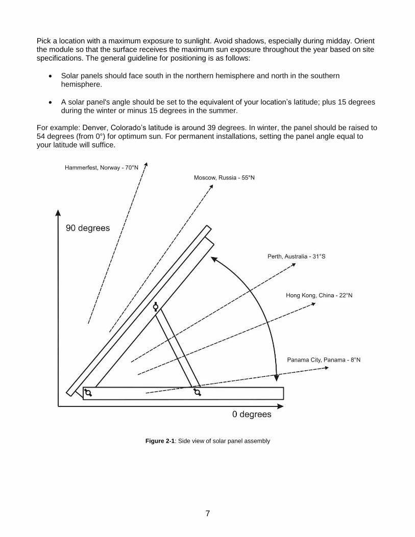
Pick a location with a maximum exposure to sunlight. Avoid shadows, especially during midday. Orient the module so that the surface receives the maximum sun exposure throughout the year based on site specifications. The general guideline for positioning is as follows:
Solar panels should face south in the northern hemisphere and north in the southern hemisphere.
A solar panel's angle should be set to the equivalent of your location’s latitude; plus 15 degrees during the winter or minus 15 degrees in the summer.
For example: Denver, Colorado’s latitude is around 39 degrees. In winter, the panel should be raised to 54 degrees (from 0°) for optimum sun. For permanent installations, setting the panel angle equal to your latitude will suffice.
Figure 2-1: Side view of solar panel assembly

8
Mounting the Control Panel The enclosure for the GECM Pneumatic Pump Controller allows the customer the option to place the control panel in a convenient and accessible location. It is recommended the control panel enclosure be placed out of the direct path of weather and sunlight. If power is to be wired to the enclosure, then all conduit runs are to be rigid metal and grounded to an equipment conductor common for non-current carrying metal parts. The enclosure needs to be elevated above the height of the wellheads to prevent kinks to the exhaust line and all air lines to the pumps. When selecting a location for your GECM controller, consider the placement of air lines to and from the unit to prevent kinks, damage, or the buildup of fluid in sagging lines. Figure 2-2 is an example of a GECM control panel mounted to a back panel with 2” (5 cm) U-bolts. Using a back panel will support the enclosure while giving you the ability to pole mount the unit.
Figure 2-2: GECM enclosure mounted to back panel with additional U-bolts for pole attachment
NEVER drill mounting holes from, or through the inside of the enclosure when attaching the controller to another surface. It is advised that you mount the enclosure to a strong back panel, using the supplied brackets before attaching the
unit to a pole or other surface.
Diagram is an example only. Mounting hardware shown is available through Geotech – see Section 9: Parts and Accessories. Always avoid drilling through the enclosure body.

9
GECM Pneumatic Pump Controller Wiring
GECM Pneumatic Pump Controller systems are supplied with 25’ (7.6 m) of 4 conductor 14 AWG cable. DO NOT modify the length of this power cable. After ensuring the power switch on the controller is set to OFF, make all external power connections as shown in Figure 2-3.
Figure 2-3: Example of external wiring for a Solar GECM Pneumatic Pump Controller system
Before installing the solar panel for the GECM Pneumatic Pump Controller, cover the solar panel array with an opaque material before making your wiring connections. This will prevent the modules from producing electricity while making the connections and reduce the risk of sparks. Observe safe electrical practices at all times. Make connections in well-ventilated areas free from flammable gas vapors and open flames.
A full size, internal wiring diagram is included when new GECM controllers are delivered. Operational flow charts are affixed to the inside door of each controller. Contact Geotech for a replacement wiring diagram as needed.
10
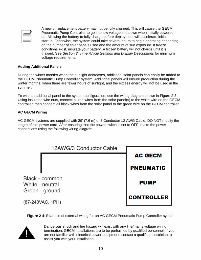
Adding Additional Panels During the winter months when the sunlight decreases, additional solar panels can easily be added to the GECM Pneumatic Pump Controller system. Additional panels will ensure production during the winter months, when there are fewer hours of sunlight, and the excess energy will not be used in the summer. To wire an additional panel to the system configuration, use the wiring diagram shown in Figure 2-3. Using insulated wire nuts, connect all red wires from the solar panel(s) to the white wire on the GECM controller, then connect all black wires from the solar panel to the green wire on the GECM controller. AC GECM Wiring AC GECM systems are supplied with 25’ (7.6 m) of 3 Conductor 12 AWG Cable. DO NOT modify the length of this power cord. After ensuring that the power switch is set to OFF, make the power connections using the following wiring diagram:
Figure 2-4: Example of external wiring for an AC GECM Pneumatic Pump Controller system
A new or replacement battery may not be fully charged. This will cause the GECM Pneumatic Pump Controller to go into low voltage shutdown when initially powered up. Allowing the battery to fully charge before deployment will accelerate initial startup. Otherwise, the system could take several hours to begin operating depending on the number of solar panels used and the amount of sun exposure. If freeze conditions exist, insulate your battery. A frozen battery will not charge until it is thawed. See Section 3: Timer/Cycle Settings and Display Descriptions for minimum voltage requirements.
Dangerous shock and fire hazard will exist with any line/mains voltage wiring termination. GECM installations are to be performed by qualified personnel. If you are not familiar with electrical power equipment, contact a qualified electrician to assist you with your installation.
11
Always verify that live voltage is not present at terminals to be worked on. Shut off all circuit breakers and disconnects. Use a voltmeter or voltage detector to verify power has been removed. Verify the voltmeter is functional by turning the power ON and OFF twice before proceeding. When wiring AC power terminals, only proceed when you are certain it is safe. Grounding If no earth ground terminal is available, then a ground spike must be installed. Connect all non-current carrying metal parts to the common ground. Connect All Tubing Runs Lay out all tubing lengths to the wellheads and secure the ends to the hose barbs or other fittings using environmentally rated clamps where applicable. Geotech can supply your GECM system with a variety of tubing and clamp choices. See Section 9: Parts and Accessories for a list of available parts. When installing tubing runs, consider the placement of air lines to and from the unit to prevent kinks, damage, or the buildup of fluid in sagging lines. Keep all air lines flat and straight, and avoid sharp bends, which can kink your line. It is recommended that air lines and hoses be protected. However, check local and state regulations regarding fuel transmission lines before installing the product discharge lines.
The last line connected will be from the compressor air supply to the side of the GECM Pneumatic Pump Controller. Good site characterization is important for successfully placing the pump assembly at the optimal level in the well. Seasonal or tidal fluctuations in the groundwater table may require pump placement adjustment.
Implementing the use of a Geotech oil/water interface probe, and keeping a record of the water level and product layer thickness is recommended for maintaining optimal system performance.
Product Recovery Tank A product recovery tank is not provided with the GECM Pneumatic Pump Controller system. A tank, preferably a 55 gallon (208L) drum or larger, must be provided by the customer with the following attributes:
A 3/4" (2 cm) or 2” (5 cm) threaded bung opening in which the Tankfull Probe will be attached. A product inlet opening for the system discharge hose. A vent opening.
If there is a chance the GECM system will be exposed to freezing conditions (see temperature range in Section 7: System Specifications), then it is suggested all discharge lines, including the battery, be insulated or your system be kept within a temperature controlled shelter during operation.
For accurate results, measure well to determine the best placement for the Pneumatic Pump. Use a Geotech oil/water interface probe to measure water level and product layer thickness, then record this information in the remediation/characterization log.
12
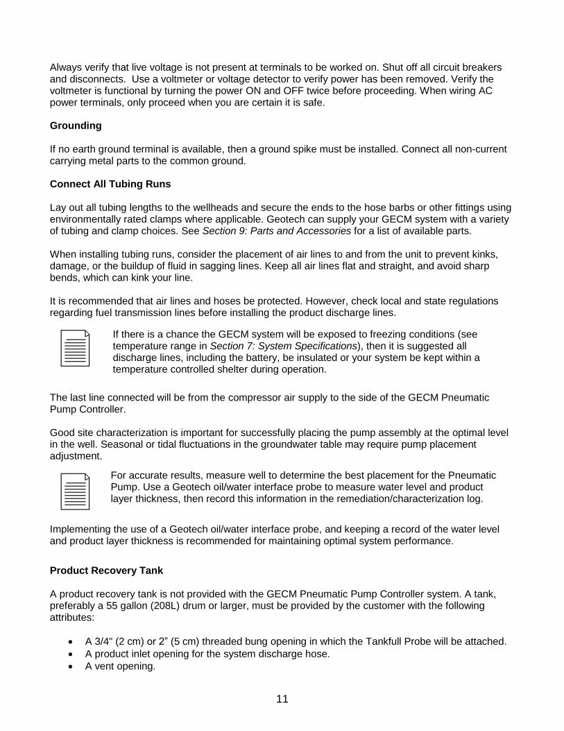
A fluid discharge fitting for draining. A Tankfull Probe, shown in Figure 2-5, is provided with new GECM Pneumatic Pump Controller systems. Additional probes can be ordered from Geotech. See Section 9: Parts and Accessories.
Figure 2-5: Example of Tankfull Probe
Ensure that the compressor air intake and exhaust air line is secured to the top of the recovery tank prior to turning on the GECM controller. DO NOT allow the end of this tubing to reach the product already collected.
13
Section 3: Timer/Cycle Settings and Display Descriptions This section describes the display functions and the operation of the GECM controller. Each controller comes with a User Interface Flowchart (shown in Figure 3-1) inside the enclosure lid. The flowchart, used in conjunction with the arrow buttons on the control panel (shown in Figure 3-2) is designed to provide the following operator functions:
Setting the cycle time (pressure and delay) for each pump assembly.
Initiating the run time for GECM system.
Accessing system status and diagnostic displays. The following pages show examples of all controller displays and a brief description of their function. Contact Geotech Technical Sales for any assistance with operating the GECM controller. Setup Displays Once the GECM system has been installed and all wiring to the controller is complete, turn on the main power switch to the GECM controller. The unit will perform a quick internal self-check and memory configuration, after which the Main Menu will appear on the display as follows: Geotech GECMPNEU
L=Setup R=Start
The first task will be to set your timer/cycle settings using the Setup displays. The Setup displays allow you to select each pump individually and assign a unique cycle time (pressure and delay) for the pump based on the performance of the well the pump resides. The cycle time range for each function is as follows: Pressure 1 second minimum to a 10 minute maximum. Delay 1 second minimum to a maximum of 24 hours.
To access the Setup displays, press the LEFT arrow button. The following display will appear: Select Well
n L=Main Menu where n = the well number
Using the UP and DOWN arrow buttons, select the well number for which cycle time you wish to set (the number of wells per GECM controller can be between 1 and 8, depending on the configuration.) After selecting a well number, press the RIGHT arrow. The Pressure display will appear: Set Pressure mm:ss
00:30
Where, hh = hours, mm = minutes, ss= seconds.
Factory default for all timer settings, for each pump installed, are: 30 seconds of pressure, 5 minutes of delay.
14
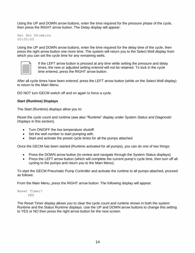
Using the UP and DOWN arrow buttons, enter the time required for the pressure phase of the cycle, then press the RIGHT arrow button. The Delay display will appear: Set Del hh:mm:ss
00:05:00
Using the UP and DOWN arrow buttons, enter the time required for the delay time of the cycle, then press the right arrow button one more time. The system will return you to the Select Well display from which you can set the cycle time for any remaining wells.
After all cycle times have been entered, press the LEFT arrow button (while on the Select Well display) to return to the Main Menu. DO NOT turn GECM switch off and on again to force a cycle. Start (Runtime) Displays The Start (Runtime) displays allow you to: Reset the cycle count and runtime (see also “Runtime” display under System Status and Diagnostic Displays in this section).
Turn ON/OFF the low temperature shutoff.
Set the well number to start pumping with.
Start and activate the preset cycle times for all the pumps attached. Once the GECM has been started (Runtime activated for all pumps), you can do one of two things:
Press the DOWN arrow button (to review and navigate through the System Status displays).
Press the LEFT arrow button (which will complete the current pump’s cycle time, then turn off all cycling to the pumps and return you to the Main Menu).
To start the GECM Pneumatic Pump Controller and activate the runtime to all pumps attached, proceed as follows: From the Main Menu, press the RIGHT arrow button. The following display will appear: Reset Timer?
YES
The Reset Timer display allows you to clear the cycle count and runtime shown in both the system Runtime and the Status Runtime displays. Use the UP and DOWN arrow buttons to change this setting to YES or NO then press the right arrow button for the next screen.
If the LEFT arrow button is pressed at any time while setting the pressure and delay times, the new or adjusted setting entered will not be retained. To lock in the cycle time entered, press the RIGHT arrow button.
15
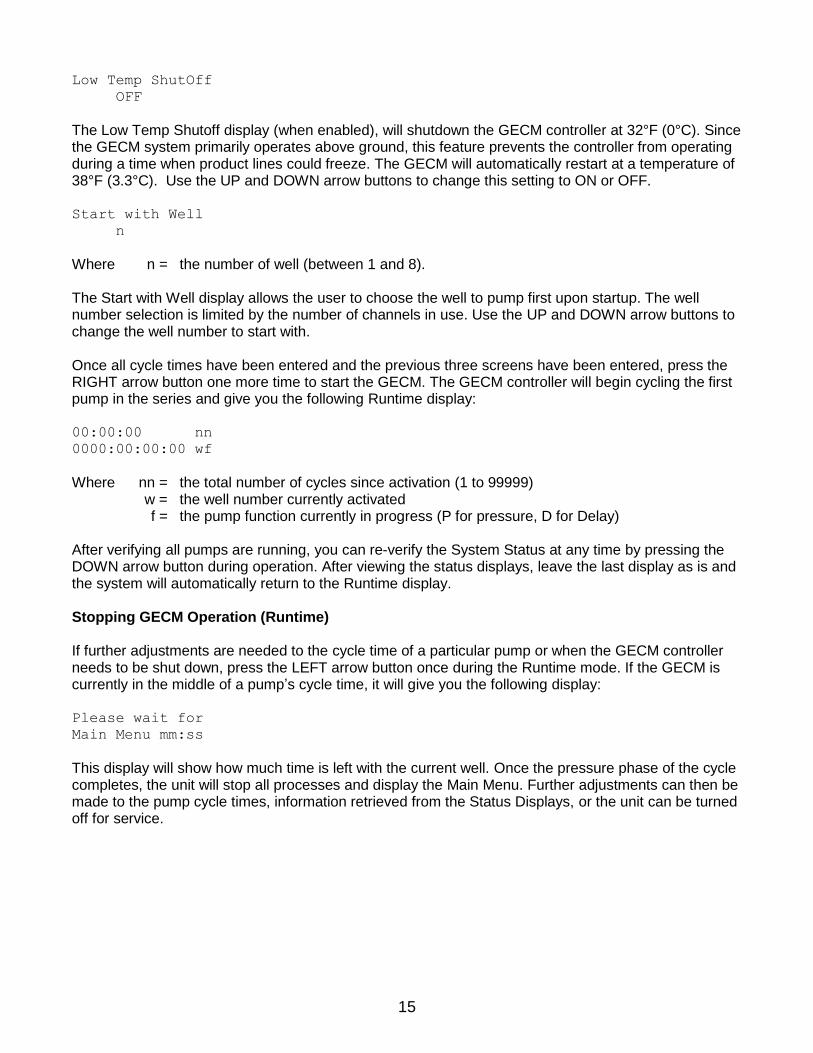
Low Temp ShutOff
OFF
The Low Temp Shutoff display (when enabled), will shutdown the GECM controller at 32°F (0°C). Since the GECM system primarily operates above ground, this feature prevents the controller from operating during a time when product lines could freeze. The GECM will automatically restart at a temperature of 38°F (3.3°C). Use the UP and DOWN arrow buttons to change this setting to ON or OFF. Start with Well
n
Where n = the number of well (between 1 and 8). The Start with Well display allows the user to choose the well to pump first upon startup. The well number selection is limited by the number of channels in use. Use the UP and DOWN arrow buttons to change the well number to start with. Once all cycle times have been entered and the previous three screens have been entered, press the RIGHT arrow button one more time to start the GECM. The GECM controller will begin cycling the first pump in the series and give you the following Runtime display: 00:00:00 nn
0000:00:00:00 wf
Where nn = the total number of cycles since activation (1 to 99999) w = the well number currently activated f = the pump function currently in progress (P for pressure, D for Delay) After verifying all pumps are running, you can re-verify the System Status at any time by pressing the DOWN arrow button during operation. After viewing the status displays, leave the last display as is and the system will automatically return to the Runtime display. Stopping GECM Operation (Runtime) If further adjustments are needed to the cycle time of a particular pump or when the GECM controller needs to be shut down, press the LEFT arrow button once during the Runtime mode. If the GECM is currently in the middle of a pump’s cycle time, it will give you the following display: Please wait for
Main Menu mm:ss
This display will show how much time is left with the current well. Once the pressure phase of the cycle completes, the unit will stop all processes and display the Main Menu. Further adjustments can then be made to the pump cycle times, information retrieved from the Status Displays, or the unit can be turned off for service.
16
System Status and Diagnostic Displays
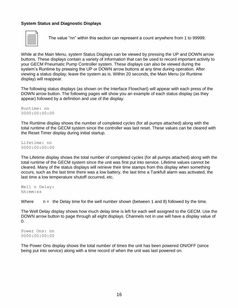
While at the Main Menu, system Status Displays can be viewed by pressing the UP and DOWN arrow buttons. These displays contain a variety of information that can be used to record important activity to your GECM Pneumatic Pump Controller system. These displays can also be viewed during the system’s Runtime by pressing the UP or DOWN arrow buttons at any time during operation. After viewing a status display, leave the system as is. Within 20 seconds, the Main Menu (or Runtime display) will reappear. The following status displays (as shown on the Interface Flowchart) will appear with each press of the DOWN arrow button. The following pages will show you an example of each status display (as they appear) followed by a definition and use of the display. Runtime: nn
0000:00:00:00
The Runtime display shows the number of completed cycles (for all pumps attached) along with the total runtime of the GECM system since the controller was last reset. These values can be cleared with the Reset Timer display during initial startup. Lifetime: nn
0000:00:00:00
The Lifetime display shows the total number of completed cycles (for all pumps attached) along with the total runtime of the GECM system since the unit was first put into service. Lifetime values cannot be cleared. Many of the status displays will retrieve their time stamps from this display when something occurs, such as the last time there was a low battery, the last time a Tankfull alarm was activated, the last time a low temperature shutoff occurred, etc. Well n Delay:
hh:mm:ss
Where n = the Delay time for the well number shown (between 1 and 8) followed by the time. The Well Delay display shows how much delay time is left for each well assigned to the GECM. Use the DOWN arrow button to page through all eight displays. Channels not in use will have a display value of 0. Power Ons: nn
0000:00:00:00
The Power Ons display shows the total number of times the unit has been powered ON/OFF (since being put into service) along with a time record of when the unit was last powered on.
The value “nn” within this section can represent a count anywhere from 1 to 99999.
17
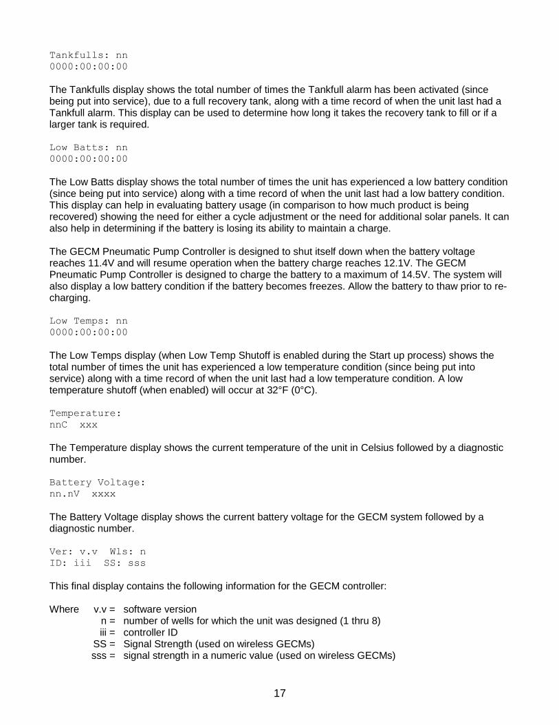
Tankfulls: nn
0000:00:00:00
The Tankfulls display shows the total number of times the Tankfull alarm has been activated (since being put into service), due to a full recovery tank, along with a time record of when the unit last had a Tankfull alarm. This display can be used to determine how long it takes the recovery tank to fill or if a larger tank is required. Low Batts: nn
0000:00:00:00
The Low Batts display shows the total number of times the unit has experienced a low battery condition (since being put into service) along with a time record of when the unit last had a low battery condition. This display can help in evaluating battery usage (in comparison to how much product is being recovered) showing the need for either a cycle adjustment or the need for additional solar panels. It can also help in determining if the battery is losing its ability to maintain a charge. The GECM Pneumatic Pump Controller is designed to shut itself down when the battery voltage reaches 11.4V and will resume operation when the battery charge reaches 12.1V. The GECM Pneumatic Pump Controller is designed to charge the battery to a maximum of 14.5V. The system will also display a low battery condition if the battery becomes freezes. Allow the battery to thaw prior to re-charging. Low Temps: nn
0000:00:00:00
The Low Temps display (when Low Temp Shutoff is enabled during the Start up process) shows the total number of times the unit has experienced a low temperature condition (since being put into service) along with a time record of when the unit last had a low temperature condition. A low temperature shutoff (when enabled) will occur at 32°F (0°C). Temperature:
nnC xxx
The Temperature display shows the current temperature of the unit in Celsius followed by a diagnostic number. Battery Voltage:
nn.nV xxxx
The Battery Voltage display shows the current battery voltage for the GECM system followed by a diagnostic number. Ver: v.v Wls: n
ID: iii SS: sss
This final display contains the following information for the GECM controller: Where v.v = software version n = number of wells for which the unit was designed (1 thru 8) iii = controller ID SS = Signal Strength (used on wireless GECMs) sss = signal strength in a numeric value (used on wireless GECMs)
18
Alarm (Condition) and Fault Displays Besides the Low Battery and Low Temperature functions, only a few other conditions will cause the GECM controller to shut down. The following display alarms will require attention from the user before the system can be restarted: TANKFULL
L=Main Menu
The TANKFULL display will appear when the recovery tank becomes full or when there is damage to the Tankfull Probe cable. When this display appears, the GECM controller will stop all activity until the alarm is addressed. To clear the alarm and restart the GECM controller, press the LEFT arrow button (to obtain the Main Menu), then initiate the Startup process. PCB Damage On rare occasions the following display may appear: Bad display val:
The Bad Display Value message will only appear when damage has occurred to the PCB within the GECM controller. Should this display appear, contact Geotech about the fault. Inform the Geotech Technical Sales Representative of all conditions (weather, temperature, vibration, etc.) and when the fault occurred. A fault message of this kind will usually require the unit be sent to Geotech for diagnostics and repair.
Optional Conductivity Sensor Override Protection An optional Geotech manufactured Conductivity Sensor to differentiate between conductive (water) and non-conductive fluids (hydrocarbons) is available. The GECM control panel also has the option to be programmed for conductive fluid (water) recovery, non-conductive fluid (hydrocarbons) recovery or disabling the sensor to operate the system without it in the control circuitry. Description of the Conductivity Probe The conductivity probe consists of a stainless steel, PTFE probe attached to a cable. The conductivity probe relies on fluid conductivity to determine the presence or absence of conductive liquid. The GECM can be configured to allow the pump(s) to run when the probe is either submerged in conductive liquid (such as H2O) or when the probe is submerged in a non-conductive liquid (for example, most hydrocarbons). Each down well intake assembly requires its own conductivity sensor. Select the configuration that best suits the needs of the site. Three options are available:
1. Disabled – for operation of the system without the sensor 2. Conductive – for operation when only water recovery is desired 3. Non-conductive – for operation when water-free hydrocarbon recovery is desired.
19
To configure the GECM Starting with the GECM turned off, press and hold the LEFT and RIGHT Arrow Buttons and move the ON/OFF switch to the ON position. When the text “Factory Setup” appears on the LCD screen, release the LEFT and RIGHT Arrow Buttons. The screen following is used to configure the number of wells at the time of manufacturing. When the number of wells is displayed on the bottom row, press both the LEFT and RIGHT Arrow Buttons again to keep the number of wells set. The following screen is to configure how the GECM operates with the conductivity probe. It will appear as:
Pump (Conductive) or
Pump (Non-Conductive) or
Pump (Sensor disabled) If you wish to operate without the conductivity probe, in the disabled mode, select sensor disabled and disconnect the conductivity probe from the terminal switch in the panel. When ready, press and hold the LEFT and RIGHT Arrow Buttons to save the configuration. Water Sensor
Setup Complete
Operating in “Conductive” mode When configured to operate in the “Conductive” mode, the GECM will only run the internal compressor and solenoid(s) when the conductivity probe is submerged in a conductive liquid. Placement of the sensor in relationship to the down well assembly intake is crucial for efficient, functional operation. Operating in “Non-Conductive” mode When configured to operate in “Non-Conductive” mode, the GECM will only run the internal compressor and solenoid(s) when the conductivity probe is submerged in a non-conductive liquid. Placement of the sensor in relationship to the down well assembly intake is crucial for efficient, functional operation.

20
Figure 3-1: Flowchart of User Interface Label
21
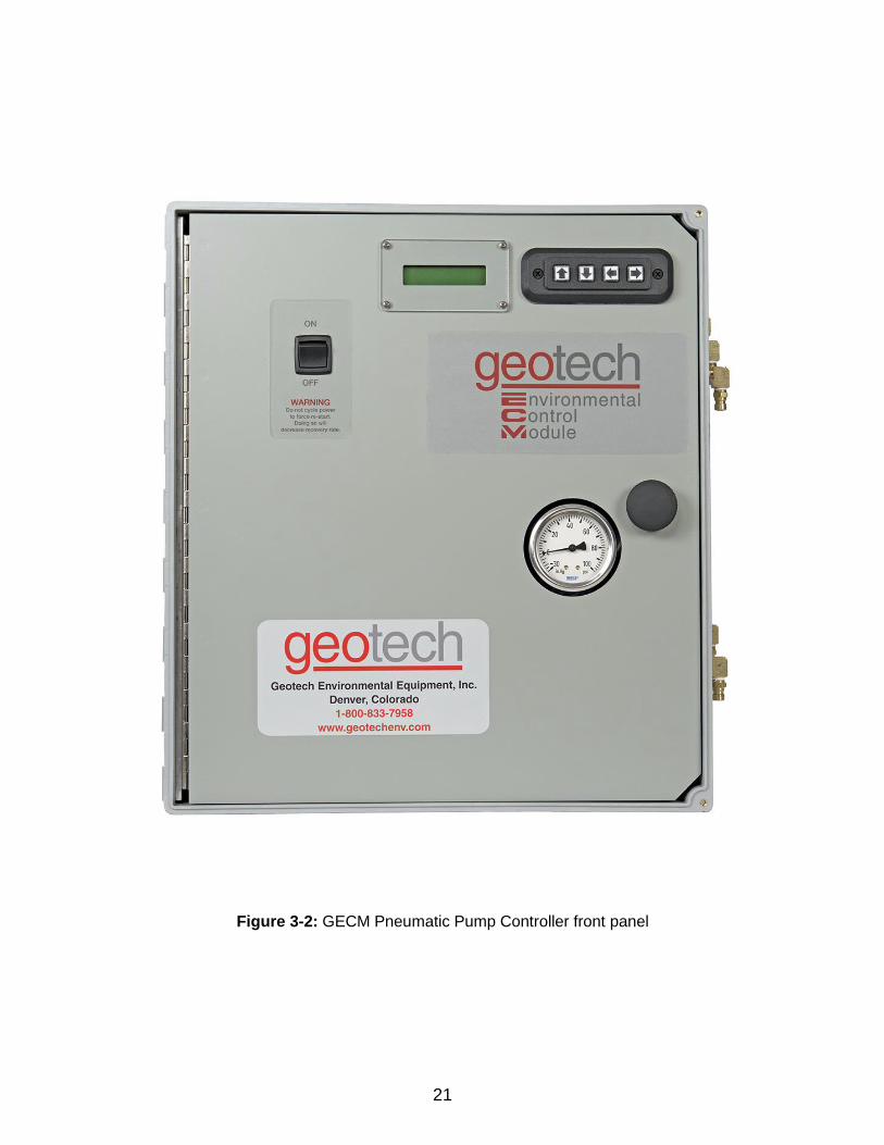
Figure 3-2: GECM Pneumatic Pump Controller front panel
22
Section 4: System Operation Establishing the Fluid Pumping Rate The first thing to consider will be a fluid recovery rate target. The maximum fluid amount that can be recovered is determined by the recharge rate of each individual well. The system can be sized and adjusted for optimal recovery rate potential based on the parameters obtained from the well. To calculate the best results, determine the average recovery of fluid in the recovery tank over a specific time frame, and then compare the results to the target recovery rate. Due to seasonal and weather related variability in ground water level, it may be difficult to determine recovery rates. Record your cycle counter value and total run time and compare these with the amount of product recovered. See Section 7: System Schematics for flow rates and other operational parameters. Initiating the GECM Runtime Once Runtime has been started, the GECM Pneumatic Pump Controller system will initiate the pressure cycle for well number one, complete that well’s cycle, and then continue to any remaining wells as per the individual user input settings.
The amount of liquid per cycle will depend on how much product is in the well. Also, depending on the viscosity of the fluid and temperature, the product layer could have a slower recharge rate. This can make it difficult to determine what the best cycle times should be for a particular site. If you have a less than one gallon (3.8 L) per hour recharge rate, then simply increase the delay time proportionally. For example, if your liquid recharge rate is 1/2 gallon (1.9 L) per hour, double the delay time.
After accounting for more or less recharge rate, you can account for additional tubing and depth to fluid.
Add 3 seconds per 25’ (7.6 m) of tubing for pressure.
Add an additional 3 seconds per 25’ (7.6 m) depth to fluid pressure to start. You will have to adjust this setting to account to the specific viscosity of the fluid and the amount of fluid in the discharge tubing.
It is not necessary to empty the entire length of discharge tubing per cycle; it will be an inefficient use of the air supply to pump air through the lines when it isn’t acting to move product. If you observe air flow from the discharge line after the product has stopped flowing, reduce your pressure time by approximately the same amount of time as the extra air flow. Example: You have a pressure time of 50 seconds; it takes 20 seconds for product to reach the exit end of the discharge tube, product flows for only 20 seconds then air flows freely for 10 seconds. You can reduce your pressure time by 30 seconds. That’s an immediate 60 percent reduction in pressure time. This will increase your battery life and overall system efficiency.
The pressure timer limits are 1 second minimum, 10 minutes maximum. Custom timer settings outside of these min/max parameters can be adjusted through restricted access menus (contact Geotech for more information.) Timer settings outside of the default min/max warrant special consideration to avoid damage to the equipment and otherwise inefficient performance of the system.
23
Recovery Tank is Full When the Tankfull Probe detects a full recovery tank, the GECM will complete the current cycle before shutting the GECM controller off. The following message will appear: TANKFULL
L=Main Menu
During this time, the unit will continue to charge the battery and, if enabled, monitor the temperature. Once the recovery tank is emptied, press the LEFT arrow button for the Main Menu and restart the unit
as described in the beginning of Section 3: Timer/Cycle Settings and Display Descriptions.
24
Section 5: System Maintenance
GECM Controller Weekly Maintenance (optional)
Record the level of the recovery tank (depending on the recovery rate).
Visually inspect all air lines and power cords for damage. Monthly Maintenance (optional)
Rinse debris off the solar panel with clean water – DO NOT use anything abrasive on the panel surface. Clean the front surface of the solar panel and controller enclosure as needed with mild soap, water, and a soft cloth.
Visually inspect the vent plugs in the bottom of the controller enclosure. Clean if obstructed with debris.
Record the uptime counter from the Lifetime display monthly during the first year. This information can be used to schedule yearly maintenance for the least productive times of the year (due to local variations in the weather and solar exposure).
Record the level of the recovery tank (depending on the recovery rate).
Check to see if wildlife (insects, birds, mice, etc.) have not taken up residence in the controller or battery enclosures. Nests and debris can result in vent plug blockage in the battery box, allowing hazardous and explosive gas to build up. Buildup on the controls can result in overheating the electronics and possible failure of components.
Verify fluid levels in the well using a Geotech Interface/water level probe. Make sure the pump is set at the correct interval for collection of fluid.
Verify pump pressure and delay settings. Make sure the cycling rate of the system is correct for the amount of liquid available. If the well is slow to recharge and/or there is only a small volume of product to pump, the pumping rate should be decreased to conserve air. Consult Geotech Technical Sales and this User Manual for guidance on how to properly set these times. DO NOT adjust if unsure.
Quarterly Maintenance (recommended)
Verify fluid (or air flow if no product in the well) is being discharged into the recovery tank to ensure pump check valves and tubing are free from blockage and that the discharge hose is not kinked or cut.
Verify that the Tankfull and Intake Switch floats move freely and operate to shut off the GECM controller when activated.
Inspect the exterior of the controller for loose fittings. Over time, vibration may cause some fittings to loosen and air leaks to develop. If uncorrected, excess air consumption and shortened controller life will result.
Verify that your solar panel is correctly positioned for maximum sunlight. Avoid placing panels in areas with high wind or near tall structures that block sunlight. Ensure panel is positioned for maximum sunlight based on the season. See Section 2: System Installation.
GECM controllers must be returned to Geotech for internal repairs or service.

25
Yearly Maintenance (required)
Turn off GECM controller.
Remove and test the battery. Replace if needed.
Replace the inline particle filters on the air lines if needed.
Contact Geotech for solar panel warranty confirmation. For technical assistance, call Geotech Environmental Equipment, Inc. at 1-800-833-7958. Solar Panel On GECM Pneumatic Pump Controller applications, it is important to keep all debris, dust, and dirt from accumulating on the solar panel surface. Clean the front surface of the solar panel as needed with mild soap and water. DO NOT use abrasive cleaners, solvents or pads. Rinsing off the panel with clean, clear water will suffice.
26
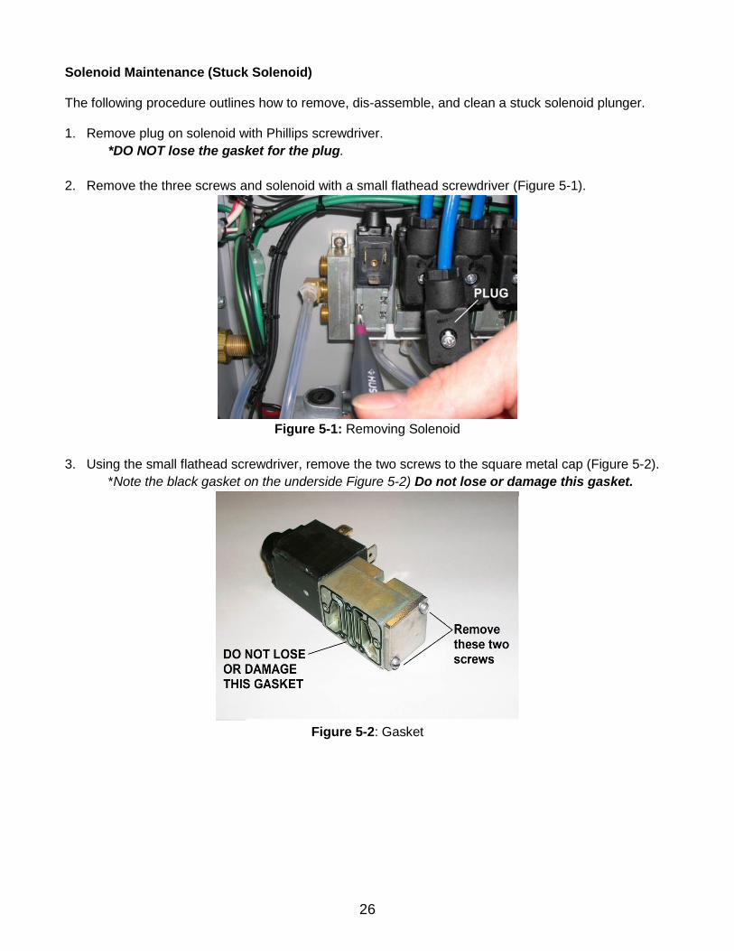
Solenoid Maintenance (Stuck Solenoid) The following procedure outlines how to remove, dis-assemble, and clean a stuck solenoid plunger. 1. Remove plug on solenoid with Phillips screwdriver.
*DO NOT lose the gasket for the plug.
2. Remove the three screws and solenoid with a small flathead screwdriver (Figure 5-1).
Figure 5-1: Removing Solenoid
3. Using the small flathead screwdriver, remove the two screws to the square metal cap (Figure 5-2).
*Note the black gasket on the underside Figure 5-2) Do not lose or damage this gasket.
Figure 5-2: Gasket

27
4. Carefully remove the spring, the O-ring, the bushing, and the plunger (Figure 5-3).
Figure 5-3: Solenoid Parts
5. Clean the plunger and plunger cavity with a spray lubricant and cotton swab.
*Silicon based or aerosol lubricant OK.
6. Orient and insert the plunger as shown in Figure 5-4.
Figure 5-4: Solenoid Plunger
7. Place the O-ring and bushing back into the opening (no orientation needed) followed by the spring
(Figure 5-5).
Figure 5-5: Solenoid Spring
28
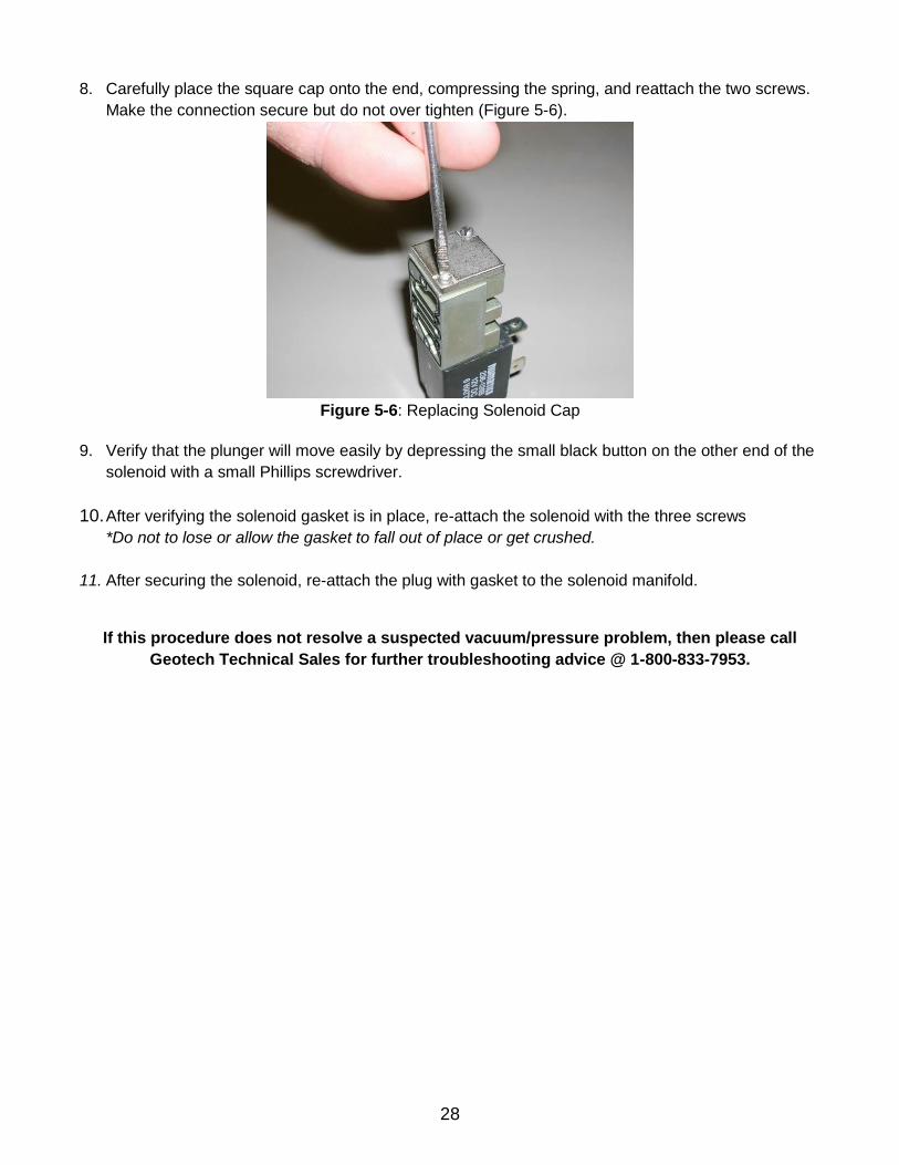
8. Carefully place the square cap onto the end, compressing the spring, and reattach the two screws.
Make the connection secure but do not over tighten (Figure 5-6).
Figure 5-6: Replacing Solenoid Cap
9. Verify that the plunger will move easily by depressing the small black button on the other end of the
solenoid with a small Phillips screwdriver.
10. After verifying the solenoid gasket is in place, re-attach the solenoid with the three screws
*Do not to lose or allow the gasket to fall out of place or get crushed.
11. After securing the solenoid, re-attach the plug with gasket to the solenoid manifold.
If this procedure does not resolve a suspected vacuum/pressure problem, then please call
Geotech Technical Sales for further troubleshooting advice @ 1-800-833-7953.

29
Section 6: System Troubleshooting Problem: No fluid is being recovered but system cycles and gauge indicates pressure generation. Solution:
Inspect product hose for kinks and blockage. Replace if needed. If freezing conditions have occurred, check the discharge lines for frozen product.
The solenoid could be stuck. If it is locked up, it may be cleared by pressing the small button on the black end of the solenoid using a small Phillips screwdriver or paper clip to actuate the solenoid manually. If this does not work, remove the small plate at the other end of the solenoid and clean the plunger and plunger cavity using the procedure found in Section 5: System Maintenance.
Visually inspect the wiring connections to see that they are not loose or otherwise compromised. Problem: System cycles but gauge does not indicate pressure generation. Solution:
Inspect tubing for abrasion, cuts or open connections. Replace if needed.
Make sure the air line connection is connected to the pump.
Verify that there is fluid in the well.
Open the controller panel and verify that all air line connections are intact. Problem: A pump is stuck in pressure. Solution:
Inspect the solenoid for residue or debris. If it is locked up, it may be cleared by pressing the small button on the black end of the solenoid using a small Phillips screwdriver or paper clip to actuate the solenoid manually. If this doesn’t work, remove the small plate at the other end of the solenoid and clean the plunger and plunger cavity using the procedure found in Section 5: System Maintenance.
Visually inspect the wiring connections to see that they are not loose or otherwise compromised.
Problem: The screen is blank.
Solution:
Press the UP arrow button. If the system is currently in a low voltage shut down, a low voltage display will be present. If all equipment is functional, then allow the unit time to recharge. See also the low battery definition in Section 3: Time/Cycle Settings and Display Descriptions.
Check for loose or damaged battery connections and solar panel connections.
Use a voltmeter to test the battery voltage. If it is below 10 volts remove the battery and charge it on a separate charger to verify that a charge can be retained. Reconnect the battery and test the system. Otherwise, when the solar panel is exposed to enough sun, the battery will eventually recharge and the system will automatically resume normal operation.
Turn off the power and check the main fuse.
DO NOT TURN THE GECM SWITCH OFF AND ON AGAIN TO FORCE A CYCLE.
30
Problem: The screen shows unintelligible characters. Solution:
Use a voltmeter and ensure the battery voltage is over 12.1 volts, if not, remove the battery and charge it on a separate charger. Otherwise, when the solar panel is exposed to enough sun the battery will eventually recharge and the system will automatically resume normal operation.
The screen display has no effect on the other hardware functions. If the voltage is over 12.1 volts, turn the ON/OFF switch to OFF and wait 60 seconds before switching on again.
Problem: System is displaying a TANKFULL alarm. Solution:
Recovery tank is full. Empty and restart the system.
Tankfull Probe is disconnected or cable is damaged. Inspect probe and cable. Replace if needed.
Verify the Tankfull float is not stuck in the up position.
If the Tankfull alarm will not clear, then contact Geotech for assistance. Problem: Controller displays a low battery condition and the battery will not recharge. Solution:
If the system experienced freezing conditions, then the battery may be frozen. Place the battery in a warm spot and allow it time to thaw, then reconnect and let it re-charge as normal.
Battery may need to be replaced. See wiring schematics in Section 2: System Installation.
Additional solar panels may be required to keep the system UP and running.
Turn unit off and back on to rest the clock crystal. Problem: Counters running slow. Solution:
Turn unit off and back on to reset the clock crystal.
If your solution cannot be found within this section, please call Geotech Technical Sales for expert troubleshooting advice @ 1-800-833-7958.
31
Section 7: System Specifications Applications 2" (5.8 cm) or larger recovery wells Recovery Rate See Pump Specifications Max. Operating Depth 330’ (100 m) Max. Pressure 150 PSIG (10.3 bar) Max CFMFlow Capacity *16.21 SCFM @ 80 PSIG / 345 **NI/m @ 6 bar Power Power Maximums (AC GECM) 87 to 240VAC, 2.7 to 1 Amp(s) (Solar GECM Pneumatic Pump Controller) 12-15VDC input @ up to 6 Amps 5 ~60 Watts continuous
Controller Operating Temperature 32° to 115º F (0° to 40° C) Storage Temperature Range -20º to 150º F (-29° to 66° C) Humidity 90% non-condensing (max) Size 10" D x 18" T x 16” W (25cm D x 46cm T x 40.5cm W) Rating NEMA 3R fiberglass Approximate Weight 30 lbs. (13.6 kg) (single channel AC GECM) Approximate Weight 29 lbs. (13 kg) (single channel GECM Pneumatic Pump Controller) Approximate Weight 46 lbs. (21 kg) (eight channel AC GECM) Approximate Weight 44 lbs. (20 kg) (eight channel GECM Pneumatic Pump Controller)
*When using 1/8” (3.8 cm) NPT pipe fittings or larger. **Nominal liters per minute.
Power usage will vary depending on application.
Additional customizations and accessories could add more weight.

32
Solar Panel: Rated Power 100 Watts (standard unit) Operating Voltage 17.4 VDC Maximum Voltage 21.5 VDC Operating Amperage 4.88 Amps (standard unit) Maximum Amperage 5.8 Amps Size: 41.2” H x 27.5” W (105 cm H x 70 cm W) Approx. Weight: 23.3 lbs. (10.5 kg) Mounting System: Module Tilt Range 15 to 65 degrees Pole Size 2" (5 cm), 4" (10 cm), and 6" (15 cm) Max Wind Speed 125 mph (200 kph) Module Orientation Landscape/Portrait Wind Exposure Category B & C Materials 5052-H32 Aluminum
Powder Coated Steel
Stainless Steel Fasteners
33
Section 8: System Schematics
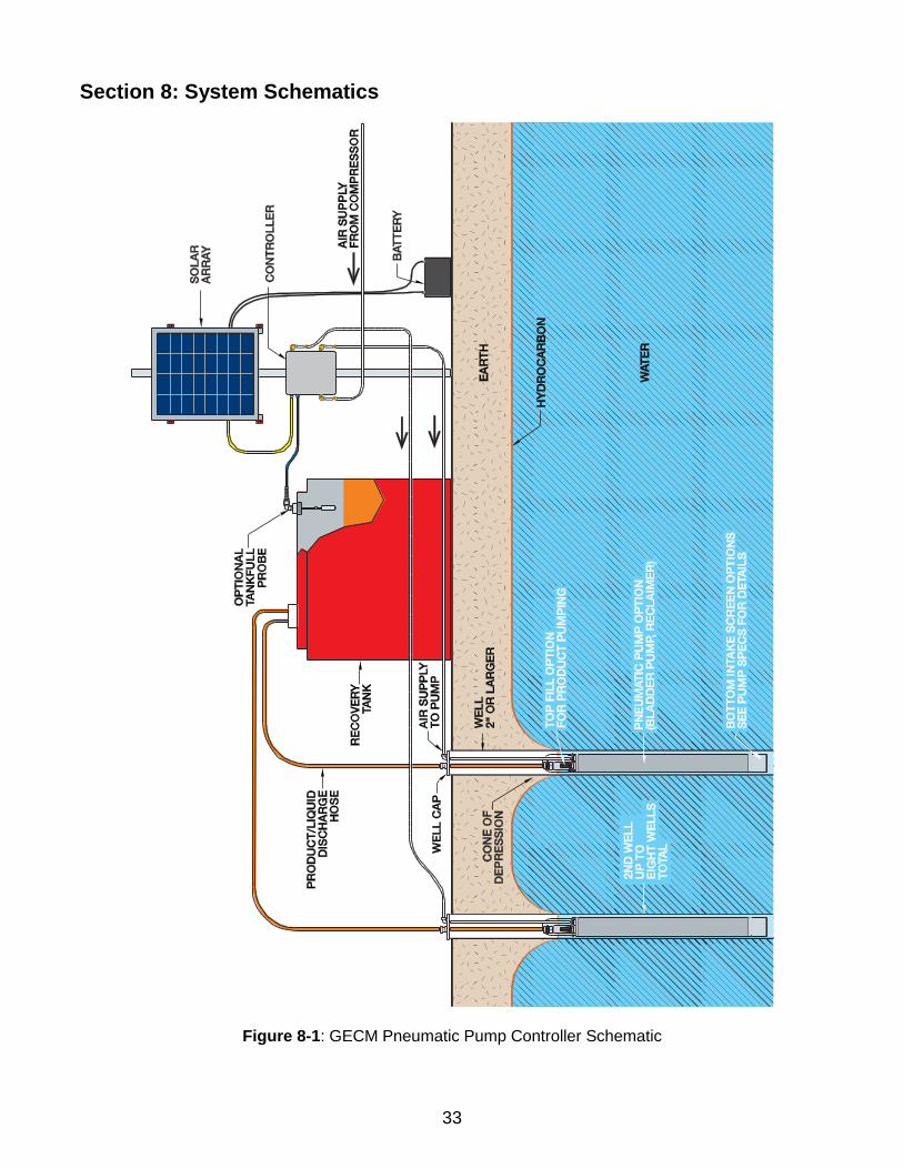
Figure 8-1: GECM Pneumatic Pump Controller Schematic
34
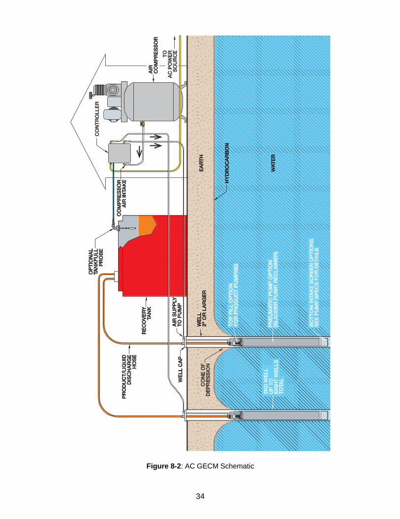
Figure 8-2: AC GECM Schematic
35
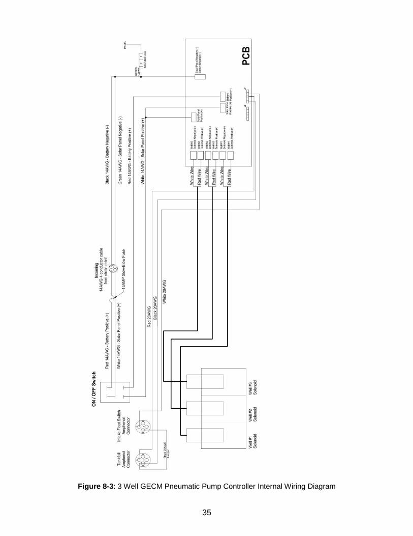
Figure 8-3: 3 Well GECM Pneumatic Pump Controller Internal Wiring Diagram

36
Figure 8-4: 8 Well GECM Pneumatic Pump Controller Internal Wiring Diagram
37
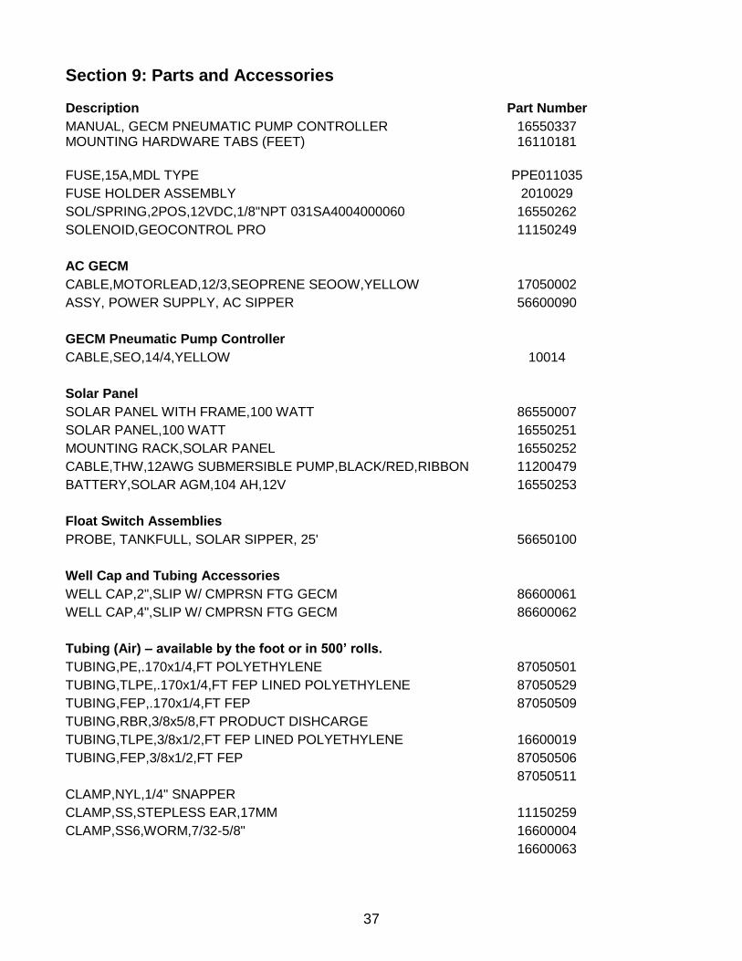
Section 9: Parts and Accessories Description Part Number
MANUAL, GECM PNEUMATIC PUMP CONTROLLER MOUNTING HARDWARE TABS (FEET)
16550337 16110181
FUSE,15A,MDL TYPE PPE011035
FUSE HOLDER ASSEMBLY 2010029
SOL/SPRING,2POS,12VDC,1/8"NPT 031SA4004000060 16550262
SOLENOID,GEOCONTROL PRO 11150249
AC GECM
CABLE,MOTORLEAD,12/3,SEOPRENE SEOOW,YELLOW 17050002
ASSY, POWER SUPPLY, AC SIPPER 56600090
GECM Pneumatic Pump Controller
CABLE,SEO,14/4,YELLOW 10014
Solar Panel
SOLAR PANEL WITH FRAME,100 WATT 86550007
SOLAR PANEL,100 WATT 16550251
MOUNTING RACK,SOLAR PANEL 16550252
CABLE,THW,12AWG SUBMERSIBLE PUMP,BLACK/RED,RIBBON 11200479
BATTERY,SOLAR AGM,104 AH,12V 16550253
Float Switch Assemblies
PROBE, TANKFULL, SOLAR SIPPER, 25' 56650100
Well Cap and Tubing Accessories
WELL CAP,2",SLIP W/ CMPRSN FTG GECM 86600061
WELL CAP,4",SLIP W/ CMPRSN FTG GECM 86600062
Tubing (Air) – available by the foot or in 500’ rolls.
TUBING,PE,.170x1/4,FT POLYETHYLENE 87050501
TUBING,TLPE,.170x1/4,FT FEP LINED POLYETHYLENE 87050529
TUBING,FEP,.170x1/4,FT FEP 87050509
TUBING,RBR,3/8x5/8,FT PRODUCT DISHCARGE
TUBING,TLPE,3/8x1/2,FT FEP LINED POLYETHYLENE 16600019
TUBING,FEP,3/8x1/2,FT FEP 87050506
87050511
CLAMP,NYL,1/4" SNAPPER
CLAMP,SS,STEPLESS EAR,17MM 11150259
CLAMP,SS6,WORM,7/32-5/8" 16600004
16600063

38
NOTES

39
DOCUMENT REVISIONS
EDCF# DESCRIPTION REV/DATE
- Previous Release 02/21/2013
1713 Edited Section 9: Parts and Accessories – Solar Panel now 100 Watts (was
85 Watts), updated Solar Panel Specs - SP 12/18/2013
- Updated Declaration of Conformity, SP 3/2/2015
1993 Changed Assy Power Supply AC Sipper part number, minor edits, StellaR 10/12/2017

EC Declaration of Conformity
Manufacturer: Geotech Environmental Equipment, Inc. 2650 E 40th Avenue Denver, CO 80205
Declares that the following products, Product Name: GECM Pneumatic Pump Controller Model(s): 86550023 – AC GECM Pneumatic Pump Controller 86550024 – DC GECM Pneumatic Pump Controller Year of manufacture: 2012 Conform to the principle safety objectives of 2006/95/EC Low Voltage Directive by application of the following standards:
EN 61010-1: 2010
Year of affixation of the CE Marking: 2012 Conform to the protection requirements of 2004/108/EC Electromagnetic Compatibility (EMC) by application of the following standards:
EN 61000-6-1: 2007 EN 61000-6-3: 2012 EN 61326-1: 2013
EMC conformity established 10/30/2012.
Production control follows the ISO 9001:2008 regulations and includes required safety routine tests. This declaration issued under the sole responsibility of Geotech Environmental Equipment, Inc.
Joe Leonard Product Development Serial number ________________
The Warranty
For a period of one (1) year from date of first sale, product is warranted to be free from defects in materials and workmanship. Geotech agrees to repair or replace, at Geotech’s option, the portion proving defective, or at our option to refund the purchase price thereof. Geotech will have no warranty obligation if the product is subjected to abnormal operating conditions, accident, abuse, misuse, unauthorized modification, alteration, repair, or replacement of wear parts. User assumes all other risk, if any, including the risk of injury, loss, or damage, direct or consequential, arising out of the use, misuse, or inability to use this product. User agrees to use, maintain and install product in accordance with recommendations and instructions. User is responsible for transportation charges connected to the repair or replacement of product under this warranty.
Equipment Return Policy
A Return Material Authorization number (RMA #) is required prior to return of any equipment to our facilities, please call our 800 number for appropriate location. An RMA # will be issued upon receipt of your request to return equipment, which should include reasons for the return. Your return shipment to us must have this RMA # clearly marked on the outside of the package. Proof of date of purchase is required for processing of all warranty requests. This policy applies to both equipment sales and repair orders.
FOR A RETURN MATERIAL AUTHORIZATION,
PLEASE CALL OUR SERVICE DEPARTMENT AT 1-800-833-7958
Model Number: ________________ Serial Number: ________________ Date of Purchase: ________________
Equipment Decontamination
Prior to return, all equipment must be thoroughly cleaned and decontaminated. Please make note on RMA form, the use of equipment, contaminants equipment was exposed to, and decontamination solutions/methods used. Geotech reserves the right to refuse any equipment not properly decontaminated. Geotech may also choose to decontaminate equipment for a fee, which will be applied to the repair order invoice.

Geotech Environmental Equipment, Inc
2650 East 40th Avenue Denver, Colorado 80205 (303) 320-4764 ● (800) 833-7958 ● FAX (303) 322-7242
email: [email protected] website: www.geotechenv.com
In the EU Geotech Equipos Ambientales
Calle Francesc I Ferrer, Guardia Local 19, Mollet del Valles, Barcelona 08100, España Tlf: (34)93 5445937
email: [email protected] website: http://spanish.geotechenv.com
Printed in the United States of America


![[PL 004-484] Model 43AP Pneumatic Indicating Controller · 2019. 3. 7. · 43AP PNEUMATIC CONTROLLER STYLE B PARTS PL 004-484 Page 5 Figure 2. Control Unit Table 4. Optional Restrictor](https://img.pdfslide.net/doc/110x75/610e0780607a9b740a5f4e72/pl-004-484-model-43ap-pneumatic-indicating-2019-3-7-43ap-pneumatic-controller.jpg)