Embed Size (px)
Citation preview
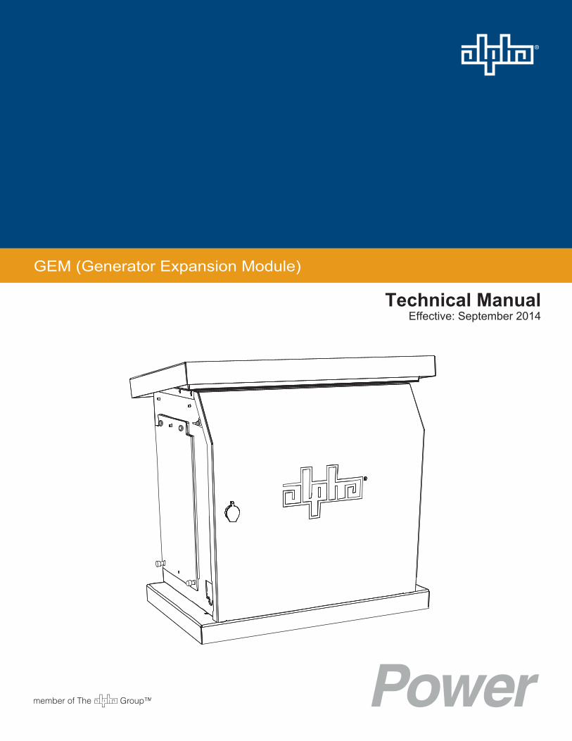
GEM (Generator Expansion Module)
Technical ManualEffective: September 2014
Safety NotesAlpha considers customer safety and satisfaction its most important priority. To reduce the risk of injury or death and to ensure continual safe operation of this product, certain information is presented differently in this manual. Alpha tries to adhere to ANSI Z535 and encourages special attention and care to information presented in the following manner:
The following sections contain important safety information that must be followed during the installation and maintenance of the equipment and batteries. Read all of the instructions before installing or operating the equipment, and save this manual for future reference.
There may be multiple warnings associated with the call out. Example:
ATTENTION provides specific regulatory/code requirements that may affect the placement of equipment and /or installation procedures.
ATTENTION:
NOTICE provides additional information to help complete a specific task or procedure. NOTICE:
ELECTRICAL HAZARD WARNING provides electrical safety information to PREVENT INJURY OR DEATH to the technician or user.
WARNING! ELECTRICAL HAZARD
FUMES HAZARD WARNING provides fumes safety information to PREVENT INJURY OR DEATH to the technician or user.
WARNING! FUMES HAZARD
FIRE HAZARD WARNING provides flammability safety information to PREVENT INJURY OR DEATH to the technician or user.
WARNING! FIRE HAZARD
This WARNING provides safety information for both Electrical AND Fire Hazards.
WARNING! ELECTRICAL & FIRE HAZARD
CAUTION provides safety information intended to PREVENT DAMAGE to material or equipment.
CAUTION!
GENERAL HAZARD WARNING provides safety information to PREVENT INJURY OR DEATH to the technician or user.
WARNING! GENERAL HAZARD

Generator Expansion Module Technical Manual031-326-B0-001, Rev. A
Effective Date: September 2014© 2014 by Alpha Technologies, Inc.
DisclaimerImages contained in this manual are for illustrative purposes only. These images may not match your installation.
Operator is cautioned to review the drawings and illustrations contained in this manual before proceeding. If there are questions regarding the safe operation of this powering system, please contact Alpha Technologies or your nearest Alpha representative.
Alpha shall not be held liable for any damage or injury involving its enclosures, power supplies, generators, batteries or other hardware if used or operated in any manner or subject to any condition not consistent with its intended purpose or is installed or operated in an unapproved manner or improperly maintained.
Contact InformationSales information and customer service in USA(7AM to 5PM, Pacific Time):
Complete technical support in USA(7AM to 5PM, Pacific Time or 24/7 emergency support):
Sales information and technical support in Canada:
Website:
1 800 863 3364
1 888 462 7487
www.alpha.com
1 800 322 5742
Table of ContentsSafety Notes .......................................................................................................................... 2
GEM Safety Notes ................................................................................................................. 6
1.0 Introduction ................................................................................................................. 8
2.0 Installing the GEM Enclosure ..................................................................................... 92.1 PWE Installation............................................................................................... 92.2 UPE Installation ..............................................................................................112.3 Standalone Pole Mounted Installation ........................................................... 13
2.3.1 Pole Mount with Bolts.......................................................................... 132.3.2 Pole Mount with Straps ....................................................................... 14
2.4 Installing the Enclosure Ground Wire ............................................................ 152.4.1 PWE Ground Wire Installation .............................................................. 152.4.2 UPE Ground Wire Installation ............................................................... 16
2.5 Installing the Generator.................................................................................. 17
3.0 Operation Using the Line Transfer Switch (LTS) ...................................................... 183.1 PWE LTS Installation ..................................................................................... 183.2 UPE LTS Installation ...................................................................................... 213.3 Operation ....................................................................................................... 22
4.0 Operation Without Line Transfer Switch ................................................................... 234.1 AC Generators ............................................................................................... 234.2 DC Generators ............................................................................................... 24
5.0 Enclosure Maintenance ............................................................................................ 25
4 031-326-B0-001, Rev. A (09/2014)
Table of ContentsFig. 1-1, Generator Expansion Module (GEM) ........................................................... 8Fig. 2-1, Mounting Hole Location ................................................................................ 9Fig. 2-2, Attaching Mounting Bracket ........................................................................ 10Fig. 2-3, Sliding GEM Into Bracket Grooves ............................................................. 10Fig. 2-4, Securing GEM Thumb Screws ....................................................................11Fig. 2-5, UPE Lid Wingnut Locations .........................................................................11Fig. 2-6, GEM Placed On UPE ................................................................................. 12Fig. 2-7, Enclosure Lid Wingnut Locations ............................................................... 12Fig. 2-8, Mounting Brackets on GEM........................................................................ 13Fig. 2-9, Pole Mount with Bolts ................................................................................. 13Fig. 2-10, Pole Mount with Straps............................................................................. 14Fig. 2-11, Approximate Drilling Location ................................................................... 15Fig. 2-12, PWE Ground Wire Hardware Installation ................................................. 15Fig. 2-13, UPE Ground Wire Hardware Installation .................................................. 16Fig. 2-14, UPE Ground Wire Connector Locations ................................................... 16Fig. 2-15, Side Panel Removal and Storage ............................................................ 17Fig. 3-1, LTS Installation ........................................................................................... 18Fig. 3-2, PWE Generator Access Door ..................................................................... 18Fig. 3-3, Drilling Locations for Legacy Enclosures.................................................... 19Fig. 3-4, Connecting Generator Cord to Generator .................................................. 20Fig. 3-5, Connecting Generator Cord to LTS ............................................................ 20Fig. 3-6 Layout of AC Boot Assembly ....................................................................... 21Fig. 3-7, Bottom-Up View of UPE and GEM Configuration with AC Boot ................ 21Fig. 3-8, Connecting Generator Cord to LTS ............................................................ 22Fig. 4-1, DC Gasket Assembly.................................................................................. 24
5031-326-B0-001, Rev. A (09/2014)
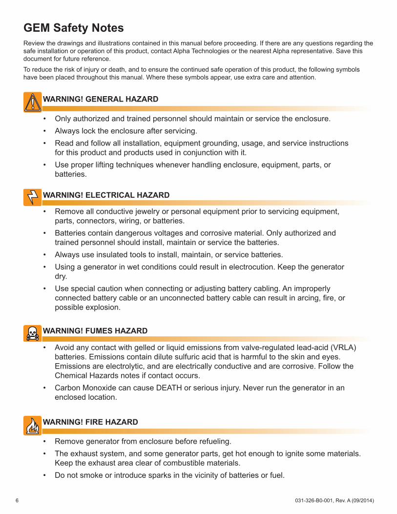
GEM Safety NotesReview the drawings and illustrations contained in this manual before proceeding. If there are any questions regarding the safe installation or operation of this product, contact Alpha Technologies or the nearest Alpha representative. Save this document for future reference.To reduce the risk of injury or death, and to ensure the continued safe operation of this product, the following symbols have been placed throughout this manual. Where these symbols appear, use extra care and attention.
• Only authorized and trained personnel should maintain or service the enclosure.• Always lock the enclosure after servicing.• Read and follow all installation, equipment grounding, usage, and service instructions
for this product and products used in conjunction with it.• Use proper lifting techniques whenever handling enclosure, equipment, parts, or
batteries.
WARNING! GENERAL HAZARD
• Remove all conductive jewelry or personal equipment prior to servicing equipment, parts, connectors, wiring, or batteries.
• Batteries contain dangerous voltages and corrosive material. Only authorized and trained personnel should install, maintain or service the batteries.
• Always use insulated tools to install, maintain, or service batteries.• Using a generator in wet conditions could result in electrocution. Keep the generator
dry.• Use special caution when connecting or adjusting battery cabling. An improperly
connected battery cable or an unconnected battery cable can result in arcing, fire, or possible explosion.
WARNING! ELECTRICAL HAZARD
• Avoid any contact with gelled or liquid emissions from valve-regulated lead-acid (VRLA) batteries. Emissions contain dilute sulfuric acid that is harmful to the skin and eyes. Emissions are electrolytic, and are electrically conductive and are corrosive. Follow the Chemical Hazards notes if contact occurs.
• Carbon Monoxide can cause DEATH or serious injury. Never run the generator in an enclosed location.
WARNING! FUMES HAZARD
• Remove generator from enclosure before refueling.• The exhaust system, and some generator parts, get hot enough to ignite some materials.
Keep the exhaust area clear of combustible materials.• Do not smoke or introduce sparks in the vicinity of batteries or fuel.
WARNING! FIRE HAZARD
6 031-326-B0-001, Rev. A (09/2014)
• The GEM enclosure is intended for temporary deployment of a portable emergency generator.• Prior to installation, contact local utilities, building maintenance departments, and cable/piping locator services to
ensure that installation does not interfere with exisiting utility cables or piping.• Installer must check local codes regarding the placement of equipment with flammable material installed on utility
equipment.
ATTENTION:
• Always verify that ALL equipment is rated for both the input and output voltages of the current application and is in proper working condition.
• Prior to handling the batteries, touch a grounded metal object to dissipate any static charge that may have developed in your body.
CAUTION!
7031-326-B0-001, Rev. A (09/2014)
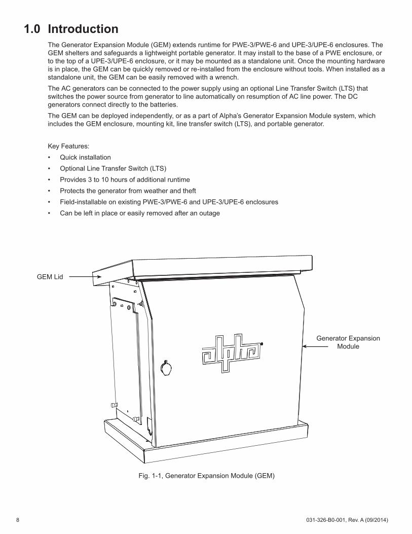
1.0 IntroductionThe Generator Expansion Module (GEM) extends runtime for PWE-3/PWE-6 and UPE-3/UPE-6 enclosures. The GEM shelters and safeguards a lightweight portable generator. It may install to the base of a PWE enclosure, or to the top of a UPE-3/UPE-6 enclosure, or it may be mounted as a standalone unit. Once the mounting hardware is in place, the GEM can be quickly removed or re-installed from the enclosure without tools. When installed as a standalone unit, the GEM can be easily removed with a wrench.The AC generators can be connected to the power supply using an optional Line Transfer Switch (LTS) that switches the power source from generator to line automatically on resumption of AC line power. The DC generators connect directly to the batteries.The GEM can be deployed independently, or as a part of Alpha’s Generator Expansion Module system, which includes the GEM enclosure, mounting kit, line transfer switch (LTS), and portable generator.
Key Features:• Quick installation• Optional Line Transfer Switch (LTS)• Provides 3 to 10 hours of additional runtime• Protects the generator from weather and theft• Field-installable on existing PWE-3/PWE-6 and UPE-3/UPE-6 enclosures• Can be left in place or easily removed after an outage
Generator Expansion Module
GEM Lid
Fig. 1-1, Generator Expansion Module (GEM)
8 031-326-B0-001, Rev. A (09/2014)
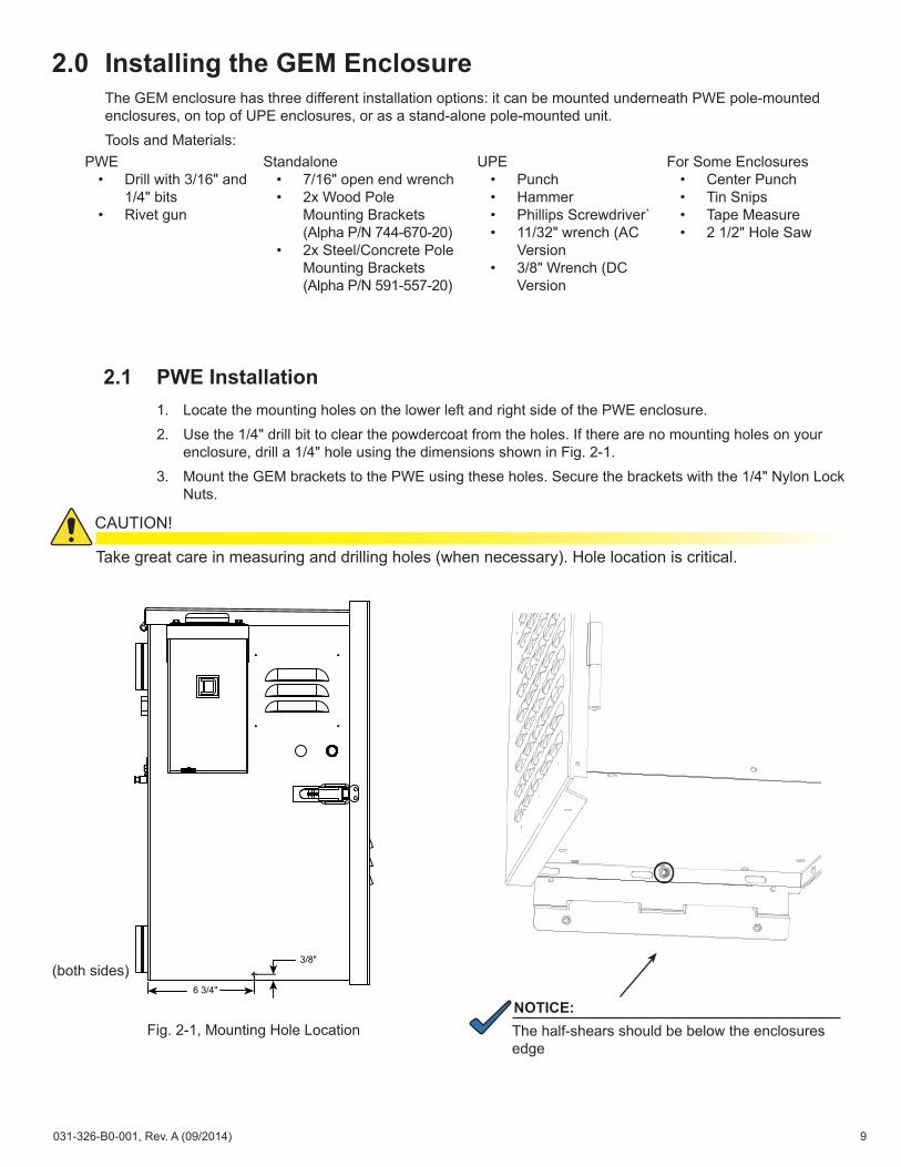
2.1 PWE Installation1. Locate the mounting holes on the lower left and right side of the PWE enclosure. 2. Use the 1/4" drill bit to clear the powdercoat from the holes. If there are no mounting holes on your
enclosure, drill a 1/4" hole using the dimensions shown in Fig. 2-1. 3. Mount the GEM brackets to the PWE using these holes. Secure the brackets with the 1/4" Nylon Lock
Nuts.
2.0 Installing the GEM EnclosureThe GEM enclosure has three different installation options: it can be mounted underneath PWE pole-mounted enclosures, on top of UPE enclosures, or as a stand-alone pole-mounted unit.Tools and Materials:
6 3/4"
3/8"
Fig. 2-1, Mounting Hole Location
(both sides)
Take great care in measuring and drilling holes (when necessary). Hole location is critical.
CAUTION!
PWE• Drill with 3/16" and
1/4" bits• Rivet gun
Standalone• 7/16" open end wrench• 2x Wood Pole
Mounting Brackets (Alpha P/N 744-670-20)
• 2x Steel/Concrete Pole Mounting Brackets (Alpha P/N 591-557-20)
UPE• Punch• Hammer• Phillips Screwdriver`• 11/32" wrench (AC
Version• 3/8" Wrench (DC
Version
For Some Enclosures• Center Punch• Tin Snips• Tape Measure• 2 1/2" Hole Saw
NOTICE:The half-shears should be below the enclosures edge
9031-326-B0-001, Rev. A (09/2014)
2.0 Installing the GEM Enclosure, continued2.1 PWE Installation, continued
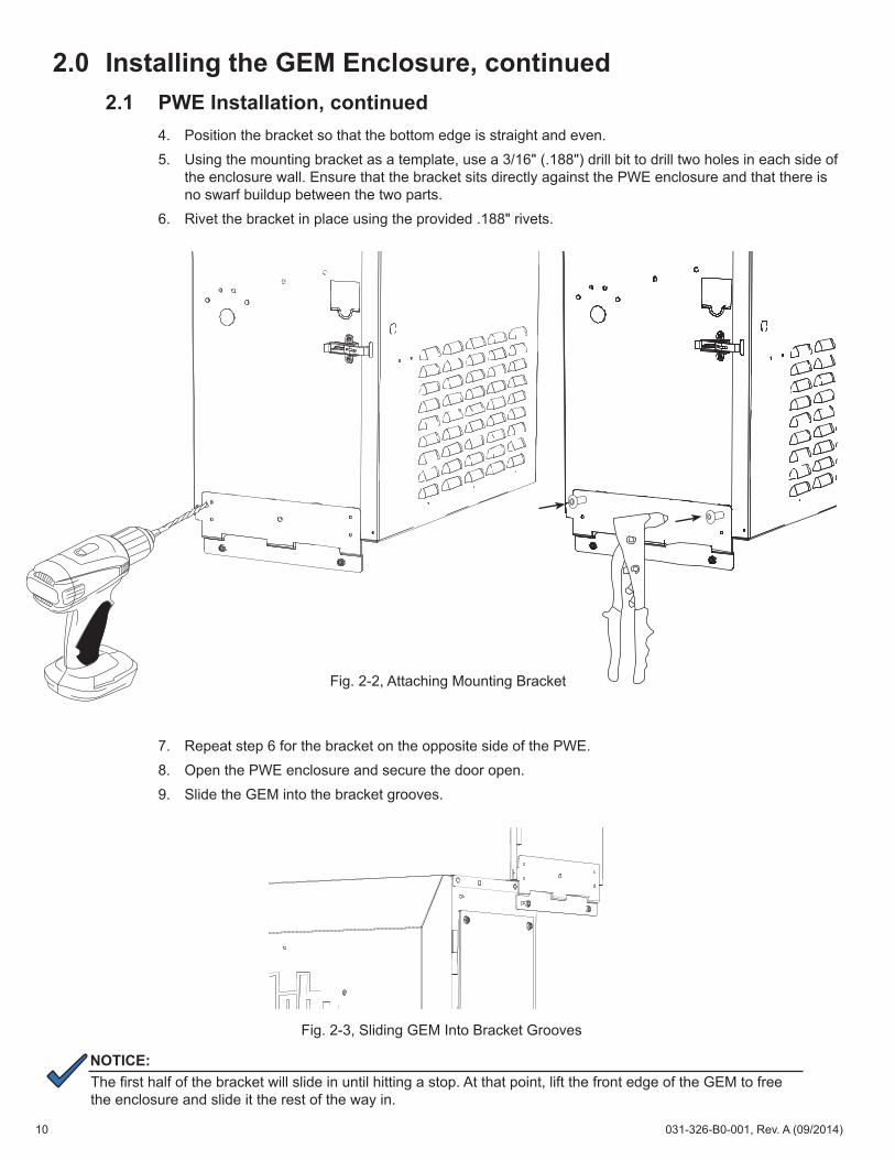
4. Position the bracket so that the bottom edge is straight and even. 5. Using the mounting bracket as a template, use a 3/16" (.188") drill bit to drill two holes in each side of
the enclosure wall. Ensure that the bracket sits directly against the PWE enclosure and that there is no swarf buildup between the two parts.
6. Rivet the bracket in place using the provided .188" rivets.
7. Repeat step 6 for the bracket on the opposite side of the PWE.8. Open the PWE enclosure and secure the door open. 9. Slide the GEM into the bracket grooves.
NOTICE:The first half of the bracket will slide in until hitting a stop. At that point, lift the front edge of the GEM to free the enclosure and slide it the rest of the way in.
Fig. 2-2, Attaching Mounting Bracket
Fig. 2-3, Sliding GEM Into Bracket Grooves
10 031-326-B0-001, Rev. A (09/2014)
Verify the brackets are properly seated and the thumb screws are securely fastened. If the thumb screws do not line up with the nuts in the mounting brackets, the enclosure is not properly seated.
CAUTION!
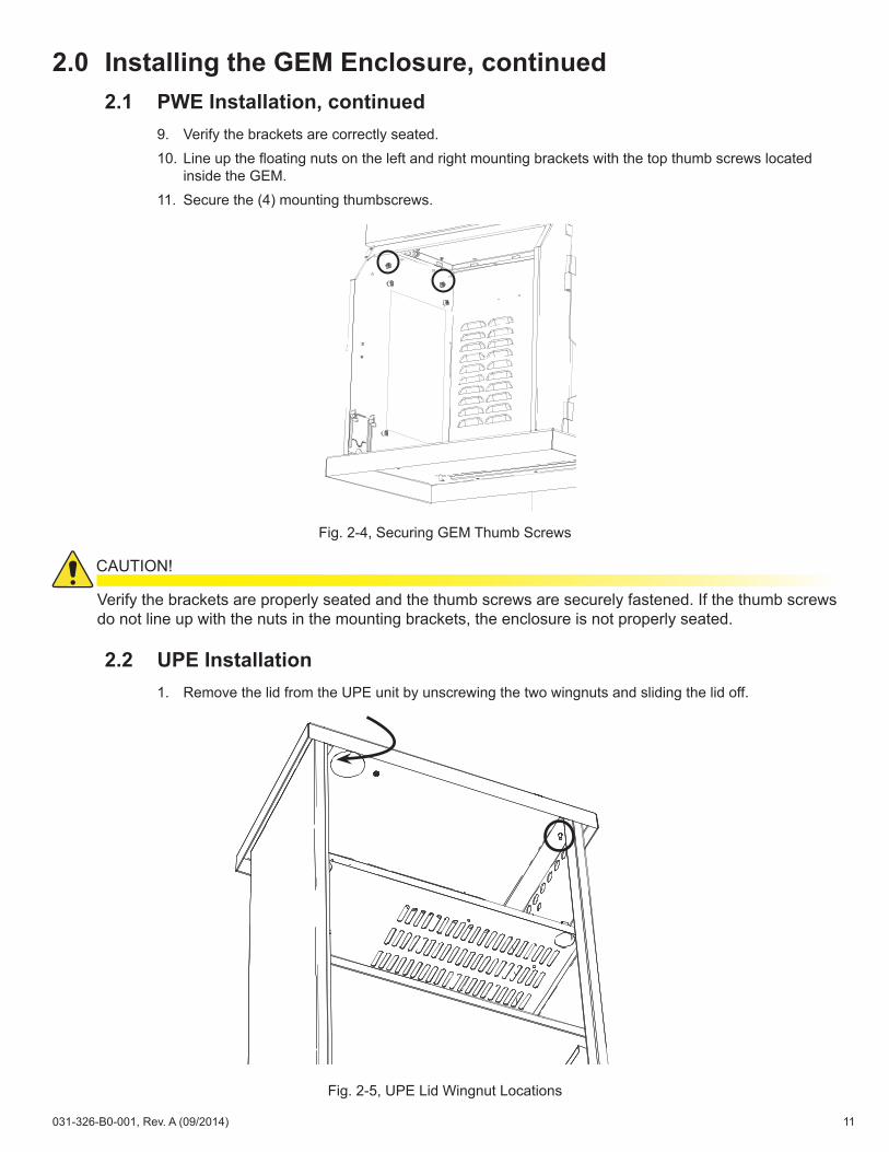
2.2 UPE Installation1. Remove the lid from the UPE unit by unscrewing the two wingnuts and sliding the lid off.
2.0 Installing the GEM Enclosure, continued2.1 PWE Installation, continued
9. Verify the brackets are correctly seated. 10. Line up the floating nuts on the left and right mounting brackets with the top thumb screws located
inside the GEM. 11. Secure the (4) mounting thumbscrews.
Fig. 2-4, Securing GEM Thumb Screws
Fig. 2-5, UPE Lid Wingnut Locations
11031-326-B0-001, Rev. A (09/2014)
2.0 Installing the GEM Enclosure, continued2.2 UPE Installation, continued
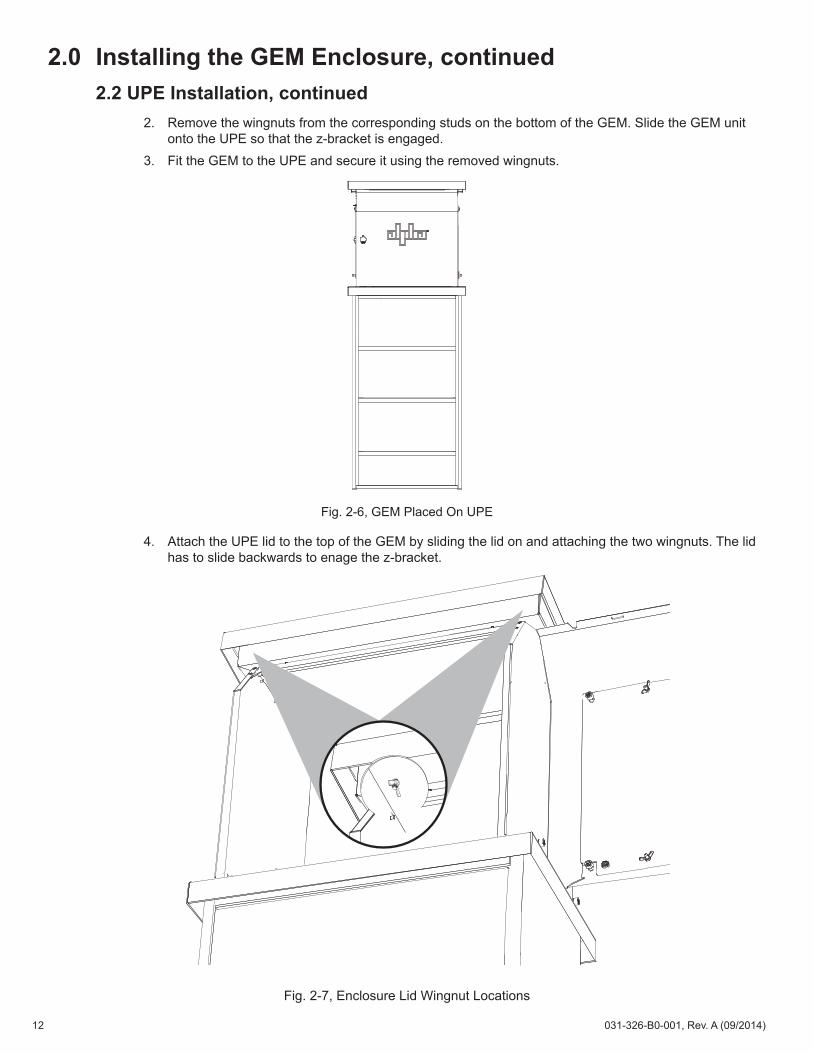
2. Remove the wingnuts from the corresponding studs on the bottom of the GEM. Slide the GEM unit onto the UPE so that the z-bracket is engaged.
3. Fit the GEM to the UPE and secure it using the removed wingnuts.
Fig. 2-6, GEM Placed On UPE
Fig. 2-7, Enclosure Lid Wingnut Locations
4. Attach the UPE lid to the top of the GEM by sliding the lid on and attaching the two wingnuts. The lid has to slide backwards to enage the z-bracket.
12 031-326-B0-001, Rev. A (09/2014)
2.0 Installing the GEM Enclosure, continued2.3 Standalone Pole Mounted Installation
When pole mounting the GEM, either bolts or straps may be used, depending on the type of pole. If pole mounting, mount the GEM on the pole using the pole mount bracket.
2.3.1 Pole Mount with Bolts
1. Position the bracket so that the bottom of the lower bracket is at least 6" off of the ground.
2. Secure the bracket to the pole using the two hex bolts.
3. Securely fasten the enclosure to the bracket using the four screws, lock washers, and flat washers (supplied).
Fig. 2-9, Pole Mount with Bolts
Upper Mounting Bracket
Lower Mounting Bracket
17" (432mm)
Nuts & Washers
Nuts & Washers
5/8" (16mm) Bolt
5/8" (16mm) Bolt
Upper Mounting Bracket
Lower Mounting Bracket
Fig. 2-8, Mounting Brackets on GEM
13031-326-B0-001, Rev. A (09/2014)
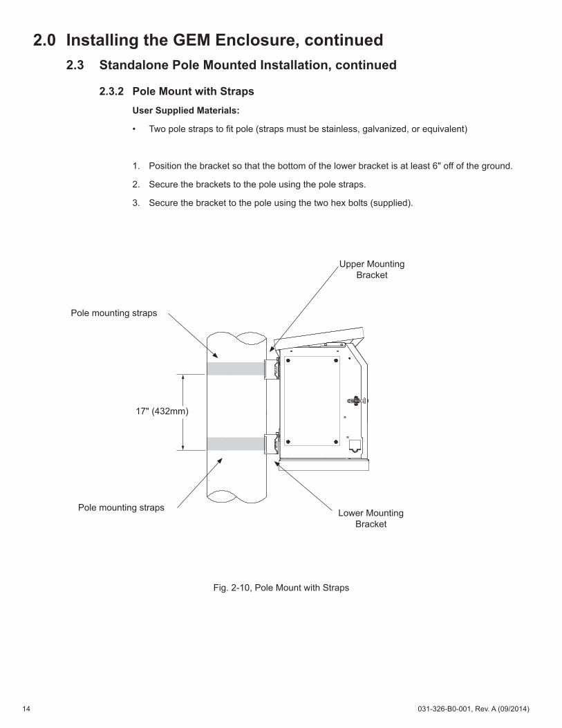
2.0 Installing the GEM Enclosure, continued2.3 Standalone Pole Mounted Installation, continued
2.3.2 Pole Mount with StrapsUser Supplied Materials:
• Two pole straps to fit pole (straps must be stainless, galvanized, or equivalent)
1. Position the bracket so that the bottom of the lower bracket is at least 6" off of the ground.
2. Secure the brackets to the pole using the pole straps.
3. Secure the bracket to the pole using the two hex bolts (supplied).
Fig. 2-10, Pole Mount with Straps
17" (432mm)
Upper Mounting Bracket
Lower Mounting Bracket
Pole mounting straps
Pole mounting straps
14 031-326-B0-001, Rev. A (09/2014)
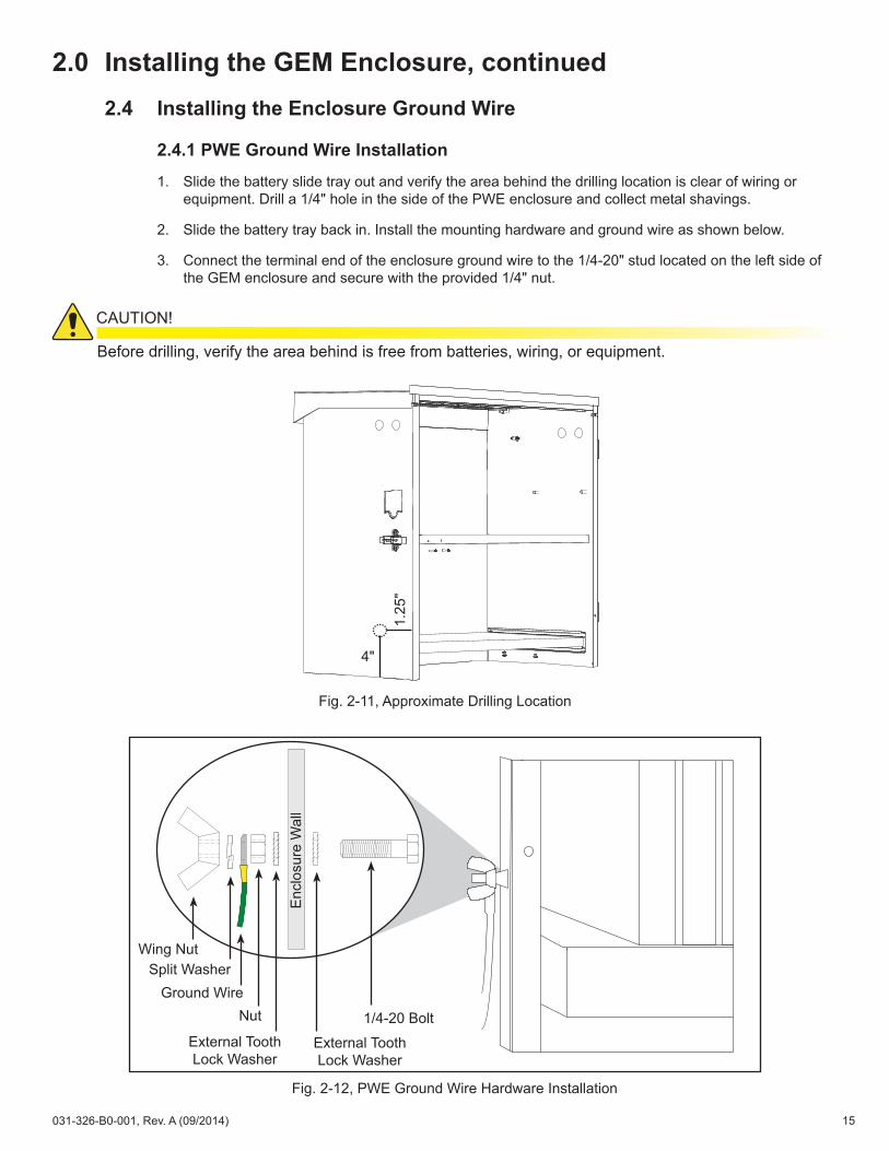
2.0 Installing the GEM Enclosure, continued2.4 Installing the Enclosure Ground Wire
2.4.1 PWE Ground Wire Installation
1. Slide the battery slide tray out and verify the area behind the drilling location is clear of wiring or equipment. Drill a 1/4" hole in the side of the PWE enclosure and collect metal shavings.
2. Slide the battery tray back in. Install the mounting hardware and ground wire as shown below.
3. Connect the terminal end of the enclosure ground wire to the 1/4-20" stud located on the left side of the GEM enclosure and secure with the provided 1/4" nut.
Wing Nut
Ground WireSplit Washer
Nut
External Tooth Lock Washer
External Tooth Lock Washer
1/4-20 Bolt
Fig. 2-12, PWE Ground Wire Hardware Installation
Before drilling, verify the area behind is free from batteries, wiring, or equipment.
CAUTION!
Fig. 2-11, Approximate Drilling Location
Enc
losu
re W
all
4"
1.25
"
15031-326-B0-001, Rev. A (09/2014)
2.0 Installing the GEM Enclosure, continued2.4 Installing the Enclosure Ground Wire, continued
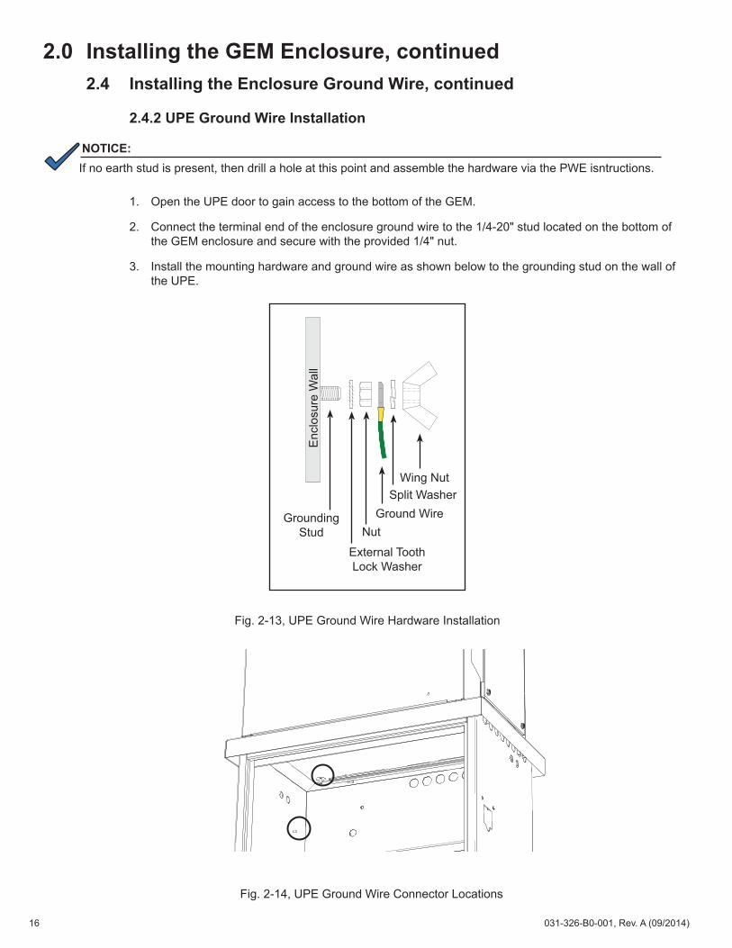
2.4.2 UPE Ground Wire Installation
1. Open the UPE door to gain access to the bottom of the GEM.
2. Connect the terminal end of the enclosure ground wire to the 1/4-20" stud located on the bottom of the GEM enclosure and secure with the provided 1/4" nut.
3. Install the mounting hardware and ground wire as shown below to the grounding stud on the wall of the UPE.
Wing Nut
Ground WireSplit Washer
Nut
External Tooth Lock Washer
Enc
losu
re W
all
Grounding Stud
Fig. 2-13, UPE Ground Wire Hardware Installation
Fig. 2-14, UPE Ground Wire Connector Locations
NOTICE:If no earth stud is present, then drill a hole at this point and assemble the hardware via the PWE isntructions.
16 031-326-B0-001, Rev. A (09/2014)
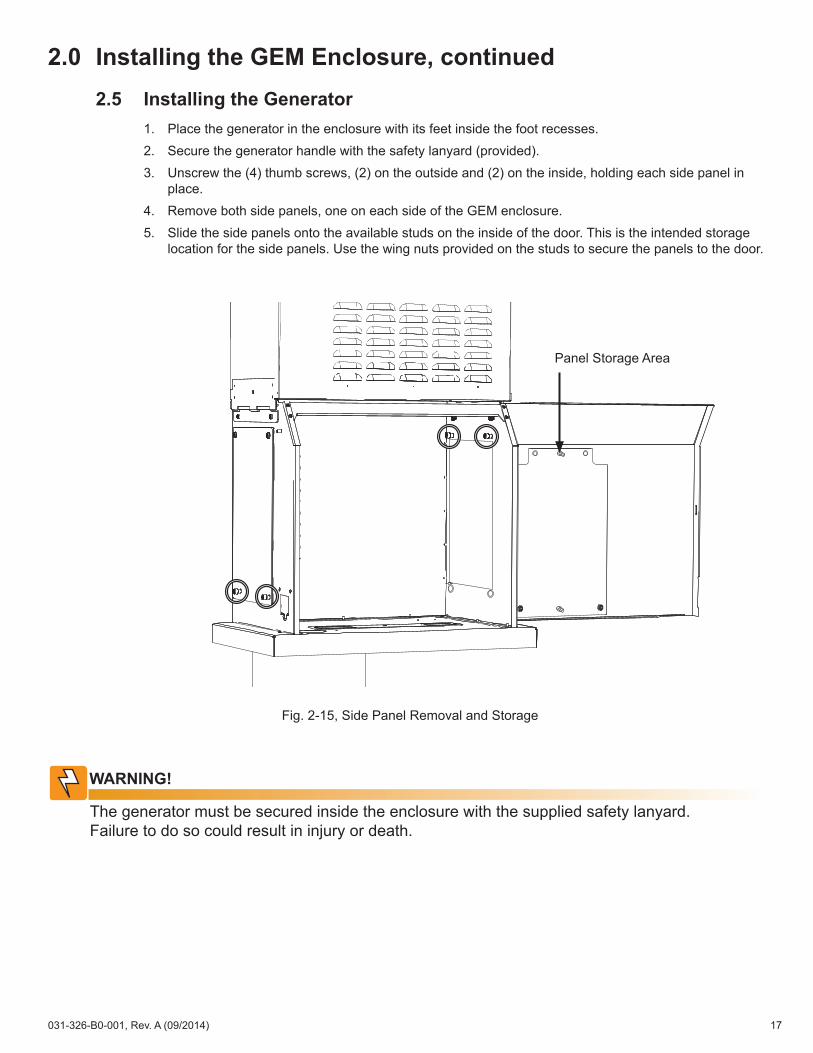
2.0 Installing the GEM Enclosure, continued2.5 Installing the Generator
1. Place the generator in the enclosure with its feet inside the foot recesses.2. Secure the generator handle with the safety lanyard (provided).3. Unscrew the (4) thumb screws, (2) on the outside and (2) on the inside, holding each side panel in
place.4. Remove both side panels, one on each side of the GEM enclosure.5. Slide the side panels onto the available studs on the inside of the door. This is the intended storage
location for the side panels. Use the wing nuts provided on the studs to secure the panels to the door.
Fig. 2-15, Side Panel Removal and Storage
The generator must be secured inside the enclosure with the supplied safety lanyard. Failure to do so could result in injury or death.
WARNING!
Panel Storage Area
17031-326-B0-001, Rev. A (09/2014)
3.0 Operation Using the Line Transfer Switch (LTS)DC generators do not use an LTS. See Section 4.0, Operation Without Line Transfer Switch.For AC generators, Alpha's recommended configuration of the GEM enclosure uses a line transfer switch. The LTS automatically switches the power supply's power source back to AC line on resumption of utility power. In cases of intermittent power, the LTS will alternate from generator to AC line power as available.
3.1 PWE LTS Installation
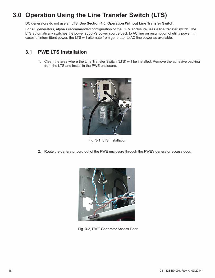
1. Clean the area where the Line Transfer Switch (LTS) will be installed. Remove the adhesive backing from the LTS and install in the PWE enclosure.
2. Route the generator cord out of the PWE enclosure through the PWE's generator access door.
Fig. 3-1, LTS Installation
Fig. 3-2, PWE Generator Access Door
18 031-326-B0-001, Rev. A (09/2014)
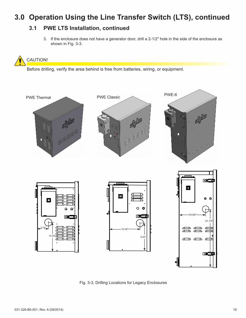
Fig. 3-3, Drilling Locations for Legacy Enclosures
PWE Thermal PWE Classic PWE-6
10.00"
3.75"
9.50"
10.50"
10.00"
21.75"
3.0 Operation Using the Line Transfer Switch (LTS), continued3.1 PWE LTS Installation, continued
3. If the enclosure does not have a generator door, drill a 2-1/2" hole in the side of the enclosure as shown in Fig. 3-3.
Before drilling, verify the area behind is free from batteries, wiring, or equipment.
CAUTION!
19031-326-B0-001, Rev. A (09/2014)
3.0 Operation Using the Line Transfer Switch (LTS), continued3.1 PWE LTS Installation, continued
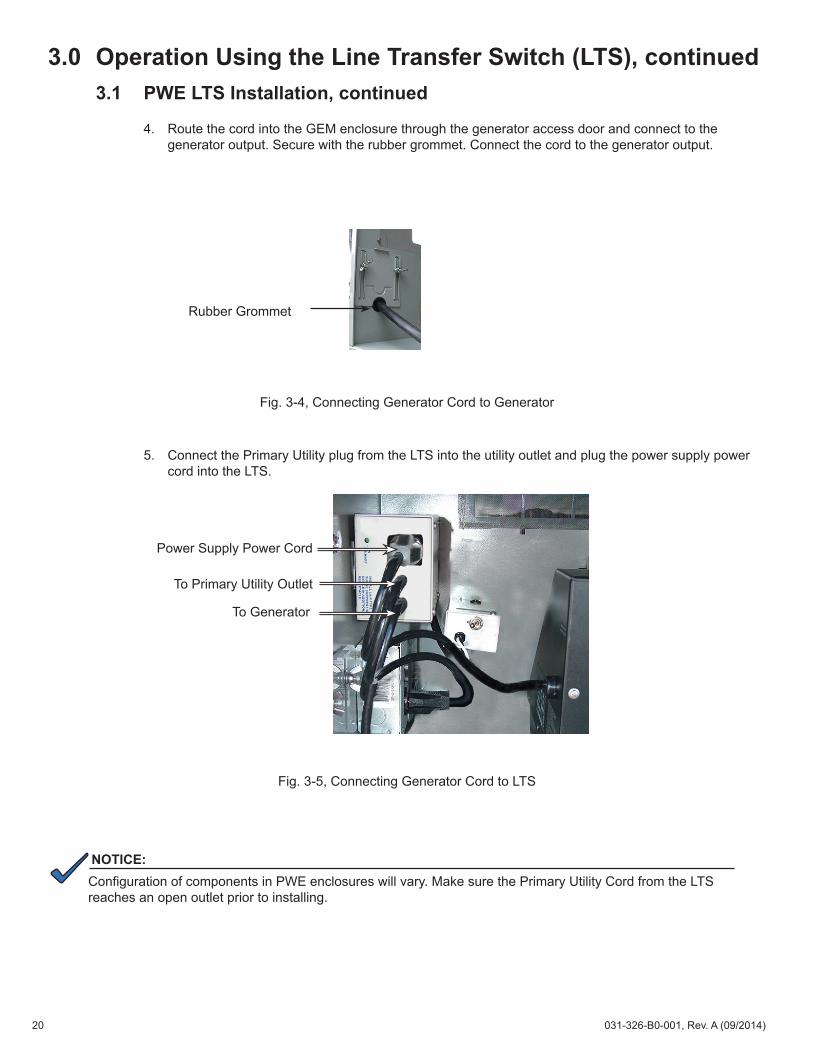
4. Route the cord into the GEM enclosure through the generator access door and connect to the generator output. Secure with the rubber grommet. Connect the cord to the generator output.
NOTICE:Configuration of components in PWE enclosures will vary. Make sure the Primary Utility Cord from the LTS reaches an open outlet prior to installing.
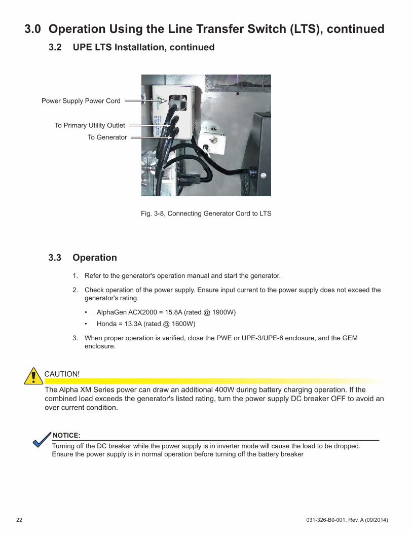
Power Supply Power Cord
To Primary Utility Outlet
To Generator
Rubber Grommet
5. Connect the Primary Utility plug from the LTS into the utility outlet and plug the power supply power cord into the LTS.
Fig. 3-4, Connecting Generator Cord to Generator
Fig. 3-5, Connecting Generator Cord to LTS
20 031-326-B0-001, Rev. A (09/2014)
3.0 Operation Using the Line Transfer Switch (LTS), continued3.2 UPE LTS Installation
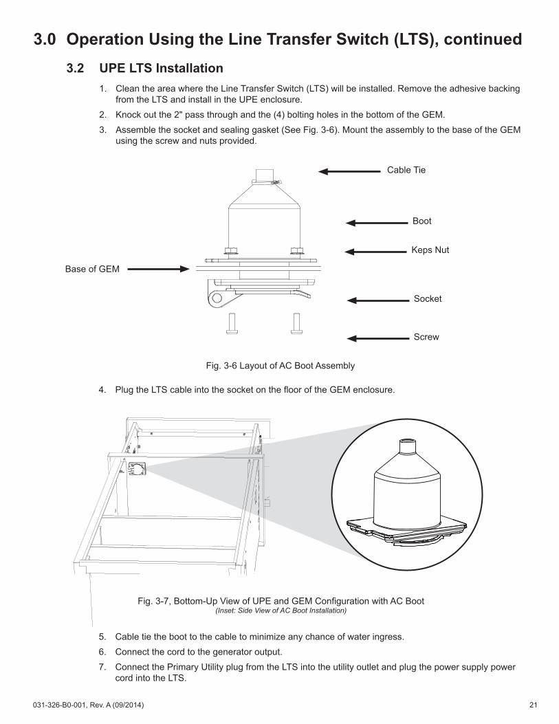
1. Clean the area where the Line Transfer Switch (LTS) will be installed. Remove the adhesive backing from the LTS and install in the UPE enclosure.
2. Knock out the 2" pass through and the (4) bolting holes in the bottom of the GEM.3. Assemble the socket and sealing gasket (See Fig. 3-6). Mount the assembly to the base of the GEM
using the screw and nuts provided.
4. Plug the LTS cable into the socket on the floor of the GEM enclosure.
Fig. 3-7, Bottom-Up View of UPE and GEM Configuration with AC Boot (Inset: Side View of AC Boot Installation)
Fig. 3-6 Layout of AC Boot Assembly
5. Cable tie the boot to the cable to minimize any chance of water ingress. 6. Connect the cord to the generator output.7. Connect the Primary Utility plug from the LTS into the utility outlet and plug the power supply power
cord into the LTS.
Cable Tie
Base of GEM
Keps Nut
Boot
Socket
Screw
21031-326-B0-001, Rev. A (09/2014)
3.0 Operation Using the Line Transfer Switch (LTS), continued3.2 UPE LTS Installation, continued
NOTICE:Turning off the DC breaker while the power supply is in inverter mode will cause the load to be dropped. Ensure the power supply is in normal operation before turning off the battery breaker
The Alpha XM Series power can draw an additional 400W during battery charging operation. If the combined load exceeds the generator's listed rating, turn the power supply DC breaker OFF to avoid an over current condition.
CAUTION!
3.3 Operation
1. Refer to the generator's operation manual and start the generator.
2. Check operation of the power supply. Ensure input current to the power supply does not exceed the generator's rating.
• AlphaGen ACX2000 = 15.8A (rated @ 1900W)
• Honda = 13.3A (rated @ 1600W)
3. When proper operation is verified, close the PWE or UPE-3/UPE-6 enclosure, and the GEM enclosure.
Power Supply Power Cord
To Primary Utility Outlet
To Generator
Fig. 3-8, Connecting Generator Cord to LTS
22 031-326-B0-001, Rev. A (09/2014)
4.0 Operation Without Line Transfer SwitchThe following procedure is for operating a generator in the GEM enclosure without a line transfer switch. When using AC generators, Alpha recommends using an LTS for efficient operation of the powering system.DC generators do not use an LTS.
4.1 AC Generators1. Connect a ground wire from the generator ground screw to the closest internal ground stud near the
GEM enclosure.2. Using a 10' outdoor rated (SJW) extension cord (minimum wire gauge for 120Vac is 12AWG),
connect the generator to the power supply's input line cord.• For PWE enclosures, the cord is plugged in to the generator access doors located on the left side
of the PWE and GEM enclosures.• For UPE-3/UPE-6 enclosures, the cord is plugged in to the boot on the floor of the GEM
enclosure.4. Refer to the generator's operation manual and start the generator.
5. Check operation of the power supply. Ensure input current to the power supply does not exceed the generator's rating.
• AlphaGen ACX2000 = 15.8A (rated @ 1900W)
• Honda = 13.3A (rated @ 1600W)
The Alpha XM Series can draw an additional 400W during battery charging operation. If the combined load exceeds the generator's listed rating, turn the power supply DC breaker OFF to avoid an over current condition.
CAUTION!
NOTICE:Turning off the DC breaker while the power supply is in inverter mode will cause the load to be dropped. Ensure the power supply is in normal operation before turning off the battery breaker
5. 6. When proper operation is verified, close the PWE or UPE-3/UPE-6 enclosure, and the GEM
enclosure.
23031-326-B0-001, Rev. A (09/2014)
4.0 Operation Without Line Transfer Switch, continued4.2 DC Generators
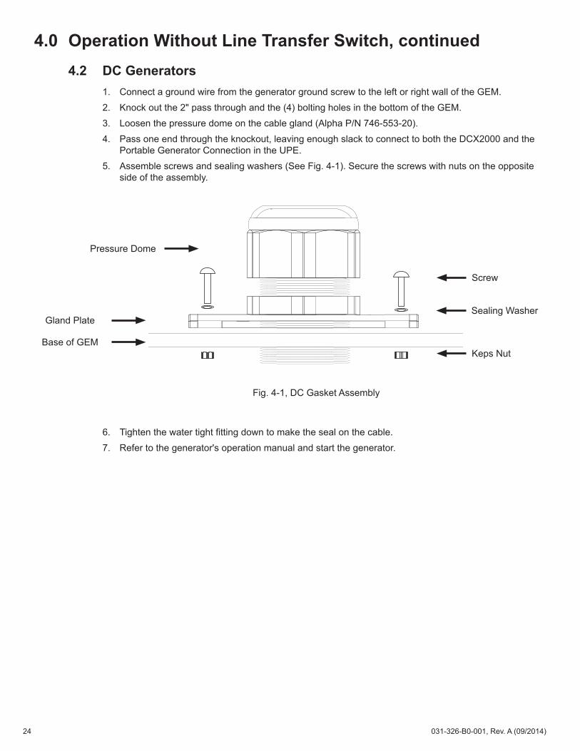
1. Connect a ground wire from the generator ground screw to the left or right wall of the GEM.2. Knock out the 2" pass through and the (4) bolting holes in the bottom of the GEM.3. Loosen the pressure dome on the cable gland (Alpha P/N 746-553-20).4. Pass one end through the knockout, leaving enough slack to connect to both the DCX2000 and the
Portable Generator Connection in the UPE.5. Assemble screws and sealing washers (See Fig. 4-1). Secure the screws with nuts on the opposite
side of the assembly.
6. Tighten the water tight fitting down to make the seal on the cable.7. Refer to the generator's operation manual and start the generator.
Fig. 4-1, DC Gasket Assembly
Pressure Dome
Base of GEM
Gland Plate
Screw
Sealing Washer
Keps Nut
24 031-326-B0-001, Rev. A (09/2014)
5.0 Enclosure MaintenancePreventive Maintenance should be performed every three to six months. Additional maintenance may be required depending on how often the GEM is used.
Inspect the Interior of the EnclosureCarefully inspect the interior of the enclosure. Look for signs of corrosion, debris, oil spills and grime, and clean the enclosure if it shows signs of wear. Ensure that the screens on both sides of the GEM are tight and clean.
Inspect the Mounting Brackets and HardwareCarefully inspect the mounting bracket and mounting hardware. Look for signs of unusual wear and loose hardware. Correct all mounting hardware concerns immediately.
Inspect Grounding Hardware, Wire and ConnectionsCarefully inspect all grounding hardware, wires and connection points. Look for signs of corrosion and loose hardware. Tighten any loose hardware. Clean or replace corroded hardware. Correct all grounding connection concerns immediately.
Inspect the Pole-mount (If Applicable)If the Pole-mount is being used, perform a complete inspection of the Pole-mount Enclosure. Look for signs of rust and corrosion, paying particular attention to the battery trays. Clean any rust or corrosion immediately.
25031-326-B0-001, Rev. A (09/2014)

Visit us at www.alpha.com
Alpha Technologies Inc.3767 Alpha WayBellingham, WA 98226 United StatesTel: +1 360 647 2360Fax: +1 360 671 4936
Alpha Technologies Europe Ltd.Twyford House ThorleyBishop’s StortfordHertfordshire, CM22 7PA United KingdomTel: +44 1279 501110Fax: +44 1279 659870
Alpha TechnologiesSuite 1903, Tower 1, 33 Canton Road, KowloonHong Kong City, ChinaPhone: +852 2736 8663Fax: +852 2199 7988
Alpha Technologies Ltd.7700 Riverfront GateBurnaby, BC V5J 5M4 CanadaTel: +1 604 436 5900Fax: +1 604 436 1233Toll Free: +1 800 667 8743
Alpha Technologies GmbHHansastrasse 8D-91126Schwabach, GermanyTel: +49 9122 79889 0Fax: +49 9122 79889 21
Alphatec Ltd.339 St. Andrews St. Suite 101 Andrea ChambersP.O. Box 564683307 Limassol, CyprusTel: +357 25 375 675Fax: +357 25 359 595
Alpha TEK oooKhokhlovskiy Pereulok 16Stroenie 1, Office 403Moscow, 109028 RussiaTel: +7 495 916 1854Fax: +7 495 916 1349
Alphatec BalticS. Konarskio Street 49-201Vilnius, LT-03123 LithuaniaTel: +370 5 210 5291Fax: +370 5 210 5292
Due to continuing product development, Alpha Technologies reserves the right to change specifications without notice. Copyright © 2014 Alpha Technologies. All Rights Reserved. Alpha® is a registered trademark of Alpha Technologies. 031-326-B0-001, Rev. A (09/2014)