Embed Size (px)
Citation preview

Newsletter
01.09.2015
Document type Technical documentation
Attached to The Gemini CAD pack, version X9 / September 1st 2015
Document version 1.0 / 2015
Author Gemini CAD Systems - Iasi, Romania
Newsletter 2015 2
Information and useful advice ............................................................................................................................ 3
New facilities in Gemini ....................................................................................................................................... 4
Gemini Pattern Editor ...................................................................................................................................... 4 1. Selected pieces number display in the technical sheet ...................................................................... 4 2. Snap on contour ghost ........................................................................................................................ 4 3. Design name import - *.plt, *.cut, *.dxf import.................................................................................. 4 4. Automatic insertion of a group of pieces in Pieces aligned to stripes and plaids .............................. 5
Gemini Cut Plan ............................................................................................................................................... 5 1. Annotations on the current marker in the Cut Plan report ................................................................ 5 2. Export design name as label ............................................................................................................... 5 3. Integration with an ERP type system .................................................................................................. 6 4. Load the numerical planning ............................................................................................................... 6
Gemini Nest Expert .......................................................................................................................................... 7 1. Edit supplementary annotations for the Nesting Report.................................................................... 7 2. Multiple stripes and plaids .................................................................................................................. 7 3. Float the parts ..................................................................................................................................... 9 4. Export design name............................................................................................................................. 9 5. Import design name (Use piece information - PLT/CUT labels) ........................................................10 6. Export marker in JPG format on a 1:1 scale .....................................................................................10 7. Preview fabric texture ......................................................................................................................10 8. Project saving warning message .......................................................................................................11 9. Overwrite MTX files...........................................................................................................................11
Solved errors .....................................................................................................................................................11
Gemini Pattern Editor ....................................................................................................................................11 1. Notches import from *.iba/*.vet files ...............................................................................................11
In progress for future versions .........................................................................................................................12
Gemini Pattern Editor ....................................................................................................................................12 1. Designs multiple import ....................................................................................................................12 2. Adding a *.vet to an already existing project ....................................................................................12 3. Message information import from *.mdl and *.iba/*.vet ................................................................12
Newsletter 2015 3
Information and useful advice
1. We made it our goal to make our software competitive and that is why our customers` suggestions
are of utmost importance in helping us improve the software. For that, we would like to thank them.
In our continuous attempt to improve the applications, some new features were added to the X9
version of the Gemini package, that are meant to help the users. It is also possible that the new
functions automatically solve some problems that the users might have had so far.
2. Most of the new features are already on the new version of the applications and they are also
explained in the Gemini Newsletter. This is why studying the Newsletter is highly recommended. The
current document includes only the latest changes of the applications, compared to the previous
version. If you have an earlier version of the Gemini package, you should read all the Newsletters
released in the meantime.
3. The version this document refers to can be downloaded manually from our website,
www.geminicad.com, the download section, or fully automatically, using the Gemini Shield
application. Using the Gemini Shield software, you will be able to see if the latest version from the
website is supported by your license. Also you will be able to automatically update the Gemini
applications.
Warning! You can update your software only if your system is still in the warranty period or if you
have a service contract for the Gemini software. To check your warranty period, please check the
Gemini Shield.
4. To find out what software version you are using, you can check the date shown on the splash image,
when opening the application, or check the Gemini Shield.
5. For more detailed information regarding the new functions, you can check the X9 version of the
Gemini User Manuals or the Appendix which will be available in the days to come. If you haven’t got
the Appendix yet, please contact someone from our technical support department.
6. For any problems, questions or suggestions you might have, please feel free to contact us:
tel./fax.: +40 232 237 546
e-mail: [email protected]
OR
Contact your distributor.
Newsletter 2015 4
New facilities in Gemini
Gemini Pattern Editor
1. Selected pieces number display in the technical sheet
Information has been added to the technical sheet header regarding the Total number of pieces, representing the number of pieces displayed on the screen of the total of main pieces from the model. Location:
Upper menu: Project/Print technical sheets/Print technical screen sketch/Print
Button: Print project technical sheet/Print technical screen sketch Functioning: The header displays the number of main pieces from the sheet / project main pieces total.
2. Snap on contour ghost
After modifying the position of a point from the contour, it can be brought to the initial position by contour snap. Functioning: The point from the contour should be selected, the ALT key should be kept pressed and the point should be dragged towards the contour ghost, to the initial position.
3. Design name import - *.plt, *.cut, *.dxf import
It is now possible to import the design name label from the standard DXF (*.dxf), PLT (*.plt) and CUT (*.cut) files. This option is also available in the Gemini Nest Expert and Gemini Cut Plan applications. Location: For the standard DXF files: Project/Import/Standard DXF Files (*.dxf)/Advanced/Use piece information/Piece detection settings/ Design identifier.
For the PLT files: Project/Import/Import PLT Files/Advanced/Use piece information/PLT Labels/Piece detection settings/Design identifier.
For the CUT files: Project/Import/Import CUT Files/Advanced/Use piece information/CUT Labels/ Piece detection settings/Design identifier Functioning: The Project menu should be accessed, the desired import type should be selected (standard DXF, PLT or CUT), the advanced settings are displayed and the Use piece information option should be checked. The Labels button should be pressed, and, in the newly-opened window, the Design identifier option should be checked. If the information regarding the design is in the imported file, it will be in the Piece information window.
Newsletter 2015 5
4. Automatic insertion of a group of pieces in Pieces aligned to stripes and plaids
The possibility of automatically including a group of pieces in Pieces aligned to stripes and plaids by using the Create automatically matching points function. Location: Pieces working mode/ Create automatically matching points button/Pieces aligned to stripes and plaids/the Pieces aligned to stripes and plaids window Functioning: The pieces following to be included in the dependency group should be selected and the Create automatically matching points button should be pressed. In the Matching points creation window that opens, the needed dependency type should be checked as follows:
if the focus is on dependency on stripes, Vertical should be checked
if the focus is on dependency on plaids, Horizontal should be checked
if the focus is on dependency on stripes and plaids, both Vertical and Horizontal should be checked The Pieces aligned to stripes and plaids option becomes active and can be checked. On the selected pieces matching points will automatically be created. The pieces will be placed in the marker according to the chosen Vertical and/or Horizontal options.
Gemini Cut Plan
1. Annotations on the current marker in the Cut Plan report
The Annotations field has been added for editing certain information regarding the current order, that are then to be displayed in the Cut Plan report.
Location: On the right side of the application main window, in the spreading and nesting parameters setting area, in the Info tab. Functioning: The necessary information for the current order should be entered in the Annotations field. The text that is entered here will be displayed in the Cut Plan Report header.
2. Export design name as label
The feature regarding exporting the design name as a label in the *.cut and *.plt files has been added. This option is available both in the Gemini Nest Expert settings (for the *.cut and *.plt files) and in the Gemini Pattern Editor settings (for the *.plt files export).
In the report that is exported in PDF format there is a limitation in characters that can be displayed next to the Annotations field (approximately 45 characters).
NOTE
Newsletter 2015 6
Location: Settings/Plotter (Cutter) settings/General settings/Labels options/Export design name. Functioning: In the Plotter settings window, in the General settings tab, the Export design name option should be checked. Moreover, the layer selected in the General settings tab, for the Export text as label, if text layer is option, needs to be the same as the layer selected in the Settings for layers tab for the Text from text axis element.
3. Integration with an ERP type system
The new Gemini Cut Plan allows integration with an ERP/SPM type system if the Customized PM Import module is acquired. Location: The Open an order from file button – the *.otx file is loaded through the Open window, that opens. Functioning: The .otx file should be selected in the order opening window. The import is possible if the file generated from the ERP/SPM system follows a pre-established syntax. For more details, the technical department should be contacted.
4. Load the numerical planning
It is now possible to use, in a new order, a planning from an already existing order. Location: The options list that opens on the arrow next to the Open an order from file button. Functioning: A project/projects is/are imported in order to create an order/a plan. The Load numerical planning option is used and, from the Open window, the order the numerical planning of which is to be loaded/copied in the new order should be selected. Following this operation, in the new order, the same quantities per sizes existing in the selected order will be displayed.
The new order needs to contain the same number of imported projects and the same number of sizes per project as the number from the existing order.
NOTE
Newsletter 2015 7
Gemini Nest Expert
1. Edit supplementary annotations for the Nesting Report
It is now possible to edit supplementary information regarding the current marker, since a new field, Annotations, has been added. Written details will be displayed in the Marker report. The text edited in this field will be displayed in the marker report. It is also possible to check and correct, in the Marker report window, the previously added details. Location: Settings/Fabric type/Annotations The information edited in the above-described path will be displayed in Marker report. Functioning: The Annotations editable field can be found on the lower side of the Settings / Fabric type window. This field can be used for entering information and details that are specific to the current marker. In the File menu, the Report option can be used, and, in the Marker report window, previously edited details can be checked and corrected. This information will be printed in the report, in the Annotations table.
2. Multiple stripes and plaids
In order to answer the practical needs in terms of carrying out nestings for fabrics with a complex drawing ratio, modifications have been made with an eye on using the multiple stripes and plaids. This involves simultaneously defining and using more colour and/or drawing ratios as grids. The advantages of using multiple stripes and plaids are the following ones:
Nesting efficiency in Nest Expert
Fabric’s distorsion accurate identification in VisionCUT. Location: Settings/Fabric type/Stripes and plaids Functioning: In order to define a colour ratio, it is important to edit the following parameters:
Name – the conventional name of the ratio, that is necessary for its subsequent identification;
Offset S. (cm) – the distance measured from the marker’s left edge to the first stripe;
Repeat S. (cm) – the distance measured between two successive stripes of the fabric;
Offset P. (cm) – the distance measured from the marker’s bottom edge to the first plaid;
Repeat P. (cm) – the distance measured between two successive plaids of the fabric;
Color – useful for the easy identification of the ratio on the surface of the marker;
Angle S. (°) – the stripes absolute inclination angle – this functionality will be implemented on a future release;
Angle P. (°) – the plaids absolute inclination angle – this functionality will be implemented on a future release.
Newsletter 2015 8
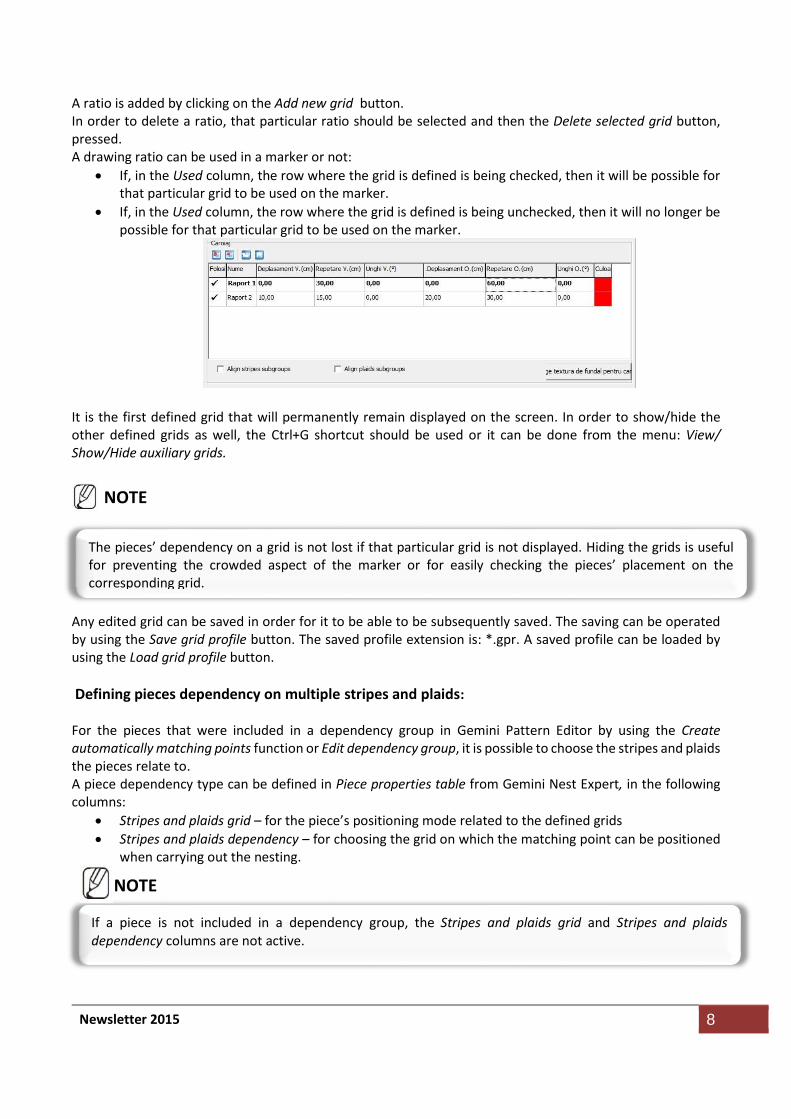
A ratio is added by clicking on the Add new grid button. In order to delete a ratio, that particular ratio should be selected and then the Delete selected grid button, pressed. A drawing ratio can be used in a marker or not:
If, in the Used column, the row where the grid is defined is being checked, then it will be possible for that particular grid to be used on the marker.
If, in the Used column, the row where the grid is defined is being unchecked, then it will no longer be possible for that particular grid to be used on the marker.
It is the first defined grid that will permanently remain displayed on the screen. In order to show/hide the other defined grids as well, the Ctrl+G shortcut should be used or it can be done from the menu: View/ Show/Hide auxiliary grids.
Any edited grid can be saved in order for it to be able to be subsequently saved. The saving can be operated by using the Save grid profile button. The saved profile extension is: *.gpr. A saved profile can be loaded by using the Load grid profile button.
Defining pieces dependency on multiple stripes and plaids: For the pieces that were included in a dependency group in Gemini Pattern Editor by using the Create automatically matching points function or Edit dependency group, it is possible to choose the stripes and plaids the pieces relate to. A piece dependency type can be defined in Piece properties table from Gemini Nest Expert, in the following columns:
Stripes and plaids grid – for the piece’s positioning mode related to the defined grids
Stripes and plaids dependency – for choosing the grid on which the matching point can be positioned when carrying out the nesting.
The pieces’ dependency on a grid is not lost if that particular grid is not displayed. Hiding the grids is useful for preventing the crowded aspect of the marker or for easily checking the pieces’ placement on the corresponding grid.
NOTE
If a piece is not included in a dependency group, the Stripes and plaids grid and Stripes and plaids dependency columns are not active.
NOTE
Newsletter 2015 9
In the Stripes and plaids dependency column one of the three dependency to multiple stripes and plaids defining modes can be selected:
Specific – the pieces with dependency on stripes and plaids will be placed related to a certain selected grid
Any – the pieces with dependency on stripes and plaids will be placed related to any of the grids
Free – the pieces from the same dependency group will be placed without dependency on any of the grids.
In the Stripes and plaids dependency column one or more editable grids can be selected. If a single grid is selected, the Specific and Any dependency pieces will be placed related to it. If more grids are selected, the selection of the one the pieces relate to is done automatically, according to the nesting efficiency. The grids that are not checked will be ignored. If no grid is checked, the pieces will be placed freely on the marker. In the case of the Specific type dependency pieces, if there are:
More grids checked – the pieces from a dependency group will be placed dependent on one of the checked grids. The selection of the grid towards which the pieces will be placed is decided automatically, according to the nesting efficiency.
A single grid checked – the pieces from a dependency group will only be placed dependent on the selected grid; the non selected grids will be ignored.
All the grids unchecked – even if the pieces are in a dependency group, the pieces will be placed freely on the marker.
In the case of the Any type dependency pieces, if there are:
More grids checked – the pieces from a dependency group will be placed dependent on any of the checked grids.
A single grid checked – the pieces from the same dependency group will only be placed dependent on the selected grid; the non selected grid will be ignored.
All the grids unchecked – even if the pieces are in a dependency group, the pieces will be placed freely on the marker; the two grids will be ignored.
Default settings
All the options described above can be defined as default settings in the tab meant for this category of settings. The newly-generated markers will have the default settings for stripes and plaids.
3. Float the parts
If, on the marker, there are small pieces that are snapped to a larger piece, in the case of the cutter cutting machines where fixing the lay is operated by vacuumation, there is the possibility of incorrectly cutting small pieces. If the large piece is cut before cutting the small pieces, it is no longer possible to ensure the vacuumation of the small pieces. This is the reason why the Float the parts function has been added, which repositions the small pieces in the neighbouring free area, with the maximum distance possible. For further details regarding the function’s operating mode, the technical support team should be contacted.
4. Export design name
A new option has been implemented in the export settings of the *.cut and *.plt files. It makes it possible for the design name to be exported as a label.
Newsletter 2015 10
Location: Settings/ Plotter (cutter) settings/ General settings/ section Labels options/ Export design name. Functioning: If the design name is to be exported as a label, the Export design name option should be checked. The prefix for this option is D: and is saved in the export settings profile when the profile is saved.
5. Import design name (Use piece information - PLT/CUT labels)
It is now possible to import the label with the design name from the standard DXF files (*.dxf), PLT (*.plt) and CUT (*.cut). Location: For the standard DXF files: File/Import/DXF Import/Import Standard DXF/Advanced/Use piece information/DXF Labels/Design identifier
For the PLT files: File/Import/HPGL files /Advanced/ Use piece information/PLT Labels/Piece detection settings/ Design identifier
For the CUT files: File/Import/ISO CUT RS274-D files/Advanced/Use piece information/CUT Labels/Piece detection settings/ Design identifier Functioning: From the Project menu, the desired import type (standard DXF, PLT or CUT) is selected, the advanced settings are displayed and the Use piece information option should be checked. The Labels button should be pressed again, and, in the newly-opened window, the Design identifier option should be checked.
6. Export marker in JPG format on a 1:1 scale
A new function has been implemented, Export marker image, that can be used to export markers in JPG format on a 1:1 scale; it will contain the image of the fabric texture in the background, as well as the pieces contour placed. Location: Buttons bar/Export marker image
Functioning: In order to export the marker image, the Export marker image button should be pressed. In the newly-opened image there is the possibility to preview the image at different zoom levels. When the Export button is pressed, a new window opens, for the saving, where the path to the disk where the image should be saved is chosen. The name for the file to be saved should be entered and the corresponding format (*.jpg, *.bmp or *.png), selected; the Save button should be pressed.
7. Preview fabric texture
In the case of the markers on fabrics with drawings, the fabric can be previewed. Location: This option is in the Fabric preview window from Settings/Fabric type. Functioning:
Newsletter 2015 11
In order to load an image of the fabric, the Load a fabric preview image button should be clicked on and the desired image should be selected. It will be displayed in the preview window. The image can be magnified or minimized with the Zoom buttons or deleted, with the Delete the current fabric preview image button.
8. Project saving warning message
It is now possible to receive a warning message if the project used in the marker was modified and saved after having saved the marker.
Functioning: The implementation of this functionality requires support from the technical department.
9. Overwrite MTX files
It is now possible to overwrite the MTX files, if their saving to a specific location is needed. This option can be useful to the companies that have an ERP/SPM system integrated.
Location: Settings/User options/MTX options/Overwrite existing mtx files
Functioning: The implementation of this functionality type requires support from the technical department.
Solved errors
Gemini Pattern Editor
1. Notches import from *.iba/*.vet files
When importing *.iba/*.vet type files, notches did not have the angle to the notches line equal to the one defined in the native file. Modifications have been made so that notches keep the declared angle.
Newsletter 2015 12
In progress for future versions
Gemini Pattern Editor
1. Designs multiple import
The possibility to make a multiple selection when importing *.iba/*.vet for the simultaneous import of more designs will be implemented.
2. Adding a *.vet to an already existing project
The possibility of adding a *.vet type file to an already existing project, by import, as a new design, will be implemented.
3. Message information import from *.mdl and *.iba/*.vet
The possibility of importing the Message information to Gemini Pattern Editor, Piece Information, next to Comment, will be implemented.