Embed Size (px)
Citation preview

GEMO Ladder Editor V1.1 © Gürbüzoğlu Elektronik Ltd. Şti., 2006
All information subject to 1/35 www.gemo.com.trchange without notice
GEMO Ladder Editor V1.1
User’s Manual
GEMO Ladder Editor V1.1 © Gürbüzoğlu Elektronik Ltd. Şti., 2006
All information subject to 2/35 www.gemo.com.trchange without notice
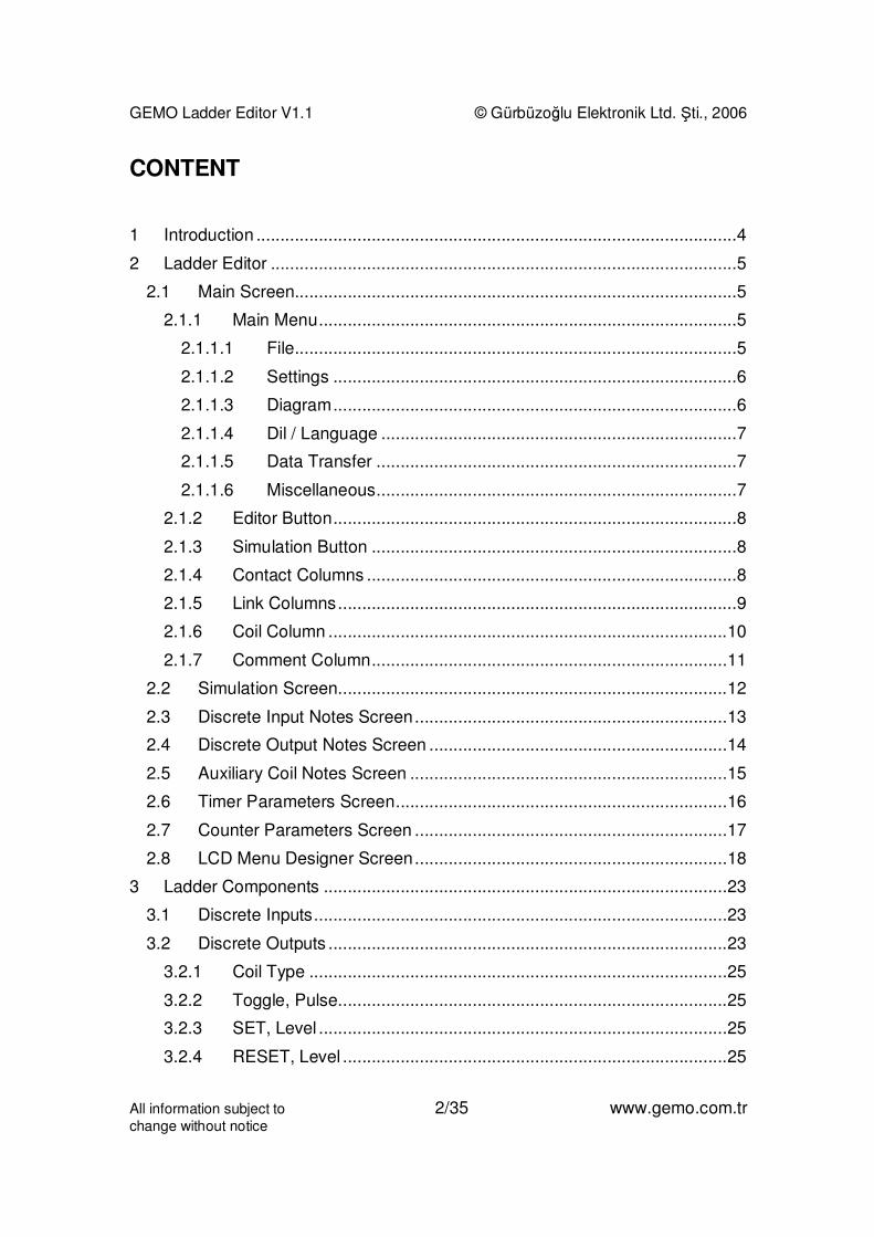
CONTENT
1 Introduction ....................................................................................................4
2 Ladder Editor .................................................................................................5
2.1 Main Screen............................................................................................5
2.1.1 Main Menu.......................................................................................5
2.1.1.1 File............................................................................................5
2.1.1.2 Settings ....................................................................................6
2.1.1.3 Diagram....................................................................................6
2.1.1.4 Dil / Language ..........................................................................7
2.1.1.5 Data Transfer ...........................................................................7
2.1.1.6 Miscellaneous...........................................................................7
2.1.2 Editor Button....................................................................................8
2.1.3 Simulation Button ............................................................................8
2.1.4 Contact Columns .............................................................................8
2.1.5 Link Columns...................................................................................9
2.1.6 Coil Column ...................................................................................10
2.1.7 Comment Column..........................................................................11
2.2 Simulation Screen.................................................................................12
2.3 Discrete Input Notes Screen.................................................................13
2.4 Discrete Output Notes Screen ..............................................................14
2.5 Auxiliary Coil Notes Screen ..................................................................15
2.6 Timer Parameters Screen.....................................................................16
2.7 Counter Parameters Screen .................................................................17
2.8 LCD Menu Designer Screen.................................................................18
3 Ladder Components ....................................................................................23
3.1 Discrete Inputs......................................................................................23
3.2 Discrete Outputs ...................................................................................23
3.2.1 Coil Type .......................................................................................25
3.2.2 Toggle, Pulse.................................................................................25
3.2.3 SET, Level .....................................................................................25
3.2.4 RESET, Level ................................................................................25

GEMO Ladder Editor V1.1 © Gürbüzoğlu Elektronik Ltd. Şti., 2006
All information subject to 3/35 www.gemo.com.trchange without notice
3.2.5 SET, Pulse.....................................................................................26
3.2.6 RESET, Pulse................................................................................26
3.3 Auxiliary Relays ....................................................................................26
3.4 Timers...................................................................................................27
3.4.1 Mode A: ON Delay.........................................................................28
3.4.2 Mode B: Pulsed Delay, OFF with RESET......................................28
3.4.3 Mode C: Retriggerable One Shot ..................................................29
3.4.4 Mode D: Non-retriggerable One Shot ............................................29
3.4.5 Mode E: Delay after Power ON .....................................................30
3.4.6 Mode F: OFF Delay .......................................................................30
3.4.7 Mode G: One Shot after OFF ........................................................31
3.4.8 Mode H: One Shot after ON and OFF ...........................................31
3.4.9 Mode I: Flashing with START........................................................32
3.4.10 Mode J: Flashing with START/RESET ..........................................32
3.4.11 Mode K: Delayed One Shot after OFF...........................................33
3.4.12 Mode L: Independent ON Delay, OFF Delay .................................33
3.5 Counters ...............................................................................................33
4 Drawing a Diagram ......................................................................................35
4.1 Inserting a New Line .............................................................................35
4.2 Deleting a Line......................................................................................35
4.3 Deleting a Contact ................................................................................35
4.4 Deleting a Link ......................................................................................35
4.5 Deleting a Contact ................................................................................35
4.6 Deleting a Comment .............................................................................35
4.7 Selecting and Deleting an Area of Diagram..........................................35
4.8 Fast Line Drawing between Contacts, Links and Coils .........................35

GEMO Ladder Editor V1.1 © Gürbüzoğlu Elektronik Ltd. Şti., 2006
All information subject to 4/35 www.gemo.com.trchange without notice
1 Introduction
GEMO Ladder Editor is a ladder logic editor/simulator used to write/draw ladderdiagrams/programs for GEMO Smart Relays/ PLC. User can test his/her ladderdiagrams by using simulation feature. User can download a diagram/program tothe smart relay by using communication cable via an RS-232 port.
This document does not instruct techniques related to writing/drawing ladderdiagrams. This document is prepared as a reference document for GEMOLadder Editor. The user/reader is assumed to have background about ladderdiagrams.
Please help us to improve our software. We appreciate if you send yourcomments, feedbacks and bug reports ([email protected]).
Please visit periodically www.gemo.com.tr for software/documentation updates.
License:
FREEWARE FOR EVERYONE. NO WARRANTIES. USE AT YOUR OWN RISK.THIS SOFTWARE AND ANY RELATED DOCUMENTATION IS PROVIDED "ASIS" WITHOUT WARRANTY OF ANY KIND. THE ENTIRE RISK ARISING OUTOF USE OR PERFORMANCE OF THIS SOFTWARE AND/OR ANY DEVICEPROGRAMMED WITH THIS SOFTWARE REMAINS WITH YOU.
This software is developed with Borland® Delphi™2005.
!
GEMO Ladder Editor V1.1 © Gürbüzoğlu Elektronik Ltd. Şti., 2006
All information subject to 5/35 www.gemo.com.trchange without notice
2 Ladder Editor
2.1 Main Screen
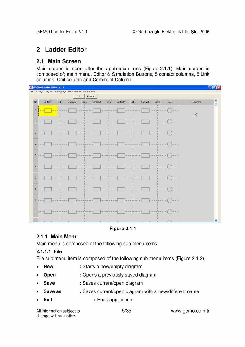
Main screen is seen after the application runs (Figure-2.1.1). Main screen iscomposed of; main menu, Editor & Simulation Buttons, 5 contact columns, 5 Linkcolumns, Coil column and Comment Column.
Figure 2.1.1
2.1.1 Main Menu
Main menu is composed of the following sub menu items.
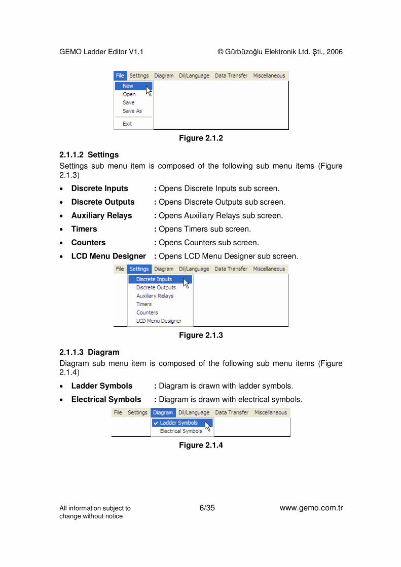
2.1.1.1 File
File sub menu item is composed of the following sub menu items (Figure 2.1.2);
• New : Starts a new/empty diagram
• Open : Opens a previously saved diagram
• Save : Saves current/open diagram
• Save as : Saves current/open diagram with a new/different name
• Exit : Ends application
GEMO Ladder Editor V1.1 © Gürbüzoğlu Elektronik Ltd. Şti., 2006
All information subject to 6/35 www.gemo.com.trchange without notice
Figure 2.1.2
2.1.1.2 Settings
Settings sub menu item is composed of the following sub menu items (Figure2.1.3)
• Discrete Inputs : Opens Discrete Inputs sub screen.
• Discrete Outputs : Opens Discrete Outputs sub screen.
• Auxiliary Relays : Opens Auxiliary Relays sub screen.
• Timers : Opens Timers sub screen.
• Counters : Opens Counters sub screen.
• LCD Menu Designer : Opens LCD Menu Designer sub screen.
Figure 2.1.3
2.1.1.3 Diagram
Diagram sub menu item is composed of the following sub menu items (Figure2.1.4)
• Ladder Symbols : Diagram is drawn with ladder symbols.
• Electrical Symbols : Diagram is drawn with electrical symbols.
Figure 2.1.4

GEMO Ladder Editor V1.1 © Gürbüzoğlu Elektronik Ltd. Şti., 2006
All information subject to 7/35 www.gemo.com.trchange without notice
2.1.1.4 Dil / Language
Dil / Language sub menu item is composed of the following sub menu items(Figure 2.1.5)
• Türkçe : Editor Language is Turkish.
• English : Editor Language is English.
Figure 2.1.5
2.1.1.5 Data Transfer
Data Transfer sub menu item is composed of the following sub menu items(Figure 2.1.6, Figure 2.1.7)
• Select Communication Port : Selects RS-232 port to download; COM1,COM2, COM3 or COM4.
• Download New Program : Starts downloading current ladderdiagram/program to Smart Relay. Previously stored diagram/program in smartrelay is permanently replaced with the new one.
• Erase Device Program : Previously stored diagram/program in smartrelay is permanently erased. User can download a new one any time later on.
Figure 2.1.6
Figure 2.1.7
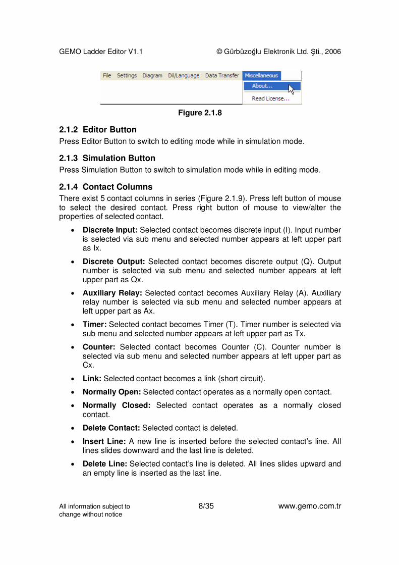
2.1.1.6 Miscellaneous
Miscellaneous sub menu item is composed of the following sub menu items(Figure 2.1.8)
About : Displays information about editor.
Read License : Displays license information about editor
GEMO Ladder Editor V1.1 © Gürbüzoğlu Elektronik Ltd. Şti., 2006
All information subject to 8/35 www.gemo.com.trchange without notice
Figure 2.1.8
2.1.2 Editor Button
Press Editor Button to switch to editing mode while in simulation mode.
2.1.3 Simulation Button
Press Simulation Button to switch to simulation mode while in editing mode.
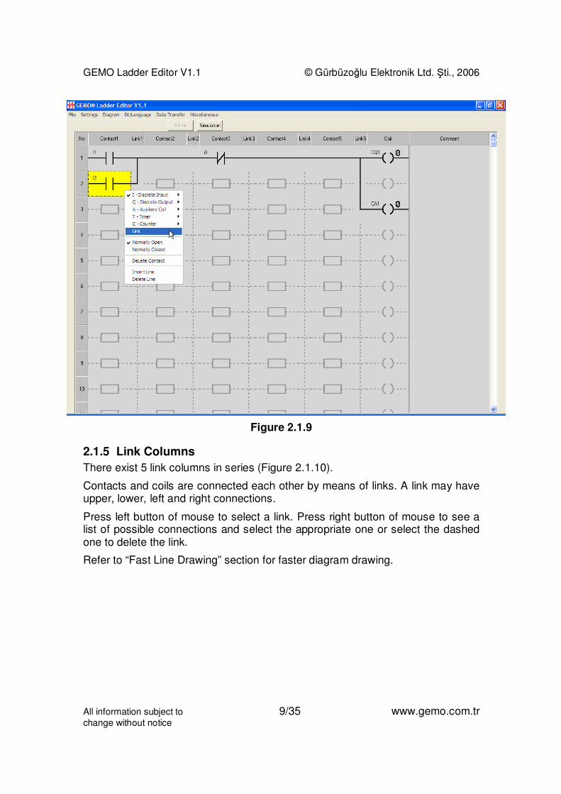
2.1.4 Contact Columns
There exist 5 contact columns in series (Figure 2.1.9). Press left button of mouseto select the desired contact. Press right button of mouse to view/alter theproperties of selected contact.
• Discrete Input: Selected contact becomes discrete input (I). Input numberis selected via sub menu and selected number appears at left upper partas Ix.
• Discrete Output: Selected contact becomes discrete output (Q). Outputnumber is selected via sub menu and selected number appears at leftupper part as Qx.
• Auxiliary Relay: Selected contact becomes Auxiliary Relay (A). Auxiliaryrelay number is selected via sub menu and selected number appears atleft upper part as Ax.
• Timer: Selected contact becomes Timer (T). Timer number is selected viasub menu and selected number appears at left upper part as Tx.
• Counter: Selected contact becomes Counter (C). Counter number isselected via sub menu and selected number appears at left upper part asCx.
• Link: Selected contact becomes a link (short circuit).
• Normally Open: Selected contact operates as a normally open contact.
• Normally Closed: Selected contact operates as a normally closedcontact.
• Delete Contact: Selected contact is deleted.
• Insert Line: A new line is inserted before the selected contact’s line. Alllines slides downward and the last line is deleted.
• Delete Line: Selected contact’s line is deleted. All lines slides upward andan empty line is inserted as the last line.
GEMO Ladder Editor V1.1 © Gürbüzoğlu Elektronik Ltd. Şti., 2006
All information subject to 9/35 www.gemo.com.trchange without notice
Figure 2.1.9
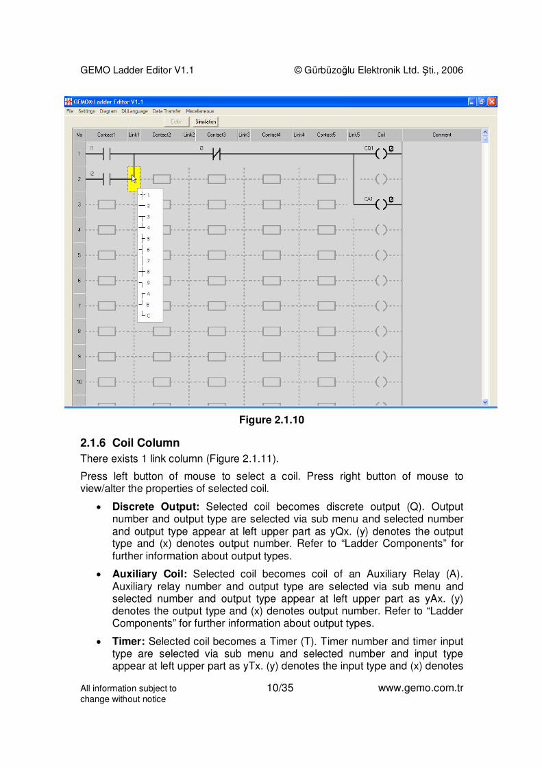
2.1.5 Link Columns
There exist 5 link columns in series (Figure 2.1.10).
Contacts and coils are connected each other by means of links. A link may haveupper, lower, left and right connections.
Press left button of mouse to select a link. Press right button of mouse to see alist of possible connections and select the appropriate one or select the dashedone to delete the link.
Refer to “Fast Line Drawing” section for faster diagram drawing.
GEMO Ladder Editor V1.1 © Gürbüzoğlu Elektronik Ltd. Şti., 2006
All information subject to 10/35 www.gemo.com.trchange without notice
Figure 2.1.10
2.1.6 Coil Column
There exists 1 link column (Figure 2.1.11).
Press left button of mouse to select a coil. Press right button of mouse toview/alter the properties of selected coil.
• Discrete Output: Selected coil becomes discrete output (Q). Outputnumber and output type are selected via sub menu and selected numberand output type appear at left upper part as yQx. (y) denotes the outputtype and (x) denotes output number. Refer to “Ladder Components” forfurther information about output types.
• Auxiliary Coil: Selected coil becomes coil of an Auxiliary Relay (A).Auxiliary relay number and output type are selected via sub menu andselected number and output type appear at left upper part as yAx. (y)denotes the output type and (x) denotes output number. Refer to “LadderComponents” for further information about output types.
• Timer: Selected coil becomes a Timer (T). Timer number and timer inputtype are selected via sub menu and selected number and input typeappear at left upper part as yTx. (y) denotes the input type and (x) denotes

GEMO Ladder Editor V1.1 © Gürbüzoğlu Elektronik Ltd. Şti., 2006
All information subject to 11/35 www.gemo.com.trchange without notice
timer number. Refer to “Ladder Components” for further information aboutoutput types.
• Counter: Selected coil becomes a Counter (C). Counter number andcounter input type are selected via sub menu and selected number andinput type appear at left upper part as yCx. (y) denotes the input type and(x) denotes counter number. Refer to “Ladder Components” for furtherinformation about output types.
• Delete Coil: Selected coil is deleted.
Figure 2.1.11
2.1.7 Comment Column
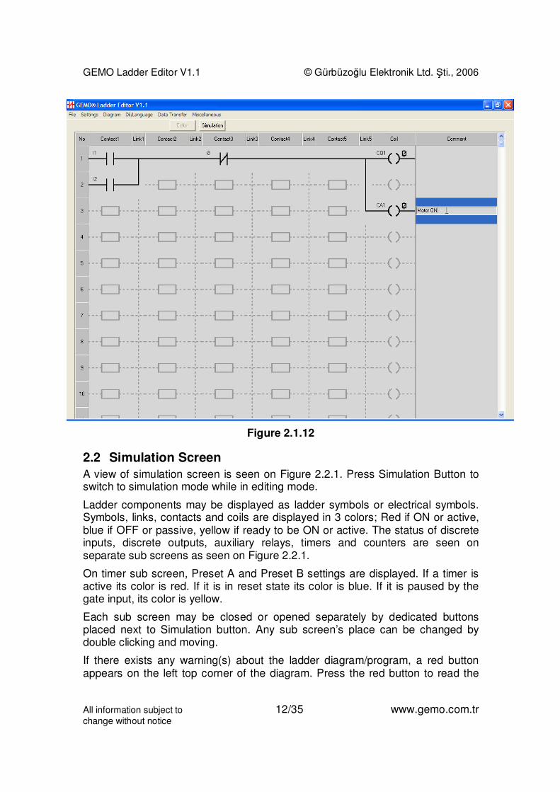
User can write a comment for each line. Double click left button of mouse to thecomment section of a line to place a comment as in Figure 2.1.12.
GEMO Ladder Editor V1.1 © Gürbüzoğlu Elektronik Ltd. Şti., 2006
All information subject to 12/35 www.gemo.com.trchange without notice
Figure 2.1.12
2.2 Simulation Screen
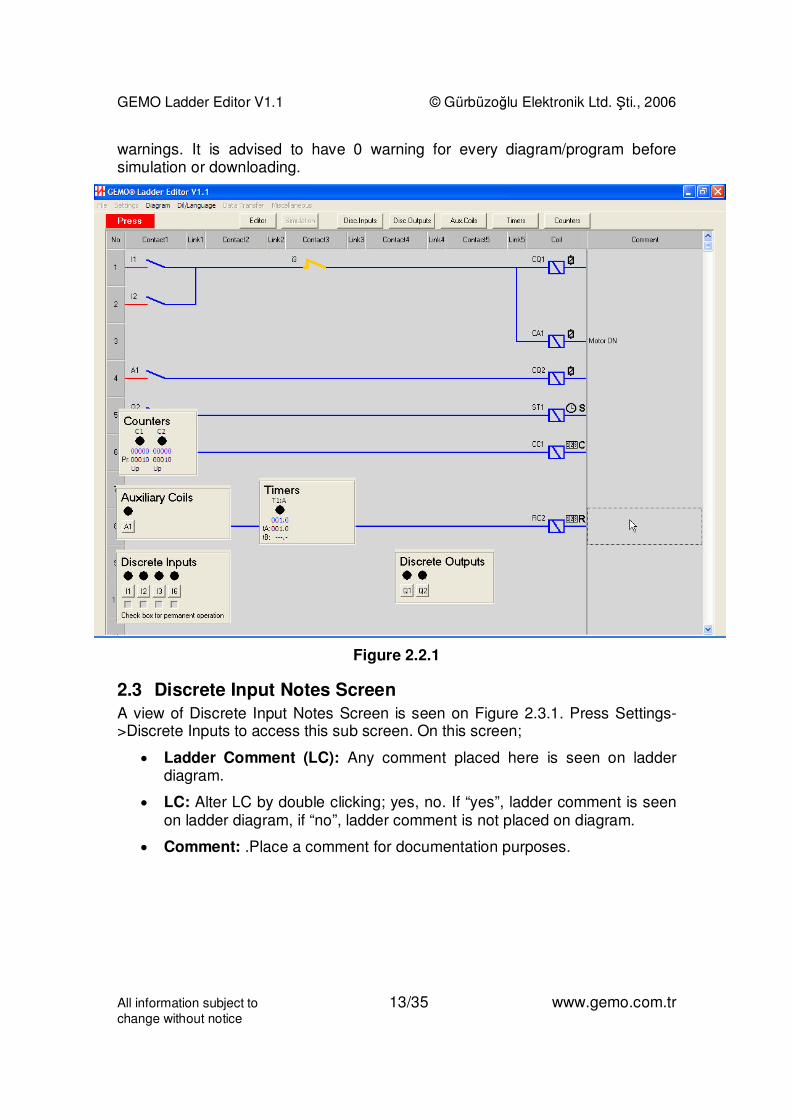
A view of simulation screen is seen on Figure 2.2.1. Press Simulation Button toswitch to simulation mode while in editing mode.
Ladder components may be displayed as ladder symbols or electrical symbols.Symbols, links, contacts and coils are displayed in 3 colors; Red if ON or active,blue if OFF or passive, yellow if ready to be ON or active. The status of discreteinputs, discrete outputs, auxiliary relays, timers and counters are seen onseparate sub screens as seen on Figure 2.2.1.
On timer sub screen, Preset A and Preset B settings are displayed. If a timer isactive its color is red. If it is in reset state its color is blue. If it is paused by thegate input, its color is yellow.
Each sub screen may be closed or opened separately by dedicated buttonsplaced next to Simulation button. Any sub screen’s place can be changed bydouble clicking and moving.
If there exists any warning(s) about the ladder diagram/program, a red buttonappears on the left top corner of the diagram. Press the red button to read the
GEMO Ladder Editor V1.1 © Gürbüzoğlu Elektronik Ltd. Şti., 2006
All information subject to 13/35 www.gemo.com.trchange without notice
warnings. It is advised to have 0 warning for every diagram/program beforesimulation or downloading.
Figure 2.2.1
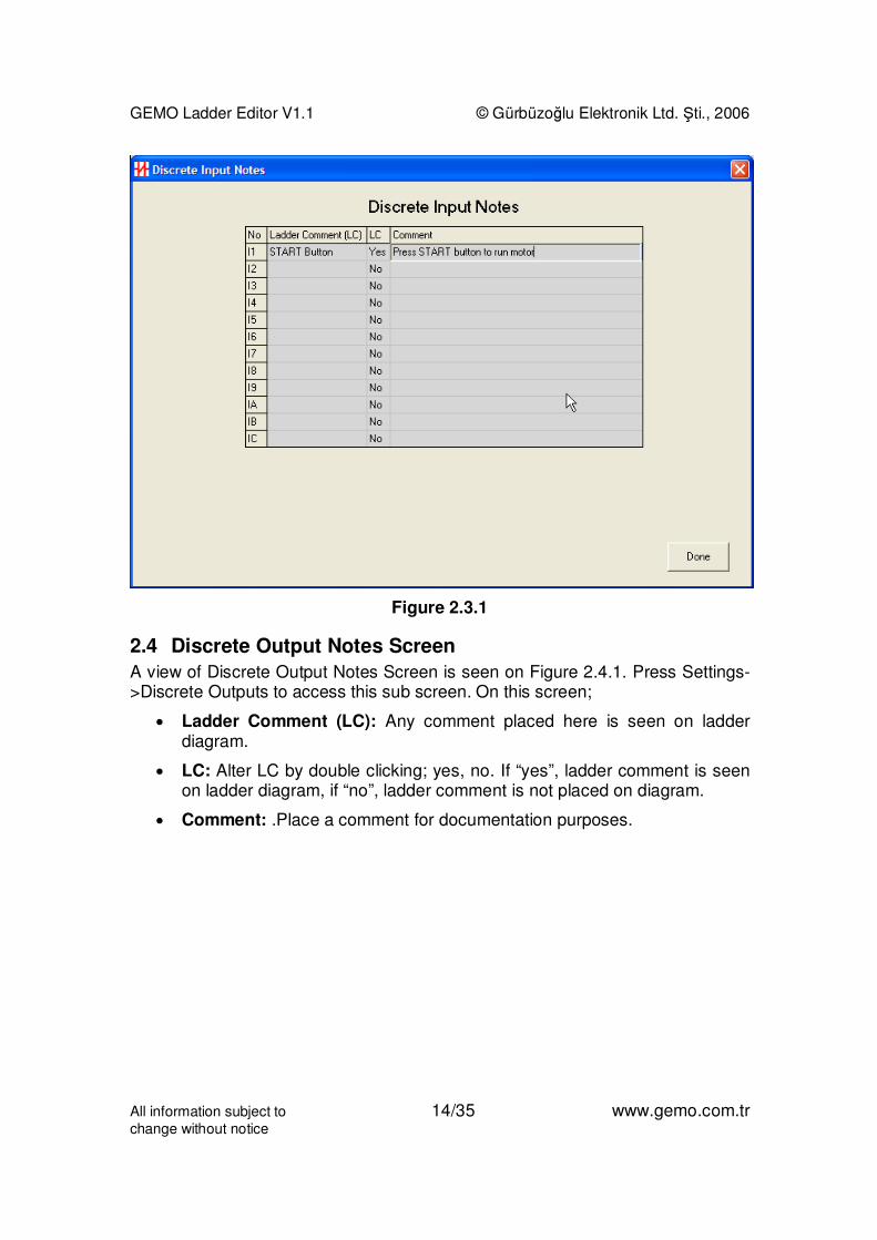
2.3 Discrete Input Notes Screen
A view of Discrete Input Notes Screen is seen on Figure 2.3.1. Press Settings->Discrete Inputs to access this sub screen. On this screen;
• Ladder Comment (LC): Any comment placed here is seen on ladderdiagram.
• LC: Alter LC by double clicking; yes, no. If “yes”, ladder comment is seenon ladder diagram, if “no”, ladder comment is not placed on diagram.
• Comment: .Place a comment for documentation purposes.
GEMO Ladder Editor V1.1 © Gürbüzoğlu Elektronik Ltd. Şti., 2006
All information subject to 14/35 www.gemo.com.trchange without notice
Figure 2.3.1
2.4 Discrete Output Notes Screen
A view of Discrete Output Notes Screen is seen on Figure 2.4.1. Press Settings->Discrete Outputs to access this sub screen. On this screen;
• Ladder Comment (LC): Any comment placed here is seen on ladderdiagram.
• LC: Alter LC by double clicking; yes, no. If “yes”, ladder comment is seenon ladder diagram, if “no”, ladder comment is not placed on diagram.
• Comment: .Place a comment for documentation purposes.

GEMO Ladder Editor V1.1 © Gürbüzoğlu Elektronik Ltd. Şti., 2006
All information subject to 15/35 www.gemo.com.trchange without notice
Figure 2.4.1
2.5 Auxiliary Coil Notes Screen
A view of Auxiliary Coil Notes Screen is seen on Figure 2.5.1. Press Settings->Auxiliary Relays to access this sub screen. On this screen;
• Ladder Comment (LC): Any comment placed here is seen on ladderdiagram.
• LC: Alter LC by double clicking; yes, no. If “yes”, ladder comment is seenon ladder diagram, if “no” ladder, comment is not placed on diagram.
• Comment: .Place a comment for documentation purposes.

GEMO Ladder Editor V1.1 © Gürbüzoğlu Elektronik Ltd. Şti., 2006
All information subject to 16/35 www.gemo.com.trchange without notice
Figure 2.5.1
2.6 Timer Parameters Screen
A view of Timer Parameters Screen is seen on Figure 2.6.1. Press Settings->Timers to access this sub screen. On this screen;
• Function: Double click this cell to view a list of built in timer functions.Select a function for each timer. Selected timers function is illustrated onbottom of the screen. Also an explanation of the selected function isdisplayed next to the illustration. Refer to “Ladder Components” section fordetailed description of each timer function.
• Unit: Select resolution (time base) for each timer.
• tA: Enter default Preset A value for each timer.
• tB: Enter default Preset B value for each timer. Preset B is not defined forsome timer functions.
• Ladder Comment (LC): Any comment placed here is seen on ladderdiagram.
• LC: Alter LC by double clicking; yes, no. If “yes”, ladder comment is seenon ladder diagram, if “no”, ladder comment is not placed on diagram.
• Comment: .Place a comment for documentation purposes.

GEMO Ladder Editor V1.1 © Gürbüzoğlu Elektronik Ltd. Şti., 2006
All information subject to 17/35 www.gemo.com.trchange without notice
Figure 2.6.1
2.7 Counter Parameters Screen
A view of Counter Parameters Screen is seen on Figure 2.7.1. Press Settings->Counters to access this sub screen. On this screen;
• Type: Double click this cell to alter counter type; up, down. Counteroperation is illustrated on bottom of the screen. Refer to “LadderComponents” section for detailed description of counter operation.
• Preset: Enter default Preset value for each counter.
• Ladder Comment (LC): Any comment placed here is seen on ladderdiagram.
• LC: Alter LC by double clicking; yes, no. If “yes”, ladder comment is seenon ladder diagram, if “no”, ladder comment is not placed on diagram.
• Comment: .Place a comment for documentation purposes.

GEMO Ladder Editor V1.1 © Gürbüzoğlu Elektronik Ltd. Şti., 2006
All information subject to 18/35 www.gemo.com.trchange without notice
Figure 2.7.1
2.8 LCD Menu Designer Screen
Use this screen to design application specific user interface pages for 2x16 LCDmodule for 2 different languages with very little effort. A view of LCD MenuDesigner Screen is seen on Figure 2.8.1.

GEMO Ladder Editor V1.1 © Gürbüzoğlu Elektronik Ltd. Şti., 2006
All information subject to 19/35 www.gemo.com.trchange without notice
Figure 2.8.1
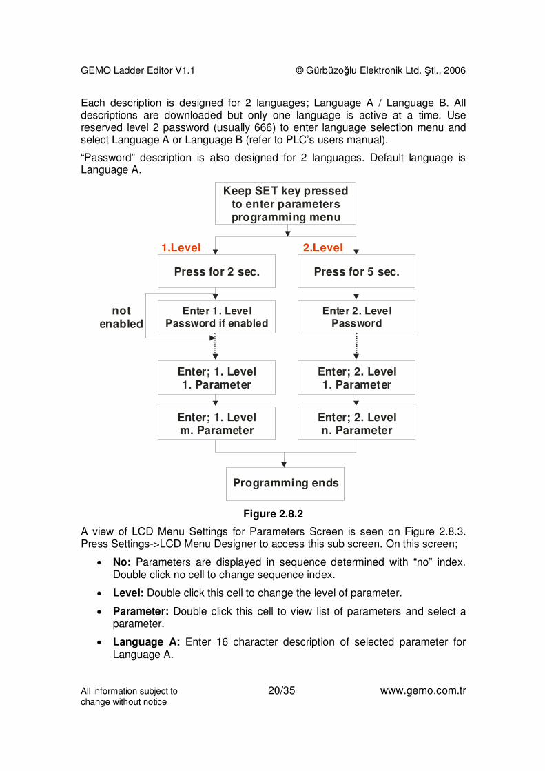
Schematic representation of multilingual menu system is shown on Figure 2.8.2.
An application specific user interface shall be designed for up to 32 parameters(total of Level1 & Level2). Parameters are divided in 2 groups; Level1 & Level2.
All parameters are programmed by SET, UP and DOWN keys on PLC.
1. Level is intended for frequent use/access. To enter 1st Level, press SET keyfor 2 seconds and wait for password screen. Enter Level 1 password to access1st Level parameters in sequence 1st, 2nd, 3rd...mth. If Level 1 password is notenabled / defined, 1st parameter is accessed directly.
2nd Level is intended for less frequent use. This level always requires apassword. Press SET key for 10 seconds, enter level 2 password and accesslevel 2 parameters in sequence 1st, 2nd, 3rd...nth. There are fixed 2nd levelpasswords reserved for special functions of PLC, like enabling downloading orselection of menu language. Please refer to PLC’s users manual for reserved2nd level passwords.
Upper line of 2x16 LCD module (totally 16 characters) can be used to display adescription for each parameter separately in 2 languages. Lower line is used todisplay the parameter ID, value and its unit with the level indicator.
GEMO Ladder Editor V1.1 © Gürbüzoğlu Elektronik Ltd. Şti., 2006
All information subject to 20/35 www.gemo.com.trchange without notice
Each description is designed for 2 languages; Language A / Language B. Alldescriptions are downloaded but only one language is active at a time. Usereserved level 2 password (usually 666) to enter language selection menu andselect Language A or Language B (refer to PLC’s users manual).
“Password” description is also designed for 2 languages. Default language isLanguage A.
Keep SET key pressedto enter parametersprogramming menu
Programming ends
Press for ec.2 s
1.Level
notenabled
2.Level
Enter 1. LevelPassword if enabled
Enter 2. LevelPassword
Enter; . Level1. Parameter
1
Enter; . Level. Parameter
1m
Enter; . Level1. Parameter
2
Enter; . Level. Parameter
2n
Press for 5 ec.s
Figure 2.8.2
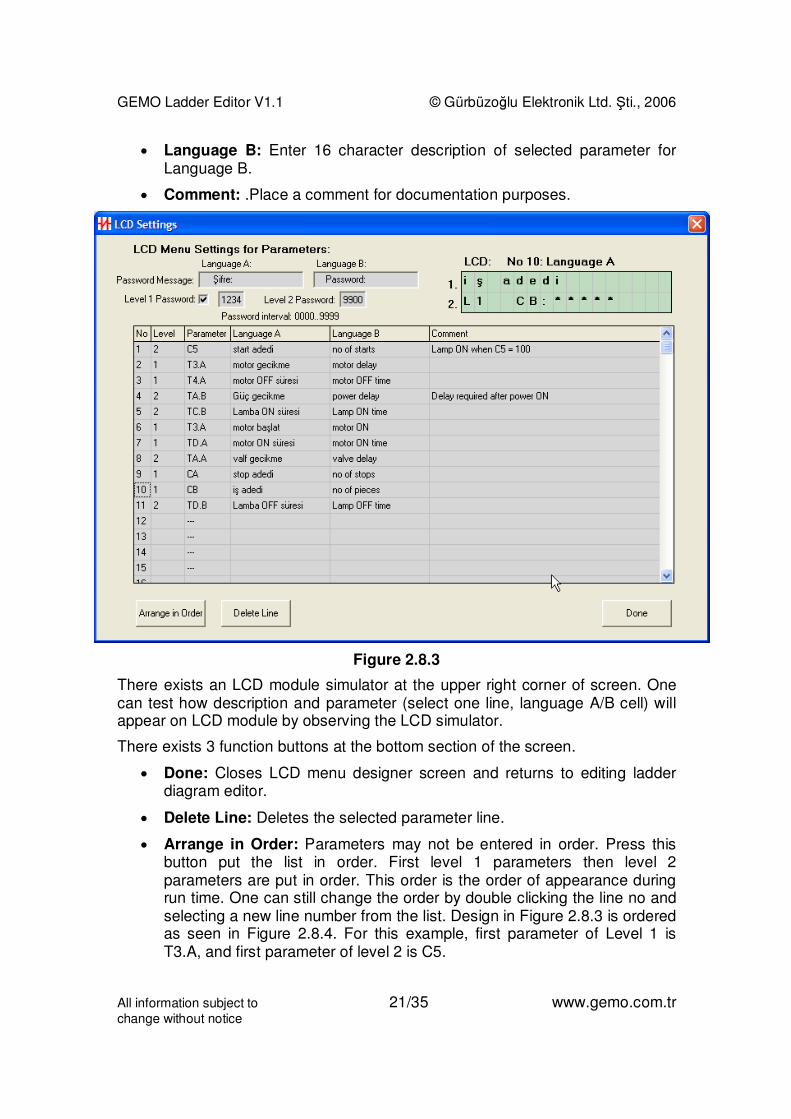
A view of LCD Menu Settings for Parameters Screen is seen on Figure 2.8.3.Press Settings->LCD Menu Designer to access this sub screen. On this screen;
• No: Parameters are displayed in sequence determined with “no” index.Double click no cell to change sequence index.
• Level: Double click this cell to change the level of parameter.
• Parameter: Double click this cell to view list of parameters and select aparameter.
• Language A: Enter 16 character description of selected parameter forLanguage A.
GEMO Ladder Editor V1.1 © Gürbüzoğlu Elektronik Ltd. Şti., 2006
All information subject to 21/35 www.gemo.com.trchange without notice
• Language B: Enter 16 character description of selected parameter forLanguage B.
• Comment: .Place a comment for documentation purposes.
Figure 2.8.3
There exists an LCD module simulator at the upper right corner of screen. Onecan test how description and parameter (select one line, language A/B cell) willappear on LCD module by observing the LCD simulator.
There exists 3 function buttons at the bottom section of the screen.
• Done: Closes LCD menu designer screen and returns to editing ladderdiagram editor.
• Delete Line: Deletes the selected parameter line.
• Arrange in Order: Parameters may not be entered in order. Press thisbutton put the list in order. First level 1 parameters then level 2parameters are put in order. This order is the order of appearance duringrun time. One can still change the order by double clicking the line no andselecting a new line number from the list. Design in Figure 2.8.3 is orderedas seen in Figure 2.8.4. For this example, first parameter of Level 1 isT3.A, and first parameter of level 2 is C5.

GEMO Ladder Editor V1.1 © Gürbüzoğlu Elektronik Ltd. Şti., 2006
All information subject to 22/35 www.gemo.com.trchange without notice
To add a new parameter to the list, simple add it at the end and change its indexby double clicking the no cell.
If a LCD menu design is downloaded without arranged in order, ordering is doneautomatically.
Cx represent Preset value of counter x. Tx.A represents Preset A of Timer x.Tx.B represents Preset B of Timer x.
Figure 2.8.4

GEMO Ladder Editor V1.1 © Gürbüzoğlu Elektronik Ltd. Şti., 2006
All information subject to 23/35 www.gemo.com.trchange without notice
3 Ladder Components
3.1 Discrete Inputs
Discrete Inputs are physical digital inputs to a PLC.
Discrete inputs are only used in contact columns. Discrete Inputs arerepresented as “Ix” or “ix”. “x” is the number/index of an input. “I” represents anormally open input and “i” represents a normally closed input. “I5” means 5thinput used as normally open, “iC” means 12th input used as normally closed.
A discrete input may be used as much as possible in any contact column androw.
Figure 3.1.1 shows normally open and normally closed discrete inputs.
Figure 3.1.1
3.2 Discrete Outputs
Discrete Outputs are physical outputs of a PLC (like a relay or a transistoroutput).

GEMO Ladder Editor V1.1 © Gürbüzoğlu Elektronik Ltd. Şti., 2006
All information subject to 24/35 www.gemo.com.trchange without notice
Discrete outputs are both used in contact and coil columns. When used incontact columns, they represents ON/OFF state of a physical discrete output.Discrete outputs are represented as “Qx” or “qx”. “x” is the number/index of anoutput. “Q” represents a normally open output contact and “q” represents anormally closed output contact. “Q5” means 5th output used as normally open,“qC” means 12th output used as normally closed.
A discrete output contact may be used as much as possible in any contactcolumn and row.
When used in coil column, a physical discrete output is addressed. A discreteoutput may be driven in 6 different ways as shown in Figures 3.2.1., 3.2.2.,3.2.3., 3.2.4., 3.2.5. and 3.2.6.
I Q
Figure 3.2.1 Digital Logic Representation of Coil Type
Q
Q
ClkI Q
D
Figure 3.2.2 Digital Logic Representation of Toggle, Pulse
QSSet
Reset
Q
R
Figure 3.2.3 Digital Logic Representation of SET & RESET Level
QSSet
Reset
Q
R
Figure 3.2.4 Digital Logic Representation of SET Pulse & RESET Level
QSSet
Reset
Q
R
Figure 3.2.5 Digital Logic Representation of SET Level & RESET Pulse
GEMO Ladder Editor V1.1 © Gürbüzoğlu Elektronik Ltd. Şti., 2006
All information subject to 25/35 www.gemo.com.trchange without notice
QSSet
Reset
Q
R
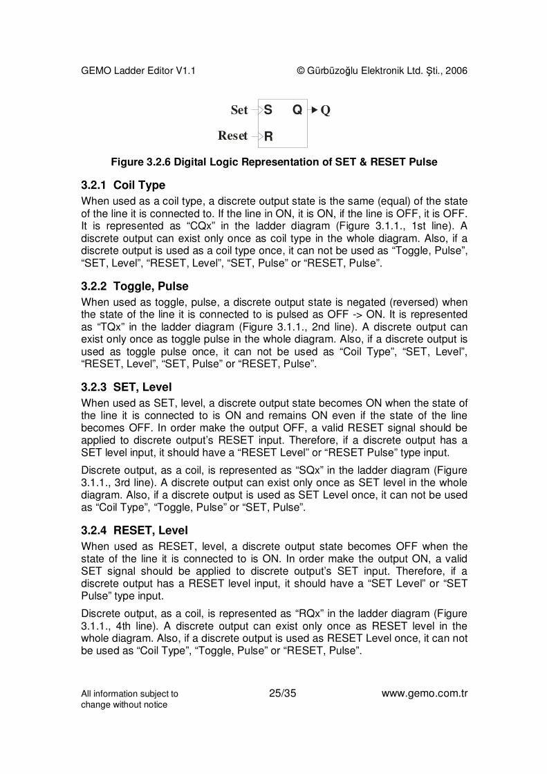
Figure 3.2.6 Digital Logic Representation of SET & RESET Pulse
3.2.1 Coil Type
When used as a coil type, a discrete output state is the same (equal) of the stateof the line it is connected to. If the line in ON, it is ON, if the line is OFF, it is OFF.It is represented as “CQx” in the ladder diagram (Figure 3.1.1., 1st line). Adiscrete output can exist only once as coil type in the whole diagram. Also, if adiscrete output is used as a coil type once, it can not be used as “Toggle, Pulse”,“SET, Level”, “RESET, Level”, “SET, Pulse” or “RESET, Pulse”.
3.2.2 Toggle, Pulse
When used as toggle, pulse, a discrete output state is negated (reversed) whenthe state of the line it is connected to is pulsed as OFF -> ON. It is representedas “TQx” in the ladder diagram (Figure 3.1.1., 2nd line). A discrete output canexist only once as toggle pulse in the whole diagram. Also, if a discrete output isused as toggle pulse once, it can not be used as “Coil Type”, “SET, Level”,“RESET, Level”, “SET, Pulse” or “RESET, Pulse”.
3.2.3 SET, Level
When used as SET, level, a discrete output state becomes ON when the state ofthe line it is connected to is ON and remains ON even if the state of the linebecomes OFF. In order make the output OFF, a valid RESET signal should beapplied to discrete output’s RESET input. Therefore, if a discrete output has aSET level input, it should have a “RESET Level” or “RESET Pulse” type input.
Discrete output, as a coil, is represented as “SQx” in the ladder diagram (Figure3.1.1., 3rd line). A discrete output can exist only once as SET level in the wholediagram. Also, if a discrete output is used as SET Level once, it can not be usedas “Coil Type”, “Toggle, Pulse” or “SET, Pulse”.
3.2.4 RESET, Level
When used as RESET, level, a discrete output state becomes OFF when thestate of the line it is connected to is ON. In order make the output ON, a validSET signal should be applied to discrete output’s SET input. Therefore, if adiscrete output has a RESET level input, it should have a “SET Level” or “SETPulse” type input.
Discrete output, as a coil, is represented as “RQx” in the ladder diagram (Figure3.1.1., 4th line). A discrete output can exist only once as RESET level in thewhole diagram. Also, if a discrete output is used as RESET Level once, it can notbe used as “Coil Type”, “Toggle, Pulse” or “RESET, Pulse”.
GEMO Ladder Editor V1.1 © Gürbüzoğlu Elektronik Ltd. Şti., 2006
All information subject to 26/35 www.gemo.com.trchange without notice
3.2.5 SET, Pulse
When used as SET, Pulse, a discrete output state becomes ON when the stateof the line it is connected to is pulsed (OFF->ON) and remains ON even if thestate of the line becomes OFF. In order make the output OFF, a valid RESETsignal should be applied to discrete output’s RESET input. Therefore, if adiscrete output has a SET pulse input, it should have a “RESET Level” or“RESET Pulse” type input.
Discrete output, as a coil, is represented as “sQx” in the ladder diagram (Figure3.1.1., 5th line). A discrete output can exist only once as SET pulse in the wholediagram. Also, if a discrete output is used as SET Pulse once, it can not be usedas “Coil Type”, “Toggle, Pulse” or “SET, Level”.
3.2.6 RESET, Pulse
When used as RESET, Pulse, a discrete output state becomes OFF when thestate of the line it is connected to is pulsed (OFF->ON). In order make the outputON, a valid SET signal should be applied to discrete output’s SET input.Therefore, if a discrete output has a RESET pulse input, it should have a “SETLevel” or “SET Pulse” type input.
Discrete output, as a coil, is represented as “rQx” in the ladder diagram (Figure3.1.1., 4th line). A discrete output can exist only once as RESET Pulse in thewhole diagram. Also, if a discrete output is used as RESET Pulse once, it can notbe used as “Coil Type”, “Toggle, Pulse” or “RESET, Level”.
3.3 Auxiliary Relays
Auxiliary relays are imaginary outputs of a PLC. They are used to store a binarystate or transfer one state a line to another line.
They have identical characteristics as discrete outputs. Refer to “DiscreteOutputs” section for detailed behavior.
Auxiliary relays are represented as “Ax” (as normally open) and “ax” (normallyclosed) in contact columns.
Auxiliary relays are represented as “CAx” (Coil type), “TAx” (toggle, pulse), “SAx”(SET, level), “RAx” (RESET, level) , “sAx” (SET, pulse) and “rAx” (RESET, pulse)as represented in Figures 3.2.1., 3.2.2., 3.2.3., 3.2.4., 3.2.5. and 3.2.6.
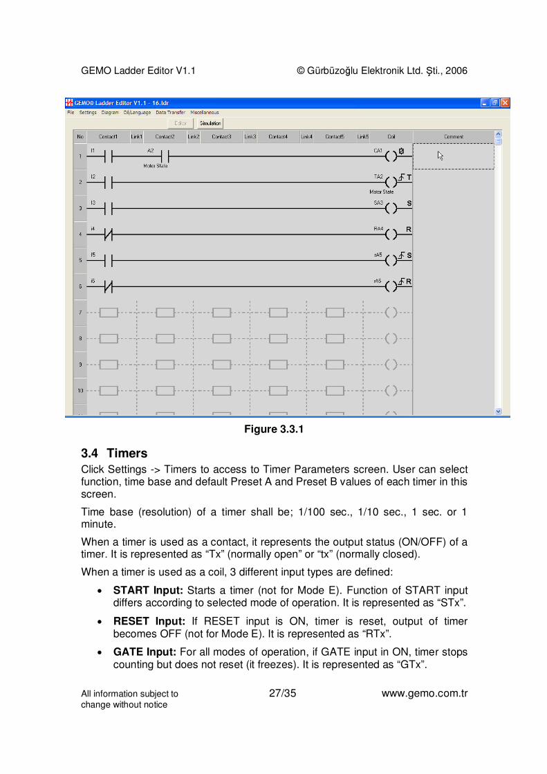
Figure 3.3.1 shows possible use of an Auxiliary relay in coil column.
GEMO Ladder Editor V1.1 © Gürbüzoğlu Elektronik Ltd. Şti., 2006
All information subject to 27/35 www.gemo.com.trchange without notice
Figure 3.3.1
3.4 Timers
Click Settings -> Timers to access to Timer Parameters screen. User can selectfunction, time base and default Preset A and Preset B values of each timer in thisscreen.
Time base (resolution) of a timer shall be; 1/100 sec., 1/10 sec., 1 sec. or 1minute.
When a timer is used as a contact, it represents the output status (ON/OFF) of atimer. It is represented as “Tx” (normally open” or “tx” (normally closed).
When a timer is used as a coil, 3 different input types are defined:
• START Input: Starts a timer (not for Mode E). Function of START inputdiffers according to selected mode of operation. It is represented as “STx”.
• RESET Input: If RESET input is ON, timer is reset, output of timerbecomes OFF (not for Mode E). It is represented as “RTx”.
• GATE Input: For all modes of operation, if GATE input in ON, timer stopscounting but does not reset (it freezes). It is represented as “GTx”.
GEMO Ladder Editor V1.1 © Gürbüzoğlu Elektronik Ltd. Şti., 2006
All information subject to 28/35 www.gemo.com.trchange without notice
Each timer has 2 preset values; Preset A and Preset B. Preset B is not definedfor some modes of operation. Both Preset A and Preset B is user settable(programmable) if included in the list of LCD designer menu.
Each timer may have a different mode of operation with a separate time base.Modes of operation defined below.
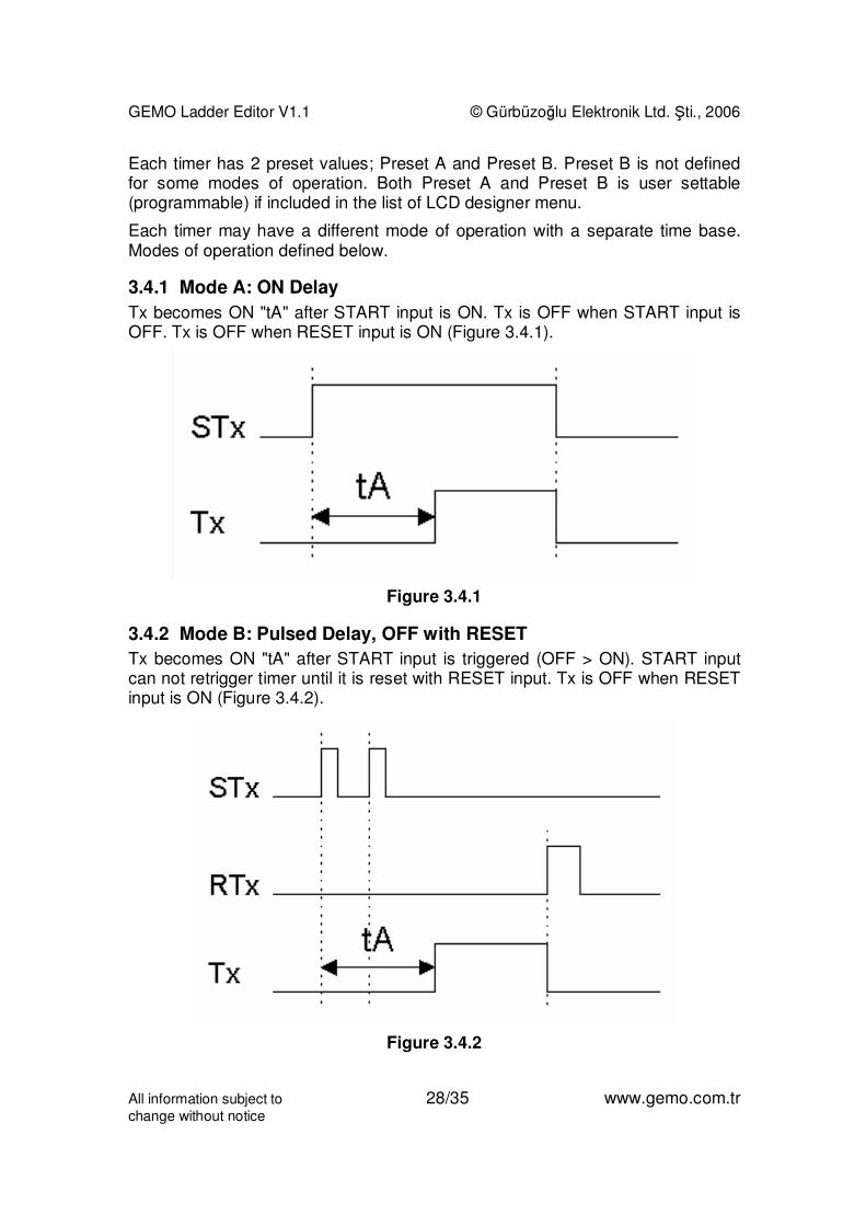
3.4.1 Mode A: ON Delay
Tx becomes ON "tA" after START input is ON. Tx is OFF when START input isOFF. Tx is OFF when RESET input is ON (Figure 3.4.1).
Figure 3.4.1
3.4.2 Mode B: Pulsed Delay, OFF with RESET
Tx becomes ON "tA" after START input is triggered (OFF > ON). START inputcan not retrigger timer until it is reset with RESET input. Tx is OFF when RESETinput is ON (Figure 3.4.2).
Figure 3.4.2
GEMO Ladder Editor V1.1 © Gürbüzoğlu Elektronik Ltd. Şti., 2006
All information subject to 29/35 www.gemo.com.trchange without notice
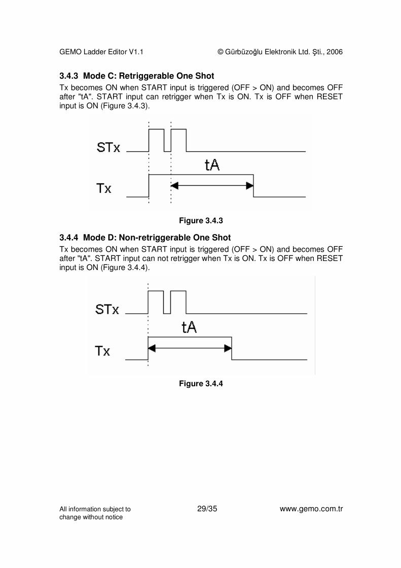
3.4.3 Mode C: Retriggerable One Shot
Tx becomes ON when START input is triggered (OFF > ON) and becomes OFFafter "tA". START input can retrigger when Tx is ON. Tx is OFF when RESETinput is ON (Figure 3.4.3).
Figure 3.4.3
3.4.4 Mode D: Non-retriggerable One Shot
Tx becomes ON when START input is triggered (OFF > ON) and becomes OFFafter "tA". START input can not retrigger when Tx is ON. Tx is OFF when RESETinput is ON (Figure 3.4.4).
Figure 3.4.4
GEMO Ladder Editor V1.1 © Gürbüzoğlu Elektronik Ltd. Şti., 2006
All information subject to 30/35 www.gemo.com.trchange without notice
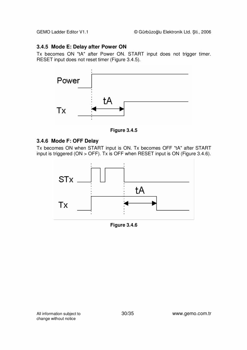
3.4.5 Mode E: Delay after Power ON
Tx becomes ON "tA" after Power ON. START input does not trigger timer.RESET input does not reset timer (Figure 3.4.5).
Figure 3.4.5
3.4.6 Mode F: OFF Delay
Tx becomes ON when START input is ON. Tx becomes OFF "tA" after STARTinput is triggered (ON > OFF). Tx is OFF when RESET input is ON (Figure 3.4.6).
Figure 3.4.6
GEMO Ladder Editor V1.1 © Gürbüzoğlu Elektronik Ltd. Şti., 2006
All information subject to 31/35 www.gemo.com.trchange without notice
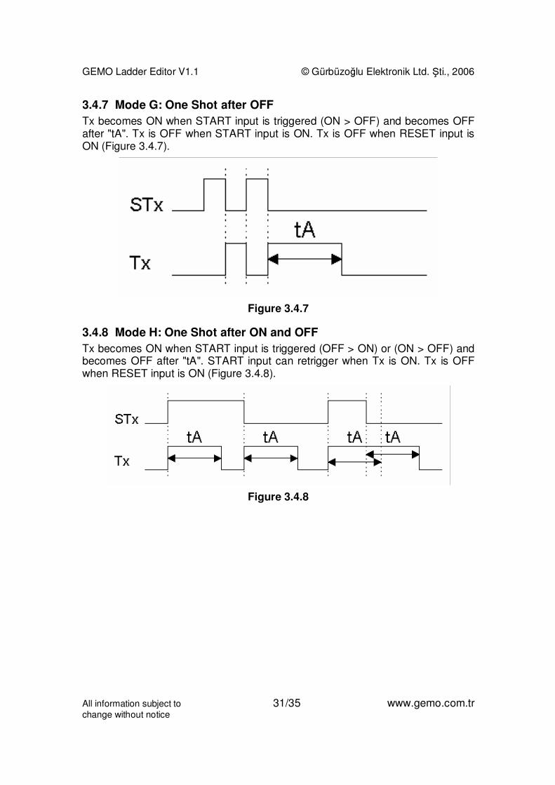
3.4.7 Mode G: One Shot after OFF
Tx becomes ON when START input is triggered (ON > OFF) and becomes OFFafter "tA". Tx is OFF when START input is ON. Tx is OFF when RESET input isON (Figure 3.4.7).
Figure 3.4.7
3.4.8 Mode H: One Shot after ON and OFF
Tx becomes ON when START input is triggered (OFF > ON) or (ON > OFF) andbecomes OFF after "tA". START input can retrigger when Tx is ON. Tx is OFFwhen RESET input is ON (Figure 3.4.8).
Figure 3.4.8
GEMO Ladder Editor V1.1 © Gürbüzoğlu Elektronik Ltd. Şti., 2006
All information subject to 32/35 www.gemo.com.trchange without notice
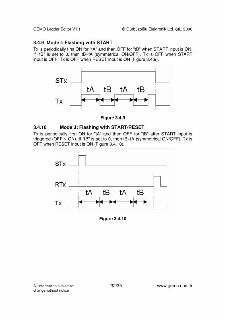
3.4.9 Mode I: Flashing with START
Tx is periodically first ON for "tA" and then OFF for "tB" when START input is ON.If "tB" is set to 0, then tB=tA (symmetrical ON/OFF). Tx is OFF when STARTinput is OFF. Tx is OFF when RESET input is ON (Figure 3.4.9).
Figure 3.4.9
3.4.10 Mode J: Flashing with START/RESET
Tx is periodically first ON for "tA" and then OFF for "tB" after START input istriggered (OFF > ON). If "tB" is set to 0, then tB=tA (symmetrical ON/OFF). Tx isOFF when RESET input is ON (Figure 3.4.10).
Figure 3.4.10
GEMO Ladder Editor V1.1 © Gürbüzoğlu Elektronik Ltd. Şti., 2006
All information subject to 33/35 www.gemo.com.trchange without notice
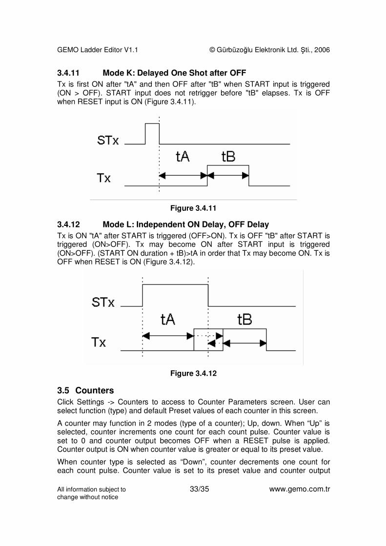
3.4.11 Mode K: Delayed One Shot after OFF
Tx is first ON after "tA" and then OFF after "tB" when START input is triggered(ON > OFF). START input does not retrigger before "tB" elapses. Tx is OFFwhen RESET input is ON (Figure 3.4.11).
Figure 3.4.11
3.4.12 Mode L: Independent ON Delay, OFF Delay
Tx is ON "tA" after START is triggered (OFF>ON). Tx is OFF "tB" after START istriggered (ON>OFF). Tx may become ON after START input is triggered(ON>OFF). (START ON duration + tB)>tA in order that Tx may become ON. Tx isOFF when RESET is ON (Figure 3.4.12).
Figure 3.4.12
3.5 Counters
Click Settings -> Counters to access to Counter Parameters screen. User canselect function (type) and default Preset values of each counter in this screen.
A counter may function in 2 modes (type of a counter); Up, down. When “Up” isselected, counter increments one count for each count pulse. Counter value isset to 0 and counter output becomes OFF when a RESET pulse is applied.Counter output is ON when counter value is greater or equal to its preset value.
When counter type is selected as “Down”, counter decrements one count foreach count pulse. Counter value is set to its preset value and counter output

GEMO Ladder Editor V1.1 © Gürbüzoğlu Elektronik Ltd. Şti., 2006
All information subject to 34/35 www.gemo.com.trchange without notice
becomes OFF when a RESET pulse is applied. Counter output is ON whencounter value is equal to 0.
Each counter is 15 bit (0...32767) wide. A counter does not count below 0. If acount pulse is applied when the counter value is 0 and counting direction is“down”, counter value remains as 0. Similarly, a counter does not count above32767. If a count pulse is applied when the counter value is 32767 and countingdirection is “up”, counter value remains as 32767.
When a counter is used as a contact, it represents the output status (ON/OFF) ofa counter. It is represented as “Cx” (normally open” or “cx” (normally closed).
When a counter is used as a coil, 3 different input types are defined:
• Count Input: Counter is incremented or decremented one count whenthis input changes state OFF -> ON. It is represented as CCx in coilcolumn.
• Reset Input: When this input is ON, the output of counter is OFF andcounter value is set to 0 if type is “Up” or counter value is preset value iftype is “Down”. It is represented as RCx in coil column.
• Direction Input: When this input is OFF, counter increments if type is“Up” and decrements if type is “Down”. When this input is ON, counterdecrements if type is “Up” and increments if type is “Down”. If this input isnot used, it is accepted as OFF.
Each counter has a single and unique preset value. Counter preset value is usersettable (programmable) if included in the list of LCD designer menu.
Each timer may have a different type of operation with a separate and uniquepreset value.
Operation of a counter is shown in Figure 3.5.1...
Figure 3.5.1

GEMO Ladder Editor V1.1 © Gürbüzoğlu Elektronik Ltd. Şti., 2006
All information subject to 35/35 www.gemo.com.trchange without notice
4 Drawing a Diagram
4.1 Inserting a New Line
Click a contact with the right button of mouse and select “Insert Line”. A new andblank line is inserted to the diagram; all lines including the contact previouslyselected are shifted down. The last line is deleted at bottom. If bottom line is notan empty line, user is warned before deleted.
4.2 Deleting a Line
Click a contact with the right button of mouse and select “Delete Line”. The linewhere the selected contact exists is deleted, all lines after deleted line are shiftedup and a new black line is added as the last line to the bottom of the diagram.
4.3 Deleting a Contact
Click a contact with the right button of mouse and select “Delete Contact”. Orselect a contact with the left button of mouse and press “Delete” key.
4.4 Deleting a Link
Click a link with the right button of mouse and select “Dashed Link”. Or select alink with the left button of mouse and press “Delete” key.
4.5 Deleting a Contact
Click a coil with the right button of mouse and select “Delete Coil”. Or select acoil with the left button of mouse and press “Delete” key.
4.6 Deleting a Comment
Select a comment with the left button of mouse and press “Delete” key.
4.7 Selecting and Deleting an Area of Diagram
Select an area of diagram by moving the mouse pointer while keeping the leftbutton of mouse pressed and press “Delete” key. Undo is not possible so pleasepay attention before deleting an area.
4.8 Fast Line Drawing between Contacts, Links and Coils
Select a contact, link or coil where you would like to start drawing a connectionby clicking the left button of mouse. Move the pointer of mouse (or alternativelyuse “Up”, ”Down”, ”Left” or “Right” arrow keys) to establish a connection whilekeeping the “Shift” key pressed.