Embed Size (px)
Citation preview

GEMO® Ladder Editor V2.3 Rev. A © Gürbüzoğlu Elektronik Ltd. Şti., 2009
GEMO® Ladder Editor V2.3
User’s ManualRev. A
All information subject to 1/112 http://www.gemo.com.trchange without notice
GEMO® Ladder Editor V2.3 Rev. A © Gürbüzoğlu Elektronik Ltd. Şti., 2009
CONTENT1Introduction...........................................................................................................62What’s New...........................................................................................................7
2.1What’s new in Ver 2.3 Rev A.........................................................................72.2What’s new in Ver 2.2 Rev A.........................................................................82.3What’s new in Ver 2.1 Rev A.........................................................................82.4Abbreviation...................................................................................................9
3Device Input Output Configurations....................................................................113.1AR2-A...........................................................................................................113.2AR2-S...........................................................................................................113.3AR2-G1.........................................................................................................11
4Some Issues that Require User Attention..........................................................124.1Retention Feature.........................................................................................124.2Power on Status of Ladder Components.....................................................124.3Rising Edge / Falling Edge Generation after Power on...............................134.4Input Edge Detection of Ladder Components after Power on.....................134.5Fast Input Counters......................................................................................144.6Weekly and Yearly Alarms...........................................................................144.7Ladder Diagram Warnings...........................................................................144.8Analog Ground and Analog Power Supply..................................................144.9RS-485 Connection......................................................................................144.10Mounting and Environmental Conditions...................................................144.11Opening a Ladder File from File Browser..................................................15
5Ladder Editor.......................................................................................................165.1Main Screen.................................................................................................16
5.1.1Main Menu.............................................................................................165.1.1.1File..................................................................................................165.1.1.2Settings...........................................................................................175.1.1.3Diagram...........................................................................................185.1.1.4View................................................................................................185.1.1.5Dil / Language.................................................................................195.1.1.6Data Transfer..................................................................................19
All information subject to 2/112 http://www.gemo.com.trchange without notice
GEMO® Ladder Editor V2.3 Rev. A © Gürbüzoğlu Elektronik Ltd. Şti., 2009
5.1.1.7Miscellaneous.................................................................................205.1.2Editor Button..........................................................................................215.1.3Simulation Button...................................................................................215.1.4Contact Columns...................................................................................215.1.5Link Columns.........................................................................................235.1.6Coil Column...........................................................................................245.1.7Comment Column..................................................................................26
5.2Simulation Screen........................................................................................265.3Discrete Input Settings Screen.....................................................................275.4Discrete Output Notes Screen.....................................................................295.5Auxiliary Relay Settings Screen...................................................................295.6Timer Parameters Screen............................................................................305.7Timer Tick Notes Screen..............................................................................325.8Counter Parameters Screen........................................................................335.9Counter Comparator Parameters Screen....................................................34
5.9.1Counter Comparator Table....................................................................345.9.2Counter Comparator Presets Table......................................................36
5.10 Fast Input Counter Parameters Screen....................................................375.11State Machine Designer Screen................................................................38
5.11.1State Machine A Table........................................................................385.11.2State Machine A Inputs Table.............................................................405.11.3State Machine A Outputs Table..........................................................415.11.4State Machine B Table........................................................................425.11.5State Machine B Inputs Table.............................................................425.11.6State Machine B Outputs Table..........................................................42
5.12Front Panel F Keys Screen........................................................................425.13 0-10V Analog Input Parameters Screen..................................................435.14Analog Comparator Parameters Screen....................................................44
5.14.1Analog Comparator Table Screen.......................................................445.14.2Analog Comparator Presets Table......................................................465.14.3Analog Comparator Hysteresis Table.................................................47
5.15 Settings for Special Password Flags Screen...........................................485.16 Yearly Alarms Screen..............................................................................49
All information subject to 3/112 http://www.gemo.com.trchange without notice
GEMO® Ladder Editor V2.3 Rev. A © Gürbüzoğlu Elektronik Ltd. Şti., 2009
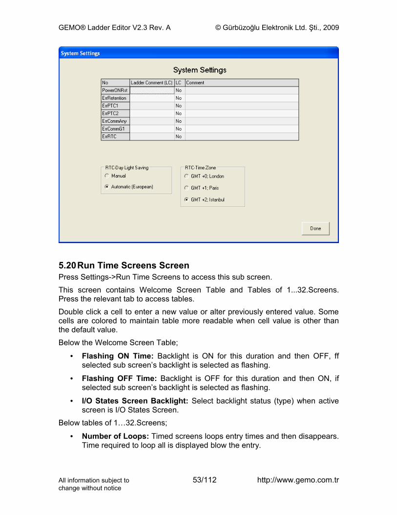
5.17 Weekly Alarms Screen..............................................................................505.18 Configuration Flags Screen.......................................................................515.19 System Settings Screen............................................................................525.20Run Time Screens Screen.........................................................................535.21Menu Design Screen..................................................................................55
6Contacts, Coils, Links.........................................................................................586.1Contacts.......................................................................................................58
6.1.1Normally Open.......................................................................................586.1.2Normally Closed....................................................................................586.1.3Rising Edge...........................................................................................586.1.4Falling Edge...........................................................................................586.1.5Link........................................................................................................596.1.6Inverter...................................................................................................59
6.2Coils..............................................................................................................596.3Links.............................................................................................................59
7Ladder Components...........................................................................................607.1Discrete Inputs.............................................................................................607.2Filtered Discrete Inputs................................................................................617.3Discrete Outputs...........................................................................................62
7.3.1Coil Type................................................................................................637.3.2Toggle, Pulse.........................................................................................637.3.3SET, Level.............................................................................................647.3.4RESET, Level........................................................................................647.3.5SET, Pulse.............................................................................................647.3.6RESET, Pulse........................................................................................64
7.4Auxiliary Relays............................................................................................667.5Timer Ticks...................................................................................................677.6Timers...........................................................................................................68
7.6.1Mode A: ON Delay.................................................................................717.6.2Mode B: Pulsed Delay, OFF with RESET.............................................717.6.3Mode C: Retriggerable One Shot..........................................................717.6.4Mode D: Non-retriggerable One Shot....................................................727.6.5Mode E: Delay after Power ON.............................................................72
All information subject to 4/112 http://www.gemo.com.trchange without notice
GEMO® Ladder Editor V2.3 Rev. A © Gürbüzoğlu Elektronik Ltd. Şti., 2009
7.6.6Mode F: OFF Delay...............................................................................737.6.7Mode G: One Shot after OFF................................................................737.6.8Mode H: One Shot after ON and OFF...................................................747.6.9Mode I: Flashing with START................................................................747.6.10Mode J: Flashing with START/RESET................................................757.6.11Mode K: Delayed One Shot after OFF................................................757.6.12Mode L: Independent ON Delay, OFF Delay......................................76
7.7Fast Input Counters......................................................................................767.8Counters.......................................................................................................787.9Counter Comparators...................................................................................817.10Front Panel F Keys.....................................................................................827.11Filtered Front Panel F Keys.......................................................................847.12Analog Inputs.............................................................................................85
7.12.10...10V Analog Inputs..........................................................................857.12.2 PTC Temperature Sensor Inputs.......................................................87
7.13Analog Comparators..................................................................................877.14 State Machines..........................................................................................897.15Run Time Screens......................................................................................947.16 Configuration Contacts..............................................................................997.17 Special Password Flags (Contacts).......................................................1007.18 Yearly Alarms.........................................................................................1017.19 Weekly Alarms.......................................................................................1037.20 System Flags (Contacts)........................................................................104
8Menu Designer..................................................................................................1079Drawing a Diagram...........................................................................................112
9.1Inserting a New Line..................................................................................1129.2Deleting a Line...........................................................................................1129.3Deleting a Contact......................................................................................1129.4Deleting a Link............................................................................................1129.5Deleting a Contact......................................................................................1129.6Deleting a Comment..................................................................................1129.7Selecting and Deleting an Area of Diagram...............................................1129.8Fast Line Drawing between Contacts, Links and Coils..............................112
All information subject to 5/112 http://www.gemo.com.trchange without notice
GEMO® Ladder Editor V2.3 Rev. A © Gürbüzoğlu Elektronik Ltd. Şti., 2009
1 Introduction
GEMO Ladder Editor is a ladder logic editor/simulator used to write/draw ladder diagrams/programs for GEMO Smart Relays/ PLC. User can test his/her ladder diagrams by using simulation feature. User can download a diagram/program to the smart relay by using communication cable via an RS-232 port.This document does not instruct techniques related to writing/drawing ladder diagrams. This document is prepared as a reference document for GEMO Ladder Editor. The user/reader is assumed to have background about ladder diagrams.Please help us to improve our software. We appreciate if you send your comments, feedbacks and bug reports ([email protected]).Please visit periodically www.gemo.com.tr for software/documentation updates.The file extension of GEMO Ladder Editor’s work file is “.ldr”. GEMO Ladder Editor does associate “.ldr” files to itself automatically. If you wish, use Windows Explorer program to associate “.ldr” files to GEMO Ladder Editor manually. If you do so, you can directly open a file with extension “.ldr” into GEMO Ladder Editor by double clicking on its name or icon from a file browser.
License:FREEWARE FOR EVERYONE. NO WARRANTIES. USE AT YOUR OWN RISK. THIS SOFTWARE AND ANY RELATED DOCUMENTATION IS PROVIDED "AS IS" WITHOUT WARRANTY OF ANY KIND. THE ENTIRE RISK ARISING OUT OF USE OR PERFORMANCE OF THIS SOFTWARE AND/OR ANY DEVICE PROGRAMMED WITH THIS SOFTWARE REMAINS WITH YOU.This software is developed with Borland® Delphi™2005.
All information subject to 6/112 http://www.gemo.com.trchange without notice
!

GEMO® Ladder Editor V2.3 Rev. A © Gürbüzoğlu Elektronik Ltd. Şti., 2009
2 What’s New
2.1 What’s new in Ver 2.3 Rev A• “Find Contact” function is added to the editor.
• “Find Coil” function is added to the editor.
• “Check device type/version” function is added to the editor.
• “Reset (Reboot) Device” function is added to the editor.
• “Select Communication Speed” function and faster downloading function is added to the editor. Now download speed may be approximately 3 times faster.
• “GEMO AR2; 4..20mA -> 0..10V Conversion Calculator” is embedded in the editor.
• “Save as Ver 2.2” function is added in Ver 2.3.
• Configuration Contacts are added.
• Printout function is added for Configuration Contacts.
• Configuration Contacts are added in Menu Designer.
• Offset function is added for Analog and PTC inputs.
• Offsets for Analog and PTC inputs are added in Menu Designer.
• Password Contacts are added.
• Password Contacts are added in Menu Designer.
• Printout function is added for Password Contacts.
• Run Time Clock is added.
• Runtime Screens are updated to print “time” and “date” on LCD.
• Current time and date shall be altered via LCD with SET3; password = FFF1.
• Weekly Alarms (RTCWA) are added.
• Printout function is added for Weekly Alarms.
• Weekly Alarms shall be altered via LCD with SET3; password = FFF8.
• Yearly Alarms (RTCWA) are added.
• Printout function is added for Yearly Alarms.
• Yearly Alarms shall be altered via LCD with SET3; password = FFF9.
• “ErrRTC” (RTC error) is added to System Contacts.
All information subject to 7/112 http://www.gemo.com.trchange without notice
GEMO® Ladder Editor V2.3 Rev. A © Gürbüzoğlu Elektronik Ltd. Şti., 2009
• Automatic European Summer/Winter time update function is added.
• Simulation is updated for Password, Configuration, Weekly Alarm and Yearly Alarm Contacts, and Runtime Screens (time and date display).
2.2 What’s new in Ver 2.2 Rev A• With Ver 2.2, AR2-A and AR2-S can communicate with extension module
AR2-G1 via network interface RS-485.
• 2 system contacts are added related to AR2-G1 extension module; ErrCommG1 and ErrCommAny.
2.3 What’s new in Ver 2.1 Rev A• Ver 2.1 now programs AR2 series devices.
• Ver 2.1 reads files prepared with Ver 1.1, loads only Language A'n items.
• Number of ladder lines increased to 256
• Printing is added.
• Rising Edge / Falling Edge added for all contacts.
• “Inverter” contact is added.
• Number of Discrete Inputs is 28.
• Filtered Discrete Inputs added
• Number of Discrete Outputs is 20.
• Number of Auxiliary Contacts is 48. Retention is added.
• Number of Timers is 32. Min. Max. Limit and Retention is added for each Timer. Each timer, now, can count hour, and may be used as an event counter (may count Timer Ticks and Fast Counter Ticks).
• Timer Ticks added.
• Number of Counters is 32. Min. Max. Limit and Retention is added for each counter. Maximum range is now 65535.
• Counter Comparators are added
• Fast Counters are added.
• State Machines are added.
• Front Panel F Keys are added.
• Filtered Front Panel F Keys are added.
• Analog Inputs and PTC temperature sensor inputs are added.
• Analog Comparators are added.
• System Contacts are added.
All information subject to 8/112 http://www.gemo.com.trchange without notice
GEMO® Ladder Editor V2.3 Rev. A © Gürbüzoğlu Elektronik Ltd. Şti., 2009
• Menu design is now 3 levels. Each level may contain up to 32 parameters. Password and parameter row/column selection are added.
• Run Time Screens are added.
• Welcome Screen is added.
• Backlight of LCD is now under user control.
• Upload of a previously downloaded with password protection is added.
• Simulation is updated for newly added and updated ladder components. LCD simulation is added
• Retention is added.
2.4 Abbreviation• DIn : Discrete Input
• DInFlt : Filtered Discrete Input
• DQ : Discrete Output
• Aux : Auxiliary Relay
• Tmr : Timer
• Cnt : Counter
• FstCnt : Fast Input Counter
• CntCmp : Counter Comparator
• CntCmpPrst : Counter Comparator Preset value
• Scr : Run Time Screen
• SmA : State Machine A
• SmB : State Machine B
• SmAIn : State Machine A Input
• SmBIn : State Machine B Input
• SmAQ : State Machine A Output
• SmBQ : State Machine B Output
• SmARst : State Machine A Reset Input
• SmAJmp : State Machine A Jump Input
• SmAInt : State Machine A Interrupt Input
• SmAEn : State Machine A Enable Input
• SmBRst : State Machine B Reset Input
• SmBJmp : State Machine B Jump Input
All information subject to 9/112 http://www.gemo.com.trchange without notice
GEMO® Ladder Editor V2.3 Rev. A © Gürbüzoğlu Elektronik Ltd. Şti., 2009
• SmBInt : State Machine B Interrupt Input
• SmBEn : State Machine B Enable Input
• Key : Front Panel F Key
• KeyFlt : Filtered Front Panel F Key
• Sys : System Contact
• An10VIn : 0-10V Analog Input
• TmrTick : Timer Tick
• AnCmp : Analog Comparator
• AnCmpPrst : Analog Comparator Preset value
• AnCmpHys : Analog Comparator Hysteresis value
• PTC : PTC Temperature Sensor (Input)
• RTC : Real Time Clock
• PowerONRst : Power On Reset pulse
• ErrRetention : Error Retention (non-volatile memory error)
• ErrPTC1 : Error PTC1 (PTC at CPU fails)
• ErrPTC2 : Error PTC2 (PTC at Extension module fails)
• ErrCommAny: Error Communication Any (There exists a communication problem with at least one of the extension modules).
• ErrCommG1 : Error Communication G1 (There exists a communication problem with AR2-G1 extension module).
• ErrRTC : Error Real Time Clock error
• CfgFlg : Configuration Contact.
• Pswd : Password Contact.
• RTCWA : Real Time Clock Weekly Alarm Contact.
• RTCYA : Real Time Clock Yearly Alarm Contact.
All information subject to 10/112 http://www.gemo.com.trchange without notice
GEMO® Ladder Editor V2.3 Rev. A © Gürbüzoğlu Elektronik Ltd. Şti., 2009
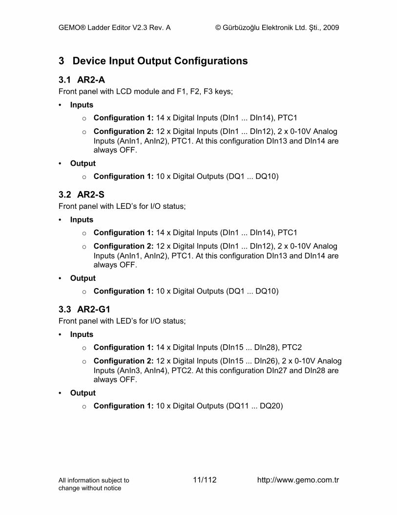
3 Device Input Output Configurations
3.1 AR2-AFront panel with LCD module and F1, F2, F3 keys;
• Inputso Configuration 1: 14 x Digital Inputs (DIn1 ... DIn14), PTC1
o Configuration 2: 12 x Digital Inputs (DIn1 ... DIn12), 2 x 0-10V Analog Inputs (AnIn1, AnIn2), PTC1. At this configuration DIn13 and DIn14 are always OFF.
• Outputo Configuration 1: 10 x Digital Outputs (DQ1 ... DQ10)
3.2 AR2-SFront panel with LED’s for I/O status;
• Inputso Configuration 1: 14 x Digital Inputs (DIn1 ... DIn14), PTC1
o Configuration 2: 12 x Digital Inputs (DIn1 ... DIn12), 2 x 0-10V Analog Inputs (AnIn1, AnIn2), PTC1. At this configuration DIn13 and DIn14 are always OFF.
• Outputo Configuration 1: 10 x Digital Outputs (DQ1 ... DQ10)
3.3 AR2-G1Front panel with LED’s for I/O status;
• Inputso Configuration 1: 14 x Digital Inputs (DIn15 ... DIn28), PTC2
o Configuration 2: 12 x Digital Inputs (DIn15 ... DIn26), 2 x 0-10V Analog Inputs (AnIn3, AnIn4), PTC2. At this configuration DIn27 and DIn28 are always OFF.
• Outputo Configuration 1: 10 x Digital Outputs (DQ11 ... DQ20)
All information subject to 11/112 http://www.gemo.com.trchange without notice
GEMO® Ladder Editor V2.3 Rev. A © Gürbüzoğlu Elektronik Ltd. Şti., 2009
4 Some Issues that Require User AttentionAlways use and support AR2 with separate and independent mechanical and/or electromechanical devices/apparatus for emergency cases.
4.1 Retention FeatureSome of ladder components have retention feature.This feature may be enabled on purpose by the user.Device senses power failure and saves status of retentive components to non volatile memory. Components which are set to be retentive resume their last status after power is on with the last status saved in the non volatile memory, and continues to operate with this resumed status. Status is output/input states and actual values, like the counting value of a counter.The status of retentive components, duration of a power failure and the time when power will be on again may not be well known all the time. This uncertainty may lead to undesired or even dangerous starting positions/conditions for an application.Use retention feature carefully. Study all conditions that may happen during/after a power failure and/or during/after power is on and take precautions.Use;
• Timers: GATE and RESET inputs,
• Counter: RESET inputs,
• Auxiliary Relays: RESET inputs,
• State Machines A/B: RESET and ENABLE inputs,to take precautions. Starting an application with a user approval, i.e. user presses to a switch to resume or another switch to cancel or stop or restart from another point, will be an appropriate design approach.If for some reason, any non volatile memory read/write error occurs for retention information, system contact ErrRetention becomes ON after power is on. In this case, retentive components are initialized as if they are not retentive.
4.2 Power on Status of Ladder ComponentsDevice initializes and tests its hardware for the first 3 seconds after power is on. Scanning starts after test and initialization.Power on status of Ladder Components (except the retentive ones);
• Digital Inputs: same as Device inputs,
• Filtered Digital Inputs: depends on the filter time and device input,
All information subject to 12/112 http://www.gemo.com.trchange without notice
!
GEMO® Ladder Editor V2.3 Rev. A © Gürbüzoğlu Elektronik Ltd. Şti., 2009
• Digital Outputs: all OFF,
• Auxiliary Relays: all OFF,
• Timers: all with RESET input is pulsed before scan,
• Counters: all with RESET input is pulsed before scan,
• Fast Input Counters: all OFF, loaded with Presets
• Counter Comparators: all OFF,
• State Machines: starts from State 1, with all outputs OFF,
• Front Panel F Keys: same as front panel F keys,
• Filtered Front Panel F Keys: depends on filter time and front panel F key status,
• Timer Ticks: all OFF,
• Run Time Screens: all OFF,
• Analog Comparators: all OFF,
• System Flags (Contacts):o PowerONRst: 0.5 seconds ON then OFF,
o ErrRetention: ON if non volatile memory read error, else OFF,
o ErrPTC1: depends on sensor,
o ErrPTC2: depends on sensor,
o ErrCommAny: OFF,
o ErrCommG1: OFF
4.3 Rising Edge / Falling Edge Generation after Power onRising Edge / Falling Edge generation is inhibited while PowerONRst is ON (the first 0.5 sec. after scanning starts). After that, Rising Edge / Falling Edge generation is enabled.Starting an application with a user approval after power on, i.e. user presses to a switch to start, will be an appropriate design approach.
4.4 Input Edge Detection of Ladder Components after Power onInput edge detection of ladder components is not allowed during the first scan cycle after Power is on. For example, a counter does not count when a rising edge exists at its “Count” input during the first scan cycle, but it counts at the next cycles.
All information subject to 13/112 http://www.gemo.com.trchange without notice
!

GEMO® Ladder Editor V2.3 Rev. A © Gürbüzoğlu Elektronik Ltd. Şti., 2009
4.5 Fast Input CountersBe sure that Preset value of a Fast Input Counter is high enough. Refer to Fast Input Counters section.
4.6 Weekly and Yearly AlarmsWeekly Alarms (RTCWA) and Yearly Alarms (RTCYA) may be ON just after power is on, depending on the user settings.Use RTCWA and RTCYA features carefully. Study all conditions that may happen during/after a power failure and/or during/after power is on and take precautions.
4.7 Ladder Diagram WarningsIf there exists any warning(s) about a ladder diagram/program, a red button appears on the left top corner of the diagram. Press the red button to read the warnings. It is advised to have no warning for every diagram/program before simulation or downloading.
4.8 Analog Ground and Analog Power SupplyDevices having analog inputs have separate Analog Ground. Do not use 18V Auxiliary supply out of device to power the external analog circuitry/device(s) that generate 10Vdc analog signal. Analog ground is isolated than Discrete Input signal return path.Use a separate power supply to power the external analog circuitry/device(s) that generate 10Vdc analog signal. This supply should be double insulated. Do not use this supply to power any other device or circuitry. Prefer to use a regulated power supply.Connect Analog Ground to the external analog circuitry/device(s) that generate 10Vdc analog signal with a separate cable. Use twisted pair cable with a shield and connect shield to earth only from the device side, leave other side unconnected.
4.9 RS-485 ConnectionUse shielded twisted pair cable for RS-485 connection. For correct line termination please refer to related application note; www.gemo.com.tr.
4.10Mounting and Environmental Conditions• Mount the device in a ventilated place, and be sure that air inlets are not
blocked. Use mounting holes to fasten or install on a rail.
• Take precautions against environmental conditions like humidity, vibration, pollution and high/low temperature during installation.
• Do not use device out of its technical specifications.
• Keep device away from circuit breaker, devices/cables emitting electrical noise, power cables.
All information subject to 14/112 http://www.gemo.com.trchange without notice
!
GEMO® Ladder Editor V2.3 Rev. A © Gürbüzoğlu Elektronik Ltd. Şti., 2009
• Keep signal and communication cables away from circuit breaker, devices/cables emitting electrical noise, power cables.
• Use shielded and twisted signal and communication cables and connect shield to ground on device side.
• Use an appropriate fuse on mains/supply input of the device. Use appropriate cables for mains connections. Apply safety regulations during installation.
4.11Opening a Ladder File from File BrowserThe file extension of GEMO Ladder Editor’s work file is “.ldr”. GEMO Ladder Editor does associate “.ldr” files to itself automatically. If you wish, use Windows Explorer program to associate “.ldr” files to GEMO Ladder Editor manually. If you do so, you can directly open a file with extension “.ldr” into GEMO Ladder Editor by double clicking on its name or icon from a file browser.
All information subject to 15/112 http://www.gemo.com.trchange without notice
!
GEMO® Ladder Editor V2.3 Rev. A © Gürbüzoğlu Elektronik Ltd. Şti., 2009
5 Ladder Editor
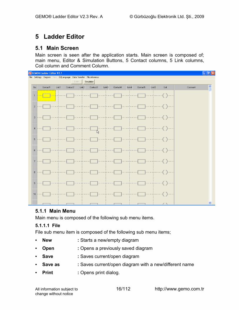
5.1 Main ScreenMain screen is seen after the application starts. Main screen is composed of; main menu, Editor & Simulation Buttons, 5 Contact columns, 5 Link columns, Coil column and Comment Column.
5.1.1 Main MenuMain menu is composed of the following sub menu items.5.1.1.1 FileFile sub menu item is composed of the following sub menu items;
• New : Starts a new/empty diagram
• Open : Opens a previously saved diagram
• Save : Saves current/open diagram
• Save as : Saves current/open diagram with a new/different name
• Print : Opens print dialog.
All information subject to 16/112 http://www.gemo.com.trchange without notice
GEMO® Ladder Editor V2.3 Rev. A © Gürbüzoğlu Elektronik Ltd. Şti., 2009
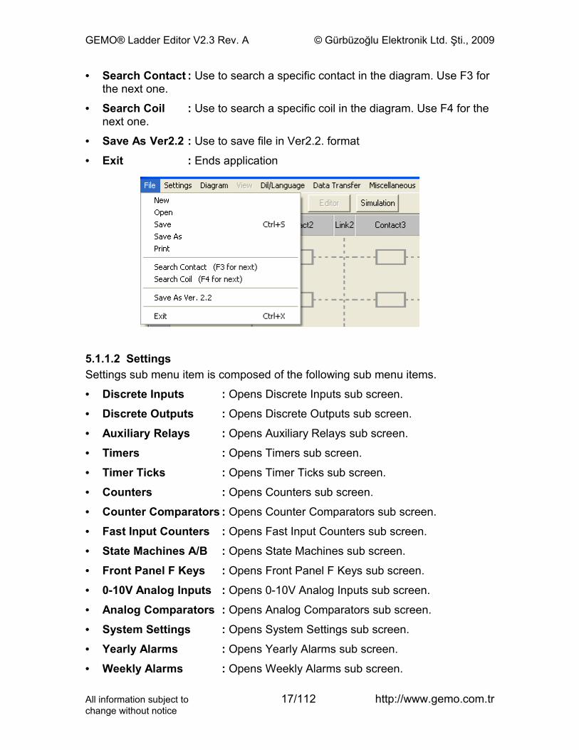
• Search Contact : Use to search a specific contact in the diagram. Use F3 for the next one.
• Search Coil : Use to search a specific coil in the diagram. Use F4 for the next one.
• Save As Ver2.2 : Use to save file in Ver2.2. format
• Exit : Ends application
5.1.1.2 SettingsSettings sub menu item is composed of the following sub menu items.
• Discrete Inputs : Opens Discrete Inputs sub screen.
• Discrete Outputs : Opens Discrete Outputs sub screen.
• Auxiliary Relays : Opens Auxiliary Relays sub screen.
• Timers : Opens Timers sub screen.
• Timer Ticks : Opens Timer Ticks sub screen.
• Counters : Opens Counters sub screen.
• Counter Comparators : Opens Counter Comparators sub screen.
• Fast Input Counters : Opens Fast Input Counters sub screen.
• State Machines A/B : Opens State Machines sub screen.
• Front Panel F Keys : Opens Front Panel F Keys sub screen.
• 0-10V Analog Inputs : Opens 0-10V Analog Inputs sub screen.
• Analog Comparators : Opens Analog Comparators sub screen.
• System Settings : Opens System Settings sub screen.
• Yearly Alarms : Opens Yearly Alarms sub screen.
• Weekly Alarms : Opens Weekly Alarms sub screen.
All information subject to 17/112 http://www.gemo.com.trchange without notice
GEMO® Ladder Editor V2.3 Rev. A © Gürbüzoğlu Elektronik Ltd. Şti., 2009
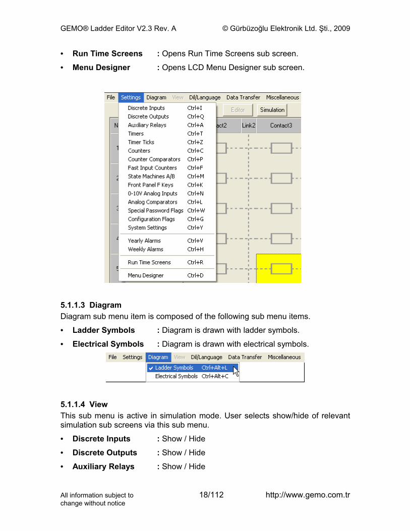
• Run Time Screens : Opens Run Time Screens sub screen.
• Menu Designer : Opens LCD Menu Designer sub screen.
5.1.1.3 DiagramDiagram sub menu item is composed of the following sub menu items.
• Ladder Symbols : Diagram is drawn with ladder symbols.
• Electrical Symbols : Diagram is drawn with electrical symbols.
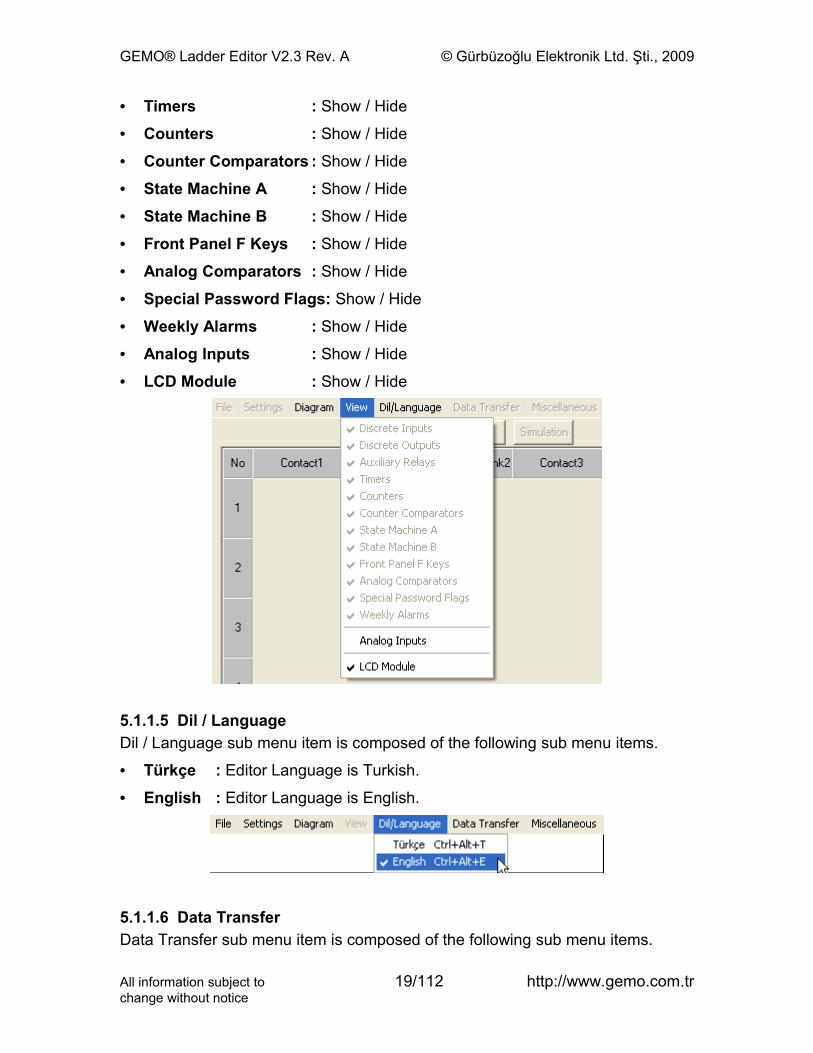
5.1.1.4 ViewThis sub menu is active in simulation mode. User selects show/hide of relevant simulation sub screens via this sub menu.
• Discrete Inputs : Show / Hide
• Discrete Outputs : Show / Hide
• Auxiliary Relays : Show / Hide
All information subject to 18/112 http://www.gemo.com.trchange without notice
GEMO® Ladder Editor V2.3 Rev. A © Gürbüzoğlu Elektronik Ltd. Şti., 2009
• Timers : Show / Hide
• Counters : Show / Hide
• Counter Comparators : Show / Hide
• State Machine A : Show / Hide
• State Machine B : Show / Hide
• Front Panel F Keys : Show / Hide
• Analog Comparators : Show / Hide
• Special Password Flags: Show / Hide
• Weekly Alarms : Show / Hide
• Analog Inputs : Show / Hide
• LCD Module : Show / Hide
5.1.1.5 Dil / LanguageDil / Language sub menu item is composed of the following sub menu items.
• Türkçe : Editor Language is Turkish.
• English : Editor Language is English.
5.1.1.6 Data TransferData Transfer sub menu item is composed of the following sub menu items.
All information subject to 19/112 http://www.gemo.com.trchange without notice
GEMO® Ladder Editor V2.3 Rev. A © Gürbüzoğlu Elektronik Ltd. Şti., 2009
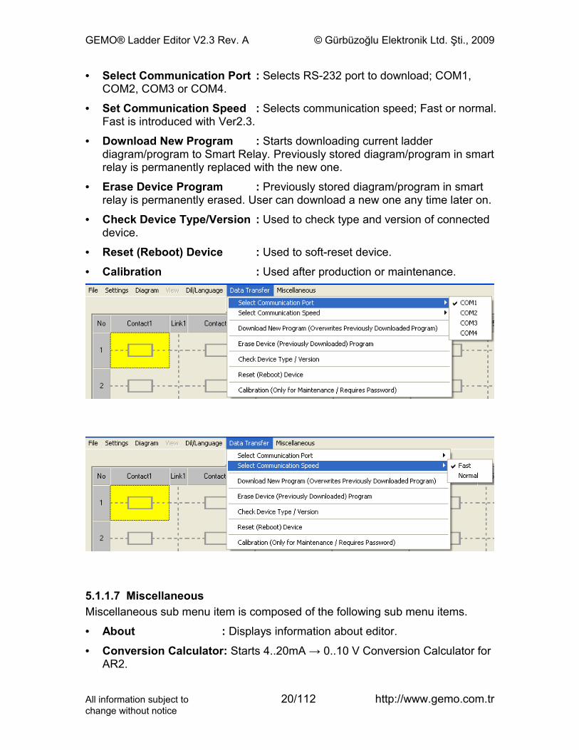
• Select Communication Port : Selects RS-232 port to download; COM1, COM2, COM3 or COM4.
• Set Communication Speed : Selects communication speed; Fast or normal. Fast is introduced with Ver2.3.
• Download New Program : Starts downloading current ladder diagram/program to Smart Relay. Previously stored diagram/program in smart relay is permanently replaced with the new one.
• Erase Device Program : Previously stored diagram/program in smart relay is permanently erased. User can download a new one any time later on.
• Check Device Type/Version : Used to check type and version of connected device.
• Reset (Reboot) Device : Used to soft-reset device.
• Calibration : Used after production or maintenance.
5.1.1.7 MiscellaneousMiscellaneous sub menu item is composed of the following sub menu items.
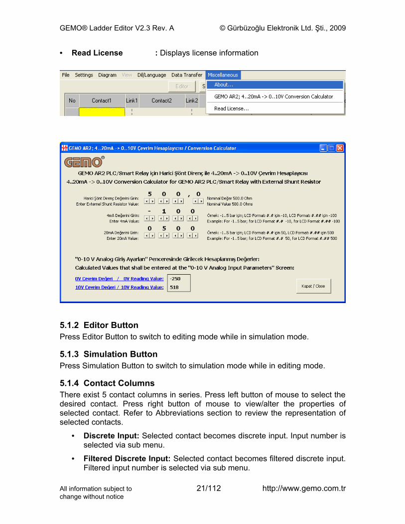
• About : Displays information about editor.
• Conversion Calculator: Starts 4..20mA → 0..10 V Conversion Calculator for AR2.
All information subject to 20/112 http://www.gemo.com.trchange without notice
GEMO® Ladder Editor V2.3 Rev. A © Gürbüzoğlu Elektronik Ltd. Şti., 2009
• Read License : Displays license information
5.1.2 Editor ButtonPress Editor Button to switch to editing mode while in simulation mode.
5.1.3 Simulation ButtonPress Simulation Button to switch to simulation mode while in editing mode.
5.1.4 Contact ColumnsThere exist 5 contact columns in series. Press left button of mouse to select the desired contact. Press right button of mouse to view/alter the properties of selected contact. Refer to Abbreviations section to review the representation of selected contacts.
• Discrete Input: Selected contact becomes discrete input. Input number is selected via sub menu.
• Filtered Discrete Input: Selected contact becomes filtered discrete input. Filtered input number is selected via sub menu.
All information subject to 21/112 http://www.gemo.com.trchange without notice
GEMO® Ladder Editor V2.3 Rev. A © Gürbüzoğlu Elektronik Ltd. Şti., 2009
• Discrete Output: Selected contact becomes discrete output. Output number is selected via sub menu.
• Auxiliary Relay: Selected contact becomes Auxiliary Relay. Auxiliary relay number is selected via sub menu.
• Timer: Selected contact becomes Timer. Timer number is selected via sub menu.
• Counter: Selected contact becomes a Counter. Counter number is selected via sub menu.
• Counter Comparator: Selected contact becomes Counter Comparator. Counter Comparator number is selected via sub menu.
• Fast Input Counter: Selected contact becomes Fast Input Counter. Fast Input Counter number is selected via sub menu.
• State Machine A: Selected contact becomes Output of State Machine A. Output number is selected via sub menu.
• State Machine B: Selected contact becomes Output of State Machine B. Output number is selected via sub menu.
• Front Panel F Key: Selected contact becomes Front Panel F Key. Key number is selected via sub menu.
• Filtered Front Panel F Key: Selected contact becomes Filtered Front Panel F Key. Key number is selected via sub menu.
• Analog Comparator: Selected contact becomes Analog Comparator. Analog Comparator number is selected via sub menu.
• Special Password Flags: Selected contact becomes Special Password Flag. Flag number is selected via sub menu.
• Configuration Flags: Selected contact becomes Configuration Flag. Flag number is selected via sub menu.
• Weekly Alarms: Selected contact becomes Weekly Alarm. Weekly Alarm number is selected via sub menu.
• Yearly Alarms: Selected contact becomes Yearly Alarm. Yearly Alarm number is selected via sub menu.
• System Flags: Selected contact becomes one of the System Flags Contact. Flag type is selected via sub menu.
• Inverter: Selected contact becomes an inverting link (logical not).
• Link: Selected contact becomes a link (short circuit).
• Normally Open: Selected contact operates as a normally open contact.
• Normally Closed: Selected contact operates as a normally closed contact.
All information subject to 22/112 http://www.gemo.com.trchange without notice
GEMO® Ladder Editor V2.3 Rev. A © Gürbüzoğlu Elektronik Ltd. Şti., 2009
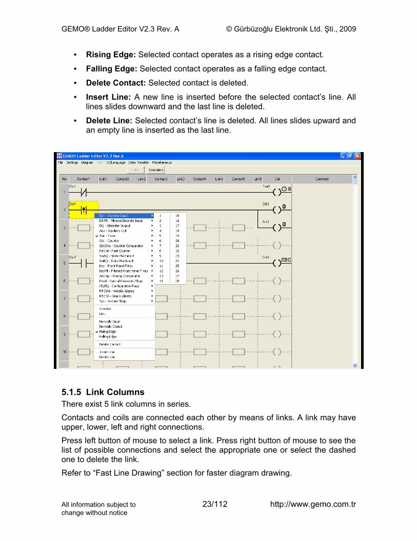
• Rising Edge: Selected contact operates as a rising edge contact.
• Falling Edge: Selected contact operates as a falling edge contact.
• Delete Contact: Selected contact is deleted.
• Insert Line: A new line is inserted before the selected contact’s line. All lines slides downward and the last line is deleted.
• Delete Line: Selected contact’s line is deleted. All lines slides upward and an empty line is inserted as the last line.
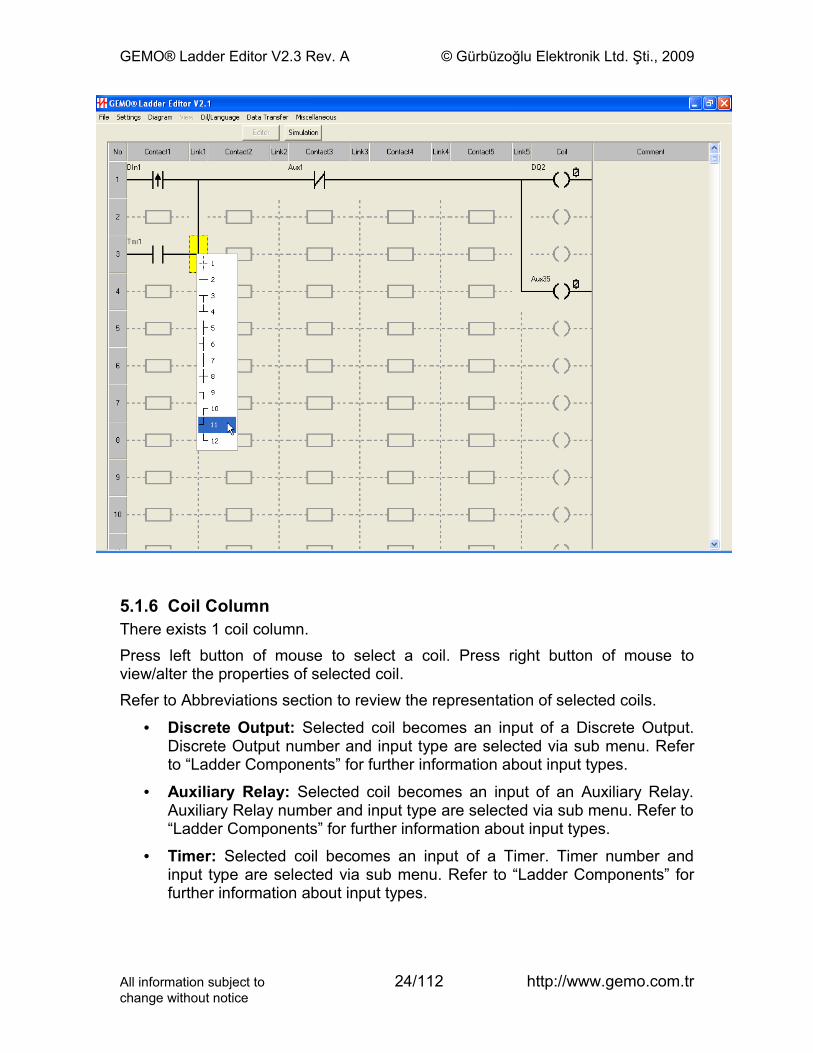
5.1.5 Link ColumnsThere exist 5 link columns in series.Contacts and coils are connected each other by means of links. A link may have upper, lower, left and right connections.Press left button of mouse to select a link. Press right button of mouse to see the list of possible connections and select the appropriate one or select the dashed one to delete the link.Refer to “Fast Line Drawing” section for faster diagram drawing.
All information subject to 23/112 http://www.gemo.com.trchange without notice
GEMO® Ladder Editor V2.3 Rev. A © Gürbüzoğlu Elektronik Ltd. Şti., 2009
5.1.6 Coil ColumnThere exists 1 coil column.Press left button of mouse to select a coil. Press right button of mouse to view/alter the properties of selected coil.Refer to Abbreviations section to review the representation of selected coils.
• Discrete Output: Selected coil becomes an input of a Discrete Output. Discrete Output number and input type are selected via sub menu. Refer to “Ladder Components” for further information about input types.
• Auxiliary Relay: Selected coil becomes an input of an Auxiliary Relay. Auxiliary Relay number and input type are selected via sub menu. Refer to “Ladder Components” for further information about input types.
• Timer: Selected coil becomes an input of a Timer. Timer number and input type are selected via sub menu. Refer to “Ladder Components” for further information about input types.
All information subject to 24/112 http://www.gemo.com.trchange without notice
GEMO® Ladder Editor V2.3 Rev. A © Gürbüzoğlu Elektronik Ltd. Şti., 2009
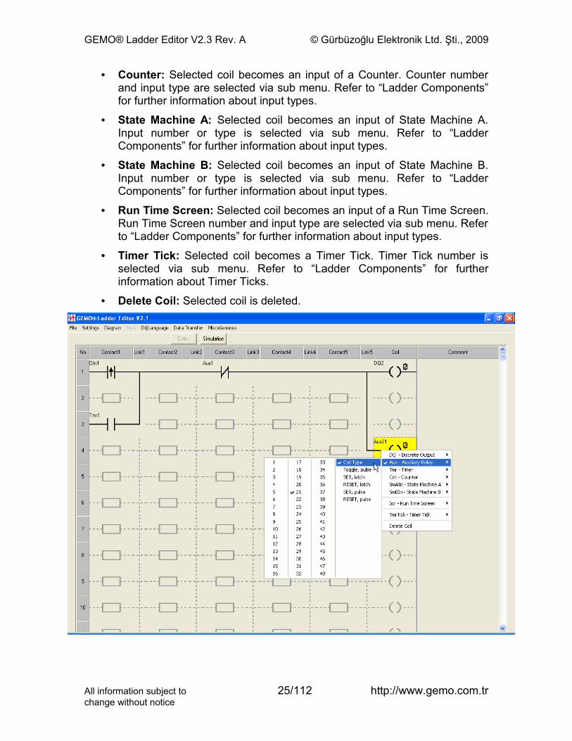
• Counter: Selected coil becomes an input of a Counter. Counter number and input type are selected via sub menu. Refer to “Ladder Components” for further information about input types.
• State Machine A: Selected coil becomes an input of State Machine A. Input number or type is selected via sub menu. Refer to “Ladder Components” for further information about input types.
• State Machine B: Selected coil becomes an input of State Machine B. Input number or type is selected via sub menu. Refer to “Ladder Components” for further information about input types.
• Run Time Screen: Selected coil becomes an input of a Run Time Screen. Run Time Screen number and input type are selected via sub menu. Refer to “Ladder Components” for further information about input types.
• Timer Tick: Selected coil becomes a Timer Tick. Timer Tick number is selected via sub menu. Refer to “Ladder Components” for further information about Timer Ticks.
• Delete Coil: Selected coil is deleted.
All information subject to 25/112 http://www.gemo.com.trchange without notice
GEMO® Ladder Editor V2.3 Rev. A © Gürbüzoğlu Elektronik Ltd. Şti., 2009
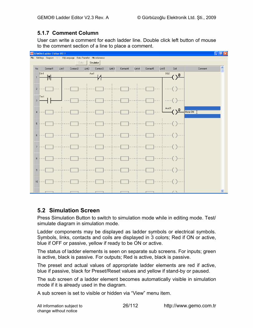
5.1.7 Comment ColumnUser can write a comment for each ladder line. Double click left button of mouse to the comment section of a line to place a comment.
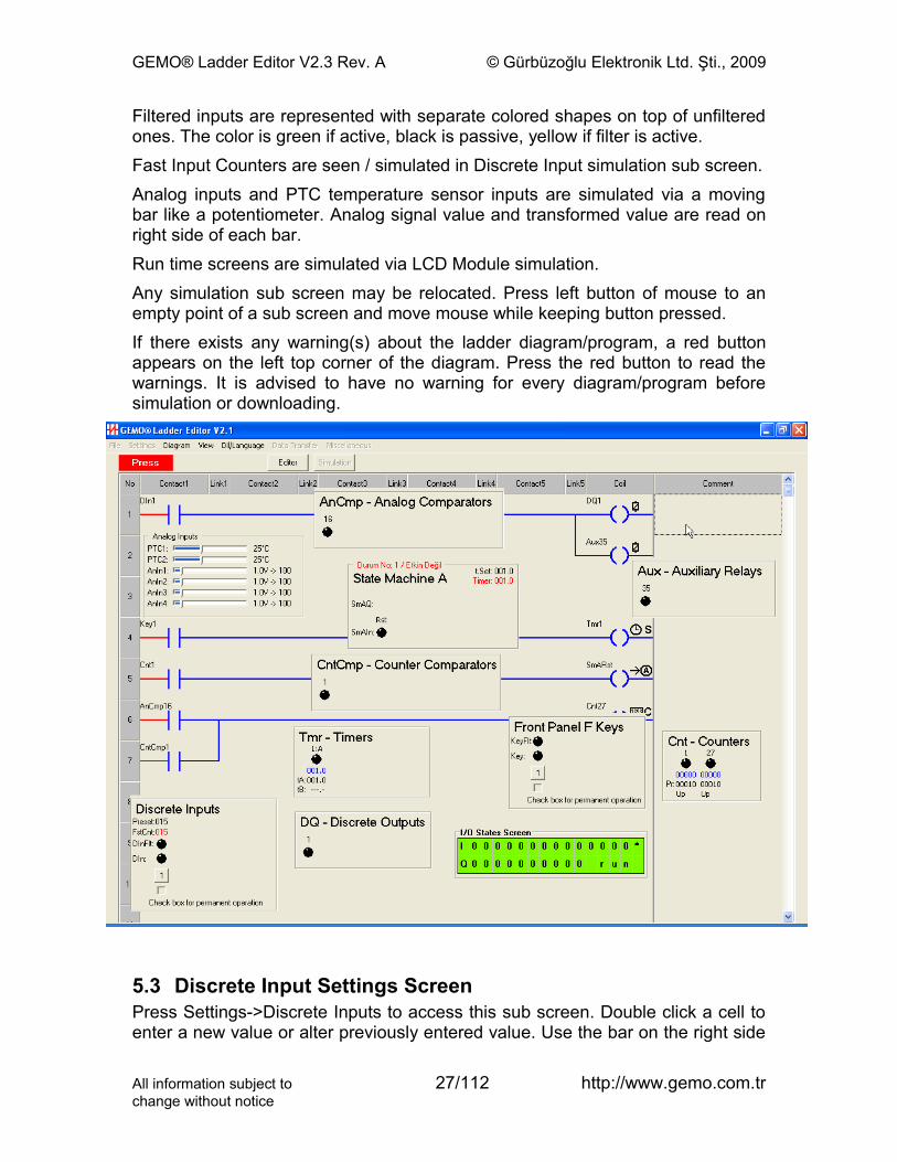
5.2 Simulation ScreenPress Simulation Button to switch to simulation mode while in editing mode. Test/simulate diagram in simulation mode.Ladder components may be displayed as ladder symbols or electrical symbols. Symbols, links, contacts and coils are displayed in 3 colors; Red if ON or active, blue if OFF or passive, yellow if ready to be ON or active.The status of ladder elements is seen on separate sub screens. For inputs; green is active, black is passive. For outputs; Red is active, black is passive.The preset and actual values of appropriate ladder elements are red if active, blue if passive, black for Preset/Reset values and yellow if stand-by or paused.The sub screen of a ladder element becomes automatically visible in simulation mode if it is already used in the diagram.A sub screen is set to visible or hidden via “View” menu item.
All information subject to 26/112 http://www.gemo.com.trchange without notice
GEMO® Ladder Editor V2.3 Rev. A © Gürbüzoğlu Elektronik Ltd. Şti., 2009
Filtered inputs are represented with separate colored shapes on top of unfiltered ones. The color is green if active, black is passive, yellow if filter is active.Fast Input Counters are seen / simulated in Discrete Input simulation sub screen.Analog inputs and PTC temperature sensor inputs are simulated via a moving bar like a potentiometer. Analog signal value and transformed value are read on right side of each bar.Run time screens are simulated via LCD Module simulation.Any simulation sub screen may be relocated. Press left button of mouse to an empty point of a sub screen and move mouse while keeping button pressed.If there exists any warning(s) about the ladder diagram/program, a red button appears on the left top corner of the diagram. Press the red button to read the warnings. It is advised to have no warning for every diagram/program before simulation or downloading.
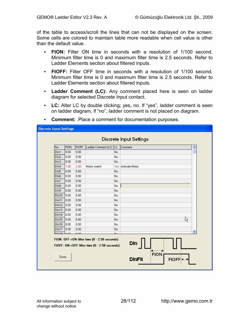
5.3 Discrete Input Settings ScreenPress Settings->Discrete Inputs to access this sub screen. Double click a cell to enter a new value or alter previously entered value. Use the bar on the right side
All information subject to 27/112 http://www.gemo.com.trchange without notice
GEMO® Ladder Editor V2.3 Rev. A © Gürbüzoğlu Elektronik Ltd. Şti., 2009
of the table to access/scroll the lines that can not be displayed on the screen. Some cells are colored to maintain table more readable when cell value is other than the default value.
• FtON: Filter ON time in seconds with a resolution of 1/100 second. Minimum filter time is 0 and maximum filter time is 2.5 seconds. Refer to Ladder Elements section about filtered inputs.
• FtOFF: Filter OFF time in seconds with a resolution of 1/100 second. Minimum filter time is 0 and maximum filter time is 2.5 seconds. Refer to Ladder Elements section about filtered inputs.
• Ladder Comment (LC): Any comment placed here is seen on ladder diagram for selected Discrete Input contact.
• LC: Alter LC by double clicking; yes, no. If “yes”, ladder comment is seen on ladder diagram, if “no”, ladder comment is not placed on diagram.
• Comment: .Place a comment for documentation purposes.
All information subject to 28/112 http://www.gemo.com.trchange without notice
GEMO® Ladder Editor V2.3 Rev. A © Gürbüzoğlu Elektronik Ltd. Şti., 2009
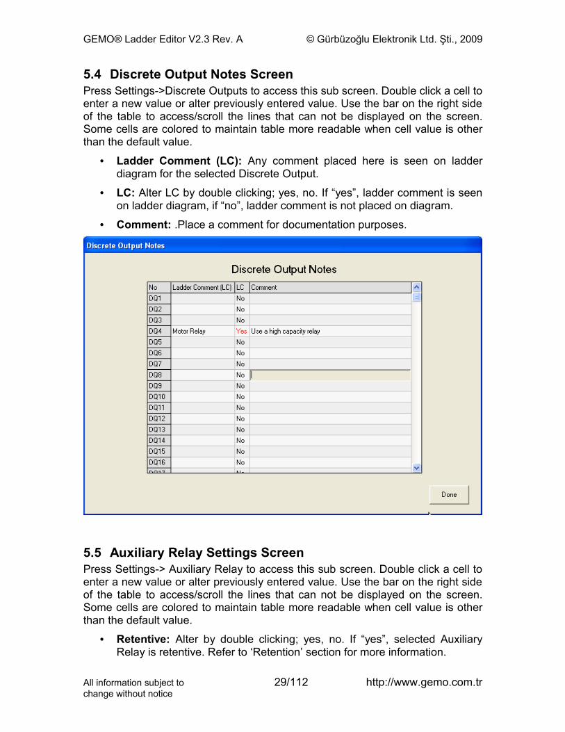
5.4 Discrete Output Notes ScreenPress Settings->Discrete Outputs to access this sub screen. Double click a cell to enter a new value or alter previously entered value. Use the bar on the right side of the table to access/scroll the lines that can not be displayed on the screen. Some cells are colored to maintain table more readable when cell value is other than the default value.
• Ladder Comment (LC): Any comment placed here is seen on ladder diagram for the selected Discrete Output.
• LC: Alter LC by double clicking; yes, no. If “yes”, ladder comment is seen on ladder diagram, if “no”, ladder comment is not placed on diagram.
• Comment: .Place a comment for documentation purposes.
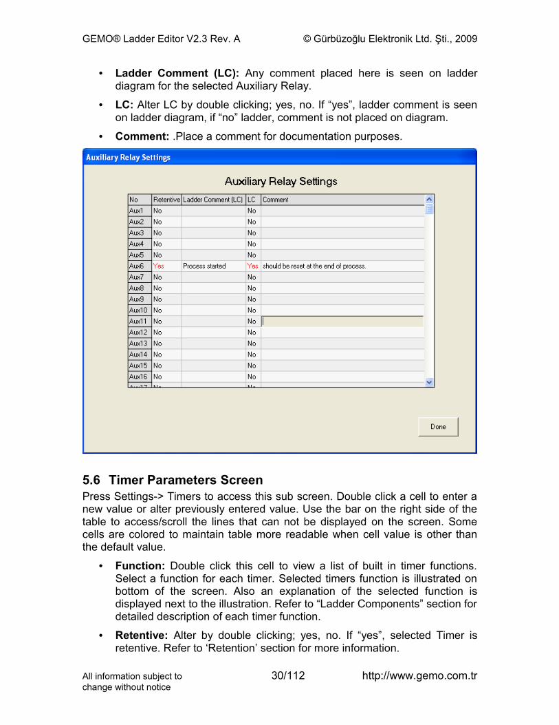
5.5 Auxiliary Relay Settings ScreenPress Settings-> Auxiliary Relay to access this sub screen. Double click a cell to enter a new value or alter previously entered value. Use the bar on the right side of the table to access/scroll the lines that can not be displayed on the screen. Some cells are colored to maintain table more readable when cell value is other than the default value.
• Retentive: Alter by double clicking; yes, no. If “yes”, selected Auxiliary Relay is retentive. Refer to ‘Retention’ section for more information.
All information subject to 29/112 http://www.gemo.com.trchange without notice
GEMO® Ladder Editor V2.3 Rev. A © Gürbüzoğlu Elektronik Ltd. Şti., 2009
• Ladder Comment (LC): Any comment placed here is seen on ladder diagram for the selected Auxiliary Relay.
• LC: Alter LC by double clicking; yes, no. If “yes”, ladder comment is seen on ladder diagram, if “no” ladder, comment is not placed on diagram.
• Comment: .Place a comment for documentation purposes.
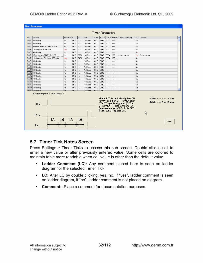
5.6 Timer Parameters ScreenPress Settings-> Timers to access this sub screen. Double click a cell to enter a new value or alter previously entered value. Use the bar on the right side of the table to access/scroll the lines that can not be displayed on the screen. Some cells are colored to maintain table more readable when cell value is other than the default value.
• Function: Double click this cell to view a list of built in timer functions. Select a function for each timer. Selected timers function is illustrated on bottom of the screen. Also an explanation of the selected function is displayed next to the illustration. Refer to “Ladder Components” section for detailed description of each timer function.
• Retentive: Alter by double clicking; yes, no. If “yes”, selected Timer is retentive. Refer to ‘Retention’ section for more information.
All information subject to 30/112 http://www.gemo.com.trchange without notice

GEMO® Ladder Editor V2.3 Rev. A © Gürbüzoğlu Elektronik Ltd. Şti., 2009
• tA: Enter default Preset A value for each timer.
• tB: Enter default Preset B value for each timer. Preset B is not defined for some timer functions.
• Unit: Select resolution (time base) for each timer.
• tA.Min.: Enter minimum value for tA that user is allowed to enter during parameter entry via device front panel. This parameter is used by device firmware to limit user entry.
• tA.Max.: Enter maximum value for tA that user is allowed to enter during parameter entry via device front panel. This parameter is used by device firmware to limit user entry.
• tB.Min.: Enter minimum value for tB that user is allowed to enter during parameter entry via device front panel. This parameter is used by device firmware to limit user entry.
• tB.Max.: Enter maximum value for tB that user is allowed to enter during parameter entry via device front panel. This parameter is used by device firmware to limit user entry.
• Ladder Comment (LC): Any comment placed here is seen on ladder diagram for the selected Timer.
• LC: Alter LC by double clicking; yes, no. If “yes”, ladder comment is seen on ladder diagram, if “no”, ladder comment is not placed on diagram.
• Comment: .Place a comment for documentation purposes.
All information subject to 31/112 http://www.gemo.com.trchange without notice
GEMO® Ladder Editor V2.3 Rev. A © Gürbüzoğlu Elektronik Ltd. Şti., 2009
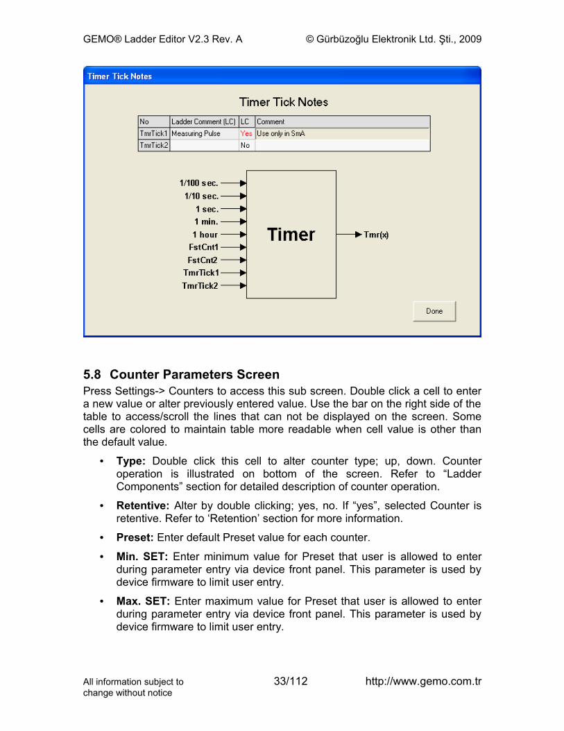
5.7 Timer Tick Notes ScreenPress Settings-> Timer Ticks to access this sub screen. Double click a cell to enter a new value or alter previously entered value. Some cells are colored to maintain table more readable when cell value is other than the default value.
• Ladder Comment (LC): Any comment placed here is seen on ladder diagram for the selected Timer Tick.
• LC: Alter LC by double clicking; yes, no. If “yes”, ladder comment is seen on ladder diagram, if “no”, ladder comment is not placed on diagram.
• Comment: .Place a comment for documentation purposes.
All information subject to 32/112 http://www.gemo.com.trchange without notice
GEMO® Ladder Editor V2.3 Rev. A © Gürbüzoğlu Elektronik Ltd. Şti., 2009
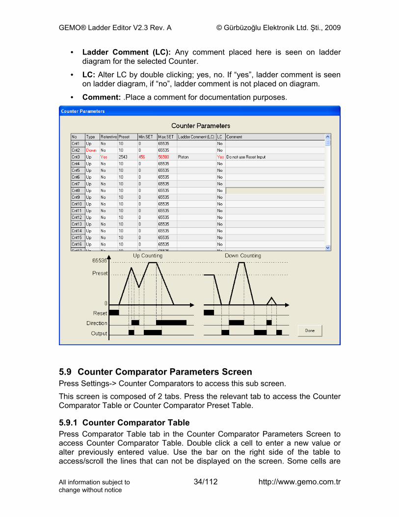
5.8 Counter Parameters ScreenPress Settings-> Counters to access this sub screen. Double click a cell to enter a new value or alter previously entered value. Use the bar on the right side of the table to access/scroll the lines that can not be displayed on the screen. Some cells are colored to maintain table more readable when cell value is other than the default value.
• Type: Double click this cell to alter counter type; up, down. Counter operation is illustrated on bottom of the screen. Refer to “Ladder Components” section for detailed description of counter operation.
• Retentive: Alter by double clicking; yes, no. If “yes”, selected Counter is retentive. Refer to ‘Retention’ section for more information.
• Preset: Enter default Preset value for each counter.
• Min. SET: Enter minimum value for Preset that user is allowed to enter during parameter entry via device front panel. This parameter is used by device firmware to limit user entry.
• Max. SET: Enter maximum value for Preset that user is allowed to enter during parameter entry via device front panel. This parameter is used by device firmware to limit user entry.
All information subject to 33/112 http://www.gemo.com.trchange without notice
GEMO® Ladder Editor V2.3 Rev. A © Gürbüzoğlu Elektronik Ltd. Şti., 2009
• Ladder Comment (LC): Any comment placed here is seen on ladder diagram for the selected Counter.
• LC: Alter LC by double clicking; yes, no. If “yes”, ladder comment is seen on ladder diagram, if “no”, ladder comment is not placed on diagram.
• Comment: .Place a comment for documentation purposes.
5.9 Counter Comparator Parameters ScreenPress Settings-> Counter Comparators to access this sub screen. This screen is composed of 2 tabs. Press the relevant tab to access the Counter Comparator Table or Counter Comparator Preset Table.
5.9.1 Counter Comparator TablePress Comparator Table tab in the Counter Comparator Parameters Screen to access Counter Comparator Table. Double click a cell to enter a new value or alter previously entered value. Use the bar on the right side of the table to access/scroll the lines that can not be displayed on the screen. Some cells are
All information subject to 34/112 http://www.gemo.com.trchange without notice
GEMO® Ladder Editor V2.3 Rev. A © Gürbüzoğlu Elektronik Ltd. Şti., 2009
colored to maintain table more readable when cell value is other than the default value. Select one of the rows and read the exact form of comparison expression of the selected Counter Comparator below table in blue color.
• Parameter A: Double click this cell to view a list of Parameters and then click to select one as Parameter A.
• Param. A No: Double click this cell to view a numbers list for Parameter A and then click to select the number of Parameter A.
• Offset: Double click this cell to enter an offset value.
• Operator: Double click this cell to view a list of logical operators and then click to select one.
• Parameter B: Double click this cell to view a list of Parameters and then click to select one as Parameter B.
• Param. B No: Double click this cell to view a numbers list for Parameter B and then click to select the number of Parameter B.
• Ladder Comment (LC): Any comment placed here is seen on ladder diagram for the selected Counter Comparator.
• LC: Alter LC by double clicking; yes, no. If “yes”, ladder comment is seen on ladder diagram, if “no”, ladder comment is not placed on diagram.
• Comment: .Place a comment for documentation purposes.
All information subject to 35/112 http://www.gemo.com.trchange without notice
GEMO® Ladder Editor V2.3 Rev. A © Gürbüzoğlu Elektronik Ltd. Şti., 2009
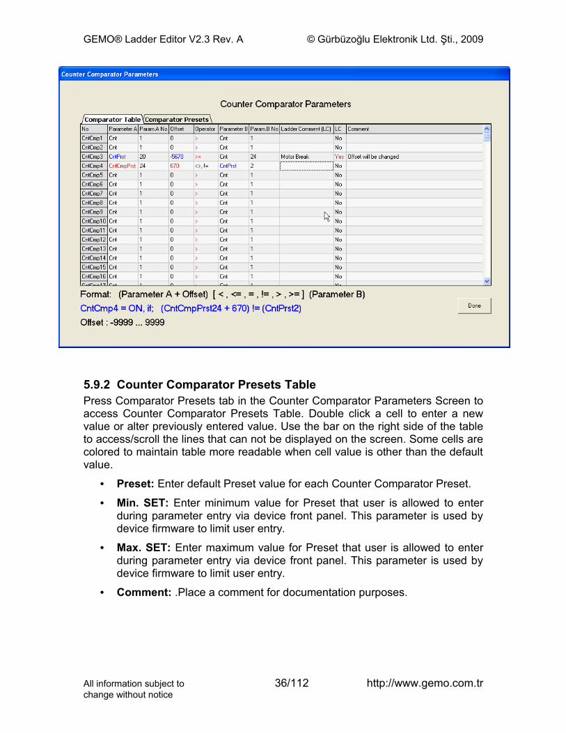
5.9.2 Counter Comparator Presets TablePress Comparator Presets tab in the Counter Comparator Parameters Screen to access Counter Comparator Presets Table. Double click a cell to enter a new value or alter previously entered value. Use the bar on the right side of the table to access/scroll the lines that can not be displayed on the screen. Some cells are colored to maintain table more readable when cell value is other than the default value.
• Preset: Enter default Preset value for each Counter Comparator Preset.
• Min. SET: Enter minimum value for Preset that user is allowed to enter during parameter entry via device front panel. This parameter is used by device firmware to limit user entry.
• Max. SET: Enter maximum value for Preset that user is allowed to enter during parameter entry via device front panel. This parameter is used by device firmware to limit user entry.
• Comment: .Place a comment for documentation purposes.
All information subject to 36/112 http://www.gemo.com.trchange without notice
GEMO® Ladder Editor V2.3 Rev. A © Gürbüzoğlu Elektronik Ltd. Şti., 2009
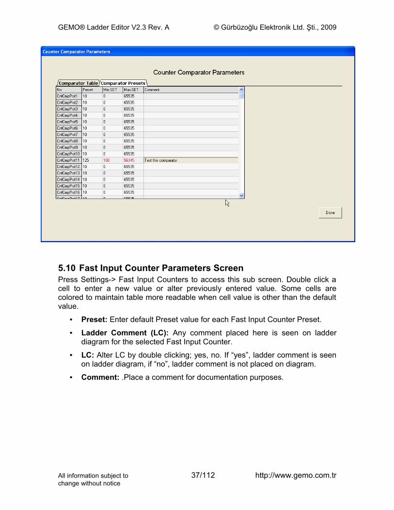
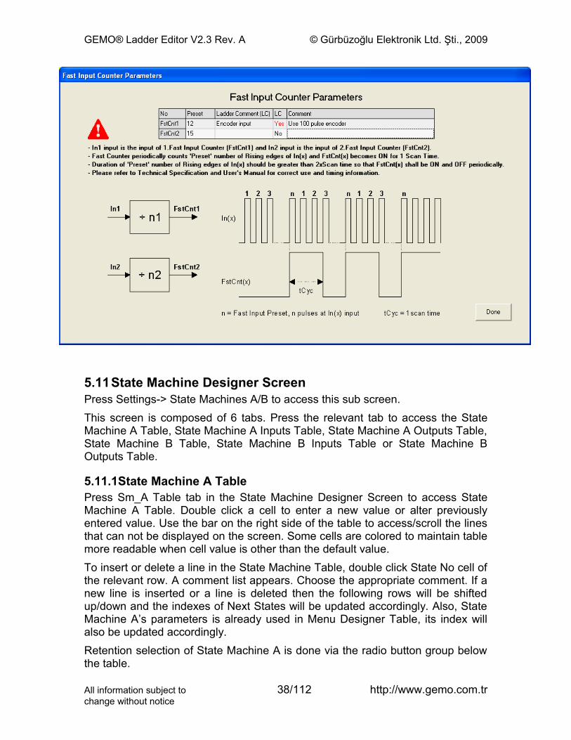
5.10 Fast Input Counter Parameters ScreenPress Settings-> Fast Input Counters to access this sub screen. Double click a cell to enter a new value or alter previously entered value. Some cells are colored to maintain table more readable when cell value is other than the default value.
• Preset: Enter default Preset value for each Fast Input Counter Preset.
• Ladder Comment (LC): Any comment placed here is seen on ladder diagram for the selected Fast Input Counter.
• LC: Alter LC by double clicking; yes, no. If “yes”, ladder comment is seen on ladder diagram, if “no”, ladder comment is not placed on diagram.
• Comment: .Place a comment for documentation purposes.
All information subject to 37/112 http://www.gemo.com.trchange without notice
GEMO® Ladder Editor V2.3 Rev. A © Gürbüzoğlu Elektronik Ltd. Şti., 2009
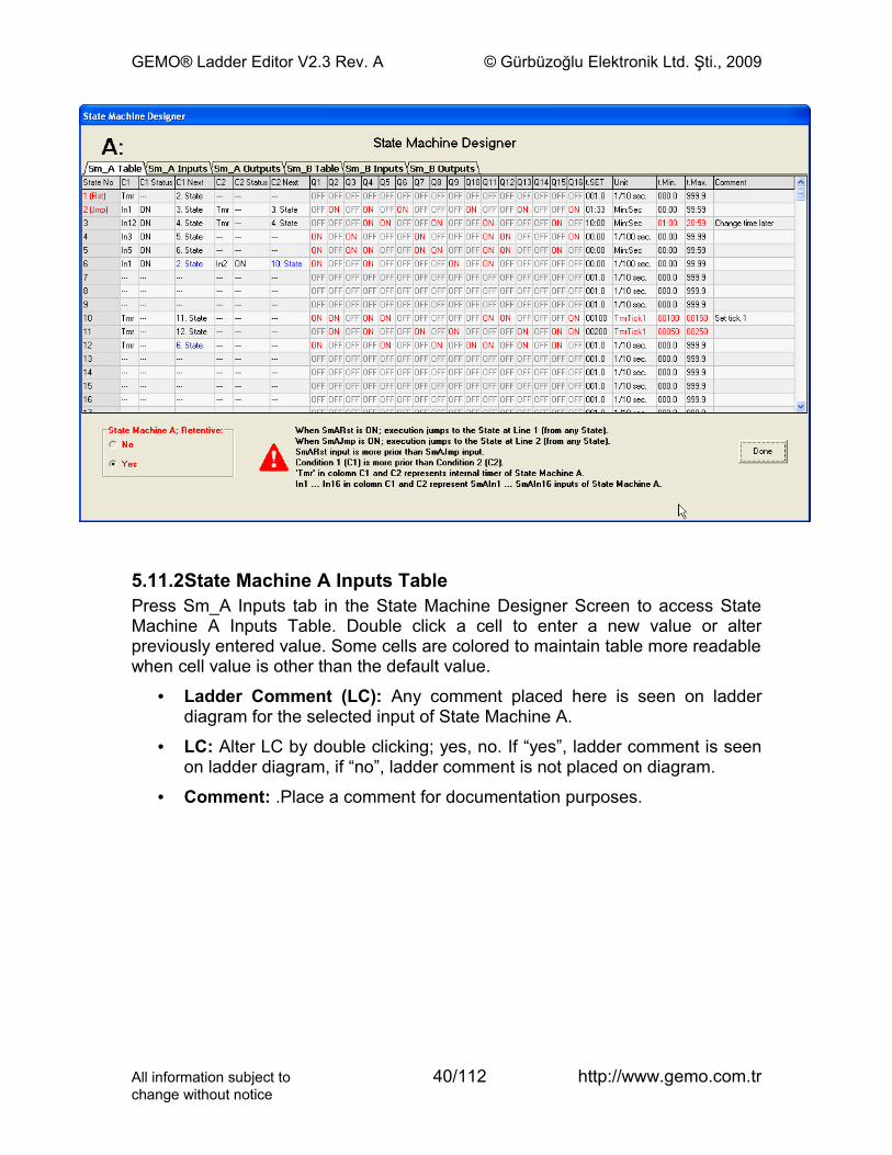
5.11State Machine Designer ScreenPress Settings-> State Machines A/B to access this sub screen. This screen is composed of 6 tabs. Press the relevant tab to access the State Machine A Table, State Machine A Inputs Table, State Machine A Outputs Table, State Machine B Table, State Machine B Inputs Table or State Machine B Outputs Table.
5.11.1State Machine A TablePress Sm_A Table tab in the State Machine Designer Screen to access State Machine A Table. Double click a cell to enter a new value or alter previously entered value. Use the bar on the right side of the table to access/scroll the lines that can not be displayed on the screen. Some cells are colored to maintain table more readable when cell value is other than the default value.To insert or delete a line in the State Machine Table, double click State No cell of the relevant row. A comment list appears. Choose the appropriate comment. If a new line is inserted or a line is deleted then the following rows will be shifted up/down and the indexes of Next States will be updated accordingly. Also, State Machine A’s parameters is already used in Menu Designer Table, its index will also be updated accordingly.Retention selection of State Machine A is done via the radio button group below the table.
All information subject to 38/112 http://www.gemo.com.trchange without notice
GEMO® Ladder Editor V2.3 Rev. A © Gürbüzoğlu Elektronik Ltd. Şti., 2009
• C1: Condition 1.Double click to view condition list and click to choose one.
• C1 Status: Status or type of Condition 1. Double click to view condition status list and click to choose one.
• C1 Next: Next State’s number to jump in case Condition 1 happens. Double click to view State Number list and click to choose one.
• C2: Condition 2.Double click to view condition list and click to choose one.
• C2 Status: Status or type of Condition 2. Double click to view condition status list and click to choose one.
• C2 Next: Next State’s number to jump in case Condition 2 happens. Double click to view State Number list and click to choose one.
• Q1...Q16: ON/OFF value of each State Machine A output for each state separately. Double click to toggle ON/OFF.
• t.SET: Double click to enter default preset value of internal timer of State Machine A (a separate value for each state).
• Unit: Double click to view time base list (and click to choose one) of internal timer of State Machine A (a separate time base for each state).
• t.Min: Enter minimum value for t.SET that user is allowed to enter during parameter entry via device front panel. This parameter is used by device firmware to limit user entry.
• t.Max: Enter maximum value for t.SET that user is allowed to enter during parameter entry via device front panel. This parameter is used by device firmware to limit user entry.
• Comment: .Place a comment for documentation purposes.
All information subject to 39/112 http://www.gemo.com.trchange without notice
GEMO® Ladder Editor V2.3 Rev. A © Gürbüzoğlu Elektronik Ltd. Şti., 2009
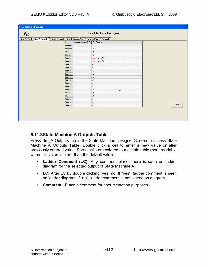
5.11.2State Machine A Inputs TablePress Sm_A Inputs tab in the State Machine Designer Screen to access State Machine A Inputs Table. Double click a cell to enter a new value or alter previously entered value. Some cells are colored to maintain table more readable when cell value is other than the default value.
• Ladder Comment (LC): Any comment placed here is seen on ladder diagram for the selected input of State Machine A.
• LC: Alter LC by double clicking; yes, no. If “yes”, ladder comment is seen on ladder diagram, if “no”, ladder comment is not placed on diagram.
• Comment: .Place a comment for documentation purposes.
All information subject to 40/112 http://www.gemo.com.trchange without notice
GEMO® Ladder Editor V2.3 Rev. A © Gürbüzoğlu Elektronik Ltd. Şti., 2009
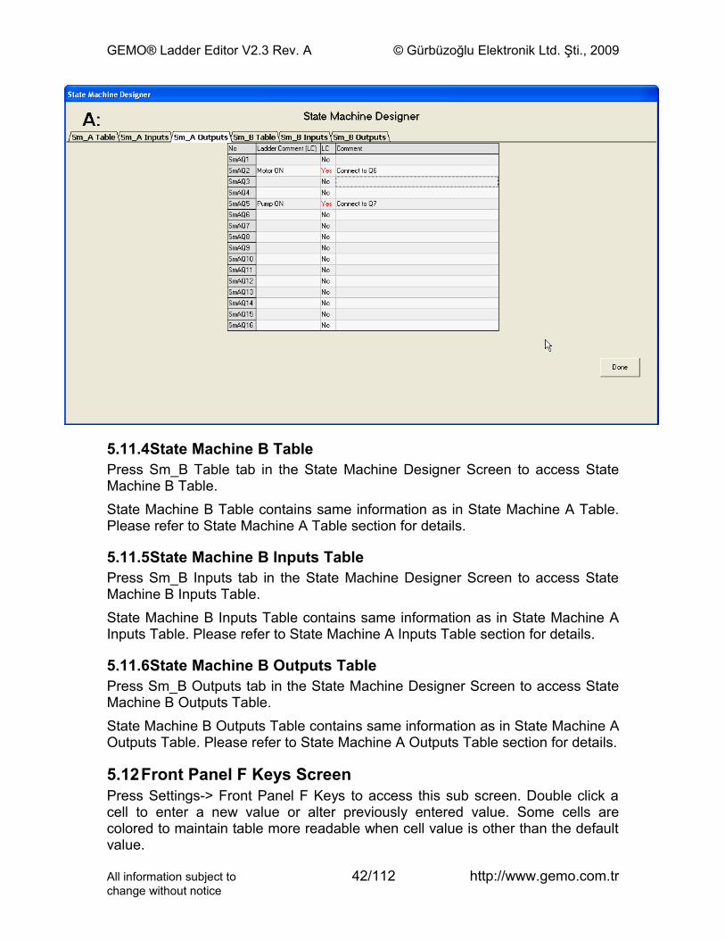
5.11.3State Machine A Outputs TablePress Sm_A Outputs tab in the State Machine Designer Screen to access State Machine A Outputs Table. Double click a cell to enter a new value or alter previously entered value. Some cells are colored to maintain table more readable when cell value is other than the default value.
• Ladder Comment (LC): Any comment placed here is seen on ladder diagram for the selected output of State Machine A.
• LC: Alter LC by double clicking; yes, no. If “yes”, ladder comment is seen on ladder diagram, if “no”, ladder comment is not placed on diagram.
• Comment: .Place a comment for documentation purposes.
All information subject to 41/112 http://www.gemo.com.trchange without notice
GEMO® Ladder Editor V2.3 Rev. A © Gürbüzoğlu Elektronik Ltd. Şti., 2009
5.11.4State Machine B TablePress Sm_B Table tab in the State Machine Designer Screen to access State Machine B Table. State Machine B Table contains same information as in State Machine A Table. Please refer to State Machine A Table section for details.
5.11.5State Machine B Inputs TablePress Sm_B Inputs tab in the State Machine Designer Screen to access State Machine B Inputs Table. State Machine B Inputs Table contains same information as in State Machine A Inputs Table. Please refer to State Machine A Inputs Table section for details.
5.11.6State Machine B Outputs TablePress Sm_B Outputs tab in the State Machine Designer Screen to access State Machine B Outputs Table. State Machine B Outputs Table contains same information as in State Machine A Outputs Table. Please refer to State Machine A Outputs Table section for details.
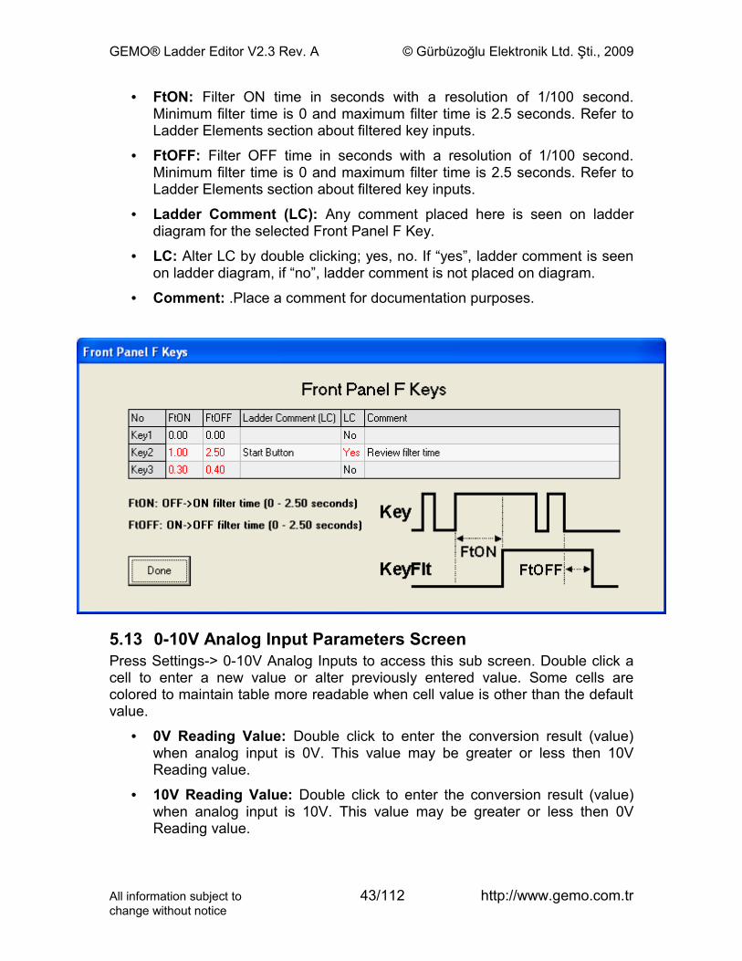
5.12Front Panel F Keys ScreenPress Settings-> Front Panel F Keys to access this sub screen. Double click a cell to enter a new value or alter previously entered value. Some cells are colored to maintain table more readable when cell value is other than the default value.
All information subject to 42/112 http://www.gemo.com.trchange without notice
GEMO® Ladder Editor V2.3 Rev. A © Gürbüzoğlu Elektronik Ltd. Şti., 2009
• FtON: Filter ON time in seconds with a resolution of 1/100 second. Minimum filter time is 0 and maximum filter time is 2.5 seconds. Refer to Ladder Elements section about filtered key inputs.
• FtOFF: Filter OFF time in seconds with a resolution of 1/100 second. Minimum filter time is 0 and maximum filter time is 2.5 seconds. Refer to Ladder Elements section about filtered key inputs.
• Ladder Comment (LC): Any comment placed here is seen on ladder diagram for the selected Front Panel F Key.
• LC: Alter LC by double clicking; yes, no. If “yes”, ladder comment is seen on ladder diagram, if “no”, ladder comment is not placed on diagram.
• Comment: .Place a comment for documentation purposes.
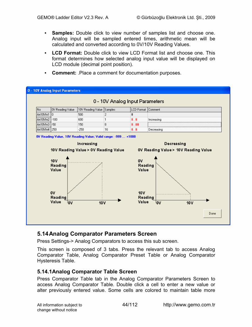
5.13 0-10V Analog Input Parameters ScreenPress Settings-> 0-10V Analog Inputs to access this sub screen. Double click a cell to enter a new value or alter previously entered value. Some cells are colored to maintain table more readable when cell value is other than the default value.
• 0V Reading Value: Double click to enter the conversion result (value) when analog input is 0V. This value may be greater or less then 10V Reading value.
• 10V Reading Value: Double click to enter the conversion result (value) when analog input is 10V. This value may be greater or less then 0V Reading value.
All information subject to 43/112 http://www.gemo.com.trchange without notice
GEMO® Ladder Editor V2.3 Rev. A © Gürbüzoğlu Elektronik Ltd. Şti., 2009
• Samples: Double click to view number of samples list and choose one. Analog input will be sampled entered times, arithmetic mean will be calculated and converted according to 0V/10V Reading Values.
• LCD Format: Double click to view LCD Format list and choose one. This format determines how selected analog input value will be displayed on LCD module (decimal point position).
• Comment: .Place a comment for documentation purposes.
5.14Analog Comparator Parameters ScreenPress Settings-> Analog Comparators to access this sub screen. This screen is composed of 3 tabs. Press the relevant tab to access Analog Comparator Table, Analog Comparator Preset Table or Analog Comparator Hysteresis Table.
5.14.1Analog Comparator Table ScreenPress Comparator Table tab in the Analog Comparator Parameters Screen to access Analog Comparator Table. Double click a cell to enter a new value or alter previously entered value. Some cells are colored to maintain table more
All information subject to 44/112 http://www.gemo.com.trchange without notice
GEMO® Ladder Editor V2.3 Rev. A © Gürbüzoğlu Elektronik Ltd. Şti., 2009
readable when cell value is other than the default value. Select one of the rows and read the exact form of comparison expression of the selected Analog Comparator below table in blue color.
• Parameter A: Double click this cell to view a list of Parameters and then click to select one as Parameter A.
• Param. A No: Double click this cell to view a numbers list for Parameter A and then click to select the number of Parameter A.
• Operator: Double click this cell to view a list of logical operators and then click to select one.
• Parameter B: Double click this cell to view a list of Parameters and then click to select one as Parameter B.
• Param. B No: Double click this cell to view a numbers list for Parameter B and then click to select the number of Parameter B.
• AnHysCmp No: Double click this cell to view a numbers list for Hysteresis and then click to select. Hysteresis selection is possible and valid only when operator is selected as (+Hys) or (-Hys).
• Ladder Comment (LC): Any comment placed here is seen on ladder diagram for the selected Analog Comparator.
• LC: Alter LC by double clicking; yes, no. If “yes”, ladder comment is seen on ladder diagram, if “no”, ladder comment is not placed on diagram.
• Comment: .Place a comment for documentation purposes.
All information subject to 45/112 http://www.gemo.com.trchange without notice

GEMO® Ladder Editor V2.3 Rev. A © Gürbüzoğlu Elektronik Ltd. Şti., 2009
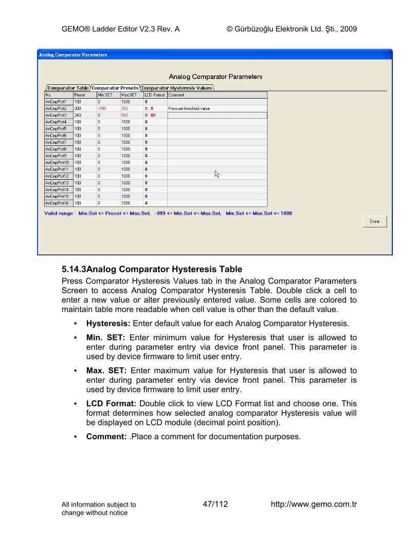
5.14.2Analog Comparator Presets TablePress Comparator Presets tab in the Analog Comparator Parameters Screen to access Analog Comparator Presets Table. Double click a cell to enter a new value or alter previously entered value. Some cells are colored to maintain table more readable when cell value is other than the default value.
• Preset: Enter default Preset value for each Analog Comparator Preset.
• Min. SET: Enter minimum value for Preset that user is allowed to enter during parameter entry via device front panel. This parameter is used by device firmware to limit user entry.
• Max. SET: Enter maximum value for Preset that user is allowed to enter during parameter entry via device front panel. This parameter is used by device firmware to limit user entry.
• LCD Format: Double click to view LCD Format list and choose one. This format determines how selected analog comparator Preset value will be displayed on LCD module (decimal point position).
• Comment: .Place a comment for documentation purposes.
All information subject to 46/112 http://www.gemo.com.trchange without notice
GEMO® Ladder Editor V2.3 Rev. A © Gürbüzoğlu Elektronik Ltd. Şti., 2009
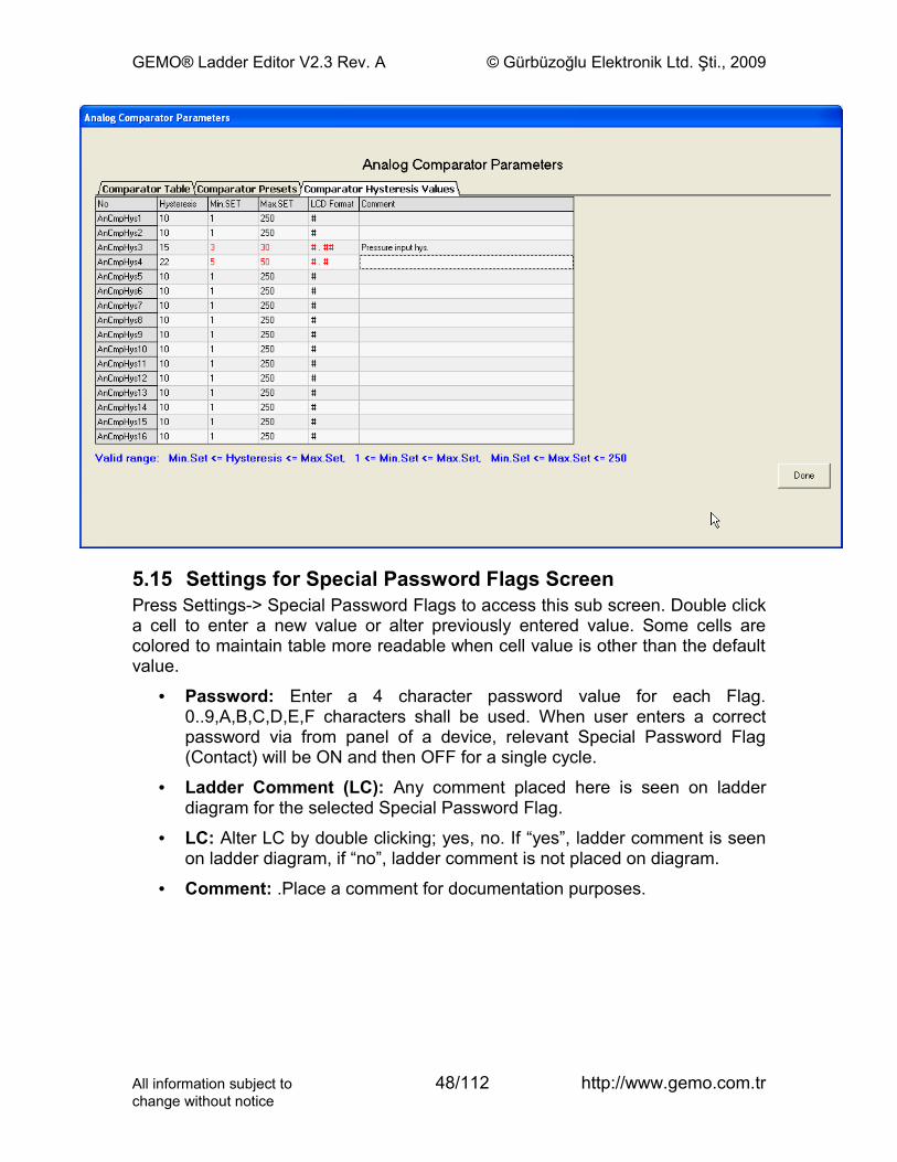
5.14.3Analog Comparator Hysteresis TablePress Comparator Hysteresis Values tab in the Analog Comparator Parameters Screen to access Analog Comparator Hysteresis Table. Double click a cell to enter a new value or alter previously entered value. Some cells are colored to maintain table more readable when cell value is other than the default value.
• Hysteresis: Enter default value for each Analog Comparator Hysteresis.
• Min. SET: Enter minimum value for Hysteresis that user is allowed to enter during parameter entry via device front panel. This parameter is used by device firmware to limit user entry.
• Max. SET: Enter maximum value for Hysteresis that user is allowed to enter during parameter entry via device front panel. This parameter is used by device firmware to limit user entry.
• LCD Format: Double click to view LCD Format list and choose one. This format determines how selected analog comparator Hysteresis value will be displayed on LCD module (decimal point position).
• Comment: .Place a comment for documentation purposes.
All information subject to 47/112 http://www.gemo.com.trchange without notice
GEMO® Ladder Editor V2.3 Rev. A © Gürbüzoğlu Elektronik Ltd. Şti., 2009
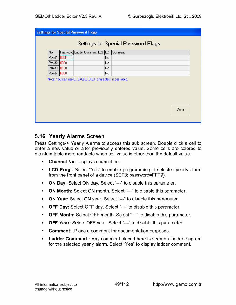
5.15 Settings for Special Password Flags ScreenPress Settings-> Special Password Flags to access this sub screen. Double click a cell to enter a new value or alter previously entered value. Some cells are colored to maintain table more readable when cell value is other than the default value.
• Password: Enter a 4 character password value for each Flag. 0..9,A,B,C,D,E,F characters shall be used. When user enters a correct password via from panel of a device, relevant Special Password Flag (Contact) will be ON and then OFF for a single cycle.
• Ladder Comment (LC): Any comment placed here is seen on ladder diagram for the selected Special Password Flag.
• LC: Alter LC by double clicking; yes, no. If “yes”, ladder comment is seen on ladder diagram, if “no”, ladder comment is not placed on diagram.
• Comment: .Place a comment for documentation purposes.
All information subject to 48/112 http://www.gemo.com.trchange without notice
GEMO® Ladder Editor V2.3 Rev. A © Gürbüzoğlu Elektronik Ltd. Şti., 2009
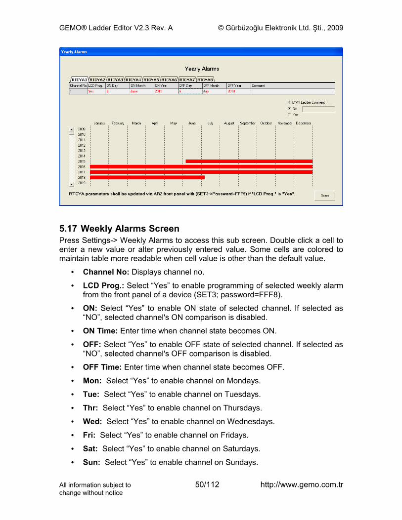
5.16 Yearly Alarms ScreenPress Settings-> Yearly Alarms to access this sub screen. Double click a cell to enter a new value or alter previously entered value. Some cells are colored to maintain table more readable when cell value is other than the default value.
• Channel No: Displays channel no.
• LCD Prog.: Select “Yes” to enable programming of selected yearly alarm from the front panel of a device (SET3; password=FFF9).
• ON Day: Select ON day. Select “---” to disable this parameter.
• ON Month: Select ON month. Select “---” to disable this parameter.
• ON Year: Select ON year. Select “---” to disable this parameter.
• OFF Day: Select OFF day. Select “---” to disable this parameter.
• OFF Month: Select OFF month. Select “---” to disable this parameter.
• OFF Year: Select OFF year. Select “---” to disable this parameter.
• Comment: .Place a comment for documentation purposes.
• Ladder Comment : Any comment placed here is seen on ladder diagram for the selected yearly alarm. Select “Yes” to display ladder comment.
All information subject to 49/112 http://www.gemo.com.trchange without notice
GEMO® Ladder Editor V2.3 Rev. A © Gürbüzoğlu Elektronik Ltd. Şti., 2009
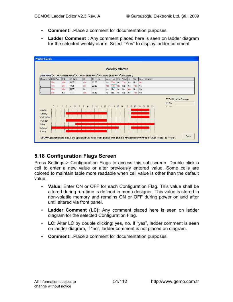
5.17 Weekly Alarms ScreenPress Settings-> Weekly Alarms to access this sub screen. Double click a cell to enter a new value or alter previously entered value. Some cells are colored to maintain table more readable when cell value is other than the default value.
• Channel No: Displays channel no.
• LCD Prog.: Select “Yes” to enable programming of selected weekly alarm from the front panel of a device (SET3; password=FFF8).
• ON: Select “Yes” to enable ON state of selected channel. If selected as “NO”, selected channel's ON comparison is disabled.
• ON Time: Enter time when channel state becomes ON.
• OFF: Select “Yes” to enable OFF state of selected channel. If selected as “NO”, selected channel's OFF comparison is disabled.
• OFF Time: Enter time when channel state becomes OFF.
• Mon: Select “Yes” to enable channel on Mondays.
• Tue: Select “Yes” to enable channel on Tuesdays.
• Thr: Select “Yes” to enable channel on Thursdays.
• Wed: Select “Yes” to enable channel on Wednesdays.
• Fri: Select “Yes” to enable channel on Fridays.
• Sat: Select “Yes” to enable channel on Saturdays.
• Sun: Select “Yes” to enable channel on Sundays.
All information subject to 50/112 http://www.gemo.com.trchange without notice
GEMO® Ladder Editor V2.3 Rev. A © Gürbüzoğlu Elektronik Ltd. Şti., 2009
• Comment: .Place a comment for documentation purposes.
• Ladder Comment : Any comment placed here is seen on ladder diagram for the selected weekly alarm. Select “Yes” to display ladder comment.
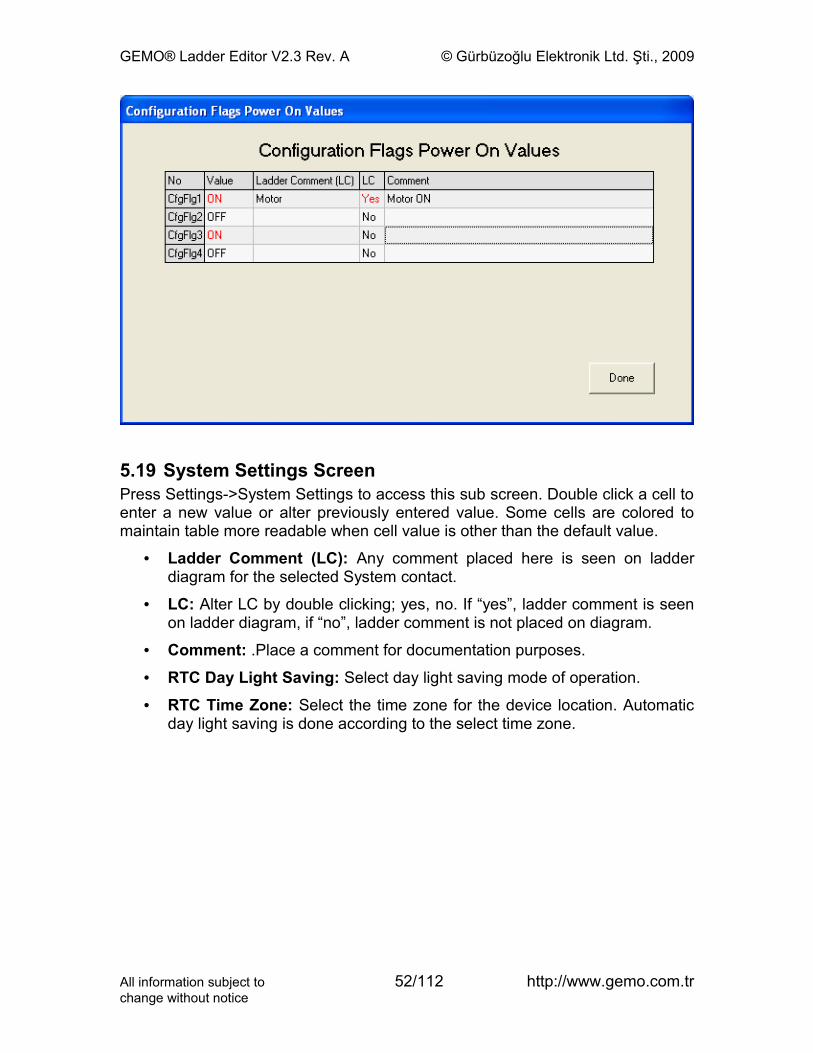
5.18 Configuration Flags ScreenPress Settings-> Configuration Flags to access this sub screen. Double click a cell to enter a new value or alter previously entered value. Some cells are colored to maintain table more readable when cell value is other than the default value.
• Value: Enter ON or OFF for each Configuration Flag. This value shall be altered during run-time is defined in menu designer. This value is stored in non-volatile memory and remains ON or OFF during power on and after until altered via front panel.
• Ladder Comment (LC): Any comment placed here is seen on ladder diagram for the selected Configuration Flag.
• LC: Alter LC by double clicking; yes, no. If “yes”, ladder comment is seen on ladder diagram, if “no”, ladder comment is not placed on diagram.
• Comment: .Place a comment for documentation purposes.
All information subject to 51/112 http://www.gemo.com.trchange without notice
GEMO® Ladder Editor V2.3 Rev. A © Gürbüzoğlu Elektronik Ltd. Şti., 2009
5.19 System Settings ScreenPress Settings->System Settings to access this sub screen. Double click a cell to enter a new value or alter previously entered value. Some cells are colored to maintain table more readable when cell value is other than the default value.
• Ladder Comment (LC): Any comment placed here is seen on ladder diagram for the selected System contact.
• LC: Alter LC by double clicking; yes, no. If “yes”, ladder comment is seen on ladder diagram, if “no”, ladder comment is not placed on diagram.
• Comment: .Place a comment for documentation purposes.
• RTC Day Light Saving: Select day light saving mode of operation.
• RTC Time Zone: Select the time zone for the device location. Automatic day light saving is done according to the select time zone.
All information subject to 52/112 http://www.gemo.com.trchange without notice
GEMO® Ladder Editor V2.3 Rev. A © Gürbüzoğlu Elektronik Ltd. Şti., 2009
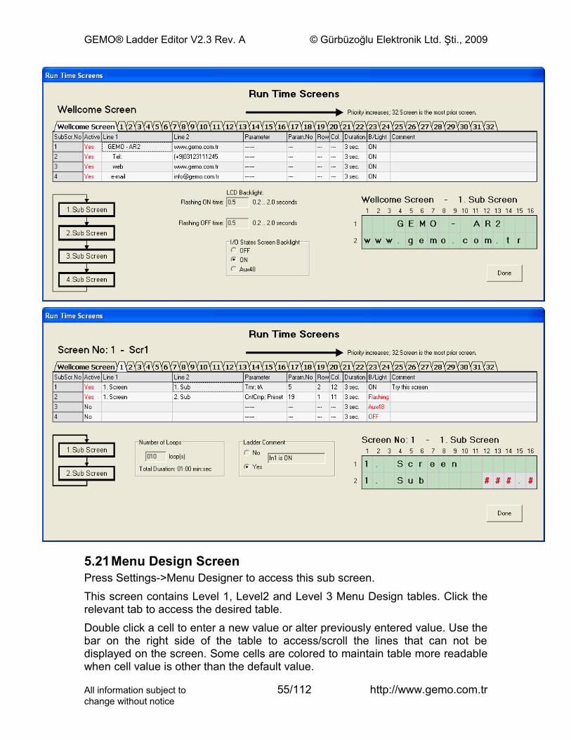
5.20Run Time Screens ScreenPress Settings->Run Time Screens to access this sub screen. This screen contains Welcome Screen Table and Tables of 1...32.Screens. Press the relevant tab to access tables.Double click a cell to enter a new value or alter previously entered value. Some cells are colored to maintain table more readable when cell value is other than the default value.Below the Welcome Screen Table;
• Flashing ON Time: Backlight is ON for this duration and then OFF, ff selected sub screen’s backlight is selected as flashing.
• Flashing OFF Time: Backlight is OFF for this duration and then ON, if selected sub screen’s backlight is selected as flashing.
• I/O States Screen Backlight: Select backlight status (type) when active screen is I/O States Screen.
Below tables of 1…32.Screens;
• Number of Loops: Timed screens loops entry times and then disappears. Time required to loop all is displayed blow the entry.
All information subject to 53/112 http://www.gemo.com.trchange without notice
GEMO® Ladder Editor V2.3 Rev. A © Gürbüzoğlu Elektronik Ltd. Şti., 2009
• Ladder Comment (LC): Any comment placed here is seen on ladder diagram for the selected Screen. Click yes to activate comment.
Tables of 1…32.Screens;
• Active: Double click to toggle Yes/No. Only active sub screens are displayed on LCD.
• Line 1: Upper line (16 characters) of selected sub screen.
• Line 2: Lower line (16 characters) of selected sub screen.
• Parameter: Double click to view a list of parameters and select one to display its real time value, located in the selected sub screen. Not valid for Welcome Screen.
• Parameter: Double click to view a list of numbers and select one for the selected parameter to display its real time value, located in the selected sub screen. Not valid for Welcome Screen.
• Row: Double click to view a list of row numbers and select one for the selected parameter to locate in the selected sub screen. Not valid for Welcome Screen.
• Col.: Double click to view a list of column numbers and select one for the selected parameter to locate in the selected sub screen. Not valid for Welcome Screen.
• Duration: Double click to enter duration in seconds that the selected sub screen will appear on LCD before following sub screen.
• B/Light: Double click to view a list and select one for the status of backlight for the selected sub screen.
• Comment: .Place a comment for documentation purposes.
To view the exact image of a sub screens that will appear on LCD is simulated on the LCD image on lower right side of the screen. Click on a row and view its image on LCD.
All information subject to 54/112 http://www.gemo.com.trchange without notice
GEMO® Ladder Editor V2.3 Rev. A © Gürbüzoğlu Elektronik Ltd. Şti., 2009
5.21Menu Design ScreenPress Settings->Menu Designer to access this sub screen. This screen contains Level 1, Level2 and Level 3 Menu Design tables. Click the relevant tab to access the desired table.Double click a cell to enter a new value or alter previously entered value. Use the bar on the right side of the table to access/scroll the lines that can not be displayed on the screen. Some cells are colored to maintain table more readable when cell value is other than the default value.
All information subject to 55/112 http://www.gemo.com.trchange without notice
GEMO® Ladder Editor V2.3 Rev. A © Gürbüzoğlu Elektronik Ltd. Şti., 2009
Menu design has a 3 level structure. Each level is separate and independent from others. Each level is activated by SET1, SET2 and SET3 keys located on the front Panel of device.For each level, separate password protection and parameter set can be designed via Menu Design Tables.Password table;
• Password Active: Double click to toggle Yes/No. Selected level is password protected if set to Yes and a password entry screen is displayed before parameter entry screens.
• Line 1: Upper line (16 characters) of password entry screen for the selected level.
• Line 2: Lower line (16 characters) of password entry screen for the selected level.
• Password: Double click to enter the password for the selected level. 0...9, A,B,C,D,E,F are defined for password string. A password is always required for Level 3.
• Row: Double click to select the row to locate the password string on the LCD.
• Col.: Double click to select the column to locate the password string on the LCD.
Parameter table;
• Line 1: Upper line (16 characters) for the selected parameter entry screen at the selected level.
• Line 2: Lower line (16 characters) for the selected parameter entry screen at the selected level.
• Parameter: Double click to select a parameter type.
• Param.No: Double click to select a parameter number.
• Row: Double click to select the row to locate the parameter on the LCD.
• Col.: Double click to select the column to locate the parameter on the LCD.
• Comment: .Place a comment for documentation purposes.It is possible to add/delete row(s) to/from Parameter Table. Double click Seq.No (sequence no) cell of relevant row and view the following command set and choose appropriate one;
• Insert Line: .Inserts a new row before the selected line. Following lines shifted one row down.
• Delete Line: .Deletes selected line. Following lines shifted one row up.
All information subject to 56/112 http://www.gemo.com.trchange without notice
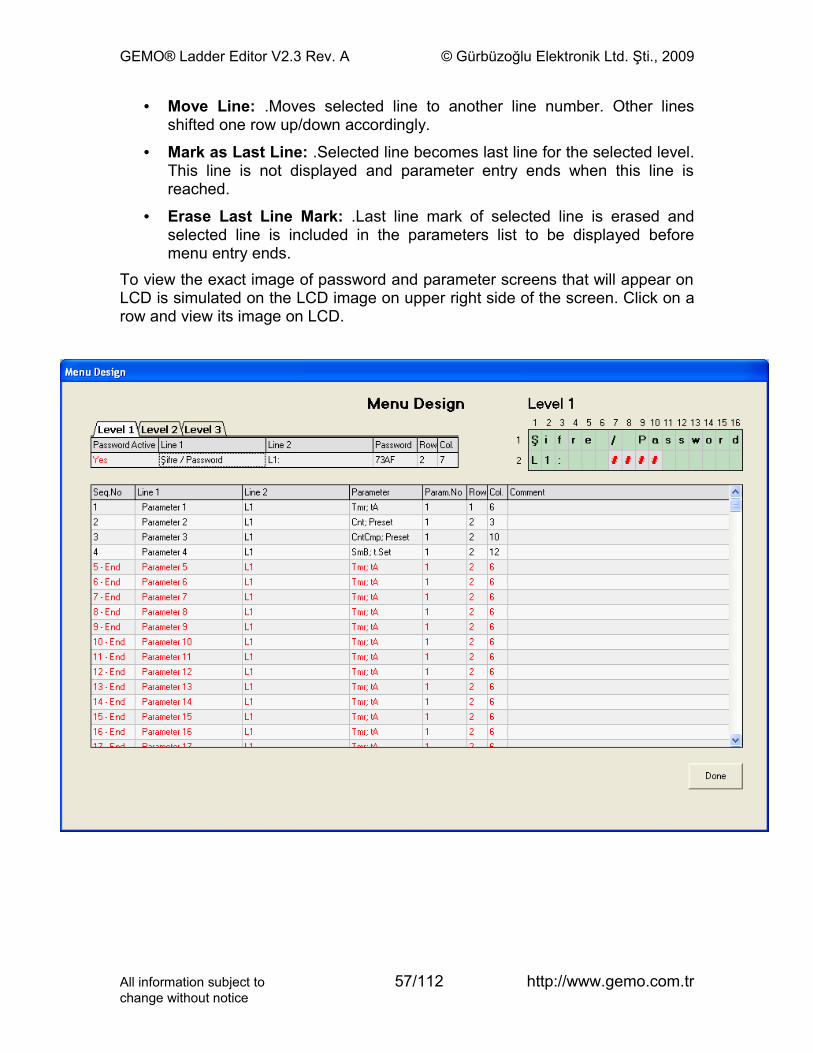
GEMO® Ladder Editor V2.3 Rev. A © Gürbüzoğlu Elektronik Ltd. Şti., 2009
• Move Line: .Moves selected line to another line number. Other lines shifted one row up/down accordingly.
• Mark as Last Line: .Selected line becomes last line for the selected level. This line is not displayed and parameter entry ends when this line is reached.
• Erase Last Line Mark: .Last line mark of selected line is erased and selected line is included in the parameters list to be displayed before menu entry ends.
To view the exact image of password and parameter screens that will appear on LCD is simulated on the LCD image on upper right side of the screen. Click on a row and view its image on LCD.
All information subject to 57/112 http://www.gemo.com.trchange without notice
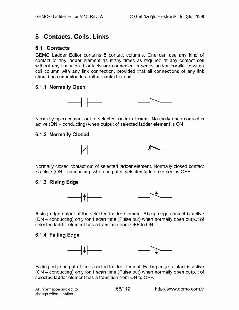
GEMO® Ladder Editor V2.3 Rev. A © Gürbüzoğlu Elektronik Ltd. Şti., 2009
6 Contacts, Coils, Links
6.1 ContactsGEMO Ladder Editor contains 5 contact columns. One can use any kind of contact of any ladder element as many times as required at any contact cell without any limitation. Contacts are connected in series and/or parallel towards coil column with any link connection, provided that all connections of any link should be connected to another contact or coil.
6.1.1 Normally Open
Normally open contact out of selected ladder element. Normally open contact is active (ON – conducting) when output of selected ladder element is ON
6.1.2 Normally Closed
Normally closed contact out of selected ladder element. Normally closed contact is active (ON – conducting) when output of selected ladder element is OFF
6.1.3 Rising Edge
Rising edge output of the selected ladder element. Rising edge contact is active (ON – conducting) only for 1 scan time (Pulse out) when normally open output of selected ladder element has a transition from OFF to ON.
6.1.4 Falling Edge
Falling edge output of the selected ladder element. Falling edge contact is active (ON – conducting) only for 1 scan time (Pulse out) when normally open output of selected ladder element has a transition from ON to OFF.
All information subject to 58/112 http://www.gemo.com.trchange without notice
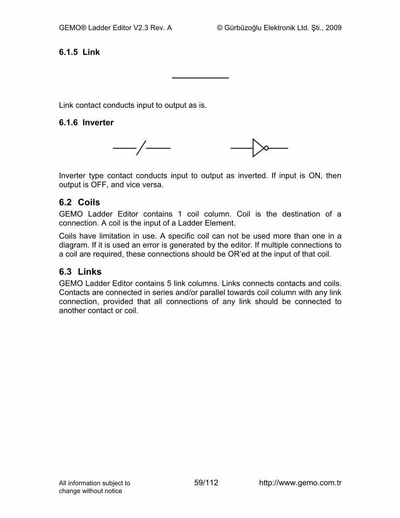
GEMO® Ladder Editor V2.3 Rev. A © Gürbüzoğlu Elektronik Ltd. Şti., 2009
6.1.5 Link
Link contact conducts input to output as is.
6.1.6 Inverter
Inverter type contact conducts input to output as inverted. If input is ON, then output is OFF, and vice versa.
6.2 CoilsGEMO Ladder Editor contains 1 coil column. Coil is the destination of a connection. A coil is the input of a Ladder Element.Coils have limitation in use. A specific coil can not be used more than one in a diagram. If it is used an error is generated by the editor. If multiple connections to a coil are required, these connections should be OR’ed at the input of that coil.
6.3 LinksGEMO Ladder Editor contains 5 link columns. Links connects contacts and coils. Contacts are connected in series and/or parallel towards coil column with any link connection, provided that all connections of any link should be connected to another contact or coil.
All information subject to 59/112 http://www.gemo.com.trchange without notice
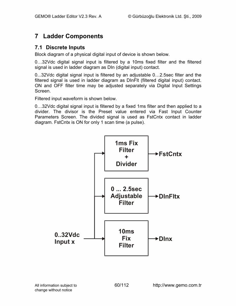
GEMO® Ladder Editor V2.3 Rev. A © Gürbüzoğlu Elektronik Ltd. Şti., 2009
7 Ladder Components
7.1 Discrete InputsBlock diagram of a physical digital input of device is shown below.0…32Vdc digital signal input is filtered by a 10ms fixed filter and the filtered signal is used in ladder diagram as DIn (digital input) contact.0...32Vdc digital signal input is filtered by an adjustable 0…2.5sec filter and the filtered signal is used in ladder diagram as DInFlt (filtered digital input) contact. ON and OFF filter time may be adjusted separately via Digital Input Settings Screen. Filtered input waveform is shown below.0…32Vdc digital signal input is filtered by a fixed 1ms filter and then applied to a divider. The divisor is the Preset value entered via Fast Input Counter Parameters Screen. The divided signal is used as FstCntx contact in ladder diagram. FstCntx is ON for only 1 scan time (a pulse).
0 x
..32VdcInput
0
Filter
... 2.5secAdjustable
1ms Filter
Fix
+Divider
1 msFix0
Filter
DInFltx
FstCntx
DInx
All information subject to 60/112 http://www.gemo.com.trchange without notice
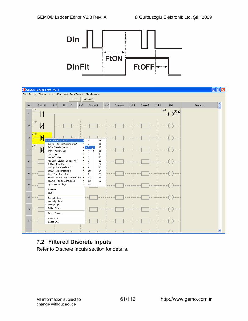
GEMO® Ladder Editor V2.3 Rev. A © Gürbüzoğlu Elektronik Ltd. Şti., 2009
FtONFtOFFDInFlt
DIn
7.2 Filtered Discrete InputsRefer to Discrete Inputs section for details.
All information subject to 61/112 http://www.gemo.com.trchange without notice
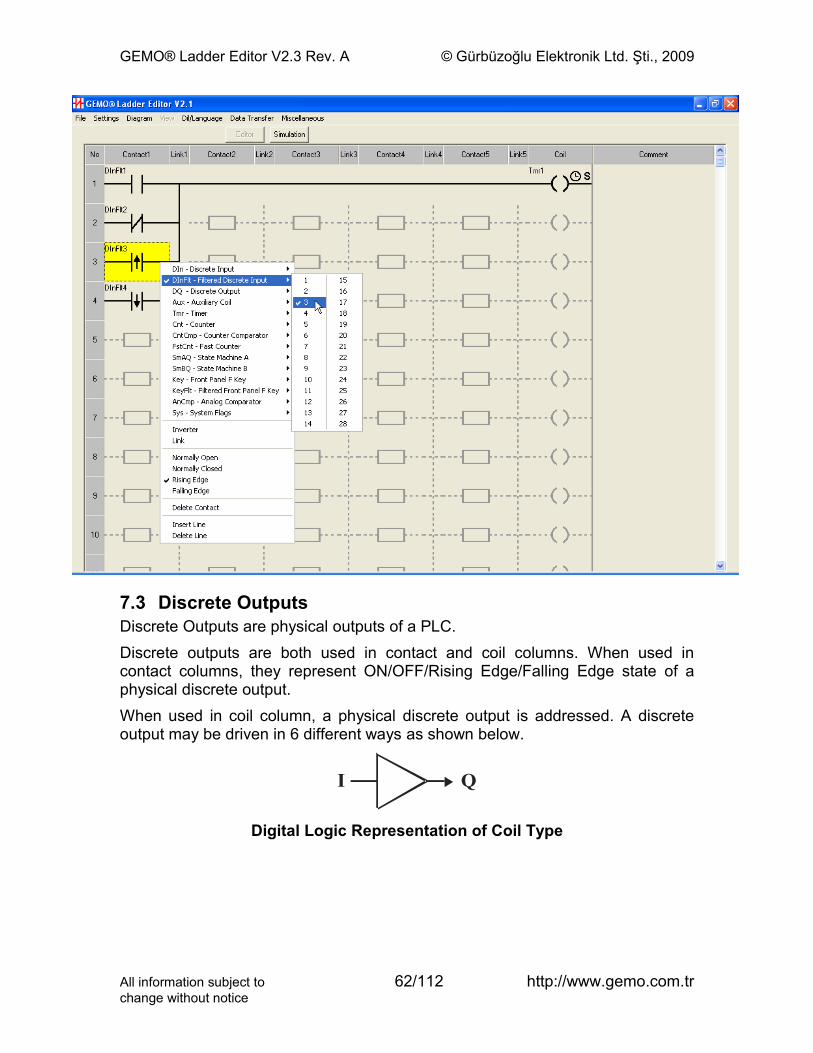
GEMO® Ladder Editor V2.3 Rev. A © Gürbüzoğlu Elektronik Ltd. Şti., 2009
7.3 Discrete OutputsDiscrete Outputs are physical outputs of a PLC.Discrete outputs are both used in contact and coil columns. When used in contact columns, they represent ON/OFF/Rising Edge/Falling Edge state of a physical discrete output.When used in coil column, a physical discrete output is addressed. A discrete output may be driven in 6 different ways as shown below.
I Q
Digital Logic Representation of Coil Type
All information subject to 62/112 http://www.gemo.com.trchange without notice
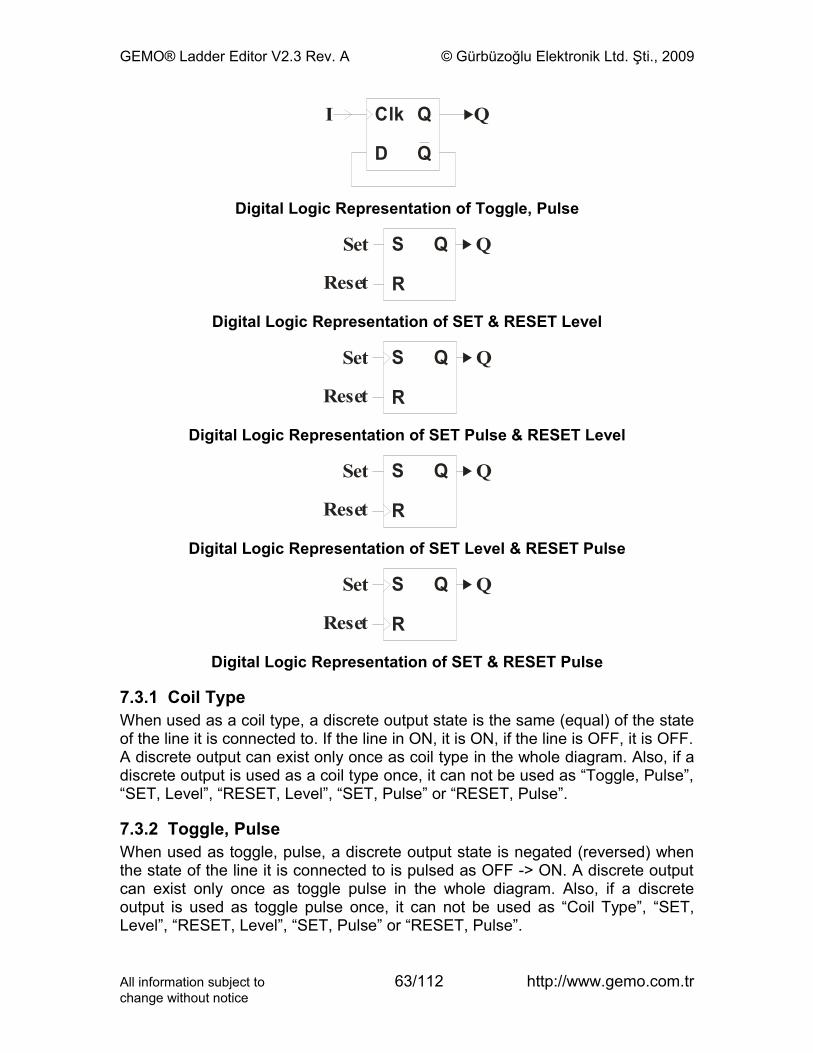
GEMO® Ladder Editor V2.3 Rev. A © Gürbüzoğlu Elektronik Ltd. Şti., 2009
Q
Q
ClkI Q
D
Digital Logic Representation of Toggle, Pulse
QSSet
Reset
Q
R
Digital Logic Representation of SET & RESET Level
QSSet
Reset
Q
R
Digital Logic Representation of SET Pulse & RESET Level
QSSet
Reset
Q
R
Digital Logic Representation of SET Level & RESET Pulse
QSSet
Reset
Q
R
Digital Logic Representation of SET & RESET Pulse
7.3.1 Coil TypeWhen used as a coil type, a discrete output state is the same (equal) of the state of the line it is connected to. If the line in ON, it is ON, if the line is OFF, it is OFF. A discrete output can exist only once as coil type in the whole diagram. Also, if a discrete output is used as a coil type once, it can not be used as “Toggle, Pulse”, “SET, Level”, “RESET, Level”, “SET, Pulse” or “RESET, Pulse”.
7.3.2 Toggle, PulseWhen used as toggle, pulse, a discrete output state is negated (reversed) when the state of the line it is connected to is pulsed as OFF -> ON. A discrete output can exist only once as toggle pulse in the whole diagram. Also, if a discrete output is used as toggle pulse once, it can not be used as “Coil Type”, “SET, Level”, “RESET, Level”, “SET, Pulse” or “RESET, Pulse”.
All information subject to 63/112 http://www.gemo.com.trchange without notice
GEMO® Ladder Editor V2.3 Rev. A © Gürbüzoğlu Elektronik Ltd. Şti., 2009
7.3.3 SET, LevelWhen used as SET, level, a discrete output state becomes ON when the state of the line it is connected to is ON and remains ON even if the state of the line becomes OFF. In order make the output OFF, a valid RESET signal should be applied to discrete output’s RESET input. Therefore, if a discrete output has a SET level input, it should have a “RESET Level” or “RESET Pulse” type input.A discrete output can exist only once as SET level in the whole diagram. Also, if a discrete output is used as SET Level once, it can not be used as “Coil Type”, “Toggle, Pulse” or “SET, Pulse”.
7.3.4 RESET, LevelWhen used as RESET, level, a discrete output state becomes OFF when the state of the line it is connected to is ON. In order make the output ON, a valid SET signal should be applied to discrete output’s SET input. Therefore, if a discrete output has a RESET level input, it should have a “SET Level” or “SET Pulse” type input.A discrete output can exist only once as RESET level in the whole diagram. Also, if a discrete output is used as RESET Level once, it can not be used as “Coil Type”, “Toggle, Pulse” or “RESET, Pulse”.
7.3.5 SET, PulseWhen used as SET, Pulse, a discrete output state becomes ON when the state of the line it is connected to is pulsed (OFF->ON) and remains ON even if the state of the line becomes OFF. In order make the output OFF, a valid RESET signal should be applied to discrete output’s RESET input. Therefore, if a discrete output has a SET pulse input, it should have a “RESET Level” or “RESET Pulse” type input.A discrete output can exist only once as SET pulse in the whole diagram. Also, if a discrete output is used as SET Pulse once, it can not be used as “Coil Type”, “Toggle, Pulse” or “SET, Level”.
7.3.6 RESET, PulseWhen used as RESET, Pulse, a discrete output state becomes OFF when the state of the line it is connected to is pulsed (OFF->ON). In order make the output ON, a valid SET signal should be applied to discrete output’s SET input. Therefore, if a discrete output has a RESET pulse input, it should have a “SET Level” or “SET Pulse” type input.A discrete output can exist only once as RESET Pulse in the whole diagram. Also, if a discrete output is used as RESET Pulse once, it can not be used as “Coil Type”, “Toggle, Pulse” or “RESET, Level”.
All information subject to 64/112 http://www.gemo.com.trchange without notice
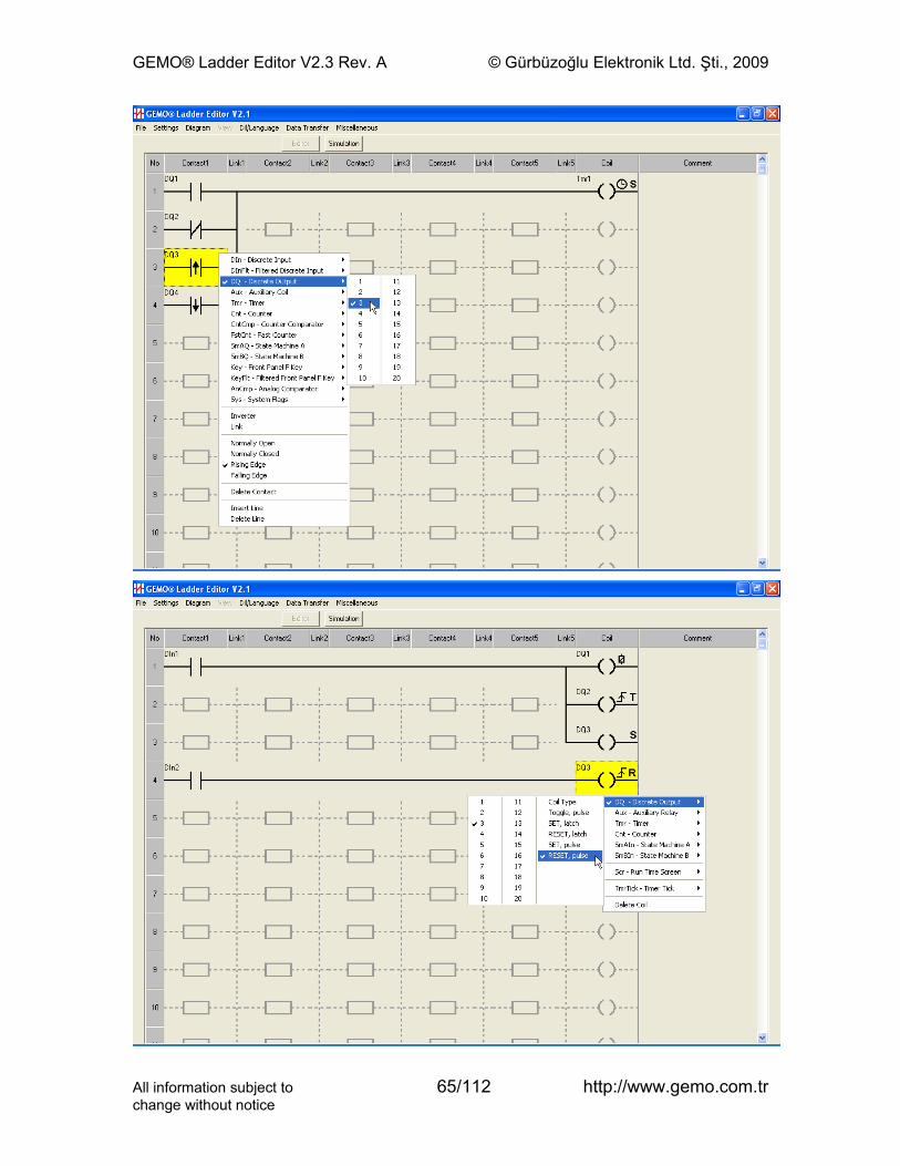
GEMO® Ladder Editor V2.3 Rev. A © Gürbüzoğlu Elektronik Ltd. Şti., 2009
All information subject to 65/112 http://www.gemo.com.trchange without notice
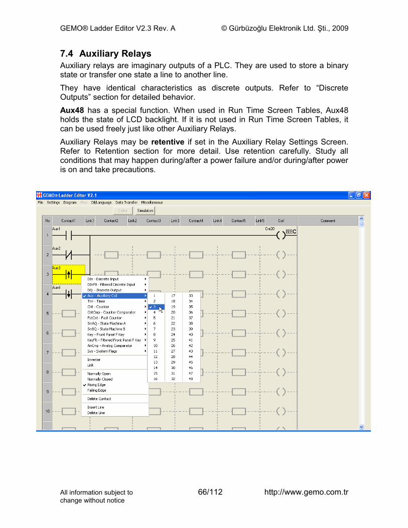
GEMO® Ladder Editor V2.3 Rev. A © Gürbüzoğlu Elektronik Ltd. Şti., 2009
7.4 Auxiliary RelaysAuxiliary relays are imaginary outputs of a PLC. They are used to store a binary state or transfer one state a line to another line.They have identical characteristics as discrete outputs. Refer to “Discrete Outputs” section for detailed behavior.Aux48 has a special function. When used in Run Time Screen Tables, Aux48 holds the state of LCD backlight. If it is not used in Run Time Screen Tables, it can be used freely just like other Auxiliary Relays.Auxiliary Relays may be retentive if set in the Auxiliary Relay Settings Screen. Refer to Retention section for more detail. Use retention carefully. Study all conditions that may happen during/after a power failure and/or during/after power is on and take precautions.
All information subject to 66/112 http://www.gemo.com.trchange without notice
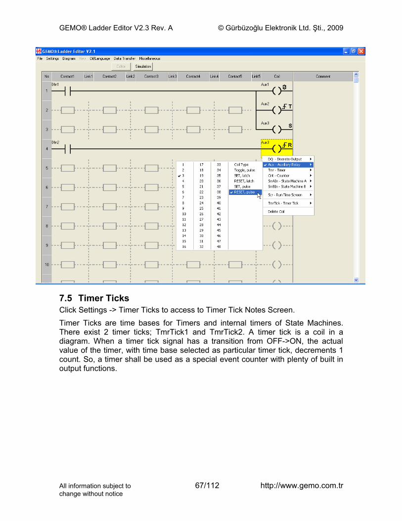
GEMO® Ladder Editor V2.3 Rev. A © Gürbüzoğlu Elektronik Ltd. Şti., 2009
7.5 Timer TicksClick Settings -> Timer Ticks to access to Timer Tick Notes Screen.Timer Ticks are time bases for Timers and internal timers of State Machines. There exist 2 timer ticks; TmrTick1 and TmrTick2. A timer tick is a coil in a diagram. When a timer tick signal has a transition from OFF->ON, the actual value of the timer, with time base selected as particular timer tick, decrements 1 count. So, a timer shall be used as a special event counter with plenty of built in output functions.
All information subject to 67/112 http://www.gemo.com.trchange without notice
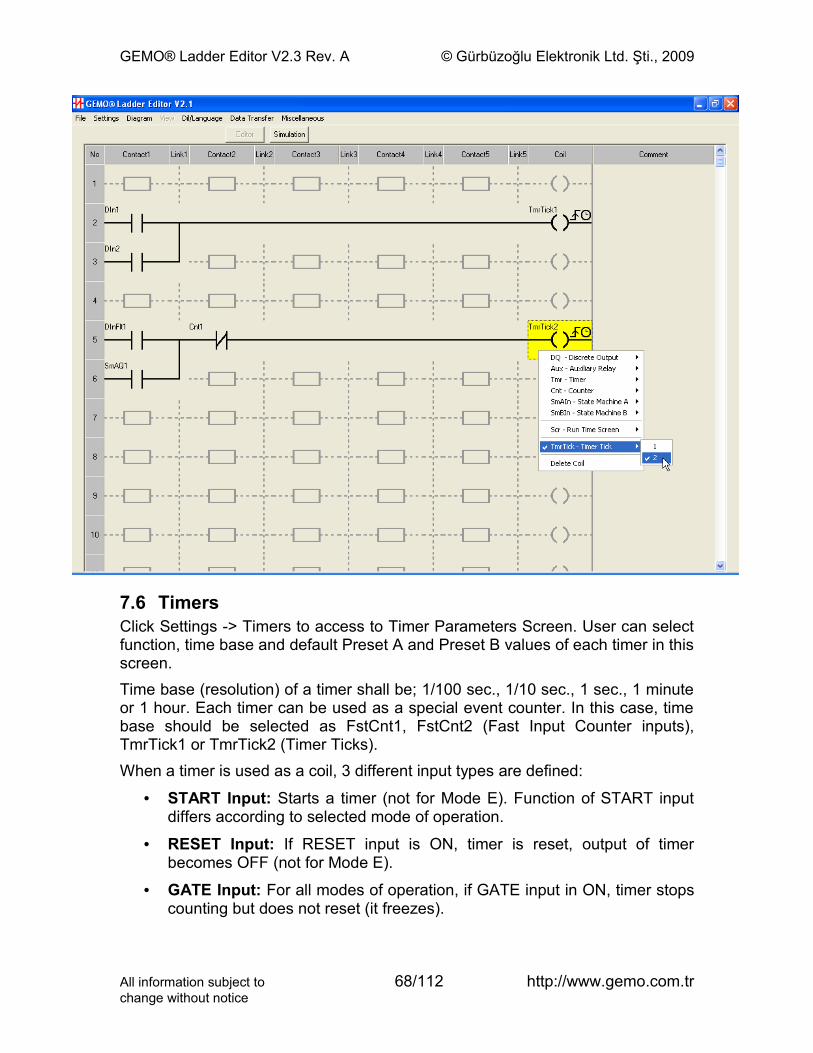
GEMO® Ladder Editor V2.3 Rev. A © Gürbüzoğlu Elektronik Ltd. Şti., 2009
7.6 TimersClick Settings -> Timers to access to Timer Parameters Screen. User can select function, time base and default Preset A and Preset B values of each timer in this screen.Time base (resolution) of a timer shall be; 1/100 sec., 1/10 sec., 1 sec., 1 minute or 1 hour. Each timer can be used as a special event counter. In this case, time base should be selected as FstCnt1, FstCnt2 (Fast Input Counter inputs), TmrTick1 or TmrTick2 (Timer Ticks).When a timer is used as a coil, 3 different input types are defined:
• START Input: Starts a timer (not for Mode E). Function of START input differs according to selected mode of operation.
• RESET Input: If RESET input is ON, timer is reset, output of timer becomes OFF (not for Mode E).
• GATE Input: For all modes of operation, if GATE input in ON, timer stops counting but does not reset (it freezes).
All information subject to 68/112 http://www.gemo.com.trchange without notice
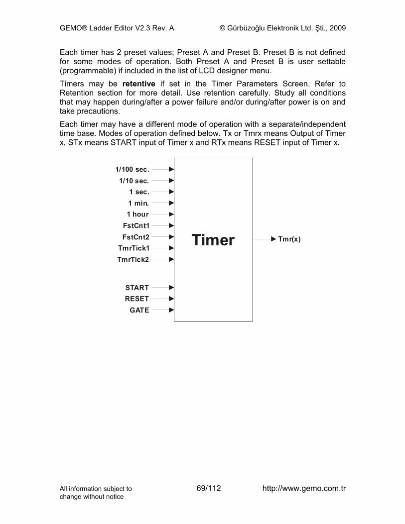
GEMO® Ladder Editor V2.3 Rev. A © Gürbüzoğlu Elektronik Ltd. Şti., 2009
Each timer has 2 preset values; Preset A and Preset B. Preset B is not defined for some modes of operation. Both Preset A and Preset B is user settable (programmable) if included in the list of LCD designer menu.Timers may be retentive if set in the Timer Parameters Screen. Refer to Retention section for more detail. Use retention carefully. Study all conditions that may happen during/after a power failure and/or during/after power is on and take precautions.Each timer may have a different mode of operation with a separate/independent time base. Modes of operation defined below. Tx or Tmrx means Output of Timer x, STx means START input of Timer x and RTx means RESET input of Timer x.
1/100 s .ec1/10 s .ec
1 s .ec1 .min1 hour
Tmr(x)
FstCnt1FstCnt2
TmrTick1TmrTick2
STARTRESET
GATE
Timer
All information subject to 69/112 http://www.gemo.com.trchange without notice
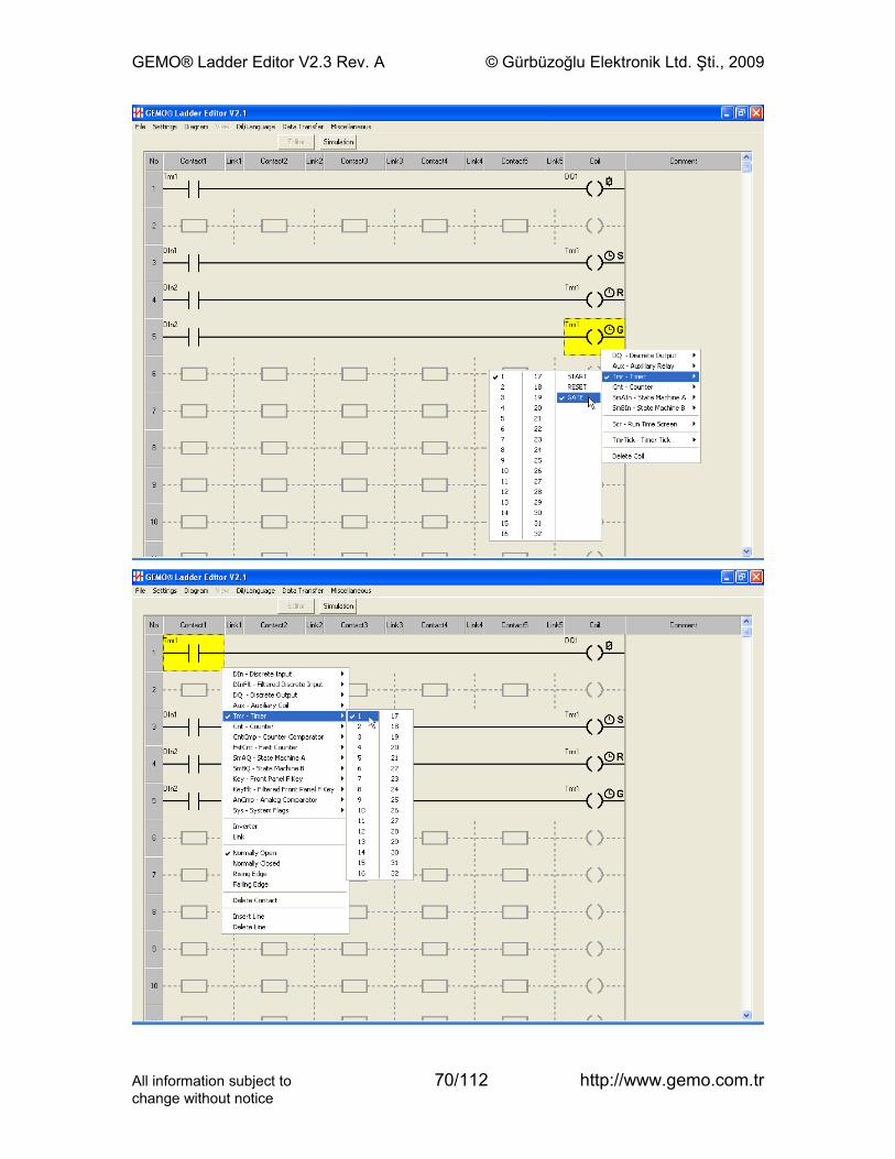
GEMO® Ladder Editor V2.3 Rev. A © Gürbüzoğlu Elektronik Ltd. Şti., 2009
All information subject to 70/112 http://www.gemo.com.trchange without notice
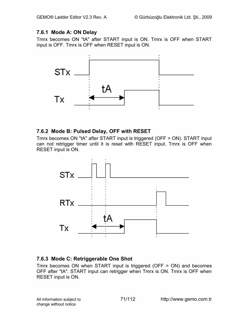
GEMO® Ladder Editor V2.3 Rev. A © Gürbüzoğlu Elektronik Ltd. Şti., 2009
7.6.1 Mode A: ON DelayTmrx becomes ON "tA" after START input is ON. Tmrx is OFF when START input is OFF. Tmrx is OFF when RESET input is ON.
7.6.2 Mode B: Pulsed Delay, OFF with RESETTmrx becomes ON "tA" after START input is triggered (OFF > ON). START input can not retrigger timer until it is reset with RESET input. Tmrx is OFF when RESET input is ON.
7.6.3 Mode C: Retriggerable One ShotTmrx becomes ON when START input is triggered (OFF > ON) and becomes OFF after "tA". START input can retrigger when Tmrx is ON. Tmrx is OFF when RESET input is ON.
All information subject to 71/112 http://www.gemo.com.trchange without notice
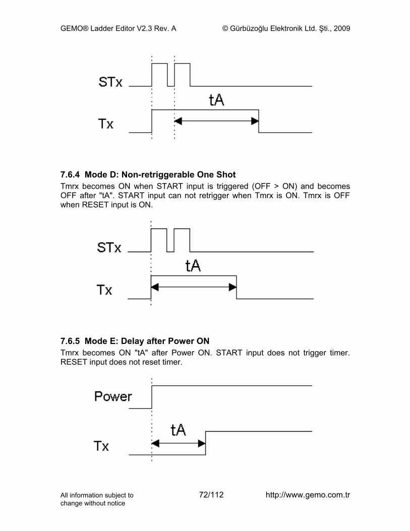
GEMO® Ladder Editor V2.3 Rev. A © Gürbüzoğlu Elektronik Ltd. Şti., 2009
7.6.4 Mode D: Non-retriggerable One ShotTmrx becomes ON when START input is triggered (OFF > ON) and becomes OFF after "tA". START input can not retrigger when Tmrx is ON. Tmrx is OFF when RESET input is ON.
7.6.5 Mode E: Delay after Power ONTmrx becomes ON "tA" after Power ON. START input does not trigger timer. RESET input does not reset timer.
All information subject to 72/112 http://www.gemo.com.trchange without notice
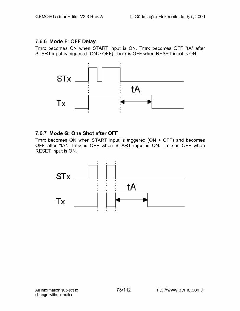
GEMO® Ladder Editor V2.3 Rev. A © Gürbüzoğlu Elektronik Ltd. Şti., 2009
7.6.6 Mode F: OFF DelayTmrx becomes ON when START input is ON. Tmrx becomes OFF "tA" after START input is triggered (ON > OFF). Tmrx is OFF when RESET input is ON.
7.6.7 Mode G: One Shot after OFFTmrx becomes ON when START input is triggered (ON > OFF) and becomes OFF after "tA". Tmrx is OFF when START input is ON. Tmrx is OFF when RESET input is ON.
All information subject to 73/112 http://www.gemo.com.trchange without notice
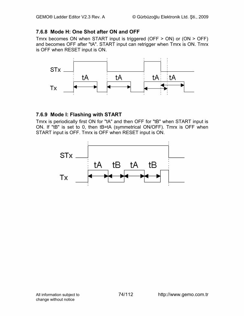
GEMO® Ladder Editor V2.3 Rev. A © Gürbüzoğlu Elektronik Ltd. Şti., 2009
7.6.8 Mode H: One Shot after ON and OFFTmrx becomes ON when START input is triggered (OFF > ON) or (ON > OFF) and becomes OFF after "tA". START input can retrigger when Tmrx is ON. Tmrx is OFF when RESET input is ON.
7.6.9 Mode I: Flashing with STARTTmrx is periodically first ON for "tA" and then OFF for "tB" when START input is ON. If "tB" is set to 0, then tB=tA (symmetrical ON/OFF). Tmrx is OFF when START input is OFF. Tmrx is OFF when RESET input is ON.
All information subject to 74/112 http://www.gemo.com.trchange without notice
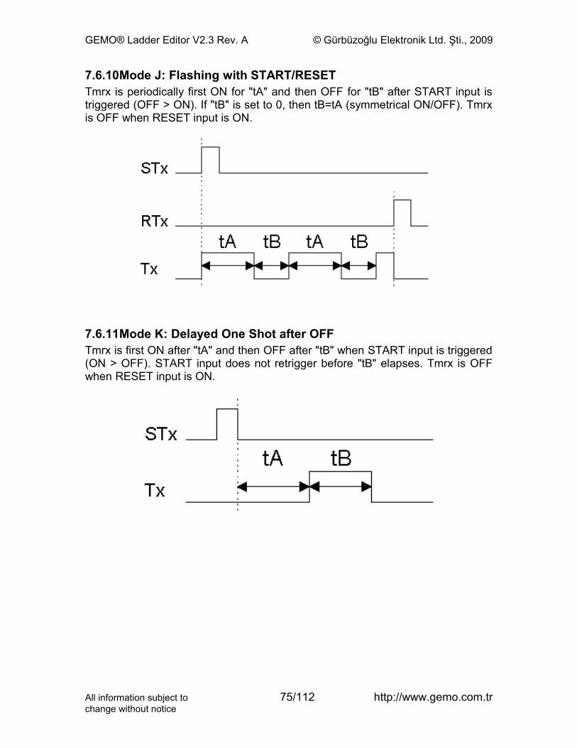
GEMO® Ladder Editor V2.3 Rev. A © Gürbüzoğlu Elektronik Ltd. Şti., 2009
7.6.10Mode J: Flashing with START/RESETTmrx is periodically first ON for "tA" and then OFF for "tB" after START input is triggered (OFF > ON). If "tB" is set to 0, then tB=tA (symmetrical ON/OFF). Tmrx is OFF when RESET input is ON.
7.6.11Mode K: Delayed One Shot after OFFTmrx is first ON after "tA" and then OFF after "tB" when START input is triggered (ON > OFF). START input does not retrigger before "tB" elapses. Tmrx is OFF when RESET input is ON.
All information subject to 75/112 http://www.gemo.com.trchange without notice
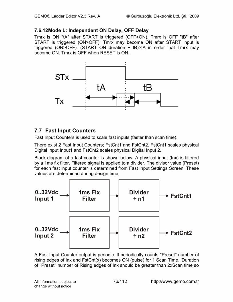
GEMO® Ladder Editor V2.3 Rev. A © Gürbüzoğlu Elektronik Ltd. Şti., 2009
7.6.12Mode L: Independent ON Delay, OFF DelayTmrx is ON "tA" after START is triggered (OFF>ON). Tmrx is OFF "tB" after START is triggered (ON>OFF). Tmrx may become ON after START input is triggered (ON>OFF). (START ON duration + tB)>tA in order that Tmrx may become ON. Tmrx is OFF when RESET is ON.
7.7 Fast Input CountersFast Input Counters is used to scale fast inputs (faster than scan time).There exist 2 Fast Input Counters; FstCnt1 and FstCnt2. FstCnt1 scales physical Digital Input Input1 and FstCnt2 scales physical Digital Input 2.Block diagram of a fast counter is shown below. A physical input (Inx) is filtered by a 1ms fix filter. Filtered signal is applied to a divider. The divisor value (Preset) for each fast input counter is determined from Fast Input Settings Screen. These values are determined during design time.
0
..32VdcInput 1
0 2
..32VdcInput
1ms Filt
Fixer
1ms Filt
Fixer
Divider÷ n1
Divider÷ 2 n
FstCnt1
FstCnt2
A Fast Input Counter output is periodic. It periodically counts ''Preset'' number of rising edges of Inx and FstCnt(x) becomes ON (pulse) for 1 Scan Time. 'Duration of ''Preset'' number of Rising edges of Inx should be greater than 2xScan time so
All information subject to 76/112 http://www.gemo.com.trchange without notice
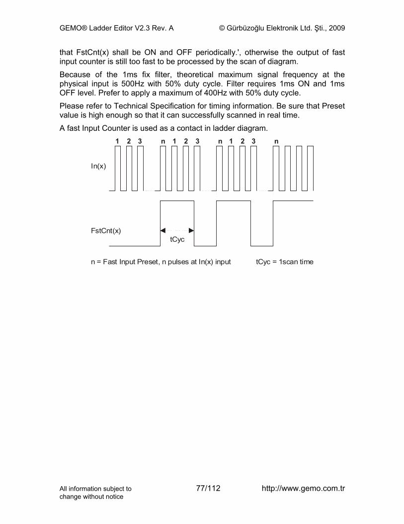
GEMO® Ladder Editor V2.3 Rev. A © Gürbüzoğlu Elektronik Ltd. Şti., 2009
that FstCnt(x) shall be ON and OFF periodically.', otherwise the output of fast input counter is still too fast to be processed by the scan of diagram.Because of the 1ms fix filter, theoretical maximum signal frequency at the physical input is 500Hz with 50% duty cycle. Filter requires 1ms ON and 1ms OFF level. Prefer to apply a maximum of 400Hz with 50% duty cycle.Please refer to Technical Specification for timing information. Be sure that Preset value is high enough so that it can successfully scanned in real time.A fast Input Counter is used as a contact in ladder diagram.
In(x)
tCyc
tCyc = 1scan time
FstCnt(x)
n = Fast Input Preset, n pulses at In(x) input
1 1 12 2 23 3 3n n n
All information subject to 77/112 http://www.gemo.com.trchange without notice
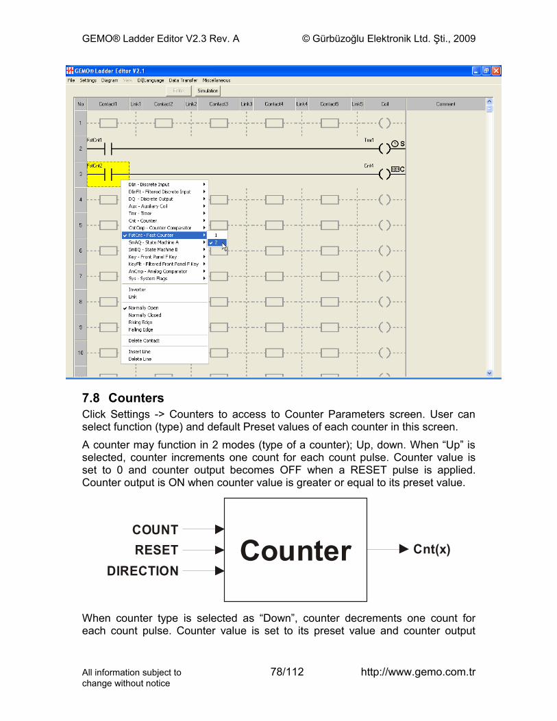
GEMO® Ladder Editor V2.3 Rev. A © Gürbüzoğlu Elektronik Ltd. Şti., 2009
7.8 CountersClick Settings -> Counters to access to Counter Parameters screen. User can select function (type) and default Preset values of each counter in this screen.A counter may function in 2 modes (type of a counter); Up, down. When “Up” is selected, counter increments one count for each count pulse. Counter value is set to 0 and counter output becomes OFF when a RESET pulse is applied. Counter output is ON when counter value is greater or equal to its preset value.
Cnt(x)COUNTR TESE
DIRECTIONCounter
When counter type is selected as “Down”, counter decrements one count for each count pulse. Counter value is set to its preset value and counter output
All information subject to 78/112 http://www.gemo.com.trchange without notice

GEMO® Ladder Editor V2.3 Rev. A © Gürbüzoğlu Elektronik Ltd. Şti., 2009
becomes OFF when a RESET pulse is applied. Counter output is ON when counter value is equal to 0.Each counter is 16 bit (0...65535) wide. A counter does not count below 0. If a count pulse is applied when the counter value is 0 and counting direction is “down”, counter value remains as 0. Similarly, a counter does not count above 65535. If a count pulse is applied when the counter value is 65535 and counting direction is “up”, counter value remains as 65535.When a counter is used as a coil, 3 different input types are defined:
• Count Input: Counter is incremented or decremented one count when this input changes state OFF -> ON.
• Reset Input: When this input is ON, the output of counter is OFF and counter value is set to 0 if type is “Up” or counter value is preset value if type is “Down”.
• Direction Input: When this input is OFF, counter increments if type is “Up” and decrements if type is “Down”. When this input is ON, counter decrements if type is “Up” and increments if type is “Down”. If this input is not used, it is accepted as OFF.
Each counter has a single and unique preset value. Counter preset value is user settable (programmable) if included in the list of LCD menu designer.Each timer may have a different type of operation with a separate and unique preset value.Counters may be retentive if set in the Counter Parameters Screen. Refer to Retention section for more detail. Use retention carefully. Study all conditions that may happen during/after a power failure and/or during/after power is on and take precautions.
Preset
Up Counting Down Counting65535
Reset
0
Output
Direction
All information subject to 79/112 http://www.gemo.com.trchange without notice
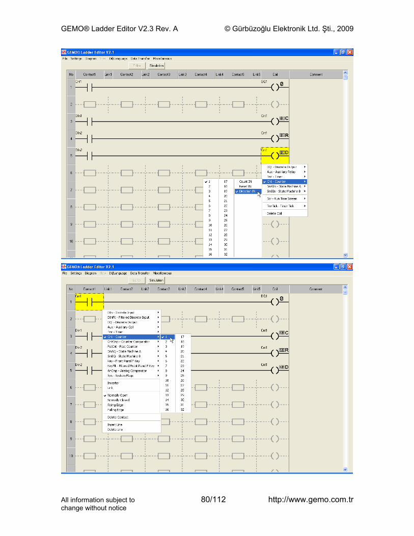
GEMO® Ladder Editor V2.3 Rev. A © Gürbüzoğlu Elektronik Ltd. Şti., 2009
All information subject to 80/112 http://www.gemo.com.trchange without notice
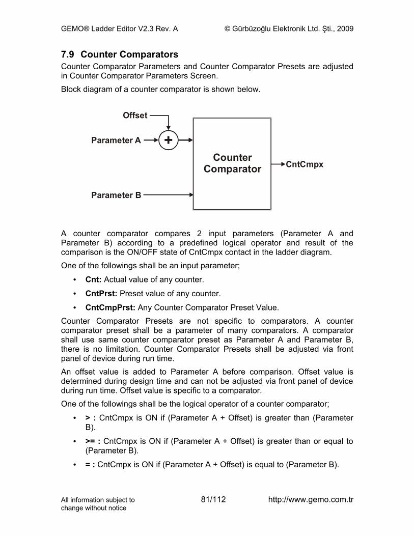
GEMO® Ladder Editor V2.3 Rev. A © Gürbüzoğlu Elektronik Ltd. Şti., 2009
7.9 Counter ComparatorsCounter Comparator Parameters and Counter Comparator Presets are adjusted in Counter Comparator Parameters Screen.Block diagram of a counter comparator is shown below.
Offset
Parameter A
Parameter B
CounterComparator CntCmpx
+
A counter comparator compares 2 input parameters (Parameter A and Parameter B) according to a predefined logical operator and result of the comparison is the ON/OFF state of CntCmpx contact in the ladder diagram.One of the followings shall be an input parameter;
• Cnt: Actual value of any counter.
• CntPrst: Preset value of any counter.
• CntCmpPrst: Any Counter Comparator Preset Value.Counter Comparator Presets are not specific to comparators. A counter comparator preset shall be a parameter of many comparators. A comparator shall use same counter comparator preset as Parameter A and Parameter B, there is no limitation. Counter Comparator Presets shall be adjusted via front panel of device during run time.An offset value is added to Parameter A before comparison. Offset value is determined during design time and can not be adjusted via front panel of device during run time. Offset value is specific to a comparator.One of the followings shall be the logical operator of a counter comparator;
• > : CntCmpx is ON if (Parameter A + Offset) is greater than (Parameter B).
• >= : CntCmpx is ON if (Parameter A + Offset) is greater than or equal to (Parameter B).
• = : CntCmpx is ON if (Parameter A + Offset) is equal to (Parameter B).
All information subject to 81/112 http://www.gemo.com.trchange without notice
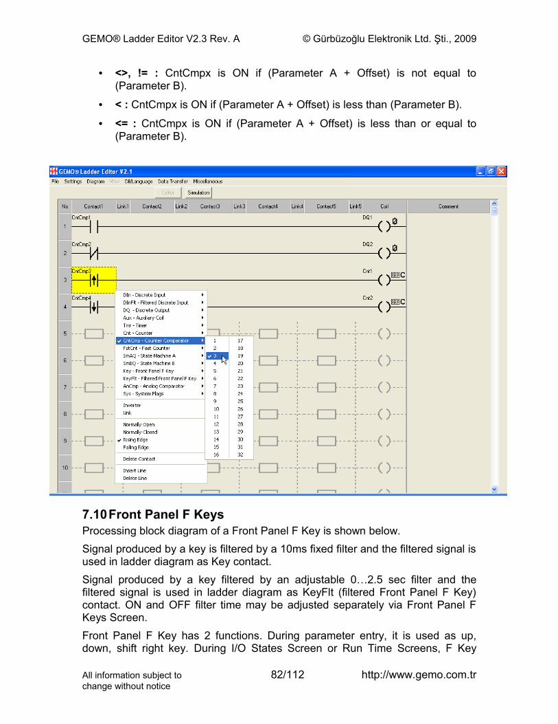
GEMO® Ladder Editor V2.3 Rev. A © Gürbüzoğlu Elektronik Ltd. Şti., 2009
• <>, != : CntCmpx is ON if (Parameter A + Offset) is not equal to (Parameter B).
• < : CntCmpx is ON if (Parameter A + Offset) is less than (Parameter B).
• <= : CntCmpx is ON if (Parameter A + Offset) is less than or equal to (Parameter B).
7.10Front Panel F KeysProcessing block diagram of a Front Panel F Key is shown below.Signal produced by a key is filtered by a 10ms fixed filter and the filtered signal is used in ladder diagram as Key contact.Signal produced by a key filtered by an adjustable 0…2.5 sec filter and the filtered signal is used in ladder diagram as KeyFlt (filtered Front Panel F Key) contact. ON and OFF filter time may be adjusted separately via Front Panel F Keys Screen. Front Panel F Key has 2 functions. During parameter entry, it is used as up, down, shift right key. During I/O States Screen or Run Time Screens, F Key
All information subject to 82/112 http://www.gemo.com.trchange without notice

GEMO® Ladder Editor V2.3 Rev. A © Gürbüzoğlu Elektronik Ltd. Şti., 2009
function is active. During parameter entry, F function is passive and F key reads OFF.Filtered input waveform is shown below.
FrontPanel Fx Key
0
Filter
... 2.5secAdjustable
1 msFix0
Filter
KeyFltx
Keyx
FtONFtOFFKeyFlt
Key
All information subject to 83/112 http://www.gemo.com.trchange without notice
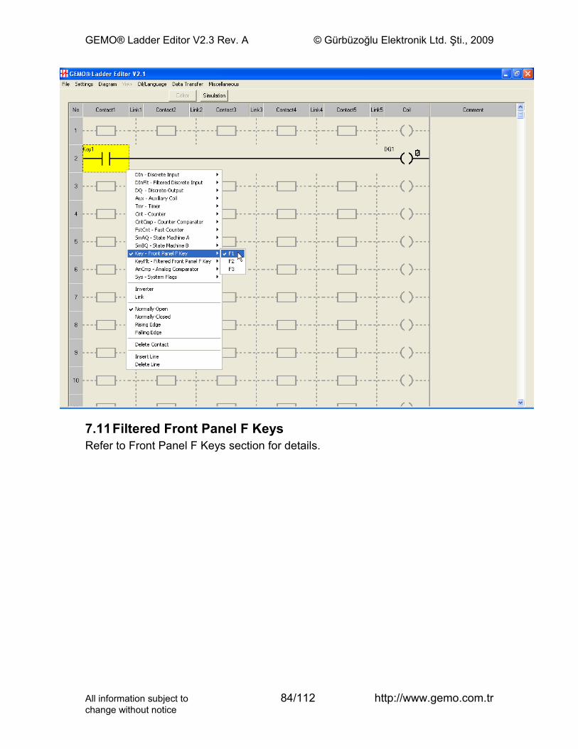
GEMO® Ladder Editor V2.3 Rev. A © Gürbüzoğlu Elektronik Ltd. Şti., 2009
7.11Filtered Front Panel F KeysRefer to Front Panel F Keys section for details.
All information subject to 84/112 http://www.gemo.com.trchange without notice
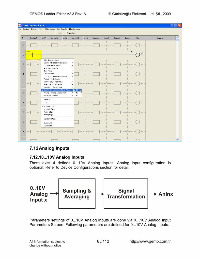
GEMO® Ladder Editor V2.3 Rev. A © Gürbüzoğlu Elektronik Ltd. Şti., 2009
7.12Analog Inputs
7.12.10...10V Analog InputsThere exist 4 defines 0...10V Analog Inputs. Analog input configuration is optional. Refer to Device Configurations section for detail.
0..10VAnalogInput x
Sampling &Averaging
SignalTransformation AnInx
Parameters settings of 0...10V Analog Inputs are done via 0…10V Analog Input Parameters Screen. Following parameters are defined for 0...10V Analog Inputs.
All information subject to 85/112 http://www.gemo.com.trchange without notice
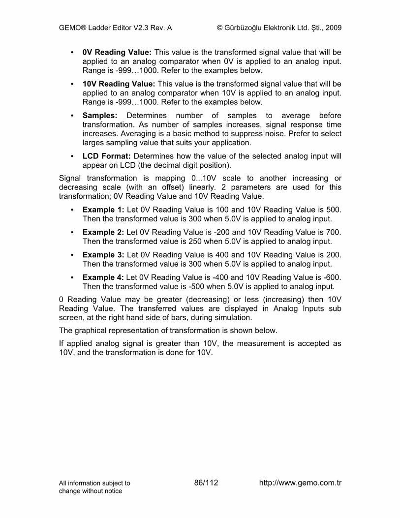
GEMO® Ladder Editor V2.3 Rev. A © Gürbüzoğlu Elektronik Ltd. Şti., 2009
• 0V Reading Value: This value is the transformed signal value that will be applied to an analog comparator when 0V is applied to an analog input. Range is -999…1000. Refer to the examples below.
• 10V Reading Value: This value is the transformed signal value that will be applied to an analog comparator when 10V is applied to an analog input. Range is -999…1000. Refer to the examples below.
• Samples: Determines number of samples to average before transformation. As number of samples increases, signal response time increases. Averaging is a basic method to suppress noise. Prefer to select larges sampling value that suits your application.
• LCD Format: Determines how the value of the selected analog input will appear on LCD (the decimal digit position).
Signal transformation is mapping 0...10V scale to another increasing or decreasing scale (with an offset) linearly. 2 parameters are used for this transformation; 0V Reading Value and 10V Reading Value.
• Example 1: Let 0V Reading Value is 100 and 10V Reading Value is 500. Then the transformed value is 300 when 5.0V is applied to analog input.
• Example 2: Let 0V Reading Value is -200 and 10V Reading Value is 700. Then the transformed value is 250 when 5.0V is applied to analog input.
• Example 3: Let 0V Reading Value is 400 and 10V Reading Value is 200. Then the transformed value is 300 when 5.0V is applied to analog input.
• Example 4: Let 0V Reading Value is -400 and 10V Reading Value is -600. Then the transformed value is -500 when 5.0V is applied to analog input.
0 Reading Value may be greater (decreasing) or less (increasing) then 10V Reading Value. The transferred values are displayed in Analog Inputs sub screen, at the right hand side of bars, during simulation.The graphical representation of transformation is shown below.If applied analog signal is greater than 10V, the measurement is accepted as 10V, and the transformation is done for 10V.
All information subject to 86/112 http://www.gemo.com.trchange without notice
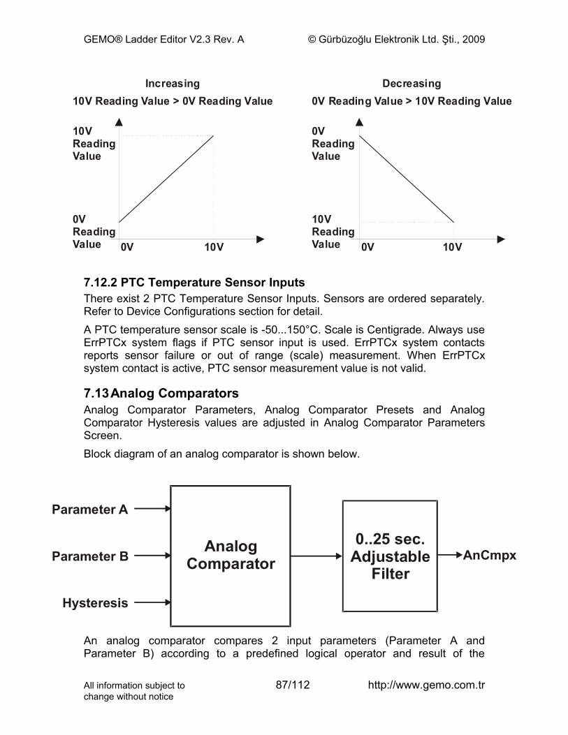
GEMO® Ladder Editor V2.3 Rev. A © Gürbüzoğlu Elektronik Ltd. Şti., 2009
10V 10V0V 0V
0VReadingValue
10VReadingValue
10VReadingValue
Increasing Decreasing
0VReadingValue
0V Reading Value > 10V Reading Value10V Reading Value > 0V Reading Value
7.12.2 PTC Temperature Sensor InputsThere exist 2 PTC Temperature Sensor Inputs. Sensors are ordered separately. Refer to Device Configurations section for detail.A PTC temperature sensor scale is -50...150°C. Scale is Centigrade. Always use ErrPTCx system flags if PTC sensor input is used. ErrPTCx system contacts reports sensor failure or out of range (scale) measurement. When ErrPTCx system contact is active, PTC sensor measurement value is not valid.
7.13Analog ComparatorsAnalog Comparator Parameters, Analog Comparator Presets and Analog Comparator Hysteresis values are adjusted in Analog Comparator Parameters Screen.Block diagram of an analog comparator is shown below.
Hysteresis
Parameter B
Parameter A
AnalogComparator
0..25 sec.Adjustable
FilterAnCmpx
An analog comparator compares 2 input parameters (Parameter A and Parameter B) according to a predefined logical operator and result of the
All information subject to 87/112 http://www.gemo.com.trchange without notice
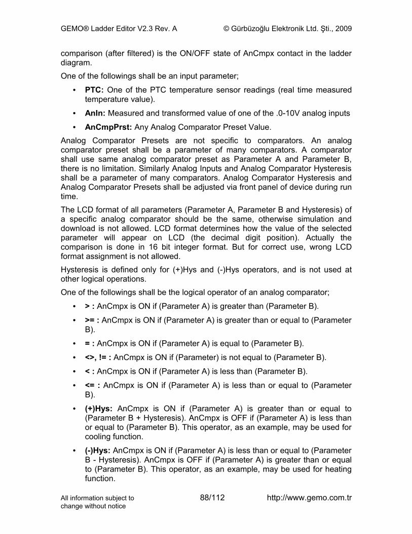
GEMO® Ladder Editor V2.3 Rev. A © Gürbüzoğlu Elektronik Ltd. Şti., 2009
comparison (after filtered) is the ON/OFF state of AnCmpx contact in the ladder diagram.One of the followings shall be an input parameter;
• PTC: One of the PTC temperature sensor readings (real time measured temperature value).
• AnIn: Measured and transformed value of one of the .0-10V analog inputs
• AnCmpPrst: Any Analog Comparator Preset Value.Analog Comparator Presets are not specific to comparators. An analog comparator preset shall be a parameter of many comparators. A comparator shall use same analog comparator preset as Parameter A and Parameter B, there is no limitation. Similarly Analog Inputs and Analog Comparator Hysteresis shall be a parameter of many comparators. Analog Comparator Hysteresis and Analog Comparator Presets shall be adjusted via front panel of device during run time.The LCD format of all parameters (Parameter A, Parameter B and Hysteresis) of a specific analog comparator should be the same, otherwise simulation and download is not allowed. LCD format determines how the value of the selected parameter will appear on LCD (the decimal digit position). Actually the comparison is done in 16 bit integer format. But for correct use, wrong LCD format assignment is not allowed.Hysteresis is defined only for (+)Hys and (-)Hys operators, and is not used at other logical operations.One of the followings shall be the logical operator of an analog comparator;
• > : AnCmpx is ON if (Parameter A) is greater than (Parameter B).
• >= : AnCmpx is ON if (Parameter A) is greater than or equal to (Parameter B).
• = : AnCmpx is ON if (Parameter A) is equal to (Parameter B).
• <>, != : AnCmpx is ON if (Parameter) is not equal to (Parameter B).
• < : AnCmpx is ON if (Parameter A) is less than (Parameter B).
• <= : AnCmpx is ON if (Parameter A) is less than or equal to (Parameter B).
• (+)Hys: AnCmpx is ON if (Parameter A) is greater than or equal to (Parameter B + Hysteresis). AnCmpx is OFF if (Parameter A) is less than or equal to (Parameter B). This operator, as an example, may be used for cooling function.
• (-)Hys: AnCmpx is ON if (Parameter A) is less than or equal to (Parameter B - Hysteresis). AnCmpx is OFF if (Parameter A) is greater than or equal to (Parameter B). This operator, as an example, may be used for heating function.
All information subject to 88/112 http://www.gemo.com.trchange without notice
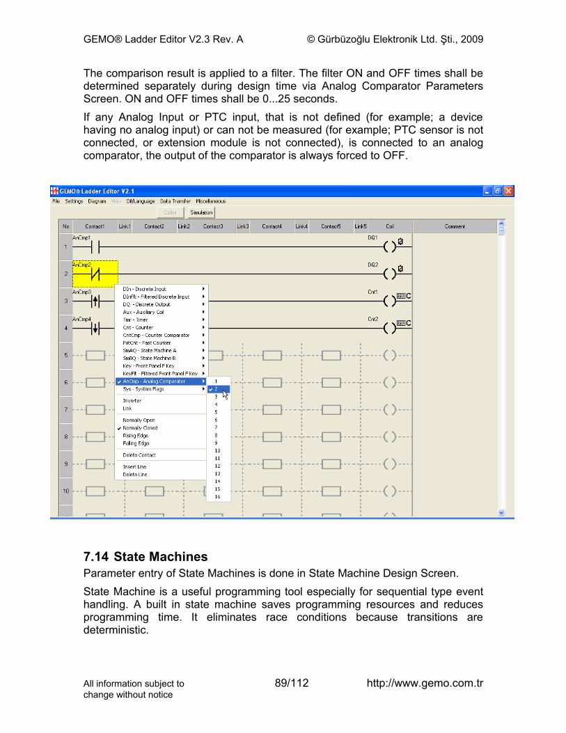
GEMO® Ladder Editor V2.3 Rev. A © Gürbüzoğlu Elektronik Ltd. Şti., 2009
The comparison result is applied to a filter. The filter ON and OFF times shall be determined separately during design time via Analog Comparator Parameters Screen. ON and OFF times shall be 0...25 seconds.If any Analog Input or PTC input, that is not defined (for example; a device having no analog input) or can not be measured (for example; PTC sensor is not connected, or extension module is not connected), is connected to an analog comparator, the output of the comparator is always forced to OFF.
7.14 State MachinesParameter entry of State Machines is done in State Machine Design Screen.State Machine is a useful programming tool especially for sequential type event handling. A built in state machine saves programming resources and reduces programming time. It eliminates race conditions because transitions are deterministic.
All information subject to 89/112 http://www.gemo.com.trchange without notice

GEMO® Ladder Editor V2.3 Rev. A © Gürbüzoğlu Elektronik Ltd. Şti., 2009
Below a sample state diagram is given. As seen in the diagram, there exist complex cases that should be handled. Also, transitions are not trivial to handle. To draw classical type of ladder diagrams for state handling is not so easy. It is time consuming, it requires a lot of resources, it is difficult to test and trace execution. Race conditions remain as pitfalls during lifetime of the application.
State1
Reset
C1
C1
C1
C1C1
C1: Condition 1C2: Condition 2
C1
C1
C1
C2
C2
C2
JumpState
2
StateA
StateB
StateDState
E
StateF
StateG
AR2 introduces State Machines, each having 48 states, to overcome many of such problems. AR2 has 2 independent and identical state machines; State Machine A and State Machine B. Each state machine has its own inputs/outputs and runs independently. So it is possible to manage 2 independent state handling functions at the same time in as single device.A block diagram is given blow for an AR2 state machine.Each AR2 state machine has a built in timer. This single timer has different Preset and times base settings for each state separately and independently. This feature shall eliminate to use external timers for timed event handling, hence eliminating complexity and saving resources. Preset value of each state shall be adjusted via front panel. Also Preset and Actual value of each timer shall be displayed on LCD during run time.Internal timer shall also count events when time base is selected as FstCnt1 and FstCnt2 (Fast Input Counters), and TmrTick1 and TmrTick2 (Timer Ticks). So, internal timer may be used as a counter, eliminating the use of an external
All information subject to 90/112 http://www.gemo.com.trchange without notice
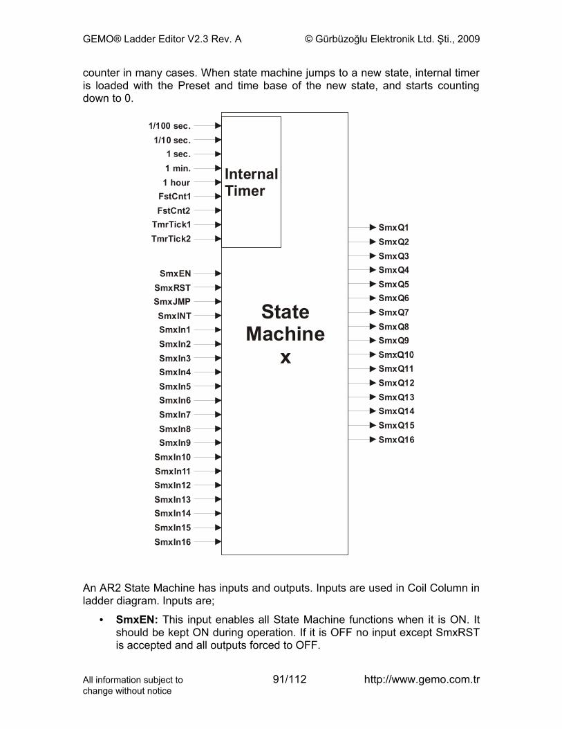
GEMO® Ladder Editor V2.3 Rev. A © Gürbüzoğlu Elektronik Ltd. Şti., 2009
counter in many cases. When state machine jumps to a new state, internal timer is loaded with the Preset and time base of the new state, and starts counting down to 0.
1/100 s .ec1/10 s .ec
1 s .ec1 .min1 hour
SmxQ1SmxQ2SmxQ3SmxQ4SmxQ5SmxQ6SmxQ7SmxQ8SmxQ9
SmxQ11SmxQ12SmxQ13SmxQ14SmxQ15SmxQ16
FstCnt1FstCnt2
TmrTick1TmrTick2
SmxENSmxRSTSmxJMPSmxINTSmxIn1SmxIn2SmxIn3SmxIn4SmxIn5SmxIn6SmxIn7SmxIn8SmxIn9
SmxIn10SmxIn11SmxIn12SmxIn13SmxIn14SmxIn15SmxIn16
StateMachine
x
InternalTimer
An AR2 State Machine has inputs and outputs. Inputs are used in Coil Column in ladder diagram. Inputs are;
• SmxEN: This input enables all State Machine functions when it is ON. It should be kept ON during operation. If it is OFF no input except SmxRST is accepted and all outputs forced to OFF.
All information subject to 91/112 http://www.gemo.com.trchange without notice
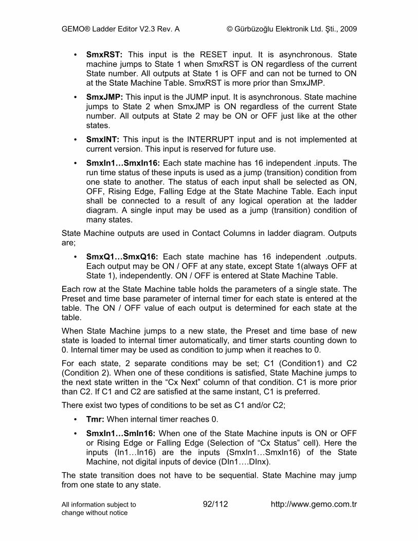
GEMO® Ladder Editor V2.3 Rev. A © Gürbüzoğlu Elektronik Ltd. Şti., 2009
• SmxRST: This input is the RESET input. It is asynchronous. State machine jumps to State 1 when SmxRST is ON regardless of the current State number. All outputs at State 1 is OFF and can not be turned to ON at the State Machine Table. SmxRST is more prior than SmxJMP.
• SmxJMP: This input is the JUMP input. It is asynchronous. State machine jumps to State 2 when SmxJMP is ON regardless of the current State number. All outputs at State 2 may be ON or OFF just like at the other states.
• SmxINT: This input is the INTERRUPT input and is not implemented at current version. This input is reserved for future use.
• SmxIn1…SmxIn16: Each state machine has 16 independent .inputs. The run time status of these inputs is used as a jump (transition) condition from one state to another. The status of each input shall be selected as ON, OFF, Rising Edge, Falling Edge at the State Machine Table. Each input shall be connected to a result of any logical operation at the ladder diagram. A single input may be used as a jump (transition) condition of many states.
State Machine outputs are used in Contact Columns in ladder diagram. Outputs are;
• SmxQ1…SmxQ16: Each state machine has 16 independent .outputs. Each output may be ON / OFF at any state, except State 1(always OFF at State 1), independently. ON / OFF is entered at State Machine Table.
Each row at the State Machine table holds the parameters of a single state. The Preset and time base parameter of internal timer for each state is entered at the table. The ON / OFF value of each output is determined for each state at the table.When State Machine jumps to a new state, the Preset and time base of new state is loaded to internal timer automatically, and timer starts counting down to 0. Internal timer may be used as condition to jump when it reaches to 0.For each state, 2 separate conditions may be set; C1 (Condition1) and C2 (Condition 2). When one of these conditions is satisfied, State Machine jumps to the next state written in the “Cx Next” column of that condition. C1 is more prior than C2. If C1 and C2 are satisfied at the same instant, C1 is preferred.There exist two types of conditions to be set as C1 and/or C2;
• Tmr: When internal timer reaches 0.
• SmxIn1…SmIn16: When one of the State Machine inputs is ON or OFF or Rising Edge or Falling Edge (Selection of “Cx Status” cell). Here the inputs (In1…In16) are the inputs (SmxIn1…SmxIn16) of the State Machine, not digital inputs of device (DIn1….DInx).
The state transition does not have to be sequential. State Machine may jump from one state to any state.
All information subject to 92/112 http://www.gemo.com.trchange without notice
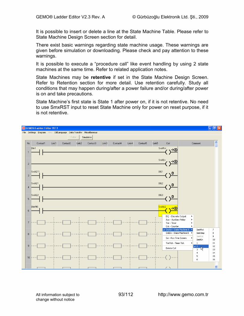
GEMO® Ladder Editor V2.3 Rev. A © Gürbüzoğlu Elektronik Ltd. Şti., 2009
It is possible to insert or delete a line at the State Machine Table. Please refer to State Machine Design Screen section for detail.There exist basic warnings regarding state machine usage. These warnings are given before simulation or downloading. Please check and pay attention to these warnings.It is possible to execute a “procedure call” like event handling by using 2 state machines at the same time. Refer to related application notes.State Machines may be retentive if set in the State Machine Design Screen. Refer to Retention section for more detail. Use retention carefully. Study all conditions that may happen during/after a power failure and/or during/after power is on and take precautions.State Machine’s first state is State 1 after power on, if it is not retentive. No need to use SmxRST input to reset State Machine only for power on reset purpose, if it is not retentive.
All information subject to 93/112 http://www.gemo.com.trchange without notice
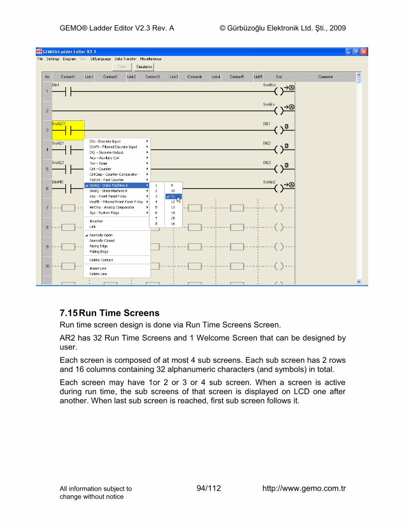
GEMO® Ladder Editor V2.3 Rev. A © Gürbüzoğlu Elektronik Ltd. Şti., 2009
7.15Run Time ScreensRun time screen design is done via Run Time Screens Screen.AR2 has 32 Run Time Screens and 1 Welcome Screen that can be designed by user.Each screen is composed of at most 4 sub screens. Each sub screen has 2 rows and 16 columns containing 32 alphanumeric characters (and symbols) in total.Each screen may have 1or 2 or 3 or 4 sub screen. When a screen is active during run time, the sub screens of that screen is displayed on LCD one after another. When last sub screen is reached, first sub screen follows it.
All information subject to 94/112 http://www.gemo.com.trchange without notice
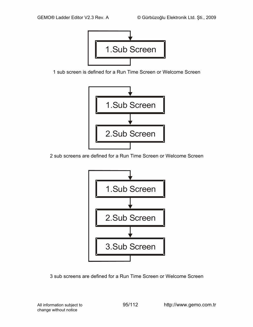
GEMO® Ladder Editor V2.3 Rev. A © Gürbüzoğlu Elektronik Ltd. Şti., 2009
1.Sub Screen
1 sub screen is defined for a Run Time Screen or Welcome Screen
1.Sub Screen
2.Sub Screen
2 sub screens are defined for a Run Time Screen or Welcome Screen
1.Sub Screen
2.Sub Screen
3.Sub Screen
3 sub screens are defined for a Run Time Screen or Welcome Screen
All information subject to 95/112 http://www.gemo.com.trchange without notice
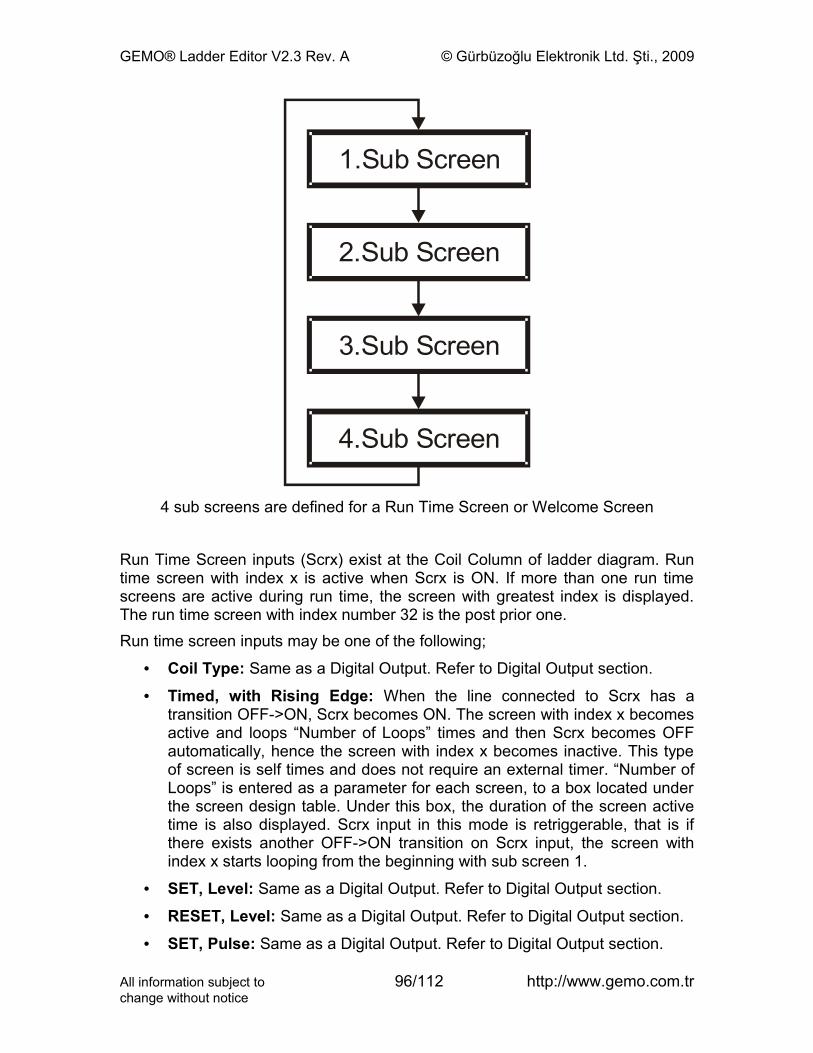
GEMO® Ladder Editor V2.3 Rev. A © Gürbüzoğlu Elektronik Ltd. Şti., 2009
1.Sub Screen
2.Sub Screen
3.Sub Screen
4.Sub Screen
4 sub screens are defined for a Run Time Screen or Welcome Screen
Run Time Screen inputs (Scrx) exist at the Coil Column of ladder diagram. Run time screen with index x is active when Scrx is ON. If more than one run time screens are active during run time, the screen with greatest index is displayed. The run time screen with index number 32 is the post prior one.Run time screen inputs may be one of the following;
• Coil Type: Same as a Digital Output. Refer to Digital Output section.
• Timed, with Rising Edge: When the line connected to Scrx has a transition OFF->ON, Scrx becomes ON. The screen with index x becomes active and loops “Number of Loops” times and then Scrx becomes OFF automatically, hence the screen with index x becomes inactive. This type of screen is self times and does not require an external timer. “Number of Loops” is entered as a parameter for each screen, to a box located under the screen design table. Under this box, the duration of the screen active time is also displayed. Scrx input in this mode is retriggerable, that is if there exists another OFF->ON transition on Scrx input, the screen with index x starts looping from the beginning with sub screen 1.
• SET, Level: Same as a Digital Output. Refer to Digital Output section.
• RESET, Level: Same as a Digital Output. Refer to Digital Output section.
• SET, Pulse: Same as a Digital Output. Refer to Digital Output section.
All information subject to 96/112 http://www.gemo.com.trchange without notice
GEMO® Ladder Editor V2.3 Rev. A © Gürbüzoğlu Elektronik Ltd. Şti., 2009
• RESET, Pulse: Same as a Digital Output. Refer to Digital Output section.Each run time screen is designed by editing a table with 4 rows. Each row design a sub screen.Each sub screen may contain a single parameter. The run time value of selected parameter is displayed on any location of the sub screen. The row and column index is entered separately. Parameter type and number is selected from the pop up lists. The appearance of the designed sub screen is viewed on the LCD simulator located below the table.The parameters are;
• Tmr, Timer: Run time (actual) value of any timer (remaining time).
• Tmr, tA: tA preset value of any timer.
• Tmr, tB: tB preset value of any timer.
• Tmr, tA-Timer: tA preset value – (minus) the run time (actual) value of any timer (passed time).
• Tmr, tB-Timer: tB preset value – (minus) the run time (actual) value of any timer (passed time).
• Cnt, Counter: Run time (actual) value of any counter.
• Cnt, Preset: Preset value of any counter.
• Cnt, Pst-Counter: Preset value – (minus) the run time (actual) value of any counter. Displays 0 if result is negative.
• CntCmp, Preset: Preset value of any counter comparator.
• SmA, Timer: Run time (actual) value of internal timer of State Machine A (remaining time).
• SmA, t.Set: Preset value of internal timer of State Machine A.
• SmA, t.Set-Timer: Preset value – (minus) the run time (actual) value of internal timer of State Machine A (passed time).
• SmB, Timer: Run time (actual) value of internal timer of State Machine B (remaining time).
• SmB, t.Set: Preset value of internal timer of State Machine B.
• SmB, t.Set-Timer: Preset value – (minus) the run time (actual) value of internal timer of State Machine B (passed time).
• PTC, Reading: Temperature in Centigrade that measures by one the PTC sensors.
• AnIn, Reading: Transformed value of any analog input measurement.
• AnCmp, Preset: Preset value of any analog comparator.
All information subject to 97/112 http://www.gemo.com.trchange without notice
GEMO® Ladder Editor V2.3 Rev. A © Gürbüzoğlu Elektronik Ltd. Şti., 2009
• Time; HR:MM:SC: Current time as hour:minute:second in 24 hour format. This function is valid for RTC models.
• Date; DD:MM:YYYY: Current date as day:month:year until 2100 (2100 excluded). This function is valid for RTC models.
Each sub screen is displayed for the duration entered at the related row of table. After this duration, next sub screen is displayed. This duration may be set as 1…250 seconds during design time.Each sub screen has its own backlight type. One of the following types may be selected for each sub screen separately;
• ON: Backlight is ON.
• ON: Backlight is OFF.
• Flashing: Backlight is flashing. Flashing ON and OFF times are set under the Welcome Screen table during design time. Flashing backlight has its own timer eliminating the use of an external timer. ON/OFF durations may be 0.2…2 seconds.
• Aux48: Backlight is OFF when Aux48 is OFF and ON when Aux48 is ON.Welcome Screen appears only once after power on and does not appear again. No parameter selection can be done for Welcome Screen. Backlight is always ON for Welcome Screen.
All information subject to 98/112 http://www.gemo.com.trchange without notice
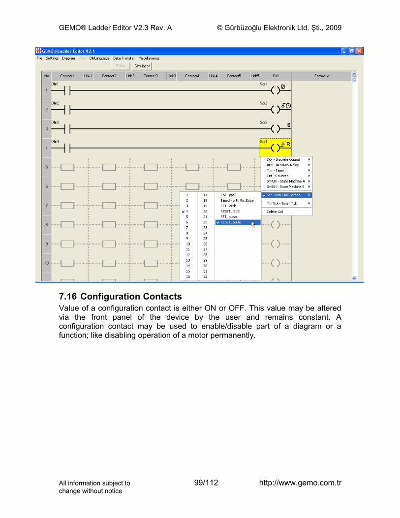
GEMO® Ladder Editor V2.3 Rev. A © Gürbüzoğlu Elektronik Ltd. Şti., 2009
7.16 Configuration ContactsValue of a configuration contact is either ON or OFF. This value may be altered via the front panel of the device by the user and remains constant. A configuration contact may be used to enable/disable part of a diagram or a function; like disabling operation of a motor permanently.
All information subject to 99/112 http://www.gemo.com.trchange without notice
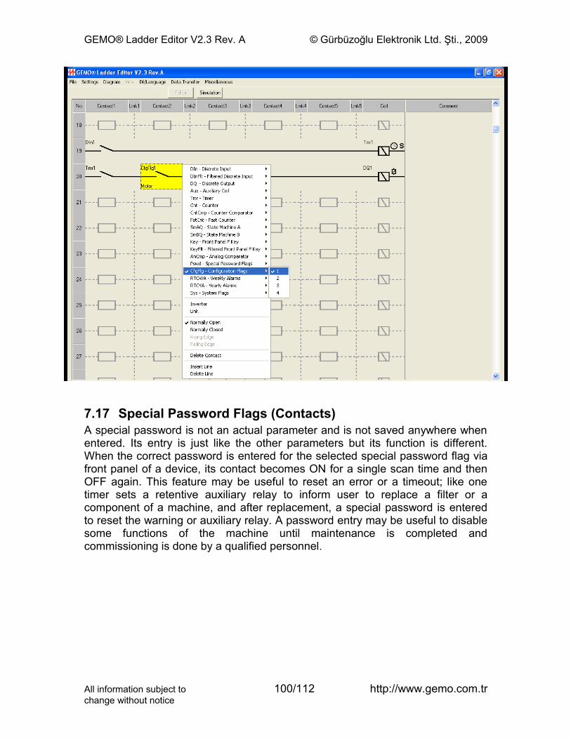
GEMO® Ladder Editor V2.3 Rev. A © Gürbüzoğlu Elektronik Ltd. Şti., 2009
7.17 Special Password Flags (Contacts)A special password is not an actual parameter and is not saved anywhere when entered. Its entry is just like the other parameters but its function is different. When the correct password is entered for the selected special password flag via front panel of a device, its contact becomes ON for a single scan time and then OFF again. This feature may be useful to reset an error or a timeout; like one timer sets a retentive auxiliary relay to inform user to replace a filter or a component of a machine, and after replacement, a special password is entered to reset the warning or auxiliary relay. A password entry may be useful to disable some functions of the machine until maintenance is completed and commissioning is done by a qualified personnel.
All information subject to 100/112 http://www.gemo.com.trchange without notice
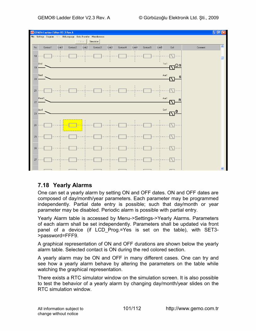
GEMO® Ladder Editor V2.3 Rev. A © Gürbüzoğlu Elektronik Ltd. Şti., 2009
7.18 Yearly AlarmsOne can set a yearly alarm by setting ON and OFF dates. ON and OFF dates are composed of day/month/year parameters. Each parameter may be programmed independently. Partial date entry is possible; such that day/month or year parameter may be disabled. Periodic alarm is possible with partial entry.Yearly Alarm table is accessed by Menu->Settings->Yearly Alarms. Parameters of each alarm shall be set independently. Parameters shall be updated via front panel of a device (if LCD_Prog.=Yes is set on the table), with SET3->password=FFF9.A graphical representation of ON and OFF durations are shown below the yearly alarm table. Selected contact is ON during the red colored section.A yearly alarm may be ON and OFF in many different cases. One can try and see how a yearly alarm behave by altering the parameters on the table while watching the graphical representation.There exists a RTC simulator window on the simulation screen. It is also possible to test the behavior of a yearly alarm by changing day/month/year slides on the RTC simulation window.
All information subject to 101/112 http://www.gemo.com.trchange without notice
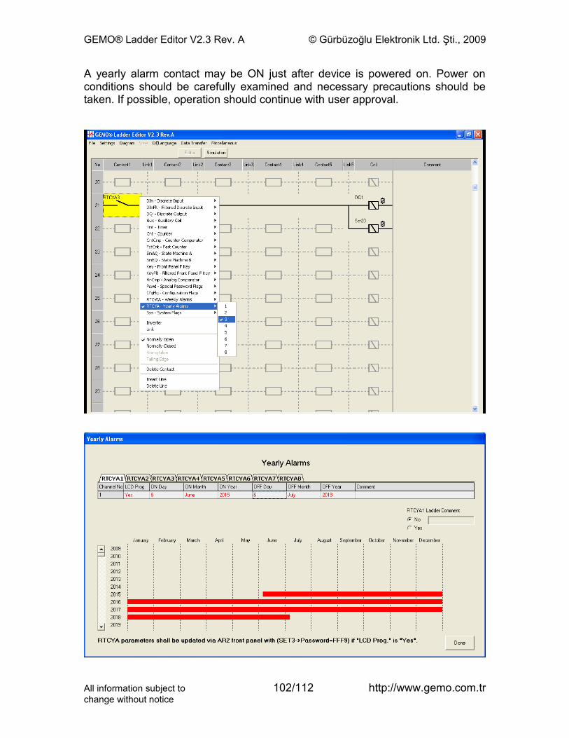
GEMO® Ladder Editor V2.3 Rev. A © Gürbüzoğlu Elektronik Ltd. Şti., 2009
A yearly alarm contact may be ON just after device is powered on. Power on conditions should be carefully examined and necessary precautions should be taken. If possible, operation should continue with user approval.
All information subject to 102/112 http://www.gemo.com.trchange without notice
GEMO® Ladder Editor V2.3 Rev. A © Gürbüzoğlu Elektronik Ltd. Şti., 2009
7.19 Weekly AlarmsOne can set a weekly alarm for one or more days of a week for different and various ON and OFF time with a resolution of a minute. Each ON and OFF time is independently set and enabled.A weekly alarm is composed of 4 independent channels. The contact state of a weekly alarm is a composition of all 4 channels of that weekly alarm.Weekly Alarm table is accessed by Menu->Settings->Weekly Alarms. Parameters shall be updated via front panel of a device (if LCD_Prog.=Yes is set on the table), with SET3->password=FFF8.A graphical representation of ON and OFF durations are shown below the weekly alarm table. Selected contact is ON during the red colored section.A weekly alarm may be ON and OFF in many different cases. Many complex ON and OFF patterns may be obtained by setting parameters of channels. One can try and see how a weekly alarm behave by altering the parameters on the table while watching the graphical representation.There exists a RTC simulator window on the simulation screen. It is also possible to test the behavior of a weekly alarm by changing hour/day/month/year slides on the RTC simulation window.A weekly alarm contact may be ON just after device is powered on. Power on conditions should be carefully examined and necessary precautions should be taken. If possible, operation should continue with user approval.
All information subject to 103/112 http://www.gemo.com.trchange without notice
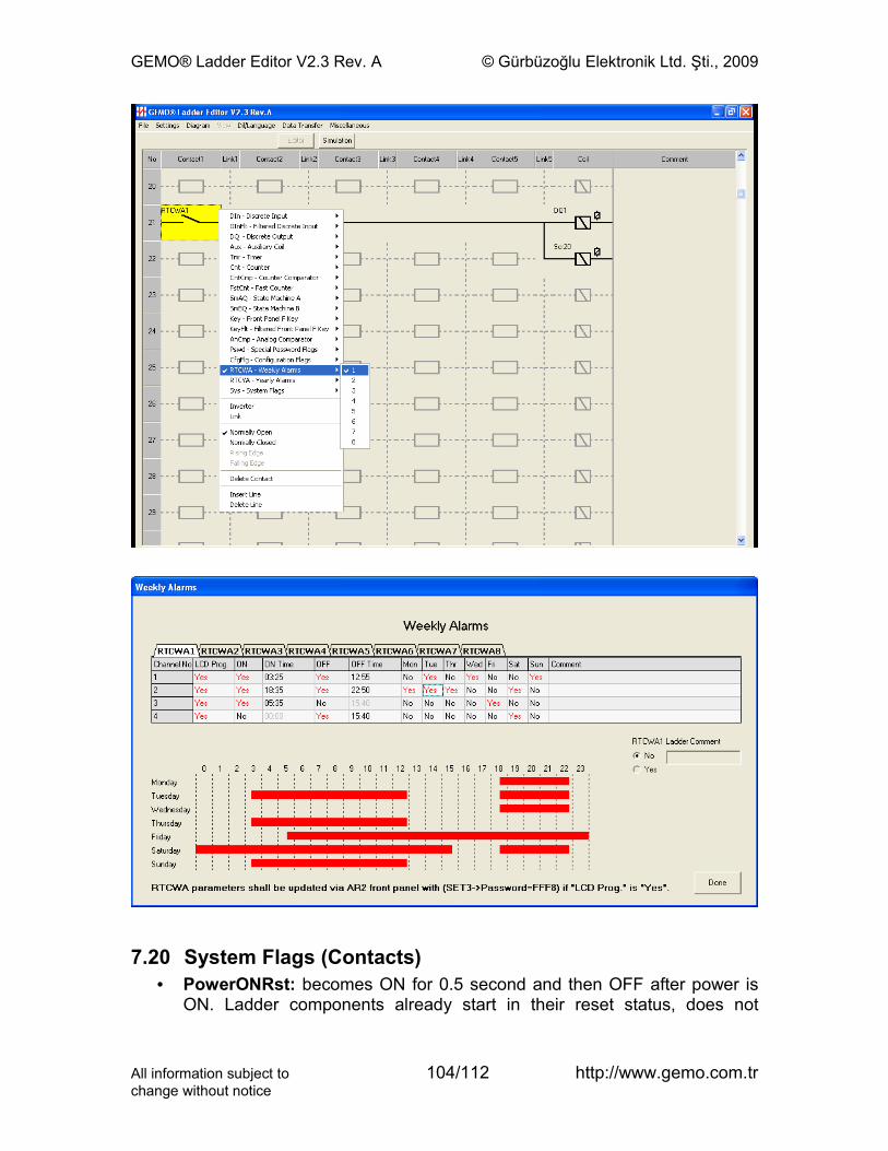
GEMO® Ladder Editor V2.3 Rev. A © Gürbüzoğlu Elektronik Ltd. Şti., 2009
7.20 System Flags (Contacts)• PowerONRst: becomes ON for 0.5 second and then OFF after power is
ON. Ladder components already start in their reset status, does not
All information subject to 104/112 http://www.gemo.com.trchange without notice
GEMO® Ladder Editor V2.3 Rev. A © Gürbüzoğlu Elektronik Ltd. Şti., 2009
require any extra resetting connection. This input may be used for starting a special initialization procedure when needed.
• ErrRetention: becomes ON when a non volatile memory read error is detected after power is ON, if not always OFF. Editor gives a warning when there exists a retentive component and ErrRetention is not used in ladder diagram. ErrRetention is ON during the first power on after a new download is done. This feature shall be used by programmer to test the part of the diagram that uses ErrRetention system contact.
• ErrPTC1: becomes ON when PTC1 sensor error (sensor or sensor cable failure) is detected or measurement is out of range. Editor gives a warning when PTC1 is used as a parameter of one of the analog comparators and ErrPTC1 is not used in ladder diagram.
• ErrPTC2: becomes ON when PTC2 sensor error (sensor or sensor cable failure) is detected or measurement is out of range. Editor gives a warning when PTC2 is used as a parameter of one of the analog comparators and ErrPTC2 is not used in ladder diagram.
• ErrCommAny: becomes ON if communication (via RS-485 port) with any of extension modules fails. OFF if communication with all the modules is okay.
• ErrCommG1: becomes ON if communication (via RS-485 port) with extension module AR2-G1 fails. OFF if communication with AR2-G1 is okay.
• ErrRTC: ErrRTC contact becomes ON if RTC fails, date/time setting is wrong or RTC battery is low. ErrRTC is always ON for the devices that does not have a RTC.
All information subject to 105/112 http://www.gemo.com.trchange without notice
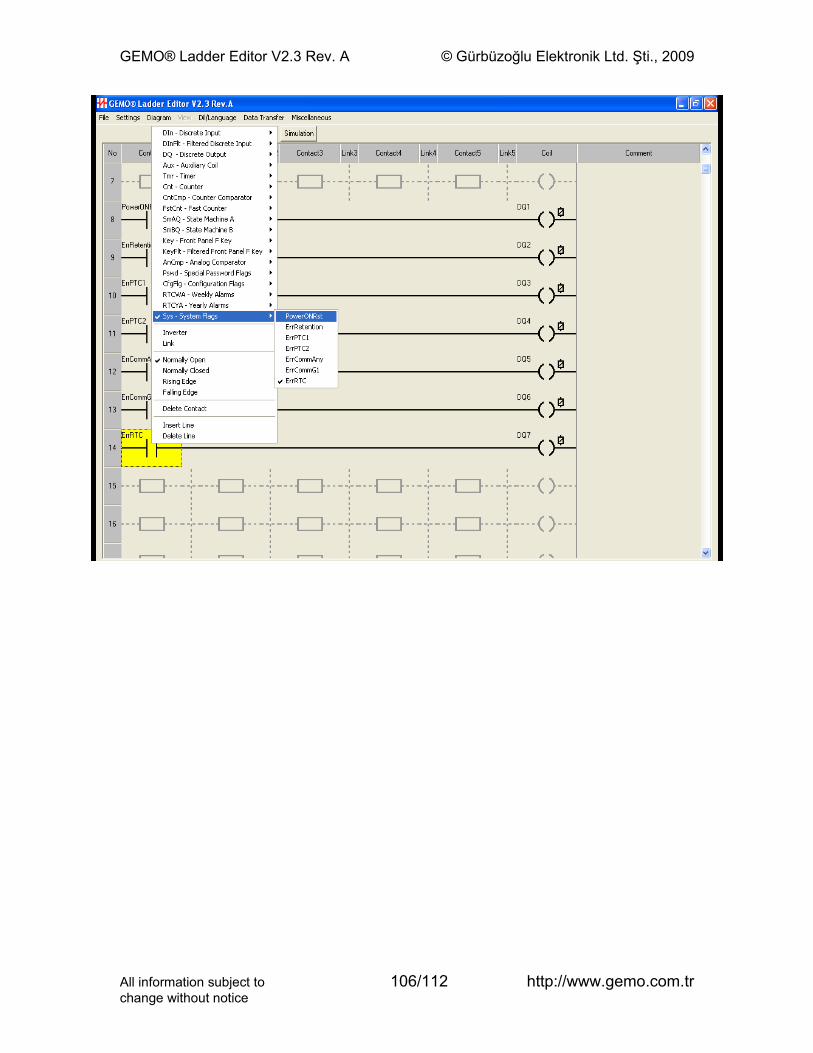
GEMO® Ladder Editor V2.3 Rev. A © Gürbüzoğlu Elektronik Ltd. Şti., 2009
All information subject to 106/112 http://www.gemo.com.trchange without notice

GEMO® Ladder Editor V2.3 Rev. A © Gürbüzoğlu Elektronik Ltd. Şti., 2009
8 Menu DesignerAR2 Menu Designer is used to design an application specific menu system (user interface) for device user to adjust Preset values of ladder elements via front panel of device during run time.Menu design is done via Menu Designer Screen.Menu system is composed of 3 independent and similar menu levels. Each level may contain no or up to 32 different parameters following each other. Parameter types and index of each parameter may be in any order. Any parameter may be used at the same or at other levels at the same menu system, no limitations at all.
PressSET1
for3 seconds
Enter Passwordfor Level 1
i Activef
NotActive
Press Up, Down, Rightbuttons to change valueand, press SET1 or SET2or SET3 to enter.
Press Up, Down, Rightbuttons to change valueand, press SET1 or SET2or SET3 to enter.
Press Up, Down, Rightbuttons to change valueand, press SET1 or SET2or SET3 to enter.
Enter1 Parameter
for Level 1
st
End
Enter Parameter
for Level 1nth
Menu Structure for Level 1
All information subject to 107/112 http://www.gemo.com.trchange without notice
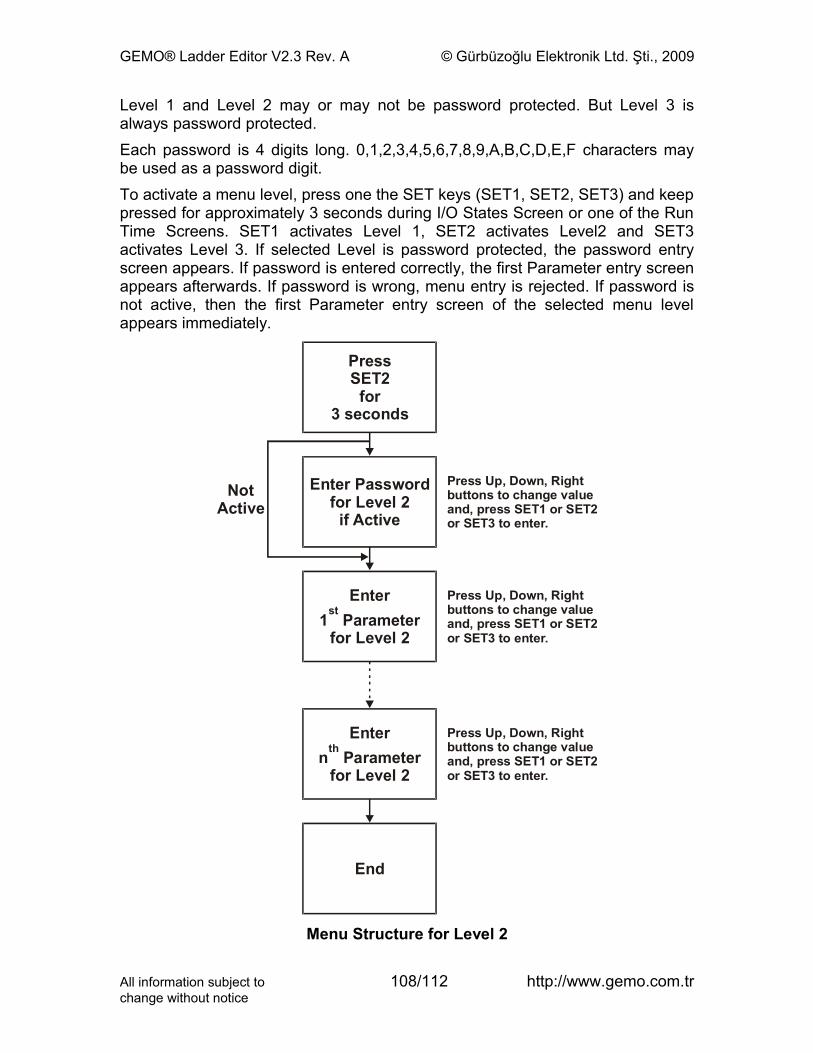
GEMO® Ladder Editor V2.3 Rev. A © Gürbüzoğlu Elektronik Ltd. Şti., 2009
Level 1 and Level 2 may or may not be password protected. But Level 3 is always password protected.Each password is 4 digits long. 0,1,2,3,4,5,6,7,8,9,A,B,C,D,E,F characters may be used as a password digit.To activate a menu level, press one the SET keys (SET1, SET2, SET3) and keep pressed for approximately 3 seconds during I/O States Screen or one of the Run Time Screens. SET1 activates Level 1, SET2 activates Level2 and SET3 activates Level 3. If selected Level is password protected, the password entry screen appears. If password is entered correctly, the first Parameter entry screen appears afterwards. If password is wrong, menu entry is rejected. If password is not active, then the first Parameter entry screen of the selected menu level appears immediately.
PressSET
for3 seconds
2
Enter Passwordfor Level
i Active2
f
NotActive
Press Up, Down, Rightbuttons to change valueand, press SET1 or SET2or SET3 to enter.
Press Up, Down, Rightbuttons to change valueand, press SET1 or SET2or SET3 to enter.
Press Up, Down, Rightbuttons to change valueand, press SET1 or SET2or SET3 to enter.
Enter1 Parameter
for Level
st
2
End
Enter Parameter
for Level n
2
th
Menu Structure for Level 2
All information subject to 108/112 http://www.gemo.com.trchange without notice
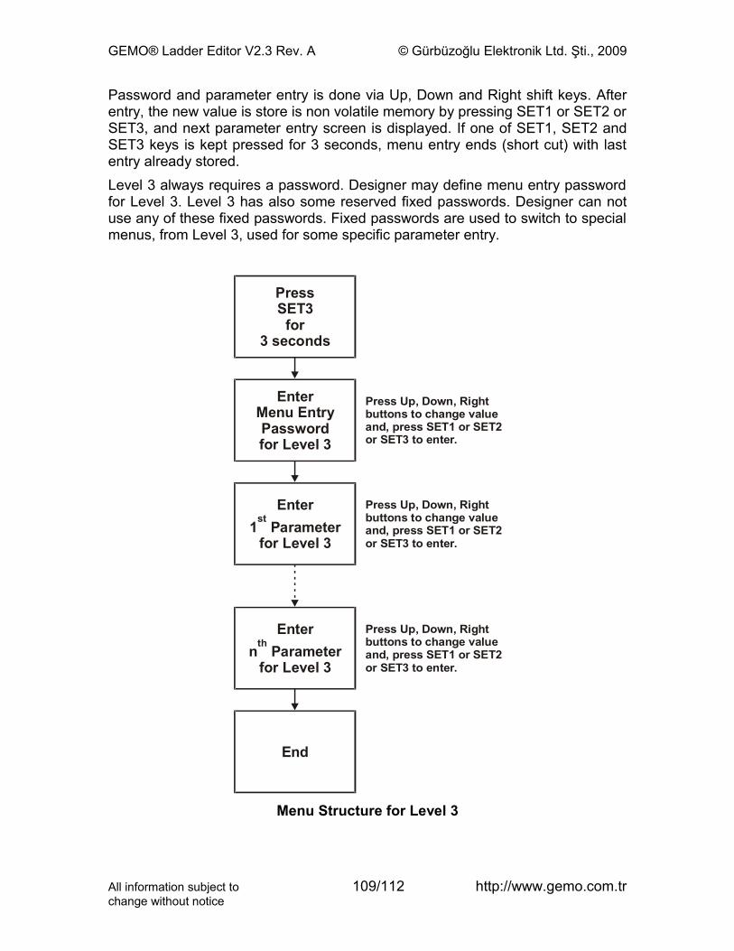
GEMO® Ladder Editor V2.3 Rev. A © Gürbüzoğlu Elektronik Ltd. Şti., 2009
Password and parameter entry is done via Up, Down and Right shift keys. After entry, the new value is store is non volatile memory by pressing SET1 or SET2 or SET3, and next parameter entry screen is displayed. If one of SET1, SET2 and SET3 keys is kept pressed for 3 seconds, menu entry ends (short cut) with last entry already stored.Level 3 always requires a password. Designer may define menu entry password for Level 3. Level 3 has also some reserved fixed passwords. Designer can not use any of these fixed passwords. Fixed passwords are used to switch to special menus, from Level 3, used for some specific parameter entry.
PressSET
for3 seconds
3
Enter
Passwordfor Level
Menu Entry
3
Press Up, Down, Rightbuttons to change valueand, press SET1 or SET2or SET3 to enter.
Press Up, Down, Rightbuttons to change valueand, press SET1 or SET2or SET3 to enter.
Press Up, Down, Rightbuttons to change valueand, press SET1 or SET2or SET3 to enter.
Enter1 Parameter
for Level
st
3
End
Enter Parameter
for Level n
3
th
Menu Structure for Level 3
All information subject to 109/112 http://www.gemo.com.trchange without notice
GEMO® Ladder Editor V2.3 Rev. A © Gürbüzoğlu Elektronik Ltd. Şti., 2009
Fixed passwords for Level 3 are;
• FFF0: enter this password to display device type, firmware version and revision information. Firmware version number and editor version number have to be the same.
• FFF1: enter this password to update date and time. This password is valid for the devices that have RTC.
• FFF8: enter this password to update RTCWA (weekly alarm) settings. This password is valid for the devices that have RTC.
• FFF9: enter this password to update RTCYA (yearly alarm) settings. This password is valid for the devices that have RTC.
• FFF2 … FFF7, FFFA ... FFFF: reserved for future use.Password and Parameter Entry screens are composed of 2 rows, each containing 16 characters (columns). The fixed text that will appear on Row 1 and Row 2 is entered separately at the ‘Line 1’ and ‘Line 2’ cells of Password and Parameter Entry Tables.The 4 digit Password string, the location of the password on LCD (row and column no) are entered on Password table. Also, “Password Active” is set to Yes if selected level is password protected, and no if else.The parameter type and index, the location of the parameter on LCD (row and column no) are entered on the Parameter Entry Table. Defined parameters are;
• Tmr, tA: tA Preset value of any timer.
• Tmr, tB: tB Preset value of any timer.
• Cnt, Preset: Preset value of any counter.
• CntCmp, Preset: Preset value of any counter comparator.
• SmA, t.SET: The preset value of any state for the internal timer of State Machine A
• SmB, t.SET: The preset value of any state for the internal timer of State Machine B.
• AnCmp, Preset: Preset value of any analog comparator.
• AnCmp, Hysteresis: Hysteresis value of any analog comparator.
• CfgFlg: Value of the selected Configuration Contact; ON or OFF.
• PTC Offset: Offset to the selected measured PTC value.
• AnIn Offset: Offset to the selected converted Analog input value.
• Special Password: Password entry of the selected Special Password Contact. If password is correct, selected special password contact becomes ON for a single scan time and then OFF.
All information subject to 110/112 http://www.gemo.com.trchange without notice
GEMO® Ladder Editor V2.3 Rev. A © Gürbüzoğlu Elektronik Ltd. Şti., 2009
The LCD simulator located at the upper right of the Menu Designer Screen displays the appearance of designed Password and Parameter entry Screens. Click appropriate row of any table and view.The order of appearance of parameters is just as ordered at the Parameter Table. The rows colored in RED are excluded and do not appear. “Seq. No” (sequence no) number is mark with “-End” expression. To include these rows to menu order, just double click on the “Seq. No” cell of desired row, and a command list appears. Select “Erase Last Line Mark”.Buy selecting the appropriate command from the list, one can insert a new row, delete an existing row, change index of row, exclude and include a row from the menu order (Refer to Menu Designer Screen section).
All information subject to 111/112 http://www.gemo.com.trchange without notice
GEMO® Ladder Editor V2.3 Rev. A © Gürbüzoğlu Elektronik Ltd. Şti., 2009
9 Drawing a Diagram
9.1 Inserting a New LineClick a contact with the right button of mouse and select “Insert Line”. A new and blank line is inserted to the diagram; all lines including the contact previously selected are shifted down. The last line is deleted at bottom. If bottom line is not an empty line, user is warned before it is deleted.
9.2 Deleting a LineClick a contact with the right button of mouse and select “Delete Line”. The line where the selected contact exists is deleted, all lines after deleted line are shifted up and a new black line is added as the last line to the bottom of the diagram.
9.3 Deleting a ContactClick a contact with the right button of mouse and select “Delete Contact”. Or select a contact with the left button of mouse and press “Delete” key.
9.4 Deleting a LinkClick a link with the right button of mouse and select “Dashed Link”. Or select a link with the left button of mouse and press “Delete” key.
9.5 Deleting a ContactClick a coil with the right button of mouse and select “Delete Coil”. Or select a coil with the left button of mouse and press “Delete” key.
9.6 Deleting a CommentSelect a comment with the left button of mouse and press “Delete” key.
9.7 Selecting and Deleting an Area of DiagramSelect an area of diagram by moving the mouse pointer while keeping the left button of mouse pressed and press “Delete” key. Undo is not possible so please pay attention before deleting an area.
9.8 Fast Line Drawing between Contacts, Links and CoilsSelect a contact, link or coil where you would like to start drawing a connection by clicking the left button of mouse. Move the pointer of mouse (or alternatively use “Up”, ”Down”, ”Left” or “Right” arrow keys) to establish a connection while keeping the “Shift” key pressed.
All information subject to 112/112 http://www.gemo.com.trchange without notice