Embed Size (px)
Citation preview
Rideau Canal PINTLE GREASE SYSTEM Section 11 99 01 Newboro Lock 36 Rehabilitation Page 1 Proj. No. R.094968.001 2018-06-01
PART 1 GENERAL
1.1 DESCRIPTION
.1 The work outlined in this section describes the new pintle grease system that will be used to grease the lower pintle bearing on all four gate leaves.
1.2 RELATED WORK
.1 Section 01 78 02 – Operation and Maintenance Manual
.1 Compile all necessary information for operation and maintenance.
.2 Section 01 79 00 – Demonstration and Training.
.3 Section 01 91 13 – General Commissioning Requirements.
.4 Section 11 99 03 – Fasteners and Hardware.
1.3 MEASUREMENT AND PAYMENT PROCEDURES
.1 There will be no measurement for all work described in this Section.
.2 Payment for all work described in this Section shall be included in the Lump Sum Price.
PART 2 PRODUCTS
2.1 GREASE LINE
.1 Materials: 316 stainless steel.
.2 Working pressure: Up to 345 Bar (5,000 psi).
.3 Working temperature: -10 °C to 50 °C.
.4 Service:
.1 Inside of line biodegradable grease, refer to grease specification.
.2 Outside of line submerged in fresh water.
.5 Tube:
.1 5/16 " OD, wall thickness capable of working pressure per SAE J1065.
.2 Tube manufacturer will specify the allowable ranges of tube wall thickness, diameter, and material hardness.
.3 ASTM A269, Grade TP316 or equivalent, high quality, fully annealed, seamless or drawn type austenitic stainless steel.
.4 Free of scratches, suitable for bending (hardness not to exceed 80 HRB), and must properly adapt to a compression fitting.
.5 Ensure OD tolerance is suitable for connections.
.6 Tube Fittings:
.1 Compression style fittings.
Rideau Canal PINTLE GREASE SYSTEM Section 11 99 01 Newboro Lock 36 Rehabilitation Page 2 Proj. No. R.094968.001 2018-06-01
.2 Fitting style must allow for disassembly and re-assembly, while maintaining a leak-tight seal.
.3 No component of any other tube fitting manufacturer will be interchanged or intermixed.
.7 Grease Nipple:
.1 1/8 " NPT standard zerk, with dust cap.
.8 Tube Supports:
.1 Stainless steel tube clamps.
.2 Self tapping stainless steel screws to hold clamps in place.
.9 Contractor to provide manufacturer’s literature to owner for review prior to procuring fittings and tube supports clamps.
2.2 GREASE
.1 Operating Temperature: -10 °C to 40 °C.
.2 Cold Storage Temperature: -40 °C. System is static during winter months.
.3 Service:
.1 Pintle bearing and grease line submerged in fresh water.
.2 Grease must resist water washout.
.4 Type: Readily biodegradable marine grease, > 85% per CEC-L-A-94, ASTM D-5864.
.5 Toxicity:
.1 Non-toxic , aquatic ecotoxicity classification WGK 1 (or equivalent).
.2 Owner to approve grease toxicity characteristics before use.
.6 Application: Plain bearing (pintle).
.7 Operating Speed: Very slow (near static).
.8 Duty Cycle: <10,000 cycles per year.
.9 Material Compatibility: Cast steel bearing, bronze wear pad and bronze bushings.
.10 Grease Delivery:
.1 Through standard zerk fitting via 5/16 " OD tube, approximately 6 m long.
.2 Grease must be able to be delivered under specified conditions with standard hand operated grease gun.
2.3 GREASE GUN
.1 Type: Manual hand pump style.
.2 Barrel:
.1 Standard to suit 420 ml nominal grease cartridge.
.2 Black powder coated or zinc plated.
.3 Grease Delivery: Maximum pressure 345 Bar (5000 psi).
.4 Nozzle:
.1 300 mm (12 ") long flex hose extension.
Rideau Canal PINTLE GREASE SYSTEM Section 11 99 01 Newboro Lock 36 Rehabilitation Page 3 Proj. No. R.094968.001 2018-06-01
.2 Hose reinforced neoprene or polypropylene.
.5 Connection: Standard zerk grease nipple, to mate with pintle line zerks.
.6 Label:
.1 Identify gun for pintle grease only.
.2 Include the following information on the label: .1 Grease brand / type. .2 Number of pumps required to re-lube bearing. Contractor to determine
number of grease gun pumps required during commissioning.
.7 Contractor to provide manufacturer’s literature to owner for review prior to procuring grease gun.
PART 3 EXECUTION
3.1 FABRICATION AND INSTALLATION
.1 Refer to the drawings.
.2 Contractor to review proposed tube routing with owner prior to installation.
.3 Tube Installation:
.1 Installation must follow current standard best practices, and tube and fitting vendor specifications.
.2 Line preparation per vendor specifications.
.3 Tube fittings will not require disassembly for inspection after assembly.
.4 Lines must be continuous with no butt-splices.
.5 Minimum bend radius per vendor specifications.
.6 Tube fitting assembly must not gall during assembly.
.4 Grease Nipple:
.1 Refer to drawings for nipple location and mounting.
.5 Pintle Connection:
.1 Contractor to adapt grease tubing to existing pintle base heel casting.
.2 Connection shown on existing site drawings (drawing file no. R-20-105.6 and R-20-105.7), contractor to confirm connection details.
.6 Tube Fasteners:
.1 Refer to drawings.
.7 Cleaning:
.1 Tube and components must be free of oils, debris, cutting fluids, etc. before grease is applied to line.
3.2 COMMISSIONING
.1 Testing:
.1 Grease all pintles during dry-lock conditions.
.2 Visually inspect each pintle to ensure it receives grease.

Rideau Canal PINTLE GREASE SYSTEM Section 11 99 01 Newboro Lock 36 Rehabilitation Page 4 Proj. No. R.094968.001 2018-06-01
.3 Visually inspect all fittings for leaks.
.4 Prepare and submit a brief written test report.
END OF SECTION
Rideau Canal OIL REMOVAL AND TRENCH CLEANING Section 11 99 02 Newboro Lock 36 Rehabilitation Page 1 Proj. No. R.094968.001 2018-06-01
PART 1 GENERAL
1.1 DESCRIPTION
.1 This section outlines the work associated with removing hydraulic oil from the existing system before the equipment is decommissioned and cleaning the existing trenches before the new equipment is installed. Refer to the drawings and specification provided.
1.2 RELATED WORK
.1 Section 01 35 43 – Environmental Procedures.
.2 Section 01 74 00 – Cleaning.
.3 Section 01 74 19 – Waste Management and Disposal.
1.3 MEASUREMENT AND PAYMENT PROCEDURES
.1 There will be no measurement for all work described in this section.
.2 Payment for all work described in this Section shall be included in the Lump Sum Price.
PART 2 PRODUCTS
2.1
.1 Not used.
PART 3 EXECUTION
3.1 HYDRAULIC OIL REMOVAL
.1 Drain all existing hydraulic oil from cylinders, lines and hydraulic power unit reservoir.
.2 Remove oil from site.
.3 Minimize and contain spills and ensure no oil drains into waterway.
3.2 TRENCH AND PIT CLEANING
.1 Remove all pooled and superficial debris, etc.
.2 Pressure wash empty trenches and pits.
3.3 MATERIAL COMPATABILITY
.1 Cleaning agents and processes must not damage existing materials (concrete, embedded steel supports for trench / pit covers, embedded conduits, etc.).
3.4 SITE LOGISITCS
.1 Trenches are adjacent to, and drain towards the waterway.
.2 Measures must be taken to ensure that all materials and cleaning agents are removed from site and not flushed into waterway or displaced onto adjacent lawns, buildings, masonry, etc.

Rideau Canal OIL REMOVAL AND TRENCH CLEANING Section 11 99 02 Newboro Lock 36 Rehabilitation Page 2 Proj. No. R.094968.001 2018-06-01 3.5 QUALIFICATIONS OF CONTRACTOR
.1 Contractor must handle, transfer and dispose of hazardous materials as per regulations.
END OF SECTION
Rideau Canal FASTENERS AND HARDWARE Section 11 99 03 Newboro Lock 36 Rehabilitation Page 1 Proj. No. R.094968.001 2018-06-01
PART 1 GENERAL
1.1 DESCRIPTION
.1 The work outlined in this section describes the fasteners and hardware to be used for fabrication and installation of all new equipment associated with the hydraulic system.
1.2 RELATED WORK
.1 Section 01 78 02 - Operation and Maintenance Manual.
.1 Compile all necessary information for operation and maintenance.
1.3 MEASUREMENT AND PAYMENT PROCEDURES
.1 There will be no measurement for all work described in this section.
.2 Payment for all work described in this Section shall be included in the Lump Sum Price.
PART 2 PRODUCTS
2.1 MACHINE CAP SCREWS, BOLTS AND ASSOCIATED NUTS / WASHERS
.1 Stainless steel, unless stated otherwise.
.2 Minimum tensile strength of 480 MPa (70,000 psi).
2.2 WEDGE ANCHORS AND ASSOCIATED NUTS / WASHERS
.1 Sizes as specified.
.2 Stainless steel.
.3 Install per manufacturer's specifications.
2.3 OTHER
.1 All components must be suitable for their intended purpose.
.2 Where no specification exists, components must be reviewed and accepted by owner.
PART 3 EXECUTION
3.1 INSTALLATION
.1 All fasteners to be installed using torque as recommended by manufacturer and/or by current machinery handbook (or other qualified reference).
.2 All fasteners accessible by public must be secured using a suitable non permanent thread locking adhesive.
.3 Follow manufacturer's specification where applicable.
END OF SECTION

Rideau Canal TUBING AND CABLE SUPPORTS Section 11 99 04 Newboro Lock 36 Rehabilitation Page 1 Proj. No. R.094968.001 2018-06-01
PART 1 GENERAL
1.1 DESCRIPTION
.1 The work outlined in this section describes the supports to be used to secure and support hydraulic tubing and electrical cables throughout the trenches, on lock gates and equipment, and on building walls, floors and ceilings.
1.2 RELATED WORK
.1 Section 01 78 02 - Operation and Maintenance Manual.
.1 Compile all necessary information for operation and maintenance.
.2 Section 11 99 03 - Fasteners and Hardware.
1.3 MEASUREMENT AND PAYMENT PROCEDURES
.1 There will be no measurement for all work described in this section.
.2 Payment for all work described in this Section shall be included in the Lump Sum Price.
PART 2 PRODUCTS
2.1 STRUT
.1 Type:
.1 U channel with cross section geometry to retain clamp assemblies.
.2 Refer to drawing M004.
.2 Material: Stainless steel.
.3 Dimensions:
.1 Thickness: 12 gauge.
.2 Width and Height: To provide suitable load rating for the application.
.4 Contractor to provide manufacturer’s literature to owner for review prior to procuring struts.
2.2 CLAMPS
.1 Type:
.1 Two piece metal clamp with cushion liner and controlled squeeze shoulder bolt to close clamp around tubing / cable.
.2 Refer to drawing M004.
.2 Materials:
.1 Metal Clamp: Stainless steel.
.2 Cushion Liner: Thermoplastic elastomer, UV resistant.
.3 Shoulder Bolt: Stainless steel.
.3 Dimensions: Sizes as required by tubing and cable diameter.
Rideau Canal TUBING AND CABLE SUPPORTS Section 11 99 04 Newboro Lock 36 Rehabilitation Page 2 Proj. No. R.094968.001 2018-06-01
.4 Contractor to provide manufacturer’s literature to owner for review prior to procuring clamps.
2.3 MOUNTING HARDWARE
.1 Type: Mechanical anchoring systems, no welding to structures and equipment.
.2 Mounting to Concrete: Use wedge anchors, size per manufacturer specification.
.3 Other Mounting (lock gates, structural steel, interior building walls): Select hardware and fasteners to follow industrial best practices.
.4 Material: Stainless steel.
.5 Contractor to provide proposed mounting methods and hardware to owner for review prior to procuring grease gun.
2.4 RETRACTABLE PIPE FRAME
.1 Refer to drawing M004 – Retractable Pipe Frame.
PART 3 EXECUTION
3.1 INSTALLATION
.1 Refer to the drawings.
.2 Strut:
.1 Size and quantity of strut anchors as per strut manufacturer’s recommendation.
.2 Remove sharp edges from cut ends.
.3 Spacing: .1 Tubing: Maximum distance between supports:
.1 For up to 12.7 mm (1/2”) OD spacing must not exceed 915 + 10 mm.
.2 For 15.9 mm (5/8”) OD to 25.4 mm (1”) OD spacing must not exceed 1220 + 10 mm.
.2 Cable: Maximum distance between supports: .1 1500 + 10 mm.
.3 Clamps:
.1 Install per manufacturer's specifications.
.2 Must allow axial movement of mounted components (tubes, etc.) to allow for thermal expansion / contraction.
END OF SECTION
Rideau Canal TUBING, FITTINGS AND HOSES Section 11 99 05 Newboro Lock 36 Rehabilitation Page 1 Proj. No. R.094968.001 2018-06-01
PART 1 GENERAL
1.1 DESCRIPTION
.1 The work outlined in this section describes the complete specification regarding the hydraulic tubing, hoses, and fittings. This includes all pressure, return and suction lines that are used to operate the hydraulic cylinders in the field. Note: there is a separate specification provided for grease lines and fittings (refer to the Pintle Grease System specification, Section 11 99 01).
1.2 RELATED WORK
.1 Section 01 78 02 - Operation and Maintenance Manual.
.1 Compile all necessary information for operation and maintenance.
.2 Section 01 79 00 - Demonstration and Training.
.3 Section 01 91 13 - General Commissioning Requirements.
.4 Section 11 99 01 - Pintle Grease System.
.5 Section 11 99 04 - Tubing and Cable Supports.
.6 Section 11 99 06 - Hydraulic Oil.
1.3 MEASUREMENT AND PAYMENT PROCEDURES
.1 There will be no measurement for all work described in this section.
.2 Payment for all work described in this Section shall be included in the Lump Sum Price.
PART 2 PRODUCTS
2.1 PRESSURE
.1 Operating Pressure: 125 Bar (1800 psi).
.2 Design Pressure: 200 Bar (2900 psi).
2.2 TEMPERATURES
.1 Operating Temperature: -10 °C to 80 °C.
.2 Cold storage temperature: -40 °C.
2.3 SERVICE
.1 Inside Diameter: Biodegradable hydraulic oil, reference Section 11 99 06.
.2 Outside Diameter: Indoor, outdoor and submerged in fresh water.
2.4 TUBING
.1 Material: 316 stainless steel, ASTM A269, Grade TP316 or equivalent, high quality, fully annealed, seamless or drawn type austenitic stainless steel.
Rideau Canal TUBING, FITTINGS AND HOSES Section 11 99 05 Newboro Lock 36 Rehabilitation Page 2 Proj. No. R.094968.001 2018-06-01
.2 Wall Thickness: Per SAE J1065, tube wall thickness must meet pressure requirements. Tube fitting manufacturer must specify the allowable ranges of tube wall thickness, diameter, and material hardness.
.3 Free of scratches, suitable for bending (hardness not to exceed 80 HRB), and must properly adapt to a compression fitting.
.4 Ensure OD tolerance is suitable for connections.
2.5 TUBE FITTINGS
.1 Compression style fittings.
.2 Fitting style must allow for disassembly and re-assembly, while maintaining a leak-tight seal.
.3 Block connections to be SAE J514 O-ring boss.
.4 No component of any other tube fitting manufacturer will be interchanged or intermixed.
.5 Contractor to provide manufacturer’s literature for owner review prior to procuring fittings.
2.6 HOSE
.1 SAE 100R2AT standard per SAE J517.
.2 Contractor to provide manufacturer’s literature for owner review prior to procuring hose.
2.7 HOSE FITTINGS
.1 316 stainless steel crimp fittings, JIC.
.2 Contractor to provide manufacturer’s literature for owner review prior to procuring fittings.
2.8 SUPPORTS
.1 Refer to drawings and Section 11 99 04.
2.9 LINE DIAMETERS
.1 Suction Lines from Oil Reservoir to Pump Inlets: To match pump inlet diameter.
.2 Pressure Lines from Outlets of Primary Pumps to Manifolds: To match primary pump outlet diameter.
.3 Pressure Lines from Outlets of Emergency Pump to Tie-in with Primary Pump Outlet Piping: To match emergency pump outlet diameter.
.4 Return Piping from Manifolds to Oil Reservoir: Minimum 14.0 mm ID.
.5 Field Piping:
.1 Between gate cylinder ports and regenerative balance valve minimum 14.0 mm ID.
.2 All other field piping minimum 9.0 mm ID.
.6 Contractor to provide schematic showing proposed line diameters prior to procuring tubing, fittings and hose.
Rideau Canal TUBING, FITTINGS AND HOSES Section 11 99 05 Newboro Lock 36 Rehabilitation Page 3 Proj. No. R.094968.001 2018-06-01 PART 3 EXECUTION
3.1 TUBE INSTALLATION
.1 Refer to the drawings.
.2 All tube and fitting installation must follow current standard best practices, and tube and fitting manufacturer specifications.
.3 Line preparation as per manufacturer specifications.
.4 All tube fittings placed where easily accessible. Tube fittings will not require disassembly for inspection after assembly.
.5 Avoid 90 ° and 45 ° elbows. All turns shall be bent tubing. Minimum bend radius per manufacturer specifications.
.6 Tube fitting assembly must not gall during assembly.
3.2 HOSE INSTALLATION
.1 Hard tubing is preferred; use hose only in locations indicated on drawings.
.2 Maximum hose length 1200 to 1800 mm.
.3 Current best practices must be followed.
.4 Hoses must not kink or twist throughout the movement of operating ranges. Routing per layout drawings.
3.3 CLEANING
.1 Tubing and all hydraulic components to be cleaned of debris, oils, etc. before installation, following applicable standards.
.2 Flush System:
.1 Flush system after installation is complete and before testing commences.
.2 Remove valve stacks from manifolds and install temporary flushing blocks.
.3 Disconnect gate cylinders at cylinder ports and loop gate cylinder hoses to include hoses in flushing. Bypass regenerative balance valves.
.4 Disconnect sluice valve cylinders at cylinder ports and temporarily loop piping at cylinder cap and rod ends.
.5 Use pumps to cycle hydraulic oil through system, minimum 1 hour per channel (through all pumps, to all actuators) until required cleanliness is achieved. Oil must meet ISO 18/16/13 as a minimum.
.6 Contractor to supply oil sample report.
3.4 TESTING
.1 Suction Piping:
.1 Test suction piping during system flushing.
.2 Inspect all connection joints for leaks during flushing; all tube and hose connections must provide a leak-tight seal.
.3 Contractor to make record of testing inspection.
.2 Pressure Piping:
Rideau Canal TUBING, FITTINGS AND HOSES Section 11 99 05 Newboro Lock 36 Rehabilitation Page 4 Proj. No. R.094968.001 2018-06-01
.1 Test pressure piping after flushing is complete and before removing flushing blocks, hose loops and temporary piping installed for flushing.
.2 Replace pressure gauges in supply lines to each manifold with pressure gauges capable of displaying pressures up to 200 Bar (3000 psi).
.3 Disconnect return piping from manifolds and blank manifold T ports.
.4 Disconnect pressure piping from pump outlets and loop open ends of piping.
.5 Connect hand pump upstream of pump outlet check valves.
.6 Before pressurizing system, ensure all air is bled out of system using test ports.
.7 Pressurize system to 1.5 times system operating pressure and hold pressure for 4 hours.
.8 Inspect all connection joints for leaks during test; all tube and hose connections must provide a leak-tight seal during the pressure test.
.9 Contractor to make record of testing inspection.
.3 Return Piping:
.1 Test return piping after pressure piping is tested and before disassembling any of the temporary piping arrangement used for pressure testing.
.2 Disconnect return piping from return filter inlet.
.3 Reconnect return piping to manifold T ports.
.4 Before pressurizing system, ensure all air is bled out of system using test ports.
.5 Pressurize system to 1.5 times return piping operating pressure and hold pressure for 4 hours.
.6 Inspect all connection joints for leaks during test; all tube and hose connections must provide a leak-tight seal during the pressure test.
.7 Contractor to make record of testing inspection.
.4 Disconnect and remove all temporary piping, hoses, gauges, etc and restore to system normal operating configuration.
.5 Tubes, hoses, pipes, fittings and components must be free of damages upon completion of testing.
END OF SECTION
Rideau Canal HYDRAULIC OIL Section 11 99 06 Newboro Lock 36 Rehabilitation Page 1 Proj. No. R.094968.001 2018-06-01
PART 1 GENERAL
1.1 DESCRIPTION
.1 This section describes the hydraulic oil to be used in the new hydraulic system.
1.2 RELATED WORK
.1 Section 01 78 02 - Operation and Maintenance Manual.
.1 Compile all necessary information for operation and maintenance.
.2 Section 01 79 00 - Demonstration and Training.
.3 Section 01 91 13 - General Commissioning Requirements.
1.3 MEASUREMENT AND PAYMENT PROCEDURES
.1 There will be no measurement for all work described in this section.
.2 Payment for all work described in this Section shall be included in the Lump Sum Price.
PART 2 PRODUCTS
2.1 TYPE
.1 Readily biodegradable hydraulic oil (80 % biodegradable) per CEC L-33-A-94, ASTM D5864.
.2 Acceptable product (or equivalent):
.1 Petro Canada - ENVIRON AW hydraulic fluid.
.2 AMSOIL TBI Synthetic Biodegradable Hydraulic Oil.
.3 Vegetable based products are NOT acceptable.
2.2 TOXICITY
.1 Must pass acute aquatic immobilization test on daphnia per OECD 202.
.2 Must pass acute aquatic toxicity test on trout per OECD 203.
.3 Owner to approve oil toxicity characteristics before contractor fills system with oil.
2.3 TEMPERATURE
.1 Operating Temperature: -10 °C to 80 °C.
.2 Cold storage temperature: -40 °C.
2.4 RUST
.1 Must pass test for rust preventing characteristics per ASTM D665.
.2 Must meet or exceed all vendor requirements for all wetted hydraulic equipment / components.
Rideau Canal HYDRAULIC OIL Section 11 99 06 Newboro Lock 36 Rehabilitation Page 2 Proj. No. R.094968.001 2018-06-01 2.5 COPPER CORROSION
.1 Must pass test for corrosiveness to copper per ASTM D130 (Value 1A).
.2 Must meet or exceed all vendor requirements for all wetted hydraulic equipment / components.
2.6 FOAMING
.1 Must pass test for anti-foaming per ASTM D892 sequence I, sequence II, sequence III.
.2 Must meet or exceed all vendor requirements for all wetted hydraulic equipment / components / specifications.
2.7 SAE GRADE
.1 To suit operating temperature.
.2 Per equipment specifications., must meet or exceed all vendor requirements for all wetted hydraulic equipment / components.
2.8 VISCOSITY
.1 To suit operating temperature.
.2 Per equipment specifications, must meet or exceed all vendor requirements for all wetted hydraulic equipment / components.
2.9 CLEANLINESS
.1 Per ISO 4406, must meet or exceed all vendor requirements for all wetted hydraulic equipment / components.
2.10 OTHER
.1 Can be recycled and reclaimed.
.2 All other characteristics must meet or exceed all vendor requirements for all wetted hydraulic equipment / components, including seals.
PART 3 EXECUTION
3.1 PROCUREMENT AND INSTALLATION
.1 Contractor to provide manufacturer’s literature to owner for review prior to procuring oil.
END OF SECTION
Rideau Canal HYDRAULIC POWER UNIT Section 11 99 07 Newboro Lock 36 Rehabilitation Page 1 Proj. No. R.094968.001 2018-06-01
PART 1 GENERAL
1.1 DESCRIPTION
.1 This section describes the hydraulic components that make up the oil reservoir and associated equipment, pump/motor assemblies, oil flow control and pressure control devices.
1.2 RELATED WORK
.1 Section 01 78 02 - Operation and Maintenance Manual.
.1 Compile all necessary information for operation and maintenance.
.2 Section 01 79 00 - Demonstration and Training.
.3 Section 01 91 13 - General Commissioning Requirements.
.4 Section 11 99 03 - Fasteners and Hardware.
.5 Section 11 99 06 - Hydraulic Oil.
1.3 MEASUREMENT AND PAYMENT PROCEDURES
.1 There will be no measurement for all work described in this Section.
.2 Payment for all work described in this Section shall be included in the Lump Sum Price.
PART 2 PRODUCTS
2.1 OIL RESERVOIR
.1 Operating Pressure: Atmosphere.
.2 Operating Temperature: -10 °C to 80 °C.
.3 Reservoir Style: Tank over pumps, fabricated skid with drip tray.
.4 Materials:
.1 Tank: 10 gauge 316 stainless steel.
.2 Skid with drip tray: Fabricated carbon steel.
.5 Tank Capacity: 120 % of system volume including system piping and all cylinders in retracted positions.
.6 Tank Cleaning Access: Removable top cover with gaskets, tee handle fasteners.
.7 Baffle: Yes.
.8 Drain: Yes, 25 mm SAE-ORB.
.9 Ports:
.1 Include sufficient number of ports to connect all necessary equipment.
.2 Three spare ports on top of tank, 50 mm NPT, plugged.
.3 One spare suction and one spare return port on bottom of tank, 50 mm NPT, plugged.
Rideau Canal HYDRAULIC POWER UNIT Section 11 99 07 Newboro Lock 36 Rehabilitation Page 2 Proj. No. R.094968.001 2018-06-01
.10 Lifting: Skid must come with suitable lifting lugs and allowance for fork lift handling.
.11 Drip Tray: 10 gauge carbon steel, sized to hold tank volume +10 %.
.12 Finishes:
.1 Tank: Unfinished stainless steel, passivate and clean all welds.
.2 Carbon steel fabrication: Epoxy paint system, surface preparation according to paint manufacturer’s instructions, submit colour to owner for acceptance.
.3 Purchased components: Factory applied protective coatings, additional painting or coating added where necessary to meet the following ISO 12944 requirements - C2 corrosivity, High durability.
.13 Component Configuration:
.1 Refer to hydraulic schematic.
.2 Contractor to follow current best practices and standards as outlined in NFPA T2.24.1.
.3 Tank completely enclosed to prevent contamination of oil and will include breather.
.4 Tank geometry to provide adequate heat dissipation.
.5 Tank bottom shall slope down towards drain port.
.6 Skid shall include lugs to allow anchoring skid to floor.
.7 Contractor to produce schematic and HPU general arrangement shop drawings for review before fabrication.
.14 Identification: Nameplate affixed to side of tank, include the following information:
.1 Manufacturer’s name, address and contact information.
.2 Main pump: pump flow and pressure; motor HP, phase, voltage and RPM.
.3 Emergency pump: pump flow and pressure; motor HP, phase, voltage and RPM .
.4 Reservoir capacity.
.5 Date of manufacture.
2.2 OIL RESERVOIR TEMPERATURE SWITCH
.1 Operating Pressure: < 15 kPa (2 psi).
.2 Maximum Pressure: 200 kPa (30 psi).
.3 Operating Temperature: -10 °C to 80 °C.
.4 Type: Bimetal switch.
.5 Housing Material: Stainless steel.
.6 Switch Type / Circuit: SPST / N.O.
.7 Electrical Switching Capacity: 1A, 120 VAC.
.8 Electrical Connection: DIN 43650A.
.9 Mounting: Male NPT or SAE-ORB, threads into side of oil reservoir.
.10 Temperature Setting: 65 °C rising.
.11 Temperature Sensing Range: 25 °C to 100 °C.
Rideau Canal HYDRAULIC POWER UNIT Section 11 99 07 Newboro Lock 36 Rehabilitation Page 3 Proj. No. R.094968.001 2018-06-01
.12 Repeatability: +/- 7 °C.
.13 Differential: <10 °C deadband.
.14 Mechanical Life: > 1 million cycles.
.15 Approvals: CSA.
.16 Identification: Identify switch with lamacoid nameplate affixed to tank.
2.3 OIL RESERVOIR TANK MAGNET
.1 Operating Pressure: < 15 kPa (2 psi).
.2 Maximum Pressure: 200 kPa (30 psi).
.3 Operating Temperature: -10 °C to 80 °C.
.4 Type: Top mounted particle magnet, removable without draining tank.
.5 Mounting: Male NPT or SAE-ORB, threads into top of oil reservoir.
.6 Magnet Length: From top of oil level to reach within 30 mm of tank bottom.
.7 Housing Material: Stainless steel.
2.4 OIL RESERVOIR LEVEL SWITCH
.1 Operating Pressure: < 15 kPa (2 psi).
.2 Maximum Pressure: 200 kPa (30 psi).
.3 Operating Temperature: -10 °C to 80 °C.
.4 Type: Float, non-magnetic.
.5 Float Configuration:
.1 Double float, vertical rod.
.2 Low level alarm.
.3 Low low level shut down when oil level at minimum pump suction level.
.6 Mounting: Male NPT or SAE-ORB, threads into top of oil reservoir.
.7 Housing Material: Stainless steel.
.8 Rod Material: To suit application.
.9 Rod Size / Reinforcement: To suit application.
.10 Switch Location: In head.
.11 Electrical Connection: DIN 43650A.
.12 Electrical Switching Capacity: 1A, 120VAC.
.13 Electrical Switch Type: SPST / N.O. (for each float).
.14 Approvals: CSA.
2.5 RETURN LINE OIL FILTER
.1 Operating Pressure: 105 kPa (15 psi).
.2 Operating Temperature: -10 °C to 80 °C.
Rideau Canal HYDRAULIC POWER UNIT Section 11 99 07 Newboro Lock 36 Rehabilitation Page 4 Proj. No. R.094968.001 2018-06-01
.3 Type / Features:
.1 Low pressure tank top return filter.
.2 Replaceable filter element.
.3 Integral bypass check valve.
.4 Colour coded pressure gauge for visual element condition indication.
.4 Element Condition Indicating Pressure Gauge:
.1 50 mm diameter face with green / yellow / red fields to facilitate quick visual status check.
.2 Green field: 0 to 140 kPa (0 to 20 psi) good operating range.
.3 Yellow field: 140 to 200 kPa (20 to 30 psi) replace filter range.
.4 Red field: 200 to 400 kPa (30 to 60 psi) clogged filter range.
.5 Flow Rate: 20.0 lpm nominal.
.6 Filter Canister Size: Pressure drop during clean filter operation not to exceed 1 psig, intentionally oversized for improved performance and extended life.
.7 Filter Element Access: Top access.
.8 Filter Media: Microglass.
.9 Particle Size: 10 micron absolute.
.10 Filter Performance Efficiency: Beta 75 (minimum).
.11 Head and Canister Material: All materials to suit application.
.12 Ports: SAE-ORB.
.13 Seals: To suit application.
2.6 OIL RESERVOIR BREATHER
.1 Operating Pressure: atmosphere.
.2 Operating Temperature: -10 °C to 80 °C.
.3 Type: Desiccant style with basket.
.4 Filtration Element:
.1 Indicating silica gel desiccant.
.2 Element must change colour to indicate when filter requires replacement.
.5 Threaded Connection: Male NPT or SAE-ORB, threads into top of oil reservoir.
.6 Body Material: To suit application.
.7 Filter Element Size: 3 micron nominal.
.8 Particle Removal Efficiency: Beta 75.
.9 Reservoir Fluid Exchange Rate: 20.0 lpm.
2.7 OIL RESERVOIR SIGHT GLASS
.1 Operating Pressure: < 15 kPa (2 psi).
.2 Maximum Pressure: 200 kPa (30 psi).
Rideau Canal HYDRAULIC POWER UNIT Section 11 99 07 Newboro Lock 36 Rehabilitation Page 5 Proj. No. R.094968.001 2018-06-01
.3 Operating Temperature: -10 °C to 80 °C.
.4 Type:
.1 Reservoir side mount, bolts into side of reservoir.
.2 Complete with thermometer (°C).
.5 Height:
.1 Visible change in fluid level to suit tank design.
.2 Must be easily readable in working range of hydraulic fluid near top of reservoir.
.6 Body: To suit application.
.7 Window: Transparent plastic window.
.8 Background: White.
.9 Seals: To suit application.
2.8 TEST PORT
.1 Operating Pressure: 125 Bar (1800 psi).
.2 Maximum Pressure: 200 Bar (3000 psi).
.3 Operating Temperature: -10 °C to 80 °C.
.4 Cold Shutdown Temperature: Test ports installed in outdoor locations will be subject to -40 °C. System is static during winter months.
.5 Configuration:
.1 Conforms to DIN 2353 standard.
.2 With metal dust cap.
.3 Test probes may be connected and disconnected to test port at full system pressure without any fluid loss or ingress of dirt.
.6 Threaded Connection: UNF, sealed with o-ring.
.7 Dust Cap: Metal, with o-ring to prevent cap loosening.
.8 Metal Parts: 316 stainless steel.
.9 Seals: Material to suit application.
2.9 OIL RESERVOIR TANK HEATER
.1 Operating Pressure: < 15 kPa (2 psi).
.2 Maximum Pressure: 200 kPa (30 psi).
.3 Operating Temperature: -10 °C to 80 °C.
.4 Type: Electric immersion heater.
.5 Capacity: Heat oil from 10 °C to 50 °C in 30 minutes.
.6 Configuration: Two element.
.7 Temperature Control:
.1 Built-in thermostat (0 °C to 120 °C range).
Rideau Canal HYDRAULIC POWER UNIT Section 11 99 07 Newboro Lock 36 Rehabilitation Page 6 Proj. No. R.094968.001 2018-06-01
.2 Switch on at 10 °C falling, off above 50 °C.
.8 Power: Single phase 120 V, 60 Hz.
.9 Housing: Stainless steel.
.10 Seals: Material to suit application.
2.10 BALL VALVE
.1 Operating Pressure: < 1 Bar to 125 Bar (< 15 psi to 1800 psi).
.2 Maximum Pressure: 200 Bar (3000 psi).
.3 Operating Temperature: -10 °C to 80 °C.
.4 Type: Full bore 90 degree ball valve.
.5 Class: ANSI Class 150 (or better).
.6 Size: To match equipment port sizes (pumps, tank outlet connection).
.7 Body / Stem Material: Stainless steel.
.8 Ball Material: Stainless steel, no metal to metal moving parts.
.9 Seats and Seals: To suit application.
.10 Connections: SAE-ORB.
.11 Handle: Locking style.
2.11 CHECK VALVE
.1 Operating Pressure: 125 Bar (1800 psi).
.2 Maximum Pressure: 200 Bar (3000 psi).
.3 Operating Temperature: -10 °C to 80 °C.
.4 Type: Poppet check valve, metal to metal seat.
.5 Cracking Pressure: Between 35 and 100 kPa (5 and 15 psi) differential.
.6 Threaded Port: SAE-ORB, size to match pump port size.
.7 Body Material: Stainless Steel.
.8 Seals: To suit application.
2.12 PRIMARY HYDRAULIC GEAR PUMP
.1 Operating Pressure: 125 Bar (1800 psi).
.2 Maximum Pressure: 200 Bar (3000 psi).
.3 Operating Temperature: -10 °C to 80 °C.
.4 Type: High pressure hydraulic gear pump.
.5 Configuration:
.1 Per hydraulic schematic
.2 Tandem pump assembly, two pumps of equal capacity driven by one common motor.
Rideau Canal HYDRAULIC POWER UNIT Section 11 99 07 Newboro Lock 36 Rehabilitation Page 7 Proj. No. R.094968.001 2018-06-01
.6 Mechanical Efficiency: > 95%.
.7 Volumetric Efficiency: > 95%.
.8 Volume Flow Rate: Each one of two tandem pumps must provide minimum 10.0 lpm based on 1750 rpm motor (total minimum delivery from tandem pump assembly 20.0 lpm).
.9 Mounting:
.1 Include adapter and coupling to directly mount to motor c-face.
.2 Coupling must have a flexible insert.
.10 Threaded Connections: SAE-ORB.
.11 Seals: To suit application.
.12 Identification: Identify each pump/motor assembly with lamacoid nameplate affixed to HPU skid.
2.13 EMERGENCY HYDRAULIC GEAR PUMP
.1 Operating Pressure: 125 Bar (1800 psi).
.2 Maximum Pressure: 200 Bar (3000 psi).
.3 Operating Temperature: -10 °C to 80 °C.
.4 Type: High pressure hydraulic gear pump.
.5 Configuration:
.1 Per hydraulic schematic.
.2 Tandem pump assembly, two pumps of equal capacity driven by one common motor.
.6 Mechanical Efficiency: > 95%.
.7 Volumetric Efficiency: > 95%.
.8 Volume Flow Rate: Each one of two tandem pumps must provide minimum 4.2 lpm based on 1750 rpm motor (total minimum delivery from tandem pump assembly 8.4 lpm).
.9 Mounting:
.1 Include adapter and coupling to directly mount to motor c-face.
.2 Coupling must have a flexible insert.
.10 Threaded Connections: SAE-ORB.
.11 Seals: To suit application.
.12 Identification: Identify each pump/motor assembly with lamacoid nameplate affixed to HPU skid.
2.14 PRESSURE GAUGE
.1 Operating Pressure: 125 Bar (1800 psi).
.2 Maximum Pressure: 200 Bar (3000 psi).
.3 Operating Temperature: -10 °C to 80 °C.
Rideau Canal HYDRAULIC POWER UNIT Section 11 99 07 Newboro Lock 36 Rehabilitation Page 8 Proj. No. R.094968.001 2018-06-01
.4 Type: Dial gauge, liquid filled, metal body, pulsation resistant.
.5 Face: White face, black dial.
.6 Dial Diameter: Minimum 50 mm.
.7 Scale: Dual scale, psi/Bar, 0 to 140 Bar (0 to 2000 psi).
.8 Fill Liquid: Glycerin.
.9 Connection: SAE.
.10 Case Material: Stainless Steel.
.11 Seals: To suit application.
2.15 CONTROL VALVE MANIFOLD
.1 Operating Pressure: 125 Bar (1800 psi).
.2 Maximum Pressure: 200 Bar (3000 psi).
.3 Operating Temperature: -10 °C to 80 °C.
.4 Type: Bar manifold.
.5 Threaded Ports: SAE-ORB.
.6 Valve Mounting Pattern: NFPA D05.
.7 Valve Spacing: Standard spacing, 3.25 inch (82.6 mm).
.8 Number of Stations: 5 per manifold.
.9 Circuit Type: Parallel.
.10 Relief Cavity: Yes for pressure relief cartridge valve.
.11 Configuration:
.1 Refer to schematic and mechanical installation drawing.
.2 Two manifolds, one supplying north side of lock and one to supply south side of lock.
.3 One common manifold stand as per drawings, fabricated carbon steel, include lugs/holes to allow anchoring stand to concrete floor.
.4 Foot brackets to secure manifolds to stand.
.5 Contractor to produce general arrangement shop drawing of manifold stand for review before fabrication.
.12 Finishes:
.1 Manifold: Unfinished aluminum.
.2 Stand: Epoxy paint system, surface preparation according to paint manufacturer’s instructions, colour to match HPU skid fabrication.
.13 Identification:
.1 Identify each manifold (north or south).
.2 Identify equipment actuated by each valve stack.
.3 Use lamacoid nameplates affixed to manifolds.
Rideau Canal HYDRAULIC POWER UNIT Section 11 99 07 Newboro Lock 36 Rehabilitation Page 9 Proj. No. R.094968.001 2018-06-01 2.16 PRESSURE RELIEF CARTRIDGE VALVE
.1 Operating Pressure: 125 Bar (1800 psi).
.2 Maximum Pressure: 200 Bar (3000 psi).
.3 Operating Temperature: -10 °C to 80 °C.
.4 Type: Pilot operated, cartridge style, balanced spool relief valve.
.5 Flow Rate: 10.0 lpm nominal.
.6 Adjustment Range: 7 to 140 Bar (100 to 2000 psi) minimum range.
.7 Adjustment: Sealed screw type, 4-6 turns through adjustment range.
.8 Configuration: Per hydraulic schematic.
.9 Connection: Must connect to control valve manifold relief cavity port.
.10 Body Material: Stainless steel.
.11 Seals: Buna-N.
.12 Identification: Identify cartridge valve with lamacoid nameplate affixed to manifold.
2.17 UNLOADING VALVE
.1 Operating Pressure: 125 Bar (1800 psi).
.2 Maximum Pressure: 200 Bar (3000 psi).
.3 Operating Temperature: -10 °C to 80 °C.
.4 Type: Solenoid, 2 position, spring return control valve, subplate mounted.
.5 Flow Rate: 10.0 lpm nominal.
.6 Mounting Pattern / Size: NFPA DO5.
.7 Spool Configuration: According to schematic.
.8 Leakage Rate: < 40 cm3/min/land, at 200 Bar (maximum), at 50 °C.
.9 Actuator Type: Wet armature solenoid.
.10 Seals: To suit application.
.11 Solenoid Voltage: 120 VAC / 60 Hz.
.12 Indicator Lights: Yes.
.13 Electrical Connection: DIN 43650A.
.14 Approvals: CSA.
2.18 SANDWICH BODY FLOW CONTROL VALVE
.1 Operating Pressure: 125 Bar (1800 psi).
.2 Maximum Pressure: 200 Bar (3000 psi).
.3 Operating Temperature: -10 °C to 80 °C.
.4 Type: Sandwich body/cartridge style needle valve flow control.
.5 Configuration: Per schematic.
Rideau Canal HYDRAULIC POWER UNIT Section 11 99 07 Newboro Lock 36 Rehabilitation Page 10 Proj. No. R.094968.001 2018-06-01
.6 Mounting Pattern / Size: NFPA DO5.
.7 Flow Rate: Valve will control flow from 0 to 10.0 lpm.
.8 Adjustment: Sealed screw type, adjustment range 4 turns minimum.
.9 Leakage: No leakage at shutoff.
.10 Seals: To suit application.
2.19 SANDWICH BODY PRESSURE REDUCING VALVE
.1 Operating Pressure: 125 Bar (1800 psi).
.2 Maximum Pressure: 200 Bar (3000 psi).
.3 Operating Temperature: -10 °C to 80 °C.
.4 Type: Modular pressure reducing valve, sandwich body/cartridge style.
.5 Configuration: Per schematic.
.6 Flow Rate: Valve must pass 10.0 lpm (minimum) throughout operating pressure range.
.7 Mounting Pattern / Size: NFPA DO5.
.8 Pressure Adjustment: Valve will control pressure between 35 and 125 Bar (500 to 1800 psi) during operation.
.9 Adjustment: Sealed screw type, adjustment range 4 turns minimum.
.10 Seals: To suit application.
2.20 DIRECTIONAL CONTROL VALVE
.1 Operating Pressure: 125 Bar (1800 psi).
.2 Maximum Pressure: 200 Bar (3000 psi).
.3 Operating Temperature: -10 °C to 80 °C.
.4 Type / Style: Double solenoid, 3 position, spring centered directional control valve, subplate mounted.
.5 Flow Rate: 10.0 lpm nominal.
.6 Mounting Pattern / Size: NFPA DO5.
.7 Spool Configuration: According to schematic.
.8 Leakage Rate: < 40 cm3/min/land, at 200 Bar (maximum), at 50 °C.
.9 Actuator Type: Wet armature solenoid.
.10 Seals: To suit application.
.11 Solenoid Voltage: 120 VAC / 60 Hz.
.12 Indicator Lights: Yes.
.13 Electrical Connection: DIN 43650A.
.14 Approvals: CSA.
Rideau Canal HYDRAULIC POWER UNIT Section 11 99 07 Newboro Lock 36 Rehabilitation Page 11 Proj. No. R.094968.001 2018-06-01 2.21 SANDWICH BODY DUAL PILOT OPERATED CHECK VALVE
.1 Operating Pressure: 125 Bar (1800 psi).
.2 Maximum Pressure: 200 Bar (3000 psi).
.3 Operating Temperature: -10 °C to 80 °C.
.4 Type: Modular pilot operated check valve, sandwich body style.
.5 Configuration: Per schematic.
.6 Mounting Pattern / Size: NFPA DO5.
.7 Flow Rate: 10.0 lpm nominal.
.8 Cracking Pressure: 3.5 Bar (50 psi).
.9 Manual Load Release: Yes, sealed screw type.
.10 Seals: To suit application.
2.22 PRESSURE COMPENSATED FLOW CONTROL VALVE
.1 Operating Pressure: 125 Bar (1800 psi).
.2 Maximum Pressure: 200 Bar (3000 psi).
.3 Operating Temperature: -10 °C to 80 °C.
.4 Type: Adjustable pressure compensated flow regulator in one direction with internal check valve allowing full free flow in opposite direction.
.5 Configuration:
.1 Per schematic.
.2 Cartridge style installed in flow control block.
.6 Mounting: Line mounted near cylinder port.
.7 Flow Rate: Valve will control flow from 0 to 5.0 lpm.
.8 Adjustment: Screw type with tamper proof cap, 4 turns minimum.
.9 Materials Exposed to Environment: Aluminum and stainless steel.
.10 Seals: To suit application.
2.23 REGENERATIVE COUNTERBALANCE VALVE ASSEMBLY
.1 Operating Pressure: 125 Bar (1800 psi).
.2 Maximum Pressure: 200 Bar (3000 psi).
.3 Operating Temperature: -10 °C to 80 °C.
.4 Cold Shutdown Temperature: -40 °C. System is static during winter months.
.5 Type: Regenerative valve with dual counterbalance function.
.6 Configuration:
.1 Per schematic.
.2 Manifold block with cartridge style components.
.7 Mounting: Line mount, mounting holes through manifold body.
Rideau Canal HYDRAULIC POWER UNIT Section 11 99 07 Newboro Lock 36 Rehabilitation Page 12 Proj. No. R.094968.001 2018-06-01
.8 Flow Rate:
.1 10.0 lpm nominal at inlet from pump.
.2 27.7 lpm nominal to full bore side of cylinder during regenerative mode.
.3 17.7 lpm nominal from rod end of cylinder during regenerative mode.
.9 Adjustment: Sealed screw type, easily accessible.
.10 Ports: SAE-ORB.
.11 Port Locations: On the sides of manifold to facilitate piping as per mechanical installation drawing.
.12 Pressure Adjustment: 35 to 140 Bar (500 to 2000 psi).
.13 Seals: To suit application.
2.24 TAGS AND NAMEPLATES
.1 Lamacoids:
.1 3 mm thick plastic engraving sheet, black face, white core.
.2 Mechanically attached with self-tapping screws. Attach with adhesive where screws are not possible such as on walls of oil reservoir tank.
PART 3 EXECUTION
3.1 FABRICATION AND INSTALLATION
.1 Refer to the drawings.
.2 Contractor to provide to following to owner for review prior to procurement of any components:
.1 System schematic.
.2 Bill of Material with manufacturer’s name and part number for each system components.
.3 Manufacturer’s literature for all components.
3.2 COMMISSIONING
.1 Refer to schematic.
.2 Refer to Section 01 91 13.
END OF SECTION
Rideau Canal HYDRAULIC CYLINDERS Section 11 99 08 Newboro Lock 36 Rehabilitation Page 1 Proj. No. R.094968.001 2018-06-01
PART 1 GENERAL
1.1 DESCRIPTION
.1 This section describes the hydraulic cylinders and associated equipment that will be used to operate the lock gates and sluice valves.
1.2 RELATED WORK
.1 Section 01 78 02 - Operation and Maintenance Manual.
.1 Compile all necessary information for operation and maintenance.
.2 Section 01 79 00 - Demonstration and Training.
.2 Section 01 91 13 - General Commissioning Requirements.
.3 Section 11 99 06 - Hydraulic Oil.
1.3 MEASUREMENT AND PAYMENT PROCEDURES
.1 There will be no measurement for all work described in this section.
.2 Payment for all work described in this Section shall be included in the Lump Sum Price.
PART 2 PRODUCTS
2.1 GATE CYLINDER
.1 Operating Pressure: 125 Bar (1800 psi).
.2 Maximum Pressure: 200 Bar (3000 psi).
.3 Operating Temperature: -10 °C to 50 °C.
.4 Cold Shutdown Temperature: -40 °C. System is static during winter months.
.5 Type: Double acting single rod end hydraulic cylinder.
.6 Operating Environment:
.1 Outdoor service.
.2 Cylinder and cylinder accessories under water for extended durations, maximum submerged 1 m.
.7 Seal Material: Compatible with oil.
.8 Configuration: As shown on drawings, cap fixed clevis mount.
.9 Bore size: 127.0 mm (5.0 in) diameter.
.10 Rod size: 76.2 mm (3.0 in) diameter.
.11 Stroke: About 965 mm (38 in), to accommodate full gate motion. Adjust dimension to suit gate travel distance and final cylinder arrangement.
.12 Ports: SAE-ORB.
.13 Accessories:
.1 Replace clevis bracket at cap end and cap end clevis pin.
Rideau Canal HYDRAULIC CYLINDERS Section 11 99 08 Newboro Lock 36 Rehabilitation Page 2 Proj. No. R.094968.001 2018-06-01
.2 Replace rod clevis and rod clevis pin.
.14 Other Features:
.1 Internal linear displacement transducer, 4-20 mA output, transducer details per Section 26 99 04 - Sensors.
.2 As noted on drawings.
2.2 SLUICE VALVE CYLINDER
.1 Operating Pressure: 125 Bar (1800 psi).
.2 Maximum Pressure: 200 Bar (3000 psi).
.3 Operating Temperature: -10 °C to 50 °C.
.4 Cold Shutdown Temperature: -40 °C. System is static during winter months.
.5 Type: Double acting single rod end hydraulic cylinder.
.6 Operating Environment:
.1 Outdoor service.
.2 Cylinder and cylinder accessories under water for extended durations, maximum submerged depth 5 m.
.7 Seal Material: Compatible with oil.
.8 Configuration: As shown on drawings, side lug mounting.
.9 Bore size: 63.5 mm (2.5 in) diameter.
.10 Rod size: 34.9 mm (1.375 in) diameter.
.11 Stroke: About 810 mm (32 in), to accommodate full sluice valve motion. Adjust dimension to suit sluice valve travel distance and final cylinder arrangement.
.12 Ports: SAE-ORB.
.13 Accessories:
.1 Replace cylinder rod extension.
.2 Refurbish rod guide bearings.
.14 Other Features:
.1 Internal linear displacement transducer, 4-20 mA output, transducer details per Section 26 99 04 - Sensors.
.2 As noted on drawings.
PART 3 EXECUTION
3.1 FABRICATION AND INSTALLATION
.1 Refer to the drawings.
.2 Contractor to provide manufacturer’s literature for all cylinders to owner for review prior to procurement of cylinders.
Rideau Canal HYDRAULIC CYLINDERS Section 11 99 08 Newboro Lock 36 Rehabilitation Page 3 Proj. No. R.094968.001 2018-06-01 3.2 COMMISSIONING
.1 Refer to schematic.
.2 Refer to Section 01 91 13.
END OF SECTION

Rideau Canal TRENCH SEALING SYSTEM Section 11 99 09 Newboro Lock 36 Rehabilitation Page 1 Proj. No. R.094968.001 2018-06-01
PART 1 GENERAL
1.1 DESCRIPTION
.1 The work outlined in this section describes the sealing system to prevent fire, smoke, gasses, dust, water and rodents from passing into the building where piping and cables pass from the outside trench into the building.
1.2 RELATED WORK
.1 Section 01 78 02 - Operation and Maintenance Manual.
.1 Compile all necessary information for operation and maintenance.
.2 Section 01 79 00 - Demonstration and Training.
.3 Section 03 30 00 - Cast-in-Place Concrete.
.4 Section 07 84 00 - Fire Stopping.
.5 Section 11 99 05 - Tubing, Fitting and Hoses.
.6 Section 26 90 02 - Cables.
1.3 MEASUREMENT AND PAYMENT PROCEDURES
.1 There will be no measurement for all work described in this section.
.2 Payment for all work described in this Section shall be included in the Lump Sum Price.
PART 2 PRODUCTS
2.1 SYSTEM REQUIREMENTS
.1 Prevent passage of any or all of the following: fire, smoke, dust, gasses, rodents and water.
.2 Water tight to 1 Bar.
.3 Minimum degree of protection to IP 67.
.4 Provide a fire resistance rating, as per regulations, that is at least equal to the hourly resistance rating of the wall into which the system will be installed.
.5 Provide cable / pipe retention support of 75 kg (165 lb) or more per cable or pipe.
.6 Can be disassembled to facilitate future changes in tubing / cable sizes and quantities.
.7 Minimum 30 % spare capacity for additional tubing / cables.
2.2 CONFIGURATION
.1 Metal Frame: For cast-in-place in concrete.
.2 Multi Diameter Compressible Insert Modules:
.1 For installation in metal frame.
.2 To surround each individual tube and cable passing through metal frame.
Rideau Canal TRENCH SEALING SYSTEM Section 11 99 09 Newboro Lock 36 Rehabilitation Page 2 Proj. No. R.094968.001 2018-06-01
.3 Stayplates:
.1 For installion in metal frame.
.2 To insert between insert modules and provide pull out resistance for modules.
.4 Compression Wedge:
.1 For installation in metal frame.
.2 To compress insert modules and form seal.
.5 Materials:
.1 Metal Components: Stainless steel.
.2 Module Material: Halogen free, vulcanized rubber mixture.
2.3 ACCEPTABLE PRODUCT
.1 Acceptable product (or equivalent):
.1 Roxtec International AB system consisting of: .1 Roxtec G Frame. .2 Roxtec RM Modules with Multidiameter. .3 Roxtec Stayplates. .4 Roxtec Wedgekit.
PART 3 EXECUTION
3.1 INSTALLATION
.1 Prepare and install system in accordance with manufacturer’s written instructions and recommendations.
.2 Assemble metal frame and cast in place in existing trench under existing building wall.
.3 Pass tubes and cables through frame.
.4 Install multi diameter compression modules around tubes and cables and install stayplates between layers of modules.
.5 Install compression wedges in frame and tighten to create seal.
END OF SECTION
Rideau Canal COMMON WORK RESULTS FOR ELECTRICAL Section 26 05 00 Newboro Lock 36 Rehabilitation Page 1 Proj. No. R.094968.001 2018-07-31
PART 1 GENERAL
1.1 RELATED REQUIREMENTS
.1 Section 01 35 29.06 - Health and Safety Requirements.
.2 Section 01 74 10 – Cleaning.
.3 Section 01 78 02 - Operation and Maintenance Manual
.1 Compile all necessary information for operation and maintenance.
.4 Section 01 79 00 - Demonstration and Training.
.5 Section 01 91 13 - Commissioning.
.6 Section 11 99 03 - Fasteners and Hardware.
.7 General requirements that are common to NMS sections found in Division26 -Electrical.
1.2 REFERENCES
.1 Canadian Standards Association (CSA International):
.1 CSA C22.1-12, Canadian Electrical Code, Part 1 (22nd Edition), Safety Standard for Electrical Installations.
.2 Workplace Hazardous Materials Information System (WHMIS)
.1 Material Safety Data Sheets (MSDS).
.3 The Ontario Electrical Safety Code 2012, and all bulletins (Ontario).
.4 Hydro requirements and local applicable codes and regulations.
1.3 DEFINITIONS
.1 Electrical and Electronic Terms: Unless otherwise specified or indicated, terms used in these specifications, and on drawings, are those defined by IEEE SP1122.
1.4 DESIGN REQUIREMENTS
.1 Operating Voltages: to CAN3-C235.
.2 Motors, electric heating, control and distribution devices and equipment to operate satisfactorily at 60 Hz within normal operating limits established by above standard.
.3 Language Operating Requirements: Provide identification nameplates and labels for control items in English.
1.5 ACTION AND INFORMATIONAL SUBMITTALS
.1 Submittals: In accordance with Section 01 33 00 - Submittal Procedures.
.2 Quality Control: in accordance with Section 01 45 01 - Quality Control.
.1 Provide CSA certified equipment and material.
.2 Where CSA certified equipment and material is not available, submit such equipment and material to Owner for approval before delivery to site.
.3 Submit test results of installed electrical systems and instrumentation.
Rideau Canal COMMON WORK RESULTS FOR ELECTRICAL Section 26 05 00 Newboro Lock 36 Rehabilitation Page 2 Proj. No. R.094968.001 2018-07-31
.4 Permits and Fees: In accordance with General Conditions of contract.
.5 Submit certificate of acceptance from authority having jurisdiction upon completion of work to Departmental Representative.
1.6 QUALITY ASSURANCE
.1 Quality Assurance: In accordance with Section 01 45 01 - Quality Control.
.2 Qualifications: Electrical work to be carried out by qualified, licensed electricians who hold valid Master Electrical Contractor license or apprentices in accordance with authorities having jurisdiction as per the conditions of Provincial Territorial Act respecting manpower vocational training and qualification.
.1 Employees registered in provincial apprentices program: Permitted, under direct supervision of qualified licensed electrician, to perform specific tasks.
.2 Permitted activities: Determined based on training level attained and demonstration of ability to perform specific duties.
1.7 OPERATING
.1 Provide for each system and principal item of equipment as specified in technical sections for use by operation and maintenance personnel.
.2 Operating instructions and maintenance manuals to include following:
.1 Wiring diagrams, control diagrams, drawings and item of equipment.
.2 Start up, proper adjustment, operating, and shutdown procedures.
.3 Safety precautions.
.4 Procedures to be followed in event of equipment failure.
.5 Other items of instruction as recommended by manufacturer of each system of item of equipment.
.3 Print or engrave operating instructions and frame under glass or in approved laminated plastic.
.4 Post instructions where directed.
.5 For operating instructions exposed to weather, provide weather-resistant materials or weatherproof enclosures.
.6 Ensure operating instructions will not fade when exposed to sunlight and are secured to prevent easy removals or peeling.
PART 2 PRODUCTS
2.1 MATERIALS AND EQUIPMENT
.1 Material and equipment to be CSA certified. Where CSA certified material and equipment is not available, obtain special approval from authority having jurisdiction before delivery to site and submit such approval as described in PART 1 - GENERAL.
.2 Factory assemble control panels and component assemblies.
Rideau Canal COMMON WORK RESULTS FOR ELECTRICAL Section 26 05 00 Newboro Lock 36 Rehabilitation Page 3 Proj. No. R.094968.001 2018-07-31 2.2 WIRING TERMINATIONS
.1 Ensure lugs, terminals, screws used for termination of wiring are suitable for either copper or aluminum conductors.
2.3 EQUIPMENT IDENTIFICATION .1 Identify electrical equipment with nameplates and labels as follows:
.1 Nameplates: Lamicoid 3 mm thick plastic engraving sheet, black face, white core, lettering accurately aligned and engraved into core.
.2 Sizes as follows:
Size 1 10 x 50 mm 1 line 3 mm high letters
Size 2 12 x 70 mm 1 line 5 mm high letters
Size 3 12 x 70 mm 2 lines 3 mm high letters
Size 4 20 x 90 mm 1 line 8 mm high letters
Size 5 20 x 90 mm 2 lines 5 mm high letters
Size 6 25 x 100 mm 1 line 12 mm high letters
Size 7 25 x 100 mm 2 lines 6 mm high letters
.3 Labels: Embossed plastic labels with 6mm high letters unless specified
otherwise. .4 Wording on nameplates and labels to be approved by Departmental
Representative prior to manufacture. .5 Allow for minimum of twenty-five (25) letters per nameplate and label. .6 Nameplates for terminal cabinets and junction boxes to indicate system
and/or voltage characteristics. .7 Identify equipment with Size 3 labels engraved as directed by
Departmental Representative. .8 Disconnects, Starters and Contactors: Indicate equipment being
controlled and voltage. .9 Terminal Cabinets and Pull Boxes: Indicate system and voltage. .10 Transformers: Indicate capacity, primary and secondary voltages.
2.4 WIRING IDENTIFICATION
.1 Identify wiring with permanent indelible identifying markings, numbered on both ends of phase conductors of feeders and branch circuit wiring.
.2 Maintain phase sequence and colour coding throughout.
.3 Colour Coding: to CSA C22.1.
.4 Use colour coded wires in communication cables, matched throughout system.
Rideau Canal COMMON WORK RESULTS FOR ELECTRICAL Section 26 05 00 Newboro Lock 36 Rehabilitation Page 4 Proj. No. R.094968.001 2018-07-31 2.5 CONDUIT AND CABLE IDENTIFICATION
.1 Colour code conduits, boxes and metallic sheathed cables.
.2 Code with plastic tape or paint at points where conduit or cable enters wall, ceiling, or floor, and at 15 m intervals.
.3 Colours: 25 mm wide prime colour and 20 mm wide auxiliary colour:
Service Prime Auxiliary up to 250 V Yellow up to 600 V Yellow Green up to 5 kV Yellow Blue up to 15 kV Yellow Red Telephone Green Other Communication Systems Green Blue Fire Alarm Red Emergency Red Blue Voice Red (+) Black (-) Other Security Systems Red Yellow
.4 The colour coding for 3-phase, 60 Hz circuits shall be:
Phase A Red Phase B Black Phase C Blue Neutral White or Grey Ground Green
.5 The insulation colour coding for single-phase, 60 Hz circuits shall be:
Current Carrying (Hot) Black Neutral White or Grey Ground Green
.6 The insulation colour coding for DC circuits shall be:
For Cable: Positive (+) Black Negative (-) White For Individual Wire: 125 VDC power and alarm Grey 24 VDC and lower voltage Grey
.7 Cable Tagging: All cables shall be tagged at each end and at each intermediate junction box with fibre tags stamped by identification in 3 mm high letters of cable numbers. The tags shall be fastened to the cable by metallic tapes, bands, or equivalent.
Rideau Canal COMMON WORK RESULTS FOR ELECTRICAL Section 26 05 00 Newboro Lock 36 Rehabilitation Page 5 Proj. No. R.094968.001 2018-07-31 PART 3 EXECUTION
3.1 INSTALLATION
.1 Do complete installation in accordance with CSA C22.1 except where specified otherwise.
.2 Do overhead and underground systems in accordance with CSA C22.3 No.1 except where specified otherwise.
3.2 NAMEPLATES AND LABELS
.1 Ensure manufacturer's nameplates, CSA labels and identification nameplates are visible and legible after equipment is installed.
3.3 FIELD QUALITY CONTROL
.1 Conduct the following tests in accordance with Section 01 45 01.
.2 Carry out tests in presence of Departmental Representative.
.3 Provide instruments, meters, equipment and personnel required to conduct tests during and at conclusion of project.
3.4 CLEANING
.1 Proceed in accordance with Section 01 74 11 - Cleaning.
.2 Clean and touch up surfaces of shop-painted equipment scratched or marred during shipment or installation, to match original paint.
.3 Clean and prime exposed non-galvanized hangers, racks and fastenings to prevent rusting.
.4 On completion and verification of performance of installation, remove surplus materials, excess materials, rubbish, tools and equipment.
3.5 LOCATION OF OUTLETS
.1 Locate outlets in accordance with the drawings.
.2 Do not install outlets back-to-back in wall; allow minimum 150 mm horizontal clearance between boxes.
.3 Change locations of outlets at no extra cost or credit, providing distance does not exceed 3000 mm, and information is given before installation.
3.6 FIELD QUALITY
.1 Conduct demonstration tests and commissioning tests in accordance with Section 01 45 01.
.2 Carry out tests in presence of Departmental Representative.
.3 Provide instruments, meters, equipment and personnel required to conduct tests during and at conclusion of project.
Rideau Canal COMMON WORK RESULTS FOR ELECTRICAL Section 26 05 00 Newboro Lock 36 Rehabilitation Page 6 Proj. No. R.094968.001 2018-07-31 3.7 MOUNTING HEIGHTS
.1 Mounting height of equipment is from finished floor to centerline of equipment unless specified or indicated otherwise.
.2 If mounting height of equipment is not specified or indicated, verify with Departmental Representative before proceeding with installation.
.3 Install electrical equipment at following heights unless indicated otherwise:
.1 Local Switches: 1400 mm.
.2 Wall Receptacles: .1 General: 300 mm. .2 Above top of continuous baseboard heater: 200 mm. .3 Above top of counters or counter splash backs: 175 mm. .4 In mechanical rooms: 1400 mm.
.3 Panel Boards: as required by Code or as indicated.
3.8 CO-ORDINATION OF PROTECTIVE DEVICES
.1 Ensure circuit protective devices such as over current trips, relays and fuses are installed to required values and settings.
3.9 DELIVERY, STORAGE AND HANDLING
.1 Material Delivery Schedule: Provide Departmental Representative with schedule within 2 weeks after award of Contract.
.2 Construction/Demolition Waste Management and Disposal: Separate waste materials for reuse and recycling in accordance with Section 01 74 19 - Construction/Demolition Waste Management and Disposal.
3.10 SYSTEM STARTUP
.1 Instruct Departmental Representative and operating personnel in operation, care and maintenance of systems, system equipment and components.
.2 Arrange and pay for services of manufacturer's factory service engineer to supervise start-up of installation, check, adjust, balance and calibrate components and instruct operating personnel.
.3 Provide these services for such period, and for as many visits as necessary to put equipment in operation, and ensure that operating personnel are conversant with aspects of system care and operation.
END OF SECTION
Rideau Canal CABLE TRAY, CONDUITS, CONDUIT FASTENERS & FITTINGS Section 26 05 34 Newboro Lock 36 Rehabilitation Page 1 Proj. No. R.094968.001 2018-07-31
PART 1 GENERAL
1.1 RELATED REQUIREMENTS
.1 Section 01 78 02 - Operation and Maintenance Manual
.1 Compile all necessary information for operation and maintenance.
1.2 REFERENCES
.1 Canadian Standards Association (CSA International)
.1 CAN/CSA C22.2 No. 18-98 (R2003), Outlet Boxes, Conduit Boxes, Fittings and Associated Hardware, A National Standard of Canada.
.2 CSA C22.2 No. 45-M1981 (R2003), Rigid Metal Conduit.
.2 Ontario Electrical Safety Code.
1.3 ACTION AND INFORMATIONA SUBMITTALS
.1 Provide submittals in accordance with Section 01 33 00 - Submittal Procedures.
PART 2 PRODUCTS
2.1 CABLES AND REELS
.1 Provide cables on reels or coils.
.1 Mark or tag each cable and outside of each reel or coil, to indicate cable length, voltage rating, conductor size, and manufacturer's lot number and reel number.
.2 Each coil or reel of cable to contain only one continuous cable without splices.
2.2 CONDUITS
.1 Rigid Metal Conduit: To CSA C22.2 No. 45, galvanized steel.
2.3 CONDUIT FASTENINGS
.1 One hole steel straps to secure surface conduits 50 mm and smaller.
.2 Two hole steel straps for conduits larger than 50 mm.
.3 Conduit fasteners shall be installed at intervals not to exceed 1.5 m.
2.4 CONDUIT FITTINGS
.1 Fittings: To CAN/CSA C22.2 No. 18, manufactured for use with conduit specified.
.2 Coating: Same as conduit.
.3 Ensure factory "elbows" are 90 degree bends for 25 mm and larger conduits.
2.5 FISH CORD
.1 Polypropylene.
Rideau Canal CABLE TRAY, CONDUITS, CONDUIT FASTENERS & FITTINGS Section 26 05 34 Newboro Lock 36 Rehabilitation Page 2 Proj. No. R.094968.001 2018-07-31 2.6 CABLE TRAY
.1 Type: Stainless steel ladder type.
.2 CSA Class: Class C1 as minimum (97 kg/m).
.3 Size: Tray width 450 mm, side rail height 102 mm minimum and 150 mm rung spacing.
.4 Standard: CAN/CSA C22.2 No.126.
.5 Cable Tray Support: U-channel strut to be used on wall mounted cable trays or in cable trench; space between supports is 3 m as maximum. For U channel strut details refer to Section 11 99 04 – Tubing and Cable Supports.
.6 Cable Tray Radii: Radii on fittings shall be 450 mm or larger.
.7 Cable Tray Grounding: Cable trays shall be grounded at one end if less than 8 m long and at 16 m intervals if longer.
.8 Cable trays shall also include #2/0 bare copper grounding conductors connected to all terminal equipment.
2.7 U-CHANNEL STRUT SYSTEM
.1 Refer to Section 11 99 04 – Tubing and Cable Supports.
2.8 GROUNDING
.1 Standard: All equipment and systems installed shall be grounded in accordance to the OESC.
.2 All metallic enclosures on equipment and exposed non-current carrying conductive materials shall be bonded to the grounding grid.
.3 Shields on shielded control cables shall be grounded. No solder shall be used on cable shields.
.4 Small items and isolated conduits not otherwise grounded will use No. 2 AWG bare copper cable for grounding.
PART 3 EXECUTION
3.1 MANUFACTURER’S INSTRUCTIONS
.1 Compliance: Comply with manufacturer's written recommendations or specifications, including product technical bulletins, handling, storage and installation instructions, and datasheets.
3.2 INSTALLATION
.1 Install conduits to conserve headroom in exposed locations and cause minimum interference in spaces through which they pass.
.2 Conceal conduits except in mechanical and electrical service rooms.
.3 Use rigid galvanized steel threaded conduit except where specified otherwise.
.4 Minimum conduit size for lighting and power circuits: 19 mm.
.5 Bend Conduit Cold:
Rideau Canal CABLE TRAY, CONDUITS, CONDUIT FASTENERS & FITTINGS Section 26 05 34 Newboro Lock 36 Rehabilitation Page 3 Proj. No. R.094968.001 2018-07-31
.1 Replace conduit if kinked or flattened more than 1/10th of its original diameter.
.6 Mechanically bend steel conduit over 19 mm diameter.
.7 Field threads on rigid conduit must be of sufficient length to draw conduits up tight.
.8 Install fish cord in empty conduits.
.9 Do not use liquids to clean out conduits.
.10 Dry conduits out before installing wire.
3.3 SURFACE CONDUITS
.1 Run parallel or perpendicular to building lines.
.2 Locate conduits behind infrared or gas fired heaters with 1.5 m clearance.
.3 Run conduits in flanged portion of structural steel.
.4 Flexible metal conduit shall be used for connections to surface from rigid conduits for hydraulic motors and connections to gate cylinder transducers, mitre proximity transducers and gate sluice valve transducers.
.5 Liquid tight flexible metal conduit shall be used for connection to motors or vibrating equipment in damp, wet or corrosive locations (ventilation fans, damper actuators, etc.)
END OF SECTION


Rideau Canal LIGTHING SYSTEM Section 26 50 00 Newboro Lock 36 Rehabilitation Page 1 Proj. No. R.094968.001 2018-07-31
PART 1 GENERAL
1.1 DESCRIPTION
.1 This section describes the outdoor lighting system.
1.2 RELATED WORK
.1 Section 01 78 02 - Operation and Maintenance Manual.
.1 Compile all necessary information for operation and maintenance.
.2 Section 01 79 00 - Demonstration and Training.
.3 Section 01 91 13 - General Commissioning Requirements.
1.3 MEASUREMENT AND PAYMENT PROCEDURES
.1 There will be no measurement for all work described in this section.
.2 Payment for all work described in this Section shall be included in the Lump Sum Price.
PART 2 PRODUCTS
2.1 LIGHTING POST
.1 Type: Surface mount base.
.2 Material: Extruded aluminum.
.3 Minimum Wall Thickness: 3.175 mm.
.4 Size: Out Diameter 76.2 mm.
.5 Pole Height: 3657 mm.
.6 Structural Base: Cast aluminum with access door for wirings.
.7 Mount Base: Mounted by anchor rods and bolts.
.8 Finish: Premium quality thermoset polyester powder coat.
.9 Colour: Black
2.2 POST TOP LUMINAIRE
.1 Type: LED post top fixture.
.2 Housing: Die-cast aluminum, traditional lantern design.
.3 Mounting: Post top mounted, 60 - 76 mm pole OD, held in place with screws.
.4 LED and Optical Assembly: High Brightness LEDs, 70 CRI at 3000 K.
.5 Supply Voltage: 120 VAC, photo electrical sensor (PE) controlled.
.6 Finish: Corrosion resistant polyester powder coat painted, minimum 2 mil dry film thickness.
.7 Colour: Black.
Rideau Canal LIGTHING SYSTEM Section 26 50 00 Newboro Lock 36 Rehabilitation Page 2 Proj. No. R.094968.001 2018-07-31
.8 Rating: IEC IP65.
.9 Surge Protection: IEEE/ANSI C136.2-2015.
.10 Vibration: 3.0G per ANSI C136.41-2010.
.11 Temperature Rate: -40°C to +50°C.
.12 Acceptable Product:
.1 Current by GE model no.: EPTT 01 0 04 A P 30 A P BLCK.
PART 3 EXECUTION
3.1 FABRICATION AND INSTALLATION
.1 Refer to the drawings.
.2 Contractor to provide manufacturer’s literature for light post and post top luminaire to owner for review prior to procurement.
3.2 MANUFACTURER’S INSTRUCTIONS
.1 Compliance: Comply with manufacturer's written recommendations or specifications, including product technical bulletins, handling, storage and installation instructions, and datasheets.
3.3 INSTALLATION
.1 Install the lighting posts on their concrete bases in accordance with drawings.
.2 Install and wire the luminaires in accordance with drawings and manufacturer’s instructions and drawings.
3.4 FIELD QUALITY CONTROL
.1 Perform tests in accordance with Section 26 05 00 - Common Work Results for Electrical.
END OF SECTION
Rideau Canal MAIN CONTROL CABINET Section 26 99 01 Newboro Lock 36 Rehabilitation Page 1 Proj. No. R.094968.001 2018-07-31
PART 1 GENERAL
1.1 DESCRIPTION
.1 This section describes the main control cabinet for the hydraulic power unit (HPU) that will be located in the control building near the HPU. It also describes all of the equipment that will be housed inside of or on the main control cabinet.
1.2 RELATED WORK
.1 Section 01 78 02 - Operation and Maintenance Manual.
.1 Compile all necessary information for operation and maintenance.
.2 Section 01 79 00 - Demonstration and Training.
.3 Section 01 91 13 - General Commissioning Requirements.
1.3 MEASUREMENT AND PAYMENT PROCEDURES
.1 There will be no measurement for all work described in this section.
.2 Payment for all work described in this Section shall be included in the Lump Sum Price.
PART 2 PRODUCTS
2.1 MAIN CONTROL CABINET
.1 Type: Continuous hinge, clamped cover.
.2 Rating: CSA Type 12.
.3 Backplane: Yes.
.4 Material: Formed 14 gauge steel body and door.
.5 Provision for Padlocking: Yes.
.6 Finish: Powder coating inside and out.
.7 Size: To be determined by Contractor.
2.2 FUSE – 20 AMP
.1 Ampere rating: 20.
.2 Class: CC.
.3 Speed: Time delay.
.4 Voltage: 600 VAC.
.5 Interrupt Rating: 200 Ka.
.6 Approvals: CSA Approved.
2.3 FUSE HOLDER THREE-POLE
.1 Type: Finger safe.
Rideau Canal MAIN CONTROL CABINET Section 26 99 01 Newboro Lock 36 Rehabilitation Page 2 Proj. No. R.094968.001 2018-07-31
.2 Mounting: DIN rail.
.3 Voltage: 600 VAC.
.4 No. of poles: 3.
.5 Withstand Rating: 200 kA.
.6 Approvals: CSA approved.
2.4 SAFETY CONTACTOR
.1 NEMA Size: 1.
.2 Continuous Current: 27 A.
.3 Enclosure Type: Open.
.4 Voltage: 575 VAC.
.5 Phase: 3.
.6 HP (kW): 10 (7.5).
.7 Coil voltage: 120 VAC.
.8 Safety Rated: Yes.
.9 No. of Aux Contacts:
.1 1 normally open.
.2 1 normally closed.
.10 Aux Contacts Type: Mechanically linked positively guided.
.11 Approvals: CSA approved.
2.5 HOUR METER
.1 Type: Panel mount.
.2 Display: 5 digit.
.3 Reset: No.
.4 Voltage: 120 VAC.
.5 Frequency: 60 Hz.
2.6 3 - POSITION SELECTOR SWITCH
.1 Type: Heavy duty.
.2 No. of Positions: 3.
.3 Contact Details: 2 contacts closed per position.
.4 Ratings: CSA Type 4X, oil tight, water tight.
.5 Size: 30 mm in diameter.
.6 Contact Continuous Current Rating: 10 A.
.7 Contact Voltage Rating: 120 VAC minimum.
Rideau Canal MAIN CONTROL CABINET Section 26 99 01 Newboro Lock 36 Rehabilitation Page 3 Proj. No. R.094968.001 2018-07-31 2.7 FUSE – 2 AMP
.1 Ampere Rating: 2.
.2 Class: CC.
.3 Speed: Time delay.
.4 Voltage: 600 VAC.
.5 Interrupt rating: 200 kA.
.6 Approvals: CSA approved.
2.8 FUSE HOLDER TWO-POLE
.1 Type: Finger safe.
.2 Mounting: DIN rail.
.3 Voltage: 600 VAC.
.4 No. of Poles: 2.
.5 Withstand Rating: 200 kA.
.6 Approvals: CSA approved.
2.9 OVERLOAD RELAY 575 VAC
.1 Type: Stand-alone.
.2 Current Range: 7 A - 12 A.
.3 Voltage: 575 VAC.
.4 Phase: 3.
.5 Capacity: 6kW.
.6 Aux Contacts:
.1 1 normally open.
.2 1 normally closed.
.3 1 normally open and 1 normally closed for future use.
.7 Approvals: CSA approved.
2.10 GROUND FAULT INTERRUPTER
.1 Type: DIN rail mount.
.2 Current Rating: 10 A.
.3 Voltage: 120 V.
.4 Phase: 1.
.5 Rated Short Circuit Capability: 10 kA.
.6 Approvals: CSA approved.
2.11 OVERLOAD RELAY 240 VAC
.1 Type: Stand-alone.
Rideau Canal MAIN CONTROL CABINET Section 26 99 01 Newboro Lock 36 Rehabilitation Page 4 Proj. No. R.094968.001 2018-07-31
.2 Current Range: 8 A - 15 A.
.3 Voltage: 240 VAC.
.4 Phase: 1.
.5 Aux Contacts:
.1 1 normally open.
.2 1 normally closed.
.3 1 normally open and 1 normally closed for future use.
.6 Approvals: CSA approved.
2.12 PROGRAMMABLE LOGIC CONTROLLER
.1 Power Supply: 120 VAC.
.2 Input Voltage Required: 120 VAC.
.3 No. of Digital Inputs: 40 minimum.
.4 No. of Analog Inputs: 16 minimum.
.5 Output Voltage Required: 120 VAC.
.6 No. of Digital Outputs: 56 minimum.
.7 Mounting Style: DIN rail.
.8 Temperature (Non 0perating): -40 °C to 85 °C.
.9 Temperature (Operating): 0 °C to 55 °C.
.10 Operating Humidity: 5 % to 95 % (without condensation).
2.13 CONTROL TRANSFORMER
.1 Type: Dry, open type,
.2 Input Voltage: 600 VAC.
.3 Input Phase: 1.
.4 Output Voltage: 120 VAC.
.5 Output Phase: 1.
.6 Output VA: 1000.
.7 Operating Frequency: 60 Hz.
.8 Standards: CSA.
2.14 SAFETY RELAY
.1 Type:
.1 Category 4 (EN954-1) safety relay.
.2 Wired for two channel e-stop with short circuit and earth fault monitoring.
.2 Safety Inputs: 2 minimum.
.3 Safety Outputs: 2 N.O. minimum.
Rideau Canal MAIN CONTROL CABINET Section 26 99 01 Newboro Lock 36 Rehabilitation Page 5 Proj. No. R.094968.001 2018-07-31
.4 Reset Function:
.1 Reset on closure of reset circuit only if safety inputs are previously closed or if safety inputs are closed within 50 ms.
.2 Must not allow reset in the case of shorted or operator defeated reset button.
.5 Monitoring:
.1 Relay must monitor for short circuit conditions on safety inputs, and not allow a reset in the case of a short circuit.
.2 Must not allow reset in the case of no change of state condition in either safety input.
.3 No output if safety inputs mismatch for more than 50ms.
.4 Earth monitoring and lockout if detected.
.6 Power Supply: 115 VAC.
.7 Mechanical Life: >10,000,000 cycles.
.8 Output Ratings: 3 A/115 VAC inductive.
.9 Operating Temperature: 0 °C to 55 °C.
.10 Mounting: DIN rail.
2.15 BUZZER
.1 Type: Panel mount.
.2 Voltage: 120 VAC.
.3 Maximum Current Draw: 100 milli-amps.
.4 Volume: >85 db minimum.
2.16 2 POSITION SELECTOR SWITCH MAINTAINED
.1 Type: Heavy duty.
.2 Operator Type: 2-position selector, gloved hand, maintained.
.3 Contact details:
.1 Left position - Empty.
.2 Right position - 1 N.O. contact.
.4 Ratings: CSA Type 4X, oil tight, water tight.
.5 Size: 30 mm in diameter.
.6 Contact Continuous Current Rating: 10 A.
.7 Contact Voltage Rating: 120 VAC minimum.
.8 Colour: Black.
.9 Illuminated Pushbutton: No.
2.17 FUSE – 4 AMP
.1 Ampere Rating: 4
.2 Class: CC.
Rideau Canal MAIN CONTROL CABINET Section 26 99 01 Newboro Lock 36 Rehabilitation Page 6 Proj. No. R.094968.001 2018-07-31
.3 Speed: Time delay.
.4 Voltage: 600 VAC.
.5 Interrupt rating: 200 kA.
.6 Approvals: CSA approved.
PART 3 EXECUTION
3.1 INSTALLATION
.1 Install Main Control Cabinet and interconnections per drawings.
.2 Cabinet installation to be in conformance with UL508.
3.2 FIELD QUALITY CONTROL
.1 Perform tests in accordance with Section 26 05 00 - Common Work Results - Electrical.
.2 Depending upon magnitude and complexity, divide control system into convenient sections, energize one section at time and check out operation of section.
.3 Upon completion of sectional test, undertake group testing.
.4 Check out complete system for operational sequencing.
3.3 IDENTIFICATION
.1 Equipment Identification: To Section 26 05 00 - Common Work Results for Electrical.
END OF SECTION
Rideau Canal CABLES Section 26 99 02 Newboro Lock 36 Rehabilitation Page 1 Proj. No. R.094968.001 2018-07-31
PART 1 GENERAL
1.1 DESCRIPTION
.1 This section describes the electrical power and electrical control cables that are associated with the new hydraulic system.
1.2 RELATED WORK
.1 Section 01 78 02 - Operation and Maintenance Manual.
.1 Compile all necessary information for operation and maintenance.
.2 Section 01 79 00 - Demonstration and Training.
.3 Section 01 91 13 - General Commissioning Requirements.
1.3 GENERAL REQUIREMENTS
.1 Power cables shall be Teck 90, manufactured and tested to CSA-C22.2 No. 131, FT-4 rated. Cables shall be copper conductors; and shall be grounding conductors included if multi-conductor cables are used.
.2 Power and control cable insulation shall be chemically cross-linked thermosetting polyethylene rated type (XLPE) RW90, 600V or higher than 600V. Cable inner jacket shall be polyvinyl chloride material (PVC). Overall covering shall be black PVC material. Armour shall be interlocking aluminium.
.3 Control cables and cables for gate cylinder and valve cylinder transducers shall be ACIC instrumentation cable, manufactured and tested to CSA-C22.2 No. 239, FT-4 rated. Cables shall be copper conductors, and shall be grounding conductors included.
.4 Power cables for hydraulic pump motors and gasoline generator shall be SOOW cables, manufactured and tested to CSA-C22.2 No. 49, FT-2 rated. Cables shall be stranded copper conductors.
.5 All power and control cables shall be terminated on terminal blocks. Splices, marettes or similar will not be accepted. All cables will be properly labelled at both ends and at any junction points.
1.4 MEASUREMENT AND PAYMENT PROCEDURES
.1 There will be no measurement for all work described in this section.
.2 Payment for all work described in this Section shall be included in the Lump Sum Price.
PART 2 PRODUCTS
2.1 #16 MULTI-CONDUCTOR ARMOURED CABLE
.1 Type: Multi-conductor armoured cable.
.2 Conductor Size: #16 AWG.
.3 Conductor Count: Multi-conductors.
Rideau Canal CABLES Section 26 99 02 Newboro Lock 36 Rehabilitation Page 2 Proj. No. R.094968.001 2018-07-31
.4 Conductor Type: Stranded.
.5 Insulation Material: PVC.
.6 Outer Shield: Yes.
.7 Outer Jacket Over Armour: Yes.
.8 Outer Jacket Over Armour Material: PVC.
.9 Armour Type: Interlocked.
.10 Armour Material: Aluminum.
.11 Operating Temperature: -40 °C to 90 °C.
.12 Maximum Voltage: 600 VAC.
.13 Suitability-Sunlight: Yes.
.14 Conductor Material: Copper.
2.2 #14 MULTI-CONDUCTOR ARMOURED CABLE
.1 Type: Multi-conductor armoured cable.
.2 Size: #14 AWG stranded.
.3 No. of Conductors: Multi-conductors.
.4 Bare Ground Wire: Yes.
.5 Insulation Material: XLPE.
.6 Outer Shield: None.
.7 Outer Jacket Over Armour: Yes.
.8 Outer Jacket Over Armour Material: PVC.
.9 Armour Type: Interlocked.
.10 Armour Material: Aluminum.
.11 Operating Temperature: -40 °C to 90 °C.
.12 Maximum Voltage: 600 VAC.
.13 Suitability-Burial: Yes.
.14 Suitability-Sunlight: Yes.
.15 Conductor Material: Copper.
2.3 CABLE - #14 RW90 – RED
.1 Type: RW90, stranded.
.2 Insulation: XLPE.
.3 Size: #14 AWG.
.4 Maximum Conductor Temperature: 90 °C
.5 Conductor Material: Copper.
.6 Colour: Red.
Rideau Canal CABLES Section 26 99 02 Newboro Lock 36 Rehabilitation Page 3 Proj. No. R.094968.001 2018-07-31
.7 Approvals: CSA approved.
2.4 CABLE - #14 RW90 – WHITE
.1 Type: RW90, stranded.
.2 Insulation: XLPE.
.3 Size: #14 AWG.
.4 Maximum Conductor Temperature: 90 °C
.5 Conductor Material: Copper.
.6 Colour: White.
.7 Approvals: CSA approved.
2.5 SOOW CABLE – 14 AWG
.1 Cable Type: SOOW flexible.
.2 Conductor Size: #14 AWG.
.3 Conductor Count: 3 conductor.
.4 Conductor Type: Stranded.
.5 Conductor Material: Bare copper.
.6 Voltage range: 600 VAC.
.7 Temperature Rating: 90 °C.
.8 Insulation Material: Chlorinated polyethylene (CPE).
.9 Screen/Shield: Unshielded.
.10 Jacketing Material: CPE.
.11 Colour: Black.
.12 Earth/Ground Wires: No.
.13 Standards: CSA.
2.6 SOOW CABLE – 10 AWG
.1 Cable Type: SOOW flexible.
.2 Conductor Size: #10 AWG.
.3 Conductor Count: 4 conductor.
.4 Conductor Type: Stranded.
.5 Conductor Material: Bare copper.
.6 Voltage Range: 600 VAC.
.7 Temperature Rating: 90 °C.
.8 Insulation Material: CPE chlorinated polyethylene.
.9 Screen/Shield: Unshielded.
.10 Jacketing Material: CPE chlorinated polyethylene.
Rideau Canal CABLES Section 26 99 02 Newboro Lock 36 Rehabilitation Page 4 Proj. No. R.094968.001 2018-07-31
.11 Colour: Black.
.12 Earth/Ground Wires: No.
.13 Standards: CSA.
2.7 #12 MULTI-CONDUCTOR ARMOURED CABLE
.1 Type: Multi-conductor armoured cable.
.2 Size: #12 AWG stranded.
.3 No. of Conductors: 3.
.4 Bare Ground Wire: Yes.
.5 Insulation Material: XLPE.
.6 Outer Shield: None.
.7 Outer Jacket Over Armour: Yes.
.8 Outer Jacket Over Armour Material: PVC.
.9 Armour Type: Interlocked.
.10 Armour Material: Aluminum.
.11 Operating Temperature: -40 °C to 90 °C.
.12 Maximum Voltage: 600 VAC.
.13 Suitability-Burial: Yes.
.14 Suitability-Sunlight: Yes.
.15 Conductor Material: Copper.
2.8 #10 MULTI-CONDUCTOR ARMOURED CABLE
.1 Type: Multi-conductor armoured cable.
.2 Size: #10 AWG stranded.
.3 No. of Conductors: 3
.4 Bare Ground Wire: Yes.
.5 Insulation Material: XLPE.
.6 Outer Shield: None.
.7 Outer Jacket Over Armour: Yes.
.8 Outer Jacket Over Armour Material: PVC.
.9 Armour Type: Interlocked.
.10 Armour Material: Aluminum.
.11 Operating Temperature: -40 °C to 90 °C.
.12 Maximum Voltage: 600 VAC.
.13 Suitability-Burial: Yes.
.14 Suitability-Sunlight: Yes.
Rideau Canal CABLES Section 26 99 02 Newboro Lock 36 Rehabilitation Page 5 Proj. No. R.094968.001 2018-07-31
.15 Conductor Material: Copper.
2.9 #6 MULTI-CONDUCTOR ARMOURED CABLE
.1 Type: Multi-conductor armoured cable.
.2 Size: #6 AWG stranded.
.3 No. of Conductors: 3.
.4 Bare Ground Wire: Yes.
.5 Insulation Material: XLPE.
.6 Outer Shield: None.
.7 Outer Jacket Over Armour: Yes.
.8 Outer Jacket Over Armour Material: PVC.
.9 Armour Type: Interlocked.
.10 Armour Material: Aluminum.
.11 Operating Temperature: -40 °C to 90 °C.
.12 Maximum Voltage: 600 VAC.
.13 Suitability-Burial: Yes.
.14 Suitability-Sunlight: Yes.
.15 Conductor Material: Copper.
2.10 #2/0 MULTI-CONDUCTOR ARMOURED CABLE
.1 Type: Multi-conductor armoured cable.
.2 Size: #2/0 AWG stranded.
.3 No. of Conductors: 3.
.4 Bare Ground Wire: Yes.
.5 Insulation Material: XLPE.
.6 Outer Shield: None.
.7 Outer Jacket Over Armour: Yes.
.8 Outer Jacket Over Armour Material: PVC.
.9 Armour Type: Interlocked.
.10 Armour Material: Aluminum.
.11 Operating Temperature: -40 °C to 90 °C.
.12 Maximum Voltage: 600 VAC.
.13 Suitability-Burial: Yes.
.14 Suitability-Sunlight: Yes.
.15 Conductor Material: Copper.
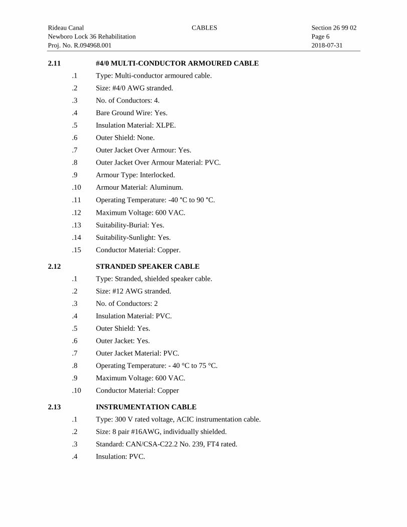
Rideau Canal CABLES Section 26 99 02 Newboro Lock 36 Rehabilitation Page 6 Proj. No. R.094968.001 2018-07-31 2.11 #4/0 MULTI-CONDUCTOR ARMOURED CABLE
.1 Type: Multi-conductor armoured cable.
.2 Size: #4/0 AWG stranded.
.3 No. of Conductors: 4.
.4 Bare Ground Wire: Yes.
.5 Insulation Material: XLPE.
.6 Outer Shield: None.
.7 Outer Jacket Over Armour: Yes.
.8 Outer Jacket Over Armour Material: PVC.
.9 Armour Type: Interlocked.
.10 Armour Material: Aluminum.
.11 Operating Temperature: -40 °C to 90 °C.
.12 Maximum Voltage: 600 VAC.
.13 Suitability-Burial: Yes.
.14 Suitability-Sunlight: Yes.
.15 Conductor Material: Copper.
2.12 STRANDED SPEAKER CABLE
.1 Type: Stranded, shielded speaker cable.
.2 Size: #12 AWG stranded.
.3 No. of Conductors: 2
.4 Insulation Material: PVC.
.5 Outer Shield: Yes.
.6 Outer Jacket: Yes.
.7 Outer Jacket Material: PVC.
.8 Operating Temperature: - 40 °C to 75 °C.
.9 Maximum Voltage: 600 VAC.
.10 Conductor Material: Copper
2.13 INSTRUMENTATION CABLE
.1 Type: 300 V rated voltage, ACIC instrumentation cable.
.2 Size: 8 pair #16AWG, individually shielded.
.3 Standard: CAN/CSA-C22.2 No. 239, FT4 rated.
.4 Insulation: PVC.
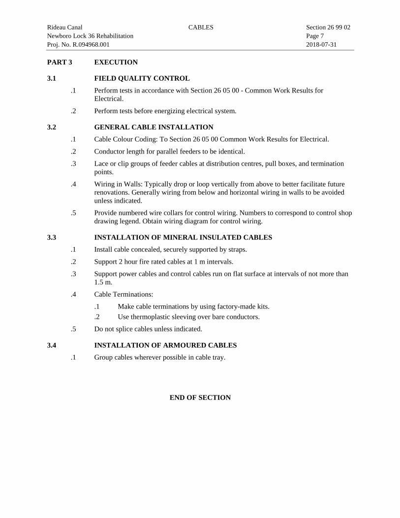
Rideau Canal CABLES Section 26 99 02 Newboro Lock 36 Rehabilitation Page 7 Proj. No. R.094968.001 2018-07-31 PART 3 EXECUTION
3.1 FIELD QUALITY CONTROL
.1 Perform tests in accordance with Section 26 05 00 - Common Work Results for Electrical.
.2 Perform tests before energizing electrical system.
3.2 GENERAL CABLE INSTALLATION
.1 Cable Colour Coding: To Section 26 05 00 Common Work Results for Electrical.
.2 Conductor length for parallel feeders to be identical.
.3 Lace or clip groups of feeder cables at distribution centres, pull boxes, and termination points.
.4 Wiring in Walls: Typically drop or loop vertically from above to better facilitate future renovations. Generally wiring from below and horizontal wiring in walls to be avoided unless indicated.
.5 Provide numbered wire collars for control wiring. Numbers to correspond to control shop drawing legend. Obtain wiring diagram for control wiring.
3.3 INSTALLATION OF MINERAL INSULATED CABLES
.1 Install cable concealed, securely supported by straps.
.2 Support 2 hour fire rated cables at 1 m intervals.
.3 Support power cables and control cables run on flat surface at intervals of not more than 1.5 m.
.4 Cable Terminations:
.1 Make cable terminations by using factory-made kits.
.2 Use thermoplastic sleeving over bare conductors.
.5 Do not splice cables unless indicated.
3.4 INSTALLATION OF ARMOURED CABLES
.1 Group cables wherever possible in cable tray.
END OF SECTION

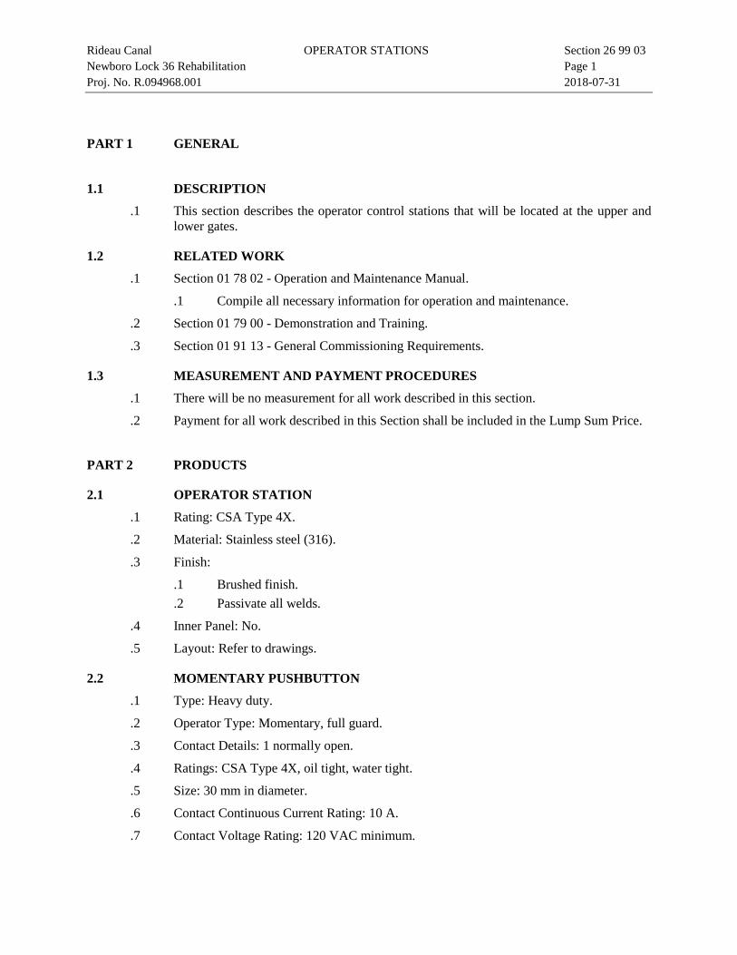
Rideau Canal OPERATOR STATIONS Section 26 99 03 Newboro Lock 36 Rehabilitation Page 1 Proj. No. R.094968.001 2018-07-31
PART 1 GENERAL
1.1 DESCRIPTION
.1 This section describes the operator control stations that will be located at the upper and lower gates.
1.2 RELATED WORK
.1 Section 01 78 02 - Operation and Maintenance Manual.
.1 Compile all necessary information for operation and maintenance.
.2 Section 01 79 00 - Demonstration and Training.
.3 Section 01 91 13 - General Commissioning Requirements.
1.3 MEASUREMENT AND PAYMENT PROCEDURES
.1 There will be no measurement for all work described in this section.
.2 Payment for all work described in this Section shall be included in the Lump Sum Price.
PART 2 PRODUCTS
2.1 OPERATOR STATION
.1 Rating: CSA Type 4X.
.2 Material: Stainless steel (316).
.3 Finish:
.1 Brushed finish.
.2 Passivate all welds.
.4 Inner Panel: No.
.5 Layout: Refer to drawings.
2.2 MOMENTARY PUSHBUTTON
.1 Type: Heavy duty.
.2 Operator Type: Momentary, full guard.
.3 Contact Details: 1 normally open.
.4 Ratings: CSA Type 4X, oil tight, water tight.
.5 Size: 30 mm in diameter.
.6 Contact Continuous Current Rating: 10 A.
.7 Contact Voltage Rating: 120 VAC minimum.
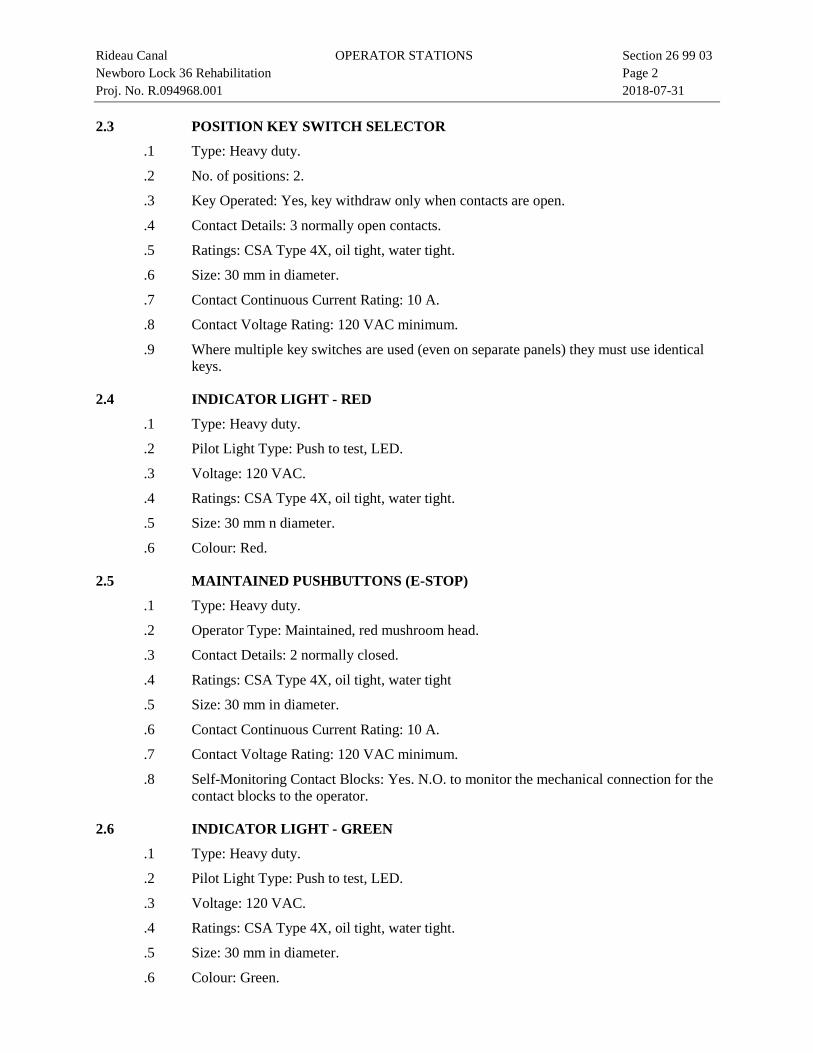
Rideau Canal OPERATOR STATIONS Section 26 99 03 Newboro Lock 36 Rehabilitation Page 2 Proj. No. R.094968.001 2018-07-31 2.3 POSITION KEY SWITCH SELECTOR
.1 Type: Heavy duty.
.2 No. of positions: 2.
.3 Key Operated: Yes, key withdraw only when contacts are open.
.4 Contact Details: 3 normally open contacts.
.5 Ratings: CSA Type 4X, oil tight, water tight.
.6 Size: 30 mm in diameter.
.7 Contact Continuous Current Rating: 10 A.
.8 Contact Voltage Rating: 120 VAC minimum.
.9 Where multiple key switches are used (even on separate panels) they must use identical keys.
2.4 INDICATOR LIGHT - RED
.1 Type: Heavy duty.
.2 Pilot Light Type: Push to test, LED.
.3 Voltage: 120 VAC.
.4 Ratings: CSA Type 4X, oil tight, water tight.
.5 Size: 30 mm n diameter.
.6 Colour: Red.
2.5 MAINTAINED PUSHBUTTONS (E-STOP)
.1 Type: Heavy duty.
.2 Operator Type: Maintained, red mushroom head.
.3 Contact Details: 2 normally closed.
.4 Ratings: CSA Type 4X, oil tight, water tight
.5 Size: 30 mm in diameter.
.6 Contact Continuous Current Rating: 10 A.
.7 Contact Voltage Rating: 120 VAC minimum.
.8 Self-Monitoring Contact Blocks: Yes. N.O. to monitor the mechanical connection for the contact blocks to the operator.
2.6 INDICATOR LIGHT - GREEN
.1 Type: Heavy duty.
.2 Pilot Light Type: Push to test, LED.
.3 Voltage: 120 VAC.
.4 Ratings: CSA Type 4X, oil tight, water tight.
.5 Size: 30 mm in diameter.
.6 Colour: Green.
Rideau Canal OPERATOR STATIONS Section 26 99 03 Newboro Lock 36 Rehabilitation Page 3 Proj. No. R.094968.001 2018-07-31 2.7 3 POSITION SELECTOR SWITCH SPRING RETURN
.1 Type: Heavy duty.
.2 Operator Type: 3-position selector, gloved hand, spring return to centre.
.3 Contact details:
.1 Left position - 1 N.O. contact.
.2 Right position - 1 N.O. contact.
.4 Ratings: CSA Type 4X, oil tight, water tight.
.5 Size: 30 mm in diameter.
.6 Contact Continuous Current Rating: 10 A.
.7 Contact Voltage Rating: 120 VAC minimum.
.8 Colour: Black.
.9 Illuminated Pushbutton: No.
2.8 3 POSITION SELECTOR SWITCH MAINTAINED
.1 Type: Heavy duty.
.2 Operator Type: 3-position selector, gloved hand, maintained.
.3 Contact details:
.1 Left position - 1 N.O. contact.
.2 Right position - 1 N.O. contact.
.4 Ratings: CSA Type 4X, oil tight, water tight.
.5 Size: 30 mm in diameter.
.6 Contact Continuous Current Rating: 10 A.
.7 Contact Voltage Rating: 120 VAC minimum.
.8 Colour: Black.
.9 Illuminated Pushbutton: No.
2.9 CONTORL PANEL COVER
.1 Form From: 11 gauge stainless steel (316).
.2 Seams (if applicable): To be continuously welded and ground smooth.
.3 Finish:
.1 Remove all sharp edges.
.2 Brushed finish.
.3 Passivate all welds.
.4 Install hardware and fasteners as noted on pedestal assembly drawings.
.5 Receptacle: Include a 120 VAC receptacle in the enclosure for PA or other devices.
.6 Padlock Holes: Ensure that padlock clearance holes align properly in opened and closed positions.
Rideau Canal OPERATOR STATIONS Section 26 99 03 Newboro Lock 36 Rehabilitation Page 4 Proj. No. R.094968.001 2018-07-31
.7 Padlock: To be supplied by Owner.
2.10 GAS SPRINGS
.1 Stainless steel body with M6 male threaded end.
.2 Stainless steel rod with M6 male threaded end.
.3 Stainless steel ball end fitting with Female M6 thread.
.4 Stainless steel mounting ball stud, sized and rated to suit.
.5 Overall Extended Length of Assembly (ball centre - ball centre): 320-325 mm.
.6 Overall Retracted Length of Assembly (ball centre - ball centre): 220-225 mm.
.7 Spring Force: Nominal spring force rating 15 lbs.
.8 Configuration: Install as shown on pedestal assembly drawing (orientation must match drawing for proper seal lubrication).
.9 Mounting Flexibility: .1 Install as shown. .2 Make minor position adjustments if necessary to accommodate actual
gas spring assembly dimensions.
PART 3 EXECUTION
3.1 INSTALLATION
.1 Install operator stations and interconnect per drawings.
.2 Cabinets to be in conformance with UL508.
3.2 FIELD QUALITY CONTROL
.1 Perform tests in accordance with Section 26 05 00 - Common Work Results - Electrical.
.2 Depending upon magnitude and complexity, divide control system into convenient sections, energize one section at time and check out operation of section.
.3 Upon completion of sectional test, undertake group testing.
.4 Check out complete system for operational sequencing.
3.3 IDENTIFICATION
.1 Equipment Identification: To Section 26 05 00 - Common Work Results for Electrical.
END OF SECTION
Rideau Canal SENSORS Section 26 99 04 Newboro Lock 36 Rehabilitation Page 1 Proj. No. R.094968.001 2018-07-31
PART 1 GENERAL
1.1 DESCRIPTION
.1 This section describes the new sensors that will be used on the gate miter locations, sluice valve cylinders and lock gate cylinders.
1.2 RELATED WORK
.1 Section 01 78 02 - Operation and Maintenance Manual.
.1 Compile all necessary information for operation and maintenance.
.2 Section 01 79 00 - Demonstration and Training.
.3 Section 01 91 13 - General Commissioning Requirements.
1.3 MEASUREMENT AND PAYMENT PROCEDURES
.1 There will be no measurement for all work described in this section.
.2 Payment for all work described in this Section shall be included in the Lump Sum Price.
PART 2 PRODUCTS
2.1 PROXIMITY SENSOR
.1 Type: Pre-wired, unshielded, 2 wire.
.2 Minimum Sensing Distance: 18 mm.
.3 Size: M30.
.4 Length: Long barrel type.
.5 Output State: Normally open.
.6 Supply Voltage: 120 VAC
.7 Sensing Object: Magnetic metals.
.8 Rating: IEC IP67.
2.2 FIELD MOUNTED JUCTION BOX
.1 Rating: CSA Type 4X.
.2 Material: Two piece molded fiberglass reinforced polyester.
.3 Size: Contractor to determine.
2.3 LINEAR DISPLACEMENT TRANSDUCER
.1 Type: 3 Wire with shield.
.2 Rating: IEC IP68 for integral cable with length of 5.2 m.
.3 Input Voltage: 24 VDC.
Rideau Canal SENSORS Section 26 99 04 Newboro Lock 36 Rehabilitation Page 2 Proj. No. R.094968.001 2018-07-31
.4 Output: Analog 4-20 mA.
.5 Repeatability: System resolution (2 μm minimum).
.6 Measuring Range: Full stroke of cylinder, cylinder stroke per Section 11 99 08 – Hydraulic Cylinders.
.7 Adjustability Null/Span: 100% of electrical stroke length, 25 mm minimum distance between set points.
PART 3 EXECUTION
3.1 SENSOR INSTALLATION
.1 Refer to the drawings.
3.2 JUNCTION BOX INSTALLATION
.1 Install junction boxes in inconspicuous but accessible locations.
.2 Install all junction boxes including those for valve transducers on shore such that bottom of box is 100 mm above grade.
.3 Install terminal block as required.
.4 Refer to the drawings.
.5 Only main junction and pull boxes are indicated on drawings. Install additional pull boxes as required by CSA C22.1.
3.3 IDENTIFICATON
.1 Equipment Identification: To Section 26 05 00 - Common Work Results for Electrical.
END OF SECTION
Rideau Canal POWER AND EMERGENCY BACKUP POWER SYSTEMS Section 26 99 05 Newboro Lock 36 Rehabilitation Page 1 Proj. No. R.094968.001 2018-07-31
PART 1 GENERAL
1.1 DESCRIPTION
.1 This section describes the equipment associated with the power system and the emergency backup power system. This includes the generator, power distribution panels and associated electrical equipment.
1.2 RELATED WORK
.1 Section 01 78 02 - Operation and Maintenance Manual.
.1 Compile all necessary information for operation and maintenance.
.2 Section 01 79 00 - Demonstration and Training.
.3 Section 01 91 13 - General Commissioning Requirements.
1.3 MEASUREMENT AND PAYMENT PROCEDURES
.1 There will be no measurement for all work described in this Section.
.2 Payment for all work described in this Section shall be included in the Lump Sum Price.
PART 2 PRODUCTS
2.1 TRANSFER SWITCH
.1 Voltage: 120 VAC minimum.
.2 Amp Rating: 30 A minimum.
.3 No. of Poles: Double pole.
.4 Transfer Mode: Manual.
.5 Approvals: CSA approved.
2.2 TWIST LOCK PLUG
.1 Wiring Scheme: 3 pole, 4 wire grounding.
.2 Voltage: 120/240 VAC.
.3 Amperage: 30 A.
.4 NEMA Configuration: L14-30P.
.5 Terminal Accommodation: 30 A #10 AWG.
.6 Rating: IEC IP66.
2.3 TWIST LOCK CONNECTOR BODY
.1 Wiring Scheme: 3 pole, 4 wire grounding.
.2 Voltage: 120/240 VAC.
.3 Amperage: 30 A.
Rideau Canal POWER AND EMERGENCY BACKUP POWER SYSTEMS Section 26 99 05 Newboro Lock 36 Rehabilitation Page 2 Proj. No. R.094968.001 2018-07-31
.4 NEMA Configuration: L14-30R.
.5 Terminal Accommodation: 30 A #10 AWG.
.6 Rating: IEC IP66.
2.4 GENERATOR
.1 Type: Two wheeled, portable, gasoline powered, electric start.
.2 Rated Voltage: 120/240 VAC.
.3 Phase: 1.
.4 Receptacles: NEMA L14-30R, 30A 125/250 V, refer to Section 26 99 05 – 2.3.
.5 Accepts NEMA Plug Number: L14-30P, refer to Section 26 99 05 – 2.5.
.6 AC Output Rated: 5,500 Watts.
.7 AC Output Max: 6,500 Watts.
.8 Run Time: Minimum 2 hours.
.9 Fuel Type: Regular unleaded gasoline.
.10 Starting Type: Electronic ignition.
.11 Starting Method: Electric start with manual recoil backup.
2.5 TWIST LOCK SAFETY SHROUD FLANGED INLET
.1 Type: Flanged inlet.
.2 Wiring Scheme: 3 pole, 4 wire grounding.
.3 Amperage: 30 A.
.4 Voltage: 125/250 VAC.
.5 NEMA Configuration: L14-30P.
.6 Style: Shrouded, watertight.
.7 Terminal Accommodation: 30 A, #10 WG.
.8 Installation: Watertight.
2.6 TRANSFORMER
.1 Type: Dry, open type.
.2 Enclosure: Ventilated indoor enclosure, NEMA 1.
.3 Input Voltage: 600 VAC.
.4 Input Phase: 3, Delta Connection.
.5 Output Voltage: 120/208 VAC.
.6 Output Phase: 3, Grounded Wye Connection.
.7 Output VA: 60 kVA.
.8 Insulation Class: 220 °C .
.9 Operating Frequency: 60 Hz.
Rideau Canal POWER AND EMERGENCY BACKUP POWER SYSTEMS Section 26 99 05 Newboro Lock 36 Rehabilitation Page 3 Proj. No. R.094968.001 2018-07-31
.10 Standards: CSA.
2.7 DISTRIBUTION PANEL B
.1 Rating: 225 A.
.2 Voltage: 120/208 VAC, 3 phase, 4 wire.
.3 Short Circuit Level: 10 kA.
.4 Minimum 48 branch circuits.
.5 Copper bus bar.
.6 Spare Branch Circuit: A minimum of 20% free branch circuits is required.
2.8 DISTRIBUTION PANEL E
.1 Rating: 225A.
.2 Voltage: 120/208.VAC, 2 phase, 3 wire.
.3 Short Circuit Level: 10 kA.
.4 Minimum 24 branch circuits.
.5 Copper bus bar.
.6 Spare Branch Circuit: A minimum of 20% free branch circuits is required.
2.9 FUSED DISCONNECT SWITCH WITH TWIST LOCKING INLET
.1 Rating: 60 A minimum.
.2 Voltage: 120/240 VAC minimum
.3 Enclosure: NEMA 3R for outdoor installation.
.4 No. of Poles: Three poles.
.5 Approvals: CSA approved.
.6 Twist Locking Inlet: See Section 26 99 05 - 2.5 TWIST LOCK SAFETY SHROUD FLANGED INLET.
PART 3 EXECUTION
3.1 FABRICATION AND INSTALLATION
.1 Refer to the drawings.
END OF SECTION

Rideau Canal MOTORS AND MOTOR STARTERS Section 26 99 06 Newboro Lock 36 Rehabilitation Page 1 Proj. No. R.094968.001 2018-07-31
PART 1 GENERAL
1.1 DESCRIPTION
.1 This section describes the primary hydraulic pump motors and the emergency backup hydraulic pump motor.
1.2 RELATED WORK
.1 Section 01 78 02 - Operation and Maintenance Manual.
.1 Compile all necessary information for operation and maintenance.
.2 Section 01 79 00 - Demonstration and Training.
.2 Section 01 91 13 - General Commissioning Requirements.
1.3 MEASUREMENT AND PAYMENT PROCEDURES
.1 There will be no measurement for all work described in this section.
.2 Payment for all work described in this Section shall be included in the Lump Sum Price.
PART 2 PRODUCTS
2.1 THREE PHASE MOTOR – PRIMARY PUMPS
.1 Enclosure: Totally enclosed fan cooled (TEFC).
.2 Mounting style: Foot mount.
.3 Flange: C.
.4 Voltage: 600 VAC.
.5 Phase: 3.
.6 RPM: 1750.
.7 HP: 7.5.
.8 Frequency: 60 Hz.
.9 Type: Squirrel cage.
.10 Efficiency: 91% Minimum.
2.2 SINGLE PHASE MOTOR – EMERGENCY PUMP
.1 Enclosure: Totally enclosed fan cooled (TEFC).
.2 Mounting style: Foot mount.
.3 Flange: C.
.4 Voltage: 240 VAC.
.5 Phase: 1.
.6 RPM: 1750.
Rideau Canal MOTORS AND MOTOR STARTERS Section 26 99 06 Newboro Lock 36 Rehabilitation Page 2 Proj. No. R.094968.001 2018-07-31
.7 HP: 3.
.8 Frequency: 60 Hz
.9 Type: Squirrel cage.
.10 Efficiency: 89.5% Minimum.
2.3 THREE PHASE MOTOR STARTER – PRIMARY PUMPS
.1 Type: Soft starter.
.2 Voltage: 600 VAC.
.3 Protection: Fuse circuit breaker, voltage contactor and adjustable three-phase thermal bi-metallic overload protection.
.4 Size: Sizes and settings of overload devices shall conform to NEMA standards.
.5 2 NC and 2 NO auxiliary contacts.
.6 Green “Open” LED pilot light mounted on the front door.
.7 Red “Closed” LED pilot light mounted on the front door.
.8 3 position selector switch for MANUAL/ OFF /AUTO operation.
2.4 SINGLE PHASE MOTOR STARTER – EMERGENCY PUMP
.1 Type: Soft starter.
.2 Voltage: 240/120 VAC.
.3 Protection: Fuse circuit breaker, voltage contactor and adjustable single-phase thermal bi-metallic overload protection.
.4 Size: Sizes and settings of overload devices shall conform to NEMA standards.
.5 2 NC and 2 NO auxiliary contacts.
.6 Green “Open” LED pilot light mounted on the front door.
.7 Red “Closed” LED pilot light mounted on the front door.
.8 3 position selector switch for MANUAL/ OFF /AUTO operation.
PART 3 EXECUTION
3.1 FABRICATION AND INSTALLATION
.1 Refer to the drawings.
3.2 MANUFACTURER’S INSTRUCTIONS
.1 Compliance: Comply with manufacturer's written recommendations or specifications, including product technical bulletins, handling, storage and installation instructions, and datasheets.
3.3 INSTALLATION
.1 Refer to drawings.
.2 Dry out motor if dampness present in accordance with manufacturer's instructions.
Rideau Canal MOTORS AND MOTOR STARTERS Section 26 99 06 Newboro Lock 36 Rehabilitation Page 3 Proj. No. R.094968.001 2018-07-31
.3 Install motors on hydraulic power unit skid as per Section 11 99 07 - Hydraulic Power Unit.
.4 Install motor starters on the wall adjacent to motors and HPU
.5 Make wiring connections.
.1 Use liquid tight PVC jacketed flexible conduit between rigid conduit and motor.
.6 Make flexible conduit long enough to permit movement of motor over entire length of slide rails.
.7 Check for correct direction of rotation, with motor uncoupled from driven equipment.
.8 Align and couple motor to driven machinery to manufacturer's instructions, using only correct parts such as couplings, as provided by manufacturer.
.9 Check for soft motor starter functions as manufacturer’s instructions and manuals.
3.4 FIELD QUALITY CONTROL
.1 Perform tests in accordance with Section 26 05 00 - Common Work Results for Electrical.
END OF SECTION

Rideau Canal PUBLIC ADDRESS SYSTEM Section 26 99 06 Newboro Lock 36 Rehabilitation Page 1 Proj. No. R.094968.001 2018-07-31
PART 1 GENERAL
1.1 DESCRIPTION
.1 This section describes the Public Address (PA) system.
1.2 RELATED WORK
.1 Section 01 78 02 - Operation and Maintenance Manual.
.1 Compile all necessary information for operation and maintenance.
.2 Section 01 79 00 - Demonstration and Training.
.2 Section 01 91 13 - General Commissioning Requirements.
1.3 MEASUREMENT AND PAYMENT PROCEDURES
.1 There will be no measurement for all work described in this section.
.2 Payment for all work described in this Section shall be included in the Lump Sum Price.
PART 2 PRODUCTS
2.1 AMPLIFIER
.1 Enclosure: CSA Type 4X.
.2 Voltage: 120 VAC.
.3 Inputs: Microphone, sound source equipment and line inputs.
.4 Rated Outputs:
.1 60 W, 4 Ω.
.2 60 W, 70 V.
.5 Frequency Response:
.1 4 Ω mode: 20 Hz to 20 kHz ±3 dB
.2 70 V mode: 60 Hz to 20 k Hz ±3 dB.
.6 Standards: UL 2043.
2.2 HORN SPEAKER
.1 Rated Input: 30 W.
.2 Line Voltage: 70 V line.
.3 70 V Line: 170 Ω (30 W), 330 Ω (15 W), 650 Ω (7.5 W).
.4 Frequency Response: 250 Hz - 10 kHz.
.5 Rating: IEC IP67.
.6 Mounting Type: Stainless bracket mounted.
.7 Colour: Black
Rideau Canal PUBLIC ADDRESS SYSTEM Section 26 99 06 Newboro Lock 36 Rehabilitation Page 2 Proj. No. R.094968.001 2018-07-31 2.3 MICROPHONE
.1 Type: Moving coil microphone.
.2 Rated Impedance: 600 Ω, balanced.
.3 Rated Sensitivity: - 47 dB (1 kHz 0 dB = 1 V/Pa).
.4 Rating: IP66
.5 Cable:
.1 2 core shielded plus 2 core cable.
.2 Connector: No connector.
.3 Length: 1 m.
.6 Talk Switch: Short-off type with lock.
.7 Mount Type: Microphones to connect to the terminal block in the amplifier mounted in Upper Control Station and Lower Control Station.
PART 3 EXECUTION
3.1 FABRICATION AND INSTALLATION
.1 Refer to the drawings.
3.2 MANUFACTURER’S INSTRUCTIONS
.1 Compliance: Comply with manufacturer's written recommendations or specifications, including product technical bulletins, handling, storage and installation instructions, and datasheets.
3.3 INSTALLATION
.1 Install the amplifiers in Upper Operator Control Station and Lower Operator Control Station or CSA Type 4X enclosures adjacent/attached to Upper Control Station/Lower Control Station
.2 Install and wire the amplifiers, speakers and microphones in accordance with drawings and manufacturer's instructions.
.3 Check and adjust amplifiers and microphones to ensure the sound levels are appropriate to operators and boaters.
.4 Check and adjust speaker directions to ensure audio coverage over locks and gate areas.
3.4 FIELD QUALITY CONTROL
.1 Perform tests in accordance with Section 26 05 00 - Common Work Results for Electrical.
END OF SECTION