Embed Size (px)
Citation preview
GeneralSpecifications
<<Contents>> <<Index>>
GS 04L75B01-01EN
GS 04L75B01-01EN©Copyright July. 2015
1st Edition July.2015(YK)
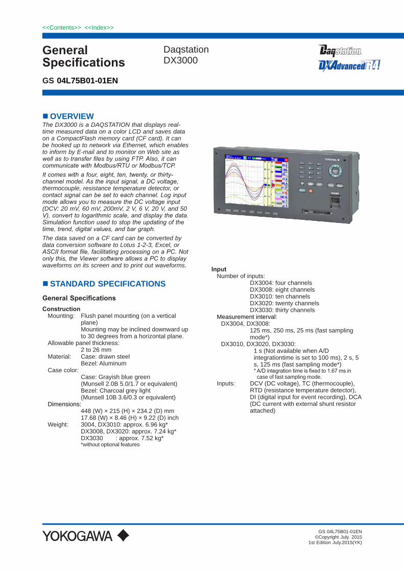
OVERVIEW The DX3000 is a DAQSTATION that displays real-time measured data on a color LCD and saves data on a CompactFlash memory card (CF card). It can be hooked up to network via Ethernet, which enables to inform by E-mail and to monitor on Web site as well as to transfer files by using FTP. Also, it can communicate with Modbus/RTU or Modbus/TCP. It comes with a four, eight, ten, twenty, or thirty-channel model. As the input signal, a DC voltage, thermocouple, resistance temperature detector, or contact signal can be set to each channel. Log input mode allows you to measure the DC voltage input (DCV: 20 mV, 60 mV, 200mV, 2 V, 6 V, 20 V, and 50 V), convert to logarithmic scale, and display the data. Simulation function used to stop the updating of the time, trend, digital values, and bar graph.The data saved on a CF card can be converted by data conversion software to Lotus 1-2-3, Excel, or ASCII format file, facilitating processing on a PC. Not only this, the Viewer software allows a PC to display waveforms on its screen and to print out waveforms.
STANDARD SPECIFICATIONS General Specifications Construction
Mounting: Flush panel mounting (on a vertical plane)
Mounting may be inclined downward up to 30 degrees from a horizontal plane.
Allowable panel thickness: 2 to 26 mm Material: Case: drawn steel Bezel: AluminumCase color: Case: Grayish blue green (Munsell 2.0B 5.0/1.7 or equivalent) Bezel: Charcoal grey light (Munsell 10B 3.6/0.3 or equivalent) Dimensions: 448 (W) × 215 (H) × 234.2 (D) mm 17.68 (W) × 8.46 (H) × 9.22 (D) inchWeight: 3004, DX3010: approx. 6.96 kg* DX3008, DX3020: approx. 7.24 kg* DX3030 : approx. 7.52 kg*
*without optional features
InputNumber of inputs: DX3004: four channels DX3008: eight channels DX3010: ten channels DX3020: twenty channels DX3030: thirty channels Measurement interval:
DX3004, DX3008: 125 ms, 250 ms, 25 ms (fast sampling
mode*)DX3010, DX3020, DX3030: 1 s (Not available when A/D
integrationtime is set to 100 ms), 2 s, 5 s, 125 ms (fast sampling mode*)
*A/Dintegrationtimeisfixedto1.67msincase of fast sampling mode.
Inputs: DCV (DC voltage), TC (thermocouple), RTD (resistance temperature detector), DI (digital input for event recording), DCA (DC current with external shunt resistor attached)
Daqstation DX3000

2
All Rights Reserved. Copyright © 2015, Yokogawa Electric Corporation
<<Contents>> <<Index>>
GS 04L75B01-01EN Jul. 01, 2015-00
Input type Range Measuring range
DCV
20 mV –20.000 to 20.000 mV60 mV –60.00 to 60.00 mV200 mV –200.00 to 200.00 mV2 V –2.0000 to 2.0000 V6 V –6.000 to 6.000 V1-5V 0.800 to 5.200 V20 V –20.000 to 20.000 V50 V –50.00 to 50.00 V
TC
R*1 0.0 to 1760.0°C 32 to 3200°FS*1 0.0 to 1760.0°C 32 to 3200°FB*1 0.0 to 1820.0°C 32 to 3308°FK*1 –200.0 to 1370.0°C –328 to 2498°FE*1 –200.0 to 800.0°C –328.0 to 1472.0°FJ*1 –200.0 to 1100.0°C –328.0 to 2012.0°FT*1 –200.0 to 400.0°C –328.0 to 752.0°FN*1 –270.0 to 1300.0°C –454 to 2372°FW*2 0.0 to 2315.0°C 32 to 4199°FL*3 –200.0 to 900.0°C –328.0 to 1652.0°FU*3 –200.0 to 400.0°C –328.0 to 752.0°FWRe*4 0.0 to 2400.0°C 32 to 4352°F
RTDPt100*5 –200.0 to 600.0°C –328.0 to 1112.0°FJPt100*5 –200.0 to 550.0°C –328.0 to 1022.0°F
DI
DCV input (TTL)
OFF : less than 2.4 VON : more than 2.4 V
Contact input Contact ON/OFF
*1 R, S, B, K, E, J, T, N: IEC584-1 (1995), DIN IEC584,JIS C 1602-1995
*2 W: W-5% Re/W-26% Re (Hoskins Mfg. Co.), ASTM E988-96(Type C equivalent of OMEGA Engineering Inc.)
*3 L: Fe-CuNi, DIN43710, U: Cu-CuNi, DIN43710*4 WRe: W-3%Re/W-25%Re (Hoskins Mfg. Co.),
ASTM E988-96(Type D equivalent of OMEGA Engineering Inc.)
*5 Pt100: JIS C 1604:2013, IEC 60751:2008, DIN IEC60751:2009 JPt100: JIS C 1604-1989,JIS C 1606-1989Measuring current: i = 1mA
A/D integration time: 20 ms (50 Hz), 16.7 ms (60 Hz), 100ms
(50/60Hz for DX3010/3020/3030), or AUTO selectable (automatic selection by detection of power supply frequency)
A/Dintegrationtimeisfixedto1.67ms(600Hz) in case of fast sampling mode.
Thermocouple burnout: Burnout upscale/downscale function can
be switched on/off (for each channel). Burnout upscale/downscale selectable Normal:Lessthan2kΩ,Burnout:More
than100kΩ Detection current: approx. 10 µA1-5V range burnout: Burnout upscale/downscale function can
be switched on/off (for each channel). Burnout upscale/downscale selectable Upscale burnout: More than +10% of
configuredspan Downscale burnout: Less than -5% of
configuredspan
Moving average: Moving average on/off selectable for
each channel Moving average cycles 2 to 400
selectableCalculation:
Differential computation: Between any two channels Available for DCV, TC, RTD and DI
ranges. Linear scaling: Available for DCV, TC, RTD and DI
ranges. Scaling limits: -30000 to 30000 Decimal point: user-selectable Engineeringunit:user-definable,upto
6 characters Over value: Exceeds ± 5% of scaling
limits (on/off selectable)Square root: Available for DCV range. Scaling limits: -30000 to 30000 Decimal point: user-selectable Engineeringunit:user-definable,upto
6 characters Low level cut off: 0.0 to 5.0% of display
span Over value: Exceeds ± 5% of scaling
limits (on/off selectable)1-5VDC scaling: Available for 1-5VDC range. Scaling limits: -30000 to 30000 Display span limit: 0.800 to 5.200 Decimal point: user-selectable Engineeringunit:user-definable,upto
6 characters Low level cut off: Fixed to lower span
limit Over value: Exceeds ± 5% of scaling
limits (on/off selectable)Display
Display unit: 10.4-inch TFT color LCD (VGA, 640 ×
480 pixels)Note) In the part of crystal display, there are some pixels
that can’t always turn on or off. Please understand that the brightness of screen looks uneven because of characteristics of crystal display, but it is not out of order.
Display group:Each measurement channel and computation channel can be assigned to display group of the trend, digital and bargraph display.
Number of display: 36 groups Number of assignable channels for one
group: 10 channelsDisplay color:
Trend/Bargraph: Selectable from 24 colorsBackground: White or black selectable
Trend display:Trend display type: Vertical, horizontal, landscape,
horizontal split or circular selectableNumber of indication channels: 10 channels per display (maximum)

3<<Contents>> <<Index>>
All Rights Reserved. Copyright © 2015, Yokogawa Electric Corporation GS 04L75B01-01EN Jul. 01, 2015-00
Number of display: 36 displays (36 groups)Line width: 1, 2, and 3 pixels selectableScales: Maximum 10 scales. Bargraph, green band area and alarm
mark can be displayed on scale display. Number of divisions: Selectable from 4
to 12 or C10 (10 divisions by main scale mark and scale values are displayed on 0, 30, 50, 70 and 100% position).
Trend update rate: 5, 10, 15, 30 sec.,1, 2, 5, 10, 15, 20, 30
min., 1, 2, 4, 10 hours/div selectable (5, 10 sec/div is available for only
DX3004 and DX3008. DX3010, DX3020,DX3030canbespecifiedto 15 sec/div when they are in fast sampling mode.)
Circular waveform span rate: 20, 30 min., 1, 2, 6, 8, 12, 16 hours, 1,
2 days, 1, 2, 4 weeks/rev selectable Bargraph display:
Direction: Vertical or horizontal selectableNumber of indication channels: 10 channels per displayNumber of display: 36 displays (36 groups)Scales: Green band area and alarm mark can
be displayed on scale display. Number of divisions: Selectable from 4 to 12 Reference position: Left, right or centerDisplay renewal rate: 1 s
Digital indication: Number of indication channels: 10 channels per display Number of display: 36 displays (36 groups) Display renewal rate: 1 s
Overview display: Number of indication channels: Measuring values and alarm status of
all channels Information display:
Alarm summary display: Display the list of latest 1000 alarms
summary. Jump to historical trend display by
cursor pointing.Message summary display: Display the list of latest 450 messages
and time. Jump to historical trend display by
cursor pointing. Memory information: Displaythefilelistininternalmemory. Jump to historical trend display by
cursor pointing. Report information: Display the report data in internal
memory.Modbus status: Display the Modbus status.Relay status: Display the on/off status of internal
switch and relay output.
Stacked bar graph display: Display the periodic sums of report
data.Event switch status: Display the event switch status.
Log display:Log display types: Login log, error log, communication log,
FTP log, Web log, E-mail log, SNTP log, DHCP log, Modbus log
Tags:Display the tag number and tag comment.Tag number:Number of characters: 16 characters maximumTag comment:Number of characters: 32 characters maximum
Messages:Number of characters: 32 characters maximumNumber of messages: 100 messages (including 10 free
messages)Message adding function: Message can be added on historical
display.Other display contents:
Status display area: Date & time (year/month/day,
hour:minute:second), batch name (batch number + lot number), login user name, display name, internal memory status, status indication icon
Trend display area: Grid lines (number of divisions
selectable from 4 to 12), hour : minutes on grid, trip levels (line widths are selectable from 1, 2 and 3 pixels)
Data referencing function: Display the retrieved data (display data or event
data) from internal or external memory. Display format: Whole display or divided to 2 areas Time axis operation: Displaymagnificationorreduction,
scroll by key operationData searching operation: Display the retrieved data from internal
memory by specifying date and time.Display auto scroll function: Display group of monitor display (trend
display, bargraph display and digital display) automatically changes in a preset interval (5, 10, 20, 30 s and 1 min).
LCD saver function: The LCD backlight automatically dims or
off (selectable) if no key is touched for a certain preset time (can be set from 1, 2, 5, 10, 30, and 60 min).
Display register function: Up to 8 display types can be registered
with display name.

4
All Rights Reserved. Copyright © 2015, Yokogawa Electric Corporation
<<Contents>> <<Index>>
GS 04L75B01-01EN Jul. 01, 2015-00
Display auto return function: The display type automatically returns to
registerd display type if no key is touched for a certain preset time (can be set from 1, 2, 5, 10, 20, 30 and 60 min)
Temperature unit: °C or °F selectableCustom display function:
Display can be customized by lay outing display parts. Display data is saved in internal memory or external medium.Number of customized display: 28 displays maximum (3 in internal
memory and 25 in external medium)Display part: - General parts (digital, bar, label, tag
number, tag comment, system icon, Modbus input, etc)
- Scale parts - Trend parts - List parts (alarm list, message list) - Figure parts (line, rectangle, circle)Edit function: Select parts, grid, edit parts (move,
resize, property, copy, paste, layout order change, dependency of visual property), group control, delete, save display
Custom display data: Contents: Display contents data (for
each display) Format: Text Output: External mediumCustom display data save/load: Eachorallcustomdisplaydatafilecan
besavedinspecifieddirectory. Custom display data can be loaded
fromspecifieddirectory.Data Saving Function
External storage medium:Medium: CompactFlash memory card (CF card)Format: FAT16 or FAT32
Internal memory:Medium: Flash memoryCapacity: 400MBMaximumnumberoffilescanbesaved: 400files(totalnumberofdisplaydata
fileandeventdatafile)Manual saving: Datafilesininternalmemorycanbesavedmanually.Selectable form all data saving or selected data saving.Drive:CFcardorUSBflashdrive(onlyforUSBoption)
Automatic saving: Display data: Periodic saving to CF cardEvent data: In case of trigger free...Periodic saving
to CF card In case of using trigger...Save the data
whensamplingisfinished
Media FIFO function : Allowstheoldestfiletobedeletedand
thenewestfiletobesavedifthefreespaceontheCFcardisinsufficient(on/off selectable).
Sampling Period (data saving period): Displaydatafile: Linked with the trend update rate Eventfile: Linkedwiththespecifiedsampling
period Event File Sampling Period:
DX3004, DX3008: Selectable from 25, 125, 250, 500 ms,
and 1, 2, 5, 10, 30, 60, 120, 300, 600, 900, 1200 and 1800 s*
DX3010, DX3020, DX3030: Selectable from 125, 250, 500 ms, and
1, 2, 5, 10, 30, 60, 120, 300, 600, 900, 1200 and 1800 s*
* Sampling period faster than measurement interval can not be selected.
Measurement data File: Thefollowingtwofiletypescanbecreated. Eventfile(storesinstantaneousvalues
sampledperiodicallyataspecifiedsampling period)
Displaydatafile(storesthemaximumand minimum values for each sampling period from among measured data sampled at measurement intervals)
Files can be created in the following combinations. (a) Eventfile+displaydatafile(b) Displaydatafileonly(c) Eventfileonly
Data format: YOKOGAWA private format (Binary) Maximumdatasizeperfile: 8,000,000 byte (8MB)Data per channel: Displaydatafile: Measurement data......4 byte/data Mathematical data......8 byte/data External channel data..4 byte/data Eventdatafile: Measurement data......2 byte/data Mathematical data......4 byte/data External channel data..2 byte/data
Sampling time: Thesamplingtimeperfile(8MB)duringmanualdata saving can be determined by the formula “number of data items per channel × interval of data saving (sampling period).” This logic is explained in more detail below: 1)Whenhandlingdisplaydatafilesonly
If we assume that the number of measuring channels is 30, the number of computing channels is 10, and the trend update rate is 30 min/div (60 sec sampling period), then:
Number of data items per channel = 8,000,000 bytes/(8 bytes(time stamp) + 30 × 4 bytes + 10 × 8 bytes) = 38,462 data itemsSamplingtimeperfile=38,462×60sec=2,307,720 sec = approx. 26 days

5<<Contents>> <<Index>>
All Rights Reserved. Copyright © 2015, Yokogawa Electric Corporation GS 04L75B01-01EN Jul. 01, 2015-00
2)WhenhandlingeventfilesonlyIf we assume that the number of measuring channels is 30, the number of computing channels is 10, and the sampling period is 1 sec, then :
Number of data items per channel = 8,000,000 bytes/(8 bytes(time stamp) + 30 × 2 bytes + 10 × 4 bytes) = 74,074 data items Samplingtimeperfile=74,074×1sec=74,074 sec = approx. 20 hours
3)WhenhandlingbothdisplaydatafilesandeventfilesThesamplingtimeiscalculatedbydefiningthesizeofdataitemsinadisplaydatafileas8,000,000 bytes and the size of data items in an eventdatafileas8,000,000bytes.Themethodof calculation is the same as shown above.
ExamplesofSamplingTimefor1file(8MB)*:*Ifsamplingtimeexceeds31days,datafileisdivided.
In case measurement ch = 8 ch, mathematical ch = 0 chDisplay data file (approx.)Trend update rate (time/div) 15 s 30 s 1 min 2 min 5 min 10 min
Sampling period 0.5 s 1 s 2 s 4 s 10 s 20 sSampling time 27.8 h 2 days 4 days 9 days 23 days 46 days
Event data file (approx.)Sampling period 25 ms 125 ms 0.5 s 1 s 2 s 5 s 10 sSampling time 2.3 h 11.6 h 46.3 h 3 days 7 days 19 days 38 days
Manual sample data:The measuring and computing data can be saved manually to the internal memory and CF card.Trigger: Key operation, communication
command or event action functionData format: Text Max. number of data: 400 data (if exceeds 400 data, oldest
data is overwritten)Report data (only for MATH option):
Types: Hourly, daily, hourly + daily, daily + weekly, and daily + monthly
Data format: TextDrive: CF card
Trigger function: Selectable from FREE or TRIG for event data saving.Trigger mode: Selectable from free, single or repeat
triggerData length: Selectable from 10, 20, 30 min, 1, 2, 3, 4,
6, 8, 12 hour, 1, 2, 3, 5, 7, 10, 14, 31 dayPre trigger: Selectable from 0, 5, 25, 50, 75, 95,
100%Trigger source: Key operation, communication
command or event action functionDisplay hard copy:
Trigger: Key operation, communication command or event action function
Data format: png format Drive/output: CF card or communication interface
Datafileretrievingfunction:DatafileinCFcardorUSBflashdrive(onlyforUSB option) can be retrieved and displayed.Retrieveddatafile: Displaydatafileoreventdatafile
Savingandretrievingofconfigurationdata:Configurationinformationcanbesavedandretrieved as text data.Drive: CFcardorUSBflashdrive(onlyfor
USB option)Alarm Function
Number of alarm levels: Up to four levels for each channelAlarm types: High and low limits, differential high and
low limits, high and low rate-of-change limits and delay high and low
Alarm delay time: 1 to 3600 sInterval time of rate-of-change alarms: The measurement interval times 1 to 32Display: The alarm status (type) is displayed
in the digital value display area upon occurrence of an alarm. A common alarm indication is also displayed.
Alarm display color and display order can bechangedbyconfiguredimportancelevel and color.
Alarming behavior: non-hold or hold-type can be selectable
for common to all channels. Hysteresis: On/off selectable (common to
measurement channels, mathematical channels or external channels)
0.0 to 5.0% of display span (or scaling span)
Outputs:Output: Internal switch or relay output (optional)Number of internal switch: 30 pointsInternal switch action: AND/ORNumber of relay output points: 6, 12, 22 or 24 points (optional)Relay action: Energized/deenergized, hold/non-hold,
AND/OR,alarmreflashselectable.

6
All Rights Reserved. Copyright © 2015, Yokogawa Electric Corporation
<<Contents>> <<Index>>
GS 04L75B01-01EN Jul. 01, 2015-00
Alarm no logging function: When alarm occurs, only internal switch
or relay output is activated. There are no alarm display on screen and no record on alarm summary.
On/off selectable for each channel and alarm level.
Memory: The times of alarm occurrences/recoveries, alarm types, etc. are stored in the memory. Up to 1000 latest alarm events are stored.
Alarm annunciator function:Alarm display and relay output based on alarm sequence.Alarm sequence: 3 types (ISA-A-4, ISA-A, ISA-M)First out display function: Not available
Event action functionGeneral: Particular action can be executed by
particular event.Number of event action: 40 actions can be setEvent list:
Event Level/Edge DescriptionRemote Level/Edge Action by remote control signalRelay Level/Edge Action by relay operationInternal switch Level/Edge Action by internal switch
operationAlarm Level/Edge Action by any alarmTimer Edge Action by timer time up
Match time Edge Action by time up of match time timer
USER key Edge Action by USER key operationEvent level switch Level/Edge Action by custom display, or
communication command
Event edge switch Edge
Action by custom display, FUNC display or communication command
Alarm OFF Level/Edge Action by alarm OFFInternal switch OFF Level/Edge Action by internal switch OFF
Relay OFF Level/Edge Action by Relay OFFLevel switch OFF Level/Edge Action by level switch OFF
Action list:
Action Level/Edge DescriptionMemory start/stop Level Memory start and stop
Memory start Edge Memory startMemory stop Edge Memory stopEvent trigger Edge Event data sampling startAlarm ACK Edge Alarm ACKMath start/stop Level Computation start and stop
Math start Edge Computation startMath stop Edge Computation stopMath reset Edge Computation resetManual sample Edge Manual sample
Snapshot Edge Save display image to external media
Message input Edge Message writing
Trend update rate change
Level Change trend update rate
Display data save Edge Save currently sampled display
datatointernalmemoryasafileEvent data save Edge Save currently sampled event
datatointernalmemoryasafileRelative time timer reset Edge Reset relative time timer
Display group change
Edge Changetospecifieddisplaygroup
Time adjustment Edge Adjust internal clock to the
nearest hourFlag Level Normal: "0", Event: "1"Settingfileload Edge LoadsettingfilefromCFcard
(upto3settingfiles).Alarm display reset Edge Reset alarm display
Comment display Edge Display comment
Favorite display Edge Display registered favorite
screen
Security functionsGeneral: Login function or key lock function
can be set for each key operation or communication operation.
Key lock function: On/off and password can be set for each
operation key and FUNC operation. Login function:
Using the login function described below, you can enter security settings on the instrument
- User name - Password
User level and number of users: System administrator: 5 users (all can
be operated) General user: 30 users (With
user restrictions, you can set restrictions on each operation key and FUNC display operation.)
User restrictions setting: 10 kinds (for general users)
7<<Contents>> <<Index>>
All Rights Reserved. Copyright © 2015, Yokogawa Electric Corporation GS 04L75B01-01EN Jul. 01, 2015-00
ClockClock: With calendar function (year of grace)Clock accuracy: ± 10 ppm, excluding a delay (of 1
second, maximum) caused each time the power is turned on.
Time setting method: Key operation, communication
command, event action function or SNTP client function
Time adjustment method:During memory sample: Adjust40mspersecond(Noinfluence
for measurement period)During memory stop: Adjust at a time
Time zone:Time difference from GMT: Settable from -1300 to 1300
Date display format: Selectable from YYYY/MM/DD, MM/DD/
YYYY, DD/MM/YYYY or DD.MM.YYYYDST function (summer/winter time): The time at which the daylight savings
time adjustment is automatically calculatedandconfigured.
Communication Functions Electricalspecifications: ConfirmstoIEEE802.3(DIXspecification
for Ethernet frames)Connection: Ethernet (10BASE-T) Protocols: TCP, UDP, IP, ICMP, ARP, DHCP, HTTP,
FTP, SMTP, SNTP, Modbus, DX private, EtherNet/IP
E-mail inform function: E-mail is sent by events as below.
- Alarm occurring/alarm canceling - Recover from power failure - Memory end - Storage medium error, FTP client
function error -Specifiedtimeperiod - Report data time up (only for
mathematical option)POP before SMTP and SMTP authentication (PLAIN and CRAM-MD5) is available.
FTP client function: Datafileauto-transferfromDXTransferreddatafile: Displaydatafile,eventdatafile,report
datafileanddisplayimagefileFTP server function: FiletransferfromDX,fileelimination,
directoryoperationandfilelistoutputareavailable by request from host computer.
Web server function: Display image of DX and alarm
information can be displayed on web browser.
Display the data searching display and report data of DX on web browser.
You can have a buzzer sound on the PC when an alarm occurs on the DX.
SNTP client function: The time on DX can be synchronized to
the time of a SNTP server.
SNTP server function: The DX can operate as a SNTP server.DHCP client function:Networkaddressconfigurationcanbeobtainedautomatically from DHCP server.Obtained information: IP address, subnet mask, default
gateway and DNS informationModbus client function: Reading or writing of measurement data
on other instruments are available by Modbus protocol.
Mathematical option or external input option is required to read the data from other instruments.
Modbus server function: Output of measurement data from DX is
available by Modbus protocol. Control operation such as message or
batch name writing is available. Access control from Modbus client to registerisavailablebyIPfiltering
function.Setting/measurement server function: Operation, setting or output of
measurement data are available by DX private protocol.
Maintenance/test server function: Output connection information or
network information of the Ethernet communication.
Instrument information server function: Output instrument information such as
serial number or model name of DX.EtherNet/IP server function: - Reading of measurement data or
mathematical channel data - Reading or writing of external channel
data - Reading or writing of communication
input channelBatch function
General: Data display and data management with batchname,textfieldfunctionandbatch
comment function are available.Batch name:Batchnamecanbeusedasfilenameofdisplaydata, event data and report data.Batch name format:
Batch number (max. 32 characters) + lot number (max. 8 characters)
Use/not use selectable for lot number, on/off selectable for auto increment function
Textfieldfunction:Field number:
1 to 24Field title:
Max. 20 charactersField text:
Max. 30 charactersBatch comment function:
Batch comment is added to display data and event data.Batch comment information:
3 comments (max. 50 characters) are available.

8
All Rights Reserved. Copyright © 2015, Yokogawa Electric Corporation
<<Contents>> <<Index>>
GS 04L75B01-01EN Jul. 01, 2015-00
Insulation resistance:Each terminal to ground terminal: 20MΩorgreater(at500VDC)
Dielectric strength:Power supply to ground terminal: 2300 VAC (50/60 Hz), 1 minContact output terminal to ground terminal: 1600 VAC (50/60 Hz), 1 minMeasuring input terminal to ground terminal: 1500 VAC (50/60 Hz), 1 minBetween measuring input terminals: 1000 VAC (50/60 Hz), 1 min (except
for b-terminal of RTD input of DX3010, DX3020, and DX3030)
Between remote control terminal to ground terminal: 1000 VDC, 1 min
Safety Standards CSA: CSA22.2 No.61010-1, CSA C22.2
No.61010-2-030 Installation category II*1, pollution degree
2*2, measurement category II*3
UL: UL61010-1, UL61010-2-030 (CSA NRTL/C)
*1: Installation Category (Overvoltage Category) II Describesanumberwhichdefinesatransient overvoltage condition. It implies the regulation for impulse withstand voltage. “II” applies to electrical equipment whichissuppliedfromfixedinstallationslike distribution boards.
*2: Pollution Degree Describes the degree to which a solid, liquid, or gas which deteriorates dielectric strength or surface resistivity is adhering. “2” applies to normal indoor atmosphere. Normally, only non-conductive pollution occurs.
*3: Measurement Category II Applies to measuring circuits connected to low voltage installation, and electrical instruments supplied with power fromfixedequipmentsuchaselectricswitchboards.
LOG input functionThis mode allows you to measure the DC voltage input (DCV: 20 mV, 60 mV, 200mV, 2 V, 6 V, 20 V, and 50 V), convert to logarithmic scale, and display the data.LOG Input Mode:
Selectable span range: Same range as the DC voltage input Span Lower must be less than Span
Upper.Selectable scale range:
1.0E-15 to 1.0E+15 (15 decades maximum)
Scale Lower must be less than Scale Upper.
Mantissa: Select two or three digits.Unit: You can set the unit.
Alarm types in LOG input mode:H, L, T, and t only.Set the alarm value using a voltage.Alarmhysteresisfixedto0%.
Simulation FunctionDisplay Freeze Function:
A function used to stop the updating of the time, trend, digital values, and bar graph.The display freeze function is controlled through the event action function or communication commands.
Memory and Trend Clear Function: A function used to clear the internal memory and the trend.The memory and trend clear function is controlled through the event action function or communication commands.
Enabling/Disabling the Time Display:A function used to disable the time display on the operation display.
Special Current Value Mark Function:A function used to display the channel using two digits for the current value mark that is displayed in the scale display position on the trend/historical trend display.
Power Supply Rated power supply: 100 to 240 VAC (automatic switching)Allowable power supply voltage range: 90 to 132 or 180 to 264 VACRated power supply frequency: 50/60 Hz (automatic switching)Power consumption:
Supply voltage LCD off Normal Max.100 VAC 28 VA 42 VA 74 VA240 VAC 38 VA 54 VA 100 VA
Allowable interruption time: Less than 1 cycle of power supply
frequencyOther Specifications
Memory backup : A built-in lithium battery backs up
the setup parameters (battery life: approximately 10 years at room temperature).

9<<Contents>> <<Index>>
All Rights Reserved. Copyright © 2015, Yokogawa Electric Corporation GS 04L75B01-01EN Jul. 01, 2015-00
Normal Operating Conditions Power voltage: 90 to 132 or 180 to 250 VAC Power supply frequency: 50 Hz ±2%, 60 Hz ±2% Ambient temperature: 0 to 50 °C Ambient humidity: 20% to 80% RH (at 5 to 40 °C) Vibration: 5≤f<8.4Hzamplitude3.5mm(peak) 8.4≤f≤160Hzacceleration9.8m/s2Shock: Not acceptable Magneticfield: 400 A/m or less (DC and 50/60 Hz) Noise:
Normal mode (50/60 Hz): DCV: The peak value including the
signal must be less than 1.2 times the measuring range.
TC: The peak value including the signal must be less than 1.2 times the measuring thermal electromotive force.
RTD: 50 mV or less Common mode noise voltage (50/60 Hz): 250 Vrms AC or less for all ranges Maximum noise voltage between channels (50/60 Hz): 250 Vrms AC or less
Mounting position: Can be inclined up to 30 deg backward. Mounting at an angle away from the
perpendicular is not acceptable. Warm-up time: At least 30 min after power on Installation location: In-roomAltitude: Less than 2000 m

10
All Rights Reserved. Copyright © 2015, Yokogawa Electric Corporation
<<Contents>> <<Index>>
GS 04L75B01-01EN Jul. 01, 2015-00
Input resistance: Approx.10MΩormoreforDCVranges
of 200 mVDC or less and TC Approx.1MΩformorethan2VDC
ranges Input source resistance: DCV,TC: 2kΩorless RTD: 10Ωorlessperwire(The
resistance of all three wires must be equal.)
Input bias current: 10 nA or less (approx. 100nA for TC
range with burnout function)Maximum common mode noise voltage: 250 Vrms AC (50/60 Hz) Maximum noise voltage between channels: 250 Vrms AC (50/60 Hz)
Standard Performance Measuring and Recording Accuracy:Thefollowingspecificationsapplytooperationoftherecorderunderstandardoperationconditions.
Temperature: 23 ± 2 °CHumidity: 55% ± 10% RHPower supply voltage: 90 to 132 or 180 to 250 VACPower supply frequency: 50/60 Hz ± 1%Warm-up time: At least 30 min.
Other ambient conditions such as vibration should not adversely affect recorder operation.
Input RangeMeasurement accuracy (digital display)
Max. resolution of digital displayA/D integration time:
16.7ms or moreA/D integration time:
1.67ms (fast sampling mode)
DCV
20 mV ±(0.05% of rdg + 12 digits) ±(0.1% of rdg + 40 digits) 1 µV60 mV
±(0.05% of rdg + 3 digits) ±(0.1% of rdg + 15 digits)10 µV
200 mV 10 µV2 V ±(0.05% of rdg + 12 digits) ±(0.1% of rdg + 40 digits) 100 µV6 V
±(0.05% of rdg + 3 digits) ±(0.1% of rdg + 15 digits)
1 mV1-5 V 1 mV20 V 1 mV50 V 10 mV
TC(Excluding RJCaccuracy)
R±(0.15% of rdg + 1°C) However,R, S:±3.7°C at 0 to 100°C±1.5°C at 100 to 300°CB:±2°C at 400 to 600°CAccuracy at less than 400°C is not guaranteed.
±(0.2% of rdg + 4°C) However,R, S:±10°C at 0 to 100°C±5°C at 100 to 300°CB:±7°C at 400 to 600°CAccuracy at less than 400°C is not guaranteed.
0.1°C
S
B
K±(0.15% of rdg + 0.7°C) However,±(0.15% of rdg + 1°C) at-200 to -100°C
±(0.2% of rdg + 3.5°C) However,±(0.15% of rdg + 6°C) at-200 to -100°C
E
±(0.15% of rdg + 0.5°C) However,±(0.15% of rdg + 0.7°C) at-200 to -100°C
±(0.2% of rdg + 2.5°C) However,±(0.2% of rdg + 5°C) at-200 to -100°C
JTLU
N
±(0.15% of rdg + 0.7°C) However,±(0.35% of rdg + 0.7°C) at-200 to 0°CAccuracy at less than -200°C is not guaranteed.
±(0.3% of rdg + 3.5°C) However,±(0.7% of rdg + 3.5°C) at-200 to 0°CAccuracy at less than -200°C is not guaranteed.
W ±(0.15% of rdg + 1°C) ±(0.3% of rdg + 7°C)
WRe ±(0.2% of rdg + 2.5°C) However,±4°C at 0 to 200°C
±(0.3% of rdg + 10°C) However,±18°C at 0 to 200°C
RTDPt100
±(0.15% of rdg + 0.3°C) ±(0.3% of rdg + 1.5°C)JPt100
Measurement accuracy in case of scaling (digits): = measurement accuracy (digits) ×
scaling span (digits)/measurement span (digits) + 2 digits
Decimals are rounded off to the next highest number.
Reference junction compensation: INT (internal)/EXT (external) selectable
(common for all channels) Reference junction compensation accuracy: Types K, J, E, T, N, L, U: ± 0.7 °C Types R, S, B*, W, WRe: ± 1.2 °C (Above 0 °C, input terminal temperature
is balanced) * Reference junction compensation is
fixed to the 0 °C.Maximum allowable input voltage: ± 60 VDC (continuous) for all input
ranges

11<<Contents>> <<Index>>
All Rights Reserved. Copyright © 2015, Yokogawa Electric Corporation GS 04L75B01-01EN Jul. 01, 2015-00
Interference between channels: 120 dB (when the input source
resistanceis500Ωandtheinputstoother channels are 60 V)
Common mode rejection ratio: A/D integration time 20 ms: More than 120 dB (50 Hz ± 0.1%,
500Ωimbalancebetweentheminusterminal and ground)
A/D integration time 16.7 ms: More than 120 dB (60 Hz ± 0.1%,
500Ωimbalancebetweentheminusterminal and ground)
A/D integration time 1.67 ms: More than 80 dB (50/60 Hz ± 0.1%,
500Ωimbalancebetweentheminusterminal and ground)
Normal mode rejection ratio: A/D integration time 20 ms: More than 40 dB (50 Hz ± 0.1%) A/D integration time 16.7 ms: More than 40 dB (60 Hz ± 0.1%)A/D integration time 1.67 ms: 50/60Hz is not rejected.
Effects of Operating Conditions Ambient temperature: (Only for 16.7 ms A/D integration time or more)
With temperature variation of 10 °C DCV, TC: ± (0.1% of rdg + 0.05% of
range) or less Excluding the error of reference junction
compensation RTD: ± (0.1% of rdg + 2 digits) or less
Power supply: With variation within 90 to 132 V and 180 to 250 VAC (50/60 Hz): Within measurement accuracyWith variation of ± 2 Hz from rated power frequency (at 100 VAC): Within measurement accuracy
Magneticfield:AC(50/60Hz)andDC400A/mfields: ± (0.1% of rdg + 10 digits) or less
Input source resistance:(1)DCVrange(withvariationof+1kΩ)
200 mVDC range or less: ± 10 µV or less
2 VDC range or greater: ± 0.15% of rdg or less (2)TCrange(withvariationof+1kΩ) ± 10 µV(3) RTD range (Pt100) Withvariationof10Ωperwire(resistanceofallthree wires must be equal):
± (0.1% of rdg + 1 digit) or less Withmaximumdifferenceof40mΩbetweenwires:
approx. ± 0.1 °C Effects of Vibration
Effects from a sinusoidal vibration along all three axis at a frequency between 10 to 60 Hz and an acceleration of 0.2 m/s2: ± (0.1% of rdg + 1 digit) or less
Transport and Storage Conditions Thefollowingspecifiestheenvironmentalconditionsrequired during transportation from shipment to the start of service and during storage as well as during transportation and storage if this instrument is temporarily taken out of service. No malfunction will occur under these conditions without serious damage, which is absolutely impossible to repair; however, calibration may be necessary to recover normal operation performance.
Ambient temperature: -25 °C to 60 °CHumidity: 5% to 95% RH (No condensation is
allowed.) Vibration: 10 to 60 Hz, 4.9 m/s2 maximum Shock: 392 m/s2 maximum (while being
packed)
SPECIFICATIONS OF OPTIONAL FUNCTIONS
Alarm Output Relays (/A3, /A4, /A5)An alarm signal is output from the rear panel as a relay contact signal.Number or output: Select from 6, 12 and 24 pointsRelay contact rating: 250 VDC/0.1 A (for resistance load), 250
VAC (50/60 Hz)/3 A Terminalconfiguration: SPDT (NO-C-NC). Energized-at-alarm/
deenergized-at-alarm, AND/OR, and hold/non-hold actions are
selectable. Serial Communication Interface (/C2, /C3)
Connection: EIA RS-232 (/C2) or RS-422A/485 (/C3) Protocols: DX private protocol, Modbus(master/
slave) protocolSynchronization method: Start-stop asynchronous transmission Connection method (RS-422A/485): 4-wire half-duplex multi-drop connection
(1 : N, N = 1 to 31) Transmission speed: 1200, 2400, 4800, 9600, 19200 or 38400
bps Data length: 7 or 8 bitsStop bit: 1 bitParity: Odd, even, or noneCommunication distance (RS-422A/485): Up to 1.2 km Communication mode: ASCII for input/output for control and
setting ASCII or binary for output of measured
data Setting/measurement server function: Operation, setting or output of
measurement data are available by DX private protocol.

12
All Rights Reserved. Copyright © 2015, Yokogawa Electric Corporation
<<Contents>> <<Index>>
GS 04L75B01-01EN Jul. 01, 2015-00
Fail & Alarm Output Relays 22 points (/F2)Combination of “Fail/Memory end output function” and “Alarm output relays 22 points”.
Mathematical Functions (/M1)Used for calculating data, displaying trends and digital values, and recording calculated data assigned to channels.Channel assignable to calculated data:
DX3004, DX3008: Up to 24 channels (101 to 124)DX3010, DX3020, DX3030: Up to 60 channels (101 to 160)
Max. character length of expression: 120 charactersOperation:
General arithmetic operations: Four arithmetic operations, square root,
absolute, common logarithm, natural logarithm, exponential, power, relational operations(>,≥,<,≤,=,≠),logicoperations (AND, OR, NOT, XOR)
Statistical operations: TLOG (Average, maximum, minimum,
summation and P-P value of time series data)
CLOG (Average, maximum, minimum, summation and P-P value of channel series data)
Special operations: PRE (Previous data) HOLD(a):b (Hold data of “b” in case of
“a” is not “0”) RESET(a):b (Reset data of “b” and
restart in case of “a” is not “0”) CARRY(a):b (If “b” exceeds “a”, “b-a”
becomes computation results)Conditional operation: [a?b:c] (Execute “b” in case of “a” is not
“0”, or execute “c” in case of “a” is “0”)Constant: Up to 60 constants (K01 to K60)Digital data input via communication: Up to 60 data (C01 to C60)External input: Up to 240 data (201 to 440) (only for
external input option)Remote status input:
Remote input status (0/1) can be used in mathematical expression
Up to 8 inputs (D01 to D08)Status input: Internal switch status (S01 to S30), relay
status (I01 to I36), memory sampling status(M01toM12)andflagstatus(F01to F08) can be used in mathematical expression
Memory status:-Memory sampling status (M01 to M12) can be used in mathematical expressionReport functions:
Number of report channels: DX3004, DX3008: up to 24 channels DX3010, DX3020, DX3030: up to 60 channelsReport type: Hourly, daily, hourly + daily, daily
+weekly and daily + monthly
Modbus communication: Reading or writing of measurement data
on other instruments are available by Modbus protocol.
Mathematical function option or external input option is needed to read measurement data from other instruments.
Control operation such as message or batch name writing is available (Modbus slave function).
Operation mode: RTU MASTER or RTU SLAVEModbus master command number: 1 to 16
Fail/Status Output (/F1)The relay contact output on the rear panel indicates the occurrence of CPU failure or selected status.You can select the contents output to the two relay output signals.
FAIL output relay: The relay contact output on the rear
panel indicates the occurrence of CPU failure.
Relay operation: CPU normal: Energized, CPU failure: Deenergized
Status output relay: The relay contact output on the rear
panel indicates the occurrence of selected status
Relay operation: Status detection: Energized
Status DescriptionMemory status Relay is energized when internal memory
or external storage media is in the following conditions: Abnormality in the internal memoryWhen automatic saving of settings to the external storage media is ON•Whentheremainingspaceontheexternal
storage medium reaches 10%.•Whenanabnormalityoccurswiththe
external storage medium, and auto save fails
•Whentheexternalstoragemediumisnot inserted, operation is same as when automatic saving of settings to the external storage media is Off
When automatic saving of settings to the external storage media is Off•Whentheremainingspaceontheinternal
memory reaches 10%•Whenthenumberofdatafilewhichisnot
saved to external storage media exceeds 390
* Not including USB memory connected to the instrument.
Measurement Failure
Relay energized upon A/D converter abnormality or burnout detection
Comm. failure Relay energized when communication error occurs in the Modbus master
Memory stop Relay energized upon memory stopAlarm Relay energized upon any alarm occurs
Relay contact rating: 250 VDC/0.1 A (for resistance load), 250
VAC (50/60 Hz)/3A

13<<Contents>> <<Index>>
All Rights Reserved. Copyright © 2015, Yokogawa Electric Corporation GS 04L75B01-01EN Jul. 01, 2015-00
Operation: Max. 4 types are selectable from
average, maximum, minimum, instantaneous and summation
Data format: TEXTExcel spread sheet template function: reports can be automatically created in
XML spread sheet format according to apredefinedspreadsheettemplate
Long term rolling average:Computation interval: 1, 2, 3, 4, 5, 6, 10, 12, 15, 20, 30 sec.,
1, 2, 3, 4, 5, 6, 10, 12, 15, 20, 30, 60 min
Number of sampling: 2 to 1500
Cu10, Cu25 RTD Input /3 leg isolated RTD Input(/N1)
This option allows Cu10 and Cu25 inputs to be added to the standard input types.A, B, b legs are of isolated input type for DX3010, DX3020, and DX3030.
Input type Measuring range:Thefollowingspecificationsapplytooperationofthe recorder under standard operation conditions.Temperature: 23 ± 2 °CHumidity: 55% ± 10% RHPower supply voltage: 90 to 132 or 180 to 250 VACPower supply frequency: 50/60 Hz ± 1%Warm-up time: At least 30 min.
Other ambient conditions such as vibration should not adversely affect recorder operation.
Input Type Measurement range
Accuracy guaranteed
range
Measurement accuracy Max. resolution of digital display
A/D integration time:16.7 ms or more
A/D integration time: 1.67ms
(Fast sampling mode)
RTD*1
Cu10 (GE)
-200 to 300°C
- 70 to 170°C
±(0.4% of rdg + 1.0°C) ±(0.8% of rdg + 5.0°C) RTD0.1°C
Cu10 (L&N) - 75 to 150°C
Cu10 (WEED) - 200 to 260°C
Cu10 (BAILEY)- 200 to 300°C
Cu10:α=0.00392at20°CCu10:α=0.00393at20°CCu25:α=0.00425at0°C ±(0.3% of rdg + 0.8°C) ±(0.5% of rdg + 2.0°C)
*1 Measuring current: i = 1mAInput source resistance: 1Ωorlessperwire(Theresistanceofallthreewiresmustbeequal.)Ambient temperature: (Only for 16.7 ms A/D integration time or more)
With temperature variation of 10 °C ± (0.2% of rdg + 2 digits) or less
Input source resistance:Withvariationof1Ωperwire(resistanceofallthreewiresmustbeequal): ± (0.1% of rdg + 1 digit) or less Withmaximumdifferenceof40mΩbetweenwires: approx. ± 1 °C
3 legs Isolated RTD Input (/N2)A, B, b legs are of isolated input type.
*Canbespecifiedonly for DX3010, DX3020, and DX3030. A, B, b legs of DX3004 and DX3008 are isolated as standard.

14
All Rights Reserved. Copyright © 2015, Yokogawa Electric Corporation
<<Contents>> <<Index>>
GS 04L75B01-01EN Jul. 01, 2015-00
Remote Control (/R1)This option allows eight functions to be controlled remotely by a contact input.Please refer the part of “Event action function” for functions to be controlled.
24 VDC transmitter power supply (/TPS4, /TPS8) Output voltage: 22.8 to 25.2 VDC (rated load current)Rated output current: 4 to 20 mADCMax. output current: 25 mADC (current to guard operation
against overcurrent: approx. 68 mADC)Allowable conductor resistance: RL≤(17.8-transmitterminimum
operation voltage)/0.02 A (not include drop voltage with load shunt resistance)
Max. length of wiring: 2 km (CEV cable)Insulation resistance: output terminal to grand terminal more
than20MΩ(500VDC)Dielectric strength:
Output terminal to grand terminal: 500 VAC (50/60 Hz, I = 10 mA), 1 minBetween output terminal: 500 VAC (50/60 Hz, I = 10 mA), 1 min
USB interface (/USB1)USBinterfacespecification:
Based on Rev1.1, host functionNumber of ports: 2 ports (Front and rear panel)Power supply: 5V, 500mA (for each port)*1Available USB devices:
Keyboard: 104/89 keyboard (US) based on USB HID Class Ver.1.1
External medium: USBflashdrive(someofUSBflash
drives may not be supported by DXAdvanced)
Barcode reader: Interface based on USB HID Class
Ver.1.1 and supports standard US keyboard
*1: For low powered devices (bus power < 100 mA): 5V ± 5% For high powered devices (bus power < 500 mA): 5V ± 10% Devices which need more than 500 mA total bus
power for 2 ports can not be connected at the same time.
External input function (/MC1)Digital input channels via communication or Modbus master function are extended to input data from other instruments*.Number of external input channels:
Up to 240 channels (channel number: 201 to 440)
* Only for DX3010, DX3020, and DX3030* Fast sampling mode is not available with external input
function option.
APPLICATION SOFTWARE DAQSTANDARD
Operating environment OS: Windows Vista (Home Premium SP1,
SP2, Business SP1, SP2)** Except for 64-bits editions
Windows 7 (Home Premium 32-bit and 64-bit editions, Professional 32-bit and 64-bit editions)
Windows 8 (32-bit and 64-bit editions (Supports the desktop mode)
Windows 8 Pro 32-bit and 64-bit editions (Supports the desktop mode)
Processor and main memoryVista: Intel Pentium 4, 3GHz or faster x64 or
x86, 2GB or more7/8/8 Pro: 32-bit edition Intel Pentium 4, 3GHz
or faster x64 or x86, 2GB or more
64-bit edition Intel x64 processor that is equivalent to Intel Pentium 4, 3 GHz or faster, 2GB or more
Hard disk: 100MB or more of free spaceDisplay: A video card that is recommended for
the OS and a display that is supported by the OS, has a resolution of 1024 × 768 or higher, and that can show 65,536 colors (16-bit, high color) or more.
Configurationsoftware:Setting mode: Configurationofsettingmodeandbasic
setting modeConfigurationviacommunication: Configurationofsettingmodeandbasic
setting mode without communication configuration(ex.IPaddress)
Data viewer software: Number of display channels: 32 channels per group, 50 groups
maximumViewer function Waveform display, digital display,
circular display, list display, report display, operation log display etc.
Signature function: Three levels of electronic signature,
select a pass/fail, and comments (32 characters maximum) can be inserted onthecurrentlydisplayeddatafile
*Applyingelectronicsignaturestodatafilescreated using the password management function requires a network that can connect with the Kerberos authentication server set on the main unit.
Data conversion: File conversion to ASCII, Lotus 1-2-3 or
MS-Excel format

15<<Contents>> <<Index>>
All Rights Reserved. Copyright © 2015, Yokogawa Electric Corporation GS 04L75B01-01EN Jul. 01, 2015-00
DAQStudio (optional)Custom display builder software Operating environment
OS: Windows Vista (Home Premium SP1, SP2, Business SP1, SP2)*
* Except for 64-bits editions Windows 7 (Home Premium 32-bit and
64-bit editions, Professional 32-bit and 64-bit editions)
ProcessorVista: Intel Pentium 4, 3GHz or faster x64 or
x86 processor7: 32-bit edition Intel Pentium 4, 3GHz
or faster x64 or x86 processor
64-bit edition Intel x64 processor that is equivalent to Intel Pentium 4, 3 GHz or faster
Memory: 2 GB or more (Windows Vista/7)Hard disk: 100MB or more of free spaceDisplay: A video card that is recommended for
the OS and a display that is supported by the OS, has a resolution of 1024 × 68 or higher, and that can show 65,536 colors (16-bit, high color) or more.
General functions(1) Send and receive the parts layout data of the
custom display (via Ethernet or CF card).(2) Display the custom screens, create new
custom display and edit.(3)Saveandloadthefileofconfiguredoredited
custom display data.

16
All Rights Reserved. Copyright © 2015, Yokogawa Electric Corporation
<<Contents>> <<Index>>
GS 04L75B01-01EN Jul. 01, 2015-00
OPTIONAL ACCESSORIESProduct Model code
(part number) Specification
Shunt resister (for M4 screw input terminal)
415920 250Ω±0.1%415921 100Ω±0.1%415922 10Ω±0.1%
CF card adapter 772090 –CF card 772093 512 MB
772094 1 GB772095 2 GB
Mounting bracket B9900BX –
MODEL AND SUFFIX CODES
Model code Suffix code
Optional code Description
DX3004 4ch, 125ms (Fast sampling mode: 25ms)DX3008 8ch, 125ms (Fast sampling mode: 25ms)DX3010 10ch, 1s (Fast sampling mode: 125ms)DX3020 20ch, 1s (Fast sampling mode: 125ms)DX3030 30ch, 1s (Fast sampling mode: 125ms)Internal memory –3 400MBExternal media –4 CF card (with media)Display language –2 English/German/French, degF, DST(summer/winter time)Options /A3 Alarm output 6 points *1
/A4 Alarm output 12 points *1 *7
/A5 Alarm output 24 points *1 *2 *6
/C2 RS-232 interface *3
/C3 RS-422A/485 interface *3
/F1 FAIL/Status output *2 *4 *7
/F2 FAIL + Alarm output 22 points *1 *4 *6
/M1 Mathematical functions /N1 Cu10,Cu25 RTD input/3 leg isolated RTD/N2 3 leg isolated RTD *5
/R1 Remote control /TPS4 24VDC transmitter power supply (4 loops) *6
/TPS8 24VDC transmitter power supply (8 loops) *6 *7
/USB1 USB interface/MC1 External input function *8
*1 /A3,/A4,/A5,/F2cannotbespecifiedtogether.*2 /A5and/F1cannotbespecifiedtogether.*3 /C2and/C3cannotbespecifiedtogether.*4 /F1and/F2cannotbespecifiedtogether.*5 /N2canbespecifiedforonlyDX3010,DX3020,andDX3030.*6 /TPS4,/TPS8,/A5and/F2cannotbespecifiedtogether.*7 Incasethat/TPS8isspecified,combinationof/A4/F1cannotbespecifiedtogether.*8 /MC1canbespecifiedforonlyDX3010,DX3020, and DX3030.
Application SoftwareModel code Description O SDXA120-S2* DAQSTANDARD software Windows Vista/7/8/8 ProDXA170 DAQStudio software (optional) Windows Vista/7DXA250 DAQManager (optional) Windows Vista/7
* Special version for the DX3000.
STANDARD ACCESSORIESProduct Qty
Mounting brackets 2User’s Manual 1DAQSTANDARD software (CD) 1CF card (128MB) 1
The electronic manual (CD, part no. B8706ZZ) is available for purchase. Please contact your nearest YOKOGAWA dealer for details.
17<<Contents>> <<Index>>
All Rights Reserved. Copyright © 2015, Yokogawa Electric Corporation GS 04L75B01-01EN Jul. 01, 2015-00
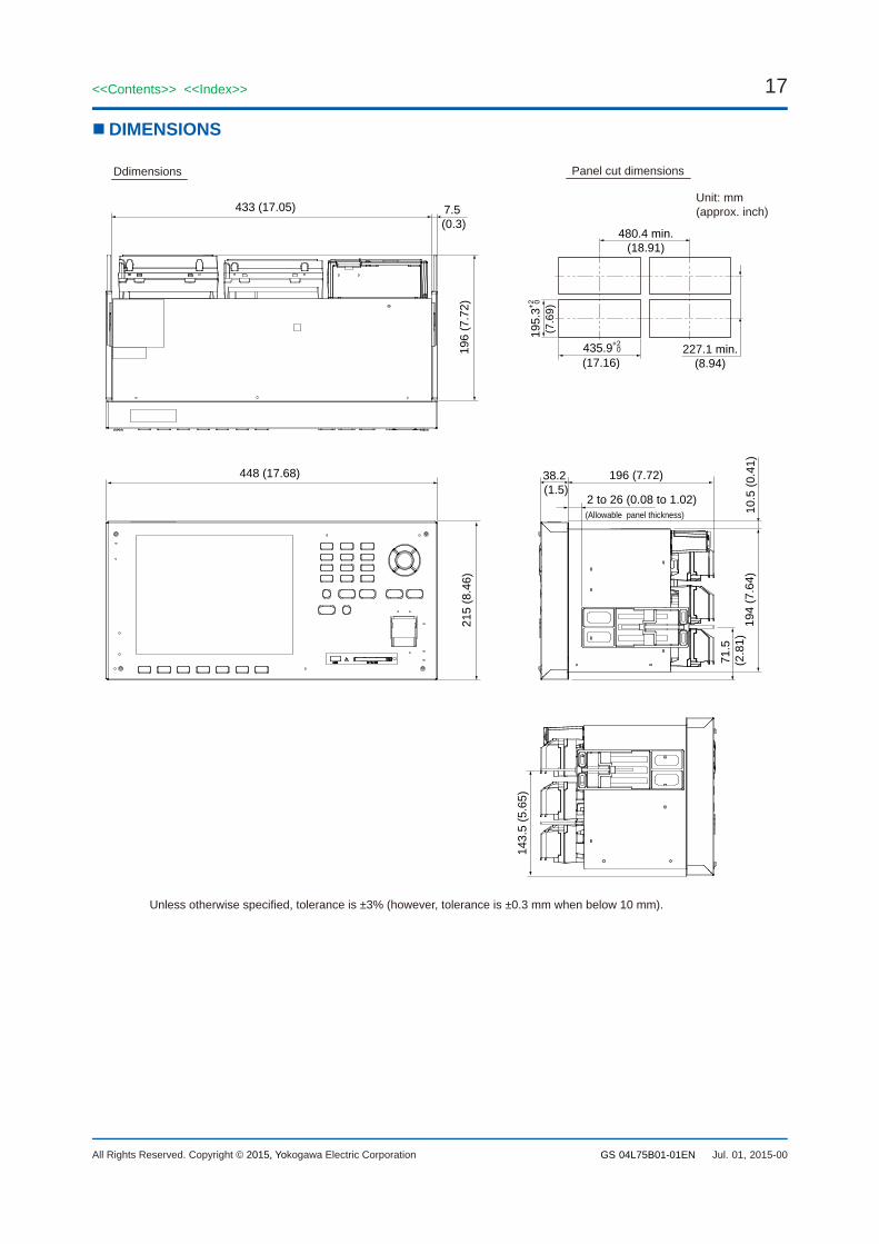
DIMENSIONS
Panel cut dimensions
448 (17.68)
194
(7.6
4)
196
(7.7
2)21
5 (8
.46)
433 (17.05)
2 to 26 (0.08 to 1.02)
38.2 (1.5)
143.
5 (5
.65)
196 (7.72)
71.5
(2.8
1)
Ddimensions
480.4 min.(18.91)
195
.3+2 0
(7.6
9)
435.9+2 0
(17.16)227.1 min.
(8.94)
7.5 (0.3)
10.5
(0.4
1)
(Allowable panel thickness)
Unit: mm (approx. inch)
Unless otherwise specified, tolerance is ±3% (however, tolerance is ±0.3 mm when below 10 mm).

18
All Rights Reserved. Copyright © 2015, Yokogawa Electric Corporation
<<Contents>> <<Index>>
GS 04L75B01-01EN Jul. 01, 2015-00
Rear View
USB port (/USB1 option) Serial interface port (/C2 option)A RS-232 interface connector.
Serial interface port (/C3 option)A RS-422A/485 interface connector.
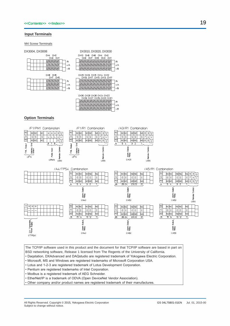
Input terminals (M4 screw Type)Connect input signal wires from themeasured item.
Optional terminals (/A[ ], /F[ ],/R1, and /TPS[ ] options)Connect optional input/outputsignal wires.
Power supply terminal andprotective earth terminal.
Ethernet port
RS-422-A/485 Terminal RS-232 Terminal
L N
FG SG SDB SDA RDB RDA123456789
N.C.RDSDN.C.SGN.C.RSCSN.C.
12345 6789
Power Supply Terminal
19
All Rights Reserved. Copyright © 2015, Yokogawa Electric Corporation
<<Contents>> <<Index>>
GS 04L75B01-01EN
19<<Contents>> <<Index>>
Jul. 01, 2015-00Subject to change without notice.
Input Terminals
M4 Screw Terminals
DX3010, DX3020, DX3030DX3004, DX3008
Option Terminals
The TCP/IP software used in this product and the document for that TCP/IP software are based in part on BSD networking software, Release 1 licensed from The Regents of the University of California.•Daqstation,DXAdvancedandDAQstudioareregisteredtrademarkofYokogawaElectricCorporation.•Microsoft,MSandWindowsareregisteredtrademarksofMicrosoftCorporationUSA.•Lotusand1-2-3areregisteredtrademarkofLotusDevelopmentCorporation.•PentiumareregisteredtrademarksofIntelCorporation.•ModbusisaregisteredtrademarkofAEGSchneider.•EtherNet/IPisatrademarkofODVA(OpenDeviceNetVendorAssociation).•Othercompanyand/orproductnamesareregisteredtrademarkoftheirmanufactures.


![HANGING SCALES/CRANE SCALES - Aviga HFO 159 page 166 1020,-from € Hanging scales/Crane scales Lisa Mayer Product specialist Hanging scales/Crane scales Tel. +49 [0] 7433 9933 - 219](https://img.pdfslide.net/doc/110x75/5afd22507f8b9a68498c727e/hanging-scalescrane-scales-hfo-159-page-166-1020-from-hanging-scalescrane.jpg)