Embed Size (px)
Citation preview

SBA1GD Rev150818
1
FIRE RESEARCH CORPORATIONwww.fireresearch.com
26 Southern Blvd., Nesconset, NY 11767TEL 631.724.8888 FAX 631.360.9727 TOLL FREE 1.800.645.0074
Document Number:XE-SBA1PMGD-R0A
SEAT MONITOR ANDDATA ACQUISITION SYSTEM
GENERAL DESCRIPTIONThe SBA document set includes the following:
SBA1GD General DescriptionSBA1HM Hardware Manual
SBA1UG User GuideSBA2DC Data Collector Manual
SBA2EM OEM Guide

SBA1GD Rev150818
2
This General Description includes basic information needed for an overall system understanding of the FRC Seat Monitor and Data Acquisition System.
Refer to the General Description (SBA1GD) for overall system information; the Hardware Manual (SBA1HM) for hardware specifications, mounting instructions, and wiring; the User Guide (SBA1UG) for HAWK software installation, set-up, and how to instructions for the data management software; the Data Collector Manual (SBA2DC) for instructions on using the FRC portable data collector; the OEM Guide (SBA2EM) for information needed by body builders, dealers, and service personnel to use the body builder/service programs in HAWK.
The FRC Seat Monitor and Data Acquisition System is designed to meet 2009 NFPA 1901 requirements for both a seat belt warning system and a vehicle data recorder.
The Seat Monitor provides a visual display that shows the condition of each seating position. The system recognizes the correct sit-buckle sequence and provides two outputs for audible alarms.
The Vehicle Data Recorder is capable of recording and storing all of the required data. The stored data is then available to be uploaded by the user to a computer using the data-management software. All data is password protected and controlled by the end user.(Refer to Appendix A or Appendix B for these requirements.)
INTRODUCTION

SBA1GD Rev150818
3
The Seat Monitor and Data Acquisition System has been designed with the following unique features:
Access the VDR via Wireless Technology or a USB Interface
Programmable Seat Configuration
Portable Data Collector Remotely Uploads and Stores Data from 12 VDRs
All Stored and Collected Data is Password Protected
J1939 CAN Bus Interface
Discrete Inputs (When Data is not Available on J1939 CAN Bus)
Audible and Visual Alarm Outputs
Highly Visible LED Display
Lateral G Indicator
HAWK Data Management Software Package
Secures All Paired Vehicle Data Recorders
All Collected and Stored Data is Password Protected
Stores Data from Multiple Vehicles
Sorts and Displays Stored Data
Displays and Prints Reports
Allows for Multiple Users with Different Levels of Access
Exceeds NFPA 1901 Standard for Automotive Fire Apparatus 2009 Edition, paragraph 4.11 requirements for a Vehicle Data Recorder.
48 Hours of Stored Second-by-Second Data
100 Engine Hours of Stored Minute-by-Minute Summary Data
All Data is Date and Time Stamped
Exceeds NFPA 1901 Standard for Automotive Fire Apparatus 2009 Edition, paragraph 14.1.3.10 requirements for a Seat Belt Warning system.
Monitors up to 13 Seating Positions
Provides a Visual Display Showing the Condition at Each Position
Validates Sit and Buckle Sequence
Audio and Visual Alarm Outputs
FEATURES

SBA1GD Rev150818
4
Seat Monitor Display Modules
The Lateral G Sensor module contains a solid-state MEMS accelerometer that provides the input to the Lateral G Indicator
on the SBA100 display.
There are four different Seat Monitor display modules available. They all
exceed NFPA requirements.
SYSTEM COMPONENTS
SBA100
SBA300
SBA400
SBA200
ProprietarySoftware
Lateral G Sensor Data Collector
The simplest model has six seat belt icons and a silence button for the audible alarm. More complex models include a message display, push buttons for navigating through programs, vehicle system warning indicators,
and the lateral acceleration indicator
The data collector has an LCD, a keypad, and a USB port. It can retrieve and store data from several wireless VDRs and then upload the data into the HAWK database by plugging in a USB cable or via the FRC wireless interface.
SBA1GD Rev150818
5
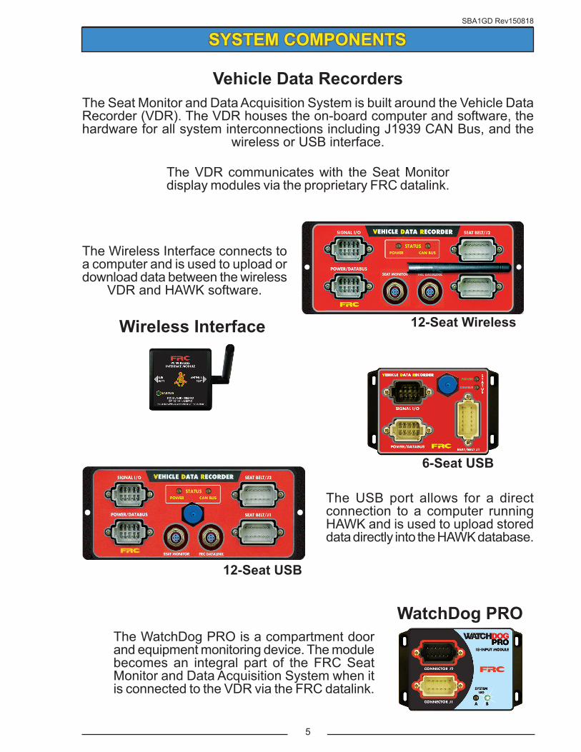
Vehicle Data Recorders
SYSTEM COMPONENTS
12-Seat Wireless
6-Seat USB
Wireless Interface
WatchDog PRO
12-Seat USB
The Seat Monitor and Data Acquisition System is built around the Vehicle Data Recorder (VDR). The VDR houses the on-board computer and software, the hardware for all system interconnections including J1939 CAN Bus, and the
wireless or USB interface.
The VDR communicates with the Seat Monitor display modules via the proprietary FRC datalink.
The WatchDog PRO is a compartment door and equipment monitoring device. The module becomes an integral part of the FRC Seat Monitor and Data Acquisition System when it is connected to the VDR via the FRC datalink.
The Wireless Interface connects to a computer and is used to upload or download data between the wireless
VDR and HAWK software.
The USB port allows for a direct connection to a computer running HAWK and is used to upload stored data directly into the HAWK database.

SBA1GD Rev150818
6
SYSTEM LAYOUT
SBA300SBA200SBA100
5-Pin Seat Monitor Cable To Seat Belt and
Seat Switches
12-SeatVDR Module
5-Pin FRC Datalink
Cable
Alarm Outputs
FRC Datalink
Supply Power
Ignition Switch
J1939 CAN
Master Optical Warning
Parking Brake
Interlock
The Seat Monitor display modules are available with two mounting options.
The SBA100 requires that the Lateral G Sensor Module is
installed. It provides the input to the Lateral G Indicator.
U-Bracket Mount
Surface Mount
Wireless Interface
USB Interface
Future Expansion.
SBA100 Only
Multiple display modules can be connected on the FRC Datalink.
Lateral G Sensor Module
Monitors up to 12 Seat Belt and Seat Switch Inputs
The FRC datalink is used to connect system and optional modules to the VDR.
SBA1GD Rev150818
7
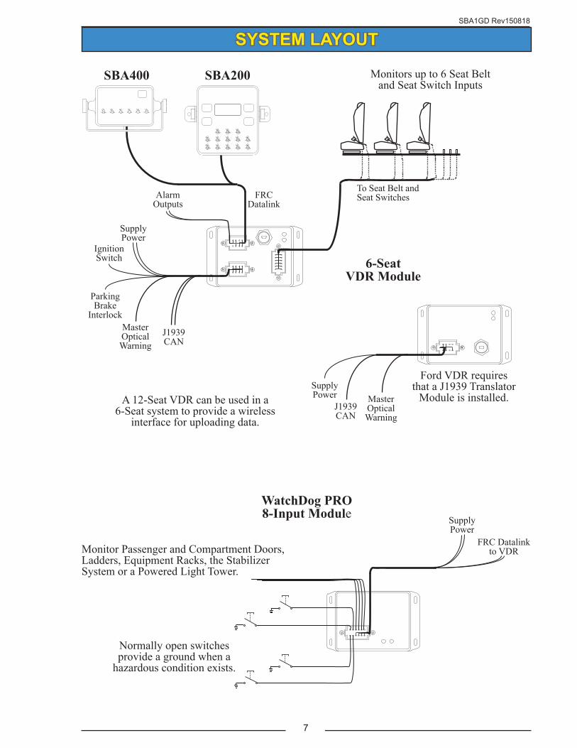
SYSTEM LAYOUT
Monitors up to 6 Seat Belt and Seat Switch Inputs
6-SeatVDR Module
SBA400
Supply Power
Ignition Switch
J1939 CAN
Master Optical Warning
Parking Brake
Interlock
Alarm Outputs
Supply Power
J1939 CAN
Master Optical Warning
Ford VDR requires that a J1939 Translator
Module is installed.
To Seat Belt and Seat SwitchesFRC
Datalink
WatchDog PRO8-Input Module Supply
PowerFRC Datalink
to VDRMonitor Passenger and Compartment Doors, Ladders, Equipment Racks, the Stabilizer System or a Powered Light Tower.
Normally open switches provide a ground when a
hazardous condition exists.
SBA200
A 12-Seat VDR can be used in a 6-Seat system to provide a wireless
interface for uploading data.
SBA1GD Rev150818
8
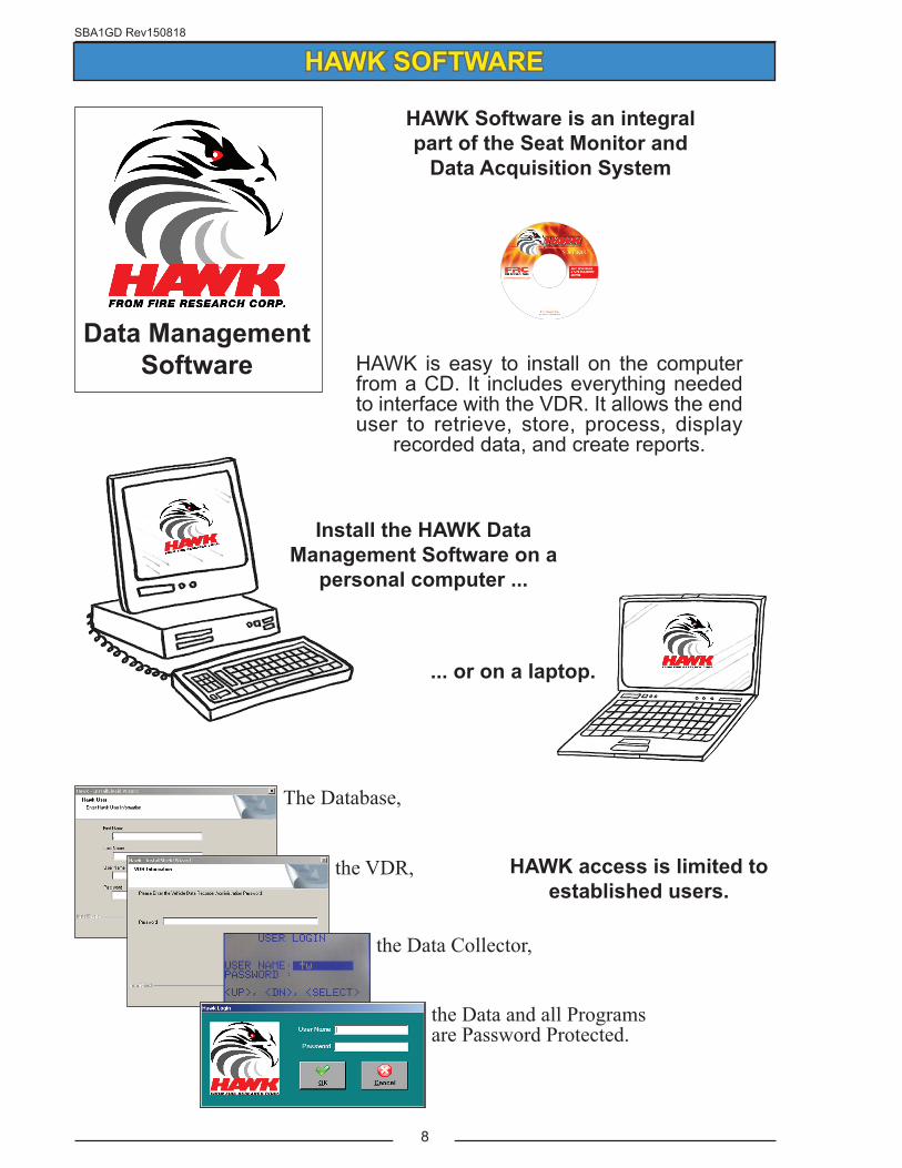
Data Management Software HAWK is easy to install on the computer
from a CD. It includes everything needed to interface with the VDR. It allows the end user to retrieve, store, process, display
recorded data, and create reports.
HAWK Software is an integral part of the Seat Monitor and
Data Acquisition System
the VDR,
The Database,
the Data Collector,
the Data and all Programs are Password Protected.
HAWK SOFTWARE
Install the HAWK Data Management Software on a
personal computer ...
HAWK access is limited to established users.
... or on a laptop.

SBA1GD Rev150818
9
Sort data by specific criteria,customize, and generate reports.
Set-up multiple user profiles with different levels of access.
Enter vehicle profiles and site information.
HAWK SOFTWARE
Upload stored VDR data directly into the HAWK database.
The HAWK software allows for multiple vehicle profiles and provides custom reports that meet NFPA 1901 requirements.
The main purpose of HAWK software is to store and manage the data collected by the VDR.
SBA1GD Rev150818
10
HAWK SOFTWARE BASICS
The HAWK software, the paired VDRs, and all stored data are secured and access is limited to established users.
The HAWK data management software is password protected. Access is controlled by the system administrator. A profile is setup for each user. This establishes the users name and password, and sets permissions for program menu access. The profile is setup by opening the Users tab and filling in a form.
The recorded data stored in each VDR is also password protected. The password is set once the VDR is paired with the owners (end users) copy of HAWK software. The Vehicle Data Recorder Administration Password is passed from HAWK to the VDR during the pairing process and locks the paired VDR to the owners copy of HAWK. Only users with the correct permissions are able to access the VDR data.
The HAWK data management software is menu driven. There are seven program menu tabs. When a menu tab is clicked on with the mouse, a directory is revealed. Directories contain folders that provide access to upload data from the VDRs, generate reports, and edit forms.
HAWK Software TermsPairing
Note: A VDR shall not be paired until the vehicle is delivered and the pairing process is carried out using the end users copy of HAWK software.
This process establishes a permanent association between the copy of HAWK software that is loaded on the end users computer and the vehicle VDR. Stored data from the VDR can only be uploaded and saved to this copy of HAWK software.
Paired Vehicle VDR
The VDR is secured so that the program and stored data is only accessible by personnel authorized by the end user. A paired VDR has the vehicle name, vehicle identification number, and the end users password embedded into its memory.
Unpaired Vehicle VDR
A new VDR that has not been associated with a copy of HAWK software. An unpaired VDR can be accessed using HAWK OEM software to upload programming.
SBA1GD Rev150818
11
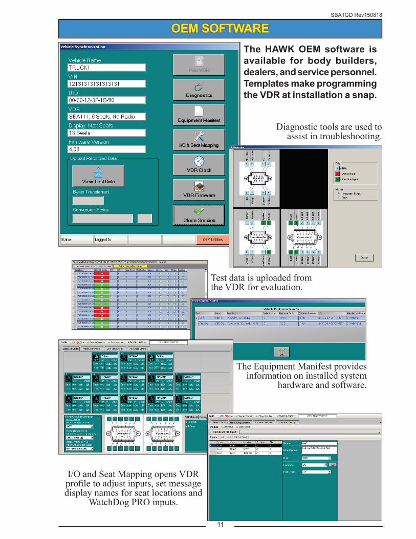
The HAWK OEM software is available for body builders, dealers, and service personnel.Templates make programming the VDR at installation a snap.
OEM SOFTWARE
Test data is uploaded from the VDR for evaluation.
Diagnostic tools are used to assist in troubleshooting.
The Equipment Manifest provides information on installed system
hardware and software.
I/O and Seat Mapping opens VDR profile to adjust inputs, set message display names for seat locations and
WatchDog PRO inputs.

SBA1GD Rev150818
12
Wireless Interface
Collect Data Using a Wireless Interface
The Wireless Interface is used to upload stored data from the VDR directly into the HAWK database.
When the vehicle mounted VDR receives a signal from an FRC Wireless Interface it responds.
VDR data is uploaded directly into the HAWK database using the Vehicle Synchronization window.
COMPUTER WIRELESS INTERFACE
The Wireless Interface is always connected to a laptop or stationary computer USB port.

SBA1GD Rev150818
13
The Data Collector is used to upload stored data from the VDR and transfer that data to HAWK.
When the vehicle mounted VDR receives a signal from an
FRC Data Collector it responds.
The Data Collector is a portable, menu driven,
wireless device.
VDR data is uploaded into the HAWK
database when the Data Collector is
synchronized.
The Data Collector is connected to a computer USB port to upload the
collected data.
Collect Data Using a Data Collector
Data Collector
PORTABLE DATA COLLECTOR

SBA1GD Rev150818
14
4.11 Vehicle Data Recorder.4.11.1 All apparatus shall be equipped with an on-board vehicle data recorder (VDR).4.11.2 The VDR shall be capable of recording the data shown in Table 4.11.2 in that order at least once per second.
4.11.3 Data shall be stored at the sampling rate in a 48-hour loop.4.11.4 Memory shall be sufficient to record 100 engine hours' worth of minute-by-minute summary showing the data in Table 4.11.4.
4.11.5 When the memory capacity is reached, the system shall erase the oldest data first.4.11.6 All data stored in the VDR shall be uploadable by the user to a computer and importable into a data management software package.4.11.7 Data shall be password protected with access controlled by the purchaser.4.11.8 Software shall be delivered with the apparatus that will run on both Windows® and Apple® operating systems and produce the following formatted reports from the uploaded data:(1) Raw second-by-second data over a specified data/time range(2) Daily log for the time the engine is running for a given date (minute-by-minute output of all values).(3) Weekly summary (maximum values each hour for each day of the week)(4) Monthly summary (maximum values each day for each day of the month)
The following requirements for the Vehicle Data Recorder are reprinted from NFPA 1901 Standard for Automotive Fire Apparatus 2009 Edition
Data Unit of MeasureMaximum vehicle speed MPHMaximum acceleration (from speedometer) MPH/Sec.Maximum deceleration (from speedometer) MPH/Sec.Maximum engine speed RPMMaximum engine throttle position % of full throttleAnti-locking braking system event On/OffSeat occupied with seat belt unbuckled Yes/No by position at 30 sec. into minuteMaster Optical Warning Device Switch On/Off at 30 sec. into minuteTime 24-hour clockDate Year/Month/Day
Data Unit of MeasureVehicle speed MPHAcceleration (from speedometer) MPH/Sec.Deceleration (from speedometer) MPH/Sec.Engine speed RPMEngine throttle position % of full throttleAnti-locking braking system event On/OffSeat occupied status Occupied: Yes/No by positionSeat belt status Buckled: Yes/No by positionMaster Optical Warning Device Switch On/OffTime 24-hour clockDate Year/Month/Day
Table 4.11.2 VDR Data
Table 4.11.4 VDR Summary
Data
APPENDIX A
SBA1GD Rev150818
15
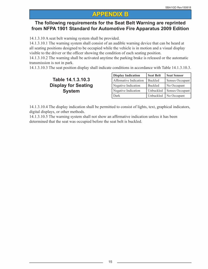
14.1.3.10 A seat belt warning system shall be provided.14.1.3.10.1 The warning system shall consist of an audible warning device that can be heard at all seating positions designed to be occupied while the vehicle is in motion and a visual display visible to the driver or the officer showing the condition of each seating position.14.1.3.10.2 The warning shall be activated anytime the parking brake is released or the automatic transmission is not in park.14.1.3.10.3 The seat position display shall indicate conditions in accordance with Table 14.1.3.10.3.
14.1.3.10.4 The display indication shall be permitted to consist of lights, text, graphical indicators, digital displays, or other methods.14.1.3.10.5 The warning system shall not show an affirmative indication unless it has been determined that the seat was occupied before the seat belt is buckled.
The following requirements for the Seat Belt Warning are reprinted from NFPA 1901 Standard for Automotive Fire Apparatus 2009 Edition
Table 14.1.3.10.3 Display for Seating
System
Display Indication Seat Belt Seat SensorAffirmative Indication Buckled Senses OccupantNegative Indication Buckled No OccupantNegative Indication Unbuckled Senses OccupantDark Unbuckled No Occupant
APPENDIX B

SBA1GD Rev150818
16