Embed Size (px)
Citation preview

GENERAL DESCRIPTION OF MODEL A3LA-RG
Revision A
May 20, 2020
451-93156-009A
Copyright © 2020 by NAL Research Corporation
11100 Endeavor Court Suite 300
Manassas, Virginia 20109 USA
Phone: 703-392-1136
E-mail: [email protected]

NAL Research Corporation (451-93156-009A) 2
LEGAL DISCLAIMER AND CONDITIONS OF USE
This document contains information for the Iridium A3LA-RG modem and accompanying accessories
(“Product”) is provided “as is.” Reasonable effort has been made to make the information in this document
reliable and consistent with specifications, test measurements and other information. However, NAL
Research Corporation and its affiliated companies, directors, officers, employees, agents, trustees or
consultants (“NAL Research”) assume no responsibility for any typographical, technical, content or other
inaccuracies in this document. NAL Research reserves the right in its sole discretion and without notice to
you to change Product specifications and materials and/or revise this document or withdraw it at any time.
User assumes the full risk of using the Product specifications and any other information provided.
NAL Research makes no representations, guarantees, conditions or warranties, either express or
implied, including without limitation, any implied representations, guarantees, conditions or warranties of
merchantability and fitness for a particular purpose, non-infringement, satisfactory quality, non-interference,
accuracy of informational content, or arising from a course of dealing, law, usage, or trade practice, use, or
related to the performance or nonperformance of any products, accessories, facilities or services or
information except as expressly stated in this guide and/or the Product and/or satellite service
documentation. Any other standards of performance, guarantees, conditions and warranties are hereby
expressly excluded and disclaimed to the fullest extent permitted by the law. This disclaimer and exclusion
shall apply even if the express limited warranty contained in this guide or such documentation fails of its
essential purpose.
In no event shall NAL Research be liable, whether in contract or tort or any other legal theory, including
without limitation strict liability, gross negligence or negligence, for any damages in excess of the purchase
price of the Product, including any direct, indirect, incidental, special or consequential damages of any kind,
or loss of revenue or profits, loss of business, loss of privacy, loss of use, loss of time or inconvenience, loss
of information or data, software or applications or other financial loss caused by the Product (including
hardware, software and/or firmware) and/or the Iridium satellite services, or arising out of or in connection
with the ability or inability to use the Product (including hardware, software and/or firmware) and/or the
Iridium satellite services to the fullest extent these damages may be disclaimed by law and whether advised
of the possibilities of such damages. NAL Research is not liable for any claim made by a third party or made
by you for a third party.

NAL Research Corporation (451-93156-009A) 3
Revision History
Revision Date Description Author
1.3 8/2/16 Initial version P. Kormendi
A 5/20/20
Added revision history
Updated address
Updated document number
Added AT^VOLB command
P. Kormendi

NAL Research Corporation (451-93156-009A) 4
TABLE OF CONTENTS
GLOSSARY ....................................................................................................................... 6
1.0 PURPOSE .................................................................................................................... 7
2.0 SPECIFICATIONS ......................................................................................................... 8
3.0 GPS RECEIVER SPECIFICATIONS ................................................................................... 9
4.0 MULTI-INTERFACE CONNECTOR .................................................................................... 9
4.1 RS232 Data Interface (Standard 9-Wire Configuration) .................................................. 10
4.2 RS232 Data Interface (3-Wire Configuration) ................................................................ 11
4.3 DC Power Input ........................................................................................................ 11
4.4 Power On/Off Control ................................................................................................ 12
4.5 Audio Interface ........................................................................................................ 12
4.6 Digital Peripheral Link (DPL) ....................................................................................... 13
5.0 IRIDIUM ANTENNA CONNECTOR .................................................................................... 13
6.0 GPS ANTENNA CONNECTOR .......................................................................................... 14
7.0 SIM CARD INTERFACE .................................................................................................. 14
8.0 LED DISPLAY .............................................................................................................. 15
9.0 CONFIGURATION SETTINGS ......................................................................................... 15
10.0 MODES OF OPERATION .............................................................................................. 15
11.0 AES-256 BIT ENCRYPTION .......................................................................................... 16
12.0 SELF-MONITORING TO PREVENT MODEM-LOCKUP ......................................................... 16
13.0 MOUNTING RECOMMENDATIONS ................................................................................. 17
14.0 TECHNICAL SUPPORT ................................................................................................. 17
APPENDIX A: AT INTERFACE .............................................................................................. 18
APPENDIX B: S-REGISTER DEFINITIONS .............................................................................. 89
APPENDIX C: SUMMARY OF RESULT CODES ......................................................................... 94
APPENDIX D: INFORMATIVE EXAMPLES ............................................................................... 97
APPENDIX E: POWER CONSUMPTION .................................................................................. 102
APPENDIX F: DESCRIPTION OF THE IRIDIUM NETWORK ........................................................ 109
APPENDIX G: STANDARDS COMPLIANCE .............................................................................. 115

NAL Research Corporation (451-93156-009A) 5
APPENDIX H: MIL-STD-810G CERTIFICATION ....................................................................... 116
APPENDIX I: EXPORT COMPLIANCE INFORMATION ................................................................ 117
APPENDIX J: MECHANICAL DRAWINGS ................................................................................ 118

NAL Research Corporation (451-93156-009A) 6
GLOSSARY
BIS Bureau of Industry and Security
DAV Data After Voice
DoD EMSS DoD Enhanced Mobile Satellite Services
DTE Data Terminal Equipment
DSN Defense Switch Network
EAR Export Administration Regulations
FDMA Frequency Division Multiple Access
GPS Global Positioning System
ISU Iridium Subscriber Units (Modems, Phones, Trackers)
LBT L-Band Transceiver
NIPRNET Non-Secure Internet Protocol Router Network
NOC Network Operation Center
OFAC Office of Foreign Asset Controls
PSTN Public Switch Telephone Network
RHCP Right Hand Circular Polarization
RUDICS Router-Based Unrestricted Digital Internetworking Connectivity Solution
SBD Short Burst Data
SIM Subscriber Identity Module
SMA Sub-Miniature Version A
SMS Short Message Service
TDD Time Domain Duplex
TDMA Time Division Multiple Access
VSWR Voltage Standing Wave Ratio

NAL Research Corporation (451-93156-009A) 7
1.0 PURPOSE
This document describes the electrical and mechanical interfaces of the A3LA-RG. Model A3LA-RG is an
Iridium satellite modem comprised of a 9523 L-band transceiver (LBT) and a built-in u-blox MAX-6Q GPS
receiver. The A3LA-RG has an internal micro-controller programmed to monitor the modem‘s connectivity
status to prevent hardware lock-up. It is designed to transmit either AES 256-bit encrypted or unencrypted
data (but not voice) via the Iridium satellite network. Similar to a standard landline modem, the A3LA-RG
can be controlled by any DTE (data terminal equipment) capable of sending standard AT commands via an
RS232 serial port. A DTE can be a desktop computer, a laptop computer, a smart phone, or even a micro-
controller. With the exception of a smaller form-factor, model A3LA-RG is functionally compatible with the
A3LA-XG. Model A3LA-RG-MIL is an A3LA-RG that has been certified to MIL-STD-810G standards and IP67
rating.
Services supported include:
1. Dial-Up Data Switch
2. Direct Internet Connection (or NIPRNET Connection)
3. Direct Internet Connection using Apollo Emulator (only for DoD EMSS Gateway)
4. Short Message Service (SMS)
5. Short-Burst Data (SBD)
6. Router-Based Unrestricted Digital Internetworking Connectivity Solution (RUDICS)
7. Voice when combined with the DPL audio handset
IMPORTANT: User should not disassemble the A3LA-RG for repair or services. The
warranty is voided if the A3LA-RG is disassembled. It should be returned to NAL Research
for any services or firmware upgrade.
IMPORTANT: GPS antenna should only be connected to the A3LA-RG when it is not
powered. Do not connect or disconnect the GPS antenna while A3LA-RG is powered. The
internal GPS receiver calibrates the noise-floor on power-up, and by connecting the GPS
antenna after power-up can result in prolonged acquisition time. To test GPS signal
reacquisition, physically block the signal to the antenna rather than disconnect and
reconnect the antenna is recommended.
Figure 1. Iridium Satellite Modem A3LA-RG.
SIM Reader under the lid
DB25 Multi-Interface Connector
SMA GPS Connector
TNC Iridium Connector

NAL Research Corporation (451-93156-009A) 8
IMPORTANT: Never feed supply voltage into the active GPS antenna. Always use the bias
voltage supplied by the A3LA-RG SMA antenna connector to power an active GPS antenna.
Feeding voltage to the GPS antenna other than the provided bias voltage will permanently
damage the A3LA-RG.
2.0 SPECIFICATIONS
2.1 Mechanical Specifications
Dimensions: 102 mm x 61 mm x 24 mm (4.0” x 2.43” x 0.95”)
Weight: 201 g (7.1 ounces)
Multi-Interface Connector: 25-Pin Male D-Sub
Iridium Antenna: TNC Female Connector
GPS Antenna: SMA Female Connector
SIM Chip Reader: Located beneath a cover plate on top of the A3LA-RG
Status Display: Four LEDs
Cooling: Convection
Enclosure: Aluminum/EMI shielding
2.2 RF Specifications
Operating Frequency: 1616 to 1626.5 MHz
Duplexing Method: TDD
Multiplexing Method: TDMA/FDMA
Link Margin: 12 dB average
Average Power during a Transmit Slot (Max): 7W
Average Power during a Frame (Typical): 0.6W
Receiver Sensitivity at 50 (Typical): –118 dBm
2.3 Electrical Specifications
Main Input Voltage Range: +4.0V to +5.4V or +5.0V to +32.0V
Average Standby Current: ~175mA @ 5.0VDC (with +5.0V to +32.0V setup)
Average Data Call Current: ~420mA @ 5.0VDC (peak of 2A)
NOTE: The power requirements apply to DC power measured at the A3LA-RG multi-
interface connector input. The average data call current may vary depending on the field-
of-view between the modem antenna and the Iridium satellite.
2.4 Environmental Specifications
Operating Temperature Range: –30oC to +70oC (–22oF to +158oF)
Operating Humidity Range: < 75% RH
Storage Temperature Range: –40oC to +85oC (–40oF to +185oF)
Storage Humidity Range: < 93% RH
2.5 Data I/O Specifications
Dial-Up Data/RUDICS: 2.4 Kbits/sec (average)
Direct Internet: 2.4 Kbits/sec (average)

NAL Research Corporation (451-93156-009A) 9
Short-Burst Data: 1960 bytes for Mobile-Originated and 1890 bytes for Mobile-Terminated
Short Messaging: 160 Characters (maximum)
Hardware Interface: RS232
Software Interface: Standard AT Commands
Encryption: AES-256 Bit when Enabled
2.6 Related Hardware
Antennas: SYN7391 Series, SAF2040 Series, SAF5340 Series, SAF5350 Series
Data Kit/Connector: HRC-24-7R, HRC-24-8R
Power Adapters: LA-3098, LA-7021
Audio Handset: DPLS0401-X
2.7 Reference Documents
A3LA-RG Product Information
Getting Started With Model A3LA-RG (TN2012-31-V1.0)
SatTerm Software Manual (TN2012-004-V8.6.0)
Additional Information on DirectIP SBD (TN2007-637-V1.0)
Additional Information on SBD (AN2012-04-V4.0)
3.0 GPS RECEIVER SPECIFICATIONS
The standard A3LA-RG hardware configuration has a u-blox MAX-6Q GPS receiver. Below are the
specifications.
Receiver Type: 50-channel u-blox 6 engine
L1 frequency (1575.42 MHz carrier frequency), C/A code
SBAS: WAAS, EGNOS, MASA
Maximum update rate: 5Hz
Accuracy: Horizontal Position 2.5m CEP
SBAS 2.0m CEP
Acquisition (typical): Cold start 27 seconds
Warm start 27 seconds
Hot start 1 second
Sensitivity: Tracking 161 dBm
Cold starts 147 dBm
Hot starts 156 dBm
Operational Limits: Velocity 500 m/sec
Altitude 50,000 m
Dynamics < 4 g
I/O Protocols: NMEA, UBX binary, RTCM
4.0 MULTI-INTERFACE CONNECTOR
The multi-interface connector is a male 25-pin miniature D-Sub type that includes five interfaces—
RS232, DC input power, ON/OFF control line, analog audio and Digital Peripheral Link (DPL). The multi-

NAL Research Corporation (451-93156-009A) 10
interface connector pin assignments are summarized in Table 1, which is ‘pin-to-pin’ the same as model
A3LA-R, A3LA-RM and A3LA-XG.
Table 1. Pin Assignment for the Multi-Interface Connector.
4.1 RS232 Data Interface (Standard 9-Wire Configuration)
The A3LA-RG supports a standard RS232 data interface to a DTE incorporating hardware handshaking
and flow control. The RS232 data interface comprises of eight standard RS232 data, control and status
signals plus a ground level signal reference as shown in Table 1. This interface allows a connected DTE to
utilize the A3LA-RG’s modem functionality through standard AT and extended sets of AT commands. These
commands are defined in Appendix A. The factory-set baud rate is 19,200 bps and can be changed using the
+IPR command.
Note that the Ring Indicator is used by the A3LA-RG to indicate that a Mobile Terminated SBD (MT-SBD)
message is queued at the gateway. Application developers can monitor this pin and apply appropriate AT
commands to the A3LA-RG to retrieve the MT-SBD message.
PIN # SIGNAL DESCRIPTION INTERFACE
1 EXT_ON_OFF Power on/off control input DC Power
2 +12VDC Output Voltage to Power the DPL Handset DC Power
3 EXT_GND External GND input DC Power
4 EXT_B+ External 4.0V – 5.4V or 5.0V – 32.0V DC Power
5 SPKR_AUD Speaker audio output Analog Audio
6 DA_TX PCM digital audio output Digital Audio
7 RI RS232 Ring Indicate RS232 Data
8 RTS RS232 Request To Send RS232 Data
9 TX RS232 Transmit Data (Input) RS232 Data
10 DCD RS232 Data Carrier Detect RS232 Data
11 DA_FS PCM digital audio frame sync output Digital Audio
12 DA_CLK PCM digital 2.048MHz audio clock output Digital Audio
13 RX RS232 Receive Data (Output) RS232 Data
14 SIGNAL GND Signal ground, 0V signal reference and return GND
15 MIC_AUD Microphone audio input Analog Audio
16 EXT_B+ External 4.0V – 5.4V or 5.0V – 32.0V DC Power
17 EXT_GND External GND input DC Power
18 DPL_TX Digital Peripheral Link (DPL) data output DPL UART
19 DTR RS232 Data Terminal Ready RS232 Data
20 DPL_RX Digital Peripheral Link (DPL) data input DPL UART
21 DSR RS232 Data Set Ready RS232 Data
22 CTS RS232 Clear To Send RS232 Data
23 SIGNAL GND Signal ground, 0V signal reference and return GND
24 DA_RX PCM digital audio input Digital Audio
25 SIGNAL GND Signal ground, 0V signal reference and return GND

NAL Research Corporation (451-93156-009A) 11
4.2 RS232 Data Interface (3-Wire Configuration)
A 3-wire RS232 data interface may also be implemented. Because of risk of over-run and data loss
especially at high baud rates, the 9-wire interface is the recommended implementation. Several steps must
be taken to allow 3-wire configuration (i.e. only using S_TX, S_RX, and SIGNAL GND). These steps ensure
the A3LA-RG and DTE to work together without having hardware handshaking.
1. The modem’s DTR line must be held high. Using the modem’s input voltage is fine for this purpose
BUT ONLY if the input voltage is less than 5VDC (see important note below). Looping back the
modem’s DSR line to DTR line will NOT work. The DSR line on the modem should be left
unconnected.
2. Disconnect the CTS, DCD, DSR, DTR, RTS and RI lines between the DTE and modem.
3. AT&Dn must be set to AT&D0 to ignore the DTR input from the DTE.
4. AT&Kn must be set to AT&K0 for no flow control.
5. The setting can be stored on the modem permanently (until another setting overwrites it) so that it
remains after a power cycle. The modem allows two profiles in which settings are stored, and user
can choose either as a default profile. The relevant commands are &Wn and &Yn. &Wn stores the
present configuration in profile <n>, where <n> can be either 0 or 1. &Yn designates which profile
is loaded after reset or power-up, again <n> is either 0 or 1.
6. Any needs of the DTE must be addressed separately.
WARNING: DO NOT use the modem’s input voltage to bring the DTR line high when the
input voltage is higher than 5VDC. Supplying voltage higher than 5VDC to the DTR line will
permanently damage the A3LA-RG.
NOTE: The Iridium’s Direct Internet service when using the Windows-based Apollo client
requires DCD to be present; hence it is incompatible with a 3-wire serial configuration. The
Direct Internet with Apollo client is available only on the EMSS DoD gateway and NOT on
the commercial gateway.
4.3 DC Power Input
The DC power input is through pin 4 & 16 (EXT_B+) and pins 3 & 17 (EXT_GND). Note that two pins are
provided for the external DC input and two pins are also provided for the associated external ground input.
This is done to distribute the current across two wires, and therefore all four pins should be utilized in the
external power connection. Cables used to supply power to the A3LA-RG should be kept as short as possible
to prevent significant voltage drop, which can cause the A3LA-RG to malfunction during a data call, an SMS
session or an SBD session. Power reset by the A3LA-RG during a call is an indicative of the DC power source
unable to sustain voltage above 4.0V at peak current demand. Appendix E provides the electrical power
profile of the A3LA-RG.
The A3LA-RG accepts either +4.0V to +5.4V or +5.0V to +32V input. The A3LA-RG is shipped with
hardware set for +5.0V to +32V input. It can be changed to +4.0V to +5.4V input through an internal
jumper—POWER MUST BE DISCONNECTED BEFORE RESETING THE JUMPER. The jumper can be found by

NAL Research Corporation (451-93156-009A) 12
removing the modem’s bottom plate. With the A3LA-RG held in the position shown in Figure 2 (DB25
connector to the left), the A3LA-RG is set for 4.0V to +5.4V when the red jumper is on the middle and left
pins and is set for +5.0V to +32V when the jumper is on the middle and right pins. Each pin is also labeled
with 5V and 32V to the left and right pins, respectively.
NOTE: User MUST remember the input voltage setting on the A3LA-RG and not to apply
voltage above the maximum limit (of either 5.4V or 32V). The A3LA-RG will be damaged
beyond repair with warranty voided if this were to occur.
IMPORTANT: User can remove the A3LA-RG’s bottom plate to set the jumper but not for
repair or services. The warranty is voided if the A3LA-RG is disassembled for any reason
other than to set the jumper.
4.4 Power On/Off Control
With the EXT_ON_OFF pin is left unconnected, the A3LA-RG will automatically turn on or off when
external DC power is applied or removed. Prior to turning the A3LA-RG off, command AT*P0 should be
issued to ensure all memory write activity is completed. When the A3LA-RG is powered off, its internal
power-on-reset circuit requires two seconds for voltages to decay. Users should not re-apply power until this
time has elapsed. If the two-second wait time is not adhered to, the reset circuit may not operate and the
A3LA-RG could be placed in a non-operational state. The state is not permanent and can be rectified by the
above procedure.
The A3LA-RG will automatically turn on/off when external DC power is applied/removed via the EXT_B+
and EXT_GND inputs. The EXT_ON_OFF (pin 1) control input is used to turn a powered A3LA-RG on and off
in a toggle fashion. The EXT_ON_OFF control input is normally “floating” (i.e. high). When it is pulled to GND
level (i.e. low) for at least 270 ms and released, the A3LA-RG will alternate from its current on/off state. The
current drawn on the external load used to pull the A3LA-RG to GND is no more than 0.5mA. The signal on
pin 1 is considered GND when it is at 0.5V or less.
4.5 Audio Interface
The A3LA-RG supports both digital and analog audio I/O. The digital audio is in PCM format. In such
format, digital audio cannot travel far (less than one foot); this is why the analog is chosen for the A3LA-RG
audio handset. The analog audio input is a single-ended, unbalanced input with a minimum impedance of
Figure 2. Power Input Setting for the A3LA-RG.
Red jumper used to set input voltage range

NAL Research Corporation (451-93156-009A) 13
10k to ground. The A3LA-RG accepts a maximum input level of 2.0V peak-to-peak without signal
distortion. The analog audio output is also a single-ended, unbalanced output capable of driving an
impedance of 600 or more to ground. The A3LA-RG delivers undistorted audio up to 2.0V peak-to-peak.
The combined analog I/O audio interface (pins 5 and 15) and the DPL UART I/O interface (pins 18 and
20) enable an analog audio handset to be connected to the A3LA-RG. With the DPL audio handset model
DPLS0401-X and DB25 data kit model HRC-24-8R, the A3LA-RG can be used both as a data modem and a
satellite phone. This setup as shown in Figure 3 can be an extremely useful developmental tool since the
modem status can be seen on the handset LCD similar to a 9555 Iridium phone.
4.6 Digital Peripheral Link (DPL)
The DPL interface is composed of two ports—a full duplex asynchronous serial link for control messages
and a PCM digital audio link for audio traffic. The protocol used on these ports is made available to
application developers only on a case-by-case basis and after appropriate Non-disclosure Agreements and/or
License Agreements are executed.
5.0 IRIDIUM ANTENNA CONNECTOR
The A3LA-RG modem uses a single TNC female 50-ohm connector for both transmit and receive (see
Figure 4). Cable loss between the modem and the antenna is critical and must be kept less than 3dB at the
operating frequency of 1616 to 1626.5 MHz. The minimum link margin of 12 dB must also be maintained.
General RF parameters are listed in the table below.
NAL Research offers several types of antennas for use with the A3LA-RG modem. These antennas
include the fixed mast, mobile magnetic/permanent mount and portable auxiliary. For low-cost and
applications where small form-factor and light-weight are required, NAL Research recommends model
SYN7391-C. If the specific application requires a custom antenna, it must meet the specifications below.
TYPE DESCRIPTION
Frequency Range 1616 to 1626.5 MHz
Input/Output Impedance 50 Ohms
Oscillator Stability 1.5ppm
DPL Handset
A3LA-RG Modem
HRC-24-8R Data Kit
Figure 3. A3LA-RG Connected to a DPL Handset via the HRC-24-8R.

NAL Research Corporation (451-93156-009A) 14
Satellite signal strength reported by the A3LA-RG when issuing an AT+CSQ command indicates the
signal strength of the ring channel. Care should be taken when using this signal reading for comparisons
between devices. Of particular notes are the followings:
1. There is a 0.5 dB tolerance on the calibration.
2. Each bar represents a 2 dB increment.
3. Multiple ring channels can be present at the same time so units can lock to different signals.
4. If the reading is near the decision threshold it would be easy to see a 1 bar difference.
6.0 GPS ANTENNA CONNECTOR
The A3LA-RG modem uses an SMA female connector for the GPS antenna (Figure 4). Any active antenna
required a bias voltage of ~3.3VDC with <50mA is appropriate. NAL Research offers a magnetic mount GPS
antenna as well as dual Iridium/GPS antenna for use with the A3LA-RG. For low-cost and applications where
small form-factor and light-weight are required, NAL Research highly recommends model SAF7352-IG.
7.0 SIM CARD INTERFACE
The A3LA-RG modem contains an integrated SIM reader. The modem uses and requires an Iridium SIM
chip for operation. The SIM chip is inserted into the opening located on top of the modem as shown in Figure
4. A plastic locking mechanism is used hold the SIM in-place. Place the SIM chip (facing down) into the SIM
reader’s bracket. Make sure that the cut-off on the SIM chip aligns with the SIM reader.
PARAMETER VALUE
Operating Temperature Range –40oC/+85oC without loss of function
Measurement Frequency Range 1616 to 1626.5 MHz
VSWR < 1.5 : 1
Maximum Gain 3 dBic
Nominal Impedance 50 Ohms
Polarization Right Hand Circular (RHCP)
Basic Pattern Omni directional and hemispherical
Figure 4. Location of the SIM Reader.
Iridium Antenna Connector
GPS Antenna Connector
SIM Reader under the lid
NAL Research Corporation (451-93156-009A) 15
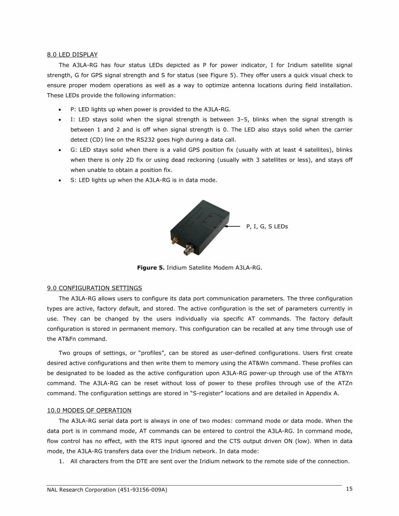
8.0 LED DISPLAY
The A3LA-RG has four status LEDs depicted as P for power indicator, I for Iridium satellite signal
strength, G for GPS signal strength and S for status (see Figure 5). They offer users a quick visual check to
ensure proper modem operations as well as a way to optimize antenna locations during field installation.
These LEDs provide the following information:
P: LED lights up when power is provided to the A3LA-RG.
I: LED stays solid when the signal strength is between 3–5, blinks when the signal strength is
between 1 and 2 and is off when signal strength is 0. The LED also stays solid when the carrier
detect (CD) line on the RS232 goes high during a data call.
G: LED stays solid when there is a valid GPS position fix (usually with at least 4 satellites), blinks
when there is only 2D fix or using dead reckoning (usually with 3 satellites or less), and stays off
when unable to obtain a position fix.
S: LED lights up when the A3LA-RG is in data mode.
9.0 CONFIGURATION SETTINGS
The A3LA-RG allows users to configure its data port communication parameters. The three configuration
types are active, factory default, and stored. The active configuration is the set of parameters currently in
use. They can be changed by the users individually via specific AT commands. The factory default
configuration is stored in permanent memory. This configuration can be recalled at any time through use of
the AT&Fn command.
Two groups of settings, or “profiles”, can be stored as user-defined configurations. Users first create
desired active configurations and then write them to memory using the AT&Wn command. These profiles can
be designated to be loaded as the active configuration upon A3LA-RG power-up through use of the AT&Yn
command. The A3LA-RG can be reset without loss of power to these profiles through use of the ATZn
command. The configuration settings are stored in “S-register” locations and are detailed in Appendix A.
10.0 MODES OF OPERATION
The A3LA-RG serial data port is always in one of two modes: command mode or data mode. When the
data port is in command mode, AT commands can be entered to control the A3LA-RG. In command mode,
flow control has no effect, with the RTS input ignored and the CTS output driven ON (low). When in data
mode, the A3LA-RG transfers data over the Iridium network. In data mode:
1. All characters from the DTE are sent over the Iridium network to the remote side of the connection.
P, I, G, S LEDs
Figure 5. Iridium Satellite Modem A3LA-RG.

NAL Research Corporation (451-93156-009A) 16
2. No unsolicited result codes are issued.
3. RTS/CTS flow control, if enabled, is active. When RTS is OFF (high), the A3LA-RG suspends transfer
of data to the DTE; when CTS is OFF, the A3LA-RG expects the DTE to suspend transfer of data.
Transitions between the modes of operation are performed automatically by the A3LA-RG in response to
AT commands; the DTE has no other control over the mode.
11.0 AES-256 BIT ENCRYPTION
The A3LA-RG modem has a built-in AES-256 encryption software module. It can transmit either
encrypted or unencrypted data in all modes—dial up, direct Internet, RUDICS, SBD and SMS. The A3LA-RG
does not support encrypted voice calls. All voice calls are made in the ‘clear’ unless an external encryption
module is hooked to it such as the General Dynamics® Sectéra. When encryption is enabled and for non-
packetized data transmission modes including dial-up, direct Internet and RUDICS, the A3LA-RG sends data
in NAL Research’s proprietary format called packet send mode. Packet send mode is implemented to handle
AES-256 frame synchronization between the A3LA-RG and a connected device. The encryption and
decryption keys are matched in each frame to ensure NIST FIPS 140-2 compliance.
Instructions on how to use encryption can be found in manuals AT Command Reference in Appendix A.
List of AT commands used to set encryption include ^CCOP, ^KD, ^KE, ^KZ, ^STR, and ^UE. The
encryption algorithm implemented into the A3LA-RG complies with NIST FIPS 140-2 as defined in the
following documents:
1. Security Requirements for Cryptographic Modules, FIPS PUB 140-2, US Department of
Commerce, National Institute of Standards and Technology, May 25th, 2001.
2. Security Requirements for Cryptographic Modules, Annex A: Approved Security Functions
for FIPS PUB 140-2, US Department of Commerce, National Institute of Standards and
Technology, February 19th, 2003.
12.0 SELF-MONITORING TO PREVENT MODEM LOCK-UP
The 9523 RF board can sometimes ‘lock-up’ when being inactive over a long period of time (a day or
longer). The only way to recover is to power cycle the ISU. The A3LA-RG has safeguards put in place with a
watch-dog timer to keep the 9523 RF board from locking up. These were done by having another micro-
controller in-line with the serial communications, monitoring the communications and making sure the 9523
is responding correctly. Each of the safeguards is enabled by default. Below is a description of each of the
four safeguards. These safeguards are also employed on the A3LA-RM and A3LA-XM.
Check When Not in a Data Call: The micro-controller has a timer that is reset every time a character
arrives from the 9523 board. The timer is set to end every 2 minutes. When the timer expires the micro-
controller will check to make sure the 9523 is still responding by sending it an AT command. If the 9523
responds it starts the counter over again. If there is not response it power cycles the 9523. This can be
enabled or disabled with the ^MPTNC command.
Check When in a Data Call: The micro-controller has a timer that is reset every time a character arrives
from the 9523 board during data calls. The timer is set to end every 4 minutes during data calls. When the
timer expires the micro-controller will check to make sure the 9523 is still responding by sending it the +++
sequence. If the 9523 responds it returns to the data connection and starts the counter over again. If there

NAL Research Corporation (451-93156-009A) 17
is no response it power cycles the 9523. This can be enabled or disabled with the ^MPTDC command.
Registrations Every 23 Hours: The micro-controller will force manual registration by implementing the
command AT+COPS=1 every 23 hours to make sure the 9523 stays registered. Registration will not occur
during a data/voice call. This can be enabled or disabled with the ^MPTFR command.
Forced Power Cycles Every 24 Hours: The micro-controller will force a power cycle of the 9523 board
every 24 hours. Power cycle will not happen during a data/voice call. This can be enabled or disabled with
the ^MPTFP command.
13.0 MOUNTING RECOMMENDATIONS
The A3LA-RG has four features on its bottom surface that can aid in its mounting (see Appendix J).
These four features are pre-drilled at a minimum depth of 0.25 inch to accept 6-32 thread type.
14.0 TECHNICAL SUPPORT
FOR TECHNICAL SUPPORT, PLEASE CONTACT US AT
Phone: 703-392-1136 FAX: 703-392-6795
E-mail: [email protected]
Technical documents are also available to download on NAL Research’s website www.nalresearch.com

NAL Research Corporation (451-93156-009A) 18
APPENDIX A: AT INTERFACE
A.1 Command Types
The A3LA-RG employs two principal types of AT commands: basic and extended. The two types have
differing syntax used to query and adjust their settings. They also have unique reference standards. A
specific basic AT command is used to reference S-registers and query and adjust their settings. Its syntax is
similar to that of extended AT commands.
A.2 Basic Commands
Basic commands are industry standard and originally developed for Hayes-compatible PSTN modems. In
many cases, basic commands consist of a single ASCII alpha character. In other cases, a special character
precedes the alpha character. Prefix characters used in A3LA-RG basic commands include &, \, %, and *.
Most alpha characters in basic commands are followed by a numeric parameter, n. To adjust its setting,
a basic command is entered with the appropriate numeric value of n. Note that if the numeric parameter n is
omitted from the basic command entry, a value of zero is assumed for n. For example, ATXn is set to a
value of 4 by entering ATX4, whereas it is set to value of 0 by entering either ATX0 or ATX.
To query a basic command setting, the AT&V command is entered to view the active configuration of a
group of basic commands. Some basic commands listed in this document are marked with “No action,
compatibility only”. In these cases, the basic command is accepted in the same fashion as is with other
modems, but has no effect on the operation of the A3LA-RG, since it has no meaning in the Iridium
environment.
A.3 Extended Commands
Extended commands perform actions or set parameters that extend the capability of the A3LA-RG
beyond that which is allowed by basic commands. In some cases, they were designed for the GPS receiver,
encryption, lock-up monitoring and non-PSTN networks such as the GSM network.
Most extended commands include a prefix of + followed by a single alpha character. Prefixes used in
A3LA-RG extended commands include +C, +D, +G, +I, and +S. Extended commands designed specifically
for Iridium products include a –MS prefix. Most extended commands include three alpha characters after the
prefix, but some commands include just one or two alpha characters after the prefix.
Some extended commands have a single execution mode. No further syntax is added after the prefix
and body of the command. For example, AT+GSN is entered as shown to query the A3LA-RG for its assigned
serial number (i.e. IMEI). Some extended commands incorporate a test mode to query their range of valid
responses. Some extended commands incorporate set, read, and test modes. For example, AT–MSVTR is
entered as AT–MSVTR=n in set mode to enable/disable receipt of DTMF messages. It is entered as AT–
MSVTR? in read mode to query its current setting and is entered as AT–MSVTR=? in test mode to query its
range of valid settings. Extended commands are grouped as shown below.
Extended Cellular Commands:
+C prefix
Used for GSM cellular phone-like functions
Standards: ETSI specifications GSM 07.07 [2] and GSM 07.05 [3]
Extended Data Compression Commands:

NAL Research Corporation (451-93156-009A) 19
+D prefix
Used for data compression
Standard: V.25ter [1]
Extended Generic Commands:
+G prefix
Used for A3LA-RG issues such as identities and capabilities
Standard: V.25ter [1]
Extended Interface Control Commands:
+I prefix
Used to control the DTE interface
Standard: V.25ter [1]
Extended Short Burst Data Commands:
+S prefix
Used for Short Burst Data messaging
Iridium Satellite Product Proprietary Commands:
–MS prefix
Proprietary to the Iridium product line
A.4 Command and Response Characters
The execution of a command string follows a left-to-right execution of each command followed by the
reporting of a result code for the entire string. The ASCII character set (CCITT T.50 International Alphabet
5, American Standard Code for Information Interchange) is used for the issuance of commands and
responses. Only the low-order 7 bits of each character are used for commands or parameters; the high-
order bit is ignored. Upper case characters are equivalent to lower case characters.
A.5 Command Entry
An AT command is a string of characters sent by the DTE to the A3LA-RG while it is in command mode.
A command string has a prefix, a body, and a terminator. The prefix consists of the ASCII characters AT or
at. The body is a string of commands restricted to printable ASCII characters. The default terminator is the
<CR> character. AT command entry syntax is critical, and the following rules apply:
All commands (apart from A/ and +++) begin with a prefix of AT or at.
The commands in a command string (apart from A/ and +++) are executed only after the
return or enter key is pressed.
Use of upper or lower case letters is allowed.
The maximum number of characters in a command string is 128.
If the numeric parameter n is omitted from the basic command entry, a value of zero is
assumed for n.
If an optional parameter is omitted from an extended command, the current value is implied.
Optional parameters are enclosed by square brackets ([...]) in this document.
NAL Research Corporation (451-93156-009A) 20
Spaces entered into a command string for clarity between the AT prefix and the body of the
command are ignored. Likewise, spaces entered for clarity within the command body between
alpha characters and decimal parameters are ignored.
The backspace or delete keys can typically be used to edit commands.
Characters that precede the AT prefix are ignored.
Ctrl-x can be used to abort a command line input.
Consider the following six commands to be entered in a single command line:
ATX0 (set basic command ATXn to n=0)
AT&V (execute basic command AT&V)
AT+GSN (execute extended command AT+GSN)
AT+CMEE=? (query the valid range of responses of extended command AT+CMEE)
AT+CPBR=1,12 (execute extended command AT+CPBR with parameters 1 and 12)
AT–MSVTR? (query the current setting of extended command AT–MSVTR)
The following are valid single command line entries of above six commands:
at x 0 &v +gsn +cmee=? +cpbr=1,12 -msvtr? (all lower case)
AT X 0 &V +GSN +CMEE=? +CPBR=1,12 –MSVTR? (all upper case)
ATX 0 &V +GSN +CMEE=? +CPBR=1,12 –MSVTR? (space omitted between AT and X)
ATX0 &V +GSN +CMEE=? +CPBR=1,12 –MSVTR? (space omitted between ATX and 0)
ATX &V +GSN +CMEE=? +CPBR=1,12 –MSVTR? (0 omitted from ATX0)
ATX;&V;+GSN;+CMEE=?;+CPBR=1,12;–MSVTR? (semicolon separators)
ATX&V+GSN+CMEE=?+CPBR=1,12–MSVTR? (no separators)
A.6 Command Responses
A result code is sent to the DTE in response to the execution of a command. It may also occur
unsolicited from other conditions such as an incoming call (e.g. RING). Responses returned as a result of a
query are called information responses.
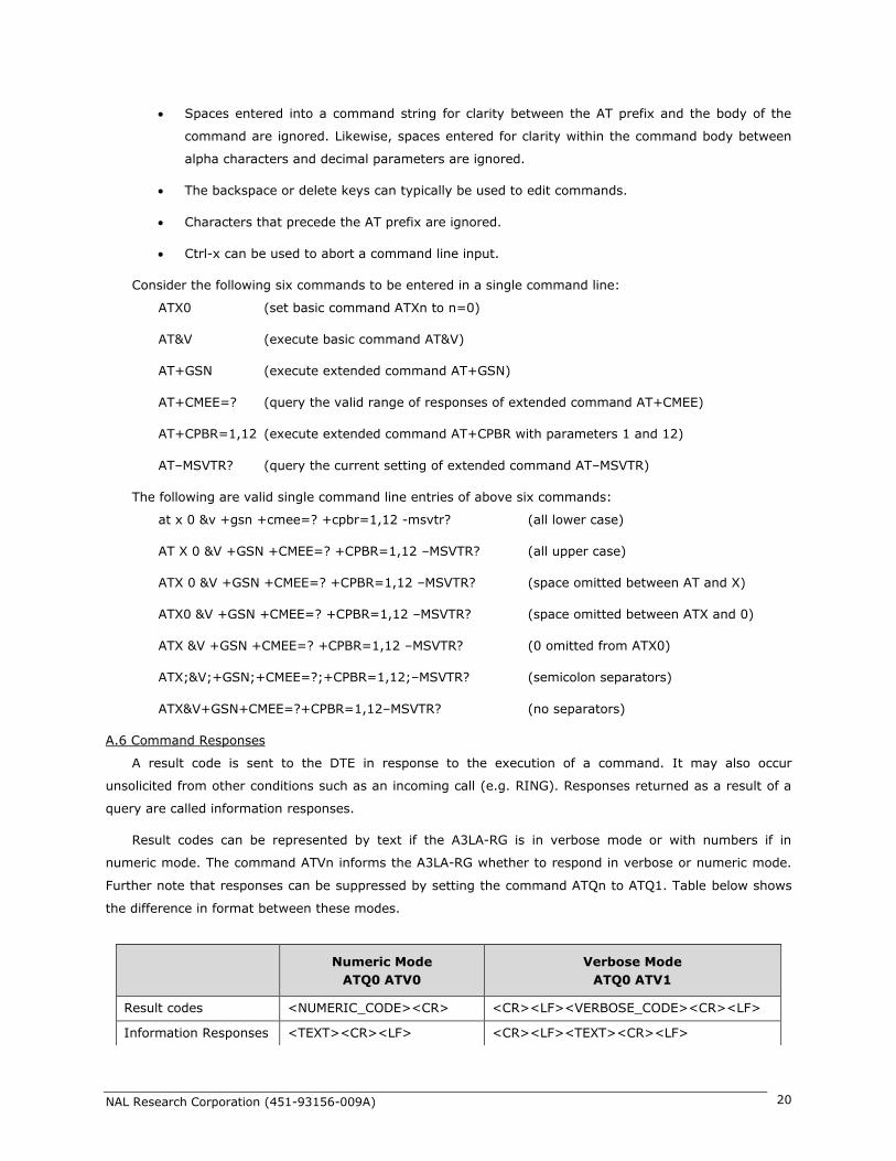
Result codes can be represented by text if the A3LA-RG is in verbose mode or with numbers if in
numeric mode. The command ATVn informs the A3LA-RG whether to respond in verbose or numeric mode.
Further note that responses can be suppressed by setting the command ATQn to ATQ1. Table below shows
the difference in format between these modes.
Numeric Mode
ATQ0 ATV0
Verbose Mode
ATQ0 ATV1
Result codes <NUMERIC_CODE><CR> <CR><LF><VERBOSE_CODE><CR><LF>
Information Responses <TEXT><CR><LF> <CR><LF><TEXT><CR><LF>

NAL Research Corporation (451-93156-009A) 21
Command entries with invalid syntax typically respond with ERROR. Command entries of valid syntax
with an out-of-range parameter can respond in one of three following manners:
Disallow out-of-range entry and respond with ERROR
Disallow out-of-range entry and respond with OK
Disallow out-of-range entry, accept the closest in-range value, and respond with OK
A.7 Hardware Failure Reporting
If the A3LA-RG detects a hardware problem during initialization, it may be unable to function correctly.
The A3LA-RG notifies the DTE of this situation by issuing an unsolicited result code at the end of
initialization:
HARDWARE FAILURE: <subsys>,<error>
where <subsys> identifies the software subsystem that detected the error, and <error> is the subsystem
specific error code. Any AT commands that cannot be handled in the failure condition will terminate with
result code 4 (“ERROR”).
A.8 Command Set Description
A.8.1 AT – Attention Code
This is the prefix for all commands except A/ and +++. When entered on its own, the A3LA-RG
will respond OK.
A.8.2 A/ – Repeat Last Command
Repeat the last command issued to the A3LA-RG unless the power was interrupted or the unit is
reset. A/ is not followed by <CR>.
A.8.3 +++ – Escape Sequence
The escape sequence is used to transfer from in-call data mode to in-call command mode
without disconnecting from the remote modem. After a pause, the A3LA-RG will respond with
OK. Register S2 can be used to alter the escape character from +, the factory default, to any
hexadecimal value in the range 0 to 255.
A.8.4 En – Echo
Echo command characters.
0 Characters are not echoed to the DTE
1 Characters are echoed to the DTE (default)
A.8.5 On – Online
Enter in-call data mode. This is used to return to in-call data mode from in-call command mode
using an existing connection. An error is reported if on-hook.
0 Switch from in-call command mode to in-call data mode
Any value for n accepted
A.8.6 Qn – Quiet Mode
Control A3LA-RG responses.
0 A3LA-RG responses are sent to the DTE (default)

NAL Research Corporation (451-93156-009A) 22
1 A3LA-RG responses are NOT sent to the DTE
A.8.7 Vn – Verbose Mode
Set the response format of the A3LA-RG, which may be either numeric or textual.
0 Numeric responses
1 Textual responses (default)
A.8.8 Wn – Error Correction Message Control
Set the format of the CONNECT messages.
0 Upon connection, the A3LA-RG reports the DTE speed (default)
1 Upon connection, the A3LA-RG reports the line speed, the error correction protocol
and the DTE speed in that order
2 Upon connection, the A3LA-RG reports its data port speed
A.8.9 Zn – Soft Reset
Reset the A3LA-RG to a user-stored configuration.
0 Restores user configuration 0
1 Restores user configuration 1
A.8.10 &Cn – DCD Option
Select how the A3LA-RG controls the DCD behavior. DCD always indicates the connection
status.
No action, compatibility only.
Allowed values for n are 0 and 1.
A.8.11 &Dn – DTR Option
Set the A3LA-RG reaction to DTR signal when auto dialing is disabled (see the ^AD command).
0 DTR is ignored. A DTR signal input is not needed when set to &D0.
1 If DTR transitions from ON to OFF during a data call and is not restored ON within
approximately 10 seconds, the call will be dropped.
2 If DTR transitions from ON to OFF during a data call, the call will be dropped
(default).
A.8.12 &Fn – Restore Factory Settings
Recall factory defaults.
0 Recall factory default 0
A.8.13 &Kn – Flow Control
Select the flow control method between the A3LA-RG and DTE.
0 Disables flow control
3 Enables RTS/CTS flow control (default)
A.8.14 &Mn – Asynchronous/Synchronous Mode
Select the DTR operating mode.
0 Selects normal asynchronous operation (default). (See &Qn)
A.8.15 &Qn – Sync/Async Mode

NAL Research Corporation (451-93156-009A) 23
Select asynchronous mode. This is an extension of the &M command and is used to control the
connection modes permitted.
Note: The register is not updated right after the user requests new values because the
requested values may or may not be what IRLP will use once a data call is established due to
negotiations with the other peer. If the register is updated right away, this may give the user
the impression that those values will be used during the data call, but there is no guarantee
that will be the case. The real values will only be known once a data call is established and the
negotiation phase is done. For that reason, the values are written to the register only after a
call is established and both sides have negotiated parameter values (such as mode of
operation). The value of the register will be reset to default value (5) after the call completed.
0, 6 Normal asynchronous operation with no error correction (unacknowledged mode)
5 Asynchronous operation with error correction (acknowledged mode) (default)
A.8.16 &Sn – DSR Override
Define the behavior of DSR.
0 DSR always active (default)
1 Same as 0
A.8.17 &V – View Active and Stored Configuration
View the current active configuration and stored profiles.
A.8.18 &Wn – Store Active Configuration
Store the active profile in non-volatile memory. This is used to store user configurations for
later use.
0 Store current (active) configuration as profile 0
1 Store current (active) configuration as profile 1
A.8.19 &Yn – Designate Default Reset Profile
Select profile for use after power-up.
0 Select profile 0 (default)
1 Select profile 1
A.8.20 \Kn – Control Break
Control the response of the A3LA-RG to a break received from the DTE or the remote modem
according to the parameter specified. The response is different in three separate states:
When a break is received from DTE when A3LA-RG is in data transfer mode:
0 Enter in-call command mode, no break sent to remote modem
1 Clear data buffers and send break to remote modem
2 Same as 0
3 Send break to remote modem immediately
4 Same as 0
5 Send break to remote modem in sequence with transmitted data (default)
When a break is received from the remote modem during a non-error corrected connection:

NAL Research Corporation (451-93156-009A) 24
0 Clear data buffers and send break to DTE
1 Same as 0
2 Send break to DTE immediately
3 Same as 2
4 Send break to DTE in sequence with received data
5 Same as 4 (default)
A.8.21 %R – Display Registers
Display all the S registers in the system.
A.8.22 *Pn – Power
Turn A3LA-RG off.
0 Turn A3LA-RG OFF
A.8.23 +CBST – Select Bearer Service Type
Set Command: +CBST=[<speed>[,<name>[,<ce>]]]
Select the bearer service type for mobile originated calls.
<speed> can have the following values:
0 Autobauding
1 300 bps V.21
2 1200 bps V.22
3 2400 bps V.22bis
6 4800 bps V.32
7 9600 bps V.32 (default)
65 300 bps V.110
66 1200 bps V.110
68 2400 bps V.110
70 4800 bps V.110
71 9600 bps V.110
<name> takes the following value:
0 data circuit asynchronous
<ce> can only take the following value:
1 non-transparent
Read Command: +CBST?
Query the current bearer service type settings. Response is in the form:
+CBST: <speed>,<name>,<ce>
Test Command: +CBST=?
List the supported <speed>, <name>, <ce>. Response is in the form:
+CBST: (supported <speed>s),(supported <name>s),(supported <ce>s)
A.8.24 +CGMI – Manufacturer Identification
Exec Command: +CGMI
Query A3LA-RG RF board manufacturer.

NAL Research Corporation (451-93156-009A) 25
A.8.25 +CGMM – Model Identification
Exec Command: +CGMM
Query A3LA-RG RF board model.
A.8.26 +CGMR – Revision
Exec Command: +CGMR
Query A3LA-RG RF board revision.
A.8.27 +CGSN – Serial Number
Exec Command: +CGSN
Query A3LA-RG IMEI.
A.8.28 +CMEE – Report Mobile Equipment Error
Set Command: +CMEE=[<x>]
Set mobile equipment error reporting level.
<x> takes the following values:
0 Disable error reporting (use ERROR result code) (default)
1 Enable numeric error reporting
2 Enable verbose error reporting
An example of an error report is:
+CME ERROR: <y>
where <y> can be the number or text listed below:
0 A3LA-RG RF board failure
1 no connection to A3LA-RG
2 A3LA-RG RF board-adaptor link reserved
3 operation not allowed
4 operation not supported
5 PH-SIM PIN required
6 PH-FSIM PIN required
7 PH-FSIM PUK required
10 SIM not inserted
11 SIM PIN required
12 SIM PUK required
13 SIM failure
14 SIM busy
15 SIM wrong
16 incorrect password
17 SIM PIN2 required
18 SIM PUK2 required
20 memory full
21 invalid index
22 not found
23 memory failure

NAL Research Corporation (451-93156-009A) 26
24 text string too long
25 invalid characters in text string
26 dial string too long
27 invalid characters in dial string
28 number is SIM fixed dialing restricted
30 no network service
31 network timeout
32 emergency calls only
40 network personalization PIN required
41 network personalization PUK required
42 network subset personalization PIN required
43 network subset personalization PUK required
44 service provider personalization PIN required
45 service provider personalization PUK required
46 corporate personalization PIN required
47 corporate personalization PUK required
100 unknown
Read Command: +CMEE?
Query mobile equipment error reporting level. The response is in the form:
+CMEE: <x>
Test Command: +CMEE=?
List the supported error reporting level. The response is in the form:
+CMEE: (supported <x>s)
A.8.29 +CPAS – Modem Activity Status
Exec Command: +CPAS
Query A3LA-RG activity status. The response is in the form:
+CPAS: <x>
where <x> can take the following values:
0 Ready (allows commands)
1 Unavailable (does not allow commands)
2 Unknown (may not respond to commands)
3 Data Call Ringing (allows commands)
4 Data Call In Progress (allows commands)
A.8.30 +CR – Service Reporting Control
Set Command: +CR=[<mode>]
Set the service reporting level.
<mode> takes the following values:
0 Disable reporting (default)
1 Enable reporting
If reporting is enabled, the intermediate result code +CR: <serv> is returned by the A3LA-RG.

NAL Research Corporation (451-93156-009A) 27
<serv> can have one of the following values:
ASYNC asynchronous transparent
SYNC synchronous transparent
REL ASYNC asynchronous non-transparent
REL SYNC synchronous non-transparent
Read Command: +CR?
Query the current service reporting level settings. The response is in the form:
+CR: <mode>
Test Command: +CR=?
List the supported reporting levels. The response is in the form:
+CR: (supported <mode>s)
A.8.31 +DS – Set Data Compression Function
Set Command: +DS=[<direction>[,<comp_neg>[,<max_dict>[,<max_string]]]]
Set the V.42bis data compression function.
<direction> can take on the following values:
0 No compression
1 Transmit only
2 Receive only
3 Both directions (default)
<comp_neg> can take on the following values:
0 Do not disconnect if V.42bis is not negotiated by the A3LA-RG as specified in
<direction> (default)
1 Disconnect if V.42bis is not negotiated by the A3LA-RG as specified in <direction>
<max_dict> can take on the following values: 512 to 2048. Default is 512.
<max_string> can take on the following values: 6 to 250. Default is 6.
Read Command: +DS?
Query the current data compression parameter settings. The response is in the form:
+DS: <direction>,<comp_neg>,<max_dict>,<max_dict>
Test Command: +DS=?
List the supported data compression parameters. The response is in the form:
+DS: (supported<direction>s),(supported<comp_neg>s,(supported
<max_dict>s),(supported<max_dict>s)
Data compression will not work if IRLP is in unacknowledged mode.
Note: The register is not updated right after the user requests new values because the
requested values may or may not be what IRLP will use once a data call is established due to
negotiations with the other peer. If the register is updated right away, this may give the user
the impression that those values will be used during the data call, but there is no guarantee
that will be the case. The real values will only be known once a data call is established and the
negotiation phase is done. For that reason, the values are written to the register only after a

NAL Research Corporation (451-93156-009A) 28
call is established and both sides have negotiated parameter values. The value of the register
will be reset to default value (3) after the call is completed.
A.8.32 +DR – Data Compression Report Level
Set Command: +DR=[<mode>]
Set the data compression reporting level.
<mode> can take on the following values:
0 Disable data compression reporting (default)
1 Enable data compression reporting
If reporting is enabled, the following intermediate result codes are transmitted by the A3LA-RG:
+DR: NONE No data compression
+DR: V42B Data compression in use in both directions
+DR: V42B RD Data compression in use in receive direction only
+DR: V42B TD Data compression in use in transmit direction only
Read Command: +DR?
Query the current reporting level setting. The response is in the form:
+DR: <mode>
Test Command: +DR=?
List the supported parameter settings. The response is in the form:
+DR: (supported <mode>s)
A.8.33 +CEER – Extended Error Report
Exec Command: +CEER
Execution command causes the A3LA-RG to return information text <report> which offers the
user an extended report of the reason of the failure in the last unsuccessful call setup
(originating or answering) or the reason for last call release. The response is in the form:
+CEER: <report>
An example of a <report> is:
User alerting, no answer
A.8.34 +CHUP – Hangup call
This command causes the A3LA-RG to hangup the current data call.
A.8.35 +CMGD – Delete SMS Message
Exec Command: +CMGD=<index>
Execution command deletes message from preferred message storage <mem1> (<mem1> is
the selected message storage from the +CPMS command) location <index>. If deleting fails,
final result code +CMS ERROR: <cms_err> is returned.
An example of an error report is:
+CMS ERROR: <cms_err>
where <cms_err> can be one of the numbers below:
1 unassigned number

NAL Research Corporation (451-93156-009A) 29
8 operator barred
3 operation not allowed (identical to 302)
10 call barred
21 SM transfer rejected
27 destination out of service
28 unidentified subscriber
29 facility rejected
30 unknown subscriber
38 network out of order
41 temporary failure
42 congestion
47 resources unavailable
50 facility not subscribed
69 facility not implemented
81 invalid SM reference value
95 invalid message
96 invalid mandatory information element
97 nonexistent message type
98 incompatible message
99 nonexistent information element
111 protocol error
127 interworking
128 telephony interworking not supported
129 SM type 0 not supported
130 cannot replace SM
143 unspecified TP-PID error
144 coding scheme not supported
145 message class not supported
159 unspecified TP-DCS error
160 command not actioned
161 command unsupported
176 TPDU not supported
192 SC busy
193 no SC subscription
194 SC system failure
195 invalid SME address
196 destination SME barred
197 SM rejected
208 SIM SMS storage full
209 no SMS storage capability in SIM
210 error in MS
211 memory capacity exceeded

NAL Research Corporation (451-93156-009A) 30
255 unspecified error
300 A3LA-RG failure
301 SMS service reserved
302 operation not allowed
303 operation not supported
304 invalid PDU mode parameter
305 invalid text mode parameter
310 no SIM
311 SIM PIN required
312 PH-SIM PIN required
313 SIM failure
314 SIM busy
315 SIM wrong
320 memory failure
321 invalid memory index
322 memory full
330 SM-SC address unknown
331 no network service
332 network timeout
500 unknown error
A.8.36 +CMGF – SMS Message Format
Set Command: +CMGF=[<mode>]
Set command tells the A3LA-RG, which input and output format of messages to use. <mode>
indicates the format of messages used with send, list, read and write commands and unsolicited
result codes resulting from received messages. Mode can be either PDU mode (entire TP data
units used) or text mode (headers and body of the messages given as separate parameters).
Only PDU mode is supported at this time.
Valid values for <mode> are:
0 PDU mode (default)
Read Command: +CMGF?
Read command returns the current <mode> set. Response is in the form:
+CMGF: <mode>
Test Command: +CMGF=?
Test command returns the list of supported <mode>s. Response is in the form:
+CMGF: (list of supported <mode>s)
A.8.37 +CMGL – List SMS Messages
Exec Command: +CMGL[=<stat>]
Execution command returns messages with status value <stat> from message storage
<mem1> (<mem1> is the selected message storage from the +CPMS command) to the DTE. If
listing fails, final result code +CMS ERROR: <cms_err> is returned.
NAL Research Corporation (451-93156-009A) 31
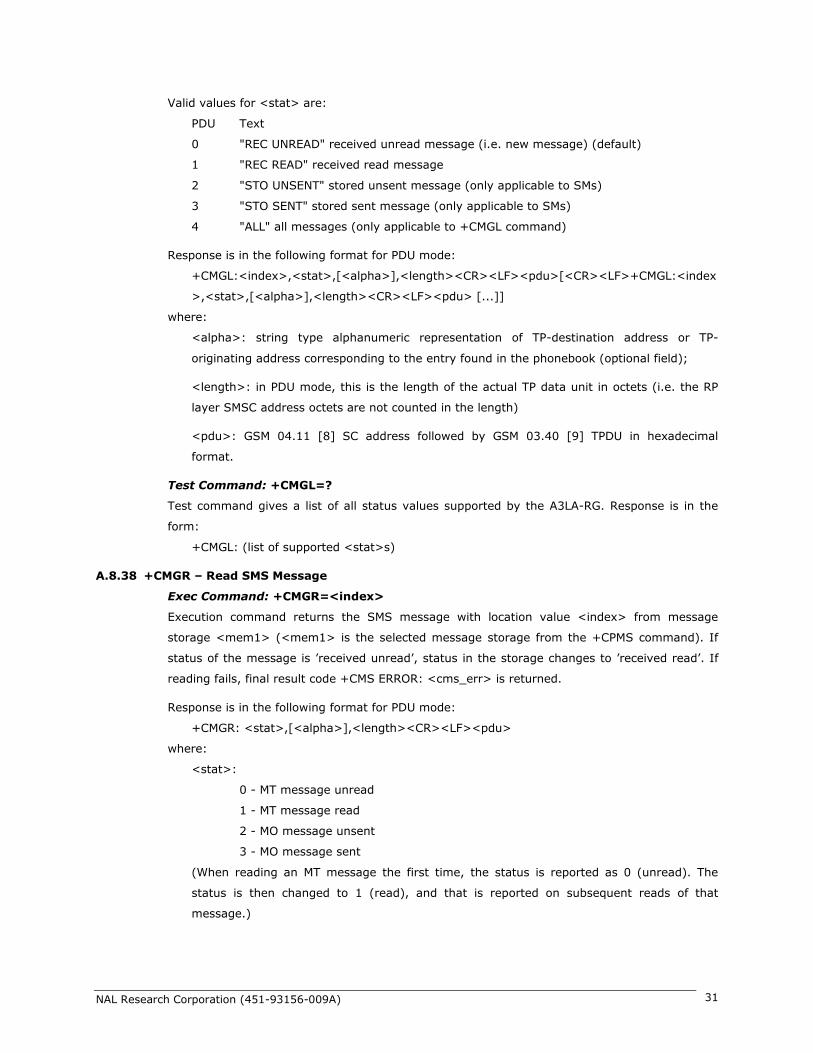
Valid values for <stat> are:
PDU Text
0 "REC UNREAD" received unread message (i.e. new message) (default)
1 "REC READ" received read message
2 "STO UNSENT" stored unsent message (only applicable to SMs)
3 "STO SENT" stored sent message (only applicable to SMs)
4 "ALL" all messages (only applicable to +CMGL command)
Response is in the following format for PDU mode:
+CMGL:<index>,<stat>,[<alpha>],<length><CR><LF><pdu>[<CR><LF>+CMGL:<index
>,<stat>,[<alpha>],<length><CR><LF><pdu> [...]]
where:
<alpha>: string type alphanumeric representation of TP-destination address or TP-
originating address corresponding to the entry found in the phonebook (optional field);
<length>: in PDU mode, this is the length of the actual TP data unit in octets (i.e. the RP
layer SMSC address octets are not counted in the length)
<pdu>: GSM 04.11 [8] SC address followed by GSM 03.40 [9] TPDU in hexadecimal
format.
Test Command: +CMGL=?
Test command gives a list of all status values supported by the A3LA-RG. Response is in the
form:
+CMGL: (list of supported <stat>s)
A.8.38 +CMGR – Read SMS Message
Exec Command: +CMGR=<index>
Execution command returns the SMS message with location value <index> from message
storage <mem1> (<mem1> is the selected message storage from the +CPMS command). If
status of the message is ’received unread’, status in the storage changes to ’received read’. If
reading fails, final result code +CMS ERROR: <cms_err> is returned.
Response is in the following format for PDU mode:
+CMGR: <stat>,[<alpha>],<length><CR><LF><pdu>
where:
<stat>:
0 - MT message unread
1 - MT message read
2 - MO message unsent
3 - MO message sent
(When reading an MT message the first time, the status is reported as 0 (unread). The
status is then changed to 1 (read), and that is reported on subsequent reads of that
message.)

NAL Research Corporation (451-93156-009A) 32
<alpha>:string type alphanumeric representation of TP-destination address or TP-
originating address corresponding to the entry found in the phonebook (optional field);
<length>:in PDU mode, this is the length of the actual TP data unit in octets (i.e. the RP
layer SMSC address octets are not counted in the length)
<pdu>: GSM 04.11 [8] SC address followed by GSM 03.40 [9] TPDU in hexadecimal
format.
A.8.39 +CMGS – Send SMS Message
Exec Command: +CMGS=<length><CR><pdu><ctrl-Z/ESC> (PDU mode)
Execution command sends message from the DTE to the network (SMS-SUBMIT). In PDU mode,
<length> is the length of the actual TP data unit in octets; <pdu> is the GSM 04.11 [8] SC
address followed by GSM 03.40 [9] TPDU in hexadecimal format.
PDU entry must be terminated by <ctrl-Z>. Sending can be cancelled by the <ESC> character.
Response is in the following format for PDU mode:
+CMGS: <mr>
where <mr> is the message reference value of the message.
If sending fails, final result code +CMS ERROR: <cms_err> is returned.
A.8.40 +CMGW – Write SMS Message To Memory
Exec Command: +CMGW=<length>[,<stat>]<CR><pdu><ctrl-Z/ESC> (PDU mode)
Execution command stores a message to memory storage <mem2> (<mem2> is selected by
the +CPMS command). In PDU mode, <length> is the length of the actual TP data unit in
octets; <pdu> is the GSM 04.11 [8] SC address followed by GSM 03.40 [9] TPDU in
hexadecimal format. By default, message status will be set to ’stored unsent’, but parameter
<stat> allows also other status values to be given.
PDU entry must be terminated by <ctrl-Z>. Storing can be cancelled by sending the <ESC>
character.
Response is in the following format for PDU mode:
+CMGW: <index>
where <index> indicates the memory location where the message is stored.
If storing fails, final result code +CMS ERROR: <cms_err> is returned.
A.8.41 +CMOD – Call Mode
Set Command: +CMOD=[<mode>]
Set command selects the call mode of further dialing commands (D) or for next answering
command (A). Mode can be either single or alternating (the terms "alternating mode" and
"alternating call" refer to all GSM bearer and tele-services that incorporate more than one basic
service (voice, data, fax) within one call). For the satellite modem, only a single call is
supported.
<mode>:
0 single mode (default)

NAL Research Corporation (451-93156-009A) 33
Read Command: +CMOD?
Query the current call mode settings. The response is in the form:
+CMOD: <mode>
Test Command: +CMOD=?
List the supported call modes. The response is in the form:
+CMOD: (supported <mode>s)
A.8.42 +CNMI – New SMS Message Indications to DTE
Set Command: +CNMI=[<mode>[,<mt>[,<bm>[,<ds>[, <bfr>]]]]]
Set command selects the procedure, how receiving of new messages from the network is
indicated to the DTE when DTE is active, e.g. DTR signal is ON.
Valid values for <mode> are:
0 Buffer unsolicited result codes in the A3LA-RG. If result code buffer is full, older
indications are discarded and replaced with the new received indications. (default)
1 Discard indication and reject new received message unsolicited result codes when
A3LA-RG-DTE link is reserved (e.g. in in-call data mode). Otherwise forward them
directly to the DTE.
2 Buffer unsolicited result codes in the A3LA-RG when A3LA-RG-DTE link is reserved
(e.g. in in-call data mode) and flush them to the DTE after reservation. Otherwise
forward them directly to the DTE.
Valid values for <mt> are:
0 No SMS-DELIVER indications are routed to the DTE. (default)
1 If SMS-DELIVER is stored in the A3LA-RG, indication of the memory location is
routed to the DTE using unsolicited result code:
+CMTI: <mem>,<index>
2 SMS-DELIVERs (except class 2 messages and messages in the message waiting
indication group (store message)) are routed directly to the TE using unsolicited
result code:
+CMT: [<alpha>],<length><CR><LF><pdu> (PDU mode)
3 Class 3 SMS-DELIVERs are routed directly to TE using unsolicited result codes
defined in <mt>=2. Messages of other data coding schemes result in indication as
defined in <mt>=1.
Valid values for <bm> are:
0 No CBM indications are routed to the DTE. (default)
Valid values for <ds> are:
0 No SMS-STATUS-REPORTs are routed to the DTE. (default)
1 SMS-STATUS-REPORTs are routed to the DTE using unsolicited result code:
+CDS: <length><CR><LF><pdu> (PDU mode)
Valid values for <bfr> are:

NAL Research Corporation (451-93156-009A) 34
0 Buffer of unsolicited result codes defined within this command is flushed to the DTE
when <mode> 1...3 is entered (OK response is returned before flushing the
codes). (default)
1 Buffer of unsolicited result codes defined within this command is cleared when
<mode> 1...3 is entered.
Read Command: +CNMI?
Read command returns the current settings for the SMS message indication. Response is in the
form:
+CNMI: <mode>,<mt>,<bm>,<ds>,<bfr>
Test Command: +CNMI=?
Test command returns the supported settings of the A3LA-RG. Response is in the form:
+CNMI: (list of supported <mode>s),(list of supported <mt>s),(list of supported
<bm>s),(list of supported <ds>s),(list of supported <bfr>s)
A.8.43 +COPS – Operator Select
Set Command: +COPS=[<mode>[,<format>[,<oper>]]]
Set command forces an attempt to manually register the A3LA-RG to the network. Only
IRIDIUM as <oper> is supported.
Valid values for the parameters are outlined below.
<mode>:
0 automatic (<oper> field is ignored) (default)
1 manual (<oper> field is optional)
<format>:
0 long format alphanumeric <oper>
1 short format alphanumeric <oper>
2 numeric <oper>
<oper> is of string type enclosed by quotes“”; for example “IRIDIUM”. <format> indicates if
the format is alphanumeric or numeric; long alphanumeric format can be up to 16 characters
long and short format up to 8 characters; numeric format is the Location Area Identification
number which consists of a three BCD (Binary Coded Decimal) digit country code plus a two
BCD digit network code; hence the number has structure: (country code digit 3)(country code
digit 2)(country code digit 1)(network code digit 2)(network code digit 1). Since IRIDIUM is the
only operator, the short and long format is “IRIDIUM” and the numeric format is “90103”. These
are the only values accepted.
Note that setting the <mode> to manual does not disable automatic registration of the A3LA-
RG to the network. It just forces a manual registration procedure when entered.
Read Command: +COPS?
Read command returns the current mode, and will always respond with “000” for <mode>. This
is due to the continually enabled nature of the automatic registration mode. The response is in
the form:
+COPS: <mode>

NAL Research Corporation (451-93156-009A) 35
For example:
+COPS:000
Test Command: +COPS=?
Test command returns the list of operators present in the network. Response is in the form:
+COPS: [list of supported (<stat>,long alphanumeric <oper>,short alphanumeric
<oper>,numeric <oper>)s] [,,(list of supported <mode>s),(list of supported <format>s)]
where <stat> indicates:
2 current
For example:
+COPS:(002),"IRIDIUM","IRIDIUM","90103",,(000-001),(000-002)
A.8.44 +CPBF – Find Phonebook Entries
Exec Command: +CPBF=<findtext>
Execution command returns phonebook entries (from the current phonebook memory storage
selected with +CPBS) which alphanumeric fields start with string <findtext>. <findtext> should
be of string type enclosed by ““; for example, “John”.
Entry fields returned are location number <index n>, phone number stored there <number> (of
address type <type>), and text <text> associated with the number. Response is in the
following format:
+CPBF: <index1>,<number>,<type>,<text>[[...]<CR><LF>+CBPF:
<index2>,<number>,<type>,<text>]
Test Command: +CPBF=?
Test command returns the maximum lengths of <number> and <text> fields for phonebook
entries. Response is in the form:
+CPBF: <nlength>,<tlength>
where <nlength> indicates the maximum length of <number> and <tlength> shows the
maximum length of <text>.
A.8.45 +CPBR – Read Phonebook Entries
Exec Command: +CPBR=<index1>[,<index2>]
Execution command returns phonebook entries in location number range <index1>... <index2>
from the current phonebook memory storage selected with +CPBS. If <index2> is left out, only
location <index1> is returned.
Entry fields returned are location number <index n>, phone number stored there <number> (of
address type <type>) and text <text> associated with the number. Response is in the form:
+CPBR: <index1>,<number>,<type>,<text>[[...] <CR><LF>+CPBR:
<index2>,<number>,<type>,<text>]
Test Command: +CPBR=?
Test command returns location range supported by the current storage and the maximum
lengths of <number> and <text> fields. Response is in the form:
+CPBR: (list of supported <index>s),<nlength>,<tlength>

NAL Research Corporation (451-93156-009A) 36
where <nlength> indicates the maximum length of <number> and <tlength> shows the
maximum length of <text>.
A.8.46 +CPBS – Select Phonebook Storage
Set Command: +CPBS=<storage>
Set command selects phonebook memory storage <storage>, which is used by other
phonebook commands. <storage> should be of string type enclosed by “”; for example, “FD”.
<storage> takes the following values:
FD SIM fixed dialing phonebook
LD Last ten calls dialed phonebook
ME A3LA-RG phonebook
MT combined A3LA-RG and SIM phonebook (default)
SM SIM phonebook
Read Command: +CPBS?
Read command returns currently selected memory, the number of used locations and total
number of locations in the memory. Response is in the form:
+CPBS: <storage>,<used>,<total>
where <used> indicates the number of used locations and <total> shows the total capacity of
<storage>.
Test Command: +CPBS=?
Test command returns supported storages.
A.8.47 +CPBW – Write Phonebook Entry
Exec Command: +CPBW=[<index>][,<number>[,<type>[<text>]]]
Execution command writes phonebook entry in location number <index> in the current
phonebook memory storage selected with +CPBS. Entry fields written are phone number
<number> (of address type <type>) and text <text> associated with the number. If those
fields are omitted, phonebook entry is deleted. If <index> is left out, but <number> is given,
entry is written to the first free location in the phonebook. Both <text> and <number> should
be of string type enclosed by ““; for example, “John”,”1234”.
Test Command: +CPBW=?
Test command returns the location range supported by the current storage, the maximum
length of <number> field, supported number formats of the storage, and the maximum length
of <text> field. Response is in form:
+CPBW: (list of supported <index>s),<nlength>,(list of supported <type>s),<tlength>
A.8.48 +CPIN – Enter PIN
Set Command: +CPIN=<pin>[,<newpin>]
Set command sends to the A3LA-RG a password which is necessary before it can be operated
(SIM Card PIN Code, SIM PUK, etc.). If no password request is pending, no action is taken by
the A3LA-RG.

NAL Research Corporation (451-93156-009A) 37
If the password required is SIM PUK, then <newpin> is required, where <newpin> is
the new SIM Card PIN to replace the old SIM Card PIN.
If the password required is SIM PUK2, then <newpin> is required, where <newpin> is
the new SIM Card PIN2 to replace the old SIM Card PIN2
Both <pin> and <newpin> should be of string type enclosed by “ “; for example,
”1234”.
Read Command: +CPIN?
Read command returns an alphanumeric string indicating whether some password is required or
not. Response is in the form:
+CPIN: <code>
where <code> can be one of the following:
READY A3LA-RG is not waiting for any password.
PH PIN A3LA-RG is waiting for Phone Unlock Code to be given.
SIM PIN A3LA-RG is waiting for SIM Card PIN1 Code to be given.
SIM PUK A3LA-RG is waiting for SIM PUK to be given (because SIM PIN1 is blocked).
SIM PIN2 A3LA-RG is waiting for SIM PIN2 to be given.*
SIM PUK2 A3LA-RG is waiting for SIM PUK2 to be given (because SIM PIN2 is
blocked).
*Note: The response “SIM PIN2” is somewhat misleading, because it indicates one of three
possible scenarios:
1. PIN1 has already been successfully entered (thus equivalent to the READY
response).
2. No PIN1 is required (thus equivalent to the READY response).
3. The A3LA-RG is waiting for PIN2 (used to access Fixed Dialing settings and other
subscription-based features).
In any of these three cases, the A3LA-RG should be available to place and receive calls.
Note: +CPIN is closely related to +CLCK and +CPWD. See these commands for additional
information.
A.8.49 +CPMS – Select Preferred SMS Message Storage
Set Command: +CPMS=<mem1>[, <mem2>[,<mem3>]]
Set command selects memory storages <mem1>, <mem2> and <mem3>. <mem1> is the
memory from which messages are read and deleted; <mem2> is the memory to which writing
and sending operations are made; <mem3> is the memory to which received SMS messages
are to be stored. If a chosen storage is not appropriate for the A3LA-RG, final result code +CMS
ERROR: <cms_err> is returned.
Valid values for <mem1>, <mem2> and <mem3> are:
"SM" SIM message storage
Response is in the form:
+CPMS: <used1>,<total1>,<used2>,<total2>,<used3>,<total3>

NAL Research Corporation (451-93156-009A) 38
where <used1>: number of messages currently in <mem1>
<total1>: total number of message locations in <mem1>
<used2>: number of messages currently in <mem2>
<total2>: total number of message locations in <mem2>
<used3>: number of messages currently in <mem3>
<total3>: total number of message locations in <mem3>
Read Command: +CPMS?
Read command returns the current storage selected, usage and capacity. Response is in the
form:
+CPMS: <mem1>,<used1>,<total1>,<mem2>,<used2>,<total2>,<mem3>,<used3>,
<total3>
Test Command: +CPMS=?
Test command returns lists of memory storages supported by the A3LA-RG. Response is in the
form:
+CPMS: (list of supported <mem1>s),(list of supported <mem2>s), (list of supported
<mem3>s)
A.8.50 +CREG – Network Registration
Set Command: +CREG=[<n>]
Set command controls the presentation of an unsolicited result code +CREG: <stat> when
<n>=1 and there is a change in the A3LA-RG network registration status, or code +CREG:
<stat>[,<lac>,<ci>] when <n>=2 and there is a change in the registration status of the A3LA-
RG.
Valid values for <n> are:
0 disable network registration unsolicited result code (default)
1 enable network registration unsolicited result code +CREG: <stat>
2 enable network registration and location information unsolicited result code
+CREG: <stat>[,<lac>,<ci>]. <lac> indicates the location area code in string
format; <ci> is in the cell identifier which is not applicable to IRIDIUM.
<stat> can be one of the following:
0 not registered, A3LA-RG is not currently searching a new operator to register to
1 registered, home network
2 not registered, but A3LA-RG is currently searching a new operator to register to
3 registration denied
4 unknown
5 registered, roaming
Read Command: +CREG?
Read command returns the status of result code presentation and an integer <stat> which
shows the network registration status of the A3LA-RG. Location information elements <lac>

NAL Research Corporation (451-93156-009A) 39
and <ci> are returned only when <n>=2 and A3LA-RG is registered in the network. Response
is in the form:
+CREG: <n>,<stat>[,<lac>,<ci>]
Test Command: +CREG=?
Test command lists the supported settings for +CREG. Response is in the form:
+CREG: (list of supported <n>s)
A.8.51 +CSCA – SMS Service Center Address
Set Command: +CSCA=<sca>[,<tosca>]
Set command updates the SMSC address, through which mobile originated SMs are
transmitted. In PDU mode, setting is used by the send and write commands, but only when the
length of the SMSC address coded into <pdu> parameter equals zero.
<sca>: GSM 04.11 [8] RP SC address Address-Value field in string format (i.e., enclosed by
quotes ““);
<tosca>: GSM 04.11 [8] RP SC address Type-of-Address octet in integer format;
Read Command: +CSCA?
Read command returns the current service center address. Response is in the form:
+CSCA: <sca>,<tosca>
A.8.52 +CSCB – Select Cell Broadcast Message Types
Read Command: +CSCB?
Read command returns the current values for <mode>, <mids> and <dcss>. Response is in
the form:
+CSCB: <mode>,<mids>,<dcss>
Test Command: +CSCB=?
Test command returns supported modes. Response is in the form:
+CSCB: (list of supported <mode>s)
A.8.53 +CSCS – Select TE Character Set
Set Command: +CSCS=[<chset>]
Set command informs the A3LA-RG which character set <chset> is used by the DTE. Only the
IRA character set is currently supported. <chset> should be of string type enclosed by ““; for
example, “IRA”.
Valid values for <chset> are: "IRA" international reference alphabet (ITU-T T.50)
Read Command: +CSCS?
Read command returns the current character set used. Response is in the form:
+CSCS: <chset>
Test Command: +CSCS=?
Test command returns the supported character set of the A3LA-RG. Response is in the form:
+CSCS: (list of supported <chset>s)

NAL Research Corporation (451-93156-009A) 40
A.8.54 +CSMS – Select SMS Message Service
Set Command: +CSMS=<service>
Set command selects short messaging service <service>. It returns the types of messages
supported by the A3LA-RG: <mt> for mobile terminated messages, <mo> for mobile originated
messages and <bm> for broadcast type messages. If chosen service is not supported, final
result code +CMS ERROR:<cms_err> shall be returned. Only message service type 0 is
currently supported.
Valid values for <service> are:
0 GSM 03.40 [9] and 03.41 [10] (the syntax of SMS AT commands is compatible with
GSM 07.05 [3] Phase 2 version 4.7.0) (default)
Response is in the form:
+CSMS: <mt>,<mo>,<bm>
where, <mt>, <mo>, <bm>:
0 type not supported
1 type supported
Read Command: +CSMS?
Read command returns the current message service type set. Response is in the form:
+CSMS: <service>,<mt>,<mo>,<bm>
Test Command: +CSMS=?
Test command returns the supported message services of the A3LA-RG. Response is in the
form:
+CSMS: (list of supported <service>s)
A.8.55 +CSTA – Select Type of Address
Set Command: +CSTA=[<type>]
Select the type of number for the dial command D. <type> is the type of address in integer
format specified in GSM 4.08 subclause 10.5.4.7. Typical values for <type> are:
129 Unknown type (default)
145 International number
Read Command: +CSTA?
Query the current address type settings. The response is in the form:
+CSTA: <type>
Test Command: +CSTA=?
List the supported address type settings. The response is in the form:
+CSTA: (supported <type>s)
A.8.56 +GMI – Manufacturer Identification
Exec Command: +GMI
Query the A3LA-RG RF board manufacturer. This command is similar to +CGMI.
A.8.57 +GMM – Model Identification

NAL Research Corporation (451-93156-009A) 41
Exec Command: +GMM
Query the A3LA-RG RF board model. This command is similar to +CGMM.
A.8.58 +GMR – Revision
Exec Command: +GMR
Query the A3LA-RG RF board revision. This command is similar to +CGMR.
A.8.59 +GSN – Serial Number
Exec Command: +GSN
Query the A3LA-RG IMEI. This command is similar to +CGSN.
A.8.60 +GCAP – General Capabilities
Exec Command: +GCAP
Query the A3LA-RG’ overall capabilities.
A.8.61 A – Answer
Answer immediately. This causes the A3LA-RG to answer the incoming data or voice call.
A.8.62 D – Dial
Dial a data or voice call number. The dial command causes the A3LA-RG to enter originate
mode and act as an auto dialer for connection to other modems or voice lines. The usual format
is ATDnx..x where n is a Dial Modifier and x is a number. The following are valid numbers:
0123456789*#ABC. Dial modifiers are used to alter the manner in which the A3LA-RG dials.
L Redial last number
+ International dialing prefix. Allows the international access code to be omitted from
dial string.
> Direct dial from phonebook locations. See subsection below for further details.
; Start up a voice call. This modifier should be given after the dialing digits (or
modifiers).
Any character received from the DTE during the call establishment phase will cause the call
attempted to be terminated.
A.8.62.1 D> – Direct Dial From Phonebook
The A3LA-RG and SIM contain phonebooks which have a phone number and an alphanumeric
field for each phonebook entry location. The use of V.25ter dialing command ensures that direct
dialing from phone memory and SIM phonebook is possible through ordinary communications
software which just gives the phone number field to be filled and then uses the D command to
originate the call. Available memories may be queried with Select Phonebook Storage test
command +CPBS=?, and location range for example with Read Phonebook Entries test
command +CPBR=?.
Execute commands: D><str>[;]
Originate call to phone number which corresponding alphanumeric field is <str> (if possible, all
available memories should be searched for the correct entry). <str> is of string type value and
should enclosed by ““ (e.g., “John”).

NAL Research Corporation (451-93156-009A) 42
D> mem<n>[;]
Originate call to phone number in memory mem entry location <n> (available memories may
be queried with Select Phonebook Storage test command +CPBS=?).
mem can be one of the following:
FD SIM fixed dialing phonebook
LD Last ten calls dialed phonebook
ME Phone memory
MT combined phone and SIM phonebook locations
SM SIM phonebook
D><n>[;]
Originate call to phone number in entry location <n> (the command Select Phonebook Memory
Storage +CPBS setting determines which phonebook storage is used).
A.8.63 Hn – Hangup
Control the hook switch. This command is used to clear a data call connection. It is also used to
clear a voice call connection when the A3LA-R/RM/RGS has originated the voice call with the
ATD dial command or terminated the voice call with the ATA or ATS0=n answer command.
0 Place the A3LA-RG on hook.
A.8.64 S0=n – Auto-Answer
Auto-answer. This causes the A3LA-RG to auto-answer the incoming data or voice call.
0 Disable auto-answer.
n>0 Enable auto-answer after n rings
A.8.65 Xn – Extended Result Codes
Select the response set to be used by the A3LA-RG when informing the DTE of the results of a
command or data or voice call.
0 OK, CONNECT, RING, NO CARRIER, NO ANSWER and ERROR
CONNECT response is used to inform of a data call connection; OK response is used
to inform of a voice call connection (only for A3LA-R/RM/RGS).
1 As X0 plus CONNECT x, where x is the DTE speed
CONNECT x response is used for data calls only.
2 As X1 plus NO DIALTONE
3 As X2 plus BUSY
4 As X3 plus CARRIER x, PROTOCOL: and COMPRESSION:, where x is the line speed
(default)
CARRIER x, PROTOCOL:, and COMPRESSION: responses are used for data calls
only.
Note that the Wn command limits which connection related responses will be reported.
A.8.66 +CLVL – Volume Level Control
Exec Command: +CLVL=<level>

NAL Research Corporation (451-93156-009A) 43
This command is used to select the ‘volume’ of the audio on the audio path. <level> is an
integer type value with the smallest value representing the lowest sound level.
Read Command: +CLVL?
Query the current volume level settings. The response is in the form:
+CLVL: <level>
0 Equivalent to level 0 displayed on a handset’s volume indicator
1 Equivalent to level 1 displayed on a handset’s volume indicator
2 Equivalent to level 2 displayed on a handset’s volume indicator
3 Equivalent to level 3 displayed on a handset’s volume indicator
4 Equivalent to level 4 displayed on a handset’s volume indicator
5 Equivalent to level 5 displayed on a handset’s volume indicator
6 Equivalent to level 6 displayed on a handset’s volume indicator
7 Equivalent to level 7 displayed on a handset’s volume indicator
Test Command: +CLVL=?
List the supported volume level settings. The response is in the form:
+CLVL: (supported <level>s)
A.8.67 +CMUT – Mute Control
Exec Command: +CMUT=<n>
This command is used to enable and disable the uplink voice muting during a voice call. <n>
can take one of the following values:
0 mute off
1 mute on
Read Command: +CMUT?
Query the current mute setting. The response is in the form:
+CMUT: <n>
Test Command: +CMUT=?
List the supported mute settings. The response is in the form:
+CMUT: (supported <n>s)
A.8.68 +CRC – Cellular Result Codes
ExecSet Command: +CRC=[<mode>]
Set the extended format of incoming data or voice call indication.
<mode> takes the following values:
0 Disable extended format (default)
1 Enable extended format
If extended format is enabled, the unsolicited result code +CRING: <type> is returned by the
A3LA-RG instead of RING, where <type> can be one of the following:
ASYNC asynchronous transparent
SYNC synchronous transparent
REL ASYNC asynchronous non-transparent

NAL Research Corporation (451-93156-009A) 44
REL SYNC synchronous non-transparent
FAX facsimile
VOICE normal voice
Read Command: +CRC?
Query the current result code settings. The response is in the form:
+CR: <mode>
Test Command: +CRC=?
List the supported result code settings. The response is in the form:
+CR: (supported <mode>s)
A.8.69 +CVHU – Voice Hangup Control
Set Command: +CVHU=[<mode>]
Selects whether the Hn (hangup) command shall cause a voice call connection to be
disconnected or not. <mode> can take one of the following values:
0 Disconnect as reaction to Hn command. OK response given.
1 Ignore Hn command. OK response given.
2 Disconnect as reaction to Hn command (default).
Read Command: +CVHU?
Query the current voice control hangup settings. The response is in the form:
+CVHU: <mode>
Test Command: +CVHU=?
List the supported voice control hangup settings. The response is in the form:
+CVHU: (supported <mode>s)
A.8.70 +CCLK – Real-Time Clock
Set Command: +CCLK=[<time>]
Sets the real-time clock of the A3LA-RG. If setting fails, ERROR is returned.
<time>: string type value; format is “yy/MM/dd,hh:mm:sszz”, where characters indicate
year two last digits), month, day, hour, minutes, seconds and time zone. There is
no blank space between the two double quotes. Since time zone feature is not
supported in Iridium, this particular field (zz) is ignored if it is entered. The range
of valid years is between 1970 and 2058.
For example, May 15, 2011, 22:10:00 hours can be set using +CCLK= “11/05/15,22:10:00”.
Read Command: +CCLK?
Read command returns the current setting of the clock.
+CCLK: <time>
A.8.71 –MSVTS – DTMF Generation in Voice Call
Set Command: –MSVTS=<string>
Generate the specified DTMF tone (i.e., send tone DTMF message to network). The parameter
<string> shall consist of elements in a list where each element is separated by a comma. Each

NAL Research Corporation (451-93156-009A) 45
element should either be (1) a single ASCII character; or (2) string that follows the format:
<tone>[,<time>] with each string enclosed in square brackets “[]”. The string parameter
values are defined as follows:
<tone> specifies the string of tones to be played or generated. The valid values are (in
ASCII): ‘0’-’9’, ‘#’, ‘*’
<time> specifies the duration of each tone in 180-millisecond unit. Default value is 1 for
180 ms.
For example, the command string –MSVTS=1,[9,2],[5,3] will:
1. Generate DTMF 1 with a duration of 180 ms (default)
2. Generate DTMF 9 with a duration of 360 ms (2 * 180 ms)
3. Generate DTMF 5 with a duration of 540 ms (3 * 180 ms)
Test Command: –MSVTS=?
List the supported parameter settings. The response is in the form:
–MSVTS: (supported <tone>s),(supported <time>s)
Note: DTMF generated with the –MSVTS command is never played back locally as tones and is
therefore neither played nor muted under control of the –MSVLS command.
A.8.72 –MSVTR – DTMF Received in Voice Call
Set Command: –MSVTR=[<mode>]
Disable or enable the receiving of DTMF messages from the network.
<mode> takes one of the following values:
0 Receiving of DTMF disabled (default)
1 Receiving of DTMF enabled
If receiving DTMF is enabled, the A3LA-R/RM/RGS sends the following unsolicited result code
every time a DTMF inband signaling data is received from the network while in a voice call:
–MSTRX: <tone>,<event>
where <tone> is the DTMF tone received (‘0’-’9’, ‘#’, ‘*’, ‘A’-’D’) and <event> can be one of the
following:
0 tone stopped (i.e. key released)
1 tone started (i.e. key pressed)
Read Command: –MSVTR?
Query the current parameter settings. The response is in the form:
–MSVTR: <mode>
Test Command: –MSVTR=?
List the supported parameter settings. The response is in the form:
–MSVTR: (supported <mode>s)
A.8.73 –MSVLS – Local DTMF Feedback Selection
Set Command: –MSVLS=[<mode>]
Disable or enable playing of DTMF tones locally (i.e. feedback tones) while in a voice call.
<mode> takes one of the following values:

NAL Research Corporation (451-93156-009A) 46
0 No mute. Play all DTMF tones (default) when pressed or received while in voice
call.
1 Enable mute mode. Mute both pressed or received DTMF tones while in voice call.
Read Command: –MSVLS?
Query the current parameter settings. The response is in the form: –MSVLS: <mode>
Test Command: –MSVLS=?
List the supported parameter settings. The response is in the form:
–MSVLS: (supported <mode>s)
Note: DTMF generated with the –MSVTS command is never played back locally as tones and is
therefore neither played nor muted under control of the –MSVLS command.
A.8.74 –MSSTM – Request System Time
Exec Command: –MSSTM
Query the latest system time received from the network. The response is the form:
–MSSTM: <system_time>
<system_time> can take one of the following forms:
no network service The A3LA-RG has not yet received system time from the network.
XXXXXXX Where XXXXXXXX is the current Iridium system time available
from the network. The system time as received through the
Iridium Air Interface, is a 32 bit integer count of the number of 90
millisecond intervals that have elapsed since the epoch. The return
value is formatted as an ASCII hexadecimal number. The counter
will rollover approximately every 12 years or be changed to
prevent a rollover and as a result should not be used as a time
source for user applications.
Iridium system time epoch: March 8, 2007, 03:50:21.00 GMT. (Note: the original
Iridium system time epoch was June 1, 1996, 00:00:11 GMT, and was reset to the
new epoch in January, 2008).
Iridium system time source: The system time is available and valid only after the A3LA-RG has
registered with the network and has received the Iridium system time from the network. Once
the time is received, the A3LA-RG uses its internal clock to increment the counter. In addition,
at least every 8 hours, or on location update or other event that requires re-registration, the
A3LA-RG will obtain a new system time from the network.
Time localization: None. The system time value is always expressed in GMT time.
Resolution and accuracy: The resolution of the system time is one Iridium frame tick, or 90 ms.
Accuracy as measured by the difference between the time reported and the actual time this
message is sent out of the A3LA-RG’ serial port should not exceed 4 frame ticks (.36 seconds)
and in most cases will be one frame tick (.09 seconds) or less.
A.8.75 –MSGEO – Request Geolocation
Exec Command: –MSGEO

NAL Research Corporation (451-93156-009A) 47
Query the geolocation grid code received from the network in the last Access Decision
Notification message. The response is of the form:
–MSGEO: <x>,<y>,<z>,<time_stamp>
<x>, <y>, <z> is a geolocation grid code from an earth centered Cartesian coordinate system,
using dimensions, x, y, and z, to specify location. The coordinate system is aligned such that
the z-axis is aligned with the north and south poles, leaving the x-axis and y-axis to lie in the
plane containing the equator. The axes are aligned such that at 0 degrees latitude and 0
degrees longitude, both y and z are zero and x is positive (x = +6376, representing the nominal
earth radius in kilometers). Each dimension of the geolocation grid code is displayed in decimal
form using units of kilometers. Each dimension of the geolocation grid code has a minimum
value of –6376, a maximum value of +6376, and a resolution of 4. <time_stamp> is assigned
by the A3LA-RG when the geolocation grid code received from the network is stored to the
A3LA-RG internal memory. Current Iridium system time, which is a running count of 90
millisecond intervals, is used for the time stamp. Time stamp is a 32-bit integer displayed in
hexadecimal form.
A.8.76 +CCFC – Call Forward Service
Exec Command:
+CCFC=<reason>,<mode>[,<number>[,<type>[,class>[,<subaddr>[,<satype>[,<ti
me>]]]]]]
This command is based on GSM 07.07 [2] subclause 7.10, and allows control of the call
forwarding supplementary service according to GSM 02.82 [11]. Registration, erasure and
status query are supported. The valid values for the parameters are as follows:
<reason> takes one of the following values:
0 unconditional
1 mobile busy
2 no reply
3 not reachable
4 all call forwarding (refer GSM 02.30 [5])
5 all conditional call forwarding (refer GSM 02.30 [5])
<mode> takes one of the following values:
0 disable (not used in Call Forward)
1 enable (not used in Call Forward)
2 query status
3 registration
4 erasure
<number>: quoted string type phone number of forwarding address. It contains digits only, or
empty string if not applicable.
<type>: type of address octet in integer format (refer to GSM 04.08 [7] subclause
10.5.4.7); default 145 when dialing string is international number, otherwise 129
<classx>: is a sum of integers each representing a class of information:

NAL Research Corporation (451-93156-009A) 48
1 voice (telephony)
2 data
<subaddr>: string type sub-address, not supported by Iridium
<satype>: type of sub-address, not supported by Iridium
<time>: string containing number of seconds (up to 30, in multiples of 5). When ‘no reply’
is enabled or queried, this gives the time in seconds to wait before call is forwarded.
if <mode>=2 and command is successful, the A3LA-RG returns a response in the form:
+CCFC:<status>,<class>[,<number>,<type>]
where <status> may be as follows:
0 not active
1 active
For example:
+CCFC:0,1
+CCFC:1,1,”+441223420024”,145
+CCFC:2,3,”00881662990000”,,1,,,”30”
Test Command: +CCFC=?
List supported <reason>s. The response is in the form of a range rather than a list:
+CCFC:(000-005)
A.8.77 +CLCC – Request Current Call Status
Exec Command: +CLCC
Returns the current call status of the A3LA-RG. The response is a comma separated list of call
states. The number of call states in the response depends on the number of active call
instances e.g. incoming calls and held calls.
+CLCC: <stat>[,<stat>[,<stat>]]
where <stat> (State of the A3LA-RG):
000 Active
001 Call Held
002 Dialing (MO Call)
004 Incoming (MT Call)
006 Idle
Note: the form of this announcement currently differs from the standard given in 3GPP TS
27.007 [12] subclause 7.18. A change to the interface may be made to become more standard.
A.8.78 +CNUM – Read MSISDN Numbers
Exec Command: +CNUM
Get the MSISDN numbers of the SIM. If returning fails, ERROR is returned. Response is in the
form:
+CNUM:<text>,<number>,<type>
<text>: alpha tag of the phone numbers
<number>: MSISDN numbers

NAL Research Corporation (451-93156-009A) 49
<type>: if the number starts with a ‘+’, then the type is 145; otherwise the type is 129
Note: MSISDN numbers are only available if they were intentionally stored on the SIM.
A.8.79 +CSSSC – Supplementary Services Short Code
Exec Command: +CSSSC=”<shortcode>”
Execute the given shortcode. If the shortcode fails, a CME ERROR code is returned. Otherwise,
OK is returned.
Note: Shortcode functionality is only available if provisioned.
Note: This command does not support command concatenation.
A.8.80 +WIRLP – Iridium Radio Link Protocol
Set Command:
+WIRLP=[<ver>[,<k1>[,<k2>[,<t1>[,<n2>[,<t2>[,<r1>[,<r2>[,<t4>[,<mode>]]]
]]]]]]]
Set desired IRLP parameters to be negotiated with the peer at the start of the next data call.
Note that these desired parameters are reset to hardcoded defaults at the end of a data call, so
this command should be issued while a call is not in progress.
<ver> specifies the desired IRLP version and can take the following values:
0 Default IRLP version (N0)
<k1> represents the maximum number of sequentially numbered I frames that may be
outstanding at any given time at downlink direction (IWF->A3LA-RG) and can take the following
values:
1-105. Default is 105.
<k2> represents the maximum number of sequentially numbered I frames that may be
outstanding at any given time at uplink direction (A3LA-RG->IWF) and can take the following
values:
1-105. Default is 105.
<t1> is used to supervise the acknowledgment of transmitted unnumbered frames. The values
are defined to be the earliest instant to enter the recovery procedure and can take on the
following values:
27-255 (in 50-ms unit). Default is 30.
<n2> is used to represent the maximum number of re-transmission attempts of a frame (e.g.
I,S,N,U frame) and can take on the following values:
1-255. Default is 15.
<t2> is used to indicate the amount of time available within which the acknowledging frame
must be transmitted and can take on the following values:
1-255 (in 10-ms unit). Default is 10.
<r1> is used to represent the maximum number of S frames that are used to acknowledge I
frames at downlink direction (IWF->A3LA-RG) and can take on the following values:

NAL Research Corporation (451-93156-009A) 50
1-10. Default is 10.
<r2> is used to represent the maximum number of S frames that are used to acknowledge I
frames at uplink direction (A3LA-RG->IWF) and can take on the following values:
1-10. Default is 10.
<t4> is used to supervise the re-sequencing of misordered frames. The values are defined to be
the earliest instant to consider a tardy frame as lost. It can take on the following values:
20-255 (in 10-ms unit). Default is 25.
<mode> is used to indicate the mode of operation and can take on the following values:
0 unacknowledged mode of operation
1 acknowledged mode of operation (default)
NOTE: For the proper operation of the IRLP procedures, t2 should be less than t1 and 2*t4
should be less than t1.
Read Command: +WIRLP?
Query the actual IRLP parameters resulting from the negotiation (XID exchange) at the start of
the most recent data call. Note that these may differ from the desired parameters set using
“+WIRLP=…”; from power-up they are set to hardcoded defaults, and will only change as the
result of the negotiation. The response is in the form:
+WIRLP: <ver>, <k1>, <k2>, <t1>, <n2>, <t2>, <r1>, <r2>, <t4>, <mode>
Test Command: +WIRLP=?
List the supported IRLP parameter settings. The response is in the form:
+WIRLP: (supported <ver>s), (supported <k1>s), (supported <k2>s), (supported <t1>s),
(supported <n2>s), (supported <t2>s), (supported <r1>s), (supported <r2s), (supported
<t4>s), (supported <mode>s)
A.8.81 +WFRNG – Force IRLP Renegotiation
Set Command: +WFRNG=<frng>
Set forced renegotiation of IRLP parameters.
<frng> can take the following values:
0 Do not renegotiate (default)
1 Renegotiate
2 Disconnect
Read Command: +WFRNG?
Query the current parameter setting. The response is in the form:
+WFRNG: <frng>
Test Command: +WFRNG=?
List the supported parameter settings. The response is in the form:
+WFRNG: (supported <frng>s)
A.8.82 +WTM – IRLP Test Mode
Set Command: +WTM=<tm>

NAL Research Corporation (451-93156-009A) 51
Select DCE mode of operation.
<tm> can take the following values:
0 IRLP test mode off (default)
1 IRLP test mode on
Read Command: +WTM?
Query the current parameter setting. The response is in the form:
+WTM: <tm>
Test Command: +WTM=?
List the supported parameter settings. The response is in the form:
+WTM: (supported <tm>s)
A.8.83 +WDLDM – IRLP Dynamic Link Delay Measurement
Set Command: +WDLDM=[<dldm>[,<mi>[,<dtl>]]]
Set the DCE dynamic link delay measurement parameters.
<dldm> can take the following values:
0 measurement off (default)
1 measurement on
<mi> denotes the measurement interval and can take the following values:
1-255 (in 1000-ms unit). Default is 15 for 15000 ms.
<dtl> denotes the delay tolerance in the link delay difference and can take the following values:
1-100 (in 1% unit). Default is 10%.
Read Command: +WDLDM?
Query the current parameter settings. The response is in the form:
+WDLDM: <dldm>,<mi>,<dtl>
Test Command: +WDLDM=?
List the supported parameter settings. The response is in the form:
+WDLDM: (supported <dldm>s), (supported <mi>s), (supported <dtl>s)
A.8.84 +WDAV – Register or Deregister an RS232 DAV Data Peripheral
Set Command: +WDAV=[<DP type>[,<encrypt>]]
Register or deregister an RS232 DAV Data Peripheral (DP).
<DP type> can take on the following values:
0 Deregister peripheral
1 Register Type 1 RS232 DAV Data Peripheral
<encrypt> can take on the following values:
0 Encryption is not supported at this time
Read Command: +WDAV?
Query the current DP registration parameter settings. The response is in the form:
+WDAV:<DP type>,<encrypt>
Test Command: +WDAV=?

NAL Research Corporation (451-93156-009A) 52
List the supported DP registration parameters. The response is in the form:
+WDAV:(supported <type>s),(supported <encrypt>s)
A.8.85 +SBDWB – Short Burst Data: Write Binary Data
Exec Command: +SBDWB=[<SBD message length>]
This command is used to transfer a binary SBD message from the DTE to the single mobile
originated buffer in the A3LA-RG. The mobile originated buffer can contain only one message at
any one time.
Once the command is entered, the A3LA-RG will indicate to the DTE that it is prepared
to receive the message by sending the ASCII encoded string “READY<CR><LF>” (hex
52 45 41 44 59 0D 0A) to the DTE.
The <SBD message length> parameter represents the length, in bytes, of the SBD
message not including the mandatory two-byte checksum.
The maximum mobile originated SBD message length is 1960 bytes. The minimum
mobile originated SBD message length is 1 byte.
Once the Dte receives the READY indication from the A3LA-RG, the SBD message must
be sent from the DTE formatted as follows:
{binary SBD message} + {2-byte checksum}
o The checksum is the least significant 2-bytes of the summation of the
entire SBD message. The high order byte must be sent first. For example if
the DTE were to send the word “hello” encoded in ASCII to the A3LA-RG
the binary stream would be hex 68 65 6c 6c 6f 02 14.
o The mobile originated buffer will be empty upon power-up.
If any data is currently in the mobile originated buffer, it will be overwritten.
Command Response:
0: SBD message successfully written to the A3LA-RG.
1: SBD message write timeout. An insufficient number of bytes were transferred to
the A3LA-RG during the transfer period of 60 seconds.
2: SBD message checksum sent from DTE does not match the checksum calculated at
the A3LA-RG.
3: SBD message size is not correct. The maximum mobile originated SBD message
length is 1960 bytes. The minimum mobile originated SBD message length is 1
byte.
A.8.86 +SBDRB – Short Burst Data: Read Binary Data
Exec Command: +SBDRB
This command is used to transfer a binary SBD message from the single mobile terminated
buffer in the A3LA-RG to the DTE. The mobile terminated buffer can contain only one message
at any one time.
The SBD message is transferred formatted as follows:
{2-byte message length} + {binary SBD message} + {2-byte checksum}

NAL Research Corporation (451-93156-009A) 53
o The {2-byte message length} field represents the length, in bytes, of the SBD
message not including the length field or the mandatory two-byte checksum.
The high order byte will be sent first.
o The maximum mobile terminated SBD message length is 1890 bytes.
o The checksum is the least significant 2-bytes of the summation of the entire
SBD message. The high order byte will be sent first. For example if the A3LA-
RG were to send the word “hello” encoded in ASCII to the DTE the binary
stream would be hex 00 05 68 65 6c 6c 6f 02 14.
o If there is no mobile terminated SBD message waiting to be retrieved from the
A3LA-RG, the message length and checksum fields will be zero.
The mobile terminated message buffer will be empty upon power-up.
Command Response:
There are no response codes generated by the A3LA-RG for this command.
A.8.87 +SBDRT – Short Burst Data: Read Text Message
Exec Command: +SBDRT
This command is used to transfer a text SBD message from the single mobile terminated buffer
in the A3LA-RG to the DTE. This command is similar to +SBDRB but does not provide a length
indicator or checksum. The intent of this command is to provide a human friendly interface to
SBD for demonstrations and application development. It is expected that most usage of SBD
will be with binary messages.
Once the command is entered, the SBD message in the mobile terminated buffer is
sent out of the port.
This command is similar to +SBDRB except no length or checksum will be provided.
The maximum mobile terminated SBD message length is 1890 bytes.
The mobile terminated message buffer will be empty upon power-up.
Command Response: +SBDRT: <CR> {mobile terminated buffer}
A.8.88 +SBDD – Short Burst Data: Clear SBD Message Buffer(s)
Exec Command: +SBDD[<Delete type>]
This command is used to clear the mobile originated buffer, mobile terminated buffer or both.
The <Delete type> parameter identifies which buffers are cleared.
0: Clear the mobile originated buffer
1: Clear the mobile terminated buffer
2: Clear both the mobile originated and mobile terminated buffers
Using this command or power cycling the phone are the only means by which both
buffers are cleared.
The mobile terminated buffer will be cleared when an SBD session is initiated.
Sending a message from the A3LA-RG to the ESS does not clear the mobile originated
buffer.
Reading a message from the A3LA-RG does not clear the mobile terminated buffer.
Command Response:

NAL Research Corporation (451-93156-009A) 54
0: Buffer(s) cleared successfully
1: An error occurred while clearing the buffer(s)
A.8.89 +SBDC – Short Burst Data: Clear SBD MOMSN
Exec Command: +SBDC
This command will clear (set to 0) the mobile originated message sequence number (MOMSN)
stored in A3LA-RG.
The MOMSN is maintained even after power cycle. Command Response:
0: The MOMSN was cleared successfully
1: An error occurred while clearing the MOMSN
A.8.90 +SBDS – Short Burst Data: Status
Exec Command: +SBDS
This command returns current state of the mobile originated and mobile terminated buffers.
Command Response: +SBDS: <MO flag>, <MOMSN>, <MT flag>, <MTMSN>
where:
<MO flag>: The MO flag indicates the existence of a message in the mobile originated buffer.
The response from the A3LA-RG is one of the following numeric codes:
0: No message in mobile originated buffer
1: Message in mobile originated buffer
<MOMSN>: The MOMSN identifies the sequence number that will be used during the next
mobile originated SBD session.
<MT Flag>: The MT flag indicates the existence of a message in the mobile terminated buffer.
The response from the A3LA-RG is one of the following numeric codes:
0: No message in mobile terminated buffer
1: Message in mobile terminated buffer
<MTMSN>: The MTMSN identifies the sequence number that was used in the most recent
mobile terminated SBD session. This value will be –1 if there is nothing in the mobile
terminated buffer.
A.8.91 +SBDTC – Short Burst Data: Transfer MO Buffer to MT Buffer
Exec Command: +SBDTC
This command will transfer the contents of the mobile originated buffer to the mobile
terminated buffer. Developers of DTE can use this command to test reading and writing to the
A3LA-RG without actually initiating SBD sessions with the ESS.
Command Response:
0: Mobile originated buffer transferred successfully
1: An error occurred while transferring the mobile originated buffer
A.8.92 +CAR – Audio Output Control
Set Command: +CAR=<n>

NAL Research Corporation (451-93156-009A) 55
This command switches the type of audio output between analog, digital and mute (no audio
output). Valid values for <n> are as follows:
0 mute
1 analog (Codec port)
2 digital (User Connector port)
Read Command: +CAR?
This command queries the current audio setting. Response is in the form:
+CAR: <n>
Test Command: +CAR=?
This command lists the supported values of <n>. Response is in the form:
+CAR: (list of supported values of <n>)
A.8.93 In – Identification
Requests the A3LA-RG to display information about itself.
0 “2400” (traffic channel rate for IRIDIUM data/fax)
1 “0000” (ROM checksum which is not supported so zero is output)
2 “OK” (result of ROM checksum verification which is not supported so OK is always
output)
3 “XXXXXXXX” (Software revision level)
4 “IRIDIUM” (Product description)
5 “XXXX” (Country code)
6 “XXX” (Factory identity)
7 “XXXXXXXX” (Hardware specification)
A.8.94 +CIER – Indicator Event Reporting
Set Command: +CIER=[<mode>[,<sigind>[,<svcind>]]]
The set command enables or disables sending of the +CIEV unsolicited result code by the A3LA-
RG in case of indicator state changes. <mode> controls the processing of the +CIEV unsolicited
result codes.
<mode>:
0 Disable indicator event reporting; do not send +CIEV unsolicited result codes to the
DTE; buffer the most recent indicator event for each indicator in the A3LA-RG.
(default)
1 Enable indicator event reporting; buffer the most recent +CIEV unsolicited result
code for each indicator when the data port is not in command mode, and flush
them to the DTE on return to command mode; otherwise forward events directly to
the DTE.
<sigind>: Control reporting of “signal quality” indicator changes.
0 No “signal quality” indicator reporting
1 Enable “signal quality” indicator reporting using result code +CIEV:0,<rssi>
where <rssi> is:
0 Equivalent to 0 bars displayed on the signal strength indicator

NAL Research Corporation (451-93156-009A) 56
1 Equivalent to 1 bar displayed on the signal strength indicator
2 Equivalent to 2 bars displayed on the signal strength indicator
3 Equivalent to 3 bars displayed on the signal strength indicator
4 Equivalent to 4 bars displayed on the signal strength indicator
5 Equivalent to 5 bars displayed on the signal strength indicator
When enabled, the signal quality indicator is reported only when the signal strength
changes.
<svcind>: Control reporting of “service availability” indicator changes.
0 No “service availability” indicator reporting
1 Enable “service availability” indicator reporting using result code +CIEV:1,<value>
where <value> is:
0 Network service currently unavailable
1 Network service is available
Network service availability is equivalent to a signal strength greater than 0. The service
availability indicator provides a way for the DTE to wait until the A3LA-RG can start an SBD
session without receiving continual notifications of changes in signal strength.
Read Command: +CIER?
Query the current indicator event reporting settings. The response is of the form:
+CIER:<mode>,<sigind>,<svcind>
Test Command: +CIER=?
List the supported settings. The response is of the form:
+CIER: (supported <mode>s),(supported <sigind>s),(supported <svcind>s)
Note: In <mode> 1, the DTE may miss some indicator state changes if they occur while the
data port is reserved (not in command mode). However, the buffering mechanism ensures that
the most recent change for each indicator during reservation will be flushed to the DTE on
return to command mode; thus the DTE is always made aware of the latest state of each
indicator.
A.8.95 +CRIS – Ring Indication Status
Exec Command: +CRIS
Query the ring indication status, returning the reason for the most recent assertion of the Ring
Indicate signal. The response contains separate indications for telephony and SBD ring
indications.
The response is in the form:
+CRIS:<tri>,<sri>
where <tri> indicates the telephony ring indication status:
0 No telephony ring alert received
1 Incoming voice call
2 Incoming data call
3 Incoming fax call
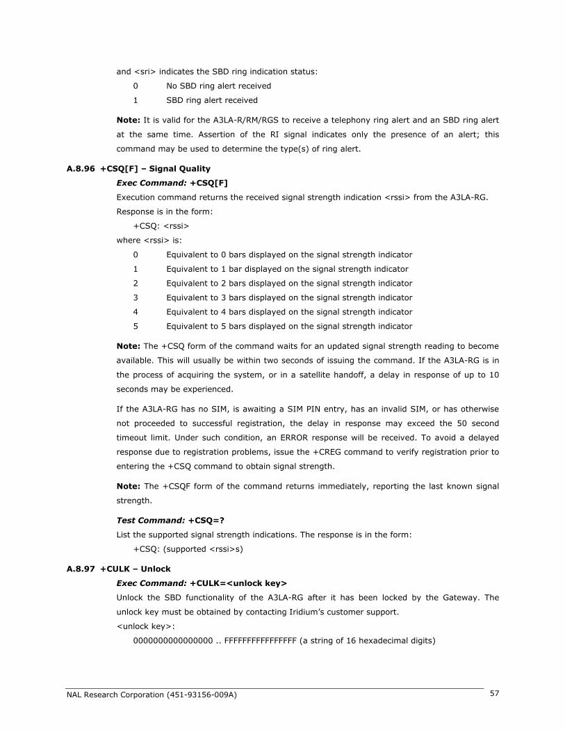
NAL Research Corporation (451-93156-009A) 57
and <sri> indicates the SBD ring indication status:
0 No SBD ring alert received
1 SBD ring alert received
Note: It is valid for the A3LA-R/RM/RGS to receive a telephony ring alert and an SBD ring alert
at the same time. Assertion of the RI signal indicates only the presence of an alert; this
command may be used to determine the type(s) of ring alert.
A.8.96 +CSQ[F] – Signal Quality
Exec Command: +CSQ[F]
Execution command returns the received signal strength indication <rssi> from the A3LA-RG.
Response is in the form:
+CSQ: <rssi>
where <rssi> is:
0 Equivalent to 0 bars displayed on the signal strength indicator
1 Equivalent to 1 bar displayed on the signal strength indicator
2 Equivalent to 2 bars displayed on the signal strength indicator
3 Equivalent to 3 bars displayed on the signal strength indicator
4 Equivalent to 4 bars displayed on the signal strength indicator
5 Equivalent to 5 bars displayed on the signal strength indicator
Note: The +CSQ form of the command waits for an updated signal strength reading to become
available. This will usually be within two seconds of issuing the command. If the A3LA-RG is in
the process of acquiring the system, or in a satellite handoff, a delay in response of up to 10
seconds may be experienced.
If the A3LA-RG has no SIM, is awaiting a SIM PIN entry, has an invalid SIM, or has otherwise
not proceeded to successful registration, the delay in response may exceed the 50 second
timeout limit. Under such condition, an ERROR response will be received. To avoid a delayed
response due to registration problems, issue the +CREG command to verify registration prior to
entering the +CSQ command to obtain signal strength.
Note: The +CSQF form of the command returns immediately, reporting the last known signal
strength.
Test Command: +CSQ=?
List the supported signal strength indications. The response is in the form:
+CSQ: (supported <rssi>s)
A.8.97 +CULK – Unlock
Exec Command: +CULK=<unlock key>
Unlock the SBD functionality of the A3LA-RG after it has been locked by the Gateway. The
unlock key must be obtained by contacting Iridium’s customer support.
<unlock key>:
0000000000000000 .. FFFFFFFFFFFFFFFF (a string of 16 hexadecimal digits)

NAL Research Corporation (451-93156-009A) 58
While the A3LA-RG is locked, it is unable to perform any SBD sessions. Any attempts to start a
session will return an error code indicating that the A3LA-RG is locked.
Command Response: +CULK:<status>
where:
<status> indicates the lock status of the A3LA-RG following the unlock attempt:
0 Unlocked – A3LA-RG is not locked and is permitted to perform SBD sessions.
1 Locked – A3LA-RG is locked and unable to perform SBD sessions. It must be
unlocked by supplying the correct unlock key to the +CULK command.
2 Permanently locked – A3LA-RG is locked and unable to perform SBD sessions. It
cannot be unlocked and must be returned to the supplier.
Read Command: +CULK?
Query the current SBD lock status of the A3LA-RG. The response is of the form:
+CULK:<status>
<status>:
0 Unlocked
1 Locked
2 Permanently locked
A.8.98 +CVMI – Voicemail Indication
Exec Command: +CVMI
Query the status of the voicemail indication flag. The response is of the form:
+CVMI:<vmi>
where <vmi> is:
0 No voicemail indication has been received
1 A voicemail indication has been received
The voicemail indication flag indicates whether a voicemail notification message has been
received from the voicemail system. The flag is set to 1 when an indication is received, and is
cleared to 0 after being queried with the +CVMI command.
Note: For this feature to function, the voicemail number must be programmed into the A3LA-
R/RM/RGS.
A.8.99 +CICCID – Read ICC ID from SIM
Exec Command: +CICCID
Query the status ICC ID of the SIM:
+CICCID
This returns the 19 or 20 digit Integrated Circuit Card Identification of the SIM.
Note: This value is cached from the SIM and thus is not available until the caching has
completed ~5-10 seconds after startup.
A.8.100 +CLIP – Calling Line Identification Presentation
Exec Command: +CLIP=<n>

NAL Research Corporation (451-93156-009A) 59
Note: While this command is implemented in the A3LA-RG, it may not yet be supported in the
Iridium network. Stand by for an Iridium Technical Bulletin announcing network support for this
feature.
This command controls the presentation of the Calling Line Identity of the calling party in a
mobile terminated call via the +CLIP unsolicited result code. <n> controls only the presentation
of the unsolicited result code; the delivery of Calling Line Identity information to the A3LA-RG is
controlled by the provisioning of the CLI Presentation supplementary service in the network
where <n> is:
0 Disable the +CLIP unsolicited result code. (default)
1 Enable the +CLIP unsolicited result code to be sent to the DTE following the RING
result code when a mobile terminated call is received and Calling Line Identity
information is present.
The unsolicited result code has the format:
+CLIP:<number>,<type>
where:
<number> is the phone number of the calling party in “quotes”, in the format specified by
<type>.
<type> indicates the type of number:
129 Dial string without the international access character
145 Dial string which includes the international access character ‘+’
Read Command: +CLIP?
Query the current CLI Presentation provisioning status and the status of the +CLIP unsolicited
result code. The response is of the form:
+CLIP:<n>,<m>
<m>:
0 CLIP not provisioned
1 CLIP provisioned
2 Unknown (e.g. no network, etc.)
A.8.101 +CLIR – Calling Line Identification Restriction
Exec Command: +CLIR=<n>
Note: While this command is implemented in the A3LA-RG, it may not yet be supported in the
Iridium network. Stand by for an Iridium Technical Bulletin announcing network support for this
feature.
This command controls the presentation of the Calling Line Identity of the calling party to the
called party in the next mobile originated call.
<n>:
0 Presentation is determined by the subscription of the CLIR service
1 CLIR invocation – i.e. hide the CLI for the next mobile originated call. This requires
CLIR to be provisioned in one of the temporary modes.

NAL Research Corporation (451-93156-009A) 60
2 CLIR suppression – i.e. show the CLI for the next mobile originated call. This
requires CLIR to be provisioned in one of the temporary modes.
Note: If the CLIR service is not provisioned, and either invocation or suppression is requested
for the next call, the next call may be rejected by the network. It is the DTE’s responsibility to
check whether CLIR is provisioned using the +CLIR? read command.
Read Command: +CLIR?
Query the current CLI Restriction provisioning status and the CLIR invocation/suppression
status for the next call. The response is of the form:
+CLIR:<n>,<m>
<m>:
0 CLIR not provisioned
1 CLIR provisioned in permanent mode
2 Unknown (e.g. no network, etc.)
3 CLIR provisioned in temporary mode, defaulting to presentation restricted
4 CLIR provisioned in temporary mode, defaulting to presentation allowed
A.8.102 +IPR – Fixed DTE Rate
Set Command: +IPR=<rate>[,<autoflag>]
Set the data rate at which the A3LA-RG will accept commands. The change in data rate takes
effect after the result code (e.g. OK) is received by the DTE.
<rate> takes the following values:
1 600 bps
2 1200 bps
3 2400 bps
4 4800 bps
5 9600 bps
6 19200 bps (default)
7 38400 bps
<autoflag> takes the following values:
0 Fixed rate – automatic rate adjustment is disabled
1 Automatic rate adjustment is enabled (default)
Read Command: +IPR?
Query the current data rate and automatic rate adjustment setting. The response is in the form:
+IPR: <rate>,<autoflag>
Test Command: +IPR=?
List the supported data rates. The response is in the form:
+IPR: (supported <rate>s),(supported <autoflag>s)
A.8.103 +SBDWT – Short Burst Data: Write a Text Message
Exec Command: +SBDWT=[<text message>]
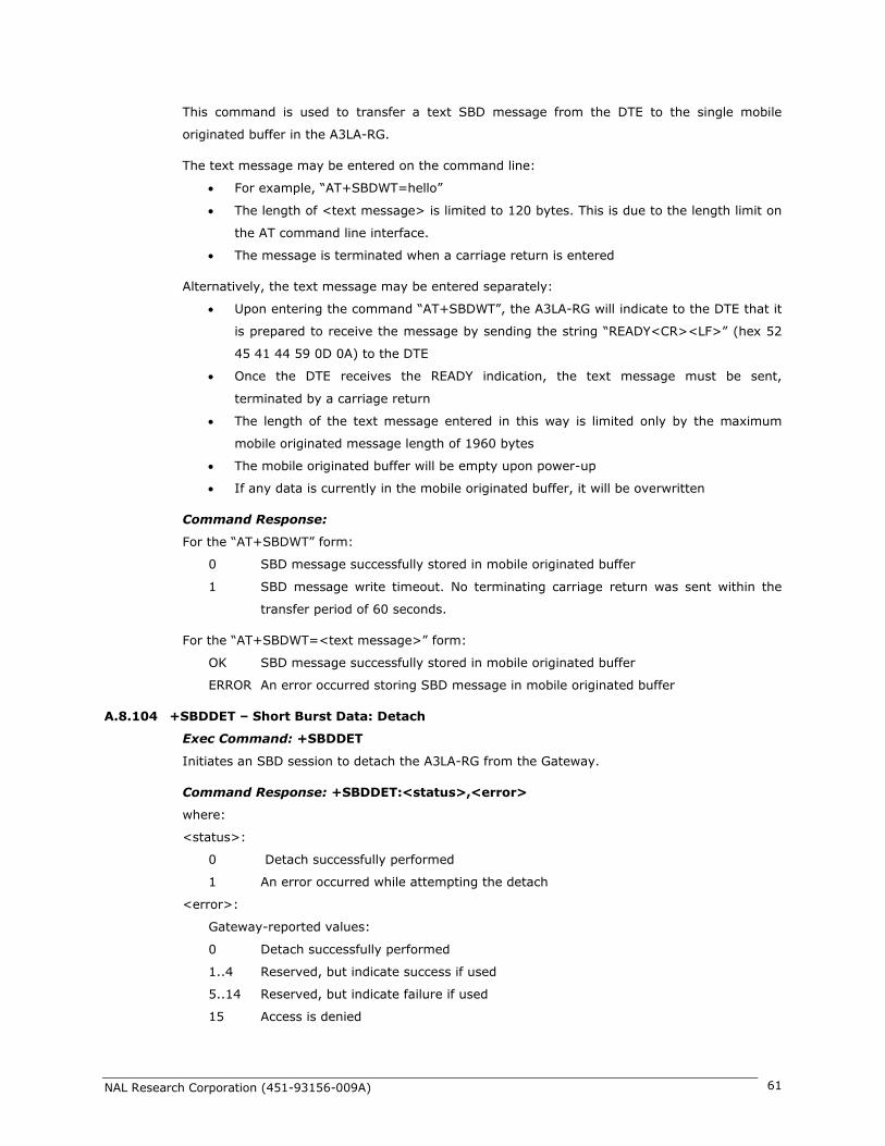
NAL Research Corporation (451-93156-009A) 61
This command is used to transfer a text SBD message from the DTE to the single mobile
originated buffer in the A3LA-RG.
The text message may be entered on the command line:
For example, “AT+SBDWT=hello”
The length of <text message> is limited to 120 bytes. This is due to the length limit on
the AT command line interface.
The message is terminated when a carriage return is entered
Alternatively, the text message may be entered separately:
Upon entering the command “AT+SBDWT”, the A3LA-RG will indicate to the DTE that it
is prepared to receive the message by sending the string “READY<CR><LF>” (hex 52
45 41 44 59 0D 0A) to the DTE
Once the DTE receives the READY indication, the text message must be sent,
terminated by a carriage return
The length of the text message entered in this way is limited only by the maximum
mobile originated message length of 1960 bytes
The mobile originated buffer will be empty upon power-up
If any data is currently in the mobile originated buffer, it will be overwritten
Command Response:
For the “AT+SBDWT” form:
0 SBD message successfully stored in mobile originated buffer
1 SBD message write timeout. No terminating carriage return was sent within the
transfer period of 60 seconds.
For the “AT+SBDWT=<text message>” form:
OK SBD message successfully stored in mobile originated buffer
ERROR An error occurred storing SBD message in mobile originated buffer
A.8.104 +SBDDET – Short Burst Data: Detach
Exec Command: +SBDDET
Initiates an SBD session to detach the A3LA-RG from the Gateway.
Command Response: +SBDDET:<status>,<error>
where:
<status>:
0 Detach successfully performed
1 An error occurred while attempting the detach
<error>:
Gateway-reported values:
0 Detach successfully performed
1..4 Reserved, but indicate success if used
5..14 Reserved, but indicate failure if used
15 Access is denied

NAL Research Corporation (451-93156-009A) 62
A3LA-RG-reported values:
16 Modem has been locked and may not make SBD calls (see +CULK command)
17 Gateway not responding (local session timeout)
18 Connection lost (RF drop)
19 Link failure (A protocol error caused termination of the call)
20..31 Reserved, but indicate failure if used
32 No network service, unable to initiate call
33..34 Reserved, but indicate failure if used
35 A3LA-RG is busy, unable to initiate call
36.. Reserved, but indicate failure if used
This instructs the GSS to disable (detach) SBD ring alerts for the calling A3LA-RG. Successful
completion of the detach command implies that the GSS has performed the requested detach
action and the A3LA-RG is no longer registered for SBD ring alerts. This session does not
transfer any MO or MT messages.
Note: A user can send an MO-SBD message and request a detach at the same time by using
the +SBDI command. The +SBDI command always requests a detach.
A.8.105 +SBDI – Short Burst Data: Initiate an SBD Session
Note: The +SBDI command is provided for backwards compatibility with existing DTEs which
do not use SBD Ring Alert functionality. For SBD calls invoked with this command:
The SBD session type is fixed at type 0 – MO call
The SBD Delivery Short Code will be the value specified by the +SBDDSC command
An SBD Detach is performed as part of the call
No SBD location update is performed
DTEs requiring SBD Ring Alert functionality should use the extended +SBDIX command.
Exec Command: +SBDI
This command initiates an SBD session between the A3LA-RG and the GSS. If there is a
message in the mobile originated buffer it will be transferred to the GSS. Similarly if there is
one or more messages queued at the GSS the oldest will be transferred to the A3LA-RG and
placed into the mobile terminated buffer.
The message, if any, in the mobile originated buffer will be sent from the A3LA-RG to
the GSS
If there is a message queued at the GSS it will be transferred to the A3LA-RG and
placed into the mobile terminated buffer
Command Response:
+SBDI:<MO status>,<MOMSN>,<MT status>,<MTMSN>,<MT length>,<MT queued>
where:
<MO status>: MO session status provides an indication of the disposition of the mobile
originated transaction. The field can take on the following values:
0 No SBD message to send from the A3LA-RG

NAL Research Corporation (451-93156-009A) 63
1 SBD message successfully sent from the A3LA-RG to the GSS
2 An error occurred while attempting to send SBD message from A3LA-RG to GSS
<MOMSN>: The Mobile Originated Message Sequence Number (MOMSN) is a value assigned by
the A3LA-RG when sending a mobile-originated message to the GSS. This value is incremented
each time an SBD session is successfully completed between the A3LA-RG to the GSS. This
wraparound counter can range from 0 to 65535.
<MT status>: The MT status provides an indication of the disposition of the mobile terminated
transaction. The field can take on the following values:
0 No SBD message to receive from the GSS
1 SBD message successfully received from the GSS
2 An error occurred while attempting to perform a mailbox check or receive a
message from the GSS
<MTMSN>: The Mobile Terminated Message Sequence Number (MTMSN) is assigned by the
GSS when forwarding a message to the A3LA-RG. This value is indeterminate if the field <MT
status> is zero. This wraparound counter can range from 0 to 65535.
<MT length>: The MT length is the length in bytes of the mobile terminated SBD message
received from the GSS. If no message was received, this field will be zero.
<MT queued>: MT queued is a count of mobile terminated SBD messages waiting at the GSS to
be transferred to the A3LA-RG.
A.8.106 +SBDIX[A] – Short Burst Data: Initiate an SBD Session Extended
Note: The +SBDIX command must be used in place of the +SBDI command for DTEs wishing
to make use of SBD Ring Alert functionality.
Exec Command: +SBDIX[A][=<location>]
This command initiates an SBD session between the A3LA-RG and the GSS, setting the SBD
Session. Type according to the type of command +SBDIX or +SBDIXA, Delivery Short Code
according to the value specified by the +SBDDSC command, and the type of location according
to whether the optional location value is provided. If there is a message in the mobile originated
buffer it will be transferred to the GSS. Similarly if there are one or more messages queued at
the GSS the oldest will be transferred to the A3LA-RG and placed into the mobile terminated
buffer.
The message, if any, in the mobile originated buffer will be sent from the A3LA-RG to
the GSS
If there is a message queued at the GSS it will be transferred to the A3LA-RG and
placed into the mobile terminated buffer
This command will always attempt an SBD registration, consisting of attach and
location update, during the SBD session in order to support SBD Ring Alert. If this is
not desired, the +SBDI command should be used.
The DTE should append an ‘A’ to the command, i.e. +SBDIXA, when the SBD session is
in response to an SBD ring alert
NAL Research Corporation (451-93156-009A) 64
<location> has format:
[+|-]DDMM.MMM,[+|-]dddmm.mmm
where:
DD Degrees latitude (00-89)
MM Minutes latitude (00-59)
MMM Thousandths of minutes latitude (000-999)
ddd Degrees longitude (000-179)
mm Minutes longitude (00-59)
mmm Thousandths of minutes longitude (000-999)
This command initiates an SBD session between the A3LA-RG and the GSS, setting the SBD
Session. The optional sign indicators specify latitude North (+) or South (-), and longitude East
(+) or West (-). If omitted, the default is +.
For example,
AT+SBDIX=5212.483,-00007.350
corresponds to 52 degrees 12.483 minutes North, 0 degrees 7.35 minutes West.
Command Response:
+SBDIX:<MO status>,<MOMSN>,<MT status>,<MTMSN>,<MT length>,<MT queued>
where:
<MO status>: MO session status provides an indication of the disposition of the mobile
originated transaction. The field can take on the following values:
Gateway-reported values:
0 MO message, if any, transferred successfully
1 MO message, if any, transferred successfully, but the MT message in the queue
was too big to be transferred
2 MO message, if any, transferred successfully, but the requested Location Update
was not accepted
3..4 Reserved, but indicate MO session success if used
5..8 Reserved, but indicate MO session failure if used
10 GSS reported that the call did not complete in the allowed time
11 MO message queue at the GSS is full
12 MO message has too many segments
13 GSS reported that the session did not complete
14 Invalid segment size
15 Access is denied
A3LA-RG-reported values:
16 Modem has been locked and may not make SBD calls (see +CULK command)
17 Gateway not responding (local session timeout)
18 Connection lost (RF drop)
19 Link failure (A protocol error caused termination of the call)
20..31 Reserved, but indicate failure if used
32 No network service, unable to initiate call

NAL Research Corporation (451-93156-009A) 65
33..34 Reserved, but indicate failure if used
35 A3LA-RG is busy, unable to initiate call
36.. Reserved, but indicate failure if used
<MOMSN>: The Mobile Originated Message Sequence Number (MOMSN) is a value assigned by
A3LA-RG when sending a mobile-originated message to the GSS. This value is incremented
each time an SBD session is successfully completed between the A3LA-RG to the GSS. This
wraparound counter can range from 0 to 65535.
<MT status>: The MT status provides an indication of the disposition of the mobile terminated
transaction. The field can take on the following values:
0 No SBD message to receive from the GSS
1 SBD message successfully received from the GSS
2 An error occurred while attempting to perform a mailbox check or receive a
message from the GSS
<MTMSN>: The Mobile Terminated Message Sequence Number (MTMSN) is assigned by the
GSS when forwarding a message to the A3LA-RG. This value is indeterminate if the field <MT
status> is zero. This wraparound counter can range from 0 to 65535.
<MT length>: The MT length is the length in bytes of the mobile terminated SBD message
received from the GSS. If no message was received, this field will be zero.
<MT queued>: MT queued is a count of mobile terminated SBD messages waiting at the GSS to
be transferred to the A3LA-RG.
A.8.107 +SBDDSC – Short Burst Data: Delivery Short Code
Set Command: +SBDDSC=<dsc>
Set the Delivery Short Code (DSC), which provides dynamic routing or control information for
MO or MT messages. This is an 8-bit value providing the ability to set individual fields. Value
0x80 (hexadecimal) sets the most significant bit. Value 0x01 sets the least significant bit. Flag
values can be added together to achieve a combination of settings. Some fields are overridden
during certain SBD sessions (e.g. a +SBDREG registration session sets flag 0x80). Enable or
disable ring indications for SBD Ring Alerts.
<dsc>:
0..255 DSC to be used for subsequent MO messages (0 default)
0x80 Hold MT message delivery
0x40 Leave MT message in queue after delivery
0x20 Destination in MO payload
Read Command: +SBDDSC?
Query the current Delivery Short Code. The response is of the form:
+SBDDSC:<dsc>
A.8.108 +SBDMTA – Short Burst Data: Mobile-Terminated Alert
Set Command: +SBDMTA=<mode>
Enable or disable ring indications for SBD Ring Alerts.

NAL Research Corporation (451-93156-009A) 66
<status>:
0 Disable ring indication
1 Enable ring indication (default)
When SBD ring indication is enabled, the A3LA-RG asserts the RI line and issues the unsolicited
result code SBDRING when an SBD ring alert is received.
Read Command: +SBDMTA?
Query the current ring indication mode. The response is of the form:
+SBDMTA:<mode>
Test Command: +SBDMTA=?
List the supported mode settings. The response is of the form:
+SBDMTA:(supported <mode> settings)
A.8.109 +SBDREG – Short Burst Data: Network Registration
Exec Command: +SBDREG[=<location>]
Triggers an SBD session to perform a manual SBD registration.
This command initiates an SBD session to perform a manual SBD registration, consisting of an
attach and location update. This session does not transfer any MO or MT messages.
Note: The A3LA-RG restricts the number of manual and automatic registrations to one every 3
minutes. Successive attempts within 3 minutes will return an error code indicating that the DTE
should try later (see error 36 below).
Note: A user can send an MO SBD message and register at the same time by using the +SBDIX
command. The +SBDIX command always performs a registration attempt and should be used
for an application requiring SBD Ring Alert. The +SBDI command never includes an SBD
registration and should be used for an application that does not require SBD Ring Alert.
<location> has format:
[+|-]DDMM.MMM,[+|-]dddmm.mmm
where:
DD Degrees latitude (00-89)
MM Minutes latitude (00-59)
MMM Thousandths of minutes latitude (000-999)
ddd Degrees longitude (000-179)
mm Minutes longitude (00-59)
mmm Thousandths of minutes longitude (000-999)
This command initiates an SBD session between the A3LA-RG and the GSS, setting the SBD
Session.
The optional sign indicators specify latitude North (+) or South (-), and longitude East (+) or
West (-). If omitted, the default is +.
For example,
AT+SBDIX=5212.483,-00007.350

NAL Research Corporation (451-93156-009A) 67
corresponds to 52 degrees 12.483 minutes North, 0 degrees 7.35 minutes West.
Command Response: +SBDREG:<status>,<reg err>
where:
<status> indicates the resulting registration status of the A3LA-RG:
0 Detached – A3LA-RG is detached as a result of a successful +SBDDET or +SBDI
command
1 Not registered – A3LA-RG is attached but has not provided a good location since it
was last detached
2 Registered – A3LA-RG is attached with a good location. Note that this may be the
case even when the most recent attempt did not provide a good location.
3 Registration denied – The GSS is denying service to the A3LA-RG
<reg err>:
Gateway-reported values:
0 No error
2 Session completed but the requested Location Update was not accepted
3..14 Reserved, but indicate Location Update failure if used
15 Access is denied
A3LA-RG-reported values:
16 Modem has been locked and may not make SBD calls (see +CULK command)
17 Gateway not responding (local session timeout)
18 Connection lost (RF drop)
19 Link failure (A protocol error caused termination of the call)
20..31 Reserved, but indicate failure if used
32 No network service, unable to initiate call
33..34 Reserved, but indicate failure if used
35 A3LA-RG is busy, unable to initiate call
36 Try later, must wait 3 minutes since last registration
37.. Reserved, but indicate failure if used
Read Command: +SBDREG?
Query the current SBD registration status of the A3LA-RG. The response is of the form:
+SBDREG:<status>
<status>:
0 Detached
1 Not registered
2 Registered
3 Registration denied
The registration status is stored in A3LA-RG non-volatile memory, and can therefore be queried
by the DTE after powering up.
A.8.110 +SBDAREG – Short Burst Data: Automatic Registration
Exec Command: +SBDAREG=<mode>

NAL Research Corporation (451-93156-009A) 68
Set the A3LA-RG’ Auto-registration mode.
<mode>:
0 Disable automatic registration (default)
1 Set the Auto-registration mode to “Automatic”
2 Set the Auto-registration mode to “Ask”
When auto-registration is enabled, mode 1 or 2, the A3LA-RG monitors its current location and
triggers an SBD auto-registration when it determines that it has moved sufficiently far away
from its last registered location. Note that auto-registration runs only while the A3LA-RG is
attached to the GSS, i.e. the registration status is “Not registered” or “Registered”.
Auto-registration may only be used with system-provided location. If the DTE is providing its
own location (e.g. GPS), the DTE should use the manual registration command, +SBDREG.
Upon triggering in mode 1, “Automatic”, the A3LA-RG autonomously initiates an SBD session in
order to perform a registration with its updated location. This session does not transfer any MO
or MT messages.
Upon triggering in mode 2, “Ask”, the A3LA-RG reports to the DTE that it should register with
the system because its location has changed (see <event> below); it is then the responsibility
of the DTE to register via +SBDREG or +SBDIX. +SBDIX allows the DTE to register while
including an MO message and/or retrieving any MT message that is pending at the GSS.
When auto-registration is enabled, mode 1 or 2, the A3LA-RG reports relevant events to the
DTE by issuing an unsolicited result code +AREG:<event>,<reg error>.
<event>:
0 Suggest DTE makes a registration attempt (mode 2 only)
1 Auto-registration has been performed successfully (mode 1 only)
2 Auto-registration has failed and will be retried after a delay (mode 1 only)
<reg error>:
Gateway-reported values:
0 No error
2 Session completed but the requested Location Update was not accepted
3..14 Reserved, but indicate Location Update failure if used
15 Access is denied
A3LA-RG-reported values:
16 A3LA-RG has been locked and may not make SBD calls (see +CULK command)
17 Gateway not responding (local session timeout)
18 Connection lost (RF drop)
19 Link failure (A protocol error caused termination of the call)
20..31 Reserved, but indicate failure if used
32 No network service, unable to initiate call
33..34 Reserved, but indicate failure if used
35 A3LA-RG is busy, unable to initiate call
36 Try later, must wait 3 minutes since last registration

NAL Research Corporation (451-93156-009A) 69
37.. Reserved, but indicate failure if used
Read Command: +SBDAREG?
Query the current automatic MT registration mode. The response is of the form:
+SBDAREG:<mode>
Test Command: +SBDAREG=?
List the supported mode settings. The response is of the form:
+SBDAREG:(supported <mode> settings)
A.8.111 +SBDSX – Short Burst Data: Status Extended
Exec Command: +SBDSX
This command returns current state of the mobile originated and mobile terminated buffers,
and the SBD ring alert status.
Command Response:
+SBDSX: <MO flag>, <MOMSN>, <MT flag>, <MTMSN>, <RA flag>, <msg waiting>
where:
<MO flag>: The MO flag indicates the existence of a message in the mobile originated buffer.
The response from the A3LA-RG is one of the following numeric codes:
0 No message in mobile originated buffer
1 Message in mobile originated buffer
<MOMSN>: The MOMSN identifies the sequence number that will be used during the next
mobile originated SBD session.
<MT Flag>: The MT flag indicates the existence of a message in the mobile terminated buffer.
The response from the A3LA-RG is one of the following numeric codes:
0 No message in mobile terminated buffer
1 Message in mobile terminated buffer
<MTMSN>: The MTMSN identifies the sequence number that was used in the most recent
mobile terminated SBD session. This value will be –1 if there is nothing in the mobile
terminated buffer.
<RA flag>: The RA flag indicates whether an SBD ring alert has been received and still needs to
be answered.
0 No SBD ring alert
1 SBD ring alert has been received and needs to be answered
Note: The RA flag is set whenever the A3LA-RG receives an SBD ring alert; this happens even if
the +SBDMTA setting specifies that SBD ring indications are disabled.
The RA flag is cleared only on successful completion of an SBD mailbox check, i.e. an SBD
session invoked with +SBDI[X[A]] in which the returned MT status indicates that no error
occurred.

NAL Research Corporation (451-93156-009A) 70
The value of the RA flag is stored in non-volatile memory so it is preserved across power cycling
of the A3LA-RG.
<msg waiting>: The message waiting flag indicates how many SBD mobile terminated
messages are currently queued at the gateway awaiting collection by the A3LA-RG. This flag is
updated after every SBD session, including +SBDI, +SBDIX, +SBDIXA, +SBDREG and
+SBDDET.
A.8.112 +CCWA – Call Waiting Service
Note: While this command is implemented in the A3LA-RG, it may not yet be supported in the
Iridium network. Stand by for an Iridium Technical Bulletin announcing network support for this
feature.
This command is based on GSM 07.07 [2] subclause 7.11, and allows control of the Iridium Call
Waiting supplementary service similar to GSM 02.83 [6]. Activation, deactivation and status
query are supported. Parameter <n> is used to disable/enable the presentation of the
unsolicited result code to the DTE when the Call Waiting service is enabled.
Command is abortable in the cases when the network is interrogated. The interaction of this
command with other commands based on other GSM supplementary services is described in the
GSM standard.
Defined values
<n> (sets/shows the result code presentation status in the A3LA-RG):
0 disable unsolicited result presentation
1 enable unsolicited result presentation
Command Possible Response(s)
+CCWA= None (command ignored without error)
+CCWA=<n>[,<mode>,<classx>] When command unsuccessful
+CME ERROR: <err>
When <mode>=2 command successful
+CCWA:<status>,<class1>
[<CR><LF>+CCWA:<status>,<class2>
[...]] (but the A3LA-RG will in practice only report a single
line, <class1> = 1)
When <mode> not 2 and command successful
None
+CCWA? Current unsolicited result presentation status
+CCWA:<n>
Test command
+CCWA=?
List of supported <n>s
+CCWA:(0,1)
None Unsolicited result notifying that a call is waiting
+CCWA:<number>,<type>,<class>

NAL Research Corporation (451-93156-009A) 71
On a DTE-DCE command, <n> will set the result code presentation status in the A3LA-RG,
regardless of the value of any <mode> parameter.
<mode> (when <mode> parameter is not given, network is not interrogated):
0 disable Call Waiting service for specified class(es)
1 enable Call Waiting service for specified class(es)
2 query status of Call Waiting service for specified class(es)
<classx> is a sum of integers each representing a class of information:
1 voice
2 data
4 fax
This parameter defaults to 7, equal to all classes, but the A3LA-R/RM/RGS only supports
Voice Call Waiting so this is illegal. Therefore in practice the DTE must supply <classx>=1.
<status>:
0 Call Waiting service not active for specified Class
1 Call Waiting service active for specified Class
<number>: quoted string type phone number of calling address in format specified by <type>
<type>: type of address octet in integer format (refer GSM 04.08 [7] subclause
10.5.4.7);default 145 when dialing string is international number, otherwise 129.
If the network rejects a request to activate/deactivate the Call Waiting service due to it not
being provisioned (or for other reasons), the reported CME ERROR code will be 133 “requested
service option not subscribed”. This is strictly speaking a GPRS-related code (GSM 07.07 [2]
subclause 9.2.2), but is the most informative choice in this case.
Informative examples:
The status of only the Voice class can be queried:
AT+CCWA=1,2,1
If the command is successful, the A3LA-RG might return (after contacting the network):
+CCWA:1,1
If a remote caller tries to place a voice call to the A3LA-RG while it already has a call in
progress, and the Call Waiting service has been made active for class Voice, then the network
will send a message to the A3LA-RG. Then, if <n> has previously been set to ‘1’, the A3LA-RG
will send an unsolicited result code to the DTE, e.g.:
+CCWA:”+441223420024”,145,1
A.8.113 +CLCK – Facility Lock
Command Possible Response(s)
+CLCK= None (command ignored without error)
+CLCK=<fac>,<mode>[<passwd>[,<classx>]] When command unsuccessful

NAL Research Corporation (451-93156-009A) 72
This command is based on GSM 07.07 [2] subclause 7.4, and is used to enable, disable or
interrogate an ME or a network facility <fac>.
Command is abortable in the cases when network facilities are set or interrogated. The
interaction of this command with other commands based on other GSM supplementary services
is described in the GSM standard.
Execute command is used to activate or deactivate Call Barring Supplementary Services, SIM
Fixed Dialling feature, the SIM card PIN Code, or to enable or disable the Phone Lock feature in
the A3LA-RG. A password code (detailed below) may be required, depending on the action
chosen.
Not all Call Barring services detailed in GSM 07.07 [2] subclause 7.4 are supported. A subset of
those implemented in the H1 menu MMI is supported.
Note: This command will not work unless the SIM PIN has been entered using the +CPIN
command.
Note: Once this command has been issued to disable the PIN, neither it nor the +CPIN need to
be issued again unless the PIN function is reactivated.
The following parameter values are currently supported:
<fac>:
“CS” CNTRL Surface (Enable/Disable Phone Lock feature). The current Phone Unlock
Code is required as <passwd>.
“SC” SIM: Activate/Deactivate SIM card PIN Code, in which the SIM asks password in ME
power-up. The PIN code is required as <passwd>.
"FD" SIM fixed dialling memory feature (PIN2 is required as <passwd>)
"AO" BAOC (Bar All Outgoing Calls) (refer GSM 02.88 [4] clause 1). The Call Barring
password is required as <passwd>.
"AI" BAIC (Bar All Incoming Calls) (refer GSM 02.88 [4] clause 2). The Call Barring
password is required as <passwd>.
"AB" All Barring services (refer GSM 02.30 [5]) (applicable only for <mode>=0). The
Call Barring password is required as <passwd>.
Note: Several GSM standard facility codes including the following are NOT supported:
+CME ERROR: <err>
When <mode>=2 and command successful
+CLCK:<status>[,<class1>
[<CR><LF>+CLCK:<status>,<class2>
[...]] (but the A3LA-RG will in practice only
report a single line, <class1> = 1)
When <mode> not 2 and command successful
None
Test command
+CLCK=?
List of supported <fac>s
+CLCK:(“CS”,”SC”,”FD”,”AO”,”AI”,”AB”)

NAL Research Corporation (451-93156-009A) 73
"OI" BOIC (Bar Outgoing International Calls) (refer GSM 02.88 [4] clause 1). All Iridium
calls are International, so this facility should not be exercised by a user interface.
"OX" BOIC-exHC (Bar Outgoing International Calls except to Home Country) (refer GSM
02.88 [4] clause 1). All Iridium calls are International, so this facility should not be
exercised by a user interface.
"IR" BIC-Roam (Bar Incoming Calls when Roaming outside the home country) (refer
GSM 02.88 [4] clause 2). In Iridium it is not possible to roam (there is only one
“home country”), so this facility should not be exercised by a user interface.
"AG" All outGoing barring services (refer GSM 02.30 [5]) (applicable only for
<mode>=0). This subgroup of services cannot be addressed; the user interface
should just use “AB”.
"AC" All inComing barring services (refer GSM 02.30 [5]) (applicable only for
<mode>=0). This subgroup of services cannot be addressed; the user interface
should just use “AB”.
<mode>:
0 Disable (Deactivate)
1 Enable (Activate)
<passwd>: string type, enclosed by “ “; for example, “1234”.
Note: Factory default SIM card PIN Code is “1111”
Note: Factory default Phone Unlock Code is “1234”
<classx> is a sum of integers each representing a class of information:
1 voice
2 data
4 fax
This parameter defaults to 7, equal to all classes, but the A3LA-RG only supports Voice Call
Barring so this is illegal. Therefore in practice the DTE must supply <classx>=1 when
querying or changing the status of any Call Barring facility. When querying (<mode>=2),
<passwd> is irrelevant and should be supplied as ”” in order to allow the <classx>=1
parameter to be supplied.
For facilities “CS”, “SC”and “FD”, the <passwd> and <classx> parameters are not relevant
and will be ignored if supplied.
Test Command: +CLCK=?
Test command returns the facility values supported by the phone. The response is in the form:
+CLCK:(list of supported <fac>s)
Note: Only “CS” will appear as a supported value if there is no SIM card in the device.
Note: +CLCK is closely related to +CPIN and +CPWD. See these commands for additional
information.

NAL Research Corporation (451-93156-009A) 74
A.8.114 +CPWD – Change Password
Exec Command: +CPWD=<fac>,<oldpwd>,<newpwd>
This command sets a new password for the facility lock function defined by the AT command
Facility Lock +CLCK. The following parameter values are currently supported:
<fac>:
“CS” CNTRL Surface (Phone Unlock Code)
“SC” SIM (SIM Card PIN Code)
“P2” SIM PIN2 (SIM Card PIN2 Code)
“AB” Call Barring password (single password used for all call barring supplementary
services)
Note: AT+CPWD=”SC”,<oldpwd>,<newpwd> will return “Error” unless the SIM Card Pin Code
is currently activated (see AT command Facility Lock +CLCK).
Note: A user interface may prompt the user for two copies of the new password, in which case
it should check the two are identical as only one copy is needed for this command.
Test Command: +CPWD=?
Test command returns a list of pairs which present the available facilities and the maximum
length of their password. Response is in the form:
+CPWD: list of supported (<fac>,<pwdlength>)s
where <pwdlength> indicates the maximum length for the password.
Note: +CPWD is closely related to +CLCK and +CPIN. See these commands for additional
information.
A.8.115 +CSDT – Sidetone
Exec Command: +CSDT=<sidetone enabled>
This command controls the A3LA-RG RF board sidetone generation. Enabling sidetone will cause
the A3LA-RG to start sidetone generation. Disabling sidetone will cause the A3LA-RG to stop
sidetone generation. The following parameter values are currently supported:
< sidetone enabled >:
1 Enable sidetone
0 Disable sidetone
Query Command: +CSDT?
This command returns the current transceiver board sidetone generation state. 1 = enabled, 0
= disabled.
Test Command: +CSDT=?
Test command returns a list of valid values. Response is in the form:
+CSDT: list of supported modes
A.8.116 +CDSI – Report SMS Status
This announcement is sent when the network responds after a mobile-originated SMS send
attempt.

NAL Research Corporation (451-93156-009A) 75
Exec Command: none
Unsolicited Announcement:
+CDSI:<status>
where:
<status>:
0..255 Success code or failure cause (TD_SMS_RP_CAUSE_*)
1 Unassigned Number
8 Operator Barring
10 Call Barred
21 SM Transfer Rejected
22 Memory Capacity Exceeded
27 Destination Out Of Order
28 Unidentified Subscriber
29 Facility Rejected
30 Unknown Subscriber
38 Network Out Of Order
41 Temporary Failure
42 Congestion
47 No Resources
50 Facility Not Subscribed
69 Facility Not Implemented
81 Invalid RP MR
95 Semantic Error
96 Mandatory IE Error
97 RP MT Not Implemented
98 Bad State
99 IE Not Implemented
111 Unspecified Error
127 Interworking Error
128 Success
129 Success Ack
253 No Transaction Id
254 CM Internal Error
255 RL Timeout
Values up to 127 are defined by GSM for SMS-PP Relay Layer messages and values 128 and
above are internal codes introduced by Iridium.
A.8.117 +PA – GPS: List of NMEA Message Formats
Exec Command: +PA=<n>

NAL Research Corporation (451-93156-009A) 76
This command returns the complete NMEA message format, where <n> is a hexadecimal
number corresponding to the following NMEA and proprietary u-blox formats. Since the A3LA-
RG does not have a GPS receiver, this command always returns no GPS information.
1 – GGA
2 – GLL
3 – GSA
4 – GSV
5 – GRS
6 – RMC
7 – VTG
8 – ZDA
9 – GST
A – PUBX,00
B – PUBX,01
C – PUBX,04
A.8.118 +PD – GPS: UTC Date
Exec Command: +PD
This command returns UTC date with the format shown below. The <Invalid Position Fix>
message will appear only if the GPS receiver could not acquire a position fix.
Command Response: +PD:
UTC Date = <mm>-<dd>-<yyyy>
<Invalid Position Fix>
Satellite Used = <zz>
where
<mm> Month (01-12), 01 may appear for an <Invalid Position Fix>
<dd> Day (01-31), 06 may appear for an <Invalid Position Fix>
<yyyy> Year (0000-9999), 1980 may appear for <Invalid Position Fix>
<zz> Number of satellite used to obtain information
A.8.119 +PG – GPS: GPS Automatically Sent
Exec Command: +PG=<CD level>[,<mode>[,<rate>[,<messages>]]]
This command automatically sets the unit to return GPS information at a set rate.
<CD level> CD level controlling when GPS information is sent. 0 is off, 1 send when CD
is low, 2 send when CD is high, 3 send when CD is low or high.
<mode> For the initial version this does not do anything. In future versions this will
determine whether to send in regular mode or in tracking mode. 1 is in
regular mode only, 2 is in tracking mode only and 3 is in regular or
tracking mode.
<rate> Frequency that the GPS information is sent over in seconds.

NAL Research Corporation (451-93156-009A) 77
<messages> Which messages are sent at the specified rate. Current list of NMEA and
proprietary u-blox messages are: 1 GGA, 2 GLL, 6 RMC, 7 VTG, 8 ZDA, A
PUBX00 and B PUBX01.
Read Command: +PG?
Returns the current settings with the messages displayed as a hexadecimal number showing
what messages are set to be sent. The bit correspondence is as follows:
Bit Message
0 Not Used
1 GGA
2 GLL
3 Not Used
4 Not Used
5 Not Used
6 RMC
7 VTG
8 ZDA
9 Not Used
10 or 0x0A PUBX,00
11 or 0x0B PUBX,01
12 or 0x0C Not Used
13 or 0x0D Not Used
14 or 0x0E Not Used
15 or 0x0F Not Used
Test Command: +PG=?
Returns the current settings with the messages displayed as a hexadecimal number showing
what messages are set to be sent.
A.8.120 +PL – GPS: Display Position to 4th Decimal Place
Exec Command: +PL
This command returns position with the format shown below. The <Invalid Position Fix>
message will appear only if the GPS receiver could not acquire a position fix. The latitude and
longitude have been rounded to 4th place. The AT+PLOC command is recommended to obtain
GPS information.
Command Response: +PL:
Latitude:<||>:<mm>.<nnnn> <N/S>
Longitude=<ooo>:<pp>.<qqqq> <E/W>
Altitude=<#> meters
<Invalid Position Fix>
Satellites Used=<zz>
where:
<||> Latitude in degrees (00-90)

NAL Research Corporation (451-93156-009A) 78
<mm> Latitude in minutes (00-59)
<nnnn> Fraction of minutes (0000-9999)
<N/S> Either North or South depending on the direction
<ooo> Longitude in degrees (000-180)
<pp> Longitude in minutes (00-59)
<qqqq> Fraction of minutes (0000-9999)
<E/W> Either East or West depending on the direction
<#> Altitude displayed with one decimal place
<zz> Number of satellites used to obtain information
A.8.121 +PLOC – GPS: Display Position to 5th Decimal Place
Exec Command: +PLOC
This command returns position with the format shown below. The <Invalid Position Fix>
message will appear only if the GPS receiver could not acquire a position fix. On the A3LA-RG
this command does not actually contain GPS information.
Command Response: +PLOC
Latitude:<||>:<mm>.<nnnnn> <N/S>
Longitude=<ooo>:<pp>.<qqqqq> <E/W>
Altitude=<#> meters
<Position Fix> = Invalid Position Fix, Valid Position Fix, or Dead Reckoning
Satellites Used=<zz>
where:
<||> Latitude in degrees (00-90)
<mm> Latitude in minutes (00-59)
<nnnnn> Fraction of minutes (00000-99999)
<N/S> Either North or South depending on the direction
<ooo> Longitude in degrees (000-180)
<pp> Longitude in minutes (00-59)
<qqqqq> Fraction of minutes (00000-99999)
<E/W> Either East or West depending on the direction
<#> Altitude displayed with one decimal place
<zz> Number of satellites used to obtain information
A.8.122 +PT – GPS: UTC Time
Exec Command: +PT
This command returns UTC time with the format shown below. The <Invalid Position Fix>
message will appear only if the GPS receiver could not acquire a position fix.
Command Response: +PT
UTC Time=<hh>:<mm>:<ss>.<xxx>
<Invalid Position Fix>
Satellites Used=<zz>
where:

NAL Research Corporation (451-93156-009A) 79
<hh> Hours (01-23)
<mm> Minutes (00-59)
<ss> Seconds (00-59)
<xxx> Fraction of seconds (000-999)
<zz> Number of satellites used to obtain information
A.8.123 +PV – GPS: Basic GPS Velocity
Exec Command: +PV
This command returns velocity (consisting of speed and direction) with the format shown below.
The <Invalid Position Fix> message will appear only if the GPS receiver could not acquire a
position fix. The AT+PVEL command is recommended to obtain velocity information because
this command also lists the vertical velocity and will sometimes indicate dead reckoning instead
of listing Invalid Position Fix.
Command Response: +PV
Ground Velocity=<#s> km/h, <#h> degrees from true North
<Invalid Position Fix>
Satellites Used=<zz>
where:
<#s> Speed displayed with one decimal place
<#h> Heading in degrees from true north ranging from 0 to 360
<zz> Number of satellites used to obtain information
A.8.124 +PVEL – GPS: GPS Velocity
Exec Command: +PVEL
This command returns velocity (consisting of speed and direction) with the format shown below.
The <Invalid Position Fix> Message will appear only if the GPS receiver could not acquire a
position fix.
Command Response: +PVEL
Ground Velocity=<#g> km/h, <#h> degrees from true North
Vertical Velocity=<#v> m/s
<Position Fix>
Satellites Used=<zz>
where:
<#g> Speed displayed
<#h> Heading in degrees from true north ranging from 0 to 360
<#v> Vertical component of velocity. Value may be negative.
<Position Fix> Invalid Position Fix, Valid Position Fix, or Dead Reckoning
<zz> Number of satellites used to obtain information
A.8.125 ^AA – Auto Answer Display
Exec Command: ^AA=<n>
This command sets whether or not to display the ^AAI unsolicited result code when attempting
to auto answer a call.

NAL Research Corporation (451-93156-009A) 80
<n>:
0 URC is not displayed
1 URC is displayed. ^AAI:1 is displayed when auto answering starts and ^AAI:0 is
displayed when auto answering is finished whether or not it was successful.
Read Command: ^AA?
Queries the current setting
Test Command: ^AA=?
Returns the accepted values
A.8.126 ^AD – Auto Dial
Exec Command: ^AD=<enabled>,<number>
This command enables or disables auto dialing. If auto dialing is enabled, the A3LA-RG will go
into auto dial mode when the DTR line is brought low and will go back to command mode when
the DTR line is brought high again. While in auto dial mode, the A3LA-RG will not respond to AT
commands. Instead, the A3LA-RG will continuously dial the number that is setup for auto
dialing. The ^ADR command controls the retry delay in between dial attempts.
<enabled>:
0 Do not auto dial when the DTR line is low (default)
1 Auto dial when the DTR line is low
<number>: The phone number to dial. The number must be enclosed in double quotes and
cannot be more than 20 characters long.
A.8.127 ^ADR – Auto Dial Retry
Exec Command: ^ADR=<delay>
This command sets the time to delay in between dial attempts in auto dial mode.
<delay>: The number of seconds to delay. The value must be between 5 and 255 seconds.
A.8.128 ^CCOP – Change Crypto Officer Password (Encryption)
Exec Command: ^CCOP=<old>,<new>
Change the Crypto Officer’s password from factory-set/old value to new value. The password
must include all printable keyboard characters. The password will not be reset by AT command
&F. When the A3LA-RG is set to echo, all entries are replaced with asterisks (*) instead of the
actual typed value. All passwords must be between 8 and 16 characters in length. The factory-
set password is ‘temp password’ and must be changed before encryption can be used.
<old>: Old password and must be enclosed by two single quotes (‘old password‘)
<new>: New password and must be enclosed by two single quotes (‘new password‘)
A.8.129 ^CMGEC – Clear SMS Encrypted Storage
This command is a synonym for ^SMSE for backward compatibility. See the ^SMSE command
for details.
A.8.130 ^FFW – Flash Firmware
Exec Command: ^FFW
Puts the firmware into flashing mode

NAL Research Corporation (451-93156-009A) 81
A.8.131 ^KD – Key for Decryption (Encryption)
Exec Command: ^KD=<password>,<key>
Allow entering the 32 bytes for the AES decryption key. These bytes must be entered with
mandatory leading 0s, where each byte is represented by 2 hexadecimal uppercase characters
for a total of 64 digits. The password and key will not be reset by &F. The password and key will
not be echoed. This command must be entered twice before an update is made.
NOTE: The decryption key must match the encryption key at the base station or network
operation center (NOC).
NOTE: A decryption key of all 0s and a TBR (Time Between Reports) value of 64801 will cause
requested reports not to be sent out in tracking mode.
<password>: The Crypto Officer Password must be enclosed by two single quotes (‘ ‘). The
Crypto Officer Password must be changed from its factory-set value before this
command will work.
<key>: The key that must be enclosed by two single quotes (‘ ‘). This can only have
characters 0-9 or A-F and must be 64 bytes long. For example,
‘0102030405060708090A0B0C0D0E0F101112131415161718191A1B1C1D1E1F20’.
A.8.132 ^KE – Key for Encryption (Encryption)
Exec Command: ^KE=<password>,<key>
Allow entering the 32 bytes for the AES encryption key. These bytes must be entered with
mandatory leading 0s, where each byte is represented by 2 hexadecimal uppercase characters
for a total of 64 digits. The password and key will not be reset by &F. The password and key will
not be echoed. This command must be entered twice before an update is made.
NOTE: The Encryption key must match the Decryption key at the base station or NOC.
<password>: The Crypto Officer Password must be enclosed by two single quotes (‘ ‘). The
Crypto Officer Password must be changed from its factory-set value before this
command will work.
<key>: The key that must be enclosed by two single quotes (‘ ‘). This can only have
characters 0-9 or A-F and must be 64 bytes long. For example,
‘0102030405060708090A0B0C0D0E0F101112131415161718191A1B1C1D1E1F20’.
A.8.133 ^KZ – Key Zeroization (Encryption)
Exec Command: ^KZ=<password>
Reset or zeroize the encryption and the decryption keys and stop encryption until the keys are
re-entered with the AT^KD and AT^KE commands.
<password>: The Crypto Officer Password must be enclosed by two single quotes (‘ ‘). The
Crypto Officer Password must be changed from its factory-set value before this
command will work.
A.8.134 ^MODRSTn – Modem Reset Information Message Displayed

NAL Research Corporation (451-93156-009A) 82
Whether to display the information message ^MODRST:1 when the modem is automatically
recovered. Command has read.
0 Information message is not displayed
1 Information message is displayed.
A.8.135 ^MPTDC- Modem Power Toggle Data Connection
Exec Command: ^MPTDC = [<mode>]
Enable or disable the modem power toggle functionality during a data connection. When in a
data connection, after there has been a four minute period of inactivity, there will be a check
sent to determine if the modem is still responding. If it is not, the modem will power cycle and
return in command mode.
<mode> takes the following values:
0 Disable the MPT functionality during a data call.
1 Enable the MPT functionality during a data call.
Read Command: ^MPTDC?
Query the current modem power toggle data connection mode. The response is in the form:
^MPTDC: <mode>
Test Command: ^MPTDC=?
List the supported modem power toggle data connection modes. The response is in the form:
^MPTDC: (supported <mode>s)
A.8.136 ^MPTFP- Modem Power Toggle Forced Power-cycle
Exec Command: ^MPTFP = [<mode>]
Enable or disable the modem power toggle forced power-cycle functionality. Every twenty-four
hours the modem will attempt to find a period of inactivity to cycle the power. If it cannot find a
period of inactivity, it will retry a set number of times, after which it will force a power-cycle.
The forced power-cycle will not occur during a data connection.
<mode> takes the following values:
0 Disable the MPT forced power-cycle functionality.
1 Enable the MPT forced power-cycle functionality.
Read Command: ^MPTFP?
Query the current modem power toggle data connection mode. The response is in the form:
^MPTFP: <mode>
Test Command: ^MPTFP=?
List the supported modem power toggle data connection modes. The response is in the form:
^MPTFP: (supported <mode>s)
A.8.137 ^MPTFR- Modem Power Toggle Forced Registration
Exec Command: ^MPTFR = [<mode>]
Enable or disable the modem power toggle forced registration functionality. Every hour the
modem will attempt to find a period of inactivity to make a registration. If it cannot find a

NAL Research Corporation (451-93156-009A) 83
period of inactivity, it will retry a set number of times, after which it will force a registration.
The modem is registered to the Iridium network by dialing a dummy number. The forced
registration will not occur during a data connection because it is assumed that the modem is
registered.
<mode> takes the following values:
0 Disable the MPT forced registration functionality.
1 Enable the MPT forced registration functionality.
Read Command: ^MPTFR?
Query the current modem power toggle forced registration.. The response is in the form:
^MPTFR: <mode>
Test Command: ^MPTFR=?
List the supported modem power toggle forced registration. The response is in the form:
^MPTFR: (supported <mode>s)
A.8.138 ^MPTNC- Modem Power Toggle Not in Data Connection
Exec Command: ^MPTNC = [<mode>]
Enable or disable the modem power toggle functionality out of a data connection. When not in a
data connection, after there has been a two minute period of inactivity, there will be a check
sent to determine if the modem is still responding. If it is not, the modem will power cycle and
return in command mode.
<mode> takes the following values:
0 Disable the MPT functionality out of a data call.
1 Enable the MPT functionality out of a data call.
Read Command: ^MPTNC?
Query the current modem power toggle not data connection mode. The response is in the form:
^MPTNC: <mode>
Test Command: ^MPTNC=?
List the supported modem power toggle not data connection modes. The response is in the
form:
^MPTNC: (supported <mode>s)
A.8.139 ^MSB – Motion Sensor Begin
Exec Command: ^MSB=<m>,<s>
This determines the number of minutes to look for motion for before the unit wakes up.
<m>: Number of minutes to wait to determine movement. The range is from 0 to 60. The
value of 0 means that the unit wakes up after sensing a single motion. Default is 3.
<s>: Sensitivity. How vigorous and consistent the motion must be every minute for the unit
to determine it is in motion. The range is 1 to 26 where 1 requires the least motion and
26 requires the most motion.
Read Command: ^MSB?

NAL Research Corporation (451-93156-009A) 84
Returns the current state for this command.
Test Command: ^MSB=?
Returns a fixed message indicating the ranges this can be set to.
A.8.140 ^PKTS – Use Packets
Exec Command: ^PKTS=<pkts>
Set the unit to send data using packets during a data connection.
<pkts> can have the following values:
0 Do not use packets
1 Use packets
2 Use streaming encryption
Read Command: ^PKTS?
Query the current setting if the unit will use packets. Response is in the form:
^PKTS: <pkts>
Test Command: ^PKTS=?
List the supported <pkts> Response is in the form:
^PKTS: (supported <pkts>s)
A.8.141 ^PKTST – Packet Send Timer
Exec Command: ^PKTST=<timer>
Sets the timeout interval for when to send a packet if the packet threshold size has not been
reached.
<timer> can have the following values:
1..600 Timeout value in 10th of seconds
Read Command: ^PKTST?
Query the current value of the send timeout if the packet size threshold is not reached.
Response is in the form:
^PKTST: <timer>
Test Command: ^PKTST=?
List the supported <timer> Response is in the form:
^PKTST: (supported <timer>s)
A.8.142 ^PKTRT – Packet Resend Timer
Exec Command: ^PKTRT=<timer>
Sets the timeout interval for when to resend a packet if an acknowledgement has not been
received.
<timer> can have the following values:
1..200 Timeout value in 10th of seconds.
Read Command: ^PKTRT?
Query the current value of the packet resend timeout delay. Response is in the form:

NAL Research Corporation (451-93156-009A) 85
^PKTRT: <pktrt>
Test Command: ^PKTRT=?
List the supported <timer> Response is in the form:
^PKTRT: (supported <timer>s)
A.8.143 ^PKTTH – Packet Send Threshold
Exec Command: ^PKTTH =<threshold>
Set the threshold size in bytes of the payload of a packet.
<threshold> can have the following values:
1..112 Size in bytes of the payload of a packet.
Read Command: ^PKTTH?
Query the current value of the packet payload threshold. Response is in the form:
^PKTTH: <threshold>
Test Command: ^PKTTH=?
List the supported <threshold> Response is in the form:
^PKTTH: (supported <threshold>s)
A.8.144 ^RESETMODEMTG – Reset Modem Toggle
Exec Command: ^RESETMODEMTG
Causes the modem to toggle its power state. When the controller receives this it brings the
modem’s on/off pin to ground for 300ms and releases it. Command must be the only command
following the AT.
A.8.145 ^RESETMODEMVF – Reset Modem Verify
Exec Command: ^RESETMODEMVF
Causes the modem to be recovered and to have the recovery verified. When the controller
receives this it runs the same code as is run when the checks have failed. Command must be
the only command following the AT.
A.8.146 ^RLE – Use Run Length Encoding
Exec Command: ^RLE=<rle>
Set the modem to utilize run length encoding for data transfers.
<rle> can have the following values:
0 Do not use run length encoding
1 Use run length encoding
Read Command: ^RLE?
Query the current setting if the unit will use packets. Response is in the form:
^RLE: <rle>
Test Command: ^RLE=?
List the supported <rle> Response is in the form:
^RLE: (supported <rle>s)

NAL Research Corporation (451-93156-009A) 86
A.8.147 ^SE – Configure Streaming Encryption
Exec Command: ^SE=<imei>,<blocks>,<timeout>
<imei>: Whether or not to send the unencrypted IMEI at the beginning of the call.
0 Do not send IMEI (Default)
1 Send IMEI
<blocks>: Max number of encrypted blocks to send before a sync byte is required.
Allowable range is 1 - 255. Default is 1.
<timeout>: Milliseconds to wait before sending a partial block.
Allowable range is 1 – 65535 in units of milliseconds. Default is 1000.
Note: The timeout value will be rounded up to the nearest tens of milliseconds.
Read Command: ^SE?
Read command returns the current streaming encryption settings. Response is in the form:
^SE: =<imei>,<blocks>,<timeout>
Test Command: ^SE=?
Test command returns lists of memory storages supported by the A3LA-RM. Response is in the
form:
^SE: (list of supported <imei >s),(list of supported <blocks>s), (list of supported
<timeout>s)
A.8.148 ^SMSD – SMS Delete
Exec Command: ^SMSD=<n>
This command deletes a message from SMS flash memory.
<n>: The index of the message to delete. The index must be between 1 and 100.
Test Command: ^SMSD=?
Returns a fixed message indicating the range of acceptable values.
A.8.149 ^SMSE – SMS Erase
Exec Command: ^SMSE
This command erases the SMS flash memory.
A.8.150 ^SMSR – SMS Read
Exec Command: ^SMSR[=<index>]
This command will display the message from SMS flash memory for the provided index or all of
the messages in SMS flash memory if the index is not specified.
<index>: The index of the message to display. The index must be between 1 and 100

NAL Research Corporation (451-93156-009A) 87
Read Command: ^SMSR?
Returns the number of messages in SMS flash memory.
Test Command: ^SMSR=?
Returns a fixed message indicating the range of acceptable values
A.8.151 ^SSI – Send Start-Up Information
Exec Command: ^SSI=<n>
This command sets whether or not to display the start-up information.
<n>:
0 Do not display the start-up information
1 Display the start-up information
Read Command: ^SSI?
Returns the current value
Test Command: ^SSI=?
Returns a fixed message indicating the range of acceptable values
A.8.152 ^STR – Self Test Run (Encryption)
Exec Command: ^STR
Cause the modem to run self-test. This is the same test performs by the modem at each power
up.
A.8.153 ^UE – Use Encryption
Exec Command: ^UE=<password>,<n>
Set the modem on whether to use encryption or not at power up. The factory-default setting is
not to use encryption at power up. Setting the ^UE command will take effect only after power
has been cycled. This command will return an error if the encryption password has not been
set.
<password>: The Crypto Officer Password which must be enclosed by two single quotes (‘ ‘)
<n>: 0 is not to use encryption and 1 is to use encryption at power up
Read Command: ^UE?
Returns whether <n> is set to 0 or 1 and then one of the following messages will appear:
"Encryption Disabled No Keys Entered"
(“Encryption Currently Enabled” OR “Encryption Currently Disabled”) AND ("Set to
be Enabled Next Power Cycle" OR "Set to be Disabled Next Power Cycle")
"Encryption Feature Not Included"
A.8.154 ^VOLB – Volume Boost
Exec Command: ^VOLB=<n>
This command controls the volume boost function. Enabling it will increase the analog audio
output by 16dB
<n>:
0 Disable volume boost

NAL Research Corporation (451-93156-009A) 88
1 Enable volume boost
Read Command: ^VOLB?
Returns the current value
Test Command: ^VOLB=?
Returns a fixed message indicating the range of acceptable values.

NAL Research Corporation (451-93156-009A) 89
APPENDIX B: S-REGISTER DEFINITIONS
S-registers allow control over specific A3LA-RG operations. Some S-registers contain a single numeric
value. Other S-registers are bit mapped where individual bits, or sets of bits, control specific functions.
B.1 S-Register Commands
Commands allow S-registers to be read, written, or simply referenced (i.e. set a pointer to designate the
current, referenced S-register). S-register commands are described in the following subsections.
B.1.1 Sr – Direct S-Register Reference
Set a pointer to reference S-register r.
B.1.2 Sr? – Direct S-Register Read
Read the value of S-register r.
B.1.3 Sr=n – Direct S-Register Write
Set the value of S-register r to n, where n is a decimal value in the range 0 to 255.
B.1.4 ? – Referenced S-Register Read
Read the value of the current referenced S-register. The current referenced S-register is that
which was last acted upon by a direct reference (ATSr), read (ATSr?), or write (ATSr=n)
command.
B.1.5 =n – Referenced S-Register Write
Set the value of the current referenced S-register to n. The current referenced S-register is that
which was last acted upon by a direct reference (ATSr), read (ATSr?), or write (ATSr=n)
command.
B.2 Standard S-Registers
Register Number
Range Default Description Sr=n Command Write Protected
in SAC0201
S3 0 127 13 Carriage return character
S4 0 127 10 Line feed character
S5 0 32 8 Backspace character
S6 0 255 4 Wait for dial-tone
No action, compatibility only
S7 0 255 50 Communication standard used by A3LA-RG
No action, compatibility only
S8 0 255 4 Pause time for comma
No action, compatibility only
S9 0 255 6 Carrier detect response time
No action, compatibility only

NAL Research Corporation (451-93156-009A) 90
S10 0 255 14 Carrier loss time
No action, compatibility only
S11 0 255 0 DTMF tone duration
No action, compatibility only Yes
S12 0 255 40
Escape guard time. Time, in 50ths of a second,
until OK displayed after entering command
mode by escape sequence.
S14 0 255 170
Bitmap register where bit 1 reflects the En
setting, bit 2 turns off command responses, bit
3 reflects the Vn setting, bit 5 reflects
pulse/tone dial mode
S21 0 255 48
Bitmap register where bit 0 reflects telephone
jack control, bit 2 reflects RTS/CTS on/off, bits 3
and 4 reflect the &Dn setting, bit 5 reflects the
&Cn setting, bit 6 reflects DSR on/off, and bit 7
reflects disconnecting long space.
Yes
S22 0 255 246
Bitmap register where bits 0 and 1 reflect the
speaker volume setting, bits 2 and 3 reflect the
speaker on/off setting, and bits 4, 5 and 6
reflect the Xn setting.
Yes
S23 0 255 61
Bitmap register:
bit 0: autobaud setting
bits 1-3: DTE baud rate
bits 4-5: parity
bits 6-7: guard tone
Yes
S25 0 255 5
Sets length of time in hundredths of a second
that a change in the DTR status has to persist
for before it is recognized.
S27 0 255 9
Bitmap register where bits 0, 1 and 3 reflect the
&Qn setting, bit 3 reflects leased line operation
setting, bits 4 and 5 reflect synchronous clock
setting.
Yes
S30 0 255 0
Disconnect activity timer. Timer used to
determine how long the call connection has
been inactive, in increments of 1/10000ms. A
value of 0 disables this function.
S31 0 255 0
Bitmap register where bit 1 reflects line
modulation method setting, bits 2 and 3 reflect
the Wn setting.
Yes
S36 0 255 7
Bitmap register where bits 0, 1 and 2 reflect the
link type setting.
No action, compatibility only
Yes

NAL Research Corporation (451-93156-009A) 91
B.3 Iridium Specific S-Register Extensions
S39 0 255 3 Bitmap register where bits 0, 1 and 2 reflect the
&Kn setting. Yes
S40 0 255 192
Bitmap register where bits 2, 3, and 4 reflect
the \K setting, and bits 6 and 7 reflect the \An
setting, bits 3-5 reflects the \Kn setting.
No action, compatibility only
Yes
S41 0 255 3
Bitmap registers where bits 2 and 6 enable
retrain on bad signal quality setting, bit 4
reflects xon/xoff usage setting, and bit 5 reflects
DTE auto rate adjustment setting.
No action, compatibility only
Yes
S95 0 255 0
Bitmap register for extended result codes
(overrides Wn setting).
0 = CONNECT shows DCE speed
2 = Enable CARRIER XXXX
3 = Enable PROTOCOL: XXXX
5 = Enable COMPRESSION: XXXX
Register Number
Range Default Description Sr=n Command Write Protected
in SAC0201
S13 0 255 0
Bitmap register where bits 0-1 reflect the DCE
data bits, bits 2-3 reflect the DCE stop bits, bits
4-6 reflect the DCE parity settings, and bit 7 is
not used
Yes
S15 0 2 0
Auto-answer mode selection
Bits 0-1: 0 (auto-answer voice and data calls)
1 (auto-answer voice calls only)
2 (auto-answer data calls only)
S34 0 255 0
Bitmap register where bit 7 reflects the +DR
setting, bits 0-1 reflect the data compression
type (PT), bit 6 reflects the +DS compression
negotiation setting.
Yes
S35 0 255 5 Bearer service capabilities
S42 0 255 0
GSM Call clearing code as returned by the
network. Refer to GSM 04.08 [7] Table 10.86
Cause Information Element Values.
Yes
S43 0 255 32 Bitmap register:
0 = +CMGF setting Yes

NAL Research Corporation (451-93156-009A) 92
1 = +CBST parameter <name> setting
2 = +CMEE setting
3 = +CMEE setting
5 = +CBST parameter <ce> setting
6 = +CRC setting
7 = +CR setting
S44 0 255 4
Bitmap register:
0-2 = +CPBS setting
5-6 = +CREG setting
7 = +CLIP setting
Yes
S45 0 255 0
Bitmap register:
0-1 = +CNMI parameter <mode> setting
2-3 = +CNMI parameter <mt> setting
4-5 = +CNMI parameter <bm> setting
6-7 = +CNMI parameter <ds> setting
Yes
S47 0 255 0 Bits 4,5, and 6 reflect TON settings for dial
string
S49 0 255 1 Bits 0-3 reflect NPI settings for dial string
S51 0 255 0 V.42bis maximum codewords (P1), high byte Yes
S52 0 255 128 V.42bis maximum codewords (P1), low byte
S54 0 255 20 V.42bis maximum string size (P2)
S58 0 255 0 V.42bis compression direction (P0)
S96 0 255 0 IRLP version number (N0) parameter
S98 0 105 105 IRLP k iwf->isu parameter
S99 0 105 105 IRLP k isu->iwf parameter
S100 1 15 15 IRLP N2 parameter
S102 26 255 30 IRLP T1 parameter
S103 10 255 10 IRLP T2 parameter
S104 4 255 4 IRLP T4 parameter
S106 1 10 10 IRLP riwf->isu parameter
S107 1 10 10 IRLP risu->iwf parameter
S112 0 255 0 SBD upload message sequence number (high
byte) Yes
S113 0 255 0 SBD upload message sequence number (low
byte) Yes

NAL Research Corporation (451-93156-009A) 93
S121 0 31 1
Bitmap register:
bit 0: +SBDMTA setting (SBD ring indication)
bits 1-2: +SBDAREG setting (SBD automatic
registration)
bit 3: +CCWA<n> setting
bit 4: +GPSSTA<n> setting
Yes
S122 0 31 0
Bitmap register:
bit 0: unused:
bits 1-3: +CIER setting (indicator event
reporting)
Yes
S123 0 255 8
Bitmap register:
bit 0: unused
bit 1 = +WTM
bit 2 = +WDLDM<dldm>
bit 3 = +WIRLP<mode>
bits 4-5 = +WFRNG
Yes
S124 0 255 15 Dynamic link measurement interval (+WDLM
<mi> setting). Value in 1000 ms unit.
S125 1 100 10
Dynamic link delay measurement delay
tolerance (+WDLM<dtl> setting). Value in %
unit.
S126 0 255 2
Bitmap register:
0 = Ignore &Dn command specified reaction to
DTR ON to OFF transitions. Disconnect as
reaction to Hn command. OK response given.
1 = Ignore &Dn command specified reaction to
DTR ON to OFF transitions. Ignore Hn command.
OK response given
2 = Comply with &Dn command specified
reaction to DTR ON to OFF transitions.
Disconnect as reaction to Hn command.
Yes
S127 0 255 0
Bitmap Register containing copies of
MSVTR/MSVLS parameters:
Bit 0 = –MSVTR: 0 = Disabled (default) 1 =
Enabled
Bit 1 = –MSVLS: 0 = No Mute (default) 1 =
Mute Enabled
Bits 2-5 = Reserved (see IID#2600)
Yes

NAL Research Corporation (451-93156-009A) 94
APPENDIX C: SUMMARY OF RESULT CODES
The following tables list the result codes returned by the A3LA-RG.
V.25ter/Hayes Result Codes
Numeric (V0) Verbose (V1) Description
0 ‘OK’ Acknowledges execution of command; voice call connection
has been established.
1 ‘CONNECT’ Data call connection has been established.
2 ‘RING’ Incoming data or voice call received (unsolicited).
3 ‘NO CARRIER’ Data or voice call connection terminated.
4 ‘ERROR’ Command not accepted.
5 ‘CONNECT 1200’ Data call connection established at 1200 bps.
6 ‘NO DIALTONE’ No dialtone detected.
7 ‘BUSY’ Busy signal detected.
8 ‘NO ANSWER’ Data or voice call connection completion timeout.
9 ‘CONNECT 0600’ Data call connection established at 600 bps.
10 ‘CONNECT 2400’ Data call connection established at 2400 bps.
11 ‘CONNECT 4800’ Data call connection established at 4800 bps.
12 ‘CONNECT 9600’ Data call connection established at 9600 bps.
13 ‘CONNECT 7200’ Data call connection established at 7200 bps.
14 ‘CONNECT 12000’ Data call connection established at 12000 bps.
15 ‘CONNECT 14400’ Data call connection established at 14400 bps.
16 ‘CONNECT 19200’ Data call connection established at 19200 bps.
17 ‘CONNECT 38400’ Data call connection established at 38400 bps.
18 ‘CONNECT 57600’ Data call connection established at 57600 bps.
19 ‘CONNECT 115200’ Data call connection established at 115200 bps.
40 ’CARRIER 300’ Data rate detected at 300 bps.
44 ’CARRIER 1200/75‘ Data rate detected at V.23 backward channel.
46 ’CARRIER 1200’ Data rate detected at 1200 bps.
47 ’CARRIER 2400’ Data rate detected at 2400 bps.
48 ’CARRIER 4800’ Data rate detected at 4800 bps.
49 ’CARRIER 7200’ Data rate detected at 7200 bps.
50 ’CARRIER 9600’ Data rate detected at 9600 bps.

NAL Research Corporation (451-93156-009A) 95
GSM 7.07 Result Codes
GSM 7.05 Result Codes
51 ’CARRIER 12000’ Data rate detected at 12000 bps.
67 ‘COMPRESSION: V.42bis’ Data call connected with V.42bis compression enabled.
69 ‘COMPRESSION: NONE’ Data call connected with no data compression.
126 ‘SBDRING’ SBD ring alert received, indicating presence of a mobile
terminated SBD message at gateway.
127 ‘HARDWARE FAILURE:
<subsys>,<error>’ Issued at initialization in case of a hardware failure.
as verbose ‘+DR: V42B NONE’ Data call connected with no data compression.
as verbose ‘+DR: V42B TD’ Data call connected with V.42bis compression enabled on
transmit direction.
as verbose ‘+DR: V42B RD’ Data call connected with V.42bis compression enabled on
receive direction.
as verbose ‘+DR: V42B’ Data call connected with V.42bis compression enabled on
both transmit and receive direction.
Numeric (V0) Verbose (V1) Description
as verbose ‘+CR: ASYNC’ Asynchronous transparent data connection
as verbose ‘+CR: REL ASYNC’ Asynchronous non-transparent data
as verbose ‘+CME ERROR: <error> Command not accepted
as verbose ‘+CREG:
<stat>[,<lac>,<ci>] Registration indication status (unsolicited if enabled)
as verbose ‘+CRING: ASYNC‘ Asynchronous transparent data call indication
as verbose ‘+CRING: REL ASYNC‘ Asynchronous non-transparent data
as verbose ‘+CRING: VOICE‘ Voice call connection
Numeric (V0) Verbose (V1) Description
as verbose ‘+CMTI: <mem>,<index>’ SMS-DELIVER message indication
(unsolicited if enabled).
as verbose ‘+CMT: <alpha>],<length><CR><LF><pdu>’
(PDU mode)
SMS-DELIVER message indication
(unsolicited if enabled).
as verbose ‘+CDS:<length><CR><LF><pdu>’ (PDU
mode)
SMS-STATUS-REPORT message
indication (unsolicited if enabled).
as verbose ‘+CMS ERROR: <error> SMS command failed.

NAL Research Corporation (451-93156-009A) 96
Iridium Specific Result Codes
Numeric (V0) Verbose (V1) Description
as verbose ‘READY’ Ready to receive SBD binary message
data from DTE.
as verbose ‘+AREG:<event>,<reg error>’ Auto-registration event report.
as verbose ‘+CIEV:<sig><value>’ Indicator event report.
as verbose '+ADJANT:<deployed>' User antenna adjustment is required.

NAL Research Corporation (451-93156-009A) 97
APPENDIX D: INFORMATIVE EXAMPLES
The examples below are presented in two different formats. The format used in each example has no
significance. A single format will be used in a future revision of this document.
D.1 Unit Identification
When beginning to build a communication link, a general DTE application controlling the A3LA-RG
should confirm the type of Iridium device to which it is connected.
D.2 Setting the Default Configuration
The DTE sets the A3LA-RG’ default configuration to no flow control, SBD automatic notifications enabled.
D.3 Power-on to Sending an SBD Message
The DTE will power up the A3LA-RG, wait for the A3LA-RG to acquire the network, and send a 70-byte
message.
To A3LA-RG (from DTE)
To DTE (from A3LA-RG) Description
AT+CGMI Get manufacturer name
Iridium
OK
AT+CGMM Get model number
<model ID>
OK
AT+CGMR Get revision
Call processor version: <revision>
DSP version: <revision>
…
OK
AT+CGSN Get IMEI
300001000000000
OK
To A3LA-RG (from DTE)
To DTE (from A3LA-RG) Description
AT&K0 Disable RTS/CTS flow control
OK
AT+SBDMTA=1 Enable SBD ring indications
OK
AT&W0 Store the configuration as profile 0
OK
AT&Y0 Select profile 0 as the power-up default OK

NAL Research Corporation (451-93156-009A) 98
D.4 SBD Automatic Notification Registration
The DTE verifies its registration state, performs a registration in order to be able to receive automatic
notifications, and enables automatic notification indications.
D.5 SBD Automatic Notification Message Reception
The DTE verifies its registration state. Upon receiving automatic notification the DTE initiates an SBD
session to receive an MT message.
To A3LA-RG
(from DTE) To DTE (from A3LA-RG) Description
Wait for DSR to become asserted
AT+CIER=1,0,1 Enable service indication reporting (note that this can be stored in the default configuration) OK
+CIEV: 1, 1 Wait for the A3LA-RG to acquire the network
AT+SBDWB=70
READY
Transfer message to A3LA-RG <binary transfer>
0
AT+SBDIX Perform SBD session
+SBDIX: 0, 23, 0, -1, 0, 0
AT+SBDD0 Clear the MO message buffer
OK
To A3LA-RG
(from DTE) To DTE (from A3LA-RG) Description
AT+SBDREG? Query the A3LA-RG registration status
+SBDREG: 0 A3LA-RG is detached, i.e. un-registered
AT+SBDREG Tell the A3LA-RG to register for automatic notifications
+SBDREG: 2,0 A3LA-RG is now registered
AT+SBDREG? Query the A3LA-RG registration status
+SBDREG: 2 A3LA-RG is registered
AT+SBDMTA=1 Enable SBD ring indications from A3LA-RG to DTE OK
To A3LA-RG (from DTE)
To DTE (from A3LA-RG) Description
AT+SBDREG? Query the A3LA-RG registration status
+SBDREG: 2 A3LA-RG is registered
… Vendor application sends an MT message to the GSS

NAL Research Corporation (451-93156-009A) 99
D.6 SBD Automatic Notification Automatic Registration
The DTE verifies its registration state and enables automatic registration using the “Ask” mode.
D.7 Originating a Data Call
An example of how to make a data call is given below:
D.8 Answering a Data Call
The A3LA-RG is capable of accepting mobile terminated data calls. The following is a sequence of
commands that can be used to establish the connection.
+SBDRING A3LA-RG indicates an incoming message. The RI line also toggles.
AT+SBDIXA DTE initiates an SBD session in answer to the automatic notification
+SBDIXA:0,23,1,237,90,2
A3LA-RG informs DTE that a 90-byte message was successfully received with MTMSN 237, and that two further MT messages are queued at the GSS
AT+SBDRB DTE retrieves the received message from the A3LA-RG <binary transfer>
To A3LA-RG (from DTE)
To DTE (from A3LA-RG) Description
AT+SBDREG? Query the A3LA-RG registration status
+SBDREG: 2 A3LA-RG is registered
AT+SBDAREG=2 DTE sets the automatic registration to “Ask” mode OK
… A3LA-RG is moved
+AREG: 0, 0 A3LA-RG notifies DTE that it needs to register
AT+SBDREG DTE instructs the A3LA-RG to register
+SBDREG: 2, 0 Registration is successful
To A3LA-RG (from DTE)
To DTE (from A3LA-RG) Description
AT+CBST=6,0,1 Asynchronous modem 4800 bps and IRLP
OK
AT+CR=1 Enable reporting
OK
ATD1234567890 Dial remote modem
OK
+CR: REL ASYNC Call connected at DTE rate of 9600
CONNECT ASYNC 9600

NAL Research Corporation (451-93156-009A) 100
D.9 Disconnecting a Data Call
D.10 Coordination of +CLCC and +CPAS responses
In order to determine the call state of the A3LA-RG, the +CLCC and +CPAS commands may be used.
The following table demonstrates how the output of the two commands, as well as the Extended Ring
Message, can be combined to provide a more detailed definition of the call state than any one of the results
provides by itself.
To A3LA-RG (from DTE)
To DTE (from A3LA-RG) Description
RING Indicates arrival of call request
ATA Manually answer the call
CONNECT 9600 Call connected at DTE rate of 9600
ATS0=2 To automatically answer a call, register 0 should be set to a non-zero value
RING Indicates arrival of call request
CONNECT Call connected at DTE rate of 9600
To A3LA-RG (from DTE)
To DTE (from A3LA-RG) Description
AT+CBST=6,0,1 Asynchronous modem 4800 bps and IRLP
OK
AT+CR=1 Enable reporting
OK
ATD1234567890 Dial remote modem
OK
+CR: REL ASYNC Call connected at DTE rate of 9600
CONNECT ASYNC 9600
… … Data transfer
<+++> Send escape sequence
OK
ATH0 Hang up call
OK
Call State +CLCC Response +CPAS Response Extended Ring
Message
Idle +CLCC: 006 +CPAS: 000 or 003 n/a
Handset dialing - Voice +CLCC: 002 +CPAS: 000 or 003 n/a
ATD dialing – Voice command aborts call command aborts call n/a
ATD dialing - Data command aborts call command aborts call n/a

NAL Research Corporation (451-93156-009A) 101
Alerting after ATD dialing - Voice command aborts call command aborts call n/a
Alerting after ATD dialing - Data command aborts call command aborts call n/a
Ringing - Voice +CLCC: 004 +CPAS: 003 CRING: VOICE
Ringing - Data +CLCC: 004 +CPAS: 003 CRING: DATA
In call - Voice +CLCC: 000 +CPAS: 000 or 003 n/a
In call - Data +CLCC: 000 +CPAS: 004 n/a
On hold - Voice +CLCC: 001 +CPAS: 000 or 003 n/a
Call waiting - Voice
2 or more call states,
one of which is 004 e.g.
+CLCC: 000,004
+CPAS: 000 or 003 n/a

NAL Research Corporation (451-93156-009A) 102
APPENDIX E: POWER CONSUMPTION
This section provides the electrical power profile of the A3LA-RG. It does not describe every situation;
however, it does offer a starting point for users to continue their own development design. The actual usage
profile can vary for a number of reasons including manufacturing variation from unit-to-unit. Users are
reminded to optimize their setup to attain the lowest possible power consumption. Some of the setup
parameters to be carefully observed include:
1. Have a clear view of the sky for the antenna—poor visibility of the sky is when a clear line-of-sight
is not available between the A3LA-RG and the satellites.
2. Keep the antenna’s VSWR low—the higher the antenna VSWR the higher the current consumed by
the A3LA-RG.
3. Keep the antenna cables’ loss to less than 3dB—the higher the antenna cable loss the higher the
current consumed by the A3LA-RG.
4. Keep the power cable between the A3LA-RG and the power source as short as possible.
5. Use both power input pins on the multi-interface connector.
Power consumption of the A3LA-RG can be divided into five distinct operating segments: (1) standby,
(2) data-switch/RUDICS call, (3) SBD transmission, (4) SMS transmission and audio call. Typical current
drawn and power consumption for these cases are shown in plots below.
The A3LA-RG is designed to accept input power at two different voltage ranges—either from 4.0V to
5.4V or from 5.0V to 32V. A different internal DC-DC converter is used for each range. In each figure below,
electrical profile for both ranges are displayed in separate curves.
The A3LA-RG can be connected to a DPL handset through an HRC-24-8R data kit to make voice calls.
The DPL handset requires 12V, which is supplied by the A3LA-RG through pin 2 of the multi-interface
connector. When the DPL handset is on with the backlight powered up, the DPL handset current drawn is
about 350mA at 12V or about 500mA at 5V. Therefore, when a DPL handset is connected to an A3LA-RG,
user must account for the added current drawn.
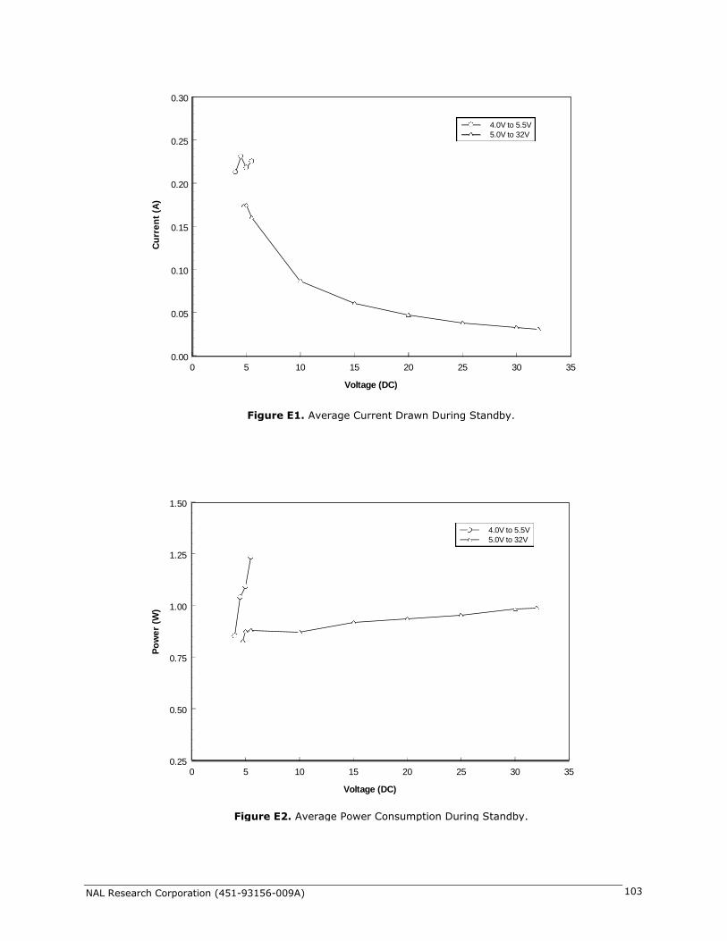
NAL Research Corporation (451-93156-009A) 103
0 5 10 15 20 25 30 35
Voltage (DC)
0.00
0.05
0.10
0.15
0.20
0.25
0.30
Cu
rre
nt
(A)
4.0V to 5.5V
5.0V to 32V
Figure E1. Average Current Drawn During Standby.
0 5 10 15 20 25 30 35
Voltage (DC)
0.25
0.50
0.75
1.00
1.25
1.50
Po
we
r (W
)
4.0V to 5.5V
5.0V to 32V
Figure E2. Average Power Consumption During Standby.

NAL Research Corporation (451-93156-009A) 104
0 5 10 15 20 25 30 35
Voltage (DC)
0.0
0.2
0.4
0.6
0.8
Cu
rre
nt
(A)
4.0V to 5.5V
5.0V to 32V
Figure E3. Average Current Drawn During Standby with DPL Handset.
0 5 10 15 20 25 30 35
Voltage (DC)
0
1
2
3
4
Po
we
r (W
)
4.0V to 5.5V
5.0V to 32V
Figure E4. Average Power Consumption During Standby with DPL Handset.

NAL Research Corporation (451-93156-009A) 105
Figure E5. Average Current Drawn During a Data Switch Call.
0 5 10 15 20 25 30 35
Voltage (DC)
0.0
0.2
0.4
0.6
0.8
Cu
rre
nt
(A)
4.0V to 5.5V
5.0V to 32V
0 5 10 15 20 25 30 35
Voltage (DC)
0
1
2
3
4
Po
we
r (W
)
4.0V to 5.5V
5.0V to 32V
Figure E6. Average Power Consumption During a Data Switch Call.

NAL Research Corporation (451-93156-009A) 106
0 5 10 15 20 25 30 35
Voltage (DC)
0.0
0.1
0.2
0.3
0.4
0.5
Cu
rre
nt
(A)
4.0V to 5.5V
5.0V to 32V
Figure E7. Average Current Drawn During an SBD Transmission.
0 5 10 15 20 25 30 35
Voltage (DC)
0.00
0.75
1.50
2.25
3.00
Po
we
r (W
)
4.0V to 5.5V
5.0V to 32V
Figure E8. Average Power Consumption During an SBD Transmission.

NAL Research Corporation (451-93156-009A) 107
0 5 10 15 20 25 30 35
Voltage (DC)
0.00
0.15
0.30
0.45
0.60
Cu
rre
nt
(A)
4.0V to 5.5V
5.0V to 32V
Figure E9. Average Current Drawn During an SMS Transmission.
0 5 10 15 20 25 30 35
Voltage (DC)
0.0
0.6
1.2
1.8
2.4
3.0
Po
we
r (W
)
4.0V to 5.5V
5.0V to 32V
Figure E10. Average Power Consumption During an SMS Transmission.

NAL Research Corporation (451-93156-009A) 108
0 5 10 15 20 25 30 35
Voltage (DC)
0.0
0.3
0.6
0.9
1.2
1.5
Cu
rre
nt
(A)
4.0V to 5.5V
5.0V to 32V
Figure E11. Average Current Drawn During a Voice Call Using DPL Handset.
0 5 10 15 20 25 30 35
Voltage (DC)
2
3
4
5
6
Po
we
r (W
)
4.0V to 5.5V
5.0V to 32V
Figure E12. Average Power Consumption During a Voice Call Using DPL Handset.

NAL Research Corporation (451-93156-009A) 109
APPENDIX F: DESCRIPTION OF THE IRIDIUM NETWORK
F.1 Description of the Iridium Network
The Iridium satellite network is owned and operated by Iridium Satellite LLC (ISLLC). It was constructed
as a constellation of 66 satellites in low-earth orbit, terrestrial gateways and Iridium subscriber units (ISU).
An ISU can either be an Iridium satellite phone or any of NAL Research’s A3LA series modems. The satellites
are placed in an approximate polar orbit at an altitude of 780 km. There are 6 polar planes populated with
11 satellites per orbit constituting the 66 satellite constellation. The near polar orbits of the Iridium
constellation provide truly real-time and global coverage from pole-to-pole.
The Iridium is designed to operate in the band of 1616 to 1626.5 MHz although the exact frequencies
used depend on the local regulating authorities and issued licenses in any particular region. Each satellite
projects 48 beams on the surface of earth, which may be viewed as providing coverage cells on the ground
similar to terrestrial systems. Each beam is approximately 600 km in diameter. The 66-satellite constellation
has the potential to support a total of 3,168 spot beams; however, as the satellite orbits converge at the
poles, overlapping beams are shut down. The satellite footprint is ~4,700 km in diameter. Under each
footprint, a satellite is power limited to ~1,100 simultaneous circuits.
The Iridium network uses a time domain duplex (TDD) method and transmits and receives in an allotted
time window within the frame structure. Since the system is TDD, the ISU transmit and receive in the same
frequency band. The access technology is a FDMA/TDMA (frequency division multiple access/time division
multiple access) method whereby an ISU is assigned a channel composed of a frequency and time slot in
any particular beam. Channel assignments may be changed across cell/beam boundaries and is controlled
by the satellite. The system will provide an average link margin of 12 dB.
Constellation
Satellite
Gateway
Satellite Network Operation Center
(SNOC)

NAL Research Corporation (451-93156-009A) 110
Although there are multiple gateways, a user is registered to a single gateway. The gateways perform
call connection setup and administrative duties such as billing and resource management. The satellite
constellation provides connectivity between users, from a user to the Iridium system gateway, and between
gateways. Within the Iridium network architecture, the satellites are cross-linked which allows ISU to ISU
communication independent of gateway intervention once the call connection is established.
There are currently two commercial Iridium gateways located in Arizona, United States and Fucino,
Italy. The U.S. government owns and operates an Iridium gateway located in Hawaii, United States. Each
gateway generates and controls all user information pertaining to its registered users, such as user identity,
geo-location and billing items. The gateway also provides connectivity from the Iridium system to the
terrestrial based networks such as the PSTN.
F.2 Description of the Iridium Network Data Capabilities
For data communications, the Iridium network supports five different modes of operation as shown in
Figure F1—dial-up data service, direct Internet connection, short-burst data (SBD), short-messaging service
(SMS) and router-based unrestricted digital internetworking connectivity solution (RUDICS).
Dial-up Data (DAV) Direct Internet
SBD SMS
RUDICS
Dial-up Data (DAV) SMS, SBD
Internet
AZ, HI or Fucino
SBD, SMS (e-mail)
RUDICS Server
IP Address
PSTN
Landline Modem
Figure F1. Iridium Network Data Capabilities.

NAL Research Corporation (451-93156-009A) 111
F.3 Dial-Up Data Service
Dial-up data service provides connectivity through the Iridium satellite network to another Iridium
modem, to the public switch telephone network (PSTN), to the Defense Switch Network (DSN), to a remote
LAN (e.g., a corporate network) or to an Internet Service Provider (ISP) at a nominal data rate of 2.4
kilobits per second (Kbps). The connection time involving user authentication and handshaking (or modem
training) can range from 15 to 30 seconds. For an Iridium-to-Iridium call, dial-up data service offers an
additional option known as data after voice or DAV. Similar to a voice call, a DAV call is routed directly from
one Iridium modem to another Iridium modem without going through the gateway.
Many desktop and laptop computers are equipped with either an internal or external modem to perform
dial-up data applications across the landline telephone network (PSTN). On these computers, terminal
emulator software or a dial-up networking connection can be configured to a specific modem with a phone
number to dial, user identification and password. The modem can then be used to call another computer, a
remote LAN or an Internet service provider as shown in Figure F2. The handshaking and protocols are
established between the modems independent of the landline.
The Iridium dial-up data service functions in much the same way as the PSTN dial-up connectivity. From
the perspective of a computer, the Iridium modem is just another external modem. The only difference is
that the dialed telephone number must conform to the international dialing pattern used by Iridium. When a
data call is placed, the Iridium modem actually dials and initiates a connection with the Iridium gateway
through the Iridium satellite constellation. Since the Iridium modem is requesting to establish a data
connection, the switch at the gateway routes the call through another modem. The modem at the Iridium
gateway then dials into and connects to another modem at the other end. Figure F3 illustrates how an
Iridium dial-up data service call is routed. The handshaking and protocols established between the modems
independent of the Iridium network.
For those ISU-to-ISU dial-up calls where data transmission delay is critical such as the application of
TCP/IP protocol, DAV should be considered in the design. This option eliminates the Iridium gateway once
Figure F2. PSTN Dial-Up Connectivity.
4.4 VDC
RS232
NAL Research
Antenna
PSTN
ISP (Internet)
Corporate Network
4.4 VDC
RS232
NAL Research
Antenna

NAL Research Corporation (451-93156-009A) 112
authentication and registration is completed allowing ISU-to-ISU communication without the gateway in the
loop.
F.4 Direct Internet Connection
The Iridium Direct Internet service allows users to connect to the Internet via the Iridium gateway
without having to sign up with an Internet service provider. This service utilizes a dedicated Apollo Server at
the Iridium gateway, which provides high-speed connectivity to the Internet and optimizes server-to-Iridium
modem communications. The dial-up networking setup is similar to the dial-up networking setup for landline
telephone. The only difference is that the dialed telephone number is an international number provided by
Iridium. Figure B3 illustrates how Iridium Internet (NIPRNet) call is routed.
Direct Internet service can be enhanced using Windows-based emulated point-to-point protocol (PPP)
called the Apollo Emulator. With the use of the Apollo Emulator software instead of Microsoft Windows®
dial-up networking, Direct Internet service can reduce connection time and improve data throughput. In
addition, the Apollo Emulator offers a feature called Smart ConnectTM, which manages airtime by seamlessly
connecting and disconnecting a user through the Iridium system. Airtime charges accumulate only while the
call is connected. Improved effective data throughput is achieved through the use of user-transparent data
Figure F3. Iridium Dial-Up Data Service.
4.4 VDC
RS232
NAL Research
Antenna
PSTN
ISP (Internet)
Corporate Network
4.4 VDC
RS232
NAL Research
Antenna
4.4 VDC
RS232
NAL Research
Antenna
AZ, HI or Fucino
4.4 VDC
RS232
NAL Research
Antenna
DAV Connectivity

NAL Research Corporation (451-93156-009A) 113
compression. The channel rate is still 2.4 Kbps. However, 10 Kbps effective throughput can be achieved
depending on content (graphics and images will result in lower effective throughput).
F.5 Short-Burst Data (SBD)
SBD is a simple and efficient bi-directional transport capability used to transfer messages with sizes
ranging from zero (a mailbox check) to 1960 bytes. SBD takes advantage of signals within the existing air
interface, without using the dedicated traffic channels. As a result, small amounts of data can be transferred
more efficiently than those associated with circuit-switched data calls. Messages that originate from an
Iridium modem can be delivered to a variety of destinations. Commonly, data are delivered across terrestrial
communications networks (NIPRnet and Internet) to servers and applications that process data from one or
multiple fielded Iridium modems. SBD service also supports the transfer of messages to Iridium modems,
where messages may originate from terrestrial sources. Delivery methods and options are initially
configured when the Iridium modem is first purchased and may be easily modified via web pages at a later
time.
F.6 Short Messaging Service (SMS)
SMS is a mechanism to deliver short data messages over the Iridium satellite network to the
NIPRNet/Internet. Iridium SMS service incorporates a subset of the GSM SMS features. Each SMS message
can be up to 160 text characters (7-bit coded) in length. The text characters are based on a 7-bit alphabet,
which is encoded and transmitted as 8-bit data, hence the 140 octet (byte) maximum message size.
SMS service is a store and forward method of transmitting messages to and from an Iridium modem.
The short message from the modem is stored in a central Short Message Center (SMSC) which then
forwards it to the destination. In the case that the recipient is not available, the SMSC will attempt to deliver
the SMS until it is delivered or the validity period expires. SMS supports a limited confirmation of message
delivery. The sender of the short message can request to receive a return message notifying them whether
the short message has been delivered or not. With this option, the originator gets a confirmation that the
message was delivered to the SMSC. Unlike standard GSM, the Iridium SMS can only acknowledge that the
message was delivered to the SMSC and not the end-destination.
SMS messages can be sent and received simultaneously while a voice call is in progress. This is possible
because SMS messages travel over and above the radio channel using the signaling path, whereas the voice
call uses a dedicated “traffic” radio channel for the duration of the call.
F.7 RUDICS
RUDICS is an enhanced gateway termination and origination capability for circuit switched data calls
across the Iridium satellite network. When an Iridium modem places a call to the RUDICS Server located at
the Iridium Gateway, the RUDICS Server connects the call to a pre-defined IP address allowing an end-to-
end IP connection between the Host Application and the Iridium modem. There are three key benefits of
using RUDICS over the conventional PSTN circuit switched data connectivity or mobile-to-mobile data
solutions: (1) elimination of analog modem training time, (2) increased call connection quality, reliability,
and maximized throughput and (3) protocol independence.

NAL Research Corporation (451-93156-009A) 114
F.8 Iridium Geo-Location
The Iridium network makes calculations of the geographical location (geo-location) of an ISU each time
a call is placed. The technique employed to determine the geo-location of an ISU is based on measurements
of the ISU and satellite propagation delay and Doppler frequency shift. These measurements are used to
estimate cosines of spherical angles that identify the ISU’s location relative to the satellite by the gateway.
The Iridium network can locate an ISU to within 10 km only about 78% of the time. The so-called error
ellipse can have a large eccentricity with the major axis oriented in the azimuth dimension and the minor
axis oriented in the radial dimension. The position of the ISU in the radial dimension relative to the satellite
can almost always be determined to within 10 km with just one measurement. Errors in the azimuth
dimension relative to the satellite are largest along the satellite’s ground path and tend to increase with
distance from the satellite. Geo-location errors in the east-west dimension, therefore, are sometimes more
than 100 times greater than in the north-south dimension.

NAL Research Corporation (451-93156-009A) 115
APPENDIX G: STANDARDS COMPLIANCE
The A3LA-RG comprises of an Iridium 9523 L-band transceiver board. The 9523 is a regulatory
approved daughter module transceiver that can be fitted within an enclosed host system. The 9523 is
designed to comply with the standards for Radio Emissions Compliance, Electromagnetic Compatibility, and
AC Safety in the United States, European Union and Canada assuming an antenna with a gain of ~3dBi and
adequate shielding.
FCC Compliance: The 9523 is certified under FCC CFR47 Parts 2, 15 and 25 as FCC ID:
Q639523. Operation is subject to the condition that this device does not cause harmful
interference. Any changes or modifications, including the use of a non-standard antenna,
not expressly approved by the party responsible for compliance could void the user's
authority to operate the equipment.
CE Compliance: The 9523, when marked with the CE symbol, complies with the European
Community Council Directive for R&TTE, 99/5/EC, provided that the integrator/user adheres
to the instructions detailed in this LBT Interface Specification. This product is in compliance
with applicable ETSI standards. Compliance with the requirements of ETSI EN 301 441
V1.1.1 requires the use of a shielded digital data interface cable.
Industry Canada: The 9523 is compliant with Industry Canada RSS-170 Issue 2 for RF
Exposure.
IMPORTANT: Output power listed is conducted. Peak power is 5.16W and mean power is 0.48W.
The antenna gain, including cable loss, must not exceed 3dBi. To comply with FCC RF exposure
experiments, a minimum separation of 20 cm is required between the antenna and all persons.
Additional testing and certification are required for applications that combine the 9523 with another
radio element or are intended for use within 20 cm of a person.

NAL Research Corporation (451-93156-009A) 116

NAL Research Corporation (451-93156-009A) 117
APPENDIX I: EXPORT COMPLIANCE INFORMATION
The A3LA-RG is controlled by the export laws and regulations of the United States of America (U.S.). It
is the policy of NAL Research to fully comply with all U.S. export and economic sanction laws and
regulations. The export of NAL Research products, services, hardware, software and technology must be
made only in accordance with the laws, regulations and licensing requirements of the U.S. Government. NAL
Research customers must also comply with these laws and regulations. Failure to comply can result in the
imposition of fines and penalties, the loss of export privileges, and termination of your contractual
agreements with NAL Research.
The export and re-export of NAL Research products and services are subject to regulation by the Export
Administration Regulations (15 CFR 730-744), as administered by the U.S. Department of Commerce,
Bureau of Industry and Security (“BIS”). See: http://www.bxa.doc.gov for further information on BIS and
the Export Administration Regulations (EAR). Additional export restrictions are administered by the U.S.
Department of the Treasury’s Office of Foreign Asset Controls (“OFAC”). See: http://www.ustreas.gov/ofac
for further information on OFAC and its requirements.

NAL Research Corporation (TN2012-32-V1.0) 118
ANICAL DRAWINGS

NAL Research Corporation (TN2012-32-V1.0) 119