Embed Size (px)
Citation preview

GENERAL DESCRIPTION OF MODEL A3LA-X
Version 1.0
May 22, 2009
Copyright © 2009 by NAL Research Corporation
The specifications in this document are subject to change at NAL Research‘s discretion. NAL Research assumes no responsibility for any claims or damages arising out of the use of this document or from the use of the A3LA-X based on this document, including but not limited to claims or damages based on infringement of patents, copyrights or other intellectual property rights. NAL Research makes no warranties, either expressed or implied with respect to the information and specifications contained in this document. Performance characteristics listed in this document are estimates only and do not constitute a warranty or guarantee of product performance.
TN2009-20-V1.0

NAL Research Corporation (TN2009-20-V1.0) 2
TABLE OF CONTENTS
GLOSSARY ....................................................................................................................... 3
1.0 PURPOSE .................................................................................................................... 4
2.0 SPECIFICATIONS ......................................................................................................... 4
2.1 Mechanical Specifications ........................................................................................... 4
2.2 RF Specifications ...................................................................................................... 5
2.3 Electrical Specifications ............................................................................................. 5
2.4 Environmental Specifications ...................................................................................... 5
2.5 Data I/O Specifications .............................................................................................. 5
2.6 Related Hardware ..................................................................................................... 5
2.7 Reference Documents ............................................................................................... 6
3.0 MULTI-INTERFACE CONNECTOR .................................................................................... 6
3.1 RS232 Data Interface (Standard 9-Wire Configuration) .................................................. 7
3.2 RS232 Data Interface (3-Wire Configuration) ................................................................ 7
3.3 DC Power Interface ................................................................................................... 7
3.4 Audio Interface ........................................................................................................ 8
3.5 Digital Peripheral Link (DPL) ....................................................................................... 9
4.0 IRIDIUM ANTENNA CONNECTOR .................................................................................... 9
5.0 GPS FEED THROUGH (OPTIONAL) .................................................................................. 10
6.0 SIM CARD INTERFACE .................................................................................................. 11
7.0 LED DISPLAY .............................................................................................................. 11
8.0 MOUNTING RECOMMENDATIONS ................................................................................... 11
9.0 TECHNICAL SUPPORT ................................................................................................... 11
APPENDIX A: DESCRIPTION OF THE IRIDIUM NETWORK ........................................................ 12
APPENDIX B: STANDARDS COMPLIANCE .............................................................................. 18
APPENDIX C: EXPORT COMPLIANCE INFORMATION ............................................................... 19
APPENDIX D: MIL-STD-810F CERTIFICATE OF COMPLIANCE ................................................... 20
APPENDIX E: MECHANICAL DRAWINGS ............................................................................... 21

NAL Research Corporation (TN2009-20-V1.0) 3
GLOSSARY
BIS Bureau of Industry and Security
DAV Data After Voice
DoD EMSS DoD Enhanced Mobile Satellite Services
DPL Digital Peripheral Link
DTE Data Terminal Equipment
DSN Defense Switch Network
EAR Export Administration Regulations
FDMA Frequency Division Multiple Access
GPS Global Positioning System
ISU Iridium Subscriber Units (Modems, Phones, Trackers)
LBT L-Band Transceiver
LED Light Emitting Diode
LNA Low Noise Amplifier
NIPRNET Non-Secure Internet Protocol Router Network
NOC Network Operation Center
OFAC Office of Foreign Asset Controls
PSTN Public Switch Telephone Network
RHCP Right Hand Circular Polarization
Rx Receiving
RUDICS Router-Based Unrestricted Digital Internetworking Connectivity Solution
SBD Short Burst Data
SIM Subscriber Identity Module
SMA Sub-Miniature Version A
SMS Short Message Service
TDD Time Domain Duplex
TDMA Time Division Multiple Access
Tx Transmitting
VSWR Voltage Standing Wave Ratio
NAL Research Corporation (TN2009-20-V1.0) 4
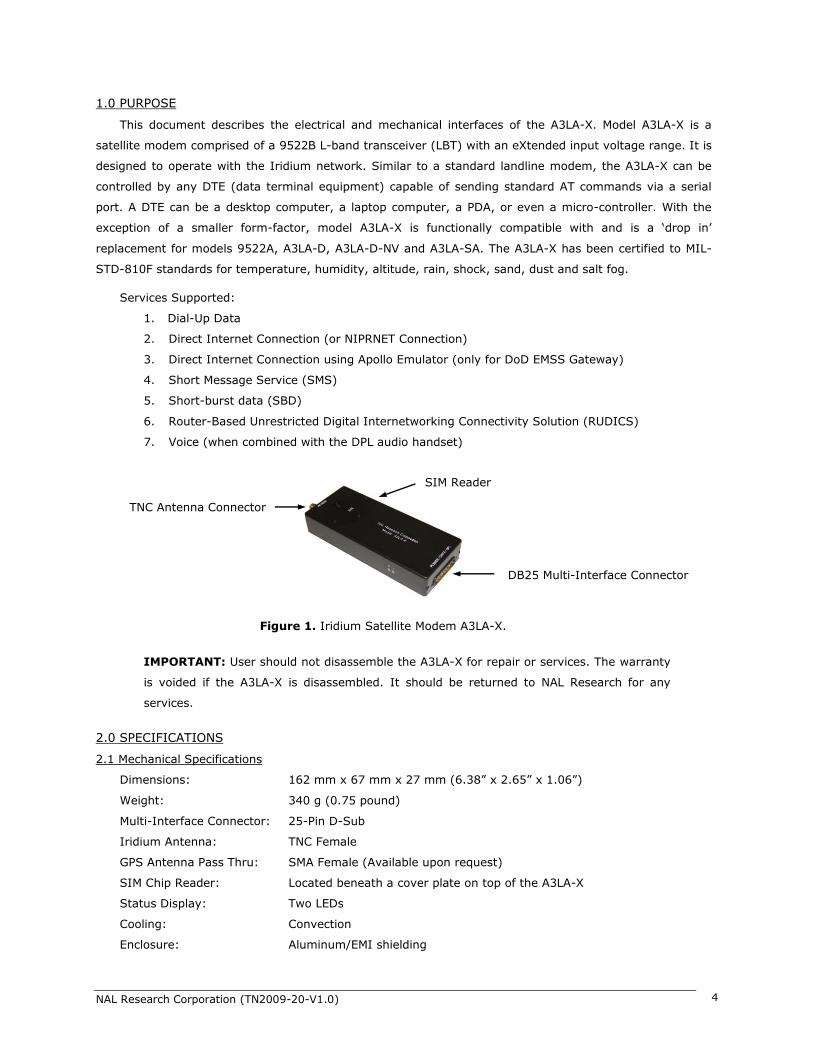
1.0 PURPOSE
This document describes the electrical and mechanical interfaces of the A3LA-X. Model A3LA-X is a
satellite modem comprised of a 9522B L-band transceiver (LBT) with an eXtended input voltage range. It is
designed to operate with the Iridium network. Similar to a standard landline modem, the A3LA-X can be
controlled by any DTE (data terminal equipment) capable of sending standard AT commands via a serial
port. A DTE can be a desktop computer, a laptop computer, a PDA, or even a micro-controller. With the
exception of a smaller form-factor, model A3LA-X is functionally compatible with and is a ‗drop in‘
replacement for models 9522A, A3LA-D, A3LA-D-NV and A3LA-SA. The A3LA-X has been certified to MIL-
STD-810F standards for temperature, humidity, altitude, rain, shock, sand, dust and salt fog.
Services Supported:
1. Dial-Up Data
2. Direct Internet Connection (or NIPRNET Connection)
3. Direct Internet Connection using Apollo Emulator (only for DoD EMSS Gateway)
4. Short Message Service (SMS)
5. Short-burst data (SBD)
6. Router-Based Unrestricted Digital Internetworking Connectivity Solution (RUDICS)
7. Voice (when combined with the DPL audio handset)
IMPORTANT: User should not disassemble the A3LA-X for repair or services. The warranty
is voided if the A3LA-X is disassembled. It should be returned to NAL Research for any
services.
2.0 SPECIFICATIONS
2.1 Mechanical Specifications
Dimensions: 162 mm x 67 mm x 27 mm (6.38‖ x 2.65‖ x 1.06‖)
Weight: 340 g (0.75 pound)
Multi-Interface Connector: 25-Pin D-Sub
Iridium Antenna: TNC Female
GPS Antenna Pass Thru: SMA Female (Available upon request)
SIM Chip Reader: Located beneath a cover plate on top of the A3LA-X
Status Display: Two LEDs
Cooling: Convection
Enclosure: Aluminum/EMI shielding
Figure 1. Iridium Satellite Modem A3LA-X.
SIM Reader
TNC Antenna Connector
DB25 Multi-Interface Connector

NAL Research Corporation (TN2009-20-V1.0) 5
2.2 RF Specifications
Operating Frequency: 1616 to 1626.5 MHz
Duplexing Method: TDD
Multiplexing Method: TDMA/FDMA
Link Margin: 13.1 dB average
Average Power during a Transmit Slot (Max): 7W
Average Power during a Frame (Typical): 0.6W
Receiver Sensitivity at 50 (Typical): –118.5 dBm
Receiver Spurious Rejection at offsets > 1MHz: 60dB
2.3 Electrical Specifications
Main Input Voltage Range: +4.0VDC to +32.0VDC
Main Input Voltage Nominal: +12.0VDC
Main Input Voltage Ripple: 40mV peak-to-peak
Average Standby Current: 300mA @ 5.0VDC
Average Data Call Current: 800mA @ 5.0VDC
Peak Data Call Current: 2.5A @ 5.0VDC
NOTE: The power requirements apply to DC power measured at the A3LA-X multi-interface
connector input. The Average Data Call Current may vary depending on the field-of-view
between the modem antenna and the Iridium satellite.
2.4 Environmental Specifications
Operating Temperature Range: –30oC to +70oC (–22oF to +158oF)
Operating Humidity Range: < 75% RH
Storage Temperature Range: –40oC to +85oC (–40oF to +185oF)
Storage Humidity Range: < 93% RH
2.5 Data I/O Specifications
Dial-Up Data/RUDICS: 2.4 Kbits/sec (average)
Direct Internet: 2.4 Kbits/sec (average)
Short-Burst Data: 1960 bytes for Mobile-Originated and 1890 bytes for Mobil-Terminated
Short Messaging: 160 Characters (maximum)
Hardware Interface: RS232
Software Interface: Standard AT Commands
2.6 Related Hardware
Antennas: SYN7391 Series, SAF2040 Series, SAF5340 Series, SAF5350 Series (These
antennas are to be used with the A3LA-X transceiver only. They are NOT
optimized and should not be used for pass through GPS receiver)
Data Kit/Connector: HRC-24-7X, HRC-24-8X
Power Adapters: LA-3098, LA-7021
DPL Audio Handset: DPLS0401-X, DPLS0401-412
RF Splitter: SYN-SLC-ALBT

NAL Research Corporation (TN2009-20-V1.0) 6
2.7 Reference Documents
A3LA-X Product Information
Getting Started With Model A3LA-X (TN2009-21-V1.0)
AT Command Reference V2.22
Current Drawn by A3LA-X (TN2009-22-V1.0)
Current Drawn by A3LA-XP (TN2009-23-V1.0)
SatTerm Software Manual (TN2009-19-V7.0)
Additional Information on DirectIP SBD (TN2007-637-V1.0)
Additional Information on SBD (AN2007-07-V3.3.0)
3.0 MULTI-INTERFACE CONNECTOR
The multi-interface connector is a male 25-pin miniature D-Sub type that includes six interfaces—
RS232, DC input power, DC output power, ON/OFF control line, analog audio and Digital Peripheral Link
(DPL). The multi-interface connector pin assignments are summarized in Table 1, which is ‗pin-to-pin‘ the
same as for models 9522A, A3LA-D, A3LA-D-NV and A3LA-SA except for Pin 2.
Table 1. Pin assignment for the multi-interface connector.
PIN # SIGNAL DESCRIPTION INTERFACE
1 EXT_ON_OFF Power on/off control input DC Power
2 +12VDC Output Voltage to Power the DPL Handset DC Power
3 EXT_GND External GND input DC Power
4 EXT_B+ External 4.0VDC – 32.0VDC input DC Power
5 SPKR_AUD Speaker audio output Analog Audio
6 DA_TX PCM digital audio output Digital Audio
7 RI RS232 Ring Indicate RS232 Data
8 RTS RS232 Request To Send RS232 Data
9 S_TX RS232 Transmit Data RS232 Data
10 DCD RS232 Data Carrier Detect RS232 Data
11 DA_FS PCM digital audio frame sync output Digital Audio
12 DA_CLK PCM digital 2.048MHz audio clock output Digital Audio
13 S_RX RS232 Receive Data RS232 Data
14 SIGNAL GND Signal ground, 0V signal reference and return GND
15 MIC_AUD Microphone audio input Analog Audio
16 EXT_B+ External 4.0VDC – 32.0VDC input DC Power
17 EXT_GND External GND input DC Power
18 DPL_TX Digital Peripheral Link (DPL) data output DPL UART
19 DTR RS232 Data Terminal Ready RS232 Data
20 DPL_RX Digital Peripheral Link (DPL) data input DPL UART
21 DSR RS232 Data Set Ready RS232 Data
22 CTS RS232 Clear To Send RS232 Data
23 SIGNAL GND Signal ground, 0V signal reference and return GND
24 DA_RX PCM digital audio input Digital Audio
25 SIGNAL GND Signal ground, 0V signal reference and return GND

NAL Research Corporation (TN2009-20-V1.0) 7
3.1 RS232 Data Interface (Standard 9-Wire Configuration)
The A3LA-X supports a standard RS232 data interface to a DTE incorporating hardware handshaking and
flow control. The RS232 data interface comprises of eight standard RS232 data, control and status signals
plus a ground level signal reference as shown in Table 1 (pins 7-RI, 8-RTS, 9-TX, 10-DCD, 13-RX, 19-DTR,
21-DSR, 22-CTS and 23-GND). This interface allows a connected DTE to utilize the A3LA-X‘s modem
functionality through standard AT and extended sets of AT commands. These commands are defined in the
document ISU AT Command Reference V2.7. The A3LA-X will automatically adjust to the DTE baud rate and
override the +IPR setting when dissimilar. Autobaud will occur on the following characters ‗a‘, ‗A‘ or CR
(carriage return). Autobaud will also occur on the escape sequence character, provided this is an odd
number of characters. Normally this is set to ‗+‘ in register S2. See the AT Command Reference for details.
3.2 RS232 Data Interface (3-Wire Configuration)
Several steps must be taken to allow 3-wire configuration (i.e. only using S_TX, S_RX, and SIGNAL
GND). These steps ensure the A3LA-X and DTE to work together without having hardware handshaking.
1. The modem‘s DTR line must be held high. Using the modem‘s input voltage is fine for this purpose
BUT ONLY if the input voltage is less than 5VDC (see important note below). Looping back the
modem‘s DSR line to DTR line will NOT work. The DSR line on the modem should be left
unconnected.
2. Disconnect the CTS, DCD, DSR, DTR, RTS and RI lines between the DTE and modem.
3. AT&Dn must be set to AT&D0 to ignore the DTR input from the DTE.
4. AT&Kn must be set to AT&K0 for no flow control or AT&K4 for XON/XOFF software flow control.
5. The setting can be stored on the modem permanently (until another setting overwrites it) so that it
remains after a power cycle. The modem allows two profiles in which settings are stored, and user
can choose either as a default profile. The relevant commands are &Wn and &Yn. &Wn stores the
present configuration in profile <n>, where <n> can be either 0 or 1. &Yn designates which profile
is loaded after reset or power-up, again <n> is either 0 or 1.
6. Any needs of the DTE must be addressed separately.
WARNING: DO NOT use the modem‘s input voltage to bring the DTR line high when the
input voltage is higher than 5VDC. Supplying voltage higher than 5VDC to the DTR line will
permanently damage the A3LA-X.
NOTE: The Iridium‘s Direct Internet service when using the Windows-based Apollo client
requires DCD to be present; hence it is incompatible with a 3-wire serial configuration. The
Direct Internet with Apollo client is available only on the EMSS DoD gateway and NOT on
the commercial gateway.
3.3 DC Power Interface
The DC power input is through pins 4 & 16 (EXT_B+) and pins 3 & 17 (EXT_GND). Note that two pins (4
and 16) are provided for the external (EXT_B+) DC input. Two pins (3 and 17) are also provided for the
associated external (EXT_GND) ground input. This is done to distribute the current across two wires, and

NAL Research Corporation (TN2009-20-V1.0) 8
therefore all four pins should be utilized in the external power connection. The DC power requirements for
the A3LA-X are summarized on page 5.
The A3LA-X will automatically turn on/off when external DC power is applied/removed via the EXT_B+
and EXT_GND inputs. The EXT_ON_OFF (pin 1) control input is used to turn a powered A3LA-X on and off in
a toggle fashion. The EXT_ON_OFF control input is normally ―floating‖ (i.e. high). When it is pulled to GND
level (i.e. low) for at least 270 ms and released, the A3LA-X will alternate from its current on/off state. The
current drawn on the external load used to pull the A3LA-X to GND is no more than 0.5mA. The signal on
pin 1 is considered GND when it is at 0.5V or less.
Cables used to supply power to the A3LA-X should be kept as short as possible to prevent significant
voltage drop, which can cause the A3LA-X to malfunction during a data call, a voice call, an SMS session or
an SBD session. Power reset by the A3LA-X during a call is an indicative of the DC power source unable to
sustain voltage above 4.0VDC at peak current demand.
3.4 Audio Interface
The A3LA-X supports both digital and analog audio I/O. The digital audio is in PCM format. In such
format, digital audio cannot travel far (less than one foot); this is why the analog is chosen for the A3LA-X
audio handset. The analog audio input is a single-ended, unbalanced input with a minimum impedance of
10k to ground. The A3LA-X accepts a maximum input level of 2.0V peak-to-peak without signal distortion.
The analog audio output is also a single-ended, unbalanced output capable of driving an impedance of 600
or more to ground. The A3LA-X delivers undistorted audio up to 2.0V peak-to-peak at this port.
The combined analog I/O audio interface (pins 5 and 15) and the DPL UART I/O interface (pins 18 and
20) enable an analog audio handset to be connected to the A3LA-X. The signal level for the DPL I/O can be
RS232 or logic level. The level can be selected using a switch that is accessible when the SIM cover plate is
removed. With the DPL audio handset model DPLS0401-X and DB25 data kit model HRC-24-8X, the A3LA-X
can be used both as data modem and a satellite phone (see Figure 2). This setup can be an extremely useful
developmental tool since the modem status can be seen on the handset LCD similar to a 9555 Iridium
phone.
Figure 2. A3LA-X Connected to a DPL Handset, AC Adapter and Data Kit.
DPL Handset Model DPLS0401-X
AC Adapter Model LA-3098
DB25 Data Kit Model HRC-24-8X

NAL Research Corporation (TN2009-20-V1.0) 9
3.5 Digital Peripheral Link (DPL)
The DPL interface is composed of two ports—a full duplex asynchronous serial link for control messages
and a PCM digital audio link for audio traffic. The protocol used on these ports is made available to
application developers only on a case-by-case basis and after appropriate Non-disclosure Agreements and/or
License Agreements are executed.
4.0 ANTENNA CONNECTOR
The A3LA-X modem uses a single TNC female 50-ohm connector for both transmit and receive. Cable
loss between the modem and the antenna is critical and must be kept less than 2dB at the operating
frequency of 1616 to 1626.5 MHz. The minimum link margin of 13.1 dB must also be maintained. General
RF parameters are listed in the table below.
NAL Research offers several types of antennas for use with the A3LA-X modem. These antennas include
the fixed mast, mobile magnetic/permanent mount and portable auxiliary. For low-cost and applications
where small form-factor and light-weight are required, NAL Research highly recommends model SYN7391-C
as shown in Figure 3.
If the specific application requires a custom antenna, it must meet the specifications in the following
table.
TYPE DESCRIPTION
Frequency Range 1616 to 1626.5 MHz
Input/Output Impedance 50 Ohms
Oscillator Stability 1.5ppm
PARAMETER VALUE
Operating Temperature Range –40oC/+85oC without loss of function
Measurement Frequency Range 1616 to 1626.5 MHz
Return Loss (Minimum) 9.5 dB (<2:1 VSWR)
Gain 0.0 dBic (weighted average minimum)
Minimum ‗Horizon‘ Gain –2.0 dBic (82 o conic average)
Nominal Impedance 50 Ohms
Polarization Right Hand Circular (RHCP)
Basic Pattern Omni directional and hemispherical
Figure 3. NAL Research‘s Antenna SYN7391-C.

NAL Research Corporation (TN2009-20-V1.0) 10
It should be noted that the A3LA-X power transmission profiles may vary for a number of reasons. Users
are reminded to optimize their setup to attain the lowest possible power transmission by the A3LA-X. Some
of the setup parameters to be carefully observed include:
1. Have a clear view of the sky for the antenna—poor visibility of the sky is when a clear line-of-sight
is not available between the A3LA-X‘s antenna and the satellites.
2. Keep the antenna‘s VSWR low—the higher the antenna VSWR the higher the current consumed by
the A3LA-X.
3. Keep the antenna cables‘ loss to less than 2dB—the higher the antenna cable loss the higher the
current consumed by the A3LA-X.
4. Keep the power cable between the A3LA-X and the power source as short as possible.
5.0 GPS FEED THROUGH (OPTIONAL)
As an option, a pass thru SMA connector can be added to the A3LA-X to allow an external GPS receiver
to share the same A3LA-X‘s Iridium antenna. The RF interface of the GPS pass through is summarized in the
table below.
The GPS pass through signal is isolated from the Iridium RF board by a directional coupler after the
A3LA-X Rx low-noise amplifier (LNA). The loss of the directional coupler cancels out the gain of the LNA
resulting in the GPS signal gain/loss at the GPS connector of 0dB. The GPS pass through connector must be
terminated with a 50 load when not in use. A suitable load is the Huber+Suhner 65_SMA-50-0-1/111_NE.
Either a passive or an active GPS receiver can be connected to the pass through GPS connector. Users
must select a wideband Iridium antenna with appropriate sensitivity in both the Iridium frequency and the
GPS frequency. GPS signal is available and is passed through to the GPS receiver when the A3LA-X is
powered but not transmitting. GPS signal will be de-graded during an Iridium call. During Iridium transmit
cycle there will be energy at the Iridium frequency which may adversely affect some GPS receivers.
PARAMETER VALUE
Frequency Range 1575 MHz
Output Impedance 50
Insertion Loss 2 dB
Noise Figure 7 dB
Figure 3. GPS Pass Through Connector Added on the A3LA-X Housing.

NAL Research Corporation (TN2009-20-V1.0) 11
6.0 SIM CARD INTERFACE
The A3LA-X modem contains an integrated SIM reader. The modem uses and requires an Iridium SIM
chip for operation. The SIM chip is detached from the full-size Iridium SIM card. The SIM chip is inserted
into the opening located on top of the modem. A plastic locking mechanism (same as with GSM wireless
phones) is used hold the SIM in-place. An external SIM card reader may also be interfaced as a peripheral to
the A3LA-X via the DPL bus. A SIM card in the external reader will take precedence over the SIM chip in the
integrated connector when both are present.
7.0 LED DISPLAY
The A3LA-X has two status LEDs depicted as P for power indicator and I for Iridium satellite registration
(see Figure 4). They offer users a quick visual check to ensure proper modem operations as well as a way to
optimize antenna locations during field installation. These LEDs provide the following information:
P (red LED): LED lights up when power is provided to the A3LA-X.
I (green LED): LED stays solid when the A3LA-X is successfully registered with the Iridium network.
The LED is off when the A3LA-X is unable to register with the Iridium network.
8.0 MOUNTING RECOMMENDATIONS
The A3LA-X has four features on its bottom surface that can aid in its mounting (see Appendix E). These
four features are pre-drilled at a minimum depth of 0.25 inch to accept 6-32 thread type. If the A3LA-X is to
be used in a harsh environment with exposure to high humidity or water, the mating of the multi-interface
connector must be further sealed to protect from moisture infiltration. It is recommended that a bead of RTV
silicone sealant be placed on the connector mating to the A3LA-X‘s multi-interface connector. A material
similar to Permatex 16B should be used.
As an option, the A3LA-X‘s bottom plate can be replaced with a bigger plate with the same mounting
hole-pattern as the A3LA-D. Figure 4 of 4 in Appendix E shows the dimension of the optional plate.
9.0 TECHNICAL SUPPORT
FOR TECHNICAL SUPPORT, PLEASE CONTACT US AT
Phone: 703-392-1136 FAX: 703-392-6795
E-mail: [email protected]
Technical documents are also available to download on NAL Research‘s website www.nalresearch.com under http://www.nalresearch.com/AnonymousFTPSite.html
Figure 4. Iridium Satellite Modem A3LA-X.
Power LED Iridium LED

NAL Research Corporation (TN2009-20-V1.0) 12
APPENDIX A: DESCRIPTION OF THE IRIDIUM NETWORK
A.1 Description of the Iridium Network
The Iridium satellite network is owned and operated by Iridium Satellite LLC (ISLLC). It was constructed
as a constellation of 66 satellites in low-earth orbit, terrestrial gateways and Iridium subscriber units (ISU).
An ISU can either be an Iridium satellite phone or any of NAL Research‘s A3LA series modems. The satellites
are placed in an approximate polar orbit at an altitude of 780 km. There are 6 polar planes populated with
11 satellites per orbit constituting the 66 satellite constellation. The near polar orbits of the Iridium
constellation provide truly real-time and global coverage from pole-to-pole.
The Iridium is designed to operate in the band of 1616 to 1626.5 MHz although the exact frequencies
used depend on the local regulating authorities and issued licenses in any particular region. Each satellite
projects 48 beams on the surface of earth, which may be viewed as providing coverage cells on the ground
similar to terrestrial systems. Each beam is approximately 600 km in diameter. The 66-satellite constellation
has the potential to support a total of 3,168 spot beams; however, as the satellite orbits converge at the
poles, overlapping beams are shut down. The satellite footprint is ~4,700 km in diameter. Under each
footprint, a satellite is power limited to ~1,100 simultaneous circuits.
The Iridium network uses a time domain duplex (TDD) method and transmits and receives in an allotted
time window within the frame structure. Since the system is TDD, the ISU transmit and receive in the same
frequency band. The access technology is a FDMA/TDMA (frequency division multiple access/time division
multiple access) method whereby an ISU is assigned a channel composed of a frequency and time slot in
any particular beam. Channel assignments may be changed across cell/beam boundaries and is controlled
by the satellite. The system will provide an average link margin of 13.1 dB.
Constellation
Satellite
Gateway
Satellite Network Operation Center
(SNOC)
NAL Research Corporation (TN2009-20-V1.0) 13
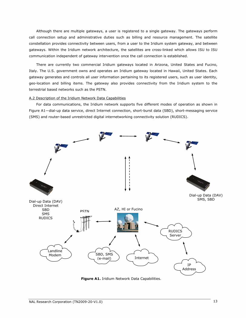
Although there are multiple gateways, a user is registered to a single gateway. The gateways perform
call connection setup and administrative duties such as billing and resource management. The satellite
constellation provides connectivity between users, from a user to the Iridium system gateway, and between
gateways. Within the Iridium network architecture, the satellites are cross-linked which allows ISU to ISU
communication independent of gateway intervention once the call connection is established.
There are currently two commercial Iridium gateways located in Arizona, United States and Fucino,
Italy. The U.S. government owns and operates an Iridium gateway located in Hawaii, United States. Each
gateway generates and controls all user information pertaining to its registered users, such as user identity,
geo-location and billing items. The gateway also provides connectivity from the Iridium system to the
terrestrial based networks such as the PSTN.
A.2 Description of the Iridium Network Data Capabilities
For data communications, the Iridium network supports five different modes of operation as shown in
Figure A1—dial-up data service, direct Internet connection, short-burst data (SBD), short-messaging service
(SMS) and router-based unrestricted digital internetworking connectivity solution (RUDICS).
Dial-up Data (DAV) Direct Internet
SBD SMS
RUDICS
Dial-up Data (DAV) SMS, SBD
Internet
AZ, HI or Fucino
SBD, SMS (e-mail)
RUDICS Server
IP Address
PSTN
Landline Modem
Figure A1. Iridium Network Data Capabilities.

NAL Research Corporation (TN2009-20-V1.0) 14
A.3 Dial-Up Data Service
Dial-up data service provides connectivity through the Iridium satellite network to another Iridium
modem, to the public switch telephone network (PSTN), to the Defense Switch Network (DSN), to a remote
LAN (e.g., a corporate network) or to an Internet Service Provider (ISP) at a nominal data rate of 2.4
kilobits per second (Kbps). The connection time involving user authentication and handshaking (or modem
training) can range from 15 to 30 seconds. For an Iridium-to-Iridium call, dial-up data service offers an
additional option known as data after voice or DAV. Similar to a voice call, a DAV call is routed directly from
one Iridium modem to another Iridium modem without going through the gateway.
Many desktop and laptop computers are equipped with either an internal or external modem to perform
dial-up data applications across the landline telephone network (PSTN). On these computers, terminal
emulator software or a dial-up networking connection can be configured to a specific modem with a phone
number to dial, user identification and password. The modem can then be used to call another computer, a
remote LAN or an Internet service provider as shown in Figure A2. The handshaking and protocols are
established between the modems independent of the landline.
The Iridium dial-up data service functions in much the same way as the PSTN dial-up connectivity. From
the perspective of a computer, the Iridium modem is just another external modem. The only difference is
that the dialed telephone number must conform to the international dialing pattern used by Iridium. When a
data call is placed, the Iridium modem actually dials and initiates a connection with the Iridium gateway
through the Iridium satellite constellation. Since the Iridium modem is requesting to establish a data
connection, the switch at the gateway routes the call through another modem. The modem at the Iridium
gateway then dials into and connects to another modem at the other end. Figure A3 illustrates how an
Iridium dial-up data service call is routed. The handshaking and protocols established between the modems
independent of the Iridium network.
For those ISU-to-ISU dial-up calls where data transmission delay is critical such as the application of
TCP/IP protocol, DAV should be considered in the design. This option eliminates the Iridium gateway once
Figure A2. PSTN Dial-Up Connectivity.
4.4 VDC
RS232
NAL Research
Antenna
PSTN
ISP (Internet)
Corporate Network
4.4 VDC
RS232
NAL Research
Antenna

NAL Research Corporation (TN2009-20-V1.0) 15
authentication and registration is completed allowing ISU-to-ISU communication without the gateway in the
loop.
A.4 Direct Internet Connection
The Iridium Direct Internet service allows users to connect to the Internet via the Iridium gateway
without having to sign up with an Internet service provider. This service utilizes a dedicated Apollo Server at
the Iridium gateway, which provides high-speed connectivity to the Internet and optimizes server-to-Iridium
modem communications. The dial-up networking setup is similar to the dial-up networking setup for landline
telephone. The only difference is that the dialed telephone number is an international number provided by
Iridium. Figure B3 illustrates how Iridium Internet (NIPRNet) call is routed.
Direct Internet service can be enhanced using Windows-based emulated point-to-point protocol (PPP)
called the Apollo Emulator. With the use of the Apollo Emulator software instead of Microsoft Windows®
dial-up networking, Direct Internet service can reduce connection time and improve data throughput. In
addition, the Apollo Emulator offers a feature called Smart ConnectTM, which manages airtime by seamlessly
connecting and disconnecting a user through the Iridium system. Airtime charges accumulate only while the
call is connected. Improved effective data throughput is achieved through the use of user-transparent data
Figure A3. Iridium Dial-Up Data Service.
4.4 VDC
RS232
NAL Research
Antenna
PSTN
ISP (Internet)
Corporate Network
4.4 VDC
RS232
NAL Research
Antenna
4.4 VDC
RS232
NAL Research
Antenna
AZ, HI or Fucino
4.4 VDC
RS232
NAL Research
Antenna
DAV Connectivity

NAL Research Corporation (TN2009-20-V1.0) 16
compression. The channel rate is still 2.4 Kbps. However, 10 Kbps effective throughput can be achieved
depending on content (graphics and images will result in lower effective throughput).
A.5 Short-Burst Data (SBD)
SBD is a simple and efficient bi-directional transport capability used to transfer messages with sizes
ranging from zero (a mailbox check) to 1960 bytes. SBD takes advantage of signals within the existing air
interface, without using the dedicated traffic channels. As a result, small amounts of data can be transferred
more efficiently than those associated with circuit-switched data calls. Messages that originate from an
Iridium modem can be delivered to a variety of destinations. Commonly, data are delivered across terrestrial
communications networks (NIPRnet and Internet) to servers and applications that process data from one or
multiple fielded Iridium modems. SBD service also supports the transfer of messages to Iridium modems,
where messages may originate from terrestrial sources. Delivery methods and options are initially
configured when the Iridium modem is first purchased and may be easily modified via web pages at a later
time.
A.6 Short Messaging Service (SMS)
SMS is a mechanism to deliver short data messages over the Iridium satellite network to the
NIPRNet/Internet. Iridium SMS service incorporates a subset of the GSM SMS features. Each SMS message
can be up to 160 text characters (7-bit coded) in length. The text characters are based on a 7-bit alphabet,
which is encoded and transmitted as 8-bit data, hence the 140 octet (byte) maximum message size.
SMS service is a store and forward method of transmitting messages to and from an Iridium modem.
The short message from the modem is stored in a central Short Message Center (SMSC) which then
forwards it to the destination. In the case that the recipient is not available, the SMSC will attempt to deliver
the SMS until it is delivered or the validity period expires. SMS supports a limited confirmation of message
delivery. The sender of the short message can request to receive a return message notifying them whether
the short message has been delivered or not. With this option, the originator gets a confirmation that the
message was delivered to the SMSC. Unlike standard GSM, the Iridium SMS can only acknowledge that the
message was delivered to the SMSC and not the end-destination.
SMS messages can be sent and received simultaneously while a voice call is in progress. This is possible
because SMS messages travel over and above the radio channel using the signaling path, whereas the voice
call uses a dedicated ―traffic‖ radio channel for the duration of the call.
A.7 RUDICS
RUDICS is an enhanced gateway termination and origination capability for circuit switched data calls
across the Iridium satellite network. When an Iridium modem places a call to the RUDICS Server located at
the Iridium Gateway, the RUDICS Server connects the call to a pre-defined IP address allowing an end-to-
end IP connection between the Host Application and the Iridium modem. There are three key benefits of
using RUDICS over the conventional PSTN circuit switched data connectivity or mobile-to-mobile data
solutions: (1) elimination of analog modem training time, (2) increased call connection quality, reliability,
and maximized throughput and (3) protocol independence.

NAL Research Corporation (TN2009-20-V1.0) 17
A.8 Iridium Geo-Location
The Iridium network makes calculations of the geographical location (geo-location) of an ISU each time
a call is placed. The technique employed to determine the geo-location of an ISU is based on measurements
of the ISU and satellite propagation delay and Doppler frequency shift. These measurements are used to
estimate cosines of spherical angles that identify the ISU‘s location relative to the satellite by the gateway.
The Iridium network can locate an ISU to within 10 km only about 78% of the time. The so-called error
ellipse can have a large eccentricity with the major axis oriented in the azimuth dimension and the minor
axis oriented in the radial dimension. The position of the ISU in the radial dimension relative to the satellite
can almost always be determined to within 10 km with just one measurement. Errors in the azimuth
dimension relative to the satellite are largest along the satellite‘s ground path and tend to increase with
distance from the satellite. Geo-location errors in the east-west dimension, therefore, are sometimes more
than 100 times greater than in the north-south dimension.

NAL Research Corporation (TN2009-20-V1.0) 18
APPENDIX B: STANDARDS COMPLIANCE
The 9522B L-band transceiver is designed to comply with the standards for Radio Emissions Compliance,
Electromagnetic Compatibility, and AC Safety in the United States, European Union and Canada assuming an
antenna with a gain of ~3dBi.
FCC Compliance: The 9522B is certified under 47 CFR Part 25 as FCC ID: Q639522B. It
also complies with Part 15 of the FCC Regulations. Operation is subject to the condition that
this device does not cause harmful interference. Any changes or modifications, including
the use of a non-standard antenna, not expressly approved by the party responsible for
compliance could void the user's authority to operate the equipment.
CE Compliance: The 9522B, when marked with the CE symbol, complies with the
European Community Council Directive for R&TTE, 99/5/EC, provided that the
integrator/user adheres to the instructions detailed in this LBT Interface Specification. This
product is in compliance with applicable ETSI standards. Compliance with the requirements
of ETSI EN 301 489 requires the use of a shielded digital data interface cable.
Industry Canada: The 9522B is compliant with Industry Canada RSS-102 for RF Exposure.
IMPORTANT: To comply with FCC RF exposure experiments, a minimum separation of 20 cm is
required between the antenna and all persons.

NAL Research Corporation (TN2009-20-V1.0) 19
APPENDIX C: EXPORT COMPLIANCE INFORMATION
The A3LA-X is controlled by the export laws and regulations of the United States of America (U.S.). It is
the policy of NAL Research to fully comply with all U.S. export and economic sanction laws and regulations.
The export of NAL Research products, services, hardware, software and technology must be made only in
accordance with the laws, regulations and licensing requirements of the U.S. Government. NAL Research
customers must also comply with these laws and regulations. Failure to comply can result in the imposition
of fines and penalties, the loss of export privileges, and termination of your contractual agreements with
NAL Research.
The export and re-export of NAL Research products and services are subject to regulation by the Export
Administration Regulations (15 CFR 730-744), as administered by the U.S. Department of Commerce,
Bureau of Industry and Security (―BIS‖). See: http://www.bxa.doc.gov for further information on BIS and
the Export Administration Regulations (EAR). Additional export restrictions are administered by the U.S.
Department of the Treasury‘s Office of Foreign Asset Controls (―OFAC‖). See: http://www.ustreas.gov/ofac
for further information on OFAC and its requirements.

NAL Research Corporation (TN2009-20-V1.0) 20
APPENDIX D: MIL-STD-810F CERTIFICATE OF COMPLIANCE

NAL Research Corporation (TN2009-20-V1.0) 21
NA
L R
esearch C
orp
oratio
n
Mod
el: A3L
A-X
POWER / SERIAL / DPL
IRIDIUM
SIM
APPENDIX E: MECHANICAL DRAWINGS

NAL Research Corporation (TN2009-20-V1.0) 22
IRIDIUM
NA
L R
esearch C
orp
oratio
n
Mo
del: A
3L
A-X
POWER / SERIAL / DPL
SIM

NAL Research Corporation (TN2009-20-V1.0) 23

NAL Research Corporation (TN2009-20-V1.0) 24