Embed Size (px)
Citation preview
SatTerm SOFTWARE MANUAL
Version 7.0
May 22, 2009
Copyright © 2009 by NAL Research Corporation
The specifications in this document are subject to change at NAL Research’s discretion. NAL Research assumes no responsibility for any claims or damages arising out of the use of this document, the use of the SatTerm software or from the use of any modem based on this document, including but not limited to claims or damages based on infringement of patents, copyrights or other intellectual property rights. NAL Research makes no warranties, either expressed or implied with respect to the information and specifications contained in this document. Performance characteristics listed in this
document are estimates only and do not constitute a warranty or guarantee of product performance.
TN2009-19-V7.0
NAL Research Corporation (TN2009-19-V7.0) 2
TABLE OF CONTENTS
1.0 INTRODUCTION .......................................................................................................... 3
2.0 INSTALLING SatTerm ................................................................................................... 4
2.1 System Requirements ............................................................................................... 4
2.2 Installing ................................................................................................................. 4
2.3 Uninstalling ............................................................................................................. 7
3.0 SETTING UP SatTerm ................................................................................................... 8
3.1 Setting SatTerm Software Properties ........................................................................... 8
3.2 Finding Help for AT Commands ................................................................................... 10
4.0 USING SatTerm WITH SBD ........................................................................................... 12
4.1 Using SBD Message Window ....................................................................................... 12
4.2 Sending SBD Messages Using E-Mail ............................................................................ 14
5.0 USING SatTerm WITH SMS ........................................................................................... 16
5.1 Setting SMS Indications ............................................................................................. 16
5.2 Using Short Message Service Window .......................................................................... 17
5.3 Sending SMS Messages Using E-Mail ........................................................................... 20
5.4 Sending SMS Messages Using the Iridium Web Site ....................................................... 21
6.0 CONFIGURING THE 9601 TRACKERS .............................................................................. 23
6.1 Configuration Settings Windows for the 9601 Trackers ................................................... 23
6.2 Description of the 9601-DGS Configuration Settings ...................................................... 29
6.3 Description of the 9601-DGS-LP V1.0.0 Configuration Settings ........................................ 30
6.4 Description of the 9601-DGS-LP V1.1.X Configuration Settings ........................................ 31
6.5 Description of the 9601-DGS-LP V1.2.X Configuration Settings ........................................ 33
6.6 Change the Configuration Settings from a Saved File ..................................................... 34
6.7 Using the Pin Window ................................................................................................ 34
7.0 ENCRYPTION SETTINGS ............................................................................................... 36
APPENDIX A: REPORT INTERVAL CHART .............................................................................. 38
APPENDIX B: NAL RESEARCH LIMITED LICENSE AGREEMENT ................................................. 39
NAL Research Corporation (TN2009-19-V7.0) 3
1.0 INTRODUCTION
SatTerm is a satellite terminal emulator software package developed by NAL Research Corporation to
communicate with the A3LA and 9601 Iridium modems and trackers. Any computer running Windows®
operating system can install SatTerm. The standard SatTerm version 7.0 replaces all previous versions of
SatTerm, SatTerm-G and SatTerm-DGS.
NAL Research recommends the use of SatTerm software with all NAL Research’s Iridium modems and
trackers since it provides a complete reference manual of AT, extended AT and AT GPS commands specific
to the Iridium satellite network. However, any terminal emulator users are accustomed to, such as
Microsoft® HyperTerminal or Symantec® Procomm, can be used. Users must carefully read and accept the
terms and conditions of the NAL Research’s Limited License Agreement document listed in Appendix B
before installing the SatTerm software.
NAL Research Corporation (TN2009-19-V7.0) 4
2.0 INSTALLING SatTerm
2.1 System Requirements
Before installing SatTerm software, make sure the Network Operating Centre server computer meets
the following requirements:
Windows© operating system
Compatible with Microsoft .NET 3.5
Minimum of 50MB available on hard drive
800 x 600 screen resolution (looks best with a screen resolution of at least 1024 x 768)
Any of NAL Research’s modems and trackers
2.2 Installing
1. Close all application programs.
2. Insert CD provided with the modem/tracker package. SatTerm software can also be downloaded
from NAL Research’s website (www.nalresearch.com).
3. Double click on the setup SatTerm program.
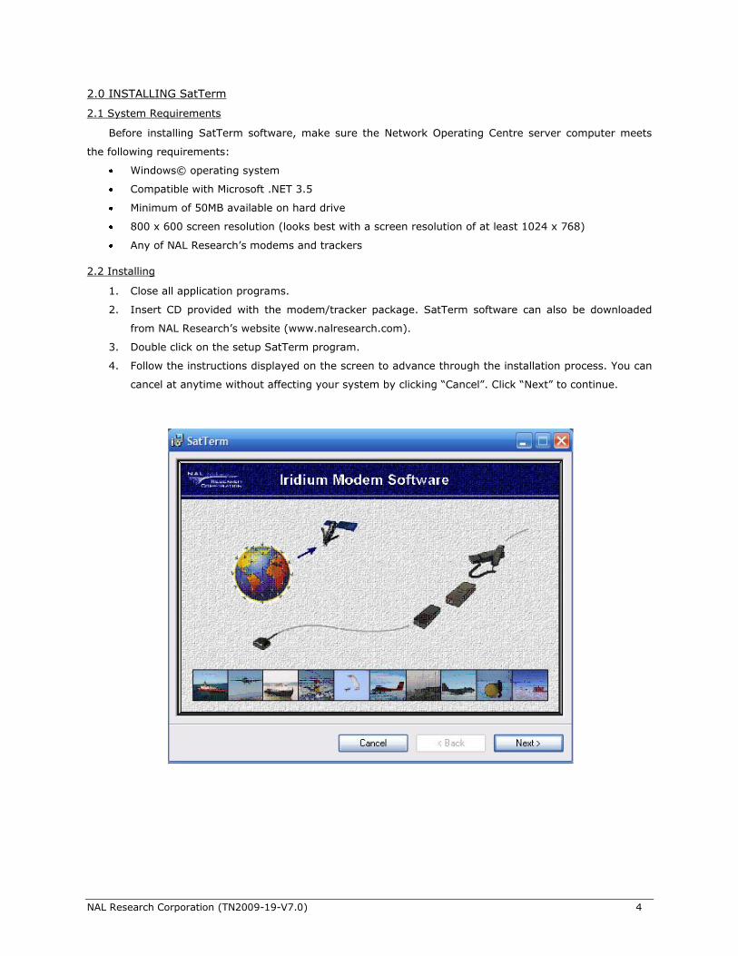
4. Follow the instructions displayed on the screen to advance through the installation process. You can
cancel at anytime without affecting your system by clicking ―Cancel‖. Click ―Next‖ to continue.
NAL Research Corporation (TN2009-19-V7.0) 5
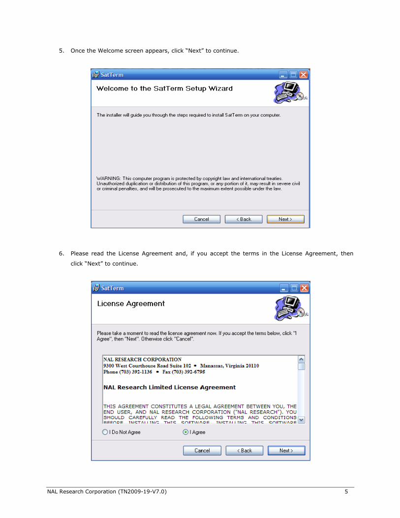
5. Once the Welcome screen appears, click ―Next‖ to continue.
6. Please read the License Agreement and, if you accept the terms in the License Agreement, then
click ―Next‖ to continue.
NAL Research Corporation (TN2009-19-V7.0) 6
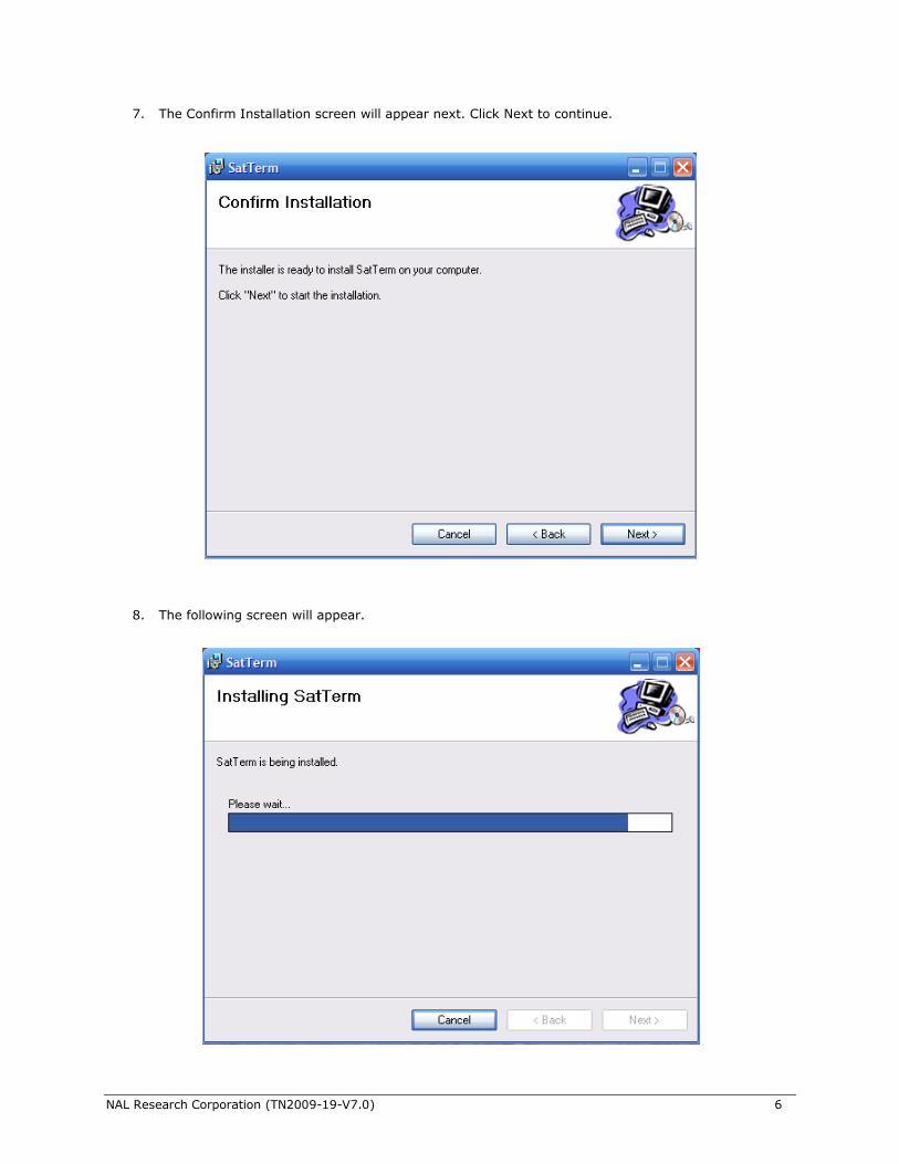
7. The Confirm Installation screen will appear next. Click Next to continue.
8. The following screen will appear.
NAL Research Corporation (TN2009-19-V7.0) 7
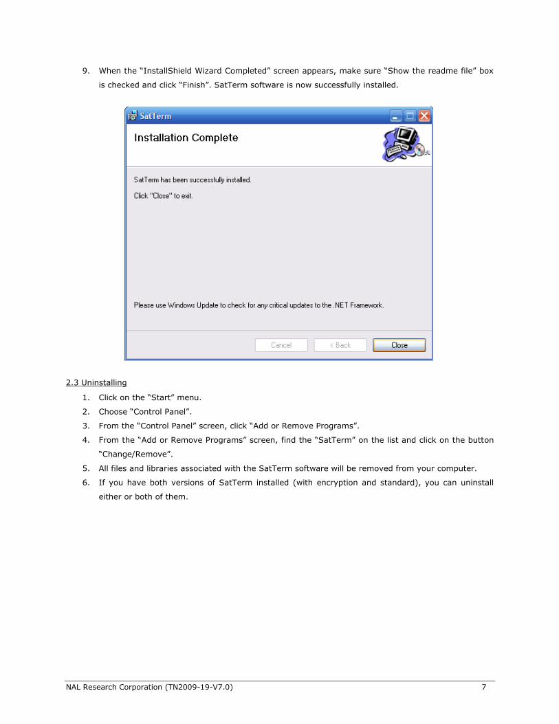
9. When the ―InstallShield Wizard Completed‖ screen appears, make sure ―Show the readme file‖ box
is checked and click ―Finish‖. SatTerm software is now successfully installed.
2.3 Uninstalling
1. Click on the ―Start‖ menu.
2. Choose ―Control Panel‖.
3. From the ―Control Panel‖ screen, click ―Add or Remove Programs‖.
4. From the ―Add or Remove Programs‖ screen, find the ―SatTerm‖ on the list and click on the button
―Change/Remove‖.
5. All files and libraries associated with the SatTerm software will be removed from your computer.
6. If you have both versions of SatTerm installed (with encryption and standard), you can uninstall
either or both of them.
NAL Research Corporation (TN2009-19-V7.0) 8
3.0 SETTING UP SatTerm
SatTerm can be accessed from the Windows® ―Start‖ button under ―All Programs/NAL Research‖ folder
or by clicking on the NAL Research Logo on the Desktop. The modem/tracker may be either powered ON or
OFF before starting SatTerm software. If a COM port is available, the modem is connected automatically
when a key is pressed. Users can also manually open the COM port by clicking the connect icon and
close the COM port by clicking the disconnect icon. Note that the status ―Connected‖ does not
necessarily mean that the modem/tracker is connected to the Iridium network. It only means that SatTerm
has successfully established communications with the COM port.
3.1 Setting SatTerm Software Properties
After the SatTerm software is loaded, its properties can be changed to reflect the hardware setup and
user’s preferences. However, ―Data bits‖, ―Parity‖ and ―Stop bits‖ should be kept at their default settings
unless the program is being used with an Iridium custom-designed modem. There are four types of
properties that can be set—modem type, port properties, dialing properties and preference properties. In
order to set the port properties and the dialing properties, the program must be disconnected from the COM
port by clicking the disconnect icon.
Modem Type
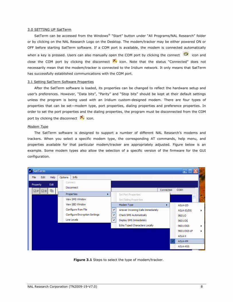
The SatTerm software is designed to support a number of different NAL Research’s modems and
trackers. When you select a specific modem type, the corresponding AT commands, help menu, and
properties available for that particular modem/tracker are appropriately adjusted. Figure below is an
example. Some modem types also allow the selection of a specific version of the firmware for the GUI
configuration.
Figure 3.1 Steps to select the type of modem/tracker.
NAL Research Corporation (TN2009-19-V7.0) 9
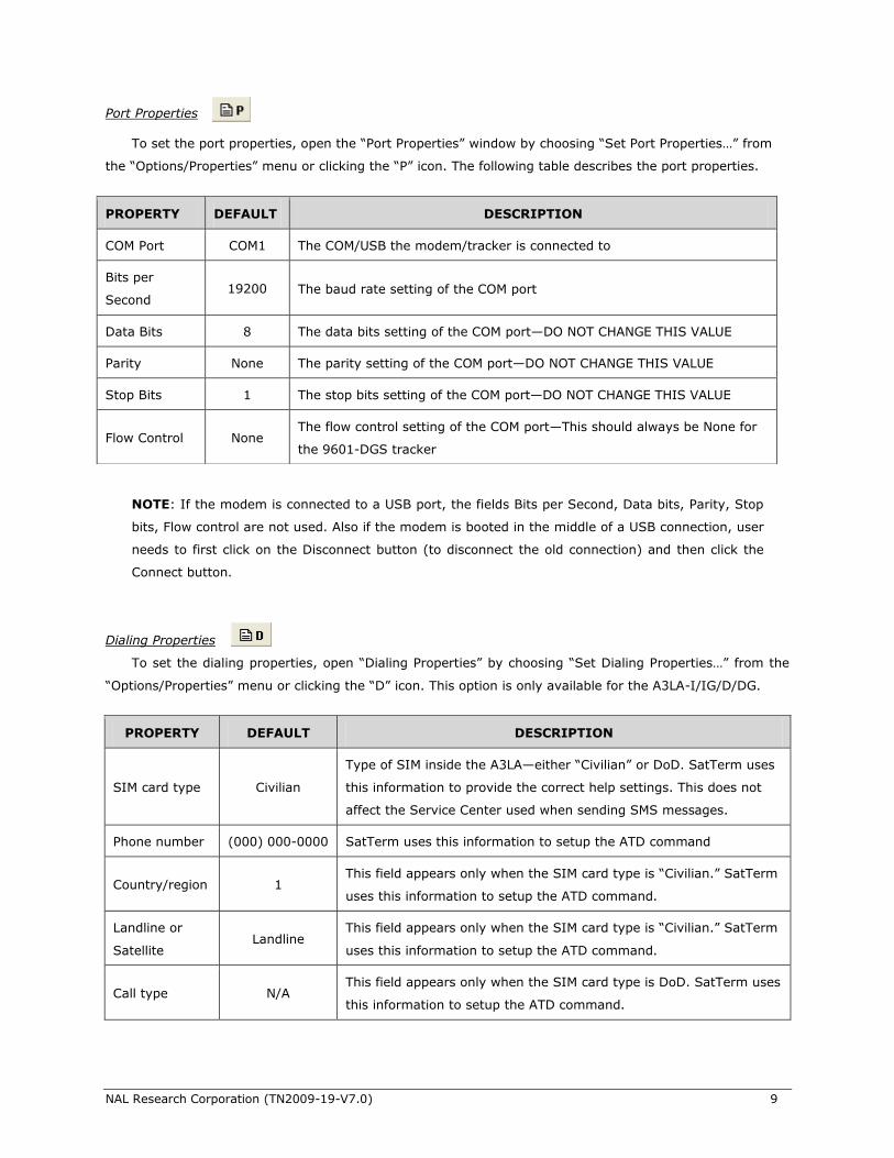
Port Properties To set the port properties, open the ―Port Properties‖ window by choosing ―Set Port Properties…‖ from
the ―Options/Properties‖ menu or clicking the ―P‖ icon. The following table describes the port properties.
NOTE: If the modem is connected to a USB port, the fields Bits per Second, Data bits, Parity, Stop
bits, Flow control are not used. Also if the modem is booted in the middle of a USB connection, user
needs to first click on the Disconnect button (to disconnect the old connection) and then click the
Connect button.
Dialing Properties
To set the dialing properties, open ―Dialing Properties‖ by choosing ―Set Dialing Properties…‖ from the
―Options/Properties‖ menu or clicking the ―D‖ icon. This option is only available for the A3LA-I/IG/D/DG.
PROPERTY DEFAULT DESCRIPTION
COM Port COM1 The COM/USB the modem/tracker is connected to
Bits per
Second 19200 The baud rate setting of the COM port
Data Bits 8 The data bits setting of the COM port—DO NOT CHANGE THIS VALUE
Parity None The parity setting of the COM port—DO NOT CHANGE THIS VALUE
Stop Bits 1 The stop bits setting of the COM port—DO NOT CHANGE THIS VALUE
Flow Control None The flow control setting of the COM port—This should always be None for
the 9601-DGS tracker
PROPERTY DEFAULT DESCRIPTION
SIM card type Civilian
Type of SIM inside the A3LA—either ―Civilian‖ or DoD. SatTerm uses
this information to provide the correct help settings. This does not
affect the Service Center used when sending SMS messages.
Phone number (000) 000-0000 SatTerm uses this information to setup the ATD command
Country/region 1 This field appears only when the SIM card type is ―Civilian.‖ SatTerm
uses this information to setup the ATD command.
Landline or
Satellite Landline
This field appears only when the SIM card type is ―Civilian.‖ SatTerm
uses this information to setup the ATD command.
Call type N/A This field appears only when the SIM card type is DoD. SatTerm uses
this information to setup the ATD command.
NAL Research Corporation (TN2009-19-V7.0) 10
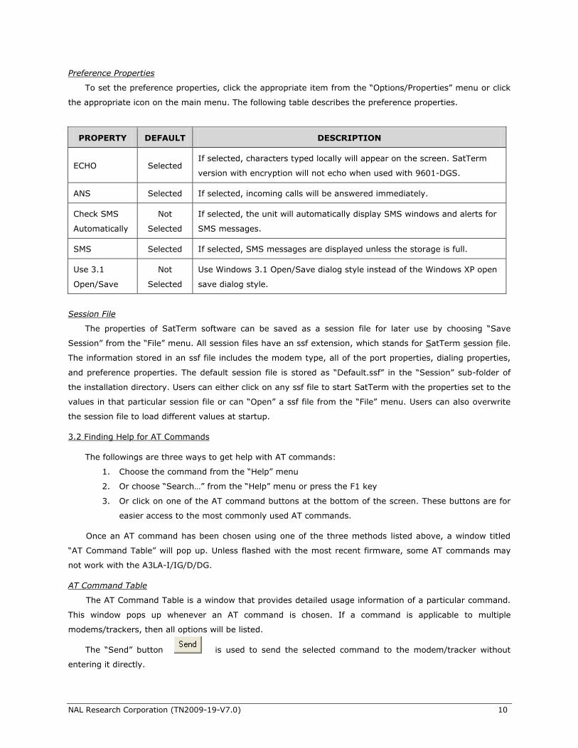
Preference Properties
To set the preference properties, click the appropriate item from the ―Options/Properties‖ menu or click
the appropriate icon on the main menu. The following table describes the preference properties.
Session File
The properties of SatTerm software can be saved as a session file for later use by choosing ―Save
Session‖ from the ―File‖ menu. All session files have an ssf extension, which stands for SatTerm session file.
The information stored in an ssf file includes the modem type, all of the port properties, dialing properties,
and preference properties. The default session file is stored as ―Default.ssf‖ in the ―Session‖ sub-folder of
the installation directory. Users can either click on any ssf file to start SatTerm with the properties set to the
values in that particular session file or can ―Open‖ a ssf file from the ―File‖ menu. Users can also overwrite
the session file to load different values at startup.
3.2 Finding Help for AT Commands
The followings are three ways to get help with AT commands:
1. Choose the command from the ―Help‖ menu
2. Or choose ―Search…‖ from the ―Help‖ menu or press the F1 key
3. Or click on one of the AT command buttons at the bottom of the screen. These buttons are for
easier access to the most commonly used AT commands.
Once an AT command has been chosen using one of the three methods listed above, a window titled
―AT Command Table‖ will pop up. Unless flashed with the most recent firmware, some AT commands may
not work with the A3LA-I/IG/D/DG.
AT Command Table
The AT Command Table is a window that provides detailed usage information of a particular command.
This window pops up whenever an AT command is chosen. If a command is applicable to multiple
modems/trackers, then all options will be listed.
The ―Send‖ button is used to send the selected command to the modem/tracker without
entering it directly.
PROPERTY DEFAULT DESCRIPTION
ECHO Selected If selected, characters typed locally will appear on the screen. SatTerm
version with encryption will not echo when used with 9601-DGS.
ANS Selected If selected, incoming calls will be answered immediately.
Check SMS
Automatically
Not
Selected
If selected, the unit will automatically display SMS windows and alerts for
SMS messages.
SMS Selected If selected, SMS messages are displayed unless the storage is full.
Use 3.1
Open/Save
Not
Selected
Use Windows 3.1 Open/Save dialog style instead of the Windows XP open
save dialog style.
NAL Research Corporation (TN2009-19-V7.0) 11
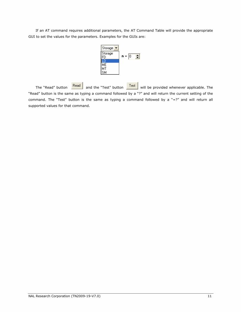
If an AT command requires additional parameters, the AT Command Table will provide the appropriate
GUI to set the values for the parameters. Examples for the GUIs are:
The ―Read‖ button and the ―Test‖ button will be provided whenever applicable. The
―Read‖ button is the same as typing a command followed by a ―?‖ and will return the current setting of the
command. The ―Test‖ button is the same as typing a command followed by a ―=?‖ and will return all
supported values for that command.
NAL Research Corporation (TN2009-19-V7.0) 12
4.0 USING SatTerm WITH SBD
4.1 Using SBD Message Window
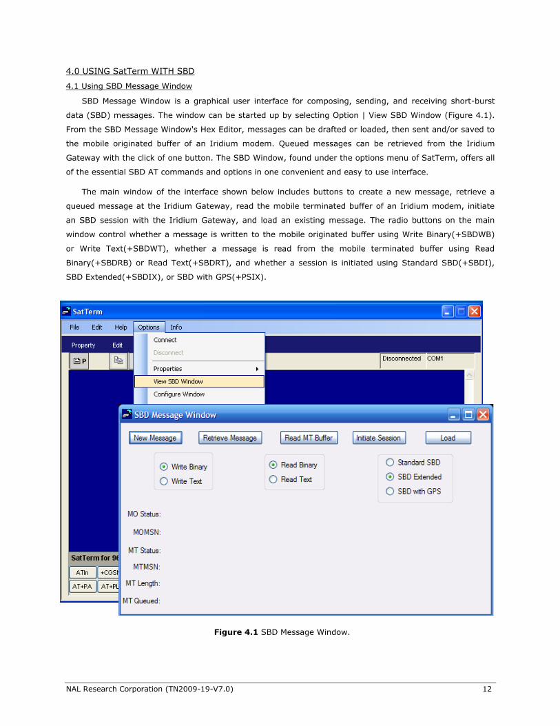
SBD Message Window is a graphical user interface for composing, sending, and receiving short-burst
data (SBD) messages. The window can be started up by selecting Option | View SBD Window (Figure 4.1).
From the SBD Message Window's Hex Editor, messages can be drafted or loaded, then sent and/or saved to
the mobile originated buffer of an Iridium modem. Queued messages can be retrieved from the Iridium
Gateway with the click of one button. The SBD Window, found under the options menu of SatTerm, offers all
of the essential SBD AT commands and options in one convenient and easy to use interface.
The main window of the interface shown below includes buttons to create a new message, retrieve a
queued message at the Iridium Gateway, read the mobile terminated buffer of an Iridium modem, initiate
an SBD session with the Iridium Gateway, and load an existing message. The radio buttons on the main
window control whether a message is written to the mobile originated buffer using Write Binary(+SBDWB)
or Write Text(+SBDWT), whether a message is read from the mobile terminated buffer using Read
Binary(+SBDRB) or Read Text(+SBDRT), and whether a session is initiated using Standard SBD(+SBDI),
SBD Extended(+SBDIX), or SBD with GPS(+PSIX).
Figure 4.1 SBD Message Window.
NAL Research Corporation (TN2009-19-V7.0) 13
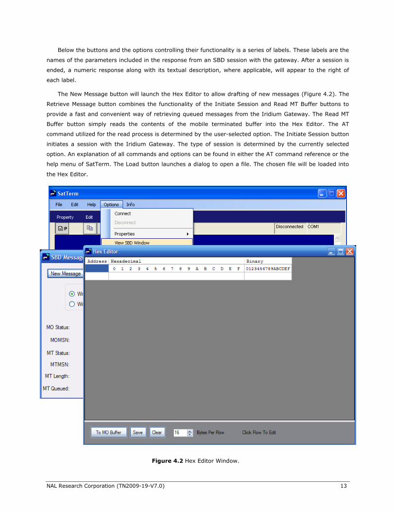
Below the buttons and the options controlling their functionality is a series of labels. These labels are the
names of the parameters included in the response from an SBD session with the gateway. After a session is
ended, a numeric response along with its textual description, where applicable, will appear to the right of
each label.
The New Message button will launch the Hex Editor to allow drafting of new messages (Figure 4.2). The
Retrieve Message button combines the functionality of the Initiate Session and Read MT Buffer buttons to
provide a fast and convenient way of retrieving queued messages from the Iridium Gateway. The Read MT
Buffer button simply reads the contents of the mobile terminated buffer into the Hex Editor. The AT
command utilized for the read process is determined by the user-selected option. The Initiate Session button
initiates a session with the Iridium Gateway. The type of session is determined by the currently selected
option. An explanation of all commands and options can be found in either the AT command reference or the
help menu of SatTerm. The Load button launches a dialog to open a file. The chosen file will be loaded into
the Hex Editor.
Figure 4.2 Hex Editor Window.
NAL Research Corporation (TN2009-19-V7.0) 14
The Hex Editor shown above is the window where messages can be drafted, loaded, edited, sent to the
mobile originated buffer, and saved. The panel on the left-hand-side of the window will display ASCII data
while the panel on the right will display hexadecimal values. The leftmost numbers in the window are row
numbers in decimal form, to the immediate right are their equivalents in hexadecimal. The numbers lining
the top of the editing windows are column numbers. Row numbers range from 0 to 1973; however, the
largest message that can be sent is 1960 bytes. The column numbers range from 0 to 32. The number of
visible columns may be adjusted by changing the value in the numeric panel labeled Bytes Per Row.
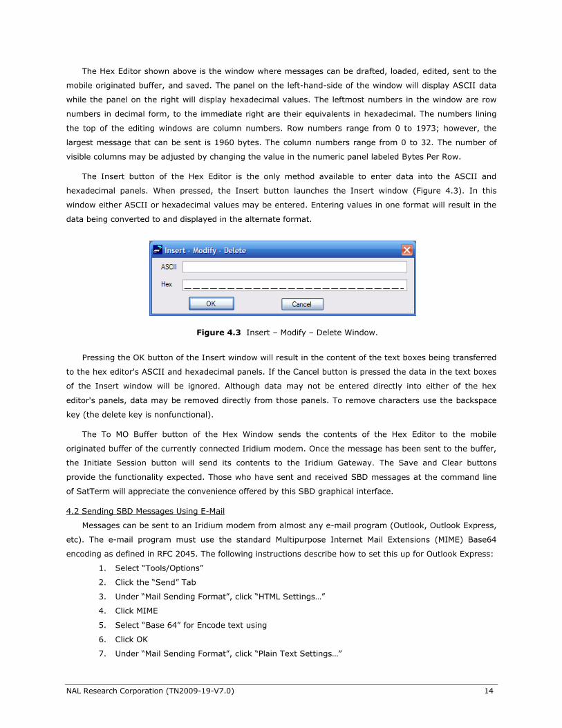
The Insert button of the Hex Editor is the only method available to enter data into the ASCII and
hexadecimal panels. When pressed, the Insert button launches the Insert window (Figure 4.3). In this
window either ASCII or hexadecimal values may be entered. Entering values in one format will result in the
data being converted to and displayed in the alternate format.
Pressing the OK button of the Insert window will result in the content of the text boxes being transferred
to the hex editor's ASCII and hexadecimal panels. If the Cancel button is pressed the data in the text boxes
of the Insert window will be ignored. Although data may not be entered directly into either of the hex
editor's panels, data may be removed directly from those panels. To remove characters use the backspace
key (the delete key is nonfunctional).
The To MO Buffer button of the Hex Window sends the contents of the Hex Editor to the mobile
originated buffer of the currently connected Iridium modem. Once the message has been sent to the buffer,
the Initiate Session button will send its contents to the Iridium Gateway. The Save and Clear buttons
provide the functionality expected. Those who have sent and received SBD messages at the command line
of SatTerm will appreciate the convenience offered by this SBD graphical interface.
4.2 Sending SBD Messages Using E-Mail
Messages can be sent to an Iridium modem from almost any e-mail program (Outlook, Outlook Express,
etc). The e-mail program must use the standard Multipurpose Internet Mail Extensions (MIME) Base64
encoding as defined in RFC 2045. The following instructions describe how to set this up for Outlook Express:
1. Select ―Tools/Options‖
2. Click the ―Send‖ Tab
3. Under ―Mail Sending Format‖, click ―HTML Settings…‖
4. Click MIME
5. Select ―Base 64‖ for Encode text using
6. Click OK
7. Under ―Mail Sending Format‖, click ―Plain Text Settings…‖
Figure 4.3 Insert – Modify – Delete Window.
NAL Research Corporation (TN2009-19-V7.0) 15
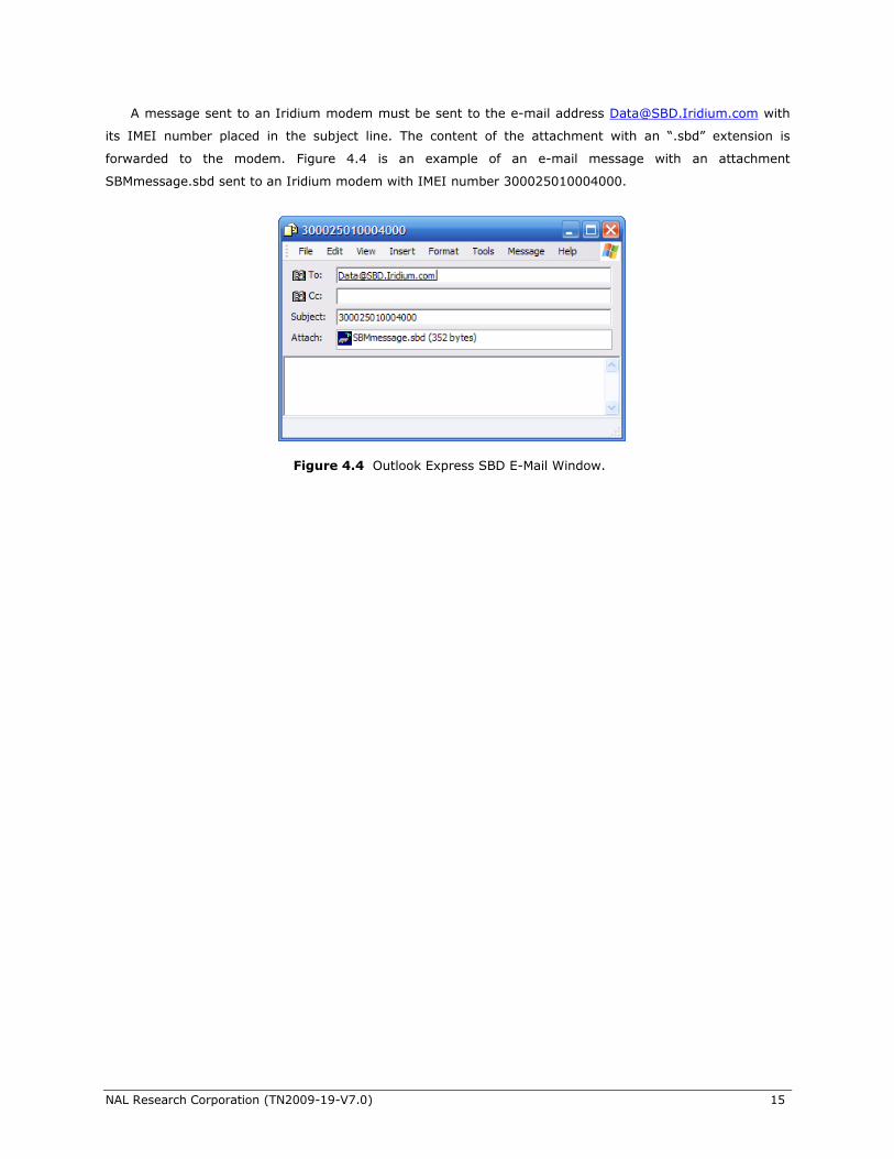
A message sent to an Iridium modem must be sent to the e-mail address [email protected] with
its IMEI number placed in the subject line. The content of the attachment with an ―.sbd‖ extension is
forwarded to the modem. Figure 4.4 is an example of an e-mail message with an attachment
SBMmessage.sbd sent to an Iridium modem with IMEI number 300025010004000.
Figure 4.4 Outlook Express SBD E-Mail Window.
NAL Research Corporation (TN2009-19-V7.0) 16
5.0 USING SatTerm WITH SMS
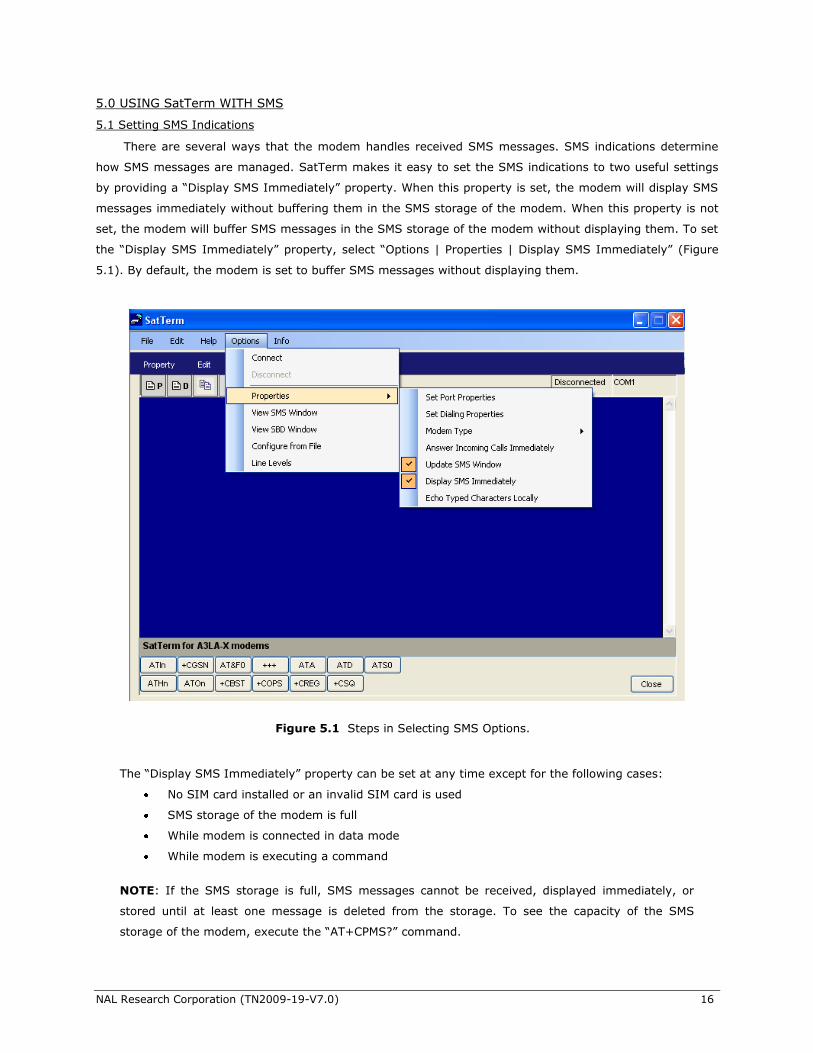
5.1 Setting SMS Indications
There are several ways that the modem handles received SMS messages. SMS indications determine
how SMS messages are managed. SatTerm makes it easy to set the SMS indications to two useful settings
by providing a ―Display SMS Immediately‖ property. When this property is set, the modem will display SMS
messages immediately without buffering them in the SMS storage of the modem. When this property is not
set, the modem will buffer SMS messages in the SMS storage of the modem without displaying them. To set
the ―Display SMS Immediately‖ property, select ―Options | Properties | Display SMS Immediately‖ (Figure
5.1). By default, the modem is set to buffer SMS messages without displaying them.
The ―Display SMS Immediately‖ property can be set at any time except for the following cases:
No SIM card installed or an invalid SIM card is used
SMS storage of the modem is full
While modem is connected in data mode
While modem is executing a command
NOTE: If the SMS storage is full, SMS messages cannot be received, displayed immediately, or
stored until at least one message is deleted from the storage. To see the capacity of the SMS
storage of the modem, execute the ―AT+CPMS?‖ command.
Figure 5.1 Steps in Selecting SMS Options.
NAL Research Corporation (TN2009-19-V7.0) 17
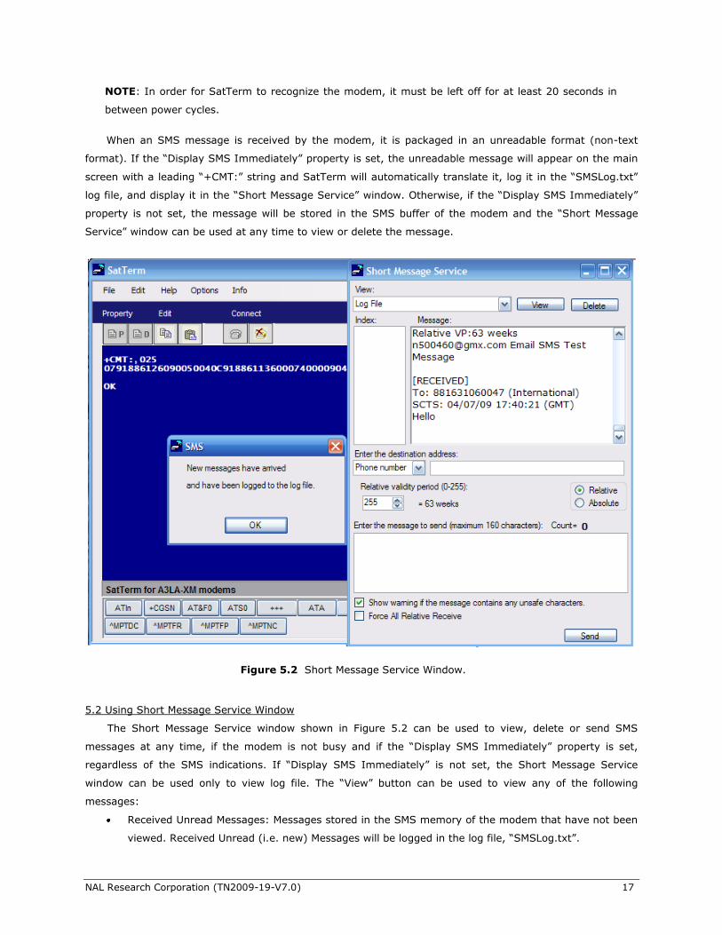
NOTE: In order for SatTerm to recognize the modem, it must be left off for at least 20 seconds in
between power cycles.
When an SMS message is received by the modem, it is packaged in an unreadable format (non-text
format). If the ―Display SMS Immediately‖ property is set, the unreadable message will appear on the main
screen with a leading ―+CMT:‖ string and SatTerm will automatically translate it, log it in the ―SMSLog.txt‖
log file, and display it in the ―Short Message Service‖ window. Otherwise, if the ―Display SMS Immediately‖
property is not set, the message will be stored in the SMS buffer of the modem and the ―Short Message
Service‖ window can be used at any time to view or delete the message.
5.2 Using Short Message Service Window
The Short Message Service window shown in Figure 5.2 can be used to view, delete or send SMS
messages at any time, if the modem is not busy and if the ―Display SMS Immediately‖ property is set,
regardless of the SMS indications. If ―Display SMS Immediately‖ is not set, the Short Message Service
window can be used only to view log file. The ―View‖ button can be used to view any of the following
messages:
Received Unread Messages: Messages stored in the SMS memory of the modem that have not been
viewed. Received Unread (i.e. new) Messages will be logged in the log file, ―SMSLog.txt‖.
Figure 5.2 Short Message Service Window.
NAL Research Corporation (TN2009-19-V7.0) 18
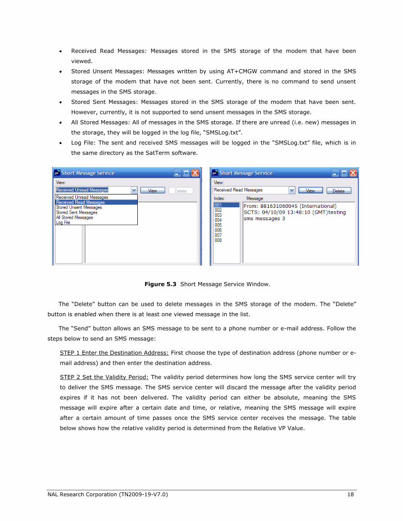
Received Read Messages: Messages stored in the SMS storage of the modem that have been
viewed.
Stored Unsent Messages: Messages written by using AT+CMGW command and stored in the SMS
storage of the modem that have not been sent. Currently, there is no command to send unsent
messages in the SMS storage.
Stored Sent Messages: Messages stored in the SMS storage of the modem that have been sent.
However, currently, it is not supported to send unsent messages in the SMS storage.
All Stored Messages: All of messages in the SMS storage. If there are unread (i.e. new) messages in
the storage, they will be logged in the log file, ―SMSLog.txt‖.
Log File: The sent and received SMS messages will be logged in the ―SMSLog.txt‖ file, which is in
the same directory as the SatTerm software.
The ―Delete‖ button can be used to delete messages in the SMS storage of the modem. The ―Delete‖
button is enabled when there is at least one viewed message in the list.
The ―Send‖ button allows an SMS message to be sent to a phone number or e-mail address. Follow the
steps below to send an SMS message:
STEP 1 Enter the Destination Address: First choose the type of destination address (phone number or e-
mail address) and then enter the destination address.
STEP 2 Set the Validity Period: The validity period determines how long the SMS service center will try
to deliver the SMS message. The SMS service center will discard the message after the validity period
expires if it has not been delivered. The validity period can either be absolute, meaning the SMS
message will expire after a certain date and time, or relative, meaning the SMS message will expire
after a certain amount of time passes once the SMS service center receives the message. The table
below shows how the relative validity period is determined from the Relative VP Value.
Figure 5.3 Short Message Service Window.
NAL Research Corporation (TN2009-19-V7.0) 19
Relative VP Value (RVPV) Relative Validity Period
0 – 143 (RVPV + 1) * 5 minutes
144 – 167 ((RVPV – 143) * 30 minutes) + 12 hours
168 – 196 (RVPV – 166) * 1 day
197 – 255 (RVPV – 192) * 1 week
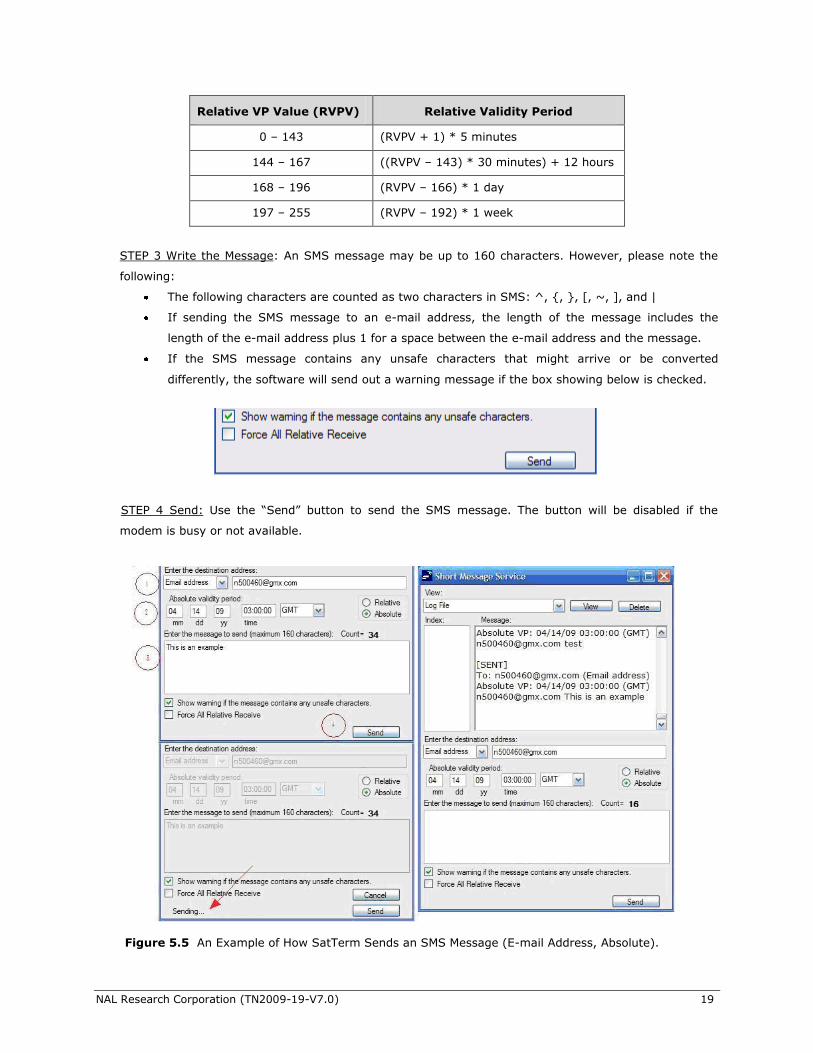
STEP 3 Write the Message: An SMS message may be up to 160 characters. However, please note the
following:
The following characters are counted as two characters in SMS: ^, {, }, [, ~, ], and |
If sending the SMS message to an e-mail address, the length of the message includes the
length of the e-mail address plus 1 for a space between the e-mail address and the message.
If the SMS message contains any unsafe characters that might arrive or be converted
differently, the software will send out a warning message if the box showing below is checked.
STEP 4 Send: Use the ―Send‖ button to send the SMS message. The button will be disabled if the
modem is busy or not available.
Figure 5.5 An Example of How SatTerm Sends an SMS Message (E-mail Address, Absolute).
NAL Research Corporation (TN2009-19-V7.0) 20
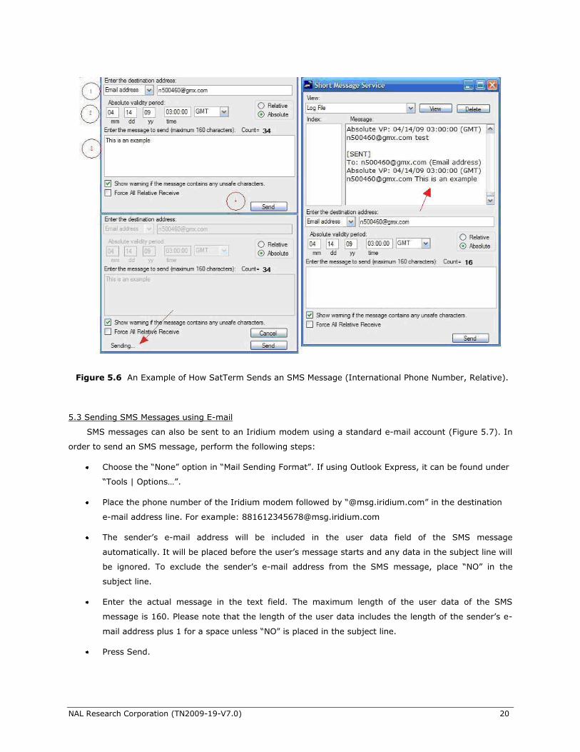
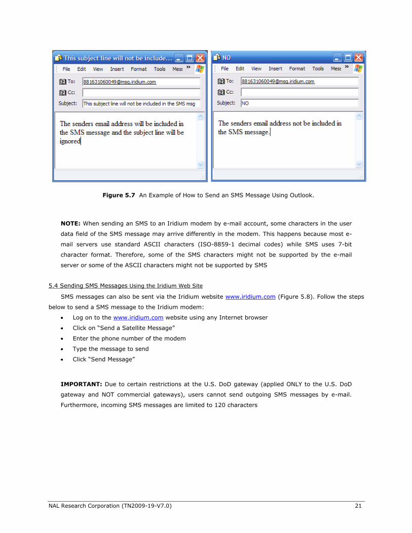
5.3 Sending SMS Messages using E-mail
SMS messages can also be sent to an Iridium modem using a standard e-mail account (Figure 5.7). In
order to send an SMS message, perform the following steps:
Choose the ―None‖ option in ―Mail Sending Format‖. If using Outlook Express, it can be found under
―Tools | Options…‖.
Place the phone number of the Iridium modem followed by ―@msg.iridium.com‖ in the destination
e-mail address line. For example: [email protected]
The sender’s e-mail address will be included in the user data field of the SMS message
automatically. It will be placed before the user’s message starts and any data in the subject line will
be ignored. To exclude the sender’s e-mail address from the SMS message, place ―NO‖ in the
subject line.
Enter the actual message in the text field. The maximum length of the user data of the SMS
message is 160. Please note that the length of the user data includes the length of the sender’s e-
mail address plus 1 for a space unless ―NO‖ is placed in the subject line.
Press Send.
Figure 5.6 An Example of How SatTerm Sends an SMS Message (International Phone Number, Relative).
NAL Research Corporation (TN2009-19-V7.0) 21
NOTE: When sending an SMS to an Iridium modem by e-mail account, some characters in the user
data field of the SMS message may arrive differently in the modem. This happens because most e-
mail servers use standard ASCII characters (ISO-8859-1 decimal codes) while SMS uses 7-bit
character format. Therefore, some of the SMS characters might not be supported by the e-mail
server or some of the ASCII characters might not be supported by SMS
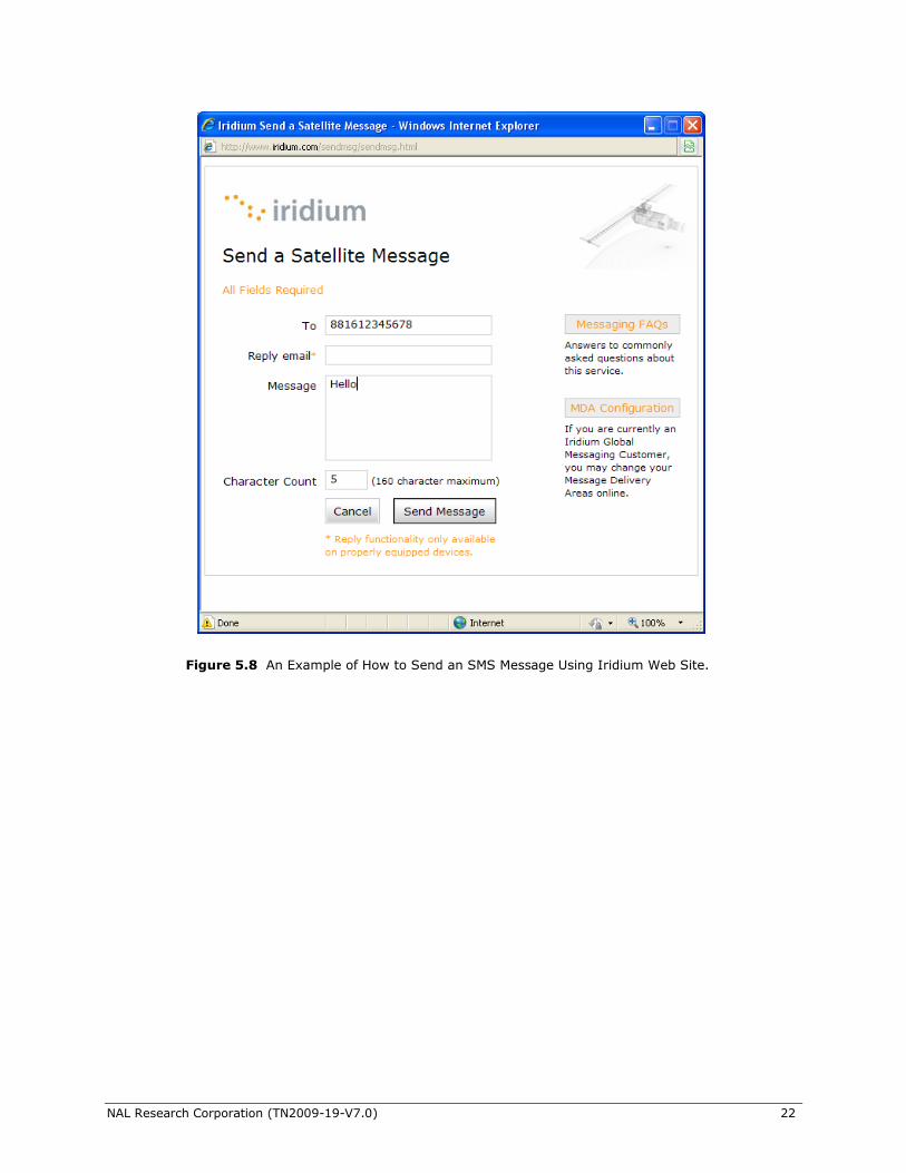
5.4 Sending SMS Messages Using the Iridium Web Site
SMS messages can also be sent via the Iridium website www.iridium.com (Figure 5.8). Follow the steps
below to send a SMS message to the Iridium modem:
Log on to the www.iridium.com website using any Internet browser
Click on ―Send a Satellite Message‖
Enter the phone number of the modem
Type the message to send
Click ―Send Message‖
IMPORTANT: Due to certain restrictions at the U.S. DoD gateway (applied ONLY to the U.S. DoD
gateway and NOT commercial gateways), users cannot send outgoing SMS messages by e-mail.
Furthermore, incoming SMS messages are limited to 120 characters
Figure 5.7 An Example of How to Send an SMS Message Using Outlook.
NAL Research Corporation (TN2009-19-V7.0) 22
Figure 5.8 An Example of How to Send an SMS Message Using Iridium Web Site.
NAL Research Corporation (TN2009-19-V7.0) 23
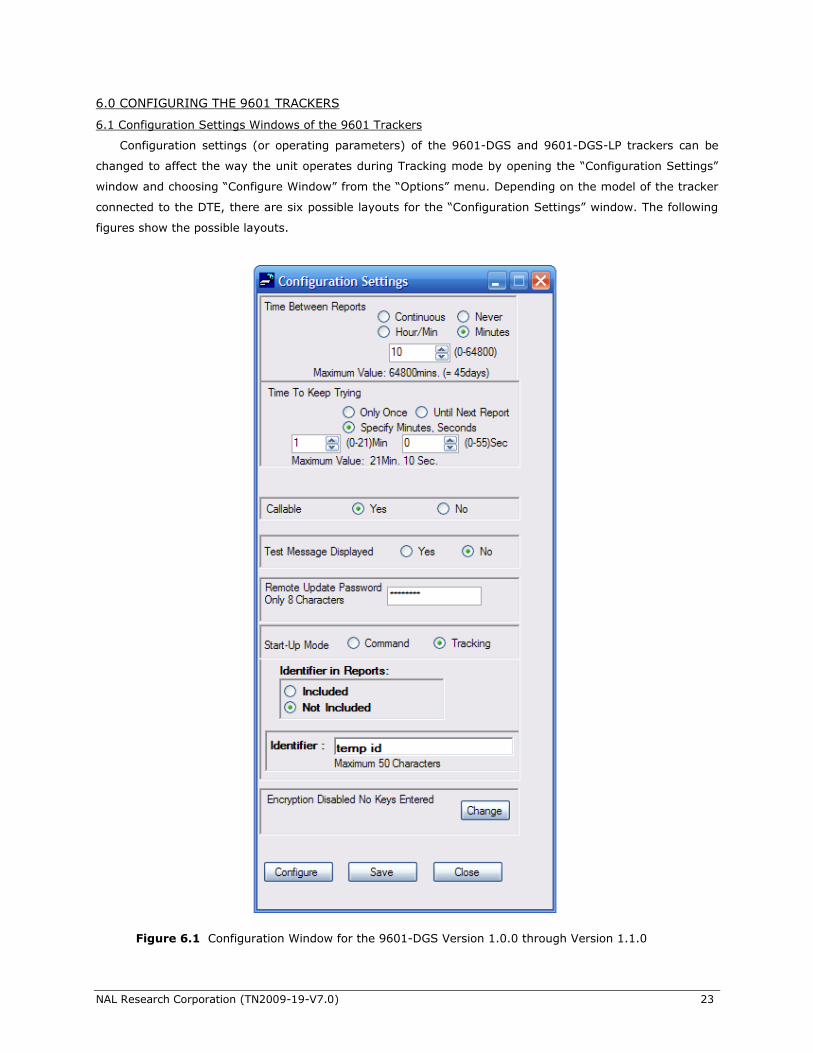
6.0 CONFIGURING THE 9601 TRACKERS
6.1 Configuration Settings Windows of the 9601 Trackers
Configuration settings (or operating parameters) of the 9601-DGS and 9601-DGS-LP trackers can be
changed to affect the way the unit operates during Tracking mode by opening the ―Configuration Settings‖
window and choosing ―Configure Window‖ from the ―Options‖ menu. Depending on the model of the tracker
connected to the DTE, there are six possible layouts for the ―Configuration Settings‖ window. The following
figures show the possible layouts.
Figure 6.1 Configuration Window for the 9601-DGS Version 1.0.0 through Version 1.1.0
NAL Research Corporation (TN2009-19-V7.0) 24
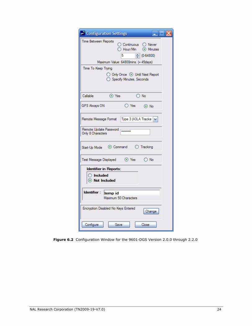
Figure 6.2 Configuration Window for the 9601-DGS Version 2.0.0 through 2.2.0
NAL Research Corporation (TN2009-19-V7.0) 25
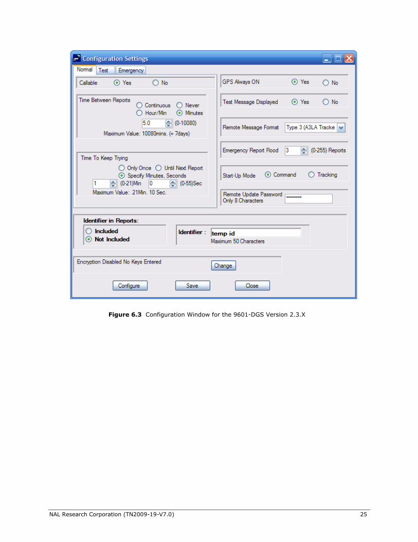
Figure 6.3 Configuration Window for the 9601-DGS Version 2.3.X
NAL Research Corporation (TN2009-19-V7.0) 26
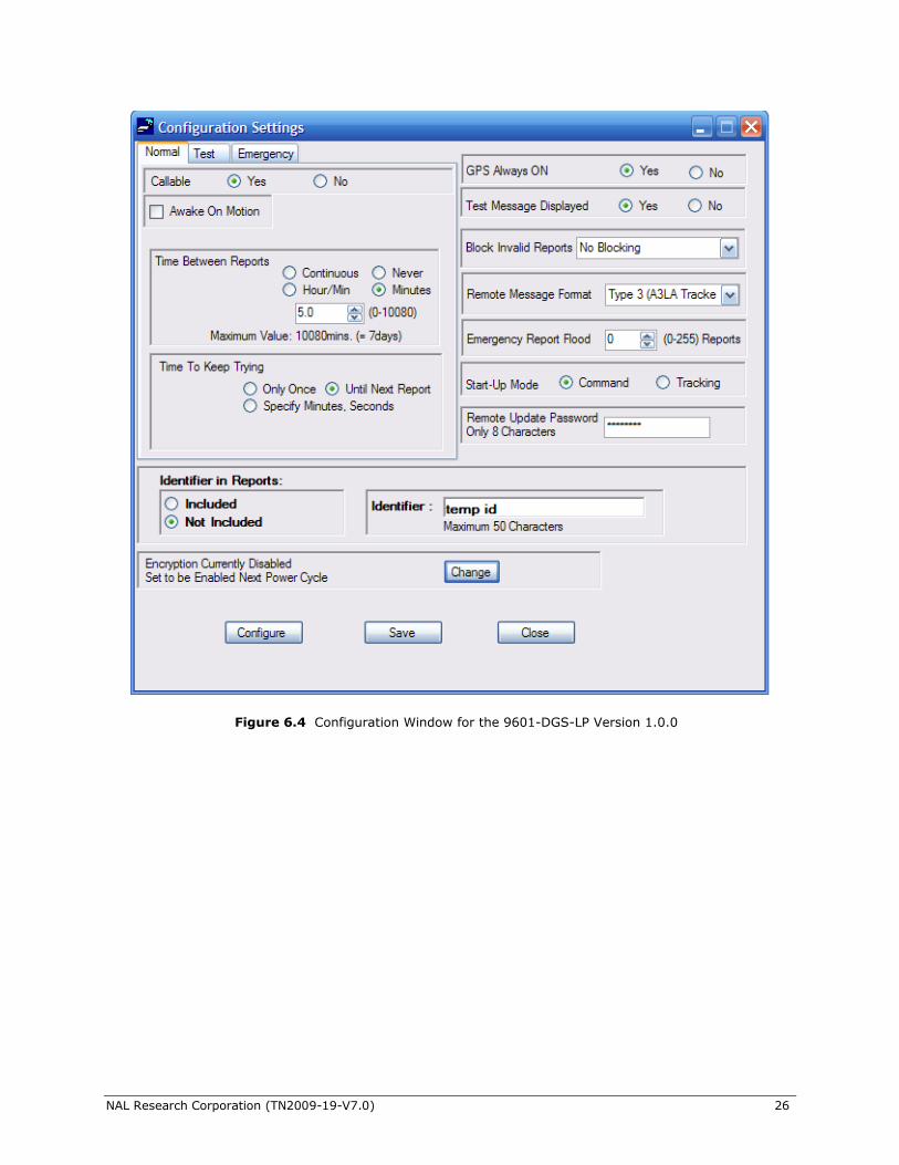
Figure 6.4 Configuration Window for the 9601-DGS-LP Version 1.0.0
NAL Research Corporation (TN2009-19-V7.0) 27
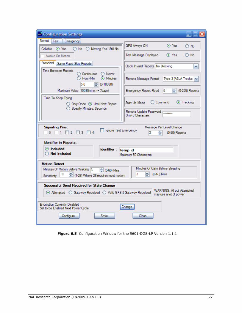
Figure 6.5 Configuration Window for the 9601-DGS-LP Version 1.1.1
NAL Research Corporation (TN2009-19-V7.0) 28
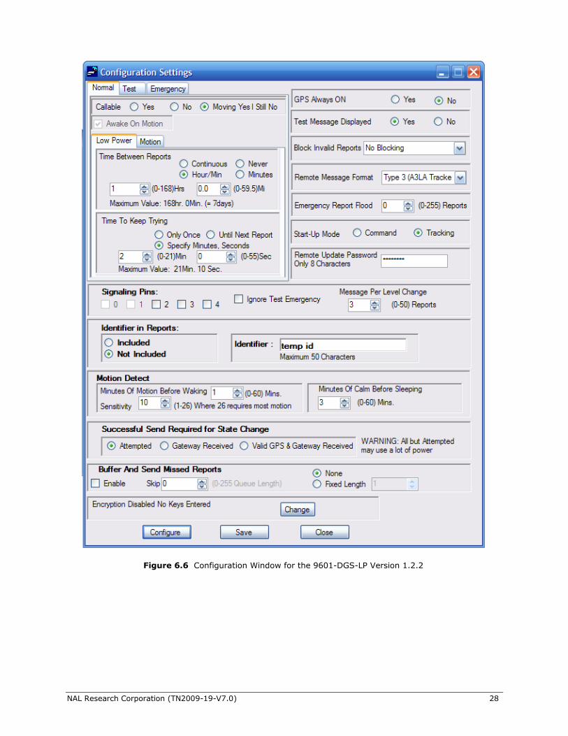
Figure 6.6 Configuration Window for the 9601-DGS-LP Version 1.2.2
NAL Research Corporation (TN2009-19-V7.0) 29
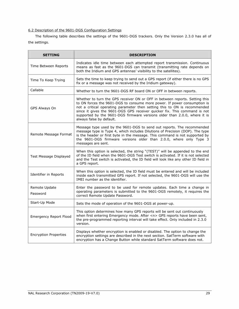
6.2 Description of the 9601-DGS Configuration Settings
The following table describes the settings of the 9601-DGS trackers. Only the Version 2.3.0 has all of
the settings.
SETTING DESCRIPTION
Time Between Reports Indicates idle time between each attempted report transmission. Continuous
means as fast as the 9601-DGS can transmit (transmitting rate depends on both the Iridium and GPS antennas’ visibility to the satellites).
Time To Keep Trying Sets the time to keep trying to send out a GPS report (if either there is no GPS fix or a message was not received by the Iridium gateway).
Callable Whether to turn the 9601-DGS RF board ON or OFF in between reports.
GPS Always On
Whether to turn the GPS receiver ON or OFF in between reports. Setting this
to ON forces the 9601-DGS to consume more power. If power consumption is not a critical operating parameter then setting this to ON is recommended since it gives the 9601-DGS GPS receiver quicker fix. This command is not supported by the 9601-DGS firmware versions older than 2.0.0, where it is always false by default.
Remote Message Format
Message type used by the 9601-DGS to send out reports. The recommended message type is Type 4, which includes Dilutions of Precision (DOP). The type is the header or first byte in the message. This command is not supported by the 9601-DGS firmware versions older than 2.0.0, where only Type 3 messages are sent.
Test Message Displayed
When this option is selected, the string ―(TEST)‖ will be appended to the end of the ID field when the 9601-DGS Test switch is activated. If it is not selected and the Test switch is activated, the ID field will look like any other ID field in a GPS report.
Identifier in Reports When this option is selected, the ID field must be entered and will be included inside each transmitted GPS report. If not selected, the 9601-DGS will use the IMEI number as the identifier.
Remote Update
Password
Enter the password to be used for remote updates. Each time a change in
operating parameters is submitted to the 9601-DGS remotely, it requires the correct Remote Update Password.
Start-Up Mode Sets the mode of operation of the 9601-DGS at power-up.
Emergency Report Flood
This option determines how many GPS reports will be sent out continuously when first entering Emergency mode. After <n> GPS reports have been sent, the pre-programmed reporting interval will take effect. Only included in 2.3.0 version.
Encryption Properties Displays whether encryption is enabled or disabled. The option to change the encryption settings are described in the next section. SatTerm software with encryption has a Change Button while standard SatTerm software does not.
NAL Research Corporation (TN2009-19-V7.0) 30
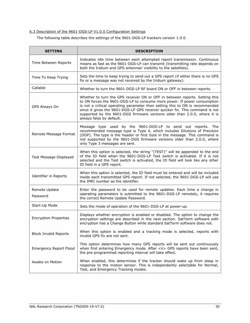
6.3 Description of the 9601-DGS-LP V1.0.0 Configuration Settings
The following table describes the settings of the 9601-DGS-LP trackers version 1.0.0.
SETTING DESCRIPTION
Time Between Reports Indicates idle time between each attempted report transmission. Continuous
means as fast as the 9601-DGS-LP can transmit (transmitting rate depends on both the Iridium and GPS antennas’ visibility to the satellites).
Time To Keep Trying Sets the time to keep trying to send out a GPS report (if either there is no GPS fix or a message was not received by the Iridium gateway).
Callable Whether to turn the 9601-DGS-LP RF board ON or OFF in between reports.
GPS Always On
Whether to turn the GPS receiver ON or OFF in between reports. Setting this
to ON forces the 9601-DGS-LP to consume more power. If power consumption is not a critical operating parameter then setting this to ON is recommended since it gives the 9601-DGS-LP GPS receiver quicker fix. This command is not supported by the 9601-DGS firmware versions older than 2.0.0, where it is always false by default.
Remote Message Format
Message type used by the 9601-DGS-LP to send out reports. The
recommended message type is Type 4, which includes Dilutions of Precision (DOP). The type is the header or first byte in the message. This command is not supported by the 9601-DGS firmware versions older than 2.0.0, where only Type 3 messages are sent.
Test Message Displayed
When this option is selected, the string ―(TEST)‖ will be appended to the end
of the ID field when the 9601-DGS-LP Test switch is activated. If it is not selected and the Test switch is activated, the ID field will look like any other ID field in a GPS report.
Identifier in Reports When this option is selected, the ID field must be entered and will be included
inside each transmitted GPS report. If not selected, the 9601-DGS-LP will use the IMEI number as the identifier.
Remote Update
Password
Enter the password to be used for remote updates. Each time a change in
operating parameters is submitted to the 9601-DGS-LP remotely, it requires the correct Remote Update Password.
Start-Up Mode Sets the mode of operation of the 9601-DGS-LP at power-up.
Encryption Properties Displays whether encryption is enabled or disabled. The option to change the encryption settings are described in the next section. SatTerm software with encryption has a Change Button while standard SatTerm software does not.
Block Invalid Reports When this option is enabled and a tracking mode is selected, reports with invalid GPS fix are not sent.
Emergency Report Flood
This option determines how many GPS reports will be sent out continuously
when first entering Emergency mode. After <n> GPS reports have been sent, the pre-programmed reporting interval will take effect.
Awake on Motion
When enabled, this determines if the tracker should wake up from sleep in
response to the motion sensor. This is independently selectable for Normal, Test, and Emergency Tracking modes.
NAL Research Corporation (TN2009-19-V7.0) 31
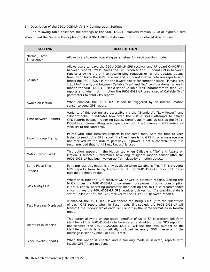
6.4 Description of the 9601-DGS-LP V1.1.X Configuration Settings
The following table describes the settings of the 9601-DGS-LP trackers version 1.1.0 or higher. Users
should read the General Description of Model 9601-DGS-LP document for more detailed descriptions.
SETTING DESCRIPTION
Normal, Test,
Emergency Allows users to enter operating parameters for each tracking mode.
Callable
Allows users to leave the 9601-DGS-LP GPS receiver and RF board ON/OFF in between reports. ―Yes‖ leaves the GPS receiver and RF board ON in between reports allowing the unit to receive ping requests or remote updates at any time. ―No‖ turns the GPS receiver and RF board OFF in between reports and
forces the 9601-DGS-LP into the lowest power consumption state. ―Moving Yes | Still No‖ is a hybrid between Callable ―Yes‖ and ―No‖ configurations. When in motion the 9601-DGS-LP uses a set of Callable ―Yes‖ parameters to send GPS reports and when not in motion the 9601-DGS-LP uses a set of Callable ―No‖ parameters to send GPS reports.
Awake on Motion When enabled, the 9601-DGS-LP can be triggered by an internal motion
sensor to send GPS report.
Time Between Reports
Variants of this setting are accessible via the ―Standard‖, ―Low Power‖, and ―Motion‖ tabs. It indicates how often the 9601-DGS-LP attempts to deliver
GPS reports between reporting cycles. Continuous means as fast as the 9601-DGS-LP can (transmitting rate depends on both the Iridium and GPS antennas’ visibility to the satellites).
Time To Keep Trying
Paired with Time Between Reports in the same tabs. Sets the time to keep trying to send out a GPS report (if either there is no GPS fix or a message was
not received by the Iridium gateway). If power is not a concern, then it is recommended that ―Until Next Report‖ is used.
Motion Sensor Wait This option appears in the Motion tab when Callable is ―No‖ and Awake on Motion is selected. Determines how long to ignore motion sensor after the 9601-DGS-LP has been woken up from sleep by a motion detect.
Same Place Skip
Reports
For simplicity this option is only available when Callable is ―Yes‖. This prevents GPS reports from being transmitted if the 9601-DGS-LP does not move outside a defined radius.
GPS Always On
Whether to turn the GPS receiver ON or OFF in between reports. Setting this to ON forces the 9601-DGS-LP to consume more power. If power consumption is not a critical operating parameter then setting this to ON is recommended since it gives the 9601-DGS-LP GPS receiver quicker fix. If a tracking state is set to Callable ―No‖, the GPS receiver will still turn OFF between reports.
Test Message Displayed
If enabled, the 9601-DGS-LP will append the string ―(TEST)‖ to the ―Identifier‖ of each GPS report when in Test mode. If disabled, the 9601-DGS-LP will transmit the ―Identifier‖ of each GPS report in the same format as in Normal mode.
Identifier in Reports
This option allows a unique static identifier of up to 50 characters (platform identifier of the 9601-DGS-LP) to be entered and added to the GPS report. If not selected, the 9601-DGS/9601-DGS-LP will use the IMEI number as the identifier, which is automatically included in every SBD message if the message is sent by email or SBD DirectIP.
Block Invalid Reports When this option is enabled and a tracking mode is selected, reports with invalid GPS fix are not sent.
NAL Research Corporation (TN2009-19-V7.0) 32
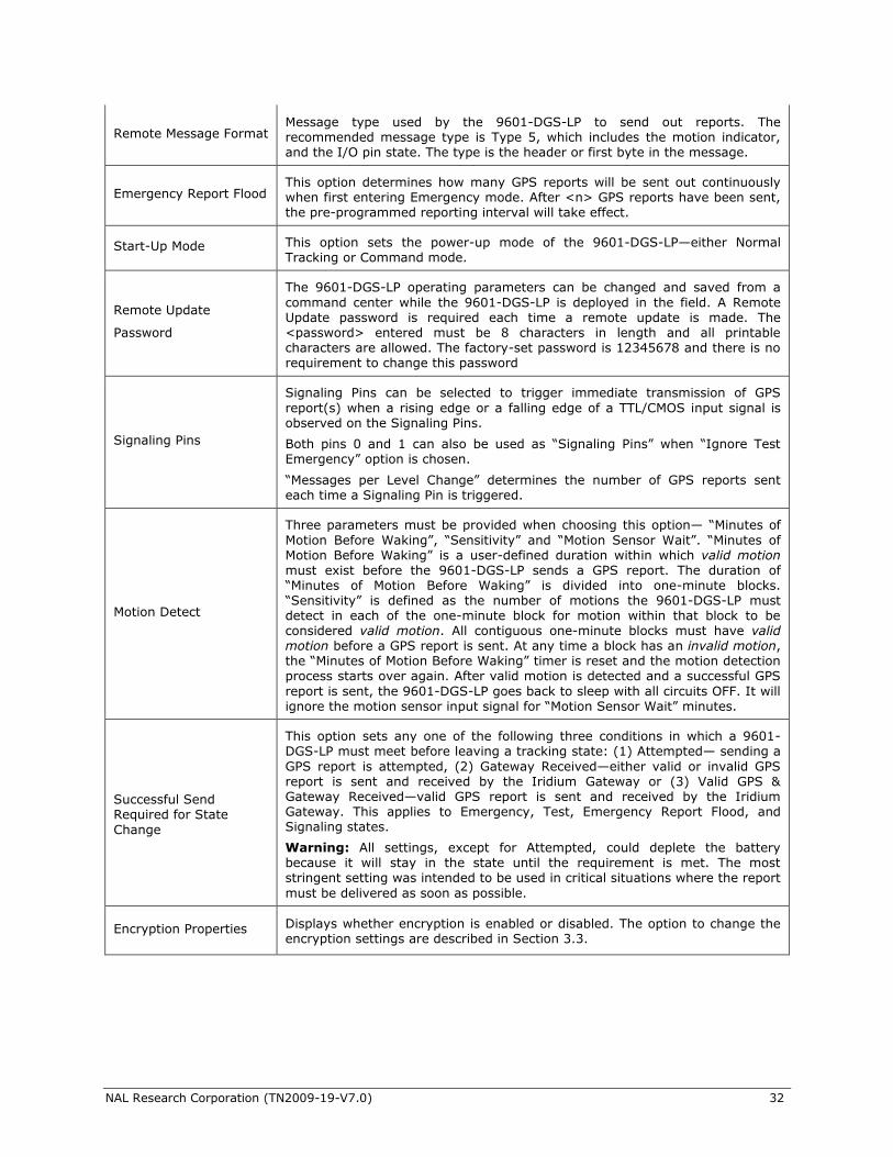
Remote Message Format Message type used by the 9601-DGS-LP to send out reports. The recommended message type is Type 5, which includes the motion indicator, and the I/O pin state. The type is the header or first byte in the message.
Emergency Report Flood This option determines how many GPS reports will be sent out continuously when first entering Emergency mode. After <n> GPS reports have been sent, the pre-programmed reporting interval will take effect.
Start-Up Mode This option sets the power-up mode of the 9601-DGS-LP—either Normal Tracking or Command mode.
Remote Update
Password
The 9601-DGS-LP operating parameters can be changed and saved from a
command center while the 9601-DGS-LP is deployed in the field. A Remote Update password is required each time a remote update is made. The <password> entered must be 8 characters in length and all printable characters are allowed. The factory-set password is 12345678 and there is no requirement to change this password
Signaling Pins
Signaling Pins can be selected to trigger immediate transmission of GPS
report(s) when a rising edge or a falling edge of a TTL/CMOS input signal is observed on the Signaling Pins.
Both pins 0 and 1 can also be used as ―Signaling Pins‖ when ―Ignore Test Emergency‖ option is chosen.
―Messages per Level Change‖ determines the number of GPS reports sent each time a Signaling Pin is triggered.
Motion Detect
Three parameters must be provided when choosing this option— ―Minutes of
Motion Before Waking‖, ―Sensitivity‖ and ―Motion Sensor Wait‖. ―Minutes of Motion Before Waking‖ is a user-defined duration within which valid motion must exist before the 9601-DGS-LP sends a GPS report. The duration of ―Minutes of Motion Before Waking‖ is divided into one-minute blocks. ―Sensitivity‖ is defined as the number of motions the 9601-DGS-LP must detect in each of the one-minute block for motion within that block to be considered valid motion. All contiguous one-minute blocks must have valid motion before a GPS report is sent. At any time a block has an invalid motion, the ―Minutes of Motion Before Waking‖ timer is reset and the motion detection process starts over again. After valid motion is detected and a successful GPS
report is sent, the 9601-DGS-LP goes back to sleep with all circuits OFF. It will ignore the motion sensor input signal for ―Motion Sensor Wait‖ minutes.
Successful Send Required for State
Change
This option sets any one of the following three conditions in which a 9601-DGS-LP must meet before leaving a tracking state: (1) Attempted— sending a
GPS report is attempted, (2) Gateway Received—either valid or invalid GPS report is sent and received by the Iridium Gateway or (3) Valid GPS & Gateway Received—valid GPS report is sent and received by the Iridium Gateway. This applies to Emergency, Test, Emergency Report Flood, and Signaling states.
Warning: All settings, except for Attempted, could deplete the battery because it will stay in the state until the requirement is met. The most stringent setting was intended to be used in critical situations where the report
must be delivered as soon as possible.
Encryption Properties Displays whether encryption is enabled or disabled. The option to change the encryption settings are described in Section 3.3.
NAL Research Corporation (TN2009-19-V7.0) 33
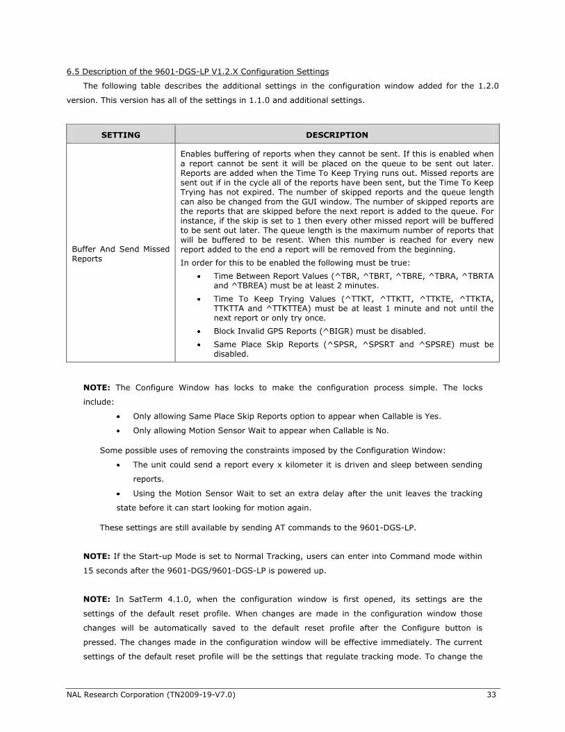
6.5 Description of the 9601-DGS-LP V1.2.X Configuration Settings
The following table describes the additional settings in the configuration window added for the 1.2.0
version. This version has all of the settings in 1.1.0 and additional settings.
SETTING DESCRIPTION
Buffer And Send Missed
Reports
Enables buffering of reports when they cannot be sent. If this is enabled when
a report cannot be sent it will be placed on the queue to be sent out later. Reports are added when the Time To Keep Trying runs out. Missed reports are sent out if in the cycle all of the reports have been sent, but the Time To Keep Trying has not expired. The number of skipped reports and the queue length can also be changed from the GUI window. The number of skipped reports are the reports that are skipped before the next report is added to the queue. For instance, if the skip is set to 1 then every other missed report will be buffered to be sent out later. The queue length is the maximum number of reports that will be buffered to be resent. When this number is reached for every new report added to the end a report will be removed from the beginning.
In order for this to be enabled the following must be true:
Time Between Report Values (^TBR, ^TBRT, ^TBRE, ^TBRA, ^TBRTA and ^TBREA) must be at least 2 minutes.
Time To Keep Trying Values (^TTKT, ^TTKTT, ^TTKTE, ^TTKTA, TTKTTA and ^TTKTTEA) must be at least 1 minute and not until the next report or only try once.
Block Invalid GPS Reports (^BIGR) must be disabled.
Same Place Skip Reports (^SPSR, ^SPSRT and ^SPSRE) must be disabled.
NOTE: The Configure Window has locks to make the configuration process simple. The locks
include:
Only allowing Same Place Skip Reports option to appear when Callable is Yes.
Only allowing Motion Sensor Wait to appear when Callable is No.
Some possible uses of removing the constraints imposed by the Configuration Window:
The unit could send a report every x kilometer it is driven and sleep between sending
reports.
Using the Motion Sensor Wait to set an extra delay after the unit leaves the tracking
state before it can start looking for motion again.
These settings are still available by sending AT commands to the 9601-DGS-LP.
NOTE: If the Start-up Mode is set to Normal Tracking, users can enter into Command mode within
15 seconds after the 9601-DGS/9601-DGS-LP is powered up.
NOTE: In SatTerm 4.1.0, when the configuration window is first opened, its settings are the
settings of the default reset profile. When changes are made in the configuration window those
changes will be automatically saved to the default reset profile after the Configure button is
pressed. The changes made in the configuration window will be effective immediately. The current
settings of the default reset profile will be the settings that regulate tracking mode. To change the
NAL Research Corporation (TN2009-19-V7.0) 34
default reset profile or to view its settings, see the AT Command Reference or the help menu in
SatTerm. In previous versions of SatTerm, SatTerm 4.0.0 and SatTerm-DGS, the settings of the
configuration window, when first opened, are loaded from the active profile. When the 9601-DGS is
configured in these older versions, the configuration changes determine the settings of the active
profile and the default reset profile similar to version 4.1.0.
NOTE: Because of the blocks on the ^BASMR reports it is sometimes necessary to only change this
setting on the screen and to configure before changing other settings.
NOTE: In order to add reports to the Buffer And Send Queue, Time To Keep Trying, ^TTKT, must
be less than Time Between Reports, ^TBR. This is because the missed reports are added when
^TTKT expires.
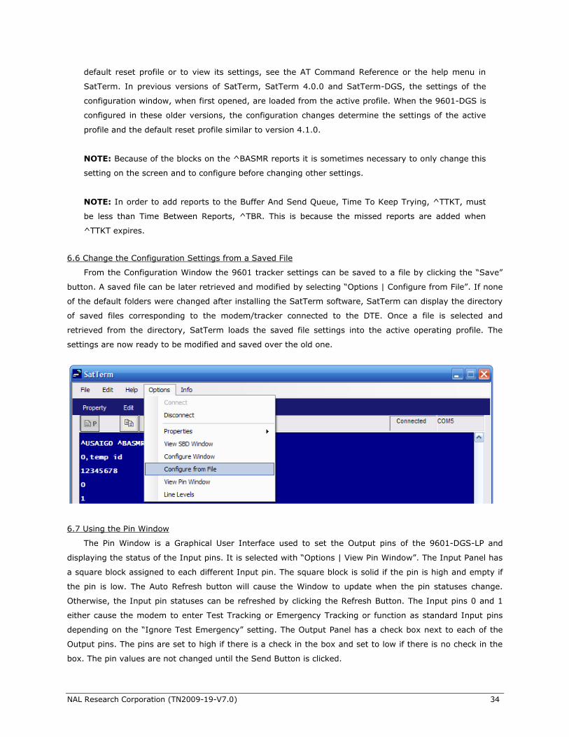
6.6 Change the Configuration Settings from a Saved File
From the Configuration Window the 9601 tracker settings can be saved to a file by clicking the ―Save‖
button. A saved file can be later retrieved and modified by selecting ―Options | Configure from File‖. If none
of the default folders were changed after installing the SatTerm software, SatTerm can display the directory
of saved files corresponding to the modem/tracker connected to the DTE. Once a file is selected and
retrieved from the directory, SatTerm loads the saved file settings into the active operating profile. The
settings are now ready to be modified and saved over the old one.
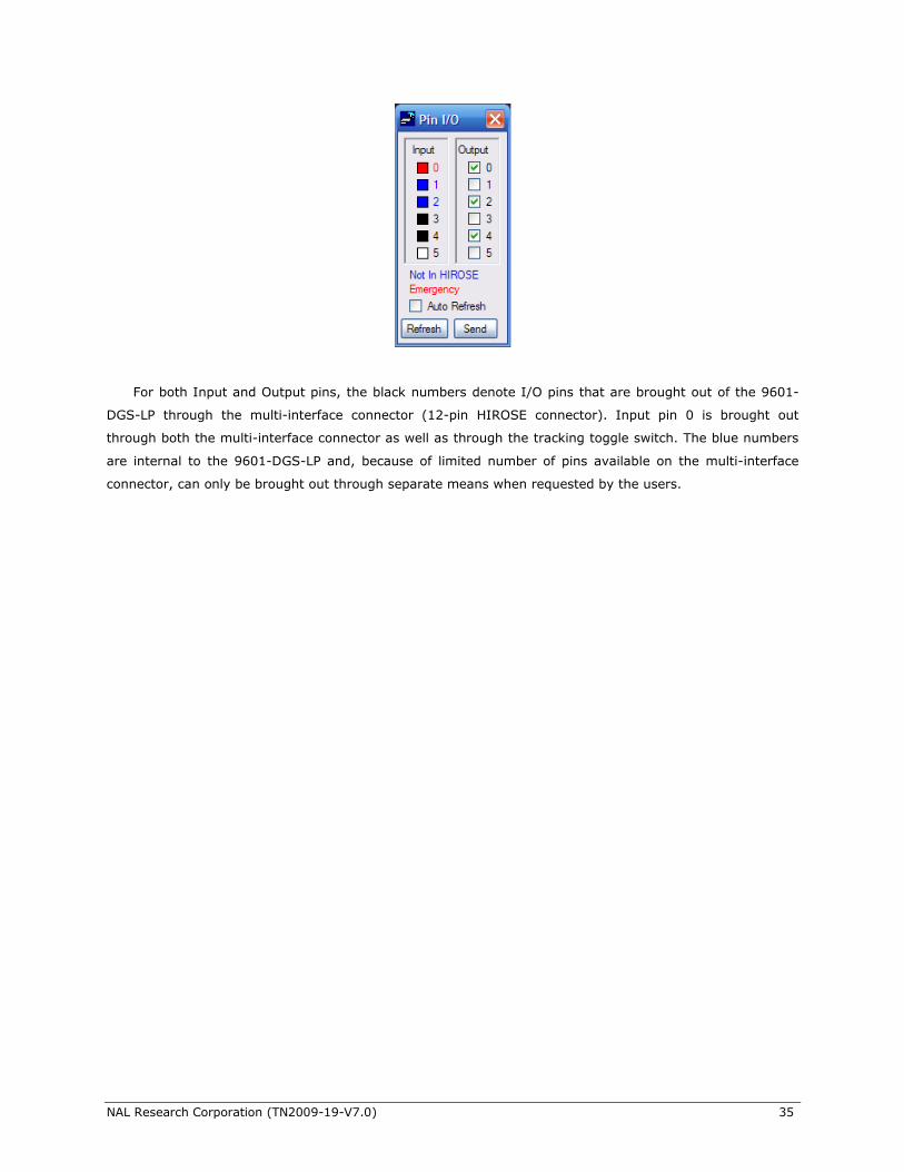
6.7 Using the Pin Window
The Pin Window is a Graphical User Interface used to set the Output pins of the 9601-DGS-LP and
displaying the status of the Input pins. It is selected with ―Options | View Pin Window‖. The Input Panel has
a square block assigned to each different Input pin. The square block is solid if the pin is high and empty if
the pin is low. The Auto Refresh button will cause the Window to update when the pin statuses change.
Otherwise, the Input pin statuses can be refreshed by clicking the Refresh Button. The Input pins 0 and 1
either cause the modem to enter Test Tracking or Emergency Tracking or function as standard Input pins
depending on the ―Ignore Test Emergency‖ setting. The Output Panel has a check box next to each of the
Output pins. The pins are set to high if there is a check in the box and set to low if there is no check in the
box. The pin values are not changed until the Send Button is clicked.
NAL Research Corporation (TN2009-19-V7.0) 35
For both Input and Output pins, the black numbers denote I/O pins that are brought out of the 9601-
DGS-LP through the multi-interface connector (12-pin HIROSE connector). Input pin 0 is brought out
through both the multi-interface connector as well as through the tracking toggle switch. The blue numbers
are internal to the 9601-DGS-LP and, because of limited number of pins available on the multi-interface
connector, can only be brought out through separate means when requested by the users.
NAL Research Corporation (TN2009-19-V7.0) 36
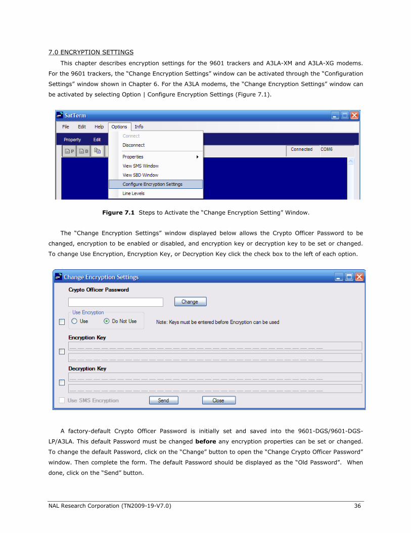
7.0 ENCRYPTION SETTINGS
This chapter describes encryption settings for the 9601 trackers and A3LA-XM and A3LA-XG modems.
For the 9601 trackers, the ―Change Encryption Settings‖ window can be activated through the ―Configuration
Settings‖ window shown in Chapter 6. For the A3LA modems, the ―Change Encryption Settings‖ window can
be activated by selecting Option | Configure Encryption Settings (Figure 7.1).
The ―Change Encryption Settings‖ window displayed below allows the Crypto Officer Password to be
changed, encryption to be enabled or disabled, and encryption key or decryption key to be set or changed.
To change Use Encryption, Encryption Key, or Decryption Key click the check box to the left of each option.
A factory-default Crypto Officer Password is initially set and saved into the 9601-DGS/9601-DGS-
LP/A3LA. This default Password must be changed before any encryption properties can be set or changed.
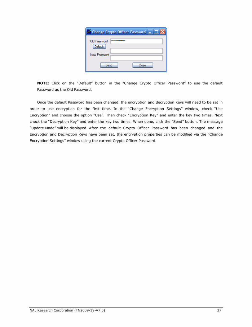
To change the default Password, click on the ―Change‖ button to open the ―Change Crypto Officer Password‖
window. Then complete the form. The default Password should be displayed as the ―Old Password‖. When
done, click on the ―Send‖ button.
Figure 7.1 Steps to Activate the ―Change Encryption Setting‖ Window.
NAL Research Corporation (TN2009-19-V7.0) 37
NOTE: Click on the ―Default‖ button in the ―Change Crypto Officer Password‖ to use the default
Password as the Old Password.
Once the default Password has been changed, the encryption and decryption keys will need to be set in
order to use encryption for the first time. In the ―Change Encryption Settings‖ window, check ―Use
Encryption‖ and choose the option ―Use‖. Then check ―Encryption Key‖ and enter the key two times. Next
check the ―Decryption Key‖ and enter the key two times. When done, click the ―Send‖ button. The message
―Update Made‖ will be displayed. After the default Crypto Officer Password has been changed and the
Encryption and Decryption Keys have been set, the encryption properties can be modified via the ―Change
Encryption Settings‖ window using the current Crypto Officer Password.
NAL Research Corporation (TN2009-19-V7.0) 38
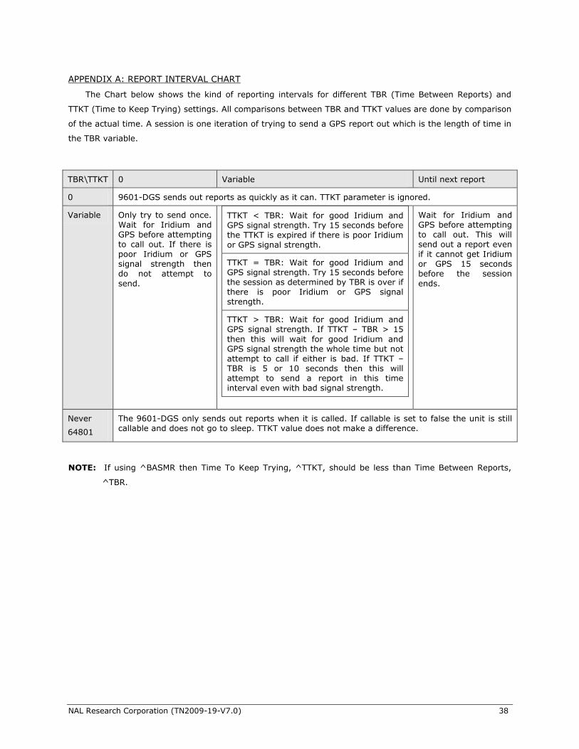
APPENDIX A: REPORT INTERVAL CHART
The Chart below shows the kind of reporting intervals for different TBR (Time Between Reports) and
TTKT (Time to Keep Trying) settings. All comparisons between TBR and TTKT values are done by comparison
of the actual time. A session is one iteration of trying to send a GPS report out which is the length of time in
the TBR variable.
TBR\TTKT 0 Variable Until next report
0 9601-DGS sends out reports as quickly as it can. TTKT parameter is ignored.
Variable Only try to send once. Wait for Iridium and GPS before attempting to call out. If there is poor Iridium or GPS signal strength then do not attempt to
send.
Wait for Iridium and GPS before attempting to call out. This will send out a report even if it cannot get Iridium or GPS 15 seconds before the session
ends.
Never
64801
The 9601-DGS only sends out reports when it is called. If callable is set to false the unit is still callable and does not go to sleep. TTKT value does not make a difference.
NOTE: If using ^BASMR then Time To Keep Trying, ^TTKT, should be less than Time Between Reports,
^TBR.
TTKT < TBR: Wait for good Iridium and GPS signal strength. Try 15 seconds before the TTKT is expired if there is poor Iridium or GPS signal strength.
TTKT = TBR: Wait for good Iridium and GPS signal strength. Try 15 seconds before the session as determined by TBR is over if there is poor Iridium or GPS signal strength.
TTKT > TBR: Wait for good Iridium and GPS signal strength. If TTKT – TBR > 15
then this will wait for good Iridium and GPS signal strength the whole time but not attempt to call if either is bad. If TTKT – TBR is 5 or 10 seconds then this will attempt to send a report in this time interval even with bad signal strength.
NAL Research Corporation (TN2009-19-V7.0) 39
APPENDIX B: NAL RESEARCH LIMITED LICENSE AGREEMENT
THIS AGREEMENT CONSTITUTES A LEGAL AGREEMENT BETWEEN YOU, THE END USER, AND NAL RESEARCH CORPORATION ("NAL RESEARCH"). YOU SHOULD CAREFULLY READ THE FOLLOWING TERMS AND CONDITIONS BEFORE INSTALLING THE SatTerm SOFTWARE. INSTALLING THIS SOFTWARE INDICATES YOUR ACCEPTANCE OF THESE TERMS AND CONDITIONS. IF YOU DO NOT AGREE TO THEM, PROMPTLY
RETURN THE UN-INSTALLED PACKAGE.
1. Grant of License.
NAL Research grants to you the right to use this copy of the enclosed NAL Research software program (the "Software") on a single computer (i.e., with a single CPU) and only with NAL Research’s modems and trackers. These modems and trackers include but not limited to the NAL Research’s A2LA, A3LA and 9601 series. You may not use the Software to operate Iridium hardware manufactured by other companies. You may not network the Software or otherwise use it on more than one computer or terminal at the same time.
2. Copy Restrictions and ownership of Software.
You own the media on which the program is recorded; NAL Research retains title to the Software including copies, regardless of form or media, and to all copyrights therein. The Software and accompanying written materials are copyrighted. You may either (a) transfer the Software to a single hard disk and retain the original Software for backup purposes, or (b) make one copy of the Software solely for backup or archival purposes.
3. Transfer restrictions.
You may transfer the Software with a copy of this Agreement to another party only on a permanent basis and only if the other party accepts the terms and conditions of this Agreement. Upon such transfer, you must transfer all accompanying written materials, and either transfer or destroy all copies of the Software. You may not lease, rent, merge, reverse engineer, decompile or disassemble the Software.
4. Termination.
This Agreement is effective until terminated. The Agreement will terminate automatically without notice from NAL Research if you fail to comply with any provision of the Agreement. You may voluntarily terminate at any time. Upon termination, you agree to destroy or purge all copies of the Software and accompanying written materials.
5. LIMITED WARRANTY.
As its only warranty under this Agreement, NAL Research warrants the media on which the Software is provided to be free from defects in materials under normal use for a period of 90 days from the date of the delivery to you as evidenced by your purchased receipt. EXCEPT AS EXPRESSLY WARRANTED
HEREIN, THE SOFTWARE IS PROVIDED "AS IS" WITHOUT WARRANTY OF ANY KIND, EITHER EXPRESS OR IMPLIED, INCLUDING BUT NOT LIMITED TO IMPLIED WARRANTIES OF MERCHANTABILITY AND FITNESS FOR A PARTICULAR PURPOSE. THE ENTIRE RISK AS TO THE QUALITY AND PERFORMANCE OF THE PROGRAM IS WITH YOU. NAL RSEARCH DOES NOT WARRANT THAT THE FUNCTIONS CONTAINED IN THE SOFTWARE WILL MEET YOUR REQUIREMENTS OR THAT THE OPERATION OF THE PROGRAM WILL BE UNINTERRUPTED OR ERROR FREE OR THAT PROGRAMS DEFECTS WILL BE CORRECTED, SOME COUNTRIES DO NOT ALLOW THE EXCLUSION OF IMPLIED WARRANTIES SO THE ABOVE EXCLUSION MAY NOT APPLY TO YOU. THIS WARRANTY GIVES YOU SPECIFIC, LIMITED RIGHTS. YOU MAY HAVE OTHER RIGHTS WHICH VARY FROM COUNTRY TO COUNTRY.
NAL Research Corporation (TN2009-19-V7.0) 40
6. LIMITATION OF LIABILITY.
NAL Research's entire liability and your sole remedy under this Agreement is, at NAL Research's option, either (a) return of payment as evidenced by a copy of your purchase receipt; or (b) replacement of media not meeting NAL Research's Limited warranty. IN NO EVENT WILL NAL RESEARCH OR ITS VENDORS BE LIABLE FOR ANY DIRECT, CONSEQUENTIAL OR INCIDENTAL DAMAGES (INCLUDING DAMAGES FOR LOSS OF BUSINESS PROFITS, INFORMATION, OR USE), EVEN IF NAL RESEARCH HAS
BEEN ADVISED OF THE POSSIBILITIES OF SUCH DAMAGES. SOME COUNTRIES DO NOT ALLOW THE EXCLUSION OR LIMITATION OF LIABILITY FOR CONSEQUENTIAL OR INCIDENTAL DAMAGES, SO THE ABOVE LIMITATION OR EXECUTION MAY NOT APPLY TO YOU.
7. This Agreement may be enforced in the courts of the Commonwealth of Virginia, United States of America to which jurisdiction the parties submit themselves for these purposes.
FOR TECHNICAL SUPPORT, PLEASE CONTACT US AT
Phone: 703-392-1136
E-mail: [email protected]
Technical documents are also available to download on NAL Research’s website www.nalresearch.com under http://www.nalresearch.com/AnonymousFTPSite.html


![Dependable Systems Software Dependability · Dependable Systems Course PT 2014 Software Dependability • Four inherent properties that make software hard [Brooks 87] • Complexity](https://img.pdfslide.net/doc/110x75/5e08d780496b3921261359f5/dependable-systems-software-dependability-dependable-systems-course-pt-2014-software.jpg)


![CHAPTER 10 – Software Metrics · 10. Software Metrics Literature • [Ghez02a] In particular, section 6.9 “Verifying Other Software Properties” and 8.2 “Project Planning”](https://img.pdfslide.net/doc/110x75/5f9f2ec1237a5c30574ee393/chapter-10-a-software-10-software-metrics-literature-a-ghez02a-in-particular.jpg)