Embed Size (px)
Citation preview

GENERAL LABORATORY HOMOGENIZER
OWNER’S MANUAL
Cole-Parmer Instrument Company 625 East Bunker Court
Vernon Hills, IL 60061 USA
Toll Free: 1-800-323-4340
Phone: 1-847-549-7600
Fax: 1-847-247-2929
Hearing Impaired: 1-800-833-7400
Email: [email protected]
Web: http://www.coleparmer.com

2
This manual is a guide for the use of the LabGEN 700 General Laboratory
Homogenizer and accessories.
Data herein has been verified and validated. It is believed adequate for the
intended use of the instrument. If the instrument or procedures are used for
purposes over and above the capabilities specified herein, confirmation of the
validity and suitability should be obtained, otherwise Cole-Parmer does not
guarantee results and assumes no obligation or liability. This publication is not
a license to operate under, or a recommendation to infringe upon, any
process patents.
Notes, cautions, and warnings within the text of this manual are used to
emphasize important and critical instructions.
This Cole-Parmer product is warranted to be free from defects in
material and workmanship for a period of ONE YEAR from the date of
delivery. Cole-Parmer will repair or replace and return free of charge any part
which is returned to its factory within said period, transportation prepaid by
user, and which is found upon inspection to have been defective in materials
or workmanship. For the first 90 days, both parts and service are without
charge. For the balance of the period, parts will be provided but
service will be charged at established labor rates. This warranty does not
include normal wear from use; it does not apply to any instrument or parts
which have been altered by anyone other than an employee of Cole-Parmer
nor to any instrument which has been damaged through accident, negligence,
failure to follow operating instructions, the use of electric currents or circuits
other than those specified on the plate affixed to the instrument, misuse, or
abuse. Cole-Parmer reserves the right to change, alter, modify, or
improve any of its instruments without any obligation whatever to make
corresponding changes to any instrument previously sold or shipped.
THE FORGOING OBLIGATION IS IN LIEU OF ALL OBLIGATIONS AND
LIABILITIES INCLUDING NEGLIGENCE AND ALL WARRANTIES OF
MERCHANTABILITY OR OTHERWISE, EXPRESSED OR IMPLIED IN FACT
OR BY LAW, AND STATE OUR ENTIRE AND EXCLUSIVE LIABILITY AND
BUYERS EXCLUSIVE REMEDY FOR ANY CLAIM OF DAMAGES IN
CONNECTION WITH THE SALE OR FURNISHING OF GOODS OR
PARTS, THEIR DESIGN, SUITABILITY FOR USE, INSTALLATION, OR
OPERATION. COLE-PARMER WILL IN NO EVENT BE LIABLE FOR ANY
SPECIAL OR CONSEQUENTIAL DAMAGES WHATSOEVER, AND THEIR
LIABILITY UNDER NO CIRCUMSTANCES WILL EXCEED THE CON-
TRACT PRICE FOR THE GOODS FOR WHICH LIABILITY IS
CLAIMED.
WARRANTY INFORMATION

3
-READ ALL INSTRUCTIONS BEFORE USING.
-SAVE THIS OWNER’S MANUAL.
The LabGEN 700 has been engineered for economical
functionality as well as safety; however, basic safety
precautions and common sense must always be demonstrated
when using any electrical product. Do not attempt to modify
any part of the LabGEN 700. If you experience problems with
or have questions about your LabGEN 700, contact your
authorized dealer or call Cole-Parmer at 1-800-323-4340
or 1-847-549-7600.
-DO NOT allow the machine to be submerged in any liquid.
-DO NOT use in any setting other than an indoor laboratory.
-DO NOT plug power cord into an incorrect outlet.
To reduce the risk of burns, electrocution, fire, or injury:
-Use this product only for its intended purpose as described in
this booklet. Do not use attachments not recommended by
the manufacturer.
-DO NOT operate the product if it is damaged in any way.
-Keep this product away from heated surfaces.
IMPORTANT SAFEGUARDS
DANGER
WARNING

4
TABLE OF CONTENTS
Warranty Information…………………………………... 2
Section 1. LabGEN 700 General Lab Homogenizer
1.1 Specifications…………………………………………….
1.2 Parts and Accessories…………………………………...
1.3 Variable Speed Operation………………………………
1.4 Stand-Mounting the LabGEN 700……………………….
5
5
6
7
Section 2. Motor Unit Maintenance
2.1 Motor Drive Unit………………………………………..
2.2 Brush Maintenance……………………………………...
2.3 Motor Bearings………………………………………….
2.4 Storage…………………………………………………..
2.5 Wiring Diagrams………………………………………...
2.7 Explosion Drawing………………………………………
8
8
8
8
9
10
Section 3. Rotor-Stator Generator Probes
3.1 Installing Rotor-Stator Generator Probes……………...
3.2 Theory of Operation……………………………………
3.3 Operation……………………………………………….
12
12
13
Section 4. Troubleshooting……………………………..
14
Section 5. Service
5.1 Assistance………………………………………………..
5.2 Decontamination………………………………………...
15
15

5
The LabGEN 700 General Laboratory Homogenizer is a variable speed, handheld or
post-mounted homogenizer. It combines 700 watt, 28,000rpm motor with a choice of
autoclavable, rotor-stator generator probes of various diameters.
1.1 SPECIFICATIONS
Motor Speed: 5,000-28,000rpm
W/ external speed control: 0-28,000rpm
Capacity: 0.03mL-10L
Height (motor only): 22cm (8.5in)
Weight (motor only): 1.6kg (56oz)
Electrical Requirements: 115V, 60Hz or 220V, 50Hz
Standards Approval/Compliance:
220V: CE Certified
1.2 PARTS AND ACCESSORIES
Prior to operation, please remove all parts from the shipping container and
inspect for damaged or missing parts. If any parts are found to be damaged or missing,
please contact Cole-Parmer at 1-800-323-4340.
The LabGEN 700 consists of the following:
Also available, but not sup-
plied with the instrument:
*The stand assembly includes a base plate, 24” post, cross rod, and post clamp.
SECTION 1. OMNI LabGEN 700 GENERAL LAB HOMOGENIZER
Description Part Number Quantity
Motor Drive Unit 1
(115V) GLH-01
(220V) GLH-02
Thumbscrew Assembly GLH11547 1
Tool Kit T1001 1
Instruction Manual H258-GLH 1
Description Part Number
Stand Assembly* 04727-88

6
SECTION 1. OMNI LabGEN 700 GENERAL LAB HOMOGENIZER
1.3 VARIABLE SPEED OPERATION
The speed of the LabGEN 700 may be regulated by means of a variable rotary
switch located at the top of the unit. Speed settings below are approximate,
and are based on running a 35mm probe in water. Actual speed will vary with
probe size and sample processed.
Speed
Setting
Approximate
Speed
1 4,000
2 5,000
3 7,500
4 10,000
5 13,500
6 28,000

7
1) Secure the 24” post by twisting it into
the base plate until securely tightened.
2) Loosen the locking knob and slide the
post clamp assembly down over the
end of the post until the clamp is at
the desired height and lock in place.
3) Twist the cross rod into the back of
the motor housing until tight.
4) Loosen the second knob on the post
clamp assembly and insert the cross
rod with motor attached
(approximately 1” of the cross rod
should protrude from the back of the
post clamp).
5) Lock in place.
1.4 STAND-MOUNTING THE LabGEN 700 (Optional)
To mount the LabGEN 700 to the stand assembly, refer to the figure and
follow these steps:
SECTION 1. OMNI LabGEN 700 GENERAL LAB HOMOGENIZER
Motor Drive Post Clamp
Assembly
Locking Knob
Cross Rod
24” Post
Base Plate

8
SECTION 2. MOTOR MAINTENANCE
2.1 MOTOR DRIVE UNIT
The Motor drive housing should be wiped off after use, especially when
concentrated and potentially damaging liquids are used during processing.
Never use solvents to clean unit or accessories.
2.2 BRUSH MAINTENANCE
If the performance of your LabGEN 700 begins to deteriorate in any of the
following ways:
The operations speed begins to decline
The unit stalls intermittently
The unit stops working all together
It probably requires a new set of brushes. The average brush life for the
LabGEN 700 is 150 hours. For service, or brush replacement, please contact
Cole-Parmer at 1-800-323-4340.
2.3 MOTOR BEARINGS
The LabGEN 700 motor is equipped with sealed ball bearings. Under normal
use they require no additional lubrication.
2.4 STORAGE
The unique design of the LabGEN 700 allows the handheld unit to stand
vertically on a bench-top or shelf so that it can be stored in less than eight
square inches of space.
WARNING: Keep all housings in place and in working order.
WARNING: Remove all tools from the generator probe before turning the
motor on.
WARNING: DO NOT use the motor in a dangerous environment.
WARNING: Disconnect the motor before servicing, and when changing the
generator probe.

9
SECTION 2. MOTOR MAINTENANCE
2.5 WIRING DIAGRAMS
WARNING: DO NOT modify the plug or cord that is provided. If the plug
will not fit the outlet, have the proper outlet installed by a qualified
electrician.
WARNING: Reduce the risk of unintentional starting; make sure the speed
switch is in the OFF position before plugging in the motor.
WARNING: Damaged or worn power cords should be repaired or replaced
immediately by a qualified electrician.
WARNING: Improper connection of the equipment can result in a risk of
electric shock.
115V LabGEN 700 220V LabGEN 700
10
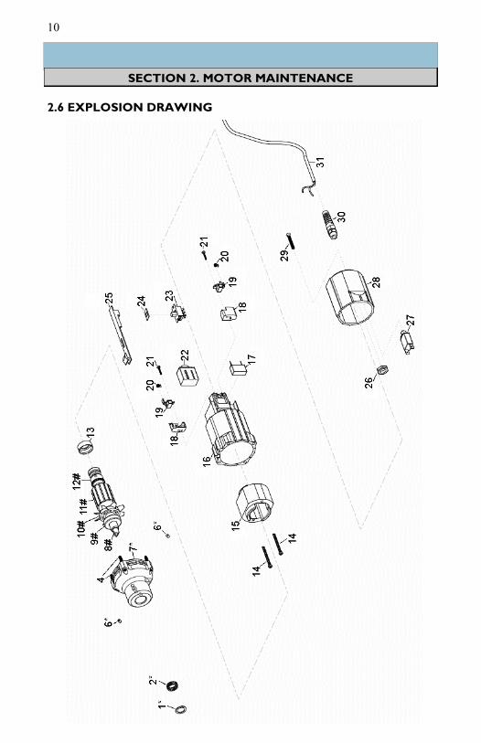
SECTION 2. MOTOR MAINTENANCE
2.6 EXPLOSION DRAWING

11
SECTION 2. MOTOR MAINTENANCE
Table of Replacement Parts for the
LabGEN 700
# Description 115V 220V
1* aluminum washer 63802 63802
2* wave spring H11543 H11543
3* aluminum washer 63802 63802
4 self tapping screw, mod 65901-1 65901-1
6* set screw 10-32 x 1/4 5903 5903
7* lower coupling GLH-04-01 GLH-04-01
8# glh drive connect GLH1155L GLH1155L
9# collet nut 50005 50005
10# ss bearing, GLH/5100 50002 50002
11# armature GLH11521 GLH2209
12# commutator bearing GLH115221 GLH115221
13 bearing mount GLH115220 GLH115220
14 ss screw GLH115222 GLH115222
15 field assembly GLH11530 GLH2210
16 motor housing GLH115218 GLH115218
17 filter assembly(230V only) N/A GLH2201
18 base brush holder GLH115213 GLH115213
19 Armature brush GLH115217 GLH2211
20 spring for brush GLH115216 GLH115216
21 screw GLH115215 GLH115215
22 vs switch GLH115210 GLH115210-220
23 switch GLH11525 GLH11525
24 dust shield GLH11526 GLH11526
25 switch/button slide GLH11527 GLH11527
26 sealcon strain relief nut GLH11514 GLH11514
27 4A circuit breaker (115V only) GLH2207 N/A
28 motor housing cap - painted GLH11524 GLH11524
29 ss screw GLH11523 GLH11523
30 sealcon strain relief GLH11513 GLH11513
31 powercord FGLH1151 FGLH1151
* Part also included in assembly number GLH1154L-ASY
# Part also included in assembly number GLH1169 (115V) or GLH2269 (230V)

12
3.1 INSTALLING ROTOR-STATOR GENERATOR PROBES
Rotor-stator generator probes are easily installed to the LabGEN 700 motor
by means of a quarter-turn bayonet mount. Simply push the generator probe
into the motor housing as far as possible, turn clockwise, and release. Remove
the blue protective cap from the tip of the generator probe and the LabGEN
700 is ready to operate.
3.2 THEORY OF OPERATION
The rotor shaft is coupled directly to the drive motor, via the drive pin.
When attached to the Homogenizer motor, the rotor shaft can spin up to
28,000rpm. This assembly makes up the rotor portion of the rotor-stator
generator probe. The tube and collar assembly is attached to the motor
housing, but does not spin. This is the stator portion of the rotor-stator
generator probe. As the rotor knife spins within the tube and collar assembly,
it creates a pumping action, pulling the sample into the open end of the
generator probe and forcing the sample out through the windows in the tube.
The interaction of the rotor knife with these windows sets up a shearing
action, reducing the particle size of the sample. The speed differential
between the rapidly moving portion and the relatively stationary portion of
the sample sets up a second force called cavitation which pulls the sample
apart, further reducing the particle size.
The processing efficiency can be affected by:
Amount of material processed vs. size and speed of the generator probe.
Container geometry and size (round vessels encourage swirling, while
fluted or cornered vessels disrupt flow patters for more effective mixing/
processing).
Processing speed vs. optimal speed.
Size and type of material and flow characteristics (material particles must
be small enough to be carried into the generator head for optimal
processing).
SECTION 3. ROTOR-STATOR GENERATOR PROBES
WARNING: The tip of a saw tooth generator probe is sharp.
CAUTION: Replace the blue protective cap on the end of the generator
probe when the generator probe is not being used.

13
SECTION 3. ROTOR-STATOR GENERATOR PROBES
The upper hole of the tube and collar assembly should be left unblocked to
allow the sample to circulate through the generator probe.
NOTE: For optimal sample recovery during processing, reduce the motor
speed and completely remove the generator probe from the sample. Then
turn off the motor drive unit.
3.3 OPERATION
Insert the generator probe into the LabGEN 700 motor and remove the blue
protective cap from the end of the generator probe. The depth of the
generator probe in the sample vessel can significantly affect flow patterns
within the vessel. This also affects processing efficiency. As a rule of thumb,
the generator probe usually operates most efficiently at a depth of 1/3 (to
1/2) of the liquid height. Heavy sediments may require deeper immersion, and
this processing depth can be optimized by observing flow patterns and related
processing results. While processing, liquid can circulate through the two
holes at the bottom of the generator probe. The top hole should not be
immersed in the sample. Blocking the upper hole could result in liquid being
drawn into the lower motor bearing.
CAUTION: When using glass-filled Teflon lower bearings, do not operate the
unit for extended periods of time without immersing the bottom of the
generator probe in liquid or the sample being processed in order to avoid
premature failure of the lower bearing.
WARNING: Reduce the risk of unintentional starting; make sure that the
variable speed switch is in the OFF position prior to plugging in the unit.
WARNING: DO NOT process pathogenic material in an open container,
since aerosols created during normal processing could be inhaled by the
operator. Please call for assistance in processing pathogens or other
material which require sealed enclosures.
WARNING: The tip of the saw tooth generator probe is sharp.

14
Do not attempt to service the LabGEN 700 in a manner other than those discussed in
this manual. For any issue that is unsuccessfully corrected using this guide, please
contact your authorized dealer or call Cole-Parmer at 1-800-323-4340.
PROBLEM CORRECTIVE ACTION
The LabGEN 700 is plugged in and turned
on but is not functioning.
-Check power cord connectors
-Check wall socket for power to the
outlet
Motor is turned ON and makes a makes a
“buzzing” sound, but is not working.
-Check that the brushes are not worn
and are correctly installed. Replace if
necessary. (see Section 2.2)
Motor unit operating speed declines, stalls
intermittently, or stops completely
-Check that the brushes are not worn
and are correctly installed. Replace if
necessary. (see Section 2.2)
Teflon bearing wears quickly -Fluid level may be too low in the tube.
-Immerse the probe deeper into the fluid.
Excessive splashing in sample tube -Fluid level too low for tube size
SECTION 4. TROUBLESHOOTING

15
SECTION 5. SERVICE
WARNING: It is a violation of federal law to transport biologically
hazardous or radioactive materials without proper packaging,
labeling, and appropriate warnings.
5.1 ASSISTANCE
Should this product ever require service, please contact Cole-Parmer at
1–800–323-4340.
5.2 DECONTAMINATION
Should an instrument or component that has been used with radioactive or
pathogenic material require factory or field service, comply with the following
procedure to ensure the safety of service personnel:
Clean the parts to be serviced of all encrusted material and
decontaminate them. There must be no radioactivity detectable by survey
equipment.
Obtain a Decontamination Certificate from Cole-Parmer. Complete the
certificate and attach to the instrument or parts being returned.
If no Decontamination Certificate is attached, and a potential radioactive or
biological hazard is detected or suspected by Cole-Parmer, the equipment will
not be serviced until proper decontamination and certification is complete.
The sender will be contacted for instructions as to the disposition of the
equipment. Disposition costs will be borne by the sender.

16
625 East Bunker Court Toll Free: 1-800-323-4340
Vernon Hills. IL 60061 Phone: 1-847-549-7600
FAX: 1-847-247-2929
www.coleparmer.com Email: [email protected]
Patents Pending Rev. 05/23/12 rb
P/N: H258-CGLH