Embed Size (px)
Citation preview
Islamic Republic of Iran
Vice Presidency for Strategic Planning and Supervision
General Technical Specification and Execution Procedures for Transmission
and Subtransmission Networks Protection Systems at
High Voltage Substations
NO: 502- 1
Energy Ministry - Tavanir Co.Power Industry Technical Criteria Project www.tavanir.ir
Office of Deputy for Strategic Supervision Bureau of Technical Execution Systemhttp://tec.mporg.ir

DESCRIPTION
ITEM PAGE
1- General requirements ................................................................................................................. 3
2- Line protection .......................................................................................................................... 4
2-1- Distance protection..................................................................................................................4
2-2- Directional earth fault relay.....................................................................................................5
2-3- Stub protection ........................................................................................................................5
2-4- Zero voltage protection ...........................................................................................................5
2-5- Over voltage protection .......................................................................................................... 6
2-6- Auto resoling ...........................................................................................................................6
2-7- Other requirements ..................................................................................................................6
3- Transformer protection .............................................................................................................. 6
3-1- Differential relay .....................................................................................................................6
3-2- Restricted earth fault relay.......................................................................................................7
3-3- Over fluxing or over voltage relay ..........................................................................................7
3-4- Zero voltage relay....................................................................................................................7
3-5-Inverse time over current relay with instantaneous Unit ..........................................................8
3-6- Neutral over current protection ...............................................................................................8
3-7- Earthing- auxiliary transformer phase and neutral over current protection.............................8
3-8- Power transformer tertiary winding over current relay ...........................................................8
3-9- Tap changer protection ............................................................................................................9
3-10- Mechanical protections .........................................................................................................9
4- Shunt reactor protection............................................................................................................. 9
4-1- High impedance type differential protection ...........................................................................9
4-2- Reactor over current and earth fault protection .....................................................................10
5- Busbar protection ...................................................................................................................... 10
5-1- Differential busbar protection ................................................................................................10
5-2- Busbar protection C.T supervision alarm relay ......................................................................11
5-3- Busbar protection C.T shorting relay .....................................................................................11
6- Breaker protection..................................................................................................................... 11
6-1- Breaker failure and pole discordance protection ...................................................................12
6-2- Circuit breaker trip coil supervision .......................................................................................12
6-3- CVT fuse failure supervision..................................................................................................12
6-4- Tripping circuits and relays ....................................................................................................13
7- Capacitor bank protection ......................................................................................................... 13
8- 20(33) kv feeder protection....................................................................................................... 13
9- Bus coupler protection .............................................................................................................. 14
10- Spare parts and tools ............................................................................................................... 14
11- Tests ........................................................................................................................................ 14
11-1- Special tests ..........................................................................................................................14
11-2- Routine tests .........................................................................................................................15
11-3- Type tests..............................................................................................................................15
11-4- Commissioning tests.............................................................................................................16
12- Drawings & documents........................................................................................................... 16
12-1- Documents to be given by tenderer ......................................................................................16
12-2- Documents to be given by contractor/ supplier ....................................................................16
General Requirements
1
Technical Specification of
Protection Systems

Technical Specification of Protection Systems 2
General Requirements
3
1- General requirements
Protection equipment and systems shall be designed, manufactured and tested according to the requirements of the latest edition of the following standards and other equivalent publications: IEC 60050: IEC vocabulary IEC 60255: Electrical relays IEC 60617: Graphical symbols for diagrams, switchgear, controlgear and protection devices. The minimum possible part of the plant shall be tripped to isolate the fault or clear the abnormal conditions. In addition, the fault must be tripped within the time necessary for personnel protection and reasonable restriction of material damage. Unless otherwise specified, all functional requirements of the relay protection shall be satisfied for short circuit current and associated impedances at the maximum, minimum and intermediate values. Owing to high source-side fault level, high source reactance to resistance ratio at busbars, necessity of using similar CT's in bays, criterion of limiting CT knee point voltage, single-shot auto-recloser requirements with duty cycle as O-0.3 sec- CO- 3min – CO, long length of cables, requirements of protection time not to exceed the required time in last auto-recloser shot under worst maximum and minimum DC offset including CT saturation conditions, large number of relays, recorders, fault locators connected on CT cores and all other technically required features, the contractor shall propose the relays & devices having lowest burdens & CT knee point requirements for various type of relaying. The distance relays & fault locators which require worst of the following criteria are preferred over those which require no transient CT saturation for the entire period:
a) The relay shall operate during switch–on to fault condition even for the extreme CT saturation due to remanence flux under line auto- reclosing conditions.
b) The relay shall require that CT should not saturate up to operating time for a fault at reach setting. The relays and fault locators whose operating time is excessively increased due to presence of worst (positive and negative) CT remanence under auto reclose conditions for a fault at reach point are not acceptable. For all relays, the contractor shall furnish details of transient and steady state CT requirements. For all distance relays, fault locators, voltage operated relays etc, the contractor shall furnish the details of transient, steady state CVT requirements. Those relays which operate successfully without any relaying time delay with normal standard CVT are preferred over those which operated with time delay. The main and backup protection systems should have independent DC and trip circuits.
Technical Specification of Protection Systems 4
2- Line protection
The line protection shall consist of SUB I and SUB II The protection in SUB I shall be divided in two panels. One of the panels is used for equipment common to both SUB I and SUB II.
2-1- Distance protection
The distance relaying shall be 3 zone, digital type, "non switched full scheme" design. The relay shall selectively operate for all type of faults with high degree of security against spurious tripping due to any type of power system or auxiliary system transients. Zone I shall have high speed clearance of faults at mid point of the protected circuit. The operating time shall be less than 25 milliseconds. For all three zones, the relay shall provide high stability against tripping for all faults behind the relay location, and for those beyond the remote termination in direction of forward reach. The relay shall have restricted reach on either side of the locus of solid faults to discriminate against through load and power swing conditions and against healthy phase impedances, etc. It shall also have controlled reach in the fourth quadrant of the complex R-X impedance plane to cater for closing-in arcing fault. Zone 2 unit shall have time graded protection for faults within the protected circuit and for those in a selected part of adjacent circuit in the direction of forward reach. The characteristics shall then cover the remote section of protected circuit not covered in zone 1 and provide partial backup protection to the main protection of circuits. Zone 3 unit merely used for backup protection and should not activate due to load impedance and power swing. The distance relaying shall be provided with high set instantaneous over current unit for clearance of faults while the line is energized. This protection shall be available only upto say 0.5 seconds from the instant of energizing the line. All zones shall be provided for zero sequence impedance compensation. In parallel lines, relays should have mutual impedance compensation. The errors in transformation of current signals as a consequence of DC offset, or effects of remanence flux and auto recluse duty cycle on the distance relay performance shall be taken into account, such that the operating time does not exceed the guaranteed relay operating time. Adequate directional function shall be provided on complete collapse of the measured voltage on all type of faults. In view of induced disturbances in control and measuring signal cables (DC, CVTAs and CTs) which come from the switchyard to the control room, the relay shall be designed with at most stability against those disturbances. The distance relay shall be designed for both single phase and three phase tripping and shall have repeat contacts for interfacing with external communications channels, auto-reclose equipment, fault locator, alarms, fault recorders and remote alarm, etc.
Directional Earth Fault Relay, Stub Protection, Zero Voltage Protection
5
Trip signal of zone I unit should be connected to the auto reclose relay. Although the design shall generally be suitable for under reach permissive intertrip type, the design shall also be such that protection can be switched over to co-operation of permissive over reach blocking intertrip scheme. All alternatives of distance protection shall be provided with blocking features due to single and three phase CVT secondary fuse failure. Facility for overriding the power swing blocking conditions shall be provided. All above requirements should be applied for distance relay in SUB II.
2-2- Directional earth fault relay
Each line shall be provided with very/normal inverse time directional earth fault relay with instantaneous unit. The directional relay shall be polarized by open delta connected auxiliary potential transformer supplied from line CVT. This relay should have minimum setting of 10% nominal current. It should have a capability to be used in permissive intertripe scheme.
2-3- Stub protection
The stub protection (if applicable) shall consist of three instantaneous overcorrent relays with a setting range as specified. The stub protection is only activated when the line isolator is open. The stub protection must be stable for through faults owing to CT saturation or characteristic mismatching, etc.
2-4- Zero voltage protection
This protection shall include three phase voltage sensing under voltage relays. All phases must be at a low voltage for protection to operate. In the event of a low voltage in only one or two phases, operation of the relay shall be blocked upto 2 seconds and an indication shall be provided. This function is necessary to avoid spurious tripping due to the removal of fuses in the measured voltage circuit. After operation of the relay, the tripping signal shall be interrupted after about 2 seconds, regardless of whether or not the voltage has been reestablished. The operation of zero voltage protection shall automatically be blocked when the series isolators or the transmission line have been opened, so that spurious tripping shall be prevented when the line is isolated.
Technical Specification of Protection Systems 6
2-5- Over voltage protection
the over voltage relaying shall generally consist of definite time over voltage relay and have a setting from 100% to 120% of rated voltage and continuously adjustable time delay of 2 to 20 sec. This protection shall trip the line and send interrupt signals to the remote end. This relaying shall be of single phase design.
2-6- Auto resoling
The transmission line numerical protection shall be designed for single phase, three phases and single or three phase reclosing. Auto- reclosing shall only take place if the tripping is initiated by the first zone of distance numerical protection or permissive (Distance or directional earth current) intertirp. When energizing the line, and 3 sec. after, the auto reclosing shall be blocked. The system shall be equipped with synchronism check. The detail of reclosing schemes and sequence priority circuit shall be submitted for engineer's approval. The dead time and reclaim time should be set in a way that the successful autoreclosing have a high probability and this auto reclosing should not be beyond the circuit breaker capability. In single phase auto reclosing, the operation of directional earth fault relay and pole discordance relay should be blocked.
2-7- Other requirements
The overcurrent relays should have a drop off to pickup ratio larger than 90%. This ratio should be larger than 98% for voltage relays.
3- Transformer protection
The transformer protection shall comprise of HV,MV & LV side protection and shall be divided in to main and backup panels.
3-1- Differential relay
It shall be low impedance biased differential type with through fault stability and second harmonic restraint features for magnetization inrush current. The set of intermediate current transformer having multi-taps for its universal application and having adequate knee point voltage to suit the respective differential relay application shall be provided on all sides of the differential relay. This could be implemented by internal software of the relay.
Restricted Earth Fault Relay, Over Fluxing or Over Voltage Relay, Zero Voltage Relay
7
Zero sequence compensations in the transformer differential protection shall be provided. This function is required to provide stabilizing effect to the differential relaying under heavy transient through fault condition. The differential relay scheme shall be such that there shall not be any necessity of changing the settings of the relay whenever the transformer taps are changed form one extreme to the other extreme. The main transformer differential protection shall always include the earthing- auxiliary transformer inside its zone of protection. Wherever the transformer tertiary is used for reactor, capacitor, or any feeder loading etc, the zero sequence compensation for stabilizing the main differential protection, should be provided.
3-2- Restricted earth fault relay
This relay shall be of single pole high impedance circulating current type. The relay should be set to cover all the winding specially near the neutral. The use of I.C.T's for this protection shall be avoided.
3-3- Over fluxing or over voltage relay
The over fluxing protection relay shall be based on the measurement of V/HZ and be of two stage type. The operating values shall be matched to the over fluxing withstand characteristics of the transformer by introducing adequate time delay functions. The range of setting of V/HZ relay shall be adjustable between 1.0 to 1.4 p.u. The timer range shall be according to the transformer over fluxing withstand capability. Whenever reactor are provided on the tertiary winding of the transformer, the function of the over fluxing or over voltage protection is to switch in the reactor when the system voltage increases over the preset value for preset time. The over voltage protection relay shall generally be definite time delay type. The relay should send an alarm for the first stage and a trip signal for the second stage.
3-4- Zero voltage relay
The transformer zero voltage protection relay shall be time delay type with 7 seconds in the event of a complete loss of voltage in all phases. This protection shall not operate the transformer lockout relays, but instead shall trip the respective C.B's via self reset type trip relays.
Technical Specification of Protection Systems 8
3-5-Inverse time over current relay with instantaneous Unit
Power transformer's HV and MV sides shall invariably be provided with phase over current protection. In case of auto transformer the protection shall be comprising of high set instantaneous unit. This unit shall primarily be provided for effective relaying of the heaviest short circuit currents including faults on connections and part of the windings. This protection is essentially required where normal differential relays may not operate under heavy short circuit conditions due to excessive C.T saturation. This protection shall trip the transformer instantaneously. Care shall be exercised in selecting the relay setting for avoiding its maloperation under busbar fault conditions. This relay should be restraint against inrush current. It should be coordinated with thermal profile of the transformer.
3-6- Neutral over current protection
The over current protections shall consist of relays connected to the C.T's located in all of the neutrals of the transformer, the protection shall be having normal inverse time characteristic in accordance with IEC 60225-4.
3-7- Earthing- auxiliary transformer phase and neutral over current protection
The 3 phase normal inverse time over current protection shall be provided for protecting the auxiliary- earthing transformer from phase faults. The single phase normal inverse time over current relay to protect the transformer from ground faults and to co-ordinated the tertiary side system ground fault relaying, shall be provided.
3-8- Power transformer tertiary winding over current relay
The over current relay shall be connected to C.T located in the tertiary windings. The protection shall comprise of two 3 phase over current relays whose coils are connected in series and contacts in parallel. One unit shall be long time delay normal inverse time relay to protect the tertiary windings for low magnitude faults. The second unit shall be high set with normal inverse characteristics. The high set relay shall be allowing pick up value for 300% or more of tertiary rated current and shall be protected the windings from heavy faults. The inverse time characteristics of both units shall be as per IEC 60255-4. The timers shall be selected based upon tertiary windings thermal curves. The range of 1 to 999 seconds for first unit timer and 0.2 to 2 seconds for second unit timer shall generally be adequate.
Shunt Reactor Protection, High Impedance Type Differential Protection
9
3-9- Tap changer protection
Tap changer protection shall consist of over current relays connected to CT.'s located in high voltage of the transformer. The protection shall be having instantaneous characteristics.
3-10- Mechanical protections
The trip signal of these relays should be transferred via auxiliary and timer relays and should be considered as backup protection.
4- Shunt reactor protection
The busbar connected reactors shall be equipped with relay protection which shall be divided into main and backup panels. The main shall consist of differential relay, main protection trip relays and all other interfacing relays between main and backup Backup shall consist of 3 phase normal inverse time over current and earth fault relay, fuse fail relay, breaker failure relay backup protection trip relays and auxiliary CT's. In the case of line connected and LV tertiary connected reactors only differential protection, 3 phase normal inverse time over current and earth fault relay shall be provided and arranged in reactor protection panel. For LV tertiary connected reactors with circuit breaker the breaker failure, pole discordance and trip coil supervision relay shall be provided with reactor protection relay.
4-1- High impedance type differential protection
This relay shall provide phase and earth fault protection for faults occurring inside the rector differential zone. The relay shall be a three phase unit or shall comprise of three single elements (one element for each phase). The operating time shall generally not exceed 25 milliseconds unless approved by the engineer. C.T supervision shall be provided to give alarm in the event of C.T open circuit connections. Nonlinear resistors shall be provided to protect the relay wiring and C.T secondary form high voltage surges produced during abnormal conditions.
Technical Specification of Protection Systems
10
4-2- Reactor over current and earth fault protection
The relay shall consist of two over current protection and one earth protection which shall be located in backup. The over current protection shall consist of two units. The first unit shall be instantaneous. It shall have second harmonic stabilization or such frequency characteristics that it will basically be energized only by 45 to 55 HZ currents (inrush proof). This characteristic is necessary for the instantaneous unit to ensure that an unnecessarily high operating values need not be selected. The second unit shall have normal inverse overcurrent characteristics according to IEC 60255-4. It shall be practically insensitive to DC component. The operating value shall be approximately 130% of the rated current and the operating time shall take into account the inrush current. The earth fault relay shall have normal inverse time characteristics according to IEC 60255-4.
5- Busbar protection
Busbar protection shall consist of differential protection, C.T. supervision alarm relay and C.T. shorting relay which usually used in 230 and 400 kV systems. Busbar protection shall be located in a separate panel for each bus it shall be arranged with protection zones in accordance with the principles of zone overlapping. The protection for all busbar of the substation shall be separated electrically and mechanically form each other. For the faults between C.T's and circuit breaker which are within the zone of busbar protection and will not be cleared by the busbar protection the CBF should be initiated. This protection shall initiate the breaker failure protection to clear this type of fault by short zone protection. The busbar protection operating time of 25 msec must not be exceeded for a fault on the busbar itself. The busbar protection shall be designed as a three phase protection (single element relay for each phase) to check the phase faults as well as ground faults. The protection shall be designed with a high degree of security against spurious tripping. It shall not initiate tripping on maximum DC offset and maximum short circuit power on external fault. All busbar feeders shall be isolated in the event of a fault. The breaker failure protection of all CB's which are located in the relay panels of each feeder shall be started on tripping of busbar protection.
5-1- Differential busbar protection
The high impedance busbar protection shall generally be consisting of three single pole elements, high speed, high degree of stability for any type of fault occurring outside the protected zone. The complete relay shall generally comprise of relay itself and an continuously adjustable resistor in series with the relay of each phase. The resistor shall be wire wound type and be of adequate wattage ratings.
Due compensation in the effective relay setting shall also be provided for number of current transformers in parallel with the relay.
Busbar Protection C.T Supervision Alarm Relay, C.T Shorting Relay, Breaker Protection
11
Non linear resistors shall be used across the relay circuit in order to limit the peak voltage developed by the current transformers under internal fault conditions to a value below the insulation level of the C.T's, relay and interconnection pilots which are normally designed to withstand 3000 V peak. The characteristics of the externally mounted non linear resistor shall be such that it complies with the following requirements:
- At the relay voltage settings, the metrosil current shall be as low as possible and not greater than approximately 30 mA r.m.s for 1 Amp CT.
- At the maximum secondary current, the metrosil cut off point shall not be greater than 1500 volts r.m.s.
In case of metrosil having characteristics other than the above, special approval from engineer for their application is required. The busbar protection could be low impedance differential type. In this case the restraint on out of zone faults should be guaranteed using percentage bias.
5-2- Busbar protection C.T supervision alarm relay
The busbar protection shall be provided with supervision of the current transformer summation circuits during normal operation. Suitable 3 phase bus wire supervision relays shall be used for each protection zone to safeguard against faults in the C.T secondary wiring. It shall be connected across AC bus wire in the relay panel and shall close its contacts when the voltage appearing across the bus wires exceeds its relay voltage setting. This relay shall be capable of detecting loss of a partial current if this value is 5-10% of the load current in maximum loaded tapping. After being actuated the supervisory equipment shall initiate an alarm after an adequate time delay and actuate the C.T secondary shortening relay. This relay could be current or voltage based type.
5-3- Busbar protection C.T shorting relay
This relay which can be used in combination with C.T supervision alarm relay, after being actuated by the supervision relay shall shorten the C.T secondary bus wires.
6- Breaker protection
Breaker protection system shall consist of breaker failure protection, pole discordance protection and trip coil supervision relays for each trip circuit. Also, each trip coil of breaker shall have individual trip relay. Also the SF6 pressure supervision relay should be considered.
Technical Specification of Protection Systems
12
6-1- Breaker failure and pole discordance protection
The breaker failure protection function shall be available for all faults. The current relays in the breaker failure protection shall be capable of withstanding continuously the specified feeder normal current and the specified maximum primary short circuit current; the current relays in the breaker failure protection shall have a short and well defined resetting time. The breaker failure protection shall be actuated only when the relay protection applies a tripping order. The breaker failure protection shall be designed with a high degree of safeguard against spurious operation. When actuated, the protection will instantaneously apply a tripping signal to the same breaker which the protection monitors and if this attempt is not successful the breaker failure protection shall trip all adjacent and relative breakers at the second step after an adjustable time delay. Breaker failure protection for line feeder CB/CB's shall be provided in main common panel and for transformer and reactor feeders shall be provided in backup panel. In addition to the breaker failure protection, all breakers must be equipped with a separate pole discordance protection. This protection shall be installed in the panel in which the breaker failure relay installed. The pole discordance protection shall use the auxiliary contacts in the different poles, of the breaker. The function shall be time delayed in two steps with specified value. The first step shall trip the breaker with discrepancy and shall initiate the breaker failure protection. If the attempt to trip the breaker form the first step in the pole discordance protection is successful the function of breaker failure protection is inhibited.
6-2- Circuit breaker trip coil supervision
Each and every trip coil of the circuit breaker, its power supply and trip circuit wiring between supervision shall be provided for both circuit breaker tripping circuits. They shall be arranged to initiate an alarm and visual indication if trip circuit of C.B fails. In this case, the relay should block the closing signal.
6-3- CVT fuse failure supervision
All 3 phase CVT secondaries shall be supervised by 3 phase CVT fuse failure supervision relay. The relay shall be designed to operate for single, two and three phase fuse failure of the supervised circuits and for an interruption in any of pilot wires or their associated fuses. The operating speed of the relay shall be fast enough to inhibit undesired operation of high speed relay (e.g. distance). The operating time shall be less that 8 msec.
Capacitor Bank Protection, 20(33) kV Feeder Protection
13
Since, this relaying can maloperate under voltage unbalance conditions due to line charging and single phase auto resoling conditions, the function to bypass the distance relay blocking form fuse failure relaying for manual line charging and dead time of auto enclosure relay shall be provided.
6-4- Tripping circuits and relays
The tripping circuits for the relay protection belonging to SUB I and SUB II or main and backup shall be entirely separate electrically and mechanically. This implies that they must not include common switching devices, connectors, terminal blocks, cables, auxiliary relays, etc. Each tripping coil of the breaker shall be supplied via individual trip relays. These relays shall be self reset type (non lockout) trip relays. For busbar protection individual high speed tripping hand/ electrical reset type (lockout) trip relay shall be provided for each circuit breaker for tripping the breaker. It shall have adequate contacts for tripping the C.B through both tripping coils, blocking autorecloser schemes and initiating breaker failure relay. Necessary switches shall be provided for taking the busbar protection out of service. Indicating lamps to indicate whether the protection is "in" or "out" of service shall be provided.
7- Capacitor bank protection
The operation of any relay in capacitor protection system, except for voltage relays, should initiate the lockout relay. The phase and ground over current relays should be restraint against closing inrush current of the capacitor bank. The unbalance relay which sensed the current passing through joint stars neutral points, should be harmonic restrained. This relay should have two stage of operation, one for alarm and one for trip command.
8- 20(33) kv feeder protection
The 20(33) kV feeder protection system shall consist of phase and earth over current relay and if required, sensitive earth fault relay. The phase over current relay with instantaneous unit should be coordinated with incoming feeder relay. Both phase and earth fault relays should initiate the autorecloser relay. In case of cable type outgoing feeder, the autorecloser relay should not be used. In these cases, sensitive earth fault relay may be used. This relay should send an alarm signal instead of trip command.
Technical Specification of Protection Systems
14
9- Bus coupler protection
The bus coupler protection system shall consist of phase and earth over current relays. These relays should be coordinated with other over current relays in the substation. In HV substation, the breaker failure protection should be included.
10- Spare parts and tools
The manufacturers recommended spare parts for 5 years trouble free operation and any special tools deemed necessary for erection, operation and repair shall be provided.
11- Tests
All relay protection shall be capable of being tested individually (even during normal cooperation) with adequate safety of the test personnel and without the risk of spurious tripping. The purpose of the tests and inspection is to provide confirmation that the equipment has been designed, manufactured and assembled in accordance with the standards, technical specification and that the equipment operates in the intended manner. Electrical tests and inspection shall be carried out at the manufacturer works prior to delivery of the equipment. Tests shall be carried out in accordance with IEC 60255 standards. Equipment shall be subjected to manufacturing routine tests and inspection. A few or every type of equipment shall normally be subjected to type testing. Panels and its equipment and secondary wiring shall be subjected to routine tests.
11-1- Special tests
Special test shall be performed on very important relays and protection systems. They generally include various types of distance relays, fault locators, and current differential protection for lines and breaker failure relays, etc. The contractor shall furnish the list of relays for such tests for engineer's approval. The tests shall be carried out to establish the characteristics and performance of power system protection relays, their accuracy and/or sensitivity of measuring, the protection or other function. Simultaneously, the correct operation of internal logic (starting, phase selection, tripping, etc) indication, output contact, etc, during steady state conditions shall be examined. Measurement of returning values (rest) of starting functions, the accuracy of timing functions, etc. also shall be done. Also the power consumption on AC current, AC voltage and DC auxiliary circuit shall be measured.
Routine Tests, Type Tests, Commissioning Tests
15
General methods of testing shall be divided into two main categories: steady state test and dynamic tests. The latter shall be performed first with the influencing quantities or factors at their rated values to establish the basic characteristics and performance of the protection equipment. Then the effect of varying some of these influencing quantities or factors within their nominal ranges shall be investigated (parametric test)
11-2- Routine tests
- Visual inspection - Accuracy and measurement range Check - Mechanical operation test - Verification of degree of protection - High voltage test (2000 volts for 1 minute) - Electrical controls, interlocks, sequential and functional operation tests. - Verification of wiring as per approved schematic drawing. - Routine tests on I.D.M.T pattern overcurrent relays according to IEC 60255. - Insulation tests on apparatus connected to pilots.
11-3- Type tests
Type tests shall be carried out in the manufacturers works on each type of protection system. During the tests, auxiliary equipment shall be erected and connected so as to reproduce service conditions as closely as possible.
- Type tests on distance protection - Heavy current conjunctive tests - Heavy current bench tests (Dynamic performance & operating characteristics) - Additional type tests for numeric protection systems - Vibration and shock tests - Environmental tests - Test to prove operation of automatic resoling equipment - Electromagnetic compatibility tests
Technical Specification of Protection Systems
16
11-4- Commissioning tests
- Wiring check - Visual Inspection - Measurement of insulation resistance for all circuits - Self checking and signal send/ receive check - Tests of CTs - Tests on CVTs - Check for setting implementation on the relays - Check alarm and trip circuits - Secondary current injection test - Secondary current injection test for out of zone faults - Check the logic diagram
12- Drawings & documents
12-1- Documents to be given by tenderer
- Filled schedules (II) - Catalogue and technical pamphlets - Summary of type test reports - Detailed summary of exceptions to tender specifications - Reference list - List of special tools - List of spare parts
12-2- Documents to be given by contractor/ supplier
The electrical and mechanical design, fabrication, factory testing, working and packing, transportation, erection, site, test, operation and maintenance drawings, documents and manuals shall be submitted not limited to the following:
- Calculation sheets to establish adequacy of protection equipment in any respect. - Technical literature and brochures for panels, devices, apparatus, and etc.
Drawings & Documents
17
- Functional block diagrams for control, metering and protection system. - Functional block diagrams for each equipment. - Trip table, logic diagram and relay functions algorithms - CVT and CT specifications and requirements. - Internal elementary and function block diagrams of protective equipments. - Wiring & cabling diagrams and tables - Mounting and adjusting manuals. - Outline dimension of equipments - Test reports and certification of compliance - Warehousing, operating and maintenance instruction manuals. - Site tests instruction manuals - List of components - Routine test certificates - Type test documents - Drawing list - Packing, transportation, operation, installation and storage instruction manuals
Technical Specification of Protection Systems
18
SCHEDULE (I) RATING AND CHARACTERISTICS OF PROTECTION SYSTEM
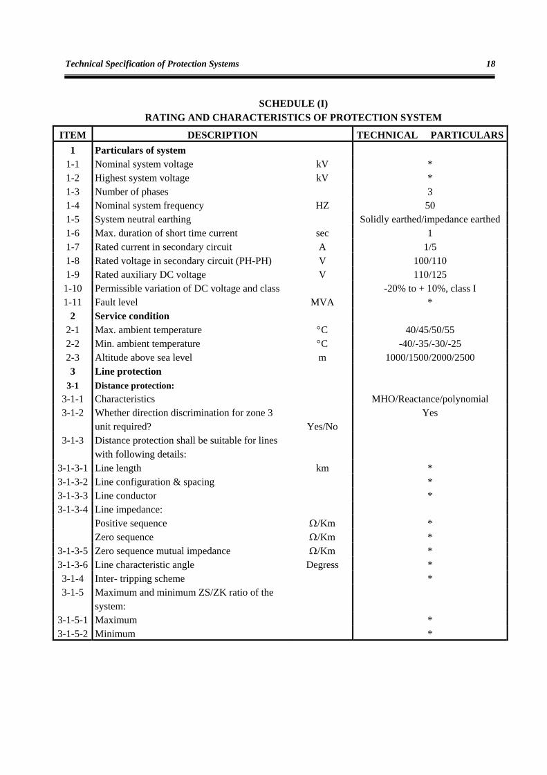
ITEM DESCRIPTION TECHNICAL PARTICULARS1 Particulars of system
1-1 Nominal system voltage kV * 1-2 Highest system voltage kV * 1-3 Number of phases 3 1-4 Nominal system frequency HZ 50 1-5 System neutral earthing Solidly earthed/impedance earthed 1-6 Max. duration of short time current sec 1 1-7 Rated current in secondary circuit A 1/5 1-8 Rated voltage in secondary circuit (PH-PH) V 100/110 1-9 Rated auxiliary DC voltage V 110/125
1-10 Permissible variation of DC voltage and class -20% to + 10%, class I 1-11 Fault level MVA *
2 Service condition 2-1 Max. ambient temperature °C 40/45/50/55 2-2 Min. ambient temperature °C -40/-35/-30/-25 2-3 Altitude above sea level m 1000/1500/2000/2500 3 Line protection
3-1 Distance protection: 3-1-1 Characteristics MHO/Reactance/polynomial 3-1-2 Whether direction discrimination for zone 3
unit required? Yes/No Yes
3-1-3 Distance protection shall be suitable for lines with following details:
3-1-3-1 Line length km * 3-1-3-2 Line configuration & spacing * 3-1-3-3 Line conductor * 3-1-3-4 Line impedance:
Positive sequence Ω/Km * Zero sequence Ω/Km *
3-1-3-5 Zero sequence mutual impedance Ω/Km * 3-1-3-6 Line characteristic angle Degress * 3-1-4 Inter- tripping scheme * 3-1-5 Maximum and minimum ZS/ZK ratio of the
system:
3-1-5-1 Maximum * 3-1-5-2 Minimum *
Tables
19
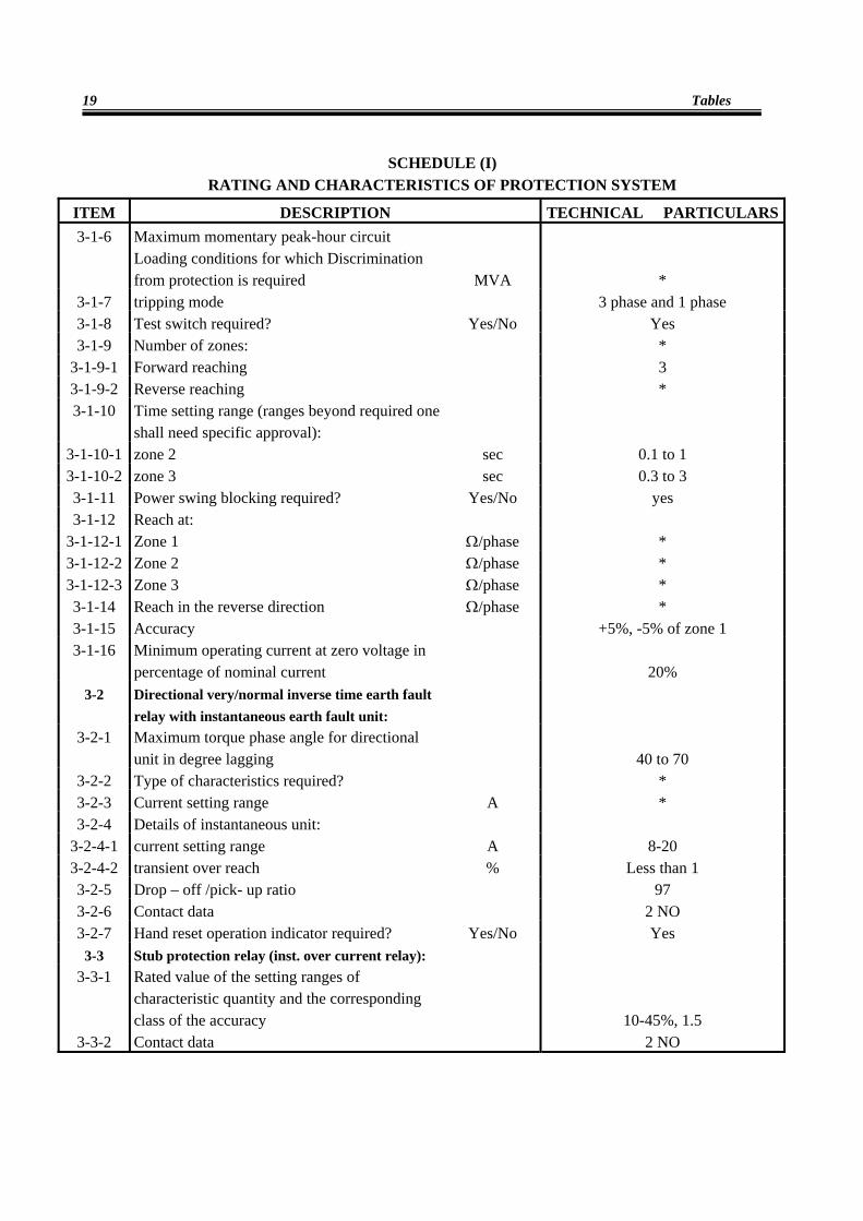
SCHEDULE (I) RATING AND CHARACTERISTICS OF PROTECTION SYSTEM
ITEM DESCRIPTION TECHNICAL PARTICULARS3-1-6 Maximum momentary peak-hour circuit
Loading conditions for which Discrimination from protection is required MVA *
3-1-7 tripping mode 3 phase and 1 phase 3-1-8 Test switch required? Yes/No Yes 3-1-9 Number of zones: *
3-1-9-1 Forward reaching 3 3-1-9-2 Reverse reaching * 3-1-10 Time setting range (ranges beyond required one
shall need specific approval):
3-1-10-1 zone 2 sec 0.1 to 1 3-1-10-2 zone 3 sec 0.3 to 3 3-1-11 Power swing blocking required? Yes/No yes 3-1-12 Reach at:
3-1-12-1 Zone 1 Ω/phase * 3-1-12-2 Zone 2 Ω/phase * 3-1-12-3 Zone 3 Ω/phase * 3-1-14 Reach in the reverse direction Ω/phase * 3-1-15 Accuracy +5%, -5% of zone 1 3-1-16 Minimum operating current at zero voltage in
percentage of nominal current
20% 3-2 Directional very/normal inverse time earth fault
relay with instantaneous earth fault unit:
3-2-1 Maximum torque phase angle for directional unit in degree lagging
40 to 70
3-2-2 Type of characteristics required? * 3-2-3 Current setting range A * 3-2-4 Details of instantaneous unit:
3-2-4-1 current setting range A 8-20 3-2-4-2 transient over reach % Less than 1 3-2-5 Drop – off /pick- up ratio 97 3-2-6 Contact data 2 NO 3-2-7 Hand reset operation indicator required? Yes/No Yes
3-3 Stub protection relay (inst. over current relay): 3-3-1 Rated value of the setting ranges of
characteristic quantity and the corresponding class of the accuracy
10-45%, 1.5 3-3-2 Contact data 2 NO
Technical Specification of Protection Systems
20
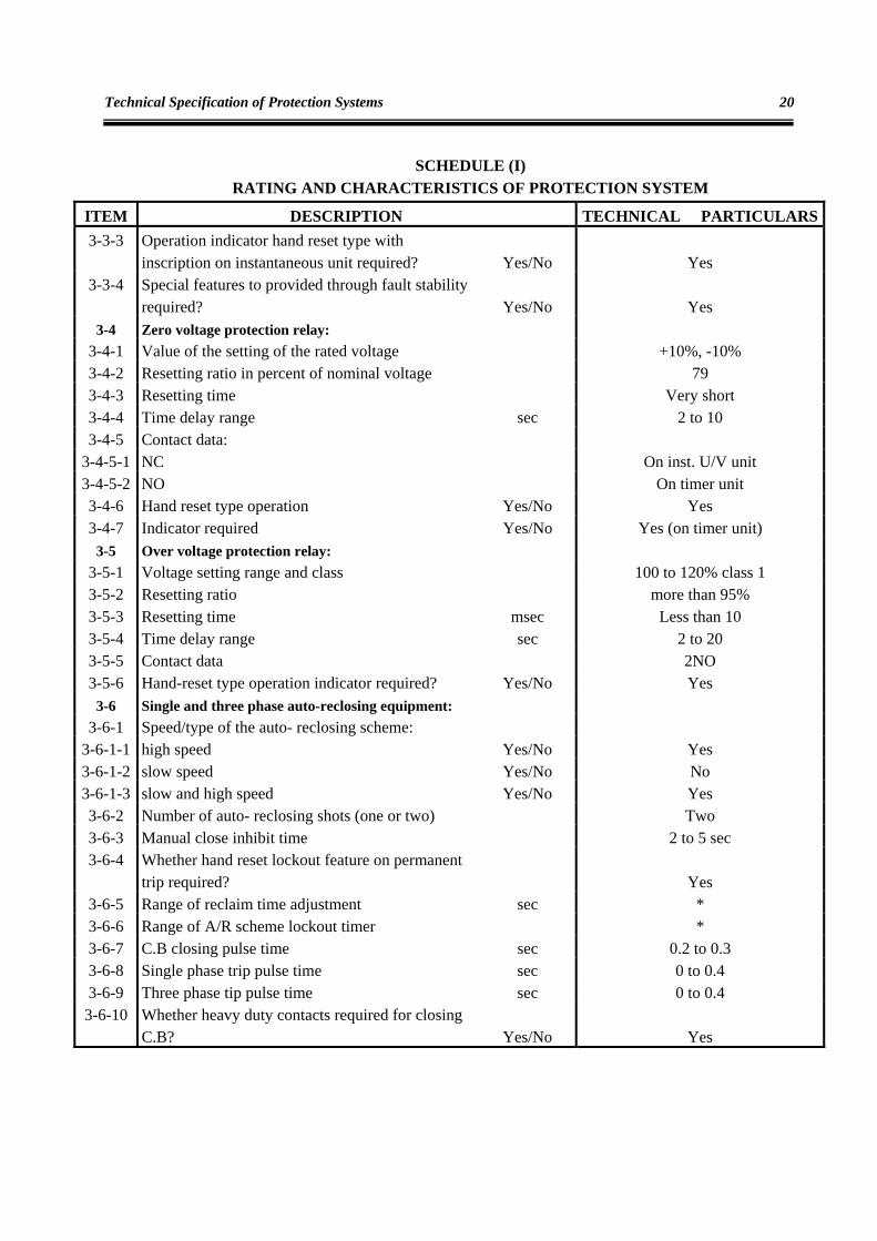
SCHEDULE (I) RATING AND CHARACTERISTICS OF PROTECTION SYSTEM
ITEM DESCRIPTION TECHNICAL PARTICULARS3-3-3 Operation indicator hand reset type with
inscription on instantaneous unit required? Yes/No Yes 3-3-4 Special features to provided through fault stability
required? Yes/No Yes 3-4 Zero voltage protection relay:
3-4-1 Value of the setting of the rated voltage +10%, -10% 3-4-2 Resetting ratio in percent of nominal voltage 79 3-4-3 Resetting time Very short 3-4-4 Time delay range sec 2 to 10 3-4-5 Contact data:
3-4-5-1 NC On inst. U/V unit 3-4-5-2 NO On timer unit 3-4-6 Hand reset type operation Yes/No Yes 3-4-7 Indicator required Yes/No Yes (on timer unit)
3-5 Over voltage protection relay: 3-5-1 Voltage setting range and class 100 to 120% class 1 3-5-2 Resetting ratio more than 95% 3-5-3 Resetting time msec Less than 10 3-5-4 Time delay range sec 2 to 20 3-5-5 Contact data 2NO 3-5-6 Hand-reset type operation indicator required? Yes/No Yes
3-6 Single and three phase auto-reclosing equipment: 3-6-1 Speed/type of the auto- reclosing scheme:
3-6-1-1 high speed Yes/No Yes 3-6-1-2 slow speed Yes/No No 3-6-1-3 slow and high speed Yes/No Yes 3-6-2 Number of auto- reclosing shots (one or two) Two 3-6-3 Manual close inhibit time 2 to 5 sec 3-6-4 Whether hand reset lockout feature on permanent
trip required?
Yes 3-6-5 Range of reclaim time adjustment sec * 3-6-6 Range of A/R scheme lockout timer * 3-6-7 C.B closing pulse time sec 0.2 to 0.3 3-6-8 Single phase trip pulse time sec 0 to 0.4 3-6-9 Three phase tip pulse time sec 0 to 0.4
3-6-10 Whether heavy duty contacts required for closing C.B? Yes/No Yes
Tables
21
SCHEDULE (I) RATING AND CHARACTERISTICS OF PROTECTION SYSTEM
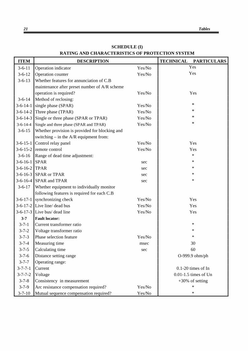
ITEM DESCRIPTION TECHNICAL PARTICULARS3-6-11 Operation indicator Yes/No Yes 3-6-12 Operation counter Yes/No Yes 3-6-13 Whether features for annunciation of C.B
maintenance after preset number of A/R scheme operation is required? Yes/No Yes
3-6-14 Method of reclosing: 3-6-14-1 single phase (SPAR) Yes/No * 3-6-14-2 Three phase (TPAR) Yes/No * 3-6-14-3 Single or three phase (SPAR or TPAR) Yes/No * 3-6-14-4 Single and three phase (SPAR and TPAR) Yes/No * 3-6-15 Whether provision is provided for blocking and
switching – in the A/R equipment from:
3-6-15-1 Control relay panel Yes/No Yes 3-6-15-2 remote control Yes/No Yes 3-6-16 Range of dead time adjustment: *
3-6-16-1 SPAR sec * 3-6-16-2 TPAR sec * 3-6-16-3 SPAR or TPAR sec * 3-6-16-4 SPAR and TPAR sec * 3-6-17 Whether equipment to individually monitor
following features is required for each C.B
3-6-17-1 synchronizing check Yes/No Yes 3-6-17-2 Live line/ dead bus Yes/No Yes 3-6-17-3 Live bus/ dead line Yes/No Yes
3-7 Fault locator: 3-7-1 Current transformer ratio * 3-7-2 Voltage transformer ratio * 3-7-3 Phase selection feature Yes/No * 3-7-4 Measuring time msec 30 3-7-5 Calculating time sec 60 3-7-6 Distance setting range O-999.9 ohm/ph 3-7-7 Operating range:
3-7-7-1 Current 0.1-20 times of In 3-7-7-2 Voltage 0.01-1.5 times of Un 3-7-8 Consistency in measurement +30% of setting 3-7-9 Arc resistance compensation required? Yes/No *
3-7-10 Mutual sequence compensation required? Yes/No *
Technical Specification of Protection Systems
22
SCHEDULE (I) RATING AND CHARACTERISTICS OF PROTECTION SYSTEM
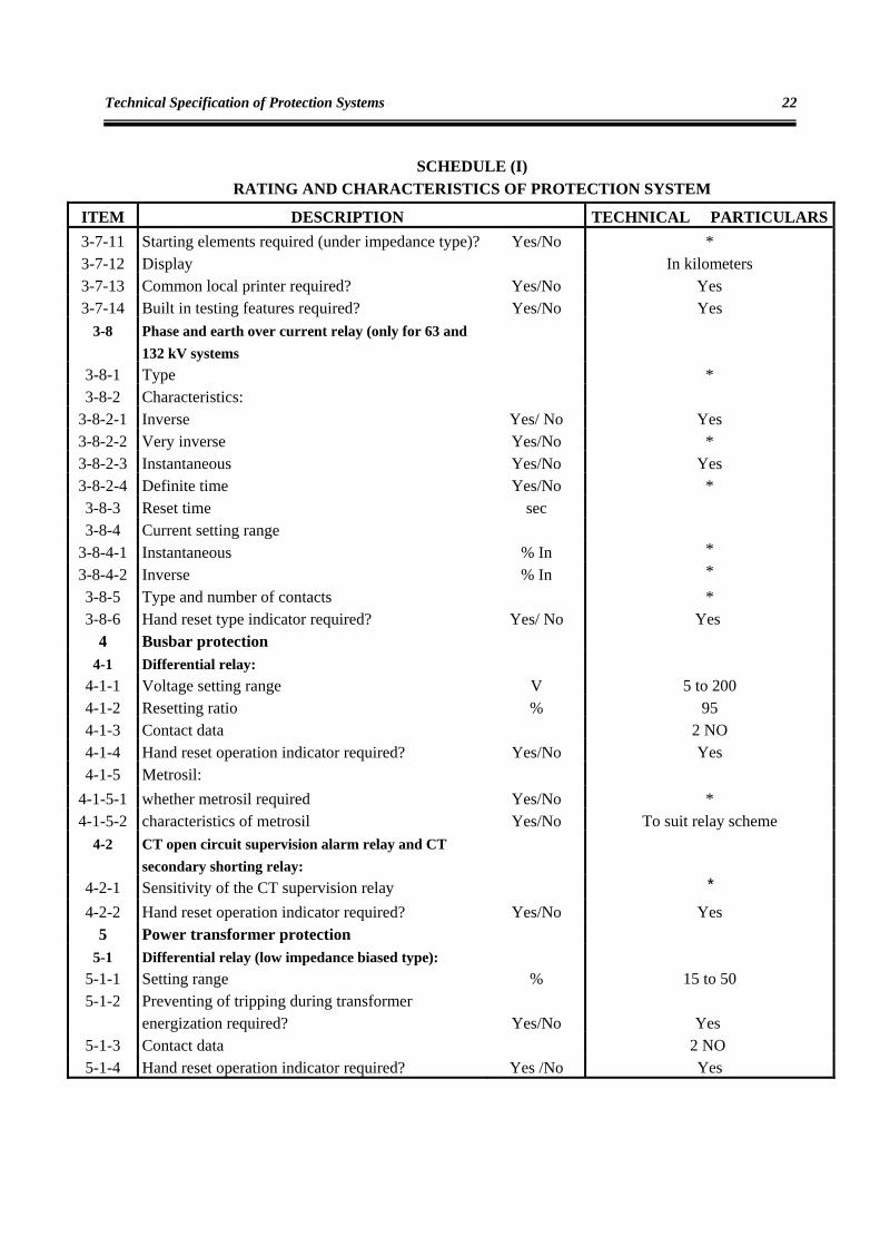
ITEM DESCRIPTION TECHNICAL PARTICULARS3-7-11 Starting elements required (under impedance type)? Yes/No * 3-7-12 Display In kilometers 3-7-13 Common local printer required? Yes/No Yes 3-7-14 Built in testing features required? Yes/No Yes
3-8 Phase and earth over current relay (only for 63 and 132 kV systems
3-8-1 Type * 3-8-2 Characteristics:
3-8-2-1 Inverse Yes/ No Yes 3-8-2-2 Very inverse Yes/No * 3-8-2-3 Instantaneous Yes/No Yes 3-8-2-4 Definite time Yes/No * 3-8-3 Reset time sec 3-8-4 Current setting range
3-8-4-1 Instantaneous % In * 3-8-4-2 Inverse % In * 3-8-5 Type and number of contacts * 3-8-6 Hand reset type indicator required? Yes/ No Yes
4 Busbar protection 4-1 Differential relay:
4-1-1 Voltage setting range V 5 to 200 4-1-2 Resetting ratio % 95 4-1-3 Contact data 2 NO 4-1-4 Hand reset operation indicator required? Yes/No Yes 4-1-5 Metrosil:
4-1-5-1 whether metrosil required Yes/No * 4-1-5-2 characteristics of metrosil Yes/No To suit relay scheme
4-2 CT open circuit supervision alarm relay and CT secondary shorting relay:
4-2-1 Sensitivity of the CT supervision relay *
4-2-2 Hand reset operation indicator required? Yes/No Yes 5 Power transformer protection
5-1 Differential relay (low impedance biased type): 5-1-1 Setting range % 15 to 50 5-1-2 Preventing of tripping during transformer
energization required? Yes/No Yes 5-1-3 Contact data 2 NO 5-1-4 Hand reset operation indicator required? Yes /No Yes
Tables
23
SCHEDULE (I) RATING AND CHARACTERISTICS OF PROTECTION SYSTEM
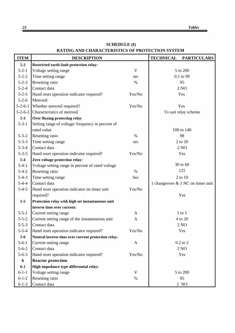
ITEM DESCRIPTION TECHNICAL PARTICULARS5-2 Restricted earth fault protection relay:
5-2-1 Voltage setting range V 5 to 200 5-2-2 Time setting range sec 0.1 to 99 5-2-3 Resetting ratio % 95 5-2-4 Contact data 2 NO 5-2-5 Hand reset operation indicator required? Yes/No Yes 5-2-6 Metrosil:
5-2-6-1 Whether metrosil required? Yes/No Yes 5-2-6-2 Characteristics of metrosil To suit relay scheme
5-3 Over fluxing protecting relay 5-3-1 Setting range of voltage/ frequency in percent of
rated value
100 to 140 5-3-2 Resetting ratio % 98 5-3-3 Time setting range sec 2 to 20 5-3-4 Contact data 2 NO 5-3-5 Hand reset operation indicator required? Yes/No Yes
5-4 Zero voltage protection relay: 5-4-1 Voltage setting range in percent of rated voltage 30 to 60 5-4-2 Resetting ratio % 125 5-4-3 Time setting range Sec 2 to 10 5-4-4 Contact data 1 changeover & 1 NC on timer unit5-4-5 Hand reset operation indicator on timer unit
required? Yes/No
Yes 5-5 Protection relay with high set instantaneous unit
inverse time over current:
5-5-1 Current setting range A 1 to 5 5-5-2 Current setting range of the instantaneous unit A 4 to 20 5-5-3 Contact data 2 NO 5-5-4 Hand reset operation indicator required? Yes/No Yes
5-6 Neutral inverse time over current protection relay: 5-6-1 Current setting range A 0.2 to 2 5-6-2 Contact data 2 NO 5-6-3 Hand reset operation indicator required? Yes/No Yes
6 Reactor protection 6-1 High impedance type differential relay:
6-1-1 Voltage setting range V 5 to 200 6-1-2 Resetting ratio % 95 6-1-3 Contact data 2 NO
Technical Specification of Protection Systems
24
SCHEDULE (I) RATING AND CHARACTERISTICS OF PROTECTION SYSTEM
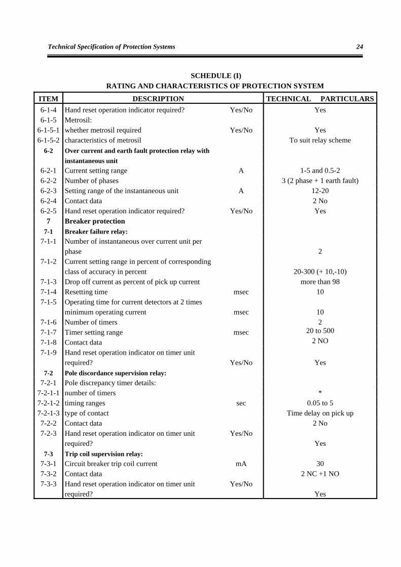
ITEM DESCRIPTION TECHNICAL PARTICULARS6-1-4 Hand reset operation indicator required? Yes/No Yes 6-1-5 Metrosil:
6-1-5-1 whether metrosil required Yes/No Yes 6-1-5-2 characteristics of metrosil To suit relay scheme
6-2 Over current and earth fault protection relay with instantaneous unit
6-2-1 Current setting range A 1-5 and 0.5-2 6-2-2 Number of phases 3 (2 phase + 1 earth fault) 6-2-3 Setting range of the instantaneous unit A 12-20 6-2-4 Contact data 2 No 6-2-5 Hand reset operation indicator required? Yes/No Yes
7 Breaker protection 7-1 Breaker failure relay:
7-1-1 Number of instantaneous over current unit per phase
2
7-1-2 Current setting range in percent of corresponding class of accuracy in percent
20-300 (+ 10,-10)
7-1-3 Drop off current as percent of pick up current more than 98 7-1-4 Resetting time msec 10 7-1-5 Operating time for current detectors at 2 times
minimum operating current msec 10 7-1-6 Number of timers 2 7-1-7 Timer setting range msec 20 to 500 7-1-8 Contact data 2 NO 7-1-9 Hand reset operation indicator on timer unit
required? Yes/No Yes 7-2 Pole discordance supervision relay:
7-2-1 Pole discrepancy timer details: 7-2-1-1 number of timers * 7-2-1-2 timing ranges sec 0.05 to 5 7-2-1-3 type of contact Time delay on pick up 7-2-2 Contact data 2 No 7-2-3 Hand reset operation indicator on timer unit
required? Yes/No
Yes 7-3 Trip coil supervision relay:
7-3-1 Circuit breaker trip coil current mA 30 7-3-2 Contact data 2 NC +1 NO 7-3-3 Hand reset operation indicator on timer unit
required? Yes/No
Yes
Tables
25
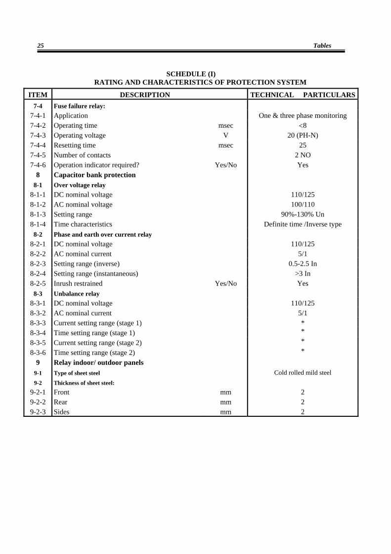
SCHEDULE (I) RATING AND CHARACTERISTICS OF PROTECTION SYSTEM
ITEM DESCRIPTION TECHNICAL PARTICULARS7-4 Fuse failure relay:
7-4-1 Application One & three phase monitoring 7-4-2 Operating time msec <8 7-4-3 Operating voltage V 20 (PH-N) 7-4-4 Resetting time msec 25 7-4-5 Number of contacts 2 NO 7-4-6 Operation indicator required? Yes/No Yes
8 Capacitor bank protection 8-1 Over voltage relay
8-1-1 DC nominal voltage 110/125 8-1-2 AC nominal voltage 100/110 8-1-3 Setting range 90%-130% Un 8-1-4 Time characteristics Definite time /Inverse type
8-2 Phase and earth over current relay 8-2-1 DC nominal voltage 110/125 8-2-2 AC nominal current 5/1 8-2-3 Setting range (inverse) 0.5-2.5 In 8-2-4 Setting range (instantaneous) >3 In 8-2-5 Inrush restrained Yes/No Yes
8-3 Unbalance relay 8-3-1 DC nominal voltage 110/125 8-3-2 AC nominal current 5/1 8-3-3 Current setting range (stage 1) * 8-3-4 Time setting range (stage 1) * 8-3-5 Current setting range (stage 2) * 8-3-6 Time setting range (stage 2) *
9 Relay indoor/ outdoor panels
9-1 Type of sheet steel Cold rolled mild steel 9-2 Thickness of sheet steel:
9-2-1 Front mm 2 9-2-2 Rear mm 2 9-2-3 Sides mm 2
Technical Specification of Protection Systems
26
SCHEDULE (II) GUARANTEED THCHNICAL INFORMATION OF PROTECTION EQUIMNENT & SYSTEMS
(TO BE SUPPLEID WITH TENDER)
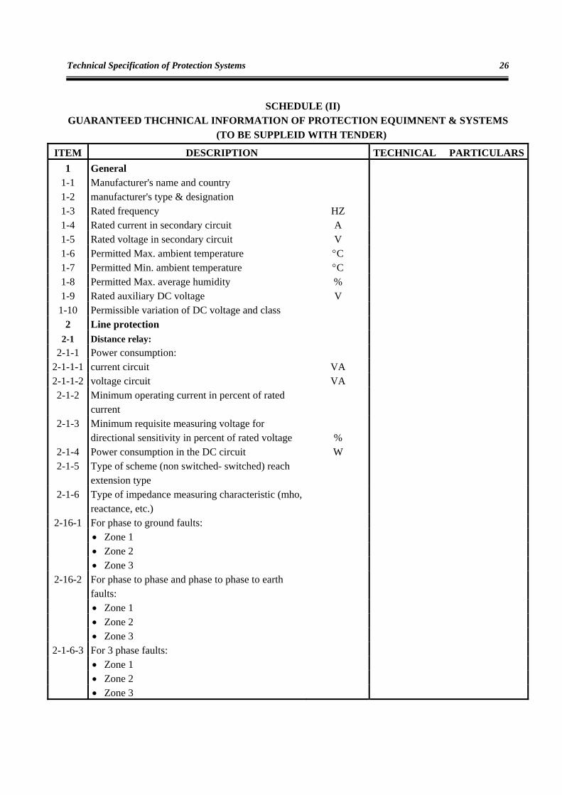
ITEM DESCRIPTION TECHNICAL PARTICULARS1 General
1-1 Manufacturer's name and country 1-2 manufacturer's type & designation 1-3 Rated frequency HZ 1-4 Rated current in secondary circuit A 1-5 Rated voltage in secondary circuit V 1-6 Permitted Max. ambient temperature °C 1-7 Permitted Min. ambient temperature °C 1-8 Permitted Max. average humidity % 1-9 Rated auxiliary DC voltage V
1-10 Permissible variation of DC voltage and class 2 Line protection
2-1 Distance relay: 2-1-1 Power consumption:
2-1-1-1 current circuit VA 2-1-1-2 voltage circuit VA 2-1-2 Minimum operating current in percent of rated
current
2-1-3 Minimum requisite measuring voltage for
directional sensitivity in percent of rated voltage % 2-1-4 Power consumption in the DC circuit W 2-1-5 Type of scheme (non switched- switched) reach
extension type
2-1-6 Type of impedance measuring characteristic (mho,
reactance, etc.)
2-16-1 For phase to ground faults:
• Zone 1 • Zone 2 • Zone 3
2-16-2 For phase to phase and phase to phase to earth faults:
• Zone 1 • Zone 2 • Zone 3
2-1-6-3 For 3 phase faults: • Zone 1 • Zone 2 • Zone 3
Tables
27
SCHEDULE (II) GUARANTEED THCHNICAL INFORMATION OF PROTECTION EQUIMNENT & SYSTEMS
(TO BE SUPPLEID WITH TENDER)
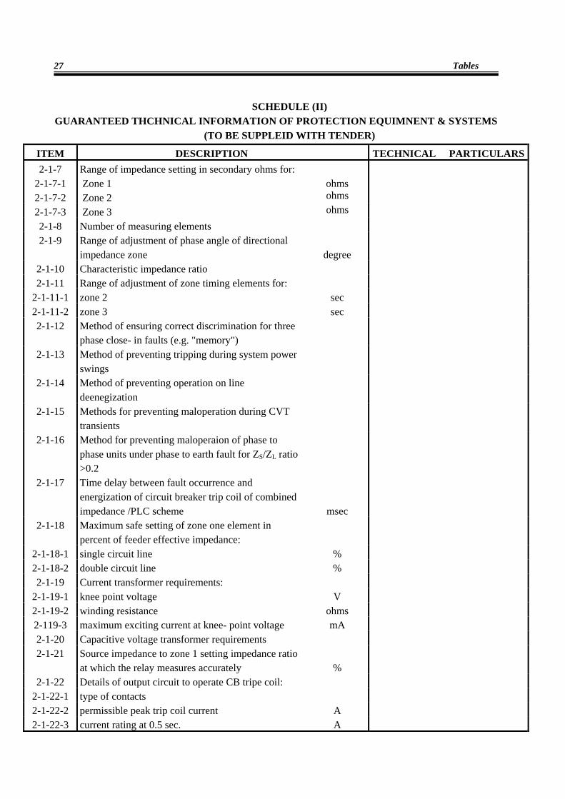
ITEM DESCRIPTION TECHNICAL PARTICULARS2-1-7 Range of impedance setting in secondary ohms for:
2-1-7-1 Zone 1 ohms 2-1-7-2 Zone 2 ohms 2-1-7-3 Zone 3 ohms 2-1-8 Number of measuring elements 2-1-9 Range of adjustment of phase angle of directional
impedance zone degree 2-1-10 Characteristic impedance ratio 2-1-11 Range of adjustment of zone timing elements for:
2-1-11-1 zone 2 sec 2-1-11-2 zone 3 sec 2-1-12 Method of ensuring correct discrimination for three
phase close- in faults (e.g. "memory")
2-1-13 Method of preventing tripping during system power
swings
2-1-14 Method of preventing operation on line
deenegization
2-1-15 Methods for preventing maloperation during CVT
transients
2-1-16 Method for preventing maloperaion of phase to
phase units under phase to earth fault for ZS/ZL ratio >0.2
2-1-17 Time delay between fault occurrence and
energization of circuit breaker trip coil of combined impedance /PLC scheme msec
2-1-18 Maximum safe setting of zone one element in percent of feeder effective impedance:
2-1-18-1 single circuit line % 2-1-18-2 double circuit line % 2-1-19 Current transformer requirements:
2-1-19-1 knee point voltage V 2-1-19-2 winding resistance ohms 2-119-3 maximum exciting current at knee- point voltage mA 2-1-20 Capacitive voltage transformer requirements 2-1-21 Source impedance to zone 1 setting impedance ratio
at which the relay measures accurately % 2-1-22 Details of output circuit to operate CB tripe coil:
2-1-22-1 type of contacts 2-1-22-2 permissible peak trip coil current A 2-1-22-3 current rating at 0.5 sec. A
Technical Specification of Protection Systems
28
SCHEDULE (II)
GUARANTEED THCHNICAL INFORMATION OF PROTECTION EQUIMNENT & SYSTEMS (TO BE SUPPLEID WITH TENDER)
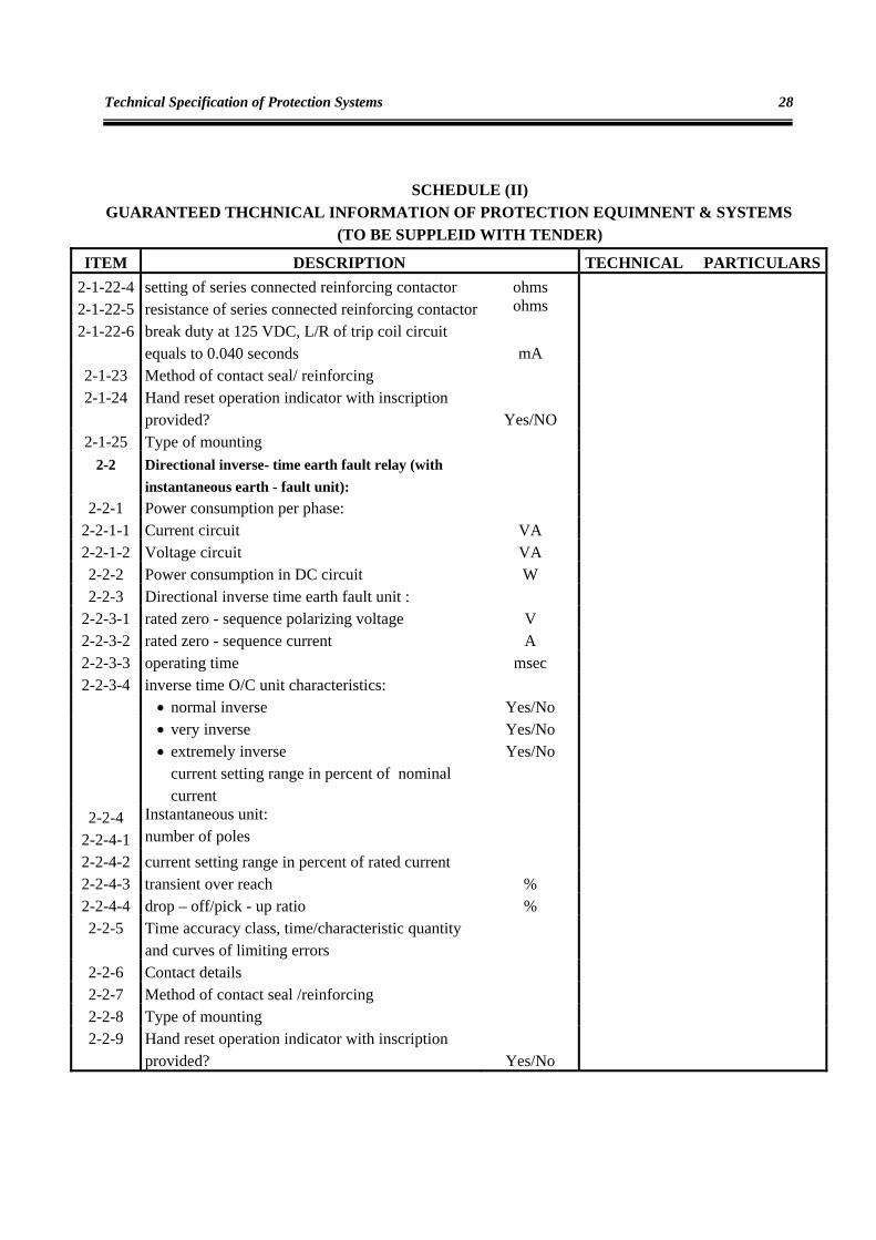
ITEM DESCRIPTION TECHNICAL PARTICULARS2-1-22-4 setting of series connected reinforcing contactor ohms 2-1-22-5 resistance of series connected reinforcing contactor ohms 2-1-22-6 break duty at 125 VDC, L/R of trip coil circuit
equals to 0.040 seconds mA 2-1-23 Method of contact seal/ reinforcing 2-1-24 Hand reset operation indicator with inscription
provided? Yes/NO 2-1-25 Type of mounting
2-2 Directional inverse- time earth fault relay (with instantaneous earth - fault unit):
2-2-1 Power consumption per phase: 2-2-1-1 Current circuit VA 2-2-1-2 Voltage circuit VA 2-2-2 Power consumption in DC circuit W 2-2-3 Directional inverse time earth fault unit :
2-2-3-1 rated zero - sequence polarizing voltage V 2-2-3-2 rated zero - sequence current A 2-2-3-3 operating time msec 2-2-3-4 inverse time O/C unit characteristics:
• normal inverse Yes/No • very inverse Yes/No • extremely inverse Yes/No current setting range in percent of nominal
current
2-2-4 Instantaneous unit:
2-2-4-1 number of poles 2-2-4-2 current setting range in percent of rated current 2-2-4-3 transient over reach % 2-2-4-4 drop – off/pick - up ratio % 2-2-5 Time accuracy class, time/characteristic quantity
and curves of limiting errors
2-2-6 Contact details 2-2-7 Method of contact seal /reinforcing 2-2-8 Type of mounting 2-2-9 Hand reset operation indicator with inscription
provided? Yes/No
Tables
29
SCHEDULE (II) GUARANTEED THCHNICAL INFORMATION OF PROTECTION EQUIMNENT & SYSTEMS
(TO BE SUPPLEID WITH TENDER)
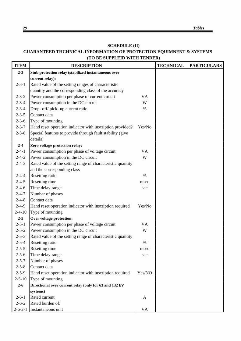
ITEM DESCRIPTION TECHNICAL PARTICULARS2-3 Stub protection relay (stabilized instantaneous over
current relay):
2-3-1 Rated value of the setting ranges of characteristic
quantity and the corresponding class of the accuracy
2-3-2 Power consumption per phase of current circuit VA 2-3-4 Power consumption in the DC circuit W 2-3-4 Drop- off/ pick- up current ratio % 2-3-5 Contact data 2-3-6 Type of mounting 2-3-7 Hand reset operation indicator with inscription provided? Yes/No 2-3-8 Special features to provide through fault stability (give
details)
2-4 Zero voltage protection relay:
2-4-1 Power consumption per phase of voltage circuit VA 2-4-2 Power consumption in the DC circuit W 2-4-3 Rated value of the setting range of characteristic quantity
and the corresponding class
2-4-4 Resetting ratio % 2-4-5 Resetting time msec 2-4-6 Time delay range sec 2-4-7 Number of phases 2-4-8 Contact data 2-4-9 Hand reset operation indicator with inscription required Yes/No
2-4-10 Type of mounting 2-5 Over voltage protection:
2-5-1 Power consumption per phase of voltage circuit VA 2-5-2 Power consumption in the DC circuit W 2-5-3 Rated value of the setting range of characteristic quantity 2-5-4 Resetting ratio % 2-5-5 Resetting time msec 2-5-6 Time delay range sec 2-5-7 Number of phases 2-5-8 Contact data 2-5-9 Hand reset operation indicator with inscription required Yes/NO
2-5-10 Type of mounting 2-6 Directional over current relay (only for 63 and 132 kV
systems)
2-6-1 Rated current A 2-6-2 Rated burden of:
2-6-2-1 Instantaneous unit VA
Technical Specification of Protection Systems
30
SCHEDULE (II) GUARANTEED THCHNICAL INFORMATION OF PROTECTION EQUIMNENT & SYSTEMS
(TO BE SUPPLEID WITH TENDER)
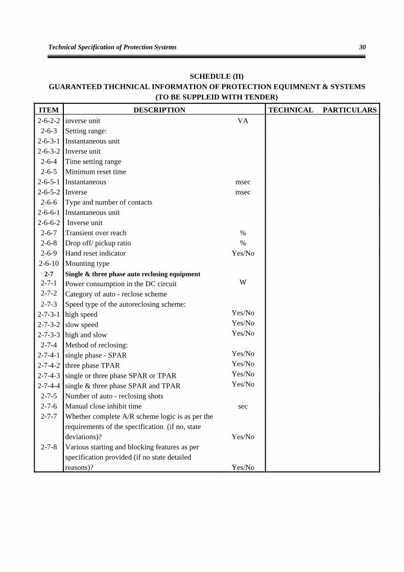
ITEM DESCRIPTION TECHNICAL PARTICULARS2-6-2-2 inverse unit VA 2-6-3 Setting range:
2-6-3-1 Instantaneous unit 2-6-3-2 Inverse unit 2-6-4 Time setting range 2-6-5 Minimum reset time
2-6-5-1 Instantaneous msec 2-6-5-2 Inverse msec 2-6-6 Type and number of contacts
2-6-6-1 Instantaneous unit 2-6-6-2 Inverse unit 2-6-7 Transient over reach % 2-6-8 Drop off/ pickup ratio % 2-6-9 Hand reset indicator Yes/No
2-6-10 Mounting type 2-7 Single & three phase auto reclosing equipment
2-7-1 Power consumption in the DC circuit W 2-7-2 Category of auto - reclose scheme 2-7-3 Speed type of the autoreclosing scheme:
2-7-3-1 high speed Yes/No 2-7-3-2 slow speed Yes/No 2-7-3-3 high and slow Yes/No 2-7-4 Method of reclosing:
2-7-4-1 single phase - SPAR Yes/No 2-7-4-2 three phase TPAR Yes/No 2-7-4-3 single or three phase SPAR or TPAR Yes/No 2-7-4-4 single & three phase SPAR and TPAR Yes/No 2-7-5 Number of auto - reclosing shots 2-7-6 Manual close inhibit time sec 2-7-7 Whether complete A/R scheme logic is as per the
requirements of the specification (if no, state deviations)? Yes/No
2-7-8 Various starting and blocking features as per specification provided (if no state detailed reasons)? Yes/No
Tables
31
SCHEDULE (II) GUARANTEED THCHNICAL INFORMATION OF PROTECTION EQUIMNENT & SYSTEMS
(TO BE SUPPLEID WITH TENDER)
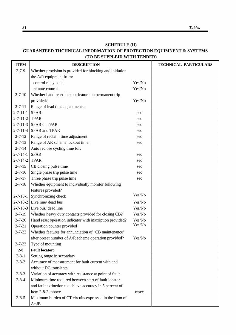
ITEM DESCRIPTION TECHNICAL PARTICULARS 2-7-9 Whether provision is provided for blocking and initiation
the A/R equipment from:
- control relay panel Yes/No - remote control Yes/No
2-7-10 Whether hand reset lockout feature on permanent trip provided? Yes/No
2-7-11 Range of lead time adjustments: 2-7-11-1 SPAR sec 2-7-11-2 TPAR sec 2-7-11-3 SPAR or TPAR sec 2-7-11-4 SPAR and TPAR sec 2-7-12 Range of reclaim time adjustment sec 2-7-13 Range of AR scheme lockout timer sec 2-7-14 Auto reclose cycling time for:
2-7-14-1 SPAR sec 2-7-14-2 TPAR sec 2-7-15 CB closing pulse time sec 2-7-16 Single phase trip pulse time sec 2-7-17 Three phase trip pulse time sec 2-7-18 Whether equipment to individually monitor following
features provided?
2-7-18-1 Synchronizing check Yes/No 2-7-18-2 Live line/ dead bus Yes/No 2-7-18-3 Live bus/ dead line Yes/No 2-7-19 Whether heavy duty contacts provided for closing CB? Yes/No 2-7-20 Hand reset operation indicator with inscription provided? Yes/No 2-7-21 Operation counter provided Yes/No 2-7-22 Whether features for annunciation of "CB maintenance"
after preset number of A/R scheme operation provided? Yes/No 2-7-23 Type of mounting
2-8 Fault locator: 2-8-1 Setting range in secondary 2-8-2 Accuracy of measurement for fault current with and
without DC transients
2-8-3 Variation of accuracy with resistance at point of fault 2-8-4 Minimum time required between start of fault locator
and fault extinction to achieve accuracy in 5 percent of item 2-8-2- above msec
2-8-5 Maximum burden of CT circuits expressed in the from of A+JB
Technical Specification of Protection Systems
32
SCHEDULE (II) GUARANTEED THCHNICAL INFORMATION OF PROTECTION EQUIMNENT & SYSTEMS
(TO BE SUPPLEID WITH TENDER)
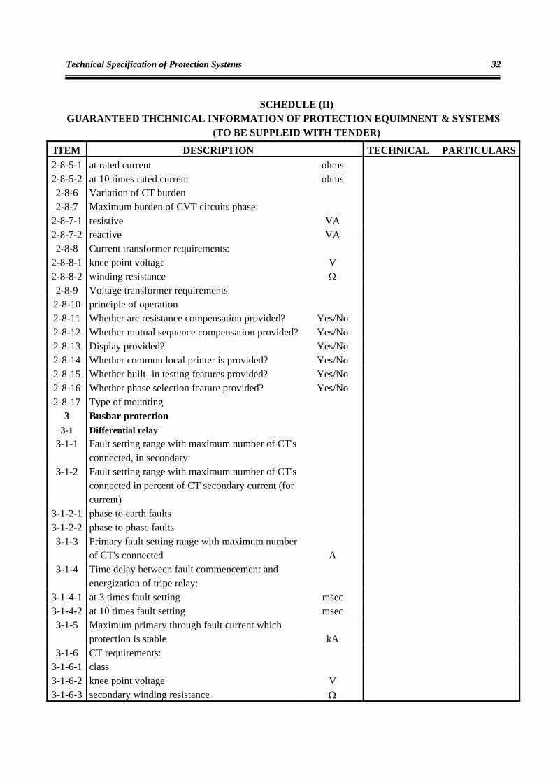
ITEM DESCRIPTION TECHNICAL PARTICULARS2-8-5-1 at rated current ohms 2-8-5-2 at 10 times rated current ohms 2-8-6 Variation of CT burden 2-8-7 Maximum burden of CVT circuits phase:
2-8-7-1 resistive VA 2-8-7-2 reactive VA 2-8-8 Current transformer requirements:
2-8-8-1 knee point voltage V 2-8-8-2 winding resistance Ω 2-8-9 Voltage transformer requirements
2-8-10 principle of operation 2-8-11 Whether arc resistance compensation provided? Yes/No 2-8-12 Whether mutual sequence compensation provided? Yes/No 2-8-13 Display provided? Yes/No 2-8-14 Whether common local printer is provided? Yes/No 2-8-15 Whether built- in testing features provided? Yes/No 2-8-16 Whether phase selection feature provided? Yes/No 2-8-17 Type of mounting
3 Busbar protection 3-1 Differential relay
3-1-1 Fault setting range with maximum number of CT's connected, in secondary
3-1-2 Fault setting range with maximum number of CT's connected in percent of CT secondary current (for current)
3-1-2-1 phase to earth faults 3-1-2-2 phase to phase faults 3-1-3 Primary fault setting range with maximum number
of CT's connected A 3-1-4 Time delay between fault commencement and
energization of tripe relay:
3-1-4-1 at 3 times fault setting msec 3-1-4-2 at 10 times fault setting msec 3-1-5 Maximum primary through fault current which
protection is stable kA 3-1-6 CT requirements:
3-1-6-1 class 3-1-6-2 knee point voltage V 3-1-6-3 secondary winding resistance Ω
Tables
33
SCHEDULE (II) GUARANTEED THCHNICAL INFORMATION OF PROTECTION EQUIMNENT & SYSTEMS
(TO BE SUPPLEID WITH TENDER)
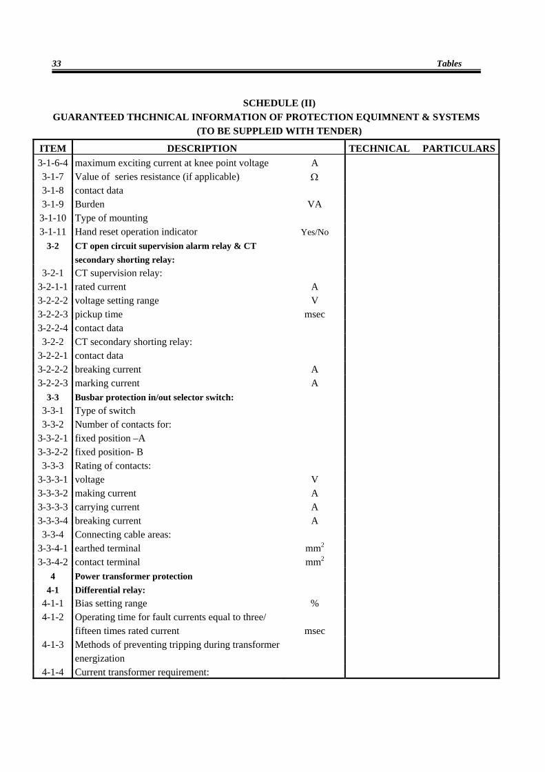
ITEM DESCRIPTION TECHNICAL PARTICULARS3-1-6-4 maximum exciting current at knee point voltage A 3-1-7 Value of series resistance (if applicable) Ω 3-1-8 contact data 3-1-9 Burden VA
3-1-10 Type of mounting 3-1-11 Hand reset operation indicator Yes/No
3-2 CT open circuit supervision alarm relay & CT secondary shorting relay:
3-2-1 CT supervision relay: 3-2-1-1 rated current A 3-2-2-2 voltage setting range V 3-2-2-3 pickup time msec 3-2-2-4 contact data 3-2-2 CT secondary shorting relay:
3-2-2-1 contact data 3-2-2-2 breaking current A 3-2-2-3 marking current A
3-3 Busbar protection in/out selector switch: 3-3-1 Type of switch 3-3-2 Number of contacts for:
3-3-2-1 fixed position –A 3-3-2-2 fixed position- B 3-3-3 Rating of contacts:
3-3-3-1 voltage V 3-3-3-2 making current A 3-3-3-3 carrying current A 3-3-3-4 breaking current A 3-3-4 Connecting cable areas:
3-3-4-1 earthed terminal mm2 3-3-4-2 contact terminal mm2
4 Power transformer protection 4-1 Differential relay:
4-1-1 Bias setting range % 4-1-2 Operating time for fault currents equal to three/
fifteen times rated current msec 4-1-3 Methods of preventing tripping during transformer
energization
4-1-4 Current transformer requirement:
Technical Specification of Protection Systems
34
SCHEDULE (II) GUARANTEED THCHNICAL INFORMATION OF PROTECTION EQUIMNENT & SYSTEMS
(TO BE SUPPLEID WITH TENDER)
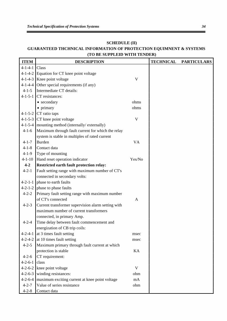
ITEM DESCRIPTION TECHNICAL PARTICULARS4-1-4-1 Class 4-1-4-2 Equation for CT knee point voltage 4-1-4-3 Knee point voltage V 4-1-4-4 Other special requirements (if any) 4-1-5 Intermediate CT details:
4-1-5-1 CT resistances: • secondary ohms • primary ohms
4-1-5-2 CT ratio taps 4-1-5-3 CT knee point voltage V 4-1-5-4 mounting method (internally/ externally) 4-1-6 Maximum through fault current for which the relay
system is stable in multiples of rated current 4-1-7 Burden VA 4-1-8 Contact data 4-1-9 Type of mounting
4-1-10 Hand reset operation indicator Yes/No 4-2 Restricted earth fault protection relay:
4-2-1 Fault setting range with maximum number of CT's connected in secondary volts:
4-2-1-1 phase to earth faults 4-2-1-2 phase to phase faults 4-2-2 Primary fault setting range with maximum number
of CT's connected A 4-2-3 Current transformer supervision alarm setting with
maximum number of current transformers connected, in primary Amp.
4-2-4 Time delay between fault commencement and energization of CB trip coils:
4-2-4-1 at 3 times fault setting msec 4-2-4-2 at 10 times fault setting msec 4-2-5 Maximum primary through fault current at which
protection is stable KA 4-2-6 CT requirement:
4-2-6-1 class 4-2-6-2 knee point voltage V 4-2-6-3 winding resistances: ohm 4-2-6-4 maximum exciting current at knee point voltage mA 4-2-7 Value of series resistance ohm 4-2-8 Contact data
Tables
35
SCHEDULE (II) GUARANTEED THCHNICAL INFORMATION OF PROTECTION EQUIMNENT & SYSTEMS
(TO BE SUPPLEID WITH TENDER)
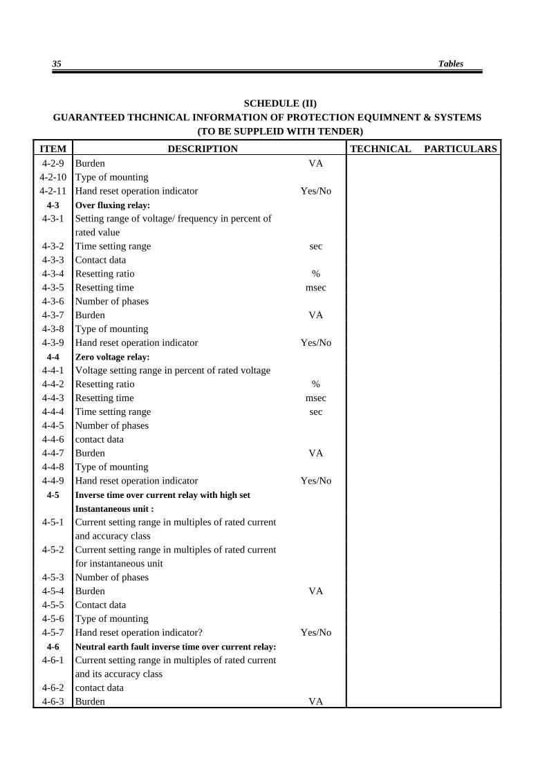
ITEM DESCRIPTION TECHNICAL PARTICULARS4-2-9 Burden VA
4-2-10 Type of mounting 4-2-11 Hand reset operation indicator Yes/No
4-3 Over fluxing relay: 4-3-1 Setting range of voltage/ frequency in percent of
rated value 4-3-2 Time setting range sec 4-3-3 Contact data 4-3-4 Resetting ratio % 4-3-5 Resetting time msec 4-3-6 Number of phases 4-3-7 Burden VA 4-3-8 Type of mounting 4-3-9 Hand reset operation indicator Yes/No
4-4 Zero voltage relay: 4-4-1 Voltage setting range in percent of rated voltage 4-4-2 Resetting ratio % 4-4-3 Resetting time msec 4-4-4 Time setting range sec 4-4-5 Number of phases 4-4-6 contact data 4-4-7 Burden VA 4-4-8 Type of mounting 4-4-9 Hand reset operation indicator Yes/No
4-5 Inverse time over current relay with high set Instantaneous unit :
4-5-1 Current setting range in multiples of rated current and accuracy class
4-5-2 Current setting range in multiples of rated current for instantaneous unit
4-5-3 Number of phases 4-5-4 Burden VA 4-5-5 Contact data 4-5-6 Type of mounting 4-5-7 Hand reset operation indicator? Yes/No
4-6 Neutral earth fault inverse time over current relay: 4-6-1 Current setting range in multiples of rated current
and its accuracy class 4-6-2 contact data 4-6-3 Burden VA
Technical Specification of Protection Systems
36
SCHEDULE (II) GUARANTEED THCHNICAL INFORMATION OF PROTECTION EQUIMNENT & SYSTEMS
(TO BE SUPPLEID WITH TENDER)
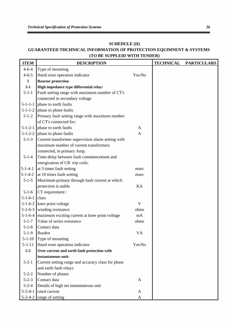
ITEM DESCRIPTION TECHNICAL PARTICULARS4-6-4 Type of mounting 4-6-5 Hand reset operation indicator Yes/No
5 Reactor protection 5-1 High impedance type differential relay:
5-1-1 Fault setting range with maximum number of CT's connected in secondary voltage
5-1-1-1 phase to earth faults 5-1-1-2 phase to phase faults 5-1-2 Primary fault setting range with maximum number
of CT's connected for: 5-1-2-1 phase to earth faults A 5-1-2-2 phase to phase faults A 5-1-3 Current transformer supervision alarm setting with
maximum number of current transformers connected, in primary Amp.
5-1-4 Time delay between fault commencement and energization of CB trip coils:
5-1-4-1 at 3 times fault setting msec 5-1-4-2 at 10 times fault setting msec
5-1-5 Maximum primary through fault current at which protection is stable KA
5-1-6 CT requirement : 5-1-6-1 class 5-1-6-2 knee point voltage V 5-1-6-3 winding resistance ohms 5-1-6-4 maximum exciting current at knee point voltage mA 5-1-7 Value of series resistance ohms 5-1-8 Contact data 5-1-9 Burden VA
5-1-10 Type of mounting 5-1-11 Hand reset operation indicator Yes/No
5-2 Over current and earth fault protection with instantaneous unit:
5-2-1 Current setting range and accuracy class for phase and earth fault relays
5-2-2 Number of phases 5-2-3 Contact data A 5-2-4 Details of high set instantaneous unit
5-2-4-1 rated current A 5-2-4-2 range of setting A
Tables
37
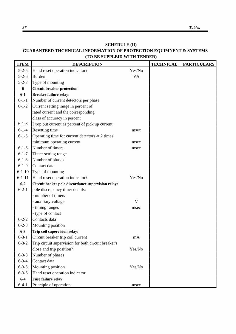
SCHEDULE (II) GUARANTEED THCHNICAL INFORMATION OF PROTECTION EQUIMNENT & SYSTEMS
(TO BE SUPPLEID WITH TENDER)
ITEM DESCRIPTION TECHNICAL PARTICULARS5-2-5 Hand reset operation indicator? Yes/No 5-2-6 Burden VA 5-2-7 Type of mounting
6 Circuit breaker protection
6-1 Breaker failure relay:
6-1-1 Number of current detectors per phase 6-1-2 Current setting range in percent of
rated current and the corresponding class of accuracy in percent
6-1-3 Drop out current as percent of pick up current 6-1-4 Resetting time msec 6-1-5 Operating time for current detectors at 2 times
minimum operating current msec
6-1-6 Number of timers msee 6-1-7 Timer setting range 6-1-8 Number of phases 6-1-9 Contact data
6-1-10 Type of mounting 6-1-11 Hand reset operation indicator? Yes/No
6-2 Circuit beaker pole discordance supervision relay: 6-2-1 pole discrepancy timer details:
- number of timers - auxiliary voltage V - timing ranges msec - type of contact
6-2-2 Contacts data 6-2-3 Mounting position
6-3 Trip coil supervision relay: 6-3-1 Circuit breaker trip coil current mA 6-3-2 Trip circuit supervision for both circuit breaker's
close and trip position? Yes/No 6-3-3 Number of phases 6-3-4 Contact data 6-3-5 Mounting position Yes/No 6-3-6 Hand reset operation indicator
6-4 Fuse failure relay: 6-4-1 Principle of operation msec
Technical Specification of Protection Systems
38
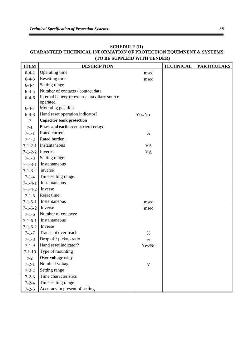
SCHEDULE (II) GUARANTEED THCHNICAL INFORMATION OF PROTECTION EQUIMNENT & SYSTEMS
(TO BE SUPPLEID WITH TENDER)
ITEM DESCRIPTION TECHNICAL PARTICULARS6-4-2 Operating time msec 6-4-3 Resetting time msec 6-4-4 Setting range 6-4-5 Number of contacts / contact data 6-4-6 Internal battery or external auxiliary source
operated
6-4-7 Mounting position 6-4-8 Hand reset operation indicator? Yes/No
7 Capacitor bank protection
7-1 Phase and earth over current relay:
7-1-1 Rated current A 7-1-2 Rated burden:
7-1-2-1 Instantaneous VA 7-1-2-2 Inverse VA 7-1-3 Setting range:
7-1-3-1 Instantaneous 7-1-3-2 inverse 7-1-4 Time setting range:
7-1-4-1 Instantaneous 7-1-4-2 Inverse 7-1-5 Reset time:
7-1-5-1 Instantaneous msec 7-1-5-2 Inverse msec 7-1-6 Number of contacts:
7-1-6-1 Instantaneous 7-1-6-2 Inverse 7-1-7 Transient over reach % 7-1-8 Drop off/ pickup ratio % 7-1-9 Hand reset indicator? Yes/No
7-1-10 Type of mounting 7-2 Over voltage relay
7-2-1 Nominal voltage V 7-2-2 Setting range 7-2-3 Time characteristics 7-2-4 Time setting range 7-2-5 Accuracy in present of setting
Tables
39
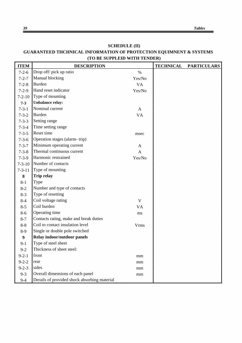
SCHEDULE (II) GUARANTEED THCHNICAL INFORMATION OF PROTECTION EQUIMNENT & SYSTEMS
(TO BE SUPPLEID WITH TENDER)
ITEM DESCRIPTION TECHNICAL PARTICULARS7-2-6 Drop off/ pick up ratio % 7-2-7 Manual blocking Yes/No 7-2-8 Burden VA 7-2-9 Hand reset indicator Yes/No
7-2-10 Type of mounting 7-3 Unbalance relay:
7-3-1 Nominal current A 7-3-2 Burden VA 7-3-3 Setting range 7-3-4 Time setting range 7-3-5 Reset time msec 7-3-6 Operation stages (alarm- trip) 7-3-7 Minimum operating current A 7-3-8 Thermal continuous current A 7-3-9 Harmonic restrained Yes/No
7-3-10 Number of contacts 7-3-11 Type of mounting
8 Trip relay
8-1 Type 8-2 Number and type of contacts 8-3 Type of resetting 8-4 Coil voltage rating V 8-5 Coil burden VA 8-6 Operating time ms 8-7 Contacts rating, make and break duties 8-8 Coil to contact insulation level Vrms 8-9 Single or double pole switched 9 Relay indoor/outdoor panels
9-1 Type of steel sheet 9-2 Thickness of sheet steel:
9-2-1 front mm 9-2-2 rear mm 9-2-3 sides mm 9-3 Overall dimensions of each panel mm 9-4 Derails of provided shock absorbing material
Technical Specification of Protection Systems
40
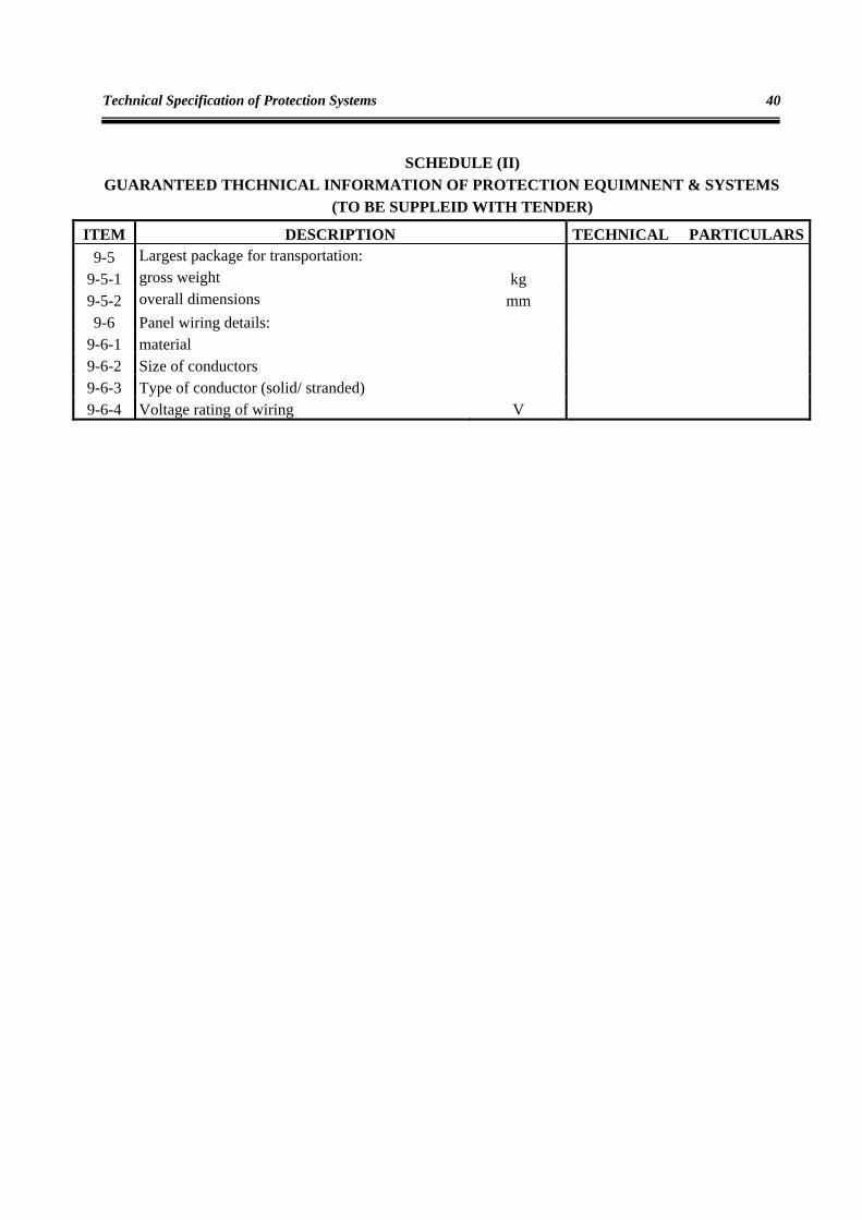
SCHEDULE (II) GUARANTEED THCHNICAL INFORMATION OF PROTECTION EQUIMNENT & SYSTEMS
(TO BE SUPPLEID WITH TENDER)
ITEM DESCRIPTION TECHNICAL PARTICULARS9-5 Largest package for transportation:
9-5-1 gross weight kg 9-5-2 overall dimensions mm 9-6 Panel wiring details:
9-6-1 material 9-6-2 Size of conductors 9-6-3 Type of conductor (solid/ stranded) 9-6-4 Voltage rating of wiring V