Embed Size (px)
Citation preview

Copyright © 2018 U.S. Society on Dams. All Rights Reserved.
GENERALIZED PROGRAMMATIC FRAMEWORK FOR SPILLWAY
INSPECTION AND POTENTIAL FAILURE MODES ASSESSMENT
Ali Reza Firoozfar, PhD PE1
Kenwarjit S. Dosanjh, PE2
Keith C. Moen, PE3
Edwin T. Zapel, PE4
Travis Ford, PE5
ABSTRACT
Dam safety risks are increasing for a number of dams as a result of structural aging,
deterioration, and downstream floodplain development. Spillways are critical for safe
dam operation, responsible for safely passing flood flow without posing danger to the
dam structure. An adequately designed and constructed spillway, reliably available, is
required to reduce the likelihood of potential failure modes (PFMs) progressing to actual
failure. Many spillways are not operated regularly or have never been required to. Often
the lack of use is a result of extended drought, water conservation focused reservoir
operation or use of other available outlet works. Such infrequent operation has, in some
cases, led to false impressions regarding the spillway’s purpose and importance,
consequently resulting in lack of attention to spillway design and operational adequacy.
Regardless of spillway operation frequency, routine inspections and assessment as part of
dam safety practice are necessary to identify and remedy deficiencies to lower the
likelihood of PFMs developing. The spillway inspection, PFM identification, and
assessment can vary depending on the type, structural, geotechnical, drainage, and
hydraulic characteristics of the spillway, its age, and historical operation and
maintenance. A programmatic and integrated inspection, evaluation, and analysis
framework encompassing the variety of spillway types, issues, and PFMs would provide
a useful tool for establishing a strategy toward a safer dam infrastructure. This paper
emphasizes the importance of spillway assessment as part of dam safety practices and
provides a generalized programmatic framework for integrating spillway inspection, PFM
identification, assessment, evaluation, and analysis.
INTRODUCTION
Dams are undoubtedly one of the many brilliant innovations of humans, used to harness
the flowing energy of Mother Nature and store life-giving water. Dams have played a
vital role in providing service (e.g., clean renewable energy, drinking water, irrigation
and recreation) and protection (e.g., flood control) to our communities and economy
throughout the ages, and their significant role continues in the modern history of the
world. The number of dams has rapidly increased with rapid growth of population and
1 Hydraulic Engineer, HDR, 601 Union St, Suite 700, Seattle, WA, [email protected] 2 Hydraulic Structure Engineer, HDR, 2365 Iron Point Rd, Folsom, CA, [email protected] 3 Hydropower Engineer, HDR, 601 Union St, Suite 700, Seattle, WA, [email protected] 4 Hydraulic Engineer, HDR, 601 Union St, Suite 700, Seattle, WA, [email protected] 5 Resources Structural Engineer, HDR, 1670 Broadway Suite 3400, Denver, CO, [email protected]
Copyright © 2018 U.S. Society on Dams. All Rights Reserved.
community development over the past century. When most of the contemporary dams
were designed and constructed risk was not considered; instead, conservative design
assumptions, criteria and parameters were typically applied to the best of technical
knowledge and standard practice at the time. Nowadays, the associated risk can be
estimated with the current advancement of risk analysis methods, available rich datasets
(e.g., hydrological and geotechnical) and related knowledge (e.g., flood prediction,
earthquake analysis, dam failure case histories). With downstream floodplain
development, population growth, and considering the estimated risk, numerous dams can
be reclassified as high hazard potential, in which the dam failure may result in loss of life
and/or significant economic losses. Safe dam operation and appropriate maintenance are
vital to sustaining the benefits and mitigating the associated risks. Dam safety is currently
receiving more attention because of the increasing overall public awareness about large
infrastructure elements (Federal Emergency Management Agency [FEMA] 2013).
Spillways are one of the most critical components of any dam structure, responsible for
safely passing flood flow without endangering the dam structure itself. An appropriately
designed and constructed spillway structure is required to reduce the likelihood of
potential failure modes (PFMs) developing. Unlike outlet works typically used to release
service discharges, spillways are generally operated during relatively large hydrologic
events. Therefore, many spillways are not operated regularly and in some cases have
never been required to. The infrequent operation of spillways in some instances has led to
false impressions regarding the importance of the spillway’s purpose, sometimes
resulting in a lack of enough attention paid to spillway soundness. Most defects and
damages to spillway structures develop progressively, leading to incidents with a wide
range of hazard potential (i.e., from minor operational issues to dam failure with
catastrophic consequences). Therefore, to reduce the risk of PFMs developing, detailed
routine inspections and assessment of the spillway, as part of dam safety practices, are
necessary to identify existing or potential issues and remedy deficiencies accordingly.
Federal agencies such as the U.S. Army Corps of Engineers (USACE), U.S. Bureau of
Reclamation (USBR), Federal Energy Regulatory Commission (FERC) and others have
significant roles in the evolving U.S. dam safety practice. The safety guidelines
developed by these agencies apply to all major features of dams, including spillways.
According to USACE (2014), spillway inspections are generally performed as part of
dam inspections. The USACE policy and procedures on the safety of dams are described
in detail in USACE Safety of Dams – Policy and Procedures (UASCE 2014). Currently,
dam inspections are performed in accordance with the dam safety program, which has
transitioned or is in the process of transitioning from a standards-based approach to a
risk-based or risk-informed approach (USBR-USACE 2015). The USBR dam safety
program, Safety Evaluation of Existing Dams (SEED), is intended to identify and
evaluate dams which pose an increased threat to the public, and also includes spillway
inspections as part of the overall program. Additional guidelines have been developed
and issued to support safety and assessment of discharge release structures such as
conduits, outlet works, and spillways (USBR 2004, FEMA 2005).

Copyright © 2018 U.S. Society on Dams. All Rights Reserved.
The general dam safety guidelines and procedures are recommended to be regularly
implemented by the owners/operators. However, spillway inspections and review of
associated PFMs have not always been fully and regularly integrated into the practice of
inspection, particularly those spillways that only receive infrequent or emergency use.
The recent incident at the Oroville Dam in California has heightened concerns regarding
spillway safety. Following the incident, FERC requested that owners/operators of high
and significant hazard dams perform a detailed spillway-focused inspection and
assessment and complete a spillway-focused PFM analysis (FERC 2017a).
Spillway inspection, PFM identification, assessment, and remedial actions determined to
be necessary can vary depending on the type, structural, geotechnical, drainage and
hydraulic characteristics of the spillway, its age and historical operation and maintenance
actions. Hence, a spillway-focused generalized programmatic and integrated inspection
and assessment framework encompassing the variety of spillway types, issues, PFMs, and
potential solutions would provide a useful tool for establishing a strategy toward a safer
dam infrastructure. This paper is intended to present such a spillway focused
programmatic assessment plan, providing the reader with a guide for preparing and
performing a hands-on spillway assessment, determination of the spillway vulnerabilities,
and reduce the risk of spillway associated PFMs. This programmatic framework is
intended to be used as general guidance; however, each spillway has unique
characteristics to which inspection and evaluation efforts need to be tailored, considering
project setting, design, construction, historical operation and maintenance, and applicable
dam safety requirements.
SPILLWAY ASSESSMENT
Spillways are typically described based on their expected priority and frequency of
operation, control condition, and linings. Primary spillways (aka principal or service
spillways) are designed to pass most large flood flow releases from the dam, and are
often the only spillway provided. They are typically designed to provide what was
considered conservative and safe operation at the time of design, and reflect the
understanding of hydrologic conditions and construction materials at the time.
Conversely, auxiliary or emergency spillways are generally intended to be operated very
rarely, only during very large flood events. They are designed to provide additional
protection against dam overtopping during extreme conditions if the normal outlet works
and/or service spillway cannot provide sufficient capacity (USBR 2004). Spillways can
be differentiated into controlled crests, where mechanical equipment such as gates,
flashboards or fuse panels are used to manage outflows, and uncontrolled crests, where
flow passes voluntarily over the crest with no control. Spillways can be further divided
into lined chutes, where concrete slab and side slope or vertical walls contain most or all
of the discharge passing through the spillway, and unlined chutes that rely on excavated
natural channels to carry the flow. Lined chutes are typically used where the spillway is
in regular use or the unit flow capacity requirements are large and the foundation
materials are not resistant to erosion. Lined chutes increase the reliability of the structure.
Unlined spillways generally rely on the natural foundation material with limited
improvement. Often, primary spillways are lined, while emergency spillways may be
Copyright © 2018 U.S. Society on Dams. All Rights Reserved.
unlined. Since the spillway-associated PFMs differ between lined and unlined spillways,
this distinction was utilized in developing the programmatic spillway inspection and
assessment procedures presented in this paper.
Generally spillway assessment and inspection efforts include six main steps: 1) initial
PFM identification, 2) document review, 3) hands-on condition assessment, 4) data
analysis, 5) PFM assessment and development, and 6) action plan development. Each of
these steps is vital to the evaluation of the safety of spillway, determine issues and
associated risks and develop a plan to remedy deficiencies.
Potential Failure Modes Identification
According to FERC (2017b), a PFM is defined as “the chain of events leading to
unsatisfactory performance of the dam or a portion thereof.” This includes any events
resulting in uncontrolled and/or unintended release of water. However, past events (e.g.
Oroville spillway failure) demonstrate that even if an event does not lead to
uncontrolled/unintended release of water, the consequences of that event can be
significant and should also be considered. Therefore, the first important step in a
generalized framework for spillway inspection is to establish a good understanding of
spillway vulnerabilities and associated PFMs. This step would identify what deficiencies
to look for during a document review and hands-on condition inspection. A list of general
considerations that would increase the spillway vulnerability and may lead to PFMs
developing is presented in Table 1.

Copyright © 2018 U.S. Society on Dams. All Rights Reserved.
Table 1. General Considerations Increasing Spillway Vulnerability
Capacity
Inadequate hydraulic capacity of the spillway and/or
chute during flood
Change in understanding of hydrology and larger
spillway flood capacity requirements
Blockage due to debris or landslide
Inability to operate the gate system (for controlled crest
spillways)
Geotechnical
Landslide/rock fall into the spillway area
Undermining of foundation due to leakage erosion/piping
Rockslide/landslide and foundation failure
Seismic consideration (e.g., existence of faults), change
in understanding of seismicity
Hydraulic
Cavitation
Hydraulic stagnation pressure
Spillway chute and/or stilling basin overtopping due to
air bulking or wave action
Structural
Surface deterioration
Structural gate members inadequacy,
deterioration/corrosion
Slab failure due to deformation, settlement, and excessive
net uplift pressures
Structural failure during seismic event
Erosion and Energy
Dissipation
Spillway erosion
Inadequate energy dissipation and downstream channel
erosion and/or head-cutting
Dam structure undercutting – undermining
Operational
Control system deterioration, malfunction and failure
(for controlled crest spillways)
Underdrain system inadequacy and/or failure
Historical Record Maintenance records (e.g., repair of damaged areas)
Project modification
Lined spillways. Concrete-lined chute/tunnel spillways usually consist of a weir to direct
reservoir outflows into the chute or tunnel conveying the water to downstream and often
some form of energy dissipation to reduce the high energy of the flow before entering the
downstream natural flow path. The PFMs to consider when inspecting concrete lined spillways can be summarized in the five main categories below.
Spillway lining overtopping:
The spillway walls can be overtopped when the spillway discharge exceeds the design
capacity, air bulking increases the volume of mixed flow greater than design capacity,
or spillway capacity within the chute is decreased due to blockage (e.g., debris, side
slope failure). If this occurs, the materials above and behind the lining that are not

Copyright © 2018 U.S. Society on Dams. All Rights Reserved.
resistant enough will be eroded by the overtopping high velocity flow. Erosion could
potentially progress rapidly beneath the concrete lining and lead to spillway failure.
Lining deterioration, instability and erosion:
Significant lining deterioration (e.g., cracks, spalls, and delamination) can result in
spillway system failure through different mechanisms such as lining structural failure,
foundation exposure, and increased pore pressure under the lining. Unrelieved uplift
pressure under the spillway chute lining can also overstress the concrete slab and lead
to chute lining failure. The uplift pressure buildup can be caused by hydraulic
stagnation at the upstream edge of displaced slabs at joints or increase in pore water
pressure due to lack of functional underdrain system. Lining erosion resulting from
cavitation or abrasion could also cause lining failure over time. Failure of the chute
lining slab or walls and resulting exposure of the foundation material to high velocity
flow can quickly worsen the situation.
Foundation erosion:
The foundation erosion process is necessary for a number of PFMs to fully develop.
If the spillway foundation is vulnerable to erosion, internal seepage through cracks,
holes, damaged or deteriorated joint sealant or water stops could introduce erosive
flows under the slab and initiate foundation erosion. Failure of, or lack of a functional
underdrain system, could also initiate internal seepage erosion beneath the slab.
Foundation material erosion can progress under the lining to such an extent that
unsupported slab or sidewall lining could crack or collapse, leading to failure of the
spillway system.
Seismic loading:
Seismic loading in excess of design consideration could initiate cracking i the
spillway structure concrete lining. Significant cracks in the concrete could lead to
failure of spillway crest, gates and piers, as well as chute lining. This could result in
unintended release of water if the spillway crest fails or expose the foundation to high
velocity flow, increasing the risk of foundation erosion if the lining fails. Also,
failed/dislodged concrete lining may block the spillway and lead to overtopping of the
lining. These failures can be further exacerbated by liquefaction of granular
foundation material due to seismic loading.
Slope instability:
Increased pore pressures in the chute side slope foundation (e.g., within the spillway
side slope foundation or on unprotected slopes above the spillway) can potentially
lead to slope failure. Slope failure in the spillway sidewall foundation could result in
concrete lining failure and exposure of the embankment to further erosive forces.
Slope failure above the spillway chute could result in spillway lining overtopping due
to flow restrictions from material blocking the chute. It could also divert water to a
new flow route that could threaten the embankment or undermine the dam
foundation. This could cause embankment and foundation erosion and threaten the
safety of both the spillway and dam. Additionally, increased pore pressure behind
spillway walls with blocked drains could potentially overstress the wall reinforcing.
Copyright © 2018 U.S. Society on Dams. All Rights Reserved.
Unlined Spillways. Since there is no lining in unlined spillways the characteristics of the
foundation rock or soils are critical when considering the PFMs. The PFMs to consider
when inspecting unlined spillways can be summarized in the following four main
categories.
Open channel erosion:
Operation of an unlined spillway may initiate open channel erosion/incision at
vulnerable locations where the bed material is not strong enough to resist the erosive
energy of spill flow. Significant erosion/incision could lead to head-cutting or slope
instability processes and threatens the integrity of the structure.
Seepage/internal erosion:
Internal erosion would start when the hydraulic gradient of seepage flow through
weak areas such as faults reaches the critical gradient. Subsequently, materials will be
plucked and transported away, creating an erosion feature. If the material has
sufficient cohesion a pipe can form, eroding material progressively further into the
foundation. The internal erosion, regardless of simple erosion feature or forming a
pipe, would carry the same risk as open channel erosion.
Headcutting:
A headcut, sudden change in bed elevation at the upstream edge of a gully, in earthen
material progressively moves upstream in the opposite direction of the flow towards
the source. Headcutting can be initiated by open-channel erosion .A breach may occur
if headcutting reaches the spillway crest, creating the potential for a catastrophic
failure in unlined spillways.
Slope instability:
Slope stability can be compromised by either toe erosion undermining the slope or
increased pore pressure reducing stability. Both spillway toe erosion and an increase
in pore pressure within the foundation or on adjacent slopes that could potentially
increase the vulnerability of the unlined spillway.
Spillway Flow Control Systems. Often, spillways are equipped with mechanical control
systems such as gates and valves. In this case, operational failure of the spillway control
system may decrease the spillway outflow capacity and consequently raise the reservoir
elevation. If the spillway is the only flood release structure or if alterative reservoir outlet
works are not operational and the issue cannot be fixed in a timely manner this could lead
to a dam overtopping PFM. Some dams have at least a few different ways of discharging
the flow (e.g., emergency spillways, outlet works, low level outlet, and powerhouse).
Sometimes, controlled spillways are equipped with multiple independent and redundant
controlled outlets (e.g., multiple gates). Therefore, the number, capacity and vulnerability
of the all flow release systems should be considered when identifying and developing
PFMs.
Document Review
Reviewing the available documents pertaining to a particular dam and spillway provides
essential information necessary for a successful spillway assessment, so its importance
Copyright © 2018 U.S. Society on Dams. All Rights Reserved.
cannot be emphasized enough. The information would guide the inspection effort and
prepare the team for the hands-on inspection and testing. This would also allow them to
identify any potential problematic areas beforehand, which require more attention during
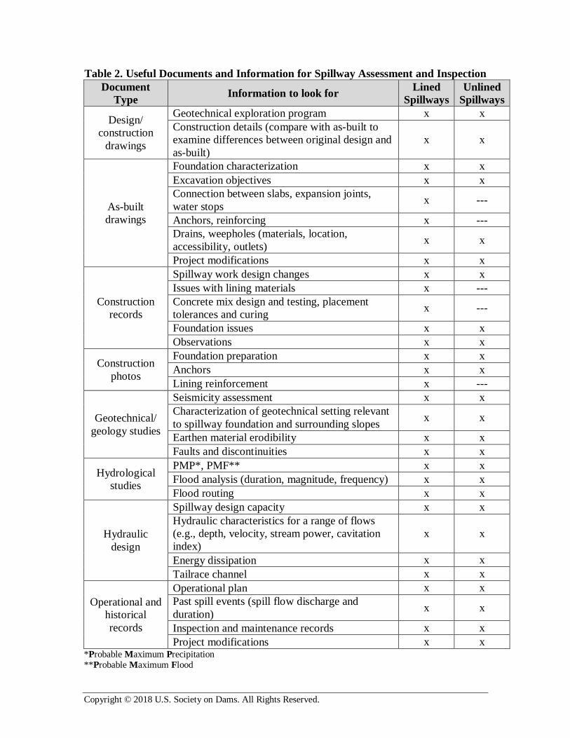
the hands-on inspection. A general list of the type of documents that may provide
valuable information for spillway assessment is provided in Table 2.
Hands-on Assessment
Prior to scheduling a date for the hands-on assessment, enough time must be allowed for
preparation and to perform a preliminary PFM identification and review available
documents. The inspection planning should also take into account the operational,
seasonal, and environmental considerations pertaining to the spillway. The inspection
team must work closely with other groups such as dam operation staff and technicians,
and consider access difficulties that may require specialists such as rope access engineers
and/or divers for safe access to parts of the facility. Also, the team may need to attend
special training sessions such as confined space training, depending on the project
specifications. The hands-on assessment encompasses different techniques, including
visual inspection, non-destructive, and destructive testings to assess the spillway
condition.
Visual Inspection. The visual inspection must be performed by individuals with adequate
training and background familiar with dam and hydraulic structures. If engineering
evaluations are included, a professional engineer, licensed in the appropriate jurisdiction
is also required. The experience and knowledge level of the inspection team, with regards
to operation, safety, structural, geotechnical and hydraulic aspects of dams, is a key factor
to a successful assessment effort. The visual inspection must be conducted by carefully
observing the spillway condition and looking for abnormal features and possible
deficiencies. This encompasses a wide range of features and deficiencies related to
hydraulic, structural, geotechnical, and operational characteristics of the system. A
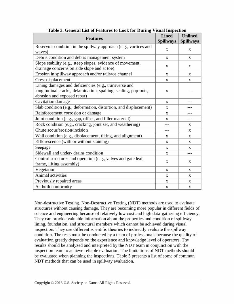
general list of features to look for during visual inspection of spillways is presented in
Table 3. It is necessary to accurately document and record the observed features during
visual inspection. Documenting spillway condition and observed features with
photographs taken from similar vantage point provides a baseline for future inspections.
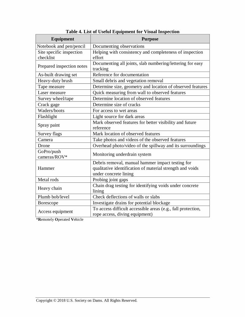
A general list of equipment that may be needed to efficiently perform the inspection is
provided in Table 4.
It should be noted that the condition of energy dissipation structures such as stilling
basins, plunge pools, and downstream channel is crucial to the overall functionality of the
spillway and should be inspected along with the spillway structure.
Copyright © 2018 U.S. Society on Dams. All Rights Reserved.
Table 2. Useful Documents and Information for Spillway Assessment and Inspection
Document
Type Information to look for
Lined
Spillways
Unlined
Spillways
Design/
construction
drawings
Geotechnical exploration program x x
Construction details (compare with as-built to
examine differences between original design and
as-built)
x x
As-built
drawings
Foundation characterization x x
Excavation objectives x x
Connection between slabs, expansion joints,
water stops x ---
Anchors, reinforcing x ---
Drains, weepholes (materials, location,
accessibility, outlets) x x
Project modifications x x
Construction
records
Spillway work design changes x x
Issues with lining materials x ---
Concrete mix design and testing, placement
tolerances and curing x ---
Foundation issues x x
Observations x x
Construction
photos
Foundation preparation x x
Anchors x x
Lining reinforcement x ---
Geotechnical/
geology studies
Seismicity assessment x x
Characterization of geotechnical setting relevant
to spillway foundation and surrounding slopes x x
Earthen material erodibility x x
Faults and discontinuities x x
Hydrological
studies
PMP*, PMF** x x
Flood analysis (duration, magnitude, frequency) x x
Flood routing x x
Hydraulic
design
Spillway design capacity x x
Hydraulic characteristics for a range of flows
(e.g., depth, velocity, stream power, cavitation
index)
x x
Energy dissipation x x
Tailrace channel x x
Operational and
historical
records
Operational plan x x
Past spill events (spill flow discharge and
duration) x x
Inspection and maintenance records x x
Project modifications x x *Probable Maximum Precipitation **Probable Maximum Flood
Copyright © 2018 U.S. Society on Dams. All Rights Reserved.
Table 3. General List of Features to Look for During Visual Inspection
Features Lined
Spillways
Unlined
Spillways
Reservoir condition in the spillway approach (e.g., vortices and
waves) x x
Debris condition and debris management system x x
Slope stability (e.g., steep slopes, evidence of movement,
drainage concerns on side slope and at toe) x x
Erosion in spillway approach and/or tailrace channel x x
Crest displacement x x
Lining damages and deficiencies (e.g., transverse and
longitudinal cracks, delamination, spalling, scaling, pop-outs,
abrasion and exposed rebar)
x ---
Cavitation damage x ---
Slab condition (e.g., deformation, distortion, and displacement) x ---
Reinforcement corrosion or damage x ---
Joint condition (e.g., gap, offset, and filler material) x ----
Rock condition (e.g., cracking, joint set, and weathering) --- x
Chute scour/erosion/incision --- x
Wall condition (e.g., displacement, tilting, and alignment) x x
Efflorescence (with or without staining) x x
Seepage x x
Sidewall and under- drains condition x ---
Control structures and operation (e.g., valves and gate leaf,
frame, lifting assembly) x x
Vegetation x x
Animal activities x x
Previously repaired areas x x
As-built conformity x x
Non-destructive Testing. Non-Destructive Testing (NDT) methods are used to evaluate
structures without causing damage. They are becoming more popular in different fields of
science and engineering because of relatively low cost and high data-gathering efficiency.
They can provide valuable information about the properties and condition of spillway
lining, foundation, and structural members which cannot be achieved during visual
inspection. They use different scientific theories to indirectly evaluate the spillway
condition. The tests must be conducted by a team of professionals because the quality of
evaluation greatly depends on the experience and knowledge level of operators. The
results should be analyzed and interpreted by the NDT team in conjunction with the
inspection team to achieve reliable evaluation. The limitations of NDT methods should
be evaluated when planning the inspections. Table 5 presents a list of some of common
NDT methods that can be used in spillway evaluation.
Copyright © 2018 U.S. Society on Dams. All Rights Reserved.
Table 4. List of Useful Equipment for Visual Inspection
Equipment Purpose
Notebook and pen/pencil Documenting observations
Site specific inspection
checklist
Helping with consistency and completeness of inspection
effort
Prepared inspection notes Documenting all joints, slab numbering/lettering for easy
tracking
As-built drawing set Reference for documentation
Heavy-duty brush Small debris and vegetation removal
Tape measure Determine size, geometry and location of observed features
Laser measure Quick measuring from wall to observed features
Survey wheel/tape Determine location of observed features
Crack gage Determine size of cracks
Waders/boots For access to wet areas
Flashlight Light source for dark areas
Spray paint Mark observed features for better visibility and future
reference
Survey flags Mark location of observed features
Camera Take photos and videos of the observed features
Drone Overhead photo/video of the spillway and its surroundings
GoPro/push
cameras/ROV* Monitoring underdrain system
Hammer
Debris removal, manual hammer impact testing for
qualitative identification of material strength and voids
under concrete lining
Metal rods Probing joint gaps
Heavy chain Chain drag testing for identifying voids under concrete
lining
Plumb bob/level Check deflections of walls or slabs
Borescope Investigate drains for potential blockage
Access equipment To access difficult accessible areas (e.g., fall protection,
rope access, diving equipment) *Remotely Operated Vehicle

Copyright © 2018 U.S. Society on Dams. All Rights Reserved.
Table 5. Some of Common Non-destructive Testing Methods for Spillway Evaluation
Non-destructive
Testing Technology Purpose
Photographic
Records
Digital
Photography
Take numerous photographs of the structure and
compare with as-built drawing for conformity
and with previous or future photographs to
determine any changing condition
LiDAR Laser light
Scan the structure and compare with as-built
drawing for conformity and with previous or
future scans to determine any changing condition
Sonar Scan Sound wave Perform underwater scan of approach channel or
stilling basin
Ground
Penetrating
Radar (GPR)
Electromagnetic
waves
Determine/locate the depth of materials within a
material (e.g., rebar within concrete)
Measure existing thicknesses of members (slabs)
Determine voids within or behind/below
structural members such as walls/slabs
Schmidt
Hammer Spring rebound Measure strength of rock/concrete
Impact Echo
(IE) Sound waves
Determine thickness and location of deficiencies
within structures (e.g., cracks, honeycombing,
voids, delamination and debonding of
reinforcement and to the foundation)
Slab Impulse
Response (SIR) Sound waves
Determine the support conditions of slabs-on-
grade pre- and post-repair and, in particular,
determining subgrade voids
Locate areas of delamination or voids within
concrete slabs within shallow depths
Half Cell
Corrosion
Mapping*
Electrical
resistance
Determine the corrosion potential of a reinforced
concrete member
Map areas with high probability of corrosion
potentially before major corrosion damage
occurs
Thermal
Imaging
Infrared
radiation
Map potential areas of deficiencies within the
structure (e.g., large air voids, cracks, and
delamination)
Ultrasonic Pulse
Velocity (UPV)
Ultrasound
waves
Determine potential defects in structure (e.g.,
delamination, honeycombing, cracks and voids)
Seismic
Reflection and
Refraction
Geophysics
Determine physical properties of subsurface
geologic materials (e.g., degree of weathering,
density, quality of rock)
Determine faulting and shear zones
Map depth to bedrock and bedrock topography
Map landslides *May require exposing the rebar, causing some damage to the structure.
Copyright © 2018 U.S. Society on Dams. All Rights Reserved.
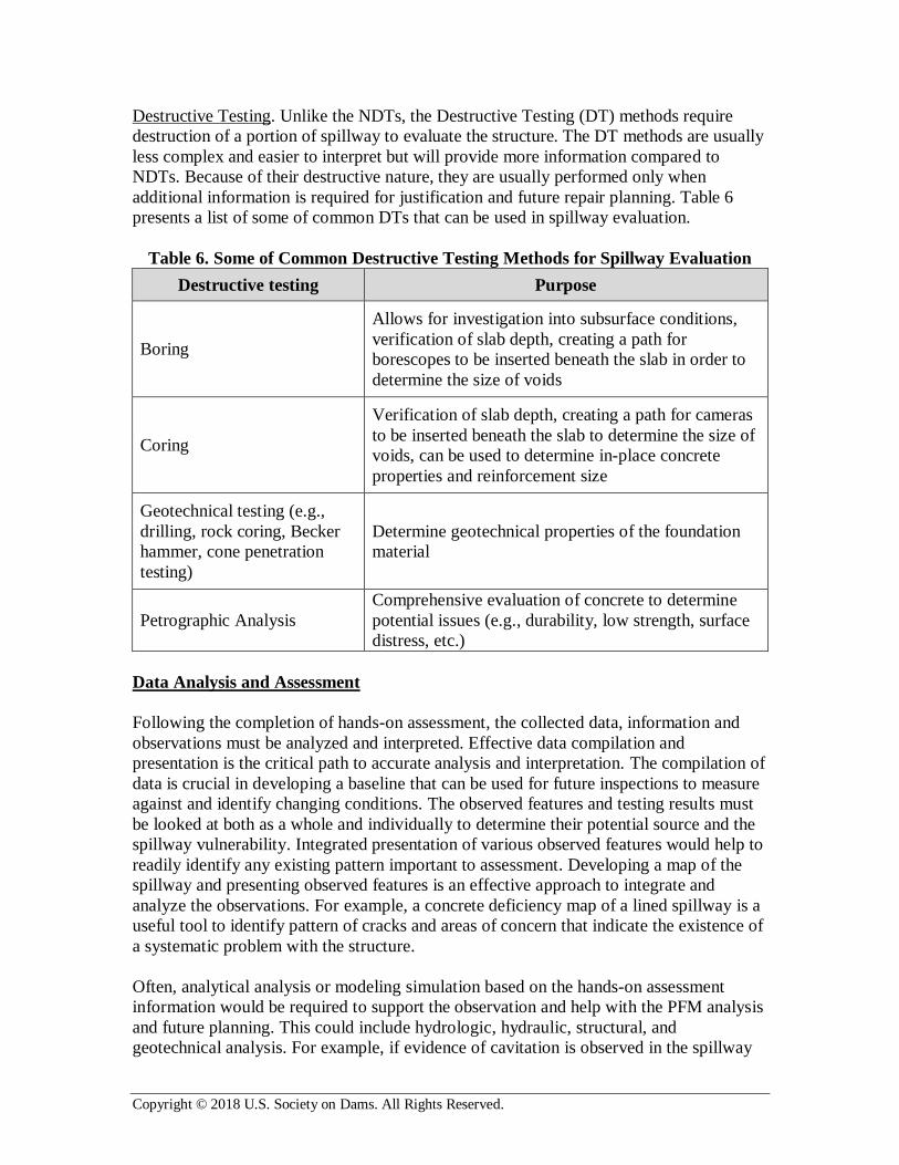
Destructive Testing. Unlike the NDTs, the Destructive Testing (DT) methods require
destruction of a portion of spillway to evaluate the structure. The DT methods are usually
less complex and easier to interpret but will provide more information compared to
NDTs. Because of their destructive nature, they are usually performed only when
additional information is required for justification and future repair planning. Table 6
presents a list of some of common DTs that can be used in spillway evaluation.
Table 6. Some of Common Destructive Testing Methods for Spillway Evaluation
Destructive testing Purpose
Boring
Allows for investigation into subsurface conditions,
verification of slab depth, creating a path for
borescopes to be inserted beneath the slab in order to
determine the size of voids
Coring
Verification of slab depth, creating a path for cameras
to be inserted beneath the slab to determine the size of
voids, can be used to determine in-place concrete
properties and reinforcement size
Geotechnical testing (e.g.,
drilling, rock coring, Becker
hammer, cone penetration
testing)
Determine geotechnical properties of the foundation
material
Petrographic Analysis
Comprehensive evaluation of concrete to determine
potential issues (e.g., durability, low strength, surface
distress, etc.)
Data Analysis and Assessment
Following the completion of hands-on assessment, the collected data, information and
observations must be analyzed and interpreted. Effective data compilation and
presentation is the critical path to accurate analysis and interpretation. The compilation of
data is crucial in developing a baseline that can be used for future inspections to measure
against and identify changing conditions. The observed features and testing results must
be looked at both as a whole and individually to determine their potential source and the
spillway vulnerability. Integrated presentation of various observed features would help to
readily identify any existing pattern important to assessment. Developing a map of the
spillway and presenting observed features is an effective approach to integrate and
analyze the observations. For example, a concrete deficiency map of a lined spillway is a
useful tool to identify pattern of cracks and areas of concern that indicate the existence of
a systematic problem with the structure.
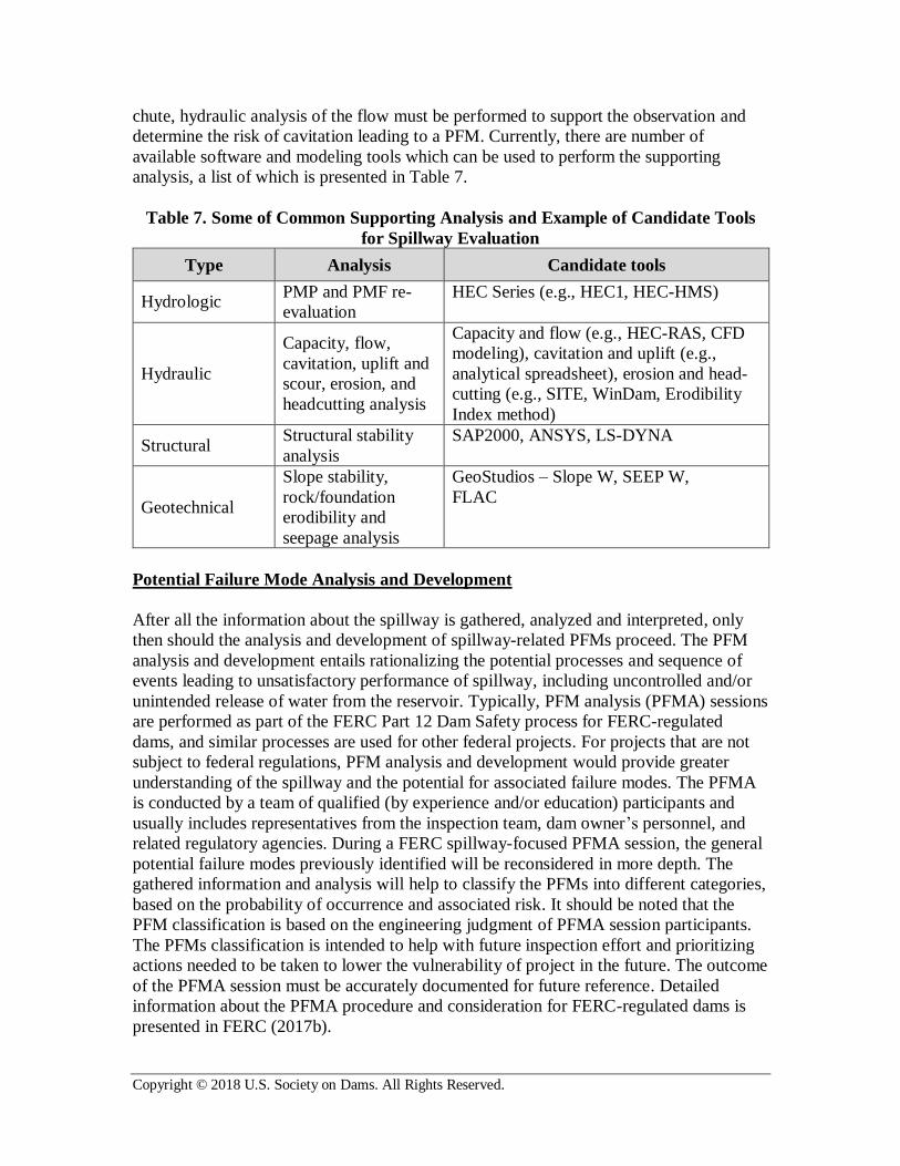
Often, analytical analysis or modeling simulation based on the hands-on assessment
information would be required to support the observation and help with the PFM analysis
and future planning. This could include hydrologic, hydraulic, structural, and
geotechnical analysis. For example, if evidence of cavitation is observed in the spillway
Copyright © 2018 U.S. Society on Dams. All Rights Reserved.
chute, hydraulic analysis of the flow must be performed to support the observation and
determine the risk of cavitation leading to a PFM. Currently, there are number of
available software and modeling tools which can be used to perform the supporting
analysis, a list of which is presented in Table 7.
Table 7. Some of Common Supporting Analysis and Example of Candidate Tools
for Spillway Evaluation
Type Analysis Candidate tools
Hydrologic PMP and PMF re-
evaluation
HEC Series (e.g., HEC1, HEC-HMS)
Hydraulic
Capacity, flow,
cavitation, uplift and
scour, erosion, and
headcutting analysis
Capacity and flow (e.g., HEC-RAS, CFD
modeling), cavitation and uplift (e.g.,
analytical spreadsheet), erosion and head-
cutting (e.g., SITE, WinDam, Erodibility
Index method)
Structural Structural stability
analysis
SAP2000, ANSYS, LS-DYNA
Geotechnical
Slope stability,
rock/foundation
erodibility and
seepage analysis
GeoStudios – Slope W, SEEP W,
FLAC
Potential Failure Mode Analysis and Development
After all the information about the spillway is gathered, analyzed and interpreted, only
then should the analysis and development of spillway-related PFMs proceed. The PFM
analysis and development entails rationalizing the potential processes and sequence of
events leading to unsatisfactory performance of spillway, including uncontrolled and/or
unintended release of water from the reservoir. Typically, PFM analysis (PFMA) sessions
are performed as part of the FERC Part 12 Dam Safety process for FERC-regulated
dams, and similar processes are used for other federal projects. For projects that are not
subject to federal regulations, PFM analysis and development would provide greater
understanding of the spillway and the potential for associated failure modes. The PFMA
is conducted by a team of qualified (by experience and/or education) participants and
usually includes representatives from the inspection team, dam owner’s personnel, and
related regulatory agencies. During a FERC spillway-focused PFMA session, the general
potential failure modes previously identified will be reconsidered in more depth. The
gathered information and analysis will help to classify the PFMs into different categories,
based on the probability of occurrence and associated risk. It should be noted that the
PFM classification is based on the engineering judgment of PFMA session participants.
The PFMs classification is intended to help with future inspection effort and prioritizing
actions needed to be taken to lower the vulnerability of project in the future. The outcome
of the PFMA session must be accurately documented for future reference. Detailed
information about the PFMA procedure and consideration for FERC-regulated dams is
presented in FERC (2017b).
Copyright © 2018 U.S. Society on Dams. All Rights Reserved.
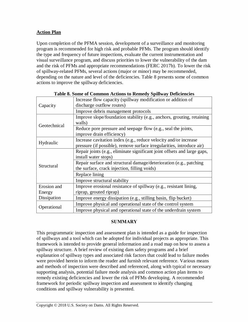
Action Plan
Upon completion of the PFMA session, development of a surveillance and monitoring
program is recommended for high risk and probable PFMs. The program should identify
the type and frequency of future inspections, evaluate the current instrumentation and
visual surveillance program, and discuss priorities to lower the vulnerability of the dam
and the risk of PFMs and appropriate recommendations (FERC 2017b). To lower the risk
of spillway-related PFMs, several actions (major or minor) may be recommended,
depending on the nature and level of the deficiencies. Table 8 presents some of common
actions to improve the spillway deficiencies.
Table 8. Some of Common Actions to Remedy Spillway Deficiencies
Capacity
Increase flow capacity (spillway modification or addition of
discharge outflow routes)
Improve debris management protocols
Geotechnical
Improve slope/foundation stability (e.g., anchors, grouting, retaining
walls)
Reduce pore pressure and seepage flow (e.g., seal the joints,
improve drain efficiency)
Hydraulic Increase cavitation index (e.g., reduce velocity and/or increase
pressure (if possible), remove surface irregularities, introduce air)
Structural
Repair joints (e.g., eliminate significant joint offsets and large gaps,
install water stops)
Repair surface and structural damage/deterioration (e.g., patching
the surface, crack injection, filling voids)
Replace lining
Improve structural stability
Erosion and
Energy
Dissipation
Improve erosional resistance of spillway (e.g., resistant lining,
riprap, grouted riprap)
Improve energy dissipation (e.g., stilling basin, flip bucket)
Operational Improve physical and operational state of the control system
Improve physical and operational state of the underdrain system
SUMMARY
This programmatic inspection and assessment plan is intended as a guide for inspection
of spillways and a tool which can be adopted for individual projects as appropriate. This
framework is intended to provide general information and a road map on how to assess a
spillway structure. A brief review of existing dam safety programs and a brief
explanation of spillway types and associated risk factors that could lead to failure modes
were provided herein to inform the reader and furnish relevant reference. Various means
and methods of inspection were described and referenced, along with typical or necessary
supporting analysis, potential failure mode analysis and common action plan items to
remedy existing deficiencies and lower the risk of PFMs developing. A recommended
framework for periodic spillway inspection and assessment to identify changing
conditions and spillway vulnerability is presented.
Copyright © 2018 U.S. Society on Dams. All Rights Reserved.
The programmatic spillway assessment and PFM analysis and development presented
herein follows after the typical procedure below:
1. Initial consideration and identification of PFMs
2. Review of existing documents
3. Selecting the most appropriate assessment methods to acquire the most information,
plan and execute the inspection and assessment
4. Synthesize the collected data and perform supporting analysis if needed
5. Conduct a PFM analysis and development
6. Develop an action plan
REFERENCES
FEMA. 2005. Technical Manual: Conduits through Embankment Dams.
FEMA. 2013. Living with Dams: Know Your Risks. FEMA-956.
FERC. 2017a. https://www.ferc.gov/industries/hydropower/safety/initiatives/spillway.asp
FERC. 2017b. Dam Safety Performance Monitoring Program. Engineering Guidelines
for the Evaluation of Hydropower Projects –Chapter 14.
USACE. 2014. Engineering and Design, Safety of Dams – Policy and Procedures.
Regulation No. ER 1110-2-1156. Washington, DC. March 31, 2014.
USBR. 2004. Inspection of Spillways, Outlet Works, and Mechanical Equipment.
Veesaert, Chris J., 2004.
USBR. 1995. Safety Evaluation of Existing Dams. Denver, Colorado.
USBR. 1988. Training Aids for Dam Safety: Identification of Visual Dam Safety
Deficiencies. Denver, Colorado: U.S. Department of the Interior, Bureau of Reclamation,
1988.
USBR-USACE. 2015. Best Practices in Dam and Levee Safety Risk Analysis.