Embed Size (px)
Citation preview

GENERATING GLOBAL ENERGY MANAGEMENT STRATEGIES: APPLICATIONTO THE CANOPEA BUILDING
Yanis Hadj-Said1, Stephane Ploix1, Camille Latremoniere11G-SCOP lab, Grenoble Institute of Technology, France
Email: [email protected], [email protected],
ABSTRACT In this paper, the energy managementsystem that has been developed for the CANOPEAbuilding is detailed. It is based on a virtual represen-tation of the building system including envelope, do-mestic appliances and technical appliances. The paperpresents a core high level language to model build-ing systems and a projection mechanism to generatemixed integer linear programming problems used forthe generation of energy management strategies. It hasbeen applied to the generation of energy managementstrategies for the CANOPEA building system.
INTRODUCTIONThe building sector is going to face two main upcom-ing issues. Firstly, the increasing weight of renewableenergies in the power resources requires means to ad-just the consumption of the power resources, whichare becoming less controllable i.e. it requires means todirectly manage or to support occupants and managersduring decision making processes. Secondly, decreas-ing the energy impact of buildings requires on the onehand, more efficient appliances and building envelope,but also, on the other hand, to adjust the configurationof a dwelling system, including configuration of shut-ters, windows, HVAC system and of other appliances,to the current context related to weather conditions,energy availability and occupant preferences and de-mands. Therefore, energy management may help tosolve the two main upcoming issues.In the literature, energy management concerns gener-ally specific systems but not a whole dwelling with allthe appliances. (John and Smith, 1995) and (Guo andMoncef., tion) propose an optimization strategy forHVAC system based on appliance consumption shift-ing out of peak consumption periods. It is carried outby exploiting the thermal inertia of buildings. (Guoand Moncef., tion) shows that 10% savings are pos-sible with such a strategy. (Linda et al., 2008) and(Christian and Ion, 2010) propose a temperature con-trol set-point based on a model predictive control algo-rithm (MPC) but it does not take into account the over-all energy efficiency problem. (Eynard, 2010) (Guil-laume, 2009) (Gregor and Dodier, 2003) focused onconsumption management based on local productioncapacity. A global model based energy managementapproach has been proposed in (Ha et al., 2012) butpractical validation is still missing.In (Ha et al., 2012), the management system usesmixed integer linear programming solvers to find bestsolutions for energy consumption in a dwelling. The
input of solver is a problem description in a low levellanguage MILP (for Mixed Integer Linear Program-ming) according to virtual representation of thermalphenomena and appliance responses to possible con-trols.Indeed, from a practical point of view, new issues arisesuch as how to easily tune model parameters that fitan actual building and how to estimate variables thatare difficult to measure. Another issue is to man-age the composition of mathematical representationsof a complex dwelling that can be used with mixed in-teger linear programming algorithm for optimization.This paper focuses on the latter point considering theCANOPEA prototype building proposed for the SolarDecathlon Europe 2012 contest by the French Rhone-Alpes team.
Figure 1: Canopea nano-tower principle
The Solar Decathlon Europe 2012 contest is an inter-national competition where 18 teams participate. Theyhave to develop futuristic visions of buildings that in-tegrates new technologies. This paper presents a partof the Rhone-alpes team vision the winner of the con-test. It consists on nano-towers bars that can be han-dled by architects to compose urban islands. Eachnano-tower is composed of maximum of ten houseswith one house per floor. It mixes between advan-tages of individual dwellings and collective housing.Houses offers 360 �Cpanoramic vision around, priva-tive space and individual air conditioning system. Thenano-towers mutualizes services like common area,washing machine,boiler of central heating system, hy-brid and PV panels installed on the roof, electric andthermal storage.For the SDE 2012 contest, only thetwo last floors corresponding to one dwelling and onecommon area of the nano-towers built. The resulting
Proceedings of BS2013: 13th Conference of International Building Performance Simulation Association, Chambéry, France, August 26-28
- 2147 -
prototype named CANOPEA includes individual ap-pliances and common to building appliances. BEMSwas developed to manage the appliances and to informoccupant about the interesting actions to be more effi-cient for the energy usage.
PROBLEM STATEMENTModel development yields compatibility problemswith solver capabilities. Solvers used for simulationare not necessarily the same than the one used forenergy management and for parameters identification.Actually, the system needs a high level model descrip-tion that describes physical phenomena without inte-grating solver constraints. High level flexible languagedescription is the keystone for the generality.
LANGUAGE REQUIREMENTSA core high level modeling language is an interfacebetween the model programmer and different applica-tions. The requirements for this core language follow.
non causal language, The first requirement is an a-causal language. This requirement is relatedto the MILP solver used to generate energymanagement strategies. Problem formulation isquite simple. It consists in a set of variablesand a set of inequality and equality constraintswith a given objective. For instance, Mat-lab/Simulink models cannot be used becausethey require variables to be either inputs or out-puts i.e. causality.
High level language modeling, To model simpledwelling, the formulation can takes over then15000 constraints. Somme of these constraintsare due to mathematical manipulations and tem-poral projections. The modeler should writeonly the mathematical equations.
multi-application modeling core language, Whendesigning a model, there is a validation anda tuning process to set up the building sys-tem model. The component models are finallyused to compute energy management strategiesin buildings. A core modeling language has tomake it possible to transform core models intoapplication model. These core models shouldlead to simulatie model for validation by set-ting up a set of variables as parameters andkeeping others as variables to be computed bythe solvers. Then, core models should alsobe reformulated for parameter identification ap-plication whose objective is to minimize errorbetween simulated values and actual measure-ments. For this application, some variables usedfor simulation have to be considered as param-eters and some variables have to be consideredas inputs coming from sensors. Another appli-cation using models is the preliminary design.It helps designers to evaluate main choices atthe beginning of the project design (Chenailler
et al., 2010). Transformation into applicationlanguages or models should also be possible.
composition mechanism, Most languages offer thepossibility of composing basic modeling ele-ments through graphical user interface. Thisfacility should be available for a core multi-application language.
transformation patterns, Transforming a core modelinto a model for energy management that can besolved by a MILP solver requires some trans-formations that basically consist in applying lin-earization patterns. Usual linearization patternsare given in (Ha et al., 2012). They are appliedrecursively:• product of n binary variables• semi-continuous product of a binary vari-
able and a continuous one• logical implication or equivalence• minimum or maximum• linearization of nonlinear function by a
stepwise function• linearization of ordinary differential equa-
tionsTherefore, the core language should allow sym-bolic handling to detect and transform nonlinearexpressions.
A prototype of core language has been developed ac-cording to the previous requirements. Then, a projec-tor implementing the linearization patterns has beenbuilt in order to translate the core models into MILPmodels. Then, CPLEX or GLPK solvers can be used.
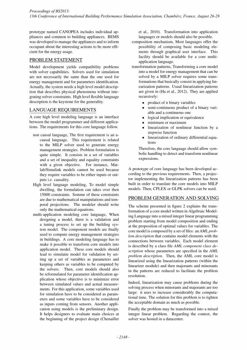
PROBLEM GENERATION AND SOLVINGThe scheme presented in figure 2 explains the trans-formation of a core model written in Algebraic Model-ing Language into a mixed integer linear programmingproblem starting from model composition and endingat the proposition of optimal values for variables. Thecore model is composed by a set of files: an AML prob-lem description that contains model elements with theconnections between variables. Each model elementis described by a class file AML component class de-scription whose parameters are specified in the AMLproblem description. Then, the AML core model islinearized using the linearization patterns (within thelinearizer module) and then majorants and minorantsin the patterns are reduced to facilitate the problemresolution.
Indeed, linearization may cause problems during thesolving process when minorants and majorants are toolarge: it uses to increase considerably the computa-tional time. The solution for this problem is to tightenthe acceptable domain as much as possible.
Finally the problem may be transformed into a mixedinteger linear problem. Regarding the contest, thesolver was hosted in a datacenter.
Proceedings of BS2013: 13th Conference of International Building Performance Simulation Association, Chambéry, France, August 26-28
- 2148 -

Figure 2: Mechanism of problem generation and resolution
CANOPEA MODELCanopea integrates a lot of technical systems. Thewalls of the envelop are composed of different ma-terials. There are double glass windows and doors.Windows can be obstructed by shutters equipped withelectrical actuators but also by blinds made of fab-ric. Canopea project integrates buffer space around thehouse. Over architectural considerations, this bufferspace creates and maintains fresh temperature, thanksto wind. Buffer isolates home walls from sun radia-tion by adding another transparent and/or semi-opaquemembrane made of glass. In cold periods, this spacelimits thermal losses if the membrane is completelyclosed.
Figure 3: Global view of the envelop
Thermal modeling is done considering the wholedwelling as a single thermal zone. The single zone
is modeled as a first order differential equation. Thisrepresentation is not very precise but sufficient for theproblem to solve. Indeed, errors related to the predic-tion of external conditions make precise models notmeaningful.
Tw
(k + 1) = F.Tw
(k) +Go
To
(k) +Gi
�i
(k) + ...
...Gw
�w
(k) +Ga
Ta
Ti
(k) = Hw
Tw
(k) +Ho
To
(k) +Hi
�i
(k)
withF = e
��⌧
Go
= Ko
⌧ (1� F )
Gi
= Ki
⌧ (1F )
Gw
= Kw
⌧ (1� F )
Ga
= Ka
⌧ (1� F )
Hw
=R
v
Rv
+Ri
Ho
=R
i
Rv
+Ri
Hi
=R
i
Rv
Rv
+Ri
with : To
: outdoor temperatureTi
: indoor temperature for the considered thermalzone.Tw
: average temperature of the walls around the room.Ta
: average temperature of the adjacent thermal zones.�i
: power provided directly inside the thermal zone .�w
: power provided directly inside the wall.R
o
;Ri
: equivalent thermal resistances.
Proceedings of BS2013: 13th Conference of International Building Performance Simulation Association, Chambéry, France, August 26-28
- 2149 -

Rv
: Thermal resistance (deduced from Heat ex-changer).C
w
: equivalent wall thermal capacity.R
a
: equivalent thermal resistance defining the powerflow exchanged with adjacent rooms.
Appliances Domestic appliances like washing ma-chine are modeled as temporary service (see (Ha et al.,2012)), i.e. a average power consumed during a giventime period for which ending time is used to evaluateoccupant satisfaction.Let K ⌘ [floor(F
in
�D), ceil(Fmax
)]. In the next,8k means 8k 2 K. Let 8k, f be the ending timeof the service with dom(f) = [F
min
, Fmax
]. Let8k, �1(k) 2 {0, 1} satisfying: �1(k) = 1 $ f k�.The ending time is before k�. Let 8k, �2(k) 2 {0, 1}satisfying: �2(k) = 1 $ f �D k�.The starting time is before k�.Let 8k, d(k) be the service duration during the periodk(only if d(k) � 0).It can be stated that:
8k, d(k) = min(f, (k + 1)�)�max(f �D, k�)
with
min(f, (k + 1)�) = (k + 1)�� ...
...(k + 1)��1(k + 1) + �1(k + 1)f
and
max(f �D, k�) = �D +D�2(k) + ...
...k��2(k) + f � �2(k)f
Therefore,
8k, d(k) = D + (k + 1)�� (k + 1)��1(k + 1)...
...�D�2(k)� k��2(k)� f + �1(k + 1)f + �2(k)f
Energy computation: Let
8k, �3(k) 2 {0, 1}
satisfying:
�3(k) = 1 $ d(k) � 0
Let 8k,E(k) 2 [0, P�] be the energy consumed dur-ing the period k. It can be stated that:
E(k) = P �3(k)d(k)
Figure 4: Heating system
Air conditioning system The air conditioning sys-tem is composed of a series of fans installed along anetwork of air transmission. This network begins witha phase-shifter which allows constant air flow to shiftthe temperature with a 12 hour time delay. This sys-tem saves energy when the night is cold and the day ishot. However, in other cases, the system can consumemore energy then what is saved. To get delayed tem-perature when the system needs it, there is a powerfulair fan permanently on.After the phase shifter, there is a three-way valve thatallows to the internal system to choose between aircoming through phase shifter or external air. After thethree-way air valve, the air flow is directed to an air/airheat pump coupled to a static exchanger. The systemcontributes to recycle the internal ambience while re-newing the air. One part of the heat recovered by theair/air heat pump is injected to the domestic hot wa-ter tank and the other part is injected in the air of thethermal zone. The system is managed by selecting anoperational mode, there are two free-cooling modes,active and passive heating mode and active and pas-sive cooling mode. Model of the system is divided intotwo parts: the first one concerns heat transfers and thesecond CO2 concentration.The thermo-dynamical heat pump is presented to showthe approach:
�h
=.
mh
Cp
(T cond
out
� T cond
in
)
�c
=.
mc
Cp
(T evap
out
� T evap
in
)
�elec
= �h
+ �c
COP =�h
�elec
�elec
= � ⇤ P compressor
elec
T cond
in
= T outdoor
in
⇤HeatMode+T indoor
in
⇤CoolMode
T evap
in
= T outdoor
in
⇤HeatMode+T indoor
in
⇤CoolMode
T evap
out
= T outdoor
out
⇤HeatMode+T indoor
out
⇤CoolMode
T cond
out
= T outdoor
out
HeatMode+T indoor
out
⇤CoolMode
HeatMode+ CoolMode+OffMode = 1
Proceedings of BS2013: 13th Conference of International Building Performance Simulation Association, Chambéry, France, August 26-28
- 2150 -

Water circuit The water circuit is an alternativeway for temperature adjustment, it is a casing sys-tem, bringing water from an external hot water loop,or from hybrid panels. The water loop recovers heatfrom plants near the building and provides it to the in-habitants. The hybrid panels are located on the roof ofthe building to pick up the heat from sun or freshnessof heaven vault by water casing and photovoltaic cells.The electric energy produced is directly used or sentto the grid or stored into batteries. The thermal en-ergy coming from panels is transferred to an internalcircuit of casings embedded into walls, floors and ceil-ings or to a thermal storage tank. The water comingfrom outdoor is not the same as the water flowing inthe internal circuits. Indeed, there is an isolation doneby a water/water heat pump that increase efficiency ofthe system and control the internal water temperaturein the loops. Water/water heat pump send energy to theinternal loops through thermal storage tank that yieldsinertia to the system and the capacity to delay the en-ergy usage from the moment of production. Exchangeis carried out by a mixing bottle.The equations of water/water heat pump are similarto air/air heat pump, only the connections are differ-ent but it will be developed in the composition sec-tion. The modeling of the system is done through com-ponents that describe different parts that compose thesystem, these parts are: hot water loop, hybrid panel,water/water heat pump, thermal storage, mixing bot-tle, water casings and three-way valves.
Solar irradiance For modeling purpose, solar irra-diance has been modeled according to the geograph-ical localization of the building and the direction ofeach facade of Canopea. The model takes into accountthe four seasons of the year where the sun is more orless far from the earth, which influences the thermaland photovoltaic gains. The model takes into accountpredicted nebulosity over the region were the buildingis situated and is able to compute direct and diffuse ra-diation around the building. The predictions concern-ing radiation are used by other elements, for example,the energy that can be captured by photovoltaic panels,windows or shutters.
Figure 5: Solar trajectory
Comfort Comfort models quantify services pro-vided by appliance according to the criteria given byoccupants. For the ambient temperature,for example,there are a preferred, minimum and maximum accept-able temperatures. Between the preferred and min/-max temperatures, the dissatisfaction increase linearly.When the predicted temperature matches exactly thepreferred temperature, the dissatisfaction is equal tozero and when the predicted temperature is extremethe dissatisfaction is maximal and equals to one. It ismodeled by:
&(k) =Tpref
Tpref
� Tmax
+Tpref
(Tmax
� Tmin
)
(Tpref
� Tmin
)(Tmax
� Tpref
)⇤. . .
· · · ⇤ �a
(k) +1
Tmax
� Tpref
T felt(k) + . . .
+ . . .Tmax
� Tmin
(Tmax
� Tpref
)(Tmin
� Tpref
)za
(k)
1
0 Tmin Tmax Tpref
!(k)
Figure 6: Disatisfaction
Another dissatisfaction model is used for the so-calledtemporary services. The dissatisfaction is modeled bya rectangular curve. It models the fact that there is nopreference regarding the ending time except that it hasto belong to a acceptable time interval.
Composition and specifications
occupationCalendar
sunImpactOnSolarPanel
sunImpactOnWindows
phaseShifter
compactP-PAC
hybridPanel
main-PAC
thermalStorageTank
hotWaterThermalStorageTank
waterLaw
earthPanel
artificialLighting
Room
thermalComfortCO2comfort
lightingComfort
northThreeStateShutter
southThreeStateShutter
eastThreeStateShutter
westThreeStateShutter
pvOnFirstInverter
pvOnSecondInverter
pvtOnSecondInverter
incurredConsumption
powerSupplierbattery
controllableConsumption
weather
thermalEquilibrium
sleepingTime
totalLighting
solarPowerInM2
electricEquilibrium
objectivesolarRadiation
Figure 7: Composition scheme
The composition as shown in figure 7 corresponds tothe connections of variables related to different ele-ments modeling the system.
Proceedings of BS2013: 13th Conference of International Building Performance Simulation Association, Chambéry, France, August 26-28
- 2151 -

Figure 8: presence
Figure 9: room temperature
Figure 10: room power absorbed
Figure 11: outdoor temperature
Figure 12: battery charge and discharge
Figure 13: west shutter
Proceedings of BS2013: 13th Conference of International Building Performance Simulation Association, Chambéry, France, August 26-28
- 2152 -

Figure 14: south shutter
Figure 15: east shutter
The case studied to generate results concerns a sunnyand cold day. The external temperature is shown infigure 9. Figure 8 shows the presence in the houseduring the studied day. Sample time is 1 hour andtime horizon for energy strategies is 24 hours. Theresults presented above are non exhaustive becausethere is more than 500 variables that are monitored.We focus only on indoor and outdoor temperatureswith required heating energy and preferred tempera-ture: 297K. Shutter positions contribute to manage thetotal heat power provided in the house. A differencebetween average outdoor temperature and preferredtemperature can be observed. This difference inducesheating needs. Figures 13, 14, 15 point out the man-agement of the shutters, the behavior of the heatingsystem according to occupancy and external temper-ature. Thanks to the model developed for Canopea,globally consistent results have been obtained anddemonstrate to the jury of the contest. It illustratesthat with the proposed approach very complex build-
ings can be managed. During the contest, a tablet ap-plication shows that this management system can behandled easily by people.
CONCLUSIONThis paper describes the core mechanisms used tomanage the energy within the Canopea building, thatgot the pole position of the Solar Decathlon Europe2012 contest. The core modeling prototype languagethat has been developed is strongly inspired from ex-isting ones but it is extended to multi-application con-text. For the contest, this language has been projectedto mixed integer linear problems according to a pro-posed process: parsing of the core language, compo-sition of modeling elements, transformation into anapplication language using linearization patterns andbound calculations. The proposed approach provedto be able to manage very complex buildings becauseit has been able to handle the global model of theCanopea building, written with the core modeling lan-guage.Some improvements regarding the multi-applicationmodeling language are under study. Indeed, the lan-guage proposed for CANOPEA is certainly able tohandle simulation and computation of global energymanagement strategies but it is actually not able tohandle parameter estimation problem, which leads tononlinear optimization problems. New principles areunder development: they rely on formal symbolic ma-nipulations of constraints. It will increase the capabil-ity of model transformations.
REFERENCESChenailler, H., Wurtz, F., Ploix, S., Jousselin, F., and
Bontemps, A. 2010. Etude pour quantifier la partdes apports internes dans batiment tertiaire bbc. ap-plication au batiment de predis. In Conferencede l’International Building Performance SimulationAssociation (IBPSA), Moret-sur-Loing, France.
Christian, G. and Ion, H. 2010. Calculation of opti-mal thermal load of intermittently heated buildings.Energy and Buildings, 42.
Eynard, J. 2010. Gestion optimale de l’energie dansun procede multi- source pour le chauffage debatiments. PhD thesis, l’Universite de PerpignanVia Domitia.
Gregor, H. and Dodier, R. 2003. Adaptive optimalcontrol of a grid- independent photovoltaic system.In Transactions of the ASME.
Guillaume, F. 2009. Pilotage optimal de systememulti-sources pour le batiment. PhD thesis, Greno-ble Institute of Technology.
Guo, Z. and Moncef., K. annee de parution. Parametricanalysis of active and passive building thermal stor-age utilization. Journal of Solar Energy Engineer-ing 127, 37–46.
Proceedings of BS2013: 13th Conference of International Building Performance Simulation Association, Chambéry, France, August 26-28
- 2153 -

Ha, L. D., Joumaa, H., Ploix, S., and Jacomino, M.2012. An optimal approach for electrical manage-ment problem in dwelings. Energy and Buildings,45:1–14.
John, H. and Smith, T. 1995. Optimal control of build-ing and hvac systems. Proceddings of the AmericanControl Conference, Seattle, Washington.
Linda, P., Jacob, S., and Rolf, U. 2008. Load pre-diction method for heat and electricity demand inbuildings for the purpose of planning for mixed en-ergy distribution systems. Energy and Buildings, 40(7):1124– 1134.
Proceedings of BS2013: 13th Conference of International Building Performance Simulation Association, Chambéry, France, August 26-28
- 2154 -