Embed Size (px)
Citation preview
Munich Personal RePEc Archive
Generator Cooling Fan Vibrational
Problems: A Design and Operational
Case in Jordan
Naamneh, Rakan and Alboursh, Asem and Al-Amer, Ayman
Zarqa Universisty
23 May 2017
Online at https://mpra.ub.uni-muenchen.de/79318/
MPRA Paper No. 79318, posted 27 May 2017 04:39 UTC
Generator Cooling Fan Vibrational Problems: A Design
and Operational Case in Jordan
By
Rakan Naamneh, Mechanical Engineering, Zarqa University
Asem Alboursh, Mechanical Engineering, Zarqa University
Ayman Al-Amer, PhD, Energy Engineering, Zarqa University
May 2017
Abstract
Generator Cooling Fan Vibrational Problems: A Design and Operational
Case in Jordan
This project covers certain types of rotor generator vibrational problem,
including both conventionally-cooled (indirect copper cooling) windings and direct
cooled copper windings as well as those with spindle and body mounted retaining rings.
The options for rewinding, modifying, or upgrading are provided for each case type as
encountered in the Jordan Petroleum Refinery. Generally; when dealing with generator
rotors, problems like oversizing, misalignment, rotor imbalance, off-design operation,
lubrication problems, shaft seals, cavitation, balancing system, and vibration are
encountered. Methods of resolving vibration problem diagnosis were discussed using
different techniques like vibration design analysis which will enhance root cause
problems. We have proposed different maintenance best practice like rotor dynamic
balance, appropriate operation, seals selection, and lubricant selection. At the end we
have proposed a design solution appropriate for failure prevention using rotor balancing
after rework or modifications
Rakan and Asem 1
Table of Contents
List of Figures .............................................................................................................viii
Abbreviations ................................................................................................................. x
Chapter ..................................................................................................................... Page
1. Introduction ................................................................................................................ 1
1.1 What is a Generator Rotor?...................................................................... 2
1.2 Problem Statement ................................................................................... 2
1.3 Objectives of the Study ............................................................................ 3
1.4 Summary and Outline of the Project ........................................................ 4
2. Literature Review....................................................................................................... 4
2.1 Core Vibration ......................................................................................... 6
2.2 Frame Vibration ....................................................................................... 6
3. Vibrations in Rotor Generator: Challenges ............................................................. 10
3.1 Generator Vibration and Maintenance Testing ............................................ 10
3.2 Rotor Vibration Testing ............................................................................ 11
3.3 Rotor Mechanical Testing ...................................................................... 12
3.4 Fan Shaft Critical Speed ........................................................................ 12
4. Research Methodology ............................................................................................ 15
5. Proposed Rotor Damper Vibration Design .............................................................. 16

Rakan and Asem 2
6. Results and Conclusions .......................................................................................... 16
References .................................................................................................................... 23
Rakan and Asem 3
List of Figures
Figure Page
Figure 1 Generator Field ................................................................................................ 1
Figure 2 Collector and Generator Field ......................................................................... 2
Figure 3-a Color Coded Tagging Compounds. .............................................................. 7
Figure 3-b Blade rubs bending. ...................................................................................... 9
Figure 3-c Shaft must stay centered. Relocation of shaft center in a segmented. ........ 11
Figure 3-d Corrosion causes imbalance. ...................................................................... 12
Figure 4 Core and Frame Accelerometers ..................................................................... 8
Figure 5 Comparison between measured and claibrated vibration .............................. 13
Figure 6 Proposed Damper Design (Front View) ........................................................ 16
Figure 7 Proposed Damper Bearing shel design .......................................................... 17
Figure 8 Rotor Load vs. Longitudinal Displacement................................................... 17
Figure 9 Special Analysis of Bearing housing vibration ............................................. 21
Rakan and Asem 4
Abbreviations
JPR Jordan Petroleum Refinery, Jordan
Acceleration The rate of change of velocity often depicted as “g’s” or in
“mm/s2”.
Alignment A condition where components within a drivetrain are parallel or
perpendicular, according to design requirements.
Failure The event, or inoperable state, in which any item or part of an
item does not, or would not, perform as specified.
Forced vibration the vibration of a machine caused by some mechanical
excitation. If the excitation is periodic and continuous, the
response motion eventually becomes steady-state.
Sensitivity The ratio between electrical signal (output) and mechanical
quantity (input).
Accelerometer A transducer whose electrical output responds directly to
acceleration. Accelerometers typically cover a much wider
frequency range, along them to pick up signals not present with
other types of transducers. Due to the frequency range,
accelerometers are ideal for most types of rotating equipment,
making them the most used transducer for vibration
measurements.
Rakan and Asem 5
Chapter 1
Introduction
1.1 What is a Generator Rotor?
The generator rotor represents an excellent combination of electrical, mechanical
and manufacturing skills in which the field coils are well insulated, supported and
ventilated in a compound structure rotating at very high speed (typically 1800 or 3600
rpm). Furthermore, though the rotor experiences great mechanical stress and high
temperatures (in some cases up to 155˚C) while subjected to electrical voltage and
current, it is expected to function in this manner for years without failure.
The three design constraints that limit the size and life of generator rotors are
temperature, mechanical force and electrical insulation.
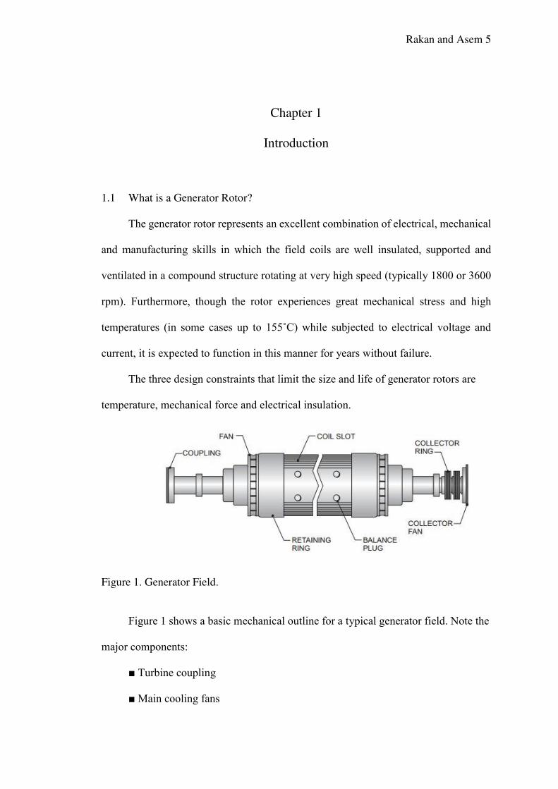
Figure 1. Generator Field.
Figure 1 shows a basic mechanical outline for a typical generator field. Note the
major components:
■ Turbine coupling
■ Main cooling fans
Rakan and Asem 6
■ Retaining rings
■ Coil slot
■ Balance plug
■ Collector rings
■ Collector fans
There are, of course, variations on this configuration. For example, while the
illustrated design uses radial fans, other designs use axial fans.
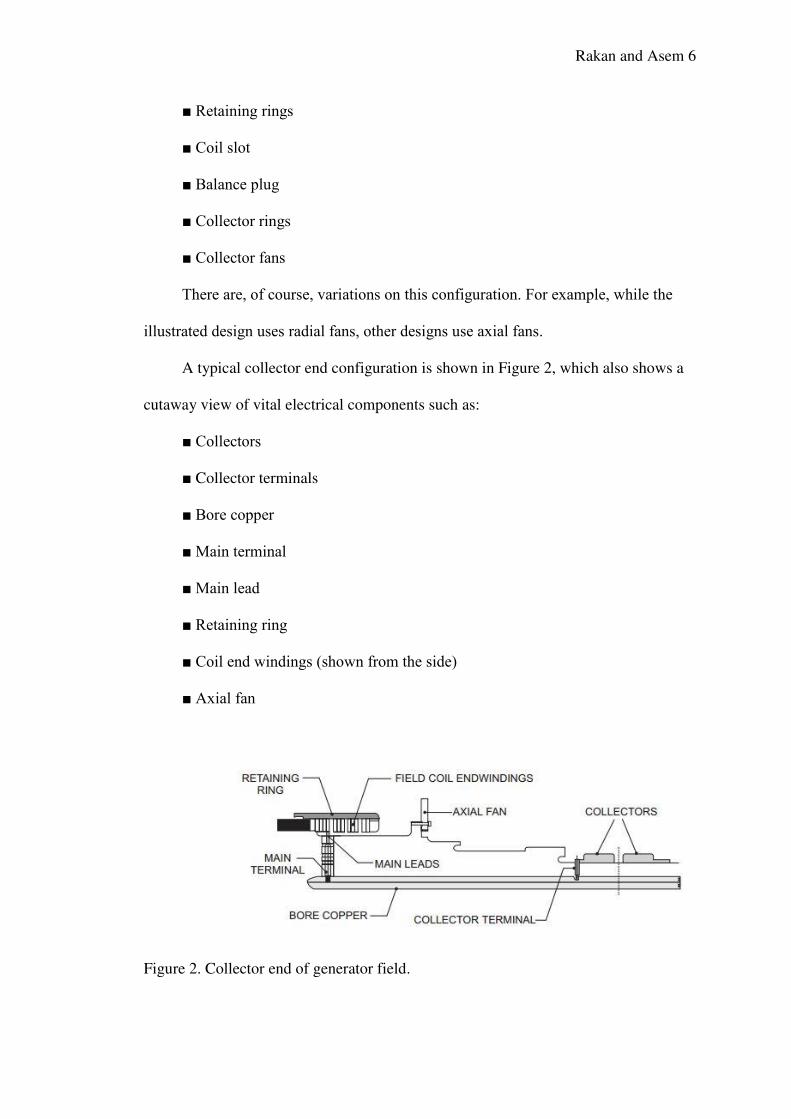
A typical collector end configuration is shown in Figure 2, which also shows a
cutaway view of vital electrical components such as:
■ Collectors
■ Collector terminals
■ Bore copper
■ Main terminal
■ Main lead
■ Retaining ring
■ Coil end windings (shown from the side)
■ Axial fan
Figure 2. Collector end of generator field.
Rakan and Asem 7
1.2 Problem Statement
As a generator rotor ages, its insulation can be affected by temperature,
mechanical wear and operating incidents. Rotor forging and other rotor components are
also at risk. The most common problems occurring with generator rotors are shorted
turns and breakdown in ground wall insulation. These two concerns will be discussed
in this project and it relevancy to vibration aspects [1].
Rakan and Asem 8
Chapter 2
Literature Review
In plain bearings such vibrations are the consequence of the intermittent mechanical
contact between the shaft and the bearing surface. When a lubricant film carries the
load between the shaft and bearing around the full circumference, such contact does not
occur, nor any noise. However, contact does occur upon start-up, when the radial forces
on the bearing are excessive (belt drive, gear, air gap field), when the shaft and/or the
bearing sleeve is not round or if they are crooked, if the sintered bearing surfaces do
not have sufficient porosity, if the shaft running surface is too smooth, or if there is not
enough lubricant in the bearing (mixed friction). The consequence is vibrations at the
roughness peaks of the bearing surfaces, which are dependent on the elasticity of the
shaft or bearing, at numerous frequencies (frequency band in spectrum) in the audible
range. The frequency of rotation and multiples thereof are particularly pronounced. The
amplitudes of the higher frequency vibrations are often simply modulated, which causes
the friction noises to become particularly objectionable. As the lack of lubricant
worsens, the mechanical contacts increase, and mechanical friction occurs and wear
increases sharply [2]. This results in natural vibrations in the bearing (with the self-
induced addition of energy from the bearing friction), which is perceived as a squeaking
or squealing noise. In plain bearings, the deformations are primary and the resulting
deformation forces are secondary (displacement excitation).
In roller bearings, rolling elements – in small motors these are generally ball bearings
– roll in inner and outer rings, usually with mechanical contact. They are surrounded
by a layer of lubricant, which has a slight cushioning effect and enlarges the contact
surface somewhat. If the rolling elements and the ring raceways are sufficiently round
Rakan and Asem 9
and undamaged, only a broad frequency band (spectrum) of oscillations results as a
consequence of the circumferential elastic deformations at the contact points caused by
the compression forces (force excitation) and as a consequence of lubricant movements
(displacement excitation). The lubricant dampens the vibrations. So if not enough
lubricant is present or if the viscosity of the lubricant is incorrect, vibration will increase
(“metallic, hard-sounding” noise) because the pressures increase at the contact points.
Material fatigue increases. Raceway damage, in particular that caused by axial
overloading of the bearings, also leads to faster material fatigue. Radial ball bearings
have radial bearing play due to how they are manufactured and how they operate. If this
radial play is “compressed to zero” as a result of an improper elastic axial preload on
the outer or inner ring, the bearing balls cannot transfer the radial forces optimally. The
installation fits of the bearing and the assembly quality play an important role in this
case. At certain rotational speeds the balls actually run in synch instead of in a circular,
wavy path. As a result, self-induced axial vibrations, which are heard as howling noises,
occur in the bearing bracket [2].
Thus in bearings, we mainly encounter motions that generate elastic forces, which in
turn lead to vibrations, as well as forces that lead to oscillating motions. This means
that there is displacement excitation as well as force excitation, so that both must be
considered when the individual case is being analyzed in theoretical terms. Stator bar
temperature will increase as electrical current flows in the copper of the winding. The
relationship of temperature to electrical current is well known as T ∝ I2. Therefore, if
the generator is at full load where the stator current is theoretically at its maximum
(Iref), then the temperature of the stator bar hose outlets will be some temperature
above the cooling water inlet temperature. The difference between the cooling water
inlet and outlet temperatures will be the temperature rise, dTref, at this reference load,
Rakan and Asem 10
due to the heat input from the stator bar I2R losses. The temperature difference
between Tout and Tin will obviously change as the generator loading (operating stator
current, Is) is increased and decreased. Applying the relationship T ∝ I2, we can use Is
and Iref in the form (Is/Iref)2 to account for generator load changes. Therefore the basic
formula to calculate stator winding hose outlet temperatures can be written as
Tout
In the relationship above, we can see that the portion of the function (Is/Iref)2 is equal
to one, as it should be, when fingerprinting of the stator winding temperatures is done
at the reference load. As Is becomes lower, at lower loads, the temperature calculated
for Tout will decrease proportionally [1]. Using the formula, the difference between the
measured reading and the calculated value can be closely monitored. An alarm value
(e.g., 5◦C) can then be added to the calculated value to produce the dynamic alarm
limit as follows [3]:
Talarm = Tout + 5◦C
2.1 Rotor Vibration Failures: Causes and Solutions
Steam turbine rotors bend during operation, but the bearing and supports are designed
to keep the static and dynamic forces under control. However, bending can cause impact
between stationary and rotating parts—often cascading impacts. An operator of many
utility-scale steam turbines like the one in Jordan Petroleum Refinary shares its
Rakan and Asem 11
extensive field experience identifying the root cause of failures as well as successful
solutions.
Rotor bending that results in premature failure of steam turbine blades and other internal
components is one of the most serious problems experienced in power plant operations.
The problems often reduce plant availability by limiting generation and increase plant
operation and maintenance cost. Extreme rotor bending problems often involve
interaction between the turbine’s rotor and stationary parts. Rotor bending may be
caused by a variety of static and dynamic factors, many of which will be explored in
this research project [4].
We begin with mechanical factors related to the rotor, the largest rotating assembly in
the turbine. Working from the inside out, we next look at rotor balance issues, followed
by rotor and casing misalignment problems, and problems caused by the casing. The
discussion is based on the authors’ experiences Jordan Petroleum Refinery located in
Jordan.
It almost goes without saying that rubbing caused by insufficient clearances, disrupts
the end sealing of the rotor. This situation commonly occurs when the high-mass rotor
at operating speed comes in contact with a stationary surface, typically caused by a too-
small clearance between the gland seals and the rotor. Secondarily, there may be a
localized temperature increase at the point of contact, causing increased metal
temperatures at the point of contact due to friction.
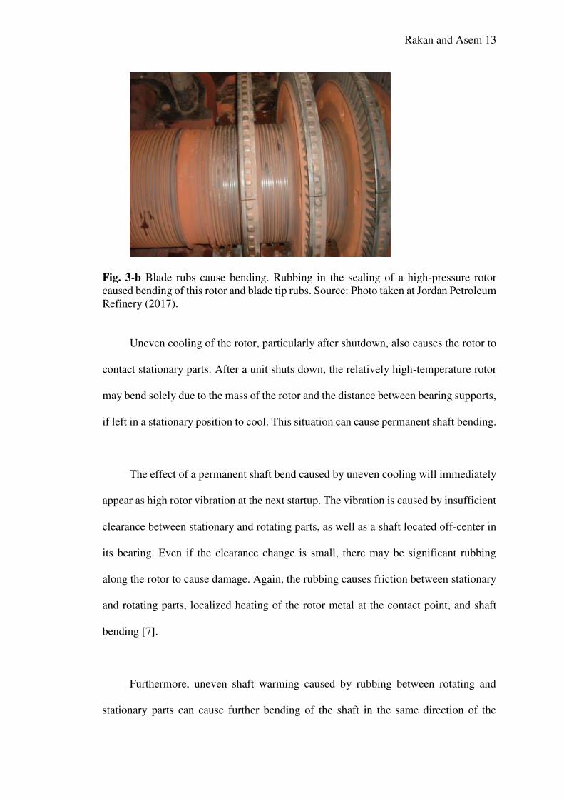
The forces produced by the impact of the large rotating rotor mass with the poorly
functioning stationary seals often impress a layer of metal on the surface of the rotor.
The rub can cause elastic deformation of the rotor at the point of impact and temporary
Rakan and Asem 12
rotor shaft bending. The shaft bending will usually cause increased vibration levels
(Figure 3-b below) [5].
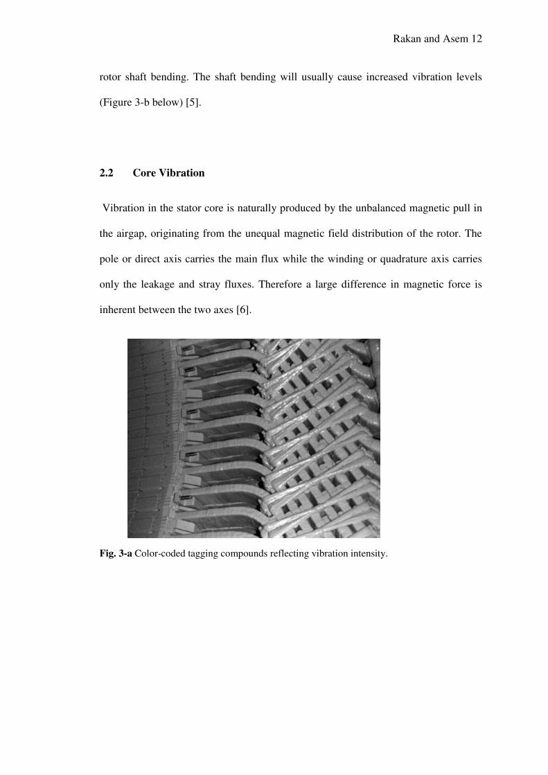
2.2 Core Vibration
Vibration in the stator core is naturally produced by the unbalanced magnetic pull in
the airgap, originating from the unequal magnetic field distribution of the rotor. The
pole or direct axis carries the main flux while the winding or quadrature axis carries
only the leakage and stray fluxes. Therefore a large difference in magnetic force is
inherent between the two axes [6].
Fig. 3-a Color-coded tagging compounds reflecting vibration intensity.
Rakan and Asem 13
Fig. 3-b Blade rubs cause bending. Rubbing in the sealing of a high-pressure rotor
caused bending of this rotor and blade tip rubs. Source: Photo taken at Jordan Petroleum
Refinery (2017).
Uneven cooling of the rotor, particularly after shutdown, also causes the rotor to
contact stationary parts. After a unit shuts down, the relatively high-temperature rotor
may bend solely due to the mass of the rotor and the distance between bearing supports,
if left in a stationary position to cool. This situation can cause permanent shaft bending.
The effect of a permanent shaft bend caused by uneven cooling will immediately
appear as high rotor vibration at the next startup. The vibration is caused by insufficient
clearance between stationary and rotating parts, as well as a shaft located off-center in
its bearing. Even if the clearance change is small, there may be significant rubbing
along the rotor to cause damage. Again, the rubbing causes friction between stationary
and rotating parts, localized heating of the rotor metal at the contact point, and shaft
bending [7].
Furthermore, uneven shaft warming caused by rubbing between rotating and
stationary parts can cause further bending of the shaft in the same direction of the
Rakan and Asem 14
existing bow and cause additional contact with stationary parts, increasing temperatures
and therefore causing more bending. The effect cascades if allowed to continue. If the
bending is allowed to continue, it is possible that the yield strength of the metal could
be exceeded, causing a permanent deformation of the shaft. The allowed bending in
3,000-rpm turbines is up to 0.02–0.03 mm in each section. When on turning gearing,
the limit is 0.05 mm.
Magnetic force is generated in the pole axes, and a weak magnetic force is present
in the winding axes. Since each pole has a north and a south (or a plus and a minus)
associated with it, an unbalanced magnetic pull is generated at twice the line frequency.
The core must be maintained tight or fretting will occur between the laminates. Minor
fretting will tend to deteriorate the inter-laminar insulation, but if the core becomes too
loose, the laminates and or the space blocks may even fatigue with the result being
pieces of loose core material breaking off and causing damage. Monitoring of core
vibrations can be done with accelerometers mounted on the core back in strategic
locations to determine the magnitude and phase of both radial and tangential vibration
modes (see above figure) [7].
To avoid rotor bending during cooling, turbine vendors provide very specific
instructions on the allowable rate of cooling. For example, the turbine should remain
on turning gear until the high-pressure (HP) cylinder temperature is below 150C and
the oil temperature is below 75C. The turbine vendor also defines the rotational speed
of the turning gear.
Rakan and Asem 15
Misalignment of the coupling between two shafts or between a shaft and bearing may
cause bending in the system. Misalignment between two shafts of an integrated rotor
can cause an eccentricity of the mass center of the rotor, and this eccentricity at high
rotational speed will produce a centrifugal force in the radial direction, causing bending
of the rotor. Misalignment between the axis of rotation and the axis of the shaft can also
cause bending in the rotor. There are six primary factors that can cause misalignment.
A poor connection between the turbine casing and the bearing pads on the foundation
frame is one cause. If a pad experiences increased friction or stops sliding during
thermal expansion (usually during startup) in the axial direction, the result is a tipping
torque on the casing. This torque can cause a misalignment between the casing and
bearing surface, causing vibration in the forward end of the turbine, foundation frame
surface support deformation, and bearing pad stall.
Also pay close attention to the foundation frame—including bolts, keys, and pads—
so that free movement of the bearing surfaces is possible, particularly while undergoing
startup and load changes. The extent of the longitudinal and lateral thermal expansion
bore centers of the cylinders and pad travel should be recorded for future comparisons.
This process should be part of routine maintenance equipment inspections [7].
Another factor concerns the difficulty in assembling the HP turbine front bearing.
While the shaft is rotating in its journal bearing, the shaft pushes oil from the bottom of
the bearing, causing the oil film thickness to change. When this happens, the centerline
of the shaft moves up and to one side. To account for this shaft movement, the
segmented bearing should automatically adjust and the contact surface of the journal
Rakan and Asem 16
bearing will remain in a good position. If there is too much contact surface, friction will
increase on the bearing surface, causing increased rubbing and corrosion of the bearing
surface and increasing vibration and rotor eccentricity. The result will be bearing oil
leakage and rubbing in the sealing glands. On the other hand, if the bearing contact area
decreases, the oil film will cause uneven movement of the rotor within the segmented
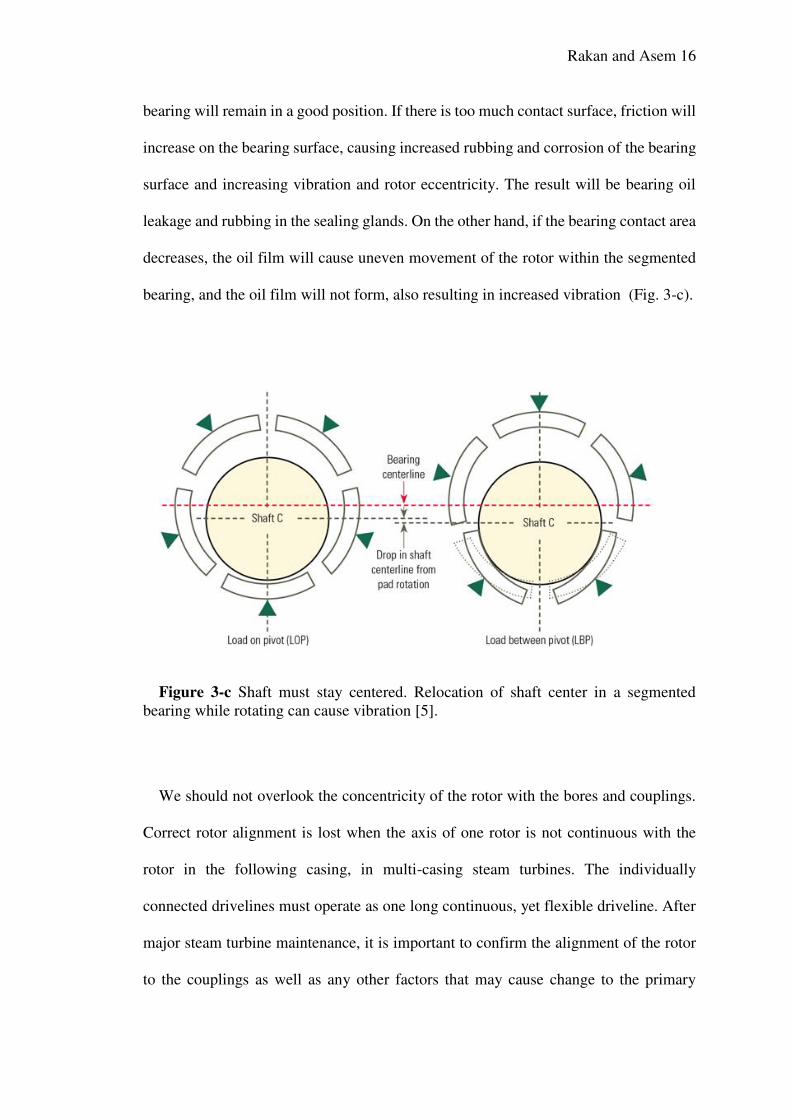
bearing, and the oil film will not form, also resulting in increased vibration (Fig. 3-c).
Figure 3-c Shaft must stay centered. Relocation of shaft center in a segmented
bearing while rotating can cause vibration [5].
We should not overlook the concentricity of the rotor with the bores and couplings.
Correct rotor alignment is lost when the axis of one rotor is not continuous with the
rotor in the following casing, in multi-casing steam turbines. The individually
connected drivelines must operate as one long continuous, yet flexible driveline. After
major steam turbine maintenance, it is important to confirm the alignment of the rotor
to the couplings as well as any other factors that may cause change to the primary
Rakan and Asem 17
positions of individual casings, bearing, and rotors. During maintenance, if rubbing is
observed at the end or intermediate sealing of the rotor or eccentricity of couplings, it
is necessary to realign the driveline to avoid high turbine vibration, contact and rubbing
of glands and so on (Figure 3-c).
Shaft curvature also shifts the rotation axis of the shaft by moving the mass center
of the rotor, creating vibration. This vibration affects blades in three significant ways.
First, the vibration causes blade structural problems [7]. The centrifugal forces
encountered during operation are significant, causing an increase in the tensile forces
in the blade cross-section and, if the center of mass is not on the radial line, bending
stresses also occur. Additionally, bending stresses are created in blade joints under the
pressure effects of the HP steam flowing axially through the turbine cylinder. The
magnitude of these stresses is dependent on the flow rate of steam, the temperature drop
across the blade stage, the rotational speed of the blades, and the blade weight. The
temperature of the steam, superheated in the first stage and saturated in the final stages,
will have an effect on the mechanical properties and corrosion of the blade materials
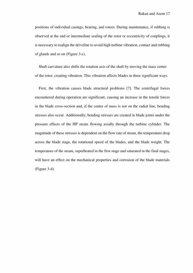
(Figure 3-d).
Rakan and Asem 18
Figure 3-d Corrosion causes imbalance. Failure of this high-pressure rotor control
stage was caused by uneven distribution of steam due to corrosion [6].
2.3 Frame Vibration
Frame vibration is also excited by unbalanced magnetic pull and by any vibration
produced in the core. There are known cases of vibration resonance occurring on the
frame as a result of the frame having a resonant frequency near line or twice line
frequency. Resonant frequencies may be corrected by either adding mass to the frame
to bring the natural frequency down, or by stiffening the frame to drive the natural
frequency higher; the object being to move the frame natural frequency away from the
exciting frequencies by at least 10%.
Severe damage to the frame can occur by initiating cracks in the frame welds or in
the frame members themselves. Residual damage from the high vibrations associated
with frame vibration is likely to be transmitted to other components of the generator if
the situation becomes severe [6].
Rakan and Asem 19
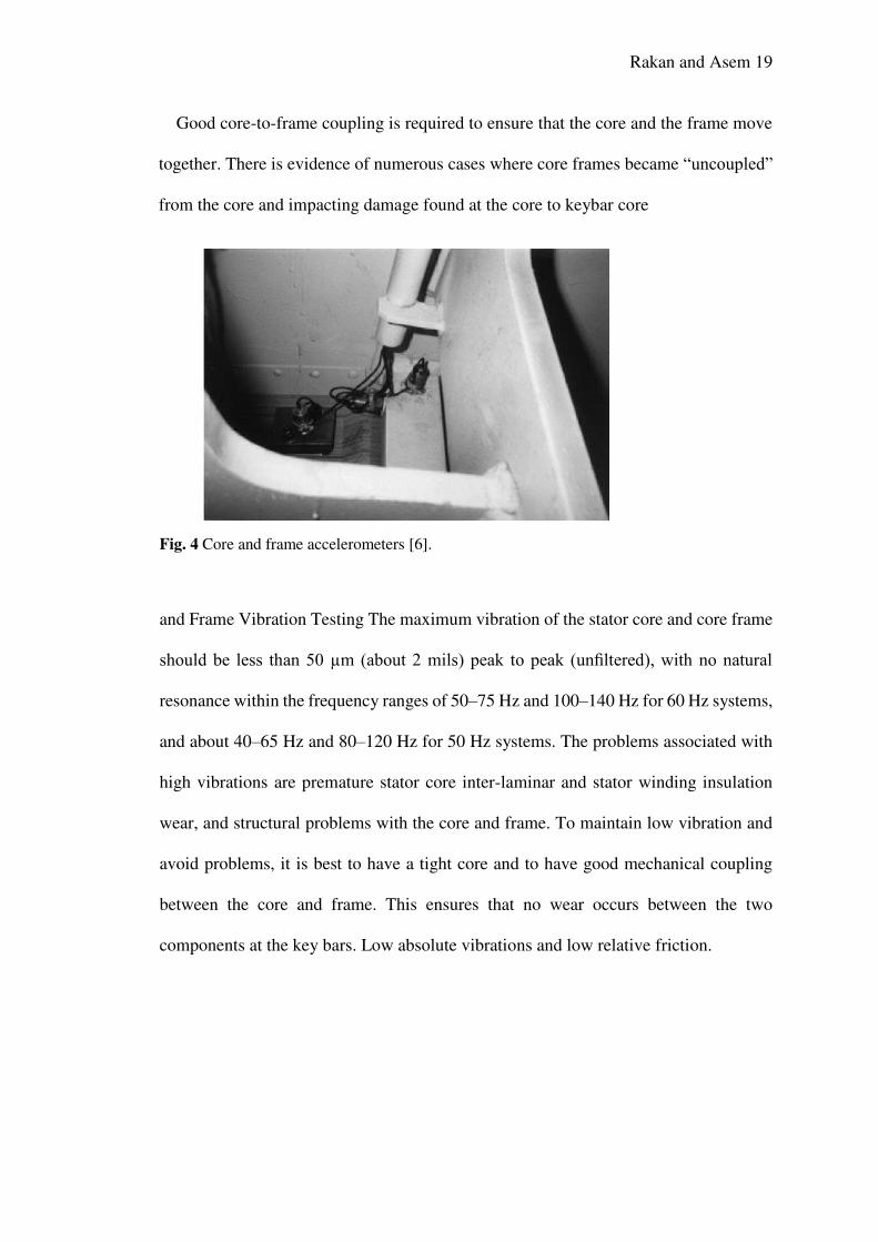
Good core-to-frame coupling is required to ensure that the core and the frame move
together. There is evidence of numerous cases where core frames became “uncoupled”
from the core and impacting damage found at the core to keybar core
Fig. 4 Core and frame accelerometers [6].
and Frame Vibration Testing The maximum vibration of the stator core and core frame
should be less than 50 µm (about 2 mils) peak to peak (unfiltered), with no natural
resonance within the frequency ranges of 50–75 Hz and 100–140 Hz for 60 Hz systems,
and about 40–65 Hz and 80–120 Hz for 50 Hz systems. The problems associated with
high vibrations are premature stator core inter-laminar and stator winding insulation
wear, and structural problems with the core and frame. To maintain low vibration and
avoid problems, it is best to have a tight core and to have good mechanical coupling
between the core and frame. This ensures that no wear occurs between the two
components at the key bars. Low absolute vibrations and low relative friction.
Rakan and Asem 20
Chapter 3
Vibration in Rotor Generator: Challenges
3.1 Generator Vibration and Maintenance Testing
Vibration between the core and frame, with the two components in phase, is a good
indicator that the core and frame structure is sound. Testing can be done off line or on
line. However, for either type of test, vibration transducers (accelerometers) must be
mounted on the core and frame, internal to the machine. This includes the stator center,
both ends, and locations on the circumference based on the nodal vibration patterns of
the stator (four nodes for two-pole machines and eight nodes for four-pole machines).
The vibrations are generally measured in the radial and tangential directions when
looking toward the end of the machine. In addition it is desirable to use a number of
portable, magnetic based transducers, which may be moved around the outside of the
generator casing, to ensure complete analysis of the machine. Off-line testing is not
generally done unless there is a known problem with core and frame vibration. The
excitation source must be artificially applied in this method, and there are a couple of
ways to accomplish this. One is to simply strike the frame with a heavy rubber hammer
and measure the frequencies where the vibrations peak. However, this does not usually
produce a significant result because the stimulus is so small. The other method is to
attach a shaker device to the frame to stimulate the stator at a fixed frequency, and then
measure the frequencies where the vibrations peak. The shaker method generally
produces good results because there is a significant stimulus and it can be controlled.
The problem with this type of testing is that it does not give an accurate picture of the
true vibration of the core and frame in operation. On-line testing is generally the best
Rakan and Asem 21
way to get a complete vibration analysis of the core and frame. With on-line testing it
is possible to look at all operating modes of the stator and determine which parameter
has the most influence on vibration. During testing the variable parameters are stator
current, field current, hydrogen pressure, and hydrogen temperature. In some cases it
has also been useful to valve out individual hydrogen coolers, successively, to change
the cooling pattern and determine its effect on the core and frame vibration. When core
and/or frame vibrations are present, it is necessary to determine if the vibrations are
most prevalent on the core or frame, and if the two components require better coupling
to each other. The possibilities of what may be found on any individual machine are
too vast to cover here. However, as a rule-of-thumb, it is often found that the core and
frame will have a natural frequency that is too close to the forbidden zones, and that
they do require some artificial means to ensure better mechanical coupling between the
two. In such cases vibration damping is also usually required. When trying to dampen
excessive vibrations, there are two methods employed. The first method requires adding
mass to lower the natural frequency. The second method entails stiffening the structure
to raise the natural frequency. Adding mass can be difficult if there is no good place to
attach it, and stiffening can sometimes cause problems with overstressing the frame
welds, causing them to crack. Stator core and frame vibration problems are very
complex to analyze, and even more complex and expensive to solve. They should be
addressed on a machine-to-machine basis, as each case will be unique.
3.2 Rotor Vibration Testing
Rotor Vibration measurement is one the most important on-line measurements taken
on the machine. Each manufacturer gives its own recommendations for alarm and trip.
The information in the following table is from an O&M engineering specification:
Rakan and Asem 22
- Machine Maximum Amplitude: 0–999 rpm 3 mils 1000–1499 rpm 2.5 mils
1500–2999 rpm 2 mils 3000 rpm & above 1 mil
Vibration is monitored continuously, and vibration charts are normally available at the
control room. Vibration is monitored in all turbine and generator bearings.
3.3 Rotor Mechanical Testing
Although vibration monitoring is generally considered an on-line monitoring function,
there are many occasions where it is necessary to carry out additional and specific
vibration testing. This would be to look for such problems as component rubs or rotor
winding shorted turns to determine the correct course of action. This type of detailed
vibration testing is very specialized and requires additional equipment to be connected
to the vibration probes installed on the generator. The type of additional testing inferred
would be to allow characterization of the vibration measurements into both magnitude
and phase relation, and to allow frequency spectrum analysis during cold and hot run
up to speed and run downs from speed. In addition load changes and field current
changes allow the differentiation between mechanically and thermally induced
vibrations. This is a very detailed topic for which entire books have been written and
the literature that can be found is substantial. Refer to Chapter 6 for an additional
discussion of the subject.
3.4 Fan Shaft Critical Speed
In the fan industry has been some confusion as to the exact definitions of
critical speed and resonant speed; therefore, to clarify the problem, the Air Movement
and Control Association (AMCA) [3] has adopted the following definitions:
Rakan and Asem 23
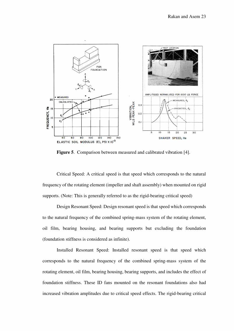
Figure 5. Comparison between measured and calibrated vibration [4].
Critical Speed: A critical speed is that speed which corresponds to the natural
frequency of the rotating element (impeller and shaft assembly) when mounted on rigid
supports. (Note: This is generally referred to as the rigid-bearing critical speed)
Design Resonant Speed: Design resonant speed is that speed which corresponds
to the natural frequency of the combined spring-mass system of the rotating element,
oil film, bearing housing, and bearing supports but excluding the foundation
(foundation stiffness is considered as infinite).
Installed Resonant Speed: Installed resonant speed is that speed which
corresponds to the natural frequency of the combined spring-mass system of the
rotating element, oil film, bearing housing, bearing supports, and includes the effect of
foundation stiffness. These ID fans mounted on the resonant foundations also had
increased vibration amplitudes due to critical speed effects. The rigid-bearing critical
Rakan and Asem 24
speed and installed resonant speed were calculated to be 1180 rpm and 960 rpm,
respectively.
The lateral critical speed should be at least 20% from the running speed to
prevent excessive vibration amplification. In this case, the calculated installed resonant
speed was only 7% above the running speed; therefore, amplification could be
expected. It is important that fan users be aware of the critical speed definitions used in
the fan industry and refer to the installed resonant speed when writing design
specifications.
Major modifications such as shortening the bearing span would be required to
increase the shaft critical speed to 20% above the running speed. These modifications
were not possible and it was decided to reduce the shaft vibrations by improving the
fan balance.
Rakan and Asem 25
Chapter 4
Research Methodology
The generally accepted methods for vibration problem of industrial equipment include;
Force Reduction, Mass Addition, Tuning, Isolation, and Damping. This research will
focus on damping related method, and describe practical methods for their application.
The Jordan Petroleum case study will be presented, with emphasis on pragmatic
solutions to their rotor vibration problems.
Rakan and Asem 26
Chapter 5
Proposed Rotor Damper Vibration Design
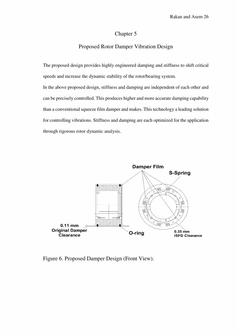
The proposed design provides highly engineered damping and stiffness to shift critical
speeds and increase the dynamic stability of the rotor/bearing system.
In the above proposed design, stiffness and damping are independent of each other and
can be precisely controlled. This produces higher and more accurate damping capability
than a conventional squeeze film damper and makes. This technology a leading solution
for controlling vibrations. Stiffness and damping are each optimized for the application
through rigorous rotor dynamic analysis.
Figure 6. Proposed Damper Design (Front View).
Rakan and Asem 27
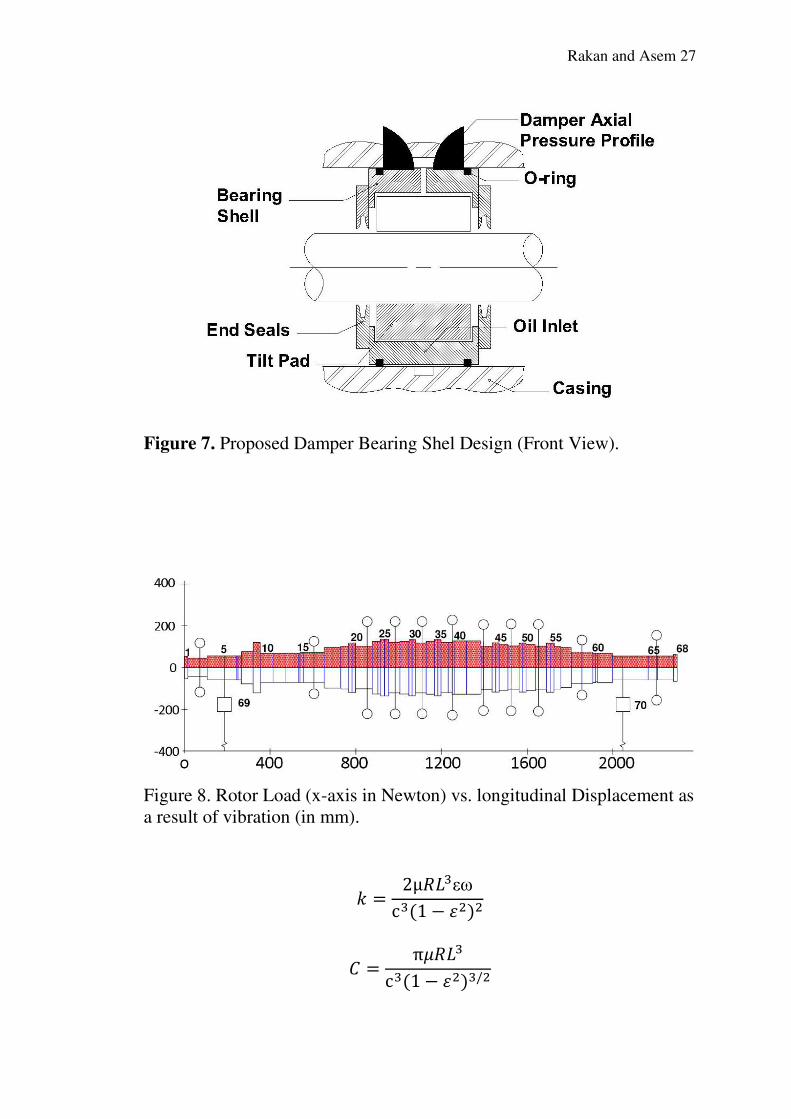
Figure 7. Proposed Damper Bearing Shel Design (Front View).
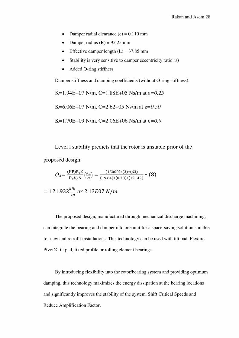
Figure 8. Rotor Load (x-axis in Newton) vs. longitudinal Displacement as
a result of vibration (in mm).
𝑘 = 2µ𝑅𝐿3εωc3(1 − 𝜀2)2
𝐶 = π𝜇𝑅𝐿3c3(1 − 𝜀2)3/2
Rakan and Asem 28
Damper radial clearance (c) = 0.110 mm
Damper radius (R) = 95.25 mm
Effective damper length (L) = 37.85 mm
Stability is very sensitive to damper eccentricity ratio (ε)
Added O-ring stiffness
Damper stiffness and damping coefficients (without O-ring stiffness):
K=1.94E+07 N/m, C=1.88E+05 Ns/m at ε=0.25
K=6.06E+07 N/m, C=2.62+05 Ns/m at ε=0.50
K=1.70E+09 N/m, C=2.06E+06 Ns/m at ε=0.9
Level l stability predicts that the rotor is unstable prior of the
proposed design:
QA= (HP)Bc𝐶Dc𝐻𝑐𝑁 (𝜌𝑑𝜌𝑠 ) = (15000)∗(3)∗(63)(19.64)∗(0.78)∗(12142) ∗ (8)
= 121.932𝑘𝑙𝑏 𝑖𝑛 𝑜𝑟 2.13𝐸07 𝑁/𝑚
The proposed design, manufactured through mechanical discharge machining,
can integrate the bearing and damper into one unit for a space-saving solution suitable
for new and retrofit installations. This technology can be used with tilt pad, Flexure
Pivot® tilt pad, fixed profile or rolling element bearings.
By introducing flexibility into the rotor/bearing system and providing optimum
damping, this technology maximizes the energy dissipation at the bearing locations
and significantly improves the stability of the system. Shift Critical Speeds and
Reduce Amplification Factor.
Rakan and Asem 29
The design can shift critical speeds and significantly reduce the amplification
factor. With the reduction in amplification factor, machine seal clearances can be
tightened to reduce gas or steam leakage.
It also reduces dynamic Bearing (Transmitting) Forces. This technology reduces
the dynamic load that is transmitted to the bearings, which reduces pedestal vibration
and increases bearing life, particularly for rolling element bearings. For fluid film
bearings, the technology can mitigate pivot wear and reduce lateral fatigue.
The proposed decrease Unbalance Sensitivity. It reduce the sensitivity to unbalance,
protecting impellers and seals from rubbing and increasing maintenance intervals.
Rakan and Asem 30
Chapter 6
Results and Conclusion
We found from the previous sections the following general rules for maintaining the
vibration level to its minimum level:
• Rule # 1: Match Design Point to System Head & Flow Requirements
• Rule # 2: Use a Long Straight Piping Run to the Inlet
• Rule # 3: Careful When & How You Throttle
• Rule # 4: Minimize Nozzle Loads
• Rule # 5: Avoid Structural Natural Frequencies
• Rule # 6: Minimize Load Cycling, if Practical
• Rule # 7: Select Materials Based on Corrosion, Fatigue , and alignments
• During the initial startup of the centrifugal fan at a JPR, the bearing housing
vibrations exceeded the 2 mils at 900 rpm specified in the Japanese contract. It
was reported that the fans could not be balanced satisfactorily; when the
vibrations were reduced on the fan bearings, the vibrations would increase on
the motor bearing.
• Detailed investigations revealed the following problems which made balancing
difficult:
• 1. Foundation resonance.
• 2. Fan shaft critical speed.
• 3. Interaction of adjacent fans.
• 4. Corrosion Imbalances.
Rakan and Asem 31
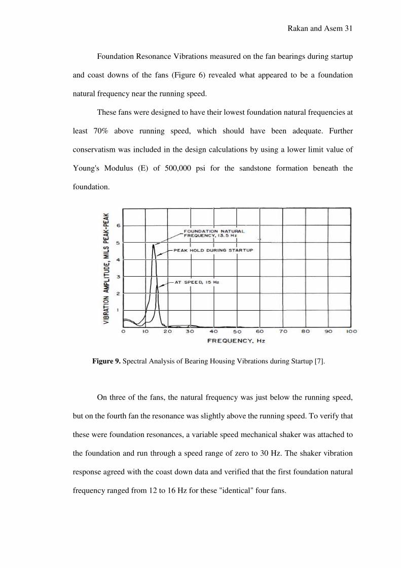
Foundation Resonance Vibrations measured on the fan bearings during startup
and coast downs of the fans (Figure 6) revealed what appeared to be a foundation
natural frequency near the running speed.
These fans were designed to have their lowest foundation natural frequencies at
least 70% above running speed, which should have been adequate. Further
conservatism was included in the design calculations by using a lower limit value of
Young's Modulus (E) of 500,000 psi for the sandstone formation beneath the
foundation.
Figure 9. Spectral Analysis of Bearing Housing Vibrations during Startup [7].
On three of the fans, the natural frequency was just below the running speed,
but on the fourth fan the resonance was slightly above the running speed. To verify that
these were foundation resonances, a variable speed mechanical shaker was attached to
the foundation and run through a speed range of zero to 30 Hz. The shaker vibration
response agreed with the coast down data and verified that the first foundation natural
frequency ranged from 12 to 16 Hz for these "identical" four fans.
Rakan and Asem 32
To evaluate the discrepancy between measured and calculated foundation
resonances, the foundation-soil dynamic system was modeled with a computer program
developed by Southwest Research Institute (SwRI). Foundation natural frequencies
were calculated for a range of soil moduli and compared with shaker data. As shown in
Figure 7, the effective soil modulus must be from 80, 000 to 120, 000 psi to match the
measured foundation natural frequencies. The lower than expected soil stiffness
beneath the foundations was probably due to blasting, over-excavation, and backfill
during construction.
A shaker test was conducted on the partially completed foundation block of an
adjacent unit (Figure 8) to determine natural frequencies and vibration mode shapes.
These tests showed that the effective soil modulus was similar to that obtained for Unit
1, which indicated that the Unit 2 ID fans would also have foundation natural
frequencies near the running speed. Foundation modifications to reduce the vibration
amplitudes were analyzed using the computer program. However, it was determined
that most modifications investigated were impractical based on cost or space limitations
and other methods were investigated to reduce the vibrations. Shaker tests on one
foundation revealed that the vibrations were increased by a factor of six when dirt was
removed from the side of the foundation. Based upon this test, sand bags were
temporarily placed against the side of the foundation to increase damping and lateral
restraint on the foundation. The vibrations were reduced by a factor of approximately
two to one.
Rakan and Asem 33
References
1. Jong Kim, PhD, " A Solution to Years of High Vibration Problems in Three
Reinjection Compressor Trains Running at 33 MPa Discharge Pressure", Asia
turbomachinery pump symposium Singapore,22-25 FEB 2016
2. Ronald J. Zawoysky & Karl C. Tornroos, ”GE Generator Rotor Design,
Operational Issues, and Refurbishment Options", GE power system publication
GER-4212, AUG 2001.
3. M O’sullivan," Diagnosis of Vibration Problems in Holland", B&K application
notes BO-0297-11.
4. Tomasz Gałka ,"Vibration-Based Diagnostics of Steam Turbines", Mechanical
Engineering, Dr. Murat(2012). Gokcek (Ed.), ISBN: 978-953-51-0505-3, In
Tech, Available Source:http://www.intechopen.com/books/mechanical-
engineering/vibration-based-diagnostics-of-steam-turbines.
5. Thomas Bertolini and Thomas Fuchs," Vibrations and Noises in Small Electric
Motors",P 25-27,Süddeutscher Verlag onpact GmbH, 81677 Munich,b
Germany,2012. Source www.sv-onpact.de.
6. Electronic Source (unidentified author):
Source:http://www.waukbearing.com/en/engineered-fluid-film/product-
lines/This(r)-integral-squeeze-film-damper
7. Donald R. Smith and Harold R. Simmons, “Unique Fan Vibration Problems”,
Cases and Solutions, 01/1980. Source:
https://www.researchgate.net/publication/295390726_UNIQUE_FAN_VIBR
ATION_PROBLEMS_THEIR_CAUSES_AND_SOLUTIONS.