Embed Size (px)
Citation preview
INSTRUCTION MANUAL FOR
GENERATOR PROTECTION SYSTEM BE1-GPS100
Publication: 9318700990 Revision: F 04/08 www .
Elec
tricalP
artM
anua
ls . c
om

www . El
ectric
alPar
tMan
uals
. com

9318700990 Rev F BE1-GPS100 Introduction i
INTRODUCTION This instruction manual provides information about the operation and installation of the BE1-GPS100 Generator Protection System. To accomplish this, the following information is provided:
• General information, specifications, and a Quick Start guide. • Functional description and setting parameters for the inputs and outputs, protection and control
functions, metering functions, and reporting and alarm functions. • BESTlogic programmable logic design and programming. • Documentation of the preprogrammed logic schemes and application tips. • Description of security and user interface setup including ASCII communication and the human-
machine interface (HMI). • Installation procedures, dimension drawings, and connection diagrams. • Description of the front panel HMI and the ASCII command interface with write access security
procedures. • A summary of setting, metering, reporting, control, and miscellaneous commands. • Testing and maintenance procedures. • Description of BESTCOMS graphical user interface (GUI). • Appendices containing time overcurrent characteristic curves and an ASCII command-HMI cross
reference. Optional instruction manuals for the BE1-GPS100 include: • Distributed Network Protocol (DNP) 3.0 (9318700992) • Modbus™ (9318700991).
WARNING! To avoid personal injury or equipment damage, only qualified personnel should perform the procedures in this manual.
NOTE Be sure that the relay is hard-wired to earth ground with no smaller than 12 AWG copper wire attached to the ground terminal on the rear of the unit case. When the relay is configured in a system with other devices, it is recommended to use a separate lead to the ground bus from each unit.
www . El
ectric
alPar
tMan
uals
. com
ii BE1-GPS100 Introduction 9318700990 Rev F
First Printing: February 2000
Printed in USA
© 2008 Basler Electric, Highland Illinois 62249 USA
All Rights Reserved
April 2008
It is not the intention of this manual to cover all details and variations in equipment, nor does this manual provide data for every possible contingency regarding installation or operation. The availability and design of all features and options are subject to modification without notice. Should further information be required, contact Basler Electric.
BASLER ELECTRIC ROUTE 143, BOX 269
HIGHLAND IL 62249 USA http://www.basler.com, [email protected]
PHONE +1 618.654.2341 FAX +1 618.654.2351
CONFIDENTIAL INFORMATION of Basler Electric, Highland Illinois, USA. It is loaned for confidential use, subject to return on request, and with the mutual understanding that it will not be used in any manner detrimental to the interest of Basler Electric.
www . El
ectric
alPar
tMan
uals
. com

9318700990 Rev F BE1-GPS100 Introduction iii
REVISION HISTORY
The following information provides a historical summary of the changes made to the BE1-GPS100 hardware, firmware, and software. The corresponding revisions made to this instruction manual (9318700990) are also summarized. Revisions are listed in reverse chronological order.
BESTCOMS Software Version and Date Change
2.04.01, 04/08 • Added “G”, “R”, and “C” to Case options in Style Chart Drawing to support Normally Open Alarm type.
• Added Settings Compare feature. 2.04.00, 10/04 • Added System Summary links.
• Updated the input state labels and Virtual Switch state label. • Changed the default value of SG-NOM voltage parameter from 120V
to 69.3V. 2.03.00, 12/03 • Added S1 double-ended case style option.
• Made compatible with RS-232 converters. 2.02.00, 03/03 • When selecting units (Per Unit or % Amp) for displaying current
settings, the settings now are grayed out until the unit of measure is selected.
• Resolved a problem with the 59P function not working properly. • Fixed a problem downloading the configuration from the PC. • Eliminated the problem of getting all zeros upon uploading the relay
conversions of the General Operation menu. • Improved the operation of the Metering screen. • Now reports an error if the name labels are left blank for the Virtual
Test Switch, Virtual Inputs, Virtual Outputs, or the BESTLOGIC scheme.
• Resolved difficulties in setting functions 24, 25, 46, and 47 associated to the relay voltage signals.
11/99 • Initial 16-bit release.
Application Firmware
Version and Date Change 2.04.02, 07/04 1.04.02, 08/04
• Improved Comtrade files and downloading. • Improved 60FL function. • Improved curve “M” of the 51 function.
2.04.00, 11/03 • Improved contact input recognition/Debounce timers. • Added frequency data to fault reports and Comtrade reports. • Increased immunity to set defaults being loaded.
2.03.04, 12/02 1.03.03, 03/03
• Improved 50BF timing accuracy for 50 Hz applications. • Added “Error Pickup Condition” to identify setting changes that could
cause an energized element to pickup or dropout. • Added negative values for RE-KWH and RE-KVARH. • Improved stability of the 32 function for 0 power conditions (120 volts,
0 amps). 2.03.03, 04/02 • Improved the firmware so that it reports the correct firmware version.
www . El
ectric
alPar
tMan
uals
. com

iv BE1-GPS100 Introduction 9318700990 Rev F
Application Firmware Version and Date Change
2.03.00, 08/01 1.03.01, 10/01
• Added real time clock with 8-hour capacitor backup on all BE1-GPS100 Version 2 relays.
• Added support for battery backup for real time clock. • Updated RF, RS, and RO display of Relay ID and Station ID to allow
32 characters. • Improved performance of 62 “Pickup/Dropout.”
1.02.00, 03/01 • Added auto ranging to the current metering function. • Reordered fault summary report for clarity. • Updated the sync check function to require a minimum frequency for
sync output when operating in GF>BF mode. • Comtrade files updated to four cycles of pre-fault data. (It was three
cycles previously.) 1.01.02, 08/00 • Changed 60FL function fixed time delay to 50 ms to fully coordinate
with voltage elements that it is meant to supervise. • Changed 81 elements to use instantaneous frequency measurements
and require at least three consecutive cycles to be past the pickup threshold before a trip. This improves security for fast time delay and tight pickup settings. The original design used the average of two instantaneous frequency measurements and required two consecutive measurements to be past the pickup threshold before a trip.
• Changed pre-trigger buffer for first Oscillographic record from three cycles to four cycles.
1.01.01, 01/00 • Released Modbus™ protocol. • Released DNP 3.0 protocol. • Fixed intermittent relay reset and/or loading of default settings when
power source voltage is marginal. 1.00.00, 11/99 • Initial release
Hardware
Version and Date Change Version 2, 10/01 • Added real-time clock with 8-hour capacitor ride through.
• Added battery backup option for real-time clock. • Added board level input voltage jumpers.
Version 1, 01/99 • Initial release
Manual
Revision and Date Change F, 04/08 • Added Section 14, BESTCOMS Software.
• Added manual part number and revision to footers. • Added GOST-R certification in Section 1. • Added Targets as Displayed table to Section 6. • Added BESTCOMS screenshots and descriptions throughout manual. • Added “G”, “R”, and “C” to case options in style chart in Section 1. • Added Settings Compare to Section 6.
www . El
ectric
alPar
tMan
uals
. com

9318700990 Rev F BE1-GPS100 Introduction v
Manual Revision and Date Change
E, 12/03 • Updated Section 1 and Section 6 to indicate that rollover of the registers for energy data reporting occurs at 1,000 Gwh, not 100 Gwh.
• Updated Section 1, Figure 1-1, Style Number Identification Chart, and Section 12 to include the S1 Double ended case option.
• Changed the pickup range in Table 4-16 from 10 to 300 volts to 1 to 150.
• Rewrote the discussion on calculating Dmax in Section 6, subheading Breaker Duty Monitoring.
• Revised Figure 6-3, TCM with Other Devices. • Revised Figure 12-17 to show terminals D19 and D20. • Updated the discussion of The 46 Curve in Appendix A, Time-
Overcurrent Characteristic Curves and replaced Figure A-17, 46 Time Characteristic Curve, with a revised drawing and with an added note.
D, 09/02 • Updated the Maintenance of Backup Battery for Real Time Clock paragraphs of Section 13, Testing and Maintenance to include battery replacement instructions for S1 case relays.
• Repaired various minor errors throughout the manual. C, 11/01 • Updated the manual to reflect changes to the labels shown on the
case. • Added information about battery backup and real time clock. • Added information about contact sensing input jumpers.
B, 02/01 • Updated the manual to reflect the addition of the S1 case. This included changing the style chart in Section 1.
• Revised Section 13 to match the latest revision of that section. A, 06/00 • Added Section 13, Testing and Maintenance.
• Updated the drawings and text of the manual to reflect UL and CSA approval.
• Added new write-up on the 51/27R element. • Updated the IE logic timing diagram. • Completed a general read through of the manual, updating text in
order to clarify given information and complete and overall consistency in the manuals appearance.
—, 02/00 • Initial release
www . El
ectric
alPar
tMan
uals
. com

vi BE1-GPS100 Introduction 9318700990 Rev F
This page intentionally left blank.
www . El
ectric
alPar
tMan
uals
. com
9318700990 Rev F BE1-GPS100 Introduction vii
CONTENTS
SECTION 1 • GENERAL INFORMATION ................................................................................................ 1-1
SECTION 2 • QUICK START.................................................................................................................... 2-1
SECTION 3 • INPUT AND OUTPUT FUNCTIONS................................................................................... 3-1
SECTION 4 • PROTECTION AND CONTROL......................................................................................... 4-1
SECTION 5 • METERING......................................................................................................................... 5-1
SECTION 6 • REPORTING AND ALARM FUNCTIONS .......................................................................... 6-1
SECTION 7 • BESTlogic PROGRAMMABLE LOGIC............................................................................... 7-1
SECTION 8 • APPLICATION .................................................................................................................... 8-1
SECTION 9 • SECURITY.......................................................................................................................... 9-1
SECTION 10 • HUMAN-MACHINE INTERFACE ................................................................................... 10-1
SECTION 11 • ASCII COMMAND INTERFACE..................................................................................... 11-1
SECTION 12 • INSTALLATION .............................................................................................................. 12-1
SECTION 13 • TESTING AND MAINTENANCE .................................................................................... 13-1
SECTION 14 • BESTCOMS SOFTWARE .............................................................................................. 14-1
APPENDIX A • TIME OVERCURRENT CHARACTERISTIC CURVES................................................... A-1
APPENDIX B • COMMAND CROSS-REFERENCE................................................................................. B-1
APPENDIX C • TERMINAL COMMUNICATION.......................................................................................C-1
www . El
ectric
alPar
tMan
uals
. com

viii BE1-GPS100 Introduction 9318700990 Rev F
This page intentionally left blank.
www . El
ectric
alPar
tMan
uals
. com
9318700990 Rev F BE1-GPS100 General Information i
SECTION 1 • GENERAL INFORMATION TABLE OF CONTENTS
SECTION 1 • GENERAL INFORMATION ................................................................................................ 1-1
DESCRIPTION....................................................................................................................................... 1-1 FEATURES............................................................................................................................................ 1-1
Input and Output Functions ................................................................................................................ 1-1 Protection and Control Functions....................................................................................................... 1-2 Metering Functions............................................................................................................................. 1-3 Reporting and Alarm Functions.......................................................................................................... 1-3 BESTlogic Programmable Logic ........................................................................................................ 1-5 Write Access Security ........................................................................................................................ 1-5 Human-Machine Interface (HMI) ........................................................................................................ 1-5 Communication................................................................................................................................... 1-5
PRIMARY APPLICATIONS ................................................................................................................... 1-6 MODEL AND STYLE NUMBER DESCRIPTION................................................................................... 1-6
General............................................................................................................................................... 1-6 Sample Style Number ........................................................................................................................ 1-6
OPERATIONAL SPECIFICATIONS ...................................................................................................... 1-7 Metered Current Values and Accuracy .............................................................................................. 1-7 Metered Voltage Values and Accuracy .............................................................................................. 1-7 Metered Frequency Values and Accuracy ......................................................................................... 1-8 Calculated Values and Accuracy ....................................................................................................... 1-8 Energy Data Reporting....................................................................................................................... 1-8 Real Time Clock ................................................................................................................................. 1-8 Instantaneous Overcurrent Functions ................................................................................................ 1-9 Time Overcurrent Functions............................................................................................................... 1-9 Time Current Characteristic Curves................................................................................................. 1-10 Directional Power (32, 132).............................................................................................................. 1-10 Loss of Excitation (40Q, 140Q) ........................................................................................................ 1-10 Volts/Hz (24)..................................................................................................................................... 1-10 Phase Undervoltage Function (27P, 127P)...................................................................................... 1-11 Auxiliary Undervoltage Function (27X, 127X) .................................................................................. 1-11 Negative-Sequence Voltage Protection (47).................................................................................... 1-11 Phase Overvoltage Function (59P, 159P)........................................................................................ 1-11 Auxiliary Overvoltage Function (59X, 159X) .................................................................................... 1-12 Over/Underfrequency Functions (81, 181, 281, 381)....................................................................... 1-12 Breaker Fail Timer (BF).................................................................................................................... 1-12 General Purpose Timers (62, 162, 262, 362)................................................................................... 1-13 Sync-Check (25)............................................................................................................................... 1-13 VT Fuse Loss Detection (60FL) ....................................................................................................... 1-13 Automatic Setting Group Characteristics ......................................................................................... 1-13 BESTlogic......................................................................................................................................... 1-13
GENERAL SPECIFICATIONS............................................................................................................. 1-13 AC Current Inputs............................................................................................................................. 1-13 Phase AC Voltage Inputs ................................................................................................................. 1-13 Auxiliary AC Voltage Inputs.............................................................................................................. 1-14 Analog to Digital Converter .............................................................................................................. 1-14 Power Supply ................................................................................................................................... 1-14 Output Contacts ............................................................................................................................... 1-14 Control Inputs ................................................................................................................................... 1-14 IRIG .................................................................................................................................................. 1-15 Contact Inputs Recognition Time ..................................................................................................... 1-15 Communication Ports ....................................................................................................................... 1-15 Display.............................................................................................................................................. 1-15 Isolation ............................................................................................................................................ 1-15 Surge Withstand Capability .............................................................................................................. 1-16 Radio Frequency Interference (RFI) ................................................................................................ 1-16
www . El
ectric
alPar
tMan
uals
. com
ii BE1-GPS100 General Information 9318700990 Rev F
Electrostatic Discharge (ESD).......................................................................................................... 1-16 Shock................................................................................................................................................ 1-16 Vibration ........................................................................................................................................... 1-16 Environment ..................................................................................................................................... 1-16 CE Qualified ..................................................................................................................................... 1-16 UL Recognition ................................................................................................................................. 1-16 CSA Certification .............................................................................................................................. 1-16 GOST-R Certification ....................................................................................................................... 1-16 DNP Certification.............................................................................................................................. 1-16 Physical ............................................................................................................................................ 1-17
Figures Figure 1-1. Style Chart .............................................................................................................................. 1-7
Tables Table 1-1. Burden.................................................................................................................................... 1-15
www . El
ectric
alPar
tMan
uals
. com

9318700990 Rev F BE1-GPS100 General Information 1-1
SECTION 1 • GENERAL INFORMATION DESCRIPTION The BE1-GPS100 Generator Protection System is an economical, microprocessor based, multifunction system that is available in a drawout, H1 (half-rack), S1, and S1 double-ended package. BE1-GPS100 relays provide a comprehensive mix of protective functions to detect generator faults and abnormal operating conditions in an integrated system. This system is suitable for any generator application and many utility/co-generation facility Intertie applications. BE1-GPS100 features include:
• Three-phase and Neutral Overcurrent Protection • Negative Sequence Overcurrent Protection • Undervoltage and Overvoltage Protection • Negative Sequence Overvoltage Protection • Frequency Protection • Directional Power Protection • Volts per Hertz Protection • Loss of Field Protection • Breaker Failure Protection
• Synchronism Checking • VT Circuit Monitoring • Virtual Selector Switches • General Purpose Timers • Real-Time Instrumentation • Reporting Functions • Communication • Self Diagnostics • Logic Programmable (BESTlogic)
BE1-GPS100 relays have four programmable contact sensing inputs, five programmable outputs, and one alarm output. Outputs can be assigned to perform protection, control, or indicator operations through logical programming. For example, protection functions could be programmed to cause a protective trip. Control functions could be programmed to cause a manual trip, manual close, or automatic reclose. Indicators could be configured to annunciate relay failure, a settings group change, and others. Protection scheme designers may select from a number of pre-programmed logic schemes that perform the most common protection and control requirements. Alternately, a custom scheme can be created using BESTlogic. A simplified Getting Started procedure for BE1-GPS100 users is provided in Section 2, Quick Start.
FEATURES The BE1-GPS100 relay includes many features for the protection, monitoring, and control of power system equipment. These features include protection and control functions, metering functions, and reporting and alarm functions. A highly flexible programmable logic system called BESTlogic allows the user to apply the available functions with complete flexibility and customize the system to meet the requirements of the protected power system. Programmable I/O, extensive communication features, and an advanced HMI (human-machine interface) provide easy access to the features provided. The following information summarizes the capabilities of this multifunction device. Each feature, along with how to set it up and how to use its outputs is described in complete detail in the later sections of this manual.
Input and Output Functions Input functions consist of Power System Measurement and Contact Sensing Inputs. Programmable Contact Outputs make up the output functions. Input and Output functions are described in the following paragraphs.
Power System Measurement Functions Three-phase currents and voltages are digitally sampled and the fundamental is extracted using a Discrete Fourier Transform (DFT) algorithm. Digital sampling of the measured frequency provides high accuracy at off-nominal values. The voltage sensing circuits automatically configure themselves internally for single-phase, three wire or four wire voltage transformer circuits. Voltage sensing circuitry provides voltage protection, frequency protection, and watt/var metering. Neutral (residual) and negative sequence voltage magnitudes are derived from the three-phase voltages. An auxiliary voltage sensing input provides protection capabilities for over/undervoltage monitoring of the first and third harmonic of the VT source connected to the Vx input. This capability is useful for stator ground fault protection and sync-check functions.
www . El
ectric
alPar
tMan
uals
. com

1-2 BE1-GPS100 General Information 9318700990 Rev F
Each current sensing circuit is low burden and isolated. Neutral (residual) and negative sequence current magnitudes are derived from the three-phase currents. An optional independent ground current input is available for direct measurement of the current in a transformer neutral, tertiary winding, or flux balancing current transformer.
Contact Sensing Inputs Four programmable contact sensing inputs (IN1, IN2, IN3, and IN4) with programmable signal conditioning provide a binary logic interface to the protection and control system. Each input function and label is programmable using BESTlogic. A user-meaningful label can be assigned to each input and to each state (energized and de-energized) for use in reporting functions.
Contact Outputs Five programmable general-purpose contact outputs (OUT1, OUT2, OUT3, OUT4, and OUT5) provide a binary logic interface to the protection and control system. One programmable, fail-safe contact output (OUTA) provides an alarm output. Each output function and label is programmable using BESTlogic. A user-meaningful name can be assigned to each output and to each state (open and closed) for use in reporting functions. Output logic can be overridden to open, close, or pulse each output contact for testing or control purposes. All output contacts are trip rated.
Protection and Control Functions Protection functions consist of Overcurrent, Voltage, Frequency, Power, Fuse Loss, Breaker Failure Protection, and general-purpose logic timers. Setting Groups and Virtual Control Switches make up the control functions. The following paragraphs describe each protection and control function.
Overcurrent Protection Phase and one neutral instantaneous overcurrent elements (50TP and 50TN) with settable time delays provide inadvertent energization protection when properly supervised by voltage and/or frequency elements (381, 159, 127). One phase time-overcurrent element can be voltage restrained (51/27R) or voltage controlled (51/27C) to provide system backup overcurrent protection (51P). Two neutral inverse time-overcurrent elements provide ground overcurrent protection and/or generator step-up (GSU) transformer ground backup protection (51TN and 151TN). Each neutral 50/51 element can be assigned to monitor either the three-phase residual (IN) or the optional independent ground input (IG). One inverse time, negative sequence overcurrent element provides generator unbalance overload protection (46). Time-overcurrent functions employ a dynamic integrating timing algorithm covering a range from pickup to 40 times pickup with selectable instantaneous or integrated reset characteristics. Time-overcurrent curves conform to the IEEE C37.112 document and include seven curves similar to Westinghouse/ABB CO curves, five curves similar to GE IAC curves, four IEC curves, a fixed time curve, and a user programmable curve. Each time current characteristic can be set for integrating or instantaneous reset. Digital signal processing filters out unwanted harmonic components while providing fast overcurrent response with limited transient overreach and over-travel.
Voltage Protection One volts per hertz protective element provides overexcitation protection for a generator and/or GSU transformer (24). Two phase overvoltage and two phase undervoltage element provides over/undervoltage protection (27P, 127P, 59P, and 159P). Phase overvoltage protection can be set for one of three, two of three, or three of three logic. When a four-wire voltage transformer connection is used, overvoltage protection can be set for either phase-to-phase voltage or phase-to-neutral voltage. Two auxiliary overvoltage and two auxiliary undervoltage elements provide over/undervoltage protection (27X, 127X, 59X, and 159X). Auxiliary voltage protection elements can be set to individually monitor the auxiliary voltage fundamental, third harmonic, or phase 3V0 voltages. Complete stator ground fault protection is provided when the auxiliary voltage input is connected to the generator grounding resistor voltage, the 27X element is set for third harmonic undervoltage, and the 59X is set for the auxiliary voltage fundamental.
www . El
ectric
alPar
tMan
uals
. com

9318700990 Rev F BE1-GPS100 General Information 1-3
With the auxiliary voltage input connected to the bus, one sync-check function provides synchronism protection when putting the generator online (25). Sync-check protection checks for phase angle difference, magnitude difference, frequency difference (slip) and, optionally, if the generator frequency is greater than the bus frequency. One negative-sequence overvoltage element provides protection for phase unbalance or a reverse system phase (47). Voltage transformer circuit monitoring adds security by detecting problems in the voltage transformer sensing circuits and preventing misoperations of the 27P, 127P, 47, 59P, 159P, and the 51/27 functions (60FL).
Directional Power Protection Two directional power elements provide loss of prime mover protection and/or sequential trip, shutdown operation (32, 132). Each directional power element can be set individually for forward or reverse power. The power measurement algorithm is adapted as appropriate for any possible three-phase or single-phase voltage transformer connection. Directional Power is calibrated on a three-phase basis regardless of the voltage transformer connection used.
Frequency Protection Four over/underfrequency protection function blocks are provided: 81, 181, 281, and 381. Each function block can be set for overfrequency or underfrequency operation.
Loss of Excitation Loss of excitation protection consists of two elements (40Q, 140Q) that use offset sloped var flow algorithm.
Breaker Failure Protection One breaker failure protection block (BF) provides programmable breaker failure protection.
General Purpose Logic Timers Four general-purpose logic timers (62, 162, 262, and 362) with six modes of operation are provided.
Setting Groups Two setting groups allow adaptive relaying to be implemented to optimize BE1-GPS100 settings for various operating conditions. Setting group selection can be made via relay logic, 43 auxiliary switches, and hard-wired inputs.
Virtual Control Switches BE1-GPS100 virtual control switches include one virtual breaker control switch and four virtual switches. Trip and close control of a selected breaker can be controlled by the virtual breaker control switch (101). The virtual breaker control switch is accessed locally from the front panel human machine interface (HMI) or remotely from the communication ports. Additional control is provided by the four virtual switches: 43, 143, 243, and 343. These virtual switches are accessed locally from the front panel HMI or remotely from the communication ports. Virtual switches can be used to trip and close additional switches or breakers, or enable and disable certain functions.
Metering Functions Metering is provided for all measured currents, voltages, and frequency and all derived neutral and negative-sequence currents and voltages. Three phase watts, vars, and power factor is provided. Per phase watts and vars is also provided when the VT connection is 4W.
Reporting and Alarm Functions Several reporting and alarm functions provide fault reporting, demand, breaker, and trip circuit monitoring, as well as relay diagnostic and firmware information.
Energy Data Reporting Energy information in the form of watt-hours and var-hours is measured and reported by the BE1-GPS100. Both positive and negative values are reported in three-phase, primary units.
www . El
ectric
alPar
tMan
uals
. com

1-4 BE1-GPS100 General Information 9318700990 Rev F
Relay Identification Two free-form fields are provided for the user to enter information to identify the relay. These fields are used by many of the reporting functions to identify the relay that the report is from. Examples of relay identification field uses are station name, circuit number, relay system, purchase order, and others.
Clock A real-time clock is included with a capacitor backup and is available with an optional battery backup. Depending upon conditions, capacitor backup maintains timekeeping during an eight to 24 hour loss of operating power. Battery backup maintains timekeeping when operating power is removed for five years or longer.
IRIG A standard IRIG input is provided for receiving time synchronization signals from a master clock. Automatic daylight saving time compensation can be enabled. Time reporting is settable for 12 or 24-hour format. The date can be formatted as mm/dd/yy or dd/mm/yy.
General Status Reporting The BE1-GPS100 provides extensive general status reporting for monitoring, commissioning, and troubleshooting. Status reports are available from the front panel HMI or communication ports.
Demand Reporting Ampere demand registers monitor phase A, B, C, Neutral, ±Power (kW), ±Reactive Power (kvar), and Negative-Sequence values. The demand interval and demand calculation method are independently settable for phase, neutral, and negative measurements. Demand reporting records today's peak, yesterday's peak, and peak since reset with time stamps for each register.
Breaker Monitoring Breaker statistics are recorded for a single breaker. They include the number of operations, accumulated interrupted I or I2, and breaker time to trip. Each of these conditions can be set to trigger an alarm.
Trip Circuit Monitoring A trip circuit monitor function is provided to monitor the trip circuit of a breaker or lockout relay for loss of voltage (fuse blown) or loss of continuity (trip coil open). The monitoring input is internally connected across OUT1. Additional trip or close circuit monitors can be implemented in BESTlogic using additional inputs, logic timers, and programmable logic alarms.
Fault Reporting Fault reports consist of simple target information, fault summary reports, and detailed oscillography records to enable the user to retrieve information about disturbances in as much detail as is desired. The relay records and reports oscillography data in industry standard IEEE Comtrade format to allow using any fault analysis software. Basler Electric provides a Windows® based program called BESTwave that can read and plot binary or ASCII format files that are in the COMTRADE format.
Sequence of Events Recorder A 255 event Sequence of Events Recorder (SER) is provided that records and time stamps all relay inputs and outputs as well as all alarm conditions monitored by the relay. Time stamp resolution is to the nearest half-cycle. I/O and Alarm reports can be extracted from the records as well as reports of events recorded during the time span associated with a specific fault report.
Alarm Function Extensive self-diagnostics will trigger a fatal relay trouble alarm if any of the relay core functions are adversely affected. Fatal relay trouble alarms are not programmable and are dedicated to the Alarm output (OUTA) and the front panel Relay Trouble LED. Additional relay trouble alarms and all other alarm functions are programmable for major or minor priority. Programmed alarms are indicated by major and minor alarm LEDs on the front panel. Major and minor alarm points can also be programmed to any output contact including OUTA. Over 20 alarm conditions are available to be monitored including user definable logic conditions using BESTlogic. Active alarms can be read and reset from the front panel HMI or from the communication ports. A historical sequence of events report with time stamps lists when each alarm occurred and cleared. These reports are available through the communication ports.
www . El
ectric
alPar
tMan
uals
. com

9318700990 Rev F BE1-GPS100 General Information 1-5
Version Report The version of the embedded software (firmware) is available from the front panel HMI or the communication ports. The unit serial number and style number is also available through the communication port.
BESTlogic Programmable Logic Each BE1-GPS100 protection and control function is implemented in an independent function element. Every function block is equivalent to its single function, discrete device counterpart so it is immediately familiar to the protection engineer. Each independent function block has all of the inputs and outputs that the discrete component counterpart might have. Programming with BESTlogic is equivalent to choosing the devices required by your protection and control scheme and then drawing schematic diagrams to connect the inputs and outputs to obtain the desired operating logic. Several preprogrammed logic schemes and a set of custom logic settings are provided. A preprogrammed scheme can be activated by merely selecting it. Custom logic settings allow you to tailor the relay functionality to match the needs of your operation's practices and power system requirements.
Write Access Security Security can be defined for three distinct functional access areas: Settings, Reports, and Control. Each access area can be assigned its own password. A global password provides access to all three functional areas. Each of the four passwords can be unique or multiple access areas can share the same password. A second dimension of security is provided by allowing the user to restrict access for any of the access areas to only specific communication ports. For example, you could set up security to deny access to control commands from the rear RS-232 port that is connected through a modem to a telephone line. Security settings only affect write access. Read access is always available in any area through any port.
Human-Machine Interface (HMI) Each BE1-GPS100 comes with a front panel display with five LED indicators for Power Supply Status, Relay Trouble Alarm, Minor Alarm, Major Alarm, and Trip. The lighted, liquid crystal display (LCD) allows the relay to replace local indication and control functions such as panel metering, alarm annunciation, and control switches. Four scrolling pushbuttons on the front panel provide a means to navigate through the menu tree. Edit and Reset pushbuttons provide access to change parameters and reset targets, alarms and other registers. In Edit mode, the scrolling pushbuttons provide data entry selections. Edit mode is indicated by an LED on the Edit pushbutton. The LCD has automatic priority logic to govern what is being displayed on the screen so that when an operator approaches, the information of most interest is automatically displayed without having to navigate the menu structure. The order of priorities is:
1. Targets 2. Alarms 3. Programmable automatic scrolling list
Up to 16 screens can be defined in the programmable, automatic scroll list.
Communication Three independent, isolated communication ports provide access to all functions in the relay. COM 0 is a 9-pin RS-232 port located on the front of the case. COM 1 is a 9-pin RS-232 port located on the back of the case. COM 2 is a two wire RS-485 port located on the back of the case. An ASCII command interface allows easy interaction with the relay, using standard, off the shelf communication software. The ASCII command interface is optimized to allow automation of the relay setting process. Settings files can be captured from the relay and edited using any software that supports the *.txt file format. These ASCII text files can then be used to set the relay using the send text file function of your communication software. ASCII, Modbus™, DNP 3.0, and Basler® TNP protocols are optionally available for the RS-485 communication port. A separate instruction manual is available for each available protocol. Consult the product bulletin or the factory for availability of these options and instruction manuals.
www . El
ectric
alPar
tMan
uals
. com

1-6 BE1-GPS100 General Information 9318700990 Rev F
PRIMARY APPLICATIONS The BE1-GPS100 Generator Protection System provides three-phase, ground, negative sequence overcurrent, voltage, reverse power, loss of excitation, volts per hertz, and sync-check protection. It is intended for use in any generator protection application. Its unique capabilities make it ideally suited for applications where:
• Wide setting range, multiple setting groups, multiple coordination curves, and versatile programmable logic is desired in one unit.
• One economical, space-saving unit provides all protection, control, metering, and local and remote indication functions.
• Applications where a small-size relay with limited behind-panel projection facilitates modernizing protection, metering, and control systems in existing substations is desired.
• Protection redundancy is desired by having differential relaying in an independent, protective relaying package.
• Communication and protocol support is required. • Drawout construction is desired. • High accuracy across a wide frequency range is required. • The capabilities of intelligent electronic devices (IEDs) are used to decrease relay and equipment
maintenance costs.
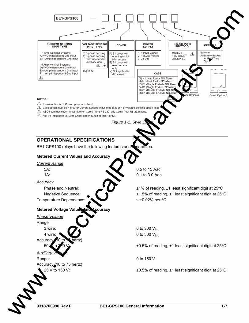
MODEL AND STYLE NUMBER DESCRIPTION
General The BE1-GPS100 Relay electrical characteristics and operational features are defined by a combination of letters and numbers that make up the style number. The model number, together with the style number, describe the options included in a specific device and appear in the clear window on the front panel and on a sticker located inside the case. Upon receipt of a relay, be sure to check the style number against the requisition and the packing list to ensure that they agree.
Sample Style Number Style number identification chart, Figure 1-1, defines the electrical characteristics and operational features included in BE1-GPS100 Relays. For example, if the style number were E3N1H0U, the device would have the following characteristics and features: BE1-GPS100 — (E) - 5 ampere nominal system with 5 ampere independent ground input (3) - Three-phase voltage sensing (N) - Not applicable (1) - 48/125 Vac/Vdc power supply (H) - Half rack case, normally closed alarm output (0) - ASCII communication (U) - Battery backup for real time clock
www . El
ectric
alPar
tMan
uals
. com
9318700990 Rev F BE1-GPS100 General Information 1-7
Figure 1-1. Style Chart
OPERATIONAL SPECIFICATIONS BE1-GPS100 relays have the following features and capabilities.
Metered Current Values and Accuracy
Current Range 5A: 0.5 to 15 Aac 1A: 0.1 to 3.0 Aac
Accuracy Phase and Neutral: ±1% of reading, ±1 least significant digit at 25°C Negative Sequence: ±1.5% of reading, ±1 least significant digit at 25°C Temperature Dependence: ≤ ±0.02% per °C
Metered Voltage Values and Accuracy
Phase Voltage Range 3 wire: 0 to 300 VL-L 4 wire: 0 to 300 VL-L Accuracy (10 to 75 hertz) 50 V to 300 V: ±0.5% of reading, ±1 least significant digit at 25°C
Auxiliary Voltage Range: 0 to 150 V Accuracy (10 to 75 hertz) 25 V to 150 V: ±0.5% of reading, ±1 least significant digit at 25°C
www . El
ectric
alPar
tMan
uals
. com

1-8 BE1-GPS100 General Information 9318700990 Rev F
Metered Frequency Values and Accuracy Frequency Range: 10 to 75 hertz Accuracy: ±0.01 hertz, ±1 least significant digit at 25°C Sensing Input 3-wire: Phase A - B 4-wire: Phase A - Neutral Minimum Frequency Tracking Voltage: 10 V RMS
Slip Frequency Range: ±10 hertz Accuracy: ±0.01 hertz, ±1 least significant digit at 25°C
Phase Angle Range: –180° to 0° to +180° Accuracy: ±0.5°
Calculated Values and Accuracy
Demand Range: 0.1 to 1.5 nominal Type: Exponential Accuracy: ±1% of reading, ±1 digit at 25°C Temperature Dependence: ≤ ±0.02% per °C Interval: 1 to 60 minutes
True Power Range 5 Ampere CT: -7,500 W to +7,500 W 1 Ampere CT: -1,500 W to +1,500 W Accuracy: ±1% at unity power factor
Reactive Power Range 5 Ampere CT: -7,500 var to +7,500 var 1 Ampere CT: -1,500 var to +1,500 var Accuracy: ±1% at zero power factor
Energy Data Reporting Range 5 Ampere Unit: 1,000,000 kWh or 1,000,000 Kvarh 1 Ampere Unit: 1,000,000 kWh or 1,000,000 kvarh Units of Measure: kilo, mega, giga Rollover Value of Registers: 1,000,000 kWh or 1,000,000 kvarh Accuracy: ±1% at unity power factor
Real Time Clock Accuracy: 1 second per day at 25°C (free running) or ±2 milliseconds (with IRIG synchronization) Resolution: 1 millisecond Date and Time Setting Provisions: Front panel, communications port, and IRIG. Leap
year and selectable daylight saving time correction provided.
Clock Power Supply Holdup Capacitor: 8 to 24 hours depending on conditions Backup Battery (optional): Greater than 5 years
www . El
ectric
alPar
tMan
uals
. com
9318700990 Rev F BE1-GPS100 General Information 1-9
Battery Type: Lithium, 3.6 Vdc, 0.95 Ah (Basler Electric P/N: 9318700012 or Applied Power P/N: BM551902)
Instantaneous Overcurrent Functions
Current Pickup Accuracy Phase and Neutral (50TP, 50TN) 5 Ampere CT: ±2% or ±50 mA 1 Ampere CT: ±2% or ±10 mA Dropout/pickup ratio: 95% or higher
Settable Time Delay Characteristics (50TP, 50TN) Definite time for any current exceeding pickup Time Range: 0.00 to 60.0 seconds Time Increment: One millisecond from 0 to 999 milliseconds, 0.1
second from 1.0 to 9.9 seconds, 1 second from 10 to 60 seconds.
Timing Accuracy 50TP, 50TN: ±0.5% or ±½ cycle whichever is greater plus trip
time for instantaneous response (0.0 setting).
Trip Time (for 0.0 delay setting) 50TP, 50TN: 2¼ cycles maximum for currents ≥ 5 times the
pickup setting. Three cycles maximum for a current of 1.5 times pickup. Four cycles maximum for a current of 1.05 times the pickup setting.
Time Overcurrent Functions
Current Pickup, Phase & Neutral (51P, 51N, 151N) Dropout/pickup ratio: 95% Pickup Accuracy 5 Ampere CT: ±2% or ±50 mA 1 Ampere CT: ±2% or ±10 mA
Current Pickup, Negative-Sequence (46) Dropout/pickup ratio: 95% Pickup Accuracy 5 Ampere CT: ±3% or ±75 mA 1 Ampere CT: ±3% or ±15 mA
Current Input All 51 Functions 5 Ampere CT Range: 0.50 to 16.0 A Increment: 0.01 from 0.50 to 9.99 0.1 from 10.0 to 16.0 1 Ampere CT Range: 0.10 to 3.2 A Increment: 0.01 A
www . El
ectric
alPar
tMan
uals
. com
1-10 BE1-GPS100 General Information 9318700990 Rev F
Time Current Characteristic Curves Timing Accuracy (All 51 Functions): Within ±5% or ±1½ cycles whichever is greater for
time dial settings greater than 0.1 and multiples of 2 to 40 times the pickup setting but not over 150 A for 5 A CT units or 30 A for 1 A CT units. See Appendix A, Time Overcurrent Characteristic Curves, for information on available timing curves.
Directional Power (32, 132) Mode: Forward, Reverse Pickup 5A: 1 to 6,000 Watts, 3 Ph 1A: 1 to 1,200 Watts, 3 Ph Accuracy: ±3% of setting or ±2W, whichever is greater, at
1.0 PF. (The relay knows the phase relationship of V vs I to within 0.5 deg when current is above 0.1A and voltage is above 5V. The power and var measurements at power factor other than 1.0 are affected accordingly.)
Time Delay: 0.05 to 600 seconds Accuracy: ±0.5 or ±3 cycles
Loss of Excitation (40Q, 140Q) Mode: Forward, Reverse Pickup 5A: 1 to 6,000 vars, 3 Ph 1A: 1 to 1,200 vars, 3 Ph Accuracy: ±3% Time Delay: 0.05 to 600 seconds Accuracy: ±0.5 or ±3 cycles
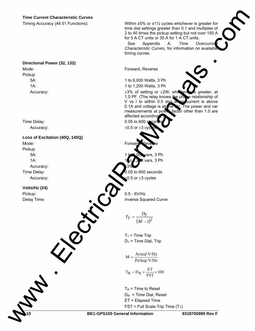
Volts/Hz (24) Pickup: 0.5 - 6V/Hz Delay Time: Inverse Squared Curve
( )21−=
MDT T
T
TT = Time Trip DT = Time Dial, Trip
V/HzPickupV/HzActualM =
100FSTETDT RR ××=
TR = Time to Reset DR = Time Dial, Reset ET = Elapsed Time FST = Full Scale Trip Time (TT)
www . El
ectric
alPar
tMan
uals
. com

9318700990 Rev F BE1-GPS100 General Information 1-11
Phase Undervoltage Function (27P, 127P)
Pickup Setting Range: 10 to 300 V Setting Increment: 0.1 V (for a range of 10 to 99.9)
1.0 V (for a range of 100 to 300) Accuracy: ±2% of setting or 1 V, whichever is greater Dropout/Pickup Ratio: 102%
Time Delay Setting Range: 0.050 to 600 seconds Increment: 1 ms from 0 to 999 ms
0.1 s from 1.0 to 9.9 s 1 s from 10 to 600 s
Accuracy: ±0.5% or ±1 cycle, whichever is greater
Auxiliary Undervoltage Function (27X, 127X) Mode 1=VX, Mode 2=3V0, Mode 3=VX
3rd
Pickup Setting Range: 1 to 150 V Setting Increment: 0.1 V (for a range of 0 to 99.9)
1.0 V (for a range of 100 to 150) Accuracy: ±2% of setting or 1 V, whichever is greater Dropout/Pickup Ratio: 102%
Time Delay Setting Range: 0.050 to 600 seconds Increment: 1 ms from 0 to 999 ms
0.1 s from 1.0 to 9.9 s 1 s from 10 to 600 s
Accuracy: ±0.5% or ±1 cycle, whichever is greater
Negative-Sequence Voltage Protection (47)
Pickup Setting Range: 1.0 to 300 VL-N Setting Increment: 0.1 V (for a range of 0 to 99.9) 1.0 V (for a range of 100 to 300) Accuracy: ±2% of setting or 1 V, whichever is greater Dropout/Pickup Ratio: 98%
Time Delay Setting Range: 0.050 to 600 seconds Increment: One ms from 0 to 999 ms 0.1 s from 1.0 to 9.9 s 1 s from 10 to 600 s Accuracy: ±0.5% or ±1 cycle, whichever is greater
Phase Overvoltage Function (59P, 159P)
Pickup Setting Range: 10 to 300 V Setting Increment: 0.1 V (for a range of 0 to 99.9)
1.0 V (for a range of 100 to 300) Accuracy: ±2% of setting or 1 V, whichever is greater Dropout/Pickup Ratio: 98%
www . El
ectric
alPar
tMan
uals
. com

1-12 BE1-GPS100 General Information 9318700990 Rev F
Time Delay Setting Range: 0.050 to 600 seconds Increment: 1 ms from 0 to 999 ms
0.1 s from 1.0 to 9.9 s 1 s from 10 to 60 s
Accuracy: ±0.5% or ±1 cycle, whichever is greater
Auxiliary Overvoltage Function (59X, 159X) Mode 1=VX, Mode 2=V3V0, Mode 3=VX
3rd
Pickup Setting Range: 1 to 150 V Setting Increment: 0.1 V (for a range of 0 to 99.9)
1.0 V (for a range of 100 to 300) Accuracy: ±2% of setting or 1 V, whichever is greater Dropout/Pickup Ratio: 98%
Time Delay Setting Range: 0.050 to 600 seconds Increment: 1 ms from 0 to 999 ms
0.1 s from 1.0 to 9.9 s 1 s from 10 to 60 s
Accuracy: ±0.5% or ±1 cycle, whichever is greater
Over/Underfrequency Functions (81, 181, 281, 381)
Pickup Setting Range: 20 to 70 Hz Setting Increment: 0.01 Hz Pickup Accuracy: ±0.01 Hz Dropout : 0.0020 over/under setting
Time Delay Setting Range: 0.00 to 600 seconds Increment One ms from 0 to 999 ms 0.1 s from 1.0 to 9.9 s 1 s from 10 to 600 s Accuracy: ±0.5% or ±1 cycle, whichever is greater
(Minimum trip time affected by a minimum 3-cycle security count.)
Undervoltage Inhibit Setting Range: 15 to 300 V Setting Increment: 0.1 V (for a range of 0.1 to 99.9)
1.0 V (for a range of 100 to 300)
Breaker Fail Timer (BF) Current Detector Pickup: Fixed at 0.5 A for 5 A unit 0.1 A for 1 A unit Current Detector Pickup Accuracy: ±2% Delay Range: 50 to 999 milliseconds Increment: 1 ms Reset Time: Within 1¼ cycles of the current being removed Timer Accuracy: ±0.5% or +1¼, -½ cycles, whichever is greater
www . El
ectric
alPar
tMan
uals
. com
9318700990 Rev F BE1-GPS100 General Information 1-13
General Purpose Timers (62, 162, 262, 362) Modes: Pickup/Dropout, 1 Shot Nonretriggerable, 1 Shot
Retriggerable, Oscillator, Integrating, latch Range: 0 to 9,999 seconds Increment: 1 ms from 0 to 999 ms 0.1 s from 1.0 to 9.9 s 1 s from 10 to 9,999 s Accuracy: ±0.5% or ±12 ms whichever is greater
Sync-Check (25) Delta Phase Angle: 1 to 99 degrees Delta Voltage Magnitude: 1 to 20 V Delta Frequency: 0.01 to 0.50 Hz
VT Fuse Loss Detection (60FL) Time Delay: Fixed at 50 milliseconds
Automatic Setting Group Characteristics Number of Setting Groups: 2 External Control Modes: Discrete Input Logic, Binary Input Logic
BESTlogic Update Rate: ½ cycle
GENERAL SPECIFICATIONS
AC Current Inputs
5 Ampere CT Continuous Rating: 20 A One Second Rating: 400 A For other current levels, use the formula: I = (K/t)½ where t = time in seconds, K=160,000(All Case styles) Saturation Limit: 150 A Burden: <10 milliohms
1 Ampere CT Continuous Rating: 4 A One Second Rating: 80 A
For other current levels, use the formula: I = (K/t)½ where t = time in seconds, K = 160,000 (S1 case), K = 90,000 (H1 case) Saturation Limit: 30 A Burden: 10 milliohms or Less at 1A
Phase AC Voltage Inputs Continuous Rating: 300 V, Line to Line One Second Rating: 600 V, Line to Neutral Burden: <1 VA @ 300Vac
www . El
ectric
alPar
tMan
uals
. com

1-14 BE1-GPS100 General Information 9318700990 Rev F
Auxiliary AC Voltage Inputs Continuous Rating: 150 V, Line to Line Fault Rating: 360 V, Line to Line One Second Rating: 600 V, Line to Neutral Burden: <1 VA @ 150Vac
Analog to Digital Converter Type: 16-bit Sampling Rate: 12 samples per cycle, adjusted to input frequency
(10 to 75 Hz)
Power Supply
Option 1 48, 110, and 125 Vdc: Range 35 to 150 Vdc 67, 110, and 120 Vac: Range 55 to135 Vac
Option 2 110, 125, and 250 Vdc: Range 90 to 300 Vdc 110, 120, and 240 Vac: Range 90 to 270 Vac
Option 3 24 Vdc: Range 17 to 32 Vdc (down to 8 Vdc for
momentary dips)
Frequency Range Options 1 and 2 only: 40 to 70 Hz
Burden Options 1, 2, and 3: 6 watts continuous, 8 watts maximum with all
outputs energized
Output Contacts Make and Carry for Tripping Duty: 30 A for 0.2 seconds per IEEE C37.90;
7 A continuous Break Resistive or Inductive: 0.3 A at 125 or 250 Vdc (L/R = 0.04 maximum)
Control Inputs Voltage Range: Same as control power
Turn-On Voltage 48/125 Vac/Vdc Power Supply: 26 to 100 V ∗ 125/250 Vac/Vdc Power Supply: 69 to 200 V ∗ 24 Vdc Power Supply: Approx. 5 Vdc
∗ Voltage ranges depend on Jumper configurations. See Section 3, Input and Output Functions, Contact Sensing Inputs.
Input Burden: Burden per contact for sensing depends on the
power supply model and the input voltage. Table 1-1 provides appropriate burden specifications.
www . El
ectric
alPar
tMan
uals
. com

9318700990 Rev F BE1-GPS100 General Information 1-15
Table 1-1. Burden
Power Supply Jumper Installed Burden
Jumper Not Installed Burden
48/125 V 13 kΩ 25 kΩ 125/250 V 25 kΩ 54 kΩ
24 Vdc N/A 7 kΩ
IRIG Supports IRIG Standard 200-98, Format B002 Input Signal: Demodulated (dc level-shifted digital signal) Logic-High Voltage: 3.5 Vdc, minimum Logic-Low Voltage: 0.5 Vdc, maximum Input Voltage Range: ±20 Vdc, maximum Resistance: Non-linear, approximately 4 kΩ at 3.5 Vdc,
approximately 3 kΩ at 20 Vdc
Contact Inputs Recognition Time Programmable, 4 to 255 milliseconds
Communication Ports
Interface Front RS-232: 300 to 19200 baud, 8N1 full duplex Rear RS-232: 300 to 19200 baud, 8N1 full duplex Rear RS-485: 300 to 19200 baud, 8N1 half duplex Response Time: <100 msec for metering and control functions
Display Type: Two line, 16 character alphanumeric LCD (liquid
crystal display) with LED (light emitting diode) back-light
Operating Temperature: -40°C (-40°F) to +70°C (+158°F) Display contrast may be impaired at temperatures below -20°C (-4°F).
Isolation Meets IEC 255-5 and exceeds IEEE C37.90 one minute dielectric test as follows: All Circuits to Ground: 2,828 Vdc
(excludes communication ports) Communication Ports to Ground: 500 Vdc Input Circuits to Output Circuits: 2,000 Vac or 2,828 Vdc
NOTE All timing specifications are for the worst-case response. This includes output contact operate times and standard BESTlogic operation timing, but excludes input debounce timing and non-standard logic configurations. If a non-standard logic scheme involves feedback, then one or more BESTlogic update rate delays must be included to calculate the worst-case delay. An example of feedback is Virtual Outputs driving Function Block Inputs. For more information, see Section 7, BESTlogic Programmable Logic.
www . El
ectric
alPar
tMan
uals
. com

1-16 BE1-GPS100 General Information 9318700990 Rev F
Surge Withstand Capability
Oscillatory Qualified to IEEE C37.90.1-1989 Standard Surge Withstand Capability (SWC) Tests for Protective Relays and Relay Systems (excluding communication ports).
Fast Transient Qualified to IEEE C37.90.1-1989 Standard Surge Withstand Capability (SWC) Tests for Protective Relays and Relay Systems (excluding communication ports). (Excluding across open output contacts due to installed surge suppression components)
Radio Frequency Interference (RFI) Qualified to IEEE C37.90.2-1995 Standard for Withstand Capability of Relays Systems to Radiated Electromagnetic Interference from Transceivers.
Electrostatic Discharge (ESD) Four kilovolts contact discharges and 8 kilovolts air discharges applied in accordance with Qualification EN61000-4-2.
Shock Qualification: IEC 255-21-2, Class 1
Vibration Qualification: IEC 255-21-1, Class 1
Environment
Temperature Operating Range: -40°C to 70°C (-40°F to 158°F) ∗ Storage Range: -40°C to 70°C (-40°F to 158°F) ∗ Display is inoperative below -20°C (-4°F)
Humidity Qualified to IEC 68-2-38, 1st Edition 1974, Basic Environmental Test Procedures, Part 2: Test Z/AD: Composite Temperature Humidity Cyclic Test.
CE Qualified This product meets or exceeds the standards required for distribution in the European Community.
UL Recognition UL recognized per Standard 508, UL File Number E97033. Note: Output contacts are not UL recognized for voltages greater than 250 V.
CSA Certification CSA certified per Standard CAN/CSA-C22.2 Number 14-M91, CSA File Number LR23131-140s. Note: Output contacts are not CSA certified for voltages greater than 250 V.
GOST-R Certification GOST-R certified No. POCC US.ME05.B03391; is in compliance with the relevant standards of Gosstandart of Russia. Issued by accredited certification body POCC RU.0001.11ME05.
DNP Certification DNP 3.0 IED certified, Subset Level 2, by SUBNET Solutions, Inc.
www . El
ectric
alPar
tMan
uals
. com

9318700990 Rev F BE1-GPS100 General Information 1-17
Physical
Weight H1: Approximately 10.0 lbs (4.54 kg) S1: Approximately 11.2 lbs (5.08 kg) S1 Double-ended: Approximately 12.8 lbs (5.81 kg)
Case Size H1, S1 & S1 Double-ended: See Section 12, Installation, for case dimensions
and Figure 1-1, Style Chart, for available options.
www . El
ectric
alPar
tMan
uals
. com

1-18 BE1-GPS100 General Information 9318700990 Rev F
This page intentionally left blank.
www . El
ectric
alPar
tMan
uals
. com
9318700990 Rev F BE1-GPS100 Quick Start i
SECTION 2 • QUICK START TABLE OF CONTENTS
SECTION 2 • QUICK START.................................................................................................................... 2-1
GENERAL.............................................................................................................................................. 2-1 About This Manual ............................................................................................................................. 2-1
BESTlogic .............................................................................................................................................. 2-2 Characteristics of Protection and Control Function Blocks ................................................................ 2-2 Function Block Logic Settings ............................................................................................................ 2-2 Output Logic Settings ......................................................................................................................... 2-3
USER INTERFACES ............................................................................................................................. 2-3 Front Panel HMI ................................................................................................................................. 2-3 ASCII Command Communications..................................................................................................... 2-4 BESTCOMS for BE1-GPS100, Graphical User Interface .................................................................. 2-5
GETTING STARTED ............................................................................................................................. 2-6 Entering Test Settings ........................................................................................................................ 2-6 Checking the State of Inputs .............................................................................................................. 2-7 Testing................................................................................................................................................ 2-7
FAQ/TROUBLESHOOTING .................................................................................................................. 2-7 Frequently Asked Questions (FAQs) ................................................................................................. 2-7
Figures Figure 2-1. 51 Time Overcurrent Logic ..................................................................................................... 2-2 Figure 2-2. Menu Screens Numbering Example ....................................................................................... 2-4
Tables Table 2-1. Function Categories and Manual Sections Cross-Reference.................................................. 2-1 Table 2-2. Trip LED Truth Table................................................................................................................ 2-9
www . El
ectric
alPar
tMan
uals
. com

ii BE1-GPS100 Quick Start 9318700990 Rev F
This page intentionally left blank.
www . El
ectric
alPar
tMan
uals
. com

9318700990 Rev F BE1-GPS100 Quick Start 2-1
SECTION 2 • QUICK START GENERAL This section provides an overview of the BE1-GPS100 Generator Protection System. You should be familiar with the concepts behind the user interfaces and BESTlogic before you begin reading about the detailed BE1-GPS100 functions. Sections 3 through 6 in the instruction manual describe each function of the BE1-GPS100 in detail. The following information is intended to provide the reader with a basic understanding of the user interfaces and the security features provided in the BE1-GPS100 relay. Detailed information on the operation of the human-machine interface (HMI) can be found in Section 10, Human-Machine Interface, and the ASCII command communications in Section 11, ASCII Command Interface. BESTCOMS is a Windows® based software application that enhances communication between the PC user and the BE1-GPS100 relay. BESTCOMS for the BE1-GPS100 is provided free of charge with the BE1-GPS100. BESTCOMS operation is very transparent, and does contain a Windows® type help file for additional operational details. Also covered in this section is an overview of BESTlogic, which is fundamental to how each of the protection and control functions is set-up and used in the BE1-GPS100 relay. Detailed information on using BESTlogic to design complete protection and control schemes for the protected circuit can be found in Section 7, BESTlogic Programmable Logic, and Section 8, Application. Sections 3 through 6 describe each function provided in the BE1-GPS100 relay and include references to the following items. Note that not all items are appropriate for each function.
• Human-machine interface (HMI) screens for setting the operational parameters. • ASCII commands for setting the operational parameters. • ASCII commands for setting up the BESTlogic required to use the function in your protection and
control scheme. • Outputs from the function such as alarm and BESTlogic variables or data reports. • HMI screens for operation or interrogation of the outputs and reports provided by each function. • ASCII commands for operation or interrogation of the outputs and reports provided by each
function.
About This Manual The various application functions provided by this multifunction relay are divided into four categories: input/output functions, protection and control functions, metering functions, and reporting and alarm functions. Detailed descriptions of each individual function, setup, and use are covered in the sections as shown in Table 2-1. Detailed information on using programmable logic to create your own protection and control scheme is described in Section 7, BESTlogic Programmable Logic.
Table 2-1. Function Categories and Manual Sections Cross-Reference
Section Title Section
Input and Output Functions Section 3
Protection and Control Section 4
Metering Section 5
Reporting and Alarm Functions Section 6
BESTlogic Programmable Logic Section 7
Application Section 8
www . El
ectric
alPar
tMan
uals
. com

2-2 BE1-GPS100 Quick Start 9318700990 Rev F
BESTlogic Each of the protection and control functions in the BE1-GPS100 is implemented as an independent function block that is equivalent to a single function, discrete device counterpart. Each independent function block has all of the inputs and outputs that the discrete component counterpart might have. Programming BESTlogic is equivalent to choosing the devices required by your protection and control scheme and drawing schematic diagrams to connect the inputs and outputs to obtain the desired operational logic. The concept is the same but the method is different in that you choose each function block by enabling it and use Boolean logic expressions to connect the inputs and outputs. The result is that in designing your system, you have even greater flexibility than you had using discrete devices. An added benefit is that you are not constrained by the flexibility limitations inherent in many multifunction relays. One user programmable, custom logic scheme created by the user may be programmed and saved in memory. To save you time, several preprogrammed logic schemes have also been provided. Any of the preprogrammed schemes can be copied into the programmable logic settings without the user having to make any BESTlogic programming. There are two types of BESTlogic settings: function block logic settings and output logic settings. These are described briefly in the following paragraphs. Detailed information on using BESTlogic to design complete protection and control schemes for the protected circuit can be found in Section 7, BESTlogic Programmable Logic, and Section 8, Application.
Characteristics of Protection and Control Function Blocks As stated before, each function block is equivalent to a discrete device counterpart. For example, the phase time-overcurrent function block in the BE1-GPS100 relay has all of the characteristics of Basler BE1 relays with similar functionality. Figure 2-1 is a logic drawing showing the inputs and outputs.
One input: • BLK (block 51P operation)
Two mode settings: • Enable 51P operation • Disable 51P operation
Two outputs: • 51PT (51 Phase Trip) • 51PPU (51 Phase Pickup)
Three operational settings: • Pickup • Time Delay • Characteristic Curve
BLOCK51PT
51PPU
Mode0-Disable1-Enable
PHASETOC(51P)
D2849-1506-17-99
Figure 2-1. 51 Time Overcurrent Logic
Of the above characteristics, the three operational settings are not included in the logic settings. They are contained in the protection settings. This is an important distinction. Since changing logic settings is similar to rewiring a panel, the logic settings are separate and distinct from the operational settings such as pickups and time delays.
Function Block Logic Settings To use a protection or control function block, there are two items that need to be set: Mode and Input Logic. The mode is equivalent to deciding which devices you want to install in your protection and control scheme. You then must set the logic variables that will be connected to the inputs. For example, the 51N function block has three modes (disabled, three-phase summation (3Io), and ground), and one input, block (torque control). To use this function block, the logic setting command might be SL-51N=1,/IN2 for Set Logic-51N to be Mode 1 (three-phase and neutral) with the function blocked when Contact Sensing Input 2 is not (/) energized. Contact Sensing Input 2 would be wired to a ground relay enable switch.
www . El
ectric
alPar
tMan
uals
. com

9318700990 Rev F BE1-GPS100 Quick Start 2-3
As noted before, the protection settings for this function block, pickup, time dial, and curve must be set separately in the setting group settings. The setting might be S0-51N=6.5,2.1,S1R for Setting in group 0 - the 51N function = pickup at 6.5 amps with a time dial of 2.1 using curve S1 with an integrating Reset characteristic. The 51N function block has two logic output variables, 51NT (Trip), and 51NPU (Picked Up). The combination of the logic settings and the operational settings for the function block govern how these variables respond to logic and current inputs.
Output Logic Settings BESTlogic, as implemented in the BE1-GPS100, supports up to 16 output expressions. The output expressions are called virtual outputs to distinguish them from the physical output relays. VOA and VO1 through VO5 drive physical outputs OUTA (failsafe alarm output) and OUT1 through OUT5, respectively. The rest of the virtual outputs can be used for intermediate logic expressions. For example, OUT 1 is wired to the trip bus of the circuit breaker. To set up the logic to trip the breaker, the BESTlogic setting command might be SL-VO1=VO11+101T+BFPU for Set Logic - Virtual Output 1 = to Virtual Output 11 (which is the intermediate logic expression for all of the function block tripping outputs) or (+) 101T (the trip output of the virtual breaker control switch) or (+) BFPU (the pickup output of the breaker failure function block that indicates that breaker failure has been initiated).
USER INTERFACES Three user interfaces are provided for interacting with the BE1-GPS100 relay: front panel HMI, ASCII communications, and BESTCOMS for BE1-GPS100. The front panel HMI provides access to a subset of the total functionality of the device. ASCII communications provides access to all settings, controls, reports, and metering functions of the system. BESTCOMS for BE1-GPS100 is software used to quickly develop setting files, view metering data, and download reports in a user-friendly, Windows® based environment.
Front Panel HMI The front panel HMI consists of a two line by 16 character LCD (liquid crystal display) with four scrolling pushbuttons, an edit pushbutton, and a reset pushbutton. The EDIT pushbutton includes an LED to indicate when edit mode is active. There are five other LEDs for indicating power supply status, relay trouble alarm status, programmable major and minor alarm status, and a multipurpose Trip LED that flashes to indicate that a protective element is picked up. The Trip LED lights continuously when the trip output is energized and seals in when a protective trip has occurred to indicate that target information is being displayed on the LCD. A complete description of the HMI is included in Section 10, Human-Machine Interface. The BE1-GPS100 HMI is menu driven and organized into a menu tree structure with six branches. A complete menu tree description with displays is also provided in Section 10, Human-Machine Interface. A list of the menu branches and a brief description for scrolling through the menu is in the following paragraphs.
1. REPORT STATUS. Display and resetting of general status information such as targets and alarms.
2. CONTROL. Operation of manual controls such as virtual switches, selection of active setting group, etc.
3. METERING. Display of real-time metering values. 4. REPORTS. Display and resetting of report information such as time and date, demand registers,
breaker duty statistics, etc. 5. PROTECTION. Display and setting of protective function setting parameters such as logic
scheme, pickups, time delays, etc. 6. GENERAL SETTINGS. Display and setting of non-protective function setting parameters such as
communication, LCD contrast, and CT ratios. Each screen is assigned a number in the HMI section. The number indicates the branch and level in the menu tree structure. Screen numbering helps you to keep track of where you are when you leave the menu tree top level. You view each branch of the menu tree by using the RIGHT and LEFT scrolling pushbuttons. To go to a level of greater detail, you use the DOWN scrolling pushbutton. Each time a
www . El
ectric
alPar
tMan
uals
. com
2-4 BE1-GPS100 Quick Start 9318700990 Rev F
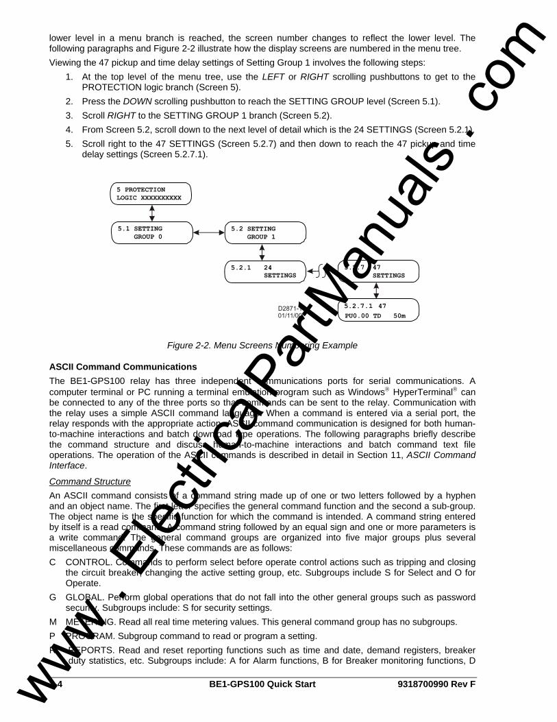
lower level in a menu branch is reached, the screen number changes to reflect the lower level. The following paragraphs and Figure 2-2 illustrate how the display screens are numbered in the menu tree. Viewing the 47 pickup and time delay settings of Setting Group 1 involves the following steps:
1. At the top level of the menu tree, use the LEFT or RIGHT scrolling pushbuttons to get to the PROTECTION logic branch (Screen 5).
2. Press the DOWN scrolling pushbutton to reach the SETTING GROUP level (Screen 5.1). 3. Scroll RIGHT to the SETTING GROUP 1 branch (Screen 5.2). 4. From Screen 5.2, scroll down to the next level of detail which is the 24 SETTINGS (Screen 5.2.1). 5. Scroll right to the 47 SETTINGS (Screen 5.2.7) and then down to reach the 47 pickup and time
delay settings (Screen 5.2.7.1).
Figure 2-2. Menu Screens Numbering Example
ASCII Command Communications The BE1-GPS100 relay has three independent communications ports for serial communications. A computer terminal or PC running a terminal emulation program such as Windows® HyperTerminal® can be connected to any of the three ports so that commands can be sent to the relay. Communication with the relay uses a simple ASCII command language. When a command is entered via a serial port, the relay responds with the appropriate action. ASCII command communication is designed for both human-to-machine interactions and batch download type operations. The following paragraphs briefly describe the command structure and discuss human-to-machine interactions and batch command text file operations. The operation of the ASCII commands is described in detail in Section 11, ASCII Command Interface.
Command Structure An ASCII command consists of a command string made up of one or two letters followed by a hyphen and an object name. The first letter specifies the general command function and the second a sub-group. The object name is the specific function for which the command is intended. A command string entered by itself is a read command. A command string followed by an equal sign and one or more parameters is a write command. The general command groups are organized into five major groups plus several miscellaneous commands. These commands are as follows: C CONTROL. Commands to perform select before operate control actions such as tripping and closing
the circuit breaker, changing the active setting group, etc. Subgroups include S for Select and O for Operate.
G GLOBAL. Perform global operations that do not fall into the other general groups such as password security. Subgroups include: S for security settings.
M METERING. Read all real time metering values. This general command group has no subgroups. P PROGRAM. Subgroup command to read or program a setting. R REPORTS. Read and reset reporting functions such as time and date, demand registers, breaker
duty statistics, etc. Subgroups include: A for Alarm functions, B for Breaker monitoring functions, D
www . El
ectric
alPar
tMan
uals
. com
9318700990 Rev F BE1-GPS100 Quick Start 2-5
for Demand recording functions, F for Fault summary reporting functions, G for General information, and S for sequence of events recorder functions.
S SETTINGS. Set all setting parameters that govern the functioning of the relay. Subgroups include: 0,1, for settings in setting groups, A for alarm settings, B for breaker monitoring settings, G for general settings, and L for logic settings.
MISCELLANEOUS. Miscellaneous commands include ACCESS, EXIT, and HELP. Examples of object names would be 51N for the neutral inverse time overcurrent function or PIA for the A phase, peak current demand register. For example, to check the 51N pickup setting in Setting Group 1, you would enter S1-51N for Setting Group 1, 51N. The relay would respond with the current pickup, time dial and curve settings for the 51N function. To edit these settings the same command would be used with an = followed by the new settings and the ENTER pushbutton. Note that it is necessary to use the ACCESS and EXIT commands when using the write version of these commands.
ASCII Command Operations Using ASCII commands, settings can be read and changed on a function-by-function basis. The mnemonic format of the commands helps you interact with the relay. It is not necessary to remember all of the object names. Most commands do not require that you specify a complete object name. If the first two letters of a command are entered, the relay will respond with all applicable object names. Example 1: Obtain a breaker operations count by entering RB (Report Breaker). The BE1-GPS100
responds with the operations counter value along with all other breaker report objects. If you know that the object name for the breaker operations counter is OPCNTR, you can enter RB-OPCNTR and read only the number of breaker operations.
Partial object names are also supported. This allows multiple objects to be read or reset at the same time. Example 2: Read all peak-since-reset demand registers. Entering RD-PI (report demand - peak
current) will return demand values and time stamps for phase A, B, C, neutral and negative-sequence current. To read only the neutral demand value, the full object name (RD-PIN) is entered. Entering RD-PI=0 resets all five of the peak-since-reset demand registers.
Batch Command Text File Operations With a few exceptions, each function of the relay uses one command to set it and each setting command operates on all of the parameters required by that function. See the example mentioned previously in the paragraph titled Command Structure. This format results in a great many commands to fully set the relay. In addition, the process of setting the relay does not use a prompting mode where the relay prompts you for each parameter in turn until you exit the setting process. For these reasons, a method for setting the relay using batch text files is recommended. In batch download type operations, the user creates an ASCII text file of commands and sends it to the relay. To facilitate this process, the response from a multiple read command is output from the BE1-GPS100 in command format. Therefore, the user need only enter S for Set (with no subgroup) and the relay responds with all of the setting commands and their associated parameters. If the user enters S1 for Setting Group 1, the relay responds with all of the setting commands for setting group 1. The user can capture this response to a file, edit it using any ASCII text editor, and then send the file back to the relay. See Section 11, ASCII Command Interface, for a more detailed discussion of how to use ASCII text files for setting the relay.
BESTCOMS for BE1-GPS100, Graphical User Interface Basler Electric's graphical user interface (GUI) software is an alternative method for quickly developing setting files in a user-friendly, Windows® based environment. Using the GUI, you may prepare setting files off-line (without being connected to the relay) and then upload the settings to the relay at your convenience. These settings include protection and control, operating and logic, breaker monitoring, metering, and fault recording. Engineering personnel can develop, test, and replicate the settings before exporting it to a file and transmitting the file to technical personnel in the field. On the field end, the technician simply imports the file into the BESTCOMS database and uploads the file to the relay where it is stored in nonvolatile memory. The GUI also has the same preprogrammed logic schemes that are stored in the relay. This gives the engineer the option (off-line) of developing his setting file using a preprogrammed logic scheme, customizing a preprogrammed logic scheme, or building a scheme from scratch. Files may be exported www .
Elec
tricalP
artM
anua
ls . c
om

2-6 BE1-GPS100 Quick Start 9318700990 Rev F
from the GUI to a text editor where they can be reviewed or modified. The modified text file may then be uploaded to the relay. After it is uploaded to the relay, it can be brought into the GUI but it cannot be brought directly into the GUI from the text file. The GUI logic builder uses basic AND/OR gate logic combined with point and click variables to build the logic expressions. This reduces the design time and increases dependability. The GUI also allows for downloading industry standard COMTRADE files for analysis of stored oscillography data. Detailed analysis of the oscillography files may be accomplished using Basler Electric's BESTwave software. For more information on Basler Electric's Windows® based BESTCOMS (GUI) software, refer to Section 14, BESTCOMS Software. For information on BESTwave, contact your local sales representative or Basler Electric, Technical Support Services Department in Highland, Illinois.
GETTING STARTED If your relay has Power Supply Option 1 or 2, it can be supplied by normal 120 Vac house power. These two power supply options (1 and 2) are the midrange and high range AC/DC power supplies. The contact sensing inputs are half-wave rectified opto-isolators. The default contact recognition and debounce settings enable their use on ac signals as well as dc signals. The BE1-GPS100 measures the A phase, B phase, and C phase current magnitudes and angles directly from the three current sensing inputs. The neutral, positive, and negative-sequence magnitudes and angles are calculated from the fundamental component of each of the three-phase currents. When evaluating the negative-sequence functions, the relay can be tested using a single-phase current source. To fully evaluate the operation of the relay in the power system, it is desirable to use a three-phase current source. Connect a computer to the front RS-232 port (refer to Section 12, Installation, for connection diagrams). Apply power and Enter A= to gain setting access. Set the clock using the RG-TIME= and RG-DATE= commands. (Refer to Section 11, ASCII Command Interface, for additional information.)
Entering Test Settings Enter SG (Setting General) to get a listing of the general setting commands with default parameters and put them in a text file as described previously in Batch Command Text File Operations. Then enter S0 (setting group 0) to get a listing of the group 0 protection setting commands with default parameters and put them in a text file also. With these two sub-groups of settings, you will not see the global security settings, user programmable BESTlogic settings, settings for protection Setting Groups 0 and 1, settings for alarm functions, and the settings for breaker monitoring functions. Open the SG file in a text editor, change settings, as required, and save the changes. For example:
• The ratios for the phase and neutral current transformers (CTP, CTG). • The demand interval and CT circuit to monitor for the phase, neutral and negative-sequence
currents (DIP, DIN, DIQ). • The nominal system frequency (FREQ). • The normal phase-sequence (ABC or ACB, nominal secondary voltage and current) for the
system (PHROT). • Open the S0 file in a text editor, change settings as required, and save the changes.
Do not forget to add E;Y (Exit; Save Settings? Yes) to the end of both files. Enter A= to gain setting access and then send each of these text files to the relay as described above under Batch Command Text File Operations. As you gain knowledge of the relay, you can experiment with the rest of the settings. To set up a file with all user settings, enter S and the relay will respond with all settings in command format. For documentation, the user should use the Print command in BESTCOMS settings. Default settings can be found several different ways. The default preprogrammed logic scheme is BASIC-LZ. Section 8, Application, lists all of the default logic settings for the default logic scheme. If you wanted to know the default logic setting for the phase instantaneous overcurrent element, you could look at the default listing and find that SL-50TP=1,/VO14. Translated, this means that the setting, logic – phase instantaneous overcurrent is enabled (1) and is blocked when Virtual Output 14 is not TRUE. You could also look in Section 4, Protection and Control, find the table for the logic settings. It lists the same information, but it lists the mode and block inputs separately. If you want to find the default settings for an input or output, look in Section 3, Input and Output Functions.
www . El
ectric
alPar
tMan
uals
. com

9318700990 Rev F BE1-GPS100 Quick Start 2-7
Checking the State of Inputs You can review the state of the inputs through the front panel HMI, the ASCII command interface, or BESTCOMS Metering screen. The front panel HMI displays the input status on Screen 1.4.1. A diagram showing all of the menu tree branches is located in Section 10, Human-Machine Interface. To get to this screen, press the UP scrolling pushbutton until you reach the top screen in the current branch. You know when you have reached the top screen because the screen stops changing when you press the UP scrolling pushbutton. From this position, press the RIGHT scrolling pushbutton until you have reached the screen titled, REPORT STATUS. From this position press the DOWN scrolling pushbutton one time (TARGETS) and press the RIGHT scrolling pushbutton three times. At this time, you should see the OPERATIONAL STATUS Screen. If you press the DOWN scrolling pushbutton from this screen, you should see the INPUTS Screen (IN 1234). To check the state of the inputs using the ASCII command interface, type in the RG-STAT command and press enter. This command only reads the status of the inputs.
Testing To determine if the relay is responding correctly to each test, the following commands are useful:
1. RG-TARG, (report general targets): reports the targets from the last fault. 2. RF, (report faults): reports a directory listing of the twelve fault summary reports. The fault summary
reports are numbered from 1 to 255, then wrap around, and start over. RF-### reports the ### report. 3. RS-##, (report sequence of events record), ## events: reports the most recent ## changes of state
in the protection and control logic.
FAQ/TROUBLESHOOTING
Frequently Asked Questions (FAQs) 1.) Why won't the trip LED reset when I press the RESET key on the front panel?
The RESET key is context sensitive. To reset the trip LED or the targets, the Targets screen must be displayed. To reset the alarms, the Alarms screen must be displayed.
2.) Is the power supply polarity sensitive?
No, the power supply will accept either an ac or a dc voltage input. However, the contact sensing for the programmable inputs is polarity sensitive. Refer to Section 12, Installation, for typical interconnection diagrams.
3.) What voltage level is used to develop current flow through the contact sensing inputs? Voltage level is dependent on the power supply option (called out in the BE1-GPS100 style chart). For additional information, see Figure 1-1 in Section 1, General Information, and Section 12, Installation.
4.) Does the BE1-GPS100 trip output contact latch after a fault? The answer to the question is yes and no. In general, once the fault goes away the output contacts open. The BE1-GPS100 does offer an option to ensure that the contact will stay closed for at least 200 milliseconds. See Section 3, Input and Output Functions for additional information on that function. However, BESTlogic can keep the relay outputs closed as long as power is applied. Refer to Application, Section 8, Application, Application Tips, for additional information.
5.) Why won't a function work when I put in settings such as the pickup and time delays? Make sure that the logic for the function is set to "Enable."
www . El
ectric
alPar
tMan
uals
. com

2-8 BE1-GPS100 Quick Start 9318700990 Rev F
6.) How many overcurrent elements does the BE1-GPS100 have available? The BE1-GPS100 has two instantaneous overcurrent and three time overcurrent elements. Just like any element, each of these elements can be assigned to any output for building logic equations.
7.) Can I make logic settings from the front panel? No, the front panel cannot program logic settings. Logic settings must be programmed using the ASCII command interface or BESTCOMS communication software.
8.) Since the BE1-GPS100 is a programmable device, what are the factory defaults? The factory default logic is BASIC-LZ logic. Default settings are shown with each function in the instruction manual. For input or output default settings see Section 3, Input and Output Functions. For protection and control functions, see Section 4, Protection and Control.
9.) Does the BE1-GPS100 have a battery installed as the back-up power source for the internal clock on loss of power? As an option, battery backup can be included. All relays come standard with a 12-hour ride-through capacitor.
10.) Why do I keep getting access conflict errors when I attempt communication with the relay? If you try to gain access to more than one port at a time, an access conflict results. The relay has three communication ports: COM 0, COM 1, and COM 2. The front panel HMI and RS-232 port are considered to be the same port and are designated COM0. The rear RS-232 port is designated as COM 1 and the rear RS-485 port is designated as COM 2. If access at the front panel HMI has been obtained, access cannot be gained at another port. The front RS-232 port can still be accessed because the HMI and front RS-232 port are considered the same port (COM 0). Access needs to be gained only when a write command to the BE1-IPS100 is required (control or setting change or report reset). When access is gained through a port, a five-minute timer starts counting down to zero. When port activity occurs, the timer resets to five minutes and resumes counting down. If no activity is seen for the duration of the five-minute timer, access is withdrawn and any unsaved changes are lost. When activity at a port is no longer required, access should be terminated with the Exit command. When using BESTCOMS, the Access and Exit commands are executed for you. Obtaining data or reports from the relay never requires password access.
11.) Why doesn't the trip LED behave as expected when the relay picks up and trips? Why don't the targets work properly? If a protective element is tripping at the desired level, but the targets and fault records are not behaving as expected, two commands should be checked. The SG-TARG command needs the protective element (function) enabled so that targets are logged. The SG-TRIGGER command must be programmed with the correct pickup logic expression and trip logic expression to initiate fault records. Section 6, Reporting and Alarm Functions, Fault Reporting, for detailed information about programming these commands. Trip LED behavior also depends on the pickup and trip expressions of the SG-TRIGGER command. When the SG-TRIGGER pickup expression is TRUE and the trip expression is FALSE, the Trip LED flashes. In other words, a flashing LED means that a protection element is in a picked up state and is timing toward a trip. When both the pickup and trip expression is TRUE, the Trip LED lights steadily. The Trip LED also lights steadily when neither expression is TRUE but latched targets exist. When resetting a target, the Trip LED will not turn off if the fault is still present. The truth table of Table 2-2 serves as an aid to interpreting Trip LED indications.
www . El
ectric
alPar
tMan
uals
. com
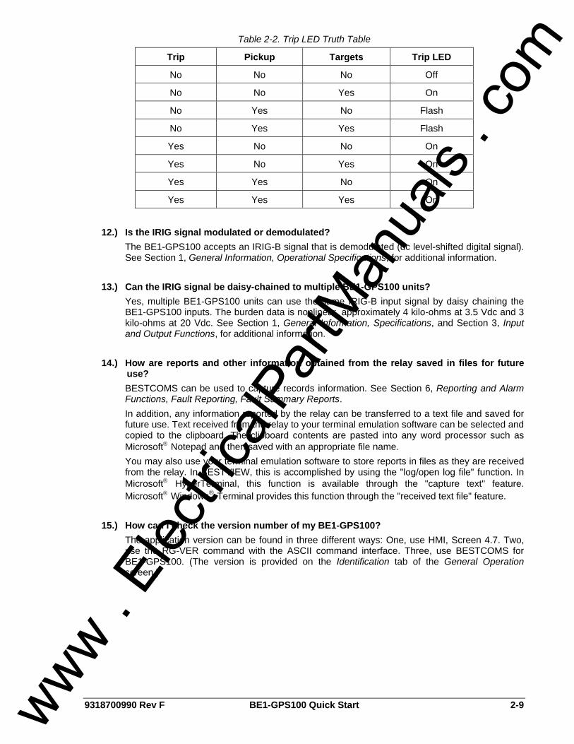
9318700990 Rev F BE1-GPS100 Quick Start 2-9
Table 2-2. Trip LED Truth Table
Trip Pickup Targets Trip LED
No No No Off
No No Yes On
No Yes No Flash
No Yes Yes Flash
Yes No No On
Yes No Yes On
Yes Yes No On
Yes Yes Yes On
12.) Is the IRIG signal modulated or demodulated?
The BE1-GPS100 accepts an IRIG-B signal that is demodulated (dc level-shifted digital signal). See Section 1, General Information, Operational Specifications, for additional information.
13.) Can the IRIG signal be daisy-chained to multiple BE1-GPS100 units? Yes, multiple BE1-GPS100 units can use the same IRIG-B input signal by daisy chaining the BE1-GPS100 inputs. The burden data is nonlinear, approximately 4 kilo-ohms at 3.5 Vdc and 3 kilo-ohms at 20 Vdc. See Section 1, General Information, Specifications, and Section 3, Input and Output Functions, for additional information.
14.) How are reports and other information obtained from the relay saved in files for future use? BESTCOMS can be used to capture records information. See Section 6, Reporting and Alarm Functions, Fault Reporting, Fault Summary Reports. In addition, any information reported by the relay can be transferred to a text file and saved for future use. Text received from the relay to your terminal emulation software can be selected and copied to the clipboard. The clipboard contents are pasted into any word processor such as Microsoft® Notepad and then saved with an appropriate file name. You may also use your terminal emulation software to store reports in files as they are received from the relay. In BESTVIEW, this is accomplished by using the "log/open log file" function. In Microsoft® HyperTerminal, this function is available through the "capture text" feature. Microsoft® Windows® Terminal provides this function through the "received text file" feature.
15.) How can I check the version number of my BE1-GPS100? The application version can be found in three different ways: One, use HMI, Screen 4.7. Two, use the RG-VER command with the ASCII command interface. Three, use BESTCOMS for BE1-GPS100. (The version is provided on the Identification tab of the General Operation screen.)
www . El
ectric
alPar
tMan
uals
. com

2-10 BE1-GPS100 Quick Start 9318700990 Rev F
This page intentionally left blank.
www . El
ectric
alPar
tMan
uals
. com
9318700990 Rev F BE1-GPS100 Input and Output Functions i
SECTION 3 • INPUT AND OUTPUT FUNCTIONS TABLE OF CONTENTS
SECTION 3 • INPUT AND OUTPUT FUNCTIONS................................................................................... 3-1
INTRODUCTION.................................................................................................................................... 3-1 POWER SYSTEM INPUTS ................................................................................................................... 3-1
Current Measurement ........................................................................................................................ 3-1 Voltage Measurement ........................................................................................................................ 3-2 Frequency Measurement ................................................................................................................... 3-2 Power Measurement .......................................................................................................................... 3-2 Measurement Functions Setup .......................................................................................................... 3-3
CONTACT SENSING INPUTS .............................................................................................................. 3-5 Digital Input Conditioning Function .................................................................................................... 3-6
OUTPUTS.............................................................................................................................................. 3-8 Hardware Outputs and Virtual Outputs .............................................................................................. 3-8 Retrieving Output Status .................................................................................................................... 3-9 Relay Trouble Alarm Disable.............................................................................................................. 3-9 Programmable Hold Timer ................................................................................................................. 3-9 Output Logic Override Control.......................................................................................................... 3-10
Figures Figure 3-1. General Operation, Power System Tab.................................................................................. 3-4 Figure 3-2. Digital Input Conditioning Timing Diagram.............................................................................. 3-6 Figure 3-3. Inputs and Outputs Screen, Inputs 1-4 Tab............................................................................ 3-7 Figure 3-4. Output Logic, General Purpose Output Contacts ................................................................... 3-8 Figure 3-5. Output Logic, Fail-Safe Alarm Output Contact ....................................................................... 3-9 Figure 3-6. Inputs and Outputs Screen, Outputs 1-5, A Tab................................................................... 3-10
Tables Table 3-1. Measurement Functions Settings............................................................................................. 3-5 Table 3-2. Contact Sensing Turn-On Voltage ........................................................................................... 3-6 Table 3-3. Digital Input Conditioning Settings ........................................................................................... 3-7 Table 3-4. Hold Timer Settings................................................................................................................ 3-10
www . El
ectric
alPar
tMan
uals
. com

ii BE1-GPS100 Input and Output Functions 9318700990 Rev F
This page intentionally left blank.
www . El
ectric
alPar
tMan
uals
. com

9318700990 Rev F BE1-GPS100 Input and Output Functions 3-1
SECTION 3 • INPUT AND OUTPUT FUNCTIONS INTRODUCTION BE1-GPS100 inputs consist of three-phase current inputs, an optional ground current input, three-phase voltage inputs, optional auxiliary voltage input, and four contact sensing inputs. Five general-purpose output contacts and one dedicated, fail-safe alarm output make up the BE1-GPS100 outputs. Each input and output is isolated and terminated at separate terminal blocks. This section describes the function and setup of each input and output and provides the equations that the BE1-GPS100 uses for calculating the power quantities.
POWER SYSTEM INPUTS Power system inputs as described in the introduction, are sampled 12 times per cycle by the BE1-GPS100. The BE1-GPS100 measures the voltage and current from these samples and uses those measurements to calculate other quantities. Frequency is measured from a zero crossing detector. Measured inputs are then recorded every quarter cycle. If the applied voltage is greater than ten volts, the BE1-GPS100 measures the frequency and varies the sampling rate to maintain 12 samples per cycle. Frequency compensation applies to all power system measurements. Power system inputs are broken down in the following paragraphs: Current Measurement, Voltage Measurement, Frequency Measurement, Power Measurement, and Measurement Functions Setup.
Current Measurement Secondary current from power system equipment CTs is applied to current transformers inside the relay. These internal transformers provide isolation and step down the monitored current to levels compatible with relay circuitry. Secondary current from each internal CT is converted to a voltage signal and then filtered by an analog, low-pass, anti-aliasing filter.
Current Measurement Functions Input waveforms are sampled by an analog-to-digital converter (ADC) at 12 samples per cycle. The relay extracts the magnitude and angle of the fundamental components of each three-phase current input and the magnitude and angle of the optional independent ground current input.
Neutral and Negative-Sequence Current Neutral and negative-sequence components are measured from the fundamental component of the three-phase current inputs. The relay can be set to accommodate ABC or ACB phase-sequence when calculating the negative-sequence component. Negative Sequence Current (I2) is calculated using vector math as follows:
⎟⎠⎞⎜
⎝⎛ ++= C
2BA2 IaaII
31I Equation 1. Current ABC Rotation
⎟⎠⎞⎜
⎝⎛ ++= CB
2A2 aIIaI
31I Equation 2. Current ACB Rotation
2401a and 1201a: 2 ∠=∠=where
Zero sequence current protection uses 3IO, using vector math and calculated as follows:
CBAO III3I ++= Equation 3. Zero Sequence Current
Fast-Dropout Current Detector A separate, fast-dropout current measurement algorithm is used by the breaker failure function and the breaker trip-speed monitoring function. This measurement algorithm has a sensitivity of 10 percent of nominal rating and detects current interruption in the circuit breaker much more quickly than the regular current measurement functions. This measurement algorithm only monitors phase current.
www . El
ectric
alPar
tMan
uals
. com

3-2 BE1-GPS100 Input and Output Functions 9318700990 Rev F
Voltage Measurement Three-Phase voltage inputs are reduced to internal signal levels by a precision resistor divider network. If the relay is set for single-phase or four-wire VT operation, the measuring elements are configured in wye. If the relay is set for three-wire VT operation, the measuring elements are configured in delta.
Voltage Measurement Functions Input waveforms are sampled by an analog-to-digital converter (ADC) at 12 samples per cycle. The relay extracts the magnitude and angle of the fundamental components of each three-phase voltage input and the magnitude of the optional auxiliary voltage input.
VT Connections When four-wire VT connections are used, the relay measures the AN, BN, and CN voltages and calculates the phase voltage quantities. Overvoltage and undervoltage functions (27/59) can be set to operate on either the phase-to-neutral (PN) or phase-to-phase (PP) quantities. Three-wire VT connections limit 27/59 operation to PP quantities. When single-phase VT connections are used, the 27/59 elements operate as appropriate for the single-phase voltage applied. Auxiliary under/overvoltage functions (27X, 127X, 59X, or 159X) measure the single-phase quantities.
⎟⎠⎞⎜
⎝⎛ ++= C
2BA2 VaaVV
31V Equation 4. Voltage ABC Rotation
⎟⎠⎞⎜
⎝⎛ ++= CB
2A2 aVVaV
31V Equation 5. Voltage ACB Rotation
Zero sequence voltage protection uses 3VO, using vector math and calculated as follows:
CBAO VVV3V ++= Equation 6. Zero Sequence Voltage
Zero-Sequence Voltage When four-wire VT connections are used, the BE1-GPS100 calculates the zero-sequence voltage (3V0). Zero-sequence voltage measurement is not available when single-phase or three-wire VT connections are used. The 27X, 127X, 59X, and 159X can be set to monitor the zero-sequence voltage.
Negative-Sequence (V2) Voltage Negative-sequence voltage is calculated from the fundamental component of the three-phase voltage inputs. It is only available on three-phase, three-wire or three-phase, four-wire systems. V2 is calibrated to the phase-to-neutral base. Negative-sequence measurements can accommodate either ABC or ACB phase-sequence. Negative sequence voltage (V2) and zero sequence voltage (3VO) are calculated the same as IZ and 3IO using voltage quantities rather than current quantities.
Frequency Measurement Power system frequency is monitored on the A phase voltage input or the AB voltage input when in three-wire mode. When the applied voltage is greater than 10 volts, the BE1-GPS100 measures the frequency. The measured frequency is used by the 81 function and applies to all measurements and calculations.
Frequency Compensation After measuring the frequency, the BE1-GPS100 varies the sampling rate to maintain 12 samples per cycle over a frequency of 10 to 75 hertz. If the voltage is too low for accurate frequency measurement or, if the measured frequency is out of range, the ADC defaults to a sampling rate appropriate for the relay nominal frequency setting. The sampling rate is adjusted every 250 milliseconds.
Nominal Frequency Nominal frequency is set for 50 hertz or 60-hertz power systems. When the voltage is too low for reliable frequency measurement, the ADC defaults to operation at the nominal frequency setting.
Power Measurement The measured fundamental component of current and voltage as described previously in this section is used to calculate the power per the following equations.
www . El
ectric
alPar
tMan
uals
. com
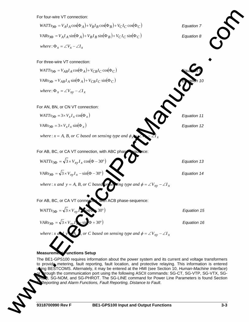
9318700990 Rev F BE1-GPS100 Input and Output Functions 3-3
For four-wire VT connection:
( ) ( ) ( )CCCBBBAAA IVIVIVWATTs Φ+Φ+Φ=Φ coscoscos3 Equation 7
( ) ( ) ( )CCCBBBAAA IVIVIVVARs Φ+Φ+Φ=Φ sinsinsin3 Equation 8
xxx IVwhere ∠−∠=Φ:
For three-wire VT connection:
( ) ( )CCCBAAAB IVIVWATTs Φ+Φ=Φ coscos3 Equation 9
( ) ( )CCCBAAAB IVIVVARs Φ+Φ=Φ sinsin3 Equation 10
xxyx IVwhere ∠−∠=Φ:
For AN, BN, or CN VT connection:
( )xxx IVWATTs Φ×=Φ cos33 Equation 11
( )xxx IVVARs Φ×=Φ sin33 Equation 12
xxx IVandtypengsensionbasedCorBAxwhere ∠−∠== φ,,:
For AB, BC, or CA VT connection, with ABC phase-sequence:
( )°−Φ×=Φ 30cos33 xxy IVWATTs Equation 13
( )°−Φ−×=Φ 30sin33 xxy IVVARs Equation 14
xxy IVandtypengsensionbasedCorBAyandxwhere ∠−∠== φ,,:
For AB, BC, or CA VT connection, with ACB phase-sequence:
( )°+Φ×=Φ 30cos33 xxy IVWATTs Equation 15
( )°+Φ−×=Φ 30sin33 xxy IVVARs Equation 16
xxy IVandtypengsensionbasedCorBAyandxwhere ∠−∠== φ,,:
Measurement Functions Setup The BE1-GPS100 requires information about the power system and its current and voltage transformers to provide metering, fault reporting, fault location, and protective relaying. This information is entered using BESTCOMS. Alternately, it may be entered at the HMI (see Section 10, Human-Machine Interface) or through the communication port using the following ASCII commands: SG-CT, SG-VTP, SG-VTX, SG-FREQ, SG-NOM, and SG-PHROT. The SG-LINE command for Power Line Parameters is found Section 6, Reporting and Alarm Functions, Fault Reporting, Distance to Fault.
www . El
ectric
alPar
tMan
uals
. com
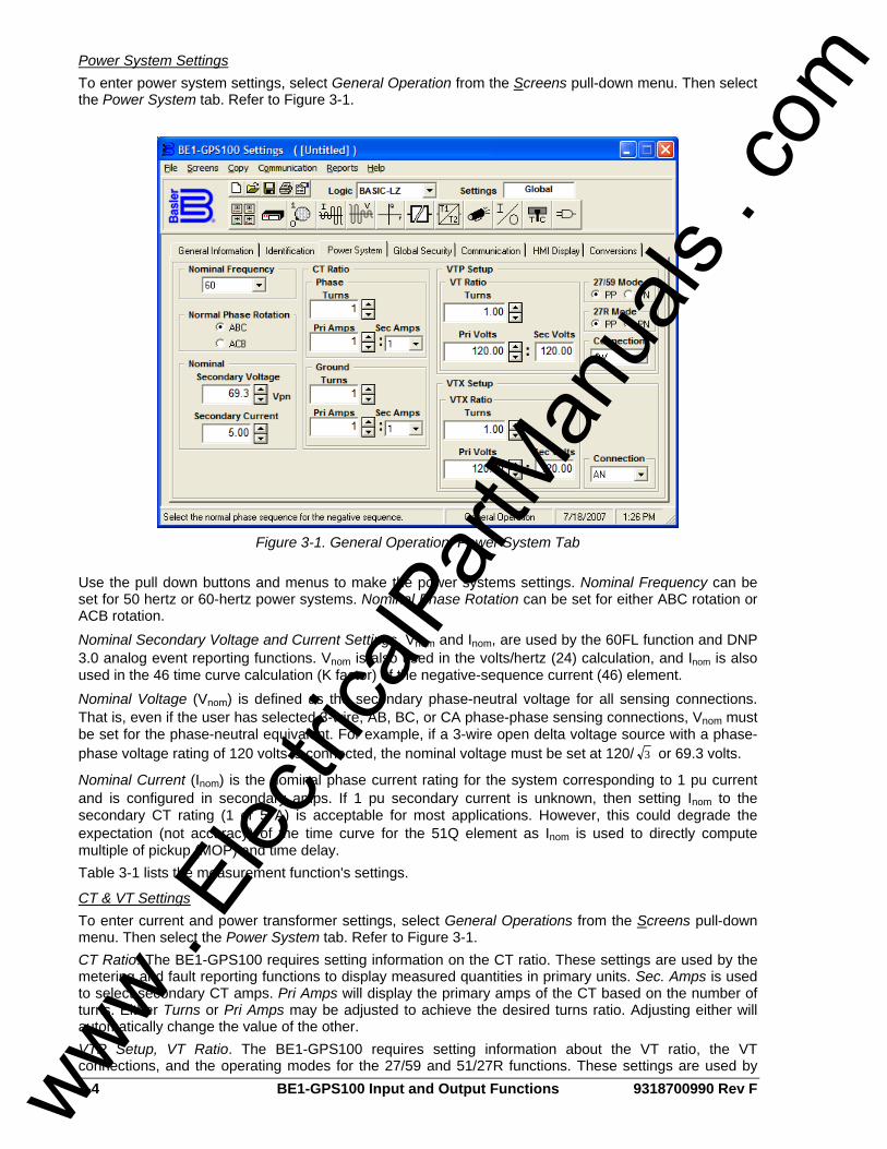
3-4 BE1-GPS100 Input and Output Functions 9318700990 Rev F
Power System Settings To enter power system settings, select General Operation from the Screens pull-down menu. Then select the Power System tab. Refer to Figure 3-1.
Figure 3-1. General Operation, Power System Tab
Use the pull down buttons and menus to make the power systems settings. Nominal Frequency can be set for 50 hertz or 60-hertz power systems. Nominal Phase Rotation can be set for either ABC rotation or ACB rotation. Nominal Secondary Voltage and Current Settings, Vnom and Inom, are used by the 60FL function and DNP 3.0 analog event reporting functions. Vnom is also used in the volts/hertz (24) calculation, and Inom is also used in the 46 time curve calculation (K factor) of the negative-sequence current (46) element. Nominal Voltage (Vnom) is defined as the secondary phase-neutral voltage for all sensing connections. That is, even if the user has selected 3-wire, AB, BC, or CA phase-phase sensing connections, Vnom must be set for the phase-neutral equivalent. For example, if a 3-wire open delta voltage source with a phase-phase voltage rating of 120 volts is connected, the nominal voltage must be set at 120/ 3 or 69.3 volts.
Nominal Current (Inom) is the nominal phase current rating for the system corresponding to 1 pu current and is configured in secondary amps. If 1 pu secondary current is unknown, then setting Inom to the secondary CT rating (1 or 5 A) is acceptable for most applications. However, this could degrade the expectation (not accuracy) of the time curve for the 51Q element as Inom is used to directly compute multiple of pickup (MOP) and time delay. Table 3-1 lists the measurement function's settings.
CT & VT Settings To enter current and power transformer settings, select General Operations from the Screens pull-down menu. Then select the Power System tab. Refer to Figure 3-1. CT Ratio. The BE1-GPS100 requires setting information on the CT ratio. These settings are used by the metering and fault reporting functions to display measured quantities in primary units. Sec. Amps is used to select secondary CT amps. Pri Amps will display the primary amps of the CT based on the number of turns. Either Turns or Pri Amps may be adjusted to achieve the desired turns ratio. Adjusting either will automatically change the value of the other. VTP Setup, VT Ratio. The BE1-GPS100 requires setting information about the VT ratio, the VT connections, and the operating modes for the 27/59 and 51/27R functions. These settings are used by
www . El
ectric
alPar
tMan
uals
. com
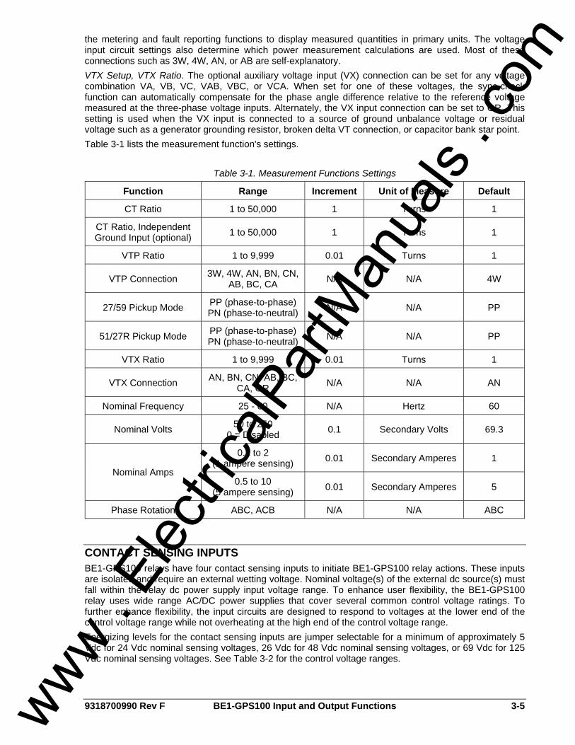
9318700990 Rev F BE1-GPS100 Input and Output Functions 3-5
the metering and fault reporting functions to display measured quantities in primary units. The voltage input circuit settings also determine which power measurement calculations are used. Most of these connections such as 3W, 4W, AN, or AB are self-explanatory. VTX Setup, VTX Ratio. The optional auxiliary voltage input (VX) connection can be set for any voltage combination VA, VB, VC, VAB, VBC, or VCA. When set for one of these voltages, the sync-check function can automatically compensate for the phase angle difference relative to the reference voltage measured at the three-phase voltage inputs. Alternately, the VX input connection can be set to GR. This setting is used when the VX input is connected to a source of ground unbalance voltage or residual voltage such as a generator grounding resistor, broken delta VT connection, or capacitor bank star point. Table 3-1 lists the measurement function's settings.
Table 3-1. Measurement Functions Settings
Function Range Increment Unit of Measure Default
CT Ratio 1 to 50,000 1 Turns 1
CT Ratio, Independent Ground Input (optional) 1 to 50,000 1 Turns 1
VTP Ratio 1 to 9,999 0.01 Turns 1
VTP Connection 3W, 4W, AN, BN, CN, AB, BC, CA N/A N/A 4W
27/59 Pickup Mode PP (phase-to-phase)PN (phase-to-neutral) N/A N/A PP
51/27R Pickup Mode PP (phase-to-phase)PN (phase-to-neutral) N/A N/A PP
VTX Ratio 1 to 9,999 0.01 Turns 1
VTX Connection AN, BN, CN, AB, BC, CA, GR N/A N/A AN
Nominal Frequency 25 - 60 N/A Hertz 60
Nominal Volts 50 to 250 0 = Disabled 0.1 Secondary Volts 69.3
0.1 to 2 (1 ampere sensing) 0.01 Secondary Amperes 1
Nominal Amps 0.5 to 10
(5 ampere sensing) 0.01 Secondary Amperes 5
Phase Rotation ABC, ACB N/A N/A ABC
CONTACT SENSING INPUTS BE1-GPS100 relays have four contact sensing inputs to initiate BE1-GPS100 relay actions. These inputs are isolated and require an external wetting voltage. Nominal voltage(s) of the external dc source(s) must fall within the relay dc power supply input voltage range. To enhance user flexibility, the BE1-GPS100 relay uses wide range AC/DC power supplies that cover several common control voltage ratings. To further enhance flexibility, the input circuits are designed to respond to voltages at the lower end of the control voltage range while not overheating at the high end of the control voltage range. Energizing levels for the contact sensing inputs are jumper selectable for a minimum of approximately 5 Vdc for 24 Vdc nominal sensing voltages, 26 Vdc for 48 Vdc nominal sensing voltages, or 69 Vdc for 125 Vdc nominal sensing voltages. See Table 3-2 for the control voltage ranges.
www . El
ectric
alPar
tMan
uals
. com

3-6 BE1-GPS100 Input and Output Functions 9318700990 Rev F
Table 3-2. Contact Sensing Turn-On Voltage
Turn-On Voltage Range Nominal Control Voltage Jumper Installed
(Low Position) Jumper Not Installed
(High Position)
24 Vdc N/A Approx. 5 Vdc
48/125 Vac or Vdc 26 – 38 Vac or Vdc 69 – 100 Vac or Vdc
125/250 Vac or Vdc 69 – 100 Vac or Vdc 138 – 200 Vac or Vdc
Each BE1-GPS100 is delivered without the contact-sensing jumpers installed for operation in the higher end of the control voltage range. If the contact sensing inputs are to be operated at the lower end of the control voltage range, the jumpers must be installed. See Section 12, Installation, for details on how to set the jumper positions in the contact sensing input circuits. The contact sensing inputs circuits are polarity sensitive. When an ac wetting voltage is applied, the input signal is half-wave rectified by the opto-isolator diodes. The contact sensing inputs drive BESTLOGIC variables IN1, IN2, IN3, and IN4. Each contact sensing input is completely programmable so meaningful labels can be assigned to each input and the logic-high and logic-low states. Section 7, BESTLOGIC Programmable Logic, provides more information about using contact sensing inputs in your programmable logic scheme.
Digital Input Conditioning Function Status of the contact sensing inputs is checked 12 times per cycle. (See Figure 3-2.) When operating on a 60-hertz power system, the result is the input status being sampled every 1.4 milliseconds (1.6 milliseconds on 50-hertz systems). User-settable digital contact recognition and debounce timers condition the signals applied to the inputs. These parameters can be adjusted to obtain the optimum compromise between speed and security for a specific application. Digital input conditioning is evaluated every quarter cycle. If the sampled status of a monitored contact is detected as energized for the recognition time, the logic variable changes from a de-energized (logic 0 or FALSE) state to an energized (logic 1 or TRUE) state. Once contact closure is recognized, the logic variable remains in the energized state until the sampled status of the monitored contact is detected to be de-energized for a period that is longer than the debounce time. At this point, the logic variable will change from an energized (logic 1 or TRUE) state to a de-energized (logic 0 or FALSE) state.
Figure 3-2. Digital Input Conditioning Timing Diagram
Setting the Digital Input Conditioning Function Settings and labels for the digital input conditioning function are set using BESTCOMS. Alternately, settings may be made using the SG-IN ASCII Command. Each of the four inputs has two settings and three labels. The settings are Recognition Time and Debounce Time. The labels include a label to describe the input, a label to describe the Energized State, and a label to describe the De-Energized State. Labels are used by the BE1-GPS100's reporting functions.
www . El
ectric
alPar
tMan
uals
. com
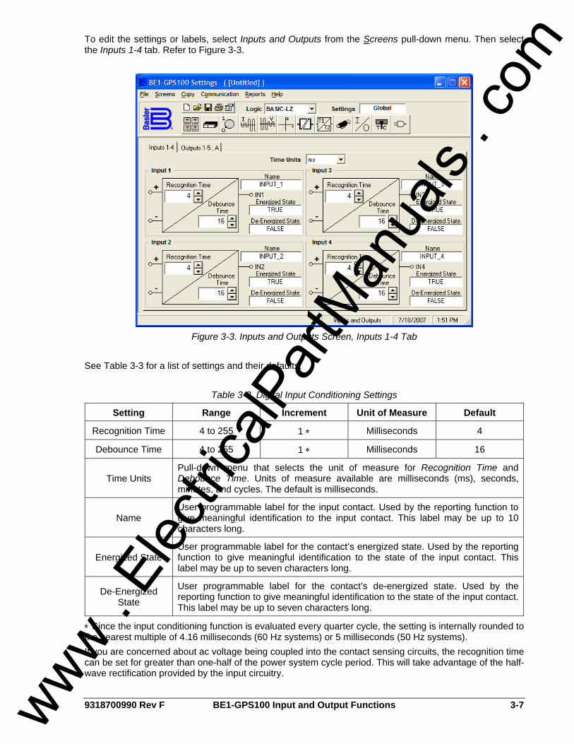
9318700990 Rev F BE1-GPS100 Input and Output Functions 3-7
To edit the settings or labels, select Inputs and Outputs from the Screens pull-down menu. Then select the Inputs 1-4 tab. Refer to Figure 3-3.
Figure 3-3. Inputs and Outputs Screen, Inputs 1-4 Tab
See Table 3-3 for a list of settings and their defaults.
Table 3-3. Digital Input Conditioning Settings
Setting Range Increment Unit of Measure Default
Recognition Time 4 to 255 1 ∗ Milliseconds 4
Debounce Time 4 to 255 1 ∗ Milliseconds 16
Time Units Pull-down menu that selects the unit of measure for Recognition Time and Debounce Time. Units of measure available are milliseconds (ms), seconds, minutes, and cycles. The default is milliseconds.
Name User programmable label for the input contact. Used by the reporting function to give meaningful identification to the input contact. This label may be up to 10 characters long.
Energized State User programmable label for the contact’s energized state. Used by the reporting function to give meaningful identification to the state of the input contact. This label may be up to seven characters long.
De-Energized State
User programmable label for the contact’s de-energized state. Used by the reporting function to give meaningful identification to the state of the input contact. This label may be up to seven characters long.
∗ Since the input conditioning function is evaluated every quarter cycle, the setting is internally rounded to the nearest multiple of 4.16 milliseconds (60 Hz systems) or 5 milliseconds (50 Hz systems). If you are concerned about ac voltage being coupled into the contact sensing circuits, the recognition time can be set for greater than one-half of the power system cycle period. This will take advantage of the half-wave rectification provided by the input circuitry.
www . El
ectric
alPar
tMan
uals
. com
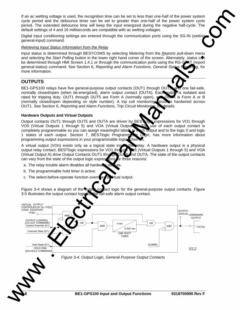
3-8 BE1-GPS100 Input and Output Functions 9318700990 Rev F
If an ac wetting voltage is used, the recognition time can be set to less than one-half of the power system cycle period and the debounce timer can be set to greater than one-half of the power system cycle period. The extended debounce time will keep the input energized during the negative half-cycle. The default settings of 4 and 16 milliseconds are compatible with ac wetting voltages. Digital input conditioning settings are entered through the communication ports using the SG-IN (setting general-input) command.
Retrieving Input Status Information from the Relay Input status is determined through BESTCOMS by selecting Metering from the Reports pull-down menu and selecting the Start Polling button in the lower right hand corner of the screen. Alternately, status can be determined through HMI Screen 1.4.1 or through the communication ports using the RG-STAT (report general-status) command. See Section 6, Reporting and Alarm Functions, General Status Reporting, for more information.
OUTPUTS BE1-GPS100 relays have five general-purpose output contacts (OUT1 through OUT5) and one fail-safe, normally closed/open (when de-energized), alarm output contact (OUTA). Each output is isolated and rated for tripping duty. OUT1 through OUT5 are Form A (normally open), and OUTA is Form A or B (normally closed/open depending on style number). A trip coil monitoring circuit is hardwired across OUT1. See Section 6, Reporting and Alarm Functions, Trip Circuit Monitoring, for details.
Hardware Outputs and Virtual Outputs Output contacts OUT1 through OUT5 and OUTA are driven by BESTlogic expressions for VO1 through VO5 (Virtual Outputs 1 through 5) and VOA (Virtual Output A). The use of each output contact is completely programmable so you can assign meaningful labels to each output and to the logic 0 and logic 1 states of each output. Section 7, BESTlogic Programmable Logic, has more information about programming output expressions in your programmable logic schemes. A virtual output (VOn) exists only as a logical state inside the relay. A hardware output is a physical output relay contact. BESTlogic expressions for VO1 through VO5 (Virtual Outputs 1 through 5) and VOA (Virtual Output A) drive Output Contacts OUT1 through OUT5 and OUTA. The state of the output contacts can vary from the state of the output logic expressions for three reasons:
a. The relay trouble alarm disables all hardware outputs. b. The programmable hold timer is active. c. The select-before-operate function overrides a virtual output.
Figure 3-4 shows a diagram of the output contact logic for the general-purpose output contacts. Figure 3-5 illustrates the output contact logic for the fail-safe alarm output contact.
Figure 3-4. Output Logic, General Purpose Output Contacts
www . El
ectric
alPar
tMan
uals
. com
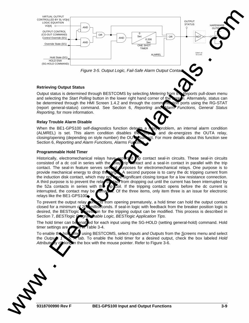
9318700990 Rev F BE1-GPS100 Input and Output Functions 3-9
0.200 Sec
0 Sec OR
ONE SHOT TIMER
AND OUT[A]
HARDWAREOUTPUT
OUTPUTSTATUS
AND
AND
ORControl Override (0/1)
Override State (0/1)
Hold State (0/1)
VO[A]
VIRTUAL OUTPUT CONTROLLED BY SL-VO[n]
LOGIC EQUATION
HOLD ENA(SG-HOLD COMMAND)
OUTPUT CONTROL (CO-OUT COMMAND)
ALMRELD2647-1903-13-06
NOT
Figure 3-5. Output Logic, Fail-Safe Alarm Output Contact
Retrieving Output Status Output status is determined through BESTCOMS by selecting Metering from the Reports pull-down menu and selecting the Start Polling button in the lower right hand corner of the screen. Alternately, status can be determined through the HMI Screen 1.4.2 and through the communication ports using the RG-STAT (report general-status) command. See Section 6, Reporting and Alarm Functions, General Status Reporting, for more information.
Relay Trouble Alarm Disable When the BE1-GPS100 self-diagnostics function detects a relay problem, an internal alarm condition (ALMREL) is set. This alarm condition disables the outputs and de-energizes the OUTA relay, closing/opening (depending on style number) the OUTA contact. For more details about this function see Section 6, Reporting and Alarm Functions, Alarms Function.
Programmable Hold Timer Historically, electromechanical relays have provided trip contact seal-in circuits. These seal-in circuits consisted of a dc coil in series with the relay trip contact and a seal-in contact in parallel with the trip contact. The seal-in feature serves several purposes for electromechanical relays. One purpose is to provide mechanical energy to drop the target. A second purpose is to carry the dc tripping current from the induction disk contact, which may not have significant closing torque for a low resistance connection. A third purpose is to prevent the relay contact from dropping out until the current has been interrupted by the 52a contacts in series with the trip coil. If the tripping contact opens before the dc current is interrupted, the contact may be damaged. Of the three items, only item three is an issue for electronic relays like the BE1-GPS100. To prevent the output relay contacts from opening prematurely, a hold timer can hold the output contact closed for a minimum of 200 milliseconds. If seal-in logic with feedback from the breaker position logic is desired, the BESTlogic expression for the tripping output can be modified. This process is described in Section 7, BESTlogic Programmable Logic, BESTlogic Application Tips. The hold timer can be enabled for each input using the SG-HOLD (setting general-hold) command. Hold timer settings are shown in Table 3-4. To enable the hold timer using BESTCOMS, select Inputs and Outputs from the Screens menu and select the Outputs 1 – 5, A tab. To enable the hold timer for a desired output, check the box labeled Hold Attribute by clicking in the box with the mouse pointer. Refer to Figure 3-6.
www . El
ectric
alPar
tMan
uals
. com
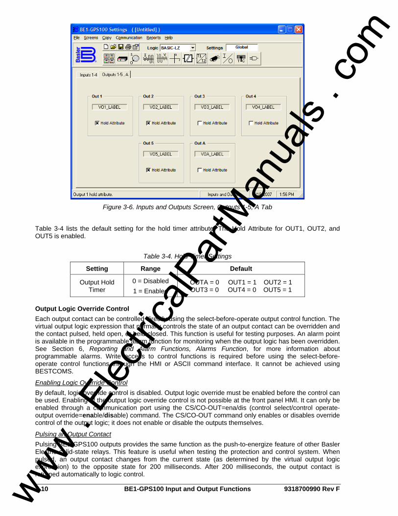
3-10 BE1-GPS100 Input and Output Functions 9318700990 Rev F
Figure 3-6. Inputs and Outputs Screen, Outputs 1-5, A Tab
Table 3-4 lists the default setting for the hold timer attribute. The Hold Attribute for OUT1, OUT2, and OUT5 is enabled.
Table 3-4. Hold Timer Settings
Setting Range Default
Output Hold Timer
0 = Disabled 1 = Enabled
OUTA = 0 OUT1 = 1 OUT2 = 1 OUT3 = 0 OUT4 = 0 OUT5 = 1
Output Logic Override Control Each output contact can be controlled directly using the select-before-operate output control function. The virtual output logic expression that normally controls the state of an output contact can be overridden and the contact pulsed, held open, or held closed. This function is useful for testing purposes. An alarm point is available in the programmable alarm function for monitoring when the output logic has been overridden. See Section 6, Reporting and Alarm Functions, Alarms Function, for more information about programmable alarms. Write access to control functions is required before using the select-before-operate control functions through the HMI or ASCII command interface. It cannot be achieved using BESTCOMS.
Enabling Logic Override Control By default, logic override control is disabled. Output logic override must be enabled before the control can be used. Enabling of the output logic override control is not possible at the front panel HMI. It can only be enabled through a communication port using the CS/CO-OUT=ena/dis (control select/control operate-output override=enable/disable) command. The CS/CO-OUT command only enables or disables override control of the output logic; it does not enable or disable the outputs themselves.
Pulsing an Output Contact Pulsing BE1-GPS100 outputs provides the same function as the push-to-energize feature of other Basler Electric solid-state relays. This feature is useful when testing the protection and control system. When pulsed, an output contact changes from the current state (as determined by the virtual output logic expression) to the opposite state for 200 milliseconds. After 200 milliseconds, the output contact is returned automatically to logic control.
www . El
ectric
alPar
tMan
uals
. com

9318700990 Rev F BE1-GPS100 Input and Output Functions 3-11
Pulse override control is accessed at Screen 2.4.1 of the HMI by entering a P in the field for the output contact to be pulsed. Pulse control is accessed through a communication port by using the CS/CO-OUTn=P (control select/control operate-output contact n=pulse) command.
Holding an Output Contact Open or Closed Outputs can be forced to a closed (logic 1 or TRUE) state or to an open (logic 0 or FALSE) state. This feature can be used to disable a contact during testing. Open or close logic override control is accessed at Screen 2.4.1 of the HMI by entering a 0 for open or 1 for closed in the field for the output contact to be controlled. Outputs are forced open or closed through a communication port by using the CS/CO-OUTn=P0/1 (control select/control operate-output contact n-0/1) command.
Returning an Output Contact to Logic Control When the output logic has been overridden and the contact is held in an open or closed state, it is necessary to manually return the output to logic control. Outputs are returned to logic control through Screen 2.4.1 of the HMI. An L is entered in the field of the contact that is to be returned to logic control. Outputs are returned to logic control through a communication port by using the CS/CO-OUTn=L (control select/control operate-output contact n=logic control) command. The output control commands require the use of select-before-operate logic. First, the command must be selected using the CS-OUT command. After the command is selected, there is a 30 second window during which the CO-OUT control command can be entered. The control selected and operation selected syntax must match exactly or the command will be blocked. If the operate command isn't entered within 30 seconds of the select command, the operate command will be blocked. An error message is returned when a control command is blocked. Output control commands are acted on immediately except when the ENA and DIS modes are used. ENA and DIS output control command changes are not executed until saved with the EXIT command. Output control status is saved in nonvolatile memory and is maintained when relay operating power is lost. All relay responses in the following examples and throughout the manual are printed in Courier New typeface. 1. Enable the output control feature. >CS-OUT=ENA OUT=ENA SELECTED >CO-OUT=ENA OUT=ENA EXECUTED >E (exit) Save Changes (Y/N/C)? >Y (yes)
2. Test all outputs by pulsing momentarily. >CS-OUT=P OUT=P SELECTED >CO-OUT=P OUT=P EXECUTED
3. Disable the trip output (OUT1) by holding it at logic 0. >CS-OUT1=0 OUT1=0 SELECTED >CO-OUT1=0 OUT1=0 EXECUTED
4. Return OUT1 to logic control. >CS-OUT1=L OUT1=L SELECTED >CO-OUT1=0 OUT1=L EXECUTED
www . El
ectric
alPar
tMan
uals
. com

3-12 BE1-GPS100 Input and Output Functions 9318700990 Rev F
5. Disable the output control feature. >CS-OUT=DIS OUT=DIS SELECTED >CO-OUT=DIS OUT=DIS EXECUTED >E (exit) Save Changes (Y/N/C)? >Y (yes)
Retrieving Output Logic Override Status The status of the output contact logic override control can be viewed at HMI Screen 1.4.3. It cannot be achieved using BESTCOMS. HMI Screen 2.4.1 is used for output control but can also display the status. Output logic status can also be viewed using the RG-STAT (report general-status) command. An L indicates that the state of the output is controlled by logic. A 0 or 1 indicates that the logic has been overridden and the contact is held open (0) or closed (1) state. A P indicates that the contact is being pulsed and will return to logic control automatically. See Section 6, Reporting and Alarm Functions, General Status Reporting, for more information.
www . El
ectric
alPar
tMan
uals
. com

9318700990 Rev F BE1-GPS100 Protection and Control i
SECTION 4 • PROTECTION AND CONTROL TABLE OF CONTENTS
SECTION 4 • PROTECTION AND CONTROL......................................................................................... 4-1
INTRODUCTION.................................................................................................................................... 4-1 Using Protection and Control Functions............................................................................................. 4-1
SETTING GROUPS............................................................................................................................... 4-1 BESTlogic Settings for Setting Group Control ................................................................................... 4-2 Operating Settings for Setting Group Control .................................................................................... 4-4 Logic Override of the Setting Group Control Function ....................................................................... 4-5 Retrieving Setting Group Control Status from the Relay ................................................................... 4-6
OVERCURRENT PROTECTION........................................................................................................... 4-6 50T - Instantaneous Overcurrent Protection with Settable Time Delay............................................. 4-6
BESTlogic Settings for Instantaneous Overcurrent........................................................................ 4-7 Operating Settings for Instantaneous Overcurrent......................................................................... 4-9 Retrieving Instantaneous Overcurrent Status from the Relay ...................................................... 4-10
51 - Time Overcurrent Protection..................................................................................................... 4-10 BESTlogic Settings for Time Overcurrent..................................................................................... 4-11 Operating Settings for Time Overcurrent...................................................................................... 4-12 Retrieving Time Overcurrent Status from the Relay..................................................................... 4-13 Voltage Restraint/Control for Time Overcurrent Protection.......................................................... 4-13 Operating Settings for Voltage Restraint/Control for Time Overcurrent....................................... 4-14
46 Negative Sequence Overcurrent Element................................................................................... 4-15 BESTlogic Settings for Negative Sequence Overcurrent ............................................................. 4-16 Operating Settings for Negative Sequence Overcurrent .............................................................. 4-17 Retrieving Negative Sequence Overcurrent Status from the Relay ............................................. 4-18
Programmable Curves ..................................................................................................................... 4-18 Setting Programmable Curves...................................................................................................... 4-19
46 Curve ........................................................................................................................................... 4-19 POWER PROTECTION....................................................................................................................... 4-20
32 - Directional Power Protection..................................................................................................... 4-20 BESTlogic Settings for Directional Power .................................................................................... 4-20 Operating Settings for Directional Power ..................................................................................... 4-21 Retrieving Directional Power Status from the Relay .................................................................... 4-23
LOSS OF EXCITATION PROTECTION .............................................................................................. 4-23 40Q - Loss of Excitation Protection.................................................................................................. 4-23
BESTlogic Settings for Loss of Excitation .................................................................................... 4-24 Operating Settings for Loss of Excitation ..................................................................................... 4-25 Retrieving Loss of Excitation Status from the Relay .................................................................... 4-27
VOLTAGE PROTECTION ................................................................................................................... 4-27 24 - Volts per Hertz Overexcitation Protection ................................................................................. 4-27
BESTlogic Settings for Volts per Hertz Overexcitation................................................................. 4-28 Operating Settings Volts per Hertz Overexcitation....................................................................... 4-29 Programmable Alarm for Volts per Hertz Overexcitation ............................................................. 4-30 Retrieving Volts per Hertz Overexcitation Status from the Relay................................................. 4-31
27P/59P - Phase Undervoltage/Overvoltage Protection.................................................................. 4-31 BESTlogic Settings for Phase Undervoltage/Overvoltage ........................................................... 4-31 Operating Settings for Phase Undervoltage/Overvoltage ............................................................ 4-33 Retrieving Phase Undervoltage/Overvoltage Status from the Relay............................................ 4-34
27X/59X - Auxiliary Undervoltage/Overvoltage Protection .............................................................. 4-34 BESTlogic Settings for Auxiliary Undervoltage/Overvoltage ........................................................ 4-35 Operating Settings for Auxiliary Undervoltage/Overvoltage ......................................................... 4-36 Retrieving Auxiliary Undervoltage/Overvoltage Status from the Relay ........................................ 4-38
47 - Negative-Sequence Overvoltage Protection............................................................................. 4-38 BESTlogic Settings for Negative-Sequence Overvoltage ............................................................ 4-38 Operating Settings for Negative-Sequence Overvoltage ............................................................. 4-39 Retrieving Negative-Sequence Overvoltage Status from the Relay ............................................ 4-41
FREQUENCY PROTECTION.............................................................................................................. 4-41
www . El
ectric
alPar
tMan
uals
. com
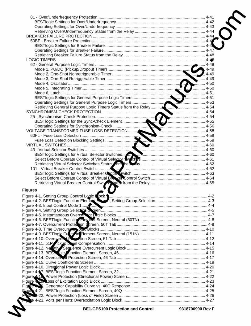
ii BE1-GPS100 Protection and Control 9318700990 Rev F
81 - Over/Underfrequency Protection............................................................................................... 4-41 BESTlogic Settings for Over/Underfrequency .............................................................................. 4-42 Operating Settings for Over/Underfrequency ............................................................................... 4-43 Retrieving Over/Underfrequency Status from the Relay .............................................................. 4-44
BREAKER FAILURE PROTECTION................................................................................................... 4-44 50BF - Breaker Failure Protection.................................................................................................... 4-44
BESTlogic Settings for Breaker Failure ........................................................................................ 4-45 Operating Settings for Breaker Failure ......................................................................................... 4-47 Retrieving Breaker Failure Status from the Relay ........................................................................ 4-48
LOGIC TIMERS ................................................................................................................................... 4-48 62 - General Purpose Logic Timers ................................................................................................. 4-48
Mode 1, PU/DO (Pickup/Dropout Timer) ...................................................................................... 4-49 Mode 2, One-Shot Nonretriggerable Timer .................................................................................. 4-49 Mode 3, One-Shot Retriggerable Timer ....................................................................................... 4-49 Mode 4, Oscillator......................................................................................................................... 4-50 Mode 5, Integrating Timer............................................................................................................. 4-50 Mode 6, Latch ............................................................................................................................... 4-51 BESTlogic Settings for General Purpose Logic Timers................................................................ 4-51 Operating Settings for General Purpose Logic Timers................................................................. 4-53 Retrieving General Purpose Logic Timers Status from the Relay................................................ 4-54
SYNCHRONISM-CHECK PROTECTION............................................................................................ 4-54 25 - Synchronism-Check Protection................................................................................................. 4-54
BESTlogic Settings for the Sync-Check Element ......................................................................... 4-55 Operating Settings for Synchronism-Check ................................................................................. 4-56
VOLTAGE TRANSFORMER FUSE LOSS DETECTION.................................................................... 4-58 60FL - Fuse Loss Detection ............................................................................................................. 4-58
Fuse Loss Detection Blocking Settings ........................................................................................ 4-59 VIRTUAL SWITCHES.......................................................................................................................... 4-60
43 - Virtual Selector Switches .......................................................................................................... 4-60 BESTlogic Settings for Virtual Selector Switches......................................................................... 4-60 Select Before Operate Control of Virtual Selector Switches ........................................................ 4-61 Retrieving Virtual Selector Switches Status from the Relay......................................................... 4-62
101 - Virtual Breaker Control Switch ................................................................................................ 4-62 BESTlogic Settings for Virtual Breaker Control Switch ................................................................ 4-63 Select Before Operate Control of Virtual Breaker Control Switch ................................................ 4-64 Retrieving Virtual Breaker Control Switch Status from the Relay................................................. 4-65
Figures Figure 4-1. Setting Group Control Logic Block.......................................................................................... 4-2 Figure 4-2. BESTlogic Function Element Screen, Setting Group Selection.............................................. 4-3 Figure 4-3. Input Control Mode 1............................................................................................................... 4-4 Figure 4-4. Setting Group Selection Screen.............................................................................................. 4-5 Figure 4-5. Instantaneous Overcurrent Logic Blocks ................................................................................ 4-7 Figure 4-6. BESTlogic Function Element Screen, Neutral (50TN)............................................................ 4-8 Figure 4-7. Overcurrent Protection Screen, 50T Tab................................................................................ 4-9 Figure 4-8. Time Overcurrent Logic Blocks............................................................................................. 4-10 Figure 4-9. BESTlogic Function Element Screen, Neutral (151N) .......................................................... 4-11 Figure 4-10. Overcurrent Protection Screen, 51 Tab .............................................................................. 4-12 Figure 4-11. 51P Pickup Level Compensation ........................................................................................ 4-14 Figure 4-12. Negative Sequence Overcurrent Logic Block ..................................................................... 4-15 Figure 4-13. BESTlogic Function Element Screen, 46............................................................................ 4-16 Figure 4-14. Overcurrent Protection Screen, 46 Tab .............................................................................. 4-17 Figure 4-15. Curve Coefficients Screen .................................................................................................. 4-19 Figure 4-16. Directional Power Logic Block ............................................................................................ 4-20 Figure 4-17. BESTlogic Function Element Screen, 32............................................................................ 4-21 Figure 4-18. Power Protection (Directional Power) Screen..................................................................... 4-22 Figure 4-19. Loss of Excitation Logic Block ............................................................................................ 4-23 Figure 4-20. Generator Capability Curve vs. 40Q Response.................................................................. 4-24 Figure 4-21. BESTlogic Function Element Screen, 40Q......................................................................... 4-25 Figure 4-22. Power Protection (Loss of Field) Screen ............................................................................ 4-26 Figure 4-23. Volts per Hertz Overexcitation Logic Block......................................................................... 4-27
www . El
ectric
alPar
tMan
uals
. com
9318700990 Rev F BE1-GPS100 Protection and Control iii
Figure 4-24. Trip Time for Various Time Dials and Multiples of Pickup .................................................. 4-28 Figure 4-25. BESTlogic Function Element Screen, 24............................................................................ 4-29 Figure 4-26. Voltage Protection Screen, 24 Tab..................................................................................... 4-30 Figure 4-27. Phase Undervoltage/Overvoltage Logic Blocks.................................................................. 4-31 Figure 4-28. BESTlogic Function Element Screen, Phase (27P)............................................................ 4-32 Figure 4-29. Voltage Protection Screen, 27P/127P Tab ......................................................................... 4-33 Figure 4-30. Auxiliary Undervoltage/Overvoltage Logic Blocks .............................................................. 4-34 Figure 4-31. BESTlogic Function Element Screen, 59X ......................................................................... 4-35 Figure 4-32. Voltage Protection Screen, 59X/159X Tab ......................................................................... 4-37 Figure 4-33. Negative-Sequence Overvoltage Logic Block .................................................................... 4-38 Figure 4-34. BESTlogic Function Element Screen, Negative Sequence (47)......................................... 4-39 Figure 4-35. Voltage Protection Screen, 47 Tab..................................................................................... 4-40 Figure 4-36. Over/Underfrequency Logic Block ...................................................................................... 4-41 Figure 4-37. BESTlogic Function Element, 81 ........................................................................................ 4-42 Figure 4-38. Voltage Protection Screen, INH/81/181/281/381 Tab......................................................... 4-43 Figure 4-39. Breaker Failure Logic Block ................................................................................................ 4-45 Figure 4-40. BESTlogic Function Element Screen, Breaker Failure ....................................................... 4-46 Figure 4-41. Breaker Failure Screen ....................................................................................................... 4-47 Figure 4-42. General Purpose Logic Timers Logic Block........................................................................ 4-48 Figure 4-43. Mode 1, PU/DO (Pickup/Dropout Timer) ............................................................................ 4-49 Figure 4-44. Mode 2, One Shot Nonretriggerable Timer......................................................................... 4-49 Figure 4-45. Mode 3, One Shot Retriggerable Timer.............................................................................. 4-50 Figure 4-46. Mode 4, Oscillator ............................................................................................................... 4-50 Figure 4-47. Mode 5, Integrating Timer................................................................................................... 4-51 Figure 4-48. Mode 6, Latch ..................................................................................................................... 4-51 Figure 4-49. BESTlogic Function Element Screen, 62............................................................................ 4-52 Figure 4-50. Logic Timers Screen ........................................................................................................... 4-53 Figure 4-51. Sync-Check Element........................................................................................................... 4-54 Figure 4-52. BESTlogic Function Element Screen, 25............................................................................ 4-56 Figure 4-53. Voltage Protection Screen, 25 Tab..................................................................................... 4-57 Figure 4-54. 60FL Element...................................................................................................................... 4-58 Figure 4-55. 60FL Element Logic ............................................................................................................ 4-58 Figure 4-56. Reporting and Alarms Screen, VT Monitor Tab.................................................................. 4-59 Figure 4-57. Virtual Selector Switches Logic Block................................................................................. 4-60 Figure 4-58. BESTlogic Function Element Screen, 43............................................................................ 4-61 Figure 4-59. 101 Function Block.............................................................................................................. 4-62 Figure 4-60. 101 Control Switch State Diagram...................................................................................... 4-63 Figure 4-61. BESTlogic Function Element Screen, 101.......................................................................... 4-63 Tables Table 4-1. BESTlogic Settings for Setting Group Control ......................................................................... 4-3 Table 4-2. Setting Group Binary Codes .................................................................................................... 4-4 Table 4-3. Automatic Setting Group Control Settings ............................................................................... 4-5 Table 4-4. BESTlogic Settings for Instantaneous Overcurrent ................................................................. 4-8 Table 4-5. Operating Settings for Instantaneous Overcurrent ................................................................ 4-10 Table 4-6. BESTlogic Settings for Time Overcurrent .............................................................................. 4-12 Table 4-7. Operating Settings for Time Overcurrent ............................................................................... 4-13 Table 4-8. VTP Connection Cross Reference ......................................................................................... 4-14 Table 4-9. Operating Settings for Voltage Restraint/Control for Time Overcurrent ................................ 4-15 Table 4-10. BESTlogic Settings for Negative Sequence Overcurrent..................................................... 4-17 Table 4-11. Operating Settings for Negative Sequence Overcurrent...................................................... 4-18 Table 4-12. Definitions for Equations 4-2 and 4-3................................................................................... 4-18 Table 4-13. Programmable Time Current Characteristic Curve Coefficients.......................................... 4-19 Table 4-14. BESTlogic Settings for Directional Power............................................................................ 4-21 Table 4-15. Operating Settings for Directional Power............................................................................. 4-22 Table 4-16. BESTlogic Settings for Loss of Excitation............................................................................ 4-25 Table 4-17. Operating Settings for Loss of Excitation............................................................................. 4-26 Table 4-18. BESTlogic Settings for Volts per Hertz Overexcitation ........................................................ 4-29 Table 4-19. Operating Settings for Volts per Hertz Overexcitation ......................................................... 4-30 Table 4-20. Programmable Alarm Settings for Volts per Hertz Overexcitation....................................... 4-30 Table 4-21. Undervoltage and Overvoltage Logic Settings..................................................................... 4-32
www . El
ectric
alPar
tMan
uals
. com
iv BE1-GPS100 Protection and Control 9318700990 Rev F
Table 4-22. Operating Settings for Phase Undervoltage/Overvoltage .................................................... 4-34 Table 4-23. BESTlogic Settings for Auxiliary Undervoltage/Overvoltage................................................ 4-36 Table 4-24. VTX Connection Settings ..................................................................................................... 4-36 Table 4-25. Operating Settings for Auxiliary Undervoltage/Overvoltage................................................. 4-37 Table 4-26. BESTlogic Settings for Negative-Sequence Overvoltage .................................................... 4-39 Table 4-27. Operating Settings for Negative-Sequence Overvoltage ..................................................... 4-40 Table 4-28. BESTlogic Settings for Over/Underfrequency...................................................................... 4-42 Table 4-29. Operating Settings for Over/Underfrequency....................................................................... 4-44 Table 4-30. BESTlogic Settings for Breaker Failure................................................................................ 4-46 Table 4-31. Operating Settings for Breaker Failure................................................................................. 4-48 Table 4-32. BESTlogic Settings for General Purpose Logic Timers ....................................................... 4-52 Table 4-33. Operating Settings for General Purpose Logic Timers ........................................................ 4-53 Table 4-34. BESTlogic Settings for Synchronism-Check........................................................................ 4-56 Table 4-35. Operating Settings for Synchronism-Check......................................................................... 4-57 Table 4-36. 60FL Logic Parameters ........................................................................................................ 4-58 Table 4-37. 60FL Element Blocking Settings .......................................................................................... 4-59 Table 4-38. BESTlogic Settings for Virtual Selector Switches ................................................................ 4-61 Table 4-39. BESTlogic Settings for Virtual Breaker Control Switch ........................................................ 4-64 Equations Equation 4-1. Restraint Pickup Level ...................................................................................................... 4-15 Equation 4-2. Time OC Characteristics for Trip ...................................................................................... 4-18 Equation 4-3. Time OC Characteristics for Reset ................................................................................... 4-18
www . El
ectric
alPar
tMan
uals
. com

9318700990 Rev F BE1-GPS100 Protection and Control 4-1
SECTION 4 • PROTECTION AND CONTROL INTRODUCTION The BE1-GPS100 provides many functions that can be used to protect and control power system equipment in and around a protected zone. BE1-GPS100 protection functions include:
• Instantaneous Overcurrent with Settable Time Delay (50TP, 50TN) • Time Overcurrent (51P, 51N, 151N, 46) • Voltage Restraint for 51P Phase Time Overcurrent (27R) • Undervoltage and Overvoltage (27P, 127P, 59P, and 159P) • Auxiliary Undervoltage and Overvoltage (27X, 127X, 59X, and 159X) • Negative-Sequence Overvoltage (47) • Directional Power (32, 132) • Loss of Excitation (40Q, 140Q) • Overfrequency and Underfrequency (81, 181, 281, 381) • Breaker Failure (BF) • VT Fuse Loss Detection (60FL) • General Purpose Logic Timers (62, 162, 262, and 362) • Overexcitation, Volts per Hertz (24) • Sync-check (25)
BE1-GPS100 control functions include: • Virtual Selector Switches (43, 143, 243, 343) • Virtual Breaker Control Switch (101)
Two setting groups allow coordination to be adapted for changes in operating conditions. Setting groups can be selected using programmable logic criteria.
Using Protection and Control Functions Three steps must be taken before using a protection or control function:
1. The function logic must be enabled in the active logic scheme by the SL-<function> command. 2. Function inputs and outputs must be connected properly in a logic scheme. 3. Function characteristics or settings must be programmed and based on the specific application
requirements. If a preprogrammed logic scheme is used in a typical application, items 1 and 2 may be skipped. Most preprogrammed schemes are general in nature. Unneeded capabilities can be disabled by a setting of zero. For example, if the second neutral time overcurrent function is enabled but not needed, disable it by setting the 151N pickup setting at zero (S#-151N=0,0,0). More information about the individual function logic of item 1 is provided in this section. Information pertaining to items 2 and 3 is available in Section 7, BESTlogic Programmable Logic, and Section 8, Application.
SETTING GROUPS The BE1-GPS100 provides a normal setting group (SG0) and one auxiliary setting group (SG1). Auxiliary setting groups allow adapting the coordination settings to optimize them for a predictable situation. Sensitivity and time coordination settings can be adjusted to optimize sensitivity or clearing time based upon source conditions or to improve security during overload conditions. The possibilities for improving protection by eliminating compromises in coordination settings with adaptive setting groups are endless. Figure 4-1 shows the setting group control logic block.
www . El
ectric
alPar
tMan
uals
. com

4-2 BE1-GPS100 Protection and Control 9318700990 Rev F
Figure 4-1. Setting Group Control Logic Block
The group of settings that are active at any point in time is controlled by the setting group control logic. This function logic allows for manual (logic) control. The function monitors logic inputs, D0 and D1 and changes the active setting group according to the status of these inputs. These inputs can be connected to logic expressions such as contact sensing inputs. The function logic has two logic variable outputs, SG0 and SG1. The appropriate variable is asserted when each setting group is active. These logic variables can be used in programmable logic to modify the logic based upon which setting group is active. For example, it may be desirable for the 32 element to be disabled when the generator is operating as a synchronous condenser. Therefore, when Setting Group 0 is enabled, normal protection as a generator is used and the 32 element is enabled as a reverse power sensing element. When changed to Setting Group 1, the 132 element may be set to use a less sensitive setting and the 32 element disabled entirely. The setting group control function logic also has an alarm output variable: SETTINGS CHANGE. This output is asserted whenever the BE1-GPS100 switches from one setting group to another. The SGC alarm bit is asserted for the SGCON time setting. This output can be used in the programmable alarms function if it is desired to monitor when the BE1-GPS100 changes to a new setting group. See Section 6, Reporting and Alarm Functions, Alarms Function for more information on using alarm outputs. The SGCON time setting also serves to provide anti-pump protection to prevent excessive changing between groups. Once a change in active group has been made, another change cannot take place for two times the SGCON setting. The SGC ACTIVE alarm output is typically used to provide an external acknowledgment that a setting group change occurred. If SCADA (Supervisory Control and Data Acquisition) is used to change the active group, then this signal could be monitored to verify that the operation occurred. The SGC ACTIVE alarm output ON time is user programmable and should be set greater than the SCADA scan rate. This can be set through the BESTCOMS graphical user interface (GUI). Alternately, it can be set using the SG-SGCON (settings general–SGC Alarm on Time) command. When the BE1-GPS100 switches to a new setting group, all functions are reset and initialized with the new operating parameters. The settings change occurs instantaneously so at no time is the BE1-GPS100 off line. The active setting group is saved in nonvolatile memory so that the BE1-GPS100 will power up using the same setting group that was used when it was powered down. To prevent the BE1-GPS100 from changing settings while a fault condition is in process, setting group changes are blocked when the BE1-GPS100 is in a picked-up state. Since the BE1-GPS100 is completely programmable, the fault condition is defined by the pickup logic expression in the fault reporting functions. See Section 6, Reporting and Alarm Functions, Fault Reporting, for more information. Selection of the active setting group provided by this function logic can also be overridden. When logic override is used, a setting group is made active and the BE1-GPS100 stays in that group regardless of the state of the manual logic control conditions.
BESTlogic Settings for Setting Group Control BESTlogic settings are made from the BESTlogic Function Element screen in BESTCOMS. The BESTCOMS screen used to select BESTlogic settings for the Settings Group Selection function is illustrated in Figure 4-2. To open the BESTlogic Function Element screen for Setting Group Selection, select Setting Group Selection from the Screens pull-down menu. Then select the BESTlogic button in the lower left hand corner of the screen. Alternately, settings may be made using the SL-GROUP ASCII command.
www . El
ectric
alPar
tMan
uals
. com
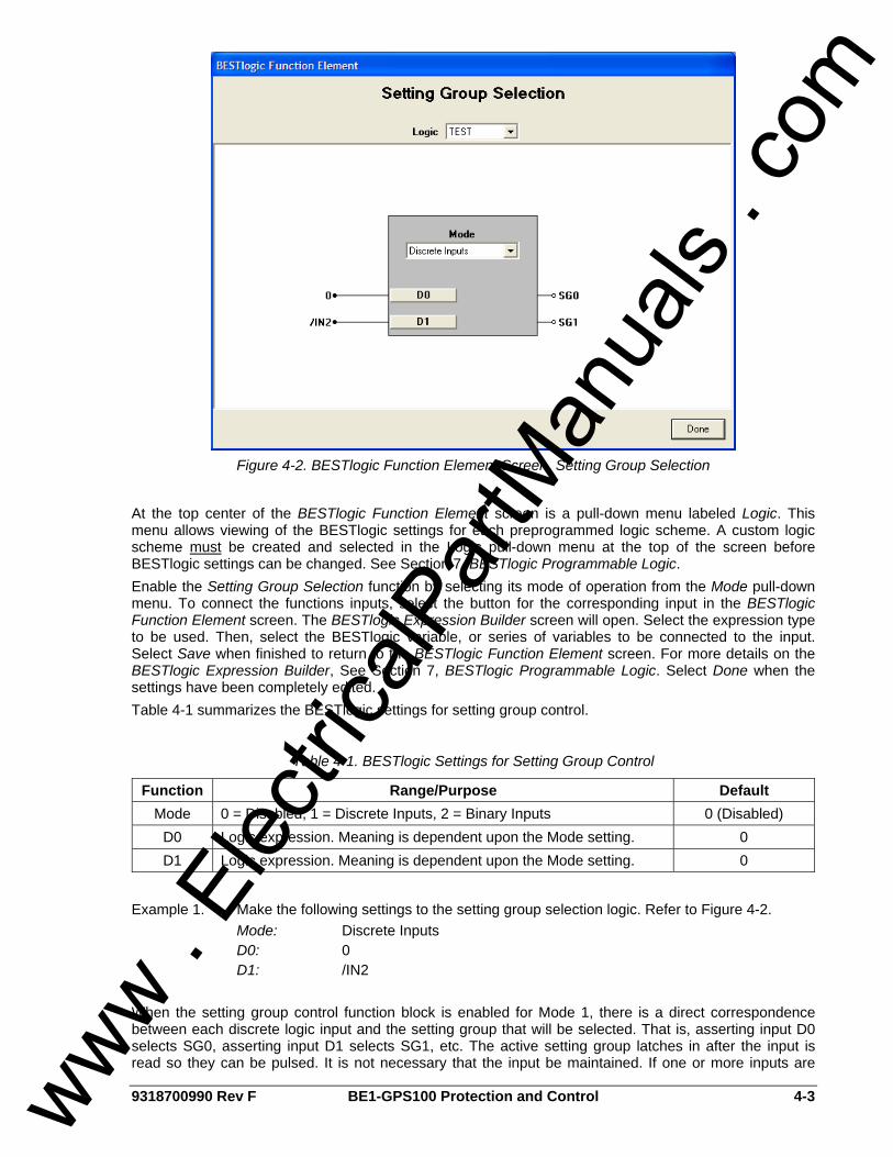
9318700990 Rev F BE1-GPS100 Protection and Control 4-3
Figure 4-2. BESTlogic Function Element Screen, Setting Group Selection
At the top center of the BESTlogic Function Element screen is a pull-down menu labeled Logic. This menu allows viewing of the BESTlogic settings for each preprogrammed logic scheme. A custom logic scheme must be created and selected in the Logic pull-down menu at the top of the screen before BESTlogic settings can be changed. See Section 7, BESTlogic Programmable Logic. Enable the Setting Group Selection function by selecting its mode of operation from the Mode pull-down menu. To connect the functions inputs, select the button for the corresponding input in the BESTlogic Function Element screen. The BESTlogic Expression Builder screen will open. Select the expression type to be used. Then, select the BESTlogic variable, or series of variables to be connected to the input. Select Save when finished to return to the BESTlogic Function Element screen. For more details on the BESTlogic Expression Builder, See Section 7, BESTlogic Programmable Logic. Select Done when the settings have been completely edited. Table 4-1 summarizes the BESTlogic settings for setting group control.
Table 4-1. BESTlogic Settings for Setting Group Control
Function Range/Purpose Default Mode 0 = Disabled, 1 = Discrete Inputs, 2 = Binary Inputs 0 (Disabled)
D0 Logic expression. Meaning is dependent upon the Mode setting. 0 D1 Logic expression. Meaning is dependent upon the Mode setting. 0
Example 1. Make the following settings to the setting group selection logic. Refer to Figure 4-2. Mode: Discrete Inputs D0: 0 D1: /IN2 When the setting group control function block is enabled for Mode 1, there is a direct correspondence between each discrete logic input and the setting group that will be selected. That is, asserting input D0 selects SG0, asserting input D1 selects SG1, etc. The active setting group latches in after the input is read so they can be pulsed. It is not necessary that the input be maintained. If one or more inputs are
www . El
ectric
alPar
tMan
uals
. com
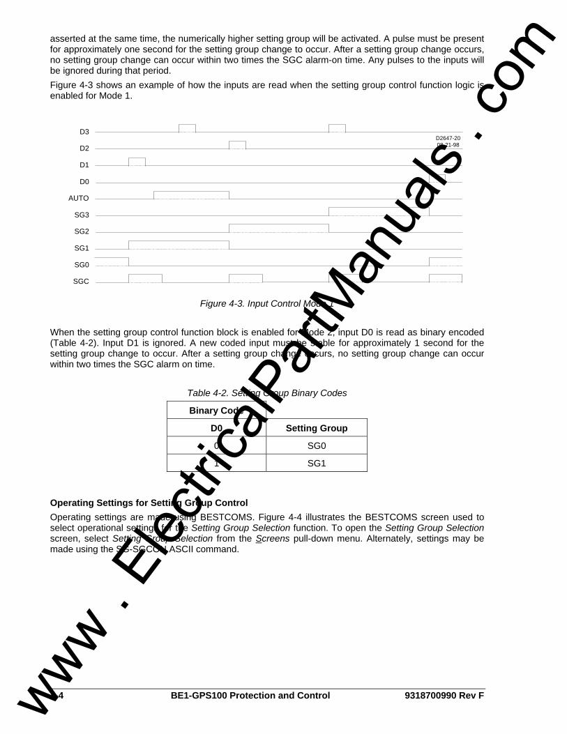
4-4 BE1-GPS100 Protection and Control 9318700990 Rev F
asserted at the same time, the numerically higher setting group will be activated. A pulse must be present for approximately one second for the setting group change to occur. After a setting group change occurs, no setting group change can occur within two times the SGC alarm-on time. Any pulses to the inputs will be ignored during that period. Figure 4-3 shows an example of how the inputs are read when the setting group control function logic is enabled for Mode 1.
D3
D2
D1
D0
AUTO
SG3
SG2
SG1
SG0
SGC
D2647-2008-21-98
Figure 4-3. Input Control Mode 1
When the setting group control function block is enabled for Mode 2, input D0 is read as binary encoded (Table 4-2). Input D1 is ignored. A new coded input must be stable for approximately 1 second for the setting group change to occur. After a setting group change occurs, no setting group change can occur within two times the SGC alarm on time.
Table 4-2. Setting Group Binary Codes
Binary Code
D0 Setting Group
0 SG0
1 SG1
Operating Settings for Setting Group Control Operating settings are made using BESTCOMS. Figure 4-4 illustrates the BESTCOMS screen used to select operational settings for the Setting Group Selection function. To open the Setting Group Selection screen, select Setting Group Selection from the Screens pull-down menu. Alternately, settings may be made using the SG-SGCON ASCII command.
www . El
ectric
alPar
tMan
uals
. com
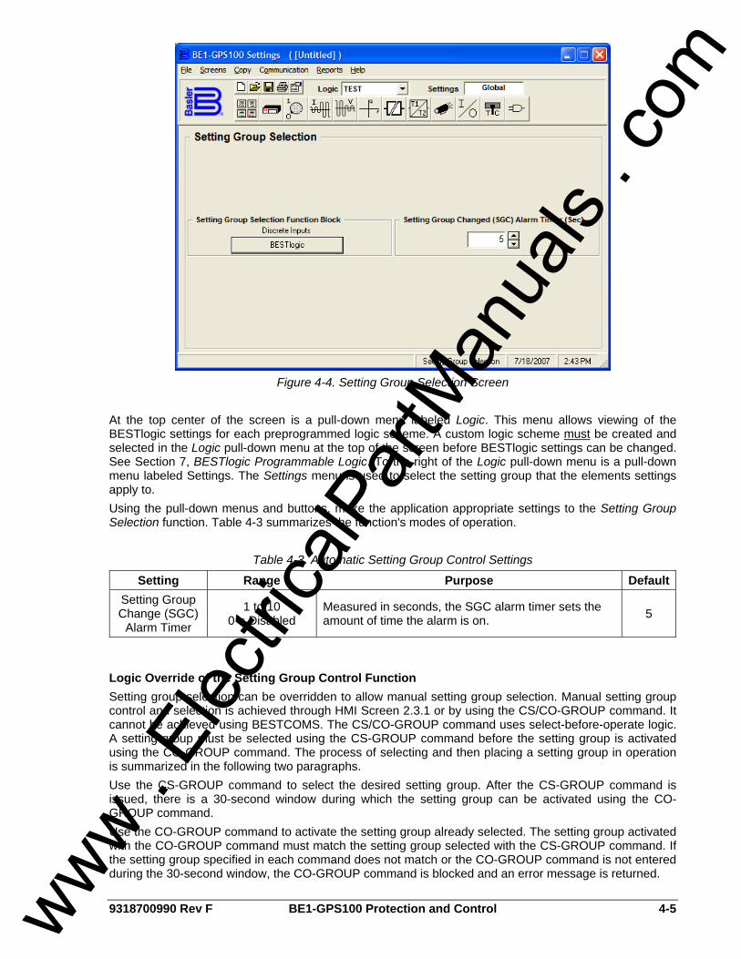
9318700990 Rev F BE1-GPS100 Protection and Control 4-5
Figure 4-4. Setting Group Selection Screen
At the top center of the screen is a pull-down menu labeled Logic. This menu allows viewing of the BESTlogic settings for each preprogrammed logic scheme. A custom logic scheme must be created and selected in the Logic pull-down menu at the top of the screen before BESTlogic settings can be changed. See Section 7, BESTlogic Programmable Logic. To the right of the Logic pull-down menu is a pull-down menu labeled Settings. The Settings menu is used to select the setting group that the elements settings apply to. Using the pull-down menus and buttons, make the application appropriate settings to the Setting Group Selection function. Table 4-3 summarizes the function's modes of operation.
Table 4-3. Automatic Setting Group Control Settings
Setting Range Purpose DefaultSetting Group Change (SGC)
Alarm Timer
1 to 10 0 = Disabled
Measured in seconds, the SGC alarm timer sets the amount of time the alarm is on. 5
Logic Override of the Setting Group Control Function Setting group selection can be overridden to allow manual setting group selection. Manual setting group control and selection is achieved through HMI Screen 2.3.1 or by using the CS/CO-GROUP command. It cannot be achieved using BESTCOMS. The CS/CO-GROUP command uses select-before-operate logic. A setting group must be selected using the CS-GROUP command before the setting group is activated using the CO-GROUP command. The process of selecting and then placing a setting group in operation is summarized in the following two paragraphs. Use the CS-GROUP command to select the desired setting group. After the CS-GROUP command is issued, there is a 30-second window during which the setting group can be activated using the CO-GROUP command. Use the CO-GROUP command to activate the setting group already selected. The setting group activated with the CO-GROUP command must match the setting group selected with the CS-GROUP command. If the setting group specified in each command does not match or the CO-GROUP command is not entered during the 30-second window, the CO-GROUP command is blocked and an error message is returned.
www . El
ectric
alPar
tMan
uals
. com
4-6 BE1-GPS100 Protection and Control 9318700990 Rev F
CS/CO-GROUP commands are executed without having to use the EXIT command to save setting changes. When a setting group change is made, any subsequent setting change is blocked for two times the duration of the SGC alarm output time setting. Refer to the Setting Groups subsection for more information about SGC Alarm settings. CS/CO-GROUP Command Purpose: Read or change logic override settings for setting group selection. Syntax: GROUP[=<mode>] Comments: mode = Setting Group 0, 1, or L. L returns group control to the automatic setting group
logic. <mode> entry of CS-GROUP command and CO-GROUP command must match or setting group selection will be rejected. If more than 30 seconds elapse after issuing a CS-GROUP command, the CO-GROUP command will be rejected.
CS/CO-GROUP Command Examples: Example 1. Read the current status of setting group override. >CO-GROUP L
Example 2. Override logic control and change the active setting group to SG1. >CS-GROUP=1 GROUP=1 SELECTED >CO-GROUP=1 GROUP=1 EXECUTED
Example 3. Return control of the active setting group to the automatic setting group logic. >CS-GROUP=L GROUP=L SELECTED >CO-GROUP=L GROUP=L EXECUTED
Retrieving Setting Group Control Status from the Relay The active setting group can be determined from HMI Screen 1.4.5 or by using the RG-STAT command. Section 6, Reporting and Alarm Functions, General Status Reporting, provides more information about determining the active setting group. The active group cannot be determined using BESTCOMS. Logic override status can be determined from HMI Screen 2.3.1 or through the RG-STAT command. Section 6, Reporting and Alarm Functions, General Status Reporting, provides more information about determining logic override status. Logic override cannot be determined using BESTCOMS.
OVERCURRENT PROTECTION The BE1-GPS100 includes instantaneous elements for Phase and Neutral, as well as time overcurrent elements for phase, neutral or ground, and negative-sequence.
50T - Instantaneous Overcurrent Protection with Settable Time Delay There is one BESTlogic elements for phase (50TP) and one element for ground (50TN) instantaneous overcurrent protection. The alphanumeric designation for each element contains the letter T to indicate that the element has an adjustable time delay. If an element has a time delay setting of zero, then that element will operate as an instantaneous overcurrent relay. The 50TP and 50TN instantaneous overcurrent elements are shown in Figure 4-5. Each element has two logic outputs: PU (Pickup) and T (Trip).
www . El
ectric
alPar
tMan
uals
. com
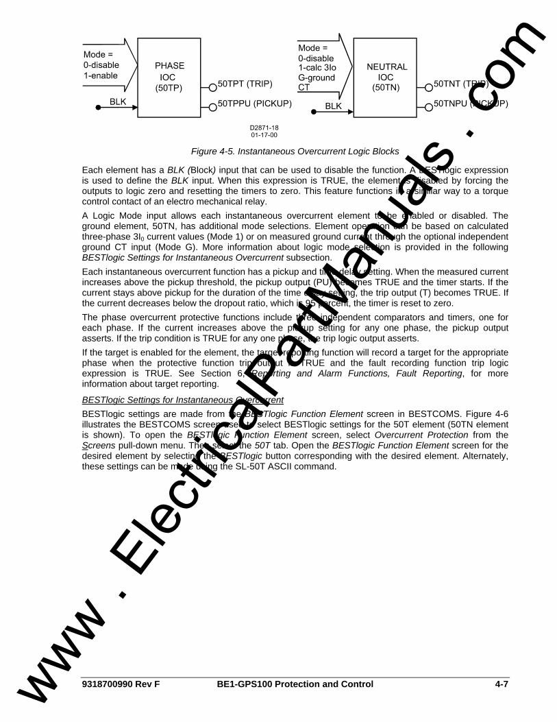
9318700990 Rev F BE1-GPS100 Protection and Control 4-7
Figure 4-5. Instantaneous Overcurrent Logic Blocks
Each element has a BLK (Block) input that can be used to disable the function. A BESTlogic expression is used to define the BLK input. When this expression is TRUE, the element is disabled by forcing the outputs to logic zero and resetting the timers to zero. This feature functions in a similar way to a torque control contact of an electro mechanical relay. A Logic Mode input allows each instantaneous overcurrent element to be enabled or disabled. The ground element, 50TN, has additional mode selections. Element operation can be based on calculated three-phase 3I0 current values (Mode 1) or on measured ground current through the optional independent ground CT input (Mode G). More information about logic mode selection is provided in the following BESTlogic Settings for Instantaneous Overcurrent subsection. Each instantaneous overcurrent function has a pickup and time delay setting. When the measured current increases above the pickup threshold, the pickup output (PU) becomes TRUE and the timer starts. If the current stays above pickup for the duration of the time delay setting, the trip output (T) becomes TRUE. If the current decreases below the dropout ratio, which is 95 percent, the timer is reset to zero. The phase overcurrent protective functions include three independent comparators and timers, one for each phase. If the current increases above the pickup setting for any one phase, the pickup output asserts. If the trip condition is TRUE for any one phase, the trip logic output asserts. If the target is enabled for the element, the target reporting function will record a target for the appropriate phase when the protective function trip output is TRUE and the fault recording function trip logic expression is TRUE. See Section 6, Reporting and Alarm Functions, Fault Reporting, for more information about target reporting.
BESTlogic Settings for Instantaneous Overcurrent BESTlogic settings are made from the BESTlogic Function Element screen in BESTCOMS. Figure 4-6 illustrates the BESTCOMS screen used to select BESTlogic settings for the 50T element (50TN element is shown). To open the BESTlogic Function Element screen, select Overcurrent Protection from the Screens pull-down menu. Then select the 50T tab. Open the BESTlogic Function Element screen for the desired element by selecting the BESTlogic button corresponding with the desired element. Alternately, these settings can be made using the SL-50T ASCII command.
www . El
ectric
alPar
tMan
uals
. com
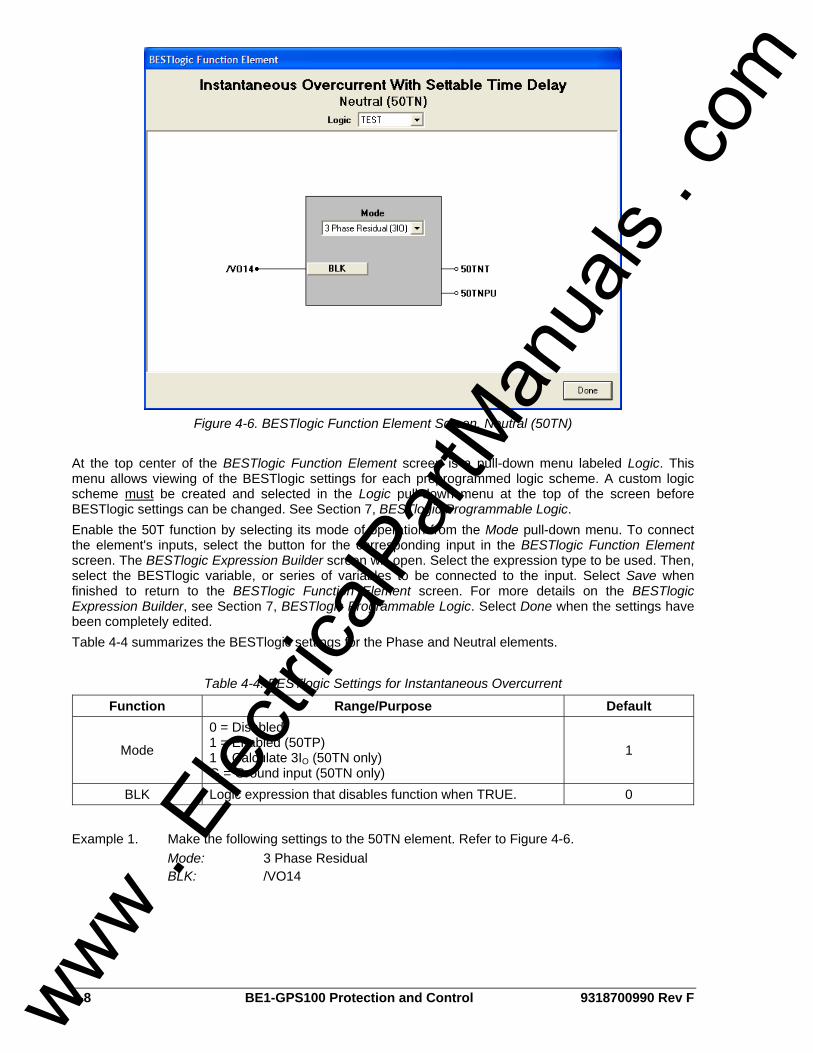
4-8 BE1-GPS100 Protection and Control 9318700990 Rev F
Figure 4-6. BESTlogic Function Element Screen, Neutral (50TN)
At the top center of the BESTlogic Function Element screen is a pull-down menu labeled Logic. This menu allows viewing of the BESTlogic settings for each preprogrammed logic scheme. A custom logic scheme must be created and selected in the Logic pull-down menu at the top of the screen before BESTlogic settings can be changed. See Section 7, BESTlogic Programmable Logic. Enable the 50T function by selecting its mode of operation from the Mode pull-down menu. To connect the element's inputs, select the button for the corresponding input in the BESTlogic Function Element screen. The BESTlogic Expression Builder screen will open. Select the expression type to be used. Then, select the BESTlogic variable, or series of variables to be connected to the input. Select Save when finished to return to the BESTlogic Function Element screen. For more details on the BESTlogic Expression Builder, see Section 7, BESTlogic Programmable Logic. Select Done when the settings have been completely edited. Table 4-4 summarizes the BESTlogic settings for the Phase and Neutral elements.
Table 4-4. BESTlogic Settings for Instantaneous Overcurrent
Function Range/Purpose Default
Mode
0 = Disabled 1 = Enabled (50TP) 1 = Calculate 3IO (50TN only) G = Ground input (50TN only)
1
BLK Logic expression that disables function when TRUE. 0
Example 1. Make the following settings to the 50TN element. Refer to Figure 4-6. Mode: 3 Phase Residual BLK: /VO14
www . El
ectric
alPar
tMan
uals
. com
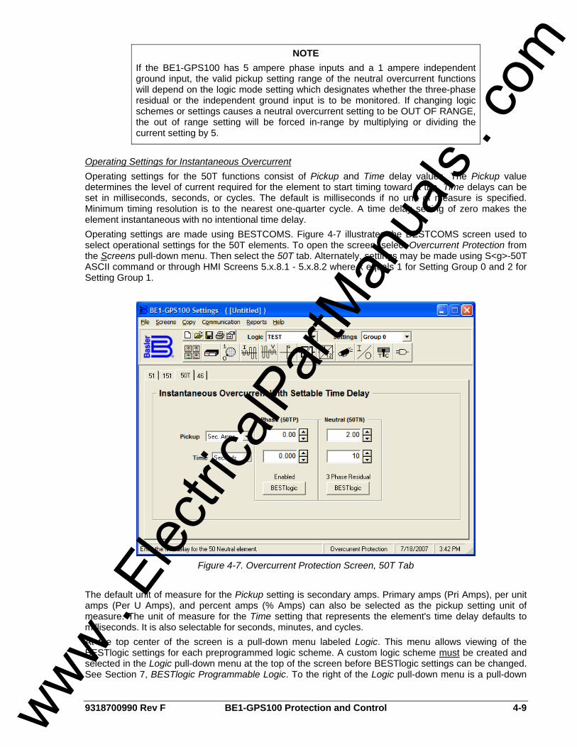
9318700990 Rev F BE1-GPS100 Protection and Control 4-9
Operating Settings for Instantaneous Overcurrent Operating settings for the 50T functions consist of Pickup and Time delay values. The Pickup value determines the level of current required for the element to start timing toward a trip. Time delays can be set in milliseconds, seconds, or cycles. The default is milliseconds if no unit of measure is specified. Minimum timing resolution is to the nearest one-quarter cycle. A time delay setting of zero makes the element instantaneous with no intentional time delay. Operating settings are made using BESTCOMS. Figure 4-7 illustrates the BESTCOMS screen used to select operational settings for the 50T elements. To open the screen, select Overcurrent Protection from the Screens pull-down menu. Then select the 50T tab. Alternately, settings may be made using S<g>-50T ASCII command or through HMI Screens 5.x.8.1 - 5.x.8.2 where x equals 1 for Setting Group 0 and 2 for Setting Group 1.
Figure 4-7. Overcurrent Protection Screen, 50T Tab
The default unit of measure for the Pickup setting is secondary amps. Primary amps (Pri Amps), per unit amps (Per U Amps), and percent amps (% Amps) can also be selected as the pickup setting unit of measure. The unit of measure for the Time setting that represents the element's time delay defaults to milliseconds. It is also selectable for seconds, minutes, and cycles. At the top center of the screen is a pull-down menu labeled Logic. This menu allows viewing of the BESTlogic settings for each preprogrammed logic scheme. A custom logic scheme must be created and selected in the Logic pull-down menu at the top of the screen before BESTlogic settings can be changed. See Section 7, BESTlogic Programmable Logic. To the right of the Logic pull-down menu is a pull-down
NOTE If the BE1-GPS100 has 5 ampere phase inputs and a 1 ampere independent ground input, the valid pickup setting range of the neutral overcurrent functions will depend on the logic mode setting which designates whether the three-phase residual or the independent ground input is to be monitored. If changing logic schemes or settings causes a neutral overcurrent setting to be OUT OF RANGE, the out of range setting will be forced in-range by multiplying or dividing the current setting by 5.
www . El
ectric
alPar
tMan
uals
. com

4-10 BE1-GPS100 Protection and Control 9318700990 Rev F
menu labeled Settings. The Settings menu is used to select the setting group that the elements settings apply to. Table 4-5 summarizes the operating settings for instantaneous overcurrent.
Table 4-5. Operating Settings for Instantaneous Overcurrent
Range Setting
1 A 5 A Increment Unit of Measure Default
Pickup 0 = Disabled
0.1 to 30 0 = Disabled
0.5 to 150
0.01 for 0.1 to 9.99 0.1 for 10.0 to 99.9 1.0 for 100 to 150
Secondary Amps 0
0 to 999 milliseconds 1 Milliseconds 0.1 for 0.1 to 9.9 Seconds
0.1 to 60 seconds 1.0 for 10 to 60 Seconds
0 to 3600 cycles (60 Hz) Time
0 to 2500 cycles (50 Hz) ∗ Cycles
0
∗ Time delays less than 10 cycles can be entered to the nearest 0.1 cycles from the front panel HMI. All time delays can be entered to the nearest 0.01 cycles from the ASCII command interface. Time delays entered in cycles are converted to milliseconds or seconds. Increment precision after conversion is limited to that appropriate for each of those units of measure. Example 1. Make the following settings to the 50TN element. Refer to Figure 4-7. Pickup: 2 secondary amps Time: 10 seconds If time delay settings are made in cycles, they are converted to seconds or milliseconds (per the nominal frequency setting stored in EEPROM) before being stored. See Section 3, Input and Output Functions, Power System Inputs, Current Measurement, for more information about this setting. If the nominal frequency setting is being changed from the default (60 hertz) and time delay settings are being set in cycles, the frequency setting should be entered and saved before making any time delay settings changes.
Retrieving Instantaneous Overcurrent Status from the Relay The status of each logic variable can be determined through the ASCII command interface using the RG-STAT (report general-status) command. See Section 6, Reporting and Alarm Functions, General Status Reporting, for more information. The status cannot be determined by using BESTCOMS.
51 - Time Overcurrent Protection BE1-GPS100 relays have one element for phase (51P) and two elements for neutral (51N and 151N) time overcurrent protection. Figure 4-8 shows the 51 elements. The 51N and 151N elements are identical in configuration. Each element has two outputs: PU (Pickup) and T (Trip). A BLK (Block) logic input is provided to disable the function. When this expression is TRUE, the element is disabled by forcing the outputs to logic 0 and resetting the timers to zero. This feature operates in a similar manner to the torque control contact of an electromechanical relay.
Figure 4-8. Time Overcurrent Logic Blocks
www . El
ectric
alPar
tMan
uals
. com
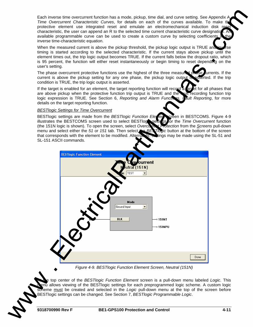
9318700990 Rev F BE1-GPS100 Protection and Control 4-11
Each inverse time overcurrent function has a mode, pickup, time dial, and curve setting. See Appendix A, Time Overcurrent Characteristic Curves, for details on each of the curves available. To make the protective element use integrated reset and emulate an electromechanical induction disk reset characteristic, the user can append an R to the selected time current characteristic curve designation. An available programmable curve can be used to create a custom curve by selecting coefficients in the inverse time-characteristic equation. When the measured current is above the pickup threshold, the pickup logic output is TRUE and inverse timing is started according to the selected characteristic. If the current stays above pickup until the element times out, the trip logic output becomes TRUE. If the current falls below the dropout ratio, which is 95 percent, the function will either reset instantaneously or begin timing to reset depending on the user's setting. The phase overcurrent protective functions use the highest of the three measured phase currents. If the current is above the pickup setting for any one phase, the pickup logic output is asserted. If the trip condition is TRUE, the trip logic output is asserted. If the target is enabled for an element, the target reporting function will record a target for all phases that are above pickup when the protective function trip output is TRUE and the fault recording function trip logic expression is TRUE. See Section 6, Reporting and Alarm Functions, Fault Reporting, for more details on the target reporting function.
BESTlogic Settings for Time Overcurrent BESTlogic settings are made from the BESTlogic Function Element screen in BESTCOMS. Figure 4-9 illustrates the BESTCOMS screen used to select BESTlogic settings for the Time Overcurrent function (the 151N logic is shown). To open the screen, select Overcurrent Protection from the Screens pull-down menu and select either the 51 or 151 tab. Then select the BESTlogic button at the bottom of the screen that corresponds with the element to be modified. Alternately, settings may be made using the SL-51 and SL-151 ASCII commands.
Figure 4-9. BESTlogic Function Element Screen, Neutral (151N)
At the top center of the BESTlogic Function Element screen is a pull-down menu labeled Logic. This menu allows viewing of the BESTlogic settings for each preprogrammed logic scheme. A custom logic scheme must be created and selected in the Logic pull-down menu at the top of the screen before BESTlogic settings can be changed. See Section 7, BESTlogic Programmable Logic.
www . El
ectric
alPar
tMan
uals
. com
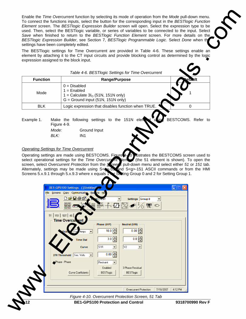
4-12 BE1-GPS100 Protection and Control 9318700990 Rev F
Enable the Time Overcurrent function by selecting its mode of operation from the Mode pull-down menu. To connect the functions inputs, select the button for the corresponding input in the BESTlogic Function Element screen. The BESTlogic Expression Builder screen will open. Select the expression type to be used. Then, select the BESTlogic variable, or series of variables to be connected to the input. Select Save when finished to return to the BESTlogic Function Element screen. For more details on the BESTlogic Expression Builder, see Section 7, BESTlogic Programmable Logic. Select Done when the settings have been completely edited. The BESTlogic settings for Time Overcurrent are provided in Table 4-6. These settings enable an element by attaching it to the CT input circuits and provide blocking control as determined by the logic expression assigned to the block input.
Table 4-6. BESTlogic Settings for Time Overcurrent
Function Range/Purpose Default
Mode
0 = Disabled 1 = Enabled 1 = Calculate 3IO (51N, 151N only) G = Ground input (51N, 151N only)
1
BLK Logic expression that disables function when TRUE. 0
Example 1. Make the following settings to the 151N element using BESTCOMS. Refer to
Figure 4-9. Mode: Ground Input BLK: IN1
Operating Settings for Time Overcurrent Operating settings are made using BESTCOMS. Figure 4-10 illustrates the BESTCOMS screen used to select operational settings for the Time Overcurrent element (the 51 element is shown). To open the screen, select Overcurrent Protection from the Screens pull-down menu and select either 51 or 151 tab. Alternately, settings may be made using S<g>-51 and S<g>-151 ASCII commands or from the HMI Screens 5.x.9.1 through 5.x.9.3 where x equals 1 for Setting Group 0 and 2 for Setting Group 1.
Figure 4-10. Overcurrent Protection Screen, 51 Tab www . El
ectric
alPar
tMan
uals
. com

9318700990 Rev F BE1-GPS100 Protection and Control 4-13
The default unit of measure for the Pickup setting is secondary amps. Primary amps (Pri Amps), per unit amps (Per U Amps), and percent amps (% Amps) can also be selected as the pickup setting unit of measure. The unit of measure for the Time setting that represents the element's time delay defaults to milliseconds. It is also selectable for seconds, minutes, and cycles. At the top center of the screen is a pull-down menu labeled Logic. This menu allows viewing of the BESTlogic settings for each preprogrammed logic scheme. A custom logic scheme must be created and selected in the Logic pull-down menu at the top of the screen before BESTlogic settings can be changed. See Section 7, BESTlogic Programmable Logic. To the right of the Logic pull-down menu is a pull-down menu labeled Settings. The Settings menu is used to select the setting group that the elements settings apply to. Using the pull-down menus and buttons, make the application appropriate settings to the Time Overcurrent function. The 27R element is explained later in this section. Table 4-7 summarizes the operating settings for Time Overcurrent.
Table 4-7. Operating Settings for Time Overcurrent
Range Setting
1 A 5 A Increment Unit of Measure Default
Pickup 0 = Disabled
0.1 to 3.2 0 = Disabled 0.5 to 16.0
0.02 for 0.1 to 9.99 0.1 for 10.0 to 16.0
Secondary Amps 0
Time Dial 0.0 to 9.9
0 to 99 (46 only) 0.1 for 0.0 to 9.9
1 for 10 to 99 (46 only) N/A 0
Curve See Appendix A, Table A-1 N/A N/A V2
Example 1. Make the following changes to the 51P Time Overcurrent element in BESTCOMS. Refer to Figure 4-10.
Pickup: 10 secondary amps Time Dial: 3.0 Curve: S1R
Retrieving Time Overcurrent Status from the Relay The status of each logic variable can be determined through the ASCII command interface using the RG-STAT (report general-status) command. See Section 6, Reporting and Alarm Functions, General Status Reporting, for more information. The status cannot be determined by using BESTCOMS.
Voltage Restraint/Control for Time Overcurrent Protection The 51P protection function can be set for voltage control or voltage restraint mode of operation (51V). This feature is used to allow increased overcurrent sensitivity while providing security from operation due to load current. This feature is also often used for generator backup protection to ensure delayed tripping during a short circuit where the fault current contribution from the generator falls to a value close to the full load rating of the generator. When set for Control mode of operation, the phase overcurrent element is disabled until the measured voltage drops below the threshold. Thus, as long as the voltage on the appropriate phase is above the 27R threshold setting, the overcurrent element will be blocked. When set for this mode of operation, the 51P pickup setting is typically set near or below load current levels. When set for Restraint mode of operation, the pickup of the phase overcurrent element is adjusted based upon the magnitude of the measured voltage. Figure 4-11 shows how the overcurrent pickup threshold setting is adjusted in response to the measured voltage level. Equation 4-1 determines the pickup level for the 51P elements when the measured voltage is between 25% and 100% of the 27R threshold setting. Below 25%, the pickup level stays at 25%. Above 100%, the pickup level stays at 100%. For example, if the 27R threshold is set for 120V and the measured voltage on the appropriate phase is 100V, (83% of the 27R threshold setting), the overcurrent pickup level for that phase will be reduced to 83% of its setting. When set for this mode of operation, the 51P pickup setting is typically set above worst case, load current levels.
www . El
ectric
alPar
tMan
uals
. com
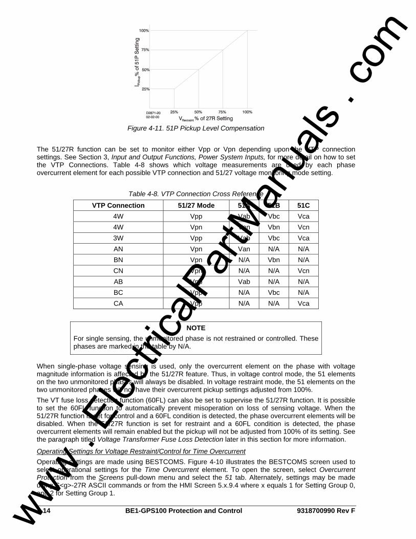
4-14 BE1-GPS100 Protection and Control 9318700990 Rev F
Figure 4-11. 51P Pickup Level Compensation
The 51/27R function can be set to monitor either Vpp or Vpn depending upon the VTP connection settings. See Section 3, Input and Output Functions, Power System Inputs, for more detail on how to set the VTP Connections. Table 4-8 shows which voltage measurements are used by each phase overcurrent element for each possible VTP connection and 51/27 voltage monitoring mode setting.
Table 4-8. VTP Connection Cross Reference
VTP Connection 51/27 Mode 51A 51B 51C 4W Vpp Vab Vbc Vca 4W Vpn Van Vbn Vcn 3W Vpp Vab Vbc Vca AN Vpn Van N/A N/A BN Vpn N/A Vbn N/A CN Vpn N/A N/A Vcn AB Vpp Vab N/A N/A BC Vpp N/A Vbc N/A CA Vpp N/A N/A Vca
When single-phase voltage sensing is used, only the overcurrent element on the phase with voltage magnitude information is affected by the 51/27R feature. Thus, in voltage control mode, the 51 elements on the two unmonitored phases will always be disabled. In voltage restraint mode, the 51 elements on the two unmonitored phases will not have their overcurrent pickup settings adjusted from 100%. The VT fuse loss detection function (60FL) can also be set to supervise the 51/27R function. It is possible to set the 60FL function to automatically prevent misoperation on loss of sensing voltage. When the 51/27R function is set for control and a 60FL condition is detected, the phase overcurrent elements will be disabled. When the 51/27R function is set for restraint and a 60FL condition is detected, the phase overcurrent elements will remain enabled but the pickup will not be adjusted from 100% of its setting. See the paragraph titled Voltage Transformer Fuse Loss Detection later in this section for more information.
Operating Settings for Voltage Restraint/Control for Time Overcurrent Operating settings are made using BESTCOMS. Figure 4-10 illustrates the BESTCOMS screen used to select operational settings for the Time Overcurrent element. To open the screen, select Overcurrent Protection from the Screens pull-down menu and select the 51 tab. Alternately, settings may be made using S<g>-27R ASCII commands or from the HMI Screen 5.x.9.4 where x equals 1 for Setting Group 0, and 2 for Setting Group 1.
NOTE For single sensing, the unmonitored phase is not restrained or controlled. These phases are marked in the table by N/A.
www . El
ectric
alPar
tMan
uals
. com

9318700990 Rev F BE1-GPS100 Protection and Control 4-15
The default unit of measure for the Pickup Threshold setting is secondary amps. Secondary amps (Sec Amps), per unit amps (Per U Amps), and percent amps (% Amps) can also be selected as the pickup setting unit of measure. At the top center of the screen is a pull-down menu labeled Logic. This menu allows viewing of the BESTlogic settings for each preprogrammed logic scheme. A custom logic scheme must be created and selected in the Logic pull-down menu at the top of the screen before BESTlogic settings can be changed. See Section 7, BESTlogic Programmable Logic. To the right of the Logic pull-down menu is a pull-down menu labeled Settings. The Settings menu is used to select the setting group that the elements settings apply to. Using the pull-down menus and buttons, make the application appropriate settings to the Voltage Restraint element. Table 4-9 summarizes the function’s modes of operation.
Table 4-9. Operating Settings for Voltage Restraint/Control for Time Overcurrent
Setting Range Increment Unit of Measure Default Pickup 30 to 250, 0 = Disable 0.1 for 30 to 99, 1.0 for 100 to 250 Volts 0 Mode C (control), R (restraint) N/A N/A R
Pickup Threshold. A setting of zero disables voltage restraint/control and allows the 51P time overcurrent function to operate normally. When voltage restraint or control is desired, the pickup value can be set over a range of 30 to 250 volts. Setting curve coefficients is discussed later in this section. Mode Setting (Mode). Two mode settings are available: Restraint and Control.
Restraint I. In Restraint mode, the 51P pickup level is reduced linearly when the sensing voltage decreases below the restraint pickup level. The 51P pickup level is determined by Equation 4-1.
settingpickup51PsettingpickuprestraintlevelvoltagesensingLevelPickupActual ×=
Equation 4-1. Restraint Pickup Level
Control I. In Control Mode, pickup level is as selected by the 27R pickup setting. Control or restraint operation can also be set by the S<g>-27R command.
46 Negative Sequence Overcurrent Element There is one element for negative sequence (46), overcurrent protection. Figure 4-12 shows the negative sequence overcurrent element with two logic outputs: PU (Pickup) and T (Trip). A BLK (Block) logic input is provided to disable the function. When this expression is TRUE, the function is disabled by forcing the outputs to logic zero and resetting the timers to zero. For example, this could be used similar to a torque control contact on an electromechanical relay.
Figure 4-12. Negative Sequence Overcurrent Logic Block
The negative sequence overcurrent element has a mode, pickup, time dial, and a curve setting. See Appendix A, Time Overcurrent Characteristic Curves, for details on each of the curves available. To make the protective element use integrated reset and emulate an electromechanical induction disk reset characteristic, the user can append an R to the selected time current characteristic curve. A programmable curve is available that can be used to create a custom curve by selecting coefficients in the inverse time-characteristic equation.
www . El
ectric
alPar
tMan
uals
. com
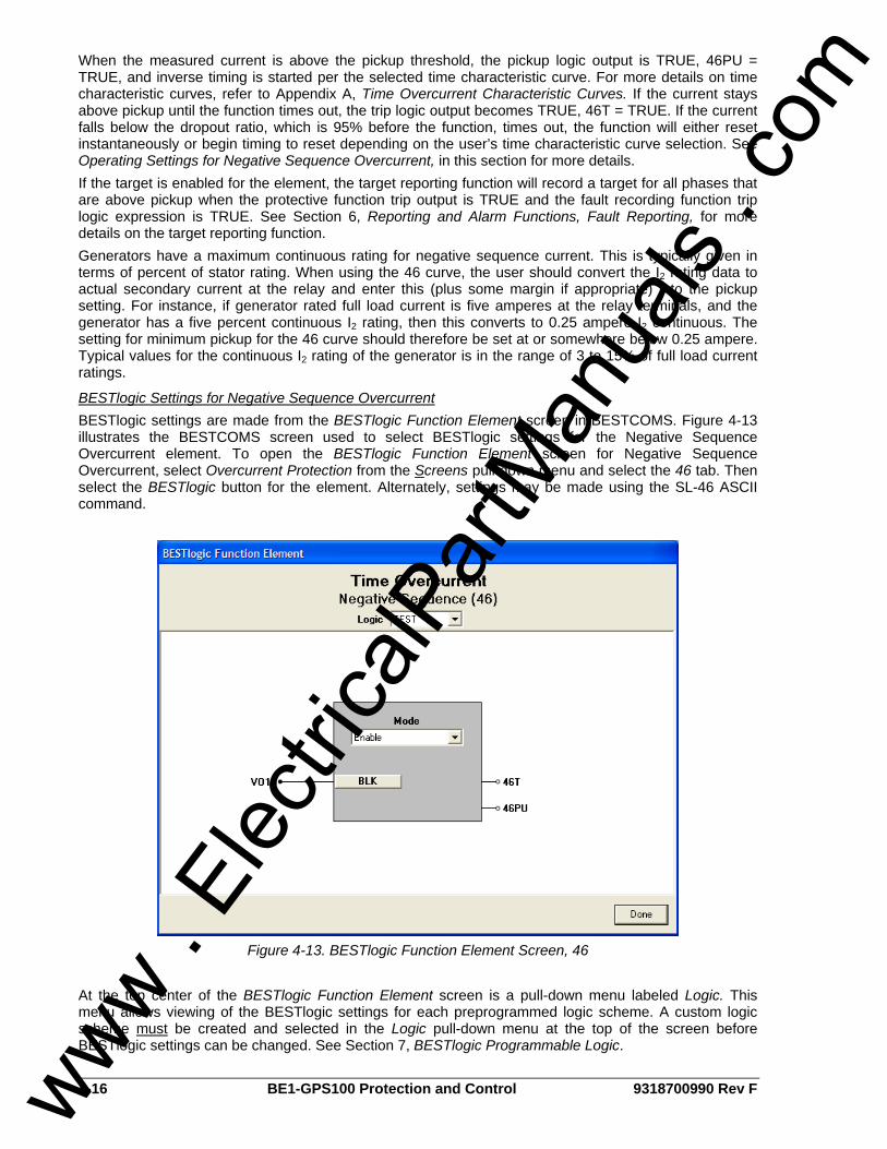
4-16 BE1-GPS100 Protection and Control 9318700990 Rev F
When the measured current is above the pickup threshold, the pickup logic output is TRUE, 46PU = TRUE, and inverse timing is started per the selected time characteristic curve. For more details on time characteristic curves, refer to Appendix A, Time Overcurrent Characteristic Curves. If the current stays above pickup until the function times out, the trip logic output becomes TRUE, 46T = TRUE. If the current falls below the dropout ratio, which is 95% before the function, times out, the function will either reset instantaneously or begin timing to reset depending on the user’s time characteristic curve selection. See Operating Settings for Negative Sequence Overcurrent, in this section for more details. If the target is enabled for the element, the target reporting function will record a target for all phases that are above pickup when the protective function trip output is TRUE and the fault recording function trip logic expression is TRUE. See Section 6, Reporting and Alarm Functions, Fault Reporting, for more details on the target reporting function. Generators have a maximum continuous rating for negative sequence current. This is typically given in terms of percent of stator rating. When using the 46 curve, the user should convert the I2 rating data to actual secondary current at the relay and enter this (plus some margin if appropriate) into the pickup setting. For instance, if generator rated full load current is five amperes at the relay terminals, and the generator has a five percent continuous I2 rating, then this converts to 0.25 ampere I2 continuous. The setting for minimum pickup for the 46 curve should therefore be set at or somewhere below 0.25 ampere. Typical values for the continuous I2 rating of the generator is in the range of 3 to 15% of full load current ratings.
BESTlogic Settings for Negative Sequence Overcurrent BESTlogic settings are made from the BESTlogic Function Element screen in BESTCOMS. Figure 4-13 illustrates the BESTCOMS screen used to select BESTlogic settings for the Negative Sequence Overcurrent element. To open the BESTlogic Function Element screen for Negative Sequence Overcurrent, select Overcurrent Protection from the Screens pull-down menu and select the 46 tab. Then select the BESTlogic button for the element. Alternately, settings may be made using the SL-46 ASCII command.
Figure 4-13. BESTlogic Function Element Screen, 46
At the top center of the BESTlogic Function Element screen is a pull-down menu labeled Logic. This menu allows viewing of the BESTlogic settings for each preprogrammed logic scheme. A custom logic scheme must be created and selected in the Logic pull-down menu at the top of the screen before BESTlogic settings can be changed. See Section 7, BESTlogic Programmable Logic.
www . El
ectric
alPar
tMan
uals
. com
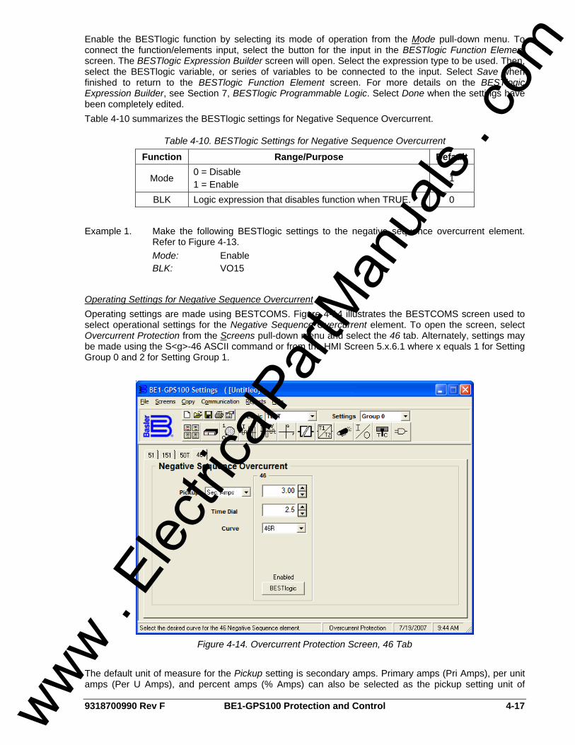
9318700990 Rev F BE1-GPS100 Protection and Control 4-17
Enable the BESTlogic function by selecting its mode of operation from the Mode pull-down menu. To connect the function/elements input, select the button for the input in the BESTlogic Function Element screen. The BESTlogic Expression Builder screen will open. Select the expression type to be used. Then, select the BESTlogic variable, or series of variables to be connected to the input. Select Save when finished to return to the BESTlogic Function Element screen. For more details on the BESTlogic Expression Builder, see Section 7, BESTlogic Programmable Logic. Select Done when the settings have been completely edited. Table 4-10 summarizes the BESTlogic settings for Negative Sequence Overcurrent.
Table 4-10. BESTlogic Settings for Negative Sequence Overcurrent
Function Range/Purpose Default
Mode 0 = Disable 1 = Enable 1
BLK Logic expression that disables function when TRUE. 0
Example 1. Make the following BESTlogic settings to the negative sequence overcurrent element.
Refer to Figure 4-13. Mode: Enable BLK: VO15
Operating Settings for Negative Sequence Overcurrent Operating settings are made using BESTCOMS. Figure 4-14 illustrates the BESTCOMS screen used to select operational settings for the Negative Sequence Overcurrent element. To open the screen, select Overcurrent Protection from the Screens pull-down menu and select the 46 tab. Alternately, settings may be made using the S<g>-46 ASCII command or from the HMI Screen 5.x.6.1 where x equals 1 for Setting Group 0 and 2 for Setting Group 1.
Figure 4-14. Overcurrent Protection Screen, 46 Tab
The default unit of measure for the Pickup setting is secondary amps. Primary amps (Pri Amps), per unit amps (Per U Amps), and percent amps (% Amps) can also be selected as the pickup setting unit of
www . El
ectric
alPar
tMan
uals
. com
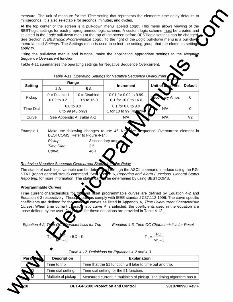
4-18 BE1-GPS100 Protection and Control 9318700990 Rev F
measure. The unit of measure for the Time setting that represents the element's time delay defaults to milliseconds. It is also selectable for seconds, minutes, and cycles. At the top center of the screen is a pull-down menu labeled Logic. This menu allows viewing of the BESTlogic settings for each preprogrammed logic scheme. A custom logic scheme must be created and selected in the Logic pull-down menu at the top of the screen before BESTlogic settings can be changed. See Section 7, BESTlogic Programmable Logic. To the right of the Logic pull-down menu is a pull-down menu labeled Settings. The Settings menu is used to select the setting group that the elements settings apply to. Using the pull-down menus and buttons, make the application appropriate settings to the Negative Sequence Overcurrent function. Table 4-11 summarizes the operating settings for Negative Sequence Overcurrent.
Table 4-11. Operating Settings for Negative Sequence Overcurrent
Range Setting
1 A 5 A Increment Unit of Measure Default
Pickup 0 = Disabled 0.02 to 3.2
0 = Disabled 0.5 to 16.0
0.01 for 0.02 to 9.99 0.1 for 10.0 to 16.0 Secondary Amps 0
Time Dial 0.0 to 9.9
0 to 99 (46 only) 0.1 for 0.0 to 9.9
1 for 10 to 99 (46 only) N/A 0
Curve See Appendix A, Table A-1 N/A N/A V2
Example 1. Make the following changes to the 46 Negative Sequence Overcurrent element in BESTCOMS. Refer to Figure 4-14.
Pickup: 3 secondary amps Time Dial: 2.5 Curve: 46R
Retrieving Negative Sequence Overcurrent Status from the Relay The status of each logic variable can be determined through the ASCII command interface using the RG-STAT (report general-status) command. See Section 6, Reporting and Alarm Functions, General Status Reporting, for more information. The status cannot be determined by using BESTCOMS.
Programmable Curves Time current characteristics for trip and reset programmable curves are defined by Equation 4-2 and Equation 4-3 respectively. These equations comply with IEEE standard C37.112-1996. The curve specific coefficients are defined for the standard curves as listed in Appendix A, Time Overcurrent Characteristic Curves. When time current characteristic curve P is selected, the coefficients used in the equation are those defined by the user. Definitions for these equations are provided in Table 4-12.
Equation 4-2. Time OC Characteristics for Trip
KBDCM
ADT NT ++−
=
Equation 4-3. Time OC Characteristics for Reset
12 −=
MRDTR
Table 4-12. Definitions for Equations 4-2 and 4-3
Parameter Description Explanation TT Time to trip Time that the 51 function will take to time out and trip. D Time dial setting Time dial setting for the 51 function. M Multiple of pickup Measured current in multiples of pickup. The timing algorithm has a
www . El
ectric
alPar
tMan
uals
. com

9318700990 Rev F BE1-GPS100 Protection and Control 4-19
Parameter Description Explanation dynamic range of 0 to 40 times pickup.
A Coefficient specific to selected curve Affects the effective range of the time dial.
B Coefficient specific to selected curve
Affects a constant term in the timing equation. Has greatest effect on curve shape at high multiples of tap.
C Coefficient specific to selected curve
Affects the multiple of PU where the curve would approach infinity if allowed to continue below pickup. Has greatest effect on curve shape near pickup.
N Exponent specific to selected curve
Affects how inverse the characteristics are. Has greatest effect on curve shape at low to medium multiples of tap.
K Constant Characteristic minimum delay term.
TR Time to reset Relevant if 51 function is set for integrating reset.
R Coefficient specific to selected curve Affects the speed of reset when integrating reset is selected.
Setting Programmable Curves Curve coefficients are entered using the SP-CURVE (Settings Protection-programmable curve) command. Table 4-13 lists the programmable curve settings.
Table 4-13. Programmable Time Current Characteristic Curve Coefficients
Setting Range Increment Default A Coefficient 0 to 600 0.0001 0.2663 B Coefficient 0 to 25 0.0001 0.0339 C Coefficient 0.0 to 1.0 0.0001 1.0000 N Coefficient 0.5 to 2.5 0.0001 1.2969 R Coefficient 0 to 30 0.0001 0.5000
Curve coefficients can also be entered using BESTCOMS. Select the Curve Coefficients button on the 51 tab in the Overcurrent Protection screen (refer to Figure 4-10). The Curve Coefficients screen will appear. See Figure 4-15. Enter the calculated values for each constant and select Done. Programmable curve coefficients can be entered regardless of the curve chosen for the protection element. However, the programmable curve will not be enabled until P is selected as the curve for the protective element.
Figure 4-15. Curve Coefficients Screen
46 Curve The 46 curve is a special curve designed to emulate the I2t withstand ratings of generators using what is frequently referred to as the generator’s K factor. Do not confuse the 46 curve with the 46 element. The 46 curve was designed for use with the 46 function. However, in actuality, the 46 curve may be selected
www . El
ectric
alPar
tMan
uals
. com
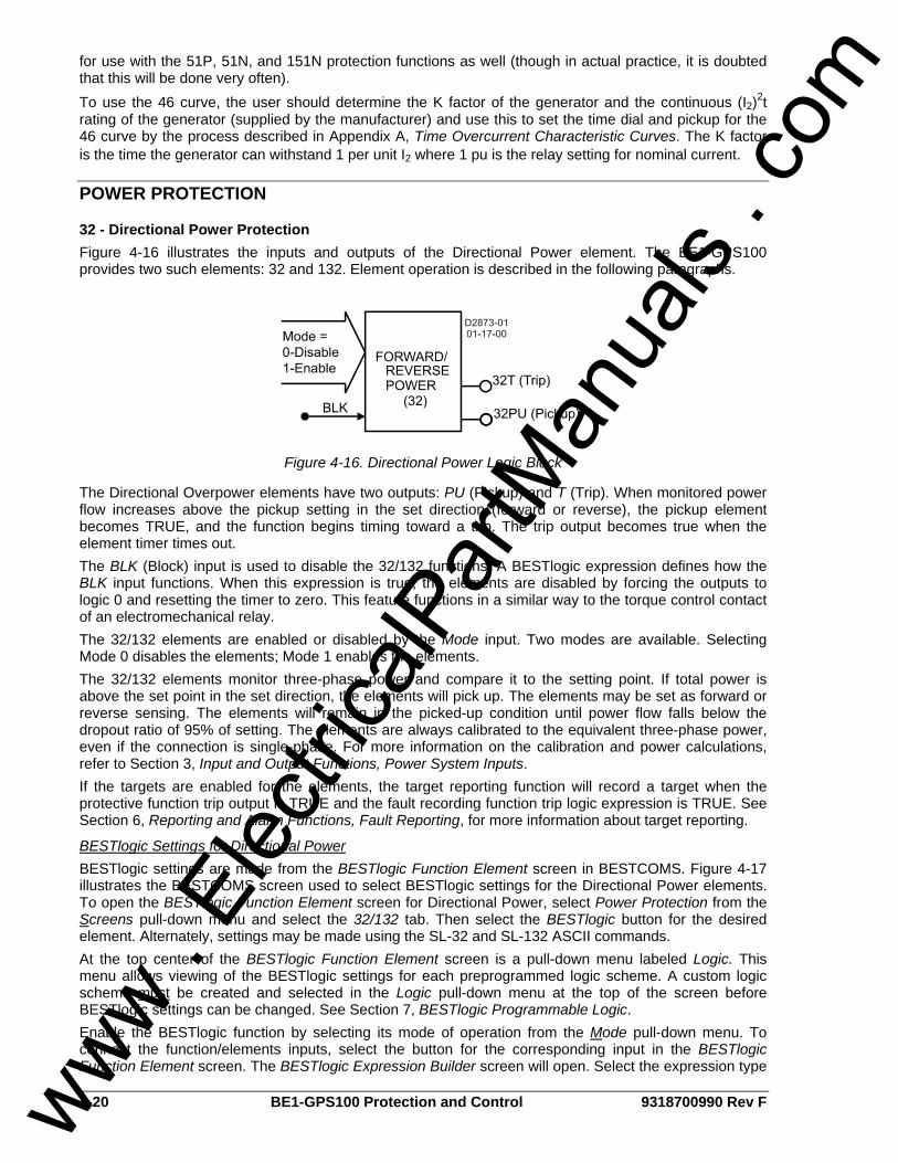
4-20 BE1-GPS100 Protection and Control 9318700990 Rev F
for use with the 51P, 51N, and 151N protection functions as well (though in actual practice, it is doubted that this will be done very often). To use the 46 curve, the user should determine the K factor of the generator and the continuous (I2)2t rating of the generator (supplied by the manufacturer) and use this to set the time dial and pickup for the 46 curve by the process described in Appendix A, Time Overcurrent Characteristic Curves. The K factor is the time the generator can withstand 1 per unit I2 where 1 pu is the relay setting for nominal current.
POWER PROTECTION
32 - Directional Power Protection Figure 4-16 illustrates the inputs and outputs of the Directional Power element. The BE1-GPS100 provides two such elements: 32 and 132. Element operation is described in the following paragraphs.
Figure 4-16. Directional Power Logic Block
The Directional Overpower elements have two outputs: PU (Pickup) and T (Trip). When monitored power flow increases above the pickup setting in the set direction (forward or reverse), the pickup element becomes TRUE, and the function begins timing toward a trip. The trip output becomes true when the element timer times out. The BLK (Block) input is used to disable the 32/132 functions. A BESTlogic expression defines how the BLK input functions. When this expression is true, the elements are disabled by forcing the outputs to logic 0 and resetting the timer to zero. This feature functions in a similar way to the torque control contact of an electromechanical relay. The 32/132 elements are enabled or disabled by the Mode input. Two modes are available. Selecting Mode 0 disables the elements; Mode 1 enables the elements. The 32/132 elements monitor three-phase power and compare it to the setting point. If total power is above the set point in the set direction, the elements will pick up. The elements may be set as forward or reverse sensing. The elements will remain in the picked-up condition until power flow falls below the dropout ratio of 95% of setting. The elements are always calibrated to the equivalent three-phase power, even if the connection is single-phase. For more information on the calibration and power calculations, refer to Section 3, Input and Output Functions, Power System Inputs. If the targets are enabled for the elements, the target reporting function will record a target when the protective function trip output is TRUE and the fault recording function trip logic expression is TRUE. See Section 6, Reporting and Alarm Functions, Fault Reporting, for more information about target reporting.
BESTlogic Settings for Directional Power BESTlogic settings are made from the BESTlogic Function Element screen in BESTCOMS. Figure 4-17 illustrates the BESTCOMS screen used to select BESTlogic settings for the Directional Power elements. To open the BESTlogic Function Element screen for Directional Power, select Power Protection from the Screens pull-down menu and select the 32/132 tab. Then select the BESTlogic button for the desired element. Alternately, settings may be made using the SL-32 and SL-132 ASCII commands. At the top center of the BESTlogic Function Element screen is a pull-down menu labeled Logic. This menu allows viewing of the BESTlogic settings for each preprogrammed logic scheme. A custom logic scheme must be created and selected in the Logic pull-down menu at the top of the screen before BESTlogic settings can be changed. See Section 7, BESTlogic Programmable Logic. Enable the BESTlogic function by selecting its mode of operation from the Mode pull-down menu. To connect the function/elements inputs, select the button for the corresponding input in the BESTlogic Function Element screen. The BESTlogic Expression Builder screen will open. Select the expression type
www . El
ectric
alPar
tMan
uals
. com
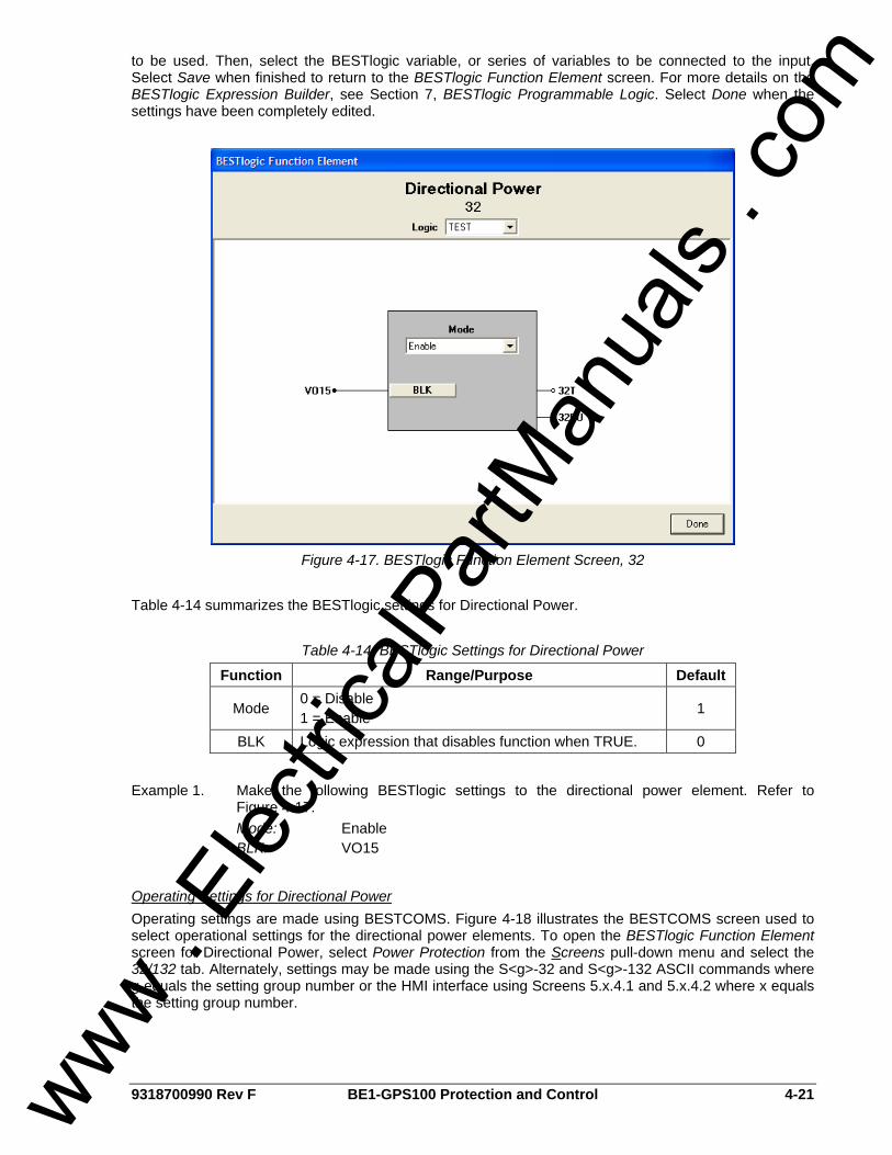
9318700990 Rev F BE1-GPS100 Protection and Control 4-21
to be used. Then, select the BESTlogic variable, or series of variables to be connected to the input. Select Save when finished to return to the BESTlogic Function Element screen. For more details on the BESTlogic Expression Builder, see Section 7, BESTlogic Programmable Logic. Select Done when the settings have been completely edited.
Figure 4-17. BESTlogic Function Element Screen, 32
Table 4-14 summarizes the BESTlogic settings for Directional Power.
Table 4-14. BESTlogic Settings for Directional Power
Function Range/Purpose Default
Mode 0 = Disable 1 = Enable
1
BLK Logic expression that disables function when TRUE. 0
Example 1. Make the following BESTlogic settings to the directional power element. Refer to
Figure 4-17. Mode: Enable BLK: VO15
Operating Settings for Directional Power Operating settings are made using BESTCOMS. Figure 4-18 illustrates the BESTCOMS screen used to select operational settings for the directional power elements. To open the BESTlogic Function Element screen for Directional Power, select Power Protection from the Screens pull-down menu and select the 32/132 tab. Alternately, settings may be made using the S<g>-32 and S<g>-132 ASCII commands where g equals the setting group number or the HMI interface using Screens 5.x.4.1 and 5.x.4.2 where x equals the setting group number.
www . El
ectric
alPar
tMan
uals
. com
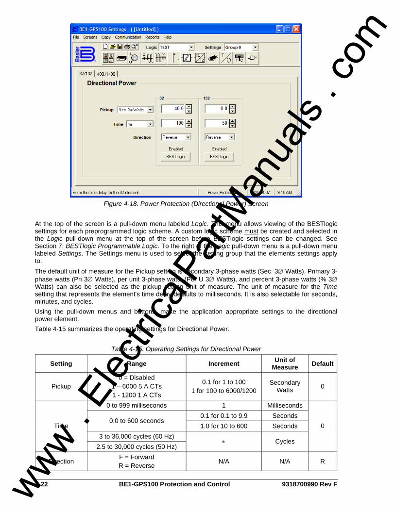
4-22 BE1-GPS100 Protection and Control 9318700990 Rev F
Figure 4-18. Power Protection (Directional Power) Screen
At the top of the screen is a pull-down menu labeled Logic. This menu allows viewing of the BESTlogic settings for each preprogrammed logic scheme. A custom logic scheme must be created and selected in the Logic pull-down menu at the top of the screen before BESTlogic settings can be changed. See Section 7, BESTlogic Programmable Logic. To the right of the Logic pull-down menu is a pull-down menu labeled Settings. The Settings menu is used to select the setting group that the elements settings apply to. The default unit of measure for the Pickup setting is secondary 3-phase watts (Sec. 3∅ Watts). Primary 3-phase watts (Pri 3∅ Watts), per unit 3-phase watts (Per U 3∅ Watts), and percent 3-phase watts (% 3∅ Watts) can also be selected as the pickup setting unit of measure. The unit of measure for the Time setting that represents the element's time delay defaults to milliseconds. It is also selectable for seconds, minutes, and cycles. Using the pull-down menus and buttons, make the application appropriate settings to the directional power element. Table 4-15 summarizes the operating settings for Directional Power.
Table 4-15. Operating Settings for Directional Power
Setting Range Increment Unit of Measure Default
Pickup 0 = Disabled
1 – 6000 5 A CTs 1 - 1200 1 A CTs
0.1 for 1 to 100 1 for 100 to 6000/1200
Secondary Watts 0
0 to 999 milliseconds 1 Milliseconds 0.1 for 0.1 to 9.9 Seconds
0.0 to 600 seconds 1.0 for 10 to 600 Seconds
3 to 36,000 cycles (60 Hz) Time
2.5 to 30,000 cycles (50 Hz) ∗ Cycles
0
Direction F = Forward R = Reverse
N/A N/A R
www . El
ectric
alPar
tMan
uals
. com
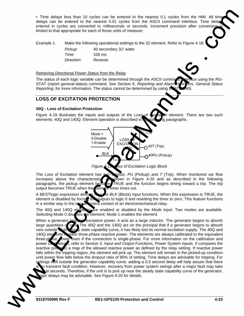
9318700990 Rev F BE1-GPS100 Protection and Control 4-23
∗ Time delays less than 10 cycles can be entered to the nearest 0.1 cycles from the HMI. All time delays can be entered to the nearest 0.01 cycles from the ASCII command interface. Time delays entered in cycles are converted to milliseconds or seconds. Increment precision after conversion is limited to that appropriate for each of those units of measure. Example 1. Make the following operational settings to the 32 element. Refer to Figure 4-18. Pickup: 40 secondary 3∅ watts Time: 100 ms Direction: Reverse
Retrieving Directional Power Status from the Relay The status of each logic variable can be determined through the ASCII command interface using the RG-STAT (report general-status) command. See Section 6, Reporting and Alarm Functions, General Status Reporting, for more information. The status cannot be determined by using BESTCOMS.
LOSS OF EXCITATION PROTECTION
40Q - Loss of Excitation Protection Figure 4-19 illustrates the inputs and outputs of the Loss of Excitation element. There are two such elements: 40Q and 140Q. Element operation is described in the following paragraphs.
Figure 4-19. Loss of Excitation Logic Block
The Loss of Excitation element has two outputs: PU (Pickup) and T (Trip). When monitored var flow increases above the characteristics as shown in Figure 4-20 and as described in the following paragraphs, the pickup element becomes TRUE and the function begins timing toward a trip. The trip output becomes TRUE when the element timer times out. A BESTlogic expression defines how the BLK (Block) input functions. When this expression is TRUE, the element is disabled by forcing the outputs to logic 0 and resetting the timer to zero. This feature functions in a similar way to the torque control contact of an electromechanical relay. The 40Q and 140Q elements are enabled or disabled by the Mode input. Two modes are available. Selecting Mode 0 disables the element; Mode 1 enables the element. When a generator loses its excitation power, it acts as a large inductor. The generator begins to absorb large quantities of vars. The 40Q and the 140Q act on the principal that if a generator begins to absorb vars outside of its steady state capability curve, it has likely lost its normal excitation supply. The 40Q and 140Q elements monitor three-phase reactive power. The elements are always calibrated to the equivalent three-phase power even if the connection is single-phase. For more information on the calibration and power calculations, refer to Section 3, Input and Output Functions, Power System Inputs. It compares the reactive power to a map of the allowed reactive power as defined by the relay setting. If reactive power falls within the tripping region, the element will pick up. The element will remain in the picked-up condition until power flow falls below the dropout ratio of 95% of setting. Time delays are advisable for tripping. For settings well outside the generator capability curve, adding a 0.5 second delay will help assure that there is no transient fault condition. However, recovery from power system swings after a major fault may take several seconds. Therefore, if the unit is to pick up near the steady state capability curve of the generator, longer delays may be advisable. See Figure 4-20 for details.
www . El
ectric
alPar
tMan
uals
. com
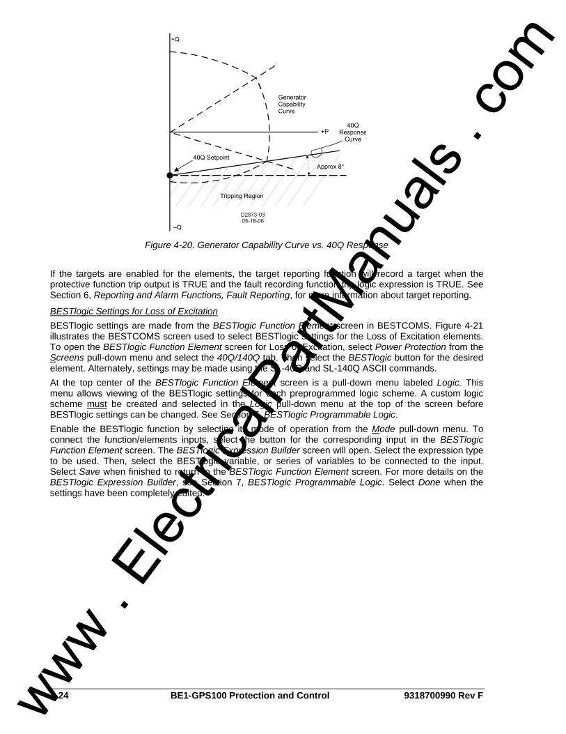
4-24 BE1-GPS100 Protection and Control 9318700990 Rev F
Figure 4-20. Generator Capability Curve vs. 40Q Response If the targets are enabled for the elements, the target reporting function will record a target when the protective function trip output is TRUE and the fault recording function trip logic expression is TRUE. See Section 6, Reporting and Alarm Functions, Fault Reporting, for more information about target reporting.
BESTlogic Settings for Loss of Excitation BESTlogic settings are made from the BESTlogic Function Element screen in BESTCOMS. Figure 4-21 illustrates the BESTCOMS screen used to select BESTlogic settings for the Loss of Excitation elements. To open the BESTlogic Function Element screen for Loss of Excitation, select Power Protection from the Screens pull-down menu and select the 40Q/140Q tab. Then select the BESTlogic button for the desired element. Alternately, settings may be made using the SL-40Q and SL-140Q ASCII commands. At the top center of the BESTlogic Function Element screen is a pull-down menu labeled Logic. This menu allows viewing of the BESTlogic settings for each preprogrammed logic scheme. A custom logic scheme must be created and selected in the Logic pull-down menu at the top of the screen before BESTlogic settings can be changed. See Section 7, BESTlogic Programmable Logic. Enable the BESTlogic function by selecting its mode of operation from the Mode pull-down menu. To connect the function/elements inputs, select the button for the corresponding input in the BESTlogic Function Element screen. The BESTlogic Expression Builder screen will open. Select the expression type to be used. Then, select the BESTlogic variable, or series of variables to be connected to the input. Select Save when finished to return to the BESTlogic Function Element screen. For more details on the BESTlogic Expression Builder, see Section 7, BESTlogic Programmable Logic. Select Done when the settings have been completely edited.
www . El
ectric
alPar
tMan
uals
. com
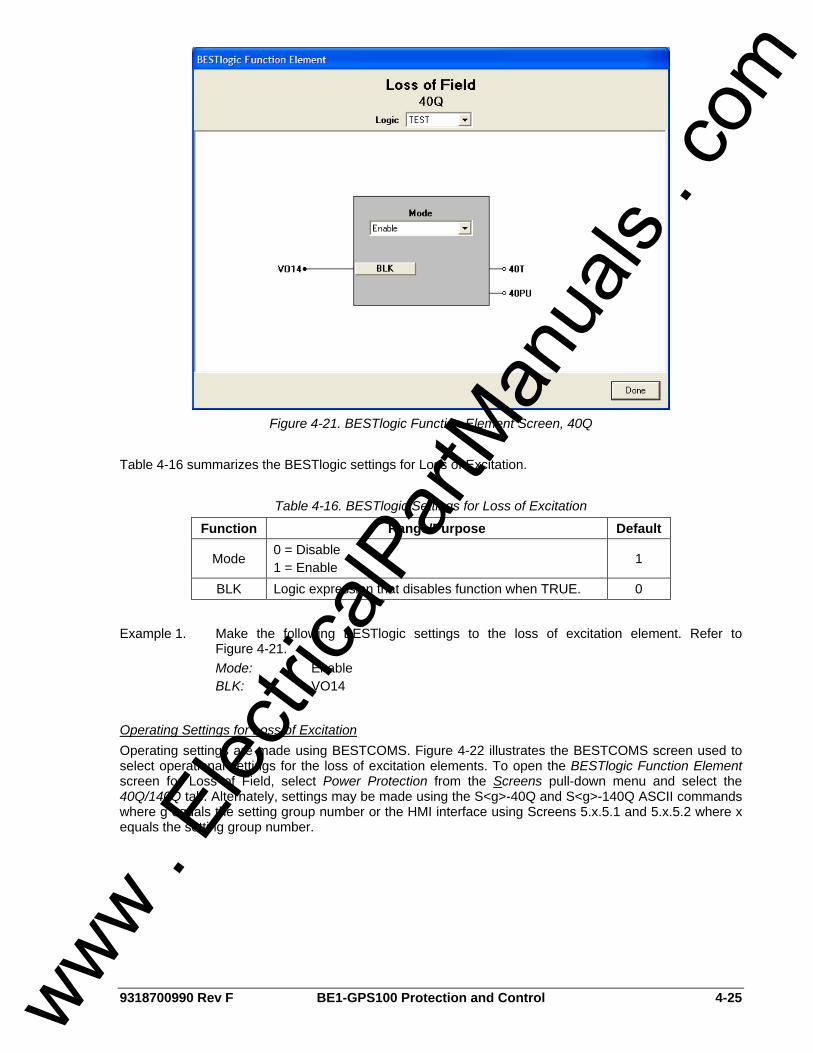
9318700990 Rev F BE1-GPS100 Protection and Control 4-25
Figure 4-21. BESTlogic Function Element Screen, 40Q
Table 4-16 summarizes the BESTlogic settings for Loss of Excitation.
Table 4-16. BESTlogic Settings for Loss of Excitation
Function Range/Purpose Default
Mode 0 = Disable 1 = Enable 1
BLK Logic expression that disables function when TRUE. 0
Example 1. Make the following BESTlogic settings to the loss of excitation element. Refer to
Figure 4-21. Mode: Enable BLK: VO14
Operating Settings for Loss of Excitation Operating settings are made using BESTCOMS. Figure 4-22 illustrates the BESTCOMS screen used to select operational settings for the loss of excitation elements. To open the BESTlogic Function Element screen for Loss of Field, select Power Protection from the Screens pull-down menu and select the 40Q/140Q tab. Alternately, settings may be made using the S<g>-40Q and S<g>-140Q ASCII commands where g equals the setting group number or the HMI interface using Screens 5.x.5.1 and 5.x.5.2 where x equals the setting group number.
www . El
ectric
alPar
tMan
uals
. com
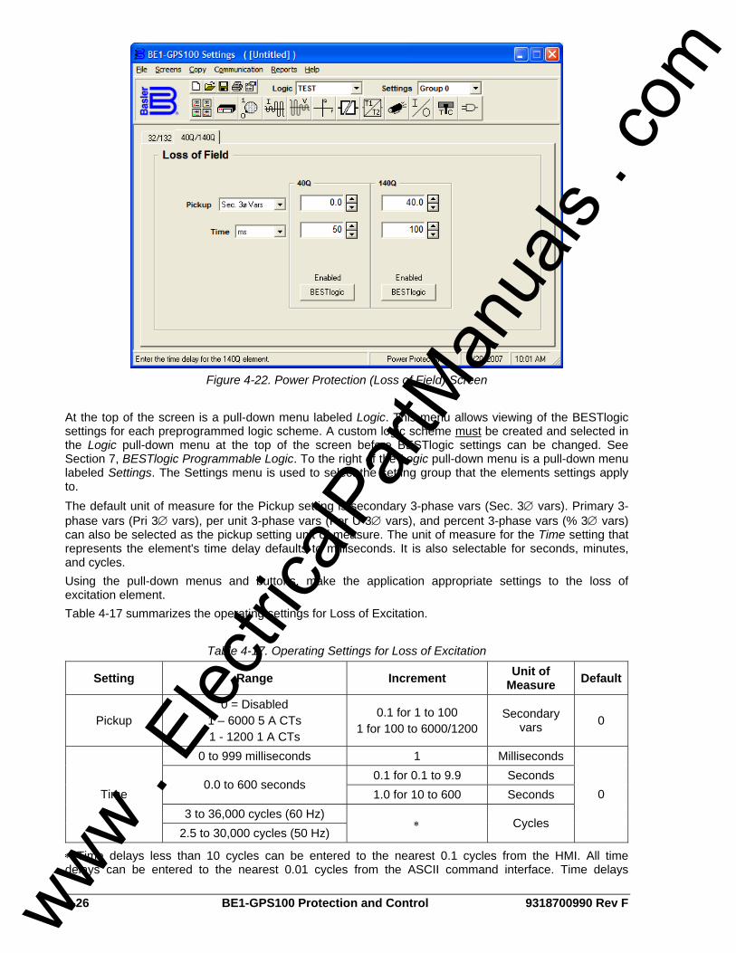
4-26 BE1-GPS100 Protection and Control 9318700990 Rev F
Figure 4-22. Power Protection (Loss of Field) Screen
At the top of the screen is a pull-down menu labeled Logic. This menu allows viewing of the BESTlogic settings for each preprogrammed logic scheme. A custom logic scheme must be created and selected in the Logic pull-down menu at the top of the screen before BESTlogic settings can be changed. See Section 7, BESTlogic Programmable Logic. To the right of the Logic pull-down menu is a pull-down menu labeled Settings. The Settings menu is used to select the setting group that the elements settings apply to. The default unit of measure for the Pickup setting is secondary 3-phase vars (Sec. 3∅ vars). Primary 3-phase vars (Pri 3∅ vars), per unit 3-phase vars (Per U 3∅ vars), and percent 3-phase vars (% 3∅ vars) can also be selected as the pickup setting unit of measure. The unit of measure for the Time setting that represents the element's time delay defaults to milliseconds. It is also selectable for seconds, minutes, and cycles. Using the pull-down menus and buttons, make the application appropriate settings to the loss of excitation element. Table 4-17 summarizes the operating settings for Loss of Excitation.
Table 4-17. Operating Settings for Loss of Excitation
Setting Range Increment Unit of Measure Default
Pickup 0 = Disabled
1 – 6000 5 A CTs 1 - 1200 1 A CTs
0.1 for 1 to 100 1 for 100 to 6000/1200
Secondary vars 0
0 to 999 milliseconds 1 Milliseconds 0.1 for 0.1 to 9.9 Seconds
0.0 to 600 seconds 1.0 for 10 to 600 Seconds
3 to 36,000 cycles (60 Hz) Time
2.5 to 30,000 cycles (50 Hz) ∗ Cycles
0
∗ Time delays less than 10 cycles can be entered to the nearest 0.1 cycles from the HMI. All time delays can be entered to the nearest 0.01 cycles from the ASCII command interface. Time delays
www . El
ectric
alPar
tMan
uals
. com
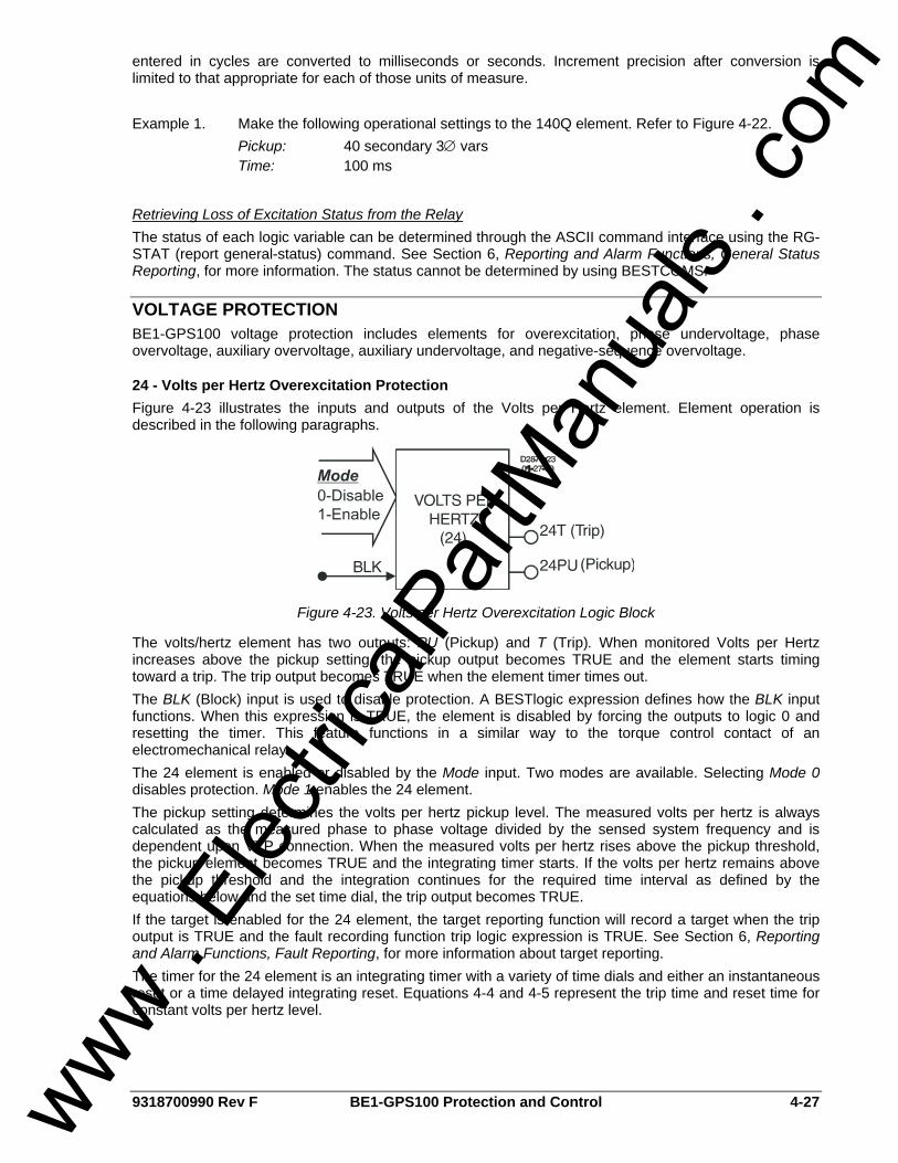
9318700990 Rev F BE1-GPS100 Protection and Control 4-27
entered in cycles are converted to milliseconds or seconds. Increment precision after conversion is limited to that appropriate for each of those units of measure. Example 1. Make the following operational settings to the 140Q element. Refer to Figure 4-22. Pickup: 40 secondary 3∅ vars Time: 100 ms
Retrieving Loss of Excitation Status from the Relay The status of each logic variable can be determined through the ASCII command interface using the RG-STAT (report general-status) command. See Section 6, Reporting and Alarm Functions, General Status Reporting, for more information. The status cannot be determined by using BESTCOMS.
VOLTAGE PROTECTION BE1-GPS100 voltage protection includes elements for overexcitation, phase undervoltage, phase overvoltage, auxiliary overvoltage, auxiliary undervoltage, and negative-sequence overvoltage.
24 - Volts per Hertz Overexcitation Protection Figure 4-23 illustrates the inputs and outputs of the Volts per Hertz element. Element operation is described in the following paragraphs.
Figure 4-23. Volts per Hertz Overexcitation Logic Block
The volts/hertz element has two outputs: PU (Pickup) and T (Trip). When monitored Volts per Hertz increases above the pickup setting, the pickup output becomes TRUE and the element starts timing toward a trip. The trip output becomes TRUE when the element timer times out. The BLK (Block) input is used to disable protection. A BESTlogic expression defines how the BLK input functions. When this expression is TRUE, the element is disabled by forcing the outputs to logic 0 and resetting the timer. This feature functions in a similar way to the torque control contact of an electromechanical relay. The 24 element is enabled or disabled by the Mode input. Two modes are available. Selecting Mode 0 disables protection. Mode 1 enables the 24 element. The pickup setting determines the volts per hertz pickup level. The measured volts per hertz is always calculated as the measured phase to phase voltage divided by the sensed system frequency and is dependent upon VTP connection. When the measured volts per hertz rises above the pickup threshold, the pickup element becomes TRUE and the integrating timer starts. If the volts per hertz remains above the pickup threshold and the integration continues for the required time interval as defined by the equations below and the set time dial, the trip output becomes TRUE. If the target is enabled for the 24 element, the target reporting function will record a target when the trip output is TRUE and the fault recording function trip logic expression is TRUE. See Section 6, Reporting and Alarm Functions, Fault Reporting, for more information about target reporting. The timer for the 24 element is an integrating timer with a variety of time dials and either an instantaneous reset or a time delayed integrating reset. Equations 4-4 and 4-5 represent the trip time and reset time for constant volts per hertz level.
www . El
ectric
alPar
tMan
uals
. com

4-28 BE1-GPS100 Protection and Control 9318700990 Rev F
( )2T1
D−
=M
TT 100**FSTE
DT TRR =
Equation 4-4. Time to Trip Equation 4-5. Time to Reset
where: TT = Time to trip TR = Time to reset DT = Time dial trip DR = Time dial, reset ET = Elapsed time M = Multiples of pickup = (measured V/Hz) divided by (V/Hz PU setting) FST = Full scale trip time (TT) ET/FST = Fraction of total travel toward trip that integration had progressed to. (After a trip,
this value will be equal to one.) Figure 4-24 shows trip time for various time dials and multiples of pickup.
0.0
0.1
1.0
10.0
100.0
1000.0
10000.0
1 1.2 1.4 1.6 1.8 2 2.2 2.4
Multiples of Pickup
Trip
Tim
ein
Seco
nds
9.95.02.01.00.50.20.1
D2871-4008-14-03
Figure 4-24. Trip Time for Various Time Dials and Multiples of Pickup
BESTlogic Settings for Volts per Hertz Overexcitation BESTlogic settings are made from the BESTlogic Function Element screen in BESTCOMS. Figure 4-25 illustrates the BESTCOMS screen used to select BESTlogic settings for the overexcitation element. To open the screen, select Voltage Protection from the Screens pull-down menu and select the 24 tab. Then select The BESTlogic button. Alternately, settings may be made using the SL-24 ASCII command.
www . El
ectric
alPar
tMan
uals
. com
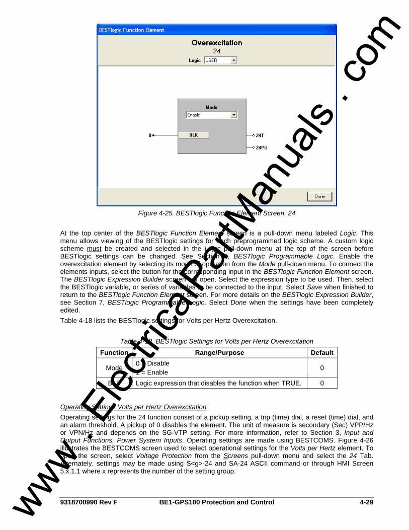
9318700990 Rev F BE1-GPS100 Protection and Control 4-29
Figure 4-25. BESTlogic Function Element Screen, 24
At the top center of the BESTlogic Function Element screen is a pull-down menu labeled Logic. This menu allows viewing of the BESTlogic settings for each preprogrammed logic scheme. A custom logic scheme must be created and selected in the Logic pull-down menu at the top of the screen before BESTlogic settings can be changed. See Section 7, BESTlogic Programmable Logic. Enable the overexcitation element by selecting its mode of operation from the Mode pull-down menu. To connect the elements inputs, select the button for the corresponding input in the BESTlogic Function Element screen. The BESTlogic Expression Builder screen will open. Select the expression type to be used. Then, select the BESTlogic variable, or series of variables to be connected to the input. Select Save when finished to return to the BESTlogic Function Element screen. For more details on the BESTlogic Expression Builder, see Section 7, BESTlogic Programmable Logic. Select Done when the settings have been completely edited. Table 4-18 lists the BESTlogic settings for Volts per Hertz Overexcitation.
Table 4-18. BESTlogic Settings for Volts per Hertz Overexcitation
Function Range/Purpose Default
Mode 0 = Disable 1 = Enable 0
BLK Logic expression that disables the function when TRUE. 0
Operating Settings Volts per Hertz Overexcitation Operating settings for the 24 function consist of a pickup setting, a trip (time) dial, a reset (time) dial, and an alarm threshold. A pickup of 0 disables the element. The unit of measure is secondary (Sec) VPP/Hz or VPN/Hz and depends on the SG-VTP setting. For more information, refer to Section 3, Input and Output Functions, Power System Inputs. Operating settings are made using BESTCOMS. Figure 4-26 illustrates the BESTCOMS screen used to select operational settings for the Volts per Hertz element. To open the screen, select Voltage Protection from the Screens pull-down menu and select the 24 Tab. Alternately, settings may be made using S<g>-24 and SA-24 ASCII command or through HMI Screen 5.x.1.1 where x represents the number of the setting group.
www . El
ectric
alPar
tMan
uals
. com

4-30 BE1-GPS100 Protection and Control 9318700990 Rev F
Figure 4-26. Voltage Protection Screen, 24 Tab
The default unit of measure for the Pickup setting is secondary V/Hz. Primary V/Hz (Pri V/Hz), per unit V/Hz (Per U V/Hz), and percent V/Hz (% V/Hz) can also be selected as the pickup setting unit of measure. The unit of measure for the Time setting that represents the element's time delay defaults to milliseconds. It is also selectable for seconds, minutes, and cycles. At the top of the screen is a pull-down menu labeled Logic. This menu allows viewing of the BESTlogic settings for each preprogrammed logic scheme. A custom logic scheme must be created and selected in the Logic pull-down menu at the top of the screen before BESTlogic settings can be changed. See Section 7, BESTlogic Programmable Logic. To the right of the Logic pull-down menu is a pull-down menu labeled Settings. The Settings menu is used to select the setting group that the element's settings apply to. Using the pull-down menus and buttons, make the application appropriate settings to the Volts per Hertz element. Table 4-19 lists the operating settings for Volts per Hertz Overexcitation.
Table 4-19. Operating Settings for Volts per Hertz Overexcitation
Setting Range Increment Unit of Measure Default Pickup 0.5 to 6 0.1 Sec. V/Hz 0
Trip Time Dial 0 to 9.9 0.1 N/A 0 Reset Time Dial 0 to 9.9 0.1 N/A 0
Programmable Alarm for Volts per Hertz Overexcitation The Volts per Hertz function also has a settable alarm feature. If the Volts per Hertz level reaches a settable percentage of the pickup level (0 to 120%), a programmable alarm bit is set. See Section 6, Reporting and Alarm Functions, for more information. The setting for the alarm is via the SA-24 command. Table 4-20 lists the programmable alarm settings for Volts per Hertz Overexcitation.
Table 4-20. Programmable Alarm Settings for Volts per Hertz Overexcitation
Setting Range Increment Unit of Measure Default Alarm Level 0 to 120 1 % of pickup level 0
www . El
ectric
alPar
tMan
uals
. com
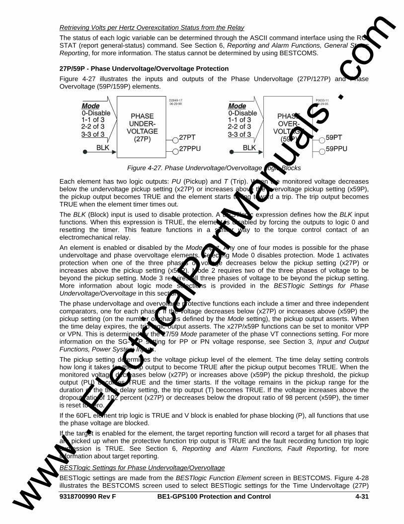
9318700990 Rev F BE1-GPS100 Protection and Control 4-31
Retrieving Volts per Hertz Overexcitation Status from the Relay The status of each logic variable can be determined through the ASCII command interface using the RG-STAT (report general-status) command. See Section 6, Reporting and Alarm Functions, General Status Reporting, for more information. The status cannot be determined by using BESTCOMS.
27P/59P - Phase Undervoltage/Overvoltage Protection Figure 4-27 illustrates the inputs and outputs of the Phase Undervoltage (27P/127P) and Phase Overvoltage (59P/159P) elements.
Figure 4-27. Phase Undervoltage/Overvoltage Logic Blocks
Each element has two logic outputs: PU (Pickup) and T (Trip). When the monitored voltage decreases below the undervoltage pickup setting (x27P) or increases above the overvoltage pickup setting (x59P), the pickup output becomes TRUE and the element starts timing toward a trip. The trip output becomes TRUE when the element timer times out. The BLK (Block) input is used to disable protection. A BESTlogic expression defines how the BLK input functions. When this expression is TRUE, the element is disabled by forcing the outputs to logic 0 and resetting the timer. This feature functions in a similar way to the torque control contact of an electromechanical relay. An element is enabled or disabled by the Mode input. Any one of four modes is possible for the phase undervoltage and phase overvoltage elements. Selecting Mode 0 disables protection. Mode 1 activates protection when one of the three phases of voltage decreases below the pickup setting (x27P) or increases above the pickup setting (x59P). Mode 2 requires two of the three phases of voltage to be beyond the pickup setting. Mode 3 requires all three phases of voltage to be beyond the pickup setting. More information about logic mode selections is provided in the BESTlogic Settings for Phase Undervoltage/Overvoltage in this section. The phase undervoltage and overvoltage protective functions each include a timer and three independent comparators, one for each phase. If the voltage decreases below (x27P) or increases above (x59P) the pickup setting (on the number of phases defined by the Mode setting), the pickup output asserts. When the time delay expires, the trip logic output asserts. The x27P/x59P functions can be set to monitor VPP or VPN. This is determined by the 27/59 Mode parameter of the phase VT connections setting. For more information on the SG-VTP setting for PP or PN voltage response, see Section 3, Input and Output Functions, Power System Inputs. The pickup setting determines the voltage pickup level of the element. The time delay setting controls how long it takes for the trip output to become TRUE after the pickup output becomes TRUE. When the monitored voltage decreases below (x27P) or increases above (x59P) the pickup threshold, the pickup output (PU) becomes TRUE and the timer starts. If the voltage remains in the pickup range for the duration of the time delay setting, the trip output (T) becomes TRUE. If the voltage increases above the dropout ratio of 102 percent (x27P) or decreases below the dropout ratio of 98 percent (x59P), the timer is reset to zero. If the 60FL element trip logic is TRUE and V block is enabled for phase blocking (P), all functions that use the phase voltage are blocked. If the target is enabled for the element, the target reporting function will record a target for all phases that are picked up when the protective function trip output is TRUE and the fault recording function trip logic expression is TRUE. See Section 6, Reporting and Alarm Functions, Fault Reporting, for more information about target reporting.
BESTlogic Settings for Phase Undervoltage/Overvoltage BESTlogic settings are made from the BESTlogic Function Element screen in BESTCOMS. Figure 4-28 illustrates the BESTCOMS screen used to select BESTlogic settings for the Time Undervoltage (27P)
www . El
ectric
alPar
tMan
uals
. com
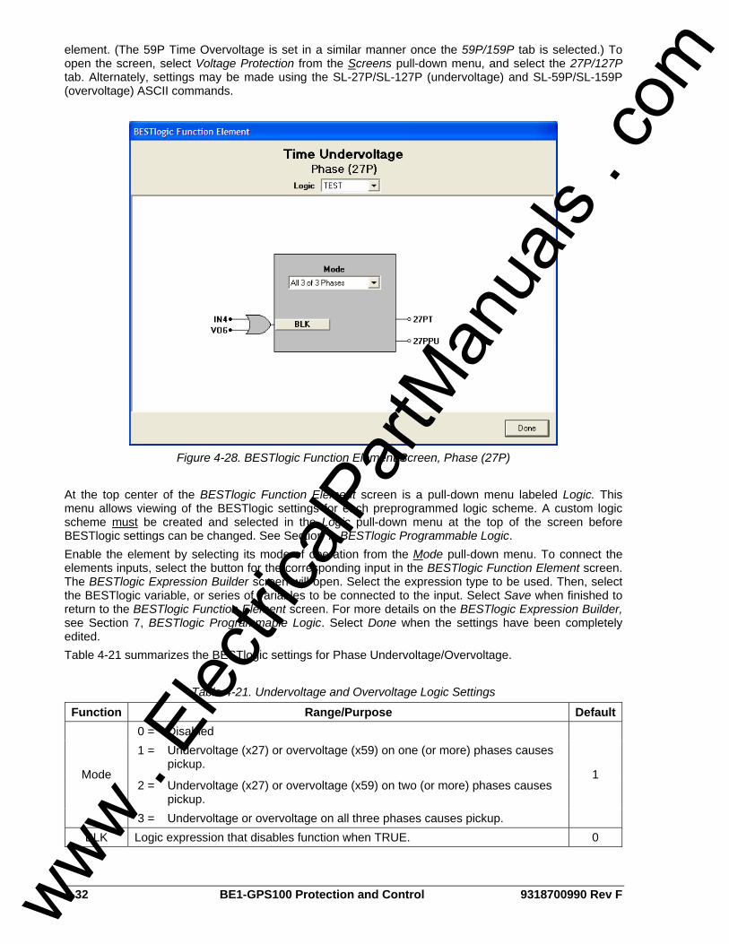
4-32 BE1-GPS100 Protection and Control 9318700990 Rev F
element. (The 59P Time Overvoltage is set in a similar manner once the 59P/159P tab is selected.) To open the screen, select Voltage Protection from the Screens pull-down menu, and select the 27P/127P tab. Alternately, settings may be made using the SL-27P/SL-127P (undervoltage) and SL-59P/SL-159P (overvoltage) ASCII commands.
Figure 4-28. BESTlogic Function Element Screen, Phase (27P)
At the top center of the BESTlogic Function Element screen is a pull-down menu labeled Logic. This menu allows viewing of the BESTlogic settings for each preprogrammed logic scheme. A custom logic scheme must be created and selected in the Logic pull-down menu at the top of the screen before BESTlogic settings can be changed. See Section 7, BESTlogic Programmable Logic. Enable the element by selecting its mode of operation from the Mode pull-down menu. To connect the elements inputs, select the button for the corresponding input in the BESTlogic Function Element screen. The BESTlogic Expression Builder screen will open. Select the expression type to be used. Then, select the BESTlogic variable, or series of variables to be connected to the input. Select Save when finished to return to the BESTlogic Function Element screen. For more details on the BESTlogic Expression Builder, see Section 7, BESTlogic Programmable Logic. Select Done when the settings have been completely edited. Table 4-21 summarizes the BESTlogic settings for Phase Undervoltage/Overvoltage.
Table 4-21. Undervoltage and Overvoltage Logic Settings
Function Range/Purpose Default0 = Disabled 1 =
Undervoltage (x27) or overvoltage (x59) on one (or more) phases causes pickup.
2 =
Undervoltage (x27) or overvoltage (x59) on two (or more) phases causes pickup.
Mode
3 = Undervoltage or overvoltage on all three phases causes pickup.
1
BLK Logic expression that disables function when TRUE. 0
www .
Elec
tricalP
artM
anua
ls . c
om
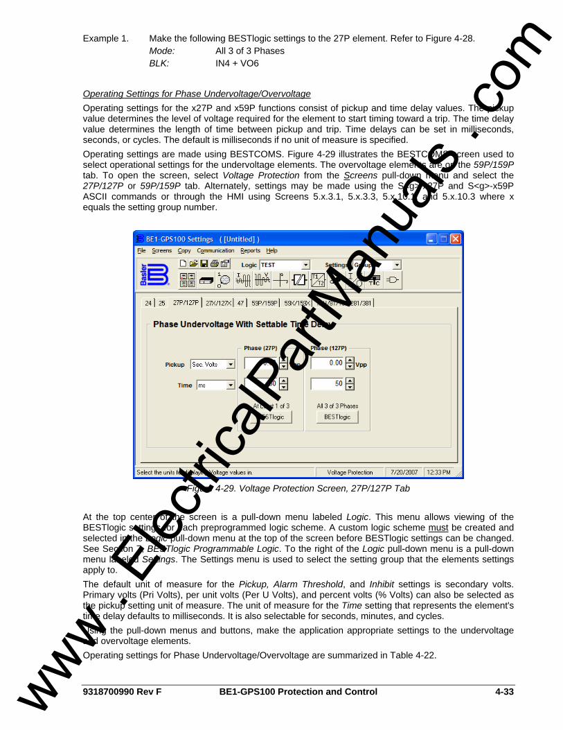
9318700990 Rev F BE1-GPS100 Protection and Control 4-33
Example 1. Make the following BESTlogic settings to the 27P element. Refer to Figure 4-28. Mode: All 3 of 3 Phases BLK: IN4 + VO6
Operating Settings for Phase Undervoltage/Overvoltage Operating settings for the x27P and x59P functions consist of pickup and time delay values. The pickup value determines the level of voltage required for the element to start timing toward a trip. The time delay value determines the length of time between pickup and trip. Time delays can be set in milliseconds, seconds, or cycles. The default is milliseconds if no unit of measure is specified. Operating settings are made using BESTCOMS. Figure 4-29 illustrates the BESTCOMS screen used to select operational settings for the undervoltage elements. The overvoltage elements are on the 59P/159P tab. To open the screen, select Voltage Protection from the Screens pull-down menu and select the 27P/127P or 59P/159P tab. Alternately, settings may be made using the S<g>-x27P and S<g>-x59P ASCII commands or through the HMI using Screens 5.x.3.1, 5.x.3.3, 5.x.10.1, and 5.x.10.3 where x equals the setting group number.
Figure 4-29. Voltage Protection Screen, 27P/127P Tab
At the top center of the screen is a pull-down menu labeled Logic. This menu allows viewing of the BESTlogic settings for each preprogrammed logic scheme. A custom logic scheme must be created and selected in the Logic pull-down menu at the top of the screen before BESTlogic settings can be changed. See Section 7, BESTlogic Programmable Logic. To the right of the Logic pull-down menu is a pull-down menu labeled Settings. The Settings menu is used to select the setting group that the elements settings apply to. The default unit of measure for the Pickup, Alarm Threshold, and Inhibit settings is secondary volts. Primary volts (Pri Volts), per unit volts (Per U Volts), and percent volts (% Volts) can also be selected as the pickup setting unit of measure. The unit of measure for the Time setting that represents the element's time delay defaults to milliseconds. It is also selectable for seconds, minutes, and cycles. Using the pull-down menus and buttons, make the application appropriate settings to the undervoltage and overvoltage elements. Operating settings for Phase Undervoltage/Overvoltage are summarized in Table 4-22.
www . El
ectric
alPar
tMan
uals
. com
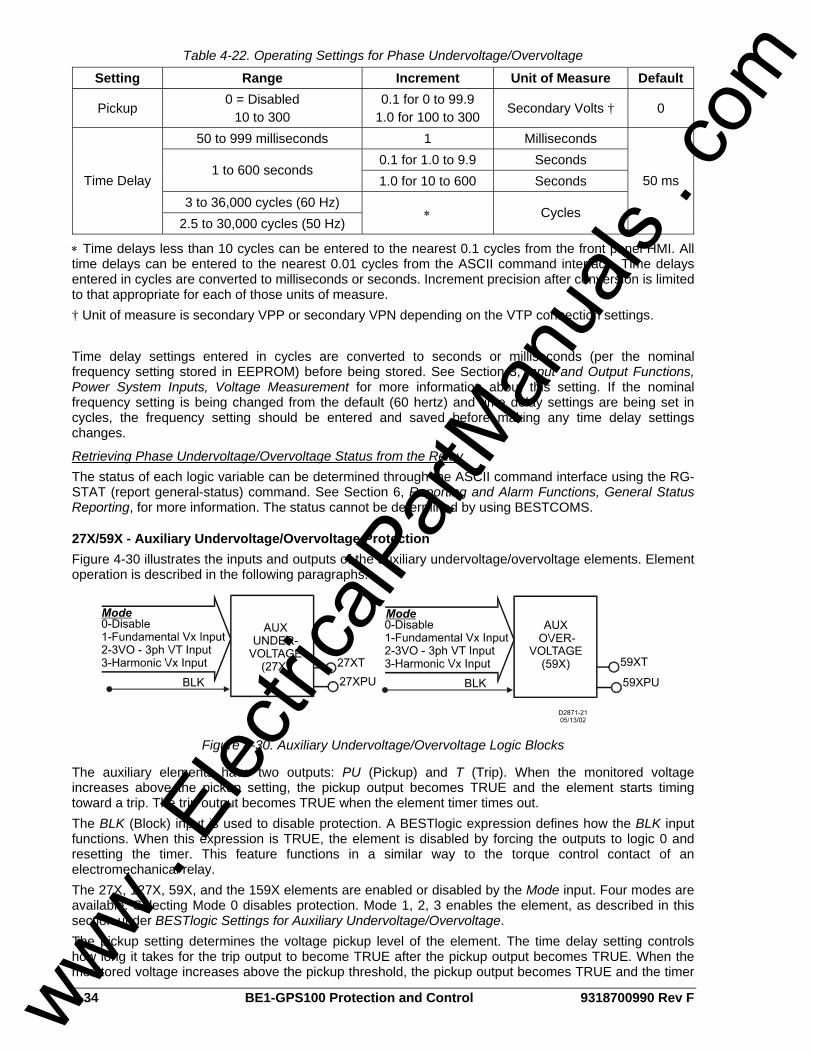
4-34 BE1-GPS100 Protection and Control 9318700990 Rev F
Table 4-22. Operating Settings for Phase Undervoltage/Overvoltage
Setting Range Increment Unit of Measure Default
Pickup 0 = Disabled
10 to 300 0.1 for 0 to 99.9
1.0 for 100 to 300 Secondary Volts † 0
50 to 999 milliseconds 1 Milliseconds 0.1 for 1.0 to 9.9 Seconds
1 to 600 seconds 1.0 for 10 to 600 Seconds
3 to 36,000 cycles (60 Hz) Time Delay
2.5 to 30,000 cycles (50 Hz) ∗ Cycles
50 ms
∗ Time delays less than 10 cycles can be entered to the nearest 0.1 cycles from the front panel HMI. All time delays can be entered to the nearest 0.01 cycles from the ASCII command interface. Time delays entered in cycles are converted to milliseconds or seconds. Increment precision after conversion is limited to that appropriate for each of those units of measure. † Unit of measure is secondary VPP or secondary VPN depending on the VTP connection settings. Time delay settings entered in cycles are converted to seconds or milliseconds (per the nominal frequency setting stored in EEPROM) before being stored. See Section 3, Input and Output Functions, Power System Inputs, Voltage Measurement for more information about this setting. If the nominal frequency setting is being changed from the default (60 hertz) and time delay settings are being set in cycles, the frequency setting should be entered and saved before making any time delay settings changes.
Retrieving Phase Undervoltage/Overvoltage Status from the Relay The status of each logic variable can be determined through the ASCII command interface using the RG-STAT (report general-status) command. See Section 6, Reporting and Alarm Functions, General Status Reporting, for more information. The status cannot be determined by using BESTCOMS.
27X/59X - Auxiliary Undervoltage/Overvoltage Protection Figure 4-30 illustrates the inputs and outputs of the auxiliary undervoltage/overvoltage elements. Element operation is described in the following paragraphs.
Figure 4-30. Auxiliary Undervoltage/Overvoltage Logic Blocks
The auxiliary elements have two outputs: PU (Pickup) and T (Trip). When the monitored voltage increases above the pickup setting, the pickup output becomes TRUE and the element starts timing toward a trip. The trip output becomes TRUE when the element timer times out. The BLK (Block) input is used to disable protection. A BESTlogic expression defines how the BLK input functions. When this expression is TRUE, the element is disabled by forcing the outputs to logic 0 and resetting the timer. This feature functions in a similar way to the torque control contact of an electromechanical relay. The 27X, 127X, 59X, and the 159X elements are enabled or disabled by the Mode input. Four modes are available. Selecting Mode 0 disables protection. Mode 1, 2, 3 enables the element, as described in this section under BESTlogic Settings for Auxiliary Undervoltage/Overvoltage. The pickup setting determines the voltage pickup level of the element. The time delay setting controls how long it takes for the trip output to become TRUE after the pickup output becomes TRUE. When the monitored voltage increases above the pickup threshold, the pickup output becomes TRUE and the timer
www . El
ectric
alPar
tMan
uals
. com
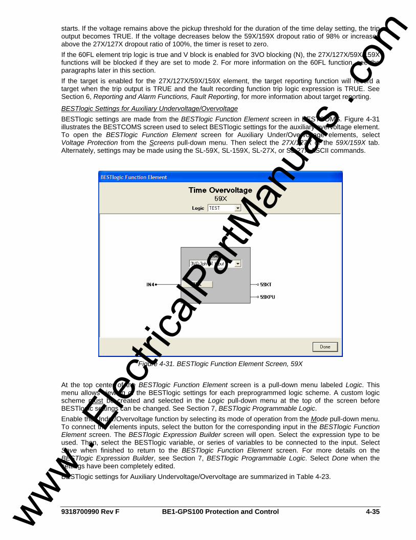
9318700990 Rev F BE1-GPS100 Protection and Control 4-35
starts. If the voltage remains above the pickup threshold for the duration of the time delay setting, the trip output becomes TRUE. If the voltage decreases below the 59X/159X dropout ratio of 98% or increases above the 27X/127X dropout ratio of 100%, the timer is reset to zero. If the 60FL element trip logic is true and V block is enabled for 3VO blocking (N), the 27X/127X/59X/159X functions will be blocked if they are set to mode 2. For more information on the 60FL function, see the paragraphs later in this section. If the target is enabled for the 27X/127X/59X/159X element, the target reporting function will record a target when the trip output is TRUE and the fault recording function trip logic expression is TRUE. See Section 6, Reporting and Alarm Functions, Fault Reporting, for more information about target reporting.
BESTlogic Settings for Auxiliary Undervoltage/Overvoltage BESTlogic settings are made from the BESTlogic Function Element screen in BESTCOMS. Figure 4-31 illustrates the BESTCOMS screen used to select BESTlogic settings for the auxiliary overvoltage element. To open the BESTlogic Function Element screen for Auxiliary Under/Overvoltage elements, select Voltage Protection from the Screens pull-down menu. Then select the 27X/127X or the 59X/159X tab. Alternately, settings may be made using the SL-59X, SL-159X, SL-27X, or SL-27X ASCII commands.
Figure 4-31. BESTlogic Function Element Screen, 59X
At the top center of the BESTlogic Function Element screen is a pull-down menu labeled Logic. This menu allows viewing of the BESTlogic settings for each preprogrammed logic scheme. A custom logic scheme must be created and selected in the Logic pull-down menu at the top of the screen before BESTlogic settings can be changed. See Section 7, BESTlogic Programmable Logic. Enable the Under/Overvoltage function by selecting its mode of operation from the Mode pull-down menu. To connect the elements inputs, select the button for the corresponding input in the BESTlogic Function Element screen. The BESTlogic Expression Builder screen will open. Select the expression type to be used. Then, select the BESTlogic variable, or series of variables to be connected to the input. Select Save when finished to return to the BESTlogic Function Element screen. For more details on the BESTlogic Expression Builder, see Section 7, BESTlogic Programmable Logic. Select Done when the settings have been completely edited. BESTlogic settings for Auxiliary Undervoltage/Overvoltage are summarized in Table 4-23.
www . El
ectric
alPar
tMan
uals
. com

4-36 BE1-GPS100 Protection and Control 9318700990 Rev F
Table 4-23. BESTlogic Settings for Auxiliary Undervoltage/Overvoltage
Function Range/Purpose Default
Mode
0 = Disabled 1 = Fundamental Vx Input 2 = 3Vo Phase Inputs ∗ 3 = 3rd Harmonic, Vx Input
0
BLK Logic expression that disables function when TRUE. A setting of 0 disables blocking. 0
∗ To use Mode 2, the VTP connection must be 4-wire. Optional Auxiliary Input must be present to use Mode 1 or Mode 3.
Operating Settings for Auxiliary Undervoltage/Overvoltage Operating settings for the 27X/127X and 59X/159X functions consist of pickup and time delay values. The pickup value determines the level of voltage required for the element to start timing toward a trip. Unit of measure is secondary volts (PP or PN) and depends on the SG-VTX setting see Table 4-24. For more information, refer to Section 3, Input and Output Functions, Power System Inputs. The time delay value determines the length of time between pickup and trip. Time delays can be set in milliseconds, seconds, or cycles. The default is milliseconds if no unit of measure is specified.
Table 4-24. VTX Connection Settings
VTX Connection Mode Unit AB, BC, CA 1 or 3 VPP AN, BN, CN 1 or 3 VPN GR 1 or 3 VPN Any 2 VPN
Operating settings are made using BESTCOMS. Figure 4-32 illustrates the BESTCOMS screen used to select operational settings for the Auxiliary Overvoltage elements. To open the Voltage Protection screen for Under/Overvoltage elements, select Voltage Protection from the Screens pull-down menu. Then select the 59X/159X tab. (The Auxiliary Undervoltage [27X/127X] element is set in a similar manner using the 27X/127X tab.) Alternately, settings may be made using the S<g>-59X, S<g>-159X, S<g>-27X, and S<g>-127X ASCII commands.
www . El
ectric
alPar
tMan
uals
. com
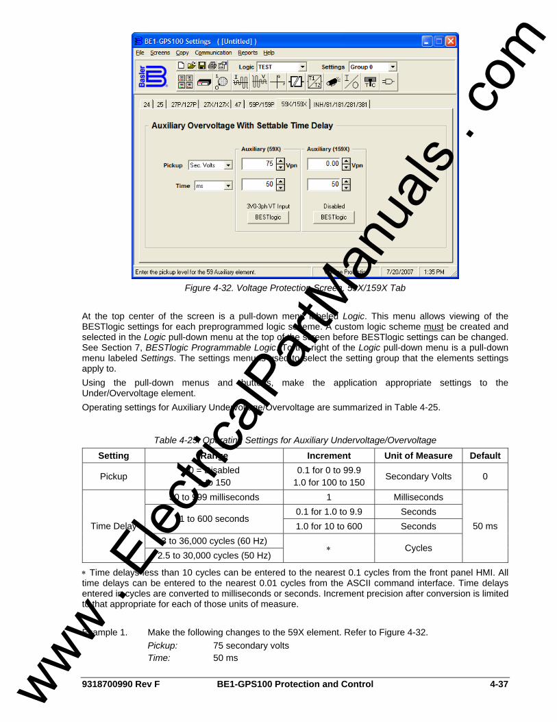
9318700990 Rev F BE1-GPS100 Protection and Control 4-37
Figure 4-32. Voltage Protection Screen, 59X/159X Tab
At the top center of the screen is a pull-down menu labeled Logic. This menu allows viewing of the BESTlogic settings for each preprogrammed logic scheme. A custom logic scheme must be created and selected in the Logic pull-down menu at the top of the screen before BESTlogic settings can be changed. See Section 7, BESTlogic Programmable Logic. To the right of the Logic pull-down menu is a pull-down menu labeled Settings. The settings menu is used to select the setting group that the elements settings apply to. Using the pull-down menus and buttons, make the application appropriate settings to the Under/Overvoltage element. Operating settings for Auxiliary Undervoltage/Overvoltage are summarized in Table 4-25.
Table 4-25. Operating Settings for Auxiliary Undervoltage/Overvoltage
Setting Range Increment Unit of Measure Default
Pickup 0 = Disabled
1 to 150 0.1 for 0 to 99.9
1.0 for 100 to 150 Secondary Volts 0
50 to 999 milliseconds 1 Milliseconds 0.1 for 1.0 to 9.9 Seconds
1 to 600 seconds 1.0 for 10 to 600 Seconds
3 to 36,000 cycles (60 Hz) Time Delay
2.5 to 30,000 cycles (50 Hz) ∗ Cycles
50 ms
∗ Time delays less than 10 cycles can be entered to the nearest 0.1 cycles from the front panel HMI. All time delays can be entered to the nearest 0.01 cycles from the ASCII command interface. Time delays entered in cycles are converted to milliseconds or seconds. Increment precision after conversion is limited to that appropriate for each of those units of measure. Example 1. Make the following changes to the 59X element. Refer to Figure 4-32. Pickup: 75 secondary volts Time: 50 ms
www . El
ectric
alPar
tMan
uals
. com
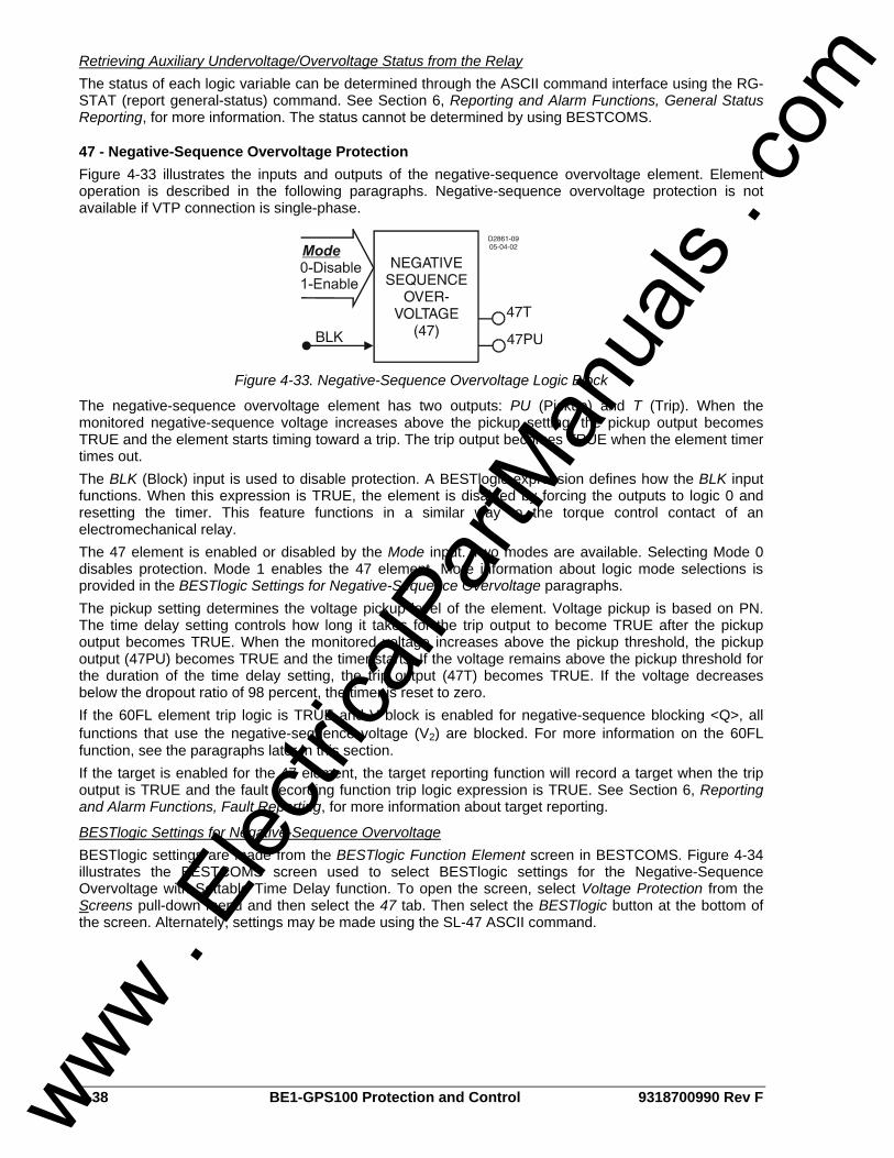
4-38 BE1-GPS100 Protection and Control 9318700990 Rev F
Retrieving Auxiliary Undervoltage/Overvoltage Status from the Relay The status of each logic variable can be determined through the ASCII command interface using the RG-STAT (report general-status) command. See Section 6, Reporting and Alarm Functions, General Status Reporting, for more information. The status cannot be determined by using BESTCOMS.
47 - Negative-Sequence Overvoltage Protection Figure 4-33 illustrates the inputs and outputs of the negative-sequence overvoltage element. Element operation is described in the following paragraphs. Negative-sequence overvoltage protection is not available if VTP connection is single-phase.
Figure 4-33. Negative-Sequence Overvoltage Logic Block
The negative-sequence overvoltage element has two outputs: PU (Pickup) and T (Trip). When the monitored negative-sequence voltage increases above the pickup setting, the pickup output becomes TRUE and the element starts timing toward a trip. The trip output becomes TRUE when the element timer times out. The BLK (Block) input is used to disable protection. A BESTlogic expression defines how the BLK input functions. When this expression is TRUE, the element is disabled by forcing the outputs to logic 0 and resetting the timer. This feature functions in a similar way to the torque control contact of an electromechanical relay. The 47 element is enabled or disabled by the Mode input. Two modes are available. Selecting Mode 0 disables protection. Mode 1 enables the 47 element. More information about logic mode selections is provided in the BESTlogic Settings for Negative-Sequence Overvoltage paragraphs. The pickup setting determines the voltage pickup level of the element. Voltage pickup is based on PN. The time delay setting controls how long it takes for the trip output to become TRUE after the pickup output becomes TRUE. When the monitored voltage increases above the pickup threshold, the pickup output (47PU) becomes TRUE and the timer starts. If the voltage remains above the pickup threshold for the duration of the time delay setting, the trip output (47T) becomes TRUE. If the voltage decreases below the dropout ratio of 98 percent, the timer is reset to zero. If the 60FL element trip logic is TRUE and V block is enabled for negative-sequence blocking <Q>, all functions that use the negative-sequence voltage (V2) are blocked. For more information on the 60FL function, see the paragraphs later in this section. If the target is enabled for the 47 element, the target reporting function will record a target when the trip output is TRUE and the fault recording function trip logic expression is TRUE. See Section 6, Reporting and Alarm Functions, Fault Reporting, for more information about target reporting.
BESTlogic Settings for Negative-Sequence Overvoltage BESTlogic settings are made from the BESTlogic Function Element screen in BESTCOMS. Figure 4-34 illustrates the BESTCOMS screen used to select BESTlogic settings for the Negative-Sequence Overvoltage with Settable Time Delay function. To open the screen, select Voltage Protection from the Screens pull-down menu and then select the 47 tab. Then select the BESTlogic button at the bottom of the screen. Alternately, settings may be made using the SL-47 ASCII command.
www . El
ectric
alPar
tMan
uals
. com
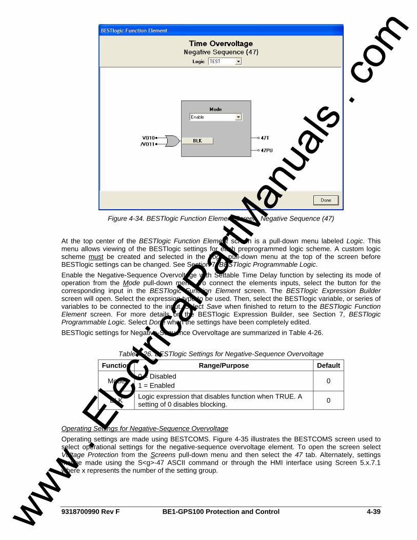
9318700990 Rev F BE1-GPS100 Protection and Control 4-39
Figure 4-34. BESTlogic Function Element Screen, Negative Sequence (47)
At the top center of the BESTlogic Function Element screen is a pull-down menu labeled Logic. This menu allows viewing of the BESTlogic settings for each preprogrammed logic scheme. A custom logic scheme must be created and selected in the Logic pull-down menu at the top of the screen before BESTlogic settings can be changed. See Section 7, BESTlogic Programmable Logic. Enable the Negative-Sequence Overvoltage with Settable Time Delay function by selecting its mode of operation from the Mode pull-down menu. To connect the elements inputs, select the button for the corresponding input in the BESTlogic Function Element screen. The BESTlogic Expression Builder screen will open. Select the expression type to be used. Then, select the BESTlogic variable, or series of variables to be connected to the input. Select Save when finished to return to the BESTlogic Function Element screen. For more details on the BESTlogic Expression Builder, see Section 7, BESTlogic Programmable Logic. Select Done when the settings have been completely edited. BESTlogic settings for Negative-Sequence Overvoltage are summarized in Table 4-26.
Table 4-26. BESTlogic Settings for Negative-Sequence Overvoltage
Function Range/Purpose Default
Mode 0 = Disabled 1 = Enabled 0
BLK Logic expression that disables function when TRUE. A setting of 0 disables blocking. 0
Operating Settings for Negative-Sequence Overvoltage Operating settings are made using BESTCOMS. Figure 4-35 illustrates the BESTCOMS screen used to select operational settings for the negative-sequence overvoltage element. To open the screen select Voltage Protection from the Screens pull-down menu and then select the 47 tab. Alternately, settings maybe made using the S<g>-47 ASCII command or through the HMI interface using Screen 5.x.7.1 where x represents the number of the setting group.
www . El
ectric
alPar
tMan
uals
. com

4-40 BE1-GPS100 Protection and Control 9318700990 Rev F
Figure 4-35. Voltage Protection Screen, 47 Tab
At the top of the screen is a pull-down menu labeled Logic. This menu allows viewing of the BESTlogic settings for each preprogrammed logic scheme. A custom logic scheme must be created and selected in the Logic pull-down menu at the top of the screen before BESTlogic settings can be changed. See Section 7, BESTlogic Programmable Logic. To the right of the Logic pull-down menu is a pull-down menu labeled Settings. The Settings menu is used to select the setting group that the elements settings apply to. The default unit of measure for the Pickup setting is secondary volts. Primary volts (Pri Volts), per unit volts (Per U Volts), and percent volts (% Volts) can also be selected as the pickup setting unit of measure. The unit of measure for the Time setting that represents the element's time delay defaults to milliseconds. It is also selectable for seconds, minutes, and cycles. Using the pull-down menus and buttons, make the application appropriate settings to the negative-sequence overvoltage element. Operating settings for Negative-Sequence Overvoltage are summarized in Table 4-27.
Table 4-27. Operating Settings for Negative-Sequence Overvoltage
Setting Range Increment Unit of Measure Default
Pickup 0 = Disabled
1 to 300 0.1 for 1 to 99.9
1.0 for 100 to 300 Secondary Volts 0
50 to 999 milliseconds 1 Milliseconds 0.1 for 0.1 to 9.9 Seconds
1 to 600 seconds 1.0 for 10 to 600 Seconds
3 to 36,000 cycles (60 Hz) Time Delay
2.5 to 30,000 cycles (50 Hz) ∗ Cycles
50 ms
∗ Time delays less than 10 cycles can be entered to the nearest 0.1 cycles from the front panel HMI. All time delays can be entered to the nearest 0.01 cycles from the ASCII command interface. Time delays entered in cycles are converted to milliseconds or seconds. Increment precision after conversion is limited to that appropriate for each of those units of measure.
www . El
ectric
alPar
tMan
uals
. com
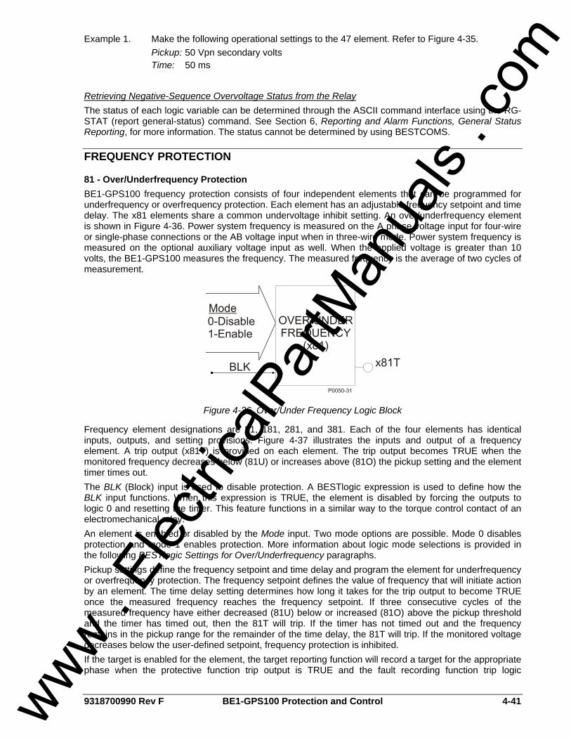
9318700990 Rev F BE1-GPS100 Protection and Control 4-41
Example 1. Make the following operational settings to the 47 element. Refer to Figure 4-35. Pickup: 50 Vpn secondary volts Time: 50 ms
Retrieving Negative-Sequence Overvoltage Status from the Relay The status of each logic variable can be determined through the ASCII command interface using the RG-STAT (report general-status) command. See Section 6, Reporting and Alarm Functions, General Status Reporting, for more information. The status cannot be determined by using BESTCOMS.
FREQUENCY PROTECTION
81 - Over/Underfrequency Protection BE1-GPS100 frequency protection consists of four independent elements that can be programmed for underfrequency or overfrequency protection. Each element has an adjustable frequency setpoint and time delay. The x81 elements share a common undervoltage inhibit setting. An over/underfrequency element is shown in Figure 4-36. Power system frequency is measured on the A phase voltage input for four-wire or single-phase connections or the AB voltage input when in three-wire mode. Power system frequency is measured on the optional auxiliary voltage input as well. When the applied voltage is greater than 10 volts, the BE1-GPS100 measures the frequency. The measured frequency is the average of two cycles of measurement.
Figure 4-36. Over/Under Frequency Logic Block
Frequency element designations are 81, 181, 281, and 381. Each of the four elements has identical inputs, outputs, and setting provisions. Figure 4-37 illustrates the inputs and output of a frequency element. A trip output (x81T) is provided on each element. The trip output becomes TRUE when the monitored frequency decreases below (81U) or increases above (81O) the pickup setting and the element timer times out. The BLK (Block) input is used to disable protection. A BESTlogic expression is used to define how the BLK input functions. When this expression is TRUE, the element is disabled by forcing the outputs to logic 0 and resetting the timer. This feature functions in a similar way to the torque control contact of an electromechanical relay. An element is enabled or disabled by the Mode input. Two mode options are possible. Mode 0 disables protection and mode 1 enables protection. More information about logic mode selections is provided in the following BESTlogic Settings for Over/Underfrequency paragraphs. Pickup settings define the frequency setpoint and time delay and program the element for underfrequency or overfrequency protection. The frequency setpoint defines the value of frequency that will initiate action by an element. The time delay setting determines how long it takes for the trip output to become TRUE once the measured frequency reaches the frequency setpoint. If three consecutive cycles of the measured frequency have either decreased (81U) below or increased (81O) above the pickup threshold and the timer has timed out, then the 81T will trip. If the timer has not timed out and the frequency remains in the pickup range for the remainder of the time delay, the 81T will trip. If the monitored voltage decreases below the user-defined setpoint, frequency protection is inhibited. If the target is enabled for the element, the target reporting function will record a target for the appropriate phase when the protective function trip output is TRUE and the fault recording function trip logic
www . El
ectric
alPar
tMan
uals
. com
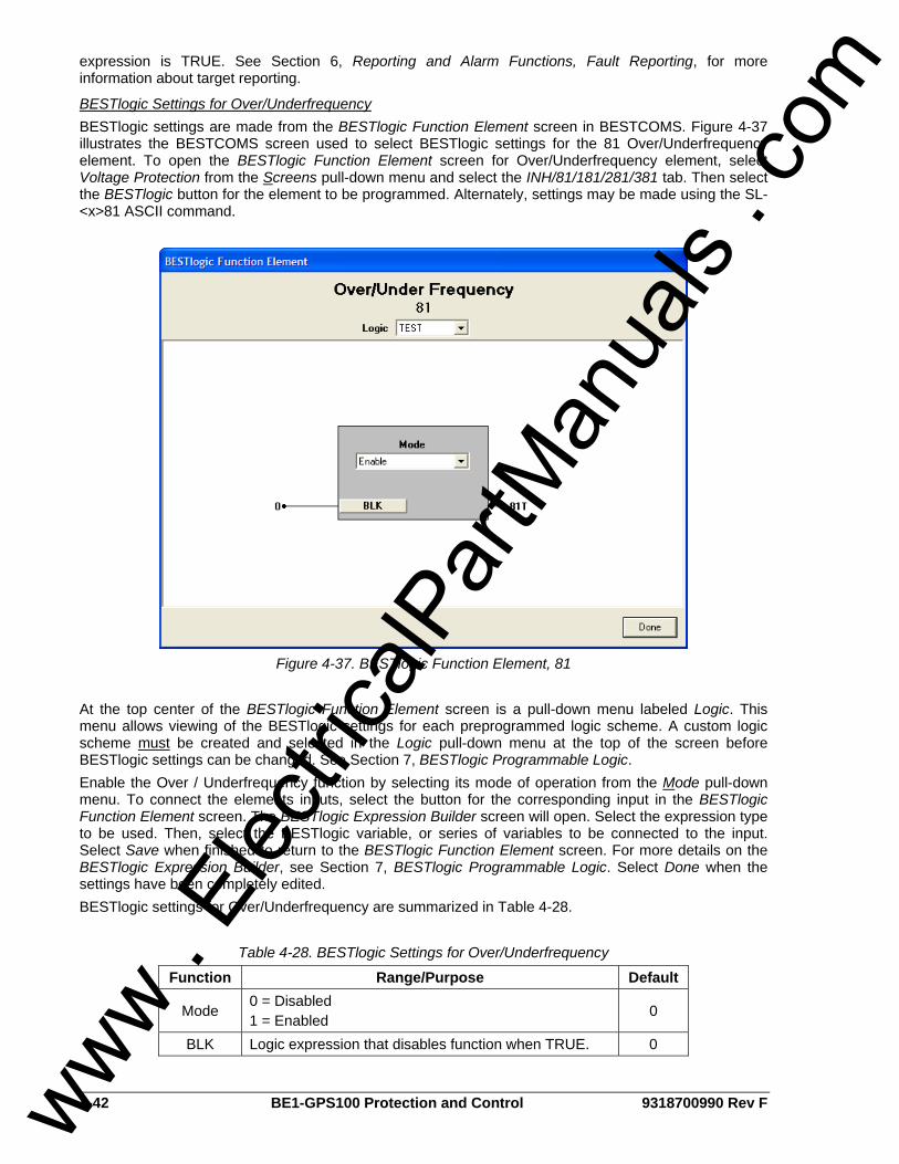
4-42 BE1-GPS100 Protection and Control 9318700990 Rev F
expression is TRUE. See Section 6, Reporting and Alarm Functions, Fault Reporting, for more information about target reporting.
BESTlogic Settings for Over/Underfrequency BESTlogic settings are made from the BESTlogic Function Element screen in BESTCOMS. Figure 4-37 illustrates the BESTCOMS screen used to select BESTlogic settings for the 81 Over/Underfrequency element. To open the BESTlogic Function Element screen for Over/Underfrequency element, select Voltage Protection from the Screens pull-down menu and select the INH/81/181/281/381 tab. Then select the BESTlogic button for the element to be programmed. Alternately, settings may be made using the SL-<x>81 ASCII command.
Figure 4-37. BESTlogic Function Element, 81
At the top center of the BESTlogic Function Element screen is a pull-down menu labeled Logic. This menu allows viewing of the BESTlogic settings for each preprogrammed logic scheme. A custom logic scheme must be created and selected in the Logic pull-down menu at the top of the screen before BESTlogic settings can be changed. See Section 7, BESTlogic Programmable Logic. Enable the Over / Underfrequency function by selecting its mode of operation from the Mode pull-down menu. To connect the elements inputs, select the button for the corresponding input in the BESTlogic Function Element screen. The BESTlogic Expression Builder screen will open. Select the expression type to be used. Then, select the BESTlogic variable, or series of variables to be connected to the input. Select Save when finished to return to the BESTlogic Function Element screen. For more details on the BESTlogic Expression Builder, see Section 7, BESTlogic Programmable Logic. Select Done when the settings have been completely edited. BESTlogic settings for Over/Underfrequency are summarized in Table 4-28.
Table 4-28. BESTlogic Settings for Over/Underfrequency
Function Range/Purpose Default
Mode 0 = Disabled 1 = Enabled 0
BLK Logic expression that disables function when TRUE. 0
www . El
ectric
alPar
tMan
uals
. com
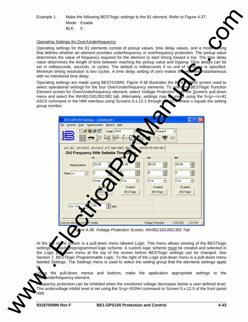
9318700990 Rev F BE1-GPS100 Protection and Control 4-43
Example 1. Make the following BESTlogic settings to the 81 element. Refer to Figure 4-37. Mode: Enable BLK: 0
Operating Settings for Over/Underfrequency Operating settings for the 81 elements consist of pickup values, time delay values, and a mode setting that defines whether an element provides underfrequency or overfrequency protection. The pickup value determines the value of frequency required for the element to start timing toward a trip. The time delay value determines the length of time between reaching the pickup value and tripping. Time delays can be set in milliseconds, seconds, or cycles. The default is milliseconds if no unit of measure is specified. Minimum timing resolution is two cycles. A time delay setting of zero makes the element instantaneous with no intentional time delay. Operating settings are made using BESTCOMS. Figure 4-38 illustrates the BESTCOMS screen used to select operational settings for the four Over/Underfrequency elements. To open the BESTlogic Function Element screen for Over/Underfrequency element, select Voltage Protection from the Screens pull-down menu and select the INH/81/181/281/381 tab. Alternately, settings may be made using the S<g>-<x>81 ASCII command or the HMI interface using Screens 5.x.12.1 through 5.x.12.4 where x equals the setting group number.
Figure 4-38. Voltage Protection Screen, INH/81/181/281/381 Tab
At the top of the screen is a pull-down menu labeled Logic. This menu allows viewing of the BESTlogic settings for each preprogrammed logic scheme. A custom logic scheme must be created and selected in the Logic pull-down menu at the top of the screen before BESTlogic settings can be changed. See Section 7, BESTlogic Programmable Logic. To the right of the Logic pull-down menu is a pull-down menu labeled Settings. The Settings menu is used to select the setting group that the elements settings apply to. Using the pull-down menus and buttons, make the application appropriate settings to the over/underfrequency element. Frequency protection can be inhibited when the monitored voltage decreases below a user-defined level. The undervoltage inhibit level is set using the S<g>-81INH command or Screen 5.x.12.5 of the front panel HMI.
www . El
ectric
alPar
tMan
uals
. com

4-44 BE1-GPS100 Protection and Control 9318700990 Rev F
The voltage inhibit setting unit of measure depends upon the VTP connection settings. For 4-wire or PN connections, it is secondary VPN. For 3-wire or PP connections, it is secondary VPP. Operating settings for Over/Underfrequency are summarized in Table 4-29.
Table 4-29. Operating Settings for Over/Underfrequency
Setting Range Increment Unit of Measure Default
Pickup 0 = Disabled
20 to 70 0.01 Hertz 0
0 to 999 milliseconds 1 Milliseconds 0.1 for 0.1 to 9.9 Seconds
0.0 to 600 seconds 1.0 for 10 to 600 Seconds
3 to 36,000 cycles (60 Hz) Time Delay
2.5 to 30,000 cycles (50 Hz) ∗ Cycles
0
Mode O = Overfrequency U = Underfrequency N/A N/A 0
Inhibit Level 0 = Disabled (functions enabled
for all voltage levels) 15 to 150
0.1 for 15 – 99.9 1.0 for 100 - 150
Secondary Volts † 40
∗ Time delays less than 10 cycles can be entered to the nearest 0.1 cycles from the front panel HMI. All time delays can be entered to the nearest 0.01 cycles from the ASCII command interface. Time delays entered in cycles are converted to milliseconds or seconds. Increment precision after conversion is limited to that appropriate for each of those units of measure. † Phase-to-phase and phase-to-neutral settings depend on the VTP connection settings. The default unit of measure for the Inhibit setting is secondary volts. Primary volts (Pri Volts), per unit volts (Per U Volts), and percent volts (% Volts) can also be selected as the pickup setting unit of measure. The unit of measure for the Time setting that represents the element's time delay defaults to milliseconds. It is also selectable for seconds, minutes, and cycles. Example 1. Make the following settings to the 81 element and to the Inhibit function. Refer to
Figure 4-38. Pickup hertz: 59.5 Time: 2 ms Mode: Under Inhibit: 100 Vpn secondary volts
Retrieving Over/Underfrequency Status from the Relay The status of each logic variable can be determined through the ASCII command interface using the RG-STAT (report general-status) command. See Section 6, Reporting and Alarm Functions, General Status Reporting, for more information. The status cannot be determined by using BESTCOMS.
BREAKER FAILURE PROTECTION
50BF - Breaker Failure Protection BE1-GPS100 relays provide one element for breaker failure protection. This function includes a timer and a current detector. Figure 4-39 shows the Breaker Failure logic block. The logic block has two outputs BFPU (Breaker Failure Pickup) and BFT (Breaker Failure Trip).
www . El
ectric
alPar
tMan
uals
. com
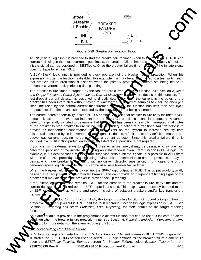
9318700990 Rev F BE1-GPS100 Protection and Control 4-45
Figure 4-39. Breaker Failure Logic Block
An INI (Initiate) logic input is provided to start the breaker failure timer. When this expression is TRUE and current is flowing in the phase current input circuits, the breaker failure timer is started. Supervision of the initiate signal can be designed in BESTlogic. Once the breaker failure timer is started, the initiate signal does not have to remain TRUE. A BLK (Block) logic input is provided to block operation of the breaker failure protection. When this expression is true, the function is disabled. For example, this may be an input wired to a test switch such that breaker failure protection is disabled when the primary protective elements are being tested to prevent inadvertent backup tripping during testing. The breaker failure timer is stopped by the fast-dropout current detector function. See Section 3, Input and Output Functions, Power System Inputs, Current Measurement, for more details on this function. The fast-dropout current detector is designed to directly determine when the current in the poles of the breaker has been interrupted without having to wait for the fault current samples to clear the one-cycle filter time used by the normal current measurement function. This function has less than one cycle dropout time. The timer can also be stopped by the block logic input being asserted. The current detector sensitivity is fixed at 10% nominal. A traditional breaker failure relay includes a fault detector function that serves two independent purposes: Current detector and fault detector. A current detector is generally included to determine that the current has been successfully interrupted in all poles of the breaker to stop breaker failure timing. The secondary function of a traditional fault detector is to provide an independent confirmation that a fault exists on the system to increase security from misoperation caused by an inadvertent initiate signal. To do this, a fault detector by definition must be set above load current reducing its sensitivity as a current detector. Since this breaker failure timer is included in a multifunction protection system, fault detector supervision is not required. If you are using external relays to initiate the breaker failure timer, it may be desirable to include fault detector supervision of the initiate signal using an instantaneous overcurrent function in BESTlogic. For example, if it is desired that a fault detector supervise certain initiate signals, it is possible to AND them with one of the 50T protective functions using a virtual output expression. In other applications, it may be desirable to have breaker failure timing with no current detector supervision. In this case, one of the general-purpose logic timers (device 62) can be used as a breaker failure timer. When the breaker failure timer is picked up, the BFPU logic output is TRUE. This output would typically be used as a re-trip signal to the protected breaker. This can provide an independent tripping signal to the breaker that may also open the breaker to prevent backup tripping. If the initiate logic expression remains TRUE for the duration of the breaker failure delay time and the current detector is still picked up, the BFT output is asserted. This output would normally be used to trip an 86F lockout relay that will trip and prevent closing of adjacent breakers and/or key transfer trip transmitters. If the target is enabled for the function block, the target reporting function will record a target when the protective function trip output is TRUE and the fault recording function trip logic expression is TRUE. See Section 6, Reporting and Alarm Functions, Fault Reporting, for more details on the target reporting function. An alarm variable is provided in the programmable alarms function that can be used to indicate an alarm condition when the breaker failure protection trips. See Section 6, Reporting and Alarm Functions, Alarms Function, for more details on the alarm reporting function.
BESTlogic Settings for Breaker Failure BESTlogic settings are made from the BESTlogic Function Element screen in BESTCOMS. Figure 4-40 illustrates the BESTCOMS screen used to select BESTlogic settings for the breaker failure element. To open the BESTlogic Function Element screen for Breaker Failure, select Breaker Failure from the www .
Elec
tricalP
artM
anua
ls . c
om
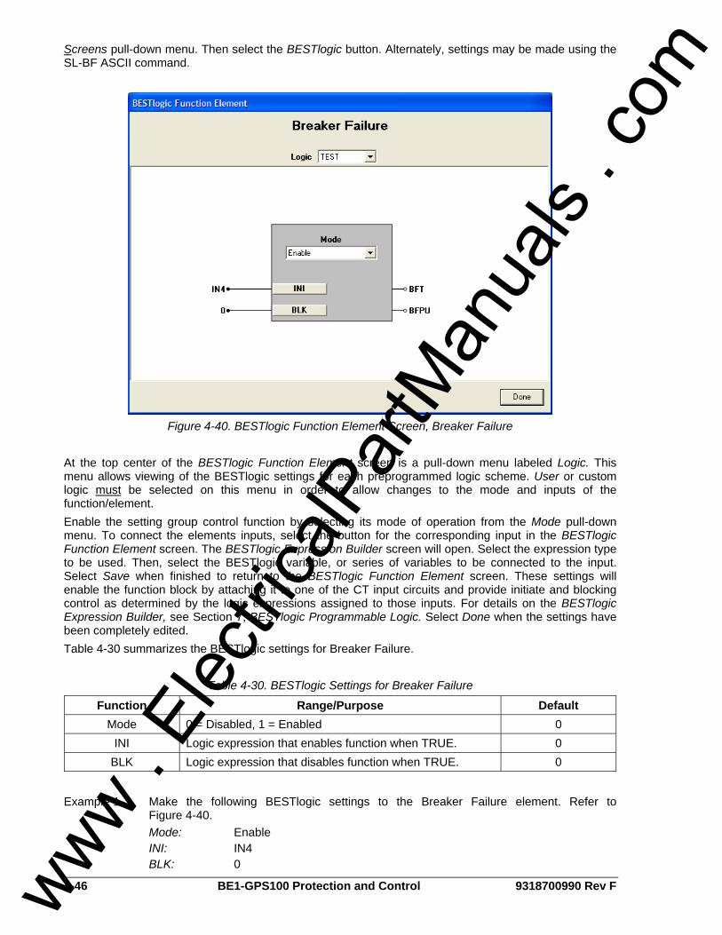
4-46 BE1-GPS100 Protection and Control 9318700990 Rev F
Screens pull-down menu. Then select the BESTlogic button. Alternately, settings may be made using the SL-BF ASCII command.
Figure 4-40. BESTlogic Function Element Screen, Breaker Failure
At the top center of the BESTlogic Function Element screen is a pull-down menu labeled Logic. This menu allows viewing of the BESTlogic settings for each preprogrammed logic scheme. User or custom logic must be selected on this menu in order to allow changes to the mode and inputs of the function/element. Enable the setting group control function by selecting its mode of operation from the Mode pull-down menu. To connect the elements inputs, select the button for the corresponding input in the BESTlogic Function Element screen. The BESTlogic Expression Builder screen will open. Select the expression type to be used. Then, select the BESTlogic variable, or series of variables to be connected to the input. Select Save when finished to return to the BESTlogic Function Element screen. These settings will enable the function block by attaching it to one of the CT input circuits and provide initiate and blocking control as determined by the logic expressions assigned to those inputs. For details on the BESTlogic Expression Builder, see Section 7, BESTlogic Programmable Logic. Select Done when the settings have been completely edited. Table 4-30 summarizes the BESTlogic settings for Breaker Failure.
Table 4-30. BESTlogic Settings for Breaker Failure
Function Range/Purpose Default Mode 0 = Disabled, 1 = Enabled 0
INI Logic expression that enables function when TRUE. 0 BLK Logic expression that disables function when TRUE. 0
Example 1. Make the following BESTlogic settings to the Breaker Failure element. Refer to
Figure 4-40. Mode: Enable INI: IN4 BLK: 0
www . El
ectric
alPar
tMan
uals
. com
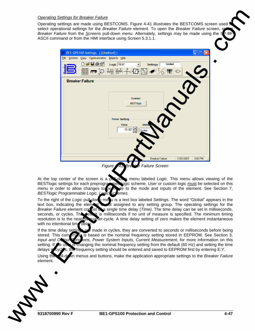
9318700990 Rev F BE1-GPS100 Protection and Control 4-47
Operating Settings for Breaker Failure Operating settings are made using BESTCOMS. Figure 4-41 illustrates the BESTCOMS screen used to select operational settings for the Breaker Failure element. To open the Breaker Failure screen, select Breaker Failure from the Screens pull-down menu. Alternately, settings may be made using the SP-BF ASCII command or from the HMI interface using Screen 5.3.1.1.
Figure 4-41. Breaker Failure Screen
At the top center of the screen is a pull-down menu labeled Logic. This menu allows viewing of the BESTlogic settings for each preprogrammed logic scheme. User or custom logic must be selected on this menu in order to allow changes to be made to the mode and inputs of the element. See Section 7, BESTlogic Programmable Logic, Logic Schemes. To the right of the Logic pull-down menu is a text box labeled Settings. The word “Global” appears in the text box, indicating the element is not assigned to any setting group. The operating settings for the Breaker Failure element consist of a single time delay (Time). The time delay can be set in milliseconds, seconds, or cycles. The default is milliseconds if no unit of measure is specified. The minimum timing resolution is to the nearest quarter-cycle. A time delay setting of zero makes the element instantaneous with no intentional time delay. If the time delay settings are made in cycles, they are converted to seconds or milliseconds before being stored. This conversion is based on the nominal frequency setting stored in EEPROM. See Section 3, Input and Output Functions, Power System Inputs, Current Measurement, for more information on this setting. If the user is changing the nominal frequency setting from the default (60 Hz) and setting the time delays in cycles, the frequency setting should be entered and saved to EEPROM first by entering E;Y. Using the pull-down menus and buttons, make the application appropriate settings to the Breaker Failure element.
www . El
ectric
alPar
tMan
uals
. com

4-48 BE1-GPS100 Protection and Control 9318700990 Rev F
Table 4-31 summarizes the operating settings for Breaker Failure.
Table 4-31. Operating Settings for Breaker Failure
Setting Range Increment Unit of Measure Default
0 = Disabled N/A N/A
50 to 999 ms 1 ms Milliseconds
0.05 to 0.999 sec. 0.001 sec. Seconds Time
0 to 59.96 (60 Hz) or 0 to 49.97 (50 Hz) ∗ Cycles
0
∗ Time delays less than 10 cycles can be entered to the nearest 0.1 cycles from the HMI. All time delays can be entered to the nearest 0.01 cycles from the ASCII command interface. Time delays entered in cycles are converted to milliseconds or seconds. Increment precision after conversion is limited to that appropriate for each of those units of measure. Example 1. Make the following operating settings to the Breaker Failure element. Refer to
Figure 4-41. Timer Setting, Time: 10.02 cycles Retrieving Breaker Failure Status from the Relay The status of each logic variable can be determined from the ASCII command interface using the RG-STAT (report general-status) or the RL (report logic) commands. Logic status cannot be determined using BESTCOMS. See Section 6, Reporting and Alarm Functions, General Status Reporting, for more information.
LOGIC TIMERS
62 - General Purpose Logic Timers BE1-GPS100 relays provide four general-purpose logic timers that are extremely versatile. Each can be set for one of six modes of operation to emulate virtually any type of timer. Each function block has one output (62, 162, 262, or 362) that is asserted when the timing criteria has been met according to the BESTlogic mode setting. Figure 4-42 shows the 62 function block as an example. Each mode of operation is described in detail in the following paragraphs.
Figure 4-42. General Purpose Logic Timers Logic Block
An INI (Initiate) logic input is provided to start the timing sequence.
A BLK (Block) logic input is provided to block operation of the timer. When this expression is TRUE, the function is disabled.
www . El
ectric
alPar
tMan
uals
. com
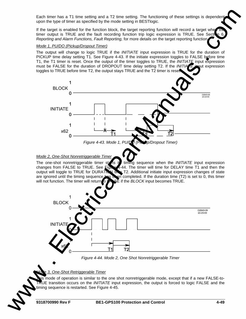
9318700990 Rev F BE1-GPS100 Protection and Control 4-49
Each timer has a T1 time setting and a T2 time setting. The functioning of these settings is dependent upon the type of timer as specified by the mode setting in BESTlogic.
If the target is enabled for the function block, the target reporting function will record a target when the timer output is TRUE and the fault recording function trip logic expression is TRUE. See Section 6, Reporting and Alarm Functions, Fault Reporting, for more details on the target reporting function.
Mode 1, PU/DO (Pickup/Dropout Timer) The output will change to logic TRUE if the INITIATE input expression is TRUE for the duration of PICKUP time delay setting T1. See Figure 4-43. If the initiate expression toggles to FALSE before time T1, the T1 timer is reset. Once the output of the timer toggles to TRUE, the INITIATE input expression must be FALSE for the duration of DROPOUT time delay setting T2. If the INITIATE input expression toggles to TRUE before time T2, the output stays TRUE and the T2 timer is reset.
D2843-0810-23-03
Figure 4-43. Mode 1, PU/DO (Pickup/Dropout Timer)
Mode 2, One-Shot Nonretriggerable Timer The one-shot nonretriggerable timer starts its timing sequence when the INITIATE input expression changes from FALSE to TRUE. See Figure 4-44. The timer will time for DELAY time T1 and then the output will toggle to TRUE for DURATION time T2. Additional initiate input expression changes of state are ignored until the timing sequence has been completed. If the duration time (T2) is set to 0, this timer will not function. The timer will return to FALSE if the BLOCK input becomes TRUE.
D2843-0910-23-03
Figure 4-44. Mode 2, One Shot Nonretriggerable Timer
Mode 3, One-Shot Retriggerable Timer This mode of operation is similar to the one shot nonretriggerable mode, except that if a new FALSE-to-TRUE transition occurs on the INITIATE input expression, the output is forced to logic FALSE and the timing sequence is restarted. See Figure 4-45.
www . El
ectric
alPar
tMan
uals
. com
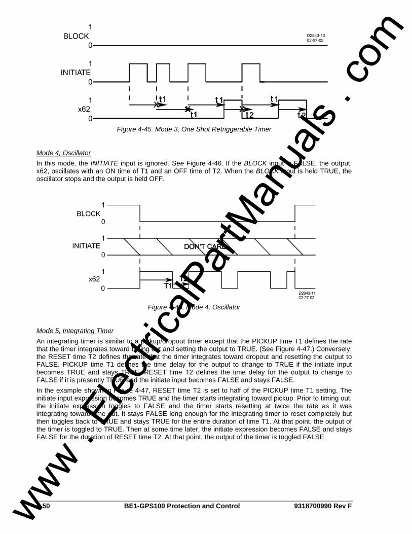
4-50 BE1-GPS100 Protection and Control 9318700990 Rev F
Figure 4-45. Mode 3, One Shot Retriggerable Timer
Mode 4, Oscillator In this mode, the INITIATE input is ignored. See Figure 4-46. If the BLOCK input is FALSE, the output, x62, oscillates with an ON time of T1 and an OFF time of T2. When the BLOCK input is held TRUE, the oscillator stops and the output is held OFF.
Figure 4-46. Mode 4, Oscillator
Mode 5, Integrating Timer An integrating timer is similar to a pickup/dropout timer except that the PICKUP time T1 defines the rate that the timer integrates toward timing out and setting the output to TRUE. (See Figure 4-47.) Conversely, the RESET time T2 defines the rate that the timer integrates toward dropout and resetting the output to FALSE. PICKUP time T1 defines the time delay for the output to change to TRUE if the initiate input becomes TRUE and stays TRUE. RESET time T2 defines the time delay for the output to change to FALSE if it is presently TRUE and the initiate input becomes FALSE and stays FALSE. In the example shown in Figure 4-47, RESET time T2 is set to half of the PICKUP time T1 setting. The initiate input expression becomes TRUE and the timer starts integrating toward pickup. Prior to timing out, the initiate expression toggles to FALSE and the timer starts resetting at twice the rate as it was integrating toward time out. It stays FALSE long enough for the integrating timer to reset completely but then toggles back to TRUE and stays TRUE for the entire duration of time T1. At that point, the output of the timer is toggled to TRUE. Then at some time later, the initiate expression becomes FALSE and stays FALSE for the duration of RESET time T2. At that point, the output of the timer is toggled FALSE.
www . El
ectric
alPar
tMan
uals
. com
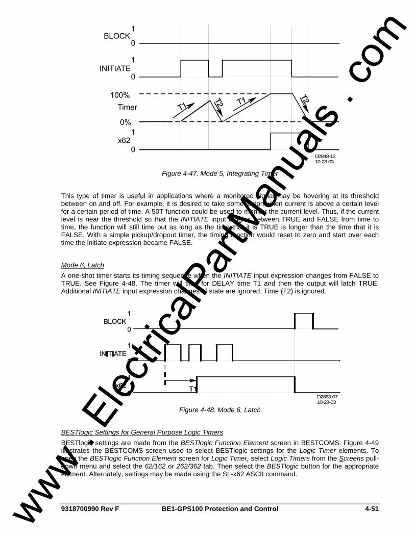
9318700990 Rev F BE1-GPS100 Protection and Control 4-51
D2843-1210-23-03
Figure 4-47. Mode 5, Integrating Timer
This type of timer is useful in applications where a monitored signal may be hovering at its threshold between on and off. For example, it is desired to take some action when current is above a certain level for a certain period of time. A 50T function could be used to monitor the current level. Thus, if the current level is near the threshold so that the INITIATE input toggles between TRUE and FALSE from time to time, the function will still time out as long as the time that it is TRUE is longer than the time that it is FALSE. With a simple pickup/dropout timer, the timing function would reset to zero and start over each time the initiate expression became FALSE.
Mode 6, Latch A one-shot timer starts its timing sequence when the INITIATE input expression changes from FALSE to TRUE. See Figure 4-48. The timer will time for DELAY time T1 and then the output will latch TRUE. Additional INITIATE input expression changes of state are ignored. Time (T2) is ignored.
D2863-0710-23-03
Figure 4-48. Mode 6, Latch
BESTlogic Settings for General Purpose Logic Timers BESTlogic settings are made from the BESTlogic Function Element screen in BESTCOMS. Figure 4-49 illustrates the BESTCOMS screen used to select BESTlogic settings for the Logic Timer elements. To open the BESTlogic Function Element screen for Logic Timer, select Logic Timers from the Screens pull-down menu and select the 62/162 or 262/362 tab. Then select the BESTlogic button for the appropriate element. Alternately, settings may be made using the SL-x62 ASCII command.
www . El
ectric
alPar
tMan
uals
. com
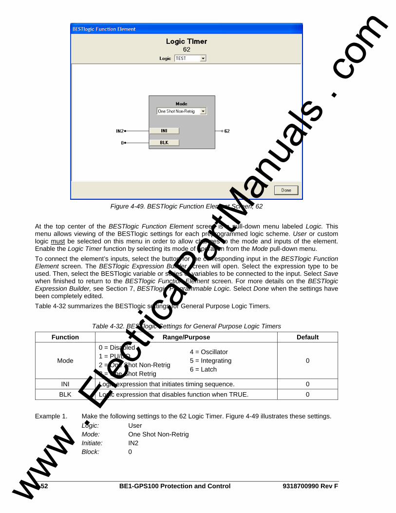
4-52 BE1-GPS100 Protection and Control 9318700990 Rev F
Figure 4-49. BESTlogic Function Element Screen, 62
At the top center of the BESTlogic Function Element screen is a pull-down menu labeled Logic. This menu allows viewing of the BESTlogic settings for each preprogrammed logic scheme. User or custom logic must be selected on this menu in order to allow changes to the mode and inputs of the element. Enable the Logic Timer function by selecting its mode of operation from the Mode pull-down menu. To connect the element’s inputs, select the button for the corresponding input in the BESTlogic Function Element screen. The BESTlogic Expression Builder screen will open. Select the expression type to be used. Then, select the BESTlogic variable or series of variables to be connected to the input. Select Save when finished to return to the BESTlogic Function Element screen. For more details on the BESTlogic Expression Builder, see Section 7, BESTlogic Programmable Logic. Select Done when the settings have been completely edited. Table 4-32 summarizes the BESTlogic settings for General Purpose Logic Timers.
Table 4-32. BESTlogic Settings for General Purpose Logic Timers
Function Range/Purpose Default
Mode
0 = Disabled 1 = PU/DO 2 = One Shot Non-Retrig 3 = One Shot Retrig
4 = Oscillator 5 = Integrating 6 = Latch
0
INI Logic expression that initiates timing sequence. 0 BLK Logic expression that disables function when TRUE. 0
Example 1. Make the following settings to the 62 Logic Timer. Figure 4-49 illustrates these settings. Logic: User Mode: One Shot Non-Retrig Initiate: IN2 Block: 0
www . El
ectric
alPar
tMan
uals
. com
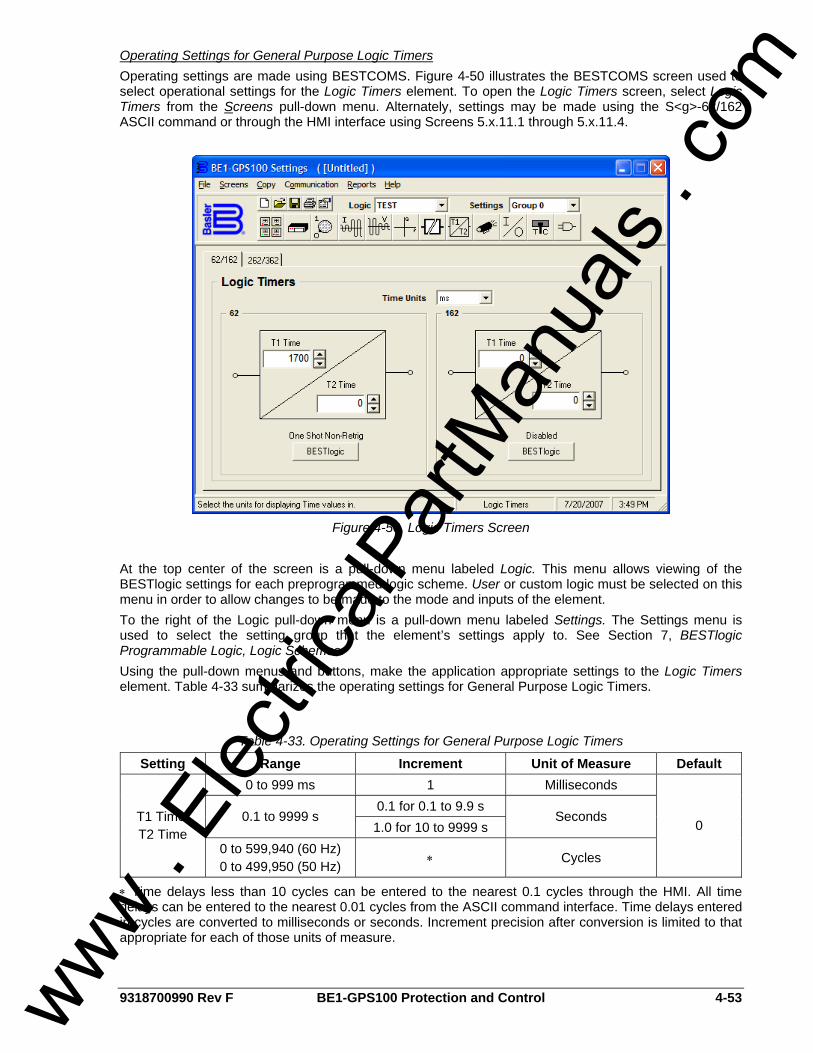
9318700990 Rev F BE1-GPS100 Protection and Control 4-53
Operating Settings for General Purpose Logic Timers Operating settings are made using BESTCOMS. Figure 4-50 illustrates the BESTCOMS screen used to select operational settings for the Logic Timers element. To open the Logic Timers screen, select Logic Timers from the Screens pull-down menu. Alternately, settings may be made using the S<g>-62/162 ASCII command or through the HMI interface using Screens 5.x.11.1 through 5.x.11.4.
Figure 4-50. Logic Timers Screen
At the top center of the screen is a pull-down menu labeled Logic. This menu allows viewing of the BESTlogic settings for each preprogrammed logic scheme. User or custom logic must be selected on this menu in order to allow changes to be made to the mode and inputs of the element. To the right of the Logic pull-down menu is a pull-down menu labeled Settings. The Settings menu is used to select the setting group that the element’s settings apply to. See Section 7, BESTlogic Programmable Logic, Logic Schemes. Using the pull-down menus and buttons, make the application appropriate settings to the Logic Timers element. Table 4-33 summarizes the operating settings for General Purpose Logic Timers.
Table 4-33. Operating Settings for General Purpose Logic Timers
Setting Range Increment Unit of Measure Default 0 to 999 ms 1 Milliseconds
0.1 for 0.1 to 9.9 s 0.1 to 9999 s
1.0 for 10 to 9999 s Seconds T1 Time,
T2 Time 0 to 599,940 (60 Hz) 0 to 499,950 (50 Hz) ∗ Cycles
0
∗ Time delays less than 10 cycles can be entered to the nearest 0.1 cycles through the HMI. All time delays can be entered to the nearest 0.01 cycles from the ASCII command interface. Time delays entered in cycles are converted to milliseconds or seconds. Increment precision after conversion is limited to that appropriate for each of those units of measure.
www . El
ectric
alPar
tMan
uals
. com
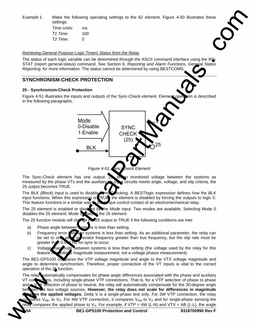
4-54 BE1-GPS100 Protection and Control 9318700990 Rev F
Example 1. Make the following operating settings to the 62 element. Figure 4-50 illustrates these settings.
Time Units: ms T1 Time: 100 T2 Time: 0
Retrieving General Purpose Logic Timers Status from the Relay The status of each logic variable can be determined through the ASCII command interface using the RG-STAT (report general-status) command. See Section 6, Reporting and Alarm Functions, General Status Reporting, for more information. The status cannot be determined by using BESTCOMS.
SYNCHRONISM-CHECK PROTECTION
25 - Synchronism-Check Protection Figure 4-51 illustrates the inputs and outputs of the Sync-Check element. Element operation is described in the following paragraphs.
Figure 4-51. Sync-Check Element
The Sync-Check element has one output: 25. When monitored voltage between the systems as measured by the phase VTs and the auxiliary Vx input circuits meets angle, voltage, and slip criteria, the 25 output becomes TRUE. The BLK (Block) input is used to disable Sync-Checking. A BESTlogic expression defines how the BLK input functions. When this expression is TRUE, the element is disabled by forcing the outputs to logic 0. This feature functions in a similar way to the torque control contact of an electromechanical relay. The 25 element is enabled or disabled by the Mode input. Two modes are available. Selecting Mode 0 disables the 25 element; Mode 1 enables the 25 element. The 25 function module will change the 25 output to TRUE if the following conditions are met:
a) Phase angle between systems is less than setting. b) Frequency error between systems is less than setting. As an additional parameter, the relay can
be set to only allow generator frequency greater than bus frequency, but the slip rate must be greater than 0.010 Hz for sync to occur.
c) Voltage magnitude between systems is less than setting (the voltage used by the relay for this feature is a voltage magnitude measurement, not a voltage phasor measurement).
The BE1-GPS100 compares the VTP voltage magnitude and angle to the VTX voltage magnitude and angle to determine synchronism. Therefore, proper connection of the VT inputs is vital to the correct operation of the 25 function. The relay automatically compensates for phase angle differences associated with the phase and auxiliary VT connections, including single-phase VTP connections. That is, for a VTP selection of phase to phase and a VTX selection of phase to neutral, the relay will automatically compensate for the 30-degree angle between the two voltage sources. However, the relay does not scale for differences in magnitude between the applied voltages. Delta V is a single-phase test only. For 3W VTP connection, the relay compares VAB, to VX. For 4W VTP connection, it compares VAN to VX and for single-phase sensing the relay compares the applied phase to VX. For example, if VTP = 4W (L-N) and VTX = AB (L-L), the angle www .
Elec
tricalP
artM
anua
ls . c
om
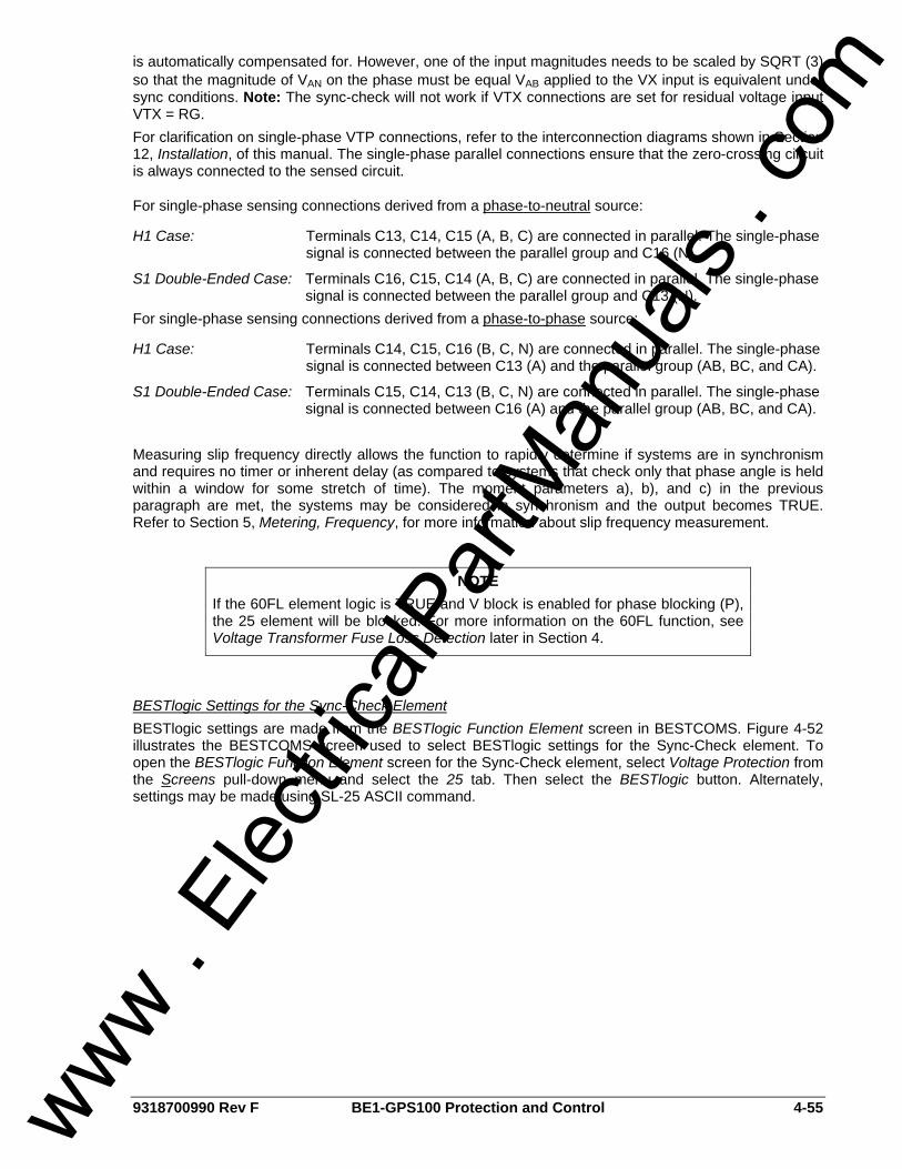
9318700990 Rev F BE1-GPS100 Protection and Control 4-55
is automatically compensated for. However, one of the input magnitudes needs to be scaled by SQRT (3) so that the magnitude of VAN on the phase must be equal VAB applied to the VX input is equivalent under sync conditions. Note: The sync-check will not work if VTX connections are set for residual voltage input VTX = RG. For clarification on single-phase VTP connections, refer to the interconnection diagrams shown in Section 12, Installation, of this manual. The single-phase parallel connections ensure that the zero-crossing circuit is always connected to the sensed circuit.
For single-phase sensing connections derived from a phase-to-neutral source:
H1 Case: Terminals C13, C14, C15 (A, B, C) are connected in parallel. The single-phase signal is connected between the parallel group and C16 (N).
S1 Double-Ended Case: Terminals C16, C15, C14 (A, B, C) are connected in parallel. The single-phase signal is connected between the parallel group and C13 (N).
For single-phase sensing connections derived from a phase-to-phase source:
H1 Case: Terminals C14, C15, C16 (B, C, N) are connected in parallel. The single-phase signal is connected between C13 (A) and the parallel group (AB, BC, and CA).
S1 Double-Ended Case: Terminals C15, C14, C13 (B, C, N) are connected in parallel. The single-phase signal is connected between C16 (A) and the parallel group (AB, BC, and CA).
Measuring slip frequency directly allows the function to rapidly determine if systems are in synchronism and requires no timer or inherent delay (as compared to systems that check only that phase angle is held within a window for some stretch of time). The moment parameters a), b), and c) in the previous paragraph are met, the systems may be considered in synchronism and the output becomes TRUE. Refer to Section 5, Metering, Frequency, for more information about slip frequency measurement.
BESTlogic Settings for the Sync-Check Element BESTlogic settings are made from the BESTlogic Function Element screen in BESTCOMS. Figure 4-52 illustrates the BESTCOMS screen used to select BESTlogic settings for the Sync-Check element. To open the BESTlogic Function Element screen for the Sync-Check element, select Voltage Protection from the Screens pull-down menu and select the 25 tab. Then select the BESTlogic button. Alternately, settings may be made using SL-25 ASCII command.
NOTE If the 60FL element logic is TRUE and V block is enabled for phase blocking (P), the 25 element will be blocked. For more information on the 60FL function, see Voltage Transformer Fuse Loss Detection later in Section 4.
www . El
ectric
alPar
tMan
uals
. com
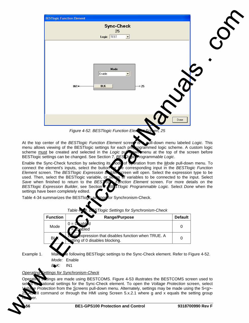
4-56 BE1-GPS100 Protection and Control 9318700990 Rev F
Figure 4-52. BESTlogic Function Element Screen, 25
At the top center of the BESTlogic Function Element screen is a pull-down menu labeled Logic. This menu allows viewing of the BESTlogic settings for each preprogrammed logic scheme. A custom logic scheme must be created and selected in the Logic pull-down menu at the top of the screen before BESTlogic settings can be changed. See Section 7, BESTlogic Programmable Logic. Enable the Sync-Check function by selecting its mode of operation from the Mode pull-down menu. To connect the element's inputs, select the button for the corresponding input in the BESTlogic Function Element screen. The BESTlogic Expression Builder screen will open. Select the expression type to be used. Then, select the BESTlogic variable, or series of variables to be connected to the input. Select Save when finished to return to the BESTlogic Function Element screen. For more details on the BESTlogic Expression Builder, see Section 7, BESTlogic Programmable Logic. Select Done when the settings have been completely edited. Table 4-34 summarizes the BESTlogic settings for Synchronism-Check.
Table 4-34. BESTlogic Settings for Synchronism-Check
Function Range/Purpose Default
Mode 0 = Disabled 1 = Enabled 0
BLK Logic expression that disables function when TRUE. A setting of 0 disables blocking. 0
Example 1. Make the following BESTlogic settings to the Sync-Check element. Refer to Figure 4-52. Mode: Enable BLK: IN1
Operating Settings for Synchronism-Check Operating settings are made using BESTCOMS. Figure 4-53 illustrates the BESTCOMS screen used to select operational settings for the Sync-Check element. To open the Voltage Protection screen, select Voltage Protection from the Screens pull-down menu. Alternately, settings may be made using the S<g>-25 ASCII command or through the HMI using Screen 5.x.2.1 where g and x equals the setting group number.
www . El
ectric
alPar
tMan
uals
. com
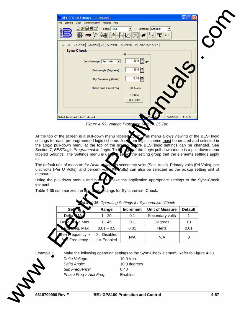
9318700990 Rev F BE1-GPS100 Protection and Control 4-57
Figure 4-53. Voltage Protection Screen, 25 Tab
At the top of the screen is a pull-down menu labeled Logic. This menu allows viewing of the BESTlogic settings for each preprogrammed logic scheme. A custom logic scheme must be created and selected in the Logic pull-down menu at the top of the screen before BESTlogic settings can be changed. See Section 7, BESTlogic Programmable Logic. To the right of the Logic pull-down menu is a pull-down menu labeled Settings. The Settings menu is used to select the setting group that the elements settings apply to. The default unit of measure for Delta Voltage is secondary volts (Sec. Volts). Primary volts (Pri Volts), per unit volts (Per U Volts), and percent volts (% Volts) can also be selected as the pickup setting unit of measure. Using the pull-down menus and buttons, make the application appropriate settings to the Sync-Check element. Table 4-35 summarizes the operating settings for Synchronism-Check.
Table 4-35. Operating Settings for Synchronism-Check
Setting Range Increment Unit of Measure Default Delta V Max 1 - 20 0.1 Secondary volts 1
Delta Angle Max 1 - 45 0.1 Degrees 10 Delta Freq. Max 0.01 – 0.5 0.01 Hertz 0.01
Gen Frequency > Bus Frequency
0 = Disabled 1 = Enabled
N/A N/A 0
Example 1. Make the following operating settings to the Sync-Check element. Refer to Figure 4-53. Delta Voltage: 10.0 Vpn Delta Angle: 10.0 degrees Slip Frequency: 0.40 Phase Freq > Aux Freq: Enabled
www . El
ectric
alPar
tMan
uals
. com
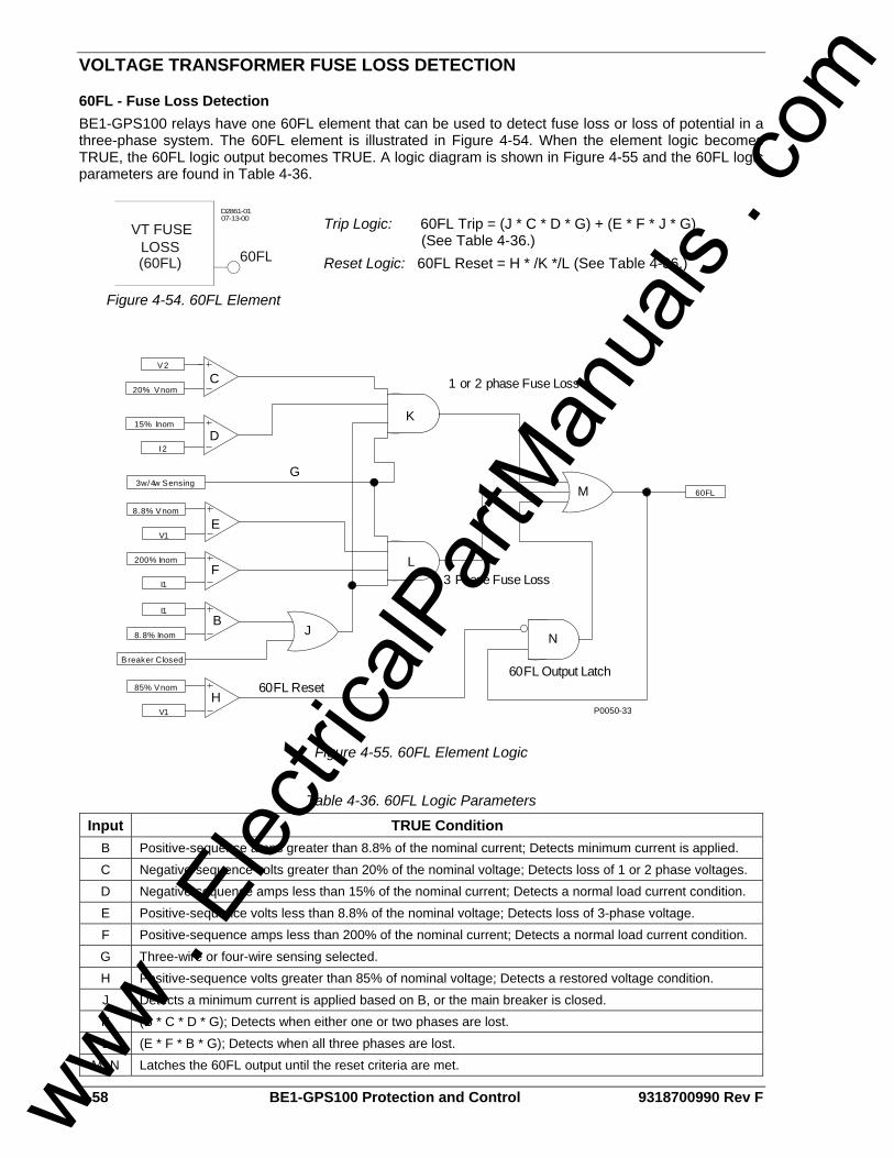
4-58 BE1-GPS100 Protection and Control 9318700990 Rev F
VOLTAGE TRANSFORMER FUSE LOSS DETECTION
60FL - Fuse Loss Detection BE1-GPS100 relays have one 60FL element that can be used to detect fuse loss or loss of potential in a three-phase system. The 60FL element is illustrated in Figure 4-54. When the element logic becomes TRUE, the 60FL logic output becomes TRUE. A logic diagram is shown in Figure 4-55 and the 60FL logic parameters are found in Table 4-36.
D2861-0107-13-00
VT FUSELOSS(60FL) 60FL
Figure 4-54. 60FL Element
Trip Logic: 60FL Trip = (J * C * D * G) + (E * F * J * G) (See Table 4-36.) Reset Logic: 60FL Reset = H * /K */L (See Table 4-36.)
60FL
V2
20% Vnom
I2
15% Inom
V1
8.8% Vnom
I1
200% Inom
I1
8.8% Inom
3w/4w Sensing
1 or 2 phase Fuse Loss
3 Phase Fuse Loss
C
D
F
B
G
E
Breaker Closed
J
V1
85% VnomH
N
60FL Output Latch60FL Reset
K
L
M
P0050-33
Figure 4-55. 60FL Element Logic
Table 4-36. 60FL Logic Parameters
Input TRUE Condition B Positive-sequence amps greater than 8.8% of the nominal current; Detects minimum current is applied. C Negative-sequence volts greater than 20% of the nominal voltage; Detects loss of 1 or 2 phase voltages. D Negative-sequence amps less than 15% of the nominal current; Detects a normal load current condition. E Positive-sequence volts less than 8.8% of the nominal voltage; Detects loss of 3-phase voltage. F Positive-sequence amps less than 200% of the nominal current; Detects a normal load current condition. G Three-wire or four-wire sensing selected. H Positive-sequence volts greater than 85% of nominal voltage; Detects a restored voltage condition. J Detects a minimum current is applied based on B, or the main breaker is closed. K (B * C * D * G); Detects when either one or two phases are lost. L (E * F * B * G); Detects when all three phases are lost.
M, N Latches the 60FL output until the reset criteria are met.
www . El
ectric
alPar
tMan
uals
. com
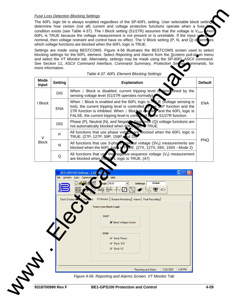
9318700990 Rev F BE1-GPS100 Protection and Control 4-59
Fuse Loss Detection Blocking Settings The 60FL logic bit is always enabled regardless of the SP-60FL setting. User selectable block settings determine how certain (not all) current and voltage protective functions operate when a fuse loss condition exists (see Table 4-37). The I Block setting (51/27R) assumes that the voltage is Vnom when 60FL is TRUE because the voltage measurement is not present or is unreliable. If the input voltage is nominal, then voltage restraint and control have no effect. The V Block setting (P, N, and Q) determines which voltage functions are blocked when the 60FL logic is TRUE. Settings are made using BESTCOMS. Figure 4-56 illustrates the BESTCOMS screen used to select blocking settings for the 60FL element. Select Reporting and Alarms from the Screens pull-down menu and select the VT Monitor tab. Alternately, settings may be made using the SP-60FL ASCII command. See Section 11, ASCII Command Interface, Command Summary, Protection Setting Commands, for more information.
Table 4-37. 60FL Element Blocking Settings
Mode Input Setting Explanation Default
DIS When I Block is disabled, current tripping level is determined by the sensing voltage level (51/27R operates normally).
I Block ENA
When I Block is enabled and the 60FL logic is TRUE (voltage sensing is lost), the current tripping level is controlled by the 51P function and the 27R function is inhibited. When I Block is enabled and the 60FL logic is FALSE, the current tripping level is controlled by the 51/27R function.
ENA
DIS Phase (P), Neutral (N), and Negative-Sequence (Q) voltage functions are not automatically blocked when 60FL logic is TRUE.
P All functions that use phase voltage are blocked when the 60FL logic is TRUE. (27P, 127P, 59P, 159P, and 25)
N All functions that use 3-phase residual voltage (3V0) measurements are blocked when the 60FL logic is TRUE. (27X, 127X, 59X, 159X - Mode 2)
V Block
Q All functions that use the negative-sequence voltage (V2) measurement are blocked when the 60FL logic is TRUE. (47)
PNQ
Figure 4-56. Reporting and Alarms Screen, VT Monitor Tab
www . El
ectric
alPar
tMan
uals
. com
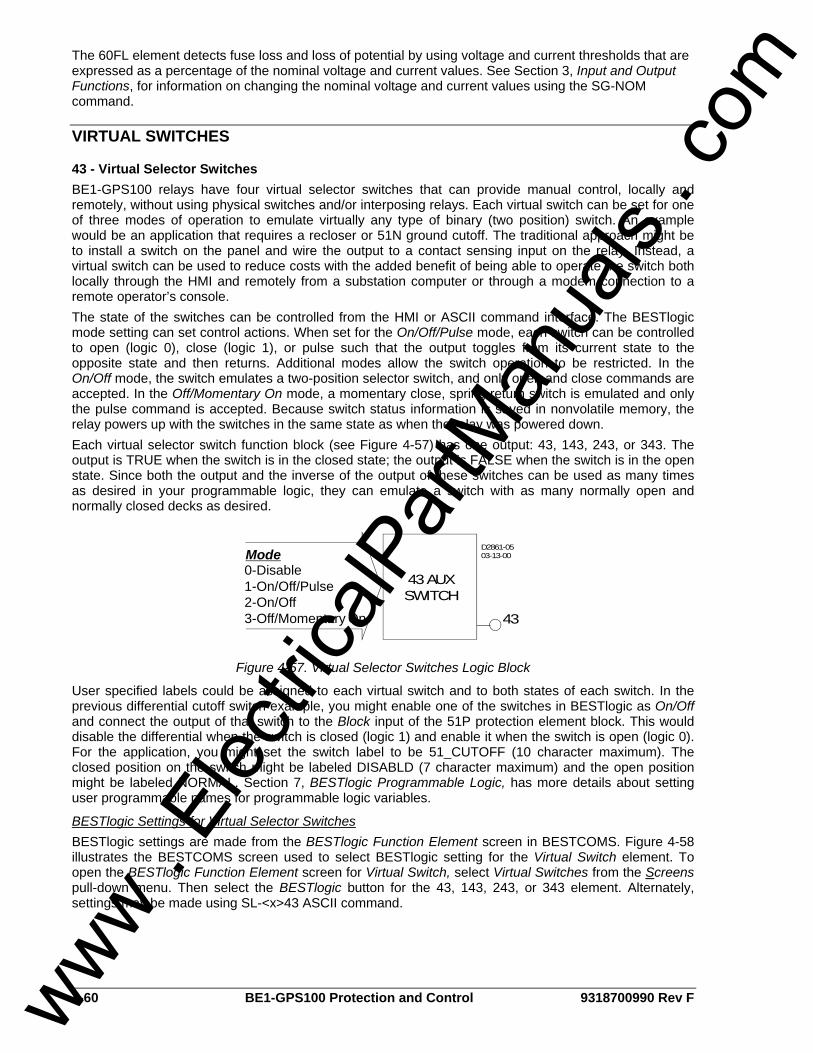
4-60 BE1-GPS100 Protection and Control 9318700990 Rev F
The 60FL element detects fuse loss and loss of potential by using voltage and current thresholds that are expressed as a percentage of the nominal voltage and current values. See Section 3, Input and Output Functions, for information on changing the nominal voltage and current values using the SG-NOM command.
VIRTUAL SWITCHES
43 - Virtual Selector Switches BE1-GPS100 relays have four virtual selector switches that can provide manual control, locally and remotely, without using physical switches and/or interposing relays. Each virtual switch can be set for one of three modes of operation to emulate virtually any type of binary (two position) switch. An example would be an application that requires a recloser or 51N ground cutoff. The traditional approach might be to install a switch on the panel and wire the output to a contact sensing input on the relay. Instead, a virtual switch can be used to reduce costs with the added benefit of being able to operate the switch both locally through the HMI and remotely from a substation computer or through a modem connection to a remote operator’s console. The state of the switches can be controlled from the HMI or ASCII command interface. The BESTlogic mode setting can set control actions. When set for the On/Off/Pulse mode, each switch can be controlled to open (logic 0), close (logic 1), or pulse such that the output toggles from its current state to the opposite state and then returns. Additional modes allow the switch operation to be restricted. In the On/Off mode, the switch emulates a two-position selector switch, and only open and close commands are accepted. In the Off/Momentary On mode, a momentary close, spring return switch is emulated and only the pulse command is accepted. Because switch status information is saved in nonvolatile memory, the relay powers up with the switches in the same state as when the relay was powered down. Each virtual selector switch function block (see Figure 4-57) has one output: 43, 143, 243, or 343. The output is TRUE when the switch is in the closed state; the output is FALSE when the switch is in the open state. Since both the output and the inverse of the output of these switches can be used as many times as desired in your programmable logic, they can emulate a switch with as many normally open and normally closed decks as desired.
43
Mode0-Disable1-On/Off/Pulse2-On/Off3-Off/Momentary On
43 AUXSWITCH
D2861-0503-13-00
Figure 4-57. Virtual Selector Switches Logic Block
User specified labels could be assigned to each virtual switch and to both states of each switch. In the previous differential cutoff switch example, you might enable one of the switches in BESTlogic as On/Off and connect the output of that switch to the Block input of the 51P protection element block. This would disable the differential when the switch is closed (logic 1) and enable it when the switch is open (logic 0). For the application, you might set the switch label to be 51_CUTOFF (10 character maximum). The closed position on the switch might be labeled DISABLD (7 character maximum) and the open position might be labeled NORMAL. Section 7, BESTlogic Programmable Logic, has more details about setting user programmable names for programmable logic variables.
BESTlogic Settings for Virtual Selector Switches BESTlogic settings are made from the BESTlogic Function Element screen in BESTCOMS. Figure 4-58 illustrates the BESTCOMS screen used to select BESTlogic setting for the Virtual Switch element. To open the BESTlogic Function Element screen for Virtual Switch, select Virtual Switches from the Screens pull-down menu. Then select the BESTlogic button for the 43, 143, 243, or 343 element. Alternately, settings may be made using SL-<x>43 ASCII command.
www . El
ectric
alPar
tMan
uals
. com
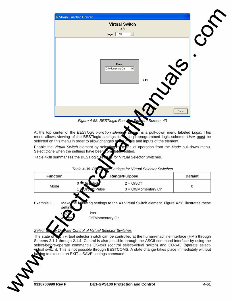
9318700990 Rev F BE1-GPS100 Protection and Control 4-61
Figure 4-58. BESTlogic Function Element Screen, 43
At the top center of the BESTlogic Function Element screen is a pull-down menu labeled Logic. This menu allows viewing of the BESTlogic settings for each preprogrammed logic scheme. User must be selected on this menu in order to allow changes to the mode and inputs of the element. Enable the Virtual Switch element by selecting its mode of operation from the Mode pull-down menu. Select Done when the settings have been completely edited. Table 4-38 summarizes the BESTlogic settings for Virtual Selector Switches.
Table 4-38. BESTlogic Settings for Virtual Selector Switches
Function Range/Purpose Default
Mode 0 = Disabled 1 = On/Off/Pulse
2 = On/Off 3 = Off/Momentary On
0
Example 1. Make the following settings to the 43 Virtual Switch element. Figure 4-58 illustrates these settings.
Logic: User Mode: Off/Momentary On
Select Before Operate Control of Virtual Selector Switches The state of each virtual selector switch can be controlled at the human-machine interface (HMI) through Screens 2.1.1 through 2.1.4. Control is also possible through the ASCII command interface by using the select-before-operate command’s CS-x43 (control select-virtual switch) and CO-x43 (operate select-virtual switch). This is not possible through BESTCOMS. A state change takes place immediately without having to execute an EXIT – SAVE settings command.
www . El
ectric
alPar
tMan
uals
. com
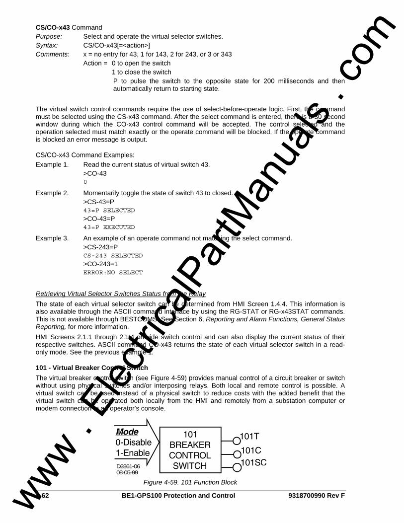
4-62 BE1-GPS100 Protection and Control 9318700990 Rev F
CS/CO-x43 Command Purpose: Select and operate the virtual selector switches. Syntax: CS/CO-x43[=<action>] Comments: x = no entry for 43, 1 for 143, 2 for 243, or 3 or 343 Action = 0 to open the switch 1 to close the switch
P to pulse the switch to the opposite state for 200 milliseconds and then automatically return to starting state.
The virtual switch control commands require the use of select-before-operate logic. First, the command must be selected using the CS-x43 command. After the select command is entered, there is a 30 second window during which the CO-x43 control command will be accepted. The control selected and the operation selected must match exactly or the operate command will be blocked. If the operate command is blocked an error message is output.
CS/CO-x43 Command Examples: Example 1. Read the current status of virtual switch 43. >CO-43 0
Example 2. Momentarily toggle the state of switch 43 to closed. >CS-43=P 43=P SELECTED >CO-43=P 43=P EXECUTED
Example 3. An example of an operate command not matching the select command. >CS-243=P CS-243 SELECTED >CO-243=1 ERROR:NO SELECT
Retrieving Virtual Selector Switches Status from the Relay The state of each virtual selector switch can be determined from HMI Screen 1.4.4. This information is also available through the ASCII command interface by using the RG-STAT or RG-x43STAT commands. This is not available through BESTCOMS. See Section 6, Reporting and Alarm Functions, General Status Reporting, for more information. HMI Screens 2.1.1 through 2.1.4 provide switch control and can also display the current status of their respective switches. ASCII command CO-x43 returns the state of each virtual selector switch in a read-only mode. See the previous example 1.
101 - Virtual Breaker Control Switch The virtual breaker control switch (see Figure 4-59) provides manual control of a circuit breaker or switch without using physical switches and/or interposing relays. Both local and remote control is possible. A virtual switch can be used instead of a physical switch to reduce costs with the added benefit that the virtual switch can be operated both locally from the HMI and remotely from a substation computer or modem connection to an operator’s console.
D2861-0608-05-99
Figure 4-59. 101 Function Block
www . El
ectric
alPar
tMan
uals
. com
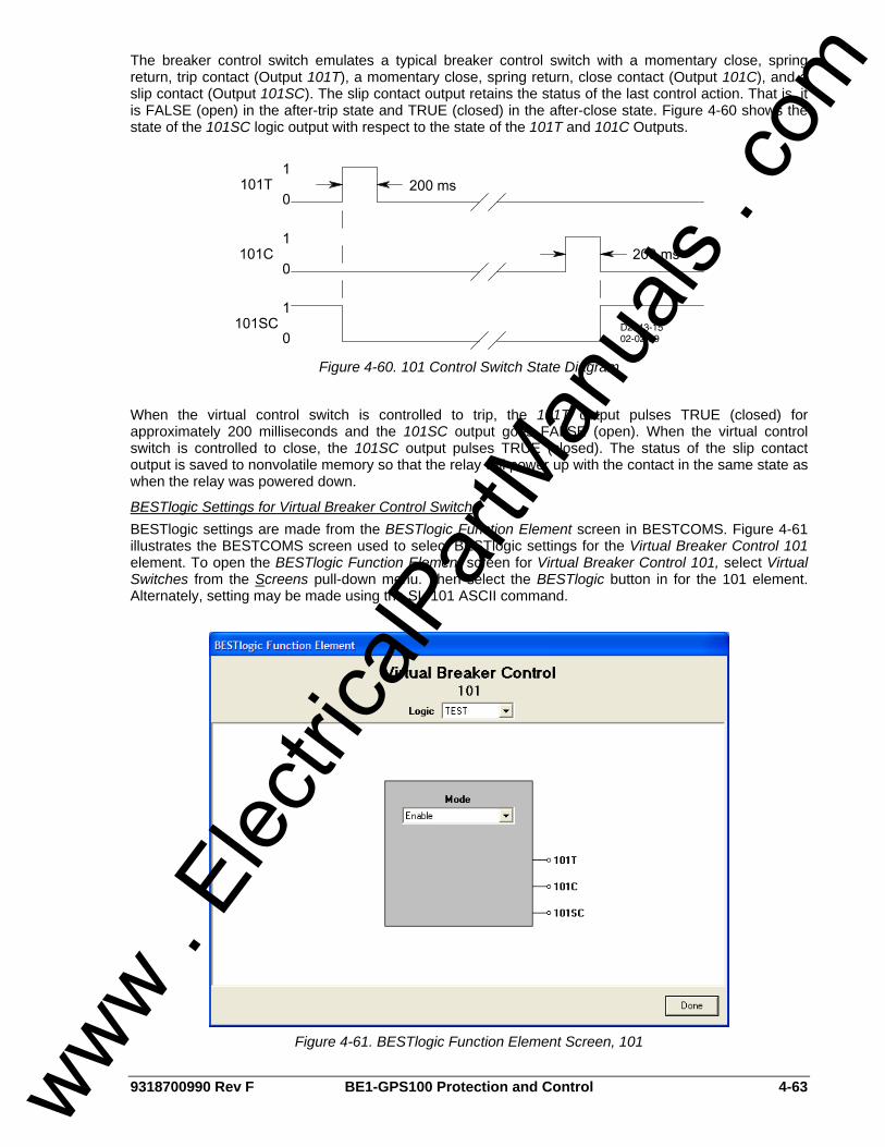
9318700990 Rev F BE1-GPS100 Protection and Control 4-63
The breaker control switch emulates a typical breaker control switch with a momentary close, spring return, trip contact (Output 101T), a momentary close, spring return, close contact (Output 101C), and a slip contact (Output 101SC). The slip contact output retains the status of the last control action. That is, it is FALSE (open) in the after-trip state and TRUE (closed) in the after-close state. Figure 4-60 shows the state of the 101SC logic output with respect to the state of the 101T and 101C Outputs.
Figure 4-60. 101 Control Switch State Diagram
When the virtual control switch is controlled to trip, the 101T output pulses TRUE (closed) for approximately 200 milliseconds and the 101SC output goes FALSE (open). When the virtual control switch is controlled to close, the 101SC output pulses TRUE (closed). The status of the slip contact output is saved to nonvolatile memory so that the relay will power up with the contact in the same state as when the relay was powered down.
BESTlogic Settings for Virtual Breaker Control Switch BESTlogic settings are made from the BESTlogic Function Element screen in BESTCOMS. Figure 4-61 illustrates the BESTCOMS screen used to select BESTlogic settings for the Virtual Breaker Control 101 element. To open the BESTlogic Function Element screen for Virtual Breaker Control 101, select Virtual Switches from the Screens pull-down menu. Then select the BESTlogic button in for the 101 element. Alternately, setting may be made using the SL-101 ASCII command.
Figure 4-61. BESTlogic Function Element Screen, 101
www . El
ectric
alPar
tMan
uals
. com
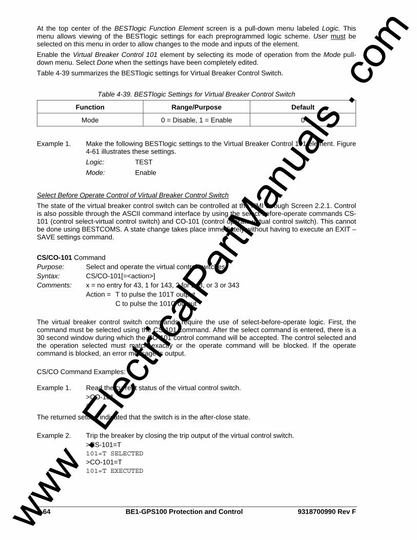
4-64 BE1-GPS100 Protection and Control 9318700990 Rev F
At the top center of the BESTlogic Function Element screen is a pull-down menu labeled Logic. This menu allows viewing of the BESTlogic settings for each preprogrammed logic scheme. User must be selected on this menu in order to allow changes to the mode and inputs of the element. Enable the Virtual Breaker Control 101 element by selecting its mode of operation from the Mode pull-down menu. Select Done when the settings have been completely edited. Table 4-39 summarizes the BESTlogic settings for Virtual Breaker Control Switch.
Table 4-39. BESTlogic Settings for Virtual Breaker Control Switch
Function Range/Purpose Default
Mode 0 = Disable, 1 = Enable 0
Example 1. Make the following BESTlogic settings to the Virtual Breaker Control 101 element. Figure
4-61 illustrates these settings. Logic: TEST Mode: Enable
Select Before Operate Control of Virtual Breaker Control Switch The state of the virtual breaker control switch can be controlled at the HMI through Screen 2.2.1. Control is also possible through the ASCII command interface by using the select-before-operate commands CS-101 (control select-virtual control switch) and CO-101 (control operate-virtual control switch). This cannot be done using BESTCOMS. A state change takes place immediately without having to execute an EXIT – SAVE settings command. CS/CO-101 Command Purpose: Select and operate the virtual control switches. Syntax: CS/CO-101[=<action>] Comments: x = no entry for 43, 1 for 143, 2 for 243, or 3 or 343 Action = T to pulse the 101T output C to pulse the 101C output The virtual breaker control switch commands require the use of select-before-operate logic. First, the command must be selected using the CS-101 command. After the select command is entered, there is a 30 second window during which the CO-101 control command will be accepted. The control selected and the operation selected must match exactly or the operate command will be blocked. If the operate command is blocked, an error message is output. CS/CO Command Examples:
Example 1. Read the current status of the virtual control switch. >CO-101 C
The returned setting indicated that the switch is in the after-close state. Example 2. Trip the breaker by closing the trip output of the virtual control switch. >CS-101=T 101=T SELECTED >CO-101=T 101=T EXECUTED
www . El
ectric
alPar
tMan
uals
. com

9318700990 Rev F BE1-GPS100 Protection and Control 4-65
Retrieving Virtual Breaker Control Switch Status from the Relay The virtual breaker control switch state (after-trip or after-close) can be determined through the ASCII command interface by using the RG-STAT (reports general-status) command. This cannot be done using BESTCOMS. See Section 6, Reporting and Alarm Functions, General Status Reporting, for more information. HMI Screen 2.2.1 provides switch control and also displays the current status of the virtual control switches (after-trip or after-close). As the previous Example 1 demonstrated, the state of the virtual breaker control switch can be determined using the CO-101 command in a read-only mode.
www . El
ectric
alPar
tMan
uals
. com

4-66 BE1-GPS100 Protection and Control 9318700990 Rev F
This page intentionally left blank.
www . El
ectric
alPar
tMan
uals
. com
9318700990 Rev F BE1-GPS100 Metering i
SECTION 5 • METERING TABLE OF CONTENTS
SECTION 5 • METERING......................................................................................................................... 5-1
INTRODUCTION.................................................................................................................................... 5-1 METERING FUNCTIONS...................................................................................................................... 5-1
Auto Ranging...................................................................................................................................... 5-1 BESTCOMS Metering Screen............................................................................................................ 5-1 Voltage ............................................................................................................................................... 5-3 Current................................................................................................................................................ 5-3 Frequency........................................................................................................................................... 5-3 Power Factor ...................................................................................................................................... 5-4 Apparent Power.................................................................................................................................. 5-4 True Power ......................................................................................................................................... 5-4
Figures Figure 5-1. Metering Screen...................................................................................................................... 5-2 Figure 5-2. Relationship of Slip Frequency and Sync Angle to Synchroscope......................................... 5-3
Tables Table 5-1. Auto Ranging Scales for Metered Values ................................................................................ 5-1 Table 5-2. Metering Functions Summary .................................................................................................. 5-2
www . El
ectric
alPar
tMan
uals
. com

ii BE1-GPS100 Metering 9318700990 Rev F
This page intentionally left blank.
www . El
ectric
alPar
tMan
uals
. com

9318700990 Rev F BE1-GPS100 Metering 5-1
SECTION 5 • METERING INTRODUCTION The BE1-GPS100 Generator Protection System measures the voltage and current inputs, displays those values in real time, records those values every ¼ second, and calculates other quantities from the measured inputs.
METERING FUNCTIONS BE1-GPS100 metering functions include voltage, current, frequency, power factor, apparent power, reactive power, and true power. Metered values are viewed through BESTCOMS, any communication port using serial commands, or at the front panel human-machine interface (HMI). Metering functions are summarized in the following paragraphs and in Table 5-2. For assistance with navigating through the HMI metering screens, refer to Section 10, Human-Machine Interface. For information on power, VA, and var calculations, refer to Section 3, Input and Output Functions, Power System Inputs, Power Measurement. Energy measurement is covered in Section 6, Reporting and Alarm Functions.
Auto Ranging The BE1-GPS100 automatically scales metered values. Table 5-1 illustrates the ranges for each value metered.
Table 5-1. Auto Ranging Scales for Metered Values
Unit Display Ranges Metered Value
Whole Units Kilo Units Mega Units Giga Units Current 0 A to 9,999 A 10 kA to 9,999 kA 10 MA N/A Voltage 0 V to 999 V 0 kV to 999 kV N/A N/A
Apparent Power N/A 0 kVA to 000 kVA 1 MVA to 999 MVA 1 GVA to 1000 GVA Reactive Power N/A 0 kvar to 999 kvar 1 Mvar to 999 Mvar 1 Gvar to 1000 Gvar
True Power N/A 0 kW to 999 kW 1 MW to 999 MW 1 GW to 1000 GW Frequency 10 to 75 Hz N/A N/A N/A
BESTCOMS Metering Screen Metered values are viewed through the BESTCOMS Metering screen (see Figure 5-1). To open the Metering screen, select Metering from the Reports pull-down menu. To begin viewing metered values, select the Start Polling button in the bottom right of the screen. Alternately, metering can be performed using the ASCII command interface or HMI using Screens 3.1 through 3.11. Refer to Table 5-2 for a list of ASCII commands used for metering.
www . El
ectric
alPar
tMan
uals
. com
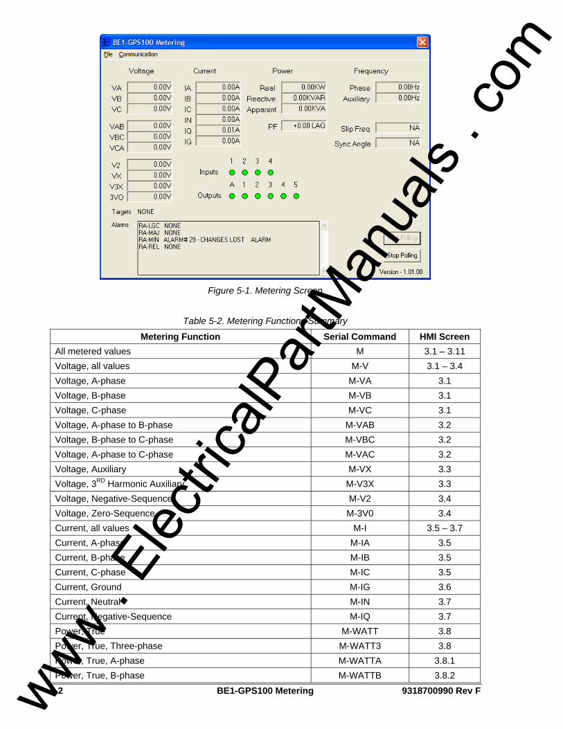
5-2 BE1-GPS100 Metering 9318700990 Rev F
Figure 5-1. Metering Screen
Table 5-2. Metering Functions Summary
Metering Function Serial Command HMI Screen All metered values M 3.1 – 3.11 Voltage, all values M-V 3.1 – 3.4 Voltage, A-phase M-VA 3.1 Voltage, B-phase M-VB 3.1 Voltage, C-phase M-VC 3.1 Voltage, A-phase to B-phase M-VAB 3.2 Voltage, B-phase to C-phase M-VBC 3.2 Voltage, A-phase to C-phase M-VAC 3.2 Voltage, Auxiliary M-VX 3.3 Voltage, 3RD Harmonic Auxiliary M-V3X 3.3 Voltage, Negative-Sequence M-V2 3.4 Voltage, Zero-Sequence M-3V0 3.4 Current, all values M-I 3.5 – 3.7 Current, A-phase M-IA 3.5 Current, B-phase M-IB 3.5 Current, C-phase M-IC 3.5 Current, Ground M-IG 3.6 Current, Neutral M-IN 3.7 Current, Negative-Sequence M-IQ 3.7 Power, True M-WATT 3.8 Power, True, Three-phase M-WATT3 3.8 Power, True, A-phase M-WATTA 3.8.1 Power, True, B-phase M-WATTB 3.8.2
www . El
ectric
alPar
tMan
uals
. com

9318700990 Rev F BE1-GPS100 Metering 5-3
Metering Function Serial Command HMI Screen Power, True, C-phase M-WATTC 3.8.3 Power, Reactive M-VAR 3.8 Power, Reactive, Three-phase M-VAR3 3.8 Power, Reactive, A-phase M-VARA 3.8.1 Power, Reactive, B-phase M-VARB 3.8.2 Power, Reactive, C-phase M-VARC 3.8.3 Power, Apparent (VA) M-S 3.9 Power Factor M-PF 3.9 Frequency M-FREQ 3.10 – 3.11 Frequency, Phase M-FREQP 3.10 Frequency, Auxiliary M-FREQX 3.10 Frequency, Slip M-FREQS 3.11 Metered sync angle between Phase and Aux inputs M-SYNC 3.11
Voltage The BE1-GPS100 meters A-phase voltage, B-phase voltage, C-phase voltage, voltage across phases A and B, phases B and C, and phases A and C. Negative-sequence voltage and three-phase zero-sequence (residual) voltage are also metered. The VTP connection determines what is measured. For the auxiliary voltage input, fundamental (Vx) and 3rd harmonic voltages (V3X) are measured.
Current Metered current includes A-phase current, B-phase current, C-phase current, neutral three-phase zero-sequence current and ground current. Other metered currents include negative-sequence current and derived neutral current. All current measurements are auto ranging. Current is displayed in amps up to 9,999 A and then switches to kilo at 10.0 kA to 9,999 kA.
Frequency Frequency is metered over a range of 10 to 75 hertz. If the measured frequency is outside this range, the nominal system frequency will be displayed. Frequency is sensed from A-phase to Neutral for four-wire sensing systems or from A-phase to B-phase for three-wire sensing systems. The frequency of auxiliary voltage VX is also measured. Refer to Figure 5-2.
Figure 5-2. Relationship of Slip Frequency and Sync Angle to Synchroscope
www . El
ectric
alPar
tMan
uals
. com

5-4 BE1-GPS100 Metering 9318700990 Rev F
Power Factor Three-phase power factor is metered over a range of maximum lagging (-0.00) to unity (1.00) to maximum leading (+0.00).
Apparent Power Metered apparent power is displayed over a range of –7,500 kilovolt amperes to +7,500 kilovars on five-ampere nominal systems. One-ampere nominal systems meter reactive power over a range of –1,500 kilovars to +1,500 kilovars.
True Power True power is metered over a range of –7,500 kilowatts to +7,500 kilowatts on five-ampere nominal systems. One-ampere nominal systems meter true power over a range of –1,500 watts to +1,500 watts.
www . El
ectric
alPar
tMan
uals
. com
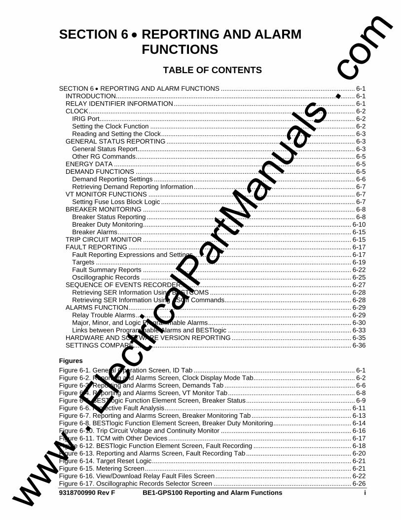
9318700990 Rev F BE1-GPS100 Reporting and Alarm Functions i
SECTION 6 • REPORTING AND ALARM FUNCTIONS
TABLE OF CONTENTS SECTION 6 • REPORTING AND ALARM FUNCTIONS .......................................................................... 6-1
INTRODUCTION.................................................................................................................................... 6-1 RELAY IDENTIFIER INFORMATION.................................................................................................... 6-1 CLOCK................................................................................................................................................... 6-2
IRIG Port............................................................................................................................................. 6-2 Setting the Clock Function ................................................................................................................. 6-2 Reading and Setting the Clock........................................................................................................... 6-3
GENERAL STATUS REPORTING ........................................................................................................ 6-3 General Status Report........................................................................................................................ 6-3 Other RG Commands......................................................................................................................... 6-5
ENERGY DATA ..................................................................................................................................... 6-5 DEMAND FUNCTIONS ......................................................................................................................... 6-5
Demand Reporting Settings ............................................................................................................... 6-6 Retrieving Demand Reporting Information......................................................................................... 6-7
VT MONITOR FUNCTIONS .................................................................................................................. 6-7 Setting Fuse Loss Block Logic ........................................................................................................... 6-7
BREAKER MONITORING ..................................................................................................................... 6-8 Breaker Status Reporting ................................................................................................................... 6-8 Breaker Duty Monitoring................................................................................................................... 6-10 Breaker Alarms................................................................................................................................. 6-15
TRIP CIRCUIT MONITOR ................................................................................................................... 6-15 FAULT REPORTING ........................................................................................................................... 6-17
Fault Reporting Expressions and Settings ....................................................................................... 6-17 Targets ............................................................................................................................................. 6-19 Fault Summary Reports ................................................................................................................... 6-22 Oscillographic Records .................................................................................................................... 6-25
SEQUENCE OF EVENTS RECORDER.............................................................................................. 6-27 Retrieving SER Information Using BESTCOMS .............................................................................. 6-28 Retrieving SER Information Using ASCII Commands...................................................................... 6-28
ALARMS FUNCTION........................................................................................................................... 6-29 Relay Trouble Alarms....................................................................................................................... 6-29 Major, Minor, and Logic Programmable Alarms............................................................................... 6-30 Links between Programmable Alarms and BESTlogic .................................................................... 6-33
HARDWARE AND SOFTWARE VERSION REPORTING .................................................................. 6-35 SETTINGS COMPARE........................................................................................................................ 6-36
Figures Figure 6-1. General Operation Screen, ID Tab ......................................................................................... 6-1 Figure 6-2. Reporting and Alarms Screen, Clock Display Mode Tab........................................................ 6-2 Figure 6-3. Reporting and Alarms Screen, Demands Tab ........................................................................ 6-6 Figure 6-4. Reporting and Alarms Screen, VT Monitor Tab...................................................................... 6-8 Figure 6-5. BESTlogic Function Element Screen, Breaker Status............................................................ 6-9 Figure 6-6. Protective Fault Analysis....................................................................................................... 6-11 Figure 6-7. Reporting and Alarms Screen, Breaker Monitoring Tab....................................................... 6-13 Figure 6-8. BESTlogic Function Element Screen, Breaker Duty Monitoring........................................... 6-14 Figure 6-10. Trip Circuit Voltage and Continuity Monitor ........................................................................ 6-16 Figure 6-11. TCM with Other Devices ..................................................................................................... 6-17 Figure 6-12. BESTlogic Function Element Screen, Fault Recording ...................................................... 6-18 Figure 6-13. Reporting and Alarms Screen, Fault Recording Tab .......................................................... 6-20 Figure 6-14. Target Reset Logic.............................................................................................................. 6-21 Figure 6-15. Metering Screen.................................................................................................................. 6-21 Figure 6-16. View/Download Relay Fault Files Screen........................................................................... 6-22 Figure 6-17. Oscillographic Records Selector Screen ............................................................................ 6-26 www .
Elec
tricalP
artM
anua
ls . c
om
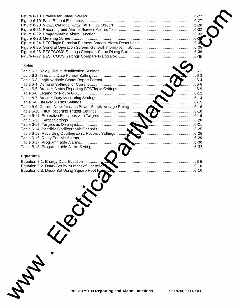
ii BE1-GPS100 Reporting and Alarm Functions 9318700990 Rev F
Figure 6-18. Browse for Folder Screen ................................................................................................... 6-27 Figure 6-19. Fault Record Filenames...................................................................................................... 6-27 Figure 6-20. View/Download Relay Fault Files Screen ........................................................................... 6-28 Figure 6-21. Reporting and Alarms Screen, Alarms Tab ........................................................................ 6-32 Figure 6-22. Programmable Alarm Function ........................................................................................... 6-33 Figure 6-23. Metering Screen.................................................................................................................. 6-33 Figure 6-24. BESTlogic Function Element Screen, Alarm Reset Logic .................................................. 6-34 Figure 6-25. General Operation Screen, General Information Tab......................................................... 6-35 Figure 6-26. BESTCOMS Settings Compare Setup Dialog Box ............................................................. 6-36 Figure 6-27. BESTCOMS Settings Compare Dialog Box........................................................................ 6-36
Tables Table 6-1. Relay Circuit Identification Settings.......................................................................................... 6-1 Table 6-2. Time and Date Format Settings ............................................................................................... 6-3 Table 6-3. Logic Variable Status Report Format ....................................................................................... 6-4 Table 6-4. Demand Settings for Current.................................................................................................... 6-6 Table 6-5. Breaker Status Reporting BESTlogic Settings......................................................................... 6-9 Table 6-6. Legend for Figure 6-6............................................................................................................. 6-12 Table 6-7. Breaker Duty Monitoring Settings .......................................................................................... 6-14 Table 6-8. Breaker Alarms Settings......................................................................................................... 6-15 Table 6-9. Current Draw for each Power Supply Voltage Rating............................................................ 6-16 Table 6-10. Fault Reporting Trigger Settings .......................................................................................... 6-18 Table 6-11. Protective Functions with Targets ........................................................................................ 6-19 Table 6-12. Target Settings ..................................................................................................................... 6-20 Table 6-13. Targets as Displayed............................................................................................................ 6-21 Table 6-14. Possible Oscillographic Records.......................................................................................... 6-25 Table 6-15. Recording Oscillographic Records Settings......................................................................... 6-26 Table 6-16. Relay Trouble Alarms........................................................................................................... 6-29 Table 6-17. Programmable Alarms.......................................................................................................... 6-30 Table 6-18. Programmable Alarm Settings ............................................................................................. 6-32
Equations Equation 6-1. Energy Data Equation......................................................................................................... 6-5 Equation 6-2. Dmax Set by Number of Operations ................................................................................. 6-10 Equation 6-3. Dmax Set Using Square Root Factor................................................................................ 6-10
www . El
ectric
alPar
tMan
uals
. com
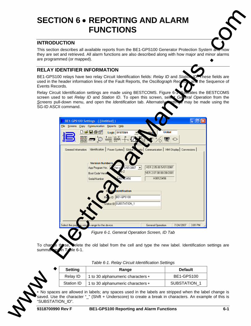
9318700990 Rev F BE1-GPS100 Reporting and Alarm Functions 6-1
SECTION 6 • REPORTING AND ALARM FUNCTIONS
INTRODUCTION This section describes all available reports from the BE1-GPS100 Generator Protection System and how they are set and retrieved. All alarm functions are also described along with how major and minor alarms are programmed (or mapped).
RELAY IDENTIFIER INFORMATION BE1-GPS100 relays have two relay Circuit Identification fields: Relay ID and Station ID. These fields are used in the header information lines of the Fault Reports, the Oscillograph Records, and the Sequence of Events Records. Relay Circuit Identification settings are made using BESTCOMS. Figure 6-1 illustrates the BESTCOMS screen used to set Relay ID and Station ID. To open this screen, select General Operation from the Screens pull-down menu, and open the Identification tab. Alternately, settings may be made using the SG-ID ASCII command.
Figure 6-1. General Operation Screen, ID Tab
To change these, delete the old label from the cell and type the new label. Identification settings are summarized in Table 6-1.
Table 6-1. Relay Circuit Identification Settings
Setting Range Default Relay ID 1 to 30 alphanumeric characters ∗ BE1-GPS100
Station ID 1 to 30 alphanumeric characters ∗ SUBSTATION_1
∗ No spaces are allowed in labels; any spaces used in the labels are stripped when the label change is saved. Use the character “_” (Shift + Underscore) to create a break in characters. An example of this is “SUBSTATION_ID”.
www . El
ectric
alPar
tMan
uals
. com
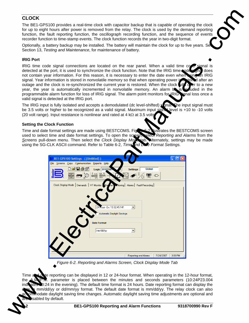
6-2 BE1-GPS100 Reporting and Alarm Functions 9318700990 Rev F
CLOCK The BE1-GPS100 provides a real-time clock with capacitor backup that is capable of operating the clock for up to eight hours after power is removed from the relay. The clock is used by the demand reporting function, the fault reporting function, the oscillograph recording function, and the sequence of events recorder function to time-stamp events. The clock function records the year in two-digit format. Optionally, a battery backup may be installed. The battery will maintain the clock for up to five years. See Section 13, Testing and Maintenance, for maintenance of battery.
IRIG Port IRIG time code signal connections are located on the rear panel. When a valid time code signal is detected at the port, it is used to synchronize the clock function. Note that the IRIG time code signal does not contain year information. For this reason, it is necessary to enter the date even when using an IRIG signal. Year information is stored in nonvolatile memory so that when operating power is restored after an outage and the clock is re-synchronized the current year is restored. When the clock rolls over to a new year, the year is automatically incremented in nonvolatile memory. An alarm bit is included in the programmable alarm function for loss of IRIG signal. The alarm point monitors for IRIG signal loss once a valid signal is detected at the IRIG port. The IRIG input is fully isolated and accepts a demodulated (dc level-shifted) signal. The input signal must be 3.5 volts or higher to be recognized as a valid signal. Maximum input signal level is +10 to -10 volts (20 volt range). Input resistance is nonlinear and rated at 4 kΩ at 3.5 volts.
Setting the Clock Function Time and date format settings are made using BESTCOMS. Figure 6-2 illustrates the BESTCOMS screen used to select time and date format settings. To open the screen, select Reporting and Alarms from the Screens pull-down menu. Then select the Clock Display Mode tab. Alternately, settings may be made using the SG-CLK ASCII command. Refer to Table 6-2, Time and Date Format Settings.
Figure 6-2. Reporting and Alarms Screen, Clock Display Mode Tab
Time and date reporting can be displayed in 12 or 24-hour format. When operating in the 12-hour format, the A.M./P.M. parameter is placed between the minutes and seconds parameters (10:24P23.004 indicates 10:24 in the evening). The default time format is 24 hours. Date reporting format can display the date in mm/dd/yy or dd/mm/yy format. The default date format is mm/dd/yy. The relay clock can also accommodate daylight saving time changes. Automatic daylight saving time adjustments are optional and are disabled by default.
www . El
ectric
alPar
tMan
uals
. com
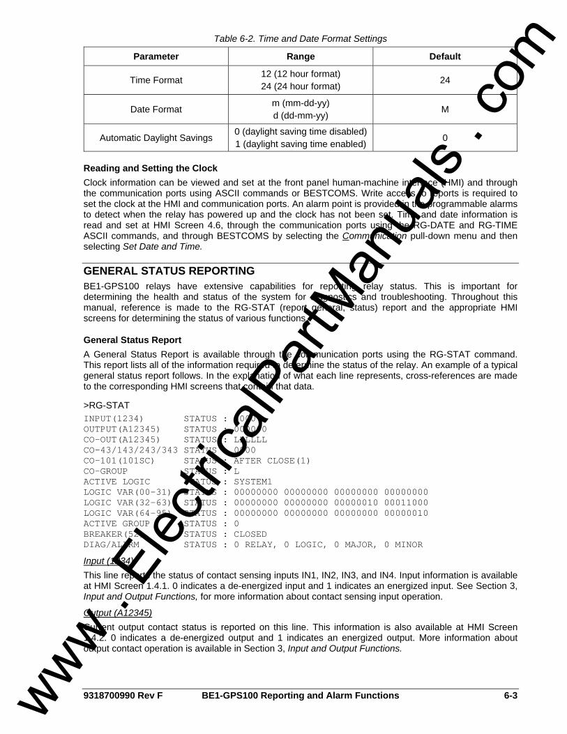
9318700990 Rev F BE1-GPS100 Reporting and Alarm Functions 6-3
Table 6-2. Time and Date Format Settings
Parameter Range Default
Time Format 12 (12 hour format) 24 (24 hour format) 24
Date Format m (mm-dd-yy) d (dd-mm-yy) M
Automatic Daylight Savings 0 (daylight saving time disabled) 1 (daylight saving time enabled) 0
Reading and Setting the Clock Clock information can be viewed and set at the front panel human-machine interface (HMI) and through the communication ports using ASCII commands or BESTCOMS. Write access to reports is required to set the clock at the HMI and communication ports. An alarm point is provided in the programmable alarms to detect when the relay has powered up and the clock has not been set. Time and date information is read and set at HMI Screen 4.6, through the communication ports using the RG-DATE and RG-TIME ASCII commands, and through BESTCOMS by selecting the Communication pull-down menu and then selecting Set Date and Time.
GENERAL STATUS REPORTING BE1-GPS100 relays have extensive capabilities for reporting relay status. This is important for determining the health and status of the system for diagnostics and troubleshooting. Throughout this manual, reference is made to the RG-STAT (report general, status) report and the appropriate HMI screens for determining the status of various functions.
General Status Report A General Status Report is available through the communication ports using the RG-STAT command. This report lists all of the information required to determine the status of the relay. An example of a typical general status report follows. In the explanation of what each line represents, cross-references are made to the corresponding HMI screens that contain that data.
>RG-STAT INPUT(1234) STATUS : 0000 OUTPUT(A12345) STATUS : 000000 CO-OUT(A12345) STATUS : LLLLLL CO-43/143/243/343 STATUS : 0000 CO-101(101SC) STATUS : AFTER CLOSE(1) CO-GROUP STATUS : L ACTIVE LOGIC STATUS : SYSTEM1 LOGIC VAR(00-31) STATUS : 00000000 00000000 00000000 00000000 LOGIC VAR(32-63) STATUS : 00000000 00000000 00000010 00011000 LOGIC VAR(64-95) STATUS : 00000000 00000000 00000000 00000010 ACTIVE GROUP STATUS : 0 BREAKER(52) STATUS : CLOSED DIAG/ALARM STATUS : 0 RELAY, 0 LOGIC, 0 MAJOR, 0 MINOR
Input (1234) This line reports the status of contact sensing inputs IN1, IN2, IN3, and IN4. Input information is available at HMI Screen 1.4.1. 0 indicates a de-energized input and 1 indicates an energized input. See Section 3, Input and Output Functions, for more information about contact sensing input operation.
Output (A12345) Current output contact status is reported on this line. This information is also available at HMI Screen 1.4.2. 0 indicates a de-energized output and 1 indicates an energized output. More information about output contact operation is available in Section 3, Input and Output Functions.
www . El
ectric
alPar
tMan
uals
. com
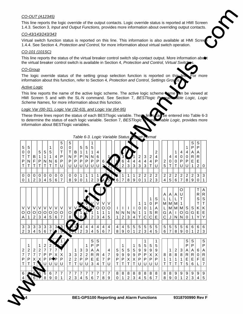
6-4 BE1-GPS100 Reporting and Alarm Functions 9318700990 Rev F
CO-OUT (A12345) This line reports the logic override of the output contacts. Logic override status is reported at HMI Screen 1.4.3. Section 3, Input and Output Functions, provides more information about overriding output contacts.
CO-43/143/243/343 Virtual switch function status is reported on this line. This information is also available at HMI Screen 1.4.4. See Section 4, Protection and Control, for more information about virtual switch operation.
CO-101 (101SC) This line reports the status of the virtual breaker control switch slip-contact output. More information about the virtual breaker control switch is available in Section 4, Protection and Control, Virtual Switches.
CO-Group The logic override status of the setting group selection function is reported on this line. For more information about this function, refer to Section 4, Protection and Control, Settings Groups.
Active Logic This line reports the name of the active logic scheme. The active logic scheme name can be viewed at HMI Screen 5 and with the SL-N command. See Section 7, BESTlogic Programmable Logic, Logic Scheme Names, for more information about this function.
Logic Var (00-31), Logic Var (32-63), and Logic Var (64-95) These three lines report the status of each BESTlogic variable. These lines can be entered into Table 6-3 to determine the status of each logic variable. Section 7, BESTlogic Programmable Logic, provides more information about BESTlogic variables.
Table 6-3. Logic Variable Status Report Format
5 0 TPT
50TNT
BFT
51PT
51NT
151NT
46T
50TPPU
50TNPU
BFPU
51PPU
51NPU
151NPU
46PU
62
162
262
362
43
143
243
343
24T
24PU
25
40T
140T
40PU
140PU
SPARE1
SPARE2 0
00
01
02
03
04
05
06
07
08
09
10
11
12
13
14
15
16
17
18
19
20
21
22
23
24
25
26
27
28
29
30
31
VOA
VO1
VO2
VO3
VO4
VO5
VO6
VO7
VO8
VO9
VO10
VO11
VO12
VO13
VO14
VO15
IN1
IN2
IN3
IN4
101T
101C
101SC
SPARE
ALMLGC
ALMMAJ
ALMMIN
OUT1MON
SG0
SG1
TRSTKEY
ARSTKEY
32
33
34
35
36
37
38
39
40
41
42
43
44
45
46
47
48
49
50
51
52
53
54
55
56
57
58
59
60
61
62
63
27PT
127PT
27XT
127XT
27PPU
127PPU
27XPU
127XPU
32T
132T
32PU
132PU
SPARE3
SPARE4
47T
47PU
59PT
159PT
59XT
159XT
59PPU
159PPU
59XPU
159XPU
81T
181T
281T
381T
SPARE5
SPARE6
60FL
SPARE7
64
65
66
67
68
69
70
71
72
73
74
75
76
77
78
79
80
81
82
83
84
85
86
87
88
89
90
91
92
93
94
95
www . El
ectric
alPar
tMan
uals
. com

9318700990 Rev F BE1-GPS100 Reporting and Alarm Functions 6-5
See Tables 7-1 and 7-2, Logic Variable Names and Descriptions, for a cross-reference of each BESTlogic bit.
Active Group The active group is indicated on this line. HMI Screen 1.4.5 also provides this information. See Section 4, Protection and Control, for more information about setting groups.
Breaker (52) This line reports the state of the breaker. This information is also available at HMI Screen 1.4.6. More information about breaker status is provided in the Breaker Monitoring subsection.
Diag/Alarm This line reports the status of the Relay Trouble Alarm, Major Alarm, Minor Alarm, and Logic Alarm. The status of these alarms can be viewed at HMI Screen 1.2. Front panel LEDs also indicate the status of the Relay Trouble Alarm, Minor Alarm, and Major Alarm. Alarm status is also available through the communication ports. The SA-MIN command reports the Minor Alarm status, the SA-MAJ command reports the Major Alarm status, and the SA-LGC command reports the Logic Alarm status.
Other RG Commands There are several other RG commands in addition to the RG-STAT command. These include RG-TIME, RG-DATE, RG-TARG, RG-VER, and RG-DST. These commands are covered in detail in respective paragraphs in this section. As with other commands, a combination read command is available to read several items in a group. If the command RG is entered by itself, the relay reports the time, date, target information, and other reports in the following example. RG-VER and RG-STAT commands have multiple line outputs and these are not read at the RG command.
ENERGY DATA Energy information in the form of watthours and varhours is measured and reported by the BE1-GPS100. Both positive and negative values are reported in three-phase, primary units. The BE1-GPS100 reports forward watts when power is fed from the generator into the bus. Forward vars are reported when lagging vars are fed from the generator into the bus. Thus, positive watts and vars are reported when a lagging power factor load is being fed from the generator. Watthour and varhour values are calculated per minute as shown in Equation 6-1.
varsorwattsSecondaryminutes60
RatioCTPrimaryRatioVTPrimary×
×
Equation 6-1. Energy Data Equation
Watt and var values are updated every 250 milliseconds and watthour and varhour values are logged once every minute. Energy registers are stored in nonvolatile memory during every update. Watthour values and varhour values can be read, reset, or changed through the HMI or communication ports. Watthour values can be accessed at the HMI through Screens 4.5.1 (positive values) and 4.5.2 (negative values). Varhour values can be accessed at the HMI through Screens 4.5.3 (positive values) and 4.5.4 (negative values). ASCII command RE-KWH (report energy-kilowatthours) gives access to both positive and negative watthour values. A lagging power factor load will report positive watts and positive vars.
ASCII command RE-KVAR (report energy - kilovarhours) gives access to both positive and negative varhour values. Energy data is also available through the communication ports by using the RE (report energy) command. This read-only command returns both the watthours and var-hours.
DEMAND FUNCTIONS The demand reporting function continuously calculates demand values for the three-phase currents, three-phase power, three-phase reactive power, neutral current (three-phase residual 3IO), and negative-sequence current. Demand values are recorded with time stamps for Peak Since Reset, Yesterday's Peak, and Today's Peak. Programmable alarm points can be set to alarm if thresholds are exceeded for overload and unbalanced loading conditions.
www . El
ectric
alPar
tMan
uals
. com
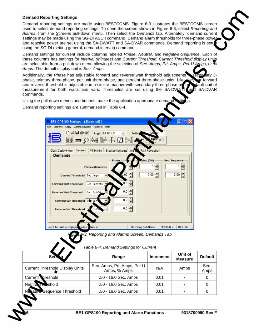
6-6 BE1-GPS100 Reporting and Alarm Functions 9318700990 Rev F
Demand Reporting Settings Demand reporting settings are made using BESTCOMS. Figure 6-3 illustrates the BESTCOMS screen used to select demand reporting settings. To open the screen shown in Figure 6-3, select Reporting and Alarms, from the Screens pull-down menu. Then select the Demands tab. Alternately, demand current settings may be made using the SG-DI ASCII command. Demand alarm thresholds for three-phase power and reactive power are set using the SA-DWATT and SA-DVAR commands. Demand reporting is setup using the SG-DI (setting general, demand interval) command. Demand settings for current include columns labeled Phase, Neutral, and Negative-Sequence. Each of these columns has settings for Interval (Minutes) and Current Threshold. Current Threshold display units are selectable from a pull-down menu allowing the selection of Sec. Amps, Pri. Amps, Per U Amps, or % Amps. The default display unit is Sec. Amps. Additionally, the Phase has adjustable forward and reverse watt threshold adjustments in secondary 3-phase, primary three-phase, per unit three-phase, and percent three-phase units. Likewise, var forward and reverse threshold is adjustable in a similar manner with secondary three-phase as the default unit of measurement for both watts and vars. Thresholds are set using the SA-DWATT and SA-DVAR commands. Using the pull-down menus and buttons, make the application appropriate demand settings. Demand reporting settings are summarized in Table 6-4.
Figure 6-3. Reporting and Alarms Screen, Demands Tab
Table 6-4. Demand Settings for Current
Setting Range Increment Unit of Measure Default
Current Threshold Display Units Sec. Amps, Pri. Amps, Per U Amps, % Amps N/A Amps Sec.
Amps Current Threshold .50 - 16.0 Sec. Amps 0.01 ∗ 0
Neutral Threshold .50 - 16.0 Sec. Amps 0.01 ∗ 0
Negative-Sequence Threshold .50 - 16.0 Sec. Amps 0.01 ∗ 0
www . El
ectric
alPar
tMan
uals
. com

9318700990 Rev F BE1-GPS100 Reporting and Alarm Functions 6-7
Setting Range Increment Unit of Measure Default
Forward Watt Threshold Reverse Watt Threshold
0.0 - 8,500 Sec. Watts
0.1 for 0 to 99.9
1 for 100 to 8,500
Watts 0
Forward Var Threshold Reverse Var Threshold
0.0 - 8,500 Sec. Vars
0.1 for 0 to 99.9
1 for 100 to 8,500
Vars 0
∗ Unit of measure is based on the threshold display unit’s selection. The default is secondary amperes, secondary watts, and secondary vars.
Retrieving Demand Reporting Information Values and time stamps in the demand registers are reported in primary values. They can be read at the front panel HMI and through the communication ports. Today's Peak, Yesterday's Peak, and Peak Since Reset demand values are accessed through HMI Screen 4.4, DEMAND REPORTS. Demand values viewed at the HMI can be reset by pressing the Reset key. When the Reset key is pressed, the viewed register value is set to zero and then updated on the next processing loop with the currently calculated demand value. No write access is needed to reset demand register values at the HMI. It is also possible to preset a value into the Peak Since Demand registers. This can be done by pressing the Edit key. Write access to the Reports functional area is required to preset values at the HMI. Values and time stamps in the demand registers can also be read through the communication ports by using the RD (report demands) command. Demand information specific to current, vars, or watts can be obtained by including an object name with the command function (R) and subgroup (D). Today's Peak, Yesterday's Peak, and Peak Since reset information for current is available using the RD-TI, RD-YI, and RD-PI commands. Today's Peak, Yesterday's Peak and Peak Since Reset information for reactive power is available using the RD-TVAR, RD-YVAR, and RD-PVAR commands. Today's Peak, Yesterday's Peak and Peak Since Reset information for power is available using the RD-TWATT, RD-YWATT and RD-PWATT commands.
VT MONITOR FUNCTIONS The VT Monitor reporting function allows the user to enable or disable Fuse Loss Block Logic. The Block Voltage Control box can be checked (enabled) or unchecked (disabled) for the 51/27 elements. Likewise, Block Phase, Block 3V0, and Block V2 can each be independently checked (enabled) or unchecked (disabled) for the 27 and 59 elements. The default value for all of these logic functions is enabled.
Setting Fuse Loss Block Logic Fuse Loss Block Logic settings can be made using BESTCOMS. Figure 6-4 illustrates the BESTCOMS screen used to select these reporting settings. To open the screen shown in Figure 6-4, select Reporting and Alarms, from the Screens pull-down menu. Then select the VT Monitor tab. Alternately, settings may be made using the SP-60FL ASCII command.
www . El
ectric
alPar
tMan
uals
. com
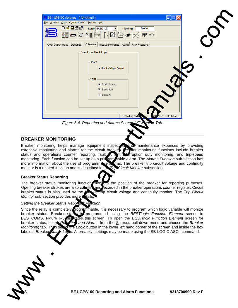
6-8 BE1-GPS100 Reporting and Alarm Functions 9318700990 Rev F
Figure 6-4. Reporting and Alarms Screen, VT Monitor Tab
BREAKER MONITORING Breaker monitoring helps manage equipment inspection and maintenance expenses by providing extensive monitoring and alarms for the circuit breaker. Breaker monitoring functions include breaker status and operations counter reporting, fault current interruption duty monitoring, and trip-speed monitoring. Each function can be set up as a programmable alarm. The Alarms Function sub-section has more information about the use of programmable alarms. The breaker trip circuit voltage and continuity monitor is a related function and is described in the Trip Circuit Monitor subsection.
Breaker Status Reporting The breaker status monitoring function monitors the position of the breaker for reporting purposes. Opening breaker strokes are also counted and recorded in the breaker operations counter register. Circuit breaker status is also used by the breaker trip circuit voltage and continuity monitor. The Trip Circuit Monitor sub-section provides more details.
Setting the Breaker Status Reporting Function Since the relay is completely programmable, it is necessary to program which logic variable will monitor breaker status. Breaker status is programmed using the BESTlogic Function Element screen in BESTCOMS. Figure 6-5 illustrates this screen. To open the BESTlogic Function Element screen for breaker status, select Reporting and Alarms from the Screens pull-down menu and choose the Breaker Monitoring tab. Then select the Logic button in the lower left hand corner of the screen and inside the box labeled, Breaker Status Logic. Alternately, settings may be made using the SB-LOGIC ASCII command.
www . El
ectric
alPar
tMan
uals
. com
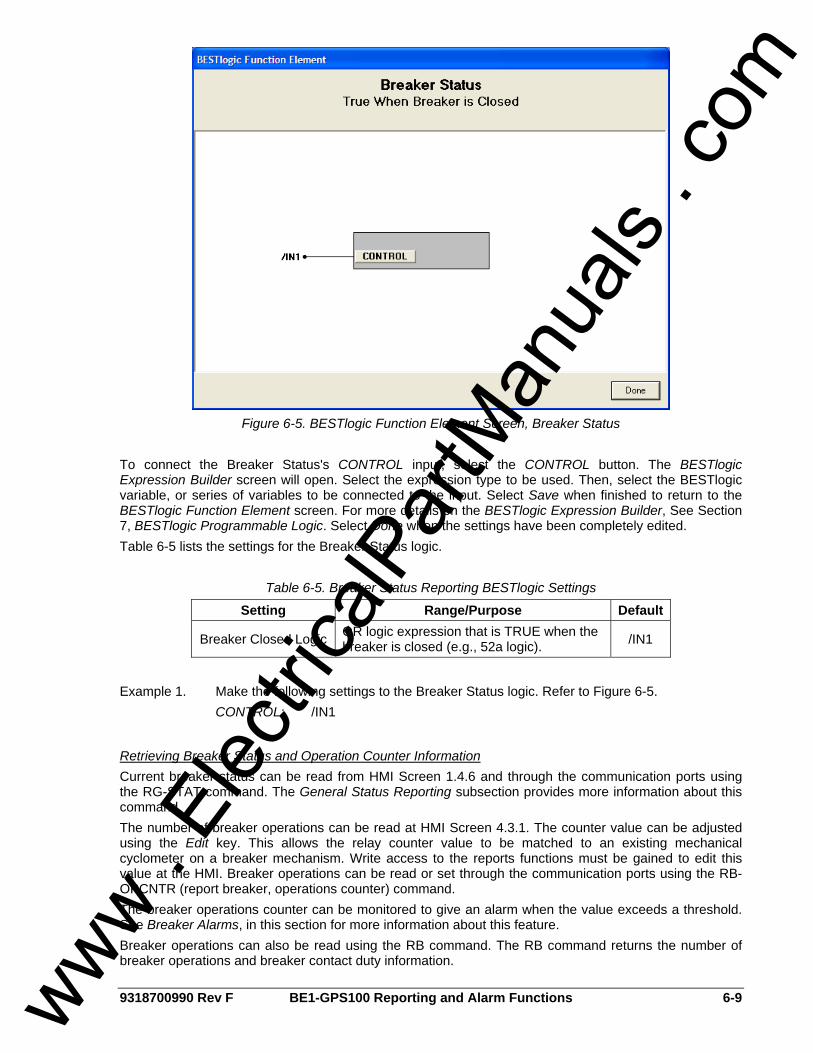
9318700990 Rev F BE1-GPS100 Reporting and Alarm Functions 6-9
Figure 6-5. BESTlogic Function Element Screen, Breaker Status
To connect the Breaker Status's CONTROL input, select the CONTROL button. The BESTlogic Expression Builder screen will open. Select the expression type to be used. Then, select the BESTlogic variable, or series of variables to be connected to the input. Select Save when finished to return to the BESTlogic Function Element screen. For more details on the BESTlogic Expression Builder, See Section 7, BESTlogic Programmable Logic. Select Done when the settings have been completely edited. Table 6-5 lists the settings for the Breaker Status logic.
Table 6-5. Breaker Status Reporting BESTlogic Settings
Setting Range/Purpose Default
Breaker Closed Logic OR logic expression that is TRUE when the breaker is closed (e.g., 52a logic). /IN1
Example 1. Make the following settings to the Breaker Status logic. Refer to Figure 6-5. CONTROL: /IN1
Retrieving Breaker Status and Operation Counter Information Current breaker status can be read from HMI Screen 1.4.6 and through the communication ports using the RG-STAT command. The General Status Reporting subsection provides more information about this command. The number of breaker operations can be read at HMI Screen 4.3.1. The counter value can be adjusted using the Edit key. This allows the relay counter value to be matched to an existing mechanical cyclometer on a breaker mechanism. Write access to the reports functions must be gained to edit this value at the HMI. Breaker operations can be read or set through the communication ports using the RB-OPCNTR (report breaker, operations counter) command. The breaker operations counter can be monitored to give an alarm when the value exceeds a threshold. See Breaker Alarms, in this section for more information about this feature. Breaker operations can also be read using the RB command. The RB command returns the number of breaker operations and breaker contact duty information.
www . El
ectric
alPar
tMan
uals
. com
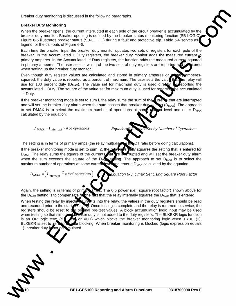
6-10 BE1-GPS100 Reporting and Alarm Functions 9318700990 Rev F
Breaker duty monitoring is discussed in the following paragraphs.
Breaker Duty Monitoring When the breaker opens, the current interrupted in each pole of the circuit breaker is accumulated by the breaker duty monitor. Breaker opening is defined by the breaker status monitoring function (SB-LOGIC). Figure 6-6 illustrates breaker status (SB-LOGIC) during a fault and protective trip. Table 6-6 serves as a legend for the call-outs of Figure 6-6. Each time the breaker trips, the breaker duty monitor updates two sets of registers for each pole of the breaker. In the Accumulated I Duty registers, the breaker duty monitor adds the measured current in primary amperes. In the Accumulated I2 Duty registers, the function adds the measured current squared in primary amperes. The user selects which of the two sets of duty registers are reported and monitored when setting up the breaker duty monitor. Even though duty register values are calculated and stored in primary amperes or primary amperes-squared, the duty value is reported as a percent of maximum. The user sets the value that the relay will use for 100 percent duty (DMAX). The value set for maximum duty is used directly for reporting the accumulated I Duty. The square of the value set for maximum duty is used for reporting the accumulated I2 Duty. If the breaker monitoring mode is set to sum I, the relay sums the sum of the currents that are interrupted and will set the breaker duty alarm when the sum passes that breaker duty setting (DMAX). The approach to set DMAX is to select the maximum number of operations at some current level and enter DMAX calculated by the equation:
operations of # ID interruptMAX ×= Equation 6-2. Dmax Set by Number of Operations
The setting is in terms of primary amps (the relay multiplies by the CT ratio before doing calculations). If the breaker monitoring mode is set to sum I2, the relay internally squares the setting that is entered for DMAX. The relay sums the square of the currents that are interrupted and will set the breaker duty alarm when the sum exceeds the square of the DMAX setting. The approach to set DMAX is to select the maximum number of operations at some current level and enter a DMAX calculated by the equation:
⎟⎠⎞⎜
⎝⎛ ×= operations of # 2
interruptIDMAX Equation 6-3. Dmax Set Using Square Root Factor
Again, the setting is in terms of primary amps. The 0.5 power (i.e., square root factor) shown above for the DMAX setting is to compensate for the fact that the relay internally squares the DMAX that is entered. When testing the relay by injecting currents into the relay, the values in the duty registers should be read and recorded prior to the start of testing. Once testing is complete and the relay is returned to service, the registers should be reset to the original pre-test values. A block accumulation logic input may be used when testing so that simulated breaker duty is not added to the duty registers. The BLKBKR logic function is an OR logic term (e.g., IN1 or VO7) which blocks the breaker monitoring logic when TRUE (1). BLKBKR is set to zero to disable blocking. When breaker monitoring is blocked (logic expression equals 1), breaker duty is not accumulated.
www . El
ectric
alPar
tMan
uals
. com
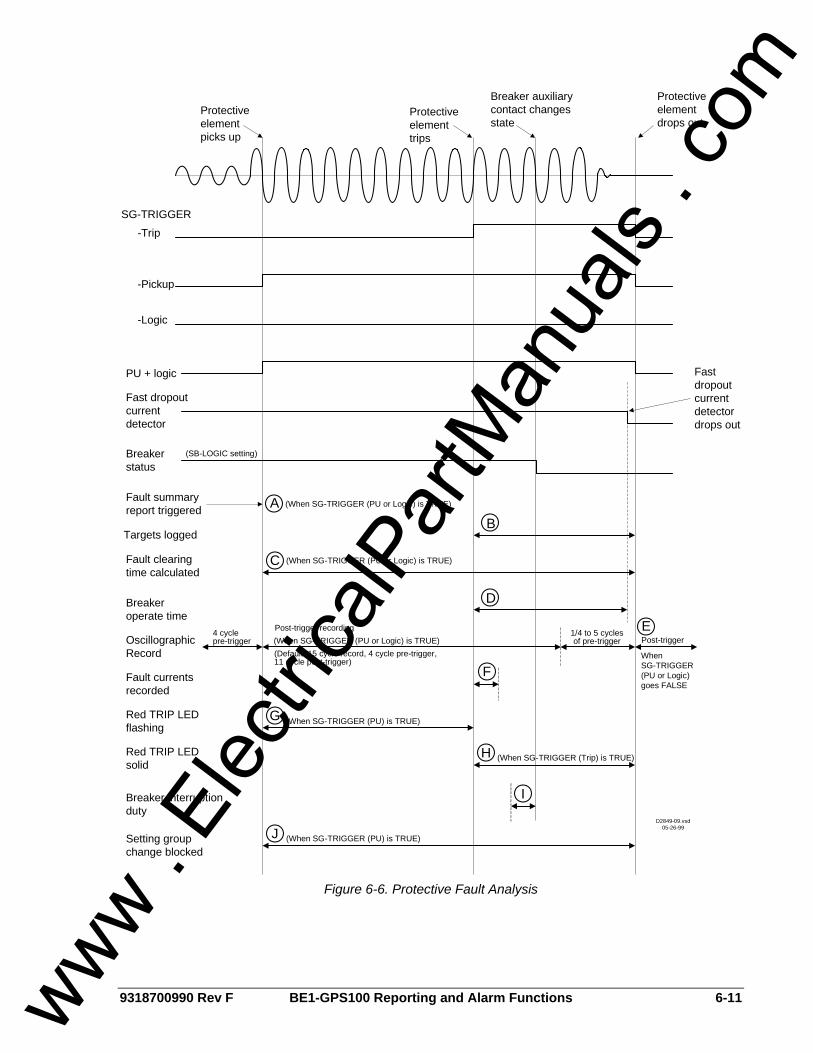
9318700990 Rev F BE1-GPS100 Reporting and Alarm Functions 6-11
Protective element picks up
Protective element trips
Breaker auxiliary contact changes state
Protective element drops out
Fast dropout current detector drops out
SG-TRIGGER
-Pickup
-Logic
PU + logic
Fast dropout current detector
Breaker status
Fault summary report triggered
(When SG-TRIGGER (PU or Logic) is TRUE)AB
Targets logged
CFault clearing time calculated
DBreaker operate time
OscillographicRecord
4 cyclepre-trigger
Post-trigger recording
(Default: 15 cycle record, 4 cycle pre-trigger, 11 cycle post-trigger)
Post-trigger1/4 to 5 cycles of pre-trigger
E
FFault currents recorded
GRed TRIP LED flashing
(When SG-TRIGGER (PU) is TRUE)
HRed TRIP LED solid
Breaker interruption duty
Setting group change blocked
I
JD2849-09.vsd
05-26-99
(SB-LOGIC setting)
-Trip
WhenSG-TRIGGER (PU or Logic) goes FALSE
(When SG-TRIGGER (PU or Logic) is TRUE)
(When SG-TRIGGER (PU or Logic) is TRUE)
(When SG-TRIGGER (PU) is TRUE)
(When SG-TRIGGER (Trip) is TRUE)
Figure 6-6. Protective Fault Analysis
www . El
ectric
alPar
tMan
uals
. com
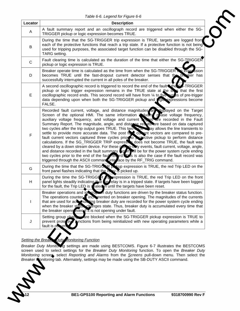
6-12 BE1-GPS100 Reporting and Alarm Functions 9318700990 Rev F
Table 6-6. Legend for Figure 6-6
Locator Description
A A fault summary report and an oscillograph record are triggered when either the SG-TRIGGER pickup or logic expression becomes TRUE.
B
During the time that the SG-TRIGGER trip expression is TRUE, targets are logged from each of the protective functions that reach a trip state. If a protective function is not being used for tripping purposes, the associated target function can be disabled through the SG-TARG setting.
C Fault clearing time is calculated as the duration of the time that either the SG-TRIGGER pickup or logic expression is TRUE.
D Breaker operate time is calculated as the time from when the SG-TRIGGER trip expression becomes TRUE until the fast-dropout current detector senses that the breaker has successfully interrupted the current in all poles of the breaker.
E
A second oscillographic record is triggered to record the end of the fault if the SG-TRIGGER pickup or logic trigger expression remains in the TRUE state at the time that the first oscillographic record ends. This second record will have from ¼ to five cycles of pre-trigger data depending upon when both the SG-TRIGGER pickup and logic expressions become FALSE.
F
Recorded fault current, voltage, and distance magnitudes are displayed on the Target Screen of the optional HMI. The same information including phase voltage frequency, auxiliary voltage frequency, and voltage and current angles are recorded in the Fault Summary Report. The magnitude, angle, and distance results are based on data captured two cycles after the trip output goes TRUE. This two-cycle delay allows the line transients to settle to provide more accurate data. The post fault current vectors are compared to pre-fault current vectors captured three cycles prior to protective pickup to perform distance calculations. If the SG_TRIGGER TRIP expression does not become TRUE, the fault was cleared by a down stream device. For these pickup-only events, fault current, voltage, angle, and distance recorded in the fault summary report will be for the power system cycle ending two cycles prior to the end of the fault record. This is also the case if the fault record was triggered through the ASCII command interface by the RF_TRIG command.
G During the time that the SG-TRIGGER pickup expression is TRUE, the red Trip LED on the front panel flashes indicating that the relay is picked up.
H During the time the SG-TRIGGER trip expression is TRUE, the red Trip LED on the front panel lights steadily indicating that the relay is in a tripped state. If targets have been logged for the fault, the Trip LED is sealed in until the targets have been reset.
I
Breaker operations and interruption duty functions are driven by the breaker status function. The operations counter is incremented on breaker opening. The magnitudes of the currents that are used for accumulating breaker duty are recorded for the power system cycle ending when the breaker status changes state. Thus, breaker duty is accumulated every time that the breaker opens even if it is not opening under fault.
J Setting group changes are blocked when the SG-TRIGGER pickup expression is TRUE to prevent protective functions from being reinitialized with new operating parameters while a fault is occurring.
Setting the Breaker Duty Monitoring Function Breaker Duty Monitoring settings are made using BESTCOMS. Figure 6-7 illustrates the BESTCOMS screen used to select settings for the Breaker Duty Monitoring function. To open the Breaker Duty Monitoring screen, select Reporting and Alarms from the Screens pull-down menu. Then select the Breaker Monitoring tab. Alternately, settings may be made using the SB-DUTY ASCII command.
www . El
ectric
alPar
tMan
uals
. com
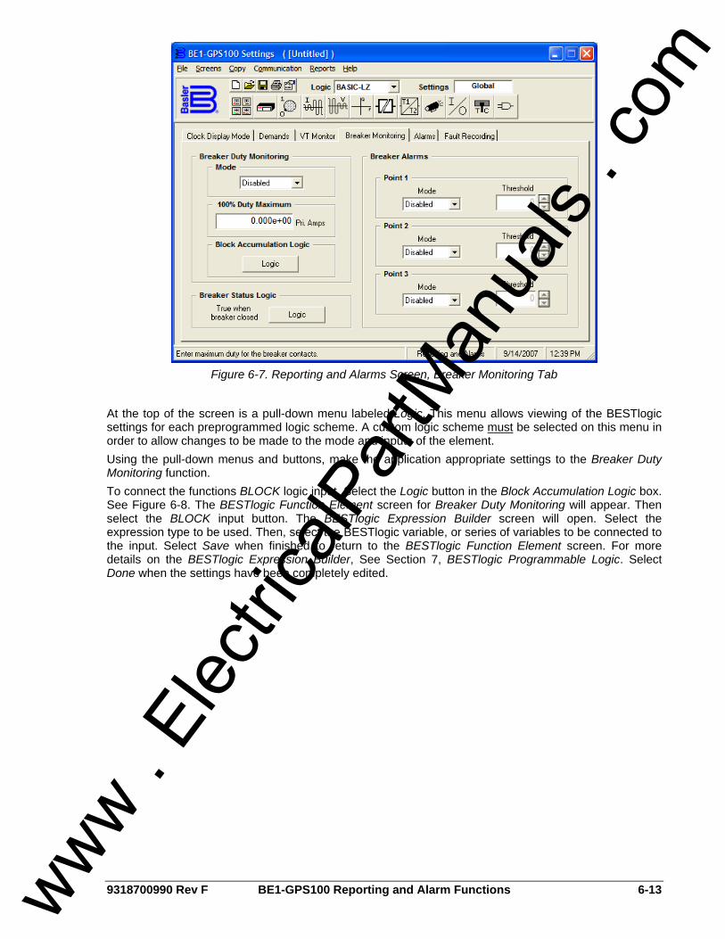
9318700990 Rev F BE1-GPS100 Reporting and Alarm Functions 6-13
Figure 6-7. Reporting and Alarms Screen, Breaker Monitoring Tab
At the top of the screen is a pull-down menu labeled Logic. This menu allows viewing of the BESTlogic settings for each preprogrammed logic scheme. A custom logic scheme must be selected on this menu in order to allow changes to be made to the mode and inputs of the element. Using the pull-down menus and buttons, make the application appropriate settings to the Breaker Duty Monitoring function. To connect the functions BLOCK logic input. Select the Logic button in the Block Accumulation Logic box. See Figure 6-8. The BESTlogic Function Element screen for Breaker Duty Monitoring will appear. Then select the BLOCK input button. The BESTlogic Expression Builder screen will open. Select the expression type to be used. Then, select the BESTlogic variable, or series of variables to be connected to the input. Select Save when finished to return to the BESTlogic Function Element screen. For more details on the BESTlogic Expression Builder, See Section 7, BESTlogic Programmable Logic. Select Done when the settings have been completely edited.
www . El
ectric
alPar
tMan
uals
. com
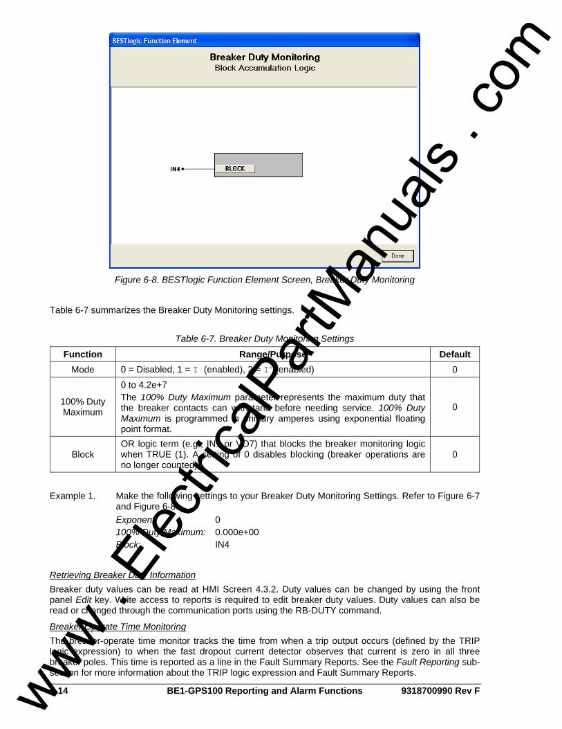
6-14 BE1-GPS100 Reporting and Alarm Functions 9318700990 Rev F
Figure 6-8. BESTlogic Function Element Screen, Breaker Duty Monitoring
Table 6-7 summarizes the Breaker Duty Monitoring settings.
Table 6-7. Breaker Duty Monitoring Settings
Function Range/Purpose Default Mode 0 = Disabled, 1 = I (enabled), 2 = I2 (enabled) 0
100% Duty Maximum
0 to 4.2e+7 The 100% Duty Maximum parameter represents the maximum duty that the breaker contacts can withstand before needing service. 100% Duty Maximum is programmed in primary amperes using exponential floating point format.
0
Block OR logic term (e.g., IN1 or VO7) that blocks the breaker monitoring logic when TRUE (1). A setting of 0 disables blocking (breaker operations are no longer counted).
0
Example 1. Make the following settings to your Breaker Duty Monitoring Settings. Refer to Figure 6-7
and Figure 6-8. Exponent: 0 100% Duty Maximum: 0.000e+00 Block: IN4
Retrieving Breaker Duty Information Breaker duty values can be read at HMI Screen 4.3.2. Duty values can be changed by using the front panel Edit key. Write access to reports is required to edit breaker duty values. Duty values can also be read or changed through the communication ports using the RB-DUTY command.
Breaker Operate Time Monitoring The breaker-operate time monitor tracks the time from when a trip output occurs (defined by the TRIP logic expression) to when the fast dropout current detector observes that current is zero in all three breaker poles. This time is reported as a line in the Fault Summary Reports. See the Fault Reporting sub-section for more information about the TRIP logic expression and Fault Summary Reports.
www . El
ectric
alPar
tMan
uals
. com
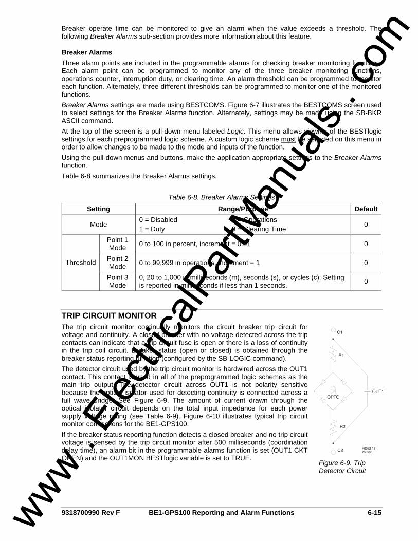
9318700990 Rev F BE1-GPS100 Reporting and Alarm Functions 6-15
Breaker operate time can be monitored to give an alarm when the value exceeds a threshold. The following Breaker Alarms sub-section provides more information about this feature.
Breaker Alarms Three alarm points are included in the programmable alarms for checking breaker monitoring functions. Each alarm point can be programmed to monitor any of the three breaker monitoring functions, operations counter, interruption duty, or clearing time. An alarm threshold can be programmed to monitor each function. Alternately, three different thresholds can be programmed to monitor one of the monitored functions. Breaker Alarms settings are made using BESTCOMS. Figure 6-7 illustrates the BESTCOMS screen used to select settings for the Breaker Alarms function. Alternately, settings may be made using the SB-BKR ASCII command. At the top of the screen is a pull-down menu labeled Logic. This menu allows viewing of the BESTlogic settings for each preprogrammed logic scheme. A custom logic scheme must be selected on this menu in order to allow changes to be made to the mode and inputs of the function. Using the pull-down menus and buttons, make the application appropriate settings to the Breaker Alarms function. Table 6-8 summarizes the Breaker Alarms settings.
Table 6-8. Breaker Alarms Settings
Setting Range/Purpose Default
Mode 0 = Disabled 1 = Duty
2 = Operations 3 = Clearing Time 0
Point 1 Mode 0 to 100 in percent, increment = 0.01 0
Point 2 Mode 0 to 99,999 in operations, increment = 1 0 Threshold
Point 3 Mode
0, 20 to 1,000 in milliseconds (m), seconds (s), or cycles (c). Setting is reported in milliseconds if less than 1 seconds. 0
TRIP CIRCUIT MONITOR The trip circuit monitor continually monitors the circuit breaker trip circuit for voltage and continuity. A closed breaker with no voltage detected across the trip contacts can indicate that a trip circuit fuse is open or there is a loss of continuity in the trip coil circuit. Breaker status (open or closed) is obtained through the breaker status reporting function (configured by the SB-LOGIC command). The detector circuit used by the trip circuit monitor is hardwired across the OUT1 contact. This contact is used in all of the preprogrammed logic schemes as the main trip output. The detector circuit across OUT1 is not polarity sensitive because the optical isolator used for detecting continuity is connected across a full wave bridge. See Figure 6-9. The amount of current drawn through the optical isolator circuit depends on the total input impedance for each power supply voltage rating (see Table 6-9). Figure 6-10 illustrates typical trip circuit monitor connections for the BE1-GPS100. If the breaker status reporting function detects a closed breaker and no trip circuit voltage is sensed by the trip circuit monitor after 500 milliseconds (coordination delay time), an alarm bit in the programmable alarms function is set (OUT1 CKT OPEN) and the OUT1MON BESTlogic variable is set to TRUE.
Figure 6-9. Trip Detector Circuit
www . El
ectric
alPar
tMan
uals
. com
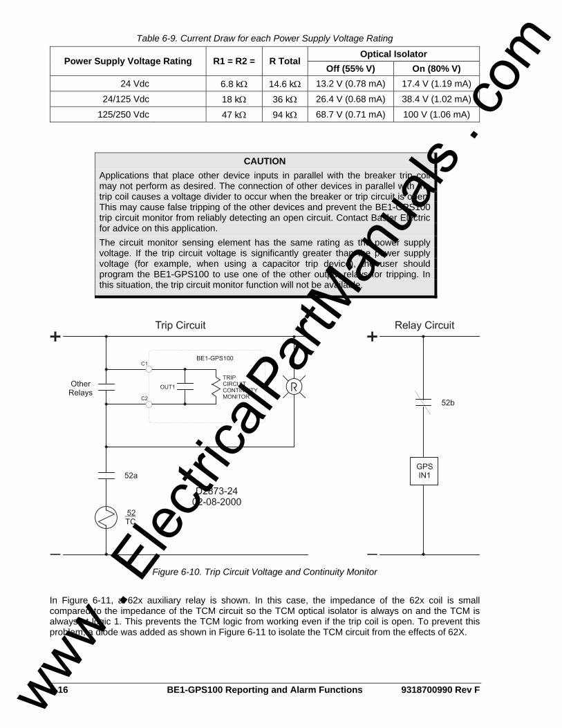
6-16 BE1-GPS100 Reporting and Alarm Functions 9318700990 Rev F
Table 6-9. Current Draw for each Power Supply Voltage Rating
Optical Isolator Power Supply Voltage Rating R1 = R2 = R Total
Off (55% V) On (80% V) 24 Vdc 6.8 kΩ 14.6 kΩ 13.2 V (0.78 mA) 17.4 V (1.19 mA)
24/125 Vdc 18 kΩ 36 kΩ 26.4 V (0.68 mA) 38.4 V (1.02 mA)
125/250 Vdc 47 kΩ 94 kΩ 68.7 V (0.71 mA) 100 V (1.06 mA)
Figure 6-10. Trip Circuit Voltage and Continuity Monitor
In Figure 6-11, a 62x auxiliary relay is shown. In this case, the impedance of the 62x coil is small compared to the impedance of the TCM circuit so the TCM optical isolator is always on and the TCM is always at logic 1. This prevents the TCM logic from working even if the trip coil is open. To prevent this problem, a diode was added as shown in Figure 6-11 to isolate the TCM circuit from the effects of 62X.
CAUTION Applications that place other device inputs in parallel with the breaker trip coil may not perform as desired. The connection of other devices in parallel with the trip coil causes a voltage divider to occur when the breaker or trip circuit is open. This may cause false tripping of the other devices and prevent the BE1-GPS100 trip circuit monitor from reliably detecting an open circuit. Contact Basler Electric for advice on this application. The circuit monitor sensing element has the same rating as the power supply voltage. If the trip circuit voltage is significantly greater than the power supply voltage (for example, when using a capacitor trip device), the user should program the BE1-GPS100 to use one of the other output relays for tripping. In this situation, the trip circuit monitor function will not be available.
www . El
ectric
alPar
tMan
uals
. com
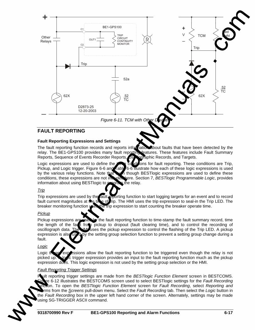
9318700990 Rev F BE1-GPS100 Reporting and Alarm Functions 6-17
Figure 6-11. TCM with Other Devices
FAULT REPORTING
Fault Reporting Expressions and Settings The fault reporting function records and reports information about faults that have been detected by the relay. The BE1-GPS100 provides many fault reporting features. These features include Fault Summary Reports, Sequence of Events Recorder Reports, Oscillographic Records, and Targets. Logic expressions are used to define the three conditions for fault reporting. These conditions are Trip, Pickup, and Logic trigger. Figure 6-6 and Table 6-6 illustrate how each of these logic expressions is used by the various relay functions. Note that even though BESTlogic expressions are used to define these conditions, these expressions are not included here. Section 7, BESTlogic Programmable Logic, provides information about using BESTlogic to program the relay.
Trip Trip expressions are used by the fault reporting function to start logging targets for an event and to record fault current magnitudes at the time of trip. The HMI uses the trip expression to seal-in the Trip LED. The breaker monitoring function uses the trip expression to start counting the breaker operate time.
Pickup Pickup expressions are used by the fault reporting function to time-stamp the fault summary record, time the length of the fault from pickup to dropout (fault clearing time), and to control the recording of oscillograph data. The HMI uses the pickup expression to control the flashing of the Trip LED. A pickup expression is also used by the setting group selection function to prevent a setting group change during a fault.
Logic Logic trigger expressions allow the fault reporting function to be triggered even though the relay is not picked up. A logic trigger expression provides an input to the fault reporting function much as the pickup expression does. This logic expression is not used by the setting group selection or the HMI.
Fault Reporting Trigger Settings Fault reporting trigger settings are made from the BESTlogic Function Element screen in BESTCOMS. Figure 6-12 illustrates the BESTCOMS screen used to select BESTlogic settings for the Fault Recording function. To open the BESTlogic Function Element screen for Fault Recording, select Reporting and Alarms from the Screens pull-down menu. Select the Fault Recording tab. Then select the Logic button in the Fault Recording box in the upper left hand corner of the screen. Alternately, settings may be made using SG-TRIGGER ASCII command.
www . El
ectric
alPar
tMan
uals
. com
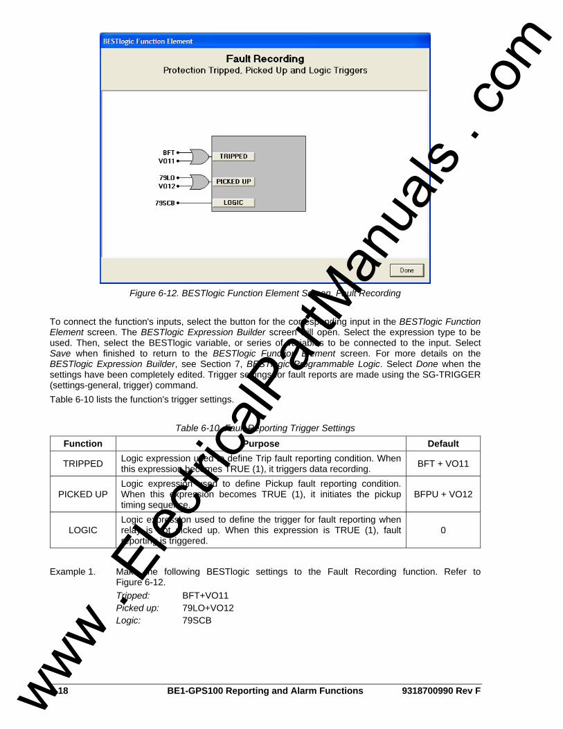
6-18 BE1-GPS100 Reporting and Alarm Functions 9318700990 Rev F
Figure 6-12. BESTlogic Function Element Screen, Fault Recording
To connect the function's inputs, select the button for the corresponding input in the BESTlogic Function Element screen. The BESTlogic Expression Builder screen will open. Select the expression type to be used. Then, select the BESTlogic variable, or series of variables to be connected to the input. Select Save when finished to return to the BESTlogic Function Element screen. For more details on the BESTlogic Expression Builder, see Section 7, BESTlogic Programmable Logic. Select Done when the settings have been completely edited. Trigger settings for fault reports are made using the SG-TRIGGER (settings-general, trigger) command. Table 6-10 lists the function's trigger settings.
Table 6-10. Fault Reporting Trigger Settings
Function Purpose Default
TRIPPED Logic expression used to define Trip fault reporting condition. When this expression becomes TRUE (1), it triggers data recording. BFT + VO11
PICKED UP Logic expression used to define Pickup fault reporting condition. When this expression becomes TRUE (1), it initiates the pickup timing sequence.
BFPU + VO12
LOGIC Logic expression used to define the trigger for fault reporting when relay is not picked up. When this expression is TRUE (1), fault reporting is triggered.
0
Example 1. Make the following BESTlogic settings to the Fault Recording function. Refer to Figure 6-12. Tripped: BFT+VO11 Picked up: 79LO+VO12 Logic: 79SCB
www . El
ectric
alPar
tMan
uals
. com

9318700990 Rev F BE1-GPS100 Reporting and Alarm Functions 6-19
Targets Each protective function (see Table 6-11) logs target information to the fault reporting function when a trip condition occurs and the trip output of the function block becomes TRUE (refer to Figure 6-6 and Table 6-6, call-out B). Target information can be viewed and reset at the HMI and through the communication ports. Target logging for a protective function can be disabled if the function is used in a supervisory or monitoring capacity. The following paragraphs describe how the relay is programmed to define which protective functions log targets.
Table 6-11. Protective Functions with Targets
Name Protective Function Target Default
51P Phase Inverse Time Overcurrent Enabled 51N Neutral Inverse Time Overcurrent Enabled 151N Second Neutral Time Overcurrent Enabled 50TP Phase Instantaneous Overcurrent Enabled 50TN Neutral Instantaneous Overcurrent Enabled
81 Under/Over Frequency Enabled 181 Second Under/Over Frequency Enabled 281 Third Under/Over Frequency Enabled 381 Fourth Under/Over Frequency Enabled 59P Phase Overvoltage Enabled
159P Second Phase Overvoltage Enabled 59X Auxiliary Overvoltage Enabled
159X Second Auxiliary Overvoltage Enabled 46 Negative-Sequence Overcurrent Enabled 47 Negative-Sequence Overvoltage Enabled
27P Phase Undervoltage Enabled 127P Second Phase Undervoltage Enabled 27X Auxiliary Undervoltage Enabled
127X Second Auxiliary Undervoltage Enabled 62 General Purpose Logic Timer Disabled 162 Second General Purpose Logic Timer Disabled 262 Third General Purpose Logic Timer Disabled 362 Fourth General Purpose Logic Timer Disabled 24 Volts per Hertz Enabled 32 Directional Power Enabled 132 Second Directional Power Enabled 40Q Loss of Excitation Enabled 140Q Second Loss of Excitation Enabled 60FL Fuse Loss Detection Disabled BF Breaker Failure Enabled
www . El
ectric
alPar
tMan
uals
. com
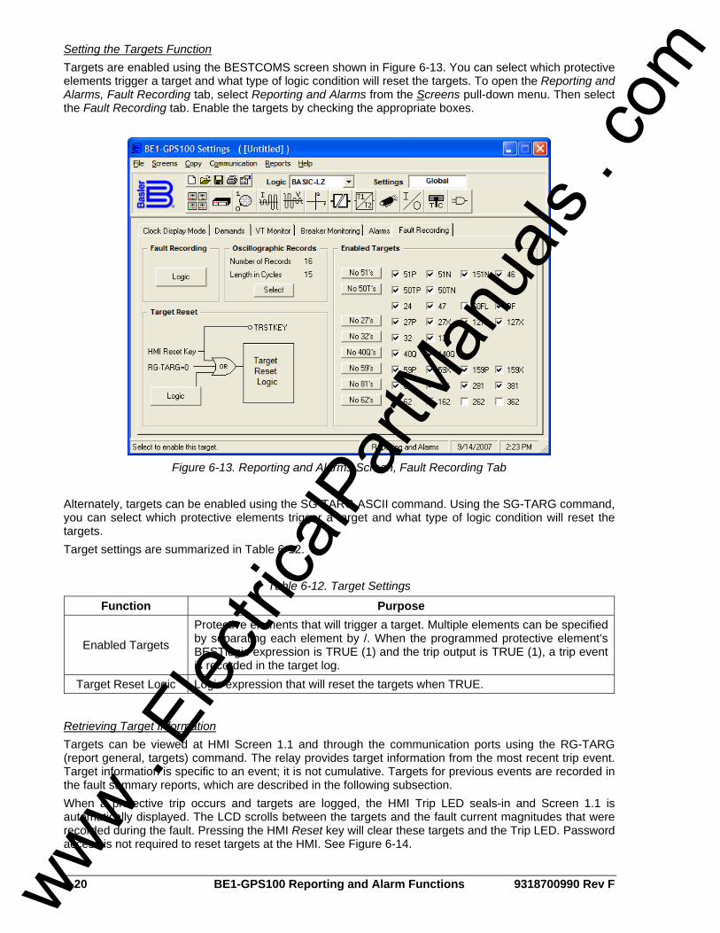
6-20 BE1-GPS100 Reporting and Alarm Functions 9318700990 Rev F
Setting the Targets Function Targets are enabled using the BESTCOMS screen shown in Figure 6-13. You can select which protective elements trigger a target and what type of logic condition will reset the targets. To open the Reporting and Alarms, Fault Recording tab, select Reporting and Alarms from the Screens pull-down menu. Then select the Fault Recording tab. Enable the targets by checking the appropriate boxes.
Figure 6-13. Reporting and Alarms Screen, Fault Recording Tab
Alternately, targets can be enabled using the SG-TARG ASCII command. Using the SG-TARG command, you can select which protective elements trigger a target and what type of logic condition will reset the targets. Target settings are summarized in Table 6-12.
Table 6-12. Target Settings
Function Purpose
Enabled Targets
Protective elements that will trigger a target. Multiple elements can be specified by separating each element by /. When the programmed protective element’s BESTlogic expression is TRUE (1) and the trip output is TRUE (1), a trip event is recorded in the target log.
Target Reset Logic Logic expression that will reset the targets when TRUE.
Retrieving Target Information Targets can be viewed at HMI Screen 1.1 and through the communication ports using the RG-TARG (report general, targets) command. The relay provides target information from the most recent trip event. Target information is specific to an event; it is not cumulative. Targets for previous events are recorded in the fault summary reports, which are described in the following subsection. When a protective trip occurs and targets are logged, the HMI Trip LED seals-in and Screen 1.1 is automatically displayed. The LCD scrolls between the targets and the fault current magnitudes that were recorded during the fault. Pressing the HMI Reset key will clear these targets and the Trip LED. Password access is not required to reset targets at the HMI. See Figure 6-14.
www . El
ectric
alPar
tMan
uals
. com
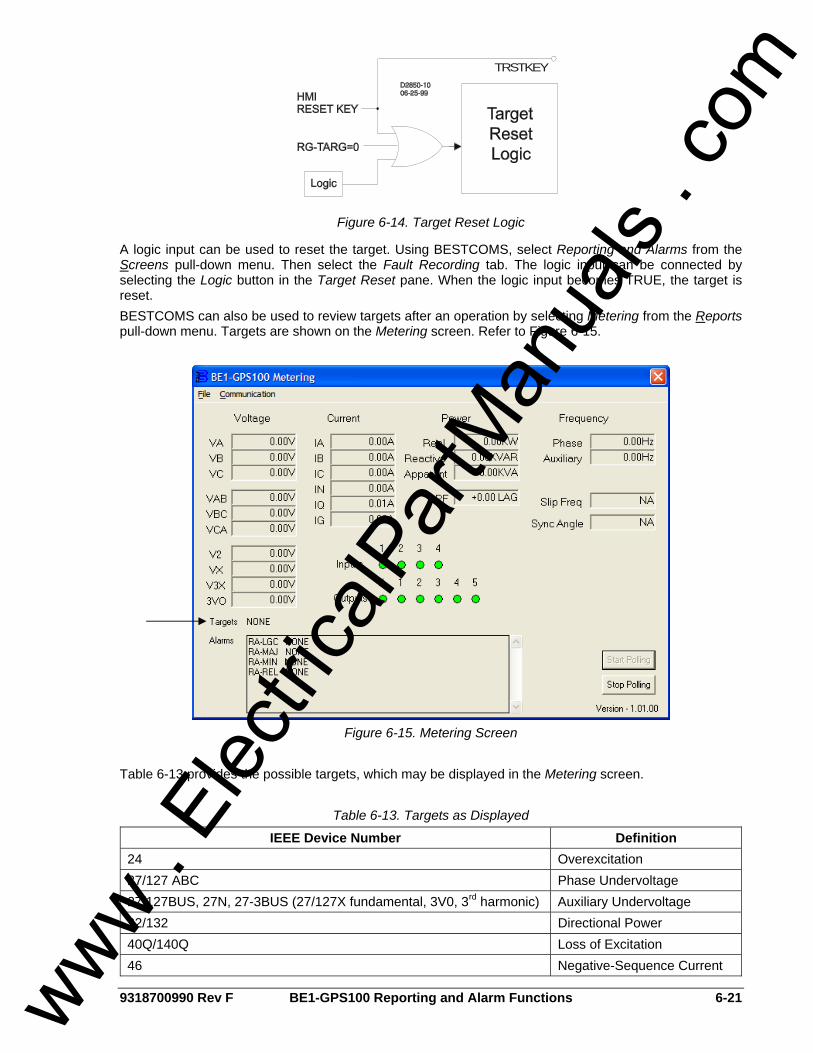
9318700990 Rev F BE1-GPS100 Reporting and Alarm Functions 6-21
TRSTKEY
Figure 6-14. Target Reset Logic
A logic input can be used to reset the target. Using BESTCOMS, select Reporting and Alarms from the Screens pull-down menu. Then select the Fault Recording tab. The logic input can be connected by selecting the Logic button in the Target Reset pane. When the logic input becomes TRUE, the target is reset. BESTCOMS can also be used to review targets after an operation by selecting Metering from the Reports pull-down menu. Targets are shown on the Metering screen. Refer to Figure 6-15.
Figure 6-15. Metering Screen
Table 6-13 provides the possible targets, which may be displayed in the Metering screen.
Table 6-13. Targets as Displayed
IEEE Device Number Definition 24 Overexcitation 27/127 ABC Phase Undervoltage 27/127BUS, 27N, 27-3BUS (27/127X fundamental, 3V0, 3rd harmonic) Auxiliary Undervoltage 32/132 Directional Power 40Q/140Q Loss of Excitation 46 Negative-Sequence Current
www . El
ectric
alPar
tMan
uals
. com
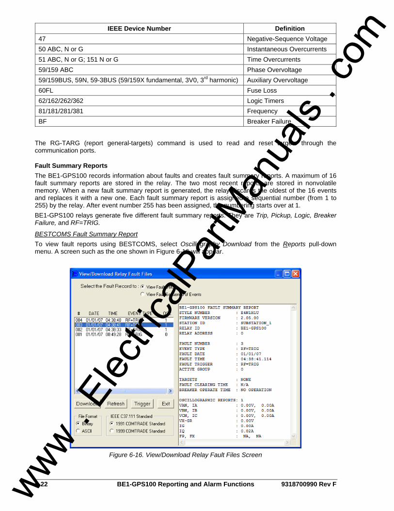
6-22 BE1-GPS100 Reporting and Alarm Functions 9318700990 Rev F
IEEE Device Number Definition 47 Negative-Sequence Voltage 50 ABC, N or G Instantaneous Overcurrents 51 ABC, N or G; 151 N or G Time Overcurrents 59/159 ABC Phase Overvoltage 59/159BUS, 59N, 59-3BUS (59/159X fundamental, 3V0, 3rd harmonic) Auxiliary Overvoltage 60FL Fuse Loss 62/162/262/362 Logic Timers 81/181/281/381 Frequency BF Breaker Failure
The RG-TARG (report general-targets) command is used to read and reset targets through the communication ports.
Fault Summary Reports The BE1-GPS100 records information about faults and creates fault summary reports. A maximum of 16 fault summary reports are stored in the relay. The two most recent reports are stored in nonvolatile memory. When a new fault summary report is generated, the relay discards the oldest of the 16 events and replaces it with a new one. Each fault summary report is assigned a sequential number (from 1 to 255) by the relay. After event number 255 has been assigned, the numbering starts over at 1. BE1-GPS100 relays generate five different fault summary reports. They are Trip, Pickup, Logic, Breaker Failure, and RF=TRIG.
BESTCOMS Fault Summary Report To view fault reports using BESTCOMS, select Oscillography Download from the Reports pull-down menu. A screen such as the one shown in Figure 6-16 will appear.
Figure 6-16. View/Download Relay Fault Files Screen
www . El
ectric
alPar
tMan
uals
. com
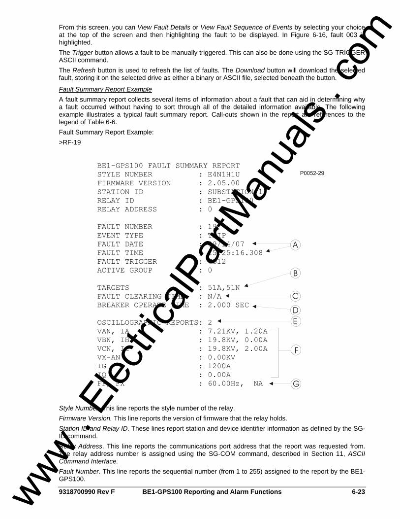
9318700990 Rev F BE1-GPS100 Reporting and Alarm Functions 6-23
From this screen, you can View Fault Details or View Fault Sequence of Events by selecting your choice at the top of the screen and then highlighting the fault to be displayed. In Figure 6-16, fault 003 is highlighted. The Trigger button allows a fault to be manually triggered. This can also be done using the SG-TRIGGER ASCII command. The Refresh button is used to refresh the list of faults. The Download button will download the selected fault, storing it on the selected drive as either a binary or ASCII file, selected beneath the button.
Fault Summary Report Example A fault summary report collects several items of information about a fault that can aid in determining why a fault occurred without having to sort through all of the detailed information available. The following example illustrates a typical fault summary report. Call-outs shown in the report are references to the legend of Table 6-6. Fault Summary Report Example: >RF-19
Style Number. This line reports the style number of the relay. Firmware Version. This line reports the version of firmware that the relay holds. Station ID and Relay ID. These lines report station and device identifier information as defined by the SG-ID command. Relay Address. This line reports the communications port address that the report was requested from. The relay address number is assigned using the SG-COM command, described in Section 11, ASCII Command Interface. Fault Number. This line reports the sequential number (from 1 to 255) assigned to the report by the BE1-GPS100.
www . El
ectric
alPar
tMan
uals
. com

6-24 BE1-GPS100 Reporting and Alarm Functions 9318700990 Rev F
Event Type. This line reports the type of event that occurred. There are five event type categories: • Trip: A fault was detected as defined by the pickup expression and the relay tripped to clear the
fault. • Pickup: A fault was detected as defined by the pickup expression but the relay never tripped
indicating that the fault was cleared by another device. • Logic: A fault report was recorded by the logic trigger expression but no fault was detected as
defined by the pickup expression. • Breaker Failure: A fault was detected as defined by the pickup expression and the breaker failure
trip became TRUE before the fault was cleared. • RF=TRIG: A fault report was recorded by the ASCII command interface.
Fault Date and Time. These lines report the date and time of the initial trigger of the event. This is based on either the pickup logic expression or the logic trigger expression becoming TRUE as defined by the SG-TRIGGER command. Refer to Figure 6-6 and Table 6-6, call-out A. Fault Trigger. This line reports the logic variables in the pickup or logic trigger expressions that became TRUE to trigger the recording of the event. Active Group. This line reports what setting group was active at the time that the fault occurred. Targets. This line reports the targets that were logged to the fault report between the time that the trip expression became TRUE until the end of the fault. Refer to Figure 6-6 and Table 6-6, call-out B. Fault Clearing Time. This line reports the time from when the relay detected the fault until the relay detected that the fault had cleared. Refer to Figure 6-6 and Table 6-6, call-out C. If the fault report was triggered by the RF-TRIG command, the recording of the report was terminated after 60 seconds and this line is reported as N/A. If the pickup or logic expressions stay TRUE for more than 60 seconds, an alarm bit in the programmable alarm function is set and this line is reported as N/A. In this situation, the fault reporting functions (including targets) will not operate again until the pickup and logic trigger expressions return to a FALSE state to enable another trigger. Breaker Operate Time. This line reports the breaker trip time from the breaker monitoring and alarm function. This is the time measured from when the breaker is tripped until the fast-dropout current detector function detects that the arc has been extinguished. Refer to Figure 6-6 and Table 6-6, call-out D. Oscillographic Reports. This line reports the number of oscillographic records that are stored in memory for this fault report. Refer to Figure 6-6 and Table 6-6; call-out E. Recording of oscillographic records is described in the Oscillographic Records subsection. IA, IB, IC, IG, IQ. These lines report the current magnitudes and angles measured two power system cycles immediately following the trip trigger. If the fault is cleared prior to the relay tripping, the recorded fault currents are for the power system cycle two cycles prior to the end of the fault. Refer to Figure 6-6 and Table 6-6, call-out F. VA, VB, VC, VX. These lines report the voltage magnitudes and angles measured two power system cycles immediately following the trip trigger. If the fault is cleared prior to the relay tripping, the recorded fault voltages are for the power system cycle two cycles prior to the end of the fault. Refer to Figure 6-6 and Table 6-6, call-out F. FP and FX. This line reports the frequency for the phase voltage input and auxiliary voltage input measured immediately following the trip trigger. Refer to Fault Summary Report Example call-out G.
Retrieving Fault Report Information from the Relay Fault Summary Directory Report. The fault reporting function provides a directory of fault summary reports that lists the number assigned to the fault summary report along with the date and time of the fault, the event type, and the total number of oscillography records stored in memory for that event. The event number is important because it is required to retrieve information about that event from the relay. This directory report can be accessed by using the RF command. New Faults Counter. One line of the fault summary directory report contains the new faults counter. The new faults counter tracks how many new fault reports have been recorded since the new faults counter was reset to 0. This counter provides a way to check the fault information and then reset the new faults counter. Then, the next time that the relay is checked, it's easy to determine if any fault reports have been entered. Resetting the new faults counter is achieved using the RF-NEW=0 command. Write access to
www . El
ectric
alPar
tMan
uals
. com
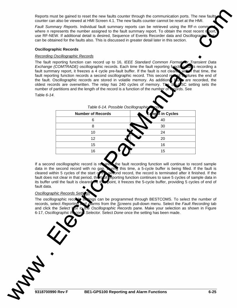
9318700990 Rev F BE1-GPS100 Reporting and Alarm Functions 6-25
Reports must be gained to reset the new faults counter through the communication ports. The new faults counter can also be viewed at HMI Screen 4.1. The new faults counter cannot be reset at the HMI. Fault Summary Reports. Individual fault summary reports can be retrieved using the RF-n command, where n represents the number assigned to the fault summary report. To obtain the most recent report, use RF-NEW. If additional detail is desired, Sequence of Events Recorder data and Oscillographic data can be obtained for the faults also. This is discussed in greater detail later in this section.
Oscillographic Records
Recording Oscillographic Records The fault reporting function can record up to 16, IEEE Standard Common Format for Transient Data Exchange (COMTRADE) oscillographic records. Each time the fault reporting function starts recording a fault summary report, it freezes a 4 cycle pre-fault buffer. If the fault is not cleared within that time, the fault reporting function records a second oscillographic record. This second record captures the end of the fault. Oscillographic records are stored in volatile memory. As additional faults are recorded, the oldest records are overwritten. The relay has 240 cycles of memory. The SG-OSC setting sets the number of partitions and the length of the record is a function of the number of records. See Table 6-14.
Table 6-14. Possible Oscillographic Records
Number of Records Length in Cycles 6 40 8 30
10 24 12 20 15 16 16 15
If a second oscillographic record is required, the fault recording function will continue to record sample data in the second record with no gap. During this time, a 5-cycle buffer is being filled. If the fault is cleared within 5 cycles of the start of the second record, the record is terminated after it finished. If the fault does not clear in that period, the fault reporting function continues to save 5 cycles of sample data in its buffer until the fault is cleared. At that point, it freezes the 5-cycle buffer, providing 5 cycles of end of fault data.
Oscillographic Records Settings The oscillographic records settings can be programmed through BESTCOMS. To select the number of records, select Reporting and Alarms from the Screens pull-down menu. Select the Fault Recording tab and click the Select box in the Oscillographic Records pane. Make your selection as shown in Figure 6-17, Oscillographic Records Selector. Select Done once the setting has been made.
www . El
ectric
alPar
tMan
uals
. com

6-26 BE1-GPS100 Reporting and Alarm Functions 9318700990 Rev F
Figure 6-17. Oscillographic Records Selector Screen
The oscillographic records settings can also be made using the SG-OSC (settings general, oscillography) ASCII command. See Table 6-15 for possible settings.
Table 6-15. Recording Oscillographic Records Settings
Setting Range Default Number of Records Saved 6, 8, 10, 12, 15, 16 16
Retrieving Oscillographic Records The fault summary directory and the fault summary reports list the numbers assigned to each fault record and the number of oscillographic records associated with each fault. Oscillographic records can be retrieved using BESTCOMS. Alternately, oscillographic records can be retrieved using the RO ASCII command. To download oscillographic records, select Oscillography Download from the Reports pull-down menu. Highlight the record to be downloaded and select either ASCII or Binary as the file type for download. Select the Download button. Assume record 003 is selected for a binary download. When the Download button is selected, the Browse for Folder screen (Figure 6-18) appears. Select a location for the file to be stored or create a New Folder and press OK. The Fault Record Filenames screen (Figure 6-19) will appear. Type the base filename in the first row. The rest of the filenames will respond by changing to match the base filename. Select OK to save the file.
www . El
ectric
alPar
tMan
uals
. com
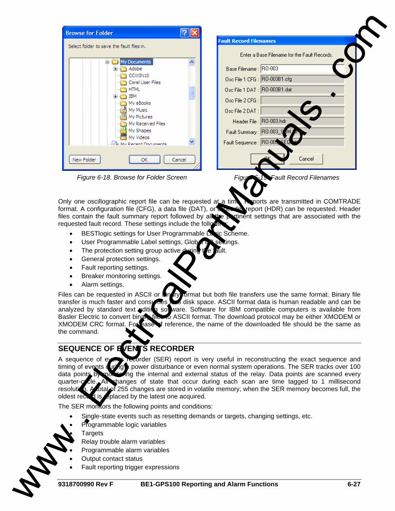
9318700990 Rev F BE1-GPS100 Reporting and Alarm Functions 6-27
Figure 6-18. Browse for Folder Screen
Figure 6-19. Fault Record Filenames
Only one oscillographic report file can be requested at a time. Reports are transmitted in COMTRADE format. A configuration file (CFG), a data file (DAT), or a header report (HDR) can be requested. Header files contain the fault summary report followed by all the pertinent settings that are associated with the requested fault record. These settings include the following:
• BESTlogic settings for User Programmable Logic Scheme. • User Programmable Label settings, Global I/O settings. • The protection setting group active during the fault. • General protection settings. • Fault reporting settings. • Breaker monitoring settings. • Alarm settings.
Files can be requested in ASCII or binary format but both file transfers use the same format. Binary file transfer is much faster and consumes less disk space. ASCII format data is human readable and can be analyzed by standard text editing software. Software for IBM compatible computers is available from Basler Electric to convert binary files to ASCII format. The download protocol may be either XMODEM or XMODEM CRC format. For ease of reference, the name of the downloaded file should be the same as the command.
SEQUENCE OF EVENTS RECORDER A sequence of events recorder (SER) report is very useful in reconstructing the exact sequence and timing of events during a power disturbance or even normal system operations. The SER tracks over 100 data points by monitoring the internal and external status of the relay. Data points are scanned every quarter-cycle. All changes of state that occur during each scan are time tagged to 1 millisecond resolution. A total of 255 changes are stored in volatile memory; when the SER memory becomes full, the oldest record is replaced by the latest one acquired. The SER monitors the following points and conditions:
• Single-state events such as resetting demands or targets, changing settings, etc. • Programmable logic variables • Targets • Relay trouble alarm variables • Programmable alarm variables • Output contact status • Fault reporting trigger expressions
www . El
ectric
alPar
tMan
uals
. com
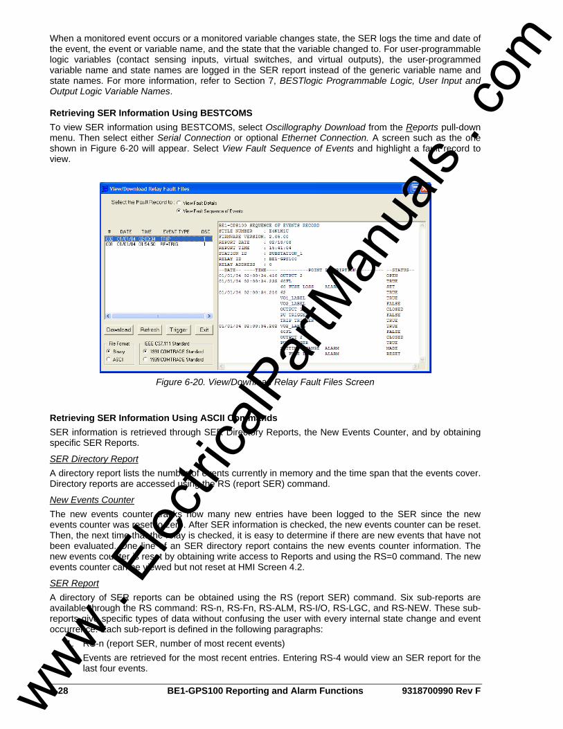
6-28 BE1-GPS100 Reporting and Alarm Functions 9318700990 Rev F
When a monitored event occurs or a monitored variable changes state, the SER logs the time and date of the event, the event or variable name, and the state that the variable changed to. For user-programmable logic variables (contact sensing inputs, virtual switches, and virtual outputs), the user-programmed variable name and state names are logged in the SER report instead of the generic variable name and state names. For more information, refer to Section 7, BESTlogic Programmable Logic, User Input and Output Logic Variable Names.
Retrieving SER Information Using BESTCOMS To view SER information using BESTCOMS, select Oscillography Download from the Reports pull-down menu. Then select either Serial Connection or optional Ethernet Connection. A screen such as the one shown in Figure 6-20 will appear. Select View Fault Sequence of Events and highlight a fault record to view.
Figure 6-20. View/Download Relay Fault Files Screen
Retrieving SER Information Using ASCII Commands SER information is retrieved through SER Directory Reports, the New Events Counter, and by obtaining specific SER Reports.
SER Directory Report A directory report lists the number of events currently in memory and the time span that the events cover. Directory reports are accessed using the RS (report SER) command.
New Events Counter The new events counter tracks how many new entries have been logged to the SER since the new events counter was reset to zero. After SER information is checked, the new events counter can be reset. Then, the next time that the relay is checked, it is easy to determine if there are new events that have not been evaluated. One line of an SER directory report contains the new events counter information. The new events counter is reset by obtaining write access to Reports and using the RS=0 command. The new events counter can be viewed but not reset at HMI Screen 4.2.
SER Report A directory of SER reports can be obtained using the RS (report SER) command. Six sub-reports are available through the RS command: RS-n, RS-Fn, RS-ALM, RS-I/O, RS-LGC, and RS-NEW. These sub-reports give specific types of data without confusing the user with every internal state change and event occurrence. Each sub-report is defined in the following paragraphs:
1. RS-n (report SER, number of most recent events) Events are retrieved for the most recent entries. Entering RS-4 would view an SER report for the last four events.
www . El
ectric
alPar
tMan
uals
. com
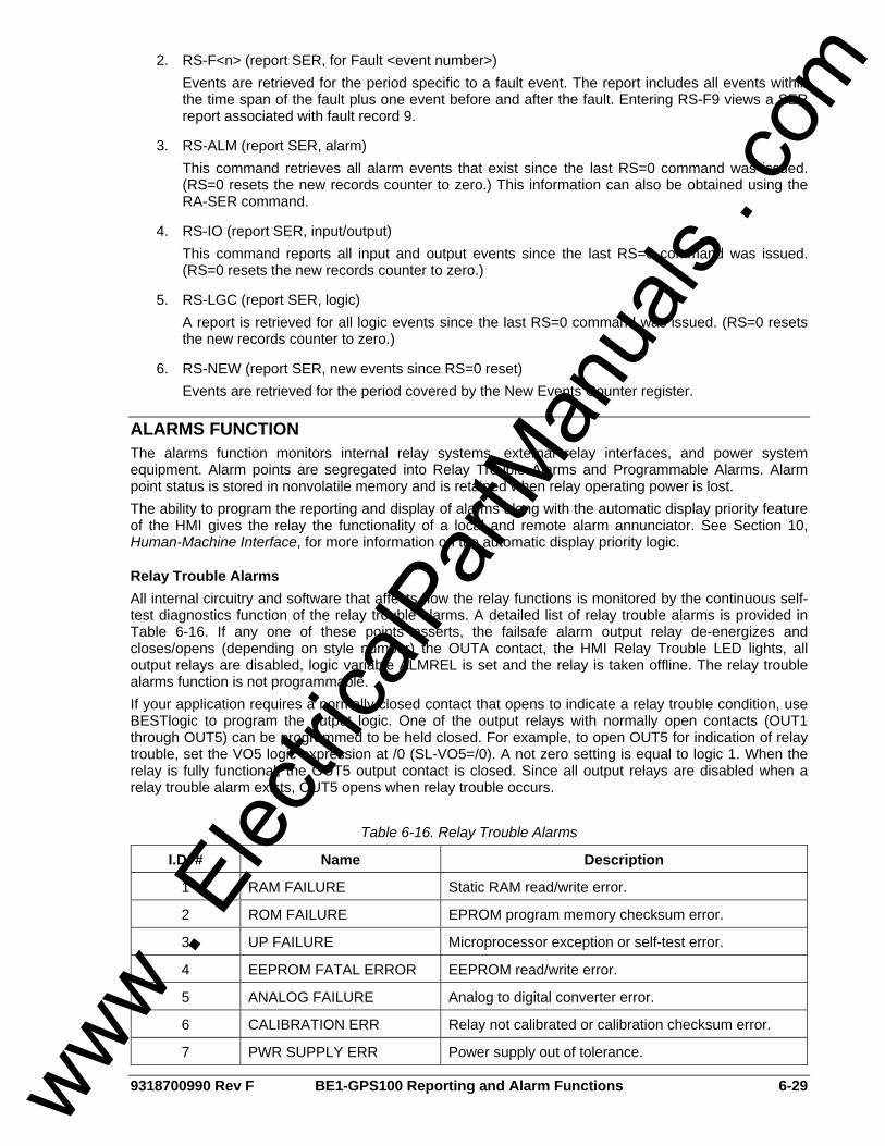
9318700990 Rev F BE1-GPS100 Reporting and Alarm Functions 6-29
2. RS-F<n> (report SER, for Fault <event number>) Events are retrieved for the period specific to a fault event. The report includes all events within the time span of the fault plus one event before and after the fault. Entering RS-F9 views a SER report associated with fault record 9.
3. RS-ALM (report SER, alarm) This command retrieves all alarm events that exist since the last RS=0 command was issued. (RS=0 resets the new records counter to zero.) This information can also be obtained using the RA-SER command.
4. RS-IO (report SER, input/output) This command reports all input and output events since the last RS=0 command was issued. (RS=0 resets the new records counter to zero.)
5. RS-LGC (report SER, logic) A report is retrieved for all logic events since the last RS=0 command was issued. (RS=0 resets the new records counter to zero.)
6. RS-NEW (report SER, new events since RS=0 reset) Events are retrieved for the period covered by the New Events Counter register.
ALARMS FUNCTION The alarms function monitors internal relay systems, external relay interfaces, and power system equipment. Alarm points are segregated into Relay Trouble Alarms and Programmable Alarms. Alarm point status is stored in nonvolatile memory and is retained when relay operating power is lost. The ability to program the reporting and display of alarms along with the automatic display priority feature of the HMI gives the relay the functionality of a local and remote alarm annunciator. See Section 10, Human-Machine Interface, for more information on the automatic display priority logic.
Relay Trouble Alarms All internal circuitry and software that affects how the relay functions is monitored by the continuous self-test diagnostics function of the relay trouble alarms. A detailed list of relay trouble alarms is provided in Table 6-16. If any one of these points asserts, the failsafe alarm output relay de-energizes and closes/opens (depending on style number) the OUTA contact, the HMI Relay Trouble LED lights, all output relays are disabled, logic variable ALMREL is set and the relay is taken offline. The relay trouble alarms function is not programmable. If your application requires a normally closed contact that opens to indicate a relay trouble condition, use BESTlogic to program the output logic. One of the output relays with normally open contacts (OUT1 through OUT5) can be programmed to be held closed. For example, to open OUT5 for indication of relay trouble, set the VO5 logic expression at /0 (SL-VO5=/0). A not zero setting is equal to logic 1. When the relay is fully functional, the OUT5 output contact is closed. Since all output relays are disabled when a relay trouble alarm exists, OUT5 opens when relay trouble occurs.
Table 6-16. Relay Trouble Alarms
I.D. # Name Description
1 RAM FAILURE Static RAM read/write error.
2 ROM FAILURE EPROM program memory checksum error.
3 UP FAILURE Microprocessor exception or self-test error.
4 EEPROM FATAL ERROR EEPROM read/write error.
5 ANALOG FAILURE Analog to digital converter error.
6 CALIBRATION ERR Relay not calibrated or calibration checksum error.
7 PWR SUPPLY ERR Power supply out of tolerance.
www . El
ectric
alPar
tMan
uals
. com

6-30 BE1-GPS100 Reporting and Alarm Functions 9318700990 Rev F
I.D. # Name Description
8 WATCHDOG FAILURE Microprocessor watchdog circuit timed out.
9 SET DEFLTS LOADED Relay using setting defaults.
10 CAL DFLTS LOADED Relay using calibration defaults.
Relay trouble alarms, except for CALIBRATION ERR, EEPROM FATAL ERR, SET DFLTS LOADED, and CALDFLTS LOADED indicate that the relay is not functional and causes the self-test diagnostics to force a microprocessor reset to try to correct the problem. CALIBRATION ERR, EEPROM FATAL ERROR, or DFLTS LOADED errors indicate that the relay is functional but needs re-calibration or the settings reprogrammed. Any relay trouble alarm will disable the protection functions, light the Relay Trouble LED, and place the output contacts in their normal, de-energized state. If a relay trouble (RA-REL) alarm is cleared by pressing the HMI Reset key while viewing Screen 1.3 or using the RA=0 or RA-REL=0 commands, then the relay will attempt to return back online by issuing a software reset. The relay resets by going through a full startup and initialization cycle. If no problems are detected, the relay returns online and enables protection.
Major, Minor, and Logic Programmable Alarms The programmable alarms function covers all circuits monitored by the continuous self-test diagnostics function that do not affect the relay core functions. Alarm functions used to monitor the power system and equipment are also part of the programmable alarms. Table 6-17 provides a detailed list of all programmable alarms. The programmable alarm points can be prioritized into Major and Minor alarms using the SA-MAJ (setting alarms, major) and SA-MIN (setting alarms, minor) commands. Major alarm points, when triggered, causes the HMI Major Alarm LED to light and the BESTlogic variable ALMMAJ to assert. Minor alarm points, when triggered, causes the HMI Minor Alarm LED to light and the BESTlogic variable ALMMIN to assert.
Table 6-17. Programmable Alarms
I.D. # Name Description
1 OUT1 CKT OPEN ∗ Trip circuit continuity and voltage monitor.
2 BKR FAIL ALARM Breaker failure trip.
3 N/A N/A
4 N/A N/A
5 BREAKER ALARM 1 Breaker Alarm 1 threshold (SA-BKR1 setting) exceeded.
6 BREAKER ALARM 2 Breaker Alarm 2 threshold (SA-BKR1 setting) exceeded.
7 BREAKER ALARM 3 Breaker Alarm 3 threshold (SA-BKR1 setting) exceeded.
8 P DEMAND ALARM ∗ Phase demand.
9 N DEMAND ALARM ∗ Neutral unbalance demand.
10 Q DEMAND ALARM ∗ Negative-sequence unbalance demand.
11 GROUP OVERRIDE ∗ Setting group control logic override.
12 SYS I/O ALARM Excessive delay in HMI or serial communication operation.
13 COMM ERROR ALARM Communication failure.
14 CLOCK ERROR ∗ Real-time clock not set.
www . El
ectric
alPar
tMan
uals
. com

9318700990 Rev F BE1-GPS100 Reporting and Alarm Functions 6-31
I.D. # Name Description
15 uP RESET ALARM Microprocessor has been reset.
16 SETTINGS CHANGE Setting change made by user.
17 EE NON FATAL ERROR EEPROM nonfatal recoverable error.
18 OUTPUT OVERRIDE ∗ One or more output contacts have logic override condition.
19 LOSS OF IRIGB Loss of IRIG synchronization.
20 SGC ACTIVE ∗ Active setting group changed.
21 VO13_LABEL ∗ VO13 logic is TRUE (user programmable logic alarm).
22 VO14_LABEL ∗ VO14 logic is TRUE (user programmable logic alarm).
23 VO15_LABEL ∗ VO15 logic is TRUE (user programmable logic alarm).
24 FAULT REPORT TIMEOUT TRUE if fault event trigger lasts longer than 60 seconds.
25 LOGIC = NONE ALARM Active Logic=NONE.
26 VAR DEMAND ALARM ∗ Var demand maximum exceeded.
27 WATT DEMAND ALARM ∗ Watt demand maximum exceeded.
28 FREQ OUT OF RANGE ∗ Frequency out of range.
29 CHANGES LOST ALARM Password access lost.
30 60FL ALARM ∗ One or more phases of voltage lost.
31 V/Hz above Alarm Threshold Trips at settable percentage of the pickup level.
∗ Alarms with an asterisk are non-latching. A non-latching alarm clears itself automatically when the alarm condition goes away. All other alarms are latching and must be manually reset by using the HMI Reset button or the RA=0 command. Any programmable alarm can also be used in programmable logic expressions without being programmed to be reported by the programmable alarm reporting function. The ALMLGC variable is provided for this purpose. Programmable alarm variables can be masked to drive BESTlogic variable ALMLGC by using the SA-LGC command.
Programming Alarm Priorities Alarm settings include Major, Minor, and Logic alarm priorities, Demand alarm points, and the Breaker alarm points. Programming details for Demand alarm points is available in the Demand Functions subsection. Refer to the Breaker Monitoring subsection for details about programming Breaker alarm points. Major, Minor, and Logic programmable alarm settings are made using BESTCOMS. To select alarm priority, select Reporting and Alarms from the Screens pull-down menu. Select the Alarms tab. See Figure 6-21. Set the alarm point priority by checking the box or boxes to its right.
www . El
ectric
alPar
tMan
uals
. com
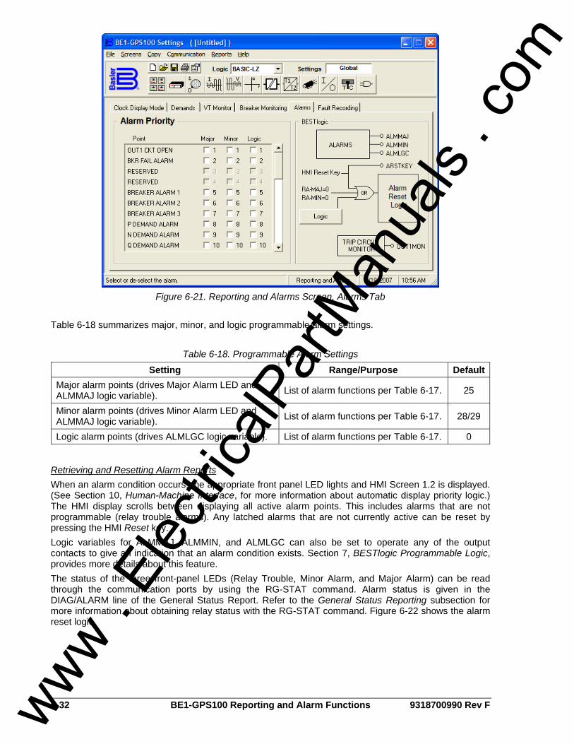
6-32 BE1-GPS100 Reporting and Alarm Functions 9318700990 Rev F
Figure 6-21. Reporting and Alarms Screen, Alarms Tab
Table 6-18 summarizes major, minor, and logic programmable alarm settings.
Table 6-18. Programmable Alarm Settings
Setting Range/Purpose DefaultMajor alarm points (drives Major Alarm LED and ALMMAJ logic variable). List of alarm functions per Table 6-17. 25
Minor alarm points (drives Minor Alarm LED and ALMMAJ logic variable). List of alarm functions per Table 6-17. 28/29
Logic alarm points (drives ALMLGC logic variable). List of alarm functions per Table 6-17. 0
Retrieving and Resetting Alarm Reports When an alarm condition occurs, the appropriate front panel LED lights and HMI Screen 1.2 is displayed. (See Section 10, Human-Machine Interface, for more information about automatic display priority logic.) The HMI display scrolls between displaying all active alarm points. This includes alarms that are not programmable (relay trouble alarms). Any latched alarms that are not currently active can be reset by pressing the HMI Reset key. Logic variables for ALMMAJ, ALMMIN, and ALMLGC can also be set to operate any of the output contacts to give an indication that an alarm condition exists. Section 7, BESTlogic Programmable Logic, provides more details about this feature. The status of the three front-panel LEDs (Relay Trouble, Minor Alarm, and Major Alarm) can be read through the communication ports by using the RG-STAT command. Alarm status is given in the DIAG/ALARM line of the General Status Report. Refer to the General Status Reporting subsection for more information about obtaining relay status with the RG-STAT command. Figure 6-22 shows the alarm reset logic.
www . El
ectric
alPar
tMan
uals
. com

9318700990 Rev F BE1-GPS100 Reporting and Alarm Functions 6-33
D2850-09.vsd06-29-99
RA-MAJ=0
Logic
AlarmResetLogic
RA-MIN=0
ARSTKEY
HMI RESET KEY
Figure 6-22. Programmable Alarm Function
The Reset key of the HMI is context sensitive. That is, the functionality depends upon what screen is currently being displayed. BESTlogic variable ARSTKEY takes advantage of this to allow the front panel Reset key to be used in the programmable logic scheme when Alarms screen 1.2 is active. An example of the use of this logic variable is to break the seal-in for a logic expression. The logic expression can be programmed so that the seal-in function uses VO13, VO14, or VO15. If the virtual output expression is included in one of the programmable alarm masks, the automatic display priority logic will cause the display to go to Alarm Screen 1.2. When the HMI Reset key is pressed, the ARSTKEY logic variable is asserted and the logic expression seal-in is broken. See Section 8, Application, Application Tips, for more information. Pressing the HMI Reset key while the Alarms screen is displayed, will clear any latched alarms that are not currently active. Refer to Table 6-17 for a list of latching alarm points and self-clearing alarm points. After an operation, alarms information can be viewed using BESTCOMS. Select Metering from the Reports pull-down menu. Alarms are shown on the Metering screen. Refer to Figure 6-23.
Figure 6-23. Metering Screen
The RA (report alarms) command can be used to read detailed alarm reports and reset latched alarms.
Links between Programmable Alarms and BESTlogic Several links between the programmable alarms and BESTlogic allow alarm functions to be used in the logic scheme and programmable logic functions to be used in the alarm reporting function.
www . El
ectric
alPar
tMan
uals
. com
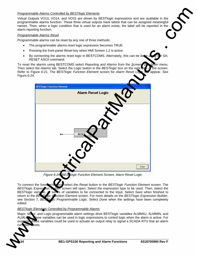
6-34 BE1-GPS100 Reporting and Alarm Functions 9318700990 Rev F
Programmable Alarms Controlled by BESTlogic Elements Virtual Outputs VO13, VO14, and VO15 are driven by BESTlogic expressions and are available in the programmable alarms function. These three virtual outputs have labels that can be assigned meaningful names. Then, when a logic condition that is used for an alarm exists, the label will be reported in the alarm reporting function.
Programmable Alarms Reset Programmable alarms can be reset by any one of three methods:
• The programmable alarms reset logic expression becomes TRUE. • Pressing the front panel Reset key when HMI Screen 1.2 is active. • By connecting the alarms reset logic in BESTCOMS. Alternately, this can be done using the SA-
RESET ASCII command. To reset the alarms using BESTCOMS select Reporting and Alarms from the Screens pull-down menu. Then select the Alarms tab. Select the Logic button in the BESTlogic box on the right side of the screen. Refer to Figure 6-21. The BESTlogic Function Element screen for Alarm Reset Logic will appear. See Figure 6-24.
Figure 6-24. BESTlogic Function Element Screen, Alarm Reset Logic
To connect the function's input, select the Reset button in the BESTlogic Function Element screen. The BESTlogic Expression Builder screen will open. Select the expression type to be used. Then, select the BESTlogic variable, or series of variables to be connected to the input. Select Save when finished to return to the BESTlogic Function Element screen. For more details on the BESTlogic Expression Builder, see Section 7, BESTlogic Programmable Logic. Select Done when the settings have been completely edited.
BESTlogic Elements Controlled by Programmable Alarms Major, Minor, and Logic programmable alarm settings drive BESTlogic variables ALMMAJ, ALMMIN, and ALMLGC. These variables can be used in logic expressions to control logic when the alarm is active. For example, these variables could be used to actuate an output relay to signal a SCADA RTU that an alarm condition exists.
www . El
ectric
alPar
tMan
uals
. com
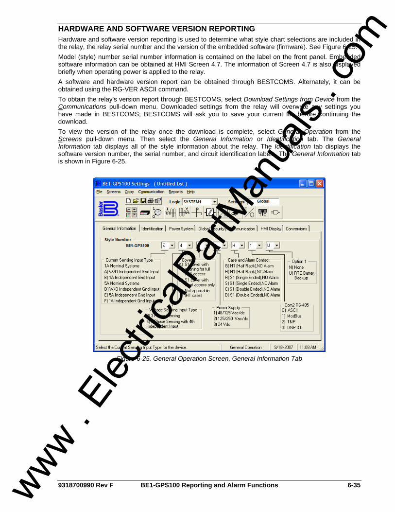
9318700990 Rev F BE1-GPS100 Reporting and Alarm Functions 6-35
HARDWARE AND SOFTWARE VERSION REPORTING Hardware and software version reporting is used to determine what style chart selections are included in the relay, the relay serial number and the version of the embedded software (firmware). See Figure 6-25. Model (style) number serial number information is contained on the label on the front panel. Embedded software information can be obtained at HMI Screen 4.7. The information of Screen 4.7 is also displayed briefly when operating power is applied to the relay. A software and hardware version report can be obtained through BESTCOMS. Alternately, it can be obtained using the RG-VER ASCII command. To obtain the relay's version report through BESTCOMS, select Download Settings from Device from the Communications pull-down menu. Downloaded settings from the relay will overwrite any settings you have made in BESTCOMS; BESTCOMS will ask you to save your current file before continuing the download. To view the version of the relay once the download is complete, select General Operation from the Screens pull-down menu. Then select the General Information or Identification tab. The General Information tab displays all of the style information about the relay. The Identification tab displays the software version number, the serial number, and circuit identification labels. The General Information tab is shown in Figure 6-25.
Figure 6-25. General Operation Screen, General Information Tab
www . El
ectric
alPar
tMan
uals
. com
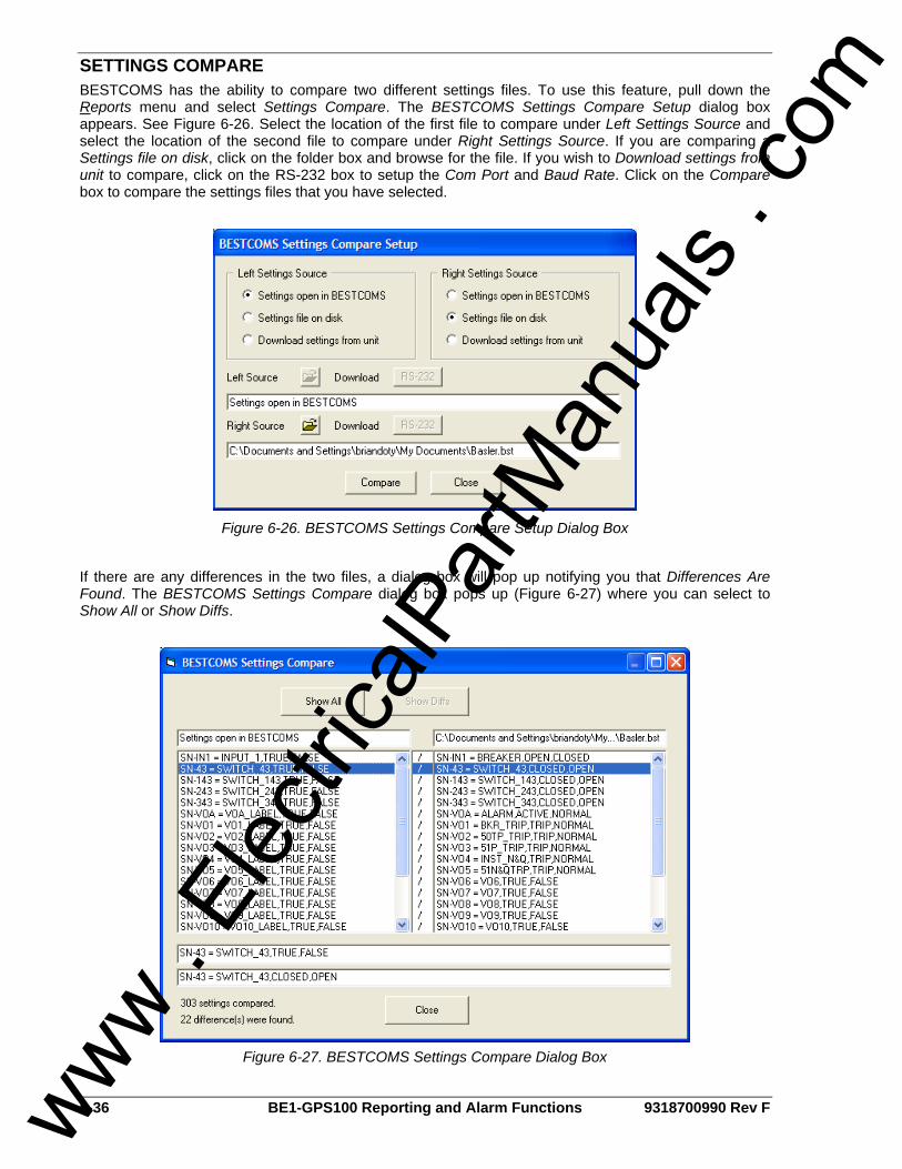
6-36 BE1-GPS100 Reporting and Alarm Functions 9318700990 Rev F
SETTINGS COMPARE BESTCOMS has the ability to compare two different settings files. To use this feature, pull down the Reports menu and select Settings Compare. The BESTCOMS Settings Compare Setup dialog box appears. See Figure 6-26. Select the location of the first file to compare under Left Settings Source and select the location of the second file to compare under Right Settings Source. If you are comparing a Settings file on disk, click on the folder box and browse for the file. If you wish to Download settings from unit to compare, click on the RS-232 box to setup the Com Port and Baud Rate. Click on the Compare box to compare the settings files that you have selected.
Figure 6-26. BESTCOMS Settings Compare Setup Dialog Box
If there are any differences in the two files, a dialog box will pop up notifying you that Differences Are Found. The BESTCOMS Settings Compare dialog box pops up (Figure 6-27) where you can select to Show All or Show Diffs.
Figure 6-27. BESTCOMS Settings Compare Dialog Box
www . El
ectric
alPar
tMan
uals
. com
9318700990 Rev F BE1-GPS100 BESTlogic Programmable Logic i
SECTION 7 • BESTLOGIC PROGRAMMABLE LOGIC
TABLE OF CONTENTS SECTION 7 • BESTLOGIC PROGRAMMABLE lOGIC ............................................................................ 7-1
INTRODUCTION.................................................................................................................................... 7-1 WORKING WITH PROGRAMMABLE LOGIC ....................................................................................... 7-1
Function Block Logic Settings ............................................................................................................ 7-4 Output Logic Settings ......................................................................................................................... 7-5
LOGIC SCHEMES ................................................................................................................................. 7-7 The Active Logic Scheme................................................................................................................... 7-7 Custom Logic Schemes ..................................................................................................................... 7-8 Copying and Renaming Preprogrammed Logic Schemes................................................................. 7-9 Creating or Customizing a Logic Scheme.......................................................................................... 7-9 Sending and Retrieving Relay Settings.............................................................................................. 7-9 Debugging the Logic Scheme ............................................................................................................ 7-9
USER INPUT AND OUTPUT LOGIC VARIABLE NAMES.................................................................... 7-9 BESTLOGIC APPLICATION TIPS....................................................................................................... 7-10
Figures Figure 7-1. BESTlogic Function Blocks..................................................................................................... 7-2 Figure 7-2. BESTlogic Function Blocks - continued.................................................................................. 7-3 Figure 7-3. Loss of Excitation Logic Block ................................................................................................ 7-5 Figure 7-4. Virtual Output Logic................................................................................................................. 7-5 Figure 7-5. BESTlogic Expression Builder Screen.................................................................................... 7-6 Figure 7-6. BESTlogic Screen, Logic Select Tab ...................................................................................... 7-8
Tables Table 7-1. Logic Variable Names and Descriptions .................................................................................. 7-4 Table 7-2. Programmable Variable Name Setting..................................................................................... 7-9
www . El
ectric
alPar
tMan
uals
. com

ii BE1-GPS100 BESTlogic Programmable Logic 9318700990 Rev F
This page intentionally left blank.
www . El
ectric
alPar
tMan
uals
. com
9318700990 Rev F BE1-GPS100 BESTlogic Programmable Logic 7-1
SECTION 7 • BESTLOGIC PROGRAMMABLE LOGIC
INTRODUCTION Multifunction relays such as the BE1-GPS100 Generator Protection System are similar in nature to a panel of single-function protective relays. Both must be wired together with ancillary devices to operate as a complete protection and control system. In the single-function static and electromechanical environment, elementary diagrams and wiring diagrams provide direction for wiring protective elements, switches, meters, and indicator lights into a unique protection and control system. In the digital, multifunction environment, the process of wiring individual protection or control elements is replaced with the entry of logic settings. The process of creating a logic scheme is the digital equivalent of wiring a panel. It integrates the multifunction protection, control, and input/output elements into a unique protection and control system. BESTlogic is a programming method used for managing the input, output, protection, control, monitoring, and reporting capabilities of Basler Electric's digital, multifunction, overcurrent protective relay systems. Each relay system has multiple, self-contained function blocks that have all of the inputs and outputs of its discrete component counterpart. Each independent function block interacts with control inputs, virtual outputs, and hardware outputs based on logic variables defined in equation form with BESTlogic. BESTlogic equations entered and saved in the relay system's nonvolatile memory integrate (electronically wire) the selected or enabled protection and control blocks with control inputs, virtual outputs, and hardware outputs. A group of logic equations defining the function of the multifunction relay is called a logic scheme. Several preprogrammed logic schemes are stored in relay memory. Each scheme is configured for a typical protection application and virtually eliminates the need for "start-from-scratch" programming. Any of the preprogrammed schemes can be copied and saved as the active logic. Preprogrammed logic schemes can also be copied and then customized to suit your application. Detailed information about preprogrammed logic schemes is provided later in this section. BESTlogic is not used to define the operating settings (pickup thresholds and time delays) of the individual protection and control functions. Operating settings and logic settings are interdependent but separately programmed functions. Changing logic settings is similar to rewiring a panel and is separate and distinct from making the operating settings that control the pickup thresholds and time delays of a relay. Detailed information about operating settings is provided in Section 4, Protection and Control.
WORKING WITH PROGRAMMABLE LOGIC BESTlogic uses two types of logic settings: output logic settings and function block logic settings. These two types of settings are discussed in the following subsections. Output logic settings are entered in equation form and control the hardware outputs of the relay. BESTlogic function blocks are illustrated in Figures 7-1 and 7-2 and are discussed in the following paragraphs. Names assigned to inputs, outputs, timers, and protection and control elements represent the logic variables in the equations. Table 7-1 lists the logic variable names and descriptions.
www . El
ectric
alPar
tMan
uals
. com
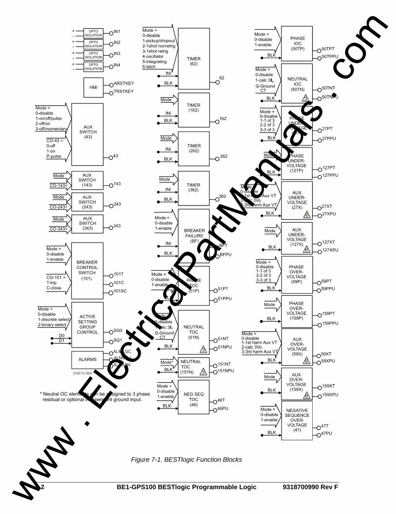
7-2 BE1-GPS100 BESTlogic Programmable Logic 9318700990 Rev F
Figure 7-1. BESTlogic Function Blocks
www .
Elec
tricalP
artM
anua
ls . c
om

9318700990 Rev F BE1-GPS100 BESTlogic Programmable Logic 7-3
Figure 7-2. BESTlogic Function Blocks - continued
www . El
ectric
alPar
tMan
uals
. com
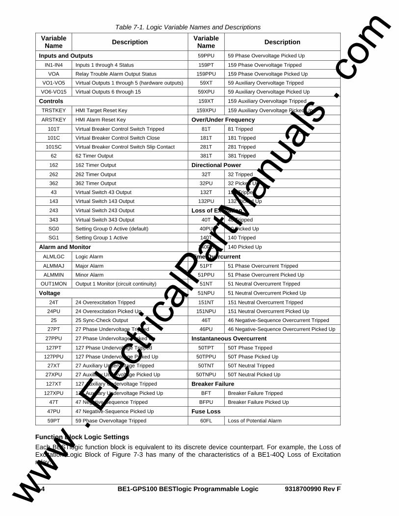
7-4 BE1-GPS100 BESTlogic Programmable Logic 9318700990 Rev F
Table 7-1. Logic Variable Names and Descriptions
Variable Name Description Variable
Name Description
Inputs and Outputs 59PPU 59 Phase Overvoltage Picked Up
IN1-IN4 Inputs 1 through 4 Status 159PT 159 Phase Overvoltage Tripped
VOA Relay Trouble Alarm Output Status 159PPU 159 Phase Overvoltage Picked Up
VO1-VO5 Virtual Outputs 1 through 5 (hardware outputs) 59XT 59 Auxiliary Overvoltage Tripped
VO6-VO15 Virtual Outputs 6 through 15 59XPU 59 Auxiliary Overvoltage Picked Up
Controls 159XT 159 Auxiliary Overvoltage Tripped
TRSTKEY HMI Target Reset Key 159XPU 159 Auxiliary Overvoltage Picked Up
ARSTKEY HMI Alarm Reset Key Over/Under Frequency 101T Virtual Breaker Control Switch Tripped 81T 81 Tripped
101C Virtual Breaker Control Switch Close 181T 181 Tripped
101SC Virtual Breaker Control Switch Slip Contact 281T 281 Tripped
62 62 Timer Output 381T 381 Tripped
162 162 Timer Output Directional Power 262 262 Timer Output 32T 32 Tripped
362 362 Timer Output 32PU 32 Picked Up
43 Virtual Switch 43 Output 132T 132 Tripped
143 Virtual Switch 143 Output 132PU 132 Picked Up
243 Virtual Switch 243 Output Loss of Excitation 343 Virtual Switch 343 Output 40T 40 Tripped
SG0 Setting Group 0 Active (default) 40PU 40 Picked Up
SG1 Setting Group 1 Active 140T 140 Tripped
Alarm and Monitor 140PU 140 Picked Up
ALMLGC Logic Alarm Time Overcurrent ALMMAJ Major Alarm 51PT 51 Phase Overcurrent Tripped
ALMMIN Minor Alarm 51PPU 51 Phase Overcurrent Picked Up
OUT1MON Output 1 Monitor (circuit continuity) 51NT 51 Neutral Overcurrent Tripped
Voltage 51NPU 51 Neutral Overcurrent Picked Up
24T 24 Overexcitation Tripped 151NT 151 Neutral Overcurrent Tripped
24PU 24 Overexcitation Picked Up 151NPU 151 Neutral Overcurrent Picked Up
25 25 Sync-Check Output 46T 46 Negative-Sequence Overcurrent Tripped
27PT 27 Phase Undervoltage Tripped 46PU 46 Negative-Sequence Overcurrent Picked Up
27PPU 27 Phase Undervoltage Picked Up Instantaneous Overcurrent 127PT 127 Phase Undervoltage Tripped 50TPT 50T Phase Tripped
127PPU 127 Phase Undervoltage Picked Up 50TPPU 50T Phase Picked Up
27XT 27 Auxiliary Undervoltage Tripped 50TNT 50T Neutral Tripped
27XPU 27 Auxiliary Undervoltage Picked Up 50TNPU 50T Neutral Picked Up
127XT 127 Auxiliary Undervoltage Tripped Breaker Failure 127XPU 127 Auxiliary Undervoltage Picked Up BFT Breaker Failure Tripped
47T 47 Negative-Sequence Tripped BFPU Breaker Failure Picked Up
47PU 47 Negative-Sequence Picked Up Fuse Loss 59PT 59 Phase Overvoltage Tripped 60FL Loss of Potential Alarm
Function Block Logic Settings Each BESTlogic function block is equivalent to its discrete device counterpart. For example, the Loss of Excitation Logic Block of Figure 7-3 has many of the characteristics of a BE1-40Q Loss of Excitation relay.
www . El
ectric
alPar
tMan
uals
. com
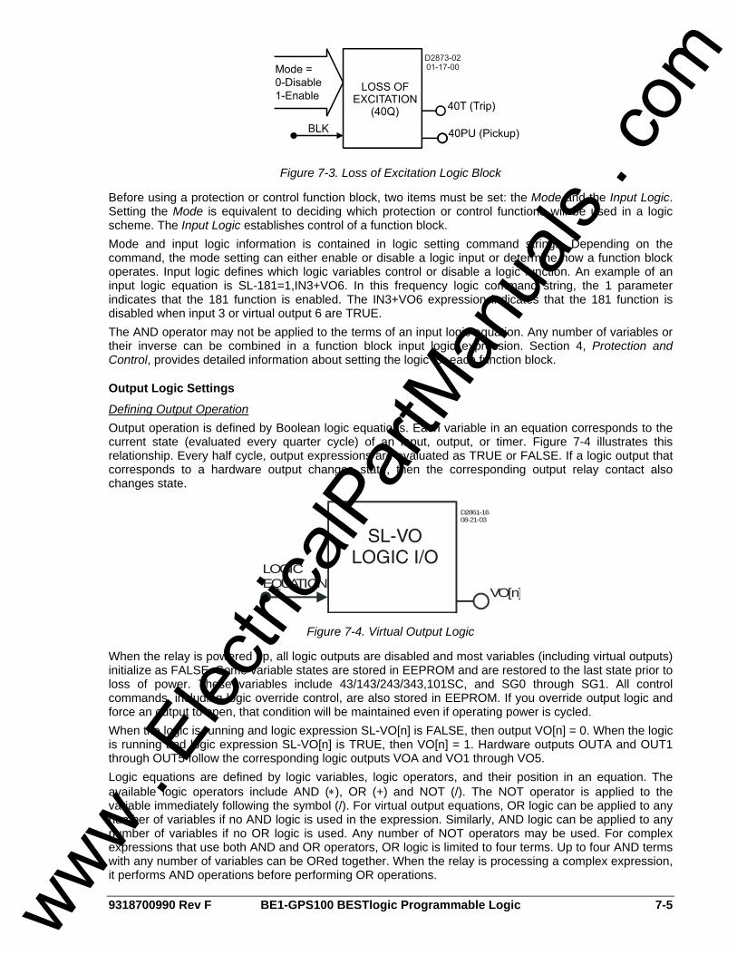
9318700990 Rev F BE1-GPS100 BESTlogic Programmable Logic 7-5
Figure 7-3. Loss of Excitation Logic Block
Before using a protection or control function block, two items must be set: the Mode and the Input Logic. Setting the Mode is equivalent to deciding which protection or control functions will be used in a logic scheme. The Input Logic establishes control of a function block. Mode and input logic information is contained in logic setting command strings. Depending on the command, the mode setting can either enable or disable a logic input or determine how a function block operates. Input logic defines which logic variables control or disable a logic function. An example of an input logic equation is SL-181=1,IN3+VO6. In this frequency logic command string, the 1 parameter indicates that the 181 function is enabled. The IN3+VO6 expression indicates that the 181 function is disabled when input 3 or virtual output 6 are TRUE. The AND operator may not be applied to the terms of an input logic equation. Any number of variables or their inverse can be combined in a function block input logic expression. Section 4, Protection and Control, provides detailed information about setting the logic for each function block.
Output Logic Settings
Defining Output Operation Output operation is defined by Boolean logic equations. Each variable in an equation corresponds to the current state (evaluated every quarter cycle) of an input, output, or timer. Figure 7-4 illustrates this relationship. Every half cycle, output expressions are evaluated as TRUE or FALSE. If a logic output that corresponds to a hardware output changes state, then the corresponding output relay contact also changes state.
VO[n]
LOGICEQUATION
D2861-1608-21-03
Figure 7-4. Virtual Output Logic
When the relay is powered up, all logic outputs are disabled and most variables (including virtual outputs) initialize as FALSE. Some variable states are stored in EEPROM and are restored to the last state prior to loss of power. These variables include 43/143/243/343,101SC, and SG0 through SG1. All control commands, including logic override control, are also stored in EEPROM. If you override output logic and force an output to open, that condition will be maintained even if operating power is cycled. When the logic is running and logic expression SL-VO[n] is FALSE, then output VO[n] = 0. When the logic is running and logic expression SL-VO[n] is TRUE, then VO[n] = 1. Hardware outputs OUTA and OUT1 through OUT5 follow the corresponding logic outputs VOA and VO1 through VO5. Logic equations are defined by logic variables, logic operators, and their position in an equation. The available logic operators include AND (∗), OR (+) and NOT (/). The NOT operator is applied to the variable immediately following the symbol (/). For virtual output equations, OR logic can be applied to any number of variables if no AND logic is used in the expression. Similarly, AND logic can be applied to any number of variables if no OR logic is used. Any number of NOT operators may be used. For complex expressions that use both AND and OR operators, OR logic is limited to four terms. Up to four AND terms with any number of variables can be ORed together. When the relay is processing a complex expression, it performs AND operations before performing OR operations.
www . El
ectric
alPar
tMan
uals
. com

7-6 BE1-GPS100 BESTlogic Programmable Logic 9318700990 Rev F
Virtual and Hardware Outputs A virtual output exists only as a logical state inside the relay. A hardware output is a physical relay contact that can be used for protection or control. Each BE1-GPS100 relay has five isolated, normally open (NO) output contacts (OUT1 - OUT5) and one isolated, normally closed (NC) or normally open (NO) alarm output (OUTA). Output contacts OUT1 through OUT5 are controlled by the status of the internal virtual logic signals VO1 through VO5. If VO[n] becomes TRUE, then the corresponding output relay OUT[n] energizes and closes the NO contacts. For the alarm output, if VOA becomes TRUE, the ALM output de-energizes and opens. More information about input and output functions is provided in Section 3, Input and Output Functions. Hardware outputs can also be controlled by the CO-OUT (control operate, output) command. The CO-OUT command overrides control of logic outputs. Outputs may be pulsed or latched in a 0 or 1 state independently from the state of the virtual output logic. More information about overriding control of logic outputs is available in Section 3, Input and Output Functions.
BESTlogic Expression Builder The BESTlogic Expression Builder is used to connect the inputs of the relay's function blocks, physical inputs and outputs, and virtual outputs. Using the BESTlogic Expression Builder is analogous to physically attaching wire between discrete relay terminals. The BESTlogic Expression Builder is opened each time the input of a BESTlogic function block is selected. Figure 7-5 illustrates the BESTlogic Expression Builder screen.
Figure 7-5. BESTlogic Expression Builder Screen
The BESTlogic Expression Builder provides a point and click interface that allows the selected input to be easily connected using a single OR gate, single AND gate, or an AND/OR combination. The usable list of inputs and outputs in the bottom left of the screen corresponds with the variable lists of Tables 7-1 and 7-2. Currently, the virtual outputs are the only functions that can use the single AND or AND/OR combination BESTlogic Expression Type. The top of the screen displays the BESTlogic expression in a text window. Above the text window, the selected input and the associated ASCII command are displayed. The Clear button will clear the expression to 0. The Reset button will reset the expression to its original state when the BESTlogic Expression Builder was first opened. The Cancel button resets the expression to its original state when the BESTlogic Expression Builder was first opened and returns the user to the
www . El
ectric
alPar
tMan
uals
. com
9318700990 Rev F BE1-GPS100 BESTlogic Programmable Logic 7-7
previous screen. The Save button saves the expression shown in the text window and returns the user to the previous window.
LOGIC SCHEMES A logic scheme is a group of logic variables written in equation form that defines the operation of a multi-function relay. Each logic scheme is given a unique name of one to eight alphanumeric characters. This gives you the ability to select a specific scheme and be confident that the selected scheme is in operation. Five logic schemes, configured for typical protection applications, are stored in nonvolatile memory. Only one of these logic schemes can be active at a given time. In most applications, preprogrammed logic schemes eliminate the need for custom programming. Preprogrammed logic schemes may provide more inputs, outputs, or features than are needed for a particular application. This is because the preprogrammed schemes are designed for a large number of applications with no special programming required. Unneeded inputs or outputs may be left open to disable a function or a function block can be disabled through operating settings. Unused current sensing inputs should be shorted to minimize noise pickup. When a custom logic scheme is required, programming time can be reduced by copying a preprogrammed scheme into the active logic. The logic scheme can then be modified to meet the specific application.
The Active Logic Scheme Digital, multifunction relays must have an active logic scheme in order to function. All Basler Electric multifunction relays are delivered with a default, active logic loaded into memory. The default, active logic scheme for the BE1-GPS100 is named BASIC-LZ. If the function block configuration and output logic of BASIC-LZ meets the requirements of your application, then only the operating settings (power system parameters and threshold settings) need to be adjusted before placing the relay in service.
If a different preprogrammed logic scheme is required, it can be easily copied to active logic and used as is or customized to your specifications. To accomplish this, communication with the relay must be established. It is accomplished by connecting a computer to the front or rear RS-232 port. Logic schemes can be selected from the logic select tab on the BESTlogic screen. To access this screen, select BESTlogic from the Screens pull-down menu. Then select the Logic Select tab. Select the desired logic scheme to Copy to Active Logic (Internal Logic). The active logic scheme is shown in the Logic Name box. In Figure 7-6, BASIC-LZ has been selected as the user logic.
NOTE There has been a fundamental improvement to the way the user sets up BESTlogic in this device. In some prior implementations of BESTlogic, it was necessary to make a separate setting that determined whether the user's logic scheme or if one of the pre-programmed logic schemes was to be made active. This setting was made from the ASCII command interface using the SP-LOGIC (Set Protection Logic) command. This setting has been eliminated. In the implementation of BESTlogic used in this relay, the logic scheme defined by the user's logic settings is always active. If the user wishes to use a preprogrammed logic scheme, he/she now copies it into his/her user logic settings. This process is accomplished from the ASCII command interface using the SL-N (Set Logic Name) command in this and previous BESTlogic implementations.
www . El
ectric
alPar
tMan
uals
. com
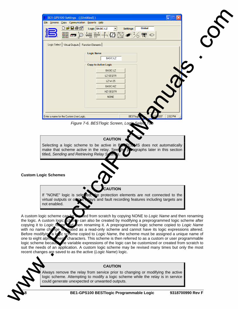
7-8 BE1-GPS100 BESTlogic Programmable Logic 9318700990 Rev F
Figure 7-6. BESTlogic Screen, Logic Select Tab
Custom Logic Schemes
A custom logic scheme can be created from scratch by copying NONE to Logic Name and then renaming the logic. A custom logic scheme can also be created by modifying a preprogrammed logic scheme after copying it to Logic Name and then renaming it. A preprogrammed logic scheme copied to Logic Name with no name change is treated as a read-only scheme and cannot have its logic expressions altered. Before modifying a logic scheme copied to Logic Name, the scheme must be assigned a unique name of one to eight alphanumeric characters. This scheme is then referred to as a custom or user programmable logic scheme because the variable expressions of the logic can be customized or created from scratch to suit the needs of an application. A custom logic scheme may be revised many times but only the most recent changes are saved to as the active (Logic Name) logic.
CAUTION Selecting a logic scheme to be active in BESTCOMS does not automatically make that scheme active in the relay. See the paragraphs later in this section titled, Sending and Retrieving Relay Settings.
CAUTION If "NONE" logic is selected, the protection elements are not connected to the virtual outputs or output relays and fault recording features including targets are not enabled.
CAUTION Always remove the relay from service prior to changing or modifying the active logic scheme. Attempting to modify a logic scheme while the relay is in service could generate unexpected or unwanted outputs.
www . El
ectric
alPar
tMan
uals
. com

9318700990 Rev F BE1-GPS100 BESTlogic Programmable Logic 7-9
Copying and Renaming Preprogrammed Logic Schemes Copying a preprogrammed logic scheme to the active logic (Logic Name) and assigning a unique name is accomplished by selecting the desired logic scheme in BESTCOMS and then typing over the logic scheme's name. Changes are not activated until the new settings have been uploaded to the device.
Creating or Customizing a Logic Scheme Before customizing a preprogrammed logic scheme, the scheme must be renamed. The following procedure outlines the process of customizing or creating a logic scheme:
Step 1. Copy the preprogrammed scheme. Step 2. Rename the scheme with a unique, non-preprogrammed, name. Step 3. Using BESTCOMS, enable or disable the desired relay functions. Step 4. Edit the logic expressions, as required. Step 5. Save the changes. Refer to Section 14, BESTCOMS Software, for more information on
how to save and export settings files.
Sending and Retrieving Relay Settings
Retrieving Relay Settings To retrieve settings from the relay, the relay must be connected to a computer through a serial port. Once the necessary connections are made, settings can be downloaded from the relay by selecting Download Settings from Device on the Communication pull-down menu.
Sending Relay Settings To send settings to the relay, the relay must be connected to a computer through a serial port. Once the necessary connections are made, settings can be uploaded to the relay by selecting Upload Settings to Device on the Communication pull-down menu.
Debugging the Logic Scheme If there are problems with a customized logic scheme, the RG-STAT command can be used to check the status of all logic variables. More information about the RG-STAT command can be found in Section 6, Reporting and Alarm Functions.
USER INPUT AND OUTPUT LOGIC VARIABLE NAMES Assigning meaningful names to the inputs and outputs makes sequential events reports easier to analyze. Input and output logic variable names are assigned by typing them into the appropriate text box on the related BESTCOMS screen. All of the BE1-GPS100’s inputs, outputs, and 43 switches have labels that can be edited. Table 7-2 shows the range and purpose of each label. Alternately, labels may be edited using the SN ASCII command.
Table 7-2. Programmable Variable Name Setting
Settings Range/Purpose Default
Name/Label 1 to 10 characters. User name to replace <var> in the RS report.
INPUT_x SWITCH_x43 VOx_LABEL
True/Energized State 1 to 7 characters. Used to replace default labels.
TRUE
False/De-Energized State 1 to 7 characters. Used to replace default labels. FALSE
www . El
ectric
alPar
tMan
uals
. com

7-10 BE1-GPS100 BESTlogic Programmable Logic 9318700990 Rev F
BESTLOGIC APPLICATION TIPS When designing a completely new logic scheme, logic evaluation order should be considered. Contact sensing inputs are evaluated first, then the function blocks, and then the virtual outputs. VO15 is evaluated first and VOA is evaluated last. If a virtual output is used in a logic expression to control another virtual output, the virtual output used in the expression should be numerically higher. Otherwise, a logic expression for a numerically smaller virtual output will not be available to a numerically higher virtual output until the next processing interval. Logic is evaluated every half cycle. When designing custom protection schemes, avoid confusion by maintaining consistency between input and output functions in the custom scheme and the preprogrammed schemes. OUT1 through OUT5 have normally open contacts (coil is de-energized). Normally open contacts can be used as normally closed outputs by inverting the logic expressions that drive them. Inverting an output logic expression causes the coil to be energized with the contacts closed in the normal state. Caution should be taken with normally closed contact logic because there are no shorting bars to maintain the closed condition if the draw-out assembly is removed from the chassis. In applications where a normally closed output is needed even when the electronics are removed, a normally open contact from the relay can be used to drive a low-cost auxiliary relay. The normally closed output of the auxiliary relay will maintain the closed output when the draw-out assembly is removed from the case. Alternately, an external switch can be used to short across a normally closed relay output when the draw-out assembly is removed. Extra care is required to ensure that the switch is closed prior to removing the draw-out assembly and that the switch is open after the relay is placed back in service. Several links between the programmable alarms function and BESTlogic programmable logic allow alarm functions to be used in a logic scheme and programmable logic functions to be used in the alarm reporting function. Programmable alarm settings for Major, Minor, and Logic alarms drive BESTlogic variables ALMMAJ, ALMMIN, and ALMLGC. These variables can be used in logic expressions to control logic when an alarm is active. Virtual outputs VO13, VO14, and VO15 are driven by BESTlogic expressions. These three logic variables are also available in the programmable alarm function. Virtual outputs can also be assigned user programmable labels (described previously). With this feature, a logic condition can be designed and used for an alarm. The virtual output label would then be reported in the Reporting and Alarm functions.
www . El
ectric
alPar
tMan
uals
. com
9318700990 Rev F BE1-GPS100 Application i
SECTION 8 • APPLICATION TABLE OF CONTENTS
SECTION 8 • APPLICATION .................................................................................................................... 8-1
INTRODUCTION.................................................................................................................................... 8-1 EXPLANATION OF TERMS .................................................................................................................. 8-1
Element .............................................................................................................................................. 8-1 High Impedance versus Low Impedance Generator Grounding........................................................ 8-1 Inadvertent Energization (I.E.) Protection .......................................................................................... 8-1 Sequential Trip ................................................................................................................................... 8-2 Torque Control ................................................................................................................................... 8-2 Tripping Scheme ................................................................................................................................ 8-2
OVERVIEW OF PREPROGRAMMED LOGIC SCHEMES ................................................................... 8-2 BASIC-LZ Logic Scheme (Basic Low Z Grounded Generator Protection) ........................................ 8-2 LZ-SEQTR Logic Scheme (Low Z Grounded Generator with Sequential Trip) ................................. 8-2 LZ-W-25 Logic Scheme (Low Z Grounded Generator with Sequential Trip and Sync Check).......... 8-2 BASIC-HZ (Basic High Z Grounded Generator Protection) ............................................................... 8-2 HZ-SEQTR (High Z Grounded Generator Protection) ....................................................................... 8-3 Notes on Logic Used in Preprogrammed Schemes........................................................................... 8-3
DETAILS OF PREPROGRAMMED LOGIC SCHEMES........................................................................ 8-3 BASIC-LZ (BASIC LOW Z GROUNDED GENERATOR PROTECTION) ............................................. 8-3
BASIC-LZ Logic Settings and Equations ........................................................................................... 8-9 LZ-SEQTR (LOW Z GROUNDED GENERATOR WITH SEQUENTIAL TRIP)................................... 8-10
LZ-SEQTR Logic Settings and Equations........................................................................................ 8-17 LZ-W-25 (LOW Z GROUNDED GENERATOR WITH SEQUENTIAL TRIP AND SYNC CHECK) ..... 8-18
LZ-W-25 Logic Settings and Equations............................................................................................ 8-25 BASIC-HZ (BASIC HIGH Z GROUNDED GENERATOR PROTECTION).......................................... 8-26
BASIC-HZ Logic Settings and Equations......................................................................................... 8-32 HZ-SEQTR (HIGH Z GROUNDED GENERATOR PROTECTION) .................................................... 8-33
HZ-SEQTR Logic Settings and Equations ....................................................................................... 8-40 MISCELLANEOUS LOGIC EXPRESSIONS ....................................................................................... 8-41 APPLICATION TIPS ............................................................................................................................ 8-41
Fuse Loss Conditions....................................................................................................................... 8-41 Differential Protection ....................................................................................................................... 8-41 Alternate Uses of IG .......................................................................................................................... 8-42 Operation - Alarms ........................................................................................................................... 8-42 Sync-Check Logic ............................................................................................................................ 8-42 V and F OK Logic ............................................................................................................................. 8-43 Inadvertent Energization Logic......................................................................................................... 8-43 Settings for the I.E. Timers and Protective Elements ...................................................................... 8-44 I.E. Operation for Loss and Return of Relay Power......................................................................... 8-45
Figures Figure 8-1. BASIC-LZ Logic Diagram........................................................................................................ 8-7 Figure 8-2. BASIC-LZ One-Line Drawing.................................................................................................. 8-8 Figure 8-3. LZ-SEQTR Logic Diagram .................................................................................................... 8-15 Figure 8-4. LZ-SEQTR One-Line Drawing .............................................................................................. 8-16 Figure 8-5. LZ-W-25 Logic Diagram........................................................................................................ 8-23 Figure 8-6. LZ-W-25 One-Line Drawing .................................................................................................. 8-24 Figure 8-7. BASIC-HZ Logic Diagram ..................................................................................................... 8-30 Figure 8-8. BASIC-HZ One-Line Drawing ............................................................................................... 8-31 Figure 8-9. HZ-SEQTR Logic Diagram ................................................................................................... 8-38 Figure 8-10. HZ-SEQTR One-Line Drawing............................................................................................ 8-39 Figure 8-11. Alternate Uses of IG Input.................................................................................................... 8-42 Figure 8-12. Sync-Check with Dead Bus Close ...................................................................................... 8-43 Figure 8-13. Inadvertent Energization Protection Logic .......................................................................... 8-43 Figure 8-14. I.E. Timer Settings............................................................................................................... 8-44
www . El
ectric
alPar
tMan
uals
. com
ii BE1-GPS100 Application 9318700990 Rev F
Tables Table 8-1. BASIC-LZ Tripping Scheme Summary .................................................................................... 8-3 Table 8-2. BASIC-LZ Contact Sensing Input Logic ................................................................................... 8-4 Table 8-3. BASIC-LZ Function Block Logic............................................................................................... 8-4 Table 8-4. BASIC-LZ Virtual Switch Logic................................................................................................. 8-5 Table 8-5. BASIC-LZ Virtual Output Logic................................................................................................. 8-5 Table 8-6. LZ-SEQTR Tripping Scheme Summary................................................................................. 8-10 Table 8-7. LZ-SEQTR Contact Sensing Input Logic ............................................................................... 8-11 Table 8-8. LZ-SEQTR Function Block Logic ........................................................................................... 8-11 Table 8-9. LZ-SEQTR Virtual Switch Logic ............................................................................................. 8-12 Table 8-10. LZ-SEQTR Virtual Output Logic........................................................................................... 8-12 Table 8-11. LZ-W-25 Tripping Scheme Summary................................................................................... 8-18 Table 8-12. LZ-W-25 Contact Sensing Input Logic ................................................................................. 8-19 Table 8-13. LZ-W-25 Function Block Logic ............................................................................................. 8-19 Table 8-14. LZ-W-25 Virtual Switch Logic ............................................................................................... 8-20 Table 8-15. LZ-W-25 Virtual Output Logic............................................................................................... 8-20 Table 8-16. BASIC-HZ Tripping Scheme Summary................................................................................ 8-26 Table 8-17. BASIC-HZ Contact Sensing Input Logic .............................................................................. 8-26 Table 8-18. BASIC-HZ Function Block Logic .......................................................................................... 8-27 Table 8-19. BASIC-HZ Virtual Switch Logic ............................................................................................ 8-28 Table 8-20. BASIC-HZ Virtual Output Logic............................................................................................ 8-28 Table 8-21. HZ-SEQTR Tripping Scheme Summary .............................................................................. 8-33 Table 8-22. HZ-SEQTR Contact Sensing Input Logic............................................................................. 8-34 Table 8-23. HZ-SEQTR Function Block Logic......................................................................................... 8-34 Table 8-24. HZ-SEQTR Virtual Switch Logic .......................................................................................... 8-35 Table 8-25. HZ-SEQTR Virtual Output Logic .......................................................................................... 8-35 Table 8-26. Miscellaneous Logic Expressions ........................................................................................ 8-41 Table 8-27. I.E. Timer Settings................................................................................................................ 8-44
www . El
ectric
alPar
tMan
uals
. com
9318700990 Rev F BE1-GPS100 Application 8-1
SECTION 8 • APPLICATION INTRODUCTION This section discusses application of the BE1-GPS100 Generator Protection System using the preprogrammed logic schemes. The Details of Preprogrammed Logic Schemes subsection describes the characteristics of each logic scheme. A detailed description of each preprogrammed scheme is also provided. This section concludes with application tips for programming a custom logic scheme to meet the requirements of your application. The preprogrammed logic schemes are designed to accommodate a set of common and mainstream generator protection applications. The protection engineer can choose a logic scheme that most closely meets his application practices and adapt it by changing the function block operation and settings. This eliminates the need to create a custom logic scheme. It should be noted that each preprogrammed logic scheme also illustrates typical ways of using or controlling various functions. The user may choose to create a custom logic scheme by mixing the logic from several of the preprogrammed schemes. The logic can also be modified to incorporate some of the features described in the application tips provided at the end of this section. The flexibility of BESTlogic allows the protection engineer to create a custom scheme that exactly meets the requirements of the application.
EXPLANATION OF TERMS The following paragraphs define terms that are used in the logic scheme discussions of this section.
Element A stand-alone protection or control function that is equivalent to its discrete component counterpart.
High Impedance versus Low Impedance Generator Grounding In high impedance grounded generator designs, there is enough neutral impedance, that if a single point ground fault were to occur, the level of ground current would be difficult to detect with normal ground over- current relaying. The level of energy dissipated in the fault would be low enough for the condition to usually cause minimal damage or even be sustained indefinitely. In this design, protective relays that monitor the fundamental and third harmonic voltages at the generator neutral are able to detect ground faults. However, overcurrent protection is still applicable because if a second ground fault is made during the presence of the first, large current flows are likely. In a low impedance grounded generator the neutral is grounded either solidly or via a low to moderate impedance device. In this grounding design, ground fault current is limited by some level of neutral impedance, but enough current will flow for most faults to allow a ground overcurrent relay to detect the condition (the main exception being ground faults near the generator neutral).
Inadvertent Energization (I.E.) Protection A situation in which a generator is connected to the system without first bringing the generator up to rated speed and frequency. This may occur for a breaker being closed early in a synchronization process or closing a generator breaker when a generator is off line under an incorrect assumption that a disconnect switch was opened. The logic to detect this event checks for current flow without previous sensing of rated voltage and frequency. A discussion of the inadvertent energization logic as implemented in the preprogrammed schemes is provided in the Application Tips at the end of this section.
CAUTION If "NONE" logic is selected, the protection elements are not connected to the virtual outputs or output relays and fault recording features including targets are not enabled. The user will have to program and enable these features and functions as part of building a custom logic scheme.
www . El
ectric
alPar
tMan
uals
. com

8-2 BE1-GPS100 Application 9318700990 Rev F
Sequential Trip This refers to the tripping of a generator prime mover prior to the tripping the main breaker and removal of the generator field. The intent is to remove mechanical power input into the generator before the electrical load is removed from the generator, thus preventing the generator from going into an overspeed condition when electrical load is lost. The typical application is for an orderly shutdown of a generator in which the prime mover is first tripped manually, which then arms a reverse power (32R) element that has a relatively sensitive setting and short time delay. When the 32R element trips, the field and the main breaker are tripped. In some applications, the field is tripped earlier in the process.
Torque Control This describes the control that the BLK (Block) input has on an element in the relay. The block input of an element provides the equivalent of torque control of an electromechanical relay. While the block input is held high, the pickup and trip outputs are held at zero and the timing function is held at the zero time state. This is in contrast to merely blocking the trip output. Torque control via the block input applies to all over current, voltage and product (V∗I) based element including those that do not emulate induction disk type (51) relays.
Tripping Scheme This tripping scheme refers to the logic used to control how and when each protective element independently trips the prime mover, generator breaker, and field. The generator prime mover, field, main breaker and possibly the plant auxiliary load breaker when tapped off the main generator bus, may all be tripped independently. Any protective element may cause a trip of any one or all of these, either immediately or in a defined sequence. The preprogrammed logic and the discussions below do not address the plant auxiliary load breaker that closely follows the main breaker trip for protective relaying concerns. The two IEEE documents that describe tripping schemes and which were used in the development of the tripping schemes in the preprogrammed logic below are IEEE Guide for Generator Protection C37.102-1995 and IEEE Tutorial for Generator Protection, TP102-1995.
OVERVIEW OF PREPROGRAMMED LOGIC SCHEMES Five preprogrammed logic schemes are available. A brief description of each preprogrammed logic scheme is provided in the following paragraphs. More detailed information about these schemes is provided in Details of Preprogrammed Logic Schemes.
BASIC-LZ Logic Scheme (Basic Low Z Grounded Generator Protection) This logic scheme provides for basic protection of generators grounded through a low to moderate neutral impedance. This schemes’ logic tends toward the simple and straightforward. The tripping scheme provides for three tripping outputs with the same logic being used for all three outputs. Tripping functions include 24, 27P, 32(R), 132(R), 40Q, 140Q, 46, 47, 50P/50N(IE Prot), 51P(VR/VC), 51N(3I0), 151(IG), 59P, and 81/181/281(O or U). It does not provide for sequential trip logic or synchronism check.
LZ-SEQTR Logic Scheme (Low Z Grounded Generator with Sequential Trip) This logic scheme provides for more elaborate protection for generators grounded through a low to moderate neutral impedance. This scheme’s logic, as compared to the BASIC-LZ logic, offers more features. It adds sequential trip logic and implements a more involved tripping scheme. It provides three trip output contacts: one each for main breaker, field, and prime mover tripping, with different logic for each. As in the BASIC-LZ, tripping, function numbers include 24, 27P, 32(R), 132(R), 40Q, 140Q, 46, 47, 50P/50N(IE Prot), 51P(VR/VC), 51N(3I0), 151(IG), 59P and 81/181/281(O or U), except there is selective and intertied logic which discriminates on which output each function trips. It provides for sequential trip logic, but not synchronism check.
LZ-W-25 Logic Scheme (Low Z Grounded Generator with Sequential Trip and Sync Check) This scheme’s logic is very similar to LZ-SEQTR except it adds synchronism checking (25 function).
BASIC-HZ (Basic High Z Grounded Generator Protection) This logic scheme provides for basic protection for generators grounded through high neutral impedance. This scheme’s logic tends toward the simple and straightforward. The tripping scheme provides for three
www . El
ectric
alPar
tMan
uals
. com

9318700990 Rev F BE1-GPS100 Application 8-3
tripping outputs with the same logic being used for all three outputs. Tripping functions include 24, 27PH, 27-3N (neutral third harmonic), 32R, 40Q, 46, 47, 50-IE, 51VR/C, 51N, 59PH, 59-Neutral, 59-3V0 and 81O/U. It does not provide for sequential trip logic. Since the auxiliary voltage input is assigned to monitoring the neutral potential, the synchronism check function is not included in this logic.
HZ-SEQTR (High Z Grounded Generator Protection) This logic scheme provides for more elaborate protection for generators grounded through high neutral impedance. This scheme’s logic, as compared to the BASIC-HZ logic, offers more features. It adds sequential trip logic and implements a more involved tripping scheme. It provides three trip output contacts: one each for main breaker, field, and prime mover tripping, with different logic for each. As in the BASIC-HZ, tripping function numbers include 24, 27PH, 27-3N (neutral third harmonic), 32R, 40Q, 46, 47, 50-IE, 51VR/C, 51N, 59PH, 59-Neutral, 59-3V0 and 81O/U. It provides for sequential trip logic.
Notes on Logic Used in Preprogrammed Schemes Under Application Tips, at the end of this section, logic used in the preprogrammed schemes is discussed.
DETAILS OF PREPROGRAMMED LOGIC SCHEMES The following subsections describe each of the five preprogrammed logic schemes in detail. For each scheme, operation of the protection and control logic under normal conditions is described. The features of each logic scheme are broken down into functional groups and described in detail.
BASIC-LZ (BASIC LOW Z GROUNDED GENERATOR PROTECTION) This logic scheme provides for basic protection of generators that are grounded through a low to moderate neutral impedance. This schemes’ logic tends toward the simple and straightforward and uses a simple tripping scheme. Physical Outputs 1, 2 and 3 follow the same logic. It does not provide for sequential trip logic or synchronism check. The IEEE functions that trip Outputs 1, 2 and 3 are summarized in Table 8-1. The components of the logic of BASIC-LZ are listed in Tables 8-2, 8-3, 8-4, and 8-5. Inspect the logic diagrams shown in Figures 8-1 and 8-2 for a more thorough understanding.
Table 8-1. BASIC-LZ Tripping Scheme Summary
Protective Function Comments VO1, VO2, VO3
24 Overexcitation. X 27P Phase UV. Blocked for breaker open. X
32R, 132R Detect loss of prime mover. X 40Q, 140Q Loss of excitation. X
46 Negative sequence current. X 47 Negative sequence voltage (reverse phase rotation). X
50TP, 50TN Part of inadvertent energization logic. X 51VR or 51VC VR or VC time overcurrent. X
51N (3I0) Phase summation (ground) time overcurrent. X
151N (IG) Independent ground input time overcurrent. Use custom logic to re-assign to 3I0 if no IG is available. X
59P Phase overvoltage. X 81, 181 Underfrequency, level 1 and 2. Blocked for breaker open. X
281 Overfrequency. X
NOTE Name Labels are limited to ten characters and State Labels are limited to seven characters.
www . El
ectric
alPar
tMan
uals
. com
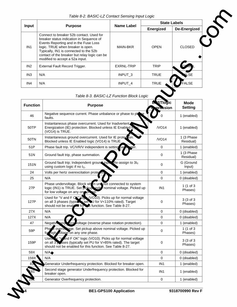
8-4 BE1-GPS100 Application 9318700990 Rev F
Table 8-2. BASIC-LZ Contact Sensing Input Logic
State Labels Input Purpose Name Label
Energized De-Energized
IN1
Connect to breaker 52b contact. Used for breaker status indication in Sequence of Events Reporting and in the Fuse Loss logic. TRUE when breaker is open. Typically, IN1 is connected to the 52b contact of the breaker but relay logic can be modified to accept a 52a input.
MAIN-BKR OPEN CLOSED
IN2 External Fault Record Trigger. EXRNL-TRIP TRIP NORMAL
IN3 N/A INPUT_3 TRUE FALSE
IN4 N/A INPUT_4 TRUE FALSE
Table 8-3. BASIC-LZ Function Block Logic
Function Purpose BESTlogic Expression
Mode Setting
46 Negative sequence current. Phase unbalance or phase to phase faults. 0 1 (enabled)
50TP Instantaneous phase overcurrent. Used for Inadvertent Energization (IE) protection. Blocked unless IE Enabled logic (VO14) is TRUE.
/VO14 1 (enabled)
50TN Instantaneous ground overcurrent. Used for IE protection. Blocked unless IE Enabled logic (VO14) is TRUE. /VO14 1 (3 Phase
Residual) 51P Phase fault trip. VC/VR/V independent is setting parameter. 0 1 (enabled)
51N Ground fault trip, phase summation. 0 1 (3 Phase Residual)
151N Ground fault trip; Independent ground input. Re-assign to 3I0 using custom logic if no IG. 0 G (Ground
Input) 24 Volts per hertz overexcitation protection. 0 1 (enabled) 25 N/A 0 0 (disabled)
27P Phase undervoltage. Block when unit not connected to system logic (IN1) is TRUE. Set pickup under nominal voltage. Picked up for low voltage on any one phase.
IN1 1 (1 of 3 Phases)
127P Used for “V and F OK” logic (VO10). Picks up for normal voltage on all 3 phases (typically set PU for V<110% rated). Target should not be enabled for this function. See Table 8-27.
0 3 (3 of 3 Phases)
27X N/A 0 0 (disabled) 127X N/A 0 0 (disabled)
47 Negative sequence voltage (reverse phase rotation protection). 0 1 (enabled)
59P Phase overvoltage. Set pickup above nominal voltage. Picked up for high voltage on any one phase. 0 1 (1 of 3
Phases)
159P Used for “V and F OK” logic (VO10). Picks up for normal voltage on all 3 phases (typically set PU for V>85% rated). The target should not be enabled for this function. See Table 8-27.
0 3 (3 of 3 Phases)
59X N/A 0 0 (disabled) 159X N/A 0 0 (disabled)
81 Generator Underfrequency protection. Blocked for breaker open. IN1 1 (enabled)
181 Second stage generator Underfrequency protection. Blocked for breaker open. IN1 1 (enabled)
281 Generator Overfrequency protection. 0 1 (enabled)
www . El
ectric
alPar
tMan
uals
. com
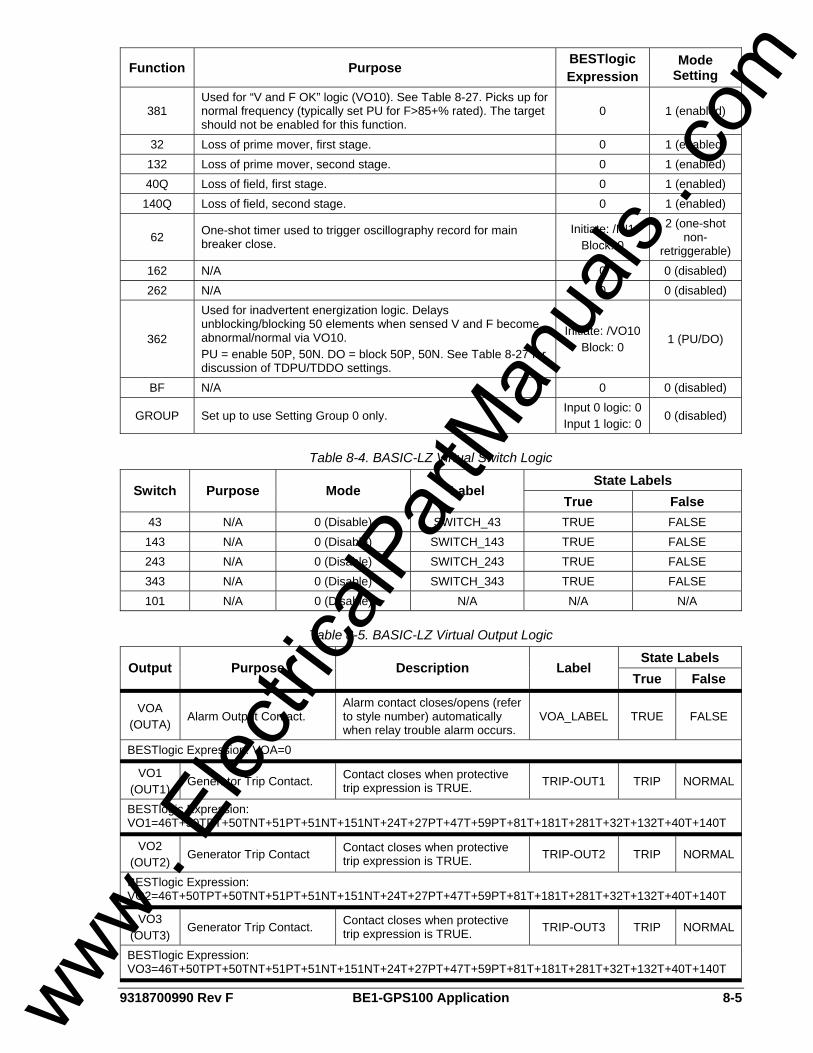
9318700990 Rev F BE1-GPS100 Application 8-5
Function Purpose BESTlogic Expression
Mode Setting
381 Used for “V and F OK” logic (VO10). See Table 8-27. Picks up for normal frequency (typically set PU for F>85+% rated). The target should not be enabled for this function.
0 1 (enabled)
32 Loss of prime mover, first stage. 0 1 (enabled) 132 Loss of prime mover, second stage. 0 1 (enabled) 40Q Loss of field, first stage. 0 1 (enabled) 140Q Loss of field, second stage. 0 1 (enabled)
62 One-shot timer used to trigger oscillography record for main breaker close.
Initiate: /IN1 Block: 0
2 (one-shot non-
retriggerable) 162 N/A 0 0 (disabled) 262 N/A 0 0 (disabled)
362
Used for inadvertent energization logic. Delays unblocking/blocking 50 elements when sensed V and F become abnormal/normal via VO10. PU = enable 50P, 50N. DO = block 50P, 50N. See Table 8-27 for discussion of TDPU/TDDO settings.
Initiate: /VO10 Block: 0
1 (PU/DO)
BF N/A 0 0 (disabled)
GROUP Set up to use Setting Group 0 only. Input 0 logic: 0 Input 1 logic: 0
0 (disabled)
Table 8-4. BASIC-LZ Virtual Switch Logic
State Labels Switch Purpose Mode Label
True False 43 N/A 0 (Disable) SWITCH_43 TRUE FALSE 143 N/A 0 (Disable) SWITCH_143 TRUE FALSE 243 N/A 0 (Disable) SWITCH_243 TRUE FALSE 343 N/A 0 (Disable) SWITCH_343 TRUE FALSE 101 N/A 0 (Disable) N/A N/A N/A
Table 8-5. BASIC-LZ Virtual Output Logic
State Labels Output Purpose Description Label
True False
VOA (OUTA)
Alarm Output Contact. Alarm contact closes/opens (refer to style number) automatically when relay trouble alarm occurs.
VOA_LABEL TRUE FALSE
BESTlogic Expression: VOA=0
VO1 (OUT1)
Generator Trip Contact. Contact closes when protective trip expression is TRUE. TRIP-OUT1 TRIP NORMAL
BESTlogic Expression: VO1=46T+50TPT+50TNT+51PT+51NT+151NT+24T+27PT+47T+59PT+81T+181T+281T+32T+132T+40T+140T
VO2 (OUT2)
Generator Trip Contact Contact closes when protective trip expression is TRUE. TRIP-OUT2 TRIP NORMAL
BESTlogic Expression: VO2=46T+50TPT+50TNT+51PT+51NT+151NT+24T+27PT+47T+59PT+81T+181T+281T+32T+132T+40T+140T
VO3 (OUT3)
Generator Trip Contact. Contact closes when protective trip expression is TRUE. TRIP-OUT3 TRIP NORMAL
BESTlogic Expression: VO3=46T+50TPT+50TNT+51PT+51NT+151NT+24T+27PT+47T+59PT+81T+181T+281T+32T+132T+40T+140T
www . El
ectric
alPar
tMan
uals
. com
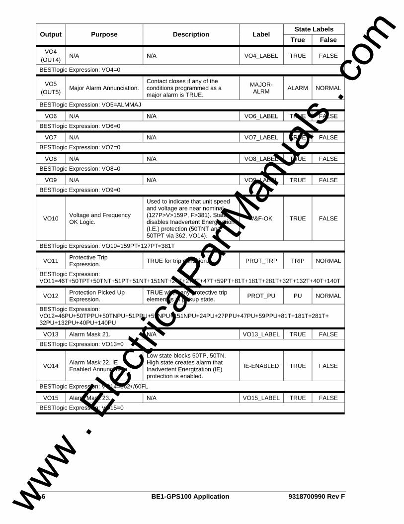
8-6 BE1-GPS100 Application 9318700990 Rev F
State Labels Output Purpose Description Label
True False
VO4 (OUT4)
N/A N/A VO4_LABEL TRUE FALSE
BESTlogic Expression: VO4=0
VO5 (OUT5)
Major Alarm Annunciation. Contact closes if any of the conditions programmed as a major alarm is TRUE.
MAJOR-ALRM ALARM NORMAL
BESTlogic Expression: VO5=ALMMAJ
VO6 N/A N/A VO6_LABEL TRUE FALSE BESTlogic Expression: VO6=0
VO7 N/A N/A VO7_LABEL TRUE FALSE BESTlogic Expression: VO7=0
VO8 N/A N/A VO8_LABEL TRUE FALSE BESTlogic Expression: VO8=0
VO9 N/A N/A VO9_LABEL TRUE FALSE BESTlogic Expression: VO9=0
VO10 Voltage and Frequency OK Logic.
Used to indicate that unit speed and voltage are near nominal (127P>V>159P, F>381). State disables Inadvertent Energization (I.E.) protection (50TNT and 50TPT via 362, VO14).
V&F-OK TRUE FALSE
BESTlogic Expression: VO10=159PT∗127PT∗381T
VO11 Protective Trip Expression. TRUE for trip condition. PROT_TRP TRIP NORMAL
BESTlogic Expression: VO11=46T+50TPT+50TNT+51PT+51NT+151NT+24T+27PT+47T+59PT+81T+181T+281T+32T+132T+40T+140T
VO12 Protection Picked Up Expression.
TRUE when any protective trip element is in pickup state. PROT_PU PU NORMAL
BESTlogic Expression: VO12=46PU+50TPPU+50TNPU+51PPU+51NPU+151NPU+24PU+27PPU+47PU+59PPU+81T+181T+281T+ 32PU+132PU+40PU+140PU
VO13 Alarm Mask 21. N/A VO13_LABEL TRUE FALSE BESTlogic Expression: VO13=0
VO14 Alarm Mask 22. IE Enabled Annunciation.
Low state blocks 50TP, 50TN. High state creates alarm that Inadvertent Energization (IE) protection is enabled.
IE-ENABLED TRUE FALSE
BESTlogic Expression: VO14=362∗/60FL
VO15 Alarm Mask 23. N/A VO15_LABEL TRUE FALSE BESTlogic Expression: VO15=0
www . El
ectric
alPar
tMan
uals
. com
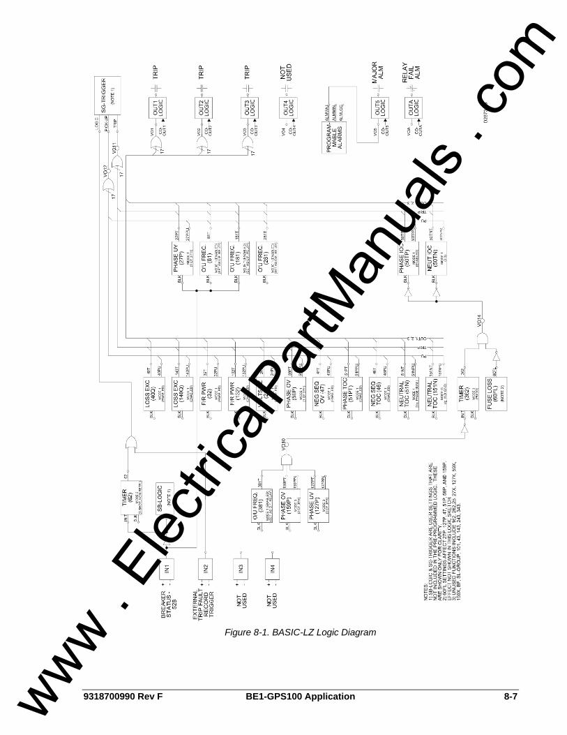
9318700990 Rev F BE1-GPS100 Application 8-7
Figure 8-1. BASIC-LZ Logic Diagram
www . El
ectric
alPar
tMan
uals
. com
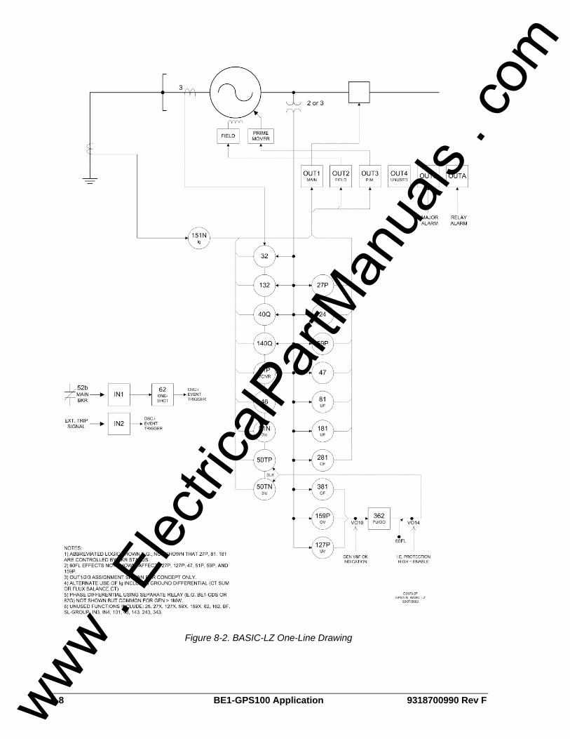
8-8 BE1-GPS100 Application 9318700990 Rev F
Figure 8-2. BASIC-LZ One-Line Drawing
www . El
ectric
alPar
tMan
uals
. com
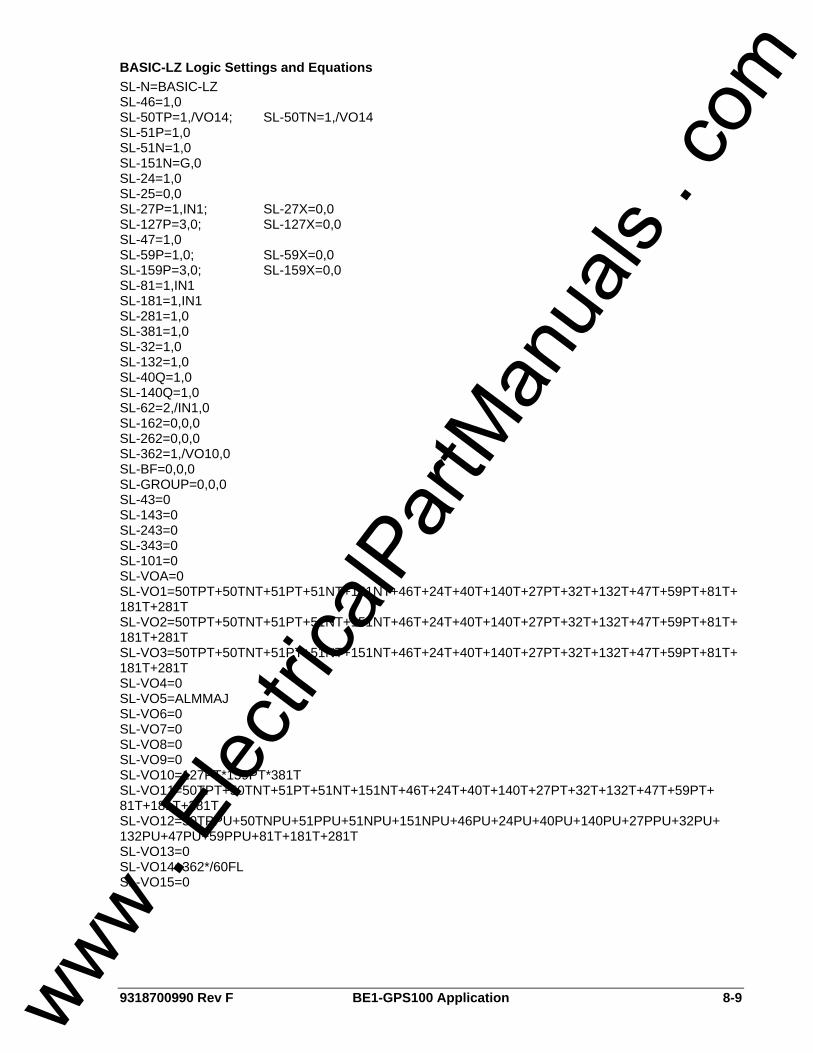
9318700990 Rev F BE1-GPS100 Application 8-9
BASIC-LZ Logic Settings and Equations SL-N=BASIC-LZ SL-46=1,0 SL-50TP=1,/VO14; SL-50TN=1,/VO14 SL-51P=1,0 SL-51N=1,0 SL-151N=G,0 SL-24=1,0 SL-25=0,0 SL-27P=1,IN1; SL-27X=0,0 SL-127P=3,0; SL-127X=0,0 SL-47=1,0 SL-59P=1,0; SL-59X=0,0 SL-159P=3,0; SL-159X=0,0 SL-81=1,IN1 SL-181=1,IN1 SL-281=1,0 SL-381=1,0 SL-32=1,0 SL-132=1,0 SL-40Q=1,0 SL-140Q=1,0 SL-62=2,/IN1,0 SL-162=0,0,0 SL-262=0,0,0 SL-362=1,/VO10,0 SL-BF=0,0,0 SL-GROUP=0,0,0 SL-43=0 SL-143=0 SL-243=0 SL-343=0 SL-101=0 SL-VOA=0 SL-VO1=50TPT+50TNT+51PT+51NT+151NT+46T+24T+40T+140T+27PT+32T+132T+47T+59PT+81T+ 181T+281T SL-VO2=50TPT+50TNT+51PT+51NT+151NT+46T+24T+40T+140T+27PT+32T+132T+47T+59PT+81T+ 181T+281T SL-VO3=50TPT+50TNT+51PT+51NT+151NT+46T+24T+40T+140T+27PT+32T+132T+47T+59PT+81T+ 181T+281T SL-VO4=0 SL-VO5=ALMMAJ SL-VO6=0 SL-VO7=0 SL-VO8=0 SL-VO9=0 SL-VO10=127PT*159PT*381T SL-VO11=50TPT+50TNT+51PT+51NT+151NT+46T+24T+40T+140T+27PT+32T+132T+47T+59PT+ 81T+181T+281T SL-VO12=50TPPU+50TNPU+51PPU+51NPU+151NPU+46PU+24PU+40PU+140PU+27PPU+32PU+ 132PU+47PU+59PPU+81T+181T+281T SL-VO13=0 SL-VO14=362*/60FL SL-VO15=0
www . El
ectric
alPar
tMan
uals
. com
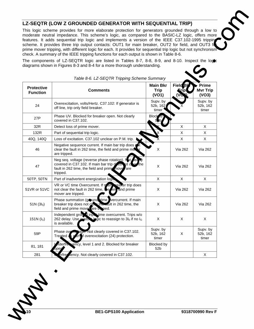
8-10 BE1-GPS100 Application 9318700990 Rev F
LZ-SEQTR (LOW Z GROUNDED GENERATOR WITH SEQUENTIAL TRIP) This logic scheme provides for more elaborate protection for generators grounded through a low to moderate neutral impedance. This scheme’s logic, as compared to the BASIC-LZ logic, offers more features. It adds sequential trip logic and implements a version of the IEEE C37.102-1995 tripping scheme. It provides three trip output contacts: OUT1 for main breaker, OUT2 for field, and OUT3 for prime mover tripping, with different logic for each. It provides for sequential trip logic but not synchronism check. A summary of the IEEE tripping functions for each output is shown in Table 8-6. The components of LZ-SEQTR logic are listed in Tables 8-7, 8-8, 8-9, and 8-10. Inspect the logic diagrams shown in Figures 8-3 and 8-4 for a more thorough understanding.
Table 8-6. LZ-SEQTR Tripping Scheme Summary
Protective Function Comments
Main Bkr Trip
(VO1)
Field Bkr Trip
(VO2)
Prime Mvr Trip
(VO3)
24 Overexcitation, volts/Hertz. C37.102: If generator is off line, trip only field breaker.
Supv. by 52b, 162
timer X
Supv. by 52b, 162
timer
27P Phase UV. Blocked for breaker open. Not clearly covered in C37.102.
Blocked by 52b
32R Detect loss of prime mover. X X X 132R Part of sequential trip logic. X X X
40Q, 140Q Loss of excitation. C37.102 unclear on P.M. trip. X X X
46 Negative sequence current. If main bar trip does not clear the fault in 262 time, the field and prime mover are tripped.
X Via 262 Via 262
47
Neg seq. voltage (reverse phase rotation). Not clearly covered in C37.102. If main bar trip does not clear the fault in 262 time, the field and prime mover are tripped.
X Via 262 Via 262
50TP, 50TN Part of inadvertent energization logic. X X X
51VR or 51VC VR or VC time Overcurrent. If main breaker trip does not clear the fault in 262 time, the field and prime mover are tripped.
X Via 262 Via 262
51N (3I0) Phase summation (ground) time overcurrent. If main breaker trip does not clear the fault in 262 time, the field and prime mover are tripped.
X Via 262 Via 262
151N (IG) Independent ground input time overcurrent. Trips w/o 262 delay. Use custom logic to reassign to 3I0 if no IG is available.
X X X
59P Phase overvoltage. Not clearly covered in C37.102. Treated as part of overexcitation (24) protection.
Supv. by 52b, 162
timer X
Supv. by 52b, 162
timer
81, 181 Underfrequency, level 1 and 2. Blocked for breaker open.
Blocked by 52b
281 Overfrequency. Not clearly covered in C37.102. X
www . El
ectric
alPar
tMan
uals
. com
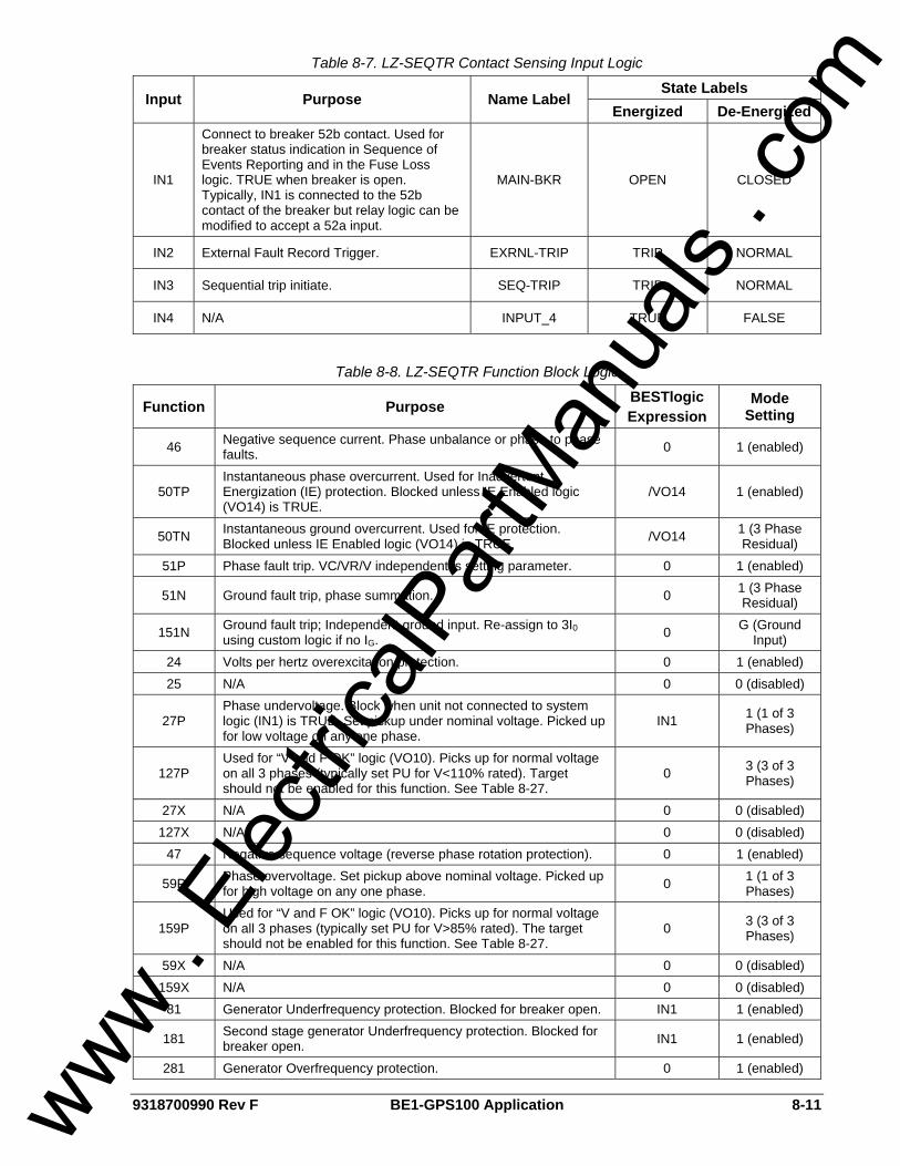
9318700990 Rev F BE1-GPS100 Application 8-11
Table 8-7. LZ-SEQTR Contact Sensing Input Logic
State Labels Input Purpose Name Label
Energized De-Energized
IN1
Connect to breaker 52b contact. Used for breaker status indication in Sequence of Events Reporting and in the Fuse Loss logic. TRUE when breaker is open. Typically, IN1 is connected to the 52b contact of the breaker but relay logic can be modified to accept a 52a input.
MAIN-BKR OPEN CLOSED
IN2 External Fault Record Trigger. EXRNL-TRIP TRIP NORMAL
IN3 Sequential trip initiate. SEQ-TRIP TRIP NORMAL
IN4 N/A INPUT_4 TRUE FALSE
Table 8-8. LZ-SEQTR Function Block Logic
Function Purpose BESTlogic Expression
Mode Setting
46 Negative sequence current. Phase unbalance or phase to phase faults. 0 1 (enabled)
50TP Instantaneous phase overcurrent. Used for Inadvertent Energization (IE) protection. Blocked unless IE Enabled logic (VO14) is TRUE.
/VO14 1 (enabled)
50TN Instantaneous ground overcurrent. Used for IE protection. Blocked unless IE Enabled logic (VO14) is TRUE. /VO14 1 (3 Phase
Residual) 51P Phase fault trip. VC/VR/V independent is setting parameter. 0 1 (enabled)
51N Ground fault trip, phase summation. 0 1 (3 Phase Residual)
151N Ground fault trip; Independent ground input. Re-assign to 3I0 using custom logic if no IG. 0 G (Ground
Input) 24 Volts per hertz overexcitation protection. 0 1 (enabled) 25 N/A 0 0 (disabled)
27P Phase undervoltage. Block when unit not connected to system logic (IN1) is TRUE. Set pickup under nominal voltage. Picked up for low voltage on any one phase.
IN1 1 (1 of 3 Phases)
127P Used for “V and F OK” logic (VO10). Picks up for normal voltage on all 3 phases (typically set PU for V<110% rated). Target should not be enabled for this function. See Table 8-27.
0 3 (3 of 3 Phases)
27X N/A 0 0 (disabled) 127X N/A 0 0 (disabled)
47 Negative sequence voltage (reverse phase rotation protection). 0 1 (enabled)
59P Phase overvoltage. Set pickup above nominal voltage. Picked up for high voltage on any one phase. 0 1 (1 of 3
Phases)
159P Used for “V and F OK” logic (VO10). Picks up for normal voltage on all 3 phases (typically set PU for V>85% rated). The target should not be enabled for this function. See Table 8-27.
0 3 (3 of 3 Phases)
59X N/A 0 0 (disabled) 159X N/A 0 0 (disabled)
81 Generator Underfrequency protection. Blocked for breaker open. IN1 1 (enabled)
181 Second stage generator Underfrequency protection. Blocked for breaker open. IN1 1 (enabled)
281 Generator Overfrequency protection. 0 1 (enabled)
www . El
ectric
alPar
tMan
uals
. com
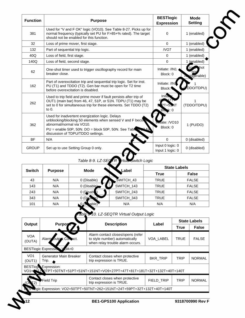
8-12 BE1-GPS100 Application 9318700990 Rev F
Function Purpose BESTlogic Expression
Mode Setting
381 Used for “V and F OK” logic (VO10). See Table 8-27. Picks up for normal frequency (typically set PU for F>85+% rated). The target should not be enabled for this function.
0 1 (enabled)
32 Loss of prime mover, first stage. 0 1 (enabled) 132 Part of sequential trip logic. /VO7 1 (enabled) 40Q Loss of field, first stage. 0 1 (enabled) 140Q Loss of field, second stage. 0 1 (enabled)
62 One-shot timer used to trigger oscillography record for main breaker close.
Initiate: /IN1 Block: 0
2 (one-shot non-
retriggerable)
162 Part of overexcitation trip and sequential trip logic. Set for inst. PU (T1) and TDDO (T2). Gen bar must be open for T2 time before overexcitation is disabled.
Initiate: /IN1 Block: 0
1 (TDDO/TDPU)
262
Used to trip field and prime mover if fault persists after trip of OUT1 (main bar) from 46, 47, 51P, or 51N. TDPU (T1) may be set to 0 for simultaneous trip for these elements. Set TDDO (T2) to 0.
Initiate: 46T+47T+
51PT+51NT Block: 0
1 (TDDO/TDPU)
362
Used for inadvertent energization logic. Delays unblocking/blocking 50 elements when sensed V and F become abnormal/normal via VO10. PU = enable 50P, 50N. DO = block 50P, 50N. See Table 8-27 for discussion of TDPU/TDDO settings.
Initiate: /VO10 Block: 0
1 (PU/DO)
BF N/A 0 0 (disabled)
GROUP Set up to use Setting Group 0 only. Input 0 logic: 0 Input 1 logic: 0
0 (disabled)
Table 8-9. LZ-SEQTR Virtual Switch Logic
State Labels Switch Purpose Mode Label
True False 43 N/A 0 (Disable) SWITCH_43 TRUE FALSE 143 N/A 0 (Disable) SWITCH_143 TRUE FALSE 243 N/A 0 (Disable) SWITCH_243 TRUE FALSE 343 N/A 0 (Disable) SWITCH_343 TRUE FALSE 101 N/A 0 (Disable) N/A N/A N/A
Table 8-10. LZ-SEQTR Virtual Output Logic
State Labels Output Purpose Description Label
True False
VOA (OUTA)
Alarm Output Contact. Alarm contact closes/opens (refer to style number) automatically when relay trouble alarm occurs.
VOA_LABEL TRUE FALSE
BESTlogic Expression: VOA=0
VO1 (OUT1)
Generator Main Breaker Trip.
Contact closes when protective trip expression is TRUE. BKR_TRIP TRIP NORMAL
BESTlogic Expression: VO1=46T+50TPT+50TNT+51PT+51NT+151NT+VO9+27PT+47T+81T+181T+32T+132T+40T+140T
VO2 (OUT2)
Field Trip Contact closes when protective trip expression is TRUE. FIELD_TRIP TRIP NORMAL
BESTlogic Expression: VO2=50TPT+50TNT+262+151NT+24T+59PT+32T+132T+40T+140T
www . El
ectric
alPar
tMan
uals
. com
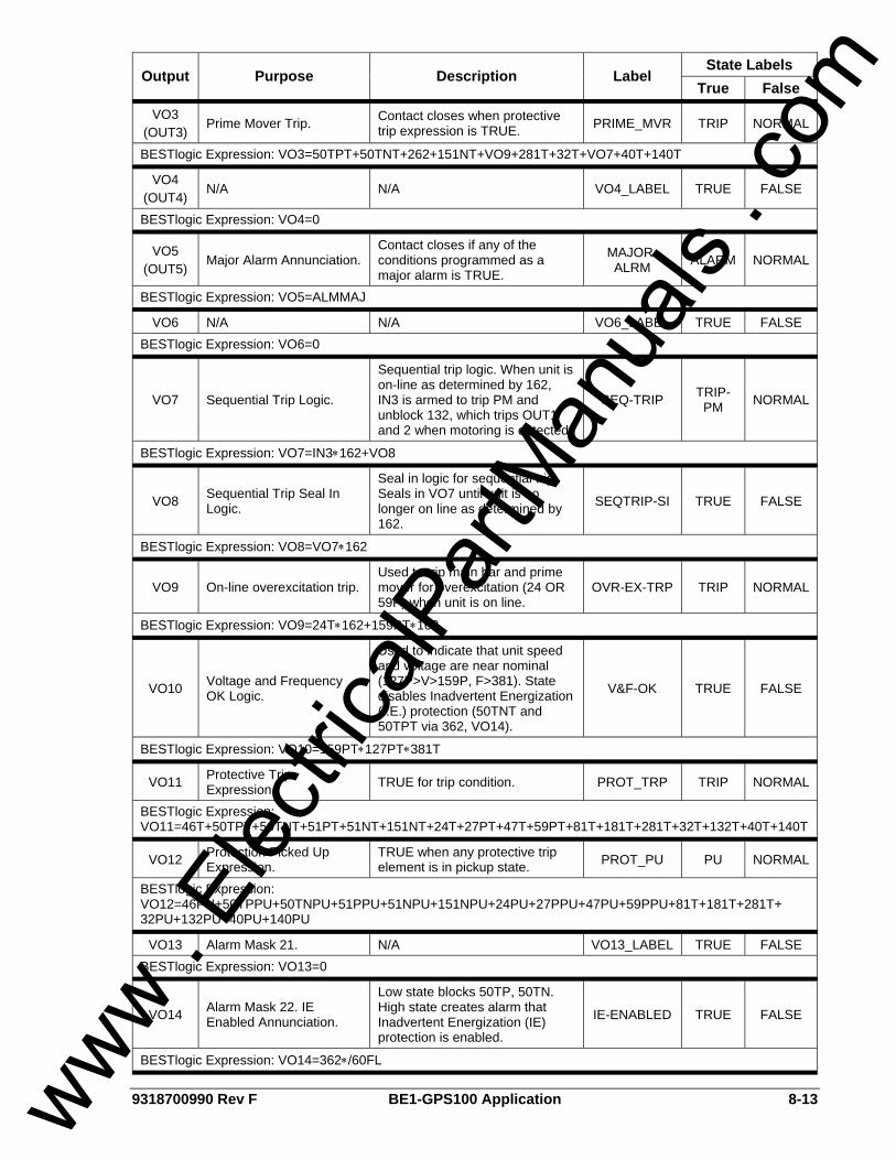
9318700990 Rev F BE1-GPS100 Application 8-13
State Labels Output Purpose Description Label
True False
VO3 (OUT3)
Prime Mover Trip. Contact closes when protective trip expression is TRUE. PRIME_MVR TRIP NORMAL
BESTlogic Expression: VO3=50TPT+50TNT+262+151NT+VO9+281T+32T+VO7+40T+140T
VO4 (OUT4)
N/A N/A VO4_LABEL TRUE FALSE
BESTlogic Expression: VO4=0
VO5 (OUT5)
Major Alarm Annunciation. Contact closes if any of the conditions programmed as a major alarm is TRUE.
MAJOR-ALRM ALARM NORMAL
BESTlogic Expression: VO5=ALMMAJ
VO6 N/A N/A VO6_LABEL TRUE FALSE BESTlogic Expression: VO6=0
VO7 Sequential Trip Logic.
Sequential trip logic. When unit is on-line as determined by 162, IN3 is armed to trip PM and unblock 132, which trips OUT1 and 2 when motoring is detected.
SEQ-TRIP TRIP-PM NORMAL
BESTlogic Expression: VO7=IN3∗162+VO8
VO8 Sequential Trip Seal In Logic.
Seal in logic for sequential trip. Seals in VO7 until unit is no longer on line as determined by 162.
SEQTRIP-SI TRUE FALSE
BESTlogic Expression: VO8=VO7∗162
VO9 On-line overexcitation trip. Used to trip main bar and prime mover for overexcitation (24 OR 59P) when unit is on line.
OVR-EX-TRP TRIP NORMAL
BESTlogic Expression: VO9=24T∗162+159PT∗162
VO10 Voltage and Frequency OK Logic.
Used to indicate that unit speed and voltage are near nominal (127P>V>159P, F>381). State disables Inadvertent Energization (I.E.) protection (50TNT and 50TPT via 362, VO14).
V&F-OK TRUE FALSE
BESTlogic Expression: VO10=159PT∗127PT∗381T
VO11 Protective Trip Expression. TRUE for trip condition. PROT_TRP TRIP NORMAL
BESTlogic Expression: VO11=46T+50TPT+50TNT+51PT+51NT+151NT+24T+27PT+47T+59PT+81T+181T+281T+32T+132T+40T+140T
VO12 Protection Picked Up Expression.
TRUE when any protective trip element is in pickup state. PROT_PU PU NORMAL
BESTlogic Expression: VO12=46PU+50TPPU+50TNPU+51PPU+51NPU+151NPU+24PU+27PPU+47PU+59PPU+81T+181T+281T+ 32PU+132PU+40PU+140PU
VO13 Alarm Mask 21. N/A VO13_LABEL TRUE FALSE BESTlogic Expression: VO13=0
VO14 Alarm Mask 22. IE Enabled Annunciation.
Low state blocks 50TP, 50TN. High state creates alarm that Inadvertent Energization (IE) protection is enabled.
IE-ENABLED TRUE FALSE
BESTlogic Expression: VO14=362∗/60FL
www . El
ectric
alPar
tMan
uals
. com

8-14 BE1-GPS100 Application 9318700990 Rev F
State Labels Output Purpose Description Label
True False
VO15 Alarm Mask 23. Seq. Trip Enabled Alarm.
Used to annunciate that the Sequential Trip input is TRUE with the unit off line.
SEQTR-ARMD TRUE FALSE
BESTlogic Expression: VO15=IN3∗/162
www . El
ectric
alPar
tMan
uals
. com
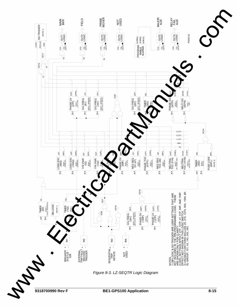
9318700990 Rev F BE1-GPS100 Application 8-15
Figure 8-3. LZ-SEQTR Logic Diagram
www . El
ectric
alPar
tMan
uals
. com
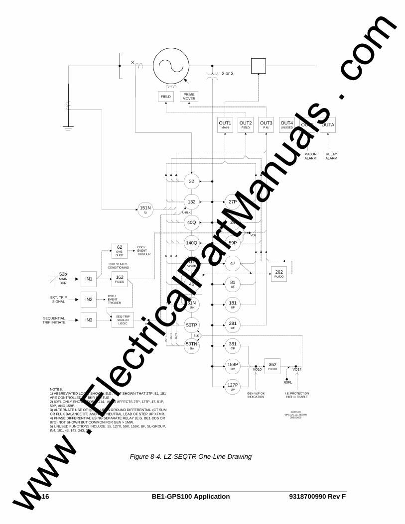
8-16 BE1-GPS100 Application 9318700990 Rev F
140Q
40Q
132
32
51PVC/VR
46
50TP
50TN3Io
51N3Io
159POV
47
24
27P
59P
81UF
181UF
281OF
381OF
151NIg
127PUV
IN2
IN3
PRIME MOVERFIELD
OUT1MAIN
OUT3P.M.
OUT2FIELD
OUT4UNUSED
OUT5
362PU/DOVO10 VO14
60FL
GEN V&F OK INDICATION
I.E. PROTECTION HIGH = ENABLE
BLK
262PU/DO162
PU/DOIN1
52bMAIN BKR
BKR STATUS CONDITIONING
62ONE-SHOT
OSC./EVENT TRIGGER
EXT. TRIP SIGNAL
OSC./EVENT TRIGGER
SEQUENTIAL TRIP INITIATE
SEQ-TRIP SEAL-IN LOGIC VO7
VO9
3
2 or 3
U-BLK
OU
T3
OU
T2
0UT
1
MAJOR ALARM
NOTES: 1) ABBREVIATED LOGIC SHOWN. E.G., NOT SHOWN THAT 27P, 81, 181 ARE CONTROLLED BY BKR STATUS.2) 60FL ONLY SHOWN FOR VO14. ALSO AFFECTS 27P, 127P, 47, 51P, 59P, AND 159P.3) ALTERNATE USE OF Ig INCLUDES GROUND DIFFERENTIAL (CT SUM OR FLUX BALANCE CT) AND WYE NEUTRAL LEAD OF STEP UP XFMR.4) PHASE DIFFERENTIAL USING SEPARATE RELAY (E.G. BE1-CDS OR 87G) NOT SHOWN BUT COMMON FOR GEN > 1MW.5) UNUSED FUNCTIONS INCLUDE: 25, 127X, 59X, 159X, BF, SL-GROUP, IN4, 101, 43, 143, 243, 343.
D2873-09GPS1LN_LZ_SEQTR
05/15/2000
OUTA
RELAY ALARM
Figure 8-4. LZ-SEQTR One-Line Drawing
www . El
ectric
alPar
tMan
uals
. com
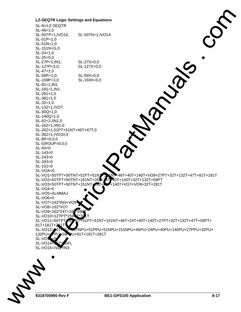
9318700990 Rev F BE1-GPS100 Application 8-17
LZ-SEQTR Logic Settings and Equations SL-N=LZ-SEQTR SL-46=1,0 SL-50TP=1,/VO14; SL-50TN=1,/VO14 SL-51P=1,0 SL-51N=1,0 SL-151N=G,0 SL-24=1,0 SL-25=0,0 SL-27P=1,IN1; SL-27X=0,0 SL-127P=3,0; SL-127X=0,0 SL-47=1,0 SL-59P=1,0; SL-59X=0,0 SL-159P=3,0; SL-159X=0,0 SL-81=1,IN1 SL-181=1,IN1 SL-281=1,0 SL-381=1,0 SL-32=1,0 SL-132=1,/VO7 SL-40Q=1,0 SL-140Q=1,0 SL-62=2,/IN1,0 SL-162=1,/IN1,0 SL-262=1,51PT+51NT+46T+47T,0 SL-362=1,/VO10,0 SL-BF=0,0,0 SL-GROUP=0,0,0 SL-43=0 SL-143=0 SL-243=0 SL-343=0 SL-101=0 SL-VOA=0 SL-VO1=50TPT+50TNT+51PT+51NT+151NT+46T+40T+140T+VO9+27PT+32T+132T+47T+81T+181T SL-VO2=50TPT+50TNT+151NT+262+24T+40T+140T+32T+132T+59PT SL-VO3=50TPT+50TNT+151NT+262+40T+140T+VO7+VO9+32T+281T SL-VO4=0 SL-VO5=ALMMAJ SL-VO6=0 SL-VO7=162*IN3+VO8 SL-VO8=162*VO7 SL-VO9=162*24T+162*59PT SL-VO10=127PT*159PT*381T SL-VO11=50TPT+50TNT+51PT+51NT+151NT+46T+24T+40T+140T+27PT+32T+132T+47T+59PT+ 81T+181T+281T SL-VO12=50TPPU+50TNPU+51PPU+51NPU+151NPU+46PU+24PU+40PU+140PU+27PPU+32PU+ 132PU+47PU+59PPU+81T+181T+281T SL-VO13=0 SL-VO14=362*/60FL SL-VO15=/162*IN3
www . El
ectric
alPar
tMan
uals
. com
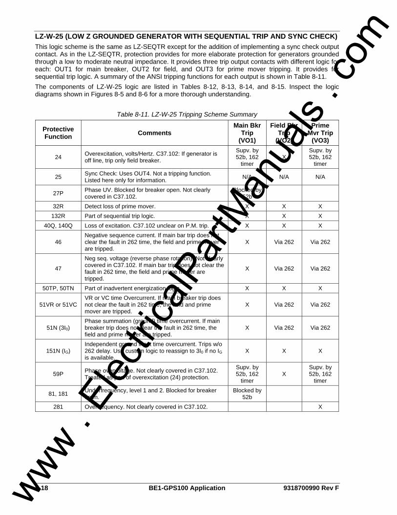
8-18 BE1-GPS100 Application 9318700990 Rev F
LZ-W-25 (LOW Z GROUNDED GENERATOR WITH SEQUENTIAL TRIP AND SYNC CHECK) This logic scheme is the same as LZ-SEQTR except for the addition of implementing a sync check output contact. As in the LZ-SEQTR, protection provides for more elaborate protection for generators grounded through a low to moderate neutral impedance. It provides three trip output contacts with different logic for each: OUT1 for main breaker, OUT2 for field, and OUT3 for prime mover tripping. It provides for sequential trip logic. A summary of the ANSI tripping functions for each output is shown in Table 8-11. The components of LZ-W-25 logic are listed in Tables 8-12, 8-13, 8-14, and 8-15. Inspect the logic diagrams shown in Figures 8-5 and 8-6 for a more thorough understanding.
Table 8-11. LZ-W-25 Tripping Scheme Summary
Protective Function Comments
Main Bkr Trip
(VO1)
Field Bkr Trip
(VO2)
Prime Mvr Trip
(VO3)
24 Overexcitation, volts/Hertz. C37.102: If generator is off line, trip only field breaker.
Supv. by 52b, 162
timer X
Supv. by 52b, 162
timer
25 Sync Check: Uses OUT4. Not a tripping function. Listed here only for information. N/A N/A N/A
27P Phase UV. Blocked for breaker open. Not clearly covered in C37.102.
Blocked by 52b
32R Detect loss of prime mover. X X X 132R Part of sequential trip logic. X X X
40Q, 140Q Loss of excitation. C37.102 unclear on P.M. trip. X X X
46 Negative sequence current. If main bar trip does not clear the fault in 262 time, the field and prime mover are tripped.
X Via 262 Via 262
47
Neg seq. voltage (reverse phase rotation). Not clearly covered in C37.102. If main bar trip does not clear the fault in 262 time, the field and prime mover are tripped.
X Via 262 Via 262
50TP, 50TN Part of inadvertent energization logic. X X X
51VR or 51VC VR or VC time Overcurrent. If main breaker trip does not clear the fault in 262 time, the field and prime mover are tripped.
X Via 262 Via 262
51N (3I0) Phase summation (ground) time overcurrent. If main breaker trip does not clear the fault in 262 time, the field and prime mover are tripped.
X Via 262 Via 262
151N (IG) Independent ground input time overcurrent. Trips w/o 262 delay. Use custom logic to reassign to 3I0 if no IG is available.
X X X
59P Phase overvoltage. Not clearly covered in C37.102. Treated as part of overexcitation (24) protection.
Supv. by 52b, 162
timer X
Supv. by 52b, 162
timer
81, 181 Underfrequency, level 1 and 2. Blocked for breaker open.
Blocked by 52b
281 Overfrequency. Not clearly covered in C37.102. X
www . El
ectric
alPar
tMan
uals
. com
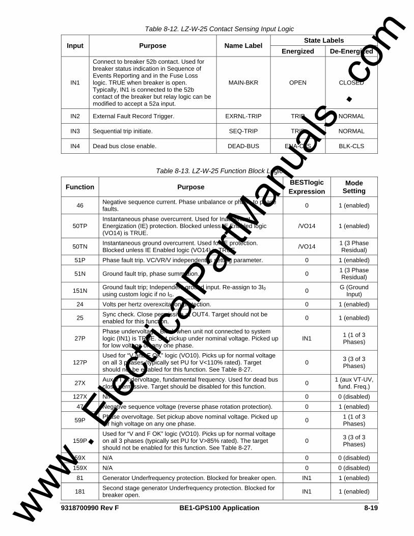
9318700990 Rev F BE1-GPS100 Application 8-19
Table 8-12. LZ-W-25 Contact Sensing Input Logic
State Labels Input Purpose Name Label
Energized De-Energized
IN1
Connect to breaker 52b contact. Used for breaker status indication in Sequence of Events Reporting and in the Fuse Loss logic. TRUE when breaker is open. Typically, IN1 is connected to the 52b contact of the breaker but relay logic can be modified to accept a 52a input.
MAIN-BKR OPEN CLOSED
IN2 External Fault Record Trigger. EXRNL-TRIP TRIP NORMAL
IN3 Sequential trip initiate. SEQ-TRIP TRIP NORMAL
IN4 Dead bus close enable. DEAD-BUS ENA-CLS BLK-CLS
Table 8-13. LZ-W-25 Function Block Logic
Function Purpose BESTlogic Expression
Mode Setting
46 Negative sequence current. Phase unbalance or phase to phase faults. 0 1 (enabled)
50TP Instantaneous phase overcurrent. Used for Inadvertent Energization (IE) protection. Blocked unless IE Enabled logic (VO14) is TRUE.
/VO14 1 (enabled)
50TN Instantaneous ground overcurrent. Used for IE protection. Blocked unless IE Enabled logic (VO14) is TRUE. /VO14 1 (3 Phase
Residual) 51P Phase fault trip. VC/VR/V independent is setting parameter. 0 1 (enabled)
51N Ground fault trip, phase summation. 0 1 (3 Phase Residual)
151N Ground fault trip; Independent ground input. Re-assign to 3I0 using custom logic if no IG. 0 G (Ground
Input) 24 Volts per hertz overexcitation protection. 0 1 (enabled)
25 Sync check. Close permissive at OUT4. Target should not be enabled for this function. 0 1 (enabled)
27P Phase undervoltage. Block when unit not connected to system logic (IN1) is TRUE. Set pickup under nominal voltage. Picked up for low voltage on any one phase.
IN1 1 (1 of 3 Phases)
127P Used for “V and F OK” logic (VO10). Picks up for normal voltage on all 3 phases (typically set PU for V<110% rated). Target should not be enabled for this function. See Table 8-27.
0 3 (3 of 3 Phases)
27X Aux VT undervoltage, fundamental frequency. Used for dead bus close permissive. Target should be disabled for this function. 0 1 (aux VT-UV,
fund. Freq.) 127X N/A 0 0 (disabled)
47 Negative sequence voltage (reverse phase rotation protection). 0 1 (enabled)
59P Phase overvoltage. Set pickup above nominal voltage. Picked up for high voltage on any one phase. 0 1 (1 of 3
Phases)
159P Used for “V and F OK” logic (VO10). Picks up for normal voltage on all 3 phases (typically set PU for V>85% rated). The target should not be enabled for this function. See Table 8-27.
0 3 (3 of 3 Phases)
59X N/A 0 0 (disabled) 159X N/A 0 0 (disabled)
81 Generator Underfrequency protection. Blocked for breaker open. IN1 1 (enabled)
181 Second stage generator Underfrequency protection. Blocked for breaker open. IN1 1 (enabled)
www . El
ectric
alPar
tMan
uals
. com
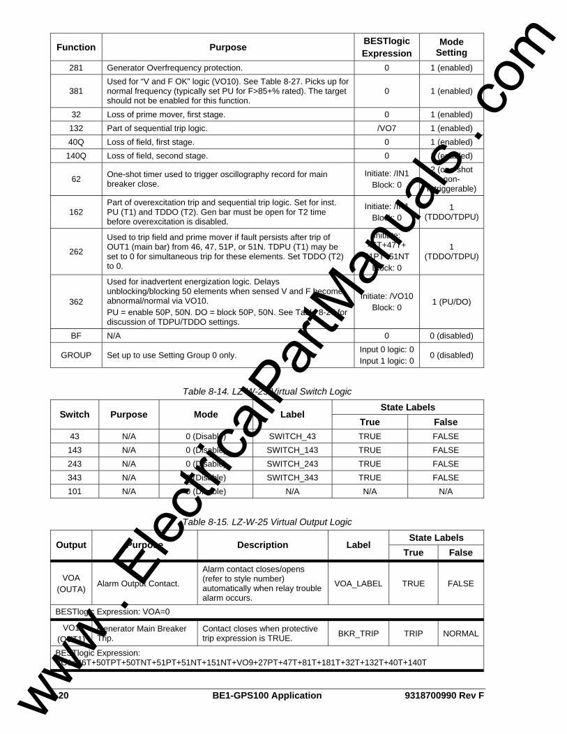
8-20 BE1-GPS100 Application 9318700990 Rev F
Function Purpose BESTlogic Expression
Mode Setting
281 Generator Overfrequency protection. 0 1 (enabled)
381 Used for “V and F OK” logic (VO10). See Table 8-27. Picks up for normal frequency (typically set PU for F>85+% rated). The target should not be enabled for this function.
0 1 (enabled)
32 Loss of prime mover, first stage. 0 1 (enabled) 132 Part of sequential trip logic. /VO7 1 (enabled) 40Q Loss of field, first stage. 0 1 (enabled) 140Q Loss of field, second stage. 0 1 (enabled)
62 One-shot timer used to trigger oscillography record for main breaker close.
Initiate: /IN1 Block: 0
2 (one-shot non-
retriggerable)
162 Part of overexcitation trip and sequential trip logic. Set for inst. PU (T1) and TDDO (T2). Gen bar must be open for T2 time before overexcitation is disabled.
Initiate: /IN1 Block: 0
1 (TDDO/TDPU)
262
Used to trip field and prime mover if fault persists after trip of OUT1 (main bar) from 46, 47, 51P, or 51N. TDPU (T1) may be set to 0 for simultaneous trip for these elements. Set TDDO (T2) to 0.
Initiate: 46T+47T+
51PT+51NT Block: 0
1 (TDDO/TDPU)
362
Used for inadvertent energization logic. Delays unblocking/blocking 50 elements when sensed V and F become abnormal/normal via VO10. PU = enable 50P, 50N. DO = block 50P, 50N. See Table 8-27 for discussion of TDPU/TDDO settings.
Initiate: /VO10 Block: 0
1 (PU/DO)
BF N/A 0 0 (disabled)
GROUP Set up to use Setting Group 0 only. Input 0 logic: 0 Input 1 logic: 0
0 (disabled)
Table 8-14. LZ-W-25 Virtual Switch Logic
State Labels Switch Purpose Mode Label
True False 43 N/A 0 (Disable) SWITCH_43 TRUE FALSE 143 N/A 0 (Disable) SWITCH_143 TRUE FALSE 243 N/A 0 (Disable) SWITCH_243 TRUE FALSE 343 N/A 0 (Disable) SWITCH_343 TRUE FALSE 101 N/A 0 (Disable) N/A N/A N/A
Table 8-15. LZ-W-25 Virtual Output Logic
State Labels Output Purpose Description Label
True False
VOA (OUTA)
Alarm Output Contact.
Alarm contact closes/opens (refer to style number) automatically when relay trouble alarm occurs.
VOA_LABEL TRUE FALSE
BESTlogic Expression: VOA=0
VO1 (OUT1)
Generator Main Breaker Trip.
Contact closes when protective trip expression is TRUE. BKR_TRIP TRIP NORMAL
BESTlogic Expression: VO1=46T+50TPT+50TNT+51PT+51NT+151NT+VO9+27PT+47T+81T+181T+32T+132T+40T+140T
www . El
ectric
alPar
tMan
uals
. com
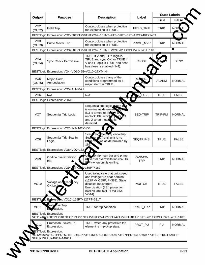
9318700990 Rev F BE1-GPS100 Application 8-21
State Labels Output Purpose Description Label
True False
VO2 (OUT2)
Field Trip Contact closes when protective trip expression is TRUE. FIELD_TRIP TRIP NORMAL
BESTlogic Expression: VO2=50TPT+50TNT+262+151NT+24T+59PT+32T+132T+40T+140T
VO3 (OUT3)
Prime Mover Trip. Contact closes when protective trip expression is TRUE. PRIME_MVR TRIP NORMAL
BESTlogic Expression: VO3=50TPT+50TNT+262+151NT+VO9+281T+32T+VO7+40T+140T
VO4 (OUT4)
Sync Check Permissive.
TRUE if V and F OK logic is TRUE and sync OK; or TRUE if V and F logic is TRUE and dead bus close is enabled (IN4).
CLOSE ALLOW DENY
BESTlogic Expression: VO4=VO10∗25+VO10∗27XT∗IN4
VO5 (OUT5)
Major Alarm Annunciation.
Contact closes if any of the conditions programmed as a major alarm is TRUE.
MAJOR-ALRM ALARM NORMAL
BESTlogic Expression: VO5=ALMMAJ
VO6 N/A N/A VO6_LABEL TRUE FALSE BESTlogic Expression: VO6=0
VO7 Sequential Trip Logic.
Sequential trip logic. When unit is on-line as determined by 162, IN3 is armed to trip PM and unblock 132, which trips OUT1 and 2 when motoring is detected.
SEQ-TRIP TRIP-PM NORMAL
BESTlogic Expression: VO7=IN3∗162+VO8
VO8 Sequential Trip Seal In Logic.
Seal in logic for sequential trip. Seals in VO7 until unit is no longer on line as determined by 162.
SEQTRIP-SI TRUE FALSE
BESTlogic Expression: VO8=VO7∗162
VO9 On-line overexcitation trip.
Used to trip main bar and prime mover for overexcitation (24 OR 59P) when unit is on line.
OVR-EX-TRP TRIP NORMAL
BESTlogic Expression: VO9=24T∗162+159PT∗162
VO10 Voltage and Frequency OK Logic.
Used to indicate that unit speed and voltage are near nominal (127P>V>159P, F>381). State disables Inadvertent Energization (I.E.) protection (50TNT and 50TPT via 362, VO14).
V&F-OK TRUE FALSE
BESTlogic Expression: VO10=159PT∗127PT∗381T
VO11 Protective Trip Expression. TRUE for trip condition. PROT_TRP TRIP NORMAL
BESTlogic Expression: VO11=46T+50TPT+50TNT+51PT+51NT+151NT+24T+27PT+47T+59PT+81T+181T+281T+32T+132T+40T+140T
VO12 Protection Picked Up Expression.
TRUE when any protective trip element is in pickup state. PROT_PU PU NORMAL
BESTlogic Expression: VO12=46PU+50TPPU+50TNPU+51PPU+51NPU+151NPU+24PU+27PPU+47PU+59PPU+81T+181T+281T+ 32PU+132PU+40PU+140PU
www . El
ectric
alPar
tMan
uals
. com

8-22 BE1-GPS100 Application 9318700990 Rev F
State Labels Output Purpose Description Label
True False
VO13 Alarm Mask 21. Dead Bus Close Enabled Annunciation.
Used to warn that dead bus close has been enabled via IN4.
DBC-ENABLD ENABLED DISABLD
BESTlogic Expression: VO13=IN4
VO14 Alarm Mask 22. IE Enabled Annunciation.
Low state blocks 50TP, 50TN. High state creates alarm that Inadvertent Energization (IE) protection is enabled.
IE-ENABLED TRUE FALSE
BESTlogic Expression: VO14=362∗/60FL
VO15 Alarm Mask 23. Seq. Trip Enabled Alarm.
Used to annunciate that the Sequential Trip input is TRUE with the unit off line.
SEQTR-ARMD TRUE FALSE
BESTlogic Expression: VO15=IN3∗/162
www . El
ectric
alPar
tMan
uals
. com
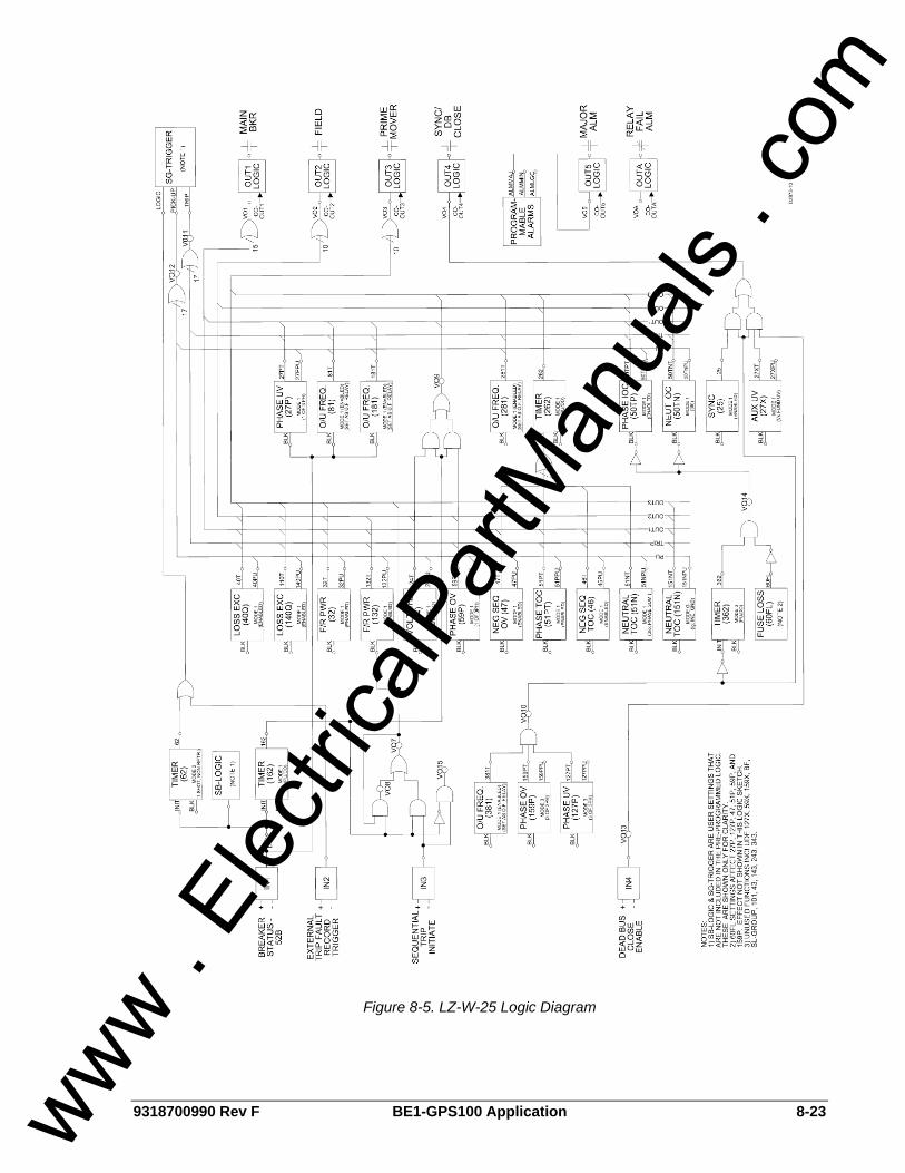
9318700990 Rev F BE1-GPS100 Application 8-23
Figure 8-5. LZ-W-25 Logic Diagram
www . El
ectric
alPar
tMan
uals
. com
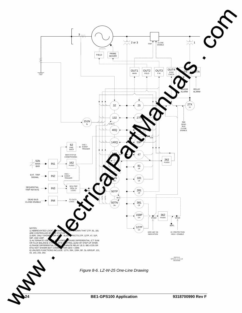
8-24 BE1-GPS100 Application 9318700990 Rev F
140Q
40Q
132
32
51PVC/VR
46
50TP
50TN3Io
51N3Io
159POV
47
24
27P
59P
81UF
181UF
281OF
381OF
151NIg
127PUV
IN2
IN3
PRIME MOVERFIELD
OUT1MAIN
OUT3P.M.
OUT2FIELD
OUT4SYNC
CHECKOUT5
362PU/DOVO10 VO14
60FL
GEN V&F OK INDICATION
I.E. PROTECTION HIGH = ENABLE
BLK
262PU/DO162
PU/DOIN1
52bMAIN BKR
BKR STATUS CONDITIONING
62ONE-SHOT
OSC./EVENT TRIGGER
EXT. TRIP SIGNAL
OSC./EVENT TRIGGER
SEQUENTIAL TRIP INITIATE
SEQ-TRIP SEAL-IN LOGIC VO7
VO9
3
2 or 3
U-BLK
OU
T3
OU
T2
0UT
1
MAJOR ALARM
NOTES: 1) ABBREVIATED LOGIC SHOWN. E.G., NOT SHOWN THAT 27P, 81, 181 ARE CONTROLLED BY BKR STATUS.2) 60FL ONLY SHOWN FOR VO14. ALSO AFFECTS 27P, 127P, 47, 51P, 59P, AND 159P.3) ALTERNATE USE OF Ig INCLUDES GROUND DIFFERENTIAL (CT SUM OR FLUX BALANCE CT) AND WYE NEUTRAL LEAD OF STEP UP XFMR.4) PHASE DIFFERENTIAL USING SEPARATE RELAY (E.G. BE1-CDS OR 87G) NOT SHOWN BUT COMMON FOR GEN > 1MW.6) UNUSED FUNCTIONS INCLUDE: 127X, 59X, 159X, BF, SL-GROUP, 101, 43, 143, 243, 343.
D2873-18GPS1LN_LZ_W_25
05/15/2000
OUTA
RELAY ALARM
27XVx
25
IN4
1
DEAD BUS CLOSE ENABLE
TO OUT4 LOGIC
CLOSE ENABLETRIP
IN4DEAD BUS
CLOSE ENABLE
Figure 8-6. LZ-W-25 One-Line Drawing
www . El
ectric
alPar
tMan
uals
. com
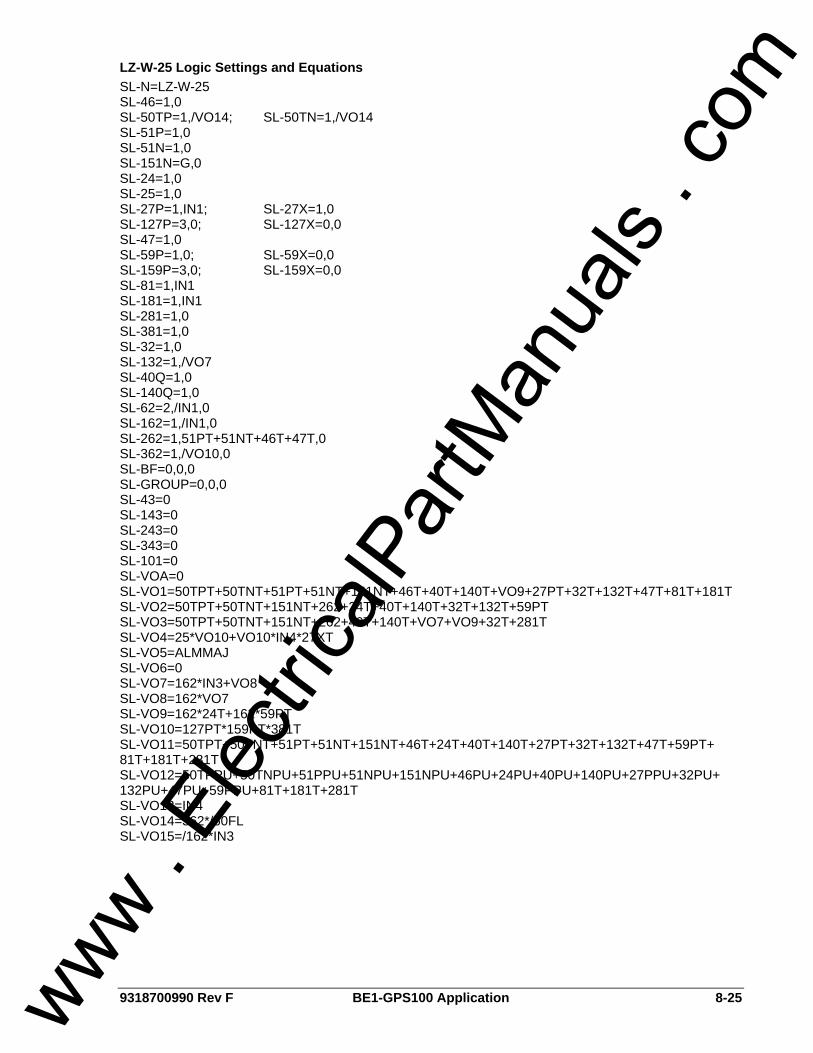
9318700990 Rev F BE1-GPS100 Application 8-25
LZ-W-25 Logic Settings and Equations SL-N=LZ-W-25 SL-46=1,0 SL-50TP=1,/VO14; SL-50TN=1,/VO14 SL-51P=1,0 SL-51N=1,0 SL-151N=G,0 SL-24=1,0 SL-25=1,0 SL-27P=1,IN1; SL-27X=1,0 SL-127P=3,0; SL-127X=0,0 SL-47=1,0 SL-59P=1,0; SL-59X=0,0 SL-159P=3,0; SL-159X=0,0 SL-81=1,IN1 SL-181=1,IN1 SL-281=1,0 SL-381=1,0 SL-32=1,0 SL-132=1,/VO7 SL-40Q=1,0 SL-140Q=1,0 SL-62=2,/IN1,0 SL-162=1,/IN1,0 SL-262=1,51PT+51NT+46T+47T,0 SL-362=1,/VO10,0 SL-BF=0,0,0 SL-GROUP=0,0,0 SL-43=0 SL-143=0 SL-243=0 SL-343=0 SL-101=0 SL-VOA=0 SL-VO1=50TPT+50TNT+51PT+51NT+151NT+46T+40T+140T+VO9+27PT+32T+132T+47T+81T+181T SL-VO2=50TPT+50TNT+151NT+262+24T+40T+140T+32T+132T+59PT SL-VO3=50TPT+50TNT+151NT+262+40T+140T+VO7+VO9+32T+281T SL-VO4=25*VO10+VO10*IN4*27XT SL-VO5=ALMMAJ SL-VO6=0 SL-VO7=162*IN3+VO8 SL-VO8=162*VO7 SL-VO9=162*24T+162*59PT SL-VO10=127PT*159PT*381T SL-VO11=50TPT+50TNT+51PT+51NT+151NT+46T+24T+40T+140T+27PT+32T+132T+47T+59PT+ 81T+181T+281T SL-VO12=50TPPU+50TNPU+51PPU+51NPU+151NPU+46PU+24PU+40PU+140PU+27PPU+32PU+ 132PU+47PU+59PPU+81T+181T+281T SL-VO13=IN4 SL-VO14=362*/60FL SL-VO15=/162*IN3
www . El
ectric
alPar
tMan
uals
. com

8-26 BE1-GPS100 Application 9318700990 Rev F
BASIC-HZ (BASIC HIGH Z GROUNDED GENERATOR PROTECTION) This logic scheme provides for basic protection of generators that are grounded through a high neutral impedance. This schemes’ logic tends toward the simple and straightforward and uses a simple tripping scheme. Physical Outputs 1, 2 and 3 follow the same logic. It does not provide for sequential trip logic or synchronism check. The IEEE functions that trip Outputs 1, 2 and 3 are summarized in Table 8-16. The components of the logic of BASIC-LZ are listed in Tables 8-17, 8-18, 8-19, and 8-20. Inspect the logic diagrams shown in Figures 8-7 and 8-8 for a more thorough understanding.
Table 8-16. BASIC-HZ Tripping Scheme Summary
Protective Function Comments VO1, VO2, VO3
24 Overexcitation. X 27P Phase UV. Blocked for breaker open. X
27-3N Generator neutral third harmonic undervoltage. X 32R, 132R Detect loss of prime mover. X 40Q, 140Q Loss of excitation. X
46 Negative sequence current. X 47 Negative sequence voltage (reverse phase rotation). X
50TP, 50TN Part of inadvertent energization logic. X 51VR or 51VC VR or VC time overcurrent. X
51N (3I0) Phase summation (ground) time overcurrent. X
151N (IG) Independent ground input time overcurrent. Use custom logic to re-assign to 3I0 if no IG is available. X
59P Phase overvoltage. X 59-3V0 Zero sequence voltage on generator leads. X 81, 181 Underfrequency, level 1 and 2. Blocked for breaker open. X
281 Overfrequency. X
Table 8-17. BASIC-HZ Contact Sensing Input Logic
State Labels Input Purpose Name Label
Energized De-Energized
IN1
Connect to breaker 52b contact. Used for breaker status indication in Sequence of Events Reporting and in the Fuse Loss logic. TRUE when breaker is open. Typically, IN1 is connected to the 52b contact of the breaker but relay logic can be modified to accept a 52a input.
MAIN-BKR OPEN CLOSED
IN2 External Fault Record Trigger. EXRNL-TRIP TRIP NORMAL
IN3 N/A INPUT_3 TRUE FALSE
IN4 N/A INPUT_4 TRUE FALSE
www . El
ectric
alPar
tMan
uals
. com

9318700990 Rev F BE1-GPS100 Application 8-27
Table 8-18. BASIC-HZ Function Block Logic
Function Purpose BESTlogic Expression
Mode Setting
46 Negative sequence current. Phase unbalance or phase to phase faults. 0 1 (enabled)
50TP Instantaneous phase overcurrent. Used for Inadvertent Energization (IE) protection. Blocked unless IE Enabled logic (VO14) is TRUE.
/VO14 1 (enabled)
50TN Instantaneous ground overcurrent. Used for IE protection. Blocked unless IE Enabled logic (VO14) is TRUE. /VO14 1 (3 Phase
Residual) 51P Phase fault trip. VC/VR/V independent is setting parameter. 0 1 (enabled)
51N Ground fault trip, phase summation. 0 1 (3 Phase Residual)
151N Ground fault trip; Independent ground input. Re-assign to 3I0 using custom logic if no IG. Possibly monitor IG on wye side of step up Delta-Wye xfmr.
0 G (Ground Input)
24 Volts per hertz overexcitation protection. 0 1 (enabled) 25 N/A 0 0 (disabled)
27P Phase undervoltage. Block when unit not connected to system logic (IN1) is TRUE. Set pickup under nominal voltage. Picked up for low voltage on any one phase.
IN1 1 (1 of 3 Phases)
127P Used for “V and F OK” logic (VO10). Picks up for normal voltage on all 3 phases (typically set PU for V<110% rated). Target should not be enabled for this function. See Table 8-27.
0 3 (3 of 3 Phases)
27X Monitors 3rd harmonic undervoltage at generator neutral for 100% stator ground detection. Blocked unless V and F OK logic is TRUE.
/VO10 3 (3rd Harm-Vx Input)
127X N/A 0 0 (disabled) 47 Negative sequence voltage (reverse phase rotation protection). 0 1 (enabled)
59P Phase overvoltage. Set pickup above nominal voltage. Picked up for high voltage on any one phase. 0 1 (1 of 3
Phases)
159P Used for “V and F OK” logic (VO10). Picks up for normal voltage on all 3 phases (typically set PU for V>85% rated). The target should not be enabled for this function. See Table 8-27.
0 3 (3 of 3 Phases)
59X Monitors fundamental frequency overvoltage at generator neutral for ground fault detection. 0
1 (Fundamental-
Vx Input)
159X Monitors fundamental frequency 3V0 on generator phase VTs for ground fault detection. Requires 4-wire VT connection. 0 2 (3V0-3ph VT
Input) 81 Generator Underfrequency protection. Blocked for breaker open. IN1 1 (enabled)
181 Second stage generator Underfrequency protection. Blocked for breaker open. IN1 1 (enabled)
281 Generator Overfrequency protection. 0 1 (enabled)
381 Used for “V and F OK” logic (VO10). See Table 8-27. Picks up for normal frequency (typically set PU for F>85+% rated). The target should not be enabled for this function.
0 1 (enabled)
32 Loss of prime mover, first stage. 0 1 (enabled) 132 Loss of prime mover, second stage. 0 1 (enabled) 40Q Loss of field, first stage. 0 1 (enabled) 140Q Loss of field, second stage. 0 1 (enabled)
62 One-shot timer used to trigger oscillography record for main breaker close.
Initiate: /IN1 Block: 0
2 (one-shot non-
retriggerable) 162 N/A 0 0 (disabled)
www . El
ectric
alPar
tMan
uals
. com
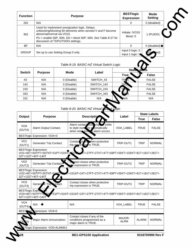
8-28 BE1-GPS100 Application 9318700990 Rev F
Function Purpose BESTlogic Expression
Mode Setting
262 N/A 0 0 (disabled)
362
Used for inadvertent energization logic. Delays unblocking/blocking 50 elements when sensed V and F become abnormal/normal via VO10. PU = enable 50P, 50N. DO = block 50P, 50N. See Table 8-27 for discussion of TDPU/TDDO settings.
Initiate: /VO10 Block: 0
1 (PU/DO)
BF N/A 0 0 (disabled)
GROUP Set up to use Setting Group 0 only. Input 0 logic: 0 Input 1 logic: 0
0 (disabled)
Table 8-19. BASIC-HZ Virtual Switch Logic
State Labels Switch Purpose Mode Label
True False 43 N/A 0 (Disable) SWITCH_43 TRUE FALSE 143 N/A 0 (Disable) SWITCH_143 TRUE FALSE 243 N/A 0 (Disable) SWITCH_243 TRUE FALSE 343 N/A 0 (Disable) SWITCH_343 TRUE FALSE 101 N/A 0 (Disable) N/A N/A N/A
Table 8-20. BASIC-HZ Virtual Output Logic
State Labels Output Purpose Description Label
True False
VOA (OUTA)
Alarm Output Contact. Alarm contact closes/opens (refer to style number) automatically when relay trouble alarm occurs.
VOA_LABEL TRUE FALSE
BESTlogic Expression: VOA=0
VO1 (OUT1)
Generator Trip Contact. Contact closes when protective trip expression is TRUE. TRIP-OUT1 TRIP NORMAL
BESTlogic Expression: VO1=46T+50TPT+50TNT+51PT+51NT+151NT+24T+27PT+27XT+47T+59PT+59XT+159XT+81T+181T+281T+ 32T+132T+40T+140T
VO2 (OUT2)
Generator Trip Contact Contact closes when protective trip expression is TRUE. TRIP-OUT2 TRIP NORMAL
BESTlogic Expression: VO2=46T+50TPT+50TNT+51PT+51NT+151NT+24T+27PT+27XT+47T+59PT+59XT+159XT+81T+181T+281T+ 32T+132T+40T+140T
VO3 (OUT3)
Generator Trip Contact. Contact closes when protective trip expression is TRUE. TRIP-OUT3 TRIP NORMAL
BESTlogic Expression: VO3=46T+50TPT+50TNT+51PT+51NT+151NT+24T+27PT+27XT+47T+59PT+59XT+159XT+81T+181T+281T+ 32T+132T+40T+140T
VO4 (OUT4)
N/A N/A VO4_LABEL TRUE FALSE
BESTlogic Expression: VO4=0
VO5 (OUT5)
Major Alarm Annunciation. Contact closes if any of the conditions programmed as a major alarm is TRUE.
MAJOR-ALRM ALARM NORMAL
BESTlogic Expression: VO5=ALMMAJ
www . El
ectric
alPar
tMan
uals
. com
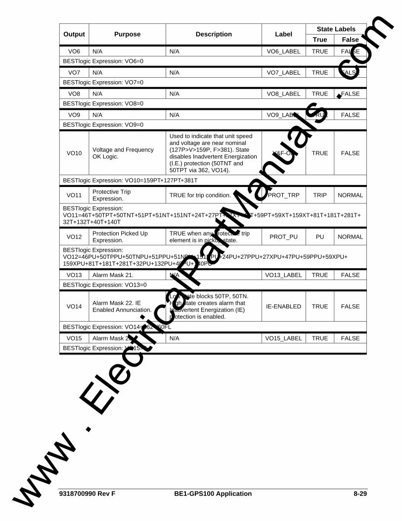
9318700990 Rev F BE1-GPS100 Application 8-29
State Labels Output Purpose Description Label
True False
VO6 N/A N/A VO6_LABEL TRUE FALSE BESTlogic Expression: VO6=0
VO7 N/A N/A VO7_LABEL TRUE FALSE BESTlogic Expression: VO7=0
VO8 N/A N/A VO8_LABEL TRUE FALSE BESTlogic Expression: VO8=0
VO9 N/A N/A VO9_LABEL TRUE FALSE BESTlogic Expression: VO9=0
VO10 Voltage and Frequency OK Logic.
Used to indicate that unit speed and voltage are near nominal (127P>V>159P, F>381). State disables Inadvertent Energization (I.E.) protection (50TNT and 50TPT via 362, VO14).
V&F-OK TRUE FALSE
BESTlogic Expression: VO10=159PT∗127PT∗381T
VO11 Protective Trip Expression. TRUE for trip condition. PROT_TRP TRIP NORMAL
BESTlogic Expression: VO11=46T+50TPT+50TNT+51PT+51NT+151NT+24T+27PT+27XT+47T+59PT+59XT+159XT+81T+181T+281T+32T+132T+40T+140T
VO12 Protection Picked Up Expression.
TRUE when any protective trip element is in pickup state. PROT_PU PU NORMAL
BESTlogic Expression: VO12=46PU+50TPPU+50TNPU+51PPU+51NPU+151NPU+24PU+27PPU+27XPU+47PU+59PPU+59XPU+ 159XPU+81T+181T+281T+32PU+132PU+40PU+140PU
VO13 Alarm Mask 21. N/A VO13_LABEL TRUE FALSE BESTlogic Expression: VO13=0
VO14 Alarm Mask 22. IE Enabled Annunciation.
Low state blocks 50TP, 50TN. High state creates alarm that Inadvertent Energization (IE) protection is enabled.
IE-ENABLED TRUE FALSE
BESTlogic Expression: VO14=362∗/60FL
VO15 Alarm Mask 23. N/A VO15_LABEL TRUE FALSE BESTlogic Expression: VO15=0
www . El
ectric
alPar
tMan
uals
. com
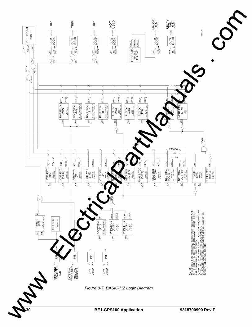
8-30 BE1-GPS100 Application 9318700990 Rev F
Figure 8-7. BASIC-HZ Logic Diagram
www . El
ectric
alPar
tMan
uals
. com

9318700990 Rev F BE1-GPS100 Application 8-31
140Q
40Q
132
32
27XVx-3RD
159XVx-FUND
51PVC/VR
46
50TP
50TN3Io
51N3Io
159POV
47
24
27P
59P
59X3Vo
81UF
181UF
281OF
381OF
151NIg
127PUV
IN2
PRIME MOVERFIELD
OUT1MAIN
OUT3P.M.
OUT2FIELD
OUT4UNUSED
OUT5
362PU/DOVO10 VO14
60FL
GEN V&F OK INDICATION
I.E. PROTECTION HIGH = ENABLE
BLK
IN152bMAIN BKR
62ONE-SHOT
OSC./EVENT TRIGGER
EXT. TRIP SIGNAL
OSC./EVENT TRIGGER
3
2 or 3
MAJOR ALARM
NOTES: 1) ABBREVIATED LOGIC SHOWN. E.G., NOT SHOWN THAT 27P, 81, 181 ARE CONTROLLED BY BKR STATUS.2) 60FL EFFECTS NOT SHOWN. AFFECTS 27P, 127P, 47, 51P, 59P, AND 159P.3) OUT1/2/3 ASSIGNMENT SHOWN FOR CONCEPT ONLY.4) ALTERNATE USE OF Ig INCLUDES GROUND DIFFERENTIAL (CT SUM OR FLUX BALANCE CT) AND WYE NEUTRAL OF STEP UP XFMR.5) PHASE DIFFERENTIAL USING SEPARATE RELAY (E.G. BE1-CDS OR 87G) NOT SHOWN BUT COMMON FOR GEN > 1MW.6) UNUSED FUNCTIONS INCLUDE: 162, 262, 25, 127X, BF, SL-GROUP, 101, IN3, IN4, 43, 143, 243, 343.
D2873-12GPS1LN_BASIC_HZ
02/08/2000
VO10 BLK
OUTA
RELAY ALARM
Figure 8-8. BASIC-HZ One-Line Drawing
www . El
ectric
alPar
tMan
uals
. com
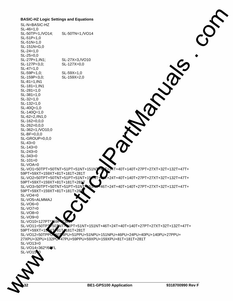
8-32 BE1-GPS100 Application 9318700990 Rev F
BASIC-HZ Logic Settings and Equations SL-N=BASIC-HZ SL-46=1,0 SL-50TP=1,/VO14; SL-50TN=1,/VO14 SL-51P=1,0 SL-51N=1,0 SL-151N=G,0 SL-24=1,0 SL-25=0,0 SL-27P=1,IN1; SL-27X=3,/VO10 SL-127P=3,0; SL-127X=0,0 SL-47=1,0 SL-59P=1,0; SL-59X=1,0 SL-159P=3,0; SL-159X=2,0 SL-81=1,IN1 SL-181=1,IN1 SL-281=1,0 SL-381=1,0 SL-32=1,0 SL-132=1,0 SL-40Q=1,0 SL-140Q=1,0 SL-62=2,/IN1,0 SL-162=0,0,0 SL-262=0,0,0 SL-362=1,/VO10,0 SL-BF=0,0,0 SL-GROUP=0,0,0 SL-43=0 SL-143=0 SL-243=0 SL-343=0 SL-101=0 SL-VOA=0 SL-VO1=50TPT+50TNT+51PT+51NT+151NT+46T+24T+40T+140T+27PT+27XT+32T+132T+47T+ 59PT+59XT+159XT+81T+181T+281T SL-VO2=50TPT+50TNT+51PT+51NT+151NT+46T+24T+40T+140T+27PT+27XT+32T+132T+47T+ 59PT+59XT+159XT+81T+181T+281T SL-VO3=50TPT+50TNT+51PT+51NT+151NT+46T+24T+40T+140T+27PT+27XT+32T+132T+47T+ 59PT+59XT+159XT+81T+181T+281T SL-VO4=0 SL-VO5=ALMMAJ SL-VO6=0 SL-VO7=0 SL-VO8=0 SL-VO9=0 SL-VO10=127PT*159PT*381T SL-VO11=50TPT+50TNT+51PT+51NT+151NT+46T+24T+40T+140T+27PT+27XT+32T+132T+47T+ 59PT+59XT+159XT+81T+181T+281T SL-VO12=50TPPU+50TNPU+51PPU+51NPU+151NPU+46PU+24PU+40PU+140PU+27PPU+ 27XPU+32PU+132PU+47PU+59PPU+59XPU+159XPU+81T+181T+281T SL-VO13=0 SL-VO14=362*/60FL SL-VO15=0
www . El
ectric
alPar
tMan
uals
. com

9318700990 Rev F BE1-GPS100 Application 8-33
HZ-SEQTR (HIGH Z GROUNDED GENERATOR PROTECTION) This logic scheme provides for more elaborate protection for generators grounded through a high neutral impedance. This scheme’s logic, as compared to the BASIC-HZ logic, offers more features. It adds sequential trip logic and implements a version of the IEEE C37.102-1995 tripping scheme. It provides three trip output contacts: OUT1 for main breaker, OUT2 for field, and OUT3 for prime mover tripping, with different logic for each. It provides for sequential trip logic but not synchronism check. A summary of the IEEE tripping functions for each output is shown in Table 8-21. The components of HZ-SEQTR logic are listed in Tables 8-22, 8-23, 8-24, and 8-25. Inspect the logic diagrams shown in Figures 8-9 and 8-10 for a more thorough understanding.
Table 8-21. HZ-SEQTR Tripping Scheme Summary
Protective Function Comments
Main Bkr Trip
(VO1)
Field Bkr Trip
(VO2)
Prime Mvr Trip
(VO3)
HI-Z Gnd Fault (VO4)
24 Overexcitation, volts/Hertz. C37.102: If generator is off line, trip only field breaker.
If main bkr closed. X X
27P Phase UV. Blocked for breaker open. Not clearly covered in C37.102. X
27-3N Generator neutral third harmonic UV. Supervised by Gen V and F OK logic (VO10). X
32R Detect loss of prime mover. X X X 132R Part of sequential trip logic. X X X
40Q, 140Q Loss of excitation. C37.102 unclear on P.M. trip. X X X
46 Negative sequence current. If main bar trip does not clear the fault in 262 time, the field and prime mover are tripped.
X Via 262 Via 262
47
Neg seq. voltage (reverse phase rotation). Not clearly covered in C37.102. If main bar trip does not clear the fault in 262 time, the field and prime mover are tripped.
X Via 262 Via 262
50TP, 50TN Part of inadvertent energization logic. X X X
51VR or 51VC
VR or VC time Overcurrent. If main breaker trip does not clear the fault in 262 time, the field and prime mover are tripped.
X Via 262 Via 262
51N (3I0)
Phase summation (ground) time overcurrent. If main breaker trip does not clear the fault in 262 time, the field and prime mover are tripped.
X Via 262 Via 262
151N (IG) Independent ground input time overcurrent. Trips w/o 262 delay. Use custom logic to reassign to 3I0 if no IG is available.
X X X
59P Phase overvoltage. Not clearly covered in C37.102. Treated as part of overexcitation (24) protection.
If main bkr closed. X X
59-Neu Generator neutral fundamental frequency overvoltage. X
59-3V0 Zero sequence voltage on generator leads. X
81, 181 Underfrequency, level 1 and 2. Blocked for breaker open.
Blocked by 52b
281 Overfrequency. Not clearly covered in C37.102. X
www . El
ectric
alPar
tMan
uals
. com
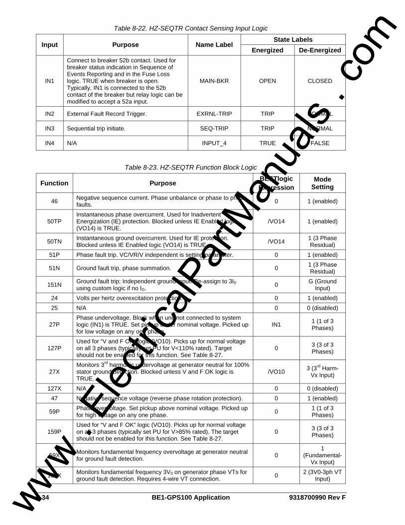
8-34 BE1-GPS100 Application 9318700990 Rev F
Table 8-22. HZ-SEQTR Contact Sensing Input Logic
State Labels Input Purpose Name Label
Energized De-Energized
IN1
Connect to breaker 52b contact. Used for breaker status indication in Sequence of Events Reporting and in the Fuse Loss logic. TRUE when breaker is open. Typically, IN1 is connected to the 52b contact of the breaker but relay logic can be modified to accept a 52a input.
MAIN-BKR OPEN CLOSED
IN2 External Fault Record Trigger. EXRNL-TRIP TRIP NORMAL
IN3 Sequential trip initiate. SEQ-TRIP TRIP NORMAL
IN4 N/A INPUT_4 TRUE FALSE
Table 8-23. HZ-SEQTR Function Block Logic
Function Purpose BESTlogic Expression
Mode Setting
46 Negative sequence current. Phase unbalance or phase to phase faults. 0 1 (enabled)
50TP Instantaneous phase overcurrent. Used for Inadvertent Energization (IE) protection. Blocked unless IE Enabled logic (VO14) is TRUE.
/VO14 1 (enabled)
50TN Instantaneous ground overcurrent. Used for IE protection. Blocked unless IE Enabled logic (VO14) is TRUE. /VO14 1 (3 Phase
Residual) 51P Phase fault trip. VC/VR/V independent is setting parameter. 0 1 (enabled)
51N Ground fault trip, phase summation. 0 1 (3 Phase Residual)
151N Ground fault trip; Independent ground input. Re-assign to 3I0 using custom logic if no IG. 0 G (Ground
Input) 24 Volts per hertz overexcitation protection. 0 1 (enabled) 25 N/A 0 0 (disabled)
27P Phase undervoltage. Block when unit not connected to system logic (IN1) is TRUE. Set pickup under nominal voltage. Picked up for low voltage on any one phase.
IN1 1 (1 of 3 Phases)
127P Used for “V and F OK” logic (VO10). Picks up for normal voltage on all 3 phases (typically set PU for V<110% rated). Target should not be enabled for this function. See Table 8-27.
0 3 (3 of 3 Phases)
27X Monitors 3rd harmonic undervoltage at generator neutral for 100% stator ground detection. Blocked unless V and F OK logic is TRUE.
/VO10 3 (3rd Harm-Vx Input)
127X N/A 0 0 (disabled) 47 Negative sequence voltage (reverse phase rotation protection). 0 1 (enabled)
59P Phase overvoltage. Set pickup above nominal voltage. Picked up for high voltage on any one phase. 0 1 (1 of 3
Phases)
159P Used for “V and F OK” logic (VO10). Picks up for normal voltage on all 3 phases (typically set PU for V>85% rated). The target should not be enabled for this function. See Table 8-27.
0 3 (3 of 3 Phases)
59X Monitors fundamental frequency overvoltage at generator neutral for ground fault detection. 0
1 (Fundamental-
Vx Input)
159X Monitors fundamental frequency 3V0 on generator phase VTs for ground fault detection. Requires 4-wire VT connection. 0 2 (3V0-3ph VT
Input)
www . El
ectric
alPar
tMan
uals
. com

9318700990 Rev F BE1-GPS100 Application 8-35
Function Purpose BESTlogic Expression
Mode Setting
81 Generator Underfrequency protection. Blocked for breaker open. IN1 1 (enabled)
181 Second stage generator Underfrequency protection. Blocked for breaker open. IN1 1 (enabled)
281 Generator Overfrequency protection. 0 1 (enabled)
381 Used for “V and F OK” logic (VO10). See Table 8-27. Picks up for normal frequency (typically set PU for F>85+% rated). The target should not be enabled for this function.
0 1 (enabled)
32 Loss of prime mover, first stage. 0 1 (enabled) 132 Part of sequential trip logic. /VO7 1 (enabled) 40Q Loss of field, first stage. 0 1 (enabled) 140Q Loss of field, second stage. 0 1 (enabled)
62 One-shot timer used to trigger oscillography record for main breaker close.
Initiate: /IN1 Block: 0
2 (one-shot non-
retriggerable)
162 N/A Initiate: 0 Block: 0
0 (disabled)
262 N/A Initiate: 0 Block: 0
0 (disabled)
362
Used for inadvertent energization logic. Delays unblocking/blocking 50 elements when sensed V and F become abnormal/normal via VO10. PU = enable 50P, 50N. DO = block 50P, 50N. See Table 8-27 for discussion of TDPU/TDDO settings.
Initiate: /VO10 Block: 0
1 (PU/DO)
BF N/A 0 0 (disabled)
GROUP Set up to use Setting Group 0 only. Input 0 logic: 0 Input 1 logic: 0
0 (disabled)
Table 8-24. HZ-SEQTR Virtual Switch Logic
State Labels Switch Purpose Mode Label
True False 43 N/A 0 (Disable) SWITCH_43 TRUE FALSE 143 N/A 0 (Disable) SWITCH_143 TRUE FALSE 243 N/A 0 (Disable) SWITCH_243 TRUE FALSE 343 N/A 0 (Disable) SWITCH_343 TRUE FALSE 101 N/A 0 (Disable) N/A N/A N/A
Table 8-25. HZ-SEQTR Virtual Output Logic
State Labels Output Purpose Description Label
True False
VOA (OUTA)
Alarm Output Contact. Alarm contact closes/opens (refer to style number) automatically when relay trouble alarm occurs.
VOA_LABEL TRUE FALSE
BESTlogic Expression: VOA=0
VO1 (OUT1)
Generator Main Breaker Trip.
Contact closes when protective trip expression is TRUE. BKR_TRIP TRIP NORMAL
BESTlogic Expression: VO1=46T+50TPT+50TNT+51PT+51NT+151NT+V09+27PT+47T+81T+181T+32T+132T+40T+140T
www . El
ectric
alPar
tMan
uals
. com
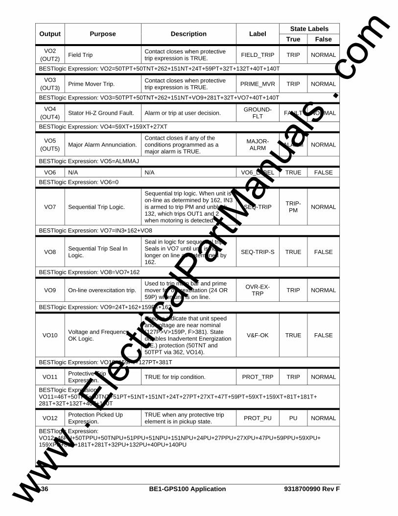
8-36 BE1-GPS100 Application 9318700990 Rev F
State Labels Output Purpose Description Label
True False
VO2 (OUT2)
Field Trip Contact closes when protective trip expression is TRUE. FIELD_TRIP TRIP NORMAL
BESTlogic Expression: VO2=50TPT+50TNT+262+151NT+24T+59PT+32T+132T+40T+140T
VO3 (OUT3)
Prime Mover Trip. Contact closes when protective trip expression is TRUE. PRIME_MVR TRIP NORMAL
BESTlogic Expression: VO3=50TPT+50TNT+262+151NT+VO9+281T+32T+VO7+40T+140T
VO4 (OUT4)
Stator Hi-Z Ground Fault. Alarm or trip at user decision. GROUND-FLT FAULT NORMAL
BESTlogic Expression: VO4=59XT+159XT+27XT
VO5 (OUT5)
Major Alarm Annunciation. Contact closes if any of the conditions programmed as a major alarm is TRUE.
MAJOR-ALRM ALARM NORMAL
BESTlogic Expression: VO5=ALMMAJ
VO6 N/A N/A VO6_LABEL TRUE FALSE BESTlogic Expression: VO6=0
VO7 Sequential Trip Logic.
Sequential trip logic. When unit is on-line as determined by 162, IN3 is armed to trip PM and unblock 132, which trips OUT1 and 2 when motoring is detected.
SEQ-TRIP TRIP-PM NORMAL
BESTlogic Expression: VO7=IN3∗162+VO8
VO8 Sequential Trip Seal In Logic.
Seal in logic for sequential trip. Seals in VO7 until unit is no longer on line as determined by 162.
SEQ-TRIP-S TRUE FALSE
BESTlogic Expression: VO8=VO7∗162
VO9 On-line overexcitation trip. Used to trip main bar and prime mover for overexcitation (24 OR 59P) when unit is on line.
OVR-EX-TRP TRIP NORMAL
BESTlogic Expression: VO9=24T∗162+159PT∗162
VO10 Voltage and Frequency OK Logic.
Used to indicate that unit speed and voltage are near nominal (127P>V>159P, F>381). State disables Inadvertent Energization (I.E.) protection (50TNT and 50TPT via 362, VO14).
V&F-OK TRUE FALSE
BESTlogic Expression: VO10=159PT∗127PT∗381T
VO11 Protective Trip Expression. TRUE for trip condition. PROT_TRP TRIP NORMAL
BESTlogic Expression: VO11=46T+50TPT+50TNT+51PT+51NT+151NT+24T+27PT+27XT+47T+59PT+59XT+159XT+81T+181T+ 281T+32T+132T+40T+140T
VO12 Protection Picked Up Expression.
TRUE when any protective trip element is in pickup state. PROT_PU PU NORMAL
BESTlogic Expression: VO12=46PU+50TPPU+50TNPU+51PPU+51NPU+151NPU+24PU+27PPU+27XPU+47PU+59PPU+59XPU+ 159XPU+81T+181T+281T+32PU+132PU+40PU+140PU
www . El
ectric
alPar
tMan
uals
. com
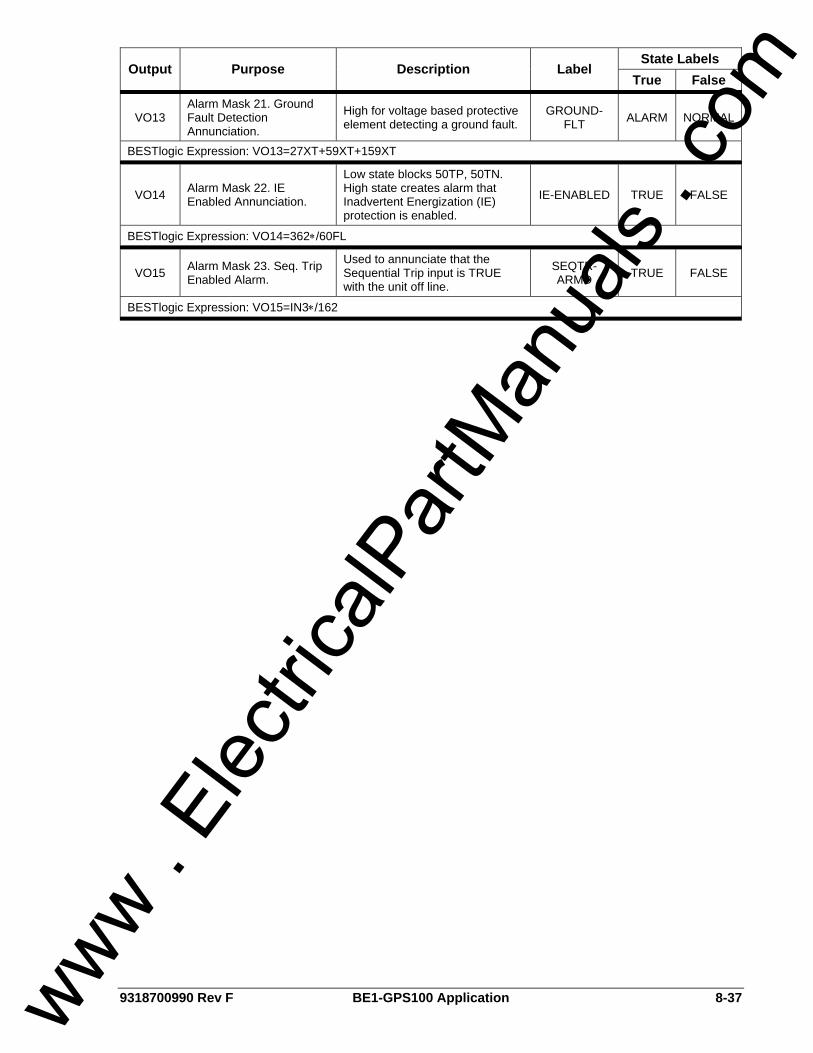
9318700990 Rev F BE1-GPS100 Application 8-37
State Labels Output Purpose Description Label
True False
VO13 Alarm Mask 21. Ground Fault Detection Annunciation.
High for voltage based protective element detecting a ground fault.
GROUND-FLT ALARM NORMAL
BESTlogic Expression: VO13=27XT+59XT+159XT
VO14 Alarm Mask 22. IE Enabled Annunciation.
Low state blocks 50TP, 50TN. High state creates alarm that Inadvertent Energization (IE) protection is enabled.
IE-ENABLED TRUE FALSE
BESTlogic Expression: VO14=362∗/60FL
VO15 Alarm Mask 23. Seq. Trip Enabled Alarm.
Used to annunciate that the Sequential Trip input is TRUE with the unit off line.
SEQTR-ARMD TRUE FALSE
BESTlogic Expression: VO15=IN3∗/162
www . El
ectric
alPar
tMan
uals
. com
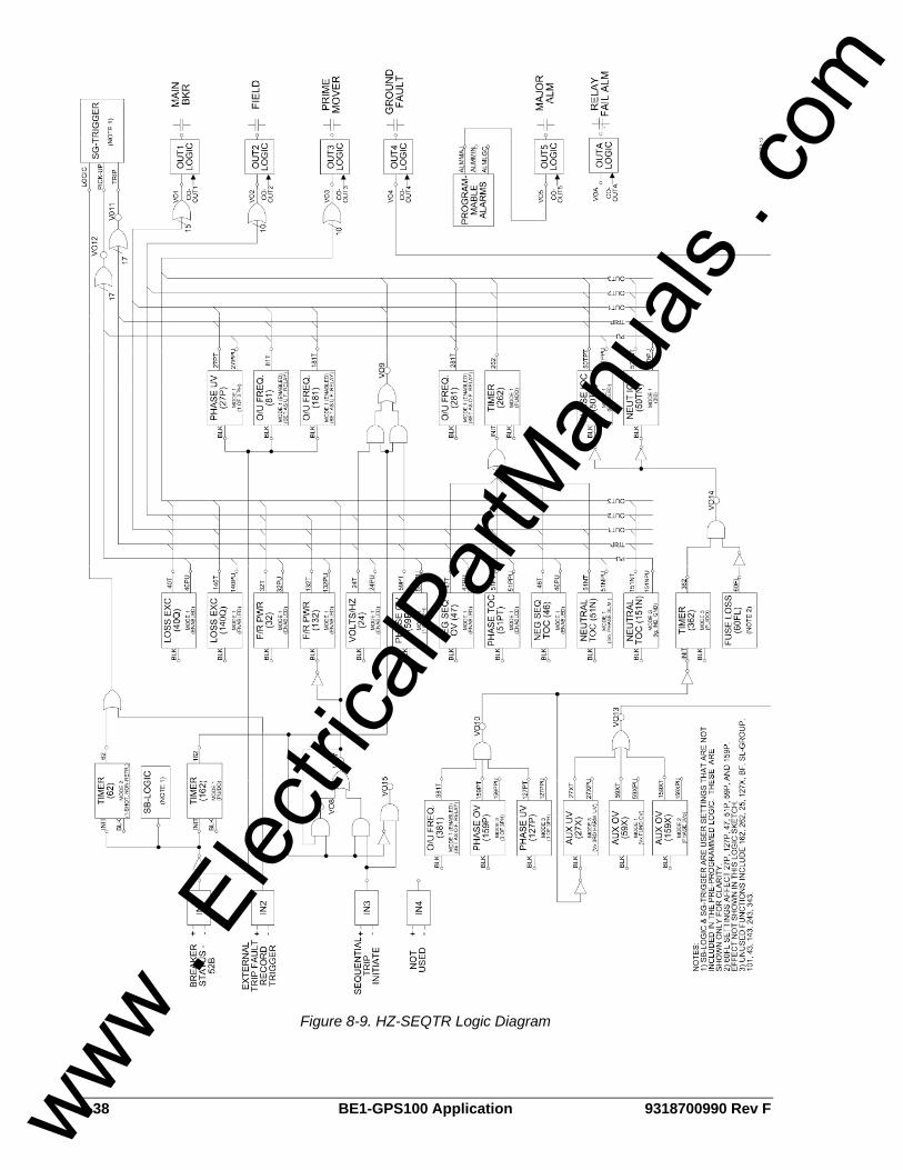
8-38 BE1-GPS100 Application 9318700990 Rev F
Figure 8-9. HZ-SEQTR Logic Diagram
www . El
ectric
alPar
tMan
uals
. com

9318700990 Rev F BE1-GPS100 Application 8-39
140Q
40Q
132
32
27XVx-3RD
159XVx-FUND
51PVC/VR
46
50TP
50TN3Io
51N3Io
159POV
47
24
27P
59P
59X3Vo
81UF
181UF
281OF
381OF
151NIg
127PUV
IN2
IN3
PRIME MOVERFIELD
OUT1MAIN
OUT3P.M.
OUT2FIELD
OUT4GND FLT
OUT5
362PU/DOVO10 VO14
60FL
GEN V&F OK INDICATION
I.E. PROTECTION HIGH = ENABLE
BLK
262PU/DO162
PU/DOIN1
52bMAIN BKR
BKR STATUS CONDITIONING
62ONE-SHOT
OSC./EVENT TRIGGER
EXT. TRIP SIGNAL
OSC./EVENT TRIGGER
SEQUENTIAL TRIP INITIATE
SEQ-TRIP SEAL-IN LOGIC VO7
VO9
3
2 or 3
U-BLK
OU
T3
OU
T2
0UT
1
MAJOR ALARM
NOTES: 1) ABBREVIATED LOGIC SHOWN. E.G., NOT SHOWN THAT 27P, 81, 181 ARE CONTROLLED BY BKR STATUS.2) 60FL ONLY SHOWN FOR VO14. ALSO AFFECTS 27P, 127P, 47, 51P, 59P, AND 159P.3) ALTERNATE USE OF Ig INCLUDES GROUND DIFFERENTIAL (CT SUM OR FLUX BALANCE CT) AND WYE NEUTRAL LEAD OF STEP UP XFMR.4) PHASE DIFFERENTIAL USING SEPARATE RELAY (E.G. BE1-CDS OR 87G) NOT SHOWN BUT COMMON FOR GEN > 1MW.5) UNUSED FUNCTIONS INCLUDE: 25, 127X, BF, SL-GROUP, IN4, 101, 43, 143, 243, 343.
D2873-14GPS1LN_HZ_SEQTR
05/15/2000
VO10 U-BLK
OUTA
RELAY ALARM
Figure 8-10. HZ-SEQTR One-Line Drawing
www . El
ectric
alPar
tMan
uals
. com
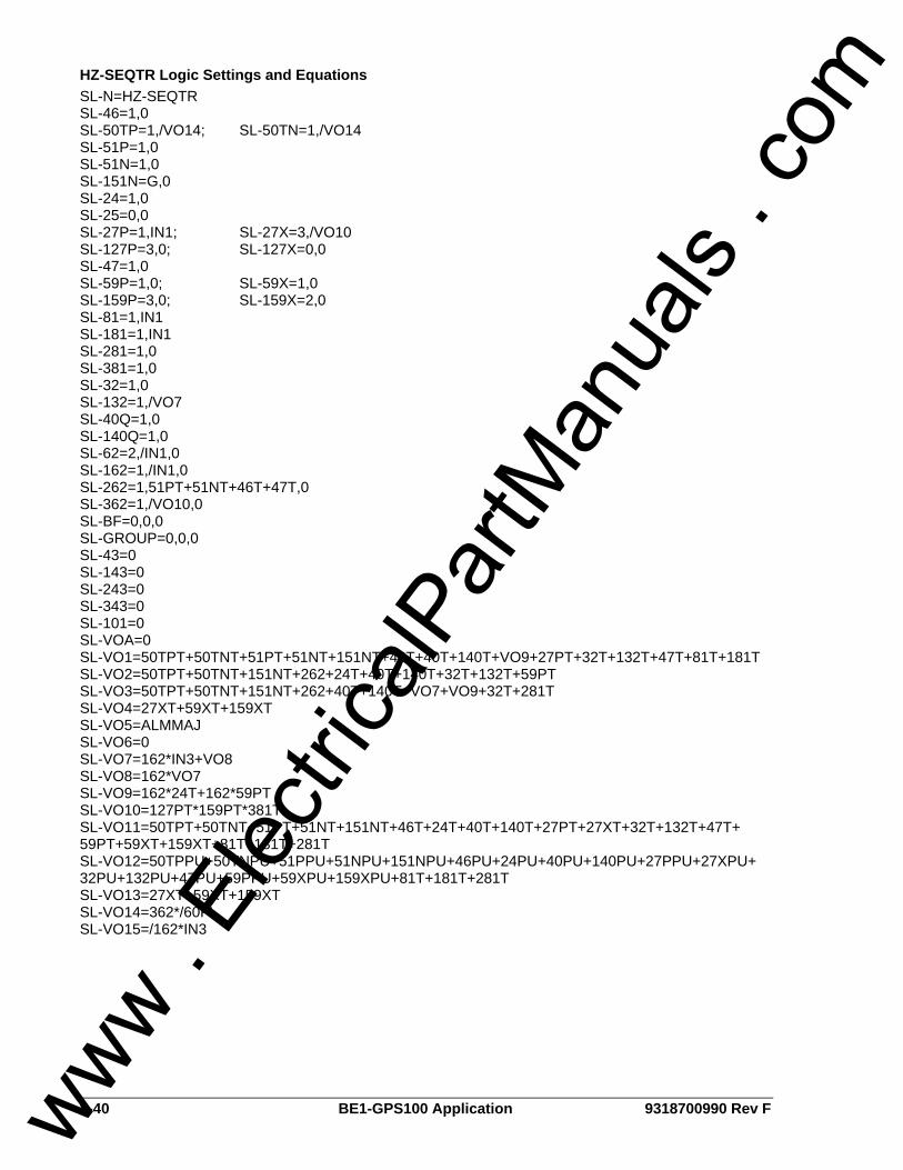
8-40 BE1-GPS100 Application 9318700990 Rev F
HZ-SEQTR Logic Settings and Equations SL-N=HZ-SEQTR SL-46=1,0 SL-50TP=1,/VO14; SL-50TN=1,/VO14 SL-51P=1,0 SL-51N=1,0 SL-151N=G,0 SL-24=1,0 SL-25=0,0 SL-27P=1,IN1; SL-27X=3,/VO10 SL-127P=3,0; SL-127X=0,0 SL-47=1,0 SL-59P=1,0; SL-59X=1,0 SL-159P=3,0; SL-159X=2,0 SL-81=1,IN1 SL-181=1,IN1 SL-281=1,0 SL-381=1,0 SL-32=1,0 SL-132=1,/VO7 SL-40Q=1,0 SL-140Q=1,0 SL-62=2,/IN1,0 SL-162=1,/IN1,0 SL-262=1,51PT+51NT+46T+47T,0 SL-362=1,/VO10,0 SL-BF=0,0,0 SL-GROUP=0,0,0 SL-43=0 SL-143=0 SL-243=0 SL-343=0 SL-101=0 SL-VOA=0 SL-VO1=50TPT+50TNT+51PT+51NT+151NT+46T+40T+140T+VO9+27PT+32T+132T+47T+81T+181T SL-VO2=50TPT+50TNT+151NT+262+24T+40T+140T+32T+132T+59PT SL-VO3=50TPT+50TNT+151NT+262+40T+140T+VO7+VO9+32T+281T SL-VO4=27XT+59XT+159XT SL-VO5=ALMMAJ SL-VO6=0 SL-VO7=162*IN3+VO8 SL-VO8=162*VO7 SL-VO9=162*24T+162*59PT SL-VO10=127PT*159PT*381T SL-VO11=50TPT+50TNT+51PT+51NT+151NT+46T+24T+40T+140T+27PT+27XT+32T+132T+47T+ 59PT+59XT+159XT+81T+181T+281T SL-VO12=50TPPU+50TNPU+51PPU+51NPU+151NPU+46PU+24PU+40PU+140PU+27PPU+27XPU+ 32PU+132PU+47PU+59PPU+59XPU+159XPU+81T+181T+281T SL-VO13=27XT+59XT+159XT SL-VO14=362*/60FL SL-VO15=/162*IN3
www . El
ectric
alPar
tMan
uals
. com
9318700990 Rev F BE1-GPS100 Application 8-41
MISCELLANEOUS LOGIC EXPRESSIONS Five logic variables are classified as miscellaneous logic expressions. These expressions are SG-TARG, SG-TRIGGER, SB-DUTY, SB-LOGIC, and SA-RESET. The equations associated with these variables determine how the BE1-GPS100 responds to conditions such as, when to target, what triggers fault reporting, defining breaker status monitoring and setup for remote alarm/target reset provisions. These variables are not included in any of the BESTlogic preprogrammed schemes. However, the factory default equations are compatible with each scheme. The default miscellaneous expressions are common among the preprogrammed and custom schemes. When a preprogrammed scheme is modified or a new scheme is created, the miscellaneous logic expressions should be reviewed to ensure desired performance. The default expressions for the miscellaneous logic settings are as follows: SG-TARG=51P/51N/151N/50TP/50TN/46/24/47/BF/27P/27X/127P/127X/32/132/40Q/140Q/59P/ 59X/159P/159X/81/181/281/381 SG-TRIGGER=BFT+VO11, BFPU+V012,0 SB-DUTY=0,0.000E+00,0 SB-LOGIC=/IN1 SA-RESET=0 Table 8-26 lists the miscellaneous commands and the sections of this manual where detailed information about each command may be found.
Table 8-26. Miscellaneous Logic Expressions
Command Reference
SG-TARG Section 6, Reporting and Alarm Functions
SG-TRIGGER Section 6, Reporting and Alarm Functions
SB-DUTY Section 6, Reporting and Alarm Functions
SB-LOGIC Section 6, Reporting and Alarm Functions
SA-RESET Section 6, Reporting and Alarm Functions
APPLICATION TIPS
Fuse Loss Conditions The 60FL element blocks inadvertent energization protection for fuse loss conditions. It is also a user option to block the 27P, 127P, 47, 59P, and 159P functions for fuse loss conditions. This is set via the SP-60FL command in Section 4, Protection and Control.
Differential Protection The GPS100 relay does not provide for differential protection. Providing differential relaying in a separate package provides an inherent redundancy factor in that if either the GPS100 or the differential relaying is out of service or has been incorrectly set, then the remaining relay provides some level of backup protection. If the differential is a multifunction relay, such as the BE1-CDS220/240, it may provide overcurrent functions as well as differential functions. The independent ground input (IG) of the BE1-GPS100 in combination with the 51N or 151N functions has the capability of acting as a ground differential detection, as shown in the following material on the use of IG.
www . El
ectric
alPar
tMan
uals
. com
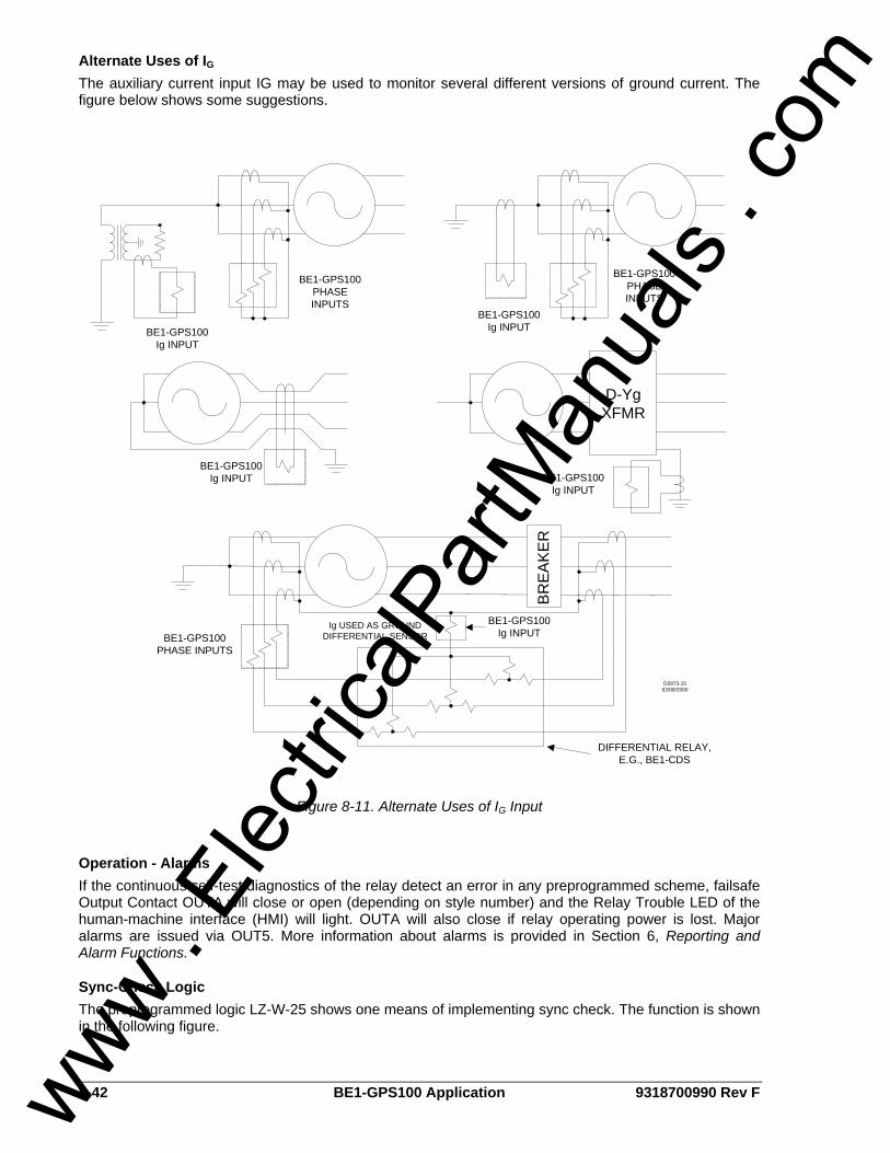
8-42 BE1-GPS100 Application 9318700990 Rev F
Alternate Uses of IG The auxiliary current input IG may be used to monitor several different versions of ground current. The figure below shows some suggestions.
BE1-GPS100PHASE INPUTS
BE1-GPS100Ig INPUT
BE1-GPS100PHASE INPUTS
BE1-GPS100Ig INPUT
BE1-GPS100Ig INPUT
D-YgXFMR
BE1-GPS100Ig INPUT
BR
EAK
ER
BE1-GPS100Ig INPUT
DIFFERENTIAL RELAY, E.G., BE1-CDS
BE1-GPS100PHASE INPUTS
Ig USED AS GROUND DIFFERENTIAL SENSOR
D2873-1502/08/2000
Figure 8-11. Alternate Uses of IG Input
Operation - Alarms If the continuous self-test diagnostics of the relay detect an error in any preprogrammed scheme, failsafe Output Contact OUTA will close or open (depending on style number) and the Relay Trouble LED of the human-machine interface (HMI) will light. OUTA will also close if relay operating power is lost. Major alarms are issued via OUT5. More information about alarms is provided in Section 6, Reporting and Alarm Functions.
Sync-Check Logic The preprogrammed logic LZ-W-25 shows one means of implementing sync check. The function is shown in the following figure. www .
Elec
tricalP
artM
anua
ls . c
om

9318700990 Rev F BE1-GPS100 Application 8-43
O/U FREQ.(381) 381TBLK
MODE 1 (ENABLED)(SET AS O.F. RELAY)
PHASE OV(159P)
159PTBLK
159PPUMODE 3 (3 OF 3PH)
PHASE UV(127P)
127PTBLK
127PPUMODE 3 (3 OF 3PH)
SYNC(25) 25BLK
MODE 1(ENABLED)
DEAD BUS CLOSE ENABLE
SYNC/DB
CLOSEOUT4LOGICCO-
OUT4AUX UV(27X)
27XTBLK
27XPUMODE 1 (Vx FUND UV)
IN4+-
VO13D2873-16
02/08/2000
VO10
Figure 8-12. Sync-Check with Dead Bus Close
Note that VO10 in the above figure is a “Gen V and F OK” feature. The 127P is set at possibly 110%+ of nominal voltage, the 159P is set at possibly 90% of nominal voltage, and the 381 is set as an overfrequency element that picks up at possibly 90%+ of nominal frequency. The 27X monitors the bus voltage, providing a dead bus close feature. Since VO13 is an alarmable logic point, it allows for alarming when dead bus close has been enabled.
V and F OK Logic In the preprogrammed logic, when voltage or frequency are near nominal, as defined by the 127P, 159P, and 381 elements, for a time greater than the time delays of the 127P, 159P, and 381, logic bit VO10 is driven high. Since these logic bits have no intentional time delays for dropout, VO10 will go low immediately for faults or transient conditions that cause voltage or frequency to drop outside the setting of these elements. The logic is seen in the figure for the sync-check logic above. The logic used to drive VO10 or some variance on it, may be used in a custom scheme developed by the user to close or open one of the relay outputs in order to initiate the transfer of control of generator speed and excitation to an automatic synchronizer.
Inadvertent Energization Logic The inadvertent energization logic used in the preprogrammed schemes is shown below. Inadvertent energization protection trips the unit if nominal voltage and frequency are not sensed for a period of time (362 timer settings) prior to the sensing of current flow. When VO10 goes low, because of the loss of nominal voltage or frequency, the 362 timing will be initiated. The 362 element waits for a period equal to T1 before it picks up. Then, if the 60FL bit is low, VO14 will be driven high and the 50TP and 50TN elements enabled. If current is suddenly detected, the 50 elements are ready to trip the unit. When frequency and voltage return to normal, the 362 goes low after a period equal to T2. VO14 will then be driven low, blocking the 50TP and 50TN elements.
VO14 IE ENABLEDTIMER(362)
362
BLK MODE 1 (PU/DO)
INITVO10 V and F OK
O/U FREQ.(381) 381TBLK
MODE 1 (ENABLED)(SET AS O.F. RELAY)
PHASE OV(159P)
159PTBLK
159PPUMODE 3 (3 OF 3PH)
PHASE UV(127P)
127PTBLK
127PPUMODE 3 (3 OF 3PH)
FUSE LOSS(60FL) 60FL
TRIP
D2873-1701/17/2001
NEUT IOC (50TN)
50TNTBLK
50TNPUMODE 1 (3I0)
PHASE IOC (50TP)
50TPTBLK
50TPPUMODE 1(ENABLED)
Note:The 381 element is set for overfrequency.
Figure 8-13. Inadvertent Energization Protection Logic
www . El
ectric
alPar
tMan
uals
. com
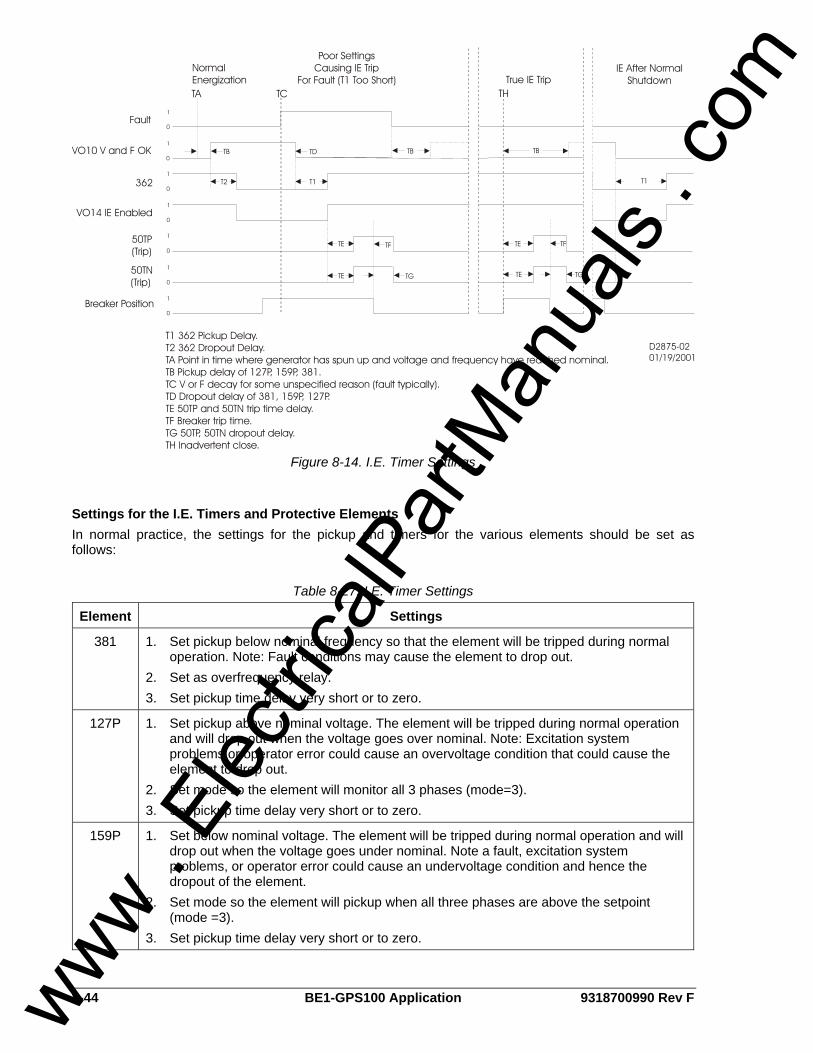
8-44 BE1-GPS100 Application 9318700990 Rev F
Fault
Breaker Position
VO10 V and F OK
362
VO14 IE Enabled
50TP(Trip)
50TN(Trip)
1
0
1
0
1
0
1
0
1
0
1
0
1
0
T2 T1 T1
TB
T1 362 Pickup Delay.T2 362 Dropout Delay.TA Point in time where generator has spun up and voltage and frequency have reached nominal.TB Pickup delay of 127P, 159P, 381.TC V or F decay for some unspecified reason (fault typically).TD Dropout delay of 381, 159P, 127P.TE 50TP and 50TN trip time delay.TF Breaker trip time.TG 50TP, 50TN dropout delay.TH Inadvertent close.
D2875-0201/19/2001
TD
TE
TE
NormalEnergization
Poor SettingsCausing IE Trip
For Fault (T1 Too Short) True IE TripIE After Normal
ShutdownTCTA TH
TB TB
TG
TE
TE
TF TF
TG
Figure 8-14. I.E. Timer Settings
Settings for the I.E. Timers and Protective Elements In normal practice, the settings for the pickup and timers for the various elements should be set as follows:
Table 8-27. I.E. Timer Settings
Element Settings
381 1. Set pickup below nominal frequency so that the element will be tripped during normal operation. Note: Fault conditions may cause the element to drop out.
2. Set as overfrequency relay. 3. Set pickup time delay very short or to zero.
127P 1. Set pickup above nominal voltage. The element will be tripped during normal operation and will drop out when the voltage goes over nominal. Note: Excitation system problems or operator error could cause an overvoltage condition that could cause the element to drop out.
2. Set mode so the element will monitor all 3 phases (mode=3). 3. Set pickup time delay very short or to zero.
159P 1. Set below nominal voltage. The element will be tripped during normal operation and will drop out when the voltage goes under nominal. Note a fault, excitation system problems, or operator error could cause an undervoltage condition and hence the dropout of the element.
2. Set mode so the element will pickup when all three phases are above the setpoint (mode =3).
3. Set pickup time delay very short or to zero.
www . El
ectric
alPar
tMan
uals
. com

9318700990 Rev F BE1-GPS100 Application 8-45
50TP 1. Set pickup either low or high, depending on which approach one wishes to use: a. Set low (as low as 10% of nominal) for high sensitivity. b. Set high (150+% of nominal) for greater security against mis-operation, noting
that inadvertent energization will commonly involve high current levels. (Unless energization is via a high impedance source such as a station auxiliary transformer.)
2. Set pickup time delay very short or to zero.
362 1. Set as a Pickup/Dropout timer (mode=1). 2. TDPU: Set to a long delay, possibly a minute. Note that when VO10 goes low
(indicating bad voltage or frequency) the timer is initiated. The TDPU allows the relay IE logic to ride through transient conditions or conditions that should be tripped by other relays. Set pickup time delay greater than the sum of the following (i + ii). i) Maximum time that one can envision that a fault (normally cleared by other relays), excitation system problems (possibly self-correcting or cleared by other relays) or operator error (hopefully self-clearing) could cause the 381, 127P, or 159P to drop out. ii) Longest pickup time delay of 381, 127P, and 159P that should normally be a very minor delay.
3. TDDO: Set to approximately 2 - 5 times the maximum IE tripping delay (e.g., the time it will take for the 50 elements to sense a fault, the GPS100 output relays to close, and the appropriate breaker(s) to clear the fault.) Note when VO10 goes high (indicating good voltage and frequency), the 362 timer starts timing toward dropout. The TDDO determines how long until the 50 elements are disabled. Since good voltage and frequency may suddenly appear during an inadvertent energization condition, the TDDO must be set long enough to allow the trip to ripple through anything that may delay the clearing of the condition.
I.E. Operation for Loss and Return of Relay Power The inadvertent energization logic is set up so that if the relay is monitoring a running generator and then power is momentarily lost to the relay, the relay wakes up the unpowered condition with the 50 elements blocked. This prevents a momentary output of the 50 elements for this condition.
www . El
ectric
alPar
tMan
uals
. com

8-46 BE1-GPS100 Application 9318700990 Rev F
This page intentionally left blank.
www . El
ectric
alPar
tMan
uals
. com
9318700990 Rev F BE1-GPS100 Security i
SECTION 9 • SECURITY TABLE OF CONTENTS
SECTION 9 • SECURITY.......................................................................................................................... 9-1
INTRODUCTION.................................................................................................................................... 9-1 Setting Password Protection .............................................................................................................. 9-1
Figures Figure 9-1. General Operation Screen, Global Security Tab .................................................................... 9-2 Figure 9-2. General Operation, Global Security Tab with Passwords Shown .......................................... 9-2
Tables Table 9-1. Password Protection Settings .................................................................................................. 9-3
www . El
ectric
alPar
tMan
uals
. com

ii BE1-GPS100 Security 9318700990 Rev F
This page intentionally left blank.
www . El
ectric
alPar
tMan
uals
. com
9318700990 Rev F BE1-GPS100 Security 9-1
SECTION 9 • SECURITY INTRODUCTION In this section, security, in the form of multilevel password protection, is discussed along with the information required for protecting specific function groups and user interface components against unauthorized access. Passwords provide access security for three distinct functional access areas: Settings, Reports, and Control. Each functional area can be assigned a unique password or one password can be assigned to multiple areas. A global password is used to access all three of the functional areas. BE1-GPS100 passwords are not case sensitive; either lowercase or uppercase letters may be entered. Password security only limits write operations; passwords are never required to read information from any area. Additional security is provided by controlling the functional areas that can be accessed from a particular communication port. For example, security can be configured so that access to Control commands from the rear RS-232 port (COM 1) is denied. Then, an attempt to issue a Control command through COM 1 will cause the relay to respond with an ACCESS DENIED and/or INVALID PASSWORD message. This will occur whether a valid password is entered or not. When configuring communication port access areas, you should be aware that the front RS-232 port (COM 0) and the front panel HMI are treated as the same port. The communication ports and password parameters act as a two-dimensional control to limit changes. For a command to be accepted, the entered password must be correct and the command must be entered through a valid port. Only one password can be active at one time for any area or port. For example, if a user gains write access at COM1, then users at other areas (COM0, front panel HMI, and COM2) will not be able to gain write access until the user at COM1 uses the EXIT command to release access control. If a port holding access privileges sees no activity (command entered or HMI key pressed) for approximately five minutes, access privileges and any pending changes will be lost. This feature ensures that password protection cannot be accidentally left in a state where access privileges are enabled for one area and other areas locked out for an indefinite period. If password protection is disabled, then entering ACCESS= followed by no password or any alphanumeric character string will obtain access to the unprotected area(s).
Setting Password Protection Password protection is configured for each access area port and communication port using BESTCOMS. Alternately, password protection can be configured using the GS-PW ASCII command. To configure password protection using BESTCOMS, select General Operation from the Screens pull-down menu. Then select the Global Security tab. Refer to Figure 9-1.
www . El
ectric
alPar
tMan
uals
. com
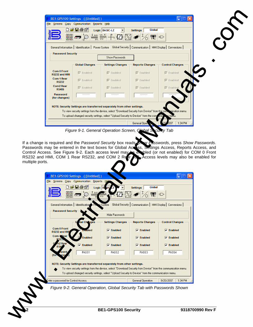
9-2 BE1-GPS100 Security 9318700990 Rev F
Figure 9-1. General Operation Screen, Global Security Tab
If a change is required and the Password Security box reads Show Passwords, press Show Passwords. Passwords may be entered in the text boxes for Global Access, Settings Access, Reports Access, and Control Access. See Figure 9-2. Each access level may be enabled (or not enabled) for COM 0 Front RS232 and HMI, COM 1 Rear RS232, and COM 2 Rear 485. Access levels may also be enabled for multiple ports.
Figure 9-2. General Operation, Global Security Tab with Passwords Shown
www . El
ectric
alPar
tMan
uals
. com

9318700990 Rev F BE1-GPS100 Security 9-3
Table 9-1 lists password protection settings.
Table 9-1. Password Protection Settings
Setting Range/Purpose
Password User defined alphanumeric string with a maximum of 8 characters. A setting of 0 (zero) disables password protection.
Com ports 0 = Front RS-232 port 1 = Rear RS-232 port 2 = Rear RS-485 port
www . El
ectric
alPar
tMan
uals
. com

9-4 BE1-GPS100 Security 9318700990 Rev F
This page intentionally left blank.
www . El
ectric
alPar
tMan
uals
. com
9318700990 Rev F BE1-GPS100 Human-Machine Interface i
SECTION 10 • HUMAN-MACHINE INTERFACE TABLE OF CONTENTS
SECTION 10 • HUMAN-MACHINE INTERFACE ................................................................................... 10-1
INTRODUCTION.................................................................................................................................. 10-1 FRONT PANEL DISPLAY.................................................................................................................... 10-1
Menu Tree ........................................................................................................................................ 10-2 Automatic HMI Display Priorities.................................................................................................... 10-10
HMI OPERATIONS............................................................................................................................ 10-11 Entering Settings ............................................................................................................................ 10-11 Performing Control Operations....................................................................................................... 10-11 Resetting Functions........................................................................................................................ 10-12 Entering Passwords ....................................................................................................................... 10-12
Figures Figure 10-1. Front Panel, H1 Case.......................................................................................................... 10-1 Figure 10-2. Menu Tree Branches........................................................................................................... 10-2 Figure 10-3. Report Status Menu Branch................................................................................................ 10-3 Figure 10-4. Control Menu Branch Structure .......................................................................................... 10-4 Figure 10-5. Metering Menu Branch Structure ........................................................................................ 10-5 Figure 10-6. Reports Menu Branch Structure ......................................................................................... 10-6 Figure 10-7. Reports Menu Branch Structure - Continued...................................................................... 10-7 Figure 10-8. Protection Menu Branch Structure...................................................................................... 10-8 Figure 10-9. General Settings Menu Branch Structure ........................................................................... 10-9 Figure 10-10. General Operation Screen HMI Display Tab .................................................................. 10-10 Figure 10-11. Virtual Control Switch 143 Screen .................................................................................. 10-11
Tables Table 10-1. Front Panel HMI Descriptions .............................................................................................. 10-1 Table 10-2. Automatic Screen Display Priority...................................................................................... 10-10 Table 10-3. Call-Out Descriptions for Figure 10-10............................................................................... 10-12
www . El
ectric
alPar
tMan
uals
. com

ii BE1-GPS100 Human-Machine Interface 9318700990 Rev F
This page intentionally left blank.
www . El
ectric
alPar
tMan
uals
. com
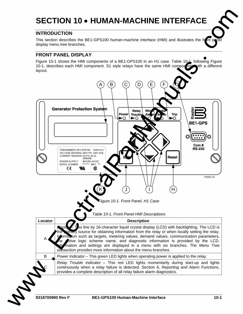
9318700990 Rev F BE1-GPS100 Human-Machine Interface 10-1
SECTION 10 • HUMAN-MACHINE INTERFACE INTRODUCTION This section describes the BE1-GPS100 human-machine interface (HMI) and illustrates the front panel display menu tree branches.
FRONT PANEL DISPLAY Figure 10-1 shows the HMI components of a BE1-GPS100 in an H1 case. Table 10-1, following Figure 10-1, describes each HMI component. S1 style relays have the same HMI components with a different layout.
P0052-31
A B
H
C D E F G
JK I
Figure 10-1. Front Panel, H1 Case
Table 10-1. Front Panel HMI Descriptions
Locator Description
A
Display – Two line by 16-character liquid crystal display (LCD) with backlighting. The LCD is the primary source for obtaining information from the relay or when locally setting the relay. Information such as targets, metering values, demand values, communication parameters, the active logic scheme name, and diagnostic information is provided by the LCD. Information and settings are displayed in a menu with six branches. The Menu Tree subsection provides more information about the menu branches.
B Power Indicator – This green LED lights when operating power is applied to the relay.
C Relay Trouble Indicator – This red LED lights momentarily during start-up and lights continuously when a relay failure is detected. Section 6, Reporting and Alarm Functions, provides a complete description of all relay failure alarm diagnostics.
www . El
ectric
alPar
tMan
uals
. com
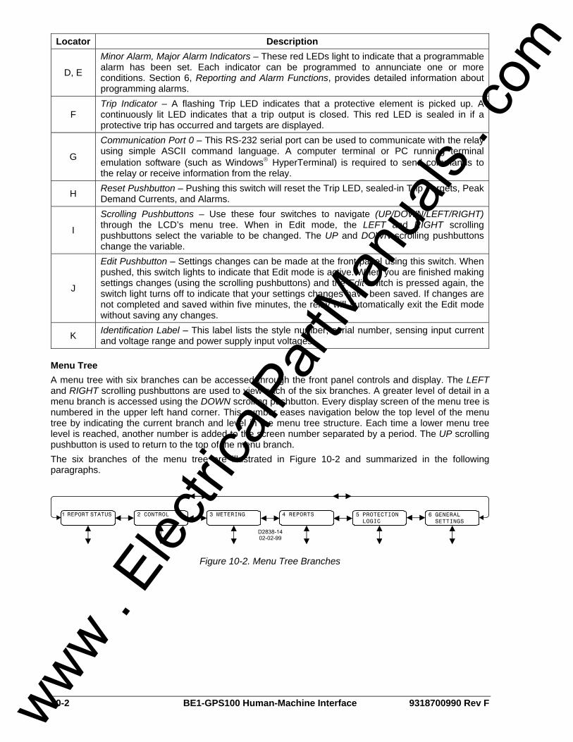
10-2 BE1-GPS100 Human-Machine Interface 9318700990 Rev F
Locator Description
D, E
Minor Alarm, Major Alarm Indicators – These red LEDs light to indicate that a programmable alarm has been set. Each indicator can be programmed to annunciate one or more conditions. Section 6, Reporting and Alarm Functions, provides detailed information about programming alarms.
F Trip Indicator – A flashing Trip LED indicates that a protective element is picked up. A continuously lit LED indicates that a trip output is closed. This red LED is sealed in if a protective trip has occurred and targets are displayed.
G
Communication Port 0 – This RS-232 serial port can be used to communicate with the relay using simple ASCII command language. A computer terminal or PC running terminal emulation software (such as Windows® HyperTerminal) is required to send commands to the relay or receive information from the relay.
H Reset Pushbutton – Pushing this switch will reset the Trip LED, sealed-in Trip Targets, Peak Demand Currents, and Alarms.
I
Scrolling Pushbuttons – Use these four switches to navigate (UP/DOWN/LEFT/RIGHT) through the LCD’s menu tree. When in Edit mode, the LEFT and RIGHT scrolling pushbuttons select the variable to be changed. The UP and DOWN scrolling pushbuttons change the variable.
J
Edit Pushbutton – Settings changes can be made at the front panel using this switch. When pushed, this switch lights to indicate that Edit mode is active. When you are finished making settings changes (using the scrolling pushbuttons) and the Edit switch is pressed again, the switch light turns off to indicate that your settings changes have been saved. If changes are not completed and saved within five minutes, the relay will automatically exit the Edit mode without saving any changes.
K Identification Label – This label lists the style number, serial number, sensing input current and voltage range and power supply input voltages.
Menu Tree A menu tree with six branches can be accessed through the front panel controls and display. The LEFT and RIGHT scrolling pushbuttons are used to view each of the six branches. A greater level of detail in a menu branch is accessed using the DOWN scrolling pushbutton. Every display screen of the menu tree is numbered in the upper left hand corner. This number eases navigation below the top level of the menu tree by indicating the current branch and level in the menu tree structure. Each time a lower menu tree level is reached, another number is added to the screen number separated by a period. The UP scrolling pushbutton is used to return to the top of the menu branch. The six branches of the menu tree are illustrated in Figure 10-2 and summarized in the following paragraphs.
Figure 10-2. Menu Tree Branches
www . El
ectric
alPar
tMan
uals
. com
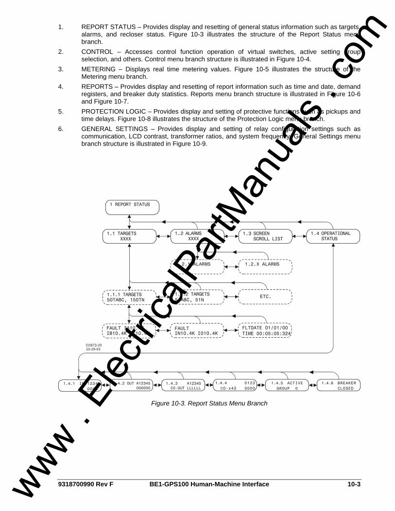
9318700990 Rev F BE1-GPS100 Human-Machine Interface 10-3
1. REPORT STATUS – Provides display and resetting of general status information such as targets, alarms, and recloser status. Figure 10-3 illustrates the structure of the Report Status menu branch.
2. CONTROL – Accesses control function operation of virtual switches, active setting group selection, and others. Control menu branch structure is illustrated in Figure 10-4.
3. METERING – Displays real time metering values. Figure 10-5 illustrates the structure of the Metering menu branch.
4. REPORTS – Provides display and resetting of report information such as time and date, demand registers, and breaker duty statistics. Reports menu branch structure is illustrated in Figure 10-6 and Figure 10-7.
5. PROTECTION LOGIC – Provides display and setting of protective functions such as pickups and time delays. Figure 10-8 illustrates the structure of the Protection Logic menu branch.
6. GENERAL SETTINGS – Provides display and setting of relay configuration settings such as communication, LCD contrast, transformer ratios, and system frequency. General Settings menu branch structure is illustrated in Figure 10-9.
1 REPORT STATUS
1.1 TARGETS XXXX
1.2. ALARMS XXXX
1.3 SCREEN SCROLL LIST
1.4 OPERATIONAL STATUS
1.1.2 TARGETS1.1.1 TARGETS
D2873-2010-29-03
1.2.1 ALARMS 1.2.X ALARMS
1.4.1 IN 1234 0000
1.4.2 OUT A12345 000000
1.4.4 0123 O-x43 0000
1.4.5 ACTIVE GROUP 0
1.4.6 BREAKER CLOSED
1.4.3 A12345 CO-OUT LLLLLL
50TABC, 150TN 51ABC, 51NETC.
IB10.4K IC10.4K IN10.4K I010.4K
FAULTFAULT IA10.4K
Figure 10-3. Report Status Menu Branch
www . El
ectric
alPar
tMan
uals
. com
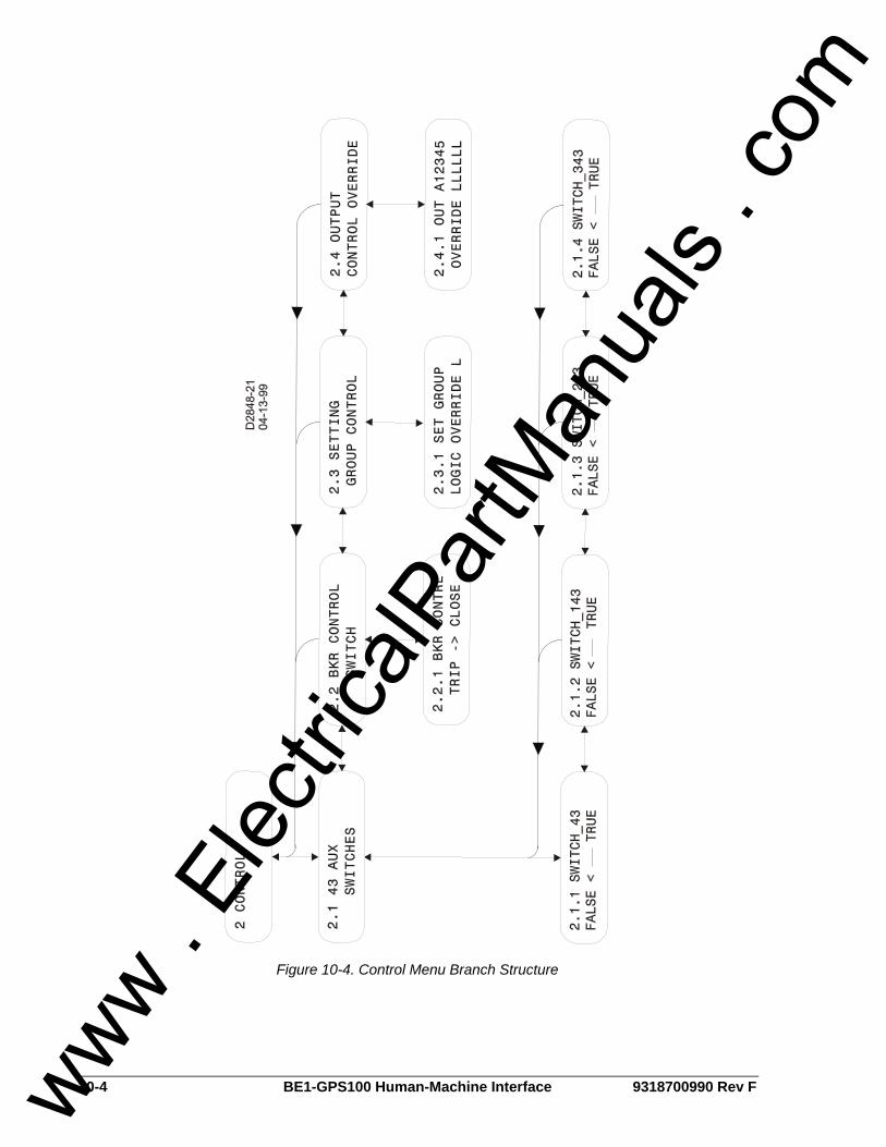
10-4 BE1-GPS100 Human-Machine Interface 9318700990 Rev F
Figure 10-4. Control Menu Branch Structure
www . El
ectric
alPar
tMan
uals
. com
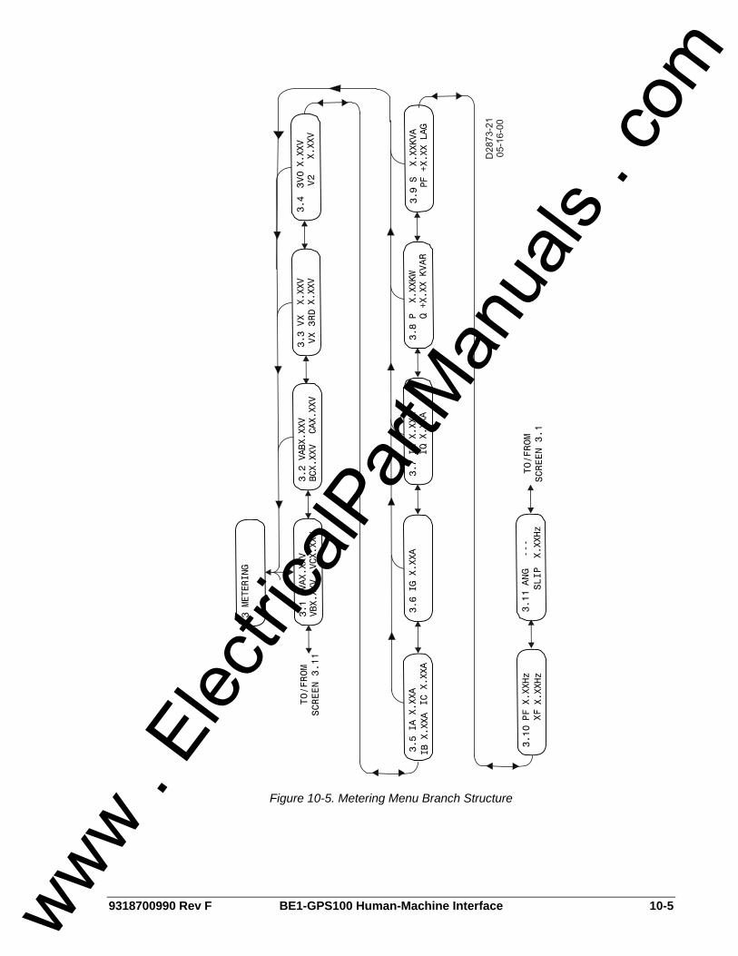
9318700990 Rev F BE1-GPS100 Human-Machine Interface 10-5
Figure 10-5. Metering Menu Branch Structure
www . El
ectric
alPar
tMan
uals
. com
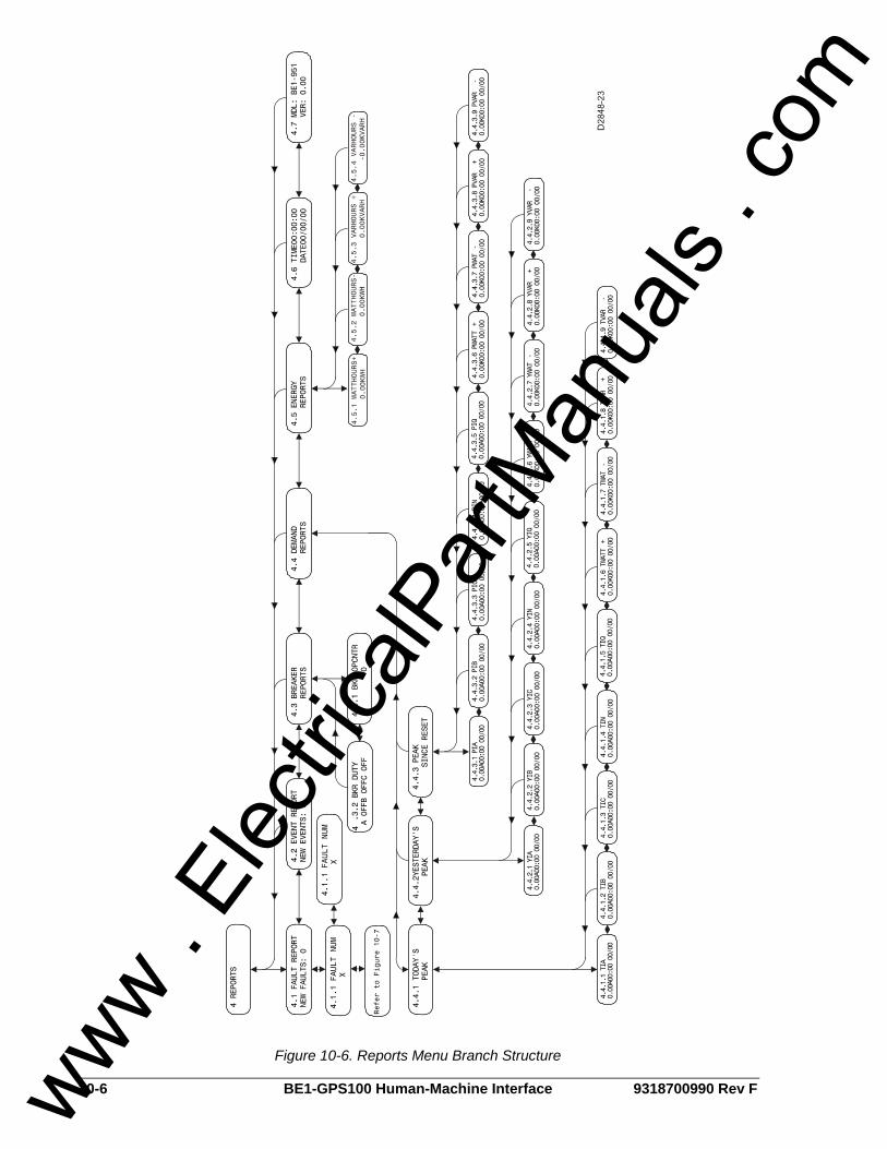
10-6 BE1-GPS100 Human-Machine Interface 9318700990 Rev F
Figure 10-6. Reports Menu Branch Structure
www . El
ectric
alPar
tMan
uals
. com
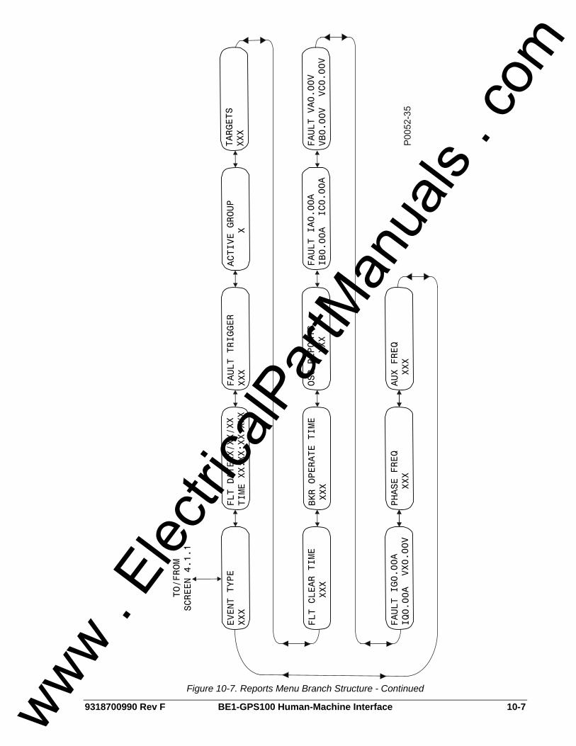
9318700990 Rev F BE1-GPS100 Human-Machine Interface 10-7
Figure 10-7. Reports Menu Branch Structure - Continued
www . El
ectric
alPar
tMan
uals
. com
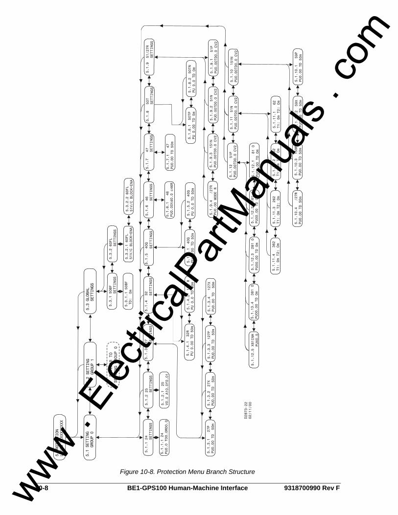
10-8 BE1-GPS100 Human-Machine Interface 9318700990 Rev F
5 PRO TECTION
LOGIC XXX XXXXXXX
5.1 S ETTING
GROUP 0
5 .2 S ETTING
GROUP 1
5.3 GLO BAL
SETTING S
5.3 .
1 50B
F
S
ETT INGS
5.3
.2 60F
L
SET
T ING S
5.3
.2.1
60FL
51V
/C
BLOCK=E
NA5 .
3.1.1
50BF
TD
: 0 m
5 .1.1 2
4
SETT
ING
S
5.1.2 2
5
SETT
ING
S
5.1.2.
1
25V0
. 0 A
10.0f0
.01
5.1.
1.1 24
PU0.0
TD0.
0RD0.
0
5.1 .
3.1
27P
PU0 .
00
TD 50m
5.1 .
3.2
27X
PU0.00
TD
50m
5.1.
3.3
127P
PU0.
00 TD
50m
5 .1.3.4
12
7X
PU0
. 00 TD
50m
S IMILA
R TO
SET TIN
G G R
OUP
0
5.1.3 27
SETTINGS
5.1.4 32
SETTINGS
5.1.5 40
Q SETTINGS
5.1.6
. 1
46PU 0
.00td0 .
0 c
46R
5.1
.6 4
6
SETTI N
GS
5.1.7
47
SE
TTING
S5.
1.9 51/
27R
SE TTIN
GS5.
1 .8 50
T
SE
TTING
S
5.1.4
.2
13 2 R
PU 0.
0 TD
50m
5.1.5
.1 4
0 QPU 0.
00
TD 50m
5.1
.5.2
40Q
PU 0.0
TD
50m
5.1
. 7.1 4
7PU0.00
TD 5
0m
5.1
.8.
2 50TN
PU 0.0
TD
0m
5.1
.9.1 5
1 PPU0.
00TD
0.0 CV
2
5 .1.9
.3 1
51N
PU0. 0
0TD
0.0 CV2
5.1.9.
4
/ 27R
PU0
.00 MO
DE R
5.1.
12
51P
PU0.
0 0TD0.
0 CV2
5.1.1
1 51N
P U0.00TD
0.0
CV2
5.1.1
0 1
51N
PU0.00TD
0.0
CV2
5.3.
2.2
60FL
51V/
C BLO
CK=E
NA
5.1
.10.
2 59
XPU0.00
TD
50m
5 .1. 1
0.3 15
9PPU0. 0
0 T
D 5 0m
5.1
.10.4
/ 27R
P U0.
00 T
D 50m
5.1 .
11.3
262
T1:
0m T2
: Om
5.1.11
. 4
362
T1:
0m T2:
Om
5.1.12. 3
2 8
1 0
PU0
0.00 TD
0m
5 .1.
13.4
381
0PU
00.00
TD
0m
5.1.12
.5
X81IN
H
PU4
0.0
5.1.10
.1
59P
PU0
.00
TD 5
0m
5.1.11
. 1
62T1:
0m T2:
Om
5.1.
11.2 1
62
T 1:
0m
T2: Om
5 .1.
12.1
81
0P U
00.00 T
D 0
m5.1 .
12. 2 1
81 0
PU00.0 0
TD
0m
5.1.9.
2 5
1NPU0
.0 0TD0
.0 C
V2
5.1.8.1
50T
PPU
0.00 TD
0 m
5. 1
.4.1
32R
PU
0.00
TD
50m
D 28 73-2 2
02/1
1/0 0
Figure 10-8. Protection Menu Branch Structure
www . El
ectric
alPar
tMan
uals
. com
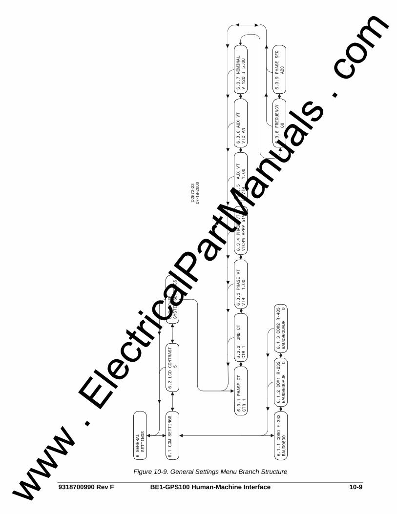
9318700990 Rev F BE1-GPS100 Human-Machine Interface 10-9
Figure 10-9. General Settings Menu Branch Structure
www . El
ectric
alPar
tMan
uals
. com
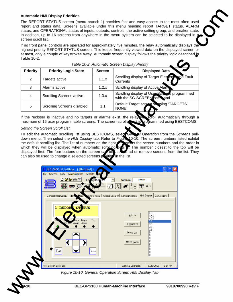
10-10 BE1-GPS100 Human-Machine Interface 9318700990 Rev F
Automatic HMI Display Priorities The REPORT STATUS screen (menu branch 1) provides fast and easy access to the most often used report and status data. Screens available under this menu heading report TARGET status, ALARM status, and OPERATIONAL status of inputs, outputs, controls, the active setting group, and breaker state. In addition, up to 16 screens from anywhere in the menu system can be selected to be displayed in a screen scroll list. If no front panel controls are operated for approximately five minutes, the relay automatically displays the highest priority REPORT STATUS screen. This keeps frequently viewed data on the displayed screen or at most, only a couple of keystrokes away. Automatic screen display follows the priority logic described in Table 10-2.
Table 10-2. Automatic Screen Display Priority
Priority Priority Logic State Screen Displayed Data
2 Targets active 1.1.x Scrolling display of Target Elements and Fault Currents
3 Alarms active 1.2.x Scrolling display of Active Alarms
4 Scrolling Screens active 1.3.x Scrolling display of User Screens programmed with the SG-SCREEN command
5 Scrolling Screens disabled 1.1 Default Target screen showing ‘TARGETS NONE’
If the recloser is inactive and no targets or alarms exist, the relay will scroll automatically through a maximum of 16 user programmable screens. The screen-scrolling list is programmed using BESTCOMS.
Setting the Screen Scroll List To edit the automatic scrolling list using BESTCOMS, select General Operation from the Screens pull-down menu. Then select the HMI Display tab. Refer to Figure 10-10. The screen numbers listed exhibit the default scrolling list. The list of numbers on the right represents the screen numbers and the order in which they will be displayed when automatic scrolling begins. The number closest to the top will be displayed first. The four buttons on the screen can be used to ad or remove screens from the list. They can also be used to change a selected screens position in the list.
Figure 10-10. General Operation Screen HMI Display Tab
www . El
ectric
alPar
tMan
uals
. com

9318700990 Rev F BE1-GPS100 Human-Machine Interface 10-11
To add a screen to the list, select the screen on the HMI simulation by clicking the mouse pointer on the arrows. Select the Add button to add the screen to the list. Alternately, these settings may be made using the SG-SCREEN ASCII command.
HMI OPERATIONS The following paragraphs describe how the HMI is used to set and control relay functions.
Entering Settings Settings for protection functions can be edited at Menu Branch 5, PROTECTION LOGIC of the HMI LCD. Settings for general and reporting functions can be edited from Menu Branch 6, GENERAL SETTINGS. To edit a setting using the manual scrolling pushbuttons, perform the following procedures:
1. Scroll to the screen that displays the function to be edited. 2. Press the Edit pushbutton to gain access. If password security has been initiated for settings, you
will be prompted to enter the appropriate password. See the paragraphs, Entering Passwords, for details on entering passwords from the HMI. Once access has been gained, the EDIT LED will be list and a cursor will appear in the first settings field on the screen.
3. Press the UP or DOWN scrolling key to select the desired setting. Some settings require entering a number, one character at a time. For example, to enter a 51 pickup as 7.3 amps, you would press the UP pushbutton until the 7 is showing. Then, press the RIGHT pushbutton to move the cursor over and press the UP pushbutton until the period is showing. Then, press the RIGHT pushbutton to move the cursor over and press the UP pushbutton until the 3 is showing. Other settings require scrolling through a list of selections. For example, you would move the cursor over to the CRV field and then scroll through a list of available TCC curves.
4. Once all of the settings on the screen have been entered, press the Edit pushbutton a second time and the settings will be validated. If the settings are in range, the screen will flash CHANGES SAVED and the EDIT LED will go out. If you want to abort the edit session without changing any settings, press the Reset pushbutton before you press the Edit pushbutton the second time. The screen will flash CHANGES LOST and the EDIT LED will go out.
Performing Control Operations Control operations can be executed at Menu Branch 2, CONTROL of the HMI LCD. These functions allow you to control the state of virtual switches, override logic, and control the active setting group and override the logic and control the state of output contacts. All of these functions work similarly to the process of entering settings in that you press the Edit pushbutton, use the UP and DOWN scroll pushbuttons to select the desired state and press the Edit pushbutton for the action to be executed. Table 10-3 describes each of the call-outs shown on Figure 10-11. The user-programmable label for this switch is RCL-DISABL. The TRUE (closed) state label has been set to DISABL. In addition, the FALSE (open) state label has been set to ENABLED. The logical mode for this application would be set to Mode 2 (On/Off switch).
2.1.2 RCL_DISABLENABLED< DISABLD
D2849-1606-22-99
A B
CDE
Figure 10-11. Virtual Control Switch 143 Screen
www . El
ectric
alPar
tMan
uals
. com

10-12 BE1-GPS100 Human-Machine Interface 9318700990 Rev F
Table 10-3. Call-Out Descriptions for Figure 10-11
Locator Description
A This is the screen number. It eases navigation by indicating the current branch and level in the menu tree structure.
B User selectable label (meaningful name) for specific virtual switches. The ‘Switch 143’ identification label is set to ‘RCL_DISABL’.
C User selectable label for the closed (1) state for Virtual Switch 143. The ‘Switch 143’ closed label is set to ‘DISABLD’.
D An arrow icon indicates the current switch position (status). In Figure 10-11, the status is open (0), which is labeled ‘ENABLD’.
E User selectable label for the open (0) state for Virtual Switch 143. The ‘Switch 143’ open label is set to ‘ENABLED’.
To operate the switch, you would use the following procedure:
1. Using the manual scrolling pushbuttons, scroll to Screen 2.1.x (43 AUX SWITCHES). Alternatively, if the screen has been placed in the automatic scroll list, simply wait for it to appear and press the RIGHT or LEFT scroll pushbuttons to freeze the display.
2. Press the Edit pushbutton to gain access. If password security has been initiated for control functions, you will be prompted to enter the appropriate password. See the following subsection Entering Passwords for details on entering passwords at the HMI. Once access is gained to the control function, the EDIT LED will light and a cursor will appear in the action field.
3. Press the UP or DOWN scrolling key to select the desired action. The selections available depend on the logic mode setting for that switch. If it is set to Mode 1, the action choices are pulse or one of the two positions as defined by the user programmable state labels. If Mode 2 (On/Off Switch) is selected, the choices for action are limited to one of the two positions. If Mode 3 (Off/Momentary On Switch) is selected, the choice for action is limited to pulse.
4. Press the Edit pushbutton a second time and the switch will change to the selected position, the screen will flash CHANGES SAVED, and the EDIT LED will go out. If you want to abort the editing session without changing any controls, press the Reset pushbutton before you press the Edit pushbutton the second time. The screen will flash CHANGES LOST and the EDIT LED will go out.
Resetting Functions The Reset pushbutton is context sensitive. Its function is dependent upon the screen that is presently being displayed. For example, pressing the Reset key when the Demand screen is displayed will reset the demands but it will not reset the alarms, etc. It is necessary to scroll through the menu tree to the Alarm screen to reset an alarm. You are not prompted for a password when using the Reset key. There are two BESTlogic variables associated with the HMI Reset pushbutton. Logic variable TRSTKEY becomes TRUE when the Reset pushbutton is pressed while the Target screen is displayed. Logic variable ARSTKEY becomes TRUE when the Reset pushbutton is pressed while the Alarm screen is displayed. See Section 8, Application, Application Tips, for examples on the use of these variables.
Entering Passwords If password security has been initiated for a function, the HMI will prompt you to enter a password when the Edit pushbutton is pressed. To gain access, you must enter the appropriate password. A field of eight asterisks appears with the cursor located under the leftmost character position. You can enter passwords by performing the following procedures:
1. Press the UP or DOWN scrolling pushbuttons until the proper first character of the password appears. Pressing UP scrolls through the alphabet and then the numbers in ascending order. Pressing DOWN scrolls through the numbers and then the alphabet in descending order.
2. Press the RIGHT scrolling pushbutton to move the cursor to the next character of the password and select the appropriate character.
3. Continue the process until the entire password has been spelled out. If the password is less than eight characters, leave the remaining asterisks in place instead of entering blanks. www .
Elec
tricalP
artM
anua
ls . c
om

9318700990 Rev F BE1-GPS100 Human-Machine Interface 10-13
4. Press the Edit pushbutton to enter the password. If the proper password has been entered, the screen will flash ACCESS GRANTED. If an incorrect password has been entered, the screen will flash ACCESS DENIED and the EDIT LED will go out.
5. Once you gain access, it remains in affect for five minutes after the last pushbutton has been pressed. As long as you continue to press the Edit key for a function for which you have gained access, the five-minute timer will be refreshed and you will not be prompted for a password.
www . El
ectric
alPar
tMan
uals
. com

10-14 BE1-GPS100 Human-Machine Interface 9318700990 Rev F
This page intentionally left blank.
www . El
ectric
alPar
tMan
uals
. com
9318700990 Rev F BE1-GPS100 ASCII Command Interface i
SECTION 11 • ASCII COMMAND INTERFACE TABLE OF CONTENTS
SECTION 11 • ASCII COMMAND INTERFACE..................................................................................... 11-1
INTRODUCTION.................................................................................................................................. 11-1 SERIAL PORT ..................................................................................................................................... 11-1
RS-232 Ports .................................................................................................................................... 11-1 RS-485 Port...................................................................................................................................... 11-1
ASCII COMMAND INTERFACE .......................................................................................................... 11-1 Command Structure ......................................................................................................................... 11-2 Using the ASCII Command Interface ............................................................................................... 11-2
Human to Machine ASCII Command Operations......................................................................... 11-2 Command Text File Operations.................................................................................................... 11-3 Embedding Comments into ASCII Text Files ............................................................................... 11-3
Miscellaneous Command Descriptions ............................................................................................ 11-3 HELP Command........................................................................................................................... 11-3 ACCESS Command ..................................................................................................................... 11-3 EXIT Command ............................................................................................................................ 11-4
Settings (S) Command Descriptions ................................................................................................ 11-5 Reading All Settings ..................................................................................................................... 11-5 Reading Specific Groups of Settings............................................................................................ 11-5 Reading Logic Settings................................................................................................................. 11-7 Configuring the Serial Port Communication Protocol ................................................................... 11-8
COMMAND SUMMARY....................................................................................................................... 11-9 Miscellaneous Commands ............................................................................................................... 11-9 Metering Commands ...................................................................................................................... 11-10 Control Commands ........................................................................................................................ 11-11 Report Commands ......................................................................................................................... 11-11 Setting Command........................................................................................................................... 11-15 S Command.................................................................................................................................... 11-15 Alarm Setting Commands .............................................................................................................. 11-15 Breaker Monitor Setting Commands .............................................................................................. 11-16 General Setting Commands........................................................................................................... 11-16 Programmable Logic Setting Commands ...................................................................................... 11-18 User Programmable Name Setting Command............................................................................... 11-21 Protection Setting Commands........................................................................................................ 11-21 Global Command ........................................................................................................................... 11-23
www . El
ectric
alPar
tMan
uals
. com

ii BE1-GPS100 ASCII Command Interface 9318700990 Rev F
This page intentionally left blank.
www . El
ectric
alPar
tMan
uals
. com

9318700990 Rev F BE1-GPS100 ASCII Command Interface 11-1
SECTION 11 • ASCII COMMAND INTERFACE INTRODUCTION Relay and power system information can be retrieved from a remote location using the ASCII command interface. The ASCII command interface is also used to enter settings, retrieve reports and metering information, and perform control operations. A communication port on the relay front panel provides a temporary, local interface for communication. Communication ports on the rear panel provide a permanent communication interface. Front and rear panel communication ports can be connected to computers, terminals, serial printers, modems and intermediate communication/control interfaces such as RS-232 serial multiplexors. BE1-GPS100 communication protocols support ASCII and binary data transmissions. ASCII data is used to send and receive human readable data and commands. Binary data is used for computer communication and transmission of raw oscillographic fault data if available. Modbus™, DNP, and other common protocols are also available. Available communication protocol instruction manuals include 9318700991 for Modbus™, and 9318700992 for DNP 3.0. For information about other protocols, consult your Basler Electric Representative.
SERIAL PORT Communication connections consist of two Data Communication Equipment (DCE) RS-232 ports, one RS-485 port, and an IRIG port. BE1-GPS100 communication protocol is compatible with readily available modem/terminal software. If required, password protection provides security against unauthorized operation. Detailed information about making communication connections is provided in Section 12, Installation. Communications port setup is covered in this section. Security settings are covered in Section 9, Security.
RS-232 Ports Two female RS-232 (DB-9) connectors are provided. One port is located on the front panel and is designated COM0. Another port is located on the rear panel and is designated COM1. Both ports support full-duplex operation. Polled operation is possible at the rear port using a simple RS-232 splitter if a polling address is programmed for COM1.
RS-485 Port RS-485 terminal block connections are located on the rear panel and designated COM2. This port supports half-duplex, multi-drop operation. Multi-drop (polled mode) operation is possible if a polling address is programmed for the port.
ASCII COMMAND INTERFACE A computer terminal or PC running terminal emulation software can be used at any of the three serial ports to send commands to the relay. Simple ASCII command language is used to communicate with the relay. When the relay receives a command, it responds with the appropriate action. ASCII commands can be used in human to machine interactions and in batch download type operations.
NOTE HyperTerminal as shipped with Windows® 98, either first or second edition, cannot be used for communications with the relay due to a problem introduced in the Windows® 98 version of HyperTerminal. The software bug is associated with the carriage return/line feed function when acting as a terminal emulator. An upgrade to HyperTerminal that fixes the problem is available from the Microsoft's source of HyperTerminal (Hilgraeve Inc.) at www.hilgraeve.com. The upgrade is referred to as "HyperTerminal-Private Edition." Companies that download and use this software must review the terms and conditions associated with the use of the software.
www . El
ectric
alPar
tMan
uals
. com

11-2 BE1-GPS100 ASCII Command Interface 9318700990 Rev F
Command Structure An ASCII command consists of a string made up of one or two letters followed by a hyphen and an object name.
xy-object name
x Specifies the general command function.
y Specifies the command subgroup.
Object Name Defines the specific object to which the command refers.
Examples of object names include 51N (neutral inverse time overcurrent function) and PIA (phase A peak current demand register). A command string entered by itself is a read command. A command string followed by an equal sign (=) and one or more parameters is a write command. General command functions are organized into five major groups plus one group of miscellaneous commands: CONTROL (C): Control commands perform select-before-operate control actions such as circuit
breaker tripping and closing and active setting group changes. Subgroups include Select (S) and Operate (O).
GLOBAL (G): One Global command performs operations that do not fall into the other general groups. The command for reading and changing passwords (GS-PW) is the only global command available.
METERING (M): Commands in this group report all real-time metering values. No subgroup is used with metering commands.
REPORTS (R): Reports commands read and reset reporting functions such as time and date, demand registers and breaker duty statistics. Subgroups include Alarms (A), Breaker Monitoring (B), Demand Recording (D), Fault Summary Reporting (F), General Information (G), Sequence of Events Recorder (S), and Oscillography (O).
SETTINGS (S): This group contains all of the setting parameters that govern relay function. Subgroups include Setting Groups 0, 1, 2 and 3 (0, 1, 2, 3), Protection Settings (P) not in setting groups, Alarm Settings (A), Breaker Monitor Settings (B), General Settings (G), and Logic Settings (L).
MISCELLANEOUS: Miscellaneous commands include Access, Exit, and Help. Note that only the first letter of these commands must be entered; entering the full command name is optional.
Using the ASCII Command Interface
Human to Machine ASCII Command Operations Using ASCII commands, settings can be read and changed on a function-by-function basis. The mnemonic format of the commands helps you interact with the relay. It is not necessary to remember all of the object names. Most commands do not require that you specify a complete object name. If the first two letters of a command are entered, the relay will respond with all applicable object names.
ASCII Command Examples: Example 1. Obtain a breaker operations count by entering RB (Report Breaker). The BE1-GPS100
responds with the operations counter value along with all other breaker report objects. If you know that the object name for the breaker operations counter is OPCNTR, you can enter RB-OPCNTR and read only the number of breaker operations.
Partial object names are also supported. This allows multiple objects to be read or reset at the same time. Example 2. Read all peak-since-reset demand current registers. Entering RD-PI (Report Demand -
Peak Current (I)) will return demand values and time stamps for phase A, B, C, neutral, and negative sequence current. To read only the neutral demand value, the full object name (RD-PIN) is entered. Entering RD-PI=0 resets all five of the peak-since-reset current demand registers.
www . El
ectric
alPar
tMan
uals
. com

9318700990 Rev F BE1-GPS100 ASCII Command Interface 11-3
Command Text File Operations In command text file operations, an ASCII text file of commands is created and sent to the relay. For example, the S command is used to retrieve a complete list of settings from the relay in ASCII command format. This list of commands is captured, saved to a file, edited with any ASCII text editor, and then uploaded to the relay. Because the number of relay settings is so large, loading settings with a text file is the preferred method of setting the BE1-GPS100.
Embedding Comments into ASCII Text Files Adding comments to ASCII settings files is an easy way to organize and label your settings. A comment line is started with two forward slashes (//) followed by the comment text. When the relay encounters // in a text file, it ignores all following characters until the next carriage return or linefeed character.
Example of embedding comments in a settings file: //Group0 is used during normal operation >S0-50TP=7.50,0m;S0-50TN=2.5,0m . . . //Group1 is used during cold load pickup >S1-50TP=0,0m; S1-50TN=0,0m; S1-50TQ=0,0m
Miscellaneous Command Descriptions
HELP Command The HELP (H) command provides general information on command syntax and functionality when the manual is not available. Entering HELP or H provides information about using the HELP command. HELP1 or H1 returns a complete list of relay commands. Entering HELP <cmd>, where <cmd> is a specific command, returns information about the use and format of the command along with an example of how the command is used. HELP Command Purpose: Obtain help on command operation Syntax: HELP {cmd} or H {cmd} for help on {cmd}, H1 for command list Example: HELP, H1, H SG-COM
ACCESS Command Before making settings changes through a communication port, the ACCESS command must be used to obtain programming access. Enter ACCESS=<password> to obtain access to change settings associated with the password. Different passwords give the ability or access to perform different operations. The relay will deny access if an invalid password is entered or if another user has already been granted programming access through another serial port or at the front panel. Only one user can have access at any one time. Even if password protection is not used, it is still necessary to obtain access so that accidental changes are prevented. If password protection is disabled, then ACCESS= will be accepted in place of a password. The relay will respond with ACCESS GRANTED: GLOBAL if the command entered was received and executed. The relay will respond with an error message and a ‘?’ if the command could not be executed. The ACCESS (A) command and the EXIT (E) command are used to change relay settings, reset report registers, and enable control commands through a serial port. These commands prevent changes from being made concurrently from two areas. For example, a user cannot make changes through COM0 at the same time a remote user is making changes through COM2. ACCESS Command Purpose: Read/Set Access level in order to change settings Syntax: ACCESS[={password}] Example: ACCESS=GPS100 Comments: The ACCESS command must be used before any changes to settings can be made.
Available ACCESS privileges are summarized in the following paragraphs.
www . El
ectric
alPar
tMan
uals
. com
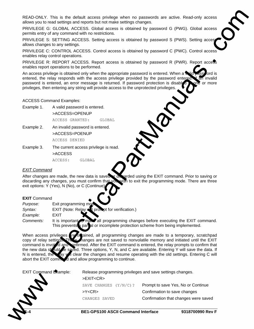
11-4 BE1-GPS100 ASCII Command Interface 9318700990 Rev F
READ-ONLY. This is the default access privilege when no passwords are active. Read-only access allows you to read settings and reports but not make settings changes. PRIVILEGE G: GLOBAL ACCESS. Global access is obtained by password G (PWG). Global access permits entry of any command with no restrictions. PRIVILEGE S: SETTING ACCESS. Setting access is obtained by password S (PWS). Setting access allows changes to any settings. PRIVILEGE C: CONTROL ACCESS. Control access is obtained by password C (PWC). Control access enables relay control operations. PRIVILEGE R: REPORT ACCESS. Report access is obtained by password R (PWR). Report access enables report operations to be performed. An access privilege is obtained only when the appropriate password is entered. When a valid password is entered, the relay responds with the access privilege provided by the password entered. If an invalid password is entered, an error message is returned. If password protection is disabled in one or more privileges, then entering any string will provide access to the unprotected privileges. ACCESS Command Examples: Example 1. A valid password is entered. >ACCESS=OPENUP ACCESS GRANTED: GLOBAL
Example 2. An invalid password is entered. >ACCESS=POENUP ACCESS DENIED
Example 3. The current access privilege is read. >ACCESS ACCESS: GLOBAL
EXIT Command After changes are made, the new data is saved or discarded using the EXIT command. Prior to saving or discarding any changes, you must confirm that you wish to exit the programming mode. There are three exit options: Y (Yes), N (No), or C (Continue). EXIT Command Purpose: Exit programming mode Syntax: EXIT (Note: Relay will prompt for verification.) Example: EXIT Comments: It is important to make all programming changes before executing the EXIT command.
This prevents a partial or incomplete protection scheme from being implemented.
When access privileges are obtained, all programming changes are made to a temporary, scratchpad copy of relay settings. These changes are not saved to nonvolatile memory and initiated until the EXIT command is invoked and confirmed. After the EXIT command is entered, the relay prompts to confirm that the new data should be saved. Three options, Y, N, and C are available. Entering Y will save the data. If N is entered, the relay will clear the changes and resume operating with the old settings. Entering C will abort the EXIT command and allow programming to continue. EXIT Command Example: Release programming privileges and save settings changes. >EXIT<CR> SAVE CHANGES (Y/N/C)? Prompt to save Yes, No or Continue >Y<CR> Confirmation to save changes CHANGES SAVED Confirmation that changes were saved
www . El
ectric
alPar
tMan
uals
. com

9318700990 Rev F BE1-GPS100 ASCII Command Interface 11-5
Settings (S) Command Descriptions
Reading All Settings All user programmable settings can be listed using the S command. This read-only command is useful for documenting relay status during installation. The settings retrieved by the S command can be saved to a standard text file and sent to another relay to be configured with the same settings. This type of settings transfer takes less than one minute. S Command Purpose: Read all relay setting parameters Syntax: S Example: S The S command returns the values of relay setting parameters in the same form that they are programmed. It can be used at the end of a programming session to make a record of the relay settings. If saved in a file, the report can be sent to another BE1-GPS100 that will use the same settings. Because the report that is created is a set of commands, sending the report to a different relay re-programs that relay with the settings contained in the S report.
Reading Specific Groups of Settings While the S command is useful for reading all relay settings, several commands are available to read specific groups of settings. Note: In examples throughout this manual, relay responses are printed in Courier New typeface. SA Command Purpose: Read all alarm settings for Major and Minor alarms Syntax: SA Example: SA SA Command Example: Example 1. Read all alarm settings. >SA SA-BKR1=0,0; SA-BKR2=0,0; SA-BKR3=0,0 SA-DIP=0.00; SA-DIN=0.00; SA-DIQ=0.00 SA-DVAR=0.0,0.0 SA-DWATT=0.0,0.0 SA-24= 0 SA-LGC=0 SA-MAJ=25/30 SA-MIN=29 SA-RESET=0
SB Command Purpose: Read all breaker settings Syntax: SB Example: SB SB Command Example: Example 1. Read all breaker settings. >SB SB-DUTY=0,0.000e+00,0 SB-LOGIC=/IN1
www . El
ectric
alPar
tMan
uals
. com
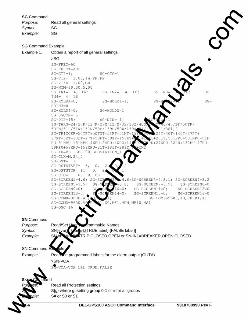
11-6 BE1-GPS100 ASCII Command Interface 9318700990 Rev F
SG Command Purpose: Read all general settings Syntax: SG Example: SG SG Command Example: Example 1. Obtain a report of all general settings. >SG SG-FREQ=60 SG-PHROT=ABC SG-CTP=1; SG-CTG=1 SG-VTP= 1.00,4W,PP,PP SG-VTX= 1.00,GR SG-NOM=69.30,5.00
SG-IN1= 4, 16; SG-IN2= 4, 16; SG-IN3= 4, 16; SG-IN4= 4, 16 SG-HOLDA=0; SG-HOLD1=1; SG-HOLD2=1; SG-HOLD3=0
SG-HOLD4=0; SG-HOLD5=1 SG-SGCON= 5 SG-DIP=15; SG-DIN= 1; SG-DIQ= 1
SG-TARG=24/27P/127P/27X/127X/32/132/40Q/140Q/46/47/BF/50TP/ 50TN/51P/51N/151N/59P/159P/59X/159X/81/181/281/381,0 SG-TRIGGER=50TPT+50TNT+51PT+51NT+151NT+46T+24T+40T+140T+27PT+ 27XT+32T+132T+47T+59PT+59XT+159XT+81T+181T+281T,50TPPU+50TNPU+51PPU+51NPU+151NPU+46PU+24PU+40PU+140PU+27PPU+27XPU+32PU+132PU+47PU+59PPU+59XPU+159XPU+81T+181T+281T,62+IN2
SG-ID=BE1-GPS100,SUBSTATION_1 SG-CLK=M,24,0 SG-DST= 1 SG-DSTSTART= 3, 0, 2, 0, 2 SG-DSTSTOP= 11, 0, 2, 0, 1 SG-UTC= 0, 0, 60
SG-SCREEN1=4.6; SG-SCREEN2=1.4.6;SG-SCREEN3=4.3.1; SG-SCREEN4=3.2 SG-SCREEN5=3.5; SG-SCREEN6=3.8; SG-SCREEN7=3.9; SG-SCREEN8=0 SG-SCREEN9=0; SG-SCREEN10=0; SG-SCREEN11=0; SG-SCREEN12=0 SG-SCREEN13=0; SG-SCREEN14=0; SG-SCREEN15=0; SG-SCREEN16=0 SG-COM0=9600,A0,P0,R1,X1; SG-COM1=9600,A0,P0,R1,X1 SG-COM2=9600,A0,P0,R1,X0,MF1,MPN,MR10,MS1 SG-OSC=16
SN Command Purpose: Read/Set User Programmable Names Syntax: SN[-{var}[={name},{TRUE label},{FALSE label}] Example: SN or SN-VO1=TRIP,CLOSED,OPEN or SN-IN1=BREAKER,OPEN,CLOSED SN Command Example: Example 1. Read the programmed labels for the alarm output (OUTA). >SN-VOA SN-VOA=VOA_LBL,TRUE,FALSE
S<g> Command Purpose: Read all Protection settings Syntax: S{g} where g=setting group 0-1 or # for all groups Example: S# or S0 or S1
www . El
ectric
alPar
tMan
uals
. com
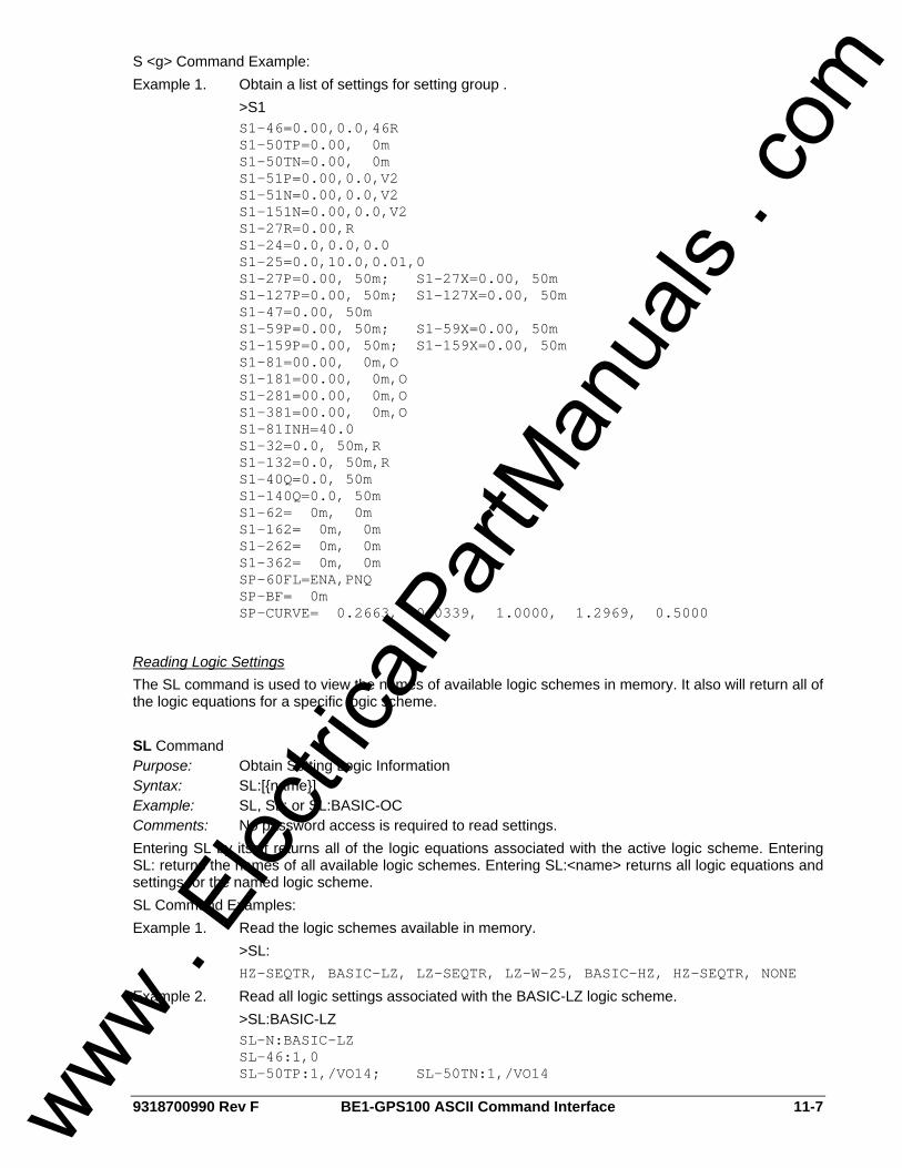
9318700990 Rev F BE1-GPS100 ASCII Command Interface 11-7
S <g> Command Example: Example 1. Obtain a list of settings for setting group . >S1
S1-46=0.00,0.0,46R S1-50TP=0.00, 0m S1-50TN=0.00, 0m S1-51P=0.00,0.0,V2 S1-51N=0.00,0.0,V2 S1-151N=0.00,0.0,V2 S1-27R=0.00,R S1-24=0.0,0.0,0.0 S1-25=0.0,10.0,0.01,0 S1-27P=0.00, 50m; S1-27X=0.00, 50m S1-127P=0.00, 50m; S1-127X=0.00, 50m S1-47=0.00, 50m S1-59P=0.00, 50m; S1-59X=0.00, 50m S1-159P=0.00, 50m; S1-159X=0.00, 50m S1-81=00.00, 0m,O S1-181=00.00, 0m,O S1-281=00.00, 0m,O S1-381=00.00, 0m,O S1-81INH=40.0 S1-32=0.0, 50m,R S1-132=0.0, 50m,R S1-40Q=0.0, 50m S1-140Q=0.0, 50m S1-62= 0m, 0m S1-162= 0m, 0m S1-262= 0m, 0m S1-362= 0m, 0m SP-60FL=ENA,PNQ SP-BF= 0m SP-CURVE= 0.2663, 0.0339, 1.0000, 1.2969, 0.5000
Reading Logic Settings The SL command is used to view the names of available logic schemes in memory. It also will return all of the logic equations for a specific logic scheme. SL Command Purpose: Obtain Setting Logic Information Syntax: SL:[{name}] Example: SL, SL: or SL:BASIC-OC Comments: No password access is required to read settings. Entering SL by itself returns all of the logic equations associated with the active logic scheme. Entering SL: returns the names of all available logic schemes. Entering SL:<name> returns all logic equations and settings for the named logic scheme. SL Command Examples: Example 1. Read the logic schemes available in memory. >SL: HZ-SEQTR, BASIC-LZ, LZ-SEQTR, LZ-W-25, BASIC-HZ, HZ-SEQTR, NONE
Example 2. Read all logic settings associated with the BASIC-LZ logic scheme. >SL:BASIC-LZ SL-N:BASIC-LZ SL-46:1,0 SL-50TP:1,/VO14; SL-50TN:1,/VO14
www . El
ectric
alPar
tMan
uals
. com
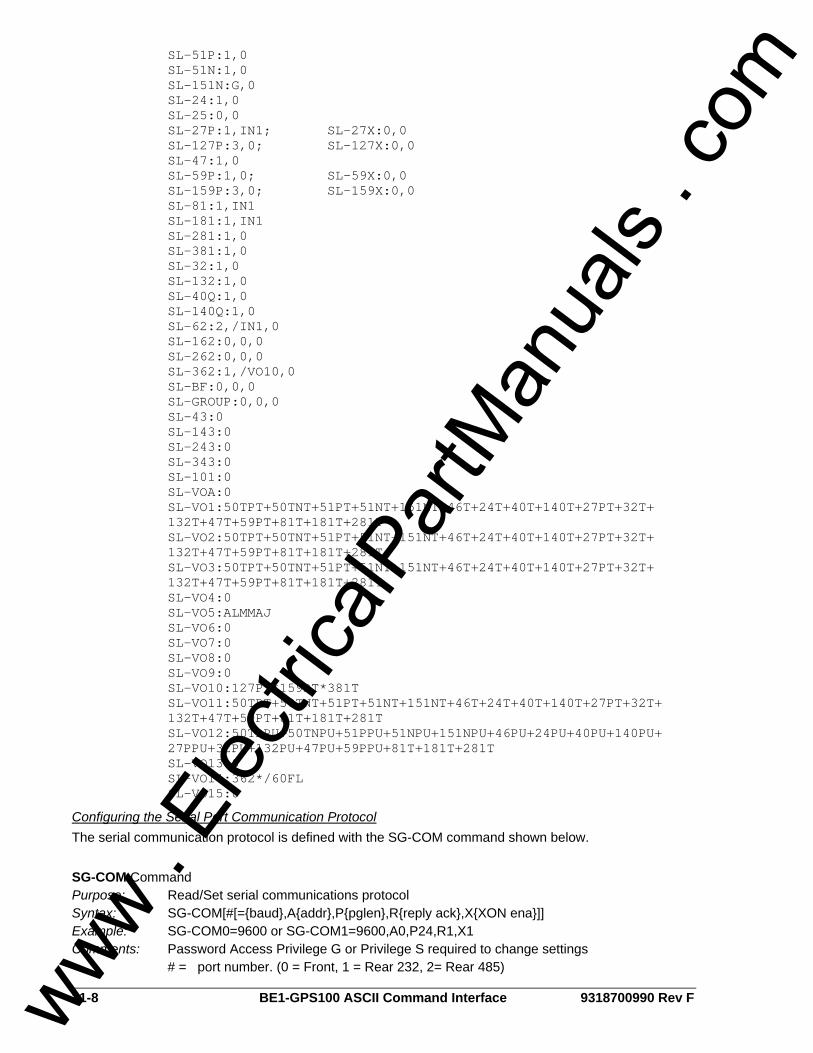
11-8 BE1-GPS100 ASCII Command Interface 9318700990 Rev F
SL-51P:1,0 SL-51N:1,0 SL-151N:G,0 SL-24:1,0 SL-25:0,0 SL-27P:1,IN1; SL-27X:0,0 SL-127P:3,0; SL-127X:0,0 SL-47:1,0 SL-59P:1,0; SL-59X:0,0 SL-159P:3,0; SL-159X:0,0 SL-81:1,IN1 SL-181:1,IN1 SL-281:1,0 SL-381:1,0 SL-32:1,0 SL-132:1,0 SL-40Q:1,0 SL-140Q:1,0 SL-62:2,/IN1,0 SL-162:0,0,0 SL-262:0,0,0 SL-362:1,/VO10,0 SL-BF:0,0,0 SL-GROUP:0,0,0 SL-43:0 SL-143:0 SL-243:0 SL-343:0 SL-101:0 SL-VOA:0
SL-VO1:50TPT+50TNT+51PT+51NT+151NT+46T+24T+40T+140T+27PT+32T+ 132T+47T+59PT+81T+181T+281T SL-VO2:50TPT+50TNT+51PT+51NT+151NT+46T+24T+40T+140T+27PT+32T+ 132T+47T+59PT+81T+181T+281T SL-VO3:50TPT+50TNT+51PT+51NT+151NT+46T+24T+40T+140T+27PT+32T+ 132T+47T+59PT+81T+181T+281T
SL-VO4:0 SL-VO5:ALMMAJ SL-VO6:0 SL-VO7:0 SL-VO8:0 SL-VO9:0 SL-VO10:127PT*159PT*381T
SL-VO11:50TPT+50TNT+51PT+51NT+151NT+46T+24T+40T+140T+27PT+32T+ 132T+47T+59PT+81T+181T+281T SL-VO12:50TPPU+50TNPU+51PPU+51NPU+151NPU+46PU+24PU+40PU+140PU+ 27PPU+32PU+132PU+47PU+59PPU+81T+181T+281T
SL-VO13:0 SL-VO14:362*/60FL SL-VO15:0
Configuring the Serial Port Communication Protocol The serial communication protocol is defined with the SG-COM command shown below. SG-COM Command Purpose: Read/Set serial communications protocol Syntax: SG-COM[#[={baud},A{addr},P{pglen},R{reply ack},X{XON ena}]] Example: SG-COM0=9600 or SG-COM1=9600,A0,P24,R1,X1 Comments: Password Access Privilege G or Privilege S required to change settings # = port number. (0 = Front, 1 = Rear 232, 2= Rear 485)
www . El
ectric
alPar
tMan
uals
. com
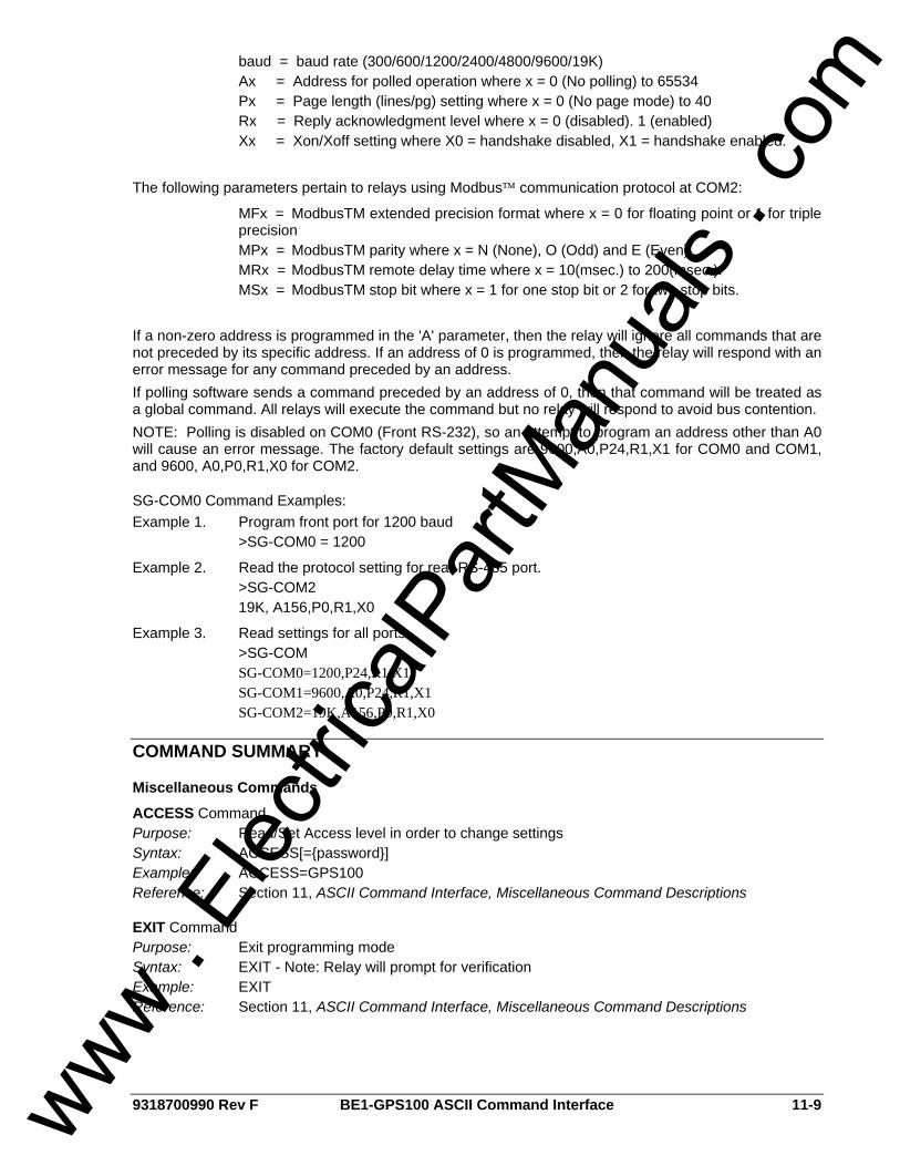
9318700990 Rev F BE1-GPS100 ASCII Command Interface 11-9
baud = baud rate (300/600/1200/2400/4800/9600/19K) Ax = Address for polled operation where x = 0 (No polling) to 65534 Px = Page length (lines/pg) setting where x = 0 (No page mode) to 40 Rx = Reply acknowledgment level where x = 0 (disabled). 1 (enabled) Xx = Xon/Xoff setting where X0 = handshake disabled, X1 = handshake enabled. The following parameters pertain to relays using Modbus™ communication protocol at COM2:
MFx = ModbusTM extended precision format where x = 0 for floating point or 1 for triple precision
MPx = ModbusTM parity where x = N (None), O (Odd) and E (Even). MRx = ModbusTM remote delay time where x = 10(msec.) to 200(msec.). MSx = ModbusTM stop bit where x = 1 for one stop bit or 2 for two stop bits. If a non-zero address is programmed in the 'A' parameter, then the relay will ignore all commands that are not preceded by its specific address. If an address of 0 is programmed, then the relay will respond with an error message for any command preceded by an address. If polling software sends a command preceded by an address of 0, then that command will be treated as a global command. All relays will execute the command but no relay will respond to avoid bus contention. NOTE: Polling is disabled on COM0 (Front RS-232), so an attempt to program an address other than A0 will cause an error message. The factory default settings are 9600,A0,P24,R1,X1 for COM0 and COM1, and 9600, A0,P0,R1,X0 for COM2.
SG-COM0 Command Examples: Example 1. Program front port for 1200 baud >SG-COM0 = 1200
Example 2. Read the protocol setting for rear RS-485 port. >SG-COM2 19K, A156,P0,R1,X0
Example 3. Read settings for all ports. >SG-COM SG-COM0=1200,P24,R1,X1 SG-COM1=9600,A0,P24,R1,X1 SG-COM2=19K,A156,P0,R1,X0
COMMAND SUMMARY
Miscellaneous Commands
ACCESS Command Purpose: Read/Set Access level in order to change settings Syntax: ACCESS[={password}] Example: ACCESS=GPS100 Reference: Section 11, ASCII Command Interface, Miscellaneous Command Descriptions
EXIT Command Purpose: Exit programming mode Syntax: EXIT - Note: Relay will prompt for verification Example: EXIT Reference: Section 11, ASCII Command Interface, Miscellaneous Command Descriptions
www . El
ectric
alPar
tMan
uals
. com
11-10 BE1-GPS100 ASCII Command Interface 9318700990 Rev F
HELP Command Purpose: Obtain help on command operation Syntax: HELP {cmd} or H {cmd} for help on {cmd}, H1 for command list Example: HELP, H1, H SG-COM Reference: Section 11, ASCII Command Interface, Miscellaneous Command Descriptions
Metering Commands
M Command Purpose: Read all metered values Syntax: M Example: M Reference: Section 5, Metering
M-FREQ Command Purpose: Read metered frequency (F) Syntax: M-FREQ[{source}] where source = P/X/S, Phase, Aux, Slip Example: M-F or M-FREQ, M-FREQP, M-FREQX, M-FREQS Reference: Section 5, Metering
M-I Command Purpose: Read metered current (I) in primary units Syntax: M-I[{phase}] where phase = A/B/C/N/Q/G Example: M-I or M-IA or M-IG Reference: Section 5, Metering
M-PF Command Purpose: Read metered 3 Phase Power Factor Syntax: M-PF Example: M-PF Reference: Section 5, Metering
M-S Command Purpose: Read metered 3 Phase VA in primary units Syntax: M-S Example: M-S Reference: Section 5, Metering
M-V Command Purpose: Read metered voltage (V) in primary units Syntax: M-V[{phase}] where phase = A/B/C/AB/BC/CA/2 Example: M-V or M-VA or M-VAB or M-V2 Reference: Section 5, Metering
M-VAR Command Purpose: Read metered 3 Phase Vars in primary units Syntax: M-VAR[{phase}] where phase = 3/A/B/C Example: M-VAR or M-VAR3, M-VARA, M-VARB, or M-VARC Reference: Section 5, Metering
M-3V0 Command Purpose: Read metered voltage (V) in primary units Syntax: M-3V0 Example: M-3V0 Reference: Section 5, Metering
www . El
ectric
alPar
tMan
uals
. com

9318700990 Rev F BE1-GPS100 ASCII Command Interface 11-11
M-WATT Command Purpose: Read metered 3 Phase Watts (W) in primary units Syntax: M-WATT[{phase}] where phase = 3/A/B/C Example: M-WATT or M-WATT3, M-WATTA, M-WATTB, or M-WATTC Reference: Section 5, Metering
Control Commands
CO Command Purpose: Control Operation Syntax: CO-{control}[={mode}] where control=GROUP/OUT/x43/101 mode=0-3/L for GROUP, 0/1/P/L/ENA/DIS for OUT, 0/1/P for x43 and T/C for 101. Example: CO-GROUP=2 or CO-OUT1=1 or CO-43=P Reference: Section 3, Input and Output Functions, Outputs (CO-OUT) Section 4, Protection and Control, Setting Groups (CO-GROUP) Section 4, Protection and Control, Virtual Switches (CO-43) Section 4, Protection and Control, Virtual Switches (CO-101)
CS Command Purpose: Control Selection Syntax: CS-control[={mode}] where control=GROUP/OUT/x43/101 mode=0-3/L for GROUP, 0/1/P/L/ENA/DIS for OUT, 0/1/P for x43 and T/C for 101. Example: CS-GROUP=2 or CS-OUT1=1 or CS-43=P Reference: Section 3, Input and Output Functions, Outputs (CS-OUT) Section 4, Protection and Control, Setting Groups (CS-GROUP) Section 4, Protection and Control, Virtual Switches (CS-43) Section 4, Protection and Control, Virtual Switches (CS-101)
Report Commands
RA Command Purpose: Report/Reset Alarm information Syntax: RA[=0] Example: RA or RA=0 Reference: Section 6, Reporting and Alarm Functions, Alarms Function
RA-LGC Command Purpose: Report/Reset Logic Alarm information Syntax: RA-LGC[=0] Example: RA-LGC or RA-LGC=0 Reference: Section 6, Reporting and Alarm Functions, Alarms Function
RA-MAJ Command Purpose: Report/Reset Major Alarm information Syntax: RA-MAJ[=0] Example: RA-MAJ or RA-MAJ=0 Reference: Section 6, Reporting and Alarm Functions, Alarms Function
RA-MIN Command Purpose: Report/Reset Minor Alarm information Syntax: RA-MIN[=0] Example: RA-MIN or RA-MIN=0 Reference: Section 6, Reporting and Alarm Functions, Alarms Function
www . El
ectric
alPar
tMan
uals
. com

11-12 BE1-GPS100 ASCII Command Interface 9318700990 Rev F
RA-REL Command Purpose: Report/Reset Relay Alarm information Syntax: RA-REL[=0] Example: RA-REL or RA-REL=0 Reference: Section 6, Reporting and Alarm Functions, Alarms Function
RB Command Purpose: Read breaker status Syntax: RB Example: RB Reference: Section 6, Reporting and Alarm Functions, Breaker Monitoring
RB-DUTY Command Purpose: Read/Set breaker contact Duty Log Syntax: RB-DUTY[{phase}[={%duty}]] where %duty is % of dmax set with SB-DUTY; Example: RB-DUTYA or RB-DUTYB=50 Reference: Section 6, Reporting and Alarm Functions, Breaker Monitoring
RB-OPCNTR Command Purpose: Read/Set Breaker Operation Counter Syntax: RB-OPCNTR[={#operations}] Example: RB-OPCNTR=32 or RB-OPCNTR=652 Reference: Section 6, Reporting and Alarm Functions, Breaker Monitoring
RD Command Purpose: Report all demand data Syntax: RD Example: RD Reference: Section 6, Reporting and Alarm Functions, Demand Functions
RD-PI Command Purpose: Read/Reset peak demand current (I) Syntax: RD-PI[{p}[=0]] where p=A/B/C/N/Q Example: RD-PI or RD-PIA or RD-PIN or RD-PI=0 Reference: Section 6, Reporting and Alarm Functions, Demand Functions
RD-PVAR Command Purpose: Read/Reset peak demand vars Syntax: RD-PVAR[=0,0] - Fwd,Rev Var Flow Example: RD-PVAR or RD-PVAR=0,0 Reference: Section 6, Reporting and Alarm Functions, Demand Functions
RD-PWATT Command Purpose: Read/Reset peak demand watts Syntax: RD-PWATT[=0,0] - Fwd,Rev Power Flow Example: RD-PWATT or RD-PWATT=0,0 Reference: Section 6, Reporting and Alarm Functions, Demand Functions
RD-TI Command Purpose: Report today's demand current (I) Syntax: RD-TI[{p}] where p=A/B/C/N/Q Example: RD-TI or RD-TIA or RD-TIN Reference: Section 6, Reporting and Alarm Functions, Demand Functions
www . El
ectric
alPar
tMan
uals
. com

9318700990 Rev F BE1-GPS100 ASCII Command Interface 11-13
RD-TVAR Command Purpose: Report today's demand vars Syntax: RD-TVAR Example: RD-TVAR Reference: Section 6, Reporting and Alarm Functions, Demand Functions
RD-TWATT Command Purpose: Report today's demand watts Syntax: RD-TWATT Example: RD-TWATT Reference: Section 6, Reporting and Alarm Functions, Demand Functions
RD-YI Command Purpose: Report yesterday's demand current (I) Syntax: RD-YI[{p}] where p=A/B/C/N/Q Example: RD-YI or RD-YIA or RD-YIN Reference: Section 6, Reporting and Alarm Functions, Demand Functions
RD-YVAR Command Purpose: Report yesterday's demand vars Syntax: RD-YVAR Example: RD-YVAR Reference: Section 6, Reporting and Alarm Functions, Demand Functions
RD-YWATT Command Purpose: Report yesterday's demand watts Syntax: RD-YWATT Example: RD-YWATT Reference: Section 6, Reporting and Alarm Functions, Demand Functions
RE Command Purpose: Report all energy data Syntax: RE Example: RE Reference: Section 6, Reporting and Alarm Functions, General Status Reporting
RE-KVARH Command Purpose: Read/Reset/Preset 3 Phase KiloVarHours in primary units Syntax: RE-KVARH[={pos_kvarh},{neg_kvarh}] Example: RE-KVARH or RE-KVARH=100,10 or RE-KVARH=0,0 Reference: Section 6, Reporting and Alarm Functions, General Status Reporting
RE-KWH Command Purpose: Read/Reset/Preset 3 Phase KiloWattHours in primary units Syntax: RE-KWH[={pos_kwh},{neg_kwh}] Example: RE-KWH or RE-KWH=100,10 or RE-KWH=0,0 Reference: Section 6, Reporting and Alarm Functions, General Status Reporting
RF Command Purpose: Read/Reset Fault Report Data Syntax: RF[-n/NEW][=0/TRIG] where n=record # or NEW = new records Example: RF (displays a directory of all fault reports in memory) RF-23 (view summary report for fault record 23) RF-NEW (view summary report for newest fault record since RF=0 reset)
www . El
ectric
alPar
tMan
uals
. com

11-14 BE1-GPS100 ASCII Command Interface 9318700990 Rev F
RF=TRIG (Manually Trigger a fault record) RF=0 (reset NEW fault counter) Reference: Section 6, Reporting and Alarm Functions, Fault Reporting
RG Command Purpose: Report General information Syntax: RG Example: RG Reference: Section 6, Reporting and Alarm Functions, Clock Section 6, Reporting and Alarm Functions, Fault Reporting
RG-DATE Command Purpose: Report/Set Date Syntax: RG-DATE[={M/D/Y}] or RG-DATE[={D-M-Y}] Example: RG-DATE=12/31/96 or RG-DATE=31-12-96 (Format set by SG-CLK Command) Reference: Section 6, Reporting and Alarm Functions, Clock
RG-DST Command Purpose: Report start and stop times and dates for Daylight Saving Time referenced to local time. Syntax: RG-DST Example: RG-DST Reference: Section 6, Reporting and Alarm Functions, Clock
RG-STAT Command Purpose: Report relay status Syntax: RG-STAT Example: RG-STAT Reference: Section 6, Reporting and Alarm Functions, General Status Reporting
RG-TARG Command Purpose: Report/Reset Target status Syntax: RG-TARG Example: RG-TARG or RG-TARG=0 Reference: Section 6, Reporting and Alarm Functions, Fault Reporting
RG-TIME Command Purpose: Report/Set Time Syntax: RG-TIME[=hr:mn:sc] or RG-TIME[=hr:mn{f}sc]] Example: RG-TIME=13:25:00 or RG-TIME=1:25P00 (Format(f) set by SG-CLK Command) Reference: Section 6, Reporting and Alarm Functions, Clock
RG-VER Command Purpose: Read Model #, Style #, Program Version, Serial # Syntax: RG-VER Example: RG-VER Reference: Section 6, Reporting and Alarm Functions, Hardware and Software Version Reporting
RO Command Purpose: Read Oscillographic COMTRADE .DAT/.CFG/.HDR Fault Report Syntax: RO-nA/B[#].CFG/DAT/HDR where n=report number,A=ASCII/B=BINARY,#=OSC 1/2 Example: RO-3A1.CFG or RO-3A1.DAT or RO-5B2.CFG or RO-5B2.DAT or RO-5A.HDR Reference: Section 6, Reporting and Alarm Functions, Fault Reporting
www . El
ectric
alPar
tMan
uals
. com
9318700990 Rev F BE1-GPS100 ASCII Command Interface 11-15
RS Command Purpose: Read/Reset Sequence of Events Record Data Syntax: RS[-n/Fn/ALM/IO/LGC/NEW][=0] where n=# of events and Fn=fault record # Example: RS (displays a directory of all event records in memory) RS-23 (view SER report for last 23 events) RS-F12 (view SER report associated with fault record 12) RS-ALM (view all SER report ALARM events since RS=0 reset) RS-IO (view all SER report INPUT OUTPUT events since RS=0 reset) RS-LGC (view all SER report LOGIC events since RS=0 reset) RS-NEW (view all SER report events since RS=0 reset) RS=0 (reset NEW records counter) Reference: Section 6, Reporting and Alarm Functions, Sequence of Events Recorder
Setting Command
S Command Purpose: Read all relay setting parameters Syntax: S Example: S Comments: Section 11, ASCII Command Interface, Settings (S) Command Descriptions
Alarm Setting Commands
SA Command Purpose: Read all alarm settings for Major and Minor alarms Syntax: SA Example: SA Reference: Section 6, Reporting and Alarm Functions, Alarms Function
SA-BKR Command Purpose: Read/Set breaker alarm settings Syntax: SA-BKR[n][={mode},{alarm limit}] where mode=0-3(disabled/%duty/#op/clr) Example: SA-BKR or SA-BKR1=1,80 or SA-BKR2=2,250, or SA-BKR3=3,6c Reference: Section 6, Reporting and Alarm Functions, Breaker Monitoring
SA-DI Command Purpose: Read/Set demand alarm settings Syntax: SA-DI[p][={alarm level}] where p=P/N/Q, alarm level=Sec Amps Example: SA-DI or SA-DIP=0 or SA-DIN=10 Reference: Section 6, Reporting and Alarm Functions, Demand Functions
SA-DVAR Command Purpose: Read/Set Var demand alarm setting Syntax: SA-DVAR[={fwd alm lvl},{rev alm lvl}] where alm lvl= FWD,REV Sec Vars Example: SA-DVAR or SA-DVAR=0,0 or SA-DV=5000,1000 Reference: Section 6, Reporting and Alarm Functions, Demand Functions
SA-DWATT Command Purpose: Read/Set Watt demand alarm setting Syntax: SA-DWATT[={fwd alm lvl},{rev alm lvl}] where alm lvl= FWD,REV Sec Watts Example: SA-DWATT or SA-DWATT=0,0 or SA-DW=5000,1000 Reference: Section 6, Reporting and Alarm Functions, Demand Functions
www . El
ectric
alPar
tMan
uals
. com

11-16 BE1-GPS100 ASCII Command Interface 9318700990 Rev F
SA-LGC Command Purpose: Read/Set logic alarm setting mask Syntax: SA-LGC[={alarm num 1}[/{alarm num 2}]...[/{alarm num n}]] Example: SA-LGC or SA-LGC=2/6/7/10/11 Reference: Section 6, Reporting and Alarm Functions, Alarms Function
SA-MAJ Command Purpose: Read/Set major alarm setting mask Syntax: SA-MAJ[={alarm num 1}[/{alarm num 2}]...[/{alarm num n}]] Example: SA-MAJ or SA-MAJ=1/3/5/12 Reference: Section 6, Reporting and Alarm Functions, Alarms Function
SA-MIN Command Purpose: Read/Set minor alarm setting mask Syntax: SA-MIN[={alarm num 1}[/{alarm num 2}]...[/{alarm num n}]] Example: SA-MIN or SA-MIN=2/6/7/10/11 Reference: Section 6, Reporting and Alarm Functions, Alarms Function
SA-RESET Command Purpose: Read/Set Programmable Alarms Reset logic Syntax: SA-RESET[={rst alm logic}] Example: SA-RESET or SA-RESET=VO1 Reference: Section 6, Reporting and Alarm Functions, Alarms Function
Breaker Monitor Setting Commands
SB Command Purpose: Read all breaker settings Syntax: SB Example: SB Reference: Section 6, Reporting and Alarm Functions, Breaker Monitoring
SB-DUTY Command Purpose: Read/Set Breaker Contact Duty where mode = 0/1/2 (disabled/I/I^2) Syntax: SB-DUTY[={mode},{dmax},{BLKBKR logic}] Example: SB-DUTY=1,60E3,IN5 Reference: Section 6, Reporting and Alarm Functions, Breaker Monitoring
SB-LOGIC Command Purpose: Read/Set Breaker Contact Logic Syntax: SB-LOGIC[={breaker close logic}] Example: SB-LOGIC=IN1 (IN1=52a) or SB-LOGIC=/IN2 (IN2=52b) Reference: Section 6, Reporting and Alarms Function, Breaker Monitoring
General Setting Commands
SG Command Purpose: Read all general settings Syntax: SG Example: SG Reference: Section 11, ASCII Command Interface, Settings (S) Command Descriptions
www . El
ectric
alPar
tMan
uals
. com

9318700990 Rev F BE1-GPS100 ASCII Command Interface 11-17
SG-CLK Command Purpose: Read/Program format of date and time display Syntax: SG-CLK[={date format(M/D)},{time format(12/24)},{dst enable(0/1)}] Example: SG-CLK=D,12,1 or SG-CLK=M,24,0 Reference: Section 6, Reporting and Alarms Function, Clock
SG-COM Command Purpose: Read/Set serial communications protocol Syntax: SG-COM[#[={baud},A{addr},P{pglen},R{reply ack},X{XON ena}]] Example: SG-COM0=9600 or SG-COM1=9600,A0,P24,R1,X1 Reference: Section 11, ASCII Command Interface, Settings (S) Command Descriptions, Configuring
the Serial Port Communication Protocol
SG-CT Command Purpose: Read/Set Phase/Neutral CT ratio Syntax: SG-CT[t][={CTratio}] where t = P/G Example: SG-CTP=80 or CTG=400:5 or CTG=400/5 Reference: Section 3, Input and Output Functions, Power System Inputs
SG-DI Command Purpose: Read/Set P(IA/IB/IC/VAR/WATT), N and Q demand interval Syntax: SG-DI[p][={interval}] where p=P/N/Q, interval=0-60 (min) Example: SG-DI or SG-DIP=15 or SG-DIN=1 Reference: Section 6, Reporting and Alarms Function, Demand Functions
SG-FREQ Command Purpose: Read/Enter power system Frequency Syntax: SG-FREQ[={freq(HZ)}] Example: SG-FREQ=60 or SG-FREQ=50 Reference: Section 3, Input and Output Functions, Power System Inputs
SG-HOLD Command Purpose: Read/Program Output Hold operation Syntax: SG-HOLD[n][={1/0 hold ena}] where 1=TRUE, 0=FALSE Example: SG-HOLD or SG-HOLD1=1 or SG-HOLD2=0 Reference: Section 3, Input and Output Functions, Outputs
SG-ID Command Purpose: Read/Set relay ID and station ID used in reports Syntax: SG-ID[={relayID(up to 30 char)},{StationID(up to 30 char)}] Example: SG-ID=448,SUBSTATION3 or SG-ID=GEN3, POWERPOINT_SUBSTATION Reference: Section 3, Input and Output Functions, Relay Identifier Information
SG-IN Command Purpose: Read/Set Input recognition/debounce Syntax: SG-IN[#[={r(ms)},{db(ms)}]] where ms=1-255msec Example: SG-IN or SG-IN3 or SG-IN3=4,16 Reference: Section 3, Input and Output Functions, Contact Sensing Inputs
SG-NOM Command Purpose: Read/Enter power system nominal Voltage & Current Syntax: SG-NOM[={Nom Volts},{Nom Amps}] Example: SG-NOM or SG-NOM=120,5 or SG-NOM=120,1 Reference: Section 4, Protection and Control, Voltage Transformer Fuse Loss Detection (60FL)
www . El
ectric
alPar
tMan
uals
. com

11-18 BE1-GPS100 ASCII Command Interface 9318700990 Rev F
SG-OSC Command Purpose: Read/Set the number of oscillograph fault records saved Syntax: SG-OSC[=6/8/10/12/15/16] Example: SG-OSC or SG-OSC=6 Reference: Section 6, Reporting and Alarm Functions, Fault Reporting
SG-PHROT Command Purpose: Read/Set Phase Rotation setting Syntax: SG-PHROT[={phase rotation}] ABC/ACB Example: SG-PHROT or SG-PHROT=ABC or SG_PHROT=ACB Reference: Section 3, Input and Output Functions, Power System Inputs
SG-SCREEN Command Purpose: Read/Set default screen(s) Syntax: SG-SCREEN[n][={default screen number}] Example: SG-SCREEN or SG-SCREEN1=2.2.1 or SG-SCREEN2=2.2.2 Reference: Section 10, Human-Machine Interface, Front Panel Display
SG-SGCON Command Purpose: Read/Set SGC output on time Syntax: SG-SGCON[={time}] where time is in (s)ec Example: SG-SGCON or SG-SGCON=1S or SG-SGCON=5S Reference: Section 4, Protection and Control, Setting Groups
SG-TARG Command Purpose: Report/Enable Target List and Reset Target Logic Syntax: SG-TARG[={x/x/..x},{rst TARG logic}] where x=27,47,50,51,59,81,181 etc. Example: SG-TARG or SG-TARG=27/50/51N/59/81/281 Reference: Section 6, Reporting and Alarm Functions, Fault Reporting
SG-TRIGGER Command Purpose: Read/Set Trigger logic Syntax: SG-TRIGGER[n][={TRIP trigger},{PU trigger},{LOGIC trigger}] Example: SG-TRIGGER or SG-TRIGGER=VO1,VO2,IN4 Reference: Section 6, Reporting and Alarm Functions, Fault Reporting
SG-VTP Command Purpose: Read/Set VT ratio, connection, 27/59 sensing mode, 51/27R sensing mode Syntax: SG-VTP[={VT_ratio},{connection},{27/59mode},{51/27Rmode}] Example: SG-VTP or VTP=10,4W,PN,PN or VTP=1200:120,3W,PP,PP or VTP=1200/120,AB Reference: Section 3, Input and Output Functions, Power System Inputs
SG-VTX Command Purpose: Read/Set Aux VT ratio and connection Syntax: SG-VTX[={VTratio},{connection}] Example: SG-VTX or VTX=10,AB or VTX=1200:120,GR or VTX=1200/120,AN Reference: Section 3, Input and Output Functions, Power System Inputs
Programmable Logic Setting Commands
SL Command Purpose: Obtain Setting Logic Information Syntax: SL:[{name}] Example: SL, SL: or SL:BASIC-OC Reference: Section 11, ASCII Command Interface, Settings (S) Command Descriptions
www . El
ectric
alPar
tMan
uals
. com

9318700990 Rev F BE1-GPS100 ASCII Command Interface 11-19
SL-24 Command Purpose: Read/Set Logic for 24 Function Modules Syntax: SL-24[={mode},{BLK logic}] Example: SL-24 or SL-24=1,0 or SL-24=1,IN3 Reference: Section 4, Protection and Control, Voltage Protection
SL-25 Command Purpose: Read/Set Logic for 25 Function Modules Syntax: SL-25[={mode},{BLK logic}] Example: SL-25 or SL-25=1,0 or SL-25=1,IN3 Reference: Section 4, Protection and Control, Synchronism-Check Protection
SL-27 Command Purpose: Read/Set Logic for 27 Function Modules Syntax: SL-{f}27[{p}[={mode},{BLK logic}]] where f= 0/1 and p=P/X Example: SL-27 or SL-27P=1,0 or SL-27X=3,0 or SL-27P=1,IN3 Reference: Section 4, Protection and Control, Voltage Protection
SL-32 Command Purpose: Read/Set Logic for 32 Function Modules Syntax: SL-{f}32[={mode},{BLK logic}] where f= 0/1 Example: SL-32 or SL-32=1,0 or SL-132=1,IN3 Reference: Section 4, Protection and Control, Directional Power Protection
SL-40Q Command Purpose: Read/Set Logic for 40Q Function Modules Syntax: SL-{f}40Q[={mode},{BLK logic}] where f= 0/1 Example: SL-40Q or SL-40Q=1,0 or SL-140Q=1,IN3 Reference: Section 4, Protection and Control, Loss of Excitation Protection
SL-43 Command Purpose: Read/Set Logic for Virtual switch (x43) Syntax: SL-{x}43[=mode] where x = blank/1/2/3, mode=0/1/2/3 Example: SL-43 or SL-143=0 or SL-243=1 Reference: Section 4, Protection and Control, Virtual Switches
SL-46 Command Purpose: Read/Set Logic for 46 Function Modules Syntax: SL-46[={mode},{BLK logic}] Example: SL-46 or SL-46=1,0 or SL-46=1,IN3 Reference: Section 4, Protection and Control, Overcurrent Protection
SL-47 Command Purpose: Read/Set Logic for 47 Function Modules Syntax: SL-47[={mode},{BLK logic}] Example: SL-47 or SL-47=1,0 or SL-47=1,IN3 Reference: Section 4, Protection and Control, Voltage Protection
SL-50T Command Purpose: Read/Set Logic for x50 Function Modules where x = blank or 1 Syntax: SL-x50T[{p}[={mode},{BLK logic}]] where p = P/N and mode = 0/1/2 Example: SL-50T or SL-50T=1,0 or SL-150TN=1,IN3 Reference: Section 4, Protection and Control, Overcurrent Protection
www . El
ectric
alPar
tMan
uals
. com

11-20 BE1-GPS100 ASCII Command Interface 9318700990 Rev F
SL-51 Command Purpose: Read/Set Logic for 51 Function Modules Syntax: SL-51[{p}[={mode},{BLK logic}]] where p=P/N Example: SL-51 or SL-51P=1,0 or SL-51N=1,IN3 or SL-151N=1,0 Reference: Section 4, Protection and Control, Overcurrent Protection
SL-59 Command Purpose: Read/Set Logic for 59 Function Modules Syntax: SL-{f}59[{p}[={mode},{BLK logic}]] where f= blank/1 and p=P/X Example: SL-59 or SL-59=1,0 or SL-59X=2,0 or SL-159X=1,IN3 Reference: Section 4, Protection and Control, Voltage Protection
SL-62 Command Purpose: Read/Set Logic for 62 Function Modules Syntax: SL-{f}62[={mode},{INI logic},{BLK logic}] where f= blank/1 Example: SL-62 or SL-62=1,VO10,0 or SL-162=2,VO9,VO8 Reference: Section 4, Protection and Control, General Purpose Logic Timers
SL-81 Command Purpose: Read/Set Logic for 81 Function Modules Syntax: SL-{f}81[={mode},{BLK logic}] where mode=0/1/X, f= blank/1/2/3 Example: SL-81 or SL-81=1,0 or SL-81=X,0 or SL-181=1,IN3 Reference: Section 4, Protection and Control, Frequency Protection
SL-101 Command Purpose: Read/Set Logic for Virtual Breaker switch (101) Syntax: SL-101[=mode] where mode=0/1 (disabled/enabled) Example: SL-101 or SL-101=0 or SL-101=1 Reference: Section 4, Protection and Control, Virtual Switches
SL-BF Command Purpose: Read/Set Logic for Breaker Failure Function Modules Syntax: SL-BF[{p}[={mode},{INI logic},{BLK logic}]] Example: SL-BF or SL-BF=1,VO1,0 or SL-BF=1,VO1,IN1 Reference: Section 4, Protection and Control, Breaker Failure Protection
SL-GROUP Command Purpose: Read/Set Logic for Setting Group Module Syntax: SL-GROUP[={mode},{D0logic},{D1logic}] Example: SL-GROUP or SL-GROUP=1,IN3,IN4 Reference: Section 4, Protection and Control, Setting Groups
SL-N Command Purpose: Read/Set Name of the custom logic Syntax: SL-N[={name}] Example: SL-N=GPS100TEST Reference: Section 7, BESTlogic Programmable Logic, Logic Schemes
SL-VO Command Purpose: Read/Set Output Logic Syntax: SL-VO[#[={Boolean equation}]] Example: SL-VO or SL-VO1=50TPT+50TNT+51PT+51NT+101T Reference: Section 7, BESTlogic Programmable Logic, Working With Programmable Logic
www . El
ectric
alPar
tMan
uals
. com

9318700990 Rev F BE1-GPS100 ASCII Command Interface 11-21
User Programmable Name Setting Command
SN Command Purpose: Read/Set User Programmable Names Syntax: SN[-{var}[={name},{TRUE label},{FALSE label}] Example: SN or SN-VO1=TRIP,CLOSED,OPEN or SN-IN1=BREAKER,OPEN,CLOSED Reference: Section 7, BESTlogic Programmable Logic, User Input and Output Logic Variable Names
Protection Setting Commands
S<g> Command Purpose: Read all Protection settings Syntax: S{g} where g=setting group 0-1 or # for all groups Example: S# or S0 or S1 Reference: Section 11, ASCII Command Interface, Settings (S) Command Descriptions
S<g>-24 Command Purpose: Read/Set 24 pickup level, time delay and reset delay Syntax: S{g}-24[={pu(V/Hz)},{td},{rst}] where g=0,1 Example: S0-24 or S0-24=2.5,6.5,9.9 or S1-24=3,2.0,5.0 Reference: Section 4, Protection and Control, Voltage Protection
S<g>-25 Command Purpose: Read/Set 25 delta volts, phase angle, slip freq and mode Syntax: S{g}-25[={Volts},{Ang},{Slip},{mode}] where g=0,1, mode=1-GF>BF, 0-GF<>BF Example: S0-25 or S0-25=5,3,0.1,0 or S1-27=2,5,0.25,1 Reference: Section 4, Protection and Control, Synchronism-Check Protection
S<g>-27 Command Purpose: Read/Set 27 pickup level, time delay Syntax: S{g}-{f}27[{p}][={pu(V)},{td(m)}] where g=0,1,f=blank/1,p=P/X Example: S0-27 or S1-27=100,0 or S1-127X=80,20 Reference: Section 4, Protection and Control, Voltage Protection
S<g>-27R Command Purpose: Read/Set (51)/27R control level and operating mode Syntax: S{g}-{f}27R[={pu(V)},{mode(m)}] where g=0,1, m=C-Control/R-Restraint Example: S0-27R or S1-27R=100,C or S2-27=80,R Reference: Section 4, Protection and Control, Voltage Protection
S<g>-32 Command Purpose: Read/Set 32 pickup level, time delay and mode Syntax: S{g}-{f}32[={pu(W)},{td(m)},{mode}] where g=0,1, f=0/1 Example: S0-32 or S1-32=100,0,R or S1-132=1800,20,F Reference: Section 4, Protection and Control, Directional Power Protection
S<g>-40Q Command Purpose: Read/Set 40Q pickup level and time delay Syntax: S{g}-{f}40Q[={pu(Vars)},{td(m)}] where g=0,1, f=0/1 Example: S0-40Q or S1-40Q=100,0 or S1-140Q=100,50 Reference: Section 4, Protection and Control, Loss of Excitation Protection
www . El
ectric
alPar
tMan
uals
. com

11-22 BE1-GPS100 ASCII Command Interface 9318700990 Rev F
S<g>-46 Command Purpose: Read/Set 46 pickup level, time delay and curve Syntax: S{g}-46[={pu(A)},{td(m)},{crv}] where g=0,1 & TD=K Example: S0-46 or S0-46=0.5,1,46R or S1-46=0.2,10,46R Reference: Section 4, Protection and Control, Overcurrent Protection
S<g>-47 Command Purpose: Read/Set 47 pickup level and time delay Syntax: S{g}-47[={pu(V)},{td(m)}] where g=0,1 Example: S0-47 or S1-47=100,0 Reference: Section 4, Protection and Control, Voltage Protection
S<g>-50TP Command Purpose: Read/Set 50TP pickup level and time delay Syntax: S{g}-50TP[={pu(A)},{td(m)}] where g=0,1 Example: S0-50TP or S1-50TP=25,0 Reference: Section 4, Protection and Control, Overcurrent Protection
S<g>-50TN Command Purpose: Read/Set 50TN pickup level and time delay Syntax: S{g}-50TN[={pu(A)},{td(m)}] where g=0,1 Example: S0-50TN or S0-50TN=25,0 or S1-50TN=3,20 Reference: Section 4, Protection and Control, Overcurrent Protection
S<g>-51P Command Purpose: Read/Set 51P pickup level, time delay and curve Syntax: S{g}-51P[={pu(A)},{td(m)},{crv}] where g=0,1 Example: S0-51P or S0-51P=7.5,6.5,S1 or S1-51P=3,2.0,S1 Reference: Section 4, Protection and Control, Overcurrent Protection
S<g>-51N Command Purpose: Read/Set 51N pickup level, time delay, curve Syntax: S{g}-{f}51N[={pu(A)},{td(m)},{crv}] where g=0,1 Example: S0-51N or S0-51N=7.5,6.5,S1 or S1-151N=3,2.0,S1 Reference: Section 4, Protection and Control, Overcurrent Protection
S<g>-59 Command Purpose: Read/Set 59 pickup level and time delay Syntax: S{g}-{f}59[{p}][={pu(V)},{td(m)}] where g=0,1,f=blank/1,p=P/X Example: S0-59 or S1-59=100,0 or S1-159X=80,20 Reference: Section 4, Protection and Control, Voltage Protection
S<g>-62 Command Purpose: Read/Set 62 Time Delay Syntax: S{g}-{f}62[={t1},{t2}] where g=0,1 and t suffix m=msec,s=sec,c=cycle Example: S0-62=500m,200m or S0-62=0.5s,0.2s or S1-162=30c,12c Reference: Section 4, Protection and Control, General Purpose Logic Timers
S<g>-81 Command Purpose: Read/Set 81 pickup level, time delay, and mode Syntax: S{g}-81[={pu(Hz)},{td(m)},{mode}] where g=0,1 Example: S0-81 or S0-81=59.00,6.5,U or S1-81=60.50,2.0,O Reference: Section 4, Protection and Control, Frequency Protection
www . El
ectric
alPar
tMan
uals
. com

9318700990 Rev F BE1-GPS100 ASCII Command Interface 11-23
S<g>-81INH Command Purpose: Read/Set 81 Under Voltage Inhibit level Syntax: S{g}-81INH[={pu(V)}] where g=0,1 Example: S0-81INH or S0-81INH=80 or S1-81INH=0 Reference: Section 4, Protection and Control, Frequency Protection
SP-60FL Command Purpose: Read/Set 60 Fuse Loss Blocking Syntax: SP-60FL[={I_Blk},{V_Blk}] I_Blk=ENA/DIS, V_Blk=DIS/PNQ/PN/PQ/NQ/P/N/Q Example: SP-60FL or SP-60FL=ENA,PNQ or SP-60FL=DIS,DIS Reference: Section 4, Protection and Control, Voltage Transformer Fuse Loss Detection
SP-BF Command Purpose: Read/Set the Breaker Failure Timer Setting Syntax: SP-BF[={time}[m/s/c]] where m=msec,s=sec,c=cycle Example: SP-BF or SP-BF=50m or SP-BF=3c Reference: Section 4, Protection and Control, Breaker Failure Protection
SP-CURVE Command Purpose: Read/Set the user programmable 51 curve parameters Syntax: SP-CURVE[={A},{B},{C},{N},{R}] Example: SP-CURVE or SP-CURVE=1.0,0,0,2.5,0 Reference: Section 4, Protection and Control, Overcurrent Protection
Global Command
GS-PW Command Purpose: Read/Set Password and password access port(s) Syntax: GS-PW[{t}[={password},{com ports(0/1/2)}]] where t=G/S/C/R Example: GS-PWG=TEST,0 or GS-PWS=XYZ,1/2 Reference: Section 9, Security
www . El
ectric
alPar
tMan
uals
. com

11-24 BE1-GPS100 ASCII Command Interface 9318700990 Rev F
This page intentionally left blank.
www . El
ectric
alPar
tMan
uals
. com
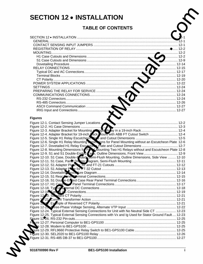
9318700990 Rev F BE1-GPS100 Installation i
SECTION 12 • INSTALLATION TABLE OF CONTENTS
SECTION 12 • INSTALLATION .............................................................................................................. 12-1
GENERAL............................................................................................................................................ 12-1 CONTACT SENSING INPUT JUMPERS ............................................................................................ 12-1 REGISTRATION OF RELAY ............................................................................................................... 12-2 MOUNTING.......................................................................................................................................... 12-2
H1 Case Cutouts and Dimensions ................................................................................................... 12-2 S1 Case Cutouts and Dimensions ................................................................................................... 12-9 Dovetailing Procedure .................................................................................................................... 12-14
RELAY CONNECTIONS.................................................................................................................... 12-15 Typical DC and AC Connections.................................................................................................... 12-17 Terminal Blocks.............................................................................................................................. 12-19 CT Polarity...................................................................................................................................... 12-20
POWER SYSTEM APPLICATIONS .................................................................................................. 12-22 SETTINGS ......................................................................................................................................... 12-24 PREPARING THE RELAY FOR SERVICE ....................................................................................... 12-24 COMMUNICATIONS CONNECTIONS.............................................................................................. 12-24
RS-232 Connectors........................................................................................................................ 12-24 RS-485 Connectors........................................................................................................................ 12-26 ASCII Command Communication .................................................................................................. 12-27 IRIG Input and Connections ........................................................................................................... 12-27
Figures Figure 12-1. Contact Sensing Jumper Locations .................................................................................... 12-2 Figure 12-2. H1 Case Dimensions .......................................................................................................... 12-3 Figure 12-3. Adapter Bracket for Mounting a Single Relay in a 19-inch Rack........................................ 12-4 Figure 12-4. Adapter Bracket for 19-inch Rack Mount with ABB FT Cutout Switch ............................... 12-4 Figure 12-5. Single H1 Relay Escutcheon Plate and Cutout Dimensions .............................................. 12-5 Figure 12-6. Single H1 Relay Mounting Dimensions for Panel Mounting without an Escutcheon Plate 12-6 Figure 12-7. Dovetailed H1 Relay Escutcheon Plate and Cutout Dimensions ....................................... 12-7 Figure 12-8. Mounting Dimensions for Panel Mounting Two H1 Relays without and Escutcheon Plate 12-8 Figure 12-9. S1 and S1 Double-Ended Case, Outline Dimensions, Front View ..................................... 12-9 Figure 12-10. S1 Case, Double-Ended, Semi-Flush Mounting, Outline Dimensions, Side View ......... 12-10 Figure 12-11. S1 Case, Panel Drilling Diagram, Semi-Flush Mounting ................................................ 12-11 Figure 12-12. S1 Adapter Plate for S2 and FT-21 Cutouts ................................................................... 12-12 Figure 12-13. S1 Adapter Plate for FT-32 Cutout ................................................................................. 12-13 Figure 12-14. Dovetailing Procedure Diagram...................................................................................... 12-14 Figure 12-15. S1 Rear Panel Terminal Connections............................................................................. 12-15 Figure 12-16. S1 Double-Ended Case Rear Panel Terminal Connections........................................... 12-16 Figure 12-17. H1 Case Rear Panel Terminal Connections................................................................... 12-17 Figure 12-18. Typical External DC Connections ................................................................................... 12-18 Figure 12-19. Typical AC Connections.................................................................................................. 12-19 Figure 12-20. Standard CT Polarity....................................................................................................... 12-21 Figure 12-21. Current Transformer Action ............................................................................................ 12-21 Figure 12-22. Example of Reversed CT Polarity................................................................................... 12-21 Figure 12-23. Three-Phase Voltage Sensing, Alternate VTP Input ...................................................... 12-22 Figure 12-24. Typical External Sensing Connections for Unit with No Neutral Side CT ...................... 12-23 Figure 12-25. Typical External Sensing Connections with Vx and Ig Used for Stator Ground Fault .... 12-23 Figure 12-26. RS-232 Pin-outs.............................................................................................................. 12-25 Figure 12-27. Personal Computer to BE1-GPS100 .............................................................................. 12-25 Figure 12-28. Modem to BE1-GPS100 ................................................................................................. 12-25 Figure 12-29. RFL9660 Protective Relay Switch to BE1-GPS100 Cable ............................................. 12-25 Figure 12-30. SEL2020 to BE1-GPS100 Relay .................................................................................... 12-26 Figure 12-31. RS-485 DB-37 to BE1-GPS100 ...................................................................................... 12-27
www . El
ectric
alPar
tMan
uals
. com

ii BE1-GPS100 Installation 9318700990 Rev F
Tables Table 12-1. Contact Sensing Turn-On Voltage ....................................................................................... 12-1 Table 12-2. RS-232 Pinouts (COM 0 and COM 1)................................................................................ 12-24 Table 12-3. RS-485 Pinouts (COM 2) ................................................................................................... 12-26 Table 12-4. IRIG Terminal Assignments ............................................................................................... 12-27
www . El
ectric
alPar
tMan
uals
. com

9318700990 Rev F BE1-GPS100 Installation 12-1
SECTION 12 • INSTALLATION GENERAL BE1-GPS100 Generator Protection Systems are delivered with an instruction manual and BESTCOMS software in a sturdy carton to prevent shipping damage. Upon receipt of the relay, check the model and style number against the requisition and packaging list for agreement. If there is evidence of shipping damage, file a claim with the carrier, and notify the Basler Electric regional sales office, your sales representative, or a sales representative at Basler Electric, Highland, Illinois. If the BE1-GPS100 is not installed immediately, store it in the original shipping package in a moisture and dust free environment.
CONTACT SENSING INPUT JUMPERS
Four contact sensing inputs provide external stimulus to initiate BE1-GPS100 actions. An external wetting voltage is required for the contact sensing inputs. The nominal voltage level of the external dc source must comply with the dc power supply input voltage ranges listed in Section 1, General Information, General Specifications. To enhance user flexibility, the BE1-GPS100 uses wide range AC/DC power supplies that cover several common control voltages. The contact sensing input circuits are designed to respond to voltages at the lower end of the control voltage range while not overheating at the high end of the range. Energizing levels for the contact sensing inputs are jumper selectable for a minimum of approximately 5 Vdc for 24 Vdc nominal sensing voltages, 26 Vdc for 48 Vdc nominal sensing voltages or 69 Vdc for 125 Vdc nominal voltages. See Table 12-1 for the control voltage ranges.
Table 12-1. Contact Sensing Turn-On Voltage
Nominal Turn-On Voltage Range Nominal Control
Voltage Jumper Installed (Low Position)
Jumper Not Installed (High Position)
24 Vdc N/A Approx. 5 Vdc
48/125 Vac or Vdc 26 - 38 Vac or Vdc 69 - 100 Vac or Vdc
125/250 Vac or Vdc 69 - 100 Vac or Vdc 138 - 200 Vac or Vdc
Each BE1-GPS100 is delivered without the contact sensing jumpers installed for operation in the higher end of the control voltage range. If the contact sensing inputs are to be operated at the lower end of the control voltage range, the jumpers must be installed. The following describes how to locate and remove/change the contact sensing input jumpers:
1. Remove the draw-out assembly by loosening the two thumbscrews and pulling the assembly out of the case. Observe all electrostatic discharge (ESD) precautions when handing the draw-out assemble.
2. Locate the two jumper blocks that are mounted on the Digital Circuit Board. The Digital Circuit Board is the middle board in the assembly and the jumper terminal blocks are located on the component side of the circuit board. Each terminal block has two sets of pins. With the jumper as installed at the factory, one pin should be visible when viewed from the side of the unit. This configuration allows the inputs to Operate at the higher end of the control voltage range. Figure 12-1 illustrates the location of the jumper terminal blocks as well as the position of a jumper placed in the high voltage position.
ATTENTION The BE1-GPS100 relay comes shipped with the input jumpers removed. Read the following paragraphs closely before placing the relay in service.
www . El
ectric
alPar
tMan
uals
. com
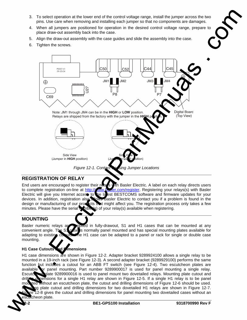
12-2 BE1-GPS100 Installation 9318700990 Rev F
3. To select operation at the lower end of the control voltage range, install the jumper across the two pins. Use care when removing and installing each jumper so that no components are damages.
4. When all jumpers are positioned for operation in the desired control voltage range, prepare to place draw-out assembly back into the case.
5. Align the draw-out assembly with the case guides and slide the assembly into the case. 6. Tighten the screws.
Figure 12-1. Contact Sensing Jumper Locations
REGISTRATION OF RELAY End users are encouraged to register their relays with Basler Electric. A label on each relay directs users to complete registration on-line at http://www.basler.com/register. Registering your relays(s) with Basler Electric will give you Internet access to the latest BESTCOMS software and firmware updates for your devices. In addition, registration also allows Basler Electric to contact you if a problem is found in the design or manufacturing of our products that might affect you. The registration process only takes a few minutes. Please have the serial number(s) of your relay(s) available when registering.
MOUNTING Basler numeric relays are supplied in fully-drawout, S1 and H1 cases that can be mounted at any convenient angle. The S1 case is normally panel mounted and has special mounting plates available for adapting to existing cutouts. The H1 case can be adapted to a panel or rack for single or double case mounting.
H1 Case Cutouts and Dimensions H1 case dimensions are shown in Figure 12-2. Adapter bracket 9289924100 allows a single relay to be mounted in a 19-inch rack (see Figure 12-3). A second adapter bracket (9289929100) performs the same function but includes a cutout for an ABB FT switch (see Figure 12-4). Two escutcheon plates are available for panel mounting. Part number 9289900017 is used for panel mounting a single relay. Escutcheon plate 9289900016 is used to panel mount two dovetailed relays. Mounting plate cutout and drilling dimensions for a single H1 relay are shown in Figure 12-5. If a single H1 relay is to be panel mounted without an escutcheon plate, the cutout and drilling dimensions of Figure 12-6 should be used. Mounting plate cutout and drilling dimensions for two dovetailed H1 relays are shown in Figure 12-7. Figure 12-8 gives the cutout and drilling dimensions for panel mounting two dovetailed cases without an escutcheon plate.
www . El
ectric
alPar
tMan
uals
. com
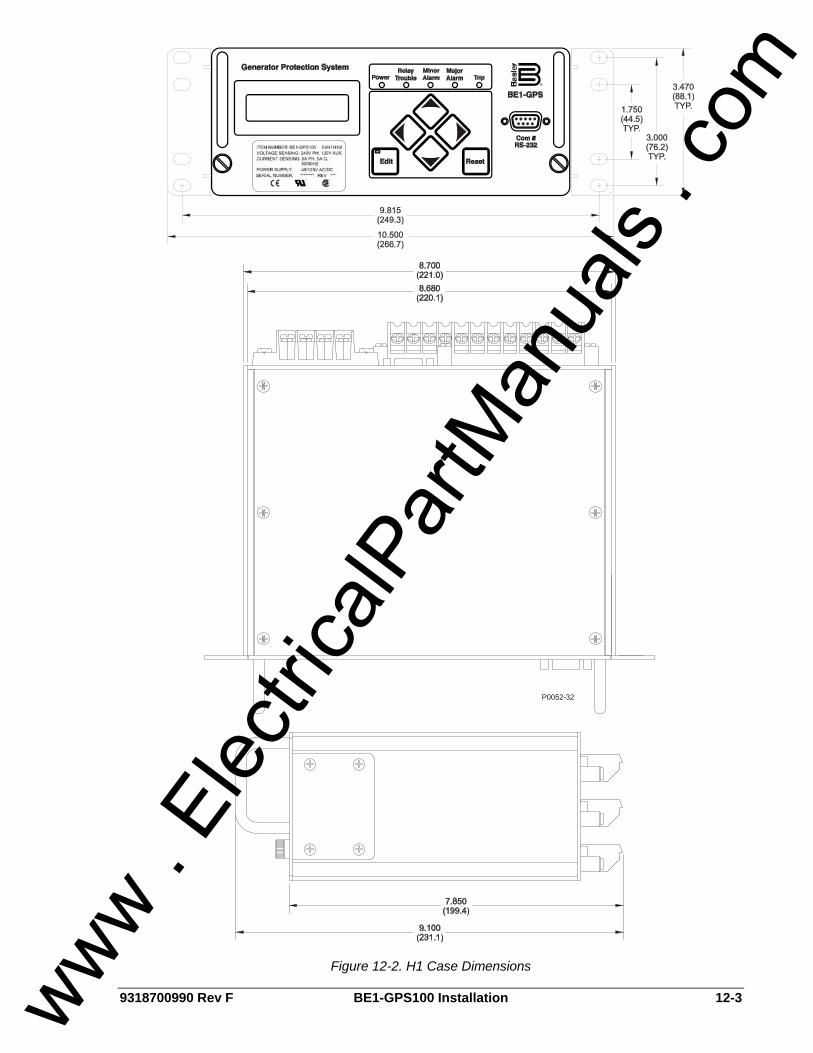
9318700990 Rev F BE1-GPS100 Installation 12-3
Figure 12-2. H1 Case Dimensions
www . El
ectric
alPar
tMan
uals
. com
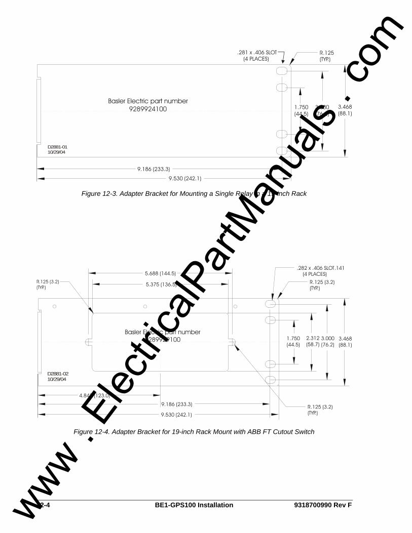
12-4 BE1-GPS100 Installation 9318700990 Rev F
9.186 (233.3)
1.750(44.5)
3.000(76.2)
9.530 (242.1)
3.468(88.1)
(TYP.)R.125.281 x .406 SLOT
(4 PLACES)
D2881-0110/29/04
Basler Electric part number9289924100
Figure 12-3. Adapter Bracket for Mounting a Single Relay in a 19-inch Rack
9.186 (233.3)
4.843 (123.0)
9.530 (242.1)
5.375 (136.5)
(TYP.)R.125 (3.2)
3.468(88.1)
3.000(76.2)
1.750(44.5)
5.688 (144.5)
(TYP.)R
2.312(58.7)
(4 PLACES).282 x .406 SLOT.141
D2881-0210/29/04
Basler Electric part number9289929100
R.125 (3.2)(TYP.)
Figure 12-4. Adapter Bracket for 19-inch Rack Mount with ABB FT Cutout Switch
www . El
ectric
alPar
tMan
uals
. com
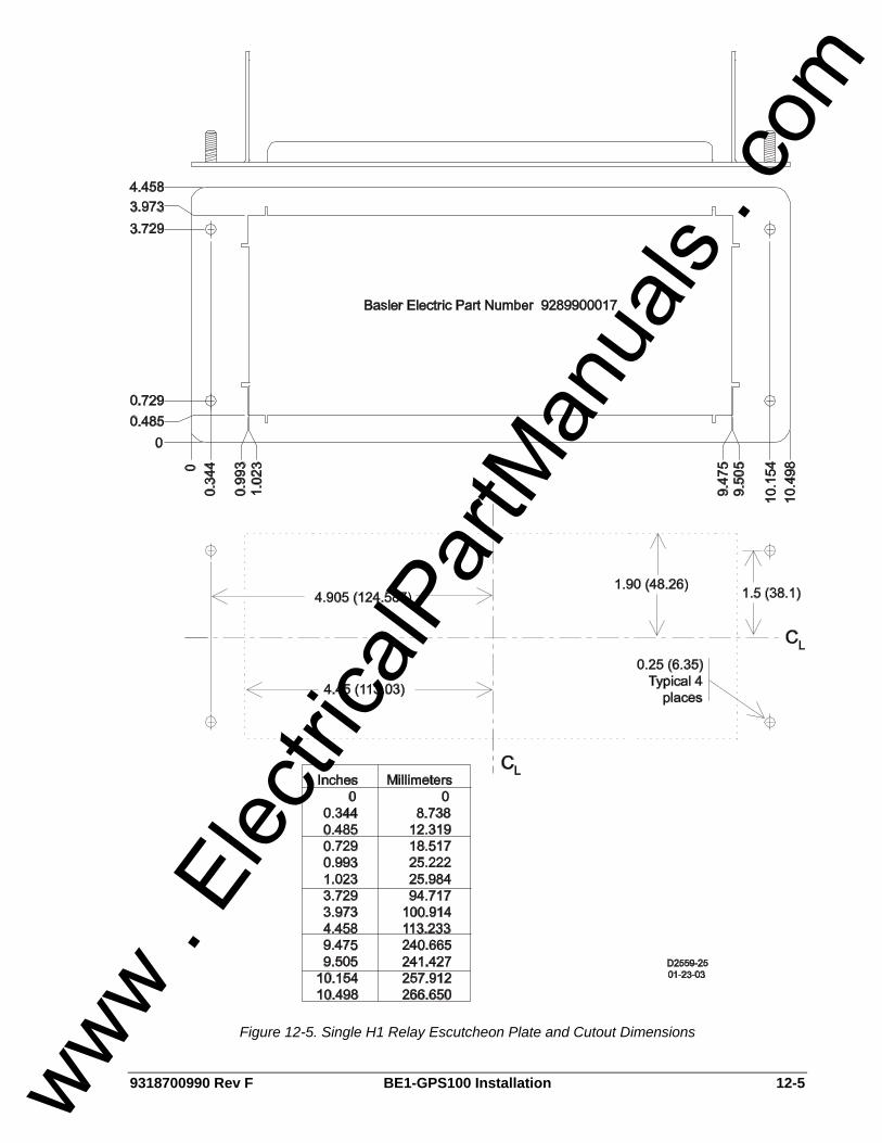
9318700990 Rev F BE1-GPS100 Installation 12-5
Figure 12-5. Single H1 Relay Escutcheon Plate and Cutout Dimensions
www . El
ectric
alPar
tMan
uals
. com
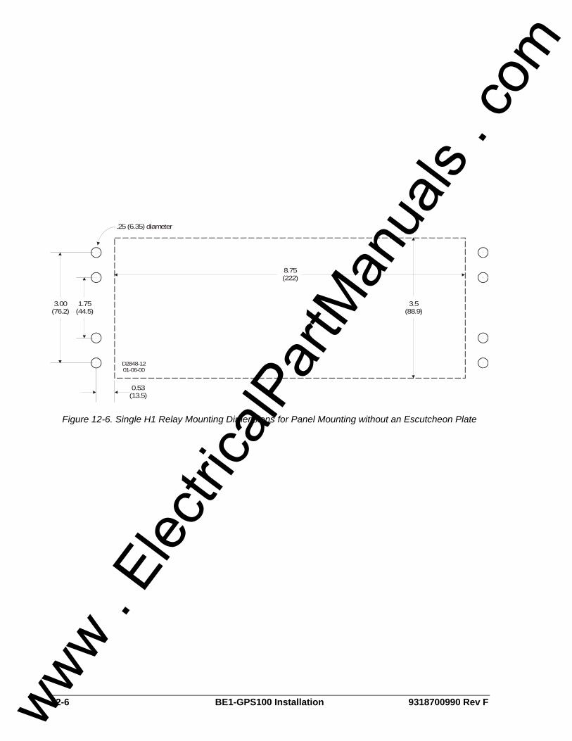
12-6 BE1-GPS100 Installation 9318700990 Rev F
8.75(222)
1.75(44.5)
3.00(76.2)
3.5(88.9)
0.53(13.5)
.25 (6.35) diameter
D2848-1201-06-00
Figure 12-6. Single H1 Relay Mounting Dimensions for Panel Mounting without an Escutcheon Plate
www . El
ectric
alPar
tMan
uals
. com
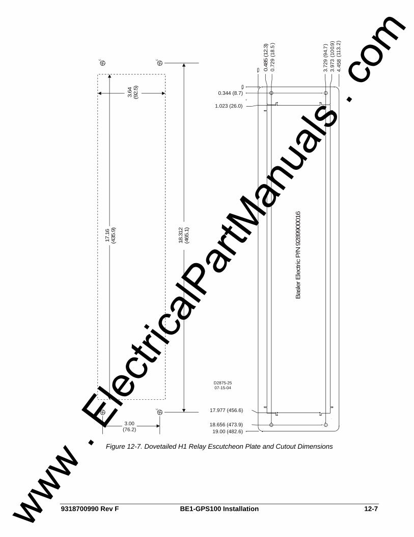
9318700990 Rev F BE1-GPS100 Installation 12-7
C CCC
D2875-2507-15-04
3.00(76.2)
0.344 (8.7)
1.023 (26.0)
4
4
.458
(113
.)
3.97
3(1
0.0
)3.
77
2
2
99
(9.
)
0.72
9(1
8.5
)
17.977 (456.6)
18.656 (473.9)19.00 (482.6)
17.1
6(4
35.9
)
3.64
(92.
5)
0.48
5 (1
2.3)
18.3
12(4
65.1
)
Bas
ler E
lect
ric P
/N 9
2899
0001
6
Figure 12-7. Dovetailed H1 Relay Escutcheon Plate and Cutout Dimensions
www . El
ectric
alPar
tMan
uals
. com
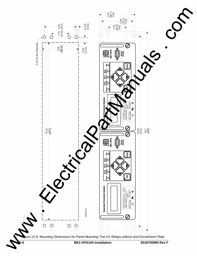
12-8 BE1-GPS100 Installation 9318700990 Rev F
Figure 12-8. Mounting Dimensions for Panel Mounting Two H1 Relays without and Escutcheon Plate
www . El
ectric
alPar
tMan
uals
. com
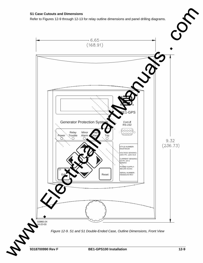
9318700990 Rev F BE1-GPS100 Installation 12-9
S1 Case Cutouts and Dimensions Refer to Figures 12-9 through 12-13 for relay outline dimensions and panel drilling diagrams.
Edit Reset
Relay Minor MajorPower Trouble Alarm Alarm Trip
Generator Protection System
BE1-GPS
RBasl
erCom 0RS-232
STYLE NUMBER:9318700100
VOLTAGE SENSING:
CURRENT SENSING:5A PH, 5A G50/60HZ
POWER SUPPLY:48/125V AC/DC
SERIAL NUMBER:H00303145 REV
240V PH, 120V AUX
D2860-2410-22-03
Figure 12-9. S1 and S1 Double-Ended Case, Outline Dimensions, Front View
www . El
ectric
alPar
tMan
uals
. com

12-10 BE1-GPS100 Installation 9318700990 Rev F
Figure 12-10. S1 Case, Double-Ended, Semi-Flush Mounting, Outline Dimensions, Side View
www . El
ectric
alPar
tMan
uals
. com

9318700990 Rev F BE1-GPS100 Installation 12-11
Figure 12-11. S1 Case, Panel Drilling Diagram, Semi-Flush Mounting
www . El
ectric
alPar
tMan
uals
. com

12-12 BE1-GPS100 Installation 9318700990 Rev F
CUTOUT
Basler Electric Adapter Plate
P/N 9108551021
.375(9.5)
1.089(27.7)
9.339(237.2)
10.063(255.6)
10.438(265.1)
.245 (6.2) .005 DIA., C’SINK+100 DEG TO .386 (9.8) DIA.
(8 PLACES)
2.438(61.9)
8.00(203.2)
.060 (1.5) R(4 PLACES)
D2863-1707-22-04
.258
(6.6
)
6.38
1(1
62.1
)6.
640
(168
.7)
.539
(13.
7)
.290
(7.4
)
6.35
0(1
61.3
)
6.10
2(1
55.0
)0
Figure 12-12. S1 Adapter Plate for S2 and FT-21 Cutouts
www . El
ectric
alPar
tMan
uals
. com

9318700990 Rev F BE1-GPS100 Installation 12-13
NO
TE:
DE
-BU
RR
AN
DBR
EAK
ALL
SH
ARP
ED
GES
.
0
0
D2863-1807/22/04
CUTOUTBasler ElectricAdapter Plate
P/N 9108551022
.158
(4.0
).3
43 (8
.7)
.407
(10.
3)
5.97
0 (1
51.6
)
6.03
3 (1
53.2
)6.
218
(157
.9)
6.37
6 (1
62.0
)
.250
(6.4
)(4
PLA
CES
)
.060
(1.5
) R4
PLA
CES
.375 (9.5)
3.935 (100.0)4.130 (104.9)
12.380 (314.5)12.565 (319.2)
16.125 (409.6)
16.500 (419.1)
Figure 12-13. S1 Adapter Plate for FT-32 Cutout
www . El
ectric
alPar
tMan
uals
. com

12-14 BE1-GPS100 Installation 9318700990 Rev F
Dovetailing Procedure Basler H1 cases can be interlocked by means of a tenon and mortise on the left and right sides of each case. The following paragraphs describe the procedure of dovetailing two cases. Figure 12-14 illustrates the process. Step 1: Remove the draw-out assembly from each case by rotating the two captive, front panel screws
counterclockwise and then sliding the assembly out of the case. Observe electrostatic discharge (ESD) precautions when handling the draw-out assemblies.
Step 2: Remove the mounting bracket from the side of each case where the two cases will mate. Each bracket is held in place by four Phillips screws.
Step 3: The rear panel must be removed from one of the cases in order for the two cases to be joined. On that panel, remove the Phillips screw from each corner of the rear panel except for the screw at the upper left-hand corner (when looking at the rear of the case). This screw is closest to Terminal Strip A.
Step 4: Turn the screw nearest to Terminal Strip A counterclockwise until the rear panel can be removed from the case. If you have difficulty removing this screw, use the alternate method described in Step 4a. Otherwise, proceed to Step 5.
Step 4a: Use a Torx® T15 driver to remove the two screws attaching Terminal Strip A to the rear panel. Remove the terminal strip and set it aside. Remove the remaining Phillips screw from the rear panel and set the rear panel aside.
Step 5: Arrange the two cases so that the rear dovetailed edge of the case without a rear panel is aligned with the front dovetailed edge of the case with the rear panel installed. Once the dovetails are aligned, slide the cases together.
Step 6: Position the rear panel on the case from which it was removed. Make sure that the panel orientation is correct. Perform Step 6a if Terminal Strip A was not removed during the disassembly process. Perform Step 6b if Terminal Strip A was removed during disassembly.
Step 6a: Position the rear panel over the case and align the screw closest to Terminal Strip A with its mating hole. Tighten the screw while maintaining proper alignment between the rear panel and case. Finish attaching the panel to the case by installing the remaining three Phillips screws. When installed, the rear panels prevent the two cases from sliding apart.
Step 6b: Align the rear panel with the case and install the four Phillips screws that hold the rear panel in place. Position Terminal Strip A in its panel opening and replace the two Torx® T15 screws. When installed, the rear panels prevent the two cases from sliding apart.
Step 7: Mount the case assembly in the desired rack or panel opening and reinstall the draw-out assembly in each case.
Figure 12-14. Dovetailing Procedure Diagram
www . El
ectric
alPar
tMan
uals
. com
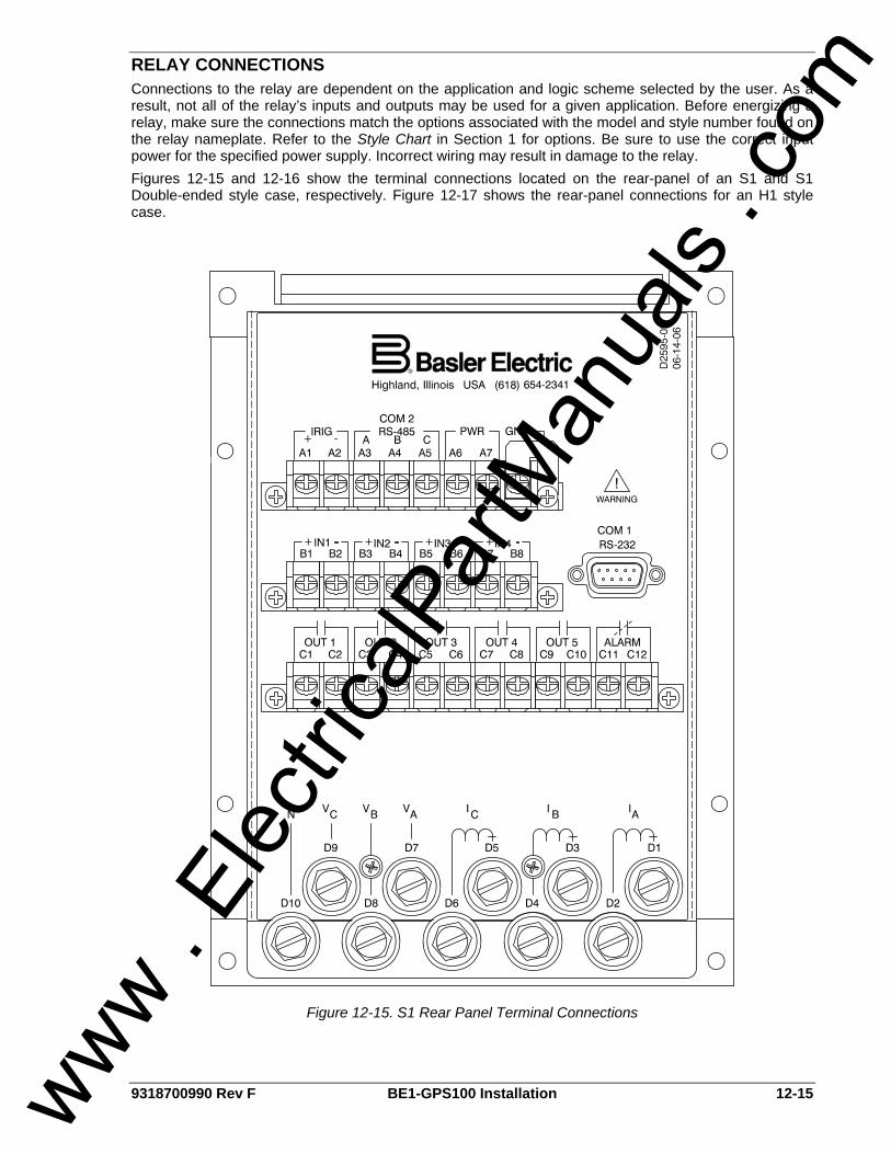
9318700990 Rev F BE1-GPS100 Installation 12-15
RELAY CONNECTIONS Connections to the relay are dependent on the application and logic scheme selected by the user. As a result, not all of the relay’s inputs and outputs may be used for a given application. Before energizing a relay, make sure the connections match the options associated with the model and style number found on the relay nameplate. Refer to the Style Chart in Section 1 for options. Be sure to use the correct input power for the specified power supply. Incorrect wiring may result in damage to the relay. Figures 12-15 and 12-16 show the terminal connections located on the rear-panel of an S1 and S1 Double-ended style case, respectively. Figure 12-17 shows the rear-panel connections for an H1 style case.
Figure 12-15. S1 Rear Panel Terminal Connections
www . El
ectric
alPar
tMan
uals
. com
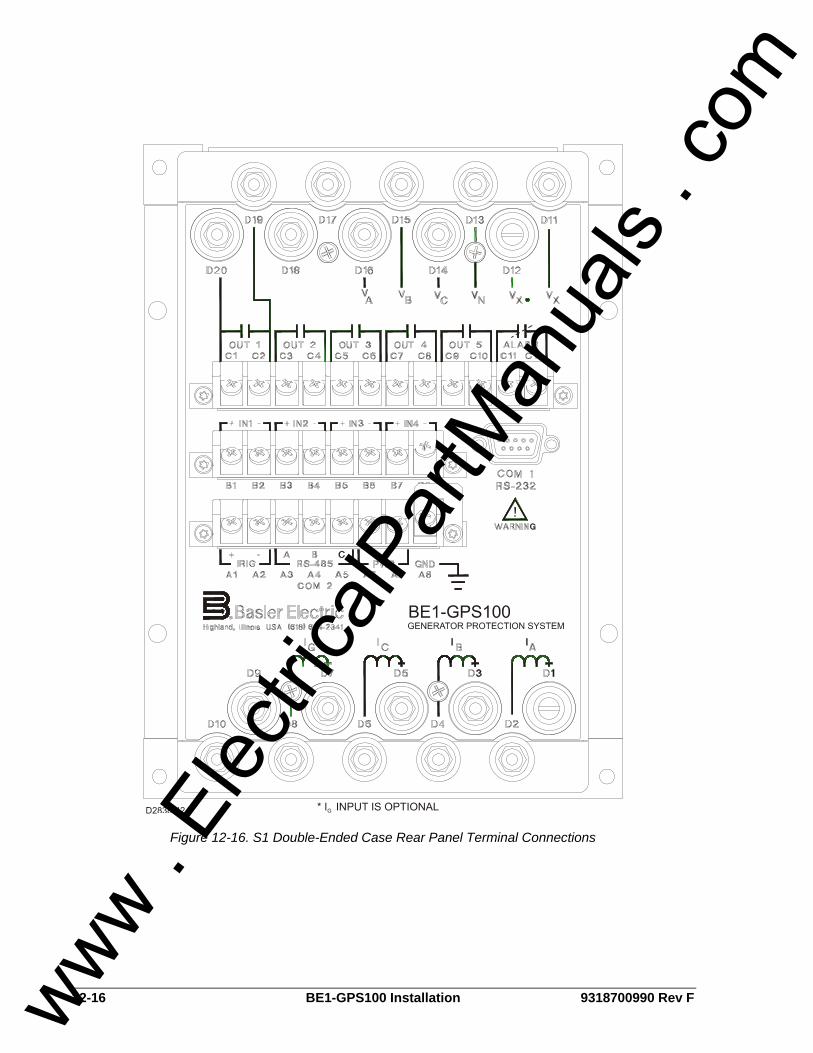
12-16 BE1-GPS100 Installation 9318700990 Rev F
Figure 12-16. S1 Double-Ended Case Rear Panel Terminal Connections
www . El
ectric
alPar
tMan
uals
. com

9318700990 Rev F BE1-GPS100 Installation 12-17
Figure 12-17. H1 Case Rear Panel Terminal Connections
Typical DC and AC Connections Typical external DC and AC connections for the BE1-GPS100 are shown in Figures 12-18 and 12-19.
NOTE The relay should be hard-wired to earth ground with no smaller than 12 AWG copper wire attached to the rear ground terminal of the relay case. When the relay is configured in a system with other protective devices, a separate ground bus lead is recommended for each relay.
www . El
ectric
alPar
tMan
uals
. com
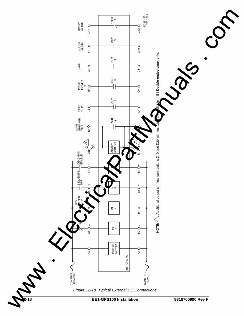
12-18 BE1-GPS100 Installation 9318700990 Rev F
Figure 12-18. Typical External DC Connections
www . El
ectric
alPar
tMan
uals
. com
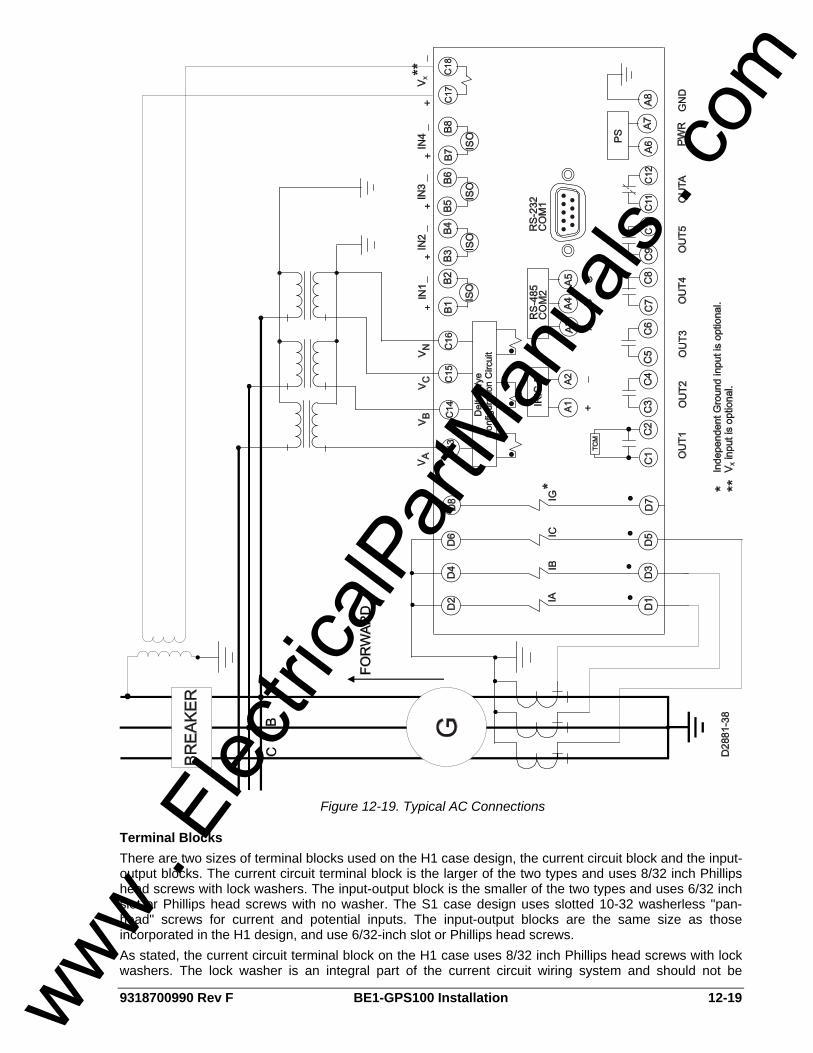
9318700990 Rev F BE1-GPS100 Installation 12-19
Figure 12-19. Typical AC Connections
Terminal Blocks There are two sizes of terminal blocks used on the H1 case design, the current circuit block and the input-output blocks. The current circuit terminal block is the larger of the two types and uses 8/32 inch Phillips head screws with lock washers. The input-output block is the smaller of the two types and uses 6/32 inch slot or Phillips head screws with no washer. The S1 case design uses slotted 10-32 washerless "pan-head" screws for current and potential inputs. The input-output blocks are the same size as those incorporated in the H1 design, and use 6/32-inch slot or Phillips head screws. As stated, the current circuit terminal block on the H1 case uses 8/32 inch Phillips head screws with lock washers. The lock washer is an integral part of the current circuit wiring system and should not be
www . El
ectric
alPar
tMan
uals
. com

12-20 BE1-GPS100 Installation 9318700990 Rev F
removed. Without the lock washer, the 8/32-inch screw may bottom out, preventing a tight fit against the lug (screw feels tight but lug may move under the screw head). The maximum wire lug width accommodated by the current circuit terminal block on the H1 case is .344 inches (8.6 mm). The maximum wire lug width accommodated by the input-output block on the H1 and S1 case is 0.320 inches (8.1 mm). Current and potential inputs on the S1 case are not limited by the barrier board terminal block design.
CT Polarity CT polarity is critical to the proper operation of the BE1-GPS100. Sidebar 12-1 provides fundamental information on CT polarity and protective relays.
NOTE Except as noted, connections to the relay should be made with a minimum wire size of #14 AWG.
www . El
ectric
alPar
tMan
uals
. com

9318700990 Rev F BE1-GPS100 Installation 12-21
Sidebar 12-1. Current Circuit Polarity By ANSI convention, current transformer (CT) polarity will face away from the protected winding of a transformer, motor, generator, or reactor, and away from the contacts in a circuit breaker. Therefore, primary current flow towards the winding or contacts (direction of protected zone) will result in a secondary current out X1, in phase with the primary (see Figures 12-20 and 12-21). On occasion, however, protection engineers will run into situations where CT polarity is reversed for a specific application. That is, non-polarity of the CT secondary will be in phase with the primary current flow (Figure 12-22). For example, a transformer differential CT from a breaker with a different polarity convention such as low voltage switchgear, or a bus differential CT taken from the low side of a transformer. Orientation of CT polarity relative to primary current flow establishes the secondary CT terminal that should be connected to polarity of the protective relay.
D2877-0607-17-00
Figure 12-20. Standard CT Polarity Figure 12-21. Current Transformer Action
Figure 12-22. Example of Reversed CT Polarity
www . El
ectric
alPar
tMan
uals
. com

12-22 BE1-GPS100 Installation 9318700990 Rev F
POWER SYSTEM APPLICATIONS Figures 12-23 through 12-25 are examples of the applications that can be served by the Basler BE1-GPS100 Generator Protection System. These applications can be used in concert with other Basler numeric systems such as the BE1-851 Utility Multifunction Relay, the BE1-CDS220/240 Current Differential Protection Systems, or the BE1-951 Overcurrent Protection System.
Figure 12-23. Three-Phase Voltage Sensing, Alternate VTP Input
www . El
ectric
alPar
tMan
uals
. com
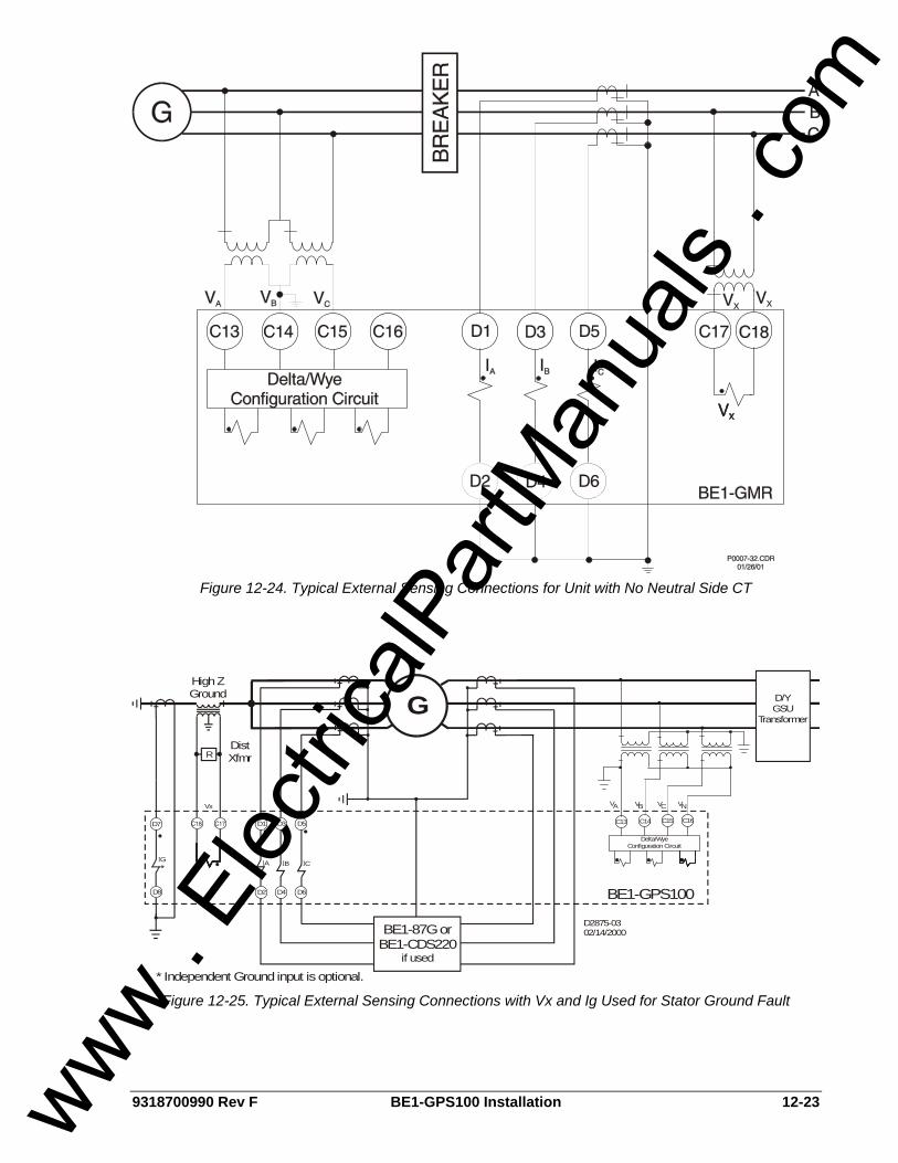
9318700990 Rev F BE1-GPS100 Installation 12-23
Figure 12-24. Typical External Sensing Connections for Unit with No Neutral Side CT
D1 D3
IA IB ICIG *
* Independent Ground input is optional.
D5 C13 C14
Delta/Wye Configuration Circuit
C15
V BA V V V
C16
D4 D6D2D8
G
D7
R
BE1-87G orBE1-CDS220
if used
BE1-GPS100
High ZGround
DistXfmr
Vx
D/YGSU
Transformer
C N
D2875-0302/14/2000
Figure 12-25. Typical External Sensing Connections with Vx and Ig Used for Stator Ground Fault
www . El
ectric
alPar
tMan
uals
. com
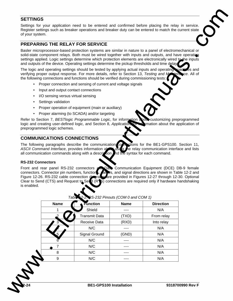
12-24 BE1-GPS100 Installation 9318700990 Rev F
SETTINGS Settings for your application need to be entered and confirmed before placing the relay in service. Register settings such as breaker operations and breaker duty can be entered to match the current state of your system.
PREPARING THE RELAY FOR SERVICE Basler microprocessor-based protection systems are similar in nature to a panel of electromechanical or solid-state component relays. Both must be wired together with inputs and outputs, and have operating settings applied. Logic settings determine which protection elements are electronically wired to the inputs and outputs of the device. Operating settings determine the pickup thresholds and time delays. The logic and operating settings should be tested by applying actual inputs and operating quantities and verifying proper output response. For more details, refer to Section 13, Testing and Maintenance. All of the following connections and functions should be verified during commissioning tests: • Proper connection and sensing of current and voltage signals • Input and output contact connections • I/O sensing versus virtual sensing • Settings validation • Proper operation of equipment (main or auxiliary) • Proper alarming (to SCADA) and/or targeting Refer to Section 7, BESTlogic Programmable Logic, for information about customizing preprogrammed logic and creating user-defined logic, and Section 8, Application, for information about the application of preprogrammed logic schemes.
COMMUNICATIONS CONNECTIONS The following paragraphs describe the communication connections for the BE1-GPS100. Section 11, ASCII Command Interface, provides information about using the relay communication interface and lists all communication commands along with a description and the syntax for each command.
RS-232 Connectors Front and rear panel RS-232 connectors are Data Communication Equipment (DCE) DB-9 female connectors. Connector pin numbers, functions, names, and signal directions are shown in Table 12-2 and Figure 12-26. RS-232 cable connection diagrams are provided in Figures 12-27 through 12-30. Optional Clear to Send (CTS) and Request to Send (RTS) connections are required only if hardware handshaking is enabled.
Table 12-2. RS-232 Pinouts (COM 0 and COM 1)
Name Function Name Direction 1 Shield ---- N/A 2 Transmit Data (TXD) From relay 3 Receive Data (RXD) Into relay 4 N/C ---- N/A 5 Signal Ground (GND) N/A 6 N/C ---- N/A 7 N/C ---- N/A 8 N/C ---- N/A 9 N/C ---- N/A
www . El
ectric
alPar
tMan
uals
. com
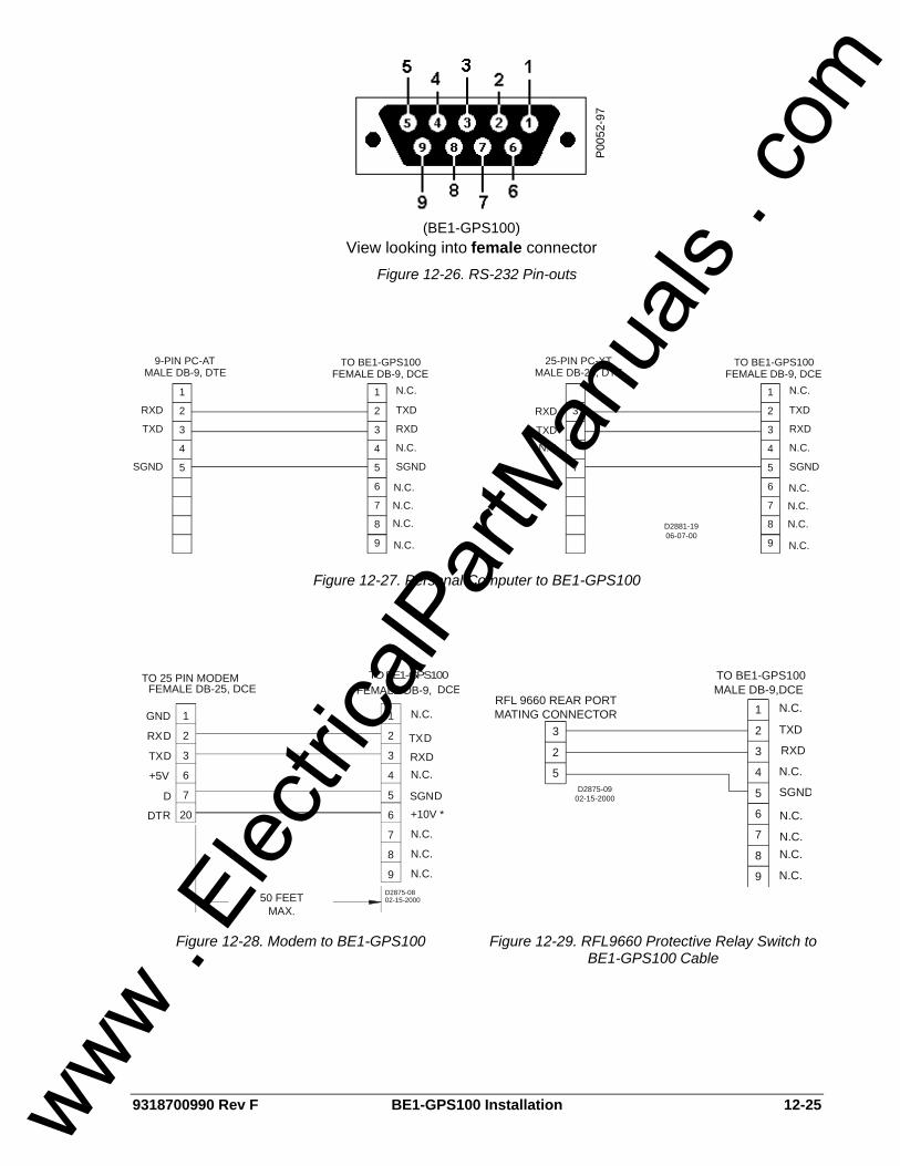
9318700990 Rev F BE1-GPS100 Installation 12-25
(BE1-GPS100)
P005
2-97
View looking into female connector Figure 12-26. RS-232 Pin-outs
5
4
3
2
1 1
2
3
4
5
RXD
TXD
SGND
TXD
RXD
N.C.
SGND
FEMALE DB-9, DCEMALE DB-9, DTE
9
6
7
8
N.C.
N.C.
TO BE1-GPS1009-PIN PC-AT
N.C.
N.C.
N.C.
D2881-1906-07-00
25-PIN PC-XT TO BE1-GPS100
N.C.
8
7
6
9
MALE DB-25, DTE FEMALE DB-9, DCE
SGND
N.C.
RXD
TXD
5
4
3
2
1
3
2
7
N.C.
N.C.
N.C.
N.C.
N.C.
RXD
TXD
Figure 12-27. Personal Computer to BE1-GPS100
20
7
6
3
2
1 1
2
3
4
5
RXD
TXD
+5V
D
TXD
RXDN.C.
SGND
50 FEETMAX.
FEMALE DB-9, DCEFEMALE DB-25, DCE
02-15-2000D2875-08
DTR
9
6
7
8 N.C.
N.C.
+10V *
N.C.
N.C.GND
TO 25 PIN MODEM TO BE1-GPS100
5
2
3
D2875-0902-15-2000
RFL 9660 REAR PORTMATING CONNECTOR
TO BE1-GPS100MALE DB-9,DCE
1
2
3
4
5
TXD
RXD
N.C.
SGND
9
6
7
8
N.C.
N.C.
N.C.N.C.
N.C.
Figure 12-28. Modem to BE1-GPS100 Figure 12-29. RFL9660 Protective Relay Switch to BE1-GPS100 Cable
www . El
ectric
alPar
tMan
uals
. com
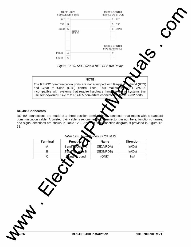
12-26 BE1-GPS100 Installation 9318700990 Rev F
2
3
5
2
3
5
4
6
TO BE1-GPS100IRIG TERMINALS
TO SEL-2020FEMALE DB-9, DTE
TO BE1-GPS100FEMALE DB-9, DCE
TXDRXD
RXDTXD
SGNDSGND
IRIG-B
IRIG-B +
Figure 12-30. SEL 2020 to BE1-GPS100 Relay
RS-485 Connectors RS-485 connections are made at a three-position terminal block connector that mates with a standard communication cable. A twisted pair cable is recommended. Connector pin numbers, functions, names, and signal directions are shown in Table 12-3. An RS-485 connection diagram is provided in Figure 12-31.
Table 12-3. RS-485 Pinouts (COM 2)
Terminal Function Name Direction A Send/Receive A (SDA/RDA) In/Out B Send/Receive B (SDB/RDB) In/Out C Signal Ground (GND) N/A
NOTE The RS-232 communication ports are not equipped with Request to Send (RTS) and Clear to Send (CTS) control lines. This makes the BE1-GPS100 incompatible with systems that require hardware handshaking or systems that use self-powered RS-232 to RS-485 converters connected to the RS-232 ports.
www . El
ectric
alPar
tMan
uals
. com
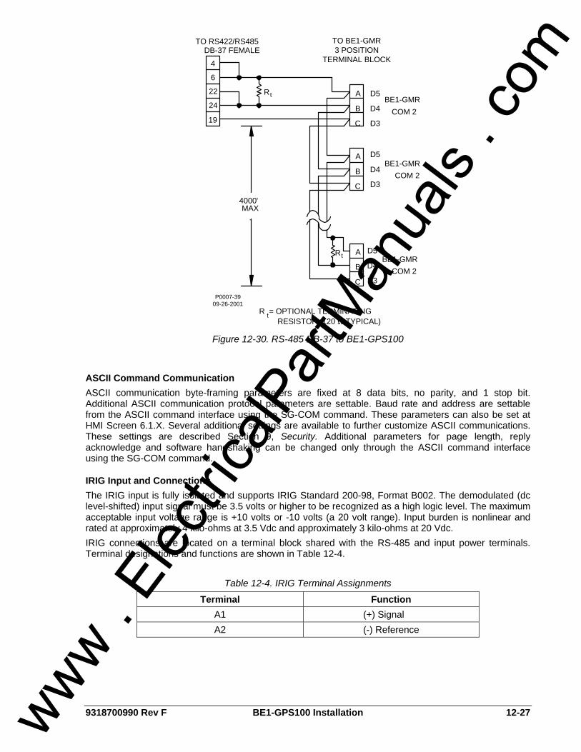
9318700990 Rev F BE1-GPS100 Installation 12-27
P0007-3909-26-2001
22
6
4
A
B
C
TO BE1-GMR3 POSITION
TERMINAL BLOCKDB-37 FEMALE
TO RS422/RS485
19
24
C
B
A
A
B
C
4000'MAX
.
COM 2BE1-GMR
BE1-GMRCOM 2
BE1-GMRCOM 2
Rt
tR
R = OPTIONAL TERMINATINGtRESISTOR (120 S TYPICAL)
A5
D5
D4
D3
D5
D4
D3
D5
D4
D3
Figure 12-30. RS-485 DB-37 to BE1-GPS100
ASCII Command Communication ASCII communication byte-framing parameters are fixed at 8 data bits, no parity, and 1 stop bit. Additional ASCII communication protocol parameters are settable. Baud rate and address are settable from the ASCII command interface using the SG-COM command. These parameters can also be set at HMI Screen 6.1.X. Several additional settings are available to further customize ASCII communications. These settings are described Section 9, Security. Additional parameters for page length, reply acknowledge and software handshaking can be changed only through the ASCII command interface using the SG-COM command.
IRIG Input and Connections The IRIG input is fully isolated and supports IRIG Standard 200-98, Format B002. The demodulated (dc level-shifted) input signal must be 3.5 volts or higher to be recognized as a high logic level. The maximum acceptable input voltage range is +10 volts or -10 volts (a 20 volt range). Input burden is nonlinear and rated at approximately 4 kilo-ohms at 3.5 Vdc and approximately 3 kilo-ohms at 20 Vdc. IRIG connections are located on a terminal block shared with the RS-485 and input power terminals. Terminal designations and functions are shown in Table 12-4.
Table 12-4. IRIG Terminal Assignments
Terminal Function A1 (+) Signal A2 (-) Reference
www . El
ectric
alPar
tMan
uals
. com

12-28 BE1-GPS100 Installation 9318700990 Rev F
This page intentionally left blank.
www . El
ectric
alPar
tMan
uals
. com

9318700990 Rev F BE1-GPS100 Testing and Maintenance i
SECTION 13 • TESTING AND MAINTENANCE TABLE OF CONTENTS
SECTION 13 • TESTING AND MAINTENANCE .................................................................................... 13-1
GENERAL............................................................................................................................................ 13-1 TESTING PHILOSOPHIES.................................................................................................................. 13-1
Acceptance Testing.......................................................................................................................... 13-1 Commissioning Testing .................................................................................................................... 13-1 Periodic Testing................................................................................................................................ 13-2 Functional Testing ............................................................................................................................ 13-2
TESTING AND TROUBLESHOOTING AIDS ...................................................................................... 13-2 Performance Testing ........................................................................................................................ 13-2 Relay Self-Test................................................................................................................................. 13-2 Status Reporting Features ............................................................................................................... 13-3 Event Reporting Features ................................................................................................................ 13-3
ACCEPTANCE TESTING.................................................................................................................... 13-3 Test Equipment ................................................................................................................................ 13-3 Power Up.......................................................................................................................................... 13-5 Communications............................................................................................................................... 13-6 Style Number and Serial Number Verification.................................................................................. 13-6 IRIG Verification (If used) ................................................................................................................. 13-6 Contact Sensing Inputs .................................................................................................................... 13-6 Control Outputs ................................................................................................................................ 13-7 Current Circuit Verification ............................................................................................................... 13-7 Three-Phase Voltage Circuit Verification ......................................................................................... 13-8 Power Reading Verification .............................................................................................................. 13-9 Auxiliary Voltage Input Verification - VX and VX 3rd (Fundamental and Third Harmonic) ............... 13-9 Line and Bus Angle, Frequency, and Slip Verification ................................................................... 13-10
COMMISSIONING TESTING ............................................................................................................ 13-10 Digital I/O Connection Verification ................................................................................................. 13-10 Virtual Selector Switches (If not used, skip to Virtual Control Switch) ........................................... 13-11 Virtual Control Switch (If not used, skip to Protection and Control Function Verification) ............. 13-11 Protection and Control Function Verification.................................................................................. 13-12 Verify Other Set Points as Appropriate .......................................................................................... 13-13 Report and Alarm Functions........................................................................................................... 13-13
PERIODIC TESTING ......................................................................................................................... 13-14 Settings Verification........................................................................................................................ 13-14 Analog Circuit Verification .............................................................................................................. 13-15
MAINTENANCE OF BACKUP BATTERY FOR REAL TIME CLOCK............................................... 13-15 To Replace Battery in H1 Case...................................................................................................... 13-15 To Replace Battery in S1 Case...................................................................................................... 13-16
CARE AND HANDLING..................................................................................................................... 13-16 UPDATING FIRMWARE AND SOFTWARE...................................................................................... 13-17
Updating Relay Firmware............................................................................................................... 13-17 Updating BESTCOMS Software..................................................................................................... 13-17
FUNCTIONAL TESTING ................................................................................................................... 13-17 Instantaneous Overcurrent (50T) ................................................................................................... 13-18 Time Overcurrent (51) .................................................................................................................... 13-21 Negative Sequence Overcurrent (46) ............................................................................................ 13-24 Voltage Restraint/Control Time Overcurrent .................................................................................. 13-26 Directional Power (32).................................................................................................................... 13-27 Loss of Excitation (40Q) ................................................................................................................. 13-28 Volts per Hertz Overexcitation (24) ................................................................................................ 13-30 Phase and Auxiliary Undervoltage/Overvoltage (27/59) ................................................................ 13-32 Negative-Sequence Voltage (47) ................................................................................................... 13-38 Over/Underfrequency (81).............................................................................................................. 13-39 Synchronism Check (25) ................................................................................................................ 13-41 Breaker Failure (BF)....................................................................................................................... 13-42
www . El
ectric
alPar
tMan
uals
. com
ii BE1-GPS100 Testing and Maintenance 9318700990 Rev F
Virtual Switches (43) ...................................................................................................................... 13-43 Virtual Breaker Control Switch (101).............................................................................................. 13-46 Logic Timer (62) ............................................................................................................................. 13-47 Automatic Setting Group Change................................................................................................... 13-54
Figures Figure 13-1. Rear Panel Terminal Connections (H1 Case)..................................................................... 13-4 Figure 13-2. Rear Panel Terminal Connections (S1 Case)..................................................................... 13-4 Figure 13-3. Rear Panel Terminal Connections (S1 Double-End Case)................................................. 13-5 Figure 13-4. Backup Battery Location ................................................................................................... 13-16 Figure 13-5. x62 Mode 1 (Pickup/Dropout) Timing Example ................................................................ 13-48 Figure 13-6. x62 Mode 2 (One-Shot Nonretriggerable) Timing Example.............................................. 13-50 Figure 13-7. Mode 3 (One-Shot Retriggerable) Timing Example.......................................................... 13-51 Figure 13-8. Mode 5 (Integrating Timer) Timing Example..................................................................... 13-53 Figure 13-9. x62 Mode 6 (Latch) Timing Example ................................................................................ 13-54
Tables Table 13-1. Input Voltages ...................................................................................................................... 13-5 Table 13-2. Input Contact Wetting Voltage ............................................................................................. 13-7 Table 13-3. Current Circuit Verification Values ....................................................................................... 13-7 Table 13-4. Voltage Circuit Verification Values ....................................................................................... 13-8 Table 13-5. Aux Voltage Circuit Verification VX & VX 3rd Values............................................................ 13-9 Table 13-6. 50T Pickup Test Commands.............................................................................................. 13-18 Table 13-7. 50T Pickup Settings ........................................................................................................... 13-18 Table 13-8. 50T Element Accuracy ....................................................................................................... 13-19 Table 13-9. 50T Time Delay Test Commands ...................................................................................... 13-19 Table 13-10. 50T Time Delay Settings .................................................................................................. 13-19 Table 13-11. 50TN Pickup Test Commands ......................................................................................... 13-20 Table 13-12. 50TN Pickup Settings....................................................................................................... 13-20 Table 13-13. 50T Element Accuracy ..................................................................................................... 13-21 Table 13-14. 50TN/150TN Time Delay Settings ................................................................................... 13-21 Table 13-15. 51P/51N Timing Test Commands .................................................................................... 13-21 Table 13-16. 51P/51N Pickup Settings.................................................................................................. 13-22 Table 13-17. 51P/51N Timing Values.................................................................................................... 13-22 Table 13-18. 51P/51N Pickup Test Commands .................................................................................... 13-23 Table 13-19. 51P/51N Pickup Settings.................................................................................................. 13-23 Table 13-20. 51P/51N Element Accuracy ............................................................................................. 13-23 Table 13-21. 151N Pickup Test Commands ......................................................................................... 13-24 Table 13-22. 46 Pickup Test Commands .............................................................................................. 13-24 Table 13-23. 46 Pickup Settings............................................................................................................ 13-25 Table 13-24. 46 Element Accuracy ....................................................................................................... 13-25 Table 13-25. 46 Time Delay Settings .................................................................................................... 13-25 Table 13-26. 51P Pickup Test Commands............................................................................................ 13-26 Table 13-27. Example of 51/27R Settings............................................................................................. 13-26 Table 13-28. 51/27R Settings................................................................................................................ 13-27 Table 13-29. 32/132 Directional Power Pickup Test Commands.......................................................... 13-27 Table 13-30. 32/132 Operational Settings............................................................................................. 13-28 Table 13-31. 32/132 Operational Settings............................................................................................. 13-28 Table 13-32. 40Q/140Q Directional Power Pickup Test Commands .................................................... 13-29 Table 13-33. 40Q/140Q Operational Settings ....................................................................................... 13-29 Table 13-34. 24 Trip and Alarm Pickup Test Commands ..................................................................... 13-30 Table 13-35. Trip and Alarm Pickup Settings........................................................................................ 13-30 Table 13-36. 24 Trip Time Settings ....................................................................................................... 13-31 Table 13-37. 24 Trip Times ................................................................................................................... 13-31 Table 13-38. 24 Reset Time Test Settings............................................................................................ 13-31 Table 13-39. Reset Time ....................................................................................................................... 13-32 Table 13-40. 27P and 59P Pickup Test Commands ............................................................................. 13-32 Table 13-41. 27P and 59P Pickup Settings........................................................................................... 13-32 Table 13-42. 27P and 59P Pickup and Time Delay Settings ................................................................ 13-33 Table 13-43. 27X/127X and 59X Pickup Test Commands.................................................................... 13-33
www . El
ectric
alPar
tMan
uals
. com

9318700990 Rev F BE1-GPS100 Testing and Maintenance iii
Table 13-44. 27X/127X and 59X/159X Pickup Settings (3E0).............................................................. 13-34 Table 13-45. 27X/127X and 59X/159X Pickup and Time Delay Settings (3E0 VT Input)..................... 13-35 Table 13-46. 27X/127X and 59X/159X Pickup Test Commands .......................................................... 13-35 Table 13-47. 27X/127X and 59X/159X Pickup Settings........................................................................ 13-36 Table 13-48. 27X/127X and 59X/159X Pickup and Time Delay Settings ............................................. 13-36 Table 13-49. 27X/127X and 59X/159X Pickup Test Commands .......................................................... 13-37 Table 13-50. 27X/127X and 59X/159X Pickup Settings........................................................................ 13-37 Table 13-51. 27X/127X and 59X/159X Pickup and Time Delay Settings ............................................. 13-38 Table 13-52. 47 Pickup Test Commands .............................................................................................. 13-38 Table 13-53. 47 Pickup Settings............................................................................................................ 13-39 Table 13-54. 47 Pickup and Time Delay Settings ................................................................................. 13-39 Table 13-55. x81 Pickup Test Commands ............................................................................................ 13-40 Table 13-56. x81 Pickup and Mode Settings......................................................................................... 13-40 Table 13-57. x81 Time Delay Settings .................................................................................................. 13-41 Table 13-58. Sync Check Pickup Test Commands............................................................................... 13-41 Table 13-59. BF Pickup Test Commands ............................................................................................. 13-42 Table 13-60. BF Current Detector Pickup Settings ............................................................................... 13-43 Table 13-61. BF Pickup Limits............................................................................................................... 13-43 Table 13-62. BF Time Delay Commands .............................................................................................. 13-43 Table 13-63. x43 Mode 1 Test Commands ........................................................................................... 13-44 Table 13-64. x43 Mode 1 On Commands ............................................................................................. 13-44 Table 13-65. x43 Mode 1 Off Commands ............................................................................................. 13-44 Table 13-66. x43 Mode 1 Pulse Commands ......................................................................................... 13-45 Table 13-67. x43 Mode 2 Test Commands ........................................................................................... 13-45 Table 13-68. x43 Mode 2 On Commands ............................................................................................. 13-45 Table 13-69. x43 Mode 2 Off Commands ............................................................................................. 13-45 Table 13-70. x43 Mode 3 Test Commands ........................................................................................... 13-46 Table 13-71. x43 Mode 3 Pulse Commands ......................................................................................... 13-46 Table 13-72. 101 Virtual Breaker Control Switch Test Commands....................................................... 13-46 Table 13-73. 101 Virtual Breaker Control Switch Trip Test Commands ............................................... 13-47 Table 13-74. 101 Virtual Breaker Control Switch Close Test Commands ............................................ 13-47 Table 13-75. x62 Mode 1 Test Commands ........................................................................................... 13-47 Table 13-76. x62 Mode 1 Pickup and Dropout Settings........................................................................ 13-48 Table 13-77. x62 Mode 1 Timer Initiate Commands ............................................................................. 13-48 Table 13-78. x62 Mode 1 Timer Initiate Removal Commands.............................................................. 13-48 Table 13-79. x62 Mode 2 Test Commands ........................................................................................... 13-49 Table 13-80. x62 Mode 2 Timer Initiate Commands ............................................................................. 13-49 Table 13-81. x62 Mode 3 Test Commands ........................................................................................... 13-50 Table 13-82. x62 Mode 3 Timer Initiate Commands ............................................................................. 13-51 Table 13-83. x62 Mode 5 Test Commands ........................................................................................... 13-51 Table 13-84. x62 Mode 5 Timer Initiate Commands ............................................................................. 13-52 Table 13-85. x62 Mode 6 Test Commands ........................................................................................... 13-53 Table 13-86. x62 Mode 6 Timer Initiate Commands ............................................................................. 13-54 Table 13-87. Discrete Mode Setting Group Selection Settings............................................................. 13-54 Table 13-88. Change to Setting Group 1 Commands........................................................................... 13-55 Table 13-89. Change to Setting Group 0 Commands........................................................................... 13-55 Table 13-90. Binary Mode Setting Group Selection Settings................................................................ 13-56 Table 13-91. Change to Setting Group 1 Commands........................................................................... 13-56 Table 13-92. Change to Setting Group 0 Commands........................................................................... 13-56
www . El
ectric
alPar
tMan
uals
. com

iv BE1-GPS100 Testing and Maintenance 9318700990 Rev F
This page intentionally left blank.
www . El
ectric
alPar
tMan
uals
. com

9318700990 Rev F BE1-GPS100 Testing and Maintenance 13-1
SECTION 13 • TESTING AND MAINTENANCE GENERAL The need to test protective relays to confirm performance as designed by relay manufacturers has always existed. However, numeric relay design is changing the industry testing paradigms that have been in use since the first protective relay was built. Each time a fault occurs, the numeric protection system is tested, and because of its fault and event recording capability, the test is documented. In the unlikely event of a protection system problem, continuous monitoring along with remote communications capability provide for removing the affected relay from service, auto switching to backup systems, and immediate notification of a manned facility. These features have virtually eliminated the need for periodic maintenance. Simple acceptance tests that verify the integrity of the relays measuring circuits and commissioning tests that verify the relays "electronic wiring" (control logic) are Basler Electric's recommended pre-installation tests. This section provides guidelines for performing these tests and others. It also provides guidelines for care, handling, and troubleshooting of the BE1-GPS100 relay. For assistance in conducting relay self-tests and troubleshooting using internal diagnostics, contact Basler Electric Technical Support Services.
TESTING PHILOSOPHIES Testing is generally divided into the following categories:
• Acceptance • Commissioning • Periodic (user scheduled maintenance) • Functional
While all types of tests may be performed, all users do not generally perform them. Likewise, the degree to which you will conduct each type of test depends on need, economics, and perceived system value.
Acceptance Testing Acceptance testing is intended to confirm that a particular relay delivered to a customer meets published specifications. Because this is a numerical relay whose characteristics are defined by software, Basler Electric does not require the user to test each operational setting in the relay. Successful completion of the Acceptance Test verifies proper response of the relay's input and output circuits as well as its response to all external sensing input quantities (voltage, current, frequency). Basler Electric performs detailed acceptance testing on all devices to verify all functions meet published specifications. All products are packaged and shipped with the strictest of standards. The BE1-GPS100 relay is a microprocessor-based relay whose operating characteristics will not change over time. The relay will also not experience any change in operating characteristics during transit. However, it remains material that the user perform these acceptance tests to verify the device has not suffered any degradation in transit. Basler Electric warrants all products against any decay in performance outside of the published specified tolerances that result from problems created during transit.
Commissioning Testing Commissioning testing verifies all physical connections and functional aspects of the protective relay for a new installation. This includes a thorough review and documentation of the operational settings to verify that the users calculated values match the actual values on each enabled protection element of the relay. All of the following connections or functions can be verified during commissioning tests:
• Proper connection and sensing of current and voltage signals as applicable • Connections of I/O contacts • I/O sensing versus virtual sensing • Setting validation • Proper operation of equipment (main or auxiliary) • Proper alarming (to SCADA) and/or targeting
www . El
ectric
alPar
tMan
uals
. com

13-2 BE1-GPS100 Testing and Maintenance 9318700990 Rev F
Periodic Testing Periodic testing can be performed at regularly scheduled intervals or upon an indication of problems or questionable operations within the relay. Verifying the integrity of the relay's performance, short of playback of recorded events, may be necessary by performing certain tests similar to those accomplished in the acceptance tests. Verification that the relay is measuring signals faithfully, that relay logic is appropriate, and that protective elements and equipment (main or auxiliary) operate correctly are goals that can be achieved during this type of testing. Basler Electric recommends that all captured fault records and sequence of event records be analyzed and kept on file as in-service periodic test results for this particular device. This is an indication that all protective elements and the associated equipment are operating satisfactorily. It is not the intent of this manual to elaborate on every conceivable test possible since this would encroach on individual preferences, techniques, and philosophies. It is the intent to pursue relevant testing methods to verify this relay meets published design specifications and applicability.
Functional Testing Functional (or application) testing is significantly more comprehensive in nature and is intended to test suitability for a particular application. Functional testing also provides a means to familiarize the user with the logic and operation of this device. Test setups are generally more involved and often times include ancillary equipment beyond voltage or current source type equipment. While economics may at times prohibit full functional testing, it is recommended that some application testing be performed when published specifications lack appropriate detail to satisfy application testing requirements. Basler Electric performs a thorough and comprehensive functional test of all relays before shipping. This ensures that this device is within specified tolerances, measures accurately, and operates correctly as designed.
TESTING AND TROUBLESHOOTING AIDS Under test or in-service, the BE1-GPS100 provides several ways to check operations, targets, or events. A continuous self-test monitors the system health and status. The most basic reporting function is targets. Targets may be viewed through ASCII command interface or through the front panel human-machine interface (HMI). Fault Summary Reports, Sequence of Events Recorder (SER) Reports, and Oscillographic Records yield more detail. Each time a system disturbance occurs in or around this relay zone of protection, it is a test of the relay performance during the fault. If a questionable operation results in the need for troubleshooting, you have several ways in which to troubleshoot the relay, the installation, and the overall application.
Performance Testing Performance testing can be accomplished through the capture and playback of system fault records. In actual applications, this type of test realizes further confirmation of faithful relay responses during system disturbances. For specific power system disturbances, relays can be to subject to a re-creation of captured events with the aide of equipment capable of replicating COMTRADE record files. In these instances, there is significant merit in testing relays in this manner to assess relay performance. Correct response of relay action in a performance test is supplemental verification of the conclusions drawn from functional (or application) tests. This type of testing verifies not only whether or not the device operated correctly for a particular system disturbance but also offers additional confirmation of your protection philosophy in this application. It is beyond the scope of this manual to develop performance tests for this device. For assistance in developing these types of tests, please consult Basler Electric and your test equipment.
Relay Self-Test All internal circuitry and software that affect the relay core functionality are monitored by the continuous self-test diagnostics. For specific relay trouble alarms, the self-test diagnostics force the microprocessor to reset and try to correct the problem. If unsuccessful, OUTA operates, the Relay Trouble LED on the front panel turns ON, all of the output relays are disabled, internal logic point ALMREL is set, and the relay is taken off line. For more information on self-test diagnostics and relay trouble alarms, see Section 6, Reporting and Alarm Functions, Alarms Function.
www . El
ectric
alPar
tMan
uals
. com

9318700990 Rev F BE1-GPS100 Testing and Maintenance 13-3
Status Reporting Features General status reporting is available through the ASCII command interface using the RG-STAT (report general, status) command. This report assembles all of the information required to determine the relay status. For more information on general status reporting, see Section 6, Reporting and Alarm Functions, General Status Reporting. Fault reporting and target data is dependent on the proper setting of trip, pickup, and logic trigger expressions (via the SG-TRIGGER command) and the assignment of protective elements to be logged as targets (via the SG-TARG command). While the design of the relay facilitates obtaining and verifying targets and event data, it is not always necessary to utilize the relay functions to determine if the device operated while testing. You may simply use an ohmmeter or continuity tester to monitor the output contact status. The following is a summary of ASCII commands where target and event data may be viewed:
• RF provides a directory of fault summary reports in memory • RF-# provides a summary report giving targets, timing and event data • RG-TARG provides target data only • RS provides a summary of sequence of events records • RS-F# provides a detailed SER report for the selected fault event # • RS-# provides a detailed SER report on the last # events
For more information on HMI menu trees, see Section 10, Human-Machine Interface.
Event Reporting Features The SER function of the relay records protective element output changes, overcurrent element pickup or dropout, input/output contact state changes, logic triggers, setting group changes, and setting changes. For more information on event reporting, see Section 6, Reporting and Alarm Functions, Sequence of Events Recorder. The following summarizes the reporting capabilities of the relay through the front panel HM:
• Trip LED (Flashing): flashes during pickup of protective elements based on the pickup logic expression set in the SG-TRIGGER command.
• Trip LED (Sealed-In): stays lit after trip logic becomes TRUE based on the trip logic expression set in the SG-TRIGGER command.
• TARGETS, Screen 1.1: provides target data. • ALARMS, Screen 1.2: provides alarm data (including BKR FAIL, REC FAIL AND REC LO). • FAULT REPORTS, Screen 4.1: indicates new fault reports. • EVENT REPORT, Screen 4.2: gives the number of new events logged by the SER since the last
new counter reset (executed only by the RS=0 command). Events must be viewed using the RS and RS# commands listed in the previous paragraph.
ACCEPTANCE TESTING Although Basler Electric performs detailed acceptance testing on all new relays, it is generally recommended that you perform each of the following acceptance test steps before installation. Performing these steps tests each function of the BE1-GPS100 relay to validate that the relay was manufactured properly and that no degradation of performance occurred because of shipping.
Test Equipment Suitable test equipment requires a minimum of two current source elements, two voltage source elements, and a contact wetting voltage. Test equipment should also have the capability of varying the frequency and the angle of the voltage and current sources.
NOTE Test connections referred to in this section are for an H1 style case relay. Refer to Figure 13-1 (H1 case) for terminal locations. If testing a relay in an S1 case, modify the current and potential test connections according to the terminal locations shown in Figure 13-2 (S1 case) or Figure 13-3 (S1 double-end case).
www . El
ectric
alPar
tMan
uals
. com

13-4 BE1-GPS100 Testing and Maintenance 9318700990 Rev F
Figure 13-1. Rear Panel Terminal Connections (H1 Case)
Figure 13-2. Rear Panel Terminal Connections (S1 Case)
www . El
ectric
alPar
tMan
uals
. com

9318700990 Rev F BE1-GPS100 Testing and Maintenance 13-5
Figure 13-3. Rear Panel Terminal Connections (S1 Double-End Case)
Power Up Purpose: To verify that the relay performs the power-up sequence. Step 1: Apply voltage to the input power Terminals A6 and A7. Table 13-1 shows the appropriate input
voltage for each relay style.
Table 13-1. Input Voltages
Style Number Voltage Input xxN1Hxx 48-125 Vac/dc xxN2Hxx 125-250 Vac/dc xxN3Hxx 24 Vdc
Step 2: Verify that the Power LED is ON, and that characters are displayed on the HMI display. Upon
power-up, the relay will perform a brief self-test.
www . El
ectric
alPar
tMan
uals
. com

13-6 BE1-GPS100 Testing and Maintenance 9318700990 Rev F
During this brief test, all front panel LEDs flash momentarily, the display indicates each step of the self-test, the relay model, the software version, and then the default display screen. Contact Basler Electric, Technical Support Services if anything appears out of the ordinary or if an LCD error message appears.
Communications Purpose: To verify that the BE1-GPS100 relay communicates through all ports. Reference Commands: ACCESS, EXIT To communicate with the BE1-GPS100 through any of the three ports, use a terminal emulation program such as HyperTerminal or VT-100 terminal running on a personal computer (PC) with a serial port that is suitable for communications. The relay communication default settings are:
• Baud rate = 9,600 bps • Data bits = 8 • Stop bit = 1 • Parity = None • Flow Control = Xon/Xoff
Set up the Relay to Communicate with the PC Step 1: Depress the Up arrow pushbutton on the front panel HMI until the top level of the menu tree is
reached. Depress the Left/Right arrow pushbuttons until Screen 6, General Settings appears. Next, depress the Down arrow pushbutton twice to get to Screen 6.1.1, COM0 F-232. This screen displays the baud rate for the front panel communication port (COM0). Verify that the baud rate is 9,600 bps.
Step 2: Connect the serial cable between the PC and the front RS-232 port on the relay. Step 3: Initiate the communication program for your computer. Step 4: Transmit the command ACCESS=. (You may use the shortcut keystrokes and just enter a=.)
RESULT: The relay should respond with ACCESS GRANTED: GLOBAL. Step 5: Transmit EXIT. Step 6: Repeat Steps 1, 2, and 3 for the rear RS-232 port (COM1). Step 7: Connect the male end of the terminal cable to the RS-232 port on a RS-232/485 converter box.
Connect the RS-485 output of the converter box to the relay RS-485 terminals and repeat Steps 1, 2, and 3.
Style Number and Serial Number Verification Purpose: To verify that the BE1-GPS100 relay model number, style number, and current software program version matches the unit and unit labels. Reference Commands: RG-VER Step 1: Through any communications port, transmit the command RG-VER. The BE1-GPS100 relay
should respond with the model number, style number, application program version and date, boot program version and date, and the relay serial number. Verify that all reported data is current, appropriate and matches the label on the relay front panel.
IRIG Verification (If used) Purpose: To verify that the BE1-GPS100 relay acquires and updates IRIG time and date information. Reference Commands: RG-DATE, RG-TIME Step 1: Connect a suitable IRIG source to relay terminals A1 and A2. Step 2: Upon receiving the IRIG signal, the relay clock will be updated with the current time, day, and
month. Verify this at Screen 4.6 on the front panel HMI or by sending the RG-TIME and RG-DATE commands to the relay through any communications port.
Contact Sensing Inputs Purpose: To verify that the BE1-GPS100 relay senses hardware input and output status. Reference Commands: ACCESS, CO-OUT, CS-OUT, EXIT, RG-STAT
www . El
ectric
alPar
tMan
uals
. com
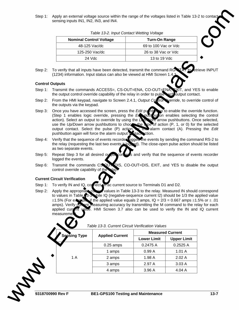
9318700990 Rev F BE1-GPS100 Testing and Maintenance 13-7
Step 1: Apply an external voltage source within the range of the voltages listed in Table 13-2 to contact sensing inputs IN1, IN2, IN3, and IN4.
Table 13-2. Input Contact Wetting Voltage
Nominal Control Voltage Turn-On Range 48-125 Vac/dc 69 to 100 Vac or Vdc
125-250 Vac/dc 26 to 38 Vac or Vdc 24 Vdc 13 to 19 Vdc
Step 2: To verify that all inputs have been detected, transmit the command RG-STAT to retrieve INPUT
(1234) information. Input status can also be viewed at HMI Screen 1.4.1.
Control Outputs Step 1: Transmit the commands ACCESS=, CS-OUT=ENA, CO-OUT=ENA, EXIT, and YES to enable
the output control override capability of the relay in order to pulse each output contact. Step 2: From the HMI keypad, navigate to Screen 2.4.1, Output Control Override, to override control of
the outputs via the keypad. Step 3: Once you have accessed the screen, press the Edit pushbutton to enable the override function.
(Step 1 enables logic override, pressing the Edit pushbutton enables selecting the control action). Select an output to override by using the Left/Right arrow pushbuttons. Once selected, use the Up/Down arrow pushbuttons to choose the type of action (P, 1, or 0) for the selected output contact. Select the pulse (P) action for the alarm contact (A). Pressing the Edit pushbutton again will force the alarm output contact action.
Step 4: Verify that the sequence of events recorder logged the events by sending the command RS-2 to the relay (requesting the last two events it logged). The close-open pulse action should be listed as two separate events.
Step 5: Repeat Step 3 for all desired output contacts and verify that the sequence of events recorder logged the events.
Step 6: Transmit the commands CS-OUT=DIS, CO-OUT=DIS, EXIT, and YES to disable the output control override capability of the relay.
Current Circuit Verification Step 1: To verify IN and IQ, connect an ac current source to Terminals D1 and D2. Step 2: Apply the appropriate current values in Table 13-3 to the relay. Measured IN should correspond
to values in Table 13-3 while IQ (negative-sequence current I2) should be 1/3 the applied value ±1.5% (For example, if the applied value equals 2 amps, IQ = 2/3 = 0.667 amps ±1.5% or ± .01 amps). Verify current measuring accuracy by transmitting the M command to the relay for each applied current value. HMI Screen 3.7 also can be used to verify the IN and IQ current measurement.
Table 13-3. Current Circuit Verification Values
Measured Current Sensing Type Applied Current
Lower Limit Upper Limit 0.25 amps 0.2475 A 0.2525 A
1 amps 0.99 A 1.01 A 2 amps 1.98 A 2.02 A 3 amps 2.97 A 3.03 A
1 A
4 amps 3.96 A 4.04 A
www . El
ectric
alPar
tMan
uals
. com

13-8 BE1-GPS100 Testing and Maintenance 9318700990 Rev F
Table 13-3. Current Circuit Verification Values (continued)
Measured Current Sensing Type Applied Current
Lower Limit Upper Limit 1 amps 0.99 A 1.01 A 5 amps 4.95 A 5.05 A 10 amps 9.90 A 10.10 A 15 amps 14.85 A 15.15 A
5 A
20 amps 19.80 A 20.20 A
Step 3: To verify IP and IG, connect a suitably sized jumper wire across relay terminals D2 and D3, D4
and D5, and D6 and D7. Apply an ac current source to Terminals D1 and D8. Step 4: Apply the appropriate current values in Table 13-3 to the relay. Verify current measuring
accuracy by transmitting the M command to the relay for each applied current value. HMI Screens 3.5 and 3.6 also can be used to verify current measurements. Screen 3.7, IN, will read 3 times the phase value.
Step 5: Leave current circuit connected and de-energized. These test connections will be used later when verifying power readings.
Three-Phase Voltage Circuit Verification Step 1: Connect an ac voltage source at nominal frequency between relay Terminals C13 (A-phase)
and C16 (Neutral terminal). Apply 100 volts and verify voltage-measuring accuracy by transmitting the M command to the relay. Readings should be M-VA = 100 volts, M-VAB = 100 volts, M-VCA = 100 volts, M-3V0 = 100 volts and M-V2 = 33.4 volts (applied divided by 3), all at ±1.0%. HMI Screens 3.1, 3.2, and 3.4 can also be monitored to verify voltage measurements.
Step 2: Connect an ac voltage source at nominal frequency between relay Terminals C14 (B-phase) and C16 (Neutral Terminal). Apply 100 volts and verify voltage-measuring accuracy by transmitting the M command to the relay. Readings should be M-VB = 100 volts, M-VAB = 100 volts, M-VBC = 100 volts, M-3V0 = 100 volts and M-V2 = 33.4 volts (applied divided by 3), all at ±1.0%. HMI Screens 3.1, 3.2, and 3.4 can also be monitored to verify voltage measurements.
Step 3: Connect an ac voltage source at nominal frequency between relay Terminals C15 (C-phase) and C16 (Neutral Terminal). Apply 100 volts and verify voltage-measuring accuracy by transmitting the M command to the relay. Readings should be M-VC = 100 volts, M-VBC = 100 volts, M-VCA = 100 volts, M-3V0 = 100 volts and M-V2 = 33.4 volts (applied divided by 3), all at ±1.0%. HMI Screens 3.1, 3.2, and 3.4 can also be monitored to verify voltage measurements.
Step 4: Connect relay Terminals C13 (A-phase), C14 (B-phase), and C15 (C-phase) together. Connect an ac voltage source at nominal frequency to the three jumpered terminals and the Neutral Terminal (C16).
Step 5: Apply the voltage values listed in Table 13-4 and verify voltage measuring accuracy by transmitting the M command to the relay. HMI Screen 3.1 can also be monitored to verify voltage measurements.
Table 13-4. Voltage Circuit Verification Values
Measured Voltage Applied Voltage
Lower Limit Upper Limit 80 volts 79.2 V 80.8 V 100 volts 99.0 V 101.0 V 120 volts 118.8 V 121.2 V 140 volts 138.6 V 141.4 V 160 volts 156.8 V 163.2 V
www . El
ectric
alPar
tMan
uals
. com

9318700990 Rev F BE1-GPS100 Testing and Maintenance 13-9
Power Reading Verification Step 1: Use the same voltage connections as in the previous test, polarity voltage jumpered to C13, 14,
and 15, neutral tied to C16. Use the same current connection as in Steps 3 and 4 of Current Circuit Verification; that is, polarity current in 1 out 8 with 2 and 3, 4 and 5, 6 and 7 jumpered together.
Step 2: Apply 100 volts at angle 0 degrees and 1 or 5 amps (depending on the current rating) at angle 0 degrees to the relay. Verify the accuracy of the power reading by transmitting the M command to the relay. Power should be 1.5 kw ±1.0% and reactive should read near 0 vars. HMI Screen 3.8 could also be monitored to verify power and reactive readings. The apparent power should be 1.5 kVA ±1.0% at unity power factor. Apparent power can also be viewed on HMI Screen 3.9.
Step 3: Reverse the current polarity and apply the same values as in Step 2. Note that the power reading is -1.5 kw, which indicates "power in" to the zone being protected.
Step 4: Return the current polarity back to Step 1 position. Apply 100 volts at angle 0 degrees and 5 amps at angle -90 degrees (I lag E by 90 degrees) to the relay, and verify reactive power accuracy by transmitting the M command to the relay. Power should be nearly 0 kw, and reactive should read 1.5 kvar ±1.0%. HMI Screen 3.8 can also be monitored to verify power and reactive values. Apparent power and power factor can also be viewed on HMI Screen 3.9. Note power factor reads near 0 with a negative sign indicating a lagging power factor angle.
Step 5: Reverse the current polarity and apply the same values as in Step 4. Note that the reactive power reading is -1.5 kvar, which indicates reactive power in to the device being protected. Also, note that the power factor angle is near 0 with a positive sign indicating a leading power factor angle.
Step 6: Repeat Step 2 and 4 for current values of 10 and 20 amps. Corresponding power reading should be 3 kw/kvar and 6 kw /kvar ±1.0%.
Auxiliary Voltage Input Verification - VX and VX 3rd (Fundamental and Third Harmonic) Step 1: Connect relay terminals C17 (polarity) and C18 to a 60 hertz ac voltage source. Step 2: Apply the voltage values listed in Table 13-5 and verify voltage-measuring accuracy by
transmitting the M-V command to the relay. HMI Screens 3.3, VX can also be monitored to verify voltage measurements.
Step 3: Connect relay Terminals C17 (polarity) and C18 to a 180-hertz (third harmonic) ac voltage source.
Step 4: Apply the voltage values listed in Table 13-5 and verify voltage-measuring accuracy by transmitting the M command to the relay. HMI Screen 3.3, VX can also be monitored to verify voltage measurements.
Table 13-5. Aux Voltage Circuit Verification VX & VX 3rd Values
Measured Voltage Applied Voltage
Lower Limit Upper Limit 5 volts 4.95 V 5.05 V
20 volts 19.8 V 20.2 V 60 volts 59.4 V 60.6 V 80 volts 79.2 V 80.8 V 120 volts 118.8 V 121.2 V
NOTE Power readings in this procedure are based on a 5 amp relay; for 1 amp values, divide by 5.
www . El
ectric
alPar
tMan
uals
. com

13-10 BE1-GPS100 Testing and Maintenance 9318700990 Rev F
Line and Bus Angle, Frequency, and Slip Verification Step 1: Connect relay Terminals C13 (polarity) and C16 (A to Neutral of the three-phase voltage input)
to a 60 hertz ac voltage source (line voltage). Step 2: Connect relay Terminals C17 (polarity) and C18 (Auxiliary Voltage Input) to a second 60-hertz
ac voltage source (bus voltage). Step 3: Apply 115 volts at 0 degrees and 60 hertz to both sources. Verify the measuring accuracy of the
line and bus frequency, angle between the two voltages, and slip frequency by transmitting the M command to the relay. HMI Screens 3.10 and 3.11 can also be monitored to verify the measurements.
Step 4: Vary the angle of the line voltage and verify the measured angle as in Step 3. Polarity of the angle measurement is relative to the angle of the line voltage. That is, if the line voltage lags the bus voltage by 30 degrees, the sign of the angle will be negative or -30 degrees. When the line voltage leads, the angle has no sign and is assumed positive.
Step 5: Return the line voltage angle to 0 degrees. Vary the frequency of the line voltage and verify the measured slip as in Step 3. (Note that the angle shown on HMI Screen 3.11 is continuously changing because of slip between the two systems. This is normal). Polarity of the slip frequency is relative to the frequency of the line. That is, if the line frequency is 58 hertz and the bus frequency is 60 hertz, the slip frequency is -2. As soon as the line frequency rises above 60 hertz, slip frequency has no sign and is assumed positive.
COMMISSIONING TESTING Because the commissioning of this relay may be a new installation or a retrofit, special precautions should be taken to ensure that all tests are performed with safety as the greatest concern. Any CT circuit signals that are routed through this device as part of a protection scheme including discrete relays or as a stand-alone device should be shorted and isolated from this relay during these tests until the final instrument transformer current circuit check. If this relay is being installed in an existing installation, please be aware of the equipment monitoring features of this device, especially if the monitoring logic will be utilized. Please make note of any pretest operation levels, duty levels, etc. on existing equipment (e.g., breakers or transformers). As the user, you may make the determination of what values the relay should have as initial monitoring values when the relay is placed in service. Also, please be aware that because of the multi-function nature of the BE1-GPS100 relay, it may on occasion be necessary to temporarily disable some of the protective elements while testing the relay to facilitate isolated testing of individual functions. Always remember to enable these functions before placing the relay in service. To assist you in the commissioning testing of this relay, you may refer to Section 6, Reporting and Alarm Functions, for various means of reporting status, alarms, and targets. Please refer to the other sections of the instruction manual for assistance on any particular functions of the relay. If you require further assistance, contact Basler Electric field application personnel or the factory.
Digital I/O Connection Verification
Contact Sensing Inputs Purpose: To verify contact sensing input label assignments and recognition and debounce settings. Reference Commands: SN-IN, SG-IN Step 1: Transmit the SN-IN1 command to verify the input 1 user-defined name, TRUE label, and FALSE
label. Step 2: Repeat Step 1 for each of the remaining contact sensing inputs. Add the number of an input to
the SN-IN command to check that input's name and labels. Step 3: Verify the recognition and debounce settings for each contact sensing input by using the SG-IN
command. When the SG-IN command is transmitted, the relay responds with the recognition and debounce settings for each input. Reported settings use the format SG-IN#=recognition, debounce.
www . El
ectric
alPar
tMan
uals
. com

9318700990 Rev F BE1-GPS100 Testing and Maintenance 13-11
Step 4: Transmit the RG-STAT command to the relay or use HMI Screen 1.4.1 to verify the status of input 1. Transmit the RS-NEW=0 command to the relay. From the actual field device, close (or open) the specific contact that supplies relay Input 1. While maintaining contact position, verify that Input 1 has changed state by transmitting the RG-STAT command or using HMI Screen 1.4.1. Return the field contact to its original state, verifying that Input 1 returns to its original state. Transmit the RS-NEW command to the relay and review the event record associated with the field contact change.
Step 5: Repeat Step 4 for each connected input.
Output Contacts Purpose: To verify output contact settings and output contact logic settings. Reference Commands: SN-VO, SL-VO, SG-HOLD Step 1: Transmit the SN-VOA command to verify the Virtual Output A user-defined name, TRUE label,
and FALSE label. Step 2: Repeat Step 1 for Virtual Outputs 1 through 15. Add the number of an output to the SN-VO
command to check that output's name and labels. Step 3: Transmit the SL-VO command to obtain a list of all virtual outputs and their Boolean logic
equations. Verify that the desired virtual output equations match the reported equations. Step 4: Verify the programmable hold timer setting for each hardware output by transmitting the
command SG-HOLD. The output hold timer setting for each output is reported as enabled (1) or disabled (0).
Step 5: Verify the output contact activity by viewing the sequence of events reports with the RS-### command.
Step 6: Use the procedure outlined under "Acceptance Tests, Control Outputs" to actuate selected output contacts (V01 through V05) and actually trip or close the connected field device (circuit breaker, lockout, etc.). Use the same procedure to verify that operation of the alarm output relay (V0A) initiates the appropriate alarm response.
Virtual Selector Switches (If not used, skip to Virtual Control Switch) Purpose: To verify the operation, labels, and logic settings of the 43 switches. Reference Commands: SN-43, SL-43, RG-STAT, CS/CO-43 Step 1: Transmit the SN-43 command to verify the Virtual Selector Switch 43 name, TRUE label, and
FALSE label. This information is reported using the format SN-x43=name,TRUE label,FALSE label.
Step 2: Repeat Step 1 for Virtual Selector Switches 143 through 343. Step 3: Use the SL-x43 command to obtain the logic setting of Virtual Switches 43 through 343. Verify
that the desired virtual selector switch setting matches the reported setting. Step 4: Transmit the RG-STAT command to obtain the position of the four virtual selector switches.
Alternately, the virtual selector switch positions can be obtained through the optional HMI Screen 1.4.4.
Step 5: Obtain write access to the relay by using the ACCESS= command. For each virtual selector switch enabled in your logic scheme, change the switch position by entering CS-x43 = 1 (TRUE), 0 (FALSE), or P (Pulse) followed by CO-x43=1,0 or P. The syntax of the CS-x43 and CO-x43 commands must match or the CO-x43 command will not be executed.
Step 6: Verify each switch position change by using the CO-x43 command or through HMI Screen 1.4.4.
Step 7: Return each virtual selector switch to the original position. Step 8: Verify the 43 Switch activities by viewing the sequence of events reports with the RS-###
command.
Virtual Control Switch (If not used, skip to Protection and Control Function Verification) Purpose: To verify the operation, label, and logic setting for the 101 Switch. Reference Commands: SB-LOGIC, SL-101, RG-STAT, CS/CO-101 Step 1: Verify the breaker label and breaker-closed logic expression with the SB-LOGIC command.
www . El
ectric
alPar
tMan
uals
. com

13-12 BE1-GPS100 Testing and Maintenance 9318700990 Rev F
Step 2: Use the SL-101 command to read the logic mode of the 101 Switch. The switch is either enabled (1) or disabled (0).
Step 3: Obtain the virtual control switch status by using the RG-STAT command. Step 4: Transmit the command ACCESS= to obtain write access to the relay. Change the switch
position by entering CS-101=T (Trip) or C (Close) followed by CO-101=T (Trip) or C (Close). The syntax of the CS-101 and CO-101 commands must match or the CO-101 command will not be executed.
Step 5: Confirm the switch position change with the RG-STAT command. Step 6: Repeat Step 4 to return the 101 Switch to the desired position for your application. Step 7: Verify the 101 Switch activities by viewing the sequence of events reports with the RS-###
command.
Protection and Control Function Verification Before placing the relay in service, the user should ensure that all system ac and dc connections are correct, that the relay functions as intended with user settings applied and that all equipment external to the relay operates as intended. All connected or monitored inputs and outputs, and polarity and phase rotation of ac connections should be tested. Verify that:
• Power supply and contact wetting voltages are correct. • User desired protection and control functions are enabled and connected to the correct CT and
VT input circuits. • The programmable logic settings (electronic wiring) provide the proper interconnection of these
functions with the I/O of the relay. • Each protection function has the desired operational set points.
Simple user designed fault tests should be used to verify that the operational settings are correct, that the proper output relays are actuated and proper targeting occurs. (Refer to Figure 13-1 or 13-2 for terminal locations.) It is not necessary to test every protection element, timer, and function in these tests. Use of the fault and event recording capability of the relay will aid in the verification of the protection and control logic. Transmit the RS command to retrieve all SER records or RS-n to get a specific operation. In addition, it is helpful to transmit RS-NEW=0 prior to starting a test. This allows the user to review only those operations recorded since the last RS-NEW was initiated. Replace the S with F and use the same commands for Fault records. Refer to Section 6, Reporting and Alarm Functions, for more detail. Please be aware that because of the multi-function nature of the BE1-GPS100 relay, it may be necessary to disable protection elements or change setting logic to verify a specific function. To guard against placing the relay in service with unwanted operational or logic settings, it is good practice to save a copy of the original setting file before the testing process begins. When testing is complete, compare the copy of the saved settings to the actual relay settings as a final verification. To accomplish this, transmit the S command to the relay. This command generates all logic and operational settings that are on the relay. Copy the data to a text editor such as Notepad and print it out. This along with the user's logic diagram provides a complete picture of the relay's protection and control capability. The logic and operational settings of the protection and control functions should be examined to determine:
• The mode setting for the function so that you know what the relay is supposed to do. • Which virtual output logic expressions contain the logic variables that represent the output
contacts for protection function being tested. • The input logic expressions for the function under test (especially the block input because it
renders the function disabled if the block input is asserted). • That the operational pickup and dropout threshold values and time delays agree with the users
calculated values. • That the fault reporting settings are set so the relay properly indicates pickup and trip states and
records targets. These settings are set from the ASCII command interface using the SG-TRIGGER and SG-TARG setting commands. Section 6, Reporting and Alarm Functions, Fault Reporting, for more details.
www . El
ectric
alPar
tMan
uals
. com

9318700990 Rev F BE1-GPS100 Testing and Maintenance 13-13
Verify Other Set Points as Appropriate Consult Functional Testing found later in this section for guidelines on testing and verifying set points of other protection and control functions.
Report and Alarm Functions Just prior to placing the relay in service, the following reporting and alarm functions should be reset and/or verified. For details on how to use the optional LCD HMI or the ASCII command interface to enter or edit relay operating values. See Sections 10 and 11, respectively.
Clock Display Set the real time clock to the current date and time. If an IRIG input is used, day and time are automatically synched to the IRIG source. However, note that the IRIG time code signal does not contain the current year information thus necessitating the entry of the year. Reference Commands: RG-TIME, RG-DATE Reference HMI Screen: 4.6 Refer to Section 6, Reporting and Alarm Functions, Clock, for setting details.
Energy Data and Demand Read, change or reset KWH and KVARH records. If the Demand Functions feature of the relay is enabled, use the following to reset the peak current, watt and var demand registers to "0" or a pre-existing value: Reference Commands: RE, RD, RD-<pp> Reference HMI Screens: 4.4.1.x, 4.4.2.x, and 4.4.3.x Refer to Section 6, Reporting and Alarm Functions, Energy Data and Demand Functions sub-sections for setting details.
Breaker Monitoring If the Breaker Monitoring features of the relay are enabled, use the following to reset the counter and the duty registers to "0" or a pre-existing value: Reference Commands: RB-OPCNTR, RB-DUTY Reference HMI Screens: 4.3.1 Refer to Section 6, Reporting and Alarm Functions, Breaker Monitoring, for setting details.
Relay Trouble Alarms Reset and verify that the relay trouble alarm is not illuminated. If required, alarm information can be read by transmitting the RA or RG-STAT commands. To attempt clearing a Relay Trouble Alarm, first gain write access to the reporting functions ("R" password) and initiate the RA=0 or RA-REL=0 commands or press the Reset key from a STAT \ALARMS \ALARM Screen on the HMI. Refer to Section 6, Reporting and Alarm Functions, Alarms Function, Relay Trouble Alarms, for setting details.
Major/Minor/Logic Programmable Alarms Reset and verify that the programmable alarms, Major, Minor, and Logic, as set to meet user needs, are not illuminated or asserted. If required, alarm information can be read by transmitting the RA or RG-STAT commands. To reset a Major/Minor/Logic Alarm, first gain write access to the reporting functions ("R" password) and initiate the RA=0 or RA-MAJ/MIN/LGC=0 commands or by pressing the Reset key from a STAT \ALARMS \DET Screen on the HMI. Refer to Section 6, Reporting and Alarms, Alarms Function, for setting details.
Targets Reset and verify that there is no target information. Targets are reset from HMI Screen 1.1.1, \STATS \TARGETS by pressing the Reset key or gaining write access to the reporting functions ("R" password) and transmitting RG-TARG [= 0]. Relay target information can be read either from HMI Screen 1.1.1, \STATS \TARGETS, or by transmitting the RG-TARG command. Refer to Section 6, Reporting and Alarm Functions, Fault Reporting, Targets, for setting details.
www . El
ectric
alPar
tMan
uals
. com

13-14 BE1-GPS100 Testing and Maintenance 9318700990 Rev F
Fault Summary Reports Reset "new" fault summary directory records to "0" by first gaining write access to the reporting functions ("R" password) and transmitting the RF-NEW [= 0] command. Verify that new faults is "0" by transmitting the RF command. Refer to Section 6, Reporting and Alarm Functions, Fault Reporting, Fault Summary Reports, for setting details.
Sequence of Events Recorder (SER) Reset the "new" SER records counter to "0" by first gaining write access to the reporting functions ("R" password) and transmitting the RS-NEW [= 0] command two times. Verify that new records is "0" by transmitting the RS command. Refer to Section 6, Reporting and Alarm Functions, Sequence of Events Recorder, for setting details.
Just Prior to Energizing - Report Documentation After completing the previous steps, capture and save a General Status Report by transmitting the RG-STAT command. This report should be kept in the permanent record file of the device so the data can be used for comparison in future maintenance procedures. Also, save the entire settings record for future reference by transmitting the "S" command. Use this record during the maintenance cycle or during the analysis of an operation to verify that the “as found" settings are exactly as left during the commissioning process. Refer to Section 6, Reporting and Alarm Functions, General Status Reporting, for details.
In Service Readings Just after energizing the equipment, transmit the "M" command to the relay. Use this record to review the following:
• M-I and M-V to verify VT and CT ratios. • Polarity of M-WATT and M-VAR readings to verify polarity of VT and CT connections. • M-IQ and M-V2 to verify proper phase-sequence connections. • M-SYNC to verify proper phase relationship of VP and VX. • Anything else that the user might find helpful.
Save this record along with the RG-STAT record mentioned earlier for future reference.
PERIODIC TESTING Because the BE1-GPS100 has extensive internal test capabilities, periodic testing of the protection system can be greatly reduced. Relay operating characteristics are a function of programming instructions that do not drift over time. Thus, the user may wish to verify items that the relay's self-testing features cannot completely determine. Periodic testing might consist of the following settings and function checks:
• Verify that the set points that were proven during commissioning have not been changed. • Verify that the inputs and outputs are interfacing properly with the rest of the protection and
control system. • Verify that the power system analog parameters used by the protection and control functions are
being measured accurately.
Settings Verification Verification of the relay digital I/O connections can be accomplished in different ways. The method used depends on your preferences and practices. You might choose to use either of the following two methods:
• Repeat the digital I/O connection and label verification under commissioning tests. • Monitor SER, status, and fault reports for proper sensing of digital signals and proper output
tripping during normal operation.
www . El
ectric
alPar
tMan
uals
. com
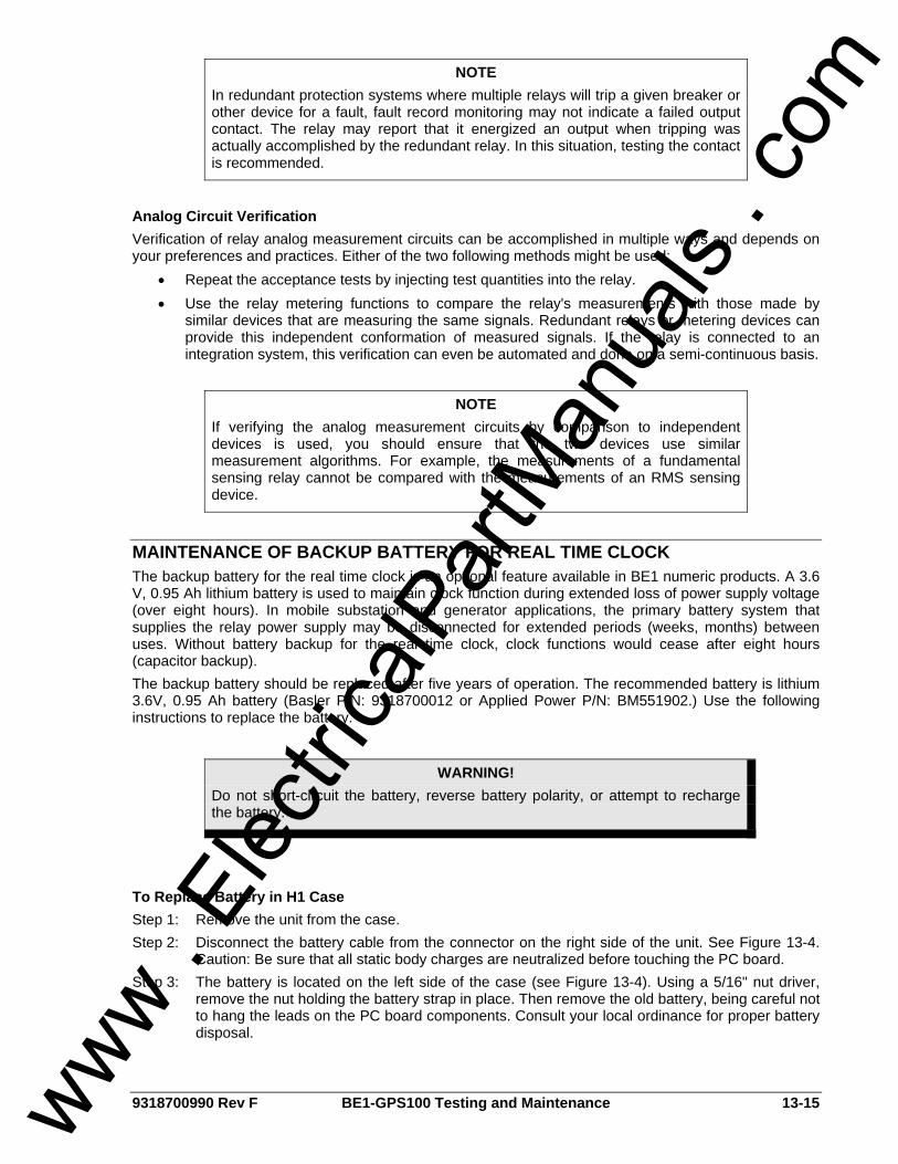
9318700990 Rev F BE1-GPS100 Testing and Maintenance 13-15
Analog Circuit Verification Verification of relay analog measurement circuits can be accomplished in multiple ways and depends on your preferences and practices. Either of the two following methods might be used:
• Repeat the acceptance tests by injecting test quantities into the relay. • Use the relay metering functions to compare the relay's measurements with those made by
similar devices that are measuring the same signals. Redundant relays or metering devices can provide this independent conformation of measured signals. If the relay is connected to an integration system, this verification can even be automated and done on a semi-continuous basis.
MAINTENANCE OF BACKUP BATTERY FOR REAL TIME CLOCK The backup battery for the real time clock is an optional feature available in BE1 numeric products. A 3.6 V, 0.95 Ah lithium battery is used to maintain clock function during extended loss of power supply voltage (over eight hours). In mobile substation and generator applications, the primary battery system that supplies the relay power supply may be disconnected for extended periods (weeks, months) between uses. Without battery backup for the real time clock, clock functions would cease after eight hours (capacitor backup). The backup battery should be replaced after five years of operation. The recommended battery is lithium 3.6V, 0.95 Ah battery (Basler P/N: 9318700012 or Applied Power P/N: BM551902.) Use the following instructions to replace the battery.
To Replace Battery in H1 Case Step 1: Remove the unit from the case. Step 2: Disconnect the battery cable from the connector on the right side of the unit. See Figure 13-4.
Caution: Be sure that all static body charges are neutralized before touching the PC board. Step 3: The battery is located on the left side of the case (see Figure 13-4). Using a 5/16" nut driver,
remove the nut holding the battery strap in place. Then remove the old battery, being careful not to hang the leads on the PC board components. Consult your local ordinance for proper battery disposal.
NOTE In redundant protection systems where multiple relays will trip a given breaker or other device for a fault, fault record monitoring may not indicate a failed output contact. The relay may report that it energized an output when tripping was actually accomplished by the redundant relay. In this situation, testing the contact is recommended.
NOTE If verifying the analog measurement circuits by comparison to independent devices is used, you should ensure that the two devices use similar measurement algorithms. For example, the measurements of a fundamental sensing relay cannot be compared with the measurements of an RMS sensing device.
WARNING! Do not short-circuit the battery, reverse battery polarity, or attempt to recharge the battery.
www . El
ectric
alPar
tMan
uals
. com

13-16 BE1-GPS100 Testing and Maintenance 9318700990 Rev F
Figure 13-4. Backup Battery Location
Step 4: Insert the new battery by carefully feeding the leads through the hole in the aluminum plate and
sliding them between the PC boards. Plug the new battery into the connector as shown in Figure 13-4.
Step 5: Place the battery under the battery strap and replace the nut. Put the unit back into the case.
To Replace Battery in S1 Case Step 1: Remove the unit from the case. Step 2: Remove the front panel from the unit by removing the four screws located in the upper, lower,
left and right hand corners. The battery will be attached to the backside of the panel, using a strap similar to what is shown for the H1 case in Figure 13-4.
Step 3: Disconnect the battery cable from the connector on the right side of the unit. Caution: Be sure that all static body charges are neutralized before touching the PC board.
Step 4: Using a 5/16" nut driver, remove the nut holding the battery strap in place. Then remove the old battery being careful not to hang the leads on the PC board components. Consult your local ordinance for proper battery disposal.
Step 5: Insert the new battery and connect the lead to the connector the old battery had been connected.
Step 6: Place the battery under the battery strap and replace the nut. Put the unit back into the case.
CARE AND HANDLING The BE1-GPS100 can be fully drawn out of the case. When the drawout assembly is removed, the current transformer input circuits are automatically shorted by the case. The case contains no components that are likely to require service; all critical components are contained in the drawout assembly. When removing the drawout assembly from the case, care should be taken to prevent electrostatic discharge (ESD) and mechanical damage. There is no need to disturb the circuit interconnections within the drawout assembly. Repair of the drawout assembly by replacement of individual circuit boards is not recommended. The printed circuit boards are constructed using surface-mount technology and are not intended to be field serviceable. If a relay failure occurs in a critical application without sufficient redundancy, protection can be restored by inserting a spare relay in the mounted and wired case of the relay requiring service. The drawout assembly requiring service can then be returned to the factory in the case from the spare relay. If a spare case is not available, care should be used when packing the drawout assembly for shipment. Use antistatic packing material that prevents mechanical damage during transit. Before returning the drawout assembly for repair, contact the Basler Electric Technical Services Department at 618-654-2341 for a return authorization number.
www . El
ectric
alPar
tMan
uals
. com

9318700990 Rev F BE1-GPS100 Testing and Maintenance 13-17
UPDATING FIRMWARE AND SOFTWARE Future enhancements to relay functionality may make a firmware update desirable. Enhancements to relay firmware typically coincide with enhancements to BESTCOMS software for that relay. When a relay is updated with the latest version of firmware, the latest version of BESTCOMS software should also be obtained.
Updating Relay Firmware If a firmware upgrade is desired, you may request a CD-ROM containing the latest firmware or download the firmware from the Basler Electric Web site. Direct your web browser to http://www.basler.com/BE1_Firm/ and complete the online form to request a CD-ROM containing the latest firmware or a password for downloading firmware from the Basler Electric Web site. Once the appropriate firmware is obtained, it can be uploaded to a relay using the BESTload software utility provided on the CD-ROM originally supplied with the relay.
Updating BESTCOMS Software Firmware enhancements often include the addition of relay settings or the modification of existing settings. BESTCOMS software is revised to accommodate the new or changed settings. When firmware is updated, the latest version of BESTCOMS should also be obtained. If a CD-ROM containing firmware was obtained from Basler Electric, then that CD-ROM will also contain the corresponding version of BESTCOMS software. BESTCOMS can also be downloaded from the Basler Electric Web site (http://www.basler.com). An on-line form can be completed to obtain a password for downloading BESTCOMS from the Basler Electric Web site.
FUNCTIONAL TESTING
Functional testing is a way to assess this relay's suitability for your application. Functional testing goes beyond the more basic tests found in acceptance testing, but lacks the detailed function testing that is part of the commissioning process. Test each of the following functions to verify that this relay measures accurately, is within specified tolerances, and operates correctly. These tests are also suitable for assisting in systematic troubleshooting in the event that an operation is questioned. Revisiting the test of a specific function can help verify whether the relay is operating within specified tolerances. For further assistance, contact Basler Electric, Technical Support Services Department. Test connections referred to in this section are for an H1 case relay. Refer to Figure 13-1 (H1 case) for terminal locations. If testing a relay in an S1 case, modify the current and potential test connections according to the terminal locations shown in Figure 13-2 (S1 case) or 13-3 (S1 Double-End Case). The Access command (A=) and the Exit with Save commands (E and Y) are shown in the initial logic setup table found in each test section. In order to include multiple test settings in each operational setting table, the "access”, and "exit with save" commands are not included. However, "access" and "exit with save" are required each time a logic or operational setting is changed. To accelerate the testing process, two protection elements may have the same setting and are tested at the same time but with different outputs. During the pickup/dropout test, one of the elements could pick up slightly ahead of the other, resulting in only one target being displayed. At some point in the test, apply 110% of the pickup value and verify that both targets display. Reset targets prior to each test by pressing the HMI Reset key.
NOTE Functional testing is NOT required for this device. It is necessary only when performing a comprehensive assessment to determine suitability for an application.
www . El
ectric
alPar
tMan
uals
. com
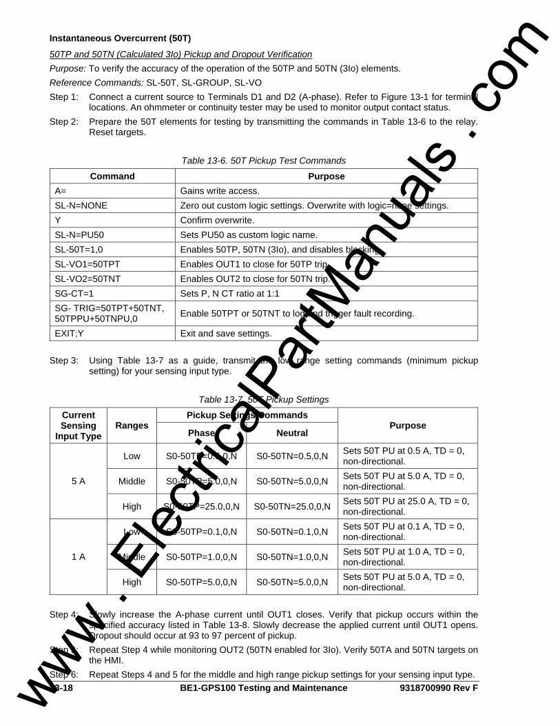
13-18 BE1-GPS100 Testing and Maintenance 9318700990 Rev F
Instantaneous Overcurrent (50T)
50TP and 50TN (Calculated 3Io) Pickup and Dropout Verification Purpose: To verify the accuracy of the operation of the 50TP and 50TN (3Io) elements. Reference Commands: SL-50T, SL-GROUP, SL-VO Step 1: Connect a current source to Terminals D1 and D2 (A-phase). Refer to Figure 13-1 for terminal
locations. An ohmmeter or continuity tester may be used to monitor output contact status. Step 2: Prepare the 50T elements for testing by transmitting the commands in Table 13-6 to the relay.
Reset targets.
Table 13-6. 50T Pickup Test Commands
Command Purpose A= Gains write access. SL-N=NONE Zero out custom logic settings. Overwrite with logic=none settings. Y Confirm overwrite. SL-N=PU50 Sets PU50 as custom logic name. SL-50T=1,0 Enables 50TP, 50TN (3Io), and disables blocking. SL-VO1=50TPT Enables OUT1 to close for 50TP trip. SL-VO2=50TNT Enables OUT2 to close for 50TN trip. SG-CT=1 Sets P, N CT ratio at 1:1 SG- TRIG=50TPT+50TNT, 50TPPU+50TNPU,0 Enable 50TPT or 50TNT to log and trigger fault recording.
EXIT;Y Exit and save settings.
Step 3: Using Table 13-7 as a guide, transmit the low range setting commands (minimum pickup setting) for your sensing input type.
Table 13-7. 50T Pickup Settings
Pickup Settings Commands Current Sensing
Input Type Ranges
Phase Neutral Purpose
Low S0-50TP=0.5,0,N S0-50TN=0.5,0,N Sets 50T PU at 0.5 A, TD = 0, non-directional.
Middle S0-50TP=5.0,0,N S0-50TN=5.0,0,N Sets 50T PU at 5.0 A, TD = 0, non-directional. 5 A
High S0-50TP=25.0,0,N S0-50TN=25.0,0,N Sets 50T PU at 25.0 A, TD = 0, non-directional.
Low S0-50TP=0.1,0,N S0-50TN=0.1,0,N Sets 50T PU at 0.1 A, TD = 0, non-directional.
Middle S0-50TP=1.0,0,N S0-50TN=1.0,0,N Sets 50T PU at 1.0 A, TD = 0, non-directional. 1 A
High S0-50TP=5.0,0,N S0-50TN=5.0,0,N Sets 50T PU at 5.0 A, TD = 0, non-directional.
Step 4: Slowly increase the A-phase current until OUT1 closes. Verify that pickup occurs within the
specified accuracy listed in Table 13-8. Slowly decrease the applied current until OUT1 opens. Dropout should occur at 93 to 97 percent of pickup.
Step 5: Repeat Step 4 while monitoring OUT2 (50TN enabled for 3Io). Verify 50TA and 50TN targets on the HMI.
Step 6: Repeat Steps 4 and 5 for the middle and high range pickup settings for your sensing input type. www . El
ectric
alPar
tMan
uals
. com
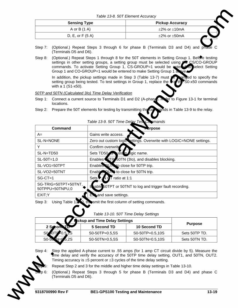
9318700990 Rev F BE1-GPS100 Testing and Maintenance 13-19
Table 13-8. 50T Element Accuracy
Sensing Type Pickup Accuracy A or B (1 A) ±2% or ±10mA
D, E, or F (5 A) ±2% or ±50mA
Step 7: (Optional.) Repeat Steps 3 through 6 for phase B (Terminals D3 and D4) and phase C (Terminals D5 and D6).
Step 8: (Optional.) Repeat Steps 1 through 8 for the 50T elements in Setting Group 1. Before testing settings in other setting groups, a setting group must be selected using the CS/CO-GROUP commands. To activate Setting Group 1, CS-GROUP=1 would be entered to select Setting Group 1 and CO-GROUP=1 would be entered to make Setting Group 1 active. In addition, the pickup settings made in Step 3 (Table 13-7) must be changed to specify the setting group being tested. To test settings in Group 1, replace the 0 in the S0-x50 commands with a 1 (S1-x50).
50TP and 50TN (Calculated 3Io) Time Delay Verification Step 1: Connect a current source to Terminals D1 and D2 (A-phase). Refer to Figure 13-1 for terminal
locations. Step 2: Prepare the 50T elements for testing by transmitting the commands in Table 13-9 to the relay.
Table 13-9. 50T Time Delay Test Commands
Command Purpose A= Gains write access. SL-N=NONE Zero out custom logic settings. Overwrite with LOGIC=NONE settings. Y Confirm overwrite. SL-N=TD50 Sets TD50 as custom logic name. SL-50T=1,0 Enables 50TP, 50TN (3Io), and disables blocking. SL-VO1=50TPT Enables OUT1 to close for 50TP trip. SL-VO2=50TNT Enables OUT2 to close for 50TN trip. SG-CT=1 Sets P, N CT ratio at 1:1 SG-TRIG=50TPT+50TNT, 50TPPU+50TNPU,0 Enable 50TPT or 50TNT to log and trigger fault recording.
EXIT;Y Exit and save settings.
Step 3: Using Table 13-10, transmit the first column of setting commands.
Table 13-10. 50T Time Delay Settings
Pickup and Time Delay Settings 2 Second TD 5 Second TD 10 Second TD
Purpose
S0-50TP=0.5,2S S0-50TP=0.5,5S S0-50TP=0.5,10S Sets 50TP TD. S0-50TN=0.5,2S S0-50TN=0.5,5S S0-50TN=0.5,10S Sets 50TN TD.
Step 4: Step the applied A-phase current to .55 amps (for 1 amp CT circuit divide by 5). Measure the
time delay and verify the accuracy of the 50TP time delay setting, OUT1, and 50TN, OUT2. Timing accuracy is ±5 percent or ±3 cycles of the time delay setting.
Step 5: Repeat Step 2 and 3 for the middle and higher time delay settings in Table 13-10. Step 6: (Optional.) Repeat Steps 3 through 5 for phase B (Terminals D3 and D4) and phase C
(Terminals D5 and D6).
www . El
ectric
alPar
tMan
uals
. com

13-20 BE1-GPS100 Testing and Maintenance 9318700990 Rev F
Step 7: (Optional.) Repeat Steps 1 through 6 for the 50T elements in Setting Group 1. Before testing settings in other setting groups, a setting group must be selected using the CS/CO-GROUP commands. To activate Setting Group 1, CS-GROUP=1 would be entered to select Setting Group 1 and CO-GROUP=1 would be entered to make Setting Group 1 active. In addition, the pickup settings made in Step 3 (Table 13-10) must be changed to specify the setting group being tested. To test settings in Group 1, replace the 0 in the S0-x50 commands with a 1 (S1-x50).
50TN (Independent Ground Input IG) Pickup and Dropout Verification Purpose: To verify the operation of the 50TN element for IG input. Reference Commands: SL-50TN Step 1: Connect a current source to Terminals D7 and D8 (IG). Step 2: Prepare the 50TN elements for testing by transmitting the commands in Table 13-11 to the
relay. Reset targets. Table 13-11. 50TN Pickup Test Commands
Command Purpose A= Gains write access. SL-N=NONE Zero out custom settings. Overwrite with LOGIC=NONE settings. Y Confirm overwrite. SL-N=50TN Sets 50TN as custom logic name. SL-50TN=G,0 Enables 50TN, disables blocking. SL-VO1=50TNT Enables OUT1 to close for 50TN trip. SG-CT=1 Sets CT ratio at 1. SG-TRIGGER=50TNT+50TNPU,0 Enable 50TNT to log and trigger fault recording.
EXIT;Y Exit and save settings.
Step 3: Using Table 13-12, transmit the first row of setting commands for your sensing input type.
Table 13-12. 50TN Pickup Settings
Sensing Type Command Purpose
S0-50TN=0.1,0,N Sets 50TN pickup at 0.1 A, TD = 0, non-directional.
S0-50TN=1.0,0,N Sets 50TN pickup at 1.0 A, TD = 0, non-directional. 1 A
S0-50TN=5.0,0,N Sets 50TN pickup at 5.0 A, TD = 0, non-directional.
S0-50TN=0.5,0,N Sets 50TN pickup at 0.5 A, TD = 0, non-directional.
S0-50TN=5.0,0,N Sets 50TN pickup at 5.0 A, TD = 0, non-directional. 5 A
S0-50TN=10.0,0,N Sets 50TN pickup at 10.0 A, TD = 0, non-directional.
Step 4: Slowly increase the IG current until OUT1 closes. Verify that pickup occurs within the specified
accuracy listed in Table 13-13. Slowly decrease the applied current until OUT1 opens. Dropout should occur at 93 to 97 percent of pickup.
Step 5: Verify 50TG target on the HMI. Verify the pickup accuracy of the middle and upper pickup settings.
www . El
ectric
alPar
tMan
uals
. com

9318700990 Rev F BE1-GPS100 Testing and Maintenance 13-21
Table 13-13. 50T Element Accuracy
Sensing Type Pickup Accuracy A or B (1 A) ±2% or ±10 mA
D, E, or F (5 A) ±2% or ±50 mA
Step 6: (Optional.) Repeat Steps 1 through 5 for the 50TN element in Setting Group 1.
50TN (Independent Ground Input IG) Time Delay Verification Step 1: Prepare the 50TN element for testing by transmitting the commands in Table 13-11 to the relay. Step 2: Using Table 13-14, transmit the first column of setting commands for your sensing input type
(5A is shown).
Table 13-14. 50TN/150TN Time Delay Settings
Pickup and Time Delay Settings 2 Second TD 5 Second TD 10 Second TD
Purpose
S0-50TN=0.5,2S S0-50TN=0.5,5S S0-50TN=0.5,10S Sets 50TN TD.
Step 3: With the current source still connected to Terminals D7 and D8 (IG), step the applied current to
.55 amps (for 1 amp CT circuit divide by 5). Measure the time delay and verify the accuracy of the 50TN time delay setting, OUT1. Timing accuracy is ±5 percent or ±3 cycles of the time delay setting.
Step 4: Repeat Step 2 and 3 for the middle and higher time delay settings in Table 13-14. Step 5: (Optional.) Repeat Steps 1 through 4 for Setting Group 1.
Time Overcurrent (51)
Timing Verification Purpose: To verify the timing operation of the 51 and 151 elements. Reference Commands: SL-51PN/151N, S<g>-51P Step 1: Prepare the 51 element for testing by transmitting the commands in Table 13-15 to the relay.
Table 13-15. 51P/51N Timing Test Commands
Command Purpose A= Gains write access. SL-N=NONE Zero out custom settings. Overwrite with LOGIC=NONE settings. Y Confirm overwrite. SL-N=PU51 Sets PU51 as custom logic name. SL-51P=1,0 Enables 51P, disables blocking. SL-51N=1,0 Enables 51N, disables blocking. SL-VO1=51PT Enables OUT1 to close for 51P trip. SL-VO2=51NT Enables OUT2 to close for 51N trip. SG-CT=1 Sets CT ratio at 1. SG-TRIG=51PT+51NT+, 51PPU+51NPU,0 Enable 51PT or 51NT to log and trigger fault recording.
EXIT;Y Exit and save settings.
Step 2: Transmit the appropriate commands in Table 13-16 for your sensing input type.
www . El
ectric
alPar
tMan
uals
. com
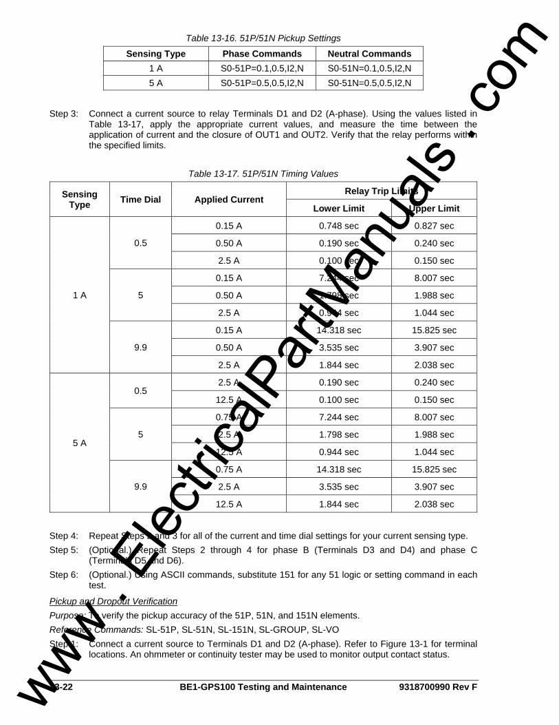
13-22 BE1-GPS100 Testing and Maintenance 9318700990 Rev F
Table 13-16. 51P/51N Pickup Settings
Sensing Type Phase Commands Neutral Commands 1 A S0-51P=0.1,0.5,I2,N S0-51N=0.1,0.5,I2,N 5 A S0-51P=0.5,0.5,I2,N S0-51N=0.5,0.5,I2,N
Step 3: Connect a current source to relay Terminals D1 and D2 (A-phase). Using the values listed in
Table 13-17, apply the appropriate current values, and measure the time between the application of current and the closure of OUT1 and OUT2. Verify that the relay performs within the specified limits.
Table 13-17. 51P/51N Timing Values
Relay Trip Limits Sensing Type Time Dial Applied Current
Lower Limit Upper Limit
0.15 A 0.748 sec 0.827 sec
0.50 A 0.190 sec 0.240 sec 0.5
2.5 A 0.100 sec 0.150 sec
0.15 A 7.244 sec 8.007 sec
0.50 A 1.798 sec 1.988 sec 5
2.5 A 0.944 sec 1.044 sec
0.15 A 14.318 sec 15.825 sec
0.50 A 3.535 sec 3.907 sec
1 A
9.9
2.5 A 1.844 sec 2.038 sec
2.5 A 0.190 sec 0.240 sec 0.5
12.5 A 0.100 sec 0.150 sec
0.75 A 7.244 sec 8.007 sec
2.5 A 1.798 sec 1.988 sec 5
12.5 A 0.944 sec 1.044 sec
0.75 A 14.318 sec 15.825 sec
2.5 A 3.535 sec 3.907 sec
5 A
9.9
12.5 A 1.844 sec 2.038 sec
Step 4: Repeat Steps 2 and 3 for all of the current and time dial settings for your current sensing type. Step 5: (Optional.) Repeat Steps 2 through 4 for phase B (Terminals D3 and D4) and phase C
(Terminals D5 and D6). Step 6: (Optional.) Using ASCII commands, substitute 151 for any 51 logic or setting command in each
test.
Pickup and Dropout Verification Purpose: To verify the pickup accuracy of the 51P, 51N, and 151N elements. Reference Commands: SL-51P, SL-51N, SL-151N, SL-GROUP, SL-VO Step 1: Connect a current source to Terminals D1 and D2 (A-phase). Refer to Figure 13-1 for terminal
locations. An ohmmeter or continuity tester may be used to monitor output contact status.
www . El
ectric
alPar
tMan
uals
. com
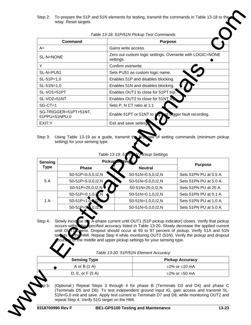
9318700990 Rev F BE1-GPS100 Testing and Maintenance 13-23
Step 2: To prepare the 51P and 51N elements for testing, transmit the commands in Table 13-18 to the relay. Reset targets.
Table 13-18. 51P/51N Pickup Test Commands
Command Purpose A= Gains write access.
SL-N=NONE Zero out custom logic settings. Overwrite with LOGIC=NONE settings.
Y Confirm overwrite. SL-N=PU51 Sets PU51 as custom logic name. SL-51P=1,0 Enables 51P and disables blocking. SL-51N=1,0 Enables 51N and disables blocking. SL-VO1=51PT Enables OUT1 to close for 51PT trip. SL-VO2=51NT Enables OUT2 to close for 51NT trip. SG-CT=1 Sets P, N CT ratio at 1:1 SG-TRIGGER=51PT+51NT, 51PPU+51NPU,0 Enable 51PT or 51NT to log and trigger fault recording.
EXIT;Y Exit and save settings.
Step 3: Using Table 13-19 as a guide, transmit the first row of setting commands (minimum pickup
setting) for your sensing type.
Table 13-19. 51P/51N Pickup Settings
Pickup Settings Sensing Type Phase Neutral
Purpose
S0-51P=0.5,0,I2,N S0-51N=0.5,0,I2,N Sets 51PN PU at 0.5 A. S0-51P=5.0,0,I2,N S0-51N=5.0,0,I2,N Sets 51PN PU at 5.0 A. 5 A S0-51P=25,0,I2,N S0-51N=25,0,I2,N Sets 51PN PU at 25 A. S0-51P=0.1,0,I2,N S0-51N=0.1,0,I2,N Sets 51PN PU at 0.1 A. S0-51P=1.0,0,I2,N S0-51N=1.0,0,I2,N Sets 51PN PU at 1.0 A. 1 A S0-51P=5.0,0,I2,N S0-51N=5.0,0,I2,N Sets 51PN PU at 5.0 A.
Step 4: Slowly increase the A-phase current until OUT1 (51P pickup indicator) closes. Verify that pickup
occurs within the specified accuracy listed in Table 13-20. Slowly decrease the applied current until OUT1 opens. Dropout should occur at 93 to 97 percent of pickup. Verify 51A and 51N targets on the HMI. Repeat Step 4 while monitoring OUT2 (51N). Verify the pickup and dropout accuracy of the middle and upper pickup settings for your sensing type.
Table 13-20. 51P/51N Element Accuracy
Sensing Type Pickup Accuracy A or B (1 A) ±2% or ±10 mA
D, E, or F (5 A) ±2% or ±50 mA
Step 5: (Optional.) Repeat Steps 3 through 4 for phase B (Terminals D3 and D4) and phase C (Terminals D5 and D6). To test independent ground input IG, gain access and transmit SL-51N=G,0 exit and save. Apply test current to Terminals D7 and D8, while monitoring OUT2 and repeat Step 4. Verify 51G target on the HMI.
www . El
ectric
alPar
tMan
uals
. com
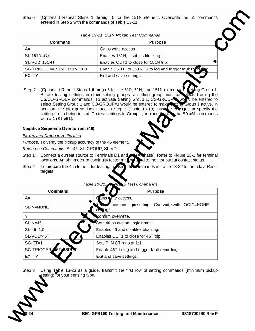
13-24 BE1-GPS100 Testing and Maintenance 9318700990 Rev F
Step 6: (Optional.) Repeat Steps 1 through 5 for the 151N element. Overwrite the 51 commands entered in Step 2 with the commands of Table 13-21.
Table 13-21. 151N Pickup Test Commands
Command Purpose A= Gains write access. SL-151N=G,0 Enables 151N, disables blocking. SL-VO2=151NT Enables OUT2 to close for 151N trip. SG-TRIGGER=151NT,151NPU,0 Enable 151NT or 151NPU to log and trigger fault recording. EXIT;Y Exit and save settings.
Step 7: (Optional.) Repeat Steps 1 through 6 for the 51P, 51N, and 151N elements in Setting Group 1.
Before testing settings in other setting groups, a setting group must be selected using the CS/CO-GROUP commands. To activate Setting Group 1, CS-GROUP=1 would be entered to select Setting Group 1 and CO-GROUP=1 would be entered to make Setting Group 1 active. In addition, the pickup settings made in Step 3 (Table 13-19) must be changed to specify the setting group being tested. To test settings in Group 1, replace the 0 in the S0-x51 commands with a 1 (S1-x51).
Negative Sequence Overcurrent (46)
Pickup and Dropout Verification Purpose: To verify the pickup accuracy of the 46 element. Reference Commands: SL-46, SL-GROUP, SL-VO Step 1: Connect a current source to Terminals D1 and D2 (A-phase). Refer to Figure 13-1 for terminal
locations. An ohmmeter or continuity tester may be used to monitor output contact status. Step 2: To prepare the 46 element for testing, transmit the commands in Table 13-22 to the relay. Reset
targets.
Table 13-22. 46 Pickup Test Commands
Command Purpose A= Gains write access.
SL-N=NONE Zero out custom logic settings. Overwrite with LOGIC=NONE settings.
Y Confirm overwrite. SL-N=46 Sets 46 as custom logic name. SL-46=1,0 Enables 46 and disables blocking. SL-VO1=46T Enables OUT1 to close for 46T trip. SG-CT=1 Sets P, N CT ratio at 1:1 SG-TRIGGER=46T+46PU,0 Enable 46T to log and trigger fault recording. EXIT;Y Exit and save settings.
Step 3: Using Table 13-23 as a guide, transmit the first row of setting commands (minimum pickup
setting) for your sensing type. www .
Elec
tricalP
artM
anua
ls . c
om

9318700990 Rev F BE1-GPS100 Testing and Maintenance 13-25
Table 13-23. 46 Pickup Settings
Sensing Type Pickup Setting Purpose
S0-46=0.1,0,46 Sets 46 PU at 0.1 A. S0-46=5.0,0,46 Sets 46 PU at 5.0 A. 5 A S0-46=10.0,0,46 Sets 46 PU at 10 A. S0-46=0.02,0,46 Sets 46 PU at 0.02 A. S0-46=1.0,0,46 Sets 46 PU at 1.0 A. 1 A S0-46=2.0,0,46 Sets 46 PU at 2.0 A.
Step 4: Slowly increase the A-phase current until OUT1 (46 operation will occur at 1/3 the phase current
value. Therefore, for testing purposes, the phase current equivalent will be 3 times the 46 setting). Verify that pickup occurs within the specified accuracy listed in Table 13-24. Slowly decrease the applied current until OUT1 opens. Dropout should occur at 93 to 97 percent of pickup. Verify the pickup and dropout accuracy of the middle and upper pickup settings for your sensing type.
Table 13-24. 46 Element Accuracy
Sensing Type Pickup Accuracy A or B (1 A) ±2% or ±10 mA
D, E, or F (5 A) ±2% or ±50 mA
Step 5: (Optional.) Repeat Step 4 for phase B (Terminals D3 and D4) and phase C (Terminals D5 and D6).
Step 6: (Optional.) Repeat Steps 4 and 5 for Setting Group 1. Before testing settings in other setting groups, a setting group must be selected using the CS/CO-GROUP commands. To activate Setting Group 1, CS-GROUP=1 would be entered to select Setting Group 1 and CO-GROUP=1 would be entered to make Setting Group 1 active. In addition, the pickup settings made in Step 3 (Table 13-23) must be changed to specify the setting group being tested. To test settings in Group 1, replace the 0 in the S0-46 command with a 1 (S1-46).
Timing Verification Purpose: To verify the timing operation of the 46 element. Reference Commands: SL-46, S<g>-46 Step 1: Using Table 13-25 as a guide, transmit the setting commands for your sensing type.
Table 13-25. 46 Time Delay Settings
Sensing Type Pickup Setting Purpose
5 A S0-46=1,2,46 Sets 46 PU at 1.0 A. 1 A S0-46=0.2,2,46 Sets 46 PU at 0.2 A.
Step 2: Refer to the 46 curve response characteristic in Appendix A of the instruction manual and see
the accompanying note. Also, refer to Section 4, Protection and Control, Overcurrent Protection, 46 Negative Sequence Overcurrent Element, for details. Based on the pickup settings in Table 13-23, per unit I2 for this test will be 0.2. Time to pickup on K2 curve at 0.2 PU I2 is t = K / (I2 PU squared) or 2/(.2 x.2) = 50 seconds ±2%.
Step 3: Connect a current source to relay Terminals D1 and D2 (A Phase). Apply 3 times the negative sequence setting and measure the time between the application of current and the closure of OUT1. Note that prior to time out, the trip light on the front panel of the relay blinks indicating
www . El
ectric
alPar
tMan
uals
. com

13-26 BE1-GPS100 Testing and Maintenance 9318700990 Rev F
the 46 element is picked up and is timing towards a trip. Verify that the relay performs within the specified limits (±2%).
Step 4: Repeat Step 3 while applying 4.5 times the negative sequence setting. Time delay will be t = 2 / (.3 x .3) = 22.22 seconds ±2%.
Step 5: Repeat Steps 3 and 4 for several K settings. Step 6: (Optional.) Repeat Steps 3 through 5 for Phase B (Terminals D3 and D4) and Phase C
(Terminals D5 and D6). Step 7: (Optional.) Repeat Steps 3 through 6 for Setting Group 1.
Voltage Restraint/Control Time Overcurrent Purpose: To verify the operating accuracy of the 27R (Restraint and Control) for the phase time overcurrent function. Reference Commands: S<g>-27R, SL-51, RG-STAT 51/27R - Voltage "Control" Pickup and Dropout Verification Step 1: To prepare the 51P element for testing, transmit the commands in Table 13-26 to the relay.
Reset targets.
Table 13-26. 51P Pickup Test Commands
Command Purpose A= Gains write access. SL-N=NONE Zero out custom logic settings. Overwrite with LOGIC=NONE settings. Y Confirm overwrite. SL-N=51/27R/C Sets custom logic name. SG-VTP=1,4W,PN,PN Set VT phase voltage parameters. SL-51P=1,0 Enables 51P and disables blocking. SL-VO1=51PT Enables OUT1 to close for 51PT trip. SG-CT=1 Sets P, N CT ratio at 1:1 EXIT;Y Exit and save settings.
Step 2: Using Table 13-27 as a guide, transmit the 51/27R setting commands to the relay.
Table 13-27. Example of 51/27R Settings
Operating Settings Purpose S0-51P=2.0,0,V2,N Sets 51P PU at 2 amps, TD = 0, Time Curve = V2, non-directional.
S0-27R=100,C Set 27R to 100 volts, 51P to Voltage Control.
Step 3: Connect and apply 120 Vac, three-phase, 50 or 60 hertz voltage source (depending on users
nominal frequency) to Terminals C13 (A-phase), C14 (B-phase), C15 (C-phase), and C16 (Neutral). Connect a variable ac current source to Terminals D1 (A-phase polarity) and D2 (A-phase non-polarity). Refer to Figure 13-1 for terminal locations.
Step 4: Apply 2 amps of A-phase current and slowly reduce A-phase voltage until OUT1 closes. Increase A-phase voltage until OUT1 just drops out. Pickup will occur within ±2 percent or 1 volt of the of the 27R voltage setting. Dropout will occur at 102 to 103% or actual pickup.
Step 5: Repeat Steps 2 and 3 for B-phase current (D3 and D4) while varying B-phase voltage and C-phase current (D5 and D6) while varying C-phase voltage.
Step 6: (Optional.) Repeat Steps 2 through 5 for Setting Group 1.
51/27R-Voltage "Restraint" Pickup and Dropout Verification Step 1: Using Table 13-28 as a guide, transmit the 51/27R setting commands to the relay.
www . El
ectric
alPar
tMan
uals
. com
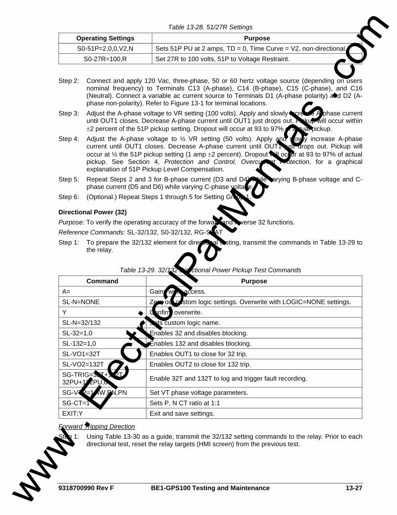
9318700990 Rev F BE1-GPS100 Testing and Maintenance 13-27
Table 13-28. 51/27R Settings
Operating Settings Purpose S0-51P=2.0,0,V2,N Sets 51P PU at 2 amps, TD = 0, Time Curve = V2, non-directional.
S0-27R=100,R Set 27R to 100 volts, 51P to Voltage Restraint.
Step 2: Connect and apply 120 Vac, three-phase, 50 or 60 hertz voltage source (depending on users
nominal frequency) to Terminals C13 (A-phase), C14 (B-phase), C15 (C-phase), and C16 (Neutral). Connect a variable ac current source to Terminals D1 (A-phase polarity) and D2 (A-phase non-polarity). Refer to Figure 13-1 for terminal locations.
Step 3: Adjust the A-phase voltage to VR setting (100 volts). Apply and slowly increase A-phase current until OUT1 closes. Decrease A-phase current until OUT1 just drops out. Pickup will occur within ±2 percent of the 51P pickup setting. Dropout will occur at 93 to 97% of actual pickup.
Step 4: Adjust the A-phase voltage to ½ VR setting (50 volts). Apply and slowly increase A-phase current until OUT1 closes. Decrease A-phase current until OUT1 just drops out. Pickup will occur at ½ the 51P pickup setting (1 amp ±2 percent). Dropout will occur at 93 to 97% of actual pickup. See Section 4, Protection and Control, Overcurrent Protection, for a graphical explanation of 51P Pickup Level Compensation.
Step 5: Repeat Steps 2 and 3 for B-phase current (D3 and D4) while varying B-phase voltage and C-phase current (D5 and D6) while varying C-phase voltage.
Step 6: (Optional.) Repeat Steps 1 through 5 for Setting Group 1.
Directional Power (32) Purpose: To verify the operating accuracy of the forward and reverse 32 functions. Reference Commands: SL-32/132, S0-32/132, RG-STAT Step 1: To prepare the 32/132 element for directional testing, transmit the commands in Table 13-29 to
the relay.
Table 13-29. 32/132 Directional Power Pickup Test Commands
Command Purpose A= Gains write access. SL-N=NONE Zero out custom logic settings. Overwrite with LOGIC=NONE settings. Y Confirm overwrite. SL-N=32/132 Sets custom logic name. SL-32=1,0 Enables 32 and disables blocking. SL-132=1,0 Enables 132 and disables blocking. SL-VO1=32T Enables OUT1 to close for 32 trip. SL-VO2=132T Enables OUT2 to close for 132 trip. SG-TRIG=32T+132T, 32PU+132PU,0 Enable 32T and 132T to log and trigger fault recording.
SG-VTP=1,4W,PN,PN Set VT phase voltage parameters. SG-CT=1 Sets P, N CT ratio at 1:1 EXIT;Y Exit and save settings.
Forward Tripping Direction Step 1: Using Table 13-30 as a guide, transmit the 32/132 setting commands to the relay. Prior to each
directional test, reset the relay targets (HMI screen) from the previous test.
www . El
ectric
alPar
tMan
uals
. com

13-28 BE1-GPS100 Testing and Maintenance 9318700990 Rev F
Table 13-30. 32/132 Operational Settings
Operating Settings Purpose S0-32=500,50ms,F Sets 32 to 500 watts, TD = 50 ms, Forward Trip Direction. S0-32=1000,50ms,F Sets 32 to 1000 watts, TD = 50 ms, Forward Trip Direction. S0-32=2000,50ms,F Sets 32 to 2000 watts, TD = 50 ms, Forward Trip Direction. S0-132=500,50ms,F Sets 132 to 500 watts, TD = 50 ms, Forward Trip Direction. S0-132=1000,50ms,F Sets 132 to 1000 watts, TD = 50 ms, Forward Trip Direction. S0-132=2000,50ms,F Sets 132 to 2000 watts, TD = 50 ms, Forward Trip Direction.
Step 2: Connect and apply a 100 Vac, three-phase voltage source at nominal frequency to Terminals
C13 (A-phase), C14 (B-phase), C15 (C-phase), and C16 (Neutral). Connect a variable ac current source to Terminals D1 (A-phase polarity) and D2 (A-phase non-polarity). Refer to Figure 13-1 for terminal locations.
Step 3: Apply 0 amp A-phase current at an angle of 0 degrees I lag E and slowly increase the current until OUT1 closes. Decrease A-phase current until OUT1 just drops out. Pickup will occur within ±2 percent of the 32 pickup setting (500 watts = 5 amps, 100 volts, 0 degrees I lag E). Dropout will occur at 93 to 97% of actual pickup. Verify 32 target on the HMI.
Step 4: With the relay picked up (OUT1 closed), change the angle of the applied current to 180 degrees I lag E and verify that OUT1 opens. This verifies that the 32 function is operating in the forward trip direction and not in the reverse direction.
Step 5: Repeat Steps 4 and 5 for the middle and upper settings in Table 13-30. Step 6: (Optional.) Repeat Steps 4 through 6 for B-phase and C-Phase currents. Step 7: (Optional.) Repeat Steps 4 and 7 for Setting Group 1.
Reverse Tripping Direction Step 1: Using Table 13-31 as a guide, transmit the 32/132 setting commands to the relay. Prior to each
test, reset the relay targets (HMI screen) from the previous test.
Table 13-31. 32/132 Operational Settings
Operating Settings Purpose S0-32=500,50ms,R Sets 32 to 500 watts, TD = 50 ms, Reverse Trip Direction. S0-132=500,50ms,R Sets 132 to 500 watts, TD = 50 ms, Reverse Trip Direction.
Step 2: Connect and apply a 100 Vac, three-phase voltage source at nominal frequency to Terminals
C13 (A-phase), C14 (B-phase), C15 (C-phase), and C16 (Neutral). Connect a variable ac current source to Terminals D1 (A-phase polarity) and D2 (A-phase non-polarity). Refer to Figure 13-1 for terminal locations.
Step 3: Apply 0 amp A-phase current at an angle of 180 degrees I lag E and slowly increase the current until OUT1 closes. Decrease A-phase current until OUT1 just drops out. Pickup will occur within ±2 percent of the 32 pickup setting (500 watts = 5 amps, 100 volts, 180 degrees I lag E). Dropout will occur at 93 to 97% of actual pickup. Verify 32 target on the HMI.
Step 4: With the relay picked up (OUT1 closed), change the angle of the applied current to 0 degrees I lag E and verify that OUT1 opens. This verifies that the 32 function is operating in the reverse trip direction and not in the forward direction.
Step 5: (Optional.) Repeat Steps 4 and 5 for B-phase and C-phase currents. Step 6: (Optional.) Repeat Steps 4 and 7 for Setting Group 1.
Loss of Excitation (40Q) Purpose: To verify the operating accuracy of the 40Q/140Q functions. Reference Commands: SL-40Q/140Q, S0-40Q/140Q, RG-STAT
www . El
ectric
alPar
tMan
uals
. com
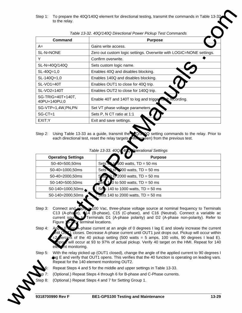
9318700990 Rev F BE1-GPS100 Testing and Maintenance 13-29
Step 1: To prepare the 40Q/140Q element for directional testing, transmit the commands in Table 13-32 to the relay.
Table 13-32. 40Q/140Q Directional Power Pickup Test Commands
Command Purpose A= Gains write access. SL-N=NONE Zero out custom logic settings. Overwrite with LOGIC=NONE settings. Y Confirm overwrite. SL-N=40Q/140Q Sets custom logic name. SL-40Q=1,0 Enables 40Q and disables blocking. SL-140Q=1,0 Enables 140Q and disables blocking. SL-VO1=40T Enables OUT1 to close for 40Q trip. SL-VO2=140T Enables OUT2 to close for 140Q trip. SG-TRIG=40T+140T, 40PU+140PU,0 Enable 40T and 140T to log and trigger fault recording.
SG-VTP=1,4W,PN,PN Set VT phase voltage parameters. SG-CT=1 Sets P, N CT ratio at 1:1 EXIT;Y Exit and save settings.
Step 2: Using Table 13-33 as a guide, transmit the 40Q/140Q setting commands to the relay. Prior to
each directional test, reset the relay targets (HMI screen) from the previous test.
Table 13-33. 40Q/140Q Operational Settings
Operating Settings Purpose S0-40=500,50ms Sets 40 to 500 watts, TD = 50 ms S0-40=1000,50ms Sets 40 to 1000 watts, TD = 50 ms S0-40=2000,50ms Sets 40 to 2000 watts, TD = 50 ms S0-140=500,50ms Sets 140 to 500 watts, TD = 50 ms S0-140=1000,50ms Sets 140 to 1000 watts, TD = 50 ms S0-140=2000,50ms Sets 140 to 2000 watts, TD = 50 ms
Step 3: Connect and apply a 100 Vac, three-phase voltage source at nominal frequency to Terminals
C13 (A-phase), C14 (B-phase), C15 (C-phase), and C16 (Neutral). Connect a variable ac current source to Terminals D1 (A-phase polarity) and D2 (A-phase non-polarity). Refer to Figure 13-1 for terminal locations.
Step 4: Apply 0 amp A-phase current at an angle of 0 degrees I lag E and slowly increase the current until OUT1 closes. Decrease A-phase current until OUT1 just drops out. Pickup will occur within ±2 percent of the 40 pickup setting (500 watts = 5 amps, 100 volts, 90 degrees I lead E). Dropout will occur at 93 to 97% of actual pickup. Verify 40 target on the HMI. Repeat for 140 element monitoring.
Step 5: With the relay picked up (OUT1 closed), change the angle of the applied current to 90 degrees I lag E and verify that OUT1 opens. This verifies that the 40 function is operating on leading vars. Repeat for the 140 element monitoring OUT2.
Step 6: Repeat Steps 4 and 5 for the middle and upper settings in Table 13-33. Step 7: (Optional.) Repeat Steps 4 through 6 for B-phase and C-Phase currents. Step 8: (Optional.) Repeat Steps 4 and 7 for Setting Group 1.
www . El
ectric
alPar
tMan
uals
. com
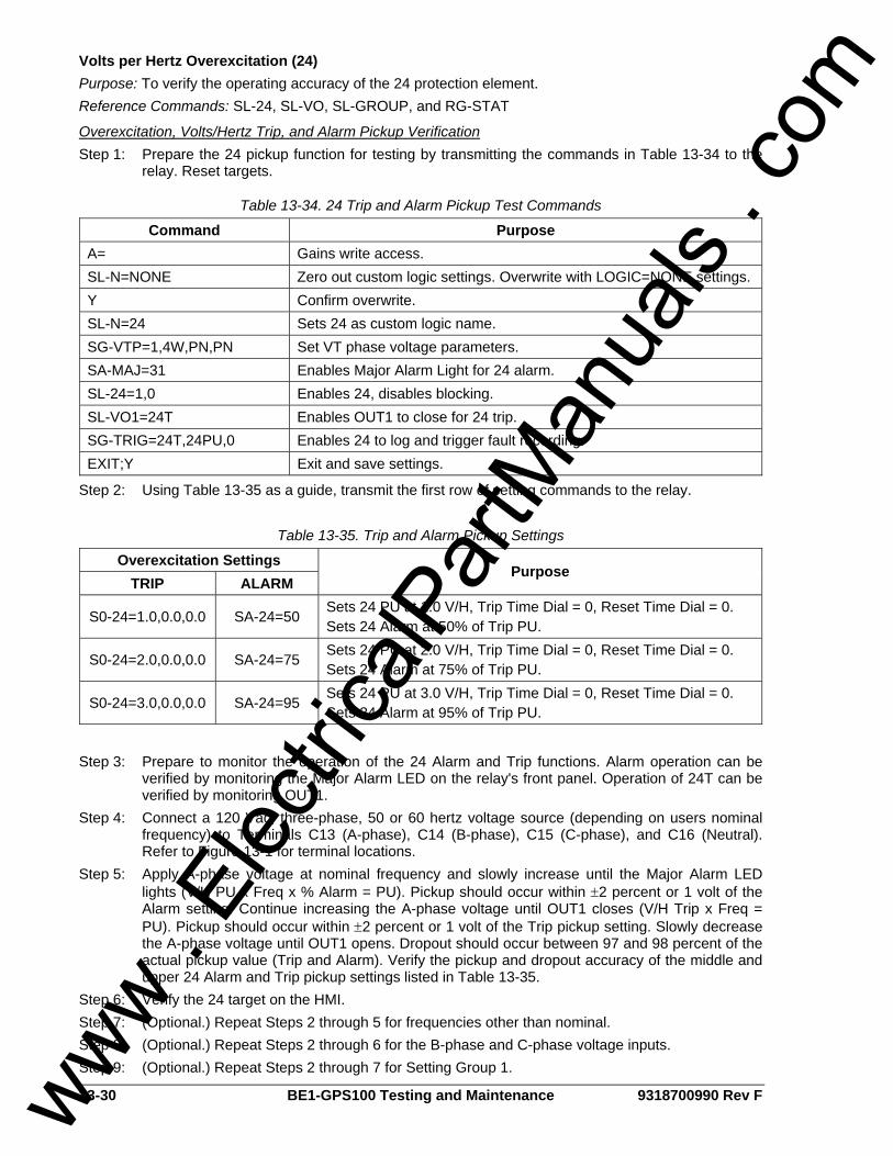
13-30 BE1-GPS100 Testing and Maintenance 9318700990 Rev F
Volts per Hertz Overexcitation (24) Purpose: To verify the operating accuracy of the 24 protection element. Reference Commands: SL-24, SL-VO, SL-GROUP, and RG-STAT
Overexcitation, Volts/Hertz Trip, and Alarm Pickup Verification Step 1: Prepare the 24 pickup function for testing by transmitting the commands in Table 13-34 to the
relay. Reset targets.
Table 13-34. 24 Trip and Alarm Pickup Test Commands
Command Purpose A= Gains write access. SL-N=NONE Zero out custom logic settings. Overwrite with LOGIC=NONE settings. Y Confirm overwrite. SL-N=24 Sets 24 as custom logic name. SG-VTP=1,4W,PN,PN Set VT phase voltage parameters. SA-MAJ=31 Enables Major Alarm Light for 24 alarm. SL-24=1,0 Enables 24, disables blocking. SL-VO1=24T Enables OUT1 to close for 24 trip. SG-TRIG=24T,24PU,0 Enables 24 to log and trigger fault recording. EXIT;Y Exit and save settings.
Step 2: Using Table 13-35 as a guide, transmit the first row of setting commands to the relay.
Table 13-35. Trip and Alarm Pickup Settings
Overexcitation Settings TRIP ALARM
Purpose
S0-24=1.0,0.0,0.0 SA-24=50 Sets 24 PU at 1.0 V/H, Trip Time Dial = 0, Reset Time Dial = 0. Sets 24 Alarm at 50% of Trip PU.
S0-24=2.0,0.0,0.0 SA-24=75 Sets 24 PU at 2.0 V/H, Trip Time Dial = 0, Reset Time Dial = 0. Sets 24 Alarm at 75% of Trip PU.
S0-24=3.0,0.0,0.0 SA-24=95 Sets 24 PU at 3.0 V/H, Trip Time Dial = 0, Reset Time Dial = 0. Sets 24 Alarm at 95% of Trip PU.
Step 3: Prepare to monitor the operation of the 24 Alarm and Trip functions. Alarm operation can be
verified by monitoring the Major Alarm LED on the relay's front panel. Operation of 24T can be verified by monitoring OUT1.
Step 4: Connect a 120 Vac, three-phase, 50 or 60 hertz voltage source (depending on users nominal frequency) to Terminals C13 (A-phase), C14 (B-phase), C15 (C-phase), and C16 (Neutral). Refer to Figure 13-1 for terminal locations.
Step 5: Apply A-phase voltage at nominal frequency and slowly increase until the Major Alarm LED lights (V/H PU x Freq x % Alarm = PU). Pickup should occur within ±2 percent or 1 volt of the Alarm setting. Continue increasing the A-phase voltage until OUT1 closes (V/H Trip x Freq = PU). Pickup should occur within ±2 percent or 1 volt of the Trip pickup setting. Slowly decrease the A-phase voltage until OUT1 opens. Dropout should occur between 97 and 98 percent of the actual pickup value (Trip and Alarm). Verify the pickup and dropout accuracy of the middle and upper 24 Alarm and Trip pickup settings listed in Table 13-35.
Step 6: Verify the 24 target on the HMI. Step 7: (Optional.) Repeat Steps 2 through 5 for frequencies other than nominal. Step 8: (Optional.) Repeat Steps 2 through 6 for the B-phase and C-phase voltage inputs. Step 9: (Optional.) Repeat Steps 2 through 7 for Setting Group 1.
www . El
ectric
alPar
tMan
uals
. com
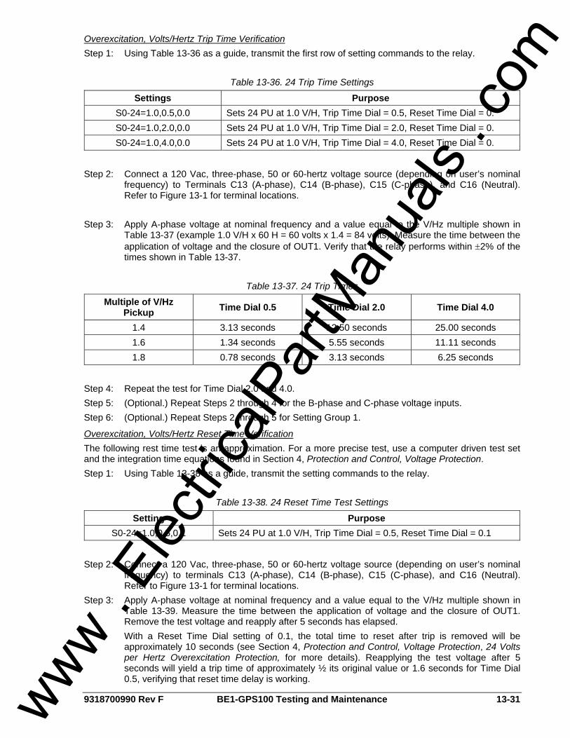
9318700990 Rev F BE1-GPS100 Testing and Maintenance 13-31
Overexcitation, Volts/Hertz Trip Time Verification Step 1: Using Table 13-36 as a guide, transmit the first row of setting commands to the relay.
Table 13-36. 24 Trip Time Settings
Settings Purpose S0-24=1.0,0.5,0.0 Sets 24 PU at 1.0 V/H, Trip Time Dial = 0.5, Reset Time Dial = 0. S0-24=1.0,2.0,0.0 Sets 24 PU at 1.0 V/H, Trip Time Dial = 2.0, Reset Time Dial = 0. S0-24=1.0,4.0,0.0 Sets 24 PU at 1.0 V/H, Trip Time Dial = 4.0, Reset Time Dial = 0.
Step 2: Connect a 120 Vac, three-phase, 50 or 60-hertz voltage source (depending on user’s nominal
frequency) to Terminals C13 (A-phase), C14 (B-phase), C15 (C-phase), and C16 (Neutral). Refer to Figure 13-1 for terminal locations.
Step 3: Apply A-phase voltage at nominal frequency and a value equal to the V/Hz multiple shown in
Table 13-37 (example 1.0 V/H x 60 H = 60 volts x 1.4 = 84 volts). Measure the time between the application of voltage and the closure of OUT1. Verify that the relay performs within ±2% of the times shown in Table 13-37.
Table 13-37. 24 Trip Times
Multiple of V/Hz Pickup Time Dial 0.5 Time Dial 2.0 Time Dial 4.0
1.4 3.13 seconds 12.50 seconds 25.00 seconds 1.6 1.34 seconds 5.55 seconds 11.11 seconds 1.8 0.78 seconds 3.13 seconds 6.25 seconds
Step 4: Repeat the test for Time Dial 2.0 and 4.0. Step 5: (Optional.) Repeat Steps 2 through 4 for the B-phase and C-phase voltage inputs. Step 6: (Optional.) Repeat Steps 2 through 5 for Setting Group 1.
Overexcitation, Volts/Hertz Reset Time Verification The following rest time test is an approximation. For a more precise test, use a computer driven test set and the integration time equations found in Section 4, Protection and Control, Voltage Protection. Step 1: Using Table 13-38 as a guide, transmit the setting commands to the relay.
Table 13-38. 24 Reset Time Test Settings
Setting Purpose S0-24=1.0,0.5,0.1 Sets 24 PU at 1.0 V/H, Trip Time Dial = 0.5, Reset Time Dial = 0.1
Step 2: Connect a 120 Vac, three-phase, 50 or 60-hertz voltage source (depending on user’s nominal
frequency) to terminals C13 (A-phase), C14 (B-phase), C15 (C-phase), and C16 (Neutral). Refer to Figure 13-1 for terminal locations.
Step 3: Apply A-phase voltage at nominal frequency and a value equal to the V/Hz multiple shown in Table 13-39. Measure the time between the application of voltage and the closure of OUT1. Remove the test voltage and reapply after 5 seconds has elapsed. With a Reset Time Dial setting of 0.1, the total time to reset after trip is removed will be approximately 10 seconds (see Section 4, Protection and Control, Voltage Protection, 24 Volts per Hertz Overexcitation Protection, for more details). Reapplying the test voltage after 5 seconds will yield a trip time of approximately ½ its original value or 1.6 seconds for Time Dial 0.5, verifying that reset time delay is working.
www . El
ectric
alPar
tMan
uals
. com
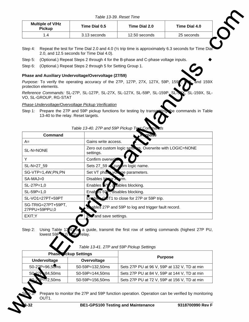
13-32 BE1-GPS100 Testing and Maintenance 9318700990 Rev F
Table 13-39. Reset Time
Multiple of V/Hz Pickup Time Dial 0.5 Time Dial 2.0 Time Dial 4.0
1.4 3.13 seconds 12.50 seconds 25 seconds
Step 4: Repeat the test for Time Dial 2.0 and 4.0 (½ trip time is approximately 6.3 seconds for Time Dial
2.0, and 12.5 seconds for Time Dial 4.0). Step 5: (Optional.) Repeat Steps 2 through 4 for the B-phase and C-phase voltage inputs. Step 6: (Optional.) Repeat Steps 2 through 5 for Setting Group 1.
Phase and Auxiliary Undervoltage/Overvoltage (27/59) Purpose: To verify the operating accuracy of the 27P, 127P, 27X, 127X, 59P, 159P, 59X, and 159X protection elements. Reference Commands: SL-27P, SL-127P, SL-27X, SL-127X, SL-59P, SL-159P, SL-59X, SL-159X, SL-VO, SL-GROUP, RG-STAT
Phase Undervoltage/Overvoltage Pickup Verification Step 1: Prepare the 27P and 59P pickup functions for testing by transmitting the commands in Table
13-40 to the relay. Reset targets.
Table 13-40. 27P and 59P Pickup Test Commands
Command Purpose A= Gains write access.
SL-N=NONE Zero out custom logic settings. Overwrite with LOGIC=NONE settings.
Y Confirm overwrite. SL-N=27_59 Sets 27_59 as custom logic name. SG-VTP=1,4W,PN,PN Set VT phase voltage parameters. SA-MAJ=0 Disables Major Alarm. SL-27P=1,0 Enables 27P, disables blocking. SL-59P=1,0 Enables 59P, disables blocking. SL-VO1=27PT+59PT Enables OUT1 to close for 27P or 59P trip. SG-TRIG=27PT+59PT, 27PPU+59PPU,0 Enables 27P and 59P to log and trigger fault record.
EXIT;Y Exit and save settings.
Step 2: Using Table 13-41 as a guide, transmit the first row of setting commands (highest 27P PU,
lowest 59P PU) to the relay.
Table 13-41. 27P and 59P Pickup Settings
Phase Pickup Settings Undervoltage Overvoltage
Purpose
S0-27P=96,50ms S0-59P=132,50ms Sets 27P PU at 96 V, 59P at 132 V, TD at min S0-27P=84,50ms S0-59P=144,50ms Sets 27P PU at 84 V, 59P at 144 V, TD at min S0-27P=72,50ms S0-59P=156,50ms Sets 27P PU at 72 V, 59P at 156 V, TD at min
Step 3: Prepare to monitor the 27P and 59P function operation. Operation can be verified by monitoring
OUT1.
www . El
ectric
alPar
tMan
uals
. com
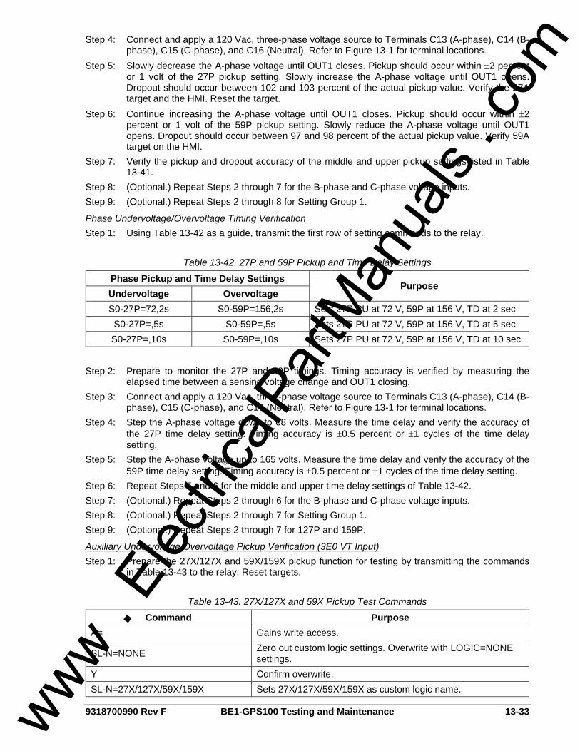
9318700990 Rev F BE1-GPS100 Testing and Maintenance 13-33
Step 4: Connect and apply a 120 Vac, three-phase voltage source to Terminals C13 (A-phase), C14 (B-phase), C15 (C-phase), and C16 (Neutral). Refer to Figure 13-1 for terminal locations.
Step 5: Slowly decrease the A-phase voltage until OUT1 closes. Pickup should occur within ±2 percent or 1 volt of the 27P pickup setting. Slowly increase the A-phase voltage until OUT1 opens. Dropout should occur between 102 and 103 percent of the actual pickup value. Verify the 27A target and the HMI. Reset the target.
Step 6: Continue increasing the A-phase voltage until OUT1 closes. Pickup should occur within ±2 percent or 1 volt of the 59P pickup setting. Slowly reduce the A-phase voltage until OUT1 opens. Dropout should occur between 97 and 98 percent of the actual pickup value. Verify 59A target on the HMI.
Step 7: Verify the pickup and dropout accuracy of the middle and upper pickup settings listed in Table 13-41.
Step 8: (Optional.) Repeat Steps 2 through 7 for the B-phase and C-phase voltage inputs. Step 9: (Optional.) Repeat Steps 2 through 8 for Setting Group 1.
Phase Undervoltage/Overvoltage Timing Verification Step 1: Using Table 13-42 as a guide, transmit the first row of setting commands to the relay.
Table 13-42. 27P and 59P Pickup and Time Delay Settings
Phase Pickup and Time Delay Settings Undervoltage Overvoltage
Purpose
S0-27P=72,2s S0-59P=156,2s Sets 27P PU at 72 V, 59P at 156 V, TD at 2 sec S0-27P=,5s S0-59P=,5s Sets 27P PU at 72 V, 59P at 156 V, TD at 5 sec S0-27P=,10s S0-59P=,10s Sets 27P PU at 72 V, 59P at 156 V, TD at 10 sec
Step 2: Prepare to monitor the 27P and 59P timings. Timing accuracy is verified by measuring the
elapsed time between a sensing voltage change and OUT1 closing. Step 3: Connect and apply a 120 Vac, three-phase voltage source to Terminals C13 (A-phase), C14 (B-
phase), C15 (C-phase), and C16 (Neutral). Refer to Figure 13-1 for terminal locations. Step 4: Step the A-phase voltage down to 68 volts. Measure the time delay and verify the accuracy of
the 27P time delay setting. Timing accuracy is ±0.5 percent or ±1 cycles of the time delay setting.
Step 5: Step the A-phase voltage up to 165 volts. Measure the time delay and verify the accuracy of the 59P time delay setting. Timing accuracy is ±0.5 percent or ±1 cycles of the time delay setting.
Step 6: Repeat Steps 5 and 6 for the middle and upper time delay settings of Table 13-42. Step 7: (Optional.) Repeat Steps 2 through 6 for the B-phase and C-phase voltage inputs. Step 8: (Optional.) Repeat Steps 2 through 7 for Setting Group 1. Step 9: (Optional.) Repeat Steps 2 through 7 for 127P and 159P.
Auxiliary Undervoltage/Overvoltage Pickup Verification (3E0 VT Input) Step 1: Prepare the 27X/127X and 59X/159X pickup function for testing by transmitting the commands
in Table 13-43 to the relay. Reset targets.
Table 13-43. 27X/127X and 59X Pickup Test Commands
Command Purpose A= Gains write access.
SL-N=NONE Zero out custom logic settings. Overwrite with LOGIC=NONE settings.
Y Confirm overwrite. SL-N=27X/127X/59X/159X Sets 27X/127X/59X/159X as custom logic name.
www . El
ectric
alPar
tMan
uals
. com
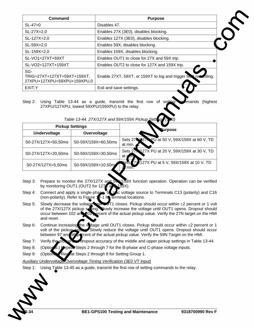
13-34 BE1-GPS100 Testing and Maintenance 9318700990 Rev F
Command Purpose SL-47=0 Disables 47. SL-27X=2,0 Enables 27X (3E0), disables blocking. SL-127X=2,0 Enables 127X (3E0), disables blocking. SL-59X=2,0 Enables 59X, disables blocking. SL-159X=2,0 Enables 159X, disables blocking. SL-VO1=27XT+59XT Enables OUT1 to close for 27X and 59X trip. SL-VO2=127XT+159XT Enables OUT2 to close for 127X and 159X trip. SG-TRIG=27XT+127XT+59XT+159XT, 27XPU+127XPU+59XPU+159XPU,0
Enable 27XT, 59XT, or 159XT to log and trigger fault recording.
EXIT;Y Exit and save settings.
Step 2: Using Table 13-44 as a guide, transmit the first row of setting commands (highest
27XPU/127XPU, lowest 59XPU/159XPU) to the relay.
Table 13-44. 27X/127X and 59X/159X Pickup Settings (3E0)
Pickup Settings Undervoltage Overvoltage
Purpose
S0-27X/127X=50,50ms S0-59X/159X=60,50ms Sets 27X/127X PU at 50 V, 59X/159X at 60 V, TD at min.
S0-27X/127X=20,50ms S0-59X/159X=30,50ms Sets 27X/127X PU at 20 V, 59X/159X at 30 V, TD at min.
S0-27X/127X=5,50ms S0-59X/159X=10,50ms Sets 27X/127X PU at 5 V, 59X/159X at 10 V, TD at min.
Step 3: Prepare to monitor the 27X/127X and 59X/159X function operation. Operation can be verified
by monitoring OUT1 (OUT2 for 127X and 159X). Step 4: Connect and apply a single-phase, 55 Vac voltage source to Terminals C13 (polarity) and C16
(non-polarity). Refer to Figure 13-1 for terminal locations. Step 5: Slowly decrease the voltage until OUT1 closes. Pickup should occur within ±2 percent or 1 volt
of the 27X/127X pickup setting. Slowly increase the voltage until OUT1 opens. Dropout should occur between 102 and 103 percent of the actual pickup value. Verify the 27N target on the HMI and reset.
Step 6: Continue increasing the voltage until OUT1 closes. Pickup should occur within ±2 percent or 1 volt of the pickup setting. Slowly reduce the voltage until OUT1 opens. Dropout should occur between 97 and 98 percent of the actual pickup value. Verify the 59N Target on the HMI.
Step 7: Verify the pickup and dropout accuracy of the middle and upper pickup settings in Table 13-44. Step 8: (Optional.) Repeat Steps 2 through 7 for the B-phase and C-phase voltage inputs. Step 9: (Optional.) Repeat Steps 2 through 8 for Setting Group 1.
Auxiliary Undervoltage/Overvoltage Timing Verification (3E0 VT Input) Step 1: Using Table 13-45 as a guide, transmit the first row of setting commands to the relay. www .
Elec
tricalP
artM
anua
ls . c
om

9318700990 Rev F BE1-GPS100 Testing and Maintenance 13-35
Table 13-45. 27X/127X and 59X/159X Pickup and Time Delay Settings (3E0 VT Input)
Pickup Settings Undervoltage Overvoltage
Purpose
S0-27X/127X=10,2S S0-59X/159X=30,2S Sets 27X/127X PU at 10 V, 59X/159X at 30 V, TD at 2 sec.
S0-27X/127X=,5S S0-59X/159X=,5S Sets 27X/127XPU at 10 V, 59X/159X at 30 V, TD at 5 sec.
S0-27X/127X=,10S S0-59X/159X=,10S Sets 27X/127X PU at 10 V, 59X/159X at 30 V, TD at 10 sec.
Step 2: Prepare to monitor the 27X/127X and 59X/159X timings. Timing accuracy is verified by
measuring the elapsed time between a sensing voltage change and OUT1 closing. Step 3: Connect and apply a single-phase, 20 Vac to Terminals C13 (polarity) and C16 (non-polarity).
Refer to Figure 13-1 for terminal locations. Step 4: Step the voltage down to 5 volts. Measure the time delay and verify the accuracy of the
27X/127X time delay setting. Timing accuracy is ±0.5 percent or ±1 cycles of the time delay setting.
Step 5: Step the voltage up to 35 volts. Measure the time delay and verify the accuracy of the 59X/159X time delay setting. Timing accuracy is ±0.5 percent or ±1 cycles of the time delay setting.
Step 6: Repeat Steps 5 and 6 for the middle and upper time delay settings of Table 13-45. Step 7: (Optional.) Repeat Steps 2 through 6 for Setting Group 1.
Auxiliary Undervoltage/Overvoltage Pickup Verification (Fundamental Vx Input) Step 1: Prepare the 27X/127X and 59X/159X pickup functions for testing by transmitting the commands
in Table 13-46 to the relay. Reset targets.
Table 13-46. 27X/127X and 59X/159X Pickup Test Commands
Command Purpose A= Gains write access.
SL-N=NONE Zero out custom logic settings. Overwrite with LOGIC=NONE settings.
Y Confirm overwrite. SL-N=27X/127X_59X/159X Sets 27X/127X_59X/159X as custom logic name. SG-VTX=1,AN Set auxiliary voltage parameters. SL-27X/127X=1,0 Enables 27X and 127X, disables blocking. SL-59X/159X=1,0 Enables 59X and 159X, disables blocking. SL-VO1=27XT+127XT+59XT+159XT Enables OUT1 to close for 27X, 127X, 59X, or 159X trip. SG-TRIG=27XT+127XT+59XT+159XT,27XPU+127XPU+59XPU+159XPU
Enables 27XT, 127XT, 59XT, or 159XT to log and trigger fault recording.
EXIT;Y Exit and save settings.
Step 2: Using Table 13-47 as a guide, transmit the first row of setting commands (highest 27X/127X
PU; lowest 59XPU/159XPU) to the relay.
www . El
ectric
alPar
tMan
uals
. com

13-36 BE1-GPS100 Testing and Maintenance 9318700990 Rev F
Table 13-47. 27X/127X and 59X/159X Pickup Settings
Pickup and Time Delay Settings Undervoltage Overvoltage
Purpose
S0-27X/127X=70,50ms S0-59X/159X=90,50ms Sets 27X/127X PU at 70 V, 59X/159X at 90 V, TD at min.
S0-27X/127X=60,50ms S0-59X/159X=100,50ms Sets 27X/127X PU at 60 V, 59X/159X at 100 V, TD at min.
S0-27X/127X=50,50ms S0-59X159X=110,50ms Sets 27X/127X PU at 50 V, 59X/159X at 110 V, TD at min.
Step 3: Prepare to monitor the 27X/127X and 59X/159X function operation. Operation can be verified
by monitoring OUT1. Step 4: Connect and apply a single-phase, 80 Vac voltage source to VX input, Terminals C17 (polarity)
and C18 (non-polarity). Refer to Figure 13-1 for terminal locations. Step 5: Slowly decrease the voltage until OUT1 closes. Pickup should occur within ±2 percent or 1 volt
of the pickup setting. Slowly increase the voltage until OUT1 opens. Dropout should occur between 102 and 103 percent of the actual pickup value. Verify the 27 bus target on the HMI and reset.
Step 6: Continue to increase the voltage until out1 closes. Pickup should occur within ±2 percent or 1 volt of the pickup setting. Slowly reduce the voltage until OUT1 opens. Dropout should occur between 97 and 98 percent of the actual pickup value. Verify the 59 bus target on the HMI.
Step 7: Verify the pickup and dropout accuracy of the middle and upper pickup settings listed in Table 13-47.
Step 8: (Optional.) Repeat Steps 2 through 7 for Setting Group 1.
Auxiliary Undervoltage/Overvoltage Timing Verification (Fundamental Vx Input) Step 1: Using Table 13-48 as a guide, transmit the first row of setting commands to the relay.
Table 13-48. 27X/127X and 59X/159X Pickup and Time Delay Settings
Pickup and Time Delay Settings Undervoltage Overvoltage
Purpose
S0-27X/127X=50,2S S0-59X/159X=110,2S Sets 27X/127X PU at 50 V, 59X/159X at 110 V, TD at 2 sec.
S0-27X/127X=,5S S0-59X/159X=,5S Sets 27X/127X PU at 50 V, 59X/159X at 110 V, TD at 5 sec.
S0-27X/127X=,10S S0-59X159X=,10S Sets 27X/127X PU at 50 V, 59X/159X at 110 V, TD at 10 sec.
Step 2: Prepare to monitor the 27X/127X and 59X/159X timings. Timing accuracy is verified by
measuring the elapsed time between a sensing voltage change and OUT1 closing. Step 3: Connect and apply a single-phase, 80 Vac voltage source to Terminals C17 (polarity) and C18
(non-polarity). Refer to Figure 13-1 for terminal locations. Step 4: Step the voltage down to 45 volts. Measure the time delay and verify the accuracy of the
27X/127X time delay setting. Timing accuracy is ±0.5 percent or ±1 cycles of the time delay setting.
Step 5: Step the voltage up to 115 volts. Measure the time delay and verify the accuracy of the 59X/159X time delay setting. Timing accuracy is ±0.5 percent or ±1 cycles of the time delay setting.
Step 6: Repeat Steps 5 and 6 for the middle and upper time delay settings of Table 13-48. Step 7: (Optional.) Repeat Steps 2 through 6 for Setting Group 1.
www . El
ectric
alPar
tMan
uals
. com
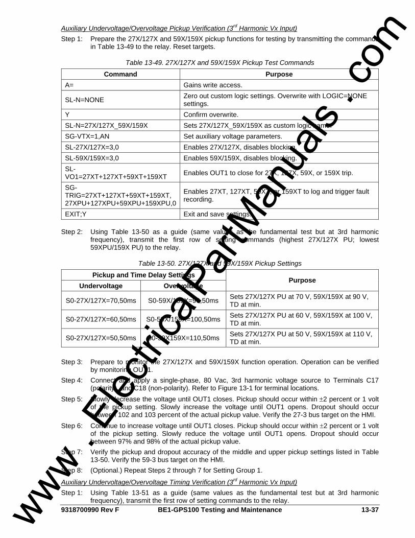
9318700990 Rev F BE1-GPS100 Testing and Maintenance 13-37
Auxiliary Undervoltage/Overvoltage Pickup Verification (3rd Harmonic Vx Input) Step 1: Prepare the 27X/127X and 59X/159X pickup functions for testing by transmitting the commands
in Table 13-49 to the relay. Reset targets.
Table 13-49. 27X/127X and 59X/159X Pickup Test Commands
Command Purpose A= Gains write access.
SL-N=NONE Zero out custom logic settings. Overwrite with LOGIC=NONE settings.
Y Confirm overwrite. SL-N=27X/127X_59X/159X Sets 27X/127X_59X/159X as custom logic name. SG-VTX=1,AN Set auxiliary voltage parameters. SL-27X/127X=3,0 Enables 27X/127X, disables blocking. SL-59X/159X=3,0 Enables 59X/159X, disables blocking. SL-VO1=27XT+127XT+59XT+159XT Enables OUT1 to close for 27X, 127X, 59X, or 159X trip.
SG-TRIG=27XT+127XT+59XT+159XT, 27XPU+127XPU+59XPU+159XPU,0
Enables 27XT, 127XT, 59XT, or 159XT to log and trigger fault recording.
EXIT;Y Exit and save settings.
Step 2: Using Table 13-50 as a guide (same values as the fundamental test but at 3rd harmonic frequency), transmit the first row of setting commands (highest 27X/127X PU; lowest 59XPU/159X PU) to the relay.
Table 13-50. 27X/127X and 59X/159X Pickup Settings
Pickup and Time Delay Settings Undervoltage Overvoltage
Purpose
S0-27X/127X=70,50ms S0-59X/159X=90,50ms Sets 27X/127X PU at 70 V, 59X/159X at 90 V, TD at min.
S0-27X/127X=60,50ms S0-59X/159X=100,50ms Sets 27X/127X PU at 60 V, 59X/159X at 100 V, TD at min.
S0-27X/127X=50,50ms S0-59X159X=110,50ms Sets 27X/127X PU at 50 V, 59X/159X at 110 V, TD at min.
Step 3: Prepare to monitor the 27X/127X and 59X/159X function operation. Operation can be verified
by monitoring OUT1. Step 4: Connect and apply a single-phase, 80 Vac, 3rd harmonic voltage source to Terminals C17
(polarity), and C18 (non-polarity). Refer to Figure 13-1 for terminal locations. Step 5: Slowly decrease the voltage until OUT1 closes. Pickup should occur within ±2 percent or 1 volt
of the pickup setting. Slowly increase the voltage until OUT1 opens. Dropout should occur between 102 and 103 percent of the actual pickup value. Verify the 27-3 bus target on the HMI.
Step 6: Continue to increase voltage until OUT1 closes. Pickup should occur within ±2 percent or 1 volt of the pickup setting. Slowly reduce the voltage until OUT1 opens. Dropout should occur between 97% and 98% of the actual pickup value.
Step 7: Verify the pickup and dropout accuracy of the middle and upper pickup settings listed in Table 13-50. Verify the 59-3 bus target on the HMI.
Step 8: (Optional.) Repeat Steps 2 through 7 for Setting Group 1.
Auxiliary Undervoltage/Overvoltage Timing Verification (3rd Harmonic Vx Input) Step 1: Using Table 13-51 as a guide (same values as the fundamental test but at 3rd harmonic
frequency), transmit the first row of setting commands to the relay. www . El
ectric
alPar
tMan
uals
. com

13-38 BE1-GPS100 Testing and Maintenance 9318700990 Rev F
Table 13-51. 27X/127X and 59X/159X Pickup and Time Delay Settings
Pickup and Time Delay Settings Undervoltage Overvoltage
Purpose
S0-27X/127X=50,2S S0-59X/159X=110,2S Sets 27X/127X PU at 50 V, 59X/159X at 110 V, TD at 2 sec.
S0-27X/127X=,5S S0-59X/159X=,5S Sets 27X/127X PU at 50 V, 59X/159X at 110 V, TD at 5 sec.
S0-27X/127X=,10S S0-59X159X=,10S Sets 27X/127X PU at 50 V, 59X/159X at 110 V, TD at 10 sec.
Step 2: Prepare to monitor the 27X/127X and 59X/159X timings. Timing accuracy is verified by
measuring the elapsed time between a sensing voltage change and OUT1 closing. Step 3: Connect and apply a single-phase, 80 Vac, 3rd harmonic voltage source to Terminals C17
polarity), and C18 (non-polarity). Refer to Figure 13-1 for terminal locations. Step 4: Step the voltage down to 45 volts. Measure the time delay and verify the accuracy of the
27X/127X time delay setting. Timing accuracy is ±5 percent or ±3 cycles of the time delay setting.
Step 5: Step the voltage up to 115 volts. Measure the time delay and verify the accuracy of the 59X/159X time delay setting. Timing accuracy is ±5 percent or ±3 cycles of the time delay setting.
Step 6: Repeat Steps 5 and 6 for the middle and upper time delay settings of Table 13-51. Step 7: (Optional.) Repeat Steps 2 through 6 for Setting Group 1.
Negative-Sequence Voltage (47) Purpose: To verify the operating accuracy of the 47 protection element. Reference Commands: SL-47, SL-VO, SL-GROUP, RG-STAT
Negative-Sequence Voltage Pickup Verification Step 1: Prepare the 47 pickup function for testing by transmitting the commands in Table 13-52 to the
relay. Reset targets.
Table 13-52. 47 Pickup Test Commands
Command Purpose A= Gains write access. SL-N=NONE Zero out custom logic settings. Overwrite with LOGIC=NONE settings. Y Confirm overwrite. SL-N=47 Sets 47 as custom logic name. SL-27P=0 Disables 27P. SL-59P=0 Disables 59P. SL-47=1,0 Enables 47, disables blocking. SP-60FL=ENA,PN Removes 60FL block from 47 element. SL-VO1=47T Enables OUT1 to close for 47 trip. SG-TRIG=47T,47PU,0 Enables 47 to log and trigger fault recording. EXIT;Y Exit and save settings.
Step 2: Using Table 13-53 as a guide, transmit the first row of setting commands to the relay.
www . El
ectric
alPar
tMan
uals
. com

9318700990 Rev F BE1-GPS100 Testing and Maintenance 13-39
Table 13-53. 47 Pickup Settings
Pickup Settings (Negative-Sequence Voltage) Purpose
S0-47=24,50ms Sets 47 PU at 24 V, Time Delay at minimum. S0-47=30,50ms Sets 47 PU at 30 V, Time Delay at minimum. S0-47=36,50ms Sets 47 PU at 36 V, Time Delay at minimum.
Step 3: Prepare to monitor 47 function operations. Operation can be verified by monitoring OUT1. Step 4: Connect and apply a 50 Vac, single-phase voltage source to Terminals C13 (A-phase) and C16
(Neutral). Refer to Figure 13-1 for terminal locations. Step 5: Negative-sequence voltage is 1/3 the phase voltage; therefore, for a V2 setting of 24 volts, the
applied phase voltage will be 24 x 3 or 72 volts. Slowly increase the A-phase voltage until OUT1 closes. Pickup should occur within ±2 percent or 1 volt of the pickup setting. Slowly decrease the A-phase voltage until OUT1 opens. Dropout should occur between 97 and 98 percent of the actual pickup value. Verify the 47 target on the HMI.
Step 6: Verify the pickup and dropout accuracy of the middle and upper 47 pickup settings. Step 7: (Optional.) Repeat Steps 2 through 6 for the B-phase and C-phase voltage inputs. Step 8: (Optional.) Repeat Steps 2 through 7 for Setting Group 1.
Negative-Sequence Voltage Timing Verification Step 1: Using Table 13-54 as a guide, transmit the first row of setting commands to the relay.
Table 13-54. 47 Pickup and Time Delay Settings
Pickup and Time Delay Settings Purpose S0-47=36,2S Sets 47 PU at 36 V, Time Dial at 2 seconds S0-47=36,5S Sets 47 PU at 36 V, Time Dial at 5 seconds S0-47=36,10S Sets 47 PU at 36 V, Time Dial at 10 seconds
Step 2: Prepare to monitor the 47 timings. Timing accuracy is verified by measuring the elapsed time
between a sensing voltage change and OUT1 closing. Step 3: Connect and apply a 100 Vac, single-phase voltage source to Terminals C13 (A-phase), and
C16 (Neutral). Refer to Figure 13-1 for terminal locations. Step 4: Step the A-phase voltage up to 115 volts. Measure the time delay and verify the accuracy of the
47-time delay setting. Timing accuracy is ±5 percent or ±3 cycles of the time delay setting. Step 5: Repeat Step 5 for the middle and upper time delay settings of Table 13-54. Step 6: (Optional.) Repeat Steps 2 through 5 for the B-phase and C-phase voltage inputs. Step 7: (Optional.) Repeat Steps 2 through 6 for Setting Group 1.
Over/Underfrequency (81) Purpose: To verify the operating accuracy of the 81/181/281/381 protection elements. Reference Commands: SL-x81, SL-VO
Pickup Verification Step 1: Prepare the x81 pickup functions for pickup testing by transmitting the commands in Table
13-55 to the relay.
www . El
ectric
alPar
tMan
uals
. com

13-40 BE1-GPS100 Testing and Maintenance 9318700990 Rev F
Table 13-55. x81 Pickup Test Commands
Command Purpose A= Gains write access. SL-N=NONE Zero out custom logic settings. Overwrite with LOGIC=NONE settings. Y Confirm overwrite. SL-N=FREQTEST Sets FREQTEST as custom logic name. SL-81=1,0 Enables 81, disables blocking. SL-181=1,0 Enables 181, disables blocking. SL-281=1,0 Enables 281, disables blocking. SL-381=1,0 Enables 381, disables blocking. SL-VO1=81T Enables OUT1 to close for 81 trip. SL-VO2=181T Enables OUT2 to close for 181 trip. SL-VO3=281T Enables OUT3 to close for 281 trip. SL-VO4=381T Enables OUT4 to close for 381 trip. EXIT;Y Exit and save settings.
Step 2: Transmit the commands in Table 13-56 to the relay. These commands set the pickup value and
operating mode (underfrequency or overfrequency) for each of the x81 functions.
Table 13-56. x81 Pickup and Mode Settings
Pickup and Mode Settings Purpose S0-81=42,0,U Sets 81 PU at 42 Hz, Underfrequency. S0-181=46,0,U Sets 181 PU at 46 Hz, Underfrequency. S0-281=65,0,O Sets 281 PU at 65 Hz, Overfrequency. S0-381=67,0,O Sets 381 PU at 67 Hz, Overfrequency.
Step 3: Prepare to monitor x81 function operation. Operation can be verified by monitoring the
programmed output contacts or HMI Screen 1.5.2. Step 4: Connect and apply a 120 Vac, 60-hertz voltage source to Terminals C13 (A-phase) and C16
(Neutral). Step 5: Slowly decrease the frequency of the applied voltage until OUT2 (181) closes. Pickup should
occur within ±0.01 hertz of the pickup setting. Slowly increase the frequency until OUT2 opens. Dropout should occur at 0.02 hertz above or below the pickup setting.
Step 6: Repeat Step 5 for the 81 (OUT1) function. Step 7: Repeat Step 4. Step 8: Slowly increase the frequency of the applied voltage until OUT3 (281) closes. Pickup should
occur within ±0.01 hertz of the pickup setting. Slowly decrease the frequency until OUT3 opens. Dropout should occur at 0.02 hertz above or below the pickup setting.
Step 9: Repeat Step 5 for the 381 (OUT4) function. Step 10: Connect and apply 120 Vac, 60 Hz voltage source to Vx input C17 and C18. Step 11: Repeat Steps 5 through 9. Step 12: (Optional.) Repeat Steps 1 through 11 for Setting Group 1.
Time Delay Verification Step 1: Prepare the x81 functions for time delay testing by transmitting the commands in the first
column (2 second TD) of Table 13-57 to the relay. Commands entered in Tables 13-55 and 13-56 should be retained for this test.
www . El
ectric
alPar
tMan
uals
. com
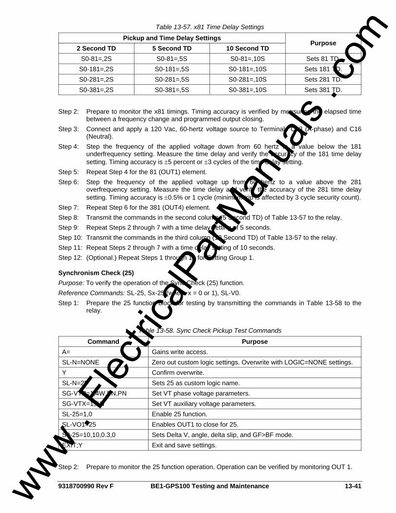
9318700990 Rev F BE1-GPS100 Testing and Maintenance 13-41
Table 13-57. x81 Time Delay Settings
Pickup and Time Delay Settings 2 Second TD 5 Second TD 10 Second TD
Purpose
S0-81=,2S S0-81=,5S S0-81=,10S Sets 81 TD. S0-181=,2S S0-181=,5S S0-181=,10S Sets 181 TD. S0-281=,2S S0-281=,5S S0-281=,10S Sets 281 TD. S0-381=,2S S0-381=,5S S0-381=,10S Sets 381 TD.
Step 2: Prepare to monitor the x81 timings. Timing accuracy is verified by measuring the elapsed time
between a frequency change and programmed output closing. Step 3: Connect and apply a 120 Vac, 60-hertz voltage source to Terminals C13 (A-phase) and C16
(Neutral). Step 4: Step the frequency of the applied voltage down from 60 hertz to a value below the 181
underfrequency setting. Measure the time delay and verify the accuracy of the 181 time delay setting. Timing accuracy is ±5 percent or ±3 cycles of the time delay setting.
Step 5: Repeat Step 4 for the 81 (OUT1) element. Step 6: Step the frequency of the applied voltage up from 60 hertz to a value above the 281
overfrequency setting. Measure the time delay and verify the accuracy of the 281 time delay setting. Timing accuracy is ±0.5% or 1 cycle (minimum trip is affected by 3 cycle security count).
Step 7: Repeat Step 6 for the 381 (OUT4) element. Step 8: Transmit the commands in the second column (5 Second TD) of Table 13-57 to the relay. Step 9: Repeat Steps 2 through 7 with a time delay setting of 5 seconds. Step 10: Transmit the commands in the third column (10 Second TD) of Table 13-57 to the relay. Step 11: Repeat Steps 2 through 7 with a time delay setting of 10 seconds. Step 12: (Optional.) Repeat Steps 1 through 11 for Setting Group 1.
Synchronism Check (25) Purpose: To verify the operation of the Sync Check (25) function. Reference Commands: SL-25, Sx-25 (where x = 0 or 1), SL-V0. Step 1: Prepare the 25 function block for testing by transmitting the commands in Table 13-58 to the
relay.
Table 13-58. Sync Check Pickup Test Commands
Command Purpose A= Gains write access. SL-N=NONE Zero out custom logic settings. Overwrite with LOGIC=NONE settings. Y Confirm overwrite. SL-N=25 Sets 25 as custom logic name. SG-VTP=1,4W,PN,PN Set VT phase voltage parameters. SG-VTX=1,AN Set VT auxiliary voltage parameters. SL-25=1,0 Enable 25 function. SL-VO1=25 Enables OUT1 to close for 25. S0-25=10,10,0.3,0 Sets Delta V, angle, delta slip, and GF>BF mode. EXIT;Y Exit and save settings.
Step 2: Prepare to monitor the 25 function operation. Operation can be verified by monitoring OUT 1.
www . El
ectric
alPar
tMan
uals
. com

13-42 BE1-GPS100 Testing and Maintenance 9318700990 Rev F
Step 3: Connect relay Terminals C13 (A-phase), C14 (B-phase), and C15 (C-phase) together. Apply a 120 vac, 50 or 60 hertz ac, 0 degree voltage source (Line VT Phase) to the three jumpered terminals and the Neutral Terminal (C16).
Step 4: Apply a second 120 Vac, 50 or 60 hertz ac, 0 degree voltage source (Auxiliary VX) to C17 and C18. OUT1 should close verifying the 25 output for a Delta Angle of 0 degrees, 0 Delta V and 0 Delta Frequency (Slip).
Step 5: Decrease the Auxiliary voltage input (VX) until OUT1 opens. Slowly increase the voltage until OUT1 closes. Pickup should occur within ±2 percent of Delta V setting. Dropout should occur at 97% to 98% of actual pickup.
Step 6: Repeat Step 5 for the Line Voltage Input (VT Phase). Return voltage inputs to 120 vac, 50 or 60 hertz, 0 degrees.
Step 7: Swing the angle between voltage source 1 and 2 until the OUT1 opens. Slowly decrease the angle until OUT1 closes. Pickup should occur within ±2 degrees of the Delta Angle setting on the leading and lagging side of 0 degrees. Dropout should occur at 97% to 98% of actual pickup. Return Delta Angle of 0 degrees.
Step 8: With the Auxiliary Voltage set at nominal frequency, step change the frequency of the Line voltage input by -0.25 hertz (59.75 on a 60 hertz relay). Note that OUT1 is closing and opening based on a slip rate of 0.25 hertz. Decrease the frequency until OUT1 stays open. Slowly increase the frequency until OUT1 begins to cycle (closed/open). Cycling pickup should occur within ±2 percent of the Delta Slip setting. Also, check on the fast side (60.25 for a 60 hertz relay).
Step 9: Repeat Step 8 for the Auxiliary Voltage input. Step 10: (Optional.) Repeat Steps 4 through 9 for Setting Group 1.
Breaker Failure (BF) Purpose: To verify the operation of the breaker failure (BF) function. Reference Commands: SL-BF, SP-BF Step 1: Prepare the BF function block for testing by transmitting the commands in Table 13-59 to the
relay.
Table 13-59. BF Pickup Test Commands
Command Purpose A= Gains write access. SL-N=NONE Zero out custom logic settings. Overwrite with LOGIC=NONE settings. Y Confirm overwrite. SL-N=BF Sets BF as custom logic name. SL-BF=1,IN4,/IN3 Enables BF, IN4 initiate, /IN3 block. SP-BF=50m Set BF time delay at minimum. SL-VO1=BFT Enables OUT1 to close for BF trip. SL-VO2=BFPU Enables OUT2 to close for BF pickup. SG-CT=1 Sets P, N CT ratio at 1:1 SG-TRIGGER=BFT,BFPU,0 Enable BFT to log and trigger fault recording. EXIT;Y Exit and save settings.
Step 2: Energize relay inputs IN3 and IN4. This enables the BF logic and BF initiate. The BF current
detector pickup setting is a fixed value that is determined by the relay current sensing type. Table 13-60 lists the pickup setting for each current sensing type.
www . El
ectric
alPar
tMan
uals
. com
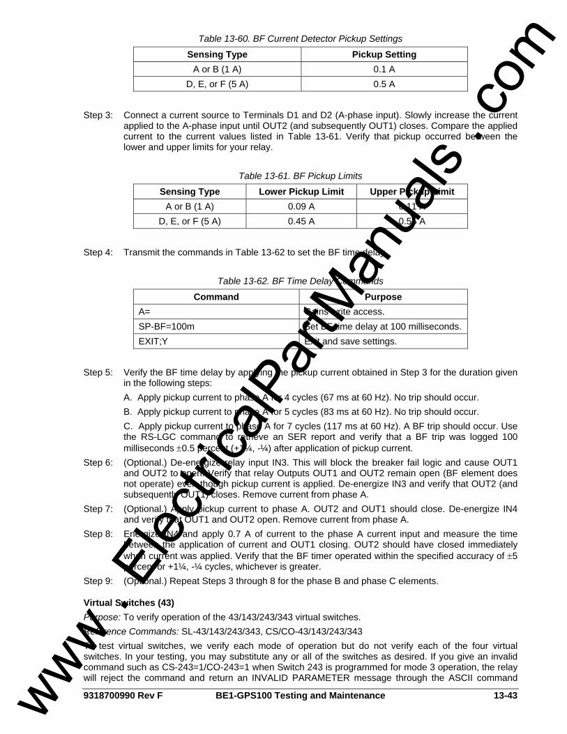
9318700990 Rev F BE1-GPS100 Testing and Maintenance 13-43
Table 13-60. BF Current Detector Pickup Settings
Sensing Type Pickup Setting A or B (1 A) 0.1 A
D, E, or F (5 A) 0.5 A
Step 3: Connect a current source to Terminals D1 and D2 (A-phase input). Slowly increase the current
applied to the A-phase input until OUT2 (and subsequently OUT1) closes. Compare the applied current to the current values listed in Table 13-61. Verify that pickup occurred between the lower and upper limits for your relay.
Table 13-61. BF Pickup Limits
Sensing Type Lower Pickup Limit Upper Pickup Limit A or B (1 A) 0.09 A 0.11 A
D, E, or F (5 A) 0.45 A 0.55 A
Step 4: Transmit the commands in Table 13-62 to set the BF time delay.
Table 13-62. BF Time Delay Commands
Command Purpose A= Gains write access. SP-BF=100m Set BF time delay at 100 milliseconds. EXIT;Y Exit and save settings.
Step 5: Verify the BF time delay by applying the pickup current obtained in Step 3 for the duration given
in the following steps: A. Apply pickup current to phase A for 4 cycles (67 ms at 60 Hz). No trip should occur. B. Apply pickup current to phase A for 5 cycles (83 ms at 60 Hz). No trip should occur.
C. Apply pickup current to phase A for 7 cycles (117 ms at 60 Hz). A BF trip should occur. Use the RS-LGC command to retrieve an SER report and verify that a BF trip was logged 100 milliseconds ±0.5 percent (+1¼, -¼) after application of pickup current.
Step 6: (Optional.) De-energize relay input IN3. This will block the breaker fail logic and cause OUT1 and OUT2 to open. Verify that relay Outputs OUT1 and OUT2 remain open (BF element does not operate) even though pickup current is applied. De-energize IN3 and verify that OUT2 (and subsequently OUT1) closes. Remove current from phase A.
Step 7: (Optional.) Apply pickup current to phase A. OUT2 and OUT1 should close. De-energize IN4 and verify that OUT1 and OUT2 open. Remove current from phase A.
Step 8: Energize IN4 and apply 0.7 A of current to the phase A current input and measure the time between the application of current and OUT1 closing. OUT2 should have closed immediately when current was applied. Verify that the BF timer operated within the specified accuracy of ±5 percent or +1¼, -¼ cycles, whichever is greater.
Step 9: (Optional.) Repeat Steps 3 through 8 for the phase B and phase C elements.
Virtual Switches (43) Purpose: To verify operation of the 43/143/243/343 virtual switches. Reference Commands: SL-43/143/243/343, CS/CO-43/143/243/343 To test virtual switches, we verify each mode of operation but do not verify each of the four virtual switches. In your testing, you may substitute any or all of the switches as desired. If you give an invalid command such as CS-243=1/CO-243=1 when Switch 243 is programmed for mode 3 operation, the relay will reject the command and return an INVALID PARAMETER message through the ASCII command
www . El
ectric
alPar
tMan
uals
. com
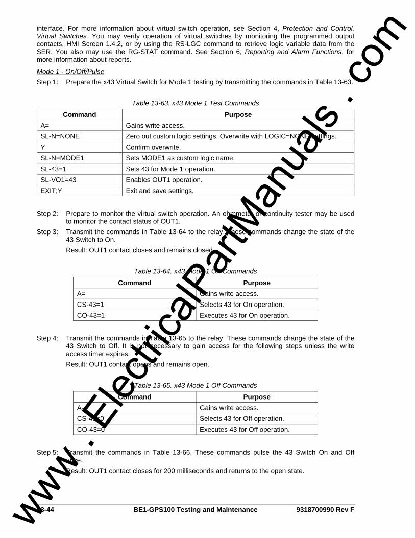
13-44 BE1-GPS100 Testing and Maintenance 9318700990 Rev F
interface. For more information about virtual switch operation, see Section 4, Protection and Control, Virtual Switches. You may verify operation of virtual switches by monitoring the programmed output contacts, HMI Screen 1.4.2, or by using the RS-LGC command to retrieve logic variable data from the SER. You also may use the RG-STAT command. See Section 6, Reporting and Alarm Functions, for more information about reports.
Mode 1 - On/Off/Pulse Step 1: Prepare the x43 Virtual Switch for Mode 1 testing by transmitting the commands in Table 13-63.
Table 13-63. x43 Mode 1 Test Commands
Command Purpose A= Gains write access. SL-N=NONE Zero out custom logic settings. Overwrite with LOGIC=NONE settings. Y Confirm overwrite. SL-N=MODE1 Sets MODE1 as custom logic name. SL-43=1 Sets 43 for Mode 1 operation. SL-VO1=43 Enables OUT1 operation. EXIT;Y Exit and save settings.
Step 2: Prepare to monitor the virtual switch operation. An ohmmeter or continuity tester may be used
to monitor the contact status of OUT1. Step 3: Transmit the commands in Table 13-64 to the relay. These commands change the state of the
43 Switch to On. Result: OUT1 contact closes and remains closed.
Table 13-64. x43 Mode 1 On Commands
Command Purpose A= Gains write access. CS-43=1 Selects 43 for On operation. CO-43=1 Executes 43 for On operation.
Step 4: Transmit the commands in Table 13-65 to the relay. These commands change the state of the
43 Switch to Off. It is not necessary to gain access for the following steps unless the write access timer expires:
Result: OUT1 contact opens and remains open.
Table 13-65. x43 Mode 1 Off Commands
Command Purpose A= Gains write access. CS-43=0 Selects 43 for Off operation. CO-43=0 Executes 43 for Off operation.
Step 5: Transmit the commands in Table 13-66. These commands pulse the 43 Switch On and Off
once. Result: OUT1 contact closes for 200 milliseconds and returns to the open state.
www . El
ectric
alPar
tMan
uals
. com
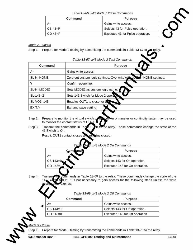
9318700990 Rev F BE1-GPS100 Testing and Maintenance 13-45
Table 13-66. x43 Mode 1 Pulse Commands
Command Purpose A= Gains write access. CS-43=P Selects 43 for Pulse operation. CO-43=P Executes 43 for Pulse operation.
Mode 2 - On/Off Step 1: Prepare for Mode 2 testing by transmitting the commands in Table 13-67 to the relay.
Table 13-67. x43 Mode 2 Test Commands
Command Purpose
A= Gains write access.
SL-N=NONE Zero out custom logic settings. Overwrite with LOGIC=NONE settings.
Y Confirm overwrite.
SL-N=MODE2 Sets MODE2 as custom logic name.
SL-143=2 Sets 143 Switch for Mode 2 operation.
SL-VO1=143 Enables OUT1 to close for 143.
EXIT;Y Exit and save setting
Step 2: Prepare to monitor the virtual switch operation. An ohmmeter or continuity tester may be used
to monitor the contact status of OUT1. Step 3: Transmit the commands in Table 13-68 to the relay. These commands change the state of the
43 Switch to On. Result: OUT1 contact closes and remains closed.
Table 13-68. x43 Mode 2 On Commands
Command Purpose A= Gains write access. CS-143=1 Selects 143 for On operation. CO-143=1 Executes 143 for On operation.
Step 4: Transmit the commands in Table 13-69 to the relay. These commands change the state of the
143 Switch to Off. It is not necessary to gain access for the following steps unless the write access timer expires.
Table 13-69. x43 Mode 2 Off Commands
Command Purpose A= Gains write access. CS-143=0 Selects 143 for Off operation. CO-143=0 Executes 143 for Off operation.
Mode 3 - Pulse Step 1: Prepare for Mode 3 testing by transmitting the commands in Table 13-70 to the relay.
www . El
ectric
alPar
tMan
uals
. com
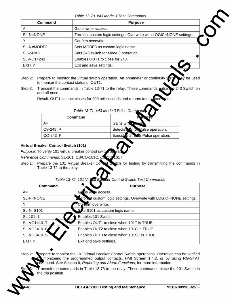
13-46 BE1-GPS100 Testing and Maintenance 9318700990 Rev F
Table 13-70. x43 Mode 3 Test Commands
Command Purpose A= Gains write access. SL-N=NONE Zero out custom logic settings. Overwrite with LOGIC=NONE settings. Y Confirm overwrite. SL-N=MODE3 Sets MODE3 as custom logic name. SL-243=3 Sets 243 switch for Mode 3 operation. SL-VO1=243 Enables OUT1 to close for 243. EXIT;Y Exit and save settings.
Step 2: Prepare to monitor the virtual switch operation. An ohmmeter or continuity tester may be used
to monitor the contact status of OUT1. Step 3: Transmit the commands in Table 13-71 to the relay. These commands pulse the 243 Switch on
and off once. Result: OUT1 contact closes for 200 milliseconds and returns to the open state.
Table 13-71. x43 Mode 3 Pulse Commands
Command Purpose A= Gains write access. CS-243=P Selects 243 for Pulse operation. CO-243=P Executes 243 for Pulse operation.
Virtual Breaker Control Switch (101) Purpose: To verify 101 virtual breaker control switch operation. Reference Commands: SL-101, CS/CO-101C, CS/CO-101T Step 1: Prepare the 101 Virtual Breaker Control Switch for testing by transmitting the commands in
Table 13-72 to the relay.
Table 13-72. 101 Virtual Breaker Control Switch Test Commands
Command Purpose A= Gains write access. SL-N=NONE Zero out custom logic settings. Overwrite with LOGIC=NONE settings. Y Confirm overwrite. SL-N=S101 Sets S101 as custom logic name. SL-101=1 Enables 101 Switch. SL-VO1=101T Enables OUT1 to close when 101T is TRUE. SL-VO2=101C Enables OUT2 to close when 101C is TRUE. SL-VO3=101SC Enables OUT3 to close when 101SC is TRUE. EXIT;Y Exit and save settings.
Step 2: Prepare to monitor the 101 Virtual Breaker Control Switch operations. Operation can be verified
by monitoring the programmed output contacts, HMI Screen 1.4.2, or by using RG-STAT command. See Section 6, Reporting and Alarm Functions, for more information.
Step 3: Transmit the commands in Table 13-73 to the relay. These commands place the 101 Switch in the trip position.
www . El
ectric
alPar
tMan
uals
. com
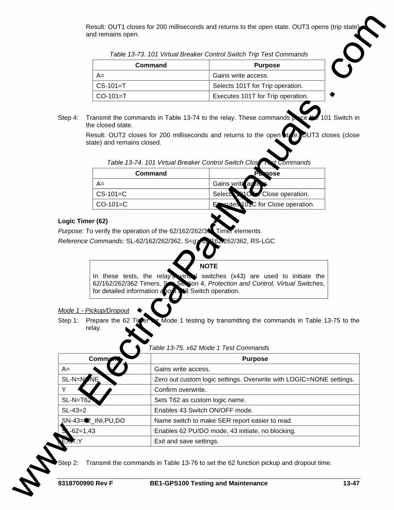
9318700990 Rev F BE1-GPS100 Testing and Maintenance 13-47
Result: OUT1 closes for 200 milliseconds and returns to the open state. OUT3 opens (trip state) and remains open.
Table 13-73. 101 Virtual Breaker Control Switch Trip Test Commands
Command Purpose A= Gains write access. CS-101=T Selects 101T for Trip operation. CO-101=T Executes 101T for Trip operation.
Step 4: Transmit the commands in Table 13-74 to the relay. These commands place the 101 Switch in
the closed state. Result: OUT2 closes for 200 milliseconds and returns to the open state. OUT3 closes (close state) and remains closed.
Table 13-74. 101 Virtual Breaker Control Switch Close Test Commands
Command Purpose A= Gains write access. CS-101=C Selects 101C for Close operation. CO-101=C Executes 101C for Close operation.
Logic Timer (62) Purpose: To verify the operation of the 62/162/262/362 Timer elements. Reference Commands: SL-62/162/262/362, S<g>-62/162/262/362, RS-LGC
Mode 1 - Pickup/Dropout Step 1: Prepare the 62 Timer for Mode 1 testing by transmitting the commands in Table 13-75 to the
relay.
Table 13-75. x62 Mode 1 Test Commands
Command Purpose A= Gains write access. SL-N=NONE Zero out custom logic settings. Overwrite with LOGIC=NONE settings. Y Confirm overwrite. SL-N=T62 Sets T62 as custom logic name. SL-43=2 Enables 43 Switch ON/OFF mode. SN-43=62_INI,PU,DO Name switch to make SER report easier to read. SL-62=1,43 Enables 62 PU/DO mode, 43 initiate, no blocking. EXIT;Y Exit and save settings.
Step 2: Transmit the commands in Table 13-76 to set the 62 function pickup and dropout time.
NOTE In these tests, the relay's virtual switches (x43) are used to initiate the 62/162/262/362 Timers. See Section 4, Protection and Control, Virtual Switches, for detailed information about x43 Switch operation.
www . El
ectric
alPar
tMan
uals
. com

13-48 BE1-GPS100 Testing and Maintenance 9318700990 Rev F
Table 13-76. x62 Mode 1 Pickup and Dropout Settings
Command Purpose A= Gains write access. S#-62=400m,2000m Sets 62 pickup at 400 milliseconds, dropout at 2,000 milliseconds. EXIT;Y Exit and save settings.
Step 3: Transmit the commands in Table 13-77 to the relay. These commands will initiate the 62 Timer
by changing the 43 Switch state to closed (logic 1). Once initiated, the 62 Timer will force an output based on the 400-millisecond pickup time setting.
Table 13-77. x62 Mode 1 Timer Initiate Commands
Command Purpose A= Gains write access. CS-43=1 Selects 43 for On operation. CO-43=1 Executes 43 for On operation.
Step 4: Transmit the commands in Table 13-78 to the relay. These commands will remove the initiate
input from the 62 Timer by changing the 43 Switch state to open (logic 0).
Table 13-78. x62 Mode 1 Timer Initiate Removal Commands
Command Purpose A= Gains write access. CS-43=0 Selects 43 for Off operation. CO-43=0 Executes 43 for Off operation.
Step 5: Use the RS-LGC command to retrieve logic variable data from the SER. Verify that the 43
Switch change to a closed state was logged and approximately 400 milliseconds later, the 62 Timer picked up. Then, some time later, the 43 Switch change to an open state was logged and the 62 Timer dropped out approximately 2,000 milliseconds later. The state of the 43 switches in the SER report use the programmable name parameters applied to the switch. Figure 13-5 illustrates the timing relationship of the 43 Switch and 62 Timer.
D2843-0810-23-03
Figure 13-5. x62 Mode 1 (Pickup/Dropout) Timing Example
Mode 2 - One-Shot Nonretriggerable Step 1: Prepare the 162 Timer for Mode 2 testing by transmitting the commands in Table 13-79 to the
relay.
www . El
ectric
alPar
tMan
uals
. com
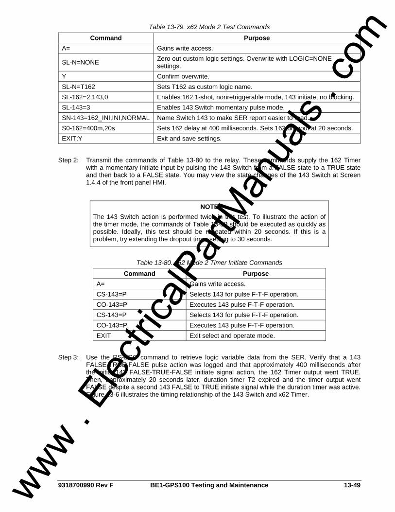
9318700990 Rev F BE1-GPS100 Testing and Maintenance 13-49
Table 13-79. x62 Mode 2 Test Commands
Command Purpose A= Gains write access.
SL-N=NONE Zero out custom logic settings. Overwrite with LOGIC=NONE settings.
Y Confirm overwrite. SL-N=T162 Sets T162 as custom logic name. SL-162=2,143,0 Enables 162 1-shot, nonretriggerable mode, 143 initiate, no blocking. SL-143=3 Enables 143 Switch momentary pulse mode. SN-143=162_INI,INI,NORMAL Name Switch 143 to make SER report easier to read. S0-162=400m,20s Sets 162 delay at 400 milliseconds. Sets 162 dropout at 20 seconds. EXIT;Y Exit and save settings.
Step 2: Transmit the commands of Table 13-80 to the relay. These commands supply the 162 Timer
with a momentary initiate input by pulsing the 143 Switch from a FALSE state to a TRUE state and then back to a FALSE state. You may view the state changes of the 143 Switch at Screen 1.4.4 of the front panel HMI.
Table 13-80. x62 Mode 2 Timer Initiate Commands
Command Purpose A= Gains write access. CS-143=P Selects 143 for pulse F-T-F operation. CO-143=P Executes 143 pulse F-T-F operation. CS-143=P Selects 143 for pulse F-T-F operation. CO-143=P Executes 143 pulse F-T-F operation. EXIT Exit select and operate mode.
Step 3: Use the RS-LGC command to retrieve logic variable data from the SER. Verify that a 143
FALSE-TRUE-FALSE pulse action was logged and that approximately 400 milliseconds after the initial 143 FALSE-TRUE-FALSE initiate signal action, the 162 Timer output went TRUE. Then, approximately 20 seconds later, duration timer T2 expired and the timer output went FALSE despite a second 143 FALSE to TRUE initiate signal while the duration timer was active. Figure 13-6 illustrates the timing relationship of the 143 Switch and x62 Timer.
NOTE The 143 Switch action is performed twice in this test. To illustrate the action of the timer mode, the commands of Table 13-80 should be executed as quickly as possible. Ideally, this test should be repeated within 20 seconds. If this is a problem, try extending the dropout timer setting to 30 seconds.
www . El
ectric
alPar
tMan
uals
. com
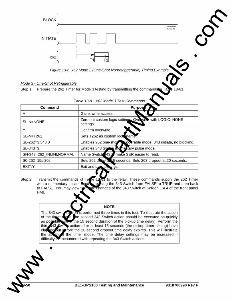
13-50 BE1-GPS100 Testing and Maintenance 9318700990 Rev F
D2843-0910-23-03
Figure 13-6. x62 Mode 2 (One-Shot Nonretriggerable) Timing Example
Mode 3 - One-Shot Retriggerable Step 1: Prepare the 262 Timer for Mode 3 testing by transmitting the commands in Table 13-81.
Table 13-81. x62 Mode 3 Test Commands
Command Purpose A= Gains write access.
SL-N=NONE Zero out custom logic settings. Overwrite with LOGIC=NONE settings.
Y Confirm overwrite. SL-N=T262 Sets T262 as custom logic name. SL-262=3,343,0 Enables 262 one-shot, retriggerable mode, 343 initiate, no blocking. SL-343=3 Enables 343 Switch momentary pulse mode. SN-343=262_INI,INI,NORMAL Name Switch 343 to make SER easier to read. S0-262=15s,20s Sets 262 delay at 15 seconds. Sets 262 dropout at 20 seconds. EXIT;Y Exit and save settings.
Step 2: Transmit the commands of Table 13-82 to the relay. These commands supply the 262 Timer
with a momentary initiate input by pulsing the 343 Switch from FALSE to TRUE and then back to FALSE. You may view the state changes of the 343 Switch at Screen 1.4.4 of the front panel HMI.
NOTE The 343 switch action is performed three times in this test. To illustrate the action of the timer mode, the second 343 Switch action should be executed as quickly as possible (within the 15 second duration of the pickup time delay). Perform the third 343 Switch action after at least 15 seconds (the pickup timer setting) have elapsed but before the 20-second dropout time delay expires. This will illustrate the action of the timer mode. The time delay settings may be increased if difficulty is encountered with repeating the 343 Switch actions.
www . El
ectric
alPar
tMan
uals
. com
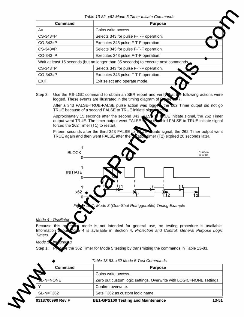
9318700990 Rev F BE1-GPS100 Testing and Maintenance 13-51
Table 13-82. x62 Mode 3 Timer Initiate Commands
Command Purpose A= Gains write access. CS-343=P Selects 343 for pulse F-T-F operation. CO-343=P Executes 343 pulse F-T-F operation. CS-343=P Selects 343 for pulse F-T-F operation. CO-343=P Executes 343 pulse F-T-F operation. Wait at least 15 seconds (but no longer than 35 seconds) to execute next commands. CS-343=P Selects 343 for pulse F-T-F operation. CO-343=P Executes 343 pulse F-T-F operation. EXIT Exit select and operate mode.
Step 3: Use the RS-LGC command to obtain an SER report and verify that the following actions were
logged. These events are illustrated in the timing diagram of Figure 13-7. After a 343 FALSE-TRUE-FALSE pulse action was logged, the 262 Timer output did not go TRUE because of a second FALSE to TRUE initiate signal action. Approximately 15 seconds after the second 343 FALSE to TRUE initiate signal, the 262 Timer output went TRUE. The timer output went FALSE when the third FALSE to TRUE initiate signal forced the 262 Timer (T1) to restart. Fifteen seconds after the third 343 FALSE to TRUE initiate signal, the 262 Timer output went TRUE again and then went FALSE after the duration timer (T2) expired 20 seconds later.
Figure 13-7. Mode 3 (One-Shot Retriggerable) Timing Example
Mode 4 - Oscillator Because this operating mode is not intended for general use, no testing procedure is available. Information about Mode 4 is available in Section 4, Protection and Control, General Purpose Logic Timers.
Mode 5 - Integrating Step 1: Prepare the 362 Timer for Mode 5 testing by transmitting the commands in Table 13-83.
Table 13-83. x62 Mode 5 Test Commands
Command Purpose A= Gains write access. SL-N=NONE Zero out custom logic settings. Overwrite with LOGIC=NONE settings. Y Confirm overwrite. SL-N=T362 Sets T362 as custom logic name.
www . El
ectric
alPar
tMan
uals
. com
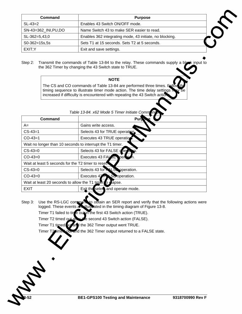
13-52 BE1-GPS100 Testing and Maintenance 9318700990 Rev F
Command Purpose SL-43=2 Enables 43 Switch ON/OFF mode. SN-43=362_INI,PU,DO Name Switch 43 to make SER easier to read. SL-362=5,43,0 Enables 362 integrating mode, 43 initiate, no blocking. S0-362=15s,5s Sets T1 at 15 seconds. Sets T2 at 5 seconds. EXIT;Y Exit and save settings.
Step 2: Transmit the commands of Table 13-84 to the relay. These commands supply a block input to
the 362 Timer by changing the 43 Switch state to TRUE.
Table 13-84. x62 Mode 5 Timer Initiate Commands
Command Purpose A= Gains write access. CS-43=1 Selects 43 for TRUE operation. CO-43=1 Executes 43 TRUE operation. Wait no longer than 10 seconds to interrupt the T1 timer. CS-43=0 Selects 43 for FALSE operation. CO-43=0 Executes 43 FALSE operation. Wait at least 5 seconds for the T2 timer to reset. CS-43=0 Selects 43 for FALSE operation. CO-43=0 Executes 43 FALSE operation. Wait at least 20 seconds to allow the T1 timer to elapse. EXIT Exit the select and operate mode.
Step 3: Use the RS-LGC command to obtain an SER report and verify that the following actions were
logged. These events are illustrated in the timing diagram of Figure 13-8. Timer T1 failed to time out in the first 43 Switch action (TRUE). Timer T2 timed out after the second 43 Switch action (FALSE). Timer T1 timed out and the 362 Timer output went TRUE. Timer T2 timed out and the 362 Timer output returned to a FALSE state.
NOTE The CS and CO commands of Table 13-84 are performed three times. Follow the timing sequence to illustrate timer mode action. The time delay settings may be increased if difficulty is encountered with repeating the 43 Switch actions.
www . El
ectric
alPar
tMan
uals
. com
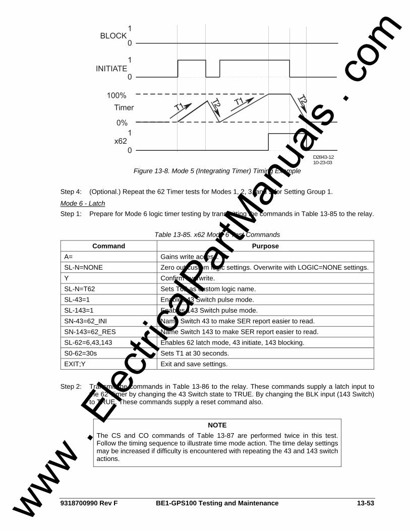
9318700990 Rev F BE1-GPS100 Testing and Maintenance 13-53
D2843-1210-23-03
Figure 13-8. Mode 5 (Integrating Timer) Timing Example Step 4: (Optional.) Repeat the 62 Timer tests for Modes 1, 2, 3, and 5 for Setting Group 1.
Mode 6 - Latch Step 1: Prepare for Mode 6 logic timer testing by transmitting the commands in Table 13-85 to the relay.
Table 13-85. x62 Mode 6 Test Commands
Command Purpose A= Gains write access. SL-N=NONE Zero out custom logic settings. Overwrite with LOGIC=NONE settings. Y Confirm overwrite. SL-N=T62 Sets T62 as custom logic name. SL-43=1 Enables 43 Switch pulse mode. SL-143=1 Enables 143 Switch pulse mode. SN-43=62_INI Name Switch 43 to make SER report easier to read. SN-143=62_RES Name Switch 143 to make SER report easier to read. SL-62=6,43,143 Enables 62 latch mode, 43 initiate, 143 blocking. S0-62=30s Sets T1 at 30 seconds. EXIT;Y Exit and save settings.
Step 2: Transmit the commands in Table 13-86 to the relay. These commands supply a latch input to
the 62 Timer by changing the 43 Switch state to TRUE. By changing the BLK input (143 Switch) to TRUE. These commands supply a reset command also.
NOTE The CS and CO commands of Table 13-87 are performed twice in this test. Follow the timing sequence to illustrate time mode action. The time delay settings may be increased if difficulty is encountered with repeating the 43 and 143 switch actions.
www . El
ectric
alPar
tMan
uals
. com
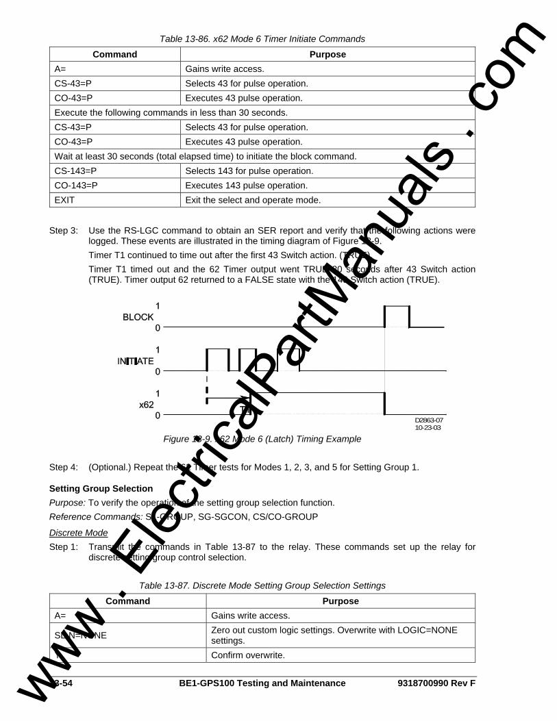
13-54 BE1-GPS100 Testing and Maintenance 9318700990 Rev F
Table 13-86. x62 Mode 6 Timer Initiate Commands
Command Purpose A= Gains write access. CS-43=P Selects 43 for pulse operation. CO-43=P Executes 43 pulse operation. Execute the following commands in less than 30 seconds. CS-43=P Selects 43 for pulse operation. CO-43=P Executes 43 pulse operation. Wait at least 30 seconds (total elapsed time) to initiate the block command. CS-143=P Selects 143 for pulse operation. CO-143=P Executes 143 pulse operation. EXIT Exit the select and operate mode.
Step 3: Use the RS-LGC command to obtain an SER report and verify that the following actions were
logged. These events are illustrated in the timing diagram of Figure 13-9. Timer T1 continued to time out after the first 43 Switch action. (TRUE).
Timer T1 timed out and the 62 Timer output went TRUE 30 seconds after 43 Switch action (TRUE). Timer output 62 returned to a FALSE state with the 143 Switch action (TRUE).
D2863-0710-23-03
Figure 13-9. x62 Mode 6 (Latch) Timing Example Step 4: (Optional.) Repeat the 62 Timer tests for Modes 1, 2, 3, and 5 for Setting Group 1.
Setting Group Selection Purpose: To verify the operation of the setting group selection function. Reference Commands: SL-GROUP, SG-SGCON, CS/CO-GROUP
Discrete Mode Step 1: Transmit the commands in Table 13-87 to the relay. These commands set up the relay for
discrete setting group control selection.
Table 13-87. Discrete Mode Setting Group Selection Settings
Command Purpose A= Gains write access.
SL-N=NONE Zero out custom logic settings. Overwrite with LOGIC=NONE settings.
Y Confirm overwrite.
www . El
ectric
alPar
tMan
uals
. com
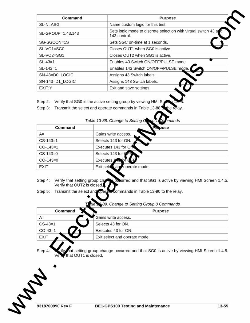
9318700990 Rev F BE1-GPS100 Testing and Maintenance 13-55
Command Purpose SL-N=ASG Name custom logic for this test.
SL-GROUP=1,43,143 Sets logic mode to discrete selection with virtual switch 43 and 143 control.
SG-SGCON=1S Sets SGC on-time at 1 seconds. SL-VO1=SG0 Closes OUT1 when SG0 is active. SL-VO2=SG1 Closes OUT2 when SG1 is active. SL-43=1 Enables 43 Switch ON/OFF/PULSE mode. SL-143=1 Enables 143 Switch ON/OFF/PULSE mode. SN-43=D0_LOGIC Assigns 43 Switch labels. SN-143=D1_LOGIC Assigns 143 Switch labels. EXIT;Y Exit and save settings.
Step 2: Verify that SG0 is the active setting group by viewing HMI Screen 1.4.5. Step 3: Transmit the select and operate commands in Table 13-88 to the relay.
Table 13-88. Change to Setting Group 1 Commands
Command Purpose A= Gains write access. CS-143=1 Selects 143 for ON. CO-143=1 Executes 143 for ON. CS-143=0 Selects 143 for OFF. CO-143=0 Executes 143 for OFF. EXIT Exit select and operate mode.
Step 4: Verify that setting group change occurred and that SG1 is active by viewing HMI Screen 1.4.5.
Verify that OUT2 is closed. Step 5: Transmit the select and operate commands in Table 13-90 to the relay.
Table 13-89. Change to Setting Group 0 Commands
Command Purpose A= Gains write access. CS-43=1 Selects 43 for ON. CO-43=1 Executes 43 for ON. EXIT Exit select and operate mode.
Step 4: Verify that setting group change occurred and that SG0 is active by viewing HMI Screen 1.4.5.
Verify that OUT1 is closed.
www . El
ectric
alPar
tMan
uals
. com
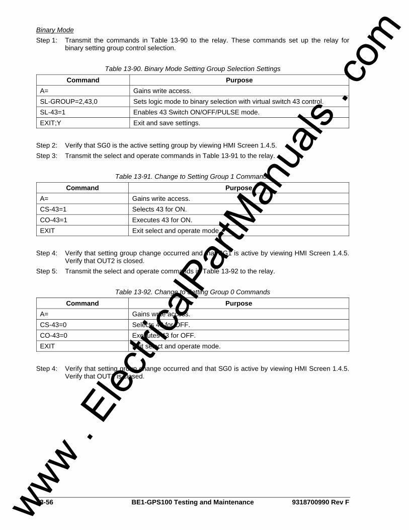
13-56 BE1-GPS100 Testing and Maintenance 9318700990 Rev F
Binary Mode Step 1: Transmit the commands in Table 13-90 to the relay. These commands set up the relay for
binary setting group control selection.
Table 13-90. Binary Mode Setting Group Selection Settings
Command Purpose A= Gains write access. SL-GROUP=2,43,0 Sets logic mode to binary selection with virtual switch 43 control. SL-43=1 Enables 43 Switch ON/OFF/PULSE mode. EXIT;Y Exit and save settings.
Step 2: Verify that SG0 is the active setting group by viewing HMI Screen 1.4.5. Step 3: Transmit the select and operate commands in Table 13-91 to the relay.
Table 13-91. Change to Setting Group 1 Commands
Command Purpose A= Gains write access. CS-43=1 Selects 43 for ON. CO-43=1 Executes 43 for ON. EXIT Exit select and operate mode.
Step 4: Verify that setting group change occurred and that SG1 is active by viewing HMI Screen 1.4.5.
Verify that OUT2 is closed. Step 5: Transmit the select and operate commands in Table 13-92 to the relay.
Table 13-92. Change to Setting Group 0 Commands
Command Purpose A= Gains write access. CS-43=0 Selects 43 for OFF. CO-43=0 Executes 43 for OFF. EXIT Exit select and operate mode.
Step 4: Verify that setting group change occurred and that SG0 is active by viewing HMI Screen 1.4.5.
Verify that OUT1 is closed.
www . El
ectric
alPar
tMan
uals
. com
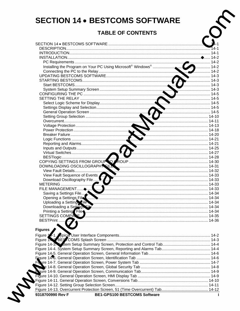
9318700990 Rev F BE1-GPS100 BESTCOMS Software i
SECTION 14 • BESTCOMS SOFTWARE TABLE OF CONTENTS
SECTION 14 • BESTCOMS SOFTWARE .............................................................................................. 14-1
DESCRIPTION..................................................................................................................................... 14-1 INTRODUCTION.................................................................................................................................. 14-1 INSTALLATION.................................................................................................................................... 14-2
PC Requirements ............................................................................................................................. 14-2 Installing the Program on Your PC Using Microsoft® Windows® ..................................................... 14-2 Connecting the PC to the Relay....................................................................................................... 14-2
UPDATING BESTCOMS SOFTWARE................................................................................................ 14-3 STARTING BESTCOMS...................................................................................................................... 14-3
Start BESTCOMS............................................................................................................................. 14-3 System Setup Summary Screen ...................................................................................................... 14-3
CONFIGURING THE PC ..................................................................................................................... 14-5 SETTING THE RELAY ........................................................................................................................ 14-5
Select Logic Scheme for Display...................................................................................................... 14-5 Settings Display and Selection......................................................................................................... 14-5 General Operation Screen ............................................................................................................... 14-5 Setting Group Selection ................................................................................................................. 14-10 Overcurrent..................................................................................................................................... 14-11 Voltage Protection .......................................................................................................................... 14-13 Power Protection ............................................................................................................................ 14-18 Breaker Failure............................................................................................................................... 14-20 Logic Functions .............................................................................................................................. 14-21 Reporting and Alarms..................................................................................................................... 14-21 Inputs and Outputs ......................................................................................................................... 14-25 Virtual Switches.............................................................................................................................. 14-27 BESTlogic....................................................................................................................................... 14-28
COPYING SETTINGS FROM GROUP TO GROUP ......................................................................... 14-30 DOWNLOADING OSCILLOGRAPHY FILES .................................................................................... 14-31
View Fault Details........................................................................................................................... 14-32 View Fault Sequence of Events ..................................................................................................... 14-33 Download Oscillography File.......................................................................................................... 14-33
METERING ........................................................................................................................................ 14-33 FILE MANAGEMENT......................................................................................................................... 14-33
Saving a Settings File..................................................................................................................... 14-34 Opening a Settings File .................................................................................................................. 14-34 Uploading a Settings File ............................................................................................................... 14-34 Downloading a Settings File........................................................................................................... 14-34 Printing a Settings File ................................................................................................................... 14-34
SETTINGS COMPARE...................................................................................................................... 14-35 BESTPrint .......................................................................................................................................... 14-36
Figures Figure 14-1. Typical User Interface Components.................................................................................... 14-2 Figure 14-2. BESTCOMS Splash Screen ............................................................................................... 14-3 Figure 14-3. System Setup Summary Screen, Protection and Control Tab............................................ 14-4 Figure 14-4. System Setup Summary Screen, Reporting and Alarms Tab............................................. 14-4 Figure 14-5. General Operation Screen, General Information Tab......................................................... 14-6 Figure 14-6. General Operation Screen, Identification Tab .................................................................... 14-6 Figure 14-7. General Operation Screen, Power System Tab ................................................................. 14-7 Figure 14-8. General Operation Screen, Global Security Tab ................................................................ 14-8 Figure 14-9. General Operation Screen, Communication Tab................................................................ 14-9 Figure 14-10. General Operation Screen, HMI Display Tab ................................................................... 14-9 Figure 14-11. General Operation Screen, Conversions Tab................................................................. 14-10 Figure 14-12. Setting Group Selection Screen...................................................................................... 14-11 Figure 14-13. Overcurrent Protection Screen, 51 (Time Overcurrent) Tab........................................... 14-12 www .
Elec
tricalP
artM
anua
ls . c
om
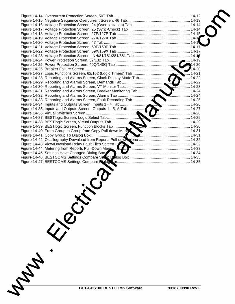
ii BE1-GPS100 BESTCOMS Software 9318700990 Rev F
Figure 14-14. Overcurrent Protection Screen, 50T Tab ........................................................................ 14-12 Figure 14-15. Negative Sequence Overcurrent Screen, 46 Tab........................................................... 14-13 Figure 14-16. Voltage Protection Screen, 24 (Overexcitation) Tab ...................................................... 14-14 Figure 14-17. Voltage Protection Screen, 25 (Sync-Check) Tab .......................................................... 14-14 Figure 14-18. Voltage Protection Screen, 27P/127P Tab ..................................................................... 14-15 Figure 14-19. Voltage Protection Screen, 27X/127X Tab ..................................................................... 14-16 Figure 14-20. Voltage Protection Screen, 47 Tab ................................................................................. 14-16 Figure 14-21. Voltage Protection Screen, 59P/159P Tab ..................................................................... 14-17 Figure 14-22. Voltage Protection Screen, 59X/159X Tab ..................................................................... 14-17 Figure 14-23. Voltage Protection Screen, INH/81/181/281/381 Tab..................................................... 14-18 Figure 14-24. Power Protection Screen, 32/132 Tab ............................................................................ 14-19 Figure 14-25. Power Protection Screen, 40Q/140Q Tab ...................................................................... 14-20 Figure 14-26. Breaker Failure Screen ................................................................................................... 14-20 Figure 14-27. Logic Functions Screen, 62/162 (Logic Timers) Tab ...................................................... 14-21 Figure 14-28. Reporting and Alarms Screen, Clock Display Mode Tab................................................ 14-22 Figure 14-29. Reporting and Alarms Screen, Demands Tab ................................................................ 14-22 Figure 14-30. Reporting and Alarms Screen, VT Monitor Tab.............................................................. 14-23 Figure 14-31. Reporting and Alarms Screen, Breaker Monitoring Tab ................................................. 14-24 Figure 14-32. Reporting and Alarms Screen, Alarms Tab .................................................................... 14-24 Figure 14-33. Reporting and Alarms Screen, Fault Recording Tab ...................................................... 14-25 Figure 14-34. Inputs and Outputs Screen, Inputs 1 - 4 Tab.................................................................. 14-26 Figure 14-35. Inputs and Outputs Screen, Outputs 1 - 5, A Tab........................................................... 14-27 Figure 14-36. Virtual Switches Screen .................................................................................................. 14-28 Figure 14-37. BESTlogic Screen, Logic Select Tab .............................................................................. 14-29 Figure 14-38. BESTlogic Screen, Virtual Outputs Tab.......................................................................... 14-29 Figure 14-39. BESTlogic Screen, Function Blocks Tab ........................................................................ 14-30 Figure 14-40. From Group to Group from Copy Pull-down Menu ......................................................... 14-31 Figure 14-41. Copy Group To Dialog Box ............................................................................................. 14-31 Figure 14-42. Oscillography Download from Reports Pull-down Menu ................................................ 14-32 Figure 14-43. View/Download Relay Fault Files Screen....................................................................... 14-32 Figure 14-44. Metering from Reports Pull-Down Menu......................................................................... 14-33 Figure 14-45. Settings Have Changed Dialog Box................................................................................ 14-34 Figure 14-46. BESTCOMS Settings Compare Setup Dialog Box ......................................................... 14-35 Figure 14-47. BESTCOMS Settings Compare Dialog Box.................................................................... 14-35
www . El
ectric
alPar
tMan
uals
. com

9318700990 Rev F BE1-GPS100 BESTCOMS Software 14-1
SECTION 14 • BESTCOMS SOFTWARE DESCRIPTION BESTCOMS is a Windows® based program that runs on an IBM compatible computer and provides a user friendly, graphical user interface (GUI) for use with Basler Electric communicating products. BESTCOMS is an acronym that stands for Basler Electric Software Tool for Communications, Operations, Maintenance, and Settings. BESTCOMS provides the user with a point and click means for setting and monitoring the in-service relay or relays under test. The point and click method provides an efficient, fast setup for configuring one or several relays. This software is provided free with every BE1-GPS100.
INTRODUCTION A primary advantage of the 32-bit BESTCOMS is that an actual unit (operating BE1 Numerical System) is not required to perform any or all settings and adjustments for any preprogrammed scheme. Nor is it needed to create a custom scheme complete with settings and adjustments. In addition, BESTCOMS for all of the BE1 Numerical Systems are identical except for differences inherit in the systems. This means that once you become familiar with a BESTCOMS for one system, you are also familiar with BESTCOMS for all of the systems. Using the BESTCOMS GUI, you may prepare setting files off-line (without being connected to the relay) and then upload the settings to the relay at your convenience. These settings include protection and control, operating and logic, breaker monitoring, metering, and fault recording. Engineering personnel can develop, test, and replicate the settings before exporting them to a file and transmitting the file to technical personnel in the field. In the field, the technician simply imports the file into the BESTCOMS database and uploads the file to the relay where it is stored in nonvolatile memory. (See the paragraphs on File Management, later in this manual for more information on saving, uploading, and downloading files.) The BESTCOMS GUI also has the same preprogrammed logic schemes that are stored in the relay. This gives the engineer the option (off-line) of developing his/her setting file using a preprogrammed logic scheme, customizing a preprogrammed logic scheme or building a scheme from scratch. Files may be exported from the GUI to a text editor where they can be reviewed or modified. The modified text file may then be uploaded to the relay. After it is uploaded to the relay, it can be brought into the GUI but it cannot be brought directly into the GUI from the text file. The GUI Logic Builder uses basic AND/OR gate logic combined with point and click variables to build the logic expressions. This reduces the design time and increases dependability. The BESTCOMS GUI also allows for downloading industry-standard COMTRADE files for analysis of stored oscillography data. Detailed analysis of the oscillography files may be accomplished using Basler Electric's BESTwave software. For more information on Basler Electric's Windows® based BESTwave software, contact your local sales representative or Basler Electric, Technical Support Services Department in Highland, Illinois. This section introduces all of the screens in the BE1-GPS100 Generator Protection System with their field layouts and typical entries. Common program activities such as applying settings, modifying logic, and setting up password security are discussed. These discussions are application oriented. We explore how the activity or task can be performed using an appropriate BE1-GPS100 BESTCOMS screen. BESTCOMS screens are similar to most Windows® based GUI. You may immediately notice common features such as the pull-down menu, toolbar, icons, and help prompts when the mouse pointer is paused over an icon. Some of these features are shown in Figure 14-1. If the Navigation Bar has a right and left arrow at the extreme right hand side of the screen, clicking on these arrows will shift the Navigation Bar to allow access to all of the icons on the bar. Like most computer programs, there is often more than one way to perform an activity or task. These various methods are discussed in the following paragraphs in conjunction with the appropriate BESTCOMS screen.
www . El
ectric
alPar
tMan
uals
. com
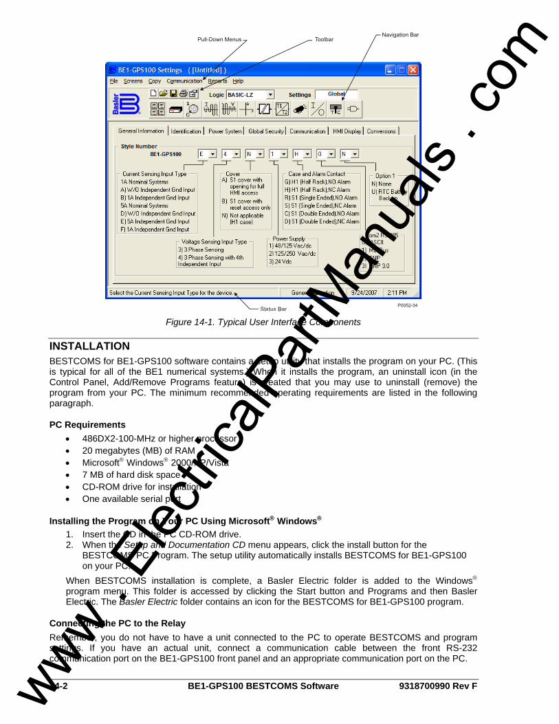
14-2 BE1-GPS100 BESTCOMS Software 9318700990 Rev F
Figure 14-1. Typical User Interface Components
INSTALLATION BESTCOMS for BE1-GPS100 software contains a setup utility that installs the program on your PC. (This is typical for all of the BE1 numerical systems.) When it installs the program, an uninstall icon (in the Control Panel, Add/Remove Programs feature) is created that you may use to uninstall (remove) the program from your PC. The minimum recommended operating requirements are listed in the following paragraph.
PC Requirements • 486DX2-100-MHz or higher processor • 20 megabytes (MB) of RAM • Microsoft® Windows® 2000/XP/Vista • 7 MB of hard disk space • CD-ROM drive for installation • One available serial port
Installing the Program on Your PC Using Microsoft® Windows® 1. Insert the CD in the PC CD-ROM drive. 2. When the Setup and Documentation CD menu appears, click the install button for the
BESTCOMS PC Program. The setup utility automatically installs BESTCOMS for BE1-GPS100 on your PC.
When BESTCOMS installation is complete, a Basler Electric folder is added to the Windows® program menu. This folder is accessed by clicking the Start button and Programs and then Basler Electric. The Basler Electric folder contains an icon for the BESTCOMS for BE1-GPS100 program.
Connecting the PC to the Relay Remember, you do not have to have a unit connected to the PC to operate BESTCOMS and program settings. If you have an actual unit, connect a communication cable between the front RS-232 communication port on the BE1-GPS100 front panel and an appropriate communication port on the PC.
www . El
ectric
alPar
tMan
uals
. com

9318700990 Rev F BE1-GPS100 BESTCOMS Software 14-3
UPDATING BESTCOMS SOFTWARE Future enhancements to relay functionality may make firmware update desirable. Enhancements to relay firmware typically coincide with enhancements to BESTCOMS software for that relay. When a relay is updated with the latest version of firmware, the latest version of BESTCOMS should also be obtained. If you obtained a CD-ROM containing firmware from Basler Electric, then that CD-ROM will also contain the corresponding version of BESTCOMS software. BESTCOMS can also be downloaded from the Basler Electric web site (http://www.basler.com). An online form can be completed to obtain a password for downloading BESTCOMS from the Basler Electric web site.
STARTING BESTCOMS
Start BESTCOMS Start BESTCOMS by clicking the Start button, Programs, Basler Electric, and then the BESTCOMS for BE1-GPS100 icon. During initial startup, the Select Language screen is displayed. The Select Language screen can later be displayed by selecting Select Language from the Tools pull-down menu. After clicking OK, a splash screen with the program title and version number is displayed for a brief time (Figure 14-2). After the splash screen clears, you can see the initial screen - the System Setup Summary screen. (This is the same process if you do or do not have a unit connected to your PC.)
Figure 14-2. BESTCOMS Splash Screen
System Setup Summary Screen This screen (Figure 14-3) gives you an overview of the system setup. There are two areas or folder tabs (like paper file folder tabs) to the screen. These are Protection and Control and Reporting and Alarms. When the screen is first displayed, the Protection and Control summary information is in the foreground and the Reporting and Alarms tab is in the background. You may select either of these tabs and bring that tab and information into the foreground. If you are at another BESTCOMS screen such as Overcurrent Protection and want to return to this screen, you may use the Screens pull-down menu or click on the System Setup Summary icon that is shown at the right margin of this paragraph.
Protection and Control Look in the lower, right-hand corner for the legend. This legend provides interpretation for the various indicated colors. Any protection and control function or element may be enabled or disabled and the current state is indicated by the associated color. If the function is enabled, the color is green. If the function is only disabled by a setting (such as zero), the color is yellow. If the function is only disabled by logic, the color is blue. If the function is disabled by both a setting and logic, the color is gray. If a function has variations such as 27X that has three modes (fundamental, three-phase residual, and third harmonic) and none of these modes are enabled, a tilde (~) is displayed. In addition to the functional status, Group Selection is displayed and the names are shown for the displayed and active logic and the virtual switches.
www . El
ectric
alPar
tMan
uals
. com
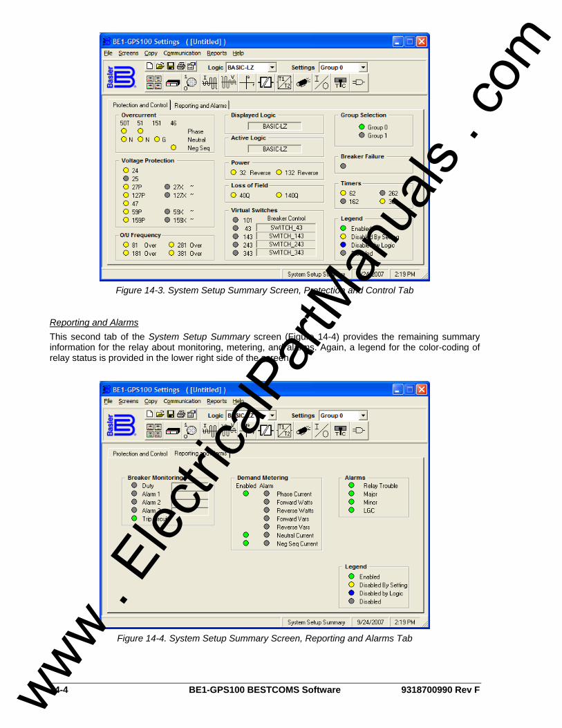
14-4 BE1-GPS100 BESTCOMS Software 9318700990 Rev F
Figure 14-3. System Setup Summary Screen, Protection and Control Tab
Reporting and Alarms This second tab of the System Setup Summary screen (Figure 14-4) provides the remaining summary information for the relay about monitoring, metering, and alarms. Again, a legend for the color-coding of relay status is provided in the lower right side of the screen.
Figure 14-4. System Setup Summary Screen, Reporting and Alarms Tab
www . El
ectric
alPar
tMan
uals
. com

9318700990 Rev F BE1-GPS100 BESTCOMS Software 14-5
CONFIGURING THE PC If you have an actual BE1-GPS100 relay, configure your PC to match the BE1-GPS100 configuration. To do this, pull down the Communication menu in the pull-down menu and select Configure. Now, match the communication configuration in the BE1-GPS100 relay. You may select Terminal (VT100 Emulation) and go directly to that communication protocol. You must close Terminal Mode before you can use BESTCOMS again. If you are comfortable using ASCII commands, the Terminal Mode is an easy method for checking the actual settings or status of the relay when you are in doubt about an action taken in BESTCOMS. ASCII commands are available in Section 11, ASCII Command Interface.
SETTING THE RELAY To set the relay, we will discuss the contents of each of the screens for BESTCOMS for BE1-GPS100. The System Setup Summary screen was discussed in previous paragraphs and we begin with the assumption that you have started BESTCOMS, connected the PC to the relay, and configured your PC to the relay. If the default settings are active in your relay, you will have to change the logic to clear the major alarm or disable the Logic = None Alarm under Alarm Priority. For more information, see Section 6, Reporting and Alarms, Alarms Function. This section describes BESTCOMS features as they occur and not on a priority (perform this setting first) basis. For information on how to select or name the active logic, see the paragraphs on BESTlogic sub-heading.
Select Logic Scheme for Display In Figure 14-3, below the pull-down menu, there is a pull down arrow for the Logic menu. To select a preprogrammed scheme, pull down this menu and click on the desired scheme. When you do, the logic-selected name is displayed in the Logic window and the System Setup Summary screen displays what results would be if that scheme were active. It does not make it the active screen. You select custom and preprogrammed logic schemes using the BESTlogic screen (see additional paragraphs within this section of the manual).
Settings Display and Selection Immediately to the right of the Logic menu, there is a Settings window. If the active screen does not have a possible Group 0, or 1 selection, then Global is shown in the Settings window. Settings available at this time are general in nature and do not apply to any group. If a group selection is possible, then a pull-down menu is shown and provides for Setting Group 0 or 1selection. An example of this is the Overcurrent Protection screen. Pull down the Screens menu and select Overcurrent Protection. If you wanted the specific setting change that you were about to make to affect the Group 1 settings, select Group 1.
General Operation Screen Pull-down the Screens menu and select General Operation or click on the General Operation icon that is shown at the right margin of this paragraph. This screen has seven folder tabs and the first tab is General Information.
General Information This information tab (Figure 14-5) allows you to fill in the style number of the relay, which is available from the label on the relay front panel. You can also enter the serial number and software application program information.
www . El
ectric
alPar
tMan
uals
. com
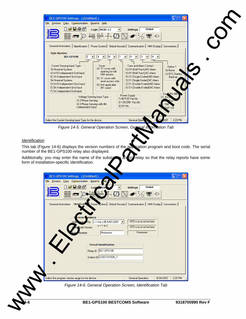
14-6 BE1-GPS100 BESTCOMS Software 9318700990 Rev F
Figure 14-5. General Operation Screen, General Information Tab
Identification This tab (Figure 14-6) displays the version numbers of the application program and boot code. The serial number of the BE1-GPS100 relay also displayed. Additionally, you may enter the name of the substation and/or relay so that the relay reports have some form of installation-specific identification.
Figure 14-6. General Operation Screen, Identification Tab
www . El
ectric
alPar
tMan
uals
. com
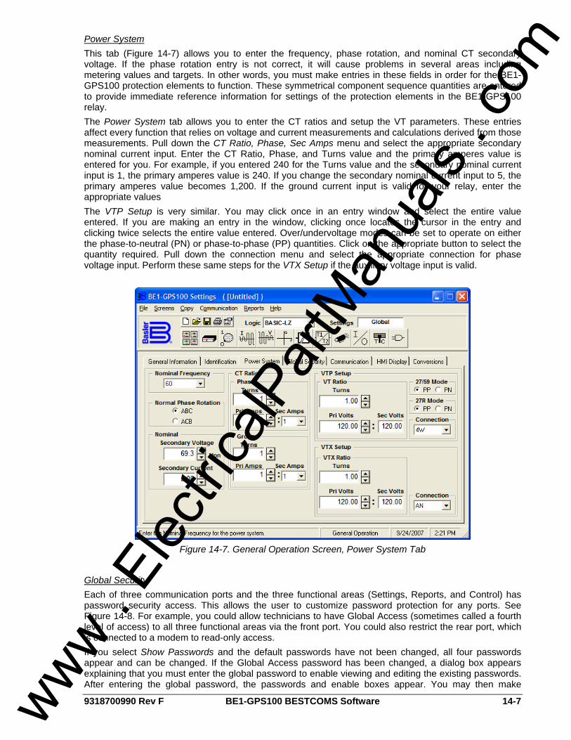
9318700990 Rev F BE1-GPS100 BESTCOMS Software 14-7
Power System This tab (Figure 14-7) allows you to enter the frequency, phase rotation, and nominal CT secondary voltage. If the phase rotation entry is not correct, it will cause problems in several areas including metering values and targets. In other words, you must make entries in these fields in order for the BE1-GPS100 protection elements to function. These symmetrical component sequence quantities are entered to provide immediate reference information for settings of the protection elements in the BE1-GPS100 relay. The Power System tab allows you to enter the CT ratios and setup the VT parameters. These entries affect every function that relies on voltage and current measurements and calculations derived from those measurements. Pull down the CT Ratio, Phase, Sec Amps menu and select the appropriate secondary nominal current input. Enter the CT Ratio, Phase, and Turns value and the primary amperes value is entered for you. For example, if you entered 240 for the Turns value and the secondary nominal current input is 1, the primary amperes value is 240. If you change the secondary nominal current input to 5, the primary amperes value becomes 1,200. If the ground current input is valid for your relay, enter the appropriate values The VTP Setup is very similar. You may click once in an entry window and select the entire value entered. If you are making an entry in the window, clicking once locates the cursor in the entry and clicking twice selects the entire value entered. Over/undervoltage modes can be set to operate on either the phase-to-neutral (PN) or phase-to-phase (PP) quantities. Click on the appropriate button to select the quantity required. Pull down the connection menu and select the appropriate connection for phase voltage input. Perform these same steps for the VTX Setup if the auxiliary voltage input is valid.
Figure 14-7. General Operation Screen, Power System Tab
Global Security Each of three communication ports and the three functional areas (Settings, Reports, and Control) has password security access. This allows the user to customize password protection for any ports. See Figure 14-8. For example, you could allow technicians to have Global Access (sometimes called a fourth level of access) to all three functional areas via the front port. You could also restrict the rear port, which is connected to a modem to read-only access. If you select Show Passwords and the default passwords have not been changed, all four passwords appear and can be changed. If the Global Access password has been changed, a dialog box appears explaining that you must enter the global password to enable viewing and editing the existing passwords. After entering the global password, the passwords and enable boxes appear. You may then make
www . El
ectric
alPar
tMan
uals
. com
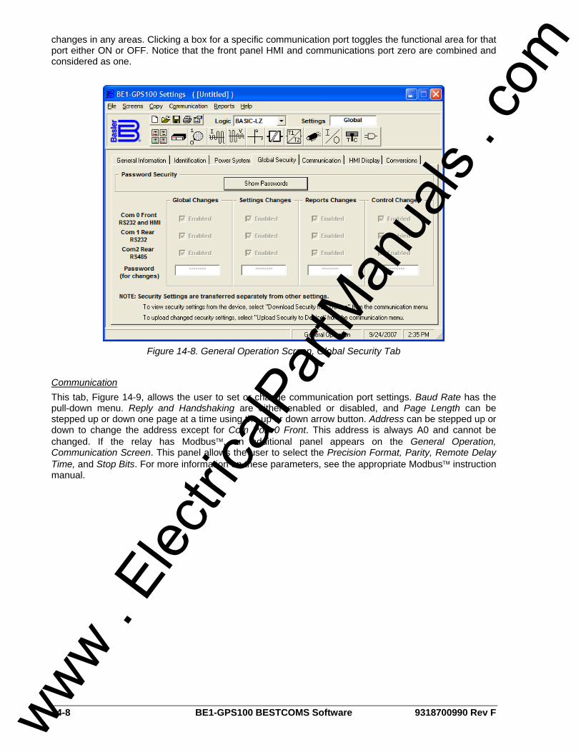
14-8 BE1-GPS100 BESTCOMS Software 9318700990 Rev F
changes in any areas. Clicking a box for a specific communication port toggles the functional area for that port either ON or OFF. Notice that the front panel HMI and communications port zero are combined and considered as one.
Figure 14-8. General Operation Screen, Global Security Tab
Communication This tab, Figure 14-9, allows the user to set or change communication port settings. Baud Rate has the pull-down menu. Reply and Handshaking are either enabled or disabled, and Page Length can be stepped up or down one page at a time using the up or down arrow button. Address can be stepped up or down to change the address except for Com Port 0 Front. This address is always A0 and cannot be changed. If the relay has Modbus™, an additional panel appears on the General Operation, Communication Screen. This panel allows the user to select the Precision Format, Parity, Remote Delay Time, and Stop Bits. For more information on these parameters, see the appropriate Modbus™ instruction manual.
www . El
ectric
alPar
tMan
uals
. com
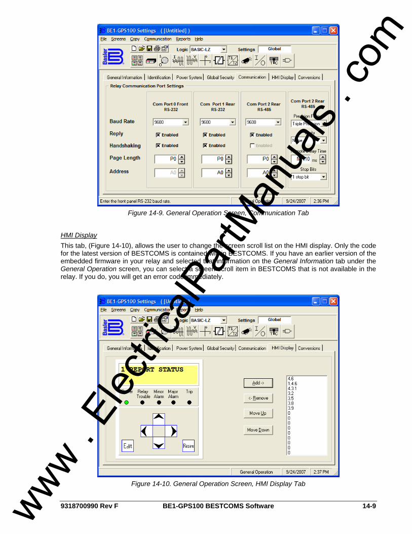
9318700990 Rev F BE1-GPS100 BESTCOMS Software 14-9
Figure 14-9. General Operation Screen, Communication Tab
HMI Display This tab, (Figure 14-10), allows the user to change the screen scroll list on the HMI display. Only the code for the latest version of BESTCOMS is contained within BESTCOMS. If you have an earlier version of the embedded firmware in your relay and selected that information on the General Information tab under the General Operation screen, you can select a screen scroll item in BESTCOMS that is not available in the relay. If you do, you will get an error code immediately.
Figure 14-10. General Operation Screen, HMI Display Tab
www . El
ectric
alPar
tMan
uals
. com
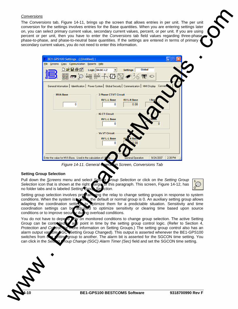
14-10 BE1-GPS100 BESTCOMS Software 9318700990 Rev F
Conversions The Conversions tab, Figure 14-11, brings up the screen that allows entries in per unit. The per unit conversion for the settings involves entries for the Base quantities. When you are entering settings later on, you can select primary current value, secondary current values, percent, or per unit. If you are using percent or per unit, then you have to enter the Conversions tab field values regarding three-phase, phase-to-phase, and phase-to-neutral base quantities. If the settings are entered in terms of primary or secondary current values, you do not need to enter this information.
Figure 14-11. General Operation Screen, Conversions Tab
Setting Group Selection Pull down the Screens menu and select Setting Group Selection or click on the Setting Group Selection icon that is shown at the right margin of this paragraph. This screen, Figure 14-12, has no folder tabs and is labeled Setting Group Selection. Setting group selection involves programming the relay to change setting groups in response to system conditions. When the system is normal, the default or normal group is 0. An auxiliary setting group allows adapting the coordination settings to optimize them for a predictable situation. Sensitivity and time coordination settings can be adjusted to optimize sensitivity or clearing time based upon source conditions or to improve security during overload conditions. You do not have to depend only on monitored conditions to change group selection. The active Setting Group can be controlled at any point in time by the setting group control logic. (Refer to Section 4, Protection and Control, for more information on Setting Groups.) The setting group control also has an alarm output variable SGC (Setting Group Changed). This output is asserted whenever the BE1-GPS100 switches from one setting group to another. The alarm bit is asserted for the SGCON time setting. You can click in the Setting Group Change (SGC) Alarm Timer (Sec) field and set the SGCON time setting.
www . El
ectric
alPar
tMan
uals
. com
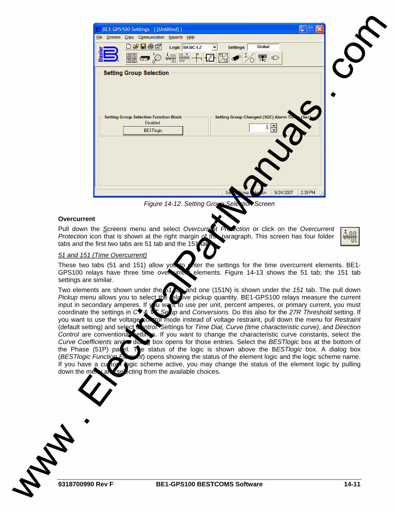
9318700990 Rev F BE1-GPS100 BESTCOMS Software 14-11
Figure 14-12. Setting Group Selection Screen
Overcurrent Pull down the Screens menu and select Overcurrent Protection or click on the Overcurrent Protection icon that is shown at the right margin of this paragraph. This screen has four folder tabs and the first two tabs are 51 tab and the 151 tab.
51 and 151 (Time Overcurrent) These two tabs (51 and 151) allow you to enter the settings for the time overcurrent elements. BE1-GPS100 relays have three time overcurrent elements. Figure 14-13 shows the 51 tab; the 151 tab settings are similar. Two elements are shown under the 51 tab and one (151N) is shown under the 151 tab. The pull down Pickup menu allows you to select the relative pickup quantity. BE1-GPS100 relays measure the current input in secondary amperes. If you want to use per unit, percent amperes, or primary current, you must coordinate the settings in CT & VT Setup and Conversions. Do this also for the 27R Threshold setting. If you want to use the voltage control mode instead of voltage restraint, pull down the menu for Restraint (default setting) and select Control. Settings for Time Dial, Curve (time characteristic curve), and Direction Control are conventional settings. If you want to change the characteristic curve constants, select the Curve Coefficients and a dialog box opens for those entries. Select the BESTlogic box at the bottom of the Phase (51P) panel. The status of the logic is shown above the BESTlogic box. A dialog box (BESTlogic Function Element) opens showing the status of the element logic and the logic scheme name. If you have a custom logic scheme active, you may change the status of the element logic by pulling down the menu and selecting from the available choices.
www . El
ectric
alPar
tMan
uals
. com
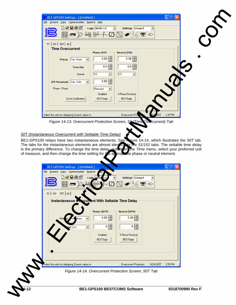
14-12 BE1-GPS100 BESTCOMS Software 9318700990 Rev F
Figure 14-13. Overcurrent Protection Screen, 51 (Time Overcurrent) Tab
50T (Instantaneous Overcurrent with Settable Time Delay) BE1-GPS100 relays have two instantaneous elements. See Figure 14-14, which illustrates the 50T tab. The tabs for the instantaneous elements are almost identical to the 51/151 tabs. The settable time delay is the primary difference. To change the time delay, pull down the Time menu, select your preferred unit of measure, and then change the time setting for the appropriate phase or neutral element.
Figure 14-14. Overcurrent Protection Screen, 50T Tab
www . El
ectric
alPar
tMan
uals
. com
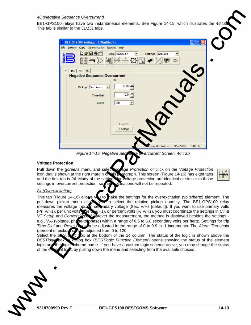
9318700990 Rev F BE1-GPS100 BESTCOMS Software 14-13
46 (Negative Sequence Overcurrent) BE1-GPS100 relays have two instantaneous elements. See Figure 14-15, which illustrates the 46 tab. This tab is similar to the 51/151 tabs.
Figure 14-15. Negative Sequence Overcurrent Screen, 46 Tab
Voltage Protection Pull down the Screens menu and select Voltage Protection or click on the Voltage Protection icon that is shown at the right margin of this paragraph. This screen (Figure 14-16) has eight tabs and the first tab is 24. Many of the settings for voltage protection are identical or similar to those settings in overcurrent protection, so the explanations will not be repeated.
24 (Overexcitation) This tab (Figure 14-16) allows you to make the settings for the overexcitation (volts/hertz) element. The pull-down pickup menu allows you to select the relative pickup quantity. The BE1-GPS100 relay measures the voltage input in secondary voltage (Sec. V/Hz [default]). If you want to use primary volts (Pri V/Hz), per unit volts (Per U V/Hz), or percent volts (% V/Hz), you must coordinate the settings in CT & VT Setup and Conversions. Whatever the measurement, the method is displayed besides the settings - e.g., VPP (voltage, phase-to-phase) within a range of 0.5 to 6.0 secondary volts per hertz. Settings for trip Time Dial and Reset Dial can be adjusted in the range of 0 to 9.9 in .1 increments. The Alarm Threshold (percent of pickup) can be adjusted from 0 to 120. Select the BESTlogic box at the bottom of the 24 column. The status of the logic is shown above the BESTlogic box. A dialog box (BESTlogic Function Element) opens showing the status of the element logic and the logic scheme name. If you have a custom logic scheme active, you may change the status of the element logic by pulling down the menu and selecting from the available choices.
www . El
ectric
alPar
tMan
uals
. com
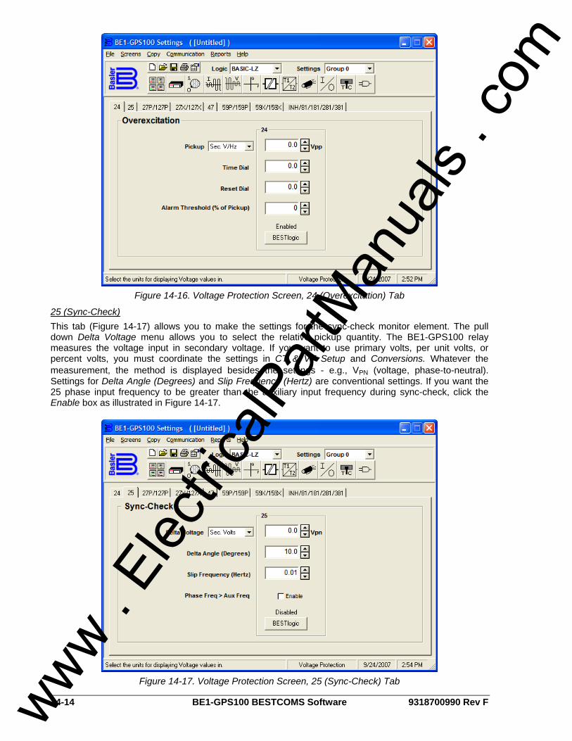
14-14 BE1-GPS100 BESTCOMS Software 9318700990 Rev F
Figure 14-16. Voltage Protection Screen, 24 (Overexcitation) Tab
25 (Sync-Check) This tab (Figure 14-17) allows you to make the settings for the sync-check monitor element. The pull down Delta Voltage menu allows you to select the relative pickup quantity. The BE1-GPS100 relay measures the voltage input in secondary voltage. If you want to use primary volts, per unit volts, or percent volts, you must coordinate the settings in CT & VT Setup and Conversions. Whatever the measurement, the method is displayed besides the settings - e.g., VPN (voltage, phase-to-neutral). Settings for Delta Angle (Degrees) and Slip Frequency (Hertz) are conventional settings. If you want the 25 phase input frequency to be greater than the auxiliary input frequency during sync-check, click the Enable box as illustrated in Figure 14-17.
Figure 14-17. Voltage Protection Screen, 25 (Sync-Check) Tab
www . El
ectric
alPar
tMan
uals
. com
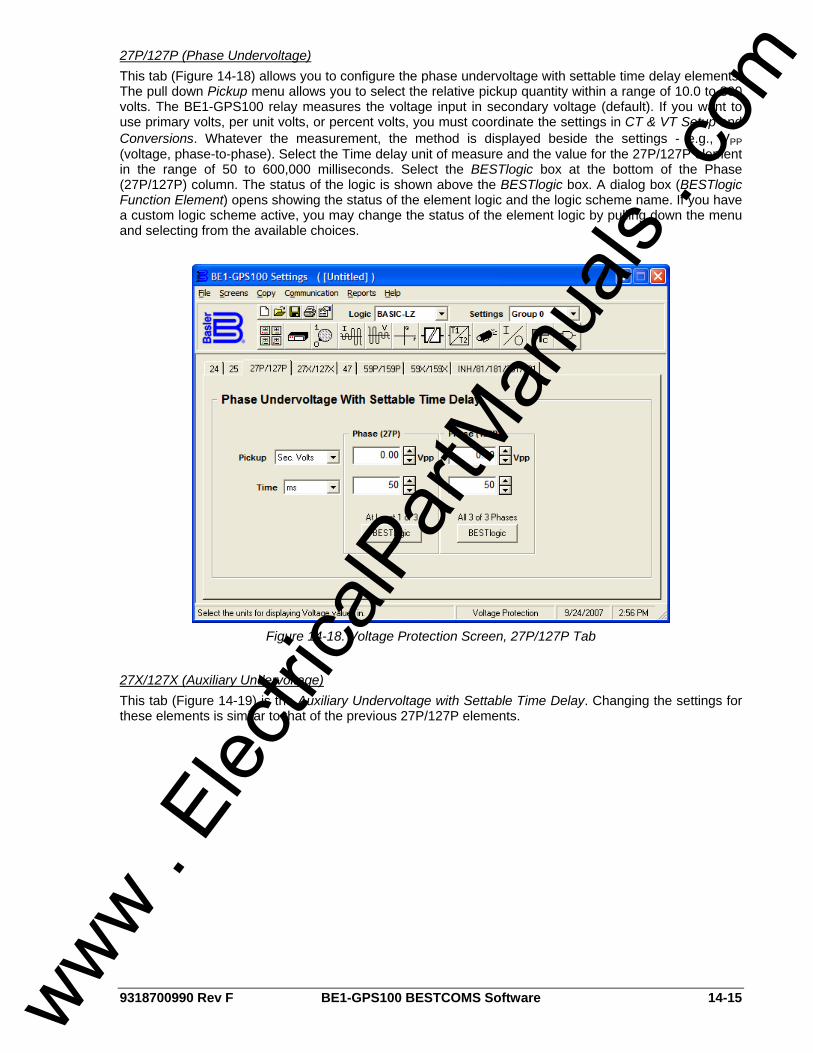
9318700990 Rev F BE1-GPS100 BESTCOMS Software 14-15
27P/127P (Phase Undervoltage) This tab (Figure 14-18) allows you to configure the phase undervoltage with settable time delay elements. The pull down Pickup menu allows you to select the relative pickup quantity within a range of 10.0 to 300 volts. The BE1-GPS100 relay measures the voltage input in secondary voltage (default). If you want to use primary volts, per unit volts, or percent volts, you must coordinate the settings in CT & VT Setup and Conversions. Whatever the measurement, the method is displayed beside the settings - e.g., VPP (voltage, phase-to-phase). Select the Time delay unit of measure and the value for the 27P/127P element in the range of 50 to 600,000 milliseconds. Select the BESTlogic box at the bottom of the Phase (27P/127P) column. The status of the logic is shown above the BESTlogic box. A dialog box (BESTlogic Function Element) opens showing the status of the element logic and the logic scheme name. If you have a custom logic scheme active, you may change the status of the element logic by pulling down the menu and selecting from the available choices.
Figure 14-18. Voltage Protection Screen, 27P/127P Tab
27X/127X (Auxiliary Undervoltage) This tab (Figure 14-19) is the Auxiliary Undervoltage with Settable Time Delay. Changing the settings for these elements is similar to that of the previous 27P/127P elements.
www . El
ectric
alPar
tMan
uals
. com
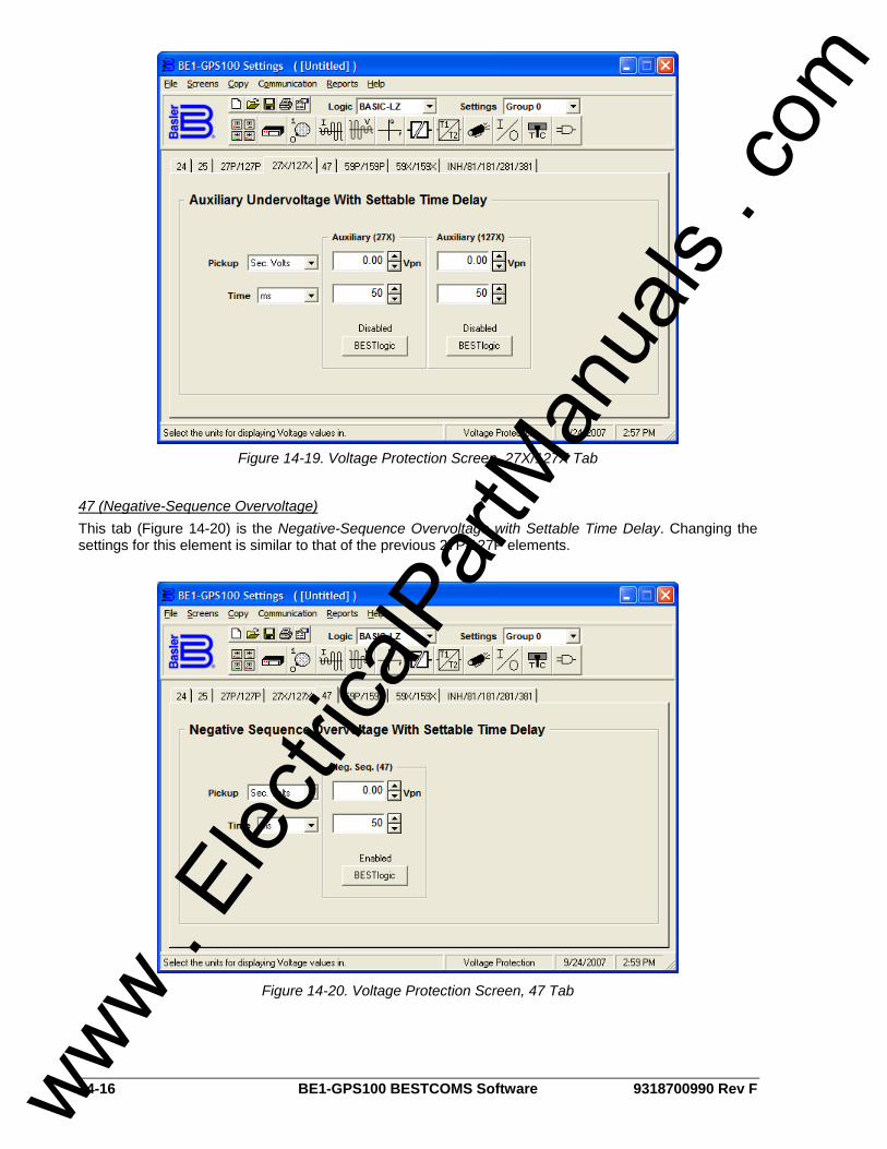
14-16 BE1-GPS100 BESTCOMS Software 9318700990 Rev F
Figure 14-19. Voltage Protection Screen, 27X/127X Tab
47 (Negative-Sequence Overvoltage) This tab (Figure 14-20) is the Negative-Sequence Overvoltage with Settable Time Delay. Changing the settings for this element is similar to that of the previous 27P/127P elements.
Figure 14-20. Voltage Protection Screen, 47 Tab
www . El
ectric
alPar
tMan
uals
. com
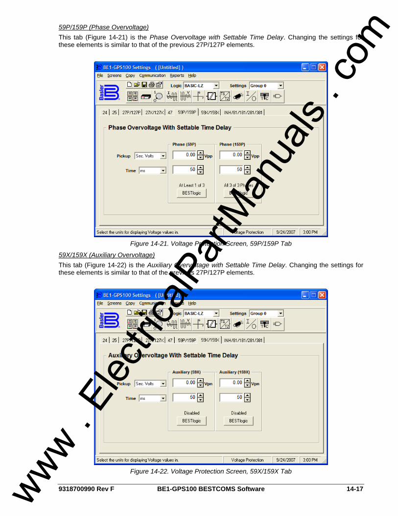
9318700990 Rev F BE1-GPS100 BESTCOMS Software 14-17
59P/159P (Phase Overvoltage) This tab (Figure 14-21) is the Phase Overvoltage with Settable Time Delay. Changing the settings for these elements is similar to that of the previous 27P/127P elements.
Figure 14-21. Voltage Protection Screen, 59P/159P Tab
59X/159X (Auxiliary Overvoltage) This tab (Figure 14-22) is the Auxiliary Overvoltage with Settable Time Delay. Changing the settings for these elements is similar to that of the previous 27P/127P elements.
Figure 14-22. Voltage Protection Screen, 59X/159X Tab
www . El
ectric
alPar
tMan
uals
. com
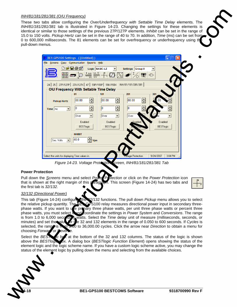
14-18 BE1-GPS100 BESTCOMS Software 9318700990 Rev F
INH/81/181/281/381 (O/U Frequency) These two tabs allow configuring the Over/Underfrequency with Settable Time Delay elements. The INH/81/181/281/381 tab is illustrated in Figure 14-23. Changing the settings for these elements is identical or similar to those settings of the previous 27P/127P elements. Inhibit can be set in the range of 15.0 to 150 volts. Pickup Hertz can be set in the range of 40 to 70. In addition, Time (ms) can be set from 0 to 600,000 milliseconds. The 81 elements can be set for overfrequency or underfrequency using the pull-down menus.
Figure 14-23. Voltage Protection Screen, INH/81/181/281/381 Tab
Power Protection Pull down the Screens menu and select Power Protection or click on the Power Protection icon that is shown at the right margin of this paragraph. This screen (Figure 14-24) has two tabs and the first tab is 32/132.
32/132 (Directional Power) This tab (Figure 14-24) configures the 32/132 functions. The pull down Pickup menu allows you to select the relative pickup quantity. The BE1-GPS100 relay measures directional power input in secondary three-phase watts. If you want to use primary three phase watts, per unit three phase watts or percent three phase watts, you must select it and coordinate the settings in Power System and Conversions. The range is from 1.0 to 6,000 secondary watts. Select the Time delay unit of measure (milliseconds, seconds, or minutes) and set the value for the 32 and 132 elements in the range of 0.050 to 600 seconds. If Cycles is selected, the range is from 3.00 to 36,000.00 cycles. Click the arrow near Direction to obtain a menu for choosing Forward or Reverse. Select the BESTlogic box at the bottom of the 32 and 132 columns. The status of the logic is shown above the BESTlogic box. A dialog box (BESTlogic Function Element) opens showing the status of the element logic and the logic scheme name. If you have a custom logic scheme active, you may change the status of the element logic by pulling down the menu and selecting from the available choices.
www . El
ectric
alPar
tMan
uals
. com
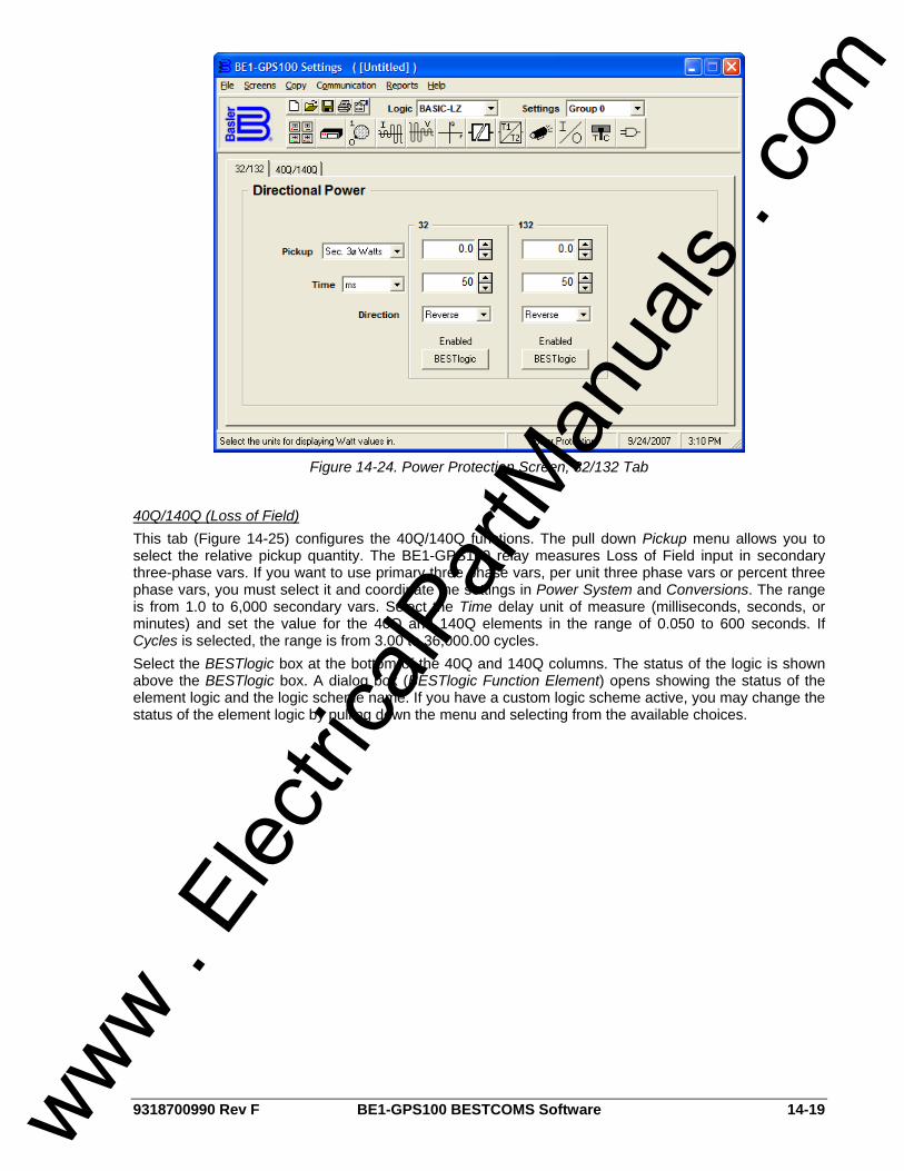
9318700990 Rev F BE1-GPS100 BESTCOMS Software 14-19
Figure 14-24. Power Protection Screen, 32/132 Tab
40Q/140Q (Loss of Field) This tab (Figure 14-25) configures the 40Q/140Q functions. The pull down Pickup menu allows you to select the relative pickup quantity. The BE1-GPS100 relay measures Loss of Field input in secondary three-phase vars. If you want to use primary three phase vars, per unit three phase vars or percent three phase vars, you must select it and coordinate the settings in Power System and Conversions. The range is from 1.0 to 6,000 secondary vars. Select the Time delay unit of measure (milliseconds, seconds, or minutes) and set the value for the 40Q and 140Q elements in the range of 0.050 to 600 seconds. If Cycles is selected, the range is from 3.00 to 36,000.00 cycles. Select the BESTlogic box at the bottom of the 40Q and 140Q columns. The status of the logic is shown above the BESTlogic box. A dialog box (BESTlogic Function Element) opens showing the status of the element logic and the logic scheme name. If you have a custom logic scheme active, you may change the status of the element logic by pulling down the menu and selecting from the available choices.
www . El
ectric
alPar
tMan
uals
. com
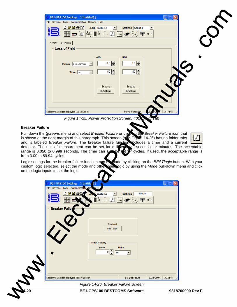
14-20 BE1-GPS100 BESTCOMS Software 9318700990 Rev F
Figure 14-25. Power Protection Screen, 40Q/140Q Tab
Breaker Failure Pull down the Screens menu and select Breaker Failure or click on the Breaker Failure icon that is shown at the right margin of this paragraph. This screen (see Figure 14-26) has no folder tabs and is labeled Breaker Failure. The breaker failure function includes a timer and a current detector. The unit of measurement can be set for milliseconds, seconds, or minutes. The acceptable range is 0.050 to 0.999 seconds. The timer can also be set for cycles. If used, the acceptable range is from 3.00 to 59.94 cycles. Logic settings for the breaker failure function can be made by clicking on the BESTlogic button. With your custom logic selected, select the mode and other input logic by using the Mode pull-down menu and click on the logic inputs to set the logic.
Figure 14-26. Breaker Failure Screen
www . El
ectric
alPar
tMan
uals
. com
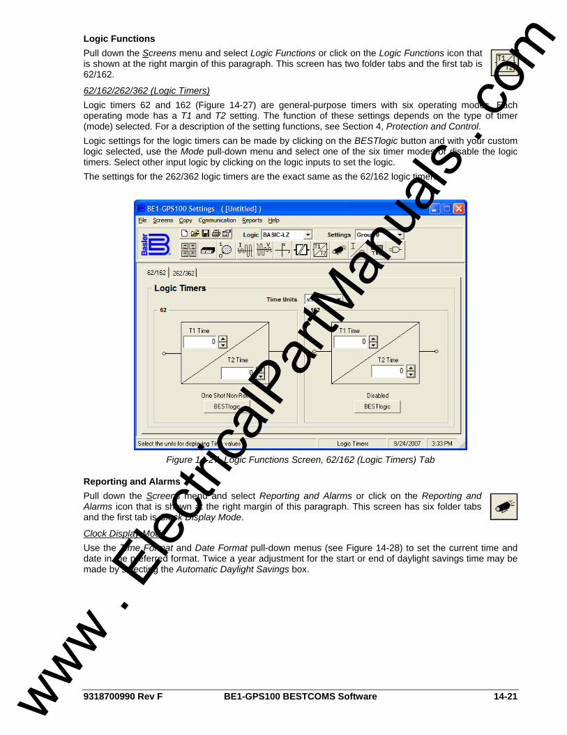
9318700990 Rev F BE1-GPS100 BESTCOMS Software 14-21
Logic Functions Pull down the Screens menu and select Logic Functions or click on the Logic Functions icon that is shown at the right margin of this paragraph. This screen has two folder tabs and the first tab is 62/162.
62/162/262/362 (Logic Timers) Logic timers 62 and 162 (Figure 14-27) are general-purpose timers with six operating modes. Each operating mode has a T1 and T2 setting. The function of these settings depends on the type of timer (mode) selected. For a description of the setting functions, see Section 4, Protection and Control. Logic settings for the logic timers can be made by clicking on the BESTlogic button and with your custom logic selected, use the Mode pull-down menu and select one of the six timer modes or disable the logic timers. Select other input logic by clicking on the logic inputs to set the logic. The settings for the 262/362 logic timers are the exact same as the 62/162 logic timers.
Figure 14-27. Logic Functions Screen, 62/162 (Logic Timers) Tab
Reporting and Alarms Pull down the Screens menu and select Reporting and Alarms or click on the Reporting and Alarms icon that is shown at the right margin of this paragraph. This screen has six folder tabs and the first tab is Clock Display Mode.
Clock Display Mode Use the Time Format and Date Format pull-down menus (see Figure 14-28) to set the current time and date in the preferred format. Twice a year adjustment for the start or end of daylight savings time may be made by selecting the Automatic Daylight Savings box.
www . El
ectric
alPar
tMan
uals
. com
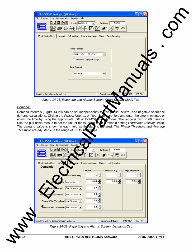
14-22 BE1-GPS100 BESTCOMS Software 9318700990 Rev F
Figure 14-28. Reporting and Alarms Screen, Clock Display Mode Tab
Demands Demand intervals (Figure 14-29) can be set independently for the phase, neutral, and negative-sequence demand calculations. Click in the Phase, Neutral, or Neg. Sequence field and enter the time in minutes or adjust the time by using the appropriate (UP or DOWN) arrow buttons. The range is zero to 60 minutes. Use the pull-down menus to set the unit of measure for each threshold setting (Threshold Display Units). The demand value is shown in each field as the data is metered. The Phase Threshold and Average Threshold are adjustable in the range of 0.5 to 16.0 amps.
Figure 14-29. Reporting and Alarms Screen, Demands Tab
www . El
ectric
alPar
tMan
uals
. com

9318700990 Rev F BE1-GPS100 BESTCOMS Software 14-23
VT Monitor (Fuse Loss Block Logic) Fuse Loss Block Logic (Figure 14-30) can prevent misoperation on loss of sensing voltage. This can be applied on both the 51/27 and 27/59 functions. When the 51/27 function is set for control and a 60FL condition is detected, the phase overcurrent elements will be disabled if you place an x in the 51/27 Block Voltage Control field by clicking in the field. If the 51/27 function is set for restraint and a 60FL condition is detected, the phase overcurrent elements will remain enabled and the pickup setting is not adjusted from 100% of the setting. If the 27/59, Block Phase is enabled with a check mark in the field and a 60FL condition is detected, all functions that use the phase voltage are blocked. If the 27/59, Block 3V0 is enabled with a check mark in the field and a 60FL condition is detected, all functions that use the auxiliary over/undervoltage (27x/59X) functions with Mode 2 selected are blocked. If the 27/59, Block V2 is enabled with a check mark in the field and a 60FL condition is detected, all functions that use the negative-sequence voltage are blocked.
Figure 14-30. Reporting and Alarms Screen, VT Monitor Tab
Breaker Monitoring Each time the breaker trips, the breaker duty monitor updates two sets of registers for each pole of the breaker. This function selects which of the two sets of duty registers are reported and monitored, sets the existing values, and programs the function logic. Use the Breaker Duty Monitoring Exponent pull-down menu (Figure 14-31) to select the exponent in the range of 1 to 3. Click in the field for 100% Duty Maximum and set the value. Logic settings for the Block Accumulation Logic can be made by clicking on the logic button and, with your custom logic selected, select the block accumulation logic. Because the relay is completely programmable, it is necessary to program which logic variable monitors breaker status (how the relay knows when the breaker is closed). Set the Breaker Status Logic by clicking on the Logic button and with your custom logic selected, select the control logic. Three breaker alarm points are programmable for checking breaker monitoring functions. Each alarm point can be programmed to monitor any of the three breaker monitoring functions or all three alarm points can be programmed to monitor one function and alarm at various threshold levels. Use the pull-down menu for Breaker Alarms - Point 1 and select the preferred breaker monitoring mode (function). With the Mode set, the Threshold field is viable and has a zero threshold. Use the keyboard to enter the threshold value or the appropriate UP or DOWN arrow buttons. Repeat the procedure for Breaker Alarms - Points 2 and 3. If desired, select the Trigger Oscillographic Record box to create an oscillographic record.
www . El
ectric
alPar
tMan
uals
. com
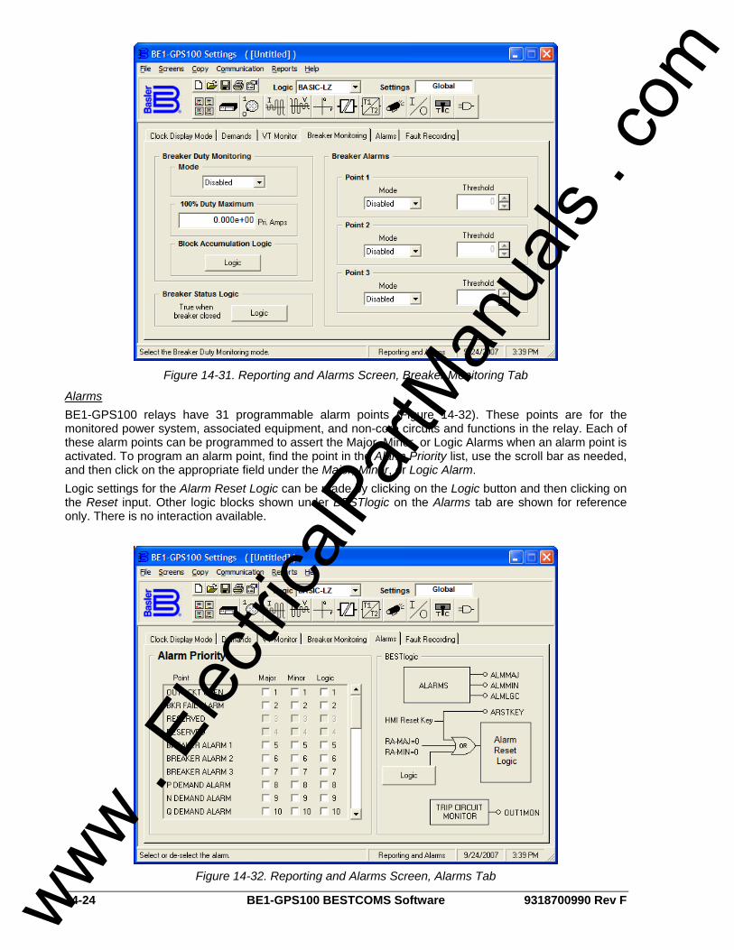
14-24 BE1-GPS100 BESTCOMS Software 9318700990 Rev F
Figure 14-31. Reporting and Alarms Screen, Breaker Monitoring Tab
Alarms BE1-GPS100 relays have 31 programmable alarm points (Figure 14-32). These points are for the monitored power system, associated equipment, and non-core circuits and functions in the relay. Each of these alarm points can be programmed to assert the Major, Minor, or Logic Alarms when an alarm point is activated. To program an alarm point, find the point in the Alarm Priority list, use the scroll bar as needed, and then click on the appropriate field under the Major, Minor, or Logic Alarm. Logic settings for the Alarm Reset Logic can be made by clicking on the Logic button and then clicking on the Reset input. Other logic blocks shown under BESTlogic on the Alarms tab are shown for reference only. There is no interaction available.
Figure 14-32. Reporting and Alarms Screen, Alarms Tab
www . El
ectric
alPar
tMan
uals
. com
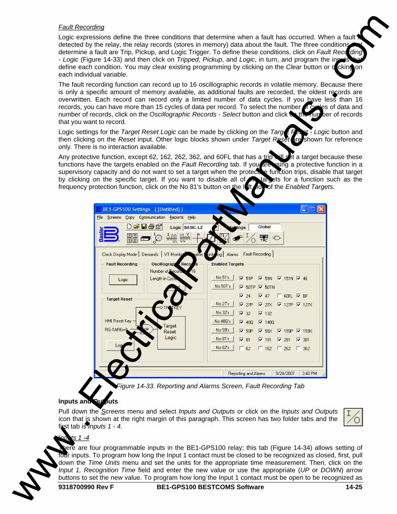
9318700990 Rev F BE1-GPS100 BESTCOMS Software 14-25
Fault Recording Logic expressions define the three conditions that determine when a fault has occurred. When a fault is detected by the relay, the relay records (stores in memory) data about the fault. The three conditions that determine a fault are Trip, Pickup, and Logic Trigger. To define these conditions, click on Fault Recording - Logic (Figure 14-33) and then click on Tripped, Pickup, and Logic, in turn, and program the inputs that define each condition. You may clear existing programming by clicking on the Clear button or clicking on each individual variable. The fault recording function can record up to 16 oscillographic records in volatile memory. Because there is only a specific amount of memory available, as additional faults are recorded, the oldest records are overwritten. Each record can record only a limited number of data cycles. If you have less than 16 records, you can have more than 15 cycles of data per record. To select the number of cycles of data and number of records, click on the Oscillographic Records - Select button and click on the number of records that you want to record. Logic settings for the Target Reset Logic can be made by clicking on the Target Reset - Logic button and then clicking on the Reset input. Other logic blocks shown under Target Reset are shown for reference only. There is no interaction available. Any protective function, except 62, 162, 262, 362, and 60FL that has a trip will set a target because these functions have the targets enabled on the Fault Recording tab. If you are using a protective function in a supervisory capacity and do not want to set a target when the protective function trips, disable that target by clicking on the specific target. If you want to disable all of the targets for a function such as the frequency protection function, click on the No 81's button on the left side of the Enabled Targets.
Figure 14-33. Reporting and Alarms Screen, Fault Recording Tab
Inputs and Outputs Pull down the Screens menu and select Inputs and Outputs or click on the Inputs and Outputs icon that is shown at the right margin of this paragraph. This screen has two folder tabs and the first tab is Inputs 1 - 4.
Inputs 1 -4 There are four programmable inputs in the BE1-GPS100 relay; this tab (Figure 14-34) allows setting of four inputs. To program how long the Input 1 contact must be closed to be recognized as closed, first, pull down the Time Units menu and set the units for the appropriate time measurement. Then, click on the Input 1, Recognition Time field and enter the new value or use the appropriate (UP or DOWN) arrow buttons to set the new value. To program how long the Input 1 contact must be open to be recognized as www .
Elec
tricalP
artM
anua
ls . c
om
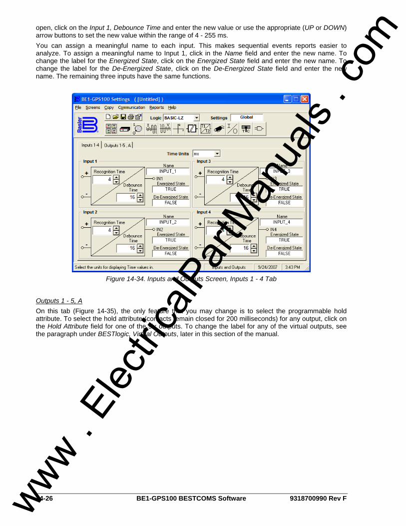
14-26 BE1-GPS100 BESTCOMS Software 9318700990 Rev F
open, click on the Input 1, Debounce Time and enter the new value or use the appropriate (UP or DOWN) arrow buttons to set the new value within the range of 4 - 255 ms. You can assign a meaningful name to each input. This makes sequential events reports easier to analyze. To assign a meaningful name to Input 1, click in the Name field and enter the new name. To change the label for the Energized State, click on the Energized State field and enter the new name. To change the label for the De-Energized State, click on the De-Energized State field and enter the new name. The remaining three inputs have the same functions.
Figure 14-34. Inputs and Outputs Screen, Inputs 1 - 4 Tab
Outputs 1 - 5, A On this tab (Figure 14-35), the only feature that you may change is to select the programmable hold attribute. To select the hold attribute (contacts remain closed for 200 milliseconds) for any output, click on the Hold Attribute field for one of the six outputs. To change the label for any of the virtual outputs, see the paragraph under BESTlogic, Virtual Outputs, later in this section of the manual.
www . El
ectric
alPar
tMan
uals
. com
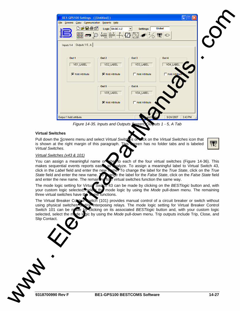
9318700990 Rev F BE1-GPS100 BESTCOMS Software 14-27
Figure 14-35. Inputs and Outputs Screen, Outputs 1 - 5, A Tab
Virtual Switches Pull down the Screens menu and select Virtual Switches or click on the Virtual Switches icon that is shown at the right margin of this paragraph. This screen has no folder tabs and is labeled Virtual Switches.
Virtual Switches (x43 & 101) You can assign a meaningful name or label to each of the four virtual switches (Figure 14-36). This makes sequential events reports easier to analyze. To assign a meaningful label to Virtual Switch 43, click in the Label field and enter the new name. To change the label for the True State, click on the True State field and enter the new name. To change the label for the False State, click on the False State field and enter the new name. The remaining four virtual switches function the same way. The mode logic setting for Virtual Switch 43 can be made by clicking on the BESTlogic button and, with your custom logic selected, select the mode logic by using the Mode pull-down menu. The remaining three virtual switches have the same functions. The Virtual Breaker Control Switch (101) provides manual control of a circuit breaker or switch without using physical switches and/or interposing relays. The mode logic setting for Virtual Breaker Control Switch 101 can be made by clicking on its associated BESTlogic button and, with your custom logic selected, select the mode logic by using the Mode pull-down menu. Trip outputs include Trip, Close, and Slip Contact.
www . El
ectric
alPar
tMan
uals
. com
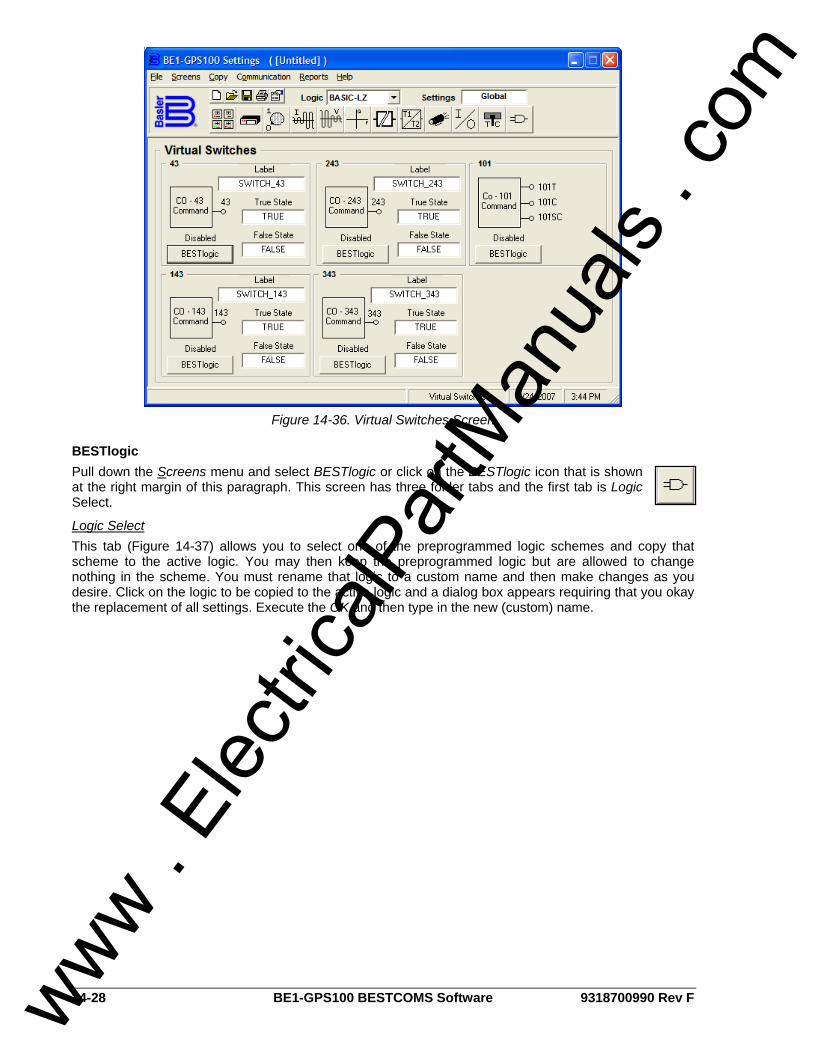
14-28 BE1-GPS100 BESTCOMS Software 9318700990 Rev F
Figure 14-36. Virtual Switches Screen
BESTlogic Pull down the Screens menu and select BESTlogic or click on the BESTlogic icon that is shown at the right margin of this paragraph. This screen has three folder tabs and the first tab is Logic Select.
Logic Select This tab (Figure 14-37) allows you to select one of the preprogrammed logic schemes and copy that scheme to the active logic. You may then keep the preprogrammed logic but are allowed to change nothing in the scheme. You must rename that logic to a custom name and then make changes as you desire. Click on the logic to be copied to the active logic and a dialog box appears requiring that you okay the replacement of all settings. Execute the OK and then type in the new (custom) name.
www . El
ectric
alPar
tMan
uals
. com
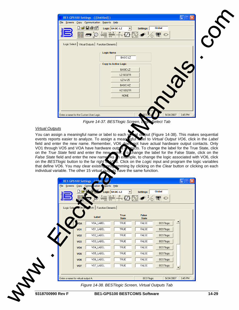
9318700990 Rev F BE1-GPS100 BESTCOMS Software 14-29
Figure 14-37. BESTlogic Screen, Logic Select Tab
Virtual Outputs You can assign a meaningful name or label to each virtual output (Figure 14-38). This makes sequential events reports easier to analyze. To assign a meaningful label to Virtual Output VO6, click in the Label field and enter the new name. Remember, VO6 does not have actual hardware output contacts. Only VO1 through VO5 and VOA have hardware output contacts. To change the label for the True State, click on the True State field and enter the new name. To change the label for the False State, click on the False State field and enter the new name. As an example, to change the logic associated with VO6, click on the BESTlogic button to the far right of VO6. Click on the Logic input and program the logic variables that define VO6. You may clear existing programming by clicking on the Clear button or clicking on each individual variable. The other 15 virtual outputs have the same function.
Figure 14-38. BESTlogic Screen, Virtual Outputs Tab
www . El
ectric
alPar
tMan
uals
. com
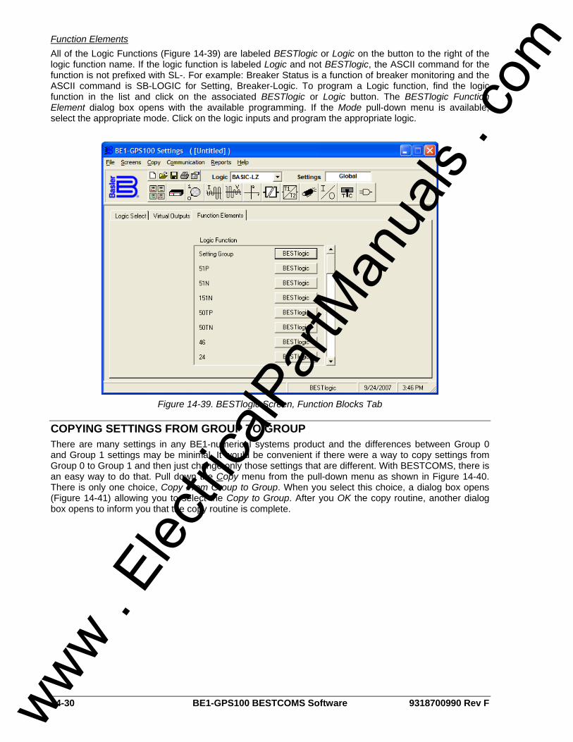
14-30 BE1-GPS100 BESTCOMS Software 9318700990 Rev F
Function Elements All of the Logic Functions (Figure 14-39) are labeled BESTlogic or Logic on the button to the right of the logic function name. If the logic function is labeled Logic and not BESTlogic, the ASCII command for the function is not prefixed with SL-. For example: Breaker Status is a function of breaker monitoring and the ASCII command is SB-LOGIC for Setting, Breaker-Logic. To program a Logic function, find the logic function in the list and click on the associated BESTlogic or Logic button. The BESTlogic Function Element dialog box opens with the available programming. If the Mode pull-down menu is available, select the appropriate mode. Click on the logic inputs and program the appropriate logic.
Figure 14-39. BESTlogic Screen, Function Blocks Tab
COPYING SETTINGS FROM GROUP TO GROUP There are many settings in any BE1-numerical systems product and the differences between Group 0 and Group 1 settings may be minimal. It would be convenient if there were a way to copy settings from Group 0 to Group 1 and then just change only those settings that are different. With BESTCOMS, there is an easy way to do that. Pull down the Copy menu from the pull-down menu as shown in Figure 14-40. There is only one choice, Copy From Group to Group. When you select this choice, a dialog box opens (Figure 14-41) allowing you to select the Copy to Group. After you OK the copy routine, another dialog box opens to inform you that the copy routine is complete.
www . El
ectric
alPar
tMan
uals
. com
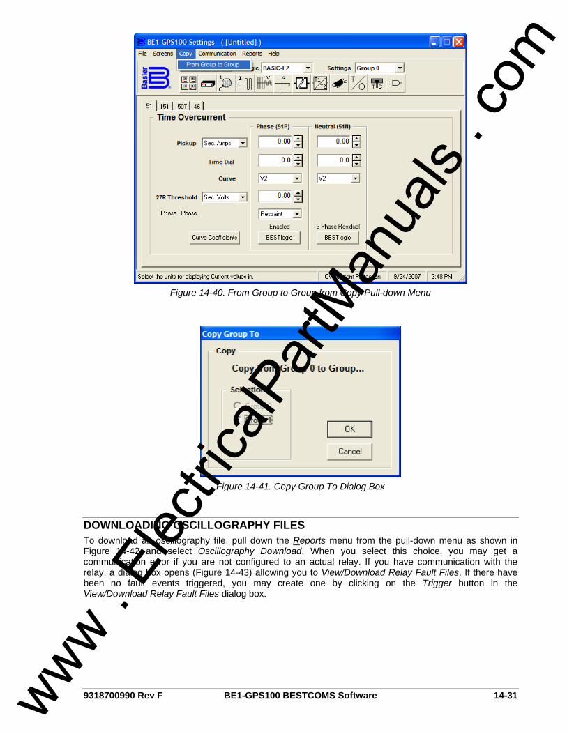
9318700990 Rev F BE1-GPS100 BESTCOMS Software 14-31
Figure 14-40. From Group to Group from Copy Pull-down Menu
Figure 14-41. Copy Group To Dialog Box
DOWNLOADING OSCILLOGRAPHY FILES To download an oscillography file, pull down the Reports menu from the pull-down menu as shown in Figure 14-42 and select Oscillography Download. When you select this choice, you may get a communication error if you are not configured to an actual relay. If you have communication with the relay, a dialog box opens (Figure 14-43) allowing you to View/Download Relay Fault Files. If there have been no fault events triggered, you may create one by clicking on the Trigger button in the View/Download Relay Fault Files dialog box.
www . El
ectric
alPar
tMan
uals
. com
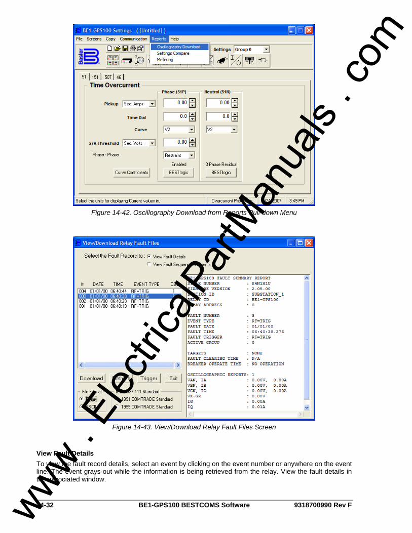
14-32 BE1-GPS100 BESTCOMS Software 9318700990 Rev F
Figure 14-42. Oscillography Download from Reports Pull-down Menu
Figure 14-43. View/Download Relay Fault Files Screen
View Fault Details To view the fault record details, select an event by clicking on the event number or anywhere on the event line. The event grays-out while the information is being retrieved from the relay. View the fault details in the associated window.
www . El
ectric
alPar
tMan
uals
. com
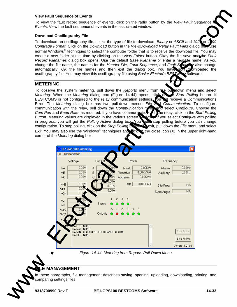
9318700990 Rev F BE1-GPS100 BESTCOMS Software 14-33
View Fault Sequence of Events To view the fault record sequence of events, click on the radio button by the View Fault Sequence of Events. View the fault sequence of events in the associated window.
Download Oscillography File To download an oscillography file, select the type of file to download: Binary or ASCII and 1991 or 1999 Comtrade Format. Click on the Download button in the View/Download Relay Fault Files dialog box. Use normal Windows® techniques to select the computer folder that is to receive the download file. You may create a new folder at this time by clicking on the New Folder button. Okay the file save and the Fault Record Filenames dialog box opens. Use the default Base Filename or enter a new file name. As you change the file name, the names for the Header File, Fault Sequence, and Fault Summary also change automatically. OK the file names and then exit the dialog box. You have now downloaded the oscillography file. You may view this oscillography file using Basler Electric's BESTwave software.
METERING To observe the system metering, pull down the Reports menu from the pull-down menu and select Metering. When the Metering dialog box (Figure 14-44) opens, click on the Start Polling button. If BESTCOMS is not configured to the relay communication settings, you will receive a Communications Error. The Metering dialog box has two pull-down menus: File and Communication. To configure communication with the relay, pull down the Communication menu and select Configure. Choose the Com Port and Baud Rate, as required. If you have communication with the relay, click on the Start Polling Button. Metering values are displayed in the various screen windows. If you select Configure with polling in progress, you will get the Polling Active dialog box. You must stop polling before you can change configuration. To stop polling, click on the Stop Polling button. To exit, pull down the File menu and select Exit. You may also use the Windows® techniques and click on the close icon (X) in the upper right-hand corner of the Metering dialog box.
Figure 14-44. Metering from Reports Pull-Down Menu
FILE MANAGEMENT In these paragraphs, file management describes saving, opening, uploading, downloading, printing, and comparing settings files.
www . El
ectric
alPar
tMan
uals
. com

14-34 BE1-GPS100 BESTCOMS Software 9318700990 Rev F
Saving a Settings File If you change any settings in the active custom logic scheme and try to exit BESTCOMS, the dialog box shown in Figure 14-45 appears. If you choose Yes, a file properties dialog box appears. The file properties dialog box also appears if you pull down the file menu and choose Save or Save As. The lines of information that are grayed-out are automatically entered based on the file name and relay identifier information command (SG-ID). You may enter up to 50 characters in the Additional Info: field and 2,500 characters in the File Comments field. When you okay the dialog box, you are given an opportunity to name the file and select the path. Clicking on Save completes the saving of a settings file.
Figure 14-45. Settings Have Changed Dialog Box
Opening a Settings File To open a settings file into BESTCOMS, pull down the File menu and choose Open. If the settings in your BESTCOMS have changed, a dialog box will open asking you if want to save the current settings changes. You may choose Yes or No. After you have taken the required action to save or not save the current settings, the Open dialog box appears. This dialog box allows you to use normal Windows® techniques to select the file that you want to open. Select the file and open it and the file settings have been brought into BESTCOMS.
Uploading a Settings File To upload a settings file to the BE1-GPS100 relay, you must first open the file through BESTCOMS or create the file using BESTCOMS. Then pull down the Communication menu and select Upload Settings to Device. You are prompted to enter the password. If the password is correct, the upload begins and the percent complete loading bar is shown. At upload completion, you are asked if you want to save the settings and make them active. After replying, you are informed of the status: Yes - settings are saved or No - settings are discarded. If you would like to view the file names as they are uploaded, pull down the Communication menu and select Configure. When the Configure Communication Port dialog box opens, click the On button for Show Commands During Data Transfer and then click OK. Now, during data transfer, you will see two screens (Sending and Status) and the percent complete loading bar. If a data transfer error occurs, you can briefly see the error notification in the Status window. The file settings will not be uploaded and the changes discarded. You may then scroll through the Status window until you find the error notification. Click on the error notification and the data file that transferred in error is shown in the Sending window.
Downloading a Settings File To download a settings file from a BE1-GPS100 relay, you must pull down the Communication menu and select Download Settings from Device. If the settings in your BESTCOMS have changed, a dialog box will open asking you if want to save the current settings changes. You may choose Yes or No. After you have taken the required action to save or not save the current settings, the downloading is executed.
Printing a Settings File To print a settings file, pull down the File menu and select Print. A dialog box, Print BE1-GPS100 Settings File opens with the settings file shown and typical Windows® choices to setup the page and the printer. Execute these commands, as necessary, and then select Print. You may also export the settings file to a text file. Pull down the File menu and select Export to Text. A dialog box, Export to Text File opens with the settings file shown. Execute the OK command and then use normal Windows® techniques to select the path. Execute the Save command and you now have a text file of your BESTCOMS settings.
www . El
ectric
alPar
tMan
uals
. com
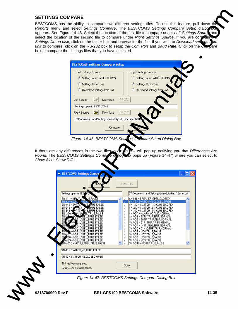
9318700990 Rev F BE1-GPS100 BESTCOMS Software 14-35
SETTINGS COMPARE BESTCOMS has the ability to compare two different settings files. To use this feature, pull down the Reports menu and select Settings Compare. The BESTCOMS Settings Compare Setup dialog box appears. See Figure 14-46. Select the location of the first file to compare under Left Settings Source and select the location of the second file to compare under Right Settings Source. If you are comparing a Settings file on disk, click on the folder box and browse for the file. If you wish to Download settings from unit to compare, click on the RS-232 box to setup the Com Port and Baud Rate. Click on the Compare box to compare the settings files that you have selected.
Figure 14-46. BESTCOMS Settings Compare Setup Dialog Box
If there are any differences in the two files, a dialog box will pop up notifying you that Differences Are Found. The BESTCOMS Settings Compare dialog box pops up (Figure 14-47) where you can select to Show All or Show Diffs.
Figure 14-47. BESTCOMS Settings Compare Dialog Box
www . El
ectric
alPar
tMan
uals
. com

14-36 BE1-GPS100 BESTCOMS Software 9318700990 Rev F
BESTPRINT BESTPrint, which is found on the CD included with the BE1-GPS100 relay, will preview and print Basler Electric relay settings files. This is via graphic representations similar to what is seen in the BESTCOMS software application. BESTPrint will only read the settings files and document the information. It will not write or change any settings in the settings file (*.bst) at this time. Profile files for each device are needed to print documentation for that particular device. New and updated profiles will be available from Basler Electric. One new set of profiles and their support files will be the optimum way to acquire additional printing of more devices or updated settings files. For additional information, see the Help files in the BESTPrint application.
www . El
ectric
alPar
tMan
uals
. com
9318700990 Rev F BE1-GPS100 Time Overcurrent Characteristic Curves i
APPENDIX A • TIME OVERCURRENT CHARACTERISTIC CURVES
TABLE OF CONTENTS
APPENDIX A • TIME OVERCURRENT CHARACTERISTIC CURVES ...................................................A-1 GENERAL..............................................................................................................................................A-1 CURVE SPECIFICATIONS ...................................................................................................................A-1 TIME OVERCURRENT CHARACTERISTIC CURVE GRAPHS...........................................................A-2 THE 46 CURVE .....................................................................................................................................A-4
Figures Figure A-1. Time Characteristic Curve S, S1, Short Inverse (Similar to ABB CO-2) ................................A-6 Figure A-2. Time Characteristic Curve S2, Short Inverse (Similar To GE IAC-55)...................................A-7 Figure A-3. Time Characteristic Curve L, L1, Long Inverse (Similar to ABB CO-5) .................................A-8 Figure A-4. Time Characteristic Curve L2, Long Inverse (Similar To GE IAC-66)....................................A-9 Figure A-5. Time Characteristic Curve D, Definite Time (Similar To ABB CO-6) ...................................A-10 Figure A-6. Time Characteristic Curve M, Moderately Inverse (Similar to ABB CO-7)...........................A-11 Figure A-7. Time Characteristic Curve I, I1, Inverse Time (Similar to ABB CO-8) .................................A-12 Figure A-8. Time Characteristic Curve I2, Inverse Time (Similar to GE IAC-51)....................................A-13 Figure A-9. Time Characteristic Curve V, V1, Very Inverse (Similar to ABB CO-9) ...............................A-14 Figure A-10. Time Characteristic Curve V2, Very Inverse (Similar to GE IAC-53) .................................A-15 Figure A-11. Time Characteristic Curve E, E1, Extremely Inverse (Similar to ABB CO-11)...................A-16 Figure A-12. Time Characteristic Curve E2, Extremely Inverse (Similar to GE IAC-77) ........................A-17 Figure A-13. Time Characteristic Curve A, Standard Inverse.................................................................A-18 Figure A-14. Time Characteristic Curve B, Very Inverse ........................................................................A-19 Figure A-15. Time Characteristic Curve C, Extremely Inverse ...............................................................A-20 Figure A-16. Time Characteristic Curve G, Long Time Inverse ..............................................................A-21 Figure A-17. 46 Time Characteristic Curve.............................................................................................A-22
Tables Table A-1. 51P, 51N, and 151N Time Characteristic Curve Constants ....................................................A-2 Table A-2. Characteristic Curve Cross-Reference....................................................................................A-3 Table A-3. Time Dial Setting Cross-Reference .........................................................................................A-4
www . El
ectric
alPar
tMan
uals
. com

ii BE1-GPS100 Time Overcurrent Characteristic Curves 9318700990 Rev F
This page intentionally left blank.
www . El
ectric
alPar
tMan
uals
. com
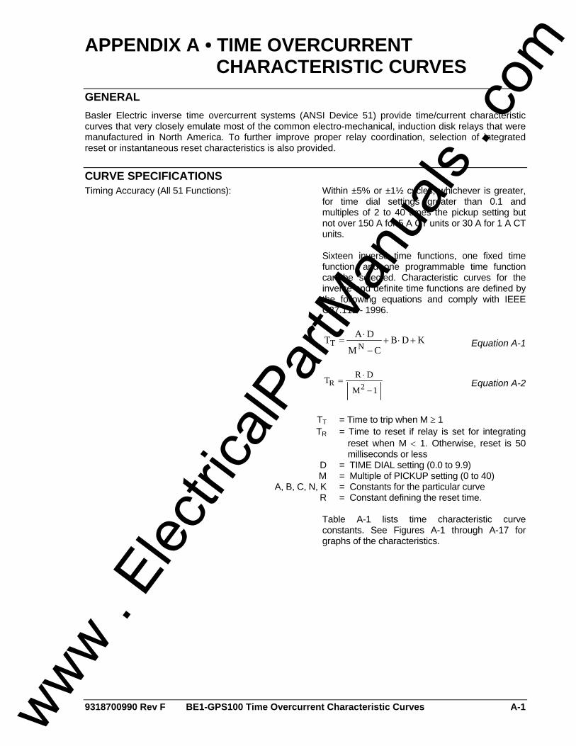
9318700990 Rev F BE1-GPS100 Time Overcurrent Characteristic Curves A-1
APPENDIX A • TIME OVERCURRENT CHARACTERISTIC CURVES
GENERAL Basler Electric inverse time overcurrent systems (ANSI Device 51) provide time/current characteristic curves that very closely emulate most of the common electro-mechanical, induction disk relays that were manufactured in North America. To further improve proper relay coordination, selection of integrated reset or instantaneous reset characteristics is also provided.
CURVE SPECIFICATIONS Timing Accuracy (All 51 Functions): Within ±5% or ±1½ cycles, whichever is greater,
for time dial settings greater than 0.1 and multiples of 2 to 40 times the pickup setting but not over 150 A for 5 A CT units or 30 A for 1 A CT units.
Sixteen inverse time functions, one fixed time
function, and one programmable time function can be selected. Characteristic curves for the inverse and definite time functions are defined by the following equations and comply with IEEE C37.112 - 1996.
KDBCM
DATNT +⋅+−
⋅= Equation A-1
1M
DRT2R−
⋅= Equation A-2
TT = Time to trip when M ≥ 1 TR = Time to reset if relay is set for integrating
reset when M < 1. Otherwise, reset is 50 milliseconds or less
D = TIME DIAL setting (0.0 to 9.9) M = Multiple of PICKUP setting (0 to 40) A, B, C, N, K = Constants for the particular curve R = Constant defining the reset time. Table A-1 lists time characteristic curve
constants. See Figures A-1 through A-17 for graphs of the characteristics.
www . El
ectric
alPar
tMan
uals
. com

A-2 BE1-GPS100 Time Overcurrent Characteristic Curves 9318700990 Rev F
Table A-1. 51P, 51N, and 151N Time Characteristic Curve Constants
Trip Characteristic Constants § Reset † Curve Selection
Curve Name A B C N K R
S1 S, S1, Short Inverse 0.2663 0.03393 1.0000 1.2969 0.0280 0.5000 S2 S2, Short Inverse 0.0286 0.02080 1.0000 0.9844 0.0280 0.0940 L1 L, L1, Long Inverse 5.6143 2.18592 1.0000 1.0000 0.0280 15.750 L2 L2, Long Inverse 2.3955 0.00000 1.0000 0.3125 0.0280 7.8001 D D, Definite Time 0.4797 0.21359 1.0000 1.5625 0.0280 0.8750 M M, Moderately Inverse 0.3022 0.12840 1.0000 0.5000 0.0280 1.7500 I1 I, I1, Inverse Time 8.9341 0.17966 1.0000 2.0938 0.0280 9.0000 I2 I2, Inverse Time 0.2747 0.10426 1.0000 0.4375 0.0280 0.8868 V1 V, V1, Very Inverse 5.4678 0.10814 1.0000 2.0469 0.0280 5.5000 V2 V2, Very Inverse 4.4309 0.09910 1.0000 1.9531 0.0280 5.8231 E1 E, E1, Extremely Inverse 7.7624 0.02758 1.0000 2.0938 0.0280 7.7500 E2 E2, Extremely Inverse 4.9883 0.01290 1.0000 2.0469 0.0280 4.7742 A A, Standard Inverse 0.01414 0.00000 1.0000 0.0200 0.0280 2.0000
B B, Very Inverse (I2t) 1.4636 0.00000 1.0000 1.0469 0.0280 3.2500
C C, Extremely Inverse (I2t) 8.2506 0.00000 1.0000 2.0469 0.0280 8.0000
G G, Long Time Inverse (I2t) 12.1212 0.00000 1.0000 1.0000 0.0280 29.0000
F Fixed Time ∗ 0.0000 1.00000 0.0000 0.0000 0.0280 1.0000
P Programmable 0 to 600 0 to 25 0 to 1 0.5 to 2.5 0.0280 0 to 30 46 Neg.-Seq. Overcurrent ‡ 0 0 2 0.0280 100
∗ Curve F has a fixed delay of one second times the Time Dial setting. † For integrated reset, append R to the curve name. For example, curve S1 has instantaneous reset.
Curve S1R has integrated reset. ‡ Constant A is variable for the 46 curve and is determined, as necessary, based on system full-load
current setting, minimum pickup, and K factor settings. § The programmable curve allows for four significant digits after the decimal place for every variable.
TIME OVERCURRENT CHARACTERISTIC CURVE GRAPHS Figures A-1 through A-16 illustrate the characteristic curves of the BE1-GPS100 relay. Table A-2 cross-references each curve to existing electromechanical relay characteristics. Equivalent time dial settings were calculated at a value of five times pickup.
www . El
ectric
alPar
tMan
uals
. com

9318700990 Rev F BE1-GPS100 Time Overcurrent Characteristic Curves A-3
Table A-2. Characteristic Curve Cross-Reference
Curve Curve Name Similar To
S1 S, S1, Short Inverse ABB CO-2
S2 S2, Short Inverse GE IAC-55
L1 L, L1, Long Inverse ABB CO-5
L2 L2, Long Inverse GE IAC-66
D D, Definite Time ABB CO-6
M M, Moderately Inverse ABB CO-7
I1 I, I1, Inverse Time ABB CO-8
I2 I2, Inverse Time GE IAC-51
V1 V, V1, Very Inverse ABB CO-9
V2 V2, Very Inverse GE IAC-53
E1 E, E1, Extremely Inverse ABB CO-11
E2 E2, Extremely Inverse GE IAC-77
A A, Standard Inverse BS, IEC Standard Inverse
B B, Very Inverse (I2t) BS, IEC Very Inverse (I2t)
C C, Extremely Inverse (I2t) BS, IEC Extremely Inverse (I2t)
G G, Long Time Inverse (I2t) BS, IEC Long Time Inverse (I2t)
F Fixed Time N/A
P Programmable N/A
Time Dial Setting Cross-Reference
Although the time characteristic curve shapes have been optimized for each relay, time dial settings of Basler Electric relays are not identical to the settings of electromechanical induction disk overcurrent relays. Table A-3 helps you convert the time dial settings of induction disk relays to the equivalent setting for Basler Electric relays. Enter time dial settings using BESTCOMS, S<g>-51P/51N/151N ASCII commands, or human-machine interface (HMI) Screens 5.x.9.1 (51P), 5.x.9.2 (51N), and 5.x.9.3 (151N). For more information, refer to Section 4, Protection and Control, Overcurrent Protection, 51 – Time Overcurrent Protection.
Using Table A-3
Cross-reference table values were obtained by inspection of published electromechanical time current characteristic curves. The time delay for a current of five times tap was entered into the time dial calculator function for each time dial setting. The equivalent Basler Electric time dial setting was then entered into the cross-reference table.
If your electromechanical relay time dial setting is between the values provided in the table, it will be necessary to interpolate (estimate the correct intermediate value) between the electromechanical setting and the Basler Electric setting.
Basler Electric relays have a maximum time dial setting of 9.9. The Basler Electric equivalent time dial setting for the electromechanical maximum setting is provided in the cross-reference table even if it exceeds 9.9. This allows interpolation as noted above.
Basler Electric time current characteristics are determined by a linear mathematical equation. The induction disk of an electromechanical relay has a certain degree of non linearity due to inertial and friction effects. For this reason, even though every effort has been made to provide characteristic curves with minimum deviation from the published electromechanical curves, slight deviations can exist between them.
www . El
ectric
alPar
tMan
uals
. com

A-4 BE1-GPS100 Time Overcurrent Characteristic Curves 9318700990 Rev F
In applications where the time coordination between curves is extremely close, we recommend that you choose the optimal time dial setting by inspection of the coordination study. In applications where coordination is tight, it is recommended that you retrofit your circuits with Basler Electric electronic relays to ensure high timing accuracy.
Table A-3. Time Dial Setting Cross-Reference Electromechanical Relay Time Dial Setting
0.5 1.0 2.0 3.0 4.0 5.0 6.0 7.0 8.0 9.0 10.0 11.0 Curve Equivalent
To Basler Electric Equivalent Time Dial Setting
S, S1 ABB CO-2 0.3 0.8 1.7 2.4 3.4 4.2 5.0 5.8 6.7 7.7 8.6 9.7
L, L1 ABB CO-5 0.4 0.8 1.5 2.3 3.3 4.2 5.0 6.0 7.0 7.8 8.8 9.9
D ABB CO-6 0.5 1.1 2.0 2.9 3.7 4.5 5.0 5.9 7.2 8.0 8.9 10.1
M ABB CO-7 0.4 0.8 1.7 2.5 3.3 4.3 5.3 6.1 7.0 8.0 9.0 9.8
I, I1 ABB CO-8 0.3 0.7 1.5 2.3 3.2 4.0 5.0 5.8 6.8 7.6 8.7 10.0
V, V1 ABB CO-9 0.3 0.7 1.4 2.1 3.0 3.9 4.8 5.7 6.7 7.8 8.7 9.6
E, E1 ABB CO-11 0.3 0.7 1.5 2.4 3.2 4.2 5.0 5.7 6.6 7.8 8.5 10.3
I2 GE IAC-51 0.6 1.0 1.9 2.7 3.7 4.8 5.7 6.8 8.0 9.3 10.6 N/A
V2 GE IAC-53 0.4 0.8 1.6 2.4 3.4 4.3 5.1 6.3 7.2 8.4 9.6 N/A
S2 GE IAC-55 0.2 1.0 2.0 3.1 4.0 4.9 6.1 7.2 8.1 8.9 9.8 N/A
L2 GE IAC-66 0.4 0.9 1.8 2.7 3.9 4.9 6.3 7.2 8.5 9.7 10.9 N/A
E2 GE IAC-77 0.5 1.0 1.9 2.7 3.5 4.3 5.2 6.2 7.4 8.2 9.9 N/A
THE 46 CURVE The 46 curve (Figure A-17) is a special curve designed to emulate the (I2)2 t withstand ratings of generators using what is frequently referred to as the generator K factor.
The 46 Curve Characteristics
46 Pickup Current
Generators have a maximum continuous rating for negative sequence current. This is typically expressed as a percent of stator rating. When using the 46 curve, the user should convert the continuous I2 rating data to actual secondary current at the relay. This value (plus some margin, if appropriate) should be entered as the pickup setting. For example, if a generator’s rated full-load current is 5 amperes, a pu setting of 0.5 A would allow 10% continuous I2.
46 Time Dial (= Generator K factor)
The amount of time that a generator can withstand a given level of unbalance is defined by Equation A-3.
( )22IKt = Equation A-3
The K factor gives the time that a generator can withstand 1 per unit negative sequence current. For example, with a K factor of 20, since (I2)2 becomes 1 at 1 per unit of current, the generator can withstand the condition for 20 seconds. Typical values for generator K factors are in the 2 to 40 range. The relay uses the “nominal current” setting of the relay (front panel Screen 6.3.7 or via the SG-NOM command) to determine what corresponds to 1 per unit current in the generator.
www . El
ectric
alPar
tMan
uals
. com

9318700990 Rev F BE1-GPS100 Time Overcurrent Characteristic Curves A-5
When curve 46 is selected, the relay changes the range of the allowed time dial to 1 to 99 (instead of the time dial range of 0.1 to 9.9 for all the other curves). The user should enter the “K” factor of the generator into the time dial field.
Relay Equation
When the 46 function is used, the relay uses the K factor (i.e., 46 time dial setting), 46 minimum pickup setting, and generator full-load current to create a constant Z (see Equation A-4).
2
SettingPickup46Setting NomI
DialTime46Z⎟⎟
⎠
⎞
⎜⎜
⎝
⎛= Equation A-4
The time to trip equation used in the relay is:
seconds0.028M
ZT2T += Equation A-5
where
SettingPickup46IMeasured
M 2= Equation A-6
which, when M > 1, reduces to:
2
Measured2ISetting NomI
DialTime46TT⎟⎟
⎠
⎞
⎜⎜
⎝
⎛= Equation A-7
www . El
ectric
alPar
tMan
uals
. com

A-6 BE1-GPS100 Time Overcurrent Characteristic Curves 9318700990 Rev F
Figure A-1. Time Characteristic Curve S, S1, Short Inverse (Similar to ABB CO-2)
www . El
ectric
alPar
tMan
uals
. com

9318700990 Rev F BE1-GPS100 Time Overcurrent Characteristic Curves A-7
Figure A-2. Time Characteristic Curve S2, Short Inverse (Similar To GE IAC-55)
www . El
ectric
alPar
tMan
uals
. com

A-8 BE1-GPS100 Time Overcurrent Characteristic Curves 9318700990 Rev F
Figure A-3. Time Characteristic Curve L, L1, Long Inverse (Similar to ABB CO-5)
www . El
ectric
alPar
tMan
uals
. com

9318700990 Rev F BE1-GPS100 Time Overcurrent Characteristic Curves A-9
Figure A-4. Time Characteristic Curve L2, Long Inverse (Similar To GE IAC-66)
www . El
ectric
alPar
tMan
uals
. com
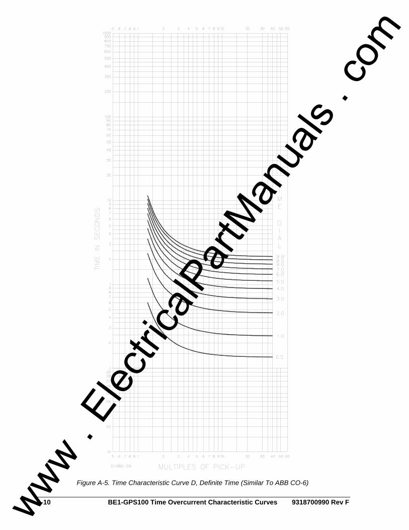
A-10 BE1-GPS100 Time Overcurrent Characteristic Curves 9318700990 Rev F
Figure A-5. Time Characteristic Curve D, Definite Time (Similar To ABB CO-6)
www . El
ectric
alPar
tMan
uals
. com

9318700990 Rev F BE1-GPS100 Time Overcurrent Characteristic Curves A-11
Figure A-6. Time Characteristic Curve M, Moderately Inverse (Similar to ABB CO-7)
www . El
ectric
alPar
tMan
uals
. com

A-12 BE1-GPS100 Time Overcurrent Characteristic Curves 9318700990 Rev F
Figure A-7. Time Characteristic Curve I, I1, Inverse Time (Similar to ABB CO-8)
www . El
ectric
alPar
tMan
uals
. com

9318700990 Rev F BE1-GPS100 Time Overcurrent Characteristic Curves A-13
Figure A-8. Time Characteristic Curve I2, Inverse Time (Similar to GE IAC-51)
www . El
ectric
alPar
tMan
uals
. com

A-14 BE1-GPS100 Time Overcurrent Characteristic Curves 9318700990 Rev F
Figure A-9. Time Characteristic Curve V, V1, Very Inverse (Similar to ABB CO-9)
www . El
ectric
alPar
tMan
uals
. com

9318700990 Rev F BE1-GPS100 Time Overcurrent Characteristic Curves A-15
Figure A-10. Time Characteristic Curve V2, Very Inverse (Similar to GE IAC-53)
www . El
ectric
alPar
tMan
uals
. com

A-16 BE1-GPS100 Time Overcurrent Characteristic Curves 9318700990 Rev F
Figure A-11. Time Characteristic Curve E, E1, Extremely Inverse (Similar to ABB CO-11)
www . El
ectric
alPar
tMan
uals
. com

9318700990 Rev F BE1-GPS100 Time Overcurrent Characteristic Curves A-17
Figure A-12. Time Characteristic Curve E2, Extremely Inverse (Similar to GE IAC-77)
www . El
ectric
alPar
tMan
uals
. com

A-18 BE1-GPS100 Time Overcurrent Characteristic Curves 9318700990 Rev F
Figure A-13. Time Characteristic Curve A, Standard Inverse
www . El
ectric
alPar
tMan
uals
. com

9318700990 Rev F BE1-GPS100 Time Overcurrent Characteristic Curves A-19
Figure A-14. Time Characteristic Curve B, Very Inverse
www . El
ectric
alPar
tMan
uals
. com

A-20 BE1-GPS100 Time Overcurrent Characteristic Curves 9318700990 Rev F
Figure A-15. Time Characteristic Curve C, Extremely Inverse
www . El
ectric
alPar
tMan
uals
. com

9318700990 Rev F BE1-GPS100 Time Overcurrent Characteristic Curves A-21
Figure A-16. Time Characteristic Curve G, Long Time Inverse
www . El
ectric
alPar
tMan
uals
. com
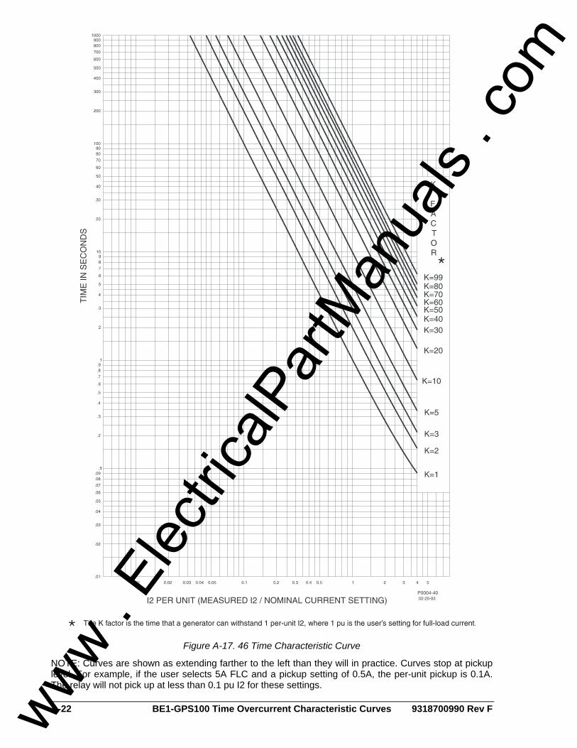
A-22 BE1-GPS100 Time Overcurrent Characteristic Curves 9318700990 Rev F
Figure A-17. 46 Time Characteristic Curve
NOTE: Curves are shown as extending farther to the left than they will in practice. Curves stop at pickup level. For example, if the user selects 5A FLC and a pickup setting of 0.5A, the per-unit pickup is 0.1A. The relay will not pick up at less than 0.1 pu I2 for these settings.
www . El
ectric
alPar
tMan
uals
. com

9318700990 Rev F BE1-GPS100 Command Cross-Reference i
APPENDIX B • COMMAND CROSS-REFERENCE TABLE OF CONTENTS
APPENDIX C • COMMAND CROSS-REFERENCE.................................................................................B-1
INTRODUCTION....................................................................................................................................B-1
Tables Table B-1. Miscellaneous Commands.......................................................................................................B-1 Table B-2. Metering Commands................................................................................................................B-1 Table B-3. Control Commands..................................................................................................................B-1 Table B-4. Report Commands...................................................................................................................B-2 Table B-5. Setting Command ....................................................................................................................B-2 Table B-6. Alarm Setting Commands........................................................................................................B-3 Table B-7. General Setting Commands ....................................................................................................B-3 Table B-8. Breaker Monitoring and Setting Commands............................................................................B-3 Table B-9. Programmable Logic Setting Commands................................................................................B-4 Table B-10. User Programmable Name Setting Command ......................................................................B-4 Table B-11. Protection Setting Commands ...............................................................................................B-4 Table B-12. Global Command...................................................................................................................B-5
www . El
ectric
alPar
tMan
uals
. com

ii BE1-GPS100 Command Cross-Reference 9318700990 Rev F
This page intentionally left blank.
www . El
ectric
alPar
tMan
uals
. com
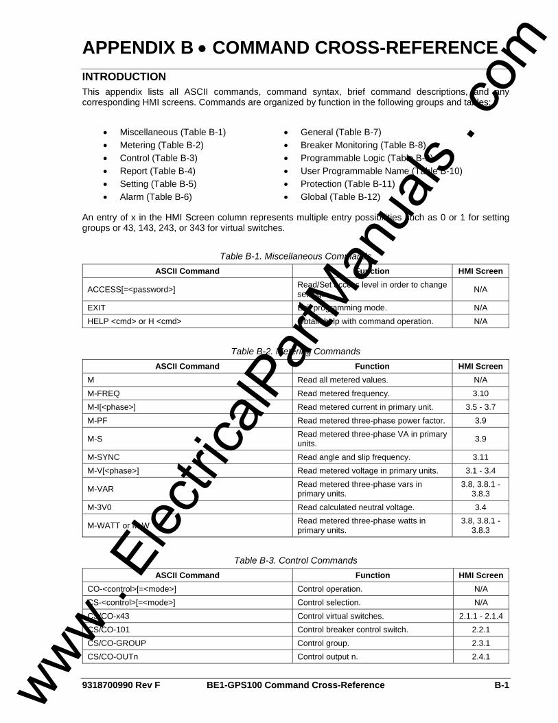
9318700990 Rev F BE1-GPS100 Command Cross-Reference B-1
APPENDIX B • COMMAND CROSS-REFERENCE INTRODUCTION This appendix lists all ASCII commands, command syntax, brief command descriptions, and any corresponding HMI screens. Commands are organized by function in the following groups and tables:
• Miscellaneous (Table B-1) • Metering (Table B-2) • Control (Table B-3) • Report (Table B-4) • Setting (Table B-5) • Alarm (Table B-6)
• General (Table B-7) • Breaker Monitoring (Table B-8) • Programmable Logic (Table B-9) • User Programmable Name (Table B-10) • Protection (Table B-11) • Global (Table B-12)
An entry of x in the HMI Screen column represents multiple entry possibilities such as 0 or 1 for setting groups or 43, 143, 243, or 343 for virtual switches.
Table B-1. Miscellaneous Commands ASCII Command Function HMI Screen
ACCESS[=<password>] Read/Set access level in order to change settings. N/A
EXIT Exit programming mode. N/A HELP <cmd> or H <cmd> Obtain help with command operation. N/A
Table B-2. Metering Commands
ASCII Command Function HMI Screen M Read all metered values. N/A M-FREQ Read metered frequency. 3.10 M-I[<phase>] Read metered current in primary unit. 3.5 - 3.7 M-PF Read metered three-phase power factor. 3.9
M-S Read metered three-phase VA in primary units. 3.9
M-SYNC Read angle and slip frequency. 3.11 M-V[<phase>] Read metered voltage in primary units. 3.1 - 3.4
M-VAR Read metered three-phase vars in primary units.
3.8, 3.8.1 - 3.8.3
M-3V0 Read calculated neutral voltage. 3.4
M-WATT or M-W Read metered three-phase watts in primary units.
3.8, 3.8.1 - 3.8.3
Table B-3. Control Commands
ASCII Command Function HMI Screen CO-<control>[=<mode>] Control operation. N/A CS-<control>[=<mode>] Control selection. N/A CS/CO-x43 Control virtual switches. 2.1.1 - 2.1.4 CS/CO-101 Control breaker control switch. 2.2.1 CS/CO-GROUP Control group. 2.3.1 CS/CO-OUTn Control output n. 2.4.1
www . El
ectric
alPar
tMan
uals
. com
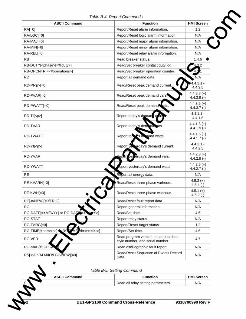
B-2 BE1-GPS100 Command Cross-Reference 9318700990 Rev F
Table B-4. Report Commands ASCII Command Function HMI Screen
RA[=0] Report/Reset alarm information. 1.2 RA-LGC[=0] Report/Reset logic alarm information. N/A RA-MAJ[=0] Report/Reset major alarm information. N/A RA-MIN[=0] Report/Reset minor alarm information. N/A RA-REL[=0] Report/Reset relay alarm information. N/A RB Read breaker status. 1.4.6 RB-DUTY[<phase>[=%duty>] Read/Set breaker contact duty log. 4.3.2 RB-OPCNTR[=<#operations>] Read/Set breaker operation counter. 4.3.1 RD Report all demand data. N/A
RD-PI<p>[=0] Read/Reset peak demand current. 4.4.3.1 - 4.4.3.5
RD-PVAR[=0] Read/Reset peak demand vars. 4.4.3.8 (+) 4.4.3.9 (-)
RD-PWATT[=0] Read/Reset peak demand watts. 4.4.3.6 (+) 4.4.3.7 (-)
RD-TI[<p>] Report today’s demand current. 4.4.1.1 - 4.4.1.5
RD-TVAR Report today’s demand vars. 4.4.1.8 (+) 4.4.1.9 (-)
RD-TWATT Report today’s demand watts. 4.4.1.6 (+) 4.4.1.7 (-)
RD-YI[<p>] Report yesterday’s demand current. 4.4.2.1 - 4.4.2.5
RD-YVAR Report yesterday’s demand vars. 4.4.2.8 (+) 4.4.2.9 (-)
RD-YWATT Report yesterday’s demand watts. 4.4.2.6 (+) 4.4.2.7 (-)
RE Report all energy data. N/A
RE-KVARH[=0] Read/Reset three-phase varhours. 4.5.3 (+) 4.5.4 (-)
RE-KWH[=0] Read/Reset three-phase watthour. 4.5.1 (+) 4.5.2 (-)
RF[-n/NEW][=0/TRIG] Read/Reset fault report data. N/A RG Report general information. N/A RG-DATE[=<M/D/Y>] or RG-DATE[=<D-M-Y>] Read/Set date. 4.6 RG-STAT Report relay status. N/A RG-TARG[=0] Report/Reset target status. 1.2 RG-TIME[=hr:mn:sc] or RG-TIME[=hr:mn<f>sc] Report/Set time. 4.6
RG-VER Read program version, model number, style number, and serial number. 4.7
RO-nA/B[#].CFG/DAT Read oscillographic fault report. N/A
RS[-n/Fn/ALM/IO/LGC/NEW][=0] Read/Reset Sequence of Events Record Data. N/A
Table B-5. Setting Command
ASCII Command Function HMI Screen S Read all relay setting parameters. N/A
www . El
ectric
alPar
tMan
uals
. com
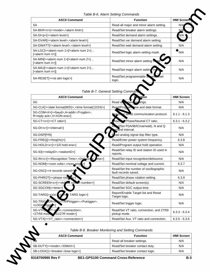
9318700990 Rev F BE1-GPS100 Command Cross-Reference B-3
Table B-6. Alarm Setting Commands ASCII Command Function HMI Screen
SA Read all major and minor alarm setting. N/A SA-BKR<n>[=<mode>,<alarm limit>] Read/Set breaker alarm settings. N/A SA-DI<p>[=<alarm level>] Read/Set demand alarm settings. N/A SA-DVAR[=<alarm level>,<alarm level>] Read/Set var demand alarm setting. N/A SA-DWATT[=<alarm level>,<alarm level>] Read/Set watt demand alarm setting. N/A SA-LGC[=<alarm num 1>[/<alarm num 2>]… [<alarm num n>]] Read/Set logic alarm setting mask. N/A
SA-MIN[=<alarm num 1>[/<alarm num 2>]… [<alarm num n>]] Read/Set minor alarm setting mask. N/A
SA-MAJ[=<alarm num 1>[/<alarm num 2>]… [<alarm num n>]] Read/Set major alarm setting mask. N/A
SA-RESET[=<rst alm logic>] Read/Set programmable alarms reset logic. N/A
Table B-7. General Setting Commands
ASCII Command Function HMI Screen SG Read all general settings. N/A SG-CLK[=<date format(M/D)>,<time format(12/24)>] Read/Program time and date format. N/A SG-COM<#>[=<baud>,A<addr>,P<pglen>, R<reply ack>,X<XON ena>] Read/Set serial communication protocol. 6.1.1 - 6.1.3
SG-CT<x>[=<CT ratio>] Read/Set Phase/Neutral CT ratio. 6.3.1 - 6.3.2
SG-DI<x>[=<interval>] Read/Set P(IA/IB/IC/var/watt), N and Q demand interval. N/A
SG-DSP[P/N] Read analog signal dsp filter type. N/A SG-FREQ[=<freq(Hz)>] Read/Enter power system frequency. 6.3.8 SG-HOLD<x>[=<1/0 hold ena>] Read/Program output hold operation. N/A
SG-ID[=<relayID>,<stationID>] Read/Set relay ID and station ID used in reports. N/A
SG-IN<x>[=<Recognition Time>,<Debounce Time>] Read/Set input recognition/debounce. N/A SG-NOM[=<nom volts>,<nom amps>] Read/Set nominal voltage and current. 6.3.7
SG-OSC[=<# records saved>] Read/Set the number of oscillographic fault records saved. N/A
SG-PHROT[=<phase rotation>] Read/Set phase rotation setting. 6.3.9 SG-SCREEN<x>[=<default screen number>] Read/Set default screen(s). N/A SG-SGCON[=<time>] Read/Set SGC output time. N/A
SG-TARG[=<x/x/…x>,<rst TARG logic>] Report/Enable Target list and Reset Target logic. N/A
SG-TRIGGER<x>[=<TRIPtrigger>,<Putrigger>, <LOGICtrigger>] Read/Set trigger logic. N/A
SG-VTP[=<VT ratio>,<connection>, <27/59 mode>,<51/27R mode>]
Read/Set VT ratio, connection, and 27/59 pickup mode. 6.3.3 - 6.3.4
SG-VTX[=<VT_ratio>,<connection>] Read/Set Aux. VT ratio and connection. 6.3.5 - 6.3.6
Table B-8. Breaker Monitoring and Setting Commands
ASCII Command Function HMI Screen SB Read all breaker settings. N/A SB-DUTY[=<mode>,<DMAX>] Read/Set breaker contact duty. N/A SB-LOGIC[=<breaker close logic>] Read/Set breaker contact logic. N/A
www . El
ectric
alPar
tMan
uals
. com
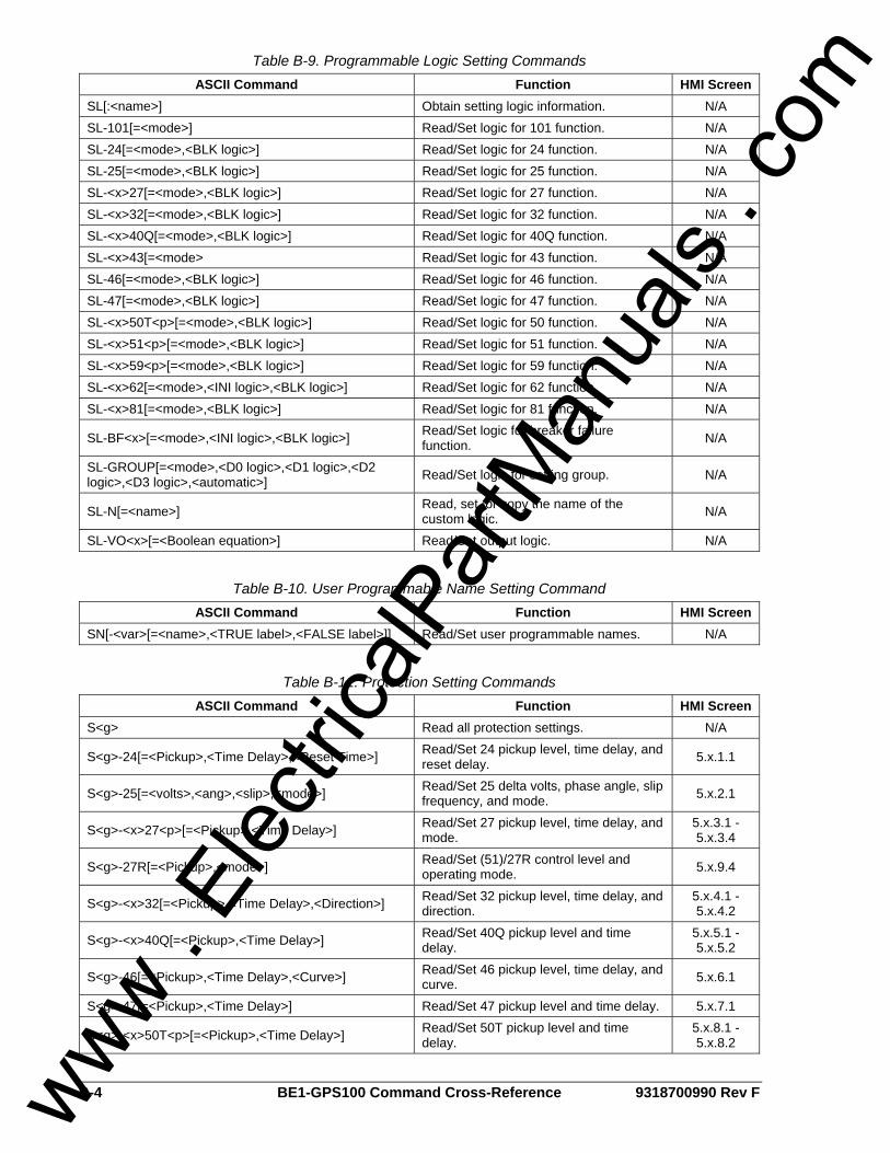
B-4 BE1-GPS100 Command Cross-Reference 9318700990 Rev F
Table B-9. Programmable Logic Setting Commands ASCII Command Function HMI Screen
SL[:<name>] Obtain setting logic information. N/A SL-101[=<mode>] Read/Set logic for 101 function. N/A SL-24[=<mode>,<BLK logic>] Read/Set logic for 24 function. N/A SL-25[=<mode>,<BLK logic>] Read/Set logic for 25 function. N/A SL-<x>27[=<mode>,<BLK logic>] Read/Set logic for 27 function. N/A SL-<x>32[=<mode>,<BLK logic>] Read/Set logic for 32 function. N/A SL-<x>40Q[=<mode>,<BLK logic>] Read/Set logic for 40Q function. N/A SL-<x>43[=<mode> Read/Set logic for 43 function. N/A SL-46[=<mode>,<BLK logic>] Read/Set logic for 46 function. N/A SL-47[=<mode>,<BLK logic>] Read/Set logic for 47 function. N/A SL-<x>50T<p>[=<mode>,<BLK logic>] Read/Set logic for 50 function. N/A SL-<x>51<p>[=<mode>,<BLK logic>] Read/Set logic for 51 function. N/A SL-<x>59<p>[=<mode>,<BLK logic>] Read/Set logic for 59 function. N/A SL-<x>62[=<mode>,<INI logic>,<BLK logic>] Read/Set logic for 62 function. N/A SL-<x>81[=<mode>,<BLK logic>] Read/Set logic for 81 function. N/A
SL-BF<x>[=<mode>,<INI logic>,<BLK logic>] Read/Set logic for breaker failure function. N/A
SL-GROUP[=<mode>,<D0 logic>,<D1 logic>,<D2 logic>,<D3 logic>,<automatic>] Read/Set logic for setting group. N/A
SL-N[=<name>] Read, set, or copy the name of the custom logic. N/A
SL-VO<x>[=<Boolean equation>] Read/Set output logic. N/A
Table B-10. User Programmable Name Setting Command
ASCII Command Function HMI Screen SN[-<var>[=<name>,<TRUE label>,<FALSE label>]] Read/Set user programmable names. N/A
Table B-11. Protection Setting Commands
ASCII Command Function HMI Screen S<g> Read all protection settings. N/A
S<g>-24[=<Pickup>,<Time Delay>,<Reset Time>] Read/Set 24 pickup level, time delay, and reset delay. 5.x.1.1
S<g>-25[=<volts>,<ang>,<slip>,<mode>] Read/Set 25 delta volts, phase angle, slip frequency, and mode. 5.x.2.1
S<g>-<x>27<p>[=<Pickup>,<Time Delay>] Read/Set 27 pickup level, time delay, and mode.
5.x.3.1 - 5.x.3.4
S<g>-27R[=<Pickup>,<mode>] Read/Set (51)/27R control level and operating mode. 5.x.9.4
S<g>-<x>32[=<Pickup>,<Time Delay>,<Direction>] Read/Set 32 pickup level, time delay, and direction.
5.x.4.1 - 5.x.4.2
S<g>-<x>40Q[=<Pickup>,<Time Delay>] Read/Set 40Q pickup level and time delay.
5.x.5.1 - 5.x.5.2
S<g>-46[=<Pickup>,<Time Delay>,<Curve>] Read/Set 46 pickup level, time delay, and curve. 5.x.6.1
S<g>-47[=<Pickup>,<Time Delay>] Read/Set 47 pickup level and time delay. 5.x.7.1
S<g>-<x>50T<p>[=<Pickup>,<Time Delay>] Read/Set 50T pickup level and time delay.
5.x.8.1 - 5.x.8.2
www . El
ectric
alPar
tMan
uals
. com
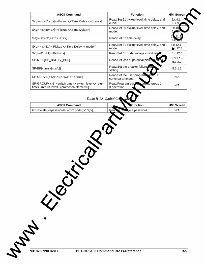
9318700990 Rev F BE1-GPS100 Command Cross-Reference B-5
ASCII Command Function HMI Screen
S<g>-<x>51<p>[=<Pickup>,<Time Delay>,<Curve>] Read/Set 51 pickup level, time delay, and curve.
5.x.9.1 - 5.x.9.3
S<g>-<x>59<p>[=<Pickup>,<Time Delay>] Read/Set 59 pickup level, time delay, and mode.
5.x.10.1 - 5.x.10.4
S<g>-<x>62[=<T1>,<T2>] Read/Set 62 time delay. 5.x.11.1 - 5.x.11.4
S<g>-<x>81[=<Pickup>,<Time Delay>,<mode>] Read/Set 81 pickup level, time delay, and mode.
5.x.12.1 - 5.x 12.4
S<g>-81INH[=<Pickup>] Read/Set 81 undervoltage inhibit level. 5.x.12.5
SP-60FL[=<I_Blk>,<V_Blk>] Read/Set loss of potential pickup setting. 5.3.2.1 - 5.3.2.2
SP-BF[<time>[m/s/c]] Read/Set the breaker failure timer setting. 5.3.1.1
SP-CURVE[=<A>,<B>,<C>,<N>,<R>] Read/Set the user programmable 51 curve parameters. N/A
SP-GROUP<x>[=<switch time>,<switch level>,<return time>,<return level>,<protection element>]
Read/Program auxiliary setting group 1 - 3 operation. N/A
Table B-12. Global Command
ASCII Command Function HMI Screen GS-PW<t>[=<password>,<com ports(0/1/2)>] Read or change a password. N/A
www . El
ectric
alPar
tMan
uals
. com

B-6 BE1-GPS100 Command Cross-Reference 9318700990 Rev F
This page intentionally left blank.
www . El
ectric
alPar
tMan
uals
. com
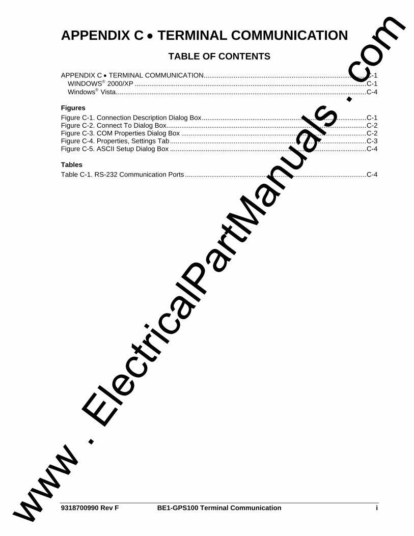
9318700990 Rev F BE1-GPS100 Terminal Communication i
APPENDIX C • TERMINAL COMMUNICATION
TABLE OF CONTENTS APPENDIX C • TERMINAL COMMUNICATION.......................................................................................C-1
WINDOWS® 2000/XP ............................................................................................................................C-1 Windows® Vista......................................................................................................................................C-4
Figures Figure C-1. Connection Description Dialog Box........................................................................................C-1 Figure C-2. Connect To Dialog Box...........................................................................................................C-2 Figure C-3. COM Properties Dialog Box ...................................................................................................C-2 Figure C-4. Properties, Settings Tab.........................................................................................................C-3 Figure C-5. ASCII Setup Dialog Box .........................................................................................................C-4
Tables Table C-1. RS-232 Communication Ports .................................................................................................C-4
www . El
ectric
alPar
tMan
uals
. com

ii BE1-GPS100 Terminal Communication 9318700990 Rev F
This page intentionally left blank.
www . El
ectric
alPar
tMan
uals
. com
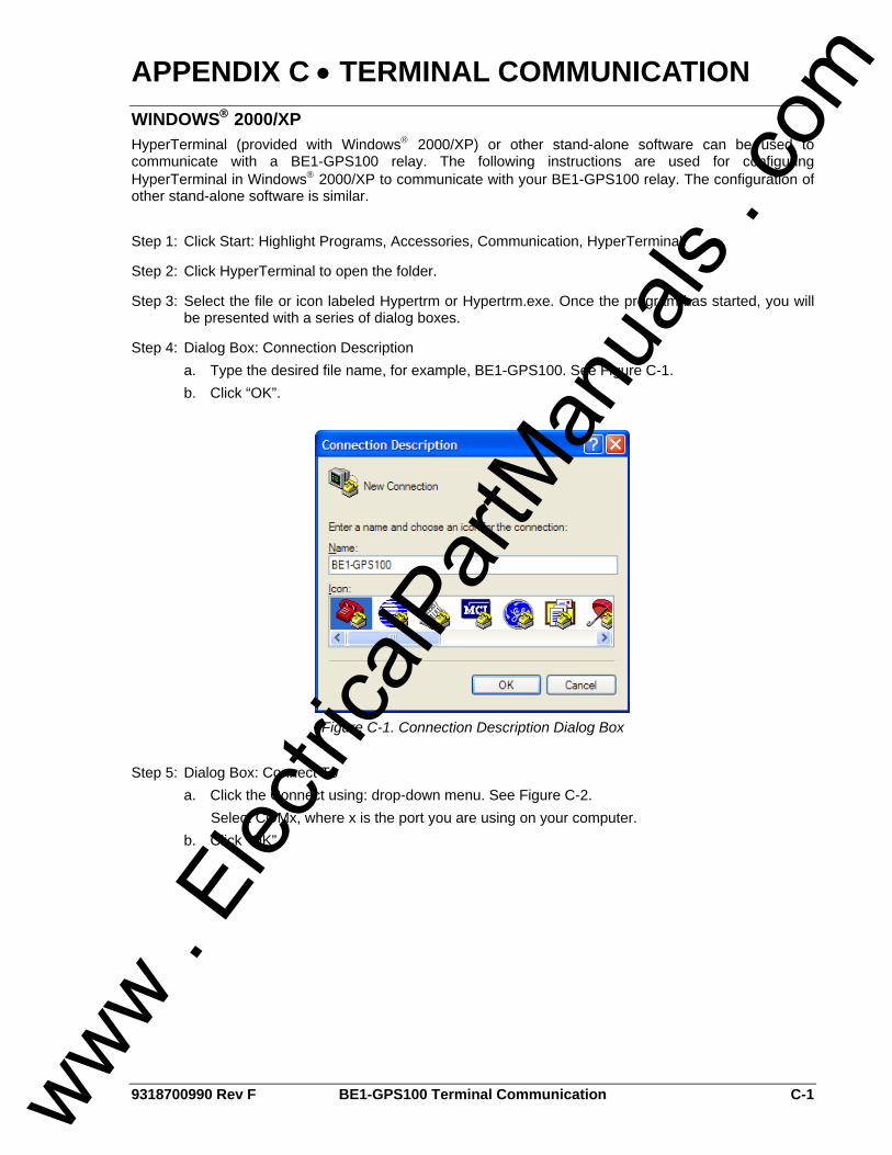
9318700990 Rev F BE1-GPS100 Terminal Communication C-1
APPENDIX C • TERMINAL COMMUNICATION WINDOWS® 2000/XP HyperTerminal (provided with Windows® 2000/XP) or other stand-alone software can be used to communicate with a BE1-GPS100 relay. The following instructions are used for configuring HyperTerminal in Windows® 2000/XP to communicate with your BE1-GPS100 relay. The configuration of other stand-alone software is similar. Step 1: Click Start: Highlight Programs, Accessories, Communication, HyperTerminal.
Step 2: Click HyperTerminal to open the folder.
Step 3: Select the file or icon labeled Hypertrm or Hypertrm.exe. Once the program has started, you will be presented with a series of dialog boxes.
Step 4: Dialog Box: Connection Description a. Type the desired file name, for example, BE1-GPS100. See Figure C-1. b. Click “OK”.
Figure C-1. Connection Description Dialog Box
Step 5: Dialog Box: Connect To
a. Click the Connect using: drop-down menu. See Figure C-2. Select COMx, where x is the port you are using on your computer.
b. Click “OK”.
www . El
ectric
alPar
tMan
uals
. com
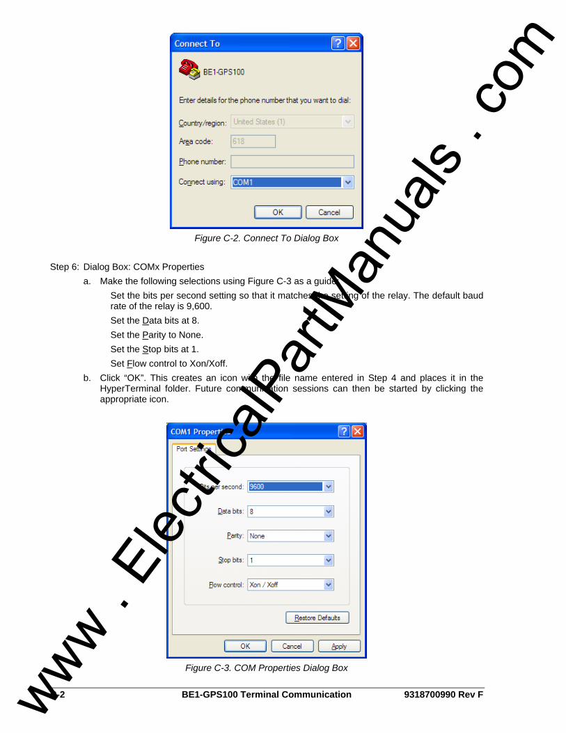
C-2 BE1-GPS100 Terminal Communication 9318700990 Rev F
Figure C-2. Connect To Dialog Box
Step 6: Dialog Box: COMx Properties
a. Make the following selections using Figure C-3 as a guide: Set the bits per second setting so that it matches the setting of the relay. The default baud rate of the relay is 9,600. Set the Data bits at 8. Set the Parity to None. Set the Stop bits at 1. Set Flow control to Xon/Xoff.
b. Click “OK”. This creates an icon with the file name entered in Step 4 and places it in the HyperTerminal folder. Future communication sessions can then be started by clicking the appropriate icon.
Figure C-3. COM Properties Dialog Box
www . El
ectric
alPar
tMan
uals
. com
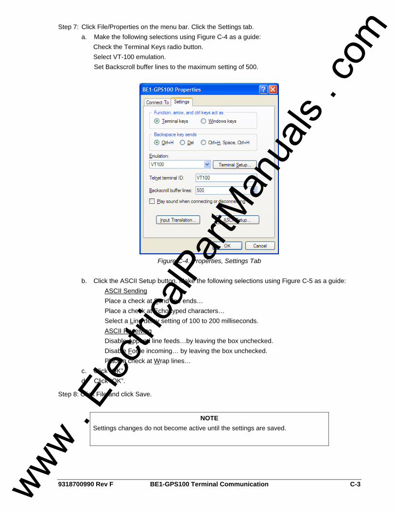
9318700990 Rev F BE1-GPS100 Terminal Communication C-3
Step 7: Click File/Properties on the menu bar. Click the Settings tab. a. Make the following selections using Figure C-4 as a guide:
Check the Terminal Keys radio button. Select VT-100 emulation. Set Backscroll buffer lines to the maximum setting of 500.
Figure C-4. Properties, Settings Tab
b. Click the ASCII Setup button. Make the following selections using Figure C-5 as a guide:
ASCII Sending Place a check at Send line ends…
Place a check at Echo typed characters… Select a Line delay setting of 100 to 200 milliseconds.
ASCII Receiving Disable Append line feeds…by leaving the box unchecked. Disable Force incoming… by leaving the box unchecked.
Place a check at Wrap lines… c. Click “OK”. d. Click “OK”.
Step 8: Click File and click Save.
NOTE Settings changes do not become active until the settings are saved.
www . El
ectric
alPar
tMan
uals
. com
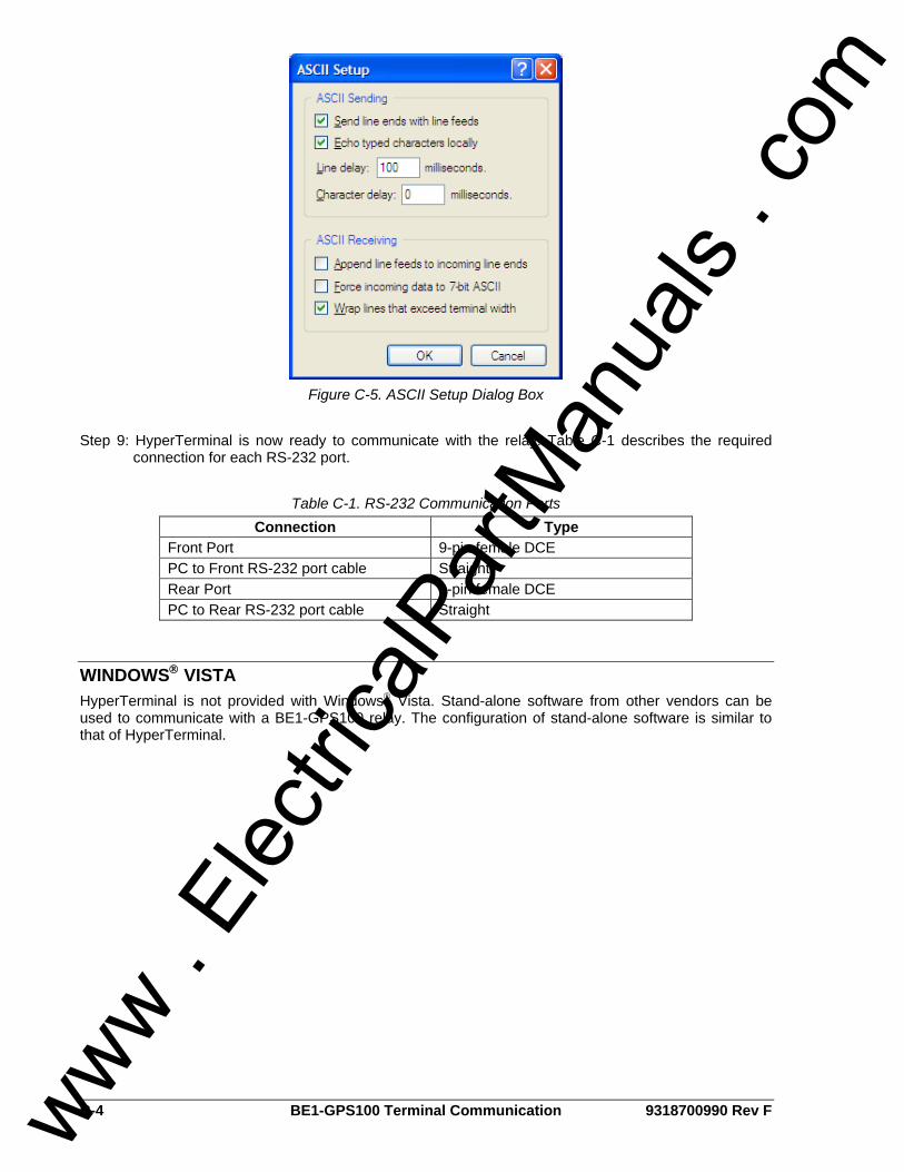
C-4 BE1-GPS100 Terminal Communication 9318700990 Rev F
Figure C-5. ASCII Setup Dialog Box
Step 9: HyperTerminal is now ready to communicate with the relay. Table C-1 describes the required
connection for each RS-232 port.
Table C-1. RS-232 Communication Ports Connection Type
Front Port 9-pin female DCE PC to Front RS-232 port cable Straight Rear Port 9-pin female DCE PC to Rear RS-232 port cable Straight
WINDOWS® VISTA HyperTerminal is not provided with Windows® Vista. Stand-alone software from other vendors can be used to communicate with a BE1-GPS100 relay. The configuration of stand-alone software is similar to that of HyperTerminal.
www . El
ectric
alPar
tMan
uals
. com

ROUTE 143, BOX 269 HIGHLAND, IL 62249 USA
http://www.basler.com, [email protected] PHONE +1 618-654-2341 FAX +1 618-654-2351 www .
Elec
tricalP
artM
anua
ls . c
om