Embed Size (px)
Citation preview
Health and Safety Executive
NUCLEAR DIRECTORATE
GENERIC DESIGN ASSESSMENT – NEW CIVIL REACTOR BUILD
STEP 3 STRUCTURAL INTEGRITY ASSESSMENT OF THE EDF and AREVA UK EPR
DIVISION 6 ASSESSMENT REPORT NO. AR 09/012-P
HSE Nuclear Directorate Redgrave Court Merton Road Bootle Merseyside L20 7HS
HSE Nuclear Directorate Division 6 Assessment Report No. AR 09/012-P
EXECUTIVE SUMMARY
This report records my assessment of the nuclear safety-related structural integrity aspects of the EDF and AREVA UK EPR, for Step 3 of the Nuclear Directorate’s (ND) Generic Design Assessment (GDA). The ND usage of the term ‘structural integrity’ covers metal pressure boundary components, their supports and some of the associated internal support structures (e.g. for a PWR, the core barrel).
In this GDA Step 3 assessment of the structural integrity aspects of the UK EPR design, I have not identified any matters that would lead to a recommendation to raise a Regulatory Issue (RI).
During GDA Step 3 I have raised a number of matters with EDF and AREVA; I have done this mostly through eleven Regulatory Observations (ROs). Some matters raised are relatively more significant than others. I consider useful progress has been made across a number of these ROs. Several aspects of these ROs remain to be resolved. I consider there is a reasonable prospect of achieving such resolution by carrying these remaining open aspects forward into GDA Step 4.
For structural integrity aspects of the UK EPR, and from an ND perspective I believe there has been a significant improvement in HSE’s understanding of the design.
I consider particular important points of progress are as follows:
1. The Design and Construction Rules for Mechanical Components of PWR Nuclear Islands (RCC-M) code (2007 edition) is in general a sound basis for design and fabrication of the primary and secondary circuit pressure boundary components. Details remain to be resolved, mainly relating to chemical composition of the low alloy ferritic steels for the main pressure vessels and aspects of the design analysis for pipework.
2. The basis of Reactor Pressure Vessel (RPV) construction with a circumferential weld at core mid-height has been justified. Aspects of the detailed chemical composition of the materials of construction remain to be resolved, along with some aspects of how pressure-temperature limit curves are determined.
3. The basis of Reactor Coolant Pump Casing construction based on casting technology has been justified. However there are still aspects to resolve in how to deal with large repairs to the castings made by welding.
For components where ‘the likelihood of gross failure is claimed to be so low it can be discounted’, EDF and AREVA have indicated a willingness to implement a method of achieving and demonstrating integrity consistent with UK practice. Toward the end of GDA Step 3, EDF and AREVA proposed programmes of work to address the main aspects of facture mechanics analyses, material toughness and qualification of manufacturing examinations. The details of this remain to be worked out and implemented, but so far I am encouraged by EDF and AREVA’s approach to understanding the type of method envisaged. Detailed assessment in this area will carry into GDA Step 4.
There is of course the question of which components have the claim that the likelihood of gross failure is so low it can be discounted. EDF and AREVA agreed to consider this matter and have provided information to justify their list of such components until essentially the end of GDA Step 3. Assessment of the matters raised in this RO will carry on into GDA Step 4.
Aspects of the chemical composition of the low alloy ferritic steels for the main vessels (Reactor Pressure Vessel, Steam Generators and Pressuriser) remain to be resolved. This topic will also carry into GDA Step 4, but it is an item that needs to be resolved sooner rather than later. Largely based on authoritative advice received under a support contract, there may be a number of aspects to discuss with EDF and AREVA, including the Sulphur, Nickel, and possibly Phosphorous content limits. However I do not see these aspects as fundamental impediments to progress and resolution.
Page (i)

HSE Nuclear Directorate Division 6 Assessment Report No. AR 09/012-P
For the Reactor Coolant Pump casings, aspects remain to be resolved on how to deal with large repairs to the castings made by welding. The areas still open relate to how to obtain confidence that crack-like defects of a size of concern for integrity, can be detected.
Useful progress has been made in understanding the approach to be used for a UK EPR in setting Pressure-Temperature limit curves for the RPV. However there are aspects still to be resolved; these are a combination of the need for clarity and better referencing of what is proposed, but also consideration of what is As Low as Reasonably Practicable (ALARP).
The UK EPR PCSR states that the Steam Generator (SG) tubing will be made using mill annealed Alloy 690 in the Thermally Treated (TT) condition. Based on my knowledge of UK experience of thermally treated Alloy 690 SG tubing and a general perception of international experience of this material, I had no particular concerns about its use. But, given the past interest in the UK of this aspect of PWR structural integrity, I judged it prudent to give the matter some consideration. I decided to do this through a support contract to review PWR Steam Generator tube materials and manufacturing routes.
Overall for SG tubing, I conclude from the review and my general knowledge of this area that Alloy 690 in the TT condition is a sound choice of material for Steam Generator Tubing. When supported by detailed manufacturing practice and in-service water chemistry control, Alloy 690TT tubing exhibits good resistance to stress corrosion cracking. Material choice, manufacturing practice and in-service water chemistry are not however a panacea. The general design and construction aspects of the Steam Generator as they affect the tubing also have a role. Important factors are the minimisation of ‘crevice’ conditions, support for the tubing to avoid vibration induced wear and support materials that themselves do not corrode. Most of these general design and construction factors have been understood for many years, and the EPR SG design takes these into account.
Late in GDA Step 3, I raised an RO regarding some of the RCC-M design analysis equations for pipework. A response has been received from EDF and AREVA. Some aspects require clarification and the approach to seismic design analysis might be the subject of further review; so, assessment of some aspects of design analysis equations for pipework might continue into GDA Step 4. In addition GDA Step 4 for structural integrity needs to move to the next level of detail and consider the content of documents such as (generic document names):
Design Specifications.
Analyses for loading conditions (mainly thermal-hydraulic analyses - this will require involvement of other ND assessment functions).
Design Reports.
Equipment Specifications. for a range of components.
A number of matters are identified above for carrying forward in to GDA Step 4 and some will require significant effort and programmes of work on the part of EDF and AREVA (e.g. the work for Regulatory Observation RO-UKEPR-20).
From an ND perspective, I consider there has been a reduction in regulatory risk.
Page (ii)
HSE Nuclear Directorate Division 6 Assessment Report No. AR 09/012-P
LIST OF ABBREVIATIONS
AFCEN Association Française pour les règles de conception, de construction et de surveillance en exploitation des matériels des chaudières électro-nucléaires (French Association for Design, Construction and In-Service Inspection Rules for Nuclear Island Components)
ALARP As Low as Reasonably Practicable
ASME American Society of Mechanical Engineers
B & PV (ASME) Boiler and Pressure Vessel Code
BMS (Nuclear Directorate) Business Management System
BSL Basic Safety Level (in SAPs)
BSO Basic Safety Objective (in SAPs)
BWR Boiling Water Reactor
DN Nominal diameter (of pipe)
dpa displacements per atom
EA The Environment Agency
EDF and AREVA Electricité de France SA and AREVA NP SAS
EdFs Acronym name for neutron irradiation of steel dose-damage relationship developed by EDF for welds (soudures)
EPRI Electric Power Research institute
FIS Acronym name for neutron irradiation of steel dose-damage relationship developed by Framatome (now AREVA) (fragilisation par irradiation supérieur - embrittlement by higher irradiation)
GDA Generic Design Assessment
HAZ Heat Affect Zone (of welded joint)
HELB High Energy Line Breaks
HSE The Health and Safety Executive
IAEA The International Atomic Energy Agency
IASCC Irradiation Assisted Stress Corrosion Cracking
IGA Intergranular Attack
IGSCC Intergranular Stress Corrosion Cracking
NB Nominal bore (of pipe)
ND Nuclear Directorate (of HSE)
NDT Non-Destructive Examination
PCC Plant Condition Category (loading conditions)
Page (iii)

HSE Nuclear Directorate Division 6 Assessment Report No. AR 09/012-P
Page (iv)
LIST OF ABBREVIATIONS
PCSR Pre-construction Safety Report
PID Project Initiation Document (HSE / ND)
POSR Pre-operational Safety Report
P-T Pressure-Temperature
PWSCC Primary Water Stress Corrosion Cracking
QA Quality Assurance
RCC-M Règles de Conception et de Construction des Matériels Mécaniques des Ilots Nucléaires REP Design and Construction Rules for Mechanical Components of PWR Nuclear Islands (AFCEN, France)
RHRS Residual Heat Removal System (French RRA)
RI Regulatory Issue
RIA Regulatory Issue Action
RO Regulatory Observation
ROA Regulatory Observation Action
RP Requesting Party
RPV Reactor Pressure Vessel
RSE-M Règles de Surveillance en Exploitation des Matériels Mécaniques des Ilots Nucléaires REP In-Service Inspection Rules for Mechanical Components of PWR Nuclear Islands. (AFCEN, France)
RSEM Acronym name for neutron irradiation of steel dose-damage relationship that appears in the RSE-M code
SAP Safety Assessment Principle (plural SAPs)
SG Steam Generator
SIS Safety injection System (French RIS)
SSC System, Structure and Component
STUK Finnish Nuclear Regulator
TAG (Nuclear Directorate) Technical Assessment Guide
TQ Technical Query
TT Thermally Treated (referring to Steam Generator tubing)
US NRC (or NRC) United States Nuclear Regulatory Commission
HSE Nuclear Directorate Division 6 Assessment Report No. AR 09/012-P
TABLE OF CONTENTS
1 INTRODUCTION...................................................................................................................... 1
2 EDF and AREVA CASE ........................................................................................................... 2
2.1 UK EPR PCSR Overview of Structure and Relevant Content........................................... 2
2.2 UK EPR PCSR Outline of Safety Case Claims for Structural Integrity.............................. 3
2.3 UK EPR PCSR Outline of Arguments and Evidence to Support the Claims for Structural Integrity..................................................................................................................... 6
3 STANDARDS AND CRITERIA................................................................................................. 7
4 GENERAL MATTERS RELATING TO ND ASSESSMENT ..................................................... 8
4.1 Outcome of Assessment in GDA Step 2 ........................................................................... 8
4.2 GDA Step 3 Assessment Compared with Project Initiation Document (PID) .................... 9
4.3 Requesting Party Response to What is Required for GDA Step 3.................................. 10
4.4 What HSE Will Do In GDA Step 3 ................................................................................... 12
5 ND ASSESSMENT GDA STEP 3 - STRUCTURAL INTEGRITY........................................... 14
5.1 Overview of Assessment................................................................................................. 14
5.2 Technical Framework Contracts...................................................................................... 15
5.3 Summary of Assessment ................................................................................................ 16
5.4 RCC-M Code................................................................................................................... 18
5.4.1 Scope and Basis of Review of RCC-M Code ....................................................... 18
5.4.2 Summary of Outcome of Review of RCC-M Code ............................................... 20
5.4.3 Recommendations From Review of RCC-M Code............................................... 21
5.5 RO-UKEPR-19. Categorisation of Safety Function, Classification of Structures -Systems and Components - “Non Breakable”, “Break Preclusion” and “No Missile” Items .. 22
5.6 RO-UKEPR-20. Avoidance of Fracture - Margins Based on Size of Crack-Like Defects. Integration of Material Toughness Properties, Non-Destructive Examinations During Manufacture and Analyses for Limiting Sizes of Crack-Like Defects ..................... 23
5.7 RO-UKEPR-21. Manufacturing Method for Reactor Coolant Pump Casings.................. 25
5.8 RO-UKEPR-22. RCC-M Overall Organisational Arrangements and Quality Assurance Arrangements ......................................................................................................... 28
5.9 RO-UKEPR-23. RCC-M Overpressure Protection .......................................................... 28
5.10 RO-UKEPR-24. Materials Specifications and Selection of Material Grade - Reactor Pressure Vessel, Pressuriser, Steam Generator Shells......................................... 30
5.11 RO-UKEPR-25. Reactor Pressure Vessel Body Cylindrical Shell Forging Material and Associated Circumferential Welds - Effects of Irradiation................................ 33
5.12 RO-UKEPR-26. Primary Circuit Vessel Nozzle to Safe End Welds ....................... 40
5.13 RO-UKEPR-27. Fatigue Crack Growth Law Equations for Ferritic Materials Covered by RCC-M M 2110 and M2120 ................................................................ 41
5.14 RO-UKEPR-28. Reactor Pressure Vessel Pressure - Temperature Limit Diagrams and Low Temperature Overpressure Protection .................................................... 41
Page (v)

HSE Nuclear Directorate Division 6 Assessment Report No. AR 09/012-P
Page (vi)
5.15 RO-UKEPR-36. RCC-M Aspects of Requirements for Design Analysis of Piping Class 1, 2 and 3...................................................................................................... 44
5.16 Steam Generator Tubing ........................................................................................ 45
6 CONCLUSIONS..................................................................................................................... 48
7 RECOMMENDATIONS.......................................................................................................... 50
8 REFERENCES....................................................................................................................... 51
Table 1: List of Regulatory Observations. UK EPR ND Generic Design Assessment - Step 3 Structural Integrity - Metal Components and Structures
Table 2: Main parts of UKEPR PCSR relevant to structural integrity assessment
Table 3: Amended version of Table 1 from Project initiation Document (PID) (Ref. 11)
Table 4: Amended version of Table 1 from Project initiation Document (PID) (Ref. 11). How PID Topics Dealt With
Table 5: Alignment of RCC-M and ASME Boiler and Pressure Vessel Code for Purposes of Comparison (and indication of number of pages in each part)
Figure 1: Cross section of EPR Reactor Pressure Vessel showing locations of three circumferential welds at core mid-height (Weld 1), just above the core (Weld 2) and just below the core (Weld 3)
Figure 2: Example of fracture toughness temperature transition curve indexed to RTNDT. This example is for KIc, other measures of toughness exist
Figure 3: KIc and KIa fracture toughness temperature transition curves indexed to RTNDT. From RCC-M Annex Z G 2005 Edition
Annex 1: UK EPR Structural Integrity – Status of Regulatory Issues and Observations
Annex 2: Regulatory Observations UK EPR Generic Design Assessment - Step 3 Structural Integrity - Metal Components and Structures
HSE Nuclear Directorate Division 6 Assessment Report No. AR 09/012-P
1 INTRODUCTION
1 This report records my assessment of the nuclear safety-related structural integrity aspects of the EDF and AREVA UK EPR, for Step 3 of the ND’s Generic Design Assessment (GDA). The ND usage of the term ‘structural integrity’ covers metal pressure boundary components, their supports and some of the associated internal support structures (e.g. for a PWR, the core barrel).
2 The specific aims of GDA Step 3 are to (Ref. 12, page 14):
improve HSE knowledge of the design;
identify significant issues;
identify whether any significant design or safety case changes may be needed;
identify major issues that may affect design acceptance and attempt to resolve them;
achieve a significant reduction in regulatory uncertainty.
3 It is expected that assessment will continue in GDA Step 4.
4 For GDA Step 3, my assessment has concentrated on the components likely to have a major influence on nuclear safety, particularly high consequence, low likelihood events. In practice this means my assessment has concentrated on the primary pressure boundary and to some extent the secondary pressure boundary of the UK EPR; and mostly those components within the containment building. Examples of components included within this scope are:
Reactor Pressure Vessel.
Pressuriser.
Steam Generators.
Reactor Coolant Pumps (pressure boundary).
Primary Coolant Loop Piping.
5 For GDA Step 3, I have not considered components outside the containment building, or low pressure / low temperature systems.
6 My assessment began in June 2008, based mainly on the UK EPR Pre-Construction Safety Report (PCSR) issued to ND by EDF and AREVA in June 2008 (Ref. 1). The formal methods of interacting with the Requesting Parties for technical aspects of their submissions are (in order of increasing significance):
Technical Queries (TQs).
Regulatory Observations (ROs).
Regulatory Issues (RIs).
7 For this assessment, most of my formal, technical interactions with EDF and AREVA have been based on a number of ROs. I sent EDF and AREVA a set of draft ROs in early September 2008, by email. These draft ROs were the basis for two meetings with EDF and AREVA, 6-7 November 2008 (Ref. 2) and 10 December 2008 (Ref. 3). This set of Regulatory Observations were made final by ND and sent to EDF and AREVA on 28 January 2009 (letter EPR70077N) - Regulatory Observations RO-UKEPR-19 to RO-UKEPR-28. See Table 1 for the list of ROs.
8 Draft proposals for actions to answer this set of Regulatory Observations were sent from ND to EDF and AREVA on 29 January 2009, by email. With the exception of one RO, EDF and AREVA agreed the way forward to answer the ROs in letter EPR00091N dated 2 April 2009. The way forward on the outstanding RO was agreed in an
Page 1

HSE Nuclear Directorate Division 6 Assessment Report No. AR 09/012-P
exchange of letters between EDF and AREVA (EPR00104N, 22 April 2009) and ND (EPR70090R, 5 May 2009).
9 Further meetings were held with EDF and AREVA on 16 June (Ref. 4), 22 July 2009 (Ref. 5) and 12 August 2009 (pm only) (Ref. 13).
10 For all the face-to-face meetings mentioned above, and progress meetings conducted by telephone, my view is all have been conducted in a professional, positive manner in an atmosphere of mutual respect.
11 EDF and AREVA issued an updated version of the UK EPR PCSR at the end of June 2009 (Ref. 6). Among other things, this updated PCSR includes changes which are responses to parts of some of the ROs.
12 A further RO was raised in early August 2009 regarding some of the design analysis equations for pipework in RCC-M. This Regulatory Observation is RO-UKEPR-36.
2 EDF AND AREVA CASE
2.1 UK EPR PCSR Overview of Structure and Relevant Content
13 The 'safety case' for the UK EPR is contained in the Pre-Construction Safety Report (PCSR) (Refs 1 and 6). For structural integrity, the main relevant parts of the PCSR are listed in Table 2.
14 For the significant pressure boundary components of interest, the most important part of the UK EPR PCSR is Chapter 5.
15 ND seeks a ‘safety case’ based on a framework of ‘Claims - Arguments - Evidence’ (see Safety Assessment Principles (SAPs) SC.3, para. 90 and SC.4 para. 91(b), (Ref. 7) and G/AST/001, para. 2.4 of Appendix - Mechanics of Assessment, where ‘claims’ are referred to as ’safety requirements’ (Ref. 15)). One way of implementing such a framework is to:
define, for each system / plant / function / operation the functional and integrity requirements relevant to safety (‘safety design bases’);
describe the detailed way in which conformity with the above ‘safety design bases’ is achieved (‘safety design approaches’).
16 The description of how conformity with the safety design bases is achieved would be the majority of the text of such a safety case - i.e. information will be the majority of the text.
17 The UK EPR PCSR does not use a framework of ‘Claims - Arguments - Evidence’ in the explicit way outlined above, of safety design bases and safety design approaches. However the UK EPR PCSR does contain a significant amount of information relevant to the functional and integrity requirements of the metal pressure boundary and other components of the UK EPR design.
18 Overall, for the structural integrity aspects dealt with here, the UK EPR PCSR has about the right level of detail. The PCSR alone however is not the complete ‘safety case’. For a given component, such as for example the Reactor Pressure Vessel RPV), there will be a number of significant documents that contribute to the safety case. Such documents will include the ‘design report’ and the ‘equipment specification’. And to realise a component requires a system of quality assurance, with documentary evidence of satisfactory compliance with requirements. The content of these additional documents is not appropriate for the PCSR, however they are part of the safety case. There should be a list of such supporting documents that, taken together constitute the ‘safety case’. With this overall structure, the PCSR (and its
Page 2

HSE Nuclear Directorate Division 6 Assessment Report No. AR 09/012-P
successors, see below) provides the ‘Claims and Arguments’ end of the framework while the supporting documents provide the ‘Evidence’ end of the framework.
19 At the stage of the PCSR, the complete suite of documents constituting the safety case is not needed, and some will not be available. However as a specific licensed site is constructed, supporting documents will be produced, and by the time the station enters service, the Station Safety Report will have evolved from the PCSR (SAP SC.3 para. 90 (Ref. 7)). The Station Safety Report as a document might look overall similar in scope and extent to the PCSR, however there will need to be a system of referencing other documentation that taken together forms the ‘safety case’. The operating plant ‘safety case’ needs to be a living document that takes account of modifications to plant or analyses which support the claims for safety. Many of the documents that are part of the safety case for an operating plant, will be ‘lifetime records’ retained at the plant.
2.2 UK EPR PCSR Outline of Safety Case Claims for Structural Integrity
20 The UK EPR PCSR deals specifically with the overall claims for integrity of pressure boundary components as follows.
Sub-chapter 3.1
1.2.1.4.2. Secondary Cooling System design
states:
“The design of the secondary cooling system also involves improvements which mainly affect the steam system, namely:
Application of the concept of ‘break preclusion’ to the pipe sections between the steam generator outlet and the fixed point located downstream of the main steam isolation valves. The result is that it is no longer necessary to consider the guillotine break of this pipework as an initiating event. The concept of break preclusion is not applied to SG feedwater piping...”
Sub-chapter 5.0
Section 2.3.3 Reactor Coolant System pipe break assumptions
states:
“The break preclusion concept applies to the main coolant lines. Connected pipework is excluded from this approach. Safety requirements relating to break preclusion are detailed in Sub-chapter 5.2. As a consequence of the break preclusion concept, main coolant lines guillotine breaks are not considered as part of PCC-4 design basis accidents. However, breaks of connected branch pipework must be considered. Such breaks apply, in particular to:
the pressuriser surge line (largest connected branch pipework)
the RRA [RHRS] nozzle on the hot leg
the RIS [SIS] nozzle on the cold leg.”
Sub-Chapter 5.2
Section 6 Requirements Applied to “Non-Breakable” Components
6.1 Special Requirements
Page 3

HSE Nuclear Directorate Division 6 Assessment Report No. AR 09/012-P
states:
“The following section specifies requirements for the design, manufacture, inspection and in-service surveillance of nuclear pressurised equipment in the basic nuclear installation that are classified as ‘non breakable’. The requirements also apply to the secondary side of the steam generators.
The failure of a class M1 pressurised equipment that may lead to situations for which the safety report does not provide any measures to recover a safe state are known as ‘non breakable’.”
I note that, by itself, it is not clear if this refers to all class M1 equipment, or just the main vessels, such as the RPV, Pressuriser and Primary Side of the Steam Generators.
Sub-Chapter 13.2
2.1.1.1.2 Leaks and breaks in pipework (> DN 50) [> NB 50]
states:
“This section does not apply to pipework covered by the break preclusion assumption (see section 2.1.1.1.3 below).
Pipework failure effects discussed in section 2.1.3 below are required to be considered for all leaks and breaks in pipework with a nominal bore >50mm, (>DN 50) [>NB 50]. Pressure waves inside the ruptured system due to the rapid depressurisation of the fluid are considered. For leaks due to small fractures it is more realistic to consider a steady pressure reduction.”
and Section 13.2.2-Table 5 summarises the effects of pipework failure to be considered:
Effects from Effects on Jet impact forces Building structures, components Pipe whip Building structures, components Reaction forces Building structures, components Compression wave forces Components Flow forces Components Differential pressure Building structures Pressure accumulation Building structures, electrical and
control system equipment Humidity Electrical and control system
equipment Temperature Building structures, electrical and
control system equipment, components
Radiation Electrical and control system equipment
Flooding Building structures, components
2.1.1.1.3 Prevention of High Energy Line Breaks (HELB) and Leaks
states:
“If certain specific requirements are adhered to, catastrophic failures of pressurised pipework may be discounted in the deterministic approach
Page 4
HSE Nuclear Directorate Division 6 Assessment Report No. AR 09/012-P
used during the design of the equipment and surrounding structures. This concept is based on the following requirements:
a) Break (Rupture) Preclusion
In order to establish that the possibility of a pipe break can be ruled out from the safety assessment, the conditions discussed in section 2.1.1.4 below must be met. The Break Preclusion concept applies to the Reactor Coolant System pipework (see Chapter 5) and to the main steam lines (see Chapter 10) between the steam generators and the fixed points downstream of the main steam isolation valves.
b) 2% Criterion
The 2% criterion is a criterion which allows pipe breaks to be excluded from the design basis if pipework is in operation under high energy conditions for a period of less than 2% of the plant lifetime. The 2% criterion is applicable only to safety classified pipework of more than 50mm nominal bore, (>DN 50) [>NB 50], that is designed in accordance with mechanical codes.”
Section 4.2.2.1 Missiles generated inside the reactor building considered in the analysis
4.2.2.1.1 Reactor vessel, steam generators, pressuriser, accumulators, reactor coolant pump body and other high energy tanks
states:
“A failure within the reactor vessel, steam generators, pressuriser, accumulators, reactor coolant system primary circuit, pump casings and other high energy tanks, with a sufficiently high classification (at least RCC-M level 3) leading to the generation of missiles, is considered to be sufficiently unlikely for this mode of missile generation to be discounted. A massive and rapid failure of these components is not considered credible due to the material characteristics, the conservative design applied to each item of equipment, the manufacturing quality controls and the construction, operation, maintenance and inspections regimes.”
and
4.2.2.1.4 Reactor coolant pump flywheel
states:
“Application of the break preclusion concept to the main reactor coolant pipework, excludes the disintegration of the reactor coolant pump flywheel. Consequently, in order to prevent any disintegration, the pump flywheel must fulfil the strict requirements covering the material, design, manufacture and inspection...
...Based on compliance with the requirements discussed above, flywheel disintegration failures are discounted under all operating conditions.
The maximum break size of pipework which is connected to the reactor coolant system does not result in flywheel over-speeds able to lead to a loss of integrity.”
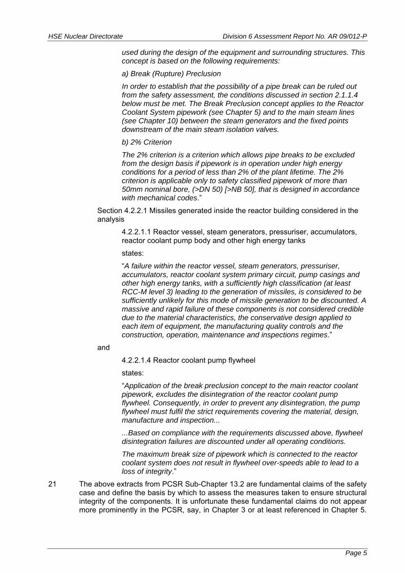
21 The above extracts from PCSR Sub-Chapter 13.2 are fundamental claims of the safety case and define the basis by which to assess the measures taken to ensure structural integrity of the components. It is unfortunate these fundamental claims do not appear more prominently in the PCSR, say, in Chapter 3 or at least referenced in Chapter 5.
Page 5
HSE Nuclear Directorate Division 6 Assessment Report No. AR 09/012-P
Ultimately this is a matter of document layout, and having found the relevant text, it is somewhat academic where it appears in the PCSR.
22 The above constitute the main ‘exceptional’ claims for structural integrity of metal pressure boundary components in the UK EPR. Components not covered by these ‘exceptional’ claims are taken to be satisfactory with ‘normal’ levels of structural integrity claim. The latter might be because the design includes features to cope with the consequences of failure, or the consequences of failure are trivial so far as nuclear safety is concerned.
2.3 UK EPR PCSR Outline of Arguments and Evidence to Support the Claims for Structural Integrity
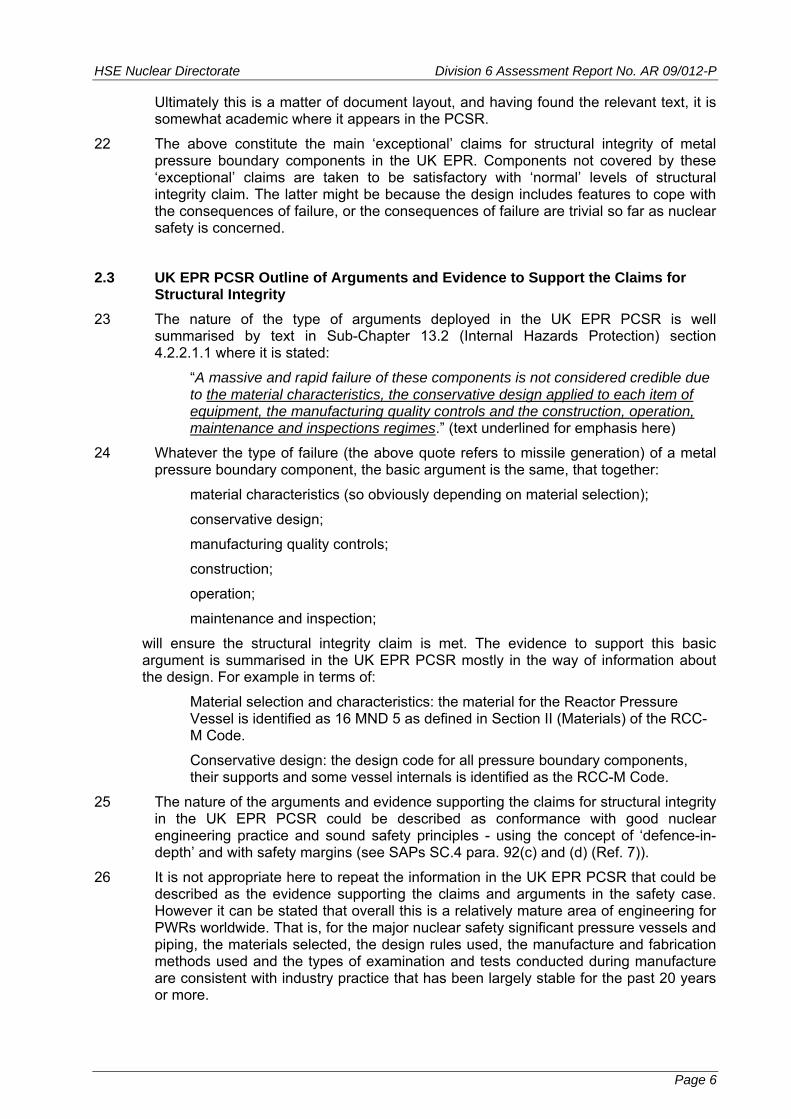
23 The nature of the type of arguments deployed in the UK EPR PCSR is well summarised by text in Sub-Chapter 13.2 (Internal Hazards Protection) section 4.2.2.1.1 where it is stated:
“A massive and rapid failure of these components is not considered credible due to the material characteristics, the conservative design applied to each item of equipment, the manufacturing quality controls and the construction, operation, maintenance and inspections regimes.” (text underlined for emphasis here)
24 Whatever the type of failure (the above quote refers to missile generation) of a metal pressure boundary component, the basic argument is the same, that together:
material characteristics (so obviously depending on material selection);
conservative design;
manufacturing quality controls;
construction;
operation;
maintenance and inspection;
will ensure the structural integrity claim is met. The evidence to support this basic argument is summarised in the UK EPR PCSR mostly in the way of information about the design. For example in terms of:
Material selection and characteristics: the material for the Reactor Pressure Vessel is identified as 16 MND 5 as defined in Section II (Materials) of the RCC-M Code.
Conservative design: the design code for all pressure boundary components, their supports and some vessel internals is identified as the RCC-M Code.
25 The nature of the arguments and evidence supporting the claims for structural integrity in the UK EPR PCSR could be described as conformance with good nuclear engineering practice and sound safety principles - using the concept of ‘defence-in-depth’ and with safety margins (see SAPs SC.4 para. 92(c) and (d) (Ref. 7)).
26 It is not appropriate here to repeat the information in the UK EPR PCSR that could be described as the evidence supporting the claims and arguments in the safety case. However it can be stated that overall this is a relatively mature area of engineering for PWRs worldwide. That is, for the major nuclear safety significant pressure vessels and piping, the materials selected, the design rules used, the manufacture and fabrication methods used and the types of examination and tests conducted during manufacture are consistent with industry practice that has been largely stable for the past 20 years or more.
Page 6
HSE Nuclear Directorate Division 6 Assessment Report No. AR 09/012-P
27 For example, the types of materials, design rules etc proposed for the UK EPR are similar to those used for the Sizewell B PWR, construction of which started in 1987, with commercial operation from late 1995. For Sizewell B, the materials of construction and design rules had been determined by 1984.
28 As will be seen later, in Section 5 of this assessment report, my assessment has concentrated on specific aspects of the proposed design for nuclear safety significant metal pressure boundary components.
3 STANDARDS AND CRITERIA
29 I have based my assessment of the structural integrity aspects of the UK EPR PCSR primarily on the following:
Safety Assessment Principles for Nuclear Facilities (the ‘SAPs’, Ref. 7);
Technical Assessment Guide - Integrity of Metal Components and Structures – T/AST/16 Issue 003 (Ref. 8).
30 For the SAPs (Ref. 7) the main relevant part is “Integrity of Metal Components and Structures” in paras 238 to 279, involving Principles EMC.1 to EMC.34. Other parts of the SAPs have some relevance to this assessment. For example, another part of some relevance is “Safety Classification and Standards” in paras 148 to 161, involving Principles ECS.1 to ECS.5.
31 In carrying out their assessment, ND Inspectors are asked to consider whether risks have been reduced 'As Low as Reasonably Practicable' (ALARP). The SAPs in para. 14 state:
“The principles are used in judging whether ALARP is achieved…Priority should be given to achieving an overall balance of safety rather than satisfying each principle or making an ALARP judgement against each principle. The judgement using the principles in the SAPs is always subject to consideration of ALARP.”
32 SAPs para. 93 states:
“To demonstrate ALARP has been achieved for new facilities, modifications or periodic safety reviews, the safety case should: a) identify and document all the options considered;
b) provide evidence of the criteria used in decision making or option selection; and
c) support comparison of costs and benefits where quantified claims of gross disproportion have been made.”
33 Some further guidance on ALARP is provided in the SAPs in the part on “Numerical targets and Legal Limits”. The SAPs define “Basic Safety Levels” (BSL) and “Basic Safety Objectives” (BSO). In terms of numerical limits such as radiological dose and frequency of occurrence, BSOs are lower (that is more onerous) than BSLs.
34 SAPs para. 571 states:
“It is HSE’s policy that a new facility or activity should at least meet the BSLs. However, in meeting the BSLs the risks may not be ALARP. The application of ALARP may drive the risks lower...”
35 SAPs para. 573 states:
“The BSOs form benchmarks that reflect modern nuclear safety standards and expectations. The BSOs also recognise that there is a level beyond which further
Page 7
HSE Nuclear Directorate Division 6 Assessment Report No. AR 09/012-P
consideration of the case would not be a reasonable use of ND resources, compared with the benefit of applying the effort to other tasks…..The dutyholder, however is not given the option of stopping at this level. ALARP considerations may be such that the dutyholder is justified in stopping before reaching the BSO, but if it is reasonably practicable to provide a higher standard of safety, then the dutyholder should do so.”
36 The assessment of the structural integrity area is on the basis of engineering practice and sound safety principles, rather than a numerical calculation of the likelihood of failure of components.
37 The UK EPR design is the outcome of many years of development and did not explicitly follow the approach to ALARP as practiced in the UK (e.g. SAPs para. 93, at quoted above). Of course design decisions will have been made, but it is difficult now to ‘back fit’ ALARP to the design. It might be possible to examine individual important areas to determine if the situation is consistent with ALARP.
38 In carrying out my assessment, I have based my judgements of the technical aspects of structural integrity on the guidance provided on ALARP. I have interpreted the guidance to reach a judgement to apply to the balance of all the factors which contribute to the structural integrity safety case.
39 Some components have a claim associated with them that gross failure is taken to be so unlikely it can be discounted. In assessing the arguments and evidence supporting this type of claim, I have applied the same basis of judgement as described above. For these highest claims of highest structural integrity, I have examined whether:
the proposals meet a minimum level for such a claim;
all that is practical has been done.
40 For these highest claims of structural integrity, I have not sought ‘perfection’; rather I have sought to determine the design is 'adequately safe' (Ref. 7 SC.4 para. 91(a)) within the context of each of the claims of the safety case.
4 GENERAL MATTERS RELATING TO ND ASSESSMENT
4.1 Outcome of Assessment in GDA Step 2
41 The assessment reported here follows on from the Step 2 assessment, the assessment report for which was completed in early 2008 (text completed 11 January 2008, report issued February 2008, Ref. 9). The GDA Step 2 assessment for the UK EPR was based on the “Fundamental Safety Overview” document provided by EDF and AREVA.
42 The GDA Step 2 assessment in the structural integrity area was brief (about 4 staff-days). In the GDA Step 2 assessment for UK EPR structural integrity, the main topics raised as likely to require further consideration were identified as:
1. Pipework - Break Preclusion - main primary loop pipework and the main steam lines.
2. Main Pressure Vessels - Reactor Pressure Vessel, Steam Generator primary side channel head and secondary side shells, Pressuriser, Safety Injection System Accumulators.
3. Overpressure Protection.
4. In-Service Pressure Tests.
5. Main Vessels Ferritic Forging Material.
Page 8

HSE Nuclear Directorate Division 6 Assessment Report No. AR 09/012-P
6. Load Combinations.
7. In-Service Inspection.
8. Reactor Coolant Pump (the pump casing).
9. Main Steam Line Valve Housings.
43 The assessment report raised a number of questions on the above topics. EDF and AREVA provided responses to these questions in letter EPR00029N, 19 March 2008 (Ref. 10).
44 For Item 4, In-Service Pressure Tests, EPR00029N states that for a UK EPR, UK practice would be followed.
45 For item 6, Load Combinations, EPR00029N clarifies the position regarding seismic loading and states that documentation will in future use clearer wording.
46 For item 7, In-Service Inspection, the assessment report notes this topic is not covered in detail in the Step 2 submission. EPR00029N states the programme will be developed later in a later phase of a UK EPR project. This is not an issue that needs to be resolved in GDA Step 2 or 3.
47 For item 9, EPR00029N provides a suitable response. This topic is not inherently a metal pressure boundary component issue, and having raised the point, obtained a response and communicated that response within ND, I regard this topic as closed.
48 Based on the above, the topics I carried forward from Step 2 to Step 3 are 1, 2, 3, 5 and 8. The titles of the Step 3 ROs, see Table 1, indicate in summary that I have dealt with topics 1, 2, 3, 5 and 8 from GDA Step 2 in GDA Step 3.
4.2 GDA Step 3 Assessment Compared with Project Initiation Document (PID)
49 My PID for GDA Step 3 (Ref. 11) was written as an overall plan to cover, at the time, three different designs (two PWRs and a BWR).
50 Table 1 of my PID (Ref. 11) sets out the main topic areas and how they will be considered in detail in GDA Step 3 and an outline of how they will be dealt with in GDA Step 4. An amended version of Table 1 of my PID for Step 3 only and for an EPR type PWR only is given in Table 3 here.
51 In Table 3, the topic headings are (number 1 was not used in the original table, see footnote to Table 3):
2. Components and Systems to be Considered.
3. Level of Integrity Required for Nuclear Safety Claim.
4. Safety Classification and Standards - Including Quality Assurance.
5. Potential Failure Modes.
6. Potential In-Service Degradation Modes (linked with 17. below).
7. Analysis - Design Analysis, Fracture Mechanics Analyses.
8. Loadings.
9. Materials - Choice and Specifications.
10. Fabrication Design and Processes.
11. In-Manufacture Examinations - Scope, Extent. Qualification of Procedures, Equipment and Personnel.
12. Procedural Control of Design, Manufacture and Installation.
Page 9

HSE Nuclear Directorate Division 6 Assessment Report No. AR 09/012-P
13. In-Manufacture Inspection.
14. Pressure System - Discharge and Flow Aspects.
15. Pre-Service Examination - Scope, Extent. Qualification of Procedures, Equipment and Personnel.
16. Definition of Operating Envelope.
17. Establish In-Service Monitoring, Examination and Testing Requirements (linked with 6 above).
52 The comments in Table 3 against each of the above topic headings indicate there are varying degrees of depth of information needed for assessment in GDA Step 3. Table 4 shows how I have dealt with each of the topic areas in Table 3, mostly in terms of the ROs I have raised. Note that the only topic area where no substantive assessment has been made is 15, Pre-Service Examination. This has been deferred to later in GDA, and can be dealt with as part of the consideration of in-service examination; see the discussion of GDA Step 2 topic 7, in section 4.1 above.
4.3 Requesting Party Response to What is Required for GDA Step 3
53 Ref. 12 page 14 sets out what the Requesting Party (RP) is required to do for GDA Step 3. There are two fundamental requirements:
1. provide a Pre-Construction Safety Report (PCSR);
2. respond to questions and points of clarification raised by ND during its assessment.
54 In Ref. 12, there is also a list of requirements for the PCSR, items 3.1 to 3.13.
55 From Section 2 above, it is clear that EDF and AREVA have provided a PCSR at the start of GDA Step 3, and it has been updated during GDA Step 3, in part at least in response to interaction with ND.
56 From Section 1 above it is clear there has been response from EDF and AREVA to ND questions and points of clarification.
57 For this assessment of structural integrity, the requirements for the PCSR in Ref. 12 (3.1 to 3.13) have varying significance. Those most relevant to this assessment of structural integrity are given below, with my commentary on the extent of meeting these requirements in italics after each item:
3.1 definition of the documentary scope and the extent of the safety case:
The PCSR June 2009 edition has much more in the way of referencing out to supporting documents than the preceding issue of the PCSR. The definition is implicit rather than explicit. The scope and extent of the safety case would be expected to evolve with time, especially as the PCSR evolves into a Pre-Operational Safety Report (POSR). For now the definition of scope and extent is enough for GDA Step 3, but will need to evolve and become more explicit.
3.3 Responses to any issues outstanding from Step 2:
There were no issues outstanding from Step 2, in the sense of questions outstanding. Most of the topics raised in the Step 2 assessment report are covered in the PCSR and have continued as topics in GDA Step 3.
3.4 Sufficient information to substantiate the claims in Step 2 (in the Preliminary Safety Report - for the UK EPR this was called the Fundamental Safety Overview):
Page 10
HSE Nuclear Directorate Division 6 Assessment Report No. AR 09/012-P
For structural integrity, the claims in Step 3 are the same as in Step 2 so the issue is whether the PCSR substantiates its own claims. This is a fundamental aspect of this assessment and is reported in another section.
3.5 Sufficient information to enable ND to assess the design against all relevant SAPs:
There is sufficient information in the PCSR to provide a sound starting point for ND assessment. Clearly this assessment has raised questions of substance and clarification, so by definition the PCSR as originally submitted was not by itself sufficient. However as questions are resolved, the resolution can provide a basis for amending the PCSR.
3.6 A demonstration that the detailed design proposal will meet the safety objectives before construction or installation commences, and that sufficient analysis and engineering substantiation has been performed to prove that the plant will be safe:
For structural integrity, the PCSR at a general level has a demonstration that the plant will be safe. There is a layer of design specific documentation below the level of the PCSR (e.g. equipment specifications, design reports, and supporting documents to the design reports) that need some examination to confirm sufficient analysis has been completed. For structural integrity, it is anticipated this lower level of documentation will be for GDA Step 4.
3.7 Detailed descriptions of system architectures, their safety functions and reliability and availability requirements:
For structural integrity, this is taken to mean a description of the components in terms of function, size, shape, materials of construction, design loadings, design codes used, and so on. In these terms the PCSR provides sufficient descriptions as a starting point for GDA Step 3 assessment.
3.8 Confirmation and justification of the design codes and standards that have been used and where they have been applied, non-compliances and their justification:
For structural integrity there is a clear statement as to the design code to be used - RCC-M 2007 edition. In general terms this code is clearly justified as an appropriate code to use. The PCSR contains some background information on RCC-M and a brief comparison with the similar American Society of Mechanical Engineers code ASME III. The PCSR does not contain justification of the technical content of the RCC-M code, and that would not be expected. However use of the RCC-M code in a UK context has some novelty and review of the RCC-M code has been a notable aspect of this GDA Step 3 assessment.
3.10 Justification of the safety of the design throughout the plant’s life cycle, from construction through operation to decommissioning, and including the on-site spent fuel and radioactive waste management issues:
For structural integrity, safety through life depends mainly on operating within the design envelope of the relevant pressure boundary components and monitoring for potential degradation mechanisms. Operation within the design envelope is primarily through compliance with ‘Technical Specifications’. An obvious example of potential degradation is neutron irradiation embrittlement of the Reactor Pressure Vessel steel material adjacent to the reactor core. UK EPR PCSR Sub-Chapter 1.1 on
Page 11
HSE Nuclear Directorate Division 6 Assessment Report No. AR 09/012-P
page 3 states that the PCSR does not contain details of operating procedures such as Technical Specifications and maintenance programmes. However, during exchanges with the Requesting Party, information relevant to determining operating limits for the primary circuit and the surveillance programme for reactor pressure vessel materials has been obtained. In addition the PCSR does recognise the need for ‘Technical Specifications’ and states these will appear in the POSR.
3.11 Identification of potentially significant safety issues raised during previous assessments of the design by overseas nuclear safety regulators, and explanations of how their resolution has been or is to be achieved:
The UK EPR PCSR does not contain a description of specific safety issues as envisaged by 3.11. However Sub-Chapter 1.5 of the UK EPR PCSR does summarise the safety assessment in France, from the start of the Franco-German collaboration in 1989; outlines the regulatory review by STUK in Finland for Olkiluoto 3; outlines the US NRC Design certification work for the US EPR.
3.12 Identification of the safe operating envelope and the operating regime that maintains the integrity of the envelope:
For structural integrity, this overlaps with item 3.10 and the comments above for 3.10 apply.
3.13 Confirmation of:
(a) which aspects of the design and its supporting documentation are complete and are to be covered by the Design Acceptance Confirmation;
(b) which aspects are still under development and identification of outstanding confirmatory work that will be addressed during Step 4.
Given the mature nature of design aspects of metal pressure boundary components it can be taken that as far as the RP is concerned the design is complete. Indeed procurement of pressure boundary components for two power stations based on the EPR design is underway.
4.4 What HSE Will Do In GDA Step 3
58 Ref. 12 page 15 sets out what HSE will do in GDA Step 3. There is one fundamental requirement:
“Undertake an assessment, on a sampling basis, primarily directed at the system level and by analysis of the RP’s supporting arguments. The scope will be partly defined by experience in Step 2 and the issues arising in that step.”
59 In Ref. 12 there is also a list of what this sampling assessment should include, items 3.14 to 3.26.
60 It will be seen in Section 5 below that I have undertaken an assessment, on a sampling basis of the structural integrity aspects of EDF and AREVA’s PCSR and supporting material. To consider even the general claims for structural integrity involves considering individual components and the term ‘directed at the system level’ is not the way I would describe this assessment. However my assessment has started with the important claims for structural integrity and delved into the supporting arguments for these claims. My assessment has been on a sampling basis. I have addressed the most important components but have concentrated on specific technical aspects and delved into the detail of arguments and evidence to varying extents. I
Page 12

HSE Nuclear Directorate Division 6 Assessment Report No. AR 09/012-P
believe my sampling is qualitatively consistent with the nature of the claims, arguments and evidence put forward by EDF and AREVA.
61 For this assessment of structural integrity, the requirements for the assessment in Ref. 12 (3.14 to 3.26) have varying significance. The main requirements relevant for this assessment of structural integrity are given below, with commentary on the extent of meeting these requirements in italics after each item:
3.14 Consideration of whether the design is likely to meet the RP’s design safety criteria and reduce risks ALARP:
This is in two parts. For this assessment of structural integrity, consideration of whether the design is likely to meet the design safety criteria, is interpreted to mean will the design meet the claims made for structural integrity. Whether the design will reduce risks ALARP has already been discussed in Section 3 above. The design of the EPR has evolved over a number of years (more than 15 years) and did not explicitly include consideration of ALARP as defined in the UK. Design options will have been considered and choices made, but that might not amount to reducing risks ALARP. The best that can be done now is to consider important aspects of the design and investigate whether other options exist and whether a change on the basis of ALARP is indeed now practical. This sort of investigation has been part of this assessment, in particular for the manufacture on the cylindrical region of the Reactor Pressure Vessel and the manufacturing route for the Reactor Coolant Pump casings
3.15 Undertaking an initial assessment of the scope and extent of the arguments in each of the technical areas, including the generic site envelope:
This is almost a restatement of the general requirement for an assessment. Here, assessment of the scope and extent of the arguments has been made for the structural integrity area.
3.18 Deciding on scope and plan of further assessment:
This assessment report provides recommendations on further assessment, in terms of closing out GDA Step 3 matters and also starting on the next level of detail in GDA Step 4.
3.19 Assessment of the quality assurance (QA) arrangements, including:
(a) QA arrangements for the early manufacture of long lead time items important to safety.
Several of the components falling under this assessment and important to safety are likely to be ‘long lead time items’. QA arrangements are relevant to such components. An RO was raised on QA in this assessment. However ND has addressed this matter in a more general way, producing a Technical Assessment Guide (TAG) (T/AST/077 Ref. 14, to be issued at the time of writing this report). I have contributed to this TAG. My understanding is details of QA arrangements for Long Lead Time Items are likely to be discussed with licensees or proto-licensees, rather than the RPs.
3.20 Identification of research needs and setting up of longer-term research or contract support to complement Step 4:
The structural integrity aspects of the design and safety case of the UK EPR are based on many years of PWR experience of primary and secondary pressure boundary component technology and operating experience. There are no really novel aspects of the pressure boundaries of the UK EPR, compared with this body of experience. For this technical area no significant research needs have been identified. There will almost certainly be a need for
Page 13

HSE Nuclear Directorate Division 6 Assessment Report No. AR 09/012-P
technical support contracts in Step 4, but these will not be in the nature of ‘research’.
5 ND ASSESSMENT GDA STEP 3 - STRUCTURAL INTEGRITY
5.1 Overview of Assessment
62 The specific aims of GDA Step 3 assessment are listed in Section 1. An outline and overview of the nature of the UK EPR safety case is given in Section 2. The standards and criteria used for this assessment are explained in Section 3. Section 4 explains how this GDA Step 3 assessment relates to the earlier Step 2 assessment and how this Step 3 assessment aligns with the Project Initiation Document. Section 1 also gives a summary of the main milestones in this GDA Step 3 assessment.
63 With the information provided in the UK EPR PCSR and further information supplied in meetings and by correspondence I have been able to make a meaningful assessment of the structural integrity aspects of the safety case.
64 It has been clear from the outset of the GDA process (at least from the start of Step 2) that so far as metal pressure boundary components are concerned (both primary and secondary circuits), this is a relatively ‘mature’ technological area of PWRs. For this technical aspect, the UK EPR design in terms of overall design, materials, fabrication and operation, is not that different from PWRs that entered service 10 to 15 years ago, and that were therefore designed 20 years ago, or more.
65 Given the maturity of this aspect of PWR design, I have not started this assessment from a ‘zero base’. Instead I have sought to confirm that general good practice has been used, taking account of international experience, but including the consideration of ALARP. In the UK the Sizewell B PWR has operated commercially since October 1995. Construction of Sizewell B started in 1987 and was preceded by design work extending back a number of years. The safety of the RPV for a prospective UK PWR had been the subject of debate for a number of years, including industry study groups (Ref. 20, 21, 22). The subject of PWR RPV integrity also featured in the Public Inquiries for the Sizewell B and Hinkley Point C stations (Refs 23 to 24).
66 The Sizewell B pressure boundary structural integrity, both in achievement and demonstration of integrity, introduced a number of additional requirements over and above the standard design code requirements (in the case of Sizewell B, the ASME code). In terms of ALARP, i.e. what is reasonably practicable, I have to take the Sizewell B approach to structural integrity into account; especially as ND licensed the station in part on the approach to structural integrity. However I have to have regard to subsequent experience and developments. What was implemented for Sizewell B was clearly practicable, because it was done, and almost certainly remains so; but whether all aspects are still reasonably practicable is something to consider in this assessment. In short, for this assessment I have taken the Sizewell B approach to structural integrity as a precedent, but not necessarily a paragon in every detail.
67 After an initial, general examination of the documentation, I concentrated on a specific number of aspects and formulated these into a number of ‘Regulatory Observations’ (ROs). The ROs are listed in Table 1 and are presented in Annex 2. The ROs were the basis of communicating initial outcomes of the assessment with EDF and AREVA.
68 The ROs do not all have equal significance. At the time of initiating the ROs I was aware they were not of equal significance. And as a result of response from EDF and AREVA, the relative significance of some of the ROs has changed.
69 Some of the ROs are long, with a degree of ‘background’ information included to explain how matters have been dealt with in the UK in the past. This might be construed as ‘assistance to the licensee’ in the terms used in the ND guidance on the
Page 14

HSE Nuclear Directorate Division 6 Assessment Report No. AR 09/012-P
assessment process (Appendix to Ref. 15: The Mechanics of Assessment, paras 1.21 to 1.23). Relevant extracts from this guidance are:
“1.21 A situation which often occurs after a legitimate objection has been raised by an assessor and has been accepted, is that a licensee will ask for assistance with respect to what needs to be done to satisfy the assessor's concern. This is a fair question for a licensee…… It is potentially a dangerous question for an assessor however, since it threatens their independence….. Hence assessors should try, at least initially, to restrict their advice to clarification of the safety principle which is being pursued rather than to the identification of specific engineering solutions.
1.22 However it is unhelpful and against the principle of openness (and also understandably regarded as perverse by licensees) to insist on keeping a potential solution secret, in the hope that it will occur independently to the licensee.
1.23 A way round this dilemma is to explain clearly the safety concern that underlies the objection, and to put forward one's idea for satisfying the concern on the strict understanding that although it appears to suffice, no guarantee of acceptability is to be assumed by the licensee, and that if it is taken up then it remains the licensee's responsibility to justify it, and it will be assessed as the licensee's own proposal…”
70 Here we are not dealing with a licensee, but a Requesting Party (RP) and obviously an RP that has not previously interacted with ND. Hence, in setting out the ROs and in discussions and correspondence, I have erred on the side of ‘being helpful’. I have not offered solutions. But where relevant, I have indicated how matters have been successfully dealt with in the UK in the past, and on occasion how things might have moved forward. Whether EDF and AREVA consider the information I have provided as being helpful is a matter for them.
71 Most of the significant activity for my assessment is captured in the ROs. However I have also included a consideration of Steam Generator (SG) tubing integrity, mainly through a Technical Framework Contract, see below. From my understanding of operational performance with the tube material for the UK EPR, I did not have concerns about the integrity of the tubing. However given past interest in the UK, I felt it prudent to review this matter. I have not pursued other historical issues, where the design takes account of past experience and current understanding of the steps to avoid such issues. Examples of such historical issues are:
Pressuriser surge line behaviour due to thermal loadings.
Reactor Pressure Vessel head control rod drive mechanism adapter tube degradation.
Thermal fatigue due to mixing (often rapid cycling) of hot and cold water within pipework systems.
For the last in the above list, thermal fatigue in pipework, there is a good understanding of the general factors leading to such situations, though predicting individual areas of pipework systems that might be susceptible is not a precise science.
5.2 Technical Framework Contracts
72 It was clear from the outset of my assessment that there would be a need for some technical support in specialist areas. In the event I established five contracts relevant
Page 15

HSE Nuclear Directorate Division 6 Assessment Report No. AR 09/012-P
to the assessment of the UK EPR design. These contracts cover the following subjects, with an indication of their relevance to the ROs I have raised:
1. Qualification of manufacturing examinations (2 contracts) (RO-UKEPR-20).
2. Neutron irradiation embrittlement of the RPV (RO-UKEPR-25).
3. Metallurgy of ferritic steels for main primary circuit pressure vessels (RO-UKEPR-24).
4. SG tubing material and manufacturing processes.
73 Items 1 to 3 above are associated with aspects of some of the more significant ROs. I had no particular concerns about the choice of SG tubing for the UK EPR. But I judged it prudent to include a contract for item 4 above, given interest in previous consideration in the UK of this aspect of PWR structural integrity.
74 The work addressing items 1 and 4 above is generic to both designs under consideration in GDA Step 3. Items 2 and 3 are such that it is necessary to consider each design specifically. A contractor provided support for item 2 and produced separate reports for each of the two designs under consideration. The same approach has been used for item 3.
75 The work for the contracts covering items 1 to 4 above has been completed and final reports received. These are Refs 16, 17 (item 1), Ref. 18 (item 2), Ref. 46 (item 3) and Ref. 45 (item 4).
5.3 Summary of Assessment
76 In general, I have dealt with the Topics in Table 4 through the ROs listed in Table 1. These ROs are not all of equal significance. Factors that determine the significance of these ROs are:
1. the safety significance;
2. the amount of work required on the part of EDF and AREVA to respond to the points raised in an RO;
3. the implications for potential changes to design, specifications, or safety case claims, arguments and evidence.
77 The overall significance of an RO is clearly somewhat subjective and can involve any combination of the above three factors.
78 In my view, the relative ranking of the ROs in Table 1 is as follows, going from highest to lowest:
1st Rank: RO-UKEPR-19, RO-UKEPR-20
2nd Rank: RO-UKEPR-25, RO-UKEPR-24, RO-UKEPR-21
3rd Rank: RO-UKEPR-28, RO-UKEPR-36
4th Rank: RO-UKEPR-23, RO-UKEPR-26
5th Rank: RO-UKEPR-27
79 In any given rank line above, I have ordered the relative significance with the highest mentioned first, though in the case of the 1st Rank, I regard both ROs as of equal significance in part because they are inter-linked.
80 The nature of the responses by EDF and AREVA to ROs could range from providing further or better arguments and evidence to support a claim, acknowledgement of a claim that was in the safety case but not explicitly declared, or a commitment to
Page 16
HSE Nuclear Directorate Division 6 Assessment Report No. AR 09/012-P
consider making a physical change to an aspect of the design or manufacturing specification of the plant.
81 It will be seen from Table 4 that the ROs address most of the topics listed in my PID (Ref. 11). The exceptions are dealt with below.
82 A notable exception is Topic 8 - Loadings in Table 4. The UK EPR PCSR (Refs 1 and 6) deals with loading conditions in Sub-Chapter 3.4. PCSR Sub-Chapter 3.4, Section 1.1 of the PCSR Sub-Chapter 3.4 describes Design Transients including the definition of operating conditions, and the terminology of ‘Normal’, ‘Upset’, ‘Emergency’, ‘Faulted’ and ‘Test’ conditions. These have essentially the same meaning as previous usage in the ASME code. In addition the term ‘Cold Thermal Shock’ is included. By definition, all are transient loading conditions, that is they involve a rate of change with time of pressure and temperature or mechanical load.
83 In the UK EPR PCSR, in Sub-Chapter 3.4, section 1.1, there is a further categorisation of the above loadings, as follows:
Category 1 – reference category, (not defined in section 1.1 but in e.g. RCC-M B 3121 see below);
Category 2 for normal and upset conditions;
Category 3 for emergency conditions;
Category 4 for faulted conditions.
84 The Category 1 (or reference category) conditions are the most severe combination of the Category 2 conditions, applied on a time-independent basis (RCC-M 2007 edition Subsection B, B 3121). The RCC-M Category 1 condition is the same as the ASME III design condition (see ASME III NCA-2142.1).
85 In sections 1.1.2, 1.1.3, 1.1.5, 1.1.6 and 1.1.7 there are lists of specific operating conditions for (with number of transients in brackets):
Normal Conditions (11).
Upset Conditions (10).
Hydraulic Test (3).
Emergency Conditions (7).
Faulted Conditions (9).
86 Tables in the UK EPR PCSR Sub-Chapter 3.4 list the transients and for Normal and Upset Conditions list the number of assumed occurrences over plant life; the latter are needed for fatigue evaluations.
87 Table 1 of the UK EPR PCSR Sub-Chapter 3.4 sets out the combinations of loads considered in the design analysis of metal pressure boundary components.
88 The various design transients are described in terms of overall plant behaviour, for example “Normal Plant Start-Up, from Cold Shutdown to Full Power”. From my understanding of PWR design, the design transients included in the design of the UK EPR, as set out in the PCSR, are a recognisable set, with no obvious omissions. Detailed pressure and temperature variations for each of these design transients are needed for the design analyses of the pressure boundary components. The determination of these pressure and temperature variations is outside the scope of the structural integrity area. This will be for others to assess. I do not see this as an area of substantial regulatory risk, and I believe the detailed assessment can await GDA Step 4.
Page 17

HSE Nuclear Directorate Division 6 Assessment Report No. AR 09/012-P
89 Overall I conclude the UK EPR PCSR provides sufficient detail for the structural integrity aspects of loading conditions, and I am satisfied this gives an indication of adequate coverage within the design of this aspect.
90 In Table 4, Topic 4 mentions Quality Assurance. And Regulatory Observation RO-UKEPR-22 addresses overall organisational and quality assurance arrangements. RO-UKEPR-22 was raised in September 2008 on the basis of the RCC-M design code 2005 edition, which has little coverage of overall organisational and quality assurance arrangements. The 2007 edition of the RCC-M code does address this matter in some detail, but only by referring out to French legal requirements. Following discussion within ND of organisational and quality assurance requirements in general (not just for pressure boundary components) it was decided to produce a TAG on procurement. The TAG has been issued (Ref. 14). However, as this is now being dealt with as a general matter, I have not pursued this aspect separately in my assessment (I have contributed to the Technical Assessment Guide, including an appendix specific to metal pressure boundary equipment). Notice of withdrawal of the Action associated with Regulatory Observation RO-UKEPR-22 was by ND letter (Ref. 32).
91 As noted in Section 4.2 above, my GDA Step 3 assessment has not dealt with Topic 15 in Table 4 - Pre-Service Examination. This can be dealt with in GDA Step 4 along with in-service examination. For now the main point is there should be access to components for pre- and in-service examination. I have not found anything in the documentation to suggest access for in-service examination would be a significant or general problem.
92 For the metal pressure boundary components of the UK EPR design, there is one overarching consideration and that is the use of the RCC-M code (Ref. 25) as the basis for design, materials specifications, manufacture and examination and testing during manufacture.
93 The UK EPR PCSR in Sub-Chapter 3.8, Section 2 (Ref. 6) provides a summary of the RCC-M code, much of which is devoted to a comparison between the RCC-M and ASME codes.
94 The overview of the RCC-M code in the UK EPR PCSR is a good summary. However the review in the PCSR and the RCC-M code itself have common corporate authorship. From a regulatory assessment perspective, I decided a review of the RCC-M code was needed as part of the ND GDA Step 3 process.
95 I think it is fair comment that to date in the UK there has been no use made of the RCC-M code and there is no body of knowledge and experience of use, certainly compared with use and experience of the ASME code. I am confident that ND has to date had little experience of the RCC-M code. Accordingly, this assessment of the UK EPR design has included a review of the RCC-M code (Ref. 26). This is dealt with in the next sub-section, with the ROs following.
96 In the following sub-sections I describe the progress made with dealing with the ROs, for simplicity I do this in number sequence rather than the above ranking. The immediate sub-section below summarises my review of the RCC-M code.
5.4 RCC-M Code
5.4.1 Scope and Basis of Review of RCC-M Code
97 A review of all aspects of the RCC-M code would be a substantial undertaking. For GDA Step 3 a complete review is not possible, nor is it necessary. Table 5 shows the main parts of the RCC-M code, how they align with parts of the ASME code, and how extensive both codes are (numbers of pages shown in brackets).
Page 18
HSE Nuclear Directorate Division 6 Assessment Report No. AR 09/012-P
98 This review of RCC-M for GDA Step 3 concentrates on:
1. General aspects.
2. Design, materials, fabrication, manufacturing examination, pressure test and overpressure protection aspects for Class 1, 2 and 3 vessels and pipework, as defined in RCC-M (ASME has a similar Class system).
Regarding materials, this review concentrates on the small sub-set of ferritic and austenitic stainless steels defined in RCC-M that are used for the main components of a PWR.
99 Whether a component meets RCC-M or ASME requirements, there is always the possibility that within the Equipment Specification for a component, there will be additional or supplementary requirements. An Equipment Specification provides the complete technical basis for the contract to supply a component. Additional or supplementary requirements will go beyond the requirements of the code. In principle, the Equipment Specification could introduce requirements in place of those in the code or even delete code requirements, but that would need justification.
100 The UK EPR Pre-Construction Safety Report (PCSR), Sub-Chapter 3.4 section 3.1 identifies RCC-M 2007 Edition as the version of RCC-M to be used for a UK EPR.
101 The basis of the review is a comparison of RCC-M with the corresponding parts of the ASME Boiler and Pressure Vessel Code (B&PV), 2007 Edition with Addenda to 2008 (Ref. 27, and principally Sections II and III, Refs 27a and 27b).
102 There are a number of reasons for this basis, as follows:
1. There is precedent and experience of using ASME B&PV Code for nuclear plant in the UK (extensively for the Sizewell B PWR).
2. The ASME B&PV Code Section III for nuclear facility components is used either directly or as a basis for nuclear design codes around the world.
3. RCC-M takes ASME B&PV as a basis for many aspects. According to a footnote on the inside front page of RCC-M, ASME has granted AFCEN the right to reproduce, translate, excerpt and adapt certain portions of the ASME code.
4. I have some experience of ASME III and how it compares with UK vessel design codes (BS5500, now PD5500 - for non-nuclear, unfired pressure vessels) (Ref. 28).
103 The basis of the review also includes a comparison of the RCC-M code 2005 version with the 2007 Edition. This comparison was necessary within the review given the sequence of versions provided by EDF and AREVA and assessed in 2008 and 2009. It is also useful to see the extent of the changes in what is overall a relatively mature design code.
104 The RCC-M code is a substantial document and it is not possible to review the whole of RCC-M for GDA Step 3. A sampling approach has been used in the review of RCC-M, concentrating on the parts which have an important bearing on the structural integrity of those most important for nuclear safety. Overall, the review considers:
i) A general overview of the structure of the RCC-M code and comparison with the general structure of ASME B&PV.
ii) The design requirements in RCC-M for its Class 1, 2 and 3 components and comparison with ASME III design requirements for its Class 1, 2 and 3 components.
Page 19

HSE Nuclear Directorate Division 6 Assessment Report No. AR 09/012-P
iii) Materials specifications in RCC-M relevant to PWR primary and secondary circuit pressure vessels and pipework, and comparison with ASME materials that would be used for the same components.
iv) An overview of the most important aspects of fabrication requirements and manufacturing examination requirements in RCC-M and comparison with the ASME Code.
v) Pressure test requirements in RCC-M and comparison with ASME III.
vi) Overpressure protection requirements in RCC-M and comparison with ASME III.
5.4.2 Summary of Outcome of Review of RCC-M Code
105 The RCC-M code provides a substantial set of rules for design and construction of mechanical components (essentially pressure boundary components, their supports and internals) of Pressurised Water Reactor (PWR) nuclear islands.
106 The RCC-M code requirements are comprehensive for materials, design, fabrication, manufacturing examination, testing and overpressure protection. For these technical aspects, the scope and extent of coverage is similar to the American Society of Mechanical Engineers Boiler and Pressure Vessel Code (ASME B&PV) as regards nuclear plant components (mainly ASME Section III Division 1).
107 There are many similarities between the RCC-M and ASME III code requirements, in places they are identical. This is not surprising, ASME has granted to the publisher of RCC-M code (AFCEN) the right to reproduce and adapt certain portions of the ASME code.
108 RCC-M is published by the ‘French Association for Design, Construction and In-Service Inspection Rules for Nuclear Island Components’ (AFCEN). AFCEN is an organisation created and controlled by EDF and AREVA. To date, EDF and AREVA have been the principal users of the RCC-M code. In contrast, the ASME B&PV code is the product and property of a professional organisation for individual engineers. In practice of course, both codes will depend for their evolution on professional engineers employed by organisations with an industrial interest in the subject.
109 Arguably the main, basic difference between the RCC-M and ASME III codes is the approach to organisational arrangements for ‘quality assurance’. The ASME code has a developed structure of organisational roles and responsibilities where the ‘Owner’ and ‘Authorised Inspection Agency’ feature prominently. In contrast, the RCC-M code depends in this respect of French law. UK experience of past use of the ASME code has included ‘adaptation’ of the general requirements, including roles and responsibilities to be consistent with UK practice. On the face of it such an adaptation approach can be applied to either the RCC-M or ASME codes.
110 Perhaps the most notable technical difference between the current editions of the RCC-M and ASME codes is in the design equations for piping analysis. There are two aspects to this:
1. The RCC-M code uses equations which were in the ASME code from 1971 to 1981. The current ASME code (2007 edition) contains the equations introduced in 1981. The difference is greatest for Class 2 and 3 piping, with more minor differences for Class 1 piping;
2. The RCC-M code has a method for dealing with the bending moment loading arising from an earthquake or similar reversing dynamic loading which does not appear in the ASME code. On the other hand the ASME code has different methods for dealing with reversing and non-reversing dynamic loading. The ASME methods were introduced in the 1994 edition but are specifically excluded
Page 20

HSE Nuclear Directorate Division 6 Assessment Report No. AR 09/012-P
by US NRC from ‘incorporation by reference’ in the US 10 CFR 50.55a requirements. This matter has been raised as Regulatory Observation RO- UKEPR-36.
111 The RCC-M Annex Z G (Fast Fracture Resistance) has been amended significantly in the 2007 edition compared to the 2005 edition. RCC-M Annex Z G is now noticeably different from ASME III Appendix G.
112 The RCC-M code has more complex requirements in terms of fatigue analysis. Whether this makes any difference in practice is not clear. For most PWR pressure boundary components fatigue degradation is small for design basis service loadings. Historically, instances of fatigue that have arisen in practice have generally been due to service loadings that were not anticipated in the design (notably thermal fatigue). The RCC-M code does not provide procedures for identifying such situations, just an exhortation to do so (e.g. RCC-M Section I, Subsection B, B 3177 and Subsection C, C 3625).
113 The RCC-M rules for Class 1 vessels require a fatigue analysis, unlike ASME III Subsection NB where if certain conditions are fulfilled, a fatigue analysis is not required.
114 The RCC-M rules for Class 2 vessels are to some degree more complex than the equivalent ASME rules for Class 2 vessels.
115 For PWR main primary circuit components (Reactor Pressure Vessel, Pressuriser, Reactor Coolant Pump Casing, Main Coolant Loop Piping, Steam Generator Tubing):
of similar size (diameter, height);
for similar design and service loads (pressure, temperature);
designed and constructed to either RCC-M or ASME III would be very similar, assuming the corresponding materials were selected in each code.
116 The ultimate determinant for design and construction of a component is the ‘Equipment Specification’ for the component. The Equipment Specification provides a complete technical basis for the contract to supply a component. The Equipment Specification might include supplementary requirements, over and above whatever code is the basis for design and construction. So the code of reference might not be the complete basis for design and construction of the components of interest here.
5.4.3 Recommendations From Review of RCC-M Code
117 This review of the RCC-M code has been part of the ND Generic Design Assessment, Step 3 for the UK EPR. For GDA Step 3 this review has looked at a sample of the RCC-M code. The sample has concentrated on Class 1, 2 and 3 vessels and pipework, the materials of construction, the design basis, some aspects of fabrication and manufacturing examinations, pressure tests and overpressure protection.
118 I would describe the overall outcome of the review of the RCC-M code for GDA Step 3 as positive, there is no objection to the vast majority of the RCC-M code. However, apart from Regulatory Observation RO-UKEPR-36, raised directly from the review of the RCC-M code, there are other Regulatory Observations where final resolution might involve adopting specifications or procedures that are different from what is in the relevant parts of the RCC-M code. In principle, I see this as no different from the past use of the ASME code in the UK where, although the vast majority of the ASME code was used unchanged, certain additional requirements were implemented, notably in the area of material specification.
Page 21
HSE Nuclear Directorate Division 6 Assessment Report No. AR 09/012-P
119 Further assessment of technical areas covered by RCC-M might well be required in GDA Step 4. GDA Step 4 assessment might consider requirements in RCC-M for welding, fabrication and manufacturing examinations. GDA Step 4 assessment might also be based more on specific Equipment Specifications, rather than just the code. Review might also be extended to RCC-M requirements for pumps and valves.
5.5 RO-UKEPR-19. Categorisation of Safety Function, Classification of Structures -Systems and Components - “Non Breakable”, “Break Preclusion” and “No Missile” Items
120 This Regulatory Observation is linked to RO-UKEPR-20; this Regulatory Observation is essentially concerned with identifying those components to which RO-UKEPR-20 might apply. As indicated in Section 5.3 above, RO-UKEPR-19 and RO-UKEPR-20 together are overall the most significant Regulatory Observations of those listed in Table 1.
121 RO-UKEPR-19 is concerned with identifying those components which require the highest reliability - where the claim is the likelihood of gross failure is so low it can be discounted. For such components, SAPs (Ref. 7) paras 243 to 253 apply along with the associated EMC.1 to EMC.3, and with SAPs ECS.3 and EMC.4 to EMC.34 are applicable with maximum stringency.
122 The PCSR sets out the manner in which multiple attributes are used to classify systems, structures and components. This Regulatory Observation is not concerned with the generality of this multiple attribute approach, it has the more limited aim of identifying the sub-set of metal pressure boundary components, and potentially a few other metal components
123 Based on my interpretation of explicit and implicit claims in the UK EPR PCSR, I offered EDF and AREVA the following list of potential candidate components that might fall under RO-UKEPR-19:
1. Reactor Pressure Vessel.
2. Core Support Structure - Lower Internals.
3. Main Coolant Loop Pipework.
4. Reactor Coolant Pump Bowl Casings.
5. Pressuriser.
6. Steam Generator Channel Head Shell, Tubesheet and Secondary Shell Pressure Boundary.
7. Main Steam Lines Inside and Outside Containment.
8. Accumulator Tanks.
9. Reactor Coolant Pump Flywheels.
124 The draft of this Regulatory Observation was discussed with EDF and AREVA at the meeting on 6-7 November 2008 (Ref. 2). After that meeting ND suggested a way forward for EDF and AREVA to respond to this Observation (letter with final versions of Regulatory Observations - EPR70077N 28 January 2009, Ref. 29, and email with draft proposals for responses 29 January 2009). This suggestion was based on EDF and AREVA’s notes of the meeting. In the event, the basis for a response took some time to finalise. The definition of the response and a timetable for the response is set out in UK EPR Project Front Office letter EPR00107N (13 May 2009) (Ref. 30).
125 EDF and AREVA’s response schedule, in summary, is as follows:
Page 22
HSE Nuclear Directorate Division 6 Assessment Report No. AR 09/012-P
i) discuss at structural integrity topic meeting (16 June 2009);
ii) provide a provisional list of major / key EPR components categorising them as unbreakable, break preclusion, no missile and definitions of the categories (by 30 June 2009);
iii) produce a technical report (by 30 September 2009);
iv) update the PCSR (by 30 November 2009).
126 A preliminary list of identified components was given in a presentation in the meeting on 16 June 2009. Without the detail of the arguments and evidence supporting the provisional list, I did not regard it possible to comment on the list, in terms of what was and was not included. In a telephone conference on 21 August 2009, I emphasised that the provisional list of components should be sent as planned (see item (ii) above). The provisional list of major / key EPR components (see item (ii) above) was provided with letter EPR00168N dated 28 August 2009 (Ref. 56).
127 Given its significance, and the dates by which responses can be expected, assessment related to this RO will carry on beyond the end of GDA Step 3.
128 EDF and AREVA appear to be dealing with this RO in a manner consistent with its significance. The provisional list of components appears to be notably shorter than the list I offered in the ROs, which was based on my reading of the PCSR. I am concerned the provisional list of components seems to be available so long before the report that will underpin the list.
129 The technical report due by 30 September 2009 was sent as an enclosure to letter EPR00192R, dated 12 October 2009 (Ref. 57). The content of the report was discussed during the meeting held on 22 October 2009 (Ref. 58). The technical report does give some support to the provisional list received earlier. However my initial assessment is that there is still some way to go in reaching a final conclusion on the list of components. This will now be a matter to be carried into GDA Step 4.
5.6 RO-UKEPR-20. Avoidance of Fracture - Margins Based on Size of Crack-Like Defects. Integration of Material Toughness Properties, Non-Destructive Examinations During Manufacture and Analyses for Limiting Sizes of Crack-Like Defects
130 This RO gives my interpretation of ND’s expectations, based on the Safety Assessment Principles (SAPs), of the arguments and evidence for components required to have the highest structural integrity.
131 For the materials and components in question, there are two basic failure modes due to tensile stress:
1. plastic deformation, where the applied load exceeds the combination of material strength and wall thickness / shape, either by single load application or repeated loading causing incremental distortion;
2. propagation of a pre-existing crack-like defect in either a ‘brittle’ or ‘ductile’ mode.
Failure mode 1 above is well controlled by the traditional, long-established requirements of design codes.
Failure mode 2 above is unlikely but arguably is not as well controlled as mode 1 by design codes. This RO deals with this failure mode.
132 Avoidance of failure by propagation of crack-like defects is based on a ‘defence-in-depth’ approach of:
Page 23

HSE Nuclear Directorate Division 6 Assessment Report No. AR 09/012-P
1. absence of crack-like defects at the end of the manufacturing process - confirmed by examinations during manufacture;
2. material toughness offering good resistance to propagation of crack-like defects - underpinned by minimum material toughness requirements in equipment specifications;
3. absence of in-service sub-critical crack growth mechanisms that could lead to the increase in the size of pre-existing defects; or in the extreme, nucleation and growth of defects from an essentially defect-free initial condition.
133 In item 1 above the role of manufacturing examinations is emphasised. The concept is that manufacturing examinations be qualified to detect with high confidence defects of a size somewhat less than the size which could cause failure during service. The difference in size of defect that could cause failure and the size which can be detected with high confidence is referred to here as a defect size margin.
134 This approach requires manufacturing examinations that are shown to be capable of detecting and sizing crack-like defects of concern. The basic logic of this approach is to underwrite the claim that the component enters service with either no crack-like defects or at least defects sufficiently small for there to be a substantial margin to the limiting defect size.
135 For this approach, there are some fundamental supporting requirements:
Materials Toughness: There needs to be a basis for a conservative (lower bound) value of fracture toughness for end of life conditions. In some cases (e.g. shells of Reactor Pressure Vessel, Steam Generators, Pressuriser), this might be based on worldwide data, with minimum requirements in the component Equipment Specification to ensure the specific materials of manufacture are within the worldwide dataset.
Qualification of Manufacturing Examinations: Ultrasonic examination is the predominant means of examination for crack-like defects. The European Network on Inspection Qualification (ENIQ) provides a framework for such qualification.
As input to the qualification, a definition is required for the nature and size of defects to be found with high confidence. Usually, the qualification requirement will not be set at the theoretical smallest defect the technique can find. Instead the requirement is to set the qualification defect size less than the limiting defect size, by some margin.
Defect aspect ratios included in the qualification, and those used in the fracture mechanics analyses for limiting defect sizes should be consistent.
Limiting Defect Size Analyses: All relevant materials are ductile thus the analyses need to make use of elastic-plastic fracture mechanics methods.
136 All this has been discussed with EDF and AREVA, in particular in meetings 6-7 November 2008 (Ref. 2), 16 June 2009 (Ref. 4), 22 July 2009 (Ref. 5) and 12 August 2009 (Ref. 13).
137 EDF and AREVA, in their schedule of responses (Ref. 31), undertook to respond with technical reports by 31 August 2009; subsequently postponed to 1 October 2009 (Ref. 55).
138 In these discussions most time was probably devoted to qualification of manufacturing examinations. This is not unexpected for although qualification of in-service examinations is now widely practiced, application of qualification to manufacturing examinations is something that has been explicitly undertaken only in the UK nuclear industry, for the last 25 years or so.
Page 24
HSE Nuclear Directorate Division 6 Assessment Report No. AR 09/012-P
139 For qualification of manufacturing examinations, I had decided to engage the efforts of Technical Support Contractors. I had already obtained a review of practice and experience in this area over the last 20 years or so (Refs 16 to 17) and I had supplied EDF and AREVA with a version of the contract report. In addition I initiated a further contract to give advice on a strategy for qualification of manufacturing Non-Destructive Examination (NDT) for new reactor build in the UK (Ref. 18). My view was Ref. 18 could be useful in providing EDF and AREVA with the outline of a framework that could be applicable to qualification of manufacturing examinations. Accordingly, I sent EDF and AREVA a copy of the contract report, (Ref. 18) and offered a meeting between ND, the support contractor and EDF and AREVA, to discuss the content of the report.
140 The meeting between ND, the support contractor and EDF and AREVA took place on 22 July 2009 (Ref. 5). In an important statement in the meeting, EDF and AREVA indicated they will implement a process for qualification of manufacturing inspections (NDT) that will meet ND expectations as set out in Regulatory Observation RO-UKEPR-20. Their formal response will come in the planned response to the Actions associated with RO-UKEPR-20.
141 The meeting on 22 July 2009 provided useful clarification of technical aspects of qualification of manufacturing examinations. However it appeared that for some aspects the level of mutual comprehension needed to be improved. Accordingly I suggested a further meeting with the intention of using a practical example of qualification to elucidate matters. This meeting was held at the premises of the technical support contractor on the afternoon of 12 August 2009. I believe this meeting was considered by all parties to be useful and helped understanding of specific matters, including the defect specification for the qualification process.
142 EDF and AREVA provided a substantive response by letter EPR00177R dated 1 October 2009 (Ref. 55). The response covers the three fundamental aspects of fracture mechanics analyses, material toughness and qualification of manufacturing examinations. Programmes of work outlined to address these aspects will be significant in terms of resources to be applied. The response to RO-UKEPR-20 was discussed in the meeting held on 22 October 2009 (Ref. 58).
143 Given the date of receipt of Ref. 55, it has not been possible to complete assessment of the response within GDA Step 3. Assessment will have to extend into GDA Step 4. But in any event, the programmes of work outlined in Ref. 55 will extend into GDA Step 4. Much useful progress has been made in this area, aspects of this Regulatory Observation to continue into GDA Step 4.
5.7 RO-UKEPR-21. Manufacturing Method for Reactor Coolant Pump Casings
144 The SAPs (Ref. 7) in para. 262 indicates a general preference for forged austenitic stainless steel components over cast stainless steel.
145 The UK EPR PCSR indicates the Reactor Coolant Pump casings are made as stainless steel castings. RO-UKEPR-21 was raised to address two general matters regarding the manufacturing route for the Reactor Coolant Pump casings, namely:
1. Had an options study been conducted for the manufacturing route of the reactor coolant pump casings? What were the pros and cons of casting versus forging?
2. Assuming a casting manufacturing route, what specific measures were implemented to ensure a sound final product, in particular what measures were in place to confirm the structural integrity of any large repair welds that might be need to be incorporated in the final product?
Page 25

HSE Nuclear Directorate Division 6 Assessment Report No. AR 09/012-P
146 In response to the above, EDF and AREVA added text to the UK EPR PCSR (June 2009 edition, Ref. 6, Sub-Chapter 5.4, Section 1.5). In particular the PCSR now contains a commentary on the relative merits of forging versus casting technology to manufacture Reactor Coolant Pump casings.
147 The UK EPR Reactor Coolant Pump casings in shape are similar to most existing PWR reactor pump casings. The shape is complex, and the walls are thick. The new text of the PCSR notes that in 1995 a feasibility study was conducted in order to assess the possibility to manufacture forged stainless steel Reactor Coolant Pump casings. The PCSR states several benefits were expected if the forging route was used including:
lack of casting defects;
absence of weld repairs;
easier control of welds to the primary loop pipework.
But a number of significant disadvantages of the forging route were identified:
weight of initial ingot required at the start of the forging process;
complex manufacturing sequence;
support feet would have to be welded to the casing;
the outlet nozzle would have to be shorter, hence a longer cold leg pipe and joining weld closer to the casing (potentially difficult access for examination);
the forging sequence would lead to a low forging ratio.
148 In the above, the point about the low achievable forging ratio is important. A forged final product starts from an ingot of steel and a casting is almost an ingot poured at the outset to the required shape. One of the main differences between the two manufacturing routes is the change of shape brought about by the forging process, and the metallurgical changes this produces at the temperature at which the forging takes place. The forging ratio is a measure of the change of shape referred to, and a low forging ratio implies a limited change in shape. A low forging ratio then implies the prospect of limited material property improvement through metallurgical change.
149 From the above, and similar explanations during meetings, I conclude that a casting manufacturing route is what is reasonably practicable for the UK EPR Reactor Coolant Pump casings.
150 If a casting could be made with no need for repair work to achieve the final product, this sort of austenitic stainless steel casing as a casting would be unexceptional. However, historically, such castings have been known to require large repairs to remove various sorts of initial casting defects. The form of repair is to locally remove material from the casting in order to remove the defect and then to replace the removed material by depositing weld metal. Such repair work is a standard feature of casting production, and permitted by relevant codes. The size of excavations for such repairs can range from relatively minor depths (say 40mm in a 160mm thick wall) up to half wall thickness or even through wall. Such repair welds are done at a time when no further heat treatment of the component is possible. This means the deposited weld metal is left in the as-welded condition. The nature of the repair process is such that it would be expected the residual stresses in the weld metal will be tensile. And it might be expected that the fracture toughness of the deposited weld metal could be lower than the parent casting material.
151 The issue of the structural integrity of any large weld repairs in cast casings of Reactor Coolant Pumps would need to be addressed to some extent. But if the claim for
Page 26

HSE Nuclear Directorate Division 6 Assessment Report No. AR 09/012-P
Reactor Coolant Pump casings is that gross failure is so unlikely it can be discounted, then particular attention needs to be given to the integrity of any large repair welds.
152 The UK EPR PCSR (June 2009 edition, Ref. 6) notes that progress has been made over the years in casting quality and quotes experience feedback from manufacture of EPR pump casings. The manufacturing experience indicates a good initial quality (low numbers of repairs per casing) and depends importantly on the experience of the casting supplier in making the same components (size, shape, weight). The experience quoted in the PCSR is not very extensive, being seven casings manufactured by one supplier and one casing manufactured by another. The data does indicate that the supplier that made the seven casings and who had only recently started such work, showed a noticeable improvement in quality (fewer major excavations with depth ≥ 35mm) as production proceeded. The PCSR notes the RCC-M materials requirements regarding ‘product and shop qualification’ (M 140) and ‘prototype parts’ (M 160).
153 The UK EPR PCSR states that the limit on mass of weld metal in repairs to the mass of the casting is less than 1.5% (additional requirement over and above RCC-M). However, as the casing has a considerable mass, a limit of 1.5% on repair weld metal would still allow one of more repairs extending through a significant fraction of the wall thickness.
154 According to the RCC-M Part Procurement Specification M 3401 (for Chromium Nickel (No Molybdenum) Austenitic-Ferritic Stainless Steel Castings for PWR Reactor Coolant Pump Casings), radiographic examination requirements for major weld repairs are the same as for the original casting. It also stipulates that charts showing the exact location and dimensions of major repairs shall be prepared. For the thick walls of the pump casings, major repairs are those involving a cavity of greater than 30 to 35mm.
155 The UK EPR PCSR (June 2009 edition, Ref. 6) also summarises the examination methods used during the manufacture of the castings. The volume of a casting is examined using radiography, and the inner and outer surfaces are examined by the liquid penetrant method. Ref. 6 claims ultrasonic examination of the casting is very difficult due to the inherently low and variable ultrasonic permeability of the material. On this basis, Ref. 6 claims ultrasonic examination of the volume of the casing would provide little benefit.
156 The matter of ultrasonic examination is included in the RO. However it is in terms of examination of near surface regions (up to 25 to 50mm from the surface) and in particular for any large repair welds (item 4 of the Discussion in RO-UKEPR-21, see Annex 2).
157 In my view, the PCSR comment on the problematic nature of ultrasonic examination applied to the ‘volume of the casting’ has missed the point about the practicality of applying ultrasonic examination to near surface regions, and in particular the near surface regions of large repair welds. The point about near surface regions is that, size for size, surface breaking defects exhibit a greater crack driving force for a given loading condition than buried defects.
158 UK experience with similar components has been that, at least when care is taken with the microstructure of the casting, ultrasonic examination can be a meaningful technique for near surface examination. This is on the basis of ‘fitness-for-purpose’ defect sizes, not theoretical limit of technique defect sizes.
159 The liquid penetrant method is applied to the surfaces, but a combination of liquid penetrant and ultrasonic examination could be a reasonably practicable (and useful) combination; and this especially for the surfaces of large repair welds.
160 I think substantial progress has been made with this Regulatory Observation. In particular there is now a reasonable basis for the claim that a manufacturing route
Page 27

HSE Nuclear Directorate Division 6 Assessment Report No. AR 09/012-P
based on casting technology is on balance preferable over one based on forging. The interchanges between ND and EDF and AREVA have given ND improved knowledge of the design. The integrity of large repairs welds (or avoiding such repairs) in the castings of Reactor Coolant Pump casings was discussed in the meeting held on 22 October 2009 (Ref. 58).
161 However I do not think the questions regarding large repair welds and their integrity, and specifically the examination of large repair welds for fitness-for-purpose, crack-like defects has been adequately addressed. I think this is something to take forward into GDA Step 4. The degree of importance of this depends to a large extent on whether the structural integrity of the reactor coolant pump casings falls within RO-UKEPR-19 and RO-UKEPR-20. Assuming it does, there are several potential ways forward, including:
1. manufacture of reactor coolant pump casings by casting for a UK EPR where the requirement is no repair excavations deeper than about 35mm. This would be consistent with the claims for high manufacturing quality for these components, once the manufacturer has got past the prototype and initial production stage;
2. investigate the qualification of the radiographic examination method applied to large repair welds for its ability to detect fitness-for-purpose, crack-like defects within weld repair zones;
3. investigate the capability of ultrasonic examination methods applied to the near surface regions of large repair welds and the qualification of the capability of such ultrasonic methods to detect fitness-for-purpose, crack-like defects within repair welds.
If 2 and 3 above are pursued, the qualification aspects would fall under the type of approach outlines in Regulatory Observation RO-UKEPR-20.
5.8 RO-UKEPR-22. RCC-M Overall Organisational Arrangements and Quality Assurance Arrangements
162 RO-UKEPR-22 was raised in September 2008 on the basis of the RCC-M design code, 2005 edition which has little coverage of overall organisational and quality assurance arrangements. The 2007 edition of the RCC-M code does address this matter in some detail, but only by referring out to French legal requirements. Following discussion within ND of organisational and quality assurance requirements in general (not just for pressure boundary components) it was decided to produce a Technical Assessment Guide (TAG) on procurement. The TAG has been issued (Ref. 14). However, as this is now being dealt with as a general matter, I have not pursued this aspect separately in my assessment (I have contributed to the TAG, including an appendix specific to metal pressure boundary equipment). Notice of withdrawal of the Action associated with Regulatory Observation RO-UKEPR-22 was by ND letter (Ref. 32).
5.9 RO-UKEPR-23. RCC-M Overpressure Protection
163 This RO was raised on the basis of RCC-M 2005 edition, which as stated in the RO does not provide rules for overpressure protection. However the UK EPR PCSR states the 2007 edition of the RCC-M code is applicable. The 2007 edition of the RCC-M code does contain rules for overpressure protection (in RCC-M Section I, Sub-Chapters B 6000, C 6000 and D 6000 for Class 1, 2 and 3 components respectively). This change is noted in my assessment report covering my review of the RCC-M code (Ref. 26, sections 3.4, 3.5 and 3.6) and compared with the ASME III overpressure
Page 28
HSE Nuclear Directorate Division 6 Assessment Report No. AR 09/012-P
protection requirements (Ref. 26 Section 9). Prior to RCC-M 2007 edition, overpressure protection requirements for French nuclear plant existed but were in a different document.
164 In Ref. 26, Appendix 7 indicates that the new RCC-M requirements for overpressure protection are similar to those in ASME III. In particular the types of device allowed are generally similar.
165 The substantive part of the response to this RO was for EDF and AREVA to supply three specific documents relating to the primary and secondary circuit overpressure protection arrangements.
166 Overpressure protection analyses are covered in the UK EPR PCSR in Sub-Chapter 3.4, Section 1.5. This part of the PCSR has modest changes in the June 2009 edition.
167 As I note in my GDA Step 2 assessment report (Ref. 9) for the primary and secondary circuit overpressure protection of the EPR:
Primary Side. As usual for PWRs (and other reactor designs), the overpressure protection depends on a combination of reactor trip and relief valves.
Secondary Side. The Overview states a new approach is used. The new basis for steam side overpressure protection also depends on a combination of reactor trip and relief valves.
168 There is nothing in the ND SAPs to preclude the above approaches for primary and secondary side overpressure protection. ND SAPs 2006 Edition para. 236 mentions the combination of relief valves and an active protection system to terminate generation of energy or mass input.
169 The UK Pressure Equipment Regulation (PER 1999) and the Pressure Systems Safety regulations (PSSR 2000) do not preclude the proposed approaches for primary and secondary side overpressure protection.
170 Apart from the new approach to secondary side overpressure protection mentioned above, there is another distinctive feature of the EPR overpressure protection concept. The new feature is that for Category 2 conditions (i.e. Normal and Upset conditions, see section 5.3 above) overpressure protection is achieved without safety valve lift (see UK EPR PCSR Section 3.4.1.5 Table 1: OPP Concept).
171 For Normal and Upset Condition loadings (Category 2), active protection systems are designed to limit maximum pressure to no more than 100% design pressure (possibly with brief overshoot but less than 105% of design pressure). At least this certainly applies on the primary side; it applies on the secondary side if only main steam bypass is initiated; this exhausts to the turbine condenser. If the main steam relief train is initiated, then it discharges to atmosphere. The active systems are: partial or complete reactor trip, main steam bypass (MSB or GCT), main steam relief train (MSRT, or VDA) and pressuriser spray (acronyms vary between French and English). My reading of the UK EPR PCSR in Sub-Chapter 3.4, Section 1,5, 1.5.2.1.1 and 1.5.2.2.1 indicates the main steam relief train (MRST) although available, does not open during the limiting primary side transient of ‘short-term loss of offsite power at full power’ or the limiting secondary side transient of ‘turbine trip for 60% of full power’. If so, there is no discharge to atmosphere.
172 For overpressure protection in Category 2 conditions, no failures of equipment are postulated (and of course failure of safety relief devices is irrelevant as they are not demanded to open) but for overpressure protection analyses, uncertainties in boundary conditions which could have a significant impact are considered.
173 Overpressure protection for Category 3 (Emergency) and 4 (Faulted) loading conditions do require safety relief devices to open. For Category 3 loading events, one
Page 29

HSE Nuclear Directorate Division 6 Assessment Report No. AR 09/012-P
safety valve is assumed to fail. For Category 4, failures are postulated in the ‘multiple event sequences’, but no others.
174 The overpressure protection systems claimed for Category 3 loading events are reactor trip, main steam safety valves and pressuriser safety valve. For Category 4 loading events, all overpressure protection systems are claimed, that is partial reactor trip, reactor trip (unless the event is Anticipated Transient Without Scram - ATWS), main steam bypass, main steam relief train, main steam safety valves, pressuriser safety valves and pressuriser spray.
175 For Category 3 events, conservative assumptions are applied to all boundary conditions for overpressure analysis. For category 4 event, realistic assumptions are applied for boundary conditions for overpressure analysis.
176 From my assessment of the overpressure protection arrangements described in the UK EPR PCSR and three additional supporting documents, I regard the arrangements as adequate to the extent I need to consider them. That is, there is a system of overpressure protection on the primary and secondary side of the plant that is consistent with general standards and codes requirements and also consistent with practice. There are two somewhat novel features of the design compared with past PWR practice (1. secondary side overpressure protection includes contribution from active systems rather than simply safety valve relief capacity, 2. no demand on safety valve opening for Normal and Upset Condition loading). However these novel aspects are within the general requirements I refer to above.
177 I have not assessed all aspects of the UK EPR overpressure protection arrangements. In particular:
I have not looked in any detail at the overpressure analyses that support the claims of maximum pressure reached given a set of assumptions;
I have not looked at the detail of design and operation of the various pressure relief valves;
both aspects are for others within ND to assess.
5.10 RO-UKEPR-24. Materials Specifications and Selection of Material Grade - Reactor Pressure Vessel, Pressuriser, Steam Generator Shells
178 The main base material for the UK EPR Reactor Pressure Vessel (RPV) is specified as 16 MND 5, with specific RCC-M Section II Part Procurement Specifications applying to different parts of the RPV. 16 MND 5 is a low alloy, quenched and tempered ferritic forging material, similar to ASME SA 508.
179 The main base material for the Pressuriser and Steam Generator shells for the UK EPR is specified as 18 MND 5, with specific RCC-M Section II Part Procurement Specifications applying to different parts of the vessels. 18 MND 5 is also a forging material, similar to 16 MND 5 and so also similar to ASME SA 508.
180 The RCC-M chemical compositions for 16 MND 5 and 18 MND 5 are very similar. 18 MND 5 has a higher required set of tensile values (i.e. higher yield and ultimate strength), which in turn means the Class 1 Design Stress Allowable (Sm) for 18 MND 5 is 200MPa (between 50 and 300oC) compared with 184MPa for 16 MND 5. However RCC-M Part Procurement Specifications based on 18 MND 5, allow the equipment specification to stipulate tensile values as for 16 MND 5. It is understood the UK EPR design, where 18 MND 5 material is specified, would make use of the higher tensile required values in the 18 MND 5 Part Procurement Specifications.
181 A point of reference for this part of my assessment is the material specification for the same vessels in Sizewell B. Before construction commenced, a good deal of time and
Page 30

HSE Nuclear Directorate Division 6 Assessment Report No. AR 09/012-P
effort was put into reviewing the ASME SA 508 material specification. As a result of this review, several amendments were made to the chemical specification, see Table 1 of RO-UKEPR-24 in Annex 2. Comparing ASME SA 508 Grade 3 Class1 with the Sizewell B specification (‘UK Usage of SA508 Class 3’), it will be seen that for the Sizewell B specification there is a lower maximum Carbon content, a lower maximum Nickel content, lower limits on Sulphur, Phosphorus and Silicon, a lower limit on Chromium and a limit on Cobalt (for activation reduction and hence lower dose to operators in outages).
182 For the Sizewell B plant, SA 508 Class 3 (designation then, now SA 508 Grade 3 Class 1) was also used for the Pressuriser and Steam Generator shells (as for the Reactor Pressure Vessel) but with a slightly different set of additional requirements, see Table 4 of RO-UKEPR-24 in Annex 2.
183 For the UK EPR Reactor Pressure Vessel, the 16 MND 5 material specification is in several ways quite close to the Sizewell B. Notably, the maximum on Nickel content is almost the same, the restrictions on Sulphur, Phosphorus and Silicon are similar (at least of the 16 MND 5 ‘beltline’ material) and there is a similar restriction on Cobalt. The RCC-M 16 MND 5 maximum allowable for carbon is slightly higher than the UK Usage of SA508 Class 3 and the UK Usage maximum on Chromium is noticeably lower than for 16 MND 5.
184 These low alloy, quenched and tempered ferritic steel forging materials have been used for many years, and the chemical composition within each standard has remained substantially the same. However some changes have been made since for instance the Sizewell B vessels were specified and procured. For example, the chemical composition of ASME SA 508 for all Grades/Classes changed after 2004 to include a maximum on Titanium (Ref. 33).
185 According to Ref. 33, the role of Titanium is to act to control prior austenite grain size, which encourages a small grain size in the final quenched and tempered condition (helpful for both tensile and fracture toughness properties). Micro-alloying elements like Titanium can form carbide, nitride or carbonitride particles, stable at high temperatures and effective in pinning austenite grain boundaries. Other micro-alloying elements that have a similar effect are Vanadium and Niobium, at temperatures up to 1200oC. Above 1200oC Titanium still has the ability to control grain size. However too much Titanium can have deleterious effects, hence the maximum level specification.
186 It will be noted that the historical UK Usage of ASME SA508 Class 3 and the RCC-M 16 MND 5 specifications do not include Titanium.
187 It is worth recalling that the detailed chemical specifications of these materials, and their quench and temper heat treatments are intended to provide large, thick-walled finished forgings with minimum tensile and toughness properties that can be depended upon to apply reasonably well throughout the volume of the forging. Ref. 34 provides examples of how variations in heat treatment practice and the location where test specimens are taken can give rather different results.
188 There will inevitably be some variation through the volume of such large forgings in terms of tensile strength and fracture toughness properties. The key is to be sure of the minimum properties wherever they occur in the finished product.
189 The ingots from which forgings are made require a certain amount of material to be removed. The RCC-M code in M 351 states:
“There shall be sufficient discard to ensure elimination of shrinkage cavities and most segregation.”
Page 31
HSE Nuclear Directorate Division 6 Assessment Report No. AR 09/012-P
This is useful so far as it goes, but the extent of material to be removed will depend on whether the ingot is solid or hollow. This aspect may well be something that is made more specific in lower tier procedure documents.
190 Also in RCC-M in M 353 for forging reduction ratio (an important parameter, there needs to be a reasonable amount of shape change during forging to achieve the metallurgical purpose of the forging process):
“Generally the overall rate of reduction as determined by M 380 shall be greater than 3.”
A reduction ratio of greater than 3 is good, but note the word ‘Generally…’. Again this aspect may be made more specific in lower tier procedure documents.
191 There are various factors which lead to a finished forging with a demonstrated level of quality. Obviously chemical composition and heat treatment are important, however the forgemaster’s skill is also important. Given the multiple parameters involved, there may well be different combinations of parameters that can give the same overall end result.
192 It is not possible to test all parts of the volume of a finished forging, the forging would be unusable. For production forgings, test specimens can only be taken from a limited number of locations. Hence the confidence in the degree of homogeneity of properties depends to a significant extent on the use of a specific set of input parameters to achieve homogeneity, or at least knowing where minimum properties are likely to occur. Then tests can be done at that location, or a correction made between the minimum location and the location where test specimens can be taken. This might be a relevant point for the fracture toughness tests that are discussed in RO-UKEPR-20.
193 Forging material chemical composition and manufacturing detail have evolved through time and are specialised metallurgical matters. Given the nature of this topic and its fundamental importance, I decided it was necessary to take authoritative advice on the topic, using a support contract. The contract, with Prof J F Knott, has provided a report with clear advice (Ref. 46).
194 My summary of the main conclusions in Ref. 46 is:
1. Generally the EPR materials specifications are appropriate.
2. Forging reduction ratio for the nozzle shell course should be explored to see if >3 can be achieved in practice, but ultimately material properties will give the answer on adequacy of reduction achieved.
3. Overall, the difference between 0.15% and 0.25% Chrome (past UK usage of SA508 and RCC-M 16 MND 5 specifications) is not significant.
4. Calcium, Silicon, Boron, Titanium and Nitrogen - the RCC-M specification is appropriate.
5. Sulphur - upper limit on Sulphur of 0.005% extremely beneficial, situation for the Steam Generator and Pressuriser needs to be clarified.
6. Phosphorous - 0.008% seems appropriate. Surveillance scheme will be an important check on predicted end-of-life material properties.
7. Copper - upper limit is appropriate.
8. Nickel - would be helpful if it was 0.7% in the ‘beltline’ forgings, and this is within the spec' spread of 0.5-0.8%.
9. Heat treatment conditions - appropriate.
10. Mechanical properties, especially manufacturing quality based material toughness based requirements - appropriate.
Page 32
HSE Nuclear Directorate Division 6 Assessment Report No. AR 09/012-P
195 From these overall conclusions of Ref. 46, there may be a number of aspects to discuss with EDF and AREVA, including the Sulphur, Nickel, and possibly Phosphorous content limits. However I do not see these aspects as fundamental impediments to progress and resolution. There was a brief discussion of what might remain to be done for this RO in the meeting held on 22 October 2009 (Ref. 58).
196 Overall, specification of the base materials for the main vessels of the UK EPR - Reactor Pressure Vessel, Steam Generators, Pressuriser - seems reasonable. Some specific detail beyond the RCC-M code specifications may be in the equipment specifications for the components, and may even reside in the practice employed by specific forgemasters. This level of detail will need to be pursued in GDA Step 4. One area to address will be the actual chemical compositions of forgings, compared with the specifications. One example would be the carbon level, and how far below the allowed maximum this might be for both 16 MND 5 and 18 MND 5.
5.11 RO-UKEPR-25. Reactor Pressure Vessel Body Cylindrical Shell Forging Material and Associated Circumferential Welds - Effects of Irradiation
197 Neutron irradiation embrittlement of the base materials and welds of PWR Reactor Pressure Vessels has historically been a significant issue, and remains so for older PWRs.
198 This is arguably the most significant ageing effect for PWR metal pressure boundary components. The effect of neutron irradiation on the ferritic steels used in such RPVs is a shift in the brittle to ductile fracture transition temperature to higher temperatures. In the past, some have supposed that neutron irradiation has little effect on upper shelf toughness. In a presentation at the meeting on 6-7 November 2008 (Ref. 2, ’Effects of Irradiation’ presentation) it is stated that it is considered that upper shelf energy (USE) and so KJc are unaffected by neutron irradiation. A different view is expressed in support work completed for this assessment (see discussion of Ref. 19 later). But in any case, the shift in transition temperature probably has more general significance than reduction in upper shelf toughness.
199 If the shift in transition temperature is significant (or the initial transition temperature is high), the region over which the transition from brittle to ductile fracture behaviour occurs can approach temperatures of operation. For instance start-up conditions involve a change of metal temperature of the RPV from ambient temperature to full operating temperature. A high toughness transition temperature can mean the early phase of start-up occurs with the RPV metal (adjacent to the core) temperature in the transition region. The same applies at the end of a shutdown sequence.
200 The issue of operation of ferritic steel nuclear reactor pressure vessels has been a significant regulatory issue around the world for 40 years or so. As an indication of this significance, ND published a Statement on the matter in 1995 (Ref. 35). Section 5 of Ref. 35 gives the ND position as:
Clear safety benefits derive from operating on the upper shelf of the toughness transition curve to ensure ductile behaviour.
RPVs must, for normal steady-state operation, operate on the upper shelf.
For other conditions the RPVs should be on the upper shelf wherever possible. However, where upper shelf conditions cannot be achieved - e.g. during shutdown, start-up or limited duration transients - it is important that all uncertainties and conditions are considered and that adequate margins on toughness are shown.
201 There is now a good understanding of the factors that influence the response of the base and weld materials to neutron irradiation.
Page 33

HSE Nuclear Directorate Division 6 Assessment Report No. AR 09/012-P
202 For a new PWR design, it is reasonable to expect the design of the RPV to take account of the accumulated knowledge regarding neutron irradiation embrittlement. So far as reasonably practical, it would be expected the design would minimise the effect of neutron irradiation embrittlement.
203 Para. 262 of the SAPs (Ref. 7) item (c) states that designs should consider avoiding welds in high neutron radiation locations.
204 Figure 1 here shows the locations of three circumferential welds in the body of the EPR Reactor Pressure Vessel, adjacent to the core. As designated here, Weld 1 is at the core mid-height, Weld 2 is just above the top of the core and Weld 3 is just below the bottom of the core.
205 At first sight, Weld 1 at core mid-height could be an issue, it is at the location of highest neutron irradiation. However the EPR core design includes a heavy reflector situated around the outside of the core, but within the core barrel (UK EPR PCSR Ref. 6, Sub-Chapter 3.4 section 6.4.2 and Figure 3.4.6-4). The reflector consists of a stack of twelve massive perforated slabs. The perforations allow cooling water flow through the reflector. This structure reflects neutrons back into the core (and will absorb some) so that the neutron flux exiting the outer surface of the core barrel is significantly reduced, compared with no reflector.
206 According to the UK EPR PCSR (Ref. 6) in Sub-Chapter 5.3 section 3.1.1, the end-of-life integrated neutron flux (i.e. fluence) is about 1.26x10¹⁹ n/cm2 (E>1MeV), assuming the following:
60-year operating life with a load factor of 0.9;
an In-Out fuel management scheme, with UO2 fuel assemblies.
The above fluence estimate takes account of the effect of the heavy reflector.
207 The In-Out management scheme refers to the way fuel is added to, moved from inner to outer and removed from the reactor core once ‘equilibrium’ fuel management conditions have been achieved. This scheme results in part-used fuel being located on the periphery of the core. This part-used fuel produces a lower flux of neutrons than newer fuel. The mean-free path of neutrons from the fuel is such that the neutron flux exiting the core barrel is dominated by the outer most fuel assemblies. The net effect of In-Out management is to reduce the neutron flux to the RPV, compared to fuel management schemes that result in new fuel at the periphery of the core.
208 From a presentation and discussion on 4 June 2008, EDF and AREVA confirmed the maximum end of life fluence of 1.26x10¹⁹ n/cm2 applies to Weld 1 with Weld 3 at about 0.8x10¹⁹ n/cm2 and Weld 2 at about 0.06x10¹⁹ n/cm2. It is worth noting that there is a strong circumferential variation of neutron fluence such that the majority of the inner surface experiences a dose notably less than the maximum.
209 The Sizewell B RPV has no weld at the core mid-height, it has a continuous forging with the equivalent of Welds 2 and 3 in Figure 1. As some comparison the fluence to end of life at the mid-height of the forging for a Sizewell B type arrangements might be about 3x10¹⁹ n/cm2 (E>1MeV) for a 40 year design life and an availability factor of about 0.8 (corresponding to about 5x10¹⁹ n/cm2 for 60 years and a 0.9 load factor). For a Sizewell B type arrangements, the Weld 3 might receive a does of about 0.8x10¹⁹ n/cm2, with the neutron dose to Weld 2 considerably lower (neutron dose to the upper and lower welds depends on factors such as the length of the fuel assemblies).
210 From the above, it will be seen that the end of life neutron dose to Weld 1 of the EPR RPV is not that different from the highest dose to a weld in a similar design that avoids a weld at this location. This is due to the heavy reflector in the EPR core design.
Page 34
HSE Nuclear Directorate Division 6 Assessment Report No. AR 09/012-P
211 This means there can be no absolute objection to the RPV design with weld in the vessel body at core mid-height. However, if it was reasonably practicable to exclude such a weld then such exclusion should be considered. But if the Weld 1 cannot be avoided, attention should focus on minimising the effect on the weld of the neutron fluence.
212 With a given neutron dose, minimisation of embrittlement centres on the chemical composition of the material of the base forgings and the welds. The importance of chemical composition is recognised both in the RCC-M Part Procurement Specifications and in the UK EPR PCSR (Ref. 6 Sub-Chapter 5.3 Section 4.1). In particular, for irradiation embrittlement, the role of Copper and Phosphorous and the need for upper limits on these elements is recognised in the PCSR. In general, chemical composition of materials has been handled under Regulatory Observation RO-UKEPR-24 (see above). It is noted here though, that equipment specification requirements for forgings in the beltline region of the RPV when made from solid ingots contains a lower maximum for Copper (0.06%) than the RCC-M standard (0.08%). This is to counter the effect of higher local concentrations (segregation) at the inner surface of a forging that is made from a solid ingot. The UK EPR PCSR in Sub-Chapter 5.3 section 7.1 states that solid ingots will be used for the two RPV body cylinder forgings.
213 Initial assessment of the factors influencing the irradiation embrittlement of the Reactor Pressure Vessel raised a number of questions. These were put to EDF and AREVA and they responded. Keys questions concerned:
1. Whether it is possible to procure a single cylindrical forging spanning between Welds 2 and 3 in Figure 1, so avoiding Weld 1. EDF and AREVA added information to the June 2009 edition of the PCSR (Ref. 6, Sub-Chapter 5.3 Section 3.1.3) which supports the claim that worldwide, present forging technology is unable to produce a single cylindrical forging of the required diameter, height and thickness. I find the information supporting this claim to be convincing. In addition, as noted above, the neutron dose to Weld 3 is only slightly less than for Weld 1 and even if a single cylindrical forging was possible, it would not completely eliminate the issue of neutron irradiation of welds. I note too that the PCSR claims that in French PWRs, end of life transition temperature shift is greatest for the base metal, not the welds. I regard the question of the presence of Weld 1 in the design as closed.
2. Above a comparison is made between anticipated neutron dose to the EPR RPV with UK experience. However there is also the interesting experience from the German Konvoi series of PWRs where the original design maximum end of life dose (40 years) is of the order 0.5x10¹⁹ n/cm2. The difference between EPR and Konvoi was raised with EDF and AREVA. The response was included as an addition in the June 2009 edition of the UK EPR PCSR (Ref. 6 Sub-Chapter 5.3, Section 3.1.1). The response is a good explanation for the factors which result in the noted difference. The change in the PCSR text includes the point that the Konvoi dose of 0.5x10¹⁹ n/cm2 was a design phase estimate; but early in plant life a low leakage fuel management scheme was applied and the neutron dose estimate was reduced to about 0.24x10¹⁹ n/cm2.
The main reasons for the Konvoi to EPR difference in neutron dose are:
the Konvoi water gap is wider than the EPR design. The water gap is between the outside of the core barrel and the inner surface of the RPV; it is also termed the downcomer as the coolant flows down this gap from the RPV inlet nozzles on the way to entry to the core. The EPR heavy reflector does not completely compensate for this. The wider Konvoi gap gives a neutron attenuation a factor of 2.3 greater than the EPR design;
Page 35

HSE Nuclear Directorate Division 6 Assessment Report No. AR 09/012-P
there is a difference in lifetime for the two designs used in calculating the dose, 32 effective full power years for Konvoi and 54 years for EPR;
there is a core power correction required, (neutron flux is about proportional to core thermal power), the Konvoi design has a core thermal power of about 3765MWTh and EPR about 4500MWTh.
In total the above reasons mean the estimated ratio of neutron dose EPR / Konvoi is 5. The actual estimated doses are 1.25x10¹⁹ n/cm2 for EPR and 0.24x10¹⁹ n/cm2 for Konvoi, a ratio of about 5, in reasonable agreement with the estimate of the ratio.
The PCSR concludes that giving these reasons means it is not ALARP to achieve an EPR dose equal to the Konvoi dose. Simply explaining such a difference does not make it ALARP from a fundamental point of view. Earlier in the design of EPR, a wider water gap could have been considered. However we have already seen forging capacity is at its limit of size for the cylindrical region of an EPR RPV. An ALARP analysis could be done (or could have been done at an earlier stage of design) for core thermal power; i.e. consider a plant with a smaller electrical output. However in practice one can ask the more pragmatic question: Does the higher dose make much difference to the integrity claimed for the Reactor Pressure Vessel at end of life? The answer to this question is essentially where the ferritic steel toughness transition temperature lies at end of life, compared with operational temperatures where the RPV is under significant load. This point is dealt with later in this section.
3. Whether there are any ‘cliff-edge’ effects in going beyond 60 years. An addition to the PCSR (Sub-Chapter 5.3, Section 4.2) in effect states that the dose-damage correlation used (in RCC-M 2007 edition (Ref. 25) Annex Z G, Z G 6122) extends to 8x10¹⁹ n/cm2 which is well beyond the expected fluence for the EPR, even in the case of life extension to say 80 years. The dose-damage correlation is a smooth function with increasing dose and so there is not reason to expect a ‘cliff-edge’ effect beyond the 60 year design life. The dose-damage correlation depends on the square root of the fluence and so the differential additional effect of extra years operation is smaller. I regard this question as closed.
4. For some years in the UK the preferred measure of neutron dose has been ‘displacement per atom’ (dpa) rather than neutrons per cm2 (n/cm2). All the information relating to the UK EPR has been presented in terms of n/cm2. EDF and AREVA have agreed to undertake a programme of analysis work to establish neutron dose in terms of dpa (Ref. 36). This programme of work will extend well into GDA Step 4. In part this is relevant to potential difference in neutron flux energy spectrum. The effect of the heavy reflector is to alter to both reduce the neutron flux and to change the flux energy spectrum. The water gap modifies the neutron flux such that at the RPV inner surface, the neutron energy spectrum is similar to past PWRs. However the surveillance specimens to monitor progress of embrittlement in service, might be subject to a somewhat different flux energy spectrum. The dpa calculations might give a measure of the practical difference in flux energy spectrum between surveillance specimen locations and the RPV inner surface.
214 As pointed out earlier in this section, the main issue is where does the toughness transition temperature lie at end of life, compared with the operating temperature region, the latter including start-up and shutdown and possibly other less likely transients. The end of life toughness transition temperature depends on the start of life toughness transition temperature and the shift to higher temperature due to neutron
Page 36
HSE Nuclear Directorate Division 6 Assessment Report No. AR 09/012-P
irradiation over the life of the plant. The widely used definition of toughness transition temperature is RTNDT (Reference Temperature for Nil Ductility).
215 An example of how one measure of fracture toughness (KIc) changes with temperature is shown in Figure 2. This curve would be expected to be a lower bound to actual test data. The temperature axis is indexed to RTNDT.
216 For the EPR, EDF and AREVA has two methods of determining the end of life (EOL) RTNDT (‘Effects of Irradiation’ presentation in meeting on 6-7 November 2008, Ref. 2):
the first method is used at the design stage, when only the Part Procurement Specification and the equipment specification requirements are known;
the second method is used after the construction of a Reactor Pressure Vessel, when actual measured start of life RTNDT is known for the forgings and welds, and actual chemical composition (Copper and Phosphorous) is know from tests on the forgings and welds.
217 The first method uses the highest initial RTNDT temperature allowed by the Part Procurement Specification (in this case -20oC, see below), and a shift in RTNDT to end of life predicted by the ‘best estimate’ dose-damage correlation in RCC-M Annex Z G (Ref. 25) using levels of Copper and Phosphorous equal to the maximum level allowed by the Part Procurement Specification. Here ‘best estimate’ means mean.
218 The second method uses the measured initial RTNDT temperature and a shift in RTNDT to end of life predicted by the ‘upper bound’ dose-damage correlation in RSEM (FIS or EdFs) using levels of Copper and Phosphorous as measured in the materials of construction. Here ‘upper bound’ means mean plus two standard deviations.
219 I understand EDF and AREVA believes end of life RTNDT determined by the first method above will in practice bound the end of life RTNDT determined by the second method. I do not think there is a formal proof that this must be the case, but I agree in practice it is likely to be so. And I consider an end of life RTNDT determined by the second method to be appropriate for estimating the in-service condition of the plant.
220 For the EPR RPV base materials, the RCC-M Part Procurement Specifications require a start of life RTNDT of less than or equal to -20oC (Ref. 6 Sub-Chapter 5.3 Section 4.1). The PCSR also claims the end of life RTNDT will be no higher than +30oC (i.e. a total shift of 50oC, based on the RCC-M mean dose-damage correlation). Figure 2 shows that with an end of life RTNDT of 30oC, upper shelf of toughness (around 200MPa√m) is achieved with a metal temperature of at least 85oC. Normal operation temperature is about 290oC. Obviously, start-up and shutdown must pass through temperatures less than 85oC, but this is where the ND Statement (and general worldwide practice) seeks adequate margins on toughness. Such margins are dealt with in Regulatory Observation RO-UKEPR-28.
221 Specifying input parameters to the forging process can help achieve the required RTNDT , however the materials tests after forging are the definitive and there can be a fairly wide spread of RTNDT achieved in practice. So the actual RTNDT could be better (lower temperature) than the specification, but until the tests on specific forgings are made this cannot be known. EDF and AREVA has shown ND information for actual forgings and welds where the initial RTNDT values lie at temperatures significantly below the maximum allowed by the Part Procurement Specification (‘Effects of Irradiation’ presentation in meeting on 6-7 November 2008, Ref. 2). The same set of information also shows that for a small set of example forgings and welds, the end of life RTNDT values predicted by the first method described above, bound the corresponding values predicted by the second method.
222 The change or shift in RTNDT with neutron irradiation over life is one of the most intensively studied topics in the field on nuclear power plant structural integrity. Over
Page 37

HSE Nuclear Directorate Division 6 Assessment Report No. AR 09/012-P
the years, several ‘dose-damage’ correlations have been established, generally associated with individual country nuclear power programmes, with some international comparisons. This is a complex area and I decided to obtain the advice of specialists. I established a technical support contract to consider dose-damage relationships and their applicability to the EPR RPV. The result of this contract work is set out in Ref. 19.
223 Ref. 19 notes that shifts in RTNDT are based on dose-damage correlations and these depend on statistical analyses of databases of materials test results. Materials tests are done either using material samples irradiated in test reactors or using specimens from operating plant surveillance schemes. Historically, such databases and resulting correlations have been generated on a national basis. Ref. 19 makes the point that as these correlations are empirical, ‘national’ details of steel specifications or steel making and welding practice might be embedded in the correlations. Also some correlations are based on data from a mixture of high and low Copper content materials, whereas other correlations are based on data from mainly low Copper content materials.
224 Ref. 19 expresses the view that if an RPV was manufactured in France, then the French dose-damage correlations (RCC-M, RSEM, FIS, EdFs) are appropriate. But Ref. 19 expresses some concern that if an RPV was manufactured outside France, then other dose-damage correlations might be appropriate. In my view this would be a concern if a vessel manufactured outside France could be notably different from one manufactured within France, when both were built to the same code (RCC-M) and equipment specification, including of course materials specification. In my view, assuming the same code and equipment specification requirements, there is only limited scope for procurement of forgings and welding operations internationally, to lead to significant effects on dose-damage correlations. In any event, Ref. 19 states that, on the basis of comparing various dose-damage correlations (mostly several USA and one Japanese correlation) “RPV fabrication outside France does not appear to induce additional problems”.
225 One important point about the French dose-damage correlations is they are mostly based on materials with ‘low’ Copper content and so more directly relevant to the EPR materials, especially when taking account of the equipment specification restrictions in addition to the RCC-M Part Procurement Specifications, see below.
226 Ref. 19 expresses some concern that for Welds 2 and 3 in Figure 1, the base material below Weld 3 and above Weld 2 is not subject to the same chemical composition restrictions as the cylindrical forgings that are joined by Weld 1. This is a reasonable concern based on the RCC-M Part Procurement Specifications. However, recently EDF and AREVA have sent ND a copy of the equipment specification for an EPR RPV (Ref. 37). This equipment specification clearly shows the following requirements in terms of Copper content:
Copper ≤ 0.08% for core shells, transition ring, flange / nozzle shell;
Copper ≤ 0.1% for lower head, nozzles, head flange, upper head.
227 The limit of 0.08% for the transition ring and flange / nozzle shell is an additional restriction compared with the RCC-M Part Procurement Specifications. It means that Welds 2 and 3 in Figure 1 have base forgings on both sides with Copper content limited to ≤ 0.08%. I believe this addresses the concern expressed on this matter in Ref. 19.
228 Another chemical composition matter is the maximum Nickel level allowed in weld metal. For base metal the maximum Nickel level is typical of this sort of material, about 0.8%. However the stated maximum Nickel level for the weld material is about 1.2% for ‘beltline region’ welds. Some dose-damage correlations include a term that depends on the Nickel content; the RCC-M correlation does not include such a term,
Page 38
HSE Nuclear Directorate Division 6 Assessment Report No. AR 09/012-P
but the RSEM FIS and EdFs correlations do include such a term. These correlations would produce a greater shift with a Nickel content of 1.2% compared with 0.8%. But in practice, according to one of the presentations at the meeting on 6-7 November 2008 (’Effects of Irradiation’ presentation, Ref. 2) French RPV welds have Nickel content less than 0.8%. If this is achieved in practice, it seems there should be no objection to ensuring it by adding a requirement in the equipment specification.
229 The foregoing has concentrated on predicting the change in material properties through life. Of equal importance is the determination of actual change in material properties by means of a surveillance programme.
230 UK EPR PCSR Subchapter 5.3 6.2.1 briefly describes the proposed arrangements for materials irradiation monitoring. It is noted that base material, weld metal and heat affected zone material will be included in the surveillance programme. It is also noted that 1/2T Compact Tension fracture mechanics specimens will be included. The PCSR states that archive materials will be kept in sufficient quantities for additional capsules.
231 During the meeting on 6-7 November 2008, EDF and AREVA presented more detail of the surveillance programme, in terms of:
numbers of each type of specimen in a surveillance capsule (Charpy, tensile and compact tension fracture mechanics specimens);
lead factors (capsules are irradiated faster than the RPV wall, due to higher neutron flux);
the schedule of capsule removal through plant life.
232 Ref. 19 concludes the monitoring scheme is likely to be acceptable, but additional information should be provided. I agree, the surveillance programme as described in outline seems reasonable. This is an aspect that can be dealt with in more formal detail in GDA Step 4; I am not suggesting this matter be closed out just on the presentation given 6-7 November 2008.
233 All the above has been concerned with irradiation embrittlement as the main concern; Ref. 19 agrees this is the key degradation mechanism to consider for a PWR RPV. However in terms of transition temperature shift, two other mechanisms may be relevant, that is thermal ageing and strain ageing. These mechanisms are not dependent on neutron irradiation.
234 The RCC-M code in Annex Z G (2007 edition, Ref. 25), considers Ageing effects in Z G 6120, and includes irradiation effects (Z G 6122), thermal ageing effect (Z G 6123) and strain ageing effects (Z G 6124). Z G 6121 includes the statement:
“Embrittlements caused by several mechanisms are not cumulative. Only the mechanism which causes the highest level of embrittlement should be considered.”
235 For thermal ageing, RCC-M Annex Z G (Ref. 25) in Z G 6123 contains a table of shifts in RTNDT which depend upon:
Phosphorous content (40 to 80ppm - 0.004 to 0.008%, the latter being the maximum in the chemical composition of all the low alloy ferritic steels for primary circuit components, 16 MND 5 and 18 MND 5).
Operating temperature between 300oC and 350oC (strong increase over this temperature range).
Life time (40 or 60 years).
Material form - base metal and Heat Affected Zone (HAZ), weld metal same as base metal.
Page 39

HSE Nuclear Directorate Division 6 Assessment Report No. AR 09/012-P
236 For a 60 year design life, thermal ageing shifts range from 2oC (base metal, P 40ppm, 300oC operating temperature) to 40oC (HAZ, P 80ppm, 350oC operating temperature).
237 Note for the EPR RPV inlet and outlet temperatures are about 295oC and 329oC respectively, only the Pressuriser is likely to operate at temperatures approaching 350oC.
238 For strain ageing, RCC-M Annex Z G (Ref. 25) in Z G 6124 proposes the following shifts, independent of any variables other than material form:
base metal +15oC;
HAZ 0oC.
239 As noted in Ref. 19, the allowance to be made for either thermal or strain ageing has not been considered recently in the UK. An estimate in 1987 proposed an allowance of 30oC shift over 40 years at an operating temperature of 324oC. If this recommendation is only for thermal ageing, it is somewhat greater than the relevant values in RCC-M Annex Z G, Z G 6123.
240 Whether the effects of irradiation shift, thermal ageing shift and strain ageing shift are additive or not, is in practice probably an academic point for the RPV. The location of highest irradiation and so irradiation shift is at a temperature where thermal ageing is likely to be a small effect. The RCC-M strain ageing shift is modest and if supported suggests this is not a significant effect.
241 In the UK there is a PWR surveillance monitoring scheme for thermal ageing effects. This is based on material exposed to relevant temperatures in ovens maintained for this purpose. This is for regions of the primary circuit not affected by neutron irradiation. For regions affected by neutron irradiation, the surveillance scheme will implicitly include thermal ageing effects, at least at the temperature of exposure of the surveillance capsules. In the UK, an attempt has been made to monitor for strain ageing effects, by including pre-strained specimens in the in-vessel surveillance scheme. However the level of pre-strain needs to be representative and if the RCC-M values are typical, it could be difficult to distinguish strain ageing shifts from other causes of shift.
242 Ref. 19 states an evaluation of the materials monitoring scheme for a UK EPR is required. The main question is probably whether an ex-vessel monitoring scheme is needed for thermal ageing. If so, and assuming Phosphorous content is not at the upper limit for all components, it would probably only be needed for the Pressuriser. In addition, the potential effect of strain ageing might be a topic for review, to substantiate or otherwise the apparent small effect. This is a topic that, if need be, can be considered further in GDA Step 4.
243 Ref. 19 recommends evaluation of neutron irradiation in terms of displacements per atom (dpa) and EDF and AREVA has already undertaken to carry out a programme of work to provide information in terms of dpa.
5.12 RO-UKEPR-26. Primary Circuit Vessel Nozzle to Safe End Welds
244 As usual with a PWR that uses stainless steel pipework, for the EPR the connection between the pipework and the ferritic pressure vessels is made by means of stainless steel ‘safe ends’ attached to the ends of the vessel nozzles. The safe ends are welded to the vessel nozzles in the fabrication shop, the welds between the safe end and the pipework are made at site.
245 UK EPR PCSR Sub-Chapter 5.3 in 4.2.3, 7.2 and 7.3.3 (Ref. 6) explains that the bimetallic connection between the Reactor Pressure Vessel ferritic nozzle and the stainless steel safe end is made directly (without buttering) by narrow gap TIG
Page 40
HSE Nuclear Directorate Division 6 Assessment Report No. AR 09/012-P
automatic welding using Inconel 52 filler material (similar to Alloy 690 base material). PCSR Sub-Chapter 5.3 7.3.1 states that this method of welding safe ends to ferritic nozzles is used for all major components of the reactor coolant system of the EPR. This includes the Pressuriser Surge Line nozzle, heater nozzle sand instrumentation wells safe ends (PCSR Ref. 6, Sub-Chapter 5.4, 4.3.1 and 4.4).
246 The narrow gap weld configuration was the subject of discussion, and EDF and AREVA added in the June 2009 edition of the PCSR (Ref. 6) more descriptive material relating to these safe end welds, for the Reactor Pressure Vessel, Steam Generators and Pressuriser (Sub-Chapter 5.3, Section 7.3.1). The updated PCSR also includes a summary of fracture toughness results in representative weld mock-ups of the safe-end welds (Sub-Chapter 5.3, Section 7.3.2).
247 Welding with Inconel 52 requires some care to obtain a good quality weld. There are modified chemical compositions for Inconel 52 to address these welding issues, some of which are proprietary to fabricators. There may also be proprietary weld procedures for Inconel 52 welds aimed at achieving good quality welds. Sound welds can be made with Inconel 52. And confirmation of the absence of crack-like defects can be done by qualified manufacturing examinations based on the approach discussed under RO-UKEPR-20. This could be particularly relevant for the welds connecting the ‘break preclusion’ pipework to the main vessels of the primary circuit. The details of the making of these welds can be taken further in GDA Step 4.
5.13 RO-UKEPR-27. Fatigue Crack Growth Law Equations for Ferritic Materials Covered by RCC-M M 2110 and M2120
248 This Regulatory Observation was raised based on the fatigue crack growth laws for ferritic materials contained in RCC-M Annex Z G, 2005 Edition. Fatigue crack growth laws do not appear in RCC-M Annex Z G, 2007 Edition.
249 I was interested to understand how the RCC-M fatigue crack growth laws compared with the generally similar ASME XI Appendix A (A-4300) fatigue crack growth laws. Crack growth laws are provided for ‘dry’ and ‘wet’ conditions.
250 EDF and AREVA responded with letter EPR00114N (Ref. 38). The letter references a document that provides a comparison between the ‘dry’ and ‘wet’ fatigue crack growth relations contained in RCC-M (2000 edition) and ASME XI 2007 Edition (Appendix A, Article A-4000, Sub-Article A-4300).
251 The comparisons show that for both ‘dry’ and ‘wet’ conditions, the fatigue crack growth laws that used to be in RCC-M Annex Z G are more conservative (predict more crack growth at any applied range of stress intensity factor cycling).
252 This response is sufficient. For the future there is the potential question of what fatigue crack growth laws would be proposed for use (e.g. for the type of fracture mechanics analyses mentioned in RO-UKEPR-20), and the document in which they are to be found.
5.14 RO-UKEPR-28. Reactor Pressure Vessel Pressure - Temperature Limit Diagrams and Low Temperature Overpressure Protection
253 This Regulatory Observation has a connection with RO-UKEPR-25 in that the pressure-temperature limit diagrams depend on the ferritic material RTNDT and this will shift to higher temperature through life, principally due to neutron irradiation embrittlement of the RPV pressure boundary wall adjacent to the reactor core.
254 The Regulatory Observation was based on the June 2008 edition of the UK EPR PCSR (Ref. 1), Sub-Chapter 5.3, Section 6.3 and the 2005 edition of the RCC-M code,
Page 41
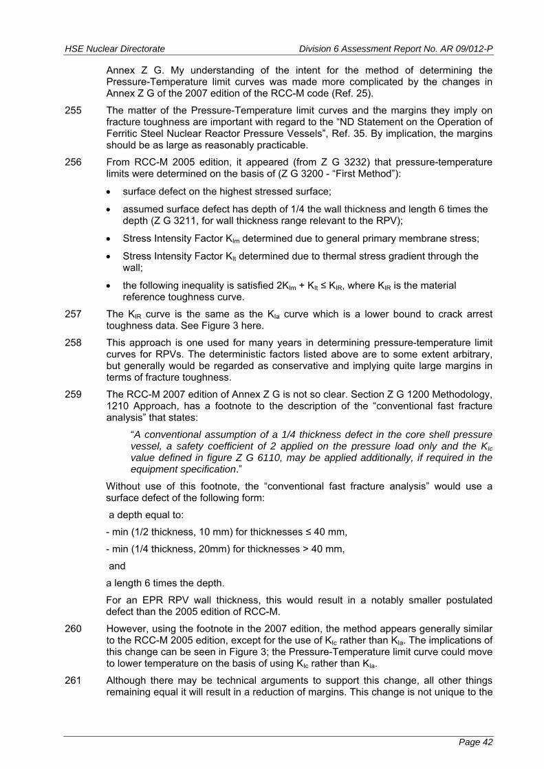
HSE Nuclear Directorate Division 6 Assessment Report No. AR 09/012-P
Annex Z G. My understanding of the intent for the method of determining the Pressure-Temperature limit curves was made more complicated by the changes in Annex Z G of the 2007 edition of the RCC-M code (Ref. 25).
255 The matter of the Pressure-Temperature limit curves and the margins they imply on fracture toughness are important with regard to the “ND Statement on the Operation of Ferritic Steel Nuclear Reactor Pressure Vessels”, Ref. 35. By implication, the margins should be as large as reasonably practicable.
256 From RCC-M 2005 edition, it appeared (from Z G 3232) that pressure-temperature limits were determined on the basis of (Z G 3200 - “First Method”):
surface defect on the highest stressed surface;
assumed surface defect has depth of 1/4 the wall thickness and length 6 times the depth (Z G 3211, for wall thickness range relevant to the RPV);
Stress Intensity Factor KIm determined due to general primary membrane stress;
Stress Intensity Factor KIt determined due to thermal stress gradient through the wall;
the following inequality is satisfied 2KIm + KIt ≤ KIR, where KIR is the material reference toughness curve.
257 The KIR curve is the same as the KIa curve which is a lower bound to crack arrest toughness data. See Figure 3 here.
258 This approach is one used for many years in determining pressure-temperature limit curves for RPVs. The deterministic factors listed above are to some extent arbitrary, but generally would be regarded as conservative and implying quite large margins in terms of fracture toughness.
259 The RCC-M 2007 edition of Annex Z G is not so clear. Section Z G 1200 Methodology, 1210 Approach, has a footnote to the description of the “conventional fast fracture analysis” that states:
“A conventional assumption of a 1/4 thickness defect in the core shell pressure vessel, a safety coefficient of 2 applied on the pressure load only and the KIc value defined in figure Z G 6110, may be applied additionally, if required in the equipment specification.”
Without use of this footnote, the “conventional fast fracture analysis” would use a surface defect of the following form:
a depth equal to:
- min (1/2 thickness, 10 mm) for thicknesses ≤ 40 mm,
- min (1/4 thickness, 20mm) for thicknesses > 40 mm,
and
a length 6 times the depth.
For an EPR RPV wall thickness, this would result in a notably smaller postulated defect than the 2005 edition of RCC-M.
260 However, using the footnote in the 2007 edition, the method appears generally similar to the RCC-M 2005 edition, except for the use of KIc rather than KIa. The implications of this change can be seen in Figure 3; the Pressure-Temperature limit curve could move to lower temperature on the basis of using KIc rather than KIa.
261 Although there may be technical arguments to support this change, all other things remaining equal it will result in a reduction of margins. This change is not unique to the
Page 42
HSE Nuclear Directorate Division 6 Assessment Report No. AR 09/012-P
RCC-M code. The approach in the US to determining Pressure-Temperature limits has been subject to similar change (Ref. 39, 40) with three relevant ASME Code Cases being incorporated in the ASME Code in the 1998 edition through to the 2000 Addenda. Background to consideration of change in this area can be found in Ref. 41 and 42.
262 I note that the Pressure-Temperature limit curves for the now closed UK Magnox steel Reactor Pressure Vessel stations were based on a combination of (Ref. 47):
reference, postulated surface defect 1/4 or 1/3 wall thickness (25mm deep in either 100 or 75mm thick wall) with extended geometry (rather than 6:1 aspect ratio);
material fracture toughness based on lower bound KIc;
irradiated material properties (strength, toughness) determined at the inside surface of the vessel wall (not mentioned in Ref. 47, but known to me through past assessment work);
pressure reserve factor of 1.2 (compared with 2 for ASME or RCC-M, but note difference in reference, postulated defect).
So there is precedent for use in the UK of a lower bound to KIc as the measure of fracture toughness in determining Pressure-Temperature limits for ferritic steel reactor pressure vessels.
263 In response to ND questions on the subject, EDF and AREVA amended the text in the PCSR (in the June 2009 edition, Ref. 6), Sub-Chapter 5.3, Section 6.3. The most useful new text in the PCSR states:
“Pressure / temperature curves are calculated according to RCC-M appendix ZG methodology, with a conventional quarter thickness defect located on the inner diameter of the core shells. The maximum fluence is determined for various selected time periods through the reactor life and the analysis is performed at the deepest point of the defect which covers the crack front intersection with the surface of the vessel wall.”
264 It can be assumed the reference to RCC-M in the above quote means the 2007 edition. This is a useful clarification; it implies the footnote in RCC-M Annex Z G is invoked for the UK EPR. It also claims that analysis at the deepest point of the postulated defect ‘covers’ the crack front intersection with the surface of the vessel wall. But there is no reference to support the claim that analysis of the deepest point covers the surface intersection. The footnote in RCC-M Annex Z G 2007 edition states that its requirements will be identified in the equipment specification. However the RPV equipment specification provided (Ref. 37) contains no such requirement. Subsequent discussion with EDF and AREVA suggests this requirement is in a different document - the ‘Requisition document’.
265 Original ND questions to EDF and AREVA included the matter of the measure of toughness to use, KIc , KIR or KIa. However, the updated PCSR does not address the matter of use of KIc versus KIR or KIa in determination of Pressure-Temperature limit curves.
266 I believe there are still some topics to be considered under this Regulatory Observation. These topics can be carried forward into GDA Step 4. Important aspects for further consideration are:
identify the document that contains the requirements for the basis of the analysis to determine pressure-temperature limit curves;
determine the arguments and evidence that support the claim that analysis of the deepest point of the postulated 1/4 wall depth crack covers the location where
Page 43

HSE Nuclear Directorate Division 6 Assessment Report No. AR 09/012-P
the crack front intersects the surface. This needs to take account of the difference in neutron dose at each location of the crack front;
determine a response to the question whether it is practicable to use the KIa material curve rather than the KIc curve (part of the ALARP consideration of this area);
determine if there are analyses available which would show specifically how the analyses are done for Pressure-Temperature limit curves;
in general, determine the factors that need to be considered in setting the Pressure-Temperature Limit curves ALARP.
5.15 RO-UKEPR-36. RCC-M Aspects of Requirements for Design Analysis of Piping Class 1, 2 and 3
267 This Regulatory Observation arises from the review of the RCC-M code (Ref. 26). In particular it comes from the comparison of the RCC-M code and the ASME III code. The RO relates to design analysis equations for pipework and the differences between the RCC-M and ASME codes.
268 The RO has two aspects:
1. The nature of the design analysis equations for primary loads for Class 1 and Class 2 pipework. The RCC-M rules for Class 3 pipework are the same as for Class 2. The differences between the equations for Class1 pipework are not large, being confined to differences in how stress limits are determined. But the differences between the equations for Class 2 pipework are, on the face of it, more significant.
2. The treatment of earthquake and other reversing dynamic loads. The methodology set out in RCC-M appears to be unique to RCC-M.
269 For Class 2/3 pipework, the equations in RCC-M are the same as equations that appeared in the ASME code between 1971 and 1981. The basis for the change in the ASME equations to their current form is explained in Refs 43, 44.
270 I asked EDF and AREVA for an explanation of why the design analysis equations in RCC-M are unchanged compared with ASME (aspect 1 above) and for the basis of the approach to earthquake loading analysis of pipework (aspect 2 above).
271 This RO was raised toward the end of GDA Step 3, after the review of the RCC-M code was completed (Ref. 48). EDF and AREVA agreed to respond to the RO (Ref. 49) and subsequently provided a response (Ref. 50). The response includes two open literature documents (Refs 51 and 52). The response was discussed in the meeting held on 22 October 2009 (Ref. 58).
272 For the Class 2 / 3 design analysis equations for piping, the RCC-M equations are the same as originally appeared in the US B31.1 design code in 1955. B31.1 still has the same equations (Ref. 53). The same form of design analysis equations appears in the corresponding European standard EN 13480-3 (Ref. 54). My understanding of the explanation is that:
experience with piping designed to the B31.1 / EN 13480 equations;
comparison of B31.1 / EN 13480 equations with experimental data showing adequate margins;
outweigh any theoretical concerns about the basis of the i-factor that multiplies the moment term in the design analysis equations, taking account of the different stress limits between the RCC-M and ASME code equations. Also comparisons of design
Page 44

HSE Nuclear Directorate Division 6 Assessment Report No. AR 09/012-P
code predictions and margins to experimental test results indicate acceptable margins (Ref. 51). I plan to check my understanding of this explanation. The B 31.1 and EN13480 analysis equations do not include limits for emergency and faulted conditions and inevitably experience of piping design under such loadings must be much more limited than for normal and expected loadings.
273 The explanation in the response for the differences in the Class 1 piping stress limits (i.e. why a stress limit based directly on Sy is not needed) is unclear and this will require further consideration. The main area to resolve is the nature of the faulted load condition stress limit.
274 Regarding the method used to deal with seismic loading, the recent SMiRT paper (Ref. 52) provides a useful explanation of the RCC-M rules. The method used in RCC-M seeks to reconcile analysis methods that are based on linear elastic methods with actual piping response that will to some degree be non-linear, mainly plastic deformation; at least for seismic loadings that are significant for response of piping. The approach is a combination of engineering insight, and validation by comparison with a number of tests. Overall, the approach is pragmatic and relies on a demonstration of suitable margins as shown by experiments.
275 For GDA Step 4 it might be desirable for ND to consider further review of the RCC-M approach to seismic design analysis of piping.
5.16 Steam Generator Tubing
276 The UK EPR PCSR states that the Steam Generator (SG) tubing will be made using mill annealed Alloy 690 in the Thermally Treated (TT) condition (Ref. 6, Sub-Chapter 5.4 Section 5.4.2 - Table 1). This material was used for the Sizewell B Steam Generators and has been widely used around the world since for PWR Steam Generators, mostly replacement Steam Generators.
277 Based on my knowledge of UK experience of thermally treated Alloy 690 SG tubing and a general perception of international experience of this material, I had no particular concerns about its use. But, given the past interest in the UK of this aspect of PWR structural integrity (Refs 23, 24), I judged it prudent to give the matter some consideration. I decided to do this through a support contract to review PWR SG tube materials and manufacturing routes.
278 The review (Ref. 45), focuses primarily on mill annealed Alloy 690 TT but includes some comparison with Alloy 600 and Alloy 800. Using open literature sources, the review deals with:
material selection (which mainly affects resistance to stress corrosion cracking);
manufacturing routes for tubing (emphasising the details of manufacturing that can also influence resistance to in-service degradation);
factors which can affect in-service degradation that are not inherently due to material selection or manufacture;
available information on in-service performance.
279 Historically, PWR SG tubing has often used mill annealed Alloy 600, Alloy 600 in the Thermally Treated condition, or Alloy 800, Nuclear Grade (NG). Alloy 800 has notably been used in the German Konvoi PWR series and the Canadian CANDU Steam Generators.
280 Sections of Ref. 45 deal with:
Tube Specifications and Manufacturing Methods.
Page 45

HSE Nuclear Directorate Division 6 Assessment Report No. AR 09/012-P
Water Chemistry, General Corrosion, Cation Release and Fouling.
Stress Corrosion Cracking, Fatigue and Wear.
Appropriately, the section on Stress Corrosion Cracking, Fatigue and Wear is the longest by some margin.
281 The main conclusions in Ref. 45 follow.
282 The main manufacturing routes of interest for Alloy 690 TT PWR SG tubing, pilgering and cold drawing, produce today high quality tubes with no significant differences in corrosion behaviour. Moreover, some initial problems with eddy current inspection of cold pilgered tubes were solved years ago.
283 Control of microstructure and of surface condition are key factors affecting in-service performance in terms of cation release and primary circuit activation as well as maximizing resistance to stress corrosion cracking from either the primary or secondary sides. Mill annealing and thermal treatment conditions (temperature and atmosphere) in combination with the alloy carbon content have been optimized to ensure good intergranular carbide morphology, minimize intragranular carbide precipitation and ensure maximum resistance to stress corrosion cracking. High mill anneal temperatures (often ~1080° C) followed by a thermal treatment of 5 to 15 h at 700-738° C are now universally used to obtain these microstructures.
284 Cation release is strongly influenced by surface condition and by the water chemistry during the build up of protective oxide layers on new tube surfaces. Attention has to be paid to cleaning processes all along the manufacturing route in order to avoid ID surface carburization or nitriding by incompletely removed cleaning solutions. Grit blasting of the ID is avoided as it results in rougher and cold worked surfaces.
285 In addition, in order not to impair resistance to stress corrosion cracking and to reduce cation release to a minimum, contact with deleterious chemical products has to be avoided (unless the surface can be efficiently cleaned), throughout the tube manufacturing and assembly processes.
286 Water chemistry is also an important factor regarding cation release. Optimization of hot functional tests may contribute to decreasing the activity of the primary circuit both by building up a ’good‘ protective layer in water chemistry conditions and at redox potentials similar to those that prevail during normal operation, and by efficiently eliminating most of the corrosion products formed before criticality so that no activation of them occurs. Attention should also be paid in the future to the primary water hydrogen concentration whose effect is not well understood; further studies are known to be underway. Finally, zinc injection from the very beginning of operation may be an effective way to decrease cation release.
287 The considerable literature on resistance to stress corrosion cracking of Alloy 690 TT in PWR primary water (PWSCC) shows that no cracking has been observed in long term, constant load or constant deformation laboratory tests in heats with good intergranular carbide morphology and few intragranular carbides. Some cracking has been observed in a few cases during constant deformation or slow strain rate tests of Alloy 690 with anomalous microstructures (i.e. non-optimized carbide distribution and morphology and perturbed, contaminated surface layers). Thus, the high chromium content of Alloy 690 cannot be relied on alone to confer complete PWSCC resistance. An intergranular network of fine carbides, which is an important objective of the manufacturing sequence for Alloy 690 TT, is essential to ensure optimum resistance to PWSCC. Nuclear grade Alloy 800 is equally resistant.
288 A recent quantitative assessment of PWSCC resistance in Alloy 690 TT relative to Alloy 600 in the mill annealed condition shows an average factor of improvement of
Page 46
HSE Nuclear Directorate Division 6 Assessment Report No. AR 09/012-P
between 40 and 100. These are minimum values dictated by the maximum testing periods used without any PWSCC being detected.
289 Alloy 690 TT has also been extensively tested in the various concentrated chemical environments that have been hypothesized as accumulating in secondary side superheated crevices in PWR steam generators by hideout of secondary water contaminants, and as responsible for secondary side attack (Intergranular Attack / Intergranular Stress Corrosion Cracking [IGA / IGSCC]) of mill annealed Alloy 600 tubing. Alloy 690 TT displays superior resistance to all other candidate SG tube alloys and is only vulnerable in very caustic environments or in the presence of lead (Pb) and possibly, to a lesser extent, to those contaminated with reduced sulphur species. Long-term future performance is, therefore, linked in part to adequate secondary water chemistry control as well as to steam generator design improvements that limit the locations and extent of the impurity concentration process.
290 Improvement factors for IGA / IGSCC resistance of Alloy 690 TT relative to Alloy 600 in the mill annealed condition depend on the particular concentrated chemical environment concerned. When these results are weighted according to the frequency of calculated crevice pH values in the field deduced from hideout return, the resulting overall weighted improvement factor for Alloy 690 TT relative to mill annealed Alloy 600 is 7.6. For Alloy 800, the equivalent figure is 4.5. The weighted improvement factor for Alloy 690 TT compares to 7.8 deduced from operating experience to 2005 without any IGA / IGSCC being observed in the field.
291 Operating experience of Alloy 690 TT tubing shows that no tubes have been damaged or plugged due to corrosion-related phenomena after up to 20 years in service. Only wear and fatigue have so far been responsible for the limited number of tubes that have been plugged in service. Alloy 800 NG steam generator tubing has also had an excellent record in service and only in the last few years have a small number of tubes been found with secondary side IGA / IGSCC attack after up to 26 years in service. A significant proportion of these cases of IGA / IGSCC is probably due to relaxation of the tube expansion near the top of the tube sheet although recently there have been some observations of cracking above the tube sheet and at the first tube support level, presumably under sludge deposits. As in the case of Alloy 690 TT, once corrosion related problems are minimal, fretting wear becomes the dominant cause of tube plugging of a relatively small number of tubes.
292 Compared to Alloy 800 NG, Alloy 690 TT is a better material regarding most physical properties (i.e. mechanical strength, thermal expansion coefficient and thermal conductivity), and several aspects of corrosion resistance (on the secondary side). Since Alloy 800 NG is an iron based material, it can be better than Alloy 690 TT regarding its contribution to activity build-up in primary circuit because it releases much less nickel and its corrosion products have a positive solubility coefficient with temperature. However, experience of Sizewell B and most recent French plants show that Alloy 690 TT can compete with Alloy 800 NG provided the ID surface condition (i.e. manufacturing process) and hot functional tests have been optimized.
293 Overall, I conclude from the review (Ref. 45) and my general knowledge of this area that Alloy 690 in the Thermally Treated condition is a sound choice of material for SG Tubing. When supported by detailed manufacturing practice and in-service water chemistry control, Alloy 690TT tubing exhibits good resistance to stress corrosion cracking. Material choice, manufacturing practice and in-service water chemistry are not however a panacea. The general design and construction aspects of the SG as they affect the tubing also have a role. Important factors are the minimisation of ‘crevice’ conditions, support for the tubing to avoid vibration induced wear and support materials that themselves do not corrode. Most of these general design and
Page 47
HSE Nuclear Directorate Division 6 Assessment Report No. AR 09/012-P
construction factors have been understood for many years, and the EPR SG design takes these into account.
294 Perhaps the most telling statement in the review (Ref. 45) is:
“Operating experience of Alloy 690 TT tubing shows that no tubes have been damaged or plugged due to corrosion-related phenomena after up to 20 years in service. Only wear and fatigue have so far been responsible for the limited number of tubes that have been plugged in service.”
6 CONCLUSIONS
295 The specific aims of GDA Step 3 are to:
improve HSE knowledge of the design;
identify significant issues;
identify whether any significant design or safety case changes may be needed;
identify major issues that may affect design acceptance and attempt to resolve them;
achieve a significant reduction in regulatory uncertainty.
296 For structural integrity aspects of the UK EPR, and from an ND perspective I believe there has been a significant improvement in HSE understanding of the design.
297 Using the ND Safety Assessment Principles (SAPs) and the relevant Technical Assessment Guide (TAG), I believe I have identified the significant matters for structural integrity. I have articulated these matters in a number of Regulatory Observations (ROs). EDF and AREVA’s responses to these ROs have been useful in making progress toward resolution.
298 I consider particular important points of progress are as follows:
1. The RCC-M code (2007 edition) is in general a sound basis for design and fabrication of the primary and secondary circuit pressure boundary components. Details remain to be resolved, mainly relating to chemical composition of the low alloy ferritic steels for the main pressure vessels and aspects of the design analysis for pipework;
2. The basis of Reactor Pressure Vessel(RPV) construction with a circumferential weld at core mid-height has been justified. Aspects of the detailed chemical composition of the materials of construction remain to be resolved, along with some aspects of how Pressure-Temperature limit curves are determined;
3. The basis of Reactor Coolant Casing construction based on casting technology has been justified. However there are still aspects to resolve in how to deal with large repairs to the castings made by welding.
299 For components where ‘the likelihood of gross failure is claimed to be so low it can be discounted’, EDF and AREVA have indicated a willingness to implement a method of achieving and demonstrating integrity consistent with UK practice. Toward the end of GDA Step 3, EDF and AREVA proposed programmes of work to address the main aspects of facture mechanics analyses, material toughness and qualification of manufacturing examinations. The details of this remain to be worked out and implemented, but so far I am encouraged by EDF and AREVA’s approach to understanding the type of method envisaged. Detailed assessment in this area will carry into GDA Step 4. This is the subject of Regulatory Observation RO-UKEPR-20.
Page 48
HSE Nuclear Directorate Division 6 Assessment Report No. AR 09/012-P
300 There is of course the question of which components have the claim that the likelihood of gross failure is so low it can be discounted. EDF and AREVA agreed to consider this matter and have provided information to justify their list of such components, essentially at the end of GDA Step 3. Assessment of the matters raised in this RO will carry on into GDA Step 4. On the basis of the substantiation of the list of components provided to date, I have some concerns there may be a gap between what I understand might be required and EDF and AREVA’s basis. This is the subject of Regulatory Observation RO-UKEPR-19.
301 Aspects of the chemical composition of the low alloy ferritic steels for the main vessels (RPV, SGs and Pressuriser) remain to be resolved. This topic will also carry into GDA Step 4, but it is an item that needs to be resolved sooner rather than later. Largely based on authoritative advice received under a support contract, there may be a number of aspects to discuss with EDF and AREVA, including the Sulphur, Nickel, and possibly Phosphorous content limits. However I do not see these aspects as fundamental impediments to progress and resolution. This is the subject of Regulatory Observation RO-UKEPR-24.
302 For the Reactor Coolant Pump casings, aspects remain to be resolved on how to deal with large repairs to the castings made by welding. The areas still open relate to how to obtain confidence that crack-like defects of a size of concern for integrity, can be detected. This is the subject of Regulatory Observation RO-UKEPR-21.
303 Useful progress has been made in understanding the approach to be used for a UK EPR in setting Pressure-Temperature limit curves for the Reactor Pressure Vessel. However there are aspects still to be resolved; these are a combination of the need for clarity and better referencing of what is proposed, but also consideration of what is ALARP. This is the subject of Regulatory Observation RO-UKEPR-28.
304 The UK EPR PCSR states that the Steam Generator tubing will be made using mill annealed Alloy 690 in the Thermally Treated (TT) condition. Based on my knowledge of UK experience of Thermally Treated Alloy 690 Steam Generator tubing and a general perception of international experience of this material, I had no particular concerns about its use. But, given the past interest in the UK of this aspect of PWR structural integrity, I judged it prudent to give the matter some consideration. I decided to do this through a support contract to review PWR Steam Generator tube materials and manufacturing routes.
305 Overall, I conclude from the review and my general knowledge of this area that Alloy 690 in the Thermally Treated condition is a sound choice of material for Steam Generator Tubing.
306 Late in GDA Step 3, I raised a Regulatory Observation regarding some of the RCC-M design analysis equations for pipework. A response has been received from EDF and AREVA. Some aspects require clarification and the approach to seismic design analysis might be the subject of further review; so, assessment of some aspects of design analysis equations for pipework might continue into GDA Step 4. This is the subject of Regulatory Observation RO-UKEPR-36.
307 A number of matters are identified above for carrying forward in to GDA Step 4 and some will require significant effort and programmes of work on the part of EDF and AREVA (e.g. the work for RO-UKEPR-20). In addition GDA Step 4 for structural integrity needs to move to the next level of detail and consider the content of documents such as (generic document names):
Design Specifications.
Analyses for loading conditions (mainly thermal-hydraulics analyses - this will require involvement of other ND assessment functions).
Page 49
HSE Nuclear Directorate Division 6 Assessment Report No. AR 09/012-P
Design Reports.
Equipment Specifications.
for a range of components.
308 From an ND perspective, I consider there has been a reduction in regulatory risk.
7 RECOMMENDATIONS
309 In this GDA Step 3 assessment of the structural integrity aspects of the UK EPR design, I have not identified any matters that would lead to a recommendation to raise a Regulatory Issue (RI).
310 During GDA Step 3 I have raised a number of matters with EDF and AREVA and I have done this mostly through eleven ROs. Some matters raised are relatively more significant than others. I consider useful progress has been made across a number of these ROs. Several aspects of these ROs remain to be resolved. I consider there is a reasonable prospect of achieving such resolution by carrying these remaining open aspects forward into GDA Step 4.
Page 50

HSE Nuclear Directorate Division 6 Assessment Report No. AR 09/012-P
8 REFERENCES
1 UK EPR Pre-Construction Safety Report. EDF and AREVA documents UKEPR-0002-xz Issue 01, where xz is the sub-chapter number in format x.z (June 2008).
2 Contact Report. Meeting with EdF/AREVA 6-7 November 2008. ND Division 6 Contact Report No 08/088. TRIM Ref. 2008/630607. (28 November 2008).
3 Contact Report. Meeting with EdF/AREVA 10 December 2008. ND Division 6 Contact Report No 08/095 TRIM Ref. 2009/11135 (12 December 2008).
4 Contact Report. Meeting with EdF/AREVA 16 June 2008. ND Division 6 Contact Report No 09/103 TRIM Ref. 2009/250931 (17 June 2009).
5 Contact Report. Meeting with EdF/AREVA 22 July 2009. ND Division 6 Contact Report No 09/126 TRIM Ref. 2009/295101 (23 July 2009).
6 UK EPR Pre-Construction Safety Report, EDF and AREVA documents UKEPR-0002-xz Issue 02, where xz is the sub-chapter number in format x.z (June 2009).
7 Safety Assessment Principles for Nuclear Facilities, 2006 Edition, Revision 1. HSE, Bootle (February 2008).
8 Technical Assessment Guide. Integrity of Metal Components and Structures, HSE Nuclear Directorate Business Management System document T/AST/016 Issue 003 (13 August 2008).
9 New Reactor Generic Design Assessment - Step 2, Preliminary Review Assessment of: Structural Integrity Aspects of AREVA/EdF EPR, ND Division 6 Assessment Report AR 08/006, TRIM Ref. 2008/67830 (February 2008).
10 Letter from UK EPR Project Office to ND, Level 3 EPR Step 2 Assessment Feedback Meeting 9-10 January 2008 Bootle - Response to Action 17, Letter Unique Number EPR00029N (19 March 2008).
11 New Reactor Generic Design Assessment - Step 3, General Plan for Assessment of Structural Integrity - GDA Step 3, Based on ND Safety Assessment Principles. Issue 1. ND Division 6 Assessment Report AR 08/026, TRIM Ref. 2008/227558 and 2008/227581 (June 2008).
12 Nuclear Power Stations Generic Design Assessment, Guidance to Requesting Parties, Version 3, HSE (August 2008).
13 Contact Report. Meeting with EdF/AREVA 12 August 2009, ND Division 6 Contact Report No 09/137 TRIM Ref. 2009/318094 (13 August 2009).
14 Technical Assessment Guide. Procurement of Nuclear Safety Related Items or Services, HSE Nuclear Directorate Business Management System document T/AST/077 Issue 001 (August 2009).
15 ND BMS document. Guidance: Assessment Process G/AST/001 Issue 2 (February 2003).
16 Whittle M J., A Review of Worldwide Practice and Experience in the Qualification of Ultrasonic Inspections of Nuclear Components over the Past Two Decades, (HSE Contract No NS/20/1129) (December 2008). TRIM Ref. 2009/324434.
17 Whittle M J., A Review of Worldwide Practice and Experience in the Qualification of Ultrasonic Inspections of Nuclear Components over the Past Two Decades, Insight, Vol. 51 No 3 pp140-150 (March 2009). See TRIM Ref. 2009/38672.
18 Rogerson A, Booler R., Strategy for the Qualification of Manufacturing NDT for New Nuclear Build in the UK, Serco document SERCO/TAS/E.003282.03/R01 Issue 01, (HSE Contract No NS/20/1205), (9 July 2009). TRIM Ref. 2009/324503.
Page 51

HSE Nuclear Directorate Division 6 Assessment Report No. AR 09/012-P
19 English C., Ortner S., Potential for Irradiation Embrittlement of RPV in UK EPR Reactor, National Nuclear Laboratory document NNL (09) 10160, Issue 2 (Final), (HSE Contract No NS/20/1200) (7 August 2009), TRIM Ref. 2009/324536.
20 UKAEA. An Assessment of the Integrity of PWR Pressure Vessels, Report of a Study Group, United Kingdom Atomic Energy Authority (1976), ( the “1st Marshall Study Group Report”).
21 UKAEA. An Assessment of the Integrity of PWR Pressure Vessels, Second Report by a Study Group, United Kingdom Atomic Energy Authority (1982), (the “2nd Marshall Study Group report).
22 UKAEA. An Assessment of the Integrity of PWR Pressure Vessels, Addendum to the Second Report of the Study Group, Since 1982, under the Chairmanship of Prof. Sir P B Hirsch. United Kingdom Atomic Energy Authority. ISBN 0705811557 (1987).
23 Layfield F., Sizewell B Public Inquiry, Report on Applications by the Central Electricity Generating Board for Consent for the Construction of a Pressurised Water Reactor and a Direction that Planning Permission be Deemed to be Granted for that Development, 8 volumes, HMSO. ISBN 0114115753 (1987), (held 11 January 1983 to 7 March 1985, report issued 5 December 1986)
24 Barnes M., The Hinkley Point Public Inquiries, A Report by Michael Barnes QC to the Secretaries of State for Energy and the Environment, 9 volumes, HMSO. ISBN 011412955X (1990) (started 4 October 1988 following pre-inquiry meetings in June and July 1988, report was published August 1990).
25 Design and Construction Rules for Mechanical Components of PWR Nuclear Islands, 2007 Edition, Published by the French Association for Design, Construction and In-Service Inspection Rules for Nuclear Island Components – AFCEN, Paris.
26 New Reactor Generic Design Assessment (GDA) - Step 3, Review of RCC-M, Design and Construction Rules for Mechanical Components of PWR Nuclear Islands (by French Association for Design, Construction and In-Service Inspection Rules for Nuclear Island Components - AFCEN), ND Division 6 Assessment Report AR 09/011. TRIM Ref. 2009/341150 (August 2009).
27 ASME Boiler and Pressure Vessel Code, 2007 Edition, American Society of Mechanical Engineers – ASME, New York.
27a Section II Materials Part A - Ferrous Material Specifications, Part D - Properties
27b Section III Rules for Construction of Nuclear Facility Components, particularly Subsection NCA and the Subsections of Division 1.
28 Harrop L P., Summary of Design of Nuclear Vessels and Piping to ASME III (NB, NC, ND) and Vessels to BS5500, International Journal of Pressure Vessels and Piping pp 231-265 Vol. 49 (1992).
29 Letter from ND to UK EPR Project Office, RO-UKEPR -19 to RO-UKEPR-28 - Regulatory Observations on Structural Integrity, Letter Unique Number EPR70077N (28 January 2009), TRIM Ref. 2009/35941.
30 Letter from UK EPR Project Office to ND, RO-UKEPR-19.A1 - Regulatory Observation Action - Revision of Wording, Letter Unique Number EPR00107N (13 May 2009), TRIM Ref. 2009/188860.
31 Letter from UK EPR Project Office to ND, RO-UKEPR-19 to RO-UKEPR-28 Regulatory Observation Actions on Structural Integrity, Letter Unique Number EPR00091N (2 April 2009), TRIM Ref. 2009/137600.
Page 52

HSE Nuclear Directorate Division 6 Assessment Report No. AR 09/012-P
32 Letter from ND to UK EPR Project Office, RO-UKEPR-22 RCC-M Overall Organisational Arrangements and Quality Assurance Arrangements, Letter Unique Number EPR70110N (24 August 2009). TRIM Ref. 2009/330143.
33 Balart M J., Knott J F., Microalloying Design for Nuclear Reactor Pressure Vessel (RPV) Steels, Chapter 5 in: Nuclear Reactor, Nuclear Fusion and Fusion Engineering, Edited by A Aasen, P Olsson, (2009) ISBN: 978-60692-508-9.
34 Cogswell D., The Effects of Microstructure on the Mechanical Properties of A508-3 Heavy Section Forgings, Nuclear Future, pp138-144, Vol.5 No.3 (May / June 2009).
35 Health and Safety Executive, Nuclear Installations Inspectorate, Statement on the Operation of Ferritic Steel Nuclear Reactor Pressure Vessels, International Journal of Pressure Vessels and Piping, pp307-310, Vol. 64 (1995).
36 Letter from UK EPR Project Front Office to ND, Structural Integrity - response to actions RO-UKEPR-25.A4 and RO-UKEPR-25.A6, Letter Unique Number EPR00160N (26 August 2009), TRIM Ref. 2009/338084.
37 Letter from UK EPR Project Front Office to ND, Structural Integrity - Action 4-SI-7 - AREVA/EdF to Provide HSE and Example of a Large Component Specification, Letter Unique Number EPR00161N (28 August 2009). TRIM Ref. 2009/349797.
38 Letter from UK EPR Project Front Office to ND, Structural Integrity - Response to Action RO-UKEPR-27.A1. Letter Unique Number EPR00114N (29 May 2009). TRIM Ref. 2009/216339.
39 ASME Code Case N-640, Alternative Reference Fracture Toughness for Development of P-T Limit Curves Section XI, Division 1, (appears in Nuclear Code Cases up to 2004 Edition, annulled12 January 2005. Incorporated in main code).
40 NRC Regulatory Issue Summary 2004-04, Use of Code Cases N-588, N-640 and N-641 in Developing Pressure- Temperature Operating Limits, US NRC (5 April 2004).
41 ASME XI Task Group on Reactor Vessel Integrity Requirements, White Paper on Reactor Pressure Vessel Integrity Requirements for level A and B Conditions, EPRI document TR-100251 (January 1993).
42 Bamford W H., Stevens G L., Griesbach T J., Malik S N., Technical Basis for Revised P-T Limit Curve Methodology, pp169-178 in Pressure Vessel and Piping Codes and Standards 2000, ASME PVP-Vol. 407, Presented at the 2000 ASME Pressure Vessels and Piping Conference, Seattle, Washington (23-27 July 2000).
43 Moore S E., Rodabaugh E C., Background for Changes in the 1981 Edition of the ASME Nuclear Power Plant Components Code for Controlling Primary Loads in Piping Systems.,Trans. ASME, Journal of Pressure Vessel Technology, pp 351-361, Vol. 104 (November 1982).
44 Slagis G C., Commentary on Class 2/3 Piping Rules, Trans. ASME, Journal of Pressure Vessel Technology, pp329-334 Vol. 110 (August 1988).
45 Scott P M., Combrade P., Review of PWR Steam Generator Tubing Materials Selection, Performance and Manufacturing Routes, Peter Scott Corrosion Consultant Report Number PMSCC.09.041 (September 2009), TRIM Ref. 2009/376337.
46 Knott J F., Advice to the Nuclear installations Inspectorate on Base Materials Compositions of Ferritic Steel Forgings for Main pressure Vessels in the Prospective UK EPR ‘New Build’ Nuclear power Plant, (September 2009). TRIM Ref. 2009/383141.
47 Flewitt P E J., Williams G H., Wright M B., Integrity of Magnox Reactor Steel Pressure Vessels, Nuclear Energy, pp383-391 Vol. 31 No 5 (October 1992).
Page 53
HSE Nuclear Directorate Division 6 Assessment Report No. AR 09/012-P
48 Letter from ND to UK EPR Project Office, Notification of Step 3 Draft Regulatory Observation RO-UKEPR-36: RCC-M Aspects of Requirements for Design Analysis of Piping Class 1, 2 and 3, Letter Unique Number EPR70104R (7 August 2009), TRIM Ref. 2009/309649.
49 Letter from UK EPR Project Front Office to ND, Structural Integrity - Actions RO-UKEPR-36.A1. and RO-UKEPR-36.A2. Letter Unique Number EPR00171N (4 September 2009). TRIM Ref. 2009/362166.
50 Letter from UK EPR Project Front Office to ND, RO-UKEPR-36.A1 & RO-UKEPR-36.A2 RCCM Aspects of requirements for design analysis of piping class 1, 2 and 3. Letter Unique Number EPR00183N (28 September 2009). TRIM Ref. 2009/382980.
51 Heng C., Grandemange J M., Framatome View on the Comparison Between Class 1 and Class 2 RCC-M Piping Design Rules, pp13-24, Welding Research Council (WRC) Bulletin No 361 (1991).
52 Le Breton F., Petesch C., Stress Analysis Criteria for Piping, RCC-M 2002 Rules and Validation, Paper 1790 (TS 5-6.2 in Technical Session 5-6A) in 20th International Conference on Structural Mechanics in Reactor Technology (SMiRT 20), Espoo, Finland (August 2009).
53 ASME Code for Pressure Piping, B31, B31.1-1998. Power Piping, American Society of Mechanical Engineers, New York.
54 BS EN 13480-3:2002+Add 3 2009. Metallic Industrial Piping - Part 3: Design and Calculation, British Standards Institution, London (2009).
55 Letter from UK EPR Project Front Office to ND, RO-UKEPR-20.A1, Avoidance of Fracture. Letter Unique Number EPR00177R (1 October 2009), TRIM Ref. 2009/394821.
56 Letter from UK EPR Project Front Office to ND, Structural Integrity – response to action RO-UKEPR-19.A1(ii). Letter Unique Number EPR00168N (28 August 2009), TRIM Ref. 2009/357892.
57 Letter from UK EPR Project Front Office to ND, RO-UKEPR-19.A1 Subpart (iii). Categorisation of safety function, classification of structures, systems and components - ‘Non Breakable’, ‘Break Preclusion’ and ‘No missile’ items. Letter Unique Number EPR00192R (12 October 2009), TRIM Ref. 2009/405126.
58 Meeting with EdF/AREVA 22 October 2009, ND Division 6 Contact Report No 09/181 TRIM Ref. 2009/422028 (5 November 2009).
Page 54

HSE Nuclear Directorate Division 6 Assessment Report No. AR 09/012-P
Table 1
List of Regulatory Observations. UK EPR ND Generic Design Assessment - Step 3 Structural Integrity - Metal Components and Structures
RO Number and TRIM Reference
Regulatory Observation Title
RO-UKEPR-19 2009/37633
Categorisation of Safety Function, Classification of Structures - Systems and Components -
“Non Breakable”, “Break Preclusion” and “No Missile” Items
RO-UKEPR-20 2009/37635
Avoidance of Fracture - Margins Based on Size of Crack-Like Defects Integration of Material Toughness Properties,
Non-Destructive Examinations During Manufacture and Analyses for Limiting Sizes of Crack-Like Defects
RO-UKEPR-21 2009/37637
Manufacturing Method for Reactor Coolant Pump Casings
RO-UKEPR-22 2009/37638
RCC-M Overall Organisational Arrangements
and Quality Assurance Arrangements
RO-UKEPR-23 2009/37646
RCC-M Overpressure Protection
RO-UKEPR-24 2009/37648
Materials Specifications and Selection of Material Grade - Reactor Pressure Vessel, Pressuriser, Steam Generator Shells
RO-UKEPR-25 2009/37650
Reactor Pressure Vessel Body Cylindrical Shell Forging Material and Associated Circumferential Welds
Effects of Irradiation
RO-UKEPR-26 2009/37655
Primary Circuit Vessel Nozzle to Safe End Welds
RO-UKEPR-27 2009/37657
Fatigue Crack Growth Law Equations for Ferritic Materials Covered by RCC-M M 2110 and M2120
RO-UKEPR-28 2009/37659
Reactor Pressure Vessel Pressure - Temperature Limit Diagrams and Low Temperature Overpressure Protection
RO-UKEPR-36 2009/307574
RCC-M Aspects of Requirements for Design Analysis of Piping
Class 1, 2 and 3
Page 55

HSE Nuclear Directorate Division 6 Assessment Report No. AR 09/012-P
Table 2
Main parts of UKEPR PCSR relevant to structural integrity assessment
UK EPR PCSR Sub-Chapter
Number Sub-Chapter Title
Chapter 3. General Design and Safety Aspects
3.2 Classification of Structures, Equipment and Systems
3.4 Mechanical Systems and Components. In particular: 1.1 Design Transients 1.2 Loading Specification 1.5 Overpressure Protection Analyses 3.1 Version of the RCC-M Used 3.2 Load Combinations, Transients and Stress Limits 6. Reactor Pressure Vessel - Lower Internals
3.8 Codes and Standards used in the EPR Design. In Particular: 2. Technical Code for Mechanical Equipment (RCC-M)
Chapter 5. Reactor Coolant System and Associated Systems
5.0 Safety Requirements
5.1 Description of the Reactor Coolant System
5.2 Integrity of the Reactor Coolant Pressure Boundary (RCPB). Including: 3. Break Preclusion of the Reactor Coolant Pipework 6. Requirements Applied to “Non Breakable” Components 7. Comparison of Requirements for break Preclusion / Non-Breakable Components with UK Requirements for IOF (section 7 added in June 2009 edition of PCSR)
5.3 Reactor Vessel
5.4 Components and Systems Sizing
Chapter 6 Containment and Safeguard Systems
6.1 Materials
6.3 Safety Injection System (for the accumulators)
Chapter 10 Main Steam and Feedwater Lines
10.3 Main Steam System (safety classified part)
10.5
Implementation of the Break Preclusion Principle for the Main Steam Lines Inside and Outside the Containment
Page 56
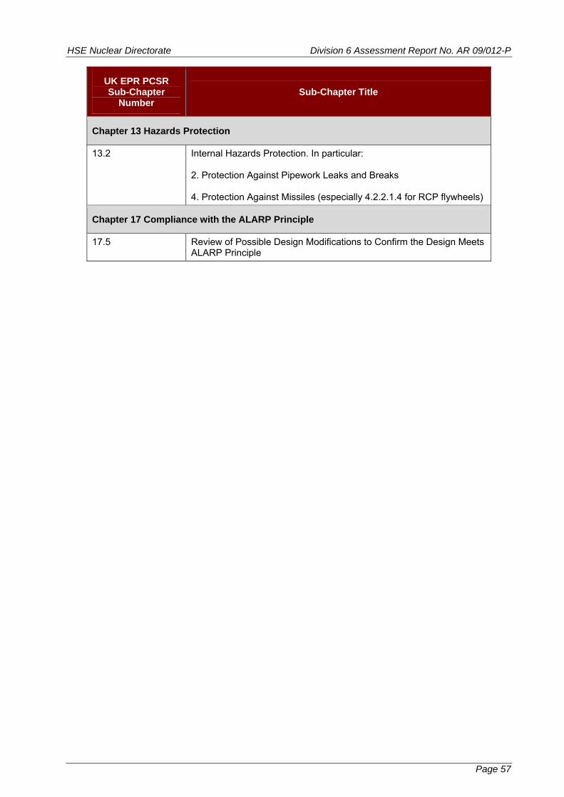
HSE Nuclear Directorate Division 6 Assessment Report No. AR 09/012-P
Page 57
UK EPR PCSR Sub-Chapter
Number Sub-Chapter Title
Chapter 13 Hazards Protection
13.2 Internal Hazards Protection. In particular: 2. Protection Against Pipework Leaks and Breaks 4. Protection Against Missiles (especially 4.2.2.1.4 for RCP flywheels)
Chapter 17 Compliance with the ALARP Principle
17.5 Review of Possible Design Modifications to Confirm the Design Meets ALARP Principle

HSE Nuclear Directorate Division 6 Assessment Report No. AR 09/012-P
Table 3
Amended version of Table 1 from Project initiation Document (PID) (Ref. 11)
Topic GDA Step 3 Detailed Scope
1. NOT USED*
2. Components and Systems to be Considered
PWR Reactor Pressure Vessel Core support structures Pressuriser Steam Generators - Primary and Secondary Side and Tubing Reactor Coolant Pumps pressure boundary and flywheel Primary Coolant Loop Pipework Pipework connecting auxiliary systems to the primary circuit Steam pipework from the Steam Generators Feedwater pipework to the Steam Generators
3. Level of Integrity Required for Nuclear Safety Claim
Identification of components where likelihood of gross failure is so low it can be discounted. This must be completed within the Step 3 period.
4. Safety Classification and Standards - Including Quality Assurance
Safety classification must be completed within Step 3 and assessment conclusion reached. Standards to be used for design, manufacture and installation must be identified and assessment conclusion reached on overall acceptability of standards proposed. Framework of quality assurance must be declared in Step 3 and assessment conclusion reached. Principle and outline of third party inspection agent for in-manufacture inspection should be agreed. General review by ND of standards for design, manufacture and installation.
5. Potential Failure Modes No assessment needed. This topic is part of the explanation of the assessment approach.
6. Potential In-Service Degradation Modes (liked with 17. below)
Evidence of knowledge of and mitigation measures applied for known potential in-service degradation mechanisms. Assessment conclusion for treatment of potential in-service degradation mechanisms.
7. Analysis - Design Analysis, Fracture Mechanics Analyses
Evidence that general, top level analysis is available for sizing pressure boundary and other structural integrity components. Assessment of this top level analysis. Evidence of capability to perform fracture mechanics analyses or manage procurement of such analyses for determination of Validation Factors and other purposes. Evidence supported by examples. Agreement on principle and outline of use of fracture mechanics analyses along with examination
Page 58
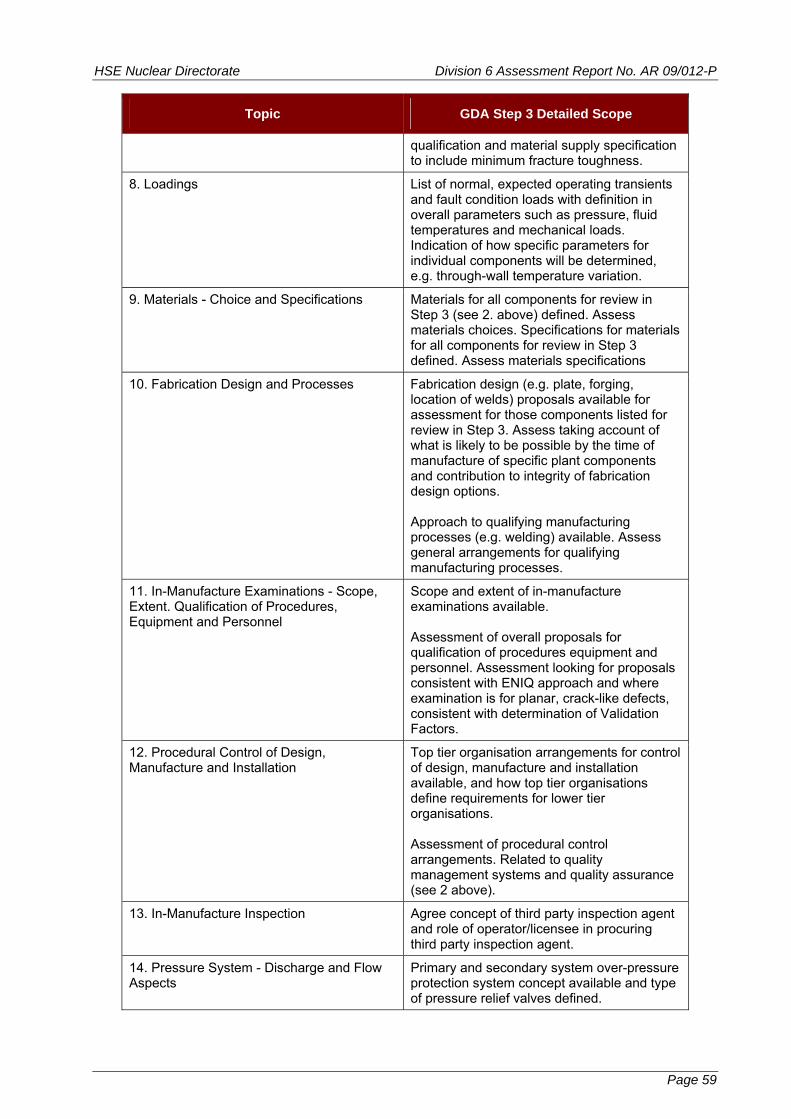
HSE Nuclear Directorate Division 6 Assessment Report No. AR 09/012-P
Page 59
Topic GDA Step 3 Detailed Scope
qualification and material supply specification to include minimum fracture toughness.
8. Loadings List of normal, expected operating transients and fault condition loads with definition in overall parameters such as pressure, fluid temperatures and mechanical loads. Indication of how specific parameters for individual components will be determined, e.g. through-wall temperature variation.
9. Materials - Choice and Specifications Materials for all components for review in Step 3 (see 2. above) defined. Assess materials choices. Specifications for materials for all components for review in Step 3 defined. Assess materials specifications
10. Fabrication Design and Processes Fabrication design (e.g. plate, forging, location of welds) proposals available for assessment for those components listed for review in Step 3. Assess taking account of what is likely to be possible by the time of manufacture of specific plant components and contribution to integrity of fabrication design options. Approach to qualifying manufacturing processes (e.g. welding) available. Assess general arrangements for qualifying manufacturing processes.
11. In-Manufacture Examinations - Scope, Extent. Qualification of Procedures, Equipment and Personnel
Scope and extent of in-manufacture examinations available. Assessment of overall proposals for qualification of procedures equipment and personnel. Assessment looking for proposals consistent with ENIQ approach and where examination is for planar, crack-like defects, consistent with determination of Validation Factors.
12. Procedural Control of Design, Manufacture and Installation
Top tier organisation arrangements for control of design, manufacture and installation available, and how top tier organisations define requirements for lower tier organisations. Assessment of procedural control arrangements. Related to quality management systems and quality assurance (see 2 above).
13. In-Manufacture Inspection Agree concept of third party inspection agent and role of operator/licensee in procuring third party inspection agent.
14. Pressure System - Discharge and Flow Aspects
Primary and secondary system over-pressure protection system concept available and type of pressure relief valves defined.
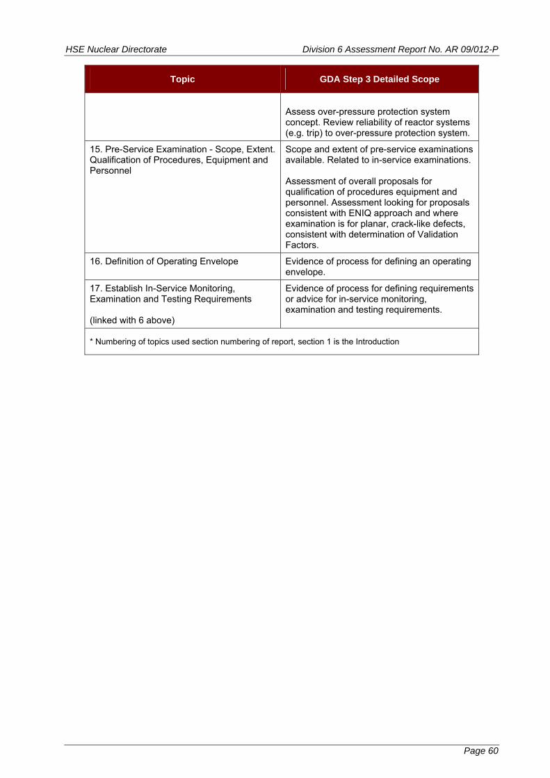
HSE Nuclear Directorate Division 6 Assessment Report No. AR 09/012-P
Page 60
Topic GDA Step 3 Detailed Scope
Assess over-pressure protection system concept. Review reliability of reactor systems (e.g. trip) to over-pressure protection system.
15. Pre-Service Examination - Scope, Extent. Qualification of Procedures, Equipment and Personnel
Scope and extent of pre-service examinations available. Related to in-service examinations. Assessment of overall proposals for qualification of procedures equipment and personnel. Assessment looking for proposals consistent with ENIQ approach and where examination is for planar, crack-like defects, consistent with determination of Validation Factors.
16. Definition of Operating Envelope Evidence of process for defining an operating envelope.
17. Establish In-Service Monitoring, Examination and Testing Requirements (linked with 6 above)
Evidence of process for defining requirements or advice for in-service monitoring, examination and testing requirements.
* Numbering of topics used section numbering of report, section 1 is the Introduction
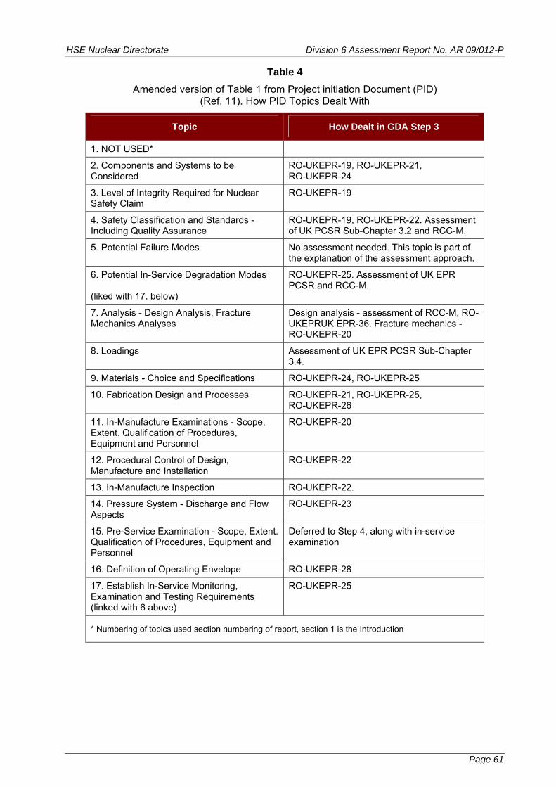
HSE Nuclear Directorate Division 6 Assessment Report No. AR 09/012-P
Table 4
Amended version of Table 1 from Project initiation Document (PID) (Ref. 11). How PID Topics Dealt With
Topic How Dealt in GDA Step 3
1. NOT USED*
2. Components and Systems to be Considered
RO-UKEPR-19, RO-UKEPR-21, RO-UKEPR-24
3. Level of Integrity Required for Nuclear Safety Claim
RO-UKEPR-19
4. Safety Classification and Standards - Including Quality Assurance
RO-UKEPR-19, RO-UKEPR-22. Assessment of UK PCSR Sub-Chapter 3.2 and RCC-M.
5. Potential Failure Modes No assessment needed. This topic is part of the explanation of the assessment approach.
6. Potential In-Service Degradation Modes (liked with 17. below)
RO-UKEPR-25. Assessment of UK EPR PCSR and RCC-M.
7. Analysis - Design Analysis, Fracture Mechanics Analyses
Design analysis - assessment of RCC-M, RO-UKEPRUK EPR-36. Fracture mechanics - RO-UKEPR-20
8. Loadings Assessment of UK EPR PCSR Sub-Chapter 3.4.
9. Materials - Choice and Specifications RO-UKEPR-24, RO-UKEPR-25
10. Fabrication Design and Processes RO-UKEPR-21, RO-UKEPR-25, RO-UKEPR-26
11. In-Manufacture Examinations - Scope, Extent. Qualification of Procedures, Equipment and Personnel
RO-UKEPR-20
12. Procedural Control of Design, Manufacture and Installation
RO-UKEPR-22
13. In-Manufacture Inspection RO-UKEPR-22.
14. Pressure System - Discharge and Flow Aspects
RO-UKEPR-23
15. Pre-Service Examination - Scope, Extent. Qualification of Procedures, Equipment and Personnel
Deferred to Step 4, along with in-service examination
16. Definition of Operating Envelope RO-UKEPR-28
17. Establish In-Service Monitoring, Examination and Testing Requirements (linked with 6 above)
RO-UKEPR-25
* Numbering of topics used section numbering of report, section 1 is the Introduction
Page 61
HSE Nuclear Directorate Division 6 Assessment Report No. AR 09/012-P
Table 5
Alignment of RCC-M and ASME Boiler and Pressure Vessel Code for Purposes of Comparison (and indication of number of pages in each part)
RCC-M ASME
Section I Nuclear Island Components Section III
Subsection A General Rules (83) Subsection NCA (54)
Subsection B Class 1 (227) Division 1 Subsection NB (220)
Subsection C Class 2 (345) Division 1 Subsection NC (287)
Subsection D Class 3 (35) Division 1 Subsection ND (266)
Subsection E Small Components (29)
Subsection G Reactor Internals (63) Subsection NG (74)
Subsection H Component Supports (106) Subsection NF (140)
Subsection J Low Pressure or Atmospheric Storage Tanks (75)
Subsection P Containment Penetrations (7)
Subsection NE * (140)
Subsection Z - Annexes (289) Division 1 Appendices (436)
Annex Z I Properties of Materials to be Use in Design (40)
Section II Part D Properties (906 for customary units version)
Section II Materials (1229) Section II Part A Ferrous Material Specification (1662) Part B Nonferrous Material Specification (1120)
Section II Part C Specifications for Welding Rods, Electrodes and Filler Metals (723)
Section III Examination Methods (141) Section V Nondestructive examination (631)
Section IV Welding (291) Section IX Welding and Brazing Qualification (276)
Section V Fabrication (139)
* ASME II Division 2 (Code for Concrete Containments) states in CC-3640 that penetrations assemblies shall be analysed using the same techniques and procedures used for metal containments in Division 1, where applicable.
(number of pages in brackets)
Page 62
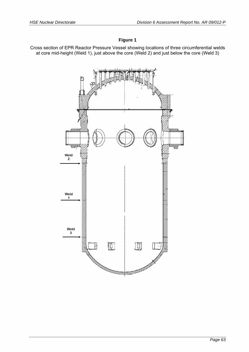
HSE Nuclear Directorate Division 6 Assessment Report No. AR 09/012-P
Page 63
Figure 1
Cross section of EPR Reactor Pressure Vessel showing locations of three circumferential welds at core mid-height (Weld 1), just above the core (Weld 2) and just below the core (Weld 3)

HSE Nuclear Directorate Division 6 Assessment Report No. AR 09/012-P
Page 64
Figure 2
Example of fracture toughness temperature transition curve indexed to RTNDT. This example is for KIc, other measures of toughness exist

HSE Nu /012-P
clear Directorate Division 6 Assessment Report No. AR 09
Page 65
Figure 3
KIc and KIa fracture toughness temperature transition curves indexed to RTNDT. From RCC-M Annex Z G 2005 Edition

HSE Nuclear Directorate Division 6 Assessment Report No. AR 09/012-P
Annex 1 – UKEPR Structural Integrity – Status of Regulatory Issues and Observations
RI / RO Identifier Date Raised Title Status
Required timescale
(GDA Step 4 / Phase 2)
Regulatory Issues
None
Regulatory Observations
RO-UKEPR-19 draft 3/9/08 final 28/1/09
Categorisation of Safety Function, Classification of Structures -
Systems and Components - ’Non Breakable‘, ’Break Preclusion‘ and ’No
Missile‘ Items
In response to this RO, EDF and AREVA offered to undertake a programme of work to identify components where the safety case depends on a claim for integrity that “the likelihood of gross failure is so low it can be discounted”. A provisional list was provided; the report providing the basis of the list was due to HSE / ND 30/9/09 and was received 12/10/09. Assessment of the matters raised under this RO will continue into GDA Step 4. (see Section 5.5 of report).
GDA Step 4
RO-UKEPR-20 draft 3/9/08 final 28/1/09
Avoidance of Fracture - Margins Based on Size of Crack-Like Defects
Integration of Material Toughness Properties, Non-Destructive Examinations During
Manufacture and Analyses for Limiting Sizes of Crack-Like
Defects
In response to this RO, EDF and AREVA agreed to plan programmes of work which will cover the matters raised. One or more reports were due from EDF and AREVA for this RO by 31/8/09; achieved with receipt of EPR00177R 1 October 2009. Assessment of the matters raised under this RO will continue into GDA Step 4 (see Section 5.6 of report).
Programme of work
GDA Step 4
RO-UKEPR-21 draft 3/9/08 final 28/1/09
Manufacturing Method for Reactor Coolant Pump Casings
Substantial progress has been made with important parts of this RO. Remaining matters are associated with integrity of any large repair welds in castings. Propose RO-UKEPR-21 be closed and new, more focussed RO opened to deal with remaining matters. (see Section 5.7 of report)
Residual matters in
GDA Step 4. Propose via
new RO
Annex 1 - Page 1
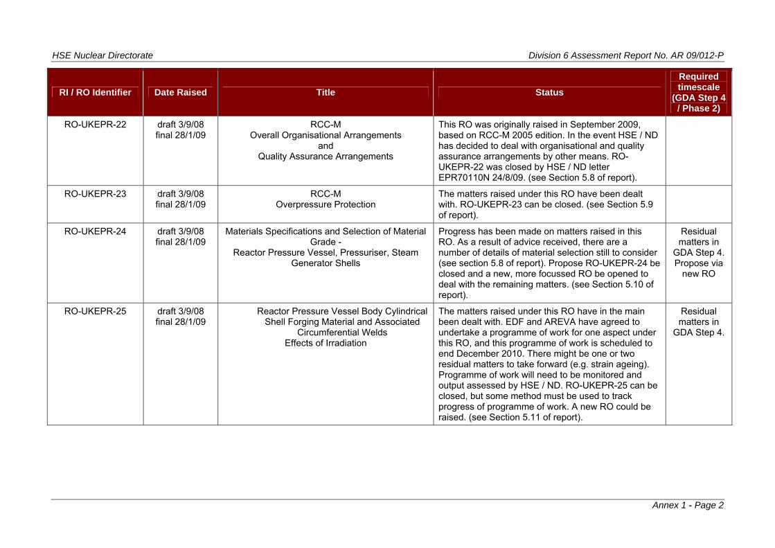
HSE Nuclear Directorate Division 6 Assessment Report No. AR 09/012-P
Annex 1 - Page 2
RI / RO Identifier Date Raised Title Status
Required timescale
(GDA Step 4 / Phase 2)
RO-UKEPR-22 draft 3/9/08 final 28/1/09
RCC-M Overall Organisational Arrangements
and Quality Assurance Arrangements
This RO was originally raised in September 2009, based on RCC-M 2005 edition. In the event HSE / ND has decided to deal with organisational and quality assurance arrangements by other means. RO-UKEPR-22 was closed by HSE / ND letter EPR70110N 24/8/09. (see Section 5.8 of report).
RO-UKEPR-23 draft 3/9/08 final 28/1/09
RCC-M Overpressure Protection
The matters raised under this RO have been dealt with. RO-UKEPR-23 can be closed. (see Section 5.9 of report).
RO-UKEPR-24 draft 3/9/08 final 28/1/09
Materials Specifications and Selection of Material Grade -
Reactor Pressure Vessel, Pressuriser, Steam Generator Shells
Progress has been made on matters raised in this RO. As a result of advice received, there are a number of details of material selection still to consider (see section 5.8 of report). Propose RO-UKEPR-24 be closed and a new, more focussed RO be opened to deal with the remaining matters. (see Section 5.10 of report).
Residual matters in
GDA Step 4. Propose via
new RO
RO-UKEPR-25 draft 3/9/08 final 28/1/09
Reactor Pressure Vessel Body Cylindrical Shell Forging Material and Associated
Circumferential Welds Effects of Irradiation
The matters raised under this RO have in the main been dealt with. EDF and AREVA have agreed to undertake a programme of work for one aspect under this RO, and this programme of work is scheduled to end December 2010. There might be one or two residual matters to take forward (e.g. strain ageing). Programme of work will need to be monitored and output assessed by HSE / ND. RO-UKEPR-25 can be closed, but some method must be used to track progress of programme of work. A new RO could be raised. (see Section 5.11 of report).
Residual matters in
GDA Step 4.

HSE Nuclear Directorate Division 6 Assessment Report No. AR 09/012-P
Annex 1 - Page 3
RI / RO Identifier Date Raised Title Status
Required timescale
(GDA Step 4 / Phase 2)
RO-UKEPR-26 draft 3/9/08 final 28/1/09
Primary Circuit Vessel Nozzle to Safe End Welds The matters raised under this RO have been dealt with. RO-UKEPR-26 can be closed. There might be further, more detailed assessment for safe end welds in GDA Step 4, the ‘vehicle’ for taking such assessment forward might, or might not be, an RO. (see Section 5.12 of report).
RO-UKEPR-27 draft 3/9/08 final 28/1/09
Fatigue Crack Growth Law Equations for Ferritic Materials
Covered by RCC-M M 2110 and M2120
The matters raised under this RO have been dealt with. RO-UKEPR-27 can be closed. (see Section 5.13 of report).
RO-UKEPR-28 draft 3/9/08 final 28/1/09
Reactor Pressure Vessel Pressure - Temperature Limit Diagrams
and Low Temperature Overpressure Protection
From this RO the basis for the Pressure-Temperature limits is somewhat clearer. Whether the P-T limits provide an ‘As Low As Reasonably Practicable’(ALARP) basis is still an open matter. The way to take matters forward here might be for HSE / ND to consider its position, in light of information available. Such consideration would probably not need an RO, though it might eventually lead to a new RO. RO-UKEPR-28 can be closed, on the understanding that HSE ND might wish to consider this topic further, and that might result in a new RO. (see Section 5.14 of report).
RO-UKEPR-36 draft 5/8/09 final 7/9/09
RCC-M Aspects of Requirements for Design Analysis of
Piping Class 1, 2 and 3
Progress has been made with the matters raised under this RO. But for GDA Step 4 it might be desirable for ND to consider further review of the RCC-M approach to seismic design analysis of piping. The basis for the stress limits used for Class 1 design analysis equations and the form of equations for Class 2 / 3 piping are still matters to be resolved. (see Section 5.15 of report).
HSE Nuclear Directorate Division 6 Assessment Report No. AR 09/012-P
ANNEX 2
Regulatory Observations
UK EPR
Generic Design Assessment - Step 3
Structural Integrity - Metal Components and Structures
NOTE
Due to page layout requirements for this Assessment Report
the text of the Regulatory Observations in general is re-paginated
compared to the original. However the content of the
Regulatory Observations is unchanged from the originals.
Annex 2 - Page 1

HSE Nuclear Directorate Division 6 Assessment Report No. AR 09/012-P
REGULATORY OBSERVATION
RO-UKEPR-19
Categorisation of Safety Function, Classification of Structures - Systems and Components -
“Non Breakable”, “Break Preclusion” and “No Missile” Items
Originated by / Organisation:
Approved by / Organisation:
Assessment Area
Date:
NII NII SI 23 January 2009
INTRODUCTION Safety Function Categorisation and Classification of Systems, Structures Components is an important, fundamental foundation in the development of a deterministic safety case. Together they are the basis for determining applicable codes and standards and other requirements applicable to Systems, Structures and Components. SAPs ECS.1 and ECS.2 address categorisation of safety function and classification of structures systems and components; SAP EKP.4 deals with identification of Safety Functions. For highest reliability metal components and structures (gross failure claimed so low it can be discounted), SAPs EMC.1 to EMC.3 apply, and SAPs ECS.3 and EMC.4 to EMC.34 are applicable with maximum stringency. ASPECTS OF UK EPR PCSR The UK EPR PCSR in Sub-Chapter 3.1 (page 29) states that: “In the EPR system the safety functions themselves are not classified. Three fundamental safety functions are identified:
Control of reactivity Removal of residual heat Containment of radioactive fission products
In the EPR systems, structures and components are classified using multiple attributes….” The three fundamental safety functions above coincide with those in IAEA NS-R-1 Section 4.6. However, the Annex to IAEA NS-R-1 lists 19 more specific safety functions (detailed sub-division of the three fundamental safety functions). For metal components and structures, IAEA NS-R-1 Annex safety functions 11 and 19 are particularly relevant (integrity of reactor coolant pressure boundary (11) and prevent failure or limit consequences of failure where the failure could cause impairment of a safety function (19)). So in general, a particular system, structure or component could contribute to more than one safety function; and the classification of a SSC should take account of all applicable safety functions. The UK EPR PCSR in Sub-Chapters 3.1 and 3.2 describes the “Mechanical”, “Functional” and “Seismic” classification principles (M1, M2, M3; F1A, F1B, F2; SC1, SC2, NC). UK EPR PCSR Sub-Chapter 3.2 Section 1.3.3 describes the mechanical classification levels
Annex 2 - Page 2
HSE Nuclear Directorate Division 6 Assessment Report No. AR 09/012-P
and section 1.7.1 describes the design requirements (design codes for pressure components). UK EPR PCSR Sub-Chapter 3.2 Table 3 shows the classifications of main mechanical systems. For the integrity of the reactor coolant pressure boundary (RCPB), PCSR Sub-Chapter 5.2 Section 6 describes requirements (including ‘special requirements’) applied to “Non Breakable” components. It is stated the requirements also apply to the secondary side of the steam generators. Sub-Chapter 5.2 Section 6 in 6.1 refers to failure of Class N1 (M1 ?) pressurised equipment that may lead to situations for which the safety report does not provide any measure to recover a safe state and this equipment is called “Non Breakable”. Sub-Chapter 5.2 Section 6, 6.1 goes on to describe at a general level the special requirements applied to “Non Breakable” components. UK EPR PCSR Sub-Chapter 5.2 Section 3 describes the “Break Preclusion” status of the Reactor Coolant Piping (Main Coolant Loops, Surge Line and other connected lines excluded - PCSR Sub-Chapter 5.0 Section 2.3.3). PCSR Sub-Chapter 3.1, 3.4 and 10.5 that “Break Preclusion” status is also applied to the Main Steam Lines inside and outside containment (up to the fixed point beyond each Main Steam Isolation Valve). According to PCSR Sub-Chapter 5.2 Section 3.1 and Sub-Chapter 10.5 Section 1, “Break Preclusion” demonstrates 2 of 4 levels of defence in depth, i.e.:
prevention, to make failure highly improbable; keeping the system within its normal operating constraints
(the other 2 levels of defence in depth cover dealing with the consequences of failure). UK EPR PCSR Sub-Chapter 13.2: in 4.2.2.1.1 states: “A failure within the reactor vessel, steam generators, pressuriser, accumulators, reactor coolant primary circuit, pump casings and other high energy tanks, with a sufficiently high classification (at least RCC-M Q3) leading to the generation of missiles, is considered to be sufficiently unlikely for this mode of missile generation to be discounted. A massive and rapid failure of these components is not considered credible due to the material characteristics, the conservative design applied to each item of equipment, the manufacturing quality control, the construction, the operation, maintenance and inspection regimes.” and in 4.2.2.1.4. states: “Application of the break preclusion concept to the main reactor coolant pipework, excludes the disintegration of the reactor coolant pump flywheel. Consequently, in order to prevent any disintegration, the pump flywheel must fulfil strict requirements covering the type of metal used, design, manufacture and inspection…….Based on compliance with the requirements discussed above, flywheel failures are discounted under any operating conditions.”
Annex 2 - Page 3
HSE Nuclear Directorate Division 6 Assessment Report No. AR 09/012-P
With regard to PCSR Sub-Chapter 13.2, 4.2.2.1.1 above, it is not obvious the design and other requirements of the accumulators are as onerous as those for the reactor vessel, steam generators or pressuriser. UK EPR Sub-Chapter 3.4 sections 5 and 6 deal with the upper and lower core support structures. The safety functions of the upper and lower core support structures include:
control of reactivity core cooling
These two safety functions coincide with the first and second fundamental safety functions listed in PCSR Sub-Chapter 3.1 (see above). By inference and without a consequences argument, gross failure of the core support structures, especially the lower core support structure could compromise the control of reactivity and core cooling fundamental safety functions. In the absence of an argument for consequences of failure, the implication is that the integrity of the lower core support structure must be so high that gross failure can be discounted; conceptually, requiring the same sort of claim, argument, evidence approach as the other components dealt with above. DISCUSSION Pulling together the above disparate parts of the UK EPR PCSR, the following components, one way or another, have a claim of such high integrity against gross failure, that gross failure can be discounted from the safety case:
1. Reactor Pressure Vessel 2. Core Support Structure - Lower Internals 3. Main Coolant Loop Pipework 4. Reactor Coolant Pump Bowl Casings 5. Pressuriser 6. Steam Generator Channel Head Shell, Tubesheet and Secondary Shell Pressure Boundary 7. Main Steam Lines Inside and Outside Containment 8. Accumulator Tanks 9. Reactor Coolant Pump Flywheels
It may be this list could have been constructed more directly, if the 19 safety functions in the Annex to IAEA NS-R-1 (in particular 11 and 19) had been used as a starting point. The topics of Categorisation of Safety Functions (identification of safety functions being the subject of SAP EKP.4) and Safety Classification of Structures, Systems and Components may be the subject of a separate, more general Regulatory Observation. For the purpose of the assessment of metal components and structures it is proposed to:
Annex 2 - Page 4

HSE Nuclear Directorate Division 6 Assessment Report No. AR 09/012-P
1. Apply a coherent approach to the integrity of those components where the claim is the likelihood of gross failure is so low it can be discounted - the components being the 9 items listed above (note ‘coherent’ does not imply exactly the same approach for every component); 2. Consider the “Mechanical” classification of components and whether the corresponding design codes and other requirements are consistent with the apparent functional requirements. Given the above, the following issues are relevant. Issue 1 Collecting together information from different parts of the UK EPR PCSR, the following components, one way or another, have a claim of such high integrity against gross failure, that gross failure can be discounted from the safety case:
1. Reactor Pressure Vessel 2. Core Support Structure - Lower Internals 3. Main Coolant Loop Pipework 4. Reactor Coolant Pump Bowl Casings 5. Pressuriser 6. Steam Generator Channel Head Shell, Tubesheet and Secondary Shell Pressure Boundary 7. Main Steam Lines Inside and Outside Containment 8. Accumulator Tanks 9. Reactor Coolant Pump Flywheels
In practical language, all these components appear to be in the “Non Breakable” category, whether they are part of the primary circuit or not. For the immediate purpose of the assessment of metal components and structures it is proposed to:
1. Apply a coherent approach to the integrity of those components where the claim is the likelihood of gross failure is so low it can be discounted - the components being the 9 items listed above (note ‘coherent’ does not imply exactly the same approach for every component);
Annex 2 - Page 5

HSE Nuclear Directorate Division 6 Assessment Report No. AR 09/012-P
2. Consider the “Mechanical” classification of components and whether the corresponding design codes and other requirements are consistent with the apparent functional requirements.
Is the above list of 9 components an accurate summary of the EPR components where in effect gross failure is discounted on the basis of the integrity claimed for the components? This question is put with the understanding of the range of consequences of failure that are evaluated for the pipework covered by “Break Preclusion”. However as the range of consequences considered is not the full range for a gross guillotine failure, the assessment will be on the basis of the avoidance of the initiating event, not ameliorated by consideration of some consequences. Issue 2 In UK EPR PCSR Sub-Chapter 13.2 section 4.2.2.1.1 the accumulators are described in terms which claim their integrity to be comparable with that of the reactor pressure vessel, steam generators and pressuriser (massive failure not considered credible - see above). But In PCSR Sub-Chapter 3.2 Table 3 (page 31/43), the RIS[SIS] accumulators are shown with Mechanical Classification M3. From Sub-Chapter 3.2 section 1.7.1 (page 10/43), M3 Mechanical Classification implies application of harmonised European standards or any code meeting Pressure Equipment Directive requirements. This implies use of “non-nuclear” design codes. The accumulators appear to have a nuclear safety function (Sub-Chapter 13.2 4.2.2.1.1 and IAEA NS-R-1 Annex item 19). How is Mechanical Category M3, the implication of use of a “non-nuclear” design code, and no ‘special requirements justified for the accumulators? Issue 3 Is Table 3 of UK EPR PCSR Sub-Chapter 3.2 complete? The RCP[RCS] section of Table 3 of Sub-Chapter 3.2 on page 28/43 does not mention the Reactor Coolant Pump casing. The section for the steam generators is not clear. Does the tube assembly/secondary assembly (PCSR Sub-Chapter 3.2 Table 3 page 27/43) refer to: 1. the channel head, tubesheet and tube bundle (‘tube assembly’) 2. the secondary side shell (‘secondary assembly’)? Issue 4 UK EPR PCSR Sub-Chapter 3.2 section 1.7.1 (page 1/43) aligns Mechanical Class M1 with RCC-M1 and Class M2 with RCC-M2.
Annex 2 - Page 6

HSE Nuclear Directorate Division 6 Assessment Report No. AR 09/012-P
Does RCC-M1 and RCC-M2 in this part of the PCSR refer respectively to RCC-M Sub-Section B, Class 1 Components and RCC-M Sub-Section C, Class 2 Components? Issue 5 UK EPR PCSR Sub-Chapter 5.2 Section 6.1 states the “Non Breakable” special requirements also apply to the secondary side of the steam generators. Are the secondary sides of the steam generators designated Mechanical Classification M1 or M2? If it is M2, how is that justified by comparison with the primary circuit which is designated Mechanical Classification M1? UK EPR PCSR Sub-Chapter 3.2 Table 3 on page 36/43, indicates the Main Steam Lines up to the Main Steam Isolation Valves and between the MSIVs and the fixed points are assigned Mechanical Classification M2. “Break Preclusion” is applied to these lengths of Main Steam Line, like the Main Coolant Loop Pipework. Given the apparent integrity claim for these sections of Main Steam line and the primary Coolant Loop pipework are comparable, why are the lengths of Main Steam line not assigned Mechanical Classification M1?
Annex 2 - Page 7
HSE Nuclear Directorate Division 6 Assessment Report No. AR 09/012-P
REGULATORY OBSERVATION
RO-UKEPR-20
Avoidance of Fracture - Margins Based on Size of Crack-Like Defects
Integration of Material Toughness Properties, Non-Destructive Examinations During Manufacture
and Analyses for Limiting Sizes of Crack-Like Defects
Originated by / Organisation:
Approved by / Organisation:
Assessment Area
Date:
NII NII SI 23 January 2009 [Note on Appendices: The data in the Appendices are for illustrative purposes only. They are not a specification. Individually and collectively the Appendices are not evidence for the data values and cannot be claimed as such] Regulatory Observation RO-UKEPR-19 lists 9 components where the likelihood of gross failure is in one way or another claimed to be so low it can be discounted. All components operate at temperatures sufficiently low for creep deformation not to be relevant. For the materials and components in question, there are two basic failure modes due to tensile stress:
3. plastic deformation, when the applied load exceeds the combination of material strength and wall thickness / shape, either by single load application or repeated loading causing incremental distortion;
4. propagation of a pre-existing crack-like defect in either a ‘brittle’ or ‘ductile’ mode. Failure mode 1 above is well controlled by the traditional, long-established requirements of design codes. Failure mode 2 above is unlikely but arguably is not as well controlled as mode 1 by design codes. Avoidance of failure by propagation of crack-like defects is based on a ‘defence in depth’ approach of:
4. absence of crack-like defects at the end of the manufacturing process - confirmed by examinations during manufacture;
5. material toughness offering good resistance to propagation of crack-like defects - underpinned by minimum material toughness requirements in equipment specifications;
6. absence of in-service sub-critical crack growth mechanisms that could lead to the increase in the size of pre-existing defects; or in the extreme, nucleation and growth of defects from an essentially defect-free initial condition.
Annex 2 - Page 8

HSE Nuclear Directorate Division 6 Assessment Report No. AR 09/012-P
Usually the main locations of concern are welds, but some base material areas may also be relevant. The dominant in-service, sub-critical defect growth mechanism for the relevant PWR components is expected to be some form of fatigue. A measure of the ‘margin’ implied by the above ‘defence-in-depth’ approach, and one based directly on defect size is: DSM = ELLDS/(QEDS + LFCG) where: DSM - Defect Size Margin ELLDS - End of Life Limiting Defect Size, is the size of defect which is calculated to give a fracture driving force equal to an end-of-life fracture toughness criterion. The fracture toughness criterion is intended to be a ‘lower bound’ to the true fracture toughness. Hence the term ‘limiting defect size’ is used rather than ‘critical defect size’, the latter implying actual failure; QEDS - Qualified Examination Defect Size, is the defect size that can be detected, sized and characterised with high confidence. The claim for defect size would be supported by qualification of the examination. The extent of qualification depends on the difficulty and novelty of the examination; LFCG - Lifetime Fatigue Crack Growth, is the calculated fatigue crack growth over the lifetime of the component, starting with an initial crack size equal to the Qualified Examination Defect Size (QEDS). The basis for the DSM, is that is a defect of the QEDS size was in a component on entering service and grew by the LFCG amount by the end of life, the resulting defect would still not be capable of precipitating failure. The approach in the UK has been to seek a target DSM of 2. A margin based on defect size is preferred over for instance on based on load margin. Fracture of a component is caused by the presence of a crack. This defect size margin approach requires manufacturing examinations capable of detecting and sizing crack-like defects of concern. The basic logic of this approach is to underwrite the claim that the component enters service with either no crack-like defects or at least defects sufficiently small for there to be a substantial margin to the limiting defect size; the margin being expressed as the Defect Size Margin (DSM). In practice the dependence on manufacturing examinations usually means use of ultrasonic techniques. The approach may require ultrasonic examinations during manufacture that are not required by the applicable design/fabrication code or standard. Crack-like defects are usually characterised by a depth (component through wall direction) and a length (along the component wall direction). For this deterministic approach, a
Annex 2 - Page 9

HSE Nuclear Directorate Division 6 Assessment Report No. AR 09/012-P
representative crack shape aspect ratio is required. To cover a range of likely possibilities, 1:10 and 1:2 depth to length ratios might be chosen. In some locations, only 1:2 ratio defects might be plausible (e.g. cracks transverse to welds or at nozzle corners). For this approach, there are some fundamental supporting requirements: Materials Toughness: The needs to be a basis for a conservative (lower bound) value of fracture toughness for end of life conditions. In some cases (e.g. shells of Reactor Pressure Vessel, Steam Generators, Pressuriser), this might be based on worldwide data, with minimum requirements in the component Equipment Specification to ensure the specific materials of manufacture are within the worldwide dataset; Qualification of Manufacturing Examinations: Ultrasonic examination is the predominant means of examination for crack-like defects. The European Network on Inspection Qualification (ENIQ) provides a framework for such qualification. As input to the qualification, a definition is required for the nature and size of defects to be found with high confidence. Usually, the qualification requirement will not be set at the theoretical smallest defect the technique can find. Instead the requirement is to set the qualification defect size less than the limiting defect size, by some margin. Defect aspect rations included in the qualification, and those used in the fracture mechanics analyses for limiting defect sizes should be consistent; Limiting Defect Size Analyses: All relevant materials are ductile thus the analyses need to make use of elastic-plastic fracture mechanics methods. All design basis load conditions need to be considered, from normal operation to fault (loads for which ASME III Service Levels A, B, C and D apply or RCC-M Level A, C and D criteria for Class components, Level A, B, C and D for Class 2). For analyses of loads for which Level A and B Limits/Criteria apply, initiation fracture toughness is expected to be used. For analyses of loads for which Levels C and D Limits/Criteria apply, fracture toughness based on a limited amount of stable tearing would be acceptable, so long as the level of toughness and stable tearing is supported by test data. This load/toughness combination balances likelihood of occurrence of the load with the margin on toughness to actual failure. Whatever measure of fracture toughness is used, it should be representative of end of life conditions. The fracture analyses should include primary and secondary stresses, including weld residual stresses. All potential locations for crack-like defects should be included in the fracture mechanics analyses. It is reasonable to use bounding analyses to limit the volume of analysis work. However care is needed in selecting bounding conditions. For example, an analysis for a load for which Level D limits apply and that used stable tearing would not bound an analysis for a
Annex 2 - Page 10
HSE Nuclear Directorate Division 6 Assessment Report No. AR 09/012-P
load for which Level A limits applied and where initiation toughness was used (the Level D load would bound the level A load, but the tearing toughness would exceed the initiation toughness and so would not be bounding). Defect aspect ratios used should be consistent with those used for the qualification of examination. Surface breaking defects at either the inner or outer surfaces of components will usually give the highest crack driving force for a given set of conditions. In determining limiting defect conditions, the analyses should consider the crack front at the deepest through-wall position and at the surface points. To implement the approach outlined above requires a number of enablers, as described below. (1) Including a requirement in the Equipment Specification for material toughness using parameters directly usable in fracture mechanics analyses. Or some requirement based on other parameters that can be shown to support some claim of minimum toughness. An example of the sort of fracture toughness requirement in an Equipment Specification for items made from low alloy ferritic steel (e.g. Reactor pressure vessel, Steam Generator shells, Pressuriser) is given in Appendix 1 of this RO. (2) Including in the manufacture of components a suitably redundant and diverse range of manufacturing examinations, most likely including ultrasonic examinations. The examinations would require qualification (se below). An example of the sort of manufacturing examination schedule for a component like a Reactor Pressure vessel is given in Appendix 2. Much of this examination schedule is additional to standard code requirements. The additional steps would have to be specified in the Equipment Specification, including the qualification of examinations carried out by the manufacturer. Ultrasonic examinations during manufacture that are not Code requirements would need acceptance criteria to be defined by the Customer and included in the Equipment Specification. The acceptance criteria would be expected to be associated with defects smaller than the qualification defect sizes (e.g. see table 2 of ref 1, compared with qualification sizes below). Qualification defect sizes are detectable with high confidence. This means the techniques will be capable of detecting smaller defects, but with reduced likelihood at smaller the defect sizes. (3) Qualification of manufacturing ultrasonic examinations - procedures, equipment and personnel - using a framework such as that of the European Network on Inspection qualification (ENIQ). This would include Technical Justifications and, as appropriate, practical trials. Examples of qualification defect sizes that would be expected to be practically achievable are given in Appendix 3. In some cases, specific measures are required to facilitate examination. For example, for austenitic stainless steel, the use of sufficiently worked forged components. The latter produces a suitable grain structure for transmission of ultrasound. The examination procedures for the required level of qualification may need to be specifically designed to meet the requirements, rather than taken straight from a code. Examples of manual ultrasonic examination procedures for ferritic and austenitic stainless steel pipe welds are given in Appendix 4.
Annex 2 - Page 11

HSE Nuclear Directorate Division 6 Assessment Report No. AR 09/012-P
Some austenitic stainless steel components may be difficult to examine using ultrasonic techniques, e.g. thick, cast components. Examination of the component walls within some distance below the surfaces could still be a contribution to integrity. However it is recognised that practically, the time required to examine large surface areas needs to be considered against the contribution to integrity. (4) Fracture mechanics analyses to determine end of life limiting crack sizes. Some aspects of such analyses are covered above. From experience it is known that such analyses have produced end of life limiting defect sizes generally meeting the Defect Size Margin target of 2, when used with the sort of Qualified Examination Defect Sizes as summarised in Appendix 3. Obviously the value of fracture toughness used in such analyses has an important effect on the calculated limiting defect sizes. Some representative examples of fracture toughness are summarised in Appendix 5. Ref 1. Whittle M J., Collier J G., The Design and Validation of reactor Vessel Inspections. In Proceedings of the Second Birmingham Seminar. The Pressurised Water Reactor and the United Kingdom. 22-23 April 1985. Editors D R Weaver, J Walker. University of Birmingham.
Annex 2 - Page 12

HSE Nuclear Directorate Division 6 Assessment Report No. AR 09/012-P
RO-UKEPR-20
APPENDIX 1
Material Fracture Toughness Requirement in the Equipment Specification -
Component Made from Low Alloy Ferritic Steel Tests shall be carried out on specimens taken from forging material and from weld metal of each weld procedure qualification test. Fracture toughness J-tests shall be carried out using standard compact tension (CT) J-specimens side-grooved to a depth of 10% each side. The test specimens shall be at least 25mm thick. Test standard to be defined. Blunting line and exclusion lines to be defined. Individual J-Δa data shall be reported. Test shall be carried out at two temperatures: T1 = (max RTNDT + ΔT) (maxRTNDT & ΔT to be defined) T2 = Normal Operating Temperature The following parameters shall be evaluated for each test: J1c - the value of J at the intersection of the blunting line and the linear regression line of data provided validity criteria are met (this is initiation toughness J) KJc - the value of K computed from J1c (initiation toughness K) JΔa2 - the value of j computed from the intersection of the data regression line at Δa=2mm The materials shall meet the following minimum toughness requirements: Test Temp > T1 T2 Forging Weld Forging Weld J1c (kJ/m2) 160 160 140 140 KJc (MPa√m) 190 190 170 170 JΔa2 (kJ/m2) 700 500 400 250 At temperature T1, no specimen shall show cleavage instability at a KJ value less than 300 MPa√m.
Annex 2 - Page 13
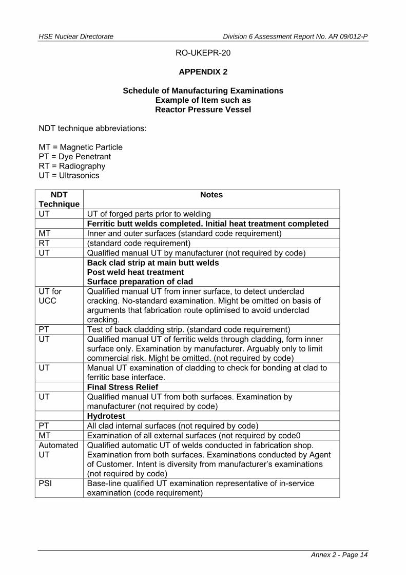
HSE Nuclear Directorate Division 6 Assessment Report No. AR 09/012-P
RO-UKEPR-20
APPENDIX 2
Schedule of Manufacturing Examinations Example of Item such as Reactor Pressure Vessel
NDT technique abbreviations: MT = Magnetic Particle PT = Dye Penetrant RT = Radiography UT = Ultrasonics
NDT Technique
Notes
UT UT of forged parts prior to welding Ferritic butt welds completed. Initial heat treatment completed MT Inner and outer surfaces (standard code requirement) RT (standard code requirement) UT Qualified manual UT by manufacturer (not required by code) Back clad strip at main butt welds
Post weld heat treatment Surface preparation of clad
UT for UCC
Qualified manual UT from inner surface, to detect underclad cracking. No-standard examination. Might be omitted on basis of arguments that fabrication route optimised to avoid underclad cracking.
PT Test of back cladding strip. (standard code requirement) UT Qualified manual UT of ferritic welds through cladding, form inner
surface only. Examination by manufacturer. Arguably only to limit commercial risk. Might be omitted. (not required by code)
UT Manual UT examination of cladding to check for bonding at clad to ferritic base interface.
Final Stress Relief UT Qualified manual UT from both surfaces. Examination by
manufacturer (not required by code) Hydrotest PT All clad internal surfaces (not required by code) MT Examination of all external surfaces (not required by code0 Automated UT
Qualified automatic UT of welds conducted in fabrication shop. Examination from both surfaces. Examinations conducted by Agent of Customer. Intent is diversity from manufacturer’s examinations (not required by code)
PSI Base-line qualified UT examination representative of in-service examination (code requirement)
Annex 2 - Page 14
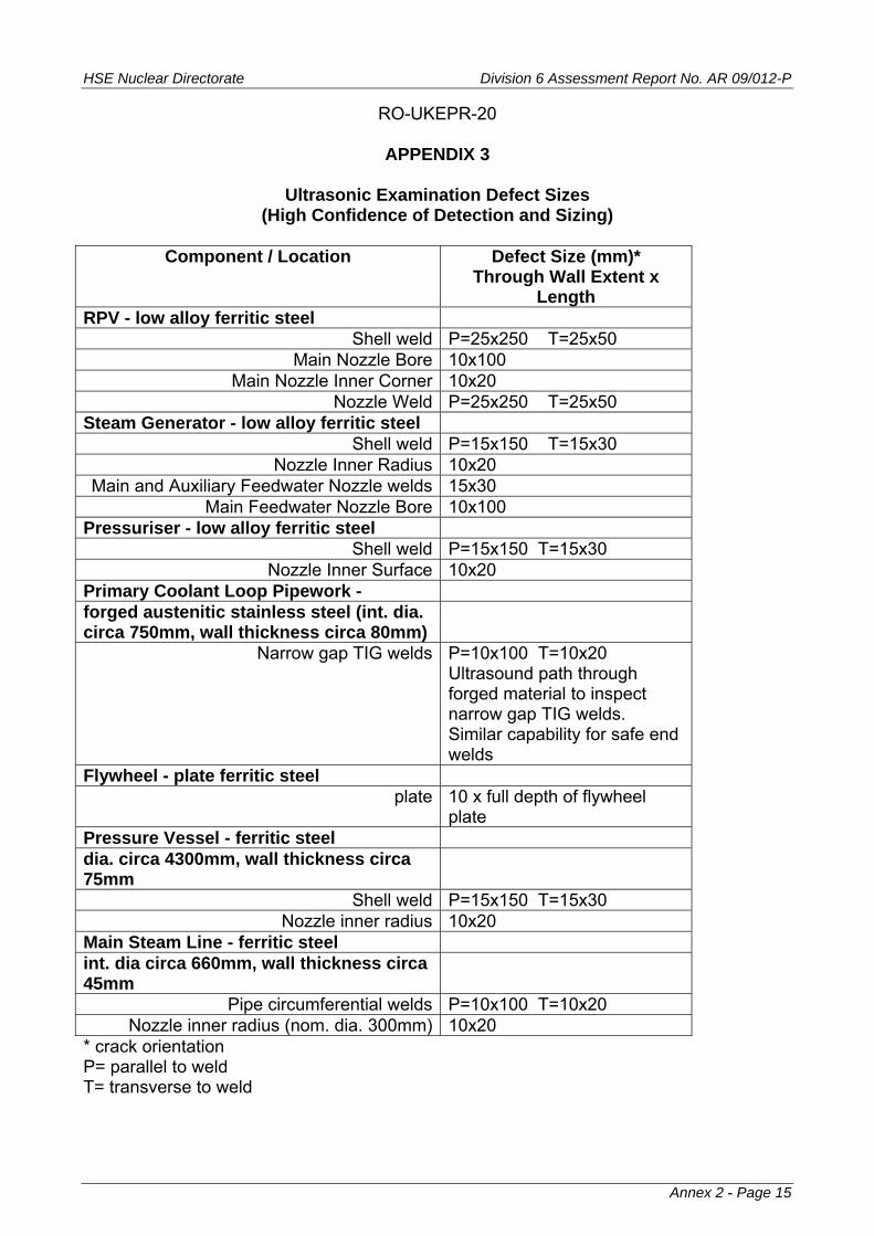
HSE Nuclear Directorate Division 6 Assessment Report No. AR 09/012-P
Annex 2 - Page 15
RO-UKEPR-20
APPENDIX 3
Ultrasonic Examination Defect Sizes (High Confidence of Detection and Sizing)
Component / Location Defect Size (mm)*
Through Wall Extent x Length
RPV - low alloy ferritic steel Shell weld P=25x250 T=25x50
Main Nozzle Bore 10x100 Main Nozzle Inner Corner 10x20
Nozzle Weld P=25x250 T=25x50 Steam Generator - low alloy ferritic steel
Shell weld P=15x150 T=15x30 Nozzle Inner Radius 10x20
Main and Auxiliary Feedwater Nozzle welds 15x30 Main Feedwater Nozzle Bore 10x100
Pressuriser - low alloy ferritic steel Shell weld P=15x150 T=15x30
Nozzle Inner Surface 10x20 Primary Coolant Loop Pipework - forged austenitic stainless steel (int. dia. circa 750mm, wall thickness circa 80mm)
Narrow gap TIG welds P=10x100 T=10x20 Ultrasound path through forged material to inspect narrow gap TIG welds. Similar capability for safe end welds
Flywheel - plate ferritic steel plate 10 x full depth of flywheel
plate Pressure Vessel - ferritic steel dia. circa 4300mm, wall thickness circa 75mm
Shell weld P=15x150 T=15x30 Nozzle inner radius 10x20
Main Steam Line - ferritic steel int. dia circa 660mm, wall thickness circa 45mm
Pipe circumferential welds P=10x100 T=10x20 Nozzle inner radius (nom. dia. 300mm) 10x20
* crack orientation P= parallel to weld T= transverse to weld

HSE Nuclear Directorate Division 6 Assessment Report No. AR 09/012-P
Annex 2 - Page 16
RO-UKEPR-20
APPENDIX 4
Manual Ultrasonic Examination Ferritic Pipe Circumferential Welds
Diameter / Wall thickness
(mm) and conditions
Qualification Crack Size Depth x length
(mm)
Summary of Ultrasonic Examination Procedure - For Guidance Only
Pipe dia. >80mm wall thickness 12-100mm Extent of surface preparation for butt welds, 4T either side of weld along whole length of weld (T=wall thickness)
Back wall and mid-wall: about 3x6mm whether weld prepared or not Near surface: (i.e. probe surface) prepared weld: 3x6mm As-welded: not detectable Note: Back wall 3mm depth takes account of weld root ultrasonic response
Examination from outside surface (the ‘near surface’). Scan for longitudinal and transverse defects. UT probes 10mm dia., 38o, 45o, 60o 4/5MHz* single shear wave, 70o single and double shear wave. * where attenuation losses exceed 6dB, 2/2.5MHz probes can be used. Longitudinal Defects: Scans using at least 2 (up to 40mm thick) or 3 (over 40mm thick) probe angles from: 45o, 60o, 70o. One angle selected so beam strikes main fusion face as near to normal incidence as possible. Transverse Defects: Scan using at least 2 probe angles from 30o, 45o, 60o, 70o. Sensitivity (using 3mm dia. side-drilled holes): Longitudinal defect scans: DAC + 14dB + ΔdB Transverse defect scans: DAC + 20dB + ΔdB DAC = Distance Amplitude Correction ΔdB = Correction for attenuation Sizing using methods in BS3923 Part 1

HSE Nuclear Directorate Division 6 Assessment Report No. AR 09/012-P
Annex 2 - Page 17
Manual Ultrasonic Examination Austenitic Stainless Steel Pipe Circumferential Welds
Diameter / Wall thickness
(mm) and conditions
Qualification Crack Size Depth x length
(mm)
Summary of Ultrasonic Examination Procedure - For Guidance Only
Normal attenuation material Forged austenitic stainless steel joined by narrow gap TIG welds
10x100 Longitudinal Defects: Twin angled compression probes (2MHz 60o and 70o) and a 2MHz 60o shear wave probe scanned axially, in both directions. Transverse Defects: Twin angled compression probes (2MHz 45o and 60o) and 2MHz 50o skewed shear wave probes scanned circumferentially in both directions. Sensitivity compensated for material attenuation Recording thresholds 20% to 30% DAC using 3mm dia. side drilled holes. Sizing using methods in BS3923 Part 1.
highly attenuating material As above, for normal attenuation material except: Longitudinal Defects: Twin angled compression probes (1.5MHz 60o and 70o) and a 1.5MHz 60o shear wave probe scanned axially, in both directions. Transverse Defects: Twin angled compression probes (2MHz 45o and 60o) and 1.5MHz 50o skewed shear wave probes scanned circumferentially in both directions.

HSE Nuclear Directorate Division 6 Assessment Report No. AR 09/012-P
RO-UKEPR-20
APPENDIX 5
Examples of Fracture Toughness Levels used in Fracture Mechanics Analyses
Low alloy steel vessel weld (e.g. RPV, SG, Pressuriser) Upper shelf toughness at normal operating temperature:
initiation toughness: 160 MPa√m toughness after 2mm stable tearing: 220MPa√m
Other ferritic steel components, base material and welds Upper shelf toughness:
initiation toughness - generic lower bound: 110MPa√m toughness after 2mm stable tearing - generic bound: 170 MPa√m
Austenitic stainless steel pipe welds MMA (including safe end welds)
initiation toughness 80MPa√m toughness after 2mm stable tearing 160 MPa√m
TIG
initiation toughness 120MPa√m toughness after 2mm stable tearing 275MPa√m
Annex 2 - Page 18

HSE Nuclear Directorate Division 6 Assessment Report No. AR 09/012-P
REGULATORY OBSERVATION
RO-UKEPR-21
Manufacturing Method for Reactor Coolant Pump Casings
Originated by / Organisation:
Approved by / Organisation:
Assessment Area
Date:
NII NII SI 23 January 2009 The UK EPR PCSR states that Reactor Coolant Pump (RCP) Casings are to be manufactured as single castings using austenitic-ferritic stainless steel. The material of the Reactor Coolant Pump Casing is mentioned in UK EPR PCSR Sub-Chapter 5.4 Section 1.1 and in Section 5.4.1 Table 2. It is noted that RCC-M Section II, M160 gives rules for a prototype part to be used to test the manufacturing method for the production of a series of castings of given design. RCP casings are listed in M140, and so the potential exclusion in M161 (limited order of casings not subject to M140) is assumed not to apply. The first item produced is considered to be the prototype. Although destructive examination is included in M160, it appears this is only used if non-destructive volumetric examination is not possible in specific areas. If no destructive examination is required, it appears that a prototype which met the criteria could be used as a production item; that is, incorporated in a nuclear power plant. RCC-M, Section II M164 defines the minimum essential variables which define the scope of validity of a satisfactory prototype. If any of these variables changes, M164 calls for a review which might (but not necessarily) lead to the need for another prototype part (because the review invalidates the existing prototype). Similarly, adverse deviations in production parts (example, unacceptable defects following examination) must be reviewed and this might also result in the need for another prototype. RCC-M Section II, M3401 is the Part Procurement Specification for “Chromium Nickel (Containing no Molybdenum) Austenitic-Ferritic Stainless Steel Castings for PWR Reactor Coolant Pump Casings”. Chemical composition is listed in Table I and mechanical property requirements in Table II. M3401 specifies solution heat treatment (1050 - 1150oC), total immersion in water and a ‘dimensional stabilisation’ heat treatment (400oC). M3401 requires surface and volumetric examinations, for volumetric examinations radiography is specified. It is noted that the radiographic examination of castings is dealt with in RCC-M Section III MC3200. M3401 section 6 states “defects such as cracks, chaplets and chill remnants shall be unacceptable”. M3401 also quotes applicable acceptance criteria in standard NF A 04-160, in terms of severity level 1 or 2. M3401 section 7.2.1 deals with removal of defects prior to repair by welding. Examination of excavations is by liquid penetrant and possibly further radiography. The overall requirement is that “Excavations shall be continued until elimination of defects which fail to meet the criteria required for the finished part”. According to M3401 section 7.3 completed repair welds are examined by liquid penetrant means and major repairs are examined
Annex 2 - Page 19
HSE Nuclear Directorate Division 6 Assessment Report No. AR 09/012-P
using radiography. Diagrams in Annexes 1 and 2 to M3401 define the boundaries between minor and major repairs, on the basis of surface area or depth. Hydrostatic pressure testing of Class 1 parts for the main primary system is dealt with in RCC-M Section I Sub-Section B, B5000. The test pressure for an individual component shall not be less than (RCC-M, B5120, 2005 Edition): (Design Pressure) x k where k=k1 x k2 k1 = 1.5 for castings (unless ‘equivalence’ to plate/forging is shown, in which case k1=1.25); k2 = ratio of minimum yield strength or ultimate strength at test temperature versus design temperature; k not to exceed 1.5 if k1=1.25 k not to exceed 1.8 if k1=1.5 (NOTE: It is understood the relevant edition of the RCC-M Code to be used is the 2007 Edition and the test pressure requirements are to some extent different between the 2005 and 2007 Editions). For the Reactor Coolant Pump casing and its material of manufacture, there are two basic failure modes due to tensile stress:
5. plastic deformation, when the applied load exceeds the combination of material strength and wall thickness / shape, either by single load application or repeated loading causing incremental distortion;
6. propagation of a pre-existing crack-like defect. The casting manufacturing method as described in RCC-M Section II, M160 and M3401 clearly addresses failure mode 1 above. However coverage of failure mode 2 above is less obvious. But the integrity requirement of the RCP casing in practical language is ‘non-breakable’, in other words the likelihood of gross failure is so low it can be discounted. The integrity status of the RCP casing is similar to the primary loop pipework to which it is connected. RCC-M M3401 classifies crack-like defects found by radiography as unacceptable, but there is no obvious way of knowing the capability of the radiographic technique to detect crack-like defects. With regard to ‘severity levels’ applied to radiographic examinations, the Steel Founder’s Society of America web site contains the following comment with regard to ASTM inspection standard usage:
“It should be borne in mind at all times that the severity rating is strictly arbitrary and based on little more than opinion. None of the reference radiographs are based on
Annex 2 - Page 20

HSE Nuclear Directorate Division 6 Assessment Report No. AR 09/012-P
any kind of test data, and the severity levels are not graded to any basis of acceptability as to service performance. They only serve as a reference point in communicating the purchasers' requirements.” [http://www.sfsa.org/sfsa/buyrord3.html#spf8.4]
Large castings such as those for the RCP casings may exhibit concentrations of defects at about the mid-point of the wall thickness. This implies at least some repair welds with through thickness extent around half wall thickness. Repair welds will be in the as-welded condition (M3401 section 7.2.3 - solution heat treatment is not required after repair welding) aside from at most a subsequent stabilisation heat treatment at about 400oC (RCC-M M3401 Section 3.4 and Section V F8410). Thus any potential crack-like defects within the volume of a repair weld would be subjected to as-welded residual stresses, in addition to applied loading stresses. And the fracture toughness of the as-deposited weld is likely to be lower than that of the parent casting material. Experience of analysing the integrity of postulated crack-like defects in large repair welds in cast austenitic stainless steel RCP casings is illustrated in ref 1. The analyses were based on surface breaking defects being of most concern, and qualified surface and ultrasonic examination procedures applied to the pump casings before and after repair. The ultrasonic examinations were only intended to detect defects within 25mm of the component surfaces (ref 2). Ultrasonic examination of the Reactor Coolant Pump Casings production parts is not a requirement of RCC-M (though it is mentioned as a substitute possibility for prototype examination, if radiography is not possible at a location). This is possibly because:
1. the microstructure of the casting material means that ultrasound will not penetrate far into the component from either inside or outside surfaces;
2. ultrasonic examination from outside and inside surfaces would require
additional surface preparation;
3. ultrasonic examination from outside and inside surfaces would take a considerable length of time.
Item 1 above is a fundamental limitation, the issues are covered in ref 3; items 2 and 3 are mainly economic factors. It is noted that while RCC-M Section II M3401 (Part Procurement Specification) is specific to castings for PWR Coolant Pump Casings, M160 (Prototype Parts) and M3200 (Radiographic Examination) are for castings in general. Overall, the requirements in RRC-M appear to provide a basis for a consistent quality / integrity but arguably do not provide a basis for a claim of very high quality/integrity (i.e. consistent with likelihood of gross failure so low it can be discounted). Casting as a manufacturing route for RCP pump casings is almost universal. However, in the past an integral forged pump casing design has been used, though in a low alloy ferritic material, rather than austenitic-ferritic stainless steel (ref 4). It is noted a large initial
Annex 2 - Page 21
HSE Nuclear Directorate Division 6 Assessment Report No. AR 09/012-P
ingot is required, with the finished forged casing being only about 25% of the mass of the initial ingot. DISCUSSION From the above, the following questions arise: 1. Has a study of options been conducted the Reactor Coolant Pump Casings, to assess the relative strengths and weaknesses of forging versus casting methods of manufacture? If such a study was done some time ago, has there been any subsequent review, taking account of developments in technology? 2. Assuming an austenitic-ferritic stainless steel casting:
How is the solution heat treatment controlled in order to give a material condition with the specified ferrite content? RCC-M Section II M3401 in 3.4 defines the solution heat treatment temperature to be between 1050 and 1150oC, but does not mention holding times. What is the corresponding range of holding times? RCC-M Section II M3401, 3.4 refers to immersion in water, is this applied at the end of the solution heat treatment hold time? If so, what is the purpose of this quench, and what effect does it have on the material microstructure through the thickness of the component and what effect does it have on the residual stress profile? RCC-M Section II M3401, 4.4 mentions re-treatment. What is the range of potential re-treatment conditions, does it include the possibility of a full re-solution heat treatment and water immersion? RCC-M Section II M3401, 3.4 mentions the possibility of a stabilising heat treatment for dimensional tolerance reasons. This is specified to be performed at 400oC for at least 48 hours. Is this heat treatment performed after all repair welding? What are the heat-up and cooling rates for this stabilisation heat treatment? What effect does this stabilisation heat treatment have on the material microstructure and residual stress profiles, for both the base casting and repair welds? RCC-M Section II M163.2 states that the prototype may be taken forward as a production part, subject to any repairs. This suggests that non-destructive tests examinations are not cross-checked by destructive examinations, beyond a level of material disturbance comparable to production part repair excavations. For Reactor Coolant Pump Casing castings, could the ‘prototype’ part be taken forward as a ‘production’ part?
3. For the cast austenitic-ferritic RCP casings, has the radiographic examination procedure been qualified for its capability to detect crack-like defects lying perpendicular to main stress components in the wall of the casing? 4. Ultrasonic examination of austenitic stainless steel castings can be difficult due to the effects on ultrasound transmission. But in some circumstances it has been shown to be possible, at least to depths up to 25 to 50mm below the surface (refs 2, 3). Would
Annex 2 - Page 22

HSE Nuclear Directorate Division 6 Assessment Report No. AR 09/012-P
ultrasonic examination at least of near surface regions provide an additional element to the evidence for integrity of the component? If scanning the complete outer and inner surfaces was considered not economic for the benefit, would at least ultrasonic examination of large repair welds be reasonable? 5. Is there an Equipment Specification for the Reactor Coolant Pump Casings and does this include extra and / or more specific requirements compared with the Part Procurement Specification in RCC-M Section II M3401? References 1. Bouchard P J., Goldthorpe M R., Prottey P., J-Integral and Local Damage Fracture Analyses for a Pump Casing Containing Large Weld Repairs. International Journal of Pressure Vessels and Piping Vol 78 pp295-305 (2001). 2. Hook D E., Booler R V., Validated Ultrasonic Techniques for Austenitic Welds and Castings. Proc. 10th Int. Conf. on NDE in the Nuclear and Pressure Vessel Industries 1990. 3. Boveyron C., Villard D., Boudot R., Ultrasonic Testing of cast Stainless Steel Components. pp 403-408, Proc. 11th Int. Conf. on NDE in the Nuclear and Pressure Vessel Industries. Albuquerque (30 April-2 may 1992). 4. Austel W., Körbe H., Integral Forged Pump Casing for the Primary Coolant Circuit of a Nuclear Reactor: Development in Design, Forging Technology, and Material. pp 285-397. Steel Forgings. A Symposium. ASTM STP 903. Edited by E G Nisbett, A S Melilli. Williamsburg (28-30 November 1994).
Annex 2 - Page 23
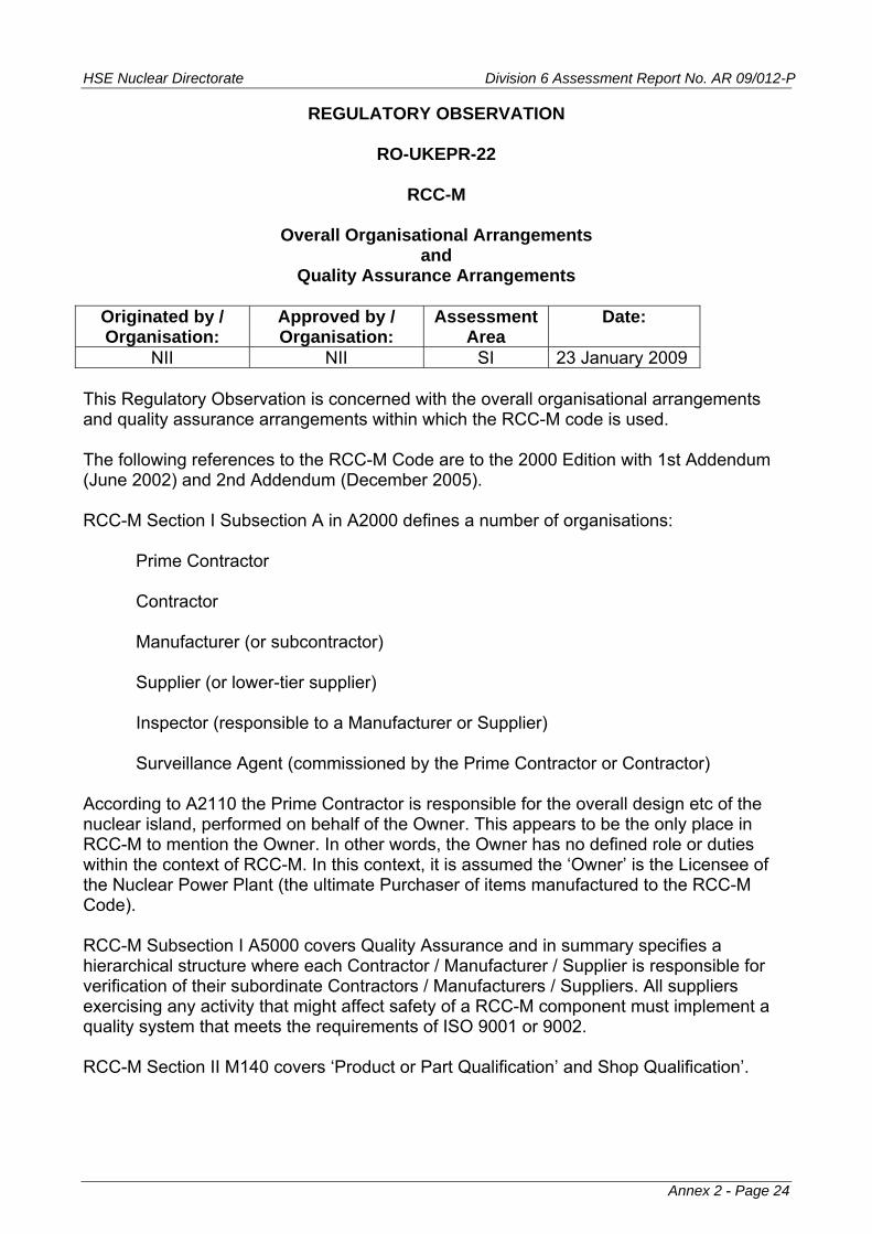
HSE Nuclear Directorate Division 6 Assessment Report No. AR 09/012-P
REGULATORY OBSERVATION
RO-UKEPR-22
RCC-M
Overall Organisational Arrangements and
Quality Assurance Arrangements
Originated by / Organisation:
Approved by / Organisation:
Assessment Area
Date:
NII NII SI 23 January 2009 This Regulatory Observation is concerned with the overall organisational arrangements and quality assurance arrangements within which the RCC-M code is used. The following references to the RCC-M Code are to the 2000 Edition with 1st Addendum (June 2002) and 2nd Addendum (December 2005). RCC-M Section I Subsection A in A2000 defines a number of organisations:
Prime Contractor Contractor Manufacturer (or subcontractor) Supplier (or lower-tier supplier) Inspector (responsible to a Manufacturer or Supplier) Surveillance Agent (commissioned by the Prime Contractor or Contractor)
According to A2110 the Prime Contractor is responsible for the overall design etc of the nuclear island, performed on behalf of the Owner. This appears to be the only place in RCC-M to mention the Owner. In other words, the Owner has no defined role or duties within the context of RCC-M. In this context, it is assumed the ‘Owner’ is the Licensee of the Nuclear Power Plant (the ultimate Purchaser of items manufactured to the RCC-M Code). RCC-M Subsection I A5000 covers Quality Assurance and in summary specifies a hierarchical structure where each Contractor / Manufacturer / Supplier is responsible for verification of their subordinate Contractors / Manufacturers / Suppliers. All suppliers exercising any activity that might affect safety of a RCC-M component must implement a quality system that meets the requirements of ISO 9001 or 9002. RCC-M Section II M140 covers ‘Product or Part Qualification’ and Shop Qualification’.
Annex 2 - Page 24
HSE Nuclear Directorate Division 6 Assessment Report No. AR 09/012-P
In the UK there is some familiarity with the American Society of Mechanical Engineers (ASME) Section III “Rules for Construction of Nuclear facility Components”, and in particular Subsection NCA “ General Requirements for Division 1 and Division 2”. ASME III NCA defines certain organisations and their responsibilities, mainly:
Owner N Certificate Holder - Division 1 NPT, NA, NS Certificate Holders Metallic Material Organisation (Quality System Programme) Authorised Inspection Agency
Authorised Nuclear Inspection Supervisor (ANIS) Authorised Nuclear Inspector (ANI)
Within the ASME approach, the above organisations require appropriate certification or accreditation from the Society. Quality assurance is dealt with in ASME III NCA-4000. N-Type Certificate Holders shall comply with ASME NQA-1, “Quality Assurance Program for Nuclear Facilities”. The Authorised Inspection Agency, ANIS and ANI are qualified in accordance with ASME QAI-1 “Qualification for Authorised Inspection”. Certificate Holders are required to complete defined Forms at specific stages. Example Data Report Forms are given in ASME III Appendix V. Similar type forms are used for Certification of Design Specifications and Design Reports (ASME III Appendix XXIII). ASME III NCA-3200 sets out the Owner’s Responsibilities and NCA-3220 sets out the responsibilities of the Owner in a list of items from (a) to (u). The activities necessary to provide compliance with responsibilities assigned to the Owner by (e) to (u) in the list may be performed on the Owner’s behalf by a designee; however the responsibility for compliance remains with the Owner. Items (a) to (d) are: (a) obtaining an Owner’s Certificate (b) documenting a Quality Assurance Plan (c) obtaining a written agreement with an Authorised Inspection Agency (d) certifying and filing of Owner’s Data Report. (Form N-3) This emphasis on the Owner’s responsibilities (assumed to be the Licensee) is consistent with NII SAP MS.2 and para. 56. In the UK, the ASME Code is not a legal requirement (unlike in the USA, where it is a legal requirement through reference in 10CFR50) and in general the ASME Code relates to
Annex 2 - Page 25

HSE Nuclear Directorate Division 6 Assessment Report No. AR 09/012-P
institutions and practices which are specific to the USA and Canada. In past application of the ASME Code Section III in the UK, an adaptation was used that substituted Licensee specified arrangements in place of ASME III Subsection NCA. Basic features of these arrangements were:
remove the requirements for the Owner and his suppliers to obtain certificates from ASME and remove the requirement for application of ASME Code Stamps to manufactured components; preserve control functions without limiting certifiers’ qualifications to those of a Professional Engineer registered in the USA or Canada. In practice this was by substituting suitably qualified UK Chartered Engineers; alternative arrangements for issue of an Owner’s Certificate (by the Institution of Mechanical Engineers, Engineering Inspection Authorities Board); employment by the Owner of one or more Independent Inspection Agencies; system of UK Certification Forms and Data Report Forms to be used at the corresponding points to the ASME Forms (corresponding to Forms described in ASME Appendices V and XXIII); Items or components procured within the USA could be procured and fabricated entirely in accordance with ASME III from suppliers holding ASME certificates.
The ASME III approach of requiring an Authorised Inspection Agency to be employed by the Owner, is similar to the longstanding, general UK practice (nuclear and non-nuclear) of the owner using an inspection agent to check activities carried out by its suppliers. Historically this has been either an independent agent or an agent that is part of the Owner’s organisation. For components important to nuclear our preference would be for an independent third party inspection agent. Activities and responsibilities of the Owner’s inspection agent might include:
with the Owner, to monitor the Quality Assurance Programme activities of contractors and suppliers;
to verify that all material used comply with the applicable requirements of the Design Specification by witnessing examinations or carrying out inspections as considered necessary;
to witness or otherwise verify in-process fabrication and erection, non-destructive examinations and tests and to witness the final hydrostatic pressure tests. To include review of welder qualification records and review of NDE personnel qualification records;
to endorse certain Forms that certify completion of certain steps in the design, manufacture and installation process;
Annex 2 - Page 26

HSE Nuclear Directorate Division 6 Assessment Report No. AR 09/012-P
to review and comment on drawings and process procedures, with the Owner to define hold and notification points on quality plans and to inspect against them.
According to ASN/Guide/5/01, ASN Approves bodies and agencies that carry out inspection activities on nuclear pressure equipment. This ASN web site page: http://www.asn.fr/sections/rubriquesprincipales/textes-reference/acces-par-theme/installations-controlees/equipements-sous-pression-nucleaire lists decisions by ASN to accept or refuse acceptance of organisations for inspection of nuclear pressure equipment and welding services. We understand ASN does not ‘Approve’ or ‘Certify’ manufacturers or suppliers of nuclear pressure equipment that is to be used in France. Similarly, NII does not ‘Approve’ or ‘Certify’ manufacturers or suppliers. DISCUSSION According to UK EPR PCSR Sub-Chapter 3.8, 2.3.2: “The RCC-M does not include provisions for certification and stamping of equipment as is the case with the ASME code. It is focused on technical aspects. Surveillance of activities by or on behalf of the owner and the contractor or suppliers must be covered in contractual documents.” However, RCC-M Section I, Subsection A does touch on organisational roles and quality arrangements. In the UK, the expectation is the Licensee would have fundamental responsibility for quality arrangements. For a nuclear power plant in the UK where the design code of nuclear pressure equipment is RCC-M, would the following quality assurance concept be compatible with RCC-M? :
the Owner as the top of the quality assurance hierarchical chain; an independent third party inspection agent employed by the Owner with this inspection agent having oversight of all relevant lower tier activities [1]; use of explicit forms to certify certain steps in the manufacture and installation process of nuclear pressure equipment.
Clearly, implementation of the above sort of approach requires the involvement of the Licensee as Owner. So rather than agreement of a Licensee to the above sort of arrangement, the question is put in terms of compatibility with RCC-M. An important enabler for the Owner and their third part inspection agent to monitor manufacture of components, is to have available at an early stage of manufacturer, a strategic Quality Plan that identifies the major stages / milestones of manufacture. Such an overall Quality Plan allows identification of major hold points and witness points.
Annex 2 - Page 27
HSE Nuclear Directorate Division 6 Assessment Report No. AR 09/012-P
NOTE 1: The use of the term ‘independent third party inspection agent (ITPIA)’ should not be confused with the term third party organisation as used in the Pressure Equipment Directive (PED, 97/23/EC). In the UK, the traditional scope of responsibility of an ITPIA is broader than that of the PED third party organisation. The UK implementation of the Pressure Equipment Directive is “The Pressure Equipment Regulations 1999” (PER 1999) - Statutory Instrument 1999 No 2001. The PER 1999 carries over from the Directive all its exclusions; they are contained in Schedule 1 of the PER 1999. The ‘nuclear use’ exclusion is item 8 in Schedule 1 to the PER 1999; this being item 3.8 in Article 1 of the PED 97/23/EC.
Annex 2 - Page 28
HSE Nuclear Directorate Division 6 Assessment Report No. AR 09/012-P
Annex 2 - Page 29
REGULATORY OBSERVATION
RO-UKEPR-23
RCC-M
Overpressure Protection
Originated by / Organisation:
Approved by / Organisation:
Assessment Area
Date:
NII NII SI 23 January 2009 RCC-M does not provide rules for overpressure protection. By comparison, ASME III in NB7000, NC7000 and ND7000 (for Class 1, 2 and 3 components respectively) provides detailed rules for overpressure protection. One of the requirements of ASME III Nx7000 is the production of an Overpressure Protection Report. This report is prepared by the Owner or their designee. ASME III Nx7000 contains a specification for the minimum contents of the report. ASME III requires the Overpressure Protection Report to be certified. DISCUSSION What is the basis of the overpressure protection provisions for the UK EPR? Assuming they are the same as the EPR basis, what document / regulations define this basis? Is an ‘Overpressure Protection Report’ similar scope to ASME III available for the EPR? Issue 1 For an EPR plant in the UK, NII would want an Overpressure Protection Report with a scope at least of the ASME III document. This would need to include the role of the reactor shutdown system as part of an integrated overpressure protection system.

HSE Nuclear Directorate Division 6 Assessment Report No. AR 09/012-P
REGULATORY OBSERVATION
RO-UKEPR-24
Materials Specifications and Selection of Material Grade -
Reactor Pressure Vessel, Pressuriser, Steam Generator Shells
Originated by / Organisation:
Approved by / Organisation:
Assessment Area
Date:
NII NII SI 23 January 2009 This Regulatory Observation addresses materials specifications and selection of materials for the following major pressure vessels: Reactor Pressure Vessel Pressuriser Steam Generators (primary and secondary circuit sides) In line with international practice for PWRs, the above vessels in the EPR are specified to be made using a quenched and tempered low-alloy ferritic steel. The EPR specifies forgings as the material form (in distinction from plate material). Appendix 1 to this Regulatory Observation makes comparisons between the following forging materials: Reactor Pressure Vessel (Tables 1 and 3)
ASME A508 Grade 3 Class1 (previously called A508 Class 3); UK specification of material, based on A508 Class 3; RCC-M 16 MND 5 material, Part Procurement Specifications M2111 and M2112.
Steam Generators and Pressuriser (Tables 4 and 5)
UK specification of material, also used A508 Class 3 for these components; RCC-M 18 MND 5 material, Part Procurement Specifications M2119, M2133, M2134.
From RCC-M (edition with Addenda to 2005) Section I Subsection B Table B2200, Part Procurement Specification M2143 is also relevant for Steam Generator channel head forgings. However, for the purposes of this comparison, it is assumed the three Specifications chosen are representative.
Annex 2 - Page 30
HSE Nuclear Directorate Division 6 Assessment Report No. AR 09/012-P
For the RPV, Table 1 compares chemical compositions and Table 3 compares heat treatment, mechanical tensile properties, design stress and fracture properties requirements. For the Steam Generators and the Pressuriser, Table 4 compares chemical compositions and Table 5 compares heat treatment, mechanical tensile properties, design stress and fracture properties requirements. COMPARISONS FOR REACTOR PRESSURE VESSEL For the Reactor Pressure Vessel, the ASME A508 Grade 3 Class 1, UK usage of ASME A508 Class 3 and the RCC-M 16 MND 5 materials specifications are broadly similar. The following are notable highlights of the comparison: Chemical Composition 1. UK usage of ASME A508 Class 3 has additional and in some cases more restrictive chemical composition requirements compared to ASME A508 Grade 3 Class 1; 2. RCC-M 16 MND 5 (M2111 and M2112) also have additional and more restrictive chemical composition requirements compared to ASME A508 Grade 3 Class 1; 3. The chemical composition requirements for RCC-M 16 MND 5 and UK usage of ASME A508 Class 3 are quite similar. However the UK usage has limits on Antimony, Arsenic, Tin (to reduce the potential for temper embrittlement) and Hydrogen that are not included in the RCC-M 16 MND 5 specification. Also the UK usage specification has a lower limit on Carbon (0.2% max vs. 0.22% max) and Chromium (0.15% max vs. 0.25% max); 4. ASME A508 Grade 3 Class 1 chemical composition includes limits on Boron, Columbium (Niobium), Calcium and Titanium. These have been introduced since the ASME code version used for Sizewell B in the UK. Tensile Properties 1. For M2111 it is noted that in the 1988 edition of RCC-M, the minimum yield strength at 350oC (Rp0.2 @ t) is defined in terms of a value recorded after a 5 minute period. Charpy Impact Energy 1. RCC-M 16 MND 5 material specification has more requirements for Charpy Impact tests than ASME A508 material specification. However, determination of RTNDT temperature (rules in ASME III Section III Subsection NB, NB-2300 rather than A508 material specification) may require Charpy tests at a range of temperatures. UK usage of ASME A508 Class 3 same as ASME but with additional ‘upper shelf temperature’ requirement; 2. UK usage of A508 Class 3 ‘upper shelf temperature’ Charpy impact energy requirement somewhat similar to +20oC RCC-M Charpy impact energy requirement. RTNDT
Annex 2 - Page 31

HSE Nuclear Directorate Division 6 Assessment Report No. AR 09/012-P
1. ASME III NB-2300 defines method for determining RTNDT but does not specify required values; 2. UK usage of ASME A508 Class 3 specifies RTNDT of less than -12oC for all RPV forgings except the nozzles and -22oC for the nozzles; 3. RCC-M 16 MND 5 M2111 specifies an RTNDT of no higher than 0oC with a value lower than -12oC being desirable. RCC-M 16 MND 5 M2112 specifies an RTNDT on higher than +16oC with a value lower than -12oC being desirable. UK EPR PCSR Sub-Chapter 5.3 on page 8/25 and 15/25 indicates RTNDT requirements of less than -20oC and -30oC, depending on location in the vessel; 4. Apart from shift in RTNDT through life due to neutron irradiation, it has been UK precedent to include the potential shift in RTNDT due to thermal and strain ageing. A representative, claimed conservative, value of RTNDT shift due to thermal and strain ageing is 30oC (covering weld and base metal).
Annex 2 - Page 32
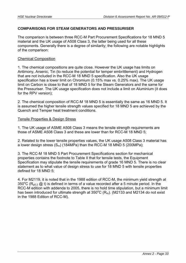
HSE Nuclear Directorate Division 6 Assessment Report No. AR 09/012-P
COMPARISONS FOR STEAM GENERATORS AND PRESSURISER The comparison is between three RCC-M Part Procurement Specifications for 18 MND 5 material and the UK usage of A508 Class 3, the latter being used for all these components. Generally there is a degree of similarity; the following are notable highlights of the comparison: Chemical Composition 1. The chemical compositions are quite close. However the UK usage has limits on Antimony, Arsenic, Tin (to reduce the potential for temper embrittlement) and Hydrogen that are not included in the RCC-M 18 MND 5 specification. Also the UK usage specification has a lower limit on Chromium (0.15% max vs. 0.25% max). The UK usage limit on Carbon is close to that of 18 MND 5 for the Steam Generators and the same for the Pressuriser. The UK usage specification does not include a limit on Aluminium (it does for the RPV version); 2. The chemical composition of RCC-M 18 MND 5 is essentially the same as 16 MND 5. It is assumed the higher tensile strength values specified for 18 MND 5 are achieved by the Quench and Temper heat treatment conditions. Tensile Properties & Design Stress 1. The UK usage of ASME A508 Class 3 means the tensile strength requirements are those of ASME A508 Class 3 and these are lower than for RCC-M 18 MND 5; 2. Related to the lower tensile properties values, the UK usage A508 Class 3 material has a lower design stress (Sm) (184MPa) than the RCC-M 18 MND 5 (200MPa); 3. The RCC-M 18 MND 5 Part Procurement Specifications section for mechanical properties contains the footnote to Table II that for tensile tests, the Equipment Specification may stipulate the tensile requirements of grade 16 MND 5. There is no clear statement as to what value of design stress to use for 18 MND 5 with tensile properties defined for 18 MND 5; 4. For M2119, it is noted that in the 1988 edition of RCC-M, the minimum yield strength at 350oC (Rp0.2 @ t) is defined in terms of a value recorded after a 5 minute period. In the RCC-M edition with addenda to 2005, there is no hold time stipulation, but a minimum limit has been introduced for ultimate strength at 350oC (Rm). (M2133 and M2134 do not exist in the 1988 Edition of RCC-M).
Annex 2 - Page 33
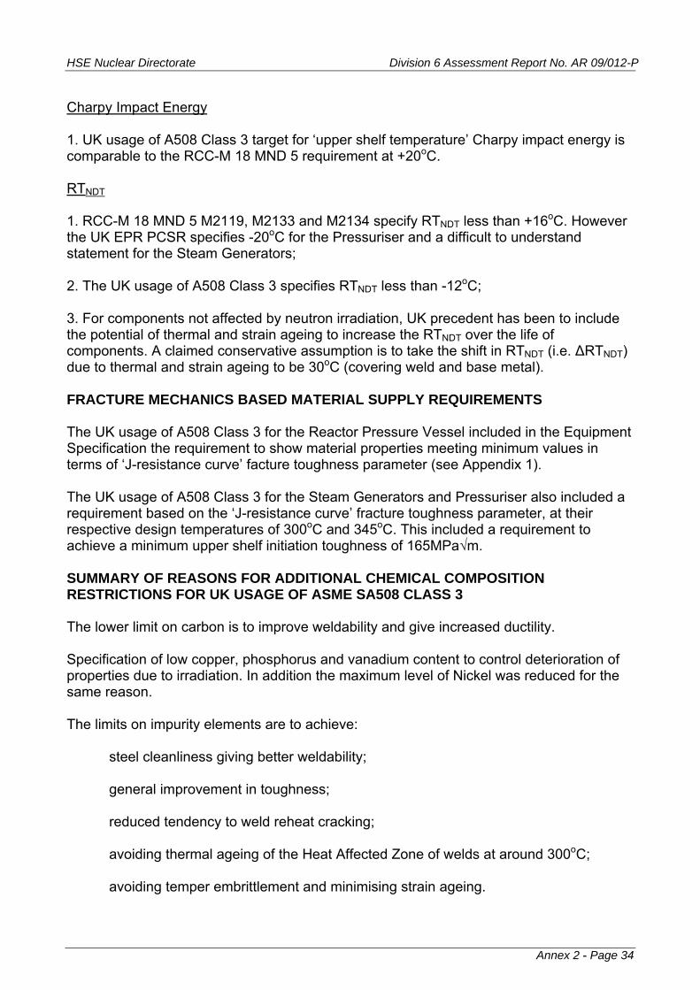
HSE Nuclear Directorate Division 6 Assessment Report No. AR 09/012-P
Charpy Impact Energy 1. UK usage of A508 Class 3 target for ‘upper shelf temperature’ Charpy impact energy is comparable to the RCC-M 18 MND 5 requirement at +20oC. RTNDT 1. RCC-M 18 MND 5 M2119, M2133 and M2134 specify RTNDT less than +16oC. However the UK EPR PCSR specifies -20oC for the Pressuriser and a difficult to understand statement for the Steam Generators; 2. The UK usage of A508 Class 3 specifies RTNDT less than -12oC; 3. For components not affected by neutron irradiation, UK precedent has been to include the potential of thermal and strain ageing to increase the RTNDT over the life of components. A claimed conservative assumption is to take the shift in RTNDT (i.e. ΔRTNDT) due to thermal and strain ageing to be 30oC (covering weld and base metal). FRACTURE MECHANICS BASED MATERIAL SUPPLY REQUIREMENTS The UK usage of A508 Class 3 for the Reactor Pressure Vessel included in the Equipment Specification the requirement to show material properties meeting minimum values in terms of ‘J-resistance curve’ facture toughness parameter (see Appendix 1). The UK usage of A508 Class 3 for the Steam Generators and Pressuriser also included a requirement based on the ‘J-resistance curve’ fracture toughness parameter, at their respective design temperatures of 300oC and 345oC. This included a requirement to achieve a minimum upper shelf initiation toughness of 165MPa√m. SUMMARY OF REASONS FOR ADDITIONAL CHEMICAL COMPOSITION RESTRICTIONS FOR UK USAGE OF ASME SA508 CLASS 3 The lower limit on carbon is to improve weldability and give increased ductility. Specification of low copper, phosphorus and vanadium content to control deterioration of properties due to irradiation. In addition the maximum level of Nickel was reduced for the same reason. The limits on impurity elements are to achieve:
steel cleanliness giving better weldability; general improvement in toughness; reduced tendency to weld reheat cracking; avoiding thermal ageing of the Heat Affected Zone of welds at around 300oC;
avoiding temper embrittlement and minimising strain ageing.
Annex 2 - Page 34

HSE Nuclear Directorate Division 6 Assessment Report No. AR 09/012-P
DISCUSSION From the foregoing the following questions arise. 1. Is there any substantive reason why the Equipment Specification for the UK EPR Reactor Pressure Vessel materials could not include limits on the chemical composition of 16 MND 5 as in the UK usage of ASME SA508 Class 3 (notably Carbon, Chromium, Arsenic, Antimony, Tin and Hydrogen)? 2. If 18 MND 5 is specified with tensile properties as for 16 MND 5 (for example, as permitted by Part Procurement Specifications M2119, M2133, M2134), is the Design Stress (Sm) reduced to that of 16 MND 5 (184MPa) compared to the 18 MND 5 value (200MPa)? 3. UK precedent has been to use the UK modified specification of ASME SA508 Class 3 (now Grade 3 Class 1) for the Reactor Pressure Vessel, Pressuriser and Steam Generator (primary and secondary side) shells. What is the reason for using an apparent plethora of versions of 18 MND 5 for the Pressuriser and Steam Generator shells in the UK EPR? Bearing in mind question 3 above, could all these pressure vessel shells be specified to be constructed from 16 MND 5? 4. Has the RCC-M chemical composition been reviewed against the current ASME chemical composition for SA508 Grade 3 Class 1 for the elements added to the ASME specification; in particular the limit on Boron? 5. For RCC-M Part Procurement Specifications M2111 and M2119, what were the reasons for changing the tensile property requirements between the 1988 Edition and the edition with addenda to 2005? This refers to the hold time for the elevated temperature yield strength in the 1988 edition but absent from the edition with addenda to 2005.
Annex 2 - Page 35

HSE Nuclear Directorate Division 6 Assessment Report No. AR 09/012-P
Annex 2 - Page 36
APPENDIX 1
Materials - Comparison Tables
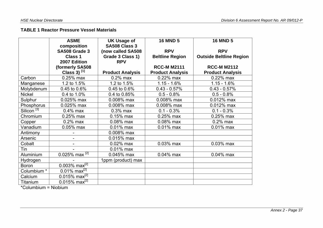
HSE Nuclear Directorate Division 6 Assessment Report No. AR 09/012-P
TABLE 1 Reactor Pressure Vessel Materials ASME
composition SA508 Grade 3
Class 1 2007 Edition
(formerly SA508 Class 3) [1]
UK Usage of SA508 Class 3
(now called SA508 Grade 3 Class 1)
RPV
Product Analysis
16 MND 5
RPV Beltline Region
RCC-M M2111
Product Analysis
16 MND 5
RPV Outside Beltline Region
RCC-M M2112
Product Analysis Carbon 0.25% max 0.2% max 0.22% max 0.22% max Manganese 1.2 to 1.5% 1.2 to 1.5% 1.15 - 1.6% 1.15 - 1.6% Molybdenum 0.45 to 0.6% 0.45 to 0.6% 0.43 - 0.57% 0.43 - 0.57% Nickel 0.4 to 1.0% 0.4 to 0.85% 0.5 - 0.8% 0.5 - 0.8% Sulphur 0.025% max 0.008% max 0.008% max 0.012% max Phosphorus 0.025% max 0.008% max 0.008% max 0.012% max Silicon [3] 0.4% max 0.3% max 0.1 - 0.3% 0.1 - 0.3% Chromium 0.25% max 0.15% max 0.25% max 0.25% max Copper 0.2% max 0.08% max 0.08% max 0.2% max Vanadium 0.05% max 0.01% max 0.01% max 0.01% max Antimony - 0.008% max Arsenic - 0.015% max Cobalt - 0.02% max 0.03% max 0.03% max Tin - 0.01% max Aluminium 0.025% max [2] 0.045% max 0.04% max 0.04% max Hydrogen - 1ppm (product) max Boron 0.003% max[2] Columbium * 0.01% max[2] Calcium 0.015% max[2] Titanium 0.015% max[2] *Columbium = Niobium
Annex 2 - Page 37

HSE Nuclear Directorate Division 6 Assessment Report No. AR 09/012-P
Both ASME and RCC-M specify steel to be made using and electric furnace and vacuum-degassed. RCC-M specifically mentions the material shall be aluminium-killed. 1. ASME A508 Specification - Supplementary Requirement S9 specifies: S9.1.1 Phosphorus 0.015% max product, Copper 0.1% max product or S9.1.2 Phosphorus 0.015% max product, Copper 0.15% max product S9.2 Sulphur 0.015% max product 2. Element limit added since ASME Code edition used for Sizewell B 3. ASME A508 Specification - Supplementary Requirement S11 sets limit on Silicon of 0.1% max. Supplementary Specification S16 sets range of Silicon content as 0.05 to 0.15%
Annex 2 - Page 38
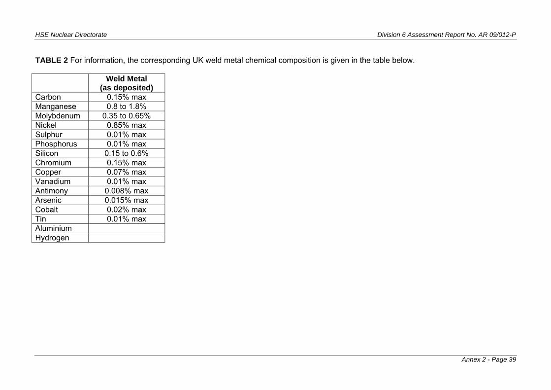
HSE Nuclear Directorate Division 6 Assessment Report No. AR 09/012-P
TABLE 2 For information, the corresponding UK weld metal chemical composition is given in the table below. Weld Metal
(as deposited) Carbon 0.15% max Manganese 0.8 to 1.8% Molybdenum 0.35 to 0.65% Nickel 0.85% max Sulphur 0.01% max Phosphorus 0.01% max Silicon 0.15 to 0.6% Chromium 0.15% max Copper 0.07% max Vanadium 0.01% max Antimony 0.008% max Arsenic 0.015% max Cobalt 0.02% max Tin 0.01% max Aluminium Hydrogen
Annex 2 - Page 39
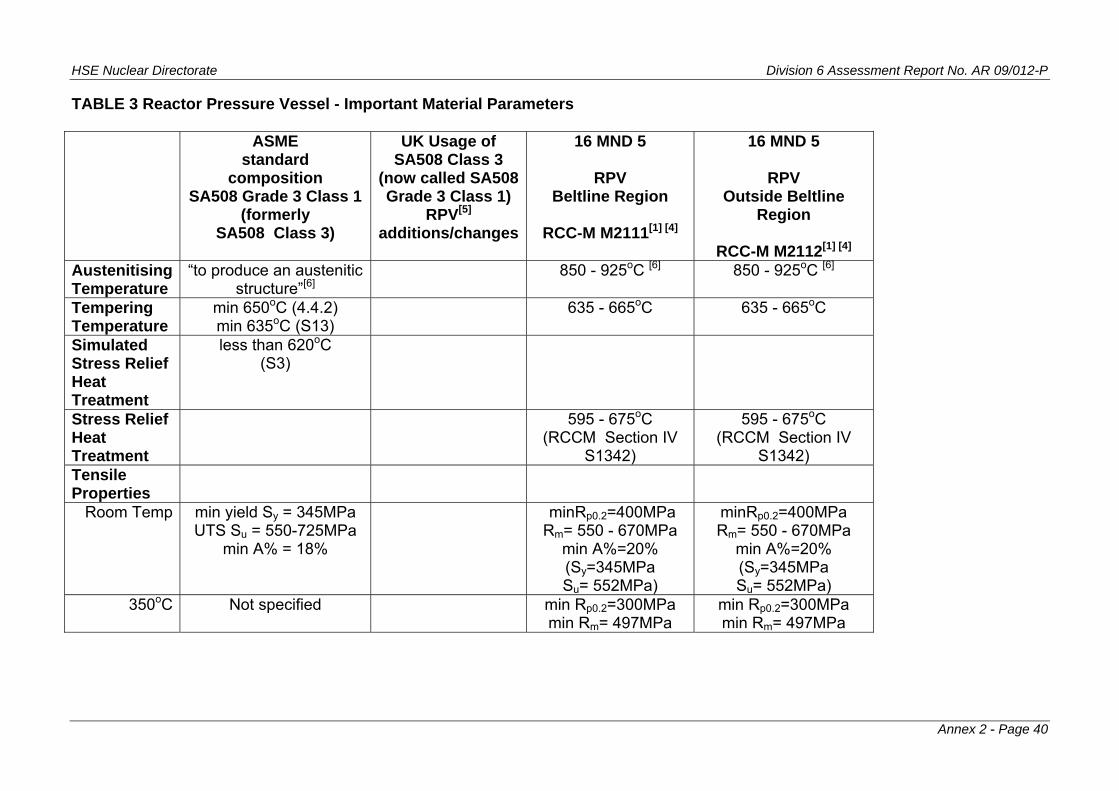
HSE Nuclear Directorate Division 6 Assessment Report No. AR 09/012-P
TABLE 3 Reactor Pressure Vessel - Important Material Parameters ASME
standard composition
SA508 Grade 3 Class 1(formerly
SA508 Class 3)
UK Usage of SA508 Class 3
(now called SA508 Grade 3 Class 1)
RPV[5] additions/changes
16 MND 5
RPV Beltline Region
RCC-M M2111[1] [4]
16 MND 5
RPV Outside Beltline
Region
RCC-M M2112[1] [4] Austenitising Temperature
“to produce an austenitic structure”[6]
850 - 925oC [6] 850 - 925oC [6]
Tempering Temperature
min 650oC (4.4.2) min 635oC (S13)
635 - 665oC 635 - 665oC
Simulated Stress Relief Heat Treatment
less than 620oC (S3)
Stress Relief Heat Treatment
595 - 675oC (RCCM Section IV
S1342)
595 - 675oC (RCCM Section IV
S1342) Tensile Properties
Room Temp min yield Sy = 345MPa UTS Su = 550-725MPa
min A% = 18%
minRp0.2=400MPa Rm= 550 - 670MPa
min A%=20% (Sy=345MPa Su= 552MPa)
minRp0.2=400MPa Rm= 550 - 670MPa
min A%=20% (Sy=345MPa Su= 552MPa)
350oC Not specified min Rp0.2=300MPa min Rm= 497MPa
min Rp0.2=300MPa min Rm= 497MPa
Annex 2 - Page 40

HSE Nuclear Directorate Division 6 Assessment Report No. AR 09/012-P
Design Stress
Room Temp 184MPa 184MPa 184MPa 300oC 184MPa 184MPa 184MPa 350oC 184MPa 184MPa 184MPa
Charpy Impact Energy
0oC transverse min average 56J
min individual 40Jlongitudinal
min average 80Jmin individual 60J
transverse min average 56J
min individual 40Jlongitudinal
min average 72Jmin individual 56J
4.4oC min average 41J min individual 34J
-20oC transverse min average 40J
min individual 28Jlongitudinal
min average 56Jmin individual 40J
transverse min average 40J
min individual 28Jlongitudinal
min average 56Jmin individual 40J
+20oC transverse min individual 104J
longitudinal min individual 120J
[Note 2]
transverse min individual 72J
longitudinal min individual 88J
[Note 2]
Annex 2 - Page 41

HSE Nuclear Directorate Division 6 Assessment Report No. AR 09/012-P
“Upper shelf
temperature” 101J in active core
region and weld between nozzle course and core shell course ‘target’ of 88J for nozzle course, nozzles and nozzle welds
RTNDT [7] Method for determination set out in ASME III NB-2300, but no criteria for values
All forgings except nozzles, less than -12oC. Nozzle forgings, less than -22oC
No higher than 0oC, a value lower than -12oC is desirable. If between -12 and 0oC actual value to be determined [Note 3]
No higher than +16oC, a value lower than -12oC is desirable. If between -12 and +16oC actual value to be determined. [Note 3]
Rp0.2 = Yield Strength at 0.2% permanent strain Rm = Ultimate Tensile Strength A% = Uniform Elongation
Annex 2 - Page 42

HSE Nuclear Directorate Division 6 Assessment Report No. AR 09/012-P
Notes to Table 3 1. Parts rejected on the basis of one or more mechanical tests may be retreated. Retreatment conditions shall be described in the test report. Tests are to be repeated. No more than 2 retreatments allowed. 2. Where one or more results fails to satisfy the requirement, this condition shall be fulfilled for three additional tests at +40oC. If requirements not met at +40oC, part shall be rejected. 3. UK EPR PCSR Sub-Chapter 5.3 page 8/25 states the initial RTNDT is less than or equal to -20oC. Sub-Chapter 5.3 page 15/25 states that for the dome to head flange weld, the RTNDT is specified as less than -30oC. 4. Design stress limits from RCC-M Section I, Subsection Z, Annex Z I. 5. UK precedent for the Reactor Pressure Vessel is to require fracture toughness tests based on the ‘J-integral’ fracture parameter, see Appendix 2 6. RCC-M Section II Part Procurement Specifications M2111 and M2112 specify quenching by immersion in water or water spraying. ASME SA-508 specification requires quenching “in a suitable liquid medium by spraying or immersion”. RCC-M specifies an austenitic grain size number greater than or equal to 5 (“fine grained”); ASME, no specific grain size requirement for A508 Grade 3 Class 1. 7. In RCC-M, method to determine RTNDT set out in Section III, MC-1000. In ASME III, method to determine RTNDT set out in ASME III Subsection NB, NB-2300 for Class 1 components. Methods are similar, based on combination of drop weight test results and Charpy impact energy test results. Both require TNDT to be determined using Pellini Drop Weight test. RCC-M and ASME specify ASTM E208 as the standard for drop weight testing. ASME allows specimen types P1, P2 or P3 to be used; RCC-M specifies specimen type P3 only. Both RCC-M and ASME III NB-2300 define RTNDT as:
(i) TNDT if at TNDT + 33oC, Charpy tests give at least 0.9mm (0.89mm ASME) lateral contraction and not less than 68J absorbed energy; (ii) If (i) not satisfied, determine temperature TCv at which Charpy test requirements in (i) are met and then RTNDT=TCv - 33oC.
Annex 2 - Page 43
HSE Nuclear Directorate Division 6 Assessment Report No. AR 09/012-P
RCC-M Section III MC-1230, gives specific guidance on sequence of Pellini Drop Weight tests for when the specification calls for an RTNDT ≤ 0oC and RTNDT ≤ +16oC.
Annex 2 - Page 44

HSE Nuclear Directorate Division 6 Assessment Report No. AR 09/012-P
TABLE 4 Steam Generator and Pressuriser Materials 18 MND 5
Alloy Steel
Forgings for PWR Components
RCC-M M2119 [1] [2] Product Analysis
18 MND 5
Alloy Steel Forgings for
Steam Generator Shells
RCC-M M2133 [1] Product Analysis
18 MND 5
Alloy Steel Ellipsoidal Domes
for Steam Generator Channel Heads
RCC-M M2134 [1] Product Analysis
UK Usage of SA508 Class 3
(now called SA508 Grade 3 Class 1)
and welds
for Steam Generators - base materials and
welds
UK Usage of SA508 Class 3
(now called SA508 Grade 3 Class 1)
and welds
for Pressuriser -
base material and welds
Carbon 0.22%max 0.22% max 0.22% max 0.2% max 0.22% max Manganese 1.15 - 1.6% 1.15 - 1.6% 1.15 - 1.6% 1.2 - 1.5% 1.2 - 1.5% Molybdenum 0.43 - 0.57% 0.43 - 0.57 0.42 - 0.57% 0.45 - 0.6% 0.45 - 0.6% Nickel 0.5 - 0.8% 0.5 - 0.8% 0.5 - 0.8% 0.4 - 0.85% 0.4 - 0.85% Sulphur 0.012% max [2] 0.012% max 0.012% max 0.01% max 0.01% max Phosphorus 0.012% max [2] 0.012% max 0.012% max 0.012% max 0.012% max Silicon 0.1 - 0.3% 0.1 - 0.3% 0.1 - 0.3% 0.3% max 0.3% max Chromium 0.25% max 0.25% max 0.25% max 0.15% max[3] 0.15% max Copper 0.2% max [2] 0.2% max 0.2% max Vanadium 0.03% max 0.03% max 0.01% max 0.01% max 0.01% max Antimony 0.01% max 0.01% max Arsenic 0.02% max 0.02% max Cobalt Tin 0.015% max 0.015% max Aluminium 0.04% max 0.04% max 0.04% max Hydrogen
Annex 2 - Page 45
HSE Nuclear Directorate Division 6 Assessment Report No. AR 09/012-P
Note: UK precedent is to use SA508 Grade 3 Class 1 (formerly SA508 Class 3) for all major primary circuit pressure vessel forgings (including secondary shells of Steam Generators). In the UK EPR PCSR, the material for the Steam Generator shells is specified as 18 MND 5 (Sub-Chapter 5.4, page 23/96). 18 MND 5 is also specified for the Pressuriser (Sub-Chapter 5.4 pages 61 and 66), but for the Pressuriser there are more restrictive limits on Phosphorous, Sulphur and Copper than the standard RCC-M limits. UK EPR PCSR Sub-Chapter 5.4 Section 4.1 page 54/96, states the Pressuriser heads (top and bottom) and the cylindrical shell are made of forgings. RCC-M (edition with Addenda to 2005) Section I Subsection B Table B2200 shows plate Procurement Specifications for the Pressuriser (M2126, M2127). It is assumed the UK EPR PCSR is the correct statement of material form. For this comparison it is assumed the Pressuriser forging material will be to the same Procurement Specification as the Steam Generators, as indicated in RCC-M Table B2200. RCC-M Part Procurement Specification M2143 is for 18 MND 5 for steam generator channel heads. For the purposes of this comparison it is taken that M2143 is sufficiently close to M2119, M2133 and M2134 not to need explicit consideration. Notes to Table 4 1. RCC-M Section II: M2119, M2133 and M2134 in Section 4.1 state that for the tensile test the values for Grade 16MND 5 can be specified in the Equipment Specification 2. UK EPR PCSR Sub-Chapter 5.4 page 66 states: values imposed by the EPR pressuriser technical specification are lower than the RCCM ones. They are respectively for Phosphorus, sulphur and copper 0.008 %, 0.005 % and 0.1 % 3. Primary side shell only, no limit set on Chromium for secondary side shell
Annex 2 - Page 46

HSE Nuclear Directorate Division 6 Assessment Report No. AR 09/012-P
TABLE 5 Steam Generator & Pressuriser Materials - Important Material Parameters 18 MND 5
Alloy Steel Forgings
for PWR Components
RCC-M M2119 [1] [4] [7]
18 MND 5
Alloy Steel Forgings for Steam
Generator Shells
RCC-M M2133 [1] [4] [7]
18 MND 5
Alloy Steel Ellipsoidal Domes
for Steam Generator Channel Heads
RCC-M M2134 [1] [4] [7]
UK Usage of SA508 Class 3
(now called SA508 Grade 3 Class 1)
and welds
for Steam Generators base materials and
welds [5]
UK Usage of SA508 Class 3
(now called SA508 Grade 3 Class 1)
and welds
for Pressuriser
base material and welds[6]
Austenitising Temperature
850 - 925oC [8] 850 - 925oC [8] 850 - 925oC [8] “to produce an austenitic structure”
“to produce an austenitic structure”
Tempering Temperature
635 - 665oC 635 - 665oC 635 - 665oC min 650oC (4.4.2) min 635oC (S13)
min 650oC (4.4.2) min 635oC (S13)
Stress Relief Heat Treatment
595 - 675oC (RCCM Section IV
S1342)
595 - 675oC (RCCM Section IV
S1342)
595 - 675oC (RCCM Section IV
S1342)
Simulated Stress Relief Heat Treatment
nominal holding temperature
615oC
nominal holding temperature
615oC
nominal holding temperature
615oC
less than 620oC (S3)
less than 620oC (S3)
Annex 2 - Page 47
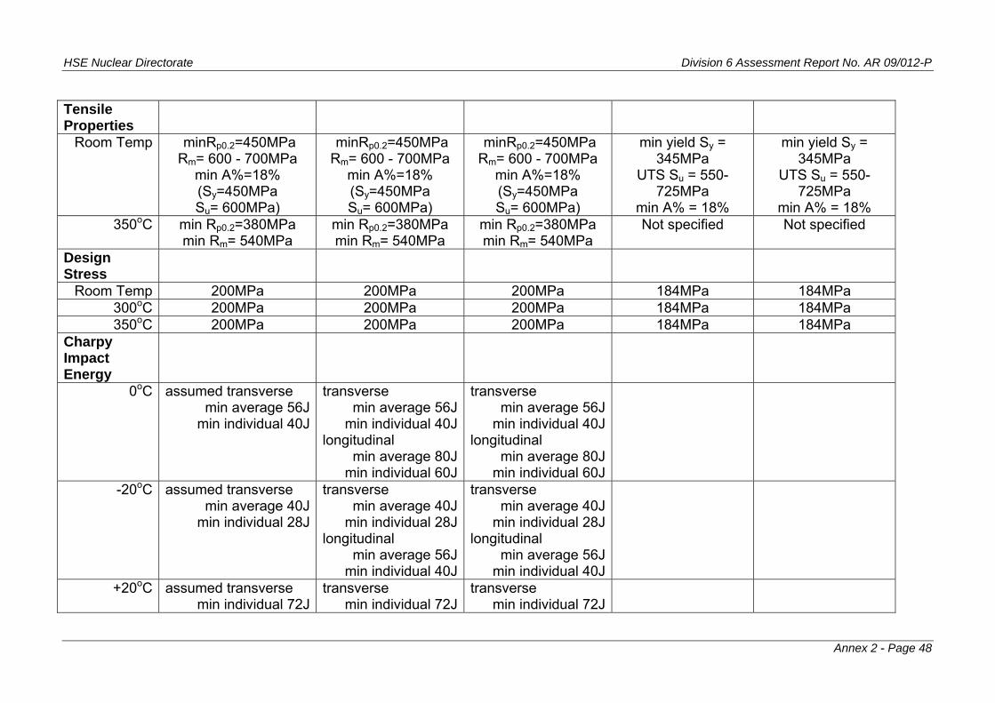
HSE Nuclear Directorate Division 6 Assessment Report No. AR 09/012-P
Annex 2 - Page 48
Tensile Properties
Room Temp minRp0.2=450MPa Rm= 600 - 700MPa
min A%=18% (Sy=450MPa Su= 600MPa)
minRp0.2=450MPa Rm= 600 - 700MPa
min A%=18% (Sy=450MPa Su= 600MPa)
minRp0.2=450MPa Rm= 600 - 700MPa
min A%=18% (Sy=450MPa Su= 600MPa)
min yield Sy = 345MPa
UTS Su = 550-725MPa
min A% = 18%
min yield Sy = 345MPa
UTS Su = 550-725MPa
min A% = 18% 350oC min p0.2=380MPa R
min Rm= 540MPa min Rp0.2=380MPa min Rm= 540MPa
min Rp0.2=380MPa min Rm= 540MPa
Not specified Not specified
Design Stress
Room Temp 200MPa 200MPa 200MPa 184MPa 184MPa 300oC 200MPa 200MPa 200MPa 184MPa 184MPa 350oC 200MPa 200MPa 200MPa 184MPa 184MPa
Charpy Impact Energy
0oC assumed transverse min average 56J
min individual 40J
transverse min average 56J
min individual 40Jlongitudinal
min average 80Jmin individual 60J
transverse min average 56J
min individual 40Jlongitudinal
min average 80Jmin individual 60J
-20oC assumed transverse min average 40J
min individual 28J
transverse min average 40J
min individual 28Jlongitudinal
min average 56Jmin individual 40J
transverse min average 40J
min individual 28Jlongitudinal
min average 56Jmin individual 40J
+20oC assumed transverse min individual 72J
transverse min individual 72J
transverse min individual 72J

HSE Nuclear Directorate Division 6 Assessment Report No. AR 09/012-P
[Note 2] longitudinal
min individual 88J[Note 2]
longitudinal min individual 88J
[Note 2] “Upper shelf
temperature” ‘target’ of 88J for all
shell materials ‘target’ of 88J for all shell materials
RTNDT [9] less than +16oC
[Note 3]
less than+16oC. Between -12oC and +16oC actual value to be determined
[Note 3]
less than+16oC. Between -12oC and +16oC actual value to be determined [Note 3]
Less than -12oC Less than -12oC
Rp0.2 = Yield Strength at 0.2% permanent strain Rm = Ultimate Tensile Strength A% = Uniform elongation Notes to Table 5: 1. RCC-M Section II - M2119, M2133 and M2134 in Section 4.1 state that for the tensile test, the values for Grade 16MND 5 can be specified in the Equipment Specification 2. Where one or more results fails to satisfy the requirement, this condition shall be fulfilled for three additional tests to be performed at +40oC. If requirements not satisfied at +40oC, part shall be rejected. 3. The UK EPR PCSR states a maximum RTNDT for the Pressuriser (-20oC, Sub-Chapter 5.4 page 61/96) but no RTNDT is stated for the Steam Generators (UK EPR PCSR Sub-Chapter 5.4 Section 2.5.1 top of page 24/96). 4. Parts rejected on the basis of one or more mechanical tests may be retreated. Retreatment conditions shall be described in the test report. Tests are to be repeated. No more than 2 retreatments allowed. 5. For UK Steam Generator forgings and welds J-resistance curve fracture toughness parameter determined at 300oC. Equipment Specification included requirement for forgings to show upper shelf initiation toughness of at least 165MPa√m.
Annex 2 - Page 49
HSE Nuclear Directorate Division 6 Assessment Report No. AR 09/012-P
Annex 2 - Page 50
6. For UK Pressuriser forgings and welds J-resistance curve fracture toughness parameter determined at 345oC. Equipment Specification included requirement for forgings to show upper shelf initiation toughness of at least 165MPa√m. 7. Room temperature tensile properties and Design Stress (Sm) values for 18 MND 5 tend towards ASME SA508 Grade 2 Class 1, (formerly Class 2) rather than ASME SA508 Grade 3 Class 1 (formerly Class 3). 8. RCC-M M2119 and M2133 specify quenching as immersion in water or by spraying, M2134 specifies quenching by immersion in water only. ASME SA-508 specification requires quenching “in a suitable liquid medium by spraying or immersion”. RCC-M specifies an austenitic grain size number greater than or equal to 5 (“fine grained”); ASME, no specific grain size requirement for A508 Grade 3 Class 1 or Grade 2 Class 1. 9. In RCC-M, method to determine RTNDT set out in Section III, MC-1000. In ASME III, method to determine RTNDT set out in ASME III Subsection NB, NB-2300 for Class 1 components. Methods are similar, based on combination of drop weight test results and Charpy impact energy test results. Both require TNDT to be determined using Pellini Drop Weight test. RCC-M and ASME both specify ASTM E208 as the standard for drop weight testing. ASME allows drop weight specimen types P1, P2 or P3 to be used; RCC-M specifies specimen type P3 only. Both RCC-M and ASME III NB-2300 define RTNDT as:
(i) TNDT if at TNDT + 33oC, Charpy tests give at least 0.9mm (0.89mm ASME) lateral contraction and not less than 68J absorbed energy; (ii) If (i) not satisfied, determine temperature TCv at which Charpy test requirements in (i) are met and then RTNDT=TCv - 33oC.
RCC-M Section III MC-1230, gives specific guidance on sequence of Pellini Drop Weight tests for when the specification calls for an RTNDT ≤ 0oC and RTNDT ≤ +16oC.
NOTE: ASME III Subsection NC and ND for Class 2 and 3 components respectively does not include requirement for determination of RTNDT. ASME III Subsection NC for Class 2 components: unless one of 9 exemptions applies, Pellini drop weight tests (TNDT) or Charpy impact tests are used (64mm maximum thickness), or combination of both (over 64mm thickness). Criterion for TNDT is margin to Lowest Service Temperature (LST) - margin set out in ASME III Appendix R (Non-Mandatory Appendix). ASME III Subsection ND for Class 3 components: unless one of 9 exemptions applies, Charpy impact tests are used, test at or below Lowest Service Temperature (LST) with criteria for minimum lateral expansion and absorbed energy.

HSE Nuclear Directorate Division 6 Assessment Report No. AR 09/012-P
APPENDIX 2
Material Fracture Toughness Requirement
in the Equipment Specification - Component Made from Low Alloy Ferritic Steel
Tests shall be carried out on specimens taken from forging material and from weld metal of each weld procedure qualification test. Fracture toughness J-tests shall be carried out using standard compact tension (CT) J-specimens side-grooved to a depth of 10% each side. The test specimens shall be at least 25mm thick. Test standard to be defined. Blunting line and exclusion lines to be defined. Individual J-Δa data shall be reported. Test shall be carried out at two temperatures: T1 = (max RTNDT + ΔT) (maxRTNDT & ΔT to be defined) T2 = Normal Operating Temperature The following parameters shall be evaluated for each test: J1c - the value of J at the intersection of the blunting line and the linear regression line of data provided validity criteria are met (this is initiation toughness J) KJc - the value of K computed from J1c (initiation toughness K) JΔa2 - the value of j computed from the intersection of the data regression line at Δa=2mm The materials shall meet the following minimum toughness requirements: Test Temp > T1 T2 Forging Weld Forging Weld J1c (kJ/m2) 160 160 140 140 KJc (MPa√m) 190 190 170 170 JΔa2 (kJ/m2) 700 500 400 250 At temperature T1, no specimen shall show cleavage instability at a KJ value less than 300 MPa√m.
Annex 2 - Page 51
HSE Nuclear Directorate Division 6 Assessment Report No. AR 09/012-P
REGULATORY OBSERVATION
RO-UKEPR-25
Reactor Pressure Vessel Body Cylindrical Shell Forging Material and Associated Circumferential Welds
Effects of Irradiation
Originated by / Organisation:
Approved by / Organisation:
Assessment Area
Date:
NII NII SI 23 January 2009
NOTE: This RO is mainly concerned with the effects of neutron irradiation on the materials of the Reactor Pressure Vessel adjacent to the core. However it also mentions strain ageing and thermal ageing.
UK EPR PCSR Sub-Chapter 5.3 Figure 1, show a side elevation of the EPR Reactor Pressure Vessel. The vessel body consists of a lower head, a transition ring, two cylindrical rings and the nozzle shell course; the nozzle shell course also includes the vessel body flange. These sections of the Reactor Pressure Vessel body are made from forgings (PCSR Sub-Chapter 5.3 Section 1) using material 16 MND 5 (PCSR Sub-Chapter 5.3, Section 3.3). The two cylindrical rings are together referred to as the core shell. The forged sections are joined by circumferential welds as follows:
between bottom head dome and transition ring; between transition ring and bottom of the lower cylindrical ring; between top of lower cylindrical ring and bottom of upper cylindrical ring; between top of upper cylindrical ring and bottom of nozzle shell / flange course.
This construction means there is a circumferential weld adjacent to the mid-height of the reactor core; i.e. in the middle of the core shell. PCSR Sub-Chapter 5.3, Section 7.1 states that two cylindrical forgings are needed to make the core shell due to forging capabilities. And section 3.1.3 states that because of size limitations during the forging processes, the presence of a weld in the core region is unavoidable. UK EPR PCSR Sub-Chapter 5.3 Section 3.1.1 states that the core shell design is based on the dimensions of the core. According to UK EPR PCSR Sub-Chapter 5.3, Section 4, the start of life RTNDT for the forging materials (core area included) is less than or equal to -20oC. Sub-Chapter 7.2 mentions the weld between the head dome and head flange has a specified initial RTNDT of
Annex 2 - Page 52

HSE Nuclear Directorate Division 6 Assessment Report No. AR 09/012-P
less than -30oC. The PCSR does not contain a corresponding definite statement for the initial RTNDT of the circumferential welds of the Reactor Pressure Vessel body. UK EPR PCSR Sub-Chapter 5.3 Sections 7.2 and 7.3 state that the circumferential welds between body forgings are made using automatic Submerged Arc Welding (SAW) with a narrow groove edge preparation. Sub-Chapter 5.3 section 7.3.2 states that after welding the circumferential welds undergo one of the two following heat treatments:
post heating (200oC minimum for at least 2 hours) - promotes hydrogen diffusion out of the Heat Affected Zone;
post weld heat treatment in order to reduce residual stresses, also promotes hydrogen diffusion. This treatment is at a temperature of 550±15oC for 1 to 5 hours, depending on the wall thickness.
The final stress relief heat treatment is carried out at a temperature between 595 and 620oC for 8 hours. Within the PCSR, no statement has been found regarding the weld consumable specification. From a review of RCC-M (edition with addenda to 2005) is assumed that filler materials will be to Data Sheet S2830A (outside high radiation zones) or S2830B (in high radiation zones). UK EPR PCSR Sub-Chapter 5.3 Section 3.1.1 states that the end-of-life neutron flux to the Reactor Pressure Vessel is about 1.26x10¹⁹ n/cm2 (E>1MeV), with the following conditions:
60 year design life with 0.9 load factor - i.e. 54 Effective Full Power Years (efpy) operation
an In-Out fuel management scheme with Uranium Dioxide fuel assemblies
core surrounded by a heavy reflector. PCSR Sub-Chapter 5.3 Section 3.1.1 states that with these conditions, the end of life RTNDT for the core shell and core shell weld is lower than +30oC. It is noted that UK EPR PCSR Sub-Chapter 3.4 Section 6.5 states that for the heavy reflector there is no operating experience available in France or Germany; however no major problem is expected. Tables 1 and 2 compare the chemical composition of relevant Reactor Pressure Vessel base materials and weld consumables respectively. UK EPR PCSR Subchapter 5.3 6.2.1 briefly describes the proposed arrangements for materials irradiation monitoring. It is noted that base material, weld metal and heat affected zone material will be included in the surveillance programme. It is also noted that 1/2T
Annex 2 - Page 53

HSE Nuclear Directorate Division 6 Assessment Report No. AR 09/012-P
compact tension specimens will be included. The PCSR states that archive materials will be kept in sufficient quantities for additional capsules. DISUSSION The UK EPR PCSR strongly asserts that forging manufacturing limits require the core shell to be manufactured from two forgings, with a central circumferential weld. This weld will be adjacent to the core mid-height and at approximately the location of highest neutron flux. The claim of limit on forging manufacturing capability needs to be justified, taking an international perspective and whether this situation might change in the near future. In making the above comment it is noted that for the EPR Reactor Pressure Vessel design (NII - EdF/AREVA meeting 4 June 2008):
the circumferential weld at the bottom of the core shell (weld to the transition ring) is predicted to receive a neutron dose comparable to the mid-height weld (about 8x10¹⁸ n/cm2); the circumferential weld at the top of the core shell (weld to the nozzle course) is predicted to receive a much lower neutron dose (about 5x10¹⁷ n/cm2).
Also from the meeting on 4 June 2008, the end of life RTNDT is predicted to be +15oC for base material (forging) and +23oC for weld metal. Apparently the basis of the estimated shift in RTNDT is the equation in RCC-M Subsection Z, Annex Z G, section Z G 3430. In RCC-M this equation is stated as applicable to parts meeting the requirements of RCC-M Section II Part Procurement Specification M2111 and associated welded joints. The equation is claimed applicable for any neutron fluence between 1018 and 6x10¹⁹ n/cm2 and for irradiation temperatures between 275oC and 300oC. Regarding the UK EPR PCSR predicted shift in RTNDT to a dose of about 1.26x10¹⁹ n/cm2, historical expectation in the UK would be broadly consistent with this given the similarity in the UK usage of A508 Class 3 and associated weld filler material and the RCC-M corresponding material specifications. The understanding of the role of Copper and Phosphorus in irradiation embrittlement and the levels to which these elements need to be restricted to minimise their effect on the embrittlement process has been understood for at least 20 years. It is noted that historically the approach in Germany for PWRs over 1000MWe was to limit the neutron fluence to the RPV wall to about 0.5x10¹⁹ n/cm2 after 40 years operation. This has been achieved by using a relatively large diameter RPV and using a large water gap (ref 1). A limit of 1x10¹⁹ n/cm2 appears in the RSK Guidelines (ref 2). It is noted the German Konvoi 1300Mwe (design dating from mid-1980s) RPV has an internal diameter of about 5000mm, whereas the 1650MWe EPR has an RPV internal diameter of about 4885mm (measured to ferritic/cladding interface). There are a number of questions regarding the approach outlined in the UK EPR PCSR. The maximum neutron dose to end of life of 1.26x10¹⁹ n/cm2 is based on the shielding provided by the heavy reflector contained within the core barrel. Clearly without the reflector, the dose to the vessel wall would be much higher. The heavy reflector, among
Annex 2 - Page 54

HSE Nuclear Directorate Division 6 Assessment Report No. AR 09/012-P
other things will presumably alter the neutron energy spectrum that irradiates the reactor vessel wall. We suppose there would be an increase in the proportion of low energy (thermal energy) neutrons to high energy neutrons. For other situations, thermal neutrons have been found to have a higher relative embrittling effect compared with high energy neutrons. The heavy reflector is a new feature. We imagine the equation relating change in RTNDT to fluence will be based on correlation with a body of historical surveillance and other irradiated material mechanical test results. UK practice has been to generally include a total of more than 30 1/2T CT specimens in each surveillance capsule. It has proved useful for continued operation to have test results from this sort of population of surveillance programme CT specimens. In addition, to be able to make meaningful inference of change from unirradiated to irradiated material properties, the heats of material should be the same for manufacture of the specimens which are tested in the unirradiated and irradiated conditions. Issue 1 Presumably the neutron energy spectrum of any historical surveillance results will be typical of a spectrum without the effect of the heavy reflector. How is the use of the equation for shift in RTNDT in RCC-M Section I Subsection Z Annex Z G, justified for the neutron energy spectrum expected for the UK EPR Reactor Pressure Vessel core shell weld and base material? Issue 2 Does the neutron energy spectrum change significantly from the surveillance specimen locations to locations through the RPV wall? Issue 3 One effect of the heavy reflector may be to increase gamma irradiation emitted from the core barrel and falling on the surveillance specimens and the RPV wall. Is there any notable material irradiation effect on the surveillance specimens and RPV wall due to gamma radiation? Is there any significant heating effect of the surveillance specimens due to the potentially greater gamma irradiation? Issue 4 The total fluence of about 1.26x10¹⁹ n/cm2 will be reached over 54 effective full power years. Current generation PWRs might be expected to reach about 3x10¹⁹ n/cm2 in about 32 effective full power years. The EPR neutron dose rate might be about 0.25 that of current generation PWRs. Is this lower dose rate likely to lead to a change in embrittlement compared with the same total dose accumulated at a higher rate? Issue 5 It is understood that use of Mixed Oxide Fuel (MOX) would increase the maximum does to the RPV after 60 years to about 2.5x10¹⁹ n/cm2. In addition, use of MOX fuel could change
Annex 2 - Page 55
HSE Nuclear Directorate Division 6 Assessment Report No. AR 09/012-P
the neutron energy spectrum compared with UO2 fuel. How would the use of MOX fuel affect the shift in RTNDT for the Reactor Pressure Vessel core shell base and weld materials? Issue 6 As a sensitivity study, what would be the effect of assuming life extension to, say, 80 years? Issue 7 Do the statements in the UK EPR PCSR and at the meeting on 4 June 2008 regarding end of life RTNDT include a contribution to shift from thermal and strain ageing, as well as neutron irradiation? Issue 8 Are the end of life RTNDT values for base and weld metal quoted in the meeting of 4 June 2008 (+15 and +23oC respectively) for an end of life fluence of 2.2x10¹⁹ n/cm2 (quoted for Flamanville 3)? Issue 9 For the weld consumable S2830B (high irradiation zones), the Nickel content is restricted to less than 1.2%. This is noticeably above the base metal upper limit for Nickel of 0.8%. What is the reason for allowing a higher Nickel content in the weld consumable? Does the RTNDT shift equation in RCC-M Section I Subsection G Annex Z G contain weld material with the same chemical composition as S2830B? Issue 10 Experimental data for shifts in RTNDT with neutron fluence, including the effects of chemical composition such a Copper, Phosphorus and Nickel, can show a wide scatter. Is the RTNDT equation in RCC-M based on a conservative bound to the available data? Is the RCC-M equation based on a statistical analysis of experimental data? The scatter in data might depend on how much data is available for a given set of conditions (neutron fluence, mixture of chemical composition). For neutron fluences applicable to end of life conditions after 60 years, how much data is available for M2111 and S2830B materials? Issue 11 We are aware that the RTNDT shift equation in RCC-M Section I Subsection Z Annex Z G, Z G 3430 has existed for a number of years (at least since 1995, ref 3, section 3.1.3). How many PWR Reactor Pressure Vessels have been made using M2111 base material and S2830B weld consumable to the requirements in RCC-M (edition with addenda to 2005)? How much irradiation embrittlement data is available for M2111 and S2830B, including results of surveillance tests? Has the RCC-M equation been reviewed against data that has become available since, say 1995?
Annex 2 - Page 56

HSE Nuclear Directorate Division 6 Assessment Report No. AR 09/012-P
Issue 12 RCC-M Section I Subsection Z, Annex Z G, Z G 3430(c) states that the unirradiated upper shelf toughness can be taken as 220MPa√m and the irradiated value as 195MPa√m. This is for M2111 base metal and associated weld metal with neutron dose between 5x10¹⁸ and 6x10¹⁹ n/cm2. Are these upper shelf values average values or claimed lower bounds to data? Is this statement in RCC-M supposed to cover the whole upper shelf region, from say 100oC to 350oC? We are aware of data which would indicate individual upper shelf initiation values down to about 160MPa√m at 300oC (Sulphur= 0.1%), while upper shelf initiation toughness tends to be higher at say 100oC than at 300oC. Some of the latter features are shown by the values of JIc and KJc given in RCC-M Section I Subsection Z Annex Z G, Table Z G 3440. How is KJc affected by neutron irradiation of the material? Issue 13 We understand the RTNDT shift equation in RSEM (B7212) for surveillance (FIS equation) has a similar form to the RCC-M design equation, but with a Copper/Nickel interaction term. Our calculations using the RSEM equation give higher shifts than the RCC-M equation, and the RSEM equation produces higher shifts for the weld consumable compared to the base metal, due to the higher potential Nickel content in the weld consumable (the RSEM equation including a term for the combined effect of Copper and Nickel, wit the Nickel content raised to the power 2). What is the relative status of the RCC-M and RSEM RTNDT shift equations? For example are the both based on the same set of experimental data, and are they both intended to have the same margin of conservatism? Issue 14 At the NII - EdF/AREVA meeting on 4 June 2008, information was presented which suggested that for Flamanville 3, the following extra requirements have been made for the core shell material M2111: Copper 0.06% max Phosphorus 0.006% max Are these additional limits proposed for the UK EPR? Do the limits also apply to the weld consumable material? Issue 15 The meeting on 4 June 2008 also indicated a Charpy Impact energy at upper shelf temperatures of greater than 130J. This appears to be an extra requirement, not contained in RCC-M, M2111. Does this requirement apply to both longitudinal and transverse directions of base material and does it apply to the associated welds? Is this a minimum Charpy Impact Energy for any temperature in the ‘upper shelf’ region? Is it intended to use this requirement for the UK EPR? Issue 16
Annex 2 - Page 57

HSE Nuclear Directorate Division 6 Assessment Report No. AR 09/012-P
Annex 2 - Page 58
How many specimens of each type (Charpy Impact, tensile, CT) are planned to be included in the surveillance programme? Will all capsules contain the same numbers of each type of specimen? By comparison with planned capsules, how much material will be kept available for additional capsules? Is the retained archive material intended to cover potential operation beyond the design life of 60 years? What is the factor of acceleration between dose to the surveillance specimens in the capsules and the inner parts of the Reactor Pressure Vessel wall? Is there a plan for the schedule of removal of capsules? Will the pre-irradiation and post-irradiation specimens be taken from the same heats of material / welds? The surveillance scheme outlined in the UK EPR PCSR is for effects of neutron irradiation. Is there a separate surveillance programme planned to cover strain ageing and thermal ageing effects? References 1. Jendrich U., Tricot N., Neutron Fluence at the reactor Pressure Vessel Wall - A Comparison of French and German Procedures and Strategies in PWRs. Paper in Eurosafe 2002 Seminar 1 paper 1. Eurosafe 2002, berlin 2-4 November 2002. (web link, working 13/1/09: http://www.eurosafe-forum.org/files/euro2_1_1neutron_fluence.pdf) 2. RSK Guidelines for Pressurised Water Reactors.Sub-section 4.1.2 bulltet item (6). 3rd Edition with amendments to 1996. (web link, working 13/1/09 to BfS English translation: http://www.bfs.de/de/bfs/recht/rsh/volltext/A1_Englisch/A1_1_01.pdf) 3. Gerard R., Survey of National Requirements. AMES Report No4. EUR16305N (June 1995).

HSE Nuclear Directorate Division 6 Assessment Report No. AR 09/012-P
TABLE 1 Reactor Pressure Vessel Materials ASME
composition SA508 Grade 3
Class 1 2007 Edition
(formerly SA508 Class 3) [1]
UK Usage of SA508 Class 3
(now called SA508 Grade 3 Class 1)
RPV
Product Analysis
16 MND 5
RPV Beltline Region
RCC-M M2111
Product Analysis
16 MND 5
RPV Outside Beltline Region
RCC-M M2112
Product Analysis Carbon 0.25% max 0.2% max 0.22% max 0.22% max Manganese 1.2 to 1.5% 1.2 to 1.5% 1.15 - 1.6% 1.15 - 1.6% Molybdenum 0.45 to 0.6% 0.45 to 0.6% 0.43 - 0.57% 0.43 - 0.57% Nickel 0.4 to 1.0% 0.4 to 0.85% 0.5 - 0.8% 0.5 - 0.8% Sulphur 0.025% max 0.008% max 0.008% max 0.012% max Phosphorus 0.025% max 0.008% max 0.008% max 0.012% max Silicon [3] 0.4% max 0.3% max 0.1 - 0.3% 0.1 - 0.3% Chromium 0.25% max 0.15% max 0.25% max 0.25% max Copper 0.2% max 0.08% max 0.08% max 0.2% max Vanadium 0.05% max 0.01% max 0.01% max 0.01% max Antimony - 0.008% max Arsenic - 0.015% max Cobalt - 0.02% max 0.03% max 0.03% max Tin - 0.01% max Aluminium 0.025% max [2] 0.045% max 0.04% max 0.04% max Hydrogen - 1ppm (product) max Boron 0.003% max[2] Columbium * 0.01% max[2] Calcium 0.015% max[2] Titanium 0.015% max[2] *Columbium = Niobium
Annex 2 - Page 59
HSE Nuclear Directorate Division 6 Assessment Report No. AR 09/012-P
Both ASME and RCC-M specify steel to be made using and electric furnace and vacuum-degassed. RCC-M specifically mentions the material shall be aluminium-killed. 1. ASME A508 Specification - Supplementary Requirement S9 specifies: S9.1.1 Phosphorus 0.015% max product, Copper 0.1% max product or S9.1.2 Phosphorus 0.015% max product, Copper 0.15% max product S9.2 Sulphur 0.015% max product 2. Element limit added since ASME Code edition used for Sizewell B 3. ASME A508 Specification - Supplementary Requirement S11 sets limit on Silicon of 0.1% max. Supplementary Specification S16 sets range of Silicon content as 0.05 to 0.15%
Annex 2 - Page 60

HSE Nuclear Directorate Division 6 Assessment Report No. AR 09/012-P
TABLE 2 Weld Metal Chemical Composition for UK usage of A508 Class 3 and RCC-M Data Sheets S2830A and S2830B Weld Metal[1]
RCC-M
S2830A [1] RCC-M
S2830B [1]
Carbon 0.15% max 0.1% max 0.1% max Manganese 0.8 to 1.8% 0.8 - 1.8 0.8 - 1.8% Molybdenum 0.35 to 0.65% 0.35 - 0.65% 0.35 - 0.65% Nickel 0.85% max 1.5% max 1.2% max Sulphur 0.01% max 0.025% max 0.015% max Phosphorus 0.01% max 0.025% max 0.01% max Silicon 0.15 to 0.6% 0.15 - 0.6% 0.15 - 0.6% Chromium 0.15% max 0.3% max 0.3% max Copper 0.07% max 0.25% max 0.07% max Vanadium 0.01% max 0.04% max 0.02% max Antimony 0.008% max Arsenic 0.015% max Cobalt 0.02% max 0.03% max Tin 0.01% max Aluminium Hydrogen
RCC-M S2830A - Flux wire for automatic welding process, low alloy steel outside high radiation zones, for 16 MND 5 and 18MND 5 base materials. RCC-M S2830B - Flux wire for automatic welding process, low alloy steel within high radiation zones, for M2111 and M2111 bis materials
1. Deposited metal
Annex 2 - Page 61
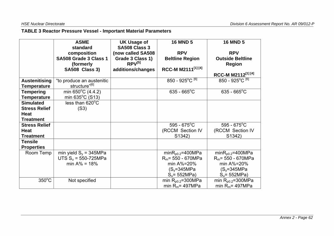
HSE Nuclear Directorate Division 6 Assessment Report No. AR 09/012-P
TABLE 3 Reactor Pressure Vessel - Important Material Parameters ASME
standard composition
SA508 Grade 3 Class 1(formerly
SA508 Class 3)
UK Usage of SA508 Class 3
(now called SA508 Grade 3 Class 1)
RPV[5] additions/changes
16 MND 5
RPV Beltline Region
RCC-M M2111[1] [4]
16 MND 5
RPV Outside Beltline
Region
RCC-M M2112[1] [4] Austenitising Temperature
“to produce an austenitic structure”[6]
850 - 925oC [6] 850 - 925oC [6]
Tempering Temperature
min 650oC (4.4.2) min 635oC (S13)
635 - 665oC 635 - 665oC
Simulated Stress Relief Heat Treatment
less than 620oC (S3)
Stress Relief Heat Treatment
595 - 675oC (RCCM Section IV
S1342)
595 - 675oC (RCCM Section IV
S1342) Tensile Properties
Room Temp min yield Sy = 345MPa UTS Su = 550-725MPa
min A% = 18%
minRp0.2=400MPa Rm= 550 - 670MPa
min A%=20% (Sy=345MPa Su= 552MPa)
minRp0.2=400MPa Rm= 550 - 670MPa
min A%=20% (Sy=345MPa Su= 552MPa)
350oC Not specified min Rp0.2=300MPa min Rm= 497MPa
min Rp0.2=300MPa min Rm= 497MPa
Annex 2 - Page 62

HSE Nuclear Directorate Division 6 Assessment Report No. AR 09/012-P
Design Stress
Room Temp 184MPa 184MPa 184MPa 300oC 184MPa 184MPa 184MPa 350oC 184MPa 184MPa 184MPa
Charpy Impact Energy
0oC transverse min average 56J
min individual 40Jlongitudinal
min average 80Jmin individual 60J
transverse min average 56J
min individual 40Jlongitudinal
min average 72Jmin individual 56J
4.4oC min average 41J min individual 34J
-20oC transverse min average 40J
min individual 28Jlongitudinal
min average 56Jmin individual 40J
transverse min average 40J
min individual 28Jlongitudinal
min average 56Jmin individual 40J
+20oC transverse min individual 104J
longitudinal min individual 120J
[Note 2]
transverse min individual 72J
longitudinal min individual 88J
[Note 2]
Annex 2 - Page 63

HSE Nuclear Directorate Division 6 Assessment Report No. AR 09/012-P
“Upper shelf
temperature” 101J in active core
region and weld between nozzle course and core shell course ‘target’ of 88J for nozzle course, nozzles and nozzle welds
RTNDT [7] Method for determination set out in ASME III NB-2300, but no criteria for values
All forgings except nozzles, less than -12oC. Nozzle forgings, less than -22oC
No higher than 0oC, a value lower than -12oC is desirable. If between -12 and 0oC actual value to be determined [Note 3]
No higher than +16oC, a value lower than -12oC is desirable. If between -12 and +16oC actual value to be determined. [Note 3]
Rp0.2 = Yield Strength at 0.2% permanent strain Rm = Ultimate Tensile Strength A% = Uniform Elongation
Annex 2 - Page 64
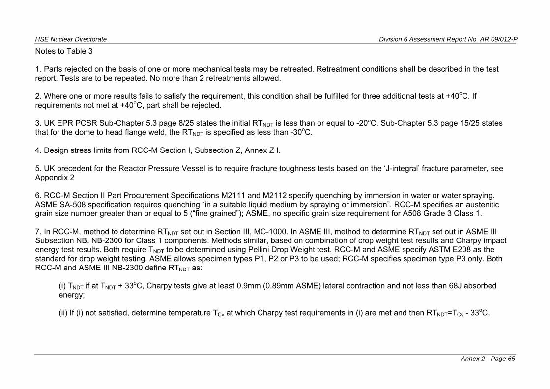
HSE Nuclear Directorate Division 6 Assessment Report No. AR 09/012-P
Notes to Table 3 1. Parts rejected on the basis of one or more mechanical tests may be retreated. Retreatment conditions shall be described in the test report. Tests are to be repeated. No more than 2 retreatments allowed. 2. Where one or more results fails to satisfy the requirement, this condition shall be fulfilled for three additional tests at +40oC. If requirements not met at +40oC, part shall be rejected. 3. UK EPR PCSR Sub-Chapter 5.3 page 8/25 states the initial RTNDT is less than or equal to -20oC. Sub-Chapter 5.3 page 15/25 states that for the dome to head flange weld, the RTNDT is specified as less than -30oC. 4. Design stress limits from RCC-M Section I, Subsection Z, Annex Z I. 5. UK precedent for the Reactor Pressure Vessel is to require fracture toughness tests based on the ‘J-integral’ fracture parameter, see Appendix 2 6. RCC-M Section II Part Procurement Specifications M2111 and M2112 specify quenching by immersion in water or water spraying. ASME SA-508 specification requires quenching “in a suitable liquid medium by spraying or immersion”. RCC-M specifies an austenitic grain size number greater than or equal to 5 (“fine grained”); ASME, no specific grain size requirement for A508 Grade 3 Class 1. 7. In RCC-M, method to determine RTNDT set out in Section III, MC-1000. In ASME III, method to determine RTNDT set out in ASME III Subsection NB, NB-2300 for Class 1 components. Methods similar, based on combination of crop weight test results and Charpy impact energy test results. Both require TNDT to be determined using Pellini Drop Weight test. RCC-M and ASME specify ASTM E208 as the standard for drop weight testing. ASME allows specimen types P1, P2 or P3 to be used; RCC-M specifies specimen type P3 only. Both RCC-M and ASME III NB-2300 define RTNDT as:
(i) TNDT if at TNDT + 33oC, Charpy tests give at least 0.9mm (0.89mm ASME) lateral contraction and not less than 68J absorbed energy; (ii) If (i) not satisfied, determine temperature TCv at which Charpy test requirements in (i) are met and then RTNDT=TCv - 33oC.
Annex 2 - Page 65
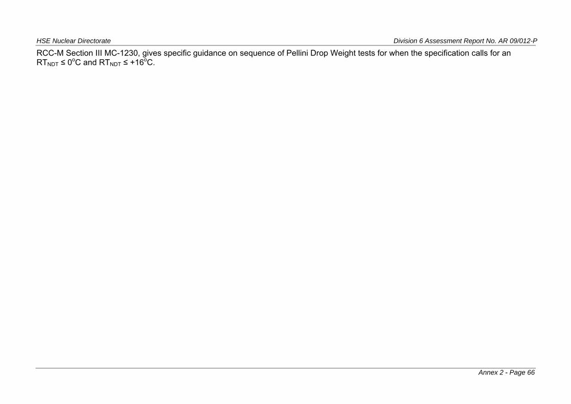
HSE Nuclear Directorate Division 6 Assessment Report No. AR 09/012-P
Annex 2 - Page 66
RCC-M Section III MC-1230, gives specific guidance on sequence of Pellini Drop Weight tests for when the specification calls for an RTNDT ≤ 0oC and RTNDT ≤ +16oC.
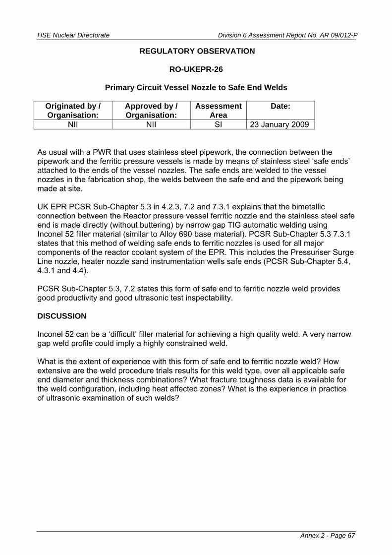
HSE Nuclear Directorate Division 6 Assessment Report No. AR 09/012-P
REGULATORY OBSERVATION
RO-UKEPR-26
Primary Circuit Vessel Nozzle to Safe End Welds
Originated by / Organisation:
Approved by / Organisation:
Assessment Area
Date:
NII NII SI 23 January 2009 As usual with a PWR that uses stainless steel pipework, the connection between the pipework and the ferritic pressure vessels is made by means of stainless steel ‘safe ends’ attached to the ends of the vessel nozzles. The safe ends are welded to the vessel nozzles in the fabrication shop, the welds between the safe end and the pipework being made at site. UK EPR PCSR Sub-Chapter 5.3 in 4.2.3, 7.2 and 7.3.1 explains that the bimetallic connection between the Reactor pressure vessel ferritic nozzle and the stainless steel safe end is made directly (without buttering) by narrow gap TIG automatic welding using Inconel 52 filler material (similar to Alloy 690 base material). PCSR Sub-Chapter 5.3 7.3.1 states that this method of welding safe ends to ferritic nozzles is used for all major components of the reactor coolant system of the EPR. This includes the Pressuriser Surge Line nozzle, heater nozzle sand instrumentation wells safe ends (PCSR Sub-Chapter 5.4, 4.3.1 and 4.4). PCSR Sub-Chapter 5.3, 7.2 states this form of safe end to ferritic nozzle weld provides good productivity and good ultrasonic test inspectability. DISCUSSION Inconel 52 can be a ‘difficult’ filler material for achieving a high quality weld. A very narrow gap weld profile could imply a highly constrained weld. What is the extent of experience with this form of safe end to ferritic nozzle weld? How extensive are the weld procedure trials results for this weld type, over all applicable safe end diameter and thickness combinations? What fracture toughness data is available for the weld configuration, including heat affected zones? What is the experience in practice of ultrasonic examination of such welds?
Annex 2 - Page 67

HSE Nuclear Directorate Division 6 Assessment Report No. AR 09/012-P
REGULATORY OBSERVATION
RO-UKEPR-27
Fatigue Crack Growth Law Equations for Ferritic Materials Covered by RCC-M M 2110 and M2120
Originated by / Organisation:
Approved by / Organisation:
Assessment Area
Date:
NII NII SI 23 January 2009 RCC-M Section I Subsection Z, Annex Z G, Z G 3322 (f) and Table Z G 3322 cover fatigue crack growth laws for materials covered by RCC-M M2110 and M2120 (ferritic low alloy steel, forging and plate materials). These equations cover both ‘dry’ and ’PWR wet’ conditions. The equations take account of R ratio and ΔK [1]. The fatigue crack growth equations in RCC-M Annex Z G have a generally similar form to those in ASME XI Appendix A (A-4300) but clearly have different coefficients and exponents. It is noted that the RCC-M fatigue crack growth laws do not use an explicit threshold ΔK, below which level crack growth is zero. DISCUSSION Are the fatigue crack growth laws in RCC-M Annex Z G used for EPR design analyses? If so, what is the basis of the fatigue crack growth laws as set out in RCC-M Section I Subsection Z Annex Z G? If other fatigue crack growth law equations are used for design analyses for EPR, what are those equations and what is their basis? Notes 1. R = Kmin/Kmax ΔK = Kmax - Kmin
Annex 2 - Page 68
HSE Nuclear Directorate Division 6 Assessment Report No. AR 09/012-P
REGULATORY OBSERVATION
RO-UKEPR-28
Reactor Pressure Vessel Pressure - Temperature Limit Diagrams and Low Temperature Overpressure Protection
Originated by / Organisation:
Approved by / Organisation:
Assessment Area
Date:
NII NII SI 23 January 2009
The content of this Regulatory Observation has some linkage to aspects of the Regulatory Observations on materials, irradiation embrittlement and overpressure protection. Reference to RCC-M is to the 2005 edition. It is now understood that the relevant version of RCC-M is the 2007 Edition. Further assessment of this topic will take account of RCC-M 2007 Edition. UK EPR PCSR Chapter 5.3 (UKEPR-0002-053 Issue 01), Section 6.3 describes very briefly the approach to start-up and shutdown operating limits. It is stated that these limits are based on the core region materials of the reactor pressure vessel and that actual material properties test data shall be used. UK EPR PCSR Chapter 5.3 Section 6.3 indicates pressure-temperature limits will depend on beltline material RTNDT and this will be adjusted for neutron irradiation embrittlement. The reference part of the PCSR also indicates the procedure for determining pressure-temperature limits involves postulating a hypothetical defect located on either the inner or outer wall of the core shell. The effect of neutron irradiation is determined at the tip of this postulated defect. DISCUSSION The description in UK EPR PCSR Chapter 5.3 (UKEPR-0002-053 Issue 01) of the procedure for determining pressure-temperature limits for start-up and shutdown is very brief. It would help to expand the summary description in the PCSR, while still retaining the summary nature. However this aspect also needs to be supported by a detailed document that explains, step by step, the procedure for determining pressure-temperature limits. Factors that need to be made explicit in the detailed document, some of which need to be summarised in the PCSR include: 1. Is the determination of pressure-temperature (P-T) limits tailored for each vessel depending on the specific chemical properties of the relevant weld or base material, or are the P-T limits determined generically on the basis of the material specification chemical limits? 2. Are the P-T limits determined at start of life on the basis of end-of-life neutron fluence, i.e. enveloping P-T limits applicable for the whole of the design life? Or, are P-T limits
Annex 2 - Page 69
HSE Nuclear Directorate Division 6 Assessment Report No. AR 09/012-P
revised through life as neutron fluence accumulates? If the latter, how are revision dates determined? 3. Are results from the reactor vessel surveillance programme used to simply confirm that bounding analyses are conservative with respect to surveillance test results? Or are P-T limits revised on the basis of results from the surveillance programme, including if the surveillance programme results are less restrictive than a generic analysis? 4. UK PCSR mentions postulating defects on the inner and outer diameter of the core shells. Is mention of inside and outside surface locations to take account of the difference in thermal stress profiles between start-up and shutdown? Is RCC-M, Annex Z G the basis for the fracture mechanics calculations? For instance, is the defect defined in terms of the “First Method” (Z G 3200) in RCC-M Annex Z G (possibly suggested by the term ‘conventional defect’ in the PCSR and ZG 3210 ‘Conventional Reference Defect’)? If so is the defect characterised as having a depth of ¼ the wall thickness with a surface length of 1.5x the thickness (i.e. length 6x the depth)? 5. Are only axial defects postulated? RCC-M Annex Z G Section Z G 3211 defines the size of defect and also states ‘The defect plane assumed to be normal to the direction of the maximum principal stress’. This could imply axial defects only in the core shell region. 6. Is the membrane stress intensity factor coefficient Mm as shown in Figure Z G 3222 determined by reference to an axially oriented defect? 7. Is the effective applied stress intensity factor determined as outline in RCC-M Annex ZG, Section Z G 3232? i.e.: KIeff = 2KIp + KIt
where: KIp is the stress intensity factor due to primary stress (membrane and potentially bending) KIt is the stress intensity factor due to the temperature gradient
8. For the core shell region, are primary bending stresses considered in determining the P-T limits? 9. What is the method used to determine the thermal stress intensity factor KIt for start-up and shutdown conditions? 10. What material, temperature dependent stress intensity function curve is used as the criterion, is it the reference Toughness Curve KIR of RCC-M Annex Z G, Section Z G 3410 / Figure Z G 3410, or KIc curve of RCC-M Annex Z G Section Z G 3420 / Figure Z G 3420? Or is some other curve used (based on ‘Actual material properties test data’, to quote from UK EPR PCSR Chapter 5.3 Section 6.3, first paragraph)?
Annex 2 - Page 70
HSE Nuclear Directorate Division 6 Assessment Report No. AR 09/012-P
The curve for KIR versus temperature in RCC-M Annex Z G Section Z G 3410 is essentially identical to the curve for KIa in ASME XI Appendix A Article A-4000, Sub-Article A-4200 (2007 Edition), even though the equation expressions of the curves are slightly different.
The curve for KIc versus temperature in RCC-M Annex Z G Section Z G 3420 is essentially identical to the curve for KIc in ASME XI Appendix A Article A-4000, Sub-Article A-4200, ASME XI / ASME III Appendix G Article G-2000, Sub-Article G-2110 and (2007 Edition), even though the equation expressions of the curves are slightly different.
WE NOTE:
11. What relationship is used to include the effects of irradiation, i.e. the change in RTNDT through life of the RPV? Is it the equation in RCC-M Annex G Section Z G 3430(b) or is it the FIS equation in RSEM? What is the rationale for the choice of relationship for the effects of irradiation? From ref 1, comparison with surveillance specimen results at low shift in transition temperature (up to 40oC), show the FIS (RSEM) equation to be conservative (Figure 8 of ref 1), while the RCC-M equation is closer to the mean of the shift (Figure 10 of ref 1 which is for USNRC Regulatory Guide 1.99 rev 1 - the same as the RSEM equation). Low shift in transition temperature would include low residual content materials anticipated for use in a UK EPR and relatively low neutron fluence.
WE NOTE:
The equation for shift in RTNDT in RCC-M Annex Z G Section Z G 3430 is the same as the equation in USNRC Regulatory Guide 1.99 Revision 1, e.g. equation 4 of ref 1.
12. The foregoing has concentrated on the core shell of the Reactor Pressure Vessel and the effect of neutron irradiation. Another potential area where pressure-temperature limits apply is the closure flange region of the Reactor Pressure Vessel body and the mating head flange. How are pressure - temperature limits for the Reactor Pressure Vessel closure flange region determined? It is noted that in RCC-M (2005 edition) Annex Z G Section Z G 3223 states that simplified methods are still in preparation for zones near geometrical discontinuities, including flanges. 13. What design features of the UK EPR deal with Low Temperature Overpressure Protection (LTOP)? How are the LTOP system allowable pressure and effective temperature determined? REFERENCES 1. Petrequin P., A Review of Formulas for Predicting Irradiation Embrittlement of reactors Vessel Materials. Report by the Ageing Materials Evaluation and Studies (AMES) Network. AMES Report No6. European Commission Report EUR16455 EN (December 1996)
Annex 2 - Page 71
HSE Nuclear Directorate Division 6 Assessment Report No. AR 09/012-P
EDF / AREVA UK-EPR GENERIC DESIGN ASSESSMENT
REGULATORY OBSERVATION RO-UKEPR-36
RCC-M
Aspects of Requirements for Design Analysis of Piping Class 1, 2 and 3
ORIGINATED BY / ORGANISATION:
APPROVED BY / ORGANISATION:
ASSESSMENT AREA
DATE RAISED:
NII NII SI 5 August 2009 Final 7/9/09
REGULATORY OBSERVATION:
An explanation is needed for the RCC-M design analysis equations for Class 1, 2 and 3 piping for two aspects: 1. form of the equations used and their limits; 2. the treatment of earthquake and similar reversing dynamic loads. This Regulatory Observation is to be addressed by response to associated Regulatory Observation Actions (ROAs).
ACKNOWLEDGEMENT REQUIRED BY: 25 August 2009 RESOLUTION REQUIRED BY: 30 September 2009
BACKGROUND / REGULATOR EXPECTATIONS
INTRODUCTION This Regulatory Observation arises from consideration of RCC-M (2007 edition) as sent to NII by letter EPR00073N (21 January 2009). In particular this Regulatory Observation is concerned with aspects of the design analysis of piping products contained within RCC-M Section I, For Class 1 piping: Subsection B, Sub-Chapter B 3650; For Class 2 piping: Subsection C, Sub-chapter C 3650. For Class 3 piping, RCC-M Subsection D, D 3650 states “The provisions of C 3650 shall be applied”; hence this Regulatory Observation applies to Class 3 piping too. Regarding design analysis of piping products, this Regulatory Observation has two parts: 1. the form of the equations used and their limits, that is:
for Class 1 piping:
B 3652 - Level 0 Criteria - Equation (9)
Annex 2 - Page 72
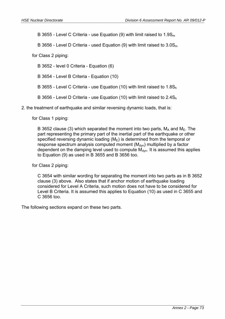
HSE Nuclear Directorate Division 6 Assessment Report No. AR 09/012-P
B 3655 - Level C Criteria - use Equation (9) with limit raised to 1.9Sm B 3656 - Level D Criteria - used Equation (9) with limit raised to 3.0Sm
for Class 2 piping:
B 3652 - level 0 Criteria - Equation (6) B 3654 - Level B Criteria - Equation (10) B 3655 - Level C Criteria - use Equation (10) with limit raised to 1.8Sh B 3656 - Level D Criteria - use Equation (10) with limit raised to 2.4Sh
2. the treatment of earthquake and similar reversing dynamic loads, that is:
for Class 1 piping:
B 3652 clause (3) which separated the moment into two parts, MA and ME. The part representing the primary part of the inertial part of the earthquake or other specified reversing dynamic loading (ME) is determined from the temporal or response spectrum analysis computed moment (Mdyn) multiplied by a factor dependent on the damping level used to compute Mdyn. It is assumed this applies to Equation (9) as used in B 3655 and B 3656 too.
for Class 2 piping:
C 3654 with similar wording for separating the moment into two parts as in B 3652 clause (3) above. Also states that if anchor motion of earthquake loading considered for Level A Criteria, such motion does not have to be considered for Level B Criteria. It is assumed this applies to Equation (10) as used in C 3655 and C 3656 too.
The following sections expand on these two parts.
Annex 2 - Page 73
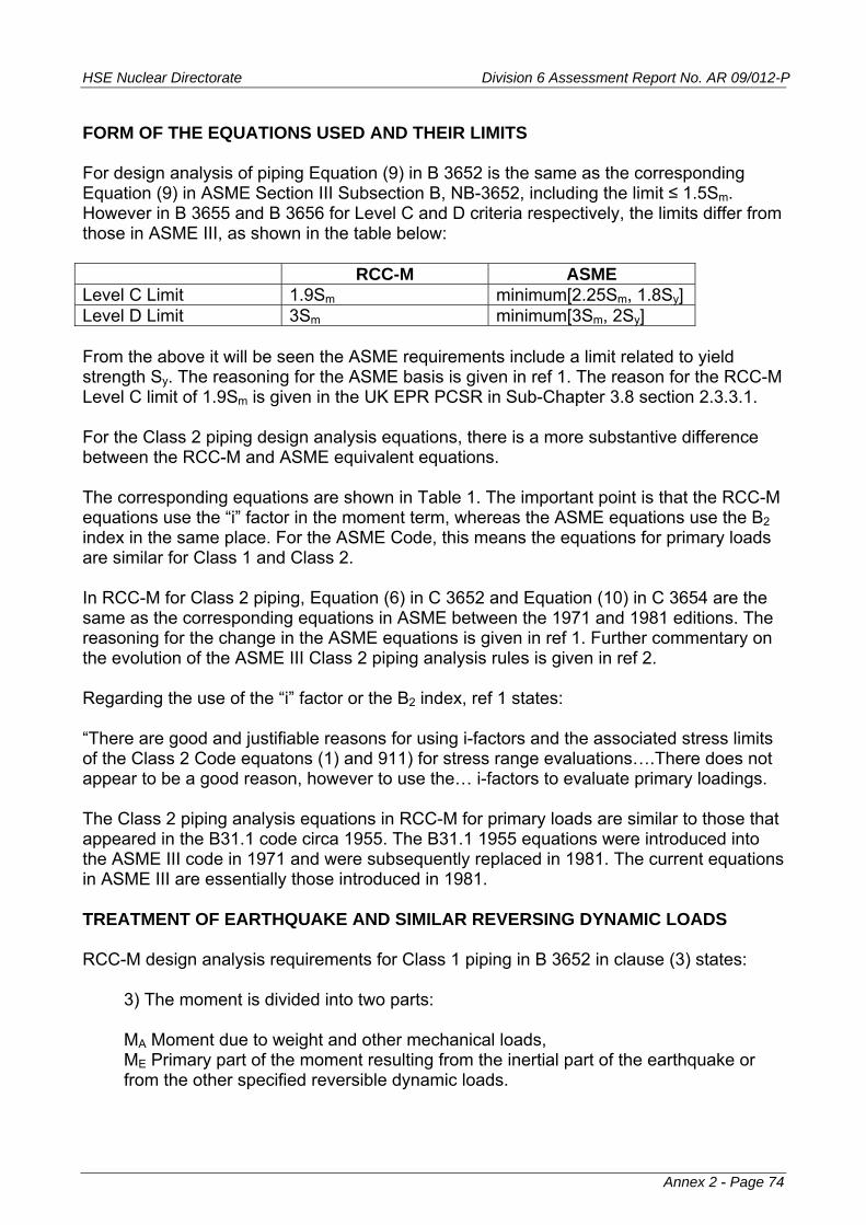
HSE Nuclear Directorate Division 6 Assessment Report No. AR 09/012-P
FORM OF THE EQUATIONS USED AND THEIR LIMITS For design analysis of piping Equation (9) in B 3652 is the same as the corresponding Equation (9) in ASME Section III Subsection B, NB-3652, including the limit ≤ 1.5Sm. However in B 3655 and B 3656 for Level C and D criteria respectively, the limits differ from those in ASME III, as shown in the table below: RCC-M ASME Level C Limit 1.9Sm minimum[2.25Sm, 1.8Sy] Level D Limit 3Sm minimum[3Sm, 2Sy] From the above it will be seen the ASME requirements include a limit related to yield strength Sy. The reasoning for the ASME basis is given in ref 1. The reason for the RCC-M Level C limit of 1.9Sm is given in the UK EPR PCSR in Sub-Chapter 3.8 section 2.3.3.1. For the Class 2 piping design analysis equations, there is a more substantive difference between the RCC-M and ASME equivalent equations. The corresponding equations are shown in Table 1. The important point is that the RCC-M equations use the “i” factor in the moment term, whereas the ASME equations use the B2 index in the same place. For the ASME Code, this means the equations for primary loads are similar for Class 1 and Class 2. In RCC-M for Class 2 piping, Equation (6) in C 3652 and Equation (10) in C 3654 are the same as the corresponding equations in ASME between the 1971 and 1981 editions. The reasoning for the change in the ASME equations is given in ref 1. Further commentary on the evolution of the ASME III Class 2 piping analysis rules is given in ref 2. Regarding the use of the “i” factor or the B2 index, ref 1 states: “There are good and justifiable reasons for using i-factors and the associated stress limits of the Class 2 Code equatons (1) and 911) for stress range evaluations….There does not appear to be a good reason, however to use the… i-factors to evaluate primary loadings. The Class 2 piping analysis equations in RCC-M for primary loads are similar to those that appeared in the B31.1 code circa 1955. The B31.1 1955 equations were introduced into the ASME III code in 1971 and were subsequently replaced in 1981. The current equations in ASME III are essentially those introduced in 1981. TREATMENT OF EARTHQUAKE AND SIMILAR REVERSING DYNAMIC LOADS RCC-M design analysis requirements for Class 1 piping in B 3652 in clause (3) states:
3) The moment is divided into two parts: MA Moment due to weight and other mechanical loads, ME Primary part of the moment resulting from the inertial part of the earthquake or from the other specified reversible dynamic loads.
Annex 2 - Page 74
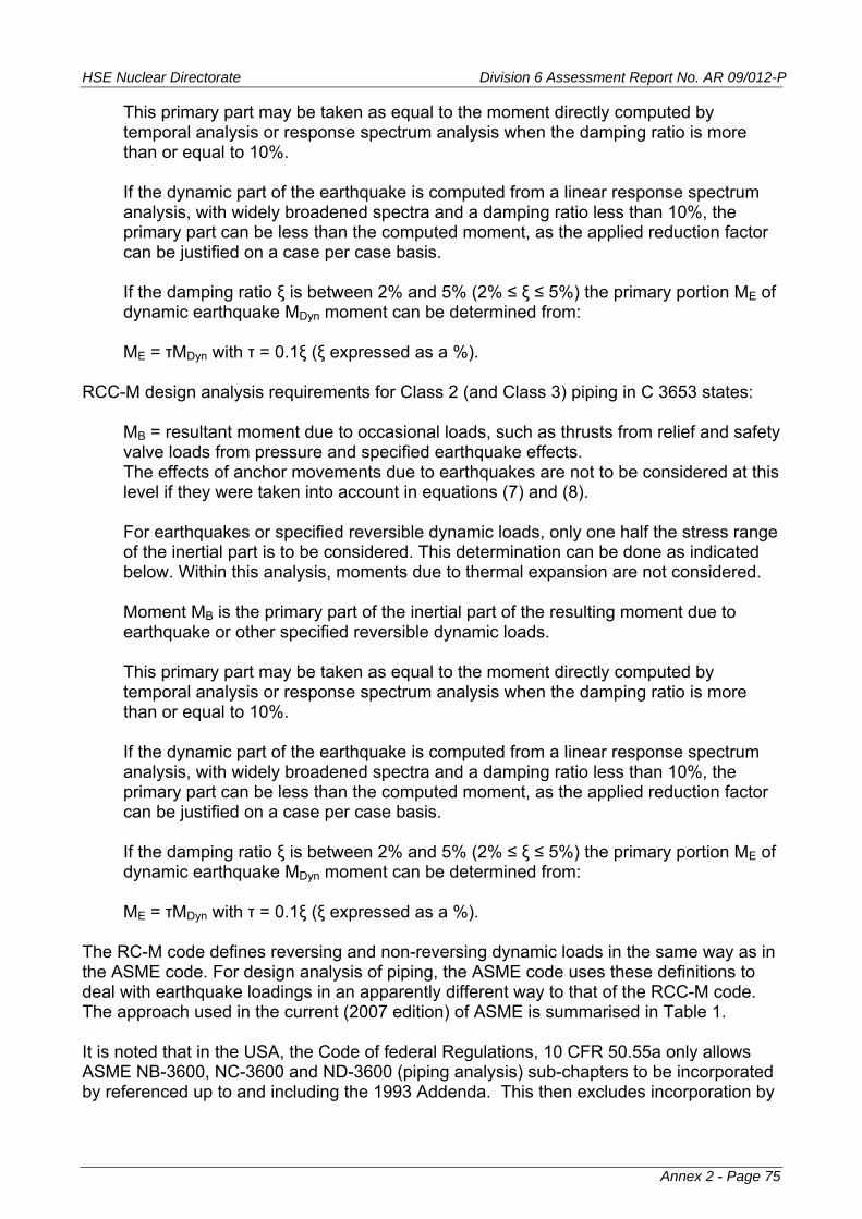
HSE Nuclear Directorate Division 6 Assessment Report No. AR 09/012-P
This primary part may be taken as equal to the moment directly computed by temporal analysis or response spectrum analysis when the damping ratio is more than or equal to 10%. If the dynamic part of the earthquake is computed from a linear response spectrum analysis, with widely broadened spectra and a damping ratio less than 10%, the primary part can be less than the computed moment, as the applied reduction factor can be justified on a case per case basis. If the damping ratio ξ is between 2% and 5% (2% ≤ ξ ≤ 5%) the primary portion ME of dynamic earthquake MDyn moment can be determined from: ME = τMDyn with τ = 0.1ξ (ξ expressed as a %).
RCC-M design analysis requirements for Class 2 (and Class 3) piping in C 3653 states:
MB = resultant moment due to occasional loads, such as thrusts from relief and safety valve loads from pressure and specified earthquake effects. The effects of anchor movements due to earthquakes are not to be considered at this level if they were taken into account in equations (7) and (8). For earthquakes or specified reversible dynamic loads, only one half the stress range of the inertial part is to be considered. This determination can be done as indicated below. Within this analysis, moments due to thermal expansion are not considered. Moment MB is the primary part of the inertial part of the resulting moment due to earthquake or other specified reversible dynamic loads. This primary part may be taken as equal to the moment directly computed by temporal analysis or response spectrum analysis when the damping ratio is more than or equal to 10%. If the dynamic part of the earthquake is computed from a linear response spectrum analysis, with widely broadened spectra and a damping ratio less than 10%, the primary part can be less than the computed moment, as the applied reduction factor can be justified on a case per case basis. If the damping ratio ξ is between 2% and 5% (2% ≤ ξ ≤ 5%) the primary portion ME of dynamic earthquake MDyn moment can be determined from: ME = τMDyn with τ = 0.1ξ (ξ expressed as a %).
The RC-M code defines reversing and non-reversing dynamic loads in the same way as in the ASME code. For design analysis of piping, the ASME code uses these definitions to deal with earthquake loadings in an apparently different way to that of the RCC-M code. The approach used in the current (2007 edition) of ASME is summarised in Table 1. It is noted that in the USA, the Code of federal Regulations, 10 CFR 50.55a only allows ASME NB-3600, NC-3600 and ND-3600 (piping analysis) sub-chapters to be incorporated by referenced up to and including the 1993 Addenda. This then excludes incorporation by
Annex 2 - Page 75

HSE Nuclear Directorate Division 6 Assessment Report No. AR 09/012-P
Annex 2 - Page 76
reference the version sof NB-3600, NC-3600 and ND-3600 that make use of the distinction between reversing and non-reversing dynamic loading. REFERENCES 1. Moore S E., Rodabaugh E C., Background for Changes in the 1981 Edition of the ASME Nuclear Power Plant Components Code for Controlling Primary Loads in Piping Systems. Trans. ASME. Journal of Pressure Vessel Technology. pp 351-361, Vol. 104 (November 1982). 2. Slagis G C., Commentary on Class 2/3 Piping Rules. Trans. ASME. Journal of Pressure Vessel Technology. pp329-334 Vol. 110 (August 1988).
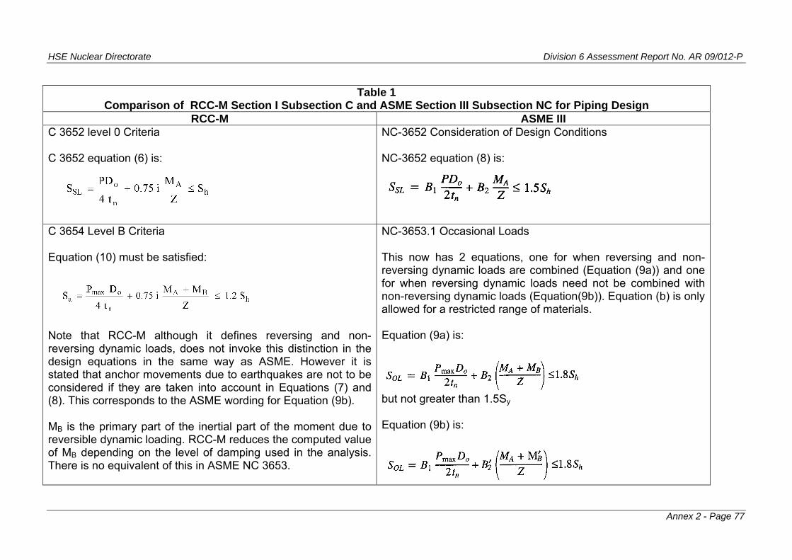
HSE Nuclear Directorate Division 6 Assessment Report No. AR 09/012-P
Annex 2 - Page 77
Table 1
Comparison of RCC-M Section I Subsection C and ASME Section III Subsection NC for Piping Design RCC-M ASME III
C 3652 level 0 Criteria C 3652 equation (6) is:
NC-3652 Consideration of Design Conditions NC-3652 equation (8) is:
C 3654 Level B Criteria Equation (10) must be satisfied:
Note that RCC-M although it defines reversing and non-reversing dynamic loads, does not invoke this distinction in the design equations in the same way as ASME. However it is stated that anchor movements due to earthquakes are not to be considered if they are taken into account in Equations (7) and (8). This corresponds to the ASME wording for Equation (9b). MB is the primary part of the inertial part of the moment due to reversible dynamic loading. RCC-M reduces the computed value of MB depending on the level of damping used in the analysis. There is no equivalent of this in ASME NC 3653.
NC-3653.1 Occasional Loads This now has 2 equations, one for when reversing and non-reversing dynamic loads are combined (Equation (9a)) and one for when reversing dynamic loads need not be combined with non-reversing dynamic loads (Equation(9b)). Equation (b) is only allowed for a restricted range of materials. Equation (9a) is:
but not greater than 1.5Sy Equation (9b) is:

HSE Nuclear Directorate Division 6 Assessment Report No. AR 09/012-P
Annex 2 - Page 78
Table 1 Comparison of RCC-M Section I Subsection C and ASME Section III Subsection NC for Piping Design
RCC-M ASME III RCC-M Equation (10) is the same as was in the ASME code for Class 2 piping introduced in the Winter 1972 Addenda and replaced in ASME with Equation (9a) in the Winter 1981 Addenda (originally as Equation (9)) - see ref 15. Note in the RCC-M Equation (10) there is no overriding limit based on Sy, as there is with ASME NC-3653.1 Equation (9a) and (9b).
but not greater than 1.5Sy where MB
’ is the moment due to reversing dynamic loads, effects of anchor loads excluded if included in either Equation (10a) or (11)
C 3655 Level C Criteria Equation (10) is satisfied with the limit of 1.2Sh replaced with 1.8Sh This is similar to option (a) in ASME NC-3654.2 but note there is overriding limit based on Sy. It is assumed the RCC-M treatment of MB for Level C Criteria is the same as for Level B Criteria
NC-3654 Consideration of Level C Service Limits NC-3654.1 permissible pressure is 1.5x the allowable working pressure determined by Equation (5) in NC-3641.1 NC-3654.2 Analysis of Piping Components (a) Use Equation (9) with the limit replaced with 2.25Sh but not greater than 1.8Sy In addition if effects of anchor motion moment from reversing dynamic loads are not considered in NC-3653, then the requirements of NC-3655(b)(4) shall be satisfied using 70% of the allowable stress given in NC-3655(b)(4) (b) as an alternative to (a) above, where loadings include reversing dynamic loadings that do not need to be combined with non-reversing dynamic loadings, the requirements of NC-3655(b) shall be satisfied using: the allowable stress in NC-3655(b)(2); 70% of the allowable stress in NC-3655(b)(3)
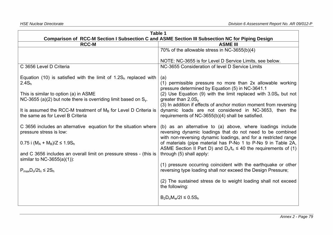
HSE Nuclear Directorate Division 6 Assessment Report No. AR 09/012-P
Annex 2 - Page 79
Table 1 Comparison of RCC-M Section I Subsection C and ASME Section III Subsection NC for Piping Design
RCC-M ASME III 70% of the allowable stress in NC-3655(b)(4) NOTE: NC-3655 is for Level D Service Limits, see below.
C 3656 Level D Criteria Equation (10) is satisfied with the limit of 1.2Sh replaced with 2.4Sh This is similar to option (a) in ASME NC-3655 (a)(2) but note there is overriding limit based on Sy. It is assumed the RCC-M treatment of MB for Level D Criteria is the same as for Level B Criteria C 3656 includes an alternative equation for the situation where pressure stress is low: 0.75 i (MA + MB)/Z ≤ 1.9Sh and C 3656 includes an overall limit on pressure stress - (this is similar to NC-3655(a)(1)): PmaxDo/2tn ≤ 2Sh
NC-3655 Consideration of level D Service Limits (a) (1) permissible pressure no more than 2x allowable working pressure determined by Equation (5) in NC-3641.1 (2) Use Equation (9) with the limit replaced with 3.0Sh but not greater than 2.0Sy (3) In addition if effects of anchor motion moment from reversing dynamic loads are not considered in NC-3653, then the requirements of NC-3655(b)(4) shall be satisfied. (b) as an alternative to (a) above, where loadings include reversing dynamic loadings that do not need to be combined with non-reversing dynamic loadings, and for a restricted range of materials (pipe material has P-No 1 to P-No 9 in Table 2A, ASME Section II Part D) and Do/tn ≤ 40 the requirements of (1) through (5) shall apply: (1) pressure occurring coincident with the earthquake or other reversing type loading shall nor exceed the Design Pressure; (2) The sustained stress de to weight loading shall not exceed the following: B2DoMw/2I ≤ 0.5Sh

HSE Nuclear Directorate Division 6 Assessment Report No. AR 09/012-P
Annex 2 - Page 80
Table 1 Comparison of RCC-M Section I Subsection C and ASME Section III Subsection NC for Piping Design
RCC-M ASME III (3) The stress due to weight and inertial loading due to reversing dynamic loads in combination with Level D coincident pressure shall not exceed the following: [(B1PDDo/2t) + (B2
’DoME/2I)] ≤ 3Sh
(4) The range of resultant moment MAM and the amplitude of the axial force FAM from the anchor motions due to earthquake and other reversing type dynamic loading shall not exceed the following: C2MAMDo/2I ≤ 6Sh FAM/AM ≤ Sh (5) (1) to (4) above assume a balanced pipe system where plastic strain is distributed throughout the system. If the pipe system design is unbalanced - plastic strain concentrated in a small portion of the piping: re-design to produce a balanced system or use 3Sm in place of 6Sm in (4) above. (b) above is similar to the Level D rules for Class 1 piping.


![2009/07/24 Areva EPR DC - Response to U.S. EPR Design Certification Application … · 2012. 12. 2. · 1 ArevaEPRDCPEm Resource From: Pederson Ronda M (AREVA NP INC) [Ronda.Pederson@areva.com]](https://img.pdfslide.net/doc/110x75/6117fa0cc0a9b343717e6f6c/20090724-areva-epr-dc-response-to-us-epr-design-certification-application.jpg)