Embed Size (px)
Citation preview

Version 2.0 Standard
GenICam_Standard.doc Page 1 of 53
GenICam Standard
Generic Interface for Cameras
Version 2.0

Version 2.0 Standard
GenICam_Standard.doc Page 2 of 53
Table of Contents
1 OVERVIEW....................................................................................................................... 5
2 GENAPI MODULE – CONFIGURING THE CAMERA............................................. 6
2.1 INTRODUCTION .............................................................................................................. 6 2.2 BASIC STRUCTURE OF THE CAMERA DESCRIPTION FILE ................................................ 7 2.3 NODES, INTERFACES, AND ABSTRACT FEATURES .......................................................... 9 2.4 GETTING AND SETTING VALUES .................................................................................. 10 2.5 ACCESS MODE ............................................................................................................. 11 2.6 CACHING...................................................................................................................... 15 2.7 IDENTIFYING AND VERSIONING A CAMERA DESCRIPTION FILE.................................... 19
2.7.1 Versioning the Schema ......................................................................................... 20 2.7.2 Versioning the Camera Description File ............................................................. 20 2.7.3 Identifying and Caching the Camera Description File........................................ 21
2.8 AVAILABLE NODE TYPES............................................................................................. 21 2.8.1 Node ..................................................................................................................... 21 2.8.2 Category ............................................................................................................... 24 2.8.3 Register................................................................................................................. 26 2.8.4 Arrays and Selectors ............................................................................................ 28 2.8.5 Integer, IntReg, MaskedIntReg............................................................................. 29 2.8.6 StructReg .............................................................................................................. 32 2.8.7 Boolean................................................................................................................. 33 2.8.8 Command ............................................................................................................. 34 2.8.9 Float, FloatReg .................................................................................................... 34 2.8.10 Enumeration, EnumEntry ................................................................................. 35 2.8.11 StringReg........................................................................................................... 37 2.8.12 String (v1.1) ...................................................................................................... 37 2.8.13 SwissKnife, IntSwissKnife, Converter, and IntConverter ................................. 37 2.8.14 ConfRom, TextDesc, and IntKey....................................................................... 40 2.8.15 DcamLock and SmartFeature ........................................................................... 41 2.8.16 Port ................................................................................................................... 42 2.8.17 Group element................................................................................................... 43
2.9 AVAILABLE INTERFACES.............................................................................................. 44 2.9.1 IInteger Interface.................................................................................................. 44 2.9.2 IFloat Interface .................................................................................................... 44 2.9.3 IString Interface ................................................................................................... 44 2.9.4 IEnumeration Interface ........................................................................................ 45 2.9.5 ICommand Interface............................................................................................. 45 2.9.6 IBoolean Interface................................................................................................ 45 2.9.7 IRegister Interface................................................................................................ 45 2.9.8 ICategory Interface .............................................................................................. 45 2.9.9 IPort Interface ...................................................................................................... 45 2.9.10 ISelector Interface............................................................................................. 45
3 APPENDIX....................................................................................................................... 46
Version 2.0 Standard
GenICam_Standard.doc Page 3 of 53
3.1 ENDIANESS OF GIGE VISION CAMERAS ....................................................................... 46 3.1.1 Behavior of products based on schema version 1.1 and newer ........................... 46 3.1.2 Behavior of products based on schema version 1.0 ............................................. 47 3.1.3 Passing the schema version to the IPort implementation .................................... 47
3.2 OTHER MODULES OF THE GENICAM STANDARD ......................................................... 48 3.2.1 Standard Feature Naming Convention ................................................................ 48 3.2.2 GenTL................................................................................................................... 49 3.2.3 CLProtocol ........................................................................................................... 49
4 ACKNOWLEDGEMENTS ............................................................................................ 50
5 RIGHTS AND TRADEMARKS .................................................................................... 50
6 INDEX .............................................................................................................................. 51
Version 2.0 Standard
GenICam_Standard.doc Page 4 of 53
HISTORY
Version Date Changed by Change
1.0 13.06.2006 Fritz Dierks, Basler Released version as voted on during the Montreal meeting
1.1 draft 1 25.03.2008 Fritz Dierks, Basler First draft for version 1.1
2.0 06.11.2009 Fritz Dierks, Basler Released
Version 2.0 Standard
GenICam_Standard.doc Page 5 of 53
1 Overview
Today’s digital cameras are packed with much more functionality than just delivering an image. Processing the image and appending the results to the image data stream, controlling external hardware, and doing the real-time part of the application have become common tasks for machine vision cameras. As a result, the programming interface for cameras has become more and more complex.
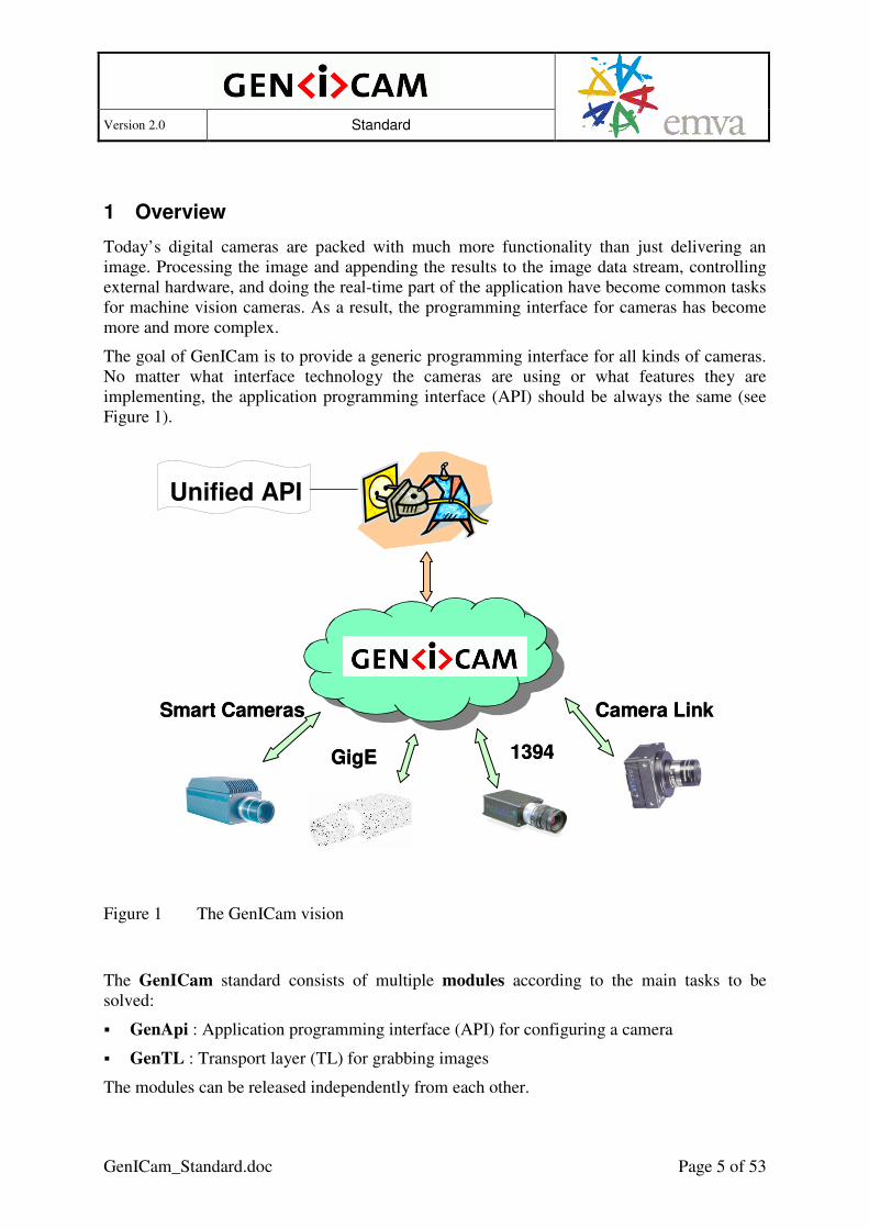
The goal of GenICam is to provide a generic programming interface for all kinds of cameras. No matter what interface technology the cameras are using or what features they are implementing, the application programming interface (API) should be always the same (see Figure 1).
Figure 1 The GenICam vision
The GenICam standard consists of multiple modules according to the main tasks to be solved:
� GenApi : Application programming interface (API) for configuring a camera
� GenTL : Transport layer (TL) for grabbing images
The modules can be released independently from each other.
Smart Cameras
GigE 1394
Camera LinkSmart Cameras
GigE 1394
Camera Link
Unified API

Version 2.0 Standard
GenICam_Standard.doc Page 6 of 53
2 GenApi Module – Configuring the Camera
2.1 Introduction
The GenApi module deals with the problem of how to configure a camera. The key idea is to make camera manufacturers provide machine readable versions of the manuals for their cameras. These camera description files contain all of the required information to
automatically map a camera’s features to its registers.
A typical feature would be the camera’s gain and the user’s attempt might be, for example, to set Gain=42. Using GenICam, a piece of generic software will be able to read the camera’s description file and figure out that setting the Gain to 42 means writing a value of 0x2A to a register located at 0x0815. Other tasks involved might be to check in advance whether the camera possesses a Gain feature and to check whether the new value is consistent with the allowed Gain range.
Note that adding a new feature to a camera just means extending the camera’s description file, thus making the new feature immediately available to all GenICam aware applications.
Application
GenApi
TransportLayer
Camera
Camera API
Transport Layer API
Camera Register Interface
Figure 2 Layers for accessing a camera
Figure 2 shows the layers involved in configuring a camera. The application requires a camera API that allows dealing with the camera’s features, for example, by writing code which looks like this:
Camera.Gain = 42;
The GenApi module will translate this call into a series of calls to register access functions provided by the transport layer API, for example, like this:
TransportLayer.WriteRegister( 0x0815, 0x2A, 2 ); // address, data, length
Version 2.0 Standard
GenICam_Standard.doc Page 7 of 53
Finally, the transport layer will deliver the calls to the camera interface. GenApi currently assumes that the camera is configured using a flat register space.
The GenICam standard defines the syntax of the camera description file plus the semantics of the transport layer API. In addition, the GenICam standard recommends – but does not enforce – the usage of certain names and types for common features such as Gain or Shutter.
The standard does not contain the actual code for reading the description file and translating features to registers, nor does it contain the transport layer code. Everyone is free to do their own implementation. There is, however, a reference implementation available that can be freely used.
Note that the GenApi section in this document deals with the camera description file only. It is intended to help the GenICam user to understand the key ideas behind the GenApi module and to enable people to write their own camera description files. The GenApi reference implementation comes with a reference manual showing how an end user can use the GenApi module even without a deeper understanding of the concepts laid out in this section.
2.2 Basic Structure of the Camera Description File
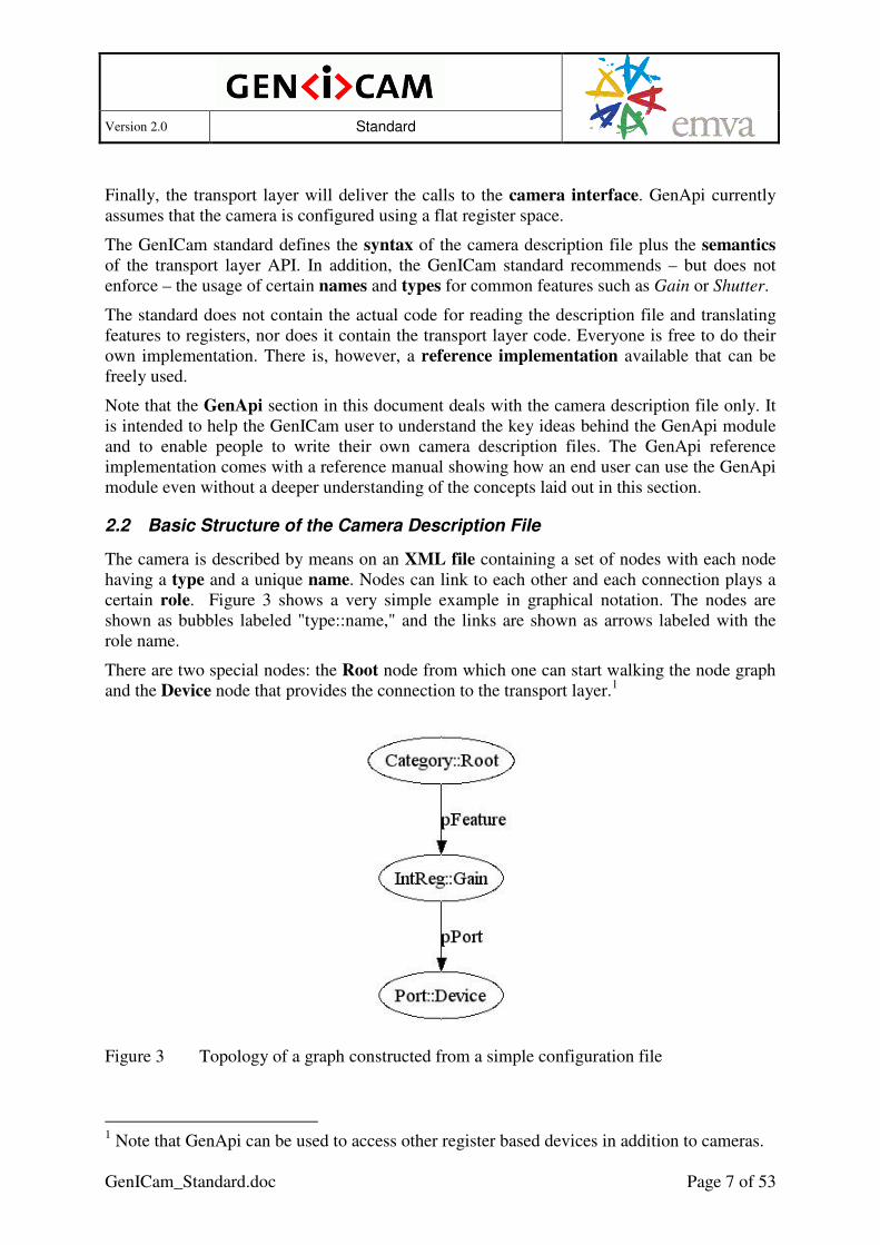
The camera is described by means on an XML file containing a set of nodes with each node having a type and a unique name. Nodes can link to each other and each connection plays a certain role. Figure 3 shows a very simple example in graphical notation. The nodes are shown as bubbles labeled "type::name," and the links are shown as arrows labeled with the role name.
There are two special nodes: the Root node from which one can start walking the node graph and the Device node that provides the connection to the transport layer.1
Figure 3 Topology of a graph constructed from a simple configuration file
1 Note that GenApi can be used to access other register based devices in addition to cameras.

Version 2.0 Standard
GenICam_Standard.doc Page 8 of 53
The Gain node in Figure 3 is of the IntReg type, which allows the extraction an integer from a register. Looked at from the Root node, it is a feature of the camera. The Root node, therefore, contains a link named pFeature referencing the Gain node. To read and write the Gain registers, the Gain node needs access to the camera port, and thus it contains a link to the Device node. The link is named pPort and references the Device node.
The Gain node contains all of the information required to extract a two byte unsigned integer in BigEndian mode. The complete camera description file looks like this:
<?xml version="1.0" encoding="utf-8"?>
<RegisterDescription
ModelName="Example01"
VendorName="Test"
ToolTip="Example 01 from the GenApi standard"
StandardNameSpace="None"
SchemaMajorVersion="1"
SchemaMinorVersion="1"
SchemaSubMinorVersion="0"
MajorVersion="1"
MinorVersion="0"
SubMinorVersion="0"
ProductGuid="1F3C6A72-7842-4edd-9130-E2E90A2058BA"
VersionGuid="7645D2A1-A41E-4ac6-B486-1531FB7BECE6"
xmlns="http://www.genicam.org/GenApi/Version_1_1"
xmlns:xsi="http://www.w3.org/2001/XMLSchema-instance"
xsi:schemaLocation="http://www.genicam.org/GenApi/Version_1_1
http://www.genicam.org/GenApi/GenApiSchema_Version_1_1.xsd">
<Category Name="Root">
<ToolTip>Entry for traversing the node graph</ToolTip>
<pFeature>Gain</pFeature>
</Category>
<IntReg Name="Gain">
<ToolTip>Access node for the camera's Gain feature</ToolTip>
<Address>0x0815</Address>
<Length>2</Length>
<AccessMode>RW</AccessMode>
<pPort>Device</pPort>
<Sign>Unsigned</Sign>
<Endianess>BigEndian</Endianess>
</IntReg>
<Port Name="Device">
<ToolTip> Port node giving access to the camera</ToolTip>
</Port>
</RegisterDescription>
The <?xml> node is a processing element giving hints about the encoding of the file and is always the same.
The <RegisterDescription> element is the outermost bracket encapsulating all nodes of the camera. The camera is identified by the ModelName and VendorName attributes (model

Version 2.0 Standard
GenICam_Standard.doc Page 9 of 53
“Example01” from vendor “Test” in this case). The other attributes are explained later in section 2.7.
Inside the <RegisterDescription> element, the nodes are lying in a flat order. Each node has a unique Name attribute and can be linked by sub-elements named pRole containing the Name of some other node.
Each node has an optional <ToolTip> element that contains a short description. The Gain node has additional elements that depend on its actual IntReg type and tells us, for example, the Address of the register or its Length.
Typically, an implementation will create one software object per node and will link these objects together according to the logical links described in the XML file.2 The nodes can either be retrieved by their (unique) name or can be found by traversing the node graph starting with the root node. Once the user has a pointer to the node, he can access that feature through the node object's programming interface.
The syntax of the XML file is defined in the XML schema given by the schemaLocation-attribute. The schema is part of the standard. This document explains the ideas and overall structure of GenICam. The schema and its embedded reference documentation describe the formal details. In case of doubt, the schema’s content overrides the content of this text.
The file location http://www.genicam.org/GenApi/GenApiSchema_Version_1_1.xsd is mandatory for the camera configuration file but can be overridden at runtime.
2.3 Nodes, Interfaces, and Abstract Features
Each node in the camera description file describes a single item. Depending on the item’s nature, the node is of a specific node type and has a specific interface. The following interfaces are currently available3 (each one is given with the typical widget used to map it on a graphical user interface):
� IInteger – maps to a slider with value, min, max, and increment
� IFloat – maps to a slider with value, min, and max plus a physical unit.
� IString – maps to an edit box showing a string
� IEnumeration – maps to a drop down box
� ICommand – maps to a command button
� IBoolean – maps to a check box
� IRegister – maps to an edit box showing a hex string
� ICategory – maps to an entry in a tree structuring the camera's features
� IPort – maps to the camera port and is typically not shown graphically
2 The actual implementation may split some of the XML nodes into a set of multiple
implementation nodes. 3 This list contains only interfaces representing a specific type. The reference implementation
contains more interfaces.

Version 2.0 Standard
GenICam_Standard.doc Page 10 of 53
The signature of the interfaces is given in more detail in section 2.9. The available node types are described in section 2.8. There might be multiple node types implementing the same interface type. The IInteger interface, for example, is (among others) implemented by the following node types:
� IntReg – extracts an integer lying byte-bounded in a register
� MaskedIntReg – extracts an integer packed into a register, e.g., from bit 8 to bit 12
� Integer – merges the integer’s value, min, max, and increment properties from different nodes
Each node type extracts an integer from different sources in a different way. The output of all of these nodes, however, can be used as type-safe input for all links where an integer is required.
Abstract features are always described in terms of an interface type, a name, and a meaning. For example, the Gain (name) of a camera might be defined as an IInteger (interface type) and might describe the amplification inside a camera (meaning). Note that other possible definitions exist, e.g., the Gain could be defined as an IEnumeration or as an
IFloat.
2.4 Getting and Setting Values
When the user reads or writes the value of a node, this node will trigger a cascade of read and write operations within the node graph. To illustrate this, Figure 4 shows a more elaborate example for the Gain feature. The Gain feature is exposed via an IInteger interface that lets the user get and set the feature's Value and lets her read (among other things) the feature's Min and Max value. The example in Figure 4 assumes that the camera has three registers, one for the Gain Value itself, one for its Min value, and one for its Max value. From each of these registers, the corresponding value is extracted using an IntReg node. The Integer node with the name Gain then collects the data and merges them, exposing the results with an IInteger interface.

Version 2.0 Standard
GenICam_Standard.doc Page 11 of 53
Figure 4 Example of the control flow when getting and setting features
If the user reads the value of the Gain node, the call will be dispatched to the GainValue node, which will in turn use the IPort interface from the Device node to ask for the right register.
If the user attempts to set the value of the Gain node, the implementation might decide to check the range first by reading the Min and Max values from the corresponding GainMin and GainMax nodes. If the value is inside the allowed range, the Gain node then will write it via the GainValue node and the Device node to the camera. Note that the implementation might cache the Min and Max values depending on the Cacheable attribute of the corresponding IntReg nodes.
2.5 Access Mode
Each node has an access mode defined according to the following table:
Readable Writable Implemented Access Mode
* * 0 NI – not implemented
0 0 1 NA – not available
0 1 1 WO – write only
1 0 1 RO – read only
1 1 1 RW – readable and writable
1 = yes, 0 = no, * = don’t care
A feature may be implemented in a camera, but be temporarily not available. If it is available, then it is, by definition, also implemented and may be readable and/or writable.

Version 2.0 Standard
GenICam_Standard.doc Page 12 of 53
Some nodes have elements to control accessibility, for example, the register node (see section 2.8.3). In addition, GenICam provides three mechanisms to change the accessibility at runtime:
� A feature can be temporarily locked depending on the value of another node. While locked, a feature is not writable. In terms of the table above, the writable flag is temporarily forced to 0.
� A feature can be temporarily not available depending on the value of another node. In terms of the table above, the writable and the readable flags are temporarily forced to 0.
� A feature can be not implemented at all depending on the value of another node. In terms of the table above, the implemented flag is permanently forced to 0.
The distinction between being available and being implemented has been made because a GUI might want to handle the two cases differently. A feature being not implemented at all will never be shown to the user and a feature being temporarily not available will be grayed out and the value will be replaced, e.g., by “—“. A temporarily locked feature will be grayed out, but the feature’s value may still be displayed.
A hardware Trigger that can be switched On and Off is a typical example for making a feature temporarily not available. If switched On, an additional feature, the TriggerPolarity, becomes available and denotes whether the hardware signal should be interpreted as an ActiveHigh or an ActiveLow signal. If the Trigger is switched Off, the TriggerPolarity is meaningless and should be grayed out.
Figure 5 shows how this information is handled in the camera description file. The Trigger and the TriggerPolarity feature are implemented using nodes of the Enumeration type that map a set of enumeration entries to integer numbers. For example, the entries for the Trigger feature are On=1 and Off=0. The integer numbers are mapped to registers using nodes of the IntReg type.

Version 2.0 Standard
GenICam_Standard.doc Page 13 of 53
Figure 5 Controlling whether a feature is accessible
The TriggerPolarity node has a pIsAvailable link that needs to point to a node exposing an IInteger interface. If the value of this node is zero, the node is temporarily not accessible.4
In the example, pIsAvailable could directly point to TriggerReg because Trigger=On is mapped to 1 and Trigger=Off is mapped to 0. If this is not the case, a node of the IntSwissKnife type comes in handy. It computes an integer result from any number of other integer nodes using a mathematical formula. In the XML file, the node looks like this:
<IntSwissKnife Name="TriggerEnabled">
<ToolTip>Determines if the Trigger feature is switched on</ToolTip>
<pVariable Name="TRIGGER">TriggerReg</pVariable>
<Formula>TRIGGER==1</Formula>
</IntSwissKnife>
The mathematical formula in the <Formula> entry is evaluated, yielding the result of the node. Before the evaluation, the symbolic names of the variables are replaced by the integer values of the corresponding nodes. In the example, there is only one <pVariable> entry pointing to the TriggerReg node and having the symbolic name TRIGGER. This is also found in the formula that reads “TRIGGER==1”.
So if the graphical user interface is updated, it will ask the TriggerPolarity node whether it is enabled. The TriggerPolarity node will in turn check the IntSwissKnife, which will in turn compute the outcome from the value of the TriggerReg node.
4 This follows the C/C++ semantic for interpreting integers as Boolean values.

Version 2.0 Standard
GenICam_Standard.doc Page 14 of 53
The BytesPerPacket feature of DCAM compliant 1394 cameras is a typical example for making a feature temporarily locked. The user can change this camera parameter, but only if the DMA of the PC adapter card is not yet set up for grabbing.5 Setting up the DMA means that the transport layer asks the camera for the BytesPerPacket parameter and configures that value to the DMA. After this has been done, BytesPerPacket must not be changed until the transport layer releases the DMA. In the meantime, the parameter must be locked in the camera.
Note that the camera itself has no way of knowing whether the DMA is set up or not. As a consequence, the “normal” nodes in the camera description files cannot be used for controlling the lock status of BytesPerPacket.
Application
GenApi
TransportLayer
Camera
reflects if theTL has lockedcertain parameters
Figure 6 Locking a feature
The solution within GenApi is to provide a floating Boolean node TLParamsLocked (see Figure 6). The BytesPerPacket links to this node with a pIsLocked link. The transport layer (TL) needs to reflect its DMA status by updating the value of the TLParamsLocked
node. Before it sets up the DMA, it locks the respective camera parameters (e.g., BytesPerPacket) by setting TLParamsLocked to true, and after the grab has been finished, it sets TLParamsLocked false again. Changing the TLParamsLocked node will in turn update the lock status of all dependent nodes, for example, the BytesPerPacket node.
Note that in order for this scheme to work generically, TLParamsLocked must be a standard node name and the transport layer must have access to the GenApi interface of the camera. In addition, the designer of the camera description file must be aware of which parameters will
5 The reason is that the DMA of a OHCI compliant PC adapter card needs to know the
BytesPerPacket parameter in advance of the data transfer to ensure that the frames are transferred to memory without causing CPU load.

Version 2.0 Standard
GenICam_Standard.doc Page 15 of 53
be locked by the transport layer. This information is included in the transport layer standard, e.g., the DCAM specification, which specifies that during grab the number of packages per frame and the package size must be fixed.
A family of cameras where some members have a Gamma feature implemented and some do not is a typical example for a feature being not implemented. If the cameras have an inquiry
bit advertising whether the camera has the Gamma feature implemented or not, you can maintain one camera description file for the whole family of cameras.
Figure 7 shows how to handle that case with GenICam. The Gamma feature node has a pIsImplemented link to a GammaInq node mapping to the inquiry bit in the camera. Multiple inquiry bits are typically packed into one register. For extracting the bits, the MaskedIntReg node type is used. It works like an IntReg node, but in addition, you can denote which bit or which contiguous group of bits you want to be extracted as an integer.
Figure 7 Checking whether a feature is implemented
2.6 Caching
If an implementation supports checking ranges, presence, and enable status for each write access, it would normally trigger a cascade of read accesses to the camera. However, most of the values required for validation do not change frequently or at all and can thus be cached. The camera description file contains all of the necessary means to ensure the cache’s coherency.

Version 2.0 Standard
GenICam_Standard.doc Page 16 of 53
Figure 8 Area of Interest
To explain this, a more elaborate example must be used. Figure 8 shows an area of interest (AOI) on the imager in a camera. The camera will send only the data from within the AOI, which is given as a rectangle defined by the parameters Top, Left, Width, and Height.
Figure 9 Controlling the Area of Interest
Each of these four parameters is exposed through a register as shown in Figure 9. This simple scheme, however, cannot deal with the fact that none of the four parameters has an unlimited range. Assuming that the pixel coordinates start with 0, the following restrictions apply:
WidthhImagerWidtLeft −≤≤0
HeighthtImagerHeigTop −≤≤0
LefthImagerWidtWidth −≤≤1
TophtImagerHeigHeight −≤≤1
ImagerWidth
ImagerHeight
Top
Left
Width
Height Area of Interest
(AOI)

Version 2.0 Standard
GenICam_Standard.doc Page 17 of 53
To take these restrictions into account, the maximum values for each of the four parameters must be computed using SwissKnife nodes; the minimum values are fixed. The resulting GenApi node graph is shown in Figure 10. Note that a second layer of Integer nodes has been introduced and that the maximum values are taken from IntSwissKnife nodes.
Figure 10 Controlling the Area of Interest while taking restrictions into account
Assuming an imager with VGA resolution (640x480), the XML code for the TopMax node might look like this:
<IntSwissKnife Name="TopMax">
<pVariable Name="CURHEIGHT">HeightReg</pVariable>
<Formula>480-CURHEIGHT</Formula>
</IntSwissKnife>
Returning to the topic of caching, you would not want the HeightReg to be read each time you set the Left feature, nor would you want the TopMax node to be evaluated each time. This is indeed not necessary if (and only if) you are certain that HeightReg will only change when the GenApi itself writes a new value to that register. If this is the case, you can cache the values of HeightReg and TopMax.
If the user writes a new value to HeightReg, the HeightReg cache can be updated immediately, and the TopMax cache needs to be invalidated. The next time someone accesses the Left node, it will read TopMax, thereby creating a new cache entry for TopMax.
As a rule, all clients of a node are informed if the node changes its content so that the clients can invalidate their caches.
Normally, the links between the nodes in the camera description file contain all of the information needed so that the implementation can deal with the caching without the user needing to worry about it. However, there are certain cases were the camera itself contains more dependencies than those directly described by the nodes.

Version 2.0 Standard
GenICam_Standard.doc Page 18 of 53
Some cameras contain a feature called Binning. When Binning is switched on, the charge from adjacent pixels is merged together, yielding a larger full well at the cost of lower resolution. Assuming a VGA resolution imager, typical configurations are:
� No Binning (640 x 480)
� Horizontal Binning (320 x 480)
� Vertical Binning (640 x 240)
� Full Binning (320 x 240)
In GenICam, this feature would be described using an enumeration with the four entries given above (see Figure 11). However, changing the binning also means changing the imager size – not the real physical imager, but rather the logical imager size that imposes the restrictions on the AOI parameters.
Figure 11 Controlling the Area of Interest taking binning into account
Let's assume that the camera provides the information about the current (logical) imager size with a register. As shown in Figure 11, this introduces two new nodes: ImagerHeightReg and ImagerWidthReg. The XML code for TopMax then looks like this:
<IntSwissKnife Name="TopMax">
<pVariable Name="CURHEIGHT">HeightReg</pVariable>
<pVariable Name="IMAGERHEIGHT">ImagerHeightReg</pVariable>
<Formula>IMAGERHEIGHT-CURHEIGHT</Formula>
</IntSwissKnife>
As we have seen, the value of ImagerHeightReg will change if the user changes the Binning feature. However, there is no data flow between the two nodes. To make sure that the node

Version 2.0 Standard
GenICam_Standard.doc Page 19 of 53
cache for ImagerHeightReg will be invalidated when the content of the BinningReg node changes, a <pInvalidator> link must be introduced between the two nodes. The sole purpose of this link is to document the hidden dependency between the two features and to make sure that the cache is always coherent.
2.7 Identifying and Versioning a Camera Description File
It must be possible to identify a camera description file, and thus the described camera, in a unique manner. In addition, a camera description file will typically evolve over time, e.g., when features are added to the corresponding camera product. This creates the necessity for a versioning mechanism. The GenApi syntax itself will also evolve over time, e.g., when new node types are added, thus a versioning mechanism for the schema is also required.
The necessary means are found in the attribute list of the <RegisterDescription> element, which is the outermost bracket of the XML file. Here is an example:
<RegisterDescription
ModelName="Example01"
VendorName="Test"
ToolTip="Example 01 from the GenApi standard"
StandardNameSpace="None"
SchemaMajorVersion="1"
SchemaMinorVersion="1"
SchemaSubMinorVersion="0"
MajorVersion="1"
MinorVersion="0"
SubMinorVersion="0"
ProductGuid="1F3C6A72-7842-4edd-9130-E2E90A2058BA"
VersionGuid="7645D2A1-A41E-4ac6-B486-1531FB7BECE6"
xmlns="http://www.genicam.org/GenApi/Version_1_1"
xmlns:xsi="http://www.w3.org/2001/XMLSchema-instance"
xsi:schemaLocation="http://www.genicam.org/GenApi/Version_1_1
../GenApiSchema_Version_1_1.xsd">
The camera described is identified by the VendorName: / ModelName pair. Assuming that vendor names are mutually exclusive due to trade marks, this scheme creates unique names. The ToolTip attribute is used to provide additional information about the device that can be displayed to the user, e.g., in a selection list of devices found on a bus.
Names inside a camera description file may come from different name spaces. This is described in more detail in section 2.8.1. Within a given camera description file, names come either from a custom name space or a standard name space. The attribute StandardNameSpace identifies the standard name space used in the file.
The versioning of the different items in a camera description file follows common rules, and a three part version number is used:
<Major>.<Minor>.<SubMinor>
An example would be ‘1.4.2’.
The following compatibility rules apply:
� Files with a higher Major version number are not backward compatible

Version 2.0 Standard
GenICam_Standard.doc Page 20 of 53
� Files with a higher Minor version number are backward compatible
� Changes in the SubMinor version number are bug fixes only; always use the file with the highest available SubMinor version number
Example: Version 1.3.0 is compatible with version 1.1.*, 1.2.* and 1.3.* (were * means don’t
care). It is not compatible with version 2.*.*. If version 1.3.2 is available, it should be used instead of 1.3.0.
2.7.1 Versioning the Schema
The attributes SchemaMajorVersion, SchemaMinorVersion, and SchemaSubMinorVersion describe the version of the GenApi schema used for the XML file. These attributes are mandatory. They are for information purposes. In addition, the Major and Minor schema version numbers are encoded in the namespace (see xmlns entry) and the schema’s file name (see xsi:schemaLocation entry).
In the example, the namespace reads “http://www.genicam.org/GenApi/Version_1_1”. A program seeking the schema file might either retrieve it over the internet using the URL or look at the file path given optionally in the second part of the schemaLocation. In the example, the path reads “../../GenApi/GenApiSchema_Version_1_1.xsd” and assumes that the XML file is stored within the folder structure of the GenICam reference implementation.
The xmlns:xsi entry “http://www.w3.org/2001/XMLSchema-instance” describes the namespace of the schema language itself.
Note that an implementation supporting, e.g., schemas up to version 1.3.* must have three schema files present: for versions 1.0.*, 1.2.*, and 1.3.*. This is required for backward compatibility – since older XML files come with an older namespace, they need older schema files. On the other hand, an XML file using a later schema version not yet supported by the implementation, say 1.4.*, needs to be rejected, hence the necessity to have the version number coded in the schema’s namespace.
2.7.2 Versioning the Camera Description File
The MajorVersion, MinorVersion, and SubMinorVersion attributes describe the version of XML file itself. The camera vendor is responsible for following the compatibility rules.
What does backward compatibility mean with respect to camera description files? Assume a camera that in version 1.0 has only a single feature implemented. Now assume the camera’s firmware is extended to have another feature. There are two ways to deal with this situation in the camera description file. If the feature is just added to the XML file, this implicitly states that the feature is always there. Because this is not true with older cameras, the new file will not be backward compatible, and consequently it must get the version number 2.0.
A second, smarter way to deal with the situation is to introduce an inquiry register in the camera(!) where the user can check to see if the new feature is present or not. The new feature can now be added in a way that lets the user learn from the access mode of the feature whether the feature is present or not. This makes the new file backward compatible and its version number would be 1.1. Of course, this is possible only if an inquiry mechanism has been implemented in the camera from the beginning. The benefit of using the second method is that only one camera description file must be maintained for a whole family of cameras.

Version 2.0 Standard
GenICam_Standard.doc Page 21 of 53
Note that compatibility refers only to the feature nodes and the underlying register layout. However it does not refer to implementation nodes (for details see section 2.8.2).
2.7.3 Identifying and Caching the Camera Description File
Loading a camera description file may involve one or more pre-processing steps. To speed things up, the pre-processed XML file can be cached. For caching, a key is required that uniquely identifies the camera description file. A combination of the <RegisterDescription> element’s VendorName, ModelName, MajorVersion, MinorVersion, and SubMinorVersion attributes would be sufficient, but is a bit clumsy to use.
To simplify this caching, the VersionGuid attribute has been introduced. The VersionGuid attribute holds a global unique identifier (GUID) that must be changed each time one of the VendorName, ModelName, MajorVersion, MinorVersion, or SubMinorVersion attributes changes. The VersionGuid uniquely identifies a certain version of a camera description file, hence the name.
Instead of caching all of the different camera description files that might come along in different versions over time, it can make sense to cache only the most recent file, which contains all others via backward compatibility. There is one such file per VendorName,
ModelName, and MajorVersion number. The caching key for that kind of file is the ProductGuid, which also holds a global unique identifier (GUID) and which must be changed each time the VendorName, ModelName, or the MajorVersion changes.
2.8 Available Node Types
This section gives a brief description of each available node type, of their behavior, usage, and most interesting parameters. In addition, there is a formal description for the XML layout of each node in an XML schema file included with the GenICam standard. This schema file can be read by most XML editors and will greatly simplify creating camera description files by providing a syntax check and context sensitive fill-in helpers.
This document refers to the GenApi schema version 1.1 found in the file GenApiSchema_Version_1_1.xsd. Note that in subsequent versions of the standard, additional node types, elements, and attributes may be added, however, backward compatibility will be maintained if at all possible.
2.8.1 Node
The Node type contains those elements and attributes common to all other node types. A stand-alone Node node is pretty useless, but is possible for testing purposes. Here is an example:

Version 2.0 Standard
GenICam_Standard.doc Page 22 of 53
<Node Name="Gain" NameSpace="Standard">
<Extension>
<MyElement>Something vendor specific</MyElement>
</Extension>
<ToolTip>The amplitication of the camera</ToolTip>
<Description>A more elborated description</Description>
<DisplayName>Gain</DisplayName>
<Visibility>Expert</Visibility>
<EventID>12fc</EventID>
<pIsImplemented>SomeNode1</pIsImplemented>
<pIsAvailable>SomeNode2</pIsAvailable>
<pIsLocked>SomeNode3</pIsLocked>
<pError>NodeIndicatingAnError</pError>
<ImposedAccessMode>RO</ImposedAccessMode>
<pAlias>SomeNode4</pAlias>
Each node has a Name attribute. The Name must be unique within the camera description file. Names can be composed of alphanumeric characters [A-Za-z0-9]. The schema also allows the use of the underscore ‘_’, but not as a leading character. This is because the reference implementation uses a leading underscore for implementation related names.
Each Name lives inside a name space. The name space is identified by the combination of the NameSpace attribute of the node and the StandardNameSpace attribute of the enclosing <RegisterDescription> element (see section 2.7). The NameSpace attribute can have two possible values: Custom or Standard. If it is Custom, any name can be used as long as it is unique within the camera description file. If it is Standard, it must come from one of the standard feature name lists available for the following camera types (for more details see section 2.9):
� IIDC : cameras following the 1394 IIDC standard (also called DCAM standard)
� GEV : cameras following the GigE Vision standard
� CL : cameras following the Camera Link standard
� USB : cameras following the USB standard
� None : no standard is used
A Node can have a MergePriority. attribute which can have the values +1, 0, or -1. It controls the way two XML files A and B are merged to a target file C. A is called the target file and B is called the inject file. Nodes are compared based on their Name attribute only.
• If a node is present only in A or B it is copied to C
• If a non-Category node is present in A and B the following rules apply (note that the MergePriority attribut of the target file A is ignored):
o If the node from the injected file B has MergePriority = +1 it is copied to C.
o If the node from B has MergePriority = -1 the corresponding node from A it is copied to C.
o If the node from B has MergePriority = 0 (default) or the MergeAttribute is missing an error occurs.

Version 2.0 Standard
GenICam_Standard.doc Page 23 of 53
o
• If a Category node is present in A and B the Category node from the target file A is copied to C with the <pFeature> entries from file B added while avoiding duplicates.
A Node can have a ExposeStatic attribute which can have the values Yes or No ro be missing. It controls which node is exposed in the static use case to the customer. The following rules apply:
• Features are exposed if they don’t have ExposeStatic=No set
• Non-Features are exposed only if they have ExposeStatic=Yes set
An <Extension> element can be used to add custom specific data to a camera description file. All elements placed inside the <Extension> element are ignored.
The <ToolTip> element gives a short description of the node. It may also be used as a brief description for a reference documentation automatically generated from the camera description file.
The <Description> element gives a more detailed description of the node. It may also be used as a long description for a reference documentation automatically generated from the camera description file.
The <DisplayName> element lets you define feature captions that might be used instead of the feature's Name.
The <Visibility> element defines the user level that should get access to the feature. Possible values are: Beginner, Expert, Guru, and Invisible. The latter is required to make a feature show up in the API, but not in the GUI (see section 2.8.2).
The <EventID> element is used for delivering asynchronous events. A camera might send an event package to indicate that one ore more data item in the camera has changed its value. GenICam handles the event by invalidating the nodes corresponding to the data items. The nodes are found by the EventID which is a hexadecimal number which comes with the event package from the camera. Each node can have one (optional) EventID element.
The <pIsImplemented>, <pIsAvaliable>, and <pIsLocked> elements contains the names of nodes implementing an IInteger interface. If these elements are present, they influence the access mode of this node as described in section 2.5.
The <pBlockPolling>> element bocks the polling on a node with a PollingTime entry if the target of the element is !=0.
An <ImposedAccessMode> element can be used to narrow the access mode resulting from other nodes.
<pAlias> points to another node which describes the same feature in a different manner. This feature will be mainly used in a GUI: a Category might be replaced by its alias if not all members are shown; an integer and a flat node might be aliases of each other if they show the raw and the abs value of a feature.
<pCastAlias> points to another node which describes the same feature in a way that the original node and the cast alias node can be casted into each other.

Version 2.0 Standard
GenICam_Standard.doc Page 24 of 53
<IsDepercated> denotes that the corresponding feature is deprecated and should not be used for new designs anymore.
<Streamable> denotes that the corresponding feature is prepared to be stored to and loaded from a file via the GenApi node tree.
<pError> points to an enumeration which is checked after setting the value of a node. The enumeration must have one entry with IntValue 0 which indicates no error. If another value is set an exception is thrown with the DisplayName and the ToolTip of the EnumEntry as error message.
<DocuURL> Provides a http URL pointing to a location were documentation for the node can be found. The notation can contain Variables in the form $(NAME) were NAME is either a Node name or one of the following special names:
− Sys::NodeName : Name of the current node
− Sys::ModelName: content of the XML file’s ModelName attribute
− Sys::VendorName: content of the XML file’s VendorName attribute
− Sys::StandardNamespace: content of the XML file’s StandardNamespace attribute
− Sys::GenApiVersion : version of the GenApi software (<Major>.<Minor>.<SubMinor>)
− Sys::DeviceVersion : version of the device (<Major>.<Minor>.<SubMinor>)
− Sys::SchemaVersion : version of the schema (<Major>.<Minor>.<SubMinor>)
− Sys::Application: Name of the executable file
− Sys::OperatingSystem: Name of the operating system. Format “Windows5.1_SP3.0”
− Sys::Language: Name of the operating system’s locale ID. Format “German”
2.8.2 Category
The Category node is used to group features that should be presented to the user. It implements the ICategory interface and inherits all Node elements. It also contains a list of <pFeature> elements that point to the features contained in the category. Categories can contain other categories, thus forming a tree of arbitrary depth.
There is one special Category node with the standard name Root6 that is the basis of the
category tree. Users may want to start browsing the features of a camera from here. The following example creates the node graph shown in Figure 12:
6 The feature ICategory::Root is defined in all standard name spaces.

Version 2.0 Standard
GenICam_Standard.doc Page 25 of 53
<Category Name="Root" NameSpace=”Standard” >
<pFeature>ScalarFeatures</pFeature>
<pFeature>Trigger</pFeature>
</Category>
<Category Name="ScalarFeatures" >
<pFeature>Shutter</pFeature>
<pFeature>Gain</pFeature>
<pFeature>Offset</pFeature>
<pFeature>WhiteBalance</pFeature>
</Category>
<Category Name="WhiteBalance" >
<pFeature>RedGain</pFeature>
<pFeature>BlueGain</pFeature>
</Category>
<Category Name="Trigger" >
<pFeature>TriggerMode</pFeature>
<pFeature>TriggerPolarity</pFeature>
</Category>
Note that a user accessing the nodes by browsing the category tree is intended only to see features nodes in the first layer below the Category nodes. Nodes deeper in the graph are called implementation nodes and are retrievable only by name or in a special browse mode that the implementation might provide for debugging purposes. Note that the names and the layout of the implementation nodes may change without notice in a new release of a camera description file, even if the vendor declares it backward compatible (see also section 2.7.3).
Figure 12 A tree of categories

Version 2.0 Standard
GenICam_Standard.doc Page 26 of 53
2.8.3 Register
The Register node maps to a contiguous array of bytes in the register space of the camera. The Register node implements the IRegister interface and inherits its elements and attributes from the Node node. It in turn leaves its elements and nodes to all specialized register access nodes, such as IntReg, StringReg, etc. A Register node, however, can also be instantiated on its own giving access to the raw binary data. Here is a simple example:
<Register Name="SensorTemperature">
<Address>0xff00</Address>
<Length>4</Length>
<AccessMode>RO</AccessMode>
<pPort>Device</pPort>
<Cachable>No</Cachable>
<PollingTime>10000</PollingTime>
</Register>
The example exposes the temperature of the camera’s sensor. The temperature can change at any time and is therefore not cacheable. If displayed, it should be polled every 10.000 ms.
The <Address> element gives the address of the register in the camera’s register space.
The <Length> element gives the length of the register in bytes. Alternatively the length can be read from another node using an <pLength> entry.
The <AccessMode> element can have the values RW (read/write), RO (read only), or WO (write only) and indicates what the camera can deliver.
The <pPort> element contains the name of a Port node that gives access to the camera’s register space (for details see section 2.8.16).
The <Cacheable> element can have the values NoCache, WriteThrough, and WriteAround. WriteThrough means that a value written to the camera is written to the cache as well. WriteAround means that only read values are written to the cache. The latter behavior makes sense, for example, with an IFloat::Gain node where the user can write any value, but when reading back, will retrieve a value that has been rounded by the camera to a value the internal analog-to-digital converter is able to deliver. Note that caching is an optional feature of any implementation.
The <PollingTime> element denotes a recommended time interval [in ms] after which a node should be invalidated. Note that polling is an optional feature of any implementation and the polling time is a hint only.
Instead of a single <Address> entry, a register can have multiple entries for the <Address>, <pAddress>, and/or <IntSwissKnife> types. The values of these entries are summed, yielding the address of the register node.
The <pAddress> element points to a node implementing an IInteger interface delivering a contribution to the final address.
The <IntSwissKnife> element can be used to compute an address contribution from multiple sources (for details see section 2.8.12).
The <pIndex Offset=”12”> element points to a node implementing an IInteger interface delivering an index. The element has an attribute Offset. The product of index and Offset is

Version 2.0 Standard
GenICam_Standard.doc Page 27 of 53
added to the address. Alternativly the offset can be taken from a node <pIndex
pOffset=”OffsetValue”>. If neiterh Offset nor pOffest attribute is given the register’s length is taken as offset.
The <pInvalidator> element contains the name of a node that when changed, will invalidate the content of this node as described in section 2.6.
The following example shows how to use this mechanism for indirect addressing (see also Figure 13):
<Integer Name="BaseAddress">
<Value>0xff00</Value>
</Integer>
<IntReg Name="Gain">
<Address>0x04</Address>
<pAddress>BaseAddress</pAddress>
<Length>4</Length>
<AccessMode>RW</AccessMode>
<pPort>Device</pPort>
<Sign>Unsigned</Sign>
<Endianess>LittleEndian</Endianess>
</IntReg>
<IntReg Name="Offset">
<Address>0x08</Address>
<pAddress>BaseAddress</pAddress>
<Length>4</Length>
<AccessMode>RW</AccessMode>
<pPort>Device</pPort>
<Sign>Unsigned</Sign>
<Endianess>LittleEndian</Endianess>
</IntReg>
This example mimics a C/C++ struct of the form:
struct { // BaseAddress 0xff00
uint32_t Reserved;
uint32_t Gain; // Offset 0x04
uint32_t Offset; // Offset 0x08
};
The value for the struct’s base address comes from a BaseAddress constant integer node and is fed into the node using a <pAddress> element. Each element of the (Gain and Offset) struct has an offset that is added to the base address using an <Address> element.

Version 2.0 Standard
GenICam_Standard.doc Page 28 of 53
Figure 13 Indirect addressing: mapping a C/C++ struct
Note that this mechanism is used very frequently with 1394 DCAM compliant cameras where the whole standard register block has a common base address that must be parsed from a IEEE 1212 configuration ROM structure at run-time (see also the ConfRom node type).
2.8.4 Arrays and Selectors
Indirect addressing as described in the previous chapter is also used for accessing arrays. The following example shows how this is done (see also Figure 14):
<Integer Name="LUTIndex">
<Value>0</Value>
<Min>0</Min>
<Max>255</Max>
<pSelected>LUTEntry</pSelected>
</Integer>
<IntReg Name="LUTEntry">
<IntSwissKnife Name="LUTEntryAddress">
<pVariable Name="INDEX">LUTIndex</pVariable>
<Formula>0xff00 + INDEX * 4</Formula>
</IntSwissKnife>
<Length>4</Length>
<AccessMode>RW</AccessMode>
<pPort>Device</pPort>
<Sign>Unsigned</Sign>
<Endianess>LittleEndian</Endianess>
</IntReg>
A LUT Entry element is used as a pointer into the LUT. The address of this element is computed using an embedded <IntSwissKnife> element that computes the address of the LUTEntry element according to the formula: ( )LUTEntryLUTIndexsBaseAddres sizeof⋅+ . The
LUTIndex is a “floating” Integer node that is not connected to the camera. Instead, it starts with <Value> and can be changed between <Min> and <Max> by the user.

Version 2.0 Standard
GenICam_Standard.doc Page 29 of 53
Figure 14 Accessing a LUT array
The fact that the LUTIndex can be used to select a specific LUTEntry is made explicit by the <pSelected> element in the LUTIndex node. Nodes implementing an IInteger or and IEnumeration interface can have any number of pSelected entries to indicate that the selected
nodes will show a different value depending on the value of selector node. Information whether a node is a selector and which are the selected nodes can be retrieved using the ISelector interface which has the according methods IsSelector and GetSelectedFeatures. Using this interface a GUI can for example show a list of LUTEntries because it knows that if it runs LUTIndex (selector) from min to max it will retrieve an array of different values from LUTEntry (selected).
Note that the selector and the indirect addressing scheme can also be used to access multi-
dimensional arrays via multiple indices.
2.8.5 Integer, IntReg, MaskedIntReg
The IInteger interface provides access to signed 64 bit integer variables that have a Value restricted by the Minimum, Maximum, and Increment parameters according to the formulas:
IncrementiMinimumValue ⋅+= with Increment
MinimumMaximumi
−≤≤0
The IntReg node maps to byte-aligned integer registers. It inherits the elements and attributes from Register nodes. Below is an example mapping to a 2 byte unsigned integer. Note that such a variable has the following restriction parameters: Minimum = 0, Maximum = 65.535, Increment = 1.

Version 2.0 Standard
GenICam_Standard.doc Page 30 of 53
<IntReg Name="Gain">
<Address>0x1234</Address>
<Length>2</Length>
<AccessMode>RW</AccessMode>
<pPort>Device</pPort>
<Sign>Unsigned</Sign>
<Endianess>BigEndian</Endianess>
</IntReg>
The <Sign> element can have the value Singed or Unsigned. Note that unsigned int64 values are not available. The largest unsingned integer accessible with a MaskedIntReg (see bleow) equals 2^63-1.
The <Endianess> element can have the values LittleEndian or BigEndian and refers to the endianess of the device as seen trough the transport layer. The transport layer must attempt to not change the endianess. Note that the implementation must be aware of whether it is running itself on a little-endian or big-endian machine.
Sometimes integers are not byte aligned, but are packed into a register. In this case, a MaskedIntReg is used. It inherits the elements and attributes from the Register node. The following XML code is an example for a 12 bit integer packed into a 2 byte register. The <LSB> and <MSB> elements denote the least significant bit and the most significant bit respectively.
<MaskedIntReg Name="Offset">
<Address>0x2345</Address>
<Length>2</Length>
<AccessMode>RW</AccessMode>
<pPort>Device</pPort>
<LSB>11</LSB>
<MSB>0</MSB>
<Sign>Unsigned</Sign>
<Endianess>BigEndian</Endianess>
</MaskedIntReg>
In the case where only a single bit must be mapped – which is quite common for presence inquiry bits – instead of using an <LSB> and an <MSB> element with the same value, you can also use a <Bit> entry.
<MaskedIntReg Name="OffsetInq">
<Address>0x2345</Address>
<Length>2</Length>
<AccessMode>RW</AccessMode>
<pPort>Device</pPort>
<Bit>15</Bit>
<Sign>Unsigned</Sign>
<Endianess>BigEndian</Endianess>
</MaskedIntReg>
The numbering of the bits differs between big-endian and little-endian as is shown for a 32 bit integer below:
Little-Endian: MSB ... LSB
31 ... 0

Version 2.0 Standard
GenICam_Standard.doc Page 31 of 53
Big-Endian: MSB ... LSB
0 ... 31
The LSB is the bit which maps to the 02 digit. Note that with big-endian the equation MSB ≤
LSB holds true while with little-endian the opposite holds true: LSB ≤ MSB.
The Integer node type is used to merge the Value and the Minimum, Maximum, and Increment parameters from different sources. It inherits the elements and attributes from the Node node. The restriction parameters are either given as constants using the <Min>, <Max>, and <Inc> elements or as a pointer to other IInteger nodes using the <pMin>, <pMax>, and <pInc> elements.
The Value normally comes from another node using the <pValue> element. Alternatively, a constant can be given inside a <Value> element. In this case, the node is a “floating” variable that can be set by the user to any value allowed by the restriction parameters. The given constant is the start value. A typical example is the following Index node that can be set to the values 0, 2, 4, …, 254:
<Integer Name="Index">
<Value>0</Value>
<Min>0</Min>
<Max>255</Max>
<Inc>2</Inc>
</Integer>
It the <pValue> element is used with an Integer node it can be optionally surrounded by any numbers of <pValueCopy> elements like in the following example.
<Integer Name="Replicator">
<pValueCopy>SomeInt1</pValueCopy>
<pValue>SomeInt2</pValue>
<pValueCopy>SomeInt3</pValueCopy>
<pValueCopy>SomeInt4</pValueCopy>
</Integer>
The GetValue method returns the value read from the pValue sub-node. The SetValue method writes to the pValue and the pValueCopy sub-nodes in the order in which they are given in the XML file. The [min, max] boundaries of the sub-nodes to are combined to find the largest boundary which will fit all sub-nodes. The increments of all sub-nodes must be the same; otherwise the node becomes not writable.
The Integer node can also work like a multiplexer or a value table like shown in the following examples:
<Integer Name="Multiplexer">
<pIndex>Selector</pIndex>
<pValueIndexed Index=”10”>SomeInt1</pValue>
<pValueIndexed Index=”20”>SomeInt2</pValue>
<ValueDefault>0</ ValueDefault>
</Integer>
<Integer Name="Table">
<pIndex>Selector</pIndex>

Version 2.0 Standard
GenICam_Standard.doc Page 32 of 53
<ValueIndexed Index=”10”>100</Value>
<ValueIndexed Index=”20”>200</Value>
<pValueDefault>SomeNode</pValueDefault>
</Integer>
The pIndex> entry refers to an Integer node. Depending on its value one of the ValueIndexed> or pValueIndexed> entries is selected which behave like Value or pValue entries respectively. The two entry types can be mixed. If the index does not match the value given in <ValueDefault> or <pValueDefault> respectivly is returend. Note that selecting an entry also forwards it’s properties Unit and Representation.
The <Unit> element denotes the physical meaning of a number.
The <Representation> element gives a hint about how to display the integer. If the element is Linear or Logarithmic, a slider with the appropriate behavior should be implemented. If the element is Boolean, a checkbox should be used. PureNumber means to use an edit box only with decimal display; HexNumber means the same with hexadecimal display. IPV4Address and MACAddress mean to show the numbers like an IP address (IP version 4) or a MAC address respectively.
Integer, IntReg and MaskedInt nodes can also have an <pSelected> element. For a descripton see section 2.8.4.
2.8.6 StructReg
MaskedInt node are often used to pick a filed of bits from a register. If a complete MaskedInt entry is used for each bit there is a lot of unnecessarily copied data in the camera description file because the different MaskedInt entries share most of their elements like, e.g. the <pPort> element, the <Endianess> etc.
In order to overcome this the StructReg node has been introduced. Here an example:
<StructReg Comment="VFormat7InqReg">
<ToolTip>Inquiry register for video format 7 color codes</ToolTip>
<Address>0x14</Address>
<pAddress>VFormat7ModeCsrBase</pAddress>
<Length>4</Length>
<AccessMode>RO</AccessMode>
<pPort>Device</pPort>
<Endianess>BigEndian</Endianess>
<StructEntry Name="VFormat7Mono8InqReg">
<ToolTip>Inquiry for ColorCode Mono8</ToolTip>
<Bit>31</Bit>
</StructEntry>
<StructEntry Name="VFormat7YUV422InqReg">
<ToolTip>Inquiry for ColorCode YUV8 422</ToolTip>
<Bit>29</Bit>
</StructEntry>
</StructEntry>
<StructEntry Name="VFormat7Raw8InqReg">
<Bit>24</Bit>
</StructEntry>
</StructReg>

Version 2.0 Standard
GenICam_Standard.doc Page 33 of 53
The StructReg node contains the same elements as the MaskedInt element. In addition it contains one or more <StructEntry> elements which in turn can contain again the same elements as the MaskedInt element. A pre-processor replaces the StructReg node with a set of MaskedInt nodes: From each <StructEntry> element one MaskedInt node is created which gets the Name attribute from the StructEntry element, all its sub-elements, plus all elements from the StructReg node which are not present already in the <StructEntry> element. Thus the first MaskedInt node created from the example above would look like this.
<MaskedInt Name="VFormat7Mono8InqReg ">
<Address>0x14</Address>
<pAddress>VFormat7ModeCsrBase</pAddress>
<Length>4</Length>
<AccessMode>RO</AccessMode>
<pPort>Device</pPort>
<Endianess>BigEndian</Endianess>
<ToolTip>Inquiry for ColorCode Mono8</ToolTip>
<Bit>31</Bit>
</MaskedInt>
Note that the <ToolTip> element was selected from the <StructEntry> element, not from the <StructReg> node. In contrast the entry with the Name VFormat7Raw8InqReg would inherit the <ToolTip> element from the <StructReg> node because it has no own. The <StructReg> element has an Comment attribute which describes it.
2.8.7 Boolean
The Boolean node maps the integer value in the <OnValue> element to true and the integer value in the <OffValue> element to false. The Boolean node implements the IBoolean interface and inherits the elements and attributes from the Node node. The following example shows how to use this capacity for a Trigger node that can be displayed in a GUI as a check box:
<Boolean Name="Trigger">
<pValue>TriggerReg</pValue>
<OnValue>1</OnValue>
<OffValue>0</OffValue>
</Boolean>
<IntReg Name="TriggerReg">
<Address>0x6789</Address>
<Length>1</Length>
<AccessMode>RW</AccessMode>
<pPort>Device</pPort>
<Sign>Unsigned</Sign>
<Endianess>BigEndian</Endianess>
</IntReg>
The Boolean node’s value is either taken from another node referenced to by a pValue >entry or holds its own value initialized by the content of the Value> entry.

Version 2.0 Standard
GenICam_Standard.doc Page 34 of 53
2.8.8 Command
The ICommand interface lets the user submit a command by calling the method Execute and then poll to learn if the execution has been accomplished by calling the method IsDone.
The corresponding Command node inherits the elements and attributes of the Node node.
In addition it has a CommandValue element which holds an integer constant which is written into a node which is referenced to by a pValue element. Writing the command value submits the command. IsDone reads the value back and returns false as long as return value equals the command value. If the node is WriteOnly IsDone always returns true. In order to make a floating Command node possible instead of a pValue element also a Value element is allowed. The CommandValue can alternatively also be taken from pCommandValue. A <PollingTime>
entry is provided in order to handle self clearing commands: While the command is active the node is invalidated each time the PollingTime expires. If a call to IsDone reveals that the command is gone idle the polling stops. If the command is write only no polling takes place.
2.8.9 Float, FloatReg
The IFloat interface has a definition similar to the definition of the IInteger interface as described in the section above. It has a Value that is restricted by the Minimum and Maximum
parameters, but in contrast to integer, the increment exists only optional. In addition, IFloat exposes a Unit that is just a string for display purposes.
The Float node is built analogously to the Integer node in that it has the <Value>, <Min>, <Max>, <Inc>, or <pValue>, <pMin>, <pMax>, <pInc> restriction parameters respectively. In addition, it can have a <Representation> element that can take the values Linear, Logarithmic, or PureNumber, a <Unit> element that contains the unit as a string, a <DisplayNotation> element which can have the value Automatic, Fixed, and Scientific, and a <DisplayPrecision> elements which is a non-negative number. The last two elements map to the correcponding stdio items. Here an example:
<Float Name="Exposure">
<pValue>ExposureReg</pValue>
<Min>0.02</Min>
<Max>10.0</Max>
<Unit>ms</Unit>
<Representation>PureNumber</Representation>
<DisplayNotation>Fixed</DisplayNotation>
<DisplayPrecision>3</DisplayPrecision>
</Float>
The Float node can also work like a multiplexer or a value table like shown in the following examples:
<Float Name="Multiplexer">
<pIndex>Selector</pIndex>
<pValueIndexed Index=”10”>SomeFloat1</pValue>
<pValueIndexed Index=”20”>SomeFloat2</pValue>
<ValueDefault>0</ ValueDefault>
</Float>
<Float Name="Table">

Version 2.0 Standard
GenICam_Standard.doc Page 35 of 53
<pIndex>Selector</pIndex>
<ValueIndexed Index=”10”>100</Value>
<ValueIndexed Index=”20”>200</Value>
<pValueDefault>SomeNode</pValueDefault>
</Float>
The pIndex> entry refers to an Integer node. Depending on its value one of the ValueIndexed> or pValueIndexed> entries is selected which behave like Value or pValue entries respectively. Note that selecting an entry also means forwarding its properties Unit, Representation, DisplayNotation, and DisplayPrecision.
The two entry types can be mixed. If the index does not match the value given in <ValueDefault> or <pValueDefault> respectivly is returend.
A FloatReg node can be used to extract a floating point value from a byte aligned register. The FloatReg node inherits the elements and nodes of the Register node. It also has an <Endianess> element. The Length can be either 4 bytes (single precision float) or 8 bytes (double precision float). The number format has to be according to IEEE standard 754-1985.
2.8.10 Enumeration, EnumEntry
The Enumeration node maps a name to an index value and implements the IEnumeration interface. The Enumeration node holds a list of EnumEntries with each representing a possible {name, index} pair. The Enumeration node inherits the elements and attributes of the Node node. In addition, it has either a <Value> element that represents the current index value or a <pValue> element that connects to a node with an IInteger interface.
The following example shows an Enumeration describing the camera's ColorCode. If the ColorCodeReg is set to 1, for example, the camera is configured to Mono16.

Version 2.0 Standard
GenICam_Standard.doc Page 36 of 53
<Enumeration Name="ColorCode">
<EnumEntry Name="Mono8">
<Value>0</Value>
</EnumEntry>
<EnumEntry Name="Mono16">
<Value>1</Value>
</EnumEntry>
<EnumEntry Name="YUV422">
<Value>3</Value>
</EnumEntry>
<pValue>ColorCodeReg</pValue>
</Enumeration>
<IntReg Name="ColorCodeReg">
<Address>0x1234</Address>
<Length>1</Length>
<AccessMode>RW</AccessMode>
<pPort>Device</pPort>
<Sign>Unsigned</Sign>
<Endianess>BigEndian</Endianess>
</IntReg>
Quite often, some of the EnumEntries in the list are temporarily unavailable and thus should not be presented to the user. To describe this with GenICam, you can have <pIsImplemented> and <pIsAvailable> elements in the EnumEntry sub-nodes, just as you can have with any other node.
Typically, the implementation will pre-process the camera description file and will create a separate node with the Name “EnumerationName_EnumEntryName” for each EnumEntry. Instead of the EnumEntry itself, a <pEnumEntry> element is placed in the Enumeration node. The original name of the EnumEntry is copied to the <Symbolic> element inside the newly created EnumEntry node. The index value represented by the EnumEntry is copied to the EnumEntry’s <Value> element. Note that <pEnumEntry> entries must not be set manually.
Sometimes it makes sense to map a list of EnumEntries to a list of numbers. For example an Enumeration GainList could have the values {Low, Mean, High} and have a Float alias GainAbs with the values {1.0, 10.0, 100.0}. In order to express this the <EnumEntry> elements supports a <NumericValue>> entry which holds the float number alias of the respective entry. If the entry is not present the default NumericValue is the integer value of the Enumentry. An Enumeration can be referenced inside the XML file by a float pointer, e.g. the <pValue> pointer of a Float node. On reading the NumericValue of the current EnumEntry is retrieved. On writing the absolute difference between the value written and the NumericValues of all writable EnumEntries are computed and the EnumEntry with the smallest absolute difference is chosen.
Enumeration nodes can also have an <pSelected> element. For a descripton see section 2.8.4.
If an Enumeration nodes has a <PollingTime> entry the polling takes only place while the enumeration’s value is set to the value of an EnumEntry which has a <IsSelfClearing> entry set to Yes. In the following example the Action node will be invalidated every 10 ms if Action==Active. If the node’s value is read while Action==Active the reading will be

Version 2.0 Standard
GenICam_Standard.doc Page 37 of 53
performed ignoring the cache. As soon as the reading reveals that Action==Idle the polling will stop and the cache will be active again.
<Enumeration Name="Action">
<EnumEntry Name="Idle">
<Value>0</Value>
</EnumEntry>
<EnumEntry Name="Active">
<Value>1</Value>
<IsSelfClearing>Yes</IsSelfClearing>
</EnumEntry>
<pValue>ActionReg</pValue>
<PollingTime>10</PollingTime>
</Enumeration>
2.8.11 StringReg
A string is a (possibly null-terminated) ASCII string placed somewhere in the address space of the camera. A string is exposed via an IString interface. The example below shows how to extract the model name of the camera using a StringReg node. We assume that the ModelName can have a maximum of 128 bytes including the terminating null character.
<StringReg Name="ModelName">
<Address>0x1234</Address>
<Length>128</Length>
<AccessMode>RO</AccessMode>
<pPort>Device</pPort>
</StringReg>
You can get and set a string through the IString interface.
2.8.12 String (v1.1)
A String node is floating node which can hold any string value.
<String Name="ModelName">
<Value>This initializes the node’s value</Value>
</String>
2.8.13 SwissKnife, IntSwissKnife, Converter, and IntConverter
To do mathematical computations within GenICam, the SwissKnife node dealing with float numbers and the IntSwissKnife node dealing with integers have been introduced. Both have the same syntax.
The following example shows how the product of two numbers is computed. The XTimesY node exposes an IInteger interface reading 504 (=12*42):
<IntSwissKnife Name="XTimesY">
<pVariable Name="X">XValue</pVariable>
<pVariable Name="Y">YValue</pVariable>

Version 2.0 Standard
GenICam_Standard.doc Page 38 of 53
<Formula>X*Y</Formula>
</IntSwissKnife>
<Integer Name="XValue">
<Value>42</Value>
</Integer>
<Integer Name="YValue">
<Value>12</Value>
</Integer>
The <Formula> element contains a mathematical formula that can refer to variables defined by <pVariable> elements which point to an IInteger node and have a Name attribute that defines the name of the variable inside the formula. The variable name must be upper case.
The Swiss knife used in the reference implementation is quite powerful. However, to simplify the task for people wanting to do their own implementation, the standard only allows a restricted set of mathematical operations. The following operations are supported by the standard:
( ) brackets
+ - * / addition, subtraction, multiplication, division
% remainder
** power
& | ^ ~ bitwise and / or / xor / not
<> = > < <= >= logical relations not equal / equal / greater / less / less of equal / greater or equal
&& || logical and / or
<< >> shift left, shift right
Conditional operator:
<condition> ? <true expr.> : <false expr.>
Functions:
SGN, NEG,
Functions present only with the SwissKnife but not with the IntSwissKnife:
ATAN, COS, SIN, TAN, ABS, EXP, LN, LG, SQRT,
TRUNC, FLOOR, CEIL, ROUND( x, precision ),
ASIN, ACOS, SGN, NEG, E, PI
When embedding formulas in XML files the problem arises that the characters <, >, and & cannot be used directly because they are part of the XML syntax. There are two possible solutions for that problem.
First you can escape these letters as follows:

Version 2.0 Standard
GenICam_Standard.doc Page 39 of 53
< becomes < (lt = thess than)
> becomes > (gt = greater than)
& becomes & (amp = ampersand)
As a result the formula (x>0) && (x<10) becomes
<formula>(x > 0) && (x < 10)</formula>
Alternatively you can declare the whole formula as non-XML-text by bracketing it with
<![CDATA[ and ]]>. The formula then becomes:
<formula><![CDATA[ (x>0) && (x<10) ]]>/formula>
The SwissKnife sythax has some extensions: You can use named constants using the Constant entry and named sub expressions using the Expression entry as shown in the following example. The sub expressions may not refer to other sub expressions.
<SwissKnife Name="Result">
<pVariable Name="X">ValueX</pVariable>
<pVariable Name="Y">ValueY</pVariable>
<Constant Name="Two">2.0</Constant>
<Expression Name="TwoX">2.0*X</Expression>
<Formula> TwoX * Y + Two </Formula>
</SwissKnife>
In Addition you can access the minimum, maximum, and increment of a node by using the variable name extensions .Min, .Max, .Inc, and – for completeness – also .Value. In addition .Entry.Name is allowed which accesses the integer value of an EnumEntry described by Name. As an example the SwissKnife to find the middle of the [min, max] range would look like this:
<SwissKnife Name="MidRange">
<pVariable Name="Gain.Max">Gain</pVariable>
<pVariable Name="Gain.Min">Gain</pVariable>
<Formula> (Gain.Max - Gain.Min) / 2 </Formula>
</SwissKnife>
In contrast to the SwissKnife the Converter works bi-directionally. It implements an IFloat interface, looks a bit like the SwissKnife but contains an additioal <pValue> element which can point to an IInteger or IFloat interface. It has two formulas: the <FormulaFrom> describes how to make the float from the int and the <FormulaTo> describes how to make the int from the float. The <Slope> entry indicates if the formula is monotonously Increasing or Decreasing, if it is Varying (in this case the full number range is used), or if the slope is determined in an Automatic way by probing the function.
The following example shows a Converter which computes an absolute shutter value (a float) by multiplying a raw shutter value (an integer) with a time base (another integer).

Version 2.0 Standard
GenICam_Standard.doc Page 40 of 53
<Converter Name="ShutterAbs">
<pVariable Name="TIMEBASE">TimeBase</pVariable>
<FormulaTo> FROM / TIMEBASE </FormulaTo>
<FormulaFrom> TO * TIMEBASE </FormulaFrom>
<pValue>ShutterRaw</pValue>
<Slope>Increasing</Slope>
</Converter>
<Integer Name="ShutterRaw">
<Value>2</Value>
</Integer>
<Integer Name="TimeBase">
<Value>10</Value>
</Integer>
The IntConverter works like the Converter but implements an IInteger interface.
The Converter has an additional element <IsLinear> which can be set to Yes or No indicating that the Converter’s formula describes a linear relationship between TO and FROM. If this is the case the increment exposed by TO is transormed to FROM.
2.8.14 ConfRom, TextDesc, and IntKey
The DCAM standard for 1394 cameras implements a Configuration ROM that is a tree-like data structure defined in the IEEE 1212 standard. Its main purpose in the context of a camera is to expose the model name, vendor name, the supported interface standard version, and the base address for the DCAM standard register block. Due to the special layout of an IEEE 1212 compliant Configuration ROM, a special ConfROM node has been introduced to give access to all of this information.
The following example searches for a unit directory with the unit ID given in the <Unit> element that describes a DCAM compliant camera. Inside this unit directory, three entries are picked and made available as sub-nodes. The <IntKey> CommandRegBase element will transform to a node with the IInteger interface reading the base address for the DCAM registers. The <TextDesc> VendorName and ModelName elements transform to nodes with the IString interface reading the vendor and the model name of the camera.7 The hex numbers in the elements are the respective key values that the entries are stored with in the unit directory.
7 Note that the strings inside the Configuration ROM are not required to be null-terminated;
see IEEE 1212.

Version 2.0 Standard
GenICam_Standard.doc Page 41 of 53
<Category Name="Root">
<pFeature>CommandRegBase</pFeature>
<pFeature>VendorName</pFeature>
<pFeature>ModelName</pFeature>
</Category>
<ConfRom Name="ConfRom">
<Unit>0x00A02D</Unit>
<Address>0x400</Address>
<pAddress>InitialNodeSpace</pAddress>
<Length>0x400</Length>
<pPort>Device</pPort>
<IntKey Name="CommandRegBase">0x40</IntKey>
<TextDesc Name="VendorName">0x81</TextDesc>
<TextDesc Name="ModelName">0x82</TextDesc>
</ConfRom>
<Integer Name="InitialNodeSpace">
<Value>0xFFFFF0000000</Value>
</Integer>
Note that a ConfROM node has <Address>, <pAddress>, <IntSwissKnife>, <Length>, and <pPort> elements that have the same meaning as with other Registers (see section 2.8.3).
The typical implementation will create separate nodes for the <IntKey> and the <TextDesc> elements that are given the name denoted in the respective entry’s Name attribute, a <p1212Parser> element pointing to the ConfROM node and a <Key> element with the respective key values.
2.8.15 DcamLock and SmartFeature
Currently, most standard register layouts are fixed mechanisms, and methods are required to give access to custom features not defined in the standard. GenICam currently supports two access mechanisms.
The DcamLock node can retrieve the address of a smart feature exposed according to the DCAM advanced features mechanism. It inherits the elements and attributes from the Register node. The following example unlocks an advanced DCAM feature with a <FeatureID> element of 0x0030533B73C3 where 0x003053 is a vendor ID and 0x3B73C3 is a feature ID defined by that vendor. The value 0 in the <Timeout> element means that the feature will not unlock automatically.
<AdvFeatureLock Name="BaslerAdvFeatureLock">
<FeatureID>0x0030533B73C3</FeatureID>
<Timeout>0</Timeout>
<Address>0xfffff2f00000</Address>
<Length>8</Length>
<AccessMode>RW</AccessMode>
<pPort>Device</pPort>
</AdvFeatureLock>

Version 2.0 Standard
GenICam_Standard.doc Page 42 of 53
The SmartFeature node can retrieve the address of a smart feature when it is given a global unique identifier (GUID) describing that feature in the <FeatureID> element. It also inherits the elements and attributes from the Register node. The following example retrieves the address of a smart feature with a GUID of {5590D58E-1B84-11D8-8447-00105A5BAE55}:
<SmartFeature Name="TimeStampAdr">
<FeatureID>5590D58E - 1B84 - 11D8 - 8447 - 00105A5BAE55</FeatureID>
<Address>0xfffff2f00010</Address>
<pPort>Device</pPort>
</SmartFeature>
2.8.16 Port
The Port object is just a proxy that forwards Read and Write calls to the transport layer. Note, however, that the proxy has all of the properties of a Node. For example, it can be “not present.” This will tell all dependent nodes that the transport layer driver is currently not open and as a result, all dependent features will automatically also be “not present.” Another example would be the implementation of a user set loader. If a user set is loaded from flash ROM inside the camera, all features inside the node graph must be invalidated. This can be achieved by simply invalidating the Port node, which in turn can be automated using a <pInvalidator> linked to the ReadUserSet feature node.
If the transport layer is restricted to a maximal chunk length or needs special alignment, e.g., quadlet-wise, the transport layer implementation must emulate the IPort interface by breaking down calls longer than the maximum chunk length into multiple calls and must pad calls not fitting the necessary alignment. In order to support certain types of quadlet based interface the <SwapEndianess>> element has been introduced: if it reads true the endianess of each quadlet must be swapped before exposing the data to GenICam via the IPort interface.
The Port node inherits the elements and attributes of the Node node. In addition, it can have a <ChunkID> element that identifies a chunk of data in a buffer. This chunk may be mapped to a virtual port that does not give access to a real device, but rather to the chunk of data residing in memory.
<Port Name="Device" NameSpace="Standard">
<ChunkID>4711</ChunkID>
</Port>
Instead of a <ChunkId> entry a <pChunkID> entry may be used to retrieve the ChunkID value from another node.
Chunk ports implement two int64 pseudo registers: The CHUNK_BASE_ADDRESS_REGISTER at
the address of INT64_MAX indicates the memory address of the start of the chunk. The CHUNK_LENGTH_REGISTER at the address of (INT64_MAX-15) indicates the length of the chunk excluding the trailer.
Chunk ports can deal with negative addresses which will be interpreted as offset from the back of the chunk. If a register node is mapped to a chunk port and a chunk is present the method GetAddress() will always return the address from start of the chunk.

Version 2.0 Standard
GenICam_Standard.doc Page 43 of 53
A chunk port can have an element <CacheChunkData> which can have the values Yes and No. If chunk data caching is enabled a copy of the chunk data is held even if the corresponding buffer is detached.
2.8.17 Group element
The <Group> element helps to make a large camera description file more readable. The element can be used to bundle blocks of nodes together as shown in the following example:
<Category Name="Root">
<pFeature>Analog</pFeature>
<pFeature>Trigger</pFeature>
</Category>
<Group Comment="Analog section">
<Category Name="Analog">
<pFeature>Shutter</pFeature>
<pFeature>Gain</pFeature>
<pFeature>Offset</pFeature>
</Category>
<IntReg Name="Shutter">
<!-- more elements -->
</IntReg>
<IntReg Name="Gain">
<!-- more elements -->
</IntReg>
<IntReg Name="Offset">
<!-- more elements -->
</IntReg>
</Group>
<Group Comment="Trigger section">
<!-- more elements -->
</Group>
A typical XML editor will be able to hide the contents of a group as shown in the following screen shot:
The <Group> node has a Comment attribute, which is displayed by the editor when the group is folded away. Groups can be nested in any depth. They do not have any meaning with respect of the functionality of the camera. If the camera description file is interpreted, they are just stripped off.

Version 2.0 Standard
GenICam_Standard.doc Page 44 of 53
2.9 Available Interfaces
This section uses a pseudo code notation to list the most important interfaces as introduced in section 2.3. An actual implementation can have more methods per interface, e.g., in parallel to a SetValue(value) method, an operator=(value) method might be implemented that maps directly to the SetValue() method. Also, the actual variable types may differ, e.g., for the pseudo code type string, the actual implementation might be CString, std::string, or something else.
A more thorough explanation is found in section 2.8.
2.9.1 IInteger Interface
� int64 GetValue() – returns the value
� void SetValue( int64 ) – sets the value
� int64 GetMin() – returns the minimum
� int64 GetMax() – returns the maximum
� int64 GetInc() – returns the increment
� ERepresentation GetRepresentation() – returns the representation as an enumeration
� string GetUnit() – returns the unit
� void ImposeMin( int64 ) – restricts the minimum
� void ImposeMax( int64 ) – restricts the maximum
2.9.2 IFloat Interface
� double GetValue() – returns the value
� void SetValue( double ) – sets the value
� double GetMin() – returns the minimum
� double GetMax() – returns the maximum
� bool HasInc() – true if the float has a constant increment
� int64 GetInc() – returns the increment if HasInc returns true
� ERepresentation GetRepresentation() – returns the representation as an enumeration
� string GetUnit() – returns the unit
� void ImposeMin( int64 ) – restricts the minimum
� void ImposeMax( int64 ) – restricts the maximum
2.9.3 IString Interface
� string GetValue() – returns the value
� void SetValue( string ) – sets the value
� int64 GetMaxLenght() – gets the maximum length of the string
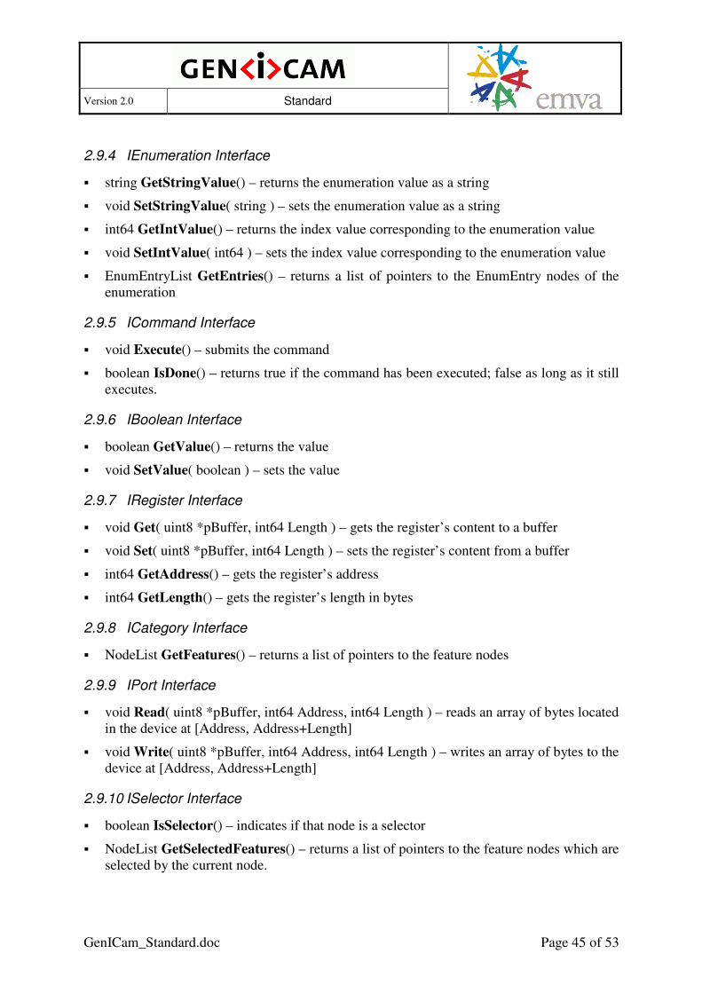
Version 2.0 Standard
GenICam_Standard.doc Page 45 of 53
2.9.4 IEnumeration Interface
� string GetStringValue() – returns the enumeration value as a string
� void SetStringValue( string ) – sets the enumeration value as a string
� int64 GetIntValue() – returns the index value corresponding to the enumeration value
� void SetIntValue( int64 ) – sets the index value corresponding to the enumeration value
� EnumEntryList GetEntries() – returns a list of pointers to the EnumEntry nodes of the enumeration
2.9.5 ICommand Interface
� void Execute() – submits the command
� boolean IsDone() – returns true if the command has been executed; false as long as it still executes.
2.9.6 IBoolean Interface
� boolean GetValue() – returns the value
� void SetValue( boolean ) – sets the value
2.9.7 IRegister Interface
� void Get( uint8 *pBuffer, int64 Length ) – gets the register’s content to a buffer
� void Set( uint8 *pBuffer, int64 Length ) – sets the register’s content from a buffer
� int64 GetAddress() – gets the register’s address
� int64 GetLength() – gets the register’s length in bytes
2.9.8 ICategory Interface
� NodeList GetFeatures() – returns a list of pointers to the feature nodes
2.9.9 IPort Interface
� void Read( uint8 *pBuffer, int64 Address, int64 Length ) – reads an array of bytes located in the device at [Address, Address+Length]
� void Write( uint8 *pBuffer, int64 Address, int64 Length ) – writes an array of bytes to the device at [Address, Address+Length]
2.9.10 ISelector Interface
� boolean IsSelector() – indicates if that node is a selector
� NodeList GetSelectedFeatures() – returns a list of pointers to the feature nodes which are selected by the current node.

Version 2.0 Standard
GenICam_Standard.doc Page 46 of 53
3 Appendix
3.1 Endianess of GigE Vision Cameras
Because the GigE Vision standard provides two different schemes for the register access (READMEM and READREG) and because this fact was frequent source of confusion among different GenICam implementations in past, this section clarifies, how GenICam endianess should be implemented by GigE Vision based products. For historical purposes, it defines two different kinds of behavior, each targeting different GenICam schema version:
• Behavior of products using GenICam schema version 1.1 and higher - this is the "correct" behavior, allowing full flexibility and no extra limitations.
• Behavior of products using GenICam schema version 1.0 - "legacy" attitude maintained for backward compatibility with schema 1.0 based products. This attitude has several limitations (or undefined behavior), especially for the little endian cameras.
Cameras providing XML files for different schema versions (eg. 1.1 and 1.0) are possible, the two attitudes differ only on side of the XML file. The behavior of the camera firmware (how registers are accessed) is defined by the GigE Vision standard and is thus independent on the GenICam. While the behavior of products using schema 1.1 and newer is normative (all devices and applications must fully respect it), the part treating schema 1.0 is just a recommendation of the typical expected behavior promising best interoperability (it cannot be normative, because schema 1.0 devices and applications were deployed prior creation of this document). Note that the following discussion targets only the GigE Vision cameras, it has no effect on other transport technologies or other GenApi uses.
3.1.1 Behavior of products based on schema version 1.1 and newer
Cameras providing XML file based on schema version 1.1 or newer must implement endianess as follows:
• The <Endianess> tags of all registers have to correspond with the real endianess of the camera, corresponding with the endianess reported in the DeviceMode bootstrap register.
• The port's <SwapEndianess> tag must not be used. It should also follow the requirements/recommendations listed in the GigE Vision specification (note that these are not mandatory requirements in the GigE Vision standard, just recommendations, but they become important when the camera is accessed through the GenICam interface):
• WRITEMEM should be implemented (if possible) when device is to be used through a GenICam interface.
• If READREG/WRITEREG is used to access strings, the camera must behave as if the string is composed of multiple 32-bit registers. This means that little endian camera must flip (reverse) each 4-character group, as expected. The same rules apply when accessing integers/floats of different size than 32-bit (particularly 64-bit and 16-bit ones).

Version 2.0 Standard
GenICam_Standard.doc Page 47 of 53
Applications (libraries) supporting schema versions 1.1 or newer should check, whether the XML file is based on schema version 1.1 or newer. If so, it must implement the endianess as follows:
• When reading/writing the data of any size, it has free choice of the access method, READMEM/WRITEMEM or READREG/WRITEREG, provided it follows the guidelines listed below. The READMEM/WRITEMEM more naturally matches the GenApi data access model and is therefore recommended option, wherever suitable.
• When reading/writing the data using READMEM/WRITEMEM (recommended option, particularly if WRITEMEM is supported by the camera), the data must be passed "as is" to the GenApi.
• When READREG/WRITEREG has to be used for any reason (eg. because WRITEMEM is not implemented by the camera), the transport layer (or other IPort implementation) has to revert the data back to the "camera order" before passing it to GenApi. This means no extra operation for big endian cameras. For little endian cameras it means to flip each 4-byte word read/written before passing it to GenApi, so that it works with the same data layout (camera's native byte order) as if READMEM/WRITEMEM was used. Note that the application knows the camera order, which can be read from the DeviceMode bootstrap register.
3.1.2 Behavior of products based on schema version 1.0
Cameras providing XML file based on schema version 1.0 should implement endianess as follows to reach best possible compatibility (although for historical reasons slightly different implementations exist in the field):
• The <Endianess> tags of all registers have to be set to "BigEndian", regardless its actual endianess.
• String registers should always be bigger than 4 bytes (the Length attribute of the registers should be bigger than 4). Device specific (non-bootstrap) strings should be read-only, particularly on little endian cameras.
• All integer and float registers should be exactly 32-bit, particularly on little endian cameras.
Applications supporting schema version 1.0 (or applications supporting multiple schema versions, when working with cameras based on schema version 1.0) should behave as follows to reach best possible compatibility (although for historical reasons slightly different implementations exist in the field):
• When reading/writing a 4-byte data, it should assume it is a integer/float register and use READREG/WRITEREG. The READREG/WRITEREG data are always in network order and it should be passed as such to GenApi.
• When reading data longer than 4 bytes, it should assume it is a string register and use READMEM. Pass the data "as is" to GenApi.
• Writing data longer than 4 bytes should be considered as non-reliable for little endian cameras.
3.1.3 Passing the schema version to the IPort implementation
The register access happens in the IPort implementation (in the IPort's Read/Write functions), ie. in the "transport layer" software component. This component typically does not retrieve and parse the XML (this is task of a top-level client component). The IPort implementation

Version 2.0 Standard
GenICam_Standard.doc Page 48 of 53
therefore needs to get notified about the schema version associated with the XML being used to access the camera.
If the two components are part of the same software package, the client can easily inform the IPort implementation about the schema version used.
If the two components are communicating through the GenTL interface (IPort implementation resides in GenTL Producer, XML retrieval and parsing in the GenTL Consumer), they need to cooperate according following rules:
• GenTL producers handling other than GigE Vision cameras don't need any specific considerations.
• GenTL producers (GenTL version 1.1 and newer) handling GigE Vision cameras must publish enumeration feature "DeviceEndianessMechanism" in the XML file associated with the GenTL device module. This enumeration must provide two entries, "Standard" and "Legacy". When the consumer selects "Standard", the producer has to implement the GCReadPort/GCWritePort functions of the associated remote device port in the standard way corresponding with schema version 1.1. When the consumer selects "Legacy", the producer has to implement the GCReadPort/GCWritePort of the associated remote device port in the legacy way corresponding with schema version 1.0.
• GenTL consumers (GenTL version 1.1 and newer) accessing a GigE Vision device must instantiate a node map of the GenTL device module and set the DeviceEndianessMechanism feature properly before any access (read/write) to the port of the remote device. The DeviceEndianessMechanism feature must be set to "Standard" when the XML file used for the remote device is based on schema version 1.1 or newer. It has to be set to "Legacy" when the XML file is based on schema version 1.0.
• The enumeration feature DeviceEndianessMechanism and corresponding rules will be standardized by the next GenTL standard version 1.1 (not yet released when publishing this document). GenTL 1.0 does not address this issue. However, GenTL 1.0 compliant producers and consumers willing to fully support little endian GigE Vision cameras are free to implement the same functionality.
3.2 Other Modules of the GenICam Standard
The following GenICam standard modules are found in separate documents:
3.2.1 Standard Feature Naming Convention
The GenApi lets you define abstract features according to their name, interface type, and meaning and make them accessible by a unified API and GUI.
In addition GenApi defines a set of features suitable for machine vision cameras. Features are described in a separate standard module dale Standard Feature Naming Convention (SFNC)
The following three features are mentioned in the standard text of the GenApi module:

Version 2.0 Standard
GenICam_Standard.doc Page 49 of 53
Interface Name Meaning
ICategory Root The root of the feature tree
IPort Device The default port of the device
IBoolean TLParamsLocked Implements a flag served by the transport layer indication that it is set up for streaming.
They will be explained in more detail in the SFNC. As soon as this is the case the SFNC will become the normative text with respect to these features.
3.2.2 GenTL
The GenTL module of the GenICam standard defines abstract interfaces and behavior rules required for implementing grabbing software. It is described in a separate document.
3.2.3 CLProtocol
The CLProtocol module describes means required to use GenApi with CameraLink cameras.

Version 2.0 Standard
GenICam_Standard.doc Page 50 of 53
4 Acknowledgements
The following companies and individuals have participated in the elaboration of the GenICam Standard:
Company Represented by
Basler Friedrich Dierks (editor GenApi), Hartmut Nebelung, Margret Albrecht, Alexander Happe
DALSA Coreco Eric Carey, Peifang Zhou
e2v semiconductors Frédéric Mathieu
JAI Pulnix Karsten Ingeman Christensen, Loai Zeineh, Michael Krag
Leutron Vision Stefan Thommen, Jan Becvar
Matrox Imaging Stephane Maurice
MVTec Software Christoph Zierl, Milan Rüder
National Instruments Johann Scholtz, Eric Gross
Pleora Alain Rivard, Francois Gobeil, Vincent Rowley
Stemmer Imaging Rupert Stelz (editor Transport Layer), Sascha Dorenbeck
5 Rights and Trademarks
The European Machine Vision Association owns the "EMVA, GenICam Standard Compliant" logo. Any company can obtain, free of charge, a license to use the "EMVA GenICam Standard Compliant" logo either for cameras that include a GenICam compliant camera description file of for software supporting the interpretation of GenICam compliant camera description files.
Licensees guarantee that they meet the terms of use in the relevant version of the EMVA GenICam standard. Licensed users will self-certify the compliance of their cameras and/or software with which the "EMVA GenICam Standard Compliant" logo is used. The licensee must check compliance with the relevant version of EMVA GenICam standard at least once a year. When displayed online, the logo must be featured with a link to EMVA standardization web page.
EMVA will not be liable for implementations that do not comply with the standard or for damage resulting therefrom. EMVA reserves the right to withdraw the granted license at any time without giving reasons.

Version 2.0 Standard
GenICam_Standard.doc Page 51 of 53
6 Index
—A— access mode 11
locked 12 not available 12 not implemented 12
API camera 6 transport layer 6
arrays accessing 28 multi-dimensional 29
—B— Boolean 33
OffValue 33 OnValue 33 pValue 33 Value 33
—C— camera description file 6 Category 24
pFeature 24 Command 34
CommandValue 34 pCommandValue 34 PollingTime 34 pValue 34 Value 34
ConfROM 40 TextDesc 40 Unit 40
ConfROMIntKey 40 Converter 39
FormulaFrom 39 FormulaTo 39 IsLinear 40 pValue 39 Slope 39
—D— DcamLock 41
FeatureID 41 Timeout 41
Device 49 —E— EnumEntry 35
IsSelfClearing 36
NumericValue 36 Symbolic 36 Value 36
Enumeration 35 EnumEntry 35 PollingTime 36 pSelected 36 pValue 35 Value 35
example area of interest
computing the maximum values 17 coupled with Binning 18 simple 16
basic structure of a camera description file 7
category tree 24 Gamma feature being implemented or
not 15 look-up table (LUT) 28 reading and writing a value 10 struct 27 trigger polarity being temporary not
available 12 —F— feature node 25 Float 34
DisplayNotation 34 DisplayPrecision 34 Max 34 Min 34 pIndex 35 pMax 34 pMin 34 pValue 34 pValueDefault 35 pValueIndexed 35 Representation 34 Unit 34 Value 34 ValueDefault 35 ValueIndexed 35
FloatReg 35 Endianess 35

Version 2.0 Standard
GenICam_Standard.doc Page 52 of 53
—G— GenApi module 6 Group element 43
Comment attribute 43 —I— IBoolean interface 33, 45 ICategory interface 24, 45 ICommand interface 34, 45 IEnumeration interface 35, 45 IFloat interface 34, 44 IInteger interface 29, 44, 45 IInteger Interface 44 implementation node 25 indirect addressing 27 IntConverter see Converter Integer 31
Inc 31 Max 31 Min 31 pInc 31 pIndex 32 pMax 31 pMin 31 pSelected 32 pValue 31 pValueCopy 31 pValueDefault 32 pValueIndexed 32 Representation 32 Unit 32 Value 31 ValueDefault 32 ValueIndexed 32
IntKey 41 Key 41 p1212Parser 41
IntReg 29 Endianess 30 pSelected 32 Sign 30
IntSwissKnife see SwissKnife IPort Interface 45 IRegister interface 26 IRegister Interface 45 ISelector interface 29, 45 IString interface 37, 44
—M— MaskedIntReg 30
Bit 30 LSB 30 MSB 30 pSelected 32
—N— Node 21
Description 23 DisplayName 23 DocuURL 24 EventID 23 ExposeStatic 23 Extension 23 ImposedAccessMode 23 IsDepecated 24 MergePriority 22 Name 22 NameSpace 22 pAlias 23 pBlockPolling 23 pCastAlias 23 pError 24 pInvalidator 27 pIsAvailable 23 pIsImplemented 23 pIsLocked 23 pSelected 29 Streamable 24 ToolTip 23 Visibility 23
—P— Port 42
CacheChunkData 43 ChunkID 42 pChunkID 42 SwapEndianess 42
—R— reference implementation 7 Register 26
AccessMode 26 Address 26 Cacheable 26 IntSwissKnife 26 Length 26 pAddress 26 pIndex 26, 27

Version 2.0 Standard
GenICam_Standard.doc Page 53 of 53
pLength 26 PollingTime 26 pPort 26
RegisterDescription 19 MajorVersion 20 MinorVersion 20 ModelName 19 ProductGuid 21 schemaLocation 20 SchemaMajorVersion 20 SchemaMinorVersion 20 SchemaSubMinorVersion 20 StandardNameSpace 19 SubMinorVersion 20 ToolTip 19 VendorName 19 VersionGuid 21
Root 49 —S— SmartFeature 42
FeatureID 42 String 37 StringReg 37 StructReg 32
Comment 33 StructEntry 33
SwissKnife 37 Constant 39 Expression 39 Formula 38 mathematical operations 38 pVariable 38
—T— TextDesc 41
Key 41 p1212Parser 41
—X— XML schema 9


![CAMBIO PASO A PASO HORARIO · node—derechos_pecuniarios.tpl.php C] node—direccion-l.tpl.php C] node—direccion.tpl.php C] node—direction.tpl.php C] node—evento.tpl.php](https://img.pdfslide.net/doc/110x75/5c77371209d3f23a068b779a/cambio-paso-a-paso-horario-nodederechospecuniariostplphp-c-nodedireccion-ltplphp.jpg)