Embed Size (px)
Citation preview
15
GENIUS: A Generator for Graphical User Interfaces
Univ.-Prof Dr.-Ing. Prof e. h. Dr. h. c. Hans-Jorg Bullinger Dr.-Ing. Dipl.-Math. Klaus-Peter Fiihnrich Dr.-Ing. Dipl.-Inform. Anette Weisbecker Fraunhofer-Institutfiir Arbeitswirtschaft und Organisation (lAO) Nobelstr. 12c, D-70569 Stuttgart, Germany, +49711 9702320, +49 711 9702300, Anette. [email protected]
Abstract GENIUS (GENerator for user Interfaces Using Software ergonomic rules) is a system that generates ergonomically designed graphical user interfaces from extended data models. GENIUS is based on a methodology to develop graphical user interfaces in a stepwise procedure starting from standard data models of a specific application system (e.g. production planning and control systems). The GENIUS system transforms these models in a series of consecutive operations into an operational graphical user interface (GUI).
The methodology introduces the definition of views for the specification of the data and functions required by the users. In addition, the derivation of the dialogue structure from the data model is presented. Based on the defined views, the automatic generation of the user interface is carried out by a rule-based system using explicit design rules derived from existing guidelines. Output is generated for an existing user interface management system. The approach supports rapid prototyping while using the advantages of standard software engineering methods and ensures the integration of these methods with user interface design.
GENIUS has been tested for the development of a series of graphical user interfaces for production planning and control systems. It has been used in typical migration situations from alphanumerical systems to be migrated into client/server solutions with graphical user interfaces as well as for the development of new systems for different platforms.
Keywords Automatic User Interface Generation, Data Models, User Interface Management Systems, Production Planning and Control System
A. Storr et al. (eds.), Software Engineering for Manufacturing Systems© Springer Science+Business Media Dordrecht 1996
182 Software Engineering for Manufacturing Systems
1 INTRODUCTION
Data and information have become important economic factors and major milestones for industry. Therefore, systems are required within a company for integrated and constant information processing. These systems must support the fulfilment of competitive objectives such as cost reduction, processing time minimization and improvement of qUality. This is especially true for customer-oriented information systems within a company which are indispensable for an efficient processing of customer orders.
There is evidence that the functionality of information systems within a company is not fully used (VDMA, 1992). The provided information appears as a huge amount of data the users cannot cope with. Nonetheless it is essential for the successful use of information systems, that the required information is represented in a comprehensive way to the user. This means that the application of software ergonomic design guidelines is imperative during software development. At present the development of software ergonomically designed user interfaces is still time-consuming and often very difficult for the system developers, because they lack the appropriate knowledge (Huttner et al., 1992).
Although a greater number of user interface development tools is available, it is difficult to follow existing user interface design guidelines and style guides (Tetzlaff, Schwartz, 1991), because the tools do not provide support for software ergonomic guidelines. In addition, user interface tools cannot make use of the models developed with general software engineering methods and tools in the early phases of the design cycle, which specifies the non-interactive part of an application. The integration of application development and user interface design which has been often demanded but is still missing in practice, leads to additional effort and potential inconsistencies when moving from requirements analysis to user interface design (Foley, 1991). It is therefore important to use analysis results such as the data model as input for user interface development tools.
The work described in this paper addresses the problems mentioned above. It shows a method and the supporting tool environment GENIUS (GENerator for user Interfaces Using Software ergonomic rules) for the automatic generation of user interfaces from extended data models (Weisbecker, 1995) and the use of GENIUS for the development of a graphical user interface for a production planning and control system. GENIUS generates user interfaces according to human factor guidelines and guarantees the integration of software engineering and user interface design by using the application data model as a basis for application development as well as for user interface design.
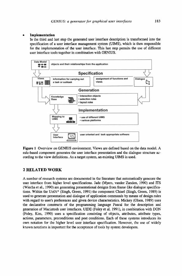
The development of graphical user interfaces with GENIUS is carried out in three main steps (Figure 1), which are described in the following chapters. The first step is interactively performed by the software developer and the other two automatically by GENIUS.
• Specification In the first step the data and functions necessary for a task are specified. This is carried out by defining the views according to the user's task and on the basis of the data model in the form of an entity relationship model.
• Generation The information specified in the first step is used for deriving the dialogue structure. In the second step it serves as the basis for generating user interfaces while applying software ergonomic rules.
GENIUS: a generator for graphical user interfaces 183
• Implementation In the third and last step the generated user interface description is transformed into the specification of a user interface management system (VIMS), which is then responsible for the implementation of the user interface. This last step permits the use of different user interface tools together in combination with GENIUS.
object. and their .. !aUonahl.,. from tho .ppllc:aUon
Specification ~f=:=----, --:-:--:--::-----:-----, .--------- r::::-:-----"'-------,
InlormoUon lor c:anylng out .. algn ... n! 01 func1ions Ind • Iosk or aubtosk vlew10
Generation • IntoncUon objlcb • .. iI<:Uon ",IH "ayout ",let
Implementation
• us. of dllle ... n! UIMS • various plotfo"""
Figure 1 Overview on GENIUS environment. Views are defined based on the data model. A rule-based component generates the user interface presentation and the dialogue structure according to the view definitions. As a target system, an existing UIMS is used.
2 RELATED WORK
A number of research systems are documented in the literature that automatically generate the user interface from higher level specifications. Jade (Myers, vander Zanden, 1990) and ITS (Wiecha et a1., 1990) are generating presentational designs from frame-like dialogue specifications. Within the VofA* (Singh, Green, 1991) the component Chisel (Singh, Green, 1989) is used to generate presentation and dialogue of application commands by means of design rules with regard to user's preferences and given device characteristics. Mickey (Olsen, 1989) uses the declarative constructs of the programming language Pascal for the description and generation of Macintosh user interfaces. VIDE (Foley et al. 1991), in combination with DON (Foley, Kim, 1990) uses a specification consisting of objects, attributes, attribute types, actions, parameters, preconditions and post conditions. Each of these systems introduces its own notation for the higher level user interface specification. However, the use of widely known notations is important for the acceptance of tools by system developers.
184 Software Engineering for Manufacturing Systems
HIGGENS (Hudson, King, 1987) is the first UIMS which incorporates data models and uses views to represent an abstract fonn of the display. In contrast to the GENIUS approach and most of the systems mentioned above, HIGGENS does not incorporate rules for the generation of the physical user interface. Thus, it offers less flexibility and power with respect to the selection and layout of interaction techniques.
The system described by de Baar, Foley and Mullet (1992) generates dialogue boxes and menus from enhanced data models. With this approach, descriptions from data modelling can be reused for the user interface specification, and double effort and consistency problems are avoided.
In the approach of Petoud and Pigneur (1990), the entity relationship models are used for user interface generation. The dynamics are textually specified and can be visualized by a precedence graph. The graph, however, can neither be modified nor substructured. Therefore, the system is probably not suitable for large applications.
As a whole, existing systems for the automatic generation of user interfaces either lack a proper integration into general software engineering methods, or sufficient support for user interface design guidelines.
3 USER INTERFACE SPECIFICATION BY VIEW DEFINITION
3.1 Deriving User Interface Presentation from Data Models
The data model in the fonn of an entity relationship model is the starting point for the specification of the user interface with GENIUS. The entity relationship model (Chen, 1976) is a well established conceptual data model. It is used in most of today's software-engineering methods (Y ourdon, 1989) and is also the most frequently used modelling technique in industry (Bittner et al., 1992). In addition, it is supported by a great number of computer-aided software engineering (CASE) tools.
The entity relationship model shows the elements of the application area and their relations; nonetheless, it does not describe the data the user need for perfonning specific tasks. Therefore so-called views are defined. A view consists of a subset of entities, relationships, and attributes of the overall data model. Additionally functions are assigned to a view, thus a view comprises the whole infonnation to perfonn a specific user task. Within these functions two different types are distinguished: data manipulation functions and navigation functions. Data manipulation functions can be applied to data elements in the view. Navigation functions detennine the dialogue structure by calling other views. They are used to define the dynamic behaviour of the user interface.
In order to enable an easy and efficient view definition, a number of extensions have been added to the entity relationship model. For specifying logical groups of attributes, complex attributes are introduced. The grouping of infonnation is used in the user interface generation process for visualizing groups of related data. For reducing the complexity of the graphical representation of entity relationship diagrams, a set of entities and relationships can be replaced by a single symbol and edited separately.
Within the GENIUS tool environment, the definition of views are defined by a direct manipulation editor. The application developer interactively selects elements from the entity relationship diagram. Thus, no programming skills are required for the definition of the views,
GENIUS: a generator for graphical user interfaces 185
and it is easy to involve non-programmers into the process e.g. application experts and interface designers.
Because the entire infonnation needed for the generation of user interface windows from views cannot be expressed in a graphical representation, it is necessary to supply additional textual descriptions. These are provided in so-called property sheets. Property sheets can be popped up during the definition of the views and edited directly. They consist of a definition of each element which in most cases is available from the data dictionary, the assignment of the functions to the view and the inclusion of task oriented properties which are used to map the application elements on appropriate interaction objects in the automatic generation process.
According to the elements in a view and their structure, two different types of views are distinguished:
• Aggregation View An aggregation view shows a collection of different elements e.g. entities, relationships and attributes. According to the presentation of the aggregation view two different fonns have been characterized:
- Reference Presentation A reference presentation shows the aggregation as a whole. It may also be called a container. Usually, entity types are represented by containers. Containers are the typical elements for the first dialogue steps (e.g. in Figure 5 parts of a production planning and control system).
- Set Presentation In a set presentation each element of an aggregation is shown. Depending on the number and structure of the elements, lists, sets or other presentation structures such as trees are used. The elements shown in the set presentation give references to the detail view of each element.
• Detail View A detail view shows the single attributes of entities. Either all or only some attributes of one entity may be shown, but also attributes of different entities which are needed in regard to a specific task (Figure 7).
The structures in the data model are preserved in the views. They are used to detennine the presentation of the attributes and to derive the dialogue structure.
Within the automatic generation of the user interface, the view elements are mapped to appropriate interaction objects by means of selection rules which take into consideration the characteristics of the attribute such as type, range and number of values. The relationships between the entities also influence the presentation and structuring ofthe view elements. For example, the attributes belonging to the same entity or relation are implicitly grouped in order to reflect their logical connection to the user. In addition, the cardinality of relationships between the entities influences the presentation of the attributes. Thus in the case of a l:n or n:m relationship, an aggregated view is used to show the different instances.

186 Software Engineering for Manufacturing Systems
3.2 Deriving Dialogue Structures from Views
The structure of the views does not only serve for determining the presentation, it also supports the automatic derivation of the dialogue structure, because both object-oriented user interface and data model are structured according to the data objects. Therefore, the data model structure can be transferred to the dialogue structure for an object-oriented user interface.
Dialogue Ently Ij ... Hi1 • AppIIca\lOllS
• Func1ions I w~~ l g • Da'. f-t S.lecllon ,. Ii ,
! • De.ai view
_ .. -· c,;,eria lor !he B - I"
I~ 1 'I.:dl seIecIion 01 an
S.1ec1iOn objecIlnSlance • • • a Q
• AggregalOln ~I c D a 1= d view I~ l • alilOS'an09S
01 an 0IljecI ===== S.lecllon Ii"" 1'2 1 • Agg<ega •• "'-· displaylng,he II~
IJ • H~I ~
seJecbon resuh Detail ===c::J= • Delail view
!! I · Inlormalion to
an instance or I an objed !
==== Figure 2 Schematic dialogue structure for object-oriented user interface.
The dialogue structure of an object-oriented user interface consists of three main parts. The first part is the application entry, which shows all relevant objects. In the second part a selection dialogue is provided in order to identify the desired object. The last part shows detailed information on the desired object. Thus, in a typical object-oriented dialogue, navigation to the desired object must be carried out first in order to perform a specific task in the second step.
The starting point for the definition of such a dialogue sequence is the coarse data model which contains merely entities and relationships (Figure 4). Based on this model, container views can be defined in order to provide a dialogue entry (Figure 5). A container view consists of those entity types which do not result from normalization.
After selecting a container object, a possibility for further selection of the desired object instance must be provided. Depending on the number of instances, three different ways can be used. If the number of instances is small, icons can be used to show the single instances of the object. For a medium-sized number of instance, a list is appropriate. A search form with criteria for further specification is provided if a large number of instances is available (Figure 7). The search process results in a list showing the objects which fulfil the search criteria. The selection of an entry in the list will lead to the details of the desired object.
The aggregation and detail views needed for such dialogue sequences can be defined interactively on the basis of the data model; to some degree, they can be automatically generated. In the generation process a window will be assigned to the container view and the entity types
GENIUS: a generator for graphical user interfaces 187
will be represented by icons. Depending on the number of instances for each entity type an aggregate view will be generated or a detail view for a search form is added. If the aggregate view or the detail view for a search form is generated automatically, either the key attributes of the entity will be shown or the attributes which are explicitly marked as identifier for selection will be used.
4 GENERATING THE USER INTERFACE
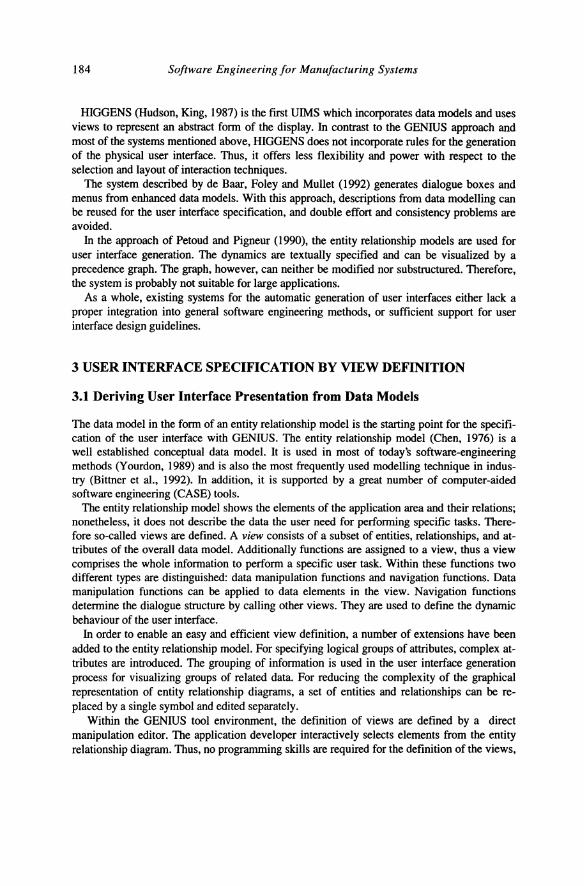
The defined views form a logical description of the application user interface. This description is used as input for a rule-based system carrying out the generation process. The generation is performed in three steps (Figure 3). In the first step appropriate interaction objects are chosen for the presentation of the data and functions specified in the views. In the second step the parameters (e.g. colour, position, size) for these interaction objects are determined. In the third step the layout is done by arranging the interaction objects.
Selection of abotract I_n Objects
.view .... window
_function ... menu operation selection
_data element ..... constant fiekl, data field, group, single and muhiple selection, list, table ...
V Parameter Detenninatlon for Interaction Objects
.data information • interaction between - name, length, format, interaction obejcts
values, defaults - inside a group - over groups
.default values - position - user preference - alignment - environment -style
V Arrangement of Interaction Objects - Window Layout
• inside a group • priority • over groups _application semantic
• Gestalt laws
Figure 3 Main generation steps in GENIUS.
4.1 Mapping View Elements on Abstract Interaction Objects
For the first generation step abstract interaction objects have been introduced. These interaction objects are called abstract because they are independent of their physical implementation, e.g. as MS-Windows, OSF/Motif or OS/2 Presentation Manager widgets. Thereby, flexibility with regard to the target environment is reached and the portability of the application is supported. The definition of the abstract interaction objects is based on an examination of available interaction objects from different style guides (OSF, 1994; IBM, 1992; Sun, 1990; Microsoft, 1992). Standard interaction objects defined for graphical user interfaces are windows, dialogue boxes, menus, entry fields, constant fields, exclusive choices, non-exclusive
188 Software Engineering for Manufacturing Systems
choices, operation choices, lists, and scroll bars. They are called abstract because they are independent of their physical implementation, e.g. as OSP/Motif or Open Look widgets.
The mapping of the defined views, functions and attributes on the appropriate abstract interaction objects is carried out by selection rules.
These rules are derived from existing guidelines and style guides. Most of the rules concerning formats and arrangement of data fields and field prompts stem from Smith and Mosier (1986). Rules for interaction object selection and layout have been extracted from the CUA (IDM, 1992), OSP/Motif (OSP, 1994) and Open Look (Sun, 1990) style guides with regard to national and international standards ISO (1994) and DIN (1988).
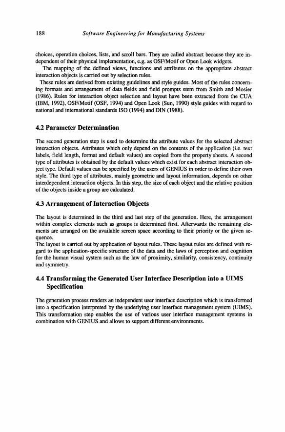
4.2 Parameter Determination
The second generation step is used to determine the attribute values for the selected abstract interaction objects. Attributes which only depend on the contents of the application (i.e. text labels, field length, format and default values) are copied from the property sheets. A second type of attributes is obtained by the default values which exist for each abstract interaction object type. Default values can be specified by the users of GENIUS in order to define their own style. The third type of attributes, mainly geometric and layout information, depends on other interdependent interaction objects. In this step, the size of each object and the relative position of the objects inside a group are calculated.
4.3 Arrangement of Interaction Objects
The layout is determined in the third and last step of the generation. Here, the arrangement within complex elements such as groups is determined first. Afterwards the remaining elements are arranged on the available screen space according to their priority or the given sequence. The layout is carried out by application of layout rules. These layout rules are defined with regard to the application-specific structure of the data and the laws of perception and cognition for the human visual system such as the law of proximity, similarity, consistency, continuity and symmetry.
4.4 Transforming the Generated User Interface Description into a UIMS Specification
The generation process renders an independent user interface description which is transformed into a specification interpreted by the underlying user interface management system (UIMS). This transformation step enables the use of various user interface management systems in combination with GENIUS and allows to support different environments.
GENIUS: a generator for graphical user interfaces
5 GENERATION OF A USER INTERFACE FOR A PRODUCTION PLANNING AND CONTROL SYSTEM
189
During the last few years, computer supported systems have been increasingly used for production planning and control. In the beginning, production planning and control systems were limited to mainframes and midrange computers. Therefore these systems have been beyond the means of small and medium sized enterprises. In the last years the situation has changed completely because of the dissemination of powerful personal computers and Unix workstations. As a consequence, implementors of production planning and control systems have been forced to transfer their systems to new hardware platforms and operating systems. The widespread use of window systems on these platforms such as the X Windows System for Unix, Presentation Manager for OS/2 or MS-Windows for DOS leads not only to the transfer of the systems onto new platforms, but also to the creation of graphical user interfaces. Most of the implementors have had to migrate the alphanumerical interfaces of their systems to graphical user interfaces. AS/400 applications for instance are provided with an OS/2 frontend with Presentation Manager, MS-DOS applications receive a Windows user interface and HP 3000 or VMS applications are transferred to Unix and receive a OSF/Motif interface. This migration does not only imply the new layout of old screens in form of windows and the use of graphical user interface elements, but also the complete redesign of the dialogue. This redesign makes it possible to consider software ergonomic design guidelines and. thus to ensure more efficient operation sequences. For the implementor of production planning and control systems the following challenges arise:
• Building up knowledge for the design and implementation of graphical user interfaces. • High expenditure of work for the creation of graphical user interfaces. • Short development cycles in order to bring out early the new product. • New design of the dialogue. • Design of graphical user interface. • Consideration of software ergonomic guidelines and style guides.
This background given, GENIUS has been used in different projects for creating graphical user interfaces for operational information systems. On the one hand projects have been concerned with developing new production planning and control systems for Unix platforms under OSF/Motif; other projects deal with the migration of MS-DOS applications to MSWindows.
By the migration of alphanumerical interfaces to graphical ones the first design could be received very quickly when using GENIUS. The automatic generation produces a first layout of windows and of the dialogue while considering basic software ergonomic design guidelines. As a starting point the data model have been used. The migration made it possible to refer to an existing data model or to derive the data model from the existing system. An existing data model is referred to when the systems uses a relational data base management system.
Central to the design of new systems is the determination of the requirements for system design. In these cases, GENIUS was used to generate prototypes. These prototypes served as the basis for discussions between users, customers and developers. The results received from the evaluation of the prototypes have been used to complete the data model. The developed data model and the determined functions have been used for generating a first sketch of the final user interface.
190 Software Engineering for Manufacturing Systems
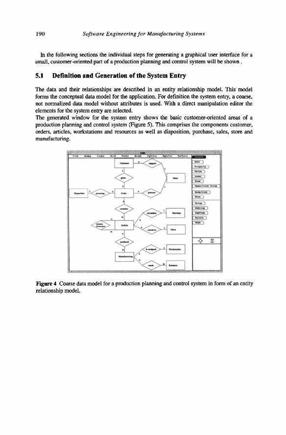
In the following sections the individual steps for generating a graphical user interface for a small, customer-oriented part of a production planning and control system will be shown .
5.1 Definition and Generation of the System Entry
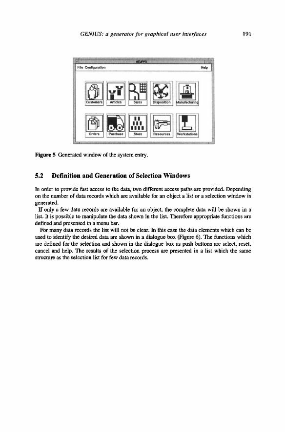
The data and their relationships are described in an entity relationship model. This model forms the conceptual data model for the application. For definition the system entry, a coarse, not normalized data model without attributes is used. With a direct manipulation editor the elements for the system entry are selected. The generated window for the system entry shows the basic customer-oriented areas of a production planning and control system (Figure 5). This comprises the components customer, orders, articles, workstations and resources as well as disposition, purchase, sales, store and manufacturing.
-
Figure 4 Coarse data model for a production planning and control system in form of an entity relationship model.
GENIUS: a generator for graphical user interfaces 191
.. File Contlgu .... on Help
~1i!]~oo ~. ~=~ ~E~ ~ [!J
Rtsourcl't: WottstaUons
Figure 5 Generated window of the system entry.
5.2 Definition and Generation of Selection Windows
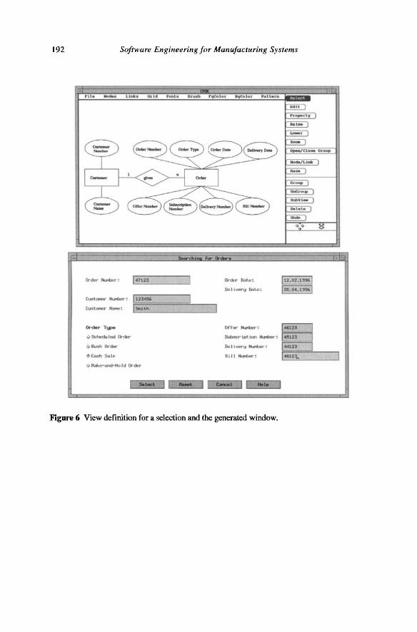
In order to provide fast access to the data, two different access paths are provided. Depending on the number of data records which are available for an object a list or a selection window is generated. If only a few data records are available for an object, the complete data will be shown in a
list. It is possible to manipulate the data shown in the list. Therefore appropriate functions are defined and presented in a menu bar.
For many data records the list will not be clear. In this case the data elements which can be used to identify the desired data are shown in a dialogue box (Figure 6). The functions which are defined for the selection and shown in the dialogue box as push buttons are select, reset, cancel and help. The results of the selection process are presented in a list which the same structure as the selection list for few data records.
192 Software Engineering for Manufacturing Systems
47123
-"'-Idl"'_
-
{)nt(y- nm-.e:
Du l' '*"U Oot.u:
Ofr.,.~:
::wmcripttun tuot.r: 145123
Dull\Mf1l"""': [44123 r-----"------, ""I _: L.;,;;81 .. 2;;:'\..!:>.. ____ -'
c..:.1 .....
Figure 6 View definition for a selection and the generated window.
GENIUS: a generator for graphical user interfaces 193
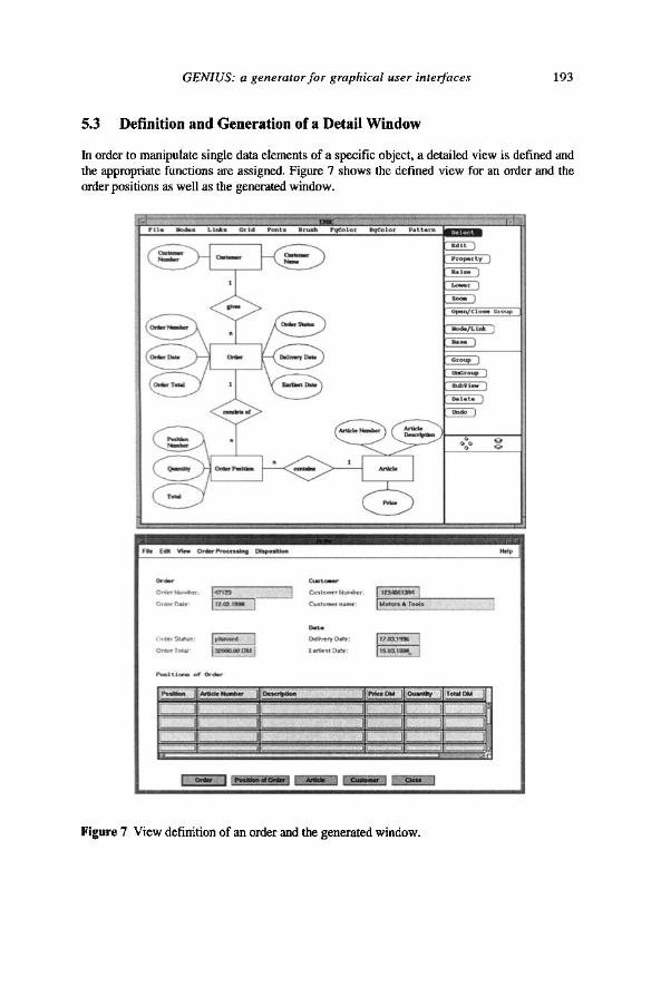
5.3 Definition and Generation of a Detail Window
In order to manipulate single data elements of a specific object, a detailed view is defined and the appropriate functions are assigned. Figure 7 shows the defined view for an order and the order positions as well as the generated window.
"'- 1 ...... - I---,
I ~! I
...... [)ellv-tryD.t .. :
[rin.Oa:
I ..... "" ]
~ ---, ==-=:.J
'- J
c=J ~
Figure 7 View definition of an order and the generated window.
-
,_ow -----.J ----.J ~
194 Software Engineering for Manufacturing Systems
6 CONCLUSION
If compared to the traditional realisation of graphical user interfaces with user interface management systems, the automatic generation from the data model significantly reduces the effort for application development. In addition, the generation guarantees consistency of the user interface within an application and across different applications.
The automatic generation of user interfaces from data models is not limited to the presentation of information in single windows. It also produces entire dialogue sequences for data-oriented applications. This reduces the effort and simplifies the design of user interfaces. Moreover, such dialogue sequences support the standardization of the dynamic part of the user interface which is not yet covered by existing style guides nor by user interface tools.
With regard to the dissemination of object oriented concepts in the industrial area during the last few years, the data model which is used as a starting point for the generation will be replaced by an object model. In contrast to the data model, an object model has the advantage, that it treats data and functions as a whole which simplifies the assignment of functions to views.
GENIUS provides an integration of user interface development with general software engineering methods. In the early development phases, the automatically generated versions of the user interface support the combination of traditional software engineering methods with prototyping. Such an integration was already demanded by Floyd (1988) and is now widely used in industrial software development projects (Kieback et al., 1992). The automatic generation does not only support the easy and fast production of prototypes but also provides the direct relationship between prototype and specification. The prototypes are the basis for an early design evaluation by the user. This evaluation can provide essential feedback for the specification of the entire software system, and can contribute to ensure the correct realization of the user requirements.
7 REFERENCES
Bittner, U.; Hesse, W.; Schnath, J. (1992) Untersuchungen zum Methodeneinsatz in SoftwareEntwicklungsprojekten. Softwaretechnik-Trends, Band 12, Heft 3, August 1992, 48-60.
Chen, P. (1976) The Entity-Relationship Model - Toward a Unified View of Data. ACM Transactions on Database Systems, Vol. 1, No.1, 1976,9-36.
De Baar, DJ.M.J., Foley, J., Mullet, K.E. (1992) Coupling Application Design and User Interface Design, in Proceedings of Human Factors in Computing Systems, CHI '92, May 1992, ACM, New York, 259-266.
DIN-Norm 66234 (1988) Teil 1-9, Bildschirmarbeitspliitze, NormenausschuB Informationsverarbeitungssysteme im DIN. Beuth Verlag, Berlin.
Floyd, Chr. (1984) A Systematic Look at Prototyping, in Approaches to Prototyping (ed. Budde, R.; Kulenkamp, K.; Mathiassen, L.; Ziillighoven, H.), Springer, Heidelberg.
Foley; J. D. (1991) User Interface Software Tools, in Telekommunikation und multimediale Anwendungen der Informatik (ed. Encarnacao, J.), GI-21. Jahrestagung, Darmstadt, Springer, Heidelberg.
GENIUS: a generator for graphical user interfaces 195
Foley, J. D.; Kim, W. C.; Kovacevic, S.; Murray, K. (1991) UIDE - An intelligent User Interface Design Environment, in Intelligent User Interfaces (ed. Sullivan, J. W.; Tyler, S. W.), Addison Wesley, Reading, Massachusetts, 339-384.
Foley, J. D.; Kim, W. C. (1990) DON: User Interface Presentation Design Assistant, in Proceedings of the ACM SIGGRAPH on User Interfaces Software and Technology, UIST '90, October 1990, ACM, New York,10-20.
Hudson, S. E.; King, R. (1986) A Generator of Direct Manipulation Office Systems. ACM Transactions on Office Information Systems 4 (2), 132-163.
Huttner, J.; Wandke, H.; Beimel, J. (1992) What do system designer know about software ergonomics and how to improve their knowledge?, in WWDU '92 (Work With Display Units), (ed. Luczak, H.; C;akir, A. E.; C;akir, G.), Conference Proceedings, Berlin, E18-E19.
mM Corporation (1992) Object-Oriented Interface Design: mM Common User Access Guidelines. Que Corporation, Carmel, IN.
ISO (1994) ISO/WD 9241 Ergonomic requirements for office work with visual display terminals (VDTs), Draft. International Standard Organization.
Kieback, A.; Lichter, H.; Schneider-Hufschmidt, M.; Ziillighoven, H. (1992) Prototyping in industrial software projects: Experiences and assessment. Information Technology & People, Vol. 6, No. 2+3, December 1992, 109-143.
Microsoft Corporation (1992) The Windows Interface - An Application Design Guide. Microsoft Press, Redmond.
Myers, B.; vander Zanden, B. (1990) Automatic, Look-and-Feel Independent Dialog Creation for Graphical User Interfaces, in Proceedings of Human Factors in Computing Systems, CHI '90, April 1990, ACM, New York, 27-34.
Olsen, D. R. (1989) A Programming Language Basis for User Interface Management, in Proceedings of Human Factors in Computing Systems, CHI '89, April 1989, ACM, New York,171-176.
Open Software Foundation (OSP) (1994) OSF/Motif Style Guide, Revision 2.0. Prentice Hall, Englewood Cliffs, N. J.
Petoud, I., Pigneur, Y. (1990) An Automatic and Visual Approach for User Interface Design, in Proceedings of the IFIP TC 21WG 2.7 Working Conference on Engineering for Human-Computer Interaction (ed. Cockton, G.), North-Holland, Amsterdam.
Singh, G.; Green, M. (1989) Chisel: A system for Creating Highly Interactive Screen Layouts, in Proceedings of the ACM SIGGRAPH Symposium on User Interface Software and Technology, UIST '89, November 1989, ACM, New York, 86-94.
Singh, G.; Green, M. (1991) Automating the Lexical and Syntactic Design of Graphical User Interfaces: The UofA* UIMS. ACM Transactions on Graphics, Vol. 10, No.3, July 1991,213-254.
Smith, S. L.; Mosier, J. N. (1986) Guidelines for Designing User Interface Software. Mitre Corporation.
Sun Microsystems (1990) Open Look - Graphical User Interface Application Style Guidelines. Addison-Wesley, Reading, Massachusetts.
Tetzlaff, L.; Schwarz, D. R. (1991) The Use of Guidelines in Interface Design, in Proceedings of Human Factors in Computing Systems, CHI '91, April 1991, ACM, New York, 329-333.
196 Software Engineering for Manufacturing Systems
VOMA (1992) Markt fUr Infonnationstechnik in der Fertigung wlichst weiter. Computerwoche Nr. 41,09.10.1992.
Weisbecker, A. (1995) A method for the automatic generation of software ergonomic designed user interfaces. Ph.D. Thesis, University of Stuttgart. Springer, Berlin, Heidelberg (in German).
Wiecha, C.; Bennett, W.; Boies, S., Gould, J.; Greene, S. (1990) ITS: A Tool for Rapidly Developing Interactive Applications. ACM Transactions on Infonnation Systems, Vol. 8, No.3, July 1990,204-236.
Yourdon, E. (1989). Modem Structured Analysis. Prentice Hall, Englewood Cliffs, N. J.
8 BIOGRAPHY
Prof. Dr.-Ing. habn. Prof. e.h. Dr. h. c. Hans-J6rg Bullinger
Dr. Bullinger is the head of the Institute for Human Factors and Technology Management (1AT) and the Fraunhofer-Institute for Industrial Engineering (lAO).
In 1978, Dr. Bullinger received the Kienzle-Medal as an award from the University Group of Manufacturing. In 1982 the gold Ring-of-Honour was awarded by the German Society of Engineers (VOl). In 1986 he received the Distinguished Foreign Colleague award from the Human Factor Society. In 1991 he became Honorary Doctor at the University of Novi Sad and Honorary Professor at the University of Science and Technology of China in Hefei. Since 1993 he has been a member of the World Academy of Productivity Science and in 1994 he became an elected honorary member of the Rumanian Society of Mechanical Engineers. In 1995 he received the Arthur Burckhardt Award.
Dr.-Ing. Dipl.-Matb. Klaus-Peter Fibnricb
Dr.-Ing. Klaus-Peter Fiihnrich is currently serving Fraunhofer Society Institute for Industrial Engineering as Deputy Head of Division Information Management. He gained fIrst education in mathematics and computer science. He received a PhD in engineering and is a lecturer at University of Stuttgart. Currently he is Head of the Departments for Software Management and for Information Systems. His areas of work are Software Management and Software Engineering, Service Engineering, Quality Management and Organisation on Human Factors. He specializes in several branches of industry like machine tool industry, car industry, service industries and media industries.
Dr.-Ing. Dipl.-Inform. Anette Weisbecker
Dr.-Ing. Anette Weisbecker studied computer science at the Technical University of Darmstadt and received a PhD in Manufacturing at the University of Stuttgart. She works at the Fraunhofer-Institute for Industrial Engineering (lAO) and currently heads the Group for Software Production. Her area of work is Software Engineering, User Interface Design, Human Factors, with main emphasis on the integration of software engineering methods and user interface design techniques.