Embed Size (px)
Citation preview

THESIS APPROVAL
The abstract and thesis of Susan L. Bednarz for the Master of Science in
Geology were presented May 29, 2002, and accepted by the thesis committee
and the department.
COMMITTEE APPROVALS: ____________________________________ Michael L. Cummings, Chair
____________________________________ Georg H. Grathoff
____________________________________ Scott F. Burns
____________________________________ Trevor D. Smith Representative of the Office of Graduate Studies
DEPARTMENTAL APPROVAL: ____________________________________ Michael L. Cummings, Chair Department of Geology

ABSTRACT
An abstract of the thesis of Susan L. Bednarz for the Master of Science in
Geology presented May 29, 2002.
Title: Influence of Halloysite on the Engineering Behavior of Basaltic Saprolites
in Northwestern Oregon and Southwestern Washington.
Saprolite is commonly developed on Tertiary basalt in northwestern
Oregon and southwestern Washington. Basalt saprolites are often sensitive, in
that they release water and lose shear strength when disturbed. Non-sensitive,
featureless residual soil mantles sensitive basalt saprolites.
Borehole samples of extrusive basalt and intrusive basalt (diabase)
saprolites from six study sites in northwestern Oregon were analyzed using X-
ray diffraction and scanning electron microscopy (SEM). Clay mineral zonation,
observed in borehole samples obtained on Mt. Scott in southeast Portland,
Oregon, show that 10Å halloysite is most abundant near the bedrock contact,
7Å halloysite is most abundant toward the middle to upper portions of the
saprolite, and kaolinite is most abundant in the residual soil. Zonation of
smectite is unclear. Interlayered halloysite/expandable clay is identified in
almost all saprolite samples analyzed but not in the overlying residual soil
samples.
Laboratory and field testing can be used to identify sensitive saprolites
prior to construction. Sensitive saprolites have high natural water contents

(generally >50%), low dry densities (5.7 to 6.4 kN/m3), Atterberg limits
and moisture/density relationships that vary with drying and remolding, and
release water when compressed.
Engineers have linked soil sensitivity in saprolites to the presence of
water-filled, hydrated (10Å) halloysite tubes that are crushed during
construction, adversely affecting stripping, placement, and compaction.
Although 7Å halloysite is found in all sensitive saprolites analyzed within the
study sites, 10Å halloysite is not ubiquitous to these soils. The water released
during compression of sensitive soils is stored in boxwork voids (identified by
SEM analysis) and not inside individual halloysite tubes. The loss of sensitivity
in surficial residual soil is due to the breakdown and collapse of the boxwork
voids within the saprolite due to pedogenic processes.

INFLUENCE OF HALLOYSITE ON THE ENGINEERING BEHAVIOR OF
BASALTIC SAPROLITES IN NORTHWESTERN OREGON AND
SOUTHWESTERN WASHINGTON
by
SUSAN L. BEDNARZ
A thesis submitted in partial fulfillment of the requirements for the degree of
MASTER OF SCIENCE in
GEOLOGY
Portland State University 2002

i
ACKNOWLEDGMENTS
Many thanks to the following individuals who provided information,
assistance, and advice towards the completion of this research: Michael
Cummings, Georg Grathoff, Scott Burns, and Sherry Cady, Portland State
University; Jim Maitland and Tim Pfeiffer of Foundation Engineering, Inc.; Derek
Cornforth, Charlie Hammond, and Brent Black of Cornforth Consulting; Jim
Griffith of the US Army Corps of Engineers; Reka Gabor, Portland, Oregon;
Reed Glasmann of Oregon State University; David Rogers of University of
Missouri, Rolla; Michael Williams of the Washington Department of
Transportation; Clackamas County Department of Transportation and
Development; Wayne Isphording, University of South Alabama. I would also
like to thank the Clay Minerals Society for providing a grant to fund this
research.

ii
TABLE OF CONTENTS
ACKNOWLEDGMENTS ........................................................................................ i
TABLE OF CONTENTS ........................................................................................ ii
LIST OF FIGURES ............................................................................................... vi
LIST OF TABLES ................................................................................................ vii
INTRODUCTION .................................................................................................. 1
BACKGROUND .................................................................................................... 3
GEOLOGIC SETTING .......................................................................................... 9
LOCAL ENGINEERING CASE HISTORIES ...................................................... 17
Mud Mountain Dam ....................................................................................... 17
Toutle River Sediment Retention Structure .................................................. 18
Trask River Dam Raise ................................................................................. 19
Hills Creek Dam ............................................................................................ 21
Spirit Lake Memorial Highway ...................................................................... 22
H3 Tunnel, Oahu, Hawaii .............................................................................. 23
STUDY SITES .................................................................................................... 24
Monterey Avenue Overcrossing, Southeast Portland, Oregon .................... 24
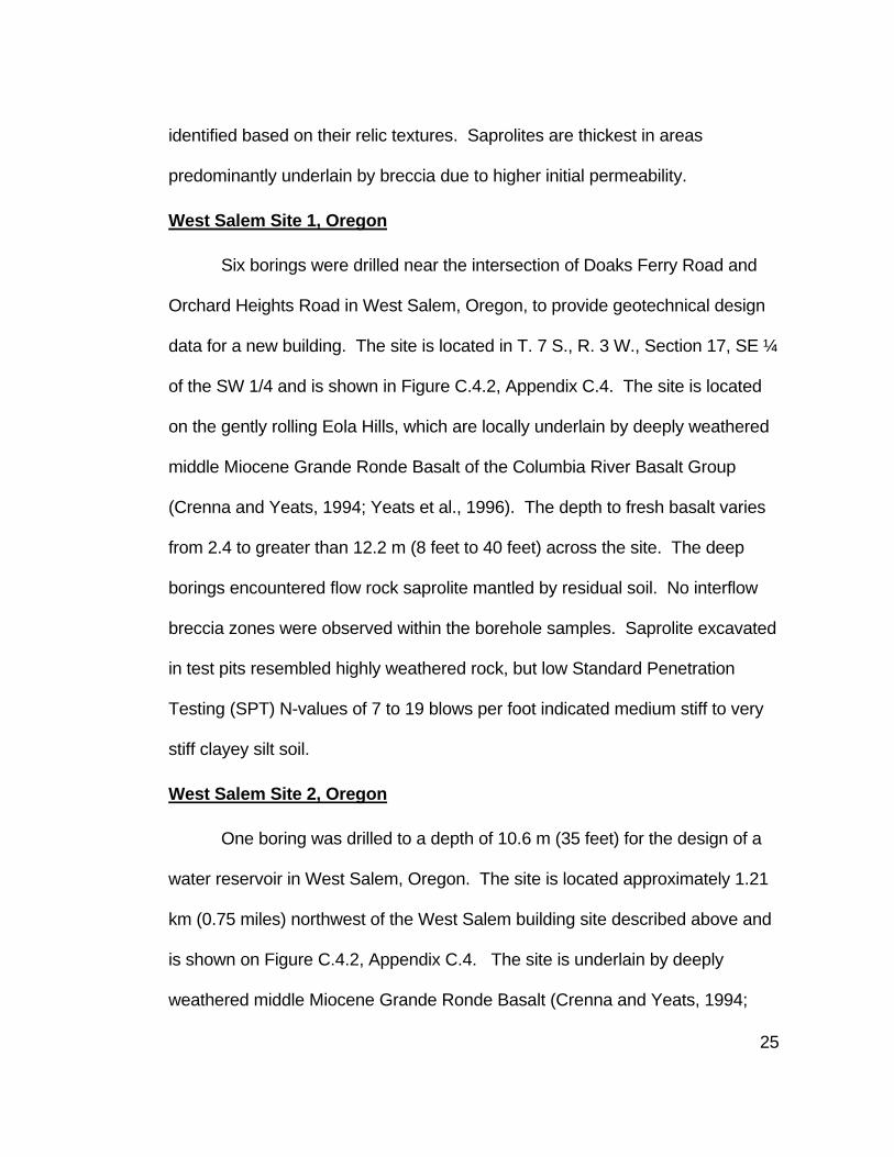
West Salem Site 1, Oregon .......................................................................... 25
West Salem Site 2, Oregon .......................................................................... 25
Carlton, Oregon............................................................................................. 26
Silverton, Oregon .......................................................................................... 26
South Salem, Oregon ................................................................................... 27

iii
METHODS .......................................................................................................... 28
Field Sampling Methods ............................................................................... 29
Field Soil Sensitivity Testing ......................................................................... 30
X-Ray Diffraction Analysis ............................................................................ 30
X-ray Diffraction Analysis of -2μm Material ............................................. 31
X-ray Diffraction Analysis of Bulk Samples ............................................. 33
Toluidine Blue Treatment .............................................................................. 33
Magnetism ..................................................................................................... 34
Scanning Electron Microscopy ..................................................................... 35
Engineering Index Testing ............................................................................ 36
RESULTS ........................................................................................................... 37
X-Ray Diffraction Analysis Overview ............................................................ 37
X-Ray Diffraction Sample Data Summary .................................................... 39
Monterey Overcrossing Borehole BH-3 .................................................. 39
Monterey Overcrossing Borehole BH-7 .................................................. 41
Monterey Overcrossing Borehole BH-10 ................................................ 43
Monterey Overcrossing Borehole BH-18 ................................................ 45
Monterey Overcrossing Borehole BH-27 ................................................ 46
Monterey Overcrossing Borehole BH-43 ................................................ 47
West Salem Site 1 Borehole BH-1 .......................................................... 47
West Salem Site 2 Borehole BH-1 .......................................................... 48
Carlton Boreholes BH-1 and BH-2 .......................................................... 48

iv
Silverton Borehole BH-1 .......................................................................... 49
South Salem Borehole BH-2 ................................................................... 49
Magnetism Observations .............................................................................. 50
Field Sensitivity Testing Results ................................................................... 51
Testing for Amorphous Clay (Allophane and Imogolite) ............................... 52
Scanning Electron Microscopy (SEM) Results ............................................. 52
Engineering Index Testing Results ............................................................... 62
DISCUSSION ..................................................................................................... 64
Clay Mineralogy in Basaltic Saprolites and Residual Soil ............................ 64
Clay Zonation .......................................................................................... 64
Mixed-Layered Halloysite/Expandable Clay ........................................... 67
Desiccation of 10Å Halloysite .................................................................. 70
Development of Sensitivity in Basaltic Saprolites ......................................... 70
Occurrence of Sensitive Saprolites in Other Volcanic Rocks ....................... 74
Identification of Sensitive Volcanic Saprolites .............................................. 75
Field Index Testing .................................................................................. 75
Engineering Index Testing ....................................................................... 76
X-Ray Diffraction Analysis ....................................................................... 78
Mitigation of Sensitive Volcanic Saprolites ................................................... 78
CONCLUSIONS ................................................................................................. 80
FUTURE WORK ................................................................................................. 84
LITERATURE CITED ......................................................................................... 85

v

vi
APPENDICES
A Oregon and Washington Case Histories of construction in Sensitive Volcanic Saprolites…………………………………………………………94
B Engineering Test Procedures and Data…………………………………113
C Study Area Sample Descriptions………………………………………...119
D X-ray Diffraction Analysis…………………………………………………139

vii
LIST OF TABLES
TABLE PAGE
1. Volcanic Saprolites in Northwestern Oregon and Southwestern Washington ....................................................................................... 10
2. Overview of Laboratory Testing ......................................................... 29
3. Significant XRD Peaks for Study Area Clay Minerals ....................... 38
4. X-ray Diffraction Peak Parameters for Clay Minerals in Monterey Overcrossing Samples ....................................................................... 42
5. Monterey Overcrossing Borehole BH-10 XRD Mineralogy ............... 44
6. Magnetic Properties of Soil Samples ................................................. 51
7. Summary of Engineering Index Data ................................................. 63

viii
LIST OF FIGURES
FIGURE PAGE
1. Undisturbed sensitive volcanic breccia saprolite ....................................... 6
2. Disturbed sensitive volcanic breccia saprolite ........................................... 6
3. Basalt exposures in northwestern Oregon and southwestern Washington ....................................................................... 12
4. Ferruginous bauxite deposits in western Oregon and southwestern Washington .............................................................................................. 14
5. Basaltic saprolite developed from Columbia River Basalt bedrock ........ 15
6. Residual clastic texture in Boring Lava breccia saprolite ........................ 16
7. Vicinity map showing the location of study sites and engineering case history sites .............................................................................................. 20
8. Example of kaolinite-poor saprolite ......................................................... 40
9. Example of kaolinite-rich saprolite ........................................................... 40
10. Residual texture visible in volcanic breccia saprolite sample SH-43-6 prior to SEM analysis............................................................................... 55
11. SEM microphotograph of sample SH-43-6 at 10X magnification ........... 56
12. SEM microphotograph of sample SH-43-6 at 50X magnification .......... 57
13. SEM microphotograph of sample SH-43-6 at 390X magnification (Box B) ............................................................................. 58
14. SEM microphotograph of sample SH-43-6 at 390X magnification (Box A1) ........................................................................... 59
15. SEM microphotograph of sample SH-43-6 at 2000X magnification (Box A2) ........................................................................... 60
16. SEM microphotograph of sample SH-43-6 at 2000X magnification (Box A3) ........................................................................... 61

ix
LIST OF FIGURES (continued)
FIGURE PAGE 17. Air-dried XRD trace of crystalline, well-ordered low cristobalite ............. 69
18. XRD trace showing expansion of halloysite peaks with glycolation ........ 72

1
INTRODUCTION
Saprolites form where bedrock has been exposed to prolonged tropical
or wet temperate climates (Prudencio et al., 1990; Schwarz, 1997). Volcanic
saprolites are commonly used as foundation and embankment soils throughout
the world (Terzaghi, 1958; Sherard et al., 1963; Wesley, 1974; Hammond and
Vessely, 1998). Characteristics of volcanic saprolites affect their engineering
properties and suitability as foundation soils. Engineers have previously
identified clay mineralogy, specifically halloysite content, as a contributing factor
to adverse engineering properties (Mitchell, 1989; Cornforth Consulting Inc.,
1991; Hammond and Vessely, 1998).
Volcanic saprolites are common in the Pacific Northwest due to climate
conditions that have deeply weathered Tertiary-age basalt and andesite units.
Local engineering projects have experienced difficulties in sensitive volcanic
saprolites, which release water and lose shear strength when disturbed. These
difficulties have resulted in expensive “change of conditions” construction
claims. Although hydrated halloysite (in conjunction with smectite) has been
suspected as the cause of sensitivity in volcanic saprolites, no systematic study
has confirmed this relationship.
This study examines clay mineral zonation with depth in selected
northwestern Oregon basaltic saprolites, compares changes in clay mineralogy
with soil sensitivity, develops a mechanism by which soils become sensitive,
and addresses the correlation between halloysite and sensitive basalt and

2
andesite saprolites. Laboratory and filed testing methods are provided to
identify sensitive soils. Mitigation techniques are developed based on case
history information.

3
BACKGROUND
Saprolite is defined as “a residual regolith developed isovolumetrically on
crystalline rocks, in which some or all of the primary minerals have been
extensively transformed in situ to weathering products” (Velbel, 1990). Saprolite
is much weaker than weathered rock but maintains the original volume,
structure, and fabric of the parent rock (Pavich, 1996). During the formation of
saprolites in igneous rocks, individual minerals are dissolved (leached) and
weathering products (clay minerals and iron and aluminum oxides) are
reprecipitated in crystal fractures along cleavage planes and around the
perimeter of the mineral (Velbel, 1989). As weathering progresses, clay- and
oxide-bounded, porous “negative pseudomorphs” of the original minerals form
micro-boxwork structures in the saprolite (Velbel, 1989). These micro-boxworks
can trap isolated pockets of water within the saprolite.
Mineralogical studies have identified both hydrated (10Å) and
dehydrated (7Å) halloysite in volcanic saprolites (Glasmann and Simonson,
1985; Prudencio et al., 1990). 7Å halloysite (Al2Si2O5(OH)4) consists of a
combined octahedral and tetrahedral sheet (1:1) structure, while 10Å halloysite
(Al2Si2O5(OH)4⋅2H2O) contains a 2.9Å layer of water between the combined 1:1
sheets (Moore and Reynolds, 1997). The nature of the relationship between 7Å
and 10Å halloysite has not been determined. They may represent two separate
phases of the same mineral or two separate minerals (Moore and Reynolds,
1997).

4
Halloysite forms as an intermediate weathering product in volcanic
material (especially plagioclase) which later transforms to kaolinite with
continued weathering (Romero et al., 1992; Jeong, 1999). Repeated alternating
wet and dry cycles and a high water content of the soil in a warm humid climate
favors the formation of halloysite in the soil and cause laterization (Wang et al.,
1998). Detecting abundant halloysite in lateritic paleosols facilitates the
identification of paleoclimates (Wang et al., 1998).
Numerous halloysite morphologies have been identified including tubes
(Kirkman, 1981; Singh, 1996; Wang et al., 1998), plates (Mitchell, 1993),
crumpled sheets (Wada and Mizota, 1982), spheroids (Prudencio et al., 1990),
and ellipsoids (Jeong, 1999). Halloysite morphology is related to aluminum
oxide (Al2O3) and iron oxide (Fe2O3) content (Bailey, 1989). Long tubes indicate
high aluminum substitution in the tetrahedral sheet, while spheroids and plates
indicate high iron substitution in the octahedral sheet (Bailey, 1989). Tubular
halloysite, which is commonly found in basalt saprolites in Oregon (R.
Glasmann, personal communication, February 2001), may store free water
internally within the tube.
Studies of halloysite in basalt saprolites have been conducted in many
parts of the world, including Spain (Prudencio et al., 1990), Kenya (Terzaghi,
1958), Indonesia (Terzaghi, 1958), Philippines (Terzaghi, 1958), Australia
(Terzaghi, 1958; Eggleton et al., 1987) and Japan (Wada and Mizota, 1982).
Numerous articles and reports discuss halloysite in basalt and andesite

5
saprolites in western Oregon and southwestern Washington (Istok, 1981; Thrall,
1981; Glasmann, 1982; Gabor et al., 1987; Gabor and Cummings, 1988;
Mitchell, 1989; Hammond and Vessely, 1998). Additionally, studies have been
conducted on halloysite in soils derived from other types of igneous rocks,
predominantly silicic lava and ash deposits (Kirkman, 1981; Theng et al., 1982;
Wada and Mizota, 1982; Romero et al., 1992; Jeong and Kim, 1993; Wang et
al., 1998; Jeong, 1999). These studies can be divided into two groups that
show little or no overlap:
• The mineralogy, morphology, formation, and presence of halloysite based on laboratory studies and theoretical modeling conducted by mineralogists and soil scientists (e.g. Glasmann, 1982; Wada and Mizota, 1982).
• Geotechnical investigations and case histories that discuss construction problems related to sensitive soils where halloysite has been identified. These documents discuss the engineering properties and performance of project soils (e.g. Terzaghi, 1958; Hammond and Vessely, 1998).
Sensitivity is defined as the ratio of the peak undisturbed (in situ)
strength to the remolded strength as determined by unconfined compression
testing (Mitchell, 1993). A soil with a ration greater than 4:1 is considered
sensitive (McCarthy, 1998). Sensitive soils experience a significant loss of
shear strength and release water when disturbed or remolded. Figures 1 and 2
show an undisturbed and remolded sensitive volcanic breccia. Although
volcanic saprolites represent only one category of sensitive soils, they are
particularly problematic in northwest Oregon and southwest Washington as a
result of the abundance of deeply weathered volcanic material.

6
Figure 1. Undisturbed sensitive volcanic breccia saprolite. Note moist appearance prior to compression under hand pressure.
Figure 2. Disturbed sensitive volcanic breccia saprolite. Note wet appearance of Figure 1 sample following compression under hand pressure.

7
Geotechnical engineers label saprolites as “residual soil”; however, the
term “residual soil” is used in this thesis to identify the featureless, highly
weathered soil that overlies and is derived from the saprolite (Pavich, 1996).
The residual soil discussed below is located in the pedogenic A and B horizons
and has lost all original rock texture and a portion of its original volume due to
collapse of the saprolite structure (Pavich, 1996). Since engineers consider
saprolites soil, the term saprolite and soil are used interchangeably.
Dr. Karl Terzaghi, who is credited with establishing the profession of
geotechnical engineering, may have been the first to describe the properties
and problems associated with sensitive volcanic soils. In the 1950’s, during the
construction of the Sasumua Dam in Nairobi, Kenya, he observed and identified
the engineering properties of sensitive volcanic saprolites used for the dam core
(Terzaghi, 1958). Additionally, geotechnical engineers have since tested
sensitive volcanic saprolites during their site investigations for dams, roads, and
other engineering structures (U.S. Army Crops of Engineers Portland Engineer
District, 1966; Hammond and Vessely, 1998). The engineering properties of
these soils include low dry density, high natural water content, significant loss of
shear strength when disturbed, and Atterberg limits values which show a
reduction in the liquid limit and plasticity index between oven dried and air dried
samples (Deere and Thornburn, 1955; Terzaghi, 1958; Pope and Anderson,
1960; Thrall, 1981). Terzaghi (1958) explained these anomalous and

8
contradictory engineering properties by theorizing that the halloysite clay forms
spongy aggregates that clump together but break apart when compressed,
thereby losing strength and releasing water.
Other mechanisms have been postulated as a cause for sensitivity in
volcanic saprolites. Water stored in hydrated halloysite tubes may be released
if these tubes are compressed and broken during construction (Hammond and
Vessely, 1998). Velbel (1990) postulates that cavities form in saprolites during
isovolumetric weathering. These cavities are bounded by clay and iron oxides
that form a rigid "boxwork" around these water-filled cavities. When these
boxworks are compressed, the interstitial water is released. Lastly, blocked soil
pores have been identified in weathered volcanic ash deposits that contain
allophane, imogolite, and halloysite (Thrall, 1981). Water stored within and
released from these pores may produce soil sensitivity. Although several
theories to explain sensitivity in volcanic saprolites have been proposed, no
absolute mechanism has been established to explain sensitivity in basaltic and
andesitic flow rock and breccia.

9
GEOLOGIC SETTING
Significant portions of northwestern Oregon and southwestern
Washington are underlain by Tertiary and Quaternary mafic and intermediate
volcanic rocks that are weathered to saprolites. Basaltic, andesitic, and dacitic
units mapped in the study area include Boring Lavas, Sardine Formation,
Columbia River Basalt, Little Butte Volcanics, Goble Volcanics, Hatchet
Mountain Volcanics, Tillamook Volcanics, Siletz River Volcanics, and various
undivided Quaternary and Tertiary units in both Oregon and Washington.
These units range in age from early Eocene to Pleistocene. Table 1 identifies
the location and lithology of Quaternary and Tertiary volcanics and their
combined exposure is shown in Figure 3. These units included flows, breccias,
tuffs, associated volcaniclastic sediments, and scattered dikes and sills.
Volcanic deposits and intrusions have been grouped together for the purpose of
this study.
Tertiary and Quaternary volcanic saprolites are common in Western
Oregon and Southwestern Washington. Although volcanic units range in age
from Eocene to Pleistocene, a temperate climate with alternating wet and dry
cycles that was present during the late Miocene through early Pliocene (Wilson,
1997) deeply weathered these rocks. Weathering since the late Miocene has
formed ferruginous bauxites on Columbia River Basalt exposures in specific
areas (Corcoran and Libbey, 1956; Livingston, 1966; Hook, 1976; Cummings
and Fassio, 1990). Figure 4 shows the distribution of ferruginous bauxite within

10
Table 1. Volcanic Saprolites in Northwestern Oregon and Southwestern Washington
Formation Age Lithology Locations of Abundant Exposures Reference
Boring Lavas Pliocene to Pleistocene
Basalt and basaltic andesite flows and interflow breccia
Western Cascades, Multnomah and Clackamas Counties,
Oregon
(Trimble, 1963; Walker and MacLeod, 1991; Madin, 1994)
Various undivided volcanic units
Pliocene to Pleistocene
Basalt, andesite, and dacite flows, breccia, tuff, and volcaniclastic sediments
Southern Washington Cascade Range
(Hammond, 1980; Phillips, 1987b; Phillips, 1987a; Walsh et
al., 1987)
Sardine Formation Upper Miocene Andesite flows, tuff breccia, and lapilli tuff, and tuff
Western Cascade Range in northern Oregon
(Thayer, 1939; Peck et al., 1964)
Columbia River Basalt Group Miocene Basalt flows
Willamette Valley north of Albany, Columbia County, Clatsop County, Oregon,
southwest Washington (west of Interstate I-5)
(Hampton, 1972; Beeson and Moran, 1979; Korosec, 1987;
Phillips, 1987b; Phillips, 1987a; Walker and Duncan, 1989;
Walker and MacLeod, 1991; Yeats et al., 1996; Tolan and Beeson, 1999; Tolan et al.,
2000) Various undivided
volcanic units (including Hatchet
Mountain volcanics)
Upper Eocene to Miocene
Andesite and basaltic andesite flows, and
andesite and dacite breccia, and tuff
Southern Washington Cascade Range
(Hammond, 1980; Phillips, 1987b; Phillips, 1987a; Walsh et al., 1987; Cummings, In Press)
Little Butte Volcanics
Oligocene to lower Miocene
Basalt and andesite flows; and andesite, dacite, and
rhyolite tuff, lapilli tuff, domes, and flows of andesite, dacite, and
rhyolite
Western Cascade Range in northern Oregon
(Thayer, 1939; Peck et al., 1964; Hammond et al., 1982; Sherrod
and Smith, 1989)

11
Table 1. Volcanic Saprolites in Northwestern Oregon and Southwestern Washington (continued)
Formation Age Lithology Locations of Abundant Exposures Reference
Goble Volcanics Upper Eocene
to lower Oligocene
Basaltic andesite flows, flow breccia, and interbedded
tuff, sandstone, and siltstone
Columbia County, Oregon and Cowlitz County, Washington.
(Phillips, 1987b; Phillips, 1987a; Walsh et al., 1987) (Walker and
MacLeod, 1991)
Tillamook Volcanics Upper to middle Eocene
Subaerial basalt flows, pillow lava, and interbedded
tuff, sandstone, and siltstone
Northern Oregon Coast Range (Wells et al., 1983; Walker and MacLeod, 1991; Wells et al.,
1994)
Siletz River Volcanics
Lower to Middle Eocene
Subaerial basalt flows, pillow lava, and interbedded
tuff, sandstone, and siltstone
Oregon Coast Range (Bela, 1979; Wells et al., 1983; Walker and MacLeod, 1991;
Wells et al., 1994)
Tertiary Intrusives Eocene to Pliocene Basalt/Diabase/Gabbro
Scattered across northwestern Oregon and southwestern
Washington highlands.
(Schlicker and Deacon, 1967; Sherrod and Smith, 1989;
Walker and MacLeod, 1991; Yeats et al., 1996)

12
Figure 3. Basalt exposures in northwestern Oregon and southwestern Washington (Walsh et al., 1987; Walker and MacLeod, 1991).
SCALE: 1 cm = 15 km

13
the study area. Flows of Boring Lava extruded during the Pleistocene also
show significant weathering.
Within northwestern Oregon, saprolites are commonly very thick with a
very narrow interface between the saprolite and fresh bedrock. Boreholes
conducted at Mt. Scott in southeast Portland penetrated up to 11.3 m (37 feet)
of decomposed basalt flows and interflow breccia before encountering
competent bedrock. Figure 5 shows a saprolite that has developed on Grande
Ronde Basalt of the Columbia River Basalt Group in the south Salem Hills.
These saprolites have the consistency of soil, but preserve the original rock
structure. Figure 6 shows a sample of Boring Lava volcanic breccia from the
Monterey Overcrossing study area in southeast Portland in which the relict rock
structure is clearly visible.

14
Figure 4. Ferruginous bauxite deposits in western Oregon and southwestern Washington (after Livingston, 1966).

15
Figure 5. Basalt saprolite (red-brown) developed from Columbia River Basalt bedrock. Quarry is located on the east side of I-5, directly south of Willamette Vineyards (T.9 S., R. 3 W., SW ¼ of Section 2). Note sharp contact between saprolite (orange) and bedrock (gray).

16
Figure 6. Residual clastic texture visible in sample of Boring Lava breccia saprolite from Monterey Avenue Overcrossing project in southeast Portland. Pointer identifies outline of ash-sized clast surrounded by secondary orange clay. (Sample diameter is approximately 1.2 inches).

17
LOCAL ENGINEERING CASE HISTORIES
Numerous engineering projects in northwestern Oregon and
southwestern Washington have experienced construction difficulties in areas
underlain by sensitive volcanic saprolites. A sampling of these projects include
the following:
• Mud Mountain Dam, Pierce County, Washington; • Toutle River Sediment Retention Structure, Cowlitz County, Washington; • Trask River Dam Raise, Tillamook County, Oregon; • Hills Creek Dam, Lane County, Oregon; and • Spirit Lake Memorial Highway, Cowlitz and Skamania Counties,
Washington.
Additionally, a case history evaluating in situ soil strength in sensitive
saprolites during the design of the H3 Tunnel in Hawaii is included to further
characterize the engineering properties of this material. Appendix A contains a
detailed description of each of the study area projects (with references). Figure
7 shows the approximate location of each of these sites, with the exception of
Mud Mountain Dam which is to the north. Appendix B.1 includes a discussion
of engineering testing methods. The key aspects of each case history are
summarized below.
Mud Mountain Dam
Mud Mountain Dam, constructed in 1941, is one of the earliest cases of
construction problems related to excessively wet volcanic soils that were used
for the dam core. Earth embankment soils were kiln-dried and covered with a
gigantic, canvas tent to reduce the water content enough to reach compaction.
18
A small amount of colloidal clay was blamed for preventing soil drying or
drainage (Anonymous, 1941a; Anonymous, 1941b).
Toutle River Sediment Retention Structure
Change of conditions claims were filed by the contractor shortly after
construction began for the Toutle River Sediment Retention Structure (SRS).
Flow top breccia and Pleistocene-age debris flow saprolites, selected for the
impervious dam core, became excessively wet and lost shear strength when
disturbed. These soils appeared to be stable, silty to sandy gravels at optimum
water content in outcrop but quickly broke down to a wet, sticky mass that
caused heavy equipment to bog down in deep ruts. The contractor claimed that
the presence of halloysite and smectite in the saprolites was responsible for the
sensitivity of the embankment soils, although 10Å halloysite was not ubiquitous
to problematic soils (Gabor and Cummings, 1988; Cornforth Consulting Inc.,
1991). They contended that excess water was trapped in the “soil grains” by
halloysite, which released this water to the soil pores when disturbed. Gabor
and Cummings (1988) observed that halloysite was not present in all sensitive
soils and concluded that soil sensitivity was caused by microtextures within the
saprolite becoming crushed during handling and releasing water trapped within
micropores. Loss of shear strength due to rapid hydration of smectite was
dismissed due to the low permeability of smectite-rich soils.

19
Trask River Dam Raise
Based on knowledge of construction difficulties in sensitive soils experienced at
the Toutle River SRS, sensitive soils were anticipated in saprolites developed
on Eocene-age basalt at the Trask River Dam site. During the geotechnical
investigation for the dam raise, sensitive soils were encountered locally. Natural
water contents ranged from 68 to 89 percent in foundation areas, but
embankment fill materials were selected to reduce the in situ moisture content
to between 30 and 43 percent and avoid sensitive soils (Cornforth Consultants
Inc., 1995). Foundation soils consisted of high plasticity (elastic) silt (MH) with a
natural water content that usually exceeded the liquid limit. Atterberg limits
tests conducted on air-dried samples produced lower liquid limits and plasticity
indexes than samples that had never been dried, indicating that an irreversible
change had occurred during drying (Hammond and Vessely, 1998).
As with the Toutle River SRS, the presence of halloysite and
montmorillonite (smectite) was thought to cause problematic saprolite soils.
Halloysite was claimed to break down with handling and release water that was
absorbed by smectite, thereby changing the character of the soil from
apparently granular to cohesive. Significant 10Å halloysite was detected in the
two borrow area samples that were tested for clay content and one of these
samples contained significant smectite (Cornforth Consultants Inc., 1995).
Even though sensitive soils were anticipated and avoided where
possible, construction equipment still became bogged down in wet weather.

20
Figure 7. Vicinity map showing the location of study sites ( ) and engineering case history sites ( ). (Mud Mountain Dam is north of map area.
South Salem
West Salem 1 & 2
Monterey Overcrossing
Silverton
Carlton
Toutle River SRS
Trask River Dam
Hills Creek Dam
Spirit Lake Memorial Highway
Scale: 1 cm = 15 km

21
Thus, stripping and placing of impervious core materials was limited to the dry
summer months.
Hills Creek Dam
Hills Creek Dam, constructed in 1961 in south-central Oregon, was one
of the first Oregon dams to experience construction difficulties related to
sensitive soils (U.S. Army Corps of Engineers Portland Engineer District, 1959).
The impervious core of the dam was partially constructed of highly weathered
alluvial gravel that contained colloidal clay. Although this in situ material
appeared near optimum moisture content when excavated, it became wetter
after handling and developed ruts. The soil’s sensitivity was attributed to small
pockets of highly plastic colloidal clay mixing with lower plasticity fines during
handling and an increase in the plasticity of halloysite-bearing soils as hydrated
(10Å) halloysite altered to highly plastic intermediate halloysite during drying
(U.S. Army Crops of Engineers Portland Engineer District, 1966). Clay
analyses conducted by Ralph Grim for the U.S. Corps of Engineers (1966)
showed 10Å, 7Å, and intermediate forms of halloysite and lesser smectite. The
highly plastic intermediate halloysite was thought to be responsible for
compaction problems. As with the Trask River Dam, Atterberg limits tests
showed a progressive decrease in the plastic limit and the plasticity index with
air and oven drying.
To mitigate against the effects of sensitive embankment soils, aggregate
was added to improve drainage, roller weight was reduced, and lift thickness

22
was reduced to 0.2 m (8 inches) (U.S. Army Crops of Engineers Portland
Engineer District, 1966).
Spirit Lake Memorial Highway
During the construction of the Spirit Lake Memorial Highway in the
Western Cascades of Washington, the performance of embankments soils was
assessed using test fills and laboratory testing. The natural water content of
these soils was significantly above the optimum moisture content for standard
compaction (Golder Associates, 1987b). In-place density measurements in
hydrothermally altered tuff test fills showed an increase in dry density with two
tractor passes, followed by either no further increase or a significant decrease in
the dry density (and compaction) with additional passes. The in situ moisture
content of test fills decreased with two tractor passes and then increased as the
dry density decreased. Concurrently, deep rutting (0.5 m or 18 inches) occurred
on the third and fourth tractor pass. Dry densities measured within these test
fills were significantly less than the maximum dry densities established during
laboratory Proctor compaction tests. The hydrothermally altered tuff was
designated as waste due to its performance in test fills and high natural water
content. Deposits of Holocene and Quaternary volcanic ash produced similar
problems in test fills and were designated as waste.
The hydrothermally altered tuff was determined by the design engineers
to have similar properties to saprolites, including poor compaction
characteristics, high natural moisture content (commonly above the liquid limit),

23
low in situ densities (unit weight), anomalous Atterberg limits and Proctor test
values, and low remolded strength. These properties were attributed to the
presence of halloysite and the release of water held in the relict structure of the
soil during construction, although the clay mineralogy was not analyzed (Golder
Associates, 1988b).
H3 Tunnel, Oahu, Hawaii
The in situ soil strength in sensitive saprolites is not accurately
determined by laboratory strength testing methods. Dr. Glenn Boyce (personal
communication, October 2000) observed that laboratory testing of remolded
standard penetration test (SPT) samples of sensitive basalt saprolite for the H3
Highway Tunnel on Oahu, Hawaii, produced low strength values. Pile design
for approach piers was based on these low strength values. Over design and
waste occurred when piles could only be driven a few feet before refusal.
Similar anomalously low strength values were previously recorded during
laboratory testing of relatively undisturbed tube samples for the Wilson Tunnel 4
km (2.5 miles) southeast of the H3 Highway Tunnels (Boyce and Abramson,
1991a). Due to the recognition that the basalt saprolite had structure, in situ
testing was initiated for the design of the H3 Tunnels (Boyce and Abramson,
1991b). This testing included pressuremeter testing and plate load testing
(using a 460 mm diameter steel plate, attached to a load frame as per ASTM D-
4394-84) to determine accurate strength values for the design of the tunnel
(Boyce and Abramson, 1991a).

24
STUDY SITES
Although the study area included sites in both northwest Oregon and
southwest Washington (Figure 7), laboratory analysis was conducted on
samples collected by me (or under my supervision) during routine geotechnical
investigations in northwestern Oregon. Most borings extended into bedrock.
Study sites for this thesis were selected based on the presence of basalt
saprolites and the availability of samples. These sites include the following:
Monterey Avenue Overcrossing, Southeast Portland, Oregon
Over 50 borings were drilled for this project, which is located in southeast
Portland on the western slopes of Mount Scott, a Pleistocene-age volcano
composed of Boring Lavas (Schlicker and Finlayson, 1979). Lava flows from
Mount Scott yield a 1.26±0.39 Ma age based on K-Ar age dating (Conrey et al.,
1996). All but one boring was logged in the field by me. Borings were
conducted along both sides of I-205 between SE Sunnyside Road and SE
Johnson Creek Road. Figure C.4.1, Appendix C.4 shows the location of the
study area in T. 1 S., R. 2 E., Section 33, SW ¼. Deeply weathered Boring
Lava including interbedded basalt flows and breccias are commonly mantled by
Quaternary-age fine-grained Missoula flood deposits (Willamette Silt). In most
borings conducted at the site, featureless residual soil overlies the basalt
saprolite that ranges up to 18.9 m (62 feet) thick. Gravel to boulder corestones
developed from the Boring Lavas are common in the residual soil. Within the
saprolite, alternating layers of flow rock and interflow volcanic breccia were
25
identified based on their relic textures. Saprolites are thickest in areas
predominantly underlain by breccia due to higher initial permeability.
West Salem Site 1, Oregon
Six borings were drilled near the intersection of Doaks Ferry Road and
Orchard Heights Road in West Salem, Oregon, to provide geotechnical design
data for a new building. The site is located in T. 7 S., R. 3 W., Section 17, SE ¼
of the SW 1/4 and is shown in Figure C.4.2, Appendix C.4. The site is located
on the gently rolling Eola Hills, which are locally underlain by deeply weathered
middle Miocene Grande Ronde Basalt of the Columbia River Basalt Group
(Crenna and Yeats, 1994; Yeats et al., 1996). The depth to fresh basalt varies
from 2.4 to greater than 12.2 m (8 feet to 40 feet) across the site. The deep
borings encountered flow rock saprolite mantled by residual soil. No interflow
breccia zones were observed within the borehole samples. Saprolite excavated
in test pits resembled highly weathered rock, but low Standard Penetration
Testing (SPT) N-values of 7 to 19 blows per foot indicated medium stiff to very
stiff clayey silt soil.
West Salem Site 2, Oregon
One boring was drilled to a depth of 10.6 m (35 feet) for the design of a
water reservoir in West Salem, Oregon. The site is located approximately 1.21
km (0.75 miles) northwest of the West Salem building site described above and
is shown on Figure C.4.2, Appendix C.4. The site is underlain by deeply
weathered middle Miocene Grande Ronde Basalt (Crenna and Yeats, 1994;

26
Yeats et al., 1996). The boring encountered 1.5 m (5 feet) of featureless
residual soil and 7.2 m (23.5 feet) of saprolite above the basalt bedrock
Carlton, Oregon
Two borings were drilled for the design of a water reservoir on a hillside
directly west of Carlton, Oregon. The site is located in T. 3 S., R. 4 W., Section
19, SE 1/4 and is shown in Figure C.4.3, Appendix C.4. The hillside is underlain
by a deeply weathered Tertiary diabase intrusion, which cuts Eocene submarine
volcanic and sedimentary rocks (Schlicker and Deacon, 1967). The borings
encountered 2.7 m (9 feet) of residual soil over 6.2 m (20.5 feet) of saprolite
with core stones. Fresh diabase bedrock was encountered at a depth of 9.0 m
(29.5 feet) below the ground surface.
Silverton, Oregon
One boring was drilled for the design of a water reservoir on a hillside on
the east side of Silverton, Oregon. The site is located in T. 6 S., R.1 W.,
Section 35, SE ¼ of the NE ¼ and is shown in Figure C.4.4, Appendix C.4. The
hillside is underlain by deeply weathered flows of the middle Miocene
Frenchman Springs Member of the Wanapum Basalt of the Columbia River
Basalt Group (Tolan and Beeson, 1999). The boring encountered 2.1 m (7 feet)
of residual soil and at least 13.1 m (43 feet) of saprolite. The depth to bedrock
was not defined during drilling.

27
South Salem, Oregon
Four borings were drilled for the design of a road in the gently rolling
Salem Hills of south Salem, Oregon. The site is located along SW Robins Lane
in T. 8 S., R 3 W., Section 23, NW 1/4 and is shown in Figure C.4.5, Appendix
C.4. The site is underlain by deeply weathered, middle Miocene Grande Ronde
Basalt flows (Walker and Duncan, 1989). Borehole BH-2, which was sampled
for this study, penetrated 6.4 m (21 feet) of decomposed basalt without
encountering bedrock.

28
METHODS
Soil samples were collected from geotechnical borings drilled in SE
Portland (Monterey Overcrossing), West Salem (Sites 1 and 2), Silverton, and
Carlton, Oregon. Two different approaches to analysis were used on samples
from these sites. At Monterey Avenue Overcrossing and West Salem Site 1,
samples from three different borings were analyzed with XRD to observe
changes in clay mineralogy with depth, soil texture, and sensitivity. At West
Salem Site 2, Silverton, and Carlton, two samples from each site were analyzed
using XRD to compare variations in clay mineralogy. At South Salem, one
sample of sensitive soil was analyzed using XRD for clay content. All sites were
tested for magnetic minerals. One sample (Monterey Overcrossing SH-43-6)
was examined to evaluate the microscopic soil texture using a scanning
electron microscope (SEM). Secondary orange clay observed at Monterey
Overcrossing was evaluated for mineralogy and the presence of amorphous
clays (allophane and imogolite) using Toluidine Blue and XRD. Table 2
identifies the type of laboratory testing conducted for samples from each site.
Due to the sample size collected, soil sensitivity is defined in this thesis
based on the amount of water released when a soil sample is compressed
under strong finger pressure. Extremely sensitive samples release abundant
water, moderately sensitive samples release less water, and samples with
minor sensitivity release only enough water to be barely visible without

29
magnification. Samples with no sensitivity did not release water when
compressed.
Table 2. Overview of Laboratory Testing
Study Site Borehole Number
Number of Samples Tested
Type of Test and/or Preparation1
Monterey Avenue Overcrossing
BH-3 1 Bulk2, E3
BH-7 9 A, G, H, D, E, T4 (One bulk sample= A, G, H)
BH-10 7 A, E
(One bulk sample=A, G, H) (One sample=A, G, H, D)
BH-18 3 A, G, H, D, E BH-27 1 A BH-43 1 A, SEM5
West Salem, Oregon Site 1 BH-1 9 A, G, H, E
(One sample=A, G, H, D) West Salem, Oregon Site 2 BH-1 2 A, G, H, E
Carlton, Oregon BH-1 1 A, G, H, E BH-2 1 A, G, H, D, E
Silverton, Oregon BH-1 2 A, G, H, D, E South Salem,
Oregon BH-2 2 A, G, H, E
1 Tests performed on one or more samples. XRD treatments include the following: A=air dried, G=ethylene glycol, H=heat, D=DMSO. 2 Bulk analyses consisted of air-dried random powder mounts of a representative portion of the entire sample. All other XRD samples consist of clay sized (-2μ) material. 3 E = Engineering index tests 4 T=Toluidine Blue 5 SEM = scanning electron microscope Field Sampling Methods
During drilling, disturbed 381 mm (1.5 inch) diameter samples were
obtained at 0.76 to 1.52 m (2.5 to 5 ft) intervals in conjunction with Standard
Penetration Testing (SPT). Several relatively undisturbed, 700 mm (2.75-inch)
diameter samples were also obtained in the Monterey Overcrossing borings.
Although bentonite drilling mud was used during drilling, care was taken to

30
remove the mud, if present, from the samples prior to storage. Samples were
stored in airtight plastic bags and were kept moist or wet prior to analysis,
except where noted.
Field Soil Sensitivity Testing
Each soil sample was field tested for sensitivity either during drilling or
within a week following drilling. Samples were stored in sealed plastic bags to
maintain the natural moisture content of the soil. An indication of sensitivity was
determined based on the soil’s ability to release water when compressed under
strong finger pressure. Non-sensitive soils did not appear to change in moisture
content or “wetness” under compression, while sensitive soils became visibly
wet, released water, and left a film on the skin surface (Figures 1 and 2).
X-Ray Diffraction Analysis
X-ray diffraction (XRD) analyses were conducted on soil samples to
evaluate the variation in clay mineralogy between sensitive and non-sensitive
soils. Clay zonation with depth was studied within two borings at the Monterey
Avenue site and one boring within the West Salem site. Two or three samples
were selected at the other four sites to evaluate variations in clay mineralogy
between sensitive (saprolite) and non-sensitive (residual soil) samples. Clay
zonation analyses were conducted on both less than 2 micrometer (-2μm)
material and the entire sample (bulk analysis). Sample treatments used during
XRD analysis of -2μm material included ethylene glycol, heating to 250° for two
hours, dimethyl sulfoxide (DMSO), and toluidine blue dye. Sample treatments

31
were required to more accurately identify the various clay minerals present in
the soils. Table 2 includes a summary of XRD analyses at each site. Table D-1
(Appendix D) provides a detailed listing of XRD analyses and sample
treatments applied to each sample. XRD traces for each sample are included in
Appendix D.3 through D.14.
X-ray Diffraction Analysis of -2μm Material
The soil samples were soaked in a solution of deionized water for
between five minutes and 24 hours (as necessary to suspend the sample) and
rinsed through a #230 sieve. The resultant minus #230 suspension initially
flocculated in many of the samples and had to be dispersed by adding 10 to 30
grains of sodium hexametaphosphate. After settling 45 minutes, the -2μm
fraction in the upper 1 cm of fluid was siphoned off, vacuumed through a
Millipore® filter, and applied as a transfer to a glass slide. This preparation
limited analysis to clay-sized particles and enhanced preferred orientation of
individual clay crystallites. Samples were then analyzed between 3° and 35° 2θ
using Copper K-α X-radiation and a 20 mm incident beam mask. An
acceleration of 40 kV and a current of 30 milliamps were used to generate X-
radiation. All air-dried samples were analyzed once without treatment. The
following treatments were used on selected samples and are discussed below.
Air Dried Preparation
Samples were prepared as discussed above and were analyzed
immediately after application to the glass slide to minimize dehydration. Sample

32
slides were visibly moist when placed in the sample holder of the X-ray
diffractometer.
Ethylene Glycol Treatment
Sample slides were placed in a covered glass jar containing ethylene
glycol for seven days prior to XRD analysis to allow time for absorption and
intercalation (Moore and Reynolds, 1997). Ethylene glycol treatment facilitates
the identification of smectite by inducing a shift in the 001 reflection from 15Å to
17Å. Peaks between 14.5 Å and 15 Å that shift to 17 Å with glycolation are
identified as smectite.
Heat Treatment
Sample slides were heated in a 250° C oven for two hours and then
cooled in a desiccator prior to XRD analysis. Heat treatment causes the
collapse of hydrated clays such as smectite and 10Å halloysite (Moore and
Reynolds, 1997).
DMSO Treatment
Sample slides were lightly sprayed with DMSO and placed in a sealed
container for 2 days prior to XRD analysis. Treatment with DMSO causes
halloysite peaks between 7.4 Å and 10.0 Å (001 reflections) and 3.6 Å (002
reflection) to shift to 11.3Å and 3.7Å, respectively (Jackson and Abdel-Kader,
1978; Gabor, 1981). Kaolinite peaks are not affected by DMSO treatment
(Gabor, 1981).

33
Kaolinite and 7Å halloysite are difficult to identify and separate based
solely on peak position. Within this paper, 7Å halloysite and kaolinite are
distinguished by the location of the 001 peak (7.15Å vs. 7.2 to 7.4Å) and based
on the magnitude of 7Å peak shift measured after DMSO treatment and
intercalation. Although intercalation of DMSO into the kaolinite structure has
been reported (Franco and Ruiz Cruz, 2002), analyses conducted for this
investigation suggest that kaolinite shows only minimal intercalation in basalt
saprolites over a time period of 48 hours. Jackson and Abdel-Kader (1978)
suggest the degree of kaolinite intercalation with DMSO is significantly reduced
with a decrease in crystal size and iron content.
X-ray Diffraction Analysis of Bulk Samples
Bulk XRD analyses of the entire sample were conducted on two samples
(one non-sensitive and one sensitive) from Monterey Avenue Borehole BH-7
and BH-10. Bulk samples were air dried and ground with a morter and pestal
to <#230 mesh and back-loaded into an aluminum sample holder to minimize
orientation. Samples were scanned from 3 to 65° 2θ at a speed of 1°/min
during bulk analysis of a randomly oriented powdered sample.
Toluidine Blue Treatment
The toluidine blue spot test was developed by Wada and Kakuto (1985)
to identify amorphous clays such as allophane and imogolite in soils. The
authors contend that toluidine blue, (CH3)2N+C6H3NSC6H2(CH3)NH2, changes
color from blue to purplish red (metachromasis) in the presence of negatively
34
charged colloids found in soils derived from granite, andesite, and sedimentary
rocks. During their testing, volcanic soils containing allophane and imogolite
remain blue when tested and do not show metachromasis.
Both a sensitive and a non-sensitive soil were tested. Additionally, one
sample of orange clay from the Monterey Avenue Overcrossing site was tested
for allophane and imogolite. The presence of amorphous clay was suspected in
this secondary clay as it appears to have been deposited by groundwater in the
voids between clasts in interflow breccias. The clay is very plastic and is
susceptible to severe cracking during desiccation.
Using the procedure outlined in Wada and Kakuto (1985), 0.4 g of a
0.02% solution of Toluidine blue was mixed with 0.04 g of the three soil samples
and one clay sample. A control sample of decayed wood replaced by abundant
allophane remained blue when tested with the above solution (G. H. Grathoff,
personal communication, March 2001).
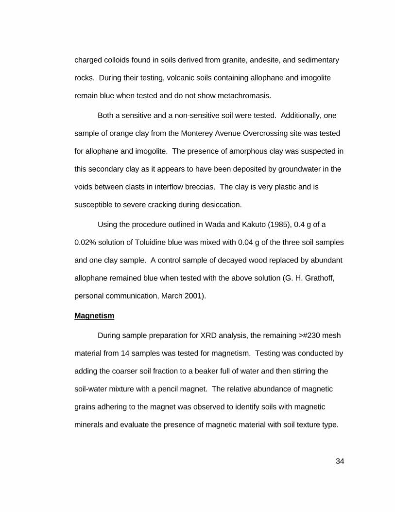
Magnetism
During sample preparation for XRD analysis, the remaining >#230 mesh
material from 14 samples was tested for magnetism. Testing was conducted by
adding the coarser soil fraction to a beaker full of water and then stirring the
soil-water mixture with a pencil magnet. The relative abundance of magnetic
grains adhering to the magnet was observed to identify soils with magnetic
minerals and evaluate the presence of magnetic material with soil texture type.

35
Magnetic mineralogy was investigated by conducting a bulk random powder
XRD analysis of a Monterey Avenue Overcrossing sample (Sample SS-10-10).
Scanning Electron Microscopy
Scanning electron microscopy (SEM) was conducted on a relatively
undistrubed sample of a sensitive decomposed volcanic breccia (SH-43-6)
obtained from Monterey Avenue Overcrossing Borehole BH-43. The analysis
was conducted to determine the microscopic fabric of the rock and look for
boxwork structures.
In preparation for SEM analysis, the sample was broken into small clods
and air dried until apparently completely desiccated. Each desiccated clod was
broken in half to expose a fresh surface and several were selected that typified
the decomposed breccia clasts. Samples were mounted using a five-minute
epoxy and the sides of the samples were painted with colloidal graphite to
facilitate electrical grounding as per Portland State University SEM laboratory
procedure. The mounted samples were placed in a vacuum and sputter-coated
with gold-palladium. The sample was analyzed using a JEOL Model JSM-35C
scanning electron microscope operated at 15kV accelerating voltage with a
working distance of 39 mm.
A series of SEM photographs of the sample were taken at magnifications
of 10X, 50X, 390X, and 2000X. Scale bars are shown on the lower right corner
of each photograph (Figures 11 through 16). A photograph of the sample prior
to desiccation is included to show megascopic saprolite structure.

36
Engineering Index Testing
Index tests, including natural water content, Atterberg limits, bulk density,
and grain size analyses, were conducted on borehole samples for foundation
design at each of the study areas. A description of each of the index tests is
included in Appendix B.1. Index tests conducted during the geotechnical
investigation for a project are extremely useful in identifying problematic
sensitive soils before construction begins. Engineering index test data for the
borehole samples analyzed in this research are provided in Table B.2.1.
Engineering index properties for samples analyzed in this investigation are
summarized in Appendix B.2. Table E.2 includes engineering index testing data
for Monterey Avenue Overcrossing samples that are similar to those analyzed
in this research.

37
RESULTS
X-Ray Diffraction Analysis Overview
Clay minerals identified by XRD analysis include 7Å and 10Å halloysite,
kaolinite, smectite, and potentially mixed-layered 7Å halloysite/expandable and
10Å halloysite/expandable. The expandable clay may be smectite or a similar
mineral. Non-clay minerals identified in both random bulk analyses and
oriented -2μm material analyses included goethite, quartz, low cristobalite,
feldspar, maghemite, chlorite, and mica. Although gibbsite commonly is present
in bauxites, none was clearly identified in the bulk or -2μm samples. X-ray
diffraction traces for all samples are included in Appendix D.3 to D.14. A
summary table (Table D.1.1) showing samples analyzed and sample treatments
is included in Appendix D.1. Diagnostic peaks for clay minerals with and
without sample treatment are listed in Table 3.
Based on analyses conducted on study area samples, DMSO appeared
to intercalate within the 7Å and the 10Å halloysite structures and caused the
001 peak for both types of halloysite to expand to 11.2Å. Kaolinite, however,
did not appear to expand with DMSO. Figure 8 shows the almost complete shift
of the broad 7.5Å peak between 7.2Å and 9Å and the 10Å peak to 11.2Å. This
saprolite sample was located at a depth of 25 to 26.5 feet. Figure 9 shows a
partial expansion of the 7Å peak to 11.2Å (halloysite), with the remaining 001
peak showing a d-spacing of 7.14Å (kaolinite). This residual soil sample was

38
Table 3. Significant XRD Peaks for Study Area Clay Minerals
Clay Mineral Location of Diagnostic Peak With Treatment1
Air Dried Ethylene Glycol 250° Heat DMSO
7Å Halloysite 7.2Å – 7.4Å2 7.2Å – 7.4Å2 7.2Å – 7.4Å2 11.2Å3
10Å Halloysite 10Å2 10Å2 7.2Å2 11.2Å3
Kaolinite 7.15Å2 7.15Å2 7.15Å2 7.15Å3,4
Smectite 14Å – 15Å2 17Å2 9.4Å2 18Å – 19Å4
Interlayered 10Å halloysite/expandable 10Å4 10.3Å - 11Å4 7.2Å4 11.2Å4
Interlayered 7Å halloysite/expandable 7.3Å – 9Å4 10.3Å - 11Å4 7.2Å4 11.2Å4
1 Sample treatments described in Methods section 2 Peak locations identified in Chen (1977) 3 Peak locations identified in Gabor (1981) 4 Peak locations identified in this paper
shallow (10 to 11.5 feet deep) and showed more weathering as indicated by a
lack of relic rock texture. A higher percentage of kaolinite is expected in this
sample (Delvaux et al., 1990; Romero et al., 1992) and the resultant significant
7.14Å peak supports the conclusion that DMSO does not intercalate with
kaolinite in basalt saprolite soils over a period of 48 hours at room temperature.
Kaolinite-rich samples were characterized by intense and symmetrical
d001 peaks that were located between 7.2 and 7.3Å. Heat treatment had no
effect on the location and intensity of the 7Å kaolinite peak. 7Å halloysite-rich
samples were characterized by broad, asymmetrical peaks that gradually
decreased toward the lower diffraction angles. Maximum peak height for 7Å
halloysite was generally located between 7.3 and 8.0Å, with the 001 peak d-
39
spacing increasing with depth. Heat treatment caused the collapse of the 7.3 to
8.0Å halloysite peak to between 7.22 to 7.3Å.
X-Ray Diffraction Sample Data Summary
The following interpretations summarize the XRD analyses conducted on
borehole samples at each of the study sites. All Monterey Overcrossing borings
penetrated Boring Lavas saprolites. Geologic units penetrated at other study
areas are identified below and are listed in Table 1.
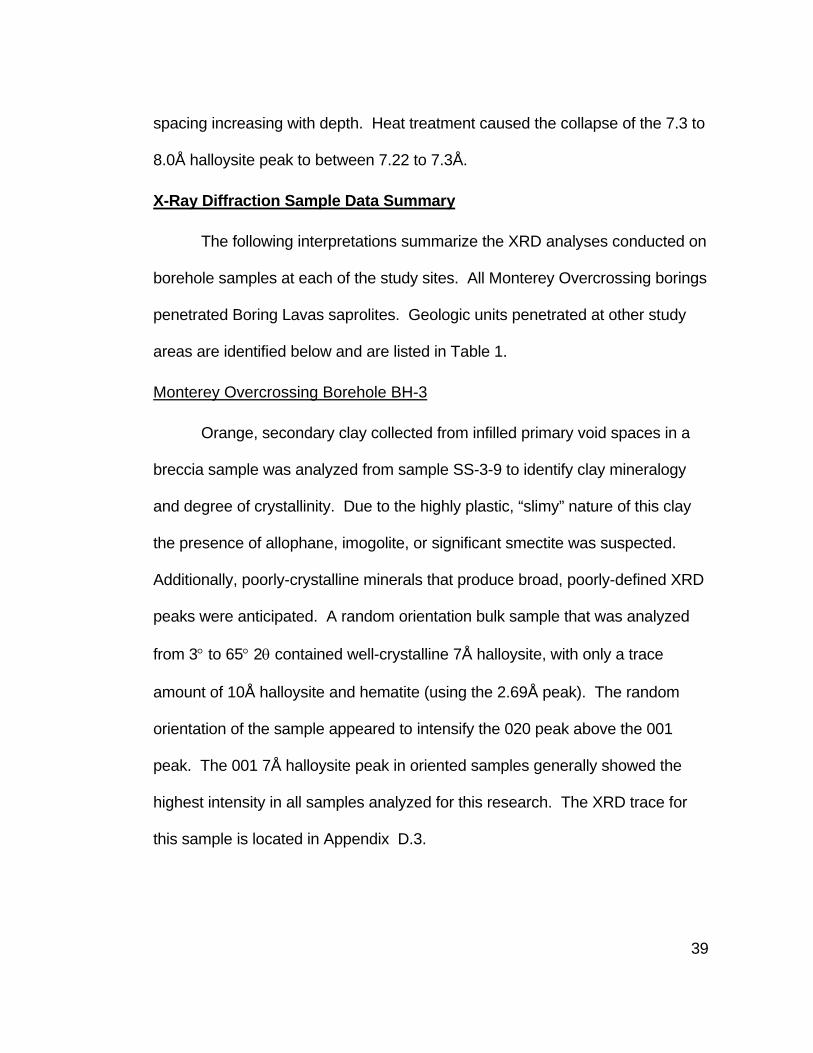
Monterey Overcrossing Borehole BH-3
Orange, secondary clay collected from infilled primary void spaces in a
breccia sample was analyzed from sample SS-3-9 to identify clay mineralogy
and degree of crystallinity. Due to the highly plastic, “slimy” nature of this clay
the presence of allophane, imogolite, or significant smectite was suspected.
Additionally, poorly-crystalline minerals that produce broad, poorly-defined XRD
peaks were anticipated. A random orientation bulk sample that was analyzed
from 3° to 65° 2θ contained well-crystalline 7Å halloysite, with only a trace
amount of 10Å halloysite and hematite (using the 2.69Å peak). The random
orientation of the sample appeared to intensify the 020 peak above the 001
peak. The 001 7Å halloysite peak in oriented samples generally showed the
highest intensity in all samples analyzed for this research. The XRD trace for
this sample is located in Appendix D.3.

40

41
Monterey Overcrossing Borehole BH-7
A detailed study of clay zonation with depth was conducted using nine
samples collected in Borehole BH-7 between depths of 2.1 m (7 ft) and 13.7 m
(45 ft). Each sample was analyzed using XRD with the following treatments:
air-dried, ethylene glycol, heat, and DMSO. The XRD traces are included in
Appendix D.4.
Borehole BH-7 penetrated 4.3 m (14 ft) of silt and clayey silt residual soil,
over volcanic breccia saprolite (silt) to a depth of 6.1 m (20 ft). Flow rock
saprolite (silty sand to sandy silt) was encountered to 9.6 m (31.5 ft) followed by
breccia (sandy silt with clay) to 13.7 m (45 feet). Fresh basalt was encountered
below 13.4 m. The borehole log for Borehole BH-7 is included in Appendix C.3.
Peak parameters were calculated for clay minerals in each of the
samples analyzed. Appendix D.2 includes a discussion of peak parameter
calculation from XRD traces. Tables D.2.1 through D.2.4 (Appendix D.2) list the
peak parameters for 7Å halloysite, 10Å halloysite, kaolinite, and smectite. A
summary of the net area of the diagnostic peak for each of the clay minerals is
shown in Table 4 below. Net area is proportional to the abundance of a clay
mineral in the soil (Moore and Reynolds, 1997).

42
Table 4. X-ray Diffraction Peak Parameters for Clay Minerals in Monterey Overcrossing Samples
Sample Depth (m) Corrected Net Area of Diagnostic Peak (°counts/sec)1 Original
Rock Morphology
Soil Texture Sensitivity 7Å Halloysite
10Å Halloysite Kaolinite Smectite
SS-7-2 2.1 – 2.6 60 0 315 810 Unknown Residual soil None
SS-7-3 3.0 – 3.5 522 229 424 230 Unknown Residual soil None
SS-7-4 4.6 – 5.0 520 41 186 101 Flow rock Saprolite Minor
SS-7-6 6.7 – 7.2 131 113 33 19 Flow rock Saprolite Moderate
SS-7-7 7.6 – 8.1 785 42 78 66 Flow rock Saprolite Moderate
SS-7-8 9.1 – 9.6 469 248 76 123 Flow rock Saprolite Moderate
SS-7-9 10.7 – 11.1 463 205 22 57 Interflow breccia Saprolite Moderate
SS-7-11 12.8 – 13.3 344 417 18 40 Interflow breccia Saprolite Moderate
SS-7-12 13.7 122 1965 18 25 Flow rock Weathered rock None
SS-18-6 4.6 – 5.0 958 0 145 41 Flow rock Saprolite None
SS-18-8 7.6 – 8.1 1193 103 45 127 Interflow breccia Saprolite Moderate
SS-18-9 9.1 – 9.6 553 316 59 30 Flow rock Saprolite None
1 Discussed in Appendix D.2.

43
The following trends in clay mineralogy were identified based on XRD analysis:
• 10Å halloysite generally increases with depth and this increase is not related to original basalt morphology.
• 7Å halloysite increases with depth, and then decreases below 7.6 m (25 ft).
• The 001 peak for 7Å halloysite generally becomes broader, less distinct, and more asymmetrical toward the lower diffraction angles with depth.
• Kaolinite decreases with depth and is significantly more abundant in residual soil.
• Smectite decreases with depth. • Trace amounts of illite and or quartz occur in residual soil samples (SS-
7-2 and SS-7-3) and are scattered within the saprolite samples (SS-7-4 and SS-7-11).
Both 7Å and 10Å halloysite in Borehole BH-7 samples expanded to
11.3Å with glycolation indicating the presence of interlayered
halloysite/expandable clay. Heat treatment caused all halloysite to collapse to
7.2 to 7.2Å. Both the intensity of the peak and the degree of
ordering/crystallinity of the 7Å peak increased with heat treatment.
Monterey Overcrossing Borehole BH-10
Seven air-dried samples were analyzed from Borehole BH-10 to
corroborate trends in clay mineral zonation identified in Borehole BH-7. Sample
SS-7-10 was evaluated for kaolinite using DMSO. A bulk, randomly oriented
sample of SS-10-10 was analyzed for total mineralogy, and an oriented sample
of –2μm material was prepared for each of the sample treatments listed in Table
D.1.1. Table 5 summarizes the clay mineralogy for each random and oriented

44
sample based predominantly on air-dried analyses and comparison with
analyses conducted on other Monterey Overcrossing samples.
Table 5. Monterey Overcrossing Borehole BH-10 XRD Mineralogy
Sample Depth (m)
7Å Halloysite1
10Å Halloysite Kaolinite1 Smectite Other
Minerals
SS-10-4 4.9 – 5.3 Some2 Trace2 Some Abundant2 Not detectable
SS-10-5 6.1 – 6.6 Some Trace Some Trace Trace goethite
SS-10-7 8.2 – 8.7 Abundant Some Trace Trace Trace goethite
SS-10-8 9.1 – 9.6 Abundant Trace Trace Some Trace goethite
SS-10-9 10.7 – 11.1 Abundant Trace Trace Trace Not detectable
SS-10-10 12.2 – 12.6 Trace Abundant3 None Trace
Abundant maghemite,
some hematite
SS-10-11 13.7 Some Trace None Some Trace feldspar
1 The amount of 7Å halloysite vs. kaolinite is only confirmed using DMSO in Sample SS-10-7. All intermediate halloysite between 7Å and 9Å is identified as 7Å halloysite. 2 Abundance of clay mineral based on XRD peak area. 3 10Å halloysite peak in Sample SS-10-10 is located at 10.88Å
Borehole BH-10 penetrated 4.6 m (15 ft) of Willamette Silt over volcanic
breccia saprolite (stiff silt with some clay) to a depth of 12.2 m (40 ft). Flow rock
saprolite was encountered to 12.8 m (42 ft) followed by fresh basalt flow rock.
The borehole log for Borehole BH-10 is included in Appendix C.3. Unlike
Borehole BH-7, BH-10 may only penetrate two feet of residual soil (not sampled
and not recorded in the borehole log). Thus, all samples show sensitivity,
ranging from minor (SS-10-4) to extreme (SS-10-10).
Borehole BH-10 confirms many of the trends identified in Borehole BH-7.
These trends include:

45
• 10Å halloysite generally increases with depth and this increase is not related to original rock morphology. Sample SS-10-11 shows only trace 10Å halloysite, but this sample consists of the weathering rind on jointed basalt bedrock and did not contain abundant clay-size material.
• 7Å halloysite increases with depth and then decreases below 10.7 m (35 ft) with the exception of Sample SS-10-11.
• The 001 peak for 7Å halloysite generally becomes broader, less distinct, and more asymmetrical toward the lower diffraction angles with depth.
• Only trace kaolinite is found in Sample SS-10-7 at 8.2 to 8.7 m (27 to 28.5 feet).
• Smectite decreases with depth but is more abundant at the bottom of the boring within the weathering rind of the jointed basalt bedrock.
Similar to Borehole BH-7, the nature of the 7Å halloysite 001 peak
changes with depth, becoming broader toward the lower diffraction angles, less
intense, and less distinct. This broadening indicates a decrease in the degree
of crystallinity and an increase in the amount of halloysite intermediate between
7Å and 9Å.
Monterey Overcrossing Borehole BH-18
Samples from Borehole BH-18 were selected to evaluate clay
mineralogy variation between sensitive and non-sensitive saprolites within a
single borehole. Three sequential samples collected at depths ranging from 4.6
to 9.6 m (15 to 31.5 ft) were analyzed. The upper and lower samples are non-
sensitive decomposed flow rock, while the center sample at 7.6 m (25 ft)
consists of moderately sensitive decomposed volcanic breccia. The peak
parameters calculated for Borehole BH-18 samples (SS-18-6, SS-18-8, and SS-
18-9) are listed in Table 4.

46
Based on XRD analyses, clay mineralogy does not appear to vary
significantly between sensitive and non-sensitive saprolites. Trends in clay
variation observed in Borehole BH-7 that are replicated in these three samples
include:
• Kaolinite content decreases with depth. • 10Å halloysite increases with depth. • 7Å halloysite is most abundant in the middle sample and becomes less
abundant and poorly crystalline in the deepest sample.
Smectite is more common in the central, sensitive sample. Both
Boreholes BH-7 and BH-18 do not show any clear association between
sensitivity and smectite content.
Interlayering of an expandable clay with both 7Å and 10Å halloysite is
present in all three samples. Both the 10Å peak and the broad, asymmetrical
peak between 7Å and 9Å shift to 10.6 to 10.7Å with glycolation (Figure 18).
Monterey Overcrossing Borehole BH-27
Similar to sample SS-3-9 discussed above, the orange, secondary clay
from saprolite sample SS-27-7 was evaluated using XRD for mineralogy and
degree of crystallinity. The air-dried, oriented sample of less than 2 micrometer
sized (-2μm) material contained predominantly 7Å halloysite, with lesser
amounts of smectite and 10Å halloysite, and a trace amount of hematite, illite,
and quartz. Each mineral, with the exception of hematite, showed distinct
peaks indicating an ordered, crystalline structure. The XRD trace for this
sample is located in Appendix D.7.

47
Monterey Overcrossing Borehole BH-43
Sample SH-43-6 was photographed using SEM to evaluate the
microtexture of this extremely sensitive volcanic breccia saprolite. An air-dried,
oriented sample of –2μm material was analyzed by XRD to determine the clay
mineralogy present in the photomicrographs of the sample. The majority of the
sample consisted of 10Å halloysite, with lesser amounts of poorly crystalline 7Å
halloysite, and only a trace amount of smectite. The XRD trace for this sample
is located in Appendix D.7.
West Salem Site 1 Borehole BH-1
Clay zonation in Borehole BH-1 was analyzed in ten samples using XRD
and the following samples treatments: air-dried, ethylene glycol, and heat.
Sample SS-1-4 was analyzed after treatment with DMSO to determine the
amount of kaolinite in the saprolite. The XRD traces for these samples are
included in Appendix D.9.
Borehole BH-1 penetrated 1.4 m (4.5 ft) of clay residual soil over flow
rock saprolite consisting of silt with some (15 to 30%) clay and trace to some
sand to the bottom of the boring 12.6 m (41.5 ft). The entire borehole appeared
to remain within a single Grande Ronde Basalt flow.
7Å halloysite, kaolinite, and minor smectite was detected in all samples.
No 10Å halloysite was observed within the borehole. The -2μm fraction of the
soil was not as well crystalline as the Monterey Overcrossing samples. Peaks
were generally low and poorly defined. Similar to the Monterey Overcrossing

48
samples, the 7Å halloysite peak shifted to between 10.9Å and 11.1Å with
glycolation indicating the presence of interlayered expandable clay.
In addition to clay minerals, significant low cristobalite and trace goethite
were detected in XRD traces. The well-crystalline low cristobalite was most
abundant between 4.6 m to 7.6 m (15 to 25 feet) and was characterized by
sharp, distinct peaks.
West Salem Site 2 Borehole BH-1
Two samples were analyzed from Borehole BH-1 at West Salem Site 2
to evaluate the variation in clay mineralogy between non-sensitive residual soil
(SS-1-1) and sensitive saprolite (SS-1-6). 7Å halloysite/kaolinite, smectite, and
trace low cristobalite, goethite, and 10Å halloysite were observed in both
samples. The residual soil sample showed well-crystalline 7Å
halloysite/kaolinite and some smectite. The sharpness, symmetry, and d-
spacing of the residual soil 7Å peak indicates that significant kaolinite is present.
The sensitive saprolite sample contained abundant smectite and some 7Å
halloysite/kaolinite. Portions of the broad 7Å peak shift to 10.7Å with glycolation
indicating interlayering with expandable clay. XRD traces for Borehole BH-1 are
included in Appendix D.10.
Carlton Boreholes BH-1 and BH-2
Unlike the sample areas above, the Carlton sample area is underlain by
a diabase intrusion. Although clay mineralogy is very similar to that observed in
the Monterey Overcrossing samples, smectite is more abundant and only trace

49
10Å halloysite is present. Smectite is present in all three samples analyzed, but
is most abundant in sensitive saprolite Sample SS-2-6 at 4.6 to 5.0 m (15 to
16.5 ft). Abundant kaolinite and trace quartz and mica were observed in the
residual soil sample (SS-2-2). Only sensitive saprolite Sample SS-1-8 showed
evidence of interlayered 7Å halloysite/expandable clay. XRD traces for
Boreholes BH-1 and BH-2 are included in Appendix D.11 and D.12,
respectively.
Silverton Borehole BH-1
Borehole BH-1 penetrated Columbia River Basalt Group flow rock
saprolite but a different unit (Frenchman Springs Member of the Wanapum
Basalt) than was encountered at West Salem Sites 1 and 2 and South Salem.
Two samples were analyzed for variation in clay content with soil type and
sensitivity. The non-sensitive residual soil sample (SS-1-2) showed abundant
kaolinite, with some 7Å halloysite and trace amounts of smectite, cristobalite,
quartz, and goethite. The sensitive saprolite sample (SS-1-4) showed 7Å
halloysite and trace amounts of smectite and goethite. Portions of the broad,
asymmetrical 7Å peak in the saprolite sample expanded to 11Å after glycolation
which indicated the presence of interlayered halloysite/expandable clay. XRD
traces for Borehole BH-1 are included in Appendix D.13.
South Salem Borehole BH-2
Borehole BH-2 penetrated Grande Ronde Basalt saprolite. One
moderately sensitive saprolite sample (SS-2-6) was analyzed to evaluate clay

50
mineralogy. The sample contained 7Å halloysite/kaolinite with trace amounts of
smectite and goethite. Similar to West Salem Sites 1 and 2 saprolite samples,
Sample SS-2-6 did not contain 10Å halloysite and the peaks were broad and
poorly-defined. Portions of the broad, asymmetrical 7Å peak in the saprolite
sample expanded to 10.8Å after glycolation, indicating the presence of
interlayered halloysite/expandable clay. XRD traces for Borehole BH-2 are
included in Appendix D.14.
Magnetism Observations
Thirteen samples from a variety of sites were tested for magnetism using
a hand-held pencil magnet placed in a soil-water suspension. Abundant
magnetic material was retained on the magnet in strongly magnetic samples.
Testing of weakly magnetic samples produced only minor magnetic material.
The results of this testing are shown in Table 6. Except for one example,
saprolite samples contained magnetic material and residual soil samples were
not magnetic.
To evaluate the magnetic mineralogy of a bulk sample, Monterey
Overcrossing Sample SS-10-10 was analyzed using random powder XRD
analysis between 3° and 65° 2θ (Appendix D.5). This analysis showed the
presence of reddish-brown maghemite, the ferromagnetic form of Fe2O3 that
forms in soils and is isostructural with magnetite (Schwertmann and Taylor,
1989). Maghemite was identified using the 2.52 and 2.96Å peaks.

51
Table 6. Magnetic Properties of Soil Samples
Site Sample Depth (m) Soil Texture Magnetism
Monterey Avenue Overcrossing
SS-7-9 10.7 – 11.1 Saprolite Strong
SS-10-10 12.2 – 12.6 Saprolite Strong
SS-18-6 4.6 – 5.0 Saprolite Strong
SS-18-8 7.6 – 8.1 Saprolite Strong
SS-18-9 9.1 – 9.6 Saprolite Strong
SH-43-6 6.6 – 7.2 Saprolite Strong
West Salem Site 1 SS-1-4 3.0 – 3.5 Saprolite Weak
West Salem Site 2 SS-1-1 8.0 – 1.2 Residual soil None
SS-1-6 4.6 – 5.0 Saprolite Weak
Carlton
SS-1-8 7.6 – 8.1 Saprolite Strong
SS-2-2 1.4 – 1.8 Residual soil None
SS-2-6 4.6 – 5.0 Saprolite Strong
Silverton SS-1-2 1.5 – 2.0 Residual soil Strong
South Salem SS-2-6 4.6 – 5.0 Saprolite None
Soils containing exclusively silt and clay-sized material were generally
not magnetic. Saprolite samples that contained abundant >#230 mesh grains
were generally more magnetic. Magnetism is attributed to the presence of
secondary maghemite based on XRD analysis of Monterey Overcrossing
Sample SS-10-10.
Field Sensitivity Testing Results
Field sensitivity testing on all the study site samples identified the
following trends:
• Soil sensitivity generally increases with depth. • Saprolite soils are generally sensitive.

52
• Residual soils are not sensitive. • Volcanic breccia saprolites are more sensitive than flow rock or intrusive
rock saprolites.
Although soil sensitivity appears generally to increase with depth, one
sample of flow rock saprolite (Monterey SS-18-8) did not appear sensitive, even
though it was beneath a sensitive volcanic breccia. Table C.1.1 (Appendix C.1)
identifies the field sensitivity of each sample.
Testing for Amorphous Clay (Allophane and Imogolite)
Samples of a non-sensitive residual soil, sensitive saprolite, and a
secondary orange clay were tested for allophane and imogolite using the
toluidine blue spot test (Wada and Kakuto, 1985). These samples included
Monterey Overcrossing samples SS-7-2, SS-7-9, and SS-7-4 (orange clay
portion). The soil – solution mixture created for each sample turned purple,
indicating that neither allophane nor imogolite were present.
Scanning Electron Microscopy (SEM) Results
A series of SEM photos were taken of Monterey Overcrossing Sample
SH-43-6 using resolutions of 10X, 50X, 390X, and 2000X to identify the nature
of primary and secondary porosity within a volcanic breccia saprolite. Figure 10
shows a slightly enlarged (1.7X) photograph of the sample prior to analysis.
Secondary orange and white clay has precipitated in relict rock joints and inter-
clast voids. A white clay has replaced the plagioclase phenocrysts.
Sample SH-43-6 was obtained at a depth of 6.6 to 6.7 m (21.5 to 22 ft),
directly above the weathered rock interface. Basalt bedrock was sampled (rock

53
core) below a depth of 7.0 m (23.5 feet). Sample SH-43-6 is best described as
a soft, dark brown mottled orange, damp to moist low plasticity silt with trace
(<15%) fine sand. The consistency of the sample is based on a SPT N-value of
3 blows per foot obtained at 6.1 to 6.6 m (20 to 21.5 feet). Although the sample
can be crushed under moderate finger pressure, it is only in the early stage of
saprolite formation and still retains much of the original rock texture and greater
than 50 percent original minerals (R. Glasmann, personal communication,
February 2001). Even though the sample is not completely weathered, it is
sensitive and freely releases water when compressed under finger pressure.
XRD analysis of the -2μm fraction identified significant amounts of 10Å
halloysite in this sample, with lesser amounts poorly crystalline 7Å halloysite,
and only trace amounts of smectite.
At 10X magnification (Figure 11), primary porosity consists of large (0.5
to 4 mm) voids within and surrounding the breccia clast. The voids appear to be
partially or completely infilled with a secondary mineral. In addition to the
primary porosity, secondary micro-voids are visible on a portion of a volcanic
breccia clast that has been outlined (Box A).
At 50X sample magnification (Figure 12), Box A1 shows enlarged micro-
voids or boxworks as defined by Velbel (1990) that are visible in the breccia
clast (Box A, Figure 11). A smooth, secondary, white, clay-like mineral is visible
in the upper right hand corner (Box B).

54
At 390X sample magnification (Figure 13), the secondary mineral in Box
B appears extremely smooth with conchoidal fractures cutting surfaces. This
material shows desiccation cracking. At 390X sample magnification (Figure
14), the portion of the breccia clast within Box A1 clearly shows a boxwork
structure of angular dissolution voids bounded by clay septa. Boxes A2 and A3
enclose the two different textural morphologies present within Box A1 (Figure
12).
At 2000X sample magnification (Figure 15), the boxwork morphology
within Box A2 (Figure 14) consists of 10 to 40μm voids. These voids form
isolated, pockets within the in situ soil structure. At the same magnification,
apparent iron oxides are visible as rounded clusters in Box A3 shown in Figure
16 (R. Glasmann, personal communication, November 2001)

55
Figure 10. Residual texture visible in volcanic breccia saprolite sample SH-43-6 from Monterey Avenue Overcrossing. Sample is approximately 70 mm (2.75 inches) in diameter (thumb tack for scale). Note orange clay infilling a relict rock joint and white clay replacing relict plagioclase phenocrysts.

56 Figure 11. SEM photomicrograph of Sample SH-43-6 at 10X magnification. Note the primary porosity in decomposed volcanic breccia.
A

57
Figure 12. SEM photomicrograph of Box A from Sample SH-43-6 at 50X magnification. Box A1 encloses portion of decomposed basaltic breccia clast. Box B encloses secondary white clay-like precipitate in a primary void or vesicle.
B
A1

58
Figure 13. SEM photomicrograph of Box B from Sample SH-43-6 at 390X magnification showing close-up of white secondary clay-like precipitate filling a void or vesicle in a decomposed basaltic breccia clast.

59
Figure 14. SEM photomicrograph of Box A1 from sample SH-43-6 at 390X magnification showing boxwork structure in decomposed basaltic breccia clast. Box A2 shows dissolution voids bounded by clay septa. Box A3 contains apparent iron oxide material.
A3
A2

60
Figure 15. SEM photomicrograph of Box A2 from Sample SH-43-6 at 2000X magnification showing close-up view of boxwork structure. Note the extremely thin clay septa dividing the dissolution void near the center of the picture (Banding on photograph caused by charging artifacts.)

61
Figure 16. SEM photomicrograph of Box A3 from Sample SH-43-6 at 2000X magnification showing close-up of apparent iron oxides.

62
Engineering Index Testing Results
Index testing of study area samples included natural water content and
Atterberg limits. Laboratory testing results are shown in Table B.2.1, Appendix
B.2. Natural water content tests were conducted on all but two of the samples.
Atterberg limits tests were conducted on West Salem Site 2, Sample SS-1-6
(saprolite) and Silverton, Sample SS-1-2 (residual soil). In addition to index
testing of samples analyzed for this project, index testing on similar samples
from Monterey Avenue Overcrossing are shown in Table B.3.1, Appendix B.3.
These tests included natural water content, Atterberg limits, percent <#200
mesh, and wet and dry unit weight. Table 7 includes a summary of the average
engineering index testing data for both sensitive and non-sensitive samples
(and similar samples) tested at each study site.
Engineering index test results show that volcanic saprolites generally
consist of high plasticity silts (MH) while residual soil generally consisted of high
plasticity clay (CH). The moisture content of the saprolite soils is extremely high
(59% average) and their dry unit weight is very low (5.6 to 6.4 kN/m3 or 36 to 41
lb/ft3 for volcanic breccia saprolite). Residual soil samples are characterized by
a lower water content (generally between 20% to 30%) and higher unit weight
(13.8 kN/m3 or 88 lb/ft3).
The moisture content of study area samples generally increase with
depth and then decrease just before the rock interface. The most sensitive soils
generally show the highest natural water content and there is a dramatic

63
difference in water content between residual and saprolite soils. Three samples
obtained from Monterey Avenue Overcrossing boreholes show moisture
contents near or above their liquid limits indicating that these soils will lose all
shear strength when disturbed.
Table 7. Summary of Engineering Index Testing Data
Site Sensitivity
Average Natural Water
Content (%)
Atterberg Limits
(LL/PI/USCS)1
Wet/Dry Unit Weight
in kN/m3 (lb/ft3)
Percent<#200 mesh
Monterey Avenue Overcrossing
Not sensitive 41 57/26/MH2 19/14
(120/88) N/A3
Sensitive 63 86/32/MH 16/6.0 (101/39) 65
West Salem Site 1
Not sensitive 39 N/A N/A N/A
Sensitive 57 N/A N/A N/A
West Salem Site 2
Not sensitive 17 N/A N/A N/A
Sensitive 55 51/6/MH N/A N/A
Carlton
Not sensitive 39 N/A N/A N/A
Sensitive 42 N/A N/A N/A
Silverton
Not sensitive 37 57/36/CH N/A N/A
Sensitive 56 N/A N/A N/A
South Salem Sensitive 63 N/A N/A N/A
1 LL = Liquid limit, PI = Plastic index, USCS = Unified Soil Classification System symbol 2 Residual soil classification at Monterey Avenue Overcrossing included a CH, CL, and MH. An average value is not representative of these soils. 3 Not determined

64
DISCUSSION
Clay Mineralogy in Basaltic Saprolites and Residual Soil
Laboratory research conducted for this paper investigates the
characteristics of individual clay minerals or mixtures and clay mineral zonation
in basalt saprolites and residual soil. The following discussions compare this
research with research conducted by others.
Clay Zonation
Zonation in clay mineralogy was observed in detail in Boreholes BH-7
and BH-10 at Monterey Overcrossing in southeast Portland and in Borehole
BH-1 at West Salem Site 1. Selected borehole samples from the other study
sites were used to evaluate and confirm trends in clay mineralogy zonation
observed in the Monterey Overcrossing borings. Based on the XRD analyses,
vertical clay zonation did not appear to be significantly affected by original rock
texture (i.e. flow verses interflow zones). 7Å halloysite is present in all zones
and appears interlayered with expandable clay only within the saprolite. 10Å
halloysite is rarely observed in the residual soil and is also commonly
interlayered with expandable clay in the saprolite. Basaltic saprolites analyzed
within the study area showed the following vertical zonation of the 1:1 clay
minerals:
10Å halloysite (deep saprolite)→ 7Å halloysite (intermediate saprolite) →
kaolinite (shallow residual soil)

65
Smectite is most abundant near the rock interface; no clear zonation
within the borehole samples was observed. Previous research has shown the
highest smectite concentration in the lower portions of the saprolite or closest to
the rock interface (Glasmann and Simonson, 1985; Eggleton et al., 1987;
Watanabe et al., 1992; Righi et al., 1999), no clear trend in smectite zonation is
observed in the study site samples. Abundant smectite is observed in the
residual soil (Monterey Sample SS-7-2, Appendix D.4) and also near the rock
interface (Carlton Sample SS-1-8, Appendix D.11). High smectite
concentrations in the residual soil may be partially attributed to contamination
from overlying soils or be due to clay enrichment in the B soil horizon. Even
though the formation of smectite usually requires low leaching rates and poorly
drained soils, the formation of smectite and halloysite in well-drained soils may
be controlled by the microenvironment developed in isolated, fluid-filled
microboxworks. Glasmann and Simmson (1985) postulated that it might be
possible for reducing conditions to exist in these water-filed voids even in an
aerated soil.
Zonation in the clay mineral crystallinity was also observed within study
site samples. The 7Å halloysite 001 peak appeared sharp and distinct in
shallow samples, but became broad and poorly defined with depth. The 001
peak became asymmetrical toward the low diffraction angles with depth. These
peak characteristics may indicate decrease in crystallinity with depth, the

66
presence of intermediate halloysite varieties, interlayering with expandable clay,
or all three.
Allophane and imogolite, which have been associated with sensitive
saprolites (Thrall, 1981), are composed of a solid solution between silica,
alumina, and water (Wada, 1989). Both minerals are x-ray amorphous and are
commonly associated with halloysite (Wada, 1989). They are most common in
saprolites formed in volcanic ash but have been found in soils derived from
basalts in warm, tropical environments (Moore and Reynolds, 1997). Allophane
forms hollow spherules (35 to 50Å in diameter), while imogolite forms tubes (18
to 20Å in diameter) (Moore and Reynolds, 1997). Both minerals form gels that
are thought to contain water in their structure and block water-filled pores
(Thrall, 1981). Since no allophane or imogolite were detected in any of the
samples tested, soil sensitivity observed in saprolites at the study area sites
cannot be attributed to these minerals.
In addition to systematic variations in clay mineralogy and crystallinity,
zonation in the abundance of well crystalline low cristobalite or opal C (SiO2) is
present in the -2μm size soil material is present at the West Salem Site 1. This
mineral is formed during the laterization process as dissolved SiO2 is carried
downward by groundwater and precipitated as metastable layered cristobalite
(Jones and Segnit, 1972). Laterization is a de-silication process in which silica,
alkalies, and alkaline earths are leached from the soil (Corcoran and Libbey,
1956). Due to the low energy environment, the stable SiO2 polymorph, quartz,

67
is unable to form (Jones and Segnit, 1972). Tridymite also precipitates in low
energy environments, but the sharpness and location of the low cristobalite
peaks in the West Salem Site 1 samples indicate limited tridymite.
Low cristobalite, although rare in soils, is characterized by sharp,
symmetric XRD peaks and is usually associated with pyroclastic rocks (Drees et
al., 1989). At West Salem Site 1, low cristobalite is most abundant between 4.6
m and 8.1 m (15.0 and 26.5 feet), based on peak height. Physical and chemical
conditions at this depth interval appear to favor the precipitation of well-ordered
cristobalite and may be related to current or ancient fluctuations in groundwater
levels. Figure 17 shows crystalline, well-ordered low cristobalite in the air-dried
XRD trace for Sample SS-1-7 at 7.6 to 8.1 m (25 to 26.5 feet) at West Salem
Site 1.
Mixed-Layered Halloysite/Expandable Clay
Mixed-layered halloysite/expandable clay was identified in study site
samples of sensitive saprolite. Previous research indicates that pure halloysite
doesn’t expand with glycolation (Glasmann and Simonson, 1985; Delvaux et al.,
1990; Moore and Reynolds, 1997). However, in interlayered halloysite/smectite
clays, Delvaux and others (1990; 1992) observe a shift in the 10Å halloysite
peak to 10.5Å, with a broadening towards the low diffraction angles, after
exposure to ethylene glycol.
Interlayered halloysite/expandable clay was observed in at least one saprolite
sample from each of the six study sites. In Monterey Avenue Overcrossing

68
Sample SS-18-8, the low diffraction angle portion of the broad(7.3Å - 9Å) peak
shifts to 10.5Å (Figure 18). The 10Å halloysite 001 peak in this sample also
shifts to 10.5Å after glycolation. This shift of the lower diffraction angle portion
of a broad 7Å halloysite peak (7.4Å<d001<10.0Å) and the entire 10Å halloysite
peak to between 10.3Å and 11Å occurs in almost all of the saprolite samples,
but does not occur in the residual soil samples with ethylene glycol sample
treatment. Monterey Overcrossing Sample SS-10-10 (a saprolite near the rock
interface) did not show a shift in the 10Å halloysite 001 peak, but that peak is
located at 10.8Å in both air-dried and glycolated analyses.
Research conducted for this thesis does not identify if the interlayered
clay is smectite, and thus it is only identified as expandable clay. Interlayering
may only include a small amount of expandable clay (10%) with R0 ordering
(Reichweite) (Moore and Reynolds, 1997). Additionally, interlayered 10Å
halloysite may separate into smectite and 7Å halloysite with glycolation-based
peak shifts observed in Monterey Overcrossing Sample SS-10-10 (Appendix
D.5). Interlayering does not appear to be present in residual soils containing
abundant kaolinite, indicating that the interlayered halloysite/expandable clay is
destroyed and converted to 7Å halloysite and kaolinite (Monterey Overcrossing
Sample SS-7-2, Appendix D.4).

69
Figure 17. Air-dried XRD trace of crystalline, well-ordered low cristobalite in West Salem Site 1 sample SS-1-7 (25 to 26.5 feet deep).
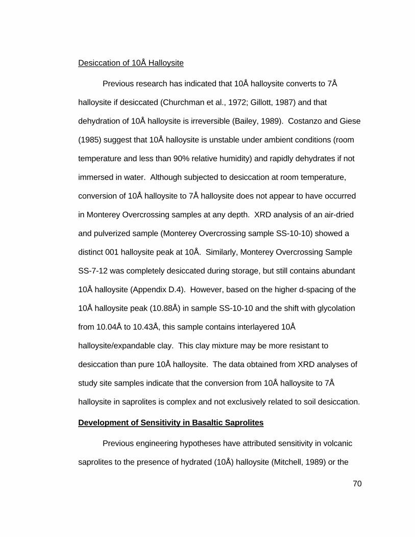
70
Desiccation of 10Å Halloysite
Previous research has indicated that 10Å halloysite converts to 7Å
halloysite if desiccated (Churchman et al., 1972; Gillott, 1987) and that
dehydration of 10Å halloysite is irreversible (Bailey, 1989). Costanzo and Giese
(1985) suggest that 10Å halloysite is unstable under ambient conditions (room
temperature and less than 90% relative humidity) and rapidly dehydrates if not
immersed in water. Although subjected to desiccation at room temperature,
conversion of 10Å halloysite to 7Å halloysite does not appear to have occurred
in Monterey Overcrossing samples at any depth. XRD analysis of an air-dried
and pulverized sample (Monterey Overcrossing sample SS-10-10) showed a
distinct 001 halloysite peak at 10Å. Similarly, Monterey Overcrossing Sample
SS-7-12 was completely desiccated during storage, but still contains abundant
10Å halloysite (Appendix D.4). However, based on the higher d-spacing of the
10Å halloysite peak (10.88Å) in sample SS-10-10 and the shift with glycolation
from 10.04Å to 10.43Å, this sample contains interlayered 10Å
halloysite/expandable clay. This clay mixture may be more resistant to
desiccation than pure 10Å halloysite. The data obtained from XRD analyses of
study site samples indicate that the conversion from 10Å halloysite to 7Å
halloysite in saprolites is complex and not exclusively related to soil desiccation.
Development of Sensitivity in Basaltic Saprolites
Previous engineering hypotheses have attributed sensitivity in volcanic
saprolites to the presence of hydrated (10Å) halloysite (Mitchell, 1989) or the

71
combined presence of halloysite and smectite (Cornforth Consulting Inc., 1991).
This hypothesis contends that water-filled 10Å halloysite tubes crush when
compacted releasing the water into the soil and causing moist soil to become
wet and lose shear strength (Mitchell, 1989). Additionally, water released by the
halloysite is absorbed by smectite, further lowering the shear strength of the soil
(Cornforth Consulting Inc., 1991). However, even if both 7Å and 10Å halloysite
form tubes (Singh and Gilkes, 1992), the energy required to rupture these small
tubes would be excessive. Furthermore, the amount of stored water within the
interior of the tubes would be inadequate to produce the effects observed in
sensitive soils. The average outside diameter of a halloysite tube is 0.07μm, the
inner diameter is 0.03μm, and tubes may be several microns in length (Grim,
1962). The volume of an individual tube is 1.4 X 10⁻³ μm. Conversely, a 10μm
boxwork void can store 1000μm3 of water, or 710,000 times the amount of
water stored in a halloysite tube. Cummings (In Press) summarizes the source
of water in sensitive saprolites in the following manner:
“The crystallization of halloysite, smectite, and other clay minerals and development of bonding between particles at the same time primary minerals are dissolving and the porosity is evolving provides an opportunity for water to be trapped in the saprolite and bedded sediments. Mechanical working progressively disrupts the bonds and releases pore water.”
Based on XRD clay data and SEM photographs included in this paper,
sensitivity is not a function of the formation of any specific clay mineral or clay
mineral association, but the development of clay-bounded boxwork voids that
trap and isolate water in the saprolite structure. Sensitive saprolites form in

72
Figure 18. Expansion of 10Å halloysite peak, half of the 7Å halloysite peak, and the broad peak between 7Å and 10Å to 10.5Å with glycolation. This expansion indicates that the halloysite has interlayered with an expandable clay. (Sample Monterey SS-18-8, the blue trace is air-dried, the green trace is glycolated, and the red trace is heated).

73
flow rocks, interflow breccias, tuffs, and well crystalline intrusive rock (diabase)
and are not related to the formation of clay minerals in weathered volcanic
glass.
Both 7Å and 10Å halloysite are stable in environments that form saprolite
boxworks. XRD data obtained from Monterey Avenue Overcrossing samples in
Borehole BH-18 indicate that clay mineralogy doesn’t vary significantly within a
saprolite between sensitive and non-sensitive soils, and 10Å halloysite is not
ubiquitous to sensitive soils. This observation supports the conclusion that soil
microstructure, and not clay mineralogy, is the controlling factor in the
development of sensitive soils.
Sensitivity in volcanic soils is found only in saprolites and is not observed
in residual soils where physical movement, desiccation, and pedogenic
processes have destroyed the original soil texture. Saprolites form
isovolumetrically, while the formation of residual soil is not isovolumetric and
involves the collapse the saprolite (boxwork) structure (Pavich, 1996). Causes
for in situ mineralogic and morphologic changes that destroy sensitivity include
the following:
• Soil creep on slopes. • Pedogenic processes within the A and B soil horizons. • Pedoturbation (soil mixing) by roots and burrowing animals. • Shrinking and swelling of expandable clays (smectite) in the vadose
zone with seasonal wetting and desiccation.

74
Each of the above processes works incrementally to break down the
saprolite boxwork structure, destroying the clay bounded voids and releasing
trapped water. Once the boxwork texture is destroyed, it cannot be recreated.
Occurrence of Sensitive Saprolites in Other Volcanic Rocks
Sensitive basalt saprolites are found in the study sites and at The Trask
River Dam Raise project site. Laboratory testing of Trask River Dam Raise
project soils identified properties similar to those found in study site samples.
Halloysite was encountered in all samples tested for this project, but the clay
mineralogy varied in each sample.
Sensitive saprolites do not form exclusively on basalt. Case history
information (Appendix A) identifies sensitive saprolites forming on flows and
tuffs composed of andesite (Toutle River SRS and Spirit Lake Memorial
Highway) and dacite (Toutle River SRS and Hills Creek Dam). Clay mineralogy
studies conducted for the Toutle River SRS identified variable clay mineralogy
including 7Å and 10Å halloysite, smectite, kaolinite, vermiculite, and expandable
mixed layer clay (Cummings, In Press). These clays were detected in sensitive
flow rock, breccia (debris flow), and volcaniclastic saprolites. Only a minor
amount of halloysite is present in portions of one sensitive unit (Hatchet
Mountain volcanics) (Cummings, In Press). X-ray diffraction analyses
conducted for the construction of Hills Creek Dam identified similar variation in
clay mineralogy in sensitive weathered terrace gravel, although halloysite was
present in each sample tested (U.S. Army Crops of Engineers Portland

75
Engineer District, 1966). Although the clay mineralogy was not consistent in
sensitive saprolites tested for these projects, similar construction difficulties
were experienced at each site.
Based on study site and case history data, sensitive soils should be
suspected within any volcanic saprolite. The presence of sensitive saprolites
does not appear to be related to original igneous rock type or texture or any
specific clay mineral, but the isovolumetric leaching of silica and other elements
to form microscopic water-filled boxwork voids bounded by aluminum and iron-
based secondary minerals. Basically, the conditions that lead to boxwork
formation in volcanic saprolites are similar to those that favor the formation of
halloysite.
Identification of Sensitive Volcanic Saprolites
Based on engineering case history information and techniques
developed for this research, field, index, and laboratory tests can be conducted
to identify sensitive volcanic saprolites prior to construction.
Field Index Testing
Field index testing during the geotechnical investigation can alert the
designers to the presence of sensitive volcanic saprolites in the project area and
can identify the need for additional laboratory testing. Sensitive volcanic
saprolites can commonly be identified by crushing a clod of soil with strong
finger pressure (Figures 1 and 2) and observing if the soil becomes wet. If the
76
soil shows no discernable increase in moisture content after crushing, it is most
likely not sensitive.
Sensitive volcanic saprolites also feel cold to the touch. During test pit
excavations, stick your hand into the pile of soil in a backhoe bucket. If the soil
feels abnormally cold, then it is sensitive (with a high water content) and should
not be used for embankment material without further testing. This technique
was used successfully by Brent Black of Cornforth Consulting (personal
communication, April 2000) during the geotechnical exploration for the Trask
River Dam raise.
Prior to construction, build test embankment fills to assess potential
compaction difficulties. Make numerous passes with the type and size (weight)
of earth moving equipment to be used during construction.
Engineering Index Testing
Once field sensitivity testing has indicated the presence of sensitive soils,
additional index testing can be conducted to determine the engineering
properties of these soils and estimate their performance during construction.
The following index tests should be conducted on soils identified for foundation
and embankment materials:
Natural Water Content
Sensitive soils have high natural moisture contents and are usually
greater than 50% water, by weight. These soils may appear only moist in
exposures.

77
Unit Weight (Dry Density)
Due to the abundant void space in sensitive saprolites, they have low dry
densities. Samples of volcanic breccia saprolite form Monterey Avenue
Overcrossing have low dry unit weights of 5.7 to 6.4 kN/m3 (36 to 41 lbs/ft3). A
non-sensitive residual soil at the same site had a unit weight of 13.8 kN/m3 (88
lbs/ft3).
Atterberg Limits Test
Atterberg limits tests are extremely helpful in identifying sensitive
volcanic saprolites. Sensitive soils are generally high plasticity silts (MH) and
often have natural moisture contents equal to or greater than the liquid limit of
the soil. Atterberg limits change between moist, air-dried, and oven dried
samples. Both the liquid limit and the plastic index decrease with increased
drying.
Proctor (Moisture-Density) Tests
Conduct Proctor tests on all materials to be used for embankment fills to
identify sensitive soils. Since the maximum dry density and optimum moisture
content become higher and drier, respectively, with working, pulverize soils prior
to Proctor testing to obtain accurate maximum dry density and optimum water
content of soils under actual construction conditions (Cornforth Consulting Inc.,
1991). Conduct Proctor density tests on samples obtained from test fills to
more accurately identify compaction parameters prior to construction (Cornforth
Consulting Inc., 1991). Additionally, Harvard miniature compaction testing may

78
provide more accurate compaction parameters than can be obtained with
Proctor testing (T. Smith, personal communication, May 2002)
X-Ray Diffraction Analysis
If index test results for project area soils are similar to values typical for
sensitive soils, XRD analysis can be helpful identifying the presence of
halloysite and smectite. Even though halloysite crystals may not store
significant water, both 7Å and 10Å halloysite (along with smectite) are
commonly associated with sensitive saprolites based on XRD analyses
conducted for this research and other engineering projects. Additionally, the
presence of intermediate halloysite, which may increase the plasticity of the soil
(U.S. Army Crops of Engineers Portland Engineer District, 1966), should be
evaluated. This intermediate halloysite shows either intermediate degrees of
hydration (U.S. Army Crops of Engineers Portland Engineer District, 1966) or
interlayered 7Å and 10Å halloysite.
Mitigation of Sensitive Volcanic Saprolites
If sensitive volcanic saprolites have been identified by field and
laboratory testing, and these soils must be worked during construction, mitigate
against adverse effects by manipulating the soil as little as possible. Use light
compaction equipment, limiting scraper size to 20 tons (D. H. Cornforth,
personal communication, April 2000). Less manipulation and lighter
compaction will limit the crushing of water-filled saprolite boxworks and reduce
the amount of soil drying required.

79
During fill placement, don’t try to dry back the soil too much with disking
or spreading. Increased manipulation will cause the soil to release more water
and become wetter. Place soil only during dry weather and grade
embankments to facilitate drainage. Limit lift thickness to enhance the soil’s
ability to dry.

80
CONCLUSIONS
Halloysite is an abundant clay mineral in sensitive basaltic and andesitic
saprolites in northwestern Oregon and southwestern Washington. These soils
release water and lose shear strength when compressed. 7Å halloysite was
detected in all sensitive soils analyzed. 10Å halloysite was abundant in only a
few of the sensitive samples analyzed, and was absent or present in trace
amounts in most samples. Both 7Å and 10Å halloysite appear to be stable in
the soil environment that forms sensitive saprolites and 10Å halloysite was
stable after desiccation at room temperature.
The significant amount of water released during compression of sensitive
soils is stored in boxwork voids, and not inside individual halloysite tubes or
spheres as has been previously suggested. These voids form by selective
crystal dissolution and precipitation along crystal perimeters and cleavage
planes. Both the small size and the amount of energy required breaking
individual halloysite crystals make them unlikely sources of stored water. Clay-
bounded boxwork voids, identified during SEM analysis, seem the most viable
source of adequate water to cause soil sensitivity. Thus, soil microstructure, hot
halloysite, is critical in the formation of sensitive soils.
Soils lacking relict texture (residual soils) are not sensitive. The loss of
sensitivity in surficial residual soils is due to a breakdown and collapse of the
boxwork voids within the saprolite. This collapse is caused by near surface soil

81
creep, shrinking and swelling of expandable clays (smectite) with seasonal
wetting and desiccation, and pedoturbation by roots and burrowing animals.
Clay mineral zonation was observed in borehole samples obtained on
Mt. Scott in southeast Portland (Monterey Overcrossing). 10Å halloysite was
most abundant toward the base of the saprolite (near the bedrock contact). 7Å
halloysite was most abundant toward the middle to upper portions of the
saprolite, and kaolinite was most abundant in the overlying, featureless residual
soil. Clay zonation was not significantly influenced by original rock type (flow
rock vs. breccia) in the basalts. Although smectite was more abundant near the
rock interface, no clear zonation was identified for smectite in these samples.
Selected samples from five other sites in northwestern Oregon confirmed this
zonation. Testing for allophane and imogolite confirmed the lack of amorphous
clay in these samples.
Interlayered halloysite/expandable clay which expands with glycolation
was identified in almost all saprolite samples analyzed, but not in the residual
soil samples. The disappearance of clay interlayering may be related to
collapse of the saprolite structure and/or the chemical conditions (including
hydration) present near the surface in the residual soil.
In addition to clay zonation, one site in the Eola Hills of West Salem
(West Salem Site 1) showed variation in the abundance of low cristobalite with
depth caused by silica dissolution and reprecipitation lower in the soil profile.

82
Maximum concentrations of well-crystalline low cristobalite occurred between
4.6 m and 8.1 m (15.0 and 26.5 ft).
Construction problems related to sensitive volcanic saprolites have been
documented in northwestern Oregon and southwestern Washington since the
1940’s and include Mud Mountain Dam, Hills Creek Dam, the Toutle River
Sediment Retention Structure, the Trask River Dam raise, and the Spirit Lake
Highway. Difficulties experienced during the construction of these structures
include excessive rutting during stripping and placing of embankment materials,
soils that are wet of optimum, and difficulty in achieving compaction.
Laboratory and field testing are invaluable tools in identifying sensitive
saprolites during the geotechnical investigation phase of design. These tests
include natural water content, dry unit weight, Atterberg limits, X-ray diffraction,
and field sensitivity measurements. Sensitive saprolites are generally high
plasticity silts (MH) that have anomalously high natural water contents (>50%),
low dry unit weight (5.7 to 6.4 kN/m3), Atterberg limits that decrease with drying,
generally contain halloysite but little or no kaolinite, and possess the ability to
release water and become wet when compressed under strong finger pressure.
Proctor density test maximum densities and optimum water contents vary with
the amount of soil working. Residual soils, however, are generally high
plasticity clays (CH), have lower natural water contents (20 to 40%), and have
higher dry unit weights (14 kN/m3)

83
Methods to mitigate the impact of sensitive saprolites include
manipulating the soils as little as possible with light weight equipment, placing
thin embankment lifts to allow the soil to dry, and grading fills to enhance
drainage.

84
FUTURE WORK
Since microstructure is the controlling mechanism in the formation of
sensitive volcanic saprolites, additional SEM analysis should be conducted to
investigate the following:
• Determine the microstructure of residual soils to confirm that boxwork voids have been destroyed or filled.
• Evaluate the microstructure of more silicic volcanic saprolites including andesites through rhyolites to see if sensitivity is related to boxwork structures in these rocks.
• Compare the microstructure of sensitive ash deposits that contain allophane and imogolite to see if boxworks are present or if water is stored within these clay minerals. Additional investigation is necessary to evaluate the relationship between
7Å and 10Å halloysite in a soil environment. The mechanism that causes 10Å
halloysite to lose its water layer and convert to 7Å halloysite is undetermined.
Furthermore, the role (if any) of interlayered expandable clay in this process
should be investigated.

85
LITERATURE CITED
Anonymous, 1941a, Dam building under canvas: Engineering News-Record, v. August 28, 1941, p. 42-44.
Anonymous, 1941b, Huge tent to protect Mud Mountain Dam core: Engineering News-Record, v. March 27, 1941, p. 36.
Anonymous, 1941c, Mud Mountain Dam redesigned as a rockfill with earth core: Engineering News-Record, v. March 13, 1941, p. 30-32.
Bailey, S. W., 1989, Halloysite--A critical assessment, Proceedings of the 9th International Clay Conference, Strasbourg, Germany, 89-98 pp.
Beeson, M. H., and Moran, M. R., 1979, Columbia River Basalt Group stratigraphy in western Oregon: Oregon Geology, v. 41, no. 1, p. 11-14.
Bela, J. L., 1979, Geologic hazards of eastern Benton County, Oregon: Oregon Department of Geology and Mineral Industries Bulletin 98, 122 pp.
Boyce, G. M., and Abramson, L. W., 1991a, Plate load and pressuremeter testing in saprolite, ASCE Special Publication 27 Geotechnical Engineering Congress, American Society of Civil Engineers 1, 52-63 pp.
Boyce, G. M., and Abramson, L. W., 1991b, Where does rock begin for three highway projects, in Kane, W. F., and Amadei, B., eds., Detection of and Construction at the Soil/Rock Interface, American Society of Civil Engineers Geotechnical Special Publication No. 28, 57-72 pp.
Chen, P.-Y., 1977, Table of key lines in X-ray powder diffraction patterns of minerals in clays and associated rocks: State of Indiana Department of Natural Resources Geologic Survey Occasional Paper 21, 67 pp.
Churchman, G. J., Aldridge, L. P., and Carr, R. M., 1972, The relationship between the hydrated and dehydrated states of halloysite: Clays and Clay Minerals, v. 20, p. 241-246.
Conrey, R. M., Uto, K., Uchium, S., Beeson, M. H., Madin, I. P., Tolan, T. L., and Swanson, D. A., 1996, Potassium-Argon ages of Boring Lava, northwest Oregon and Southwest Washington: Isochron/West, no. 63, p. 3-9.
Corcoran, R. E., and Libbey, F. W., 1956, Ferruginous bauxite deposits in the Salem Hills, Marion County, Oregon: Oregon Department of Geology and Mineral Industries Bulletin No. 46, 53 pp.

86
Cornforth Consulting Inc., April 1991, Clay mineralogy claims analysis, Sediment Retention Structure, Contract DACW57-88-C-0018: Report to U. S. Army Corps of Engineers, Portland District, Portland, Oregon.
Cornforth Consultants Inc., December 1993, Barney Reservoir expansion clay borrow source field explorations and laboratory testing: Report to City of Hillsboro Utilities Commission, Hillsboro, Oregon.
Cornforth Consultants Inc., March 1995, Barney Reservoir expansion rock quarry and foundation investigations and laboratory testing: Report to Barney Reservoir Joint Ownership Commission, Hillsboro, Oregon.
Costanzo, P. M., and Giese, R. F., Jr., 1985, Dehydration of synthetic hydrated kaolinites: A model for the dehydration of halloysite (10Å): Clays and Clay Minerals, v. 33, no. 5, p. 415-423.
Crenna, P. A., and Yeats, R. S., 1994, Late Cenozoic tectonics and paleogeography of the Salem metropolitan area, central Willamette Valley, Oregon: Oregon Geology, v. 56, no. 6, p. 129-136.
Cummings, M. L., In Press, Clay mineralogy and construction problems in volcanic soils near Mount St. Helens: Sediment Retention Structure, southwestern Washington, USA: International Clay Minerals Society 2001 Meeting, Argentina.
Cummings, M. L., and Fassio, J. M., 1990, Geochemistry and mineralogy of ferruginous bauxite developed from basalt flows in the Pacific Northwest, U.S.A.: International Association of Geochemistry and Cosmochemistry: Working Group on Geochemistry of Weathering, Diagenesis, and Sedimentary Processes: Aix-En-Provence, France: Chemical Geology, v. 84, p. 40-41.
Deere, D. U., and Thornburn, T. H., 1955, Soil mechanics properties of weathered volcanic rocks in Hawaii: Society of Economic Geologists, Abstracts for Annual Meeting, New Orleans, p. 771.
Delvaux, B., Herbillon, A. J., Vielvoye, L., and Mestdagh, M. M., 1990, Surface properties and clay mineralogy of hydrated halloysitic soil clays. II: Evidence for the presence of halloysite/smectite (H/SM) mixed-layer clays: Clay Minerals, v. 25, p. 141-160.
Delvaux, B., Tessier, D., Herbillon, A. J., Burtin, G., Jaunet, A.-M., and Vielvoye, L., 1992, Morphology, texture, and microstructure of halloysitic soil clays as related to weathering and exchangeable cations: Clays and Clay Minerals, v. 40, no. 4, p. 446-456.

87
Drees, L. R., Wilding, L. P., Smeck, N. E., and Senkayi, A. L., 1989, Silica in soils: Quartz and disordered silica polymorphs, in Dixon, J. B., and Weed, S. B., eds., Minerals in Soil Environments, Soil Science Society of America, 913-974 pp.
Eggleton, R. A., Foudoulis, C., and Varkevisser, D., 1987, Weathering of basalt: Changes in rock chemistry and mineralogy: Clays and Clay Minerals, v. 35, no. 3, p. 161-169.
Franco, F., and Ruiz Cruz, M. D., 2002, High-temperature x-ray diffraction, differential thermal analysis and thermogravimetry of the kaolinite-dimethylsulfoxide intercalation complex: Clays and Clay Minerals, v. 50, no. 1, p. 47-55.
Gabor, R., and Cummings, M. L., March 30, 1988, Summary of clay and bulk mineralogy, Toutle River Sediment Retention Structure: Report to Granite Construction Company, 45 pp.
Gabor, R., Cummings, M. L., and Trone, P. M., June 23, 1987, Clay and bulk mineralogy of the right-side of the Toutle River in the vicinity of the Mount St. Helens Sediment Retention Structure: Report to Granite Construction Company, 47 pp.
Gabor, R. K., 1981, The influence of halloysite content of the shear strength of kaolinite [M.S. Thesis]: Portland State University, Portland, Oregon, 89 pp.
Gillott, J. E., 1987, Clay in Engineering Geology, Elsevier.
Glasmann, J. R., 1982, Alterationof andesite in wet, unstable soils of Oregon's Western Cascades: Clays and Clay Minerals, v. 30, no. 4, p. 253-263.
Glasmann, J. R., and Simonson, G. H., 1985, Alteration of basalt in soils in Western Oregon: Soil Science Society of America Journal, v. 49, p. 262-275.
Golder Associates (a), 1987, Geotechnical Report, Segment 2, Station 1602+00 to 1770+00, Spirit Lake Memorial Highway, State Route 504, Cowlitz County, Washington: Report to Washington State Department of Transportation.
Golder Associates (b), 1987, Geotechnical Report, Segment 3, Station 1770+00 to 1900+00, Spirit Lake Memorial Highway, State Route 504, Cowlitz County, Washington: Report to Report to Washington State Department of Transportation.

88
Golder Associates (c), 1988, Geotechnical Report, Segment 1, Station 1439+00 to 1576+35, Spirit Lake Memorial Highway, State Route 504, Cowlitz County, Washington: Report to Report to Washington State Department of Transportation.
Golder Associates (d), 1988, Geotechnical Report, Segment 4, Station 1900+00 to 2050+00, Spirit Lake Memorial Highway, State Route 504, Cowlitz County, Washington: Report to Report to Washington State Department of Transportation.
Golder Associates (e), 1988, Geotechnical Report, Segment 5, Station 2050+00 to 2210+00, Spirit Lake Memorial Highway, State Route 504, Cowlitz County, Washington: Report to Report to Washington State Department of Transportation.
Golder Associates (f), 1988, Geotechnical Report, Segment 6, Station 2209+50 to 2317+95, Spirit Lake Memorial Highway, State Route 504, Cowlitz County, Washington: Report to Report to Washington State Department of Transportation.
Grim, R. E., 1962, Applied Clay Mineralogy, McGraw-Hill Book Company, Inc., 422 pp.
Hammond, C. M., and Vessely, D. A., 1998, Engineering geology of the Trask River Dam raise, Oregon Coast Range, in Burns, S., ed., Environmental, Groundwater and Engineering Geology: Applications from Oregon, Star Publishing Company, p. 161-168.
Hammond, P. E., 1980, Reconnaissance geologic map and cross sections of southern Washington Cascade Range, latitude 45° 30'-47° 15' N., longitude 120° 45' - 122° 22.5' W: Publications of the Department of Earth Sciences, Portland State University, Portland, Oregon, 31 pp.
Hammond, P. E., Manning Geyer, K., and Anderson, J. L., 1982, Preliminary geologic map and cross sections of the upper Clackamas and North Santiam Rivers area, northern Oregon Cascade Range: Portland State University Press, Portland Oregon
Hampton, E. R., 1972, Geology and ground water of the Molalla-Salem slope area, northern Willamette Valley, Oregon: U. S. Geological Survey Water-Supply Paper 1997, 83 pp.
Hook, J. W., 1976, Ferruginous bauxites of the Pacific Northwest: Oregon Department of Geology and Mineral Industries Open-File Report O-76-3, 26 pp.

89
Istok, J., 1981, Clay mineralogy in relation to landscape instability in the Coast Range of Oregon [M.S. Thesis]: Oregon State University, Corvallis Oregon, 79 pp.
Jackson, M. L., and Abdel-Kader, F. H., 1978, Kaolinite intercalation procedure for all sizes and types with X-ray diffraction spacing distinctive from other phyllosilicates: Clays and Clay Minerals, v. 26, no. 7, p. 81-87.
Jeong, G. Y., 1999, Formation of vermicular kaolinite from halloysite aggregates in the weathering of plagioclase: Clays and Clay Minerals, v. 46, no. 3, p. 270-279.
Jeong, G. Y., and Kim, S. J., 1993, Boxwork fabric of halloysite-rich kaolin formed by weathering of anorthosite in the Sancheong area, Korea: Clay and Clay Minerals, v. 41, no. 1, p. 56-65.
Jones, J. B., and Segnit, E. R., 1972, Genesis of crystobalite and tridymite at low temperatures: Journal of the Geological Society of Australia, v. 18, no. 4, p. 419-422.
Kirkman, J. H., 1981, Morphology and structure of halloysite in New Zealand tephras: Clays and Clay Minerals, v. 29, no. 1, p. 1-9.
Korosec, M. A., 1987, Geologic map of the Hood River quadrangle, Washington and Oregon: Washington Division of Geology and Earth Resources Open File Report 87-6, 42 pp.
Livingston, V. E., 1966, Geology and mineral resources of the Kelso-Cathlamet area, Cowlitz and Wahkiakum Counties, Washington: Washington Division of Mines and Geology Bulletin No. 54, 110 pp.
Madin, I. P., 1994, Geologic map of the Damascus quadrangle, Clackamas and Multnomah Counties, Oregon: Oregon Department of Geology and Mineral Industries Geological Map Series GMS-60, scale: 1:24,000.
McCarthy, D. F., 1998, Essentials of Soil Mechanics and Foundation, Basic Geotechnics, Fifth Edition: Prentice Hall, 730 pp.
Mitchell, J. K., 1989, Failed expectations, The 1989 Woodward Lecture, Silver Anniversary Symposium Professional Development Program Woodward-Clyde Consultants, 44 pp.
Mitchell, J. K., 1993, Fundamentals of Soil Behavior, John Wiley and Sons, Inc., 437 pp.

90
Moore, D. M., and Reynolds, R. C., Jr., 1997, X-Ray Diffraction and the Identification and Analysis of Clay Minerals, Second Edition, Oxford University Press, Inc., 378 pp.
Pavich, M. J., 1996, Appalachian piedmont regolith: Relations of saprolite and residual soils to rock-type, in Matheson, G., ed., Design with Residual Materials, American Society of Civil Engineers Geotechnical Special Publication No. 63, p. 1-11.
Peck, D. L., Griggs, A. B., Schlicker, H. G., Wells, F., G., and Dole, H. M., 1964, Geology of the central and northern parts of the Western Cascade Range in Oregon: U. S. Geological Survey Professional Paper 449, 56 pp.
Phillips, W. M., 1987a, Geologic map of the Mount St. Helens Quadrangle, Washington and Oregon: Washington Division of Geology and Earth Resources Open File Report 87-4, 48 pp.
Phillips, W. M., 1987b, Geologic map of the Vancouver quadrangle, Washington and Oregon: Washington Division of Geology and Earth Resources Open File Report 87 -10, 32 pp.
Pope, R. J., and Anderson, M. W., 1960, Strength properties of clays derived from volcanic rocks, Research Conference on Shear Strength of Cohesive Soils, Boulder, Colorado, American Society of Civil Engineers, 315-340 pp.
Prudencio, M. I., Sequeira Braga, M. A., and Cabral, J. M. P., 1990, Basalts weathering in the Lisbon Volcanic Complex (Portugal): Extended Abstract, 2nd International Symposium on the Geochemistry of the Earth's Surface and of Mineral Formation, Aix-en-Provence, France, July 2-8, 1990, Chemical Geology, v. 84, p. 119-121.
Righi, D., Terribile, F., and Petit, S., 1999, Pedogenic formation of kaolinite-smectite mixed layers in a soil toposequence developed from basaltic parent material in Sardinia (Italy): Clays and Clay Minerals, v. 47, no. 4, p. 505-514.
Romero, R., Robert, M., Elsass, F., and Garcia, C., 1992, Abundance of halloysite neoformation in soils developed from crystalline rocks. Contribution of transmission electron mocroscipy: Clay Minerals, v. 27, p. 35-46.
Schlicker, H. G., and Deacon, R. J., 1967, Engineering geology of the Tualatin Valley region, Oregon: Oregon Department of Geology and Mineral Industries Bulletin 60, 103 pp.

91
Schlicker, H. G., and Finlayson, C. T., 1979, Geology and geologic hazards of northwestern Clackamas County, Oregon: Oregon Department of Geology and Mineral Industries Bulletin 99, 79 pp.
Schwarz, T., 1997, Lateritic bauxite in central Germany and implications for Miocene palaeoclimate: Palaeogeography, Palaeoclimatology, Palaeoecology, v. 129, p. 37-50.
Schwertmann, U., and Taylor, R. M., 1989, Iron Oxides, in Dixon, J. B., and Weed, S. B., eds., Minerals in Soil Environments, Soil Science Socitey of America Book Series, no. 1, Soil Science Society of America, 379-438 pp.
Sherard, J. L., Woodward, R. J., Gizienski, S., and Clevenger, W., 1963, Earth and Earth-Rock Dams, John Wiley and Sons, Inc., 725 pp.
Sherrod, D. R., and Smith, J. G., 1989, Preliminary map of upper Eocene to Holocene volcanic and related rocks of the Cascade Range, Oregon: U. S. Geological Survey Open-File Report 89-14, 20 pp.
Singh, B., 1996, Why does halloysite roll?--A new model: Clays and Clay Minerals, v. 44, no. 2, p. 191-196.
Singh, B., and Gilkes, R. J., 1992, An electron optical investigation of the alteration of kaolinite to halloysite: Clays and Clay Minerals, v. 40, no. 2, p. 212-229.
Terzaghi, K., 1958, The design and performance of the Sasumua Dam: Proceedings, Institution of Civil Engineers, London, no. 6252, p. 369-394.
Thayer, T. P., 1939, Geology of the Salem Hills and the North Santiam River Basin, Oregon: Oregon Department of Geology and Mineral Industries Bulletin No. 15, 40 pp.
Theng, B. K. G., Russell, M., Churchman, G. J., and Parfitt, R. L., 1982, Surface properties of allophane, halloysite, and imogolite: Clays and Clay Minerals, v. 30, no. 2, p. 143-149.
Thrall, F. G., 1981, Geotechnical significance of poorly crystalline soils derived from volcanic ash [Ph.D. Dissertation]: Oregon State University, Corvallis, Oregon, 445 pp.
Tolan, T. L., and Beeson, M. H., 1999, Geologic map of the Scotts Mills, Silverton, and Stayton Northeast 7.5 minute quadrangles, Oregon: U.S. geological Survey Open-file Report 99-141, 23 pp.

92
Tolan, T. L., Beeson, M. H., and DuRoss, C. B., 2000, Geologic map and database of the Salem East and Turner 7.5 minute quadrangles, Marion County, Oregon: A digital database: U.S. Geological Survey Open-File Report 00-351, 13 pp.
Trimble, D. E., 1963, Geology of Portland, Oregon and adjacent areas: U. S. Geological Survey Bulletin 1119, 119 pp.
U.S. Army Corps of Engineers Portland Engineer District, October, 1954, Hills Creek Dam site preliminary geology and foundations: Report to U.S. Army Corps of Engineers.
U.S. Army Corps of Engineers Portland Engineer District, June 1959, Embankment Design Review: Hills Creek Reservoir, Middle Fork Willamette River, Oregon: Report to U.S. Army Corps of Engineers.
U.S. Army Crops of Engineers Portland Engineer District, June 1966, Hills Creek Reservoir, Middle Fork Willamette River, Oregon: Design Memorandum No. 4, Embankment Design, Addendum B, Completion Report: Report to U.S. Army Corps of Engineers.
Velbel, M. A., 1989, Weathering of hornblende to ferruginous products by a dissolution-repreciptiation mechanism: Petrography and stoichiometry: Clays and Clay Minerals, v. 37, no. 6, p. 515-524.
Velbel, M. A., 1990, Mechanisms of saprolitization, isovolumetric weathering, and pseudomorphous replacement during rock weathering--A review: Extended Abstract, 2nd International Symposium on the Geochemistry of the Earth's Surface and of Mineral Formation, Aix-en-Provence, France, July 2-8, 1990, Chemical Geology, v. 84, p. 17-18.
Wada, K., 1989, Allophane and imogolite, in Dixon, J. B., and Weed, S. B., eds., Minerals in Soil Environments, Soil Science Society of America, p. 1051-1087.
Wada, K., and Kakuto, Y., 1985, A spot test with toluidine blue for allophane and imogolite: Soil Science Society of America Journal, v. 49, p. 276-278.
Wada, S. I., and Mizota, C., 1982, Iron-rich halloysite(10A) with crumpled lamellar morphology from Hokkaido, Japan: Clays and Clay Minerals, v. 30, no. 4, p. 315-317.
Walker, G. W., and Duncan, R. A., 1989, Geologic map of the Salem 1° by 2° quadrangle, western Oregon: U. S. Geological Survey Miscellaneous Investigations Series Map I-1893

93
Walker, G. W., and MacLeod, N. S., 1991, Geologic Map of Oregon: U.S. Geological Society
Walsh, T. J., Korosec, M. A., Phillips, W. M., Logan, R. L., and Schasse, H. W., 1987, Geologic map of Washington--southwest quadrant: Washington Division of Geology and Earth Resources Geologic Map GM-34, 28 pp.
Wang, W. M., Yeh, H. W., Chen, P. Y., and Wang, M. K., 1998, Kaolin mineralogy of clays in paleosol profiles on the late-Miocene sediments in Penghu Islands (Pescadores), Taiwan: Clays and Clay Minerals, v. 46, no. 1, p. 1-9.
Warkentin, B. P., April 1988, Soil conditions at the Mount St. Helens Sediment Retention Structure, Draft Report #1: Report to Cornforth Consultants Inc., 7 pp.
Watanabe, T., Sawada, Y., Russell, J. D., McHardy, W. J., and Wilson, M. J., 1992, The conversion of montmorillonite to interstratified halloysite-smectite by weathering in the Omi acid clay deposit, Japan: Clay Minerals, v. 27, p. 159-173.
Wells, R. E., Niem, A. R., MacLeod, N. S., Snavely, P. D., Jr., and Niem, W. A., 1983, Preliminary geologic map of the west half of the Vancouver (Wa.-Ore.) 1° x 2° quadrangle, Oregon: U. S. Geological Survey Open-File Report 83-591
Wells, R. E., Snavely, P. D., Jr., MacLeod, N. S., Kelly, M. M., and Parker, M. J., 1994, Geologic map of the Tillamook Highlands, northwest Oregon Coast Range (Tillamook, Nehalem, Enright, Timber, Fairdale, and Blaine 15 minute quadrangles: U. S. Geological Survey Open File Report 94-21, 24 pp.
Wesley, L. D., 1974, Tjipanundjang Dam in West Java, Indonesia: Journal of the Geotechnical Engineering Division, American Society of Civil Engineers, v. 100, no. GT5, p. 503-523.
Wilson, D. C., 1997, Post-middle Miocene geologic history of the Tualatin Basin, Oregon with hydrogeologic implications [PhD Dissertation]: Portland State University, Portland, Oregon, 321 pp.
Yeats, R. S., Graven, E. P., Werner, K. S., Goldfinger, C., and Popowski, T. A., 1996, Tectonics of the Willamette Valley, Oregon, Assessing earthquake hazards and reducing risk in the Pacific Northwest, U.S. Geological Survey Professional Paper 1560, 183-222 pp.
94
APPENDIX A OREGON AND WASHINGTON
CASE HISTORIES OF CONSTRUCTION IN SENSITIVE VOLCANIC SAPROLITES

95
Appendix A.1 Mud Mountain Dam, Pierce County, Washington
One of the earliest records of construction problems in the Pacific
Northwest related to excessively wet volcanic soils was observed in 1941 at the
Mud Mountain Dam, located in Pierce County 76 km (47 miles) southeast of
Seattle, Washington. The design of the earth and rock-fill embankment had to
be modified to include more rock when embankment soils could not be dried
back to optimum moisture content for compaction (Anonymous, 1941c). The
presence of a small amount of colloidal clay was blamed for preventing the soil
from adequately drying or draining (Anonymous, 1941c). To allow for
construction during wet weather, a huge canvas tent was suspended over the
earth-fill core to prevent rainwater infiltration (Anonymous, 1941b). Additionally,
construction of the impervious core was completed using oil-burning kilns to
reduce the moisture content of embankment soils by 2.5% to 5% (Anonymous,
1941a).

96
Appendix A.2 Toutle River Sediment Retention Structure, Cowlitz County, Washington
The Toutle River Sediment Retention Structure (SRS) was constructed
by the US Corps of Engineers (COE) to impound volcaniclastic debris deposited
during the 1980 eruption of Mount St. Helens. The Toutle River valley, which is
located in the Cascade Range of southwest Washington, was partially infilled
with debris flows and lahars during the 1980 eruption of Mount St. Helens. The
location of the SRS was selected to prevent upstream eruptive material from
washing downstream during flooding and impacting shipping on the Columbia
River.
Shortly after dam construction began, Granite Construction claimed a
change of conditions and initiated litigation (Cornforth Consulting Inc., 1991;
Cummings, In Press). Problematic soil and rock was encountered in several
geologic units, including Tertiary-age decomposed andesitic and basaltic flow
rock and flow top breccia (Hatchet Mountain volcanics), Pleistocene-age debris
flow material (saprolitic diamicton), layered clay-rich deposits (“the slimes”), and
pre-eruption river alluvium. Although these materials appeared stable in situ,
once disturbed they became excessively wet and slippery, extremely difficult to
compact, and unstable in the dam core and waste piles.
Heavy equipment used to place and compact impervious core material
routinely created deep ruts and bogged-down. The decomposed flow-top
breccia of the Hachet Mountian volcanics and the debris flow material were
selected for the impervious core (Cornforth Consulting Inc., 1991). According to
97
Granite, “The Impervious Material was very deceiving. When viewed in a cut
slope, it appeared to be gravelly in nature, fairly dry and stiff, very stable and
almost at optimum water content. As it was disturbed by construction
equipment, the water inside the structure of the clay and relic rock clasts was
freed, and material that had appeared to have good bearing capacity was
reduced to a wet, sticky mass that scrapers could not operate efficiently
upon…The more manipulation by construction equipment, the more excess
water and instability was realized” (Cornforth Consulting Inc., 1991). The
layered clay-rich deposits and pre-eruption river alluvium, designated as waste
material, were difficult to strip due to rutting and flowed when placed in spoils
piles (M. L. Cummings, personal communication, April 2000).
Granite Construction claimed that the presence of halloysite and smectite
in volcaniclastic soils created water sensitive soils that were responsible for the
construction problems at the SRS. They claimed that halloysite held water “in
the soil grain” and resisted drying. During stripping and placing of borrow
materials, the halloysite “grains” broke apart, releasing water into the soil pores.
This additional water has to be removed before adequate compaction can be
attained. The optimum moisture content of the in situ borrow soil was ±4%
lower than the optimum moisture content of the fill soils. Extensive disking,
used by Granite to aerate and dry the fill soils, exacerbated the problem by
increasing the maximum dry density of the soil, decreasing its optimum moisture
content, and further lowering its shear strength.

98
To support Granite’s claim, clay mineral analyses were conducted on
sensitive soils. Gabor and Cummings (1988) identified smectite and 7Å
halloysite (with minor kaolinite and vermiculite) in the Hachet Mountain
volcanics flow top breccia. Total clay content ranged between 31% and 100%.
The debris flow material contained 37% to 64% clay minerals including
predominantly 7Å halloysite, with generally lesser amounts of 10Å halloysite,
smectite, and vermiculite. Kaolinite was detected near the upper contact of the
debris flow saprolite at the approximate location of a paleosurface (Cummings,
In Press). Layered clay-rich deposits contained 18% to 43% clay minerals,
including 7Å halloysite, 10Å halloysite, chlorite, smectite, vermiculite, kaolinite,
and mixed-layer clays. Significant 10Å halloysite was found in three out of the
seven samples. The matrix of pre-eruption alluvial deposits contained 18% to
46% total clay minerals, predominantly 7Å halloysite, chlorite, smectite,
vermiculite, and lesser kaolinite (one sample) and mixed-layer clays. 10Å
halloysite is present in two of the six samples. Gabor and Cummings (1988)
and Cummings (In Press) concluded that soil sensitivity was caused when
microtextures in saprolites were crushed during handling and water trapped
within micropore spaces was released. Cummings (In Press) observes that
volcaniclastic deposits have become bonded by precipitated clay minerals and
silica as weathering progresses within local deposits from the 1980 eruption.
Due to this bonding, micropores form isovolumetrically in the saprolite during

99
leaching (Cummings, In Press). 10Å halloysite was not ubiquitous to the
problem soils.
Swelling in smectite-rich soils was dismissed by Warkentin (1988) as a
cause of the rutting problems experienced during SRS construction. He
discounted rapid swelling and loss of shear strength in these soils due to their
low hydraulic conductivity and contended that a 0.9 m (3-foot) thick layer of soil
would require months to reach an expanded condition. He did acknowledge
that decomposed volcanic rock can be crushed by heavy equipment,
“…releasing clay minerals, amorphous minerals, halloysite, or smectite, and the
water associated with them” and creating a “…smeary clay with excess water.”
Gabor and Cummings (1988), however, hypothesized that water freed from
crushed micropores was absorbed by adjacent smectite crystallites. Based on
the ubiquitous presence of water within the saprolitic soil structure, low hydraulic
conductivity would not inhibit swelling of smectite minerals.
In addition to swelling from pore-derived water, slaking within smectite-
rich flow rock and flow breccia caused by repeated wetting and drying
transformed apparently hard rock into soil when exposed to the air. Such
degradation occurred along haul roads constructed out of hard blocks of flow
breccia (D. H. Cornforth, personal communication, April 2000).

100
Appendix A.3 Trask River Dam Raise, Tillamook County, Oregon
The Trask River Dam impounds Barney Reservoir in the Coast Range of
northwestern Oregon (Figure 3). The dam site is located on a deeply
weathered uplifted erosional surface that forms the core of the northern Oregon
Coast Range. The dam area is underlain by Eocene-age Siletz River Volcanics
composed of submarine basalt flows, pillow lavas, flow breccias, and siltstone
and shale interbeds (Wells et al., 1983; Wells et al., 1994). Bedrock is mantled
by an average of 50 feet of saprolite soil (Hammond and Vessely, 1998).
In 1995, construction for the enlargement of the dam was initiated and
anticipated sensitive soils were encountered in selected areas (C. M.
Hammond, personal communication, May 2000). Cornforth Consultants, Inc.
(1993) identified these soils as sandy silts and silty sands with lesser clay-sized
material. The natural water content of the soils encountered during the
geotechnical investigation for the dam raise averaged 60%, but ranged up to
100%. Cornforth Consultants, Inc. (1995) found that natural water contents in
the foundation area of the expanded dam averaged 68%, but ranged up to 89%.
In situ water contents for the existing embankment fill ranged between 30% and
43%. Atterberg limits testing on foundation soils identified high plasticity silts
with relatively high liquid limits (46% to 80%) and low plastic indexes (<27%).
The natural moisture content of the majority of the foundation soils exceeded
their liquid limits.

101
Borrow areas were selected to attempt to avoid sensitive saprolites.
Atterberg limits testing on borrow soils identified high plasticity silts with
relatively high liquid limits (50% to 75 %) and low plastic indexes (<20%). In the
borrow areas, the liquid limit did not exceed the natural water content of the soil.
Atterberg limits varied for moist and air-dried samples. Even after rehydrating
prior to testing, the air-dried samples showed lower liquid limits and plastic
indexes than samples that had never been dried, indicating an irreversible
change had occurred during drying.
Compaction testing (standard Proctor—ASTM D698) was conducted on
test fills composed of borrow soils (Cornforth Consultants Inc., 1995). Maximum
dry densities ranged from 11.3 to 13.2 kN/m3 (72 to 84 lb/ft3), with optimum
moisture contents of 32% to 42%. Although these values showed a slight
seasonal variation between July and October, in every case the optimum
moisture content ranged from 6% to 15% less than the natural moisture content.
The problematic soils had relict rock texture (saprolite) and were “…very
sensitive to handling and moisture due to the presence of halloysite and
montmorillonite clay minerals” (Hammond and Vessely, 1998). “Upon handling,
halloysites frequently break down and release water trapped in the soil grain.
Smectites, and to a lesser degree vermiculites, readily accept free water and
may expand and soften when additional free water is available.” (Cornforth
Consultants Inc., 1995). This absorption of water by expandable clay minerals

102
supposedly changes the texture of the soil from granular to cohesive (Cornforth
Consultants Inc., 1995).
Clay analyses conducted on two borrow area samples with natural
moisture contents greater than 45% identified 66% hydrated (10Å) halloysite
(with an additional 34% possible 7Å halloysite) in one sample, and 42%
hydrated halloysite (with 53% smectite) in the second. These samples were
collected at depths of 1.5 to 2.0 m (5 to 6.5 feet). The four other borrow
samples tested had natural moisture contents 24% to 44% and contained
chloritized vermiculite, 7Å halloysite, and possibly mixed layered kaolinite and
halloysite.
Since the geotechnical engineering for the Trask River Dam raise was
conducted after the SRS change of conditions claim, sensitive soils were
anticipated and avoided, where possible. However, anticipation of adverse soil
conditions did not eliminate all construction problems. Construction equipment
still became bogged-down in wet weather limiting stripping and placing of
impervious core materials to the dry summer months (Hammond and Vessely,
1998). Lighter equipment was used to compact the fill in the dam core. The
weight of the scrappers was limited to 178 kN (20 tons), instead of 445 kN (50
tons) (D. H. Cornforth, personal communication, April 2000).

103
Appendix A.4 Hills Creek Dam, Lane County, Oregon
Hills Creek Dam was one of the first Oregon dams to experience
construction difficulties related to sensitive volcanic saprolites. The dam, which
was completed in 1961 by the Army Corps of Engineers, impounds the Middle
Fork of the Willamette River. It is located approximately 8 km (5 miles)
southeast of Oakridge in the Western Cascades of central western Oregon.
The dam site is underlain by massive lapilli tuff and hydrothermally altered,
highly fractured dacite of the Oligocene to lower Miocene-age Little Butte
Volcanics (U.S. Army Corps of Engineers Portland Engineer District, 1954;
Peck et al., 1964). The lapilli tuff bedrock has been deeply weathered and
fractured and joints are either open or partially infilled with secondary colloidal
clay (U.S. Army Corps of Engineers Portland Engineer District, 1954). Within
the river channel, the bedrock is overlain by “older” (Pliocene or Pleistocene)
valley fill consisting of highly weathered, gravel in a cemented matrix of silt and
clay (decomposed volcanic ash) (U.S. Army Corps of Engineers Portland
Engineer District, 1954). Colloidal clay coats sand and gravel clasts and fills
voids in the older valley fill. The upper 10 to 15 feet of the older valley fill had
been reworked by the river. More recent alluvium flood plain deposits of silty
sand, fresh valley boulder gravel mantle the older valley fill.
The impervious core of the dam was constructed of both reworked and in
situ older valley fill gravel deposits, but only the in situ gravel was difficult to

104
place and compact (U.S. Army Corps of Engineers Portland Engineer District,
1959). Although the valley fill gravel appeared near the optimum moisture
content when excavated from the borrow area, it appear wetter after spreading.
Core fill consisting of the sensitive in situ gravel rutted, became more plastic,
and caused 50-ton rollers to become stuck. The sensitive fill could not be
compacted properly even when spread and allowed to dry for 24 hours. The
COE attributed soil sensitivity to small pockets of highly plastic colloidal clay
mixing with lower plasticity fines during remolding and an increase in the
plasticity of halloysite-bearing soils as hydrated halloysite is altered to highly
plastic intermediate halloysite during drying.
An Atterberg limits test run on a sample from the impervious core
material showed a progressive reduction in the plastic limit and plasticity index
with air drying followed by oven drying. This trend is similar to that observed
within sensitive soils at the Trask River Dam.
Soft colloidal clay that filled voids and coats gravel and sand grains in the
in situ older alluvium is blamed for these construction problems even though
grain size analyses identified the older gravel deposits as well graded with 2%
to 4% silt and clay size material (U.S. Army Crops of Engineers Portland
Engineer District, 1966). Clay analyses conducted by Dr. Ralph Grim on the silt
and clay sized matrix material identified predominantly of 10Å, 7Å, and
intermediate forms of halloysite, with lesser smectite (U.S. Army Crops of
Engineers Portland Engineer District, 1966). Dr. Grim advanced the following

105
hypothesis regarding the unusual properties of soils that contain partially
hydrated halloysite:
“…2H2O [dehydrated] or 4H2O [hydrated] form [of halloysite] has very low plasticity. Its
[Atterberg] limits are very low and sometimes it appears to be substantially nonplastic.
In an intermediate state of hydration with a moisture content between the 2 and 4 H2O
form the mineral has very different properties – it may be and usually is quite plastic
and very difficult to compact. When the molecular layer is complete (4H2O) or when it
is absent (2 H2O), the silicate layers are held together rigidly. When the water layer is
partially present, the silicate layers are easily split apart and very different properties
develop” (U.S. Army Crops of Engineers Portland Engineer District, 1966).
To improve compaction within the sensitive older valley fill, each lift was
covered by a 0.76 m (2.5 foot) lift of “random” rock (U.S. Army Crops of
Engineers Portland Engineer District, 1966). This more permeable aggregate
created a layered fill that allowed the excessively wet sensitive alluvium to drain.
Additionally, the weight of the roller was reduced to 178 kN (20 tons) which
produced only 12 inch ruts. A D-9 tractor was required to pull the lighter roller
across the fill. Eventually, Dr. Arthur Casagrande recommended minimizing
rutting by reducing the lift thickness to 0.2 m (8 inches), compacting each lift
with two passes of the tractor treads after spreading, and sloping the core of the
dam to promote drainage (U.S. Army Crops of Engineers Portland Engineer
District, 1966). Following implementation of these modifications, construction of
the dam core was completed.

106
Appendix A.5 Spirit Lake Memorial Highway,
Cowlitz and Skamania Counties, Washington
Spirit Lake Memorial Highway (SR 504) is located in Cowlitz and
Skamania Counties in southwest Washington. Damage caused by debris
torrents along the Toutle River during the 1980 eruption of Mount St. Helens
required 32 km (20 miles) of the existing SR 504 to be rebuilt and an additional
40 km (25 miles) of road was built to reach the Coldwater Lake observation
area near the mountain (Golder Associates, 1988a). Construction of the new
road was completed in six segments.
The project area is located in the Washington Western Cascades and is
underlain by Tertiary-age volcanic rocks consisting of andesite and basalt flows,
agglomerates, and tuffs (including lahar deposits). These volcanic rocks have
subsequently been intruded and hydrothermally altered by andesite, basalt, and
gabbro dikes and sills. Bedrock is mantled by Pleistocene and Holocene ash
deposits, glacial drift, colluvium, and alluvium (Golder Associates, 1988a).
Performance of the construction materials, including embankment soil,
was assessed during the geotechnical investigation for Segment 3 of the new
road (Golder Associates, 1987b). The field test procedure consisted of placing
a 1.0 to 1.5 foot layer of soil in a loose condition and then measuring the density
change after successive passes of a D8 or D7G track-type tractor. Prior to field
testing, laboratory testing was conducted on embankment soils to determine

107
Atterberg limits, dry density, natural moisture content and standard Proctor
values for maximum dry density and optimum moisture content.
Five test fills were constructed in Segment 3. Two of these test fills were
used to evaluate the workability of the hydrothermally altered tuff (Golder
Associates, 1987b). Both test fills were composed of soils with significant fines
(48% and 50% <#200 mesh) that consisted of low plasticity silts (ML) with very
low plastic indexes (5% and 9%). In both cases, the natural moisture content of
the soil was significantly (6% and 11%) above the optimum moisture content for
standard compaction. Maximum dry densities and optimum moisture contents
established during standard Proctor compaction tests (ASTM D698) averaged
16 kN/m3 (99 lb/ft3) and 22%, respectively.
In-place density measurements on the hydrothermally altered tuff test fills
showed an increase in dry density with two tractor passes, followed by either no
further increase or a significant decrease in the dry density with additional
passes (Figure A.5.1) (Golder Associates, 1987b). Dry densities measured
within these test fills were significantly less than the maximum dry densities as
established by standard Proctor moisture/density testing (ASTM D698). The in
situ moisture content of the test fills decreased with two tractor passes and then
increased as the dry density decreased (Golder Associates, 1987b).
Concurrently, pumping and deep rutting occurred on the third tractor pass in
one test fill and on the fourth in the other. Ruts ranged from 0.2 to 0.5 m (8 to
18 inches) deep (Figure A.5.2). Based on the results of these test fills and the

108
above optimum natural water content and high silt content of this material, the
altered tuff was identified as unworkable (Golder Associates, 1987b).

109
FIGURE IS INCLUDED IN GEOLOGY DEPARTMENT AND LIBRARY THESIS COPY
Figure A.5.1. Effect of compaction on density on hydrothermally altered tuff test fill (Golder Associates, 1987b).

110
FIGURE IS INCLUDED IN GEOLOGY DEPARTMENT AND LIBRARY THESIS COPY
Figure A.5.2. Rutting in a sensitive hydrothermally altered tuff test fill during construction of the Spirit Lake Memorial Highway (Golder Associates, 1987b).

111
Portions of Segments 1, 2, 4, 5, and 6 are also underlain by
hydrothermally altered and weathered andesite and tuff (“Completely Altered
Rock”) (Golder Associates, 1987a; Golder Associates, 1988c; Golder
Associates, 1988d; Golder Associates, 1988a; Golder Associates, 1988b).
These units contain 30% corestones in a decomposed matrix of sand, gravel,
and low plasticity silt and clay (ML and CL). In each of these segments, the
optimum water contents in the altered andesite and tuff were significantly lower
than the natural water contents indicating that the soils would require extensive
drying prior to compaction. Thus, Golder classified “Completely Altered Rock”
in all six segments as waste material. Golder Associates (1988b) describe
andesite and tuff saprolites in the following manner:
“The Completely Altered Rocks appeared to exhibit some properties typical of
residual soils. Properties generally attributed to residual soils include poor
compaction characteristics, high natural moisture contents often above the
liquid limit, Atterberg Limit and compaction results sensitive to the method of
drying, low in situ unit weights, local zones of low in situ strengths, and low
remolded strengths. This behavior is generally attributed to the types of clay
minerals present, often including halloysite, and the retained structure of the
parent bedrock. The completely altered rocks encountered in Segment 4
exhibited many of these properties, including low in situ unit weights and high in
situ moisture contents, often exceeding the liquid limit and well above the
optimum Proctor compaction moisture contents…The Completely Altered Rock

112
has a low in situ unit weight and a high water content attributed, at least in part,
to the relict structure of the formation. Once excavated, place, and
recompacted the structure will be destroyed and the resulting fill will be at a
water content in excess of optimum.”
Portions of Segment 1 of the Spirit Lake Memorial Highway are underlain
by Holocene and Quaternary volcanic ash (Golder Associates, 1988a). The
thickness of ash deposits range from 0.6 to 7.0 m (2 to 23 feet) thick and
Atterberg Limits testing identified both ash deposits as low plasticity silts (ML).
The dry unit weights of the Holocene and Quaternary volcanic ash are
approximately 9.4 to 14.1 kN/m3 (60 and 90 lb/ft3), respectively. The
anomalously low dry unit weight of the Holocene volcanic ash indicates a high
amount of porosity undoubtedly related to the mode of deposition. Natural
water contents for Holocene and Quaternary volcanic ash average 45% and
40%, respectively, but range from 22% to 83%. Natural moisture contents were
significantly higher (14%) than optimum moisture contents obtained for standard
Proctor compaction tests (ASTM D 698). The in situ strength of both ash
deposits is higher than that indicated by Standard Penetration Testing during
drilling. Effective angles of internal friction (φ) ranged from 32 to 35 degrees
with an effective cohesion of 4.8 to 14.3 kN/m2 (100 to 300 lb/ft2). Construction
difficulties were anticipated by Golder Associates in both ash deposits due to
their high natural water content, high silt content, and apparent cementation and
these materials were designated as waste.

113
APPENDIX B ENGINERING TEST PROCEDURES AND DATA

114
Appendix B.1 Discussion of Engineering Test Procedures
Natural Moisture Content (ASTM D2216)
The natural or in situ soil moisture content is the ratio of the weight of
water in a given volume of soil to the weight of the solid particles within that
same volume and is reported as a percentage. The test requires placing a soil
sample in a 71°C degree oven for a period of 24 hours before calculating the
dry weight. Using this method, water trapped within soil voids is evaporated.
Atterberg Limits (ASTM D4318)
Atterberg limits discussed in this report include the plastic limit, liquid
limit, and plastic index and classify the amount of plasticity in cohesive soils.
These tests are conducted on material finer than #40 mesh including fine sand,
silt, and clay. Although the methods for determining the plastic and liquid limits
are somewhat arbitrary, these limits are widely used by engineers to classify
soils and predict their engineering properties. The plastic limit is defined as the
moisture content at which a thread of soil just begins to crack and crumble when
rolled to a diameter of 3 mm (1/8 inch). The liquid limit is defined as the
moisture content at which a 2 mm wide groove in a soil sample closes for a
distance of 13 mm (½ inch) when dropped 25 times in a standard brass cup.
The cup on the liquid limit device falls 10 mm each time at a rate of 2 drops per
second. The plasticity index is the difference in moisture content between the
liquid limit and the plastic limit. Accurate Atterberg limits are recorded on soil

115
samples that have never been desiccated. Air-drying or oven drying sensitive
soils changes their Atterberg limits.
Inorganic soils are classified into four categories based their plasticity as
identified by their liquid limit and plastic index. These categories include low
plasticity silt (ML), low plasticity or “lean” clay (CL), high plasticity or “elastic” silt
(MH), and high plasticity or “fat” clay (CH). Soils that are finer than #40 mesh,
but cannot be rolled into a 1/8 inch thread at any moisture content are identified
as nonplastic (NP).
Unit Weight
The unit weight or density of a soil sample is the ratio of the weight of the
soil to the total volume of the soil and is commonly reported in lb/ft3, kN/m3, or
g/cm3. Natural (moist), saturated, and dry unit weight are commonly calculated.
Dry density is used for moisture/density (Proctor) tests (see below).
Void Ratio
The void ratio of a soil sample is the ratio of the volume of the voids
contained in the soil to the volume of the soil solids, expressed as a decimal.
The void ratio is determined by consolidation testing.
Maximum Dry Density (ASTM D 698)
The maximum dry density of a soil is defined as the highest density (or
greatest compaction) that the soil can attained under a specific compactive
effort. Greater compaction can be obtained if larger (heavier) earthmoving

116
equipment is used. The maximum dry density is determined by conducting a
standard or modified Proctor or moisture-density test to measure the compacted
soil’s density at a variety of water contents. The water content of the soil is
critical to attaining maximum dry density. As water is added to the soil, it
facilitates compaction by allowing individual soil particles to move over one
another more easily. As even more water is added to the soil, the voids
between the particles begin to fill with water, further increasing the density of the
soil. However, when most of the voids become full, the water begins to push
the soil particles apart, lowering the soil dry density. The optimum water
content of the soil occurs when the majority of the soil voids are filled with water
and the maximum dry density is reached.
Percent –200 Mesh
To determine the percentage of silt and clay-sized material in a sample,
the sample is washed through a 200-mesh sieve and the remaining +200-mesh
material is oven dried at 110° and weighed. The natural water content of the
soil is measured to calculate the initial dry weight of the soil. The difference
between the initial and washed sample weight is the weight of the –200 mesh
material in the sample. The percent –200 mesh is the ratio of the weight of the
–200 mesh material over the initial dry weight, expressed as a percent.

117
Appendix B.2 Engineering Index Test Data for Samples
Analyzed Using X-Ray Diffraction
Table B.2.1 Engineering Test Results for X-ray Samples1
Site Borehole Sample Natural Water Content (%)
Atterberg Limits
(LL/PI/USCS)2
Monterey Avenue BH-3 SS-3-9 40
Monterey Avenue BH-7
SS-7-2 32 SS-7-3 43 SS-7-4 58 SS-7-6 55 SS-7-7 52 SS-7-8 34 SS-7-9 68 SS-7-11 75 SS-7-12 333
Monterey Avenue BH-10
SS-10-4 31 SS-10-5 66 SS-10-7 74 SS-10-8 83 SS-10-9 72 SS-10-10 69 SS-10-11 253
Monterey Avenue BH-18 SS-18-6 60 SS-18-8 74 SS-18-9 52
Monterey Avenue BH-27 SS-27-7 58
West Salem Site 1 BH-1
SS-1-1 26 SS-1-2 40 SS-1-3 51 SS-1-4 56 SS-1-5 61 SS-1-6 55
West Salem Site 2 BH-1 SS-1-1 17 SS-1-6 55 51/6/MH
Carlton BH-1 SS-1-8 50
BH-2 SS-2-2 39 SS-2-6 33
Silverton BH-1 SS-1-2 37 57/36/CH SS-1-4 56
South Salem BH-2 SS-2-6 63
1 Soil sensitivity for each sample is identified in Table C.1.1 (Appendix C.1) 2 LL = Liquid limit, PI = Plastic index, USCS = Unified Soil Classification System symbol
3 Samples contain abundant rock material

118
Appendix B.3
Engineering Index Test Data for Monterey Avenue Similar Samples
Table B.3.1 Engineering Test Results for Similar Monterey Avenue Samples
Borehole/Test Pit Sample Depth
(m) Soil
Description Soil Texture Sensitivity
Natural Water
Content (%)
Atterberg Limits
(LL/PI/USCS)1
Wet/Dry Unit
Weight in kN/m3 (lb/ft3)
Percent –200 mesh
BH-17 SH-17-2 3.0 - 3.7 Silt with sand
Decomposed breccia
Moderate 59 90/45/MH 16/6.4 (101/41) 75
BH-28 SS-28-4 5.8 - 6.2 Silt with sand Extremely 69 68/27/MH --- 68
TP-4 S-4-3 2.9 - 3.0 Clayey silt Moderate 61 97/5/MH --- 73
BH-40 SH-40-3 3.8 - 4.4 Sandy clay with silt Moderate 65 87/50/CH 16/5.7
(101/36) 45
BH-46 SS-46-5 7.6 - 8.1 Sandy silt Decomposed basalt None 58 56/16/MH --- ---
TP-9 S-9-1 1.5 - 1.7 Clay Residual soil None
22 70/38/CH --- ---
BH-44 SH-44-4 5.3 - 5.9 Clay with silt 32 45/25/CL 19/14 (120/88) ---
1 LL = Liquid limit, PI = Plastic index, USCS = Unified Soil Classification System symbol

119
APPENDIX C STUDY AREA SAMPLE DESCRIPTIONS
AND STUDY SITE LOCATIONS

120
Appendix C.1 Geologic Properties of Study Area Samples
Table C.1.1. Geologic and Engineering Properties of Study Area Samples
Study Site Borehole Sample Depth
(m) Soil/Rock Description1 Sensitivity Original Lithology
Soil/Rock Texture
Description2
Monterey Avenue BH-3 SS-3-9 9.4 – 9.9 Medium dense silty sand Moderate
Basalt interflow breccia
Secondary orange clay in
void space
Monterey Avenue BH-7
SS-7-2 2.1 – 2.6 Stiff clayey silt None Unknown Residual soil SS-7-3 3.0 – 3.5 Stiff clayey silt None SS-7-4 4.6 – 5.0 Stiff silt Minor
Basalt flow rock
Saprolite
SS-7-6 6.7 – 7.2 Very stiff sand silt Moderate SS-7-7 7.6 – 8.1 Medium dense silty sand
SS-7-8 9.1 – 9.6 Dense silty sand SS-7-9 10.7 – 11.1 Stiff sandy silt with some clay
Moderate Basalt
interflow breccia SS-7-11 12.8 – 13.3 Loose silty sand
SS-7-12 13.7 Extremely weak to very weak basalt N/A Basalt flow rock
Highly weathered flow rock
Monterey Avenue BH-10
SS-10-4 4.9 – 5.3 Hard clayey silt with trace sand Minor
Basalt flow rock Saprolite
SS-10-5 6.1 – 6.6 Stiff silt Moderate SS-10-7 8.2 – 8.7 Stiff silt Moderate SS-10-8 9.1 – 9.6 Stiff silt with trace clay Moderate SS-10-9 10.7 – 11.1 Medium stiff silt Extreme SS-10-10 12.2 – 12.6 Medium stiff sandy silt Extreme
SS-10-11 13.7 Weak to very weak basalt N/A Basalt flow rock
Highly weathered flow rock

121
Study Site Borehole Sample Depth
(m) Soil/Rock Description1 Sensitivity Original Lithology
Soil/Rock Texture
Description2
Monterey Avenue BH-18
SS-18-6 4.6 – 5.0 Loose silty sand None Basalt flow rock
Saprolite SS-18-8 7.6 – 8.1 Stiff silt with some sand Moderate Basalt
interflow breccia
SS-18-9 9.1 – 9.6 Medium dense sand with some silt None Basalt flow rock
Monterey Avenue BH-27 SS-27-7 10.7 – 11.1 Medium dense silty sand Moderate Basalt flow
rock
Secondary orange clay in
void space
Monterey Avenue BH-43 SH-43-6 6.6 – 7.2 Soft silt with some silt and sand Extreme
Basalt interflow breccia
Saprolite
West Salem, Site 1
BH-1
SS-1-1 0.8 – 1.2 Hard clay with some silt and trace sand None
Basalt flow rock
Residual soil
SS-1-2 1.5 – 2.0 Very stiff silt with some clay None
Saprolite
SS-1-3 2.3 – 2.7 Medium stiff silt with some clay None SS-1-4 3.0 – 3.5 Medium stiff silt with some clay Minor
SS-1-5 4.6 – 5.0 Medium stiff silt with some clay and trace fine sand Moderate
SS-1-6 6.1 – 6.6 Medium stiff silt with some clay and
trace fine sand and gravel-sized angular clasts
Moderate
SS-1-7 7.6 – 8.1 Stiff silt with trace clay and sand Moderate SS-1-8 9.1 – 9.6 Stiff silt with some sand Moderate SS-1-9 10.7 – 11.1 Stiff sandy silt Moderate
SS-1-10 12.2 – 12.6 Medium stiff silt with trace sand and clay Moderate
West Salem Site 2
BH-1 SS-1-1 0.8 – 1.2 Hard clayey silt None Basalt flow
rock
Residual soil
SS-1-6 4.6 – 5.0 Hard sandy silt with some clay and trace gravel-sized angular clasts Moderate Saprolite

122
Study Site Borehole Sample Depth
(m) Soil/Rock Description1 Sensitivity Original Lithology
Soil/Rock Texture
Description2
Carlton
BH-1 SS-1-8 7.6 – 8.1 Stiff silt with sand and gravel-sized angular clasts Moderate
Basaltic dike or sill
Saprolite
BH-2 SS-2-2 1.4 – 1.8 Very stiff clayey silt None Residual soil
SS-2-6 4.6 – 5.0 Stiff sandy silt with trace angular gravel-sized angular clasts Extremely Saprolite
Silverton BH-1 SS-1-2 1.5 – 2.0 Stiff clay with trace fine to coarse sand None Basalt flow
rock Residual soil
SS-1-4 3.0 – 3.5 Stiff sandy silt Moderate Saprolite South Salem BH-2 SS-2-6 4.6 – 5.0 Medium stiff clayey silt Moderate Basalt flow
rock Saprolite
1Key to soil and rock descriptions in Appendix C.2 2Residual soil shows no original rock texture and has been subjected to more sever weathering, desiccation, soil creep, and bioturbation. Saprolite, while classified as a soil, shows relict rock texture including phenocrysts, joints, and breccia clast boundaries.

123
REMAINING APPENDICES ARE INCLUDED IN THE GEOLOGY DEPARTMENT AND LIBRARY THESIS COPIES


![New ey Report 28 GRAPTOLITE BIOSTRATIGRAPHY OF THEweb.pdx.edu › ~i1kc › publications › 1992-Martinsburg.pdf · KennethM.Crt]ik_hallk M. KingHubbertGeomechanicsLabo_ttory Departmentof](https://img.pdfslide.net/doc/110x75/5f18946653e39435e60b5c84/new-ey-report-28-graptolite-biostratigraphy-of-a-i1kc-a-publications-a-1992-martinsburgpdf.jpg)