Embed Size (px)
Citation preview
Geometric Optics
April 21, 2023
Areas of Optics Geometric Optics
Light as a ray.
Physical Optics
Light as a wave.
Quantum Optics Light as a particle.
Mirrors
Reflection
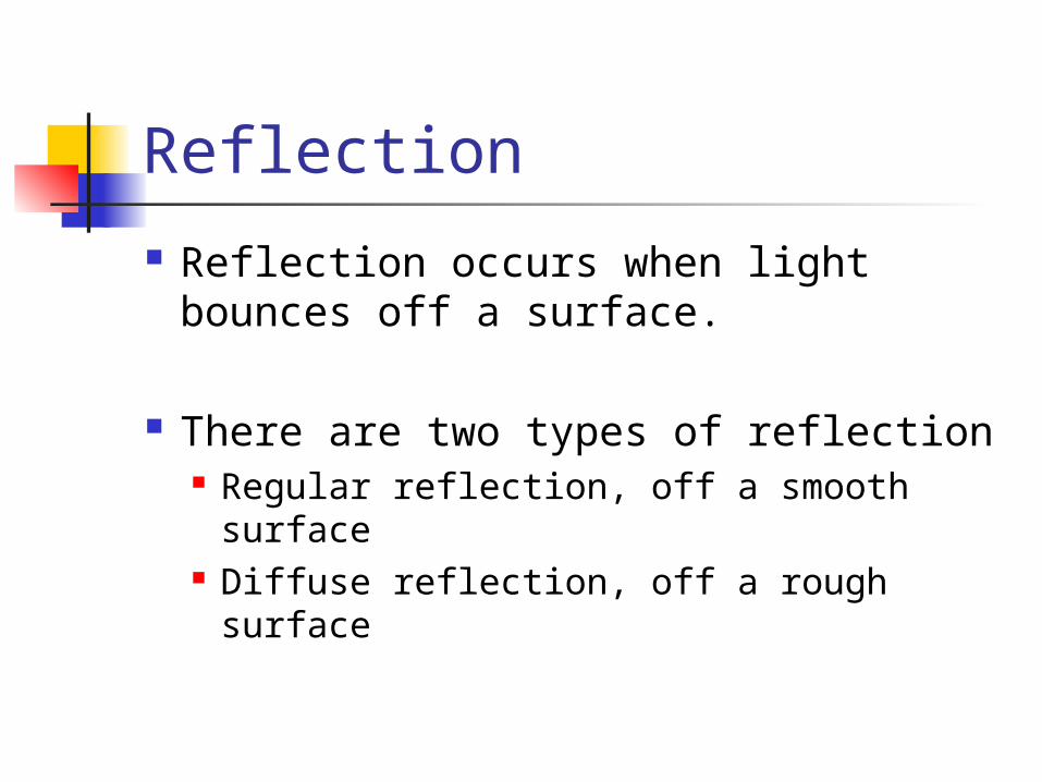
Reflection occurs when light bounces off a surface.
There are two types of reflection Regular reflection, off a smooth
surface Diffuse reflection, off a rough surface
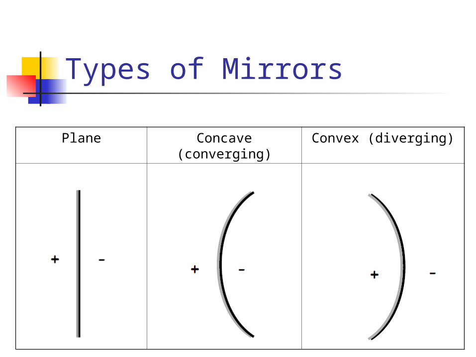
Types of Mirrors
Plane Concave (converging)
Convex (diverging)
Ray Diagrams Ray tracing is a method of constructing an
image using the model of light as a ray.
We use ray tracing to construct optical images produced by mirrors and lenses.
Ray tracing lets us describe what happens to the light as it interacts with a medium.
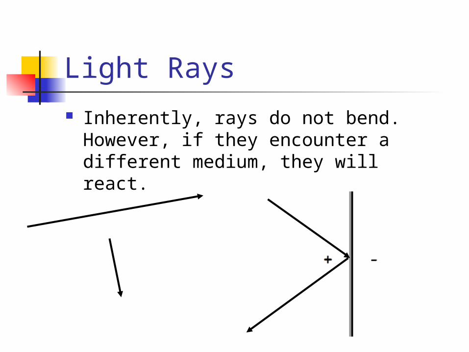
Light Rays Inherently, rays do not bend. However,
if they encounter a different medium, they will react.
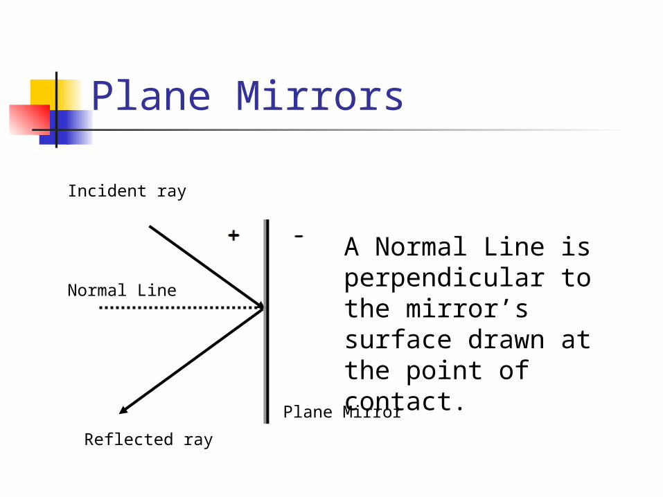
Plane Mirrors
Incident ray
Reflected ray
Normal Line
Plane Mirror
A Normal Line is perpendicular to the mirror’s surface drawn at the point of contact.
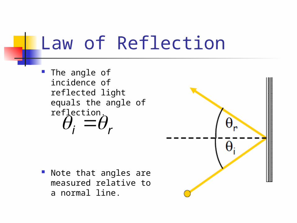
Law of Reflection The angle of incidence
of reflected light equals the angle of reflection.
Note that angles are measured relative to a normal line.
ri
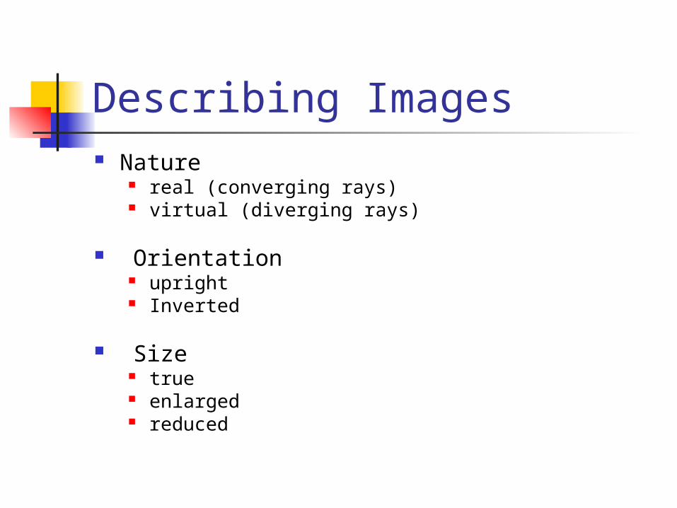
Describing Images Nature
real (converging rays) virtual (diverging rays)
Orientation upright Inverted
Size true enlarged reduced
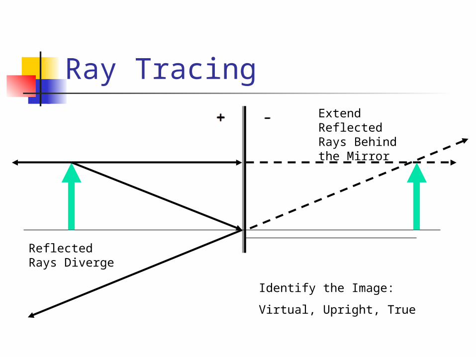
Ray Tracing
Identify the Image:
Virtual, Upright, True
Extend Reflected Rays Behind the Mirror
Reflected Rays Diverge
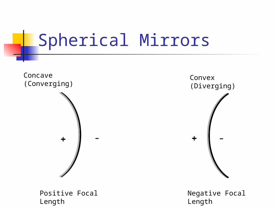
Spherical Mirrors
Positive Focal Length
Negative Focal Length
Concave (Converging)
Convex (Diverging)
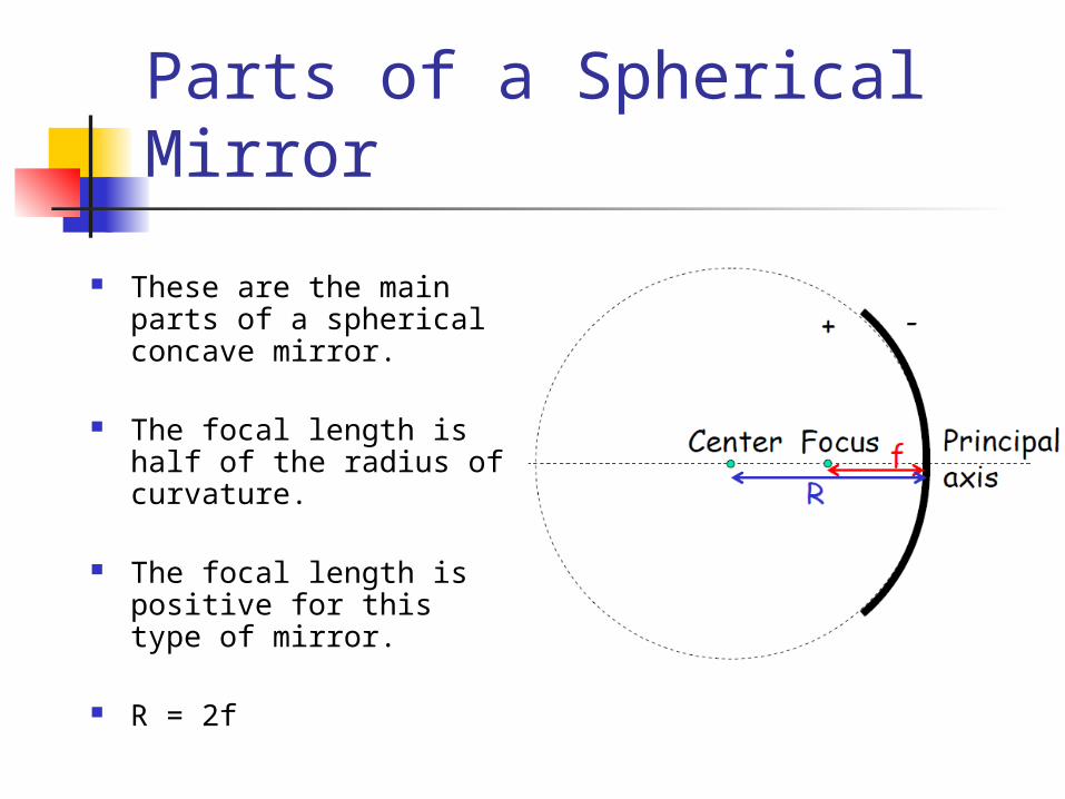
Parts of a Spherical Mirror
These are the main parts of a spherical concave mirror.
The focal length is half of the radius of curvature.
The focal length is positive for this type of mirror.
R = 2f
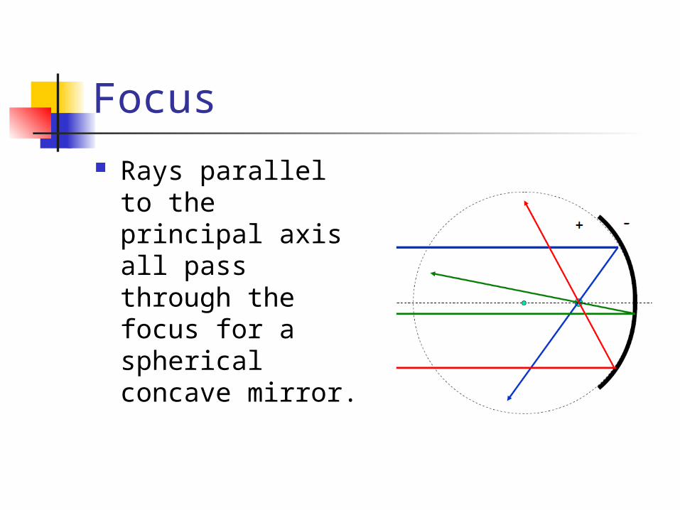
Focus Rays parallel to
the principal axis all pass through the focus for a spherical concave mirror.
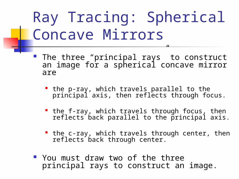
Ray Tracing: Spherical Concave Mirrors The three “principal rays” to construct an
image for a spherical concave mirror are
the p-ray, which travels parallel to the principal axis, then reflects through focus.
the f-ray, which travels through focus, then reflects back parallel to the principal axis.
the c-ray, which travels through center, then reflects back through center.
You must draw two of the three principal rays to construct an image.
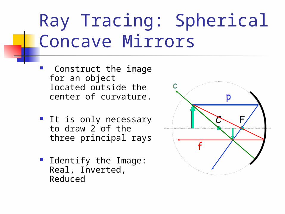
Ray Tracing: Spherical Concave Mirrors Construct the image
for an object located outside the center of curvature.
It is only necessary to draw 2 of the three principal rays
Identify the Image: Real, Inverted, Reduced
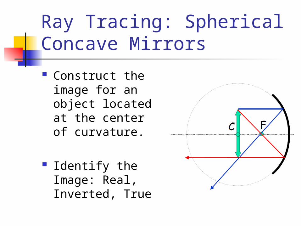
Ray Tracing: Spherical Concave Mirrors Construct the
image for an object located at the center of curvature.
Identify the Image: Real, Inverted, True
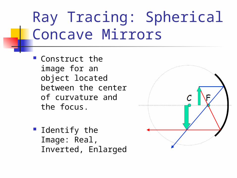
Ray Tracing: Spherical Concave Mirrors Construct the
image for an object located between the center of curvature and the focus.
Identify the Image: Real, Inverted, Enlarged
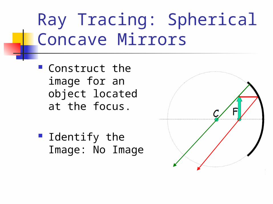
Ray Tracing: Spherical Concave Mirrors Construct the
image for an object located at the focus.
Identify the Image: No Image
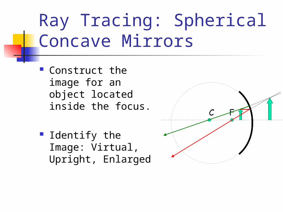
Ray Tracing: Spherical Concave Mirrors Construct the
image for an object located inside the focus.
Identify the Image: Virtual, Upright, Enlarged
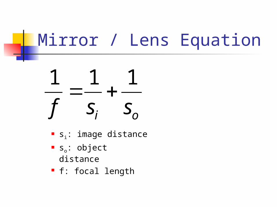
Mirror / Lens Equation
si: image distance so: object distance f: focal length
oi ssf
111
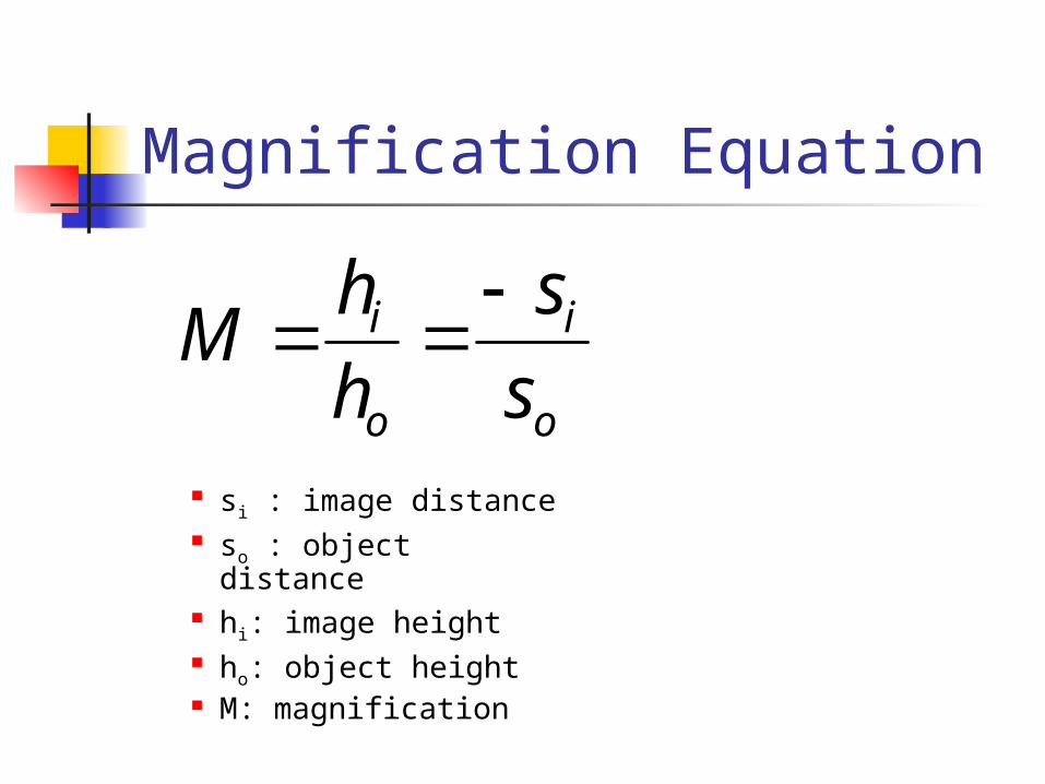
Magnification Equation
si : image distance so : object distance hi: image height ho: object height M: magnification
o
i
o
i
s
s
h
hM
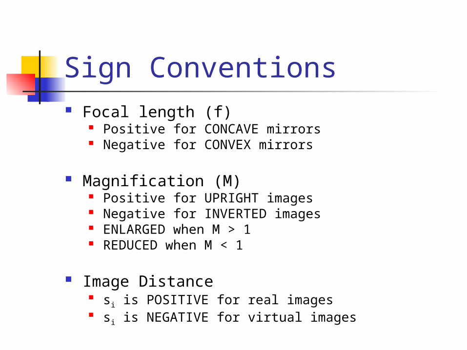
Sign Conventions Focal length (f)
Positive for CONCAVE mirrors Negative for CONVEX mirrors
Magnification (M)
Positive for UPRIGHT images Negative for INVERTED images ENLARGED when M > 1 REDUCED when M < 1
Image Distance si is POSITIVE for real images si is NEGATIVE for virtual images
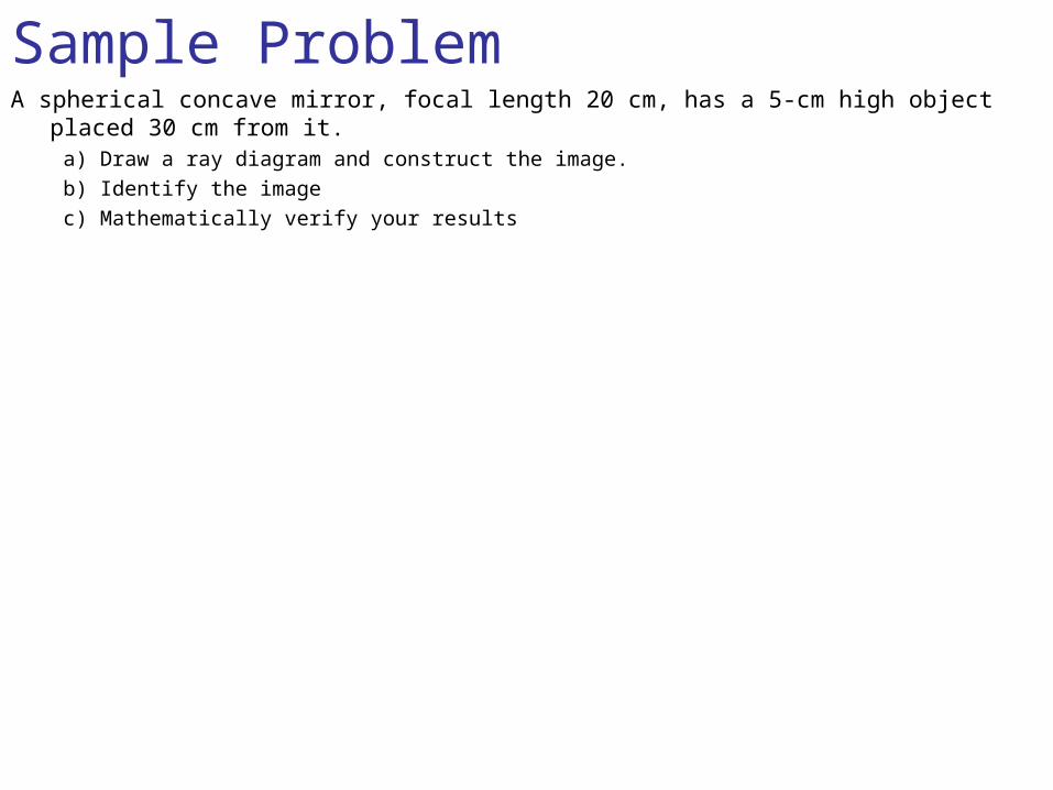
Sample ProblemA spherical concave mirror, focal length 20 cm, has a 5-cm high object placed 30 cm
from it.a) Draw a ray diagram and construct the image.b) Identify the imagec) Mathematically verify your results
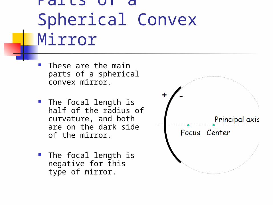
Parts of a Spherical Convex Mirror These are the main parts
of a spherical convex mirror.
The focal length is half of the radius of curvature, and both are on the dark side of the mirror.
The focal length is negative for this type of mirror.
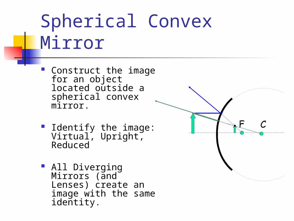
Spherical Convex Mirror Construct the image
for an object located outside a spherical convex mirror.
Identify the image: Virtual, Upright, Reduced
All Diverging Mirrors (and Lenses) create an image with the same identity.
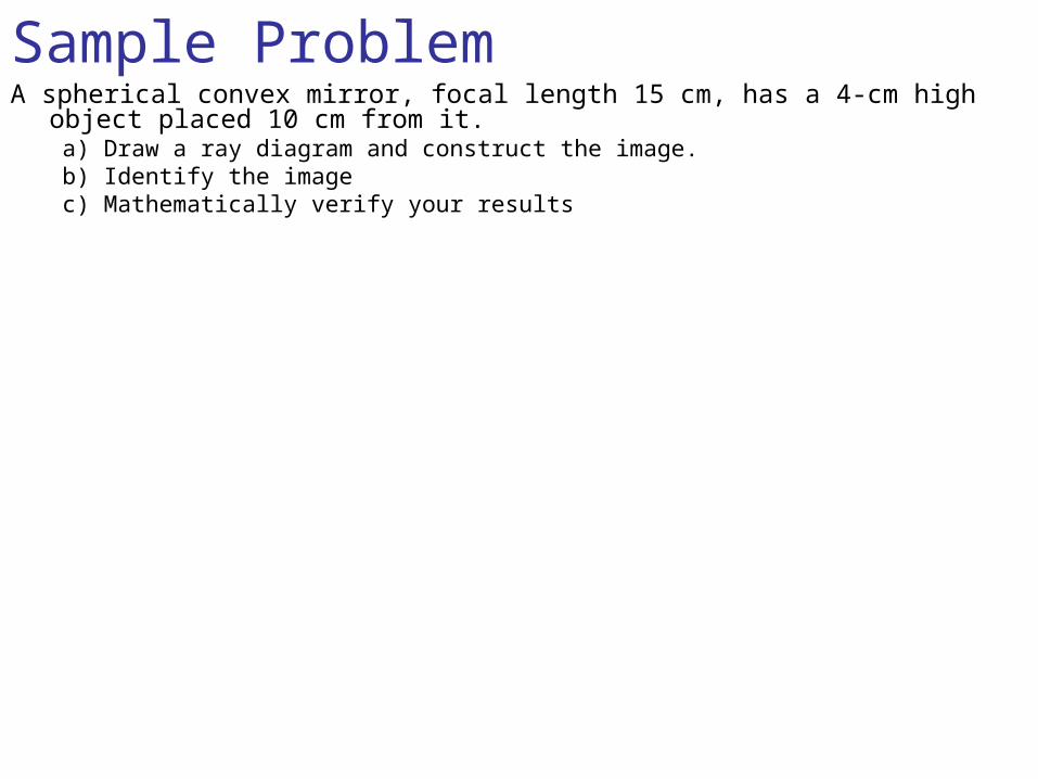
Sample ProblemA spherical convex mirror, focal length 15 cm, has a 4-cm high object placed
10 cm from it.a) Draw a ray diagram and construct the image.b) Identify the imagec) Mathematically verify your results
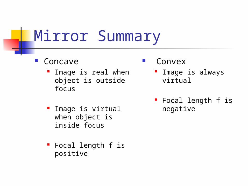
Mirror Summary Concave
Image is real when object is outside focus
Image is virtual when object is inside focus
Focal length f is positive
Convex Image is always
virtual
Focal length f is negative
Refraction
Refraction Refraction is the movement of light from
one medium into another medium.
Refraction cause a change in speed of light as it moves from one medium to another.
Refraction can cause bending of the light at the interface between media.
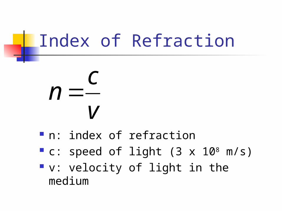
Index of Refraction
n: index of refraction c: speed of light (3 x 10⁸ m/s) v: velocity of light in the medium
v
cn
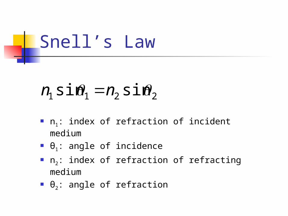
Snell’s Law
n1: index of refraction of incident medium θ1: angle of incidence n2: index of refraction of refracting medium θ2: angle of refraction
2211 sinsin nn
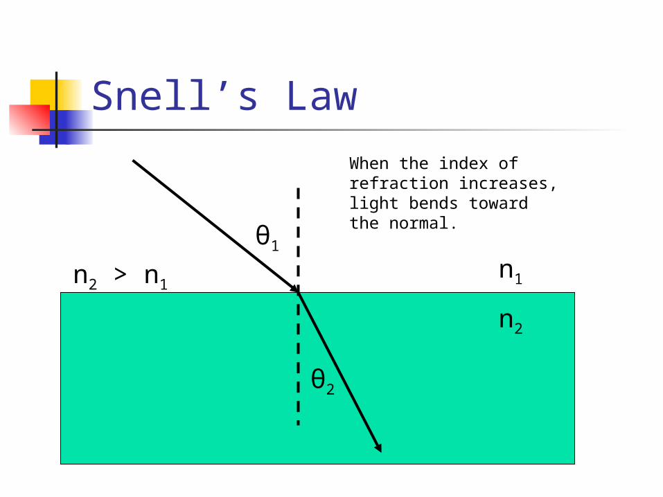
Snell’s Law
n1
n2
θ1
θ2
When the index of refraction increases, light bends towardthe normal.
n2 > n1
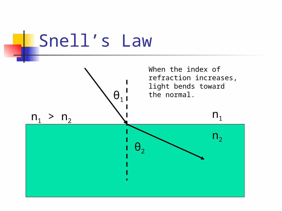
Snell’s Law
n1
n2
θ1
θ2
When the index of refraction increases, light bends towardthe normal.
n1 > n2
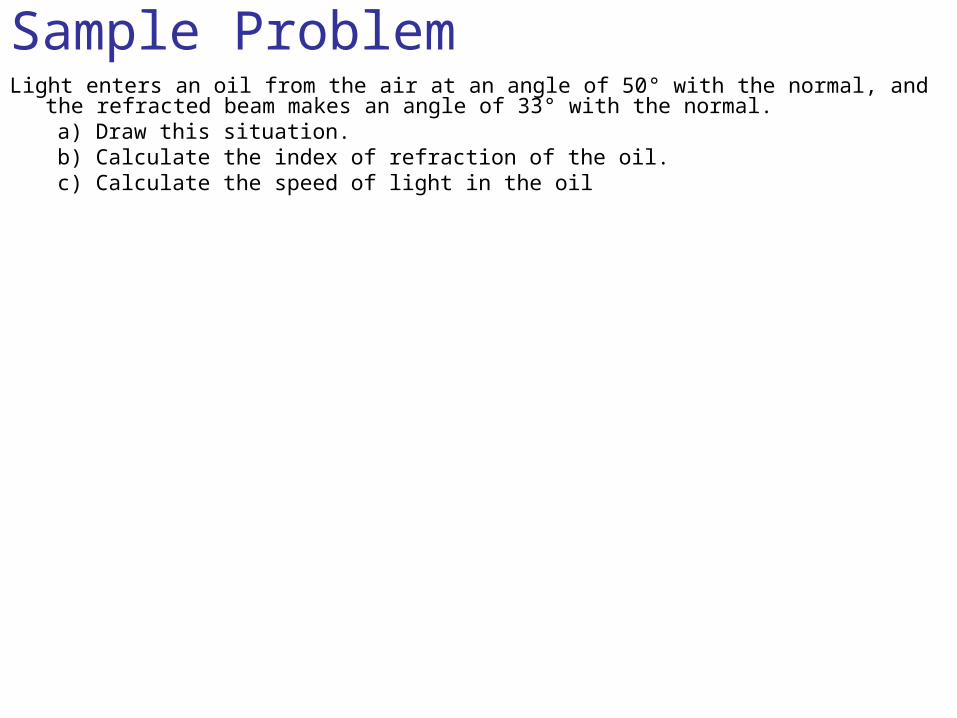
Sample ProblemLight enters an oil from the air at an angle of 50° with the normal, and the refracted
beam makes an angle of 33° with the normal.a) Draw this situation.b) Calculate the index of refraction of the oil.c) Calculate the speed of light in the oil
Prism ProblemLight in air enters a 30-60-90 prism perpendicular to the long side and
passes through the prism. If the refractive index of the glass is 1.55, calculate the angle of refraction when it leaves the prism.
Critical Angle
Critical Angle
If light passes into a medium with a greater refractive index than the original medium, it bends away from the normal and the angle of refraction is greater than the angle of incidence.
If the angle of refraction is > 90°, the light cannot leave the medium.
The smallest angle of incidence for which light cannot leave a medium is called the critical angle of incidence.
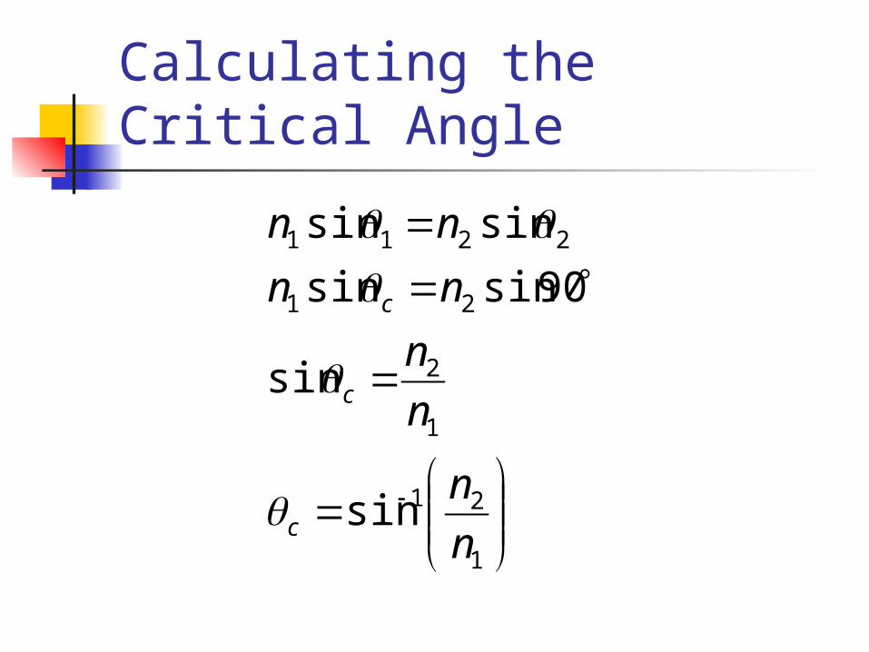
Calculating the Critical Angle
1
21
1
2
21
2211
sin
sin
90sinsin
sinsin
n
n
n
n
nn
nn
c
c
c
Sample Problem What is the critical angle of incidence for a gemstone with refractive index 2.45 if it
is in air?
Lenses
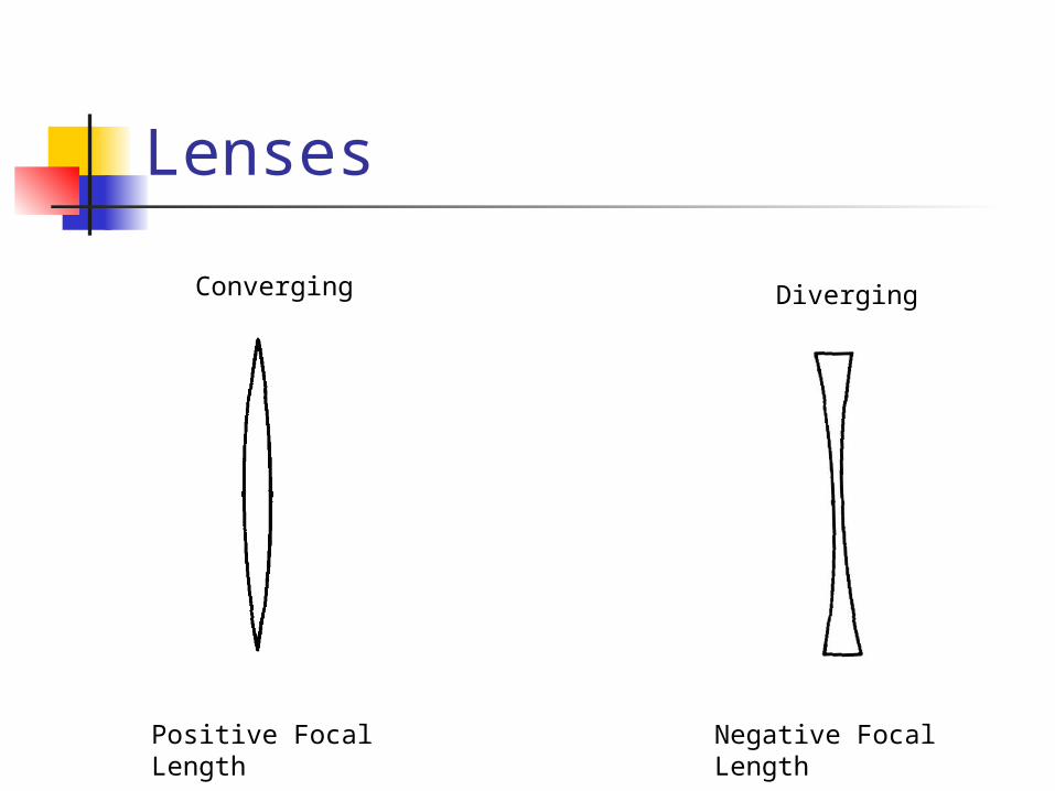
Lenses
Positive Focal Length
Negative Focal Length
Converging Diverging
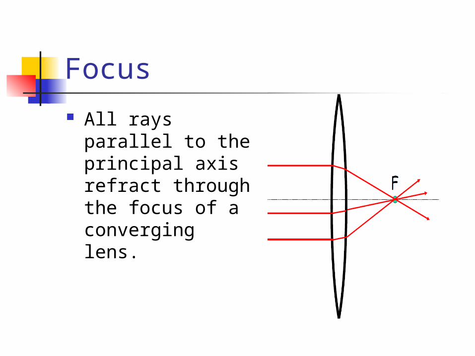
Focus All rays parallel to
the principal axis refract through the focus of a converging lens.
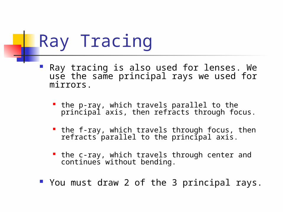
Ray Tracing Ray tracing is also used for lenses. We use the
same principal rays we used for mirrors.
the p-ray, which travels parallel to the principal axis, then refracts through focus.
the f-ray, which travels through focus, then refracts parallel to the principal axis.
the c-ray, which travels through center and continues without bending.
You must draw 2 of the 3 principal rays.
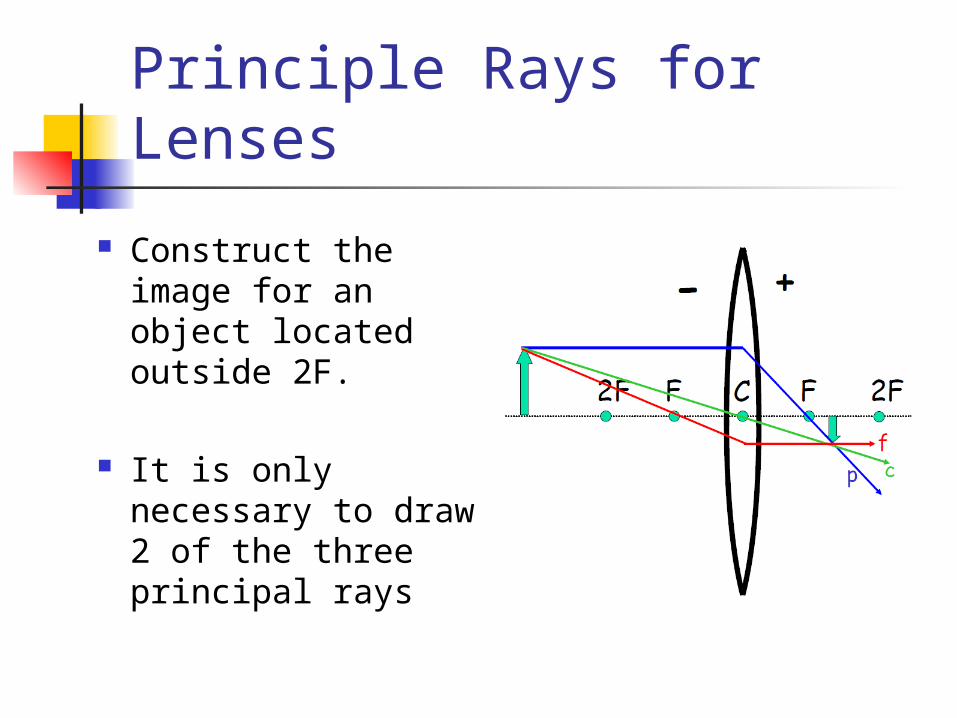
Principle Rays for Lenses
Construct the image for an object located outside 2F.
It is only necessary to draw 2 of the three principal rays
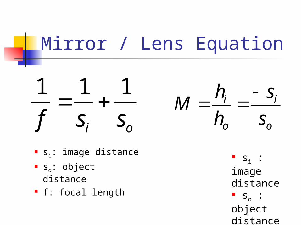
Mirror / Lens Equation
si: image distance so: object distance f: focal length
oi ssf
111
o
i
o
i
s
s
h
hM
si : image distance so : object distance hi: image height ho: object height M: magnification
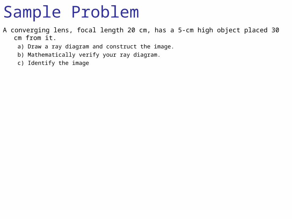
Sample ProblemA converging lens, focal length 20 cm, has a 5-cm high object placed 30 cm from it.
a) Draw a ray diagram and construct the image.b) Mathematically verify your ray diagram.c) Identify the image
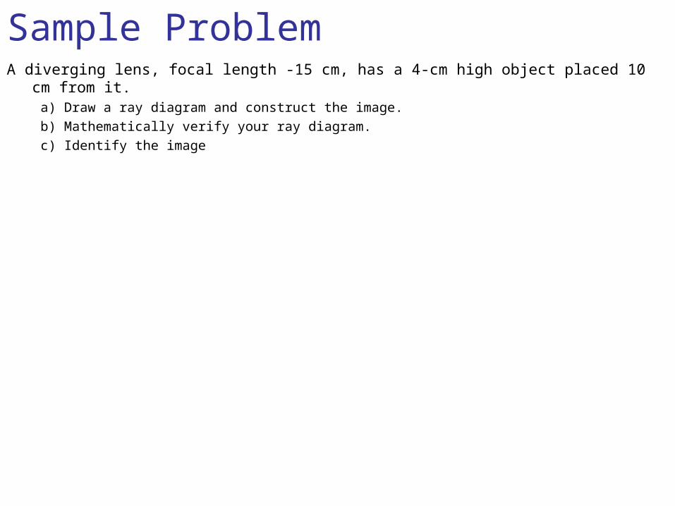
Sample ProblemA diverging lens, focal length -15 cm, has a 4-cm high object placed 10 cm from it.
a) Draw a ray diagram and construct the image.b) Mathematically verify your ray diagram.c) Identify the image
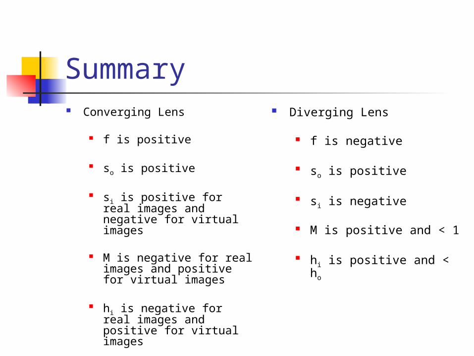
Summary Converging Lens
f is positive
so is positive
si is positive for real images and negative for virtual images
M is negative for real images and positive for virtual images
hi is negative for real images and positive for virtual images
Diverging Lens
f is negative
so is positive
si is negative
M is positive and < 1
hi is positive and < ho
Multiple Lenses / Mirrors When drawing ray diagrams for a
combination of lenses/mirrors, use the image from the first lens/mirror as the object for the second.
When appropriate, apply the p-ray, f-ray, and c-ray rules to the second lens/mirror.
To Identify the image, the result is compared to the original object.
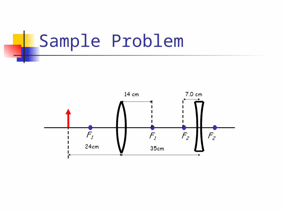
Sample Problem