Embed Size (px)
Citation preview

Page 1
26 Jan 10 © 2010 Zen Engineering / Mark S. Ditko
Page 6-1
Geometry Intro - Objectives
An InRoads Geometry Project overview
A look at the Geometry Project file Structure
Opening and Creating Geometry Projects
Horizontal Alignment layout tools and key-ins
Viewing existing H. Alignments & Stationing
Setting the start Station & Station Equations
Saving the InRoads Geometry data
Some other Geometry commands & tools
26 Jan 10 © 2010 Zen Engineering / Mark S. Ditko
Page 6-2
The Geometry Project
The Geometry Project is
where the COGO Point &
Alignment information is
stored and organized.
It acts as a warehouse for
all project geometry
A single job may have
more than one project
associated with it
Page 2
26 Jan 10 © 2010 Zen Engineering / Mark S. Ditko
Page 6-3
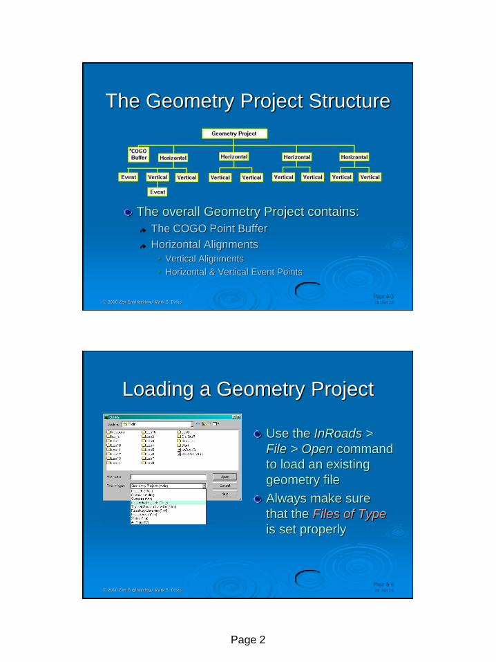
The Geometry Project Structure
The overall Geometry Project contains:
The COGO Point Buffer
Horizontal Alignments
Vertical Alignments
Horizontal & Vertical Event Points
26 Jan 10 © 2010 Zen Engineering / Mark S. Ditko
Page 6-4
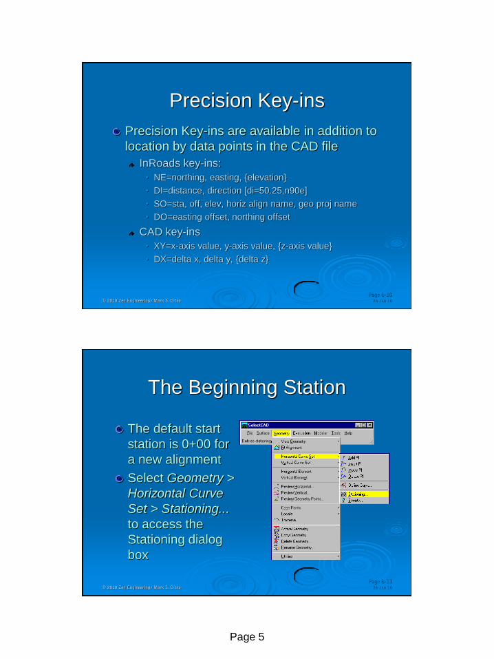
Loading a Geometry Project
Use the InRoads >
File > Open command
to load an existing
geometry file
Always make sure
that the Files of Type
is set properly

Page 3
26 Jan 10 © 2010 Zen Engineering / Mark S. Ditko
Page 6-5
Several Geometry Projects
Many Geometry Projects
can be loaded in InRoads
Each Geo Project has the
complete Geometry file
structure stored with it
The ‘active’ Project defines
the collection of Geometry
that InRoads is actively working on
Only the active geometry can receive input
26 Jan 10 © 2010 Zen Engineering / Mark S. Ditko
Page 6-6
Horizontal Alignments
Create the ‘slot’ in the Geometry Project
Layout the Horizontal Alignment via
Horizontal Curve Set method (PI’s)
Horizontal Element method (Elements)
Simplified Horizontal Element method
Traverse tools (Direction, Angle/Deflection, Curve)
Create Alignment by COGO Points
Regression Analysis
Import from Graphics
Import from an ASCII or .ICS file

Page 4
26 Jan 10 © 2010 Zen Engineering / Mark S. Ditko
Page 6-8
Defining Horizontal Curves
Define Curve from the Horizontal Curve Set toolbar will define & edit the horizontal curves
Upper Portion Editor
Lower area Defines Curve
Spirals or not
Curve & Design Calcs
Undo (InRoads V8.3 only)
26 Jan 10 © 2010 Zen Engineering / Mark S. Ditko
Page 6-9
Horizontal Element Tools
Horizontal Element tools are another method
for creating and editing horizontal alignments.
These tools work with ‘components’ versus PIs
Discontinuities refer to ‘gaps’ in a feature or
alignment and are permissible in InRoads V8
Layout the lab tangents using these tools if you
feel like expanding your layout options.
Page 5
26 Jan 10 © 2010 Zen Engineering / Mark S. Ditko
Page 6-10
Precision Key-ins
Precision Key-ins are available in addition to
location by data points in the CAD file
InRoads key-ins:
• NE=northing, easting, {elevation}
• DI=distance, direction [di=50.25,n90e]
• SO=sta, off, elev, horiz align name, geo proj name
• DO=easting offset, northing offset
CAD key-ins
• XY=x-axis value, y-axis value, {z-axis value}
• DX=delta x, delta y, {delta z}
26 Jan 10 © 2010 Zen Engineering / Mark S. Ditko
Page 6-11
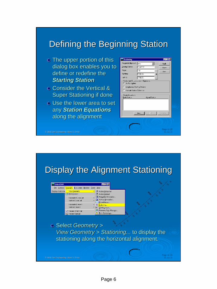
The Beginning Station
The default start
station is 0+00 for
a new alignment
Select Geometry >
Horizontal Curve
Set > Stationing...
to access the
Stationing dialog
box
Page 6
26 Jan 10 © 2010 Zen Engineering / Mark S. Ditko
Page 6-12
Defining the Beginning Station
The upper portion of this
dialog box enables you to
define or redefine the
Starting Station
Consider the Vertical &
Super Stationing if done
Use the lower area to set
any Station Equations
along the alignment
26 Jan 10 © 2010 Zen Engineering / Mark S. Ditko
Page 6-13
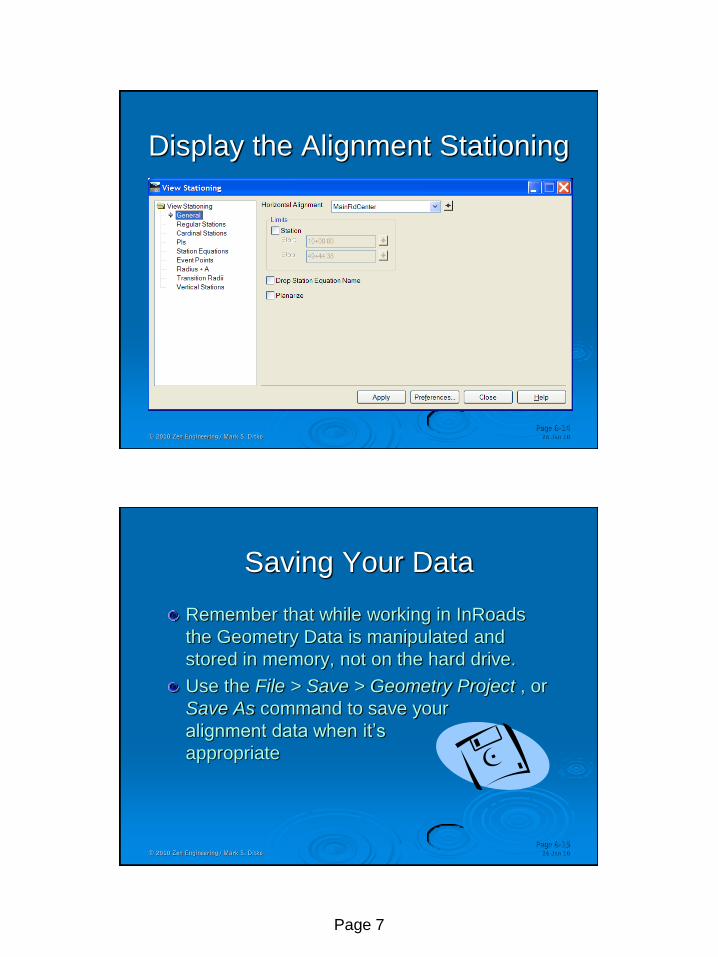
Display the Alignment Stationing
Select Geometry >
View Geometry > Stationing... to display the
stationing along the horizontal alignment.
Page 7
26 Jan 10 © 2010 Zen Engineering / Mark S. Ditko
Page 6-14
Display the Alignment Stationing
26 Jan 10 © 2010 Zen Engineering / Mark S. Ditko
Page 6-15
Saving Your Data
Remember that while working in InRoads
the Geometry Data is manipulated and
stored in memory, not on the hard drive.
Use the File > Save > Geometry Project , or
Save As command to save your
alignment data when it’s
appropriate

Page 8
26 Jan 10 © 2010 Zen Engineering / Mark S. Ditko
Page 6-16
Transform
Sometimes observations are collected and
coordinates are processed using an assumed
initial coordinate, you can translate the
resultant points and alignments to the
appropriate coordinate system by going to
Geometry > Utilities > Transform
26 Jan 10 © 2010 Zen Engineering / Mark S. Ditko
Page 6-17
Transforming Geometry
Identify the Geometry to transform
Choose the Filter to select a portion of the geometry project
The Methods allow you to convert to Metric or Imperial
The H & V Scale factors are rigid body scaling, not warping.

Page 9
26 Jan 10 © 2010 Zen Engineering / Mark S. Ditko
Page 6-18
Horizontal Event Points
Event Points: based
on alignment data
Points added as: COGO
Station / Offset
Northing / Easting
Single or Multiple
points at a time
26 Jan 10 © 2010 Zen Engineering / Mark S. Ditko
Page 6-19
Laying Out Cul-de-sacs
Cul-de-sacs are part of
Geometry Utilities Select the Type
Enter the dimensions
Follow the prompts

Page 10
26 Jan 10 © 2010 Zen Engineering / Mark S. Ditko
Page 6-20
Placing Curb Returns
Geometry > Utilities >
Multicentered Curve One Center
Two Center
Three Center
Enter Radius and Widths
26 Jan 10 © 2010 Zen Engineering / Mark S. Ditko
Page 6-21
Other Geometry Utilities
Other Geometry Utilities will help to construct
and work with Horizontal Alignments
Join
Trim Alignment
Extend Alignment
Partial Delete
Transpose
Parallel Horizontal by Element
Parallel Horizontal by Station
Assign names
Page 11
26 Jan 10 © 2010 Zen Engineering / Mark S. Ditko
Page 6-22
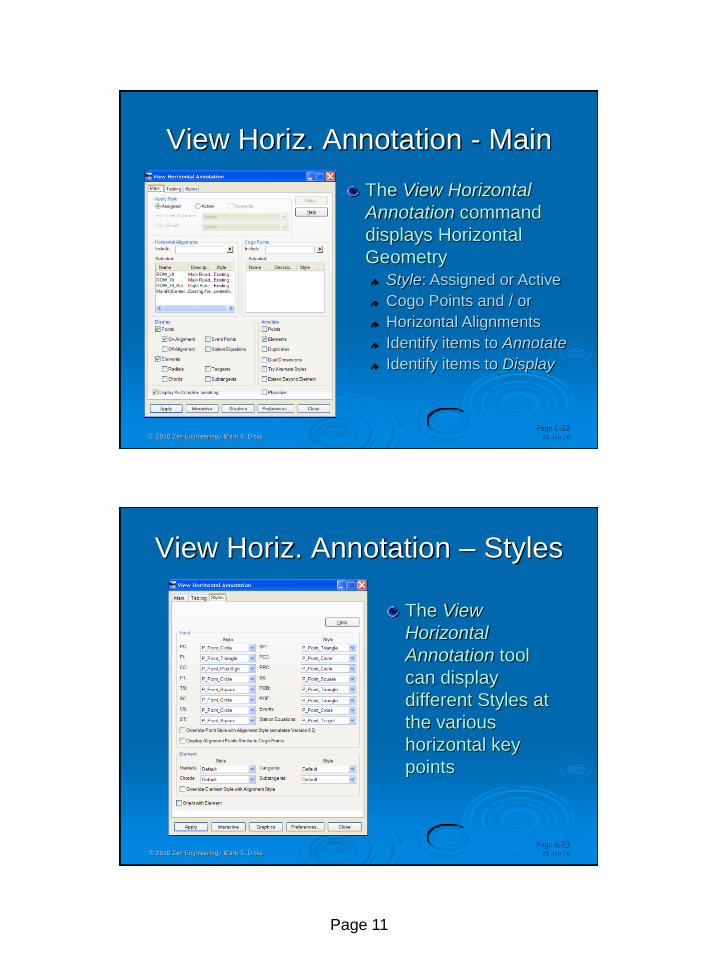
View Horiz. Annotation - Main
The View Horizontal
Annotation command
displays Horizontal
Geometry Style: Assigned or Active
Cogo Points and / or
Horizontal Alignments
Identify items to Annotate
Identify items to Display
26 Jan 10 © 2010 Zen Engineering / Mark S. Ditko
Page 6-23
View Horiz. Annotation – Styles
The View
Horizontal
Annotation tool
can display
different Styles at
the various
horizontal key
points
Page 12
07 May 02 © 2002 Zen Engineering / Mark S. Ditko
Page 6-24
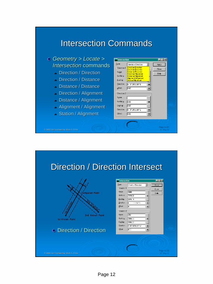
Intersection Commands
Geometry > Locate >
Intersection commands
Direction / Direction
Direction / Distance
Distance / Distance
Direction / Alignment
Distance / Alignment
Alignment / Alignment
Station / Alignment
07 May 02 © 2002 Zen Engineering / Mark S. Ditko
Page 6-25
Direction / Direction Intersect
Direction / Direction

Page 13
07 May 02 © 2002 Zen Engineering / Mark S. Ditko
Page 6-26
Direction / Distance Intersect
Direction / Distance
07 May 02 © 2002 Zen Engineering / Mark S. Ditko
Page 6-27
Distance / Distance Intersect
Distance / Distance
Page 14
07 May 02 © 2002 Zen Engineering / Mark S. Ditko
Page 6-28
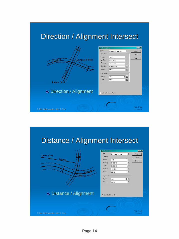
Direction / Alignment Intersect
Direction / Alignment
07 May 02 © 2002 Zen Engineering / Mark S. Ditko
Page 6-29
Distance / Alignment Intersect
Distance / Alignment
Page 15
07 May 02 © 2002 Zen Engineering / Mark S. Ditko
Page 6-30
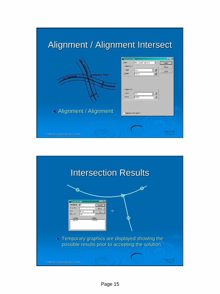
Alignment / Alignment Intersect
Alignment / Alignment
07 May 02 © 2002 Zen Engineering / Mark S. Ditko
Page 6-31
Intersection Results
Temporary graphics are displayed showing the
possible results prior to accepting the solution.

Page 16
26 Jan 10 © 2010 Zen Engineering / Mark S. Ditko
Page 6-32
Geometry Intro - Summary
InRoads Geometry is stored in a structured file
All new components of the Geometry file are
created under File > New (ie: G. Proj, H & V)
Horizontal PI’s can be set by precision key-in.
Choose the appropriate geometry layout
method, or use what you are comfortable with
Once the Geometry is created you can:
Display the active alignment and its stationing
Reset the beginning station of the alignment
Save the alignment data to disk


![ɷ[s waner] intro to differential geometry and gene](https://img.pdfslide.net/doc/110x75/568caaba1a28ab186da2ba05/s-waner-intro-to-differential-geometry-and-gene.jpg)