Embed Size (px)
Citation preview

Geotechnical Engineering ReportProposed Culver’s Restaurant
Ottumwa, IowaNovember 19, 2014
Terracon Project No. 06145638.01
Prepared for:ARC Design Resources, Inc.
Loves Park, Illinois
Prepared by:Terracon Consultants, Inc.
Iowa City, Iowa


TABLE OF CONTENTS
Responsive ■ Resourceful ■ Reliable
PageEXECUTIVE SUMMARY .......................................................................................................................... i1.0 INTRODUCTION ........................................................................................................................ 12.0 PROJECT INFORMATION ......................................................................................................... 2
2.1 Project Description ......................................................................................................... 22.2 Site Location and Description ......................................................................................... 2
3.0 SUBSURFACE CONDITIONS .................................................................................................... 23.1 Typical Subsurface Profile .............................................................................................. 23.2 Groundwater Conditions ................................................................................................. 3
4.0 RECOMMENDATIONS FOR DESIGN AND CONSTRUCTION ................................................... 44.1 Geotechnical Considerations .......................................................................................... 44.2 Earthwork ....................................................................................................................... 6
4.2.1 Site Preparation ................................................................................................. 64.2.2 Soil Stabilization................................................................................................. 74.2.3 Excavation Considerations ................................................................................. 74.2.4 Fill Material Requirements .................................................................................. 74.2.5 Compaction Requirements ................................................................................. 94.2.6 Grading and Drainage ........................................................................................ 9
4.3 Shallow Foundations .................................................................................................... 104.3.1 Shallow Foundation Design Recommendations ................................................ 104.3.2 Shallow Foundation Construction Considerations ............................................. 11
4.4 Floor Slabs ................................................................................................................... 124.4.1 Floor Slab Design Recommendations............................................................... 124.4.2 Floor Slab Construction Considerations ............................................................ 13
4.5 Seismic Considerations ................................................................................................ 134.6 Pavement Recommendations ....................................................................................... 14
4.6.1 Pavement Subgrade Preparation ..................................................................... 144.6.2 Pavement Design Recommendations ............................................................... 144.6.3 Pavement Subdrain System ............................................................................. 164.6.4 Pavement Design Considerations..................................................................... 174.6.5 Pavement Maintenance.................................................................................... 17
4.7 Frost Considerations..................................................................................................... 185.0 GENERAL COMMENTS ........................................................................................................... 18
APPENDIX A – FIELD EXPLORATIONExhibit A-1 Site Location PlanExhibit A-2 Boring Location PlanExhibit A-3 Field Exploration DescriptionExhibits A-4 to A-9 Boring Logs
APPENDIX B – SUPPORTING INFORMATIONExhibit B-1 Laboratory Testing
APPENDIX C – SUPPORTING DOCUMENTSExhibit C-1 General NotesExhibit C-2 Unified Soil Classification System

Geotechnical Engineering ReportProposed Culver’s Restaurant ■ Ottumwa, IowaNovember 19, 2014 ■ Terracon Project No. 06145638.01
Responsive ■ Resourceful ■ Reliable i
EXECUTIVE SUMMARY
A geotechnical exploration has been performed for the proposed Culver’s restaurant located atthe intersection of Venture Drive and Venture Way in Ottumwa, Iowa. Terracon’s geotechnicalscope of service included the advancement of six borings to approximate depths of 20½ to 25½feet below existing site grades. Based on the information obtained from our subsurfaceexploration, the following geotechnical considerations were identified:
n Existing fill was encountered in the borings to depths of approximately 17 to 22 feet belowgrade. The existing fill had variable densities and composition and does not appear to havebeen placed using consistent moisture-density control procedures. The existing fill is notconsidered suitable for positive support of foundations, and would be subjected to higher thannormal foundation and floor slab movement.
n The proposed Culver’s restaurant may be supported on shallow foundations bearing onexisting fill materials that have been improved with a system of aggregate piers such asGeopiers. This system will reduce the potential for differential settlement due toinconsistencies within the existing fill. Alternatively, the foundations could be supported onnew structural fill extending through the existing fill to suitable native soils. We anticipatethat this option will not be feasible due to the scale of excavation needed to remove theexisting fill. Other foundation alternatives that could be considered include helical piers,micropiles, or augercast piles.
n Strong consideration should be given to supporting the floor slabs for the restaurant onaggregate piers to reduce the risk of poor slab performance and structural distress. At aminimum and assuming the Owner accepts the risk of poor performance, we recommend atleast 24 inches of low plasticity structural fill be present below the floor slabs and pavementswhere existing fill is left in place for slab/pavement support.
n Assuming proper site preparation and any necessary foundation bearing soil corrections,total and differential settlement should be less than about 1 inch and two-thirds (2/3) of totalsettlement, respectively.
n The majority of the on-site existing fill soils appear suitable for reuse as compactedstructural fill above foundations; however, portions of the fill consist of higher plasticity soilswhich are subjected to shrink-swell potential with varying moisture content. If the soils donot meet the low plasticity fill criteria, they should not be utilized within 4 feet of finishedsubgrade elevation.
n Based on the limited subsurface information obtained during our site exploration, the 2012International Building Code (IBC), seismic site classification for this site is D.

Geotechnical Engineering ReportProposed Culver’s Restaurant ■ Ottumwa, IowaNovember 19, 2014 ■ Terracon Project No. 06145638.01
Responsive ■ Resourceful ■ Reliable ii
n Earthwork on the project should be observed and evaluated by Terracon. The evaluation ofearthwork should include observation and testing of structural fill, subgrade preparation,foundation bearing materials, and other geotechnical conditions exposed duringconstruction.
This summary should be used in conjunction with the entire report for design purposes. Itshould be recognized that details were not included or fully developed in this section, and thereport must be read in its entirety for a comprehensive understanding of the items containedherein. The section titled GENERAL COMMENTS should be read for an understanding of thereport limitations.

Responsive ■ Resourceful ■ Reliable 1
GEOTECHNICAL ENGINEERING REPORTPROPOSED CULVER’S RESTAURANT
NW of INTERSECTION OF VENTURE DRIVE and VENTURE WAYOTTUMWA, IOWA
Terracon Project No. 06145638.01November 19, 2014
1.0 INTRODUCTION
This report presents the results of our subsurface exploration and geotechnical engineeringservices performed for the proposed Culver’s restaurant located at the intersection of VentureDrive and Venture Way in Ottumwa, Iowa. The purpose of these services is to provideinformation and geotechnical engineering recommendations relative to:
n subsurface soil conditions n foundation design and constructionn groundwater conditions n floor slab design and constructionn site preparation and earthwork n seismic site classification per IBCn excavation considerations n pavement design and constructionn dewatering considerations n frost considerations
The geotechnical engineering scope of service for this project included the advancement of sixborings to depths ranging from approximately 20½ to 25½ feet below existing site grades.
A Site Location Plan (Exhibit A-1), a Boring Location Plan (Exhibit A-2), and logs of the borings(Exhibits A-4 to A-9) are included in Appendix A of this report. The results of the laboratorytesting performed on soil samples obtained from the site during the field exploration areincluded on the boring logs of this report. Descriptions of the field exploration and laboratorytesting are included in their respective appendices.
A Phase I Environmental Site Assessment (ESA) is being prepared for this project and will beissued under separate cover (Terracon Project No. 06147737). The designer of any project onthis site should be aware of the contents of the ESA.
Terracon also performed subsurface explorations for the Ottumwa Retail Shopping Center(Terracon Project Nos. 06045622.01, dated April 30, 2004, and 06105669 in October 2010).Since the center’s construction, the building, floor slabs, and pavements have beenexperiencing higher than normal differential settlement and subgrade movement. This hasresulted in visible structural distress, including cracked floor slabs and pavements and issuesopening doors and windows. The information from these prior explorations was also used indeveloping the recommendations contained in this report.

Geotechnical Engineering ReportProposed Culver’s Restaurant ■ Ottumwa, IowaNovember 19, 2014 ■ Terracon Project No. 06145638.01
Responsive ■ Resourceful ■ Reliable 2
2.0 PROJECT INFORMATION
2.1 Project DescriptionItem Description
Site layout n See Appendix A, Exhibit A-2: Boring Location Plan
Structure n Single-story building with a proposed plan area ofapproximately 4,200 square feet
Building construction(assumed)
n Wood-frame with brick veneern Slab-on-grade
Finished floor elevation(provided)
n 669.40 feet
Maximum loads(assumed)
n Columns: 50 kipsn Walls: 2 klfn Slabs: 100 psf
Grading(based on provided grading plan)
n Building area: fills of about 3 to 5 feet anticipatedn Pavement area: limited cuts and fills of about 1 to 8 feet
anticipatedFree-standing retaining walls(provided)
n Potential retaining wall to west of drive-through arean Not in scope of services
Below grade areas(assumed)
n None anticipated
Pavementsn Drivewaysn Passenger vehicle parking: 72 spacesn Dumpster pad
2.2 Site Location and Description
Item Description
Locationn Intersection of Venture Drive and Venture Way in
Ottumwa, Iowan Parcel area of about 54,925 square feet
Existing improvements n UnimprovedExisting topography(ARC Design topo plan)
n Site generally slopes downward to the northeast withsurface elevations ranging from about 670 to 661 feet
3.0 SUBSURFACE CONDITIONS
3.1 Typical Subsurface Profile
Based on the results of the borings, subsurface conditions at the boring locations can begeneralized as follows:

Geotechnical Engineering ReportProposed Culver’s Restaurant ■ Ottumwa, IowaNovember 19, 2014 ■ Terracon Project No. 06145638.01
Responsive ■ Resourceful ■ Reliable 3
StratumApproximate Depth to
Bottom of Stratum(feet)
Material Description Consistency /Relative Density
Surficial 2 to 3 inches Topsoil / Root Zone N/A
1 17 to 22Existing fill – generally composed of sandylean clay with interbedded layers of fat clay
and sand pocketsN/A
2 20½ to 25½ 1 Native soil – lean clay and sandy lean clay(possible buried topsoil)
Medium stiff
3a21 2
(Boring B-2)Sandy lean clay, trace gravel and sand
seamsVery stiff
3b25½ 3
(Boring B-4)Fat clay with sand seams
Medium stiff tovery stiff
1. Borings B-1, B-3, B-5, and B-6 terminated in Stratum 2 soils.
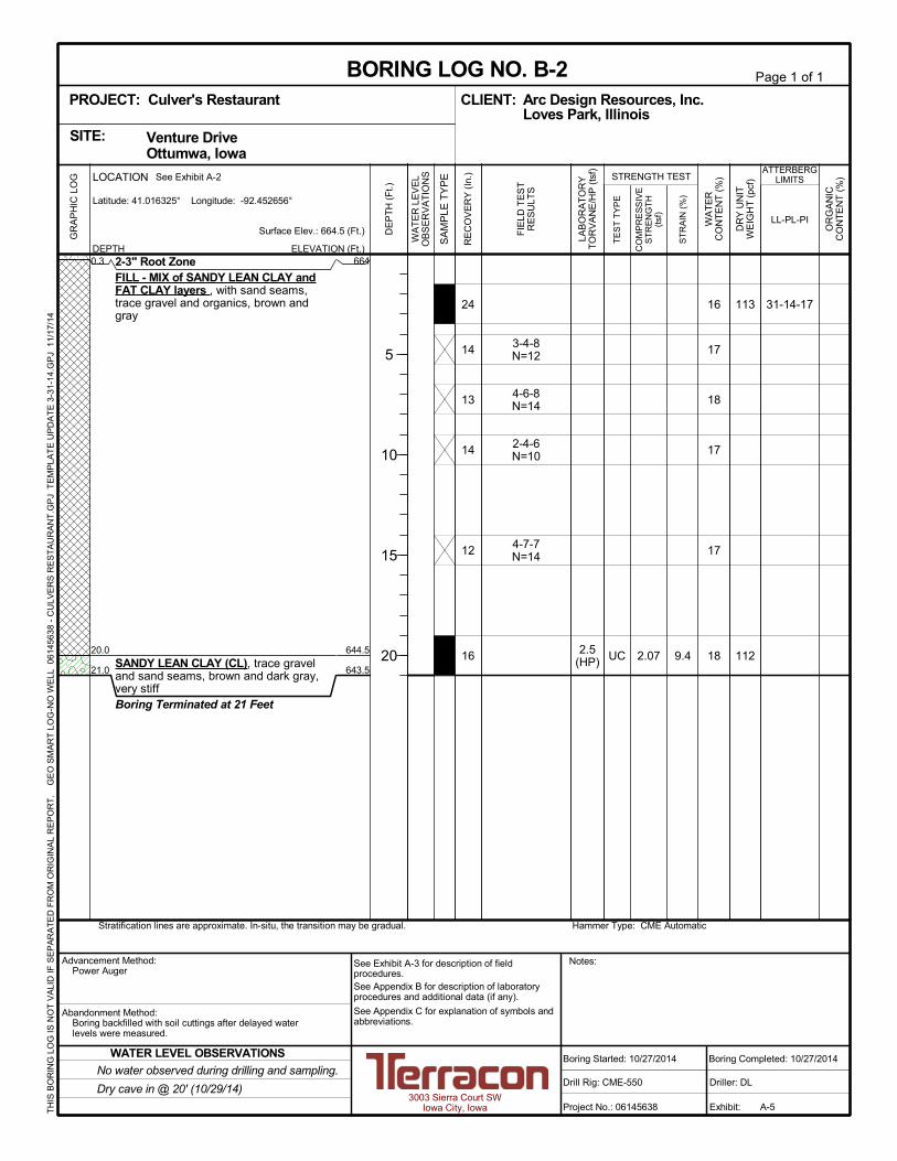
Conditions encountered at each boring location are indicated on the individual boring logs.Stratification boundaries on the boring logs represent the approximate location of changes innative soil types; in situ, the transition between materials may be gradual. Details for each ofthe borings can be found on the boring logs in Appendix A of this report.
3.2 Groundwater Conditions
The borings were observed for the presence of groundwater during drilling and sampling. Theborings were left open approximately 2 days so delayed water level observations could bemade. Following the delayed observations, the borings were backfilled with on-site soils. Waterlevels observations are presented in the table below.
WATER LEVEL OBSERVATIONS
Boring No.
While Sampling(feet)
After Boring(feet)
Depth Elevation Depth Elevation
B-1 None - - Dry cave-in @ 24 642B-2 None - - Dry cave-in @ 20 644½B-3 19 643½ 19½ 643B-4 None - - Dry cave-in @ 24 643B-5 None - - Dry cave-in @ 19 644½B-6 4 662 Dry cave-in @ 23 643
These water level observations provide an approximate indication of the groundwater conditionsexisting on the site at the time the observations were made. The absence of water in the

Geotechnical Engineering ReportProposed Culver’s Restaurant ■ Ottumwa, IowaNovember 19, 2014 ■ Terracon Project No. 06145638.01
Responsive ■ Resourceful ■ Reliable 4
boreholes does not necessarily mean that they terminated above the water table, since, for thelower permeability clay soils encountered in the borings, a longer time may be required todevelop representative water level in the boreholes. Longer-term observations using casedholes or piezometers, sealed from the influence of surface water, would be required for a betterevaluation of the groundwater conditions on this site.
The United States Department of Agriculture - Natural Resources Conservation Service (USDANRCS) Soil Survey of Wapello County, Iowa was also reviewed for information relating toanticipated seasonally high groundwater levels. In undisturbed areas, the Lawson-Quiver-Nodaway complex soils are reported to have apparent seasonal high groundwater of about 1foot below their natural grades.
Fluctuations of the groundwater levels will likely occur due to seasonal variations in the amountof rainfall, runoff and other factors not evident at the time the borings were performed.Therefore, groundwater levels during construction or at other times in the life of the structuremay be different than the levels indicated on the boring logs. Also, trapped or “perched” watercould be present within the sand or silt seams within native clay soils and/or in cohesionlesssoils (fill and native) above lower permeability clay soil layers. The possibility of groundwaterlevel fluctuations and perched water should be considered when developing the design andconstruction plans for the project.
4.0 RECOMMENDATIONS FOR DESIGN AND CONSTRUCTION
4.1 Geotechnical Considerations
Based on the results of the subsurface exploration, laboratory testing, and our analyses, it is ouropinion that the proposed Culver’s can be supported on shallow foundations bearing on existingfill materials that have been improved with a system of aggregate piers such as Geopiers.Alternatively, the foundations could be supported on properly placed and compacted structuralfill that extends completely through the existing fill to suitable native soils.
The presence of a deep layer of existing fill is one of the primary geotechnical concerns for thedevelopment of this site as a new Culver’s restaurant. Existing fill was encountered in theborings to depths ranging from about 17 to 22 feet below existing grades. Based on the testresults and composition of the fill, it appears that the fill may not have been placed usingconsistent control of composition, moisture, and density. Test pits could be performed to furtherevaluate the extent and composition of the fill.
Terracon has performed geotechnical engineering services for the nearby outdoor strip malllocated on Venture Drive to the west of the Culver’s project site. The facility is supported oversimilar existing fill soils and has experienced higher than normal total and differential settlement

Geotechnical Engineering ReportProposed Culver’s Restaurant ■ Ottumwa, IowaNovember 19, 2014 ■ Terracon Project No. 06145638.01
Responsive ■ Resourceful ■ Reliable 5
and other structural distress over its lifespan. This information was discussed during aconference call with Ryan Swanson and Ryan Shaulis at ARC Design Resources, and furtherinformation was revealed regarding cosmetic distress experienced at the Pizza Ranchrestaurant located directly east of the proposed Culver’s. Several options for foundation supportwere discussed on the call, and aggregate piers were the preferred option as selected by ARCDesign Resources. This report has been tailored to the use of aggregate piers as thefoundation support system; however, other deep foundation alternatives are summarilydiscussed at the end of this section and further information on any of these options can beprovided upon request.
Due to the risks associated with support of the new Culver’s restaurant directly on the existingfill, we recommend all foundations be supported over a system of aggregate piers. Dependingon the amount of risk of poor slab performance that the owner is willing to assume, strongconsideration should also be given to supporting the floor slab over aggregate piers to reducethe risk of differential slab settlement and subsequent cracking and other distress. “Geopier®
Rammed Aggregate Piers”, “Vibro-Replacement Stone Columns®”, or other similar aggregatepier systems are proprietary systems designed by licensed contractors who could providefurther information regarding these support options.
If the use of aggregate piers is not a feasible option at this site, consideration could be given tousing an overexcavation and backfill procedure to support the shallow foundations. The existingfill is not considered suitable for positive support of foundations. All excavations would need toextend through the existing fill to suitable native soils. However, this process would result in asubstantially large excavation to satisfy OSHA requirements for excavated slopes, and may bedifficult to accomplish due to property line restrictions. A significant amount of import materialwould be required to backfill the excavation up to the design finished floor elevation. Weanticipate that this option will not be appropriate at this site.
We recommend that a minimum of 24 inches of low plasticity structural fill be present below thefloor slabs and pavements. This layer can include the recommended granular base discussedlater in sections 4.4 Floor Slabs and 4.6 Pavement Recommendations. Support of footings,floor slabs, and pavements on or above existing fill soils is discussed in this report. However,even with the recommended construction testing services, there is an inherent risk for the ownerthat compressible fill or unsuitable material within or buried by the fill will not be discovered.This risk of unforeseen conditions cannot be eliminated without completely removing theexisting fill, but can be reduced by performing additional testing and evaluation.
Based on the boring elevations and the proposed finished grades, about 3 to 5 feet of fill will berequired in the building area. We anticipate that the existing fill will undergo additionalsettlement from the placement of this new fill. This settlement will be in addition to settlementattributed to the loadings of the new shallow foundations. To avoid excessive settlements, the

Geotechnical Engineering ReportProposed Culver’s Restaurant ■ Ottumwa, IowaNovember 19, 2014 ■ Terracon Project No. 06145638.01
Responsive ■ Resourceful ■ Reliable 6
new fill should be allowed to consolidate the underlying soils for approximately 2 to 3 weeksprior to the continuation of construction activities.
Moderate plasticity (lean to fat clay) soils were encountered in the existing fill to depths of about17 to 22 feet and will likely be encountered across the project site. These soils have thepotential to shrink and swell with soil moisture content fluctuations. This report providesrecommendations to help mitigate the effects of soil shrinkage and expansion. However, even ifthese procedures are followed, some movement and cracking (e.g. slabs-on-grade) should beanticipated. The severity of cracking and other damage such as uneven floor slabs will probablyincrease if any modification of the site results in excessive wetting or drying of the expansivesoils. Eliminating the risk of movement and distress may not be feasible, but it may be possibleto further reduce the risk of movement if significantly more expensive measures are used duringconstruction. We would be pleased to discuss other construction alternatives with you uponrequest.
Other foundation alternatives may be feasible for support of the proposed Culver’s restaurantsuch as a system of helical piers, micropiles, or augercast piles. The soil borings may need tobe extended further to develop sufficient data to assist in designs for these options.Consideration could also be given to using a waffle-type shallow mat foundation. Thisreinforced foundation allows the structure to act as a single unit. The foundation would still besubject to settlement from the fill, but the entire structure would move uniformly and notexperience differential movement that may cause cosmetic damage such as cracks or doors notopening properly. If additional information pertaining to any of these alternatives is desired, ourgeotechnical engineer should be consulted.
4.2 Earthwork
4.2.1 Site PreparationTopsoil, vegetation, and any otherwise unsuitable materials should be removed from theconstruction areas. Existing fill should be removed depending on the amount of risk assumedby the Owner. Approximately 2 to 3 inches of topsoil were encountered in the borings.Excessively wet or dry material should either be removed or moisture conditioned andrecompacted. Soft and/or low-density soil should be removed or compacted in place prior toplacing new fill.
The proposed floor slab and pavement subgrades should also be stripped of existing fill toaccommodate at least 24 inches of low plasticity structural fill soils back to planned subgradelevel.
After rough grade has been established, the exposed subgrade should be proofrolled by thecontractor and test probed by Terracon. Proofrolling on clay subgrades could be accomplishedby using heavy, rubber-tired construction equipment or a tandem axle dump truck (gross weight

Geotechnical Engineering ReportProposed Culver’s Restaurant ■ Ottumwa, IowaNovember 19, 2014 ■ Terracon Project No. 06145638.01
Responsive ■ Resourceful ■ Reliable 7
of about 25 tons). This surficial proofroll would help to provide a stable base for the compactionof new structural fill, and delineates low density, soft, or disturbed areas that may exist belowsubgrade level. Soft or loose areas should be undercut, moisture conditioned, andrecompacted or replaced with approved structural fill. Subgrade conditions should be observedby Terracon during construction.
Upon completion of filling and grading, care should be taken to maintain the subgrade moisturecontent prior to construction of floor slabs and pavements. Construction traffic over thecompleted subgrade should be avoided to the extent practical. The site should also be gradedto prevent ponding of surface water on the prepared subgrades or in excavations. If thesubgrade should become frozen, desiccated, saturated, or disturbed, the affected materialshould be removed or these materials should be scarified, moisture conditioned, andrecompacted prior to floor slab and pavement construction.
4.2.2 Soil StabilizationA Terracon representative should observe subgrade preparation and could assist in developingappropriate stabilization procedures based on conditions encountered during construction.Methods of subgrade improvement could include scarification, moisture conditioning, andrecompaction, removal of unstable materials and replacement with granular fill (with or withoutgeosynthetics) and chemical stabilization. The appropriate method of improvement, if required,would be dependent on factors such as schedule, weather, the size of area to be stabilized, andthe nature of the instability. More detailed recommendations can be provided duringconstruction as the need for subgrade stabilization occurs. Performing site grading operationsduring warm seasons and dry periods would help reduce the amount of subgrade stabilizationrequired.4.2.3 Excavation ConsiderationsAll excavations should comply with the requirements of OSHA 29CFR, Part 1926, Subpart P,"Excavations" and its appendices, as well as other applicable codes. This document states thatthe excavation safety is the responsibility of the contractor. Reference to this OSHA requirementshould be included in the project specifications. Slope heights, slope inclinations and/orexcavation depths should in no case exceed those specified in local, state or federal safetyregulations, including current OSHA excavation and trench safety standards. If any excavationsextend to a depth greater than 20 feet, side slopes and/or bracing must be designed by aprofessional engineer according to OSHA regulations.
4.2.4 Fill Material RequirementsThe existing fill materials encountered in the borings are generally considered suitable for reuseas site mass grading fill above foundations. Some sorting will be required if zones ofdeleterious lean to fat clay or fat clay material are encountered in the existing fill. The lean to fatclay and fat clay soils will have Atterberg limits greater than those recommended below, andshould not be used as fill within 4 feet of finished floor slab or pavement subgrade elevation.

Geotechnical Engineering ReportProposed Culver’s Restaurant ■ Ottumwa, IowaNovember 19, 2014 ■ Terracon Project No. 06145638.01
Responsive ■ Resourceful ■ Reliable 8
Fill placed in building and pavement areas should be low plasticity cohesive soil or granular soil.Fill placed in confined excavations, utility trenches crossing pavements, and structurefoundation overexcavations should consist of relatively clean and well-graded granular material.This should provide for greater ease of placement and compaction in confined areas wherelarger compaction equipment cannot be operated. The use of granular fill in these isolated andpotentially deeper excavations would reduce the potential for differential settlement for buildingcomponents.
Compacted structural fill should meet the following material property requirements:Fill Type 1 USCS Classification Acceptable Location for Placement
Low PlasticityCohesive 2 CL-ML, CL, ML General site grading fill
High PlasticityCohesive
CL/CH, CHGreen (non-structural) locations
General site grading fill 3
GranularGW, GP, GM, GCSW, SP, SM, SC
General site grading fillBelow foundations, pavements
Unsuitable MH, OL, OH, PT Green (non-structural) locations
On-Site Soils CL, CHThe on-site soils encountered in the borings
generally appear suitable for reuse as structuralfill above foundations. 3
1. Structural fill should consist of approved materials that are free of organic matter and debris.Frozen material should not be used, and fill should not be placed on a frozen subgrade. A sampleof each material type should be submitted to the geotechnical engineer for evaluation prior to useon this site.
2. Low plasticity cohesive soil would have a liquid limit less than 45 and a plasticity index of less than23.
3. CH and CL/CH soils should not be used for structural fill within 4 feet of finished subgradeelevation.
Appropriate laboratory tests, including Atterberg Limits for cohesive soils, organic content testsfor dark colored soils, and standard Proctor (ASTM D 698) moisture-density relationship testsshould be performed on proposed fill materials prior to their use as structural fill. Furtherevaluation of any on-site soils or off-site fill materials should be performed by Terracon prior totheir use in compacted fill sections.

Geotechnical Engineering ReportProposed Culver’s Restaurant ■ Ottumwa, IowaNovember 19, 2014 ■ Terracon Project No. 06145638.01
Responsive ■ Resourceful ■ Reliable 9
4.2.5 Compaction RequirementsItem Description
Maximum Fill Lift Thickness
n 9 inches or less in loose thickness when heavy, self-propelled compaction equipment is used
n 4 inches in loose thickness when hand-guidedequipment (i.e. jumping jack or plate compactor) isused
Minimum CompactionRequirements 1, 2, 3
n 98% beneath foundations and within 1 foot of finishedpavement subgrade
n 95% above foundations and more than 1 foot belowpavement subgrade
Moisture Content Range 1n Low plasticity cohesive: -2% to +3%n High plasticity cohesive: 0 to +4%n Granular: -3% to +3%
1. As determined by the standard Proctor test (ASTM D 698).2. Lean to fat clay and fat clay should not be compacted to more than 100 percent of standard Proctor
maximum dry density.3. If the granular material is a coarse sand or gravel, or of a uniform size, or has a low fines content,
compaction comparison to relative density may be more appropriate. In this case, granularmaterials should be compacted to at least 70% relative density (ASTM D 4253 and D 4254).
4.2.6 Grading and DrainageFinal surrounding grades should be sloped to provide effective drainage away from therestaurant building and pavements during and after construction. In addition, roof drainageshould be collected by a system of gutters and downspouts and transmitted by pipe to the stormwater drainage system or discharged a minimum of 5 feet away from the structure. As analternative, splash blocks may be used as long as the ground surface is paved and slopes awayfrom the structure. Grades around the structure should also be periodically inspected andadjusted as necessary, as part of the structure’s maintenance program.
Water permitted to pond next to the building or on pavements can result in greater soilmovements than those discussed in this report. These greater movements can result inunacceptable differential floor slab and pavement movements, cracked slabs and walls, androof leaks. Estimated movements described in this report are based on effective drainage forthe life of the structure and pavement and cannot be relied upon if effective drainage is notmaintained.
Trees or other vegetation whose root systems have the ability to remove excessive moisturefrom the subgrade and foundation soils should not be planted next to the structure. Trees andshrubbery should be kept away from the exterior edges of the foundation element a distance atleast equal to 1½ times their expected mature height.

Geotechnical Engineering ReportProposed Culver’s Restaurant ■ Ottumwa, IowaNovember 19, 2014 ■ Terracon Project No. 06145638.01
Responsive ■ Resourceful ■ Reliable 10
4.3 Shallow Foundations
Based upon the subsurface conditions encountered in the borings and the proposedconstruction, the proposed structures can be supported on conventional footing foundationsbearing on existing fill material improved using a system of aggregate piers such as Geopiers.Alternatively, consideration could be given to removing all existing fill below foundations andbackfilling with properly compacted structural fill. The Owner could consider performing a partialremoval and backfilling with compacted dense-graded crushed stone material if the Owner iswilling to assume risk of higher than normal settlement. As a minimum, we suggest that aminimum of 4 feet of overexcavation below foundations. It should be noted that the deeper theoverexcavation, the lower the risk.
4.3.1 Shallow Foundation Design RecommendationsDescription Value
Suitable bearing materialsn Existing fill improved by aggregate piersn Total removal and replacement of existing filln Partial removal and replacement of existing fill
Net allowable bearing pressure 1n Aggregate piers: typically 3,000 to 6,000 psf 2
n Total removal of fill: 3,000 psfn Partial removal of fill: as low as practical
Minimum dimensionsn Columns: 30 inchesn Walls: 18 inches
Minimum embedment belowfinished grade 3
n 42 inches: perimeter footings and other footings inunheated areas
n 24 inches – interior footings in heated areas 4
Approximate total settlement fromfoundation loads 2 n Less than about 1 inch
Estimated differential settlementfrom foundation loads n About two-thirds (2/3) of total settlement
Ultimate coefficient of slidingfriction n 0.30
1. The recommended net allowable bearing pressure is the pressure in excess of the minimumsurrounding overburden pressure at the footing base elevation. The allowable foundation bearingpressures apply to dead loads plus design live load conditions. The design bearing pressure maybe increased by one-third when considering total loads that include seismic conditions.
2. The design bearing pressure and resulting load-settlement relationship is provided by theaggregate pier designer/installer.
3. Finished grade is defined as the lowest adjacent grade within 5 feet of the foundation for perimeter(or exterior) footings and finished floor level for interior footings.
4. Interior footings should be constructed to a minimum embedment of 42 inches if they will be

Geotechnical Engineering ReportProposed Culver’s Restaurant ■ Ottumwa, IowaNovember 19, 2014 ■ Terracon Project No. 06145638.01
Responsive ■ Resourceful ■ Reliable 11
Description Valuesubjected to frost conditions during construction.
Footings, foundation walls, and masonry walls should be reinforced as necessary to reduce thepotential for distress caused by differential foundation movement. The use of joints at openingsor other discontinuities in masonry walls (if any) is recommended.
Foundation excavations should be observed by Terracon. If the soil conditions encountereddiffer significantly from those presented in this report, supplemental recommendations will berequired.
4.3.2 Shallow Foundation Construction ConsiderationsIf unsuitable bearing soils are encountered in footing excavations, the excavations should beextended deeper to suitable soils and the footings could bear directly on these soils at the lowerlevel or on properly compacted backfill extending down to the suitable soils. Overexcavation forcompacted backfill placement below footings should extend laterally beyond all edges of thefootings at least 8 inches per foot of overexcavation depth below footing base elevation. Theoverexcavation should then be backfilled up to the footing base elevation with structural fill ordensely-graded crushed stone material (depending upon the remediation method employed)placed in lifts of 9 inches or less in loose thickness and compacted to at least 98 percent of thematerial's maximum standard Proctor dry density (ASTM D 698). The overexcavation andbackfill procedure is shown in the figure below.
The base of all foundation excavations should be free of water and loose or soft soils prior toplacement of reinforcing steel and concrete. If groundwater is encountered at the time ofconstruction, it should be lowered and controlled to a minimum depth of 2 feet below theexcavation elevation. Should the soils at the bearing level become disturbed, the affected soilshould be stabilized or removed prior to placement of concrete. Concrete should be placed assoon as possible after excavating to minimize disturbance of bearing soils.

Geotechnical Engineering ReportProposed Culver’s Restaurant ■ Ottumwa, IowaNovember 19, 2014 ■ Terracon Project No. 06145638.01
Responsive ■ Resourceful ■ Reliable 12
4.4 Floor Slabs
We recommend that consideration be given to supporting the floor slabs for the new Culver’sover aggregate piers to reduce the potential for differential settlement. As discussed previously,we recommend that a minimum of 24 inches of low plasticity structural fill be present below floorslabs where existing fill is left in place for floor slab support.
4.4.1 Floor Slab Design RecommendationsItem Description
Interior floor system Slab-on-grade portland cement concrete
Floor slab support
n Minimum 6 inches of free-draining (less than 6% passingthe U.S. No. 200 sieve) crushed aggregate compacted toat least 95% of ASTM D 698
n At least 2 feet of new structural fill should be present belowfloor slabs where portions of existing fill materials are left inplace for floor slab support
Estimated modulus of subgradereaction
n 100 pounds per square inch per inch (psi/in) for point loadsn May be increased to 150 psi/in where at least 18 inches
of granular material are present below floor slabs1. To reduce contamination of the recommended 6-inch thick drainage layer of free-draining material
(e.g. IDOT Gradation 12a, Section 4121, or other aggregate with less than 6 percent passing the U.S.No. 200 sieve), we recommend that all aggregate pier and footing construction be completed beforethe drainage aggregate is placed.
The use of a vapor retarder should be considered beneath concrete slabs on grade that will becovered with wood, tile, carpet or other moisture sensitive or impervious coverings, or when theslab will support equipment sensitive to moisture. When conditions warrant the use of a vaporretarder, the slab designer should refer to ACI 360 for procedures and cautions regarding theuse and placement of a vapor retarder.
Where floor slabs are tied to perimeter walls or turn-down slabs to meet structural or otherconstruction objectives, our experience indicates that any differential movement between thewalls and slabs will likely be observed in adjacent slab expansion joints or floor slab cracks thatoccur beyond the length of the structural dowels. The structural engineer should account forthis potential differential settlement through use of sufficient control joints, appropriatereinforcing or other means.
Settlements of floor slabs supported on existing fill materials cannot be accurately predicted, butcould be larger than normal and result in some cracking. Any unsuitable subgrade materialsobserved during construction should be overexcavated and replaced with new structural fill.Frequent control joints are recommended in the floor slabs where existing fill materials arepresent to help control any cracking. A higher than normal percentage of steel reinforcementshould be considered in floor slabs to provide additional strength and help control crack

Geotechnical Engineering ReportProposed Culver’s Restaurant ■ Ottumwa, IowaNovember 19, 2014 ■ Terracon Project No. 06145638.01
Responsive ■ Resourceful ■ Reliable 13
displacement. Additional replacement of existing fill materials below the slab areas with newstructural fill could also be considered to help reduce the risk and to provide a more uniformbearing surface. A high modulus geogrid (e.g. Tensar TriAx TX 140) placed between thesubgrade and base course could also be used to improve the degree and uniformity ofsubgrade support. However, all below-grade construction should be completed before thegeogrid is placed.
4.4.2 Floor Slab Construction ConsiderationsOn most project sites, the site grading is generally accomplished early in the constructionphase. However as construction proceeds, the subgrade will likely be disturbed due to utilityexcavations, construction traffic, desiccation, rainfall, etc. Correction to subgrades prior toplacement of base course crushed stone and concrete should be anticipated, particularly wheresubgrades consist of and/or are underlain by high moisture content clay soils.
Terracon should review the condition of the floor slab subgrade immediately prior to slabconstruction. Particular attention should be given to high traffic areas that were rutted and/ordisturbed earlier and to areas where backfilled trenches are located. Areas where unsuitableconditions are located should be repaired by scarification, moisture conditioning, andrecompaction or by removing the affected material and replacing it with structural fill.
4.5 Seismic Considerations
Description Value2012 International Building Code Site Classification (IBC) 1 D 2
Site Latitude N 41° 00’ 58.76”
Site Longitude W 92° 27’ 08.60”
SDS Spectral Acceleration for a Short Period 3 0.089g
SD1 Spectral Acceleration for a 1-Second Period 3 0.092g
1. In general accordance with the 2012 International Building Code, Table 1613.5.2. IBC Site Class is based onthe average characteristics of the upper 100 feet of the subsurface profile.
2. The 2012 International Building Code (IBC) uses a site soil profile determination extending to a depth of 100feet for seismic site classification. The current scope does not include a 100 foot soil profile determination.Borings extended to a maximum depth of 25.5 feet. Additional exploration to deeper depths, or seismic velocitytesting would be required to confirm the conditions below the current depth of exploration.
3. These values were obtained using online seismic design maps and tools provided by the USGS(http://earthquake.usgs.gov/hazards/designmaps/).

Geotechnical Engineering ReportProposed Culver’s Restaurant ■ Ottumwa, IowaNovember 19, 2014 ■ Terracon Project No. 06145638.01
Responsive ■ Resourceful ■ Reliable 14
4.6 Pavement Recommendations
4.6.1 Pavement Subgrade PreparationAs previously discussed, we recommend that at least 24 inches of low plasticity structural fill bepresent below the new pavements to address the higher plasticity soils and the potential forexcessive differential settlement due to the existing fill. Depending on the final grading plan forthe site, additional overexcavation of existing fill materials may be required to develop this lowplasticity zone and existing fill soils. Consideration could also be given in incorporating geogridor geotextile material in the pavement section in order to help minimize abrupt differentialmovement.
The subgrade for pavements should be prepared in accordance with section 4.2 Earthwork. Inaddition to the scarification and compaction recommended, we recommend the exposedsubgrade be proofrolled. Unstable and/or organic material encountered below subgrade levelshould be further undercut and replaced with structural fill. The upper 1 foot of subgradematerial should be compacted to at least 98 percent of the material’s maximum dry density asdetermined by ASTM D 698.
If there is a delay between subgrade preparation and paving, the pavement subgrades shouldbe carefully re-evaluated as the time for pavement construction approaches. Within a few daysof the scheduled paving, we recommend the pavement areas be proofrolled again with a loadedtandem axle dump truck (gross weight of about 25 tons) in the presence of Terracon personnel.Particular attention should be given to the areas that were rutted and disturbed earlier duringconstruction operations and frequent movement of construction equipment. Areas whereunsuitable conditions exist should be repaired by removing and replacing the materials withproperly compacted fill.
4.6.2 Pavement Design RecommendationsTraffic load information was not available at the time of this report; therefore, a formal pavementdesign is not provided. Some typical pavement sections are provided below. Asphaltic cementconcrete pavement thicknesses are based on the Asphalt Paving Association of Iowa (APAI)Asphalt Paving Design Guide and local design practice. Portland cement concrete thicknessesare based on the American Concrete Institute (ACI) ACI 330R-08 – Guide for the Design andConstruction of Concrete Parking Lots. Thickness recommendations for Passenger VehicleParking sections are based on light passenger vehicle (gross weight less than 4 tons) trafficonly, and only occasional truck traffic such as snow removal trucks (APAI Class II, ACI TrafficCategory A). As part of the layout design of the project we recommend the designer use signsand preventive structures to restrict heavy truck traffic from entering these areas. TheDriveways & Truck Access sections are based on less than 25 trucks per day (APAI TrafficClass III, ACI Traffic Category B).
As a minimum, we suggest the following typical pavement sections be considered.

Geotechnical Engineering ReportProposed Culver’s Restaurant ■ Ottumwa, IowaNovember 19, 2014 ■ Terracon Project No. 06145638.01
Responsive ■ Resourceful ■ Reliable 15
Traffic Area Alternative
Recommended Pavement Section Thickness 1 (inches)AsphalticCement
Concrete3
PortlandCement
Concrete
AggregateBase
CourseTotal
Passenger VehicleParking
A --- 5 4 5 9
B 4 --- 6 10
Driveways & DeliveryTruck Access 2
A --- 6 4 5 11
B 5½ --- 6 11½1. All materials should meet the current Iowa Department of Transportation (IDOT) Standard
Specifications for Highway and Bridge Construction.
n Asphaltic Surface - IDOT Type A Asphaltic Cement Concrete: Section 2303
n Asphaltic Base - IDOT Type B Asphaltic Cement Concrete, Class I: Section 2303
n Concrete Pavement - IDOT Portland Cement Concrete Type C: Section 2301
2. In areas of anticipated heavy traffic, fire trucks, delivery trucks, or concentrated loads (e.g.dumpster pads), and areas with repeated turning or maneuvering of heavy vehicles, a minimumconcrete thickness of 7 inches is recommended but should be evaluated further when loadingconditions are known.
3. A minimum 1.5-inch surface course should be used on ACC pavements.
4. A 4-inch (or greater) granular base is recommended below PCC pavements to help reducepotential for slab curl, shrinkage cracking, and subgrade “pumping” through joints, unless thesubgrades are stabilized with hydrated lime or Class C fly ash.
5. To help prolong the service life of the PCC pavement, consideration should be given to using apavement subdrain system consisting of a permeable base and subdrains as discussed insection 4.6.3.
The estimated pavement sections provided in this report are minimums for the assumed designcriteria, and as such, periodic maintenance should be expected. Areas for parking of heavyvehicles, concentrated turn areas, and start/stop maneuvers could require thicker pavementsections. Edge restraints (i.e. concrete curbs or aggregate shoulders) should be planned alongcurves and areas of maneuvering vehicles. A maintenance program that includes surfacesealing, joint cleaning and sealing, and timely repair of cracks and deteriorated areas willincrease the pavement’s service life. As an option, thicker sections could be constructed todecrease future maintenance.
All concrete for rigid pavements should have a minimum 28-day compressive strength of 4,000psi, and be placed with a maximum slump of 4 inches. Although not required for structuralsupport, a minimum 6-inch thick freely-draining granular base course layer is recommended tohelp reduce potential for slab curl, shrinkage cracking, and subgrade “pumping” through joints.Proper joint spacing will also be required to prevent excessive slab curling and shrinkagecracking. All joints should be sealed to prevent entry of foreign material and dowelled wherenecessary for load transfer.

Geotechnical Engineering ReportProposed Culver’s Restaurant ■ Ottumwa, IowaNovember 19, 2014 ■ Terracon Project No. 06145638.01
Responsive ■ Resourceful ■ Reliable 16
Where practical, we recommend “early-entry” cutting of crack-control joints in Portland cementconcrete pavements. Cutting of the concrete in its “green” state typically reduces the potentialfor micro-cracking of the pavements prior to the crack control joints being formed, compared tocutting the joints after the concrete has fully set. Micro-cracking of pavements may lead tocrack formation in locations other than the sawed joints, and/or reduction of fatigue life of thepavement.
Pavement design methods are intended to provide structural sections with adequate thicknessover a particular subgrade such that wheel loads are reduced to a level the subgrade cansupport. The support characteristics of the subgrade for pavement design do not account forshrink/swell movements of a potentially expansive clay subgrade such as some of the materialintermixed in the existing fill. Thus, the pavement may be adequate from a structuralstandpoint, yet still experience cracking and deformation due to shrink/swell related movementof the subgrade. It is, therefore, important to minimize moisture changes in the subgrade toreduce shrink/swell movements.
Openings in pavements, such as decorative landscaped areas, are sources for water infiltrationinto surrounding pavement systems. Water can collect in the islands and migrate into thesurrounding subgrade soils thereby degrading support of the pavement. This is especiallyapplicable for islands with raised concrete curbs, irrigated foliage, and low permeability near-surface soils. The civil design for the pavements with these conditions should include features torestrict or to collect and discharge excess water from the islands. Examples of features areedge drains connected to the storm water collection system, longitudinal subdrains, or othersuitable outlet and impermeable barriers preventing lateral migration of water such as a cutoffwall installed to a depth below the pavement structure.
Terracon has observed dishing in some parking lots surfaced with ACC. Dishing is usuallyobserved in frequently-used parking stalls (such as near the front of buildings), and occursunder the wheel footprint in these stalls. The use of higher-grade asphaltic cement, or surfacingthese areas with PCC, should be considered. The dishing is exacerbated by factors such asirrigated islands or planter areas, sheet surface drainage to the front of structures, and placingthe ACC directly on a compacted clay subgrade.
4.6.3 Pavement Subdrain SystemConsideration could be given to installing a pavement subdrain system to control subgrademoisture, improve stability, and improve long term pavement performance.
We recommend that at least 4 inches of free-draining granular material should be placedbeneath the pavements. The use of a free draining granular base will also reduce the potentialfor frost action. We recommend that pavement subgrades be crowned at least 2 percent topromote the flow of water towards the subdrains, and to reduce the potential for ponding of

Geotechnical Engineering ReportProposed Culver’s Restaurant ■ Ottumwa, IowaNovember 19, 2014 ■ Terracon Project No. 06145638.01
Responsive ■ Resourceful ■ Reliable 17
water on the subgrade. The design recommendations for the subdrains are provided in thefollowing table:
Subdrain Design RecommendationsItem Value
Free draining granular base thicknessbelow pavement
4 inches of material meeting IDOT Specification4121 or 4123
Minimum drain pipe diameter 4 inches
Drain trench width 16 inches or greater to provide minimum 6 inchannulus of drainage aggregate around drain pipe.
Invert depth below subgrade elevation 3½ feetMaximum drain pipe spacing 50 feet on-centerSubdrain trench backfill material IDOT Section 4131 (porous backfill)
The subdrains should be hydraulically connected to the free-draining granular base layer.Subdrains should be sloped to provide positive gravity drainage to reliable discharge points.Periodic maintenance of subdrains is required for long-term proper performance.
The pavement surfacing and adjacent sidewalks should be sloped to provide rapid drainage ofsurface water. Water should not be allowed to pond on or adjacent to these grade supportedslabs, since this could saturate the subgrade and contribute to premature pavement or slabdeterioration.4.6.4 Pavement Design ConsiderationsLong term pavement performance will be dependent upon several factors, including pavementand subgrade thicknesses, maintaining subgrade moisture levels and providing for preventivemaintenance. The following recommendations should be considered the minimum:
n Final grade adjacent to paved areas should slope down from the edges at a minimum 2%;n The subgrade and pavement surface should have a minimum 2% slope to promote proper
surface drainage;n Install below pavement drainage systems surrounding areas anticipated for frequent wetting;n Install joint sealant and seal cracks immediately;n Seal all landscaped areas in or adjacent to pavements to reduce moisture migration to
subgrade soils;n Place compacted, low permeability backfill against the exterior side of curb and gutter; and,n Place curb, gutter and/or sidewalk directly on clay subgrade soils rather than on unbound
granular base course materials.
4.6.5 Pavement MaintenanceThe pavement sections provided in this report represent minimum recommended thicknessesand, as such, periodic maintenance should be anticipated. Therefore preventive maintenanceshould be planned and provided for through an on-going pavement management program.

Geotechnical Engineering ReportProposed Culver’s Restaurant ■ Ottumwa, IowaNovember 19, 2014 ■ Terracon Project No. 06145638.01
Responsive ■ Resourceful ■ Reliable 18
Maintenance activities are intended to slow the rate of pavement deterioration and to preservethe pavement investment. Maintenance consists of both localized maintenance (e.g. crack andjoint sealing and patching) and global maintenance (e.g. surface sealing). Preventivemaintenance is usually the first priority when implementing a pavement maintenance program.Additional engineering observation is recommended to determine the type and extent of a costeffective program. Even with periodic maintenance, some movements and related crackingmay still occur and repairs may be required.
4.7 Frost Considerations
The soils on this site are frost susceptible, and small amounts of water can affect theperformance of the slabs on-grade, sidewalks, and pavements. Exterior slabs should beanticipated to heave during winter months. If frost action needs to be eliminated in criticalareas, we recommend the use of non-frost susceptible fill or structural slabs (e.g., structuralstoops in front of building doors). As an alternative to extending the non-frost susceptible fill tothe full frost depth, consideration can be made to placing extruded polystyrene or cellularconcrete under a buffer of at least 2 feet of non-frost susceptible fill.
5.0 GENERAL COMMENTS
Terracon should be retained to review the final design plans and specifications so commentscan be made regarding interpretation and implementation of our geotechnical recommendationsin the design and specifications. Terracon also should be retained to provide observation andtesting services during grading, excavation, foundation construction and other earth-relatedconstruction phases of the project.
The analysis and recommendations presented in this report are based upon the data obtainedfrom the borings performed at the indicated locations and from other information discussed inthis report. This report does not reflect variations that may occur between borings, across thesite, or due to the modifying effects of construction or weather. The nature and extent of suchvariations may not become evident until during or after construction. If variations appear, weshould be immediately notified so that further evaluation and supplemental recommendationscan be provided.
The scope of services for this project does not include either specifically or by implication anyenvironmental or biological (e.g., mold, fungi, bacteria) assessment of the site or identification orprevention of pollutants, hazardous materials or conditions. If the owner is concerned about thepotential for such contamination or pollution, other studies should be undertaken. A Phase IEnvironmental Site Assessment has been performed by Terracon (Terracon Project No.06147737), and will be submitted under separate cover.


APPENDIX AFIELD EXPLORATION

DIAGRAM IS FOR GENERAL LOCATION ONLY, AND IS NOTINTENDED FOR CONSTRUCTION PURPOSES
2640 12th Street SW Cedar Rapids, Iowa 52404
PH. (319) 366-8321 FAX. (319) 366-0032
A-1
FIG No.SITE LOCATION PLAN
PROPOSED CULVER’S RESTAURANTVENTURE DRIVEOTTUMWA, IOWA
Project Manager:
Drawn by:
Checked by:
Approved by:
NLH
NLH
AMG
AMG
Project No.
Scale:
File Name:
Date:
06145638.01
N.T.S
06145638 A-1
11/11/2014
PROJECT SITE

DIAGRAM IS FOR GENERAL LOCATION ONLY, AND IS NOTINTENDED FOR CONSTRUCTION PURPOSES
2640 12th Street SW Cedar Rapids, Iowa 52404
PH. (319) 366-8321 FAX. (319) 366-0032
A-2
FIG No.PROPOSED BORING LOCATION PLAN
PROPOSED CULVER’S RESTAURANTVENTURE DRIVEOTTUMWA, IOWA
Project Manager:
Drawn by:
Checked by:
Approved by:
NLH
NLH
AMG
AMG
Project No.
Scale:
File Name:
Date:
06145638
N.T.S
06145638-A2
11/11/2014
LEGEND
- Approximate BoringLocation
B-2B-1
B-2
B-4
B-3
B-5
B-6

Geotechnical Engineering ReportProposed Culver’s Restaurant ■ Ottumwa, IowaNovember 19, 2014 ■ Terracon Project No. 06145638.01
Responsive ■ Resourceful ■ Reliable Exhibit A-3
Field Exploration DescriptionOur field exploration consisted of performing six soil borings at the project site. The boringswere extended to depths of about 20½ to 25½ feet below the existing grades. The boringlocations were selected and laid out in the field by Terracon personnel. The approximate boringlocations are indicated on the attached Boring Location Plan. The ground surface elevationsindicated on the boring logs are also approximate (rounded to the nearest ½ foot), and wereobtained by Terracon personnel by interpolating between the contours of the suppliedtopographic contour map. True surface elevations at the boring locations could differ due tointerpolation, and other differences could occur from superposing approximate boring locationson the topographic plan. The locations and elevations of the borings should be consideredaccurate only to the degree implied by the means and methods used to define them.
The borings were drilled with an ATV-mounted, rotary drilling rig using continuous flight, solid-stemmed augers to advance the boreholes. Samples were obtained using either thin-walledtube or split-barrel sampling procedures. In the thin-walled tube sampling procedure, a thin-walled tube or seamless steel tube with a sharp cutting edge is pushed hydraulically into theground to obtain relatively undisturbed samples of cohesive or moderately cohesive soils. In thesplit-barrel sampling procedure, a standard 2-inch O.D. split-barrel sampling spoon is driven intothe ground with a 140-pound hammer falling a distance of 30 inches.
A CME automatic SPT hammer was used to advance the split-barrel sampler in the boringsperformed for this project. A significantly greater efficiency is achieved with the automatichammer compared to the conventional safety hammer operated with a cathead and rope. Thishigher efficiency has an appreciable effect on the SPT-N value. The effect of the automatichammer's efficiency has been considered in the interpretation and analysis of the subsurfaceinformation for this report. The number of blows required to advance the sampling spoon thelast 12 inches of a normal 18-inch penetration is recorded as the standard penetrationresistance value. These values are indicated on the boring logs at the corresponding depths ofoccurrence. The samples were sealed and returned to the laboratory for testing andclassification.
Field logs of the borings were prepared by the drill crew. Each log included visual classificationof the materials encountered during drilling as well as the driller's interpretation of thesubsurface conditions between samples. The boring logs included with this report represent aninterpretation of the field logs by a geotechnical engineer and include modifications based onlaboratory observation and tests on select samples.

0.3
21.0
25.5
2-3" Root ZoneFILL - MIX of SANDY LEAN CLAY andFAT CLAY layers , with sand seams,trace gravel and organics, brown andgray
SANDY LEAN CLAY (Possible BuriedTopsoil) (CL), trace organics, dark gray,medium stiff
Boring Terminated at 25.5 Feet
1-3-4N=7
3-2-4N=6
2-4-7N=11
2-4-4N=8
1-2-3N=5
0.5(HP)
18
16
21
17
17
20
24
107
114
42-18-24
665.5
645
640.5
8
15
15
14
14
16
Hammer Type: CME AutomaticStratification lines are approximate. In-situ, the transition may be gradual.
LOCATION
DEPTH
Latitude: 41.016435° Longitude: -92.452835°
GR
AP
HIC
LO
G See Exhibit A-2
TH
IS B
OR
ING
LO
G IS
NO
T V
ALI
D IF
SE
PA
RA
TE
D F
RO
M O
RIG
INA
L R
EP
OR
T.
G
EO
SM
AR
T L
OG
-NO
WE
LL 0
614
563
8 -
CU
LVE
RS
RE
ST
AU
RA
NT
.GP
J T
EM
PLA
TE
UP
DA
TE
3-3
1-1
4.G
PJ
11/
17/1
4
Venture Drive Ottumwa, IowaSITE:
Page 1 of 1
Advancement Method:Power Auger
Abandonment Method:Boring backfilled with soil cuttings after delayed waterlevels were measured.
3003 Sierra Court SWIowa City, Iowa
Notes:
Project No.: 06145638
Drill Rig: CME-550
Boring Started: 10/27/2014
BORING LOG NO. B-1Arc Design Resources, Inc.CLIENT:Loves Park, Illinois
Driller: DL
Boring Completed: 10/27/2014
Exhibit: A-4
See Exhibit A-3 for description of fieldprocedures.See Appendix B for description of laboratoryprocedures and additional data (if any).
See Appendix C for explanation of symbols andabbreviations.
PROJECT: Culver's Restaurant
FIE
LD T
ES
TR
ES
ULT
S
LAB
OR
AT
OR
YT
OR
VA
NE
/HP
(ts
f)
TE
ST
TY
PE
CO
MP
RE
SS
IVE
ST
RE
NG
TH
(tsf
)
ST
RA
IN (
%)
OR
GA
NIC
CO
NT
EN
T (
%)
WA
TE
RC
ON
TE
NT
(%
)
DR
Y U
NIT
WE
IGH
T (
pcf)
ATTERBERGLIMITS
LL-PL-PI
ELEVATION (Ft.)
Surface Elev.: 666 (Ft.) DE
PT
H (
Ft.)
5
10
15
20
25
WA
TE
R L
EV
EL
OB
SE
RV
AT
ION
S
SA
MP
LE T
YP
E
RE
CO
VE
RY
(In
.) STRENGTH TEST
No water observed during drilling and sampling.
Dry cave in @ 24' (10/29/14)
WATER LEVEL OBSERVATIONS
0.3
20.0
21.0
2-3" Root ZoneFILL - MIX of SANDY LEAN CLAY andFAT CLAY layers , with sand seams,trace gravel and organics, brown andgray
SANDY LEAN CLAY (CL), trace graveland sand seams, brown and dark gray,very stiffBoring Terminated at 21 Feet
3-4-8N=12
4-6-8N=14
2-4-6N=10
4-7-7N=14
2.5(HP) UC 2.07 9.4
16
17
18
17
17
18
113
112
31-14-17
664
644.5
643.5
24
14
13
14
12
16
Hammer Type: CME AutomaticStratification lines are approximate. In-situ, the transition may be gradual.
LOCATION
DEPTH
Latitude: 41.016325° Longitude: -92.452656°
GR
AP
HIC
LO
G See Exhibit A-2
TH
IS B
OR
ING
LO
G IS
NO
T V
ALI
D IF
SE
PA
RA
TE
D F
RO
M O
RIG
INA
L R
EP
OR
T.
G
EO
SM
AR
T L
OG
-NO
WE
LL 0
614
563
8 -
CU
LVE
RS
RE
ST
AU
RA
NT
.GP
J T
EM
PLA
TE
UP
DA
TE
3-3
1-1
4.G
PJ
11/
17/1
4
Venture Drive Ottumwa, IowaSITE:
Page 1 of 1
Advancement Method:Power Auger
Abandonment Method:Boring backfilled with soil cuttings after delayed waterlevels were measured.
3003 Sierra Court SWIowa City, Iowa
Notes:
Project No.: 06145638
Drill Rig: CME-550
Boring Started: 10/27/2014
BORING LOG NO. B-2Arc Design Resources, Inc.CLIENT:Loves Park, Illinois
Driller: DL
Boring Completed: 10/27/2014
Exhibit: A-5
See Exhibit A-3 for description of fieldprocedures.See Appendix B for description of laboratoryprocedures and additional data (if any).
See Appendix C for explanation of symbols andabbreviations.
PROJECT: Culver's Restaurant
FIE
LD T
ES
TR
ES
ULT
S
LAB
OR
AT
OR
YT
OR
VA
NE
/HP
(ts
f)
TE
ST
TY
PE
CO
MP
RE
SS
IVE
ST
RE
NG
TH
(tsf
)
ST
RA
IN (
%)
OR
GA
NIC
CO
NT
EN
T (
%)
WA
TE
RC
ON
TE
NT
(%
)
DR
Y U
NIT
WE
IGH
T (
pcf)
ATTERBERGLIMITS
LL-PL-PI
ELEVATION (Ft.)
Surface Elev.: 664.5 (Ft.) DE
PT
H (
Ft.)
5
10
15
20
WA
TE
R L
EV
EL
OB
SE
RV
AT
ION
S
SA
MP
LE T
YP
E
RE
CO
VE
RY
(In
.) STRENGTH TEST
No water observed during drilling and sampling.
Dry cave in @ 20' (10/29/14)
WATER LEVEL OBSERVATIONS
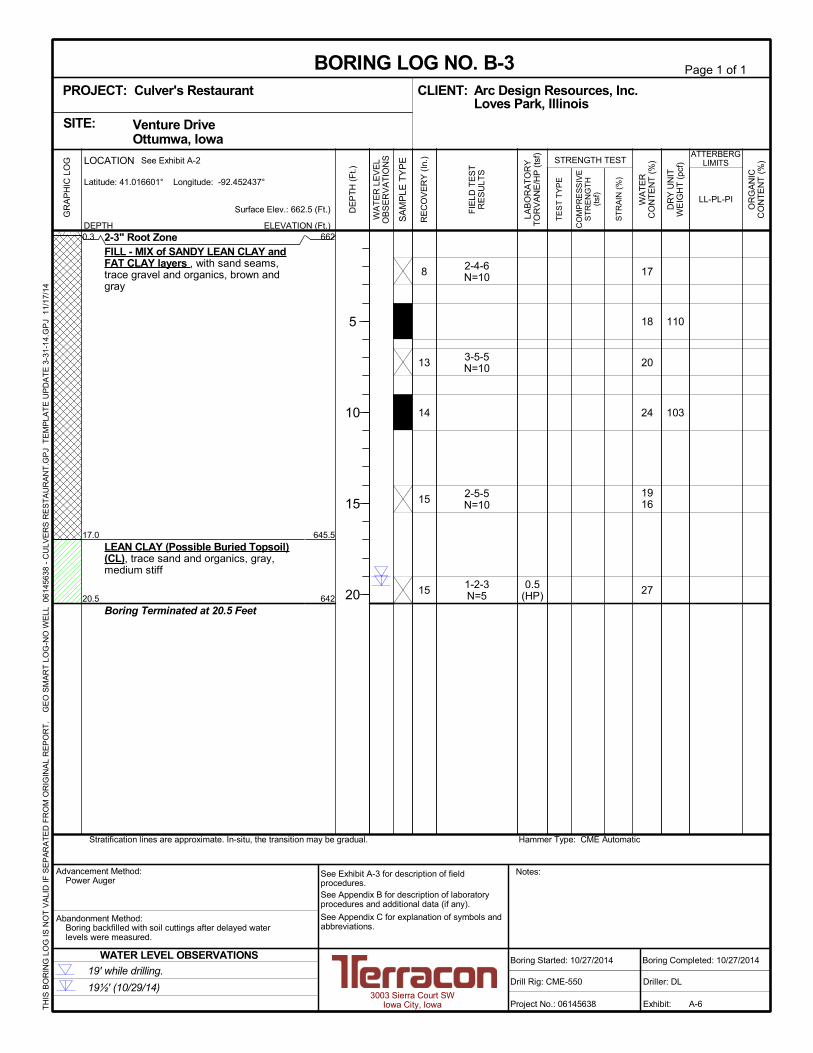
0.3
17.0
20.5
2-3" Root ZoneFILL - MIX of SANDY LEAN CLAY andFAT CLAY layers , with sand seams,trace gravel and organics, brown andgray
LEAN CLAY (Possible Buried Topsoil)(CL), trace sand and organics, gray,medium stiff
Boring Terminated at 20.5 Feet
2-4-6N=10
3-5-5N=10
2-5-5N=10
1-2-3N=5
0.5(HP)
17
18
20
24
1916
27
110
103
662
645.5
642
8
13
14
15
15
Hammer Type: CME AutomaticStratification lines are approximate. In-situ, the transition may be gradual.
LOCATION
DEPTH
Latitude: 41.016601° Longitude: -92.452437°
GR
AP
HIC
LO
G See Exhibit A-2
TH
IS B
OR
ING
LO
G IS
NO
T V
ALI
D IF
SE
PA
RA
TE
D F
RO
M O
RIG
INA
L R
EP
OR
T.
G
EO
SM
AR
T L
OG
-NO
WE
LL 0
614
563
8 -
CU
LVE
RS
RE
ST
AU
RA
NT
.GP
J T
EM
PLA
TE
UP
DA
TE
3-3
1-1
4.G
PJ
11/
17/1
4
Venture Drive Ottumwa, IowaSITE:
Page 1 of 1
Advancement Method:Power Auger
Abandonment Method:Boring backfilled with soil cuttings after delayed waterlevels were measured.
3003 Sierra Court SWIowa City, Iowa
Notes:
Project No.: 06145638
Drill Rig: CME-550
Boring Started: 10/27/2014
BORING LOG NO. B-3Arc Design Resources, Inc.CLIENT:Loves Park, Illinois
Driller: DL
Boring Completed: 10/27/2014
Exhibit: A-6
See Exhibit A-3 for description of fieldprocedures.See Appendix B for description of laboratoryprocedures and additional data (if any).
See Appendix C for explanation of symbols andabbreviations.
PROJECT: Culver's Restaurant
FIE
LD T
ES
TR
ES
ULT
S
LAB
OR
AT
OR
YT
OR
VA
NE
/HP
(ts
f)
TE
ST
TY
PE
CO
MP
RE
SS
IVE
ST
RE
NG
TH
(tsf
)
ST
RA
IN (
%)
OR
GA
NIC
CO
NT
EN
T (
%)
WA
TE
RC
ON
TE
NT
(%
)
DR
Y U
NIT
WE
IGH
T (
pcf)
ATTERBERGLIMITS
LL-PL-PI
ELEVATION (Ft.)
Surface Elev.: 662.5 (Ft.) DE
PT
H (
Ft.)
5
10
15
20
WA
TE
R L
EV
EL
OB
SE
RV
AT
ION
S
SA
MP
LE T
YP
E
RE
CO
VE
RY
(In
.) STRENGTH TEST
19' while drilling.
19½' (10/29/14)
WATER LEVEL OBSERVATIONS

0.3
21.0
25.5
2-3" Root ZoneFILL - MIX of SANDY LEAN CLAY andFAT CLAY layers , with sand seams,trace gravel and organics, brown andgray
FAT CLAY (CH), with sand seams,brown, medium stiff to very stiff
Boring Terminated at 25.5 Feet
2-3-7N=10
3-4-5N=9
4-6-9N=15
4-7-9N=16
2-3-4N=7
3.0(HP)
14
20
16
17
16
17
22
114
110
666.5
646
641.5
5
13
11
16
13
15
15
Hammer Type: CME AutomaticStratification lines are approximate. In-situ, the transition may be gradual.
LOCATION
DEPTH
Latitude: 41.01619° Longitude: -92.452723°
GR
AP
HIC
LO
G See Exhibit A-2
TH
IS B
OR
ING
LO
G IS
NO
T V
ALI
D IF
SE
PA
RA
TE
D F
RO
M O
RIG
INA
L R
EP
OR
T.
G
EO
SM
AR
T L
OG
-NO
WE
LL 0
614
563
8 -
CU
LVE
RS
RE
ST
AU
RA
NT
.GP
J T
EM
PLA
TE
UP
DA
TE
3-3
1-1
4.G
PJ
11/
17/1
4
Venture Drive Ottumwa, IowaSITE:
Page 1 of 1
Advancement Method:Power Auger
Abandonment Method:Boring backfilled with soil cuttings after delayed waterlevels were measured.
3003 Sierra Court SWIowa City, Iowa
Notes:
Project No.: 06145638
Drill Rig: CME-550
Boring Started: 10/27/2014
BORING LOG NO. B-4Arc Design Resources, Inc.CLIENT:Loves Park, Illinois
Driller: DL
Boring Completed: 10/27/2014
Exhibit: A-7
See Exhibit A-3 for description of fieldprocedures.See Appendix B for description of laboratoryprocedures and additional data (if any).
See Appendix C for explanation of symbols andabbreviations.
PROJECT: Culver's Restaurant
FIE
LD T
ES
TR
ES
ULT
S
LAB
OR
AT
OR
YT
OR
VA
NE
/HP
(ts
f)
TE
ST
TY
PE
CO
MP
RE
SS
IVE
ST
RE
NG
TH
(tsf
)
ST
RA
IN (
%)
OR
GA
NIC
CO
NT
EN
T (
%)
WA
TE
RC
ON
TE
NT
(%
)
DR
Y U
NIT
WE
IGH
T (
pcf)
ATTERBERGLIMITS
LL-PL-PI
ELEVATION (Ft.)
Surface Elev.: 667 (Ft.) DE
PT
H (
Ft.)
5
10
15
20
25
WA
TE
R L
EV
EL
OB
SE
RV
AT
ION
S
SA
MP
LE T
YP
E
RE
CO
VE
RY
(In
.) STRENGTH TEST
No water observed during drilling and sampling.
Dry cave in @ 24' (10/29/14)
WATER LEVEL OBSERVATIONS

0.3
17.0
20.5
2-3" Root ZoneFILL - MIX of SANDY LEAN CLAY andFAT CLAY layers , with sand seams,trace gravel and organics, brown andgray
LEAN CLAY (Possible Buried Topsoil)(CL), with sand, trace organics, darkgray, medium stiff
Boring Terminated at 20.5 Feet
% Passing #200 sieve = 73%For bulk sample from 0 to 17 feet
2-5-7N=12
4-6-7N=13
2-4-4N=8
2-4-5N=9
2-3-4N=7
1.0(HP)
16
18
19
18
16
26
107 38-14-24
663
646.5
643
9
14
11
13
13
14
Hammer Type: CME AutomaticStratification lines are approximate. In-situ, the transition may be gradual.
LOCATION
DEPTH
Latitude: 41.016409° Longitude: -92.452089°
GR
AP
HIC
LO
G See Exhibit A-2
TH
IS B
OR
ING
LO
G IS
NO
T V
ALI
D IF
SE
PA
RA
TE
D F
RO
M O
RIG
INA
L R
EP
OR
T.
G
EO
SM
AR
T L
OG
-NO
WE
LL 0
614
563
8 -
CU
LVE
RS
RE
ST
AU
RA
NT
.GP
J T
EM
PLA
TE
UP
DA
TE
3-3
1-1
4.G
PJ
11/
17/1
4
Venture Drive Ottumwa, IowaSITE:
Page 1 of 1
Advancement Method:Power Auger
Abandonment Method:Boring backfilled with soil cuttings after delayed waterlevels were measured.
3003 Sierra Court SWIowa City, Iowa
Notes:
Project No.: 06145638
Drill Rig: CME-550
Boring Started: 10/27/2014
BORING LOG NO. B-5Arc Design Resources, Inc.CLIENT:Loves Park, Illinois
Driller: DL
Boring Completed: 10/27/2014
Exhibit: A-8
See Exhibit A-3 for description of fieldprocedures.See Appendix B for description of laboratoryprocedures and additional data (if any).
See Appendix C for explanation of symbols andabbreviations.
PROJECT: Culver's Restaurant
FIE
LD T
ES
TR
ES
ULT
S
LAB
OR
AT
OR
YT
OR
VA
NE
/HP
(ts
f)
TE
ST
TY
PE
CO
MP
RE
SS
IVE
ST
RE
NG
TH
(tsf
)
ST
RA
IN (
%)
OR
GA
NIC
CO
NT
EN
T (
%)
WA
TE
RC
ON
TE
NT
(%
)
DR
Y U
NIT
WE
IGH
T (
pcf)
ATTERBERGLIMITS
LL-PL-PI
ELEVATION (Ft.)
Surface Elev.: 663.5 (Ft.) DE
PT
H (
Ft.)
5
10
15
20
WA
TE
R L
EV
EL
OB
SE
RV
AT
ION
S
SA
MP
LE T
YP
E
RE
CO
VE
RY
(In
.) STRENGTH TEST
No water observed during drilling and sampling.
Dry cave in @ 19' (10/29/14)
WATER LEVEL OBSERVATIONS

0.3
22.0
25.5
2-3" Root ZoneFILL - MIX of SANDY LEAN CLAY andFAT CLAY layers , with sand seams,trace gravel and organics, brown andgray
LEAN CLAY (Possible Buried Topsoil)(CL), with sand, trace organics, darkgray, medium stiff
Boring Terminated at 25.5 Feet
1-1-1N=2
0-1-1N=2
0-0-1N=1
2-2-5N=7
3-7-9N=16
1-2-2N=4
0.5(HP)
5.0%
21
20
31
17
20
1525
29
109
41-16-25
665.5
644
640.5
5
2
17
15
9
14
15
Hammer Type: CME AutomaticStratification lines are approximate. In-situ, the transition may be gradual.
LOCATION
DEPTH
Latitude: 41.016119° Longitude: -92.452312°
GR
AP
HIC
LO
G See Exhibit A-2
TH
IS B
OR
ING
LO
G IS
NO
T V
ALI
D IF
SE
PA
RA
TE
D F
RO
M O
RIG
INA
L R
EP
OR
T.
G
EO
SM
AR
T L
OG
-NO
WE
LL 0
614
563
8 -
CU
LVE
RS
RE
ST
AU
RA
NT
.GP
J T
EM
PLA
TE
UP
DA
TE
3-3
1-1
4.G
PJ
11/
17/1
4
Venture Drive Ottumwa, IowaSITE:
Page 1 of 1
Advancement Method:Power Auger
Abandonment Method:Boring backfilled with soil cuttings after delayed waterlevels were measured.
3003 Sierra Court SWIowa City, Iowa
Notes:
Project No.: 06145638
Drill Rig: CME-550
Boring Started: 10/27/2014
BORING LOG NO. B-6Arc Design Resources, Inc.CLIENT:Loves Park, Illinois
Driller: DL
Boring Completed: 10/27/2014
Exhibit: A-9
See Exhibit A-3 for description of fieldprocedures.See Appendix B for description of laboratoryprocedures and additional data (if any).
See Appendix C for explanation of symbols andabbreviations.
PROJECT: Culver's Restaurant
FIE
LD T
ES
TR
ES
ULT
S
LAB
OR
AT
OR
YT
OR
VA
NE
/HP
(ts
f)
TE
ST
TY
PE
CO
MP
RE
SS
IVE
ST
RE
NG
TH
(tsf
)
ST
RA
IN (
%)
OR
GA
NIC
CO
NT
EN
T (
%)
WA
TE
RC
ON
TE
NT
(%
)
DR
Y U
NIT
WE
IGH
T (
pcf)
ATTERBERGLIMITS
LL-PL-PI
ELEVATION (Ft.)
Surface Elev.: 666 (Ft.) DE
PT
H (
Ft.)
5
10
15
20
25
WA
TE
R L
EV
EL
OB
SE
RV
AT
ION
S
SA
MP
LE T
YP
E
RE
CO
VE
RY
(In
.) STRENGTH TEST
4' while drilling.
Dry cave in @ 23' (10/29/14)
WATER LEVEL OBSERVATIONS

APPENDIX BSUPPORTING INFORMATION

Geotechnical Engineering ReportProposed Culver’s Restaurant ■ Ottumwa, IowaNovember 19, 2014 ■ Terracon Project No. 06145638.01
Responsive ■ Resourceful ■ Reliable Exhibit B-1
Laboratory TestingSoil samples were tested in the laboratory to measure their natural water contents (ASTM D2216). Dry unit weight measurements were performed on portions of intact thin-walled tubesamples (ASTM D 7263). The unconfined compressive strength of some thin-walled tubesamples was also measured (ASTM D 2166). A hand penetrometer was used to estimate theunconfined compressive strength of some cohesive samples. The hand penetrometer providesa better estimate of soil consistency than visual examination alone. The following index testswere performed to aid in classifying the soils and evaluating their engineering properties:
n Atterberg limits (liquid and plastic) tests (ASTM D 4318);n Organic content (loss on ignition) determinations (ASTM D 2974);n Standard Proctor moisture-density relationship tests (ASTM D 698).
The results of the laboratory tests are shown on the boring logs, adjacent to the soil profiles, attheir corresponding sample depths.
As a part of the laboratory testing program, the soil samples were classified in the laboratorybased on visual observation, texture, plasticity, and the limited laboratory testing describedabove. Additional testing could be performed to more accurately classify the samples. Portionsof the recovered samples were placed in sealed containers, and the samples will be retained forat least 1 month in case additional testing is requested. The soil descriptions presented on theboring logs for native soils are in accordance with our enclosed General Notes and UnifiedSoil Classification System (USCS). The estimated group symbol for the USCS is also shownon the boring logs, and a brief description of the Unified System is attached to this report.
Procedural standards noted above are for reference to methodology in general. In some casesvariations to methods are applied as a result of local practice or professional judgment.

APPENDIX CSUPPORTING DOCUMENTS

PLASTICITY DESCRIPTION
Term
< 1515 - 29> 30
Descriptive Term(s)of other constituents
Water InitiallyEncountered
Water Level After aSpecified Period of Time
Major Componentof Sample
Percent ofDry Weight
(More than 50% retained on No. 200 sieve.)Density determined by Standard Penetration Resistance
Includes gravels, sands and silts.
Hard
Unconfined CompressiveStrength, Qu, tsf
Very Loose 0 - 3 0 - 6 Very Soft less than 0.25
7 - 18 Soft 0.25 to 0.50
10 - 29 19 - 58 0.50 to 1.00
59 - 98 Stiff 1.00 to 2.00
> 99 2.00 to 4.00
LOCATION AND ELEVATION NOTES
SA
MP
LIN
G
FIE
LD
TE
ST
S
(HP)
(T)
(b/f)
(PID)
(OVA)
DESCRIPTION OF SYMBOLS AND ABBREVIATIONS
Descriptive Term(Density)
Non-plasticLowMediumHigh
BouldersCobblesGravelSandSilt or Clay
10 - 18
> 50 15 - 30 19 - 42
> 30 > 42
_
Hand Penetrometer
Torvane
Standard PenetrationTest (blows per foot)
Photo-Ionization Detector
Organic Vapor Analyzer
Water levels indicated on the soil boringlogs are the levels measured in theborehole at the times indicated.Groundwater level variations will occurover time. In low permeability soils,accurate determination of groundwaterlevels is not possible with short termwater level observations.
CONSISTENCY OF FINE-GRAINED SOILS
(50% or more passing the No. 200 sieve.)Consistency determined by laboratory shear strength testing, field
visual-manual procedures or standard penetration resistance
DESCRIPTIVE SOIL CLASSIFICATION
Unless otherwise noted, Latitude and Longitude are approximately determined using a hand-held GPS device. The accuracyof such devices is variable. Surface elevation data annotated with +/- indicates that no actual topographical survey wasconducted to confirm the surface elevation. Instead, the surface elevation was approximately determined from topographicmaps of the area.
Soil classification is based on the Unified Soil Classification System. Coarse Grained Soils have more than 50% of their dryweight retained on a #200 sieve; their principal descriptors are: boulders, cobbles, gravel or sand. Fine Grained Soils haveless than 50% of their dry weight retained on a #200 sieve; they are principally described as clays if they are plastic, andsilts if they are slightly plastic or non-plastic. Major constituents may be added as modifiers and minor constituents may beadded according to the relative proportions based on grain size. In addition to gradation, coarse-grained soils are definedon the basis of their in-place relative density and fine-grained soils on the basis of their consistency.
Plasticity Index
01 - 1011 - 30
> 30
RELATIVE PROPORTIONS OF FINES
Descriptive Term(s)of other constituents
Percent ofDry Weight
< 55 - 12> 12
TraceWithModifier
Water Level Aftera Specified Period of Time
GRAIN SIZE TERMINOLOGYRELATIVE PROPORTIONS OF SAND AND GRAVEL
TraceWithModifier
Standard Penetration orN-Value
Blows/Ft.
Descriptive Term(Consistency)
Loose
Very Stiff
Standard Penetration orN-Value
Blows/Ft.
Ring SamplerBlows/Ft.
Ring SamplerBlows/Ft.
Medium Dense
Dense
Very Dense
0 - 1 < 3
4 - 9 2 - 4 3 - 4
Medium-Stiff
8 - 15
Exhibit C-1
5 - 9
30 - 50
WA
TE
R L
EV
EL
Auger
Shelby Tube
Ring Sampler
Grab Sample
Split Spoon
Macro Core
Rock Core
No Recovery
RELATIVE DENSITY OF COARSE-GRAINED SOILS
Particle Size
Over 12 in. (300 mm)12 in. to 3 in. (300mm to 75mm)3 in. to #4 sieve (75mm to 4.75 mm)#4 to #200 sieve (4.75mm to 0.075mmPassing #200 sieve (0.075mm)
ST
RE
NG
TH
TE
RM
S
> 4.00
4 - 8
GENERAL NOTES

Exhibit C-2
UNIFIED SOIL CLASSIFICATION SYSTEM
Criteria for Assigning Group Symbols and Group Names Using Laboratory Tests A
Soil Classification
Group
Symbol Group Name
B
Coarse Grained Soils:
More than 50% retained
on No. 200 sieve
Gravels:
More than 50% of
coarse fraction retained
on No. 4 sieve
Clean Gravels:
Less than 5% fines C
Cu 4 and 1 Cc 3 E
GW Well-graded gravel F
Cu 4 and/or 1 Cc 3 E
GP Poorly graded gravel F
Gravels with Fines:
More than 12% fines C
Fines classify as ML or MH GM Silty gravel F,G,H
Fines classify as CL or CH GC Clayey gravel F,G,H
Sands:
50% or more of coarse
fraction passes No. 4
sieve
Clean Sands:
Less than 5% fines D
Cu 6 and 1 Cc 3 E
SW Well-graded sand I
Cu 6 and/or 1 Cc 3 E
SP Poorly graded sand I
Sands with Fines:
More than 12% fines D
Fines classify as ML or MH SM Silty sand G,H,I
Fines classify as CL or CH SC Clayey sand G,H,I
Fine-Grained Soils:
50% or more passes the
No. 200 sieve
Silts and Clays:
Liquid limit less than 50
Inorganic: PI 7 and plots on or above “A” line
J CL Lean clay
K,L,M
PI 4 or plots below “A” line J ML Silt
K,L,M
Organic: Liquid limit - oven dried
0.75 OL Organic clay
K,L,M,N
Liquid limit - not dried Organic silt K,L,M,O
Silts and Clays:
Liquid limit 50 or more
Inorganic: PI plots on or above “A” line CH Fat clay
K,L,M
PI plots below “A” line MH Elastic Silt K,L,M
Organic: Liquid limit - oven dried
0.75 OH Organic clay
K,L,M,P
Liquid limit - not dried Organic silt K,L,M,Q
Highly organic soils: Primarily organic matter, dark in color, and organic odor PT Peat
A Based on the material passing the 3-inch (75-mm) sieve
B If field sample contained cobbles or boulders, or both, add “with cobbles
or boulders, or both” to group name. C
Gravels with 5 to 12% fines require dual symbols: GW-GM well-graded
gravel with silt, GW-GC well-graded gravel with clay, GP-GM poorly
graded gravel with silt, GP-GC poorly graded gravel with clay. D
Sands with 5 to 12% fines require dual symbols: SW-SM well-graded
sand with silt, SW-SC well-graded sand with clay, SP-SM poorly graded
sand with silt, SP-SC poorly graded sand with clay
E Cu = D60/D10 Cc =
6010
2
30
DxD
)(D
F If soil contains 15% sand, add “with sand” to group name.
G If fines classify as CL-ML, use dual symbol GC-GM, or SC-SM.
H If fines are organic, add “with organic fines” to group name.
I If soil contains 15% gravel, add “with gravel” to group name.
J If Atterberg limits plot in shaded area, soil is a CL-ML, silty clay.
K If soil contains 15 to 29% plus No. 200, add “with sand” or “with gravel,”
whichever is predominant. L
If soil contains 30% plus No. 200 predominantly sand, add “sandy” to
group name. M
If soil contains 30% plus No. 200, predominantly gravel, add
“gravelly” to group name. N
PI 4 and plots on or above “A” line. O
PI 4 or plots below “A” line. P
PI plots on or above “A” line. Q
PI plots below “A” line.


![Ottumwa tri-weekly courier (Ottumwa, Iowa), 1907-01-24, [p ].€¦ · Bond, 308 North Benton street, with whom they have been visiting, return ed home last evening. Mrs. Edna Carr,](https://img.pdfslide.net/doc/110x75/5f9ee0c398af2a64843d8a03/ottumwa-tri-weekly-courier-ottumwa-iowa-1907-01-24-p-bond-308-north-benton.jpg)