Embed Size (px)
Citation preview
CONSULTING ENGINEERS AND GEOLOGISTSCOTTON, SHIRES AND ASSOCIATES, INC.
330 Village Lane ! Los Gatos, California 95030 ! (408) 354-5542 Fax (408) 354-1852
6417 Dogtown Road ! San Andreas, California 95249 ! (209) 736-4252 Fax (209) 736-1212
2804 Camino Dos Rios, Suite 201 ! Thousand Oaks, California 91320 ! (805) 375-1050 Fax (805) 375-1059
Prepared for:
DAVID J. POWERS & ASSOCIATES, INC.
1871 The Alameda, Suite 200
San Jose, CA 95126
April 2018
GEOTECHNICAL FEASIBILITY
INVESTIGATION
Vallco Special Area Specific Plan
Cupertino, California
GEOTECHNICAL FEASIBILITY INVESTIGATION
Vallco Special Area Specific Plan Cupertino, California
For: DAVID J. POWERS & ASSOCIATES, INC.
1871 The Alameda, Suite 200 San Jose, CA 95126
by COTTON, SHIRES AND ASSOCIATES, INC.
330 Village Lane Los Gatos, California 95030
April 2018
April 27, 2018 G5035
TO : Kristy Weis DAVID J. POWERS & ASSOCIATES, INC. 1871 The Alameda, Suite 200 San Jose, CA 95126 SUBJECT : Geologic and Geotechnical Feasibility Evaluation RE : Vallco Special Area Specific Plan
Proposed Multi-Use Development Wolfe Road and Vallco Parkway, Cupertino
Dear Ms. Weis: Cotton, Shires and Associates, Inc. (CSA) is pleased to provide David J. Powers & Associates, Inc. with this letter-report summarizing our geotechnical feasibility investigation of the proposed multi-use development referred to as the Vallco Special Area Specific Plan, located along Wolfe Road, just south of Interstate 280. In this report, we provide preliminary geologic and geotechnical characterization of the area, summarize the potential geologic and geotechnical hazards, and provide preliminary recommendations for site development.
We trust that this provides you with the information that you need at this time. If you have any questions regarding this report, or need additional information, please feel free to call.
Very truly yours,
COTTON, SHIRES AND ASSOCIATES, INC. John M. Wallace Principal Engineering Geologist CEG 1923
Patrick O. Shires Senior Principal Geotechnical Engineer GE 770
JMW:POS:st
i
GEOTECHNICAL FEASIBILITY INVESTIGATION Vallco Special Area Specific Plan
Cupertino, California
Table of Contents FEASIBILITY REPORT .................................................................................................... Page 1.0 INTRODUCTION ............................................................................................... 1 1.1 Purpose and Scope of Work .................................................................. 1 1.2 Discussion ................................................................................................. 2 2.0 PHYSICAL SETTING ......................................................................................... 3 2.1 Topography .............................................................................................. 3 2.2 Geologic Setting ....................................................................................... 4 2.3 Seismic Setting .......................................................................................... 4 3.0 SITE CONDITIONS ........................................................................................... 5 3.1 Surface Conditions ................................................................................... 5 3.2 Subsurface Conditions ............................................................................ 5 3.3 Groundwater ............................................................................................ 6 3.4 Laboratory Testing ................................................................................... 6 4.0 POTENTIAL GEOLOGIC AND GEOTECHNICAL HAZARDS ............... 6 4.1 Seismic Hazards ....................................................................................... 6 4.1.1 Seismic Ground Shaking ............................................................ 6 4.1.2 Fault Rupture ............................................................................... 7 4.1.3 Liquefaction ................................................................................. 7 4.1.4 Lateral Spreading ........................................................................ 7 4.1.5 Seismically Induced Landsliding .............................................. 7 4.1.6 Tsunami ........................................................................................ 7 4.2 Flooding ..................................................................................................... 8 4.3 Settlement and Subsidence ..................................................................... 8 4.4 Expansive Soils ......................................................................................... 8 4.5 Soil Corrosion ........................................................................................... 9 4.6 Project Construction Hazards ................................................................ 9 5.0 CONCLUSIONS AND PRELIMINARY RECOMMENDATIONS ............ 9 5.1 Geotechnical Constraints ........................................................................ 10 5.1.1 Strong Seismic Shaking .............................................................. 10 5.1.2 Expansive Soils ............................................................................ 10
ii
5.1.3 Temporary Basement Excavation Support .............................. 10 5.1.4 Removal of Existing Structures ................................................. 10 5.2 Design-Level Geotechnical Investigation ............................................. 11 6.0 PRELIMINARY GEOTECHNICAL RECOMMENDATIONS .................... 11 6.1 Foundation Design Considerations ....................................................... 11 6.2 Temporary Shoring .................................................................................. 11 6.3 Site Grading .............................................................................................. 12 6.4 Seismic Design .......................................................................................... 12 6.5 Technical Review ..................................................................................... 12 6.6 Earthwork Construction Inspection and Testing ................................ 12 7.0 INVESTIGATION LIMITATIONS ................................................................. 13 8.0 REFERENCES ...................................................................................................... 14 8.1 Documents/Maps ..................................................................................... 14 8.2 Stereo-Pair Aerial Photographs .............................................................. 15 8.3 Google Earth Aerial Photographs .......................................................... 15 FIGURES Follows Page
1. Site Location Map .......................................................................................... 1 2. Regional Geologic Map .................................................................................. 4 3. San Francisco Bay Area Fault Map ............................................................... 4 4. Boring Location Map ...................................................................................... 5
TABLES Page
1. Summary of Project and Project Alternative Development ..................... 3 2. Seismic Design Parameters............................................................................ 12
1
GEOTECHNICAL FEASIBILITY INVESTIGATION Vallco Special Area Specific Plan
Cupertino, California
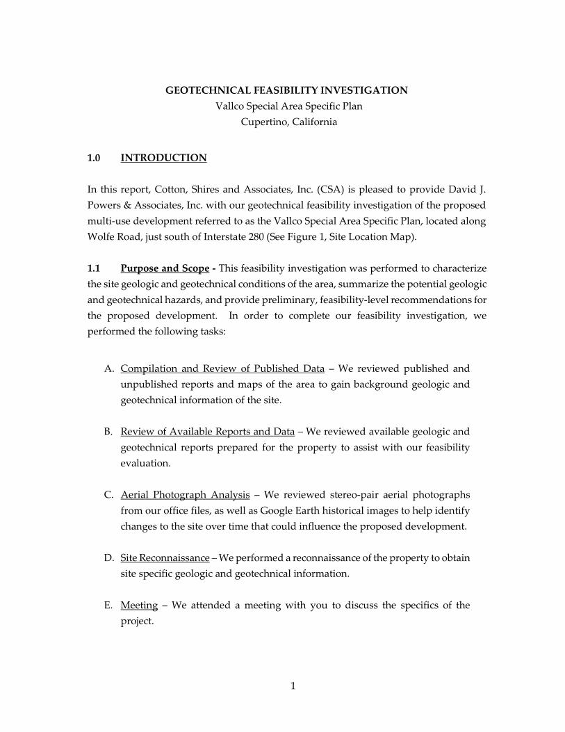
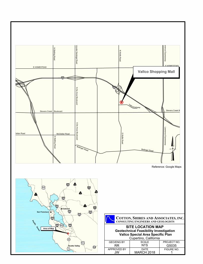
1.0 INTRODUCTION In this report, Cotton, Shires and Associates, Inc. (CSA) is pleased to provide David J. Powers & Associates, Inc. with our geotechnical feasibility investigation of the proposed multi-use development referred to as the Vallco Special Area Specific Plan, located along Wolfe Road, just south of Interstate 280 (See Figure 1, Site Location Map).
1.1 Purpose and Scope - This feasibility investigation was performed to characterize the site geologic and geotechnical conditions of the area, summarize the potential geologic and geotechnical hazards, and provide preliminary, feasibility-level recommendations for the proposed development. In order to complete our feasibility investigation, we performed the following tasks:
A. Compilation and Review of Published Data – We reviewed published and
unpublished reports and maps of the area to gain background geologic and geotechnical information of the site.
B. Review of Available Reports and Data – We reviewed available geologic and
geotechnical reports prepared for the property to assist with our feasibility evaluation.
C. Aerial Photograph Analysis – We reviewed stereo-pair aerial photographs
from our office files, as well as Google Earth historical images to help identify changes to the site over time that could influence the proposed development.
D. Site Reconnaissance – We performed a reconnaissance of the property to obtain
site specific geologic and geotechnical information.
E. Meeting – We attended a meeting with you to discuss the specifics of the project.
280
280
E HOMESTEAD
Stevens Creek Boulevard
McClellan Road
B
ollin
ger R
oad
E HOMESTEAD
Stevens Creek Boulevard
Sunnyvale S
aratoga R
oad
N S
telling R
oad
S S
telling R
oad
N W
olfe R
oad
S W
olfe R
oad
S D
e A
nza B
oulevard
N D
e A
nza B
oulevard
B
o
llin
g
e
r
R
o
a
d
Law
rence E
xpressw
ay
Law
rence E
xpressw
ay
V
a
l
l
c
o
Parkway
McClellan Road
Scotts Valley
880
80
680
5
580
380
580
780
205
5
Oakland
San Francisco
P
a
c
i
f
i
c
O
c
e
a
n
101280
101
4
99
1
12
113
17
1
101
152
Area of Map
CONSULTING ENGINEERS AND GEOLOGISTS
APPROVED BY
GEO/ENG BY SCALE
NTS
DATE FIGURE NO.
PROJECT NO.
COTTON, SHIRES AND ASSOCIATES, INC.
G5035RR
JW MARCH 2018 1
SITE LOCATION MAP
Geotechnical Feasibility Investigation
Vallco Special Area Specific Plan
N
Reference: Google Maps
Cupertino, California
Vallco Shopping Mall
2
F. Feasibility Report – We summarized our findings, and provided feasibility level recommendations, as deemed appropriate, in this letter-report.
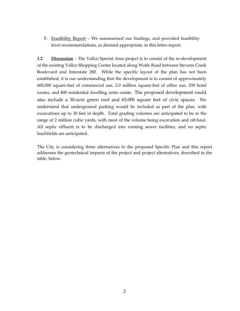
1.2 Discussion – The Vallco Special Area project is to consist of the re-development of the existing Vallco Shopping Center located along Wolfe Road between Stevens Creek Boulevard and Interstate 280. While the specific layout of the plan has not been established, it is our understanding that the development is to consist of approximately 600,000 square-feet of commercial use, 2.0 million square-feet of office use, 339 hotel rooms, and 800 residential dwelling units onsite. The proposed development could also include a 30-acre green roof and 65,000 square feet of civic spaces. We understand that underground parking would be included as part of the plan, with excavations up to 30 feet in depth. Total grading volumes are anticipated to be in the range of 2 million cubic yards, with most of the volume being excavation and off-haul. All septic effluent is to be discharged into existing sewer facilities, and no septic leachfields are anticipated. The City is considering three alternatives to the proposed Specific Plan and this report addresses the geotechnical impacts of the project and project alternatives, described in the table, below.
3
Summary of Project and Project Alternative Development
Land Uses
Commercial (square footage)
Office (square footage)
Hotel (rooms)
Residential (dwelling
units)
Green Roof
(acres)
Civic Space
(square feet)
Proposed Specific Plan 600,000 2,000,000 339 800 30
65,000 (10,000
of which would be for STEM
lab use)
Project Alternatives
General Plan Buildout with Maximum Residential Alternative
600,000 1,000,000 339 2,640 30
65,000 (10,000
of which would be for STEM
lab use)
Retail and Residential Alternative
600,000 0 339 4,000 0 0
Occupied/Re-Tenanted Mall Alternative
1,207,774 0 148 0 0 0
2.0 PHYSICAL SETTING
The project site is influenced by a number of physical parameters, including topography, geologic setting and seismicity. The following is a brief description of the engineering geologic and geotechnical engineering site constraints related to these parameters.

4
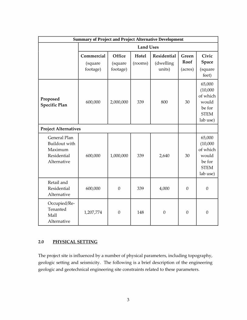
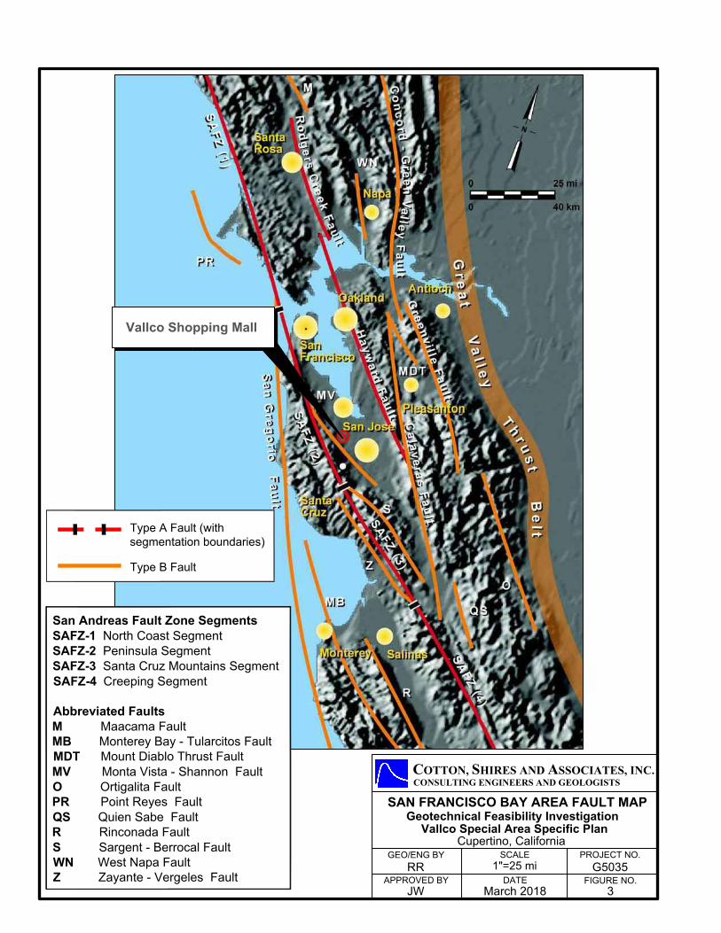
2.1 Topography - The project site is characterized, in general, by relatively level alluvial floodplain topography associated with the Santa Clara Valley floor. Elevations range from approximately El. 190 feet above sea level near Stevens Creek Boulevard, and El. 175 feet near Interstate 280. An artificial drainage channel is located along the northern portion of the site adjacent to Interstate 280, and is approximately 15 to 20 feet in depth. 2.2 Geologic Setting – The project site is located within the Coast Range Geomorphic Province. Local uplift of the Santa Cruz Mountains within the last 2 to 3 million years has occurred due to a restraining bend of the San Andreas fault, producing transpressional forces across the plate boundary. Thrust faults bound the San Andreas fault, and are responsible for uplift of the range. The range is characterized by rugged hills with moderate relief, steep valleys, and locally steep hillsides abutting drainages. East-flowing drainages result in dissection of the mountain range and alluvial deposition within the San Francisco Bay structural trough. According to published geologic maps (Dibblee, 2007), the site is underlain by unconsolidated older alluvial sediments (Figure 2, Regional Geologic Map). Young bay margin alluvium is locally susceptible to settlement and liquefaction; however these sediments are approximately 7 miles from the site. In the 1948 aerial photographs, the project site was an orchard. By 1970, the majority of the site was still an orchard; however, a large building was in place at the northwest corner of Stevens Creek Boulevard and Wolfe Road. 2.3 Seismic Setting - The project site is situated in a very seismically active area. Historically, this area has been subjected to very strong ground shaking from major earthquakes and the site will continue to experience very strong ground shaking in the future. Figure 3 illustrates the significant active faults located closest to the site, including the San Andreas fault zone (located 6.3 miles toward the southwest), the Hayward fault (located 12 miles to the northeast), the Sargent/Berrocal fault (located 5.2 miles toward the southwest), and the Monta Vista/Shannon fault (2.7 miles to the southwest). The site is not located within a State (California Geological Survey) Mapped Alquist-Priolo fault zone, or an Earthquake-Induced Landslide or Liquefaction Hazard Zone. We performed a peak ground acceleration analysis of the site employing the U.S.G.S. Seismic Design Tool, with the 2010 ASCE 7 (with March 2013 errata) Design Code. The results of our analysis indicate an appropriate Maximum Considered Earthquake
CONSULTING ENGINEERS AND GEOLOGISTS
FIGURE NO.
PROJECT NO.
DATE
SCALE
APPROVED BY
GEO/ENG BY
GEOLOGIC MAP
RR
JW
1"=2000' G5035
MARCH 2018 3
0 1000 2000
(FEET)
N
Alluvial gravel, sand, silt and clay;
represents younger stream
alluvium in fan deposits; mapped
as part of undivided Qa where not
differentiated
Qa. 2
Alluvial sand, fine-grained, silt, and
gravel; where differentiated
represents alluvial fan deposits at
base of slope and upper fan areas;
mapped as part of undivided Qa
where not differentiated
Qa. 1
EXPLANATION
Geotechnical Feasibility Investigation
Vallco Special Area Specific Plan
COTTON, SHIRES AND ASSOCIATES, INC.
Vallco Shopping Mall
Reference: Geologic Map of the Cupertino and San Jose West Quadrangles,
Thomas W. Dibblee, Jr. 2007
Cupertino, California
Type A Fault (with
segmentation boundaries)
Type B Fault
San Andreas Fault Zone Segments
SAFZ-1 North Coast Segment
SAFZ-2 Peninsula Segment
SAFZ-3 Santa Cruz Mountains Segment
SAFZ-4 Creeping Segment
Abbreviated Faults
M Maacama Fault
MB Monterey Bay - Tularcitos Fault
MDT Mount Diablo Thrust Fault
MV Monta Vista - Shannon Fault
O Ortigalita Fault
PR Point Reyes Fault
QS Quien Sabe Fault
R Rinconada Fault
S Sargent - Berrocal Fault
WN West Napa Fault
Z Zayante - Vergeles Fault
CONSULTING ENGINEERS AND GEOLOGISTS
APPROVED BY
GEO/ENG BY SCALE
1"=25 mi
DATE FIGURE NO.
PROJECT NO.
COTTON, SHIRES AND ASSOCIATES, INC.
G5035RR
JW March 2018 3
Vallco Special Area Specific Plan
Geotechnical Feasibility Investigation
SAN FRANCISCO BAY AREA FAULT MAP
Cupertino, California
Vallco Shopping Mall
5
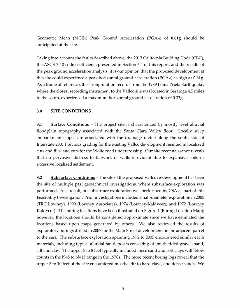
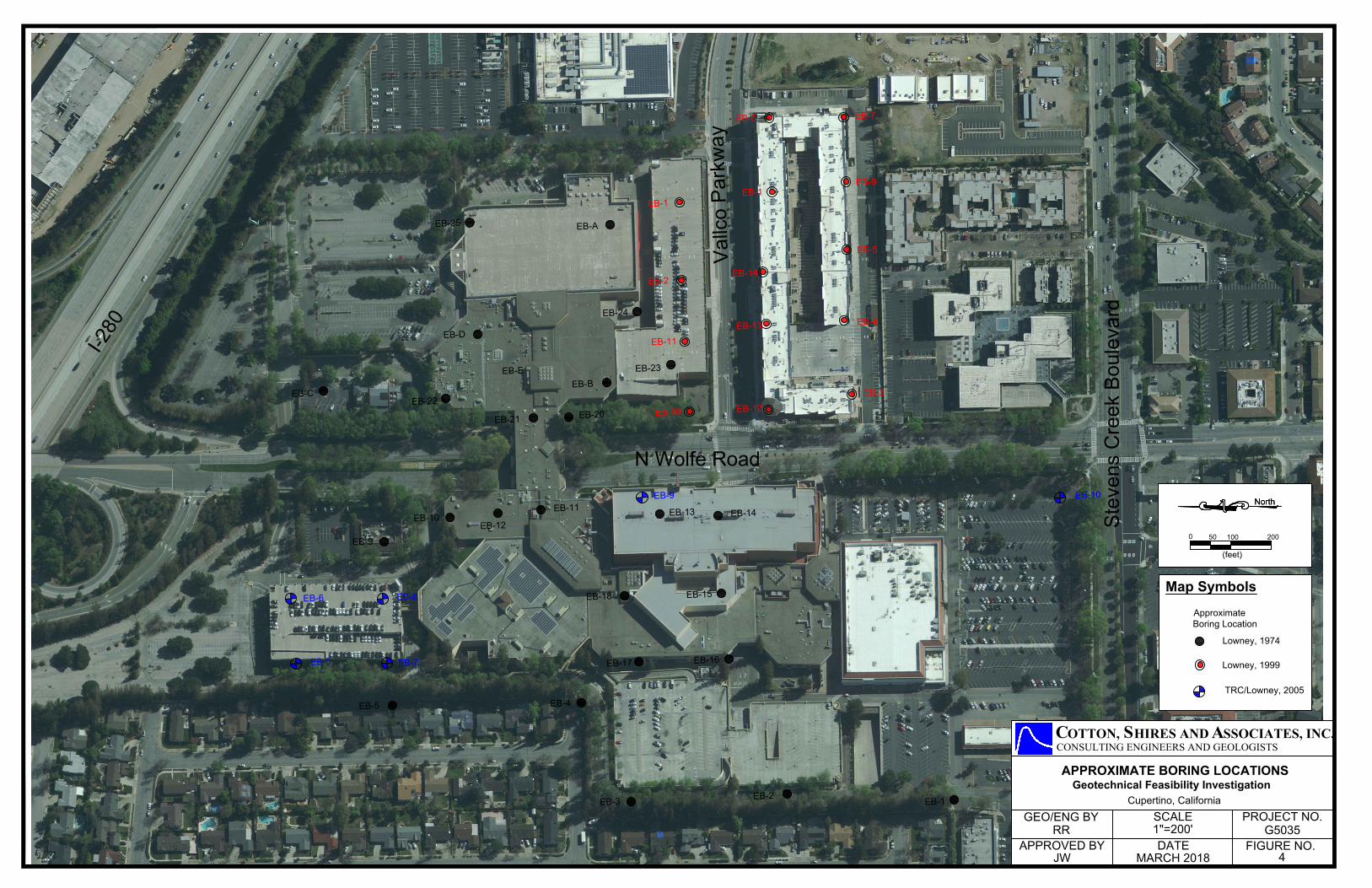
Geometric Mean (MCEG) Peak Ground Acceleration (PGAM) of 0.61g should be anticipated at the site. Taking into account the faults described above, the 2013 California Building Code (CBC), the ASCE 7-10 code coefficients presented in Section 6.4 of this report, and the results of the peak ground acceleration analysis, it is our opinion that the proposed development at this site could experience a peak horizontal ground acceleration (PGAM) as high as 0.61g. As a frame of reference, the strong-motion records from the 1989 Loma Prieta Earthquake, where the closest recording instrument to the Vallco site was located in Saratoga 4.5 miles to the south, experienced a maximum horizontal ground acceleration of 0.33g. 3.0 SITE CONDITIONS 3.1 Surface Conditions – The project site is characterized by mostly level alluvial floodplain topography associated with the Santa Clara Valley floor. Locally steep embankment slopes are associated with the drainage ravine along the south side of Interstate 280. Previous grading for the existing Vallco development resulted in localized cuts and fills, and cuts for the Wolfe road undercrossing. Our site reconnaissance reveals that no pervasive distress to flatwork or walls is evident due to expansive soils or excessive localized settlement. 3.2 Subsurface Conditions – The site of the proposed Vallco re-development has been the site of multiple past geotechnical investigations, where subsurface exploration was performed. As a result, no subsurface exploration was performed by CSA as part of this Feasibility Investigation. Prior investigations included small-diameter exploration in 2005 (TRC Lowney), 1999 (Lowney Associates), 1974 (Lowney-Kaldveer), and 1972 (Lowney Kaldveer). The boring locations have been illustrated on Figure 4 (Boring Location Map); however, the locations should be considered approximate since we have estimated the locations based upon maps generated by others. We also reviewed the results of exploratory borings drilled in 2007 for the Main Street development on the adjacent parcel to the east. The subsurface exploration spanning 1972 to 2005 encountered similar earth materials, including typical alluvial fan deposits consisting of interbedded gravel, sand, silt and clay. The upper 5 to 8 feet typically included loose sand and soft clays with blow counts in the N=5 to N=15 range in the 1970s. The more recent boring logs reveal that the upper 5 to 10 feet of the site encountered mostly stiff to hard clays, and dense sands. We
EB-C
EB-25
EB-D
EB-22
EB-21
EB-E
EB-20
EB-B
EB-23
EB-24
EB-A
EB-9
EB-10
EB-12
EB-11
EB-13
EB-14
EB-18
EB-17
EB-16
EB-5
EB-4
EB-3
EB-2
EB-1
EB-15
EB-5
EB-6
EB-8
EB-7
EB-9 EB-10
EB-1
EB-2
EB-11
EB-10
EB-12
EB-13
EB-14
EB-1
EB-6
EB-7
EB-9
EB-5
EB-4
EB-3
Lowney, 1974
Lowney, 1999
TRC/Lowney, 2005
Approximate
Boring Location
Map Symbols
NorthNorth
050 100 200
(feet)
COTTON, SHIRES AND ASSOCIATES, INC.CONSULTING ENGINEERS AND GEOLOGISTS
Cupertino, California
JW
RR
MARCH 2018
1"=200'
FIGURE NO.
PROJECT NO. G5035
DATE
SCALE
APPROVED BY
GEO/ENG BY
APPROXIMATE BORING LOCATIONS
4
Geotechnical Feasibility Investigation
N Wolfe Road
Vallc
o Pa
rkw
ay
I-280
Stev
ens
Cre
ek B
oule
vard
6
interpret this difference between the older investigations and the newer investigations to be the result of the Vallco development where excavation/compaction of the loose upper soils was performed. The recent borings reveal that, in general, the site is underlain by medium dense to dense sands, and stiff to hard clays. 3.3 Groundwater – Based upon our review of the California Geological Survey, 2002, Seismic Hazard Zone Report for the Cupertino 7.5-Minute Quadrangle, the depth to groundwater at the site is likely to be greater than 50 feet below the ground surface. The 2005 TRC Lowney investigation encountered free groundwater in only one boring (EB-9), which was drilled to a depth of 84.5 feet and encountered groundwater at a depth of 68 feet. 3.4 Laboratory Testing – Atterberg Limits tests on representative undisturbed samples obtained from exploratory borings during previous investigations reveal that the site surficial soils have Plasticity Indexes (P.I.) ranging from 12 to 26. These test results indicate that the tested soils range from low expansion potential to high expansion potential. 4.0 POTENTIAL GEOLOGIC AND GEOTECHNICAL HAZARDS In the following section, we list identified potential geologic and geotechnical hazards at the proposed Vallco re-development site, along with the corresponding degrees of estimated potential risk. These potential hazards include seismic hazards, flooding, settlement, and expansive soils. In Section 5.0, we provide preliminary recommendations for possible mitigation measures. 4.1 Seismic Hazards – Due to the location of the site in an area of high seismicity, we summarize the potential seismic hazards, including: seismic shaking, fault rupture, liquefaction, lateral spreading, and seismically induced landsliding. 4.1.1 Seismic Ground Shaking - Seismic ground shaking associated with a large earthquake on the San Andreas fault or one of the closer faults should be expected during the design life of the development. Peak ground accelerations of up to 0.61g should be anticipated at the site (see report Section 2.3). With prudent design in accordance with
7
the most up-to-date building codes, the risk from seismic ground shaking can be reduced to acceptable levels.
4.1.2 – Fault Rupture - No active faults have been recognized on, or mapped through, the subject property. Thus, the potential for surface faulting and ground rupture from faulting at the subject site is considered to be low. The Monta Vista/Shannon fault (Type B fault) is the closest mapped fault to the site, located approximately 2.7 miles to the southwest. 4.1.3 – Liquefaction – Liquefaction occurs during seismic, cyclic ground shaking when saturated, loose to medium dense cohesionless soil experiences increased pore water pressure and reduced effective stress. This can result in the transformation of the soil from a solid to near-liquid state. Large shear deformations may result, as well as settlement. Subsurface exploration at the site primarily encountered stiff to hard clays, and medium dense to dense sands. Isolated loose to medium dense sands were encountered locally; however, due to the lack of groundwater within the upper 50 feet at this site, we judge the liquefaction risk to be Low. 4.1.4 – Lateral Spreading – Lateral spreading occurs when earth materials lose strength, often as a result of liquefaction, and flow or slide toward a ‘free face’. The free face is an area lacking confinement, such as an open channel, or excavation. A small (10- to 15-foot deep) creek channel is located along the far northern portion of the site; however, due to the lack of weak liquefiable material, and depth to groundwater that exceeds 50 feet, the risk of lateral spreading is low. 4.1.5 – Seismically Induced Landsliding – Due to the lack of topography at the site, the risk of seismically induced landsliding is low. 4.1.6 – Tsunami – The project site is located at an elevation of approximately 175 to 190 feet above sea level. Our review of the California Geologic Survey Tsunami Inundation map (2009) reveals that the inundation zone associated with the San Francisco Bay is located over 7.5 miles north of the Vallco site. Therefore, the risk of tsunami inundation at the site is low.
8
4.2 Flooding – The City of Cupertino prepared an emergency dam failure plan, in accordance with the California Government Code's Emergency Services Act (ESA, Section 8589.5), which calls for public safety agencies whose territory contains populated areas below dams to adopt emergency procedures for the evacuation and control of these areas in the event of a partial or total failure of the dam. The Joint Stevens Creek Dam Failure Plan was prepared in 2012 and inundation maps were prepared as part of the Dam Failure Plan. The flood area shown from a potential failure of the Stevens Creek Dam, located approximately 4 miles southwest of the project area, is primarily confined to Stevens Creek Canyon, extending from the dam site to Interstate 280, and then spreads out north of Interstate 280. Therefore, a catastrophic failure of the Stevens Creek Dam is not expected to inundate the proposed development. 4.3 Settlement and Subsidence – The site is underlain by unconsolidated alluvial sediments consisting of interbedded gravel, sand, silt and clay. Isolated loose to medium dense sand and gravel layers were encountered in the borings that could result in the potential for settlement. The existing development at the site has not, to our knowledge, been adversely impacted by differential settlement; therefore, provided the proposed development concept is grossly similar, the risk due to excessive differential settlement is low. However, the proposed development concept has not been developed at this time, thus, quantifying settlement is not possible. Once the development concept has been generated, a site-specific geotechnical investigation should be performed to evaluate and quantify the settlement potential. Land subsidence is a settling of the earth’s surface due to the compaction of subsurface materials, often times associated with groundwater or oil extraction. The Santa Clara Valley Water District (SCVWD) actively monitors for land subsidence through surveying, groundwater elevation monitoring, and data from compaction wells. SCVWD reduces the potential for land subsidence county-wide by reducing demand on groundwater and recharging groundwater basins.[1] There are no groundwater extraction wells on-site and no active pumping of groundwater on-site; therefore, the risk of site subsidence is low. 4.4 Expansive Soils – Expansive soils are clay rich soils that have the ability to undergo large volume changes with changes in moisture content. The large fluctuations in volume, often referred to as shrink/swell potential, can adversely impact foundations. Previous laboratory tests performed on soil samples at the site, specifically Atterberg
9
Limits tests, reveal that the site soils have Plasticity Indexes ranging from 12 to 26, which corresponds with low to high expansion potential. With prudent design, the risk from potentially expansive soils can be reduced to acceptable levels. Additional testing should be performed as part of a site-specific geotechnical investigation. 4.5 Soil Corrosion - Corrosion of steel and sulfate attack on concrete is a potential hazard to construction elements and utilities in contact with soil. These hazards are unknown at this time, but can typically be accounted for with prudent design. Appropriate laboratory tests should be performed as part of a site-specific geotechnical design investigation so that corrosion resistant materials can be incorporated into the design so that corrosion hazards can be reduced to acceptable low levels. 4.6 Project Construction Hazards – The proposed project construction could adversely impact adjacent structures if proper construction methods are not incorporated. A qualified contractor must be selected, and with proper shoring, vibration monitoring, and construction observation, the risks posed by the construction activities (i.e., settlement, trench collapse, loss of subjacent support, and excessive vibrations) can be reduced to acceptable levels.
5.0 CONCLUSIONS AND PRELIMINARY RECOMMENDATIONS Based upon our geotechnical feasibility investigation, which included review of available reports, aerial photographs, and site reconnaissance evaluations, it is our opinion that re-development of the Vallco site is feasible from a geotechnical engineering standpoint, provided the recommendations in this report, and of a site-specific report are adhered to, and the proposed development is grossly similar in scope as the existing development (i.e. relatively shallow basements, and above ground structures that are relatively low compared with their foundation area, including a possible 30-acre green roof and 65,000 square feet of civic spaces). The following preliminary design recommendations are intended to be used for conceptual planning of the project. A design-level geotechnical investigation should be performed to provide specific geotechnical recommendations for the project once a design concept has been developed.
10
5.1 Geotechnical Constraints - The prim ary geologic and geotechnical constraints to site development include the following: 1) seismic ground shaking; 2) expansive soils; 3) temporary basement excavation support; and 4) demolition and removal of existing facilities. 5.1.1 Strong Seismic Shaking – Strong seismic ground shaking is anticipated at the site, but it is not a unique geologic hazard, but one that is common to all structures in the vicinity. With prudent design to the most up-to-date building codes, the risk from seismic ground shaking can be reduced to acceptable levels. We recommend that, at a minimum, the proposed project be designed in accordance with the seismic design criteria as discussed in Section 2.3, and to the site seismic coefficients presented in Table 1 (see Section 6.4)
5.1.2 Expansive Soils – Geotechnical sampling and testing should be performed once the conceptual development plan is available, and geotechnical design recommendations provided to either remove and replace highly expansive soils, treat them in place, or increase the thickness of non-expansive base material beneath foundations and slabs on grade.
5.1.3 Temporary Basement Excavation Support - The w alls of temporary basement excavations, if not properly shored, could yield or fail and adversely impact adjacent properties and structures. The temporary excavations could be supported by various methods depending upon the final basement design, but could include tiebacks and shotcrete, soldier beam and wood lagging walls, interior supports, or sloping of the excavations. Pre-construction surveys should be performed to document the condition of adjacent structures, roadways and facilities, and could include the following tasks depending upon the nature of the adjacent property: photographs, floor level surveys, surface surveys, and distress documentation. In addition, we recommend that diligent ‘during construction’ monitoring be conducted if excavations are close to nearby structures, including vibration monitoring and tilt surveys.
5.1.4 Removal of Existing Structures - Removal of the existing Vallco facilities will result in large-scale demolition and grading, resulting in disruption to the site soils. Following removal of asphalt, concrete and utilities, areas of the site that will not be excavated for basements should be investigated to assure removal of all debris and loose fill. These areas should be over-excavated and re-compacted with engineered fill to assure
11
uniform, competent earth materials support the new structures and roads.
5.2 Design-Level Geotechnical Investigation - A site-specific design-level geotechnical investigation should be performed once site development plans are completed. Detailed geotechnical design recommendations for foundations, retaining walls, grading and drainage will be presented in the site-specific report. The recommendations of this feasibility report are for the purpose of providing feasibility-level input for conceptual planning purposes only, and are based upon a review of previous geotechnical reports, site reconnaissance evaluations, and our experience with the area. The subsurface information and laboratory test data provide informative general information for portions of the site, but site-specific subsurface information should be gathered once the development plan is available.
6.0 PRELIMINARY GEOTECHNICAL RECOMMENDATIONS
6.1 Foundation Design Considerations - The principal factors affecting foundation type are potentially expansive earth materials, the potential for localized settlement, and the proximity of footings to cuts and fills. It is likely that the majority of the at-grade structures may be supported on either conventional spread footings bearing on the undisturbed, non-expansive native soils or on compacted engineered fill, or on reinforced mat foundations. Where structures are adjacent to cuts, or adjacent to retaining walls, or where expansive soils are deep, pier-supported foundations may be necessary.
6.2 Temporary Shoring – Temporary shoring should be anticipated for basement excavations and utility trenches. We anticipate that the pipeline and outfall structures will be excavated in CAL-OSHA ‘Type C Soils’. The temporary shoring should be designed by the contractor in order to protect personnel, existing adjacent structures, and utilities. It should be designed to prevent settlement, heave and lateral movement into the excavation, and should be designed to minimize vibrations and withstand anticipated surcharge loads from vehicular traffic. The contractor is responsible for on-site safety, and all shoring should comply with CAL-OSHA excavation and grading codes, and the contractor shall have a ‘competent person’ (as defined by CAL-OSHA) on site each day, and throughout the day, to monitor the site soil, groundwater and shoring systems, as conditions may change. Additionally, the project specifications should require the
12
contractor to repair all damages to adjacent structures, roads and utilities resulting from the project construction. 6.3 Site Grading - Grading excavations should be within the capabilities of moderate excavation equipment (i.e., backhoes and excavators).
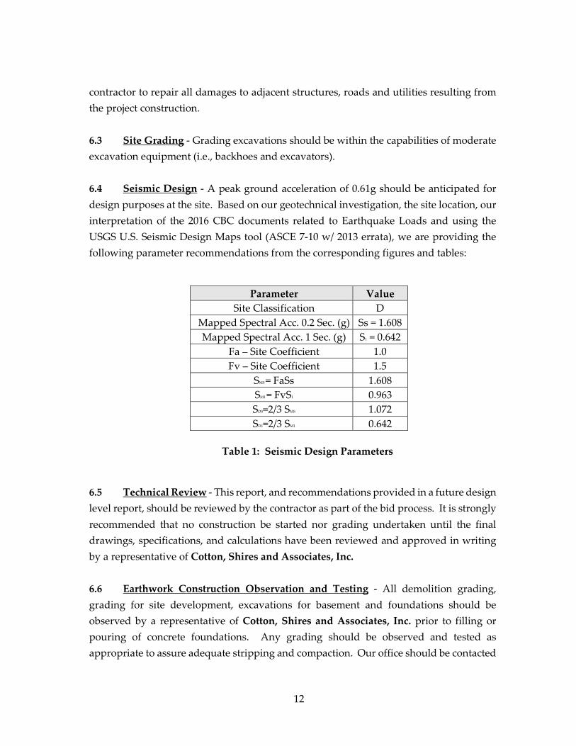
6.4 Seismic Design - A peak ground acceleration of 0.61g should be anticipated for design purposes at the site. Based on our geotechnical investigation, the site location, our interpretation of the 2016 CBC documents related to Earthquake Loads and using the USGS U.S. Seismic Design Maps tool (ASCE 7-10 w/ 2013 errata), we are providing the following parameter recommendations from the corresponding figures and tables:
Parameter Value Site Classification D
Mapped Spectral Acc. 0.2 Sec. (g) Ss = 1.608 Mapped Spectral Acc. 1 Sec. (g) S1 = 0.642
Fa – Site Coefficient 1.0 Fv – Site Coefficient 1.5
SMS = FaSs 1.608 SM1 = FvS1 0.963 SDS=2/3 SMS 1.072 SD1=2/3 SM1 0.642
Table 1: Seismic Design Parameters
6.5 Technical Review - This report, and recommendations provided in a future design level report, should be reviewed by the contractor as part of the bid process. It is strongly recommended that no construction be started nor grading undertaken until the final drawings, specifications, and calculations have been reviewed and approved in writing by a representative of Cotton, Shires and Associates, Inc. 6.6 Earthwork Construction Observation and Testing - All demolition grading, grading for site development, excavations for basement and foundations should be observed by a representative of Cotton, Shires and Associates, Inc. prior to filling or pouring of concrete foundations. Any grading should be observed and tested as appropriate to assure adequate stripping and compaction. Our office should be contacted
13
with a minimum of 48 hours advance notice of construction activities requiring inspection and/or testing services and a minimum of 72 hours advance notice and provision of representative laboratory compaction curve samples for testing of fill. 7.0 LIMITATIONS Our services consist of professional opinions and recommendations made in accordance with generally accepted engineering geology and geotechnical engineering principles and practices. No warranty, expressed or implied, or merchantability of fitness, is made or intended in connection with our work, by the proposal for consulting or other services, or by the furnishing of oral or written reports or findings. Any recommendations and/or design criteria presented in this report are contingent upon our firm being retained to perform a site-specific geotechnical investigation, review the final drawings and specifications, to be consulted when any questions arise with regard to the recommendations contained herein, and to provide testing and inspection services for earthwork and construction operations. Unanticipated soil and geologic conditions are commonly encountered during construction which cannot be fully determined from existing exposures or by limited subsurface investigation. Such conditions may require additional expenditures during construction to obtain a properly constructed project. Some contingency fund is recommended to accommodate these possible extra costs. This report is issued with the understanding that it is the responsibility of the owner, or of his representative, to ensure that the information and recommendations contained herein are called to the attention of the project architect and/or engineer and incorporated into the plans. Furthermore, it is also the responsibility of the owner, or of his representative, to ensure that the contractor and subcontractors carry out such recommendations in the field. 8.0 REFERENCES 8.1 Publications and Maps
14
Bowles, J.E., Foundation Analysis and Design, Third Edition, 1982, McGraw-Hill Book Company.
California Geological Survey, 2008, Guidelines for Evaluating and Mitigating Seismic
Hazards in California: Special Publication 117A. California Geological Survey, California Emergency Management Agency, University of
Southern California, 2009, Tsunami Inundation Map for Emergency Planning, San Francisco Bay Area.
California Geological Survey, 2002, Seismic Hazard Zone Report for the Cupertino 7.5-
Minute Quadrangle, Santa Clara County, California, Seismic Hazard Zone Report 068. City of Cupertino, 2012, Joint Stevens Creek Dam Failure Plan, Cupertino Emergency Plan,
prepared by the Santa Clara County Fire Department.
Dibblee Jr., T.W., 2007, Geologic Map of the Cupertino and San Jose West Quadrangles. McLaughlin, R.J., Clark, J.C., Brabb, E.E., Helley, E.J., and Colon, C.J., 2001. Geologic maps
and structure sections of the southwestern Santa Clara Valley and southern Santa Cruz Mountains, Santa Clara and Santa Cruz Counties, California, US Geological Survey, Miscellaneous field studies, Map MF-2373.
Santa Clara Valley Water District, website information on subsidence. Sarna-Wojcicki, A.M., Pampeyan, E.H., and Hall, T., 1975, Map showing recently active
breaks along the San Andreas fault between the central Santa Cruz Mountains and the northern Gabilan Range, California: USGS Miscellaneous Field Studies Map MF-650, scale: 1:24,000, 2 sheets.
Southern California Earthquake Center, 1999, Recommended Procedures for Implementation of DMG Special Publication 117, Guidelines for Analyzing and Mitigating Liquefaction Hazards in California.
Terzaghi, K., and Peck, R.B., 1967, Soil Mechanics in Engineering Practice, John Wiley and Sons, Inc.
15
TRC Lowney, 2015, Preliminary Geotechnical Investigation, The Hills at Vallco, November 19, 2015.
TRC Lowney, 2007, Preliminary-Level Geotechnical Investigation, Vallco Mixed-Use
Development, November 27, 2007. TRC Lowney, 2007, Supplemental Geotechnical Recommendations, Vallco Mixed-Use
Creek Fill Investigation, December 17, 2007. TRC Lowney, 2005, Geotechnical Investigation Vallco Fashion Park Mixed-Use
Expansion, June 7, 2005. TRC Lowney, 1999, Geotechnical Investigation for Vallco Fashion Park Expansion, June
20, 1999.
U. S. Department of the Navy, 1986; Design Manual Soil Mechanics, Foundations, and Earth Structures, NAVFAC DM-7.02.
U.S. Geological Survey, 2015, Cupertino Quadrangle, California; Santa Clara County, 7.5-Minute Topographic Map, scale 1:24,000.
U.S. Geological Survey, U.S. Seismic Design Maps Tool Web Application, ASCE 7-10, errata July 2013.
8.2 Stereo-Pair Aerial Photographs Date Scale Line Vendor 9-3-1970 1”= 1,200’ Cupertino 9, 13 CSA Office File
8.3 Google Earth Aerial Images 1948, 1991, 1993, 2000 to Present