Embed Size (px)
Citation preview
20173992.001A/SAC17R57127 Page i of v April 10, 2017 © 2017 Kleinfelder
GEOTECHNICAL INVESTIGATION REPORT YUBA CITY WWTF IMPROVEMENTS HASSETT AVENUE AND BURNS DRIVE YUBA CITY, CALIFORNIA KLEINFELDER PROJECT NO.: 20173992.001A
April 10, 2017
Copyright 2017 Kleinfelder
All Rights Reserved
ONLY THE CLIENT OR ITS DESIGNATED REPRESENTATIVES MAY USE THIS DOCUMENT AND ONLY
FOR THE SPECIFIC PROJECT FOR WHICH THIS REPORT WAS PREPARED.
20173992.001A/SAC17R57127 Page ii of v April 10, 2017 © 2017 Kleinfelder
April 10, 2017 Project No. 20173992.001A Mr. Kingsley Kuang, PE RMC, a Woodard & Curran Company 2175 N. California Blvd, Suite 315 Walnut Creek, CA 94596 Subject: Geotechnical Investigation Report
Yuba City WWTF Improvements Hassett Avenue and Burns Drive
Yuba City, California Dear Mr. Kuang: Kleinfelder is pleased to present the attached geotechnical investigation report for the proposed improvements to the Yuba City wastewater treatment facility (WWTF) located south of the intersection of Hassett Avenue and Burns Drive in Yuba City, California. This report provides the results of field explorations, laboratory testing, and engineering analyses performed to provide geotechnical recommendations for project design and construction. The primary geotechnical considerations at this site are shallow groundwater, soft soils and the potential for liquefaction settlement at the site due to design earthquake ground motions. These issues are addressed in detail in the report. We appreciate the opportunity to be of service on this project. If you have questions, comments, or require additional information, please do not hesitate to contact our office at (916) 366-1701. Respectfully submitted, KLEINFELDER, INC. Rebecca L. Money, PE, GE Kenneth G. Sorensen, PE, GE Senior Geotechnical Engineer Principal Geotechnical Engineer
20173992.001A/SAC17R57127 Page iii of v April 10, 2017 © 2017 Kleinfelder
TABLE OF CONTENTS ___________________________________________________________________________________
1 INTRODUCTION ............................................................................................................. 1
1.1 PROJECT DESCRIPTION ................................................................................... 1
1.2 PURPOSE ........................................................................................................... 2
1.3 SITE LOCATION AND DESCRIPTION ................................................................ 2
1.4 PREVIOUS EXPLORATIONS .............................................................................. 3
1.5 SCOPE OF SERVICES ....................................................................................... 3
2 FIELD EXPLORATION AND LABORATORY TESTING ................................................. 6
2.1 FIELD EXPLORATION ........................................................................................ 6
2.1.1 Site Reconnaissance ................................................................................ 6
2.1.2 Field Exploration ....................................................................................... 6
2.1.3 Sampling Procedures ............................................................................... 7
2.2 GEOTECHNICAL LABORATORY TESTING ....................................................... 8
3 GEOLOGIC AND SUBSURFACE CONDITIONS ............................................................ 9
3.1 REGIONAL GEOLOGY........................................................................................ 9
3.2 SITE GEOLOGY .................................................................................................. 9
3.3 GEOLOGIC HAZARDS ...................................................................................... 10
3.3.1 Seismicity ............................................................................................... 10
3.3.2 Liquefaction ............................................................................................ 10
3.3.3 Flooding ................................................................................................. 11
3.3.4 Tectonic Ground Rupture ....................................................................... 11
3.3.5 Subsidence ............................................................................................ 11
3.3.6 Tsunami and Seiche ............................................................................... 11
3.3.7 Slope Instability ...................................................................................... 11
3.3.8 Naturally Occurring Asbestos ................................................................. 12
3.4 SURFACE CONDITIONS .................................................................................. 12
3.5 SUBSURFACE SOIL CONDITIONS .................................................................. 12
3.5.1 Flood Plain Deposits .............................................................................. 13
3.5.2 Alluvium (Channel Deposits) .................................................................. 13
3.6 GROUNDWATER .............................................................................................. 13
4 CONCLUSIONS AND RECOMMENDATIONS ............................................................. 15
4.1 GENERAL.......................................................................................................... 15
4.2 SOIL LIQUEFACTION ....................................................................................... 15
4.3 SITE PREPARATION AND GRADING .............................................................. 16
4.3.1 General .................................................................................................. 16
4.3.2 Clearing and Stripping ............................................................................ 16
4.3.3 Existing Utilities, Wells, and/or Foundations ........................................... 16
4.3.4 Secondary Clarifier Foundation Preparation ........................................... 17
4.3.5 Dewatering Equipment Building and Canopy .......................................... 17
4.3.6 Wet Weather Construction ..................................................................... 17
4.3.7 Engineered Fill Materials ........................................................................ 18
4.3.8 Engineered Fill Compaction Criteria ....................................................... 19
4.3.9 Pipe Zone and Trench Backfill ................................................................ 19
4.4 TEMPORARY EXCAVATIONS .......................................................................... 20
4.4.1 General .................................................................................................. 20
4.4.2 Excavations and Slopes ......................................................................... 20
20173992.001A/SAC17R57127 Page iv of v April 10, 2017 © 2017 Kleinfelder
4.4.3 Construction Considerations................................................................... 20
4.5 SHORING .......................................................................................................... 21
4.5.1 General .................................................................................................. 21
4.5.2 Site History and Shoring Types .............................................................. 21
4.5.3 Lateral Earth Pressures .......................................................................... 21
4.5.4 Lateral Deflections .................................................................................. 22
4.5.5 Lateral Resistance .................................................................................. 22
4.5.6 Surcharge Pressures .............................................................................. 22
4.5.7 Existing Utilities, Structures and Pavements ........................................... 23
4.5.8 Existing Trench Backfill Conditions ......................................................... 23
4.5.9 Monitoring .............................................................................................. 23
4.5.10 Shoring Removal .................................................................................... 23
4.6 TEMPORARY DEWATERING ........................................................................... 24
4.6.1 General .................................................................................................. 24
4.6.2 Dewatering Systems .............................................................................. 24
4.6.3 Dewatering Settlement ........................................................................... 25
4.6.4 Dewatering Evaluation ............................................................................ 25
4.6.5 Construction Monitoring .......................................................................... 26
4.7 FOUNDATION RECOMMENDATIONS ............................................................. 26
4.7.1 Dewatering Equipment Building and Canopy .......................................... 26
Allowable Footing Bearing Pressure ................................ 26
Estimated Settlement ...................................................... 27
Spread Foundation Construction Considerations ............ 27
4.7.2 Concrete Mat Foundations ..................................................................... 27
Allowable Mat Foundation Bearing Pressure ................... 28
Estimated Mat Settlement ............................................... 28
Lateral Load Resistance .................................................. 28
Subgrade Modulus .......................................................... 29
Construction Considerations for Mat Foundations ........... 29
4.8 LATERAL EARTH PRESSURES ....................................................................... 29
4.9 BUOYANCY RESISTANCE ............................................................................... 30
4.10 PIPELINE THRUST BLOCKS ............................................................................ 30
4.11 2016 CBC SEISMIC DESIGN PARAMETERS ................................................... 30
4.12 SURFACE DRAINAGE ...................................................................................... 31
4.13 SOIL CORROSION POTENTIAL ....................................................................... 32
5 ADDITIONAL SERVICES ............................................................................................. 33
5.1 PLANS AND SPECIFICATIONS REVIEW ......................................................... 33
5.2 CONSTRUCTION OBSERVATION AND TESTING ........................................... 33
6 LIMITATIONS ............................................................................................................... 34
7 REFERENCES .............................................................................................................. 35
TABLES 4.1 Engineered Fill Requirements 4.2 Design Criteria for Retaining Walls 4.3 Ground Motion Parameters Based on 2016 CBC 4.4 Corrosion Test Results
20173992.001A/SAC17R57127 Page v of v April 10, 2017 © 2017 Kleinfelder
FIGURES 1 Site Location 2 Boring Location Map APPENDICES A Boring Logs B Laboratory Test Data C Corrosion Test Results D Previous Explorations from 1998
E Previous Explorations from 2001 F Previous Explorations from 2007 G GBA Informational Sheet
20173992.001A/SAC17R57127 Page 1 of 37 April 10, 2017 © 2017 Kleinfelder
GEOTECHNICAL INVESTIGATION REPORT YUBA CITY WWTF IMPROVEMENTS
HASSETT AVENUE AND BURNS DRIVE YUBA CITY, CALIFORNIA
1 INTRODUCTION
___________________________________________________________________________________
1.1 PROJECT DESCRIPTION
This project includes improvements to the existing wastewater treatment facility (WWTF) including
new Secondary Clarifier #4 and a dewatering equipment pad and canopy. Preliminary plans for
the dewatering equipment site entitled “Site Grading Plan” and “Dewatering Building Section-1”
and conceptual project plans provided by RMC entitled “Secondary Clarifier No. 3 Plan, Sections
and Details” and “Layout and Grading” were reviewed during preparation of this report. Based on
review of these documents, it is our understanding that the dewatering equipment pad will be
approximately 40 feet by 25 feet in plan area and the canopy structure will be approximately 50
feet by 50 feet. These structures are anticipated to have a shallow spread footings or mat
foundations. The Secondary Clarifier #4 will be approximately 120 feet in diameter with a depth
of approximately 18 to 23 feet below existing site grade.
At the time of this report, final grading plans were not available. However, as site grades are
presently well-established, we anticipate minor cuts and fills on the order of 2 to 3 feet or less will
be needed to construct final grades for the proposed improvements. In addition, foundation and
pipeline trench excavations between 5 to 28 feet below existing grade are anticipated. Depths of
underground utility trenches are unknown at this time, but may be up to 28 feet deep. Actual
design loads are presently unknown. However, based upon our review of the proposed
structures, we anticipate relatively light loading for the dewatering equipment structure. Since it
is a basin structure, the secondary clarifier load will be close net zero since it is filled with water
and should weigh less than the excavated soils.
A plot plan indicating the proposed project layout is shown on Figure 2.
20173992.001A/SAC17R57127 Page 2 of 37 April 10, 2017 © 2017 Kleinfelder
1.2 PURPOSE
This report presents the results of the geotechnical investigation for the proposed Yuba City
Waste Water Treatment Facility (WWTF) improvements project located in Yuba City, California.
The approximate location of the site is shown on Figure 1, Site Location Map. A site plan showing
the approximate locations of subsurface explorations performed as part of this study and the
conceptual layout of the proposed Secondary Clarifier #4 and dewatering equipment pad and
canopy is presented on Figure 2, Exploration Location Map.
The purpose of the study was to evaluate the surface and subsurface conditions at the site,
perform geotechnical engineering evaluations, and provide geotechnical recommendations
related to design and construction of the proposed improvements. This report presents the results
of our background review, subsurface exploration, laboratory testing, geotechnical analyses, and
our conclusions and recommendations regarding the geotechnical conditions at the project site.
This report was prepared in general accordance with the scope of work described in Kleinfelder’s
proposal dated January 30, 2016.
The conclusions and recommendations presented in the report are based on the subsurface
information encountered in our explorations, the results of geotechnical laboratory testing, our site
observations, and our experience with similar projects. The recommendations contained in this
report are subject to the provisions and requirements outlined in the ADDITIONAL SERVICES
and LIMITATIONS sections of this report.
1.3 SITE LOCATION AND DESCRIPTION
The location of the site is shown on Figure 1. The address and latitude/longitude coordinates for
the project site are:
Address: Yuba City WWTF
302 Burns Drive
Yuba City, California
Latitude: 39.10827° N
Longitude: 121.61239° W
20173992.001A/SAC17R57127 Page 3 of 37 April 10, 2017 © 2017 Kleinfelder
The project site is located within the existing treatment facility, which is bounded by Burns Drive
to the north, a softball complex to the west, the Feather River right bank levee to the east, and
undeveloped land immediately to the south. The proposed improvements are located in the south
central portion of the facility. The Secondary Clarifier #4 is located in an area covered by grass
near three existing clarifiers. The Dewatering Equipment pad and canopy are located in a nearby
area that is also currently covered with grass and an existing concrete pad and other structures
housing equipment. Site topography is relatively flat with minimal elevation difference across this
portion of the site. Site survey data was not available for this project at the time of preparing this
report. An aerial photograph of the site layout is presented on Figure 2.
1.4 PREVIOUS EXPLORATIONS
Kleinfelder has performed multiple geotechnical investigations on the project site. This
information has been provided in the following reports:
• “Geotechnical Investigation Report, Proposed Primary Sedimentation Tank and
Equipment Slabs, Wastewater Treatment Plant, Yuba City, California,” dated December
15, 1997 (File No. 23-483341)
• “Geotechnical Investigation Report, Proposed Wastewater Treatment Plant Upgrades,
Yuba City Water Reclamation Plant, Burns Drive, Yuba City, California,” dated February
23, 2001 (File No. 23-484601)
• “Geotechnical Recommendations for Repairs, Yuba City WWTP Ponds and WTP Intake
Access Road Repairs, Yuba City and Sutter County, California,” dated March 19, 2007
(File No. 78494)
Boring maps and logs of borings from the above studies are included in Appendices D, E, and F
of this report.
1.5 SCOPE OF SERVICES
The scope of our services was outlined in our proposal dated January 30, 2017, and included the
following:
1. Site reconnaissance to observe existing conditions and features and to mark proposed
boring locations for Underground Service Alert (USA)
20173992.001A/SAC17R57127 Page 4 of 37 April 10, 2017 © 2017 Kleinfelder
2. Exploration of the subsurface conditions at various locations within the area of the
proposed improvements utilizing three drilled borings
3. Limited laboratory testing of representative samples obtained during the field investigation
to evaluate relevant engineering parameters of the subsurface soils.
4. Engineering analyses on which to base our recommendations for the design and
construction of the geotechnical aspects of the project
5. Preparation of this report which includes:
a. A description of the project
b. Discussion of generalized surface and subsurface conditions encountered during
the field investigation
c. A brief discussion of the corrosion potential of the near-surface soils encountered
during the field exploration based on laboratory corrosivity tests performed (NOTE:
It is important to note that our scope does not include corrosion engineering and
that detailed analysis of corrosion test results is not included in this proposal.)
d. A site plan that shows existing site features and approximate field exploration
locations
e. A description of the site geologic setting and potentially adverse geologic hazards
that could impact the project such as ground shaking and soil liquefaction.
f. Recommendations related to the geotechnical aspects of:
i. General earthwork, including site stripping, subgrade preparation, import
fill, compaction criteria, and general alternatives to remediate wet/soft soil
conditions if encountered during construction
ii. Temporary excavations, shoring, and trench backfill
iii. Excavation dewatering
iv. Pipeline design criteria including potential differential settlement
20173992.001A/SAC17R57127 Page 5 of 37 April 10, 2017 © 2017 Kleinfelder
v. Discussion of shallow (spread or mat) foundation design and construction,
including allowable bearing capacity, lateral resistance, settlement, and
foundation depth
vi. Seismic design parameters in accordance with the 2016 California Building
Code (CBC)
vii. Earth retaining walls
viii. Concrete slabs supported on grade
6. An appendix that includes the logs of borings drilled for this study
7. An appendix that includes the results of laboratory testing of soil samples
8. Appendices that include boring maps and logs of borings from previous studies at the
treatment plant
Our scope of services did not include an evaluation of any possible hazardous or toxic materials
that may be present at the site.
20173992.001A/SAC17R57127 Page 6 of 37 April 10, 2017 © 2017 Kleinfelder
2 FIELD EXPLORATION AND LABORATORY TESTING
___________________________________________________________________________________
2.1 FIELD EXPLORATION
2.1.1 Site Reconnaissance
Prior to the site reconnaissance, an aerial photograph of the project site area was reviewed for
conflicts of utilities and access restrictions. The aerial photograph review did not identify features
that might represent concerns during the field exploration program.
A site reconnaissance of the project area was performed by a Kleinfelder professional to meet
with site facility representatives and clear the proposed exploration locations for existing
underground utilities known by the WWTF staff. Utilities were marked by paint or flagging in the
field. Kleinfelder marked the proposed exploration locations with white paint and wooden stakes.
2.1.2 Field Exploration
The subsurface conditions at the site were explored on March 1, 2017 by drilling one boring in
the area of the dewatering equipment pad and canopy to a depth of about 20 feet below the
ground surface (Boring KB-1), and two borings in the area of the proposed secondary clarifier to
depths of about 50 feet (Borings KB-2 and KB-3). The boring locations are shown on Figure 2.
The borings drilled for this study were advanced using a CME-55 track mounted drill rig equipped
with 4-inch-diameter solid stem auger or a 6-inch-diameter hollow stem auger.
Prior to the subsurface exploration, Underground Service Alert (USA) and a private utility locator
were utilized in order to provide utility clearance at the proposed boring locations. A site-specific
health and safety plan was prepared for the field exploration activities. This plan was discussed
with the field crew prior to the start of field exploration work.
Borings were located in the field by visual sighting and/or placing from existing site features.
Therefore, the locations of borings shown on Figure 2 should be considered approximate and
may vary from that indicated on the figure.
20173992.001A/SAC17R57127 Page 7 of 37 April 10, 2017 © 2017 Kleinfelder
A Kleinfelder professional maintained logs of the borings, visually classified the soils encountered
according to the Unified Soil Classification System presented on Figure A-1 and Soil Description
Key provided on Figure A-2 in Appendix A, and obtained samples of the subsurface materials.
Soil classifications made in the field from samples and auger cuttings were made in accordance
with American Society for Testing and Materials (ASTM) Method D2488. These classifications
were re-evaluated in the laboratory after further examination and testing in accordance with ASTM
D2487. Sample classifications, blow counts recorded during sampling, and other related
information were recorded on the boring logs. The blow counts listed on the boring logs are raw
values and have not been corrected for the effects of overburden pressure, rod length, sampler
size, or hammer efficiency. The consistency terms used on the boring logs are based on field
observations. The boundaries between soil types shown on the logs are approximate and the
transitions between different soil layers may be abrupt or gradual. The Boring Logs are presented
on Figures A-3 through A-5 in Appendix A.
Following drilling, the borings were backfilled with neat cement grout per Sutter County
environmental health department requirements.
2.1.3 Sampling Procedures
Soil samples were collected from the borings at various depths. The sampling intervals generally
ranged from about 2.5 to 5 feet in depth. Samples were collected from the borings at selected
depths by driving a 2.5-inch inside diameter (I.D.) California sampler or 1.4-inch I.D. standard
penetration test (SPT) sampler driven 18 inches (unless otherwise noted) into undisturbed soil.
The samplers were driven using a 140-pound, automatic hammer free-falling a distance of 30
inches. Blow counts were recorded at 6-inch depth intervals for each sample attempt and are
reported on the logs.
The 2.5-inch I.D. California sampler contained brass or stainless steel liners and the sampler was
in general conformance with American Society of Testing Materials (ASTM) D3550. Driven soil
samples obtained using this sampler may have experienced some disturbance due to hammer
impact, retrieval, and handling. The SPT sampler has a space for liners but was used without
them. The SPT sampler was in general conformance with ASTM D1586.
Soil samples obtained from the borings were packaged and sealed in the field to reduce moisture
loss and disturbance. Following drilling, the samples were returned to our Sacramento laboratory
for further examination and testing.
20173992.001A/SAC17R57127 Page 8 of 37 April 10, 2017 © 2017 Kleinfelder
2.2 GEOTECHNICAL LABORATORY TESTING
Kleinfelder performed laboratory tests on selected samples recovered from the borings to
evaluate their physical and engineering characteristics. The following laboratory tests were
performed:
• Moisture Content (ASTM D2216) and Dry Unit Weight (ASTM D7263 Method B)
• Atterberg Limits (ASTM D4318)
• Sieve Analysis (ASTM D6913 and D422)
• Triaxial Compression Test – Undrained Unconsolidated (ASTM D2850)
Corrosivity testing of selected soils samples was performed by Sunland Analytical of Rancho
Cordova, California. The following laboratory tests were performed:
• Corrosion – Soluble Sulfate Content (Cal 417)
• Corrosion – Soluble Chloride Content (Cal 422)
• pH (Cal 643)
• Minimum Resistivity (Cal 643)
• Redox (ASTM G200)
• Sulfides (AWWA C105/A25.5)
The results of most of the laboratory tests are summarized on the boring logs in Appendix A. All
laboratory test data are included in Appendix B. The soluble sulfate, soluble chloride, pH,
minimum resistivity, redox potential, and sulfide test results are presented in the “Soil Corrosion
Potential” section of this report and in Appendix C.
20173992.001A/SAC17R57127 Page 9 of 37 April 10, 2017 © 2017 Kleinfelder
3 GEOLOGIC AND SUBSURFACE CONDITIONS
___________________________________________________________________________________
3.1 REGIONAL GEOLOGY
Our geologic evaluation consisted of reviewing aerial photographs, researching readily available
geologic reports and maps, and observing the geotechnical conditions in the field at the time of
our subsurface investigation.
The site is situated in the east-central portion of Sutter County, California within the southeastern
portion of the Sacramento Valley. The Sacramento Valley represents the northern portion of the
Great Valley geomorphic province of California. The foothills of the Sierra Nevada geomorphic
province occur east of the Great Valley and the Coast Ranges geomorphic province occurs to the
west. The Great Valley is an asymmetrical trough approximately 400 miles long and 40 miles
wide forming the broad valley along the axis of California. Erosion of the Coast Ranges to the
west, Sierra Nevada mountains to the east and Klamath and Cascade mountains to the north has
generated alluvial, overbank, and localized lacustrine sediments up to 50,000 feet thick.
Subsequent deformation has folded these sediments into an asymmetrical syncline with its axis
off center toward the western Coast Ranges. These sediments thin toward the boundary of the
valley basin where they contact against metamorphic terrain and crystalline basement rock of the
Sierra Nevada foothills.
3.2 SITE GEOLOGY
Based on geologic mapping performed by Helley and Harwood (1985), the project area is
underlain by Holocene alluvial deposits (including flood plain deposits) that were derived from the
Feather River as it meandered in the area. The site is immediately underlain by flood plain
deposits that consist of fine sand and silt. Underlying the flood plain deposits is alluvium in the
form of sandy gravel. The alluvium was deposited as channel and terrace deposits. Review of
the Olivehurst Quadrangle (USGS, 1973) provided geomorphic information which indicates the
site location was at one time underlain by the Feather River. There is an elongated depression
which begins 600 feet to the south of the site and runs for 3000 feet to the south before turning
east and running another 3,000 feet towards the Feather River. This depression appears to be
the geomorphic expression left by the channel of the Feather River, which at one time likely ran
through the site location.
20173992.001A/SAC17R57127 Page 10 of 37 April 10, 2017 © 2017 Kleinfelder
3.3 GEOLOGIC HAZARDS
The primary geologic hazards identified at the site include liquefaction of relatively deep sandy
soils under the design earthquake ground motion and flooding. These issues are discussed in
detail below. Other geologic hazards, including ground rupture, lurching, subsidence, tsunami,
seiche, slope instability, and seepage, are not considered likely at the site.
3.3.1 Seismicity
Although active faults are not known to exist at or near the subject site, they are mapped within
50 miles of the site and could generate an earthquake resulting ground shaking at the site. A
design-level earthquake on a nearby fault could be capable of producing a mean, peak ground
acceleration at this site of about 0.208g during an event of moment magnitude 6.9.
3.3.2 Liquefaction
Liquefaction describes a condition in which saturated soil loses shear strength and deforms as a
result of increased pore water pressure induced by strong ground shaking during an earthquake.
Dissipation of the excess pore pressures can produce volume changes within the liquefied soil
layer, which can result in ground surface settlement. Factors known to influence liquefaction
include soil type, structure, grain size, relative density, confining pressure, depth to groundwater,
and the intensity and duration of ground shaking. Soils most susceptible to liquefaction are
saturated, loose sandy soils and low plasticity clays and silts.
Using the data collected from Borings B-2 and B-3 and our previous borings at the site,
liquefaction analyses were performed using the method proposed by Idriss & Boulanger (2008).
An earthquake moment magnitude of 6.9 and a modified peak ground acceleration (PGAM) of
0.289g were used in our liquefaction analyses. Groundwater was assumed to be at a depth of
about 10 feet below the ground surface based on our borings and reviewed groundwater level
history. Due to the plasticity of the silts encountered to depths between about 34½ and 38½ feet,
these soils do not appear liquefiable. However, some of the silty and poorly-graded sands below
the silts may liquefy. Further discussion of the effects of liquefaction on the site is including in the
Conclusions and Recommendations section of this report.
20173992.001A/SAC17R57127 Page 11 of 37 April 10, 2017 © 2017 Kleinfelder
3.3.3 Flooding
Review of the Federal Emergency Management Agency (FEMA) map entitled “FIRM, Flood
Insurance Rate Map, Sutter County, California,” indicated that the subject site is part of an ”Area
Not Included” on the map. The subject site is located in an area that is protected from flooding
via an extensive system of levees. It should be noted that the flood hazard at this site is dependent
on the performance of the levee system. The integrity of the levee system which protects the site
location has not been reviewed as part of this investigation.
3.3.4 Tectonic Ground Rupture
The site does not contain active or potentially active faults, nor are there indications of ancient
faults on or trending towards the property. The property is not close to a mapped, active fault and
is not within an Alquist-Priolo Earthquake Fault Zone. Therefore, the risk of ground rupture at the
site is considered negligible.
3.3.5 Subsidence
Subsidence is a process where soils undergo a reduction in volume, resulting in a lowering of the
ground surface. The site is not within an area of known ground subsidence, and the subsurface
conditions beneath the site do not appear susceptible to subsidence unless induced by
construction activities such as dewatering or fill placement. Considering the proposed
improvements, the potential risk for subsidence at the site appears to be very low if dewatering is
performed in accordance with the recommendations included in this report.
3.3.6 Tsunami and Seiche
The site is located approximately 85 miles from the coast, and reservoirs of significant size are
not located in the vicinity of the subject site. Therefore, the risk of damage from seismic sea
waves (tsunamis), or large waves (seiches) need not be considered.
3.3.7 Slope Instability
The possibility of landslides is considered to be unlikely due to the flat topography of the site and
the distance to the nearest slope. However, given the unconsolidated condition of near surface
20173992.001A/SAC17R57127 Page 12 of 37 April 10, 2017 © 2017 Kleinfelder
soils, excavations or fills (if proposed) may be susceptible to instability and excavation side slopes
should be constructed in accordance with the recommendations provided herein.
3.3.8 Naturally Occurring Asbestos
Naturally occurring asbestos minerals (NOA), formerly a valuable mineral resource in California
and often associated with serpentine, the state rock, are recognized as a potential hazard when
disrupted or agitated severely by activities such as earthwork, used for unpaved access roads, or
quarrying. According to the General Location Map of Ultramafic Rocks in California – Areas More
Likely to Contain Naturally Occurring Asbestos (Churchill et al, 2000) the project site is located
over 10 miles west of the nearest rock formation and fault zone that is likely to contain NOA.
Given this distance, the potential for NOA to occur at the site at levels equal to or above the
regulatory threshold of 0.25 percent (California Air Resources Board, revised 2015) is considered
low.
3.4 SURFACE CONDITIONS
The proposed dewatering equipment pad and canopy is located on the south side of the existing
multi-story Dewatering Building. A set of exterior, open, steel framed stairs founded on a small
concrete landing are present in this area. A grassy area surround this site of the building and
stairway landing and continues to the maintenance roads located to the south and east. A
concrete vault box is located approximately 15 to 20 feet southwest of the building adjacent to the
proposed project footprint and it is understood that underground utilities enter and exit through
this structure. The depth, quantity, and size of utilities is unknown, but were located by plant
representatives during the site meeting.
The proposed Secondary Clarifier #4 is located in the southwest corner of three existing
secondary clarifiers located in the southeast portion of the treatment plant facility. The site is
covered with grass. During the site meeting, multiple subsurface utilities were marked by the
plant representatives in this area.
3.5 SUBSURFACE SOIL CONDITIONS
Based on our findings, the subsurface soils consist of flood plain deposits composed of sandy silt,
lean clay, and silt to depths of about 34½ to 38½ feet, and alluvial channel deposits composed of
silty sand, poorly-graded sand and sandy gravel to depths of about 50 feet where the borings
20173992.001A/SAC17R57127 Page 13 of 37 April 10, 2017 © 2017 Kleinfelder
were terminated. A discussion of the geologic formations in order of increasing age is presented
below. More detailed information regarding the subsurface conditions at the site is presented on
the logs of borings included in Appendix A and on the logs of borings from previous investigations
included in Appendices D, E, and F.
3.5.1 Flood Plain Deposits
Flood plain deposits were encountered in the borings to depths up to about 38½ feet below the
ground surface. Some of the near-surface soils may be fill materials from the original plant
grading. At the dewatering equipment pad (Boring B-1), silty sand was encountered in the upper
3½ feet that was underlain by soft to firm lean clay to a depth of about 12 feet and then soft to
firm silt to the bottom of the boring.
At the Secondary Clarifier #4 site, soft to firm lean clays were encountered in the upper 7 feet of
Boring B-2 but not in Boring B-3. Below a depth of about 7 feet in Boring B-2 and from the ground
surface in Boring B-3, soft to firm silt was encountered to depths of about 34½ and 38½ feet,
respectively.
3.5.2 Alluvium (Channel Deposits)
Below the flood plain deposits, loose silty sand and medium dense to very dense poorly-graded
sand and poorly-graded gravel were encountered between depths of about 34½ to 38½ feet and
extended to or beyond the maximum depths explored of about 50 feet.
3.6 GROUNDWATER
The site is located in the flood plain of the Feather River. The active river channel is approximately
0.5 miles to the east of the site. Groundwater level information obtained from the soil borings
drilled at the site in March 2017 indicate the groundwater depth is approximately 5 to 9 feet below
the ground surface. We understand the WWTF has monitoring wells, but the data is not recorded.
Employees working at the site indicate that groundwater is currently approximately 10 feet below
the ground surface and is considered a high water table. Plant employees also noted the
groundwater table during the drought years varied between about 15 and 18 feet below the ground
surface.
20173992.001A/SAC17R57127 Page 14 of 37 April 10, 2017 © 2017 Kleinfelder
Groundwater level information from previous studies by Kleinfelder in 1997, 2001 and 2007
indicate static groundwater levels between about 20 and 26 feet below the ground surface. The
California Department of Water Resources (DWR) Groundwater Information Center Map Interface
(2017, https://gis.water.ca.gov/app/groundwater/) provides regional groundwater contours below
ground surface, based on collected historical ground water data. The groundwater level below
the project area is indicated to be between approximately 20 and 30 feet using Spring 2016 data.
This is deeper than the plant operations staff have indicated.
It should be noted that our explorations for this report were performed following near-record
rainfalls and high river stages. As a result, groundwater levels encountered during this report are
much higher than seasonal averages. The groundwater levels later in the season should be lower
than the present conditions. This should be considered when scheduling construction and
evaluating excavation dewatering needs.
Groundwater elevations and soil moisture conditions within the project area will vary depending
on seasonal rainfall, river elevation, irrigation practices, land use, and/or runoff conditions not
apparent at the time of our field investigation. The evaluation of such factors is beyond the scope
of this investigation.
20173992.001A/SAC17R57127 Page 15 of 37 April 10, 2017 © 2017 Kleinfelder
4 CONCLUSIONS AND RECOMMENDATIONS
___________________________________________________________________________________
4.1 GENERAL
Based upon the data collected during this investigation, and from a geologic and geotechnical
engineering standpoint, the site may be developed as planned provided the recommendations
presented in this report are incorporated into the design and construction of the project.
The primary geotechnical concerns with respect to the proposed construction are the soft silt and
shallow groundwater in the Secondary Clarifier #4 area and minor liquefaction potential in the
sandy soils below depths of about 34½ feet. These issues are further discussed in the following
sections of this report.
Shallow groundwater conditions will require dewatering and stabilization of the excavation bottom
to facilitate construction of the secondary clarifier. The proposed dewatering equipment building
and canopy can be constructed using shallow foundations bearing in the near-surface soils.
The following opinions, conclusions, and recommendations are based on the properties of the
materials encountered in our borings and the results of the laboratory testing program. We
recommend that Kleinfelder be retained to review foundation and earthwork plans and
specifications. It has been our experience that this review prior to the start of construction
provides an opportunity to evaluate whether the intent of our recommendations have been
properly interpreted and to address possible conflicts or misinterpretations of our
recommendations.
We also recommend Kleinfelder be retained to provide observation and testing services during
site earthwork grading and construction of foundations. This will allow us the opportunity to
compare actual subsurface soil conditions with those encountered in our investigation and, if
necessary, to expedite supplemental recommendations if warranted by the exposed conditions.
4.2 SOIL LIQUEFACTION
Results of our soil liquefaction analysis indicate the sandy soil layers at depths below about 34½
feet are susceptible to liquefaction. The effects of this liquefaction are ground surface settlement
20173992.001A/SAC17R57127 Page 16 of 37 April 10, 2017 © 2017 Kleinfelder
on the order of 1 to 2 inches. Based on our previous work throughout the treatment plant, it
appears that the majority of the site is underlain by relatively deep, low plasticity silts that have
low liquefaction potential that are underlain by sandy and gravelly soils at depth that appear to be
liquefiable. Based on these findings, it appears any soil liquefaction would likely be widespread
and may not be observable at the ground surface following a design level earthquake event.
Other structures at the site are likely to settle similarly to the proposed structures if the design
ground motion is experienced at the site. Loss of bearing support due to liquefaction is not
considered an issue for the proposed structures at this site. Therefore, we are not recommending
liquefaction mitigation measures for this project or the site in general.
4.3 SITE PREPARATION AND GRADING
4.3.1 General
Final grading plans were not available for our review at the time this report was prepared.
However, conceptual and preliminary drawings indicate approximately 1 to 2 feet of cut in the
dewatering equipment pad foundation area and 18 to 23 feet of excavation for the secondary
clarifier construction. All references to compaction in this report are based on the American
Society of Testing and Materials (ASTM) standard D1557.
4.3.2 Clearing and Stripping
Prior to general site grading, existing vegetation, organic topsoil, existing structures and/or utilities
to be abandoned, and any debris should be removed and disposed of outside the construction
limits. Stripping or organic materials in grassy areas is anticipated to extend about 3 inches below
present site grades.
4.3.3 Existing Utilities, Wells, and/or Foundations
Existing utility pipelines are present within the project footprint. It is also possible that abandoned
utility lines, wells, irrigation structures, and/or foundations may exist on site. If encountered within
the areas of construction, these items should be removed and disposed of off-site. Existing wells
that must be removed should be abandoned in accordance with applicable regulatory
requirements.
20173992.001A/SAC17R57127 Page 17 of 37 April 10, 2017 © 2017 Kleinfelder
All excavations resulting from removal activities should be cleaned of loose or disturbed material
(including all previously-placed backfill) and dish-shaped (with sides sloped 3(h):1(v) or flatter) to
permit access for compaction equipment.
4.3.4 Secondary Clarifier Foundation Preparation
Based on our findings and previous experience, the soft silts present at the proposed excavation
bottom will be wet and unstable. They are also relatively weak and below present groundwater
levels. In order to provide a stable base for construction, we recommend the area be dewatered
to at least 3 feet below the proposed excavation bottom prior to excavation. Recommendations
for dewatering are presented in the “Temporary Dewatering” section of this report.
Upon successful dewatering, excavation and shoring, the bottom of the excavation should be
over-excavated at least 2 feet followed by placement of a woven geotextile (such as Mirafi 500x
or equal) over the exposed soils and placement at least 2 feet of clean crushed rock above it.
The crushed rock should help stabilize the subgrade and provide a means to remove any
nuisance water that may collect in the excavation bottom. The type and maximum size of crushed
rock to be used as well as the final thickness of the crushed rock layer should be selected by the
contractor based on their approach to construction.
4.3.5 Dewatering Equipment Building and Canopy
Reinforced concrete spread foundations for the dewatering equipment building and canopy may
be constructed on existing, undisturbed soils following any required stripping, grubbing or
demolition. The subgrade soils beneath equipment slabs-on-grade should be scarified to a depth
of at least 8 inches, uniformly moisture conditioned to between 1 and 3 percentage points above
the optimum moisture content and be compacted to at least 90 percent relative compaction.
4.3.6 Wet Weather Construction
Should site grading be performed during or following extended periods of rainfall, the moisture
content of the near-surface soils may be significantly above optimum. Furthermore, it is common
to encounter isolated or “perched” groundwater within the near surface soils. These conditions,
if encountered, could seriously impede grading by causing an unstable subgrade condition.
Typical remedial measures include discing and aerating the soils during dry weather; mixing the
soil with dryer materials; removing and replacing the soils with an approved fill material;
20173992.001A/SAC17R57127 Page 18 of 37 April 10, 2017 © 2017 Kleinfelder
stabilization with a geotextile fabric or grid; or mixing the soil with an approved hydrating agent,
such as a lime or cement product. Our firm should be consulted prior to implementing any
remedial measure to observe the unstable subgrade condition and provide site specific
recommendations. Prior to bidding, we suggest the site be made available to potential bidders to
explore the moisture condition of the near-surface soils. Earthwork contractors should include
wet soil mitigation costs (if any) in their bids.
4.3.7 Engineered Fill Materials
The near-surface soils encountered in the borings consist predominately of silts, sands, and lean
clays. These soils may be used as engineered fill where needed. Highly plastic clays are not
suitable for engineered fil and, if encountered on site, should not be used for engineered fill.
In general, imported engineered fill soils should be nearly free of organic material, debris, and/or
other deleterious materials, be essentially non-plastic, and have a maximum particle size less
than 3 inches in maximum dimension. In general, well-graded mixtures of gravel, sand, non-
plastic silt, and small quantities of non-plastic clay are acceptable for use as engineered fill.
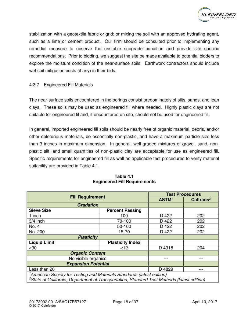
Specific requirements for engineered fill as well as applicable test procedures to verify material
suitability are provided in Table 4.1.
Table 4.1
Engineered Fill Requirements
Fill Requirement Test Procedures
ASTM1 Caltrans2 Gradation
Sieve Size Percent Passing 1 inch 100 D 422 202 3/4 inch 70-100 D 422 202 No. 4 50-100 D 422 202 No. 200 15-70 D 422 202
Plasticity Liquid Limit Plasticity Index
<30 <12 D 4318 204 Organic Content
No visible organics --- --- Expansion Potential
Less than 20 D 4829 --- 1American Society for Testing and Materials Standards (latest edition) 2State of California, Department of Transportation, Standard Test Methods (latest edition)
20173992.001A/SAC17R57127 Page 19 of 37 April 10, 2017 © 2017 Kleinfelder
All imported fill materials to be used for engineered fill should be sampled and tested by the project
Geotechnical Engineer prior to being transported to the site.
4.3.8 Engineered Fill Compaction Criteria
Soils used for engineered fill should be uniformly moisture conditioned to between 1 and 3 percent
above the optimum moisture content, placed in horizontal lifts less than 8 inches in loose
thickness, and compacted to at least 90 percent relative compaction. All fills exceeding 5 feet in
thickness should be compacted to at least 95 percent relative compaction. Disking and/or
blending may be required to uniformly moisture-condition soils used for engineered fill.
4.3.9 Pipe Zone and Trench Backfill
Pipe bedding and initial backfill (i.e., material beneath and in the immediate vicinity of the pipe)
should consist of native or imported soil with a maximum particle size less than one inch in
maximum dimension. Alternatively, pipe bedding and initial backfill may consist of concrete, lean
concrete, or cement slurry products such as Controlled Low Strength Material (CLSM) or
Controlled Density Fill (CDF).
If import material is used for pipe zone backfill, we recommend it consist of compacted washed
sand, Caltrans Class 2 aggregate base material, or clean crushed rock. Due to the potential for
soil migration into the relatively large void spaces present in clean gravel materials, these
materials should be completely surrounded by a nonwoven filter fabric such as Mirafi 140N
approved equal. Recommendations provided above for pipe zone backfill are minimum
requirements only. More stringent material specifications may be required to fulfill local codes
and/or bedding requirements for specific types of pipes. We recommend the project Civil
Engineer develop these material specifications based on planned pipe types, bedding conditions,
and other factors beyond the scope of this study.
All trench backfill should be placed and compacted in accordance with recommendations provided
above for engineered fill. Mechanical compaction is recommended. Ponding or jetting as a sole
means of compaction is not recommended.
20173992.001A/SAC17R57127 Page 20 of 37 April 10, 2017 © 2017 Kleinfelder
4.4 TEMPORARY EXCAVATIONS
4.4.1 General
All excavations must comply with applicable local, state, and federal safety regulations including
the current OSHA Excavation and Trench Safety Standards. Construction site safety generally
is the sole responsibility of the Contractor, who shall also be solely responsible for the means,
methods, and sequencing of construction operations. We are providing the information below
solely as a service to our client. Under no circumstances should the information provided be
interpreted to mean that Kleinfelder is assuming responsibility for construction site safety or the
Contractor's activities. Such responsibility is not being implied and should not be inferred.
4.4.2 Excavations and Slopes
The Contractor should be aware that slope height, slope inclination, or excavation depths
(including utility trench excavations) should in no case exceed those specified in local, state,
and/or federal safety regulations (e.g., OSHA Health and Safety Standards for Excavations, 29
CFR Part 1926, or successor regulations). Such regulations are strictly enforced and, if they are
not followed, the Owner, Contractor, and/or earthwork and utility subcontractors could be liable
for substantial penalties. Flatter slopes and/or trench shields may be required if loose,
cohesionless soils and/or water are encountered along the slope face.
4.4.3 Construction Considerations
Heavy construction equipment, building materials, excavated soil, and vehicular traffic should not
be allowed within 1/3 the slope height from the top of any excavation. Where the stability of
adjoining buildings, walls, or other structures is endangered by excavation operations, support
systems such as shoring, bracing, or underpinning may be required to provide structural stability
and to protect personnel working within the excavation. Shoring, bracing, or underpinning
required for the project (if any) should be designed by a professional engineer registered in the
State of California.
During wet weather, earthen berms or other methods should be used to prevent runoff water from
entering all excavations. All runoff water and/or groundwater encountered within the excavations
should be collected and disposed of outside the construction limits.
20173992.001A/SAC17R57127 Page 21 of 37 April 10, 2017 © 2017 Kleinfelder
4.5 SHORING
4.5.1 General
Shoring may be required where space or other restrictions do not allow a sloped excavation.
Since selection of appropriate shoring systems will be dependent on construction methods and
scheduling, we recommend the Contractor be solely responsible for the design, installation,
maintenance, and performance of temporary shoring systems.
Discontinuous shoring systems are not recommended for excavations deeper than about 8 feet
at the site based on the soils and groundwater conditions encountered. Continuous shoring
systems such as Slide Rail, internally braced systems, trench boxes, or other applicable shoring
systems may be suitable provided Cal OSHA regulations are met and damage to existing adjacent
improvements does not result from their use.
4.5.2 Site History and Shoring Types
It was reported to us by the treatment plant staff that during past excavations near the influent
pump station building, sheet pile shoring systems were driven adjacent to a clarifier that
experienced settlement as a result. The very weak silts may be subject to settlement due to
driving vibrations. If driven shoring systems are used that are near existing structures, care should
be taken to avoid excessive vibrations. If the adjacent structure is far enough away to avoid
settlement (generally over about 50 feet), then driven shoring stems such as sheet piles may be
appropriate. If adjacent structures are too close to use driven systems, drilled shoring systems
should be used such as soldier piles with lagging or similar approaches. In all cases, the
contractor should evaluate the potential for the shoring system to affect adjacent structures both
due to settlement and due to lateral movement of the shoring system and select an appropriate
system that will mitigate these issues.
4.5.3 Lateral Earth Pressures
Since the Contractor will be responsible for the design, installation, maintenance, and
performance of temporary shoring systems, additional evaluations should be performed by the
contractor and/or shoring designer as necessary to address the specific excavation conditions
encountered or expected.
20173992.001A/SAC17R57127 Page 22 of 37 April 10, 2017 © 2017 Kleinfelder
4.5.4 Lateral Deflections
Lateral deflection of the shored excavation will depend on the relative stiffness of the shoring
system selected and mobilization of the active earth pressure. The limiting condition of active
earth pressure for soft to firm silts is generally reached when the shoring tilts or deflects laterally
about 2 percent of the shoring wall height. If the shoring tilts or deflects less than the limiting
condition, the lateral earth pressure will lie between the active and at-rest earth pressures. This
soil movement can extend horizontally from 1H to 2H back from the top of cantilever retaining
structures, with vertical movements approximately equal to the horizontal. The movement tends
to be greatest close to the excavation and becomes less with increasing distance away.
Backfilling void spaces behind shoring with sand or pea gravel may reduce the potential for
vertical and lateral movements around the excavation.
The shoring designer should perform a deflection analysis of the shoring system. If movements
are greater than the tolerance of existing project features (utilities, pavements, structures, etc.)
tie-backs, dead-man anchors, or cross bracing may be needed to reduce deflections. Design
using the at-rest pressure and/or more stringent tie-back or bracing systems may be required in
the vicinity of improvements that cannot withstand lateral movements.
4.5.5 Lateral Resistance
The passive earth pressure, similar to active earth pressures, is mobilized when the shoring below
the excavation bottom tilts or deflects laterally. For soft to firm silt conditions, the limiting condition
of maximum passive earth pressure is generally reached when the shoring deflects laterally below
the base of the excavation about 4 percent of the shoring wall height. If the shoring system is
restrained against movement, the lateral resistance below the base of the excavation will lie
somewhere between the passive and at-rest earth pressure conditions. Accordingly, if lateral
deflection at the base of the excavation is objectionable, the at-rest earth pressure should be used
in design for lateral resistance.
4.5.6 Surcharge Pressures
Shoring systems should be designed to resist lateral pressures due to hydrostatic forces, if
present, and surface loads adjacent to excavations. We anticipate surface loads will be imposed
by construction equipment, foundations, roadways, etc.
20173992.001A/SAC17R57127 Page 23 of 37 April 10, 2017 © 2017 Kleinfelder
4.5.7 Existing Utilities, Structures and Pavements
The shoring designer should complete a survey of existing utilities, pavements, and structures
adjacent to those portions of the proposed excavation that will be shored. The purpose of this
review would be to evaluate the ability of existing pipelines or conduits to withstand horizontal
movements associated with a shored excavation. If existing utilities, pavements, and structures
are not capable of withstanding anticipated lateral movements, alternative shoring systems may
be required. It may be necessary to repair cracks in pavements adjacent to shored portions of
excavations due to anticipated lateral displacements of the shoring systems.
4.5.8 Existing Trench Backfill Conditions
In areas where existing trench backfills are exposed in or located adjacent to excavations for the
proposed interceptor improvements, the guideline trench side slope and shoring design criteria
presented above may not be valid. The shoring designer should consider the presence of existing
utility trenches in and near the proposed excavation areas as well as methods to protect the
utilities. If existing trench backfill materials are encountered in excavations on the site, the shoring
designer should be notified immediately to observe and address the encountered conditions. It
should be noted that trench wall collapses have occurred where these conditions were not
recognized and addressed during construction.
4.5.9 Monitoring
Where existing facilities adjacent to an excavation must be protected, horizontal and vertical
movements of the shoring system should be monitored by establishing survey points, installation
of inclinometers, or a combination of both prior to excavation such that the vertical and horizontal
positions of the monitoring points can be recorded to the nearest 0.01 feet. The results should
be reviewed by a qualified Geotechnical Engineer on a daily basis for a period of at least one
week during excavation and following construction of the shoring system. Measurements should
be obtained on a weekly basis thereafter. Detailed recommendations for monitoring should be
provided by a qualified Geotechnical Engineer after a review of the planned shoring system.
4.5.10 Shoring Removal
Shoring systems typically are removed as part of the trench backfill process. For the secondary
clarifier excavation, shoring systems may be left in place.
20173992.001A/SAC17R57127 Page 24 of 37 April 10, 2017 © 2017 Kleinfelder
Depending on the shoring system used, the removal process may create voids along the sides of
the trench excavation. If these voids are left in place and are significantly large, backfill may shift
laterally into the voids resulting in settlement of the backfill and overlying improvements.
Therefore, care should be taken to remove the shoring system and backfill the trench in such a
way as to not create these voids. If the shoring system requires removal after backfill is in place,
resulting voids should be filled with cement slurry or grout.
4.6 TEMPORARY DEWATERING
4.6.1 General
Excavations that extend below the groundwater level, such as that for the proposed secondary
clarifier, should be dewatered. The borings drilled for this study encountered groundwater depths
between 5 and 9 feet. However, during the late summer and fall months, groundwater levels will
likely be deeper. Historical data indicates the historical low groundwater level at the site is about
26 feet below the ground surface. Therefore, if practical, we recommend construction of the
clarifier be performed when groundwater levels are at their lowest.
4.6.2 Dewatering Systems
Construction dewatering may include sump pumps, well-points, wells, eductors, or a combination
of each strategy to control groundwater. At the clarifier excavation, the majority of the structure
will be constructed within silt that has low plasticity and low to moderate groundwater flow rate.
Beneath the silt at depth, sands and gravels that can transmit groundwater rapidly are present. It
has been our prior experience that boils can develop at the bottoms of excavations that are not
properly dewatered prior to excavation. This causes loosening of the foundation soils and loss of
support for the structure above. It is recommended that dewatering systems depressurize the
lower sands and gravels at depths between about 34½ and 50 feet. Otherwise, lowering of
groundwater levels near the center of the clarifier excavation may not occur and seepage boils
could develop.
Since the secondary clarifier excavation will be about 120 feet in diameter, dewatering wells
installed around the perimeter may not be completely effective at lowering the groundwater level
at the center of the excavation. It will be necessary to monitor the groundwater level at the center
of the excavation in order to prevent the excavation from occurring before the groundwater level
20173992.001A/SAC17R57127 Page 25 of 37 April 10, 2017 © 2017 Kleinfelder
is below the excavation bottom. It has been our experience at this site that dewatering using
wells may take about 1 to 2 months to lower the groundwater level to an acceptable range.
4.6.3 Dewatering Settlement
Since lowering of site groundwater levels below historical lows can cause ground settlement
adjacent to the new secondary clarifier excavation, existing structures located adjacent to the
dewatered area could be adversely affected. Consideration should be given to performing
dewatering in a manner that will not cause excessive settlement of adjacent facilities. If
dewatering results lowering of groundwater levels below about 26 feet, it may be necessary to
use groundwater barriers (such as sheet piles or similar barriers) between the new excavation
dewatering system and existing facilities to prevent such occurrence. Groundwater barriers would
need to be deep enough to effectively cut-off the groundwater flow from inside and outside of the
excavation. Dewatering the excavation within its shoring system would help control excessive
groundwater lowering outside the shoring. However, this approach would make it more difficult
to construct the clarifier structure while dewatering is being performed. So if dewatering wells are
placed around the shored clarifier excavation, an additional groundwater barrier may be needed
between the wells and existing facilities to be protected.
4.6.4 Dewatering Evaluation
Due to the risks associated with variable flow rates controlled by the hydrogeology and settlement
due to dewatering, Kleinfelder recommends that a construction dewatering evaluation be
conducted to assess the hydraulic conductivity, transmissivity, and potential groundwater flow
rates of the saturated soil within the planned construction boundaries (horizontally and vertically),.
For this project we recommend the installation of test wells and aquifer testing in the form a
pumping test. This will enable the evaluation of anticipated flow rates, the radial impacts (cones
of depression) of dewatering wells, and conceptual modeling of the aquifer with a dewatering
system and a variety of groundwater control options. This data can be used to evaluate the risk
of settlement to adjacent structures due to dewatering and can be used by the contractor in
developing a dewatering plan.
Since temporary dewatering will impact and be dependent on construction methods and
scheduling, we recommend that the Contractor be solely responsible for the design, installation,
maintenance, and performance of all temporary dewatering systems. The dewatering system
should also be compatible with temporary excavation shoring systems. We recommend the
20173992.001A/SAC17R57127 Page 26 of 37 April 10, 2017 © 2017 Kleinfelder
contractor prepare a detailed dewatering plan for review by the design team and owner prior to
construction. The plan should be based on the information contained in this report as well as any
specific dewatering evaluation prepared subsequent to this report.
4.6.5 Construction Monitoring
Due to the potential for ground settlement that may be caused by temporary dewatering,
monitoring of the ground surface and/or existing structures near dewatering points is
recommended. Monitoring may consist of survey points affixed to the ground or adjacent
structures such that the vertical and horizontal positions of the monitoring points can be recorded
to the nearest 0.01 feet. Monitoring points should be installed prior to construction and baseline
readings obtained. During excavation and operation of the dewatering system, readings should
be taken on a daily basis through completion of the structure base and walls and provided to the
engineer of record for review. In the event that excessive settlement (over about 1/4 inch) is
observed at a monitoring point, dewatering should be halted until appropriate revisions can be
made to the dewatering system.
4.7 FOUNDATION RECOMMENDATIONS
Foundations should satisfy two independent criteria with respect to foundation soils. First, the
foundation should have an adequate safety factor against bearing failure with respect to the shear
strength of the foundation soils. Second, the vertical movements of the foundation due to
settlement (both immediate elastic settlement and consolidation settlement) should be within
tolerable limits for the structure. Recommendations for shallow foundation design are presented
below.
4.7.1 Dewatering Equipment Building and Canopy
Allowable Footing Bearing Pressure
The proposed building and canopy structure can be supported on shallow spread footings
constructed of reinforced concrete founded in undisturbed soil. The footings should be founded
at least 18 inches below lowest adjacent finished grade. Continuous footings should have a
minimum width of 12 inches. Isolated footings should have a minimum width of 24 inches.
Footings may be designed for a net allowable bearing pressure of up to 1,200 pounds per square
foot (psf) due to dead plus live loads.
20173992.001A/SAC17R57127 Page 27 of 37 April 10, 2017 © 2017 Kleinfelder
The allowable bearing pressure provided above is a net value. Therefore, the weight of the
foundation that extends below grade may be neglected when computing dead loads. The
allowable bearing pressure applies to dead plus live loads, includes a calculated factor of safety
of at least 3, and may be increased by 1/3 for short-term loading due to wind or seismic forces.
To maintain the desired support, foundations adjacent to utility trenches or other existing
foundations should be deepened so that their bearing surfaces are below an imaginary plane
having an inclination of 1.5H:1V (horizontal to vertical), extending upward from the bottom edge
of the adjacent foundations or utility trenches.
Estimated Settlement
Total settlement will vary depending on the plan dimensions of the foundation and the actual load.
Based on the anticipated foundation dimensions and loads, we estimate the maximum settlement
of foundations designed and constructed in accordance with the preceding recommendations to
be less than about ¾inch. The differential settlement is anticipated to be less than half the total
settlement. Settlement of all foundations is expected to occur rapidly and should be essentially
complete shortly after initial application of the loads.
Spread Foundation Construction Considerations
Prior to placing steel or concrete, foundation excavations should be cleaned of any debris,
disturbed soil or water. All foundation excavations should be observed by a representative of
Kleinfelder just prior to placing steel or concrete. The purpose of these observations is to check
that the bearing soils actually encountered in the foundation excavations are similar to those
assumed in analysis and to verify the recommendations contained herein are implemented during
construction.
4.7.2 Concrete Mat Foundations
Beneath cast-in-place concrete mat foundations, we recommend the design include a base
course of well-graded aggregate (such as Caltrans Class 2 Aggregate Base) at least 4 inches
thick. Under slabs that will be subjected to vehicle loading, the aggregate base course thickness
should be increased to a minimum of 6 inches. The base course should be compacted to at least
95 percent relative compaction at a moisture content slightly above optimum. Mat slabs should
20173992.001A/SAC17R57127 Page 28 of 37 April 10, 2017 © 2017 Kleinfelder
have turned down or thickened edges at least 12 inches deep to reduce water infiltration beneath
the slabs. Thickened slab edges should engage the building pad soil and should not be underlain
by the gravel base course.
Allowable Mat Foundation Bearing Pressure
For properly-prepared subgrades consisting of compacted native soil or engineered fill prepared
as described herein, reinforced concrete mat slab foundations may be designed for a net
allowable bearing pressure of 1,200 psf due to dead plus live loads. A one-third increase may be
applied to this value when considering the effects of transient loads such as wind or seismic. The
recommended net allowable bearing pressure includes a safety factor of at least 3 with respect
to shear failure of the foundation soils.
Estimated Mat Settlement
For a mat foundation supporting the dewatering equipment building and/or canopy with design
pressures equal to or less than the net allowable pressure provided above, and under static
loading conditions, total post-construction foundation settlement is expected to be less than about
1 inch. At the corners of the mat, the estimated settlement is about 1/3 of the total settlement at
the center. Post-construction differential settlement of individual foundation elements is expected
to be about ½ inch or less. These settlement estimates are based on the assumption that the
foundation subgrade is properly prepared and the foundations are designed and constructed in
accordance with the recommendations presented in this report.
Lateral Load Resistance
Lateral loads on shallow mat and spread foundations may be resisted by a combination of friction
between the foundation bottoms and the supporting subgrade, and by passive resistance acting
against the embedded vertical faces of the foundations. An allowable coefficient of sliding friction
of 0.30 between the foundation and the supporting subgrade may be used for design. This value
includes a safety factor of at least 1.5 and is based on the foundation being embedded into
engineered fill. For allowable passive resistance, an equivalent fluid weight of 350 pounds per
cubic foot (pcf) acting against the footing may be used. This value is based on a safety factor of
at least 1.5. Passive resistance in the upper 12 inches should be neglected unless the area in
front of the footing is protected from disturbance by concrete or pavement. The friction coefficient
and passive resistance may be used concurrently without reduction.
20173992.001A/SAC17R57127 Page 29 of 37 April 10, 2017 © 2017 Kleinfelder
Subgrade Modulus
A modulus of subgrade reaction, KV1 of 125 pounds per square inch per inch of deflection (for a
1 square-foot bearing plate) may be used for mat slab design in the near-surface soils. The
modulus should be adjusted for the actual slab size using appropriate formulas or software.
Construction Considerations for Mat Foundations
Underground utilities paralleling the mat slab that are 4 feet or shallower generally should be
located no closer than 2 feet outside of the perimeter edges of the slab. Deeper utilities should
be located above a 1.5H:1V slope projected downward from the bottom edges of the slab. Utility
plans should be reviewed by Kleinfelder prior to trenching to evaluate conformance with this
requirement.
4.8 LATERAL EARTH PRESSURES
Retaining walls including the secondary clarifier walls should be designed to resist the earth
pressure exerted by the retained soil and water plus any additional lateral force that will be applied
to the walls due to surface loads placed at or near the walls. The design criteria for retaining walls
are presented in Table 4.2. Walls that are restrained against lateral deflection should be designed
using the at-rest earth pressure. Walls that are free to deflect at their tops may be designed for
the active earth pressure.
Table 4.2
Design Criteria for Retaining Walls
Backfill Configuration Earth Pressure Equivalent Fluid Density (pcf)
Drained Submerged
Level Active
At-Rest 45 65
85 95
Surcharge factor = 0.5 x surcharge pressure
Since the at-rest earth pressure should be used for design of the secondary clarifier walls, a
seismic increment of earth pressure will not be needed for design since the calculated at-rest
20173992.001A/SAC17R57127 Page 30 of 37 April 10, 2017 © 2017 Kleinfelder
earth pressure presented above exceeds the active plus seismic increment of lateral earth
pressure.
Lateral earth pressures provided above are ultimate values. Therefore, a suitable factor of safety
should be applied to these values for design purposes. The appropriate factor of safety will
depend on the design condition and should be determined by the project Structural Engineer. A
typical factor of safety for soil parameters used in retaining wall design is 1.5.
4.9 BUOYANCY RESISTANCE
Structures extending below the groundwater level may be subject to buoyancy forces if the
groundwater elevation rises near the ground surface. Uplift resistance can be provided by the
weight of the concrete structure, by soil friction acting on the sidewalls of the structure, and/or by
some means of anchorage (i.e., drilled piers, helical anchors, etc.).
We recommend the secondary clarifier structure be designed to resist buoyant forces for a high
groundwater level of 2 feet below the ground surface. The preferred method for this would be to
design the structure to resist buoyancy using its dead weight with the clarifier basin empty, similar
to a condition when the basin is being cleaned.
If the structure requires side friction or anchorage for buoyancy resistance, Kleinfelder can provide
additional consultation and recommendations for those applications. It will be necessary to know
the methods of construction of the secondary clarifier excavation to provide side friction values.
Sufficient information exists from this study to provide anchorage recommendations, if needed.
4.10 PIPELINE THRUST BLOCKS
Thrust blocks for pipelines may be designed using an allowable lateral bearing pressure of 1,000
psf at a minimum depth of 3 feet in firm native soil or engineered fill. Below that depth, an
additional passive resistance of 350 pcf equivalent fluid weight can be used for each foot of
additional depth below 3 feet.
4.11 2016 CBC SEISMIC DESIGN parameters
For a 2016 California Building Code (CBC) based design, the estimated Maximum Considered
Earthquake (MCE) mapped spectral accelerations for 0.2 second and 1 second periods (SS and
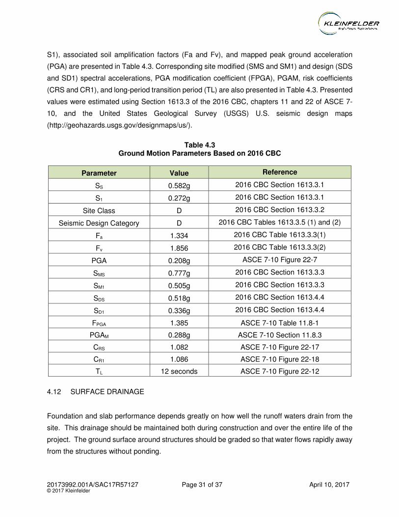
20173992.001A/SAC17R57127 Page 31 of 37 April 10, 2017 © 2017 Kleinfelder
S1), associated soil amplification factors (Fa and Fv), and mapped peak ground acceleration
(PGA) are presented in Table 4.3. Corresponding site modified (SMS and SM1) and design (SDS
and SD1) spectral accelerations, PGA modification coefficient (FPGA), PGAM, risk coefficients
(CRS and CR1), and long-period transition period (TL) are also presented in Table 4.3. Presented
values were estimated using Section 1613.3 of the 2016 CBC, chapters 11 and 22 of ASCE 7-
10, and the United States Geological Survey (USGS) U.S. seismic design maps
(http://geohazards.usgs.gov/designmaps/us/).
Table 4.3
Ground Motion Parameters Based on 2016 CBC
Parameter Value Reference
SS 0.582g 2016 CBC Section 1613.3.1
S1 0.272g 2016 CBC Section 1613.3.1
Site Class D 2016 CBC Section 1613.3.2
Seismic Design Category D 2016 CBC Tables 1613.3.5 (1) and (2)
Fa 1.334 2016 CBC Table 1613.3.3(1)
Fv 1.856 2016 CBC Table 1613.3.3(2)
PGA 0.208g ASCE 7-10 Figure 22-7
SMS 0.777g 2016 CBC Section 1613.3.3
SM1 0.505g 2016 CBC Section 1613.3.3
SDS 0.518g 2016 CBC Section 1613.4.4
SD1 0.336g 2016 CBC Section 1613.4.4
FPGA 1.385 ASCE 7-10 Table 11.8-1
PGAM 0.288g ASCE 7-10 Section 11.8.3
CRS 1.082 ASCE 7-10 Figure 22-17
CR1 1.086 ASCE 7-10 Figure 22-18
TL 12 seconds ASCE 7-10 Figure 22-12
4.12 SURFACE DRAINAGE
Foundation and slab performance depends greatly on how well the runoff waters drain from the
site. This drainage should be maintained both during construction and over the entire life of the
project. The ground surface around structures should be graded so that water flows rapidly away
from the structures without ponding.
20173992.001A/SAC17R57127 Page 32 of 37 April 10, 2017 © 2017 Kleinfelder
4.13 SOIL CORROSION POTENTIAL
A series of chemical tests were performed by Sunland Analytical of Rancho Cordova, California
on a selected sample of the near-surface soils for parameters commonly used to evaluate
corrosivity of soils, including pH, minimum resistivity, oxidation reduction potential, redox, sulfide,
chloride and soluble sulfate content. Table 4.4 presents the results.
Table 4.4
Corrosion Test Results
Location Depth
(ft)
Minimum Resistivity, (ohm-cm) pH
Oxidation Reduction Potential,
mV
Water-Soluble Ion Concentration, ppm
Saturated In-Situ
Moisture Chloride Sulfide Sulfate
B-2 4.5-5 1,740 25.1 7.73 189 82.1 Not
Present 37.9
Note: ^ Water soluble ion concentrations are reported as % in soil by mass.
These tests are a generalized indicator of soil corrosivity for the sample tested. Other soils on site
may be more, less, or similarly corrosive in nature. Imported fill materials should be tested to
confirm that their corrosion potential is not more severe than those noted.
Although Kleinfelder does not practice corrosion engineering, resistivity values between 1,000
and 3,000 ohm-cm are normally considered highly corrosive to buried ferrous metals (NACE,
2006). The concentrations of soluble sulfates indicate that the subsurface soils represent a Class
S0 exposure to sulfate attack on concrete in contact with the soil based on ACI 318 Table 4.2.1
(ACI, 2011). Therefore, in accordance with ACI Building Code 318-11, no special provisions for
selection of cement type are required.
20173992.001A/SAC17R57127 Page 33 of 37 April 10, 2017 © 2017 Kleinfelder
5 ADDITIONAL SERVICES
___________________________________________________________________________________
5.1 PLANS AND SPECIFICATIONS REVIEW
We recommend Kleinfelder conduct a general review of final plans and specifications to evaluate
that our earthwork and foundation recommendations have been properly interpreted and
implemented during design. In the event Kleinfelder is not retained to perform this recommended
review, we will assume no responsibility for misinterpretation of our recommendations.
5.2 CONSTRUCTION OBSERVATION AND TESTING
We recommend that all earthwork during construction be monitored by a representative from
Kleinfelder, including site preparation, placement of all engineered fill and trench backfill,
construction of slab and roadway subgrades, and all foundation excavations. The purpose of
these services would be to provide Kleinfelder the opportunity to observe the soil conditions
encountered during construction, evaluate the applicability of the recommendations presented in
this report to the soil conditions encountered, and recommend appropriate changes in design or
construction procedures if conditions differ from those described herein.
20173992.001A/SAC17R57127 Page 34 of 37 April 10, 2017 © 2017 Kleinfelder
6 LIMITATIONS
___________________________________________________________________________________
Recommendations contained in this report are based on our field observations and subsurface
explorations, limited laboratory tests, and our present knowledge of the proposed construction. It
is possible that soil conditions could vary between or beyond the points explored. If soil conditions
are encountered during construction that differ from those described herein, we should be notified
immediately in order that a review may be made and any supplemental recommendations
provided. If the scope of the proposed construction, including the proposed loads or structural
locations, changes from that described in this report, our recommendations should also be
reviewed.
We have prepared this report in substantial accordance with the generally accepted geotechnical
engineering practice, as it exists in the site area at the time of our study. No warranty either
express or implied is made. The recommendations provided in this report are based on the
assumption that an adequate program of tests and observations will be conducted by Kleinfelder
during the construction phase in order to evaluate compliance with our recommendations. Other
standards or documents referenced in any given standard cited in this report, or otherwise relied
upon by the author of this report, are only mentioned in the given standard. They are not
incorporated into it or “included by reference”, as that latter term is used relative to contracts or
other matters of law.
This report may be used only by the client and only for the purposes stated, within a reasonable
time from its issuance. Land use, site conditions (both on site and off site) or other factors may
change over time, and additional work may be required with the passage of time. Any party other
than the client who wishes to use this report shall notify Kleinfelder of such intended use. Based
on the intended use of the report, Kleinfelder may require that additional work be performed and
that an updated report be issued. Non-compliance with any of these requirements by the client
or anyone else will release Kleinfelder from any liability resulting from the use of this report by any
unauthorized party.
20173992.001A/SAC17R57127 Page 35 of 37 April 10, 2017 © 2017 Kleinfelder
7 REFERENCES
___________________________________________________________________________________
American Concrete Institute, 2008, Building Code Requirements for Structural Concrete and
Commentary, ACI Standard 318-08.
ASCE 7-10, “Minimum Design Loads for Buildings and Other Structures”, current version
Bray, J. D. and Sancio, R. B. (2006) “Assessment of the liquefaction susceptibility of fine-grained
soils,” Journal of Geotechnical and Geoenvironmental Engineering, ASCE, Vol. 132, No.
9, pp. 1165-1177.
Brown, Dan A., Turner, John P., and Castelli, Raymond J. (2010), Drilled Shafts: Construction
Procedures and LRFD Design Methods, NHI Course No. 132014, Geotechnical
Engineering Circular No. 10, National Highway Institute, U.S. Department of
Transportation, Federal Highway Administration, Washington, D.C., Report No. FHWA
NHI-10-016, May 2010.
Bryant, W.A. and Hart, E.W., 2007, Fault-Rupture Hazard Zones in California, California
Geological Survey, Department of Conservation, Special Publication 42, Interim Revision
2007.
California Air Resources Board, (2015), Asbestos ATCM for Construction, Grading,
Quarrying, and Surface Mining Operations.
California Building Code, 2016, California Building Standards Commission.
California Department of Water Resources, (2015), Water Data Library, Groundwater Level Data,
DWR, http://www.water.ca.gov/waterdatalibrary/index.cfm
California Geological Survey (2015), Regional Geologic Hazards Mapping Program web site,
http://www.quake.ca.gov/gmaps/WH/regulatorymaps.htm
California Geological Survey (CGS), (2013), Checklist for the Review of Engineering Geology and
Seismology Reports for California Public Schools, Hospitals, and Essential Services
Buildings: CGS Note 48.
20173992.001A/SAC17R57127 Page 36 of 37 April 10, 2017 © 2017 Kleinfelder
California Geological Survey (CGS), 2008, Guidelines for Evaluation and Mitigation of Seismic
Hazards in California, Special Publication 117A.
Cetin, K. O., Bilge, H. T.,Wu, J., Kammerer, A. M., and Seed, R. B. (2009). “Probabilistic Model
for the Assessment of Cyclically Induced Reconsolidation (Volumetric) Settlements.” J.
Geotech. Geoenviron. Eng., 135(3), 387–398.
Cetin, K. O., Seed, R. B., Der Kiureghian, A., Tokimatsu, K., Harder, L. F., Kayen, R. E., and
Moss, R. E. S. (2004). Standard penetration test-based probabilistic and deterministic
assessment of seismic soil liquefaction potential, J. Geotechnical and Geoenvironmental
Eng., ASCE 130(12), 1314–340.
Churchill, R.K. and Hill, R.L., (2000), A General Guide for Ultramafic Rocks in California - Areas
More Likely to Contain Naturally Occurring Asbestos: Department of Conservation,
Division of Mines and Geology, Open-File Report 2000-19 (map, 1:1,100,000 scale).
Helley, E.J., and Harwood, D.S., 1985, “Geologic Map of Late Cenozoic Deposits of the
Sacramento Valley and Northern Sierran Foothills, California”, U.S. Geological Survey
Miscellaneous Field Studies Map MF-1790, Map Scale: 1:62,500.
Idriss, I. M., and Boulanger, R. W. (2006). Semi-empirical procedures for evaluating liquefaction
potential during earthquakes, J. Soil Dynamics and Earthquake Eng. 26, 115–30.
Idriss, I.M. and Boulanger, R.W. (2008), "Soil Liquefaction During Earthquakes," Engineering
Monograph MNO-12, Earthquake Engineering Research Institute, Oakland, CA.
Kleinfelder (1997), “Geotechnical Investigation Report, Proposed Primary Sedimentation Tank
and Equipment Slabs, Wastewater Treatment Plant, Yuba City, California,” dated
December 15, 1997 (File No. 23-483341).
Kleinfelder (2001), “Geotechnical Investigation Report, Proposed Wastewater Treatment Plant
Upgrades, Yuba City Water Reclamation Plant, Burns Drive, Yuba City, California,” dated
February 23, 2001 (File No. 23-484601).
Kleinfelder (2007), “Geotechnical Recommendations for Repairs, Yuba City WWTP Ponds and
WTP Intake Access Road Repairs, Yuba City and Sutter County, California,” dated March
19, 2007 (File No. 78494).
20173992.001A/SAC17R57127 Page 37 of 37 April 10, 2017 © 2017 Kleinfelder
Saucedo G. J. & Wagner D.L., 1992, “Geologic Map of the Chico Quadrangle, California”,
California Geological Survey, Regional Geologic Map No. 7A, 1:250,000 scale.
Seed, H.B and Harder, L.F., 1990, “SPT-based analysis of cyclic pore pressure generation and
undrained residual strength.” Proc. H.B. Seed Mem. Symp., 2, 351-376.
Youd, T.L., Idriss, I.M. Andrus, R.D. Arango, I., Castro, G., Christian, J.T., Dobry, R., Liam Finn,
W.D.L., Harder, L.F., Jr., Hynes, M.E., Ishihara, K., Koester, J.P., Liao, S.S.C., Marcuson,
W.F., III, Martin, G.R., Mitchell, J.K., Moriwaki, Y., Power, M.S., Robertson, P.K., Seed,
R.B., Stokoe, K.H., II (2001), Liquefaction Resistance of Soils: Summary Report from the
1996 NCEER and 1998 NCEER/NSF Workshops on Evaluation of Liquefaction
Resistance of Soils, ASCE, Journal of Geotechnical and Geoenvironmental Engineering,
Vol. 127, No. 10, pp 817-833.
_̂
Source: Esri, DigitalGlobe, GeoEye, Earthstar Geographics, CNES/AirbusDS, USDA, USGS, AEX, Getmapping, Aerogrid, IGN, IGP, swisstopo, andthe GIS User Community, Esri, HERE, DeLorme, MapmyIndia, ©OpenStreetMap contributors, Esri, HERE, DeLorme, MapmyIndia, ©OpenStreetMap contributors, and the GIS user community
Copyright:© 2015 DeLorme
£
0 10.5
Miles
SITE LOCATION MAP
Yuba City Wastewater Treatment plant
305 Burns driveYuba City, California
1
20173992.001A
B. Money
The information included on this graphic representation has been compiled from a variety of sources and is subject to change without notice. Kleinfelder makes no representations or warranties, express or implied, as to accuracy, completeness, timeliness, or rights to the use of such information. This document is not intended for use as a land survey product nor is it designed or intended as a construction design document. The use or misuse of the information contained on this graphic representation is at the sole risk of the party using or misusing the information.
PROJECT NO.
DRAWN:
DRAWN BY:
CHECKED BY:
FIGURE
www.kleinfelder.com
DetailArea
Base:DeLorme World Base, ESRI
Do
cum
en
t P
ath
: K
:\2
017
_P
RO
JE
CT
S\2
01
73
99
2.0
01
A-Y
ub
a C
ity W
TT
P\C
AD
\20
17
39
92_
SL
M.m
xd
FILE NAME: 20173992_SLM.mxd
Da
te S
aved
: 3
/7/2
01
7 1
2:1
4:0
7 P
M
3/7/2017
D. Ross
PROJECT SITE
B-1
B-2
B-3
FILE NAME:
DRAWN BY:
CHECKED BY:
DRAWN:
PROJECT NO.
www.kleinfelder.com
The information included on this graphic representation has been compiled from a variety of
sources and is subject to change without notice. Kleinfelder makes no representations or
warranties, express or implied, as to accuracy, completeness, timeliness, or rights to the use of
such information. This document is not intended for use as a land survey product nor is it
designed or intended as a construction design document. The use or misuse of the information
contained on this graphic representation is at the sole risk of the party using or misusing the
information.
Yuba City Wastewater Treatment Plant
305 Burns Drive
Yuba City, California20173992-2.dwg
20173992.001A
03/07/2017
D. Ross
B. Money
BORING LOCATION MAPFIGURE
2
PLOT
TED:
07 M
ar 20
17, 1
2:37p
m, D
Ross
Bright People. Right Solutions
0
APPROXIMATE SCALE: 1 inch =
200
100 feet
50 100100
Image courtesy © 2017 Microsoft Corporation © 2017 HERE and © bing
CAD
FILE
: K:\2
017_
PROJ
ECTS
\2017
3992
.001A
-Yub
a City
WTT
P\CA
D\
LAYO
UT: L
ayou
t1PL
OTTE
D: 0
7 Mar
2017
, 12:3
7pm,
DRo
ss
LEGEND
Approximate Boring Location
20173992.001A/SAC17R57127 April 10, 2017 © 2017 Kleinfelder
APPENDIX A LOGS OF BORINGS
____________________________________________________________________________
LIST OF ATTACHMENTS
The following figures are attached and complete this appendix.
Figure A-1 Unified Soil Classification System
Figure A-2 Soil Description Key
Figure A-3 Log of Boring B-1
Figure A-4 Log of Boring B-2
Figure A-5 Log of Boring B-3
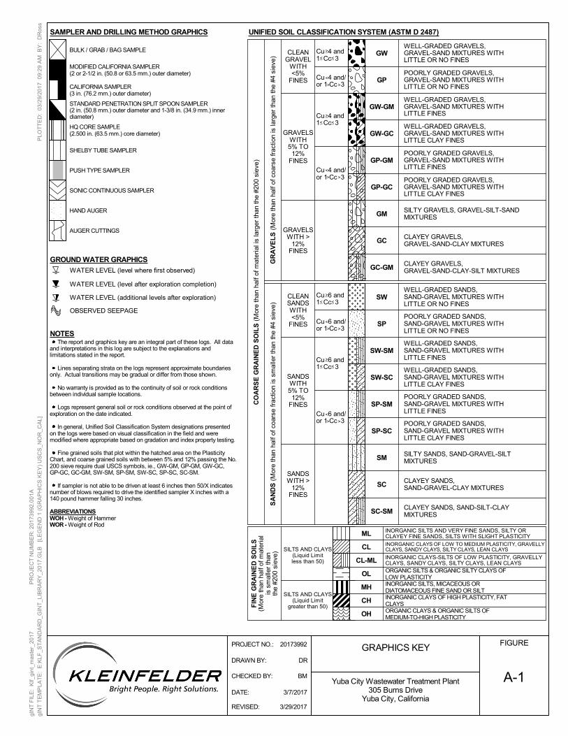
A-1
FIGURE
Yuba City Wastewater Treatment Plant305 Burns Drive
Yuba City, California
The report and graphics key are an integral part of these logs. All dataand interpretations in this log are subject to the explanations andlimitations stated in the report.
Lines separating strata on the logs represent approximate boundariesonly. Actual transitions may be gradual or differ from those shown.
No warranty is provided as to the continuity of soil or rock conditionsbetween individual sample locations.
Logs represent general soil or rock conditions observed at the point ofexploration on the date indicated.
In general, Unified Soil Classification System designations presentedon the logs were based on visual classification in the field and weremodified where appropriate based on gradation and index property testing.
Fine grained soils that plot within the hatched area on the PlasticityChart, and coarse grained soils with between 5% and 12% passing the No.200 sieve require dual USCS symbols, ie., GW-GM, GP-GM, GW-GC,GP-GC, GC-GM, SW-SM, SP-SM, SW-SC, SP-SC, SC-SM.
If sampler is not able to be driven at least 6 inches then 50/X indicatesnumber of blows required to drive the identified sampler X inches with a140 pound hammer falling 30 inches.
ABBREVIATIONSWOH - Weight of HammerWOR - Weight of Rod
CL
CL-ML
_
_
_
GM
GC
GW
GP
GW-GM
GW-GC
_ _
_
CH
CLAYEY GRAVELS,GRAVEL-SAND-CLAY MIXTURES
GRAVELSWITH >
12%FINES
>
Cu 4 and1 Cc 3
>
Cu 6 and/or 1 Cc 3
>
_
SILTY SANDS, SAND-GRAVEL-SILTMIXTURES
CLAYEY SANDS,SAND-GRAVEL-CLAY MIXTURES
SW-SM
CLAYEY SANDS, SAND-SILT-CLAYMIXTURES
Cu 6 and1 Cc 3
SC-SM
Cu 4 and1 Cc 3
< _
ORGANIC SILTS & ORGANIC SILTY CLAYS OFLOW PLASTICITY
SILTS AND CLAYS(Liquid Limitless than 50)
SILTS AND CLAYS(Liquid Limit
greater than 50)
WELL-GRADED SANDS,SAND-GRAVEL MIXTURES WITHLITTLE OR NO FINES
POORLY GRADED SANDS,SAND-GRAVEL MIXTURES WITHLITTLE OR NO FINES
MH
OH
ML
GC-GM
CO
AR
SE
GR
AIN
ED
SO
ILS
(M
ore
than
hal
f of m
ater
ial i
s la
rger
than
the
#200
sie
ve)
UNIFIED SOIL CLASSIFICATION SYSTEM (ASTM D 2487)
<
Cu 6 and1 Cc 3
GP-GM
GP-GC
_
_ _
INORGANIC CLAYS OF LOW TO MEDIUM PLASTICITY, GRAVELLYCLAYS, SANDY CLAYS, SILTY CLAYS, LEAN CLAYS
GRAPHICS KEY
<
>
<
<
>
CLEANSANDSWITH<5%
FINES
GR
AV
EL
S (
Mor
e th
an h
alf o
f coa
rse
frac
tion
is la
rger
than
the
#4 s
ieve
)
Cu 6 and/or 1 Cc 3>
<
<
SANDSWITH5% TO
12%FINES
SANDSWITH >
12%FINES
SA
ND
S (
Mor
e th
an h
alf o
f coa
rse
frac
tion
is s
mal
ler
than
the
#4 s
ieve
)
WELL-GRADED SANDS,SAND-GRAVEL MIXTURES WITHLITTLE FINES
Cu 4 and/or 1 Cc 3>
CLEANGRAVEL
WITH<5%
FINES
GRAVELSWITH5% TO
12%FINES
OL
<
>
<
<
>
SP
SP-SM
SP-SC
SM
SC
< _<
>
WELL-GRADED GRAVELS,GRAVEL-SAND MIXTURES WITHLITTLE OR NO FINES
POORLY GRADED GRAVELS,GRAVEL-SAND MIXTURES WITHLITTLE OR NO FINES
WELL-GRADED GRAVELS,GRAVEL-SAND MIXTURES WITHLITTLE FINES
WELL-GRADED GRAVELS,GRAVEL-SAND MIXTURES WITHLITTLE CLAY FINES
POORLY GRADED GRAVELS,GRAVEL-SAND MIXTURES WITHLITTLE FINES
POORLY GRADED GRAVELS,GRAVEL-SAND MIXTURES WITHLITTLE CLAY FINES
SILTY GRAVELS, GRAVEL-SILT-SANDMIXTURES
CLAYEY GRAVELS,GRAVEL-SAND-CLAY-SILT MIXTURES
WELL-GRADED SANDS,SAND-GRAVEL MIXTURES WITHLITTLE CLAY FINES
POORLY GRADED SANDS,SAND-GRAVEL MIXTURES WITHLITTLE CLAY FINES
SW
SW-SC
POORLY GRADED SANDS,SAND-GRAVEL MIXTURES WITHLITTLE FINES
Cu 4 and/or 1 Cc 3>
>
FIN
E G
RA
INE
D S
OIL
S(M
ore
than
hal
f of m
ater
ial
is s
mal
ler
than
the
#200
sie
ve)
INORGANIC SILTS AND VERY FINE SANDS, SILTY ORCLAYEY FINE SANDS, SILTS WITH SLIGHT PLASTICITY
ORGANIC CLAYS & ORGANIC SILTS OFMEDIUM-TO-HIGH PLASTICITY
INORGANIC CLAYS OF HIGH PLASTICITY, FATCLAYS
INORGANIC SILTS, MICACEOUS ORDIATOMACEOUS FINE SAND OR SILT
INORGANIC CLAYS-SILTS OF LOW PLASTICITY, GRAVELLYCLAYS, SANDY CLAYS, SILTY CLAYS, LEAN CLAYS
STANDARD PENETRATION SPLIT SPOON SAMPLER(2 in. (50.8 mm.) outer diameter and 1-3/8 in. (34.9 mm.) innerdiameter)
CALIFORNIA SAMPLER(3 in. (76.2 mm.) outer diameter)
MODIFIED CALIFORNIA SAMPLER(2 or 2-1/2 in. (50.8 or 63.5 mm.) outer diameter)
BULK / GRAB / BAG SAMPLE
SAMPLER AND DRILLING METHOD GRAPHICS
SHELBY TUBE SAMPLER
AUGER CUTTINGS
PUSH TYPE SAMPLER
HAND AUGER
SONIC CONTINUOUS SAMPLER
HQ CORE SAMPLE(2.500 in. (63.5 mm.) core diameter)
NOTES
GROUND WATER GRAPHICS
OBSERVED SEEPAGE
WATER LEVEL (level after exploration completion)
WATER LEVEL (level where first observed)
WATER LEVEL (additional levels after exploration)
DRAWN BY: DR
CHECKED BY: BM
DATE: 3/7/2017
REVISED: 3/29/2017
PLO
TT
ED
: 03
/29/
201
7 0
9:2
9 A
M B
Y:
DR
oss
PROJECT NO.: 20173992
gIN
T F
ILE
: K
lf_gi
nt_m
aste
r_20
17
P
RO
JEC
T N
UM
BE
R: 2
0173
992.
001
A
gIN
T T
EM
PLA
TE
: E
:KLF
_ST
AN
DA
RD
_GIN
T_L
IBR
AR
Y_2
017
.GLB
[L
EG
EN
D 1
(G
RA
PH
ICS
KE
Y)
US
CS
_NO
R_C
AL]
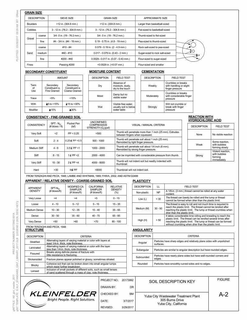
CALIFORNIASAMPLER(# blows/ft)
MODIFIED CASAMPLER(# blows/ft)
SPT-N60
(# blows/ft)
A-2
FIGURE
Yuba City Wastewater Treatment Plant305 Burns Drive
Yuba City, California
The thread is easy to roll and not much time is required toreach the plastic limit. The thread cannot be rerolled afterreaching the plastic limit. The lump or thread crumbles whendrier than the plastic limit.It takes considerable time rolling and kneading to reach theplastic limit. The thread can be rerolled several times afterreaching the plastic limit. The lump or thread can be formedwithout crumbling when drier than the plastic limit.
30 - 50
> 50
Medium (M)
High (H)
RELATIVEDENSITY
(%)
APPARENTDENSITY
30 - 50
10 - 30
4 - 10
<4
>60
35 - 60
12 - 35
5 - 12
<4
>70
40 - 70
15 - 40
5 - 15
CONSISTENCY
<2
Moist
DESCRIPTION
Strongly
FIELD TEST
Alternating layers of varying material or color with the layerless than 1/4-in. thick, note thickness.
FIELD TEST
Absence ofmoisture, dusty,dry to the touch
Moderately
Will not crumble orbreak with fingerpressure
Pocket Pen(tsf)
Termof
Use
<5%
With
Modifier
5 to <15%
15%
Trace <15%
15 to <30%
30%
AMOUNT
>30
Very Soft
SOIL DESCRIPTION KEY
DESCRIPTION
Damp but novisible water
Boulders
Cobbles
coarse
fineGravel
Sand
Fines
GRAIN SIZE
>12 in. (304.8 mm.)
3 - 12 in. (76.2 - 304.8 mm.) Fist-sized to basketball-sized
3/4 -3 in. (19 - 76.2 mm.) Thumb-sized to fist-sized
0.19 - 0.75 in. (4.8 - 19 mm.) Pea-sized to thumb-sized
0.079 - 0.19 in. (2 - 4.9 mm.)#10 - #4
0.017 - 0.079 in. (0.43 - 2 mm.)
#200 - #40
coarse
fine
medium
SIEVE SIZE APPROXIMATE SIZE
Larger than basketball-sized>12 in. (304.8 mm.)
3 - 12 in. (76.2 - 304.8 mm.)
3/4 -3 in. (19 - 76.2 mm.)
#4 - 3/4 in. (#4 - 19 mm.)
Rock salt-sized to pea-sized
#40 - #10 Sugar-sized to rock salt-sized
0.0029 - 0.017 in. (0.07 - 0.43 mm.) Flour-sized to sugar-sized
Passing #200 <0.0029 in. (<0.07 mm.) Flour-sized and smaller
DESCRIPTION
SecondaryConstituent isFine Grained
SecondaryConstituent is
Coarse Grained
SPT - N60
(# blows / ft)
Soft
Stiff
Very Stiff
Hard
2 - 4
4 - 8
8 - 15
15 - 30
WeaklyCrumbles or breakswith handling or slightfinger pressure
Crumbles or breakswith considerable fingerpressure
UNCONFINEDCOMPRESSIVE
STRENGTH (Qu)(psf)VISUAL / MANUAL CRITERIA
<500
0.5 PP <1
1 PP <2
2 PP <4
4 PP >8000
4000 - 8000
500 - 1000
1000 - 2000
2000 - 4000
Rounded
Subrounded
Dry
WetVisible free water,usually soil is belowwater table
Thumb will penetrate more than 1 inch (25 mm). Extrudesbetween fingers when squeezed.
Thumb will penetrate soil about 1 inch (25 mm).Remolded by light finger pressure.
Thumb will penetrate soil about 1/4 inch (6 mm).Remolded by strong finger pressure.
Can be imprinted with considerable pressure from thumb.
Thumb will not indent soil but readily indented withthumbnail.
Thumbnail will not indent soil.
Particles have nearly plane sides but have well-rounded corners andedges.
AngularParticles have sharp edges and relatively plane sides with unpolishedsurfaces.
DESCRIPTION
Fissured
Slickensided
Blocky
Lensed
CRITERIA
Stratified
Laminated
Fracture planes appear polished or glossy, sometimes striated.
Alternating layers of varying material or color with layers atleast 1/4-in. thick, note thickness.
Breaks along definite planes of fracture withlittle resistance to fracturing.
Cohesive soil that can be broken down into small angular lumpswhich resist further breakdown.Inclusion of small pockets of different soils, such as small lensesof sand scattered through a mass of clay; note thickness.
Subangular
Particles have smoothly curved sides and no edges.
Particles are similar to angular description but have rounded edges.
None
Weak
Strong
No visible reaction
DESCRIPTION CRITERIA
A 1/8-in. (3 mm.) thread cannot be rolled at any watercontent.
NPNon-plastic
The thread can barely be rolled and the lump or threadcannot be formed when drier than the plastic limit.
< 30Low (L)
85 - 100
65 - 85
35 - 65
15 - 35
<5 0 - 15
Very Dense
Dense
Medium Dense
>50
Loose
Very Loose
FROM TERZAGHI AND PECK, 1948
LLDESCRIPTION FIELD TEST
Some reaction,with bubblesforming slowly
Violent reaction,with bubblesformingimmediately
DESCRIPTION FIELD TEST
PP < 0.25
0.25 PP <0.5
Medium Stiff
PLASTICITYAPPARENT / RELATIVE DENSITY - COARSE-GRAINED SOIL
MOISTURE CONTENTSECONDARY CONSTITUENT CEMENTATION
CONSISTENCY - FINE-GRAINED SOIL
FROM TERZAGHI AND PECK, 1948; LAMBE AND WHITMAN, 1969; FHWA, 2002; AND ASTM D2488
REACTION WITHHYDROCHLORIC ACID
ANGULARITYSTRUCTURE
GRAIN SIZE
DRAWN BY: DR
CHECKED BY: BM
DATE: 3/7/2017
REVISED: 3/29/2017
PLO
TT
ED
: 03
/29/
201
7 0
9:2
9 A
M B
Y:
DR
oss
PROJECT NO.: 20173992
gIN
T F
ILE
: K
lf_gi
nt_m
aste
r_20
17
P
RO
JEC
T N
UM
BE
R: 2
0173
992.
001
A
gIN
T T
EM
PLA
TE
: E
:KLF
_ST
AN
DA
RD
_GIN
T_L
IBR
AR
Y_2
017
.GLB
[L
EG
EN
D 2
(S
OIL
DE
SC
KE
Y)]
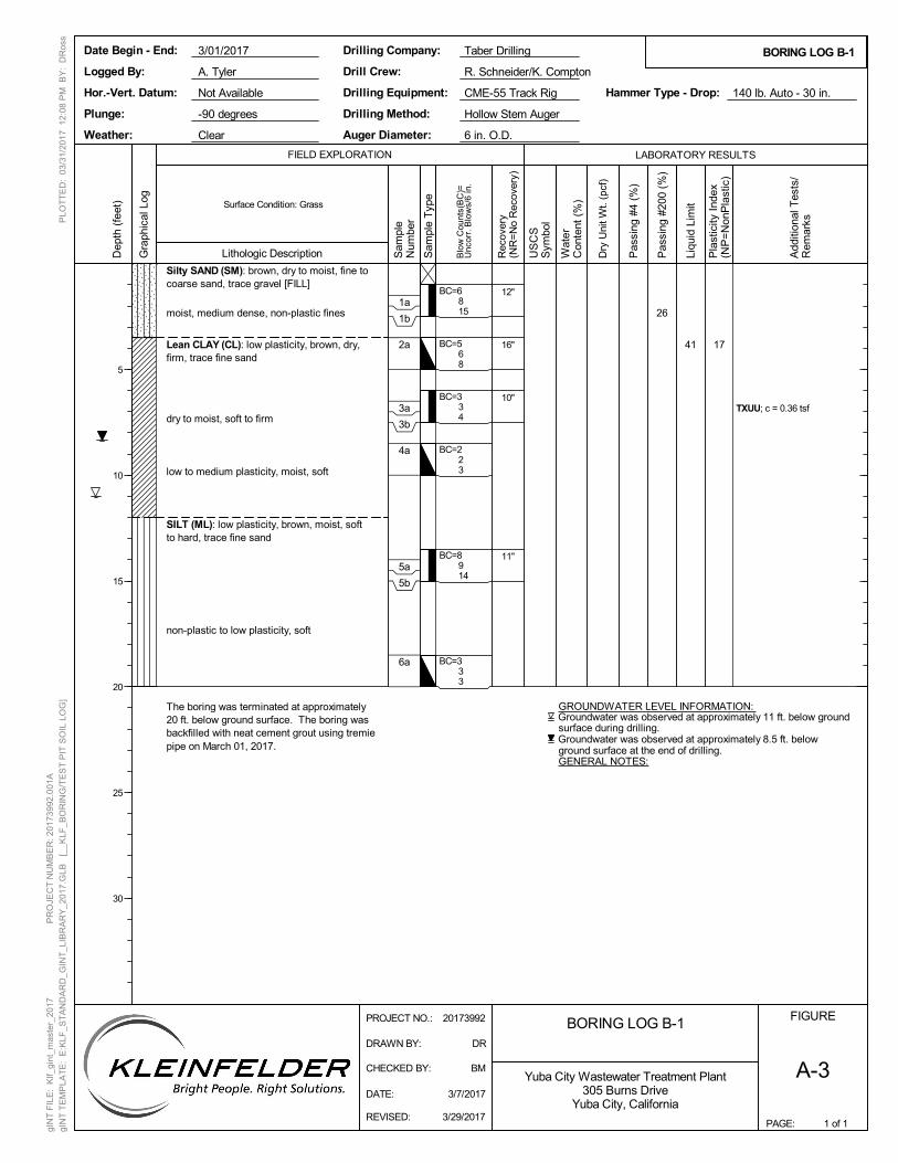
26
Silty SAND (SM): brown, dry to moist, fine tocoarse sand, trace gravel [FILL]
moist, medium dense, non-plastic fines
Lean CLAY (CL): low plasticity, brown, dry,firm, trace fine sand
dry to moist, soft to firm
low to medium plasticity, moist, soft
SILT (ML): low plasticity, brown, moist, softto hard, trace fine sand
non-plastic to low plasticity, soft
The boring was terminated at approximately20 ft. below ground surface. The boring wasbackfilled with neat cement grout using tremiepipe on March 01, 2017.
TXUU; c = 0.36 tsf
BC=6815
BC=568
BC=334
BC=223
BC=8914
BC=333
41 17
Groundwater was observed at approximately 11 ft. below groundsurface during drilling.
Groundwater was observed at approximately 8.5 ft. belowground surface at the end of drilling.GENERAL NOTES:
GROUNDWATER LEVEL INFORMATION:
12"
16"
10"
11"
BORING LOG B-1FIGURE
A-3
1 of 1
LABORATORY RESULTS
Lithologic Description
PAGE:
FIELD EXPLORATION
BORING LOG B-1
Dry
Uni
t Wt.
(pcf
)
Pas
sing
#4
(%)
Pas
sing
#20
0 (%
)
Surface Condition: Grass
Not Available CME-55 Track Rig
R. Schneider/K. Compton
Taber Drilling
-90 degreesPlunge:
Drilling Company:
Drilling Method:
Drilling Equipment:
3/01/2017
6 in. O.D.Clear Auger Diameter:
A. Tyler
Hammer Type - Drop:
Hollow Stem Auger
140 lb. Auto - 30 in.
Logged By:
Date Begin - End:
Hor.-Vert. Datum:
Weather:
Drill Crew:
Add
ition
al T
ests
/R
emar
ks
Blo
w C
ount
s(B
C)=
Unc
orr.
Blo
ws/
6 in
.
Liqu
id L
imit
Pla
stic
ity I
ndex
(NP
=N
onP
last
ic)
Yuba City Wastewater Treatment Plant305 Burns Drive
Yuba City, California
Dep
th (
feet
)
5
10
15
20
25
30
Gra
phic
al L
og
Sam
ple
Num
ber
Rec
over
y(N
R=
No
Rec
over
y)
US
CS
Sym
bol
Wat
erC
onte
nt (
%)
1a
1b
2a
3a
3b
4a
5a
5b
6a
DATE: 3/7/2017
DRAWN BY: DR
REVISED: 3/29/2017
PLO
TT
ED
: 03
/31/
201
7 1
2:0
8 P
M B
Y:
DR
oss
PROJECT NO.: 20173992
gIN
T F
ILE
: K
lf_gi
nt_m
aste
r_20
17
P
RO
JEC
T N
UM
BE
R: 2
0173
992.
001
A
gIN
T T
EM
PLA
TE
: E
:KLF
_ST
AN
DA
RD
_GIN
T_L
IBR
AR
Y_2
017
.GLB
[_
_KLF
_BO
RIN
G/T
ES
T P
IT S
OIL
LO
G]
CHECKED BY: BM
Sam
ple
Typ
e
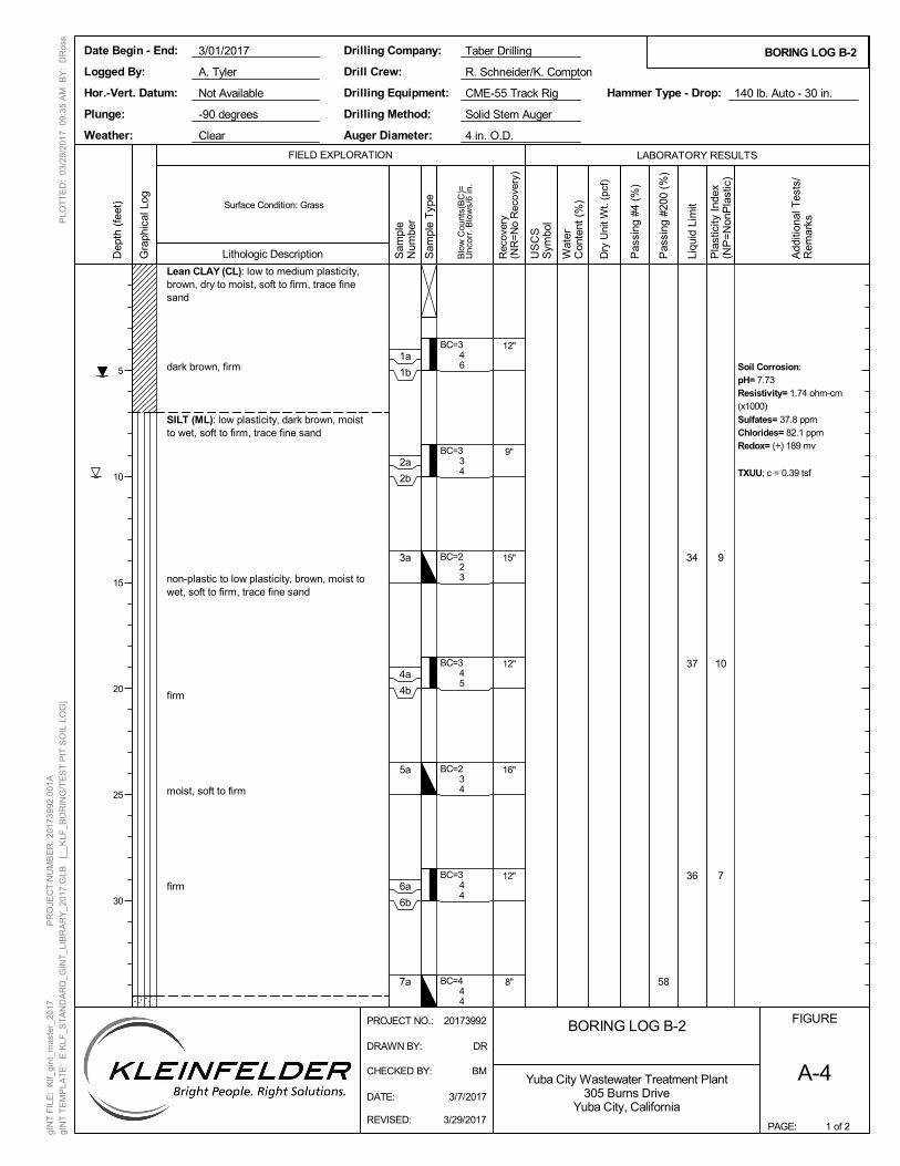
58
Lean CLAY (CL): low to medium plasticity,brown, dry to moist, soft to firm, trace finesand
dark brown, firm
SILT (ML): low plasticity, dark brown, moistto wet, soft to firm, trace fine sand
non-plastic to low plasticity, brown, moist towet, soft to firm, trace fine sand
firm
moist, soft to firm
firm
Soil Corrosion:pH= 7.73Resistivity= 1.74 ohm-cm(x1000)
Sulfates= 37.8 ppmChlorides= 82.1 ppmRedox= (+) 189 mv
TXUU; c = 0.39 tsf
BC=346
BC=334
BC=223
BC=345
BC=234
BC=344
BC=444
34
37
36
9
10
7
12"
9"
15"
12"
16"
12"
8"
BORING LOG B-2FIGURE
A-4
1 of 2
LABORATORY RESULTS
Lithologic Description
PAGE:
FIELD EXPLORATION
BORING LOG B-2
Dry
Uni
t Wt.
(pcf
)
Pas
sing
#4
(%)
Pas
sing
#20
0 (%
)
Surface Condition: Grass
Not Available CME-55 Track Rig
R. Schneider/K. Compton
Taber Drilling
-90 degreesPlunge:
Drilling Company:
Drilling Method:
Drilling Equipment:
3/01/2017
4 in. O.D.Clear Auger Diameter:
A. Tyler
Hammer Type - Drop:
Solid Stem Auger
140 lb. Auto - 30 in.
Logged By:
Date Begin - End:
Hor.-Vert. Datum:
Weather:
Drill Crew:
Add
ition
al T
ests
/R
emar
ks
Blo
w C
ount
s(B
C)=
Unc
orr.
Blo
ws/
6 in
.
Liqu
id L
imit
Pla
stic
ity I
ndex
(NP
=N
onP
last
ic)
Yuba City Wastewater Treatment Plant305 Burns Drive
Yuba City, California
Dep
th (
feet
)
5
10
15
20
25
30
Gra
phic
al L
og
Sam
ple
Num
ber
Rec
over
y(N
R=
No
Rec
over
y)
US
CS
Sym
bol
Wat
erC
onte
nt (
%)
1a
1b
2a
2b
3a
4a
4b
5a
6a
6b
7a
DATE: 3/7/2017
DRAWN BY: DR
REVISED: 3/29/2017
PLO
TT
ED
: 03
/29/
201
7 0
9:3
5 A
M B
Y:
DR
oss
PROJECT NO.: 20173992
gIN
T F
ILE
: K
lf_gi
nt_m
aste
r_20
17
P
RO
JEC
T N
UM
BE
R: 2
0173
992.
001
A
gIN
T T
EM
PLA
TE
: E
:KLF
_ST
AN
DA
RD
_GIN
T_L
IBR
AR
Y_2
017
.GLB
[_
_KLF
_BO
RIN
G/T
ES
T P
IT S
OIL
LO
G]
CHECKED BY: BM
Sam
ple
Typ
e
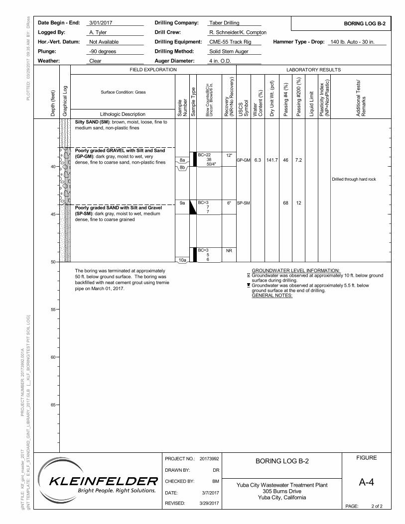
141.7 46
68
7.2
12
Silty SAND (SM): brown, moist, loose, fine tomedium sand, non-plastic fines
Poorly graded GRAVEL with Silt and Sand(GP-GM): dark gray, moist to wet, verydense, fine to coarse sand, non-plastic fines
Poorly graded SAND with Silt and Gravel(SP-SM): dark gray, moist to wet, mediumdense, fine to coarse grained
The boring was terminated at approximately50 ft. below ground surface. The boring wasbackfilled with neat cement grout using tremiepipe on March 01, 2017.
Drilled through hard rock
BC=223850/4"
BC=377
BC=356
Groundwater was observed at approximately 10 ft. below groundsurface during drilling.
Groundwater was observed at approximately 5.5 ft. belowground surface at the end of drilling.GENERAL NOTES:
GROUNDWATER LEVEL INFORMATION:
12"
6"
NR
GP-GM
SP-SM
6.3
BORING LOG B-2FIGURE
A-4
2 of 2
LABORATORY RESULTS
Lithologic Description
PAGE:
FIELD EXPLORATION
BORING LOG B-2
Dry
Uni
t Wt.
(pcf
)
Pas
sing
#4
(%)
Pas
sing
#20
0 (%
)
Surface Condition: Grass
Not Available CME-55 Track Rig
R. Schneider/K. Compton
Taber Drilling
-90 degreesPlunge:
Drilling Company:
Drilling Method:
Drilling Equipment:
3/01/2017
4 in. O.D.Clear Auger Diameter:
A. Tyler
Hammer Type - Drop:
Solid Stem Auger
140 lb. Auto - 30 in.
Logged By:
Date Begin - End:
Hor.-Vert. Datum:
Weather:
Drill Crew:
Add
ition
al T
ests
/R
emar
ks
Blo
w C
ount
s(B
C)=
Unc
orr.
Blo
ws/
6 in
.
Liqu
id L
imit
Pla
stic
ity I
ndex
(NP
=N
onP
last
ic)
Yuba City Wastewater Treatment Plant305 Burns Drive
Yuba City, California
Dep
th (
feet
)
40
45
50
55
60
65
Gra
phic
al L
og
Sam
ple
Num
ber
Rec
over
y(N
R=
No
Rec
over
y)
US
CS
Sym
bol
Wat
erC
onte
nt (
%)
8a
8b
9a
10a
DATE: 3/7/2017
DRAWN BY: DR
REVISED: 3/29/2017
PLO
TT
ED
: 03
/29/
201
7 0
9:3
5 A
M B
Y:
DR
oss
PROJECT NO.: 20173992
gIN
T F
ILE
: K
lf_gi
nt_m
aste
r_20
17
P
RO
JEC
T N
UM
BE
R: 2
0173
992.
001
A
gIN
T T
EM
PLA
TE
: E
:KLF
_ST
AN
DA
RD
_GIN
T_L
IBR
AR
Y_2
017
.GLB
[_
_KLF
_BO
RIN
G/T
ES
T P
IT S
OIL
LO
G]
CHECKED BY: BM
Sam
ple
Typ
e
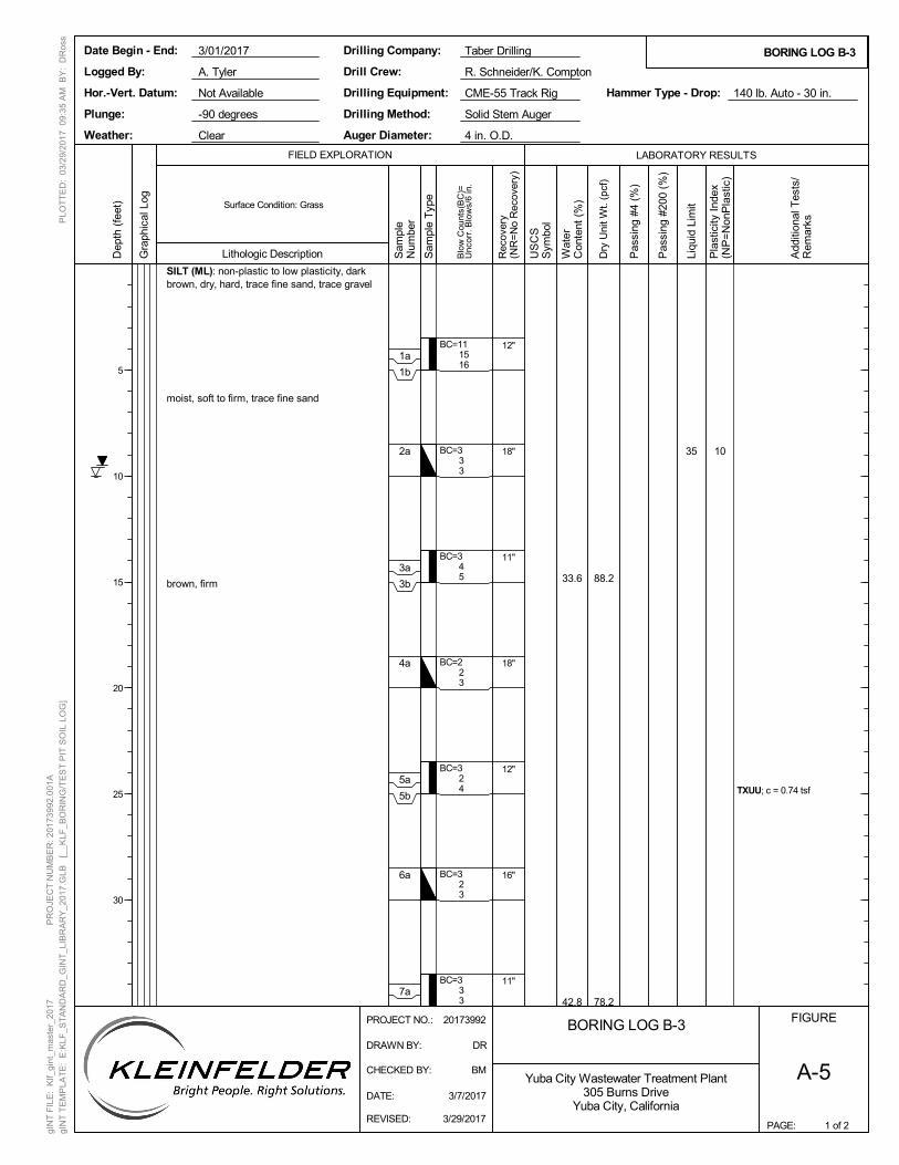
88.2
78.2
SILT (ML): non-plastic to low plasticity, darkbrown, dry, hard, trace fine sand, trace gravel
moist, soft to firm, trace fine sand
brown, firm
TXUU; c = 0.74 tsf
BC=111516
BC=333
BC=345
BC=223
BC=324
BC=323
BC=333
35 10
12"
18"
11"
18"
12"
16"
11"
33.6
42.8
BORING LOG B-3FIGURE
A-5
1 of 2
LABORATORY RESULTS
Lithologic Description
PAGE:
FIELD EXPLORATION
BORING LOG B-3
Dry
Uni
t Wt.
(pcf
)
Pas
sing
#4
(%)
Pas
sing
#20
0 (%
)
Surface Condition: Grass
Not Available CME-55 Track Rig
R. Schneider/K. Compton
Taber Drilling
-90 degreesPlunge:
Drilling Company:
Drilling Method:
Drilling Equipment:
3/01/2017
4 in. O.D.Clear Auger Diameter:
A. Tyler
Hammer Type - Drop:
Solid Stem Auger
140 lb. Auto - 30 in.
Logged By:
Date Begin - End:
Hor.-Vert. Datum:
Weather:
Drill Crew:
Add
ition
al T
ests
/R
emar
ks
Blo
w C
ount
s(B
C)=
Unc
orr.
Blo
ws/
6 in
.
Liqu
id L
imit
Pla
stic
ity I
ndex
(NP
=N
onP
last
ic)
Yuba City Wastewater Treatment Plant305 Burns Drive
Yuba City, California
Dep
th (
feet
)
5
10
15
20
25
30
Gra
phic
al L
og
Sam
ple
Num
ber
Rec
over
y(N
R=
No
Rec
over
y)
US
CS
Sym
bol
Wat
erC
onte
nt (
%)
1a
1b
2a
3a
3b
4a
5a
5b
6a
7a
DATE: 3/7/2017
DRAWN BY: DR
REVISED: 3/29/2017
PLO
TT
ED
: 03
/29/
201
7 0
9:3
5 A
M B
Y:
DR
oss
PROJECT NO.: 20173992
gIN
T F
ILE
: K
lf_gi
nt_m
aste
r_20
17
P
RO
JEC
T N
UM
BE
R: 2
0173
992.
001
A
gIN
T T
EM
PLA
TE
: E
:KLF
_ST
AN
DA
RD
_GIN
T_L
IBR
AR
Y_2
017
.GLB
[_
_KLF
_BO
RIN
G/T
ES
T P
IT S
OIL
LO
G]
CHECKED BY: BM
Sam
ple
Typ
e
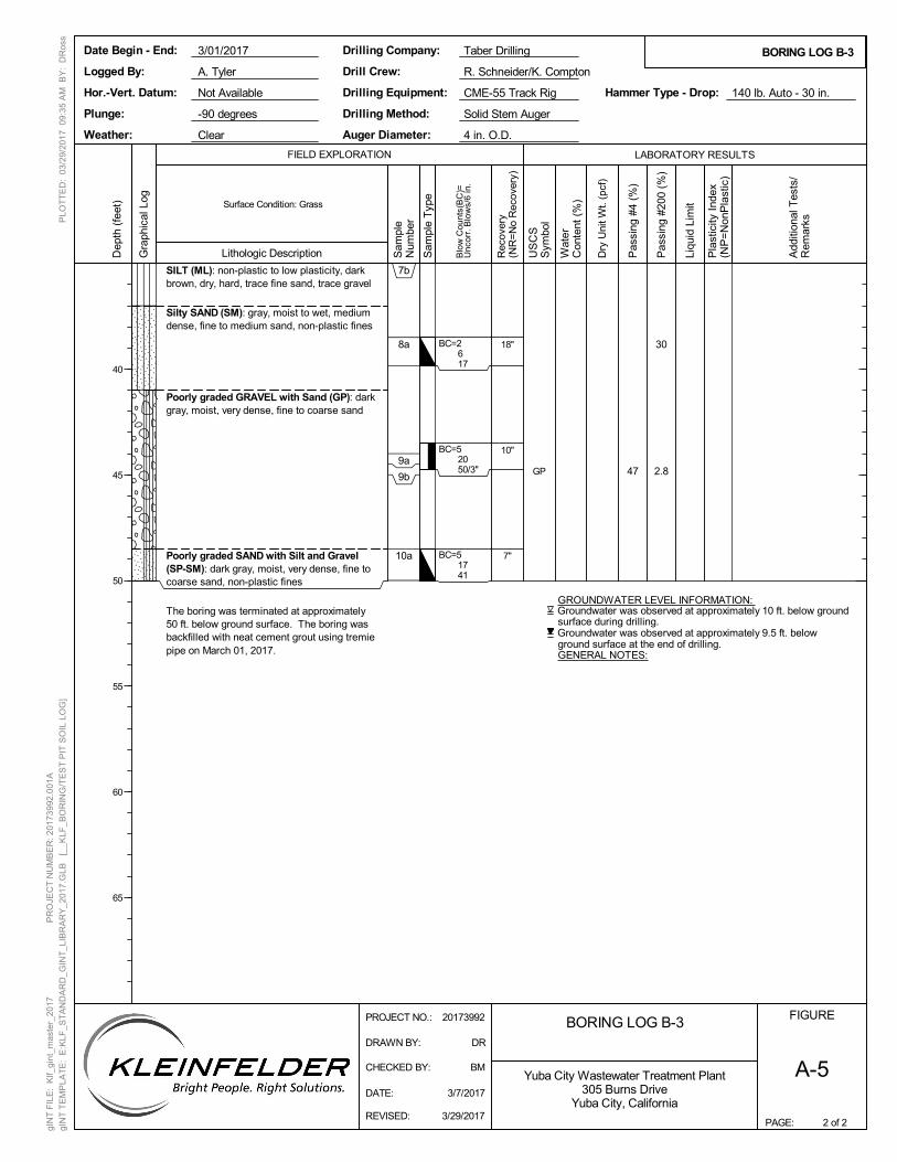
47
30
2.8
SILT (ML): non-plastic to low plasticity, darkbrown, dry, hard, trace fine sand, trace gravel
Silty SAND (SM): gray, moist to wet, mediumdense, fine to medium sand, non-plastic fines
Poorly graded GRAVEL with Sand (GP): darkgray, moist, very dense, fine to coarse sand
Poorly graded SAND with Silt and Gravel(SP-SM): dark gray, moist, very dense, fine tocoarse sand, non-plastic fines
The boring was terminated at approximately50 ft. below ground surface. The boring wasbackfilled with neat cement grout using tremiepipe on March 01, 2017.
BC=2617
BC=52050/3"
BC=51741
Groundwater was observed at approximately 10 ft. below groundsurface during drilling.
Groundwater was observed at approximately 9.5 ft. belowground surface at the end of drilling.GENERAL NOTES:
GROUNDWATER LEVEL INFORMATION:
18"
10"
7"
GP
BORING LOG B-3FIGURE
A-5
2 of 2
LABORATORY RESULTS
Lithologic Description
PAGE:
FIELD EXPLORATION
BORING LOG B-3
Dry
Uni
t Wt.
(pcf
)
Pas
sing
#4
(%)
Pas
sing
#20
0 (%
)
Surface Condition: Grass
Not Available CME-55 Track Rig
R. Schneider/K. Compton
Taber Drilling
-90 degreesPlunge:
Drilling Company:
Drilling Method:
Drilling Equipment:
3/01/2017
4 in. O.D.Clear Auger Diameter:
A. Tyler
Hammer Type - Drop:
Solid Stem Auger
140 lb. Auto - 30 in.
Logged By:
Date Begin - End:
Hor.-Vert. Datum:
Weather:
Drill Crew:
Add
ition
al T
ests
/R
emar
ks
Blo
w C
ount
s(B
C)=
Unc
orr.
Blo
ws/
6 in
.
Liqu
id L
imit
Pla
stic
ity I
ndex
(NP
=N
onP
last
ic)
Yuba City Wastewater Treatment Plant305 Burns Drive
Yuba City, California
Dep
th (
feet
)
40
45
50
55
60
65
Gra
phic
al L
og
Sam
ple
Num
ber
Rec
over
y(N
R=
No
Rec
over
y)
US
CS
Sym
bol
Wat
erC
onte
nt (
%)
7b
8a
9a
9b
10a
DATE: 3/7/2017
DRAWN BY: DR
REVISED: 3/29/2017
PLO
TT
ED
: 03
/29/
201
7 0
9:3
5 A
M B
Y:
DR
oss
PROJECT NO.: 20173992
gIN
T F
ILE
: K
lf_gi
nt_m
aste
r_20
17
P
RO
JEC
T N
UM
BE
R: 2
0173
992.
001
A
gIN
T T
EM
PLA
TE
: E
:KLF
_ST
AN
DA
RD
_GIN
T_L
IBR
AR
Y_2
017
.GLB
[_
_KLF
_BO
RIN
G/T
ES
T P
IT S
OIL
LO
G]
CHECKED BY: BM
Sam
ple
Typ
e
20173992.001A/SAC17R57127 April 10, 2017 © 2016 Kleinfelder
APPENDIX B
LABORATORY TEST RESULTS ____________________________________________________________________________
LIST OF ATTACHMENTS
The following figures are attached and complete this appendix.
Figure B-1 Laboratory Test Result Summary
Figure B-2 Atterberg Limits
Figure B-3 Sieve Analysis Results
Figure B-4 through B-6 Triaxial Compression Test (UU)
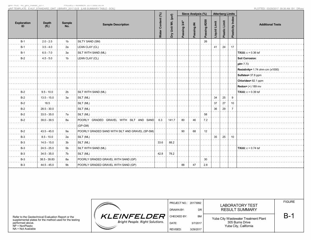
B-1 2.0 - 2.5 1b SILTY SAND (SM) 26
B-1 3.5 - 4.0 2a LEAN CLAY (CL) 41 24 17
B-1 6.5 - 7.0 3a SILT WITH SAND (ML) TXUU; c = 0.36 tsf
B-2 4.5 - 5.0 1b LEAN CLAY (CL) Soil Corrosion:
pH= 7.73
Resistivity= 1.74 ohm-cm (x1000)
Sulfates= 37.8 ppm
Chlorides= 82.1 ppm
Redox= (+) 189 mv
B-2 9.5 - 10.0 2b SILT WITH SAND (ML) TXUU; c = 0.39 tsf
B-2 13.5 - 15.0 3a SILT (ML) 34 25 9
B-2 18.5 SILT (ML) 37 27 10
B-2 28.5 - 30.0 SILT (ML) 36 29 7
B-2 33.5 - 35.0 7a SILT (ML) 58
B-2 39.0 - 39.5 8a POORLY GRADED GRAVEL WITH SILT AND SAND
(GP-GM)
6.3 141.7 80 46 7.2
B-2 43.5 - 45.0 9a POORLY GRADED SAND WITH SILT AND GRAVEL (SP-SM) 90 68 12
B-3 8.5 - 10.0 2a SILT (ML) 35 25 10
B-3 14.5 - 15.0 3b SILT (ML) 33.6 88.2
B-3 24.5 - 25.0 5b SILT WITH SAND (ML) TXUU; c = 0.74 tsf
B-3 34.5 - 35.0 7b SILT (ML) 42.8 78.2
B-3 38.5 - 39.83 8a POORLY GRADED GRAVEL WITH SAND (GP) 30
B-3 44.5 - 45.0 9b POORLY GRADED GRAVEL WITH SAND (GP) 88 47 2.8
Pla
stic
ity
Ind
ex
SampleNo.
Depth(ft.)
Atterberg Limits
Liq
uid
Lim
it
Sample Description
Pla
stic
Lim
it
Wat
er C
on
ten
t (%
)
Dry
Un
it W
t. (
pcf
)
ExplorationID Additional Tests
Refer to the Geotechnical Evaluation Report or thesupplemental plates for the method used for the testingperformed above.NP = NonPlasticNA = Not Available
FIGURELABORATORY TESTRESULT SUMMARY
B-1
Pas
sin
g 3
/4"
Sieve Analysis (%)
Pas
sin
g #
4
Pas
sin
g #
200
Yuba City Wastewater Treatment Plant305 Burns Drive
Yuba City, California
PLOTTED: 03/29/2017 09:36 AM BY: DRoss
gINT FILE: Klf_gint_master_2017 PROJECT NUMBER: 20173992.001A
gINT TEMPLATE: E:KLF_STANDARD_GINT_LIBRARY_2017.GLB [LAB SUMMARY TABLE - SOIL]
CHECKED BY: BM
DRAWN BY: DR
REVISED: 3/29/2017
DATE: 3/7/2017
PROJECT NO.: 20173992
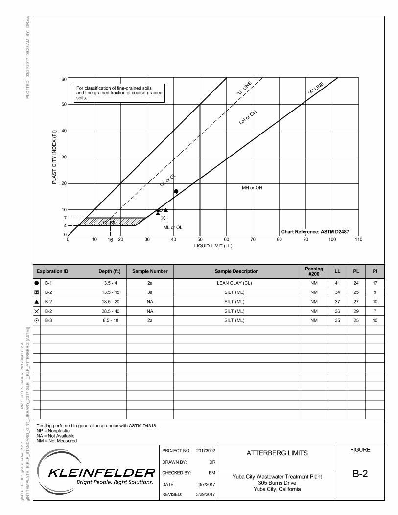
0
10
20
30
40
50
60
0 10 20 30 40 50 60 70 80 90 100 110
ATTERBERG LIMITS
LL PL PIPassing#200
B-2
Exploration ID Depth (ft.)
16
24
25
27
29
25
NM
NM
NM
NM
NM
2a
3a
NA
NA
2a
3.5 - 4
13.5 - 15
18.5 - 20
28.5 - 40
8.5 - 10
CL-ML
LIQUID LIMIT (LL)
PLA
ST
ICIT
Y I
ND
EX
(P
I)
CL or OL
"U" L
INE
ML or OL4
7
MH or OH
"A" L
INE
CH or OH
Sample Number
Testing perfomed in general accordance with ASTM D4318.NP = NonplasticNA = Not AvailableNM = Not Measured
Sample Description
B-1
B-2
B-2
B-2
B-3
41
34
37
36
35
17
9
10
7
10
LEAN CLAY (CL)
SILT (ML)
SILT (ML)
SILT (ML)
SILT (ML)
FIGURE
Yuba City Wastewater Treatment Plant305 Burns Drive
Yuba City, California
Chart Reference: ASTM D2487
DATE: 3/7/2017
DRAWN BY: DR
REVISED: 3/29/2017
PLO
TT
ED
: 03
/29/
201
7 0
9:2
8 A
M B
Y:
DR
oss
PROJECT NO.: 20173992
gIN
T F
ILE
: K
lf_gi
nt_m
aste
r_20
17
P
RO
JEC
T N
UM
BE
R: 2
0173
992.
001
A
gIN
T T
EM
PLA
TE
: E
:KLF
_ST
AN
DA
RD
_GIN
T_L
IBR
AR
Y_2
017
.GLB
[_
KLF
_AT
TE
RB
ER
G (
AS
TM
)]
CHECKED BY: BM
For classification of fine-grained soilsand fine-grained fraction of coarse-grainedsoils.
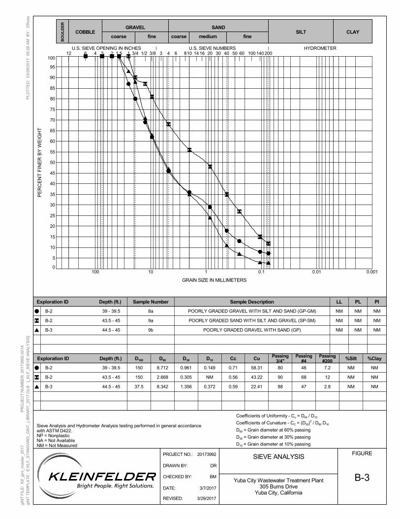
0
5
10
15
20
25
30
35
40
45
50
55
60
65
70
75
80
85
90
95
100
0.0010.010.1110100
Sample Number Sample Description LL PL PI
%SiltCu %ClayCcExploration ID Depth (ft.)
B-3
SIEVE ANALYSIS
50HYDROMETERU.S. SIEVE OPENING IN INCHES U.S. SIEVE NUMBERS
1403 4 20 40
BO
UL
DE
R
6 601.5 8 143/4 1/212 3/8 3 10024 16 301 2006 10
Sieve Analysis and Hydrometer Analysis testing performed in general accordancewith ASTM D422.NP = NonplasticNA = Not AvailableNM = Not Measured
D60 D30 D10D100Passing
3/4"Passing
#4Passing
#200
NM
NM
NM
NM
NM
NM
NM
NM
NM
8a
9a
9b
0.961
0.305
1.356
0.149
NM
0.372
39 - 39.5
43.5 - 45
44.5 - 45
46
68
47
80
90
88
150
150
37.5
NM
NM
NM
NM
NM
NM
Exploration ID Depth (ft.)
PE
RC
EN
T F
INE
R B
Y W
EIG
HT
GRAIN SIZE IN MILLIMETERS
medium fine
GRAVEL SANDCOBBLE
coarse coarseCLAYSILT
fine
Coefficients of Uniformity - Cu = D60 / D10
Coefficients of Curvature - CC = (D30)2 / D60 D10
D60 = Grain diameter at 60% passing
D30 = Grain diameter at 30% passing
D10 = Grain diameter at 10% passing
7.2
12
2.8
39 - 39.5
43.5 - 45
44.5 - 45
B-2
B-2
B-3
B-2
B-2
B-3
8.712
2.668
8.342
POORLY GRADED GRAVEL WITH SILT AND SAND (GP-GM)
POORLY GRADED SAND WITH SILT AND GRAVEL (SP-SM)
POORLY GRADED GRAVEL WITH SAND (GP)
0.71
0.56
0.59
58.31
43.22
22.41
FIGURE
Yuba City Wastewater Treatment Plant305 Burns Drive
Yuba City, CaliforniaDATE: 3/7/2017
DRAWN BY: DR
REVISED: 3/29/2017
PLO
TT
ED
: 03
/29/
201
7 0
9:2
8 A
M B
Y:
DR
oss
PROJECT NO.: 20173992
gIN
T F
ILE
: K
lf_gi
nt_m
aste
r_20
17
P
RO
JEC
T N
UM
BE
R: 2
0173
992.
001
A
gIN
T T
EM
PLA
TE
: E
:KLF
_ST
AN
DA
RD
_GIN
T_L
IBR
AR
Y_2
017
.GLB
[_
KLF
_SIE
VE
AN
ALY
SIS
]
CHECKED BY: BM
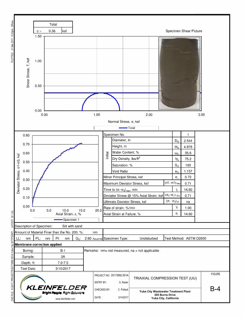
Yuba City Wastewater Treatment Plant
305 Burns Drive
Yuba City, California
CAD
FILE
: K:\2
017_
PROJ
ECTS
\2017
3992
.001A
-Yub
a City
WTT
P\GI
NT\
LAY
OUT:
B-1
UU
PLOT
TED:
21 M
ar 20
17, 1
2:03p
m, D
Ross
ENTRY BY:
CHECKED BY:
DATE:
PROJECT NO.
www.kleinfelder.com
TRIAXIAL COMPRESSION TEST (UU)
20173992.001A
3/14/2017
C. Pollack
S. Rader
FIGURE
B-4
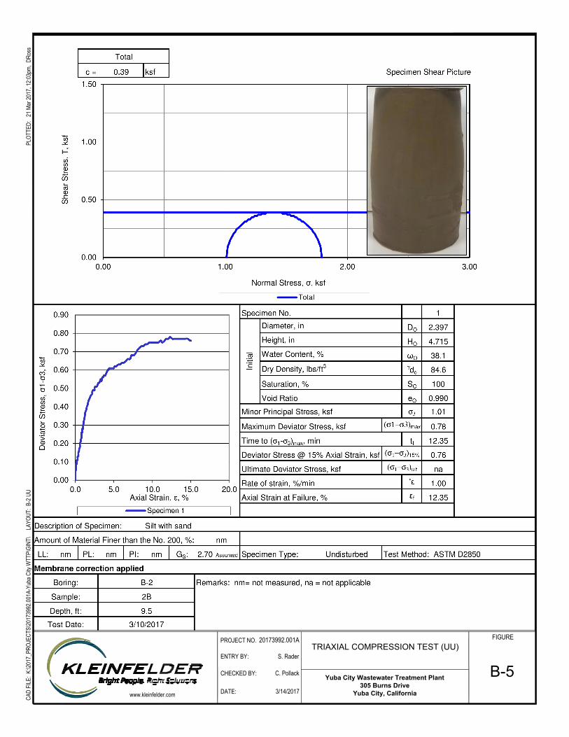
Yuba City Wastewater Treatment Plant
305 Burns Drive
Yuba City, California
CAD
FILE
: K:\2
017_
PROJ
ECTS
\2017
3992
.001A
-Yub
a City
WTT
P\GI
NT\
LAY
OUT:
B-2
UU
PLOT
TED:
21 M
ar 20
17, 1
2:03p
m, D
Ross
ENTRY BY:
CHECKED BY:
DATE:
PROJECT NO.
www.kleinfelder.com
TRIAXIAL COMPRESSION TEST (UU)
20173992.001A
3/14/2017
C. Pollack
S. Rader
FIGURE
B-5
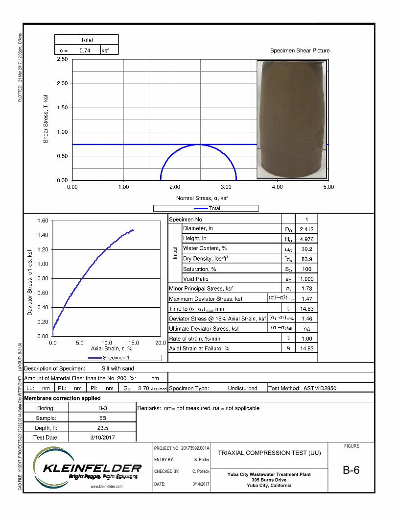
Yuba City Wastewater Treatment Plant
305 Burns Drive
Yuba City, California
CAD
FILE
: K:\2
017_
PROJ
ECTS
\2017
3992
.001A
-Yub
a City
WTT
P\GI
NT\
LAY
OUT:
B-3
UU
PLOT
TED:
21 M
ar 20
17, 1
2:03p
m, D
Ross
ENTRY BY:
CHECKED BY:
DATE:
PROJECT NO.
www.kleinfelder.com
TRIAXIAL COMPRESSION TEST (UU)
20173992.001A
3/14/2017
C. Pollack
S. Rader
FIGURE
B-6

20173992.001A/SAC17R57127 April 10, 2017 © 2017 Kleinfelder
APPENDIX C
CORROSION TESTING RESULTS ____________________________________________________________________________
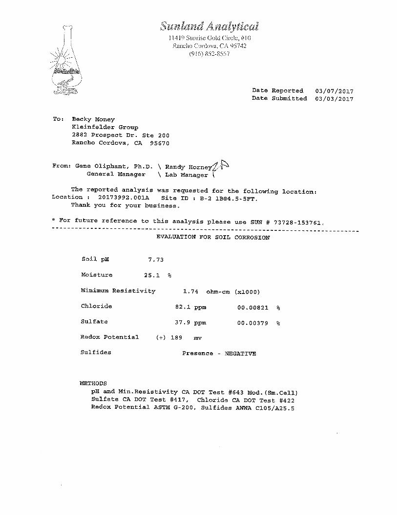

20173992.001A/SAC17R57127 April 10, 2017 © 2017 Kleinfelder
APPENDIX D PREVIOUS EXPLORATIONS FROM 1998
___________________________________________________________________________________
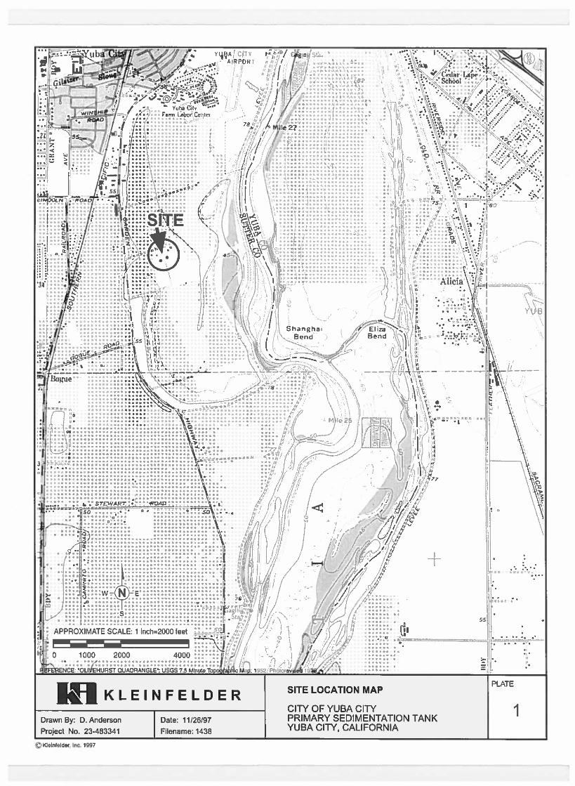
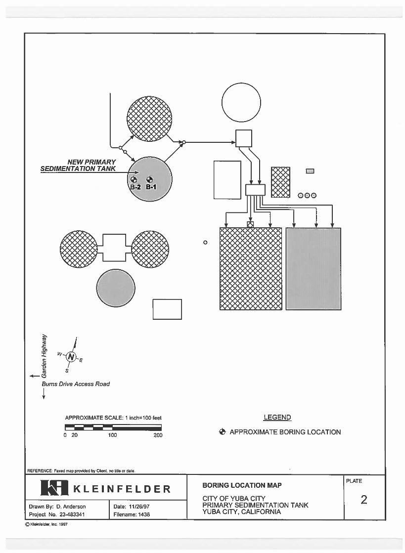
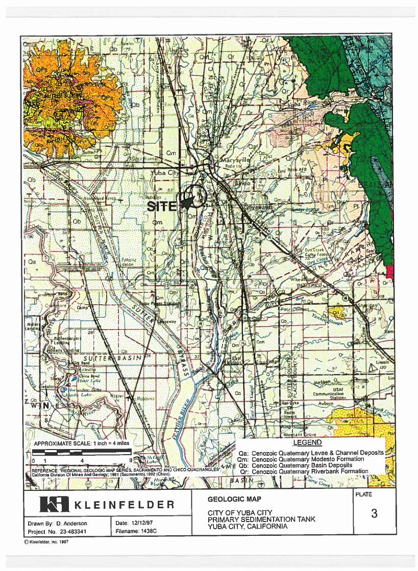
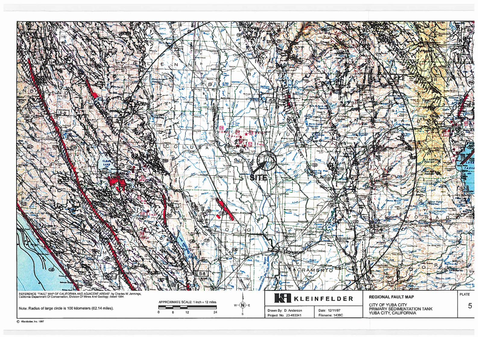
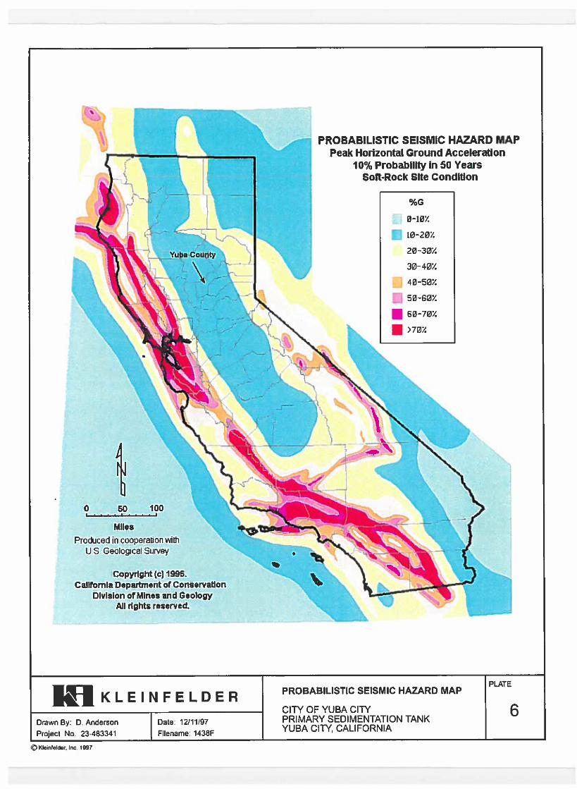
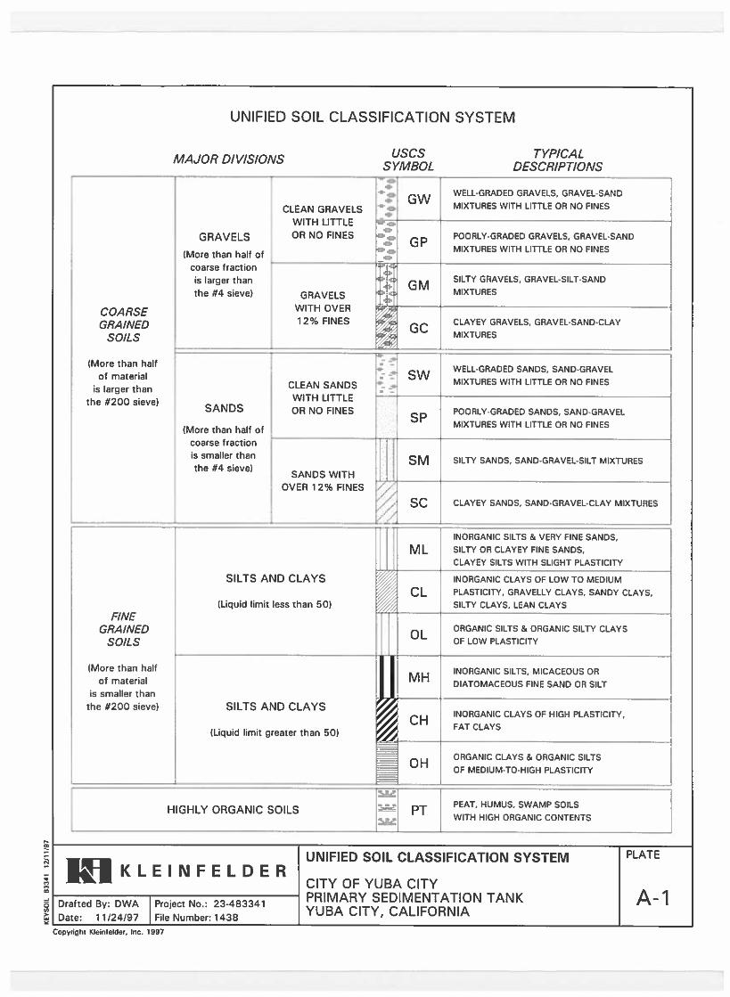
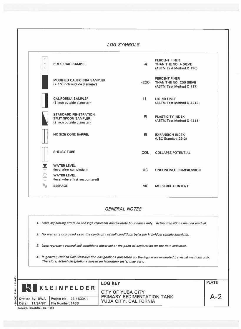
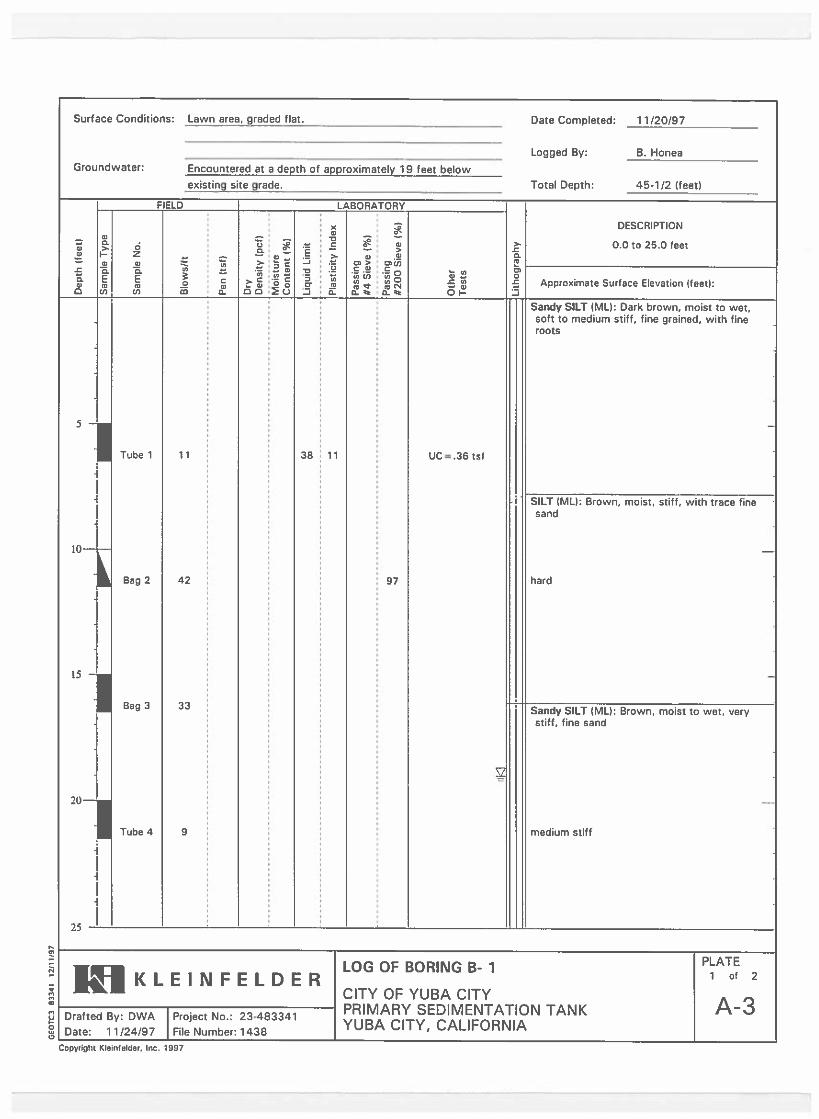
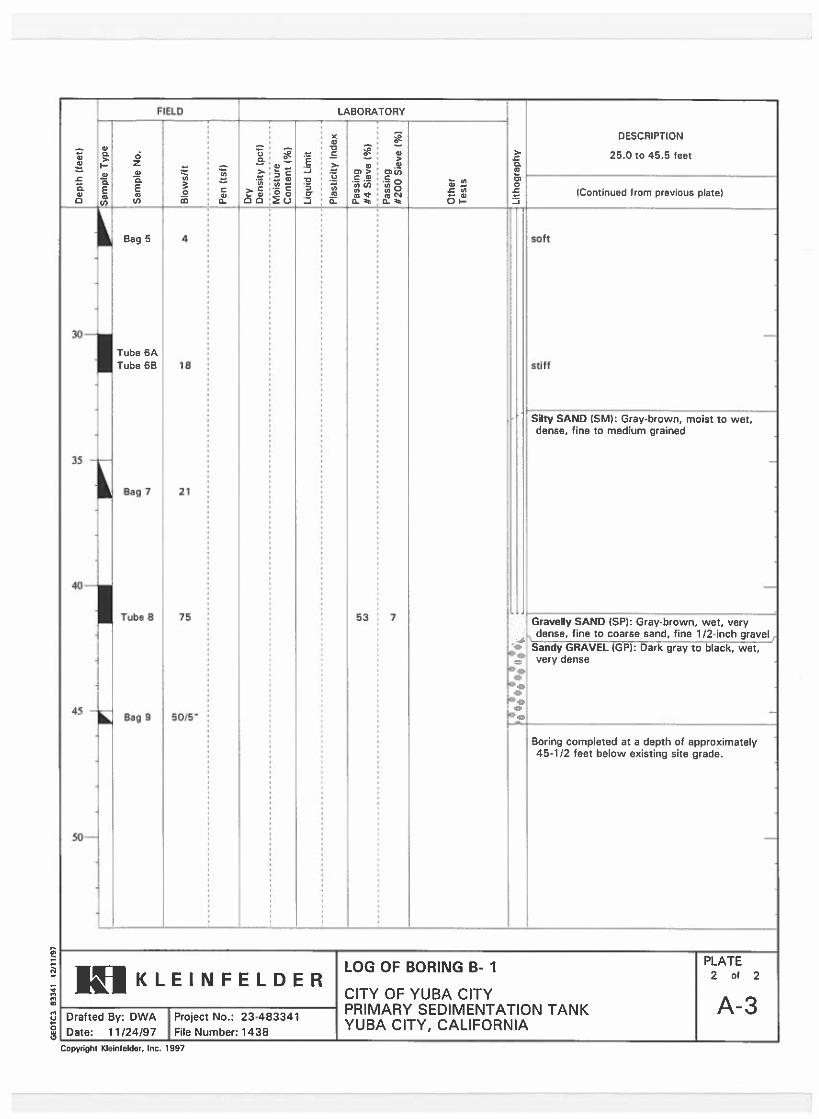
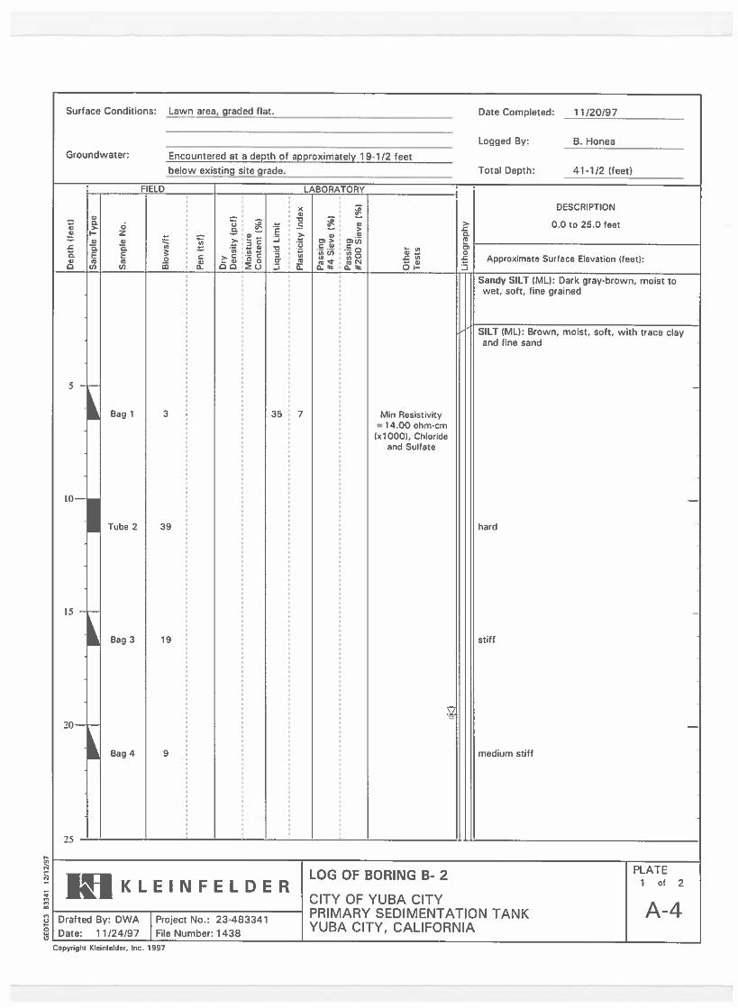
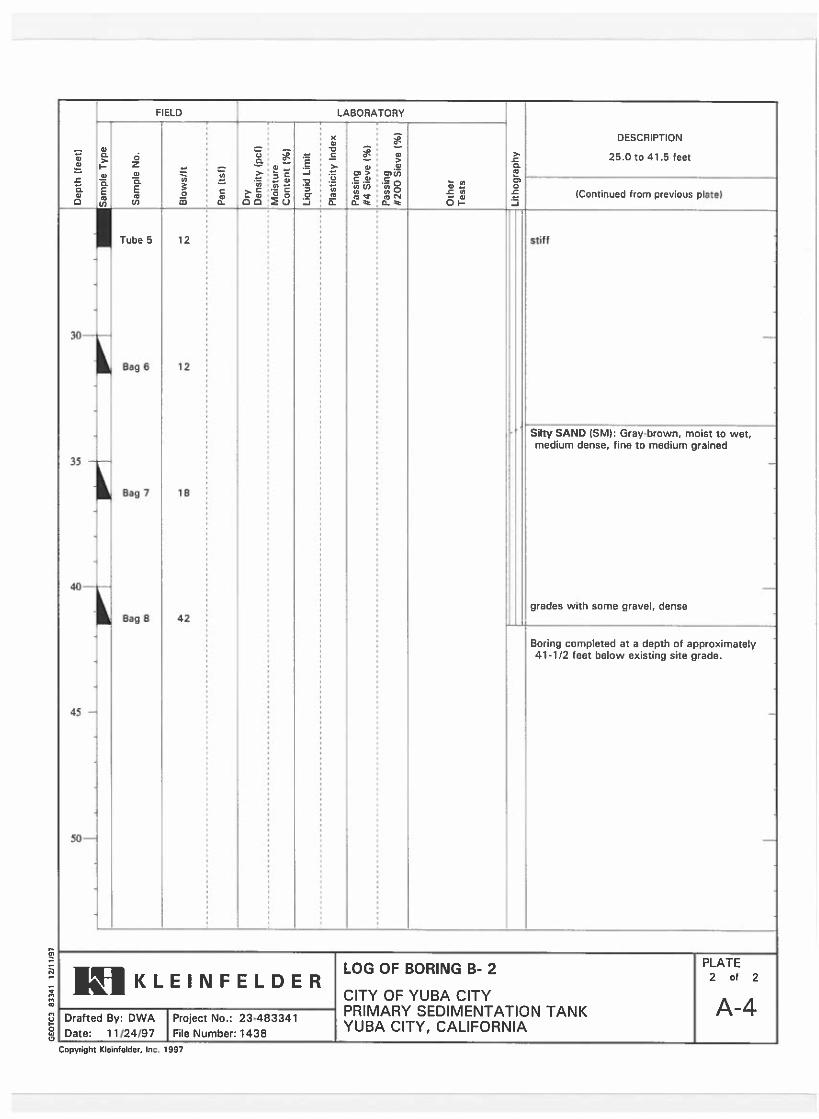
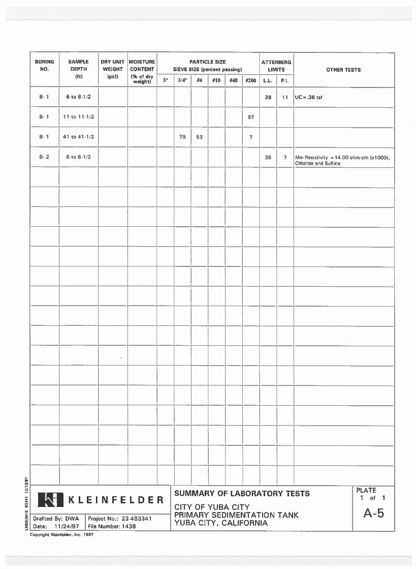
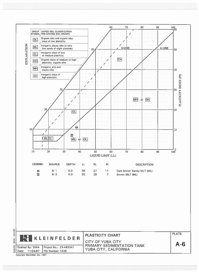

20173992.001A/SAC17R57127 April 10, 2017 © 2017 Kleinfelder
APPENDIX E PREVIOUS EXPLORATIONS FROM 2001
___________________________________________________________________________________
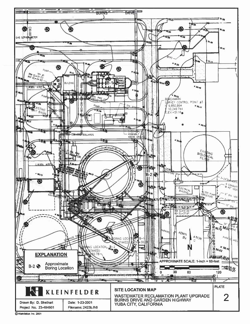
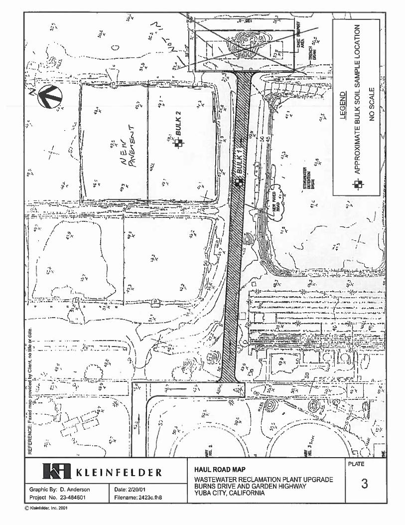
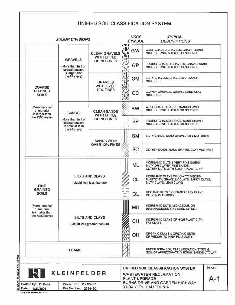
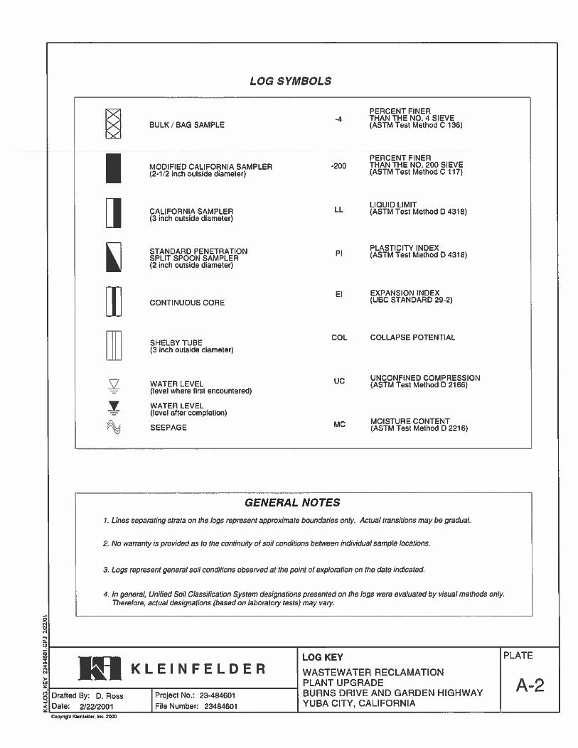
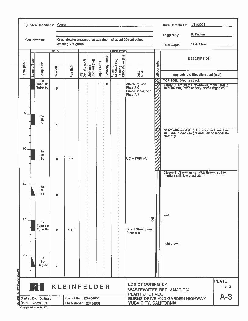
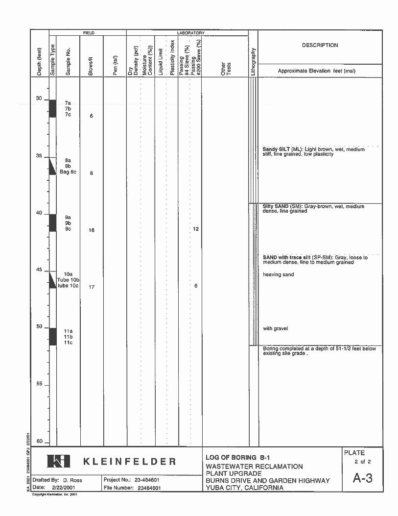
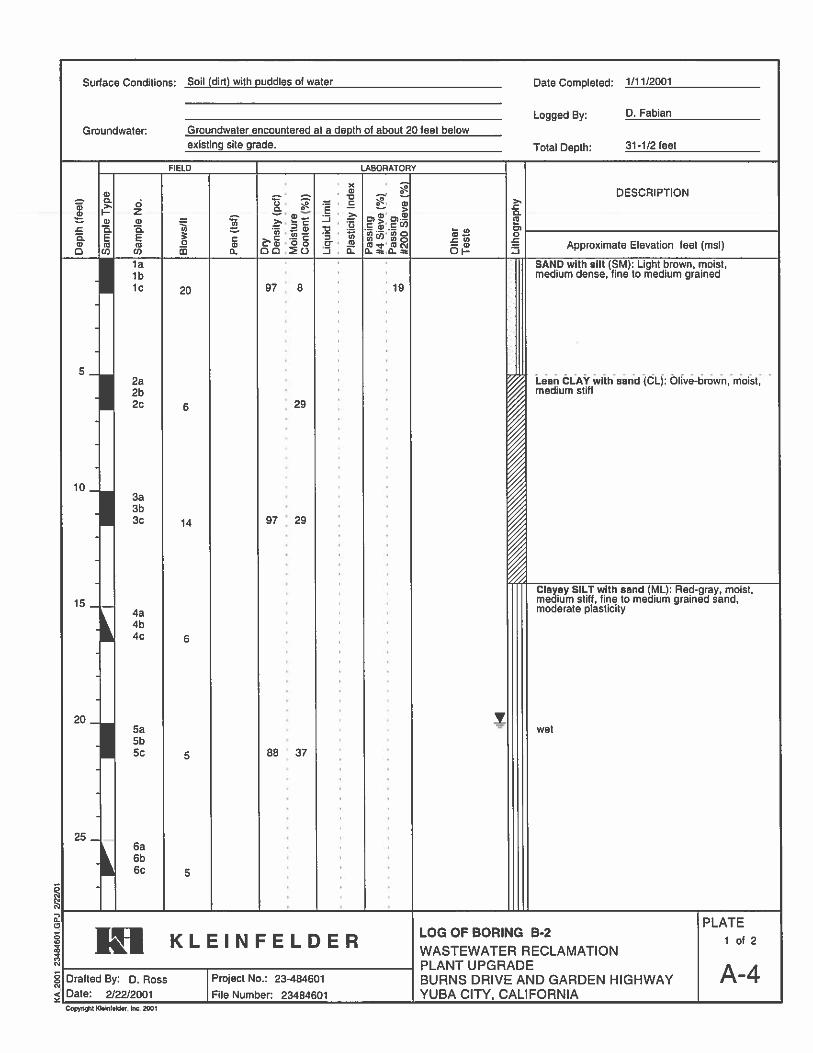
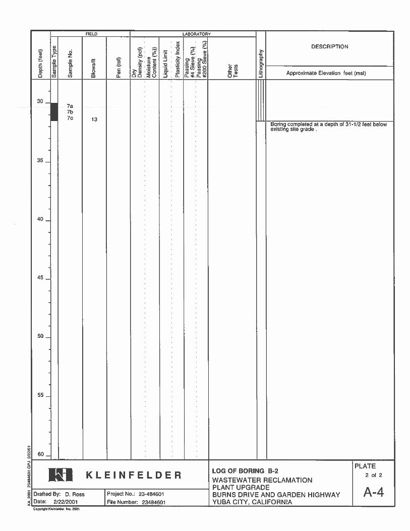
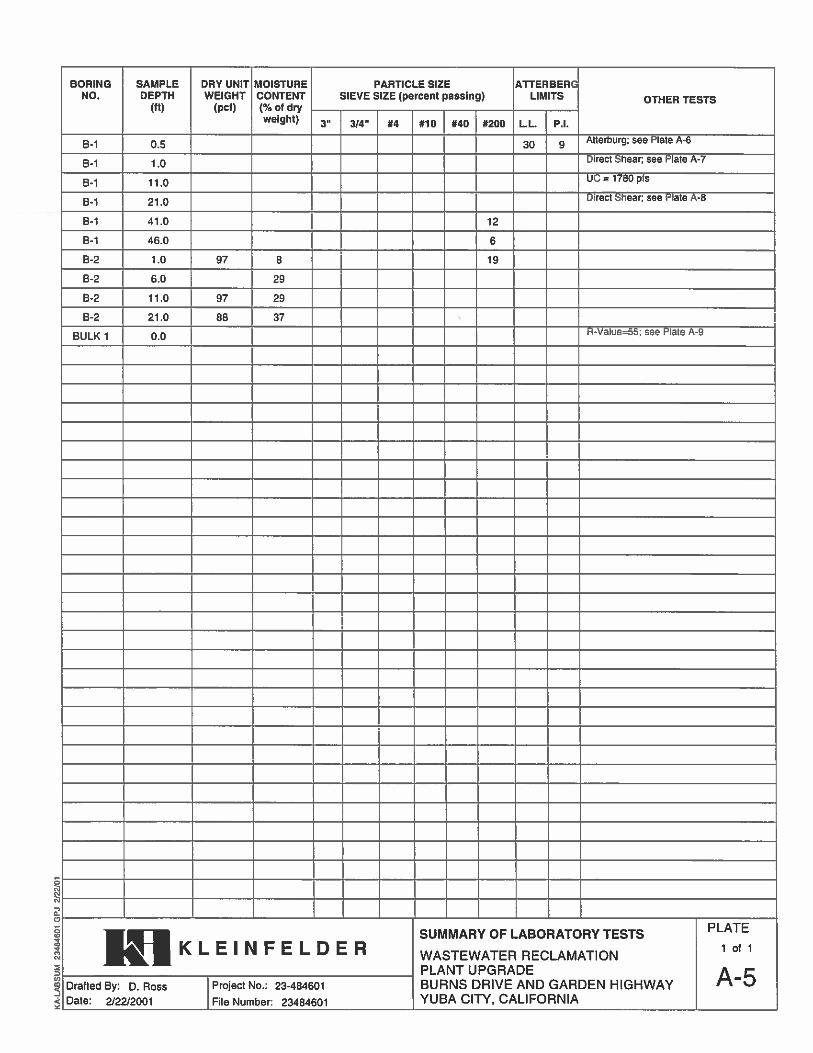
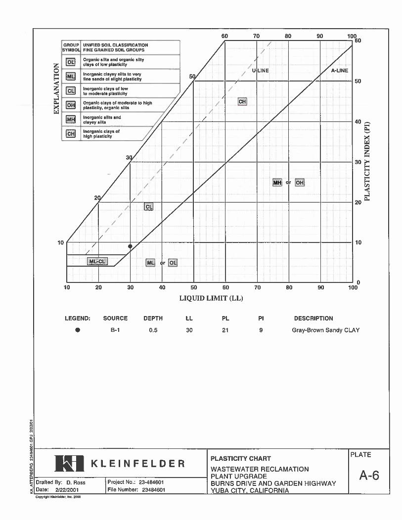

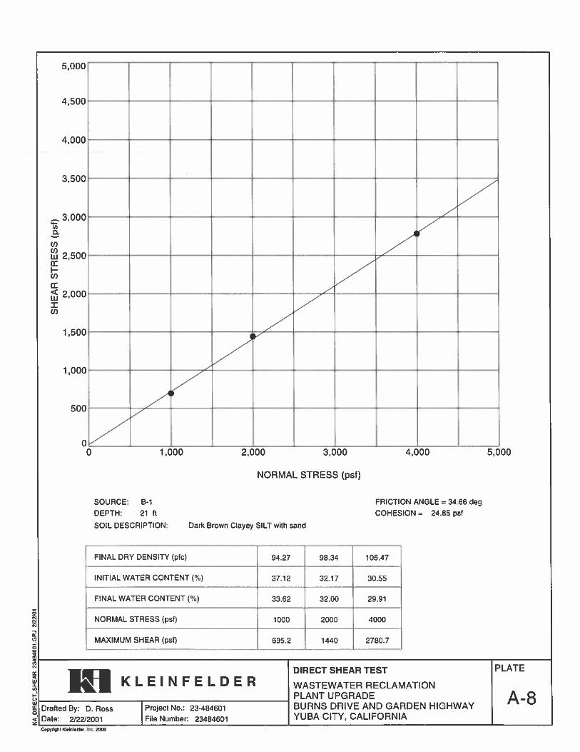
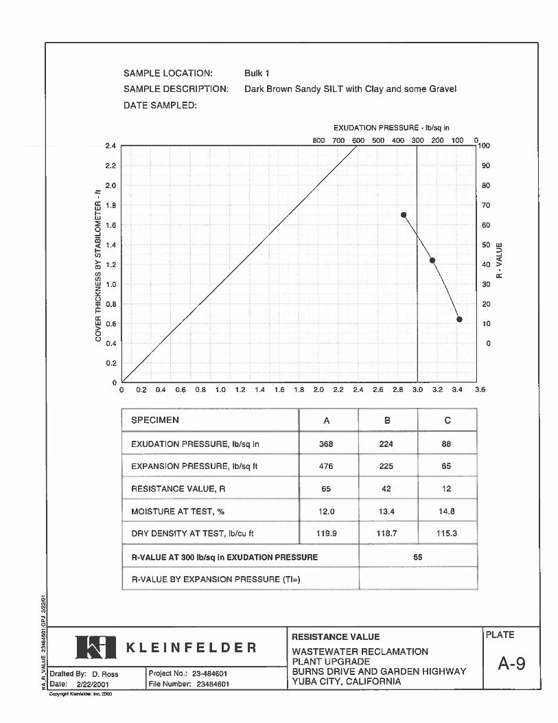

20173992.001A/SAC17R57127 April 10, 2017 © 2017 Kleinfelder
APPENDIX F PREVIOUS EXPLORATIONS FROM 2007
___________________________________________________________________________________
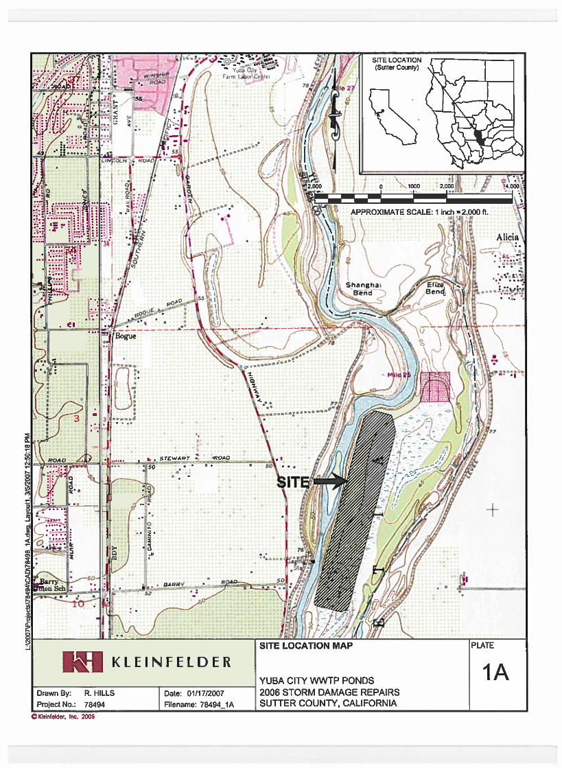
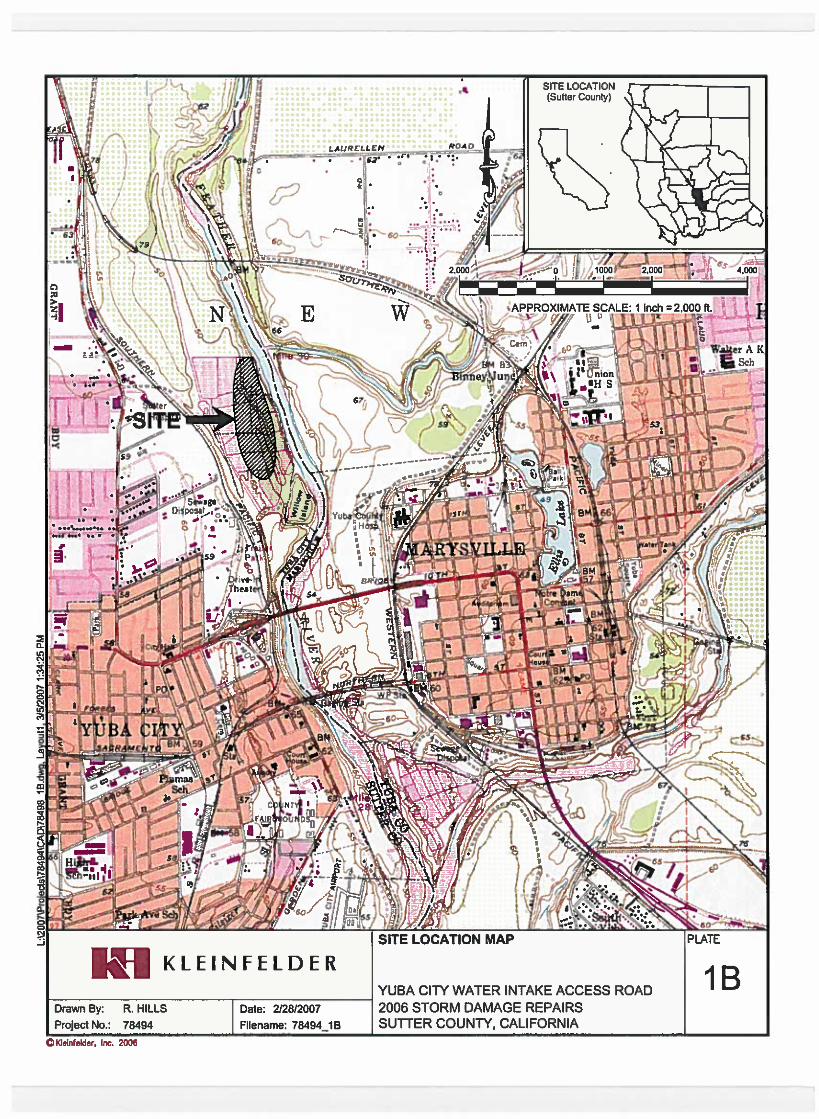
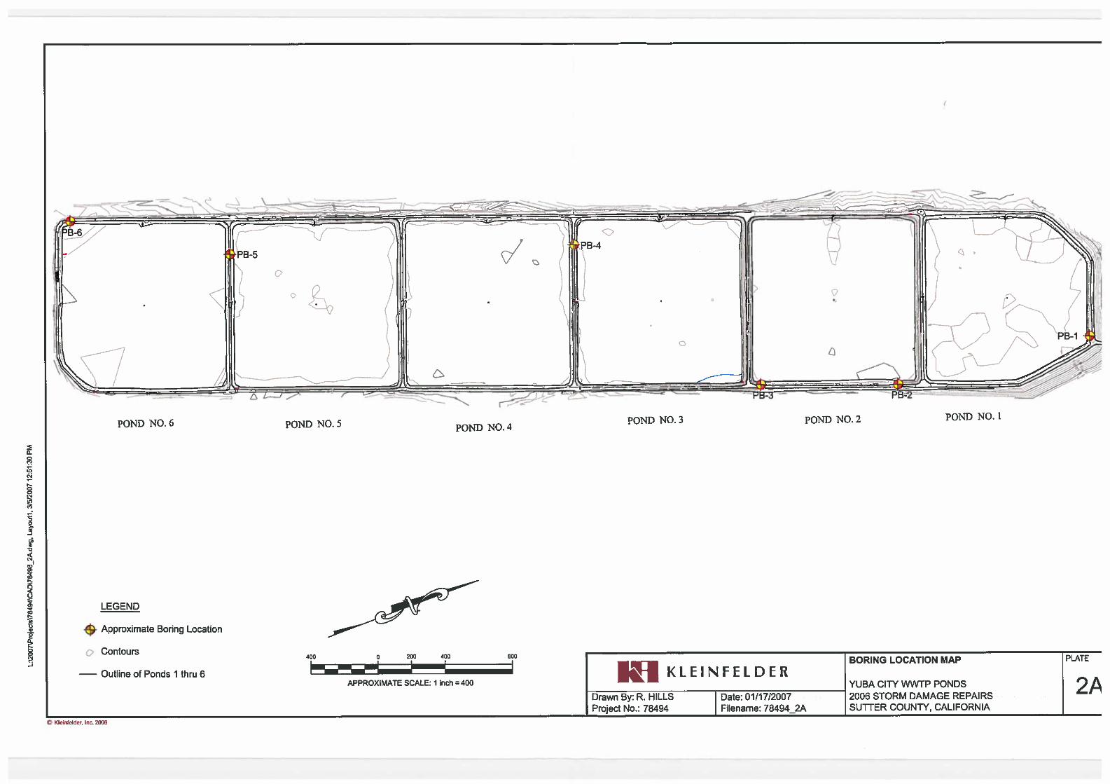
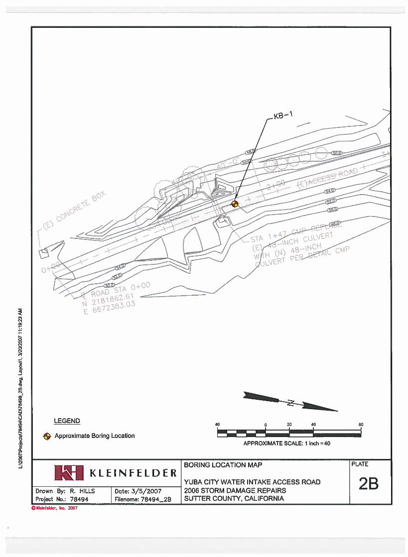

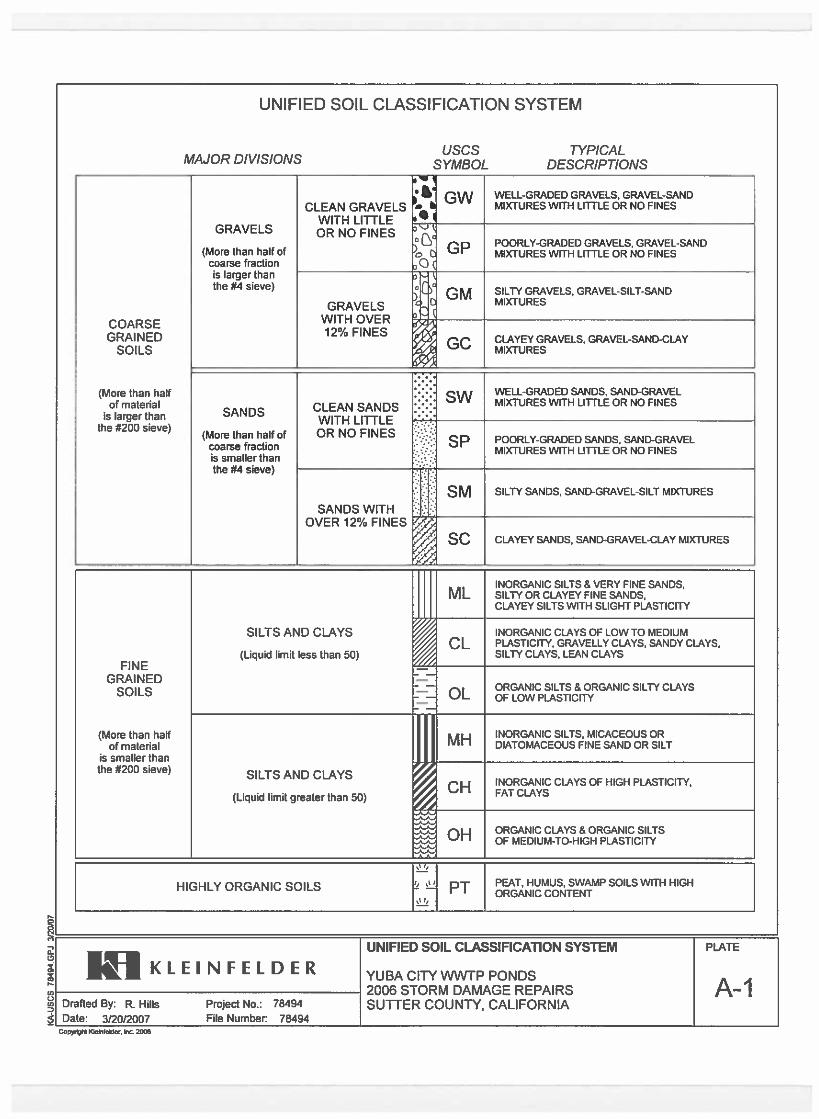
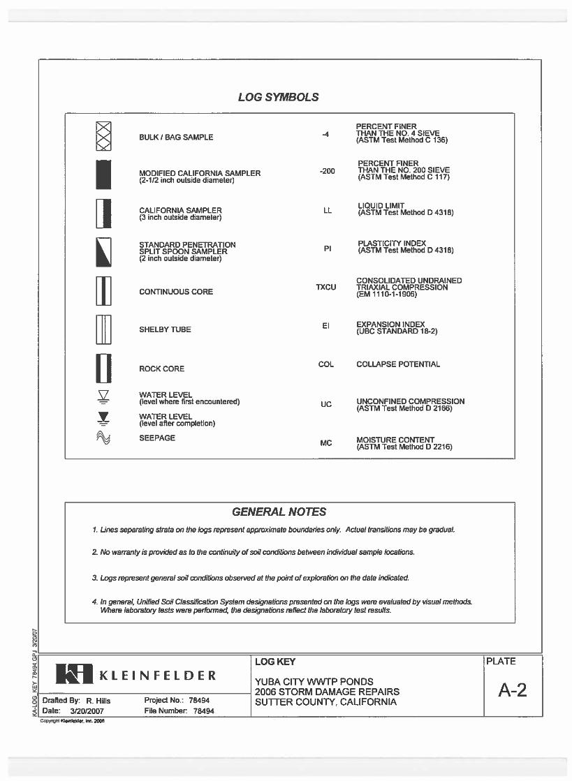
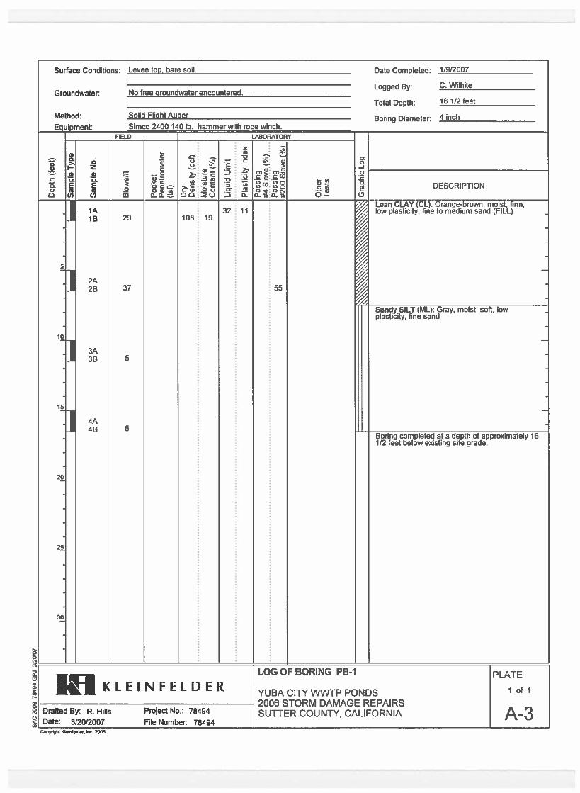
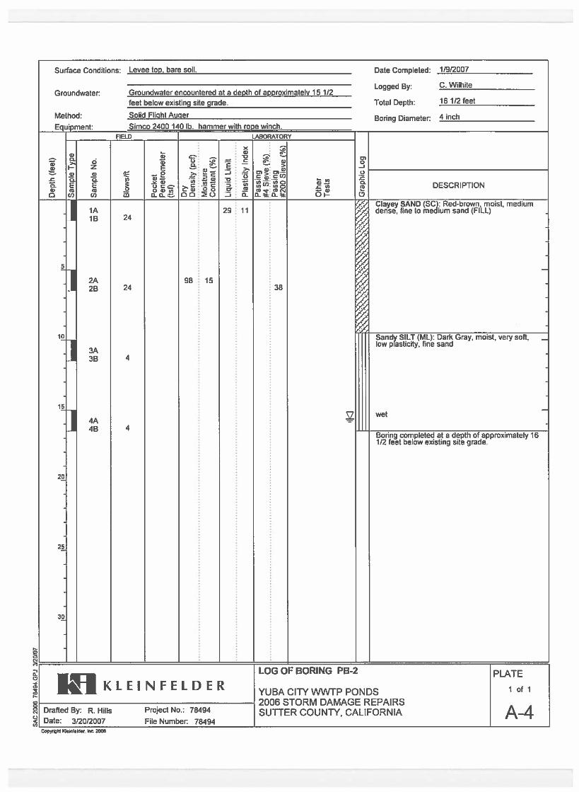
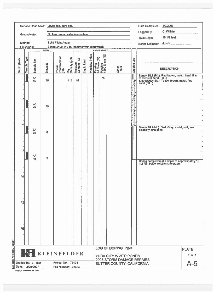
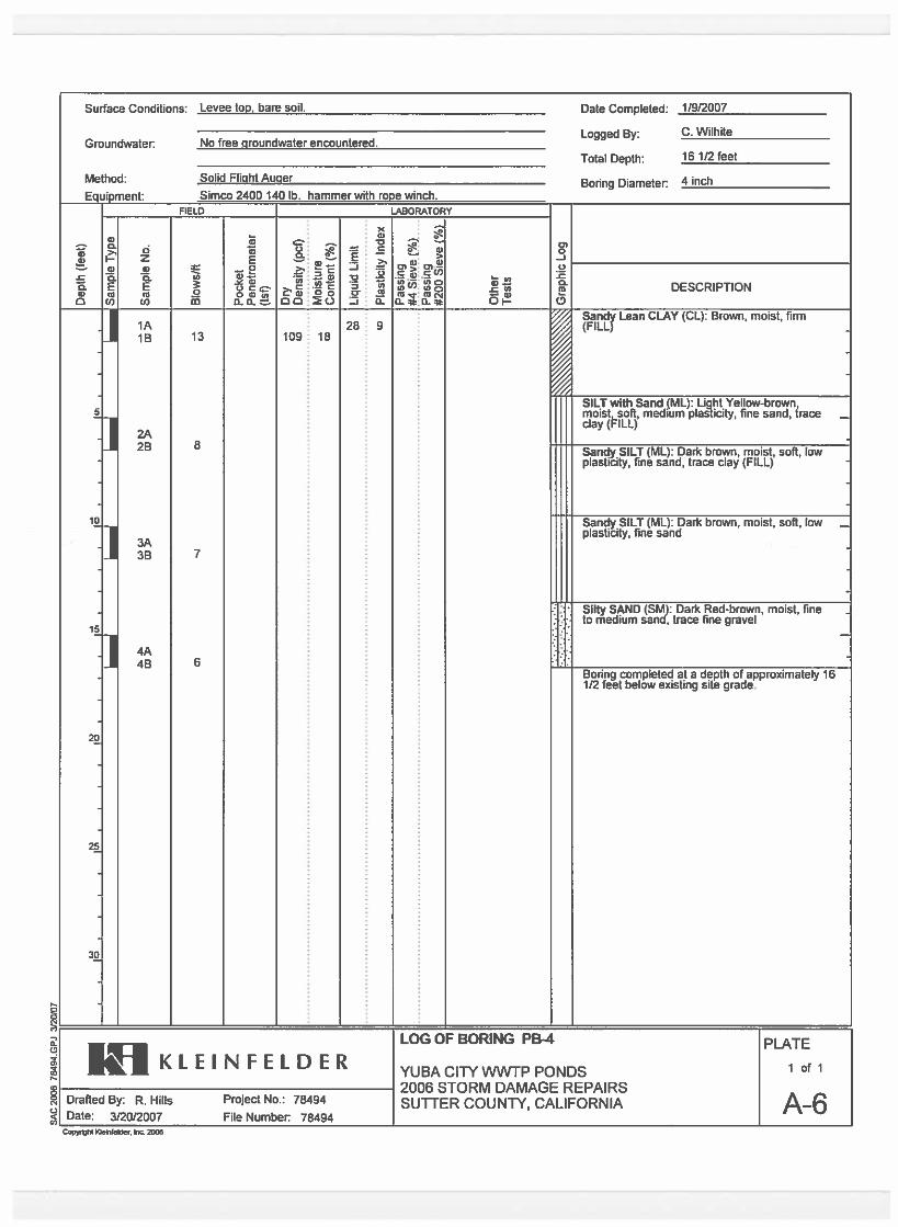
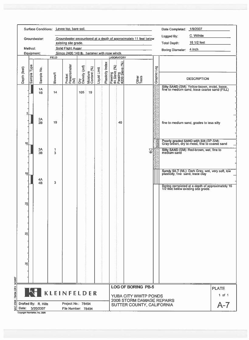
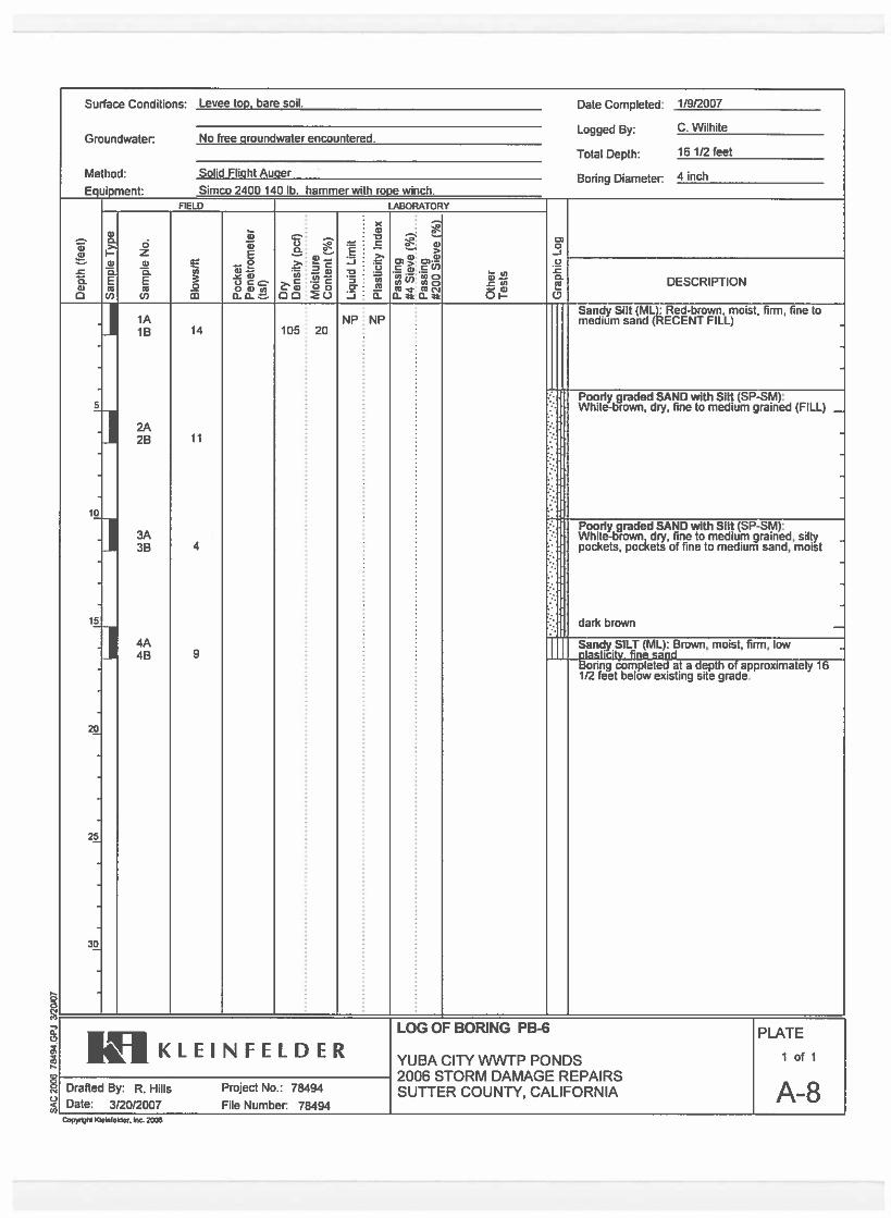
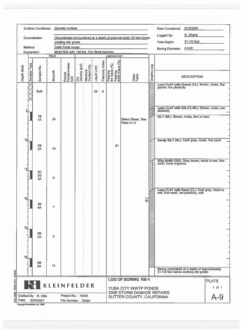
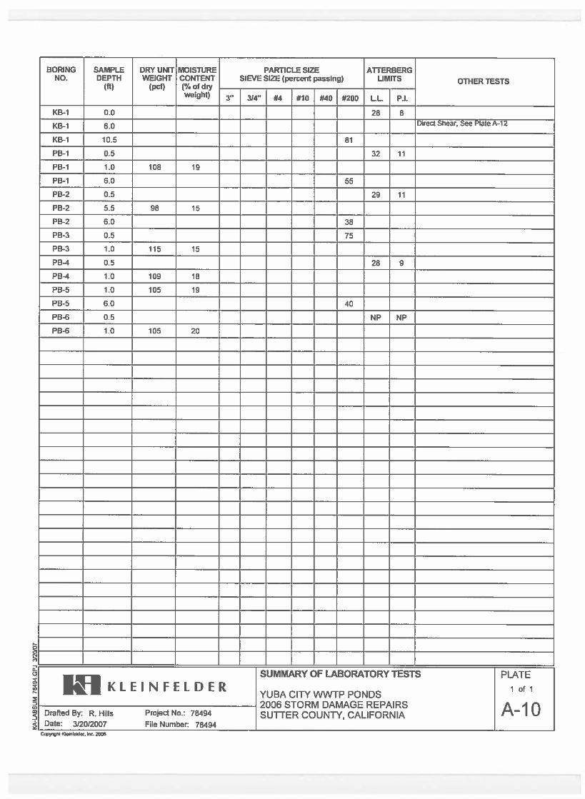
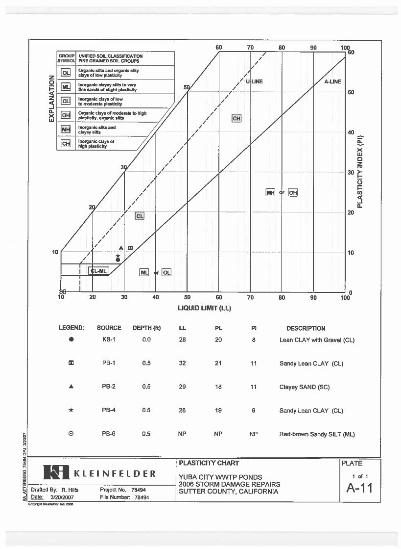
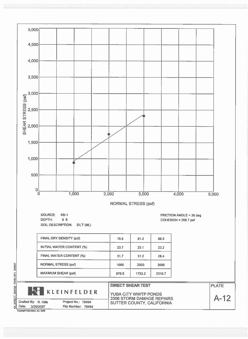

20173992.001A/SAC17R57127 April 10, 2017 © 2017 Kleinfelder
APPENDIX G GBA INFORMATIONAL SHEET
___________________________________________________________________________________

Geotechnical-Engineering ReportImportant Information about This
Subsurface problems are a principal cause of construction delays, cost overruns, claims, and disputes.
While you cannot eliminate all such risks, you can manage them. The following information is provided to help.
The Geoprofessional Business Association (GBA) has prepared this advisory to help you – assumedly a client representative – interpret and apply this geotechnical-engineering report as effectively as possible. In that way, clients can benefit from a lowered exposure to the subsurface problems that, for decades, have been a principal cause of construction delays, cost overruns, claims, and disputes. If you have questions or want more information about any of the issues discussed below, contact your GBA-member geotechnical engineer. Active involvement in the Geoprofessional Business Association exposes geotechnical engineers to a wide array of risk-confrontation techniques that can be of genuine benefit for everyone involved with a construction project.
Geotechnical-Engineering Services Are Performed for Specific Purposes, Persons, and ProjectsGeotechnical engineers structure their services to meet the specific needs of their clients. A geotechnical-engineering study conducted for a given civil engineer will not likely meet the needs of a civil-works constructor or even a different civil engineer. Because each geotechnical-engineering study is unique, each geotechnical-engineering report is unique, prepared solely for the client. Those who rely on a geotechnical-engineering report prepared for a different client can be seriously misled. No one except authorized client representatives should rely on this geotechnical-engineering report without first conferring with the geotechnical engineer who prepared it. And no one – not even you – should apply this report for any purpose or project except the one originally contemplated.
Read this Report in FullCostly problems have occurred because those relying on a geotechnical-engineering report did not read it in its entirety. Do not rely on an executive summary. Do not read selected elements only. Read this report in full.
You Need to Inform Your Geotechnical Engineer about ChangeYour geotechnical engineer considered unique, project-specific factors when designing the study behind this report and developing the confirmation-dependent recommendations the report conveys. A few typical factors include: • the client’s goals, objectives, budget, schedule, and risk-management preferences; • the general nature of the structure involved, its size, configuration, and performance criteria; • the structure’s location and orientation on the site; and • other planned or existing site improvements, such as retaining walls, access roads, parking lots, and underground utilities.
Typical changes that could erode the reliability of this report include those that affect:• the site’s size or shape;• the function of the proposed structure, as when it’s changed from a parking garage to an office building, or from a light-industrial plant to a refrigerated warehouse;• the elevation, configuration, location, orientation, or weight of the proposed structure;• the composition of the design team; or• project ownership.
As a general rule, always inform your geotechnical engineer of project changes – even minor ones – and request an assessment of their impact. The geotechnical engineer who prepared this report cannot accept responsibility or liability for problems that arise because the geotechnical engineer was not informed about developments the engineer otherwise would have considered.
This Report May Not Be ReliableDo not rely on this report if your geotechnical engineer prepared it:• for a different client;• for a different project;• for a different site (that may or may not include all or a portion of the original site); or • before important events occurred at the site or adjacent to it; e.g., man-made events like construction or environmental remediation, or natural events like floods, droughts, earthquakes, or groundwater fluctuations.
Note, too, that it could be unwise to rely on a geotechnical-engineering report whose reliability may have been affected by the passage of time, because of factors like changed subsurface conditions; new or modified codes, standards, or regulations; or new techniques or tools. If your geotechnical engineer has not indicated an “apply-by” date on the report, ask what it should be, and, in general, if you are the least bit uncertain about the continued reliability of this report, contact your geotechnical engineer before applying it. A minor amount of additional testing or analysis – if any is required at all – could prevent major problems.
Most of the “Findings” Related in This Report Are Professional OpinionsBefore construction begins, geotechnical engineers explore a site’s subsurface through various sampling and testing procedures. Geotechnical engineers can observe actual subsurface conditions only at those specific locations where sampling and testing were performed. The data derived from that sampling and testing were reviewed by your geotechnical engineer, who then applied professional judgment to form opinions about subsurface conditions throughout the site. Actual sitewide-subsurface conditions may differ – maybe significantly – from those indicated in this report. Confront that risk by retaining your geotechnical engineer to serve on the design team from project start to project finish, so the individual can provide informed guidance quickly, whenever needed.
This Report’s Recommendations Are Confirmation-DependentThe recommendations included in this report – including any options or alternatives – are confirmation-dependent. In other words, they are not final, because the geotechnical engineer who developed them relied heavily on judgment and opinion to do so. Your geotechnical engineer can finalize the recommendations only after observing actual subsurface conditions revealed during construction. If through observation your geotechnical engineer confirms that the conditions assumed to exist actually do exist, the recommendations can be relied upon, assuming no other changes have occurred. The geotechnical engineer who prepared this report cannot assume responsibility or liability for confirmation-dependent recommendations if you fail to retain that engineer to perform construction observation.
This Report Could Be MisinterpretedOther design professionals’ misinterpretation of geotechnical-engineering reports has resulted in costly problems. Confront that risk by having your geotechnical engineer serve as a full-time member of the design team, to: • confer with other design-team members, • help develop specifications, • review pertinent elements of other design professionals’ plans and specifications, and • be on hand quickly whenever geotechnical-engineering guidance is needed. You should also confront the risk of constructors misinterpreting this report. Do so by retaining your geotechnical engineer to participate in prebid and preconstruction conferences and to perform construction observation.
Give Constructors a Complete Report and GuidanceSome owners and design professionals mistakenly believe they can shift unanticipated-subsurface-conditions liability to constructors by limiting the information they provide for bid preparation. To help prevent the costly, contentious problems this practice has caused, include the complete geotechnical-engineering report, along with any attachments or appendices, with your contract documents, but be certain to note conspicuously that you’ve included the material for informational purposes only. To avoid misunderstanding, you may also want to note that “informational purposes” means constructors have no right to rely on the interpretations, opinions, conclusions, or recommendations in the report, but they may rely on the factual data relative to the specific times, locations, and depths/elevations referenced. Be certain that constructors know they may learn about specific project requirements, including options selected from the report, only from the design drawings and specifications. Remind constructors that they may
perform their own studies if they want to, and be sure to allow enough time to permit them to do so. Only then might you be in a position to give constructors the information available to you, while requiring them to at least share some of the financial responsibilities stemming from unanticipated conditions. Conducting prebid and preconstruction conferences can also be valuable in this respect.
Read Responsibility Provisions CloselySome client representatives, design professionals, and constructors do not realize that geotechnical engineering is far less exact than other engineering disciplines. That lack of understanding has nurtured unrealistic expectations that have resulted in disappointments, delays, cost overruns, claims, and disputes. To confront that risk, geotechnical engineers commonly include explanatory provisions in their reports. Sometimes labeled “limitations,” many of these provisions indicate where geotechnical engineers’ responsibilities begin and end, to help others recognize their own responsibilities and risks. Read these provisions closely. Ask questions. Your geotechnical engineer should respond fully and frankly.
Geoenvironmental Concerns Are Not CoveredThe personnel, equipment, and techniques used to perform an environmental study – e.g., a “phase-one” or “phase-two” environmental site assessment – differ significantly from those used to perform a geotechnical-engineering study. For that reason, a geotechnical-engineering report does not usually relate any environmental findings, conclusions, or recommendations; e.g., about the likelihood of encountering underground storage tanks or regulated contaminants. Unanticipated subsurface environmental problems have led to project failures. If you have not yet obtained your own environmental information, ask your geotechnical consultant for risk-management guidance. As a general rule, do not rely on an environmental report prepared for a different client, site, or project, or that is more than six months old.
Obtain Professional Assistance to Deal with Moisture Infiltration and MoldWhile your geotechnical engineer may have addressed groundwater, water infiltration, or similar issues in this report, none of the engineer’s services were designed, conducted, or intended to prevent uncontrolled migration of moisture – including water vapor – from the soil through building slabs and walls and into the building interior, where it can cause mold growth and material-performance deficiencies. Accordingly, proper implementation of the geotechnical engineer’s recommendations will not of itself be sufficient to prevent moisture infiltration. Confront the risk of moisture infiltration by including building-envelope or mold specialists on the design team. Geotechnical engineers are not building-envelope or mold specialists.
Copyright 2016 by Geoprofessional Business Association (GBA). Duplication, reproduction, or copying of this document, in whole or in part, by any means whatsoever, is strictly prohibited, except with GBA’s specific written permission. Excerpting, quoting, or otherwise extracting wording from this document is permitted only with the express written permission of GBA, and only for purposes of scholarly research or book review. Only members of GBA may use this document or its wording as a complement to or as an element of a report of any
kind. Any other firm, individual, or other entity that so uses this document without being a GBA member could be committing negligent
Telephone: 301/565-2733e-mail: [email protected] www.geoprofessional.org