Embed Size (px)
Citation preview

Intrax Consulting Engineers Pty Ltd
ABN: 31 106 481 252
ACN: 106 481 252
Head Office – 35 Bank Street, South Melbourne VIC 3205
P: 03 8371 0100 F: 03 8371 0199
W: www.intrax.com.au
Geotechnical Site Investigation
No 72 Junction Road
Schofields, NSW
Submitted to:
Simeon McGovern
Betop Holdings P/L
C/- Moho Developments
Level 5, 9 Help Street
Chatswood NSW 2067
Date:
Site Number:
Revision:
7/05/2018
104665
1

Commercial Report Template 1.8
7/05/2018
Document Revision: 1
Template Version: Vx
Page 1 of 14
Confidentiality
All documents are subject to the ‘Intrax Terms and Conditions’ and ‘Intrax Terms and Conditions- NAC’
documents. These documents are available on our website.
Copyright
© 2017 Intrax Consulting Engineers Pty Ltd (ABN 31 106 481 252).
This geotechnical site inspection report has been prepared expressly for the client for the sole purpose of
constructing the building described in the plans and specifications. This report is copyright to Intrax Consulting
Engineers Pty Ltd.
No part of this report shall be used for any other purpose nor by any third party without the prior written consent
of Intrax Consulting Engineers Pty Ltd. The client is defined as the person or persons named in this report or the
person or persons for whom the named building company is acting as agent.
Conditions of Use
This report is not intended for use by any other person or third party other than the named client. This report is
not to be used or quoted except as a complete document including all appendices and subject to the report
limitations as stipulated in section 6 of this document.
Direct Contact
Any questions or queries regarding this report should be directed to the Geotechnical Department, Engineering
Team on 03 8371 0100 or [email protected].
Document Template
Geotechnical Commercial Report Template Vx released 18.09.2017
Document Revision History
Date Version Author Reviewer Comments
7/05/2018 Vx.1 Prageeth
Edirisinghe Scott Emmett Site address revised
Commercial Report Template 1.8
7/05/2018
Document Revision: 1
Template Version: Vx
Page 2 of 14
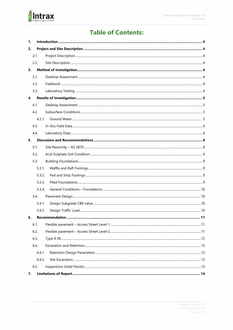
Table of Contents:
1. Introduction ......................................................................................................................................................... 4
2. Project and Site Description .............................................................................................................................. 4
2.1. Project Description ......................................................................................................................................................................... 4
2.2. Site Description ................................................................................................................................................................................ 4
3. Method of Investigation..................................................................................................................................... 4
3.1. Desktop Assessment ..................................................................................................................................................................... 4
3.2. Fieldwork ............................................................................................................................................................................................ 4
3.3. Laboratory Testing ......................................................................................................................................................................... 4
4. Results of Investigation ...................................................................................................................................... 5
4.1. Desktop Assessment ..................................................................................................................................................................... 5
4.2. Subsurface Conditions .................................................................................................................................................................. 5
4.2.1. Ground Water ............................................................................................................................................................................. 5
4.3. In-Situ Field Data ............................................................................................................................................................................ 6
4.4. Laboratory Data ............................................................................................................................................................................... 6
5. Discussion and Recommendations ................................................................................................................... 8
5.1. Site Reactivity – AS 2870.............................................................................................................................................................. 8
5.2. Acid Sulphate Soil Condition ..................................................................................................................................................... 9
5.3. Building Foundations .................................................................................................................................................................... 9
5.3.1. Waffle and Raft Footings ....................................................................................................................................................... 9
5.3.2. Pad and Strip Footings ........................................................................................................................................................... 9
5.3.3. Piled Foundations ..................................................................................................................................................................... 9
5.3.4. General Conditions – Foundations .................................................................................................................................. 10
5.4. Pavement Design .......................................................................................................................................................................... 10
5.4.1. Design Subgrade CBR value ............................................................................................................................................... 10
5.4.2. Design Traffic Load ................................................................................................................................................................. 10
6. Recommendation .............................................................................................................................................. 11
6.1. Flexible pavement – Access Street Level-1 ........................................................................................................................ 11
6.2. Flexible pavement – Access Street Level-2 ........................................................................................................................ 11
6.3. Type A fill .......................................................................................................................................................................................... 12
6.4. Excavation and Retention .......................................................................................................................................................... 12
6.4.1. Retention Design Parameters ............................................................................................................................................ 12
6.4.2. Site Excavation .......................................................................................................................................................................... 13
6.5. Inspections (Hold Points) ........................................................................................................................................................... 13
7. Limitations of Report ........................................................................................................................................ 14
Commercial Report Template 1.8
7/05/2018
Document Revision: 1
Template Version: Vx
Page 3 of 14
List of Appendices:
APPENDIX A: Site Plan and Borehole Logs
APPENDIX B: Site Photography
APPENDIX C: Laboratory Data
REFERENCED STANDARDS:
AS 1726-2017, Geotechnical site investigations, Standards Australia, Sydney, Retrieved from SAI Global
AS 2870-2011, Residential slabs and footings, Standards Australia, Sydney, Retrieved from SAI Global
AS 3798-2007, Guidelines on earthworks for commercial and residential developments, Standards Australia,
Sydney, Retrieved from SAI Global
AS 4678-2002, Earth-retaining structures, Standards Australia, Sydney, Retrieved from SAI Global
REPORT AUTHOR/S:
Mr Prageeth Edirisinghe
Geotechnical Engineer
BEng (Civil) Hons
Mr Scott Emmett
Geologist
BSc (EarthScience) Hons, MAIG
REPORT CONTACT:
Prageeth Edirisinghe
03 8371 0188
Intrax Consulting Engineers Pty Ltd
Geotechnical Consultants
Unit 11, 85 Mt Derrimut Road
DEER PARK, VIC, 3023

Commercial Report Template 1.8
7/05/2018
Document Revision: 1
Template Version: Vx
Page 4 of 14
1. Introduction
Intrax Consulting Engineers has completed a geotechnical investigation for the proposed subdivision
development at No 72 Junction Road Schofields NSW.
The investigation was carried out in accordance with the fee proposal Quintau 3561 commissioned by Betop
Holding P/L.
This report outlines the geotechnical site investigation carried out on 31.01 2018, 01.02 and 05.02.2018, and
subsequent laboratory testing. The report includes a site classification in accordance with AS2870-2011 and
geotechnical recommendations and design parameters for foundations, pavements, retaining walls and site
excavations.
2. Project and Site Description
2.1. Project Description
The proposed development is a single or double storey thirty-four (34) townhouse or units as outlined in the
ground layout plan by the client. It is expected that standard building materials will be used during the
construction phase. The development also contains asphalt paving access street.
2.2. Site Description
No 72 Junction Road Schofields NSW is an irregular shaped allotment covering an approximate area of 1.7
hectares. The site is located at the corner of Junction Road and Scholfields Road. The proposed development is
spreads over northern half of the block containing residential allotments. The site at the time of the investigation
was occupied with buildings and tall native trees. The ground cover consisted of bare earth and patches of native
grass.
Site conditions on the date of inspection are visible in the attached photography in Appendix B with the site
features indicated in the site plan, refer Appendix A.
3. Method of Investigation
3.1. Desktop Assessment
Geological maps from the Geological Survey of New South Wales, aerial photography and our local experienced
were used to assess the anticipated site conditions and the area geology.
3.2. Fieldwork
The fieldwork consisted of drilling a total of fifteen (15) boreholes to a maximum depth of 5.0 metres with solid
flight auger powered and NQ rock coring by a Comacchio Geo 205 Hydraulic drill rig. The approximate locations
of the boreholes are shown on the attached site plan in Appendix A. The subsurface materials were visually
classified in accordance with AS1726-2017: Geotechnical Site Investigation.
In-situ testing consisted of fifteen (15) Dynamic Cone Penetrometer (DCP) tests were conducted adjacent to each
borehole.
TWENTY (20) selected soil samples were retrieved from the substrata for further laboratory testing.
3.3. Laboratory Testing
Laboratory testing included ten (10) Atterberg limit tests, three (3) four days soaked CBR tests, three (3) shrink
swell index test and four (4) pH tests. Results of laboratory test are outlined in section 4 and detailed in Appendix
C.
Commercial Report Template 1.8
7/05/2018
Document Revision: 1
Template Version: Vx
Page 5 of 14
4. Results of Investigation
4.1. Desktop Assessment
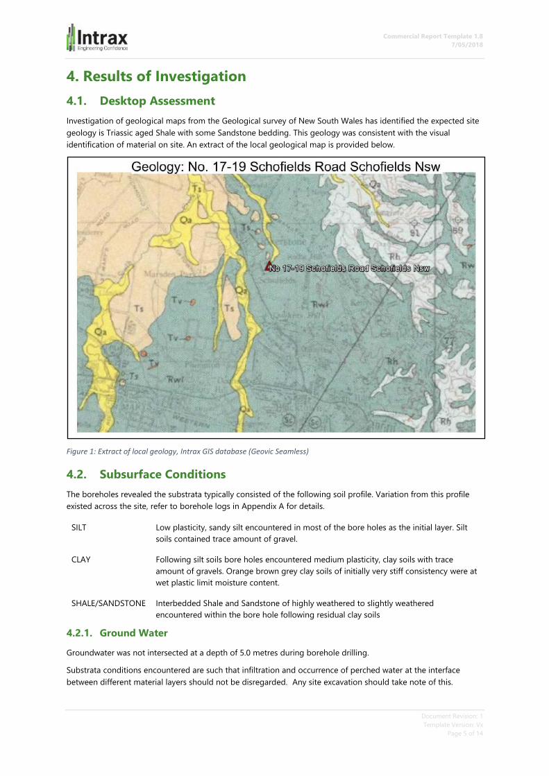
Investigation of geological maps from the Geological survey of New South Wales has identified the expected site
geology is Triassic aged Shale with some Sandstone bedding. This geology was consistent with the visual
identification of material on site. An extract of the local geological map is provided below.
Figure 1: Extract of local geology, Intrax GIS database (Geovic Seamless)
4.2. Subsurface Conditions
The boreholes revealed the substrata typically consisted of the following soil profile. Variation from this profile
existed across the site, refer to borehole logs in Appendix A for details.
SILT Low plasticity, sandy silt encountered in most of the bore holes as the initial layer. Silt
soils contained trace amount of gravel.
CLAY Following silt soils bore holes encountered medium plasticity, clay soils with trace
amount of gravels. Orange brown grey clay soils of initially very stiff consistency were at
wet plastic limit moisture content.
SHALE/SANDSTONE Interbedded Shale and Sandstone of highly weathered to slightly weathered
encountered within the bore hole following residual clay soils
4.2.1. Ground Water
Groundwater was not intersected at a depth of 5.0 metres during borehole drilling.
Substrata conditions encountered are such that infiltration and occurrence of perched water at the interface
between different material layers should not be disregarded. Any site excavation should take note of this.
Commercial Report Template 1.8
7/05/2018
Document Revision: 1
Template Version: Vx
Page 6 of 14
4.3. In-Situ Field Data
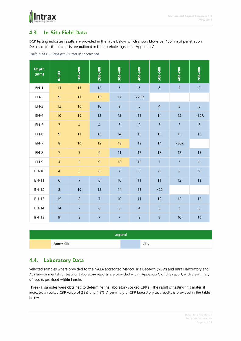
DCP testing indicates results are provided in the table below, which shows blows per 100mm of penetration.
Details of in-situ field tests are outlined in the borehole logs, refer Appendix A.
Table 1: DCP - Blows per 100mm of penetration
Depth
(mm)
0-1
00
10
0-2
00
20
0-3
00
30
0-4
00
40
0-5
00
50
0-6
00
60
0-7
00
70
0-8
00
BH-1 11 15 12 7 8 8 9 9
BH-2 9 11 15 17 >20R
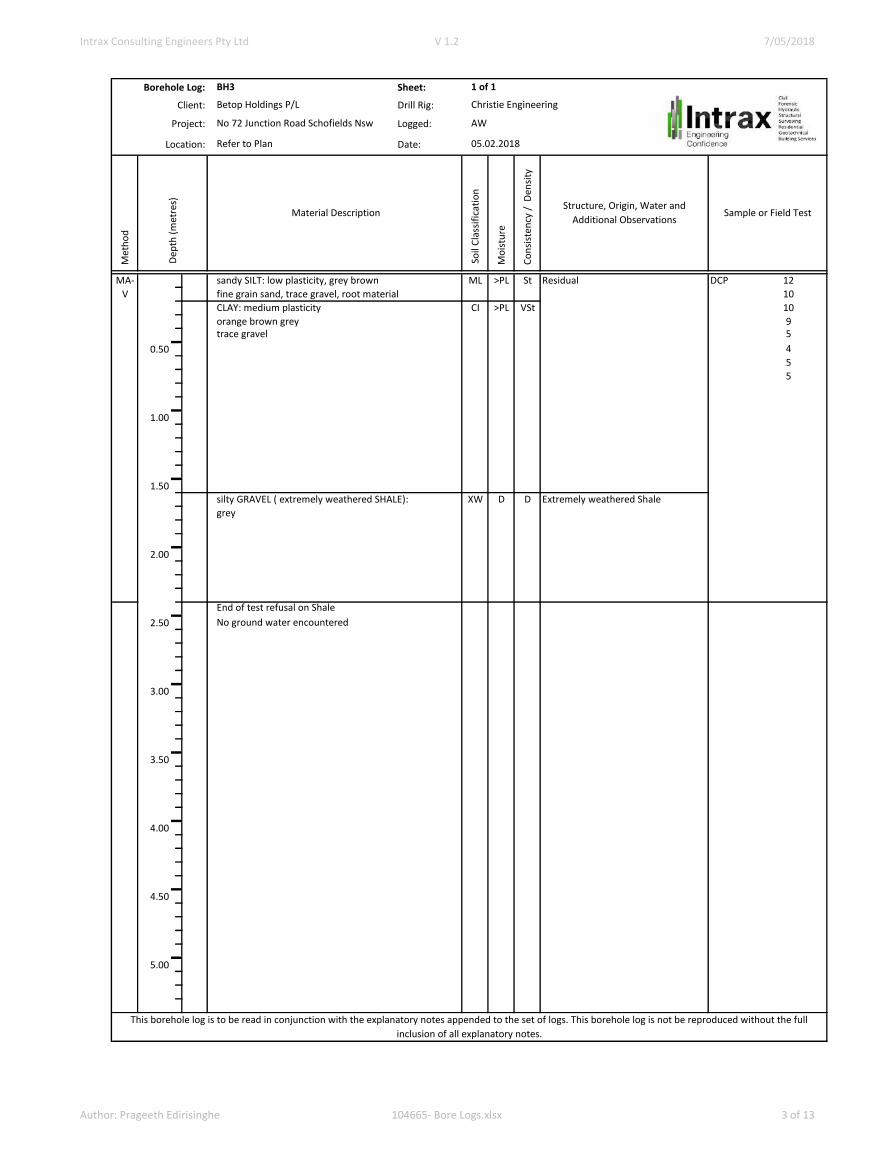
BH-3 12 10 10 9 5 4 5 5
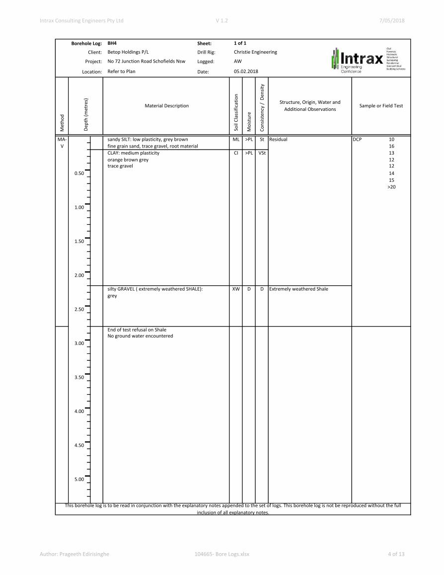
BH-4 10 16 13 12 12 14 15 >20R
BH-5 3 4 4 3 2 3 5 6
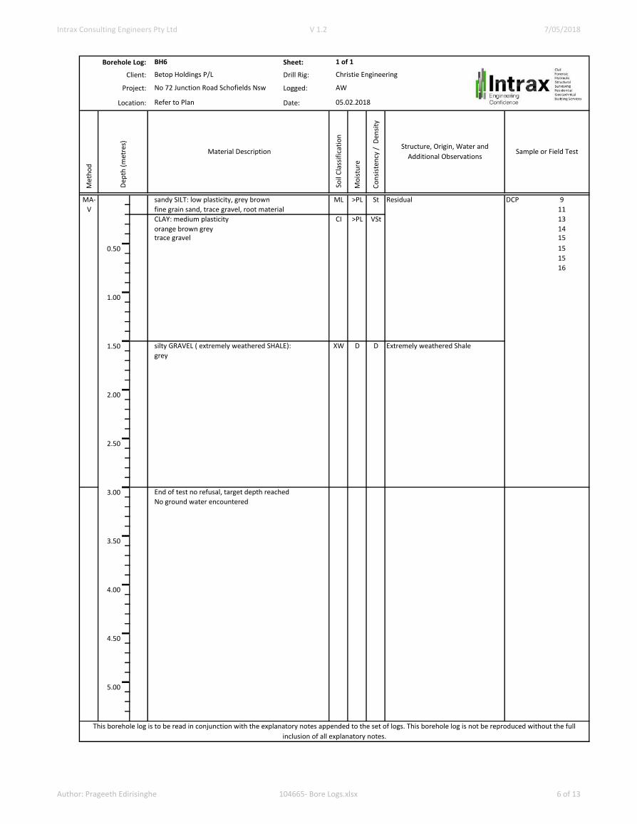
BH-6 9 11 13 14 15 15 15 16
BH-7 8 10 12 15 12 14 >20R
BH-8 7 7 9 11 12 13 13 15
BH-9 4 6 9 12 10 7 7 8
BH-10 4 5 6 7 8 8 9 9
BH-11 6 7 8 10 11 11 12 13
BH-12 8 10 13 14 18 >20
BH-13 15 8 7 10 11 12 12 12
BH-14 14 7 6 5 4 3 3 3
BH-15 9 8 7 7 8 9 10 10
Legend
Sandy Silt Clay
4.4. Laboratory Data
Selected samples where provided to the NATA accredited Maccquarie Geotech (NSW) and Intrax laboratory and
ALS Environmental for testing. Laboratory reports are provided within Appendix C of this report, with a summary
of results provided within herein.
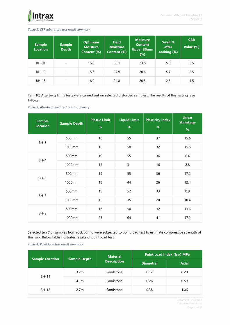
Three (3) samples were obtained to determine the laboratory soaked CBR’s. The result of testing this material
indicates a soaked CBR value of 2.5% and 4.5%. A summary of CBR laboratory test results is provided in the table
below.
Commercial Report Template 1.8
7/05/2018
Document Revision: 1
Template Version: Vx
Page 7 of 14
Table 2: CBR laboratory test result summary
Sample
Location
Sample
Depth
Optimum
Moisture
Content (%)
Field
Moisture
Content (%)
Moisture
Content
Upper 30mm
(%)
Swell %
after
soaking (%)
CBR
Value (%)
BH-01 - 15.0 30.1 23.8 5.9 2.5
BH-10 - 15.6 27.9 20.6 5.7 2.5
BH-13 - 16.0 24.8 20.3 2.5 4.5
Ten (10) Atterberg limits tests were carried out on selected disturbed samples. The results of this testing is as
follows:
Table 3: Atterberg limit test result summary
Sample
Location Sample Depth
Plastic Limit
%
Liquid Limit
%
Plasticity Index
%
Linear
Shrinkage
%
BH-3
500mm 18 55 37 15.6
1000mm 18 50 32 15.6
BH-4
500mm 19 55 36 6.4
1000mm 15 31 16 8.8
BH-6
500mm 19 55 36 17.2
1000mm 18 44 26 12.4
BH-8
500mm 19 52 33 8.8
1000mm 15 35 20 10.4
BH-9
500mm 18 50 32 13.6
1000mm 23 64 41 17.2
Selected ten (10) samples from rock coring were subjected to point load test to estimate compressive strength of
the rock. Below table illustrates results of point load test:
Table 4: Point load test result summary
Sample Location Sample Depth Material
Description
Point Load Index (Is50) MPa
Diametral Axial
BH-11
3.2m Sandstone 0.12 0.20
4.1m Sandstone 0.26 0.59
BH-12 2.7m Sandstone 0.38 1.06

Commercial Report Template 1.8
7/05/2018
Document Revision: 1
Template Version: Vx
Page 8 of 14
4.7m Sandstone 0.07 0.47
BH-13
3.7m Sandstone 0.19 0.11
3.9m Sandstone 0.03 0.44
BH-14
3.2m Sandstone 0.15 1.51
4.2m Sandstone 0.34 1.08
Bh-15
3.6m Sandstone 0.17 2.10
4.9m Sandstone 0.38 2.94
Three (3) Shrink-Swell Index tests were carried out on undisturbed 50mm thin walled push tube samples. The test
results are summarised in the table below.
Table 5: Shrink swell index test result summary
Sample
Location Sample Depth
Moisture
Content (%) Shrink (%) Swell (%)
Shrink-Swell
Index, Iss (%)
BH-3 500mm 14.9-16.3 2.99 3.60 2.7
BH-4 500mm 17.9-18.6 3.14 0.80 2.0
BH-5 500mm 20.5-21.3 3.83 3.04 3.0
ASS careening test was carried out for selected four (4) disturbed samples during auger drilling. These samples
were tested at NATA accredited ALS Environmental laboratory. A summary of the test is highlighted below:
Table 6: ASS test result summary
Sample
Location
Sample Depth Material
Description
pHF pHFOX pHF- pHFOX
BH-1
BH-1
500mm Clay 5.4 4.9 0.5
1000mm Clay 5.5 5.0 0.5
BH-2
BH-2
500mm Clay 6.2 5.1 1.1
1000mm Clay 7.8 7.0 0.8
5. Discussion and Recommendations
5.1. Site Reactivity – AS 2870
After considering the area geology, the soil profile encountered in the bores, and the climatic zone of the area,
this site has been classified as CLASS P with respect to foundation construction (Australian Standard 2870-2011
Residential Slabs and Footings) due to prevailing abnormal moisture condition caused by trees and recently
removed structures. It is anticipated that the seasonal surface movement under normal moisture conditions at
this site will not exceed 40mm. Note that, this classification is only applicable to Class 1 and 10a structures in
Commercial Report Template 1.8
7/05/2018
Document Revision: 1
Template Version: Vx
Page 9 of 14
accordance with the Building Code of Australia, for other structures this classification should be used as a guide
only.
5.2. Acid Sulphate Soil Condition
Based on ASS screening test conducted on the samples retrieved from auger drilling it is established that this site
is unlikely to be acid sulphate soil.
5.3. Building Foundations
5.3.1. Waffle and Raft Footings
It is recommended that the foundation system be designed by engineering principles. (AS 2870 - 2011 Cl 1.4). We
recommend that the designing engineer refer to AS2870 - 2011 to ensure design compliance to this document,
especially Sections 1.3 “Performance of Footing Systems” and “Design Considerations”.
Based on the site classification an engineer designed foundation systems is required at this site. The foundation
systems must be designed to cater for the potential movements associated with the drying effects of a tree or a
group of trees. The designer may adopt the classification of the site soil “Class M” for the purposes of
determining the total Yt. The designer should also pay close to attention to any adverse scenario where the tree
will be removed and the subsequent heave that could be expected under this scenario.
The designer should refer to AS2870-2011 Appendix H for further guidance.
In addition to above recommendation the design should also consider the surface movement caused by drying
effect of existing building founded on ventilated footing system and elevated moisture condition due to slab on
ground and similar (paving).
Allowable bearing pressures provided in section 5.3.2 for strip footings can be adopted for load bearing ribs on
waffle/raft foundations.
5.3.2. Pad and Strip Footings
An engineer design Pad and strip footings are an appropriate footing arrangement for the proposed structure.
Based on the site investigation, pad and strip footings founded at least 100mm into the naturally occurring Clay
as described in the logs of boring can be assumed to have an allowable bearing pressure of 140kPa and 120kPa
respectively.
As a guide, with regard to the above along with information obtained from the bores, the founding depths of
shallow foundations at this site will be up to 600mm below the existing surface.
Based on the site investigation, pad and strip footings founded at least a minimum of 500mm into the naturally
occurring Clay as described in the logs of boring can be assumed to have allowable bearing pressures of 180kPa
for pad footings and 150kPa for strip footings.
Pad and strip footings founded 100mm minimum into extremely weathered shale/sandstone may adopt an
allowable end bearing pressure of 550kPa.
The allowable bearing capacity values provided in this report are maximum values without further geotechnical
investigation or detailed analysis of foundation design.
5.3.3. Piled Foundations
If bored piers are used for proposed development, must be designed by a qualified structural engineer
considering the prevailing abnormal moisture conditions on site. The design engineer may adopt following
bearing pressures listed in the table below.

Commercial Report Template 1.8
7/05/2018
Document Revision: 1
Template Version: Vx
Page 10 of 14
Table 7: Pile foundation bearing pressures
Material Type Embedded depth below
surface level
Allowable end bearing
pressure (kPa)
Allowable Skin Friction
(kPa)
Clay soils 1500mm 250 20
Extremely Low Strength
Shale/Sandstone
2000mm 800 60
Low strength
Shale/Sandstone
+3000mm 1100 100
The allowable bearing capacity values provided in this report are maximum values without further geotechnical
investigation or detailed analysis of foundation designs.
5.3.4. General Conditions – Foundations
Where footings are founded in different soil groups (especially reactive and non-reactive soils), the designer
should provide articulation for the structure to accommodate to for potential damages which could be caused by
differential movement of the soil due to seasonal moisture variation.
Note it is our preference that the design engineer adopt the same founding material across the structure where
possible.
After excavation for the footings has been completed if there is any doubt as to the bearing capacity of the
founding soil, then Intrax should be contacted and an inspection of the sites founding conditions carried out.
Foundations proposed for founding in and on existing fill, if any, then the fill must be stripped and the surface of
the natural soil must be compacted with the soil in a moist condition. Stripped or imported fill meeting the
minimum suitability requirements of section 4 of AS3798 must be placed at minimum 150mm uncompacted
layers and each layer shall be compacted to minimum 98% dry density ratio at moisture contents between 90%
and 110% of the optimum moisture content. Following the above ground preparation, an allowable bearing
pressure of 80kPa can be assumed at 200mm below the compacted surface. Should additional filling depths
exceed 1.0m it is recommended that a specification for earthworks be prepared.
5.4. Pavement Design
5.4.1. Design Subgrade CBR value
It is understood that boxed pavement construction method is to be adopted for the proposed pavement. It is
anticipated that subgrade will comprise of either naturally occurring clay soils. Based on CBR test results within
existing subgrade material a Design CBR values of 2.5% for natural occurring clay soils is considered appropriate
for this site.
5.4.2. Design Traffic Load
The following design traffic loading parameters have been used based upon the information (traffic loading)
provided by the client and anticipated data to provide traffic loading which Intrax deemed satisfactory for
expected road types.
Table 8: Design traffic load
Road Type
Access Street-level 1 Access street-level 2
AADT (vehicles per day) 300 800

Commercial Report Template 1.8
7/05/2018
Document Revision: 1
Template Version: Vx
Page 11 of 14
DF- Directional factor 0.5 0.5
%HV- Heavy Vehicle % 3.0% 3.5%
LDF- Lane directional factor 1 1
R- Annual growth rate (%) 1.0% 1.5%
P- Design life 20 20
CGF- cumulative growth factor 22.02 23.12
NHVAG – average number of axle groups per
heavy vehicle
2.1 2.2
NDT – Cumulative heavy axle groups 1.0 x 10⁵ 5 x 10⁵
ESAs/HVAG 0.2 0.25
DESA- design number of equivalent standard
axles
2.0 x 10⁴ 1.2 x 10⁵
6. Recommendation
6.1. Flexible pavement – Access Street Level-1
Table 9: Pavement design Access Street level-1
Thickness Material type Overall depth (mm)
Wearing Course (25mm) AC 10 25mm
Base Course (25mm) AC 10 50mm
Single coat hot bitumen seal
Base (140mm thick) Class 2, Fine Crushed Rock 20mmCompacted to not
less than 98% of AS 1289, 5.2.1 (Modified
Compaction)- DGB20
190mm
Sub Base (100mm thick) Class 3, Crushed Rock 20mm Compacted to not less
than 98% of AS 1289, 5.2.1
290mm
Capping Layer (150mm) Type A fill- refer section 6.5 for further details 440mm
Sub Grade Naturally occurring clay soils- Design CBR=2.5%
6.2. Flexible pavement – Access Street Level-2
Table 10: Pavement design Access Street level-2
Thickness Material type Overall depth (mm)
Wearing Course (25mm) AC 10 25mm

Commercial Report Template 1.8
7/05/2018
Document Revision: 1
Template Version: Vx
Page 12 of 14
Base Course (25mm) AC 10 50mm
Single coat hot bitumen seal
Base (140mm thick) Class 2, Fine Crushed Rock 20mmCompacted to not
less than 98% of AS 1289, 5.2.1 (Modified
Compaction)- DGB20
190mm
Sub Base (140mm thick Class 3, Crushed Rock 20mm Compacted to not less
than 98% of AS 1289, 5.2.1
330mm
Capping Layer (150mm) Type A fill- refer section 6.5 for further details 480mm
Sub Grade Naturally occurring clay soils- Design CBR=2.5%
6.3. Type A fill
Table 11: Type A fill specification
Physical Properties Limits of grading (% passing)
after compaction sieve size AS
Plasticity
index * %
passing
0.425mm
after
compaction
(max.)
Plasticity
index (max)
after
compaction
CBR
(min)
(%)
Swell
(max) (%)
Permeability
(max) m/s 75mm 4.75mm 0.075mm
1000 6-25
10 ≤1.5 5x10⁻⁹ 100 40-80 10-40
6.4. Excavation and Retention
6.4.1. Retention Design Parameters
The following parameters established from Rankine’s theory would be valid in the design of a retention system.
These values assume that the soil being retained/supported has horizontal surface.
Table 12: Geotechnical soil and retention design parameters
Material
Description
Unit
weight
(kN/m3)
Cu
(kPa)
Friction
angle (°) Ka# Kp# Ko#
Fill 18 - 28 0.36 2.56 0.53
Clay 17 60 26 0.39 2.56 0.56
Shale/Sandstone (XW) 22 120 32 0.31 3.25 0.47
Shale/Sandstone (MW-SW) 24 200 36 0.26 3.85 0.41
*Approximate depth based on borehole logs completed during geotechnical investigation

Commercial Report Template 1.8
7/05/2018
Document Revision: 1
Template Version: Vx
Page 13 of 14
#Ka, Kp and Ko are the active, passive and at-rest earth pressure coefficients.
Allowable bearing pressures given under 5.3 are relevant for foundation loading.
The above parameters assume that the level of the water table is below the bottom of the excavation by the use
of adequate drainage and that any adjacent surcharge loads are superimposed.
6.4.2. Site Excavation
It is anticipated that a minimum site excavation will require for proposed development. Sewer installation will
require to excavate through fill, naturally occurring clay soils and shale/sandstone. Excavation through fill, residual
clay and extremely weathered shale/sandstone can be readily achievable by a conventional backhoes excavator
with minimum effort. However, based on observation made during rock coring along with previous experiences
of this office, excavation through moderately weathered to higher strength rock will require specialise excavation
techniques. Rock ripping, breaking equipment and some blasting may require excavating through moderately
weathered or higher strength rock.
Any bulk excavation on site should be completed using short term batter angles provided in the table below.
Vertical excavation through clay soils and extremely weathered Shale/Sandstone will remain stable for several
days (maximum up to 7days) depending on site weather conditions. Vertical excavation beyond 1.5m in height is
not allowed within a limited access availability and personal access is required frequently.
Slightly weathered Shale/Sandstone or higher strength rock is self-supporting material hence vertical excavation
through the rock (SW and higher strength) will not require battering or shoring. However, based on observation
made by core boxes highly fractured zones are presented within SW or higher strength rock must require
temporary shoring or propping during construction. There fractures zone can be stabilised by a layer of shotcrete.
Table 13: Safe batter angles
Material Description
Safe Batter Angles Vertical Cut
Peroid Short Term Long Term
Clay 55 35 7
XW Shale/Sandstone 75 55 14
SW Shale/Sandstone or higher strength - 90 -
6.5. Inspections (Hold Points)
Intrax must be engaged at the following stages:
1. In the event soil conditions encountered differ significantly from those described within this report.
2. If project design is altered significantly from drawings reviewed and outlined or project described within
this report
Intrax should be engaged at the following stages:
1. To confirm safe batter angles and excavation construction during construction.
2. To confirm founding materials and allowable bearing pressures.
3. To approve subgrade soil of pavement.

Commercial Report Template 1.8
7/05/2018
Document Revision: 1
Template Version: Vx
Page 14 of 14
7. Limitations of Report
1. The recommendations in this report are based on the following:
a. Information about the site & its history, proposed site treatment and building type conveyed to
us by the client and or their agent
b. Professional judgements and opinions using the most recent information in soil testing practice
that is available to us.
c. The location of our test sites and the information gained from this and other investigations.
Should the client or their agent neglect to supply us with correct or relevant information,
including information about previous buildings, trees or past activities on the site, or should
changes be made to the building type, size and or/position, this report may be made obsolete,
irrelevant or unsuitable. In such cases, Intrax will not accept any liability for the consequences
and Intrax reserves the right to make an additional charge if more testing or a change to the
report is necessary.
2. The recommendations made in this report may need to be reviewed should any site works disturb any
soil 200mm below the proposed founding depth.
3. The descriptions of the soils encountered in the boreholes follow those outlined in AS1726-2017;
Geotechnical Site Investigations. Colour descriptions can vary with soil moisture content and individual
interpretation.
4. If the site conditions at the time of construction differ from those described in this report then Intrax
must be contacted so a site inspection can be carried out prior to any footing being poured. The
owner/builder will be responsible for any fees associated with this additional work.
5. This report assumes that the soil profile observed in the boreholes are representative of the entire site.
If the soil profile and site conditions appear to differ substantially from those reported herein, then
Intrax should be contacted immediately and this report may need to be reviewed and amended where
appropriate. The owner/builder will be responsible for any fees associated with this additional work.
6. The user of this report must take into account the following limitations. Soil and drilling depths are
given to a tolerance of +/- 200mm.
It must be understood and a condition of acceptance of this report is that whilst every effort is made to
identify fill material across the site, difficulties exist in determining fill material, in particular, for example,
well compacted site or area derived fill, when utilising a small diameter auger. Consequently Intrax
emphasises that we will not be responsible for any financial losses, consequential or otherwise, that may
occur as a result of not accurately determining the fill profile across the site.
7. Finally, no responsibility will be taken for this report if it is altered in any way or is not reproduced in full.
Commercial Report Template 1.8
7/05/2018
Document Revision: 1
Template Version: Vx
APPENDIX A
Site Plan and Borehole Logs

Client:
Project:
Drawing: Ver.Project No.
Date:
Sheets:
Scale (A4):
CivilForensicHydraulicStructuralSurveyingResidentialGeotechnicalBuilding Services
C This drawing is copyright to Intrax Consulting Engineers, no part of this drawing shall be used for any other purpose without the prior written consent of Intrax Consulting Engineers.
35 Bank Street South MelbourneVIC 3205 03 8371 0100
Geelong 03 5221 8282New South Wales 02 4869 5666Queensland 07 3813 5617South Australia 08 8165 0122
A.B.N. 31 106 481 252www.intrax.com.au
EngineeringConfidence
Not to scale
1
1
No 72 Junction Road Schofields
Betop Holdings P/L
Site Plan 104665
26.02.2018
22

Intrax Consulting Engineers Pty Ltd V 1.2 7/05/2018
Borehole Log: Sheet:
Client: Drill Rig:
Project: Logged:
Location: Date:
Met
ho
d
Mo
istu
re
Co
nsi
sten
cy /
Den
sity
MA- sandy SILT: low plasticity, grey brown >PL St Residual DCP 11
V fine grain sand, trace gravel, root material 15
CLAY: medium plasticity >PL VSt 12
orange brown grey 7trace gravel 8
0.50 8
9
9
1.00
1.50silty GRAVEL ( extremely weathered SHALE): D D Extremely weathered Shale
grey
2.00
End of test refusal on ShaleNo ground water encountered
2.50
3.00
3.50
4.00
4.50
5.00
XW
BH1
Christie Engineering
AW
05.02.2018
1 of 1
Betop Holdings P/L
No 72 Junction Road Schofields Nsw
Refer to Plan
This borehole log is to be read in conjunction with the explanatory notes appended to the set of logs. This borehole log is not be reproduced without the full
inclusion of all explanatory notes.
Structure, Origin, Water and
Additional Observations Material Description
Dep
th (
met
res)
Sample or Field Test
So
il C
lass
ific
atio
n
ML
CI
Author: Prageeth Edirisinghe 104665- Bore Logs.xlsx 1 of 13

Intrax Consulting Engineers Pty Ltd V 1.2 7/05/2018
BH (2) Borehole Log: Sheet:
Client: Drill Rig:
Project: Logged:
Location: Date:
Met
ho
d
Mo
istu
re
Co
nsi
sten
cy /
Den
sity
MA- sandy SILT: low plasticity, grey brown >PL St Residual DCP 9
V fine grain sand, trace gravel, root material 11
15
CLAY: medium plasticity >PL VSt 17orange brown grey >20
0.50 trace gravel
1.00
1.50
silty GRAVEL ( extremely weathered SHALE): D D Extremely weathered Shalegrey
2.00
2.50
End of test refusal on Shale
No ground water encountered
3.00
3.50
4.00
4.50
5.00
This borehole log is to be read in conjunction with the explanatory notes appended to the set of logs. This borehole log is not be reproduced without the full
inclusion of all explanatory notes.
XW
Sample or Field Test
CI
ML
Refer to Plan 05.02.2018
Dep
th (
met
res)
Material Description
So
il C
lass
ific
atio
n
Structure, Origin, Water and
Additional Observations
BH2 1 of 1
Betop Holdings P/L Christie Engineering
No 72 Junction Road Schofields Nsw AW
Author: Prageeth Edirisinghe 104665- Bore Logs.xlsx 2 of 13
Intrax Consulting Engineers Pty Ltd V 1.2 7/05/2018
BH (3) Borehole Log: Sheet:
Client: Drill Rig:
Project: Logged:
Location: Date:
Met
ho
d
Mo
istu
re
Co
nsi
sten
cy /
Den
sity
MA- sandy SILT: low plasticity, grey brown >PL St Residual DCP 12
V fine grain sand, trace gravel, root material 10
CLAY: medium plasticity >PL VSt 10
orange brown grey 9trace gravel 5
0.50 4
5
5
1.00
1.50silty GRAVEL ( extremely weathered SHALE): D D Extremely weathered Shale
grey
2.00
End of test refusal on Shale
2.50 No ground water encountered
3.00
3.50
4.00
4.50
5.00
This borehole log is to be read in conjunction with the explanatory notes appended to the set of logs. This borehole log is not be reproduced without the full
inclusion of all explanatory notes.
XW
Sample or Field Test
ML
CI
Refer to Plan 05.02.2018
Dep
th (
met
res)
Material Description
So
il C
lass
ific
atio
n
Structure, Origin, Water and
Additional Observations
BH3 1 of 1
Betop Holdings P/L Christie Engineering
No 72 Junction Road Schofields Nsw AW
Author: Prageeth Edirisinghe 104665- Bore Logs.xlsx 3 of 13
Intrax Consulting Engineers Pty Ltd V 1.2 7/05/2018
BH (4) Borehole Log: Sheet:
Client: Drill Rig:
Project: Logged:
Location: Date:
Met
ho
d
Mo
istu
re
Co
nsi
sten
cy /
Den
sity
MA- sandy SILT: low plasticity, grey brown >PL St Residual DCP 10
V fine grain sand, trace gravel, root material 16
CLAY: medium plasticity >PL VSt 13
orange brown grey 12trace gravel 12
0.50 14
15
>20
1.00
1.50
2.00
silty GRAVEL ( extremely weathered SHALE): D D Extremely weathered Shale
grey
2.50
End of test refusal on ShaleNo ground water encountered
3.00
3.50
4.00
4.50
5.00
This borehole log is to be read in conjunction with the explanatory notes appended to the set of logs. This borehole log is not be reproduced without the full
inclusion of all explanatory notes.
XW
Sample or Field Test
ML
CI
Refer to Plan 05.02.2018
Dep
th (
met
res)
Material Description
So
il C
lass
ific
atio
n
Structure, Origin, Water and
Additional Observations
BH4 1 of 1
Betop Holdings P/L Christie Engineering
No 72 Junction Road Schofields Nsw AW
Author: Prageeth Edirisinghe 104665- Bore Logs.xlsx 4 of 13

Intrax Consulting Engineers Pty Ltd V 1.2 7/05/2018
BH (5) Borehole Log: Sheet:
Client: Drill Rig:
Project: Logged:
Location: Date:
Met
ho
d
Mo
istu
re
Co
nsi
sten
cy /
Den
sity
MA- sandy SILT: low plasticity, grey brown >PL St Residual DCP 3
V fine grain sand, trace gravel, root material 4
CLAY: medium plasticity >PL VSt 4
orange brown grey 3trace gravel 2
0.50 3
5
6
1.00
silty GRAVEL ( extremely weathered SHALE): D D Extremely weathered Shale
1.50 grey
2.00
2.50
End of test refusal on Shale
No ground water encountered
3.00
3.50
4.00
4.50
5.00
This borehole log is to be read in conjunction with the explanatory notes appended to the set of logs. This borehole log is not be reproduced without the full
inclusion of all explanatory notes.
XW
Sample or Field Test
CI
Refer to Plan 05.02.2018
Dep
th (
met
res)
Material Description
So
il C
lass
ific
atio
n
Structure, Origin, Water and
Additional Observations
ML
BH5 1 of 1
Betop Holdings P/L Christie Engineering
No 72 Junction Road Schofields Nsw AW
Author: Prageeth Edirisinghe 104665- Bore Logs.xlsx 5 of 13
Intrax Consulting Engineers Pty Ltd V 1.2 7/05/2018
BH (6) Borehole Log: Sheet:
Client: Drill Rig:
Project: Logged:
Location: Date:
Met
ho
d
Mo
istu
re
Co
nsi
sten
cy /
Den
sity
MA- sandy SILT: low plasticity, grey brown >PL St Residual DCP 9
V fine grain sand, trace gravel, root material 11
CLAY: medium plasticity >PL VSt 13
orange brown grey 14trace gravel 15
0.50 15
15
16
1.00
1.50 silty GRAVEL ( extremely weathered SHALE): D D Extremely weathered Shale
grey
2.00
2.50
3.00 End of test no refusal, target depth reached
No ground water encountered
3.50
4.00
4.50
5.00
This borehole log is to be read in conjunction with the explanatory notes appended to the set of logs. This borehole log is not be reproduced without the full
inclusion of all explanatory notes.
Sample or Field Test
ML
CI
Dep
th (
met
res)
Material Description
So
il C
lass
ific
atio
n
Structure, Origin, Water and
Additional Observations
XW
BH6 1 of 1
Betop Holdings P/L Christie Engineering
No 72 Junction Road Schofields Nsw AW
Refer to Plan 05.02.2018
Author: Prageeth Edirisinghe 104665- Bore Logs.xlsx 6 of 13

Intrax Consulting Engineers Pty Ltd V 1.2 7/05/2018
BH (7) Borehole Log: Sheet:
Client: Drill Rig:
Project: Logged:
Location: Date:
Met
ho
d
Mo
istu
re
Co
nsi
sten
cy /
Den
sity
MA- sandy SILT: low plasticity, grey brown >PL St Residual DCP 8
V fine grain sand, trace gravel, root material 10
12
15CLAY: medium plasticity >PL VSt 12
0.50 orange brown grey 14
trace gravel >20
1.00
silty GRAVEL ( extremely weathered SHALE): D D Extremely weathered Shale
grey
1.50
2.00
2.50
End of test refusal on Shale
No ground water encountered
3.00
3.50
4.00
4.50
5.00
This borehole log is to be read in conjunction with the explanatory notes appended to the set of logs. This borehole log is not be reproduced without the full
inclusion of all explanatory notes.
Sample or Field Test
XW
ML
CI
Dep
th (
met
res)
Material Description
So
il C
lass
ific
atio
n
Structure, Origin, Water and
Additional Observations
BH7 1 of 1
Betop Holdings P/L Christie Engineering
No 72 Junction Road Schofields Nsw AW
Refer to Plan 05.02.2018
Author: Prageeth Edirisinghe 104665- Bore Logs.xlsx 7 of 13

Intrax Consulting Engineers Pty Ltd V 1.2 7/05/2018
BH (8) Borehole Log: Sheet:
Client: Drill Rig:
Project: Logged:
Location: Date:
Met
ho
d
Mo
istu
re
Co
nsi
sten
cy /
Den
sity
MA- sandy SILT: low plasticity, grey brown >PL St Residual DCP 7
V fine grain sand, trace gravel, root material 7
9
CLAY: medium plasticity >PL VSt 11orange brown grey 12
0.50 trace gravel 13
13
15
silty GRAVEL ( extremely weathered SHALE): D D Extremely weathered Shalegrey
1.00
1.50
2.00
2.50
3.00 End of test no refusal, target depth reached
No ground water encountered
3.50
4.00
4.50
5.00
This borehole log is to be read in conjunction with the explanatory notes appended to the set of logs. This borehole log is not be reproduced without the full
inclusion of all explanatory notes.
XW
Sample or Field Test
CI
Refer to Plan 05.02.2018
Dep
th (
met
res)
Material Description
So
il C
lass
ific
atio
n
Structure, Origin, Water and
Additional Observations
ML
BH8 1 of 1
Betop Holdings P/L Christie Engineering
No 72 Junction Road Schofields Nsw AW
Author: Prageeth Edirisinghe 104665- Bore Logs.xlsx 8 of 13

Intrax Consulting Engineers Pty Ltd V 1.2 7/05/2018
BH (9) Borehole Log: Sheet:
Client: Drill Rig:
Project: Logged:
Location: Date:
Met
ho
d
Mo
istu
re
Co
nsi
sten
cy /
Den
sity
MA- sandy SILT: low plasticity, grey brown >PL St Residual DCP 4
V fine grain sand, trace gravel, root material 6
9
12CLAY: medium plasticity >PL VSt 10
0.50 orange brown grey 7
trace gravel 7
8
1.00
silty GRAVEL ( extremely weathered SHALE): D D Extremely weathered Shalegrey
1.50
2.00
2.50
3.00 End of test no refusal, target depth reached
No ground water encountered
3.50
4.00
4.50
5.00
This borehole log is to be read in conjunction with the explanatory notes appended to the set of logs. This borehole log is not be reproduced without the full
inclusion of all explanatory notes.
Sample or Field Test
ML
CI
Dep
th (
met
res)
Material Description
So
il C
lass
ific
atio
n
Structure, Origin, Water and
Additional Observations
XW
BH9 1 of 1
Betop Holdings P/L Christie Engineering
No 72 Junction Road Schofields Nsw AW
Refer to Plan 05.02.2018
Author: Prageeth Edirisinghe 104665- Bore Logs.xlsx 9 of 13

Intrax Consulting Engineers Pty Ltd V 1.2 7/05/2018
BH (10) Borehole Log: Sheet:
Client: Drill Rig:
Project: Logged:
Location: Date:
Met
ho
d
Mo
istu
re
Co
nsi
sten
cy /
Den
sity
MA- sandy SILT: low plasticity, grey brown >PL St Residual DCP 4
V fine grain sand, trace gravel, root material 5
6
CLAY: medium plasticity >PL VSt 7orange brown grey 8
0.50 trace gravel 8
9
9
1.00 silty GRAVEL ( extremely weathered SHALE): D D Extremely weathered Shale
grey
1.50
End of test refusal on ShaleNo ground water encountered
2.00
2.50
3.00
3.50
4.00
4.50
5.00
This borehole log is to be read in conjunction with the explanatory notes appended to the set of logs. This borehole log is not be reproduced without the full
inclusion of all explanatory notes.
Sample or Field Test
XW
ML
CI
Refer to Plan 05.02.2018
Dep
th (
met
res)
Material Description
So
il C
lass
ific
atio
n
Structure, Origin, Water and
Additional Observations
BH10 1 of 1
Betop Holdings P/L Christie Engineering
No 72 Junction Road Schofields Nsw AW
Author: Prageeth Edirisinghe 104665- Bore Logs.xlsx 10 of 13

Intrax Consulting Engineers Pty Ltd V 1.0 7/05/2018
Borehole Log: Sheet:
Client: Location:
Project: Coordinates:
Job Number: Surface RL:
Contractor: Datum: Logged: Date:
Drill Rig: Inclination: Checked: Date:
Met
ho
d
Res
ista
nce
Wat
er
RL
Rec
ove
red
Gra
ph
ic L
og
So
il C
lass
ific
atio
n
Mo
istu
re
Co
nsi
sten
cy /
Den
sity
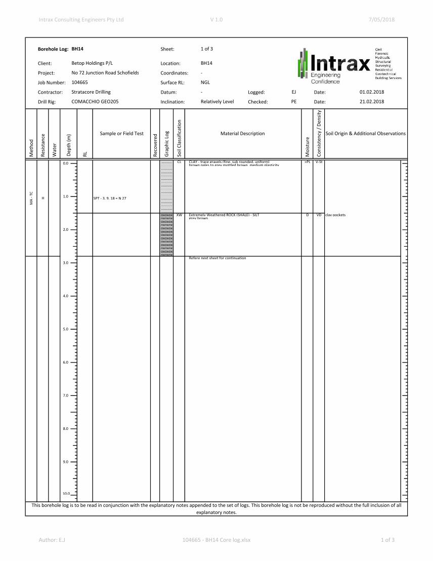
…………. CL CLAY - trace gravels (fine, sub rounded, uniform) >PL V-St…………. brown pales to grey mottled brown, medium plasticity………….………….………….………….………….………….………….………….………….
SPT - 9,14,43 = N 57 ………….………….………….oxoxox XW Extremely Weathered ROCK (SHALE) - SILT D VD clay pocketsoxoxox grey brownoxoxoxoxoxoxoxoxoxoxoxoxoxoxoxoxoxoxoxoxox
Refere next sheet for continuation
10.0
MA
- T
C
H
31.01.2018
Soil Origin & Additional Observations
COMACCHIO GEO205
1 of 3
NGL
-
BH11
Betop Holdings P/L
No 72 Junction Road
Schofields
104665
Stratacore Drilling
BH11
-
EJ
This borehole log is to be read in conjunction with the explanatory notes appended to the set of logs. This borehole log is not be reproduced without the full inclusion of all
explanatory notes.
Relatively Level
Dep
th (
m) Sample or Field Test Material Description
1.0
9.0
8.0
7.0
6.0
5.0
4.0
3.0
2.0
0.0
PE
Author: EJ 104665 - BH11 Core log.xlsx 1 of 6

Intrax Consulting Engineers Pty Ltd V 1.0 7/05/2018
Borehole Log: Sheet:
Client: Location:
Project: Coordinates:
Job Number: Surface RL:
Contractor: Datum: Logged: Date:
Drill Rig: Inclination: Checked: Date:
<VL
VL
L M H VH
EH 10
30
10
03
00
10
00
30
00
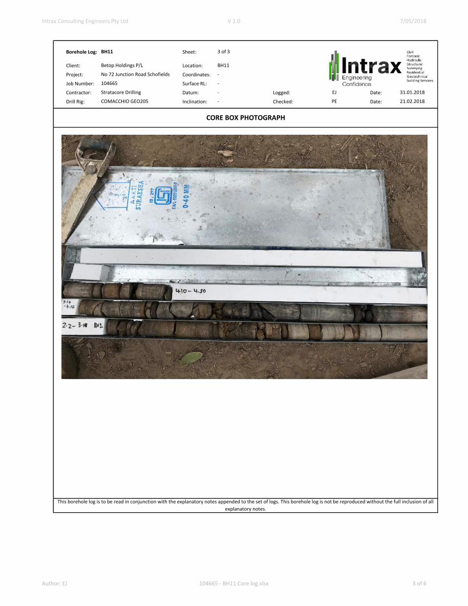
- - - - - - Thinly Laminated SHALE, brown HW- - - - - - Thinly Laminated SANDSTONE - brown 0 degrees - IS, PL, SM, CL- - - - - - Thinly Laminated SHALE, brown 0 degrees - BR, PL, SM, ST- - - - - - 0 degrees - IS, PL, SM, CL- - - - - - 0 degrees - CS, ST, RO, ST- - - - - - Thinly Laminated SANDSTONE SW- - - - - - brown 0 degrees - BR, PL, SM, ST- - - - - -- - - - - -- - - - - - 45 degrees - JT, ST, SM, CL- - - - - - Thinly Laminated SHALE 0 degrees - BR, PL, SM, ST- - - - - - dark grey 0 degrees - IS, PL, SM, CL- - - - - -- - - - - - 0 degrees - CS, ST, RO, ST- - - - - - 45 degrees - JT, ST, SM, CL- - - - - - 0 degrees - IS, PL, SM, CL- - - - - -- - - - - - 0 degrees - CS, ST, RO, ST- - - - - -- - - - - - Thinly Laminated SANDSTONE 0 degrees - BR, PL, SM, ST- - - - - - brown 0 degrees - IS, PL, SM, CL- - - - - - 0 degrees - IS, PL, SM, CL- - - - - -
End of test, Target depth reachedNo ground water encountered
NM
LC
100% 24%
0.0
10.0
6.0
7.0
3.0
4.0
5.0
Material Description
Gra
ph
ic L
og
BH11
-
-
Relatively Level
EJ
PE
-
2 of 3BH11
31.01.2018
21.02.2018
No 72 Junction Road Schofields
104665
Stratacore Drilling
COMACCHIO GEO205
Betop Holdings P/L
This borehole log is to be read in conjunction with the explanatory notes appended to the set of logs. This borehole log is not be reproduced without the full inclusion of all
explanatory notes.
Met
ho
d
Wat
er
TCR
(%
)
RQ
D (
%)
Dep
th (
m)
RL
Inferred Rock
Strength Defects & Additional Observations
Defect Spacing
(mm)
Wea
ther
ing
1.0
2.0
8.0
9.0
Author: EJ 104665 - BH11 Core log.xlsx 2 of 6
Intrax Consulting Engineers Pty Ltd V 1.0 7/05/2018
Borehole Log: Sheet:
Client: Location:
Project: Coordinates:
Job Number: Surface RL:
Contractor: Datum: Logged: Date:
Drill Rig: Inclination: Checked: Date:
3 of 3
EJ
PE
BH11
Betop Holdings P/L
-
-
104665
No 72 Junction Road Schofields
BH11
-
This borehole log is to be read in conjunction with the explanatory notes appended to the set of logs. This borehole log is not be reproduced without the full inclusion of all
explanatory notes.
CORE BOX PHOTOGRAPH
Stratacore Drilling
COMACCHIO GEO205 -
31.01.2018
21.02.2018
Author: EJ 104665 - BH11 Core log.xlsx 3 of 6

Intrax Consulting Engineers Pty Ltd V 1.0 7/05/2018
Borehole Log: Sheet:
Client: Location:
Project: Coordinates:
Job Number: Surface RL:
Contractor: Datum: Logged: Date:
Drill Rig: Inclination: Checked: Date:
Met
ho
d
Res
ista
nce
Wat
er
RL
Rec
ove
red
Gra
ph
ic L
og
So
il C
lass
ific
atio
n
Mo
istu
re
Co
nsi
sten
cy /
Den
sity
………… CL CLAY - trace gravels (fine, sub rounded, uniform) >PL V-St………… brown pales to grey mottled brown, medium plasticity……………………………………………………………………………………oxoxox XW Extremely Weathered ROCK (SHALE) - SILT D VD clay pockets
SPT - 18, 31, 35 = N 66 oxoxox grey brownoxoxoxoxoxoxoxoxoxoxoxoxoxoxoxoxoxoxoxoxoxoxoxoxoxoxoxoxoxoxoxoxox
Refere next sheet for continuation
10.0
This borehole log is to be read in conjunction with the explanatory notes appended to the set of logs. This borehole log is not be reproduced without the full inclusion of all
explanatory notes.
Relatively Level
Dep
th (
m) Sample or Field Test Material Description
1.0
9.0
8.0
7.0
6.0
5.0
4.0
3.0
2.0
0.0
PE
1 of 3
NGL
-
BH12
Betop Holdings P/L
No 72 Junction Road Schofields
104665
Stratacore Drilling
BH11
-
EJ
MA
- T
C
H
31.01.2018
21.02.2018
Soil Origin & Additional Observations
COMACCHIO GEO205
Author: E.J 104665 - BH12 Core log.xlsx 1 of 3

Intrax Consulting Engineers Pty Ltd V 1.0 7/05/2018
Borehole Log: Sheet:
Client: Location:
Project: Coordinates:
Job Number: Surface RL:
Contractor: Datum: Logged: Date:
Drill Rig: Inclination: Checked: Date:
<VL
VL
L M H VH
EH 10
30
10
03
00
10
00
30
00
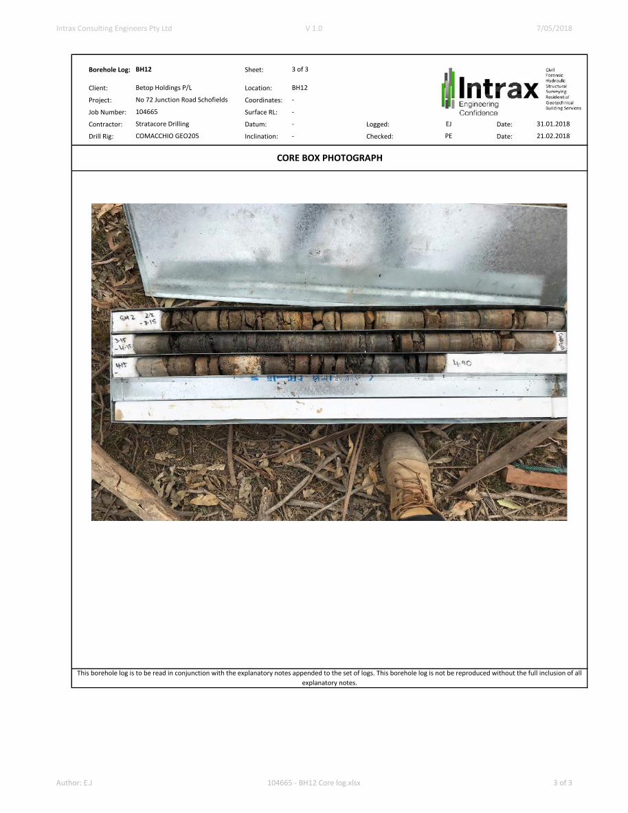
- - - - - Thinly Laminated SHALE SW 0 degrees - CS, ST, RO, ST- - - - - brown- - - - - 0 degrees - CS, ST, RO, ST- - - - - Thinly Laminated SANDSTONE- - - - - brown 0 degrees - CS, ST, RO, ST- - - - - - - - - - HW 0 degrees - IS, PL, SM, CL- - - - - Thinly Laminated SHALE- - - - - dark grey 0 degrees - IS, PL, SM, CL- - - - - - - - - - - - - - - 0 degrees - IS, PL, SM, CL (XW ROCK - - - - - seams at regular intervals)- - - - - - - - - - - - - - - Thinly Laminated SANDSTONE 0 degrees - SZ, PL, RO, CL- - - - - brown- - - - - 0 degrees - IS, PL, SM, CL
core loss- - - - - Thinly Laminated SHALE- - - - - brown grey- - - - - SW 0 degrees - IS, PL, SM, CL (Clay seam 100mm)- - - - - - - - - - HW- - - - - 0 degrees - CS, ST, RO, ST- - - - - - - - - -
End of test, Target depth reachedNo ground water encountered
This borehole log is to be read in conjunction with the explanatory notes appended to the set of logs. This borehole log is not be reproduced without the full inclusion of all
explanatory notes.
Met
ho
d
Wat
er
TCR
(%
)
RQ
D (
%)
Dep
th (
m)
RL
Inferred Rock
Strength Defects & Additional Observations
Defect Spacing
(mm)
Wea
ther
ing
1.0
2.0
8.0
2 of 3BH12
31.01.2018
21.02.2018
No 72 Junction Road Schofields
104665
Stratacore Drilling
COMACCHIO GEO205
Betop Holdings P/L BH12
-
-
Relatively Level
EJ
PE
-
98% 16%
Material Description
Gra
ph
ic L
og
NM
LC
0.0
10.0
6.0
7.0
3.0
4.0
5.0
9.0
Author: E.J 104665 - BH12 Core log.xlsx 2 of 3
Intrax Consulting Engineers Pty Ltd V 1.0 7/05/2018
Borehole Log: Sheet:
Client: Location:
Project: Coordinates:
Job Number: Surface RL:
Contractor: Datum: Logged: Date:
Drill Rig: Inclination: Checked: Date:-
This borehole log is to be read in conjunction with the explanatory notes appended to the set of logs. This borehole log is not be reproduced without the full inclusion of all
explanatory notes.
CORE BOX PHOTOGRAPH
Stratacore Drilling
COMACCHIO GEO205 -
31.01.2018
21.02.2018
3 of 3
EJ
PE
BH12
Betop Holdings P/L
-
-
104665
No 72 Junction Road Schofields
BH12
-
Author: E.J 104665 - BH12 Core log.xlsx 3 of 3

Intrax Consulting Engineers Pty Ltd V 1.0 7/05/2018
Borehole Log: Sheet:
Client: Location:
Project: Coordinates:
Job Number: Surface RL:
Contractor: Datum: Logged: Date:
Drill Rig: Inclination: Checked: Date:
Met
ho
d
Res
ista
nce
Wat
er
RL
Rec
ove
red
Gra
ph
ic L
og
So
il C
lass
ific
atio
n
Mo
istu
re
Co
nsi
sten
cy /
Den
sity
……….. CL CLAY - trace gravels (fine, sub rounded, uniform) >PL V-St………… brown pales to grey mottled brown, medium plasticity………………………………………………………………………………………………
SPT - 4, 6, 9 = N 15 ……………………………………………………oxoxox XW Extremely Weathered ROCK (SHALE) - SILT D VD clay pocketsoxoxox grey brownoxoxoxoxoxoxoxoxox
SPT - 6,32,35 = N 67 oxoxoxoxoxoxoxoxoxoxoxoxoxoxoxoxoxoxoxoxox
Refere next sheet for continuation
10.0
MA
- T
C
H
01.02.2018
21.02.2018
Soil Origin & Additional Observations
COMACCHIO GEO205
1 of 3
NGL
-
BH13
Betop Holdings P/L
No 72 Junction Road Schofields
104665
Stratacore Drilling
BH13
-
EJ
This borehole log is to be read in conjunction with the explanatory notes appended to the set of logs. This borehole log is not be reproduced without the full inclusion of all
explanatory notes.
Relatively Level
Dep
th (
m) Sample or Field Test Material Description
1.0
9.0
8.0
7.0
6.0
5.0
4.0
3.0
2.0
0.0
PE
Author: Joseph McPherson 104665 - BH13 Core log.xlsx 1 of 3

Intrax Consulting Engineers Pty Ltd V 1.0 7/05/2018
Borehole Log: Sheet:
Client: Location:
Project: Coordinates:
Job Number: Surface RL:
Contractor: Datum: Logged: Date:
Drill Rig: Inclination: Checked: Date:
<VL
VL
L M H VH
EH 10 30 100
300
1000
3000
CORE LOSS
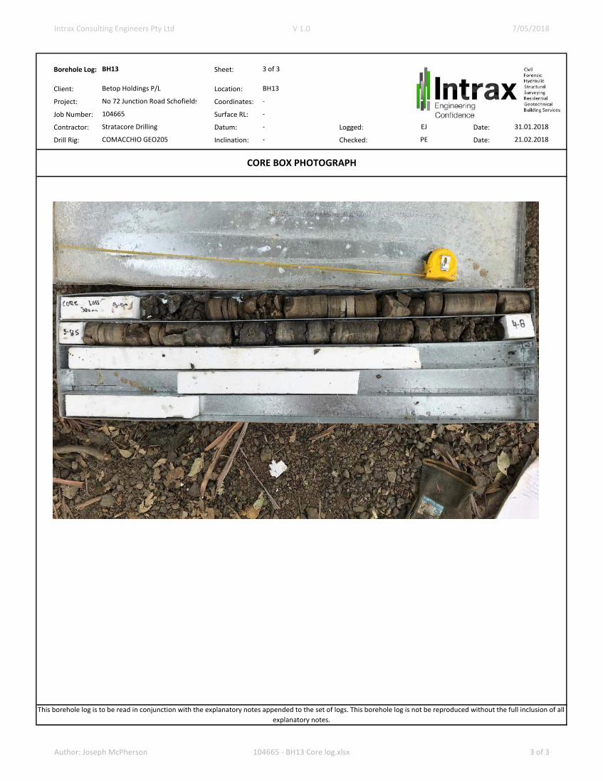
- - - - - Thinly Laminated SHALE HW- - - - - grey 0 degrees - CS, ST, RO, ST- - - - -- - - - - 0 degrees - CS, ST, RO, ST- - - - - Thinly Laminated SANDSTONE- - - - - brown- - - - -- - - - - Thinly Laminated SHALE- - - - - brown- - - - - 0 degrees - SZ, PL, RO, CL- - - - -- - - - - dark grey- - - - - 45 degrees - JT, ST, SM, CL- - - - -- - - - -- - - - -- - - - -- - - - - SW 0 degrees - IS, PL, SM, CL - - - - - (XW rock seams at regular intervals)
End of test, Target depth reachedNo ground water encountered
10.0
6.0
7.0
3.0
4.0
5.0
NM
LC
86% 22%
Material Description G
rap
hic
Lo
g
0.0
2 of 3BH13
01.02.2018
21.02.2018
No 72 Junction Road Schofields
104665
Stratacore Drilling
COMACCHIO GEO205
Betop Holdings P/L BH13
-
-
Relatively Level
EJ
PE
-
This borehole log is to be read in conjunction with the explanatory notes appended to the set of logs. This borehole log is not be reproduced without the full inclusion of all
explanatory notes.
Met
ho
d
Wat
er
TCR
(%
)
RQ
D (
%)
Dep
th (
m)
RL
Inferred Rock
Strength Defects & Additional Observations
Defect Spacing
(mm)
Wea
ther
ing
1.0
2.0
8.0
9.0
Author: Joseph McPherson 104665 - BH13 Core log.xlsx 2 of 3
Intrax Consulting Engineers Pty Ltd V 1.0 7/05/2018
Borehole Log: Sheet:
Client: Location:
Project: Coordinates:
Job Number: Surface RL:
Contractor: Datum: Logged: Date:
Drill Rig: Inclination: Checked: Date:
3 of 3
EJ
PE
BH13
Betop Holdings P/L
-
-
104665
No 72 Junction Road Schofields
BH13
-
This borehole log is to be read in conjunction with the explanatory notes appended to the set of logs. This borehole log is not be reproduced without the full inclusion of all
explanatory notes.
CORE BOX PHOTOGRAPH
Stratacore Drilling
COMACCHIO GEO205 -
31.01.2018
21.02.2018
Author: Joseph McPherson 104665 - BH13 Core log.xlsx 3 of 3
Intrax Consulting Engineers Pty Ltd V 1.0 7/05/2018
Borehole Log: Sheet:
Client: Location:
Project: Coordinates:
Job Number: Surface RL:
Contractor: Datum: Logged: Date:
Drill Rig: Inclination: Checked: Date:
Met
ho
d
Res
ista
nce
Wat
er
RL
Rec
ove
red
Gra
ph
ic L
og
So
il C
lass
ific
atio
n
Mo
istu
re
Co
nsi
sten
cy /
Den
sity
……….. CL CLAY - trace gravels (fine, sub rounded, uniform) >PL V-St………… brown pales to grey mottled brown, medium plasticity………………………………………………………………………………………………
SPT - 3, 9, 18 = N 27 ……………………………………………………oxoxox XW Extremely Weathered ROCK (SHALE) - SILT D VD clay pocketsoxoxox grey brownoxoxoxoxoxoxoxoxoxoxoxoxoxoxoxoxoxoxoxoxoxoxoxoxoxoxoxoxoxoxoxoxox
Refere next sheet for continuation
10.0
This borehole log is to be read in conjunction with the explanatory notes appended to the set of logs. This borehole log is not be reproduced without the full inclusion of all
explanatory notes.
Relatively Level
Dep
th (
m) Sample or Field Test Material Description
1.0
9.0
8.0
7.0
6.0
5.0
4.0
3.0
2.0
0.0
PE
1 of 3
NGL
-
BH14
Betop Holdings P/L
No 72 Junction Road Schofields
104665
Stratacore Drilling
BH14
-
EJ
MA
- T
C
H
01.02.2018
21.02.2018
Soil Origin & Additional Observations
COMACCHIO GEO205
Author: E.J 104665 - BH14 Core log.xlsx 1 of 3

Intrax Consulting Engineers Pty Ltd V 1.0 7/05/2018
Borehole Log: Sheet:
Client: Location:
Project: Coordinates:
Job Number: Surface RL:
Contractor: Datum: Logged: Date:
Drill Rig: Inclination: Checked: Date:
<VL
VL
L M H VH
EH 10
30
10
03
00
10
00
30
00
…………
- - - - - Thinly Laminated SANDSTONE HW 0 degrees - CS, ST, RO, ST- - - - - brown- - - - - 0 degrees - IS, PL, SM, CL- - - - - - - - - - 0 degrees - JT, ST, SM, CL- - - - - Thinly Laminated SHALE- - - - - grey- - - - - - - - - - - - - - - - - - - - - - - - - - - - - - - - - - - 0 degrees - CS, ST, RO, ST- - - - - - - - - - - - - - - - - - - - - - - - - - - - - -
End of test, Target depth reachedEnd of test, Target depth reachedNo ground water encounteredNo ground water encountered
This borehole log is to be read in conjunction with the explanatory notes appended to the set of logs. This borehole log is not be reproduced without the full inclusion of all
explanatory notes.
Met
ho
d
Wat
er
TCR
(%
)
RQ
D (
%)
Dep
th (
m)
RL
Inferred Rock
Strength Defects & Additional Observations
Defect Spacing
(mm)
Wea
ther
ing
1.0
2.0
8.0
9.0
2 of 3BH14
01.02.2018
21.02.2018
No 72 Junction Road Schofields
104665
Stratacore Drilling
COMACCHIO GEO205
Betop Holdings P/L
Material Description
Gra
ph
ic L
og
BH14
-
-
Relatively Level
EJ
PE
-
NM
LC
70%100%
0.0
10.0
6.0
7.0
3.0
4.0
5.0
Author: E.J 104665 - BH14 Core log.xlsx 2 of 3

Intrax Consulting Engineers Pty Ltd V 1.0 7/05/2018
Borehole Log: Sheet:
Client: Location:
Project: Coordinates:
Job Number: Surface RL:
Contractor: Datum: Logged: Date:
Drill Rig: Inclination: Checked: Date:
This borehole log is to be read in conjunction with the explanatory notes appended to the set of logs. This borehole log is not be reproduced without the full inclusion of all
explanatory notes.
CORE BOX PHOTOGRAPH
Stratacore Drilling
COMACCHIO GEO205 -
01.02.2018
21.02.2018
3 of 3
EJ
PE
BH14
Betop Holdings P/L
-
-
104665
No 72 Junction Road Schofields
BH14
-
Author: E.J 104665 - BH14 Core log.xlsx 3 of 3
Intrax Consulting Engineers Pty Ltd V 1.0 7/05/2018
Borehole Log: Sheet:
Client: Location:
Project: Coordinates:
Job Number: Surface RL:
Contractor: Datum: Logged: Date:
Drill Rig: Inclination: Checked: Date:
Met
ho
d
Res
ista
nce
Wat
er
RL
Rec
ove
red
Gra
ph
ic L
og
So
il C
lass
ific
atio
n
Mo
istu
re
Co
nsi
sten
cy /
Den
sity
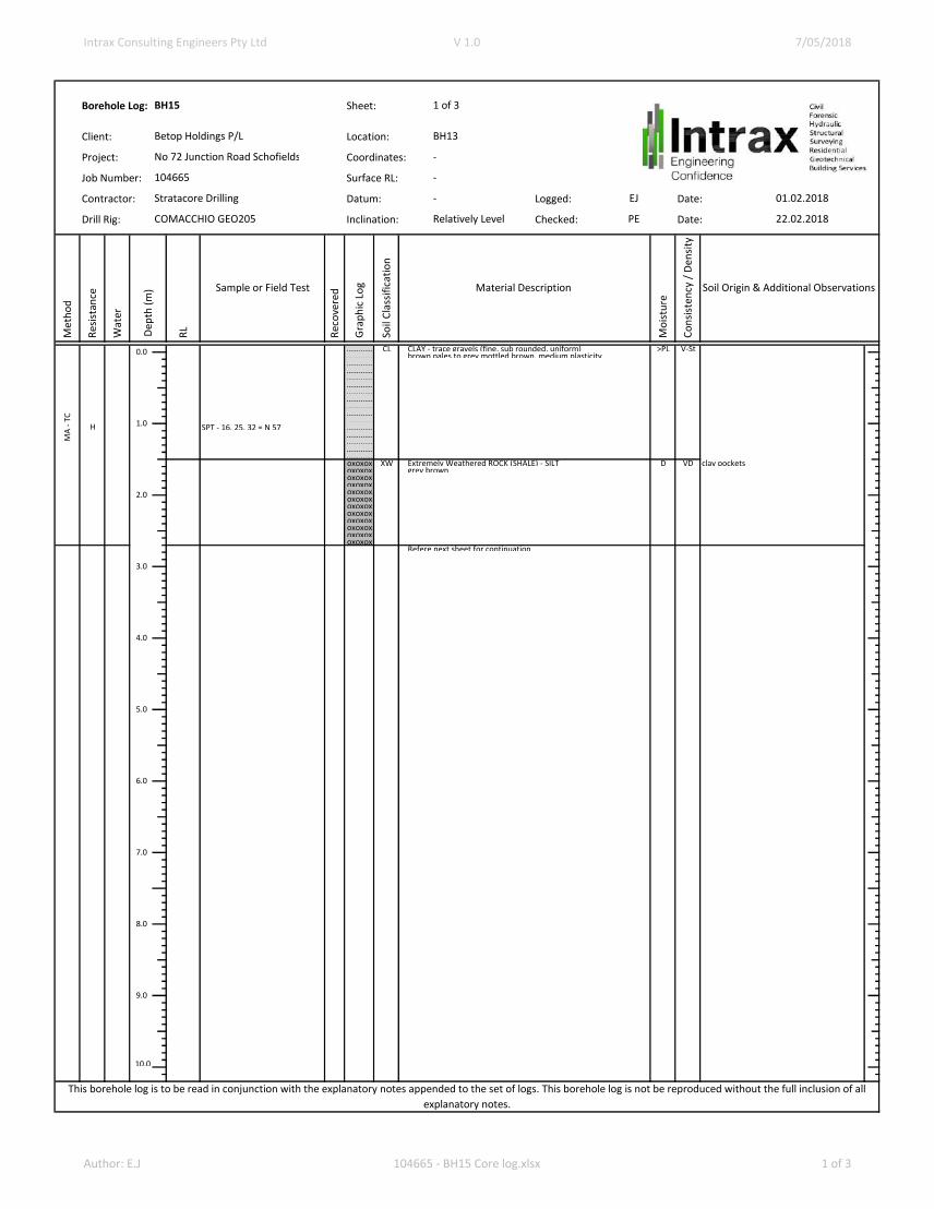
…………. CL CLAY - trace gravels (fine, sub rounded, uniform) >PL V-St…………. brown pales to grey mottled brown, medium plasticity………….………….………….………….………….………….………….………….………….
SPT - 16, 25, 32 = N 57 ………….………….………….………….………….oxoxox XW Extremely Weathered ROCK (SHALE) - SILT D VD clay pocketsoxoxox grey brownoxoxoxoxoxoxoxoxoxoxoxoxoxoxoxoxoxoxoxoxoxoxoxoxoxoxoxoxoxox
Refere next sheet for continuation
10.0
This borehole log is to be read in conjunction with the explanatory notes appended to the set of logs. This borehole log is not be reproduced without the full inclusion of all
explanatory notes.
Relatively Level
Dep
th (
m) Sample or Field Test Material Description
1.0
9.0
8.0
7.0
6.0
5.0
4.0
3.0
2.0
0.0
PE
1 of 3
-
-
BH15
Betop Holdings P/L
No 72 Junction Road Schofields
104665
Stratacore Drilling
BH13
-
EJ
MA
- T
C
H
01.02.2018
22.02.2018
Soil Origin & Additional Observations
COMACCHIO GEO205
Author: E.J 104665 - BH15 Core log.xlsx 1 of 3

Intrax Consulting Engineers Pty Ltd V 1.0 7/05/2018
Borehole Log: Sheet:
Client: Location:
Project: Coordinates:
Job Number: Surface RL:
Contractor: Datum: Logged: Date:
Drill Rig: Inclination: Checked: Date:
<VL
VL
L M H VH
EH 10
30
10
03
00
10
00
30
00
- - - - - - Thinly Laminated SANDSTONE HW- - - - - - brown- - - - - -- - - - - -- - - - - -- - - - - -- - - - - -- - - - - -- - - - - -- - - - - - Thinly Laminated SHALE SW 0 degrees - JT, ST, SM, CL- - - - - - grey- - - - - -- - - - - -- - - - - -- - - - - -- - - - - -- - - - - - 0 degrees - CS, ST, RO, ST- - - - - -- - - - - - 0 degrees - SS, PL, SM, CL- - - - - -- - - - - -- - - - - -- - - - - -
End of test no refusal, target depth reachedNo ground water encountered
0 degrees - CS, ST, RO, ST0 degrees - BR, PL, SM, ST0 degrees - SZ, PL, RO, CL45 degrees - JT, ST, SM, CL
This borehole log is to be read in conjunction with the explanatory notes appended to the set of logs. This borehole log is not be reproduced without the full inclusion of all
explanatory notes.
Met
ho
d
Wat
er
TCR
(%
)
RQ
D (
%)
Dep
th (
m)
RL
Inferred Rock
Strength Defects & Additional Observations
Defect Spacing
(mm)
Wea
ther
ing
1.0
2.0
8.0
9.0
01.02.2018
22.02.2018
No 72 Junction Road Schofields
104665
Stratacore Drilling
COMACCHIO GEO205
Betop Holdings P/L BH13
-
Relatively Level
EJ
PE
NM
LC
100% 39%
Material Description
Gra
ph
ic L
og
0.0
10.0
6.0
7.0
3.0
4.0
5.0
Author: E.J 104665 - BH15 Core log.xlsx 2 of 3

Intrax Consulting Engineers Pty Ltd V 1.0 7/05/2018
Borehole Log: Sheet:
Client: Location:
Project: Coordinates:
Job Number: Surface RL:
Contractor: Datum: Logged: Date:
Drill Rig: Inclination: Checked: Date:
This borehole log is to be read in conjunction with the explanatory notes appended to the set of logs. This borehole log is not be reproduced without the full inclusion of all
explanatory notes.
CORE BOX PHOTOGRAPH
Stratacore Drilling
COMACCHIO GEO205 -
31.01.2018
22.02.2018
3 of 3
EJ
PE
BH15
Betop Holdings P/L
-
-
104665
No 72 Junction Road Schofields
BH15
-
Author: E.J 104665 - BH15 Core log.xlsx 3 of 3
Intrax Consulting Engineers Pty Ltd V 1.0 7/05/2018
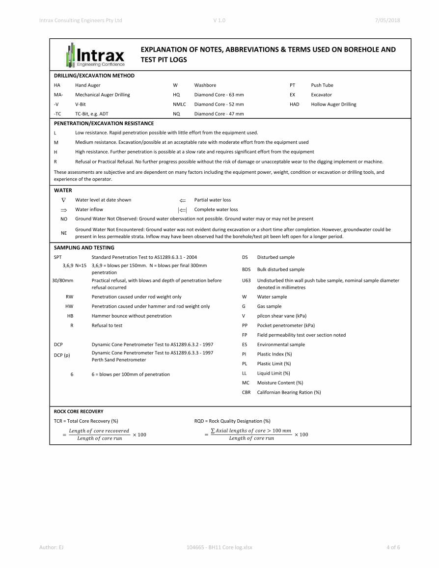
DRILLING/EXCAVATION METHOD
HA Hand Auger W Washbore PT Push Tube
MA- Mechanical Auger Drilling HQ Diamond Core - 63 mm EX Excavator
-V V-Bit NMLC Diamond Core - 52 mm HAD Hollow Auger Drilling
-TC TC-Bit, e.g. ADT NQ Diamond Core - 47 mm
PENETRATION/EXCAVATION RESISTANCE
L
M
H
R Refusal or Practical Refusal. No further progress possible without the risk of damage or unacceptable wear to the digging implement or machine.
WATER
Water level at date shown Partial water loss
Water inflow Complete water loss
NO
SAMPLING AND TESTING
SPT Standard Penetration Test to AS1289.6.3.1 - 2004 DS Disturbed sample
3,6,9 N=15BDS Bulk disturbed sample
30/80mm U63
RW Penetration caused under rod weight only W Water sample
HW Penetration caused under hammer and rod weight only G Gas sample
HB Hammer bounce without penetration V pilcon shear vane (kPa)
R Refusal to test PP Pocket penetrometer (kPa)
FP Field permeability test over section noted
DCP Dynamic Cone Penetrometer Test to AS1289.6.3.2 - 1997 ES Environmental sample
DCP (p) PI Plastic Index (%)
PL Plastic Limit (%)
6 6 = blows per 100mm of penetration LL Liquid Limit (%)
MC Moisture Content (%)
CBR Californian Bearing Ration (%)
ROCK CORE RECOVERY
TCR = Total Core Recovery (%) RQD = Rock Quality Designation (%)
Dynamic Cone Penetrometer Test to AS1289.6.3.3 - 1997
Perth Sand Penetrometer
EXPLANATION OF NOTES, ABBREVIATIONS & TERMS USED ON BOREHOLE AND
TEST PIT LOGS
Low resistance. Rapid penetration possible with little effort from the equipment used.
Medium resistance. Excavation/possible at an acceptable rate with moderate effort from the equipment used
High resistance. Further penetration is possible at a slow rate and requires significant effort from the equipment
These assessments are subjective and are dependent on many factors including the equipment power, weight, condition or excavation or drilling tools, and
experience of the operator.
Ground Water Not Observed: Ground water obersvation not possible. Ground water may or may not be present
NEGround Water Not Encountered: Ground water was not evident during excavation or a short time after completion. However, groundwater could be
present in less permeable strata. Inflow may have been observed had the borehole/test pit been left open for a longer period.
3,6,9 = blows per 150mm. N = blows per final 300mm
penetration
Practical refusal, with blows and depth of penetration before
refusal occurred
Undisturbed thin wall push tube sample, nominal sample diameter
denoted in millimetres
=𝐿𝑒𝑛𝑔𝑡ℎ 𝑜𝑓 𝑐𝑜𝑟𝑒 𝑟𝑒𝑐𝑜𝑣𝑒𝑟𝑒𝑑
𝐿𝑒𝑛𝑔𝑡ℎ 𝑜𝑓 𝑐𝑜𝑟𝑒 𝑟𝑢𝑛× 100 =
σ𝐴𝑥𝑖𝑎𝑙 𝑙𝑒𝑛𝑔𝑡ℎ𝑠 𝑜𝑓 𝑐𝑜𝑟𝑒 > 100 𝑚𝑚
𝐿𝑒𝑛𝑔𝑡ℎ 𝑜𝑓 𝑐𝑜𝑟𝑒 𝑟𝑢𝑛× 100
Author: EJ 104665 - BH11 Core log.xlsx 4 of 6

Intrax Consulting Engineers Pty Ltd V 1.0 7/05/2018
SOIL CLASSIFICATION SYSTEM
Coarse Grained Soil Fine Grained Soils
GW Well graded gravels, gravel-sand mixtures, little or no fines ML
GP
CL, CI
GM Silty gravels, gravel-sand-silt mixtures OL Organic silts and organic silty clays of low plasticity
GC Clayey gravels, gravel-sand-clay mixtures MH Inorganic silts, micaceous or diatomaceous fine sand for silty soils
SW Well-graded sands, gravelly sands, little or no fines CH Inorganic clays of high plasticity
SP Poorly-graded sands, gravelly sand, little or no fines OH Organic clays of medium to high plasticity, organic silts
SM Silty sands, sand-silt mixtures PT Peat, humus, swamp soils with high organic contents
SC Clayey sands, sand-clay mixtures
First Letter: G = Gravel, S = Sand, M = Silt, C = Clay; Second Letter: W = Well-graded, P = Poorly-graded, M = Mixture, O = Organic, L = Low plasticity, H = High plasticity
Soils may be a combination of multiple soil classifications where borderline
Soil Sub-Division
Coarse
Medium
Fine
Coarse
Medium
Fine
0.075mm is the approximate minimum particle size discernible by eye
MOISTURE CONDITION
D Dry Sands and gravels are free flowing.
M Moist Soils are darker than in the dry condition and may feel cool. Sands and gravels tend to cohere.
W Wet Soils exude free water. Sands and gravels tend to cohere.
PL Plastic Limit
LL Liquid Limit
CONSISTENCY AND DENSITY
Fine Grained Soils Pocket Pentrometer Coarse Grained Soil
Reading (kPa) Density Index % 'N' Value
VS Very Soft Exudes between fingers when squeezed <25 VL Very Loose ≤15 0 - 4
S Soft Can be moulded by light finger pressure 20 - 50 L Loose 15 - 35 4 - 10
F Firm Can be moulded by strong finger pressure 50 - 100 MD Medium Dense 35 - 65 10 - 30
St Stiff Cannot be moulded by fingers. Can be indented by thumb 100 - 200 D Dense 65 - 85 30 - 50
VSt Very Stiff Can be indented by thumb nail 200 - 400 VD Very Dense >85 >50
H Hard Can be indented by thumb nail with difficulty >400
SECONDARY OR MINOR SOIL COMPONENTS
%Fines %Sand/gravel
≤5 ≤15
5 - 12 15 - 30
> 15 >30
EXPLANATION OF NOTES, ABBREVIATIONS & TERMS USED ON BOREHOLE AND
TEST PIT LOGS - SOIL DESCRIPTION (AS1726 - 2017)
Inorganic silts and very fine sands, rock flour, silty or clayey fine sands
or silts with low plasticity Poorly-graded gravels, gravel-sand mixtures, little or no fines, uniform
gravels Inorganic clays of low to medium plasticity, gravelly clays, sandy clays
PARTICLE SIZE PLASTICITY CHART
Major Division Particle Size (mm)
Co
arse
Boulders >200
Cobbles 63 - 200
Gravel
20 - 63
6 - 20
2.36 - 6
Sand
0.6 - 2.36
0.2 - 0.6
0.075 - 0.2
Fin
e Silt 0.002 - 0.075
Clay < 0.002
Co
arse
Fin
e Moisture content of fine grain soils are described; as below plastic limit (<PL), near to plastic limit (=PL), above plastic limit
(>PL), near to the liquid limit (=LL), or above the liquid limit (>LL)
Designation of
components
In coarse grained soils In fine grained soils
Terminology %Accessory Coarse Fraction Terminology Terminology
Minor
'trace' clay/silt ≤15 'trace' sand/gravel 'trace' sand/gravel
'with' clay/silt 15 - 30 'with' sand/gravel 'with' sand/gravel
Secondary Prefix silty or clayey >30 Prefix sandy or gravelly Prefix sandy or gravelly
Author: EJ 104665 - BH11 Core log.xlsx 5 of 6

Intrax Consulting Engineers Pty Ltd V 1.0 7/05/2018
STRENGTH OF INTACT ROCK
Symbol Term
M Medium
VH Very High
EH Extremely High
Material with rock strength less than 'Very Low' are described using soil properties
DEGREE OF ROCK WEATHERING
Distinctly Weathered is to be used when it is not possible to differentiate between highly and moderately weathered.
Extremely Weathered material is to be described using soil properties
ROCK MASS PROPERTIES
DEFECT TYPES AND DESCRIPTIONS
Defect Type Defect Shape Surface Roughness Defect Coatings
BR Bedding parting PL Planar VR Very rough CL Clean
JT Joint ST Stepped RO Rough ST Stained
SR Sheared surface CR Curved SM Smooth VN Veneer
SZ Sheared zone IR Irregular PO Polished CT Coating
SS Sheared seam UN Undulating SL Slickenside
CS Crushed seam
IS Infill seam Vertical Boreholes - The dip of the defect is given from the horizontal
XS Extremely Weathered Seam Inclined Boreholes - The angle of the defect is given from the core axis
EXPLANATION OF NOTES, ABBREVIATIONS & TERMS USED ON BOREHOLE AND
TEST PIT LOGS - ROCK DESCRIPTION (AS1726 - 2017)
Point Load Index, (Is50) MPa Field Guide to Strength
VL Very Low 0.03 ≤ Is50 < 0.1Material crumbles under firm blows with sharp end of pick; can be peeled with knife; pieces up to 30mm
thick can be broken by finger pressure
L Low 0.1 ≤ Is50 < 0.3Easily scored with knife; indentations 1mm to 3mm after firm blow with pick point; core 150mm long and
50mm diameter can be broken by hand; sharp edges of core friable
0.3 ≤ Is50 < 1.0 Readily scored with knife; core 150mm long and 50mm diameter can be broken by hand with difficulty
Residual Soil RSSoil derived from the weathering of rock; the mass structure and material fabric are no longer evident the
soil has not been significantly transported.
H High 1.0 ≤ Is50 < 3Core 150mm long and 50mm diameter cannot be broken by hand but can be broken by single firm blow of
pick; rock rings under hammer
3 ≤ Is50 < 10 Hand held specimen breaks with pick after more than one blow; rock rings under hammer
10 ≤ Is50 Specimen requires many pick blows to break intact rock, rock rings under hammer
Term Symbol Definition
Extremely Weathered XWMaterial is weathered to such an extent that it has soil properties, i.e. it either disintegrates or can be
remoulded, in water. Fabric of original rock still visible.
Highly Weathered Distinctly
Weathered
HW
DW
Rock strength is changed by weathering. The whole of the rock material is discoloured, usually by iron
staining or bleaching to the extent that the colour of the original rock is not recognizable. Some minerals
are decomposed to clay minerals. Porosity may be increased by leach, or may be decreased due to
deposition of weathering products in pores.
Moderately Weathered MWThe whole of the rock material is discoloured, usually by iron staining or bleaching to the extent that the
colour of the original rock is not recognisable, but shows little or no change of strength from fresh rock.
Slightly Weathered SW Rock is slightly discoloured but shows little or no change of strength from fresh rock
Fresh FR Rock shows no sign of decomposition or staining
TermSeparation of
Stratification PlanesTerm Description
Thinly laminated < 6mm Fragmented Primarily fragments < 20mm length and mostly of width < core diameter
Laminated 6mm to 20 mm Highly fractured Core lengths generally less than 20mm to 40mm with occasional fragments
Very thinly bedded 20mm to 60mm
Core has no fractures
Thinly bedded 60mm to 200mm Fractured Core lengths mainly 30mm to 100mm with occasional shorter and longer pieces
Medium bedded 0.2m to 0.6m Slightly fractured Core lengths generally 0.3m to 1.0m with occasional longer and shorter sections
Thickly bedded 0.6m to 2.0m
Massive < 2m Unbroken
Author: EJ 104665 - BH11 Core log.xlsx 6 of 6

Commercial Report Template 1.8
7/05/2018
Document Revision: 1
Template Version: Vx
APPENDIX B
Site Photography
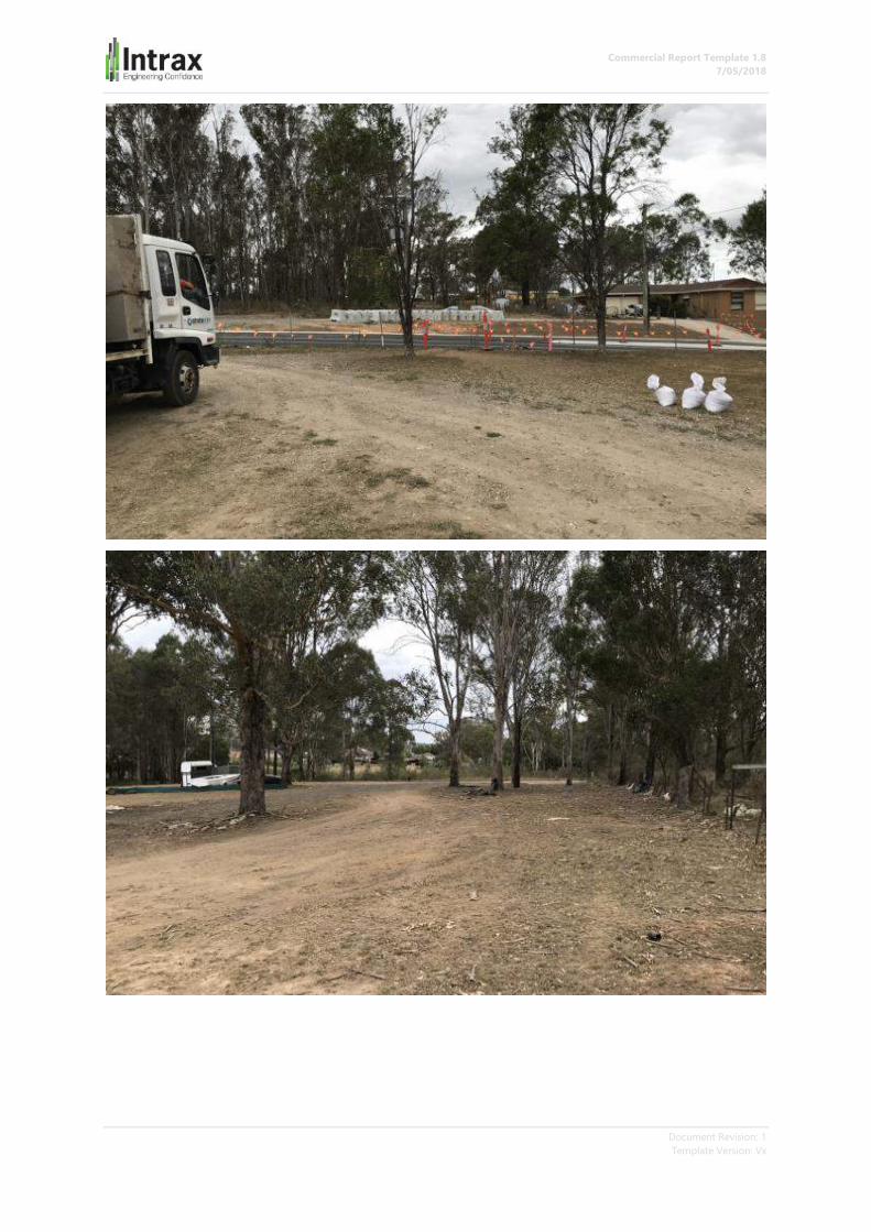
Commercial Report Template 1.8
7/05/2018
Document Revision: 1
Template Version: Vx

Commercial Report Template 1.8
7/05/2018
Document Revision: 1
Template Version: Vx

Commercial Report Template 1.8
7/05/2018
Document Revision: 1
Template Version: Vx

Commercial Report Template 1.8
7/05/2018
Document Revision: 1
Template Version: Vx
APPENDIX C
Laboratory Data

0 0.00 True
Environmental
CERTIFICATE OF ANALYSISWork Order : Page : 1 of 2ES1803882
:: LaboratoryClient INTRAX CONSULTING ENGINEERS Environmental Division Sydney
: :ContactContact RENAN YAOKOOB Customer Services ES
:: AddressAddress 27/1-5 Jacobs Street
Bankstown NSW, AUSTRALIA 2200
277-289 Woodpark Road Smithfield NSW Australia 2164
:Telephone 0428 963 825 :Telephone +61-2-8784 8555
:Project 104665 Date Samples Received : 05-Feb-2018 16:25
:Order number ---- Date Analysis Commenced : 09-Feb-2018
:C-O-C number ---- Issue Date : 14-Feb-2018 10:20
Sampler : AW
Site : ----
Quote number : SYBQ/286/17
4:No. of samples received
4:No. of samples analysed
This report supersedes any previous report(s) with this reference. Results apply to the sample(s) as submitted. This document shall not be reproduced, except in full.
This Certificate of Analysis contains the following information:
l General Comments
l Analytical Results
Additional information pertinent to this report will be found in the following separate attachments: Quality Control Report, QA/QC Compliance Assessment to assist with
Quality Review and Sample Receipt Notification.
SignatoriesThis document has been electronically signed by the authorized signatories below. Electronic signing is carried out in compliance with procedures specified in 21 CFR Part 11.
Signatories Accreditation CategoryPosition
Satishkumar Trivedi Acid Sulfate Soils Supervisor Brisbane Acid Sulphate Soils, Stafford, QLD
R I G H T S O L U T I O N S | R I G H T P A R T N E R
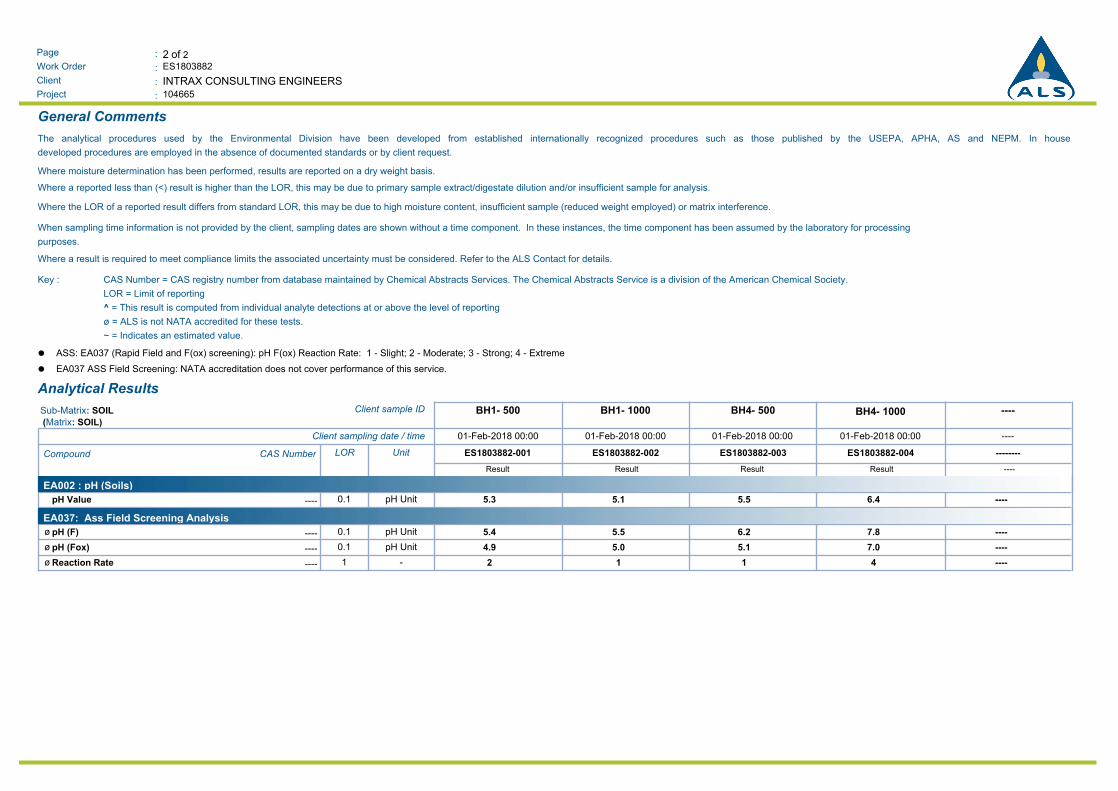
2 of 2:Page
Work Order :
:Client
ES1803882
104665:Project
INTRAX CONSULTING ENGINEERS
General Comments
The analytical procedures used by the Environmental Division have been developed from established internationally recognized procedures such as those published by the USEPA, APHA, AS and NEPM. In house
developed procedures are employed in the absence of documented standards or by client request.
Where moisture determination has been performed, results are reported on a dry weight basis.
Where a reported less than (<) result is higher than the LOR, this may be due to primary sample extract/digestate dilution and/or insufficient sample for analysis.
Where the LOR of a reported result differs from standard LOR, this may be due to high moisture content, insufficient sample (reduced weight employed) or matrix interference.
When sampling time information is not provided by the client, sampling dates are shown without a time component. In these instances, the time component has been assumed by the laboratory for processing
purposes.
Where a result is required to meet compliance limits the associated uncertainty must be considered. Refer to the ALS Contact for details.
CAS Number = CAS registry number from database maintained by Chemical Abstracts Services. The Chemical Abstracts Service is a division of the American Chemical Society.
LOR = Limit of reporting
^ = This result is computed from individual analyte detections at or above the level of reporting
ø = ALS is not NATA accredited for these tests.
~ = Indicates an estimated value.
Key :
ASS: EA037 (Rapid Field and F(ox) screening): pH F(ox) Reaction Rate: 1 - Slight; 2 - Moderate; 3 - Strong; 4 - Extremel
EA037 ASS Field Screening: NATA accreditation does not cover performance of this service.l
Analytical Results
----BH4- 1000BH4- 500BH1- 1000BH1- 500Client sample IDSub-Matrix: SOIL
(Matrix: SOIL)
----01-Feb-2018 00:0001-Feb-2018 00:0001-Feb-2018 00:0001-Feb-2018 00:00Client sampling date / time
--------ES1803882-004ES1803882-003ES1803882-002ES1803882-001UnitLORCAS NumberCompound
Result Result Result Result ----
EA002 : pH (Soils)
5.3 5.1 5.5 6.4 ----pH Unit0.1----pH Value
EA037: Ass Field Screening Analysis
5.4ø 5.5 6.2 7.8 ----pH Unit0.1----pH (F)
4.9ø 5.0 5.1 7.0 ----pH Unit0.1----pH (Fox)
2ø 1 1 4 -----1----Reaction Rate

Client:
Project:
Job No.:
Test Procedure:
Sampling:
Preparation:
Compaction and Placement Data
Compaction Used Standard Dry Density
Maximum Dry Density t/m3 1.73 At Compaction 1.70 t/m
3 98.0 % Comp.
Optimum Moisture Content % 15.0 After Soaking t/m31.60 t/m3 92.0 % Comp.
No. of Layers 3 Moisture Content Moisture Ratio (%)
Blows per Layer 53 At Compaction % 14.8 99
Drop of Rammer mm 300 After Soaking % 24.7 165
Mass of Rammer kg 2.7 After Penetration (Top 30mm) % 30.1 201
Surcharge Used kg 4.5 After Penetration (Entire Depth) % 23.8 158
% Ret. 19mm Sieve 0 Swell After 4 Days Soaking %% 5.9
Note: material coarser than +19mm Sieve was discarded (as per test method)
California Bearing Ratio
CBR (4-day Soaked) = 2.5 % at 2.5 mm Penetration
Date:
Sampled by Client
AS1289 6.1.1 Soil strength and consolidation tests - Determination of the California Bearing Ratio of a soil - Standard laboratory method for a remoulded specimen
CALIFORNIA BEARING RATIO REPORT
Intrax Consulting Engineers Pty Ltd
Address:Suite 27/1-5, Jacobs Street, Bankstown,
NSW 2200
U8 10 Bradford Street
Alexandria NSW 2015
Prepared in accordance with the test method
Source:
Sample Description:
Report No.:
Lab No.:
AS1289 5.1.1 Soil compaction and density tests - Determination of the dry density/moisture content relationship of a soil using standard compactive effort
Geo (104665)
S18039
Silty CLAY
S30524-CBR
S30524
BH1
1/02/2018
AS1289 2.1.1 Soil moisture content tests - Determination of the moisture content of a soil - Oven drying method (standard method
Date Sampled:
Macquarie Geotechnical
Lo
ad
(K
N)
19/02/2018
Authorised Signatory:
Chris Lloyd
Penetration (mm)
NATA Accredited Laboratory Number: 14874
Notes:
0
0.1
0.2
0.3
0.4
0.5
0.6
0.7
0.8
0.00 1.00 2.00 3.00 4.00 5.00 6.00 7.00 8.00 9.00 10.00 11.00 12.00 13.00
The results of the tests, calibrations and/or measurements includedin this document are traceable to Australian/national standards.Accredited for compliance with ISO/IEC 17025. This document shallnot be reproduced, except in full.
Report Form: CBR-Rta Issue 1 - Revision A - Issue Date 1/2/12 Page1of1
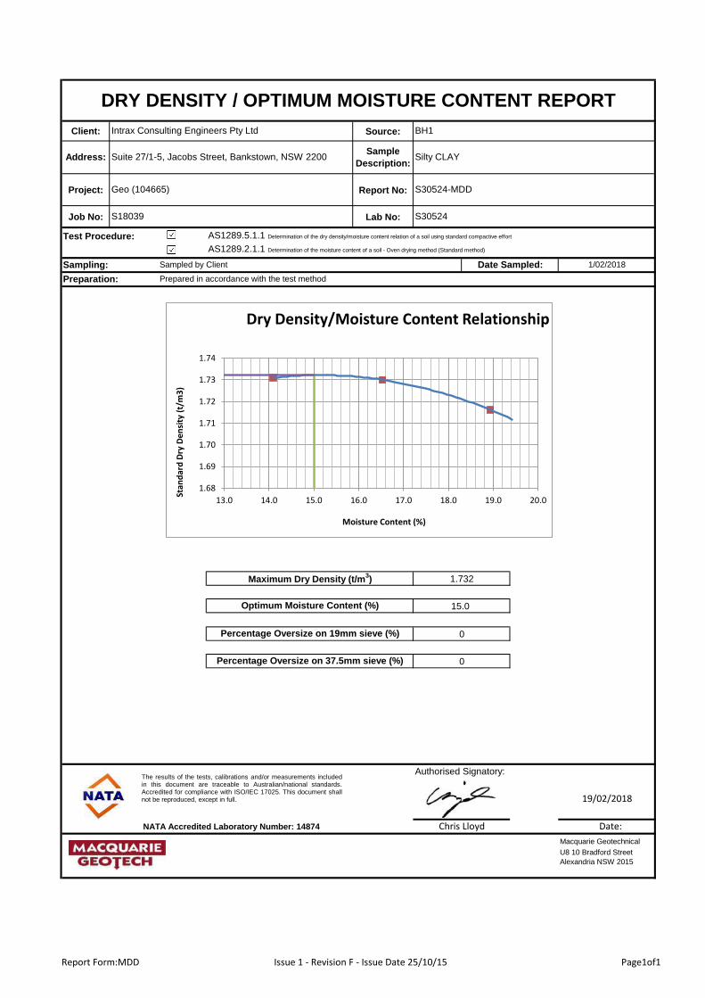
Client: Source:
Project: Report No:
Job No: Lab No:
Test Procedure: AS1289.5.1.1 Determination of the dry density/moisture content relation of a soil using standard compactive effort
AS1289.2.1.1 Determination of the moisture content of a soil - Oven drying method (Standard method)
Sampling:
Authorised Signatory:
NATA Accredited Laboratory Number: 14874
U8 10 Bradford Street
Alexandria NSW 2015
Maximum Dry Density (t/m3)
Optimum Moisture Content (%)
Percentage Oversize on 19mm sieve (%)
Percentage Oversize on 37.5mm sieve (%)
1.732
15.0
0
0
Macquarie Geotechnical
Date:
19/02/2018
Chris Lloyd
Intrax Consulting Engineers Pty Ltd BH1
DRY DENSITY / OPTIMUM MOISTURE CONTENT REPORT
Preparation:
Silty CLAYSuite 27/1-5, Jacobs Street, Bankstown, NSW 2200Address:
S30524-MDD
S30524
1/02/2018Date Sampled:
S18039
Sampled by Client
Geo (104665)
Sample
Description:
Prepared in accordance with the test method
The results of the tests, calibrations and/or measurements includedin this document are traceable to Australian/national standards.Accredited for compliance with ISO/IEC 17025. This document shallnot be reproduced, except in full.
1.68
1.69
1.70
1.71
1.72
1.73
1.74
13.0 14.0 15.0 16.0 17.0 18.0 19.0 20.0
Stan
dar
d D
ry D
en
sity
(t/
m3
)
Moisture Content (%)
Dry Density/Moisture Content Relationship
Report Form:MDD Issue 1 - Revision F - Issue Date 25/10/15 Page1of1
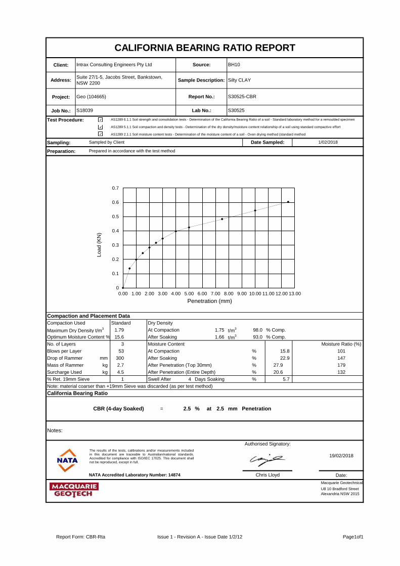
Client:
Project:
Job No.:
Test Procedure:
Sampling:
Preparation:
Compaction and Placement Data
Compaction Used Standard Dry Density
Maximum Dry Density t/m3 1.79 At Compaction 1.75 t/m
3 98.0 % Comp.
Optimum Moisture Content % 15.6 After Soaking t/m31.66 t/m3 93.0 % Comp.
No. of Layers 3 Moisture Content Moisture Ratio (%)
Blows per Layer 53 At Compaction % 15.8 101
Drop of Rammer mm 300 After Soaking % 22.9 147
Mass of Rammer kg 2.7 After Penetration (Top 30mm) % 27.9 179
Surcharge Used kg 4.5 After Penetration (Entire Depth) % 20.6 132
% Ret. 19mm Sieve 1 Swell After 4 Days Soaking %% 5.7
Note: material coarser than +19mm Sieve was discarded (as per test method)
California Bearing Ratio
CBR (4-day Soaked) = 2.5 % at 2.5 mm Penetration
Date:
Sampled by Client
AS1289 6.1.1 Soil strength and consolidation tests - Determination of the California Bearing Ratio of a soil - Standard laboratory method for a remoulded specimen
CALIFORNIA BEARING RATIO REPORT
Intrax Consulting Engineers Pty Ltd
Address:Suite 27/1-5, Jacobs Street, Bankstown,
NSW 2200
U8 10 Bradford Street
Alexandria NSW 2015
Prepared in accordance with the test method
Source:
Sample Description:
Report No.:
Lab No.:
AS1289 5.1.1 Soil compaction and density tests - Determination of the dry density/moisture content relationship of a soil using standard compactive effort
Geo (104665)
S18039
Silty CLAY
S30525-CBR
S30525
BH10
1/02/2018
AS1289 2.1.1 Soil moisture content tests - Determination of the moisture content of a soil - Oven drying method (standard method
Date Sampled:
Macquarie Geotechnical
Lo
ad
(K
N)
19/02/2018
Authorised Signatory:
Chris Lloyd
Penetration (mm)
NATA Accredited Laboratory Number: 14874
Notes:
0
0.1
0.2
0.3
0.4
0.5
0.6
0.7
0.00 1.00 2.00 3.00 4.00 5.00 6.00 7.00 8.00 9.00 10.00 11.00 12.00 13.00
The results of the tests, calibrations and/or measurements includedin this document are traceable to Australian/national standards.Accredited for compliance with ISO/IEC 17025. This document shallnot be reproduced, except in full.
Report Form: CBR-Rta Issue 1 - Revision A - Issue Date 1/2/12 Page1of1

Client: Source:
Project: Report No:
Job No: Lab No:
Test Procedure: AS1289.5.1.1 Determination of the dry density/moisture content relation of a soil using standard compactive effort
AS1289.2.1.1 Determination of the moisture content of a soil - Oven drying method (Standard method)
Sampling:
Authorised Signatory:
NATA Accredited Laboratory Number: 14874
DRY DENSITY / OPTIMUM MOISTURE CONTENT REPORT
Preparation:
Silty CLAYSuite 27/1-5, Jacobs Street, Bankstown, NSW 2200Address:
S30525-MDD
S30525
1/02/2018Date Sampled:
S18039
Sampled by Client
Geo (104665)
Sample
Description:
Prepared in accordance with the test method
Intrax Consulting Engineers Pty Ltd BH10
U8 10 Bradford Street
Alexandria NSW 2015
Maximum Dry Density (t/m3)
Optimum Moisture Content (%)
Percentage Oversize on 19mm sieve (%)
Percentage Oversize on 37.5mm sieve (%)
1.785
15.6
1
0
Macquarie Geotechnical
Date:
19/02/2018
Chris Lloyd
The results of the tests, calibrations and/or measurements includedin this document are traceable to Australian/national standards.Accredited for compliance with ISO/IEC 17025. This document shallnot be reproduced, except in full.
1.73
1.74
1.75
1.76
1.77
1.78
1.79
12.0 13.0 14.0 15.0 16.0 17.0 18.0
Stan
dar
d D
ry D
en
sity
(t/
m3
)
Moisture Content (%)
Dry Density/Moisture Content Relationship
Report Form:MDD Issue 1 - Revision F - Issue Date 25/10/15 Page1of1

Client:
Project:
Job No.:
Test Procedure:
Sampling:
Preparation:
Compaction and Placement Data
Compaction Used Standard Dry Density
Maximum Dry Density t/m3 1.81 At Compaction 1.77 t/m
3 98.0 % Comp.
Optimum Moisture Content % 16.0 After Soaking t/m31.73 t/m3 95.0 % Comp.
No. of Layers 3 Moisture Content Moisture Ratio (%)
Blows per Layer 53 At Compaction % 16.1 101
Drop of Rammer mm 300 After Soaking % 20.5 128
Mass of Rammer kg 2.7 After Penetration (Top 30mm) % 24.8 155
Surcharge Used kg 4.5 After Penetration (Entire Depth) % 20.3 127
% Ret. 19mm Sieve 0 Swell After 4 Days Soaking %% 2.5
Note: material coarser than +19mm Sieve was discarded (as per test method)
California Bearing Ratio
CBR (4-day Soaked) = 4.5 % at 2.5 mm Penetration
Date:
Sampled by Client
AS1289 6.1.1 Soil strength and consolidation tests - Determination of the California Bearing Ratio of a soil - Standard laboratory method for a remoulded specimen
CALIFORNIA BEARING RATIO REPORT
Intrax Consulting Engineers Pty Ltd
Address:Suite 27/1-5, Jacobs Street, Bankstown,
NSW 2200
U8 10 Bradford Street
Alexandria NSW 2015
Prepared in accordance with the test method
Source:
Sample Description:
Report No.:
Lab No.:
AS1289 5.1.1 Soil compaction and density tests - Determination of the dry density/moisture content relationship of a soil using standard compactive effort
Geo (104665)
S18039
Silty CLAY
S30526-CBR
S30526
BH13
1/02/2018
AS1289 2.1.1 Soil moisture content tests - Determination of the moisture content of a soil - Oven drying method (standard method
Date Sampled:
Macquarie Geotechnical
Lo
ad
(K
N)
19/02/2018
Authorised Signatory:
Chris Lloyd
Penetration (mm)
NATA Accredited Laboratory Number: 14874
Notes:
0
0.2
0.4
0.6
0.8
1
1.2
1.4
0.00 1.00 2.00 3.00 4.00 5.00 6.00 7.00 8.00 9.00 10.00 11.00 12.00 13.00
The results of the tests, calibrations and/or measurements includedin this document are traceable to Australian/national standards.Accredited for compliance with ISO/IEC 17025. This document shallnot be reproduced, except in full.
Report Form: CBR-Rta Issue 1 - Revision A - Issue Date 1/2/12 Page1of1

Client: Source:
Project: Report No:
Job No: Lab No:
Test Procedure: AS1289.5.1.1 Determination of the dry density/moisture content relation of a soil using standard compactive effort
AS1289.2.1.1 Determination of the moisture content of a soil - Oven drying method (Standard method)
Sampling:
Authorised Signatory:
NATA Accredited Laboratory Number: 14874
DRY DENSITY / OPTIMUM MOISTURE CONTENT REPORT
Preparation:
Silty CLAYSuite 27/1-5, Jacobs Street, Bankstown, NSW 2200Address:
S30526-MDD
S30526
1/02/2018Date Sampled:
S18039
Sampled by Client
Geo (104665)
Sample
Description:
Prepared in accordance with the test method
Intrax Consulting Engineers Pty Ltd BH13
U8 10 Bradford Street
Alexandria NSW 2015
Maximum Dry Density (t/m3)
Optimum Moisture Content (%)
Percentage Oversize on 19mm sieve (%)
Percentage Oversize on 37.5mm sieve (%)
1.812
16.0
0
0
Macquarie Geotechnical
Date:
19/02/2018
Chris Lloyd
The results of the tests, calibrations and/or measurements includedin this document are traceable to Australian/national standards.Accredited for compliance with ISO/IEC 17025. This document shallnot be reproduced, except in full.
1.76
1.77
1.78
1.79
1.80
1.81
1.82
12.0 13.0 14.0 15.0 16.0 17.0 18.0 19.0
Stan
dar
d D
ry D
en
sity
(t/
m3
)
Moisture Content (%)
Dry Density/Moisture Content Relationship
Report Form:MDD Issue 1 - Revision F - Issue Date 25/10/15 Page1of1
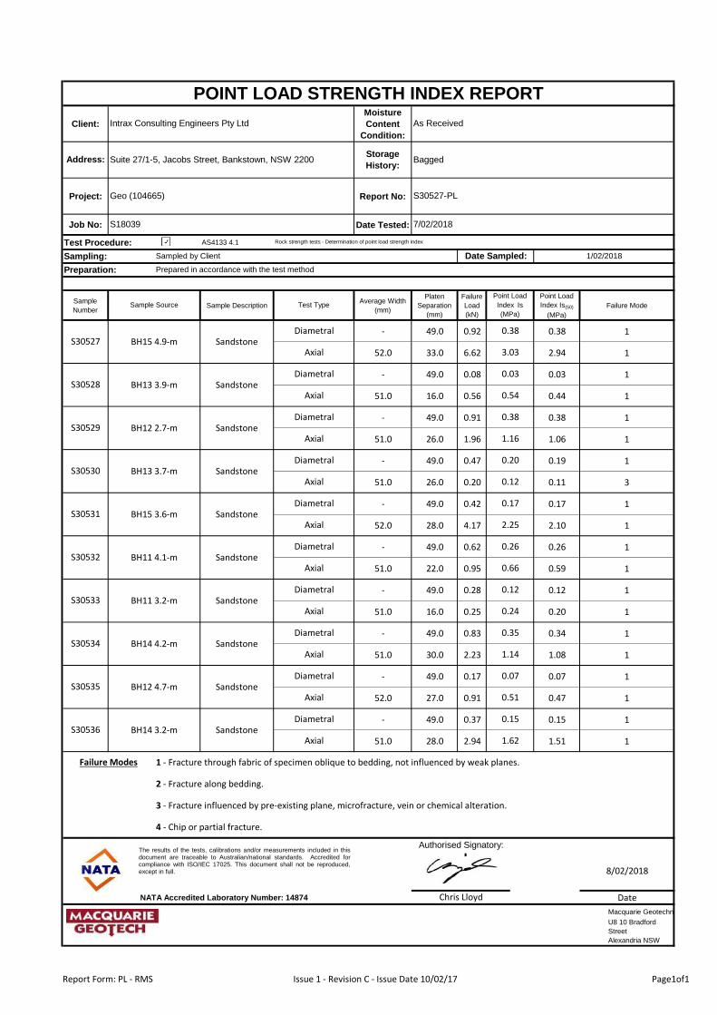
Client:
Moisture
Content
Condition:
Project: Report No:
Job No: Date Tested:
Test Procedure: AS4133 4.1
Sampling:
Sample
NumberSample Description
Average Width
(mm)
Platen
Separation
(mm)
Failure
Load
(kN)
Point Load
Index Is(50)
(MPa)
Failure Mode
- 49.0 0.92 0.38 1
52.0 33.0 6.62 2.94 1
- 49.0 0.08 0.03 1
51.0 16.0 0.56 0.44 1
- 49.0 0.91 0.38 1
51.0 26.0 1.96 1.06 1
- 49.0 0.47 0.19 1
51.0 26.0 0.20 0.11 3
- 49.0 0.42 0.17 1
52.0 28.0 4.17 2.10 1
- 49.0 0.62 0.26 1
51.0 22.0 0.95 0.59 1
- 49.0 0.28 0.12 1
51.0 16.0 0.25 0.20 1
- 49.0 0.83 0.34 1
51.0 30.0 2.23 1.08 1
- 49.0 0.17 0.07 1
52.0 27.0 0.91 0.47 1
- 49.0 0.37 0.15 1
51.0 28.0 2.94 1.51 1
NATA Accredited Laboratory Number: 14874 Date
0.35
1.14
0.07
0.51
0.15
BH11 3.2-m
BH14 4.2-m
BH12 4.7-m
BH14 3.2-m
Diametral
0.12
0.24
U8 10 Bradford
Street
Alexandria NSW
3 - Fracture influenced by pre-existing plane, microfracture, vein or chemical alteration.
2 - Fracture along bedding.
1 - Fracture through fabric of specimen oblique to bedding, not influenced by weak planes.
Chris Lloyd
1.62
Authorised Signatory:
8/02/2018
Failure Modes
Macquarie Geotechnical
4 - Chip or partial fracture.
POINT LOAD STRENGTH INDEX REPORT
Storage
History:
Preparation:
BaggedSuite 27/1-5, Jacobs Street, Bankstown, NSW 2200Address:
S30527-PL
7/02/2018
As ReceivedIntrax Consulting Engineers Pty Ltd
Geo (104665)
S18039
Rock strength tests - Determination of point load strength index
Prepared in accordance with the test method
Sampled by Client Date Sampled: 1/02/2018
Test Type
S30536
S30535
S30531
S30530
S30534
S30533
S30532
Diametral
Axial
Diametral
Axial
Diametral
Diametral
Axial
Axial
Axial
Diametral
Axial
Axial
DiametralSandstone
Sandstone
Sandstone
Sandstone
Point Load
Index Is
(MPa)
0.38
3.03
0.03
0.54
BH15 3.6-m
BH11 4.1-m
Sandstone
2.25
0.26
0.66
Sample Source
Axial
Diametral
Axial
Diametral
Axial
0.38
1.16
0.20
0.12
0.17
Diametral
S30528
S30527
SandstoneS30529
Sandstone
Sandstone
Sandstone
Sandstone
BH15 4.9-m
BH13 3.9-m
BH12 2.7-m
BH13 3.7-m
The results of the tests, calibrations and/or measurements included in thisdocument are traceable to Australian/national standards. Accredited forcompliance with ISO/IEC 17025. This document shall not be reproduced,except in full.
Report Form: PL - RMS Issue 1 - Revision C - Issue Date 10/02/17 Page1of1

Shrink Swell Test Report: :
: :
:
: :
: :
:
:
:
18.6 NIL NIL 0
: Tested by : JM
Reported by : KF
Approved Signatory : Kamal Fernando
Laboratory Manager
NATA Accredited Laboratory Number: 19862
Accredited for compliance ISO/IEC 17025 - Testing. The results of the
tests, calibrations and/or measurements included in this document are
traceable to Australian/national standards
Intrax.CML.Doc.004.R.V3 Page 01 of 01
Test Methods
Comments
AS 1289. 1.1, 2.1.1, 7.1.1
Specific sampling procedure not specified by sampler
Shrink Swell Index
2.0
0.80 17.9
PRJ183112
15/02/2018
1/02/2018
LAB 6844
BH4
500
Sample Details
Sample
Description
12/02/2018
UD
CLAY, dark brown mottled red, trace sand,
stiff
BH Number
Date Tested
Depth (mm)
Type of Sample
Swell
on
Saturation %
Swell TestMoisture Content
Crumbling Cracking
Shrink
on
Drying %
Iss =
Shrink Test
Betop Holdings P/L
104665
3.1423.9
Before Test After Test
Moisture
Content
:
Sample No
Test Results
Inert
Material
%
Intrax Consulting Engineers Pty Ltd
Construction Materials Laboratory
Unit 11, 85 Mt Derrimut Rd, Deer Park VIC 3023
Project
Report Date
Date Sampled
Site Address No. 72 Junction Road, Schofields, Nsw, 2762
Client
Report Number
-1.0
0.0
1.0
2.0
3.0
4.0
0 5 10 15 20 25 30
Sw
ell
% E
sw
S
hri
nk %
Es
h
Moisture Content (%)
Shrink Swell
Intrax.CML.Doc.004.R.V3 Date Issued : 02/03/2016 Issued by : RJ

Shrink Swell Test Report: :
: :
:
: :
: :
:
:
:
20.5 NIL NIL 0.5
: Tested by : JM
Reported by : KF
Intrax Consulting Engineers Pty Ltd
Construction Materials Laboratory
Unit 11, 85 Mt Derrimut Rd, Deer Park VIC 3023
Project
Report Date
Date Sampled
Site Address No. 72 Junction Road, Schofields, Nsw, 2762
Client
Report Number
:
Sample No
Test Results
Inert
Material
%
Betop Holdings P/L
104665
3.8326.5
Before Test After Test
Moisture
Content
Shrink
on
Drying %
Iss =
Shrink Test
silty CLAY, grey mottled red, trace gravel (
fine, subrounded), soft
BH Number
Date Tested
Depth (mm)
Type of Sample
Swell
on
Saturation %
Swell TestMoisture Content
Crumbling Cracking
PRJ183112
15/02/2018
1/02/2018
LAB 6845
BH5
500
Sample Details
Sample
Description
12/02/2018
UD
Comments
AS 1289. 1.1, 2.1.1, 7.1.1
Specific sampling procedure not specified by sampler
Shrink Swell Index
3.0
3.04 21.3
Approved Signatory : Kamal Fernando
Laboratory Manager
NATA Accredited Laboratory Number: 19862
Accredited for compliance ISO/IEC 17025 - Testing. The results of the
tests, calibrations and/or measurements included in this document are
traceable to Australian/national standards
Intrax.CML.Doc.004.R.V3 Page 01 of 01
Test Methods
-4.0
-3.0
-2.0
-1.0
0.0
1.0
2.0
3.0
4.0
5.0
0 5 10 15 20 25 30
Sw
ell
% E
sw
S
hri
nk %
Es
h
Moisture Content (%)
Shrink Swell
Intrax.CML.Doc.004.R.V3 Date Issued : 02/03/2016 Issued by : RJ

Shrink Swell Test Report: :
: :
:
: :
: :
:
:
:
14.9 NIL NIL 0
: Tested by : JM
Reported by : KF
Intrax Consulting Engineers Pty Ltd
Construction Materials Laboratory
Unit 11, 85 Mt Derrimut Rd, Deer Park VIC 3023
Project
Report Date
Date Sampled
Site Address No. 72 Junction Road, Schofields, Nsw, 2762
Client
Report Number
:
Sample No
Test Results
Inert
Material
%
Betop Holdings P/L
104665
2.9922.1
Before Test After Test
Moisture
Content
Shrink
on
Drying %
Iss =
Shrink Test
silty CLAY, grey mottled red, softBH Number
Date Tested
Depth (mm)
Type of Sample
Swell
on
Saturation %
Swell TestMoisture Content
Crumbling Cracking
PRJ183112
15/02/2018
1/02/2018
LAB 6845
BH3
500
Sample Details
Sample
Description
12/02/2018
UD
Comments
AS 1289. 1.1, 2.1.1, 7.1.1
Specific sampling procedure not specified by sampler
Shrink Swell Index
2.7
3.60 16.3
Approved Signatory : Kamal Fernando
Laboratory Manager
NATA Accredited Laboratory Number: 19862
Accredited for compliance ISO/IEC 17025 - Testing. The results of the
tests, calibrations and/or measurements included in this document are
traceable to Australian/national standards
Intrax.CML.Doc.004.R.V3 Page 01 of 01
Test Methods
-4.0
-3.0
-2.0
-1.0
0.0
1.0
2.0
3.0
4.0
0 5 10 15 20 25
Sw
ell
% E
sw
S
hri
nk %
Es
h
Moisture Content (%)
Shrink Swell
Intrax.CML.Doc.004.R.V3 Date Issued : 02/03/2016 Issued by : RJ

Atterberg Limits and Linear Shrinkage Test Report: Client :
: Report Number :
: Sample Number :
: Sampled by :
:
Sample Detail
:
:
:
:
:
:
:
:
Atterburg Limits test results
:
:
:
Linear Shrinkage test results
:
:
:
:
: kf
kfReported by :
Depth (mm)
Additive
Test Methods
Site Address
Cracking no
noneSpecific sampling procedure
Tested by :
Curling
Type of sample
Sample description
Borehole number
Disturbed
silty CLAY, brown mottled grey, high plasticity, <PL
BH3
Linear Shrinkage (%)
55
18
Accredited for compliance ISO/IEC 17025 - Testing. The results of the tests,
calibrations and/or measurements included in this document are traceable
to Australian/national standards
History of sample
Method of preperation
Liquid Limit (%)
Plastic Limit (%)
Plasticity Index (%)
Crumbling
no
Yes
Intrax.CML.Doc.002.R.V2
AS 1289. 1.1, 2.1.1, 3.1.1, 3.2.1, 3.4.1, 3.3.1
Page 1 of 1
Observations
-
Approved Signatory : Kamal Fernando
37
15.5
500
none
50° C Oven dried
Dry sieved
Report Date 21/02/2018 104665
Date Tested 19/02/2018 AW
1/02/2018 LAB 6873Date Sampled
Laboratory Manager
NATA Accredited Laboratory Number: 19862
Intrax Consulting Engineers Pty Ltd
Construction Materials Laboratory
Unit 11, 85 Mt Derrimut Rd, Deer Park VIC 3023
Project PRJ183112 Betop Holdings P/L
No. 72 Junction Road, Schofields, Nsw, 2762
Intrax.CML.Doc.002.R.V2 Date issued: 24/02/2016 Issued by : RJ

Atterberg Limits and Linear Shrinkage Test Report: Client :
: Report Number :
: Sample Number :
: Sampled by :
:
Sample Detail
:
:
:
:
:
:
:
:
Atterburg Limits test results
:
:
:
Linear Shrinkage test results
:
:
:
:
: kf
kfReported by :
Depth (mm)
Additive
Test Methods
Site Address
Cracking no
noneSpecific sampling procedure
Tested by :
Curling
Type of sample
Sample description
Borehole number
Disturbed
silty CLAY, grey mottled brown, medium plasticity,
<PL
BH3
Linear Shrinkage (%)
50
18
Accredited for compliance ISO/IEC 17025 - Testing. The results of the tests,
calibrations and/or measurements included in this document are traceable
to Australian/national standards
History of sample
Method of preperation
Liquid Limit (%)
Plastic Limit (%)
Plasticity Index (%)
Crumbling
no
Yes
Intrax.CML.Doc.002.R.V2
AS 1289. 1.1, 2.1.1, 3.1.1, 3.2.1, 3.4.1, 3.3.1
Page 1 of 1
Observations
-
Approved Signatory : Kamal Fernando
32
15.5
1000
none
50° C Oven dried
Dry sieved
Report Date 21/02/2018 104665
Date Tested 19/02/2018 AW
1/02/2018 LAB 6874Date Sampled
Laboratory Manager
NATA Accredited Laboratory Number: 19862
Intrax Consulting Engineers Pty Ltd
Construction Materials Laboratory
Unit 11, 85 Mt Derrimut Rd, Deer Park VIC 3023
Project PRJ183112 Betop Holdings P/L
No. 72 Junction Road, Schofields, Nsw, 2762
Intrax.CML.Doc.002.R.V2 Date issued: 24/02/2016 Issued by : RJ

Atterberg Limits and Linear Shrinkage Test Report: Client :
: Report Number :
: Sample Number :
: Sampled by :
:
Sample Detail
:
:
:
:
:
:
:
:
Atterburg Limits test results
:
:
:
Linear Shrinkage test results
:
:
:
:
: kf
kf
Laboratory Manager
NATA Accredited Laboratory Number: 19862
Intrax Consulting Engineers Pty Ltd
Construction Materials Laboratory
Unit 11, 85 Mt Derrimut Rd, Deer Park VIC 3023
Project PRJ183112 Betop Holdings P/L
No. 72 Junction Road, Schofields, Nsw, 2762
Report Date 21/02/2018 104665
Date Tested 19/02/2018 AW
1/02/2018 LAB 6875Date Sampled
36
6.5
500
none
50° C Oven dried
Dry sieved
Crumbling
no
Yes
Intrax.CML.Doc.002.R.V2
AS 1289. 1.1, 2.1.1, 3.1.1, 3.2.1, 3.4.1, 3.3.1
Page 1 of 1
Observations
-
Approved Signatory : Kamal Fernando
Accredited for compliance ISO/IEC 17025 - Testing. The results of the tests,
calibrations and/or measurements included in this document are traceable
to Australian/national standards
History of sample
Method of preperation
Liquid Limit (%)
Plastic Limit (%)
Plasticity Index (%)
Curling
Type of sample
Sample description
Borehole number
Disturbed
silty CLAY, brown mottled grey, high plasticity, <PL
BH4
Linear Shrinkage (%)
55
19
Reported by :
Depth (mm)
Additive
Test Methods
Site Address
Cracking no
noneSpecific sampling procedure
Tested by :
Intrax.CML.Doc.002.R.V2 Date issued: 24/02/2016 Issued by : RJ
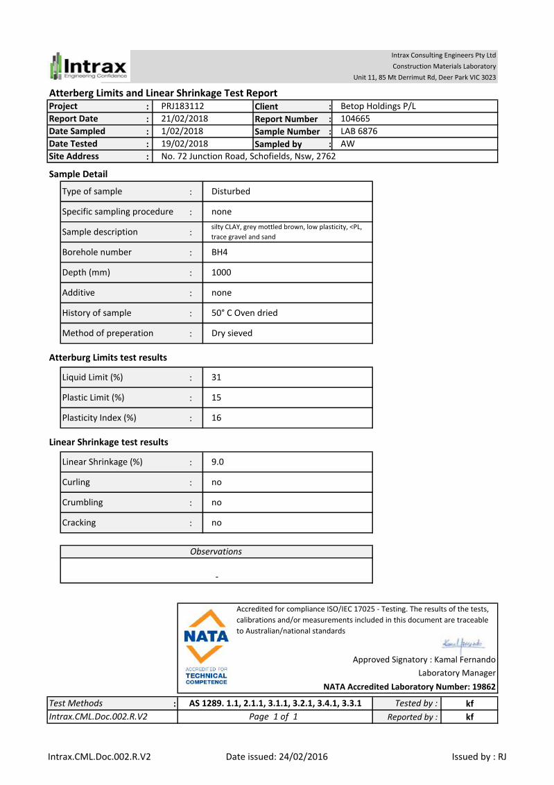
Atterberg Limits and Linear Shrinkage Test Report: Client :
: Report Number :
: Sample Number :
: Sampled by :
:
Sample Detail
:
:
:
:
:
:
:
:
Atterburg Limits test results
:
:
:
Linear Shrinkage test results
:
:
:
:
: kf
kf
Laboratory Manager
NATA Accredited Laboratory Number: 19862
Intrax Consulting Engineers Pty Ltd
Construction Materials Laboratory
Unit 11, 85 Mt Derrimut Rd, Deer Park VIC 3023
Project PRJ183112 Betop Holdings P/L
No. 72 Junction Road, Schofields, Nsw, 2762
Report Date 21/02/2018 104665
Date Tested 19/02/2018 AW
1/02/2018 LAB 6876Date Sampled
16
9.0
1000
none
50° C Oven dried
Dry sieved
Crumbling
no
no
Intrax.CML.Doc.002.R.V2
AS 1289. 1.1, 2.1.1, 3.1.1, 3.2.1, 3.4.1, 3.3.1
Page 1 of 1
Observations
-
Approved Signatory : Kamal Fernando
Accredited for compliance ISO/IEC 17025 - Testing. The results of the tests,
calibrations and/or measurements included in this document are traceable
to Australian/national standards
History of sample
Method of preperation
Liquid Limit (%)
Plastic Limit (%)
Plasticity Index (%)
Curling
Type of sample
Sample description
Borehole number
Disturbed
silty CLAY, grey mottled brown, low plasticity, <PL,
trace gravel and sand
BH4
Linear Shrinkage (%)
31
15
Reported by :
Depth (mm)
Additive
Test Methods
Site Address
Cracking no
noneSpecific sampling procedure
Tested by :
Intrax.CML.Doc.002.R.V2 Date issued: 24/02/2016 Issued by : RJ

Atterberg Limits and Linear Shrinkage Test Report: Client :
: Report Number :
: Sample Number :
: Sampled by :
:
Sample Detail
:
:
:
:
:
:
:
:
Atterburg Limits test results
:
:
:
Linear Shrinkage test results
:
:
:
:
: kf
kf
Laboratory Manager
NATA Accredited Laboratory Number: 19862
Intrax Consulting Engineers Pty Ltd
Construction Materials Laboratory
Unit 11, 85 Mt Derrimut Rd, Deer Park VIC 3023
Project PRJ183112 Betop Holdings P/L
No. 72 Junction Road, Schofields, Nsw, 2762
Report Date 21/02/2018 104665
Date Tested 19/02/2018 AW
1/02/2018 LAB 6877Date Sampled
36
17.0
500
none
50° C Oven dried
Dry sieved
Crumbling
no
no
Intrax.CML.Doc.002.R.V2
AS 1289. 1.1, 2.1.1, 3.1.1, 3.2.1, 3.4.1, 3.3.1
Page 1 of 1
Observations
-
Approved Signatory : Kamal Fernando
Accredited for compliance ISO/IEC 17025 - Testing. The results of the tests,
calibrations and/or measurements included in this document are traceable
to Australian/national standards
History of sample
Method of preperation
Liquid Limit (%)
Plastic Limit (%)
Plasticity Index (%)
Curling
Type of sample
Sample description
Borehole number
Disturbed
silty CLAY, brown mottled grey, high plasticity, <PL
BH6
Linear Shrinkage (%)
55
19
Reported by :
Depth (mm)
Additive
Test Methods
Site Address
Cracking no
noneSpecific sampling procedure
Tested by :
Intrax.CML.Doc.002.R.V2 Date issued: 24/02/2016 Issued by : RJ
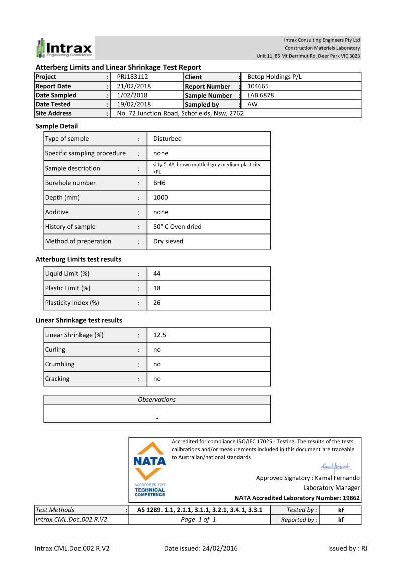
Atterberg Limits and Linear Shrinkage Test Report: Client :
: Report Number :
: Sample Number :
: Sampled by :
:
Sample Detail
:
:
:
:
:
:
:
:
Atterburg Limits test results
:
:
:
Linear Shrinkage test results
:
:
:
:
: kf
kfReported by :
Depth (mm)
Additive
Test Methods
Site Address
Cracking no
noneSpecific sampling procedure
Tested by :
Curling
Type of sample
Sample description
Borehole number
Disturbed
silty CLAY, brown mottled grey medium plasticity,
<PL
BH6
Linear Shrinkage (%)
44
18
Accredited for compliance ISO/IEC 17025 - Testing. The results of the tests,
calibrations and/or measurements included in this document are traceable
to Australian/national standards
History of sample
Method of preperation
Liquid Limit (%)
Plastic Limit (%)
Plasticity Index (%)
Crumbling
no
no
Intrax.CML.Doc.002.R.V2
AS 1289. 1.1, 2.1.1, 3.1.1, 3.2.1, 3.4.1, 3.3.1
Page 1 of 1
Observations
-
Approved Signatory : Kamal Fernando
26
12.5
1000
none
50° C Oven dried
Dry sieved
Report Date 21/02/2018 104665
Date Tested 19/02/2018 AW
1/02/2018 LAB 6878Date Sampled
Laboratory Manager
NATA Accredited Laboratory Number: 19862
Intrax Consulting Engineers Pty Ltd
Construction Materials Laboratory
Unit 11, 85 Mt Derrimut Rd, Deer Park VIC 3023
Project PRJ183112 Betop Holdings P/L
No. 72 Junction Road, Schofields, Nsw, 2762
Intrax.CML.Doc.002.R.V2 Date issued: 24/02/2016 Issued by : RJ

Atterberg Limits and Linear Shrinkage Test Report: Client :
: Report Number :
: Sample Number :
: Sampled by :
:
Sample Detail
:
:
:
:
:
:
:
:
Atterburg Limits test results
:
:
:
Linear Shrinkage test results
:
:
:
:
: kf
kf
Laboratory Manager
NATA Accredited Laboratory Number: 19862
Intrax Consulting Engineers Pty Ltd
Construction Materials Laboratory
Unit 11, 85 Mt Derrimut Rd, Deer Park VIC 3023
Project PRJ183112 Betop Holdings P/L
No.72 Junction Road, Schofields, Nsw, 2762
Report Date 21/02/2018 104665
Date Tested 19/02/2018 AW
1/02/2018 LAB 6879Date Sampled
33
9.0
500
none
50° C Oven dried
Dry sieved
Crumbling
no
Yes
Intrax.CML.Doc.002.R.V2
AS 1289. 1.1, 2.1.1, 3.1.1, 3.2.1, 3.4.1, 3.3.1
Page 1 of 1
Observations
-
Approved Signatory : Kamal Fernando
Accredited for compliance ISO/IEC 17025 - Testing. The results of the tests,
calibrations and/or measurements included in this document are traceable
to Australian/national standards
History of sample
Method of preperation
Liquid Limit (%)
Plastic Limit (%)
Plasticity Index (%)
Curling
Type of sample
Sample description
Borehole number
Disturbed
silty CLAY, brown mottled grey, high plasticity, <PL
BH8
Linear Shrinkage (%)
52
19
Reported by :
Depth (mm)
Additive
Test Methods
Site Address
Cracking no
noneSpecific sampling procedure
Tested by :
Intrax.CML.Doc.002.R.V2 Date issued: 24/02/2016 Issued by : RJ

Atterberg Limits and Linear Shrinkage Test Report: Client :
: Report Number :
: Sample Number :
: Sampled by :
:
Sample Detail
:
:
:
:
:
:
:
:
Atterburg Limits test results
:
:
:
Linear Shrinkage test results
:
:
:
:
: kf
kf
Laboratory Manager
NATA Accredited Laboratory Number: 19862
Intrax Consulting Engineers Pty Ltd
Construction Materials Laboratory
Unit 11, 85 Mt Derrimut Rd, Deer Park VIC 3023
Project PRJ183112 Betop Holdings P/L
No. 72 Junction Road, Schofields, Nsw, 2762
Report Date 21/02/2018 104665
Date Tested 19/02/2018 AW
1/02/2018 LAB 6880Date Sampled
20
10.5
1000
none
50° C Oven dried
Dry sieved
Crumbling
no
no
Intrax.CML.Doc.002.R.V2
AS 1289. 1.1, 2.1.1, 3.1.1, 3.2.1, 3.4.1, 3.3.1
Page 1 of 1
Observations
-
Approved Signatory : Kamal Fernando
Accredited for compliance ISO/IEC 17025 - Testing. The results of the tests,
calibrations and/or measurements included in this document are traceable
to Australian/national standards
History of sample
Method of preperation
Liquid Limit (%)
Plastic Limit (%)
Plasticity Index (%)
Curling
Type of sample
Sample description
Borehole number
Disturbed
silty CLAY, grey mottled brown, low plasticity, <PL,
trace gravel and sand
BH8
Linear Shrinkage (%)
35
15
Reported by :
Depth (mm)
Additive
Test Methods
Site Address
Cracking no
noneSpecific sampling procedure
Tested by :
Intrax.CML.Doc.002.R.V2 Date issued: 24/02/2016 Issued by : RJ

Atterberg Limits and Linear Shrinkage Test Report: Client :
: Report Number :
: Sample Number :
: Sampled by :
:
Sample Detail
:
:
:
:
:
:
:
:
Atterburg Limits test results
:
:
:
Linear Shrinkage test results
:
:
:
:
: kf
kf
Laboratory Manager
NATA Accredited Laboratory Number: 19862
Intrax Consulting Engineers Pty Ltd
Construction Materials Laboratory
Unit 11, 85 Mt Derrimut Rd, Deer Park VIC 3023
Project PRJ183112 Betop Holdings P/L
No. 72 Junction Road, Schofields, Nsw, 2762
Report Date 21/02/2018 104665
Date Tested 19/02/2018 AW
1/02/2018 LAB 6881Date Sampled
32
13.5
500
none
50° C Oven dried
Dry sieved
Crumbling
no
no
Intrax.CML.Doc.002.R.V2
AS 1289. 1.1, 2.1.1, 3.1.1, 3.2.1, 3.4.1, 3.3.1
Page 1 of 1
Observations
-
Approved Signatory : Kamal Fernando
Accredited for compliance ISO/IEC 17025 - Testing. The results of the tests,
calibrations and/or measurements included in this document are traceable
to Australian/national standards
History of sample
Method of preperation
Liquid Limit (%)
Plastic Limit (%)
Plasticity Index (%)
Curling
Type of sample
Sample description
Borehole number
Disturbed
silty CLAY, brown mottled grey, medium plasticity,
<PL
BH9
Linear Shrinkage (%)
50
18
Reported by :
Depth (mm)
Additive
Test Methods
Site Address
Cracking no
noneSpecific sampling procedure
Tested by :
Intrax.CML.Doc.002.R.V2 Date issued: 24/02/2016 Issued by : RJ

Atterberg Limits and Linear Shrinkage Test Report: Client :
: Report Number :
: Sample Number :
: Sampled by :
:
Sample Detail
:
:
:
:
:
:
:
:
Atterburg Limits test results
:
:
:
Linear Shrinkage test results
:
:
:
:
: kf
kfReported by :
Depth (mm)
Additive
Test Methods
Site Address
Cracking no
noneSpecific sampling procedure
Tested by :
Curling
Type of sample
Sample description
Borehole number
Disturbed
silty CLAY, brown mottled grey, high plasticity, <PL
BH9
Linear Shrinkage (%)
64
23
Accredited for compliance ISO/IEC 17025 - Testing. The results of the tests,
calibrations and/or measurements included in this document are traceable
to Australian/national standards
History of sample
Method of preperation
Liquid Limit (%)
Plastic Limit (%)
Plasticity Index (%)
Crumbling
no
no
Intrax.CML.Doc.002.R.V2
AS 1289. 1.1, 2.1.1, 3.1.1, 3.2.1, 3.4.1, 3.3.1
Page 1 of 1
Observations
-
Approved Signatory : Kamal Fernando
41
17.0
1000
none
50° C Oven dried
Dry sieved
Report Date 21/02/2018 104665
Date Tested 19/02/2018 AW
1/02/2018 LAB 6882Date Sampled
Laboratory Manager
NATA Accredited Laboratory Number: 19862
Intrax Consulting Engineers Pty Ltd
Construction Materials Laboratory
Unit 11, 85 Mt Derrimut Rd, Deer Park VIC 3023
Project PRJ183112 Betop Holdings P/L
No. 72 Junction Road, Schofields, Nsw, 2762
Intrax.CML.Doc.002.R.V2 Date issued: 24/02/2016 Issued by : RJ