Embed Size (px)
Citation preview
The Repulsine
On this page, I will try to give you a possible explanation about the working principle of "the " flying saucer from Viktor Schauberger (1938-1957). Simply "click" on the image thumbnails for a larger view. This document is the synthesis of a fine analysis on pictures of real working devices, on Schauberger's researches in vortexes (implosion principle) and on some technical papers from Henri Coanda (1886-1972) and Bernoulli's principle. Page Four of this site will offer even more detail, and quite a number of surprises, as well. NOTE: All of these inventions can be built, today. All I need is the funding from investors. Once built, and implemented into the economy, they would spell and end for our dependence on fossil fuels, or more specifically, our dependence on an oil-based economy. Additionally, we have now begun a partnership between myself (Frank Germano), my former partner and life-long friend from ITP - Martin Dorantes, Dr. Evgeni Sorokodum (from Vortex Oscillation Technology, LTD, Russia), Curt Hallburg and his group (Institute of Ecological Technology, Krokegatan, Goteborg), and Kim Zorzi (from Ultra-Lite America). It is our aim, once investor funding has been definitely secured, to build a working Repulsine. If the historical and scientific facts are correct, this will mean the abolishment of our current fossil-fuel driven economy. Why? Because the Repulsine does not need an outside fuel source. It's motive fuel is that of nature - air. Read on to learn how it works.
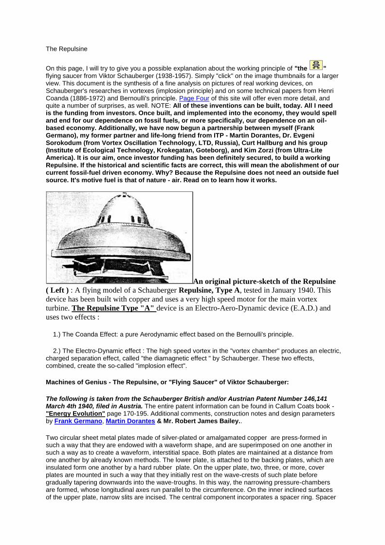
An original picture-sketch of the Repulsine
( Left ) : A flying model of a Schauberger Repulsine, Type A, tested in January 1940. This
device has been built with copper and uses a very high speed motor for the main vortex
turbine. The Repulsine Type "A" device is an Electro-Aero-Dynamic device (E.A.D.) and
uses two effects :
1.) The Coanda Effect: a pure Aerodynamic effect based on the Bernoulli's principle.
2.) The Electro-Dynamic effect : The high speed vortex in the "vortex chamber" produces an electric, charged separation effect, called "the diamagnetic effect " by Schauberger. These two effects, combined, create the so-called "implosion effect".
Machines of Genius - The Repulsine, or "Flying Saucer" of Viktor Schauberger:
The following is taken from the Schauberger British and/or Austrian Patent Number 146,141 March 4th 1940, filed in Austria. The entire patent information can be found in Callum Coats book - "Energy Evolution" page 170-195. Additional comments, construction notes and design parameters by Frank Germano, Martin Dorantes & Mr. Robert James Bailey..
Two circular sheet metal plates made of silver-plated or amalgamated copper are press-formed in such a way that they are endowed with a waveform shape, and are superimposed on one another in such a way as to create a waveform, interstitial space. Both plates are maintained at a distance from one another by already known methods. The lower plate, is attached to the backing plates, which are insulated form one another by a hard rubber plate. On the upper plate, two, three, or more, cover plates are mounted in such a way that they initially rest on the wave-crests of such plate before gradually tapering downwards into the wave-troughs. In this way, the narrowing pressure-chambers are formed, whose longitudinal axes run parallel to the circumference. On the inner inclined surfaces of the upper plate, narrow slits are incised. The central component incorporates a spacer ring. Spacer
rings, incorporating nozzles can be provided in the interstitial space. Furthermore, the hollow shaft opens into the cup-shaped component, whose inner surface is advantageously fluted, and which has exit openings into the interstitial space.
If the device is caused to rotate rapidly, then the liquid or gaseous substances entering the pressure-chambers will be impressed downwards and sideways through the slits, into the interstitial space, in which a considerable suction evolves, so that the space acts as a suction-chamber. The whole device therefore represents a kind of multi-stage centrifuge, each concentric wave being regarded as a stage. It can readily be understood that the liquid or gaseous substance present in the pressure-chamber, having been subjected to strong pressure forces here, immediately passes through the slits in the pressure-chamber walls and partially expands. At an appropriate rate of rotation, a maximum pressure will be reached, under which a bio-electric energy evolves, with whose aid, the primary combinations of the through-flowing liquid, or gaseous substance, will split up, whereupon these freed energies can be synthesized into any desired form or be drawn off.
As material for the two plates, silver-plated or amalgamated gold, or synthetic resins (plastics) can be used. If plastics are used, and seawater, for example, is impelled through the suction-chamber, an insipid fresh water is obtained as a result of this process. The arrangement can be so designed that like upper plate, the lower plate can also be provided with cover-plates, so that the pressure-chambers lie on both sides of the suction-space.
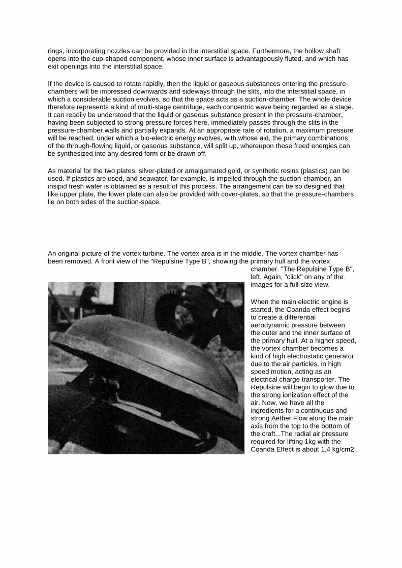
An original picture of the vortex turbine. The vortex area is in the middle. The vortex chamber has been removed. A front view of the "Repulsine Type B", showing the primary hull and the vortex
chamber. "The Repulsine Type B", left. Again, "click" on any of the images for a full-size view.
When the main electric engine is started, the Coanda effect begins to create a differential aerodynamic pressure between the outer and the inner surface of the primary hull. At a higher speed, the vortex chamber becomes a kind of high electrostatic generator due to the air particles, in high speed motion, acting as an electrical charge transporter. The Repulsine will begin to glow due to the strong ionization effect of the air. Now, we have all the ingredients for a continuous and strong Aether Flow along the main axis from the top to the bottom of the craft...The radial air pressure required for lifting 1kg with the Coanda Effect is about 1,4 kg/cm2
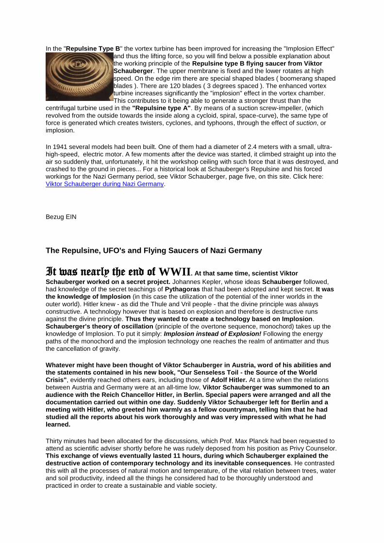
In the "Repulsine Type B" the vortex turbine has been improved for increasing the "Implosion Effect" and thus the lifting force, so you will find below a possible explanation about the working principle of the Repulsine type B flying saucer from Viktor Schauberger. The upper membrane is fixed and the lower rotates at high speed. On the edge rim there are special shaped blades ( boomerang shaped blades ). There are 120 blades ( 3 degrees spaced ). The enhanced vortex turbine increases significantly the "implosion" effect in the vortex chamber. This contributes to it being able to generate a stronger thrust than the
centrifugal turbine used in the "Repulsine type A". By means of a suction screw-impeller, (which revolved from the outside towards the inside along a cycloid, spiral, space-curve), the same type of force is generated which creates twisters, cyclones, and typhoons, through the effect of suction, or implosion.
In 1941 several models had been built. One of them had a diameter of 2.4 meters with a small, ultra-high-speed, electric motor. A few moments after the device was started, it climbed straight up into the air so suddenly that, unfortunately, it hit the workshop ceiling with such force that it was destroyed, and crashed to the ground in pieces... For a historical look at Schauberger's Repulsine and his forced workings for the Nazi Germany period, see Viktor Schauberger, page five, on this site. Click here: Viktor Schauberger during Nazi Germany.
Bezug EIN
The Repulsine, UFO's and Flying Saucers of Nazi Germany
It was nearly the end of WWII. At that same time, scientist Viktor
Schauberger worked on a secret project. Johannes Kepler, whose ideas Schauberger followed, had knowledge of the secret teachings of Pythagoras that had been adopted and kept secret. It was the knowledge of Implosion (in this case the utilization of the potential of the inner worlds in the outer world). Hitler knew - as did the Thule and Vril people - that the divine principle was always constructive. A technology however that is based on explosion and therefore is destructive runs against the divine principle. Thus they wanted to create a technology based on Implosion. Schauberger's theory of oscillation (principle of the overtone sequence, monochord) takes up the knowledge of Implosion. To put it simply: Implosion instead of Explosion! Following the energy paths of the monochord and the implosion technology one reaches the realm of antimatter and thus the cancellation of gravity.
Whatever might have been thought of Viktor Schauberger in Austria, word of his abilities and the statements contained in his new book, "Our Senseless Toil - the Source of the World Crisis", evidently reached others ears, including those of Adolf Hitler. At a time when the relations between Austria and Germany were at an all-time low, Viktor Schauberger was summoned to an audience with the Reich Chancellor Hitler, in Berlin. Special papers were arranged and all the documentation carried out within one day. Suddenly Viktor Schauberger left for Berlin and a meeting with Hitler, who greeted him warmly as a fellow countryman, telling him that he had studied all the reports about his work thoroughly and was very impressed with what he had learned.
Thirty minutes had been allocated for the discussions, which Prof. Max Planck had been requested to attend as scientific adviser shortly before he was rudely deposed from his position as Privy Counselor. This exchange of views eventually lasted 11 hours, during which Schauberger explained the destructive action of contemporary technology and its inevitable consequences. He contrasted this with all the processes of natural motion and temperature, of the vital relation between trees, water and soil productivity, indeed all the things he considered had to be thoroughly understood and practiced in order to create a sustainable and viable society.
When Viktor had finished his explanations, Max Planck, who had remained silent, was asked his opinion about Viktor's natural theories. His response was the remarkable and revealing statement that "Science has nothing to do with Nature". Pausing for a moment to take in this astonishing admission, Viktor then referred to the proposed four-year plan, the so-called Goering Plan, stating that, "not only was the time frame far too short, but, if instituted, it would gradually undermine and ultimately destroy Germany's biological foundations. As a result, the Third Reich would last only ten instead of the boasted 1,000 years." (Viktor was not far out in his estimate!)
During the earlier part of the discussion, Hitler had been enthusiastic, but he became greatly perturbed at what he had just heard and ordered his technical and economic advisers, Keppler and Wiluhn, to discuss with Schauberger what could be done. Once outside the door, these two men demanded to know how Viktor had got in there in the first place. Angered at their truculently condescending air, he replied "Through the same door I've just come out of!" Seeing that his ideas had no hope of acceptance, and leaving them gaping, he returned to his hotel and left for Austria the following morning. Keppler and Wiluhn, however, were to get their revenge later, after the Anschluss on March 13th, 1938.
Once again he was the victim of deceit and his ideas were usurped, for, in a later letter to his son Walter, he wrote that copies of the preliminary application had been fraudulently obtained by Prof. Ernst Heinkel, the famous aircraft designer, through a firm of patent attorneys, Lehmann-Harlens in Berlin. By mining the information contained in this document, Heinkel obtained insights into how a jet-engine could be produced, even though he misinterpreted its findings; his first prototype exploded due to his lack of proper understanding. With a certain absence of principle, he then sought Viktor's collaboration in the project. Although some initial discussion eventually took place, Viktor did not cooperate, having become aware of what Heinkel had done, and further contact between the two men ceased. Using his ill-gotten gains, however, Heinkel persevered with his research, which culminated in the construction of the first successful jet-plane, its first flight being on August 27th, 1939.
Although Heinkel never had the honesty to reveal the source of the ideas for his invention, keeping all the kudos for himself, this jet plane was nevertheless built as a direct result of Viktor's theories. Viktor Schauberger is therefore the real father of the present jet age. He even went as far as to state that in order to develop and build fast-flying, supersonic aircraft successfully, the bodily forms of deep-sea fish should be copied. Today's 'stealth bombers' very much emulate these forms. In 1939 Viktor's personal research virtually came to an end, all the materials he needed being appropriated for war production. In 1941, however, he was summoned by Air Marshal Ernst Udet to discuss the growing crisis of energy production and means of solving it. Premises were subsequently set up near Augsburg for research and development, all of which came to nothing partly due to the death of Udet and partly because it was bombed by the Allies in 1942.
In 1943, despite his incapacitating war wounds and 58 years of age, Viktor was declared fit for active duty and was inducted into the Waffen-SS, very much under duress. He came under the control of Heinrich Himmler, who forced him into research to develop a new secret weapon. Provided with suitable accommodation at Schloss Schonbrunn, the nearby Mauthausen Concentration Camp to supply the workforce of prisoner engineers, Viktor was threatened with his life if he did not comply with orders and carry out this research. In spite of these threats, however, Viktor put his foot down and demanded from the SS Command the absolute right to select the various engineers he needed. He further demanded that any technicians he chose were to be removed entirely from the camp, fed properly, dressed in normal civilian clothes and billeted in civilian accommodation, otherwise they would be unproductive. As he explained, people who live in fear of their lives and under great emotional stress could work neither consistently nor creatively. Surprisingly the SS agreed and so Viktor selected somewhere between twenty and thirty engineers, craftsmen and tradesman from Mauthausen, to be accommodated in various houses near the plant.
When they were all assembled, Viktor exhorted them to work as hard as they could, but under no circumstances were they to attempt to escape, otherwise his own life would be forfeit. They set to work with a will, and, while not understanding what Viktor was trying to achieve, they nevertheless carried out his instructions faithfully. Two machines were eventually built, one called a 'Repulsator' and the other a 'Repulsine', reflecting their forces of recoil. Accurate information about them is difficult to obtain, because after the end of the War all top-secret information was confiscated by the Allies - the Russians, French, English and Americans - and is therefore no longer available to
the general public. Let's run this by again, with particular emphasis on the Repulsine, both the A & B models.
Viktor Schauberger's Repusline A & B
(1940-1945)
Viktor Schauberger, an Austrian forester who observed the effects of nature - especially of water, privately met Adolf Hitler in 1934 to discuss the fundamental principals of agriculture, forestry, and water engineering. While Hitler was impressed by Schauberger’s radical ideas for utilizing water power in new and dynamic ways, he was also displeased that Schauberger was not willing to participate in work for the Third Reich. Subsequently and unfortunately for Schauberger this meant that once Austria was annexed in 1938 and war broke out in 1939 the SS would come searching for him and his ideas based on his patents for an “air turbine” and “procedure for lifting liquids and gases” from 1935 and the “warm-cold” machine built for Siemens in 1937 but destroyed in an unauthorized test.
In 1940, Schauberger began construction of the Repulsin(e) discoid motor in Vienna with help of the Kertl company. He patented his idea on March 4, 1940 in Austria under patent 146,141. But very soon afterwards he was reported by the Viennese Association of Engineers to the SS who placed Schauberger in a mental hospital in Mauer-Ohling. Schauberger was then forced to work with Messerschmitt on liquid vortex cooling systems and Heinkel concerning applications of water towards aircraft engines. At this point Heinkel received reports on the early Repulsin A. At Mauthausen, under orders from Heinrich Himmler himself, Schauberger was to carry out research and development for the Third Reich war effort. He was given approximately 20-30 prisoner engineers to proceed with his research into what was termed “higher atomic energies”. For this Schauberger was given special dispensations from the SS for both himself and fellow engineers.
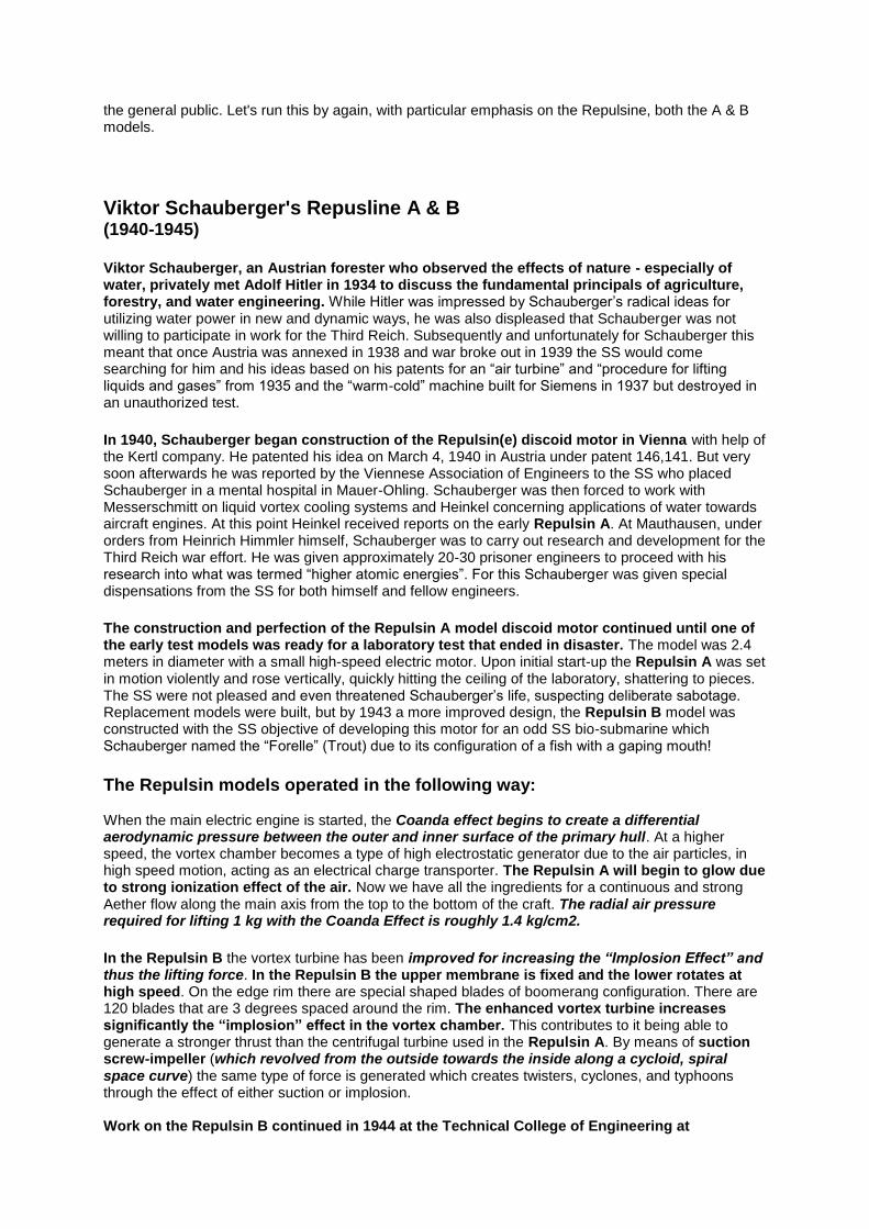
The construction and perfection of the Repulsin A model discoid motor continued until one of the early test models was ready for a laboratory test that ended in disaster. The model was 2.4 meters in diameter with a small high-speed electric motor. Upon initial start-up the Repulsin A was set in motion violently and rose vertically, quickly hitting the ceiling of the laboratory, shattering to pieces. The SS were not pleased and even threatened Schauberger’s life, suspecting deliberate sabotage. Replacement models were built, but by 1943 a more improved design, the Repulsin B model was constructed with the SS objective of developing this motor for an odd SS bio-submarine which Schauberger named the “Forelle” (Trout) due to its configuration of a fish with a gaping mouth!
The Repulsin models operated in the following way: When the main electric engine is started, the Coanda effect begins to create a differential aerodynamic pressure between the outer and inner surface of the primary hull. At a higher speed, the vortex chamber becomes a type of high electrostatic generator due to the air particles, in high speed motion, acting as an electrical charge transporter. The Repulsin A will begin to glow due to strong ionization effect of the air. Now we have all the ingredients for a continuous and strong Aether flow along the main axis from the top to the bottom of the craft. The radial air pressure required for lifting 1 kg with the Coanda Effect is roughly 1.4 kg/cm2.
In the Repulsin B the vortex turbine has been improved for increasing the “Implosion Effect” and thus the lifting force. In the Repulsin B the upper membrane is fixed and the lower rotates at high speed. On the edge rim there are special shaped blades of boomerang configuration. There are 120 blades that are 3 degrees spaced around the rim. The enhanced vortex turbine increases significantly the “implosion” effect in the vortex chamber. This contributes to it being able to generate a stronger thrust than the centrifugal turbine used in the Repulsin A. By means of suction screw-impeller (which revolved from the outside towards the inside along a cycloid, spiral space curve) the same type of force is generated which creates twisters, cyclones, and typhoons through the effect of either suction or implosion. Work on the Repulsin B continued in 1944 at the Technical College of Engineering at
Rosenhugel in Vienna. Schauberger was finally released back to Leonstein, Austria that same year. It appears that the SS had discarded the idea of applying the Schauberger motor to a submarine when the benefits would greatly improve their work on the secret Flugkreisel which was taken from Rudolf Schriever back in 1941. By 1943 the machine had flown but proved to be unstable. The leader of the SS replacement team was Dr. Richard Miethe who proposed several Flugkreisel replacements with varied power plants, most of which relied on jets or rocket power, until it was learned that Schauberger had engineered a type of turbine machine that would create an up-current of axially-spinning air so powerful that the up-current’s drag force would speed the whole machine higher and higher into the air with a thrust equal to 10,000 hp simply by moving “air”. The turbine was considered a priority for flight development into a manned machine by the SS. It is speculated that Miethe’s final design built in Breslau that flew in 1944 was an enlarged manned Repulsin-type craft.
So, just what the happened to these flying machines after the war???
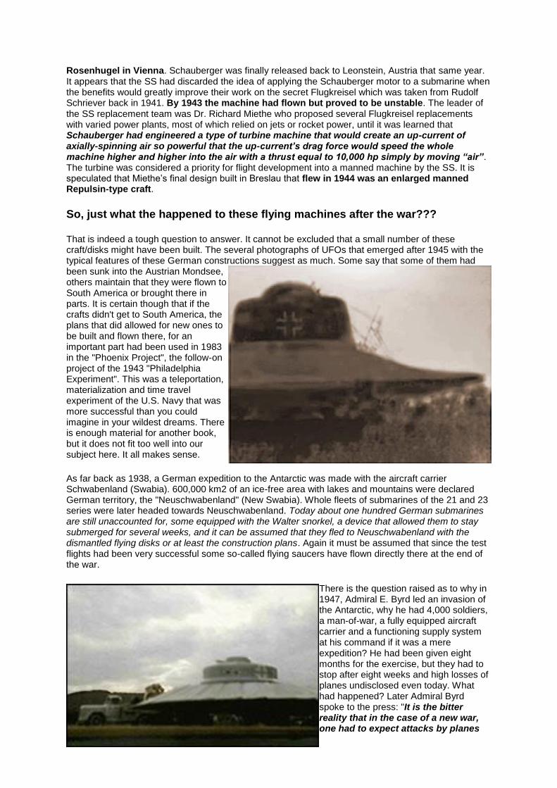
That is indeed a tough question to answer. It cannot be excluded that a small number of these craft/disks might have been built. The several photographs of UFOs that emerged after 1945 with the typical features of these German constructions suggest as much. Some say that some of them had been sunk into the Austrian Mondsee, others maintain that they were flown to South America or brought there in parts. It is certain though that if the crafts didn't get to South America, the plans that did allowed for new ones to be built and flown there, for an important part had been used in 1983 in the "Phoenix Project", the follow-on project of the 1943 "Philadelphia Experiment". This was a teleportation, materialization and time travel experiment of the U.S. Navy that was more successful than you could imagine in your wildest dreams. There is enough material for another book, but it does not fit too well into our subject here. It all makes sense.
As far back as 1938, a German expedition to the Antarctic was made with the aircraft carrier Schwabenland (Swabia). 600,000 km2 of an ice-free area with lakes and mountains were declared German territory, the "Neuschwabenland" (New Swabia). Whole fleets of submarines of the 21 and 23 series were later headed towards Neuschwabenland. Today about one hundred German submarines are still unaccounted for, some equipped with the Walter snorkel, a device that allowed them to stay submerged for several weeks, and it can be assumed that they fled to Neuschwabenland with the dismantled flying disks or at least the construction plans. Again it must be assumed that since the test flights had been very successful some so-called flying saucers have flown directly there at the end of the war.
There is the question raised as to why in 1947, Admiral E. Byrd led an invasion of the Antarctic, why he had 4,000 soldiers, a man-of-war, a fully equipped aircraft carrier and a functioning supply system at his command if it was a mere expedition? He had been given eight months for the exercise, but they had to stop after eight weeks and high losses of planes undisclosed even today. What had happened? Later Admiral Byrd spoke to the press: "It is the bitter reality that in the case of a new war, one had to expect attacks by planes
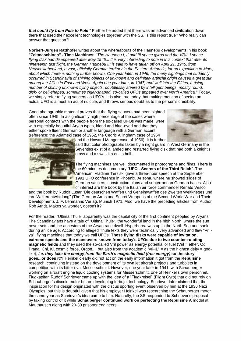
that could fly from Pole to Pole." Further he added that there was an advanced civilization down there that used their excellent technologies together with the SS. Is this report true? Who really can answer that question?!
Norbert-Jurgen Ratthofer writes about the whereabouts of the Haunebu developments in his book "Zeitmaschinen" . Time Machines: "The Haunebu I, II and III space gyros and the VRIL I space flying disk had disappeared after May 1945... It is very interesting to note in this context that after its nineteenth test flight, the German Haunebu III is said to have taken off on April 21, 1945, from Neuschwabenland, a vast, officially German territory in the Eastern Antarctic, for an expedition to Mars, about which there is nothing further known. One year later, in 1946, the many sightings that suddenly occurred in Scandinavia of shining objects of unknown and definitely artificial origin caused a great stir among the Allies in East and West. Again one year later, in 1947, and well into the Fifties, a rising number of shining unknown flying objects, doubtlessly steered by intelligent beings, mostly round, disk- or bell-shaped, sometimes cigar-shaped, so-called UFOs appeared over North America." Today, we simply refer to flying saucers as UFO's. It is also true today that making mention of seeing an actual UFO is almost an act of ridicule, and throws serious doubt as to the person's credibility.
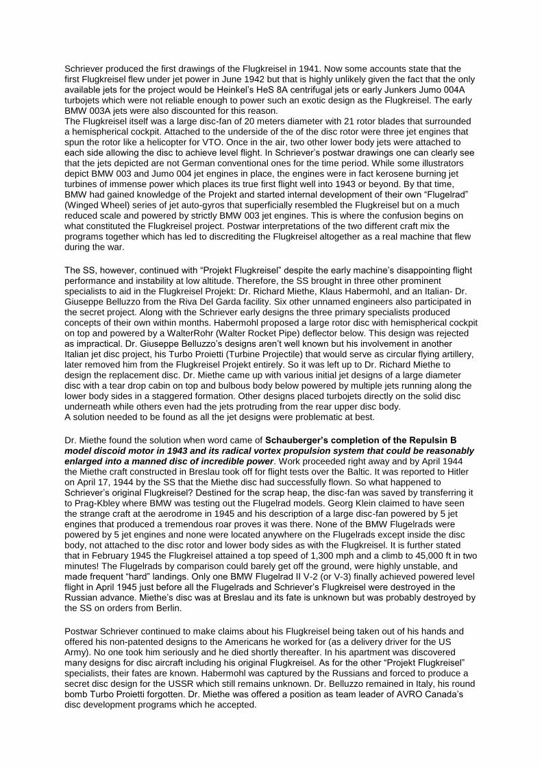
Good photographic material proves that the flying saucers had been sighted often since 1945. In a significantly high percentage of the cases where personal contacts with the people from the so-called UFOs was made, were with especially beautiful Aryan types, blond and blue-eyed and that they either spoke fluent German or another language with a German accent (reference: the Adamski case of 1952, the Cedric Allingham case of 1954
and the Howard Menger case of 1956). It is further said that color photographs taken by a night guard in West Germany in the Seventies exist of a landed and restarted flying disk that had both a knight's cross and a swastika on its hull.
The flying machines are well documented in photographs and films. There is the 60 minutes documentary "UFO - Secrets of the Third Reich". The American, Vladimir Terziski gave a three-hour speech at the September 1991 UFO conference in Phoenix, Arizona, where he showed slides of German saucers, construction plans and subterranean German bases. Also of interest are the book by the Italian air force commander Renato Vesco
and the book by Rudolf Lusar "Die deutschen Waffen und Geheimwaffen des Zweiten Weltkrieges und ihre Weiterentwicklung" (The German Arms and Secret Weapons of the Second World War and Their Development), J. F. Lehmanns Verlag, Munich 1971. Also, we have the preceding articles from Author Rob Arndt. Makes ya wonder, doesn't it?
For the reader: "Ultima Thule" apparently was the capital city of the first continent peopled by Aryans. The Scandinavians have a tale of "Ultima Thule", the wonderful land in the high North, where the sun never sets and the ancestors of the Aryan race dwell. Hyperborea was up in the North Sea and sank during an ice age. According to alleged Thule texts they were technically very advanced and flew "Vril-ya", flying machines that today we call UFOs. These flying disks were capable of levitation, extreme speeds and the maneuvers known from today's UFOs due to two counter-rotating magnetic fields and they used the so-called Vril power as energy potential or fuel (Vril = ether, Od, Prana, Chi, Ki, cosmic force, Orgon..., but also from the academic "vri-IL" = as the highest deity = god-like), i.e. they take the energy from the Earth's magnetic field (free energy) so the story goes...or does it?! Heinkel clearly did not act on the early information it got from the Repulsine research, continuing instead on the development of its own jet aircraft projects and turbojets in competition with its bitter rival Messerschmitt. However, one year later in 1941, with Schauberger working on aircraft engine liquid cooling systems for Messerschmitt, one of Heinkel’s own personnel, Flugkapitan Rudolf Schriever came up with the idea of a “Flugkreisel” (Flight Gyro) that did not rely on Schauberger’s discoid motor but on developing turbojet technology. Schriever later claimed that the inspiration for his design originated with the discus sporting event observed by him at the 1936 Nazi Olympics, but this is doubtful given that his employer Heinkel was researching the Schauberger motor the same year as Schriever’s idea came to him. Naturally, the SS responded to Schriever’s proposal by taking control of it while Schauberger continued work on perfecting the Repulsine A model at Mauthausen along with 20-30 prisoner engineers.
Schriever produced the first drawings of the Flugkreisel in 1941. Now some accounts state that the first Flugkreisel flew under jet power in June 1942 but that is highly unlikely given the fact that the only available jets for the project would be Heinkel’s HeS 8A centrifugal jets or early Junkers Jumo 004A turbojets which were not reliable enough to power such an exotic design as the Flugkreisel. The early BMW 003A jets were also discounted for this reason. The Flugkreisel itself was a large disc-fan of 20 meters diameter with 21 rotor blades that surrounded a hemispherical cockpit. Attached to the underside of the of the disc rotor were three jet engines that spun the rotor like a helicopter for VTO. Once in the air, two other lower body jets were attached to each side allowing the disc to achieve level flight. In Schriever’s postwar drawings one can clearly see that the jets depicted are not German conventional ones for the time period. While some illustrators depict BMW 003 and Jumo 004 jet engines in place, the engines were in fact kerosene burning jet turbines of immense power which places its true first flight well into 1943 or beyond. By that time, BMW had gained knowledge of the Projekt and started internal development of their own “Flugelrad” (Winged Wheel) series of jet auto-gyros that superficially resembled the Flugkreisel but on a much reduced scale and powered by strictly BMW 003 jet engines. This is where the confusion begins on what constituted the Flugkreisel project. Postwar interpretations of the two different craft mix the programs together which has led to discrediting the Flugkreisel altogether as a real machine that flew during the war.
The SS, however, continued with “Projekt Flugkreisel” despite the early machine’s disappointing flight performance and instability at low altitude. Therefore, the SS brought in three other prominent specialists to aid in the Flugkreisel Projekt: Dr. Richard Miethe, Klaus Habermohl, and an Italian- Dr. Giuseppe Belluzzo from the Riva Del Garda facility. Six other unnamed engineers also participated in the secret project. Along with the Schriever early designs the three primary specialists produced concepts of their own within months. Habermohl proposed a large rotor disc with hemispherical cockpit on top and powered by a WalterRohr (Walter Rocket Pipe) deflector below. This design was rejected as impractical. Dr. Giuseppe Belluzzo’s designs aren’t well known but his involvement in another Italian jet disc project, his Turbo Proietti (Turbine Projectile) that would serve as circular flying artillery, later removed him from the Flugkreisel Projekt entirely. So it was left up to Dr. Richard Miethe to design the replacement disc. Dr. Miethe came up with various initial jet designs of a large diameter disc with a tear drop cabin on top and bulbous body below powered by multiple jets running along the lower body sides in a staggered formation. Other designs placed turbojets directly on the solid disc underneath while others even had the jets protruding from the rear upper disc body. A solution needed to be found as all the jet designs were problematic at best.
Dr. Miethe found the solution when word came of Schauberger’s completion of the Repulsin B model discoid motor in 1943 and its radical vortex propulsion system that could be reasonably enlarged into a manned disc of incredible power. Work proceeded right away and by April 1944 the Miethe craft constructed in Breslau took off for flight tests over the Baltic. It was reported to Hitler on April 17, 1944 by the SS that the Miethe disc had successfully flown. So what happened to Schriever’s original Flugkreisel? Destined for the scrap heap, the disc-fan was saved by transferring it to Prag-Kbley where BMW was testing out the Flugelrad models. Georg Klein claimed to have seen the strange craft at the aerodrome in 1945 and his description of a large disc-fan powered by 5 jet engines that produced a tremendous roar proves it was there. None of the BMW Flugelrads were powered by 5 jet engines and none were located anywhere on the Flugelrads except inside the disc body, not attached to the disc rotor and lower body sides as with the Flugkreisel. It is further stated that in February 1945 the Flugkreisel attained a top speed of 1,300 mph and a climb to 45,000 ft in two minutes! The Flugelrads by comparison could barely get off the ground, were highly unstable, and made frequent “hard” landings. Only one BMW Flugelrad II V-2 (or V-3) finally achieved powered level flight in April 1945 just before all the Flugelrads and Schriever’s Flugkreisel were destroyed in the Russian advance. Miethe’s disc was at Breslau and its fate is unknown but was probably destroyed by the SS on orders from Berlin.
Postwar Schriever continued to make claims about his Flugkreisel being taken out of his hands and offered his non-patented designs to the Americans he worked for (as a delivery driver for the US Army). No one took him seriously and he died shortly thereafter. In his apartment was discovered many designs for disc aircraft including his original Flugkreisel. As for the other “Projekt Flugkreisel” specialists, their fates are known. Habermohl was captured by the Russians and forced to produce a secret disc design for the USSR which still remains unknown. Dr. Belluzzo remained in Italy, his round bomb Turbo Proietti forgotten. Dr. Miethe was offered a position as team leader of AVRO Canada’s disc development programs which he accepted.
AVRO Canada had tried to persuade Viktor Schauberger to join Miethe in producing a disc aircraft but he declined and stayed in Leonstein, Austria. The Russians and Americans had taken away all his Repulsins and documents, the US finally forcing him to sign over everything to them in 1958 after a short visit to the US. Why? Because Schauberger did not want to build a disc war machine. He only wanted his vortex technology applied to peaceful projects. The US took his work from him and sent him home heartbroken. He died shortly thereafter. It would seem that Miethe by himself could not replicate the Schauberger propulsion system so instead he resorted to designing Canadian discs powered by jets based on Henri Coanda’s lenticular disc design. Dr. Miethe left AVRO Canada for the US and produced the first US non-VTOL disc aircraft which were at one time at MacDill AB. Like Viktor Schauberger, Rudolf Schriever never had any real control over his disc design. They both died while others took credit for their ideas and work. Rob Arndt, v-2005/01/10
BEZUG AUS
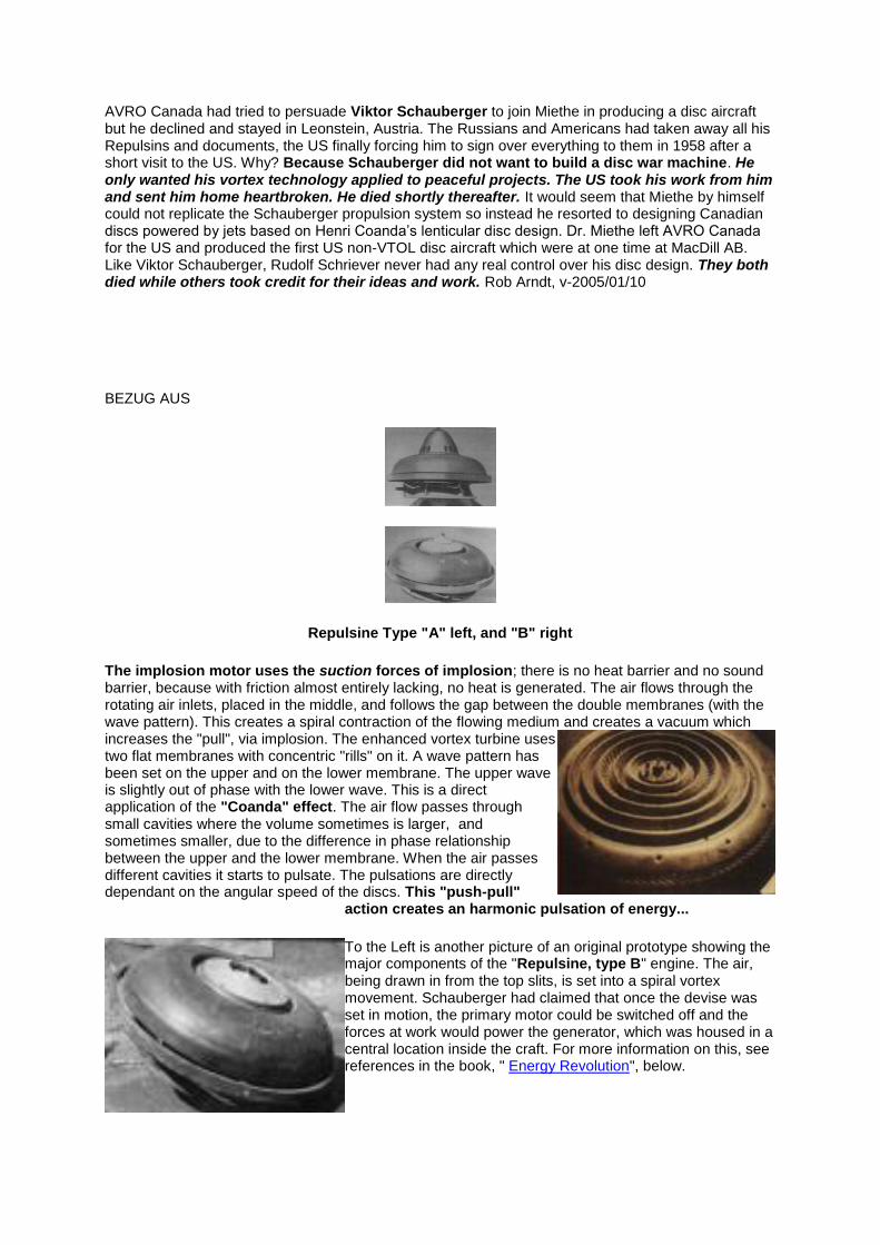
Repulsine Type "A" left, and "B" right
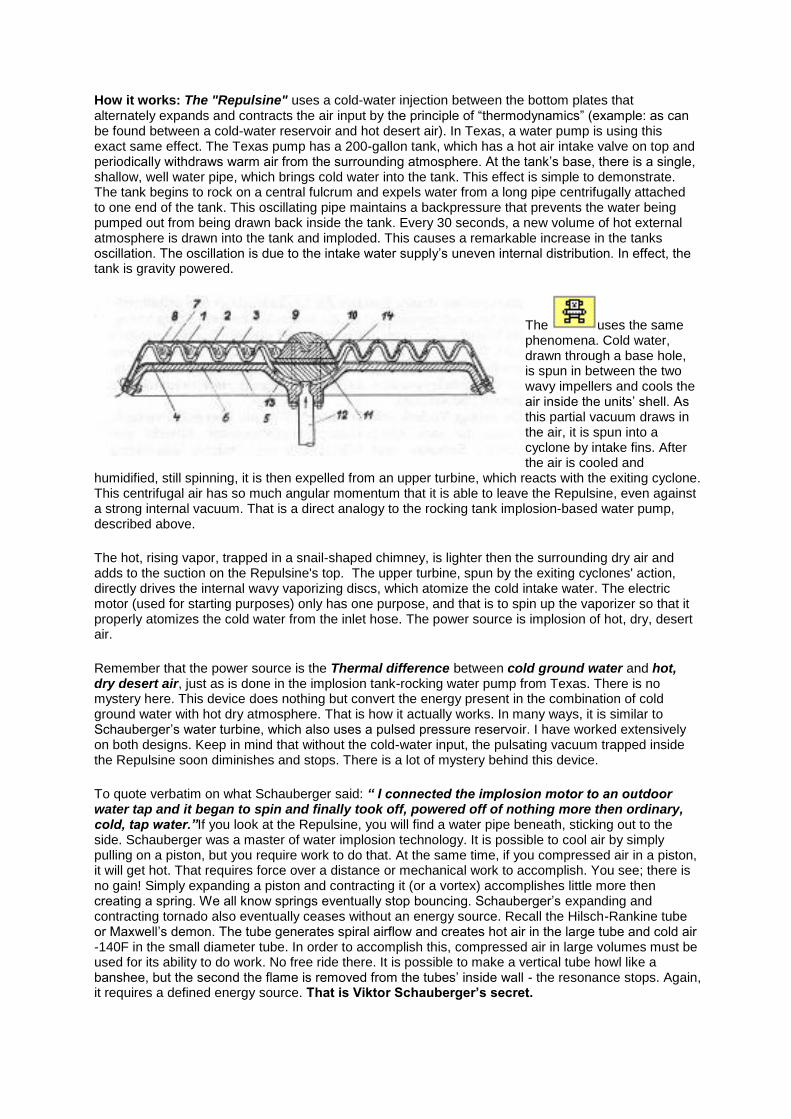
The implosion motor uses the suction forces of implosion; there is no heat barrier and no sound barrier, because with friction almost entirely lacking, no heat is generated. The air flows through the rotating air inlets, placed in the middle, and follows the gap between the double membranes (with the wave pattern). This creates a spiral contraction of the flowing medium and creates a vacuum which increases the "pull", via implosion. The enhanced vortex turbine uses two flat membranes with concentric "rills" on it. A wave pattern has been set on the upper and on the lower membrane. The upper wave is slightly out of phase with the lower wave. This is a direct application of the "Coanda" effect. The air flow passes through small cavities where the volume sometimes is larger, and sometimes smaller, due to the difference in phase relationship between the upper and the lower membrane. When the air passes different cavities it starts to pulsate. The pulsations are directly dependant on the angular speed of the discs. This "push-pull"
action creates an harmonic pulsation of energy...
To the Left is another picture of an original prototype showing the major components of the "Repulsine, type B" engine. The air, being drawn in from the top slits, is set into a spiral vortex movement. Schauberger had claimed that once the devise was set in motion, the primary motor could be switched off and the forces at work would power the generator, which was housed in a central location inside the craft. For more information on this, see references in the book, " Energy Revolution", below.
How it works: The "Repulsine" uses a cold-water injection between the bottom plates that alternately expands and contracts the air input by the principle of “thermodynamics” (example: as can be found between a cold-water reservoir and hot desert air). In Texas, a water pump is using this exact same effect. The Texas pump has a 200-gallon tank, which has a hot air intake valve on top and periodically withdraws warm air from the surrounding atmosphere. At the tank’s base, there is a single, shallow, well water pipe, which brings cold water into the tank. This effect is simple to demonstrate. The tank begins to rock on a central fulcrum and expels water from a long pipe centrifugally attached to one end of the tank. This oscillating pipe maintains a backpressure that prevents the water being pumped out from being drawn back inside the tank. Every 30 seconds, a new volume of hot external atmosphere is drawn into the tank and imploded. This causes a remarkable increase in the tanks oscillation. The oscillation is due to the intake water supply’s uneven internal distribution. In effect, the tank is gravity powered.
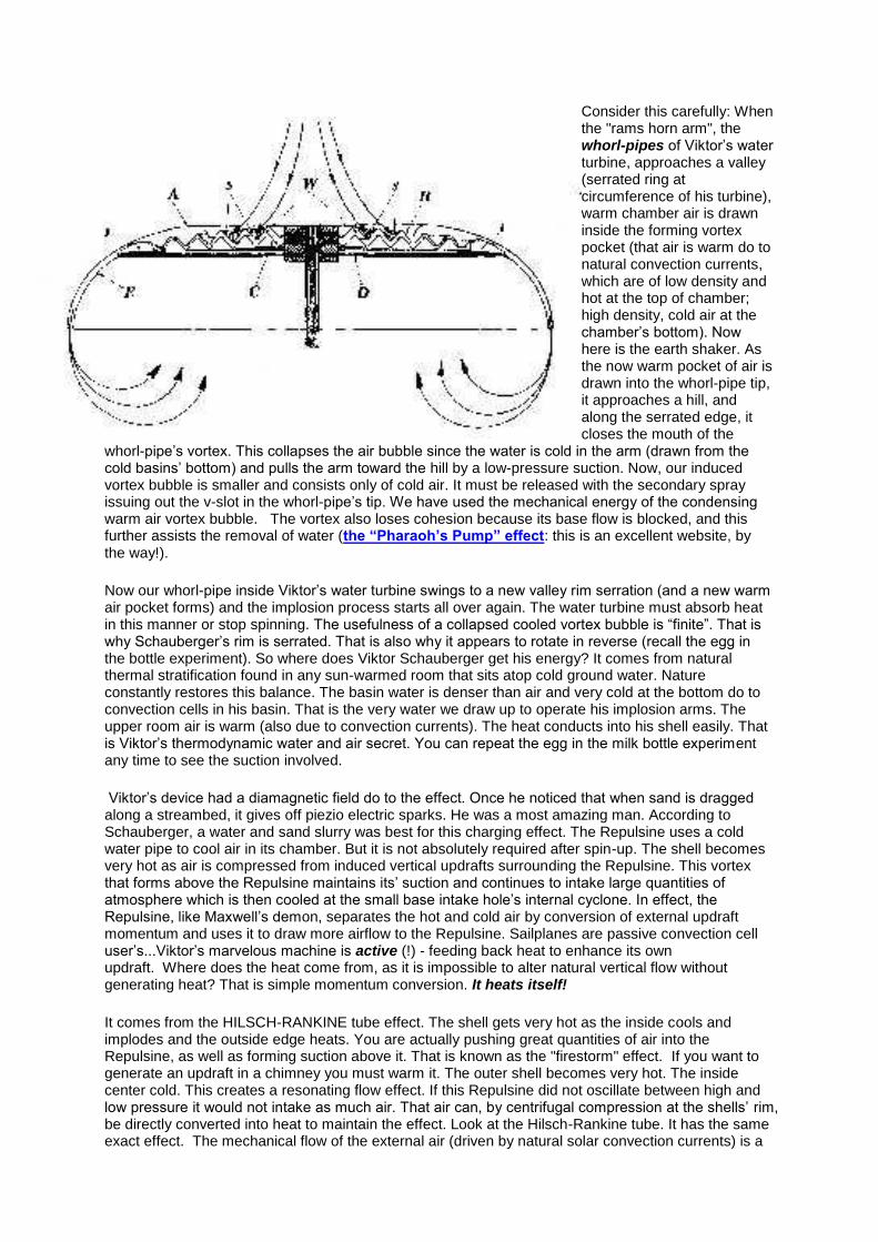
The uses the same phenomena. Cold water, drawn through a base hole, is spun in between the two wavy impellers and cools the air inside the units’ shell. As this partial vacuum draws in the air, it is spun into a cyclone by intake fins. After the air is cooled and
humidified, still spinning, it is then expelled from an upper turbine, which reacts with the exiting cyclone. This centrifugal air has so much angular momentum that it is able to leave the Repulsine, even against a strong internal vacuum. That is a direct analogy to the rocking tank implosion-based water pump, described above.
The hot, rising vapor, trapped in a snail-shaped chimney, is lighter then the surrounding dry air and adds to the suction on the Repulsine's top. The upper turbine, spun by the exiting cyclones' action, directly drives the internal wavy vaporizing discs, which atomize the cold intake water. The electric motor (used for starting purposes) only has one purpose, and that is to spin up the vaporizer so that it properly atomizes the cold water from the inlet hose. The power source is implosion of hot, dry, desert air.
Remember that the power source is the Thermal difference between cold ground water and hot, dry desert air, just as is done in the implosion tank-rocking water pump from Texas. There is no mystery here. This device does nothing but convert the energy present in the combination of cold ground water with hot dry atmosphere. That is how it actually works. In many ways, it is similar to Schauberger’s water turbine, which also uses a pulsed pressure reservoir. I have worked extensively on both designs. Keep in mind that without the cold-water input, the pulsating vacuum trapped inside the Repulsine soon diminishes and stops. There is a lot of mystery behind this device.
To quote verbatim on what Schauberger said: “ I connected the implosion motor to an outdoor water tap and it began to spin and finally took off, powered off of nothing more then ordinary, cold, tap water.”If you look at the Repulsine, you will find a water pipe beneath, sticking out to the side. Schauberger was a master of water implosion technology. It is possible to cool air by simply pulling on a piston, but you require work to do that. At the same time, if you compressed air in a piston, it will get hot. That requires force over a distance or mechanical work to accomplish. You see; there is no gain! Simply expanding a piston and contracting it (or a vortex) accomplishes little more then creating a spring. We all know springs eventually stop bouncing. Schauberger’s expanding and contracting tornado also eventually ceases without an energy source. Recall the Hilsch-Rankine tube or Maxwell’s demon. The tube generates spiral airflow and creates hot air in the large tube and cold air -140F in the small diameter tube. In order to accomplish this, compressed air in large volumes must be used for its ability to do work. No free ride there. It is possible to make a vertical tube howl like a banshee, but the second the flame is removed from the tubes’ inside wall - the resonance stops. Again, it requires a defined energy source. That is Viktor Schauberger’s secret.
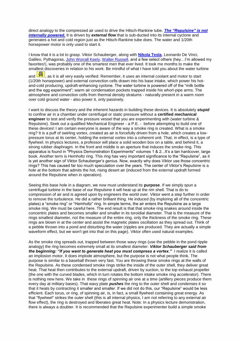
Consider this carefully: When the "rams horn arm", the whorl-pipes of Viktor’s water turbine, approaches a valley (serrated ring at circumference of his turbine), warm chamber air is drawn inside the forming vortex pocket (that air is warm do to natural convection currents, which are of low density and hot at the top of chamber; high density, cold air at the chamber’s bottom). Now here is the earth shaker. As the now warm pocket of air is drawn into the whorl-pipe tip, it approaches a hill, and along the serrated edge, it closes the mouth of the
whorl-pipe’s vortex. This collapses the air bubble since the water is cold in the arm (drawn from the cold basins’ bottom) and pulls the arm toward the hill by a low-pressure suction. Now, our induced vortex bubble is smaller and consists only of cold air. It must be released with the secondary spray issuing out the v-slot in the whorl-pipe’s tip. We have used the mechanical energy of the condensing warm air vortex bubble. The vortex also loses cohesion because its base flow is blocked, and this further assists the removal of water (the “Pharaoh’s Pump” effect: this is an excellent website, by the way!).
Now our whorl-pipe inside Viktor’s water turbine swings to a new valley rim serration (and a new warm air pocket forms) and the implosion process starts all over again. The water turbine must absorb heat in this manner or stop spinning. The usefulness of a collapsed cooled vortex bubble is “finite”. That is why Schauberger’s rim is serrated. That is also why it appears to rotate in reverse (recall the egg in the bottle experiment). So where does Viktor Schauberger get his energy? It comes from natural thermal stratification found in any sun-warmed room that sits atop cold ground water. Nature constantly restores this balance. The basin water is denser than air and very cold at the bottom do to convection cells in his basin. That is the very water we draw up to operate his implosion arms. The upper room air is warm (also due to convection currents). The heat conducts into his shell easily. That is Viktor’s thermodynamic water and air secret. You can repeat the egg in the milk bottle experiment any time to see the suction involved.
Viktor’s device had a diamagnetic field do to the effect. Once he noticed that when sand is dragged along a streambed, it gives off piezio electric sparks. He was a most amazing man. According to Schauberger, a water and sand slurry was best for this charging effect. The Repulsine uses a cold water pipe to cool air in its chamber. But it is not absolutely required after spin-up. The shell becomes very hot as air is compressed from induced vertical updrafts surrounding the Repulsine. This vortex that forms above the Repulsine maintains its’ suction and continues to intake large quantities of atmosphere which is then cooled at the small base intake hole’s internal cyclone. In effect, the Repulsine, like Maxwell’s demon, separates the hot and cold air by conversion of external updraft momentum and uses it to draw more airflow to the Repulsine. Sailplanes are passive convection cell user’s...Viktor’s marvelous machine is active (!) - feeding back heat to enhance its own updraft. Where does the heat come from, as it is impossible to alter natural vertical flow without generating heat? That is simple momentum conversion. It heats itself!
It comes from the HILSCH-RANKINE tube effect. The shell gets very hot as the inside cools and implodes and the outside edge heats. You are actually pushing great quantities of air into the Repulsine, as well as forming suction above it. That is known as the "firestorm" effect. If you want to generate an updraft in a chimney you must warm it. The outer shell becomes very hot. The inside center cold. This creates a resonating flow effect. If this Repulsine did not oscillate between high and low pressure it would not intake as much air. That air can, by centrifugal compression at the shells’ rim, be directly converted into heat to maintain the effect. Look at the Hilsch-Rankine tube. It has the same exact effect. The mechanical flow of the external air (driven by natural solar convection currents) is a
direct analogy to the compressed air used to drive the Hilsch-Rankine tube. The “Repulsine” is not internally powered. It is driven by external flow that is sub-ducted into its internal cyclone and generates a hot and cold region just as the Hilsch-Rankine tube does. The water and 1/20th horsepower motor is only used to start it.
I know that it is a lot to grasp. Viktor Schauberger, along with Nikola Tesla, Leonardo De Vinci, Galileo, Pythagoras, John Worrall Keely, Walter Russell, and a few select others (hey…I’m allowed my favorites!), was probably one of the smartest men that ever lived. It took me months to make the smallest discoveries in relation to his work. Be mindful of what I have told you about the water turbine
and , as it is all very easily verified. Remember, it uses an internal coolant and motor to start (1/20th horsepower) and external convection cells drawn into his base intake, which power his hot-and-cold producing, updraft-enhancing cyclone. The water turbine is powered off of the “milk bottle and the egg experiment”; warm air condensation pockets trapped inside his whorl-pipe arms. The atmosphere and convection cells from thermal density stratums - naturally present in a warm room over cold ground water - also power it, only passively.
I want to discuss the theory and the inherent hazards in building these devices. It is absolutely stupid to confine air in a chamber under centrifugal or static pressure without a certified mechanical engineer to test and verify the pressure vessel that you are experimenting with (water turbine & Repulsine). Seek out a qualified Mechanical Engineer - a P.E. - before attempting to build one of these devices! I am certain everyone is aware of the way a smoke ring is created. What is a smoke ring? It is a puff of swirling vortex, created as air is forcefully driven from a hole, which creates a low-pressure torus at its center, holding the external vortex into a coherent unit. That, in effect, is a type of flywheel. In physics lectures, a professor will place a solid wooden box on a table, and behind it, a strong rubber diaphragm. In the front and middle is an aperture that induces the smoke ring. This apparatus is found in "Physics Demonstration Experiments" volumes 1 & 2...It’s a tan hardcover, large book. Another term is Hemholtz ring. This ring has very important significance to the “Repulsine”, as it is yet another sign of Viktor Schauberger’s genius. Now, exactly why does Viktor use those concentric rings? This has caused far too much speculation over the years. The center of Viktor’s Repulsine is a hole at the bottom that admits the hot, rising desert air (induced from the external updraft formed around the Repulsine when in operation).
Seeing this base hole in a diagram, we now must understand its purpose. If we simply spun a centrifugal turbine in the base of our Repulsine it will heat up at the rim shell. That is do to compression of air and is agreed upon by engineers the world over. Viktor went a step further in order to remove the turbulence. He did a rather brilliant thing. He induced (by imploring all of the concentric plates) a “smoke ring” or “Hemholtz” ring. In simple terms, the air enters the Repulsine as a large smoke ring. We must be careful here. The end result is that that smoke ring snakes around inside the concentric plates and becomes smaller and smaller in its toroidial diameter. That is the measure of the rings smallest diameter, not the measure of the entire ring, only the thickness of the smoke ring. These rings are blown in at the center and assist the magnetic plates oscillation as they spread out. Think of a pebble thrown into a pond and disturbing the water (ripples are produced. They are actually a simple waveform effect, but we won't get into that on this page). Viktor often used natural examples.
As the smoke ring spreads out, trapped between those wavy rings (use the pebble in the pond ripple analogy) the ring becomes extremely small at its smallest diameter. Viktor Schauberger said from the beginning: “if you want to generate heat you must compress a vortex.” I realize it is called an implosion motor. It does implode atmosphere, but the purpose is not what people think. The purpose is similar to a baseball thrown very fast. You are throwing these smoke rings at the walls of the Repulsine. As these condensed smoke rings strike the inside of the outer shell, they deliver great heat. That heat then contributes to the external updraft, driven by suction, to the top exhaust propeller (the one with the curved blades, which in turn rotates the bottom intake smoke ring accelerator). There is nothing new here. We take in these rings of spinning air one at a time (artillery pieces produce them every day at military bases). That wavy plate pushes the ring to the outer shell and condenses it so that it heats by contracting it smaller and smaller. If we did not do this, our “Repulsine” would be less efficient. Each torus, or ring, of spinning air, is, in fact, a small flywheel containing great energy. As that "flywheel" strikes the outer shell (this is all internal physics, I am not referring to any external air flow effect), the ring is destroyed and liberates great heat. Note: In a physics lecture demonstration, there is always a doubter. It is recommended that the Repulsine experimenter build a simple smoke
ring chamber as listed in the “Physics Demonstration Experiments” text. You will find that a smoke ring (it actually requires no smoke and is a lay term) can transport a large quantity of energy.
So the purpose of those wavy discs in the base of our Repulsine is, and has always been, to accelerate intake-formed smoke rings. As they expand to the rim, they contract forcefully and gain definition. They then impact the inner wall of the outer shell, heating it enough to induce a strong external updraft, (as does a campfire). This feeds back still more energy to the upper exhaust turbine that is assisted by a rising dust-devil formed above the Repulsine. Victor Schauberger never used an inefficient technique. A simple centrifugal plate as is seen on standard tank-type vacuum cleaner chops the intake air into millions of pieces.
By retaining the coherence of the intake air (remember this is an inverse ring effect, as if using the physics demonstration ring box in reverse). Viktor gains the maximum energy release from his rings as they strike the inner wall and deliver their heat load as the ring is destroyed. A simple centrifugal compressor plate destroys the entering smoke ring shape. This causes turbulence and interferes with additional intake flow. Viktor takes in one vortex, or smoke ring, at a time. This orderly process insures an endless procession of rings into his implosion shell. It pulsates as each new ring is formed. The main point is that it is very orderly. It interacts only in the most stable way with the "wavy" or vortex-ring accelerator plates. The wavy plates, in effect, spread and contract into a very small thickness diameter the entering ring. It looks like a wave spreading in a pond after a stone is thrown into the middle. One final time; the purpose of those discs is to take the intake vortex rings and contract them so their thickness is reduced and increase there overall diameter until they strike the shell wall and liberate (like a flywheel) a great deal of heat (that feeds the external updraft or "firestorm" effect. Thinking of a common desert dust-devil is another way of looking at it.
Let me try putting this another way. It is difficult to explain the fluid dynamics that are involved here. Viktor cooled warm air in his water turbine arm to contract the vortex bubble against a serrated hill on its rim. That transferred heat to the water vortex that was exiting the whorl-pipe. It is no different in the “Repulsine” case. In this case, the vortex is in the form of a ring, instead of a long finger, as in the water turbine spray arm (whorl-pipe tip). The vortex begins to cool inside the Repulsine and contracts its tornado shell around it as its thickness diameter decreases rapidly. That increases the speed of the ring vortex itself. This liberates a great deal of heat to the shell. I know how difficult this is to understand. If we use the brilliant research of the “Pharaoh’s Pump Group” (note: this link may be broken!) , we find that water can spin around a core of air until it reaches a great depth. Then, the spinning water is destroyed, and the air inside is highly compressed. The Pharaoh’s Water Pump surrounds air with a vortex and drops it to a lower elevation and then, collapses the water vortex around the air and liberates it as compressed air. Study this carefully. (Better yet; study the Pharaohs Pump website from the link above. Then come back to this page and continue. Note: they produce their own book...you can only get the book through their website, as it's not available from AMAZON.COM, Borders, or Barnes & Noble Books. Too bad.)
To continue; Viktor’s Repulsine does the same thing. The intake smoke-ring then contracts, due to its own cooling. Place a hot smoke ring into cold air (as is found inside Viktor’s implosion motor). That ring will begin to contract, but, as it contracts, it increases its rotation velocity. That in turn increases its impact energy at the shell wall. Viktor intakes a large vortex ring that is composed of hot, swirling air. That ring is cooled inside the implosion motor by the contraction discs or wavy-plate discs. As the ring is cooled, it shrinks to its smallest diameter or thickness, which greatly increases its toroidial rotation velocity, or vortex-ring tornado velocity. Now the ring widens in its overall diameter and strikes the shell wall with great energy. Remember; velocity equates to friction. A supersonic jet has very hot skin from air friction (hundreds of degrees Fahrenheit). So Viktor’s implosion motor literally intakes little ring tornadoes that cool inside his wavy disc chamber and therefore contract and spin even faster, perpendicular to their toroidial center circle line.
The Schauberger Repulsine literally "absorbs" little baby tornado rings, and uses their high velocity to generate internal hull friction, which assists the external updraft. Exactly how do we make a tornado in nature? First, we bring cold air from, let’s say, Canada. Then we bring up warm Gulf air from the United States. The warm Gulf air collides with the cool Canadian or Arctic air. The warm Gulf air is now “sandwiched” inside a rolling column of cold arctic air. This causes the internal warm air to contract violently as the heat exchanges from the interaction of the surrounding cold Arctic air. We now have a dangerous energy sandwich. The internal trapped Gulf warm air quickly contracts as it liberates heat to the surrounding cold Arctic air vortex (recall the water turbine arm). This greatly
accelerates the vortex velocity. An analogy would be as an ice skating ballerina pulls in her arms, she spins much faster. That requires mechanical force (in her case; muscle) that force is a direct resultant of the thermo mechanical internal air contraction do to rapid cooling.
Viktor does the exact same thing in both his Repulsine and water turbine. In the Implosion Motor, it takes the form of a ring vortex spreading out to the external shell. In the water turbine, it takes the form of finger like filament that stops at the center. It is exactly what Viktor told us all along. Viktor Schauberger paved the way as he showed us how to extract energy from a cooling vortex. It is all in the cooling vortex and its ability to be harnessed as high velocity wind friction source. The ring inside Viktor’s Implosion Motor is hot on the inside and cold on the outside. That is why it contracts so violently. The vortex in the HILSCH-RANKINE TUBE is the exact opposite. The Hilsch-Rankine tube uses mechanical energy from compressed air to create one of these vortex strands. As its core expands, it cools and heat goes to the outer shell of the H-R tube do to wall friction and compression. . We use just the opposite of this effect to turn a warm air core vortex with a cold external core into compressed air as the vortex collapses. The H-R tube expands air by slowing the incoming airflow. That requires mechanical work from the compressed air source. It takes mechanical energy to pull air at its center apart by vacuum induction. The Schauberger implosion motor vortex package is warm at its center and cold at its out side and therefore contracts forming a small ribbon of compressed air that heats the hull.
So all Viktor did was use a Hilsch-Rankine tube in reverse! Instead of wasting compressed air, he actually generated it. Compressed air then drives the upper exhaust turbine, and heats the hull. “Brilliant” would hardly seem an appropriate word for Schauberger’s insight and achievement, and, it starts leading us into the energy future. There is no free energy here, only simple thermodynamics.... and hot and cold atmospheric convection flows. That is how he did it. After looking at independent sources to see if we were on the right track, Kim Zorzi sent me this update via email which confirmed our initial thoughts:
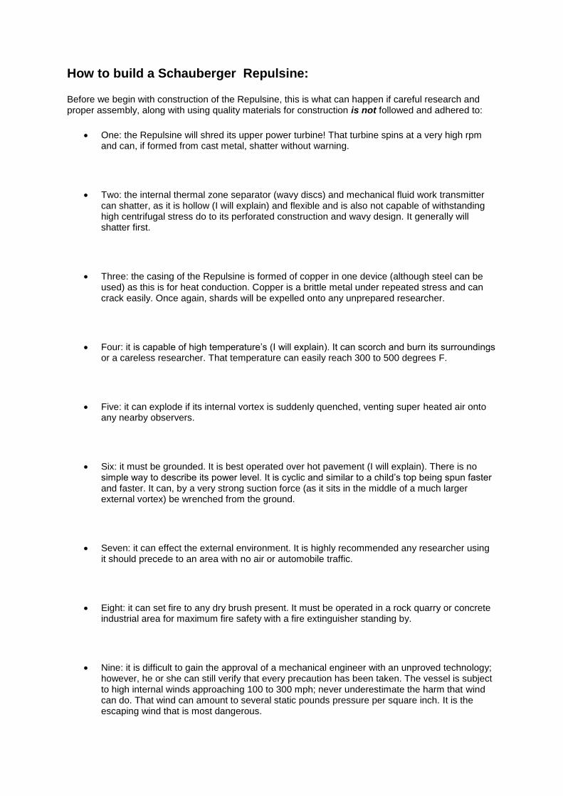
How to build a Schauberger Repulsine:
Before we begin with construction of the Repulsine, this is what can happen if careful research and proper assembly, along with using quality materials for construction is not followed and adhered to:
One: the Repulsine will shred its upper power turbine! That turbine spins at a very high rpm and can, if formed from cast metal, shatter without warning.
Two: the internal thermal zone separator (wavy discs) and mechanical fluid work transmitter can shatter, as it is hollow (I will explain) and flexible and is also not capable of withstanding high centrifugal stress do to its perforated construction and wavy design. It generally will shatter first.
Three: the casing of the Repulsine is formed of copper in one device (although steel can be used) as this is for heat conduction. Copper is a brittle metal under repeated stress and can crack easily. Once again, shards will be expelled onto any unprepared researcher.
Four: it is capable of high temperature’s (I will explain). It can scorch and burn its surroundings or a careless researcher. That temperature can easily reach 300 to 500 degrees F.
Five: it can explode if its internal vortex is suddenly quenched, venting super heated air onto any nearby observers.
Six: it must be grounded. It is best operated over hot pavement (I will explain). There is no simple way to describe its power level. It is cyclic and similar to a child’s top being spun faster and faster. It can, by a very strong suction force (as it sits in the middle of a much larger external vortex) be wrenched from the ground.
Seven: it can effect the external environment. It is highly recommended any researcher using it should precede to an area with no air or automobile traffic.
Eight: it can set fire to any dry brush present. It must be operated in a rock quarry or concrete industrial area for maximum fire safety with a fire extinguisher standing by.
Nine: it is difficult to gain the approval of a mechanical engineer with an unproved technology; however, he or she can still verify that every precaution has been taken. The vessel is subject to high internal winds approaching 100 to 300 mph; never underestimate the harm that wind can do. That wind can amount to several static pounds pressure per square inch. It is the escaping wind that is most dangerous.
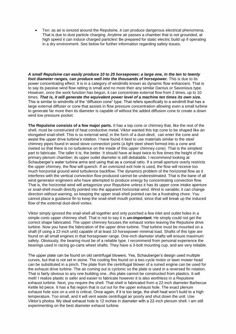
Ten: as air is ionized around the Repulsine, it can produce dangerous electrical phenomena. That is due to dust particle charging. Anytime air passes a chamber that is not grounded, at high speed it can induce charged particles! Be prepared for static electric build up if operating in a dry environment. See below for further information regarding safety issues.
A small Repulsine can easily produce 10 to 25 horsepower; a large one, in the ten to twenty foot diameter ranges, can produce well into the thousands of horsepower. This is due to its power concentrating effect. It is in a category of windmills known as dynamic flow enhancers. That is to say its passive wind flow ratting is small and no more then any similar Darrius or Savonious type. However, once the work function has begun, it can concentrate external flow from 2 times, up to 10 times. That is, it will generate the equivalent power level of a machine ten times its own size. This is similar to windmills of the “diffusion cone” type. That refers specifically to a windmill that has a large external diffuser or cone that assists in flow pressure concentration allowing even a small turbine to generate far more then its diameter is capable of without the added diffusion cone to create a down wind low pressure pocket.
The Repulsine consists of a few major parts. It has a top cone or chimney that, like the rest of the shell, must be constructed of heat conductive metal. Viktor wanted this top cone to be shaped like an elongated snail-shell. This is so external wind, in the form of a dust-devil, can enter the cone and assist the upper drive turbine’s rotation. I have found it best to use materials similar to the steel chimney pipes found in wood stove connection joints (a light steel sheet formed into a cone and riveted so that there is no turbulence on the inside of this upper chimney cone). That is the simplest part to fabricate. The taller it is; the better. It should have at least twice to five times the height of the primary plenum chamber; its upper outlet diameter is still debatable. I recommend looking at Schauberger’s water turbine arms and using that as a conical ratio. If a small aperture overly restricts the upper chimney, the flow will quench. If an oversized exit hole is used, the flow will receive too much horizontal ground wind turbulence backflow. The dynamics problem of the horizontal flow as it interferes with the vertical convection flow produced cannot be underestimated. That is the bane of all wind generator engineers who have attempted to produce energy by concentrating convection flow. That is, the horizontal wind will antagonize your Repulsine unless it has its upper cone intake aperture or snail-shell mouth directly pointed into the apparent horizontal wind. Wind is variable; it can change direction without warning, so keeping the upper snail-shell pointed can be a frustrating chore. You cannot place a guidance fin to keep the snail-shell mouth pointed, since that will break up the induced flow of the external dust-devil vortex.
Viktor simply ignored the snail-shell all together and only punched a few inlet and outlet holes in a simple conic upper chimney shell. That is not to say it is un-important. He simply could not get the correct shape fabricated. The upper chimney focuses the exhaust vortex leaving the Repulsine drive turbine. Now you have the fabrication of the upper drive turbine. That turbine must be mounted on a shaft (if using a 22-inch unit) capable of at least 10 horsepower minimal load. Shafts of this type are found on all small engines in that horsepower range. One-inch diameter shafts will ensure maximum safety. Obviously, the bearing must be of a reliable type. I recommend from personal experience the bearings used in racing go-carts wheel shafts. They have a 3-bolt mounting cup, and are very reliable.
The upper plate can be found on old centrifugal blowers. Yes, Schauberger’s design used multiple curves, but that is not set in stone. The cooling fins found on a two-cycle motor or lawn mower head can be substituted in a pinch. The plate from the centrifugal blower of a ruined engine can be used for the exhaust drive turbine. The air coming out is cyclonic so the plate is used in a reversed fin rotation. That is fairly obvious to any one building one...this plate cannot be constructed from plastics. It will melt! I realize plastic is safer and easier to fabricate however it is also worthless in a Repulsine exhaust turbine. Next, you require the shell. That shell is fabricated from a 22-inch diameter Barbecue Kettle lid piece. It has a flat region that is cut out for the upper exhaust hole. The exact plenum exhaust hole size on a unit is critical. Once again, if it is too large, the shell heat won’t build to a high temperature. Too small, and it will vent waste centrifugal air poorly and shut down the unit. Use Viktor’s photos. My ideal exhaust hole is 12 inches in diameter with a 22-inch plenum shell. I am still experimenting on the best diameter exhaust turbine.
The Repulsine has need of two active parts; the upper exhaust turbine (or reversed centrifuge blower plate) and the inner wavy discs (that use the mechanical work from the upper turbine). Theses discs are not easy to fabricate. The best material I can find is used in fireplace screening and perforated. You must locate a source of perforated steel. That perforation is to allow airflow through the wavy discs, which also prevents back conduction of heat from the outer shell or rim region (I will explain). It will be found that Hammel, used a perforated metal cone on his devices. That is the type of shell you are after. Perforating a steel sheet of that thickness with thousands of holes is difficult and imprecise. If you place too many perforations in one area, the disc may shatter!
Why do it at all? Recall that I spoke of the H-R tube. Those wavy discs serve to conduct vortex strands and transmit mechanical energy to the internal plenum chamber vortex from the upper exhaust turbine. They cannot be underestimated. They are the Repulsine...Think of the drive exhaust turbine as a simple windmill. Updrafts and convection currents power it. It is also driven off of any horizontal flow that is swirled into the upper chimney shell snail shell mouth. That is all it does! It uses waste exhaust to spin that is given maximum pressure advantage from the suction above it in the upper chimney shell vortex. There are three vortexes at work here!
o One, is the external shell heat vortex or outer dust-devil, o Two, is the vortex in the upper snail shaped chimney shell, o Three, is the mechanical work vortex inside the “Repulsine” plenum or H-R tube vortex,
The novice experimenter should examine carefully the work done by vortex Wind Engineers on the web. The entire upper part of the unit is already in use at many wind turbine-generating sites! Assuming you have successfully fabricated the exhaust turbine and mounted it in a typical tri-arm mount, flush with your plenum shell, and mounted the two opposed perforated wavy discs on the long drive shaft, you now require a base shell. This shell must be as strong or stronger then the upper shell. It can be flat and still function. If it is flat steel it must be reinforced. It is always best to use shaped steel that is self-integrated structurally due to its own 3-dimensional form. For example, it can also have a wave ring shape. That is far more rigid then a simple flat piece. That is yet another reason the wavy discs are curved so they are rigid when the Repulsine tilts or lifts.
This is then bolted and sealed to the upper shell. This is critical. The outer rim is subject to great pressure and heat. The bottom hole is smaller then the exhaust hole, however the relative surface area is comparable. This is because a great deal of the upper exhaust turbine plate is sealed with only a small exit region open at its circumference. The bottom shaft bearing can be tri-arm mounted as well. These hole-sizes are critical. If the bottom axle area intake hole is too small, it will not take in enough air! The exact diameter, as compared to the upper exhaust hole is still a matter of experimentation. It is between 4 and 6 inches in diameter. In other words, its diameter in surface area approximates the exhaust outlet surface area. The entire assembly is best placed on yet another Barbecue Kettle piece - the bottom hemisphere. In this use, it is placed round side up (that is its rim on the ground). Several metal posts now go to your bottom plenum. The plenum or H-R work chamber is mounted 6 to 12 inches above the inverted kettle hemisphere. Those posts will later have metal fins on them, which will be twisted to guide air into the single intake hole, placed concentric with the drive shaft.
Now, with all in place, you can do a first spin test. Instead of an attached motor, you can use the pressure exhaust of a large tank-type vacuum cleaner. It requires precise aim. Place the hose near the exhaust turbine and push air against the curved blades the same direction the air is meant to leave the plenum chamber. This is a simple reaction effect. The snail-shell hole is more then large enough for you to place the start-up air jet. Recall that model pulsejets were actually started with a bicycle pump. Now your unit is spinning! What happens next? Usually, very little will happen. It will spin of course, but, until the exact exhaust ratio and intake ratio is found, you can expect no miracles. The bearing races must be low-friction units. If you do it correctly, the unit will begin to heat up at its plenum shell circumference. Why (?) - because the internal wavy perforated discs and compressions on the shell rim are spinning air centrifugally. That can be seen directly by touching the top of any large-tank vacuum cleaner with a metal flange head. In fact all centrifugal air compressors or high pressure fans heat in this manner. Inside the plenum, the air is being separated into a center, or axle region, cold-zone and outer rim region hot-zone. Mechanical work from the upper exhaust disc is being used to separate these temperature regions. This effect is no different than is seen on the H-R tube! The only difference is that air is being spun on the unit by frictional interaction with the wavy disc set. In the H-R tube, it is from the mechanical energy, released as compressed air, and is swirled into a vortex tube. The exact same thermal separation occurs. The inner region is cold, and outer region is hot. That heat
now contributes to a rising updraft vortex about the Repulsine. Recall in a calorimeter experiment, paddles are spun to heat water in a closed shell . One experiment is to then spray water at various temperatures into the shell. If it is done properly, it will assist in imploding the center cold air mass and greatly increasing the RPM. of the turbine. This is a science experiment of a lifetime.
Why does it work? As the work being done on the Repulsine internal plenum increases from the exhaust turbine drive shaft, the steel shell reaches a critical temperature level. At that point the rim air approaches several hundred degrees. The wavy discs prevent heat from easily moving from the rim to the center (that is one reason they are perforated and cannot be solid). The plenum will begin to alternately heat and cool as new air is drawn in at its base. If its core air trapped in between the wavy discs is cooled, the plenum velocity will increase. If it is heated by intake air, the velocity will slow. This effect is resonant and typical of the Repulsine operation. It is very hard to explain. Viktor claims, that any time you allow the core air of his Repulsine to heat and expand, it pulls the internal vortex wider apart! Next, as you intake cooler air, it snaps back together again. This is a phenomenon of thermo-mechanical resonance. Tesla coils use the very same principle.
The point is that your plenum will be driven off of induced external updrafts (as if a campfire) and off of a resonance caused by changes in the core vortex temperature! That is to say, the plenum chamber is like a child’s top. Any temperature change will cause the internal vortex (a vertical axis vortex centered about the drive axle) to expand and contract. The temperature changes must work in resonant fashion. Think of the child’s top being spun faster and faster, as they plunge its push rod up and down. This resonant expanding and contracting vortex bounces off the wavy rings much as ball bounces on a floor. Each time a little more energy is added. It is like stretching and contracting a rubber band around your fingers. When thermal mechanical vortex resonance is achieved, the implosion motor takes off. This is not an out-dated centrifugal air compressor. It is a chamber where any intake air is being converted into rotary motion. As the air vortex enlarges, it strikes the rim and cools. This causes it to bounce and return like a wave, to the center of the chamber (much like an echo reflecting off a hard surface). This compresses the center cold air and heats it, causing the wave front to once more expand.
That is why the wavy perforated discs are so important. They guide this echoing vortex band as it bounces from the rim to center and back again. To see what Schauberger saw, go to a circular water bath or tank (it must be a perfect circle). Put a Styrofoam disc at its center with a stick attached. Start to resonantly plunge the disk up and down. If you time it right, the wave crest will work with your plunges in harmony, as it bounces off the tank’s wall. This is exactly why those disks are wavy and perforated. They allow the vortex bounces to build up energy. Yes, you can argue that it wastes power. Actually it does not. The heat leaving the rim feeds back into the exhaust turbine updraft. You are amplifying this echo effect. Now the skeptic will begin to squirm in their seat. What good is this resonance effect? Sure, a Tesla coil makes a big spark, but that uses up electrical power even at high Q.
What makes a two-cycle motorcycle tail pipe exhaust expansion chamber work? Echo! That is correct. The principle that helps back pressure a two-cycle motorcycle engine is the exact same principle that feeds back energy in a Schauberger Repulsine implosion motor. It makes no difference. We can get mechanical work either way! A Sterling engine obtains mechanical work on both its cold cycle and hot cycle! We now have two defined reservoirs; a cold rim reservoir and a hot central intake reservoir. These reservoirs are maintained by external wind and sunlight. This is not a guess; it is a fact! A Stirling engine uses a displacer to shuttle an air mass between a hot and cold reservoir! Go to the fine Japanese Stirling engine pages found all over the web and you will soon understand this principle.
In the Repulsine, it is accomplished by the natural vortex echo inside of the chamber. This echo builds up our RPM. That is why the wavy discs are perforated. They must help spin the vortex but never stop its wave front echo. Think of that as a natural air displacer. Striking the rim cools the vortex and reaching the center heats it. The center bottom is hot from intake air ramming. Think of it this way before you stop reading this material. The echo bounce places our vortex over the center and then the rim region. That takes the place of the Stirling engine displacer. The vortex acts like a flywheel that stores the bounce energy. In effect, it is a simple Stirling engine hybrid that uses the expanding and contracting vortex as both a piston and a displacer, at the same time.
This is not difficult to understand. The Schauberger is a new class of Stirling, atmospheric-feedback, hot-air motor. Schauberger’s genius removed the complex piston and displacer. They are replaced by a bouncing and expanding vortex and contracting vortex ring. If the reader takes away nothing more about the “Repulsine”, consider the following. IT is not a centrifugal air compressor. It is a new class of Stirling hot air engine, that converts a captive vortex into a piston and displacer that therefore shuttles between a hot center region, and a cold outer shell. This vortex also forms the Stirling Engine hybrid’s flywheel. In one simple gesture, Viktor removed the flywheel - the displacer and the piston - of a Stirling hot air engine - its closest thermo-mechanical cousin. By combining all of these elements, he simplified the Stirling engine, and, allowed it to directly feed back energy to an updraft. In other words, its own waste heat assists in increasing a natural external flow. No Stirling engine does that!
A final purpose of the wavy internal discs is to help "bounce" the vortex. It is similar to the 90-degree phase drive rod that activates the displacer. It forces the vortex wall back out to the rim. I realize that I said the rim is hot and it is. That is because it is constantly relieving itself of heat from the internal bouncing vortex. It is also cooled by the swirling external vortex. Without that, it is no longer a useful reservoir. In effect we have discovered a dynamic feedback Stirling Engine suited to extracting energy from a stationary external tornadic convection cell. This is not free energy...but I feel it is neglected physics. Only time and a little faith in Schauberger’s genius and commitment to relieving the suffering of mankind will tell.
In the “Phillips Technical Review Notes” we found references to an Air Core Betatron containing only a few kilograms of active magnetic flux material. That is to say the Phillips engineers had found a way to avoid the entire heavy iron superstructure used on a Betatron. It relied instead, like a Tesla coil, on resonance in heavy cables. To add, therefore to the list of things to avoid when constructing a Repulsine, I must now in all fairness add the Air Core Betatron effect. This means very simply, your Repulsine is capable of hard X-ray production from an internal current imploded with the thermo-mechanical rim resonance vortex bounce. To put it simply; the Repulsine at full resonance is a radiation source. It is possible that 50 thousand to 10 million electron volt-level radiation by-products, in the form of hard X-rays, will be present during operation. Any time you contract a charged electron cloud so that its magnetic field is cut, you can, and will accelerate electrons in the defined nature of a Betatron Particle Accelerator! It can and will emit high-energy particle radiation of the class known as High Energy Electrons and Hard X-rays. The Phillips’ Air Core Betatron proves a large ferromagnetic induction mass is not required for electron volt energy levels up to 9 MEV. Prolonged X-ray exposure is a certified tissue destroying process. For those “would’be” Nuclear Physicists out there, any doubts that the Repulsine is capable of Betatron particle acceleration will be quashed after reading about the “Phillips T.R. papers on their 9 MEV “Air Core Betatron””.
The final piece of the puzzle; The Repulsine's rim is resonantly cooled by thermally induced downdraft feedback, as the internal plenum flow expands for its re-coil or implosion echo. It is a surface effect. Hot internal centrifugal air induces a cold downdraft pulse that is in effect the capacitive analogy to our thermo-mechanical vortex resonance, taking place in the unit. Hot always attracts cold ...remember that! The Repulsine is unpredictable and dangerous, and, in an evacuated condition, is capable of Hard X-ray production. It is NOT a toy. It is best left in the hands of certified engineers and physicists!
My compliments and thanks to Mr. Robert (James) Bailey for his support, research data, notes and insight regarding construction of the working Repulsine model. The information that Mr. Bailey provided was absolutely invaluable in the compiling and research regarding construction and operation of a true Schauberger Repulsine. A heart felt "thank you" from all of us at ITP & GET. Also my unending respect and gratitude to Mr. Callum Coats, and Mr. Alick Bartholomew, (authors, publishers and writers) without whose work none of this website (or anything regarding Schauberger!) would be possible.
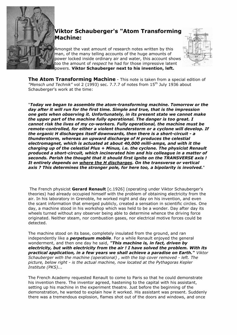
Viktor Schauberger's "Atom Transforming Machine:
Amongst the vast amount of research notes written by this
man, of the many telling accounts of the huge amounts of
power locked inside ordinary air and water, this account shows
too the amount of respect he had for those impressive latent
powers. Viktor Schauberger next to his invention, left.
The Atom Transforming Machine - This note is taken from a special edition of
"Mensch und Technik" vol 2 (1993) sec. 7.7.7 of notes from 15th July 1936 about
Schauberger's work at the time:
"Today we began to assemble the atom-transforming machine. Tomorrow or the
day after it will run for the first time. Simple and true, that is the impression
one gets when observing it. Unfortunately, in its present state we cannot make
the upper part of the machine fully operational. The danger is too great. I
cannot risk the lives of my co-workers. Fully operational, the machine must be
remote-controlled, for either a violent thunderstorm or a cyclone will develop. If
the organic H discharges itself downwards, then there is a short-circuit - a
thunderstorm, whereas an upward discharge of H produces the celestial
electromagnet, which is actuated at about 40,000 milli-amps, and with it the
charging up of the celestial Plus + Minus, i.e. the cyclone. The physicist Renault
produced a short-circuit, which incinerated him and his colleague in a matter of
seconds. Perish the thought that it should first ignite on the TRANSVERSE axis !
It entirely depends on where the H discharges. On the transverse or vertical axis ? This determines the stronger pole, for here too, a bipolarity is involved."
The French physicist Gerard Renault [c.1926] (operating under Viktor Schauberger's
theories) had already occupied himself with the problem of obtaining electricity from the
air. In his laboratory in Grenoble, he worked night and day on his invention, and even
the scant information that emerged publicly, created a sensation in scientific circles. One
day, a machine stood in his workshop which was held to be a wonder. Day after day its
wheels turned without any observer being able to determine whence the driving force
originated. Neither steam, nor combustion gases, nor electrical motive forces could be
detected.
The machine stood on its base, completely insulated from the ground, and ran
independently like a perpetuum mobile. For a while Renault enjoyed the general
wonderment, and then one day he said, "This machine is, in fact, driven by
electricity, but with electricity from the air ! I have solved the problem. With its
practical application, in a few years we shall achieve a paradise on Earth." Viktor
Schauberger with the machine (operational) , with the top cover removed - left. The
picture, below right - is the actual machine, now located at the Pythagoras Kepler
Institute (PKS)...
The French Academy requested Renault to come to Paris so that he could demonstrate
his invention there. The inventor agreed, hastening to the capital with his assistant,
setting up his machine in the experiment theatre. Just before the beginning of the
demonstration, he wanted to explain how it worked. His assistant was present. Suddenly
there was a tremendous explosion, flames shot out of the doors and windows, and once
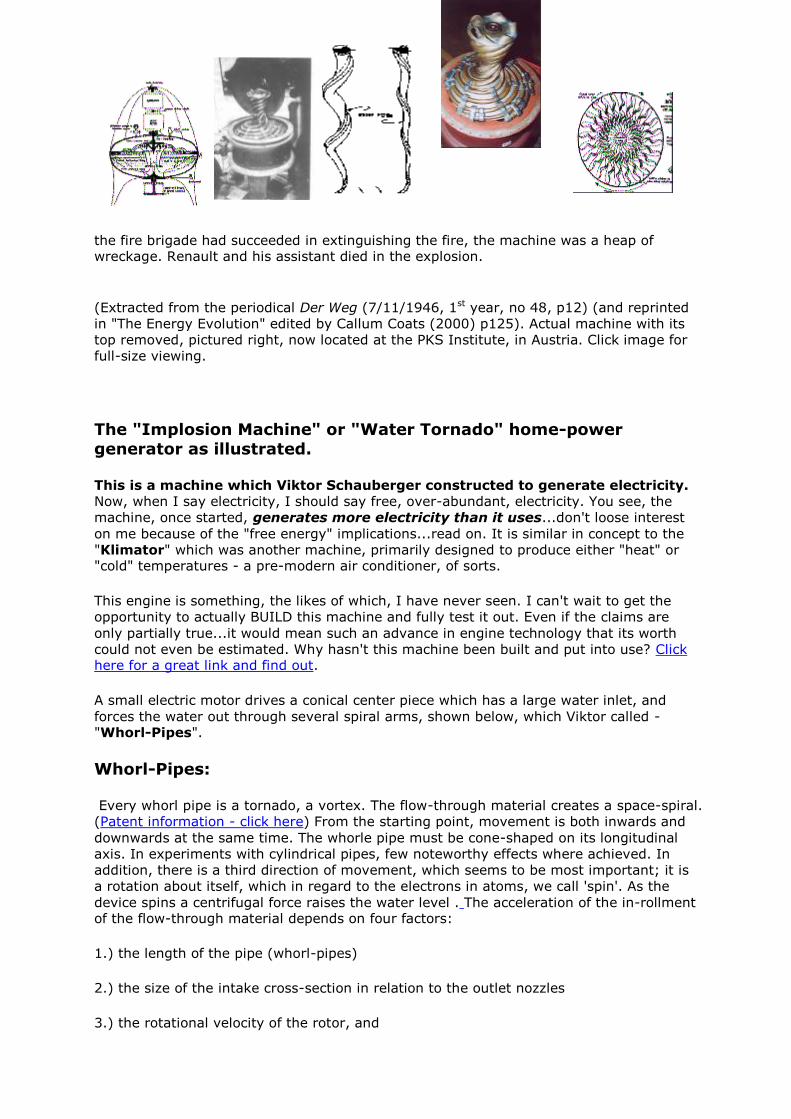
the fire brigade had succeeded in extinguishing the fire, the machine was a heap of wreckage. Renault and his assistant died in the explosion.
(Extracted from the periodical Der Weg (7/11/1946, 1st year, no 48, p12) (and reprinted
in "The Energy Evolution" edited by Callum Coats (2000) p125). Actual machine with its
top removed, pictured right, now located at the PKS Institute, in Austria. Click image for
full-size viewing.
The "Implosion Machine" or "Water Tornado" home-power
generator as illustrated.
This is a machine which Viktor Schauberger constructed to generate electricity.
Now, when I say electricity, I should say free, over-abundant, electricity. You see, the
machine, once started, generates more electricity than it uses...don't loose interest
on me because of the "free energy" implications...read on. It is similar in concept to the
"Klimator" which was another machine, primarily designed to produce either "heat" or "cold" temperatures - a pre-modern air conditioner, of sorts.
This engine is something, the likes of which, I have never seen. I can't wait to get the
opportunity to actually BUILD this machine and fully test it out. Even if the claims are
only partially true...it would mean such an advance in engine technology that its worth
could not even be estimated. Why hasn't this machine been built and put into use? Click here for a great link and find out.
A small electric motor drives a conical center piece which has a large water inlet, and
forces the water out through several spiral arms, shown below, which Viktor called - "Whorl-Pipes".
Whorl-Pipes:
Every whorl pipe is a tornado, a vortex. The flow-through material creates a space-spiral.
(Patent information - click here) From the starting point, movement is both inwards and
downwards at the same time. The whorle pipe must be cone-shaped on its longitudinal
axis. In experiments with cylindrical pipes, few noteworthy effects where achieved. In
addition, there is a third direction of movement, which seems to be most important; it is
a rotation about itself, which in regard to the electrons in atoms, we call 'spin'. As the
device spins a centrifugal force raises the water level . The acceleration of the in-rollment of the flow-through material depends on four factors:
1.) the length of the pipe (whorl-pipes)
2.) the size of the intake cross-section in relation to the outlet nozzles
3.) the rotational velocity of the rotor, and
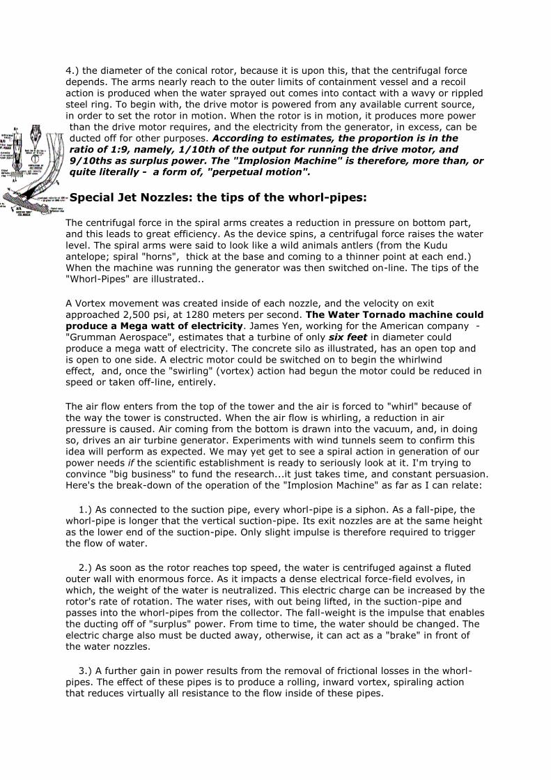
4.) the diameter of the conical rotor, because it is upon this, that the centrifugal force
depends. The arms nearly reach to the outer limits of containment vessel and a recoil
action is produced when the water sprayed out comes into contact with a wavy or rippled
steel ring. To begin with, the drive motor is powered from any available current source,
in order to set the rotor in motion. When the rotor is in motion, it produces more power
than the drive motor requires, and the electricity from the generator, in excess, can be
ducted off for other purposes. According to estimates, the proportion is in the
ratio of 1:9, namely, 1/10th of the output for running the drive motor, and
9/10ths as surplus power. The "Implosion Machine" is therefore, more than, or quite literally - a form of, "perpetual motion".
Special Jet Nozzles: the tips of the whorl-pipes:
The centrifugal force in the spiral arms creates a reduction in pressure on bottom part,
and this leads to great efficiency. As the device spins, a centrifugal force raises the water
level. The spiral arms were said to look like a wild animals antlers (from the Kudu
antelope; spiral "horns", thick at the base and coming to a thinner point at each end.)
When the machine was running the generator was then switched on-line. The tips of the "Whorl-Pipes" are illustrated..
A Vortex movement was created inside of each nozzle, and the velocity on exit
approached 2,500 psi, at 1280 meters per second. The Water Tornado machine could
produce a Mega watt of electricity. James Yen, working for the American company -
"Grumman Aerospace", estimates that a turbine of only six feet in diameter could
produce a mega watt of electricity. The concrete silo as illustrated, has an open top and
is open to one side. A electric motor could be switched on to begin the whirlwind
effect, and, once the "swirling" (vortex) action had begun the motor could be reduced in speed or taken off-line, entirely.
The air flow enters from the top of the tower and the air is forced to "whirl" because of
the way the tower is constructed. When the air flow is whirling, a reduction in air
pressure is caused. Air coming from the bottom is drawn into the vacuum, and, in doing
so, drives an air turbine generator. Experiments with wind tunnels seem to confirm this
idea will perform as expected. We may yet get to see a spiral action in generation of our
power needs if the scientific establishment is ready to seriously look at it. I'm trying to
convince "big business" to fund the research...it just takes time, and constant persuasion. Here's the break-down of the operation of the "Implosion Machine" as far as I can relate:
1.) As connected to the suction pipe, every whorl-pipe is a siphon. As a fall-pipe, the
whorl-pipe is longer that the vertical suction-pipe. Its exit nozzles are at the same height
as the lower end of the suction-pipe. Only slight impulse is therefore required to trigger the flow of water.
2.) As soon as the rotor reaches top speed, the water is centrifuged against a fluted
outer wall with enormous force. As it impacts a dense electrical force-field evolves, in
which, the weight of the water is neutralized. This electric charge can be increased by the
rotor's rate of rotation. The water rises, with out being lifted, in the suction-pipe and
passes into the whorl-pipes from the collector. The fall-weight is the impulse that enables
the ducting off of "surplus" power. From time to time, the water should be changed. The
electric charge also must be ducted away, otherwise, it can act as a "brake" in front of the water nozzles.
3.) A further gain in power results from the removal of frictional losses in the whorl-
pipes. The effect of these pipes is to produce a rolling, inward vortex, spiraling action that reduces virtually all resistance to the flow inside of these pipes.
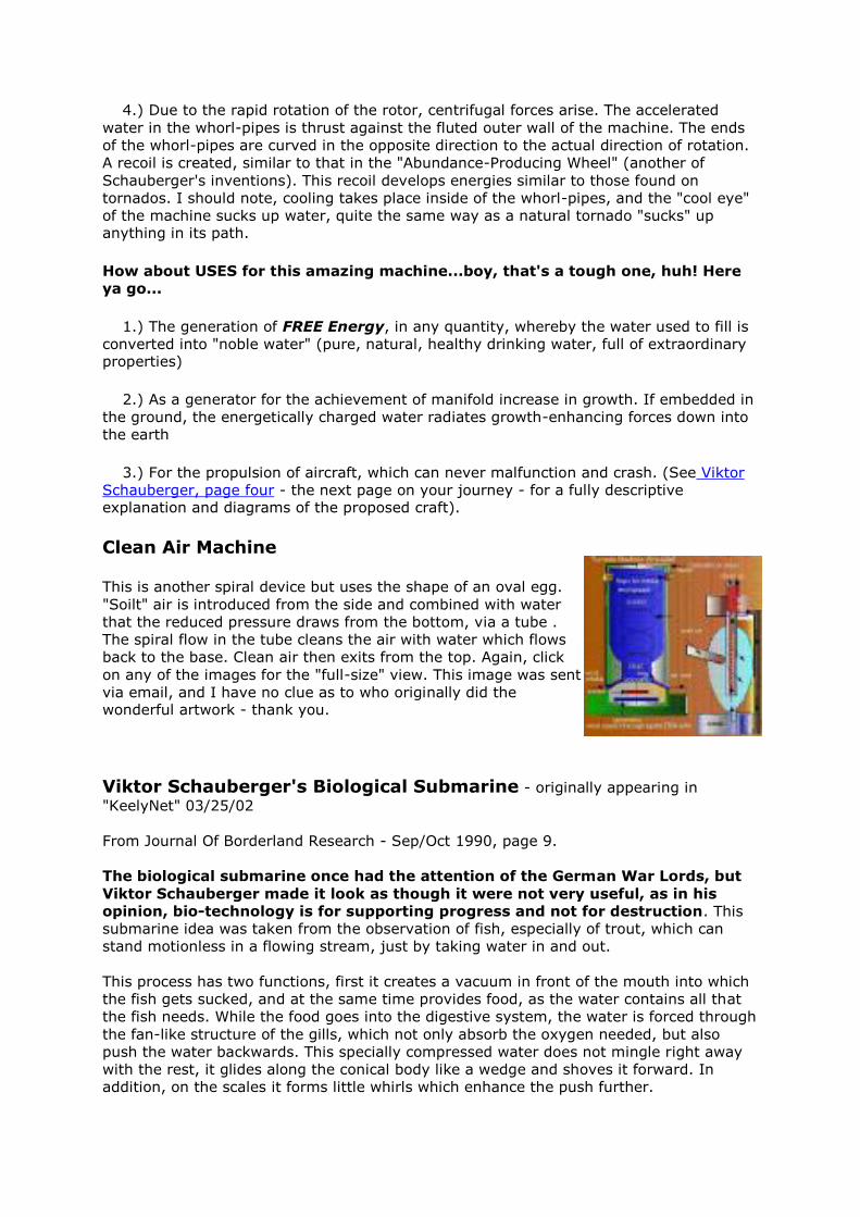
4.) Due to the rapid rotation of the rotor, centrifugal forces arise. The accelerated
water in the whorl-pipes is thrust against the fluted outer wall of the machine. The ends
of the whorl-pipes are curved in the opposite direction to the actual direction of rotation.
A recoil is created, similar to that in the "Abundance-Producing Wheel" (another of
Schauberger's inventions). This recoil develops energies similar to those found on
tornados. I should note, cooling takes place inside of the whorl-pipes, and the "cool eye"
of the machine sucks up water, quite the same way as a natural tornado "sucks" up anything in its path.
How about USES for this amazing machine...boy, that's a tough one, huh! Here
ya go...
1.) The generation of FREE Energy, in any quantity, whereby the water used to fill is
converted into "noble water" (pure, natural, healthy drinking water, full of extraordinary properties)
2.) As a generator for the achievement of manifold increase in growth. If embedded in
the ground, the energetically charged water radiates growth-enhancing forces down into
the earth
3.) For the propulsion of aircraft, which can never malfunction and crash. (See Viktor
Schauberger, page four - the next page on your journey - for a fully descriptive explanation and diagrams of the proposed craft).
Clean Air Machine
This is another spiral device but uses the shape of an oval egg.
"Soilt" air is introduced from the side and combined with water
that the reduced pressure draws from the bottom, via a tube .
The spiral flow in the tube cleans the air with water which flows
back to the base. Clean air then exits from the top. Again, click
on any of the images for the "full-size" view. This image was sent
via email, and I have no clue as to who originally did the wonderful artwork - thank you.
Viktor Schauberger's Biological Submarine - originally appearing in
"KeelyNet" 03/25/02
From Journal Of Borderland Research - Sep/Oct 1990, page 9.
The biological submarine once had the attention of the German War Lords, but
Viktor Schauberger made it look as though it were not very useful, as in his
opinion, bio-technology is for supporting progress and not for destruction. This
submarine idea was taken from the observation of fish, especially of trout, which can
stand motionless in a flowing stream, just by taking water in and out.
This process has two functions, first it creates a vacuum in front of the mouth into which
the fish gets sucked, and at the same time provides food, as the water contains all that
the fish needs. While the food goes into the digestive system, the water is forced through
the fan-like structure of the gills, which not only absorb the oxygen needed, but also
push the water backwards. This specially compressed water does not mingle right away
with the rest, it glides along the conical body like a wedge and shoves it forward. In
addition, on the scales it forms little whirls which enhance the push further.
However, Viktor Schauberger was not the sole observer of this phenomenon. Before him
others not only formed the same idea but even constructed prototypes with some results.
One inventor, A. Borner, came to the conclusion that the speedy motion of the fish is
relative to the size of its gills. He constructed a boat with a precise opening in its bow,
where a turbine sucked in water like a fish, and pushed it out through slit-like exit ports
in such a way that it glided along the hull like a sheet, not only separating it from the
friction of the outside water, but also giving it an additional push forward.
Further, he applied skin depressions like sharks have on his ship's hull, presuming that
they cause small swirls, and so increased the forward motion. Borner even incorporated
the slippery skin layer that fish have by applying oil to the hull to reduce friction. He
hoped all this would bring a 60-80% reduction in fuel. Indeed, experiments with his boat
FORELLE, meaning 'trout', achieved twice the speed, while still using the same amount of
fuel. Apparently, Borner did not know about the spiral-vortex, which is an invention of
Viktor Schauberger. If properly applied, it will not only increase speed, but also reduce
fuel consumption to a minimum!
The drawing (left) by Dipl. Ing. Walter Schauberger,
Viktor's son, shows such a submarine. His bio-technical
submarine has a moveable bow, which gives the boat the
flexibility fish have. The conical and rifled (rippled) water-
intake permits a variable step-up, creating a strong torque on
the water, which, after entering the implosion turbine, will be
intensified to such a pitch, that now its recoil (resonance) is driving it instead of
the motor, as bio-technical applications always have a pull and push action. Such a
turbine consists of tapered-down pipes with inside rifling which are bent into spirals.
Such FREE ENERGY is not a question of time, rather the will to USE IT, as it
already exists, giving us a chance to move on water, under it and in the air using only a fraction of the energy we use today! Click thumbnail to enlarge image.
We've taken the time to "modernize", if you will, Viktor's craft, and come up
with both the Bio-Technical Submarine, and the Bio-Airship - click the thumbnail
images, below for a larger view. Both operate on the same principals set forth
in Viktor's patent - with the exception of using our Bladeless Disk systems as the propulsion: renderings provided by our friend, Frank Chase.
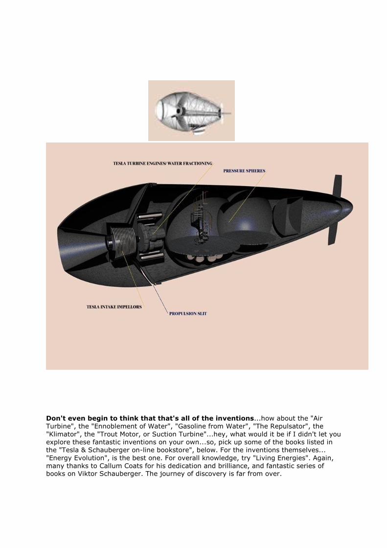
Don't even begin to think that that's all of the inventions...how about the "Air
Turbine", the "Ennoblement of Water", "Gasoline from Water", "The Repulsator", the
"Klimator", the "Trout Motor, or Suction Turbine"...hey, what would it be if I didn't let you
explore these fantastic inventions on your own...so, pick up some of the books listed in
the "Tesla & Schauberger on-line bookstore", below. For the inventions themselves...
"Energy Evolution", is the best one. For overall knowledge, try "Living Energies". Again,
many thanks to Callum Coats for his dedication and brilliance, and fantastic series of books on Viktor Schauberger. The journey of discovery is far from over.
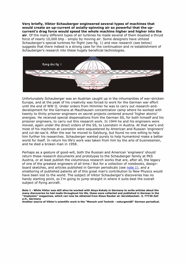
Very briefly, Viktor Schauberger engineered several types of machines that
would create an up-current of axially-spinning air so powerful that the up-
current's drag force would speed the whole machine higher and higher into the
air. Of the many different types of air turbines he made several of them boasted a thrust
force of nearly 10,000 bhp - simply by moving air. Some designers have utilized
Schauberger's special turbines for flight (see fig. 1) and new research (see below)
suggests that there indeed is a strong case for the continuation and re-establishment of Schauberger's research into these hugely beneficial technologies.
Unfortunately Schauberger was an Austrian caught up in the inhumanities of war-stricken
Europe, and at the peak of his creativity was forced to work for the German war effort
until the end of WW II. Under orders from Himmler he was to carry out research-and-
development for the Germans at Mauthausen concentration camp where he worked with
twenty to thirty prisoner engineers on secret projects centered around 'higher atomic'
energies. He received special dispensations from the German SS, for both himself and his
prisoner engineers, to carry out this research work. In 1944 he and his engineers were
moved, again under the direct orders of the SS, to Leonstein in Austria. At that war's end
most of his machines at Leonstein were sequestered by American and Russian 'engineers'
and cul-de-sac'd. After the war he moved to Salzburg, but found no-one willing to help
him further his researches. Schauberger wanted purely to help humankind make a better
world for itself. In return his life's work was taken from him by the arts of businessmen, and he died a broken man in 1958.
Perhaps as a gesture of good-will, both the Russian and American 'engineers' should
return these research documents and prototypes to the Schauberger family at PKS
Austria, or at least publish the voluminous research works that are, after all, the legacy
of one of the greatest engineers of all time.! But for a collection of notebooks, design-
board sketches, and articles published in German periodicals (see note 1), and a
smattering of published patents all of this great man's contribution to New Physics would
have been lost to the world. The subject of Viktor Schauberger's discoveries has no
handy starting point, so I'm going to jump straight in where it suits best the overall subject of flying aircraft.
Note 1 - While Viktor was still alive he worked with Aloys Kokaly in Germany to write articles about the many discoveries he had made throughout his life, these were collected and published in German in the "Implosion" magazines, which can now be obtained from Klaus Rauber at: Geroldseckstr. 4, 77736 Zell a.H., Germany Another source of Viktor's scientific work is the "Mensch und Technik - naturgemäß" German periodical.
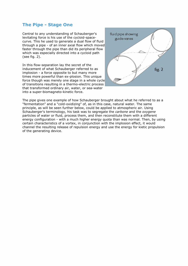
The Pipe - Stage One
Central to any understanding of Schauberger's
levitating force is his use of the cycloid-space-
curve. This he used to generate a dual flow of fluid
through a pipe - of an inner axial flow which moved
faster through the pipe than did its peripheral flow
which was especially directed into a cycloid path (see fig. 2).
In this flow-separation lay the secret of the
inducement of what Schauberger referred to as
implosion - a force opposite to but many more
times more powerful than ex-plosion. This unique
force though was merely one stage in a whole cycle
of transitions resulting in a thermo-electric process
that transformed ordinary air, water, or sea-water into a super-biomagneto-kinetic force.
The pipe gives one example of how Schauberger brought about what he referred to as a
"fermentation" and a "cold-oxidizing" of, as in this case, natural water. The same
principle, as will be seen further below, could be applied to atmospheric air. Using
Schauberger's terminology, his task was to segregate the carbone and the oxygene
particles of water or fluid, process them, and then reconstitute them with a different
energy configuration - with a much higher energy quota than was normal. Then, by using
certain characteristics of a vortex, in conjunction with the implosion effect, it would
channel the resulting release of repulsion energy and use the energy for kietic propulsion
of the generating device.
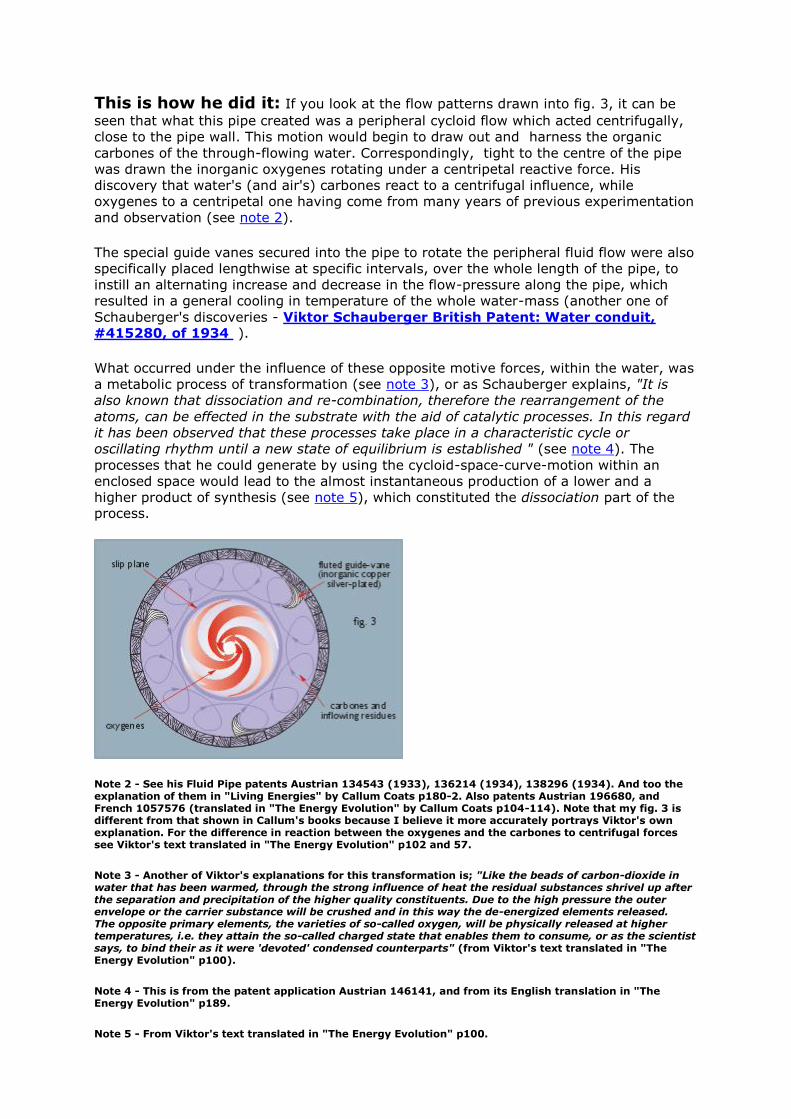
This is how he did it: If you look at the flow patterns drawn into fig. 3, it can be
seen that what this pipe created was a peripheral cycloid flow which acted centrifugally,
close to the pipe wall. This motion would begin to draw out and harness the organic
carbones of the through-flowing water. Correspondingly, tight to the centre of the pipe
was drawn the inorganic oxygenes rotating under a centripetal reactive force. His
discovery that water's (and air's) carbones react to a centrifugal influence, while
oxygenes to a centripetal one having come from many years of previous experimentation
and observation (see note 2).
The special guide vanes secured into the pipe to rotate the peripheral fluid flow were also
specifically placed lengthwise at specific intervals, over the whole length of the pipe, to
instill an alternating increase and decrease in the flow-pressure along the pipe, which
resulted in a general cooling in temperature of the whole water-mass (another one of
Schauberger's discoveries - Viktor Schauberger British Patent: Water conduit, #415280, of 1934 ).
What occurred under the influence of these opposite motive forces, within the water, was
a metabolic process of transformation (see note 3), or as Schauberger explains, "It is
also known that dissociation and re-combination, therefore the rearrangement of the
atoms, can be effected in the substrate with the aid of catalytic processes. In this regard
it has been observed that these processes take place in a characteristic cycle or
oscillating rhythm until a new state of equilibrium is established " (see note 4). The
processes that he could generate by using the cycloid-space-curve-motion within an
enclosed space would lead to the almost instantaneous production of a lower and a
higher product of synthesis (see note 5), which constituted the dissociation part of the process.
Note 2 - See his Fluid Pipe patents Austrian 134543 (1933), 136214 (1934), 138296 (1934). And too the explanation of them in "Living Energies" by Callum Coats p180-2. Also patents Austrian 196680, and French 1057576 (translated in "The Energy Evolution" by Callum Coats p104-114). Note that my fig. 3 is different from that shown in Callum's books because I believe it more accurately portrays Viktor's own explanation. For the difference in reaction between the oxygenes and the carbones to centrifugal forces see Viktor's text translated in "The Energy Evolution" p102 and 57.
Note 3 - Another of Viktor's explanations for this transformation is; "Like the beads of carbon-dioxide in water that has been warmed, through the strong influence of heat the residual substances shrivel up after the separation and precipitation of the higher quality constituents. Due to the high pressure the outer envelope or the carrier substance will be crushed and in this way the de-energized elements released. The opposite primary elements, the varieties of so-called oxygen, will be physically released at higher temperatures, i.e. they attain the so-called charged state that enables them to consume, or as the scientist says, to bind their as it were 'devoted' condensed counterparts" (from Viktor's text translated in "The Energy Evolution" p100).
Note 4 - This is from the patent application Austrian 146141, and from its English translation in "The Energy Evolution" p189.
Note 5 - From Viktor's text translated in "The Energy Evolution" p100.
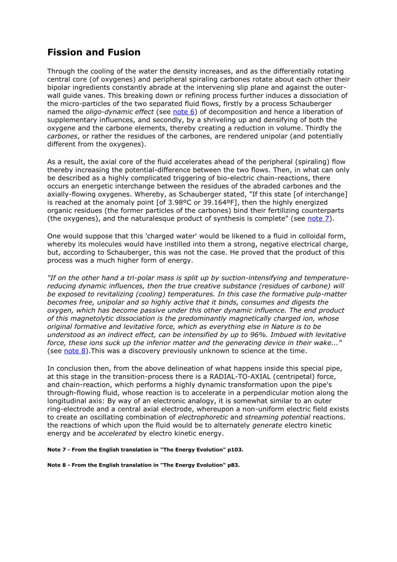
Fission and Fusion
Through the cooling of the water the density increases, and as the differentially rotating
central core (of oxygenes) and peripheral spiraling carbones rotate about each other their
bipolar ingredients constantly abrade at the intervening slip plane and against the outer-
wall guide vanes. This breaking down or refining process further induces a dissociation of
the micro-particles of the two separated fluid flows, firstly by a process Schauberger
named the oligo-dynamic effect (see note 6) of decomposition and hence a liberation of
supplementary influences, and secondly, by a shriveling up and densifying of both the
oxygene and the carbone elements, thereby creating a reduction in volume. Thirdly the
carbones, or rather the residues of the carbones, are rendered unipolar (and potentially different from the oxygenes).
As a result, the axial core of the fluid accelerates ahead of the peripheral (spiraling) flow
thereby increasing the potential-difference between the two flows. Then, in what can only
be described as a highly complicated triggering of bio-electric chain-reactions, there
occurs an energetic interchange between the residues of the abraded carbones and the
axially-flowing oxygenes. Whereby, as Schauberger stated, "If this state [of interchange]
is reached at the anomaly point [of 3.98ºC or 39.164ºF], then the highly energized
organic residues (the former particles of the carbones) bind their fertilizing counterparts (the oxygenes), and the naturalesque product of synthesis is complete" (see note 7).
One would suppose that this 'charged water' would be likened to a fluid in colloidal form,
whereby its molecules would have instilled into them a strong, negative electrical charge,
but, according to Schauberger, this was not the case. He proved that the product of this process was a much higher form of energy.
"If on the other hand a tri-polar mass is split up by suction-intensifying and temperature-
reducing dynamic influences, then the true creative substance (residues of carbone) will
be exposed to revitalizing (cooling) temperatures. In this case the formative pulp-matter
becomes free, unipolar and so highly active that it binds, consumes and digests the
oxygen, which has become passive under this other dynamic influence. The end product
of this magnetolytic dissociation is the predominantly magnetically charged ion, whose
original formative and levitative force, which as everything else in Nature is to be
understood as an indirect effect, can be intensified by up to 96%. Imbued with levitative
force, these ions suck up the inferior matter and the generating device in their wake..." (see note 8).This was a discovery previously unknown to science at the time.
In conclusion then, from the above delineation of what happens inside this special pipe,
at this stage in the transition-process there is a RADIAL-TO-AXIAL (centripetal) force,
and chain-reaction, which performs a highly dynamic transformation upon the pipe's
through-flowing fluid, whose reaction is to accelerate in a perpendicular motion along the
longitudinal axis: By way of an electronic analogy, it is somewhat similar to an outer
ring-electrode and a central axial electrode, whereupon a non-uniform electric field exists
to create an oscillating combination of electrophoretic and streaming potential reactions.
the reactions of which upon the fluid would be to alternately generate electro kinetic
energy and be accelerated by electro kinetic energy.
Note 7 - From the English translation in "The Energy Evolution" p103.
Note 8 - From the English translation in "The Energy Evolution" p83.
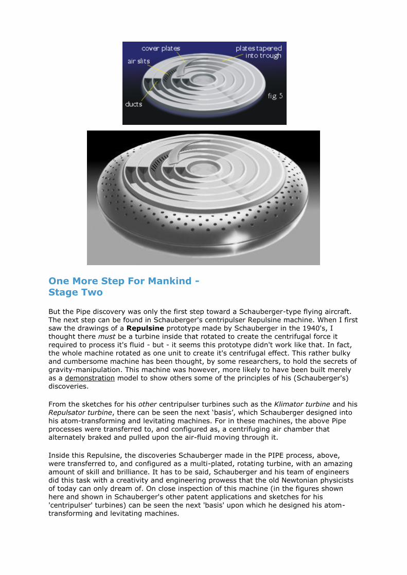
One More Step For Mankind - Stage Two
But the Pipe discovery was only the first step toward a Schauberger-type flying aircraft.
The next step can be found in Schauberger's centripulser Repulsine machine. When I first
saw the drawings of a Repulsine prototype made by Schauberger in the 1940's, I
thought there must be a turbine inside that rotated to create the centrifugal force it
required to process it's fluid - but - it seems this prototype didn't work like that. In fact,
the whole machine rotated as one unit to create it's centrifugal effect. This rather bulky
and cumbersome machine has been thought, by some researchers, to hold the secrets of
gravity-manipulation. This machine was however, more likely to have been built merely
as a demonstration model to show others some of the principles of his (Schauberger's) discoveries.
From the sketches for his other centripulser turbines such as the Klimator turbine and his
Repulsator turbine, there can be seen the next ‘basis’, which Schauberger designed into
his atom-transforming and levitating machines. For in these machines, the above Pipe
processes were transferred to, and configured as, a centrifuging air chamber that alternately braked and pulled upon the air-fluid moving through it.
Inside this Repulsine, the discoveries Schauberger made in the PIPE process, above,
were transferred to, and configured as a multi-plated, rotating turbine, with an amazing
amount of skill and brilliance. It has to be said, Schauberger and his team of engineers
did this task with a creativity and engineering prowess that the old Newtonian physicists
of today can only dream of. On close inspection of this machine (in the figures shown
here and shown in Schauberger's other patent applications and sketches for his
'centripulser' turbines) can be seen the next 'basis' upon which he designed his atom-transforming and levitating machines.
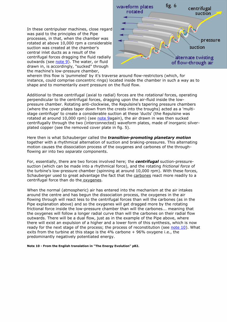
In these centripulser machines, close regard
was paid to the principles of the Pipe
processes, in that, when the chamber was
rotated at above 10,000 rpm a considerable
suction was created at the chamber's
central inlet ducts as a result of the
centrifugal forces dragging the fluid radially
outwards (see note 9). The water, or fluid
drawn in, is accordingly, "sucked" through
the machine's low-pressure chamber,
wherein this flow is 'pummeled' by it's traverse around flow-restrictors (which, for
instance, could comprise concentric rings) located inside the chamber in such a way as to
shape and to momentarily exert pressure on the fluid flow.
Additional to these centrifugal (axial to radial) forces are the rotational forces, operating
perpendicular to the centrifugal forces, dragging upon the air-fluid inside the low-
pressure chamber. Rotating anti-clockwise, the Repulsine's tapering pressure chambers
(where the cover plates taper down from the crests into the troughs) acted as a 'multi-
stage centrifuge' to create a considerable suction at these 'ducts' (the Repulsine was
rotated at around 10,000 rpm) (see note 9again), the air drawn in was then sucked
centrifugally through the two (interconnected) waveform plates, made of inorganic silver-
plated copper (see the removed cover plate in fig. 5).
Here then is what Schauberger called the transition-promoting planetary motion
together with a rhythmical alternation of suction and braking-pressures. This alternating
motion causes the dissociation process of the oxygenes and carbones of the through-flowing air into two separate components.
For, essentially, there are two forces involved here; the centrifugal suction-pressure-
suction (which can be made into a rhythmical force), and the rotating frictional force of
the turbine's low-pressure chamber (spinning at around 10,000 rpm). With these forces,
Schauberger used to great advantage the fact that the carbones react more readily to a centrifugal force than do the oxygenes.
When the normal (atmospheric) air has entered into the mechanism at the air intakes
around the centre and has begun the dissociation process, the oxygenes in the air
flowing through will react less to the centrifugal forces than will the carbones (as in the
Pipe explanation above) and so the oxygenes will get dragged more by the rotating
frictional force inside the low-pressure chamber than will the carbones... meaning that
the oxygenes will follow a longer radial curve than will the carbones on their radial flow
outwards. There will be a dual flow, just as in the example of the Pipe above, where
there will exist an expulsion of a higher and a lower form of this synthesis, which is now
ready for the next stage of the process; the process of reconstitution (see note 10). What
exits from the turbine at this stage is the 4% carbone + 96% oxygene i.e., the predominantly negatively potentiated energy.
Note 10 - From the English translation in "The Energy Evolution" p82.
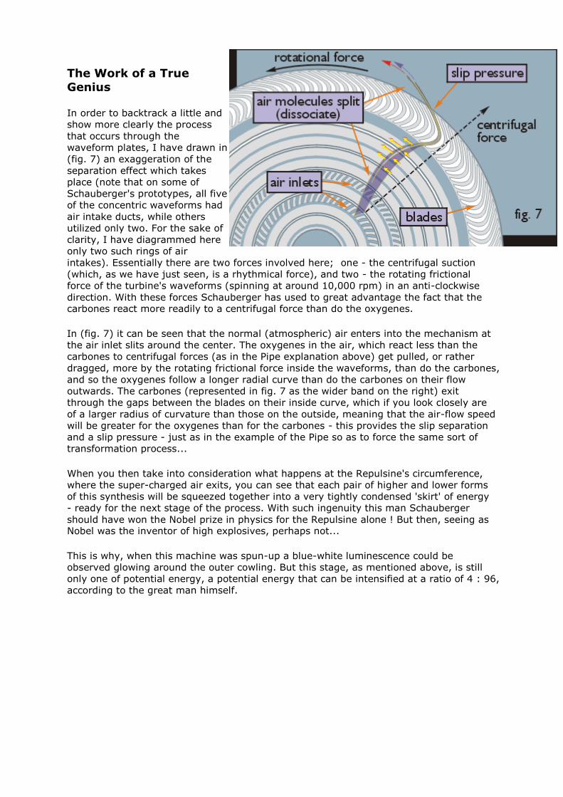
The Work of a True
Genius
In order to backtrack a little and
show more clearly the process
that occurs through the
waveform plates, I have drawn in
(fig. 7) an exaggeration of the
separation effect which takes
place (note that on some of
Schauberger's prototypes, all five
of the concentric waveforms had
air intake ducts, while others
utilized only two. For the sake of
clarity, I have diagrammed here
only two such rings of air
intakes). Essentially there are two forces involved here; one - the centrifugal suction
(which, as we have just seen, is a rhythmical force), and two - the rotating frictional
force of the turbine's waveforms (spinning at around 10,000 rpm) in an anti-clockwise
direction. With these forces Schauberger has used to great advantage the fact that the carbones react more readily to a centrifugal force than do the oxygenes.
In (fig. 7) it can be seen that the normal (atmospheric) air enters into the mechanism at
the air inlet slits around the center. The oxygenes in the air, which react less than the
carbones to centrifugal forces (as in the Pipe explanation above) get pulled, or rather
dragged, more by the rotating frictional force inside the waveforms, than do the carbones,
and so the oxygenes follow a longer radial curve than do the carbones on their flow
outwards. The carbones (represented in fig. 7 as the wider band on the right) exit
through the gaps between the blades on their inside curve, which if you look closely are
of a larger radius of curvature than those on the outside, meaning that the air-flow speed
will be greater for the oxygenes than for the carbones - this provides the slip separation
and a slip pressure - just as in the example of the Pipe so as to force the same sort of
transformation process...
When you then take into consideration what happens at the Repulsine's circumference,
where the super-charged air exits, you can see that each pair of higher and lower forms
of this synthesis will be squeezed together into a very tightly condensed 'skirt' of energy
- ready for the next stage of the process. With such ingenuity this man Schauberger
should have won the Nobel prize in physics for the Repulsine alone ! But then, seeing as Nobel was the inventor of high explosives, perhaps not...
This is why, when this machine was spun-up a blue-white luminescence could be
observed glowing around the outer cowling. But this stage, as mentioned above, is still
only one of potential energy, a potential energy that can be intensified at a ratio of 4 : 96,
according to the great man himself.

Stage Three - To Infinity and Beyond...
Now, following on from the above two stages, we have a highly energetic force at the
periphery of the machine, which is absolutely crackling with energy. If a suitably curved
vessel is located below this rotating peripheral force, and which can turn and guide this
force back towards the machine's axis - to transform this energy flow into a centripetal
force - then, just as Schauberger describes its effect, it becomes an accelerated radically-to-axially in-winding rotational force.
And we are back at the same situation with what happened inside the Pipe in stage one,
where it resulted in the axial fluid being accelerated at great speed through the pipe -
well not quite. In this configuration, there is a lot more energy involved, and it has
already gone through one stage of synthesis. Now it is being mechanically forced
centripetally in towards the centre for its final transformation, the reaction to which is
very forceful. This is IMPLOSION.
This is one of Viktor Schauberger's descriptions of what happens next to this energy; "As
the end product of a natural or unnatural sequence of motion, it will be
accelerated along either the longitudinal or the transverse axis. In the
naturalesque - formative - direction of acceleration, which must take place
along the longitudinal axis (centripetally), so-called electricism acts as the
absolutely indispensable resistance for all motion. As the formative velocity
rises, the resistance increases commensurately in order to provide the
additional frictional (resisting) surfaces required by the accelerating matter.
The actual loss of formative energy associated with this amounts to about 4%,
i.e. in this case approximately 96% of the formative energy (= magnetism
streaming upwards at enormous speed = levitism) is freed, which sucks up its
generating device and a portion of its immediate environs in its wake" (see note
10). Indeed, in all of Schauberger's descriptions of this levitative force he nowhere
describes it as either a propulsive effect i.e. created by a pressure-force, or as an
electrical effect i.e. an electrokinetic force.
May the Force be Levitative
This force was one that streamed in spiral fashion upwards above the machine from the
machine at high speed, and which drew the generating machine or craft up in its wake -
an inverted vortex or black hole if you will. Schauberger variously referred to this
projectile of force as a "magnetism", a "biomagnetism", an "organic vacuum", an "all-attracting force" or, as it was most often called, a "diamagnetismus" (see note 11).
Essentially it seems to have been the second stage of implosion. The first stage of
implosion is the densifying effect (where the products implode under the centripetal
cycloid motion and are squeezed into an ever-decreasing space where, as he says, they
become increasingly densified) but there must follow on from this a repulsion force - as
the next natural progression - which, just like in the Pipe process, shoots the product out
of this densified core like a bullet high into the air (see note 12).
Note 11 - It was probably a big mistake to call this force "diamagnetismus", which Viktor meant as 'through an attracting force that moved in a magnetic flux-like curve' to describe an involuting motion, which always converges toward a line, while at the same time curling back in on itself... because it got miss-translated in English (and especially by the American scientists after the war) to represent DIAMAGNETIC as in the Hall effect or the attribute of a bismuth or a copper - which is a miniscule effect detected only in micro-electronic semi-conductors. A lot of people get fooled by that one, I certainly did - a long time ago! In some cases, more with regard to the implosion of water than of air, Viktor refers to this "attracting magnet for the surrounding air-masses" as dissociated (H), where H referred partly to a suctional force, and partly to an atom of the least amount of density, more from the fact that there just wasn't a better way of describing this previously unrecognized force.
Note 12 - This second stage of implosion describes the process of inter-atomic repulsion, where the atomic lattice (and the inter-atomic spacing therein) can collapse only so far, because whoever constructed this universe ensured that when the inter-atomic spacing reaches a certain level of compression the atoms gain a repulsion force - and the greater the compression, or densifying, the greater the magnitude of repulsive forces the atoms gain. Viktor does actually say that at the formative stage (of implosion) the up flowing force does encounter a resistance which increases "commensurably in order to provide the additional frictional surfaces required by the accelerating matter" (from the English translation in "The Energy Evolution" p81/2).
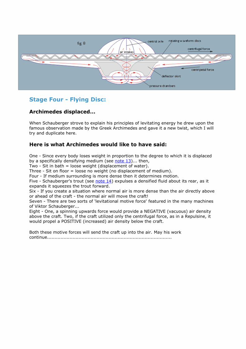
Stage Four - Flying Disc:
Archimedes displaced...
When Schauberger strove to explain his principles of levitating energy he drew upon the
famous observation made by the Greek Archimedes and gave it a new twist, which I will try and duplicate here.
Here is what Archimedes would like to have said:
One - Since every body loses weight in proportion to the degree to which it is displaced
by a specifically densifying medium (see note 13)... then,
Two - Sit in bath = loose weight (displacement of water).
Three - Sit on floor = loose no weight (no displacement of medium).
Four - If medium surrounding is more dense then it determines motion.
Five - Schauberger's trout (see note 14) expulses a densified fluid about its rear, as it
expands it squeezes the trout forward.
Six - If you create a situation where normal air is more dense than the air directly above
or ahead of the craft - the normal air will move the craft!
Seven - There are two sorts of 'levitational motive force' featured in the many machines
of Viktor Schauberger...
Eight - One, a spinning upwards force would provide a NEGATIVE (vacuous) air density
above the craft. Two, if the craft utilized only the centrifugal force, as in a Repulsine, it would propel a POSITIVE (increased) air density below the craft.
Both these motive forces will send the craft up into the air. May his work continue...................................................................................