Embed Size (px)
Citation preview

Getting Started with
ST Drone Kit
Adriano Basile
v.0.97
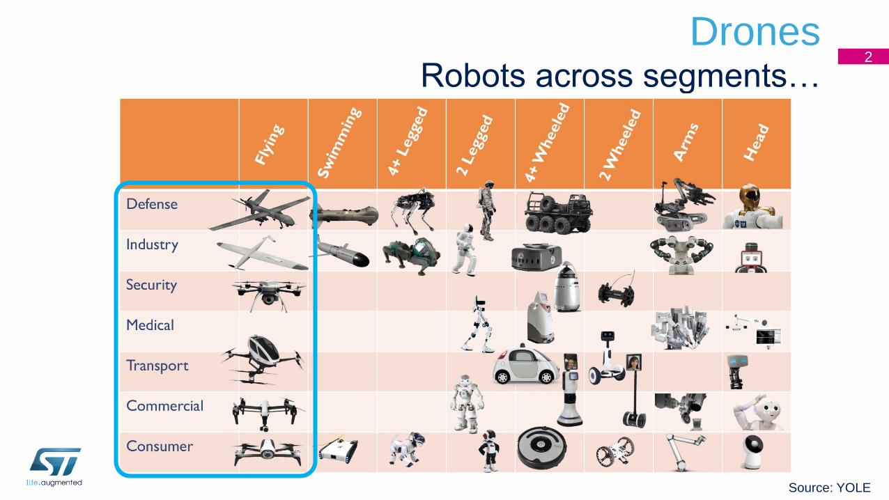
DronesRobots across segments…
2
Source: YOLE
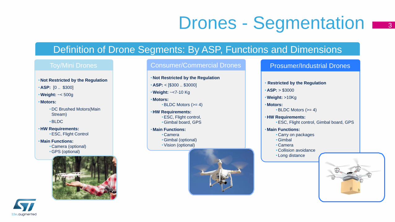
Drones - Segmentation
Definition of Drone Segments: By ASP, Functions and Dimensions
• Not Restricted by the Regulation
• ASP: < [$300 .. $3000]
• Weight: ~<7-10 Kg
• Motors:
• BLDC Motors (>= 4)
• HW Requirements:
• ESC, Flight control,
• Gimbal board, GPS
• Main Functions:
• Camera
• Gimbal (optional)
• Vision (optional)
• Not Restricted by the Regulation
• ASP: [0 .. $300]
• Weight: ~< 500g
• Motors:
• DC Brushed Motors(Main
Stream)
• BLDC
• HW Requirements:
• ESC, Flight Control
• Main Functions:
• Camera (optional)
• GPS (optional)
Toy/Mini Drones Consumer/Commercial Drones
• Restricted by the Regulation
• ASP: > $3000
• Weight: >10Kg
• Motors:
• BLDC Motors (>= 4)
• HW Requirements:
• ESC, Flight control, Gimbal board, GPS
• Main Functions:
• Carry on packages
• Gimbal
• Camera
• Collision avoidance
• Long distance
Prosumer/Industrial Drones
3
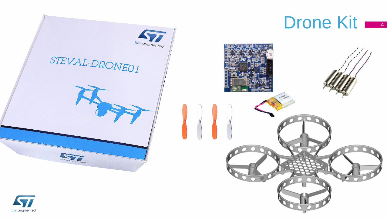
Drone Kit 4

Overview 5
Getting started: assemble the items
STEVAL-FCU001V1 HW description
2
3
1 Basics of multicopters
STEVAL-FCU001V1 SW description 4
Appendixes5
Definition of UAS, drone, multicopter 6
An UAS (Unmanned Aircraft System), sometimes called a drone, is an aircraft without a human pilot
on-board; instead, the UAS is controlled from an operator on the ground.
A multicopter or multirotor is a rotorcraft with more than two rotors. While single (and double) rotor
helicopters are more complex to build because they need variable pitch rotors whose pitch varies as
the blade rotates for flight stability and control, multicopters use fixed-pitch blades. Control of the
multicopter is achieved by varying the relative speed of each rotor to change the thrust and torque
produced by each.
A quadcopter is a 4-rotor multicopter. In this document we will also use the more popular term, drone.

Quadcopter basics: flight control dynamics 7
FCU
Front direction
Each rotor produces both a thrust and a torque about its
center of rotation. If all rotors are spinning at the same
angular velocity, with M1 and M3 rotating CW and M2
and M4 rotating CCW, the angular acceleration about
the yaw axis is exactly zero (so there is no need for a tail
rotor like on conventional helicopters).
FCU: Flight Control Unit
M3
M1
M2
M4
Front Direction
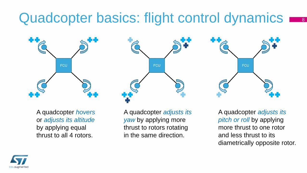
Quadcopter basics: flight control dynamics 8
A quadcopter hovers
or adjusts its altitude
by applying equal
thrust to all 4 rotors.
A quadcopter adjusts its
yaw by applying more
thrust to rotors rotating
in the same direction.
A quadcopter adjusts its
pitch or roll by applying
more thrust to one rotor
and less thrust to its
diametrically opposite rotor.

Quadcopter basics: flight control dynamics 9
Motor
Action 1 2 3 4 Note
Pitch (x) Slow (Fast) Fast (Slow) Fast (Slow) Slow (Fast) Move Backward (Forward)
Roll (y) Slow (Fast) Slow (Fast) Fast (Slow) Fast (Slow) Move Right (Left)
Yaw (z) Fast (Slow) Slow (Fast) Fast (Slow) Slow (Fast) Heading Left (Right)
Up / Down Fast (Slow) Fast (Slow) Fast (Slow) Fast (Slow) Move Up (Down)
• Coordinate System: ENU
• Frame Type: X-type
• 4 x Motor, rotation direction as shown
• Movement:
• Forward / Backward (Pitch)
• Left / Right (Roll)
• Turn Left / Right (Yaw)
• Up / Down
ENU: East North Up

Quadcopter basics: mechanical structure 10
Frame: there are several frames of different size and materials available on
the market. For simplest control algorithm (reference FW available with
STEVAL-FCU001V1) the motors and propellers should be placed at
equidistant intervals.
Motors: for small drones, DC coreless motors are usually used, while for
bigger frames, 3-ph DC brushless motors are preferred. The choice of the
motor must be made together with the frame and propeller selection. Please
be aware that some motors are designed to be used only in CW or CCW
direction (especially DC brushed).
Propellers: are a type of fan that convert rotational motion into thrust. There is
a wide choice with 2, 3, and 4 blades, different materials and shapes.
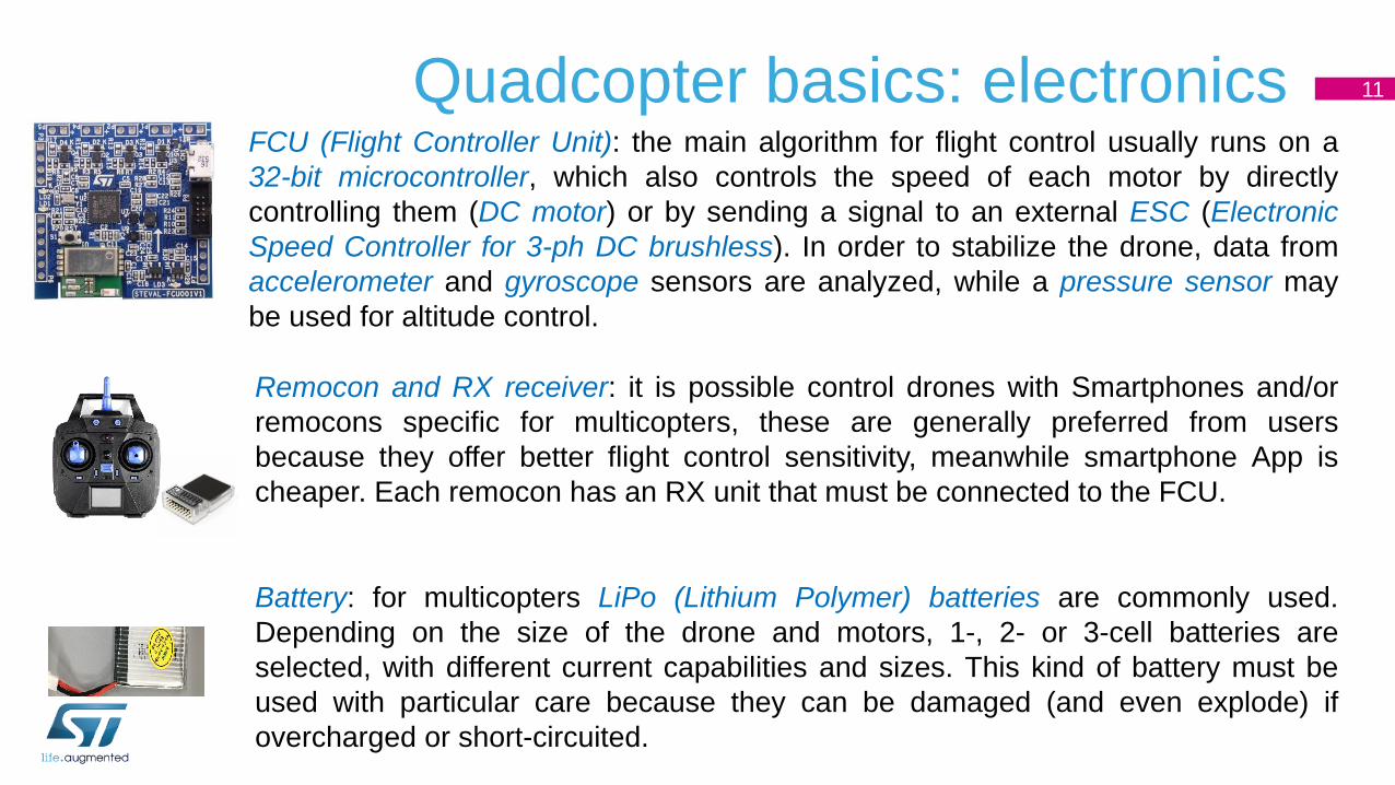
Quadcopter basics: electronics 11
FCU (Flight Controller Unit): the main algorithm for flight control usually runs on a
32-bit microcontroller, which also controls the speed of each motor by directly
controlling them (DC motor) or by sending a signal to an external ESC (Electronic
Speed Controller for 3-ph DC brushless). In order to stabilize the drone, data from
accelerometer and gyroscope sensors are analyzed, while a pressure sensor may
be used for altitude control.
Remocon and RX receiver: it is possible control drones with Smartphones and/or
remocons specific for multicopters, these are generally preferred from users
because they offer better flight control sensitivity, meanwhile smartphone App is
cheaper. Each remocon has an RX unit that must be connected to the FCU.
Battery: for multicopters LiPo (Lithium Polymer) batteries are commonly used.
Depending on the size of the drone and motors, 1-, 2- or 3-cell batteries are
selected, with different current capabilities and sizes. This kind of battery must be
used with particular care because they can be damaged (and even explode) if
overcharged or short-circuited.
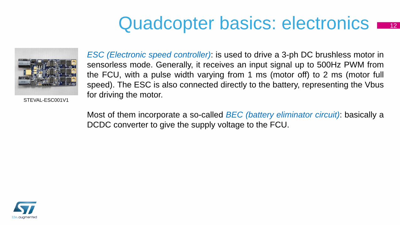
Quadcopter basics: electronics 12
ESC (Electronic speed controller): is used to drive a 3-ph DC brushless motor in
sensorless mode. Generally, it receives an input signal up to 500Hz PWM from
the FCU, with a pulse width varying from 1 ms (motor off) to 2 ms (motor full
speed). The ESC is also connected directly to the battery, representing the Vbus
for driving the motor.
Most of them incorporate a so-called BEC (battery eliminator circuit): basically a
DCDC converter to give the supply voltage to the FCU.
STEVAL-ESC001V1
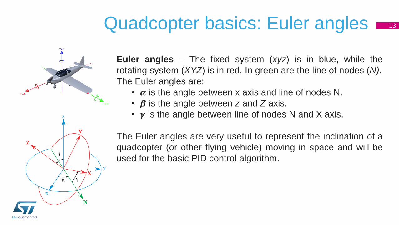
Quadcopter basics: Euler angles 13
Euler angles – The fixed system (xyz) is in blue, while the
rotating system (XYZ) is in red. In green are the line of nodes (N).
The Euler angles are:
• 𝜶 is the angle between x axis and line of nodes N.
• 𝜷 is the angle between z and Z axis.
• 𝜸 is the angle between line of nodes N and X axis.
The Euler angles are very useful to represent the inclination of a
quadcopter (or other flying vehicle) moving in space and will be
used for the basic PID control algorithm.
Overview 14
Getting started: assemble the items
STEVAL-FCU001V1 HW description
2
3
1 Basics of multicopters
STEVAL-FCU001V1 SW description 4
Appendixes5

Assemble the items: mechanical structure 15
STEVAL-FCU001V1
board
3D mechanical
frame
1-cell battery 3.7V
600mAh 30C
2 x CW, 2 x CCW
coreless DC motor
8.5x20mm
Remote Controller or Smartphone App4 x 65mm propellers
The items below represent possible assembly items for a small drone and have
already been tested with the current FW version, demonstrating stable flight
performance.

Mechanical structure of STEVAL-DRONE01 16
The drone frame is one of the critical part of drone because its size, weight
and material impact on the flight capability. In the kit, it has been included a
good tradeoff between weight and easy replicability, in fact the frame has been
made with a 3D printer: the STL file could be downloaded by the product
folder.
In order to support the air flow for clockwise and counterclockwise motors, the
three arms to sustain the motors have been designed as airfoils, see Figure
on next slide.
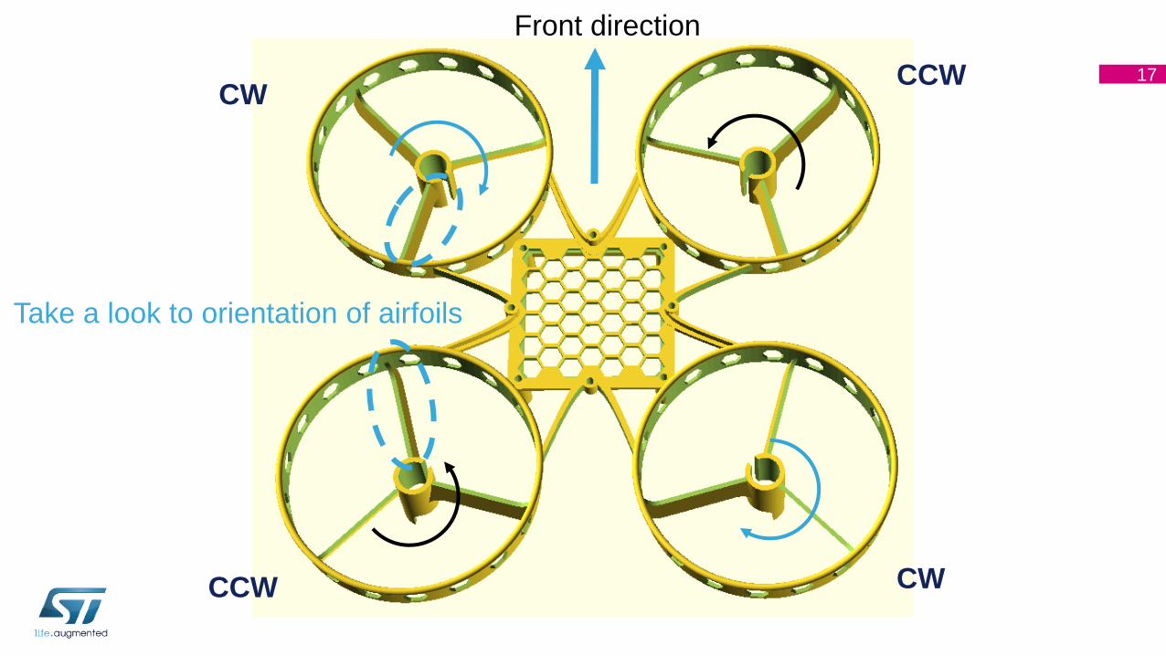
17
Front direction
Take a look to orientation of airfoils
CW
CCWCW
CCW

Step 1: mounting STEVAL-FCU001V1
board on frame18
• The STEVAL-FCU001V1 must be mounted in the center
of the drone, equidistant from the four motors.
• Front direction is indicated on the STEVAL-FCU001V1
by a small arrow. Take care about frame orientation
(see figure on left).
• The board must be mounted as flat as possible and well
anchored to the frame.
• You can use an adhesive sponge between the frame and
the FCU board to minimize mechanical vibration from
motors.
• Current FW supports the common “x” configuration
shown here. To use a “+” configuration, some
modifications to the FW are needed (*).(*) Please refer to the FW explanation session for more details.
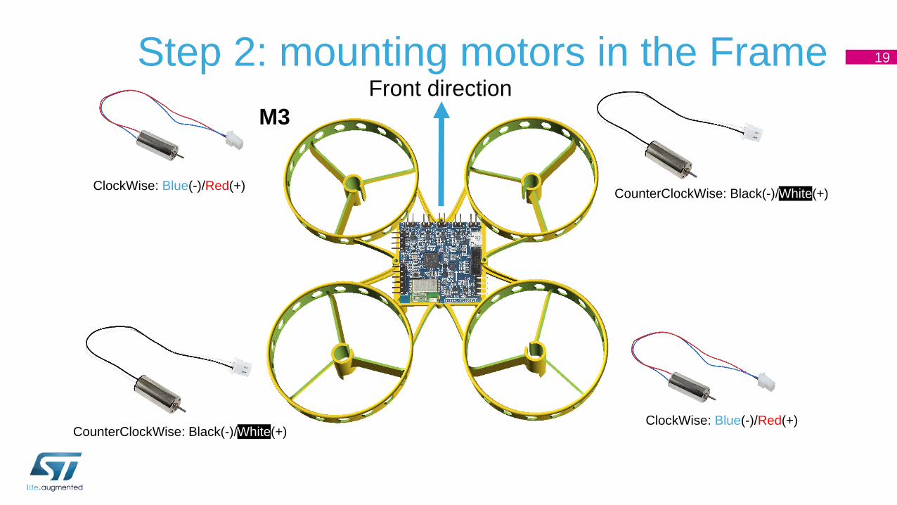
Step 2: mounting motors in the Frame 19
ClockWise: Blue(-)/Red(+)CounterClockWise: Black(-)/White(+)
CounterClockWise: Black(-)/White(+)ClockWise: Blue(-)/Red(+)
Front direction
M3

Step 3: motor connection on the board 20
DC motors should be connected to P5, P4, P2 and P1
connectors following the sequence in the figure.
CW: Blue(-)/Red(+)
CCW: Black(-)/White(+)
M4M2 M3 M1
Warning: A CW DC motor can rotate in CCW
direction if “+” and “-” are reversed, but the brushes
are designed for CW rotation and prolonged use in
the opposite direction may reduce its lifetime
Note: This configuration is valid also for
3-ph DC brushless motors connected
through external ESC
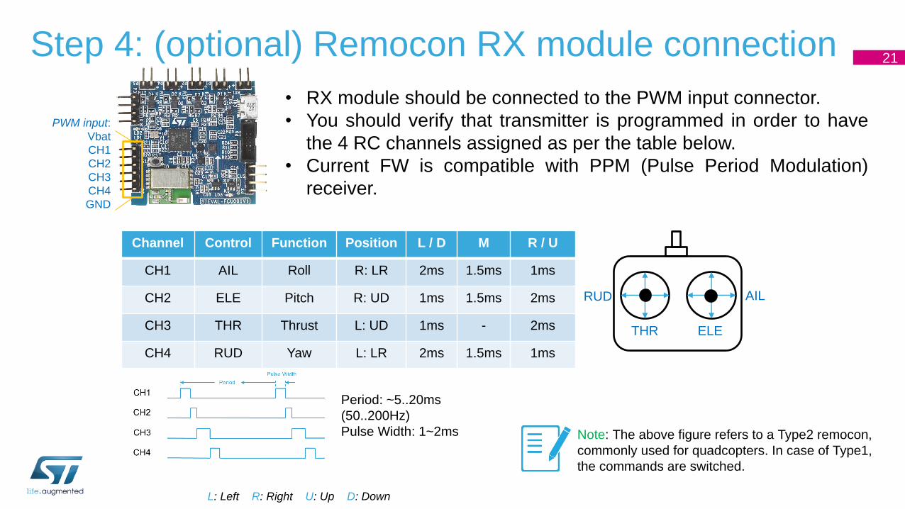
Step 4: (optional) Remocon RX module connection21
• RX module should be connected to the PWM input connector.
• You should verify that transmitter is programmed in order to have
the 4 RC channels assigned as per the table below.
• Current FW is compatible with PPM (Pulse Period Modulation)
receiver.
Channel Control Function Position L / D M R / U
CH1 AIL Roll R: LR 2ms 1.5ms 1ms
CH2 ELE Pitch R: UD 1ms 1.5ms 2ms
CH3 THR Thrust L: UD 1ms - 2ms
CH4 RUD Yaw L: LR 2ms 1.5ms 1ms
L: Left R: Right U: Up D: Down
Period: ~5..20ms
(50..200Hz)
Pulse Width: 1~2ms Note: The above figure refers to a Type2 remocon,
commonly used for quadcopters. In case of Type1,
the commands are switched.
THR
RUD AIL
ELE
PWM input:
Vbat
CH1
CH2
CH3
CH4
GND

Step 5: Battery connection 22
A LiPO 1-cell battery can be connected directly to connector BT1 on STEVAL-
FCU001V1 board and battery can be charged via USB thanks to the on-board
charger.
In case of 2-cell or 3-cell, the battery should be connected to the ESC and Vbat
should be connected to the 5V (max input voltage 5.5V) generated by the BEC
of the ESC.
BT1 connector
BAT input
Warning: a reverse battery protection diode is not mounted, check carefully before connecting the
battery!
Warning: LiPO batteries can be damaged and even explode if they are short-circuited or overcharged.
They should also always be kept in a safe bag when not used or during charging. Please read detailed
information from battery maker or on the Internet before handling a LiPO battery.
Warning: as soon as the battery is discharged after a flight (when there is not enough power to make
the drone fly), disconnect the battery from the board immediately. If the battery remains connected and
is completely discharged, it will be damaged and you will no longer be able to recharge.
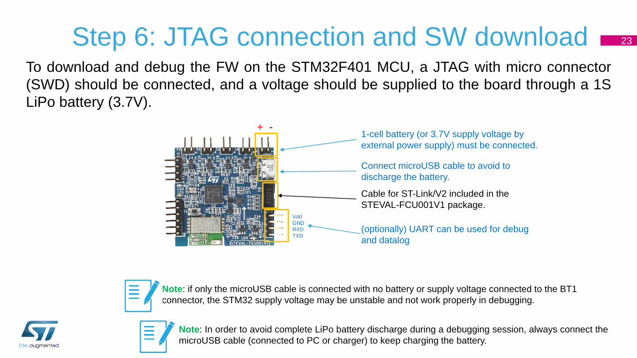
Step 6: JTAG connection and SW download 23
To download and debug the FW on the STM32F401 MCU, a JTAG with micro connector
(SWD) should be connected, and a voltage should be supplied to the board through a 1S
LiPo battery (3.7V).
Cable for ST-Link/V2 included in the
STEVAL-FCU001V1 package.
(optionally) UART can be used for debug
and datalog
1-cell battery (or 3.7V supply voltage by
external power supply) must be connected.
Connect microUSB cable to avoid to
discharge the battery.
+ -
Vdd
GND
RXD
TXD
Note: if only the microUSB cable is connected with no battery or supply voltage connected to the BT1
connector, the STM32 supply voltage may be unstable and not work properly in debugging.
Note: In order to avoid complete LiPo battery discharge during a debugging session, always connect the
microUSB cable (connected to PC or charger) to keep charging the battery.

24
M4 M2 M3 M1 + -
Resume: Motor and Battery connections
CC
W:
Bla
ck( -
)/W
hite
(+)
Clockwise
M3
Counter-Clockwise
M4Clockwise
M1
Counter-Clockwise
M2
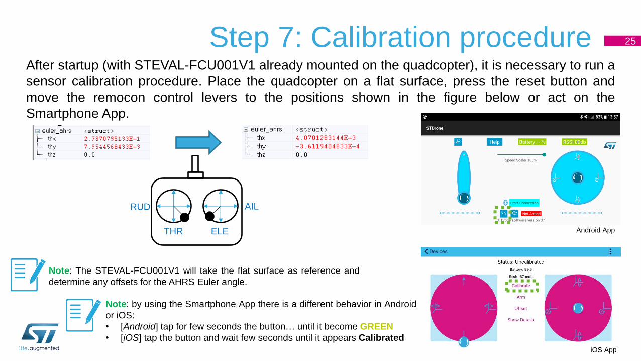
Step 7: Calibration procedure 25
After startup (with STEVAL-FCU001V1 already mounted on the quadcopter), it is necessary to run a
sensor calibration procedure. Place the quadcopter on a flat surface, press the reset button and
move the remocon control levers to the positions shown in the figure below or act on the
Smartphone App.
THR
RUD AIL
ELE
Note: by using the Smartphone App there is a different behavior in Android
or iOS:
• [Android] tap for few seconds the button… until it become GREEN
• [iOS] tap the button and wait few seconds until it appears Calibrated
Note: The STEVAL-FCU001V1 will take the flat surface as reference and
determine any offsets for the AHRS Euler angle.
Android App
iOS App

Step 7: Arming procedure 26
The first operational tests should be performed without the propellers mounted to verify that
connections are correct, the motors function and the remocon connection is established.
For safety reasons, the drone is initially Disarmed: even if connection with Remocon TX is
established and throttle is at full scale, the motors are intentionally not driven (red LED on the
STEVAL-FCU001V1 blinks).
To allow flight, you must perform an Arming procedure: in the current FW implementation, arming is
achieved by moving the remocon levers to the positions shown in the figure below for at least 2
seconds (the red LED will stop blinking and remain ON) or by tapping the button on the
Smartphone App.
THR
RUD AIL
ELE
Note: by using the Smartphone App tap the button… you will see Armed message
Android AppiOS App
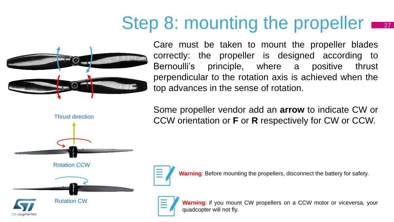
Step 8: mounting the propeller 27
Care must be taken to mount the propeller blades
correctly: the propeller is designed according to
Bernoulli’s principle, where a positive thrust
perpendicular to the rotation axis is achieved when the
top advances in the sense of rotation.
Some propeller vendor add an arrow to indicate CW or
CCW orientation or F or R respectively for CW or CCW.
Rotation CCW
Thrust direction
Warning: Before mounting the propellers, disconnect the battery for safety.
Warning: if you mount CW propellers on a CCW motor or viceversa, your
quadcopter will not fly.
Rotation CW

Step 9: first test flight 28
Proceed with your first test flight in an open area with no one in the immediate
vicinity after you have followed all the safety procedures during setup and have
completed the arming procedure.
• First make the drone hover at 2m altitude and ensure that it remains stable.
• Then proceed with simple flight maneuvres like forming a cross at 2-3 m altitude.
Troubleshooting: if the drone seems unstable and starts to oscillate, try reducing the PID
proportional gain, refer to the FW description section and PID tuning tutorials on the Internet.
3-5 m
3-5 m
Overview 29
Getting started: assemble the items
STEVAL-FCU001V1 HW description
2
3
1 Basics of multicopters
STEVAL-FCU001V1 SW description 4
Appendixes5
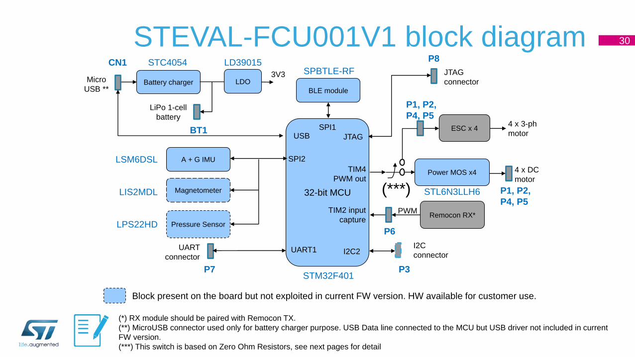
STEVAL-FCU001V1 block diagram 30
32-bit MCU
A + G IMU SPI2
Magnetometer
Power MOS x4TIM4
PWM out
Remocon RX*TIM2 input
capture Pressure Sensor
SPI1
STM32F401
LSM6DSL
LPS22HD
Battery chargerMicro
USB **
LIS2MDL
I2C
connector
(*) RX module should be paired with Remocon TX.
(**) MicroUSB connector used only for battery charger purpose. USB Data line connected to the MCU but USB driver not included in current
FW version.
(***) This switch is based on Zero Ohm Resistors, see next pages for detail
4 x DC
motor
ESC x 44 x 3-ph
motor
LiPo 1-cell
battery
BLE module
Block present on the board but not exploited in current FW version. HW available for customer use.
PWM
I2C2
SPBTLE-RF
UART
connectorUART1
JTAG
JTAG
connector
USB
STC4054
LDO3V3
LD39015
P7 P3
P6
P1, P2,
P4, P5
P1, P2,
P4, P5
P8
BT1
CN1
STL6N3LLH6(***)

STM32F401 connections 31
BLE
Sensors
R/C
Motors
Pin Connection
STM32CubeMX:
• It is a graphic interface for configuring the STM32
peripherals and generating the relative source code
• It contains embedded STM32Cube libraries
• STM32CubeF4 is designed to be used with the
STM32F4 family

STEVAL-FCU001V1 schematics (1/4) 32

STEVAL-FCU001V1 schematics (2/4) 33

STEVAL-FCU001V1 schematics (3/4) 34
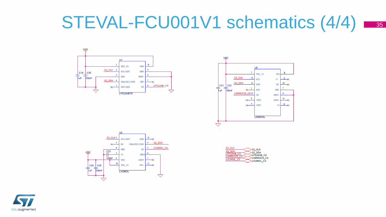
STEVAL-FCU001V1 schematics (4/4) 35
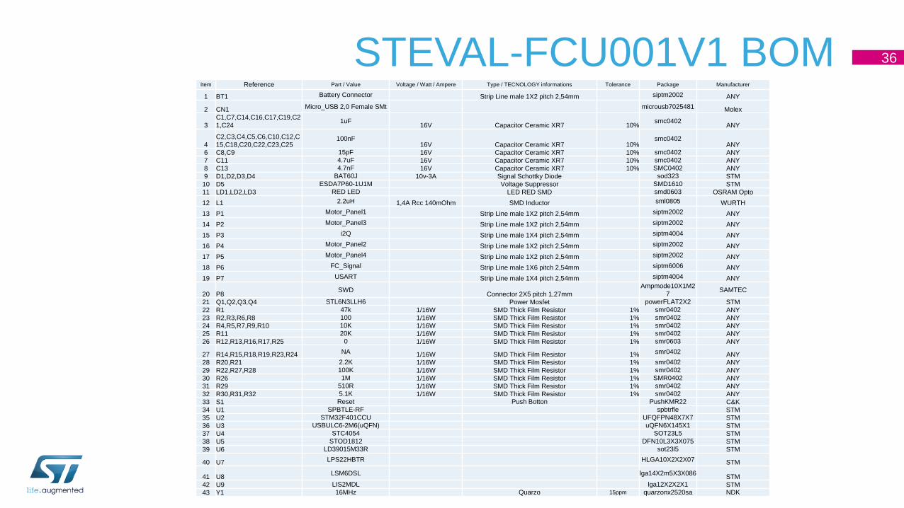
STEVAL-FCU001V1 BOM 36
Item Reference Part / Value Voltage / Watt / Ampere Type / TECNOLOGY informations Tolerance Package Manufacturer
1 BT1 Battery Connector Strip Line male 1X2 pitch 2,54mm siptm2002 ANY
2 CN1 Micro_USB 2,0 Female SMt microusb7025481 Molex
3
C1,C7,C14,C16,C17,C19,C2
1,C241uF
16V Capacitor Ceramic XR7 10%smc0402
ANY
4
C2,C3,C4,C5,C6,C10,C12,C
15,C18,C20,C22,C23,C25100nF
16V Capacitor Ceramic XR7 10%smc0402
ANY
6 C8,C9 15pF 16V Capacitor Ceramic XR7 10% smc0402 ANY
7 C11 4.7uF 16V Capacitor Ceramic XR7 10% smc0402 ANY
8 C13 4.7nF 16V Capacitor Ceramic XR7 10% SMC0402 ANY
9 D1,D2,D3,D4 BAT60J 10v-3A Signal Schottky Diode sod323 STM
10 D5 ESDA7P60-1U1M Voltage Suppressor SMD1610 STM
11 LD1,LD2,LD3 RED LED LED RED SMD smd0603 OSRAM Opto
12 L1 2.2uH 1,4A Rcc 140mOhm SMD Inductor sml0805 WURTH
13 P1 Motor_Panel1 Strip Line male 1X2 pitch 2,54mm siptm2002 ANY
14 P2 Motor_Panel3 Strip Line male 1X2 pitch 2,54mm siptm2002 ANY
15 P3 i2Q Strip Line male 1X4 pitch 2,54mm siptm4004 ANY
16 P4 Motor_Panel2 Strip Line male 1X2 pitch 2,54mm siptm2002 ANY
17 P5 Motor_Panel4 Strip Line male 1X2 pitch 2,54mm siptm2002 ANY
18 P6 FC_Signal Strip Line male 1X6 pitch 2,54mm siptm6006 ANY
19 P7 USART Strip Line male 1X4 pitch 2,54mm siptm4004 ANY
20 P8SWD
Connector 2X5 pitch 1,27mm
Ampmode10X1M2
7SAMTEC
21 Q1,Q2,Q3,Q4 STL6N3LLH6 Power Mosfet powerFLAT2X2 STM
22 R1 47k 1/16W SMD Thick Film Resistor 1% smr0402 ANY
23 R2,R3,R6,R8 100 1/16W SMD Thick Film Resistor 1% smr0402 ANY
24 R4,R5,R7,R9,R10 10K 1/16W SMD Thick Film Resistor 1% smr0402 ANY
25 R11 20K 1/16W SMD Thick Film Resistor 1% smr0402 ANY
26 R12,R13,R16,R17,R25 0 1/16W SMD Thick Film Resistor 1% smr0603 ANY
27 R14,R15,R18,R19,R23,R24 NA 1/16W SMD Thick Film Resistor 1% smr0402 ANY
28 R20,R21 2.2K 1/16W SMD Thick Film Resistor 1% smr0402 ANY
29 R22,R27,R28 100K 1/16W SMD Thick Film Resistor 1% smr0402 ANY
30 R26 1M 1/16W SMD Thick Film Resistor 1% SMR0402 ANY
31 R29 510R 1/16W SMD Thick Film Resistor 1% smr0402 ANY
32 R30,R31,R32 5.1K 1/16W SMD Thick Film Resistor 1% smr0402 ANY
33 S1 Reset Push Botton PushKMR22 C&K
34 U1 SPBTLE-RF spbtrfle STM
35 U2 STM32F401CCU UFQFPN48X7X7 STM
36 U3 USBULC6-2M6(uQFN) uQFN6X145X1 STM
37 U4 STC4054 SOT23L5 STM
38 U5 STOD1812 DFN10L3X3X075 STM
39 U6 LD39015M33R sot23l5 STM
40 U7 LPS22HBTR HLGA10X2X2X07 STM
41 U8LSM6DSL lga14X2m5X3X086
STM
42 U9 LIS2MDL lga12X2X2X1 STM
43 Y1 16MHz Quarzo 15ppm quarzonx2520sa NDK
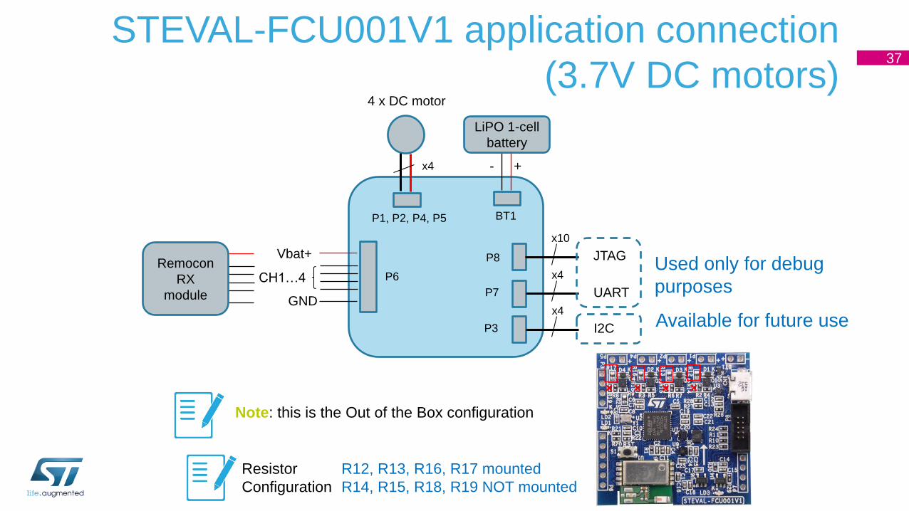
STEVAL-FCU001V1 application connection
(3.7V DC motors)37
LiPO 1-cell
battery
BT1P1, P2, P4, P5
+-x4
4 x DC motor
P6
Vbat+
GND
CH1…4
x10
JTAG
x4
UART
P8
P7
x4
I2CP3
Used only for debug
purposes
Available for future use
Remocon
RX
module
R12, R13, R16, R17 mounted
R14, R15, R18, R19 NOT mounted
Resistor
Configuration
Note: this is the Out of the Box configuration
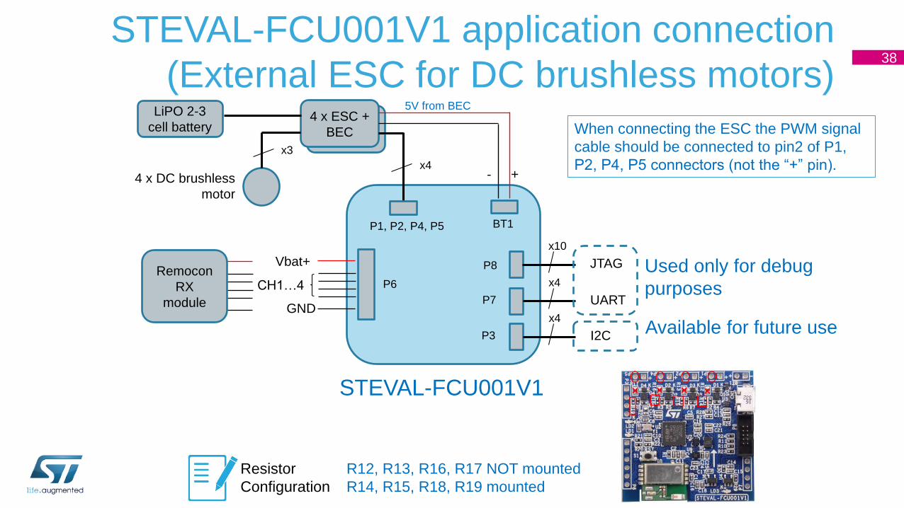
STEVAL-FCU001V1 application connection
(External ESC for DC brushless motors)38
STEVAL-FCU001V1
LiPO 2-3
cell battery
BT1P1, P2, P4, P5
+-x4
4 x DC brushless
motor
P6
Vbat+
GND
CH1…4
x10
JTAG
x4
UART
P8
P7
x4
I2CP3
Used only for debug
purposes
Available for future use
Remocon
RX
module
R12, R13, R16, R17 NOT mounted
R14, R15, R18, R19 mounted
4 x ESC +
BEC
x3
5V from BEC
When connecting the ESC the PWM signal
cable should be connected to pin2 of P1,
P2, P4, P5 connectors (not the “+” pin).
Resistor
Configuration
Overview 39
Getting started: assemble the items
STEVAL-FCU001V1 HW description
2
3
1 Basics of multicopters
STEVAL-FCU001V1 SW description 4
Appendixes5

STEVAL-FCU001V1 FW download 40
The source code of the STEVAL-FCU001V1 can be downloaded
at the following link (or QR code):
https://github.com/STMicroelectronics-CentralLabs/ST_Drone_FCU_F401
Warning: The source FW code is intended to be used for evaluation of the board, and must be
used or modified by experts. The FW is not designed and tested for commercial use and for the
mass production of commercial products.

FW Architecture
• The firmware is structured in different levels:
• Application: contains all the functions developed for
the user to control the flight of the drone.
• Middleware: libraries to manage connectivity (USB
and BLE).
• Drivers: the level nearest to the HW with all the
functions managing the sensors and peripherals of the
microcontroller.
• The Utilities and CMSIS are functions
directly related to the STM32 architecture
and corresponding Cortex-M4.
41
USB Virtual COM
STM32Cube Hardware
Abstraction Layer (HAL)
LSM6DSM LISM2DLSTM32F4
LPS22HD BLUENRG-MS
Remote Control Flight Control
PID ControlAHRS
Development board
STEVAL-FCU001V1
HW components
Application
Middleware
Drivers
CMSIS
Utilities
Board Support
PackageComponents
Support Package
Sensors
Management
BLE stack
Module not yet implemented in current FW
implementation.
Motors
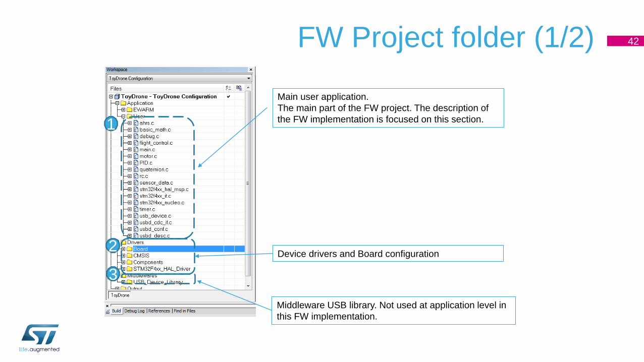
FW Project folder (1/2) 42
1
2
3
Main user application.
The main part of the FW project. The description of
the FW implementation is focused on this section.
Device drivers and Board configuration
Middleware USB library. Not used at application level in
this FW implementation.

FW Project folder (2/2) 43
1
Standard STM32CUBE Application Files
User Application Files
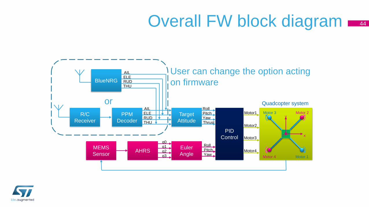
44Overall FW block diagram
AILELERUDTHU
Yaw
RollPitch
ThrustYawPitchRoll
R/C
Receiver
PPM
Decoder
AILELERUDTHU
Target
Attitude
MEMS
SensorAHRS
Euler
Angle
q0q1q2q3
PID
Control
Motor1
Motor2
Motor3
Motor4
Motor 1
Motor 2Motor 3
Motor 4
x
y
z
BlueNRG
or Quadcopter system
User can change the option acting
on firmware
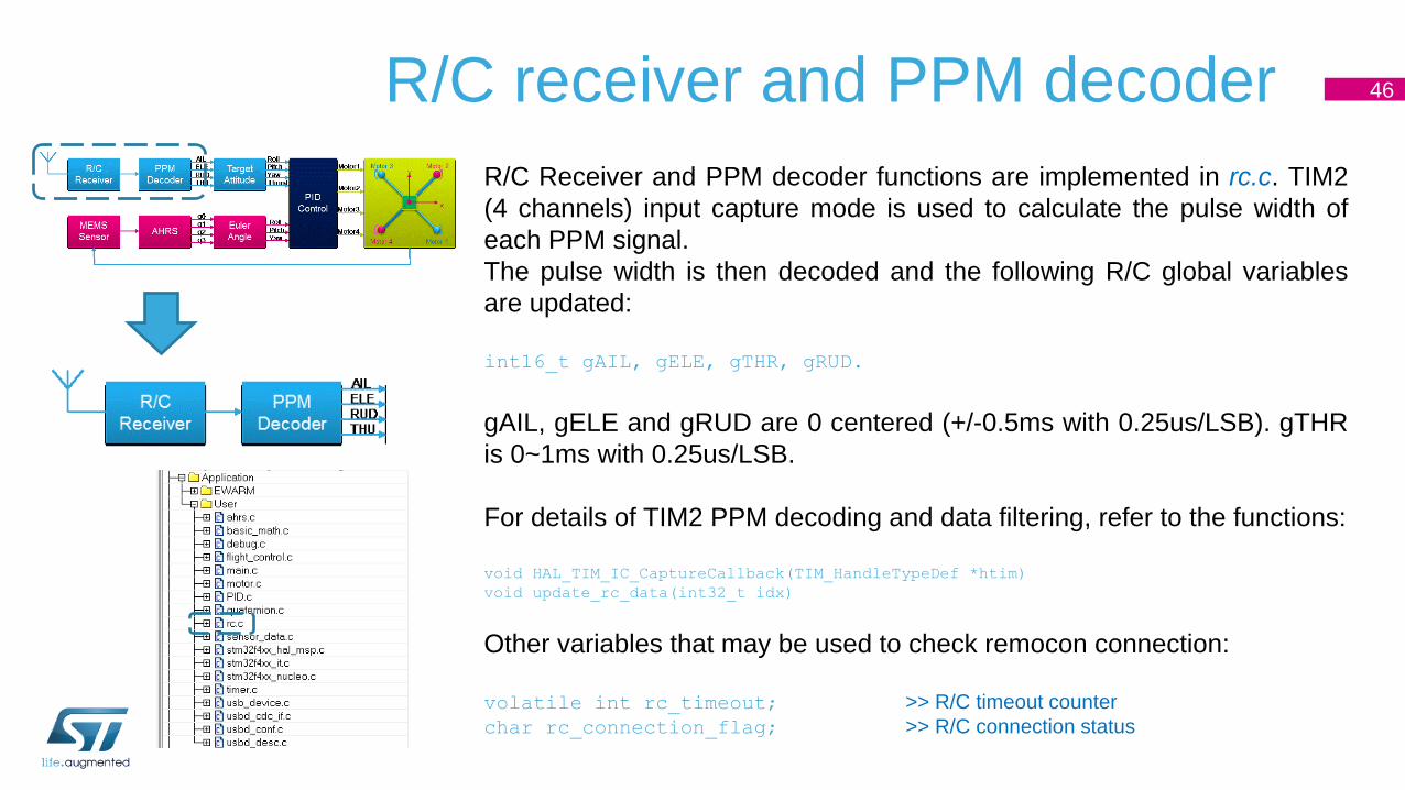
46R/C receiver and PPM decoder
R/C Receiver and PPM decoder functions are implemented in rc.c. TIM2
(4 channels) input capture mode is used to calculate the pulse width of
each PPM signal.
The pulse width is then decoded and the following R/C global variables
are updated:
int16_t gAIL, gELE, gTHR, gRUD.
gAIL, gELE and gRUD are 0 centered (+/-0.5ms with 0.25us/LSB). gTHR
is 0~1ms with 0.25us/LSB.
For details of TIM2 PPM decoding and data filtering, refer to the functions:
void HAL_TIM_IC_CaptureCallback(TIM_HandleTypeDef *htim)
void update_rc_data(int32_t idx)
Other variables that may be used to check remocon connection:
volatile int rc_timeout; >> R/C timeout counter
char rc_connection_flag; >> R/C connection status

Smartphone Apps 47
1
12
2
3 4
3
4
Right joystick (ELE, AIL)
Left joystick(THR, RUD) 1
2
3 Calibrate button
4 ARM button
https://play.google.com/store/apps/details?id=com.st.STDrone
https://apps.apple.com/it/app/st-ble-drone/id1471332188
Bluetooth ST AppDrone
• When using BLE to control the drone, the difference is in the presence of the BLE stack to
manage the communication, and in the absence of the PPM Decoder, since the values are given
directly by the BLE module with the variables:
int16_t gAIL, gELE, gTHR, gRUD.
• To switch from the R/C to the BLE app configuration, simply change a define in the file «rc.h»:
//#define REMOCON_PWM // Remocon RX 4 channel PWM
#define REMOCON_BLE // BLE Remocon App
48

Overview 49
Getting started: assemble the items
STEVAL-FCU001V1 HW description
2
3
1 Basics of multicopters
STEVAL-FCU001V1 SW description 4
Appendixes5

Appendix A
ST Support and Community

community.st.com/dronezone
Appendix B
Fine Tuning of the Firmware

53R/C channels and R/C calibration
The RC channels are mapped in the file config_drone.h, where it is also
possible to define the timeout interval (if no signal from remocon motor OFF):
#define RC_TIMEOUT_VALUE 30
// Define the GPIO port for R/C input capture channels
#define RC_CHANNEL1_PORT GPIOA
#define RC_CHANNEL1_PIN GPIO_PIN_0
…
You can also calibrate the Remocon by fine tuning certain parameters (center
and full scale positions, arming threshold) in rc.h:
// Definition for AIL(Roll) Channel
#define AIL_LEFT 7661
#define AIL_MIDDLE 6044
#define AIL_RIGHT 4434
…
#define RC_FULLSCALE 1500
#define RC_CAL_THRESHOLD 1200
THR
RUD AIL
ELE
Channel Control GPIO
CH1 AIL PA0
CH2 ELE PA1
CH3 THR PA2
CH4 RUD PA3
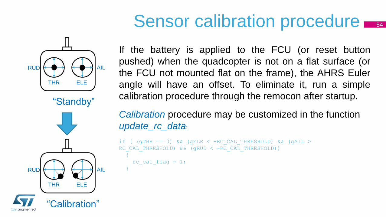
54Sensor calibration procedure
If the battery is applied to the FCU (or reset button
pushed) when the quadcopter is not on a flat surface (or
the FCU not mounted flat on the frame), the AHRS Euler
angle will have an offset. To eliminate it, run a simple
calibration procedure through the remocon after startup.
Calibration procedure may be customized in the function
update_rc_data:
if ( (gTHR == 0) && (gELE < -RC_CAL_THRESHOLD) && (gAIL >
RC_CAL_THRESHOLD) && (gRUD < -RC_CAL_THRESHOLD))
{
rc_cal_flag = 1;
}
THR
RUD AIL
ELE
“Standby”
“Calibration”
THR
RUD AIL
ELE
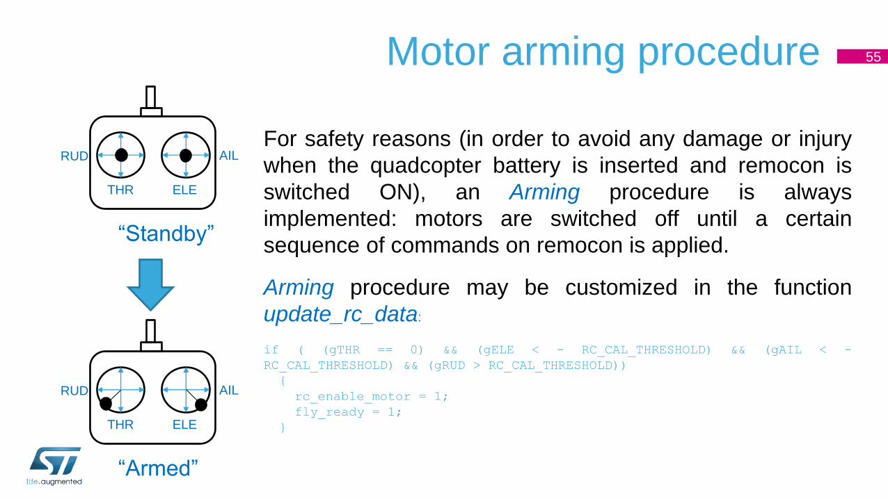
55Motor arming procedure
For safety reasons (in order to avoid any damage or injury
when the quadcopter battery is inserted and remocon is
switched ON), an Arming procedure is always
implemented: motors are switched off until a certain
sequence of commands on remocon is applied.
Arming procedure may be customized in the function
update_rc_data:
if ( (gTHR == 0) && (gELE < - RC_CAL_THRESHOLD) && (gAIL < -
RC_CAL_THRESHOLD) && (gRUD > RC_CAL_THRESHOLD))
{
rc_enable_motor = 1;
fly_ready = 1;
}
THR
RUD AIL
ELE
“Standby”
“Armed”
THR
RUD AIL
ELE

56Target attitudeConversion from Remocon Euler angle to AHRS Euler angle (needed for
setting the target of the PID control loop) is implemented in the rc.c file in
the function:
void GetTargetEulerAngle(EulerAngleTypeDef *euler_rc, EulerAngleTypeDef *euler_ahrs)
The data from the Remocon (i.e. gELE) is normalized to the full scale value
and converted in angle:
t1 = gELE;
if (t1 > RC_FULLSCALE)
t1 = RC_FULLSCALE;
else if (t1 < -RC_FULLSCALE)
t1 = - RC_FULLSCALE;
euler_rc->thx = -t1 * max_pitch_rad / RC_FULLSCALE;
const float max_pitch_rad = I*PITCH_MAX_DEG/180.0;
The change of sign (-t1) is related to the fact than increasing ELE (plus
compared to Mid level) to move forward, corresponds to a negative target
angle for pitch.
FWD
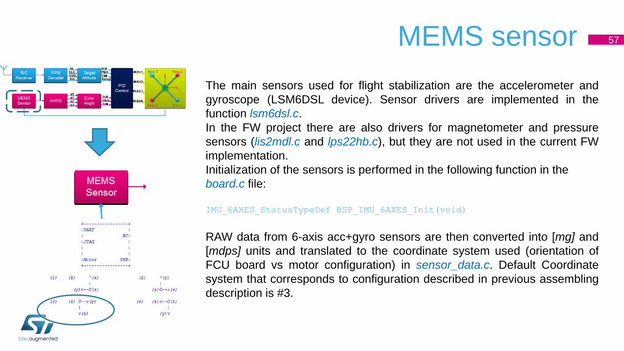
57MEMS sensor
The main sensors used for flight stabilization are the accelerometer and
gyroscope (LSM6DSL device). Sensor drivers are implemented in the
function lsm6dsl.c.
In the FW project there are also drivers for magnetometer and pressure
sensors (lis2mdl.c and lps22hb.c), but they are not used in the current FW
implementation.
Initialization of the sensors is performed in the following function in the
board.c file:
IMU_6AXES_StatusTypeDef BSP_IMU_6AXES_Init(void)
RAW data from 6-axis acc+gyro sensors are then converted into [mg] and
[mdps] units and translated to the coordinate system used (orientation of
FCU board vs motor configuration) in sensor_data.c. Default Coordinate
system that corresponds to configuration described in previous assembling
description is #3.
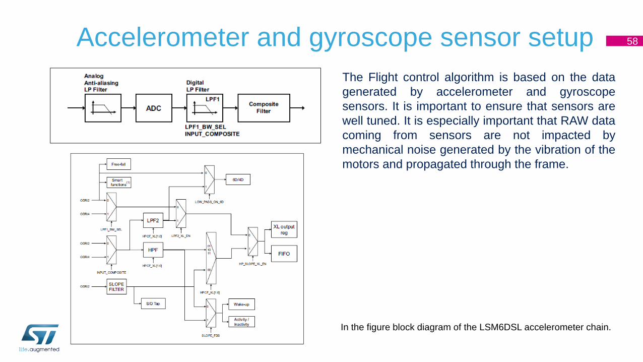
Accelerometer and gyroscope sensor setup 58
The Flight control algorithm is based on the data
generated by accelerometer and gyroscope
sensors. It is important to ensure that sensors are
well tuned. It is especially important that RAW data
coming from sensors are not impacted by
mechanical noise generated by the vibration of the
motors and propagated through the frame.
In the figure block diagram of the LSM6DSL accelerometer chain.

59
Accelerometer key parameter settings:• Accelerometer full-scale selection FS default ±2g >> set to ±4g
• Analog Filter Bandwith default 1.5KHz >> keep default
• Output data rate and power mode selection ODR default Power down mode >> set to 1.6kHz
• Composite filter input selection default ODR/2 >> keep default
• Accelerometer low-pass filter LPF2 selection default >> set to Low pass filter enabled @ ODR/50 or ODR/100 depending on
mechanical vibration noise
BSP_ACCELERO_Set_ODR_Value(LSM6DSL_X_0_handle, 1660.0); /* ODR 1.6kHz */
BSP_ACCELERO_Set_FS(LSM6DSL_X_0_handle, FS_MID); /* FS 4g */
LSM6DSL_ACC_GYRO_W_InComposit(LSM6DSL_X_0_handle, LSM6DSL_ACC_GYRO_IN_ODR_DIV_2); /* ODR/2 low pass filtered sent
to composite filter */
LSM6DSL_ACC_GYRO_W_LowPassFiltSel_XL(LSM6DSL_X_0_handle, LSM6DSL_ACC_GYRO_LPF2_XL_ENABLE); /* Enable LPF2 filter in
composite filter block */
LSM6DSL_ACC_GYRO_W_HPCF_XL(LSM6DSL_X_0_handle, LSM6DSL_ACC_GYRO_HPCF_XL_DIV100); /* Low pass filter @ ODR/100 */
uint8_t tmp_6axis_reg_value;
BSP_ACCELERO_Read_Reg(LSM6DSL_X_0_handle, 0x10, &tmp_6axis_reg_value);
tmp_6axis_reg_value = tmp_6axis_reg_value & 0xFE; /* Set LSB to 0 >> Analog filter 1500Hz*/
BSP_ACCELERO_Write_Reg(LSM6DSL_X_0_handle, 0x10, tmp_6axis_reg_value);
Accelerometer sensor setup

Accelerometer sensor setup 60
1. Full-scale selection FS ±4g
2. Analog Filter Bandwith 1.5KHz
3. Output data rate ODR 1.6kHz
4. Composite filter input selection ODR/2
5. Low-pass filter LPF2 selection enabled @ ODR/50 or ODR/100
2
4 5
5
31
Composite filter

Gyroscope sensor setup 61
• Gyroscope key parameter settings:• Gyroscope Full Scale selection default 245 dps >> set to 2000dps
• Gyroscope output data rate selection ODR default power down >> set to 104Hz
• Gyroscope's low-pass filter bandwidth selection LPF1 FTYPE >> set to Narrow (10b)
BSP_GYRO_Set_FS(LSM6DSL_G_0_handle, FS_HIGH); /* Set FS to 2000dps */
BSP_GYRO_Set_ODR(LSM6DSL_G_0_handle, ODR_HIGH); /* Set ODR to 104Hz */
LSM6DSL_ACC_GYRO_W_LP_BW_G(LSM6DSL_G_0_handle,
LSM6DSL_ACC_GYRO_LP_G_NARROW); /* LPF1 FTYPE set to 10b */
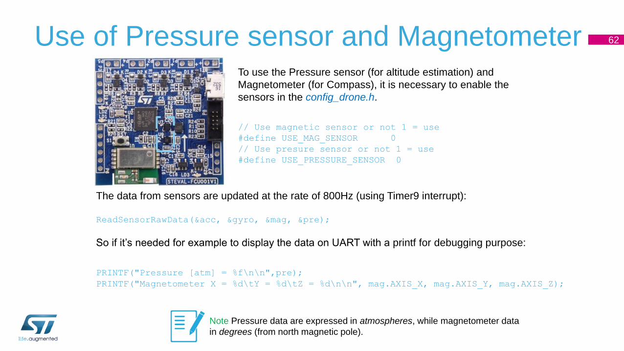
62Use of Pressure sensor and MagnetometerTo use the Pressure sensor (for altitude estimation) and
Magnetometer (for Compass), it is necessary to enable the
sensors in the config_drone.h.
// Use magnetic sensor or not 1 = use
#define USE_MAG_SENSOR 0
// Use presure sensor or not 1 = use
#define USE_PRESSURE_SENSOR 0
The data from sensors are updated at the rate of 800Hz (using Timer9 interrupt):
ReadSensorRawData(&acc, &gyro, &mag, &pre);
So if it’s needed for example to display the data on UART with a printf for debugging purpose:
PRINTF("Pressure [atm] = %f\n\n",pre);
PRINTF("Magnetometer X = %d\tY = %d\tZ = %d\n\n", mag.AXIS_X, mag.AXIS_Y, mag.AXIS_Z);
Note Pressure data are expressed in atmospheres, while magnetometer data
in degrees (from north magnetic pole).
Sensor calibration after startup (1/2) 63
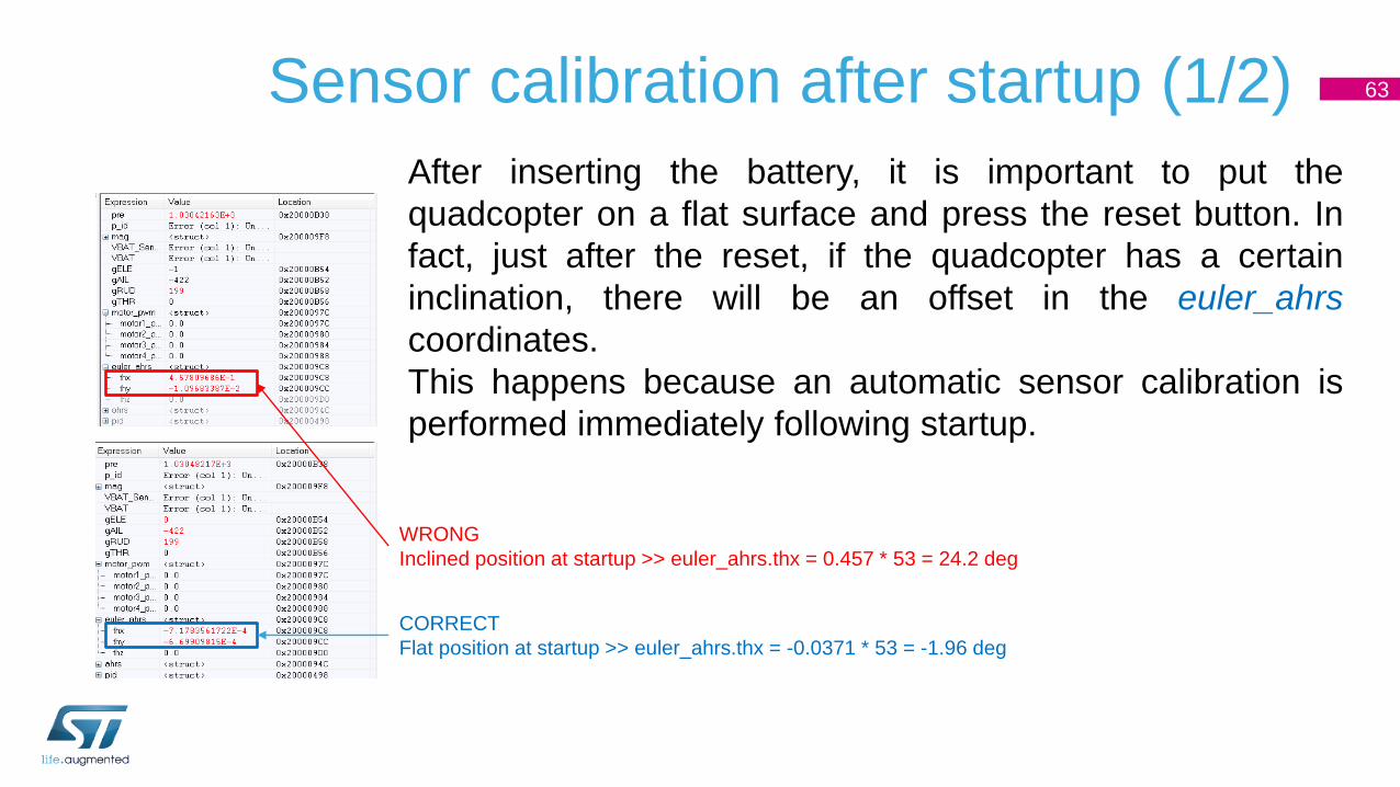
After inserting the battery, it is important to put the
quadcopter on a flat surface and press the reset button. In
fact, just after the reset, if the quadcopter has a certain
inclination, there will be an offset in the euler_ahrs
coordinates.
This happens because an automatic sensor calibration is
performed immediately following startup.
WRONG
Inclined position at startup >> euler_ahrs.thx = 0.457 * 53 = 24.2 deg
CORRECT
Flat position at startup >> euler_ahrs.thx = -0.0371 * 53 = -1.96 deg
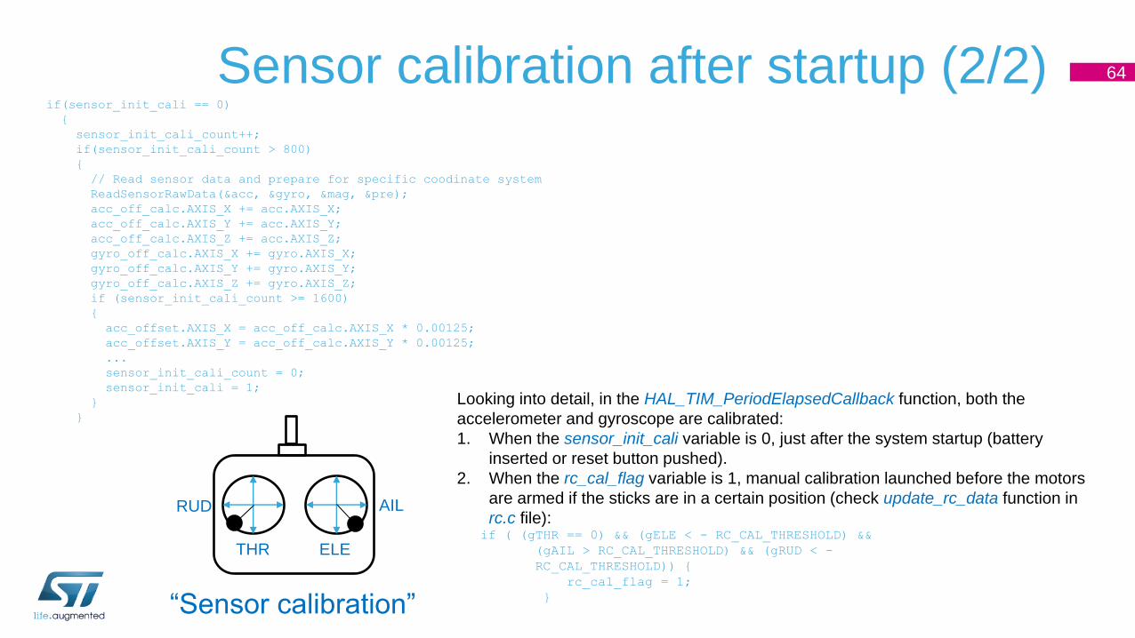
Sensor calibration after startup (2/2) 64
if(sensor_init_cali == 0)
{
sensor_init_cali_count++;
if(sensor_init_cali_count > 800)
{
// Read sensor data and prepare for specific coodinate system
ReadSensorRawData(&acc, &gyro, &mag, &pre);
acc_off_calc.AXIS_X += acc.AXIS_X;
acc_off_calc.AXIS_Y += acc.AXIS_Y;
acc_off_calc.AXIS_Z += acc.AXIS_Z;
gyro_off_calc.AXIS_X += gyro.AXIS_X;
gyro_off_calc.AXIS_Y += gyro.AXIS_Y;
gyro_off_calc.AXIS_Z += gyro.AXIS_Z;
if (sensor_init_cali_count >= 1600)
{
acc_offset.AXIS_X = acc_off_calc.AXIS_X * 0.00125;
acc_offset.AXIS_Y = acc_off_calc.AXIS_Y * 0.00125;
...
sensor_init_cali_count = 0;
sensor_init_cali = 1;
}
}
Looking into detail, in the HAL_TIM_PeriodElapsedCallback function, both the
accelerometer and gyroscope are calibrated:
1. When the sensor_init_cali variable is 0, just after the system startup (battery
inserted or reset button pushed).
2. When the rc_cal_flag variable is 1, manual calibration launched before the motors
are armed if the sticks are in a certain position (check update_rc_data function in
rc.c file):if ( (gTHR == 0) && (gELE < - RC_CAL_THRESHOLD) &&
(gAIL > RC_CAL_THRESHOLD) && (gRUD < -
RC_CAL_THRESHOLD)) {
rc_cal_flag = 1;
}
THR
RUD AIL
ELE
“Sensor calibration”

65Battery voltage monitoringIt is sometimes important to monitor the level of the battery for telemetry purposes, or to
trigger certain actions (stop the motor, sound alarm, …).
For this reason, the ADC1 channel 9 (PB1) is connected to Vbat through a resistor partition.
For debug purposes, a simple code fragment is inserted in the main.c to perform a single
ADC reading(*) and send the data converted to UART:
HAL_ADC_Start(&hadc1);
if (HAL_ADC_PollForConversion(&hadc1, 1000000) == HAL_OK)
{
VBAT_Sense = HAL_ADC_GetValue(&hadc1);
VBAT = (((VBAT_Sense*3.3)/4095)*(BAT_RUP+BAT_RDW))/BAT_RDW;
PRINTF("Battery voltage = %fV\r", VBAT);
}
HAL_ADC_Stop(&hadc1);
(*) It may eventually be possible to use the ADC with direct conversion to DMA, without launching the ADC
conversion each time.
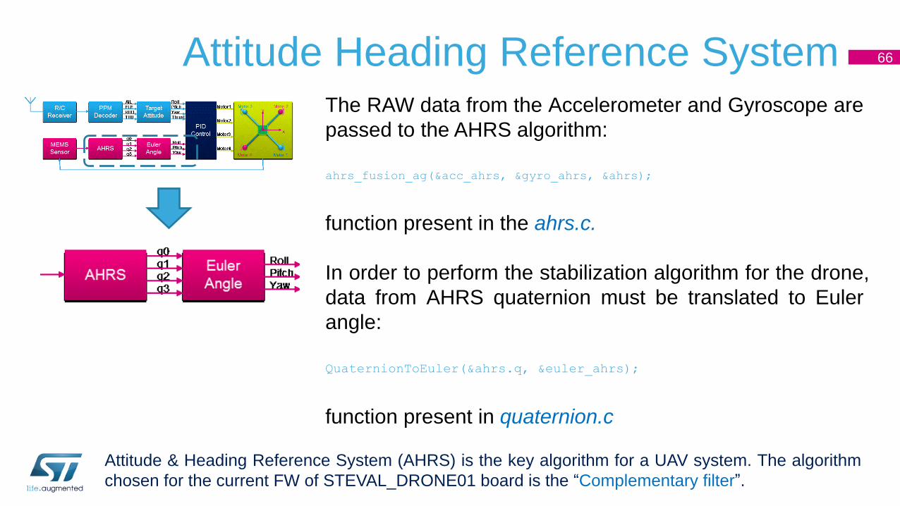
66Attitude Heading Reference SystemThe RAW data from the Accelerometer and Gyroscope are
passed to the AHRS algorithm:
ahrs_fusion_ag(&acc_ahrs, &gyro_ahrs, &ahrs);
function present in the ahrs.c.
In order to perform the stabilization algorithm for the drone,
data from AHRS quaternion must be translated to Euler
angle:
QuaternionToEuler(&ahrs.q, &euler_ahrs);
function present in quaternion.c
Attitude & Heading Reference System (AHRS) is the key algorithm for a UAV system. The algorithm
chosen for the current FW of STEVAL_DRONE01 board is the “Complementary filter”.
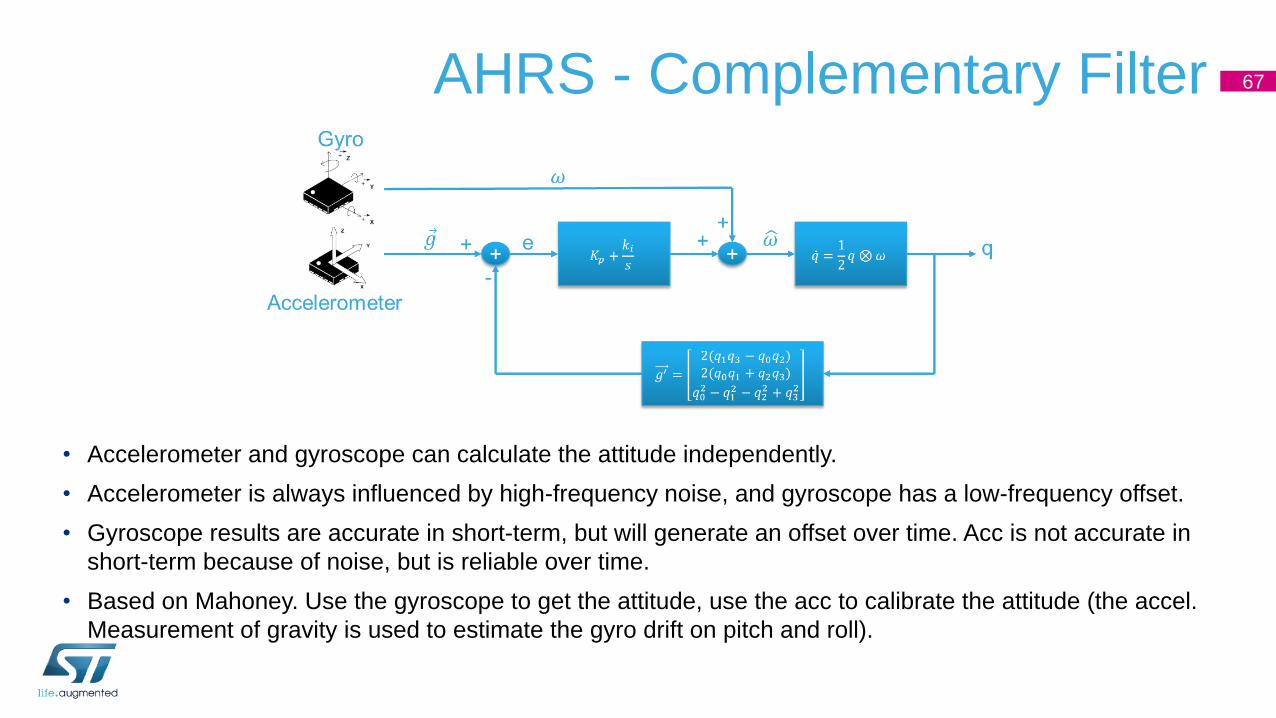
AHRS - Complementary Filter
• Accelerometer and gyroscope can calculate the attitude independently.
• Accelerometer is always influenced by high-frequency noise, and gyroscope has a low-frequency offset.
• Gyroscope results are accurate in short-term, but will generate an offset over time. Acc is not accurate in
short-term because of noise, but is reliable over time.
• Based on Mahoney. Use the gyroscope to get the attitude, use the acc to calibrate the attitude (the accel.
Measurement of gravity is used to estimate the gyro drift on pitch and roll).
67

Flight PID Control 68
The stabilization algorithm is performed with PID control. Target for
the PID is given by the Euler angle imposed by the Remocon,
which is compared to the Euler angle of the actual drone position.
FlightControlPID_OuterLoop(&euler_rc_fil, &euler_ahrs, &ahrs, &pid);
function present in flight_control.c.
The output of the PID is the value of the 4 motors’s speed (PWM
HW signal for ESC or Mosfet driving) for the quadcopter:
motor_pwm->motor1_pwm = motor_thr - pid->x_s2 - pid->y_s2 + pid->z_s2 +
MOTOR_OFF1;
motor_pwm->motor2_pwm = motor_thr + pid->x_s2 - pid->y_s2 - pid->z_s2 +
MOTOR_OFF2;
motor_pwm->motor3_pwm = motor_thr + pid->x_s2 + pid->y_s2 + pid->z_s2 +
MOTOR_OFF3;
motor_pwm->motor4_pwm = motor_thr - pid->x_s2 + pid->y_s2 - pid->z_s2 +
MOTOR_OFF4;
M1
M2
M3
M4
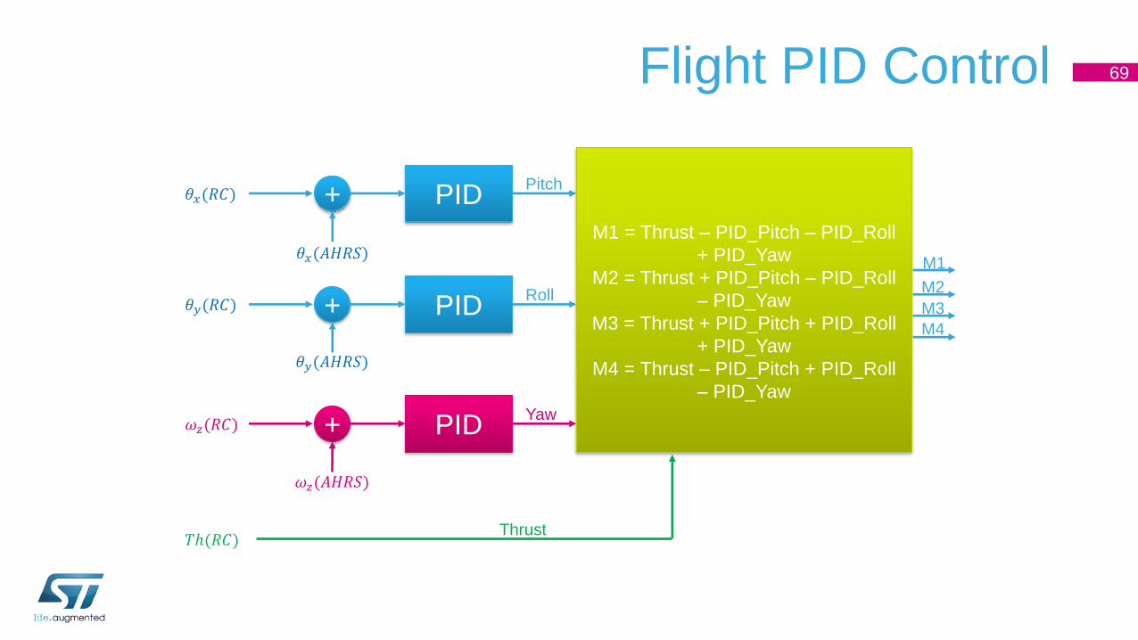
Flight PID Control 69
+𝜃𝑥(𝑅𝐶)
𝜃𝑥(𝐴𝐻𝑅𝑆)
PIDPitch
+𝜃𝑦(𝑅𝐶)
𝜃𝑦(𝐴𝐻𝑅𝑆)
PIDRoll
+𝜔𝑧(𝑅𝐶)
𝜔𝑧(𝐴𝐻𝑅𝑆)
PIDYaw
𝑇ℎ(𝑅𝐶)Thrust
M1 = Thrust – PID_Pitch – PID_Roll
+ PID_Yaw
M2 = Thrust + PID_Pitch – PID_Roll
– PID_Yaw
M3 = Thrust + PID_Pitch + PID_Roll
+ PID_Yaw
M4 = Thrust – PID_Pitch + PID_Roll
– PID_Yaw
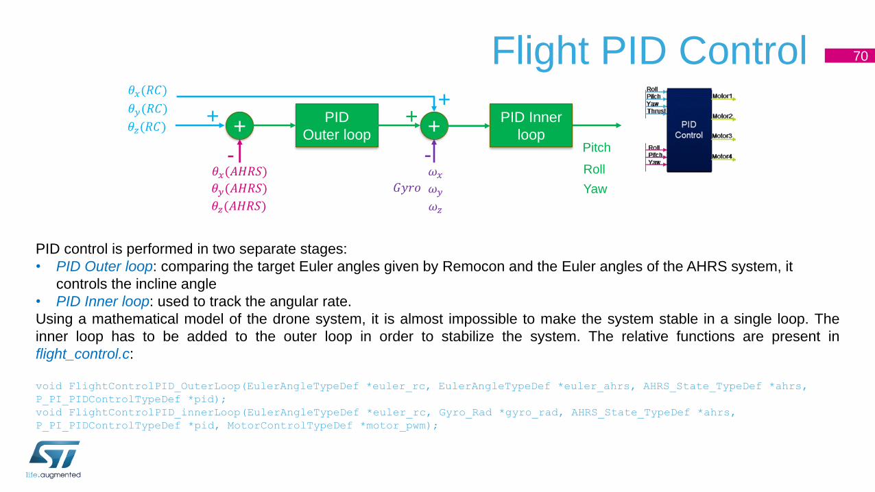
Flight PID Control 70
PID control is performed in two separate stages:
• PID Outer loop: comparing the target Euler angles given by Remocon and the Euler angles of the AHRS system, it
controls the incline angle
• PID Inner loop: used to track the angular rate.
Using a mathematical model of the drone system, it is almost impossible to make the system stable in a single loop. The
inner loop has to be added to the outer loop in order to stabilize the system. The relative functions are present in
flight_control.c:
void FlightControlPID_OuterLoop(EulerAngleTypeDef *euler_rc, EulerAngleTypeDef *euler_ahrs, AHRS_State_TypeDef *ahrs,
P_PI_PIDControlTypeDef *pid);
void FlightControlPID_innerLoop(EulerAngleTypeDef *euler_rc, Gyro_Rad *gyro_rad, AHRS_State_TypeDef *ahrs,
P_PI_PIDControlTypeDef *pid, MotorControlTypeDef *motor_pwm);
+
𝜃𝑥(𝑅𝐶)
𝜃𝑥(𝐴𝐻𝑅𝑆)
𝜃𝑦(𝑅𝐶)
𝜃𝑦(𝐴𝐻𝑅𝑆)
PID
Outer loop +PID Inner
loop
𝜔𝑥𝜔𝑦
Pitch
Roll
𝐺𝑦𝑟𝑜
+
-
+
-
𝜃𝑧(𝑅𝐶)
𝜃𝑧(𝐴𝐻𝑅𝑆) 𝜔𝑧
Yaw
+
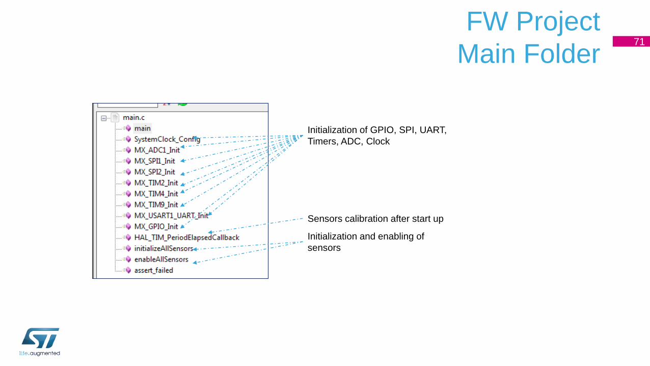
FW Project
Main Folder71
Initialization of GPIO, SPI, UART,
Timers, ADC, Clock
Initialization and enabling of
sensors
Sensors calibration after start up

STEVAL-FCU001V1 FW Flow Diagram from Code...
/* USER CODE BEGIN 1 */
MCU Configuration
/* Reset of all peripherals, Initializes the Flash interface and the Systick. */
/* Configure the system clock */
/* Initialize all configured peripherals */
// Initialize Onboard LED
/* Configure and disable all the Chip Select pins for sensors on SPI*/
/* Initialize and Enable the available sensors on SPI*/
/* Initialize settings for 6-axis MEMS Accelerometer */
/* Initialize settings for 6-axis MEMS Gyroscope */
/* Initialize settings for Magnetometer settings (By default after reset is in in
idle mode) */
/* Initialize Remote control*/
/* Initialize TIM2 for External Remocon RF receiver PWM Input*/
/* Initialize TIM4 for Motors PWM Output*/
/* Initialize General purpose TIM9 50Hz*/
/* Initialize PID and set Motor PWM to zero */
/* Setup a timer with 5ms interval */
Infinite loop
// AHRS update, quaternion & true gyro data are stored in ahrs
// Calculate euler angle drone
// Get target euler angle from remote control
FlightControlPID_OuterLoop
72
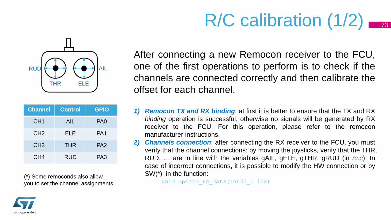
73R/C calibration (1/2)
After connecting a new Remocon receiver to the FCU,
one of the first operations to perform is to check if the
channels are connected correctly and then calibrate the
offset for each channel.
1) Remocon TX and RX binding: at first it is better to ensure that the TX and RX
binding operation is successful, otherwise no signals will be generated by RX
receiver to the FCU. For this operation, please refer to the remocon
manufacturer instructions.
2) Channels connection: after connecting the RX receiver to the FCU, you must
verify that the channel connections: by moving the joysticks, verify that the THR,
RUD, … are in line with the variables gAIL, gELE, gTHR, gRUD (in rc.c). In
case of incorrect connections, it is possible to modify the HW connection or by
SW(*) in the function:void update_rc_data(int32_t idx)
THR
RUD AIL
ELE
Channel Control GPIO
CH1 AIL PA0
CH2 ELE PA1
CH3 THR PA2
CH4 RUD PA3
(*) Some remoconds also allow
you to set the channel assignments.
74R/C calibration (2/2)
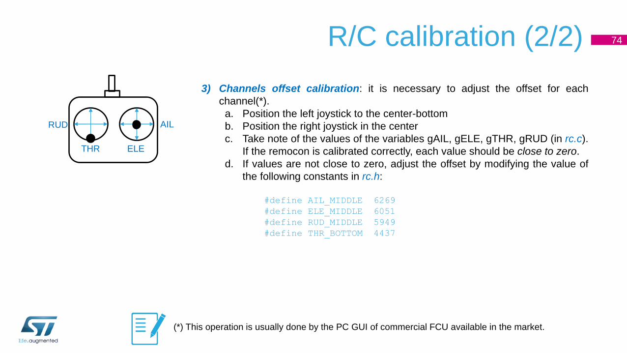
3) Channels offset calibration: it is necessary to adjust the offset for each
channel(*).
a. Position the left joystick to the center-bottom
b. Position the right joystick in the center
c. Take note of the values of the variables gAIL, gELE, gTHR, gRUD (in rc.c).
If the remocon is calibrated correctly, each value should be close to zero.
d. If values are not close to zero, adjust the offset by modifying the value of
the following constants in rc.h:
#define AIL_MIDDLE 6269
#define ELE_MIDDLE 6051
#define RUD_MIDDLE 5949
#define THR_BOTTOM 4437
THR
RUD AIL
ELE
(*) This operation is usually done by the PC GUI of commercial FCU available in the market.

75Motor connection check
It is easy to connect the motors to the FCU incorrectly
(correct configuration described in “Step2 – DC motor
connection” section).
This can be verified by increasing the Throttle value
(just enough to spin the motor but not to lift the
quadcopter), and forcing an inclination. The figure
shows what happens when there is a wrong
connection: the motor in lower position is stopped while
the one in higher position is spinning >> it should be
opposite to stabilize the drone.
Wrong connection situation.
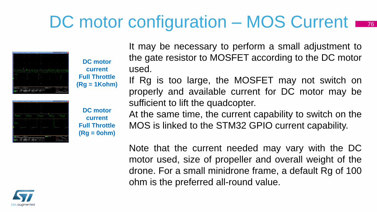
DC motor configuration – MOS Current 76
It may be necessary to perform a small adjustment to
the gate resistor to MOSFET according to the DC motor
used.
If Rg is too large, the MOSFET may not switch on
properly and available current for DC motor may be
sufficient to lift the quadcopter.
At the same time, the current capability to switch on the
MOS is linked to the STM32 GPIO current capability.
Note that the current needed may vary with the DC
motor used, size of propeller and overall weight of the
drone. For a small minidrone frame, a default Rg of 100
ohm is the preferred all-round value.
DC motor
current
Full Throttle
(Rg = 1Kohm)
DC motor
current
Full Throttle
(Rg = 0ohm)
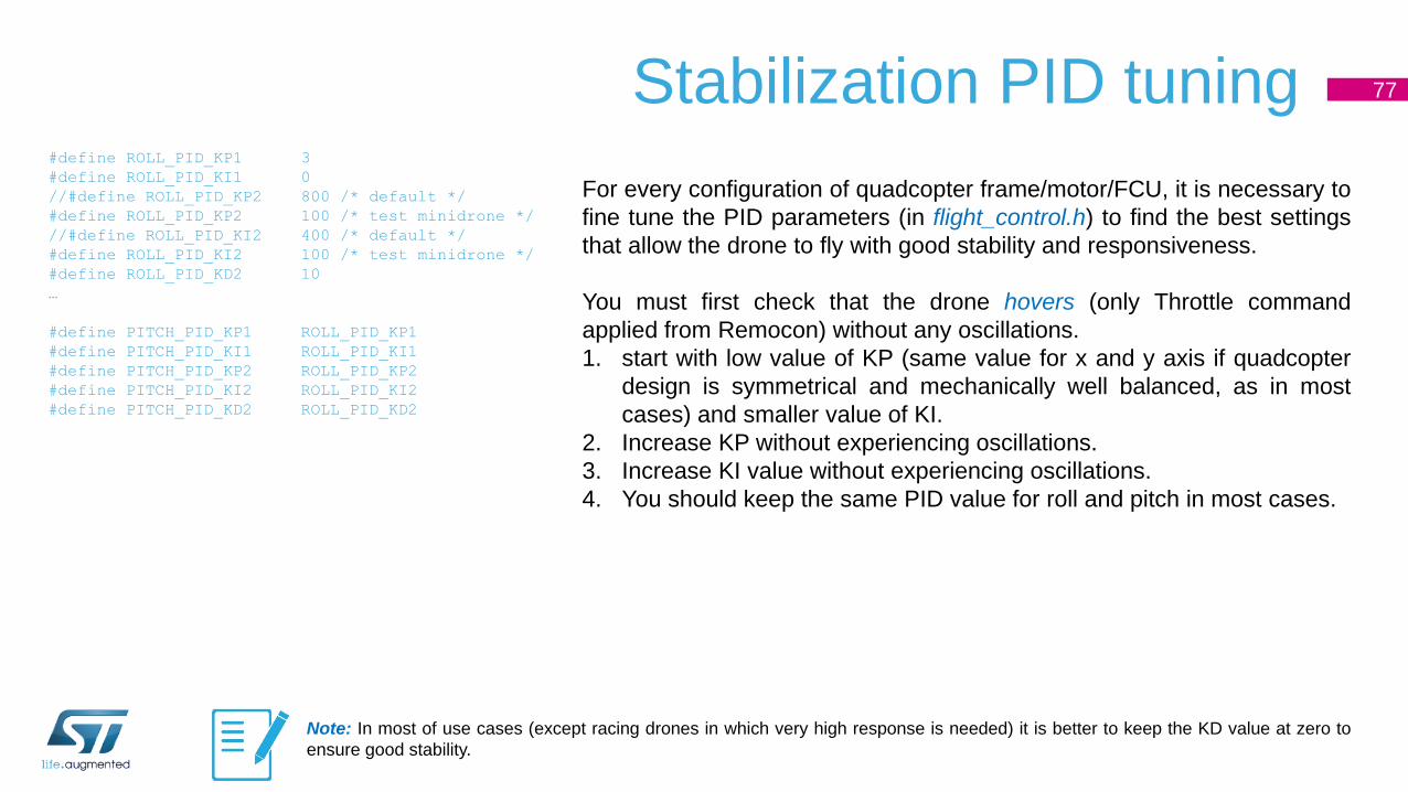
Stabilization PID tuning 77
#define ROLL_PID_KP1 3
#define ROLL_PID_KI1 0
//#define ROLL_PID_KP2 800 /* default */
#define ROLL_PID_KP2 100 /* test minidrone */
//#define ROLL_PID_KI2 400 /* default */
#define ROLL_PID_KI2 100 /* test minidrone */
#define ROLL_PID_KD2 10
…
#define PITCH_PID_KP1 ROLL_PID_KP1
#define PITCH_PID_KI1 ROLL_PID_KI1
#define PITCH_PID_KP2 ROLL_PID_KP2
#define PITCH_PID_KI2 ROLL_PID_KI2
#define PITCH_PID_KD2 ROLL_PID_KD2
For every configuration of quadcopter frame/motor/FCU, it is necessary to
fine tune the PID parameters (in flight_control.h) to find the best settings
that allow the drone to fly with good stability and responsiveness.
You must first check that the drone hovers (only Throttle command
applied from Remocon) without any oscillations.
1. start with low value of KP (same value for x and y axis if quadcopter
design is symmetrical and mechanically well balanced, as in most
cases) and smaller value of KI.
2. Increase KP without experiencing oscillations.
3. Increase KI value without experiencing oscillations.
4. You should keep the same PID value for roll and pitch in most cases.
Note: In most of use cases (except racing drones in which very high response is needed) it is better to keep the KD value at zero to
ensure good stability.
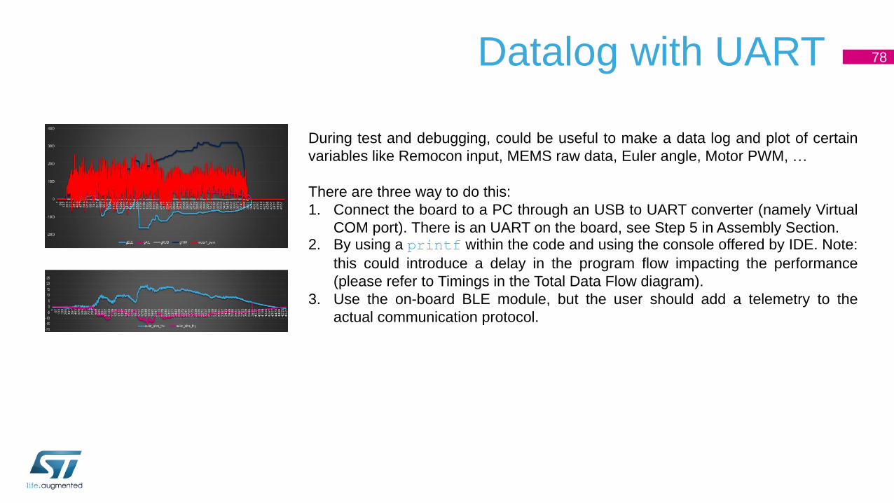
Datalog with UART 78
During test and debugging, could be useful to make a data log and plot of certain
variables like Remocon input, MEMS raw data, Euler angle, Motor PWM, …
There are three way to do this:
1. Connect the board to a PC through an USB to UART converter (namely Virtual
COM port). There is an UART on the board, see Step 5 in Assembly Section.2. By using a printf within the code and using the console offered by IDE. Note:
this could introduce a delay in the program flow impacting the performance
(please refer to Timings in the Total Data Flow diagram).
3. Use the on-board BLE module, but the user should add a telemetry to the
actual communication protocol.
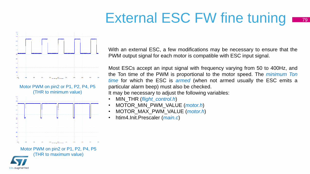
External ESC FW fine tuning 79
With an external ESC, a few modifications may be necessary to ensure that the
PWM output signal for each motor is compatible with ESC input signal.
Most ESCs accept an input signal with frequency varying from 50 to 400Hz, and
the Ton time of the PWM is proportional to the motor speed. The minimum Ton
time for which the ESC is armed (when not armed usually the ESC emits a
particular alarm beep) must also be checked.
It may be necessary to adjust the following variables:
• MIN_THR (flight_control.h)
• MOTOR_MIN_PWM_VALUE (motor.h)
• MOTOR_MAX_PWM_VALUE (motor.h)
• htim4.Init.Prescaler (main.c)
Motor PWM on pin2 or P1, P2, P4, P5
(THR to minimum value)
Motor PWM on pin2 or P1, P2, P4, P5
(THR to maximum value)

Accelerometer sensor fine tuning – Low vibration frame80
If the frame does not experience high vibration from the motors, it is also possible to use alternative settings for the MEMS
accelerometer:
• Accelerometer full-scale selection FS default ±2g >> set to ±4g
• Analog Filter Bandwidth default 1.5KHz >> set to 400Hz
• Output data rate and power mode selection ODR default Power down mode >> set to 1.6kHz
• Composite filter input selection default ODR/2 >> set to ODR/4
• Accelerometer low-pass filter LPF2 selection default >> set to Low pass filter enabled @ ODR/50
BSP_ACCELERO_Set_ODR_Value(LSM6DSL_X_0_handle, 1660.0); /* ODR 1.6kHz */
BSP_ACCELERO_Set_FS(LSM6DSL_X_0_handle, FS_MID); /* FS 4g */
LSM6DSL_ACC_GYRO_W_InComposit(LSM6DSL_X_0_handle, LSM6DSL_ACC_GYRO_IN_ODR_DIV_4);
/* ODR/4 low pass filtered sent to composite filter */
LSM6DSL_ACC_GYRO_W_LowPassFiltSel_XL(LSM6DSL_X_0_handle, LSM6DSL_ACC_GYRO_LPF2_XL_ENABLE);
/* Enable LPF2 filter in composite filter block */
LSM6DSL_ACC_GYRO_W_HPCF_XL(LSM6DSL_X_0_handle, LSM6DSL_ACC_GYRO_HPCF_XL_DIV4);
/* Low pass filter @ ODR/50 */
uint8_t tmp_6axis_reg_value;
BSP_ACCELERO_Read_Reg(LSM6DSL_X_0_handle, 0x10, &tmp_6axis_reg_value);
tmp_6axis_reg_value = tmp_6axis_reg_value | 0x01;
/* Set LSB to 1 >> Analog filter 400Hz*/
BSP_ACCELERO_Write_Reg(LSM6DSL_X_0_handle, 0x10, tmp_6axis_reg_value);
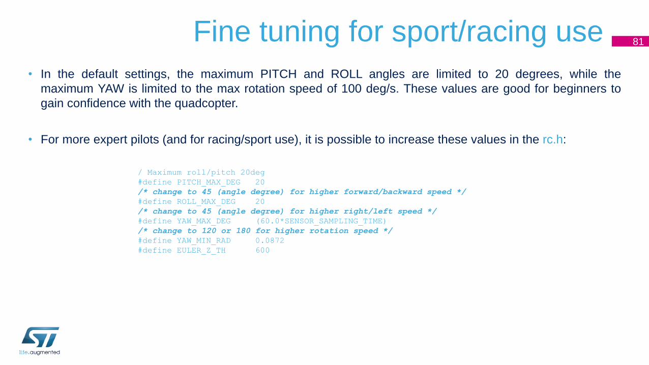
Fine tuning for sport/racing use 81
• In the default settings, the maximum PITCH and ROLL angles are limited to 20 degrees, while the
maximum YAW is limited to the max rotation speed of 100 deg/s. These values are good for beginners to
gain confidence with the quadcopter.
• For more expert pilots (and for racing/sport use), it is possible to increase these values in the rc.h:
/ Maximum roll/pitch 20deg
#define PITCH_MAX_DEG 20
/* change to 45 (angle degree) for higher forward/backward speed */
#define ROLL_MAX_DEG 20
/* change to 45 (angle degree) for higher right/left speed */
#define YAW_MAX_DEG (60.0*SENSOR_SAMPLING_TIME)
/* change to 120 or 180 for higher rotation speed */
#define YAW_MIN_RAD 0.0872
#define EULER_Z_TH 600

Appendix C
AHRS Formula details

AHRS Algorithm 83
Accelerometer,
Gyroscope,
(Magnetometer)
Roll
Yaw
Pitch
Sensors
Attitude
Complementary
filter, gradient
descent, or
Kalman filter
Accelerometer,
Gyroscope,
Magnetometer,
GPS, Barometer,
Camera, etc.
Roll, Yaw, Pitch,
Position, Speed,
Altitude, etc.
Kalman filter
(EKF or UKF)
Toy Level(Simply, Resource limited)
Professional Level(Accurate, Performance)

AHRS - EKF (1)• 13 States, 3 Measurements
• Gyro data is G input, Accelerometer data A is the measurement
84
State: 𝑥 =𝑄
𝐺0𝑓𝑓, where
𝑄 = 𝑞0 𝑞1 𝑞2 𝑞3 𝑇 is the quaternion;
𝐺𝑜𝑓𝑓 = 𝑔𝑥_𝑜𝑓𝑓 𝑔𝑦_𝑜𝑓𝑓 𝑔𝑧_𝑜𝑓𝑓 𝑇 is the gyro bias
error
Measurement: 𝑧 = 𝐴 , where
𝐴 = 𝑎𝑥 𝑎𝑦 𝑎𝑧 𝑇 is the gravity measured
by accelerometer
ො𝑥𝑘+1 =𝑄𝑘+1
𝐺𝑜𝑓𝑓 𝑘+1=
𝑄𝑘 +1
2𝑄𝑘 ⊗ (𝐺𝑘 − 𝐺𝑏 𝑘) ∙ 𝑇
𝐺𝑜𝑓𝑓 𝑘
State
Equation
Ƹ𝑧𝑘+1 = 𝑄𝐾+1∗
0001
𝑄𝐾+1
Measurement
Equation
𝑥𝑘+1 = ො𝑥𝑘+1 + 𝐾𝑘+1(𝑧𝑘+1 − Ƹ𝑧𝑘+1)State
Update

AHRS - EKF (2)• 13 States, 3 Measurements
• Gyro data is G input, Quaternion from accelerometer &
magnetometer data 𝑍𝑘 = 𝑄𝑀 is the measurement
85
State: 𝑥 =
𝑄𝐺𝑜𝑓𝑓𝑀𝑒
𝑀𝑜𝑓𝑓
, where 𝑄 = 𝑞0 𝑞1 𝑞2 𝑞3 𝑇 is the quaternion;
𝐺𝑜𝑓𝑓 = 𝑔𝑥_𝑜𝑓𝑓 𝑔𝑦_𝑜𝑓𝑓 𝑔𝑧_𝑜𝑓𝑓 𝑇 is the gyro bias error; 𝑀𝑒 = 𝑚𝑥 𝑚𝑦 𝑚𝑧 𝑇 is true earth magnetic field measured in body
frame; 𝑀𝑜𝑓𝑓 = 𝑚𝑥𝑜𝑓𝑓 𝑚𝑦𝑜𝑓𝑓 𝑚𝑧𝑜𝑓𝑓𝑇 is the hard iron offset
Measurement: 𝑧 = 𝑞 , where 𝐴 = 𝑞0 𝑞1 𝑞2 𝑞3 𝑇 is the quaternion estimated by gravity & magnetic field
State Equation ො𝑥𝑘+1 =
𝑄𝑘+1𝐺𝑏 𝑘+1𝑀𝑒 𝑘+1
𝑀𝑜𝑓𝑓 𝑘+1
=
𝑄𝑘 +1
2𝑄𝑘 ⊗ (𝐺𝑘 − 𝐺𝑏 𝑘) ∙ 𝑇
𝐺𝑏 𝑘𝑀𝑒 𝑘 − 𝑇Ω𝑘𝑀𝑒 𝑘
𝑀𝑜𝑓𝑓 𝑘
Measurement Equation Ƹ𝑧𝑘+1 = 𝑄𝑘+1
State update 𝑥𝑘+1 = ො𝑥𝑘+1 + 𝐾𝑘+1(𝑧𝑘+1 − Ƹ𝑧𝑘+1)

Appendix D
On board Battery charger for LiPO

Charge of a LiPO battery 87
Batt voltage
Batt charging
current
4.2V voltage at maximum charge
3
4
2
3 When Battery voltage reaches ~4.1V the charging switches from constant
current mode to constant voltage mode. Battery voltage increases slowly
till 4.2V and Charging current decrease.
1 Battery discharged at cutoff voltage (2.7V).
The diagram shows a typical charging curve for a LiPo battery. It
consists of the following steps:
1
2 Charge current set to ~135mA (*).
Charge current reached termination (1/10 of charging current) value, it
just keeps battery charge.
5
4
5
The two diagrams are relative to 2 different batteries:
• 250mAh battery >> ~1h 25m from full discharge to full charge
• 380mAh battery >> ~2h from full discharge to full charge
Batt voltage
Batt charging
current
(*) Charge current can be changed by the resistor connected to PROG pin of STLC4054.

Use of LiPO battery in drone application 88
Note the following tips when using a LiPO Battery in the application:
1. Depending on several factors (drone total weight, motors and propeller
used, …), the drone may not be able to lift (or just hovering at few cm
from ground) at a voltage greater than full discharge value (i.e. 3.5V or
3.6V). It will be necessary to charge the battery from this voltage level, it
will shorten battery charging time.
2. Choosing a larger battery will increase flight time, but attention must be
paid to the trade off with the total weight.
3. After flight, battery should be immediately disconnected from FCU board.
If it remains connected for a long time and battery voltage drops below
2.7V, there is the risk of permanently damaging the battery to the point
that it can no longer be charged.
4. It is recommended that charge current should not exceed ~1/3 of
maximum capacity (i.e. 380mAh >> charging current 130mA).
Batt voltage
Batt charging
current
Threshold for
drone to lift up
250mAh 1 cell Batt >> 8g
380mAh 1 cell Batt >> 11g


![Skaffold - storage.googleapis.com · [getting-started getting-started] Hello world! [getting-started getting-started] Hello world! [getting-started getting-started] Hello world! 5](https://img.pdfslide.net/doc/110x75/5ec939f2a76a033f091c5ac7/skaffold-getting-started-getting-started-hello-world-getting-started-getting-started.jpg)


