Embed Size (px)
Citation preview
BEWEGUNG MIT SYSTEM
LTU Arena, Düsseldorf
GEZE RWA SYSTEMS
GEZE RWA Systems
Drives, central control units and control elements for smoke and heat extraction systems
2
RWA Systems
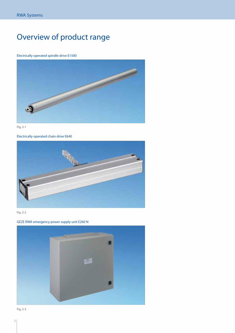
Overview of product range
GEZE RWA emergency power supply unit E260 N
Fig. 2-3
Fig. 2-2
Fig. 2-1
Electrically operated chain drive E640
Electrically operated spindle drive E1500
3
RWA Systems
Contents
Foreword .................................................................................................................................................... 4
GEZE RWA Systems ................................................................................................................................. 7
Direct opener electrically operated spindle drives E250, E1500 and E3000 ...................... 8
Direct opener electrically operated chain drives E600 to E680 ............................................25
Opening and locking systems RWA 100E, 105E and 110E .....................................................31
Electrically operated linear drives E212 and E205 .....................................................................45
Emergency power supply units E260 N ........................................................................................48
Accessories ..............................................................................................................................................50
RWA special versions ............................................................................................................................55
4
RWA Systems Foreword
Foreword
Cleaning and maintenanceAccording to the Model Building Code (MBO) building owners or principals are basically obliged to undertake proper maintenance since building installations "are to be laid out, built, altered and maintained in such a way that public safety and order and in particu-lar, life, health and the natural basis of life are not endangered". Building products must not be used without proper maintenance and upkeep (cf. MBO Art. 3 Paras. 1 and 3).
The building owner or contractor must at his responsibility look after care, maintenance and inspection. All components must be checked regularly for damage or deformation. The operator of an RWA installation is obliged to take all necessary precautions to prevent endangerment of persons and property inside the building.
By carrying out regular maintenance of the smoke and heat extraction systems in the interests of their functionality he will very deci-sively reduce the actual risk of damage and consequently his risk of liability in the event of a claim. He can in this way document at all times that he has fulfi lled his obligation to keep the RWA installation in a state fi t for service and operation.
A selection of regulations and public statutes
Basic Constitutional Law, Art. 2:"Everyone has the right to physical integrity".
MBO Art. 3 Para. 1 (version of November 2002)"Installations are to be laid out, built, altered and maintained in such a way that public safety and order and in particular, life, health and the natural basis of life are not endangered".
MBO Art. 14 (version of November 2002)"Building installations are to be laid out, built, altered and maintained in such a way that the occurrence of fi re and the spreading of fi re and smoke is prevented and in the event of a fi re, it will be possible to save people and animals and fi ght the fi re eff ectively".
DIN VDE 0833-1 (5.3.4 / 2003)"Maintenance should be carried out at least once per year on the basis of the manufacturer's information and taking into account special service conditions".
DIN 18232 Pt. 2 (version of November 2007)At regular intervals as specifi ed by the manufacturer but as a rule once per year smoke extraction systems and their operating and control elements, opening units, incoming power lines and accessories must be inspected for functional capability and service readi-ness, maintained and if necessary repaired. Inspections and maintenance work must be logged in an inspection book. Inspections may only be carried out by specialist companies qualifi ed for natural smoke extraction systems.
Directive on the monitoring of building installationsIn addition to the regular annual inspection, smoke and heat extraction systems in buildings of a special nature and utilization – such as offi ce buildings, places of assembly, large multistorey car parks – must be inspected at three-year intervals by an expert offi cially recognized or recognized under building legislation.Regular maintenance is an essential precondition of these statutory inspections. As a rule the maintenance company will take over the obligation of the operator to provide suitable specialists for the inspection of the installations conducted by the expert.Requirements relating to care and maintenance are laid down separately in the technical installations inspection directives of the individual German states.
5
RWA Systems Foreword
For this reason the following points should be observed without fail as regards the care and maintenance of smoke and heat extrac-tion systems:
Smoke and heat extraction systems must be maintained at least once per year and if necessary repaired. Only qualifi ed personnel are permitted to carry out maintenance work. Proof must be submitted of such qualifi cations. Authoriza- tion by GEZE is required.Inspections must be logged in an inspections book.
Support during installation function tests and acceptanceGEZE will provide support here either from authorized partner companies or from the parent company. A smoke and heat extraction system must always be installed and function-checked by the manufacturer or by a specialist company authorized by the manufac-turer since this is the only way of ensuring that system-relevant functions are implemented perfectly. Acceptance of the smoke and heat extraction system must be conducted by an expert.
Important informationDuring installation and disassembly of the drive the window is not secured against tilting and slamming! The local building regulations as well as the relevant accident prevention regulations, DIN standards and VDE directive must be observed.In addition, the guidelines for power-operated windows, doors and gates BGR 232 issued by the German Federation of trade associations, the central agency for safety prevention and health at work will apply.All installation works must be carried out by a specialist. Installation (mech.): window manufacturer or metal worker; Installation (electr.): qualifi ed electriciansFor further information on installation, commissioning, maintenance and so on, see the installation drawings and wiring dia- grams.
Smoke and heat extraction systemsFor fi re protection a distinction is drawn between the concepts of "fi re-fi ghting" and "preventive fi re protection":
Fire-fi ghting The term "fi re-fi ghting" covers all steps taken in the event of a fi re to combat the dangers posed to life, health and property.
Preventive fi re protection: This term covers all steps taken to prevent a fi re from breaking out or spreading and to keep escape routes open. The aim is to ob-struct the spread of a fi re long enough for people to be able to escape to safety by their own eff orts and to give the fi re brigade time to allow people to escape safely from the building.The smoke and heat extraction system is classed under preventive fi re protection and will save life in the event of a fi re. The legal foundations are the building codes, special building codes and technical regulations of Germany on the federal and state levels.
Mode of operation of natural smoke extractionTriggered by automatic smoke detectors or even manually, the smoke and heat extraction system vents are opened with the aid of the electrically operated drives in the upper part of the building. Through these vents, the thermally ascendingsmoke gases can escape even during the initial phase. The requisite incoming air vents in the lower part of the buildings assist this process by balancing out the necessary mass fl ow.
6
RWA Systems Foreword
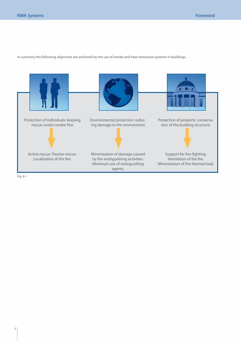
Protection of individuals: keeping rescue routes smoke free
Active rescue. Passive rescue.Localization of the fi re.
Environmental protection: reduc-ing damage to the environment
Minimization of damage caused by fi re extinguishing activities.Minimum use of extinguishing
agents.
Protection of property: conserva-tion of the building structure.
Support for fi re-fi ghting.Ventilation of the fi re.
Minimization of the thermal load.
Fig. 6-1
In summary the following objectives are achieved by the use of smoke and heat extraction systems in buildings.
7
RWA Systems RWA Systems
Opening systems
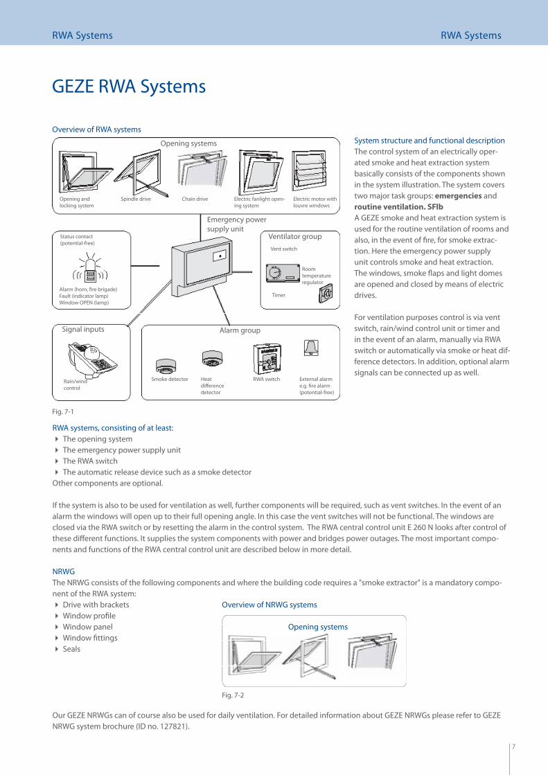
RWA systems, consisting of at least:The opening system The emergency power supply unit The RWA switch The automatic release device such as a smoke detector
Other components are optional.
If the system is also to be used for ventilation as well, further components will be required, such as vent switches. In the event of an alarm the windows will open up to their full opening angle. In this case the vent switches will not be functional. The windows are closed via the RWA switch or by resetting the alarm in the control system. The RWA central control unit E 260 N looks after control of these diff erent functions. It supplies the system components with power and bridges power outages. The most important compo-nents and functions of the RWA central control unit are described below in more detail.
NRWGThe NRWG consists of the following components and where the building code requires a "smoke extractor" is a mandatory compo-nent of the RWA system:
Drive with brackets Window profi le Window panel Window fi ttings Seals
Our GEZE NRWGs can of course also be used for daily ventilation. For detailed information about GEZE NRWGs please refer to GEZE NRWG system brochure (ID no. 127821).
Opening and locking system
Chain driveSpindle drive
Alarm group
Vent switch
Timer
Room temperatureregulator
Emergency powersupply unit
Rain/windcontrol
Alarm (horn, fi re brigade)Fault (indicator lamp)Window OPEN (lamp)
Status contact(potential-free)
Signal inputs
Ventilator group
Heatdiff erencedetector
Smoke detector External alarme.g. fi re alarm (potential-free)
RWA switch
Electric fanlight open-ing system
Electric motor with louvre windows
GEZE RWA Systems
System structure and functional descriptionThe control system of an electrically oper-ated smoke and heat extraction system basically consists of the components shown in the system illustration. The system covers two major task groups: emergencies and routine ventilation. SFlb
A GEZE smoke and heat extraction system is used for the routine ventilation of rooms and also, in the event of fi re, for smoke extrac-tion. Here the emergency power supply unit controls smoke and heat extraction. The windows, smoke fl aps and light domes are opened and closed by means of electric drives. For ventilation purposes control is via vent switch, rain/wind control unit or timer and in the event of an alarm, manually via RWA switch or automatically via smoke or heat dif-ference detectors. In addition, optional alarm signals can be connected up as well.
Overview of RWA systems
Opening systems
Fig. 7-1
Fig. 7-2
Overview of NRWG systems
8
RWA Systems Electrically operated spindle drives
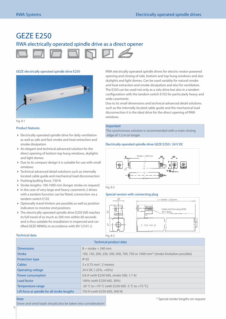
GEZE E250RWA electrically operated spindle drive as a direct opener
RWA electrically operated spindle drives for electric-motor-powered opening and closing of side, bottom and top hung windows and also skylights and light domes. Can be used variably for natural smoke and heat extraction and smoke dissipation and also for ventilation. The E250 can be used not only as a solo drive but also in a tandem confi guration with the tandem switch E102 for particularly heavy and wide casements. Due to its small dimensions and technical advanced detail solutions such as the internally located cable guide and the mechanical load disconnection it is the ideal drive for the direct opening of RWA windows.
ImportantThe synchronous solution is recommended with a main closing edge of 1.2 m or longer
Product features
Electrically operated spindle drive for daily ventilation as well as safe and fast smoke and heat extraction and smoke dissipationAn elegant and technical advanced solution for the direct opening of bottom top hung windows, skylights and light domesDue to its compact design it is suitable for use with small windowsTechnical advanced detail solutions such as internally located cable guide and mechanical load disconnectionPushing/pulling force: 750 N Stroke lengths: 100-1000 mm (longer stroke on request) In the case of very large and heavy casements 2 drives with a tandem function can be fi tted; connection via a tandem switch E102Optionally travel limiters are possible as well as position indicators to monitor end positionsThe electrically operated spindle drive E250 VdS reaches its full travel of as much as 500 mm within 60 seconds and is thus suitable for installation in inspected and cer-tifi ed GEZE NRWGs in accordance with EN 12101-2.
Technical product data
Dimensions B = stroke + 240 mm
Stroke 100, 150, 200, 230, 300, 500, 700, 750 or 1000 mm* (stroke limitation possible)
Protection type IP 65
Cables 3 x 0.75 mm2, 2 metres
Operating voltage 24 V DC (-25%, +45%)
Power consumption 0.8 A (with E250 VdS, stroke 500, 1.7 A)
Load factor 100% (with E250 VdS, 30%)
Temperature range -20 °C to +70 °C (with E250 VdS -5 °C to +75 °C)
Lift force at spindle for all stroke lengths 750 N (with E250 VdS, 500 N)
* Special stroke lengths on request
Technical data
L = Stroke + 250 mm
Cable exit from plug GDM 3011 Black
Stroke + 240 mm
Electrically operated spindle drive GEZE E250 / 24 V DC
Special version with connecting plug
NoteSnow and wind loads should also be taken into consideration!
GEZE electrically operated spindle drive E250
Fig. 8-1
Fig. 8-2
Fig. 8-3
9
RWA Systems Electrically operated spindle drives
a
66
22
22
6643
22
2266
Amax [82 mm]165Ü [0-25 mm]
6020
14
66
13
30A
B [5
1 m
m]
15
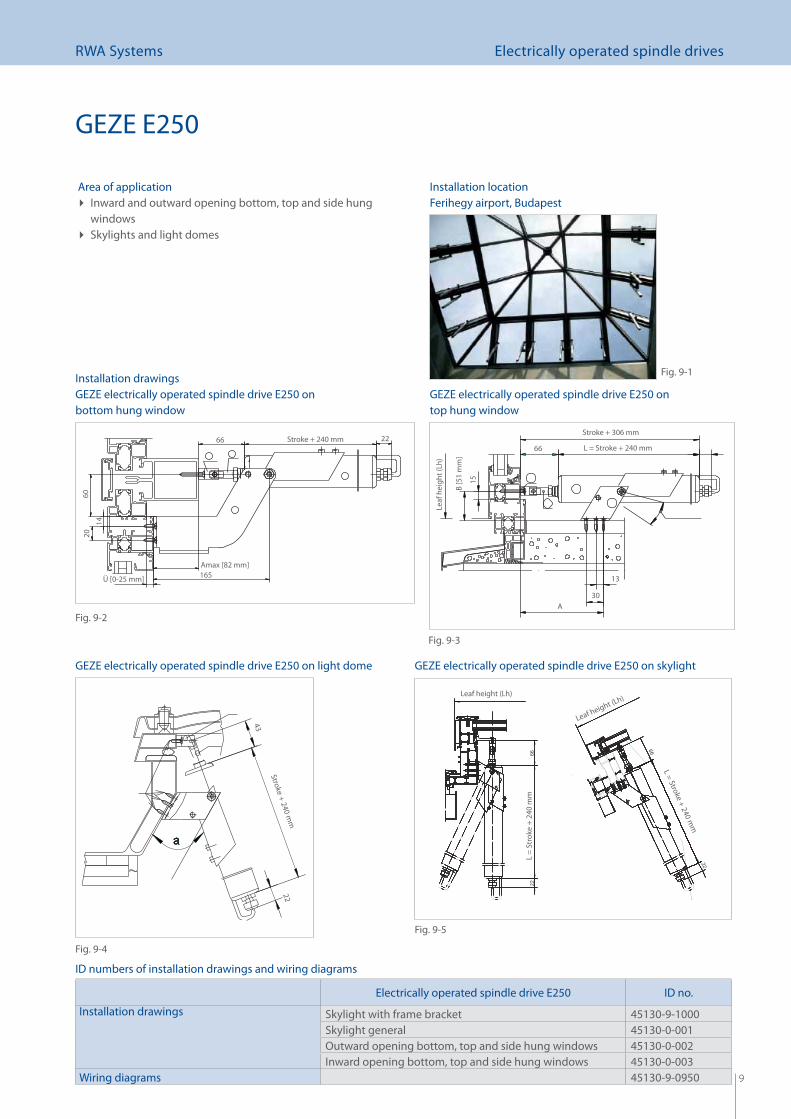
Area of applicationInward and outward opening bottom, top and side hung windowsSkylights and light domes
Installation drawings
ID numbers of installation drawings and wiring diagrams
GEZE E250
Electrically operated spindle drive E250 ID no.
Installation drawings Skylight with frame bracket 45130-9-1000Skylight general 45130-0-001Outward opening bottom, top and side hung windows 45130-0-002Inward opening bottom, top and side hung windows 45130-0-003
Wiring diagrams 45130-9-0950
GEZE electrically operated spindle drive E250 on skylightGEZE electrically operated spindle drive E250 on light dome
GEZE electrically operated spindle drive E250 on bottom hung window
GEZE electrically operated spindle drive E250 on top hung window
Leaf height (Lh)
Leaf height (Lh)
L = Stroke + 240 mm
L =
Stro
ke +
240
mm
Fig. 9-1
Fig. 9-2
Fig. 9-3
Fig. 9-5
Stroke + 240 mm
Stroke + 240 mmStroke + 306 mm
L = Stroke + 240 mmLe
af h
eigh
t (Lh
)
Fig. 9-4
Installation locationFerihegy airport, Budapest
10
RWA Systems Electrically operated spindle drives
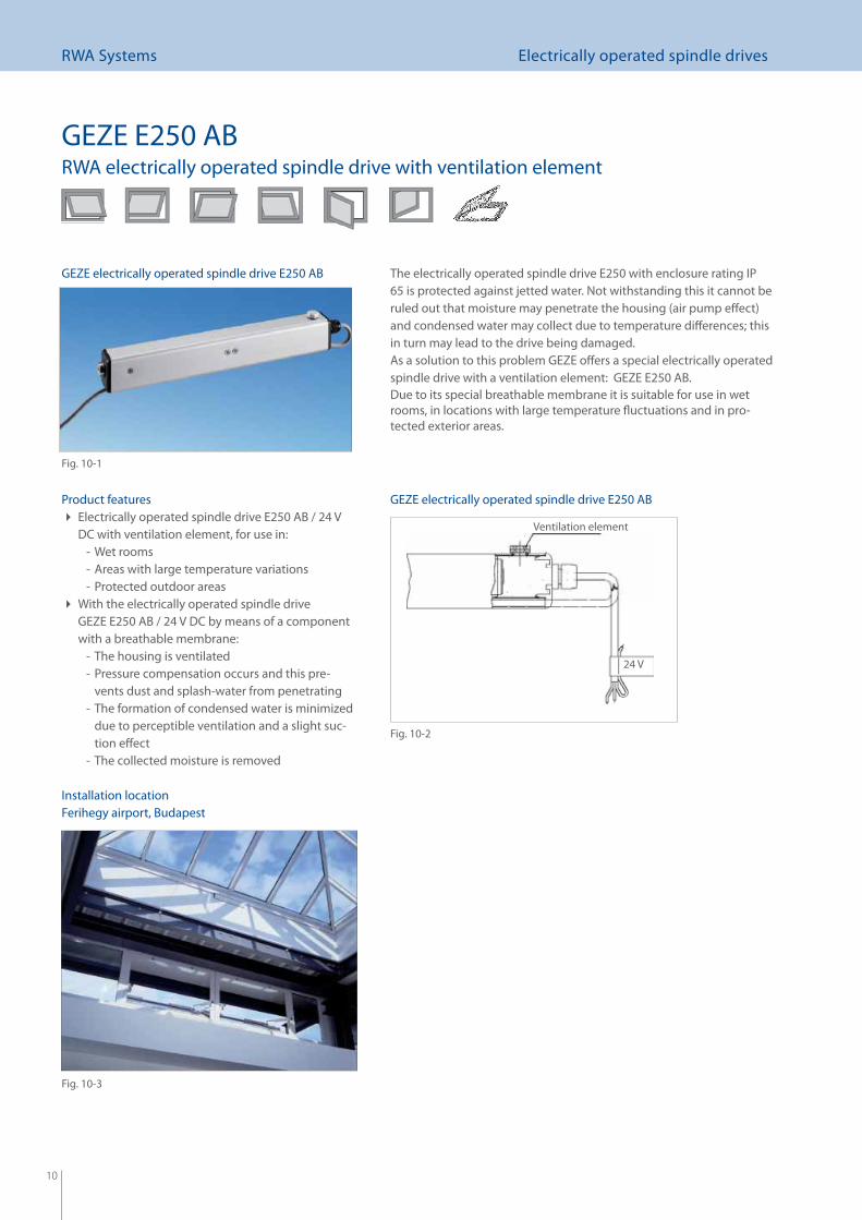
The electrically operated spindle drive E250 with enclosure rating IP 65 is protected against jetted water. Not withstanding this it cannot be ruled out that moisture may penetrate the housing (air pump eff ect) and condensed water may collect due to temperature diff erences; this in turn may lead to the drive being damaged.As a solution to this problem GEZE off ers a special electrically operated spindle drive with a ventilation element: GEZE E250 AB.Due to its special breathable membrane it is suitable for use in wet rooms, in locations with large temperature fl uctuations and in pro-tected exterior areas.
GEZE E250 ABRWA electrically operated spindle drive with ventilation element
Product featuresElectrically operated spindle drive E250 AB / 24 V DC with ventilation element, for use in:
Wet rooms -Areas with large temperature variations -Protected outdoor areas -
With the electrically operated spindle drive GEZE E250 AB / 24 V DC by means of a component with a breathable membrane:
The housing is ventilated -Pressure compensation occurs and this pre- -vents dust and splash-water from penetratingThe formation of condensed water is minimized -due to perceptible ventilation and a slight suc-tion eff ectThe collected moisture is removed -
Installation locationFerihegy airport, Budapest
Ventilation element
24 V
GEZE electrically operated spindle drive E250 AB
Fig. 10-1
GEZE electrically operated spindle drive E250 AB
Fig. 10-2
Fig. 10-3
11
RWA Systems Electrically operated spindle drives
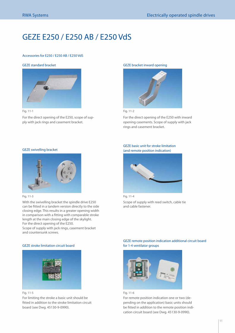
With the swivelling bracket the spindle drive E250 can be fi tted in a tandem version directly to the side closing edge. This results in a greater opening width in comparison with a fi tting with comparable stroke length at the main closing edge of the skylight.For the direct opening of the E250.Scope of supply with jack rings, casement bracket and countersunk screws.
Accessories for E250 / E250 AB / E250 VdS
For the direct opening of the E250, scope of sup-ply with jack rings and casement bracket.
GEZE E250 / E250 AB / E250 VdS
For the direct opening of the E250 with inward opening casements. Scope of supply with jack rings and casement bracket.
For limiting the stroke a basic unit should be fi tted in addition to the stroke limitation circuit board (see Dwg. 45130-9-0990).
Scope of supply with reed switch, cable tie and cable fastener.
For remote position indication one or two (de-pending on the application) basic units should be fi tted in addition to the remote position indi-cation circuit board (see Dwg. 45130-9-0990).
Fig. 11-1 Fig. 11-2
Fig. 11-3 Fig. 11-4
Fig. 11-5 Fig. 11-6
GEZE standard bracket GEZE bracket inward opening
GEZE swivelling bracketGEZE basic unit for stroke limitation (and remote position indication)
GEZE stroke limitation circuit boardGEZE remote position indication additional circuit board for 1-4 ventilator groups
12
RWA Systems Electrically operated spindle drives
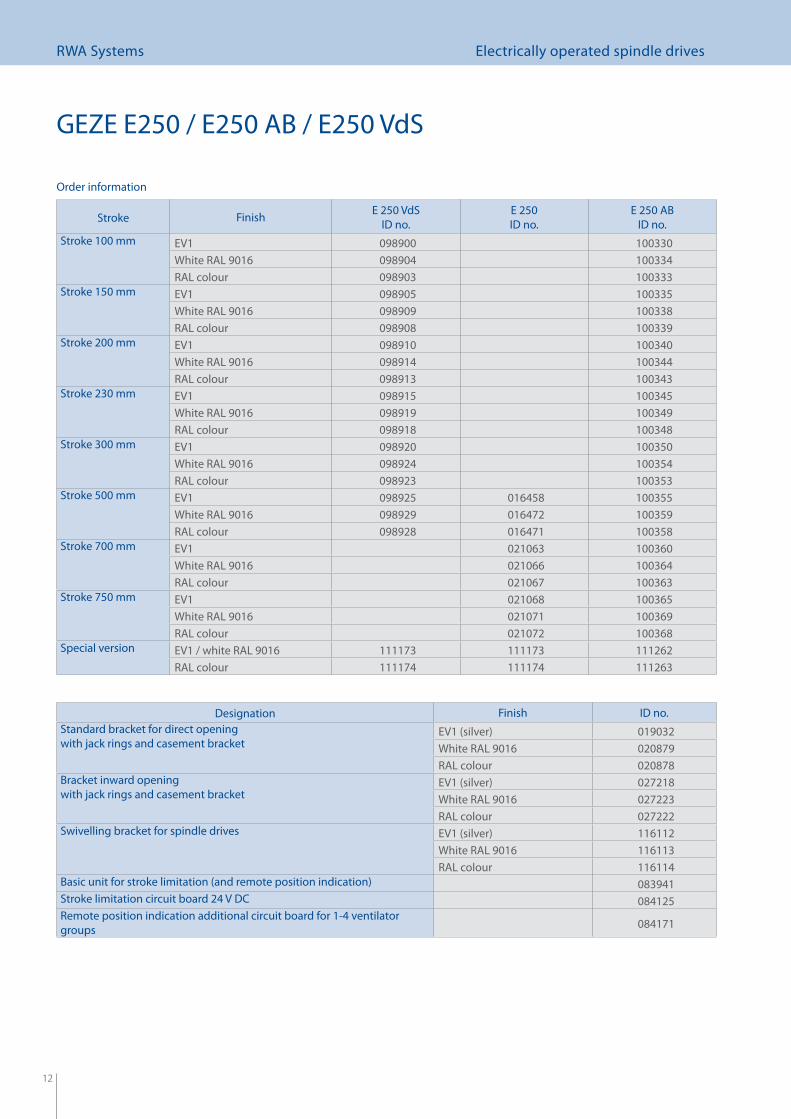
Order information
GEZE E250 / E250 AB / E250 VdS
Stroke Finish E 250 VdSID no.
E 250 ID no.
E 250 ABID no.
Stroke 100 mm EV1 098900 100330White RAL 9016 098904 100334RAL colour 098903 100333
Stroke 150 mm EV1 098905 100335White RAL 9016 098909 100338RAL colour 098908 100339
Stroke 200 mm EV1 098910 100340White RAL 9016 098914 100344RAL colour 098913 100343
Stroke 230 mm EV1 098915 100345White RAL 9016 098919 100349RAL colour 098918 100348
Stroke 300 mm EV1 098920 100350White RAL 9016 098924 100354RAL colour 098923 100353
Stroke 500 mm EV1 098925 016458 100355White RAL 9016 098929 016472 100359RAL colour 098928 016471 100358
Stroke 700 mm EV1 021063 100360White RAL 9016 021066 100364RAL colour 021067 100363
Stroke 750 mm EV1 021068 100365White RAL 9016 021071 100369RAL colour 021072 100368
Special version EV1 / white RAL 9016 111173 111173 111262RAL colour 111174 111174 111263
Designation Finish ID no.Standard bracket for direct opening with jack rings and casement bracket
EV1 (silver) 019032White RAL 9016 020879RAL colour 020878
Bracket inward opening with jack rings and casement bracket
EV1 (silver) 027218White RAL 9016 027223RAL colour 027222
Swivelling bracket for spindle drives EV1 (silver) 116112White RAL 9016 116113RAL colour 116114
Basic unit for stroke limitation (and remote position indication) 083941Stroke limitation circuit board 24 V DC 084125Remote position indication additional circuit board for 1-4 ventilator groups 084171
13
RWA Systems Electrically operated spindle drives
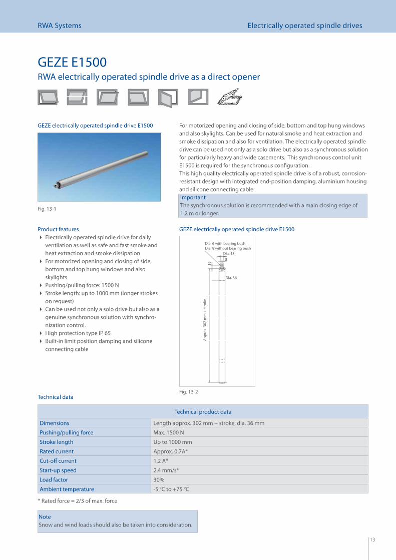
For motorized opening and closing of side, bottom and top hung windows and also skylights. Can be used for natural smoke and heat extraction and smoke dissipation and also for ventilation. The electrically operated spindle drive can be used not only as a solo drive but also as a synchronous solution for particularly heavy and wide casements. This synchronous control unit E1500 is required for the synchronous confi guration. This high quality electrically operated spindle drive is of a robust, corrosion-resistant design with integrated end-position damping, aluminium housing and silicone connecting cable.ImportantThe synchronous solution is recommended with a main closing edge of 1.2 m or longer.
GEZE E1500RWA electrically operated spindle drive as a direct opener
Product featuresElectrically operated spindle drive for daily ventilation as well as safe and fast smoke and heat extraction and smoke dissipationFor motorized opening and closing of side, bottom and top hung windows and also skylightsPushing/pulling force: 1500 N Stroke length: up to 1000 mm (longer strokes on request)Can be used not only a solo drive but also as a genuine synchronous solution with synchro-nization control.High protection type IP 65 Built-in limit position damping and silicone connecting cable
Technical product data
Dimensions Length approx. 302 mm + stroke, dia. 36 mm
Pushing/pulling force Max. 1500 N
Stroke length Up to 1000 mm
Rated current Approx. 0.7A*
Cut-off current 1.2 A*
Start-up speed 2.4 mm/s*
Load factor 30%
Ambient temperature -5 °C to +75 °C
* Rated force = 2/3 of max. force
Technical data
NoteSnow and wind loads should also be taken into consideration.
Dia. 6 with bearing bushDia. 8 without bearing bush
19A
ppro
x. 3
02 m
m +
str
oke
Dia. 36
Dia. 188
GEZE electrically operated spindle drive E1500
Fig. 13-1
GEZE electrically operated spindle drive E1500
Fig. 13-2
14
RWA Systems Electrically operated spindle drives
4710
057
120
30
86
20°~
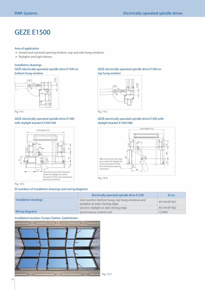
Installation drawings
GEZE E1500
GEZE electrically operated spindle drive E1500 on bottom hung window
GEZE electrically operated spindle drive E1500 on top hung window
GEZE electrically operated spindle drive E1500 with skylight bracket E1500 H40
GEZE electrically operated spindle drive E1500 with skylight bracket E1500 H86
Leaf height (Lh)
Take into account the clearance under the skylight for swivel movement of the drive during the opening movement
Leaf height (Lh)
Take into account the clear-ance under the skylight for swivel movement of the drive during the opening movement
ID numbers of installation drawings and wiring diagrams
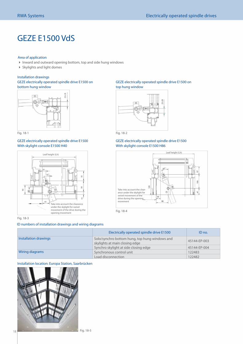
Area of applicationInward and outward opening bottom, top and side hung windows Skylights and light domes
Fig. 14-1 Fig. 14-2
Fig. 14-3
Fig. 14-4
Installation location: Europa Station, Saarbrücken
Electrically operated spindle drive E1500 ID no.Installation drawings Solo/synchro bottom hung, top hung windows and
skylights at main closing edge 45144-EP-001
Synchro skylight at side closing edge 45144-EP-002Wiring diagrams Synchronous control unit 122481
Fig. 14-5
15
RWA Systems Electrically operated spindle drives
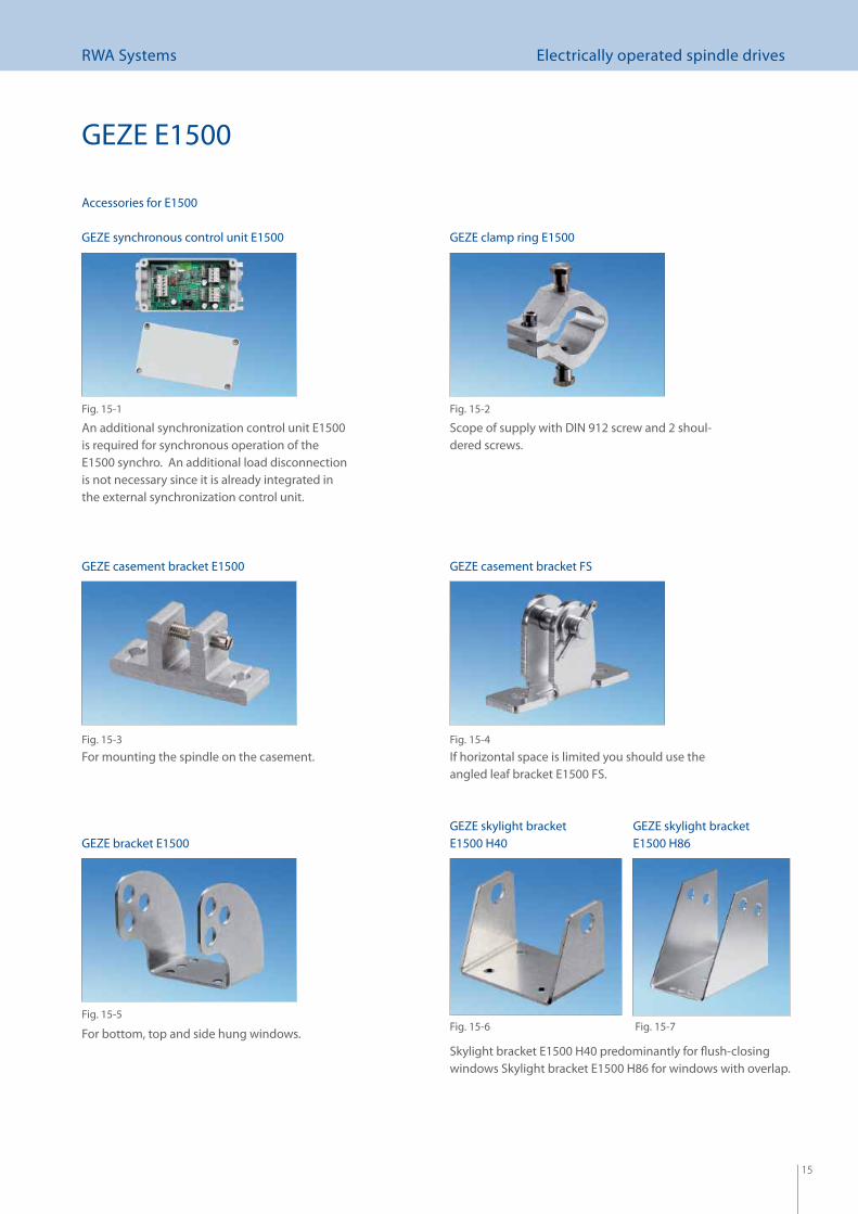
Accessories for E1500
An additional synchronization control unit E1500 is required for synchronous operation of the E1500 synchro. An additional load disconnection is not necessary since it is already integrated in the external synchronization control unit.
Skylight bracket E1500 H40 predominantly for fl ush-closing windows Skylight bracket E1500 H86 for windows with overlap.
For bottom, top and side hung windows.
Scope of supply with DIN 912 screw and 2 shoul-dered screws.
GEZE E1500
Fig. 15-1 Fig. 15-2
GEZE synchronous control unit E1500
For mounting the spindle on the casement.
GEZE clamp ring E1500
GEZE casement bracket E1500
Fig. 15-3
GEZE bracket E1500
Fig. 15-5
GEZE skylight bracket E1500 H40
Fig. 15-6
If horizontal space is limited you should use the angled leaf bracket E1500 FS.
GEZE casement bracket FS
Fig. 15-4
Fig. 15-7
GEZE skylight bracket E1500 H86

16
RWA Systems Electrically operated spindle drives
GEZE E1500
Order information
Designation Finish ID no.
SoloE1500 solo stroke 300 mm EV1 (silver) 121167
White RAL 9016 121168RAL colour 121169
E1500 solo stroke 500 mm EV1 (silver) 121170White RAL 9016 121191RAL colour 121192
E1500 solo stroke 750 mm EV1 (silver) 121193White RAL 9016 121194RAL colour 121195
E1500 solo stroke 1000 mm EV1 (silver) 121196White RAL 9016 121197RAL colour 121198
E1500 solo special version EV1 (silver) 121199RAL colour 121200
SynchronousE1500 synchronous* stroke 300 mm EV1 (silver) 121201
White RAL 9016 121202RAL colour 121203
E1500 synchronous* stroke 500 mm EV1 (silver) 121204White RAL 9016 121205RAL colour 121206
E1500 synchronous* stroke 750 mm EV1 (silver) 121207White RAL 9016 121208RAL colour 121209
E1500 solo stroke 1000 mm EV1 (silver) 121210White RAL 9016 121211RAL colour 121212
E1500 synchronous* special version EV1 (silver) 121213RAL colour 121214
* ID no. for one electrically operated spindle drive in each case For synchronous operation: order in each case 2 drives + additional synchronous control unit E1500
AccessoriesClamp ring E1500 EV1 (silver) 121215
White RAL 9016 121216RAL colour 121217
Casement bracket E1500 EV1 (silver) 121218White RAL 9016 121219RAL colour 121220
Casement bracket E1500 FS (If horizontal space is limited for casement bracket E1500)
EV1 (silver) 123085White RAL 9016 123086RAL colour 123087
Skylight bracket E1500 H40 (predominantly for fl ush-closing window) EV1 (silver) 121221White RAL 9016 121222RAL colour 121223
Skylight bracket E1500 H86 (predominantly for window with projection) EV1 (silver) 121224White RAL 9016 121225RAL colour 121226
Bracket E1500 (for bottom, top and side hung windows) EV1 (silver) 123088White RAL 9016 123089RAL colour 123090
Synchronous control unit E1500 121271
17
RWA Systems Electrically operated spindle drives
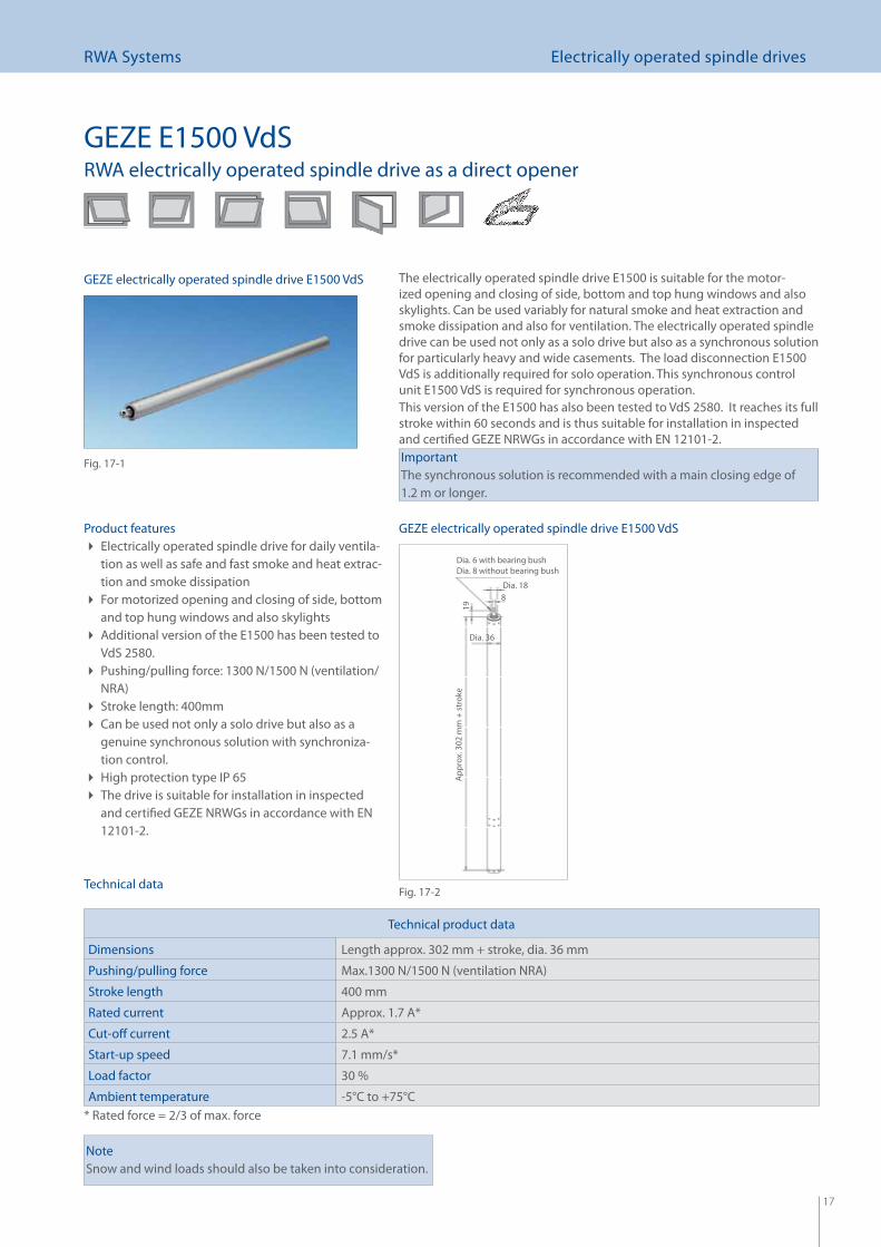
The electrically operated spindle drive E1500 is suitable for the motor-ized opening and closing of side, bottom and top hung windows and also skylights. Can be used variably for natural smoke and heat extraction and smoke dissipation and also for ventilation. The electrically operated spindle drive can be used not only as a solo drive but also as a synchronous solution for particularly heavy and wide casements. The load disconnection E1500 VdS is additionally required for solo operation. This synchronous control unit E1500 VdS is required for synchronous operation. This version of the E1500 has also been tested to VdS 2580. It reaches its full stroke within 60 seconds and is thus suitable for installation in inspected and certifi ed GEZE NRWGs in accordance with EN 12101-2. ImportantThe synchronous solution is recommended with a main closing edge of 1.2 m or longer.
GEZE E1500 VdSRWA electrically operated spindle drive as a direct opener
Product featuresElectrically operated spindle drive for daily ventila- tion as well as safe and fast smoke and heat extrac-tion and smoke dissipationFor motorized opening and closing of side, bottom and top hung windows and also skylightsAdditional version of the E1500 has been tested to VdS 2580.Pushing/pulling force: 1300 N/1500 N (ventilation/ NRA)Stroke length: 400mm Can be used not only a solo drive but also as a genuine synchronous solution with synchroniza-tion control.High protection type IP 65 The drive is suitable for installation in inspected and certifi ed GEZE NRWGs in accordance with EN 12101-2.
NoteSnow and wind loads should also be taken into consideration.
Technical product data
Dimensions Length approx. 302 mm + stroke, dia. 36 mm
Pushing/pulling force Max.1300 N/1500 N (ventilation NRA)
Stroke length 400 mm
Rated current Approx. 1.7 A*
Cut-off current 2.5 A*
Start-up speed 7.1 mm/s*
Load factor 30 %
Ambient temperature -5°C to +75°C* Rated force = 2/3 of max. force
Technical data
Dia. 6 with bearing bushDia. 8 without bearing bush
19A
ppro
x. 3
02 m
m +
str
oke
Dia. 36
Dia. 188
GEZE electrically operated spindle drive E1500 VdS
Fig. 17-1
GEZE electrically operated spindle drive E1500 VdS
Fig. 17-2
18
RWA Systems Electrically operated spindle drives
4710
057
120
30
86
20°~
Electrically operated spindle drive E1500 ID no.
Installation drawings Solo/synchro bottom hung, top hung windows and skylights at main closing edge 45144-EP-003
Synchro skylight at side closing edge 45144-EP-004Wiring diagrams Synchronous control unit 122483
Load disconnection 122482
Installation drawings
GEZE E1500 VdS
GEZE electrically operated spindle drive E1500 on bottom hung window
GEZE electrically operated spindle drive E1500 on top hung window
GEZE electrically operated spindle drive E1500 With skylight console E1500 H40
GEZE electrically operated spindle drive E1500 With skylight console E1500 H86
Leaf height (Lh)
Take into account the clearance under the skylight for swivel movement of the drive during the opening movement
Leaf height (Lh)
Take into account the clear-ance under the skylight for swivel movement of the drive during the opening movement
ID numbers of installation drawings and wiring diagrams
Area of applicationInward and outward opening bottom, top and side hung windows Skylights and light domes
Fig. 18-1 Fig. 18-2
Fig. 18-3
Fig. 18-4
Installation location: Europa Station, Saarbrücken
Fig. 18-5
19
RWA Systems Electrically operated spindle drives
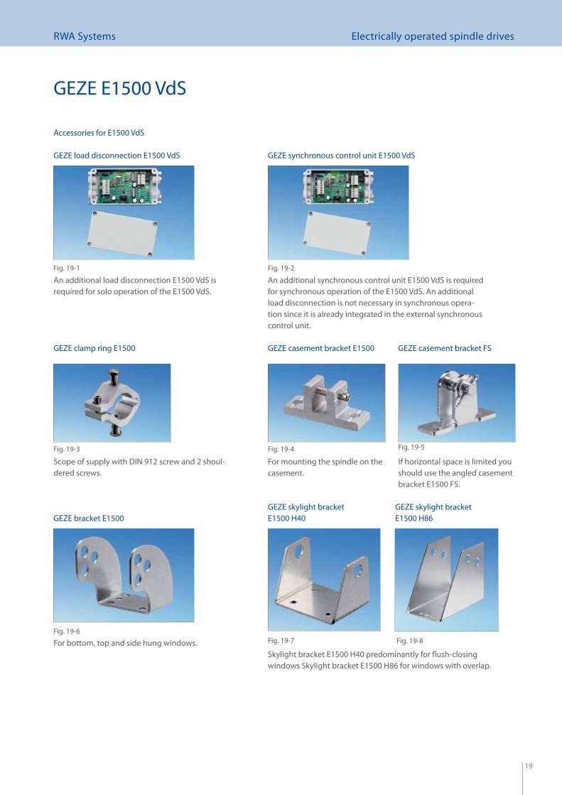
Accessories for E1500 VdS
An additional load disconnection E1500 VdS is required for solo operation of the E1500 VdS.
An additional synchronous control unit E1500 VdS is required for synchronous operation of the E1500 VdS. An additional load disconnection is not necessary in synchronous opera-tion since it is already integrated in the external synchronous control unit.
GEZE E1500 VdS
GEZE load disconnection E1500 VdS
Fig. 19-1
GEZE synchronous control unit E1500 VdS
Fig. 19-2
For bottom, top and side hung windows.
For mounting the spindle on the casement.
GEZE casement bracket E1500
Fig. 19-4
GEZE bracket E1500
Fig. 19-6
Scope of supply with DIN 912 screw and 2 shoul-dered screws.
Fig. 19-3
GEZE clamp ring E1500
Skylight bracket E1500 H40 predominantly for fl ush-closing windows Skylight bracket E1500 H86 for windows with overlap.
GEZE skylight bracket E1500 H40
Fig. 19-7 Fig. 19-8
GEZE skylight bracket E1500 H86
If horizontal space is limited you should use the angled casement bracket E1500 FS.
GEZE casement bracket FS
Fig. 19-5
20
RWA Systems Electrically operated spindle drives
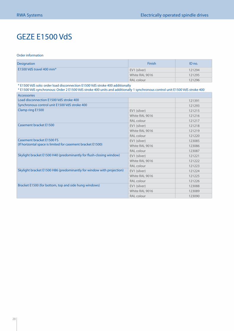
Designation Finish ID no.
E1500 VdS travel 400 mm* EV1 (silver) 121294White RAL 9016 121295RAL colour 121296
* E1500 VdS solo: order load disconnection E1500 VdS stroke 400 additionally* E1500 VdS synchronous: Order 2 E1500 VdS stroke 400 units and additionally 1 synchronous control unit E1500 VdS stroke 400
AccessoriesLoad disconnection E1500 VdS stroke 400 121391Synchronous control unit E1500 VdS stroke 400 121293Clamp ring E1500 EV1 (silver) 121215
White RAL 9016 121216RAL colour 121217
Casement bracket E1500 EV1 (silver) 121218White RAL 9016 121219RAL colour 121220
Casement bracket E1500 FS (If horizontal space is limited for casement bracket E1500)
EV1 (silver) 123085White RAL 9016 123086RAL colour 123087
Skylight bracket E1500 H40 (predominantly for fl ush-closing window) EV1 (silver) 121221White RAL 9016 121222RAL colour 121223
Skylight bracket E1500 H86 (predominantly for window with projection) EV1 (silver) 121224White RAL 9016 121225RAL colour 121226
Bracket E1500 (for bottom, top and side hung windows) EV1 (silver) 123088White RAL 9016 123089RAL colour 123090
Order information
GEZE E1500 VdS
21
RWA Systems Electrically operated spindle drives
GEZE E3000 RWA electrically operated spindle drive as a direct opener
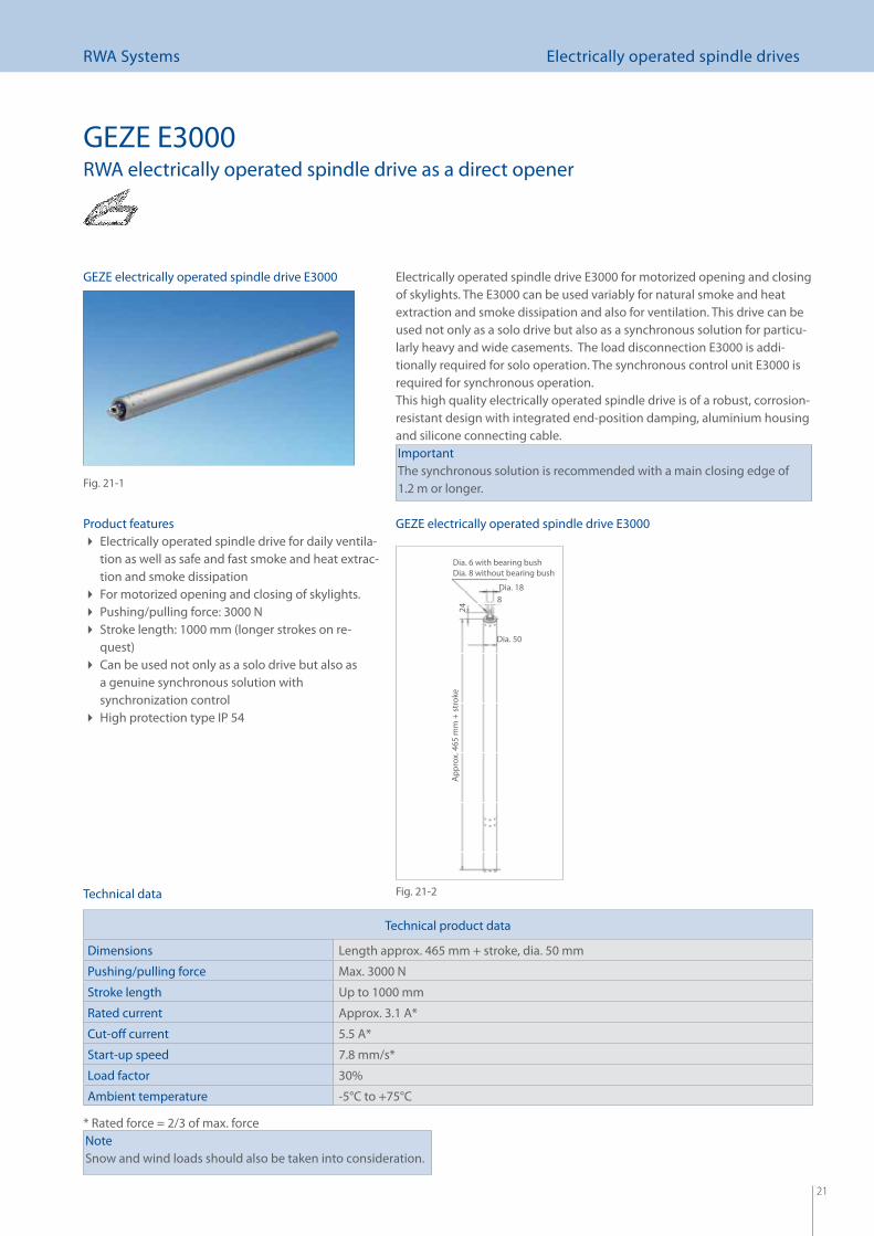
Electrically operated spindle drive E3000 for motorized opening and closing of skylights. The E3000 can be used variably for natural smoke and heat extraction and smoke dissipation and also for ventilation. This drive can be used not only as a solo drive but also as a synchronous solution for particu-larly heavy and wide casements. The load disconnection E3000 is addi-tionally required for solo operation. The synchronous control unit E3000 is required for synchronous operation. This high quality electrically operated spindle drive is of a robust, corrosion-resistant design with integrated end-position damping, aluminium housing and silicone connecting cable.ImportantThe synchronous solution is recommended with a main closing edge of 1.2 m or longer.
Product featuresElectrically operated spindle drive for daily ventila- tion as well as safe and fast smoke and heat extrac-tion and smoke dissipationFor motorized opening and closing of skylights. Pushing/pulling force: 3000 N Stroke length: 1000 mm (longer strokes on re- quest)Can be used not only as a solo drive but also as a genuine synchronous solution with synchronization controlHigh protection type IP 54
NoteSnow and wind loads should also be taken into consideration.
Technical product data
Dimensions Length approx. 465 mm + stroke, dia. 50 mm
Pushing/pulling force Max. 3000 N
Stroke length Up to 1000 mm
Rated current Approx. 3.1 A*
Cut-off current 5.5 A*
Start-up speed 7.8 mm/s*
Load factor 30%
Ambient temperature -5°C to +75°C
* Rated force = 2/3 of max. force
Technical data
GEZE electrically operated spindle drive E3000
Fig. 21-1
GEZE electrically operated spindle drive E3000
Fig. 21-2
Dia. 6 with bearing bushDia. 8 without bearing bush
24A
ppro
x. 4
65 m
m +
str
oke
Dia. 50
Dia. 188
22
RWA Systems Electrically operated spindle drives
ID numbers of installation drawings and wiring diagrams
GEZE E3000
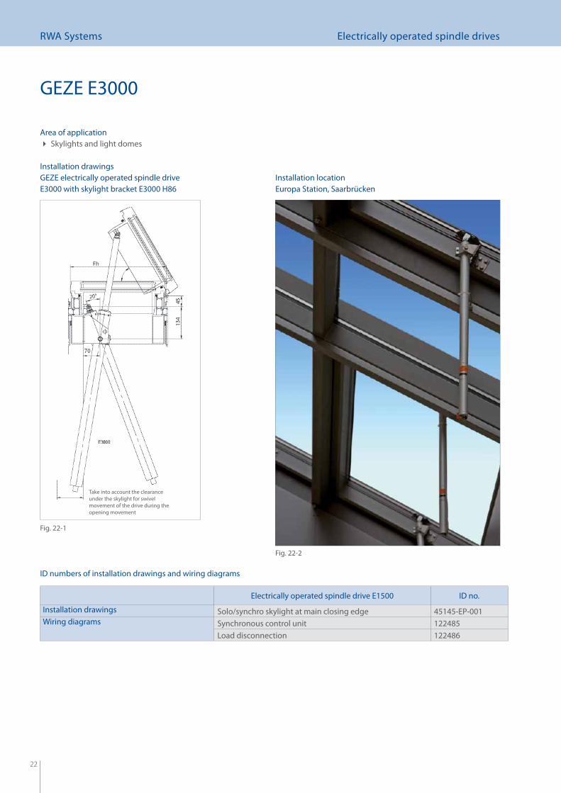
Installation drawingsInstallation locationGEZE electrically operated spindle drive
E3000 with skylight bracket E3000 H86
Area of applicationSkylights and light domes
Electrically operated spindle drive E1500 ID no.
Installation drawings Solo/synchro skylight at main closing edge 45145-EP-001Wiring diagrams Synchronous control unit 122485
Load disconnection 122486
Fig. 22-1
Fig. 22-2
Europa Station, Saarbrücken
Take into account the clearance under the skylight for swivel movement of the drive during the opening movement
23
RWA Systems Electrically operated spindle drives
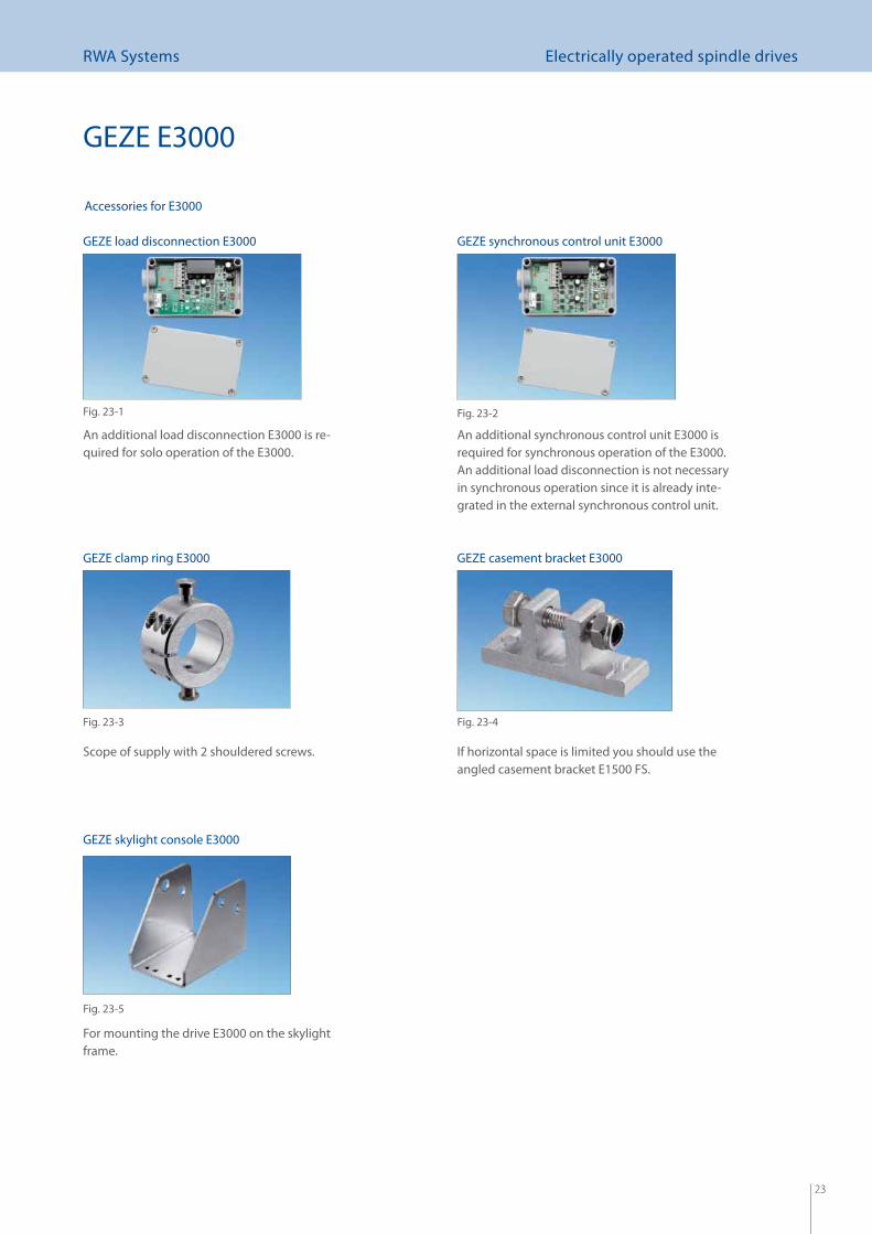
Accessories for E3000
An additional load disconnection E3000 is re-quired for solo operation of the E3000.
An additional synchronous control unit E3000 is required for synchronous operation of the E3000. An additional load disconnection is not necessary in synchronous operation since it is already inte-grated in the external synchronous control unit.
If horizontal space is limited you should use the angled casement bracket E1500 FS.
GEZE skylight console E3000
Scope of supply with 2 shouldered screws.
GEZE load disconnection E3000
Fig. 23-1
GEZE synchronous control unit E3000
Fig. 23-2
Fig. 23-3 Fig. 23-4
Fig. 23-5
GEZE clamp ring E3000 GEZE casement bracket E3000
GEZE E3000
For mounting the drive E3000 on the skylight frame.
24
RWA Systems Electrically operated spindle drives
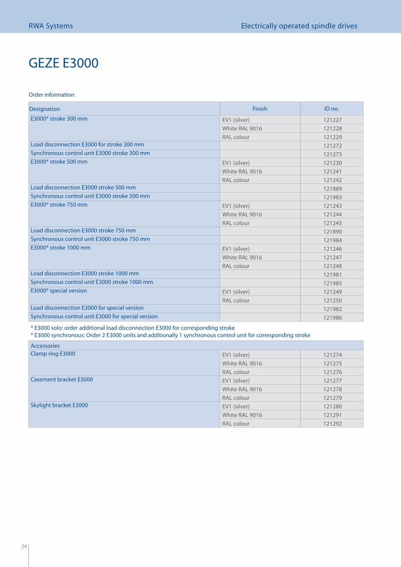
Designation Finish ID no.
E3000* stroke 300 mm EV1 (silver) 121227White RAL 9016 121228RAL colour 121229
Load disconnection E3000 for stroke 300 mm 121272Synchronous control unit E3000 stroke 300 mm 121273E3000* stroke 500 mm EV1 (silver) 121230
White RAL 9016 121241RAL colour 121242
Load disconnection E3000 stroke 500 mm 121889Synchronous control unit E3000 stroke 500 mm 121983E3000* stroke 750 mm EV1 (silver) 121243
White RAL 9016 121244RAL colour 121245
Load disconnection E3000 stroke 750 mm 121890Synchronous control unit E3000 stroke 750 mm 121984E3000* stroke 1000 mm EV1 (silver) 121246
White RAL 9016 121247RAL colour 121248
Load disconnection E3000 stroke 1000 mm 121981Synchronous control unit E3000 stroke 1000 mm 121985E3000* special version EV1 (silver) 121249
RAL colour 121250Load disconnection E3000 for special version 121982Synchronous control unit E3000 for special version 121986
* E3000 solo: order additional load disconnection E3000 for corresponding stroke* E3000 synchronous: Order 2 E3000 units and additionally 1 synchronous control unit for corresponding stroke
AccessoriesClamp ring E3000 EV1 (silver) 121274
White RAL 9016 121275RAL colour 121276
Casement bracket E3000 EV1 (silver) 121277White RAL 9016 121278RAL colour 121279
Skylight bracket E3000 EV1 (silver) 121280White RAL 9016 121291RAL colour 121292
Order information
GEZE E3000
25
RWA Systems Electrically operated chain drives
2525
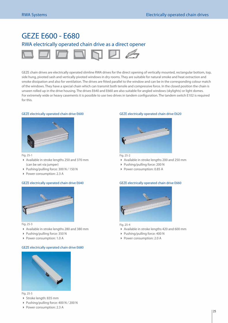
GEZE chain drives are electrically operated slimline RWA drives for the direct opening of vertically mounted, rectangular bottom, top, side hung, pivoted sash and vertically pivoted windows in dry rooms. They are suitable for natural smoke and heat extraction and smoke dissipation and also for ventilation. The drives are fi tted parallel to the window and can be in the corresponding colour match of the windows. They have a special chain which can transmit both tensile and compressive force. In the closed position the chain is unseen rolled up in the drive housing. The drives E640 and E660 are also suitable for angled windows (skylights) or light domes. For extremely wide or heavy casements it is possible to use two drives in tandem confi guration. The tandem switch E102 is required for this.
Available in stroke lengths 250 and 370 mm (can be set via jumper)Pushing/pulling force: 300 N / 150 N Power consumption: 2.3 A
Available in stroke lengths 200 and 250 mm Pushing/pulling force: 200 N Power consumption: 0.85 A
Available in stroke lengths 280 and 380 mm Pushing/pulling force: 350 N Power consumption: 1.0 A
Available in stroke lengths 420 and 600 mm Pushing/pulling force: 400 N Power consumption: 2.0 A
Stroke length: 835 mm Pushing/pulling force: 400 N / 200 N Power consumption: 2.3 A
GEZE electrically operated chain drive E600
Fig. 25-1
GEZE electrically operated chain drive E620
Fig. 25-2
GEZE electrically operated chain drive E640
Fig. 25-3
GEZE electrically operated chain drive E660
Fig. 25-4
GEZE electrically operated chain drive E680
Fig. 25-5
GEZE E600 - E680RWA electrically operated chain drive as a direct opener
26
RWA Systems Electrically operated chain drives
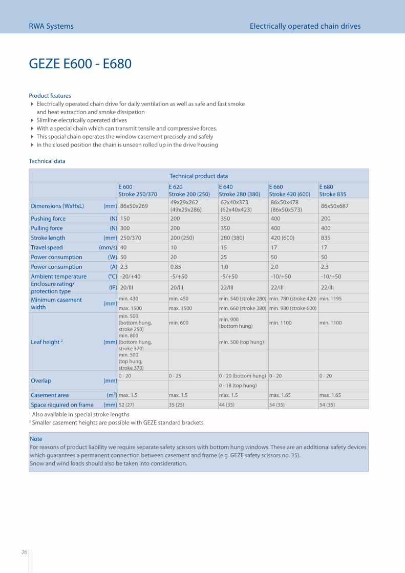
Technical product data
E 600Stroke 250/370
E 620Stroke 200 (250)
E 640 Stroke 280 (380)
E 660Stroke 420 (600)
E 680Stroke 835
Dimensions (WxHxL) (mm) 86x50x269 49x29x262 (49x29x286)
62x40x373 (62x40x423)
86x50x478 (86x50x573) 86x50x687
Pushing force (N) 150 200 350 400 200
Pulling force (N) 300 200 350 400 400
Stroke length (mm) 250/370 200 (250) 280 (380) 420 (600) 835
Travel speed (mm/s) 40 10 15 17 17
Power consumption (W) 50 20 25 50 50
Power consumption (A) 2.3 0.85 1.0 2.0 2.3
Ambient temperature (°C) -20/+40 -5/+50 -5/+50 -10/+50 -10/+50Enclosure rating/protection type (IP) 20/III 20/III 22/III 22/III 22/III
Minimum casement width (mm)
min. 430 min. 450 min. 540 (stroke 280) min. 780 (stroke 420) min. 1195
max. 1500 max. 1500 min. 660 (stroke 380) min. 980 (stroke 600)
Leaf height 2 (mm)
min. 500 (bottom hung, stroke 250)
min. 600 min. 900 (bottom hung) min. 1100 min. 1100
min. 800 (bottom hung, stroke 370)
min. 500 (top hung)
min. 500 (top hung, stroke 370)
Overlap (mm)0 - 20 0 - 25 0 - 20 (bottom hung) 0 - 20 0 - 20
0 - 18 (top hung)
Casement area (m2) max. 1.5 max. 1.5 max. 1.5 max. 1.65 max. 1.65
Space required on frame (mm) 52 (27) 35 (25) 44 (35) 54 (35) 54 (35)
NoteFor reasons of product liability we require separate safety scissors with bottom hung windows. These are an additional safety devices which guarantees a permanent connection between casement and frame (e.g. GEZE safety scissors no. 35).Snow and wind loads should also be taken into consideration.
GEZE E600 - E680
1 Also available in special stroke lengths2 Smaller casement heights are possible with GEZE standard brackets
Technical data
Product featuresElectrically operated chain drive for daily ventilation as well as safe and fast smoke and heat extraction and smoke dissipationSlimline electrically operated drives With a special chain which can transmit tensile and compressive forces. This special chain operates the window casement precisely and safely In the closed position the chain is unseen rolled up in the drive housing
27
RWA Systems Electrically operated chain drives
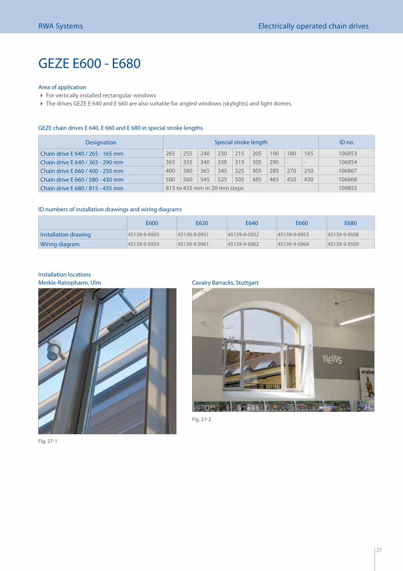
Area of applicationFor vertically installed rectangular windows The drives GEZE E 640 and E 660 are also suitable for angled windows (skylights) and light domes.
E600 E620 E640 E660 E680
Installation drawing 45139-9-0950 45139-9-0951 45139-9-0952 45139-9-0953 45139-9-9508
Wiring diagram 45139-9-0959 45139-9-0961 45139-9-0962 45139-9-0964 45139-9-9509
Installation locations
ID numbers of installation drawings and wiring diagrams
Designation Special stroke length ID no.
Chain drive E 640 / 265 - 165 mm 265 255 240 230 215 205 190 180 165 106853Chain drive E 640 / 365 - 290 mm 365 355 340 330 315 305 290 - - 106854Chain drive E 660 / 400 - 250 mm 400 380 365 345 325 305 285 270 250 106867Chain drive E 660 / 580 - 430 mm 580 560 545 525 505 485 465 450 430 106868Chain drive E 680 / 815 - 435 mm 815 to 435 mm in 20 mm steps 109855
GEZE chain drives E 640, E 660 and E 680 in special stroke lengths
Cavalry Barracks, Stuttgart
Fig. 27-1
Fig. 27-2
GEZE E600 - E680
Merkle-Ratiopharm, Ulm
28
RWA Systems Electrically operated chain drives
GEZE E600 - E680
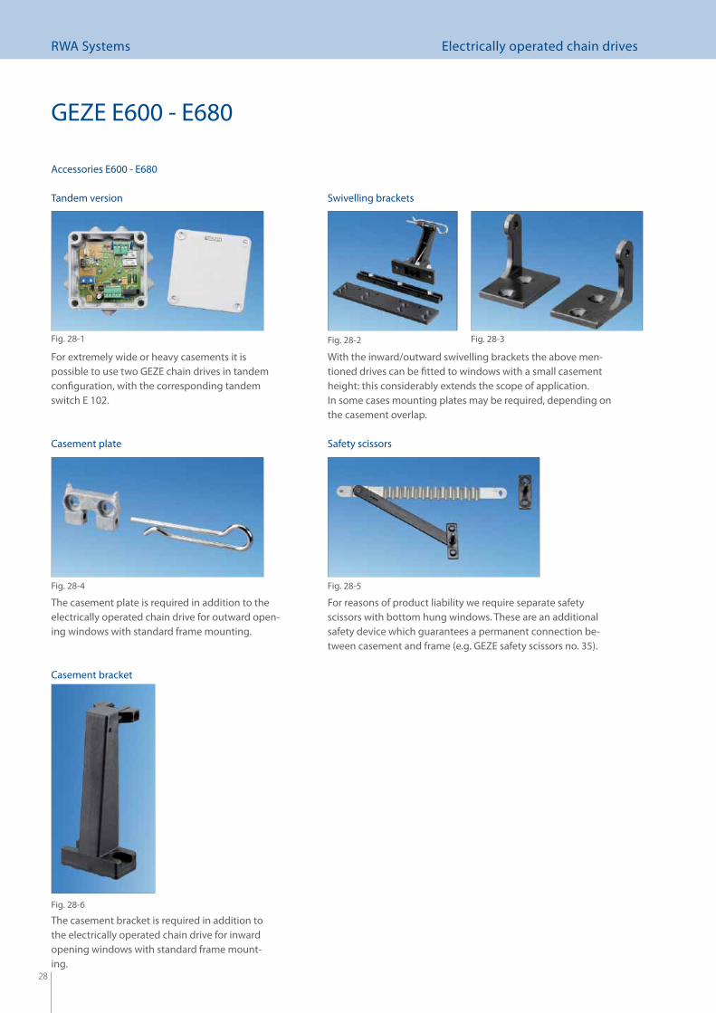
For extremely wide or heavy casements it is possible to use two GEZE chain drives in tandem confi guration, with the corresponding tandem switch E 102.
With the inward/outward swivelling brackets the above men-tioned drives can be fi tted to windows with a small casement height: this considerably extends the scope of application.In some cases mounting plates may be required, depending on the casement overlap.
For reasons of product liability we require separate safety scissors with bottom hung windows. These are an additional safety device which guarantees a permanent connection be-tween casement and frame (e.g. GEZE safety scissors no. 35).
The casement plate is required in addition to the electrically operated chain drive for outward open-ing windows with standard frame mounting.
The casement bracket is required in addition to the electrically operated chain drive for inward opening windows with standard frame mount-ing.
Accessories E600 - E680
Tandem version
Fig. 28-1
Swivelling brackets
Fig. 28-2
Casement bracket
Fig. 28-6
Casement plate
Fig. 28-4
Safety scissors
Fig. 28-5
Fig. 28-3
29
RWA Systems Electrically operated chain drives
Mechanical locking bracketfor GEZE electrically operated chain drives
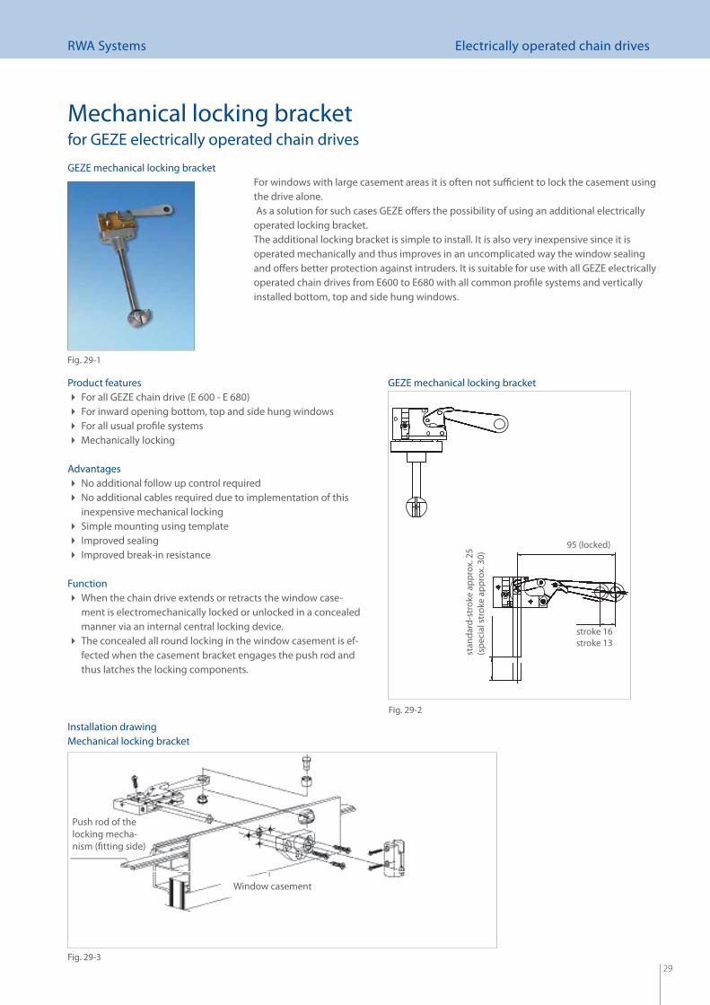
For windows with large casement areas it is often not suffi cient to lock the casement using the drive alone. As a solution for such cases GEZE off ers the possibility of using an additional electrically operated locking bracket.The additional locking bracket is simple to install. It is also very inexpensive since it is operated mechanically and thus improves in an uncomplicated way the window sealing and off ers better protection against intruders. It is suitable for use with all GEZE electrically operated chain drives from E600 to E680 with all common profi le systems and vertically installed bottom, top and side hung windows.
Product featuresFor all GEZE chain drive (E 600 - E 680) For inward opening bottom, top and side hung windows For all usual profi le systems Mechanically locking
AdvantagesNo additional follow up control required No additional cables required due to implementation of this inexpensive mechanical lockingSimple mounting using template Improved sealing Improved break-in resistance
FunctionWhen the chain drive extends or retracts the window case- ment is electromechanically locked or unlocked in a concealed manner via an internal central locking device.The concealed all round locking in the window casement is ef- fected when the casement bracket engages the push rod and thus latches the locking components.
Installation drawing
Push rod of the locking mecha-nism (fi tting side)
Window casement
GEZE mechanical locking bracket
Fig. 29-1
Fig. 29-2
Fig. 29-3
GEZE mechanical locking bracket
Mechanical locking bracket
95 (locked)
stroke 16stroke 13
stan
dard
-str
oke
appr
ox. 2
5(s
peci
al s
trok
e ap
prox
. 30)
30
RWA Systems Electrically operated chain drives
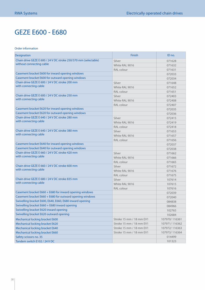
GEZE E600 - E680
Designation Finish ID no.
Chain drive GEZE E 600 / 24 V DC stroke 250/370 mm (selectable) without connecting cable
Silver 071628White RAL 9016 071632RAL colour 071631
Casement bracket E600 for inward opening windows 072033Casement bracket E600 for outward opening windows 072034Chain drive GEZE E 600 / 24 V DC stroke 200 mm with connecting cable
Silver 071648White RAL 9016 071652RAL colour 071651
Chain drive GEZE E 600 / 24 V DC stroke 250 mm with connecting cable
Silver 072403White RAL 9016 072408RAL colour 072407
Casement bracket E620 for inward opening windows 072035Casement bracket E620 for outward opening windows 072036Chain drive GEZE E 640 / 24 V DC stroke 280 mm with connecting cable
Silver 072415White RAL 9016 072419RAL colour 072418
Chain drive GEZE E 640 / 24 V DC stroke 380 mm with connecting cable
Silver 071653White RAL 9016 071657RAL colour 071656
Casement bracket E640 for inward opening windows 072037Casement bracket E640 for outward opening windows 072038Chain drive GEZE E 660 / 24 V DC stroke 420 mm with connecting cable
Silver 071662White RAL 9016 071666RAL colour 071665
Chain drive GEZE E 660 / 24 V DC stroke 600 mm with connecting cable
Silver 071672White RAL 9016 071676RAL colour 071675
Chain drive GEZE E 680 / 24 V DC stroke 835 mm with connecting cable
Silver 107614White RAL 9016 107615RAL colour 107616
Casement bracket E660 + E680 for inward opening windows 072039Casement bracket E660 + E680 for outward opening windows 072040Swivelling bracket E600, E640, E660, E680 inward opening 084838Swivelling bracket E660 + E680 inward opening 084966Swivelling bracket E620 inward opening 102765Swivelling bracket E620 outward opening 102684Mechanical locking bracket E600 Stroke 15 mm / 18 mm EV1 107970/ 116361Mechanical locking bracket E620 Stroke 15 mm / 18 mm EV1 107971/ 116362Mechanical locking bracket E640 Stroke 15 mm / 18 mm EV1 107972/ 116363Mechanical locking bracket E660 Stroke 15 mm / 18 mm EV1 107973/ 116364Safety scissors no. 35 014499Tandem switch E102 / 24 V DC 101323
Order information
31
RWA Systems Opening and locking systems
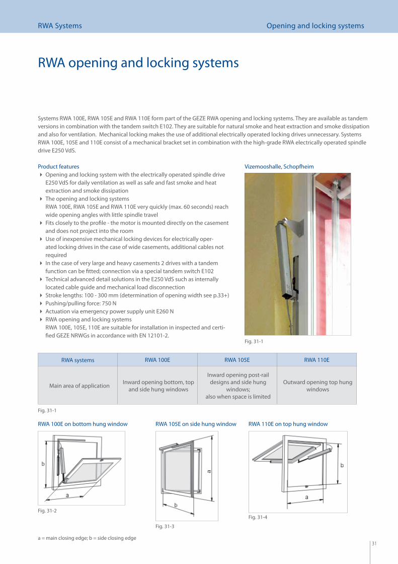
RWA opening and locking systems
Systems RWA 100E, RWA 105E and RWA 110E form part of the GEZE RWA opening and locking systems. They are available as tandem versions in combination with the tandem switch E102. They are suitable for natural smoke and heat extraction and smoke dissipation and also for ventilation. Mechanical locking makes the use of additional electrically operated locking drives unnecessary. Systems RWA 100E, 105E and 110E consist of a mechanical bracket set in combination with the high-grade RWA electrically operated spindle drive E250 VdS.
Product featuresOpening and locking system with the electrically operated spindle drive E250 VdS for daily ventilation as well as safe and fast smoke and heat extraction and smoke dissipationThe opening and locking systems RWA 100E, RWA 105E and RWA 110E very quickly (max. 60 seconds) reach wide opening angles with little spindle travelFits closely to the profi le - the motor is mounted directly on the casement and does not project into the roomUse of inexpensive mechanical locking devices for electrically oper- ated locking drives in the case of wide casements, additional cables not requiredIn the case of very large and heavy casements 2 drives with a tandem function can be fi tted; connection via a special tandem switch E102Technical advanced detail solutions in the E250 VdS such as internally located cable guide and mechanical load disconnectionStroke lengths: 100 - 300 mm (determination of opening width see p.33+) Pushing/pulling force: 750 N Actuation via emergency power supply unit E260 N RWA opening and locking systems RWA 100E, 105E, 110E are suitable for installation in inspected and certi-fi ed GEZE NRWGs in accordance with EN 12101-2.
RWA systems RWA 100E RWA 105E RWA 110E
Main area of application Inward opening bottom, top and side hung windows
Inward opening post-rail designs and side hung
windows; also when space is limited
Outward opening top hung windows
RWA 100E on bottom hung window RWA 105E on side hung window RWA 110E on top hung window
a = main closing edge; b = side closing edge
Fig. 31-1
Fig. 31-2
Fig. 31-3
Fig. 31-4
Fig. 31-1
Vizemooshalle, Schopfheim
32
RWA Systems Opening and locking systems
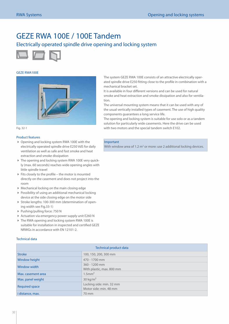
GEZE RWA 100E / 100E TandemElectrically operated spindle drive opening and locking system
The system GEZE RWA 100E consists of an attractive electrically oper-ated spindle drive E250 fi tting close to the profi le in combination with a mechanical bracket set. It is available in four diff erent versions and can be used for natural smoke and heat extraction and smoke dissipation and also for ventila-tion. The universal mounting system means that it can be used with any of the usual vertically installed types of casement. The use of high quality components guarantees a long service life.The opening and locking system is suitable for use solo or as a tandem solution for particularly wide casements. Here the drive can be used with two motors and the special tandem switch E102.
ImportantWith window area of 1.2 m2 or more: use 2 additional locking devices.
Technical data
Product featuresOpening and locking system RWA 100E with the electrically operated spindle drive E250 VdS for daily ventilation as well as safe and fast smoke and heat extraction and smoke dissipationThe opening and locking system RWA 100E very quick- ly (max. 60 seconds) reaches wide opening angles with little spindle travelFits closely to the profi le – the motor is mounted directly on the casement and does not project into the roomMechanical locking on the main closing edge Possibility of using an additional mechanical locking device at the side closing edge on the motor sideStroke lengths: 100-300 mm (determination of open- ing width see Fig.33-1)Pushing/pulling force: 750 N Actuation via emergency power supply unit E260 N The RWA opening and locking system RWA 100E is suitable for installation in inspected and certifi ed GEZE NRWGs in accordance with EN 12101-2.
GEZE RWA100E
Fig. 32-1
Technical product data
Stroke 100, 150, 200, 300 mm
Window height 470 - 1700 mm
Window width 360 - 1200 mmWith plastic, max. 800 mm
Max. casement area 1.5mm2
Max. panel weight 30 kg/m2
Required space Locking side: min. 32 mmMotor side: min. 48 mm
i distance, max. 70 mm
33
RWA Systems Opening and locking systems
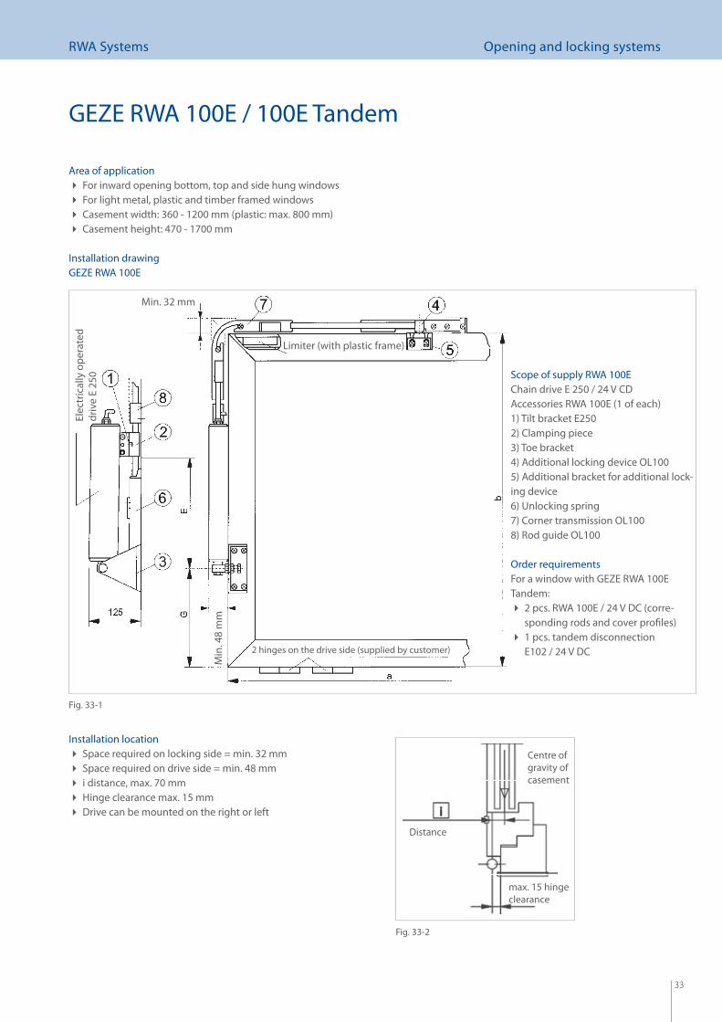
Installation locationSpace required on locking side = min. 32 mm Space required on drive side = min. 48 mm i distance, max. 70 mm Hinge clearance max. 15 mm Drive can be mounted on the right or left
Centre of gravity of casement
Area of applicationFor inward opening bottom, top and side hung windows For light metal, plastic and timber framed windows Casement width: 360 - 1200 mm (plastic: max. 800 mm) Casement height: 470 - 1700 mm
Installation drawingGEZE RWA 100E
Scope of supply RWA 100EChain drive E 250 / 24 V CDAccessories RWA 100E (1 of each)1) Tilt bracket E2502) Clamping piece3) Toe bracket4) Additional locking device OL1005) Additional bracket for additional lock-ing device6) Unlocking spring7) Corner transmission OL1008) Rod guide OL100
Order requirementsFor a window with GEZE RWA 100E Tandem:
2 pcs. RWA 100E / 24 V DC (corre- sponding rods and cover profi les)1 pcs. tandem disconnection E102 / 24 V DC2 hinges on the drive side (supplied by customer)
Min
. 48
mm
Elec
tric
ally
ope
rate
d dr
ive
E 25
0
Min. 32 mm
Limiter (with plastic frame)
Fig. 33-1
Fig. 33-2
Distance
max. 15 hinge clearance
GEZE RWA 100E / 100E Tandem
34
RWA Systems Opening and locking systems
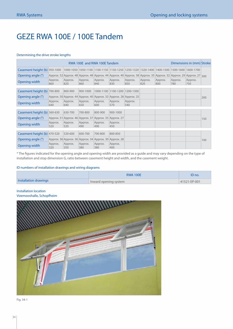
GEZE RWA 100E / 100E Tandem
RWA 100E and RWA 100E Tandem Dimensions in (mm) Stroke
Casement height (b) 950-1000 1000-1050 1050-1100 1100-1150 1150-1250 1250-1320 1320-1400 1400-1500 1500-1600 1600-1700
300Opening angle (°) Approx. 52 Approx. 48 Approx. 48 Approx. 44 Approx. 40 Approx. 38 Approx. 35 Approx. 32 Approx. 29 Approx. 27
Opening width Approx. 860
Approx. 820
Approx. 860
Approx. 840
Approx. 830
Approx. 850
Approx. 820
Approx. 800
Approx. 780
Approx. 750
Casement height (b) 700-800 800-900 900-1000 1000-1100 1100-1200 1200-1300
200Opening angle (°) Approx. 50 Approx. 44 Approx. 40 Approx. 33 Approx. 28 Approx. 25
Opening width Approx. 640
Approx. 640
Approx. 650
Approx. 600
Approx. 570
Approx. 540
Casement height (b) 560-630 630-700 700-800 800-900 900-1000
150Opening angle (°) Approx. 51 Approx. 46 Approx. 37 Approx. 35 Approx. 27
Opening width Approx. 520
Approx. 520
Approx. 490
Approx. 490
Approx. 450
Casement height (b) 470-520 520-600 600-700 700-800 800-850
100Opening angle (°) Approx. 36 Approx. 36 Approx. 34 Approx. 30 Approx. 28
Opening width Approx. 320
Approx. 350
Approx. 380
Approx. 380
Approx. 400
* The fi gures indicated for the opening angle and opening width are provided as a guide and may vary depending on the type of installation and stop dimension G, ratio between casement height and width, and the casement weight.
ID numbers of installation drawings and wiring diagrams
Determining the drive stroke lengths
Installation locationVizemooshalle, Schopfheim
RWA 100E ID no.
Installation drawings Inward opening system 41521-EP-001
Fig. 34-1
35
RWA Systems Opening and locking systems
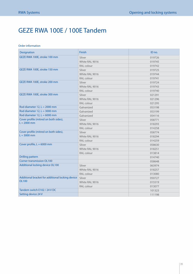
Designation Finish ID no.
GEZE RWA 100E, stroke 100 mm Silver 019726White RAL 9016 019745RAL colour 019742
GEZE RWA 100E, stroke 150 mm Silver 019725White RAL 9016 019744RAL colour 019741
GEZE RWA 100E, stroke 200 mm Silver 019724White RAL 9016 019743RAL colour 019740
GEZE RWA 100E, stroke 300 mm Silver 021291White RAL 9016 021296RAL colour 021295
Rod diameter 12, L = 2000 mm Galvanized 053198Rod diameter 12, L = 3000 mm Galvanized 053199Rod diameter 12, L = 6000 mm Galvanized 054116Cover profi le (mitred on both sides), L = 2000 mm
Silver 058771White RAL 9016 018293RAL colour 014258
Cover profi le (mitred on both sides), L = 3000 mm
Silver 058774White RAL 9016 018294RAL colour 014259
Cover profi le, L = 6000 mm Silver 058630White RAL 9016 018251RAL colour 013814
Drilling pattern 014740Corner transmission OL100 058648Additional locking device OL100 Silver 063974
White RAL 9016 018257RAL colour 013080
Additional bracket for additional locking device OL100
Silver 050727White RAL 9016 015519RAL colour 013077
Tandem switch E102 / 24 V DC 101323Setting device 24 V 111198
Order information
GEZE RWA 100E / 100E Tandem
36
RWA Systems Opening and locking systems
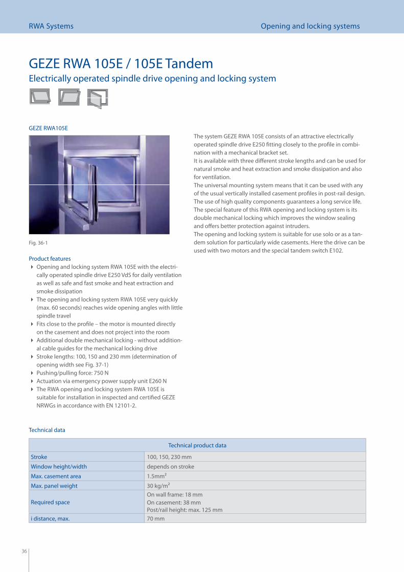
GEZE RWA 105E / 105E TandemElectrically operated spindle drive opening and locking system
Product featuresOpening and locking system RWA 105E with the electri- cally operated spindle drive E250 VdS for daily ventilation as well as safe and fast smoke and heat extraction and smoke dissipationThe opening and locking system RWA 105E very quickly (max. 60 seconds) reaches wide opening angles with little spindle travelFits close to the profi le – the motor is mounted directly on the casement and does not project into the roomAdditional double mechanical locking - without addition- al cable guides for the mechanical locking driveStroke lengths: 100, 150 and 230 mm (determination of opening width see Fig. 37-1)Pushing/pulling force: 750 N Actuation via emergency power supply unit E260 N The RWA opening and locking system RWA 105E is suitable for installation in inspected and certifi ed GEZE NRWGs in accordance with EN 12101-2.
The system GEZE RWA 105E consists of an attractive electrically operated spindle drive E250 fi tting closely to the profi le in combi-nation with a mechanical bracket set.It is available with three diff erent stroke lengths and can be used for natural smoke and heat extraction and smoke dissipation and also for ventilation. The universal mounting system means that it can be used with any of the usual vertically installed casement profi les in post-rail design. The use of high quality components guarantees a long service life.The special feature of this RWA opening and locking system is its double mechanical locking which improves the window sealing and off ers better protection against intruders.The opening and locking system is suitable for use solo or as a tan-dem solution for particularly wide casements. Here the drive can be used with two motors and the special tandem switch E102.
Technical data
Fig. 36-1
GEZE RWA105E
Technical product data
Stroke 100, 150, 230 mm
Window height/width depends on stroke
Max. casement area 1.5mm2
Max. panel weight 30 kg/m2
Required space On wall frame: 18 mmOn casement: 38 mmPost/rail height: max. 125 mm
i distance, max. 70 mm
37
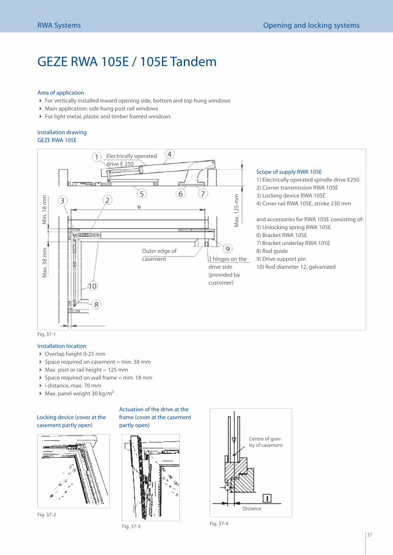
RWA Systems Opening and locking systems
Installation locationOverlap height 0-25 mm Space required on casement = min. 38 mm Max. post or rail height = 125 mm Space required on wall frame = min. 18 mm i distance, max. 70 mm Max. panel weight 30 kg/m2
Distance
Centre of grav-ity of casement
Area of applicationFor vertically installed inward opening side, bottom and top hung windows Main application: side hung post rail windows For light metal, plastic and timber framed windows
Max
. 125
mm
Electrically operated drive E 250
Outer edge of casement 2 hinges on the
drive side (provided by customer)
Max
. 38
mm
Min
. 18
mm
Scope of supply RWA 105E1) Electrically operated spindle drive E2502) Corner transmission RWA 105E3) Locking device RWA 105E4) Cover rail RWA 105E, stroke 230 mm
and accessories for RWA 105E consisting of:5) Unlocking spring RWA 105E6) Bracket RWA 105E7) Bracket underlay RWA 105E8) Rod guide9) Drive support pin10) Rod diameter 12, galvanized
Installation drawingGEZE RWA 105E
Fig. 37-1
Actuation of the drive at the frame (cover at the casement partly open)
Locking device (cover at the casement partly open)
Fig. 37-2
Fig. 37-3 Fig. 37-4
GEZE RWA 105E / 105E Tandem
38
RWA Systems Opening and locking systems
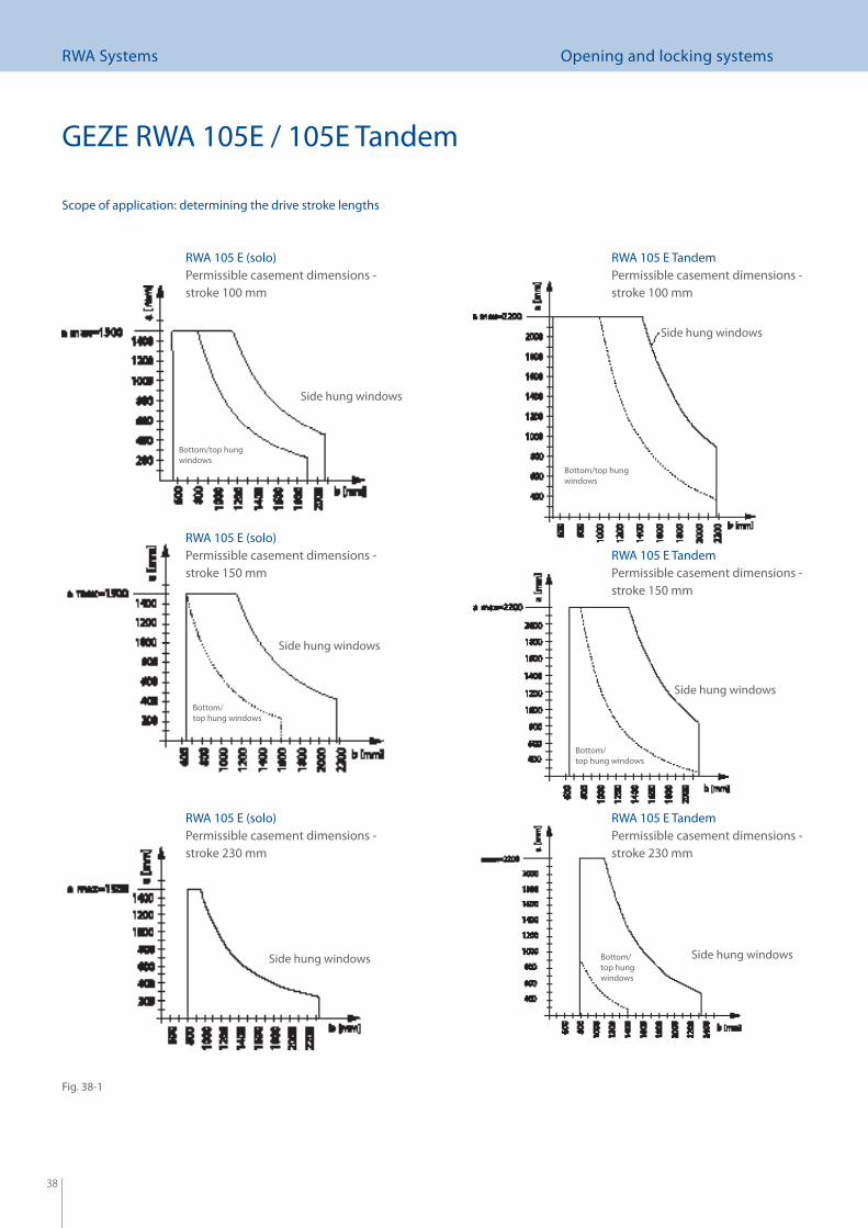
Scope of application: determining the drive stroke lengths
RWA 105 E (solo)Permissible casement dimensions - stroke 100 mm
RWA 105 E TandemPermissible casement dimensions - stroke 100 mm
RWA 105 E (solo)Permissible casement dimensions - stroke 150 mm
RWA 105 E TandemPermissible casement dimensions - stroke 150 mm
RWA 105 E (solo)Permissible casement dimensions - stroke 230 mm
RWA 105 E TandemPermissible casement dimensions - stroke 230 mm
Side hung windows
Side hung windows
Side hung windows
Side hung windows Side hung windows
Side hung windows
Bottom/top hung windows
Bottom/top hung windows
Bottom/ top hung windows
Bottom/ top hung windows
Bottom/ top hung windows
GEZE RWA 105E / 105E Tandem
Fig. 38-1
39
RWA Systems Opening and locking systems
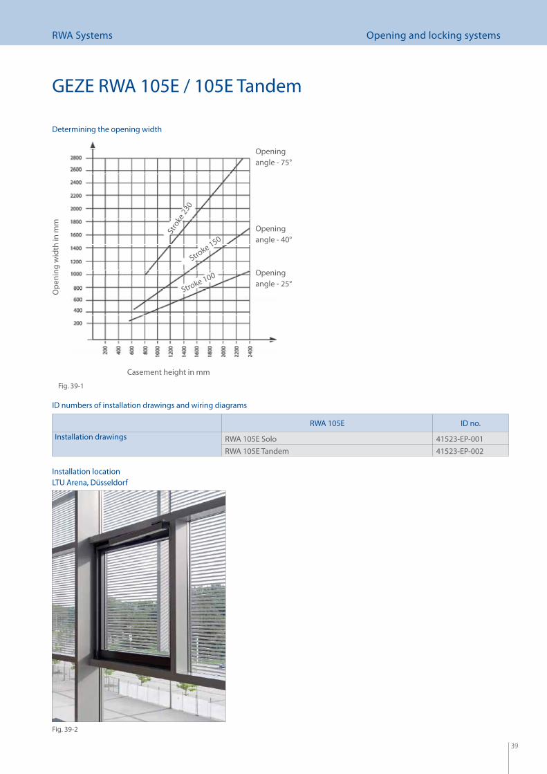
Determining the opening width
Ope
ning
wid
th in
mm
Casement height in mm
Opening angle - 75°
Opening angle - 40°
Opening angle - 25°
Stro
ke 23
0
Stroke 150
Stroke 100
GEZE RWA 105E / 105E Tandem
ID numbers of installation drawings and wiring diagrams
RWA 105E ID no.
Installation drawings RWA 105E Solo 41523-EP-001RWA 105E Tandem 41523-EP-002
Fig. 39-1
Fig. 39-2
Installation locationLTU Arena, Düsseldorf
40
RWA Systems Opening and locking systems
GEZE RWA 105E / 105E Tandem
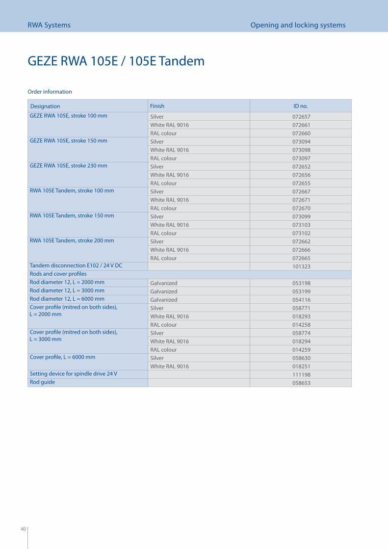
Designation Finish ID no.
GEZE RWA 105E, stroke 100 mm Silver 072657White RAL 9016 072661RAL colour 072660
GEZE RWA 105E, stroke 150 mm Silver 073094White RAL 9016 073098RAL colour 073097
GEZE RWA 105E, stroke 230 mm Silver 072652White RAL 9016 072656RAL colour 072655
RWA 105E Tandem, stroke 100 mm Silver 072667White RAL 9016 072671RAL colour 072670
RWA 105E Tandem, stroke 150 mm Silver 073099White RAL 9016 073103RAL colour 073102
RWA 105E Tandem, stroke 200 mm Silver 072662White RAL 9016 072666RAL colour 072665
Tandem disconnection E102 / 24 V DC 101323Rods and cover profi lesRod diameter 12, L = 2000 mm Galvanized 053198Rod diameter 12, L = 3000 mm Galvanized 053199Rod diameter 12, L = 6000 mm Galvanized 054116Cover profi le (mitred on both sides), L = 2000 mm
Silver 058771White RAL 9016 018293RAL colour 014258
Cover profi le (mitred on both sides), L = 3000 mm
Silver 058774White RAL 9016 018294RAL colour 014259
Cover profi le, L = 6000 mm Silver 058630White RAL 9016 018251
Setting device for spindle drive 24 V 111198Rod guide 058653
Order information
41
RWA Systems Opening and locking systems
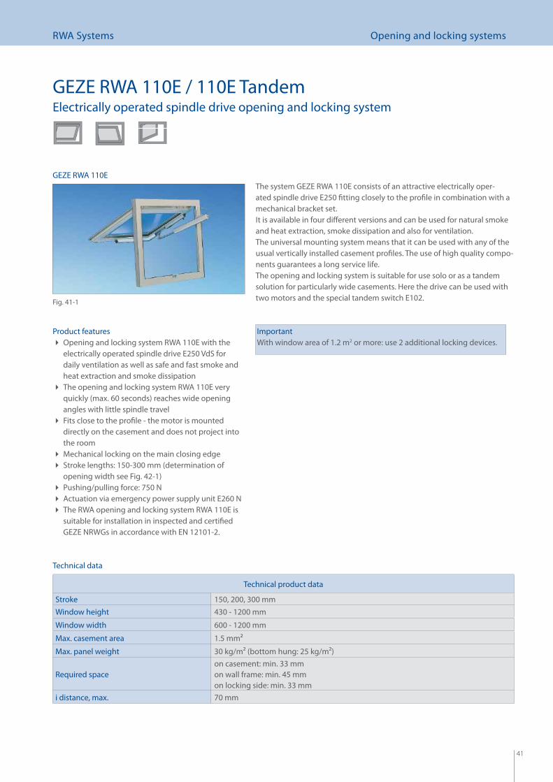
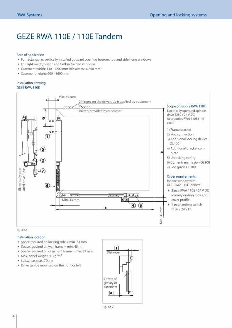
GEZE RWA 110E / 110E TandemElectrically operated spindle drive opening and locking system
Product featuresOpening and locking system RWA 110E with the electrically operated spindle drive E250 VdS for daily ventilation as well as safe and fast smoke and heat extraction and smoke dissipationThe opening and locking system RWA 110E very quickly (max. 60 seconds) reaches wide opening angles with little spindle travelFits close to the profi le - the motor is mounted directly on the casement and does not project into the roomMechanical locking on the main closing edge Stroke lengths: 150-300 mm (determination of opening width see Fig. 42-1)Pushing/pulling force: 750 N Actuation via emergency power supply unit E260 N The RWA opening and locking system RWA 110E is suitable for installation in inspected and certifi ed GEZE NRWGs in accordance with EN 12101-2.
The system GEZE RWA 110E consists of an attractive electrically oper-ated spindle drive E250 fi tting closely to the profi le in combination with a mechanical bracket set.It is available in four diff erent versions and can be used for natural smoke and heat extraction, smoke dissipation and also for ventilation. The universal mounting system means that it can be used with any of the usual vertically installed casement profi les. The use of high quality compo-nents guarantees a long service life.The opening and locking system is suitable for use solo or as a tandem solution for particularly wide casements. Here the drive can be used with two motors and the special tandem switch E102.
ImportantWith window area of 1.2 m2 or more: use 2 additional locking devices.
Technical data
Fig. 41-1
GEZE RWA 110E
Technical product data
Stroke 150, 200, 300 mmWindow height 430 - 1200 mm
Window width 600 - 1200 mm
Max. casement area 1.5 mm2
Max. panel weight 30 kg/m2 (bottom hung: 25 kg/m2)
Required space on casement: min. 33 mmon wall frame: min. 45 mmon locking side: min. 33 mm
i distance, max. 70 mm
42
RWA Systems Opening and locking systems
Area of applicationFor rectangular, vertically installed outward opening bottom, top and side hung windows For light metal, plastic and timber framed windows Casement width: 430 - 1200 mm (plastic: max. 800 mm) Casement height: 600 - 1600 mm
Installation locationSpace required on locking side = min. 33 mm Space required on wall frame = min. 45 mm Space required on casement frame = min. 33 mm Max. panel weight 30 kg/m2 i distance, max. 70 mm Drive can be mounted on the right or left
Distance
Centre of gravity of casement
Installation drawing
Scope of supply RWA 110EElectrically operated spindle drive E250 / 24 V DCAccessories RWA 110E (1 of each)
1) Frame bracket2) Rod connection3) Additional locking device OL1004) Additional bracket com plete5) Unlocking spring6) Corner transmission OL1007) Rod guide OL100
Order requirementsfor one window with GEZE RWA 110E Tandem:
2 pcs. RWA 110E / 24 V DC (corresponding rods and cover profi le)1 pcs. tandem switch E102 / 24 V DC
2 hinges on the drive side (supplied by customer)Min. 45 mm
Min. 33 mm
Elec
tric
ally
ope
r-at
ed d
rive
E 20
5
Min
. 33
mm
Limiter (provided by customer)
GEZE RWA 110E
Fig. 42-1
Fig. 42-2
GEZE RWA 110E / 110E Tandem
43
RWA Systems Opening and locking systems
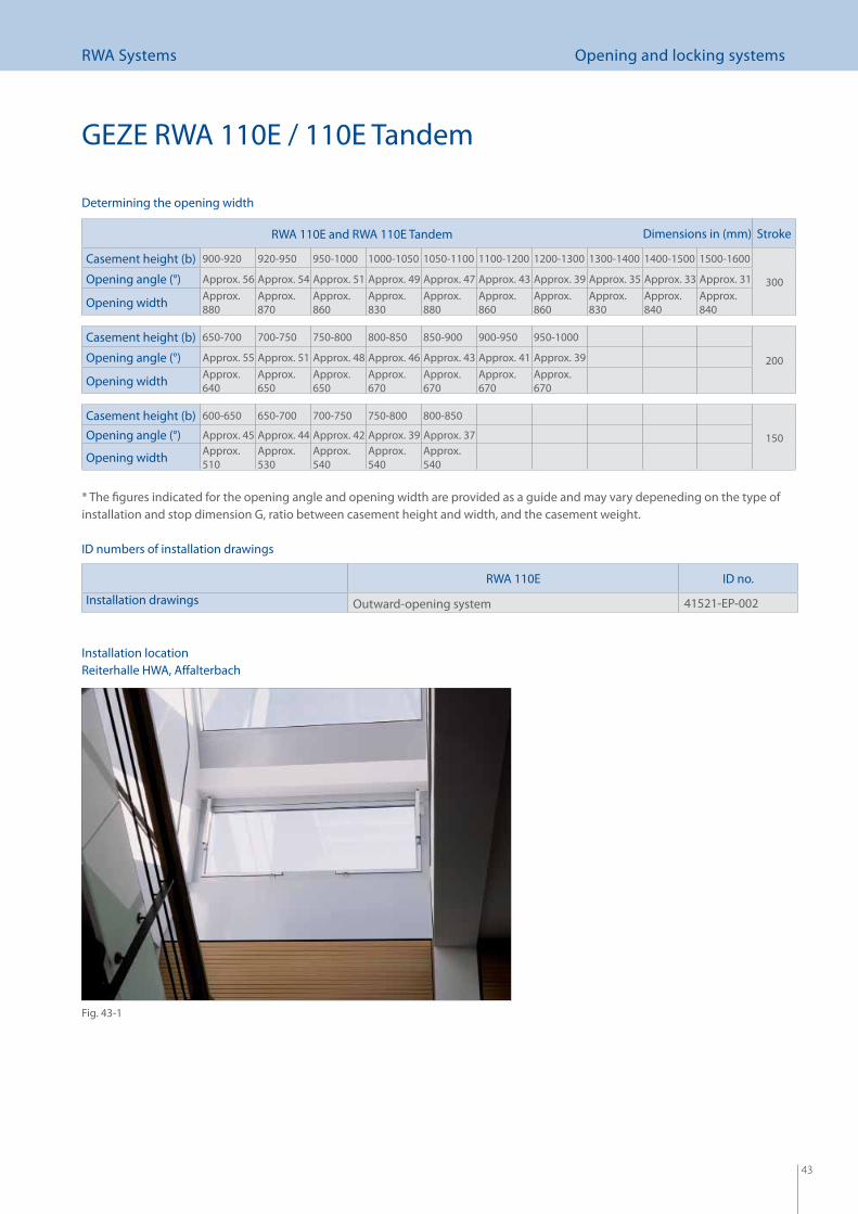
GEZE RWA 110E / 110E Tandem
RWA 110E and RWA 110E Tandem Dimensions in (mm) Stroke
Casement height (b) 900-920 920-950 950-1000 1000-1050 1050-1100 1100-1200 1200-1300 1300-1400 1400-1500 1500-1600
300Opening angle (°) Approx. 56 Approx. 54 Approx. 51 Approx. 49 Approx. 47 Approx. 43 Approx. 39 Approx. 35 Approx. 33 Approx. 31
Opening width Approx. 880
Approx. 870
Approx. 860
Approx. 830
Approx. 880
Approx. 860
Approx. 860
Approx. 830
Approx. 840
Approx. 840
Casement height (b) 650-700 700-750 750-800 800-850 850-900 900-950 950-1000
200Opening angle (°) Approx. 55 Approx. 51 Approx. 48 Approx. 46 Approx. 43 Approx. 41 Approx. 39
Opening width Approx. 640
Approx. 650
Approx. 650
Approx. 670
Approx. 670
Approx. 670
Approx. 670
Casement height (b) 600-650 650-700 700-750 750-800 800-850
150Opening angle (°) Approx. 45 Approx. 44 Approx. 42 Approx. 39 Approx. 37
Opening width Approx. 510
Approx. 530
Approx. 540
Approx. 540
Approx. 540
* The fi gures indicated for the opening angle and opening width are provided as a guide and may vary depeneding on the type of installation and stop dimension G, ratio between casement height and width, and the casement weight.
Determining the opening width
ID numbers of installation drawings
RWA 110E ID no.
Installation drawings Outward-opening system 41521-EP-002
Fig. 43-1
Reiterhalle HWA, Aff alterbachInstallation location
44
RWA Systems Opening and locking systems
GEZE RWA 110E / 110E Tandem
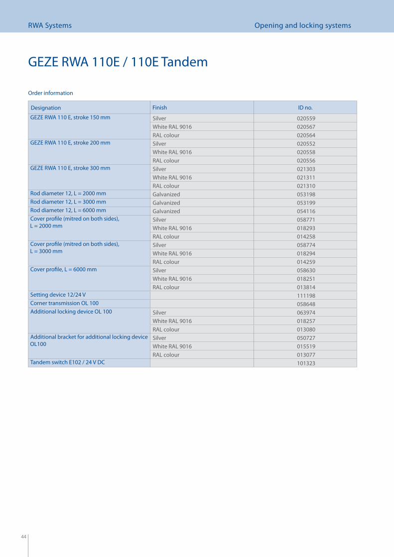
Designation Finish ID no.
GEZE RWA 110 E, stroke 150 mm Silver 020559White RAL 9016 020567RAL colour 020564
GEZE RWA 110 E, stroke 200 mm Silver 020552White RAL 9016 020558RAL colour 020556
GEZE RWA 110 E, stroke 300 mm Silver 021303White RAL 9016 021311RAL colour 021310
Rod diameter 12, L = 2000 mm Galvanized 053198Rod diameter 12, L = 3000 mm Galvanized 053199Rod diameter 12, L = 6000 mm Galvanized 054116Cover profi le (mitred on both sides), L = 2000 mm
Silver 058771White RAL 9016 018293RAL colour 014258
Cover profi le (mitred on both sides), L = 3000 mm
Silver 058774White RAL 9016 018294RAL colour 014259
Cover profi le, L = 6000 mm Silver 058630White RAL 9016 018251RAL colour 013814
Setting device 12/24 V 111198Corner transmission OL 100 058648Additional locking device OL 100 Silver 063974
White RAL 9016 018257RAL colour 013080
Additional bracket for additional locking device OL100
Silver 050727White RAL 9016 015519RAL colour 013077
Tandem switch E102 / 24 V DC 101323
Order information
45
RWA Systems Electrically operated linear drives
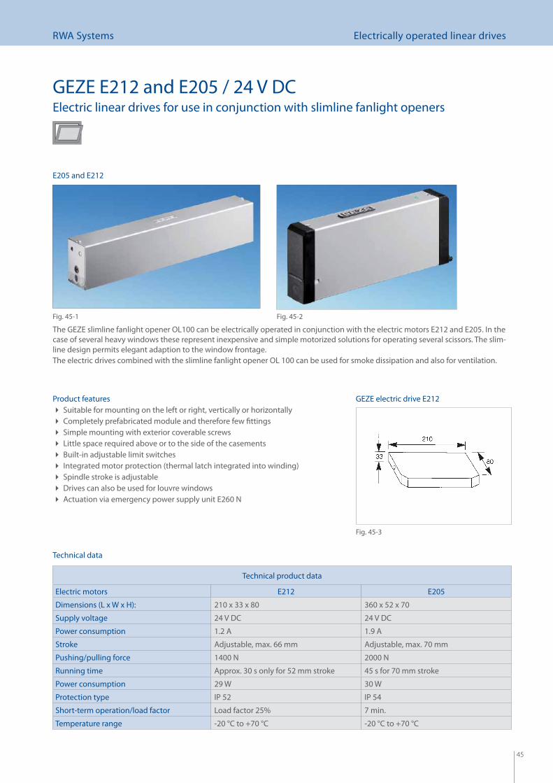
GEZE E212 and E205 / 24 V DCElectric linear drives for use in conjunction with slimline fanlight openers
The GEZE slimline fanlight opener OL100 can be electrically operated in conjunction with the electric motors E212 and E205. In the case of several heavy windows these represent inexpensive and simple motorized solutions for operating several scissors. The slim-line design permits elegant adaption to the window frontage. The electric drives combined with the slimline fanlight opener OL 100 can be used for smoke dissipation and also for ventilation.
Product featuresSuitable for mounting on the left or right, vertically or horizontally Completely prefabricated module and therefore few fi ttings Simple mounting with exterior coverable screws Little space required above or to the side of the casements Built-in adjustable limit switches Integrated motor protection (thermal latch integrated into winding) Spindle stroke is adjustable Drives can also be used for louvre windows Actuation via emergency power supply unit E260 N
Technical product data
Electric motors E212 E205
Dimensions (L x W x H): 210 x 33 x 80 360 x 52 x 70
Supply voltage 24 V DC 24 V DC
Power consumption 1.2 A 1.9 A
Stroke Adjustable, max. 66 mm Adjustable, max. 70 mm
Pushing/pulling force 1400 N 2000 N
Running time Approx. 30 s only for 52 mm stroke 45 s for 70 mm stroke
Power consumption 29 W 30 W
Protection type IP 52 IP 54
Short-term operation/load factor Load factor 25% 7 min.
Temperature range -20 °C to +70 °C -20 °C to +70 °C
Technical data
E205 and E212
Fig. 45-1
GEZE electric drive E212
Fig. 45-3
Fig. 45-2
46
RWA Systems Electrically operated linear drives
x
y
GEZE E212 and E205 / 24 V DC
Product E212 E205
Installation drawings Horizontal mounting 40408-EP-030 Horizontal mounting 40408-EP-003
Vertical mounting 40408-EP-029 Vertical mounting 40408-EP-002Mounting on post-rail windows 40408-0-031
Wiring diagrams 45109-9-0956 45106-9-0955
Installation drawings and wiring diagrams
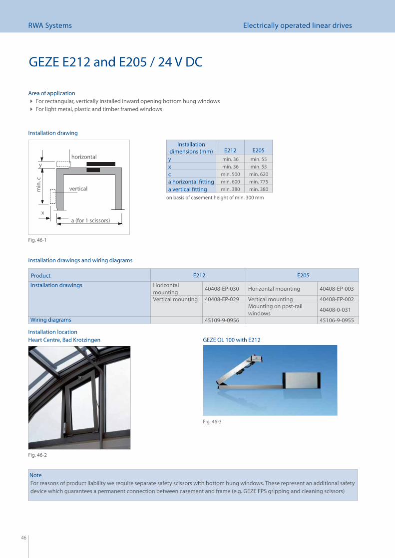
Installation dimensions (mm) E212 E205
y min. 36 min. 55x min. 36 min. 55c min. 500 min. 620a horizontal fi tting min. 600 min. 775a vertical fi tting min. 380 min. 380
on basis of casement height of min. 300 mm
horizontal
verticalmin
. c
a (for 1 scissors)
Installation location
NoteFor reasons of product liability we require separate safety scissors with bottom hung windows. These represent an additional safety device which guarantees a permanent connection between casement and frame (e.g. GEZE FPS gripping and cleaning scissors)
Heart Centre, Bad Krotzingen
Installation drawing
Area of applicationFor rectangular, vertically installed inward opening bottom hung windows For light metal, plastic and timber framed windows
Fig. 46-1
Fig. 46-2
Fig. 46-3
GEZE OL 100 with E212
47
RWA Systems Electrically operated linear drives
Designation Finish ID no.
Electrically operated drive GEZE E212 / 24 V DC EV1 010899White RAL 9016 015540RAL colour 010915
Setting device for GEZE E212 / 24 V DC 002754Electrically operated drive GEZE E205 / 24 V DC EV1 056041
White RAL 9016 027096RAL colour 027095
Gripping and cleaning scissors FPS 340 size 1 030249FPS 520 size 2 030250FPS 720 size 3 030251
Order information
Accessories
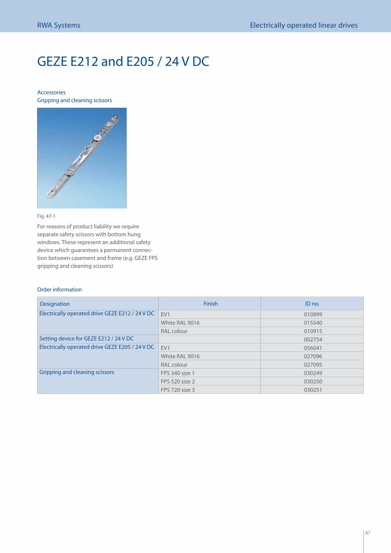
For reasons of product liability we require separate safety scissors with bottom hung windows. These represent an additional safety device which guarantees a permanent connec-tion between casement and frame (e.g. GEZE FPS gripping and cleaning scissors)
GEZE E212 and E205 / 24 V DC
Gripping and cleaning scissors
Fig. 47-1
48
RWA Systems Emergency power supply units
RWA emergency power supply units E260 N
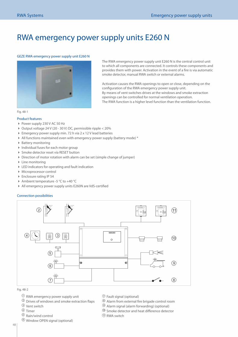
The RWA emergency power supply unit E260 N is the central control unit to which all components are connected. It controls these components and provides them with power. Activation in the event of a fi re is via automatic smoke detector, manual RWA switch or external alarms.
Activation causes the RWA openings to open or close, depending on the confi guration of the RWA emergency power supply unit.By means of vent switches drives at the windows and smoke extraction openings can be controlled for normal ventilation operation.The RWA function is a higher level function than the ventilation function.
Product featuresPower supply 230 V AC 50 Hz Output voltage 24 V (20 - 30 V) DC, permissible ripple < 20% Emergency power supply min. 72 h via 2 x 12 V lead batteries All functions maintained even with emergency power supply (battery mode) * Battery monitoring Individual fuses for each motor group Smoke detector reset via RESET button Direction of motor rotation with alarm can be set (simple change of jumper) Line monitoring LED indicators for operating and fault indication Microprocessor control Enclosure rating IP 54 Ambient temperature -5 °C to +40 °C All emergency power supply units E260N are VdS-certifi ed
Connection possibilities
RWA emergency power supply unitDrives of windows and smoke extraction fl apsVent switchTimerRain/wind controlWindow OPEN signal (optional)
Fault signal (optional)Alarm from external fi re brigade control roomAlarm signal (alarm forwarding) (optional)Smoke detector and heat diff erence detectorRWA switch
GEZE RWA emergency power supply unit E260 N
Fig. 48-1
Fig. 48-2
49
RWA Systems Emergency power supply units
Overview of technical data for emergency power supply units E260 N
Technical product data
E260 N2/1
VdS
E260 N4/1 to N4/2VdS
E260 N8/1 to N8/4VdS
E260 N12/2
VdS
E260 N32/2to N32/8VdS
Dimensions in mm(width x height x depth) 256x217x112 295x261x112 362x319x131 362x319x131 600x600x210
Max. number of ventilator groups 1 1-2 1-4 1-2 2-8
Max. output current 2.0 A 4.0 A 7.5 A 12 A 32 A
Max. RWA switches 4 pcs. in line 10 pcs. in line 15 pcs. in line
Max. smoke or heat diff erence detectors 10 pcs. in line 20 pcs. in line
Max. vent switches 3 pcs. with LED per group / any number without LED
Max. conductor size of control lineMax. motor line
Max. 2.5 mm2 Max. 4.0 mm2
Available signal inputs Rain/wind control - external fi re brigade control room (potential-free)
Performance data for transformer/battery 80 VA / 1.2 Ah 130 VA / 2.1 Ah 260 VA / 6-7.2 Ah 480 VA / 6-7.2 Ah 1400 VA / 17 Ah
Optional add-ons With additional circuit board:
Alarm (horn/signal line) Fault (indicator lamp) Window not closed, switching capacity 30 W (indicator lamp)
Second alarm group (ad- ditional 15 RWA switches /20 smoke or heat diff er-ence detectors)System interconnection (up to 30 systems)
Installation examples
RWA emergency power supply units E260 N
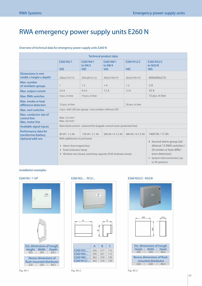
E260 N2 / 1 UP E260 N2/... - N12/... E260 N32/2 - N32/8
A B CE260 N2/... 256 217 112E260 N4/... 295 261 112E260 N8/... 362 318 130E260 N12/... 362 318 130
Ext. dimensions of troughHeight Width Depth
305 293 84.5
Recess dimensions of fl ush-mounted distributor
320 320 84.5
Fig. 49-1 Fig. 49-2 Fig. 49-3
Ext. dimensions of troughHeight Width Depth
305 293 84.5
Recess dimensions of fl ush-mounted distributor
320 320 84.5
50
RWA Systems Accessories
Accessories
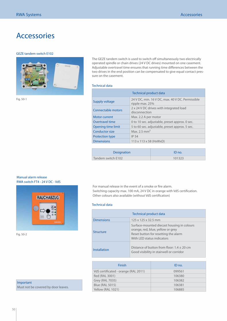
The GEZE tandem switch is used to switch off simultaneously two electrically operated spindle or chain drives (24 V DC drives) mounted on one casement.Adjustable overtravel time ensures that running time diff erences between the two drives in the end position can be compensated to give equal contact pres-sure on the casement.
Technical product data
Supply voltage 24 V DC, min. 16 V DC, max. 40 V DC. Permissible ripple max. 25%
Connectable motors 2 x 24 V DC drives with integrated load disconnection
Motor current Max. 2.2 A per motorOvertravel time 0 to 10 sec. adjustable, preset approx. 0 sec.Opening time limit 5 to 60 sec. adjustable, preset approx. 5 sec.Conductor size Max. 2.5 mm2Protection type IP 54Dimensions 113 x 113 x 58 (HxWxD)
Technical data
Designation ID no.
Tandem switch E102 101323
For manual release in the event of a smoke or fi re alarm.Switching capacity max. 100 mA, 24 V DC in orange with VdS certifi cation. Other colours also available (without VdS certifi cation)
ImportantMust not be covered by door leaves.
Technical product data
Dimensions 125 x 125 x 32.5 mm
Structure
Surface-mounted diecast housing in colours orange, red, blue, yellow or greyReset button for resetting the alarmWith LED status indicators
InstallationDistance of button from fl oor: 1.4 ± 20 cmGood visibility in stairwell or corridor
Manual alarm releaseRWA switch FT4 - 24 V DC - VdS
Finish ID no.
VdS certifi cated - orange (RAL 2011) 099561Red (RAL 3001) 106380Grey (RAL 7035) 106382Blue (RAL 5015) 106381Yellow (RAL 1021) 106885
GEZE tandem switch E102
Fig. 50-1
Fig. 50-2
Technical data
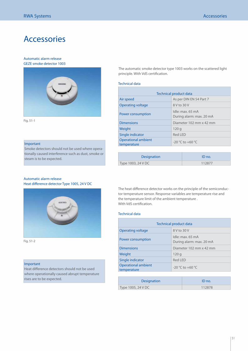
51
RWA Systems Accessories
Accessories
The automatic smoke detector type 1003 works on the scattered light principle. With VdS certifi cation.
ImportantSmoke detectors should not be used where opera-tionally caused interference such as dust, smoke or steam is to be expected.
Automatic alarm release
Designation ID no.
Type 1003, 24 V DC 112877
GEZE smoke detector 1003
Technical data
Fig. 51-1
The heat diff erence detector works on the principle of the semiconduc-tor temperature sensor. Response variables are temperature rise and the temperature limit of the ambient temperature . With VdS certifi cation.
ImportantHeat diff erence detectors should not be used where operationally caused abrupt temperature rises are to be expected.
Technical product data
Operating voltage 8 V to 30 V
Power consumptionIdle: max. 65 mADuring alarm: max. 20 mA
Dimensions Diameter 102 mm x 42 mm
Weight 120 g
Single indicator Red LEDOperational ambient temperature -20 °C to +60 °C
Designation ID no.
Type 1005, 24 V DC 112878
Automatic alarm releaseHeat diff erence detector Type 1005, 24 V DC
Fig. 51-2
Technical data
Technical product dataAir speed As per DIN EN 54 Part 7
Operating voltage 8 V to 30 V
Power consumptionIdle: max. 65 mADuring alarm: max. 20 mA
Dimensions Diameter 102 mm x 42 mm
Weight 120 g
Single indicator Red LEDOperational ambient temperature -20 °C to +60 °C
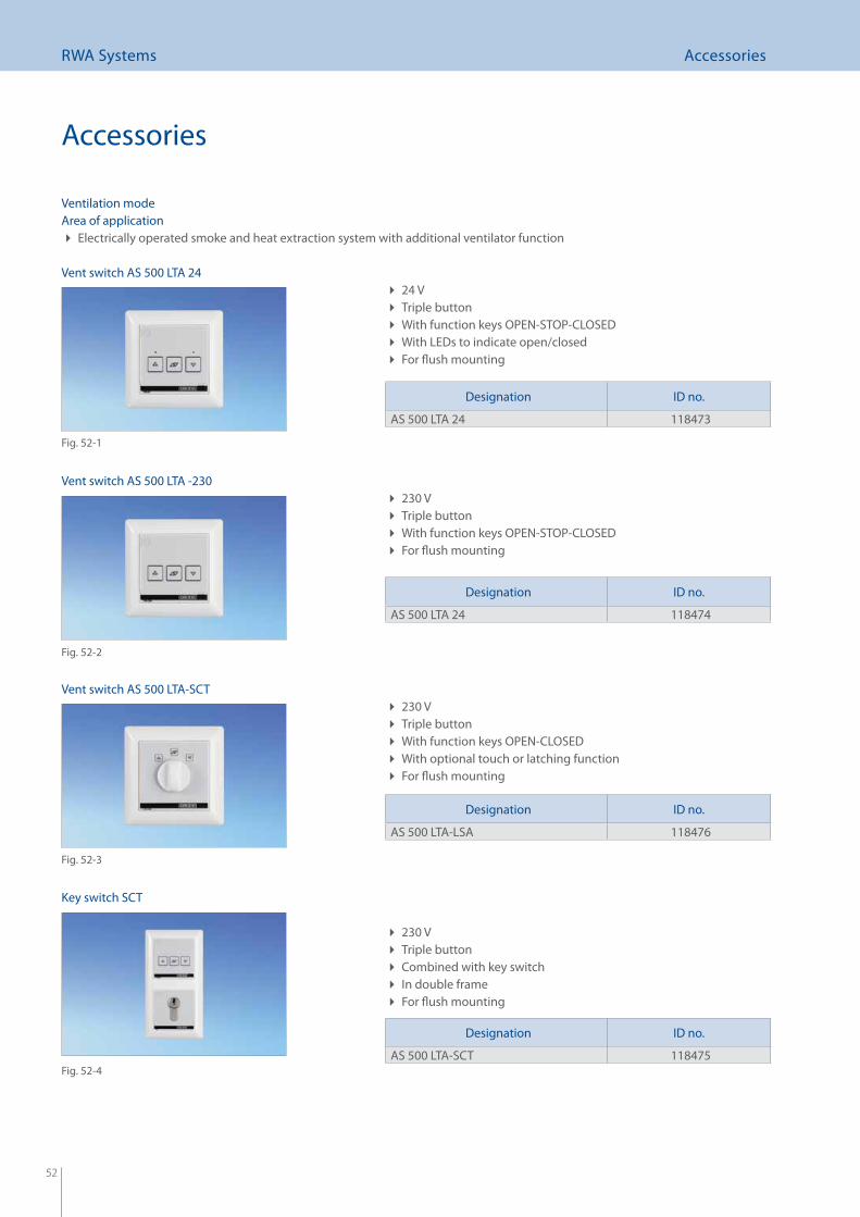
52
RWA Systems Accessories
24 V Triple button With function keys OPEN-STOP-CLOSED With LEDs to indicate open/closed For fl ush mounting
Area of applicationElectrically operated smoke and heat extraction system with additional ventilator function
Ventilation mode
230 V Triple button With function keys OPEN-CLOSED With optional touch or latching function For fl ush mounting
Accessories
230 V Triple button Combined with key switch In double frame For fl ush mounting
Designation ID no.
AS 500 LTA 24 118473
Designation ID no.
AS 500 LTA-LSA 118476
Designation ID no.
AS 500 LTA-SCT 118475
Vent switch AS 500 LTA 24
Fig. 52-1
Vent switch AS 500 LTA -230
Fig. 52-2
Vent switch AS 500 LTA-SCT
Fig. 52-3
Key switch SCT
Fig. 52-4
230 V Triple button With function keys OPEN-STOP-CLOSED For fl ush mounting
Designation ID no.
AS 500 LTA 24 118474
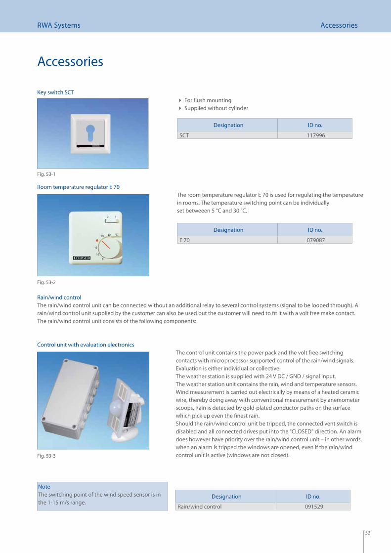
53
RWA Systems Accessories
For fl ush mounting Supplied without cylinder
Designation ID no.
SCT 117996
The room temperature regulator E 70 is used for regulating the temperature in rooms. The temperature switching point can be individuallyset betweeen 5 °C and 30 °C.
Accessories
Rain/wind controlThe rain/wind control unit can be connected without an additional relay to several control systems (signal to be looped through). A rain/wind control unit supplied by the customer can also be used but the customer will need to fi t it with a volt free make contact.The rain/wind control unit consists of the following components:
The control unit contains the power pack and the volt free switching contacts with microprocessor supported control of the rain/wind signals. Evaluation is either individual or collective. The weather station is supplied with 24 V DC / GND / signal input.The weather station unit contains the rain, wind and temperature sensors. Wind measurement is carried out electrically by means of a heated ceramic wire, thereby doing away with conventional measurement by anemometer scoops. Rain is detected by gold-plated conductor paths on the surface which pick up even the fi nest rain. Should the rain/wind control unit be tripped, the connected vent switch is disabled and all connected drives put into the "CLOSED" direction. An alarm does however have priority over the rain/wind control unit – in other words, when an alarm is tripped the windows are opened, even if the rain/wind control unit is active (windows are not closed).
NoteThe switching point of the wind speed sensor is in the 1-15 m/s range.
Designation ID no.
E 70 079087
Designation ID no.
Rain/wind control 091529
Key switch SCT
Fig. 53-1
Room temperature regulator E 70
Fig. 53-2
Control unit with evaluation electronics
Fig. 53-3
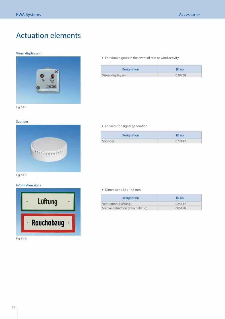
54
RWA Systems Accessories
Actuation elements
For visual signals in the event of rain or wind activity.
Information signs
Designation ID no.
Visual display unit 029238
Designation ID no.
Sounder 072112
Designation ID no.
Ventilation (Lüftung) 025647Smoke extraction (Rauchabzug) 005158
Dimensions 52 x 148 mm
Visual display unit
Fig. 54-1
Sounder
Fig. 54-2
Fig. 54-3
For acoustic signal generation
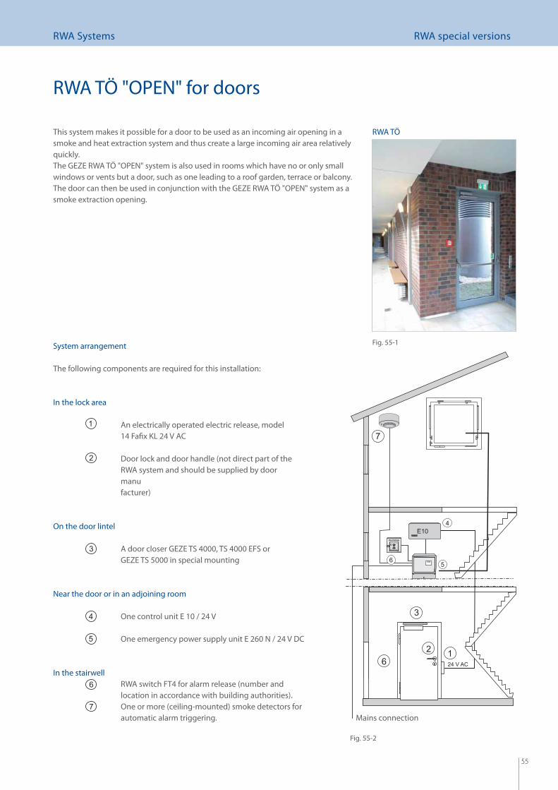
55
RWA Systems RWA special versions
System arrangement
The following components are required for this installation:
In the lock area
An electrically operated electric release, model 14 Fafi x KL 24 V AC
Door lock and door handle (not direct part of the RWA system and should be supplied by door manu facturer)
On the door lintel
A door closer GEZE TS 4000, TS 4000 EFS or GEZE TS 5000 in special mounting
Near the door or in an adjoining room
One control unit E 10 / 24 V
One emergency power supply unit E 260 N / 24 V DC
In the stairwell RWA switch FT4 for alarm release (number and
location in accordance with building authorities). One or more (ceiling-mounted) smoke detectors for
automatic alarm triggering.
RWA TÖ "OPEN" for doors
Mains connection
This system makes it possible for a door to be used as an incoming air opening in a smoke and heat extraction system and thus create a large incoming air area relatively quickly.The GEZE RWA TÖ "OPEN" system is also used in rooms which have no or only small windows or vents but a door, such as one leading to a roof garden, terrace or balcony. The door can then be used in conjunction with the GEZE RWA TÖ "OPEN" system as a smoke extraction opening.
Fig. 55-1
Fig. 55-2
RWA TÖ
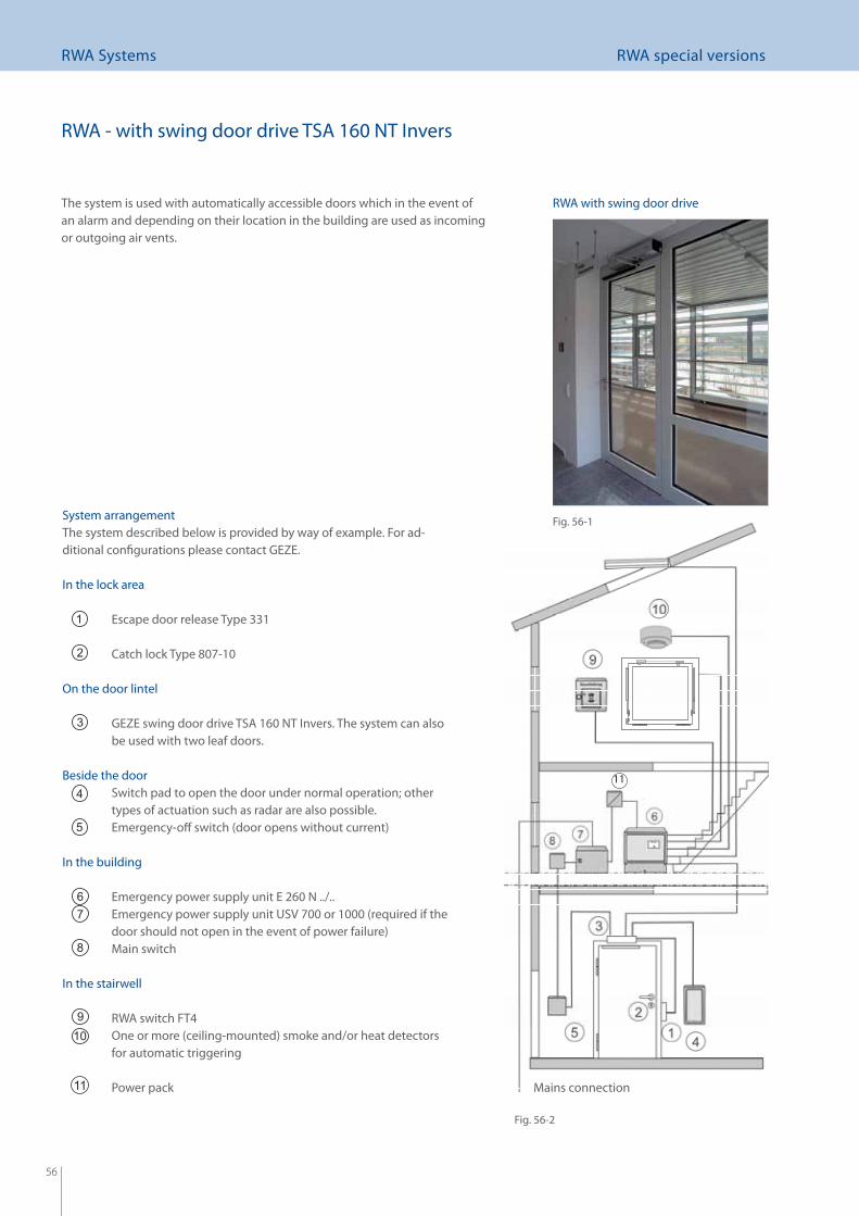
56
RWA Systems RWA special versions
11
The system is used with automatically accessible doors which in the event of an alarm and depending on their location in the building are used as incoming or outgoing air vents.
System arrangementThe system described below is provided by way of example. For ad-ditional confi gurations please contact GEZE.
In the lock area
Escape door release Type 331
Catch lock Type 807-10
On the door lintel
GEZE swing door drive TSA 160 NT Invers. The system can also be used with two leaf doors.
Beside the door Switch pad to open the door under normal operation; other
types of actuation such as radar are also possible. Emergency-off switch (door opens without current)
In the building
Emergency power supply unit E 260 N ../.. Emergency power supply unit USV 700 or 1000 (required if the
door should not open in the event of power failure) Main switch
In the stairwell
RWA switch FT4 One or more (ceiling-mounted) smoke and/or heat detectors
for automatic triggering
Power pack Mains connection
RWA - with swing door drive TSA 160 NT Invers
Fig. 56-1
Fig. 56-2
RWA with swing door drive
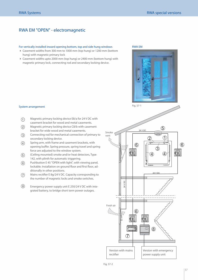
57
RWA Systems RWA special versions
RWA EM "OPEN" - electromagnetic
System arrangement
Magnetic primary locking device E8/a for 24 V DC with casement bracket for wood and metal casements.
Magnetic primary locking device C8/b with casement bracket for wide wood and metal casements.
Connecting rod for mechanical connection of primary to secondary locking device.
Spring arm, with frame and casement brackets, with opening buff er. Spring pressure, spring travel and spring force are adjusted to the window system.
(Ceiling mounted) smoke and/or heat detectors, Type 142, with plinth for automatic triggering.
Pushbutton E 45 "OPEN with light", with viewing panel, lockable. Installation on ground fl oor and fi rst fl oor, ad-ditionally in other positions.
Mains rectifi er E 8g/24 V DC. Capacity corresponding to the number of magnetic locks and smoke switches.
Emergency power supply unit E 250/24 V DC with inte-grated battery, to bridge short term power outages.
Smoke vent
Fresh air
For vertically installed inward opening bottom, top and side hung windowsCasement widths from 300 mm to 1000 mm (top hung) or 1200 mm (bottom hung) with magnetic primary lockCasement widths upto 2000 mm (top hung) or 2400 mm (bottom hung) with magnetic primary lock, connecting rod and secondary locking device.
Version with mains rectifi er
Version with emergency power supply unit
Fig. 57-1
Fig. 57-2
RWA EM
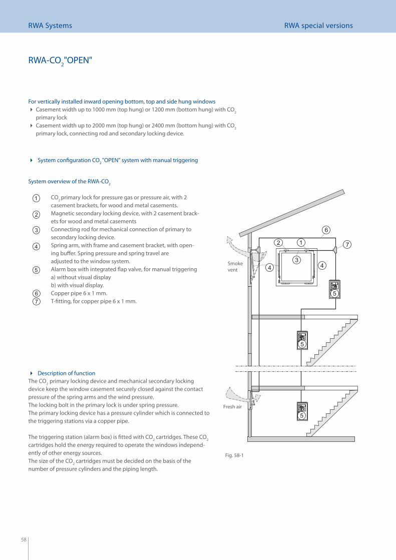
58
RWA Systems RWA special versions
CO2 primary lock for pressure gas or pressure air, with 2
casement brackets, for wood and metal casements. Magnetic secondary locking device, with 2 casement brack-
ets for wood and metal casements Connecting rod for mechanical connection of primary to
secondary locking device. Spring arm, with frame and casement bracket, with open-
ing buff er. Spring pressure and spring travel are adjusted to the window system.
Alarm box with integrated fl ap valve, for manual triggeringa) without visual displayb) with visual display.
Copper pipe 6 x 1 mm. T-fi tting, for copper pipe 6 x 1 mm.
Smoke vent
Fresh air
RWA-CO2"OPEN"
Description of function The CO2 primary locking device and mechanical secondary locking device keep the window casement securely closed against the contact pressure of the spring arms and the wind pressure.The locking bolt in the primary lock is under spring pressure.The primary locking device has a pressure cylinder which is connected to the triggering stations via a copper pipe.
The triggering station (alarm box) is fi tted with CO2 cartridges. These CO2 cartridges hold the energy required to operate the windows independ-ently of other energy sources.The size of the CO2 cartridges must be decided on the basis of the number of pressure cylinders and the piping length.
System overview of the RWA-CO2
For vertically installed inward opening bottom, top and side hung windowsCasement width up to 1000 mm (top hung) or 1200 mm (bottom hung) with CO 2 primary lockCasement width up to 2000 mm (top hung) or 2400 mm (bottom hung) with CO 2 primary lock, connecting rod and secondary locking device.
System confi guration CO 2 "OPEN" system with manual triggering
Fig. 58-1

59
GEZE GmbH
P.O. Box 1363
71226 Leonberg
Germany
GEZE GmbHReinhold-Vöster-Strasse 21-2971229 LeonbergGermanyPhone +49 (0) 7152-203-0Fax +49 (0) 7152-203-310
www.geze.com
Germany
GEZE GmbHNorth/east branchBühringstrasse 813086 Berlin (Weissensee)Phone +49 (0) 30-47 89 90-0Fax +49 (0) 30-47 89 90-17Email: [email protected]
GEZE GmbHWest branchNordsternstrasse 6545329 EssenPhone +49 (0)201-83082-0 Fax +49 (0)201-83082-20Email: [email protected]
GEZE GmbHCentral branchAdenauerallee 261440 Oberursel (b. Frankfurt)Phone +49 (0)6171-63610-0Fax +49 (0)6171-63610-1Email: [email protected]
GEZE GmbHSouth branchReinhold-Vöster-Strasse 21-2971229 LeonbergPhone +49 (0)7152-203-594Fax +49 (0)7152-203-438Email: [email protected]
GEZE Sonderkonstruktionen GmbHPlanken 197944 Boxberg-SchweigernPhone +49 (0)7930-9294-0Fax +49 (0)7930-9294-10Email: [email protected]
GEZE Service GmbHReinhold-Vöster-Strasse 2571229 LeonbergPhone +49 (0)7152-9233-0Fax +49 (0)7152-9233-60Email: [email protected]
Germany
GEZE Service GmbHBerlin branchBühringstrasse 813086 Berlin (Weissensee)Phone +49 (0)30-470217-30Fax +49 (0)30-470217-33
Austria
GEZE Austria GmbHMayrwiesstrasse 125300 Hallwang b. SalzburgPhone +43 (0)662-663142Fax +43 (0)662-663142-15Email: [email protected]
Asia Pacifi c
GEZE Asia Sales Ltd.No. 88-1-408, East RoadFree Trade Zone of Tianjin PortTianjin, P.R. ChinaPhone +86 (0)22-26 97 39 95-0Fax +86 (0)22 26 97 27 02Email: [email protected]
Baltic States
GEZE Baltic StatesDzelzavas iela 120 S1021 RigaPhone +371 (0)67 896 035Fax +371 (0)67 896 036Email: offi [email protected]
Benelux
GEZE Benelux B.V.Leemkuil 1Industrieterrein Kapelbeemd5626 EA EindhovenPhone +31 (0)40-26290-80Fax +31 (0)40-26290-85Email: [email protected]
China
GEZE Industries (Tianjin) Co., Ltd.Shuangchenzhong RoadBeichen Economic DevelopmentArea (BEDA)Tianjin 300400, P.R. ChinaPhone +86 (0)22-26973995-0Fax +86 (0)22-26972702Email: [email protected]
GEZE Industries (Tianjin) Co., Ltd.Branch Offi ce ShanghaiR. 3010, Tower 2, Grand GatewayNo. 3 Hongqiao RoadXuHui District200030 Shanghai, P.R. ChinaPhone +86 (0)21-644 75 908Fax +86 (0)21-644 72 007Email: [email protected]
Italy
GEZE Italia SrlVia Giotto 420040 Cambiago (MI)Phone +39 02 95 06 95-11Fax +39 02 95 06 95-33Email [email protected]
GEZE Engineering Roma SrlVia Lucrezia Romana 9100178 RomaPhone +39 06-7265311Fax +39 06-72653136Email: [email protected]
Kazakhstan
GEZE Central Asia384 Raiymbek Ave., 3rd Floor050061 AlmatyPhone + 7 (0)777 265 06 05 Email: offi [email protected]
Poland
GEZE Polska Sp. z o.oUl. Annopol 3 (Zeran Park)03-236 Warszawa Phone +48 (0)22-8142211Fax +48 (0)22-6142540Email: [email protected]
Romania
GEZE RomaniaStr. Ionescu Baican nr. 22021835 Bucuresti, Sector 2Phone +40 (0)21 250 77 50Fax +40 (0)21 250 77 50Email: offi [email protected]
Russian Federation
GEZE RussiaKolodesnii pereulok 3, Str. 25Offi ce No. 5201-5203107076 MoscowPhone +7 (0)495 589 9052Fax +7 (0)495 589 9051Email: offi [email protected]
Scandinavia
GEZE Scandinavia ABMallslingan 10Box 706018711 Täby, SwedenPhone +46 (0)8-7323-400Fax +46 (0)8-7323-499Email: [email protected]
GEZE Scandinavia AB avd. NorgePostboks 632081 Eidsvoll, NorwayPhone +47 (0)6 39-57 200Fax +47 (0)6 39-57 173Email: [email protected]
GEZE FinlandBranch offi ce of GEZE Scand. ABPostbox 20158 71 HollolaPhone +358 (0)10-400 51 00Fax +358 (0)10-400 51 20Email: fi [email protected]
Scandinavia
GEZE DenmarkBranch offi ce of GEZE Scand. ABHøje Taastrup Boulevard 532630 Taastrup +45 (0)46-323324+45 (0)46-323326Email: [email protected]
South Africa
DCLSA Distributors (Pty.) Ltd.1027 Richards Drive, MidrandP.O. Box 7934Midrand 1685Phone +27 (0)11 315 82 86Fax +27 (0)11 315 82 61Email: [email protected]
Switzerland
GEZE Schweiz AGBodenackerstrasse 794657 DullikenPhone +41 (0)62-285 54 00Fax +41 (0)62-285 54 01Email: [email protected]
GEZE Security Systems GmbHBodenackerstrasse 794657 DullikenPhone +41 (0)62-285 55 00Fax +41 (0)62-285 55 01Email: [email protected]
Turkey
GEZE TurkeyAtatürk mah. Ata 2-3 PLAZA kat 9 D. 6434757 Atasehir – IstanbulPhone + 90 (0)216 4554315Fax + 90 (0)216 4558215 Email: offi [email protected]
Ukraine
GEZE UkraineVikentija Hvojki str. 21Offi ce 15104655 KievPhone +380 (0)44 499 77 25Fax +380 (0)44 499 77 25Email: offi [email protected]
United Arab Emirates/GCC
GEZE Middle EastP.O. Box 17903Jebel Ali Free ZoneDubaiPhone +971 (0)4-8833112Fax +971 (0)4-8833240Email: [email protected]
United Kingdom
GEZE UK Ltd.Blenheim WayFradley ParkLichfi eldStaff ordshire WS13 8SYPhone: +44 (0) 1543 443000Fax: +44 (0) 1543 443001Email: [email protected]
China
GEZE Industries (Tianjin) Co., Ltd.Branch Offi ce GuangzhouRoom 17C3Everbright Bank Building, No. 689Tian He Bei Road510630 Guangzhou, P.R. ChinaPhone +86 (0)20-38 73 1842Fax +86 (0)20-38 73 1834Email: [email protected]
GEZE Industries (Tianjin) Co., Ltd.Branch Offi ce BeijingNo. 6-32 BuildingJili AvenueDaxing District100076 Beijing, P.R. ChinaPhone +86-(0)10-87 97 51-77/-78Fax +86-(0)10-87 97 51-71Email: [email protected]
GEZE Sonderkonstruktionen (Tianjin) Ltd.No. 6-32 BuildingJili AvenueDaxing District100076 Beijing, P.R. ChinaPhone +86-(0)10-87 96 51-52Fax +86-(0)10-87 97 14-76Email: [email protected]
France
GEZE France S.A.R.L.ZAC de l’Orme RondRN 1977170 ServonPhone +33 (0)1-60626070Fax +33 (0)1-60626071Email: [email protected]
Hungary
GEZE HungaryBartók Béla út 105 – 1131115 BudapestPhone + 36 (0)1 481 4670Fax + 36 (0)1 481 4671Email: offi [email protected]
Iberia
GEZE Iberia S.R.L.Pol. Ind. El PlaC/ Comerc, 2-22, Nave 1208980 Sant Feliu de Llobregat (Barcelona)Phone +34 (0)9 02 19 40 36Fax +34 (0)9 02 19 40 35Email [email protected]
India
GEZE India409, Apeejay Business Centre39, Haddows RoadChennai – 600 006Tamil NaduPhone + 91 (0)44 2821 1300Fax + 91 (0)44 2821 1300Email: offi [email protected]
ID no. 127785 · Vers. DE 03/08 - Subject to change
GEZE representative
GEZE RWA SYSTEMS