Embed Size (px)
Citation preview
Gilflo ILVA flowmetersfor steam, liquids and gases
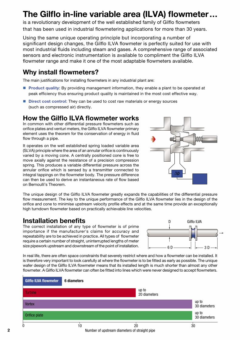
2 Number of upstream diameters of straight pipe
The Gilflo in-line variable area (ILVA) flowmeter ... is a revolutionary development of the well established family of Gilflo flowmeters that has been used in industrial flowmetering applications for more than 30 years.
Using the same unique operating principle but incorporating a number of significant design changes, the Gilflo ILVA flowmeter is perfectly suited for use with most industrial fluids including steam and gases. A comprehensive range of associated sensors and electronic instrumentation is available to compliment the Gilflo ILVA flowmeter range and make it one of the most adaptable flowmeters available.
Turbine
Vortex
Orifice plate
10 20 300
Why install flowmeters? The main justifications for installing flowmeters in any industrial plant are:
Product quality: By providing management information, they enable a plant to be operated at peak efficiency thus ensuring product quality is maintained in the most cost effective way.
Direct cost control: They can be used to cost raw materials or energy sources (such as compressed air) directly.
D Gilflo ILVA
6 D 3 D
Installation benefitsThe correct installation of any type of flowmeter is of prime importance if the manufacturer's claims for accuracy and repeatability are to be achieved in practice. All types of flowmeter require a certain number of straight, uninterrupted lengths of meter size pipework upstream and downstream of the point of installation.
In real life, there are often space constraints that severely restrict where and how a flowmeter can be installed. It is therefore very important to look carefully at where the flowmeter is to be fitted as early as possible. The unique wafer design of the Gilflo ILVA flowmeter means that its installed length is much shorter than almost any other flowmeter. A Gilflo ILVA flowmeter can often be fitted into lines which were never designed to accept flowmeters.
p
How the Gilflo ILVA flowmeter worksIn common with other differential pressure flowmeters such as orifice plates and venturi meters, the Gilflo ILVA flowmeter primary element uses the theorem for the conservation of energy in fluid flow through a pipe.
It operates on the well established spring loaded variable area (SLVA) principle where the area of an annular orifice is continuously varied by a moving cone. A centrally positioned cone is free to move axially against the resistance of a precision compression spring. This produces a variable differential pressure across the annular orifice which is sensed by a transmitter connected to integral tappings on the flowmeter body. The pressure difference can then be used to derive an instantaneous rate of flow based on Bernoulli’s Theorem.
The unique design of the Gilflo ILVA flowmeter greatly expands the capabilities of the differential pressure flow measurement. The key to the unique performance of the Gilflo ILVA flowmeter lies in the design of the orifice and cone to minimise upstream velocity profile effects and at the same time provide an exceptionally high turndown flowmeter based on practically achievable line velocities.
Gilflo ILVA flowmeter 6 diameters
up to 30 diameters
up to 30 diameters
up to 20 diameters
3
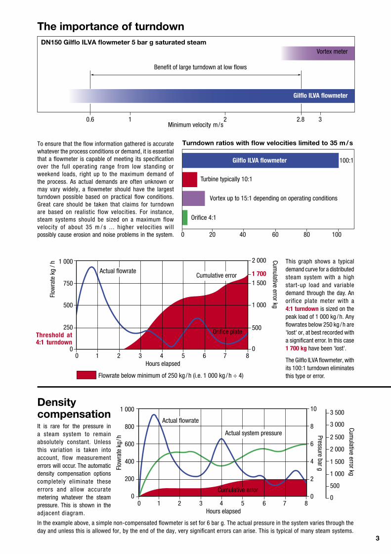
Benefit of large turndown at low flows
0.6 1 2 2.8 3
DN150 Gilflo ILVA flowmeter 5 bar g saturated steam
Gilflo ILVA flowmeter
Minimum velocity m/s
The importance of turndown
Vortex meter
This graph shows a typical demand curve for a distributed steam system with a high start-up load and variable demand through the day. An orifice plate meter with a 4:1 turndown is sized on the peak load of 1 000 kg / h. Any flowrates below 250 kg / h are 'lost' or, at best recorded with a significant error. In this case 1 700 kg have been 'lost'.
The Gilflo ILVA flowmeter, with its 100:1 turndown eliminates this type or error.
Cumulative error kg
Actual flowrateCumulative error
Flow
rate
kg
/h 1 000
750
500
250
0
Threshold at 4:1 turndown
To ensure that the flow information gathered is accurate whatever the process conditions or demand, it is essential that a flowmeter is capable of meeting its specification over the full operating range from low standing or weekend loads, right up to the maximum demand of the process. As actual demands are often unknown or may vary widely, a flowmeter should have the largest turndown possible based on practical flow conditions. Great care should be taken that claims for turndown are based on realistic flow velocities. For instance, steam systems should be sized on a maximum flow velocity of about 35 m / s ... higher velocities will possibly cause erosion and noise problems in the system.
Turbine typically 10:1
Vortex up to 15:1 depending on operating conditions
Orifice 4:1
20 40 60 80 100
100:1
Turndown ratios with flow velocities limited to 35 m/s
0
Orifice plate
Gilflo ILVA flowmeter
In the example above, a simple non-compensated flowmeter is set for 6 bar g. The actual pressure in the system varies through the day and unless this is allowed for, by the end of the day, very significant errors can arise. This is typical of many steam systems.
1 000
800
600
400
200
0
Flow
rate
kg/
h
0 1 2 3 4 5 6 7 8Hours elapsed
Pressure bar g
10
8
6
4
2
0
Cumulative error kg
2 500
2 000
1 500
1 000
500
0
Actual system pressure
Actual flowrate
Cumulative error
3 500
3 000
2 000
1 7001 500
1 000
500
00 1 2 3 4 5 6 7 8
Hours elapsed
Flowrate below minimum of 250 kg /h (i.e. 1 000 kg / h ÷ 4)
Density compensationIt is rare for the pressure in a steam system to remain absolutely constant. Unless this variation is taken into account, flow measurement errors will occur. The automatic density compensation options completely eliminate these errors and allow accurate metering whatever the steam pressure. This is shown in the adjacent diagram.
4
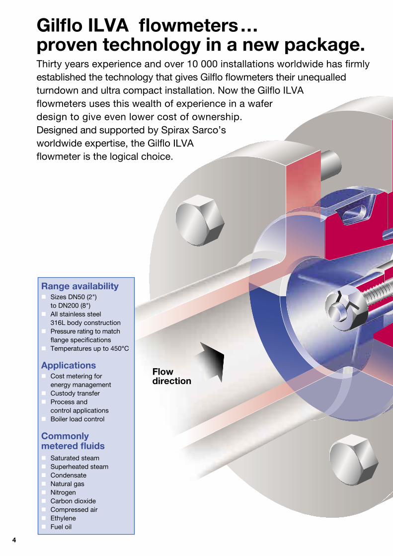
Gilflo ILVA flowmeters ...proven technology in a new package.Thirty years experience and over 10 000 installations worldwide has firmly established the technology that gives Gilflo flowmeters their unequalled turndown and ultra compact installation. Now the Gilflo ILVA flowmeters uses this wealth of experience in a wafer design to give even lower cost of ownership. Designed and supported by Spirax Sarco’s worldwide expertise, the Gilflo ILVA flowmeter is the logical choice.
Range availability Sizes DN50 (2") to DN200 (8") All stainless steel 316L body construction Pressure rating to match flange specifications Temperatures up to 450°C
Applications Cost metering for energy management Custody transfer Process and control applications Boiler load control
Commonly metered fluids Saturated steam Superheated steam Condensate Natural gas Nitrogen Carbon dioxide Compressed air Ethylene Fuel oil
Flow direction
5
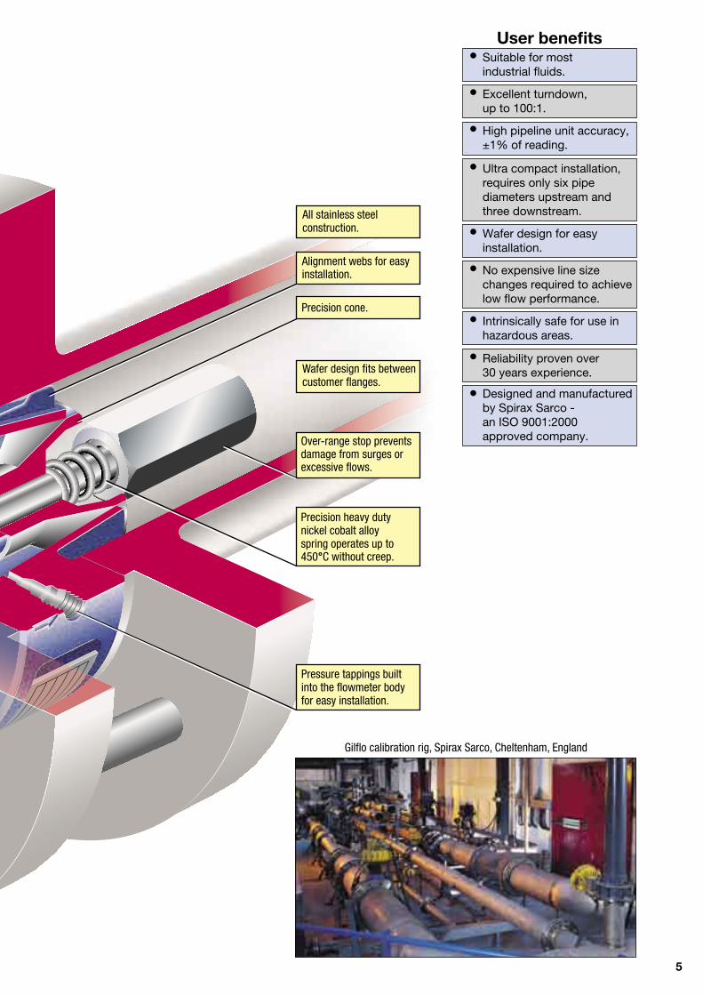
Gilflo calibration rig, Spirax Sarco, Cheltenham, England
Wafer design fits between customer flanges.
All stainless steel construction.
Pressure tappings built into the flowmeter body for easy installation.
User benefits • Suitable for most industrial fluids.
• Excellent turndown, up to 100:1. • High pipeline unit accuracy, ±1% of reading. • Ultra compact installation, requires only six pipe diameters upstream and three downstream.
• Wafer design for easy installation.
• No expensive line size changes required to achieve low flow performance.
• Intrinsically safe for use in hazardous areas.
• Reliability proven over 30 years experience.
• Designed and manufactured by Spirax Sarco - an ISO 9001:2000 approved company.
Precision cone.
Alignment webs for easy installation.
Precision heavy duty nickel cobalt alloy spring operates up to 450°C without creep.
Over-range stop prevents damage from surges or excessive flows.
6
ok
M800
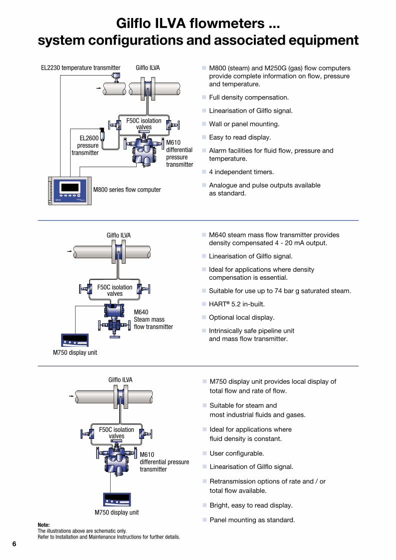
Gilflo ILVA flowmeters ...system configurations and associated equipment
M800 (steam) and M250G (gas) flow computers provide complete information on flow, pressure and temperature.
Full density compensation.
Linearisation of Gilflo signal.
Wall or panel mounting.
Easy to read display.
Alarm facilities for fluid flow, pressure and temperature.
4 independent timers.
Analogue and pulse outputs available as standard.
M750 display unit provides local display of total flow and rate of flow.
Suitable for steam and most industrial fluids and gases.
Ideal for applications where fluid density is constant.
User configurable.
Linearisation of Gilflo signal.
Retransmission options of rate and / or total flow available.
Bright, easy to read display.
Panel mounting as standard.
Gilflo ILVAEL2230 temperature transmitter
F50C isolation valves
EL2600pressure
transmitter
M800 series flow computer
M610 differential pressure transmitter
M750 display unit
F50C isolation valves
M610 differential pressure transmitter
Gilflo ILVA
Note: The illustrations above are schematic only. Refer to Installation and Maintenance Instructions for further details.
M640 steam mass flow transmitter provides density compensated 4 - 20 mA output.
Linearisation of Gilflo signal.
Ideal for applications where density compensation is essential.
Suitable for use up to 74 bar g saturated steam.
HART® 5.2 in-built.
Optional local display.
Intrinsically safe pipeline unit and mass flow transmitter.
M640 Steam mass flow transmitter
F50C isolation valves
Gilflo ILVA
M750 display unit
7
Equivalent water flowrate QE
Mass flow units Volumetric units
Liquids QE = qm
QE = QL SG SG Gases and steam actual flow QE = qm
1 000 QE = QF
DF
conditions DF
1 000
Gases QE =
qm QE = QS
DS x PS x
TF
standard DS x PF x
TS 1 000 PF TS conditions 1 000 PS TF
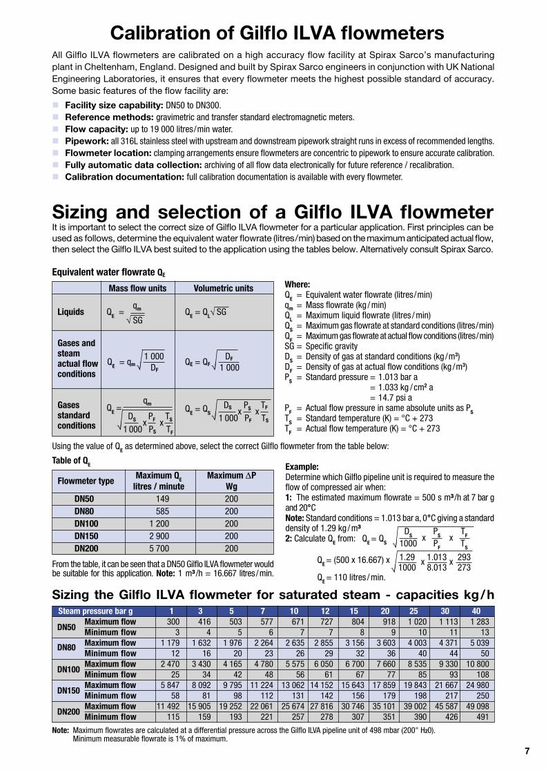
Calibration of Gilflo ILVA flowmetersAll Gilflo ILVA flowmeters are calibrated on a high accuracy flow facility at Spirax Sarco’s manufacturing plant in Cheltenham, England. Designed and built by Spirax Sarco engineers in conjunction with UK National Engineering Laboratories, it ensures that every flowmeter meets the highest possible standard of accuracy. Some basic features of the flow facility are:
Sizing and selection of a Gilflo ILVA flowmeterIt is important to select the correct size of Gilflo ILVA flowmeter for a particular application. First principles can be used as follows, determine the equivalent water flowrate (litres/min) based on the maximum anticipated actual flow, then select the Gilflo ILVA best suited to the application using the tables below. Alternatively consult Spirax Sarco.
Sizing the Gilflo ILVA flowmeter for saturated steam - capacities kg/h
Note: Maximum flowrates are calculated at a differential pressure across the Gilflo ILVA pipeline unit of 498 mbar (200" H20). Minimum measurable flowrate is 1% of maximum.
Where:QE = Equivalent water flowrate (litres/min)qm = Mass flowrate (kg / min)QL = Maximum liquid flowrate (litres / min)QS = Maximum gas flowrate at standard conditions (litres/min)QF = Maximum gas flowrate at actual flow conditions (litres/min)SG = Specific gravityDS = Density of gas at standard conditions (kg /m3)DF = Density of gas at actual flow conditions (kg /m3)PS = Standard pressure = 1.013 bar a = 1.033 kg / cm2 a = 14.7 psi aPF = Actual flow pressure in same absolute units as PSTS = Standard temperature (K) = °C + 273TF = Actual flow temperature (K) = °C + 273
Using the value of QE as determined above, select the correct Gilflo flowmeter from the table below:
Example: Determine which Gilflo pipeline unit is required to measure the flow of compressed air when:1: The estimated maximum flowrate = 500 s m³ /h at 7 bar g and 20°CNote: Standard conditions = 1.013 bar a, 0°C giving a standard density of 1.29 kg /m³2: Calculate QE from: QE = QS
DS x PS x TF
1000 PF TS
1.29 x 1.013 x 293 1000 8.013 273
QE = (500 x 16.667) x
QE = 110 litres /min.
From the table, it can be seen that a DN50 Gilflo ILVA flowmeter would be suitable for this application. Note: 1 m³ /h = 16.667 litres /min.
Table of QE
Flowmeter type Maximum QE Maximum P
litres / minute Wg DN50 149 200 DN80 585 200 DN100 1 200 200 DN150 2 900 200 DN200 5 700 200
Steam pressure bar g 1 3 5 7 10 12 15 20 25 30 40
DN50 Maximum flow 300 416 503 577 671 727 804 918 1 020 1 113 1 283
Minimum flow 3 4 5 6 7 7 8 9 10 11 13 DN80 Maximum flow 1 179 1 632 1 976 2 264 2 635 2 855 3 156 3 603 4 003 4 371 5 039 Minimum flow 12 16 20 23 26 29 32 36 40 44 50
DN100 Maximum flow 2 470 3 430 4 165 4 780 5 575 6 050 6 700 7 660 8 535 9 330 10 800
Minimum flow 25 34 42 48 56 61 67 77 85 93 108
DN150 Maximum flow 5 847 8 092 9 795 11 224 13 062 14 152 15 643 17 859 19 843 21 667 24 980
Minimum flow 58 81 98 112 131 142 156 179 198 217 250
DN200 Maximum flow 11 492 15 905 19 252 22 061 25 674 27 816 30 746 35 101 39 002 45 587 49 098
Minimum flow 115 159 193 221 257 278 307 351 390 426 491
Facility size capability: DN50 to DN300. Reference methods: gravimetric and transfer standard electromagnetic meters. Flow capacity: up to 19 000 litres/min water. Pipework: all 316L stainless steel with upstream and downstream pipework straight runs in excess of recommended lengths. Flowmeter location: clamping arrangements ensure flowmeters are concentric to pipework to ensure accurate calibration. Fully automatic data collection: archiving of all flow data electronically for future reference / recalibration. Calibration documentation: full calibration documentation is available with every flowmeter.
8
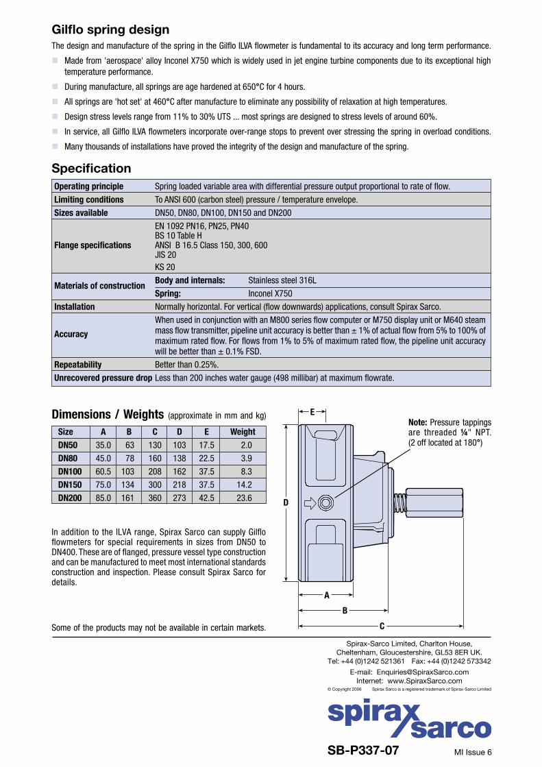
Note: Pressure tappings are threaded ¼" NPT.(2 off located at 180°)
D
E
C
B
A
MI Issue 6SB-P337-07
Dimensions / Weights (approximate in mm and kg)
In addition to the ILVA range, Spirax Sarco can supply Gilflo flowmeters for special requirements in sizes from DN50 to DN400. These are of flanged, pressure vessel type construction and can be manufactured to meet most international standards construction and inspection. Please consult Spirax Sarco for details.
Gilflo spring designThe design and manufacture of the spring in the Gilflo ILVA flowmeter is fundamental to its accuracy and long term performance.
Made from 'aerospace' alloy Inconel X750 which is widely used in jet engine turbine components due to its exceptional high temperature performance.
During manufacture, all springs are age hardened at 650°C for 4 hours.
All springs are 'hot set' at 460°C after manufacture to eliminate any possibility of relaxation at high temperatures.
Design stress levels range from 11% to 30% UTS ... most springs are designed to stress levels of around 60%.
In service, all Gilflo ILVA flowmeters incorporate over-range stops to prevent over stressing the spring in overload conditions.
Many thousands of installations have proved the integrity of the design and manufacture of the spring.
Size A B C D E Weight DN50 35.0 63 130 103 17.5 2.0
DN80 45.0 78 160 138 22.5 3.9
DN100 60.5 103 208 162 37.5 8.3
DN150 75.0 134 300 218 37.5 14.2
DN200 85.0 161 360 273 42.5 23.6
Spirax-Sarco Limited, Charlton House,Cheltenham, Gloucestershire, GL53 8ER UK.
Tel: +44 (0)1242 521361 Fax: +44 (0)1242 573342
E-mail: [email protected]: www.SpiraxSarco.com
© Copyright 2006 Spirax Sarco is a registered trademark of Spirax-Sarco Limited
Some of the products may not be available in certain markets.
Operating principle Spring loaded variable area with differential pressure output proportional to rate of flow.
Limiting conditions To ANSI 600 (carbon steel) pressure / temperature envelope.
Sizes available DN50, DN80, DN100, DN150 and DN200
EN 1092 PN16, PN25, PN40 BS 10 Table HFlange specifications ANSI B 16.5 Class 150, 300, 600 JIS 20 KS 20
Materials of construction Body and internals: Stainless steel 316L
Spring: Inconel X750
Installation Normally horizontal. For vertical (flow downwards) applications, consult Spirax Sarco.
When used in conjunction with an M800 series flow computer or M750 display unit or M640 steam
Accuracy mass flow transmitter, pipeline unit accuracy is better than ± 1% of actual flow from 5% to 100% of maximum rated flow. For flows from 1% to 5% of maximum rated flow, the pipeline unit accuracy will be better than ± 0.1% FSD.
Repeatability Better than 0.25%.
Unrecovered pressure drop Less than 200 inches water gauge (498 millibar) at maximum flowrate.
Specification


![3_pdfsam_expertiza Ilva Parte Scrisa 1[1]](https://img.pdfslide.net/doc/110x75/5571ff4d49795991699d0237/3pdfsamexpertiza-ilva-parte-scrisa-11.jpg)